
1 Scope
The joint VDMA and OPC Foundation Working Group "VDMA OPC UA Weighing Technology Initiative" developed an OPC UA information model for communication of scale systems. Scale systems are defined as devices within a value chain that measure the weight or mass flow of a product or Object containing several additional parameters (e.g., price, tare of packaging, etc.). Scale systems stand for a complete weight measuring device that includes one or multiple scales. The scales may fulfill different use cases within one scale system (e.g., filling and price labeling). Each scale consists of one or multiple load cells which capture the weight. It is the smallest unit regarding the components of a scale system within this Companion Specification.
The OPC UA Weighing Technology Companion Specification covers the following scale system types directly: Automatic Filling Scales, catchweigher (Automatic Price Labeling Scales, Automatic Weight Labeling Scales, checkweigher), Continuously Scales, Hopper Scales, Laboratory Scales, Piece Counting Scales, Simple Scales, Totalizing Scales and Vehicle Scales.
Other scale systems including weighing bridges may be modeled based on this Companion Specification, but probably need to be extended by certain parameters.
2 Normative references
The following documents, in whole or in part, are normatively referenced in this document and are indispensable for its application. For dated references, only the edition cited applies. For undated references, the latest edition of the referenced document (including any amendments) applies.
OPC 10000-1, OPC Unified Architecture - Part 1: Overview and Concepts
| OPC 10000-1 |
OPC 10000-3, OPC Unified Architecture - Part 3: Address Space Model
| OPC 10000-3 |
OPC 10000-4, OPC Unified Architecture - Part 4: Services
| OPC 10000-4 |
OPC 10000-5, OPC Unified Architecture - Part 5: Information Model
| OPC 10000-5 |
OPC 10000-7, OPC Unified Architecture - Part 7: Profiles
| OPC 10000-7 |
OPC 10000-8, OPC Unified Architecture - Part 8: Data Access
| OPC 10000-8 |
OPC 10000-9, OPC Unified Architecture - Part 9: Alarms and Conditions
| OPC 10000-9 |
OPC 10000-100, OPC Unified Architecture - Part 100: Devices
OPC 10000-100
OPC 10000-200, OPC Unified Architecture - Part 200: Industrial Automation - Basics
OPC 10000-200
OPC 30050, OPC UA for PackML
http://www.opcfoundation.org/documents/30050
OPC 40001-1, OPC UA for Machinery - Part 1: Basic Building Blocks OPC 40001-1
http://www.opcfoundation.org/documents/40001-1
| The International Vocabulary of Basic and General Terms in Metrology (VIM) | 2.9 |
| International Vocabulary of Legal Metrology (VIML) | V1 - 2013 |
| OIML D 11 General requirements for measuring instruments - Environmental conditions | 2011 |
| OIML D 31 General requirements for software-controlled measuring instruments | 2008 |
| OIML R 50 - Continuous totalizing automatic weighing instruments (belt weighers) | 2014 |
| OIML R 51 - Automatic catchweighing instruments | 2006 |
| OIML R 61 - Automatic gravimetric filling instruments | 2017 |
| OIML R 76 - Non-automatic weighing instruments | 2006 |
| OIML R 107 - Discontinuous totalizing automatic weighing instruments (totalizing hopper weighers) | 2007 |
| WELMEC 6.4 - Guide for packers and importers of e-marked prepacked products | June 2005 |
3 Terms, definitions and conventions
3.1 Overview
For this specification it is assumed that basic concepts of OPC UA information modelling are understood. This specification will use these concepts to describe the OPC UA for the Weighing Technology Companion Specification Information Model. For the purpose of this document, the terms and definitions given in OPC 10000-1, OPC 10000-3, OPC 10000-4, OPC 10000-5, OPC 10000-7, OPC 10000-100, OPC 10000-200, OPC 30050, OPC 40001-1 as well as in the following apply.
3.2 OPC UA for Weighing Technology terms
The terminology used in this specification conforms to
The International Vocabulary of Legal Metrology (VIML)
Basic and General Terms in Metrology (VIM)
D 11 General requirements for measuring instruments - Environmental conditions
R 76 Non-automatic weighing instruments,
D 31 General requirements for software-controlled measuring instruments.
In addition, the following definitions apply.
3.2.1 General Terms
| Term | Definition |
| Actual scale interval, d | Value expressed in units of mass of: the difference between the values corresponding to two consecutive scale marks, for analog indication; or the difference between two consecutive indicated values, for digital indication. (OIML R51) |
| Automatic scale | An instrument that weighs without the intervention of an operator and follows a predetermined program of automatic processes, which are characteristic of the instrument. |
| Current weight | Defines the current value that is measured at the sensor at the concurrent timestamp. Might be a highly fluctuating value. |
| Division | Value of the smallest increment. See also (actual scale interval, verification scale interval) |
| Feeder | Devices for conveying the product to or from the weighing module |
| Flow rate | The flow rate is a measured value passes per unit of time. The flow rate can be defined as mass flow rate (flow of mass m through a surface per unit time t) or as volumetric flow rate (flow of volume of fluid V through a surface per unit time t) |
| Gross value | Indication of the weight value of a load on an instrument, with no tare or preset tare device in operation. (see OIML R 76) Weight of an objective or sample (net weight) including its container or packaging (tare weight) |
| Height | Length of an item in direction of global gravity. |
| Item | A physical product in scales that process a set of physical products like catchweigher. In case a "productType" represented a set of physical products the single physical product is called item. |
| Length | In direction of travel. |
| Load | Amount of product that is currently introducing the force on the load receptor. (OIML R61) A general term for any Object when it is intended to convey the meaning that this Object is exerting a weight force |
| Measurement result | Set of quantity values being attributed to a measurand together with any other available relevant information (see VIM 2.9) |
| Minimum Weight | The Minimum Weight is the smallest sample quantity required for a weighment to just achieve a specified relative accuracy of weighing. So it is the smallest load or component of a recipe that may be weighted on the scale. |
| Net value | Indication of the weight value of a load placed on an instrument after operation of a tare device. (see OIML R 76) The weight of a material or sample after deducting the weight of its packaging or of the transport instrument (tare weight) |
| PackML | "PackML stands for Packaging Machine Language and is an interface standard originally used in batch manufacturing in the packaging industry, but which is now used in multiple different types of production and assembly lines." (see OPC 30050) |
| Preset tare value | Numerical value, representing a weight value, that is introduced into the instrument. It is a predetermined tare value that is used for one or several weighings. (see OIML R 76) |
| Product | For the purposes of this Companion Specification, a product is a physical good that is processed by a weighing system. Depending on the type of scale and type of good, the result may be a single weighing and/or a statistical evaluation of many weighing operations. Additional process steps (e.g., metal detection) can also be performed. A OPC UA Object of type "productType" represented a physical product or a set of physical products and contain additional (meta-)information like a target value or some identifier. |
| Proportional tare | Tare value that is determined by the scale automatically and that is proportional to the gross weight. |
| Recipe | See Annex B |
| RegisteredWeight | Defines the last valid measurement that was recorded and will be used for further processing. |
| Scale | Synonym: weighing instrument Measuring instrument that serves to determine the mass of an amount of material by using the action of gravity on this material. NOTE: In this Recommendation "mass" (or "weight value") is preferably used in the sense of "conventional mass" or "conventional value of the result of weighing in air" according to OIML R 111 and OIML D 28, whereas "weight" is preferably used for an embodiment (= material measure) of mass that is regulated in regard to its physical and metrological characteristics. The instrument may also be used to determine other quantities, magnitudes, parameters or characteristics related to mass. According to its method of operation, a weighing instrument is classified as automatic or non-automatic. (See OIML R 76) |
| Scale division | See division |
| Scale system | A scale system is the combination of several scales that are addressed by a common interface. A scale system can have additional functions, such as a state machine or a production preset. |
| Setpoint | Time at which an action is triggered |
| Standard deviation | A quantity expressing by how much the members of a group differ from the mean value for the group. |
| Tare value, T | Weight value of a load, determined by a tare weighing device. (see OIML R 76) The mass of packaging or transport container of the material that is being weighed |
| Target value | Requested value of a variable size at a given time and under specified conditions. (see IEC 60050) |
| Tolerable Negative Error (TU1) for prepackages | Only a small number of prepackages may have a content below the nominal quantity minus the maximum permissible error (TU1-limit). These prepackages are known and referred to as 'defectives' (see Welmec 6.4) |
| TU2-limit | No prepackage with a quantity of product less than the nominal quantity minus twice the tolerable negative error (TU2-limit) may be ℮-marked. (see Welmec 6.4) |
| Verification scale interval, e | Value, expressed in units of mass, used for the classification and verification of an instrument. (OIML R51) |
| Weighing | Process of determining the mass of a load using the effect of gravity on that load (OIML R61) |
| Weighing bridge | Mechanical component of the scale that carry the load. One or more load cells are integrated into the WeighingBridge as an element of mass determination. |
| Weighing good ID | Defines the identifier of an Object that is to be weighed (load) |
| Weighing instrument | Synonym: scale |
| Weighing module | Part of the weighing instrument that comprises all mechanical and electronic devices (i.e., load receptor, load-transmitting device, load cell, and analog data processing device or digital data processing device) but not having the means to display the weighing result. It may optionally have devices for further processing (digital) data and operating the instrument. (OIML R76) |
| Weighing range | The range of a scale can measure a mass. A scale can have several weighing ranges with different scale divisions |
| Width | In third possible orthogonal direction to height and length |
3.2.2 State machine terms
The terms for state machine defined in OPC 30050.
3.3 Abbreviations and symbols
| value | |
| mean value | |
| DCS | Distributed Control Systems |
| G | Gross |
| HMI | Human Machine Interface |
| HTTP | Hypertext Transfer Protocol |
| IP | Internet Protocol |
| L | Load |
| N | Net |
| OIML | International Organization of Legal Metrology |
| PT | Preset tare |
| T | Tare |
| TCP | Transmission Control Protocol |
| TU1 | lower tolerance limit |
| count | |
| standard deviation |
3.4 Conventions used in this document
3.4.1 Conventions for Node descriptions
Node definitions are specified using tables (see Table 3).
Attributes are defined by providing the Attribute name and a value, or a description of the value.
References are defined by providing the ReferenceType name, the BrowseName of the TargetNode and its NodeClass.
If the TargetNode is a component of the Node being defined in the table, the Attributes of the composed Node are defined in the same row of the table.
The DataType is only specified for Variables; "[<number>]" indicates a single-dimensional array, for multi-dimensional arrays the expression is repeated for each dimension (e.g. [2][3] for a two-dimensional array). For all arrays the ArrayDimensions is set as identified by <number> values. If no <number> is set, the corresponding dimension is set to 0, indicating an unknown size. If no number is provided at all the ArrayDimensions can be omitted. If no brackets are provided, it identifies a scalar DataType and the ValueRank is set to the corresponding value (see OPC 10000-3). In addition, ArrayDimensions is set to null or is omitted. If it can be Any or ScalarOrOneDimension, the value is put into "{<value>}", so either "{Any}" or "{ScalarOrOneDimension}" and the ValueRank is set to the corresponding value (see OPC 10000-3) and the ArrayDimensions is set to null or is omitted. Examples are given in Table 2.
| Notation | DataType | ValueRank | ArrayDimensions | Description |
| Int32 | Int32 | -1 | omitted or null | A scalar Int32. |
| Int32[] | Int32 | 1 | omitted or {0} | Single-dimensional array of Int32 with an unknown size. |
| Int32[][] | Int32 | 2 | omitted or {0,0} | Two-dimensional array of Int32 with unknown sizes for both dimensions. |
| Int32[3][] | Int32 | 2 | {3,0} | Two-dimensional array of Int32 with a size of 3 for the first dimension and an unknown size for the second dimension. |
| Int32[5][3] | Int32 | 2 | {5,3} | Two-dimensional array of Int32 with a size of 5 for the first dimension and a size of 3 for the second dimension. |
| Int32{Any} | Int32 | -2 | omitted or null | An Int32 where it is unknown if it is scalar or array with any number of dimensions. |
| Int32{ScalarOrOneDimension} | Int32 | -3 | omitted or null | An Int32 where it is either a single-dimensional array or a scalar. |
The TypeDefinition is specified for Objects and Variables.
The TypeDefinition column specifies a symbolic name for a NodeId, i.e., the specified Node points with a HasTypeDefinition Reference to the corresponding Node.
The ModellingRule of the referenced component is provided by specifying the symbolic name of the rule in the ModellingRule column. In the AddressSpace, the Node shall use a HasModellingRule Reference to point to the corresponding ModellingRule Object.
If the NodeId of a DataType is provided, the symbolic name of the Node representing the DataType shall be used.
Nodes of all other NodeClasses cannot be defined in the same table; therefore, only the used ReferenceType, their NodeClass and their BrowseName are specified. A reference to another part of this document points to their definition.
Table 3 illustrates the table. If no components are provided, the DataType, TypeDefinition and ModellingRule columns may be omitted and only a Comment column is introduced to point to the Node definition.
| Attribute | Value | ||||
| Attribute name | Attribute value. If it is an optional Attribute that is not set "--" will be used. | ||||
| References | NodeClass | BrowseName | DataType | TypeDefinition | ModellingRule |
| ReferenceType name | NodeClass of the TargetNode. | BrowseName of the target Node. If the Reference is to be instantiated by the server, then the value of the target Node's BrowseName is "--". | DataType of the referenced Node, only applicable for Variables. | TypeDefinition of the referenced Node, only applicable for Variables and Objects. | Referenced ModellingRule of the referenced Object. |
| NOTE: Notices referencing footnotes of the table content. | |||||
Components of Nodes can be complex that is containing components by themselves. The TypeDefinition, NodeClass, DataType and ModellingRule can be derived from the type definitions, and the symbolic name can be created as defined in 3.4.3.1. Therefore, those containing components are not explicitly specified; they are implicitly specified by the type definitions.
3.4.2 NodeIds and BrowseNames
3.4.2.1 NodeIds
The NodeIds of all Nodes described in this standard are only symbolic names. Annex A defines the actual NodeIds.
The symbolic name of each Node defined in this specification is its BrowseName, or, when it is part of another Node, the BrowseName of the other Node, a ".", and the BrowseName of itself. In this case "part of" means that the whole has a 0:HasProperty or 0:HasComponent Reference to its part. Since all Nodes not being part of another Node have a unique name in this specification, the symbolic name is unique.
The namespace for all NodeIds defined in this specification is defined in Annex A The namespace for this NamespaceIndex is Server-specific and depends on the position of the namespace URI in the server namespace table.
3.4.2.2 BrowseNames
The text part of the BrowseNames for all Nodes defined in this specification is specified in the tables defining the Nodes. The NamespaceIndex for all BrowseNames defined in this specification is defined in Annex A.
If the BrowseName is not defined by this specification, a namespace index prefix like '0:EngineeringUnits' or '2:DeviceRevision' is added to the BrowseName. This is typically necessary if a Property of another specification is overwritten or used in the OPC UA types defined in this specification. Table 18 provides a list of namespaces and their indexes as used in this specification.
3.4.3 Common Attributes
3.4.3.1 General
The Attributes of Nodes, their DataTypes and descriptions are defined in OPC 10000-3. Attributes not marked as optional are mandatory and shall be provided by a Server. The following tables define if the Attribute value is defined by this specification or if it is server-specific.
For all Nodes specified in this specification, the Attributes named in Table 4 shall be set as specified in the table.
| Attribute | Value |
| DisplayName | The DisplayName is a 0:LocalizedText. Each server shall provide the DisplayName identical to the BrowseName of the Node for the LocaleId "en". Whether the server provides translated names for other LocaleIds is server-specific. |
| Description | Optionally a server-specific description is provided. |
| NodeClass | Shall reflect the NodeClass of the Node. |
| NodeId | The NodeId is described by BrowseNames as defined in 3.4.2.1. |
| WriteMask | Optionally the WriteMask Attribute can be provided. If the WriteMask Attribute is provided, it shall set all non-server-specific Attributes to not writeable. For example, the Description Attribute may be set to writeable since a Server may provide a server-specific description for the Node. The NodeId shall not be writeable, because it is defined for each Node in this specification. |
| UserWriteMask | Optionally the UserWriteMask Attribute can be provided. The same rules as for the WriteMask Attribute apply. |
| RolePermissions | Optionally server-specific role permissions can be provided. |
| UserRolePermissions | Optionally the role permissions of the current Session can be provided. The value is server-specific and depend on the RolePermissions Attribute (if provided) and the current Session. |
| AccessRestrictions | Optionally server-specific access restrictions can be provided. |
3.4.3.2 Objects
For all Objects specified in this specification, the Attributes named in Table 5 shall be set as specified in the table. The definitions for the Attributes can be found in OPC 10000-3.
| Attribute | Value |
| EventNotifier | Whether the Node can be used to subscribe to Events or not is server-specific. |
3.4.3.3 Variables
For all Variables specified in this specification, the Attributes named in Table 6 shall be set as specified in the table. The definitions for the Attributes can be found in OPC 10000-3.
| Attribute | Value |
| MinimumSamplingInterval | Optionally, a server-specific minimum sampling interval is provided. |
| AccessLevel | The access level for Variables used for type definitions is server-specific, for all other Variables defined in this specification, the access level shall allow reading; other settings are server-specific. |
| UserAccessLevel | The value for the UserAccessLevel Attribute is server-specific. It is assumed that all Variables can be accessed by at least one user. |
| Value | For Variables used as InstanceDeclarations, the value is server-specific; otherwise it shall represent the value described in the text. |
| ArrayDimensions | If the ValueRank does not identify an array of a specific dimension (i.e., ValueRank <= 0) the ArrayDimensions can either be set to null or the Attribute is missing. This behavior is server-specific. If the ValueRank specifies an array of a specific dimension (i.e., ValueRank > 0) then the ArrayDimensions Attribute shall be specified in the table defining the Variable. |
| Historizing | The value for the Historizing Attribute is server-specific. |
| AccessLevelEx | If the AccessLevelEx Attribute is provided, it shall have the bits 8, 9, and 10 set to 0, meaning that read and write operations on an individual Variable are atomic, and arrays can be partly written. |
3.4.3.4 VariableTypes
For all VariableTypes specified in this specification, the Attributes named in Table 7 shall be set as specified in the table. The definitions for the Attributes can be found in
| Attributes | Value |
| Value | Optionally a server-specific default value can be provided. |
| ArrayDimensions | If the ValueRank does not identify an array of a specific dimension (i.e., ValueRank <= 0) the ArrayDimensions can either be set to null or the Attribute is missing. This behavior is server-specific. If the ValueRank specifies an array of a specific dimension (i.e., ValueRank > 0) then the ArrayDimensions Attribute shall be specified in the table defining the VariableType. |
3.4.3.5 Methods
For all Methods specified in this specification, the Attributes named in Table 8 shall be set as specified in the table. The definitions for the Attributes can be found in OPC 10000-3.
| Attributes | Value |
| Executable | All Methods defined in this specification shall be executable (Executable Attribute set to "True") unless it is defined differently in the Method definition. |
| UserExecutable | The value of the UserExecutable Attribute is server-specific. It is assumed that all Methods can be executed by at least one user. |
4 General Information on Weighing Technology and OPC UA
4.1 Introduction to Weighing Technology Companion Specification
Scales are used in a wide range of applications. Therefore, this section describes the schematic structure of a scale and includes a simple classification of scale types.
4.1.1 Schematic Structure of a Scale system
In addition to the definition of a scale of OIML R76 the following definition applies:
A scale is a computer system, device or measuring instrument used to determine the mass or mass flow of a quantity of material and consisting of one or more weighing modules (including load receptor, load-transmitting device, load cell and data processing device) and additional modules or peripheral devices (see Figure 1). Each weighing module determines a mass. The weighing result of the scale may be the result of one weighing module or the addition of several weighing modules. Not all partial results need to be included in the result.
In addition, a scale can also have subdevices such as printers or feeder systems. Each scale needs a data processing device and at least one interface like a display or field bus. Thus, an interaction other than OPC UA is always possible.
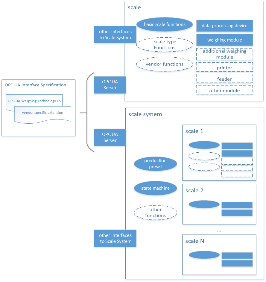
Each scale provides a specific set of functions. These functions can be divided into three categories. The basic set of functions is available for all scales and behaves the same way for all scales. The scale type functions depend on the scale types (see Section 5.1.2) and behave the same within this type. An example is the administration of zones at the checkweigher or the administration of recipes at the recipe scale. In addition, further functions or applications can be specifically defined by a vendor.
A scale system is the combination of several scales that are addressed by a common interface and can have additional functions, such as a state machine or a production preset. However, a scale must be included in any case.
The schematic described here is a significant simplification of scales and focuses on the external representation of entire scale systems. It does not include any metrological details. In addition, real systems can deviate significantly from this schematic.
4.1.2 Introduction into scale classification
This classification of the scales is based on the aspect of communication via OPC UA. If possible, existing classifications (e.g., from OIML) were used. However, further conflicting classifications may exist. Since the boundaries are partly fluid, some devices can be assigned to several scale types. The resulting classification is shown in Figure 2.
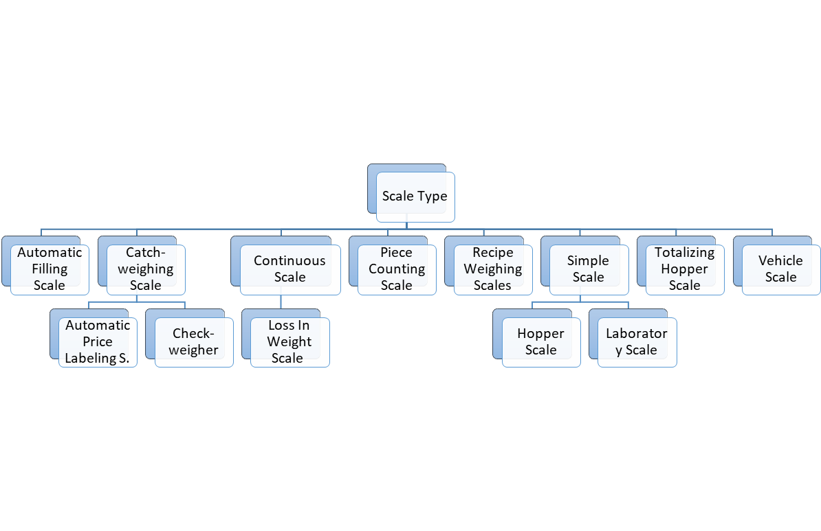
The definitions of the individual types can be found in Table 9.
| Term | Definition |
| Automatic Filling Scale | Instrument which fills containers with predetermined and virtually constant mass of product from bulk by automatic weighing, and which comprises essentially automatic feeding device(s) associated with weighing unit(s) and the appropriate control and discharge devices. (Definition is based on OIML R61) |
| Catchweighing Scale (catchweigher) | Automatic weighing instrument that weighs pre-assembled discrete loads or single loads of loose material. (Definition is based on OIML R51) |
| Automatic Weight Labeling Scale | catchweigher that labels individual pre-assembled discrete loads (e.g., prepackages) with the weight value. (Definition is based on OIML R51) |
| Automatic Price Labeling Scale | catchweigher that calculates the price to pay on the basis of the indicated mass and the unit price and labels individual pre-assembled discrete loads (e.g., prepackages with the weight value, unit price and price to pay). (Definition is based on OIML R51) |
| checkweigher | catchweigher that sub-divides prepackages of different mass into two or more sub-groups according to the value of the difference between their mass and the nominal set point. (Definition is based on OIML R51) |
| Continuous Scale | An automatic weighing instrument for continuously weighing a bulk product on a conveyor belt (or other mechanical facilities), without systematic subdivision of the mass and without interrupting the movement of the conveyor belt. (Definition is based on OIML R50) |
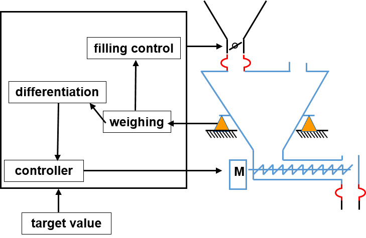
| Loss In Weight Scale | A special type of continuous scale is the loss in weight scale. It works according to the principle of controlled material increase or removal. The weight of the material is weighed by load cells and the change in weight per time unit is determined. The change in weight corresponds to the actual feed rate of the feeder when re-filling or emptying is stopped. A schematic overview is shown in Figure 3. |
| Piece Counting Scale | A scale that can determine the number of parts in the load. A reference weight must first be determined or stored. |
| Recipe Weighing Scale | Scale with the capacity to manage and process recipes. Single recipe steps in a recipe can be the weighing of ingredients, the display of user instructions, the monitoring of switching values or the activation of aggregates. |
| Simple Scale | Simple scales do not have any major functional extensions and provide only basic weighing functionality, i.e., acting as a sensor. |
| Hopper Scale | A scale for weighing a bulk product with a tank, vessel, box or hopper mounted on one or more weighing bridges. The primary use case is tank level monitoring. |
| Laboratory Scale | The laboratory scales have a particularly high resolution and represent highly sensitive measuring instruments. For this reason, additional processes and measures are necessary to carry out an accurate measurement. For this purpose, e.g., the shielding of the environment with additional signs may be necessary. |
Totalizing Hopper Scale | An automatic weighing instrument that weighs a bulk product by dividing it into discrete loads, determining the mass of each discrete load in sequence, summing the weighing results and delivering the discrete loads to bulk. (Definition is based on OIML R107) |
| Vehicle Scale | Automatic or non-automatic scale having one or more weight bridges that determines the mass of a vehicle. The load is typically a truck with or without a trailer or a rail wagon. A special variant is the automatic rail-weighbridge (see OIML R106), which has one or more load receptors, including rails for the transport of rail vehicles, which determine the mass of the wagons and/or of the entire train by weighing during travel. |
4.1.3 Product Handle Handling of product-related information
In addition to measuring, scales may also perform other tasks such as managing product data (production presetting and statistics/production output). To ensure that product-related information does not become inconsistent during the weighing process, it must be protected accordingly. For this purpose, a corresponding product information handle model shown in Figure 4 is described in this Companion Specification. It defines two different modes (ProductHandleMode/AccessRestrictionMode).
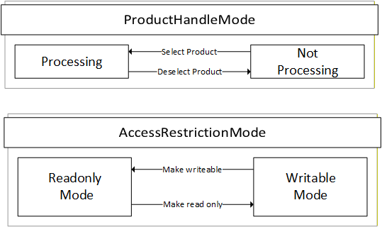
The ProductHandleMode indicates if a product can currently be processed by the scale or not. It is possible that the product-related information can be writeable or read only in both modes. The transition between the two states of the mode can be triggered internally in the scale or via the OPC UA methods SelectProduct, DeselectProduct, SwitchProduct (see sections 7.7 - 7.8). In some cases, it is possible that several products are in the "Processing" mode. For example, a catchweigher can process different products in parallel, while a continuous scale can only process one product at a time.
The AccessRestrictionMode can be used to define the access restriction of the product. A client can make a set of changes (e.g., multiple write operations and method calls) only when the mode is in "WritableMode". This mode applies to the entire product Object, including all components such as zones. The access level of all child nodes of the product Object should at least have written access and the method should be executable. The AccessRestritionMode is used via the LockingService descripted in OPC 10000-100.
4.2 Introduction to OPC Unified Architecture
4.2.1 What is OPC UA?
OPC UA is an open and royalty free set of standards designed as a universal communication protocol. While there are numerous communication solutions available, OPC UA has key advantages:
A state of art security model (see OPC 10000-2).
A fault tolerant communication protocol.
An information modelling framework that allows application developers to represent their data in a way that makes sense to them.
OPC UA has a broad scope which delivers for economies of scale for application developers. This means that a larger number of high-quality applications at a reasonable cost are available. When combined with semantic models such as Weighing Technology Companion Specification, OPC UA makes it easier for end users to access data via generic commercial applications.
The OPC UA model is scalable from small devices to ERP systems. OPC UA Servers process information locally and then provide that data in a consistent format to any application requesting data - ERP, MES, PMS, Maintenance Systems, HMI, Smartphone or a standard Browser, for examples. For a more complete overview see OPC 10000-1.
4.2.2 Basics of OPC UA
As an open standard, OPC UA is based on standard internet technologies, like TCP/IP, HTTP, Web Sockets.
As an extensible standard, OPC UA provides a set of Services (see OPC 10000-4) and a basic information model framework. This framework provides an easy manner for creating and exposing vendor defined information in a standard way. More importantly all OPC UA Clients are expected to be able to discover and use vendor-defined information. This means OPC UA users can benefit from the economies of scale that come with generic visualization and historian applications. This specification is an example of an OPC UA Information Model designed to meet the needs of developers and users.
OPC UA Clients can be any consumer of data from another device on the network to browser based thin clients and ERP systems. The full scope of OPC UA applications is shown in Figure 5.

OPC UA provides a robust and reliable communication infrastructure having mechanisms for handling lost messages, failover, heartbeat, etc. With its binary encoded data, it offers a high-performing data exchange solution. Security is built into OPC UA as security requirements become more and more important especially since environments are connected to the office network or the internet and attackers are starting to focus on automation systems.
4.2.3 Information modelling in OPC UA
4.2.3.1 Concepts
OPC UA provides a framework that can be used to represent complex information as Objects in an AddressSpace which can be accessed with standard services. These Objects consist of Nodes connected by References. Different classes of Nodes convey different semantics. For example, a Variable Node represents a value that can be read or written. The Variable Node has an associated DataType that can define the actual value, such as a 0:String, float, structure etc. It can also describe the Variable value as a variant. A Method Node represents a function that can be called. Every Node has a number of Attributes including a unique identifier called a NodeId and non-localized name called as BrowseName. An Object representing a 'Reservation' is shown in Figure 6.

Object and Variable Nodes represent instances, and they always reference a TypeDefinition (ObjectType or VariableType) Node which describes their semantics and structure. Figure 7 illustrates the relationship between an instance and its TypeDefinition.
The type Nodes are templates that define all the children that can be present in an instance of the type. In the example in Figure 7 the PersonType ObjectType defines two children: First Name and Last Name. All instances of PersonType are expected to have the same children with the same BrowseNames. Within a type the BrowseNames uniquely identify the children. This means Client applications can be designed to search for children based on the BrowseNames from the type instead of NodeIds. This eliminates the need for manual reconfiguration of systems if a Client uses types that multiple Servers implement.
OPC UA also supports the concept of sub-typing. This allows a modeller to take an existing type and extend it. There are rules regarding sub-typing defined in OPC 10000-3, but in general they allow the extension of a given type or the restriction of a DataType. For example, the modeller may decide that the existing ObjectType in some cases needs an additional Variable. The modeller can create a subtype of the ObjectType and add the Variable. A Client that is expecting the parent type can treat the new type as if it was of the parent type. Regarding DataTypes, subtypes can only restrict. If a Variable is defined to have a numeric value, a sub type could restrict it to a float.

References allow Nodes to be connected in ways that describe their relationships. All References have a ReferenceType that specifies the semantics of the relationship. References can be hierarchical or non-hierarchical. Hierarchical references are used to create the structure of Objects and Variables. Non-hierarchical are used to create arbitrary associations. Applications can define their own ReferenceType by creating subtypes of an existing ReferenceType. Subtypes inherit the semantics of the parent but may add additional restrictions. Figure 8 depicts several References, connecting different Objects.

The figures above use a notation that was developed for the OPC UA specification. The notation is summarized in Figure 9. UML representations can also be used; however, the OPC UA notation is less ambiguous because there is a direct mapping from the elements in the figures to Nodes in the AddressSpace of an OPC UA Server.
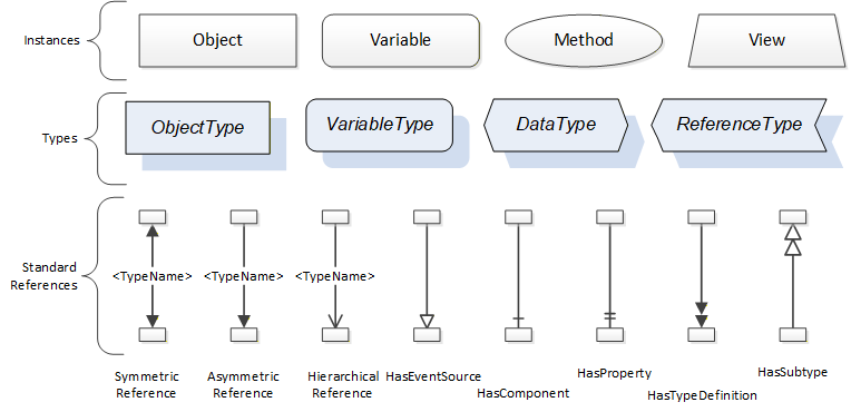
A complete description of the different types of Nodes and References can be found in OPC 10000-3, and the base structure is described in OPC 10000-5.
OPC UA specification defines a very wide range of functionality in its basic information model. It is not expected that all Clients or Servers support all functionality in the OPC UA specifications. OPC UA includes the concept of Profiles, which segment the functionality into testable certifiable units. This allows the definition of functional subsets (that are expected to be implemented) within a Companion Specification. The Profiles do not restrict functionality but generate requirements for a minimum set of functionalities (see OPC 10000-7).
4.2.3.2 Namespaces
OPC UA allows information from many different sources to be combined into a single coherent AddressSpace. Namespaces are used to make this possible by eliminating naming and ID conflicts between information from different sources. Namespaces in OPC UA have a globally unique 0:String called a NamespaceUri, and a locally unique integer called a NamespaceIndex. The NamespaceIndex is only unique within the context of a Session between an OPC UA Client and an OPC UA Server. The Services defined for OPC UA use the NamespaceIndex to specify the Namespace for qualified values.
There are two types of values in OPC UA that are qualified with Namespaces: NodeIds and QualifiedNames. NodeIds are globally unique identifiers for Nodes. This means the same Node with the same NodeId can appear in many Servers. This, in turn, means Clients can have built in knowledge of some Nodes. OPC UA Information Models generally define globally unique NodeIds for the TypeDefinitions defined by the Information Model.
QualifiedNames are non-localized names qualified with a Namespace. They are used for the BrowseNames of Nodes and allow the same names to be used by different information models without conflict. TypeDefinitions are not allowed to have children with duplicate BrowseNames; however, instances do not have that restriction.
4.2.3.3 Companion Specifications
An OPC UA Companion Specification for an industry specific vertical market describes an Information Model by defining ObjectTypes, VariableTypes, DataTypes and ReferenceTypes that represent the concepts used in the vertical market, and potentially also well-defined Objects as entry points into the AddressSpace.
4.2.4 RelativePath
A RelativePath is a structure that describes a sequence of References and Nodes to follow. Annex A of Part 4 Services describes a text format for a RelativePath that can be used in documentation or in files used to store configuration information
The components of a RelativePath text format are specified in Table 10.
| Symbol | Meaning |
| / | The forward slash character indicates that the Server is to follow any subtype of HierarchicalReferences. |
| . | The period (dot) character indicates that the Server is to follow any subtype of an Aggregates ReferenceType. |
| <[#!ns:]ReferenceType> | A 0:String delimited by the '<' and '>' symbols specifies the BrowseName of a ReferenceType to follow. By default, any References of the subtypes the ReferenceType are followed as well. A '#' placed in front of the BrowseName indicates that subtypes should not be followed. A '!' in front of the BrowseName is used to indicate that the inverse Reference should be followed. The BrowseName may be qualified with a namespace index (indicated by a numeric prefix followed by a colon). This namespace index is used specify the namespace component of the BrowseName for the ReferenceType. If the namespace prefix is omitted, then namespace index 0 is used. |
| [ns:]BrowseName | A 0:String that follows a '/', '.' or '>' symbol specifies the BrowseName of a target Node to return or follow. This BrowseName may be prefixed by its namespace index. If the namespace prefix is omitted, then namespace index 0 is used. Omitting the final BrowseName from a path is equivalent to a wildcard operation that matches all Nodes which are the target of the Reference specified by the path. |
| & | The & sign character is the escape character. It is used to specify reserved characters that appear within a BrowseName. A reserved character is escaped by inserting the '&' in front of it. Examples of BrowseNames with escaped characters are: Received browse path name Resolves to "&/Name_1" "/Name_1" "&.Name_2" ".Name_2" "&:Name_3" ":Name_3" "&&Name_4" "&Name_4" |
5 Use cases
5.1 General
This Weighing Technology Companion Specification describes how a scale system is addressed via OPC UA. For this purpose, the following primary use cases for the different scale types from section 4.1.2 were considered. Other use cases can also be covered or specified in other standards (vendor or Companion Specification).
In all defined use cases the scale system usually has the role of an OPC UA server. Therefore, this specification describes and defines the way an OPC UA client can read or write data and control the scale system via OPC UA. A scale system may also have a different interface (e.g., an HMI) that can control the scale as well. Some peripheral devices (e.g., printer, feeder) are also described in this specification but the communication between the peripheral devices and the scale is not part of the description.
5.2 Accessing Data of measurement results and statistics
An important application of a scale is the data access of individual measurement results. In many cases, the measurement result is a weight value with a unit derived from the weight (e.g., flow rate, volume, ...). A distinction can be made between the continuous display of the measured value (called "current Weight") and a measurement (internal or external) that has been registered (called "registered Weight"). A registration could be triggered from an OPC UA-Client. The use case also includes the needed meta-data (e.g., product ID, unit) for identifying the result in further processing.
In some cases, the individual measurement result is not relevant or only of minor relevance. In some cases, a statistic (mean value, standard deviation) over several measured values or over a period of time is required.
5.3 State Machine of the Scale
A defined state machine enables the user to obtain a uniform overview of different devices from different manufacturers. This is useful in applications with a large number of machines. The interaction between a client system and the scale system depends on the current state of the device. Transition between two states can be triggered by method calls from an OPC UA client, by another interface or internally. Each state change creates an event in the OPC UA server. The PackML state machine is used for the scale system, as it is already in use in Weighing Technology, e.g., for checkweighers, and can be adapted accordingly for other scales. A more detailed description of the state machine can be found in the Companion Specification PackML for OPC UA. NOTE: Scales do not have to implement the SubStateMachine within the state "Execute".
5.4 Production Preset
Part of the access of a higher-level system to a weighing system is the management of products. This standard describes a way of creating, editing and selecting products on the scale. The entire information flow via OPC UA can also run completely or in parts via different interfaces. The schematic structure of production management is described in Section 5.1.3.
6 Weighing Technology Information Model overview
6.1 General
The information model for Weighing Technology has three main aspects: the generic part for all scale devices, the production management and the scale type specific part.
6.2 Overview of generic Scales
Figure 10 shows an overview of the different ObjectTypes for the Weighing Technology devices and the references to the types from the Companion Specification for devices. Four subtypes of the ComponentType are defined:
FeederModuleType
PrinterModuleType
ScaleSystemType
ScaleDeviceType
The entry point of a server is an instance of the ScaleSystemType or a ScaleDeviceType. The ScaleSystemType represents a multi-scale system and includes one or more scales and has some common information (e.g., serial number). The ScaleDeviceType is abstract and only subtypes of it can be instantiated (see section 6.3). Both Types (ScaleDeviceType and ScaleSystemType) can optionally have an Object of the ProductionPresetType (see section 7.7) and/or an Object (called ProductionOutput) of the StatisticType.
Figure 10 shows the most important Object types used in the information model and the relations between them.
6.3 Modular scale devices
A modular scale device is represented by a (subtype of) ScaleDeviceType or ScaleSystemType that is composed of a top-device and a set of subdevices (modules). It uses the modular devices concept of OPC UA Companion Specification for Devices (see OPC 10000-100 9.2). The modules (subdevices) of modular scale devices are aggregated in the SubDevices Object. The SupportedTypes folder for SubDevices is used to maintain the set of modules that can be added to the ScaleDevice or scale system (see Figure 11).
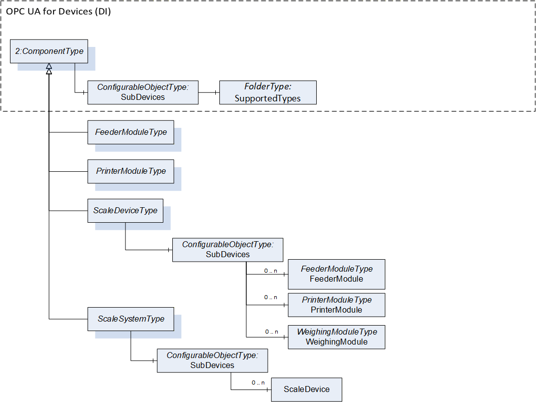
This Companion Specification defines the following supported types (including the subtypes) for the ScaleDeviceType:
FeederModuleType
PrinterModuleType
WeighingModuleType
This Companion Specification defines the following supported type (including the subtypes) for the ScaleSystemType:
ScaleDeviceType
The SupportedTypes folder may only refer to a subset of all possible subdevices for the modular device. Other vendor-specific modules or modules of other Companion Specifications can be defined. For more details of the concept see OPC 10000-100.
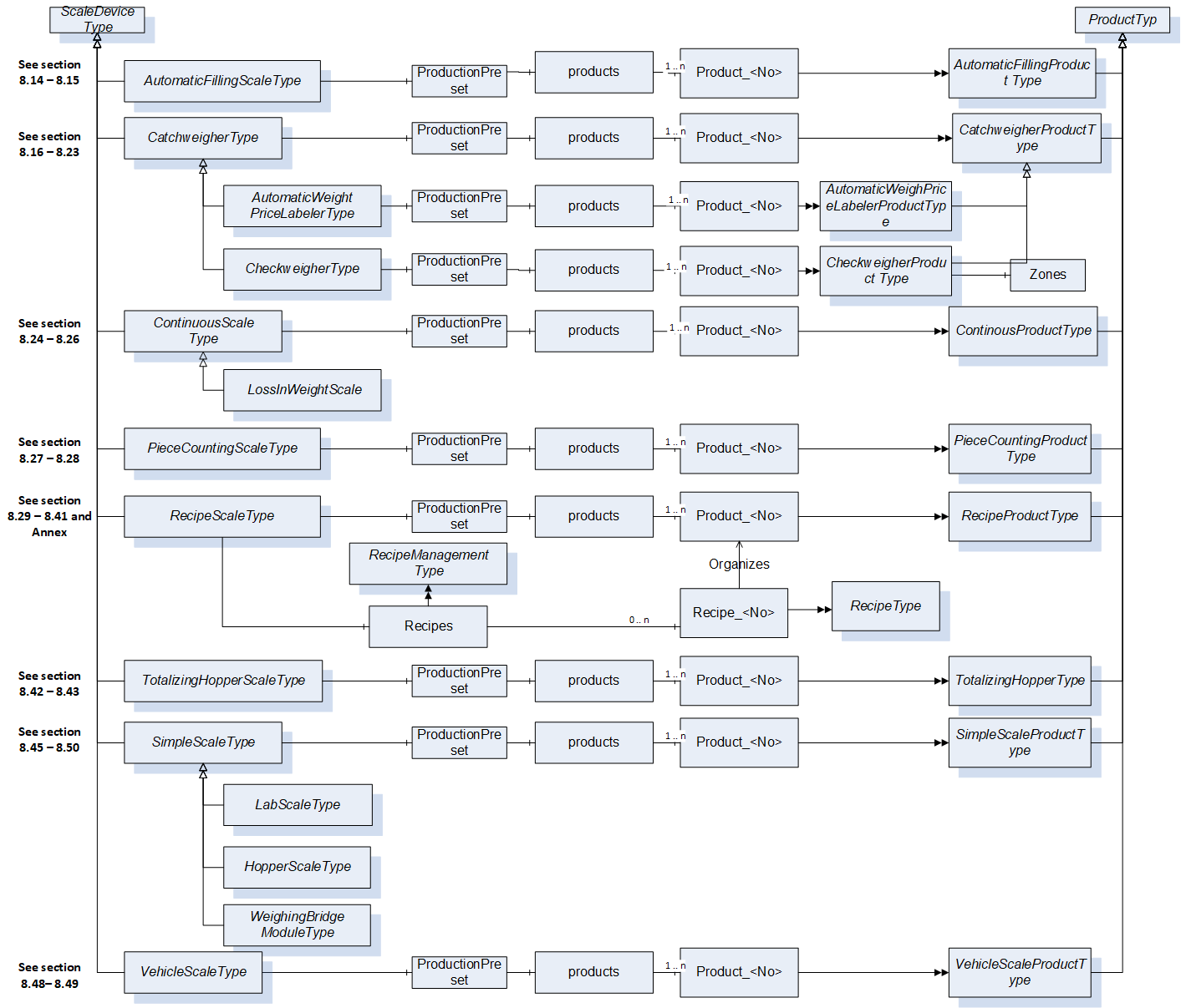
6.4 Subtypes of the ScaleDeviceType
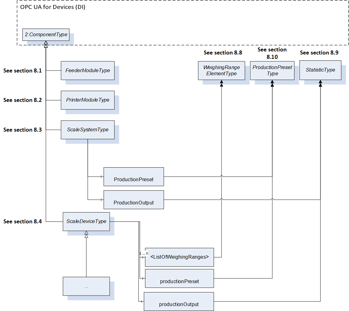
In the information model different subtypes of a ScaleDeviceType are defined for the different scale types (see section 4.1.2). For many subtypes of the ScaleDeviceType, a subtype of the ProductType exists as a counterpart. The ProductFolder defined in the ScaleDeviceType is overload and can only contain the specific subtype of the ProductType or a subtype of them.
Figure 12 shows the main Object types used in the information model and the relations between them.
7 OPC UA ObjectTypes
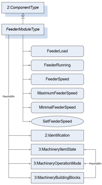
7.1 FeederModuleType Definition
7.1.1 Overview
The FeederModuleType defines the structure of an Object of the FeederModuleType. Figure 13 shows the hierarchical structure and details of the composition. It is formally defined in Table 11.
An Object of the FeederModuleType represents a feeder system. A feeder system is a subdevice of an automatic scale for conveying the product (e.g., a belt or a screw conveyor) to or from the WeighingBridge. A feeder must be part of another device (e.g., an Object of the ScaleDeviceType).
The Type defines a general communication interface for a feeder system. It contains only variables and methods.
7.1.2 ObjectType Definition
| Attribute | Value | ||||
| BrowseName | FeederModuleType | ||||
| IsAbstract | False | ||||
| References | NodeClass | BrowseName | DataType | TypeDefinition | ModellingRule |
|---|---|---|---|---|---|
| Subtype of the ComponentType defined in OPC 10000-100 | |||||
| 0:HasComponent | Variable | FeederLoad | 0:Number | MeasuredItemType | Optional |
| 0:HasProperty | Variable | FeederRunning | 0:Boolean | 0:PropertyType | Optional |
| 0:HasComponent | Variable | FeederSpeed | 0:Number | TargetItemType | Optional |
| 0:HasComponent | Method | SetFeederSpeed | Optional | ||
| 0:HasComponent | Variable | MaximumFeederSpeed | 0:Number | 0:AnalogUnitType | Optional |
| 0:HasComponent | Variable | MinimalFeederSpeed | 0:Number | 0:AnalogUnitType | Optional |
| 0:HasAddIn | Object | 2:Identification | 4:MachineryItemIdentificationType | Mandatory | |
| 0:HasAddIn | Object | 4:MachineryItemState | 4:MachineryItemState_StateMachineType | Optional | |
| 0:HasAddIn | Object | 4:MachineryOperationMode | 4:MachineryOperationModeStateMachineType | Optional | |
| 0:HasComponent | Object | 4:Machinery BuildingBlocks | 0:FolderType | Optional | |
| Conformance Units | |||||
|---|---|---|---|---|---|
| Scales FeederModule |
The components of the FeederModuleType have additional references which are defined in Table 12.
| SourceBrowsePath | Reference Type | Is Forward | TargetBrowsePath |
| 4:MachineryBuildingBlocks | 0:HasAddIn | True | 4:MachineryItemState |
| 4:MachineryBuildingBlocks | 0:HasAddIn | True | 4:MachineryOperationMode |
7.1.3 ObjectType Description
FeederLoad defines the current loaded weight on the feeder system.
FeederRunning indicates that the feeder system is running.
FeederSpeed defines the current speed of a feeder system. The unit of the FeederSpeed depends on the construction system. Possible values are velocity or a flow rate (kg/s).
MaximumFeederSpeed defines the maximum possible speed of the feeder.
MinimalFeederSpeed defines the minimal possible speed of the feeder.
The Identification-AddIn contains information about the identification and nameplate of a feeder.
MachineryItemState is used as defined in OPC 40001-1. Shall also be referenced as AddIn in the MachineryBuildingBlocks Folder
MachineryOperationMode is used as defined in OPC 40001-1. Shall also be referenced as AddIn in the MachineryBuildingBlocks Folder
MachineryBuildingBlocks is used as described in OPC 40001-1.
7.1.4 Method SetFeederSpeed
Allows to set a new value for the speed of the feeder system. The OPC UA server must check if the value is between the minimal and maximum allowed speed and if the unit is allowed. The signature of this Method is specified below. Table 13 and Table 14 specify the Arguments and AddressSpace representation, respectively.
Signature
	SetFeederSpeed(
	[in]	Float		FeederSpeed
[in] EUInformation EngineeringUnits);| Argument | Description |
| FeederSpeed | The target speed of a feeder system. |
| EngineeringUnits | The unit of the target feeder speed. The server must check the unit. |
| Attribute | Value | ||||
| BrowseName | SetFeederSpeed | ||||
| References | NodeClass | BrowseName | DataType | TypeDefinition | ModellingRule |
|---|---|---|---|---|---|
| 0:HasProperty | Variable | InputArguments | Argument[] | 0:PropertyType | Mandatory |
7.2 PrinterModuleType Definition
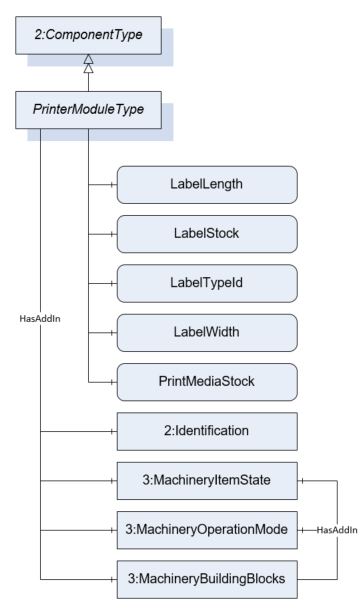
7.2.1 Overview
The PrinterModuleType defines the structure of an Object of the PrinterModuleType. Figure 14 shows the hierarchical structure and details of the composition. It is formally defined in Table 15.
An Object of the PrinterModuleType represents a printing device. A printing device is a subdevice of a scale that prints labels or other documents related to the scale or to the measurement results. The variables of the module are only readable. So, the primary use case of the module is to monitor the label and print media status.
7.2.2 ObjectType Definition
| Attribute | Value | ||||
| BrowseName | PrinterModuleType | ||||
| IsAbstract | False | ||||
| References | NodeClass | BrowseName | DataType | TypeDefinition | ModellingRule |
|---|---|---|---|---|---|
| Subtype of the ComponentType defined in OPC 10000-100 | |||||
| 0:HasComponent | Variable | LabelLength | 0:Number | 0:AnalogUnitType | Optional |
| 0:HasComponent | Variable | LabelStock | 0:Number | 0:AnalogItemType | Optional |
| 0:HasComponent | Variable | LabelTypeId | 0:String | BaseDataVariableType | Optional |
| 0:HasComponent | Variable | LabelWidth | 0:Number | 0:AnalogUnitType | Optional |
| 0:HasComponent | Variable | PrintMediaStock | 0:Number | 0:AnalogItemType | Optional |
| 0:HasAddIn | Object | 2:Identification | 4:MachineryItemIdentificationType | Mandatory | |
| 0:HasAddIn | Object | 4:MachineryItemState | 4:MachineryItemState_StateMachineType | Optional | |
| 0:HasAddIn | Object | 4:MachineryOperationMode | 4:MachineryOperationModeStateMachineType | Optional | |
| 0:HasComponent | Object | 4:Machinery BuildingBlocks | 0:FolderType | Optional | |
| Conformance Units | |||||
|---|---|---|---|---|---|
| Scales PrinterModule |
The components of the ObjectType have additional subcomponents which are defined in Table 16
| SourceBrowsePath | Reference Type | Is Forward | TargetBrowsePath |
| 4:MachineryBuildingBlocks | 0:HasAddIn | True | 4:MachineryItemState |
| 4:MachineryBuildingBlocks | 0:HasAddIn | True | 4:MachineryOperationMode |
7.2.3 ObjectType Description
LabelLength defines the length of the labels in stock.
LabelStock indicates the level of labels in stock in percent.
LabelTypeId defines the Id of the label to be printed.
LabelWidth defines the width of the labels in stock.
PrintMediaStock defines the level of the print media in percent (e.g., ink, wear of thermal element, etc.).
The Identification-AddIn contains information about the identification and nameplate of a printer.
MachineryItemState is used as defined in OPC 40001-1. Shall also be referenced as AddIn in the MachineryBuildingBlocks Folder
MachineryOperationMode is used as defined in OPC 40001-1. Shall also be referenced as AddIn in the MachineryBuildingBlocks Folder
MachineryBuildingBlocks is used as described in OPC 40001-1.
7.3 ScaleSystemType Definition
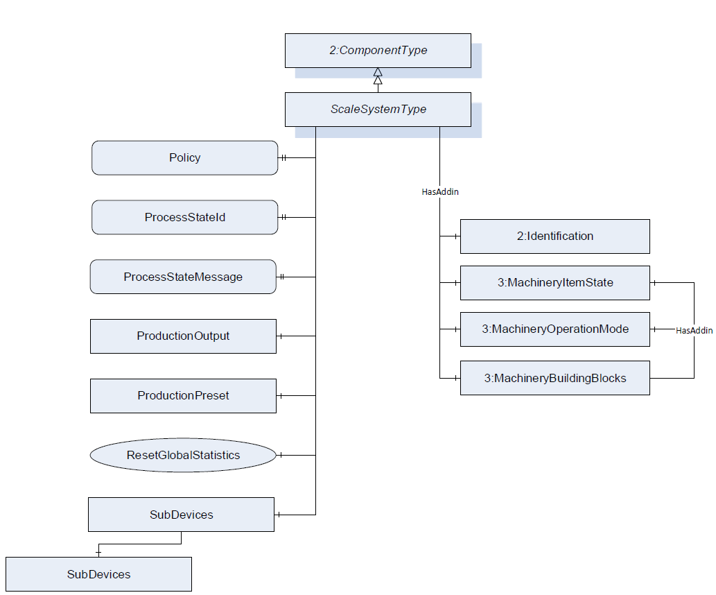
7.3.1 Overview
The ScaleSystemType defines the structure of an Object of the ScaleSystemType. Figure 15 shows the hierarchical structure and details of the composition. It is formally defined in Table 17.
An Object of the ScaleSystemType represents a scale system and contains one or more scales. The ScaleSystemType defines a general communication interface for a scale system and is the entry point for clients. This interface makes it possible to interact with this system independent of the knowledge of the internal structure and the underlying processes of the scale system.
The system is modelled with a finite state machine and contains primary information about the state and the status of the system. It optionally can also contain the objects ProductionPreset and ProductionOutput.
7.3.2 ObjectType Definition
| Attribute | Value | ||||
| BrowseName | ScaleSystemType | ||||
| IsAbstract | False | ||||
| References | NodeClass | BrowseName | DataType | TypeDefinition | ModellingRule |
|---|---|---|---|---|---|
| Subtype of the ComponentType defined in OPC 10000-100 | |||||
| 0:HasProperty | Variable | Policy | 0:LocalizedText[] | 0:PropertyType | Optional |
| 0:HasProperty | Variable | ProcessStateId | 0:String | 0:PropertyType | Optional |
| 0:HasProperty | Variable | ProcessStateMessage | 0:LocalizedText | 0:PropertyType | Mandatory |
| 0:HasComponent | Object | ProductionPreset | ProductionPresetType | Optional | |
| 0:HasComponent | Object | ProductionOutput | StatisticType | Optional | |
| 0:HasComponent | Object | SystemState | 5:PackMLBaseStateMachineType | Optional | |
| 0:HasComponent | Object | SubDevices | 2:ConfigurableObjectType | Optional | |
| 0:HasComponent | Method | ResetGlobalStatistics | Optional | ||
| 0:HasAddIn | Object | 4:MachineryItemState | 4:MachineryItemState_StateMachineType | Optional | |
| 0:HasAddIn | Object | 4:MachineryOperationMode | 4:MachineryOperationModeStateMachineType | Optional | |
| 0:HasComponent | Object | 4:Machinery BuildingBlocks | 0:FolderType | Optional | |
| 0:HasAddIn | Object | 2:Identification | 4:MachineIdentificationType | Mandatory | |
| Conformance Units | |||||
|---|---|---|---|---|---|
| Scales ScaleSystemType |
| SourceBrowsePath | Reference Type | Is Forward | TargetBrowsePath |
| 4:MachineryBuildingBlocks | 0:HasAddIn | True | 4:MachineryItemState |
| 4:MachineryBuildingBlocks | 0:HasAddIn | True | 4:MachineryOperationMode |
7.3.3 ObjectType Description
The Identification-AddIn contains information about the identification and nameplate of a machine.
A scale system can contain one or more scales. The scales must be a subtype of the ScaleDeviceType but must not be of the same type. The ScaleDeviceType is described in section 7.4.
Policy defines the legal guidelines that apply for the scale or need to be complied by the scale.
ProcessStateId contains a relating identification for the occurring ProcessStateMessage.
ProcessStateMessage contains the message of the current overall state of the scale.
ProductionPreset contains the production presets. See section 7.7 for the complete definition of the ProductionPresetType.
SystemState provides information about the current state of the scale system and methods for controlling it. PackMLBaseStateMachineType is defined in OPC 30050.
ProductionOutput defines the overall statistic for the scale production.
The modules (subdevices) of a scale system are aggregated in the SubDevices Object (see section 6.3 and OPC 10000-100).
MachineryItemState is used as defined in OPC 40001-1. Shall also be referenced as AddIn in the MachineryBuildingBlocks Folder
MachineryOperationMode is used as defined in OPC 40001-1. Shall also be referenced as AddIn in the MachineryBuildingBlocks Folder
MachineryBuildingBlocks is used as described in OPC 40001-1.
The components of the ScaleSystemType have additional references which are defined in Table 19.
| BrowsePath | References | NodeClass | BrowseName | DataType | TypeDefinition | Others |
| SubDevices | 0:HasComponent | Object | <ScaleDevice> | ScaleDeviceType | OptionalPlaceholder |
7.3.4 Method ResetGlobalStatistics
All statistics relating to the scale system but not to a product are reset.
Signature
	ResetGlobalStatistics(
	);
7.4 ScaleDeviceType Definition
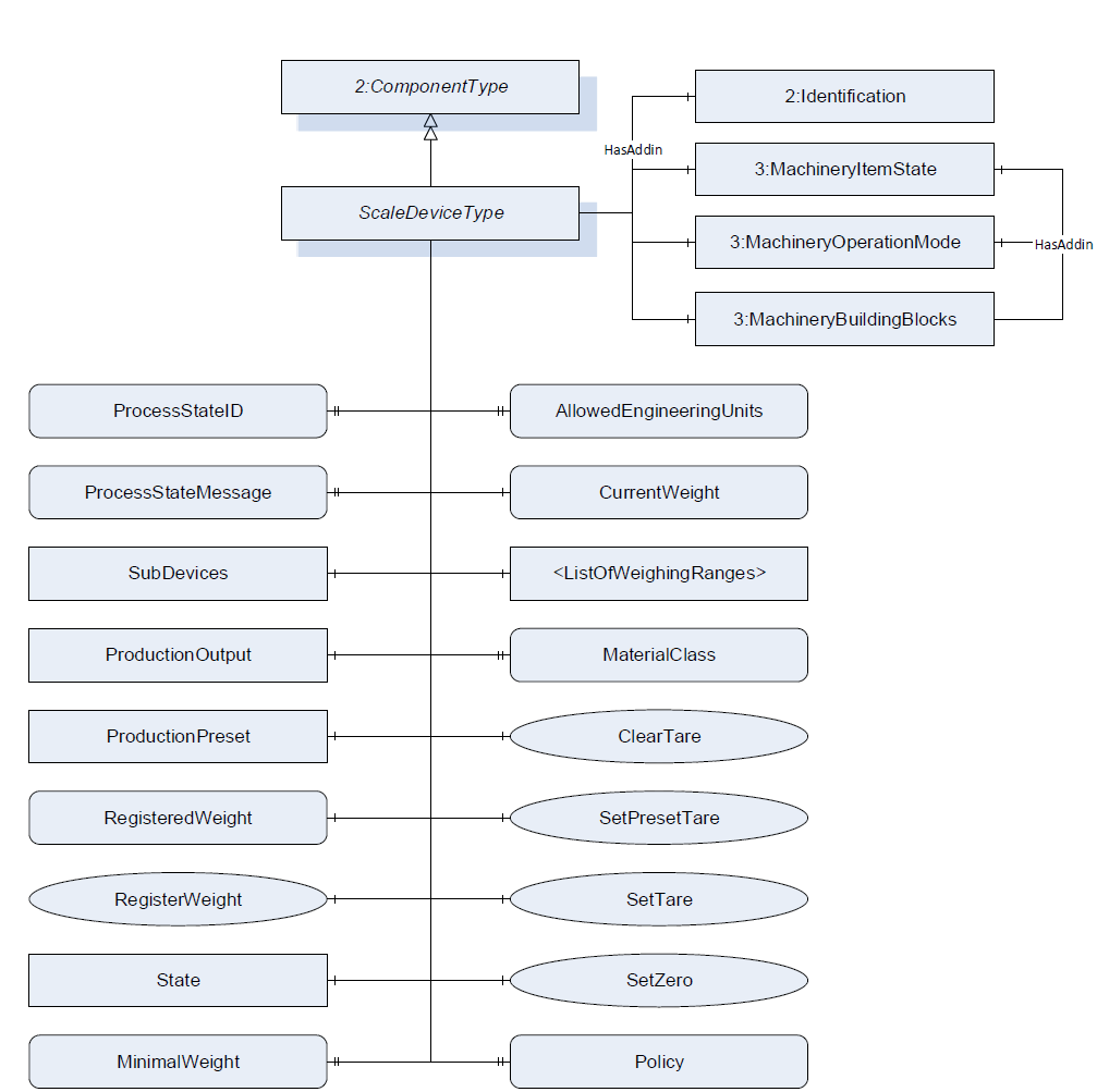
7.4.1 Overview
The ScaleDeviceType defines the structure of an Object of the ScaleDeviceType. Figure 16 shows the hierarchical structure and details of the composition. It is formally defined in Table 20.
The ScaleDeviceType is an abstract ObjectType. An Object of a subtype of the ScaleDeviceType represents a scale. The ScaleDeviceType contains all information that is relevant for most of the scale types. The system is modeled with a finite state machine and contains primary information about the state and the status of the system.
7.4.2 ObjectType Definition
| Attribute | Value | ||||
| BrowseName | ScaleDeviceType | ||||
| IsAbstract | True | ||||
| References | NodeClass | BrowseName | DataType | TypeDefinition | ModellingRule |
|---|---|---|---|---|---|
| Subtype of the ComponentType defined in OPC 10000-100 | |||||
| 0:HasProperty | Variable | AllowedEngineeringUnits | 0:EUInformation[] | 0:PropertyType | Optional |
| 0:HasComponent | Method | ClearTare | Optional | ||
| 0:HasComponent | Variable | CurrentWeight | WeightType | WeightItemType | Mandatory |
| 0:HasComponent | Object | <ListOfWeighingRanges> | WeighingRangeElementType | MandatoryPlaceholder | |
| 0:HasProperty | Variable | MaterialClass | 0:LocalizedText | 0:PropertyType | Optional |
| 0:HasComponent | Variable | MinimalWeight | 0:Number | 0:AnalogUnitType | Optional |
| 0:HasProperty | Variable | ProcessStateId | 0:String | 0:PropertyType | Optional |
| 0:HasProperty | Variable | ProcessStateMessage | 0:LocalizedText | 0:PropertyType | Optional |
| 0:HasComponent | Object | ProductionOutput | StatisticType | Optional | |
| 0:HasComponent | Object | ProductionPreset | ProductionPresetType | Optional | |
| 0:HasProperty | Variable | Policy | 0:LocalizedText[] | 0:PropertyType | Optional |
| 0:HasComponent | Variable | RegisteredWeight | WeightType | WeightItemType | Optional |
| 0:HasComponent | Method | RegisterWeight | Optional | ||
| 0:HasComponent | Method | SetPresetTare | Optional | ||
| 0:HasComponent | Method | SetTare | Optional | ||
| 0:HasComponent | Method | SetZero | Optional | ||
| 0:HasComponent | Object | SubDevices | 2:ConfigurableObjectType | Optional | |
| 0:HasComponent | Object | State | 5:PackMLBaseStateMachineType | Optional | |
| 0:HasAddIn | Object | 4:MachineryItemState | 4:MachineryItemState_StateMachineType | Optional | |
| 0:HasAddIn | Object | 4:MachineryOperationMode | 4:MachineryOperationModeStateMachineType | Optional | |
| 0:HasComponent | Object | 4:Machinery BuildingBlocks | 0:FolderType | Optional | |
| 0:HasAddIn | Object | 2:Identification | 4:MachineIdentificationType | Mandatory | |
| Conformance Units | |||||
|---|---|---|---|---|---|
| Scales ScaleDeviceType |
The components of the ScaleDeviceType have additional references which are defined in Table 21.
| SourceBrowsePath | Reference Type | Is Forward | TargetBrowsePath |
| 4:MachineryBuildingBlocks | 0:HasAddIn | True | 4:MachineryItemState |
| 4:MachineryBuildingBlocks | 0:HasAddIn | True | 4:MachineryOperationMode |
7.4.3 ObjectType Description
AllowedEngineeringUnits contains an array of engineering units that can be handled by the OPC UA server. A server that supports a method with the input argument EUInformation must also provide this array.
CurrentWeight defines the current value that is measured at the sensor at the current timestamp. This might be a highly fluctuating value.
MaterialClass defines the allowed material the scale may measure. It is only relevant for certain scales (e.g., totalizing hopper scale or continuous scale).
The MinimalWeight is the smallest sample quantity required for a weighment to just achieve a specified relative accuracy of weighing (see also EURAMET Calibration Guide No. 18). So it is the smallest load or component of a recipe that may be weighed on the scale. SubDevices: the modules (subdevices) of a modular scale are aggregated in the SubDevices Object. See OPC Unified Architecture for Devices for more information.
ProcessStateId contains a relating identification for the occurring ProcessStateMessage.
ProcessStateMessage contains the message of the current overall state of the scale.
ProductionOutput defines the statistic for the scale prodution related to this ScaleDeviceType instance.
ProductionPreset contains the production presets. See section 7.7 for the complete definition of the ProductionPresetType.
RegisteredWeight defines the last valid measurement that was recorded and will be used for further processing.
<ListOfWeighingRanges> defines the weighing range and resolution the scale may operate in with a structure of range and resolution.
Policy defines the legal guidelines that apply for the scale or need to be complied by the scale.
ScaleStateMachine provides information about the current state of the scale system and methods for controlling it. PackMLBaseStateMachineType is defined in OPC 30050.
MachineryItemState is used as defined in OPC 40001-1. Shall also be referenced as AddIn in the MachineryBuildingBlocks Folder
MachineryOperationMode is used as defined in OPC 40001-1. Shall also be referenced as AddIn in the MachineryBuildingBlocks Folder
MachineryBuildingBlocks is used as described in OPC 40001-1.
The components of the ScaleDeviceType have additional subcomponents which are defined in Table 22.
| BrowsePath | References | NodeClass | BrowseName | DataType | TypeDefinition | Others |
| SubDevices | 0:HasComponent | Object | <FeederModule> | FeederModuleType | OptionalPlaceholder | |
| SubDevices | 0:HasComponent | Object | <PrinterModule> | PrinterModuleType | OptionalPlaceholder | |
| SubDevices | 0:HasComponent | Object | <WeighingModule> | WeighingModuleType | OptionalPlaceholder |
7.4.4 Method ClearTare
The tare value is set to zero or deleted.
Signature
	ClearTare(
	);
7.4.5 Method RegisterWeight
Triggers the registration of a measured value and a new value for the RegisteredWeight will be calculated.
Signature
	RegisterWeight(
	);
7.4.6 Method SetPresetTare
The method set the current PresetTare.
Signature
	SetPresetTare(
	[in]	Double		PresetTare
[in] EUInformation EngineeringUnits);| Argument | Description |
| PresetTare | The value which should be set as tare value. |
| EngineeringUnits | The unit of the preset. The server must check the unit. |
| Attribute | Value | ||||
| BrowseName | SetPresetTare | ||||
| References | NodeClass | BrowseName | DataType | TypeDefinition | ModellingRule |
|---|---|---|---|---|---|
| 0:HasProperty | Variable | InputArguments | Argument[] | 0:PropertyType | Mandatory |
7.4.7 Method SetZero
The method sets zero point. It uses the gross value of the CurrentWeight value.
Signature
	SetZero (
	);
7.4.8 Method SetTare
The method triggers the tare operation. The CurrentWeight value is used as the tare.
Signature
SetTare(
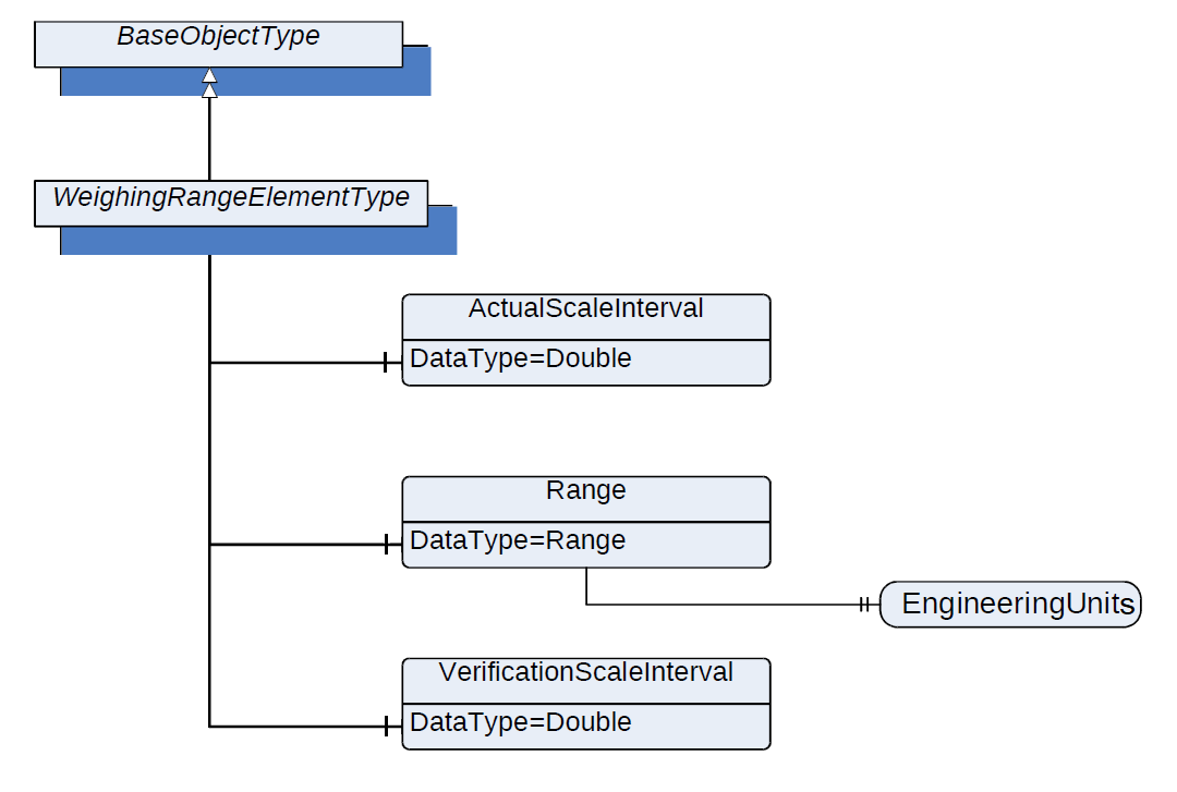
);7.5 WeighingRangeElementType Definition
7.5.1 Overview
The WeighingRangeElementType defines the structure of an Object of WeighingRangeElementType. Figure 17 shows the hierarchical structure and details of the composition. It is formally defined in Table 25.
7.5.2 ObjectType Definition
| Attribute | Value | ||||
| BrowseName | WeighingRangeElementType | ||||
| IsAbstract | False | ||||
| References | NodeClass | BrowseName | DataType | TypeDefinition | ModellingRule |
|---|---|---|---|---|---|
| Subtype of the BaseObjectType defined in OPC 10000-5 | |||||
| 0:HasComponent | Variable | ActualScaleInterval | 0:Double | AnalogUnitType | Mandatory |
| 0:HasComponent | Variable | Range | 0:Range | BaseDataVariableType | Mandatory |
| 0:HasComponent | Variable | VerificationScaleInterval | 0:Double | AnalogUnitType | Mandatory |
| Conformance Units | |||||
|---|---|---|---|---|---|
| Scales ScaleDeviceType |
7.5.3 ObjectType Description
ActualScaleInterval defines the difference between two consecutive indicated values.
Range defines the range within the scale that may be operated depending on the additional parameters within this type.
Range.EngineeringUnit defines the engineering unit of the range.
VerificationScaleInterval defines the value, expressed in units of mass, used for the classification and verification of an instrument.
The components of the WeighingRangeElementType have additional references which are defined in Table 26
| Source Path | References | NodeClass | BrowseName | DataType | TypeDefinition | Others |
| Range | 0:HasProperty | Variable | 0:EngineeringUnits | 0:EUInformation | 0:PropertyType | Mandatory |
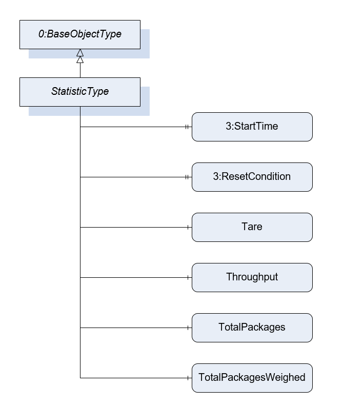
7.6 StatisticType Definition
7.6.1 Overview
The StatisticType defines the structure of an Object of StatisticType. Figure 18 shows the hierarchical structure and details of the composition. It is formally defined in Table 27.
The StatisticType is a container for the different statistic values. All variables are optional so that the statistics can be instantiated in an application-specific way. The StatisticType can be instantiated with parent nodes (e.g., ScaleDeviceType, …). Parent nodes other than those described in this Companion Specification are possible.
7.6.2 ObjectType Definition
| Attribute | Value | ||||
| BrowseName | StatisticType | ||||
| IsAbstract | False | ||||
| References | NodeClass | BrowseName | DataType | TypeDefinition | ModellingRule |
|---|---|---|---|---|---|
| Subtype of the BaseObjectType defined in OPC 10000-5 | |||||
| 0:HasInterface | ObjectType | 3:IAggregateStatisticsType | |||
| 0:HasProperty | Variable | 3:StartTime | 0:DateTime | 0:PropertyType | Optional |
| 0:HasProperty | Variable | 3:ResetCondition | 0:String | 0:PropertyType | Optional |
| 3:HasStatisticComponent | Variable | Tare | 0:Double | 0:AnalogUnitType | Optional |
| 3:HasStatisticComponent | Variable | Throughput | 0:UInteger | 0:AnalogUnitType | Optional |
| 3:HasStatisticComponent | Object | TotalPackages | StatisticCounterType | Optional | |
| 3:HasStatisticComponent | Object | TotalPackagesWeighed | StatisticCounterType | Optional | |
| 0:HasComponent | Object | LastItem | WeighingItemType | Optional | |
| Conformance Units | |||||
|---|---|---|---|---|---|
| Scales ScaleDeviceType |
7.6.3 ObjectType Description
StartTime defines the point in time at which the system starts acquiring the statistic (e.g., 15:00). This value is relevant for time statistics. For example, it can be used to create statistics for the last 3 hours.
ResetCondition is a vendor-specific, human readable string that describes the reason and context for the reset of the statistics. For example, after 4 hours or after 1000 items. Please note that the subtype FloatingStatisticType is used for floating statistics.
	Examples:
	ResetCondition::= "AFTER 4 HOURS"
	ResetCondition::= "AFTER 1000 ITEMS"
	ResetCondition::= "OPERATOR"
Tare defines the last occurring tare value of the period of time which is used for the statistic.
Throughput defines the number of items registered over the period of the statistic (e.g., packages/min).
TotalPackages defines the totalized number of packages of one cell for weight determination. Contains packages that were sorted out but were physically transported via the scale. This value may be calculated by TotalPackagesAccepted + TotalPackagesRejected.
TotalPackagesWeighed defines the totalized number of packages for which a weight was measured. No reference to acceptance or rejection of the package.
LastItem contains the values of the last item.
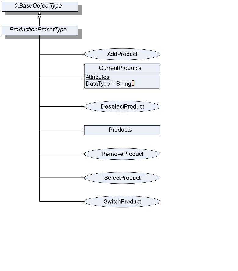
7.7 ProductionPresetType Definition
7.7.1 Overview
The ProductionPresetType defines the structure of an Object of ProductionPresetType. Figure 19 shows the hierarchical structure and details of the composition. It is formally defined in Table 28.
ProductionPresetType provides methods to manage the production preset.
7.7.2 ObjectType Definition
| Attribute | Value | ||||
| BrowseName | ProductionPresetType | ||||
| IsAbstract | False | ||||
| References | NodeClass | BrowseName | DataType | TypeDefinition | ModellingRule |
|---|---|---|---|---|---|
| Subtype of the BaseObjectType defined in OPC 10000-5 | |||||
| 0:HasComponent | Method | AddProduct | Optional | ||
| 0:HasComponent | Variable | CurrentProducts | 0:String[] | BaseDataVariableType | Optional |
| 0:HasComponent | Method | DeselectProduct | Optional | ||
| 0:HasComponent | Method | RemoveProduct | Optional | ||
| 0:HasComponent | Method | SelectProduct | Optional | ||
| 0:HasComponent | Method | SwitchProduct | Optional | ||
| 0:HasComponent | Object | Products | FolderType | Optional | |
| Conformance Units | |||||
|---|---|---|---|---|---|
| Scales ManageProduct | |||||
| Scales SelectProduct |
7.7.3 ObjectType Description
CurrentProducts is an array containing the Ids of all product objects currently in processing mode. The product process can be started using the SelectProduct method or another interface or an external trigger signal.
Products contains the products used in the scale aggregated in the Products Object. The objects in the folder should have the type ProductType or a subtype of it. The subcomponents of the Products Object are defined in Table 29.
| BrowsePath | References | NodeClass | BrowseName | DataType | TypeDefinition | Others |
| Products | 0:HasComponent | Object | <Product> | ProductType | MandatoryPlaceholder |
7.7.4 Method AddProduct
The method creates an Object with a subtype of ProductType from the address space. The Object needs a reference of the type "0:HasComponent" to the product folder of the scale device. The signature of this Method is specified below. Table 30 and Table 31 specify the Arguments and AddressSpace representation, respectively.
Signature
	AddProduct(
	[in]	String		ProductName
	[in]	String		ProductId
	[in]	NodeId		ProductType
	[out]	NodeId		ProductNodeId
);| Argument | Description |
| ProductName | A user-readable name of this Batch. |
| ProductId | A unique Id of this product |
| ProductType | The NodeId of a subtype of the ProductType or the NodeId of the ProductType itself |
| ProductNodeId | The NodeId of the created Object |
| Attribute | Value | ||||
| BrowseName | AddProduct | ||||
| References | NodeClass | BrowseName | DataType | TypeDefinition | ModellingRule |
|---|---|---|---|---|---|
| 0:HasProperty | Variable | InputArguments | Argument[] | 0:PropertyType | Mandatory |
| 0:HasProperty | Variable | OutputArguments | Argument[] | 0:PropertyType | Mandatory |
7.7.5 Method SelectProduct
Selects the product. The scale is now able to process the product. This includes that the ID is saved in the CurrentProducts array and that the ProductMode switches from "Not processing" to "Processing". Table 32 and Table 33 specify the Arguments and AddressSpace representation, respectively.
Signature
	SelectProduct (
		[in]	String		ProductId
);| Argument | Description |
| ProductId | The ProductId of the product Object that represents the product to be selected |
| Attribute | Value | ||||
| BrowseName | SelectProduct | ||||
| References | NodeClass | BrowseName | DataType | TypeDefinition | ModellingRule |
|---|---|---|---|---|---|
| 0:HasProperty | Variable | InputArguments | Argument[] | 0:PropertyType | Mandatory |
7.7.6 Method DeselectProduct
Deselects the product. The scale should stop to process the product. This includes that the ID is removed in the CurrentProducts array and that the ProductMode switches from "Processing" to "Not processing". The signature of this Method is specified below. Table 34 and Table 35 specify the Arguments and AddressSpace representation, respectively.
Signature
	DeselectProduct (
		[in]	String		ProductId
);| Argument | Description |
| ProductId | The ProductId of the product Object that represents the product to be selected |
| Attribute | Value | ||||
| BrowseName | DeselectProduct | ||||
| References | NodeClass | BrowseName | DataType | TypeDefinition | ModellingRule |
|---|---|---|---|---|---|
| 0:HasProperty | Variable | InputArguments | Argument[] | 0:PropertyType | Mandatory |
7.7.7 Method RemoveProduct
The method removes an Object from the address space with a subtype of the ProductType. The signature of this Method is specified below. Table 36 and Table 37 specify the Arguments and AddressSpace representation, respectively.
Signature
	RemoveProduct (
		[in]	String		ProductId
);| Argument | Description |
| ProductId | The ProductId of the product Object that represents the product to be selected |
| Attribute | Value | ||||
| BrowseName | RemoveProduct | ||||
| References | NodeClass | BrowseName | DataType | TypeDefinition | ModellingRule |
|---|---|---|---|---|---|
| 0:HasProperty | Variable | InputArguments | Argument[] | 0:PropertyType | Mandatory |
7.7.8 Method SwitchProduct
Selects the new product and deselects the old product. The scale is now able to process the new product. This includes that the new ID is saved in the CurrentProducts array and that the ProductMode switches from "Not processing" to "Processing". Additionally, the old ID is removed in the CurrentProducts array and the ProductMode of the old product switches from "Processing" to "Not Processing". This method is only possible if only one product is used. The signature of this Method is specified below. Table 38 and Table 39 specify the Arguments and AddressSpace representation, respectively.
Signature
	SwitchProduct (
		[in]	String		ProductId
);| Argument | Description |
| ProductId | The ID of the product Object that represents the product to be selected |
| Attribute | Value | ||||
| BrowseName | SwitchProduct | ||||
| References | NodeClass | BrowseName | DataType | TypeDefinition | ModellingRule |
|---|---|---|---|---|---|
| 0:HasProperty | Variable | InputArguments | Argument[] | 0:PropertyType | Mandatory |
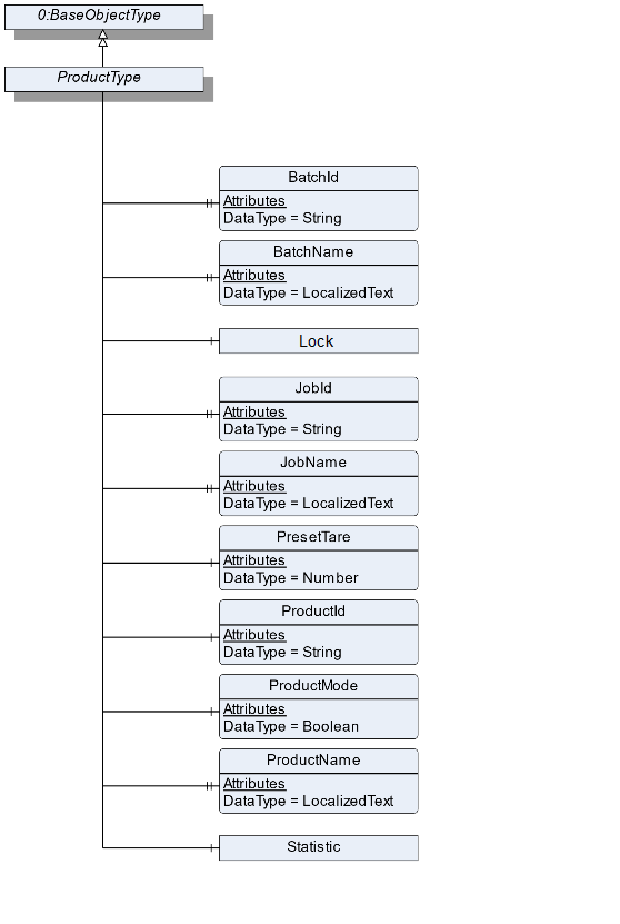
7.8 ProductType Definition
7.8.1 Overview
The ProductType is an abstract type that defines the basic structure of all objects that represent a product. Figure 20 shows the hierarchical structure and details of the composition. It is formally defined in Table 40. An Object of the type ProductType represents a product related to the scale.
The different subtypes of the ProductType are described in the following sections. The ProductType only contains the basic information about a product. The scale type-specific information is modeled in the subtypes for the different scale types. The Create Method makes it possible that a vendor can add own Variables and extend the Create Method.
7.8.2 ObjectType Definition
| Attribute | Value | ||||
| BrowseName | ProductType | ||||
| IsAbstract | True | ||||
| References | NodeClass | BrowseName | DataType | TypeDefinition | ModellingRule |
|---|---|---|---|---|---|
| Subtype of the BaseObjectType defined in OPC 10000-5 | |||||
| 0:HasProperty | Variable | BatchId | 0:String | 0:PropertyType | Optional |
| 0:HasProperty | Variable | BatchName | 0:LocalizedText | 0:PropertyType | Optional |
| 0:HasProperty | Variable | JobId | 0:String | 0:PropertyType | Optional |
| 0:HasProperty | Variable | JobName | 0:LocalizedText | 0:PropertyType | Optional |
| 0:HasComponent | Object | Lock | 2:LockingServicesType | Optional | |
| 0:HasComponent | Variable | PresetTare | 0:AnalogUnitType | Optional | |
| 0:HasComponent | Variable | ProductId | 0:String | 0:BaseDataVariableType | Mandatory |
| 0:HasComponent | Variable | ProductMode | 0:Boolean | 0:TwoStateDiscreteType | Optional |
| 0:HasProperty | Variable | ProductName | 0:LocalizedText | 0:PropertyType | Mandatory |
| 0:HasComponent | Object | Statistic | StatisticType | Optional | |
| Conformance Units | |||||
|---|---|---|---|---|---|
| Scales ProductType |
7.8.3 ObjectType Description
BatchId is the ID of the batch to which this product belongs.
BatchName is the human-readable name of the batch to which this product belongs.
JobId is the ID of the job to which this product belongs.
JobName is the human-readable name of the job to which this product belongs.
PresetTare defines the predefined tare weight. The value must be written before the item is measured.
ProductId defines a unique ID of this product.
The ProductMode displays the current mode of the product. The ProductType instance can be in the mode "Processing" or "Not Processing". The mode is independent from the Lock. Thus, it is possible that a product is in the "Processing mode" and writeable. The combination of these both modes should be used with care as the writeable element may be in an inconsistent state. If the ProductMode is true the Object is in "Processing". Otherwise, it is in the mode "Not Processing".
ProductName defines the name of this product.
Lock is used as container for the LockingServicesType Methods and Properties. It is defined in OPC 10000-100 (Locking). In addition to this definition, the server can also lock an object of the ProductType. In this case the property LockingClient contains the ProductUri of the server and LockingUser contains an empty String.
Statistic contains the different statistic values of the product. The statistic can't be reset manually. All measurements that relate to the product of the job will be used in the statistics.
The components of the ProductType have additional Attributes defined in Table 41.
| BrowsePath | Value Attribute | Description Attribute | ||
| Processing | |||
| NotProcessing |
7.9 AutomaticFillingScaleType Definition
7.9.1 Overview
The AutomaticFillingScaleType defines the structure of an Object of the AutomaticFillingScaleType. Figure 21 shows the hierarchical structure and details of the composition. It is formally defined in Table 42.
An Object of AutomaticFillingScaleType represents an automatic filling scale. It defines additional Methods and Properties required for managing automatic filling scales.
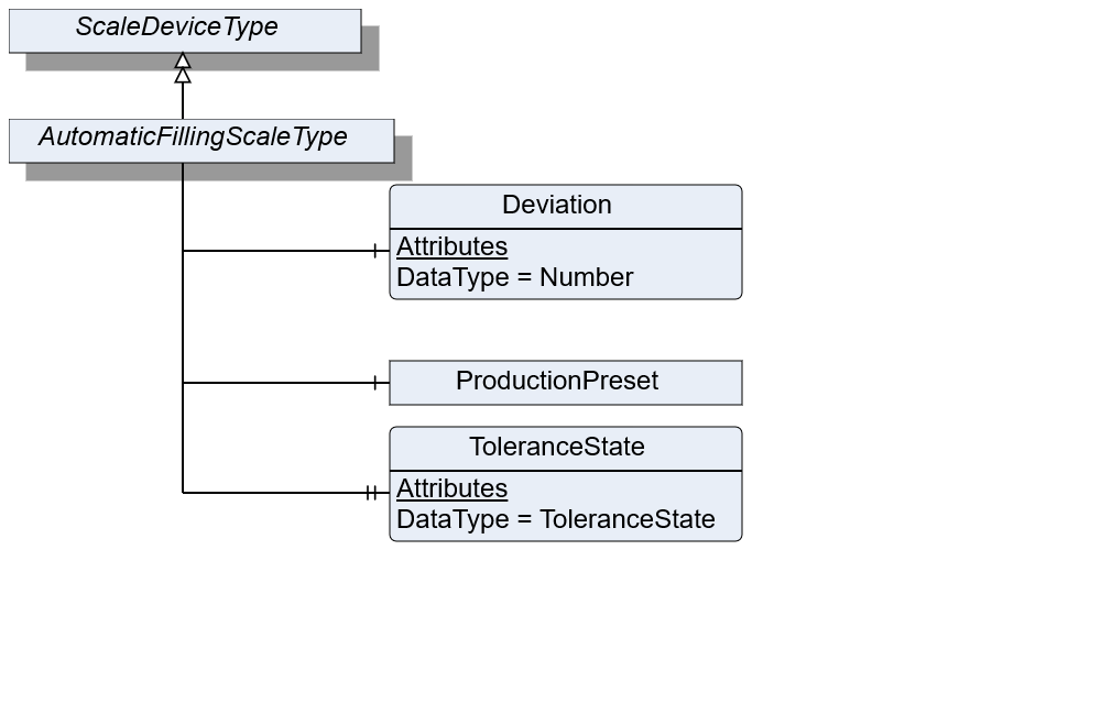
7.9.2 ObjectType Definition
| Attribute | Value | ||||
| BrowseName | AutomaticFillingScaleType | ||||
| IsAbstract | False | ||||
| References | NodeClass | BrowseName | DataType | TypeDefinition | ModellingRule |
|---|---|---|---|---|---|
| Subtype of the ScaleDeviceType | |||||
| 0:HasComponent | Variable | Deviation | 0:Number | 0:AnalogUnitType | Optional |
| 0:HasProperty | Variable | ToleranceState | ToleranceState | 0:PropertyType | Optional |
| Conformance Units | |||||
|---|---|---|---|---|---|
| Scales AutomaticFillingScale |
7.9.3 ObjectType Description
Deviation defines the relative amount of over (positive value) or under (negative value) dosed value in relation to the TargetWeight.
ToleranceState describes the state of the tolerance deviation. Under: underneath the lower tolerance value. Over: above the upper tolerance value. In: within the tolerance values. The options "under" and "over" need to be determined via the TargetItemType information of TargetWeight.
ProductionPreset, which is inherited from ScaleDeviceType shall have instances of AutomaticFillingProductType or a subtype in the Products folder.
7.10 AutomaticFillingProductType Definition
7.10.1 Overview
The AutomaticFillingProductType defines the structure of an Object of the AutomaticFillingProductType. Figure 22 shows the hierarchical structure and details of the composition. It is formally defined in Table 43.
An Object of AutomaticFillingProductType represents a product of an automatic filling scale. It defines additional methods and properties required for managing the product.
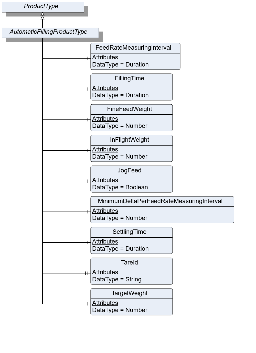
7.10.2 ObjectType Definition
| Attribute | Value | ||||
| BrowseName | AutomaticFillingProductType | ||||
| IsAbstract | False | ||||
| References | NodeClass | BrowseName | DataType | TypeDefinition | ModellingRule |
|---|---|---|---|---|---|
| Subtype of the ProductType | |||||
| 0:HasComponent | Variable | FeedRateMeasuringInterval | 0:Duration | BaseDataVariableType | Optional |
| 0:HasComponent | Variable | FillingTime | 0:Duration | BaseDataVariableType | Optional |
| 0:HasComponent | Variable | FineFeedWeight | 0:Number | 0:AnalogItemType | Optional |
| 0:HasComponent | Variable | InFlightWeight | 0:Number | 0:AnalogItemType | Mandatory |
| 0:HasComponent | Variable | JogFeed | 0:Boolean | BaseDataVariableType | Optional |
| 0:HasComponent | Variable | MinimumDeltaPerFeedRateMeasuringInterval | 0:Number | 0:AnalogItemType | Optional |
| 0:HasComponent | Variable | SettlingTime | Duration | BaseDataVariableType | Optional |
| 0:HasProperty | Variable | TareId | 0:String | 0:PropertyType | Optional |
| 0:HasComponent | Variable | TargetWeight | 0:Number | TargetItemType | Mandatory |
| Conformance Units | |||||
|---|---|---|---|---|---|
| Scales AutomaticFillingScale |
7.10.3 ObjectType Description
FeedRateMeasuringInterval defines the measuring interval for evaluating the current flowrate.
FillingTime defines the maximum duration for the filling process to take place. Needs to be completed during this period.
FineFeedWeight defines the volume to be dosed in fine flow.
InFlightWeight defines the volume that is behind the valve/in flight after feeding is stopped.
JogFeed defines if an additional dosage is necessary.
MinimumDeltaPerFeedRateMeasuringInterval defines the minimum amount of weight data which needs to change within the FeedRateMeasuringInterval. Otherwise, the filling procedure is not valid.
SettlingTime defines the time that needs to be passed before the measurement process can be triggered.
TareId defines an ID of tare value for the current product or item.
TargetWeight defines the preset of the volume to be processed.
7.11 CatchweigherType Definition
7.11.1 Overview
The CatchweigherType defines the structure of an Object of the CatchweigherType. Figure 23 shows the hierarchical structure and details of the composition. It is formally defined in Table 44.
An Object of the CatchweigherType represents a catchweigher. It has no method or properties defined. The CheckweigherType and the AutomaticWeightPriceLablerType inherit from the CatchweigherType.
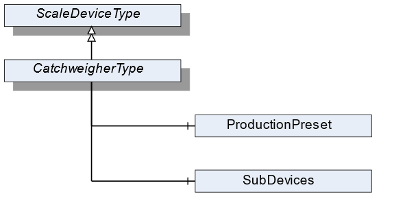
7.11.2 ObjectType Definition
| Attribute | Value | ||||
| BrowseName | CatchweigherType | ||||
| IsAbstract | False | ||||
| References | NodeClass | BrowseName | DataType | TypeDefinition | ModellingRule |
|---|---|---|---|---|---|
| Subtype of the ScaleDeviceType | |||||
| Conformance Units | |||||
|---|---|---|---|---|---|
| Scales Catchweigher |
7.11.3 ObjectType Description
ProductionPreset, which is inherited from ScaleDeviceType shall have instances of CatchweigherProductType or a subtype in the Products folder.
7.12 CatchweigherProductType Definition
7.12.1 Overview
The CatchweigherProductType defines the structure of an Object of the CatchweigherProductType. Figure 24 shows the hierarchical structure and details of the composition. It is formally defined in Table 45.
An Object of the CatchweigherProductType represents a product of a catchweigher. It defines additional methods and properties required for managing the product.
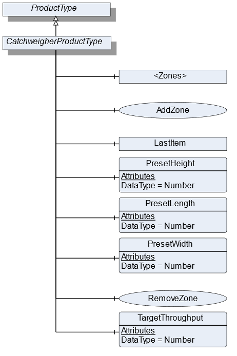
7.12.2 ObjectType Definition
| Attribute | Value | ||||
| BrowseName | CatchweigherProductType | ||||
| IsAbstract | False | ||||
| References | NodeClass | BrowseName | DataType | TypeDefinition | ModellingRule |
|---|---|---|---|---|---|
| Subtype of the ProductType | |||||
| 0:HasComponent | Object | <Zones> | ZoneType | OptionalPlaceholder | |
| 0:HasComponent | Method | AddZone | Optional | ||
| 0:HasComponent | Object | LastItem | WeighingItemType | Optional | |
| 0:HasComponent | Variable | PresetHeight | 0:Number | 0:AnalogUnitType | Optional |
| 0:HasComponent | Variable | PresetLength | 0:Number | 0:AnalogUnitType | Optional |
| 0:HasComponent | Variable | PresetWidth | 0:Number | 0:AnalogUnitType | Optional |
| 0:HasComponent | Method | RemoveZone | Optional | ||
| 0:HasComponent | Variable | TargetThroughput | 0:Number | TargetItemType | Optional |
| Conformance Units | |||||
|---|---|---|---|---|---|
| Scales Catchweigher |
7.12.3 ObjectType Description
<Zones> is an OptionalPlaceholder for the different zones. Each zone defines different weighing ranges a product has to be within.
LastItem contains the measured values of the last item that was processed by the catchweigher.
PresetHeight defines the predefined height (in direction of global gravity, see Figure 25) of the measured item. If the PresetHeight value is used, the value must be written before the item is measured.
PresetLength defines the predefined length (in direction of travel, see Figure 25) of the measured item. If the PresetLength value is used, the value must be written before the item is measured.
PresetWidth defines the predefined width (in third possible orthogonal direction to height and length, see Figure 25) of the measured item. If the PresetWidth value is used, the value must be written before the item is measured.
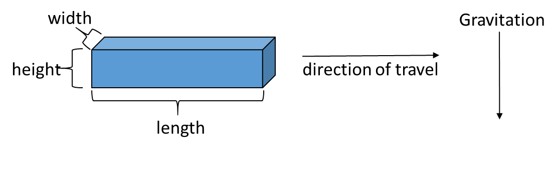
TargetThroughput is the target value for the throughput.
7.12.4 Method AddZone
Adds a zone to the zone array. The signature of this Method is specified below. Table 46 and Table 47 specify the Arguments and AddressSpace representation, respectively.
Signature
	AddZone(
	[in]	LocalizedText		ZoneName
	[in]	Double		LowerLimit
	[in]	Double		UpperLimit
	[in]	EUInformation		EngineeringUnits
[out] NodeId ZoneNodeId);| Argument | Description |
| ZoneName | User-readable name of the zone |
| LowerLimit | Lower weight limit of this zone. The lower limit is prior to the upper limit if two zones are beside each other |
| UpperLimit | Upper weight limit of this zone |
| EngineeringUnits | Unit of the Lower and the UpperLimit. The two Limits must have the same unit |
| ZoneNodeId | NodeId of the created Object |
| Attribute | Value | ||||
| BrowseName | AddZone | ||||
| References | NodeClass | BrowseName | DataType | TypeDefinition | ModellingRule |
|---|---|---|---|---|---|
| 0:HasProperty | Variable | InputArguments | Argument[] | 0:PropertyType | Mandatory |
| 0:HasProperty | Variable | OutputArguments | Argument[] | 0:PropertyType | Mandatory |
7.12.5 Method RemoveZone
Removes a zone from the zone array. The signature of this Method is specified below. Table 48 and Table 49 specify the Arguments and AddressSpace representation, respectively.
Signature
	RemoveZone(
[in] NodeId ZoneNodeId);| Argument | Description |
| ZoneNodeId | NodeId of the Object that should be deleted |
| Attribute | Value | ||||
| BrowseName | RemoveZone | ||||
| References | NodeClass | BrowseName | DataType | TypeDefinition | ModellingRule |
|---|---|---|---|---|---|
| 0:HasProperty | Variable | InputArguments | Argument[] | 0:PropertyType | Mandatory |
7.13 WeighingItemType Definition
7.13.1 Overview
The WeighingItemType defines the structure of an Object of an item. Figure 26 shows the hierarchical structure and details of the composition. It is formally defined in Table 50.
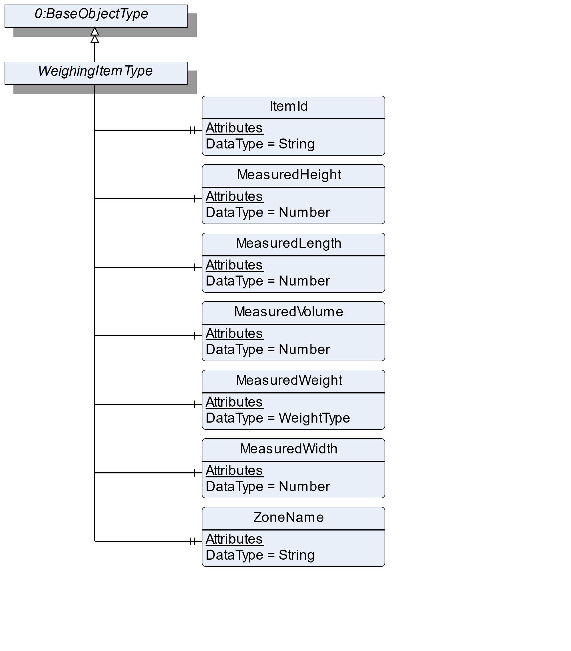
7.13.2 ObjectType Definition
| Attribute | Value | ||||
| BrowseName | WeighingItemType | ||||
| IsAbstract | False | ||||
| References | NodeClass | BrowseName | DataType | TypeDefinition | ModellingRule |
|---|---|---|---|---|---|
| Subtype of the BaseObjectType defined in OPC 10000-5 | |||||
| 0:HasProperty | Variable | ItemId | 0:String | 0:PropertyType | Optional |
| 0:HasComponent | Variable | MeasuredWeight | WeightType | WeightItemType | Mandatory |
| 0:HasComponent | Variable | MeasuredHeight | 0:Number | 0:AnalogUnitType | Optional |
| 0:HasComponent | Variable | MeasuredLength | 0:Number | 0:AnalogUnitType | Optional |
| 0:HasComponent | Variable | MeasuredVolume | 0:Number | 0:AnalogUnitType | Optional |
| 0:HasComponent | Variable | MeasuredWidth | 0:Number | 0:AnalogUnitType | Optional |
| 0:HasProperty | Variable | ZoneName | 0:String | 0:PropertyType | Optional |
| Conformance Units | |||||
|---|---|---|---|---|---|
| Scales Catchweigher |
7.13.3 ObjectType Description
ItemId defines a unique number that is assigned to an item.
MeasuredWeight defines the registered weight that may be unmistakably referenced to one item.
MeasuredHeight defines the maximum measured height (in direction of global gravity, see Figure 25) of the measured item.
MeasuredLength defines the maximum measured length (in direction of travel, see Figure 25) of the measured item
MeasuredWidth defines the maximum measured width (in third possible orthogonal direction to height and length, see Figure 25) of the measured item.
MeasuredVolume defines the volume of the item.
ZoneName defines the name of the zone in which the item was sorted.
7.14 AutomaticWeightPriceLabelerType Definition
7.14.1 Overview
The AutomaticWeightPriceLabelerType defines the structure of an Object of the AutomaticWeightPriceLabelerType. Figure 27 shows the hierarchical structure and details of the composition. It is formally defined in Table 51.
An Object of AutomaticWeightPriceLabelerType represents an automatic weight-price-labeler. It defines additional methods and properties required for managing the automatic weight-price-labeler.
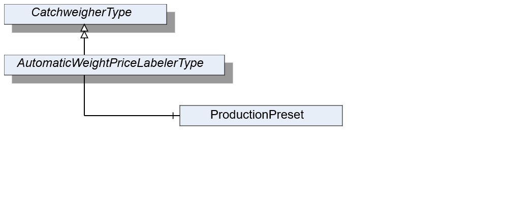
7.14.2 ObjectType Definition
| Attribute | Value | ||||
| BrowseName | AutomaticWeightPriceLabelerType | ||||
| IsAbstract | False | ||||
| References | NodeClass | BrowseName | DataType | TypeDefinition | ModellingRule |
|---|---|---|---|---|---|
| Subtype of the CatchweigherType | |||||
| Conformance Units | |||||
|---|---|---|---|---|---|
| Scales AutomaticWeightPriceLabeler |
7.14.3 ObjectType Description
ProductionPreset, which is inherited from ScaleDeviceType shall have instances of AutomaticWeighPriceLabelerProductType or a subtype in the Products folder.
7.15 AutomaticWeightPriceLabelerProductType Definition
7.15.1 Overview
The AutomaticWeightPriceLabelerProductType defines the structure of an Object of the AutomaticWeightPriceLabelerProductType. Figure 28 shows the hierarchical structure and details of the composition. It is formally defined in Table 52.
An object of AutomaticWeightPriceLabelerProductType represents a product of an automatic weight-price-labeler. It defines additional methods and properties required for managing the product.
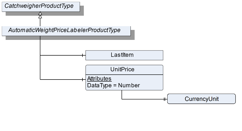
7.15.2 ObjectType Definition
| Attribute | Value | ||||
| BrowseName | AutomaticWeightPriceLabelerProductType | ||||
| IsAbstract | False | ||||
| References | NodeClass | BrowseName | DataType | TypeDefinition | ModellingRule |
|---|---|---|---|---|---|
| Subtype of the CatchweigherProductType | |||||
| 0:HasComponent | Variable | UnitPrice | 0:Number | BaseDataVariableType | Optional |
| The following nodes are overridden from CatchweigherProductType and the TypeDefinition changed | |||||
| 0:HasComponent | Object | LastItem | PriceItemType | Optional | |
| Conformance Units | |||||
|---|---|---|---|---|---|
| Scales AutomaticWeightPriceLabeler |
7.15.3 ObjectType Description
UnitPrice defines the price per weight unit.
The components of the AutomaticWeightPriceLabelerProductType have additional references which are defined in Table 53.
| Source Path | References | NodeClass | BrowseName | DataType | TypeDefinition | Others |
| UnitPrice | 0: HasProperty | Variable | CurrencyUnit | CurrencyUnitType | 0:PropertyType | Mandatory |
7.16 PriceItemType Definition
7.16.1 Overview
The PriceItemType defines the structure of an Object of an item that also has a price. Figure 29 shows the hierarchical structure and details of the composition. In the AutomaticWeightPriceLabeler the PriceItemType is used instead of the WeighingItemType for the LastItem Object. It is formally defined in Table 54.
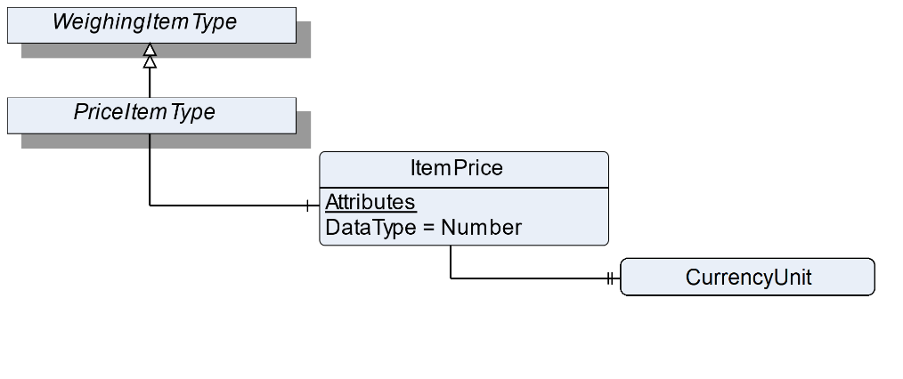
7.16.2 ObjectType Definition
| Attribute | Value | ||||
| BrowseName | PriceItemType | ||||
| IsAbstract | False | ||||
| References | NodeClass | BrowseName | DataType | TypeDefinition | ModellingRule |
|---|---|---|---|---|---|
| Subtype of the WeighingItemType | |||||
| 0:HasComponent | Variable | ItemPrice | 0:Number | BaseDataVariableType | Optional |
| Conformance Units | |||||
|---|---|---|---|---|---|
| Scales AutomaticWeightPriceLabeler |
7.16.3 ObjectType Description
ItemPrice defines the price related to measured weight and UnitPrice.
The components of the PriceItemType have additional references which are defined in Table 55.
| Source Path | References | NodeClass | BrowseName | DataType | TypeDefinition | Others |
| ItemPrice | 0: HasProperty | Variable | CurrencyUnit | CurrencyUnitType | 0:PropertyType | Mandatory |
7.17 CheckweigherType Definition
7.17.1 Overview
The CheckweigherType defines the structure of an Object of the CheckweigherType. Figure 30 shows the hierarchical structure and details of the composition. It is formally defined in Table 56.
An Object of the CheckweigherType represents a checkweigher. It defines additional methods and properties required for managing the checkweigher.
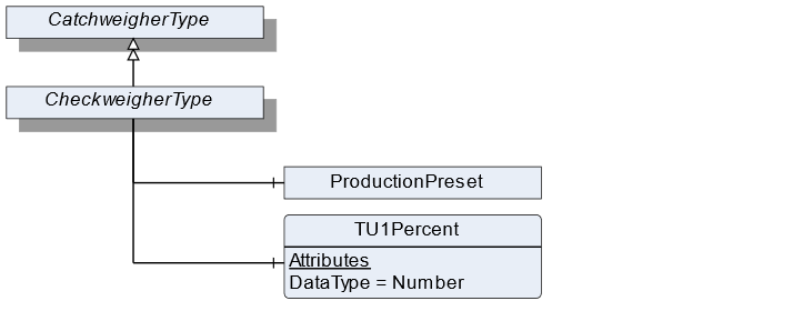
7.17.2 ObjectType Definition
| Attribute | Value | ||||
| BrowseName | CheckweigherType | ||||
| IsAbstract | False | ||||
| References | NodeClass | BrowseName | DataType | TypeDefinition | ModellingRule |
|---|---|---|---|---|---|
| Subtype of the CatchweigherType | |||||
| 0:HasComponent | Variable | TU1Percent | 0:Number | DataItemType | Optional |
| Conformance Units | |||||
|---|---|---|---|---|---|
| Scales Checkweigher |
7.17.3 ObjectType Description
TU1Percent is the permitted percentage of items with a weight of less than TU1 and upper TU2.
ProductionPreset, which is inherited from ScaleDeviceType shall have instances of CheckweigherProductType or a subtype in the Products folder.
7.18 CheckweigherProductType Definition
7.18.1 Overview
The CheckweigherProductType defines the structure of an Object of the CheckweigherProductType. Figure 31 shows the hierarchical structure and details of the composition. It is formally defined in Table 57.
An Object of the CheckweigherProductType represents a product of a checkweigher. It defines additional methods and properties required for managing the product.
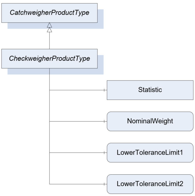
7.18.2 ObjectType Definition
| Attribute | Value | ||||
| BrowseName | CheckweigherProductType | ||||
| IsAbstract | False | ||||
| References | NodeClass | BrowseName | DataType | TypeDefinition | ModellingRule |
|---|---|---|---|---|---|
| Subtype of the CatchweigherProductType | |||||
| 0:HasComponent | Variable | NominalWeight | 0:Number | TargetItemType | Mandatory |
| 0:HasComponent | Variable | LowerToleranceLimit1 | 0:Number | AnalogUnitType | Optional |
| 0:HasComponent | Variable | LowerToleranceLimit2 | 0:Number | AnalogUnitType | Optional |
| The following nodes are overridden from CatchweigherProductType and the TypeDefinition changed | |||||
| 0:HasComponent | Object | Statistic | CheckweigherStatisticType | Optional | |
| Conformance Units | |||||
|---|---|---|---|---|---|
| Scales Checkweigher |
7.18.3 ObjectType Description
NominalWeight defines the nominal (printed) weight of the product.
For this ObjectType the Statistic is overridden with the specific CheckweigherStatisticType.
LowerToleranceLimit1 defines the first LowerToleranceLimit.
LowerToleranceLimit2 defines the second LowerToleranceLimit.
7.19 CheckweigherStatisticType Definition
7.19.1 Overview
The CheckweigherStatisticType defines the structure of an Object that represents the statistic for a checkweigher. Figure 32 shows the hierarchical structure and details of the composition. It is formally defined in Table 58.
The CheckweigherStatisticType is a container for the different statistic values needed in a checkweigher.
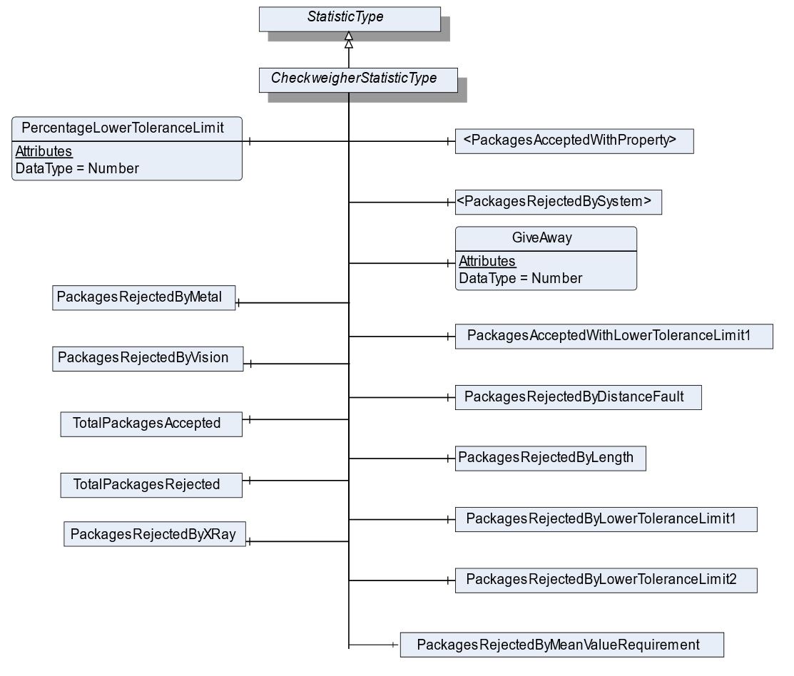
7.19.2 ObjectType Definition
| Attribute | Value | ||||
| BrowseName | CheckweigherStatisticType | ||||
| IsAbstract | False | ||||
| References | NodeClass | BrowseName | DataType | TypeDefinition | ModellingRule |
|---|---|---|---|---|---|
| Subtype of the StatisticType | |||||
| 3:HasStatisticComponent | Object | <PackagesRejectedBySystem> | RejectedStatisticCounterType | OptionalPlaceholder | |
| 3:HasStatisticComponent | Object | PackagesRejectedByMetal | RejectedStatisticCounterType | Optional | |
| 3:HasStatisticComponent | Object | PackagesRejectedByVision | RejectedStatisticCounterType | Optional | |
| 3:HasStatisticComponent | Object | PackagesRejectedByXRay | RejectedStatisticCounterType | Optional | |
| 3:HasStatisticComponent | Object | PackagesRejectedByDistanceFault | RejectedStatisticCounterType | Optional | |
| 3:HasStatisticComponent | Object | PackagesRejectedByLength | RejectedStatisticCounterType | Optional | |
| 3:HasStatisticComponent | Object | PackagesRejectedByMeanValueRequirement | RejectedStatisticCounterType | Optional | |
| 3:HasStatisticComponent | Object | PackagesRejectedByLowerToleranceLimit1 | RejectedStatisticCounterType | Optional | |
| 3:HasStatisticComponent | Object | PackagesRejectedByLowerToleranceLimit2 | RejectedStatisticCounterType | Optional | |
| 3:HasStatisticComponent | Object | <PackagesAcceptedWithProperty> | AcceptedStatisticCounterType | OptionalPlaceholder | |
| 3:HasStatisticComponent | Object | PackagesAcceptedWithLowerToleranceLimit1 | AcceptedStatisticCounterType | Optional | |
| 3:HasStatisticComponent | Variable | PercentageLowerToleranceLimit | 0:Number | 0:AnalogItemType | Optional |
| 3:HasStatisticComponent | Object | TotalPackagesAccepted | AcceptedStatisticCounterType | Optional | |
| 3:HasStatisticComponent | Object | TotalPackagesRejected | RejectedStatisticCounterType | Optional | |
| 3:HasStatisticComponent | Variable | GiveAway | 0:Number | 0:AnalogUnitType | Optional |
| Conformance Units | |||||
|---|---|---|---|---|---|
| Scales Checkweigher |
7.19.3 ObjectType Description
PackagesRejectedBySystem defines an optional placeholder for additional categories in which rejected packages may be counted in. The Object representing the rejected package should be named like TotalPackagesRejectedBy<SYSTEM>. <SYSTEM> can be an additional system or reason why the packages are rejected. Some reasons could be:
OpenFlap
AskewPackage
UpperToleranceLimit1
UpperToleranceLimit2
Presorting
…
PackagesRejectedByMetal defines a statistic counter for items rejected by a metal detection system.
PackagesRejectedByVision defines a statistic counter for items rejected by a machine vision system.
PackagesRejectedByXRay defines a statistic counter for items rejected by a x ray detection system.
PackagesRejectedByDistanceFault defines a statistic counter for items rejected by a distance fault.
PackagesRejectedByLength defines a statistic counter for items that rejected due to the item length.
PackagesRejectedByMeanValueRequirement defines a statistic counter for items that rejected due to the required mean value.
PackagesRejectedByLowerToleranceLimit1 defines a statistic counter for items that are lower than the ToleranceLimit1
PackagesRejectedByLowerToleranceLimit2 defines a statistic counter for items that are lower than the ToleranceLimit2
PackagesAcceptedWithProperty defines an optional placeholder for additional categories in which accepted packages may be counted in. The AcceptedStatisticCounterType shall be used, and the accepted packages are added to TotalPackagesAccepted. The Object representing the accepted package should be named like TotalPackagesAccepted<PROPERTY>. <PROPERTY> can be an additional system or reason why the package is accepted.
PackagesAcceptedWithLowerToleranceLimit1 defines a statistic counter for items that are lower than TU1 and upper TU2 but accepted to the "The 3 Packers Rules" of the Welmec 6.4
TotalPackagesRejected defines the totalized number of packages, which were rejected during verification, controlling or weighing processes, that may be upstream or downstream of the weighing process itself.
TotalPackagesAccepted defines the totalized number of packages, which successfully completed all verification, controlling and weighing processes.
GiveAway defines the totalized value of volume deviation from NominalWeight. The giveaway is an indicator of overproduction and is calculated as follows:
PercentageLowerToleranceLimit1 defines the current percentage of accepted items which are lower TU1 and upper TU2 as defined in the CheckweigherType.
7.20 StatisticCounterType Definition
7.20.1 Overview
The StatisticCounterType defines the structure of an Object of the StatisticCounterType. Figure 33 shows the hierarchical structure and details of the composition. It is formally defined in Table 59.
The StatisticType is a container for the different statistic values needed in a checkweigher. Each zone has a StatisticCounterType. There are also different total packages counters. The flag Weighed must be set if packages of this statistic should be counted in the counter TotalPackagesWeighed.
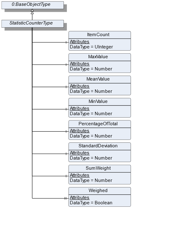
7.20.2 ObjectType Definition
| Attribute | Value | ||||
| BrowseName | StatisticCounterType | ||||
| IsAbstract | False | ||||
| References | NodeClass | BrowseName | DataType | TypeDefinition | ModellingRule |
|---|---|---|---|---|---|
| Subtype of the BaseObjectType defined in OPC 10000-5 | |||||
| 3:HasStatisticComponent | Variable | ItemCount | 0:UInteger | BaseDataVariableType | Mandatory |
| 3:HasStatisticComponent | Variable | MaxValue | 0:Number | 0:AnalogUnitType | Optional |
| 3:HasStatisticComponent | Variable | MeanValue | 0:Number | 0:AnalogUnitType | Optional |
| 3:HasStatisticComponent | Variable | MinValue | 0:Number | 0:AnalogUnitType | Optional |
| 3:HasStatisticComponent | Variable | PercentageOfTotal | 0:Number | 0:AnalogUnitType | Optional |
| 3:HasStatisticComponent | Variable | StandardDeviation | 0:Number | 0:AnalogUnitType | Optional |
| 3:HasStatisticComponent | Variable | SumWeight | 0:Number | 0:AnalogUnitType | Optional |
| 0:HasProperty | Variable | Weighed | Boolean | 0:PropertyType | Mandatory |
| Conformance Units | |||||
|---|---|---|---|---|---|
| Scales ScaleDeviceType | |||||
| Scales CheckweigherType |
7.20.3 ObjectType Description
ItemCount is the totalized count of measurements within the scope of this statistic.
SumWeight is the totalized weight of all items in the ItemCount.
PercentageOfTotal is the percentage of this statistic in relation to the total. The total is the count of the overall statistic, just regarding the ItemCount.
MaxValue defines the highest registered weight value.
MeanValue defines the mean value of all registered weight values.
MinValue defines the lowest registered weight value.
StandardDeviation is defined as follows:
| for samples | |
| for 100% check |
Weighed indicates that the element is considered also in the TotalPackageWeighed variable of the StatisticType.
7.21 AcceptedStatisticCounterType Definition
7.21.1 Overview
The AcceptedStatisticCounterType defines the structure of an Object of the AcceptedStatisticCounterType. It is formally defined in Table 60.
The AcceptedStatisticCounterType is subtype of the StatisticCounterType and changes the semantic meaning of the StatisticCounterType. An object with the AcceptedStatisticCounterType is used, if counted items are accepted by the scale.
7.21.2 ObjectType Definition
| Attribute | Value | ||||
| BrowseName | AcceptedStatisticCounterType | ||||
| IsAbstract | False | ||||
| References | NodeClass | BrowseName | DataType | TypeDefinition | ModellingRule |
|---|---|---|---|---|---|
| Subtype of the StatisticCounterType | |||||
| Conformance Units | |||||
|---|---|---|---|---|---|
| Scales CheckweigherType |
7.22 RejectedStatisticCounterType Definition
7.22.1 Overview
The RejectedStatisticCounterType defines the structure of an Object of the RejectedStatisticCounterType. It is formally defined in Table 61.
The RejectedStatisticCounterType is subtype of the StatisticCounterType and changes the semantic meaning of the StatisticCounterType. An object with the RejectedStatisticCounterType is used, if counted items are rejected by the scale.
7.22.2 ObjectType Definition
| Attribute | Value | ||||
| BrowseName | RejectedStatisticCounterType | ||||
| IsAbstract | False | ||||
| References | NodeClass | BrowseName | DataType | TypeDefinition | ModellingRule |
|---|---|---|---|---|---|
| Subtype of the StatisticCounterType | |||||
| Conformance Units | |||||
|---|---|---|---|---|---|
| Scales CheckweigherType |
7.23 ZoneType Definition
7.23.1 Overview
The ZoneType defines the structure of an Object of the ZoneType. Figure 34 shows the hierarchical structure and details of the composition. It is formally defined in Table 62.
The ZoneType is a container for the weighing zones in a checkweigher. It defines additional methods and properties required for managing the different zones and provides a ZoneStatistic.
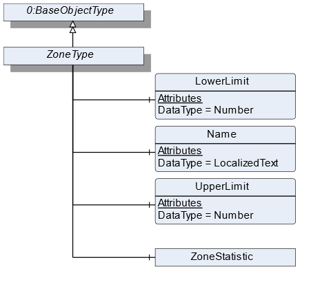
7.23.2 ObjectType Definition
| Attribute | Value | ||||
| BrowseName | ZoneType | ||||
| IsAbstract | False | ||||
| References | NodeClass | BrowseName | DataType | TypeDefinition | ModellingRule |
|---|---|---|---|---|---|
| Subtype of the BaseObjectType defined in OPC 10000-5 | |||||
| 0:HasComponent | Variable | LowerLimit | 0:Number | 0:AnalogUnitType | Mandatory |
| 0:HasComponent | Variable | Name | 0:LocalizedText | BaseDataVariableType | Mandatory |
| 0:HasComponent | Variable | UpperLimit | 0:Number | 0:AnalogUnitType | Mandatory |
| 0:HasComponent | Object | ZoneStatistic | StatisticCounterType | Optional | |
| Conformance Units | |||||
|---|---|---|---|---|---|
| Scales Catchweigher |
7.23.3 ObjectType Description
LowerLimit defines the lower weight limit of this zone. The lower limit is prior to the upper limit if two zones are next to each other.
Name defines the user-readable name of the zone.
UpperLimit defines the upper weight limit of this zone.
ZoneStatistic contains statistics regarding this zone.
7.24 ContinuousScaleType Definition
7.24.1 Overview
The ContinuousScaleType defines the structure of an Object of the ContinuousScaleType. Figure 35 shows the hierarchical structure and details of the composition. It is formally defined in Table 63.
An Object of the ContinuousScaleType represents a continuous scale. These types of scales control a continuous material output, i.e., the material output at a given flow rate. It defines additional methods and properties required for managing the continuous scale.
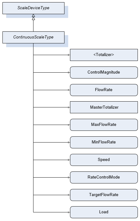
7.24.2 ObjectType Definition
| Attribute | Value | ||||
| BrowseName | ContinuousScaleType | ||||
| IsAbstract | False | ||||
| References | NodeClass | BrowseName | DataType | TypeDefinition | ModellingRule |
|---|---|---|---|---|---|
| Subtype of the ScaleDeviceType | |||||
| 0:HasComponent | Object | <Totalizer> | TotalizerType | Optional Placeholder | |
| 0:HasComponent | Variable | ControlMagnitude | 0:Number | 0:AnalogUnitType | Optional |
| 0:HasComponent | Variable | FlowRate | BaseDataType | MeasuredItemType | Mandatory |
| 0:HasComponent | Object | MasterTotalizer | TotalizerType | Optional | |
| 0:HasComponent | Variable | MaxFlowRate | 0:Number | 0:AnalogUnitType | Optional |
| 0:HasComponent | Variable | MinFlowRate | 0:Number | 0:AnalogUnitType | Optional |
| 0:HasComponent | Variable | Speed | 0:Number | 0:AnalogUnitType | Optional |
| 0:HasComponent | Variable | RateControlMode | RateControlMode | 0:BaseDataVariableType | Optional |
| 0:HasComponent | Variable | TargetFlowRate | 0:Number | 0:AnalogUnitType | Optional |
| 0:HasComponent | Variable | Load | 0:Number | 0:AnalogUnitType | Optional |
| Conformance Units | |||||
|---|---|---|---|---|---|
| Scales ContinuousScale |
7.24.3 ObjectType Description
Totalizer defines the overall material quantity (weight) that was conveyed over a defined duration. Multiple objects may be instantiated depending on the use case.
ControlMagnitude is used to run the device using a defined control signal (volumetric mode) e.g., run a motor at a pre-defined speed without taking into account the TargetFlowRate. The value is usually read from the server.
FlowRate defines current measured flow rate in mass per time.
MasterTotalizer defines the overall material quantity (weight) that was conveyed over the lifetime of the scale.
MaxFlowRate set maximum allowed gravimetric flow rate (upper limit).
MinFlowRate set minimum gravimetric flow rate (lower limit).
Speed defines the speed of the volumetric feeding device.
RateControlMode defines the mode in which the controller shall regulate the flow rate. The possible rate control modes are defined by the enumeration.
TargetFlowRate is used to set the desired gravimetric flow rate.
ProductionPreset, which is inherited from ScaleDeviceType shall have instances of ContinuousProductType or a subtype in the Products folder. These elements display specific settings for the production lot.
Load defines the load on the weighing bridge - for a belt weigher it´s typically the belt load.
7.25 ContinuousProductType Definition
7.25.1 Overview
The ContinuousProductType defines the structure of an Object of the ContinuousProductType. Figure 36 shows the hierarchical structure and details of the composition. It is formally defined in Table 64.
An Object of the ContinuousProductType represents a product of a continuous scale. It defines additional methods and properties required for managing the product.
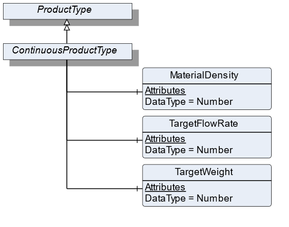
7.25.2 ObjectType Definition
| Attribute | Value | ||||
| BrowseName | ContinuousProductType | ||||
| IsAbstract | False | ||||
| References | NodeClass | BrowseName | DataType | TypeDefinition | ModellingRule |
|---|---|---|---|---|---|
| Subtype of the ProductType | |||||
| 0:HasComponent | Variable | MaterialDensity | 0:Number | 0:AnalogUnitType | Optional |
| 0:HasComponent | Variable | TargetFlowRate | 0:Number | TargetItemType | Optional |
| 0:HasComponent | Variable | TargetWeight | 0:Number | TargetItemType | Optional |
| Conformance Units | |||||
|---|---|---|---|---|---|
| Scales ContinuousScale |
7.25.3 ObjectType Description
MaterialDensity defines the bulk density of the used material.
TargetFlowRate defines a preset of flowrate that needs to be conveyed. This value defines the setpoint for the FlowRate control loop.
TargetWeight defines a preset of the volume to be processed.
7.26 LossInWeightScaleType Definition
7.26.1 Overview
The LossInWeightScaleDeviceType defines the structure of an Object of the LossInWeightScaleDeviceType. Figure 37 shows the hierarchical structure and details of the composition. It is formally defined in Table 65.
An Object of the LossInWeightScaleDeviceType represents a loss in weight scale. It defines additional methods and properties required for managing the loss in weight scale.
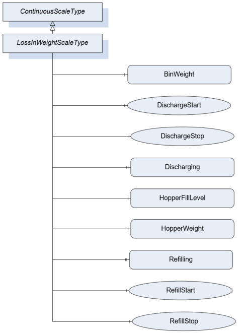
7.26.2 ObjectType Definition
| Attribute | Value | ||||
| BrowseName | LossInWeightScaleType | ||||
| IsAbstract | False | ||||
| References | NodeClass | BrowseName | DataType | TypeDefinition | ModellingRule |
|---|---|---|---|---|---|
| Subtype of the ContinuousScaleType | |||||
| 0:HasComponent | Variable | BinWeight | 0:BaseDataType | MeasuredItemType | Optional |
| 0:HasComponent | Method | DischargeStart | Mandatory | ||
| 0:HasComponent | Method | DischargeStop | Mandatory | ||
| 0:HasProperty | Variable | Discharging | 0:Boolean | 0:PropertyType | Mandatory |
| 0:HasComponent | Variable | HopperFillLevel | 0:Number | 0:AnalogUnitType | Mandatory |
| 0:HasComponent | Variable | HopperWeight | 0:BaseDataType | MeasuredItemType | Mandatory |
| 0:HasProperty | Variable | Refilling | 0:Boolean | 0:PropertyType | Mandatory |
| 0:HasComponent | Method | RefillStart | Mandatory | ||
| 0:HasComponent | Method | RefillStop | Mandatory | ||
| Conformance Units | |||||
|---|---|---|---|---|---|
| Scales Loss In Weight Scale |
7.26.3 ObjectType Description
Discharging indicates that hopper discharge operation is in progress.
BinWeight defines the weight of the filled material in an additional bin.
HopperFillLevel defines the fill weight relative to the maximal fill weight of the hopper (Unit: percentage).
HopperWeight defines the weight of the material within the feed hopper. This excludes the weight of the hopper itself.
Refilling indicates that a refill process into the hopper is taking place.
7.26.4 Method DischargeStart
Command to completely discharge the hopper.
Signature
	DischargeStart(
	);
7.26.5 Method DischargeStop
Command to terminate the complete hopper discharge procedure.
Signature
	DischargeStop(
	);
7.26.6 Method RefillStart
Manually starts a refill process.
Signature
	RefillStart(
	);
7.26.7 Method RefillStop
Manually stops a running refill process.
Signature
	RefillStop(
	);
7.27 PieceCountingScaleType Definition
7.27.1 Overview
The PieceCountingScaleType defines the structure of an Object of the PieceCountingScaleType. Figure 38 shows the hierarchical structure and details of the composition. It is formally defined in Table 66.
An Object of the PieceCountingScaleType represents a piece counting scale. It defines additional methods and properties required for managing the piece counting scale.
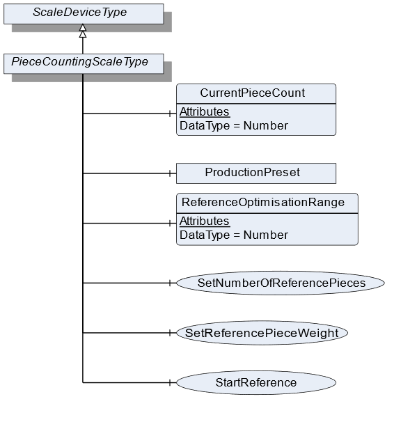
7.27.2 ObjectType Definition
| Attribute | Value | ||||
| BrowseName | PieceCountingScaleType | ||||
| IsAbstract | False | ||||
| References | NodeClass | BrowseName | DataType | TypeDefinition | ModellingRule |
|---|---|---|---|---|---|
| Subtype of the ScaleDeviceType | |||||
| 0:HasComponent | Variable | CurrentPieceCount | 0:Number | MeasuredItemType | Mandatory |
| 0:HasComponent | Variable | ReferenceOptimisationRange | 0:Number | 0:AnalogItemType | Optional |
| 0:HasComponent | Method | SetReferencePieceWeight | Mandatory | ||
| 0:HasComponent | Method | StartReference | Optional | ||
| 0:HasComponent | Method | SetNumberOfReferencePieces | Mandatory | ||
| Conformance Units | |||||
|---|---|---|---|---|---|
| Scales PieceCountingScale |
7.27.3 ObjectType Description
CurrentPieceCount defines the number of pieces that are currently measured related to the ReferencePieceWeight.
ReferenceOptimisationRange defines the tolerance range within which the scale may optimize the ReferencePieceWeight.
ProductionPreset, which is inherited from ScaleDeviceType shall have instances of PieceCountingProductType or a subtype in the Products folder.
7.27.4 Method SetReferencePieceWeight
Sets the value for the ReferencePieceWeight (product-specific data). The signature of this Method is specified below. Table 67 and Table 68 specify the Arguments and AddressSpace representation, respectively.
Signature
	SetReferencePieceWeight(
	[in]	UInt32		ReferencePieceWeight
[in] EUInformation EngineeringUnits);| Argument | Description |
| ReferencePieceWeight | The reference weight of a piece |
| EngineeringUnits | Unit of the ReferencePieceWeight |
| Attribute | Value | ||||
| BrowseName | SetReferencePieceWeight | ||||
| References | NodeClass | BrowseName | DataType | TypeDefinition | ModellingRule |
|---|---|---|---|---|---|
| 0:HasProperty | Variable | InputArguments | Argument[] | 0:PropertyType | Mandatory |
7.27.5 Method StartReference
Triggers the reference weighing process. The signature of this Method is specified below. Table 69 and Table 70 specify the Arguments and AddressSpace representation, respectively.
Signature
	StartReference(
[in] UInt32 NumberOfReferencePieces);| Argument | Description |
| NumberOfReferencePieces | The number of the references Pieces that should be used by the next references process. |
| Attribute | Value | ||||
| BrowseName | StartReference | ||||
| References | NodeClass | BrowseName | DataType | TypeDefinition | ModellingRule |
|---|---|---|---|---|---|
| 0:HasProperty | Variable | InputArguments | Argument[] | 0:PropertyType | Mandatory |
7.27.6 Method SetNumberOfReferencePieces
Sets the value for NumberOfReferencePieces (product-specific data). The signature of this Method is specified below. Table 71 and Table 72 specify the Arguments and AddressSpace representation, respectively.
Signature
	SetNumberOfReferencePieces(
[in] UInt32 NumberOfReferencePieces);| Argument | Description |
| NumberOfReferencePieces | The number of the references Pieces that should be used by the next references process. |
| Attribute | Value | ||||
| BrowseName | SetNumberOfReferencePieces | ||||
| References | NodeClass | BrowseName | DataType | TypeDefinition | ModellingRule |
|---|---|---|---|---|---|
| 0:HasProperty | Variable | InputArguments | Argument[] | 0:PropertyType | Mandatory |
7.28 PieceCountingProductType Definition
7.28.1 Overview
The PieceCountingProductType defines the structure of an Object of the PieceCountingProductType. Figure 39 shows the hierarchical structure and details of the composition. It is formally defined in Table 73.
An Object of the PieceCountingProductType represents a product of a piece counting scale. It defines additional methods and properties required for managing the product.
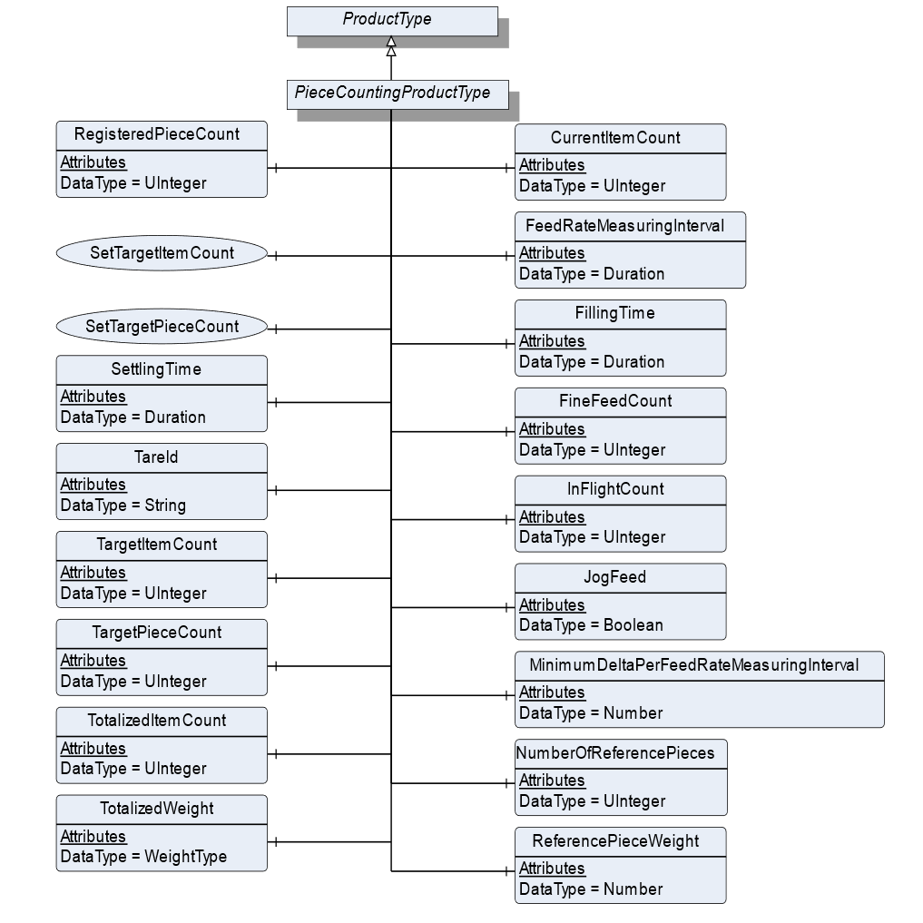
7.28.2 ObjectType Definition
| Attribute | Value | ||||
| BrowseName | PieceCountingProductType | ||||
| IsAbstract | False | ||||
| References | NodeClass | BrowseName | DataType | TypeDefinition | ModellingRule |
|---|---|---|---|---|---|
| Subtype of the ProductType | |||||
| 0:HasComponent | Variable | CurrentItemCount | 0:UInteger | BaseDataVariableType | Optional |
| 0:HasComponent | Variable | FeedRateMeasuringInterval | Duration | BaseDataVariableType | Optional |
| 0:HasComponent | Variable | FillingTime | Duration | BaseDataVariableType | Optional |
| 0:HasComponent | Variable | InFlightCount | 0:UInteger | BaseDataVariableType | Optional |
| 0:HasComponent | Variable | JogFeed | Boolean | BaseDataVariableType | Optional |
| 0:HasComponent | Variable | MinimumDeltaPerFeedRateMeasuringInterval | 0:Number | 0:AnalogItemType | Optional |
| 0:HasComponent | Variable | NumberOfReferencePieces | 0:UInteger | BaseDataVariableType | Mandatory |
| 0:HasComponent | Variable | ReferencePieceWeight | 0:Number | 0:AnalogItemType | Mandatory |
| 0:HasComponent | Variable | RegisteredPieceCount | 0:UInteger | BaseDataVariableType | Mandatory |
| 0:HasComponent | Method | SetTargetItemCount | Optional | ||
| 0:HasComponent | Method | SetTargetPieceCount | Optional | ||
| 0:HasComponent | Variable | SettlingTime | Duration | BaseDataVariableType | Optional |
| 0:HasComponent | Variable | TareId | 0:String | BaseDataVariableType | Optional |
| 0:HasComponent | Variable | TargetItemCount | 0:UInteger | BaseDataVariableType | Optional |
| 0:HasComponent | Variable | TargetPieceCount | 0:UInteger | TargetItemType | Optional |
| 0:HasComponent | Variable | TotalizedItemCount | 0:UInteger | BaseDataVariableType | Optional |
| 0:HasComponent | Variable | TotalizedWeight | WeightType | WeightItemType | Optional |
| 0:HasComponent | Variable | FineFeedCount | 0:UInteger | BaseDataVariableType | Optional |
| Conformance Units | |||||
|---|---|---|---|---|---|
| Scales PieceCountingScale |
7.28.3 ObjectType Description
CurrentItemCount defines the current number of items that are captured by the scale.
FeedRateMeasuringInterval defines the measurement interval for evaluating the current flowrate.
FillingTime defines the interval during which the filling has to be completed.
InFlightCount defines the number of items that are behind valve/in flight after feeding is stopped.
JogFeed defines if an additional dosage is necessary.
MinimumDeltaPerFeedRateMeasuringInterval defines the minimum amount of weight that needs to change within the FeedRateMeasuringInterval. Otherwise the filling procedure is not valid.
NumberOfReferencePieces defines the number of pieces that need to be used for the reference process.
ReferencePieceWeight defines the reference weight of a piece.
RegisteredPieceCount defines the number of pieces that were actually counted related to the ReferencePieceWeight.
SettlingTime defines the time that needs to be passed before the measurement process can be triggered.
TareId defines the ID of the tare value for the current product or item.
TargetItemCount defines the number of items that are supposed to be counted during the measurement process.
TargetPieceCount defines the number of pieces that need to be counted.
TotalizedItemCount defines the summed-up number of items. It will be reset, which is triggered either by the user or by a different product selection.
TotalizedWeight defines the summed-up number of weights. It will be reset, which is triggered either by the user or a different product selection.
FineFeedCount defines the Items to be dosed in fine flow
7.28.4 Method SetTargetItemCount
Sets the number of the TargetItemCount. See TargetItemCount. The signature of this Method is specified below. Table 74 and Table 75 specify the Arguments and AddressSpace representation, respectively.
Signature
	SetTargetItemCount(
[in] UInt32 TargetItemCount);| Argument | Description |
| TargetItemCount | 0:Number of items that are supposed to be counted during the measurement process. |
| Attribute | Value | ||||
| BrowseName | SetTargetItemCount | ||||
| References | NodeClass | BrowseName | DataType | TypeDefinition | ModellingRule |
|---|---|---|---|---|---|
| 0:HasProperty | Variable | InputArguments | Argument[] | 0:PropertyType | Mandatory |
7.28.5 Method SetTargetPieceCount
Sets the value of the TargetPieceCount. See TargetPieceCount. The signature of this Method is specified below. Table 76 and Table 77 specify the Arguments and AddressSpace representation, respectively.
Signature
	SetTargetPieceCount(
	[in]	UInt32		TargetPieceCount
	[in]	UInt32		PlusTolerance
[in] UInt32 MinusTolerance);| Argument | Description |
| TargetPieceCount | 0:Number of pieces that need to be counted. |
| PlusTolerance | Plus Tolerance of the TargetPieceCount |
| MinusTolerance | Minus Tolerance of the TargetPieceCount |
| Attribute | Value | ||||
| BrowseName | SetTargetPieceCount | ||||
| References | NodeClass | BrowseName | DataType | TypeDefinition | ModellingRule |
|---|---|---|---|---|---|
| 0:HasProperty | Variable | InputArguments | Argument[] | 0:PropertyType | Mandatory |
7.29 RecipeScaleType Definition
7.29.1 Overview
The RecipeScaleType defines the structure of an Object of the RecipeScaleType. Figure 40 shows the hierarchical structure and details of the composition. It is formally defined in Table 78.
An Object of the RecipeScaleType represents a recipe scale. It defines additional methods and properties required for managing the recipe scale.
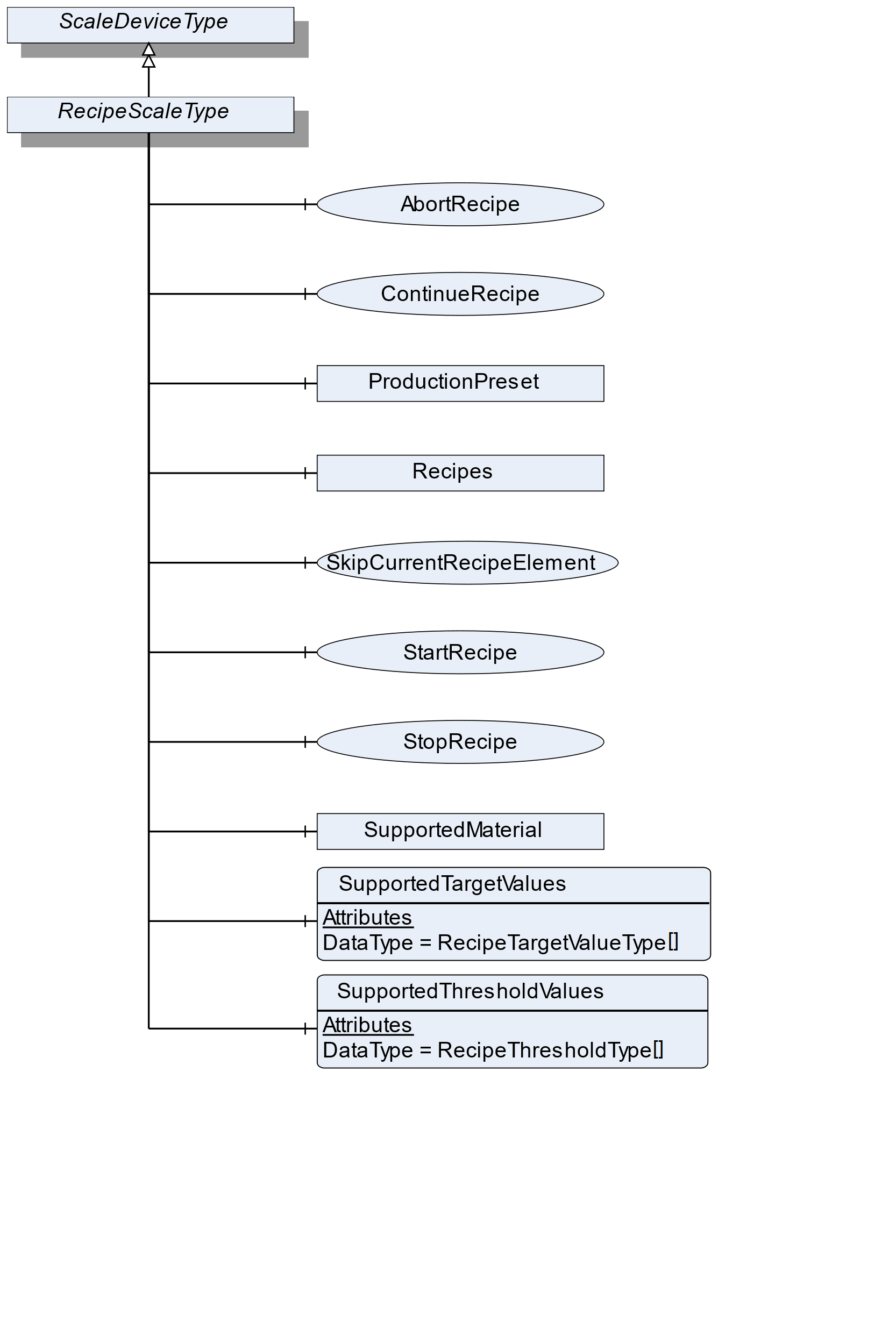
7.29.2 ObjectType Definition
| Attribute | Value | ||||
| BrowseName | RecipeScaleType | ||||
| IsAbstract | False | ||||
| References | NodeClass | BrowseName | DataType | TypeDefinition | ModellingRule |
|---|---|---|---|---|---|
| Subtype of the ScaleDeviceType | |||||
| 0:HasComponent | Object | Recipes | RecipeManagementType | Optional | |
| 0:HasComponent | Variable | SupportedTargetValues | RecipeTargetValueType[] | BaseDataVariableType | Optional |
| 0:HasComponent | Variable | SupportedThresholdValues | RecipeThresholdType[] | BaseDataVariableType | Optional |
| 0:HasComponent | Method | StartRecipe | Optional | ||
| 0:HasComponent | Method | StopRecipe | Optional | ||
| 0:HasComponent | Method | ContinueRecipe | Optional | ||
| 0:HasComponent | Method | SkipCurrentRecipeElement | Optional | ||
| 0:HasComponent | Method | AbortRecipe | Optional | ||
| 0:HasComponent | Object | SupportedMaterial | MaterialType | Optional | |
| Conformance Units | |||||
|---|---|---|---|---|---|
| Scales RecipeScale |
7.29.3 ObjectType Description
Recipes is an object of the Type RecipeManagmentType that contains all recipes. Elements in this folder must have the RecipeType and can be connected to the ReferenceType NextRecipeElementType. It also has some method to add and removes recipes.
SupportedTargetValues defines a list of values that may be set via the recipe.
SupportedThresholdValues defines a list of threshold values that may be used within one recipe.
SupportedMaterial defines the material that is supported.
ProductionPreset, which is inherited from ScaleDeviceType shall have instances of RecipeProductType or a subtype in the Products folder.
7.29.4 Method StartRecipe
Starts the given recipe (input parameter). Precondition: The scale needs to be enabled/released in advance. Table 79 and Table 80 specify the Arguments and AddressSpace representation, respectively.
Signature
	StartRecipe(
	[in]	NodeId	RecipeNodeId
);| Argument | Description |
| RecipeNodeId | NodeId of the recipe to be started |
| Attribute | Value | ||||
| BrowseName | StartRecipe | ||||
| References | NodeClass | BrowseName | DataType | TypeDefinition | ModellingRule |
|---|---|---|---|---|---|
| 0:HasProperty | Variable | InputArguments | Argument[] | 0:PropertyType | Mandatory |
7.29.5 Method StopRecipe
Pauses the current processing of a recipe. ContinueRecipe() continues the processing. AbortRecipe() stops the processing. Table 81 and Table 82 specify the Arguments and AddressSpace representation, respectively.
Signature
	StopRecipe(
	[in]	NodeId	RecipeNodeId
);| Argument | Description |
| RecipeNodeId | NodeId of the recipe to be stopped |
| Attribute | Value | ||||
| BrowseName | StopRecipe | ||||
| References | NodeClass | BrowseName | DataType | TypeDefinition | ModellingRule |
|---|---|---|---|---|---|
| 0:HasProperty | Variable | InputArguments | Argument[] | 0:PropertyType | Mandatory |
7.29.6 Method ContinueRecipe
If the recipe processing is stopped, the process can continue at the same point by means of the method ContinueRecipe. Table 83 and Table 84 specify the Arguments and AddressSpace representation, respectively.
Signature
	ContinueRecipe(
	[in]	NodeId	RecipeNodeId
);| Argument | Description |
| RecipeNodeId | NodeId of the recipe that can continue |
| Attribute | Value | ||||
| BrowseName | ContinueRecipe | ||||
| References | NodeClass | BrowseName | DataType | TypeDefinition | ModellingRule |
|---|---|---|---|---|---|
| 0:HasProperty | Variable | InputArguments | Argument[] | 0:PropertyType | Mandatory |
7.29.7 Method SkipCurrentRecipeElement
The current RecipeElement will be skipped (e.g., manually completed) and the scale continues with the next RecipeElement. Attention: This may result in a different execution of the process. Table 85 and Table 86 specify the Arguments and AddressSpace representation, respectively.
Signature
	SkipCurrentRecipeElement(
	[in]	NodeId	RecipeNodeId
);| Argument | Description |
| RecipeNodeId | NodeId of the recipe that can continue |
| Attribute | Value | ||||
| BrowseName | SkipCurrentRecipeElement | ||||
| References | NodeClass | BrowseName | DataType | TypeDefinition | ModellingRule |
|---|---|---|---|---|---|
| 0:HasProperty | Variable | InputArguments | Argument[] | 0:PropertyType | Mandatory |
7.29.8 Method AbortRecipe
Aborts the current processing of a recipe. Table 87 and Table 88 specify the Arguments and AddressSpace representation, respectively.
Signature
	AbortRecipe(
	[in]	NodeId	RecipeNodeId
);| Argument | Description |
| RecipeNodeId | NodeId of the recipe that can continue |
| Attribute | Value | ||||
| BrowseName | AbortRecipe | ||||
| References | NodeClass | BrowseName | DataType | TypeDefinition | ModellingRule |
|---|---|---|---|---|---|
| 0:HasProperty | Variable | InputArguments | Argument[] | 0:PropertyType | Mandatory |
7.30 RecipeProductType Definition
7.30.1 Overview
The RecipeProductType defines the structure of an Object of the RecipeProductType. Figure 41 shows the hierarchical structure and details of the composition. It is formally defined in Table 89.
An Object of the RecipeProductType represents a product of a recipe scale. It defines additional methods and properties required for managing the product.
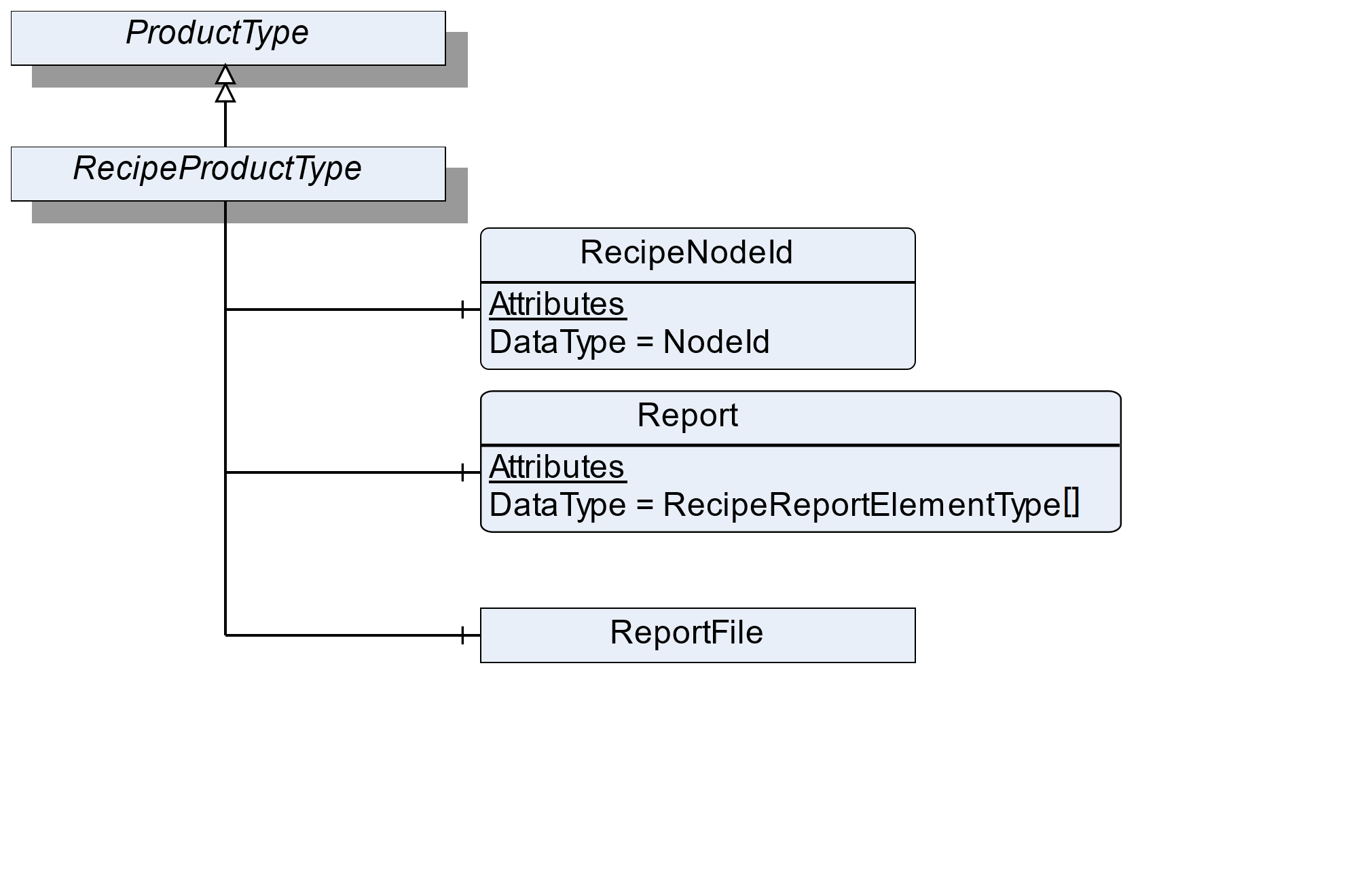
7.30.2 ObjectType Definition
| Attribute | Value | ||||
| BrowseName | RecipeProductType | ||||
| IsAbstract | False | ||||
| References | NodeClass | BrowseName | DataType | TypeDefinition | ModellingRule |
|---|---|---|---|---|---|
| Subtype of the ProductType | |||||
| 0:HasComponent | Variable | RecipeNodeId | NodeId | BaseDataVariableType | Mandatory |
| 0:HasComponent | Variable | Report | RecipeReportElementType[] | BaseDataVariableType | Mandatory |
| 0:HasComponent | Object | ReportFile | FileType | Optional | |
| Conformance Units | |||||
|---|---|---|---|---|---|
| Scales RecipeScale |
7.30.3 ObjectType Description
RecipeNodeId defines the node ID of the recipe that is being produced.
Report defines an array with the various messages from the recipe. Each RecipeElement generates its own report message.
ReportFile defines the file (binary, xml or other) that contains the report of the current process.
7.31 RecipeType Definition
7.31.1 Overview
The RecipeType defines the structure of an Object of the RecipeType. Figure 42 shows the hierarchical structure and details of the composition. It is formally defined in Table 90.
An Object of the RecipeType represents a recipe. It defines additional methods and properties required for managing a recipe. The description and the structure of the recipe can be found in Annex B.
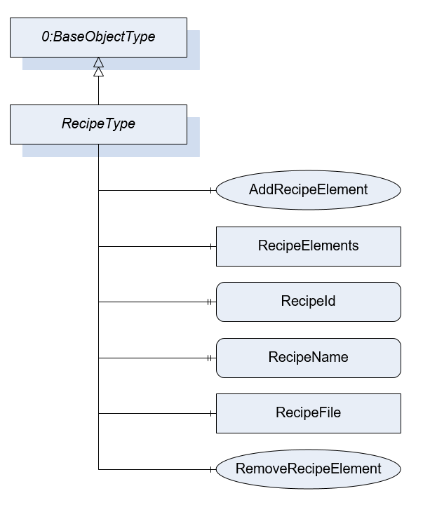
7.31.2 ObjectType Definition
| Attribute | Value | ||||
| BrowseName | RecipeType | ||||
| IsAbstract | False | ||||
| References | NodeClass | BrowseName | DataType | TypeDefinition | ModellingRule |
|---|---|---|---|---|---|
| Subtype of the BaseObjectType defined in OPC 10000-5 | |||||
| 0:HasComponent | Object | RecipeElements | FolderType | Optional | |
| 0:HasProperty | Variable | RecipeId | 0:String | 0:PropertyType | Mandatory |
| 0:HasProperty | Variable | RecipeName | 0:LocalizedText | 0:PropertyType | Mandatory |
| 0:HasComponent | Method | AddRecipeElement | Optional | ||
| 0:HasComponent | Method | RemoveRecipeElement | Optional | ||
| 0:HasComponent | Object | RecipeFile | 0:FileType | Optional | |
| Conformance Units | |||||
|---|---|---|---|---|---|
| Scales RecipeManagement | |||||
| Scales FileRecipeManagement |
7.31.3 ObjectType Description
RecipeElements defines a folder for all RecipeElements that are part of the recipe.
RecipeId defines a unique identifier of a recipe.
RecipeName defines a user-readable name of the recipe.
RecipeFile is a file that contains the recipe in a vendor-specific format. If a client uploads the file, the recipe elements can be also part of the AddressSpace. But the Method AddRecipeElement and RemoveRecipeElement should not be used. So a recipe uploaded via file transfer cannot be modified via AddRecipeElement or RemoveRecipeElement. This avoids that there is another version of the recipe in the file and the server.
7.31.4 Method AddRecipeElement
AddRecipeElement is a method to add an additional RecipeElement to the recipe. Table 91 and Table 92 specify the Arguments and AddressSpace representation, respectively.
Signature
	AddRecipeElement(
	[in]	NodeId	ElementType
	[in]	String	ElementName
	[in]	NodeId[]	PreviousElements
	[out]	NodeId	ElementNodeId
);| Argument | Description |
| ElementType | NodeId of the Object that should be added |
| ElementName | A user-readable name of the element |
| PreviousElements | The NodeIds of the directly previous Elements. If the element is the start Element use the Recipe node. |
| ElementNodeId | The NodeId of the created RecipeElement |
| Attribute | Value | ||||
| BrowseName | AddRecipeElement | ||||
| References | NodeClass | BrowseName | DataType | TypeDefinition | ModellingRule |
|---|---|---|---|---|---|
| 0:HasProperty | Variable | InputArguments | Argument[] | 0:PropertyType | Mandatory |
| 0:HasProperty | Variable | OutputArguments | Argument[] | 0:PropertyType | Mandatory |
7.31.5 Method RemoveRecipeElement
Method to remove a RecipeElement in this recipe with all related references. Table 93 and Table 94 specify the Arguments and AddressSpace representation, respectively.
Signature
	RemoveRecipeElement(
	[in]	NodeId	RecipeElementNodeId
);| Argument | Description |
| RecipeElementNodeId | NodeId of the Object that should be removed |
| Attribute | Value | ||||
| BrowseName | RemoveRecipeElement | ||||
| References | NodeClass | BrowseName | DataType | TypeDefinition | ModellingRule |
|---|---|---|---|---|---|
| 0:HasProperty | Variable | InputArguments | Argument[] | 0:PropertyType | Mandatory |
7.32 RecipeManagementType Definition
7.32.1 Overview
The RecipeManagementType defines the structure of an Object of the RecipeManagementType. Figure 43 shows the hierarchical structure and details of the composition. It is formally defined in Table 95.
An Object of the RecipeManagementType contains methods and properties required for managing recipes. The description and the structure of the recipe can be found in Annex B.
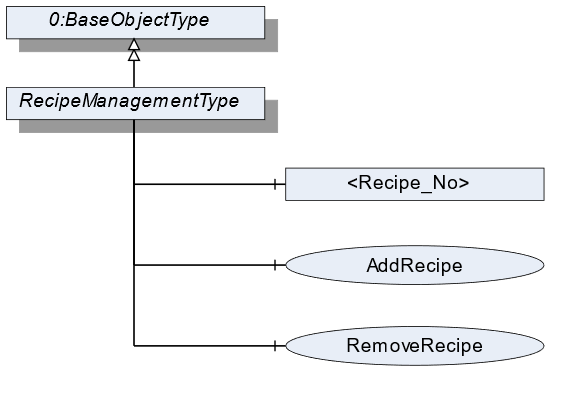
7.32.2 ObjectType Definition
| Attribute | Value | ||||
| BrowseName | RecipeManagementType | ||||
| IsAbstract | False | ||||
| References | NodeClass | BrowseName | DataType | TypeDefinition | ModellingRule |
|---|---|---|---|---|---|
| Subtype of the BaseObjectType defined in OPC 10000-5 | |||||
| 0:HasComponent | Method | AddRecipe | Optional | ||
| 0:HasComponent | Object | <Recipe_No> | RecipeType | OptionalPlaceholder | |
| 0:HasComponent | Method | RemoveRecipe | Optional | ||
| Conformance Units | |||||
|---|---|---|---|---|---|
| Scales RecipeManagment |
7.32.3 ObjectType Description
Recipe_No defines an instance of a recipe with the value "No".
7.32.4 Method AddRecipe
Method to add an additional recipe of the RecipeType. The signature of this Method is specified below. Table 96 and Table 97 specify the Arguments and AddressSpace representation, respectively.
Signature
	AddRecipe(
	[in]	0:String		RecipeId
	[in]	0:LocalizedText		RecipeName
[out] NodeId RecipeNodeId);| Argument | Description |
| RecipeId | Unique identifier of a recipe. |
| RecipeName | User-readable name of the recipe. |
| RecipeNodeId | NodeId of the created Object. |
| Attribute | Value | ||||
| BrowseName | AddRecipe | ||||
| References | NodeClass | BrowseName | DataType | TypeDefinition | ModellingRule |
|---|---|---|---|---|---|
| 0:HasProperty | Variable | InputArguments | Argument[] | 0:PropertyType | Mandatory |
| 0:HasProperty | Variable | OutputArguments | Argument[] | 0:PropertyType | Mandatory |
7.32.5 Method RemoveRecipe
Method to remove a recipe of the RecipeType. The signature of this Method is specified below. Table 98 and Table 99 specify the Arguments and AddressSpace representation, respectively.
Signature
	RemoveRecipe(
	[in]	0:String			RecipeId
);| Argument | Description |
| RecipeId | User-readable name of the recipe. |
| Attribute | Value | ||||
| BrowseName | RemoveRecipe | ||||
| References | NodeClass | BrowseName | DataType | TypeDefinition | ModellingRule |
|---|---|---|---|---|---|
| 0:HasProperty | Variable | InputArguments | Argument[] | 0:PropertyType | Mandatory |
7.33 RecipeElementType Definition
7.33.1 Overview
The RecipeElementType defines the structure of an Object of the RecipeElementType. Figure 44 shows the hierarchical structure and details of the composition. It is formally defined in Table 100.
An Object of the RecipeElementType represents a step, process, or action in a recipe. It defines additional methods and properties required for managing a recipe. The description and the structure of the recipe can be found in Annex B.
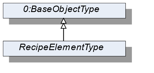
7.33.2 ObjectType Definition
| Attribute | Value | ||||
| BrowseName | RecipeElementType | ||||
| IsAbstract | True | ||||
| References | NodeClass | BrowseName | DataType | TypeDefinition | ModellingRule |
|---|---|---|---|---|---|
| Subtype of the BaseObjectType defined in OPC 10000-5 | |||||
| Conformance Units | |||||
|---|---|---|---|---|---|
| Scales RecipeManagement | |||||
| Scales DynamicRecipeManagement |
7.34 ActivationType Definition
7.34.1 Overview
The ActivationType defines the structure of an Object of the ActivationType. Figure 45 shows the hierarchical structure and details of the composition. It is formally defined in Table 101.
An Object of the ActivationType represents an activation step in a recipe.
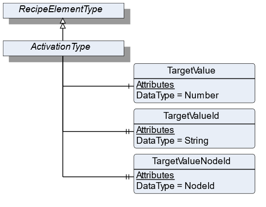
7.34.2 ObjectType Definition
| Attribute | Value | ||||
| BrowseName | ActivationType | ||||
| IsAbstract | False | ||||
| References | NodeClass | BrowseName | DataType | TypeDefinition | ModellingRule |
|---|---|---|---|---|---|
| Subtype of the RecipeElementType | |||||
| 0:HasComponent | Variable | TargetValue | 0:Number | 0:AnalogUnitType | Mandatory |
| 0:HasProperty | Variable | TargetValueId | 0:String | 0:PropertyType | Mandatory |
| 0:HasProperty | Variable | TargetValueNodeId | NodeId | 0:PropertyType | Optional |
| Conformance Units | |||||
|---|---|---|---|---|---|
| Scales RecipeManagement | |||||
| Scales DynamicRecipeManagement |
7.34.3 ObjectType Description
TargetValue defines the value to be reached of an aggregate that is referenced by TargetValueId.
TargetValueId defines a unique ID of the aggregate that is being activated. A list of all possible TargetValueIds is defined in RecipeScaleDeviceType.
TargetValueNodeId defines the NodeId of the aggregate that is being activated. If possible, this value should be used instead of the TargetValueId.
7.35 ConditionSleepType Definition
7.35.1 Overview
The ConditionSleepType defines the structure of an Object of the ConditionSleepType. Figure 46 shows the hierarchical structure and details of the composition. It is formally defined in Table 102.
An Object of ConditionSleepType represents a condition sleep step in a recipe. The recipe waits until the condition is solved.
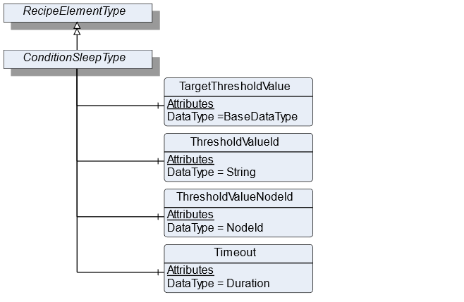
7.35.2 ObjectType Definition
| Attribute | Value | ||||
| BrowseName | ConditionSleepType | ||||
| IsAbstract | True | ||||
| References | NodeClass | BrowseName | DataType | TypeDefinition | ModellingRule |
|---|---|---|---|---|---|
| Subtype of the RecipeElementType | |||||
| 0:HasComponent | Variable | TargetThresholdValue | BaseDataType | DataItemType | Mandatory |
| 0:HasComponent | Variable | ThresholdValueId | 0:String | DataItemType | Mandatory |
| 0:HasComponent | Variable | ThresholdValueNodeId | NodeId | BaseDataVariableType | Optional |
| 0:HasComponent | Variable | Timeout | Duration | DataItemType | Optional |
| Conformance Units | |||||
|---|---|---|---|---|---|
| Scales DynamicRecipeManagement |
7.35.3 ObjectType Description
TargetThresholdValue is the target value with which the threshold value is compared.
ThresholdValueId defines an ID of the process value that needs to be monitored and is element of the SupportedThresholdValues in the RecipeScale.
ThresholdValueNodeId is the NodeId of the process value that needs to be monitored and is element of the SupportedThresholdValues in the RecipeScale. This variable should be used if the value is part of the address space.
Timeout specifies the duration within which the TargetThresholdValue needs to be reached. If Timeout is exceeded an operator intervention is necessary.
7.36 AnalogConditionSleepType Definition
7.36.1 Overview
The AnalogConditionSleepType defines the structure of an Object of the AnalogConditionSleepType. Figure 47 shows the hierarchical structure and details of the composition. It is formally defined in Table 104.
An Object of the AnalogConditionSleepType represents a condition sleep step in a recipe. The recipe waits until the analog condition is solved. The condition depends on the EqualityAndRelationalOperator (see section 10.6). The conditions are listed in Table 103.
| ConditionMode | Condition |
| Equal | ThresholdValue = TargetThresholdValue |
| NotEqual | ThresholdValue != TargetThresholdValue |
| LessThan | ThresholdValue < TargetThresholdValue |
| LessOrEqualThan | ThresholdValue <= TargetThresholdValue |
| GreaterThan | ThresholdValue > TargetThresholdValue |
| GreaterOrEqualThan | ThresholdValue >= TargetThresholdValue |
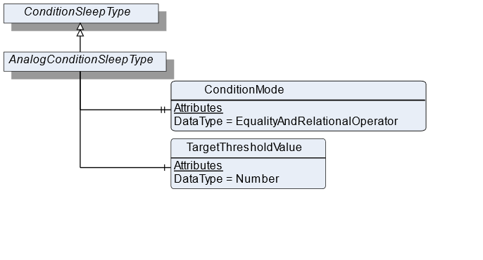
7.36.2 ObjectType Definition
| Attribute | Value | ||||
| BrowseName | AnalogConditionSleepType | ||||
| IsAbstract | False | ||||
| References | NodeClass | BrowseName | DataType | TypeDefinition | ModellingRule |
|---|---|---|---|---|---|
| Subtype of the ConditionSleepType | |||||
| 0:HasProperty | Variable | ConditionMode | EqualityAndRelationalOperator | 0:PropertyType | Mandatory |
| 0:HasComponent | Variable | TargetThresholdValue | 0:Number | TargetItemType | Mandatory |
| Conformance Units | |||||
|---|---|---|---|---|---|
| Scales DynamicRecipeManagement | |||||
| Scales RecipeManagement |
7.36.3 ObjectType Description
ConditionMode defines the type of condition operator that is used.
TargetThresholdValue is the target value with which the threshold value is compared.
7.37 EdgeTriggeredSleepType Definition
7.37.1 Overview
The EdgeTriggeredSleepType defines the structure of an Object of the EdgeTriggeredSleepType. Figure 48 shows the hierarchical structure and details of the composition. It is formally defined in Table 106.
An Object of the EdgeTriggeredSleepType represents a condition sleep step in a recipe. The recipe waits until the binary condition is solved. The condition depends on the EdgeOperator (see section 10.7). The conditions are listed in Table 105.
| ConditionMode | Condition |
| Rising | Is true if after ThresholdValue transition from false to true |
| Falling | Is true if after ThresholdValue transition from true to false |
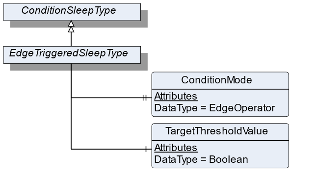
7.37.2 ObjectType Definition
| Attribute | Value | ||||
| BrowseName | EdgeTriggeredSleepType | ||||
| IsAbstract | False | ||||
| References | NodeClass | BrowseName | DataType | TypeDefinition | ModellingRule |
|---|---|---|---|---|---|
| Subtype of the ConditionSleepType | |||||
| 0:HasProperty | Variable | ConditionMode | EdgeOperator | 0:PropertyType | Mandatory |
| 0:HasComponent | Variable | TargetThresholdValue | Boolean | DataItemType | Mandatory |
| Conformance Units | |||||
|---|---|---|---|---|---|
| Scales RecipeManagement | |||||
| Scales DynamicRecipeManagement |
7.37.3 ObjectType Description
ConditionMode defines the type of condition operator that is used.
TargetThresholdValue is the target value with which the threshold value is compared.
7.38 TimerType Definition
7.38.1 Overview
The TimerType defines the structure of an Object of the TimerType. Figure 49 shows the hierarchical structure and details of the composition. It is formally defined in Table 107.
An Object of the TimerType represents a timer step in a recipe. The recipe waits until at least Duration has passed.
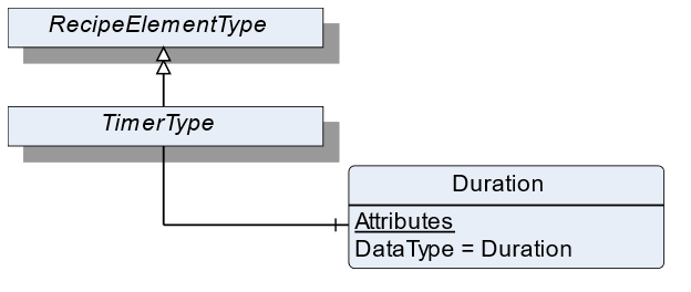
7.38.2 ObjectType Definition
| Attribute | Value | ||||
| BrowseName | TimerType | ||||
| IsAbstract | False | ||||
| References | NodeClass | BrowseName | DataType | TypeDefinition | ModellingRule |
|---|---|---|---|---|---|
| Subtype of the RecipeElementType | |||||
| 0:HasComponent | Variable | Duration | Duration | BaseDataVariableType | Mandatory |
| Conformance Units | |||||
|---|---|---|---|---|---|
| Scales RecipeManagement | |||||
| Scales DynamicRecipeManagement |
7.38.3 ObjectType Description
Duration defines the period of time the processing needs to wait before processing the next RecipeElement.
7.39 UserInstructionType Definition
7.39.1 Overview
The UserInstructionType defines the structure of an Object of the UserInstructionType. Figure 50 shows the hierarchical structure and details of the composition. It is formally defined in Table 108.
An Object of UserInstructionType represents a recipe step that requires user interaction. The recipe scale displays instructions (a text and/or application-specific symbols) on an HMI and waits until the user acknowledges the instructions.
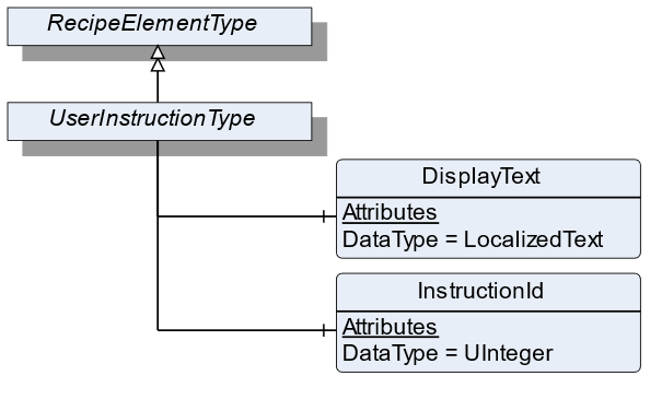
7.39.2 ObjectType Definition
| Attribute | Value | ||||
| BrowseName | UserInstructionType | ||||
| IsAbstract | False | ||||
| References | NodeClass | BrowseName | DataType | TypeDefinition | ModellingRule |
|---|---|---|---|---|---|
| Subtype of the RecipeElementType | |||||
| 0:HasComponent | Variable | DisplayText | 0:LocalizedText | BaseDataVariableType | Mandatory |
| 0:HasComponent | Variable | InstructionId | 0:UInteger | BaseDataVariableType | Optional |
| Conformance Units | |||||
|---|---|---|---|---|---|
| Scales RecipeManagement | |||||
| Scales DynamicRecipeManagement |
7.39.3 ObjectType Description
DisplayText defines instructions for this RecipeElement that will be displayed to the user.
InstructionId defines a unique ID used to identify the instruction that is displayed via DisplayText.
7.40 WeighingType Definition
7.40.1 Overview
The WeighingType defines the structure of an Object of the WeighingType. Figure 51 shows the hierarchical structure and details of the composition. It is formally defined in Table 109.
An Object of the WeighingType represents a weighing process in a recipe. The process can be an automatic or a manual filling process. The WeighingType contains all information needed in the weighing process.
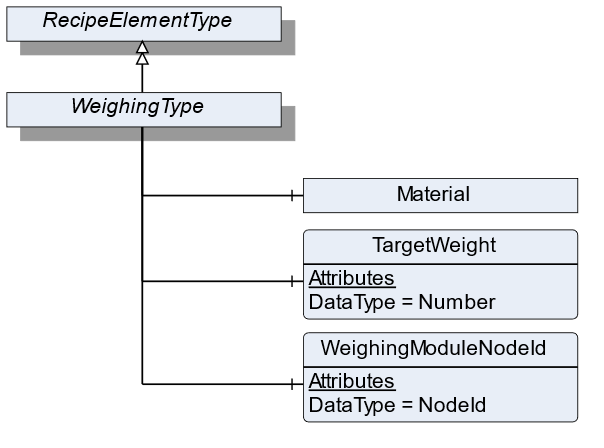
7.40.2 ObjectType Definition
| Attribute | Value | ||||
| BrowseName | WeighingType | ||||
| IsAbstract | False | ||||
| References | NodeClass | BrowseName | DataType | TypeDefinition | ModellingRule |
|---|---|---|---|---|---|
| Subtype of the RecipeElementType | |||||
| 0:HasComponent | Variable | WeighingModuleNodeId | NodeId | BaseDataVariableType | Mandatory |
| 0:HasComponent | Object | Material | MaterialType | Optional | |
| 0:HasComponent | Variable | TargetWeight | 0:Number | TargetItemType | Mandatory |
| Conformance Units | |||||
|---|---|---|---|---|---|
| Scales RecipeManagement | |||||
| Scales DynamicRecipeManagement |
7.40.3 ObjectType Description
WeighingModuleNodeId defines the ID of the load cell which is used for weighing the product.
Material defines the material which needs to be measured. Each material has different characteristics that are defined in MaterialType.
TargetWeight defines the preset of the volume to be processed.
7.41 MaterialAutomaticType Definition
7.41.1 Overview
The MaterialAutomaticType defines the structure of an Object of the MaterialAutomaticType. Figure 52 shows the hierarchical structure and details of the composition. It is formally defined in Table 110.
An Object of MaterialAutomaticType represents a material in a recipe that will be filled automatically.
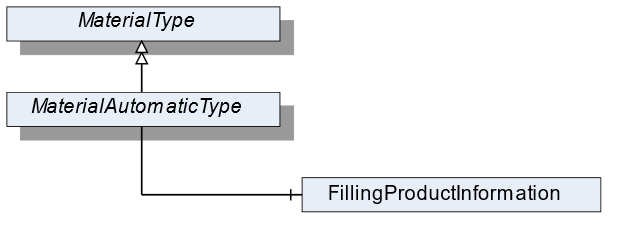
7.41.2 ObjectType Definition
| Attribute | Value | ||||
| BrowseName | MaterialAutomaticType | ||||
| IsAbstract | False | ||||
| References | NodeClass | BrowseName | DataType | TypeDefinition | ModellingRule |
|---|---|---|---|---|---|
| Subtype of the MaterialType | |||||
| 0:HasComponent | Object | FillingProductInformation | AutomaticFillingProductType | Mandatory | |
| Conformance Units | |||||
|---|---|---|---|---|---|
| Scales RecipeScale |
7.41.3 ObjectType Description
FillingProductInformation defines the parameters necessary for the filling of the material. It derives from product-specific information within the AutomaticFillingScaleType.
7.42 TotalizingHopperScaleType Definition
7.42.1 Overview
The TotalizingHopperScaleType defines the structure of an Object of the TotalizingHopperScaleType. Figure 53 shows the hierarchical structure and details of the composition. It is formally defined in Table 111.
An Object of the TotalizingHopperScaleType represents a totalizing hopper scale. It defines additional methods and properties required for managing the totalizing hopper scale.
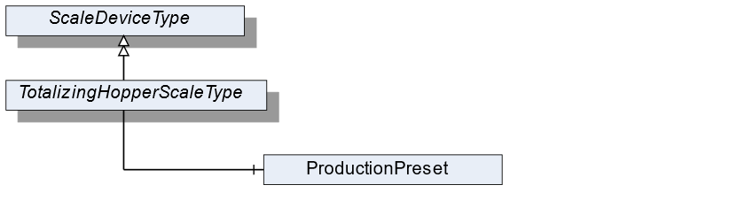
7.42.2 ObjectType Definition
| Attribute | Value | ||||
| BrowseName | TotalizingHopperScaleType | ||||
| IsAbstract | False | ||||
| References | NodeClass | BrowseName | DataType | TypeDefinition | ModellingRule |
|---|---|---|---|---|---|
| Subtype of the ScaleDeviceType | |||||
| Conformance Units | |||||
|---|---|---|---|---|---|
| Scales TotalizingHopperScale |
7.42.3 ObjectType Description
ProductionPreset, which is inherited from ScaleDeviceType shall have instances of TotalizingHopperProductType or a subtype in the Products folder.
7.43 TotalizingHopperProductType Definition
7.43.1 Overview
The TotalizingHopperProductType defines the structure of an Object of the TotalizingHopperProductType. Figure 54 shows the hierarchical structure and details of the composition. It is formally defined in Table 112.
An Object of the TotalizingHopperProductType represents a product of a totalizing hopper scale. It defines additional methods and properties required for managing the product.
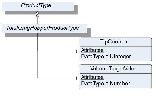
7.43.2 ObjectType Definition
| Attribute | Value | ||||
| BrowseName | TotalizingHopperProductType | ||||
| IsAbstract | False | ||||
| References | NodeClass | BrowseName | DataType | TypeDefinition | ModellingRule |
|---|---|---|---|---|---|
| Subtype of the ProductType | |||||
| 0:HasComponent | Variable | VolumeTargetValue | 0:Number | TargetItemType | Optional |
| 0:HasComponent | Variable | TipCounter | 0:UInteger | BaseDataVariableType | Mandatory |
| Conformance Units | |||||
|---|---|---|---|---|---|
| Scales TotalizingHopperScale |
7.43.3 ObjectType Description
TargetValue defines the preset of the volume to be processed.
TipCounter defines the number of fillings (downpour, bulk produce).
7.44 SimpleScaleType Definition
7.44.1 Overview
The SimpleScaleType defines the structure of an Object of the SimpleScaleType. Figure 55 shows the hierarchical structure and details of the composition. It is formally defined in Table 113.
An Object of the SimpleScaleType represents a simple scale. It defines additional methods and properties required for managing the simple scale.
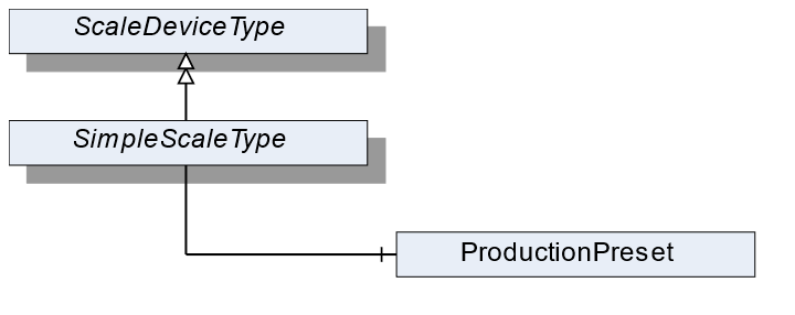
7.44.2 ObjectType Definition
| Attribute | Value | ||||
| BrowseName | SimpleScaleType | ||||
| IsAbstract | False | ||||
| References | NodeClass | BrowseName | DataType | TypeDefinition | ModellingRule |
|---|---|---|---|---|---|
| Subtype of the ScaleDeviceType | |||||
| Conformance Units | |||||
|---|---|---|---|---|---|
| Scales SimpleScale |
7.44.3 ObjectType Description
ProductionPreset, which is inherited from ScaleDeviceType shall have instances of SimpleProductType or a subtype in the Products folder.
7.45 SimpleProductType Definition
7.45.1 Overview
The SimpleProductType defines the structure of an Object of the SimpleProductType. Figure 56 shows the hierarchical structure and details of the composition. It is formally defined in Table 114.
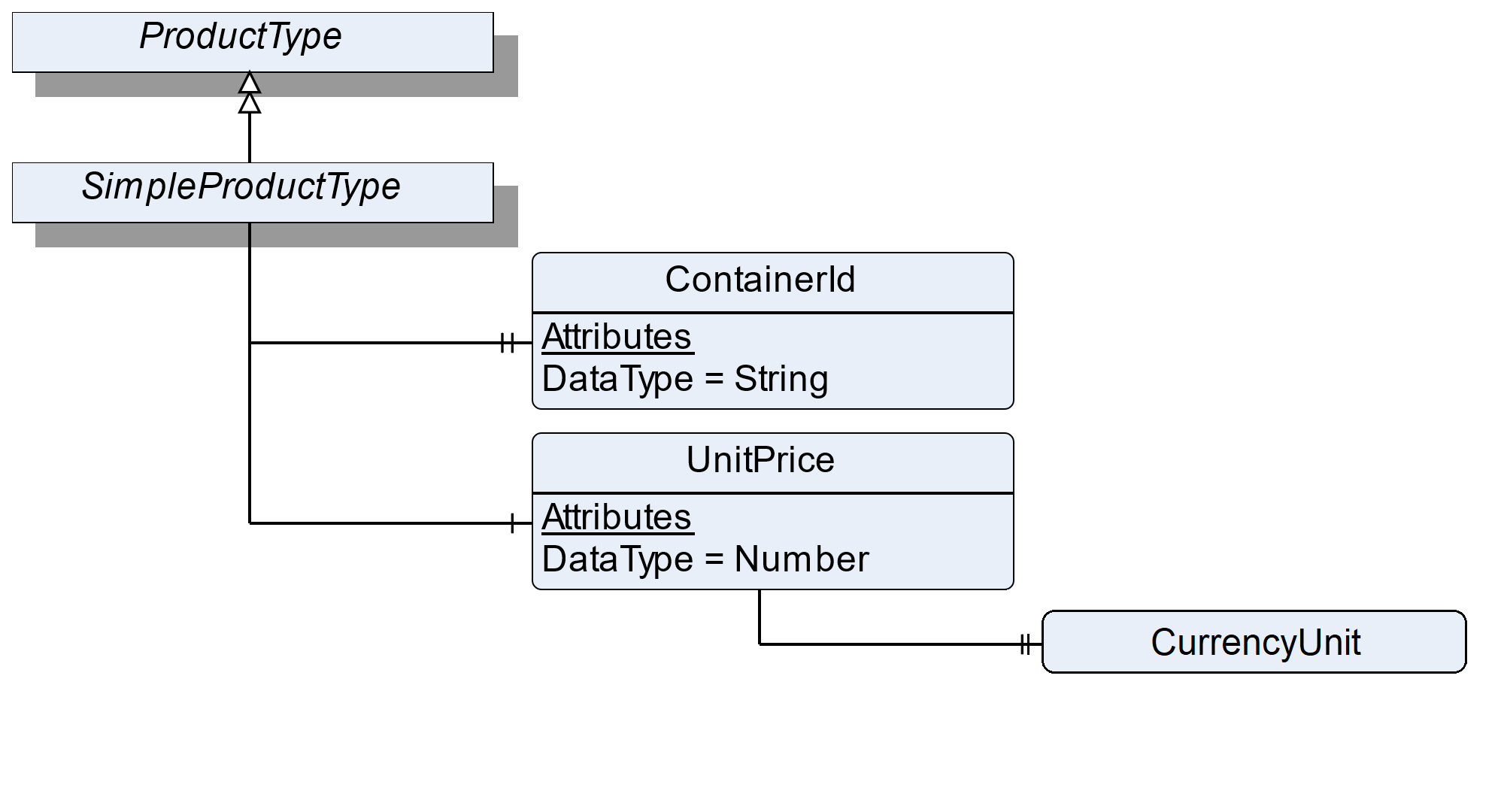
7.45.2 ObjectType Definition
| Attribute | Value | ||||
| BrowseName | SimpleProductType | ||||
| IsAbstract | False | ||||
| References | NodeClass | BrowseName | DataType | TypeDefinition | ModellingRule |
|---|---|---|---|---|---|
| Subtype of the ProductType | |||||
| 0:HasProperty | Variable | ContainerId | 0:String | 0:PropertyType | Optional |
| 0:HasComponent | Variable | UnitPrice | 0:Number | BaseDataVariableType | Optional |
| Conformance Units | |||||
|---|---|---|---|---|---|
| Scales SimpleScale |
7.45.3 ObjectType Description
ContainerId defines the identifier of a container which contains the weighing good (e.g., bottles upon a pallet which will be filled with liquid).
UnitPrice defines the price per weight unit.
The components of the SimpleProductType have additional references which are defined in Table 115.
| Source Path | References | NodeClass | BrowseName | DataType | TypeDefinition | Others |
| UnitPrice | 0: HasProperty | Variable | CurrencyUnit | CurrencyUnitType | 0:PropertyType | M |
7.46 LaboratoryScaleType Definition
7.46.1 Overview
The LaboratoryScaleType defines the structure of an Object of the LaboratoryScaleType. Figure 57 shows the hierarchical structure and details of the composition. It is formally defined in Table 116.
An Object of the LaboratoryScaleType represents a laboratory scale. It defines additional methods and properties required for managing the laboratory scale.
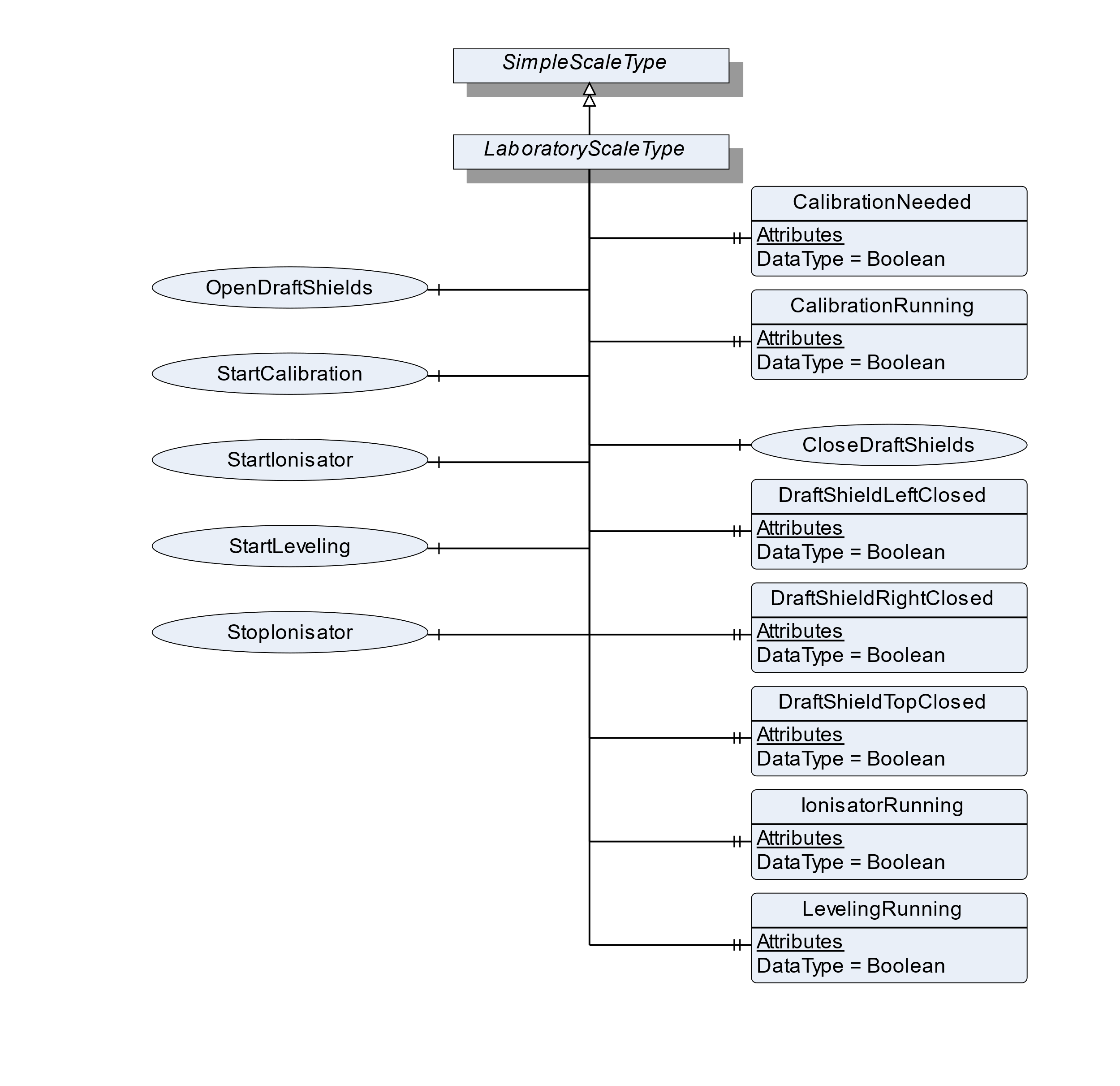
7.46.2 ObjectType Definition
| Attribute | Value | ||||
| BrowseName | LaboratoryScaleType | ||||
| IsAbstract | False | ||||
| References | NodeClass | BrowseName | DataType | TypeDefinition | ModellingRule |
|---|---|---|---|---|---|
| Subtype of the SimpleScaleType | |||||
| 0:HasProperty | Variable | CalibrationNeeded | Boolean | 0:PropertyType | Optional |
| 0:HasProperty | Variable | CalibrationRunning | Boolean | 0:PropertyType | Optional |
| 0:HasComponent | Method | CloseDraftShields | Optional | ||
| 0:HasProperty | Variable | DraftShieldLeftClosed | Boolean | 0:PropertyType | Optional |
| 0:HasProperty | Variable | DraftShieldRightClosed | Boolean | 0:PropertyType | Optional |
| 0:HasProperty | Variable | DraftShieldTopClosed | Boolean | 0:PropertyType | Optional |
| 0:HasProperty | Variable | LevelingRunning | Boolean | 0:PropertyType | Optional |
| 0:HasProperty | Variable | IonisatorRunning | Boolean | 0:PropertyType | Optional |
| 0:HasProperty | Variable | LevelingRunning | Boolean | 0:PropertyType | Optional |
| 0:HasComponent | Method | OpenDraftShields | Optional | ||
| 0:HasComponent | Method | StartLeveling | Optional | ||
| 0:HasComponent | Method | StartCalibration | Optional | ||
| 0:HasComponent | Method | StartIonisator | Optional | ||
| 0:HasComponent | Method | StopIonisator | Optional | ||
| Conformance Units | |||||
|---|---|---|---|---|---|
| Scales LaboratoryScale |
7.46.3 ObjectType Description
CalibrationNeeded defines if a calibration procedure is needed and if the current process should be paused.
CalibrationRunning defines if a calibration procedure is running (e.g., started via method StartCalibration).
DraftShieldLeftClosed defines if the left draft shield is closed.
DraftShieldRightClosed defines if the right draft shield is closed.
DraftShieldTopClosed defines if the top draft shield is closed.
LevelingRunning defines if a leveling process is running (e.g., started via the method StartLeveling).
IonisatorRunning defines if an ionization procedure is running (e.g., started via the method StartIonizer).
7.46.4 Method CloseDraftShields
Method to close a certain draft shield or all draft shields. The signature of this Method is specified below. Table 117 and Table 118 specify the Arguments and AddressSpace representation, respectively.
Signature
	CloseDraftShields(
	[in]	DraftShieldType		Shield
);| Argument | Description |
| Shield | The DraftShield that should be closed. |
| Attribute | Value | ||||
| BrowseName | CloseDraftShields | ||||
| References | NodeClass | BrowseName | DataType | TypeDefinition | ModellingRule |
|---|---|---|---|---|---|
| 0:HasProperty | Variable | InputArguments | Argument[] | 0:PropertyType | Mandatory |
7.46.5 Method OpenDraftShields
Method to open a certain draft shield or all draft shields. The signature of this Method is specified below. Table 119 and Table 120 specify the Arguments and AddressSpace representation, respectively.
Signature
	OpenDraftShields(
		[in]	DraftShieldType	Shield
);| Argument | Description |
| Shield | The DraftShield that should be open. |
| Attribute | Value | ||||
| BrowseName | OpenDraftShields | ||||
| References | NodeClass | BrowseName | DataType | TypeDefinition | ModellingRule |
|---|---|---|---|---|---|
| 0:HasProperty | Variable | InputArguments | Argument[] | 0:PropertyType | Mandatory |
7.46.6 Method StartLeveling
Method to start the automatic leveling procedure of the scale.
Signature
	SartLeveling(
	);
7.46.7 Method StartCalibration
Method to start the automatic calibration procedure.
Signature
	StartCalibration(
	);
7.46.8 Method StartIonisator
Method to start the ionization process.
Signature
	StartIonisator(
	);
7.46.9 Method StopIonisator
Method to stop the ionization process.
Signature
	StopIonisator(
	);
7.47 HopperScaleType Definition
7.47.1 Overview
The HopperScaleType defines the structure of an Object of the HopperScaleType. Figure 58 shows the hierarchical structure and details of the composition. It is formally defined in Table 121.
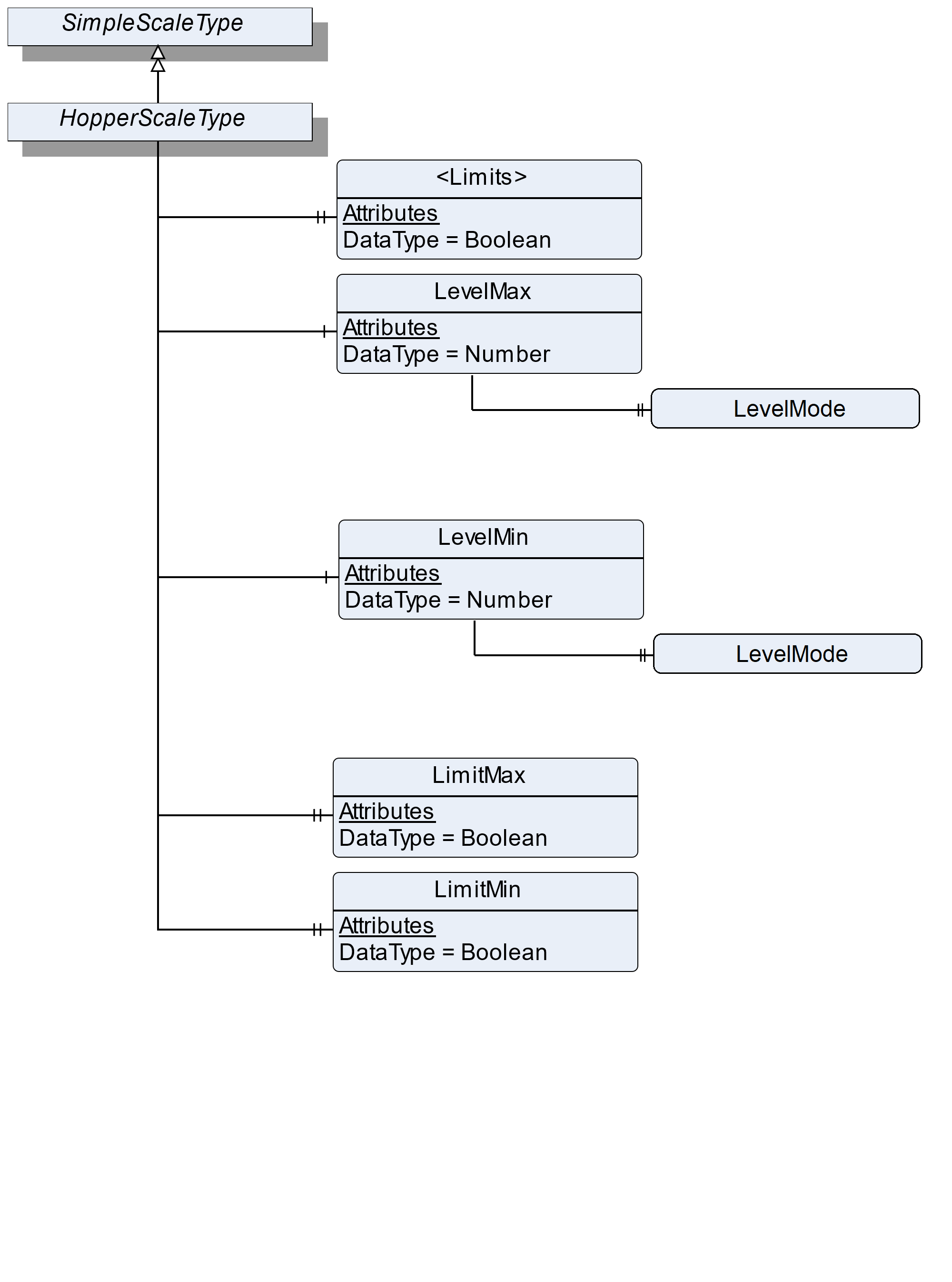
7.47.2 ObjectType Definition
| Attribute | Value | ||||
| BrowseName | HopperScaleType | ||||
| IsAbstract | False | ||||
| References | NodeClass | BrowseName | DataType | TypeDefinition | ModellingRule |
|---|---|---|---|---|---|
| Subtype of the SimpleScaleType | |||||
| 0:HasProperty | Variable | <Limits> | Boolean | 0:PropertyType | OptionalPlaceholder |
| 0:HasComponent | Variable | LevelMax | 0:Number | 0:AnalogUnitType | Optional |
| 0:HasComponent | Variable | LevelMin | 0:Number | 0:AnalogUnitType | Optional |
| 0:HasProperty | Variable | LimitMax | Boolean | 0:PropertyType | Mandatory |
| 0:HasProperty | Variable | LimitMin | Boolean | 0:PropertyType | Mandatory |
| Conformance Units | |||||
|---|---|---|---|---|---|
| Scales HopperScale |
7.47.3 ObjectType Description
<Limits> defines a placeholder for individual additional limits that may be reached.
LimitMin: The current fill level falls below the allowed minimum level.
LimitMax: The current fill level exceeds the allowed maximum level.
LevelMax defines the maximum fill level where an action is necessary.
LevelMin defines the minimum fill level where an action is necessary.
The components of the HopperScaleType have additional references which are defined in Table 122.
The LevelMax/LevelMode defines with which condition the LevelMax and the current fill level (CurrentWeight) are compared.
The LevelMin/LevelMode defines with which condition the LevelMin and the current fill level (CurrentWeight) are compared.
| Source Path | References | NodeClass | BrowseName | DataType | TypeDefinition | Others |
| LevelMax | 0:HasProperty | Variable | LevelMode | EqualityAndRelationalOperator | 0:PropertyType | Optional |
| LevelMin | 0:HasProperty | Variable | LevelMode | EqualityAndRelationalOperator | 0:PropertyType | Optional |
7.48 VehicleScaleType Definition
7.48.1 Overview
The VehicleScaleType defines the structure of an Object of the VehicleScaleType. Figure 61 shows the hierarchical structure and details of the composition. It is formally defined in Table 124.
An Object of the VehicleScaleType represents a vehicle scale. It defines additional methods and properties required for managing the vehicle scale.
The following use cases for a vehicle scale exist:
Checking the weight of the vehicle (e.g., a traffic check or an overload check) (check vehicle weight)
The weight of the vehicle is known and only one measurement is needed to determine the gross weight (one pass weighing)
The weight of the vehicle is unknown, and more than one measurement is needed to determine the gross weight (more pass weighing) (e.g. a vehicle arrives at a gravel plant full/empty and leaves it empty/full)
Table 123 shows the process of the different use cases:
| Checkweighing | One pass weighing | More pass weighing |
| Call the method RegisterWeight to get the current value | Call the method OnePassWeighing to trigger an outbound weighing and use the preset tare to calculate DeltaWeight | Call the method InboundWeighing if the vehicle arrives at the area and call the method OutboundWeighing if the vehicle leaves the area. The results must be saved in the scale. If OutboundWeighing and InboundWeighing are stored in the scale the DeltaWeight (as result) can be calculated |
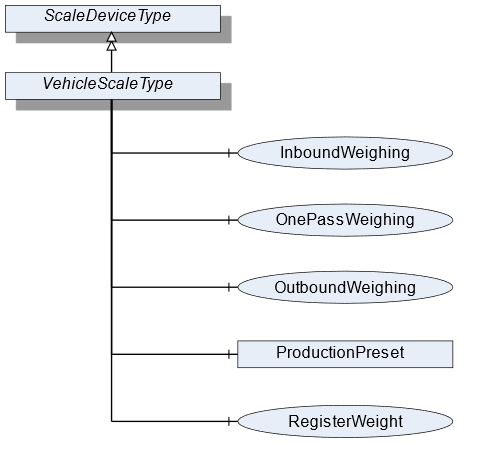
7.48.2 ObjectType Definition
| Attribute | Value | ||||||
| BrowseName | VehicleScaleType | ||||||
| IsAbstract | False | ||||||
| References | NodeClass | BrowseName | DataType | TypeDefinition | ModellingRule | ||
|---|---|---|---|---|---|---|---|
| Subtype of the ScaleDeviceType | |||||||
| 0:HasComponent | Method | InboundWeighing | Optional | ||||
| 0:HasComponent | Method | OutboundWeighing | Optional | ||||
| 0:HasComponent | Method | OnePassWeighing | Optional | ||||
| Conformance Units | |||||||
|---|---|---|---|---|---|---|---|
| Scales VehicleScale |
7.48.3 ObjectType Description
ProductionPreset, which is inherited from ScaleDeviceType shall have instances of VehicleProductType or a subtype in the Products folder.
7.48.4 Method InboundWeighing
The Method triggers an inbound weighing process of a vehicle arriving in an (e.g., filling) area. This is done to determine the present weight of the vehicle. This method may require a vehicle ID to identify the vehicle and to return the measured value. The signature of this Method is specified below. Table 125 and Table 126 specify the Arguments and AddressSpace representation, respectively.
Signature
	InboundWeighing(
		[in]	0:String		VehicleId
);| Argument | Description |
| VehicleId | The ID of the vehicle |
| Attribute | Value | ||||
| BrowseName | InboundWeighing | ||||
| References | NodeClass | BrowseName | DataType | TypeDefinition | ModellingRule |
|---|---|---|---|---|---|
| 0:HasProperty | Variable | InputArguments | Argument[] | 0:PropertyType | Mandatory |
7.48.5 Method OutboundWeighing
Triggers an outbound weighing process of a vehicle leaving an (e.g., filling) area. This is done to determine the total weight of the vehicle. This method may require a vehicle ID to identify the vehicle and to return the measured value. The signature of this Method is specified below. Table 127 and Table 128 specify the Arguments and AddressSpace representation, respectively.
Signature
	OutboundWeighing(
		[in]	0:String	VehicleId
);| Argument | Description |
| VehicleId | The ID of the vehicle |
| Attribute | Value | ||||
| BrowseName | OutboundWeighing | ||||
| References | NodeClass | BrowseName | DataType | TypeDefinition | ModellingRule |
|---|---|---|---|---|---|
| 0:HasProperty | Variable | InputArguments | Argument[] | 0:PropertyType | Mandatory |
7.48.6 Method OnePassWeighing
Triggers an outbound weighing and uses the preset tare to calculate the DeltaWeight (one-pass use case). The signature of this Method is specified below. Table 129 and Table 130 specify the Arguments and AddressSpace representation, respectively.
Signature
	OnePassWeighing(
		[in]	0:String	VehicleId
);| Argument | Description |
| VehicleId | The ID of the vehicle |
| Attribute | Value | ||||
| BrowseName | OnePassWeighing | ||||
| References | NodeClass | BrowseName | DataType | TypeDefinition | ModellingRule |
|---|---|---|---|---|---|
| 0:HasProperty | Variable | InputArguments | Argument[] | 0:PropertyType | Mandatory |
7.49 VehicleProductType Definition
7.49.1 Overview
The VehicleProductType defines the structure of an Object of the VehicleProductType. Figure 60 shows the hierarchical structure and details of the composition. It is formally defined in Table 131.
An Object of the VehicleProductType represents a product of a vehicle product. It defines additional Methods and Properties required for managing the product.
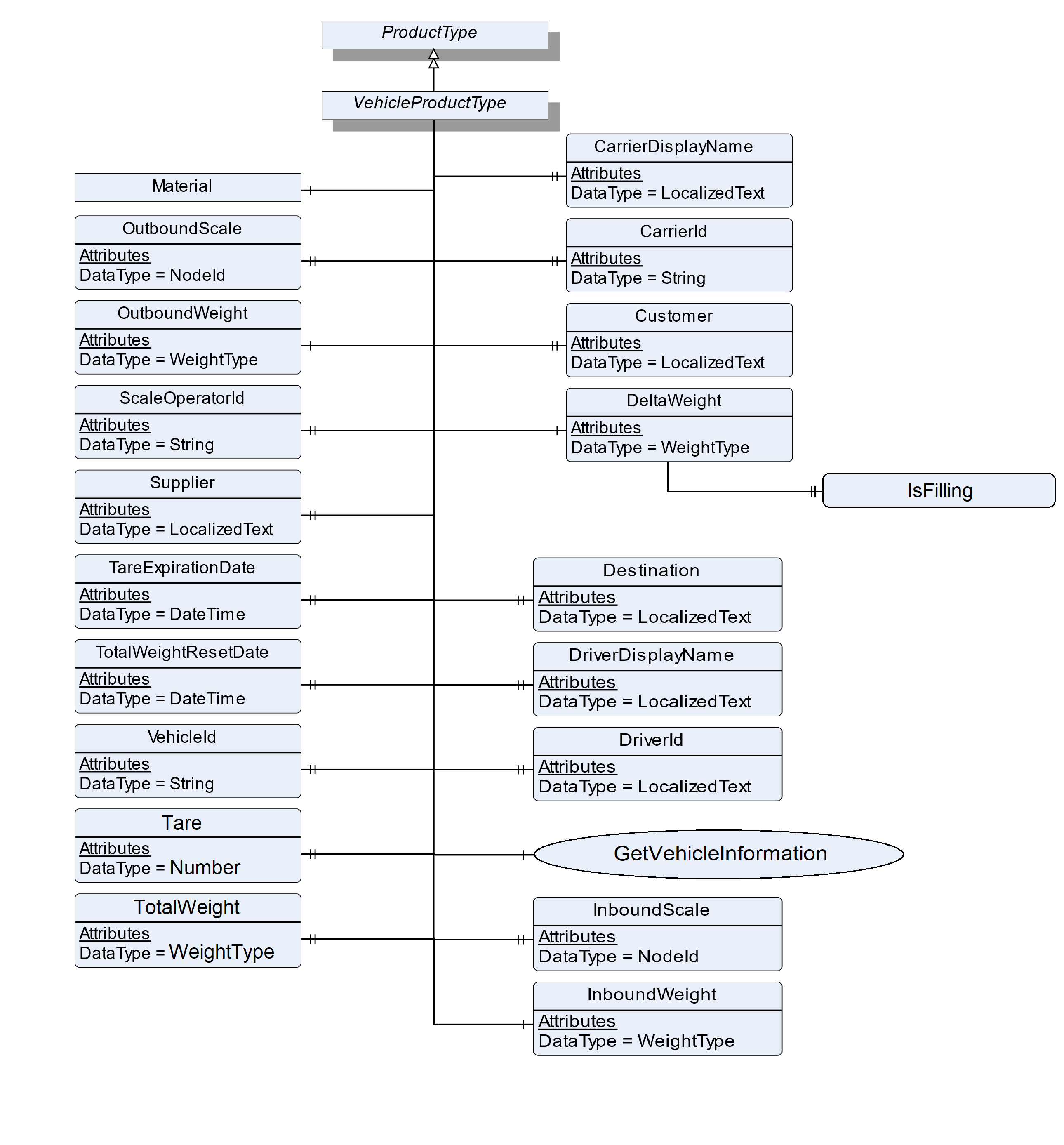
7.49.2 ObjectType Definition
| Attribute | Value | ||||
| BrowseName | VehicleProductType | ||||
| IsAbstract | False | ||||
| References | NodeClass | BrowseName | DataType | TypeDefinition | ModellingRule |
|---|---|---|---|---|---|
| Subtype of the ProductType | |||||
| 0:HasProperty | Variable | CarrierDisplayName | 0:LocalizedText | 0:PropertyType | Optional |
| 0:HasProperty | Variable | CarrierId | 0:String | 0:PropertyType | Optional |
| 0:HasProperty | Variable | Customer | 0:LocalizedText | 0:PropertyType | Optional |
| 0:HasComponent | Variable | DeltaWeight | WeightType | WeightItemType | Mandatory |
| 0:HasProperty | Variable | Destination | 0:LocalizedText | 0:PropertyType | Optional |
| 0:HasProperty | Variable | DriverId | 0:String | 0:PropertyType | Optional |
| 0:HasProperty | Variable | DriverDisplayName | 0:LocalizedText | 0:PropertyType | Optional |
| 0:HasComponent | Method | GetVehicleInformation | Optional | ||
| 0:HasProperty | Variable | InboundScale | NodeId | 0:PropertyType | Optional |
| 0:HasComponent | Variable | InboundWeight | WeightType | WeightItemType | Optional |
| 0:HasComponent | Object | Material | MaterialType | Optional | |
| 0:HasProperty | Variable | OutboundScale | NodeId | 0:PropertyType | Optional |
| 0:HasComponent | Variable | OutboundWeight | WeightType | WeightItemType | Mandatory |
| 0:HasProperty | Variable | ScaleOperatorId | 0:String | 0:PropertyType | Optional |
| 0:HasProperty | Variable | Supplier | 0:LocalizedText | 0:PropertyType | Optional |
| 0:HasProperty | Variable | Tare | 0:Number | 0:PropertyType | Optional |
| 0:HasProperty | Variable | TareExpirationDate | 0:DateTime | 0:PropertyType | Optional |
| 0:HasProperty | Variable | TotalWeight | WeightType | 0:PropertyType | Optional |
| 0:HasProperty | Variable | TotalWeightResetDate | 0:DateTime | 0:PropertyType | Optional |
| 0:HasProperty | Variable | VehicleId | 0:String | 0:PropertyType | Mandatory |
| Conformance Units | |||||
|---|---|---|---|---|---|
| Scales VehicleScale |
7.49.3 ObjectType Description
| InboundWeight | gives the result of the InboundWeighing method in a separate variable. |
InboundScale defines the NodeId of the scale that was used for measuring the InboundWeight in a multi-scale-system
OutboundWeight gives the result of the OutboundWeighing and a CheckWeighing method in a separate variable.
OutboundScale defines the NodeId of the scale that was used for measuring the OutboundWeight in a multi-scale-system.
DeltaWeight gives the loaded or unloaded net weight and is defined by the difference between InboundWeight and OutboundWeight. In case of OutboundWeighing only, the delta is defined by OutboundWeight minus tare.
Tare defines the tare value for the vehicle, used during a one pass transaction. This is different than the tare set on the terminal for regular weighing.
TareExpirationDate is the date on which the tare expires.
TotalWeight is the sum of net weights for the vehicle defined in VehicleId.
TotalWeightResetDate is the date on which the TotalWeight was reset last time.
VehicleId is a unique identifier to determine which vehicle is present (e.g., license plate number or wagon number).
Material is the name of the material.
CarrierDisplayName is the display name of the carrier that is involved in the occurring process.
CarrierId is the number of the carrier that is involved in the occurring process.
DriverDisplayName is the display name of the driver who is involved in the occurring process.
| DriverId | is the number of the driver who is involved in the occurring process. |
Customer is an address of the customer who is involved in the occurring process.
Destination is the address of the destination that is involved in the occurring process.
Supplier is the address of the supplier that is involved in the occurring process.
ScaleOperatorId defines the ID of the operator that is triggering and the operation of the scale.
The components of the VehicleProductType have additional references which are defined in Table 132.
| Source Path | References | NodeClass | BrowseName | DataType | TypeDefinition | Others |
| DeltaWeight | 0:HasProperty | Variable | IsFilling | 0:Boolean | 0:PropertyType | Optional |
DeltaWeight.IsFilling defines if the deltaWeight is a filling weight or an unloading weight.
7.49.4 Method GetVehicleInformation
The Method loads vehicle information of the data store. It requires a unique vehicle ID as input. Table 133 and Table 134 specify the Arguments and AddressSpace representation, respectively.
Signature
	GetVehicleInformation (
		[in]	0:String		VehicleId
);| Argument | Description |
| VehicleId | The ID of the vehicle |
| Attribute | Value | ||||
| BrowseName | SetFeederSpeed | ||||
| References | NodeClass | BrowseName | DataType | TypeDefinition | ModellingRule |
|---|---|---|---|---|---|
| 0:HasProperty | Variable | InputArguments | Argument[] | 0:PropertyType | Mandatory |
7.50 WeighingModuleType Definition
7.50.1 Overview
The WeighingModuleType defines the structure of an Object of the WeighingModuleType. Figure 61 shows the hierarchical structure and details of the composition. It is formally defined in Table 135.
An Object of the WeighingModuleType represents a weighing bridge. It defines additional methods and properties required for managing the weighing bridge. The Object should be a subdevice of another device (e.g., a VehicleScaleDeviceType).
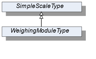
7.50.2 ObjectType Definition
| Attribute | Value | ||||
| BrowseName | WeighingModuleType | ||||
| IsAbstract | False | ||||
| References | NodeClass | BrowseName | DataType | TypeDefinition | ModellingRule |
|---|---|---|---|---|---|
| Subtype of the SimpleScaleType | |||||
| Conformace Units | |||||
|---|---|---|---|---|---|
| Scales WeighingBridge |
7.50.3 ObjectType Description
No additional properties exist.
7.51 MaterialType Definition
7.51.1 Overview
The MaterialType defines the structure of an Object of the MaterialType. Figure 62 shows the hierarchical structure and details of the composition. It is formally defined in Table 136.
An Object of the MaterialType represents a material. It defines additional properties required for managing materials (for example as part of a vehicle product or in a recipe).
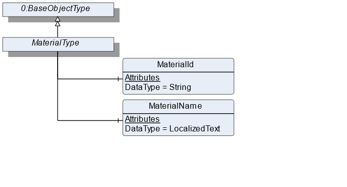
7.51.2 ObjectType Definition
| Attribute | Value | ||||
| BrowseName | MaterialType | ||||
| IsAbstract | False | ||||
| References | NodeClass | BrowseName | DataType | TypeDefinition | ModellingRule |
|---|---|---|---|---|---|
| Subtype of the BaseObjectType defined in OPC 10000-5 | |||||
| 0:HasComponent | Variable | MaterialId | 0:String | BaseDataVariableType | Mandatory |
| 0:HasComponent | Variable | MaterialName | 0:LocalizedText | BaseDataVariableType | Mandatory |
| Conformance Units | |||||
|---|---|---|---|---|---|
| Scales RecipeScale |
7.51.3 ObjectType Description
MaterialId defines a unique identifier for the material.
MaterialName defines a user-readable name of the material.
7.52 FloatingStatisticType Definition
7.52.1 Overview
The FloatingStatisticType defines the structure of an Object of the FloatingStatisticType. Figure 63 shows the hierarchical structure and the details of the composition. It is formally defined in Table 137.
The FloatingStatisticType is a subtype of the StatisticType and also a container for the different statistic values. All Variables are optional so that the statistics can be instantiated in an application-specific way. The FloatingStatisticType is not used directly in the information model but should be used for application-specific statistics. Unlike the StatisticType, the statistic behind the FloatingStatisticType is not time-based, but contains the last NumberOfValues values.
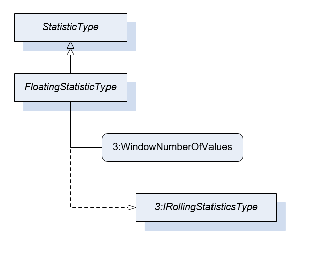
7.52.2 ObjectType Definition
| Attribute | Value | ||||
| BrowseName | FloatingStatisticType | ||||
| IsAbstract | False | ||||
| References | NodeClass | BrowseName | DataType | TypeDefinition | ModellingRule |
|---|---|---|---|---|---|
| Subtype of the StatisticType | |||||
| 0:HasProperty | Variable | 3:WindowNumberOfValues | UInt32 | 0:PropertyType | Mandatory |
| 0:HasInterface | ObjectType | 3:IRollingStatisticsType | |||
| Conformance Units | |||||
|---|---|---|---|---|---|
| Scales ScaleDeviceType |
7.52.3 ObjectType Description
WindowNumberOfValues defines the number of values that are considered for this floating statistic.
7.53 TotalizerType Definition
7.53.1 Overview
The TotalizerType defines the structure of an Object of the TotalizerType. Figure 64 shows the hierarchical structure and details of the composition. It is formally defined in Table 138.
An Object of the TotalizerType contains the sum of the last measurement results (TotalizedValue). Additionally, it defines a Method to reset the totalizer and the addition of the result starts with zero.
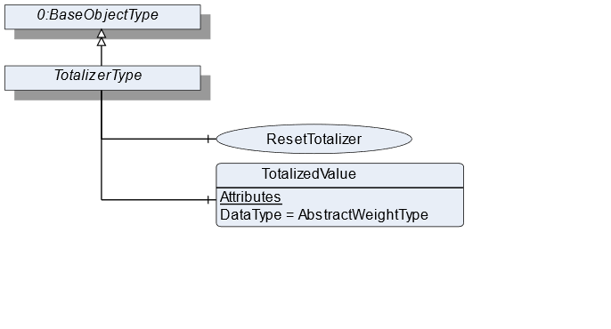
7.53.2 ObjectType Definition
| Attribute | Value | ||||
| BrowseName | TotalizerType | ||||
| IsAbstract | False | ||||
| References | NodeClass | BrowseName | DataType | TypeDefinition | ModellingRule |
|---|---|---|---|---|---|
| Subtype of the BaseObjectType defined in OPC 10000-5 | |||||
| 0:HasComponent | Method | ResetTotalizer | Optional | ||
| 0:HasComponent | Variable | TotalizedValue | AbstractWeightType | MeasuredItemType | Mandatory |
| Conformance Units | |||||
|---|---|---|---|---|---|
| Scales ContinuousScale |
7.53.3 ObjectType Description
TotalizedValue defines a summed up/totalized volume within a period of time.
7.53.4 Method ResetTotalizer
Resets the TotalizedValue of this totalizer Object. Only useful if the reset is not related to a period of time (e.g., over 1h).
Signature
	ResetTotalizer(
	);
8 OPC UA EventTypes
The ScaleEventType and the ScaleAlarmType both contain the NotificationId to identify the event or alarm. Annex C contains all events and alarms defined in this specification. If possible, scales must use these events/alarms. The NotificationId contains the properties EnumValue and ValueAsText (inherit from the MultiStateValueDiscreteType) which contain the value and a short 0:String of the available NotificationIds. This can be a subset of all NotificationIds descripted in Annex C. Additional NotificationIds can be defined in a vendor-specific way. The value of the EnumValue for vendor-specific NotificationIds must be greater than 5000. Each vendor can use an additional ID (vendor-specific NotificationId) to transmit the vendor-specific ID.
8.1 ScaleEventType Definition
8.1.1 Overview
The ScaleEventType is a subtype of the BaseEventType, which it extends with some Properties. It should be used for all Events that are relevant to the weighing technology.
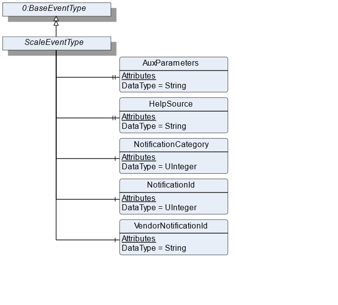
8.1.2 ScaleEventType Definition
| Attribute | Value | ||||
| BrowseName | ScaleEventType | ||||
| IsAbstract | False | ||||
| References | NodeClass | BrowseName | DataType | TypeDefinition | ModellingRule |
|---|---|---|---|---|---|
| Subtype of the BaseEventType defined in OPC 10000-5 | |||||
| 0:HasProperty | Variable | AuxParameters | 0:String[] | 0:PropertyType | Optional |
| 0:HasProperty | Variable | HelpSource | 0:String | 0:PropertyType | Optional |
| 0:HasComponent | Variable | NotificationCategory | 0:UInteger | MultiStateValueDiscreteType | Mandatory |
| 0:HasComponent | Variable | NotificationId | 0:UInteger | MultiStateValueDiscreteType | Mandatory |
| 0:HasComponent | Variable | VendorNotificationId | 0:String | BaseDataVariableType | Optional |
8.1.3 ScaleEventType Description
AuxParameters is an additional text of the event. In the text it is used for the placeholders in the message to the alarm.
HelpSource is a source for additional help information.
NotificationCategory provides the category of the notification. It is used to distinguish if the message is representing an internal event, an information, a dialogue message, an error, a warning, a state or an acknowledgement. Annex C contains all NotificationCategory defined in this specification.
NotificationId provides a unique identifier for the event. Annex C contains all IDs defined in this specification.
VendorNotificationId is a unique vendor-specific identifier for the event.
8.2 ScaleAlarmType Definition
8.2.1 Overview
The ScaleAlarmType is a subtype of the AlarmConditionType and extends it with some Properties. It should be used for all alarms relevant for the weighing technology.
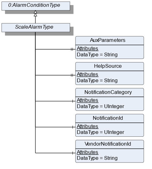
8.2.2 ScaleAlarmType Definition
| Attribute | Value | ||||
| BrowseName | ScaleAlarmType | ||||
| IsAbstract | False | ||||
| References | NodeClass | BrowseName | DataType | TypeDefinition | ModellingRule |
|---|---|---|---|---|---|
| Subtype of the AlarmConditionType defined in OPC 10000-9 | |||||
| 0:HasProperty | Variable | AuxParameters | 0:String[] | 0:PropertyType | Optional |
| 0:HasProperty | Variable | HelpSource | 0:String | 0:PropertyType | Optional |
| 0:HasComponent | Variable | NotificationCategory | 0:UInteger | MultiStateValueDiscreteType | Mandatory |
| 0:HasComponent | Variable | NotificationId | 0:UInteger | MultiStateValueDiscreteType | Mandatory |
| 0:HasComponent | Variable | VendorNotificationId | 0:String | BaseDataVariableType | Optional |
8.2.3 ScaleAlarmType Description
AuxParameters is an additional text of the alarm. In the text it is used for the placeholders in the message to the alarm.
HelpSource is a source for additional help information.
NotificationCategory provides the category of the notification. It is used to distinguish if the message is representing an internal event, an information, a dialogue message, an error, a warning, a state or an acknowledgement. Annex D contains all options for NotificationCategory defined in this specification.
NotificationId provides a unique identifier for the alarm. Annex D contains all IDs defined in this specification.
VendorNotificationId is a unique vendor-specific identifier for the event.
9 OPC UA VariableTypes
9.1 TargetItemType
9.1.1 Overview
The VariableType defines the general characteristics of a TargetItem. A TargetItem is a OPC UA Variable that represents a target value. It is formally defined in Table 141.
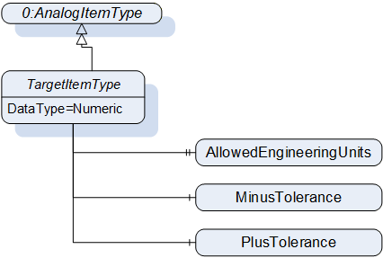
9.1.2 TargetItemType Definition
| Attribute | Value | ||||
| BrowseName | TargetItemType | ||||
| IsAbstract | False | ||||
| ValueRank | -2 | ||||
| DataType | 0:Number | ||||
| References | NodeClass | BrowseName | DataType | TypeDefinition | ModellingRule |
|---|---|---|---|---|---|
| Subtype of the 0:AnalogItemType | |||||
| 0:HasComponent | Variable | MinusTolerance | 0:Number | 0:AnalogUnitType | Optional |
| 0:HasComponent | Variable | PlusTolerance | 0:Number | 0:AnalogUnitType | Optional |
| 0:HasProperty | Variable | AllowedEngineeringUnits | 0:EUInformation[] | 0:PropertyType | Optional |
9.1.3 TargetItemType Description
MinusTolerance contains the lower relative limit of the value in TargetItemType. This may be a percentage or a relative concrete value.
PlusTolerance contains the upper relative limit of the value in TargetItemType. This may be a percentage or a relative concrete value.
AllowedEngineeringUnits contains an array of engineering units that can be handled by the OPC UA server.
9.2 MeasuredItemType
9.2.1 Overview
The VariableType defines the general characteristics of a MeasuredItem. A MeasuredItem is an OPC UA Variable that represents a measured value. It adds some Properties that describe the measurement parameters. It is formally defined in Table 142 and is leaned to the 0:AnalogItemType from OPC 10000-8.
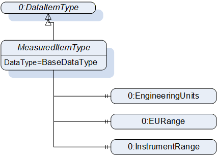
9.2.2 MeasuredItemType Definition
| Attribute | Value | ||||
| BrowseName | MeasuredItemType | ||||
| IsAbstract | False | ||||
| ValueRank | -2 | ||||
| DataType | BaseDataType | ||||
| References | NodeClass | BrowseName | DataType | TypeDefinition | ModellingRule |
|---|---|---|---|---|---|
| Subtype of the DataItemType | |||||
| 0:HasProperty | Variable | 0:EngineeringUnits | 0:EUInformation | 0:PropertyType | Mandatory |
| 0:HasProperty | Variable | 0:EURange | 0:Range | 0:PropertyType | Mandatory |
| 0:HasProperty | Variable | 0:InstrumentRange | 0:Range | 0:PropertyType | Optional |
9.2.3 MeasuredItemType Description
EngineeringUnits specifies the units for the DataItems value (e.g. DEGC, hertz, seconds). The 0:EUInformation type is specified in OPC 10000-8. If the DataType is a WeightItemType or a PrintableWeightItemType it is the unit of net, gross and tare.
EURange is specified like the EURange of the 0:AnalogItemType in OPC 10000-8. If the DataType is a WeightItemType or a PrintableWeightItemType it is the range of net, gross and tare.
InstrumentRange is specified like the EURange of the 0:AnalogItemType in OPC 10000-8.
9.3 WeightItemType
9.3.1 Overview
The VariableType defines the general characteristics of a WeightItem. The WeightItem is a measured weight value with some Properties. The value attribute has the DataType AbstractWeightType (see section 10.1) and contains the value of net, gross and tare. It is formally defined in Table 143.
The value of the WeightItemType is rounded to a verification scale division value if the scale is verified, otherwise it is rounded to the scale division.
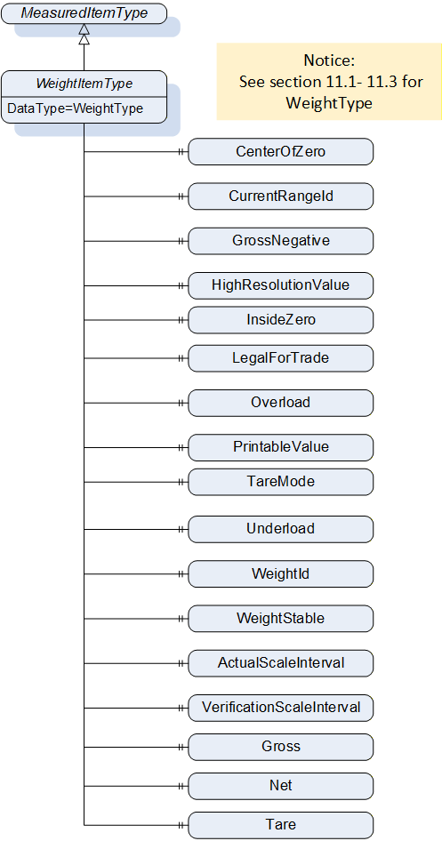
9.3.2 WeightItemType Definition
| Attribute | Value | |||||
| BrowseName | WeightItemType | |||||
| IsAbstract | False | |||||
| ValueRank | -1 | |||||
| DataType | WeightType | |||||
| References | NodeClass | BrowseName | DataType | TypeDefinition | ModellingRule | |
|---|---|---|---|---|---|---|
| Subtype of the MeasuredItemType | ||||||
| 0:HasProperty | Variable | CenterOfZero | 0:Boolean | 0:PropertyType | Optional | |
| 0:HasProperty | Variable | CurrentRangeId | 0:UInt16 | 0:PropertyType | Optional | |
| 0:HasProperty | Variable | GrossNegative | 0:Boolean | 0:PropertyType | Optional | |
| 0:HasProperty | Variable | HighResolutionValue | WeightType | 0:PropertyType | Optional | |
| 0:HasProperty | Variable | InsideZero | 0:Boolean | 0:PropertyType | Optional | |
| 0:HasProperty | Variable | LegalForTrade | 0:Boolean | 0:PropertyType | Optional | |
| 0:HasProperty | Variable | Overload | 0:Boolean | 0:PropertyType | Mandatory | |
| 0:HasProperty | Variable | PrintableValue | PrintableWeightType | 0:PropertyType | Optional | |
| 0:HasProperty | Variable | TareMode | TareMode | 0:PropertyType | Mandatory | |
| 0:HasProperty | Variable | Underload | 0:Boolean | 0:PropertyType | Mandatory | |
| 0:HasProperty | Variable | WeightId | 0:String | 0:PropertyType | Optional | |
| 0:HasProperty | Variable | WeightStable | 0:Boolean | 0:PropertyType | Optional | |
| 0:HasProperty | Variable | Net | 0:Double | 0:PropertyType | Optional | |
| 0:HasProperty | Variable | Gross | 0:Double | 0:PropertyType | Optional | |
| 0:HasProperty | Variable | Tare | 0:Double | 0:PropertyType | Optional | |
9.3.3 WeightItemType Description
CenterOfZero defines if a value is in the vendor-specific tolerance to be zero (e.g., value differs by signal noise).
CurrentRangeId describes the identifier of the current range.
GrossNegative defines if the gross value is negative (e.g., in case of a too high preload).
HighResolutionValue defines the measured value. It is the best resolution the scale can provide in the current configuration.
InsideZero defines if the current measured value is within the valid range for the zero-setting procedure. If this variable is true, the setZero method can be called successfully if the Property does not change.
LegalForTrade defines if the current measured value is legal for trade.
Overload defines if the maximum allowed measured weight value is exceeded.
PrintableValue defines the measured value as 0:String representation without a unit. It is also rounded.
TareMode describes how the tare value is set.
Underload defines if the measued weight falls below the minimum allowed measured weight value.
WeightId defines a unique ID that refers to the verified value of a measurement procedure.
WeightStable defines if the weight is stable and not in movement.
Gross defines the gross value of weight as a 0:Double precision floating point number.
Net defines the net value of weight as a 0:Double precision floating point number.
Tare defines the tare value of weight as a 0:Double precision floating point number.
10 OPC UA DataTypes
10.1 AbstractWeightType
This is an abstract DataType that has the PrintableWeightType and the WeightType as subtypes. Both subtypes have the same structure, but their members have a different DataType. The AbstractWeightType is necessary to be able to define a VariableType with AbstractDataType and to add the actual DataType during instantiation. It is formally defined in
Table 144.
| Attribute | Value | ||
| BrowseName | AbstractWeightType | ||
| IsAbstract | True | ||
| DisplayName | Type | IsArray | Optional |
|---|---|---|---|
| Subtype of Structure defined in OPC 10000-5 | |||
10.2 PrintableWeightType
The DataType defines the general structure of a PrintableWeight. It is formally defined in Table 145.
| Attribute | Value | ||
| BrowseName | PrintableWeightType | ||
| IsAbstract | False | ||
| DisplayName | Type | IsArray | Optional |
|---|---|---|---|
| Subtype of AbstractWeightType | |||
The structure is defined in Table 146.
| Name | Type | Description |
|---|---|---|
| PrintableWeightType | structure | Subtype of the AbstractWeightType defined in this Companion Specification |
Gross | 0:String | Gross defines the gross value of weight in 0:String without a unit. |
Net | 0:String | Net defines the net value of weight in 0:String without a unit. |
Tare | 0:String | Tare defines the tare value of weight in 0:String without a unit. |
10.3 WeightType
The DataType defines the general structure of a weight. It is formally defined in Table 147.
| Attribute | Value | ||
| BrowseName | WeightType | ||
| IsAbstract | False | ||
| DisplayName | Type | IsArray | Optional |
|---|---|---|---|
| Subtype of AbstractWeightType | |||
The structure is defined in Table 148.
| Name | Type | Description |
|---|---|---|
| WeightType | structure | Subtype of the AbstractWeightType defined in this Companion Specification |
Gross | 0:Double | Gross defines the gross value of weight as a 0:Double precision floating point number. |
Net | 0:Double | Net defines the net value of weight as a 0:Double precision floating point number. |
Tare | 0:Double | Tare defines the tare value of weight as a 0:Double precision floating point number. |
10.4 RecipeReportElementType
The DataType defines the general structure of a RecipeReportElementType. The RecipeReportElementType is used to create a RecipeReport (see section 7.31 for a detailed description of a RecipeReport). It is formally defined in Table 149.
| Attribute | Value | ||
| BrowseName | RecipeReportElementType | ||
| IsAbstract | False | ||
| DisplayName | Type | IsArray | Optional |
|---|---|---|---|
| Subtype of Structure defined in OPC 10000-5 | |||
| ReportMessage | 0:LocalizedText | False | False |
| Timestamp | UtcTime | False | False |
The structure is defined in Table 150.
| Name | Type | Description |
|---|---|---|
| RecipeReportElementType | structure | Subtype of the AbstractWeightType defined in this Companion Specification |
ReportMessage | 0:LocalizedText | ReportMessage defines a message that is to be added to the report. |
Timestamp | UtcTime | Timestamp defines the time where the RecipeMessage was generated. |
10.5 RecipeTargetValueType
The DataType defines the general structure of a RecipeTargetValueType. The RecipeTargetValueType is used to define and describe target values for a recipe. It is formally defined in Table 151.
| Attribute | Value | ||
| BrowseName | RecipeTargetValueType | ||
| IsAbstract | False | ||
| DisplayName | Type | IsArray | Optional |
|---|---|---|---|
| Subtype of Structure defined in OPC 10000-5 | |||
The structure is defined in Table 152.
| Name | Type | Description | Optional |
|---|---|---|---|
| RecipeTargetValueType | structure | Subtype of the AbstractWeightType defined in this Companion Specification | |
TargetValueId | UInt32 | TargetValueId defines a unique identifier for the target value within the scale. If the value does exist in the address space, the TargetValueNodeId should be used. | False |
TargetValueNodeId | NodeId | TargetValueNodeId defines the NodeId of the target value within the address space of the scale. If the value does exist in the address space, this value should be used. | True |
TargetValueName | 0:LocalizedText | TargetValueName defines a user-readable name of the target value. | False |
10.6 EqualityAndRelationalOperator
This Enumeration describes the different condition modes for an analog condition. Its representation in the AddressSpace and the possible values are defined in Table 153.
| Name | Value | Description |
| Equal_0 | 0 | The related condition is solved if the two values are equal |
| NotEqual_1 | 1 | The related condition is solved if the two values are not equal |
| LessOrEqualThan_2 | 2 | The related condition is solved if the variable value is less or equal than the reference value |
| GreaterOrEqualThan_3 | 3 | The related condition is solved if the variable value is greater or equal than the reference value |
| LessThan_4 | 4 | The related condition is solved if the variable value is less than the reference value |
| GreaterThan_5 | 5 | The related condition is solved if the variable value is greater than the reference value |
10.7 EdgeOperator
This Enumeration describes the different condition modes for a binary condition. Its representation in the AddressSpace and the possible values are defined in Table 154.
| Name | Value | Description |
| Rising_0 | 0 | The related condition is solved if the variable value is change from false to true. |
| Falling_1 | 1 | The related condition is solved if the variable value is change from true to false. |
10.8 DraftShieldType
This Enumeration describes the different positions of the draft shield. The value "all" accesses all possible DraftShields. Its representation in the AddressSpace and the possible values are defined in Table 155.
| Name | Value | Description |
| Right_0 | 0 | The draft shield that is located right of the scale. |
| Left_1 | 1 | The draft shield that is located left of the scale. |
| Top_2 | 2 | The draft shield that is located on top of the scale. |
| All_3 | 3 | All draft shield of the scale. |
10.9 TareMode
This Enumeration describes how the tare value is set. Its representation in the AddressSpace and the possible values are defined in Table 156.
| Name | Value | Description |
| None_0 | 0 | No tare mode is used |
| MeasuredTare_1 | 1 | The tare value is used. The tare value must be determined before measurement. |
| PresetTare_2 | 2 | The preset tare value is used as tare value. |
| ProportionalTare_3 | 3 | The proportional tare value is used as tare value. |
10.10 ToleranceState
This Enumeration describes the different states of tolerance. Its representation in the AddressSpace and the possible values are defined in Table 157.
| Name | Value | Description |
| In_0 | 0 | The value is within the tolerance range. |
| Under_1 | 1 | The value is underneath the tolerance range. |
| Over_2 | 2 | The value is above the tolerance range |
| UnderOrOver_3 | 3 | The value is underneath or above the tolerance range and is not further determined. |
10.11 RecipeThresholdType
This Structure describes threshold values for recipes. It is formally defined in Table 158.
| Attribute | Value | ||
| BrowseName | RecipeThresholdType | ||
| IsAbstract | False | ||
| DisplayName | Type | IsArray | Optional |
|---|---|---|---|
| Subtype of Structure defined in OPC 10000-5 | |||
The Structure is defined in Table 159.
| Name | Type | Description | Optional |
|---|---|---|---|
| RecipeThresholdType | Structure | Structure describing threshold values for recipes. | |
ThresholdId | UInt32 | ThresholdId defines a unique identifier for the threshold. | False |
ThresholdNodeId | NodeId | ThresholdNodeId defines the NodeId of the threshold within the address space of the scale. If the value does exist in the address space, this value should be used. | True |
ThresholdName | LocalizedText | ThresholdName defines a user-readable name of the threshold. | False |
10.12 RateControlMode
This Enumeration describes the RateControlMode used in the ContinuousScaleType. Its representation in the AddressSpace and the possible values are defined in Table 160.
| Name | Value | Description |
| Gravimetric_0 | 0 | Rate control mode based on weight measurement. |
| Volumetric_1 | 1 | Rate control mode based on volume measurement |
11 ReferenceType
11.1 NextRecipeElementType
This ReferenceType is used to connect different RecipeElements. It defines that the RecipeElement described in the start node must be processed before the RecipeElement described by the target node. It is defined in Table 161.
| Attribute | Value |
| BrowseName | NextRecipeElement |
| InverseName | PreviousRecipeElement |
| Symmetric | False |
| IsAbstract | False |
| Subtype of HierarchicalReferences in OPC 10000-5 | |
12 Profiles and Conformance Units
12.1 Conformance Units
Table 162 defines the corresponding ConformanceUnits for the OPC UA Information Model for Weighing Technology.
| Category | Title | Description |
| Server | Scales AutomaticFillingScale | Supports the handling of the AutomaticFillingScaleType |
| Server | Scales AutomaticWeightPriceLabeler | Supports the handling of the AutomaticWeightPriceLabelerType |
| Server | Scales Catchweigher | Supports the handling of the CatchweigherType |
| Server | Scales Checkweigher | Supports the handling of the CheckweigherType |
| Server | Scales ContinuousScale | Supports the handling of the ContinuousScaleType |
| Server | Scales Display_SI_units | Properties with the DataType 0:EUInformation only contains SI units or units derived from SI units |
| Server | Scales DynamicProductAddressSpace | Supports ProductionPreset handling with dynamic address space (the server dynamically deletes and adds ProductType objects). |
| Server | Scales DynamicRecipeManagement | Supports the possibility to add Recipe via OPC UA methods |
| Server | Scales FileRecipeManagement | Supports the upload of Recipe files |
| Server | Scales FeederModule | Supports the handling of the FeederModuleType and the mandatory components of the types |
| Server | Scales HopperScale | Supports the handling of the HopperScaleType |
| Server | Scales InputArgument_SI_units | The OPC UA server only accepted SI units or units derived from SI units as InputArgument |
| Server | Scales LaboratoryScale | Supports the handling of the LaboratoryScaleType |
| Server | Scales Loss In Weight Scale | Supports the handling of the LossInWeightScaleType |
| Server | Scales ManageProduct | Supports the handling of the methods AddProduct/RemoveProduct |
| Server | Scales PieceCountingScale | Supports the handling of the PieceCountingScaleType |
| Server | Scales PrinterModule | Supports the handling of the PrinterModuleType and the mandatory components of the types |
| Server | Scales ProductType | Supports the handling of the ProductType. |
| Server | Scales RecipeManagment | Supports the handling of the RecipeManagmentType |
| Server | Scales RecipeScale | Supports the handling of the RecipeScaleType |
| Server | Scales ScaleDeviceType | Supports the handling of the ScaleDeviceType and the mandatory components of the type |
| Server | Scales ScaleSystemType | Supports the handling of the ScaleSystemType and the mandatory components of the type |
| Server | Scales SelectProduct | Supports the handling of the methods SelectProduct / DeselectProduct |
| Server | Scales SimpleScale | Supports the handling of the SimpleScaleType |
| Server | Scales StaticProductAddressSpace | The product folder contains at least one product Object , but the objects are static in the address space (it is not possible to add or remove object from the product folder). To change product-related information, a product Object must be overwritten. |
| Server | Scales TotalizingHopperScale | Supports the handling of the TotalizingHopperScaleType |
| Server | Scales VehicleScale | Supports the handling of the VehicleScaleType |
| Server | Scales WeighingBridge | Supports the handling of the WeighingModuleType |
| Server | Scales DataChange | Support the Standard DataChange Subscription Facet of OPC UA 10000-7 |
This section defines the corresponding Profiles and Conformance Units for the OPC UA Information Model for Weighing Technology. Profiles are named groupings of Conformance Units. Facets are Profiles that will be combined with other Profiles to define the complete functionality of an OPC UA Server or Client.
12.2 Profiles
12.2.1 Profile list
Table 163 lists all Profiles defined in this document and defines their URIs.
12.2.2 Server Facets
12.2.2.1 Overview
The following sections specify the Facets available for Servers that implement the Weighing Technology companion specification. Each section defines and describes a Facet or Profile.
12.2.2.2 Scales V2 Base Scale Server Facet
Table 164 defines a Facet for servers that implement a simple scale device.
| Group | Conformance Unit / Profile Title | Optional/ Mandatory |
| Profile | 0:ComplexType Server Facet | M |
| Profile | 2:BaseDevice_Server_Facet | M |
| Profile | 4: Machinery Machine Identification Server Facet | M |
| PackML | 5:PackML State Information | O |
| Scales | ScaleDeviceType | M |
| Machinery | 4:Machinery Building Block Organization | O |
| Machinery | 4:Machinery MachineryItemState | O |
| Machinery | 4:Machinery OperationMode | O |
12.2.2.3 Scales V2 Scale System Server Facet
Table 165 defines a Facet for servers that implement a multi scale device with a ScaleSystemType. Figure 70 shows an example of a scale system with two scales as subdevices: a catchweigher and a checkweigher.
| Group | Conformance Unit / Profile Title | Optional/ Mandatory |
| Profile | 0:ComplexType Server Facet | M |
| Profile | 2:BaseDevice_Server_Facet | M |
| Profile | 4: Machinery Machine Identification Server Facet | M |
| Scales | ScalesSystemType | M |
| Machinery | 4:Machinery Building Block Organization | O |
| Machinery | 4:Machinery MachineryItemState | O |
| Machinery | 4:Machinery OperationMode | O |
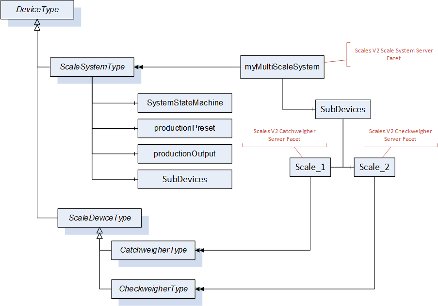
12.2.2.4 Scales V2 Feeder Module Server Facet
Table 166 defines a Facet for servers that implement feeder subdevices.
| Group | Conformance Unit / Profile Title | Optional/ Mandatory |
| Profile | 2:BaseDevice_Server_Facet | M |
| Profile | 4: Machinery Machine Identification Server Facet | M |
| Scales | Scales FeederModule | M |
| Machinery | 4:Machinery Building Block Organization | O |
| Machinery | 4:Machinery MachineryItemState | O |
| Machinery | 4:Machinery OperationMode | O |
12.2.2.5 Scales V2 Printer Module Server Facet
Table 167 defines a Facet for servers that implement printer subdevices.
| Group | Conformance Unit / Profile Title | Optional/ Mandatory |
| Profile | 2:BaseDevice_Server_Facet | M |
| Profile | 4: Machinery Machine Identification Server Facet | M |
| Scales | Scales PrinterModule | M |
| Machinery | 4:Machinery Building Block Organization | O |
| Machinery | 4:Machinery MachineryItemState | O |
| Machinery | 4:Machinery OperationMode | O |
12.2.2.6 Scales V2 Minimal Production Preset Server Facet
| Group | Conformance Unit / Profile Title | Optional/ Mandatory |
| Scales | Scales DataChange | O |
| Scales | Scales ProductType | M |
| Scales | Scales StaticProductAddressSpace | M |
| Scales | Scales SelectProduct | O |
12.2.2.7 Scales V2 Full Production Preset Server Facet
Table 169 defines a Facet for servers that implement a full production solution. This solution requires a dynamic address space. For each product a product Object will be created with the method AddProduct.
| Group | Conformance Unit / Profile Title | Optional/ Mandatory |
| Scales | Scales DataChange | O |
| Scales | Scales ProductType | M |
| Scales | Scales DynamicProductAddressSpace | M |
| Scales | Scales SelectProduct | M |
| Scales | Scales ManageProduct | M |
12.2.2.8 Scales V2 International System of Units Server Facet
Table 170 defines a Facet for servers that use only SI units or units derived from SI units.
| Group | Conformance Unit / Profile Title | Optional/ Mandatory |
| Scales | Scales Display_SI_units | M |
| Scales | Scales InputArgument_SI_units | M |
12.2.2.9 Scales V2 AutomaticFillingScale Server Facet
Table 171 defines a Facet for servers that implement an AutomaticFillingScale.
| Group | Conformance Unit / Profile Title | Optional/ Mandatory |
| Profile | Scales V2 Base Scale Server Facet | M |
| Scales | Scales AutomaticFillingScale | M |
12.2.2.10 Scales V2 Catchweigher Server Facet
Table 172 defines a Facet for servers that implement a catchweigher.
| Group | Conformance Unit / Profile Title | Optional/ Mandatory |
| Scales | Scales Catchweigher | M |
| Profile | Scales V2 Base Scale Server Facet | M |
12.2.2.11 Scales V2 AutomaticWeightPriceLabeler Server Facet
Table 173 defines a Facet for servers that implement an automatic weight-price labeler.
| Group | Conformance Unit / Profile Title | Optional/ Mandatory |
| Scales | Scales AutomaticWeightPriceLabeler | M |
| Profile | Scales V2 Base Scale Server Facet | M |
12.2.2.12 Scales V2 Checkweigher Server Facet
Table 174 defines a Facet for servers that implement a checkweigher.
| Group | Conformance Unit / Profile Title | Optional/ Mandatory |
| Scales | Scales Checkweigher | M |
| Profile | Scales V2 Base Scale Server Facet | M |
12.2.2.13 Scales V2 Continuous Scale Server Facet
Table 175 defines a Facet for servers that implement a continuous scale.
| Group | Conformance Unit / Profile Title | Optional/ Mandatory |
| Scales | Scales ContinuousScale | M |
| Profile | Scales V2 Base Scale Server Facet | M |
12.2.2.14 Scales V2 LossInWeight Scale Server Facet
Table 176 defines a Facet for servers that implement a loss in weight scale.
| Group | Conformance Unit / Profile Title | Optional/ Mandatory |
| Scales | Scales Loss In Weight Scale | M |
| Profile | Scales V2 Base Scale Server Facet | M |
12.2.2.15 Scales V2 PieceCountingScale Server Facet
Table 177 defines a Facet for servers that implement a piece counting scale.
| Group | Conformance Unit / Profile Title | Optional/ Mandatory |
| Scales | Scales PieceCountingScale | M |
| Profile | Scales V2 Base Scale Server Facet | M |
12.2.2.16 Scales V2 RecipeScale Server Facet
Table 178 defines a Facet for servers that implement a recipe scale.
| Group | Conformance Unit / Profile Title | Optional/ Mandatory |
| Scales | Scales RecipeScale | M |
| Scales | Scales RecipeManagment | O |
| Scales | Scales DynamicRecipeManagement | O |
| Scales | Scales FileRecipeManagement | O |
| Profile | Scales V2 Base Scale Server Facet | M |
12.2.2.17 Scales V2 Totalizing Hopper Scale Server Facet
Table 179 defines a Facet for servers that implement a totalizing hopper scale.
| Group | Conformance Unit / Profile Title | Optional/ Mandatory |
| Scales | Scales TotalizingHopperScale | M |
| Profile | Scales V2 Base Scale Server Facet | M |
12.2.2.18 Scales V2 Simple Scale Server Facet
Table 180 defines a Facet for servers that implement a simple scale.
| Group | Conformance Unit / Profile Title | Optional/ Mandatory |
| Scales | Scales SimpleScale | M |
| Profile | Scales V2 Base Scale Server Facet | M |
12.2.2.19 Scales V2 Laboratory Scale Server Facet
Table 181 defines a Facet for servers that implement a laboratory scale.
| Group | Conformance Unit / Profile Title | Optional/ Mandatory |
| Scales | Scales LaboratoryScale | M |
| Profile | Scales V2 Base Scale Server Facet | M |
12.2.2.20 Scales V2 Hopper Scale Server Facet
Table 182 defines a Facet for servers that implement a hopper scale.
| Group | Conformance Unit / Profile Title | Optional/ Mandatory |
| Scales | Scales HopperScale | M |
| Profile | Scales V2 Base Scale Server Facet | M |
12.2.2.21 Scales V2 Weighing Bridge Server Facet
Table 183 defines a Facet for servers that implement a weighing module.
| Group | Conformance Unit / Profile Title | Optional/ Mandatory |
| Scales | Scales WeighingBridge | M |
| Profile | Scales V2 Base Scale Server Facet | M |
12.2.2.22 Scales V2 Vehicle Scale Server Facet
Table 184 Table 183 defines a Facet for servers that implement a vehicle scale.
| Group | Conformance Unit / Profile Title | Optional/ Mandatory |
| Scales | Scales VehicleScale | M |
| Profile | Scales V2 Base Scale Server Facet | M |
13 Namespaces
13.1 Namespace Metadata
Table 185 defines the namespace metadata for this specification. The Object namespace metadata is used to provide version information for the namespace and an indication about static Nodes. Static Nodes are identical for all Attributes in all Servers, including the Value Attribute. See OPC 10000-5 for more details.
The information is provided as Object of the type NamespaceMetadataType. This Object is a component of the Namespace Object that is part of the Server Object. The NamespaceMetadataType ObjectType and its Properties are defined in OPC 10000-5.
The version information is also provided as part of the ModelTableEntry in the UANodeSet XML file. The UANodeSet XML schema is defined in OPC 10000-6.
| Attribute | Value | ||
| BrowseName | http://opcfoundation.org/UA/Scales/V2/ | ||
| Property | DataType | Value | |
|---|---|---|---|
| NamespaceUri | String | http://opcfoundation.org/UA/Scales/V2/ | |
| NamespaceVersion | String | 2.00 | |
| NamespacePublicationDate | DateTime | 2025-03-01 | |
| IsNamespaceSubset | Boolean | False | |
| StaticNodeIdTypes | IdType [] | 0 | |
| StaticNumericNodeIdRange | NumericRange [] | ||
| StaticStringNodeIdPattern | String | ||
13.2 Handling of OPC UA Namespaces
Namespaces are used by OPC UA to create unique identifiers across different naming authorities. The Attributes NodeId and BrowseName are identifiers. A Node in the UA AddressSpace is unambiguously identified using a NodeId. Unlike NodeIds, the BrowseName cannot be used to unambiguously identify a Node. Different Nodes may have the same BrowseName. They are used to build a browse path between two Nodes or to define a standard Property.
Servers may often choose to use the same namespace for the NodeId and the BrowseName. However, if they want to provide a standard Property, its BrowseName shall have the namespace of the standard body although the namespace of the NodeId reflects something else, for example the EngineeringUnits Property. All NodeIds of Nodes not defined in this specification shall not use the standard namespaces.
Table 186 provides a list of mandatory and optional namespaces used in a weighing technology OPC UA server.
| NamespaceURI | Description | Use |
| http://opcfoundation.org/UA/ | Namespace for NodeIds and BrowseNames defined in the OPC UA specification. This namespace shall have namespace index 0. | Mandatory |
| Local Server URI | Namespace for nodes defined in the local server. This may include types and instances used in an AutoID Device represented by the server. This namespace shall have namespace index 1. | Mandatory |
| http://opcfoundation.org/UA/DI/ | Namespace for NodeIds and BrowseNames defined in OPC 10000-100. The namespace index is server specific. | Mandatory |
| http://opcfoundation.org/UA/IA/ | Namespace for NodeIds and BrowseNames defined in OPC 10000-200. The namespace index is server specific. | Mandatory |
| http://opcfoundation.org/UA/Machinery/ | Namespace for NodeIds and BrowseNames defined in OPC 40001-1. The namespace index is Server specific. | Mandatory |
| http://opcfoundation.org/UA/PackML/ | Namespace for NodeIds and BrowseNames defined in OPC 30050. The namespace index is Server specific. | Mandatory |
| http://opcfoundation.org/UA/Scales/V2/ | Namespace for NodeIds and BrowseNames defined in this specification. The namespace index is server specific. | Mandatory |
| Vendor-specific types and instances | A server may provide vendor-specific types like types derived from ObjectTypes defined in this specification or vendor-specific instances of those types in a vendor-specific namespace. | Optional |
Table 187 provides a list of namespaces and their index used for BrowseNames in this specification. The default namespace of this specification is not listed since all BrowseNames without prefix use this default namespace.
| NamespaceURI | Namespace Index | Example |
| http://opcfoundation.org/UA/ | 0 | 0:EngineeringUnits |
| http://opcfoundation.org/UA/DI/ | 2 | 2:DeviceRevision |
| http://opcfoundation.org/UA/IA/ | 3 | 3:StartTime |
| http://opcfoundation.org/UA/Machinery/ | 4 | 4:MachineIdentificationType |
| http://opcfoundation.org/UA/PackML/ | 5 | 5:PackMLBaseStateMachineType |
Annex A Weighing Technology Namespace and mappings (Normative)
A.1 NodeSet and Supplementary Files for Weighing Technology Information Model
The Weighing Technology Information Model is identified by the following URI:
http://opcfoundation.org/UA/Scales/V2/
Documentation for the NamespaceUri can be found here.
The NodeSet associated with this version of specification can be found here:
https://reference.opcfoundation.org/nodesets/?u=http://opcfoundation.org/UA/Scales/V2/&v=2.00&i=1
The NodeSet associated with the latest version of the specification can be found here:
https://reference.opcfoundation.org/nodesets/?u=http://opcfoundation.org/UA/Scales/V2/&i=1
The supplementary files associated with this version of specification can be found here:
https://reference.opcfoundation.org/nodesets/?u=http://opcfoundation.org/UA/Scales/V2/&v=2.00&i=2
The supplementary files associated with the latest version of the specification can be found here:
https://reference.opcfoundation.org/nodesets/?u=http://opcfoundation.org/UA/Scales/V2/&i=2
Annex B Recipe and Recipe Management (Normative)
B.1 What is a Recipe?
A recipe in the context of this specification is a description of single steps (called recipe elements) that can be performed sequentially and/or in parallel. Within a recipe there can be different types of steps. This specification defines the following recipe steps:
user instruction
conditional sleep
activation
The list of defined steps is not complete and can be extended vendor-specifically or in later versions.
B.2 Structures of Recipes for Weighing Technology
In this chapter, the structure of a recipe will be described in more detail. Each recipe contains a start and an end element as well as many recipe steps and dependencies between the individual steps. The following sequences must be modeled for typical scale applications:
A recipe element is activated when another recipe element is finished (sequential).
Several steps can be activated in parallel (forking). If several recipe elements are activated, the scale must decide whether they can be started independent of each other ("real simultaneous") or must be processed sequentially ("quasi-simultaneous"). The scale does not guarantee a sequential sequence.
A step is not activated until several other steps have been completed (joining).
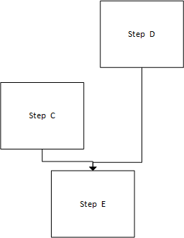
A recipe represents a directed graph without cycles. A recipe element A may therefore only refer to a recipe element B if there is no path between the start and A where B is an element.
Annex C Event and Alarm Categories (Normative)
Table 188 contains the defined NotificationCategories which can be used for classification of the alarms or events.
| Name | ValueAsText | EnumValue | Description |
| Others | OTHERS | 0 | Notifications that are not related to another class |
| Process | PROCESS | 1 | Notification that are related to the weighing or value-added process |
| System | SYSTEM | 2 | Notifications that are related to scale system, like date errors or hardware errors |
| Memory | MEMORY | 3 | Notification that are related to the memory. |
| Component | COMPONENT | 4 | Notifications that are related a component of the scale |
| Communication | COMMUNICATION | 5 | Notification that are related a communication system like a field bus error |
| WeighingBridgeModule | WEIGHING_MODULE | 6 | Notifications that are related to the weighingBridgeModule |
| Environment | ENVIRONMENT | 7 | Notification that are related to the environment |
Table 189 contains the defined NotificationIds.
| NotificationId - ValueAsText | NotificationId - EnumValue | NotificationCategory | Description |
| NotificationIds that are not related to another class | |||
| GENERAL_OTHER_FAULT | 1 | OTHERS | A general fault that not related to another NotificationCategory |
| NotificationIds related to the Process | |||
| GENERAL_PROCESS_FAULT | 100 | PROCESS | A general fault that is related to the process. This fault should be used if no other fault related to the process exist |
| PRODUCT_DATA_FAULT | 101 | PROCESS | Inconsistent or incomplete product data |
| LABEL_FAULT | 102 | PROCESS | General label error, limited only to the label |
| BAD_PACK | 103 | PROCESS | Package sorted out |
| CRITICAL_EXTERNAL_FAULT | 104 | PROCESS | Critical Alarm from external Device (like metal detector, external storage etc.) |
| REJECT_VERIFICATION_FAULT | 105 | PROCESS | Item reject process not successful |
| CONTAMINATION_DETECT | 106 | PROCESS | Machine rejects due to a detected contamination (x-ray / MD) |
| VISION_INSPECTION | 107 | PROCESS | Machine rejects due to a wrong vision of code inspection |
| CONSECUTIVE_REJECTS | 108 | PROCESS | Machine stop due to consecutive rejects |
| EMERGENCY_STOP | 109 | PROCESS | Emergency stop is active and not acknowledged yet |
| NotificationIds related to the System | |||
| GENERAL_SYSTEM_FAULT | 200 | SYSTEM | A general fault that is related to the system. This fault should be used if no other fault related to the system exist |
| LOGIN_FAULT | 201 | SYSTEM | Unsuccessful login event |
| NotificationIds related to the Memory | |||
| GENERAL_MEMORY_FAULT | 300 | MEMORY | A general fault that is related to the memory |
| NotificationIds related to the Component of a scale | |||
| GENERAL_COMPONENT_FAULT | 400 | COMPONENT | A general fault that is related to the component of a system. This fault should be used if no other fault related to the component exist |
| PRINTER_FAULT | 401 | COMPONENT | General printer fault, which prevents at least one printer from printing |
| FEEDER_FAULT | 402 | COMPONENT | General Feeder error, but feeder is running yet |
| FEEDER_NOT_RUNNING | 403 | COMPONENT | Special Alarm to indicate "feeder not running" state |
| NotificationIds related to the Communication of a scale | |||
| GENERAL_COMMUNICATION_FAULT | 500 | COMMUNICATION | A general fault that is related to the communication system. This fault should be used if no other fault related to the communication exist |
| NotificationIds related to the weighing module | |||
| GENERAL_WEIGHING_MODULE_FAULT | 600 | WEIGHING_MODULE | A general fault that is related to the weighing module This fault should be used if no other fault related to the weighing module exist |
| OVERLOAD_FAULT | 601 | WEIGHING_MODULE | Scale overloaded. That means the maximum allowed measured weight value is exceeded and the Overload property of a WeightItemType is true. |
| OUT_OF_RANGE_FAULT | 602 | WEIGHING_MODULE | Weight out of (approved) range, but not yet overload |
| UNDERLOAD_FAULT | 603 | WEIGHING_MODULE | Scale underloaded. That means the minimum allowed measured weight value is gone below. |
| TARE_SETTING_FAULT | 604 | WEIGHING_MODULE | Error during tare setting |
| ZERO_SETTING_FAULT | 605 | WEIGHING_MODULE | Error during zero setting |
| REZERO_REQUIRED | 606 | WEIGHING_MODULE | Load cell re-zeroing is required |
| NotificationIds related to the Environment | |||
| GENERAL_ENVIRONMENT_FAULT | 700 | ENVIRONMENT | A general fault that is related to the environment system. This fault should be used if no other fault related to the environment exist |
| POWER_SUPPLY_FAULT | 701 | ENVIRONMENT | General faulty power supply |
| AIR_PRESSURE_FAULT | 702 | ENVIRONMENT | General faulty air pressure |
Annex D Example (Informative)
D.1 Example 1 - Simple Scale
Figure 74 shows the address space of an OPC UA Server of a simple scale. The Object mySimpleScale represents the scale. The Object has the ObjectType SimpleScaleType and all mandatory nodes. The variable CurrentWeight has the DataType WeightType, which contains the gross, net and tare value.
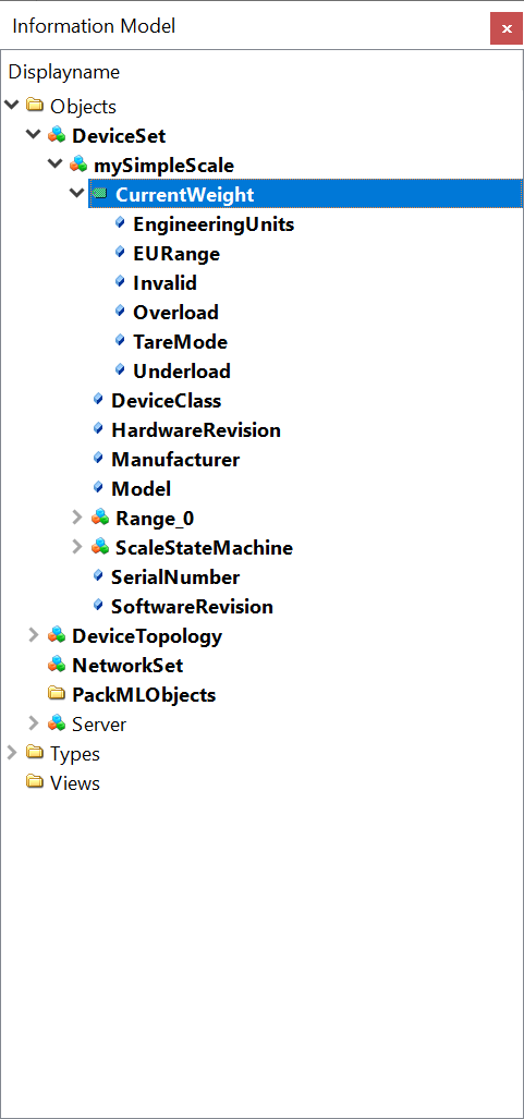
Agreement of Use
COPYRIGHT RESTRICTIONS
This document is provided "as is" by the OPC Foundation and the VDMA
Right of use for this specification is restricted to this specification and does not grant rights of use for referred documents.
Right of use for this specification will be granted without cost.
This document may be distributed through computer systems, printed or copied as long as the content remains unchanged, and the document is not modified.
OPC Foundation and VDMA do not guarantee usability for any purpose and shall not be made liable for any case using the content of this document.
The user of the document agrees to indemnify OPC Foundation and VDMA and their officers, directors and agents harmless from all demands, claims, actions, losses, damages (including damages from personal injuries), costs and expenses (including attorneys' fees) which are in any way related to activities associated with its use of content from this specification.
The document shall not be used in conjunction with company advertising, shall not be sold or licensed to any party.
The intellectual property and copyright are solely owned by the OPC Foundation and the VDMA.
PATENTS
The attention of adopters is directed to the possibility that compliance with or adoption of OPC or VDMA specifications may require use of an invention covered by patent rights. OPC Foundation or VDMA shall not be responsible for identifying patents for which a license may be required by any OPC or VDMA specification, or for conducting legal inquiries into the legal validity or scope of those patents that are brought to its attention. OPC or VDMA specifications are prospective and advisory only. Prospective users are responsible for protecting themselves against liability for infringement of patents.
WARRANTY AND LIABILITY DISCLAIMERS
WHILE THIS PUBLICATION IS BELIEVED TO BE ACCURATE, IT IS PROVIDED "AS IS" AND MAY CONTAIN ERRORS OR MISPRINTS. THE OPC FOUDATION NOR VDMA MAKES NO WARRANTY OF ANY KIND, EXPRESSED OR IMPLIED, WITH REGARD TO THIS PUBLICATION, INCLUDING BUT NOT LIMITED TO ANY WARRANTY OF TITLE OR OWNERSHIP, IMPLIED WARRANTY OF MERCHANTABILITY OR WARRANTY OF FITNESS FOR A PARTICULAR PURPOSE OR USE. IN NO EVENT SHALL THE OPC FOUNDATION NOR VDMA BE LIABLE FOR ERRORS CONTAINED HEREIN OR FOR DIRECT, INDIRECT, INCIDENTAL, SPECIAL, CONSEQUENTIAL, RELIANCE OR COVER DAMAGES, INCLUDING LOSS OF PROFITS, REVENUE, DATA OR USE, INCURRED BY ANY USER OR ANY THIRD PARTY IN CONNECTION WITH THE FURNISHING, PERFORMANCE, OR USE OF THIS MATERIAL, EVEN IF ADVISED OF THE POSSIBILITY OF SUCH DAMAGES.
The entire risk as to the quality and performance of software developed using this specification is borne by the user of this specification.
RESTRICTED RIGHTS LEGEND
This Specification is provided with Restricted Rights. Use, duplication, or disclosure by the U.S. government is subject to restrictions as set forth in (a) this Agreement pursuant to DFARs 227.7202-3(a); (b) subparagraph (c)(1)(i) of the Rights in Technical Data and Computer Software clause at DFARs 252.227 -7013; or (c) the Commercial Computer Software Restricted Rights clause at FAR 52.227-19 subdivision (c)(1) and (2), as applicable. Contractor / manufacturer are the OPC Foundation, 16101 N. 82nd Street, Suite 3B, Scottsdale, AZ, 85260 -1830.
TRADEMARKS
Most computer and software brand names have trademarks or registered trademarks. The individual trademarks have not been listed here.
GENERAL PROVISIONS
Should any provision of this Agreement be held to be void, invalid, unenforceable, or illegal by a court, the validity and enforceability of the other provisions shall not be affected thereby.
This Agreement shall be governed by and construed under the laws of Germany.
This Agreement embodies the entire understanding between the parties with respect to and supersedes any prior understanding or agreement (oral or written) relating to, this specification.
This Agreement embodies the entire understanding between the parties with respect to, and supersedes any prior understanding or agreement (oral or written) relating to, this specification.
Version 2.00 Changes
The following table gives an overview of the changes in this version of the specification.
| Summary | Changes |
| Integration of StateMachine from CS Machinery | Addition of 4:MachineryItemState, 4:MachineryOperationMode and 4:MachineryBuildingBlocks to 7.1 FeederModuleType 7.2 PrinterModuleType 7.3 ScaleSystemType and 7.4 ScaleDeviceType |
| ProductionOutput added in ScaleDeviceType - 7.4.2 | ProductionOutput added in ScaleDeviceType - 7.4.2 |
| Numerous changes from AnalogItemType to AnalogUnitType | BREAKING CHANGE 7.1 MaximumFeederSpeed, MinimalFeederSpeed 7.2 LabelLength, LabelWidth 7.6 Tare, Throughput 7.8 PresetTare 7.9 Deviation 7.12 PresetHeight, PresetLength, PresetWidth 7.13 MeasuredHeight, MeasuredLength, MeasuredVolume, MeasuredWidth 7.19 GiveAway 7.20 MaxValue, MeanValue, MinValue, PercentageOfTotal, StandardDeviation, SumWeight 7.23 LowerLimit, UpperLimit 7.24 MaxFlowRate, MinFlowRate 7.25 MaterialDensity 7.34 TargetValue 7.47 LevelMax, LevelMin 9.1.2 MinusTolerance, PlusTolerance |
| LowerToleranceLimit1 and LowerToleranceLimit2 added in CheckweigherProductType - 7.18.2 | LowerToleranceLimit1 and LowerToleranceLimit2 added in CheckweigherProductType - 7.18.2 |
| Components added/changed in ContinuousScaleType | BREAKING CHANGE 7.24 MaxFlowRate and MinFlowRate changed to optional added ControlMagnitude, Speed, RateControlMode, TargetFlowRate and Load removed HopperWeight |
| Components added in LossInWeightScaleType | BREAKING CHANGE 7.26 added mandatory HopperFillLevel and HopperWeight added BinWeight |
| Change of TypeDefinition of accepted and rejected statistics in CheckweigherStatisticType | BREAKING CHANGE 7.19 changed <PackagesRejectedBySystem> and TotalPackagesRejected to RejectedStatisticCounterType changed TotalPackagesAccepted to AcceptedStatisticCounterType |
| Changed TypeDefinition of ThresholdValueNodeId in ConditionSleepType | 7.35 TypeDefinition of ThresholdValueNodeId in ConditionSleepType changed to BaseDataVariableType |
| Integration of Statistics from CS Industrial Automation | BREAKING CHANGE Using the appropriate subtype of 3:IStatisticsType and the 3:HasStatisticComponent Reference in 7.6 StatisticType 7.19 CheckweigherStatisticType 7.20 StatisticCounterType 7.52 FloatingStatisticType |
| Changed Machinery Identification to Mandatory | BREAKING CHANGE Change of 2:Identification to Mandatory in 7.1 FeederModuleType |
| Reverted mandatory Identification parameters | BREAKING CHANGE Reverted 2:DeviceClass, 2:HardwareRevision, 2:Manufacturer, 2:Model, 2:SerialNumber and 2:SoftwareRevision not to be overridden to mandatory in 7.3 ScaleSystemType and |