5.3 Mapping Example
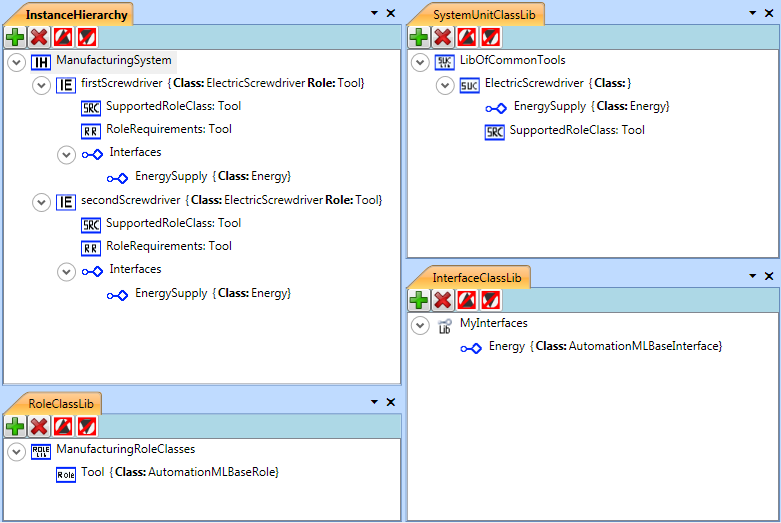
Figure 14 depicts the tree structure of an AutomationML example. This example shows a simple AutomationML document (version 2.0) which contains:
one InstanceHierarchy with InternalElements
one SystemUnitClassLib with one SystemUnitClass
one RoleClassLib with one RoleClass and
one InterfaceClassLib with one InterfaceClass.
The elements in this example are designed to model some aspects of a manufacturing system. The RoleClassLib contains a RoleClass to characterize a system component as a ’Tool’. The InterfaceClassLib contains an InterfaceClass which models the energy supply of any tool. The SystemUnitClassLib contains a class representing an electric screwdriver. The InstanceHierarchy describes a manufacturing system containing the two screwdrivers in the system.
The used AutomationML-Libraries (AutomationMLBaseRoleClassLibrary and AutomationMLInterfaceClassLibrary) are stored in separated CAEX files and are included via external references.
Annex A contains the XML text of the example in AutomationML.
The example shown in Figure 14 will now be redefined within OPC UA. Annex A contains the XML text of the example in OPC UA.
Figure 15 depicts the main structure of the example including the folder objects for the organization of the address space. The used graphical notation is defined by the OPC Foundation and is explained in chapter 4.2.2. It includes the OPC UA Objects used to organize the address space structure which are explained in chapter 6.4.1.
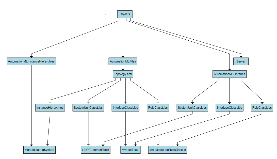
Figure 16 depicts the role classes of the example. It includes the inheritance structure of the roles. In the RoleClassLibs ‘ManufacturingRoleClasses’ the RoleClass ‘Tool’ is included.
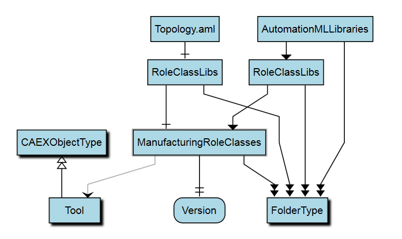
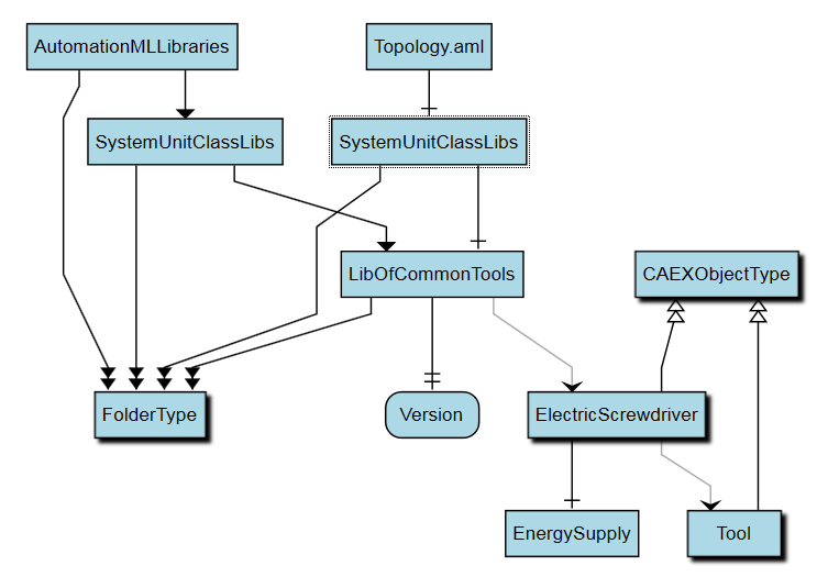
Figure 17 shows the SystemUnitClasses. The SystemUnitClassLib ‘LibOfCommonTools’ includes a SystemUnitClass ‘ElectricScrewdriver’ with reference to the role ‘Tool’. This SystemUnitClass includes an ExternalInterface ‘EnergySupply’.
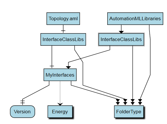
In Figure 18 you can find the InterfaceClassLib ‘MyInterfaces’ including the InterfaceClass ‘Energy’.
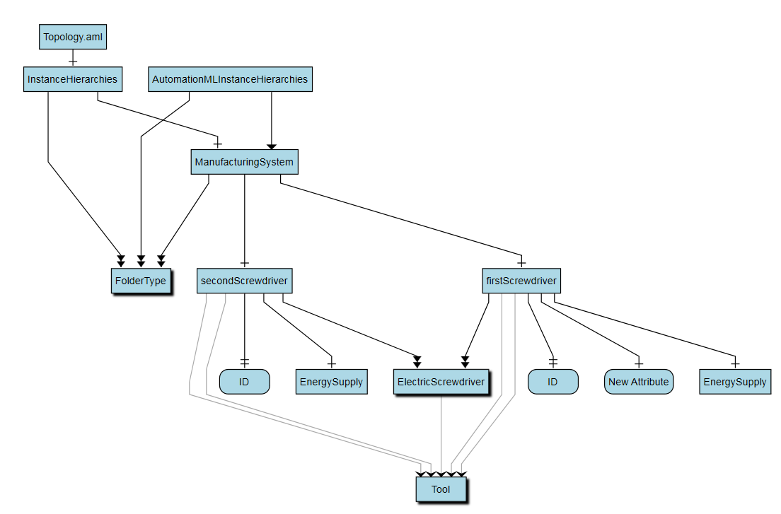
The mapping of the InstanceHierarchy is shown in Figure 19. The File ‘Topology.aml’ includes the InstanceHierarchy ‘ManufacturingSystem’ which includes two InternalElements ‘firstScrewdriver’ and ‘secondScrewdriver’. They are derived from the SystemUnitClass ‘ElectricScrewdriver’ and inherit its structure and elements, such as a variable ‘ID’, an ExternalInterface ‘EnergySupply’ and the assigned RoleClass ‘Tool’. The InternalElement ‘firstScrewdriver’ additionally consists of a variable ‘NewAttribute’.