
1 Scope
This document provides an Information Model enabling data interoperability between systems in the field, including Controller-to-Controller, Controller-to-Device, Device-to-Device and Controller/Device-to-Compute. It includes base Information Models for devices and controllers, ensuring smooth, high-speed information flow for critical factory and process systems. These systems can include safety systems. It is expected that the Information Models specified in this document will be extended to include other specific device or system types, such as motion control. For a complete overview, see OPC 10000-80.
This initial scope includes Controller-to-Controller using PubSub for data exchange. A future release will include Controller-to-Device and Device-to-Device. A future release will also include Client Server for data exchange.
2 Normative references
The following referenced documents are indispensable for the application of this document. For dated references, only the edition cited applies. For undated references, the latest edition of the referenced document (including any amendments and errata) applies.
OPC 10000-1 - OPC Unified Architecture - Part 1: Overview and Concepts
https://opcfoundation.org/documents/10000-1/
OPC 10000-2 - OPC Unified Architecture - Part 2: Security Model
https://opcfoundation.org/documents/10000-2/
OPC 10000-3 - OPC Unified Architecture - Part 3: Address Space Model
https://opcfoundation.org/documents/10000-3/
OPC 10000-4 - OPC Unified Architecture - Part 4: Services
https://opcfoundation.org/documents/10000-4/
OPC 10000-5 - OPC Unified Architecture - Part 5: Information Model
https://opcfoundation.org/documents/10000-5/
OPC 10000-6 - OPC Unified Architecture - Part 6: Mappings
https://opcfoundation.org/documents/10000-6/
OPC 10000-7 - OPC Unified Architecture - Part 7: Profiles
https://opcfoundation.org/documents/10000-7/
OPC 10000-8 - OPC Unified Architecture - Part 8: Data Access
https://opcfoundation.org/documents/10000-8/
OPC 10000-12 - OPC Unified Architecture - Part 12: Discovery and Global Services
https://opcfoundation.org/documents/10000-12/
OPC 10000-14 - OPC Unified Architecture - Part 14: PubSub
https://opcfoundation.org/documents/10000-14/
OPC 10000-16 - OPC Unified Architecture - Part 16: State Machines
https://opcfoundation.org/documents/10000-16/ OPC 10000-16
OPC 10000-17 - OPC Unified Architecture - Part 17: Alias Names
https://opcfoundation.org/documents/10000-17/
OPC 10000-18 - OPC Unified Architecture - Part 18: Role-Based Security
https://opcfoundation.org/documents/10000-18/
OPC 10000-20 - OPC Unified Architecture - Part 20: File Transfer
https://opcfoundation.org/documents/10000-19/
OPC 10000-23 - OPC Unified Architecture - Part 23: Common ReferenceTypes
https://opcfoundation.org/documents/10000-23/
OPC 10000-26 - OPC Unified Architecture - Part 26: LogObject Model
https://opcfoundation.org/documents/10000-26/
OPC 10000-80 - OPC Unified Architecture - Part 80: OPC UA FX Overview
https://opcfoundation.org/documents/10000-80/
OPC 10000-83 - OPC Unified Architecture - Part 83: OPC UA FX Offline Engineering
https://opcfoundation.org/documents/10000-83/
OPC 10000-84 - OPC Unified Architecture - Part 84: OPC UA FX Profiles
https://opcfoundation.org/documents/10000-84/
OPC 10000-100 - OPC Unified Architecture - Part 100: Devices
https://opcfoundation.org/documents/10000-100/
OPC 10000-110 - OPC Unified Architecture - Part 110: Asset Management Basics
https://opcfoundation.org/documents/10000-110/
3 Terms, definitions, abbreviated terms, and conventions
3.1 Terms and definitions
For the purposes of this document, the terms and definitions given in OPC 10000-1, OPC 10000-2, OPC 10000-3, OPC 10000-4, OPC 10000-5, OPC 10000-7, OPC 10000-8, OPC 10000-14, OPC 10000-17, OPC 10000-80, OPC 10000-100, OPC 10000-110 as well as the following apply.
All used terms are italicised in the specification as described in OPC 10000-1.
3.1.1 AggregatingServer
Server collecting information from underlying Servers and sourcing to higher-level Servers or applications
3.2 Abbreviated terms
QoS Quality of Service
LLDP Link Layer Discovery Protocol
SKS Security Key Service
3.3 Conventions used in this document
3.3.1 Usage of Other column in type definitions
In all type definitions, the "Other" column defines additional characteristics of the Node. Examples of characteristics that can appear in this column are shown in Table 1.
| Name | Short Name | Description |
| Mandatory | M | The Node has the Mandatory ModellingRule. |
| Optional | O | The Node has the Optional ModellingRule. |
| MandatoryPlaceholder | MP | The Node has the MandatoryPlaceholder ModellingRule. |
| OptionalPlaceholder | OP | The Node has the OptionalPlaceholder ModellingRule. |
| ReadOnly | RO | The Node AccessLevel Attribute has the CurrentRead bit set but not the CurrentWrite bit. |
| ReadWrite | RW | The Node AccessLevel Attribute has the CurrentRead and CurrentWrite bits set. |
| WriteOnly | WO | The Node AccessLevel Attribute has the CurrentWrite bit set but not the CurrentRead bit. |
If multiple characteristics are defined, they are separated by commas. Throughout this document, the short name is used.
3.3.2 Usage of Asset and FunctionalEntity
Subclause 6.3 defines an Asset as an Object either derived from FxAssetType or an Object of any type that implements the required Interfaces. Asset (plural Assets) is used throughout this document to designate an instance of such an Object, regardless of whether derived from the type or implementing the Interfaces.
Subclause 6.4 defines a FunctionalEntity as an Object either derived from FunctionalEntityType or an Object of any type that implements the required Interface. FunctionalEntity (plural FunctionalEntities) is used throughout this document to designate an instance of such an Object, regardless of whether derived from the type or implementing the Interfaces.
3.3.3 Usage of Instance of a type
In this document, the name of a type without the addition of "Type" is used to indicate an instance of the type. For example, the following phrase, "an instance of ConnectionConfigurationSetType," can be replaced with "a ConnectionConfigurationSet". The phrase "instances of ConnectionEndpointType" can be replaced with "ConnectionEndpoints".
3.3.4 ConformanceUnits and Node definitions
Each Node defined in this document references at least one ConformanceUnit. (defined in OPC 10000-84). If a Server supports the ConformanceUnit, it shall expose the Nodes related to the ConformanceUnit in its AddressSpace. If two Nodes are exposed, all References between the Nodes defined in this document shall be exposed as well.
The relations between Nodes and ConformanceUnits are defined at the end of the tables that define Nodes, with one row per ConformanceUnit.
4 OPC UA FX Information Model Overview
4.1 Overview
This document provides a detailed description of Connection functionality and the related Information Model for OPC UA FX. For an overview, please see OPC 10000-80.
4.2 AutomationComponent model
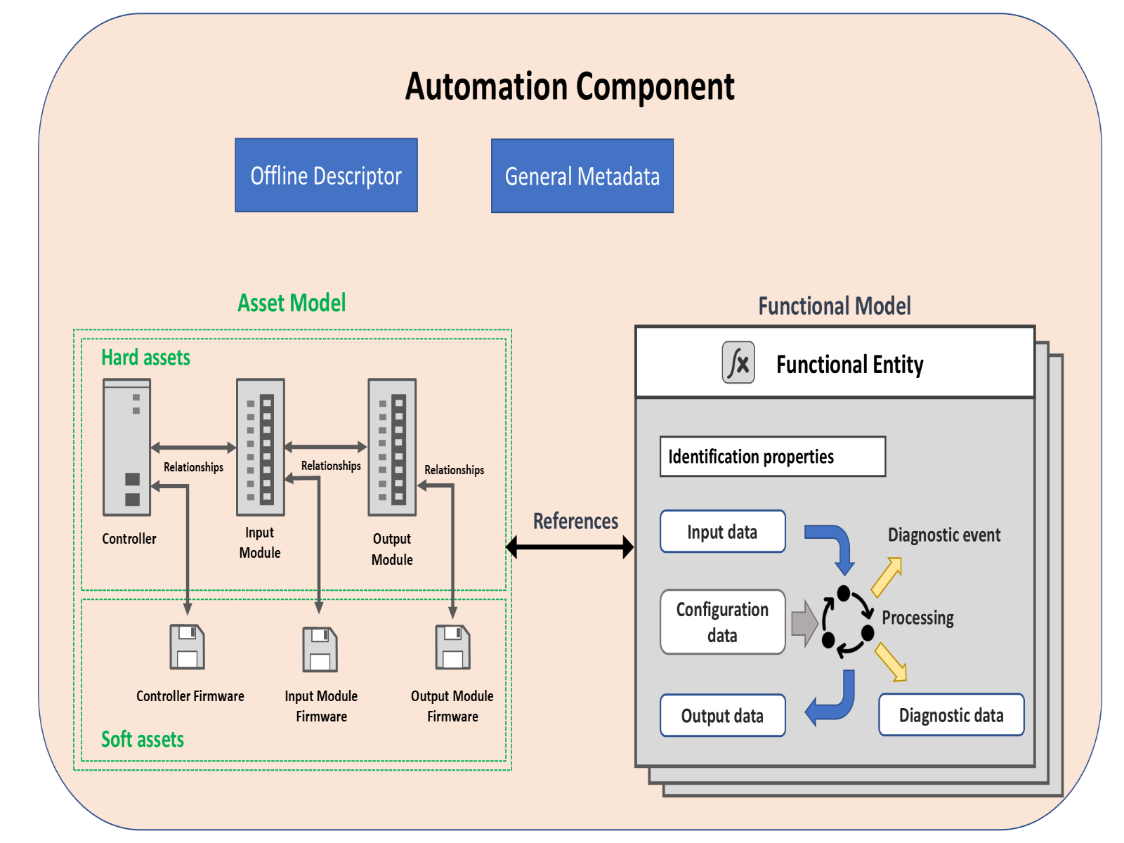
This model is provided to model AutomationComponents in OPC UA FX. In OPC UA FX, an AutomationComponent is an entity that performs one or more automation functions and provides connection capabilities defined in this document. The AutomationComponentType is composed of two major sub-models: the asset model and the functional model. It also provides information related to OfflineEngineering (see OPC 10000-83) and general metadata such as communication capabilities and health status. Figure 1 illustrates this model. For a formal definition of the AutomationComponentType, see 6.2.
Asset information is typically used to describe physical items, but it can also include items that are not physical, such as firmware or licenses. FunctionalEntities encapsulate logical functionality, which can include function blocks, IO module functionality, drive functionality, sensor functionality, actuator functionality, or more complex logical items. FunctionalEntities can be related to Assets, and the representation of such relationships is included in the model. Both Assets and FunctionalEntities can be nested. The Information Model also includes relationships between FunctionalEntities. For a detailed description of the asset model, see the definition of FxAssetType in 6.3. For a detailed description of the FunctionalEntity model, see the definition of FunctionalEntityType in 6.4. For a description of the available ReferenceTypes in this Information Model, see 11.1.
The Information Model is defined to be used either as a base for modelling an AutomationComponentType or for extending an existing Information Model with OPC UA FX-defined functionality. When used as a base model, it is expected that it will require subtyping to add information specific to a component or model, such as variables, or to provide context, e.g., to describe the temperature value in a device that represents a temperature sensor reading. Examples of extending the existing model and using the base model are provided in Annex B.
The AutomationComponentType also includes information related to the offline configuration. For a detailed description of OfflineEngineering, see OPC 10000-83.
4.3 Asset model
4.3.1 Overview
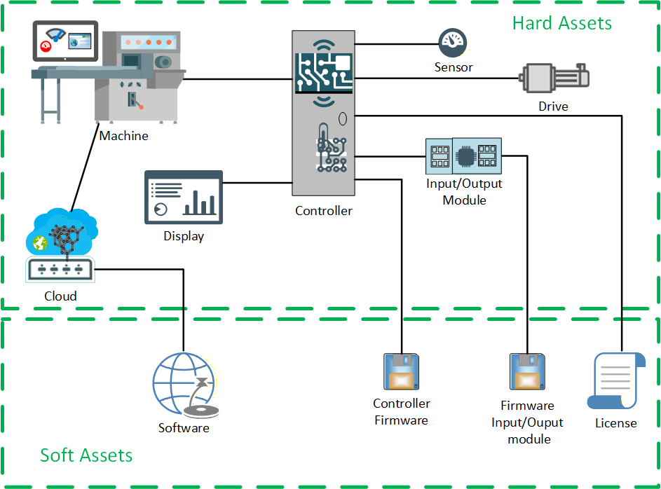
This Information Model provides a general model for Assets in an OPC UA FX system (illustrated in Figure 2). An Asset is defined as a component with a lifecycle, where the lifecycle includes version information. FxAssetType (see 6.3) provides a base concept of the asset model defined in this document. The OPC UA FX Information Model supports the modelling of hard Assets and soft Assets. A hard Asset represents physical hardware like devices, controllers, modules, hardware components, or other hardware-based products. A soft Asset represents firmware, software, licenses, etc. The asset model can model an actual physical device or a virtual representation of the physical device. The asset model is capable of defining a simple Asset, such as a sensor or a complex Asset, such as a machine with multiple nested and/or related Assets.
The asset model is designed to support the nesting of Assets into higher-level devices. The asset model could be used as a base model for plant-wide asset management systems.
4.3.2 Asset information
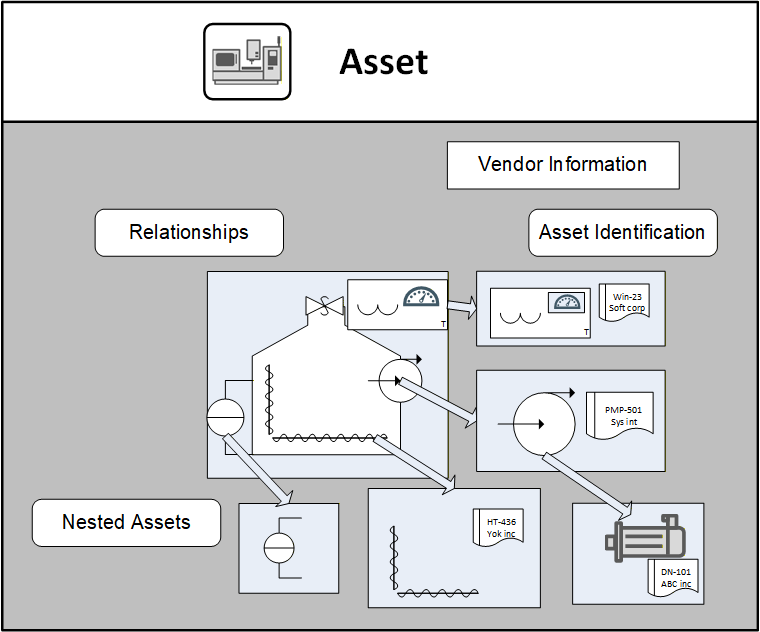
The asset model (illustrated in Figure 3) requires that Assets provide a minimum level of information. This includes Asset type identification as well as the unique identification of Asset instances. It also contains vendor information and information from the model defined in OPC UA Devices (see OPC 10000-100). The asset model supports functionality to verify the identity and compatibility of the Assets. For a complete description of the FxAssetType, see 6.3.
4.3.3 Asset model relationships
The asset model provides a means for representing the relationships between Assets. It also supports the concept that there might be multiple types of relationships between various Assets. These types of relationships might be used to provide multiple views of the asset model. For example:
Asset management view
Physical hierarchy view
Maintenance view
Interconnected view (network, electrical, hydraulic)
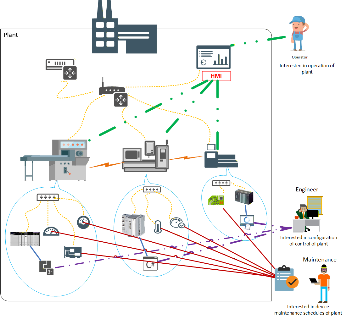
Vendors or end-users are free to create their own view of the Asset relationships. The asset model makes use of specific ReferenceTypes to represent these relationships. OPC 10000-5 and OPC 10000-23 define some base ReferenceTypes, but this document further extends the available list of ReferenceTypes (see 11.1). Figure 4 illustrates some possible views that an asset model can include. Some Assets could contain other Assets (blue speech bubble), while some are just related to each other (orange lightning bolts). There could be network views showing the network topology (yellow dashed lines), which can be derived from LLDP or other input (see OPC 10000-82). There could be a list of sensors or other devices that require routine maintenance (solid red line). There might be a list of all software Assets that an engineer is responsible for (purple dash-dot lines), and the software Asset might be related to the hardware on which it is executed (green dash-dot-dot lines). All of these Assets might be part of a single plant.
The asset model can be as complex or as simple as a specific installation requires. This basic asset model can be part of a plant-wide asset management system or might be a simple asset model used for identity verification. OPC UA FX expects that this model will be extended and that it can operate with other higher-level asset management systems. The asset model might be dynamic during operation.
OPC UA FX defines a minimum asset model that all AutomationComponents are required to support.
4.4 Functional model
4.4.1 Overview
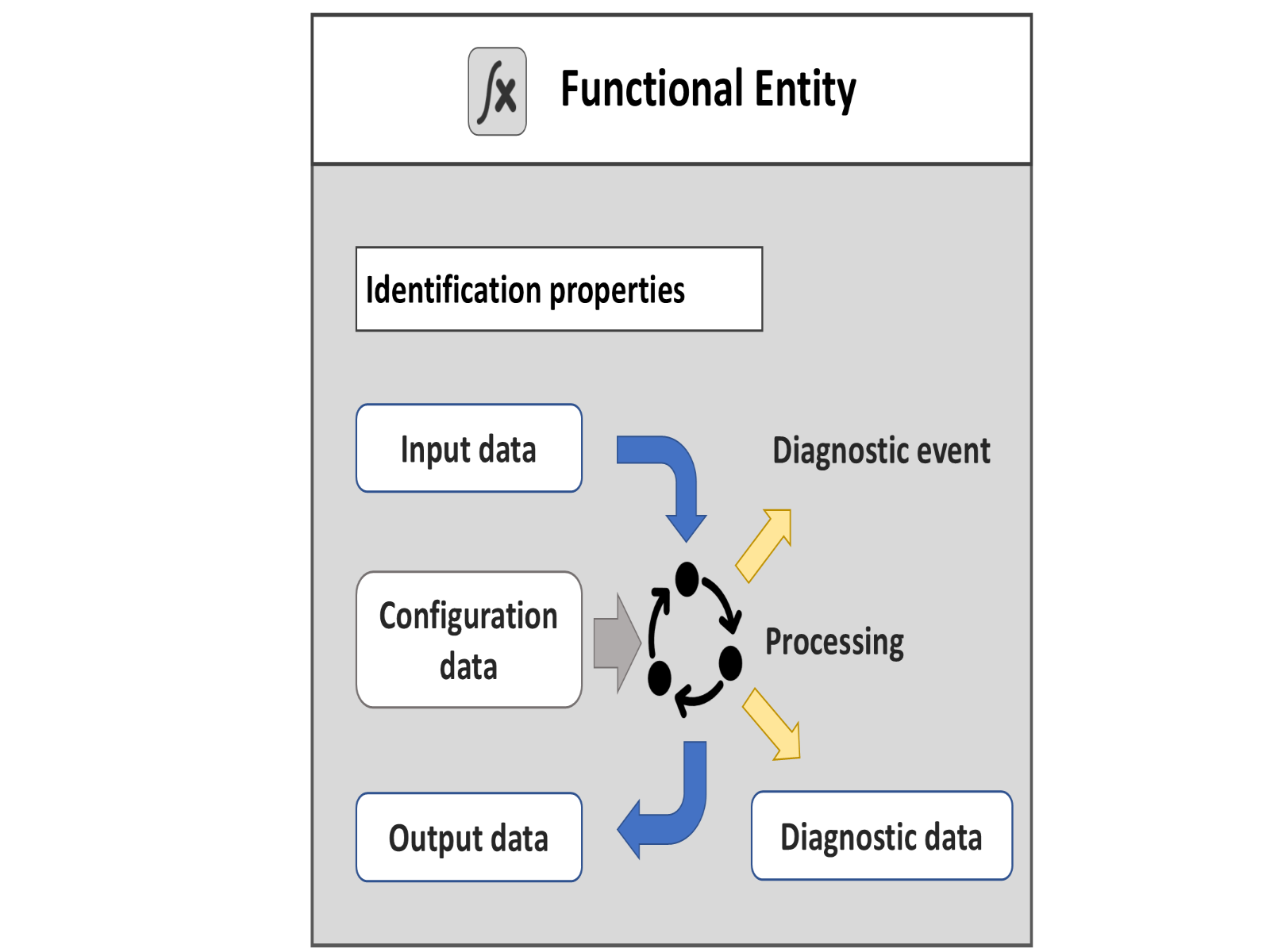
FunctionalEntities encapsulate logical functionality. The OPC UA FX Information Model defines an Object Model for FunctionalEntities. Figure 5 illustrates the Object Model, which includes general information about the FunctionalEntityType, its input variables, output variables, and diagnostic information. FunctionalEntities can be nested or have relationships to other FunctionalEntities. The Object Model also includes a representation of Connections (communication) between FunctionalEntities.
FunctionalEntities are designed to describe functionality of any complexity, ranging from acquiring a single measured value to controlling an entire machine or production line. FunctionalEntities can be preconfigured and fixed, e.g., in a device such as a drive, or dynamically created during engineering or at run time, e.g., in a programmable device such as a controller.
4.4.2 FunctionalEntityType
The FunctionalEntityType defines the base information and functionality that all FunctionalEntities provide. The FunctionalEntityType provides data and methods for controlling and monitoring its functionality. This includes input, output, and configuration data. A FunctionalEntity also provides identification information and methods to perform functionality-related verifications. An important part of the FunctionalEntity model is the interaction between FunctionalEntities, which is modelled as a Connection. The FunctionalEntity part of the model includes information such as status, diagnostics, and other information to help represent this Connection:
Identification properties: Identity - When establishing a Connection between FunctionalEntities, it could be essential to confirm identity, e.g. to check that the other FunctionalEntity is the one that is expected. For an overview of verification, see 5.1.
Input data - describes the values that are produced by another FunctionalEntity and consumed by this FunctionalEntity.
Output data - describes the values that are produced by the processing of this FunctionalEntity and are available for other FunctionalEntities to consume.
Configuration data - describes any value that is used to set up and configure functionality.
Diagnostic data - describes information related to the status of its functionality, including the status of any Connections. This could include generating Events or Alarms related to problems or issues encountered by the FunctionalEntity.
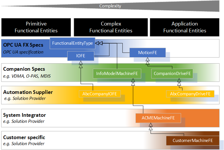
4.4.3 FunctionalEntity type hierarchy
A FunctionalEntity can vary in complexity and represent different granularity and abstraction levels, from primitive functionality to an entire application. Various providers could define FunctionalEntities. For example:
there are primitive FunctionalEntities that only generate output data, like a temperature sensor or only receive input data, like a relay;
more complex FunctionalEntities like a motion axis can receive control data, perform a calculation or action, provide status/feedback data, expose methods for operation and have different operating modes, including closed-loop controls;
or FunctionalEntities on the process application level representing an entire application, such as a paper machine or a boiler, where the FunctionalEntity has multiple nested SubFunctionalEntities.
This document defines the FunctionalEntityType base type. Various companion standards can provide extensions to this document. Manufacturers or suppliers can provide further extensions to FunctionalEntities. They can group them or structure them into a nested hierarchy. Finally, machine builders or end-users can provide FunctionalEntities for their individual automation solutions (see Figure 6 for examples of possible derivations).
The model is defined using OPC UA Interfaces. An Information Model defined in another standard can add support for FunctionalEntities by including these Interfaces or by deriving from the FunctionalEntityType.
4.5 Relationships between FunctionalEntities and Assets
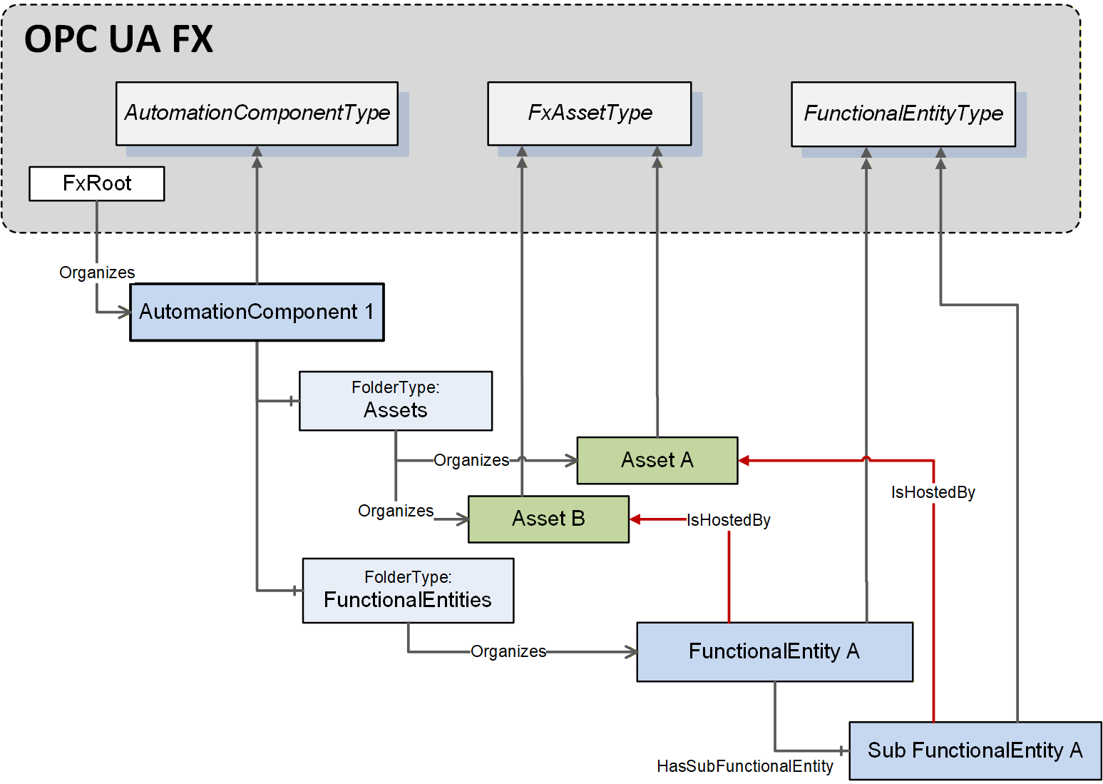
Assets can be related to FunctionalEntities. A single Asset might be related to zero or more FunctionalEntities. A FunctionalEntity might be related to zero or more Assets. The models for both FunctionalEntities and Assets are independent. Specific References only link them (see Figure 7 for an illustration and 11.1 for details on ReferenceTypes).
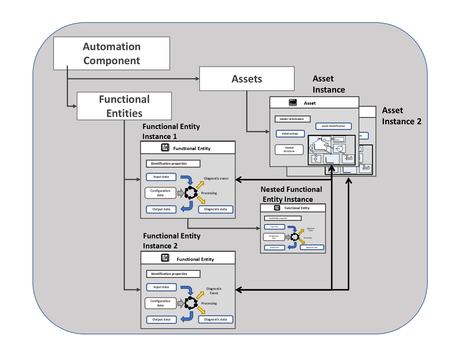
Figure 7 also illustrates an AutomationComponent that groups related FunctionalEntities and Assets.
4.6 FunctionalEntities and applications
Functionality from different FunctionalEntities (in different AutomationComponents) can be used to construct applications. An application can involve communication between one or more FunctionalEntities. FunctionalEntities can be arranged into hierarchies or any type of organisation. The details required in a FunctionalEntity for an application are application-specific, but the base functional model is required to describe the interaction between the FunctionalEntities so that all interactions can be represented in the same manner.
A FunctionalEntity can interact with other FunctionalEntities by exchanging data. This exchange of data can be for control or monitoring purposes. Information related to these interactions is represented in the FunctionalEntity by Connections (see Figure 8).
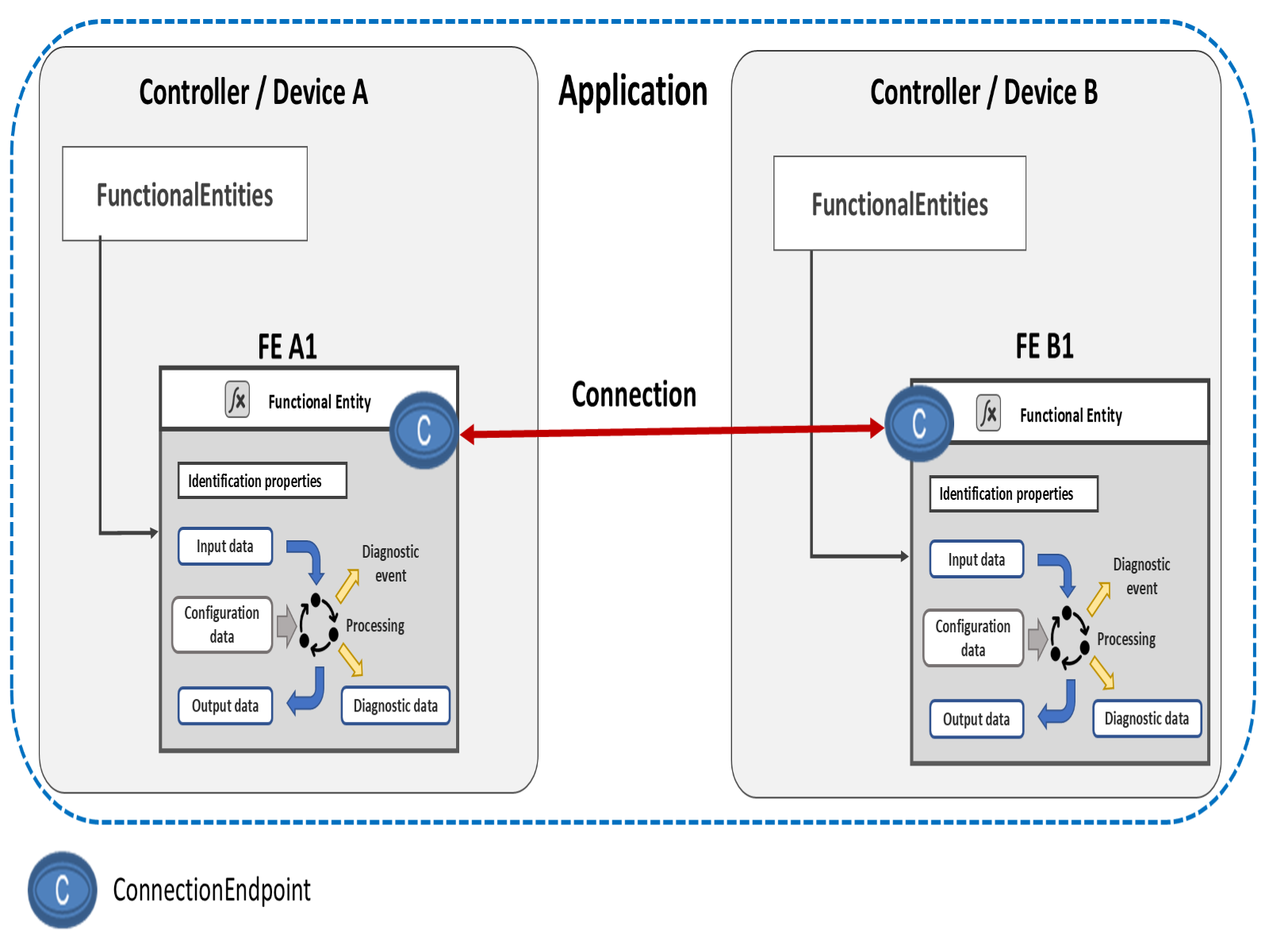
The process of establishing a Connection can include identity and compatibility verification, identifying the information to be exchanged, establishing exclusive access (locking) to the information, setting ConfigurationData, configuring the communication, and finally, enabling the communication. An established Connection is represented on a connected FunctionalEntity by the ConnectionEndpoint. For more information, see the definition of the ConnectionEndpointType in 6.6.
The FunctionalEntity can group input data and output data for easier configuration or as the application requires.
A FunctionalEntity exposes ControlGroups to allow the selection between available uses of a FunctionalEntity. The selected use might restrict access to data; it might lock a value from being changed or only to be changed by a specific entity or Role. Multiple ControlGroups might reference overlapping data. ControlGroups might be created dynamically or be pre-configured as part of an application. ControlGroups might be nested. For more information, see the definition of the ControlGroupType in 6.5. ControlGroups use a Controls Reference defined in OPC 10000-23 to indicate who owns the ControlGroup.
Transportation of data between FunctionalEntities can be accomplished using existing OPC UA communication models. The FunctionalEntity includes Connection information that reflects the established communication model, represented by ConnectionEndpoints. For more information, see 6.6.
4.7 ConnectionManager
4.7.1 Overview
A ConnectionManager is an optional entity that interacts with multiple AutomationComponents to establish Connections between FunctionalEntities. The ConnectionManager can execute on any Server supporting the OPC UA FX Information Model. In the OPC UA FX Information Model, the ConnectionManager is represented by the ConnectionManagerType, which defines functionality and interfaces to manage the establishment of Connections between FunctionalEntities.
Several ConnectionManagers within a network could establish Connections independently of each other. For example, a ConnectionManager on a controller can establish Connections from the controller to its associated IO devices. In contrast, another ConnectionManager on a line controller could establish Connections between FunctionalEntities on the controllers. Figure 9 illustrates possible deployments of a ConnectionManager. It also illustrates ConnectionConfigurationSets, which contain the information needed to establish Connections.
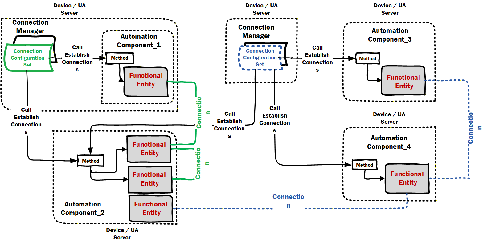
For a conceptual overview of how Connections are established by a ConnectionManager and the main ObjectTypes used in this process, see 5.5.
This document defines the core functionality of a ConnectionManager with respect to the process of establishing and closing Connections, reporting errors related to it, and the ConnectionConfigurationSets. This document does not define the implementation of a ConnectionManager. It can be implemented as a standalone application that monitors and manages Connections. It can be integrated into a vendor application, which establishes and closes Connections according to the overall application. The vendor application can also monitor the state of established Connections and trigger a re-establishment of Connections.
NOTE For simplicity in this document, we will describe that a ConnectionManager monitors a Connection, with it being understood that this could be some other application.
4.7.2 Creating / Monitoring / Closing Connections
Connections to be created are part of a ConnectionManager configuration (ConnectionConfigurationSet).
An AutomationComponent and the included FunctionalEntities report the status of Connections that are part of the FunctionalEntity, and Clients can monitor this status. Some ConnectionManagers could:
know when to create a Connection.
just respond to external or internal commands, i.e., the application triggers the creation of the connection.
monitor the Connections they create.
Possible reasons for monitoring Connection status include:
An application or ConnectionManager monitors ConnectionEndpoints on AutomationComponents to decide whether it needs to (re)establish or close Connections. For example:
On startup, it checks if the desired Connections already exist. For Connections that do not exist, it could trigger the establishment processing.
At runtime, it would check if any Connections were cleaned up (see 5.5.4) or disappeared (e.g. restarted application). If so, it could trigger establishment processing on the Connection.
It might determine, for application-defined reasons, that a Connection needs to be closed, and it could trigger the close Connection processing.
Vendor-specific diagnostic applications monitor Connections defined in ConnectionConfigurationSets on a ConnectionManager and the ConnectionEndpoints on AutomationComponents to present comprehensive Connection information to the operator or engineers, including identification information, current status and last error information.
ConnectionManagers can expose capabilities that describe the functionality they provide (see 6.7.2).
5 OPC UA FX Information Model concepts
5.1 Overview
OPC UA provides the concepts for standard communication between Servers and Clients as well as Publishers and Subscribers, but additional concepts are required for OPC UA FX. These concepts include Connection establishment and bidirectional communication. The establishment of Connections further requires concepts such as identity and compatibility verification of Asset and FunctionalEntity, establishing control via ControlGroup selection, setting ConfigurationData, and communication configuration. These concepts are mapped to existing OPC UA communication models and are provided by the OPC UA FX Information Model. This clause conceptually describes the functionality provided in the overview of the Objects defined by the OPC UA FX Information Model.
5.2 Identity and compatibility verification
5.2.1 Overview
In an industrial automation system, device identity and compatibility verification refer to the process and mechanisms used to check that AutomationComponents (e.g., controllers, drives, IO devices) in a system allow operation that is consistent or compatible with what was expected by system engineering.
It is a common practice that various properties of communicating AutomationComponents are verified to check that:
AutomationComponents present in a system are either consistent with system engineering (i.e., match expectations),
their communication interfaces and exhibited application behaviour are compatible with system engineering expectations.
There are several scenarios where the verification of various properties of an AutomationComponent is utilised in an automation system:
ensuring that AutomationComponents match system engineering expectations during commissioning or initiating communication (e.g., detecting missing Assets like IO modules in a modular IO system),
replacing or updating an AutomationComponent or any of its subcomponents.
Identity and compatibility verification can be done at any time (and executed by any AutomationComponent or tool that knows expected properties and their values) as long as the AutomationComponents can be accessed via Client Server services. In an automation system, verification is typically done before AutomationComponents participate in the industrial control application or process. It is crucial to ensure that the participating AutomationComponents will supply output data (to a consuming AutomationComponent) and use the input data (from a producing AutomationComponent) in an expected way.
This document defines verification modes and a verification Method for Assets, which provides the possibility to verify an Asset's identity and whether or not it performs at a level that is compatible with what is expected by system engineering. For FunctionalEntities, a verification Method is defined, which can be used to verify instance-specific properties (e.g., identity properties) to ensure that they are consistent with what is expected by system engineering.
The subsequent subclauses provide the general concepts for identity and compatibility verification.
5.2.2 Asset verification
5.2.2.1 Overview
Asset verification provides functionality to verify whether a given Asset's type and instance information match or are compatible with what was expected by system engineering.
Applicable use cases include:
commissioning an automation system (e.g., a machine) to ensure all Assets in an engineered system are from the expected manufacturer and are the expected model;
prior to or at the initiation of data communication between AutomationComponents to ensure nothing has been (adversely) changed (e.g., during maintenance or shutdown);
after conducting a firmware update to ensure the updated Asset is compatible with what was engineered;
after replacing an Asset to ensure that the Asset has been replaced by one that is compatible or identical to what was engineered;
verification of the instance of an Asset (e.g., serial number), which is often a requirement in certain applications and industries (e.g., pharmaceutical).
5.2.2.2 Asset identity
Asset identity refers to an Asset's properties that make unambiguous identification possible. The IAssetRevisionType VerifyAsset Method provides the possibility to verify an Asset's identity. See 6.3.3 for a detailed description.
5.2.2.3 Asset compatibility
This subclause introduces the concept of Asset compatibility, which allows an Asset to report if it is compatible with what was expected by system engineering.
An important use case is AutomationComponent replacement. If an identical replacement (same manufacturer, model, and firmware) is unavailable, the vendor could be shipping a compatible substitute with updated hardware or firmware.
Asset compatibility verification provides functionality to verify whether a specific Asset's properties match or are compatible (e.g., a newer firmware that is backwards compatible) with what was expected by system engineering.
Knowledge about Asset (and/or firmware) compatibility typically only exists with the vendor of a specific Asset. Thus, compatibility can only be determined by vendor-specific tools or a vendor's Asset.
The IAssetRevisionType VerifyAsset Method, combined with the AssetVerificationModeEnum AssetCompatibility, allows verifying an Asset's compatibility; see 6.3.3 for a detailed description.
5.2.3 FunctionalEntity verification
FunctionalEntity verification ensures that a given FunctionalEntity conforms to what was expected by system engineering. This verification includes checking the FunctionalEntity's author, identifier, or version (issued by the author of a FunctionalEntity). It also supports checking any Variables defined by the application.
It can include checking for instance-specific additional properties (e.g., the existence and values of optional properties that can represent the configuration of optional functionality or whether a FunctionalEntity is part of a specific application).
The IFunctionalEntityType Verify Method provides the possibility to verify instance-specific properties of a FunctionalEntity; see 6.4.3 for a detailed description.
5.3 ControlGroups
A FunctionalEntity can support multiple operating modes or groupings of functionality. An example might be a simple PID function block that supports cascade. In non-cascade mode, an HMI can set a setpoint, but the ability to externally set the setpoint is blocked in cascade. ControlGroups allow a FunctionalEntity to advertise these different groupings or modes.
A FunctionalEntity might define multiple (even nested) ControlGroups. These ControlGroups might be mutually exclusive, or they might be concurrently active. A ControlGroup might be related to just part of the functionality exposed by a FunctionalEntity.
Selecting a ControlGroup for control will often result in the locking of configuration or restricted access to ConfigurationData as defined by the FunctionalEntity (when the ControlGroup was defined). ControlGroups expose what restriction would occur if the given ControlGroup were selected for control. Locking can restrict access to Variables or Methods to a specific application/user. It can also just block all access to Variables or Methods. What occurs with the selection of a ControlGroup is defined as part of the ControlGroup. For example, all changes to some configuration parameters might need to be blocked as long as communication is occurring, or all changes to some configuration Variables might need to be restricted to a specific application. Any ControlGroup can reference any Variable / Method, and multiple ControlGroups might reference the same Variable / Method.
The ControlGroup provides a standard mechanism to configure what would be restricted or blocked, and with what application or functionality the restriction/block is associated. ControlGroups might be configured by product vendors and be related to the functionality provided by the AutomationComponent (e.g., a drive vendor or function block library vendor). It could also be defined by a system integrator that defines an application that will be using the FunctionalEntity.
5.4 ConfigurationData
ConfigurationData describes a collection of Variables within a FunctionalEntity that are used to set up and configure its functionality. As part of establishing a Connection between FunctionalEntities, some configuration might be required. This configuration is separate from the configuration required for the actual communication. The EstablishConnections Method allows any of the FunctionalEntity's ConfigurationData to be set.
ConfigurationData can contain Variables that have the AccessLevelEx Attribute NonVolatile bit set to TRUE (see OPC 10000-3). After a power cycle, such Variables are initialised to the last value written before the power cycle.
OPC UA FX defines the concept of the storage of Variables (see 6.4.6). Variables that do not have the AccessLevelEx Attribute NonVolatile bit set can be configured to be part of the storage and are initialised to the stored value following a power cycle.
Variables that are not stored and do not have the AccessLevelEx Attribute NonVolatile bit set have an unspecified value (e.g., vendor-specific value) after a power cycle.
It is up to the provider of the FunctionalEntity whether to provide NonVolatile ConfigurationData or to support storage of Variables.
5.5 Logical connections
5.5.1 Overview
The logical functionality of an AutomationComponent is represented by one or more FunctionalEntities described in 4.4. An important part of the functional model is the data exchange between FunctionalEntities using logical connections. Figure 8 illustrates this interaction.
A logical connection is represented by two ConnectionEndpoints, one on each FunctionalEntity that is part of the connection. Figure 28 provides a more detailed view of the Objects involved.
Logical connections are configured using ConnectionConfigurationSets.
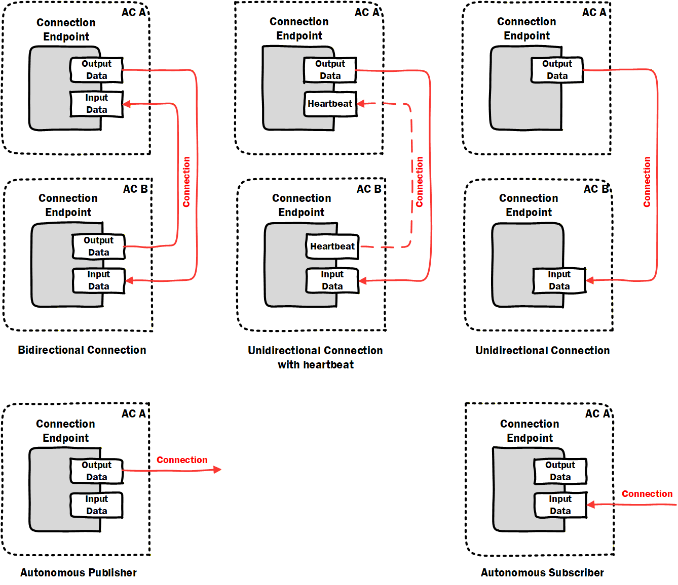
The following types of logical connections are supported (see Figure 10):
Bidirectional connections describe bidirectional data exchange between two FunctionalEntities.
Unidirectional connections with heartbeat describe unidirectional data exchange in one direction and a heartbeat message (for logical connection monitoring) in the opposite direction between two FunctionalEntities.
Unidirectional connections describe unidirectional data exchange between two FunctionalEntities.
Autonomous publisher describes data published by a FunctionalEntity, where the related subscribing ConnectionEndpoint(s) are unknown to the logical connection.
Autonomous subscriber describes data subscribed by a FunctionalEntity, where the related publishing ConnectionEndpoint(s) are unknown to the logical connection.
Auditing reports problems and changes triggered by an external application. A subscription within a Connection is considered a source of data (for source of data, see OPC 10000-4). Changes in the values of Variables from a data source do not generate Audit Events.
5.5.2 Generation, deployment, and modification
This document defines the required data model for logical connection configuration information, represented by the ConnectionConfigurationSetType and additional ObjectTypes it utilizes.
The ConnectionManagerType (see 6.7) exposes configuration information related to the establishment of logical connections. The configuration information is typically generated by an engineering tool based on offline or online information.
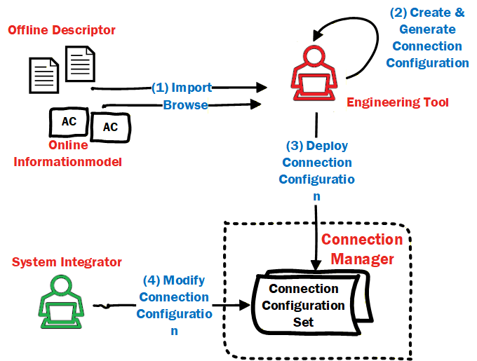
OfflineEngineering (see OPC 10000-83) offers the concept of Descriptors that describe the AutomationComponents; see Figure 11 label 1. Using these Descriptors or retrieving information online from the AutomationComponents, application engineers use vendor-specific engineering tools to generate the configuration data for logical connections (see Figure 11 label 2). All configuration data represented by one or more logical connections are defined in a ConnectionConfigurationSet. The instances can also include configuration information for the utilized OPC UA communication model (e.g., PubSub or Client Server [future]).
The engineering tool and ConnectionManager could reside on separate devices or be located on the same device.
ConnectionConfigurationSets can be deployed to the ConnectionManager (see Figure 11 label 3) using functionality defined in Annex F or vendor-specific means.
A ConnectionConfigurationSet can allow changes. For example, addressing information that is only available at commissioning time or communication-related properties like the PublishingInterval for data exchange can be modified by a system integrator. The changes that can be made can be restricted by the generator of the ConnectionConfigurationSet (see 6.8.1). The ConnectionManager exposes the ConnectionConfigurationSets (see 6.86.8), representing sets of logical connections to be established. Using generic tools (Clients), the ConnectionConfigurationSets can be modified as restricted (see Figure 11 label 4).
The ConnectionManager provides optional Methods to interact with these sets of logical connections, i.e., for editing and committing updates to sets (see 6.7.4) and to trigger processing (establishment for all logical connections) of sets (see 6.7.5). The ConnectionManager can also provide vendor-specific means.
5.5.3 Establishing and closing Connections
As introduced in 4.7, logical connection establishment can be executed by a ConnectionManager. If present on a Server, the ConnectionManager is represented in the Information Model by a well-known instance of ConnectionManagerType (see 6.7). To start the establishment of logical connections, the ConnectionManager could be triggered by vendor-specific means or by a Client using the ProcessConnectionConfigurationSets Method. It could also be an application that is always executing. The ConnectionManager calls the EstablishConnections Method on the AutomationComponents to establish the logical connections.
For each logical connection to be established, the ConnectionConfigurationSet includes:
address information, e.g., Server address, BrowsePath to the AutomationComponent, FunctionalEntity, etc.,
optional parameters to be used for verifying the Assets and FunctionalEntities,
optional parameters to be used for establishing control,
optional parameters to be used for configuring the application behaviour,
the definition of the data to be exchanged via the logical connection,
communication model-specific properties for the utilized OPC UA communication model (e.g., PubSub or Client Server [future]).
For more details on the ConnectionConfigurationSetType, see 6.8. For details on ConnectionManager functionality, see 6.7.
The ConnectionManager could be triggered to close logical connections by vendor-specific means or by a Client invoking the ProcessConnectionConfigurationSets Method. The ConnectionManager calls the CloseConnections Method on the AutomationComponents to close the logical connections.
5.5.4 Cleaning up Connections
5.5.4.1 Overview
A consumer of data can always detect data loss (e.g., caused by loss of network communication or a faulty producer), but in many industrial control applications, it is of interest to the application producing the data whether the consumer(s) of that data are still available. OPC UA FX provides a configurable clean-up of logical connections and all associated resources.
5.5.4.2 Operation
The lifetime of a logical connection on an AutomationComponent can be tied to its Status (see 6.6.2), which is, in turn, tied to the reception of data or heartbeat messages. A configurable CleanupTimeout (see 6.6.2) allows the deletion of all resources allocated to a specific ConnectionEndpoint once its status indicates loss of data reception.
This revision of the specification supports logical connections that utilize the PubSub communication model and hence builds on the usage of either DataSetMessages or heartbeat messages (see OPC 10000-14).
5.5.5 Persistent and preconfigured objects
Establishing logical connections can involve creating several Objects within the AutomationComponents.
Persistence refers to the ability of AutomationComponents to store configuration, which allows these Objects to be restored after a power cycle or other restart. Individual logical connections can be marked for persistence (see IsPersistent in 6.6.2).
An AutomationComponent can provide preconfigured Objects (e.g., PublishedDataSet or ConnectionEndpoint). An example might be a FunctionalEntity that includes a preconfigured PublishedDataSet that is used as part of a logical connection. The other parts of the logical connection (e.g., ConnectionEndpoint, WriterGroup, DataSetWriter) are all created during connection establishment. If the Connection is not marked for persistence, the other parts are deleted on clean-up or on a power cycle, and the preconfigured Objects will remain.
5.5.6 Relationship to OPC UA communication models
5.5.6.1 Overview
Connections between FunctionalEntities are designed to exchange data by utilizing OPC UA communication models. This revision of the specification supports the PubSub communication model as defined in OPC 10000-14. Future revisions will support the Client Server communication model.
5.5.6.2 PubSub
5.5.6.2.1 Overview
This subclause illustrates how Connections utilize the PubSub communication model, focusing on three use cases relevant in the context of industrial automation and the design of AutomationComponents. These are just illustrations. Additional or different uses might also apply. The grey-blue boxes in these illustrations are defined in this document, while the yellow blocks are defined in OPC 10000-14.
5.5.6.2.2 Single Connection using unicast network messages
This use case, illustrated in Figure 12, describes a single logical connection between two FunctionalEntities located on the AutomationComponents A and B, each containing a Publisher, a Subscriber, and a single PubSubConnectionEndpoint. Both FunctionalEntities could be publishing data (bidirectional Connection), or only one could be publishing data while the other publishes a heartbeat (unidirectional connection with heartbeat).
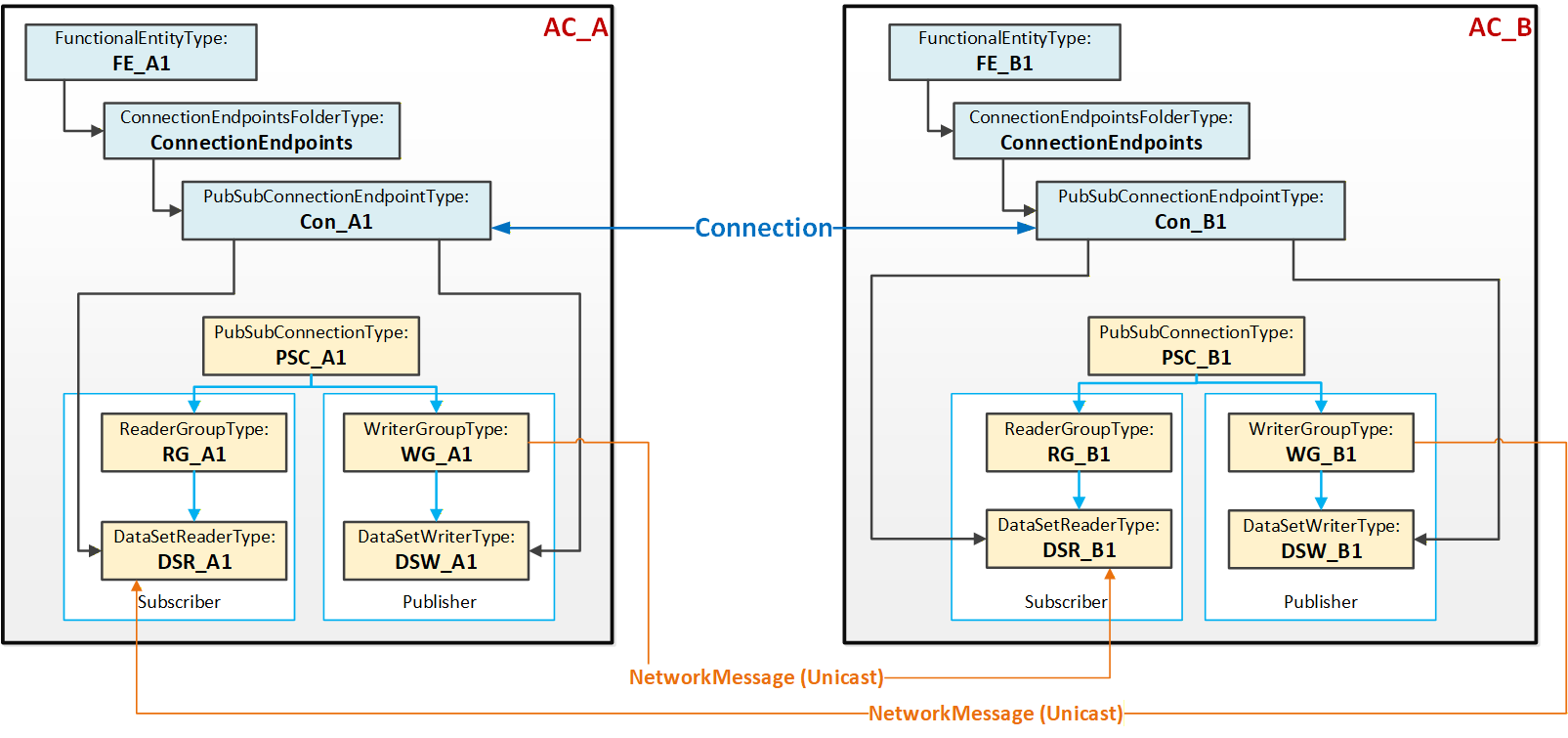
Figure 12 illustrates the logical connection between the two FunctionalEntities FE_A1 and FE_B1. Each FunctionalEntity contains a PubSubConnectionEndpoint (Con_A1 and Con_B1), which references a DataSetReader and DataSetWriter.
The PubSub instances are configured to exchange data between AutomationComponents AC_A and AC_B using unicast NetworkMessages.
5.5.6.2.3 Multiple Connections using unicast network messages
This use case, illustrated in Figure 13, typically applies to AutomationComponents that host multiple FunctionalEntities and/or nested FunctionalEntities.
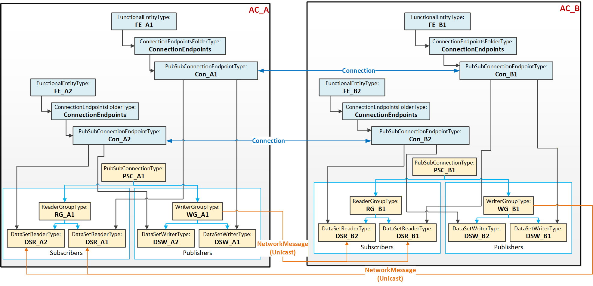
Figure 13 illustrates two Connections, each between two PubSubConnectionEndpoints. Each PubSubConnectionEndpoint on AC_A (and similarly on AC_B) references a DataSetWriter (and DataSetReader) that is located under the same WriterGroup (and ReaderGroup).
The PubSub instances are configured to exchange data between AC_A and AC_B using unicast NetworkMessages. This use case is called aggregated because a single NetworkMessage aggregates multiple DataSetMessages (one per logical connection). Aggregation reduces the required network bandwidth.
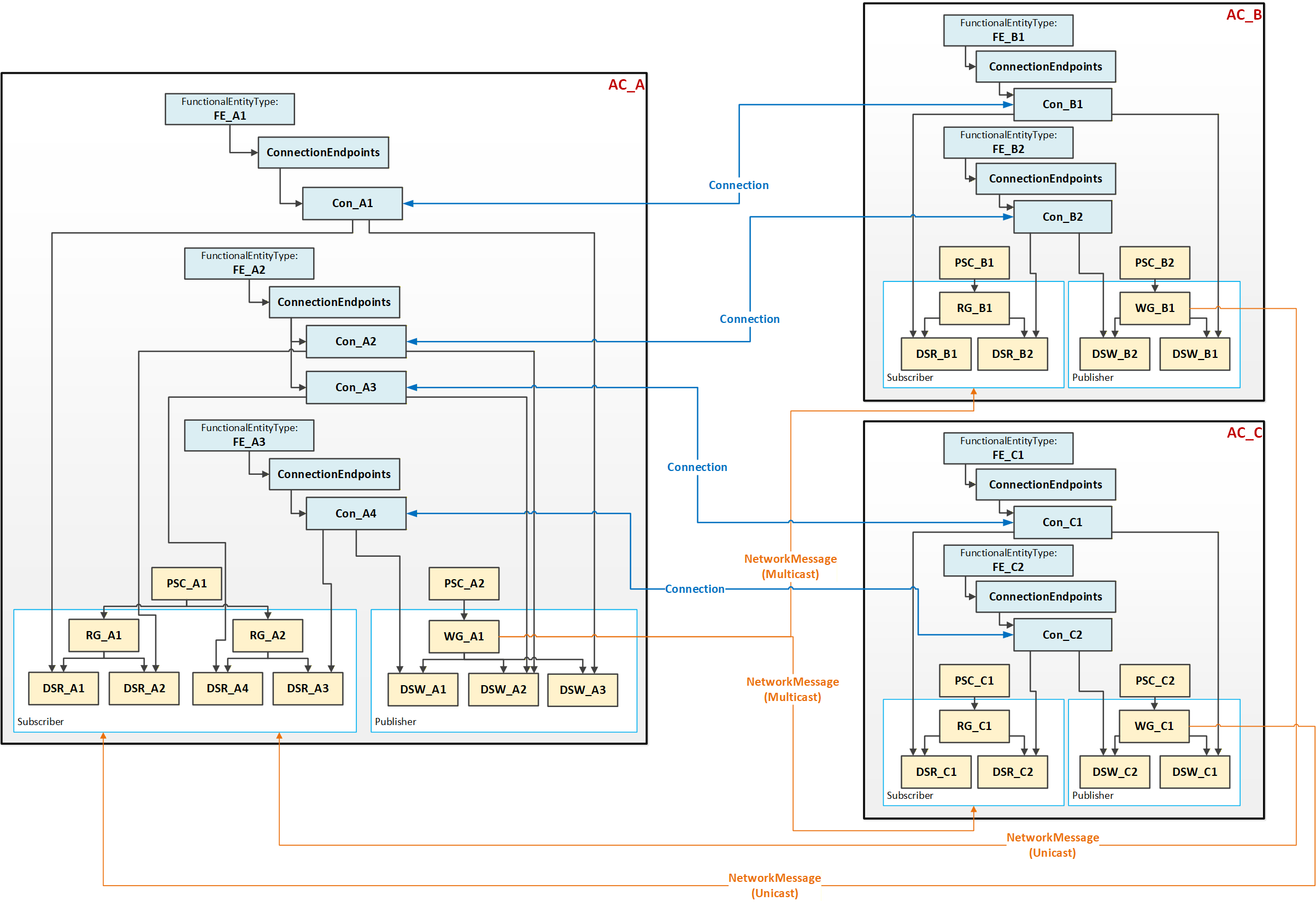
5.5.6.2.4 Multiple Connections using multicast network messages
This use case, illustrated in Figure 14, could be applied to an AutomationComponent (AC_A) communicating with multiple AutomationComponents (AC_B and AC_C). To minimize network bandwidth usage in specific topologies, AC_A can aggregate published data into a single NetworkMessage, which is sent via multicast to the associated AutomationComponents AC_B and AC_C. In turn, AC_B and AC_C publish an individual NetworkMessage back to AC_A. Multicast can also help with scaling issues in the device (less processing of network messages is required).
5.5.6.2.5 DataSetMetaData
Connections are configured by an engineering tool on behalf of Descriptors and are deployed to a ConnectionManager (see 5.5.2). Independent of the lifetime of a Connection, another engineering tool can update a FunctionalEntity, including its preconfigured DataSets. In addition, the Descriptor can describe a different version of the FunctionalEntity to be connected at runtime. This can result in misinterpretation of the exchanged data.
To prevent this error scenario, PubSub provides the DataSetMetaData. DataSetMetaData describes the content and semantics of a DataSet. In addition, the DataSetMetaData provides the details defining the contract between the Publisher and the Subscriber, including how to encode and decode the DataSetMessage. Thus, Subscribers must know about the PublishedDataSet's DataSetMetaData. For the concepts of the DataSetMetaData and its definition, see OPC 10000-14.
Any change to a PublishedDataSet regarding its content but also its semantics (e.g., engineering units) would generate changes to its DataSetMetaData, indicated by a change in its ConfigurationVersion (see OPC 10000-14). Depending on the chosen UADP header layout, the ConfigurationVersion of an individual Publisher or a GroupVersion combining the ConfigurationVersions of all Publishers belonging to a WriterGroup is transmitted with the NetworkMessage. Any mismatch between the transmitted version and the one configured at the Subscriber will cause the Subscriber to go into Error. To resolve the Error, the Subscriber needs an update of the DataSetMetaData. OPC 10000-14 offers multiple ways to accomplish this.
5.6 Health
Assets, FunctionalEntities, ConnectionEndpoints, and ConnectionConfigurationSets provide general health status and diagnostic conditions. This health status is aggregated from child Objects to parent Objects (e.g., from ConnectionEndpoints to the FunctionalEntity, from FunctionalEntities to the AutomationComponent, or from ConnectionConfigurationSets to the ConnectionManager). The aggregated health status allows a Client to easily detect whether diagnostic conditions are present somewhere in the Information Model. If the aggregated health status is "good", a Client does not have to check other Objects in the tree. If a status other than "good" is reported, aggregated health status indicates the elements (e.g., Assets) which need more investigation (see 6.2.2).
5.7 AliasNames and OPC UA FX
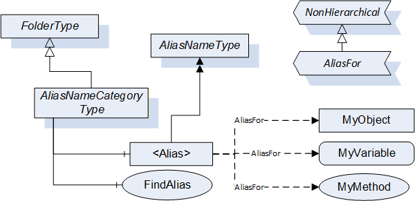
AliasNames is a concept in OPC UA (defined in OPC 10000-17) that allows defining alternate names for Objects, Variables or Methods in an AddressSpace (see Figure 15). These names can be grouped into categories. The FindAlias method returns the ExpandedNodeId for the actual Object/Variable/Method. AliasNames are most commonly used for configuration management, but can also be used for DataSet/topic discovery and many other uses.
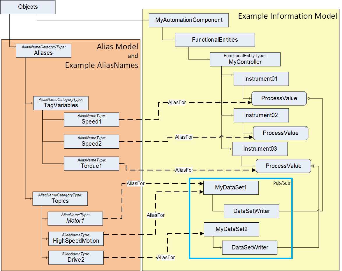
In OPC UA FX, AliasNames can be used to define a configuration for information used by the ConnectionManager. AliasNames allow offline engineering tools to assign alternate names to Variables or Objects that are used in the configuration (see Figure 16). These alternate names could be assigned and used long before the actual configuration is available. They can be exchanged between vendors, allowing vendors to configure Connections without having all required data defined. The resolution of this configuration information into the actual Server / NodeId of the Node identified by the AliasName happens at runtime. The aggregation of AliasNames into a Global Discovery Server (GDS) happens automatically for Servers that are registered with a GDS. An AggregatingServer can also collect AliasNames.
5.8 Aggregation of OPC UA FX Servers
AggregatingServers can be used to collect information from multiple underlying Servers and add additional functionality to the information and/or source the information for higher-level applications, offloading the underlying Servers. The Information Model that is defined in this document can be aggregated. This subclause provides some explanation regarding the aggregation of AutomationComponents and ConnectionManagers.
The AutomationComponent(s) can be reflected in a higher-level Server. This reflection can include Assets and FunctionalEntities, but it is expected that the communication model (between FunctionalEntities) will only exist in the actual Servers, not in the AggregatingServer. Any actions performed against the AutomationComponent in the AggregatingServer are expected to be passed down and performed on the actual Server, including any method calls. Also, only the status/configuration information from a ConnectionEndpoint would be mirrored. ControlGroup information can be displayed in an AggregatingServer. Still, all data just reflects data from the underlying Servers, so changes to values would only occur in the underlying Server and could only be made if no locks are in place. Any writes or Method calls made against an AutomationComponent on an AggregatingServer would need to be applied against the AutomationComponent in the underlying Server. The value in the AggregatingServer would only be updated due to mirroring the change in the underlying Server. The value would not be directly updated in the AggregatingServer.
An AggregatingServer can add functionality, such as the generation of Alarms or historization. It can also be the source of data for higher-level applications such as HMIs or advanced control applications. Multiple AutomationComponents from multiple Servers could be included under a single AggregatingServer.
An AggregatingServer can expose a ConnectionManager, but only one well-known ConnectionManager is allowed on a Server. This single ConnectionManager can reflect the ConnectionConfigurationSets from the underlying Servers. It can directly execute any commands it receives or pass the commands down to the underlying Servers.
5.9 Well-Known Roles
All Servers supporting OPC UA FX should support the well-known Roles as defined in OPC 10000-3. The well-known Role ConfigureAdmin should be extended as indicated in Table 2.
| BrowseName | Suggested Permissions |
|---|---|
| 0:ConfigureAdmin | The Role is allowed to browse the Information Model, execute methods related to application configuration, and read and write non-security-related configuration settings. This includes changing connection and network-related configuration settings. Safety configuration is explicitly separate from this Role. |
All Servers supporting OPC UA FX should support the additional well-known Role as defined in Table 3.
| BrowseName | Suggested Permissions |
|---|---|
| 3:ConnectionAdmin | The Role is allowed to establish, close, and modify Connections between FunctionalEntities. This includes reading and writing connection configuration settings, reading endpoint and connection capabilities, and executing methods related to management of Connections. It is intended to be a non-human Role. |
For a detailed description of Roles, see OPC 10000-3, OPC 10000-14, and OPC 10000-18.
6 OPC UA FX ObjectTypes
6.1 OPC UA FX ObjectTypes overview
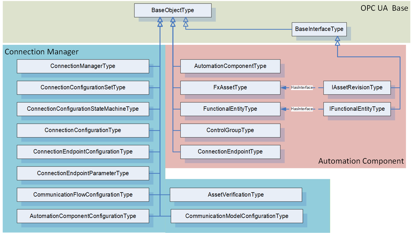
This document defines several ObjectTypes that can be used to create an OPC UA FX Information Model. It also specifies a number of Interfaces that can be applied to existing Information Models, allowing existing models to be used as part of an OPC UA FX system. For additional guidance on mapping this model to existing Information Models, see Annex B. For an overview of the main OPC UA FX ObjectTypes, see Figure 17.
Since the OPC UA FX Information Model supports both small embedded devices and powerful controllers, it includes many optional items. Some of these items are mandatory for controller-level Profiles but optional for embedded device Profiles. For a complete list of Profiles related to OPC UA FX, see OPC 10000-84.
6.2 AutomationComponentType
6.2.1 Overview
The AutomationComponentType ObjectType provides for a grouping of Assets and FunctionalEntities in a given model. It exposes a Method that is used to establish Connections between FunctionalEntities. An overview of the AutomationComponentType is illustrated in Figure 18.
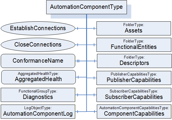
6.2.2 AutomationComponentType definition
The AutomationComponentType is the base ObjectType for an OPC UA FX device, controller, PLC, instrument, and similar components. It includes information related to the current Asset, the available functionality, its capabilities (including communication-related capabilities) and any related offline information. The AutomationComponentType is formally defined in Table 4 and Table 5.
| Attribute | Value | ||||
| BrowseName | 3:AutomationComponentType | ||||
| IsAbstract | False | ||||
| References |
Node
Class | BrowseName | DataType | TypeDefinition | Other |
|---|---|---|---|---|---|
| Subtype of the 0:BaseObjectType defined in OPC 10000-5 | |||||
| 0:HasComponent | Object | 3:FunctionalEntities | 0:FolderType | M | |
| 0:HasComponent | Object | 3:Assets | 0:FolderType | M | |
| 0:HasComponent | Object | 3:PublisherCapabilities | 3:PublisherCapabilitiesType | O | |
| 0:HasComponent | Object | 3:SubscriberCapabilities | 3:SubscriberCapabilitiesType | O | |
| 0:HasComponent | Object | 3:ComponentCapabilities | 3:AutomationComponentCapabilitiesType | M | |
| 0:HasProperty | Variable | 3:ConformanceName | 0:UriString | 0:PropertyType | O |
| 0:HasComponent | Method | 3:EstablishConnections | Defined in 6.2.4 | M | |
| 0:HasComponent | Method | 3:CloseConnections | Defined in 6.2.5 | M | |
| 0:HasComponent | Object | 3:Descriptors | 0:FolderType | M | |
| 0:HasComponent | Variable | 3:AggregatedHealth | 3:AggregatedHealthDataType | 3:AggregatedHealthType | M |
| 0:HasComponent | Object | 5:Diagnostics | 5:FunctionalGroupType | O | |
| 0:HasComponent | Object | 3:AutomationComponentLog | 0:LogObjectType | O | |
| ConformanceUnits | |||||
|---|---|---|---|---|---|
| UAFX AutomationComponent Base |
| SourceBrowsePath | Reference Type | IsForward | TargetBrowsePath | ||||
| 0:IsHostedBy | True |
|
The components of the AutomationComponentType have additional subcomponents, which are defined in Table 6.
| BrowsePath | References | NodeClass | BrowseName | DataType | TypeDefinition | Others |
| 3:FunctionalEntities | 0:Organizes | Object | 3:<FunctionalEntity> | 3:FunctionalEntityType | OP | |
| 3:Assets | 0:Organizes | Object | 3:<Asset> | 3:FxAssetType | OP | |
| 3:Descriptors | 0:HasComponent | Object | 3:<Descriptor> | 3:AcDescriptorType | OP | |
| 5:Diagnostics | 0:HasComponent | Variable | 3:EstablishCallCount | 0:UInt32 | 0:BaseDataVariableType | O |
| 5:Diagnostics | 0:HasComponent | Variable | 3:EstablishCallFailedCount | 0:UInt32 | 0:BaseDataVariableType | O |
| 5:Diagnostics | 0:HasComponent | Variable | 3:CloseCallCount | 0:UInt32 | 0:BaseDataVariableType | O |
| 5:Diagnostics | 0:HasComponent | Variable | 3:CloseCallFailedCount | 0:UInt32 | 0:BaseDataVariableType | O |
FunctionalEntities provides a Folder for the FunctionalEntities that this AutomationComponent exposes. The Folder shall be restricted to hold only instances of a type derived from FunctionalEntityType or instances that implement the IFunctionalEntityType Interface. The Folder may be empty. FunctionalEntities can reference other FunctionalEntities, but FunctionalEntities that are directly referenced from this Folder are considered top-level FunctionalEntities.
Assets provides a Folder for assets. It shall include all assets that are referenced from the FunctionalEntities of this AutomationComponent. An Asset might be a complex type that includes other Assets. Assets directly referenced from this Folder are considered top-level Assets. For more details on the asset model, see 6.3. The Folder shall be restricted to hold only instances of FxAssetType or a subtype of it or instances that implement the IVendorNameplateType, ITagNameplateType, and IAssetRevisionType Interfaces. The Folder may be empty; however, typically, there is at least one entry in this Folder. For examples of Assets, see Annex D.
Objects may be added/removed to/from the FunctionalEntities or Assets Folders during operation, in which case the Server shall generate GeneralModelChangeEvent to reflect these changes.
The optional PublisherCapabilities provide the Publisher capabilities associated with this AutomationComponent. They apply to all instances in the FunctionalEntities Folder. An individual FunctionalEntity can further restrict these capabilities. If an AutomationComponent supports being a Publisher as defined in OPC 10000-14, then an instance of this Object shall be provided.
The optional SubscriberCapabilities provides the general Subscriber capabilities associated with this AutomationComponent. They apply to all instances in the FunctionalEntities Folder. An individual FunctionalEntity can further limit these capabilities. If an AutomationComponent supports being a Subscriber as defined in OPC 10000-14, then an instance of this Object shall be provided.
ComponentCapabilities is an AutomationComponentCapabilitiesType Folder that describes the functionality provided by an AutomationComponent (e.g., number of supported Connections, etc.).
The optional ConformanceName provides the URL to the product's listing on the OPC Foundation website, under which the result of the conformance testing for this product can be found. The product's name may be different from the name of the AutomationComponent since conformance testing may be done for a product family, but this shall be described on the OPC Foundation product page. The DisplayName of the instance of the AutomationComponent shall be able to be resolved on the Website to the specifics of the product that was tested. Furthermore, at least one Asset listed in this AutomationComponent shall include IVendorNameplateType information on the related OPC Foundation product page.
Descriptors is a Folder that can contain AcDescriptors. Typically, at least one AcDescriptor is included, but depending on the system's architecture, additional AcDescriptors might be added. These added AcDescriptors describe added FunctionalEntities or added Assets or added combinations of Assets and FunctionalEntities. The individual Assets or FunctionalEntities may have a DescribedInDescriptor Reference to one of the AcDescriptors in Descriptors. The additional ACDescriptors can result from application developers adding functionality, integration of this AutomationComponent into a larger piece of equipment, or the addition of modular Assets to the system. This Folder may also contain other Folders that can be used to organise the AcDescriptors.
AggregatedHealth provides the aggregated health of the AutomationComponent; this includes an aggregation of the health of all included Assets and FunctionalEntities. For the definition of the AggregatedHealthType and the aggregation rules, see 9.1.
AutomationComponentLog exposes a LogObject for the AutomationComponent. The LogObject (see OPC 10000-26) can be accessed to obtain the log of activity related to this AutomationComponent. Events can be mapped to LogRecords (see OPC 10000-26) for the LogObject. LogObject records can also be generated without the generation of an Event. If the LogObject is supported, the AutomationComponent shall produce LogRecords for all calls of the EstablishConnections and CloseConnections Methods. The LogObject configuration would determine if the LogRecords are stored. The LogRecords shall include the optional TraceContext information if it is provided by the Client invoking the EstablishConnection or CloseConnection calls. In addition, it is recommended that for errors, the AdditionalData field includes the error information as described in the OPC 10000-26 Subclause "Log Event EventType".
Diagnostics is a FunctionalGroup (Folder) that contains Variables that report diagnostic statistics and counters (see OPC 10000-100 Recommended FunctionalGroup BrowseNames).
EstablishCallCount diagnostics counter Variable provides a count of the number of EstablishConnections calls received.
EstablishCallFailedCount diagnostics counter Variable provides a count of the number of EstablishConnections calls that failed (any command).
CloseCallCount diagnostics counter Variable provides a count of the number of CloseConnections calls received.
CloseCallFailedCount diagnostics counter Variable provides a count of the number of CloseConnections calls that failed.
The IsHostedBy ReferenceType (see OPC 10000-23) indicates the Assets used to execute the functionality provided by a FunctionalEntity. There may be multiple IsHostedBy References from one FunctionalEntity to multiple Assets. An example is a drive axis FunctionalEntity, which has IsHostedBy References to a drive inverter Asset and a motor Asset. Another example is an input FunctionalEntity having IsHostedBy References to the input module, the head, and the firmware Assets of a modular device.
Figure 19 illustrates an example of the usage of IsHostedBy.
6.2.3 AcDescriptorType definition
An instance of AcDescriptorType is used to represent a Descriptor. This Object shall include either a DescriptorFile or the pair of DescriptorIdentifier and DescriptorVersion. It may include all three.
The AcDescriptorType is formally defined in Table 7.
| Attribute | Value | ||||
| BrowseName | 3:AcDescriptorType | ||||
| IsAbstract | False | ||||
| References | Node Class | BrowseName | DataType | TypeDefinition | Other |
|---|---|---|---|---|---|
| Subtype of the 0:BaseObjectType defined in OPC 10000-5 | |||||
| 0:HasProperty | Variable | 3:DescriptorIdentifier | 0:UriString | 0:PropertyType | O |
| 0:HasProperty | Variable | 3:DescriptorVersion | 3:FxVersion | 0:PropertyType | O |
| 0:HasComponent | Object | 3:DescriptorFile | 0:FileType | O | |
| ConformanceUnits | |||||
|---|---|---|---|---|---|
| UAFX AutomationComponent Descriptor |
The optional DescriptorIdentifier provides a globally unique identifier of the Descriptor of the AutomationComponent. It can be used to retrieve the Descriptor from the vendor's product listing on the OPC Foundation Website (i.e., the OPC Marketplace).
The optional DescriptorVersion provides the version of the Descriptor used to describe this AutomationComponent.
The optional DescriptorFile exposes the Descriptor (defined in OPC 10000-83) directly from the AutomationComponent.
If both the DescriptorFile and the DescriptorIdentifier are provided, the value of the DescriptorIdentifier Variable exposed in the Object shall match the value of DescriptorIdentifier provided in the manifest of the DescriptorFile. If, in addition, the DescriptorVersion is provided, the value of the DescriptorVersion Variable exposed in the Object shall match the value of DescriptorVersion provided in the manifest of the DescriptorFile.
6.2.4 EstablishConnections method
6.2.4.1 Overview
The EstablishConnections Method establishes one or more Connections. The ConnectionManager typically calls it. It allows for creating ConnectionEndpoints, establishing control, verifying FunctionalEntity and Asset compatibility, applying ConfigurationData, and configuring the communication model to be used for data exchange.
It is recommended that this Method be restricted to Client connections that have the well-known Role ConnectionAdmin as defined in Subclause 5.9.
6.2.4.2 EstablishConnections signature
The signature of this Method is specified below; the arguments are defined in Table 8.
Signature
	EstablishConnections (
	  [in] 2:FxCommandMask				CommandMask,
	  [in] 2:AssetVerificationDataType[]		AssetVerifications,
	  [in] 2:ConnectionEndpointConfigurationDataType[]
								ConnectionEndpointConfigurations,
	  [in] 2:ReserveCommunicationIdsDataType[]	ReserveCommunicationIds,
	  [in] 2:CommunicationConfigurationDataType[]	CommunicationConfigurations,

	  [out] 2:AssetVerificationResultDataType[]	AssetVerificationResults,
	  [out] 2:ConnectionEndpointConfigurationResultDataType[]
							ConnectionEndpointConfigurationResults,
	  [out] 2:ReserveCommunicationIdsResultDataType[]
								ReserveCommunicationIdsResults,
	  [out] 2:CommunicationConfigurationResultDataType[]
								CommunicationConfigurationResults
);| Argument | Description |
| CommandMask | CommandMask provides the commands to be processed by the implementation of this Method. How individual commands shall be processed is described in 6.2.4.3. The CommandMask contains bits for the following commands: VerifyAssetCmd (see 6.2.4.3.2), VerifyFunctionalEntityCmd (see 6.2.4.3.3), ReserveCommunicationIdsCmd (see 6.2.4.3.4), CreateConnectionEndpointCmd (see 6.2.4.3.5), EstablishControlCmd (see 6.2.4.3.6), SetConfigurationDataCmd (see 6.2.4.3.7), ReassignControlCmd (see 6.2.4.3.8), SetCommunicationConfigurationCmd (see 6.2.4.3.9), and EnableCommunicationCmd (see 6.2.4.3.10). For a formal definition of the CommandMask, see 10.23. The CommandMask shall have at least one command bit set to TRUE. |
| AssetVerifications | Provides parameters for Asset verification. For a formal definition of the AssetVerificationDataType, see 10.5. If CommandMask VerifyAssetCmd is set, AssetVerifications shall contain at least one element. If CommandMask VerifyAssetCmd is not set, AssetVerifications shall be null or empty. |
| ConnectionEndpointConfigurations | Provides configuration information for Connections. For a formal definition of the ConnectionEndpointConfigurationDataType, see 10.14. If CommandMask VerifyFunctionalEntityCmd, CreateConnectionEndpointCmd, EstablishControlCmd, SetConfigurationDataCmd, ReassignControlCmd, SetCommunicationConfigurationCmd, or EnableCommunicationCmd is set, ConnectionEndpointConfigurations shall contain at least one element. If CommandMask VerifyFunctionalEntityCmd, CreateConnectionEndpointCmd, EstablishControlCmd, SetConfigurationDataCmd, ReassignControlCmd, SetCommunicationConfigurationCmd, and EnableCommunicationCmd are not set, ConnectionEndpointConfigurations shall be null or empty. If CommandMask VerifyFunctionalEntityCmd is set, at least one of the ConnectionEndpointConfigurations elements shall contain ExpectedVerificationVariables with at least one element. If CommandMask VerifyFunctionalEntityCmd is not set, all ExpectedVerificationVariables in all ConnectionEndpointConfigurations shall be null or empty. For the EstablishControlCmd, SetConfigurationDataCmd, ReassignControlCmd, SetCommunicationConfigurationCmd, or EnableCommunicationCmd, a non-null ConnectionEndpoint is required. If CommandMask CreateConnectionEndpointCmd is set, at least one of the ConnectionEndpointConfigurations elements shall expose ConnectionEndpointDefinitionDataType with Parameter (see 10.16) as ConnectionEndpoint. If CommandMask CreateConnectionEndpointCmd is not set, all ConnectionEndpointConfigurations elements shall expose ConnectionEndpointDefinitionDataType with Node (see 10.16) as ConnectionEndpoint. If CommandMask EstablishControlCmd or ReassignControlCmd is set, at least one of the ConnectionEndpointConfigurations elements shall contain ControlGroups with at least one element. If CommandMask EstablishControlCmd and ReassignControlCmd are not set, all ControlGroups in all ConnectionEndpointConfigurations shall be null or empty. If CommandMask SetConfigurationDataCmd is set, at least one of the ConnectionEndpointConfigurations elements shall contain ConfigurationData with at least one element. If CommandMask SetConfigurationDataCmd is not set, all ConfigurationData in all ConnectionEndpointConfigurations shall be null or empty. If CommandMask SetCommunicationConfigurationCmd is set, at least one of the ConnectionEndpointConfigurations elements shall contain a non-null CommunicationLinks. If CommandMask SetCommunicationConfigurationCmd is not set, all CommunicationLinks in all ConnectionEndpointConfigurations shall be set to null. |
| ReserveCommunicationIds | Provides the request for communication model-specific identifiers. For a formal definition of the ReserveCommunicationIdsDataType, see 10.44. If CommandMask ReserveCommunicationIdsCmd is set, ReserveCommunicationIds shall contain at least one element. If CommandMask ReserveCommunicationIdsCmd is not set, ReserveCommunicationIds shall be null or empty. |
| CommunicationConfigurations | Provides the ConfigurationData specific to the communication model utilised by the provided Connections. For a formal definition of the CommunicationConfigurationDataType, see 10.10. If CommandMask SetCommunicationConfigurationCmd is set, CommunicationConfigurations shall contain a single element. If CommandMask SetCommunicationConfigurationCmd is not set, CommunicationConfigurations shall be null or empty. |
| AssetVerificationResults | Indicates the results for the command VerifyAssetCmd (see 6.2.4.3.2). For a formal definition of the AssetVerificationResultDataType, see 10.6. If CommandMask VerifyAssetCmd is set, the length of this array shall match the length of AssetVerifications, and each element shall contain the result of the corresponding element in AssetVerifications. If CommandMask VerifyAssetCmd is not set, it shall be null or empty. |
| ConnectionEndpointConfigurationResults | Indicates the results for the commands VerifyFunctionalEntityCmd (see 6.2.4.3.3), CreateConnectionEndpointCmd (see 6.2.4.3.5), EstablishControlCmd (see 6.2.4.3.6), SetConfigurationDataCmd (see 6.2.4.3.7), ReassignControlCmd (see 6.2.4.3.8), SetCommunicationConfigurationCmd (see 6.2.4.3.9) or EnableCommunicationCmd (see 6.2.4.3.10). For a formal definition of the ConnectionEndpointConfigurationResultDataType, see 10.15. If CommandMask VerifyFunctionalEntityCmd, CreateConnectionEndpointCmd, EstablishControlCmd, SetConfigurationDataCmd, ReassignControlCmd, SetCommunicationConfigurationCmd, or EnableCommunicationCmd are set, the length of this array shall match the length of ConnectionEndpointConfigurations, and each element shall contain the result of the corresponding element in ConnectionEndpointConfigurations. If CommandMask VerifyFunctionalEntityCmd, CreateConnectionEndpointCmd, EstablishControlCmd, SetConfigurationDataCmd, ReassignControlCmd, SetCommunicationConfigurationCmd, and EnableCommunicationCmd are not set, it shall be null or empty. For the setting of the individual results in the ConnectionEndpointConfigurationResultDataType, see 6.2.4.3 (if the appropriate CommandMask bit is set) and 10.15 (if the appropriate CommandMask bit is not set). |
| ReserveCommunicationIdsResults | Indicates the results for the command ReserveCommunicationIdsCmd (see 6.2.4.3.4). For a formal definition of the ReserveCommunicationIdsResultDataType, see 10.43. If CommandMask ReserveCommunicationIdsCmd is set, the length of this array shall match the length of the ReserveCommunicationIds, and each element shall contain the result of the corresponding element in ReserveCommunicationIds. If CommandMask ReserveCommunicationIdsCmd is not set, it shall be null or empty. |
| CommunicationConfigurationResults | Indicates the result for the command SetCommunicationConfigurationCmd (see 6.2.4.3.9). For a formal definition of the CommunicationConfigurationResultDataType, see 10.11. If CommandMask SetCommunicationConfigurationCmd is set, a single element shall exist containing the result of the SetCommunicationConfigurationCmd command. If CommandMask SetCommunicationConfigurationCmd is not set, it shall be null or empty. |
The possible Method result codes are formally defined in Table 9.
| Result Code | Description |
|---|---|
| Bad_InvalidArgument | One or multiple Arguments do not match the requirements specified for the commands set in CommandMask (see Table 8), or no bits in CommandMask are set. |
| Bad_InvalidState | A command bit or combination of command bits set in CommandMask cannot be processed in the current state of the AutomationComponent. |
| Bad_TooManyOperations | The requested number of Connections to establish exceeds the MaxConnectionsPerCall capability of the AutomationComponent (see 6.2.6). |
| Uncertain | The Method was aborted due to errors while executing a command. Depending on the executed commands, one or more of the AssetVerificationResults, ConnectionEndpointConfigurationResults, ReserveCommunicationIdsResults, and CommunicationConfigurationResults will contain additional information. |
The possible StatusCodes for the AssetVerificationResults VerificationStatus are formally defined in Table 10.
| Result Code | Description |
|---|---|
| Bad_NodeIdUnknown | AssetToVerify does not exist in the Server address space. |
| Bad_NodeIdInvalid | The syntax of AssetToVerify is invalid. |
| Bad_InvalidArgument | AssetToVerify is not an Asset. |
| Also, include all result codes in Table 32. |
The possible StatusCodes for the ConnectionEndpointConfigurationResults FunctionalEntityNodeResult are formally defined in Table 11.
| Result Code | Description |
|---|---|
| Bad_NodeIdUnknown | The NodeId for FunctionalEntityNode does not exist in the Server address space. |
| Bad_NodeIdInvalid | The syntax of the NodeId for FunctionalEntityNode was invalid. |
| Bad_InvalidArgument | The NodeId for FunctionalEntityNode was neither a FunctionalEntity nor related to the AutomationComponent on which EstablishConnections was called. |
| Good | The NodeId for FunctionalEntityNode was valid. |
The possible StatusCodes for the ConnectionEndpointConfigurationResults ConnectionEndpointResult are formally defined in Table 12.
| Result Code | Description |
| Bad_NotSupported | The requested IsPersistent was not supported. The requested Connection does not include a feedback signal (PubSubConnectionEndpointParameterDataType Mode is set to Publisher), but the FunctionalEntity requires it (FeedbackSignalRequired is set to TRUE (see 6.4.7)). |
| Bad_TypeDefinitionInvalid | The requested ConnectionEndpointTypeId does not reference a supported type (see 6.6). |
| Bad_InvalidArgument | Neither InputVariableIds nor OutputVariableIds was specified. An element of InputVariableIds or OutputVariableIds has an unknown or invalid NodeId or was not a Variable. An element of InputVariableIds is not referenced from an input folder in either the FunctionalEntityNode or a SubFunctionalEntity of it. An element of OutputVariableIds is not referenced from an output folder in either the FunctionalEntityNode or a SubFunctionalEntity of it. The NodeId for the requested ConnectionEndpoint was not a ConnectionEndpoint. A null RelatedEndpoint was specified. A null ConnectionEndpoint was supplied, but the command required a ConnectionEndpoint. The requested ConnectionEndpointTypeId does not match a concrete subtype of ConnectionEndpointType. A preconfigured ConnectionEndpoint exists, but it does not match the requested parameters. The preconfigured ConnectionEndpoint was not found. This error code may also be used for any other parameter error in an EstablishConnections Call. |
| Bad_BrowseNameDuplicated | The name for the ConnectionEndpoint was not unique within the scope of the FunctionalEntity's ConnectionEndpoints Folder. |
| Bad_ResourceUnavailable | Maximum number of Connections exceeded. See AutomationComponentCapabilityType MaxConnections in 6.2.6. An AutomationComponent may set this StatusCode, even if the optional AutomationComponentCapability MaxConnections does not exist. |
| Bad_NothingToDo | The operation was skipped. Creating this ConnectionEndpoint was skipped because a preceding command had already resulted in an error. |
| Bad_NodeIdUnknown | The NodeId for the requested ConnectionEndpoint does not exist in the FunctionalEntity. |
| Bad_NodeIdInvalid | The syntax of the NodeId for the requested ConnectionEndpoint was invalid. |
| Bad_RequestNotAllowed | The ConnectionEndpoint to be enabled references input Variables, which are referenced by another enabled ConnectionEndpoint. |
| Bad_InvalidState | A preconfigured ConnectionEndpoint exists, but it is currently in use, as indicated by a RelatedEndpoint. |
| Good | Creating or using the ConnectionEndpoint succeeded. |
The possible StatusCodes for the ConnectionEndpointConfigurationResults EstablishControlResult are formally defined in Table 13.
| Result Code | Description |
| Bad_NodeIdUnknown | The NodeId for the requested ControlGroup does not exist in the FunctionalEntity. |
| Bad_NodeIdInvalid | The syntax of the NodeId for the requested ControlGroup was invalid. |
| Bad_InvalidArgument | The NodeId for the requested ControlGroup was not a ControlGroup. |
| Bad_NothingToDo | Establishing control was skipped because a preceding command had already resulted in an error. |
| Also, include all result codes in Table 65. |
The possible StatusCodes for the ConnectionEndpointConfigurationResults ConfigurationDataResult are formally defined in Table 14.
| Result Code | Description |
| Bad_NodeIdUnknown | The NodeId for the requested Key does not exist in the FunctionalEntity hierarchy. |
| Bad_NodeIdInvalid | The syntax of the NodeId for the requested Key was invalid. |
| Bad_InvalidArgument | The NodeId for the requested Key was not a Node in the ConfigurationData Folder hierarchy. |
| Bad_TypeMismatch | The value supplied for the configuration Variable is not of the same type as the implemented configuration Variable. |
| Bad_UserAccessDenied | The change to a configuration Variable failed; this may result from a Lock existing on the Variable. |
| Bad_NothingToDo | Applying the Value to this Key was skipped because a preceding command had already resulted in an error. |
| Bad_ConfigurationError | The applied configuration data is inconsistent. |
| Good | Setting the ConfigurationData succeeded. |
The possible StatusCodes for the ConnectionEndpointConfigurationResults ReassignControlResult are formally defined in Table 15.
| Result Code | Description |
| Bad_NodeIdUnknown | The NodeId for the requested ControlGroup does not exist in the FunctionalEntity. |
| Bad_NodeIdInvalid | The syntax of the NodeId for the requested ControlGroup was invalid. |
| Bad_InvalidArgument | The NodeId for the requested ControlGroup was not a ControlGroup, or the LockContext was null, invalid, or non-existent. |
| Bad_NothingToDo | Reassigning control was skipped because a preceding command had already resulted in an error. |
| Bad_ConfigurationError | The applied configuration data is inconsistent. |
| Also, include all result codes in Table 70 |
The possible StatusCodes for the ConnectionEndpointConfigurationResults CommunicationLinksResult are formally defined in Table 16.
| Result Code | Description |
| Bad_NotFound | At least one of the configuration elements referenced by the CommunicationLinks was not found in the CommunicationConfiguration. |
| Bad_InvalidArgument | At least one of the CommunicationLinks contains an invalid ConfigurationMask (see Table 150). |
| Bad_NoMatch | At least one of the configuration elements referenced by the CommunicationLinks does not match the ConnectionEndpoint. |
| Bad_ConfigurationError | The version of the DataSet related to the DataSetReader and/or DataSetWriter referenced by the CommunicationLinks does not match the expected version. |
| Bad_NothingToDo | Establishing communication links was skipped because a preceding command had already resulted in an error. |
| Bad_InvalidState | At least one of the configuration elements referenced by the CommunicationLinks or one of its parent elements is not persisted for a persistent ConnectionEndpoint. |
| Good | The operation was either successfully executed or not executed since CommandMask SetCommunicationConfigurationCmd was not set. |
| Also, include all StatusCodes defined in OPC 10000-14 |
The possible StatusCodes for the ConnectionEndpointConfigurationResults EnableCommunicationResult are formally defined in Table 17.
| Result Code | Description |
| Bad_NothingToDo | EnableCommunicationCmd was skipped because a preceding command had already resulted in an error. |
| Bad_RequestNotAllowed | The ConnectionEndpoint to be enabled references InputVariables, which are referenced by another enabled ConnectionEndpoint. |
| Bad_InvalidState | Neither ToDataSetReader and/or ToDataSetWriter References nor DataSetReaderPath and/or DataSetWriterPath are provided for the ConnectionEndpoint. |
| Good | The operation was either successfully executed or not executed since CommandMask EnableCommunicationCmd was not set. |
| Also, include all StatusCodes defined in OPC 10000-14 |
The possible StatusCodes for the ReserveCommunicationIdsResults Result are formally defined in Table 18.
| Result Code | Description |
| Include all Method Result Codes of the ReserveIds Method defined in OPC 10000-14 |
The possible StatusCodes for the CommunicationConfigurationResults Result are formally defined in Table 19.
| Result Code | Description |
| Bad_ConfigurationError | The communication configuration violates the capabilities of the AutomationComponent, FunctionalEntity, Input- or OutputGroup, or the applied configuration data is inconsistent. |
| Bad_ResourceUnavailable | The Server does not have enough resources to add the entire PubSub configuration. |
| Bad_InvalidState | The current State of the Object does not allow a configuration change. |
| Bad_NothingToDo | The ConfigurationReferences array is null or empty. |
The EstablishConnections Method representation in the AddressSpace is formally defined in Table 20.
| Attribute | Value | ||||
| BrowseName | 3:EstablishConnections | ||||
| References | Node Class | BrowseName | DataType | TypeDefinition | Other |
|---|---|---|---|---|---|
| 0:HasProperty | Variable | 0:InputArguments | 0:Argument[] | 0:PropertyType | M |
| 0:HasProperty | Variable | 0:OutputArguments | 0:Argument[] | 0:PropertyType | M |
| 0:GeneratesEvent | ObjectType | 2:AuditUpdateMethodResultEventType | Defined in 8.4 | ||
| ConformanceUnits | |||||
|---|---|---|---|---|---|
| UAFX AutomationComponent Base |
If Auditing is supported, the AutomationComponent shall generate an Event of type AuditUpdateMethodResultEventType for all EstablishConnections Method calls. The SourceNode for this Event shall be the AutomationComponent on which the EstablishConnections Method was called.
6.2.4.3 EstablishConnections behaviour
6.2.4.3.1 Overview
A Client calling the EstablishConnections Method may provide multiple commands and the required Arguments for each command. If multiple commands are provided in a single call, the individual commands shall be processed in the order: VerifyAssetCmd, VerifyFunctionalEntityCmd, ReserveCommunicationIdsCmd, CreateConnectionEndpointCmd, EstablishControlCmd, SetConfigurationDataCmd, ReassignControlCmd, SetCommunicationConfigurationCmd, EnableCommunicationCmd, which is illustrated in Figure 20.
A Client may issue the same command in consecutive EstablishConnections Calls, e.g., to apply large configuration data in multiple Calls with SetConfigurationDataCmd.
If the processing of a command results in an error, the processing of the command sequence shall be stopped at the command that caused the error, and the EstablishConnections Method Call shall be aborted, as described in 6.2.4.3.11.
An AutomationComponent may support individual commands in EstablishConnections Method Calls or may require that certain commands be bundled in a single EstablishConnections Method Call. If an AutomationComponent requires bundled commands, the CommandBundleRequired capability shall be provided and set to TRUE (see 6.2.6). The set of bundled commands is defined as follows: CreateConnectionEndpointCmd, EstablishControlCmd, SetConfigurationDataCmd, ReassignControlCmd, and SetCommunicationConfigurationCmd. The commands CreateConnectionEndpointCmd and SetCommunicationConfigurationCmd are mandatory in the bundle; the remaining commands are optional. An AutomationComponent requiring bundled commands shall return Bad_InvalidArgument for any command in the set of bundled commands that is issued individually, i.e., not issued in a bundle.
How the commands are processed is described in Subclauses 6.2.4.3.2 to 6.2.4.3.10.
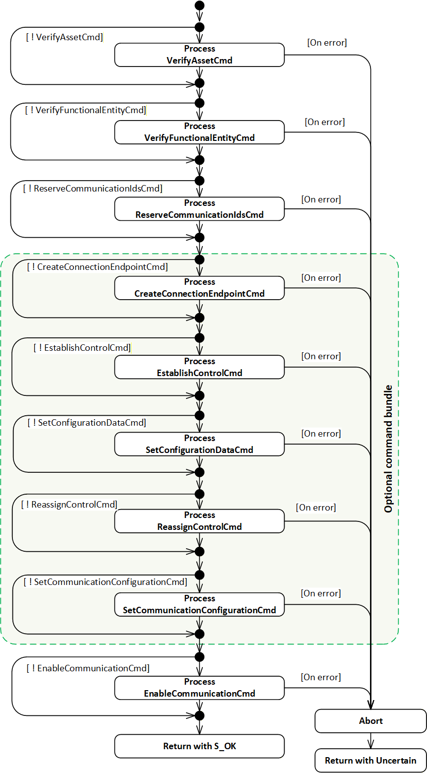
6.2.4.3.2 Command VerifyAssetCmd
If CommandMask VerifyAssetCmd is set, the EstablishConnections implementation shall execute the IAssetRevisionType VerifyAsset Method for each element in the AssetVerifications array. The VerifyAsset Method shall be called on each AssetToVerify, supplying the VerificationMode, ExpectedVerificationVariables and ExpectedAdditionalVerificationVariables as Method Arguments.
The StatusCode returned by the VerifyAsset Method and the values of its output Arguments VerificationResult, VerificationVariablesErrors, and VerificationAdditionalVariablesErrors shall be stored in the appropriate elements in AssetVerificationResults (see 10.6).
Once all array processing is complete, if at least one of the following conditions is true:
AssetToVerify was unknown or invalid,
at least one of the returned AssetVerificationResults VerificationResult equals NotSet, Mismatch, or Compatible when ExpectedVerificationResult requires Match,
at least one VerifyAsset Method execution returned an error,
then the EstablishConnections implementation shall abort processing of additional commands as described in 6.2.4.3.11.
The possible StatusCodes related to the command VerifyAssetCmd are formally defined in Table 10. The StatusCodes related to individual verification Variables are formally defined in Table 33 and Table 34.
6.2.4.3.3 Command VerifyFunctionalEntityCmd
If CommandMask VerifyFunctionalEntityCmd is set, the EstablishConnections implementation shall execute the FunctionalEntityType Verify Method for each element in ConnectionEndpointConfigurations with a non-empty ExpectedVerificationVariables array. For elements with a null or empty ExpectedVerificationVariables array, the VerificationStatus shall be set to Good_NoData, VerificationResult to NotSet, and VerificationVariablesErrors to null or empty. The Method shall be called on the FunctionalEntity identified by FunctionalEntityNode, supplying the ExpectedVerificationVariables as Method Argument.
The StatusCode returned by the Verify Method shall be stored in VerificationStatus, and the values of its output Arguments VerificationResult and VerificationVariablesErrors in VerificationResult and VerificationVariablesErrors (see 10.15).
If the FunctionalEntityNode was not found, the VerificationVariablesErrors shall be set to null or empty, and the VerificationResult shall be set to Mismatch.
Once all array processing is complete, if any one of the following conditions applies:
at least one FunctionalEntityNode was not found;
at least one VerificationResult equals Mismatch;
at least one VerificationResult equals NotSet, and VerificationVariablesErrors is populated;
at least one Verify Method execution returned an error;
the EstablishConnections implementation shall abort the processing of subsequent commands as described in 6.2.4.3.11.
The possible StatusCodes for the FunctionalEntityNodeResult are formally defined in Table 11. The possible StatusCodes for VerificationStatus are formally defined in Table 44. The possible StatusCodes for VerificationVariablesErrors are formally defined in Table 45.
6.2.4.3.4 Command ReserveCommunicationIdsCmd
6.2.4.3.4.1 General
If CommandMask ReserveCommunicationIdsCmd is set, the EstablishConnections implementation shall reserve communication model identifiers for each element in ReserveCommunicationIds.
6.2.4.3.4.2 PubSub
For a PubSub communication model, a structure of type PubSubReserveCommunicationIds2DataType (see 10.43.4) shall be used.
The EstablishConnections implementation shall reserve the requested number of IDs for both WriterGroups and DataSetWriters for each requested TransportProfileUri. For additional details, see OPC 10000-14 ReserveIds Method, including error definitions.
If any error occurs, the EstablishConnections implementation shall abort processing as described in 6.2.4.3.11.
The EstablishConnections implementation shall return the default value for each requested TransportProfileUri for the PublisherId, the reserved WriterGroupIds, and DataSetWriterIds in the output Argument ReserveCommunicationIdsResults. Additionally, if the RequestTransportSpecificInfo is set to TRUE in the request for the given TransportProfileUri, it shall also return a non-null TransportSpecificInfo. In the case of UDP-UADP, this will be a UDP port number used to receive UDP unicast traffic.
The possible StatusCodes for the ReserveCommunicationIdsResults Result are formally defined in Table 18.
6.2.4.3.4.3 Client Server
This clause may be defined in a future version of this document.
6.2.4.3.5 Command CreateConnectionEndpointCmd
If CommandMask CreateConnectionEndpointCmd is set, the EstablishConnections Method shall create a ConnectionEndpoint or shall verify and update a preconfigured ConnectionEndpoint for each element in ConnectionEndpointConfigurations (see 10.14) with Parameter defined in ConnectionEndpoint (see 10.16).
The EstablishConnections implementation shall set ConnectionEndpointConfigurationResults ConnectionEndpointResult on errors as specified in Table 12.
If IsPreconfigured is set to FALSE, the EstablishConnections implementation shall create a ConnectionEndpoint in the ConnectionEndpoints Folder of the FunctionalEntity identified by FunctionalEntityNode. The created ConnectionEndpoint shall be of the subtype specified in ConnectionEndpointTypeId. The BrowseName shall be set to Name, and all Variables shall be set according to Parameter. The appropriate entries in InputVariables and OutputVariables shall be populated.
If IsPreconfigured is set to TRUE, a preconfigured ConnectionEndpoint (see 5.5.5) shall exist with a BrowseName that matches Name in the ConnectionEndpoints Folder of the FunctionalEntity identified by FunctionalEntityNode. Its ConnectionEndpointTypeId, InputVariables and OutputVariables shall match what is specified in Parameter. IsPersistent, CleanupTimeout, and RelatedEndpoint of the preconfigured ConnectionEndpoint shall be set according to Parameter.
The implementation shall return the NodeId of the ConnectionEndpoint in the corresponding element in ConnectionEndpointConfigurationResults. If additional commands in the EstablishConnections Method sequence are present, this NodeId shall be used.
The EstablishConnections implementation shall stop processing this command on the first error and abort processing as described in 6.2.4.3.11.
The possible StatusCodes for the FunctionalEntityNodeResult are formally defined in Table 11. The possible StatusCodes for the ConnectionEndpointResult are formally defined in Table 12.
6.2.4.3.6 Command EstablishControlCmd
If CommandMask EstablishControlCmd is set, the EstablishConnections implementation shall call the EstablishControl Method on each element in ControlGroups for each element in ConnectionEndpointConfigurations. If ControlGroups is null or empty, EstablishControlResult shall be set to null or empty (see 10.15).
This command shall pass the ApplicationUri of the Session associated with the EstablishConnections Method Call as LockContext Argument to EstablishControl (see 6.5.3).
The EstablishConnections implementation shall stop processing this command on the first error and shall abort processing as described in 6.2.4.3.11.
The possible StatusCodes for the EstablishControlResult are formally defined in Table 13. The possible StatusCodes for the FunctionalEntityNodeResult are formally defined in Table 11. The possible StatusCodes for the ConnectionEndpointResult are formally defined in Table 12.
6.2.4.3.7 Command SetConfigurationDataCmd
If CommandMask SetConfigurationDataCmd is set, the EstablishConnections implementation shall apply the Value to the Key for each element in ConnectionEndpointConfigurations and each element in ConfigurationData. If the ConnectionEndpoint related to ConfigurationData has IsPersistent set, SetStoredVariables (see 6.4.6.3) shall be called for all Variables indicated by Key having the NonVolatile bit in the AccessLevelEx Attribute not set. If ConfigurationData is empty, ConfigurationDataResult shall be set to null or empty (see 10.15).
The EstablishConnections implementation shall stop processing this command on the first error and abort processing as described in 6.2.4.3.11.
The possible StatusCodes for the ConfigurationDataResult are formally defined in Table 14. The possible StatusCodes for the FunctionalEntityNodeResult are formally defined in Table 11. The possible StatusCodes for the ConnectionEndpointResult are formally defined in Table 12.
6.2.4.3.8 Command ReassignControlCmd
If CommandMask ReassignControlCmd is set, the EstablishConnections implementation shall call the ReassignControl Method on each element in ControlGroups for each element in ConnectionEndpointConfigurations. If ControlGroups is null or empty, ReassignControlResult shall be set to null or empty (see 10.15).
This command shall pass the string representation of the NodeId of the ConnectionEndpoint as LockContext Argument to ReassignControl.
The EstablishConnections implementation shall stop processing this command on the first error and shall abort processing as described in 6.2.4.3.11.
The possible StatusCodes for the ReassignControlResult are formally defined in Table 15. The possible StatusCodes for the FunctionalEntityNodeResult are formally defined in Table 11. The possible StatusCodes for the ConnectionEndpointResult are formally defined in Table 12.
6.2.4.3.9 Command SetCommunicationConfigurationCmd
6.2.4.3.9.1 General
If CommandMask SetCommunicationConfigurationCmd is set, the EstablishConnections implementation shall apply the communication model configuration supplied in CommunicationConfigurations in an atomic operation.
6.2.4.3.9.2 PubSub
The communication configuration applied in the case of a PubSub communication model is a structure of the type PubSubCommunicationConfigurationDataType (see 10.10.3).
The result of applying the communication configuration in the case of a PubSub communication model is a structure of the type PubSubCommunicationConfigurationResultDataType (see 10.11.3).
The EstablishConnections implementation shall process the supplied PubSubConfiguration with RequireCompleteUpdate and ConfigurationReferences in an atomic operation according to the behaviour of the CloseAndUpdate Method specified by OPC 10000-14. It shall set the overall processing result in the Result field of the result structure and the returned ChangesApplied, ReferenceResults, ConfigurationValues, and ConfigurationObjects in other corresponding fields of that structure.
If an error is returned, the EstablishConnections implementation shall abort processing as described in 6.2.4.3.11.
The SetCommunicationConfigurationCmd will apply the PubSubConfiguration, including the values of all Enabled flags for the configuration elements. Depending on the values of the Enabled flags, this may result in overall enabled PubSub communication without passing the EnableCommunicationCmd or parts of the PubSub communication being enabled while others are disabled.
The EstablishConnections implementation shall create the ToDataSetReader and ToDataSetWriter References according to the link information supplied in ConnectionEndpointConfigurations CommunicationLinks (see 10.13). If the PubSub configuration model is not exposed by this Server, the PubSubConnectionEndpoint DataSetReaderPath and/or PubSubConnectionEndpoint DataSetWriterPath shall be provided instead of the References. If the References (or paths) cannot be created, an appropriate StatusCode shall be set in the appropriate element in ConnectionEndpointConfigurationResults CommunicationLinksResult, and the EstablishConnections implementation shall abort processing as described in 6.2.4.3.11.
The EstablishConnections implementation shall verify the SubscribedDataSet associated with the referenced DataSetReader for each element in ConnectionEndpointConfigurations.
If ExpectedSubscribedDataSetVersion MajorVersion is 0 (for the definition of MajorVersion, see OPC 10000-14), no verification shall be performed. If ExpectedSubscribedDataSetVersion MinorVersion is 0 (for the definition of MinorVersion, see OPC 10000-14), the verification for MinorVersion shall be skipped. If the ExpectedSubscribedDataSetVersion does not match the version of the associated SubscribedDataSet, the appropriate element in ConnectionEndpointConfigurationResults CommunicationLinksResult shall be set to Bad_ConfigurationError, and the EstablishConnections implementation shall abort processing as described in 6.2.4.3.11
If InputVariableIds is used, and at least one Variable is not contained in the associated SubscribedDataSet, the appropriate element in ConnectionEndpointConfigurationResults CommunicationLinksResult shall be set to Bad_NoMatch, and the EstablishConnections implementation shall abort processing as described in 6.2.4.3.11.
The EstablishConnections implementation shall verify the PublishedDataSet associated with the referenced DataSetWriter for each element in ConnectionEndpointConfigurations.
If ExpectedPublishedDataSetVersion MajorVersion is 0, no verification shall be performed. If ExpectedPublishedDataSetVersion MinorVersion is 0, the verification for MinorVersion shall be skipped. If the ExpectedPublishedDataSetVersion does not match the version of the associated PublishedDataSet, the appropriate element in ConnectionEndpointConfigurationResults CommunicationLinksResult shall be set to Bad_ConfigurationError, and the EstablishConnections implementation shall abort processing as described in 6.2.4.3.11
If OutputVariableIds is used, and at least one Variable is not contained in the associated PublishedDataSet, the appropriate element in ConnectionEndpointConfigurationResults CommunicationLinksResult shall be set to Bad_NoMatch, and the EstablishConnections implementation shall abort processing as described in 6.2.4.3.11.
The EstablishConnections implementation shall verify that ConnectionEndpoints with their IsPersistent Property set to TRUE reference a DataSetReader and/or DataSetWriter which are persisted, including all parent Objects, i.e., WriterGroup, ReaderGroup, PubSubConnection and PublishSubscribe (see NotPersisted in OPC 10000-14). If the IsPersistent Property is set to FALSE, the EstablishConnections implementation shall verify that the DataSetReader and/or DataSetWriter are not persisted (see NotPersisted in OPC 10000-14). Otherwise, Bad_InvalidState shall be set in the appropriate element in ConnectionEndpointConfigurationResults CommunicationLinksResult, and the EstablishConnections implementation shall abort processing as described in 6.2.4.3.11.
If communication configuration exceeds capabilities (PublisherCapabilities, SubscriberCapabilities or ComponentCapabilities) of the AutomationComponent, FunctionalEntities, InputData or OutputData, or if communication configuration cannot be applied, Bad_ConfigurationError shall be set in the Result field of the result structure, and the EstablishConnections implementation shall abort processing as described in 6.2.4.3.11.
In the ConnectionEndpointConfigurationResults, the possible StatusCodes for the FunctionalEntityNodeResult are formally defined in Table 11. The possible StatusCodes for the ConnectionEndpointResult are formally defined in Table 12. The possible StatusCodes for the CommunicationLinksResult are formally defined in Table 16.
The possible StatusCodes for the CommunicationConfigurationResults Result are formally defined in Table 19.
Standard OPC UA Diagnostics can be used to obtain additional information related to any PubSub configuration errors.
6.2.4.3.9.3 Client Server
This clause may be defined in a future version of this document.
6.2.4.3.10 Command EnableCommunicationCmd
6.2.4.3.10.1 General
If CommandMask EnableCommunicationCmd is set, the EstablishConnections implementation shall enable all communication model-specific Objects related to the ConnectionEndpoints in an atomic operation.
6.2.4.3.10.2 PubSub
The EstablishConnections implementation shall enable the DataSetReader and/or DataSetWriter referenced by the ToDataSetReader and/or ToDataSetWriter References (or listed in the DataSetReaderPath and/or DataSetWriterPath if the PubSub configuration model is not exposed) for each element in ConnectionEndpointConfigurations. It shall also ensure that the parent Objects (WriterGroup, ReaderGroup, PubSubConnection, and PublishSubscribe) are enabled.
If enabling any communication model-specific Objects fails, the EstablishConnections implementation shall abort processing as described in 6.2.4.3.11.
If enabling a ConnectionEndpoint would lead to multiple DataSetReaders being enabled that reference the same TargetVariable(s), the EstablishConnections implementation shall abort processing as described in 6.2.4.3.11.
The possible StatusCodes for the FunctionalEntityNodeResult are formally defined in Table 11. The possible StatusCodes for the ConnectionEndpointResult are formally defined in Table 12. The possible StatusCodes for the EnableCommunicationResult are formally defined in Table 17.
The target of an enabled Connection is the Operational State, but various factors can affect this transition and are not reflected in the result of the EnableCommunicationCmd. The behaviour of the Connection Status and its dependency on PubSub objects is defined in 6.6.3.
6.2.4.3.10.3 Client Server
This clause may be defined in a future version of this document.
6.2.4.3.11 Abort
The EstablishConnections implementation shall abort processing if one of the issued commands fails; see the individual command behaviour descriptions in Subclauses 6.2.4.3.2 to 6.2.4.3.10. No further commands requested for this Method Call shall be executed. The result of the commands executed with this Method Call shall be rolled back according to Table 21.
| Command | Rollback action |
| VerifyAssetCmd | None |
| VerifyFunctionalEntityCmd | None |
| ReserveCommunicationIdsCmd | None |
| CreateConnectionEndpointCmd | All ConnectionEndpoints in the context of this Method Call shall be deleted. |
| EstablishControlCmd | All requested ControlGroups requested in the context of this Method Call shall be released by calling ReleaseControl. All Control References created shall be deleted. |
| SetConfigurationDataCmd | None Note: Any settings that have been applied will remain. |
| ReassignControlCmd | None |
| SetCommunicationConfigurationCmd | All communication configuration and References created in the context of this Method Call shall be deleted. |
| EnableCommunicationCmd | All communication configuration Objects that were enabled in the context of this Method Call shall be disabled. |
The Method shall set the appropriate StatusCodes for not executed commands to Bad_NothingToDo and return with an Uncertain result.
There is no rollback provided by the Method over multiple Method calls; such a rollback is the responsibility of the caller of the Method (e.g., the ConnectionManager). The caller of the Method can use the CloseConnections Method to issue a complete rollback.
6.2.5 CloseConnections method
6.2.5.1 CloseConnections signature
This Method disables one or more Connections. Optionally, it also removes these Connections. It is recommended that this Method has the execute privilege for the well-known Role ConnectionAdmin as defined in Subclause 5.9.
The signature of the Method is described below, and the arguments are described in Table 22.
Signature
	CloseConnections (
	  [in] 0:NodeId[]			ConnectionEndpoints,
	  [in] 0:Boolean			Remove,
	  [out] 0:StatusCode[]		Results
);| Argument | Description |
| ConnectionEndpoints | The list of Connections to be closed. |
| Remove | When TRUE, the Objects dynamically created for the Connection are removed. |
| Results | The results of closing the Connections identified by the ConnectionEndpoints argument, see Table 24. The length of this array shall match the length of the ConnectionEndpoints list. Clients may inspect this list to determine which Connections failed to be closed. |
The possible Method result codes are formally defined in Table 23.
| Result Code | Description |
| Uncertain | There was at least one error or warning for one of the Connections. Results will contain additional information. |
The possible Results StatusCodes are formally defined in Table 24.
| Result Code | Description |
| Bad_NodeIdUnknown | The NodeId for the requested ConnectionEndpoint does not exist in the Server address space. |
| Bad_NodeIdInvalid | The syntax of the NodeId for the requested ConnectionEndpoint was invalid. |
| Bad_InvalidArgument | The NodeId for the requested ConnectionEndpoint was not a ConnectionEndpoint. |
The CloseConnections Method representation in the AddressSpace is formally defined in Table 25.
| Attribute | Value | ||||
| BrowseName | 3:CloseConnections | ||||
| References | Node Class | BrowseName | DataType | TypeDefinition | Other |
|---|---|---|---|---|---|
| 0:HasProperty | Variable | 0:InputArguments | 0:Argument[] | 0:PropertyType | M |
| 0:HasProperty | Variable | 0:OutputArguments | 0:Argument[] | 0:PropertyType | M |
| 0:GeneratesEvent | ObjectType | 2:AuditUpdateMethodResultEventType | Defined in 8.4 | ||
| ConformanceUnits | |||||
|---|---|---|---|---|---|
| UAFX AutomationComponent Base |
If Auditing is supported, the AutomationComponent shall generate an Event of type AuditUpdateMethodResultEventType for all CloseConnections Method calls. The SourceNode for this Event shall be the AutomationComponent that CloseConnections Method was called on.
6.2.5.2 CloseConnections behaviour
The Method implementation shall disable all communication model Objects for each element in ConnectionEndpoints in an atomic operation. For additional details on ConnectionEndpoints, see 6.6, and PubSubConnectionEndpoints, see 6.6.3.
If PubSub is used as the communication model for a ConnectionEndpoint, the Method implementation shall only disable the DataSetReader and DataSetWriter referenced by ToDataSetReader and/or ToDataSetWriter References (or identified by DataSetReaderPath and/or DataSetWriterPath if the PubSub configuration model is not exposed) if no further References from other ConnectionEndpoints exist. Their parent Objects (WriterGroup, ReaderGroup, PubSubConnection, and PublishSubscribe) shall be left in their current state.
The behaviour of the Client Server communication model may be defined in a future version of this document.
The CleanupTimeout processing shall be disabled.
If Remove is TRUE, the Method implementation shall remove what has been dynamically created by EstablishConnections Method Call(s) related to the ConnectionEndpoints. This includes any configuration specific to the utilized communication model, all related communication model Objects if not referenced from other ConnectionEndpoints, the ConnectionEndpoints, and all persisted items. In addition, all ControlGroups-based restrictions placed on Objects shall be released. Preconfigured Objects or Objects referenced by other ConnectionEndpoints shall not be removed.
What occurs with the ConfigurationData that was applied when establishing the ConnectionEndpoints is vendor-specific.
6.2.6 AutomationComponentCapabilitiesType
The AutomationComponentCapabilitiesType extends the FolderType defined in OPC 10000-5. It shall be restricted to contain only Variables that reflect the capabilities of the AutomationComponentType.
The AutomationComponentCapabilitiesType is formally defined in Table 26.
| Attribute | Value | ||||
| BrowseName | 3:AutomationComponentCapabilitiesType | ||||
| IsAbstract | False | ||||
| References |
Node
Class | BrowseName | DataType | TypeDefinition | Other |
|---|---|---|---|---|---|
| Subtype of the 0:FolderType defined in OPC 10000-5 | |||||
| 3:HasCapability | Variable | 3:<Capability> | 0:BaseDataType | 0:BaseDataVariableType | OP |
| 3:HasCapability | Variable | 3:SupportsPersistence | 0:Boolean | 0:BaseDataVariableType | O |
| 3:HasCapability | Variable | 3:MaxFunctionalEntities | 0:UInt32 | 0:BaseDataVariableType | O |
| 3:HasCapability | Variable | 3:MaxConnections | 0:UInt32 | 0:BaseDataVariableType | O |
| 3:HasCapability | Variable | 3:MinConnections | 0:UInt32 | 0:BaseDataVariableType | O |
| 3:HasCapability | Variable | 3:MaxConnectionsPerCall | 0:UInt32 | 0:BaseDataVariableType | O |
| 3:HasCapability | Variable | 3:CommandBundleRequired | 0:Boolean | 0:BaseDataVariableType | O |
| ConformanceUnits | |||||
|---|---|---|---|---|---|
| UAFX AutomationComponent Base |
<Capability> - is an OptionalPlaceholder (defined in OPC 10000-3) to indicate that additional capabilities may be added by this document, by a companion specification or by a vendor application. These capabilities shall include a Description, and they follow all of the rules associated with an OptionalPlaceholder.
The optional SupportsPersistence indicates whether this AutomationComponent supports persistent Connections. For additional details on persistence, see 6.6. If this capability is not present or set to FALSE, the AutomationComponent does not support persistent Connections.
The optional MaxFunctionalEntities indicates the maximum number of FunctionalEntities that the AutomationComponent can support.
The optional MaxConnections indicates the maximum number of Connections that the AutomationComponent can support. This number may be further restricted based on the type of Connections being provided (i.e., a high-speed Connection might further reduce the number of available Connections).
The optional MinConnections indicates the minimum number of Connections that the AutomationComponent can always guarantee. MinConnections shall be less than or equal to MaxConnections (if both exist). The actual number of Connections that might exist may be some number between the MinConnections and the MaxConnections.
The optional MaxConnectionsPerCall indicates the maximum number of Connections that can be established in a single EstablishConnections Call (see 6.2.4). MaxConnectionsPerCall shall be less than or equal to MaxConnections (if both exist).
If MaxFunctionalEntities, MaxConnections, and MaxConnectionsPerCall are not present, then no limit is specified.
The optional CommandBundleRequired indicates whether this AutomationComponent requires a single Method Call for bundled commands when EstablishConnections is called (see 6.2.4.3.1). If the capability is not present or set to FALSE, the AutomationComponent supports individual calls.
6.2.7 PublisherCapabilitiesType
The PublisherCapabilitiesType is a subtype of the BaseObjectType. It is used to contain the various Publisher capabilities that can be supported. An instance of this ObjectType groups the capabilities and can be deployed as part of any Object that desires to expose a range of capabilities that are supported by that Object.
It is formally defined in Table 27.
| Attribute | Value | ||||
| BrowseName | 3:PublisherCapabilitiesType | ||||
| IsAbstract | False | ||||
| References | Node Class | BrowseName | DataType | TypeDefinition | Other |
|---|---|---|---|---|---|
| Subtype of the 0:BaseObjectType defined in OPC 10000-5 | |||||
| 0:HasComponent | Variable | 3:SupportedPublishingIntervals | 2:IntervalRange[] | 0:BaseDataVariableType | O |
| 0:HasComponent | Variable | 3:SupportedQos | 3:PublisherQosDataType[] | 0:BaseDataVariableType | O |
| 0:HasComponent | Variable | 3:PreconfiguredPublishedDataSets | 0:String[] | 0:BaseDataVariableType | O |
| 0:HasComponent | Variable | 3:PreconfiguredDataSetOnly | 0:Boolean | 0:BaseDataVariableType | O |
| 0:HasComponent | Variable | 3:SupportedTransportProtocolMappings | 0:String[] | 0:BaseDataVariableType | O |
| ConformanceUnits | |||||
|---|---|---|---|---|---|
| UAFX AutomationComponent PublisherCapabilities Base |
SupportedPublishingIntervals provides the supported intervals for publishing. If this capability is not present, it indicates that no restrictions are defined by this instance.
SupportedQos provides the supported Quality of Service settings. If this capability is not present, it indicates that no restrictions are defined by this instance.
PreconfiguredPublishedDataSets provides the names of preconfigured PublishedDataSets (see 5.5.5), where the name is the string part of the BrowseName of a PublishedDataSet that is listed in the PublishedDataSets Folder tree of the PublishSubscribe Object (see OPC 10000-14). If PublisherCapabilities is referenced from a FunctionalEntity (see 6.4.2) or OutputData (see 6.4.5), a preconfigured PublishedDataSet shall only reference OutputVariables of this FunctionalEntity and its sub-FunctionalEntities. If the PublisherCapabilities is referenced from an AutomationComponent, a PreconfiguredPublishedDataSet shall only reference OutputVariables from FunctionalEntities that are part of the AutomationComponent. When the preconfigured PublishedDataSet is used in a ConnectionConfigurationSet, Connections shall be established to one or more of the FunctionalEntities whose variables are present in the DataSet. If this capability is not present, it indicates that no preconfigured PublishedDataSets are defined by this instance.
PreconfiguredDataSetOnly, if set to TRUE, indicates that the Publisher supports publishing of preconfigured PublishedDataSets only. If set to FALSE, the Publisher supports publishing of customized PublishedDataSets as well as preconfigured PublishedDataSets. If this capability is omitted, it is the same as indicating a False.
SupportedTransportProtocolMappings provides an array of protocol names that are supported for communication. The name shall be one of the schemes (starting strings) defined in OPC 10000-14 Transport Protocol Mappings, e.g. "opc.udp" or "opc.dtls" or "opc.eth" If this capability is not present, it indicates that no restrictions are defined by this instance.
6.2.8 SubscriberCapabilitiesType
The SubscriberCapabilitiesType is a subtype of the BaseObjectType. It is used to contain the various Subscriber capabilities that can be supported. An instance of this ObjectType groups the capabilities and can be deployed as part of any Object that desires to expose a range of capabilities that are supported by that Object.
It is formally defined in Table 28.
| Attribute | Value | ||||
| BrowseName | 3:SubscriberCapabilitiesType | ||||
| IsAbstract | False | ||||
| References | Node Class | BrowseName | DataType | TypeDefinition | Other |
|---|---|---|---|---|---|
| Subtype of the 0:BaseObjectType defined in OPC 10000-5 | |||||
| 0:HasComponent | Variable | 3:SupportedPublishingIntervals | 2:IntervalRange[] | 0:BaseDataVariableType | O |
| 0:HasComponent | Variable | 3:SupportedQos | 3:SubscriberQosDataType[] | 0:BaseDataVariableType | O |
| 0:HasComponent | Variable | 3:SupportedMessageReceiveTimeouts | 2:IntervalRange[] | 0:BaseDataVariableType | O |
| 0:HasComponent | Variable | 3:PreconfiguredSubscribedDataSets | 0:String[] | 0:BaseDataVariableType | O |
| 0:HasComponent | Variable | 3:PreconfiguredDataSetOnly | 0:Boolean | 0:BaseDataVariableType | O |
| 0:HasComponent | Variable | 3:SupportedTransportProtocolMappings | 0:String[] | 0:BaseDataVariableType | O |
| ConformanceUnits | |||||
|---|---|---|---|---|---|
| UAFX AutomationComponent SubscriberCapabilities Base |
SupportedPublishingIntervals provides the intervals for publications, which this Subscriber is able to receive. If this capability is not present, it indicates that no restrictions are defined by this instance.
SupportedQos provides the supported Quality of Service settings. If this capability is not present, it indicates no restrictions are defined by this instance.
SupportedMessageReceiveTimeouts provides the supported timeouts for receiving messages. If this capability is not present, it indicates no restrictions are defined by this instance.
PreconfiguredSubscribedDataSets provides the names of preconfigured StandaloneSubscribedDataSets (see 5.5.5), where the name is the string part of the BrowseName of a StandaloneSubscribedDataSet that is listed in the SubscribedDataSets Folder tree of the PublishSubscribe Object (see OPC 10000-14). If SubscriberCapabilities is referenced from a FunctionalEntity (see 6.4.2) or InputData (see 6.4.4), a preconfigured StandaloneSubscribedDataSet shall only reference InputVariables from the FunctionalEntity and its sub-FunctionalEntities. If the SubscriberCapabilities is referenced from an AutomationComponent, a preconfigured StandaloneSubscribedDataSet shall only reference InputVariables from FunctionalEntities that are part of the AutomationComponent. When the preconfigured StandaloneSubscribedDataSet is used in a ConnectionConfigurationSet, Connections shall be established to one or more of the FunctionalEntities whose variables are present in the DataSet. If this capability is not present, it indicates no preconfigured StandaloneSubscribedDataSets are defined by this instance.
PreconfiguredDataSetOnly, if set to TRUE, indicates that the Subscriber only supports subscribing with preconfigured StandaloneSubscribedDataSets. If set to FALSE, the subscriber supports subscribing with customized SubscribedDataSets as well as preconfigured StandaloneSubscribedDataSets. If this capability is omitted, it is the same as indicating a False.
SupportedTransportProtocolMappings provides an array of protocol names that are supported for communication. The name shall be one of the schemes (starting strings) defined in OPC 10000-14 Transport Protocol Mappings, e.g. "opc.udp" or "opc.dtls" or "opc.eth". If this capability is not present, it indicates that no restrictions are defined by this instance.
6.3 FxAssetType definition
6.3.1 Overview
Figure 21 provides an illustration of the FxAssetType model. The figure includes an illustration of the Nodes that are added via the Interfaces.
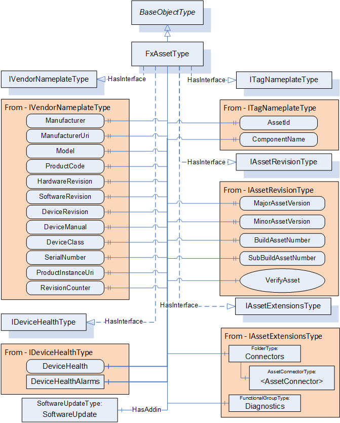
6.3.2 FxAssetType definition
The FxAssetType provides general information as defined in OPC 10000-100. It also includes additional information that is defined as an Interface. Being defined as an Interface allows other device models to include what is required for OPC UA FX Asset modelling without having to implement the FxAssetType Object directly. Conformance testing shall test that the required information, defined by the Interfaces included in the FxAssetType, is available, not that the Object is of FxAssetType. Any Object that implements the Interfaces defined in FxAssetType that are required in profiles is considered an Asset.
Additional References are defined as part of the model to show relationships between Assets, within Assets, and between Assets and FunctionalEntities and the overall AutomationComponent model (see 11.1). These References allow the creation of nested Assets. For additional examples of nested Assets, see D.2.
The FxAssetType is formally defined in Table 29.
| Attribute | Value | ||||
| BrowseName | 3:FxAssetType | ||||
| IsAbstract | False | ||||
| References |
Node
Class | BrowseName | DataType | TypeDefinition | Other |
|---|---|---|---|---|---|
| Subtype of the 0:BaseObjectType defined in OPC 10000-5 | |||||
| 0:HasInterface | ObjectType | 5:IVendorNameplateType | |||
| Applied from IVendorNameplateType (defined in OPC 10000-100 ) | |||||
|---|---|---|---|---|---|
| 0:HasProperty | Variable | 5:Manufacturer | 0:LocalizedText | 0:PropertyType | O |
| 0:HasProperty | Variable | 5:ManufacturerUri | 0:String | 0:PropertyType | O |
| 0:HasProperty | Variable | 5:Model | 0:LocalizedText | 0:PropertyType | O |
| 0:HasProperty | Variable | 5:ProductCode | 0:String | 0:PropertyType | O |
| 0:HasProperty | Variable | 5:HardwareRevision | 0:String | 0:PropertyType | O |
| 0:HasProperty | Variable | 5:SoftwareRevision | 0:String | 0:PropertyType | O |
| 0:HasProperty | Variable | 5:DeviceRevision | 0:String | 0:PropertyType | O |
| 0:HasProperty | Variable | 5:DeviceManual | 0:String | 0:PropertyType | O |
| 0:HasProperty | Variable | 5:DeviceClass | 0:String | 0:PropertyType | O |
| 0:HasProperty | Variable | 5:SerialNumber | 0:String | 0:PropertyType | O |
| 0:HasProperty | Variable | 5:ProductInstanceUri | 0:String | 0:PropertyType | O |
| 0:HasProperty | Variable | 5:RevisionCounter | 0:Int32 | 0:PropertyType | O |
| 0:HasInterface | ObjectType | 5:ITagNameplateType | |||
| Applied from ITagNameplateType (defined in OPC 10000-100 ) | |||||
|---|---|---|---|---|---|
| 0:HasProperty | Variable | 5:AssetId | 0:String | 0:PropertyType | O |
| 0:HasProperty | Variable | 5:ComponentName | 0:LocalizedText | 0:PropertyType | O |
| 0:HasInterface | ObjectType | 3:IAssetRevisionType | |||
| Applied from IAssetRevisionType | |||||
|---|---|---|---|---|---|
| 0:HasProperty | Variable | 3:MajorAssetVersion | 0:UInt16 | 0:PropertyType | O |
| 0:HasProperty | Variable | 3:MinorAssetVersion | 0:UInt16 | 0:PropertyType | O |
| 0:HasProperty | Variable | 3:BuildAssetNumber | 0:UInt16 | 0:PropertyType | O |
| 0:HasProperty | Variable | 3:SubBuildAssetNumber | 0:UInt16 | 0:PropertyType | O |
| 0:HasComponent | Method | 3:VerifyAsset | Defined in 6.3.3 | O | |
| 0:HasInterface | ObjectType | 3:IAssetExtensionsType | |||
| Applied from IAssetExtensionsType | |||||
|---|---|---|---|---|---|
| 0:HasComponent | Object | 3:Connectors | 0:FolderType | O | |
| 0:HasComponent | Object | 5:Diagnostics | 5:FunctionalGroupType | O | |
| 0:HasInterface | ObjectType | 5:IDeviceHealthType | |||
| Applied from IDeviceHealthType (defined in OPC 10000-100) | |||||
|---|---|---|---|---|---|
| 0:HasComponent | Variable | 5:DeviceHealth | 5:DeviceHealthEnumeration | 0:BaseDataVariableType | O |
| 0:HasComponent | Object | 5:DeviceHealthAlarms | 0:FolderType | O | |
| 0:HasAddIn | Object | 5:SoftwareUpdate | 5:SoftwareUpdateType | O | |
| ConformanceUnits | |||||
|---|---|---|---|---|---|
| UAFX FxAsset Type |
The components of the FxAssetType have additional subcomponents, which are defined in Table 30.
| BrowsePath | References | NodeClass | BrowseName | DataType | TypeDefinition | Others |
| 5:Diagnostics | 0:HasComponent | Variable | 3:UpTime | 0:Duration | 0:BaseDataVariableType | O |
| 5:Diagnostics | 0:HasComponent | Variable | 3:CurrentCPUUtilization | 0:Float | 0:BaseDataVariableType | O |
| 5:Diagnostics | 0:HasComponent | Variable | 3:MaxCPUUtilization | 0:Float | 0:BaseDataVariableType | O |
| 5:Diagnostics | 0:HasComponent | Variable | 3:CurrentMemoryUtilization | 0:Float | 0:BaseDataVariableType | O |
| 5:Diagnostics | 0:HasComponent | Variable | 3:MaxMemoryUtilization | 0:Float | 0:BaseDataVariableType | O |
| 3:Connectors | 0:HasComponent | Object | 3:<AssetConnector> | 3:AssetConnectorType | OP |
The display name of the Asset should be used to provide the name that an operator/engineer would expect for the Asset.
For examples of how to apply the OPC UA FX Information Model to other models, see Annex B. For examples of FxAssetType models, see Annex D.
The following are the definitions associated with the IVendorNameplateType interface; they are enclosed in quotes and included here for clarity. Their formal definition is in OPC 10000-100. Additional notes are provided for recommended usage within this model.
"Manufacturer provides the name of the company that manufactured the item to which this Interface is applied."
"ManufacturerUri provides a unique identifier for this company. This identifier should be a fully qualified domain name; however, it may be a GUID or similar construct that ensures global uniqueness."
"Model provides the name of the product."
"ProductCode provides a unique combination of numbers and letters used to identify the product. It may be the order information displayed on type shields or in ERP systems."
"HardwareRevision provides the revision level of the hardware of an Asset."
"SoftwareRevision provides the version or revision level of the software component, the software/firmware of a hardware component, or the software/firmware of the Device."
"DeviceRevision provides the overall revision level of a hardware component or the Device. As an example, this Property can be used in ERP systems together with the ProductCode Property."
"DeviceManual allows specifying an address of the user manual for an Asset. It may be a pathname in the file system or a URL (Web address)."
"DeviceClass indicates in which domain or for what purpose a certain ComponentType is used. Examples are "ProgrammableController", "RemoteIO", and "TemperatureSensor". This standard does not predefine any DeviceClass names. More specific standards that utilize this Interface will likely introduce such classifications."
Within this model, this information is typically used for display purposes only. It is recommended that if this Property is provided, the string should be from some standardized dictionary.
"SerialNumber is a unique production number of the manufacturer of the Asset. This is often stamped on the outside of a physical component and may be used for traceability and warranty purposes."
"ProductInstanceUri is a globally unique resource identifier provided by the manufacturer. This is often stamped on the outside of a physical component and may be used for traceability and warranty purposes. The maximum length is 255 characters. The syntax of the ProductInstanceUri is: <ManufacturerUri>/<any string> where <any string> is unique among all instances using the same ManufacturerUri."
Within this model, ProductInstanceUri, SerialNumber, or both shall be provided for Assets listed directly in the Assets Folder of the AutomationComponent.
"RevisionCounter is an incremental counter indicating the number of times the configuration data within an Asset has been modified."
Within this model, this configuration data may be one of the items defined in this document, but more likely, it is a configuration item that has been added to the asset model either as part of a companion specification or as part of an instance.
The following two definitions are from the ITagNameplateType interface. They are enclosed in quotes and included here for clarity. Their formal definition is in OPC 10000-100. Additional notes are provided for recommended usage within OPC UA FX.
"AssetId is a user-writable alphanumeric character sequence uniquely identifying a component. The ID is provided by the integrator or user of the device. It typically contains an identifier in a branch use case or user-specific naming scheme. This could be, for example, a reference to an electric scheme. "
"ComponentName is a user-writable name provided by the integrator or user of the component."
The following two definitions are from the IDeviceHealthType interface. They are enclosed in quotes and included here for clarity. Their formal definition is in OPC 10000-100. Additional notes are provided for recommended usage within OPC UA FX.
"The DeviceHealthEnumeration DataType is an enumeration that defines the device condition."
"DeviceHealthAlarms shall be used for instances of the DeviceHealth AlarmTypes specified in OPC 10000-100." AlarmType instances can also be defined in other specifications, such as OPC 10000-110 or this document.
The IDeviceHealthType Interface shall be implemented on top-level Assets and any other Assets that maintain their own status information. DeviceHealth of the top-level Assets is aggregated into AggregatedDeviceHealth (see 9.1.2). Whether nested Assets aggregate their DeviceHealth into DeviceHealth of their parent Asset is vendor-specific and is further described in OPC 10000-110 (e.g., for redundant nested Assets, one might fail without the parent Asset failing).
SoftwareUpdate is an AddIn (see OPC 10000-100) that defines support for firmware or software updates. This optional AddIn should be included in any Asset that includes firmware or software that can be upgraded or changed. For a definition of the AddIn concept, see OPC 10000-3.
The following definitions are associated with the IAssetRevisionType interface (see 7.3).
The MajorAssetVersion shall be updated for major changes in an Asset that may break compatibility with previous versions.
The MinorAssetVersion shall be updated for minor changes in an Asset that should not change the behaviour of the Asset regarding compatibility. Higher numeric values of MinorAssetVersion should be backwards compatible with lower ones, e.g., behaviour that is present in MinorAssetVersion 12 shall still be supported by MinorAssetVersion 13 or greater. An incremented MinorAssetVersion may add new behaviour which is not present in a lower MinorAssetVersion while retaining existing functionality.
The BuildAssetNumber and SubBuildAssetNumber reflect detailed information about the version of the Asset. Together with the MajorAssetVersion and MinorAssetVersion, they provide the capability to unambiguously identify a specific version of an Asset.
The following definitions are associated with the IAssetExtensionsType interface (see 7.4).
Connectors is a Folder used to group and list physical- or software-based connectors (instances of AssetConnectorType) that can be used to link multiple Assets. A connector provides more information about an Asset connection than a simple Reference can. For a formal definition of the AssetConnectorType, see 6.3.4.
Diagnostics is a FunctionalGroup (Folder) that contains Variables that report diagnostic statistics and counters (see OPC 10000-100 Recommended FunctionalGroup BrowseNames).
The UpTime Variable provides the module up-time since the last power-on.
The CurrentCPUUtilization Variable provides the current CPU utilization in percent (the calculation is vendor-specific).
The MaxCPUUtilization Variable provides the maximum CPU utilization in percent since the last power-on (the calculation is vendor-specific).
The CurrentMemoryUtilization Variable provides the current memory utilization in percent (the calculation is vendor-specific).
The MaxMemoryUtilization Variable provides the maximum memory utilization in percent since the last power on (the calculation is vendor-specific).
6.3.3 VerifyAsset method
The VerifyAsset Method allows a Client to verify whether an Asset's identity and functionality meet the expectations of system engineering.
Three different modes are available for Asset verification (see VerificationMode). Each mode depends on a set of mandatory and optional Variables (see definition of AssetVerificationModeEnum in 10.4) to be present for verification. The VerifyAsset Method also accepts additional Variables for verification.
An Asset implementing the VerifyAsset Method shall at least support the VerificationMode AssetCompatibility and expose the corresponding mandatory and implemented optional Variables in its Information Model. If at least one of the optional Variables, SerialNumber and/or ProductInstanceUri, is provided, then the VerificationModes AssetIdentity and AssetIdentityAndCompatibility shall be supported.
The signature of this Method is specified below; the arguments are defined in Table 31.
Signature
	VerifyAsset (
	[in] 2:AssetVerificationModeEnum	VerificationMode,
	[in] 0:KeyValuePair[]			ExpectedVerificationVariables,
	[in] 2:NodeIdValuePair[]			ExpectedAdditionalVerificationVariables,
	[out] 2:AssetVerificationResultEnum	VerificationResult,
	[out] 0:StatusCode[]			VerificationVariablesErrors,
	[out] 0:StatusCode[]			VerificationAdditionalVariablesErrors
	);
| Argument | Description |
| VerificationMode | Mode for Asset verification: see 10.4 for a definition of the AssetVerificationModeEnum. |
| ExpectedVerificationVariables | An array of KeyValuePair containing verification Variables. Key shall be the BrowseName of the Variable to verify (relative to the Asset this Method is being called on), and Value is its expected value. A Client shall pass all mandatory and implemented optional Variables depending on VerificationMode: AssetCompatibility: IVendorNameplateType ManufacturerUri (M), IVendorNameplateType ProductCode (M), IAssetRevisionType MajorAssetVersion (M), IAssetRevisionType MinorAssetVersion (M), IAssetRevisionType BuildAssetNumber (O), IAssetRevisionType SubBuildAssetNumber (O), IVendorNameplateType HardwareRevision (O), IVendorNameplateType SoftwareRevision (O) AssetIdentity: IVendorNameplateType ManufacturerUri (M), IVendorNameplateType ProductCode (M), At least one of: IVendorNameplateType SerialNumber, IVendorNameplateType ProductInstanceUri AssetIdentityAndCompatibility: All mandatory Variables of both AssetCompatibility and AssetIdentity are mandatory for top-level Assets (those directly in the Assets Folder in the AutomationComponent). All optional Variables of AssetCompatibility are optional. |
| ExpectedAdditionalVerificationVariables | An array of NodeIdValuePair containing additional verification Variables. NodeId shall be the NodeId of the Variable to verify, and Value shall be its expected value. This array may be null or empty if no additional Variables are to be verified. The following rules shall apply to the usage of NodeIdValuePair: If NodeId refers to variables of type array, it shall be verified that Value is a matching array. If the ArrayIndex is provided, the value shall be checked against the corresponding index. If Value is null, it shall be verified that NodeId exists. The Node may be a of any NodeClass, but only the NodeClass of Variable or VariableType can have a non-null value. |
| VerificationResult | The result of Asset verification is determined by the Method implementation; see 10.7 for a definition of the AssetVerificationResultEnum. The following general rule applies to determine VerificationResult: All string-type Variables shall be stripped of leading and trailing whitespaces before processing. The following specific rules apply to determine AssetCompatibility:
NotSet: Shall be returned if verification is not possible due to invalid elements in ExpectedVerificationVariables and/or ExpectedAdditionalVerificationVariables (e.g., a Variable was passed by the Client that does not exist in the Asset's Information Model). Match: Shall be returned if all Variables in ExpectedVerificationVariables and ExpectedAdditionalVerificationVariables exist in the Information Model of this Asset and their actual values are identical to the expected values. Compatible: Shall be returned if all of the following conditions apply: The actual value of at least one ExpectedVerificationVariables does not match its expected value, but overall, the Asset is still compatible (e.g., expected IAssetRevisionType MinorAssetVersion 1, but the actual value is 2, being backwards compatible to 1). All ExpectedAdditionalVerificationVariables match their expected values. Mismatch: Shall be returned if any of the following conditions apply: The actual value of at least one ExpectedVerificationVariables does not match its expected value, and the Asset overall is not compatible. The actual value of at least one ExpectedAdditionalVerificationVariables does not match its expected value. If this value is set, VerificationVariablesErrors and/or VerificationAdditionalVariablesErrors shall be populated. The following specific rules apply to determine AssetIdentity: NotSet: See description for AssetCompatibility. Match: See description for AssetCompatibility. Compatible: Shall never be returned.
Mismatch: Shall be returned if all Variables in ExpectedVerificationVariables and ExpectedAdditionalVerificationVariables exist and the actual value of at least one does not match its expected value. The following specific rules apply to determine AssetIdentityAndCompatibility: NotSet: Shall be returned if verification of AssetCompatibility or AssetIdentity or both result in NotSet. Match: Shall be returned if both the verification of AssetIdentity and AssetCompatibility result in Match. Compatible: Shall be returned if verification of AssetIdentity results in Match and verification of AssetCompatibility results in Compatible. Mismatch: Shall be returned if verification of AssetCompatibility or AssetIdentity or both result in Mismatch. |
| VerificationVariablesErrors | An array of StatusCode corresponding to the ExpectedVerificationVariables input argument that indicates any errors that occurred during the processing of ExpectedVerificationVariables. If this array is populated, the length of this array shall match the length of ExpectedVerificationVariables. For possible values in this array, see Table 33. |
| VerificationAdditionalVariablesErrors | An array of StatusCode corresponding to the ExpectedAdditionalVerificationVariables input argument that indicates any errors that occurred during the processing of ExpectedAdditionalVerificationVariables. If this array is populated, the length of this array shall match the length of ExpectedAdditionalVerificationVariables. For possible values in this array, see Table 34. |
The possible Method result codes are formally defined in Table 32. The order in which checks are performed is vendor-specific. A bad result code in the Method (an error code in Table 32) shall result in all output arguments listed in the Method signature being empty/null. The check of provided Variables (Bad_InvalidArgument) shall take precedence over the actual checks related to the values of provided Variables.
| Result Code | Description |
| Bad_InvalidArgument | One or more arguments are invalid, or ExpectedVerificationVariables are missing Variables that are mandatory for the chosen VerificationMode (or optional, and the implementation of this Method expects them because they are implemented). |
| Bad_NotSupported | The Client specified a VerificationMode that is not supported by this Method implementation. |
| Uncertain | At least one element in ExpectedVerificationVariables and/or ExpectedAdditionalVerificationVariables is invalid or failed verification. VerificationVariablesErrors and/or VerificationAdditionalVariablesErrors will contain additional information. |
The VerificationVariablesErrors StatusCodes are formally defined in Table 33.
| Result Code | Description |
| Bad_BrowseNameInvalid | The BrowseName for the verification Variable is invalid or was passed more than once. |
| Bad_TypeMismatch | The value supplied for the verification Variable (if non-null) is not of the same type as the implemented verification Variable. |
| Bad_OutOfRange | The value supplied for the Variable is not equal to the actual value of the Variable (if non-null). |
| Good | The verification for this Variable succeeded. |
The VerificationAdditionalVariablesErrors StatusCodes are formally defined in Table 34.
| Result Code | Description |
| Bad_OutOfRange | The value supplied for the Variable is not equal to the actual value of the Variable (if non-null). |
| Bad_TypeMismatch | The value supplied for the verification Variable (if non-null) is not of the same type as the implemented verification variable. |
| Bad_NodeIdInvalid | The NodeIdValuePair contains a NodeId in its key field with an invalid syntax. |
| Bad_NodeIdUnknown | The NodeIdValuePair contains a NodeId in its key field that does not exist in the Server address space. |
| Good | The verification for this Variable succeeded. |
The VerifyAsset Method representation in the AddressSpace is formally defined in Table 35.
| Attribute | Value | ||||
| BrowseName | 3:VerifyAsset | ||||
| References | Node Class | BrowseName | DataType | TypeDefinition | Other |
|---|---|---|---|---|---|
| 0:HasProperty | Variable | 0:InputArguments | 0:Argument[] | 0:PropertyType | M |
| 0:HasProperty | Variable | 0:OutputArguments | 0:Argument[] | 0:PropertyType | M |
| ConformanceUnits | |||||
|---|---|---|---|---|---|
| UAFX IAssetRevision VerifyAsset Base |
6.3.4 AssetConnectorType definition
The AssetConnectorType provides information about physical connections that are part of an Asset. An example of these connections might be slots in which cards can be mounted or sockets to which cables can be connected. For additional examples, see Annex D. It is expected that subtypes of this type that provide or require additional Properties or Variables will be created. Figure 22 provides an illustration of the AssetConnectorType.
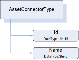
The AssetConnectorType is an abstract type and must be subtyped. It is formally defined in Table 36.
| Attribute | Value | ||||
| BrowseName | 3:AssetConnectorType | ||||
| IsAbstract | True | ||||
| References | Node Class | BrowseName | DataType | TypeDefinition | Other |
|---|---|---|---|---|---|
| Subtype of the 0:BaseObjectType defined in OPC 10000-5 | |||||
| 0:HasProperty | Variable | 3:Id | 0:UInt16 | 0:PropertyType | O |
| 0:HasProperty | Variable | 3:Name | 0:String | 0:PropertyType | O |
| 0:HasSubtype | ObjectType | 3:SlotType | Defined in 6.3.5 | ||
| 0:HasSubtype | ObjectType | 3:SocketType | Defined in 6.3.6 | ||
| 0:HasSubtype | ObjectType | 3:ClampType | Defined in 6.3.7 | ||
| 0:HasSubtype | ObjectType | 3:ClampBlockType | Defined in 6.3.8 | ||
| ConformanceUnits | |||||
|---|---|---|---|---|---|
| UAFX AssetConnector Slot Base | |||||
| UAFX AssetConnector Socket Base | |||||
| UAFX AssetConnector Clamp Base | |||||
| UAFX AssetConnector ClampBlock Base |
Id provides the (physical) ID of the connector, representing the physical location of the connector in the Asset. The use of this ID can be further explained or defined in subtypes.
Name provides the physical label that is associated with this connector. The use of Name can be further explained or defined in subtypes. For example, it might be the name of the target of this connector, the DisplayName would be slot1, and the Name would be Pump1.
Figure 23 provides an illustration of some of the possible subtypes of the AssetConnectorType.
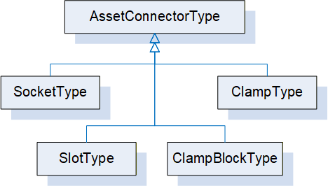
Some connector types are used to link other Assets, while other AssetConnectorTypes might be used to indicate physical connections.
6.3.5 SlotType definition
The SlotType represents a physical slot to which a module can be attached, e.g., in a modular Asset like a PLC backplane or modular IO device.
The SlotType is formally defined in Table 37.
| Attribute | Value | ||||
| BrowseName | 3:SlotType | ||||
| IsAbstract | False | ||||
| References | Node Class | BrowseName | DataType | TypeDefinition | Other |
|---|---|---|---|---|---|
| Subtype of the 3:AssetConnectorType | |||||
| 0:HasProperty | Variable | 3:Id | 0:UInt16 | 0:PropertyType | M |
| 0:HasProperty | Variable | 3:LogicalId | 0:UInt16 | 0:PropertyType | O |
| ConformanceUnits | |||||
|---|---|---|---|---|---|
| UAFX AssetConnector Slot Base |
Id is from AssetConnectorType and is mandatory in SlotType. It shall start at 1 and increment by 1 for each physical slot in a rack or device.
The optional LogicalId represents the "logical slot number" that might be assigned to a physical ID. For example, module 3 is physically plugged into slot 3, but internally it is used as slot 8.
Each Slot that has a module plugged into it shall have a HasPhysicalComponent Reference (see OPC 10000-23) or a subtype of it, or an IsPhysicallyConnectedTo Reference or a subtype of it indicating the Asset that occupies the Slot.
6.3.6 SocketType definition
The SocketType represents a physical socket where a cable can be connected.
The SocketType is formally defined in Table 38.
| Attribute | Value | ||||
| BrowseName | 3:SocketType | ||||
| IsAbstract | False | ||||
| References | Node Class | BrowseName | DataType | TypeDefinition | Other |
|---|---|---|---|---|---|
| Subtype of the 3:AssetConnectorType | |||||
| 0:HasComponent | Variable | 3:Kind | 0:UInt16 | 0:MultiStateValueDiscreteType | O |
| 0:HasProperty | Variable | 3:Name | 0:String | 0:PropertyType | M |
| ConformanceUnits | |||||
|---|---|---|---|---|---|
| UAFX AssetConnector Socket Base |
Name is from AssetConnectorType and is mandatory in SocketType. It represents the label that would be associated with a Socket.
The optional Kind is a MultiStateValueDiscreteType that describes the type of socket, e.g., RJ-45 or M12. The MultiStateValueDiscreteType has two properties: EnumValues and ValueAsText. An enumeration (SocketKindEnum) is defined (see 10.47) that provides a default list of Kind values. The configured list of EnumValues for a Socket can use the list provided by the default enumeration, extend the default list, or create its own list of EnumValues. A companion specification may define a different or extended list of Kind EnumValues.
6.3.7 ClampType definition
The ClampType represents a wire connection, such as a twisted pair or single wire connection, where the wire needs to be connected to some termination connection.
The ClampType is formally defined in Table 39.
| Attribute | Value | ||||
| BrowseName | 3:ClampType | ||||
| IsAbstract | False | ||||
| References | Node Class | BrowseName | DataType | TypeDefinition | Other |
|---|---|---|---|---|---|
| Subtype of the 3:AssetConnectorType | |||||
| 0:HasProperty | Variable | 3:Name | 0:String | 0:PropertyType | M |
| 0:HasComponent | Variable | 3:Kind | 0:UInt16 | 0:MultiStateValueDiscreteType | O |
| ConformanceUnits | ||||||
|---|---|---|---|---|---|---|
| UAFX AssetConnector Clamp Base | ||||||
| UAFX AssetConnector ClampBlock Base | ||||||
Name is from AssetConnectorType and is mandatory in ClampType.
The optional Kind is a MultiStateValueDiscreteType that describes the type of clamp, e.g., screw connector, thumb connector, etc. The MultiStateValueDiscreteType has two properties: EnumValues and ValueAsText. An enumeration is defined (see 10.8) that provides a default list of Kind EnumValues. The configured list of EnumValues for a Clamp can use the default list, can extend the default list, or can create its own list of EnumValues. A companion specification may define a different or extended list of Kind EnumValues.
6.3.8 ClampBlockType definition
The ClampBlockType represents a wire connection block, where the block contains a number of termination points for twisted pair or single wire connections.
The ClampBlockType is formally defined in Table 40.
| Attribute | Value | ||||
| BrowseName | 3:ClampBlockType | ||||
| IsAbstract | False | ||||
| References | Node Class | BrowseName | DataType | TypeDefinition | Other |
|---|---|---|---|---|---|
| Subtype of the 3:AssetConnectorType | |||||
| 0:HasProperty | Variable | 3:Name | 0:String | 0:PropertyType | M |
| 0:HasProperty | Variable | 3:BlockSize | 0:UInt16 | 0:PropertyType | O |
| 0:HasComponent | Variable | 3:Kind | 0:UInt16 | 0:MultiStateValueDiscreteType | O |
| 0:HasComponent | Object | 3:<Clamp> | 3:ClampType | OP | |
| ConformanceUnits | |||||
|---|---|---|---|---|---|
| UAFX AssetConnector ClampBlock Base |
Name is from AssetConnectorType and is mandatory in ClampBlockType.
The optional BlockSize is the maximum number of clamps that this block can support.
The optional Kind is a MultiStateValueDiscreteType that describes the type of clamp, e.g., screw connector, thumb connector, etc. The MultiStateValueDiscreteType has two properties: EnumValues and ValueAsText. An enumeration is defined (see 10.8) that provides a default list of Kind EnumValues. The configured list of EnumValues for a ClampBlock can use the list provided by the default EnumValues, extend the default list, or create its own list of EnumValues. A companion specification may define a different or extended list of Kind EnumValues.
<Clamp> are entries for each Clamp that is in use with the details of that specific clamp in the block.
6.4 FunctionalEntityType definition
6.4.1 Overview
FunctionalEntityType is the base type for the definition of all functionality in an OPC UA FX Information Model. A FunctionalEntity can provide InputData, OutputData, ConfigurationData, diagnostic information and Methods for manipulating or sharing the data. It is expected that other models will subtype the FunctionalEntityType. It can have SubFunctionalEntities and relationships to other Objects defined in this model or other models. A FunctionalEntity may be implemented using the IFunctionalEntityType Interface. It does not need to be an instance of FunctionalEntityType or an instance of a subtype of FunctionalEntityType.
The FunctionalEntityType is illustrated in Figure 24.
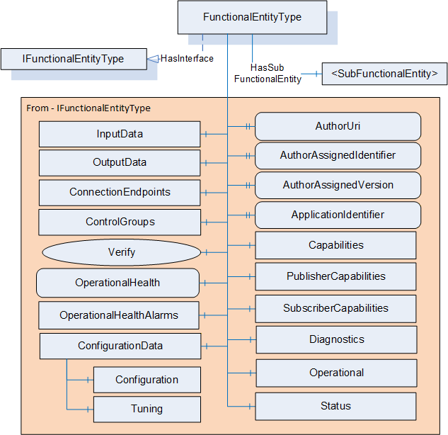
6.4.2 FunctionalEntityType definition
The FunctionalEntityType is formally defined in Table 41. Most of this ObjectType is obtained from the IFunctionalEntityType Interface (see 7.2). The description of the components and properties in a FunctionalEntityType is in this subclause; the IFunctionalEntityType only references this subclause. For examples of extending FunctionalEntityType or utilising it in an existing model, see Annex B. A FunctionalEntity could also be used to transport Safety data, Annex C provides a description of this process.
| Attribute | Value | ||||
| BrowseName | 3:FunctionalEntityType | ||||
| IsAbstract | False | ||||
| References |
Node
Class | BrowseName | DataType | TypeDefinition | Other |
|---|---|---|---|---|---|
| Subtype of the 0:BaseObjectType defined in OPC 10000-5 | |||||
| 0:HasInterface | ObjectType | 3:IFunctionalEntityType | |||
| Applied from IFunctionalEntityType | |||||
|---|---|---|---|---|---|
| 0:HasProperty | Variable | 3:AuthorUri | 0:UriString | 0:PropertyType | O |
| 0:HasProperty | Variable | 3:AuthorAssignedIdentifier | 0:String | 0:PropertyType | O |
| 0:HasProperty | Variable | 3:AuthorAssignedVersion | 3:FxVersion | 0:PropertyType | O |
| 0:HasProperty | Variable | 3:ApplicationIdentifier | 3:ApplicationIdentifierDataType[] | 0:PropertyType | O |
| 0:HasComponent | Method | 3:Verify | Defined in 6.4.3 | O | |
| 0:HasComponent | Object | 3:InputData | 3:InputsFolderType | O | |
| 0:HasComponent | Object | 3:OutputData | 3:OutputsFolderType | O | |
| 0:HasComponent | Object | 3:ConfigurationData | 3:ConfigurationDataFolderType | O | |
| 0:HasComponent | Object | 3:Capabilities | 3:FunctionalEntityCapabilitiesType | O | |
| 0:HasComponent | Object | 3:PublisherCapabilities | 3:PublisherCapabilitiesType | O | |
| 0:HasComponent | Object | 3:SubscriberCapabilities | 3:SubscriberCapabilitiesType | O | |
| 0:HasComponent | Object | 3:ConnectionEndpoints | 3:ConnectionEndpointsFolderType | O | |
| 0:HasComponent | Object | 3:ControlGroups | 3:ControlGroupsFolderType | O | |
| 0:HasComponent | Variable | 3:OperationalHealth | 3:OperationalHealthOptionSet | 0:BaseDataVariableType | O, RO |
| 0:HasComponent | Object | 3:OperationalHealthAlarms | 0:FolderType | O | |
| 0:HasComponent | Object | 5:Status | 5:FunctionalGroupType | O | |
| 0:HasComponent | Object | 5:Diagnostics | 5:FunctionalGroupType | O | |
| 0:HasComponent | Object | 5:Operational | 5:FunctionalGroupType | O | |
| 3:HasSubFunctionalEntity | Object | 3:<SubFunctionalEntity> | 3:FunctionalEntityType | OP | |
| ConformanceUnits | |||||
|---|---|---|---|---|---|
| UAFX FunctionalEntity Base |
The components of the FunctionalEntityType have additional subcomponents, which are defined in Table 42.
| BrowsePath | References | NodeClass | BrowseName | DataType | TypeDefinition | Others |
| 3:ConfigurationData | 0:Organizes | Object | 5:Configuration | 5:FunctionalGroupType | O | |
| 3:ConfigurationData | 0:Organizes | Object | 5:Tuning | 5:FunctionalGroupType | O | |
| 5:Diagnostics | 0:HasComponent | Variable | 3:OperationalConnectionCount | 0:UInt32 | 0:BaseDataVariableType | O |
| 5:Diagnostics | 0:HasComponent | Variable | 3:ExistingConnectionCount | 0:UInt32 | 0:BaseDataVariableType | O |
| 5:Diagnostics | 0:HasComponent | Variable | 3:ErrorConnectionCount | 0:UInt32 | 0:BaseDataVariableType | O |
| 5:Diagnostics | 0:HasComponent | Variable | 3:FailedConnectionCount | 0:UInt32 | 0:BaseDataVariableType | O |
| 5:Diagnostics | 0:HasComponent | Variable | 3:CleanedUpConnectionCount | 0:UInt32 | 0:BaseDataVariableType | O |
| 5:Diagnostics | 0:HasComponent | Variable | 3:TotalEstablishAttemptsCount | 0:UInt32 | 0:BaseDataVariableType | O |
| 5:Diagnostics | 0:HasComponent | Variable | 3:FailedEstablishAttemptsCount | 0:UInt32 | 0:BaseDataVariableType | O |
| 5:Diagnostics | 0:HasComponent | Variable | 3:FailedVerificationCount | 0:UInt32 | 0:BaseDataVariableType | O |
The FunctionalEntityType is a base ObjectType. It is expected that companion specifications or vendors will define subtypes of FunctionalEntityType. Subtypes will define additional Variables that would exist in InputData, OutputData and ConfigurationData. The subtypes might also add Objects and Methods or define nested FunctionalEntityType instances. In addition, the information in the FunctionalEntityType may be directly used in an existing ObjectType, either via the AddIn concept or the Interface concept defined in OPC 10000-3. For an illustration of how this can be accomplished, see B.3.
The optional AuthorUri is a string that is a URI that resolves to the website of the company responsible for this FunctionalEntity.
The optional AuthorAssignedIdentifier provides a unique code used to identify the author-defined type of this FunctionalEntity. This Property is maintained by the author. The semantic of the AuthorAssignedIdentifier is author-specific.
The optional AuthorAssignedVersion provides the version of this FunctionalEntity. The semantic of the AuthorAssignedVersion is author-specific. This identifier is provided to allow additional information beyond what the AuthorAssignedIdentifier provides. For example, some authors might have more than one version of the motor controller model or the PID controller algorithm.
The optional ApplicationIdentifier - provides application information consisting of two properties: a localized Name that is intended to be human-readable and a unique identifier that is intended to be machine-readable. For a definition of the ApplicationIdentifierDataType, see 10.3. The ApplicationIdentifier shall be used as follows:
Name provides the name of the application in which this FunctionalEntity is used. The name is given by the system integrator, manufacturer or end-user that created the application.
UniqueIdentifier provides a unique identifier for the application in which FunctionalEntity is used. UniqueIdentifier is maintained by the creator of the identifier. This field is of ApplicationId DataType to allow the creator to create any type of identifier. An ApplicationId DataType allows the field to contain a string, integer, GUID, or ByteString. It is up to the creator of the identifier to choose which of these types is used.
The optional ApplicationIdentifier is specified as an array since it may indicate multiple levels of application and thus have multiple values. For example, the product vendor of an advanced alarm control creates a FunctionalEntity and assigns to it an identifier. A system integrator customizes it with settings for boiler alarming and assigns an additional identifier. The end-user may further deploy an instance of the configured FunctionalEntity on "Boiler #5" and provide an additional identifier.
The optional InputData provides a grouping of information in this FunctionalEntity. It provides a reference to all data that this FunctionalEntity can use as input to its processing. The InputsFolderType is defined in 6.4.4.
The optional OutputData provides a grouping of information in this FunctionalEntity. It provides a reference to all data that this FunctionalEntity can use as output from its processing. The OutputsFolderType is defined in 6.4.5.
The optional ConfigurationData provides a grouping of information in this FunctionalEntity into logical groupings that are considered configuration information (for additional information, see 5.4). The ConfigurationDataFolderType is defined in 6.4.6.
The ConfigurationData Folder may also contain two FunctionalGroups (Configuration or Tuning) to further organize configuration information.
The optional Configuration FunctionalGroup contains Variables representing the configuration items of the FunctionalEntity (see OPC 10000-100 Recommended FunctionalGroup BrowseNames).
The optional Tuning FunctionalGroup contains Variables that can be used to optimize the behaviour of the FunctionalEntity (see OPC 10000-100 Recommended FunctionalGroup BrowseNames).
The optional Capabilities is a FunctionalEntityCapabilitiesType Folder that describes the functionality provided by a FunctionalEntity (see 6.4.7).
The optional PublisherCapabilities provide the Publisher capabilities associated with this FunctionalEntity. They also apply to all sub-FunctionalEntities of this FunctionalEntity. The PublisherCapabilities for the FunctionalEntity shall describe additional restrictions of the PublisherCapabilities defined in the AutomationComponent. It can also be further restricted by the PublisherCapabilities provided in OutputData or a sub-FunctionalEntity. The restrictions for a sub-FunctionalEntity only apply if the Connection is established with the sub-FunctionalEntity or if OutputData defined in the sub-FunctionalEntity are part of the Connection. If a Connection utilizes data from multiple sub-FunctionalEntities, a Server shall report an error (Bad_ConfigurationError) if the requested settings do not meet all of the sub-FunctionalEntities PublisherCapabilities. If an entry is missing, then it shall not change the settings defined in the AutomationComponent (or FunctionalEntity if defined in a sub-FunctionalEntity).
The optional SubscriberCapabilities provide the Subscriber capabilities associated with this FunctionalEntity. They also apply to all sub-FunctionalEntities of this FunctionalEntity. The SubscriberCapabilities for the FunctionalEntity shall describe additional restrictions of the SubscriberCapabilities defined in the AutomationComponent. It can also be further restricted by the SubscriberCapabilities provided in InputData or a sub-FunctionalEntity. The restrictions for a sub-FunctionalEntity only apply if the Connection is established with the sub-FunctionalEntity or if InputData defined in the sub-FunctionalEntity are part of the Connection. If a Connection utilizes data from multiple sub-FunctionalEntities, a Server shall report an error (Bad_ConfigurationError) if the requested settings do not meet all of the sub-FunctionalEntities SubscriberCapabilities. If an entry is missing, then it shall not change the settings defined in the AutomationComponent (or FunctionalEntity if defined in a sub-FunctionalEntity).
The ConnectionEndpoints Folder provides a container for all Connection-related information that this FunctionalEntity might contain. For details on the ConnectionEndpointsFolderType, see 6.4.8. For details on the ConnectionEndpointType that this Folder contains, see 6.6. If the FunctionalEntity does not expose ConnectionEndpoints, the Folder may be missing.
The ControlGroups Folder provides a container for all ControlGroupType instances this FunctionalEntity might contain. For the concepts, see 5.3. For details on the ControlGroupsFolderType, see 6.4.9. For details on the ControlGroupType that this Folder contains, see 6.5.
The optional OperationalHealth indicates the operational health of the FunctionalEntity. It aggregates the health of its SubFunctionalEntities and the health of ConnectionEndpoints. For the definition of the OperationalHealthOptionSet, see 10.34.
The aggregation rules are defined as follows:
SubOperationalWarning is set to TRUE if at least one SubFunctionalEntity has OperationalWarning or SubOperationalWarning set to TRUE.
SubOperationalError is set to TRUE if at least one SubFunctionalEntity has OperationalError or SubOperationalError set to TRUE.
The lower 16 bits of OperationalHealth are set to the result of a logical OR of CommHealth in the ConnectionEndpoints Folder of the FunctionalEntity, and the lower 16 bits of the OperationalHealth of all SubFunctionalEntities.
All top-level FunctionalEntities shall implement OperationalHealth. The OperationalHealth of the top-level FunctionalEntities is aggregated into the AggregatedOperationalHealth (see 9.1.2) Variable of the AggregatedHealth Variable in the AutomationComponent (see 6.2.2).
The optional OperationalHealthAlarms Folder shall be restricted to hold only instances of Alarms. No UAFX-specific Alarms are defined in this release, but base OPC UA Alarms can be used. In future versions of this document, UAFX-specific Alarms will be defined.
The Operational FunctionalGroup contains Variables and Methods useful during normal operation, like process data (see OPC 10000-100 Recommended FunctionalGroup BrowseNames).
The Status FunctionalGroup contains Variables which describe the general health of the FunctionalEntity (see OPC 10000-100 Recommended FunctionalGroup BrowseNames).
The Diagnostics FunctionalGroup contains Variables and Methods for diagnostics. For UAFX this includes diagnostics defined by UAFX (see OPC 10000-100 Recommended FunctionalGroup BrowseNames).
The optional <SubFunctionalEntity> allows for the nesting of FunctionalEntities. A FunctionalEntity can have any number of SubFunctionalEntities. SubFunctionalEntities are identified by the HasSubFunctionalEntity ReferenceType. They may be of FunctionalEntityType or another ObjectType that implements the IFunctionalEntityType Interface.
The OperationalConnectionCount provides the number of current ConnectionEndpoints with a Status of Operational in this FunctionalEntity.
The ExistingConnectionCount provides the number of ConnectionEndpoints that currently exist in this FunctionalEntity.
The ErrorConnectionCount provides the number of current ConnectionEndpoints with a Status indicating an error in this FunctionalEntity.
The FailedConnectionCount provides the number of transitions to the Error state for any ConnectionEndpoint in this FunctionalEntity.
The CleanedUpConnectionCount provides the number of ConnectionEndpoints that have been removed due to the expiration of the CleanupTimeout in this FunctionalEntity.
The TotalEstablishAttemptsCount provides the total number of attempts to create a ConnectionEndpoint that failed or succeeded in this FunctionalEntity.
The FailedEstablishAttemptsCount provides the total number of attempts to create a ConnectionEndpoint that failed due to an error in this FunctionalEntity.
The FailedVerificationCount provides the number of calls to Verify that returned a bad StatusCode in this FunctionalEntity.
6.4.3 Verify method
The Verify Method allows a Client to verify whether a FunctionalEntity meets the expectation of system engineering (e.g., whether it is of the expected author, but also if it implements any optional Variables required by a Client application). It also supports verifying any Variables defined by the application. The Verify Method should process all provided NodeIdValuePairs, but it is also acceptable to stop processing on the first NodeIdValuePair that results in a Mismatch or NotSet.
The signature of this Method is specified below; the arguments are defined in Table 43.
Signature
	Verify (
	[in] 2:NodeIdValuePair[]				ExpectedVerificationVariables,
	[out] 2:FunctionalEntityVerificationResultEnum	VerificationResult,
	[out] 0:StatusCode[]				VerificationVariablesErrors
);| Argument | Description |
| ExpectedVerificationVariables | An array of NodeIdValuePair containing verification variables. NodeId shall be the NodeId of the node to verify, and for Variables, the Value is its expected value. The following rules shall apply to the usage of NodeIdValuePair: If NodeId refers to variables of type array, it shall be verified that Value is a matching array unless ArrayIndex is provided. If the ArrayIndex is provided, then a non-array Value is provided and shall be checked against the corresponding index. If Value is null, it shall be verified that NodeId exists. If the NodeId references a FunctionalEntity ApplicationIdentifier, then its Name sub-element shall always be ignored; only its UniqueIdentifier shall be used. A Client may pass in any NodeId with a null Value to verify if the Node exists in the Server. The Node may be of any NodeClass, but only the NodeClass of Variable or VariableType can have a non-null value. |
| VerificationResult | The result of the verification; see 10.22 for a definition of the FunctionalEntityVerificationResultEnum. The following general rules apply to determine VerificationResult: All string-type variables shall be stripped of leading and trailing whitespaces before processing. The following specific rules shall apply to determine VerificationResult: NotSet: Shall be returned if verification is not possible due to invalid elements in ExpectedVerificationVariables. An element is invalid if a non-null Value in NodeIdValuePair is not of the same type as the implemented verification variable. If this value is set, VerificationVariablesErrors shall be populated. Match: Shall be returned if all variables in ExpectedVerificationVariables exist in the Server and their actual values are identical to the expected values (where Value in NodeIdValuePair is not null). Mismatch: Shall be returned if one or more variables in ExpectedVerificationVariables either do not exist in the Server or do not have the expected value (where Value in NodeIdValuePair is not null). If this value is set, VerificationVariablesErrors shall be populated. |
| VerificationVariablesErrors | An array of StatusCode corresponding to the ExpectedVerificationVariables input argument that indicates any errors (if VerificationResult equals NotSet) or detailed verification results (if VerificationResult equals Mismatch). If this array is populated, the length of this array shall match the length of ExpectedVerificationVariables. For possible values in this array, see Table 45. |
The Method result codes are formally defined in Table 44.
| Result Code | Description |
| Bad_InvalidArgument | ExpectedVerificationVariables is empty. |
| Uncertain | There was at least one error or warning for one of the Variables to be verified. VerificationVariablesErrors will contain additional information. |
The VerificationVariablesErrors StatusCodes are formally defined in Table 45.
| Result Code | Description |
| Bad_TypeMismatch | The value supplied for the verification variable (if non-null) is not of the same type as the implemented verification variable. |
| Bad_NodeIdInvalid | The NodeIdValuePair contains a NodeId with an invalid syntax in its key field. |
| Bad_NodeIdUnknown | The NodeIdValuePair contains a NodeId in its key field that does not exist in the Server. |
| Bad_OutOfRange | The value supplied for the verification variable is not equal to the actual value of the Variable (if non-null). This includes if an array index is provided and the supplied value is not a scalar or an index was provided that is out of bounds of the array. This error is also reported if the node type is not a Variable or VariableType and a value is provided. In all cases, the value does not match. |
| Bad_NothingToDo | The operation was skipped. Verification of this Variable was skipped because verification of preceding Variables already resulted in VerificationResult being set to Mismatch or NotSet. |
| Good | The verification for this Variable succeeded. |
The Verify Method representation in the AddressSpace is formally defined in Table 46.
| Attribute | Value | ||||
| BrowseName | 3:Verify | ||||
| References | NodeClass | BrowseName | DataType | TypeDefinition | Other |
|---|---|---|---|---|---|
| 0:HasProperty | Variable | 0:InputArguments | 0:Argument[] | 0:PropertyType | M |
| 0:HasProperty | Variable | 0:OutputArguments | 0:Argument[] | 0:PropertyType | M |
| ConformanceUnits | |||||
|---|---|---|---|---|---|
| UAFX IFunctionalEntity Verify |
6.4.4 InputsFolderType
The InputsFolderType is a subtype of the FolderType defined in OPC 10000-5.
The InputsFolderType is formally defined in Table 47.
| Attribute | Value | ||||
| BrowseName | 3:InputsFolderType | ||||
| IsAbstract | False | ||||
| References | NodeClass | BrowseName | DataType | TypeDefinition | Other |
|---|---|---|---|---|---|
| Subtype of the 0:FolderType defined in OPC 10000-5 | |||||
| 0:HasComponent | Object | 3:SubscriberCapabilities | 3:SubscriberCapabilitiesType | O | |
| 3:HasInputGroup | Object | 3:<InputGroup> | 3:InputsFolderType | OP | |
| 0:Organizes | Variable | 3:<InputVariable> | 0:BaseDataType | 0:BaseDataVariableType | OP |
| 0:HasComponent | Variable | 3:<InputVariable1> | 0:BaseDataType | 0:BaseDataVariableType | OP |
| ConformanceUnits | |||||
|---|---|---|---|---|---|
| UAFX FunctionalEntity Base |
The InputsFolderType provides for the grouping of input variables. It shall be restricted to hold only Variables, SubscriberCapabilities or nested <InputGroup>. The InputsFolder may be empty.
The optional SubscriberCapabilities shall only be present on InputData of the FunctionalEntity. It provides the Subscriber capabilities associated with the InputData and describes additional restrictions of the SubscriberCapabilities defined in the FunctionalEntity or AutomationComponent. The restrictions for InputData only apply if the Connection is established with Variables referenced in InputData or any subfolders. If an entry is missing, then it shall not change the settings defined in the AutomationComponent, FunctionalEntity or if defined in a sub-FunctionalEntity.
<InputGroup> allows for the nesting of Folders. Nested instances can be used to create a structure of input groups.
<InputVariable> is a reference to input Variables in this FunctionalEntity. The Variables shall be Organized in this Folder.
<InputVariable1> is a reference to input Variables in this FunctionalEntity. The Variables shall be referenced by the HasComponent ReferenceType or subtypes of it.
The BrowseNames of Variables in this Folder shall be unique within this Folder; the use of nested <InputGroup> can be used to help accomplish this.
When using PubSub for periodic data with a fixed layout, Strings, ByteStrings, and variable-size arrays can cause problems. Without a defined maximum size for the Variables in a data packet, the fixed size of the data packet cannot be calculated. If using PubSub periodic data with a fixed layout, then the following apply:
Any Variables that are included in this Folder that have a DataType of String shall include a MaxStringLength property.
Any Variables that are included in this Folder that have a DataType of ByteString shall include a MaxByteStringLength property.
It is also recommended that any arrays are defined to have fixed dimensions.
6.4.5 OutputsFolderType
The OutputsFolderType is a subtype of the FolderType defined in OPC 10000-5.
The OutputsFolderType is formally defined in Table 48.
| Attribute | Value | ||||
| BrowseName | 3:OutputsFolderType | ||||
| IsAbstract | False | ||||
| References |
Node
Class | BrowseName | DataType | TypeDefinition | Other |
|---|---|---|---|---|---|
| Subtype of the 0:FolderType defined in OPC 10000-5 | |||||
| 0:HasComponent | Object | 3:PublisherCapabilities | 3:PublisherCapabilitiesType | O | |
| 3:HasOutputGroup | Object | 3:<OutputGroup> | 3:OutputsFolderType | OP | |
| 0:Organizes | Variable | 3:<OutputVariable> | 0:BaseDataType | 0:BaseDataVariableType | OP |
| 0:HasComponent | Variable | 3:<OutputVariable1> | 0:BaseDataType | 0:BaseDataVariableType | OP |
| ConformanceUnits | |||||
|---|---|---|---|---|---|
| UAFX FunctionalEntity Base |
The OutputsFolderType provides for the grouping of output variables. It shall be restricted to hold only Variables, PublisherCapabilities or nested <OutputGroup>. The OutputsFolder may be empty.
The optional PublisherCapabilities shall only be present on OutputData of the FunctionalEntity. It provides the Publisher capabilities associated with the OutputData and describes additional restrictions of the PublisherCapabilities defined in the FunctionalEntity or AutomationComponent. The restrictions for OutputData only apply if the Connection is established with Variables referenced in OutputData or any subfolders. If an entry is missing, then it shall not change the settings defined in the AutomationComponent, FunctionalEntity or if defined in a sub-FunctionalEntity.
<OutputGroup> allows for the nesting of Folders. Nested instances can be used to create a structure of output groups.
<OutputVariable> is a reference to output Variables in this FunctionalEntity. The Variables shall be Organized in this Folder.
<OutputVariable1> is a reference to output Variables in this FunctionalEntity. The Variables shall be referenced via the HasComponent ReferenceType or subtypes of it.
The BrowseNames of Variables in this Folder shall be unique within this Folder; the use of nested <OutputGroup> can be used to help accomplish this.
When using PubSub for periodic data with a fixed layout, Strings, ByteStrings, and variable-size arrays can cause problems. Without a defined maximum size for the Variables in a data packet, the fixed size of the data packet cannot be calculated. If using PubSub periodic data with a fixed layout, then the following apply:
Any Variables that are included in this Folder that have a DataType of String shall include a MaxStringLength property.
Any Variables that are included in this Folder that have a DataType of ByteString shall include a MaxByteStringLength property.
It is also recommended that any arrays are defined to have fixed dimensions.
6.4.6 ConfigurationDataFolderType
6.4.6.1 Overview
The ConfigurationDataFolderType is used to organize ConfigurationData Variables and provides the Methods for supporting the storage of Variables (see 5.4). A ConfigurationDataFolder may contain sub-Folders derived from FunctionalGroupType.
The ConfigurationDataFolderType is illustrated in Figure 25.
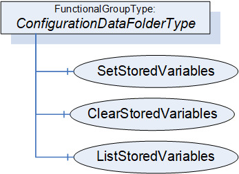
6.4.6.2 ConfigurationDataFolderType definition
The ConfigurationDataFolderType extends the FunctionalGroupType defined in OPC 10000-100.
The ConfigurationDataFolderType is formally defined in Table 49.
| Attribute | Value | ||||
| BrowseName | 3:ConfigurationDataFolderType | ||||
| IsAbstract | False | ||||
| References |
Node
Class | BrowseName | DataType | TypeDefinition | Other |
|---|---|---|---|---|---|
| Subtype of the 5:FunctionalGroupType defined in OPC 10000-100 | |||||
| 0: Organizes | Variable | 3:<ConfigurationVariable> | 0:BaseDataType | 0:BaseDataVariableType | OP |
| 0: HasComponent | Variable | 3:<ConfigurationVariable1> | 0:BaseDataType | 0:BaseDataVariableType | OP |
| 0:HasComponent | Method | 3:SetStoredVariables | Defined in 6.4.6.3 | O | |
| 0:HasComponent | Method | 3:ClearStoredVariables | Defined in 6.4.6.4 | O | |
| 0:HasComponent | Method | 3:ListStoredVariables | Defined in 6.4.6.5 | O | |
| ConformanceUnits | |||||
|---|---|---|---|---|---|
| UAFX FunctionalEntity Base |
<ConfigurationVariable> represents the optional configuration data.
<ConfigurationVariable1> represents the optional configuration data
The Variables in this Folder shall be Organized in this Folder, or the Folder shall reference the Variables via subtypes of the HasChild Reference (HasProperty, HasComponent or other subtypes).
The BrowseNames of Variables in this Folder shall be unique within this Folder. All Variables in this folder shall be configuration data.
The FunctionalGroupType, as defined in OPC 10000-100, includes the ability to have nested FunctionalGroups. It is expected that configuration data will often be organized into a tree of FunctionalGroups. This will also assist with the uniqueness requirement for BrowseNames.
The optional Methods SetStoredVariables, ClearStoredVariables, and ListStoredVariables allow for the maintenance of storage for configuration Variables. If storage is supported, SetStoredVariables, ClearStoredVariables, and ListStoredVariables shall be supported.
6.4.6.3 SetStoredVariables method
The optional SetStoredVariables Method allows a Client to store current values of configuration Variables for the FunctionalEntity and its SubFunctionalEntities.
The FunctionalEntity shall apply the stored values to the configuration variables after a power cycle.
The signature of this Method is specified below; the arguments are defined in Table 50.
Signature
	SetStoredVariables (
	  [in] 0:NodeId[]		VariablesToStore,
	  [out] 0:StatusCode[]	Results
);| Argument | Description |
| VariablesToStore | An array of NodeIds containing configuration data variables. NodeId shall be the NodeId of a configuration data variable belonging to ConfigurationData of this FunctionalEntity or one of its SubFunctionalEntities. |
| Results | An array of StatusCode corresponding to the VariablesToStore input argument that indicates any errors that occurred during the processing of VariablesToStore. If this array is populated, it has the same length as the VariablesToStore array. For possible values in this array, see Table 52. |
The possible Method result codes are formally defined in Table 51.
| Result Code | Description |
| Uncertain | There was at least one error while processing the Variables to be stored. Results will contain additional information. |
The Results StatusCodes are formally defined in Table 52.
| Result Code | Description |
| Bad_InvalidArgument | The NodeId is not a ConfigurationData Variable or does not belong to this FunctionalEntity or one of its SubFunctionalEntities. |
| Bad_NotSupported | The NodeId specifies a Variable that is non-volatile. |
| Bad_ResourceUnavailable | There are not enough resources to store this Variable. |
| Good | Storing this Variable succeeded. |
The SetStoredVariables Method representation in the AddressSpace is formally defined in Table 53.
| Attribute | Value | ||||
| BrowseName | 3:SetStoredVariables | ||||
| References | Node Class | BrowseName | DataType | TypeDefinition | Other |
|---|---|---|---|---|---|
| 0:HasProperty | Variable | 0:InputArguments | 0:Argument[] | 0:PropertyType | M |
| 0:HasProperty | Variable | 0:OutputArguments | 0:Argument[] | 0:PropertyType | M |
| ConformanceUnits | |||||
|---|---|---|---|---|---|
| UAFX ConfigurationDataFolder VariableStorage |
6.4.6.4 ClearStoredVariables Method
The optional ClearStoredVariables Method allows a Client to clear the Variable from the list of Variables that are to be restored.
The signature of this Method is specified below; the arguments are defined in Table 54.
Signature
	ClearStoredVariables (
	  [in] 0:NodeId[]		VariablesToClear,
	  [out] 0:StatusCode[]	Results
);| Argument | Description |
| VariablesToClear | An array of NodeId containing configuration data variables. |
| Results | An array of StatusCode corresponding to the VariablesToClear input argument that indicates any errors that occurred during the processing of VariablesToClear. If this array is populated, it has the same length as the VariablesToClear array. For possible values in this array, see Table 56. |
The possible Method result codes are formally defined in Table 55.
| Result Code | Description |
| Uncertain | There was at least one error while processing the Variables to be cleared. Results will contain additional information. |
The Results StatusCodes are formally defined in Table 56.
| Result Code | Description |
| Bad_InvalidArgument | The NodeId is not a ConfigurationData Variable or does not belong to this FunctionalEntity or one of its SubFunctionalEntities. |
| Bad_NotSupported | The NodeId specifies a Variable that is non-volatile or does not have storage for the Variable. |
| Good | Clearing the storage for this Variable succeeded. |
The ClearStoredVariables Method representation in the AddressSpace is formally defined in Table 57.
| Attribute | Value | ||||
| BrowseName | 3:ClearStoredVariables | ||||
| References | Node Class | BrowseName | DataType | TypeDefinition | Other |
|---|---|---|---|---|---|
| 0:HasProperty | Variable | 0:InputArguments | 0:Argument[] | 0:PropertyType | M |
| 0:HasProperty | Variable | 0:OutputArguments | 0:Argument[] | 0:PropertyType | M |
| ConformanceUnits | |||||
|---|---|---|---|---|---|
| UAFX ConfigurationDataFolder VariableStorage |
6.4.6.5 ListStoredVariables
The optional ListStoredVariables Method allows a Client to list the Variables that are currently in storage.
The signature of this Method is specified below; the arguments are defined in Table 58.
Signature
	ListStoredVariables (
	  [out] 2:NodeIdValuePair[]		StoredVariables
);| Argument | Description |
| StoredVariables | An array of NodeIdValuePair. Key indicates a Variable belonging to ConfigurationData of this FunctionalEntity or one of its SubFunctionalEntities. Value indicates the stored value. |
The ListStoredVariables Method representation in the AddressSpace is formally defined in Table 59.
| Attribute | Value | ||||
| BrowseName | 3:ListStoredVariables | ||||
| References | Node Class | BrowseName | DataType | TypeDefinition | Other |
|---|---|---|---|---|---|
| 0:HasProperty | Variable | 0:OutputArguments | 0:Argument[] | 0:PropertyType | M |
| ConformanceUnits | |||||
|---|---|---|---|---|---|
| UAFX ConfigurationDataFolder VariableStorage |
6.4.7 FunctionalEntityCapabilitiesType
The FunctionalEntityCapabilitiesType extends the FolderType defined in OPC 10000-5. It shall be restricted to contain only Variables that reflect the capabilities of the FunctionalEntity.
The FunctionalEntityCapabilitiesType is formally defined in Table 60.
| Attribute | Value | ||||
| BrowseName | 3:FunctionalEntityCapabilitiesType | ||||
| IsAbstract | False | ||||
| References |
Node
Class | BrowseName | DataType | TypeDefinition | Other |
|---|---|---|---|---|---|
| Subtype of the 0:FolderType defined in OPC 10000-5 | |||||
| 3:HasCapability | Variable | 3:<Capability> | 0:BaseDataType | 0:BaseDataVariableType | OP |
| 3:HasCapability | Variable | 3:FeedbackSignalRequired | 0:Boolean | 0:BaseDataVariableType | O |
| ConformanceUnits | |||||
|---|---|---|---|---|---|
| UAFX FunctionalEntity Base |
<Capability> - is an OptionalPlaceholder (defined in OPC 10000-3) to indicate that additional capabilities may be added by this document, by a companion specification or by a vendor application. These capabilities shall include a Description, and they follow all of the rules associated with an OptionalPlaceholder.
If the optional FeedbackSignalRequired is present and set to TRUE, the FunctionalEntity requires a feedback signal for all Connections. A feedback signal is represented by the reception of either data or a heartbeat. The following connection types (see 5.5.1) support feedback: bidirectional, unidirectional with heartbeat, unidirectional Subscriber, and autonomous Subscriber. If FeedbackSignalRequired is missing or set to FALSE, the connection types unidirectional Publisher and autonomous Publisher are also supported.
6.4.8 ConnectionEndpointsFolderType
The ConnectionEndpointsFolderType extends the FolderType defined in OPC 10000-5. It shall be restricted to hold only instances of ConnectionEndpointType or subtypes of ConnectionEndpointType. It may be empty.
The ConnectionEndpointsFolderType is formally defined in Table 61.
| Attribute | Value | ||||
| BrowseName | 3:ConnectionEndpointsFolderType | ||||
| IsAbstract | False | ||||
| References |
Node
Class | BrowseName | DataType | TypeDefinition | Other |
|---|---|---|---|---|---|
| Subtype of the 0:FolderType defined in OPC 10000-5 | |||||
| HasConnectionEndpoint | Object | 3:<ConnectionEndpoint> | 3:ConnectionEndpointType | OP | |
| 0:HasComponent | Variable | 3:CommHealth | 3:CommHealthOptionSet | 0:BaseDataVariableType | O, RO |
| ConformanceUnits | |||||
|---|---|---|---|---|---|
| UAFX FunctionalEntity Base |
The optional CommHealth aggregates the Status of all ConnectionEndpoints contained in the Folder. The aggregation rules are defined as follows:
If at least one ConnectionEndpoint established at this FunctionalEntity has its Status set to Error, the CommHealth CommError bit shall be set.
If at least one ConnectionEndpoint established at this FunctionalEntity has its Status set to Initial, the CommHealth CommInitial bit shall be set.
If at least one ConnectionEndpoint established at this FunctionalEntity has its Status set to PreOperational, the CommHealth CommPreOperational bit shall be set.
For the definition of the CommHealthOptionSet, see 10.9.
6.4.9 ControlGroupsFolderType
The ControlGroupsFolderType extends the FolderType defined in OPC 10000-5. It shall be restricted to hold only instances of ControlGroupType (see 6.5). The ControlGroupsFolder may be empty.
The ControlGroupsFolderType is formally defined in Table 62.
| Attribute | Value | ||||
| BrowseName | 3:ControlGroupsFolderType | ||||
| IsAbstract | False | ||||
| References |
Node
Class | BrowseName | DataType | TypeDefinition | Other |
|---|---|---|---|---|---|
| Subtype of the 0:FolderType defined in OPC 10000-5 | |||||
| 3:HasControlGroup | Object | 3:<ControlGroup> | 3:ControlGroupType | OP | |
| ConformanceUnits | |||||
|---|---|---|---|---|---|
| UAFX FunctionalEntity Base |
6.5 ControlGroupType
6.5.1 Overview
The ControlGroupType is used to manage the control of the functionality provided by a FunctionalEntity or part of it. ControlGroups are used when some part of a FunctionalEntity is to be "controlled" by another FunctionalEntity or application. ControlGroups can be used by an application to help understand how the Variables (inputs, outputs, configuration) and Methods are logically related to each other in the application. ControlGroups utilize the LockingServices defined in OPC 10000-100. The ControlGroupType is illustrated in Figure 26.
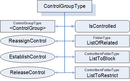
6.5.2 ControlGroupType definition
ControlGroups are part of the FunctionalEntity model and are independent of any communication model (Client Server, PubSub, etc.). A ControlGroup is used to identify the usage of parts of the FunctionalEntity. ControlGroups may result in a restriction to the grouped items. The restriction can include Objects (input and configuration Variables) and Method invocations. The restriction can block all changes to Variables or restrict changes to only the lock-owner (application or user). The lock-owner of the restrictions may be unrelated to the caller of the EstablishControl Method.
A Variable, Object, or Method may be referenced from more than one ControlGroup. Multiple ControlGroups might exist with different combinations.
ListToRestrict and ListToBlock each have their own instances of LockingServices. When a ControlGroup is assigned to a user or application, the Variables or Methods in ListToBlock or ListToRestrict are associated with that user or application (that user or application becomes the lock owner). The LockingServices exposed in ListToBlock and ListToRestrict (InitLock, RenewLock, ExitLock) can only be called by the lock-owner. An administrative user with appropriate rights may override a Lock and release it.
The ControlGroup also exposes EstablishControl, ReassignControl, and ReleaseControl Methods. EstablishControl will acquire the Lock for both ListToRestrict and ListToBlock. ReassignControl can be used to change the lock-owner to a different user or application. ReleaseControl will release the Lock. A user or application different from the lock owner shall not be able to successfully call EstablishControl on another ControlGroup that references the same Variables or Methods in ListToBlock or ListToRestrict.
The EstablishConnections Method supports commands to establish control (EstablishControlCmd) and reassign control (ReassignControlCmd). The CloseConnections Method will release any Locks that may have been acquired as part of connection establishment. The functionality provided by EstablishConnections (ReassignControlCmd) and CloseConnections is the same as that provided by the individual Methods in the ControlGroup, except they operate on the Locks as the lock-owner. If a ControlGroup is assigned to a ConnectionEndpoint, only those having the rights to call EstablishConnections or CloseConnections can reassign or release control (i.e., the EstablishConnections and CloseConnections Methods act as the ConnectionEndpoint).
One or more Clients may call EstablishControl on separate ControlGroups that do not share any Variables or Methods (in ListToRestrict or ListToBlock). For examples of ControlGroups, see Annex D.3.
The FunctionalEntity may provide Variables in its InputData, OutputData and ConfigurationData Folders. A ControlGroup may include any combination of the input, output, and configuration Variables from the FunctionalEntity. A FunctionalEntity may provide information in InputData, OutputData and ConfigurationData that are not part of any ControlGroup.
ControlGroups are primarily used for locking, but they may also be used to merely provide a subset of FunctionalEntity configuration related to a specific described set of controls. The described grouping of functionality may be nested to allow further organization of the functionality. For example, a simple PID may be modelled as a FunctionalEntity; it can be run in cascade mode where another FunctionalEntity provides the setpoint input, or it can allow an operator to enter setpoints via an HMI. In this case, two ControlGroups could be provided by the PID FunctionalEntity, and the choice of ControlGroup would lock the functionality into a specific mode. More complex FunctionalEntities might also restrict which ControlGroups are available based on configuration settings.
The ControlGroupType is formally defined in Table 63.
| Attribute | Value | ||||
| BrowseName | 3:ControlGroupType | ||||
| IsAbstract | False | ||||
| References |
Node
Class | BrowseName | DataType | TypeDefinition | Other |
|---|---|---|---|---|---|
| Subtype of the 0:BaseObjectType defined in OPC 10000-5 | |||||
| 0:HasComponent | Object | 3:ListToBlock | 3:ControlItemFolderType | M | |
| 0:HasComponent | Object | 3:ListToRestrict | 3:ControlItemFolderType | M | |
| 0:HasComponent | Object | 3:ListOfRelated | 0:FolderType | M | |
| 0:HasProperty | Variable | 3:IsControlled | 0:Boolean | 0:PropertyType | M |
| 0:HasComponent | Method | 3:EstablishControl | Defined in 6.5.3 | O | |
| 0:HasComponent | Method | 3:ReleaseControl | Defined in 6.5.4 | O | |
| 0:HasComponent | Method | 3:ReassignControl | Defined in 6.5.5 | O | |
| 0:HasComponent | Object | 3:<ControlGroup> | 3:ControlGroupType | OP | |
| ConformanceUnits | |||||
|---|---|---|---|---|---|
| UAFX IFunctionalEntity ControlGroups |
ListToBlock is a group of items that are to be blocked from any changes to Variables or executing Methods. This could be any Variables or Methods in the hierarchical structure of instances in the FunctionalEntity. Once an EstablishControl Call is made, the values of Variables in this list can no longer be modified, and Methods in this list can no longer be executed.
ListToRestrict is a group of items that are to be restricted to allow only the lock owner (see OPC 10000-100) to change Variables or execute Methods. This could be any Variables or Methods in the hierarchical structure of instances in the FunctionalEntity.
ListOfRelated is a group of items that are part of the ControlGroup that are not blocked or restricted (i.e., it is Objects, Variables, Methods).
A Variable, Method or Object shall not be included in more than one of the lists within a ControlGroup.
IsControlled is a flag that indicates if the ControlGroup is currently controlled. When this bit is set, the controlling entity can be determined by following the Controls Reference or by the information in the Lock Object (i.e., the Lock LockingClient) in either the ListToRestrict Folder or the ListToBlock Folder.
The optional EstablishControl Method invokes the LockingServices in both the ListToBlock and ListToRestrict groups. The Lock LockingClient is set to the LockContext parameter unless this parameter is a null String, in which case it is set to the ApplicationUri of the Client connection used to call this Method.
The optional ReassignControl Method will assign all active Locks in the ControlGroup to a different LockingClient.
The Locks can be assigned to a ConnectionEndpoint. In this case, the following applies:
All Locks automatically call the ExitLock Method if the associated ConnectionEndpoint is being removed.
The Lock LockingUser shall be set to "UAFX".
The Locks are automatically renewed as long as the Status of the ConnectionEndpoint is different from Error.
A Controls Reference (see OPC 10000-23) shall be added with a SourceNode of the ConnectionEndpoint and the TargetNode of the ControlGroup.
If the lock is assigned to the Client connection, the Controls Reference (see OPC 10000-23) shall have a SourceNode of the Object associated with the Client connection (see OPC 10000-100) and a TargetNode of the ControlGroup.
The optional ReleaseControl Method calls the ExitLock Method on all established Locks and removes the Controls Reference. It also clears the IsControlled flag.
Calling the ExitLock Method on the Locks does not affect the IsControlled flag and associated Controls Reference; it will only release the Lock on the given group of items (ListToBlock, ListToRestrict).
The LockingServices provide a system-wide MaxInactiveLockTime, which a local MaxInactiveLockTime can overwrite in each lock Folder. If the CleanupTimeout is different for each Connection, then a local MaxInactiveLockTime should be specified and related to the ConnectionEndpoint CleanupTimeout. It is important to understand that this timeout will be used to timeout locks and thus must be larger than the CleanupTimeout if a lock is not to be removed before a Connection is removed. The system-wide MaxInactiveLockTime may be used for other applications or deployments of LockingServices, so care should be exercised if a local MaxInactiveLockTime is not used.
A ControlGroup can contain additional nested ControlGroups. The specified Methods of ControlGroupType shall not be applied to any nested ControlGroups.
6.5.3 EstablishControl method
This Method shall acquire Locks required by the ControlGroup in the ListToRestrict and ListToBlock. If acquiring any Lock fails, all Locks shall be released, and the appropriate LockStatus shall be returned. If all required Locks can be acquired, the Method shall set the IsControlled flag and create the Controls Reference.
It is recommended that this Method be restricted to Client connections that have the well-known Role ConnectionAdmin as defined in Subclause 5.9.
EstablishControl shall set Lock LockingClient to the LockContext Argument.
The signature of this Method is specified below; the arguments are defined in Table 64.
Signature
	EstablishControl (
		[in] 0:String 	LockContext,
		[out] 0:Int32 	LockStatus
);| Argument | Description |
| LockContext | A string used to provide context information about the lock-owner. It may be the NodeId (in string representation) of a ConnectionEndpoint or the ApplicationUri of a Client connection as provided in the CreateSession Service Call (see OPC 10000-4). If this parameter is a null string, it shall default to the ApplicationUri of the Client connection initiating this command. |
| LockStatus | 0 - OK -1 - E_AlreadyLocked - An element is already locked; this might be an entire Lock, or it might be a single variable in one of the lists. -2 - E_Invalid - the element cannot be locked |
The possible Method result codes are formally defined in Table 65.
| ResultCode | Description |
| Bad_UserAccessDenied | The caller is not allowed to establish control of the ControlGroup. |
The EstablishControl Method representation in the AddressSpace is formally defined in Table 66.
| Attribute | Value | ||||
| BrowseName | 3:EstablishControl | ||||
| References | Node Class | BrowseName | DataType | TypeDefinition | Other |
|---|---|---|---|---|---|
| 0:HasProperty | Variable | 0:InputArguments | Argument[] | 0:PropertyType | M |
| 0:HasProperty | Variable | 0:OutputArguments | Argument[] | 0:PropertyType | M |
| ConformanceUnits | |||||
|---|---|---|---|---|---|
| UAFX IFunctionalEntity ControlGroups |
6.5.4 ReleaseControl method
This Method Call shall release the ControlGroup and issue a Call to the Lock Objects in each Folder for the ExitLock Method (see OPC 10000-100). It shall create the appropriate parameters for the ExitLock Method. It shall remove the Controls Reference from the ControlGroup.
It is recommended that this Method be restricted to Client connections that have the well-known Role ConnectionAdmin as defined in sublause 5.9.
The signature of this Method is specified below.
Signature
	ReleaseControl (
	);
The possible Method result codes are formally defined in Table 67.
| Result Code | Description |
| Bad_UserAccessDenied | The caller is not allowed to release control on the ControlGroup. |
The ReleaseControl Method representation in the AddressSpace is formally defined in Table 68.
| Attribute | Value | ||||
| BrowseName | 3:ReleaseControl | ||||
| References | Node Class | BrowseName | DataType | TypeDefinition | Other |
|---|---|---|---|---|---|
| ConformanceUnits | |||||
| UAFX IFunctionalEntity ControlGroups | |||||
6.5.5 ReassignControl method
This Method shall reassign Locks required by the ControlGroup in the ListToRestrict and ListToBlock. It shall reassign the SourceNode of the Controls Reference (see OPC 10000-23) to the controlling entity as defined by the LockContext.
It shall set Lock LockingClient to the LockContext Argument.
It is recommended that this Method be restricted to Client connections that have the well-known Role ConnectionAdmin as defined in Subclause 5.9.
The signature of this Method is specified below; the arguments are defined in Table 69.
Signature
	ReassignControl (
		[in] 0:String 	LockContext,
		[out] 0:Int32 	LockStatus
);| Argument | Description |
| LockContext | A string used to provide context information about the lock-owner. It may be the NodeId (in string representation) of a ConnectionEndpoint or the ApplicationUri of a Client connection as provided in the CreateSession Service Call (see OPC 10000-4). It cannot be null. |
| LockStatus | 0 - OK -1 - E_NotLocked - the Object is not locked -2 - E_Invalid - the element cannot be reassigned |
The possible Method result codes are formally defined in Table 70.
| Result Code | Description |
| Bad_UserAccessDenied | The caller is not allowed to reassign control on the ControlGroup. |
| Bad_InvalidArgument | LockContext was null, invalid, or non-existing. |
The ReassignControl Method representation in the AddressSpace is formally defined in Table 71.
| Attribute | Value | ||||
| BrowseName | 3:ReassignControl | ||||
| References | Node Class | BrowseName | DataType | TypeDefinition | Other |
|---|---|---|---|---|---|
| 0:HasProperty | Variable | 0:InputArguments | 0:Argument[] | 0:PropertyType | M |
| 0:HasProperty | Variable | 0:OutputArguments | 0:Argument[] | 0:PropertyType | M |
| ConformanceUnits | |||||
|---|---|---|---|---|---|
| UAFX IFunctionalEntity ControlGroups |
6.5.6 ControlItemFolderType
The ControlItemFolderType is a subtype of the FunctionalGroupType.
The ControlItemFolderType is formally defined in Table 72.
| Attribute | Value | ||||
| BrowseName | 3:ControlItemFolderType | ||||
| IsAbstract | False | ||||
| References |
Node
Class | BrowseName | DataType | TypeDefinition | Other |
|---|---|---|---|---|---|
| Subtype of the 5:FunctionalGroupType defined in OPC 10000-100 | |||||
| 0:HasComponent | Object | 5:Lock | 5:LockingServicesType | M | |
| 0:HasProperty | Variable | 5:MaxInactiveLockTime | 0:Duration | 0:PropertyType | O |
| ConformanceUnits | |||||
|---|---|---|---|---|---|
| UAFX IFunctionalEntity ControlGroups |
The Lock is of LockingServicesType defined in Device Integration (see OPC 10000-100) and provides the basic locking functionality.
As described in OPC 10000-100, Locks will timeout after a MaxInactiveLockTime period unless there is activity as defined or unless the RenewLock Method is called on a Lock. An optional local MaxInactiveLockTime shall have precedence over the global MaxInactiveLockTime defined in the ServerCapabilities Object.
6.6 ConnectionEndpointType
6.6.1 Overview
A ConnectionEndpoint is used to represent an endpoint of a Connection between two FunctionalEntities for data exchange. It provides information about which InputVariables and/or OutputVariables are exchanged. ConnectionEndpoints reside in the ConnectionEndpoints Folder of a FunctionalEntity.
The ConnectionEndpointType is illustrated in Figure 27.
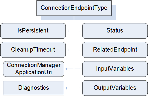
A ConnectionEndpoint further describes the link between Variables in the FunctionalEntityType and the communication model used for exchange. Communication models can be Client Server or PubSub. This type specifies the exchanged Variables and contains the status of the Connection. Subtypes of ConnectionEndpointType provide details specific to the utilized communication model and specify how the Connection status shall be determined for a given communication model.
Figure 28 illustrates a Connection between two FunctionalEntities and the use of PubSubConnectionEndpointType to represent the exchanged Variables, as well as corresponding References to the PubSub Information Model.
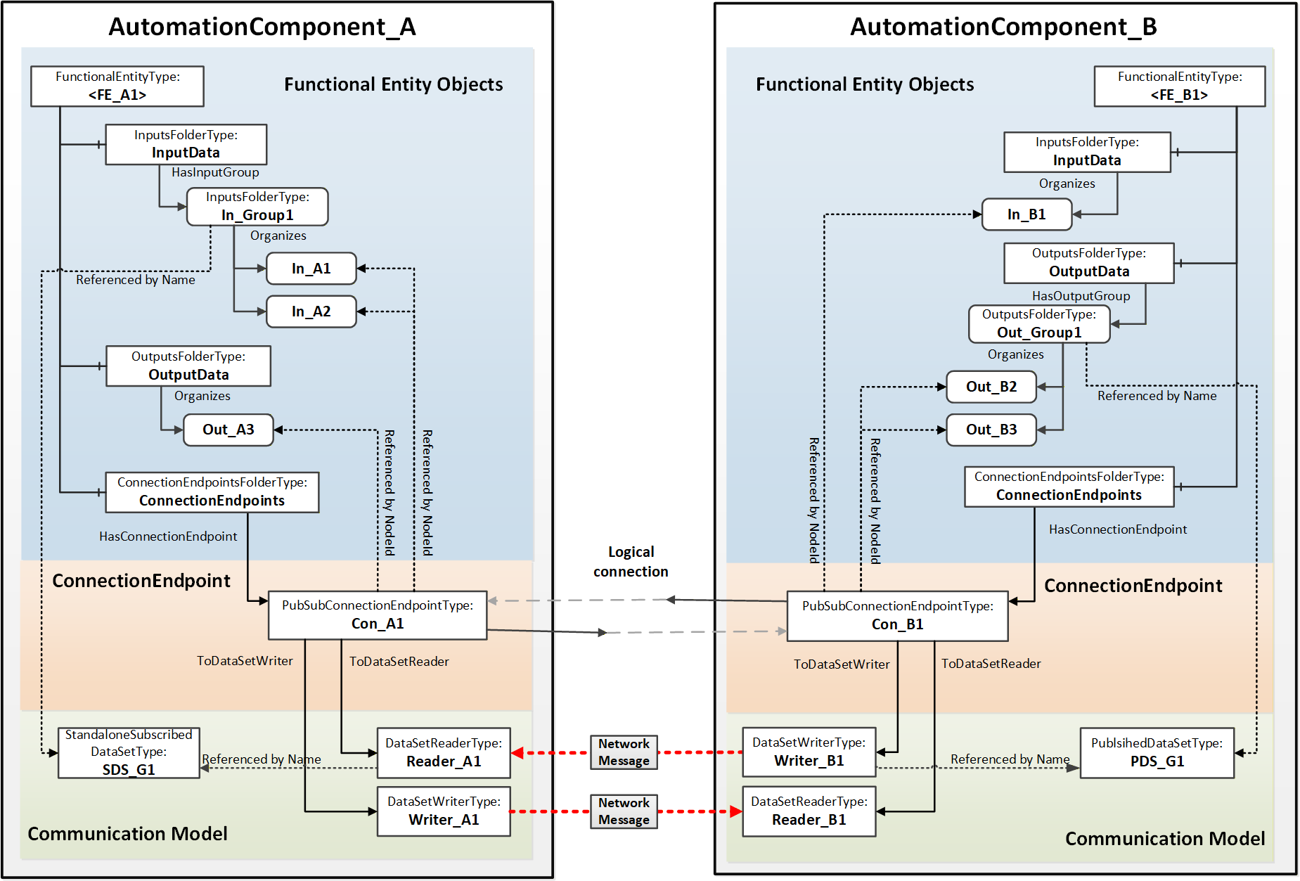
6.6.2 ConnectionEndpointType definition
This ObjectType is the abstract base type of all communication model-specific ConnectionEndpointTypes. It defines the elements and behaviour that are common to all ConnectionEndpointTypes. Additional communication model-specific subtypes are defined in subsequent subclauses.
The ConnectionEndpointType is formally defined in Table 73Error! No bookmark name given..
| Attribute | Value | ||||
| BrowseName | 3:ConnectionEndpointType | ||||
| IsAbstract | True | ||||
| References |
Node
Class | BrowseName | DataType | TypeDefinition | Other |
|---|---|---|---|---|---|
| Subtype of the 0:BaseObjectType defined in OPC 10000-5 | |||||
| 0:HasComponent | Variable | 3:Status | 3:ConnectionEndpointStatusEnum | 0:BaseDataVariableType | M, RO |
| 0:HasComponent | Variable | 3:RelatedEndpoint | 2:RelatedEndpointDataType | 0:BaseDataVariableType | M |
| 0:HasComponent | Variable | 3:InputVariables | 0:NodeId[] | 0:BaseDataVariableType | O |
| 0:HasComponent | Variable | 3:OutputVariables | 0:NodeId[] | 0:BaseDataVariableType | O |
| 0:HasComponent | Variable | 3:IsPersistent | 0:Boolean | 0:BaseDataVariableType | M |
| 0:HasComponent | Variable | 3:CleanupTimeout | 0:Duration | 0:BaseDataVariableType | M |
| 0:HasComponent | Variable | 3:ConnectionManagerApplicationUri | 0:String | 0:BaseDataVariableType | O |
| 0:HasComponent | Object | 5:Diagnostics | 5:FunctionalGroupType | O | |
| 0:GeneratesEvent | ObjectType | 3:AuditConnectionCleanupEventType | Defined in 8.3 | ||
| 0:HasSubtype | ObjectType | 3:PubSubConnectionEndpointType | Defined in 6.6.3 | ||
| ConformanceUnits | |||||
|---|---|---|---|---|---|
| UAFX ConnectionEndpoint Base |
The components of the ConnectionEndpointType have additional subcomponents, which are defined in Table 74.
| BrowsePath | References | Node Class | BrowseName | DataType | TypeDefinition | Others |
| 5:Diagnostics | 0:HasComponent | Variable | 3:CreationTime | 0:DateTime | 0:BaseDataVariableType | O |
| 5:Diagnostics | 0:HasComponent | Variable | 3:ModificationTime | 0:DateTime | 0:BaseDataVariableType | O |
The Status describes the current status of a ConnectionEndpoint. This status is illustrated by the state machine in Figure 29. The Status values are defined in the ConnectionEndpointStatusEnum (see 10.17).
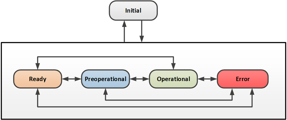
How Status is determined for a specific communication model is specified in the subtypes of ConnectionEndpointType.
The optional InputVariables indicate Variables that are to have their values updated by the communication model connected to the ConnectionEndpoint. All referenced Variables shall be in the InputData of the FunctionalEntity related to the ConnectionEndpoint or a SubFunctionalEntity of the FunctionalEntity. The referenced Variables may be a subset of the Variables referenced by InputData.
The optional OutputVariables reference Variables that are to be reported by the communication model connected to the ConnectionEndpoint. All referenced Variables shall be listed in the OutputData of the FunctionalEntity related to the ConnectionEndpoint or a SubFunctionalEntity of the FunctionalEntity. The referenced Variables may be a subset of the Variables referenced by OutputData.
The communication represented by the ConnectionEndpoint shall include all referenced InputVariables and OutputVariables.
A ConnectionEndpoint shall include at least one of the following:
1 or more InputVariables
1 or more OutputVariables
RelatedEndpoint points to the related ConnectionEndpoint (i.e., the other end of the Connection). The RelatedEndpointDataType is defined in 10.42. If the ConnectionEndpoint is not exposed in the Information Model of the related connection partner, RelatedEndpoint will specify the path to the connected FunctionalEntity.
IsPersistent indicates if the ConnectionEndpoint shall be persistent. Persistent ConnectionEndpoints shall be restored following a power cycle by the AutomationComponent. The restoration of a persistent ConnectionEndpoint shall include:
ConnectionEndpoint including references to ControlGroups and communication model Objects
Established control on related ControlGroups
Communication model Objects
An AutomationComponent indicates support for persistent Connections; see SupportsPersistence in 6.2.6.
Non-persistent ConnectionEndpoints following a power cycle behave as if the CloseConnections Method was called with Remove set to TRUE (see 6.2.5).
The CleanupTimeout defines a time delay period before a clean-up shall occur. The time delay period starts following a status change from Operational to any other Status. The time delay is reset to its original value when the Status changes back to Operational. If the time delay expires, this Connection shall be closed as if the CloseConnections Method was called with Remove set to TRUE (see 6.2.5), and if Auditing is supported, an Event of AuditConnectionCleanupEventType shall be generated. Any negative number indicates that the CleanupTimeout shall not be used and no clean-up occurs. For a persistent ConnectionEndpoint, the CleanupTimeout shall be set to a negative number. A zero indicates immediate clean-up. CleanupTimeout processing may be disabled by a CloseConnections Call (see 6.2.5). If AutomationComponentLog is supported, when a Connection is cleaned up then a LogRecord shall be generated. This LogRecord shall have the SourceNode set to the NodeId of the FunctionalEntity that the connection is in. This LogRecord shall have SourceName set to the BrowseName of the Connection that was closed. This LogRecord Message shall indicate that a timeout occurred.
The ConnectionManagerApplicationUri can be used to identify the ConnectionManager that created this ConnectionEndpoint. The ConnectionManagerApplicationUri shall be set to the ApplicationUri in the ApplicationDescription associated with the Client connection from the ConnectionManager that established this Connection. If the ConnectionManager is local to this AutomationComponent (no Client connection), this shall be set to the ApplicationUri associated with the local ConnectionManager.
The CreationTime provides the timestamp associated with the creation of this ConnectionEndpoint.
The ModificationTime provides the timestamp associated with any modification of this ConnectionEndpoint, including creation.
6.6.3 PubSubConnectionEndpointType definition
PubSubConnectionEndpointType is a subtype of the ConnectionEndpointType. It extends the abstract ConnectionEndpointType with behaviour that is specific to the OPC UA PubSub communication model.
The PubSubConnectionEndpointType is illustrated in Figure 30.
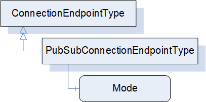
The PubSubConnectionEndpointType is formally defined in Table 75 and Table 76.
| Attribute | Value | ||||
| BrowseName | 3:PubSubConnectionEndpointType | ||||
| IsAbstract | False | ||||
| References |
Node
Class | BrowseName | DataType | TypeDefinition | Other |
|---|---|---|---|---|---|
| Subtype of the 3:ConnectionEndpointType | |||||
| 0:HasComponent | Variable | 3:Mode | 2:PubSubConnectionEndpointModeEnum | 0:BaseDataVariableType | M |
| 0:HasComponent | Variable | 3:DataSetReaderPath | 0:String[] | 0:BaseDataVariableType | O |
| 0:HasComponent | Variable | 3:DataSetWriterPath | 0:String[] | 0:BaseDataVariableType | O |
| ConformanceUnits | |||||
|---|---|---|---|---|---|
| UAFX ConnectionEndpoint PubSub |
| SourceBrowsePath | Reference Type | IsForward | TargetBrowsePath | ||||||
| 3:ToDataSetReader | True |
| |||||||
| 3:ToDataSetWriter | True |
|
Mode defines the mode of the ConnectionEndpoint with respect to the Connection. The modes are formally defined in the PubSubConnectionEndpointModeEnum defined in Subclause 10.41.
If the PubSub configuration model is exposed, the DataSetReader associated with this PubSubConnectionEndpoint is referenced directly using a ToDataSetReader Reference. Otherwise, the DataSetReader is referenced by path using DataSetReaderPath.
If the PubSub configuration model is exposed, the DataSetWriter associated with this PubSubConnectionEndpoint is referenced directly using a ToDataSetWriter Reference. Otherwise, the DataSetWriter is referenced by path using DataSetWriterPath.
DataSetReaderPath provides a path to the DataSetReader associated with this PubSubConnectionEndpoint. The path is expressed as an array of strings, starting with the <PubSubConnection>, then the <ReaderGroup> and finally the <DataSetReader>. This path reflects the hierarchy of elements inside the PubSubConfiguration2DataType structure, i.e. the Name field for PubSubConnection, ReaderGroup and DataSetReader elements.
DataSetWriterPath provides a path to the DataSetWriter associated with this PubSubConnectionEndpoint. The path is expressed as an array of strings, starting with the <PubSubConnection>, then the <WriterGroup> and finally the <DataSetWriter>. This path reflects the hierarchy of elements inside the PubSubConfiguration2DataType structure (i.e. the Name field for PubSubConnection, WriterGroup and DataSetWriter elements).
Depending on Mode, the following references shall be created:
If Mode is Publisher, only a DataSetWriter shall be referenced directly or by path.
If Mode is Subscriber, only a DataSetReader shall be referenced directly or by path.
If Mode is PublisherSubscriber, a DataSetReader and a DataSetWriter shall be referenced directly or by path.
The referenced DataSetReader shall be present if the PubSubConnectionEndpoint references InputVariables or receives a heartbeat. The referenced DataSetReader shall be associated with a SubscribedDataSet that contains all of the referenced ConnectionEndpoint InputVariables. If no InputVariables are referenced, the referenced DataSetReader shall be associated with a null DataSet (heartbeat).
The referenced DataSetWriter shall be present if the PubSubConnectionEndpoint references OutputVariables or publishes a heartbeat. The referenced DataSetWriter shall be associated with a PublishedDataSet that contains all of the referenced ConnectionEndpoint OutputVariables. If no OutputVariables are referenced, the referenced DataSetWriter shall be associated with a null DataSet to publish the heartbeat.
The Status is determined based on the Status of the referenced DataSetReader and DataSetWriter. If a required referenced DataSetReader or DataSetWriter is missing, the Status shall be Initial.
For PubSubConnectionEndpoints with the Mode value of PublisherSubscriber, the Status shall be determined by the Status of the referenced DataSetReader and DataSetWriter as defined in Figure 31.
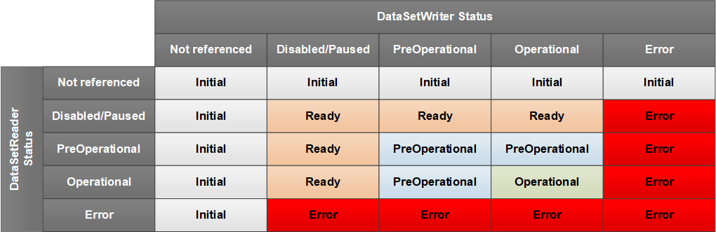
For PubSubConnectionEndpoints with Mode of Subscriber, the Status shall be determined by the Status of the referenced DataSetReader according to Figure 32.
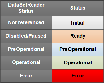
For PubSubConnectionEndpoints with Mode of Publisher, the Status shall be determined by the Status of the referenced DataSetWriter according to Figure 33.
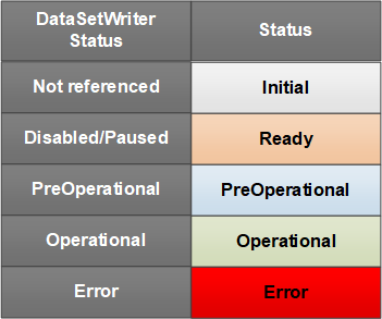
For the connection types autonomous publisher and autonomous subscriber (see 5.5.1), RelatedEndpoint Address shall be set to the Server address of the ConnectionEndpoint, the ConnectionEndpoint array shall be set to null or empty, and the ConnectionEndpointName to an empty String.
Annex E provides examples of PubSubConnectionEndpoints for the various types of Connections.
6.6.4 ClientServerConnectionEndpointType
The ClientServerConnectionEndpointType may be defined in a future version of this document.
6.7 ConnectionManagerType
6.7.1 Overview
Figure 34 illustrates the structure of the ConnectionManagerType. A ConnectionManager uses the configuration data stored in a ConnectionConfigurationSet (see 6.8) to establish Connections. Optional Methods are provided by ConnectionManagerType to allow Clients to manage editing and trigger the processing of Connections.
A ConnectionManager is represented by an instance of ConnectionManagerType; see 12 for details on its location in the UAFX Information Model.
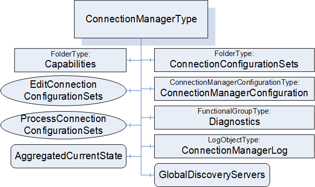
ConnectionConfigurationSets may be serialised into a file format as described in Annex F.
6.7.2 ConnectionManagerType definition
The ConnectionManagerType is formally defined in Table 77.
| Attribute | Value | ||||
| BrowseName | 4:ConnectionManagerType | ||||
| IsAbstract | False | ||||
| References |
Node
Class | BrowseName | DataType | TypeDefinition | Other |
|---|---|---|---|---|---|
| Subtype of the 0:BaseObjectType defined in OPC 10000-5 | |||||
| 0:HasComponent | Object | 4:ConnectionConfigurationSets | 0:FolderType | M | |
| 0:HasComponent | Object | 4:ConnectionManagerConfiguration | 4:ConnectionManagerConfigurationType | O | |
| 0:HasComponent | Method | 4:EditConnectionConfigurationSets | Defined in 6.7.4 | O | |
| 0:HasComponent | Method | 4:ProcessConnectionConfigurationSets | Defined in 6.7.5 | O | |
| 0:HasComponent | Object | 4:Capabilities | 4:ConnectionManagerCapabilitiesType | O | |
| 0:HasComponent | Variable | 4:AggregatedCurrentState | 0:Boolean | 0:BaseDataVariableType | O |
| 0:HasComponent | Object | 5:Diagnostics | 5:FunctionalGroupType | O | |
| 0:HasComponent | Object | 4:ConnectionManagerLog | 0:LogObjectType | O | |
| 0:HasComponent | Variable | 4:GlobalDiscoveryServers | 0:String[] | 0:BaseDataVariableType | O |
| 0:GeneratesEvent | ObjectType | 4:CloseConnectionErrorEventType | |||
| 0:GeneratesEvent | ObjectType | 4:EstablishConnectionErrorEventType | |||
| ConformanceUnits | |||||
|---|---|---|---|---|---|
| UAFX ConnectionManager Base |
The components of the ConnectionManagerType have additional subcomponents, which are defined in Table 78.
| BrowsePath | References | Node Class | BrowseName | DataType | TypeDefinition | Other |
| 5:Diagnostics | 0:HasComponent | Variable | 4:EstablishCallCount | 0:UInt32 | 0:BaseDataVariableType | O |
| 5:Diagnostics | 0:HasComponent | Variable | 4:EstablishCallFailedCount | 0:UInt32 | 0:BaseDataVariableType | O |
| 5:Diagnostics | 0:HasComponent | Variable | 4:CloseCallCount | 0:UInt32 | 0:BaseDataVariableType | O |
| 5:Diagnostics | 0:HasComponent | Variable | 4:CloseCallFailedCount | 0:UInt32 | 0:BaseDataVariableType | O |
| 4:ConnectionConfigurationSets | 0:HasComponent | Object | 4:<ConnectionConfigurationSet> | 4:ConnectionConfigurationSetType | OP |
ConnectionConfigurationSets provides a Folder for the ConnectionConfigurationSets (defined in 6.8) that are exposed by this ConnectionManager. It shall be restricted to holding only instances of ConnectionConfigurationSetType, which provide the data required by a ConnectionManager to establish Connections. This Folder may also contain other Folders that can be used to organise the ConnectionConfigurationSets. The Folder may be empty. The string part of the BrowseName of ConnectionConfigurationSets shall be unique within a ConnectionConfigurationSets Folder.
ConnectionManagerConfiguration provides standardised mechanisms for adding, removing, or replacing ConnectionConfigurationSets (see F.1).
EditConnectionConfigurationSets provides a way to alter the Edit Property of one or more ConnectionConfigurationSets in a single Call.
ProcessConnectionConfigurationSets causes the ConnectionManager to manage Connections contained in one or more ConnectionConfigurationSets in a single Call (see 6.7.5). In addition, vendor-specific means may be used to trigger the processing of ConnectionConfigurationSets. All processing of ConnectionConfigurationSets shall follow the behaviour defined in 6.7.
Capabilities is a ConnectionManagerCapabilitiesType Folder that describes the functionality provided by a ConnectionManager (see 6.7.6).
AggregatedCurrentState shall be set to TRUE if one or more ConnectionConfigurationSets' ConnectionConfigurationSetStateMachine is in State Error. This only indicates that the ConnectionManager encountered a problem in processing one or more of the ConnectionConfigurationSets; it does not indicate the status of the Connections.
ConnectionManagerLog exposes a LogObject for the ConnectionManager. The LogObject (see OPC 10000-26) can be accessed to obtain the log of activity related to the ConnectionManager. Standardised Events that can be used to trigger records for the LogObject are defined in 8.10 and 8.11. LogObject records can also be generated without the generation of an Event. If the LogObject is supported, the ConnectionManager shall generate LogRecords for all calls of the EditConnectionConfigurationSets and ProcessConnectionConfigurationSets Methods. When acting as a Client establishing Connections, the ConnectionManager shall generate LogRecords for all EstablishConnections calls, CloseConnections calls, and any related calls, including reporting of all errors (see 8.10 and 8.11 for the required LogRecord content. Reporting all errors might result in multiple LogRecords for a single Method call. For example, if there are multiple verification errors (e.g. Asset verification or FunctionalEntity verification), all would be logged. To facilitate tracking of LogRecords between the ConnectionManager and an AutomationComponent, the ConnectionManager shall provide the SpanContextDataType as part of the EstablishConnection Method Call to each AutomationComponent, as defined in OPC 10000-26. The details of each LogRecord are defined where the functionality being implemented is defined.
GlobalDiscoveryServers contains a list of URLs of GDS endpoints that the ConnectionManager shall use if applicable (see 13 for client behaviours). See OPC 10000-12 for more information. If more than one GDS exists in the system, this array should provide the GDSs in the order they are to be accessed. It is recommended that the first GDS listed includes Discovery Services, so the ConnectionManager can discover the functionality associated with the other GDS(s) that might be listed. Clause 13 provides details on GDS utilisation.
EstablishCallCount diagnostics counter provides a count of the number of EstablishConnections calls issued by the ConnectionManager. This applies to local and remote calls.
EstablishCallFailedCount diagnostics counter provides a count of the number of EstablishConnections calls that failed (any command). This applies to local and remote calls.
CloseCallCount diagnostics counter provides a count of the number of CloseConnections calls issued by the ConnectionManager. This applies to local and remote calls.
CloseCallFailedCount diagnostics counter provides a count of the number of CloseConnections calls issued by the ConnectionManager that failed. This applies to local and remote calls.
6.7.3 ConnectionManager behaviour
6.7.3.1 Overview
The ConnectionManager performs the functionality described in this subclause. This functionality may be invoked by a ConnectionManagerType-defined Method or by vendor-specific means.
6.7.3.2 Establishing Connections
To establish Connections defined in a ConnectionConfigurationSet, the ConnectionManager shall use the sequence of Calls illustrated in Figure 36 to the EstablishConnections Method on the involved AutomationComponents.
See Figure 35 for an illustration of the configuration information contained in the ConnectionConfigurationSet. The figure illustrates a single Connection. For further examples, please refer to Annex E.
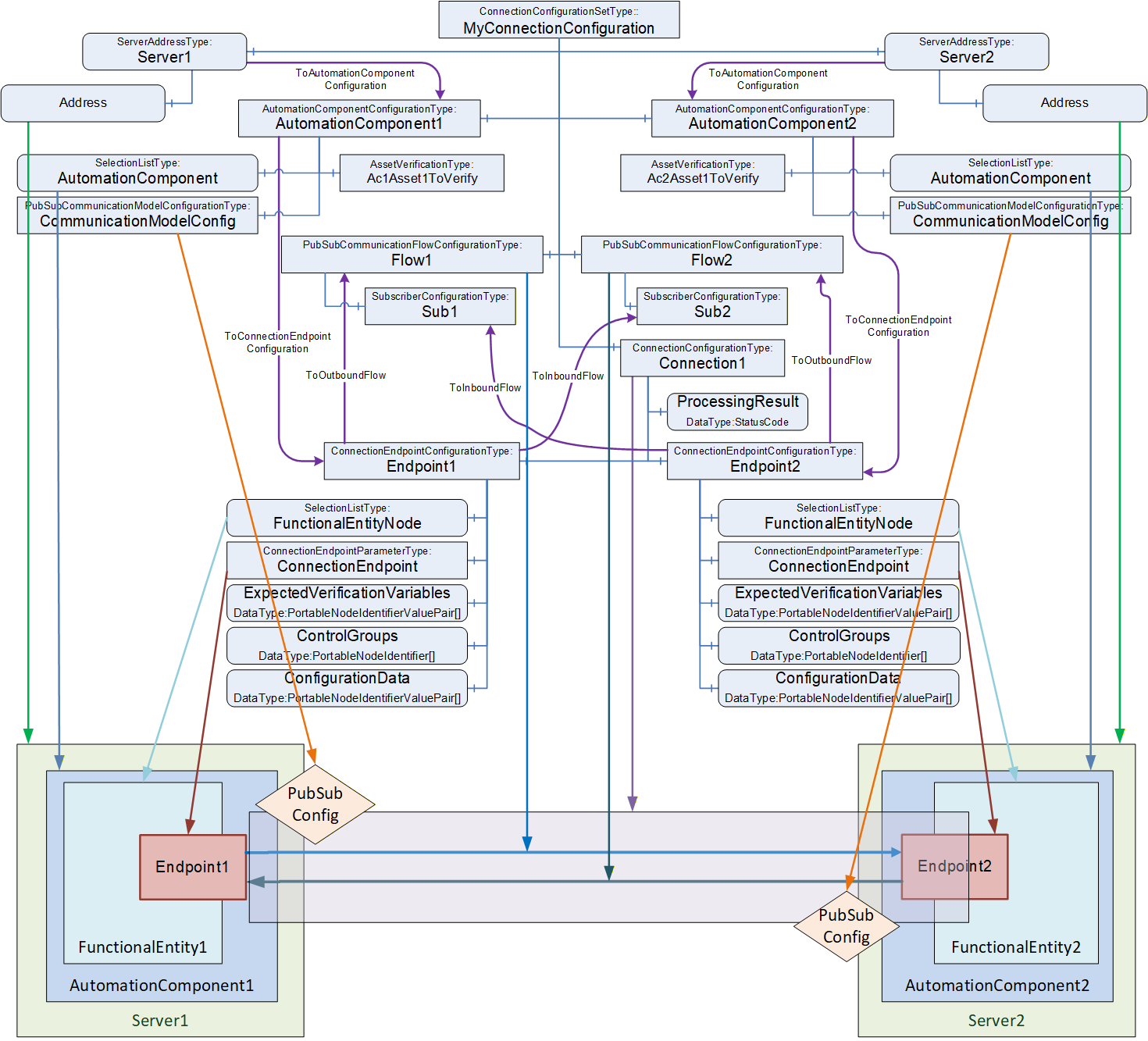
The EstablishConnections Method (see 6.2.4) is used to establish ConnectionEndpoints on an AutomationComponent.
The Method allows for the establishment of multiple Connections with a single Call. The number of Connections to be established with a single Call may be restricted by the addressed AutomationComponent as indicated by MaxConnectionsPerCall (see 6.2.6).
The Method provides several commands (see Figure 36) to verify and create the individual Information Model Objects related to a Connection.
Figure 36 illustrates the sequence of commands to a single AutomationComponent when calling the EstablishConnections Method.
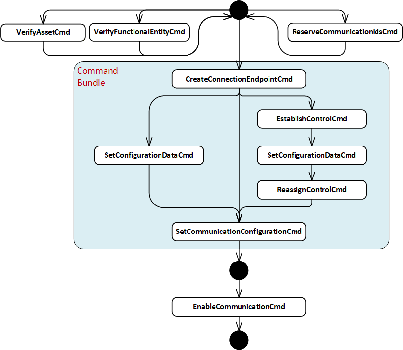
A ConnectionManager shall call the EstablishConnections Method on the AutomationComponents, passing in one or several commands to be executed together with their required arguments. A ConnectionManager may issue one or multiple EstablishConnections Calls (see 6.2.4).
The ConnectionManager shall use the following commands in the following sequence: CreateConnectionEndpointCmd, EstablishControlCmd, SetConfigurationDataCmd, ReassignControlCmd, and SetCommunicationConfigurationCmd. The sequence may be built by having one EstablishConnections Call with the required commands (in this case, the mandated sequence is maintained by the AutomationComponent) or multiple subsequent EstablishConnections Calls by keeping the sequence of commands across the Calls (in this case, the mandated sequence is maintained by the ConnectionManager).
The ConnectionManager may use the following commands at any time and in any order: VerifyAssetCmd, VerifyFunctionalEntityCmd, ReserveCommunicationIdsCmd, and EnableCommunicationCmd.
A Client using the Methods exposed in the Information Model (e.g., VerifyAsset, ReassignControl) can invoke them in any order or at any time. The sequence is only mandated for the commands within the EstablishConnections Method.
The following applies to the usage of commands:
Commands may be omitted if not needed, e.g., if no ControlGroups are exposed by the AutomationComponent or used by the configuration in the ConnectionConfigurationSet, the commands EstablishControlCmd and ReassignControlCmd can be omitted.
Method Calls are subject to certain limits defined by OPC UA and provided by a Server (e.g., MaxMessageSize, MaxByteStringLength, etc.). Therefore, it might be necessary to issue commands in consecutive EstablishConnections Calls, e.g., to apply large configuration data, multiple Calls with SetConfigurationDataCmd can be required.
If AutomationComponentConfiguration CommandBundleRequired is set to TRUE, the ConnectionManager shall issue all required bundled commands in a single Call (see 6.2.4.3.1).
It is recommended that the ConnectionManager issue all required commands in a single Call.
It is recommended that a ConnectionManager performs operations in parallel when establishing multiple Connections between multiple AutomationComponents.
If Auditing is supported, the ConnectionManager shall generate an Event of AuditClientUpdateMethodResultEventType for all calls of the EstablishConnections Method and shall pass the AuditEntryId as part of the Method invocation.
If the ConnectionManagerLog is supported, the LogRecords for the EstablishConnections Calls shall include the following:
SourceNode shall be the NodeId of the ConnectionConfigurationSet that the Connection belongs to.
SourceName shall be the BrowseName of the Connection that is being created.
Message shall describe the action(s) being reported (e.g. create Connection, Connection creation failed, enable Connection failed…).
The AdditionalData shall contain any related data that was passed in in the Call.
In the case of an error, the ErrorCode shall contain the detailed error code returned in the EstablishConnections Method. This may result in more than one LogRecord (one for each error). The ErrorCodeNode shall contain the NodeId of the Node related to the error being reported. E.g. this might be an Asset that failed verification or an FunctionalEntity that had an error.
It is recommended that the ConnectionManager has the well-known Role ConnectionAdmin as defined in Subclause 5.9.
Table 79 lists the commands and their required configuration information in the ConnectionConfigurationSetType Information Model.
| Command | Description | Relevant types from configuration model |
|---|---|---|
| VerifyAssetCmd | Verify that the Assets are the ones expected by system engineering. | The argument AssetVerifications that is passed for this command is constructed out of the AssetVerificationType instances in the AutomationComponentConfiguration. |
| VerifyFunctionalEntityCmd | Verify that the FunctionalEntity is the one expected by system engineering. | The argument ConnectionEndpointConfigurations ExpectedVerificationVariables that is passed for this command is constructed out of the ExpectedVerificationVariables contained in Endpoint1 or Endpoint2 Object in the instances of ConnectionConfigurationType. |
| ReserveCommunicationIdsCmd | Reserves identifiers for the communication configuration. | The argument ReserveCommunicationIds that is passed for this command is constructed out of the instance of CommunicationModelConfigurationType. |
| CreateConnectionEndpointCmd | Create a ConnectionEndpoint on the FunctionalEntity. Alternatively, use a preconfigured ConnectionEndpoint. | The argument ConnectionEndpointConfigurations ConnectionEndpoint that is passed for this command is constructed out of the Parameter Object in the ConnectionEndpoint Object in Endpoint1 or Endpoint2 Object in the instances of ConnectionConfigurationType. |
| EstablishControlCmd | Establish control of specific ControlGroups of the FunctionalEntity. | The argument ConnectionEndpointConfigurations ControlGroups that is passed for this command is constructed out of the ControlGroups Variable in Endpoint1 or Endpoint2 Object in the instances of ConnectionConfigurationType. |
| SetConfigurationDataCmd | Set ConfigurationData on the FunctionalEntity to adapt its behaviour as required (e.g., setting engineering units). | The argument ConnectionEndpointConfigurations ConfigurationData that is passed for this command is constructed out of the ConfigurationData Variable in Endpoint1 or Endpoint2 Object in the instances of ConnectionConfigurationType. |
| ReassignControlCmd | Reassigns the ControlGroups to be associated with a Connection. | The argument ConnectionEndpointConfigurations ControlGroups that is passed for this command is constructed out of the ControlGroups Variable in Endpoint1 or Endpoint2 Object in the instances of ConnectionConfigurationType. |
| SetCommunicationConfigurationCmd | Set communication configuration specific to the communication model utilized for data exchange (e.g., PubSub). | The argument CommunicationConfigurations that is passed for this command is constructed out of the instance of CommunicationModelConfigurationType. The argument ConnectionEndpointConfigurations CommunicationLinks is constructed out of the CommunicationLinks Variable in Endpoint1 or Endpoint2 Object in the instances of ConnectionConfigurationType. |
| EnableCommunicationCmd | Enable the communication model. | The argument ConnectionEndpointConfigurations ConnectionEndpoint that is passed for this command is constructed out of the ConnectionEndpoint Object in Endpoint1 or Endpoint2 Object in the instances of ConnectionConfigurationType. |
The ConnectionManager shall resolve identifier information contained in the ConnectionConfigurationSets to the arguments required for the EstablishConnections Call (see 13).
If any of the ConnectionEndpoints require SKS configuration, the ConnectionManager shall also call the SKS and add the appropriate configuration (SecurityGroups and/or PushTargets; see E.5 for examples).
If a configuration entry is null or empty, the corresponding command shall be skipped.
If EstablishConnections returns Uncertain, indicating an Abort of the Method (see 6.2.4.3.11) or if a fatal OPC UA communication error occurs, the ConnectionManager shall stop the establishing sequence and initiate a ProcessingToError transition in the ConnectionConfigurationSetStateMachine (see 6.9). If RollbackOnError is TRUE, the ConnectionManager shall call the Method CloseConnections for all ConnectionEndpoints established so far with Remove set to TRUE. If RollbackOnError is FALSE, no additional actions are performed by the ConnectionManager.
6.7.3.3 Closing Connections
To close Connections defined in a ConnectionConfigurationSet, a ConnectionManager shall use the CloseConnections Method on the AutomationComponents (see 6.2.5). A ConnectionManager may remove or disable the Connections.
If CloseConnections returns any error, the ConnectionManager shall complete closing all Connections in the ConnectionConfigurationSet and initiate a ProcessingToError transition in the ConnectionConfigurationSetStateMachine (see 6.9).
If any of the ConnectionEndpoints require SKS configuration and were removed, the ConnectionManager shall also remove the appropriate configuration from the SKS (SecurityGroups and/or PushTargets; see E.5 for examples).
6.7.4 EditConnectionConfigurationSets Method
The EditConnectionConfigurationSets Method manages the editing of ConnectionConfigurationSets by a Client.
The Method shall set the Edit Property to TRUE for the requested ConnectionConfigurationSets. For ConnectionConfigurationSets that are not editable (indicated by the absence of the Property Edit), this Method shall return Bad_InvalidState. For the ConnectionConfigurationSets that allow editing, the Method shall also set the Lock to the Client Session associated with this Method Call. The Lock shall behave as described in OPC 10000-100, including the requirement to renew the Lock and to remove the Lock in the case of the Client Session exiting. If the Lock exits for any reason, the internal action on the ConnectionConfigurationSets shall be as if this Method was called with a DiscardUpdates Action. For ConnectionConfigurationSet, which is already in edit mode and locked to this Client Session, no action shall be performed on this ConnectionConfigurationSet, and a successful result will be returned.
If Action is CommitUpdates, the Method shall set the Property Edit to FALSE for all requested ConnectionConfigurationSets. The ConnectionManager shall only process committed updates. It shall reassign the Lock back to the ConnectionManager. If Version is supported, it shall always be incremented; for additional behaviour, see Version in 6.8.2. If the requesting Client does not own the Lock, the request is rejected with an error.
If Action is DiscardUpdates, the Method shall set the Property Edit to FALSE for all requested ConnectionConfigurationSets. The ConnectionManager shall discard the updates to the ConnectionConfigurationSet. It shall reassign the Lock back to the ConnectionManager. If the requesting Client does not own the Lock, the request is rejected with an error.
If a ConnectionConfigurationSet is called with Action set to either CommitUpdates or DiscardUpdates, but the Edit Property is FALSE, the Method shall ignore the Call for the ConnectionConfigurationSet.
The signature of this Method is specified below. The Method parameters are defined in Table 80.
Signature
	EditConnectionConfigurationSets (
		[in] 4:FxEditEnum		Action,
		[in] 0:NodeId[]		ConnectionConfigurationSets,
		[out] 0:StatusCode[]	Results
);| Argument | Description |
| Action | Indicates whether to allow editing, commit the updates to the ConnectionConfigurationSets or discard the updates. |
| ConnectionConfigurationSets | A list of NodeIds of ConnectionConfigurationSets to be edited. |
| Results | A list of StatusCode corresponding to the ConnectionConfigurationSets input argument. The length of this array shall match the length of the ConnectionConfigurationSets NodeId array. Clients may inspect this list to determine which ConnectionConfigurationSets were successfully updated and which failed. See Table 82 for possible Results values. |
The possible Method result codes are formally defined in Table 81.
| ResultCode | Description |
| Bad_UserAccessDenied | The caller is not allowed to invoke this Method. |
| Uncertain | There was at least one error or warning for one of the ConnectionConfigurationSets. Results will contain additional information. |
The possible Results StatusCodes are formally defined in Table 82. The Results array shall contain Good for any ConnectionConfigurationSet that was successfully updated.
| ResultCode | Description |
| Good | The operation succeeded. |
| Bad_NodeIdUnknown | The NodeId refers to a non-existent ConnectionConfigurationSet. |
| Bad_NodeIdInvalid | The syntax of the NodeId is not valid. |
| Bad_InvalidArgument | The NodeId for the requested ConnectionConfigurationSet was not a ConnectionConfigurationSet. |
| Bad_UserAccessDenied | The caller is not allowed to edit this ConnectionConfigurationSet. |
| Bad_InvalidState | The ConnectionConfigurationSet cannot be edited. The caller is not allowed to edit, commit, or discard updates since the ConnectionConfigurationSet is locked by a different Client. |
The EditConnectionConfigurationSets Method representation in the AddressSpace is formally defined in Table 83.
| Attribute | Value | ||||
| BrowseName | 4:EditConnectionConfigurationSets | ||||
| References | Node Class | BrowseName | DataType | TypeDefinition | Other |
|---|---|---|---|---|---|
| 0:HasProperty | Variable | 0:InputArguments | 0:Argument[] | 0:PropertyType | M |
| 0:HasProperty | Variable | 0:OutputArguments | 0:Argument[] | 0:PropertyType | M |
| 0:GeneratesEvent | ObjectType | 2:AuditUpdateMethodResultEventType | Defined in 8.4 | ||
| ConformanceUnits | |||||
|---|---|---|---|---|---|
| UAFX ConnectionManager EditConnectionConfigurationSets |
If Auditing is supported, the ConnectionManger shall generate an Event of type AuditUpdateMethodResultEventType for all EditConnectionConfigurationSets Method calls. The SourceNode for this Event shall be the ConnectionManager
If ConnectionManagerLog is supported, the ConnectionManager shall produce a LogRecord for each ConnectionConfigurationSet in the invocation of this Method. For each LogRecord:
The SourceNode shall be the NodeId of the ConnectionConfigurationSet.
The SourceName shall be the Uri of the Client that invoked the Method.
The Message shall include "ConnectionManager/EditConnection".
Note:the Message field in future releases will be updated to define fixed strings and mandatory fields for distinct messages and will be included . The fixed text will be provided in multiple languages.
6.7.5 ProcessConnectionConfigurationSets method
6.7.5.1 Overview
The ProcessConnectionConfigurationSets Method causes the ConnectionManager to process the requested ConnectionConfigurationSets according to the specified Action:
ActionEstablishConnectionsEnabled, ActionEstablishConnectionsDisabled, and ActionEstablishConnections - establish all Connections contained in the ConnectionConfigurationSets.
ActionRemoveConnections - disable and remove all Connections contained in the ConnectionConfigurationSets (see 6.7.5.3.2)
ActionEnableConnections - enable the communication model for all Connections contained in the ConnectionConfigurationSets (see 6.7.5.3.3)
ActionDisableConnections - disable the communication model for all Connections contained in the ConnectionConfigurationSets (see 6.7.5.3.4)
6.7.5.2 ProcessConnectionConfigurationSets signature
The ProcessConnectionConfigurationSets Method shall initiate the ReadyToProcessing or ErrorToProcessing transition in the ConnectionConfigurationSetStateMachine (see 6.9) on all requested ConnectionConfigurationSets.
The Method triggers the processing and returns immediately. The result of processing is "returned" asynchronously by one of the ConnectionConfigurationSetEventType Events.
The signature of this Method is specified below; the Method arguments are defined in Table 84.
Signature
	ProcessConnectionConfigurationSets (
		 [in] 4:FxProcessEnum	Action,
		 [in] 0:NodeId[]		ConnectionConfigurationSets,
		 [out] 0:StatusCode[]	Results
);| Argument | Description |
| Action | The operation to be performed on the ConnectionConfigurationSets (see 10.25). |
| ConnectionConfigurationSets | A list of NodeIds of ConnectionConfigurationSets to be processed. |
| Results | The array of StatusCode corresponding to the ConnectionConfigurationSets input argument. The length of this array shall match the length of the ConnectionConfigurationSets NodeId array. Clients may inspect this list to determine the status of the individual Call to Trigger processing on each ConnectionConfigurationSet. For possible values for StatusCode, see Table 86. |
The possible Method result codes are formally defined in Table 85.
| ResultCode | Description |
| Bad_UserAccessDenied | The caller is not allowed to invoke this Method. |
| Bad_NotSupported | The requested Action is not supported. |
| Uncertain | There was at least one error or warning for one of the ConnectionConfigurationSets. Results will contain additional information. |
The possible Result StatusCodes are formally defined in Table 86.
| Result Code | Description |
| Good | Changing the State succeeded for the ConnectionConfigurationSet. |
| Bad_NodeIdInvalid | The syntax of the NodeId is not valid. |
| Bad_NodeIdUnknown | The NodeId refers to a node that does not exist in the Server address space. |
| Bad_InvalidArgument | The NodeId for the requested ConnectionConfigurationSet was not a ConnectionConfigurationSet. |
| Bad_UserAccessDenied | The caller is not allowed to trigger the processing of this ConnectionConfigurationSet. |
| Bad_InvalidState | The ConnectionConfigurationSet is in a State that does not allow it to be triggered for processing. |
The ProcessConnectionConfigurationSets Method representation in the AddressSpace is formally defined in Table 87.
| Attribute | Value | ||||
| BrowseName | 4:ProcessConnectionConfigurationSets | ||||
| References | Node Class | BrowseName | DataType | TypeDefinition | Other |
|---|---|---|---|---|---|
| 0:HasProperty | Variable | 0:InputArguments | 0:Argument[] | 0:PropertyType | M |
| 0:HasProperty | Variable | 0:OutputArguments | 0:Argument[] | 0:PropertyType | M |
| 0:GeneratesEvent | ObjectType | 2:AuditUpdateMethodResultEventType | Defined in 8.4 | ||
| 0:GeneratesEvent | ObjectType | ConnectionConfigurationSetProcessingStartedEventType | Defined in 8.7 | ||
| 0:GeneratesEvent | ObjectType | ConnectionConfigurationSetProcessingSucceededEventType | Defined in 8.8 | ||
| 0:GeneratesEvent | ObjectType | ConnectionConfigurationSetProcessingFailedEventType | Defined in 8.9 | ||
| ConformanceUnits | |||||
|---|---|---|---|---|---|
| UAFX ConnectionManager ProcessConnectionConfigurationSets |
If Auditing is supported, the ConnectionManger shall generate an Event of type AuditUpdateMethodResultEventType for all ProcessConnectionConfigurationSets Method calls. The SourceNode for this Event shall be the ConnectionManager.
If ConnectionManagerLog is supported, the ConnectionManager shall produce a LogRecord for each ConnectionConfigurationSet in the invocation of this Method. For each LogRecord:
The SourceNode shall be the NodeId of the ConnectionConfigurationSet.
The SourceName shall be the applicationUri from the ClientDescription of the Client that invoked the Method (see OPC 10000-4 ApplicationDescriptionType).
The Message shall include "ConnectionManager/ProcessConnection" and the Action being invoked.
6.7.5.3 ProcessConnectionConfigurationSets behaviour
6.7.5.3.1 ActionEstablishConnectionsEnabled / ActionEstablishConnectionsDisabled / ActionEstablishConnections
Calling ProcessConnectionConfigurationSets with Action set to ActionEstablishConnectionsEnabled, ActionEstablishConnectionsDisabled, or ActionEstablishConnections shall establish the Connections contained in the ConnectionConfigurationSets and their related communication model.
Establishing connections shall follow the behaviour specified in 6.7.3.2.
The ConnectionManager shall ensure the expected result of the requested Action as follows:
Calling ProcessConnectionConfigurationSets with Action set to ActionEstablishConnectionsEnabled shall establish all Connections contained in the ConnectionConfigurationSets with a disabled communication model and include EnableCommunicationCmd in the command sequence. A disabled communication model has Enabled flags set to FALSE for all DataSetReader and DataSetWriter configuration elements and to TRUE for all other elements (WriterGroup, ReaderGroup, PubSubConnection, and PublishSubscribe).
A disabled ClientServer communication model may be defined in a future version of this document.
Calling ProcessConnectionConfigurationSets with Action set to ActionEstablishConnectionsDisabled shall establish all Connections contained in the ConnectionConfigurationSets with a disabled communication model and omit EnableCommunicationCmd from the command sequence. A disabled communication model has Enabled flags set to FALSE for all DataSetReader and DataSetWriter configuration elements and to TRUE for all other elements (WriterGroup, ReaderGroup, PubSubConnection, and PublishSubscribe).
Calling ProcessConnectionConfigurationSets with Action set to ActionEstablishConnections shall establish all Connections contained in the ConnectionConfigurationSets with the communication model as configured by the engineering tool generating the communication model. The ConnectionManager shall apply the communication model as is using the SetCommunicationConfigurationCmd and omit EnableCommunicationCmd from the command sequence. Depending on the state of the configuration elements (e.g., the value of the Enabled flag for PubSub configuration elements), parts of the communication model may be enabled, and others may be disabled. This allows, for example, a subset of the Connections to be enabled and the rest disabled. It is the responsibility of the engineering tool to configure the state of the configuration elements properly and consistently.
6.7.5.3.2 ActionRemoveConnections
Calling ProcessConnectionConfigurationSets with Action set to ActionRemoveConnections shall remove all Connections contained in the ConnectionConfigurationSets and their related communication model.
For each ConnectionConfigurationSet, the ConnectionManager shall call the CloseConnections Method (see 6.2.5) with Remove set to TRUE for all contained ConnectionEndpoints. See 6.7.3.3 for ConnectionManager behaviour.
6.7.5.3.3 ActionEnableConnections
Calling ProcessConnectionConfigurationSets with Action set to ActionEnableConnections shall enable all Connections contained in the ConnectionConfigurationSets.
For each ConnectionConfigurationSet, the ConnectionManager shall call the EstablishConnections Method containing the EnableCommunicationCmd for all contained ConnectionEndpoints. See 6.7.3.2 for ConnectionManager behaviour.
6.7.5.3.4 ActionDisableConnections
Calling ProcessConnectionConfigurationSets with Action set to ActionDisableConnections shall disable all Connections contained in the ConnectionConfigurationSets.
For each ConnectionConfigurationSet, the ConnectionManager shall call the CloseConnections Method (see 6.2.5) with Remove set to FALSE for all contained ConnectionEndpoints. See 6.7.3.3 for ConnectionManager behaviour.
6.7.6 ConnectionManagerCapabilitiesType
The ConnectionManagerCapabilitiesType extends the FolderType defined in OPC 10000-5. It shall be restricted to contain only Variables that reflect the capabilities of the ConnectionManager.
The ConnectionManagerCapabilitiesType is formally defined in Table 88.
| Attribute | Value | ||||
| BrowseName | 4:ConnectionManagerCapabilitiesType | ||||
| IsAbstract | False | ||||
| References |
Node
Class | BrowseName | DataType | TypeDefinition | Other |
|---|---|---|---|---|---|
| Subtype of the 0:FolderType defined in OPC 10000-5 | |||||
| 4:HasCMCapability | Variable | 4:<Capability> | 0:BaseDataType | 0:BaseDataVariableType | OP |
| 4:HasCMCapability | Variable | 4:MaxConnectionConfigurationSets | 0:UInt32 | 0:BaseDataVariableType | O |
| 4:HasCMCapability | Variable | 4:MonitorsLocalConnectionEndpoints | 0:Boolean | 0:BaseDataVariableType | O |
| 4:HasCMCapability | Variable | 4:MonitorsAllConnectionEndpoints | 0:Boolean | 0:BaseDataVariableType | O |
| ConformanceUnits | |||||
|---|---|---|---|---|---|
| UAFX ConnectionManager Capabilities Base |
<Capability> - is an OptionalPlaceholder (defined in OPC 10000-3) to indicate that additional capabilities may be added by this document, a companion specification, or by a vendor at any time. These capabilities shall include a Description, and they follow all of the rules associated with an OptionalPlaceholder.
MaxConnectionConfigurationSets indicates the maximum number of ConnectionConfigurationSets that the ConnectionManager can support.
MonitorsLocalConnectionEndpoints, when true, describes the capability of the ConnectionManager Information Model to report the status of all the Connections created by this ConnectionManager that have a ConnectionEndpoint on this Server. If this capability is not provided, or false, the ConnectionManager Information Model does not report the current status of Connections.
NOTE In some cases, this status might include the status of the remote Connection.
MonitorsAllConnectionEndpoints, when true, describes the capability of the ConnectionManager Information Model to report status information for all ConnectionEndpoints of all Connections created by this ConnectionManager. This capability extends the MonitorsLocalConnectionEndpoints capability and shall not be provided if MonitorsLocalConnectionEndpoints is not provided.
6.8 ConnectionConfigurationSetType
6.8.1 Overview
The ConnectionConfigurationSetType is an ObjectType representing one or more Connection configurations. Connections are grouped in a set, for example, to allow sharing communication model configurations by multiple Connections; see 5.5.6.2.3 and 5.5.6.2.4 for appropriate use cases.
ConnectionConfigurationSets are generated and deployed to the ConnectionManager (see Figure 11 label 3). The ConnectionManager may expose the ConnectionConfigurationSets in its AddressSpace.
A ConnectionConfigurationSet exposes diagnostic information about the Connections as part of its Information Model. It also allows Connection configurations to be available for modification by standard Clients (see Figure 11 label 4), and it could provide an interface to trigger the processing of such Connection configurations.
A ConnectionConfigurationSet may only be modified by a standard Client as follows:
The SelectionListType (see OPC 10000-5) is used to indicate where the support for modifications is required by the UAFX specification. This type allows the generator of the ConnectionConfigurationSet to provide a list of Selections and an optional description of them. If the optional RestrictToList is set to TRUE, a Client changing the Variable is restricted to the provided Selections. If set to FALSE or missing, a Client may change the Variable to any value, including one of the Selections. For example, the value of PublishingInterval may be restricted to the values 2 ms, 4 ms, and 8 ms by adding these values to Selections and setting RestrictToList to TRUE. If the value is fixed, the SelectionListType value shall be the fixed value, the Selections list shall be populated with the same fixed value, and the RestrictToList shall be TRUE.
Vendors can set any other Variables' ReadWrite settings to allow them to be written and can set the Permission of the data to restrict write operations to users/applications with specific Roles. A Client can determine if it has access by examining the AccessLevel and UserAccessLevel Attributes of the data.
With these mechanisms, the generator of the ConnectionConfigurationSet can specify and restrict the allowed changes.
If Auditing is supported, the ConnectionManager shall generate an Event of type AuditUpdateConnectionConfigurationSetEventType for all ConnectionConfigurationSet data modifications.
If the ConnectionManagerLog is supported, the ConnectionManager shall produce LogRecords for each change. The LogRecord includes:
The SourceNode shall be the NodeId of the Variable that was changed.
The SourceName shall be the BrowseName of the Node being updated.
The Message shall include the BrowseName of the ConnectionConfigurationSet that contains the Node being updated, as well as the old and new values for the SelectionList item.
For an overview of the ConnectionConfigurationSetType and its related types, see Figure 35. For examples, see Annex E.
The ConnectionConfigurationSetType is illustrated in Figure 37.
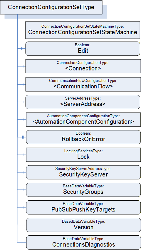
6.8.2 ConnectionConfigurationSetType definition
The ConnectionConfigurationSetType is formally defined in Table 89 and Table 90.
| Attribute | Value | ||||
| BrowseName | 4:ConnectionConfigurationSetType | ||||
| IsAbstract | False | ||||
| References |
Node
Class | BrowseName | DataType | TypeDefinition | Other |
|---|---|---|---|---|---|
| Subtype of the 0:BaseObjectType defined in OPC 10000-5 | |||||
| 0:HasComponent | Object | 4:ConnectionConfigurationSetStateMachine | 4:ConnectionConfigurationSetStateMachineType | M | |
| 0:HasProperty | Variable | 4:Edit | 0:Boolean | 0:PropertyType | O, RO |
| 4:HasConnectionConfiguration | Object | 4:<Connection> | 4:ConnectionConfigurationType | MP | |
| 4:HasCommunicationFlowConfiguration | Object | 4:<CommunicationFlow> | 4:CommunicationFlowConfigurationType | MP | |
| 4:HasServerAddress | Variable | 4:<ServerAddress> | 4:ServerAddressDataType | 4:ServerAddressType | MP |
| 4:HasAutomationComponentConfiguration | Object | 4:<AutomationComponentConfiguration> | 4:AutomationComponentConfigurationType | MP | |
| 0:HasProperty | Variable | 4:RollbackOnError | 0:Boolean | 0:PropertyType | M |
| 0:HasComponent | Object | 5:Lock | 5:LockingServicesType | M | |
| 0:HasComponent | Variable | 4:SecurityKeyServer | 4:SecurityKeyServerAddressDataType | 4:SecurityKeyServerAddressType | O |
| 0:HasComponent | Variable | 4:SecurityGroups | 0:SecurityGroupDataType[] | 0:BaseDataVariableType | O |
| 0:HasComponent | Variable | 4:PubSubKeyPushTargets | 0:PubSubKeyPushTargetDataType[] | 0:BaseDataVariableType | O |
| 0:HasComponent | Variable | 4:Version | 0:UInt32 | 0:BaseDataVariableType | O, RO |
| 0:HasComponent | Variable | 4:ConnectionsDiagnostics | 4:ConnectionDiagnosticsDataType[] | 0:BaseDataVariableType | O, RO |
| ConformanceUnits | |||||
|---|---|---|---|---|---|
| UAFX ConnectionManager Base |
| SourceBrowsePath | Reference Type | IsForward | TargetBrowsePath | ||
| 4:<ServerAddress> | 4:ToAutomationComponentConfiguration | True | 4:<AutomationComponentConfiguration> | ||
| 4:<AutomationComponentConfiguration> | 4:ToConnectionEndpointConfiguration | True |
| ||
| 4:<AutomationComponentConfiguration> | 4:ToConnectionEndpointConfiguration | True |
|
ConnectionConfigurationSetStateMachine contains the current State of this ConnectionConfigurationSet. See 6.9 for a formal definition of the state machine.
If Edit is present, the ConnectionConfigurationSet supports transactional editing. If Edit is TRUE, the ConnectionConfigurationSet is currently being edited by a Client. See 6.7.4 on editing a ConnectionConfigurationSet.
<Connection> represents one or more instances of ConnectionConfigurationType, which defines Connection configurations to be established. For a formal definition, see 6.10.
<CommunicationFlow> represents one or more instances of CommunicationFlowConfigurationType, which defines communication model-specific configuration to apply to a Connection. For a formal definition, see 6.13. There may be fewer instances of this type than ConnectionConfigurations.
<ServerAddress> represents one or more instances of ServerAddressType, which defines addressing information for AutomationComponents. For a formal definition, see 9.2. There may be fewer instances of this type than ConnectionConfigurations.
<AutomationComponentConfiguration> represents one or more AutomationComponents. In addition, it holds the parameters used for Asset verification. For a formal definition, see 6.14.
RollbackOnError indicates the behaviour that should be followed when there is an error with Connection establishment. If this Property is TRUE and an error occurs during the Connection establishment sequence, establishing the set shall stop, and all established Connections that are part of this set shall be closed (see 6.7.3.2).
It is recommended that the system integrator Client use the well-known Role ConfigureAdmin, as defined in Sublause 5.9, for accessing this Object. It is recommended that the modifiable content of the ConnectionConfigurationSet has the write privilege for the well-known Role ConfigureAdmin as defined in Subclause 5.9.
Lock is an instance of LockingServicesType, defined in OPC 10000-100, which provides the basic locking functionality. A ConnectionConfigurationSet that is not in editable mode shall be locked to the ConnectionManager and blocked from any changes (the Client is set to the NodeId of the ConnectionManager, and the user is set to "CM"). A Client can call the EditConnectionConfigurationSets Method on a ConnectionManager to release the Lock from the ConnectionManager and assign it to the Client that issued the EditConnectionConfigurationSets Method Call (for additional details, see 6.7.4).
SecurityKeyServerAddress defines the location of the SKS to be used for PubSub security configuration of this ConnectionConfigurationSet. For a formal definition, see 9.3.
SecurityGroups and PubSubPushKeyTargets define the configuration information to be applied to the SKS for PubSub security configuration of the ConnectionConfigurationSet.
Version shall be a monotonically increasing number. It shall be incremented by 1 on each change to a given ConnectionConfigurationSet, no matter the source of the change. Its ServerTimestamp shall be set to the time of the change. When a ConnectionConfigurationSet is added or replaced (i.e., new NodeId), Version shall be set to 1. Changes could occur via the CloseAndUpdate Method defined in F.3.3, via the EditConnectionConfigurationSets Method, or via vendor-specific means.
ConnectionsDiagnostics provides an array of diagnostic information for Connections included in this ConnectionConfigurationSet. There shall be one element in this array for each <Connection> instance in the ConnectionConfigurationSet. The Name field of the ConnectionDiagnosticsType provides a linkage between an array element and a specific <Connection>. The value of this Variable shall be updated every time the ConnectionManager finishes processing the ConnectionConfigurationSet. If a ConnectionManager monitors ConnectionEndpoints, it shall also update the value when it acquires new information about the status of the Connections. See 10.19 and 10.20 for details on how to update the value.
For a ConnectionManager that is monitoring the state of Connections and supports ConnectionManagerLog, the change of state of all Connections should be logged. Each LogRecord for a change of state shall include the following:
The SourceNode shall be the NodeId of the ConnectionConfigurationSet that contains the Connection.
The SourceName shall be the BrowseName of the Connection with the status change.
The Message shall include the previous state and the new state of the Connection.
The ToAutomationComponentConfiguration Reference is used to link a ServerAddress to AutomationComponentConfiguration (see 6.14). The ServerAddress provides the Connection information to address the referenced AutomationComponent.
The ToConnectionEndpointConfiguration Reference is used to link an AutomationComponentConfiguration to ConnectionEndpointConfigurations (see 6.11).
The ToOutboundFlow Reference is used to link a ConnectionEndpointConfiguration to a PubSubCommunicationFlowConfiguration (see 6.13.3). This Reference defines the PubSub-specific configuration to be used for the transmission of output data related to this ConnectionEndpoint. It shall be present if an outbound PubSub flow is configured.
The ToInboundFlow Reference is used to link a ConnectionEndpointConfiguration to a SubscriberConfiguration (see 6.13.3.3). This Reference defines the PubSub-specific configuration to be used for the reception of input data related to this ConnectionEndpoint. It shall be present if an in-bound PubSub flow is configured.
A ConnectionEndpointConfiguration shall have at most one ToOutboundFlow and at most one ToInboundFlow Reference.
The References used to link a ConnectionEndpointConfiguration to Client Server-specific communication configuration will be defined in a later version of this document.
6.9 ConnectionConfigurationSetStateMachineType
6.9.1 Overview
A state machine is defined as a mechanism to coordinate actions executed internally (a ConnectionManager establishing Connections) that involve the processing of a ConnectionConfigurationSet. The States and Transitions that comprise the state machine are illustrated in Figure 38. Numbers in circles indicate the TransitionNumber of a transition.
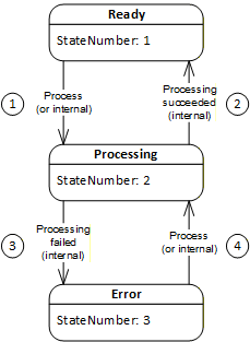
The transitions with TransitionNumber 1 and 4 (process) may also be triggered by a Client but are more typically triggered internally by a vendor-specific algorithm. The transitions with TransitionNumber 2 (processing succeeded) and 3 (processing failed) are only triggered internally on completion of Connection establishment processing.
A ConnectionConfigurationSetStateMachine may transition to Error for several reasons. Transient errors will be resolved by re-processing the ConnectionConfigurationSet. If the transient error has cleared, the state machine will transition to Ready; otherwise, it will return to Error. The error may be a permanent error that needs correction by the system integrator.
6.9.2 ConnectionConfigurationSetStateMachineType definition
The ConnectionConfigurationSetStateMachineType and the corresponding set of Methods (see ConnectionConfigurationSetType) and Events (subtypes of the ConnectionConfigurationSetEventType) are illustrated in Figure 39.
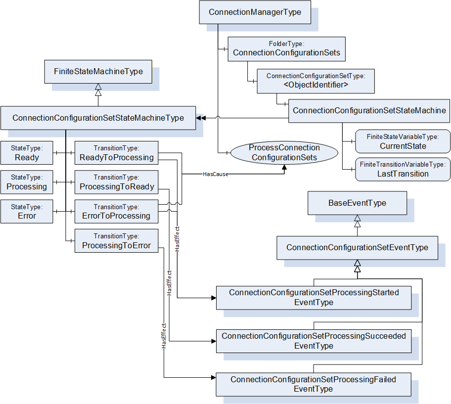
Methods and Events illustrated in Figure 39 are defined in subsequent subclauses. The ConnectionConfigurationSetStateMachineType is formally defined in Table 91. StateType and TransitionType only exist in the type system; thus, they do not have a modelling rule.
| Attribute | Value | ||||
| BrowseName | 4:ConnectionConfigurationSetStateMachineType | ||||
| IsAbstract | False | ||||
| References |
Node
Class | BrowseName |
Data
Type | TypeDefinition | Other |
|---|---|---|---|---|---|
| Subtype of the 0:FiniteStateMachineType defined in OPC 10000-16 | |||||
| 0:HasComponent | Variable | 0:LastTransition | 0:LocalizedText | 0:FiniteTransitionVariableType | M |
| 0:HasComponent | Object | 4:Ready | 0:StateType | ||
| 0:HasComponent | Object | 4:Processing | 0:StateType | ||
| 0:HasComponent | Object | 4:Error | 0:StateType | ||
| 0:HasComponent | Object | 4:ReadyToProcessing | 0:TransitionType | ||
| 0:HasComponent | Object | 4:ProcessingToReady | 0:TransitionType | ||
| 0:HasComponent | Object | 4:ProcessingToError | 0:TransitionType | ||
| 0:HasComponent | Object | 4:ErrorToProcessing | 0:TransitionType | ||
| ConformanceUnits | |||||
|---|---|---|---|---|---|
| UAFX ConnectionManager Base |
The components of the ConnectionConfigurationSetStateMachineType have additional references, which are defined in Table 92.
| SourceBrowsePath | Reference Type | IsForward | TargetBrowsePath | |||
| 4:ReadyToProcessing | 0:ToState | True | 4:Processing | |||
| 4:ReadyToProcessing | 0:FromState | True | 4:Ready | |||
| 4:ReadyToProcessing | 0:HasCause | True |
| |||
| 4:ReadyToProcessing | 0:HasEffect | True | 4:ConnectionConfigurationSetProcessingStartedEventType | |||
| 4:ProcessingToReady | 0:ToState | True | 4:Ready | |||
| 4:ProcessingToReady | 0:FromState | True | 4:Processing | |||
| 4:ProcessingToReady | 0:HasEffect | True | 4:ConnectionConfigurationSetProcessingSucceededEventType | |||
| 4:ProcessingToError | 0:ToState | True | 4:Error | |||
| 4:ProcessingToError | 0:FromState | True | 4:Processing | |||
| 4:ProcessingToError | 0:HasEffect | True | 4:ConnectionConfigurationSetProcessingFailedEventType | |||
| 4:ErrorToProcessing | 0:ToState | True | 4:Processing | |||
| 4:ErrorToProcessing | 0:FromState | True | 4:Error | |||
| 4:ErrorToProcessing | 0:HasCause | True |
| |||
| 4:ErrorToProcessing | 0:HasEffect | True | 4:ConnectionConfigurationSetProcessingStartedEventType |
The component Variables of the ConnectionConfigurationSetStateMachineType have additional Attributes defined in Table 93.
| BrowsePath | Value Attribute | ||
| 1 | ||
| 2 | ||
| 3 | ||
| 1 | ||
| 2 | ||
| 3 | ||
| 4 |
Ready - A ConnectionConfigurationSet in this State may be processed by the ConnectionManager.
Processing - A ConnectionConfigurationSet in this State indicates that it is currently being processed by the ConnectionManager (i.e., Connections are being established). Internals of the processing executed in this State are described in 6.7.5.
Error - A ConnectionConfigurationSet in this State indicates an error has occurred during Processing.
ReadyToProcessing - This transition shall be initiated by the ProcessConnectionConfigurationSets Method Call. In addition, this state transition may also be initiated by vendor-specific means. While in State Processing, the ConnectionManager establishes or closes the Connections contained in the ConnectionConfigurationSet; for details, see 6.7.5.3.
ProcessingToReady - This transition shall be initiated if the ConnectionManager succeeds in processing all of the Connections contained in the ConnectionConfigurationSet.
ProcessingToError - This transition shall be initiated if the ConnectionManager fails the processing of any Connection contained in the ConnectionConfigurationSet.
Information about the success or failure of the establishment of specific Connections is provided by the ProcessingResult Property in ConnectionConfigurationType.
ErrorToProcessing - This transition shall be initiated by the ProcessConnectionConfigurationSets Method Call. In addition, this state transition may also be initiated by vendor-specific means.
The HasEffect Reference describe Events that are to be generated if eventing is supported.
If ConnectionManagerLog is supported, then for all transition that include a HasEffect Reference, a LogRecord shall be generate. The LogRecord shall include the following:
The SourceNode shall be the NodeId of the ConnectionConfigurationSet that this StateMachine is part of.
The SourceName shall be the BrowseName of the Transition that the HasEffect is referencing.
The Message shall include both the ToState State and FromState State the Transition is associated with.
6.10 ConnectionConfigurationType
6.10.1 Overview
The ConnectionConfigurationType ObjectType describes the configuration information needed to establish a single Connection contained in the ConnectionConfigurationSetType.
The ConnectionConfigurationType is illustrated in Figure 40.
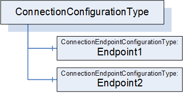
6.10.2 ConnectionConfigurationType definition
The ConnectionConfigurationType is formally defined in Table 94.
| Attribute | Value | ||||
| BrowseName | 4:ConnectionConfigurationType | ||||
| IsAbstract | False | ||||
| References |
Node
Class | BrowseName | DataType | TypeDefinition | Other |
|---|---|---|---|---|---|
| Subtype of the 0:BaseObjectType defined in OPC 10000-5 | |||||
| 0:HasComponent | Object | 4:Endpoint1 | 4:ConnectionEndpointConfigurationType | M | |
| 0:HasComponent | Object | 4:Endpoint2 | 4:ConnectionEndpointConfigurationType | O | |
| ConformanceUnits | |||||
|---|---|---|---|---|---|
| UAFX ConnectionManager Base |
Endpoint1 and the optional Endpoint2 hold the configuration information for the endpoints of the Connection. The ConnectionEndpointConfigurationType is defined in 6.11.
6.11 ConnectionEndpointConfigurationType
6.11.1 Overview
The ConnectionEndpointConfigurationType ObjectType holds the information for an endpoint of a Connection.
The ConnectionEndpointConfigurationType is illustrated in Figure 41.
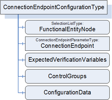
6.11.2 ConnectionEndpointConfigurationType definition
The ConnectionEndpointConfigurationType is formally defined in Table 95.
| Attribute | Value | ||||
| BrowseName | 4:ConnectionEndpointConfigurationType | ||||
| IsAbstract | False | ||||
| References |
Node
Class | BrowseName | DataType | TypeDefinition | Other |
|---|---|---|---|---|---|
| Subtype of the 0:BaseObjectType defined in OPC 10000-5 | |||||
| 0:HasComponent | Variable | 4:FunctionalEntityNode | 4:PortableNodeIdentifier | 0:SelectionListType | M |
| 0:HasComponent | Object | 4:ConnectionEndpoint | 4:ConnectionEndpointParameterType | M | |
| 0:HasComponent | Variable | 4:ExpectedVerificationVariables | 4:PortableNodeIdentifierValuePair[] | 0:BaseDataVariableType | O |
| 0:HasComponent | Variable | 4:ControlGroups | 4:PortableNodeIdentifier[] | 0:BaseDataVariableType | O |
| 0:HasComponent | Variable | 4:ConfigurationData | 4:PortableNodeIdentifierValuePair[] | 0:BaseDataVariableType | O |
| ConformanceUnits | |||||
|---|---|---|---|---|---|
| UAFX ConnectionManager Base |
FunctionalEntityNode specifies the identifier of the FunctionalEntity to configure for this Connection. If a PortableRelativePath is specified, the path shall be relative to FxRoot.
ConnectionEndpoint specifies the parameters for the ConnectionEndpoint to be used for the Connection.
ExpectedVerificationVariables, if present, specifies the variables to be verified. If a PortableRelativePath is specified as Key, the path shall be relative to FunctionalEntityNode.
ControlGroups, if present, specifies the ControlGroups to be controlled. If a PortableRelativePath is specified, the path shall be relative to FunctionalEntityNode.
6.12 ConnectionEndpointParameterType
6.12.1 Overview
The ConnectionEndpointParameterType ObjectType holds the parameters to create the ConnectionEndpoint of a Connection.
The ConnectionEndpointParameterType is illustrated in Figure 42.
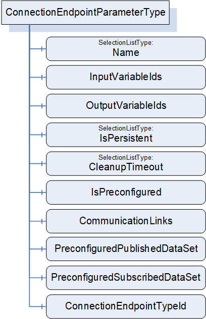
6.12.2 ConnectionEndpointParameterType definition
The ConnectionEndpointParameterType is formally defined in Table 96.
| Attribute | Value | ||||
| BrowseName | 4:ConnectionEndpointParameterType | ||||
| IsAbstract | False | ||||
| References |
Node
Class | BrowseName | DataType | TypeDefinition | Other |
|---|---|---|---|---|---|
| Subtype of the 0:BaseObjectType defined in OPC 10000-5 | |||||
| 0:HasComponent | Variable | 4:Name | 0:String | 0:SelectionListType | M |
| 0:HasComponent | Variable | 4:ConnectionEndpointTypeId | 0:PortableNodeId | 0:BaseDataVariableType | M |
| 0:HasComponent | Variable | 4:InputVariableIds | 4:PortableNodeIdentifier[] | 0:BaseDataVariableType | O |
| 0:HasComponent | Variable | 4:OutputVariableIds | 4:PortableNodeIdentifier[] | 0:BaseDataVariableType | O |
| 0:HasComponent | Variable | 4:IsPersistent | 0:Boolean | 0:SelectionListType | M |
| 0:HasComponent | Variable | 4:CleanupTimeout | 0:Duration | 0:SelectionListType | M |
| 0:HasComponent | Variable | 4:IsPreconfigured | 0:Boolean | 0:BaseDataVariableType | M |
| 0:HasComponent | Variable | 4:CommunicationLinks | 2:CommunicationLinkConfigurationDataType | 0:BaseDataVariableType | O |
| 0:HasComponent | Variable | 4:PreconfiguredPublishedDataSet | 0:String | 0:BaseDataVariableType | O |
| 0:HasComponent | Variable | 4:PreconfiguredSubscribedDataSet | 0:String | 0:BaseDataVariableType | O |
| ConformanceUnits | |||||
|---|---|---|---|---|---|
| UAFX ConnectionManager Base |
Name specifies the BrowseName of the ConnectionEndpoint to create. This name shall be unique within the FunctionalEntity's ConnectionEndpoints Folder. This Name is required for maintaining/closing the Connection, thus a ConnectionManager shall reject changes to this Variable, if the Connection is established. The Name can be changed if the Connection does not exist.
ConnectionEndpointTypeId specifies the well-known NodeId of the type definition, which shall be used to create the ConnectionEndpoint. This can be any of the subtypes of the ConnectionEndpointType (for example, PubSubConnectionEndpointType).
InputVariableIds, if present, specifies a list of node identifiers to be used as inputs. If InputVariableIds is present, it shall contain at least one element.
OutputVariableIds, if present, specifies a list of node identifiers to be used as outputs. If OutputVariableIds is present, it shall contain at least one element.
If a PortableRelativePath is specified for InputVariableIds or OutputVariableIds, the path shall be relative to the FunctionalEntityNode specified in the ConnectionEndpointConfigurations.
A ConnectionEndpointParameter shall include at least one of the following fields:
1 or more InputVariableIds, or
1 or more OutputVariableIds
IsPersistent, if TRUE, specifies the created ConnectionEndpoint shall be persistent.
CleanupTimeout specifies the value to be used for the clean-up timeout. A negative number indicates an infinite timeout. A zero indicates an immediate clean-up.
IsPreconfigured, if TRUE, specifies the ConnectionEndpoint is preconfigured.
CommunicationLinks specifies the configuration data related to this ConnectionEndpoint within the CommunicationModelConfigurationType (see 6.16).
PreconfiguredPublishedDataSet shall only be present if the ConnectionEndpointTypeId is PubSubConnectionEndpointType. If it is not an empty string, it specifies the name of a preconfigured PublishedDataSet (see 6.2.7 for more information on preconfigured DataSets) to be used for connecting the OutputVariables. The ConnectionManager can obtain any required information related to this preconfigured PublishedDataSet from the UA Publisher's exposed PubSub configuration. The Subscriber does not need to expose or utilize all Variables that are being published.
PreconfiguredSubscribedDataSet shall only be present if the ConnectionEndpointTypeId is PubSubConnectionEndpointType. If it is not an empty string, it specifies the name of a preconfigured StandaloneSubscribedDataSet (see 6.2.8 for more information on preconfigured DataSets) to be used for connecting the InputVariables. The ConnectionManager can obtain any required information related to this preconfigured StandaloneSubscribedDataSet from the UA Subscribers exposed PubSub configuration. The Publisher is required to provide all data in the StandaloneSubscribedDataSet, but it may include additional data that is not required by the Subscriber.
6.13 CommunicationFlowConfigurationType
6.13.1 Overview
The CommunicationFlowConfigurationType describes the communication-model-specific configuration to be used for an information flow. An information flow consists of the transmission of output data from a ConnectionEndpoint to input data of a ConnectionEndpoint. The CommunicationFlowConfiguration allows a standard Client to adapt communication-model-specific parameters (e.g., destination address or update interval) without having to understand the internals of the CommunicationModelConfiguration. The ConnectionManager reflects the changes of a Client in the related elements in CommunicationModelConfiguration.
CommunicationFlowConfigurations are referenced by ConnectionEndpointConfigurations using the ToOutboundFlow or ToInboundFlow References. The absence or presence of these References reflects the type of Connection in which the particular ConnectionEndpoint(s) are participating, such as bidirectional, unidirectional, unidirectional with heartbeat, autonomous publisher, or autonomous subscriber. For details about possible Connection types, see 5.5.1. Examples of the configuration can be seen in Annex E.
Multiple ConnectionEndpointConfigurations may reference the same CommunicationFlowConfiguration to share the set of configuration items (e.g., address, QoS, interval, or timeout).
The CommunicationFlowConfigurationType is illustrated in Figure 43.
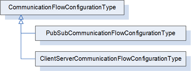
6.13.2 CommunicationFlowConfigurationType definition
The CommunicationFlowConfigurationType is an abstract type. It is formally defined in Table 97.
| Attribute | Value | ||||
| BrowseName | 4:CommunicationFlowConfigurationType | ||||
| IsAbstract | True | ||||
| References |
Node
Class | BrowseName | DataType | TypeDefinition | Other |
|---|---|---|---|---|---|
| Subtype of the 0:BaseObjectType defined in OPC 10000-5 | |||||
| 0:HasSubtype | ObjectType | 4:PubSubCommunicationFlowConfigurationType | Defined in 6.13.3 | ||
| ConformanceUnits | |||||
|---|---|---|---|---|---|
| UAFX ConnectionManager Base |
PubSubCommunicationFlowConfigurationType indicates the usage of PubSub as the communication model for the Connections. It is formally defined in 6.13.3.
ClientServerCommunicationFlowConfigurationType may be defined in a future release to indicate the usage of Client Server as the communication model for the Connections.
6.13.3 PubSubCommunicationFlowConfigurationType
6.13.3.1 Overview
The PubSubCommunicationFlowConfigurationType defines the PubSub-specific communication configuration (see OPC 10000-14).
For examples of PubSubCommunicationFlowConfigurationType, see Annex E.
The PubSubCommunicationFlowConfigurationType is illustrated in Figure 44.
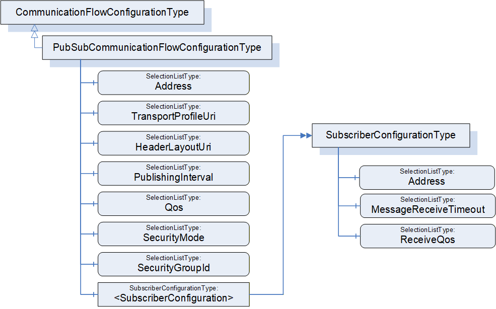
6.13.3.2 PubSubCommunicationFlowConfigurationType definition
The PubSubCommunicationFlowConfigurationType is formally defined in Table 98.
The PubSubCommunicationFlowConfigurationType contains the configuration needed for both the publishing and subscribing of an information flow. In terms of this model, the information flow can be linked with ConnectionEndpointConfiguration Objects to explicitly indicate the Publisher and Subscriber(s) of the information flow. The linkage is provided by ToOutboundFlow and ToInboundFlow References (defined in 11.25 and 11.26; see 6.8.2 for additional description). There are, in general, two types of information flows: 1 to 1 (unicast) or 1 to N (multicast), which imply the following relations:
Unicast
Publishing ConnectionEndpointConfiguration, if specified, references the PubSubCommunicationFlowConfiguration Object using the ToOutboundFlow Reference.
Subscribing ConnectionEndpointConfiguration, if specified, shall reference the single instance of the <SubscriberConfiguration> using the ToInboundFlow Reference.
Multicast
Publishing ConnectionEndpointConfiguration, if specified, references the PubSubCommunicationFlowConfiguration Object using the ToOutboundFlow Reference.
Subscribing ConnectionEndpointConfigurations, if specified, shall reference the <SubscriberConfiguration> Objects using the ToInboundFlow Reference. There can be as many <SubscriberConfiguration> Objects as there are Subscribers, in which case each ConnectionEndpointConfiguration references its corresponding configuration. <SubscriberConfiguration> Objects may be shared by the ConnectionEndpointConfiguration Objects.
The referenced SubscriberConfiguration does not replicate information that is contained in its parent object, but the parent information is required to establish the Connection.
For the usage of SelectionLists, see 6.8.1.
| Attribute | Value | ||||
| BrowseName | 4:PubSubCommunicationFlowConfigurationType | ||||
| IsAbstract | False | ||||
| References |
Node
Class | BrowseName | DataType | TypeDefinition | Other |
|---|---|---|---|---|---|
| Subtype of the 4:CommunicationFlowConfigurationType | |||||
| 0:HasComponent | Variable | 4:Address | 0:NetworkAddressDataType | 0:SelectionListType | O |
| 0:HasComponent | Variable | 4:TransportProfileUri | 0:String | 0:SelectionListType | O |
| 0:HasComponent | Variable | 4:HeaderLayoutUri | 0:String | 0:SelectionListType | O |
| 0:HasComponent | Variable | 4:PublishingInterval | 0:Duration | 0:SelectionListType | O |
| 0:HasComponent | Variable | 4:Qos | 4:CommunicationFlowQosDataType | 0:SelectionListType | O |
| 0:HasComponent | Variable | 4:SecurityMode | 0:MessageSecurityMode | 0:SelectionListType | O |
| 0:HasComponent | Variable | 4:SecurityGroupId | 0:String | 0:SelectionListType | O |
| 0:HasComponent | Object | 4:<SubscriberConfiguration> | 4:SubscriberConfigurationType | OP | |
| ConformanceUnits | |||||
|---|---|---|---|---|---|
| UAFX ConnectionManager PubSubCommunicationFlowConfiguration |
The components of the PubSubCommunicationFlowConfigurationType have additional subcomponents which are defined in Table 99
| BrowsePath | References | NodeClass | BrowseName | DataType | TypeDefinition | Others |
| 4:PublishingInterval | 0:HasProperty | Variable | 4:AvailableRanges | 2:IntervalRange[] | 0:PropertyType | O |
The optional Address specifies the destination network address to be used for transmission of NetworkMessages by the Publisher of the information flow. This is an abstract type, and a concrete subtype shall be used. For the usage of Address, see OPC 10000-14 Clause "PubSub mappings", Subclause "Transport protocol mappings". The configuration is invalid if Address is omitted here and in <SubscriberConfiguration>.
The optional TransportProfileUri specifies the transport protocol mapping and the message mapping to be used. If TransportProfileUri is omitted, the default transport protocol for the Address shall be used. For the definition of TransportProfileUri, see OPC 10000-14.
The optional HeaderLayoutUri specifies the UADP header formats for both NetworkMessages and DataSetMessages. If HeaderLayoutUri is omitted, a fixed layout for periodic data shall be used (http://opcfoundation.org/UA/PubSub-Layouts/UADP-Periodic-Fixed). For the definition of HeaderLayoutUri, see OPC 10000-14.
The optional PublishingInterval specifies the interval to be used for publishing NetworkMessages. For the definition of PublishingInterval, see OPC 10000-14.
The optional AvailableRanges Property under the PublishingInterval SelectionListType provides the IntervalRanges that are associated with the PublishingInterval SelectionList. If this Variable is provided, the SelectionList Property RestrictToList shall either be omitted or shall have a value of FALSE. A UAFX aware Client can display the ranges provided in AvailableRanges to a user as a prompt for valid values of PublishingInterval that can be entered.
The optional Qos specifies the Quality of Service to be used for the information flow. For the definition of CommunicationFlowQosDataType, see 10.12. Qos ReceiveQos may be overridden by a <SubscriberConfiguration> (see 6.13.3.3).
SecurityMode specifies the security mode to be used for the information flow. For the definition of SecurityMode, see OPC 10000-14.
SecurityGroupId specifies the security group to be used for the information flow. For the definition of SecurityGroupId, see OPC 10000-14.
The optional <SubscriberConfiguration> represents instances of SubscriberConfigurationType. It defines the configuration of the information flow for the Subscriber(s). <SubscriberConfiguration> is omitted for an autonomous publisher.
6.13.3.3 SubscriberConfigurationType definition
The SubscriberConfigurationType is formally defined in Table 100. It describes the Subscriber-specific information for the Subscriber of an information flow. The configuration of the Subscriber requires additional information from the parent object, which applies to all Subscribers.
| Attribute | Value | ||||
| BrowseName | 4:SubscriberConfigurationType | ||||
| IsAbstract | False | ||||
| References |
Node
Class | BrowseName | DataType | TypeDefinition | Other |
|---|---|---|---|---|---|
| Subtype of the 0:BaseObjectType defined in OPC 10000-5 | |||||
| 0:HasComponent | Variable | 4:Address | 0:NetworkAddressDataType | 0:SelectionListType | O |
| 0:HasComponent | Variable | 4:MessageReceiveTimeout | 0:Duration | 0:SelectionListType | M |
| 0:HasComponent | Variable | 4:ReceiveQos | 0:ReceiveQosDataType[] | 0:SelectionListType | O |
| ConformanceUnits | |||||
|---|---|---|---|---|---|
| UAFX ConnectionManager PubSubCommunicationFlowConfiguration |
The optional Address specifies the network address to be used for the reception of NetworkMessages at the Subscriber of the information flow. This is an abstract type, and a concrete subtype shall be used. For the usage of Address, see OPC 10000-14 Clause "PubSub mappings", Subclause "Transport protocol mappings". If Address is omitted and the parent Object contains a multicast network address, the Address of the parent Object shall be used for the Subscriber. If Address is omitted and the parent Object contains a unicast network address, the default reception address with the default port shall be used (e.g., "opc.udp://localhost"; for details, see OPC 10000-14). The configuration is invalid if Address is omitted here and in the parent Object.
The MessageReceiveTimeout specifies the maximum acceptable time between DataSetMessages. Received by the Subscriber. For the definition of MessageReceiveTimeout, see OPC 10000-14.
The optional ReceiveQos specifies the Quality of Service to be used for the Subscriber of the information flow. It shall only be present if Qos is present in the parent Object. If present, ReceiveQos will override Qos ReceiveQos of the parent Object. For the definition of ReceiveQos, see OPC 10000-14. This field is typically used when a Publisher is configured for a multicast address, and an individual Subscriber requires a different Qos setting.
6.13.4 ClientServerCommunicationFlowConfigurationType
The ClientServerCommunicationFlowConfigurationType may be defined in a future version of this document.
6.14 AutomationComponentConfigurationType
6.14.1 Overview
The AutomationComponentConfigurationType ObjectType holds the information to be used for locating an AutomationComponent within a Server.
The AutomationComponentConfigurationType is illustrated in Figure 45.
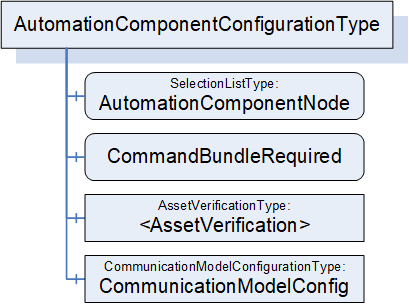
6.14.2 AutomationComponentConfigurationType definition
The AutomationComponentConfigurationType is formally defined in Table 101.
| Attribute | Value | ||||
| BrowseName | 4:AutomationComponentConfigurationType | ||||
| IsAbstract | False | ||||
| References |
Node
Class | BrowseName | DataType | TypeDefinition | Other |
|---|---|---|---|---|---|
| Subtype of the 0:BaseObjectType defined in OPC 10000-5 | |||||
| 0:HasComponent | Variable | 4:AutomationComponentNode | 4:PortableNodeIdentifier | 0:SelectionListType | M |
| 4:HasCharacteristic | Variable | 4:CommandBundleRequired | 0:Boolean | 0:BaseDataVariableType | M |
| 4:HasAssetToVerify | Object | 4:<AssetVerification> | 4:AssetVerificationType | OP | |
| 0:HasComponent | Object | 4:CommunicationModelConfig | 4:CommunicationModelConfigurationType | O | |
| ConformanceUnits | |||||
|---|---|---|---|---|---|
| UAFX ConnectionManager Base |
AutomationComponentNode specifies the AutomationComponent that is to be used for establishing Connections. If a PortableRelativePath is specified, the path shall be relative to FxRoot.
CommandBundleRequired, when TRUE, specifies that the ConnectionManager shall bundle commands to this AutomationComponent.
AssetVerification holds the Asset verification parameters for an Asset associated with this AutomationComponent. The AssetVerificationType is defined in 6.15.2.
CommunicationModelConfig provides the ConfigurationData specific to the communication model utilized by the Connections.
6.15 AssetVerificationType
6.15.1 Overview
The AssetVerificationType ObjectType holds the information to be used for compatibility verification of an Asset.
The AssetVerificationType is illustrated in Figure 46.
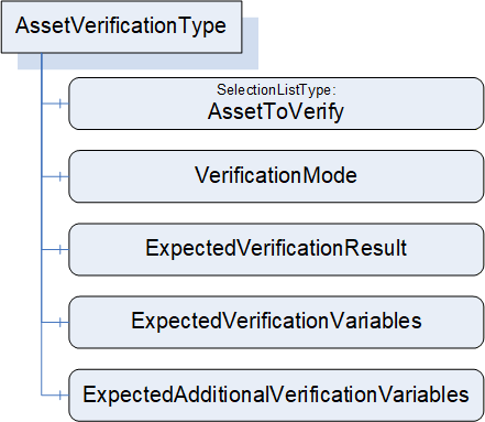
6.15.2 AssetVerificationType definition
The AssetVerificationType is formally defined in Table 102.
| Attribute | Value | ||||
| BrowseName | 4:AssetVerificationType | ||||
| IsAbstract | False | ||||
| References |
Node
Class | BrowseName | DataType | TypeDefinition | Other |
|---|---|---|---|---|---|
| Subtype of the 0:BaseObjectType defined in OPC 10000-5 | |||||
| 0:HasComponent | Variable | 4:AssetToVerify | 4:PortableNodeIdentifier | 0:SelectionListType | M |
| 0:HasComponent | Variable | 4:VerificationMode | 2:AssetVerificationModeEnum | 0:BaseDataVariableType | M |
| 0:HasComponent | Variable | 4:ExpectedVerificationResult | 2:AssetVerificationResultEnum | 0:BaseDataVariableType | M |
| 0:HasComponent | Variable | 4:ExpectedVerificationVariables | 4:PortableNodeIdentifierValuePair[] | 0:BaseDataVariableType | M |
| 0:HasComponent | Variable | 4:ExpectedAdditionalVerificationVariables | 4:PortableNodeIdentifierValuePair[] | 0:BaseDataVariableType | M |
| ConformanceUnits | |||||
|---|---|---|---|---|---|
| UAFX ConnectionManager Base |
AssetToVerify specifies the expected Asset to be verified. If a PortableRelativePath is specified, the path shall be relative to AutomationComponentNode.
VerificationMode is the mode to use for the verification (compatibility and/or identity).
ExpectedVerificationResult is the expected level of compatibility that this Asset shall provide.
ExpectedVerificationVariables hold the variables to be verified for compatibility and/or identity. It is expected that this list contains IdentifierBrowsePath with a PortableRelativePath as Keys using BrowseNames as defined in Table 31.
ExpectedAdditionalVerificationVariables hold the variables to be verified for compatibility and/or identity. If a PortableRelativePath is specified, the path shall be relative to the expected Asset.
6.16 CommunicationModelConfigurationType
6.16.1 Overview
The CommunicationModelConfigurationType ObjectType provides the configuration data specific to the communication model utilized by the Connections.
The CommunicationModelConfigurationType is illustrated in Figure 47.
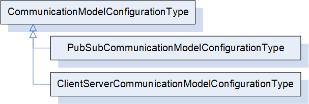
PubSubCommunicationModelConfigurationType provides the configuration data specific to the usage of PubSub as the communication model for the Connections. It is formally defined in 6.16.3.
ClientServerCommunicationModelConfigurationType indicates the usage of Client Server as the communication model for the Connections. It may be defined in a future release.
6.16.2 CommunicationModelConfigurationType definition
This ObjectType is the abstract base type of all communication model-specific configuration data.
The CommunicationModelConfigurationType is formally defined in Table 103.
| Attribute | Value | ||||
| BrowseName | 4:CommunicationModelConfigurationType | ||||
| IsAbstract | True | ||||
| References |
Node
Class | BrowseName | DataType | TypeDefinition | Other |
|---|---|---|---|---|---|
| Subtype of the 0:BaseObjectType defined in OPC 10000-5 | |||||
| 0:HasSubtype | ObjectType | 4:PubSubCommunicationModelConfigurationType | Defined in 6.16.36.17.3 | ||
| ConformanceUnits | |||||
|---|---|---|---|---|---|
| UAFX ConnectionManager Base |
6.16.3 PubSubCommunicationModelConfigurationType
6.16.3.1 Overview
The PubSubCommunicationModelConfigurationType defines the communication model-related configuration information for the usage of PubSub as the communication model (see OPC 10000-14).
The PubSubCommunicationModelConfigurationType is illustrated in Figure 48.
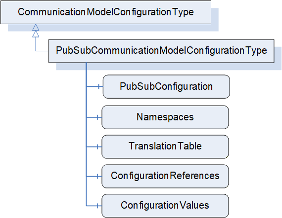
6.16.3.2 PubSubCommunicationModelConfigurationType definition
The PubSubCommunicationModelConfigurationType is formally defined in Table 104.
| Attribute | Value | ||||
| BrowseName | 4:PubSubCommunicationModelConfigurationType | ||||
| IsAbstract | False | ||||
| References |
Node
Class | BrowseName | DataType | TypeDefinition | Other |
|---|---|---|---|---|---|
| Subtype of the 4:CommunicationModelConfigurationType | |||||
| 0:HasComponent | Variable | 4:PubSubConfiguration | 0:PubSubConfiguration2DataType | 0:BaseDataVariableType | M |
| 0:HasComponent | Variable | 4:Namespaces | 0:String[] | 0:BaseDataVariableType | M |
| 0:HasComponent | Variable | 4:TranslationTable | 4:NodeIdTranslationDataType[] | 0:BaseDataVariableType | M |
| 0:HasComponent | Variable | 4:ConfigurationReferences | 0:PubSubConfigurationRefDataType[] | 0:BaseDataVariableType | M |
| 0:HasComponent | Variable | 4:ConfigurationValues | 0:PubSubConfigurationValueDataType[] | 0:BaseDataVariableType | M |
| ConformanceUnits | |||||
|---|---|---|---|---|---|
| UAFX ConnectionManager PubSubCommunicationFlowConfiguration |
The PubSubConfiguration modifies the existing PubSub configuration on the addressed Server when establishing Connections. The PubSubConfiguration2DataType is defined in OPC 10000-14.
Namespaces contains namespace URIs for NamespaceIndex used in the PubSubConfiguration. Examples are NodeIds contained in PublishedDataSets. The NamespaceIndex in the PubSubConfiguration will need to be updated to reflect the NamespaceIndexes in the addressed Server.
NodeIds contained in the PubSubConfiguration, which use the special namespace "http://opcfoundation.org/UA/FX/CM/Translation/", are not valid NodeIds but placeholders which shall be resolved before the ConnectionManager can use the PubSubConfiguration for connection establishment. The resolution consists of 2 steps. The first step is done locally within the ConnectionManager, and it involves the conversion of these NodeIds to PortableNodeIdentifiers according to the TranslationTable. The second step involves the resolution of the PortableNodeIdentifiers to actual NodeIds of the Nodes on the target Server (see 13). If a PortableNodeIdentifier is represented by a PortableRelativePath, the starting node of such a path depends on which PubSubConfiguration element the identifier corresponds to. If the identifier corresponds to a published or subscribed Variable (e.g., PublishedVariable of PublishedVariableDataType or TargetNodeId of FieldTargetDataType), the path shall start at the hosting AutomationComponent.
ConfigurationReferences points to elements within the PubSubConfiguration and indicates whether they are to be added, matched, modified, or removed. The PubSubConfigurationRefDataType is defined in OPC 10000-14.
PubSubConfiguration and ConfigurationReferences are generated by the engineering tool creating the ConnectionConfigurationSet or by the ConnectionManager. The relation of configuration elements in PubSubConfiguration to a ConnectionEndpoint is provided by the CommunicationLinks (see 6.12.2).
For examples of how to establish the configuration information for AutomationComponents, see E.2, and for the SKS, see E.5.
The ConfigurationValues Variable contains the names and identifiers that were assigned by EstablishConnections. They correspond to null names or 0 identifiers in the PubSubConfiguration.
OPC UA FX allows multiple ConnectionManagers to establish Connections to a single AutomationComponent independently of each other. It also allows any Client to establish Connections. An AutomationComponent may even receive PubSub configuration (unrelated to OPC UA FX) via corresponding Methods exposed in the PubSub configuration model. Coordinating all possible sources of PubSub configuration can become a very difficult task. Since OPC 10000-14 requires certain elements of the PubSub configuration model to be unique (e.g., WriterGroupId and DataSetWriterId), such scenarios may lead to conflicting PubSub configurations (e.g., identical WriterGroupIds configured by two different ConnectionManagers).
Since the Clients passing in such (potentially conflicting) PubSub configurations are unaware of each other, resolving conflicting configuration elements can only be provided by the entity receiving them. In scenarios where PubSub configuration is generated by a single entity (e.g., an engineering tool), this does not apply since the entity generating PubSub configuration could uniquely determine all names and identifiers.
For certain elements in PubSubConfiguration, the entity generating the ConnectionConfigurationSet may set their names (i.e., PubSubConnection, ReaderGroup, WriterGroup, DataSetReader, DataSetWriter) to a specific value or to null. If set to null, a unique name is generated by the addressed AutomationComponent when passing the PubSubConfiguration using the EstablishConnections SetCommunicationConfigurationCmd. If it has a specific value, that value will be used.
For certain elements in PubSubConfiguration, the entity generating the ConnectionConfigurationSet may set their identifiers (i.e., PublisherId, WriterGroupId, WriterId) to a specific value or to null. If set to null, a unique identifier is generated by the addressed AutomationComponent (see OPC 10000-14). Two options exist:
The ConnectionManager could apply identifiers (WriterGroupIds, WriterIds) that it reserved on the AutomationComponent with a previously issued EstablishConnections ReserveCommunicationIdsCmd before passing PubSubConfigurations using EstablishConnections SetCommunicationConfigurationCmd. PubSubConnections need specific handling; for details, see additional information in later paragraphs.
The ConnectionManager could pass the PubSubConfiguration using EstablishConnections SetCommunicationConfigurationCmd with identifiers set to null, allowing the AutomationComponent to generate and assign the identifiers.
It is recommended that the entity generating the ConnectionConfigurationSet uses null Names and identifiers. Additional details for each identifier are provided below. See Annex E.5 for examples.
For PubSubConnections, specific handling applies: OPC 10000-14 requires a PubSubConnection to have a unique Address across all PubSubConnections. This implies that there is exactly one PubSubConnection with a specific Address determining the PublisherId to be used for that Address. It is therefore recommended that the entity generating the ConnectionConfigurationSet sets the names and PublisherIds of PubSubConnections to null and that the ConnectionManager uses ElementAdd and ElementMatch with a null name and a null PublisherId for PubSubConnections. This allows the sharing of existing PubSubConnections. If the PubSubConnection matches, the PublisherId of the matching PubSubConnection shall be used; otherwise, a new PubSubConnection is created with the default PublisherId. The ConnectionManager shall adapt the PubSubConfiguration of subscribing AutomationComponents with the returned PublisherIds as required.
It is recommended to use ElementAdd for WriterGroups and ReaderGroups under the assumption that each ConnectionManager maintains groups separate from other ConnectionManagers.
After a ConnectionConfigurationSet is edited (see 6.7.4), the ConnectionManager shall update the PubSubConfiguration (see Annex E.5 for examples).
6.16.4 ClientServerCommunicationModelConfigurationType
The ClientServerCommunicationModelConfigurationType may be defined in a future version of this document.
7 OPC UA FX Interfaces
7.1 Overview
This clause defines all of the Interfaces defined in this document. These Interfaces will be used internally in this model and will be available for companion specifications. Figure 49 illustrates the Interfaces that are defined in this document. The definition of the components that are part of the Interface is provided in the Object Model that utilizes the Interface. In this clause, only the definition of the Interface is provided.
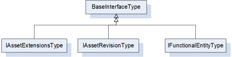
7.2 IFunctionalEntityType Interface definition
The functional model is required to be able to be applied to existing Information Models. These models have defined their own Object Models and their own hierarchy of Objects. OPC UA does not support multiple inheritance. By defining the IFunctionalEntityType Interface, the OPC UA FX Information Model can be applied to any existing Object, adding the required IFunctionalEntityType items into the existing Information Model.
The IFunctionalEntityType Interface is formally defined in Table 105.
| Attribute | Value | ||||
| BrowseName | 3:IFunctionalEntityType | ||||
| IsAbstract | True | ||||
| References |
Node
Class | BrowseName | DataType | TypeDefinition | Other |
|---|---|---|---|---|---|
| Subtype of the 0:BaseInterfaceType defined in OPC 10000-5 | |||||
| 0:HasProperty | Variable | 3:AuthorUri | 0:UriString | 0:PropertyType | O |
| 0:HasProperty | Variable | 3:AuthorAssignedIdentifier | 0:String | 0:PropertyType | O |
| 0:HasProperty | Variable | 3:AuthorAssignedVersion | 3:FxVersion | 0:PropertyType | O |
| 0:HasProperty | Variable | 3:ApplicationIdentifier | 3:ApplicationIdentifierDataType[] | 0:PropertyType | O |
| 0:HasComponent | Method | 3:Verify | Defined in 6.4.3 | O | |
| 0:HasComponent | Object | 3:InputData | 3:InputsFolderType | O | |
| 0:HasComponent | Object | 3:OutputData | 3:OutputsFolderType | O | |
| 0:HasComponent | Object | 3:ConfigurationData | 3:ConfigurationDataFolderType | O | |
| 0:HasComponent | Object | 3:Capabilities | 3:FunctionalEntityCapabilitiesType | O | |
| 0:HasComponent | Object | 3:PublisherCapabilities | 3:PublisherCapabilitiesType | O | |
| 0:HasComponent | Object | 3:SubscriberCapabilities | 3:SubscriberCapabilitiesType | O | |
| 0:HasComponent | Object | 3:ConnectionEndpoints | 3:ConnectionEndpointsFolderType | O | |
| 0:HasComponent | Object | 3:ControlGroups | 3:ControlGroupsFolderType | O | |
| 0:HasComponent | Variable | 3:OperationalHealth | 3:OperationalHealthOptionSet | 0:BaseDataVariableType | O, RO |
| 0:HasComponent | Object | 3:OperationalHealthAlarms | 0:FolderType | O | |
| 0:HasComponent | Object | 5:Status | 5:FunctionalGroupType | O | |
| 0:HasComponent | Object | 5:Diagnostics | 5:FunctionalGroupType | O | |
| 0:HasComponent | Object | 5:Operational | 5:FunctionalGroupType | O | |
| ConformanceUnits | |||||
|---|---|---|---|---|---|
| UAFX FunctionalEntity Base |
The components of the IFunctionalEntityType have additional subcomponents, which are defined in Table 106
| BrowsePath | References | NodeClass | BrowseName | DataType | TypeDefinition | Others |
| 3:ConfigurationData | 0: Organizes | Object | 5:Configuration | 5:FunctionalGroupType | O | |
| 3:ConfigurationData | 0: Organizes | Object | 5:Tuning | 5:FunctionalGroupType | O | |
| 5:Diagnostics | 0:HasComponent | Variable | 3:OperationalConnectionCount | 0:UInt32 | 0:BaseDataVariableType | O |
| 5:Diagnostics | 0:HasComponent | Variable | 3:ExistingConnectionCount | 0:UInt32 | 0:BaseDataVariableType | O |
| 5:Diagnostics | 0:HasComponent | Variable | 3:ErrorConnectionCount | 0:UInt32 | 0:BaseDataVariableType | O |
| 5:Diagnostics | 0:HasComponent | Variable | 3:FailedConnectionCount | 0:UInt32 | 0:BaseDataVariableType | O |
| 5:Diagnostics | 0:HasComponent | Variable | 3:CleanedUpConnectionCount | 0:UInt32 | 0:BaseDataVariableType | O |
| 5:Diagnostics | 0:HasComponent | Variable | 3:TotalEstablishAttemptsCount | 0:UInt32 | 0:BaseDataVariableType | O |
| 5:Diagnostics | 0:HasComponent | Variable | 3:FailedEstablishAttemptsCount | 0:UInt32 | 0:BaseDataVariableType | O |
| 5:Diagnostics | 0:HasComponent | Variable | 3:FailedVerificationCount | 0:UInt32 | 0:BaseDataVariableType | O |
The definitions of all Properties, Variables and Objects that are used in this Interface are provided in 6.4.2. Examples of how this interface could be used are provided in Annex B.
7.3 IAssetRevisionType Interface definition
The IAssetRevisionType is an Interface that may be used in any existing asset model. This Interface defines version information that may be used by the VerifyAsset Method (also defined in the interface).
The IAssetRevisionType Interface is formally defined in Table 107.
| Attribute | Value | ||||
| BrowseName | 3:IAssetRevisionType | ||||
| IsAbstract | True | ||||
| References |
Node
Class | BrowseName | DataType | TypeDefinition | Other |
|---|---|---|---|---|---|
| Subtype of the 0:BaseInterfaceType defined in OPC 10000-5 | |||||
| 0:HasProperty | Variable | 3:MajorAssetVersion | 0:UInt16 | 0:PropertyType | O |
| 0:HasProperty | Variable | 3:MinorAssetVersion | 0:UInt16 | 0:PropertyType | O |
| 0:HasProperty | Variable | 3:BuildAssetNumber | 0:UInt16 | 0:PropertyType | O |
| 0:HasProperty | Variable | 3:SubBuildAssetNumber | 0:UInt16 | 0:PropertyType | O |
| 0:HasComponent | Method | 3:VerifyAsset | Defined in 6.3.3 | O | |
| ConformanceUnits | |||||
|---|---|---|---|---|---|
| UAFX Asset Base |
The definitions of all Properties that are used in this Interface are provided in 6.3.2.
7.4 IAssetExtensionsType Interface definition
The IAssetExtensionsType is an Interface that may be used in any existing asset model. This Interface defines a folder that can be used as a standard location for collecting Connector information.
The IAssetExtensionsType Interface is formally defined in Table 108.
| Attribute | Value | ||||
| BrowseName | 3:IAssetExtensionsType | ||||
| IsAbstract | True | ||||
| References |
Node
Class | BrowseName | DataType | TypeDefinition | Other |
|---|---|---|---|---|---|
| Subtype of the 0:BaseInterfaceType defined in OPC 10000-5 | |||||
| 0:HasComponent | Object | 3:Connectors | 0:FolderType | O | |
| 0:HasComponent | Object | 5:Diagnostics | 5:FunctionalGroupType | O | |
| ConformanceUnits | |||||
|---|---|---|---|---|---|
| UAFX Asset Base |
The components of the IAssetExtensionsType have additional subcomponents, which are defined in Table 109.
| BrowsePath | References | NodeClass | BrowseName | DataType | TypeDefinition | Others |
| 5:Diagnostics | 0:HasComponent | Variable | 3: UpTime | 0:Duration | 0:BaseDataVariableType | O |
| 5:Diagnostics | 0:HasComponent | Variable | 3:CurrentCPUUtilization | 0:Float | 0:BaseDataVariableType | O |
| 5:Diagnostics | 0:HasComponent | Variable | 3:MaxCPUUtilization | 0:Float | 0:BaseDataVariableType | O |
| 5:Diagnostics | 0:HasComponent | Variable | 3:CurrentMemoryUtilization | 0:Float | 0:BaseDataVariableType | O |
| 5:Diagnostics | 0:HasComponent | Variable | 3:MaxMemoryUtilization | 0:Float | 0:BaseDataVariableType | O |
| 3:Connectors | 0:HasComponent | Object | 3:<AssetConnector> | 3:AssetConnectorType | OP |
The definitions of all items that are used in this Interface are provided in 6.3.2.
8 OPC UA FX EventTypes
8.1 Overview
OPC UA FX extends the Standard EventType hierarchy by several EventTypes defined in this clause. Figure 50 informally describes the hierarchy of these EventTypes.
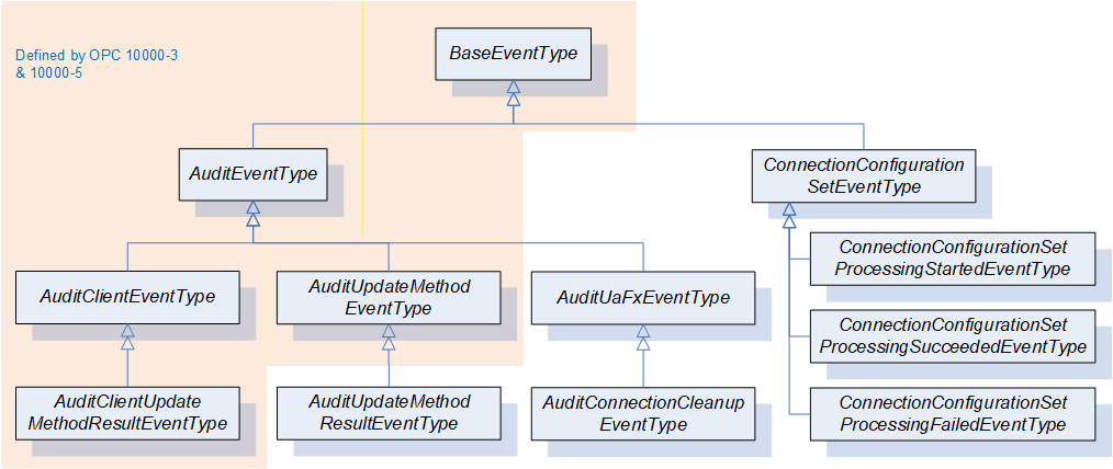
8.2 AuditUaFxEventType
This EventType is used to categorize Events generated by a Server implementing UAFX. Its representation in the AddressSpace is formally defined in Table 110.
| Attribute | Value | ||||
| BrowseName | 3:AuditUaFxEventType | ||||
| IsAbstract | True | ||||
| References | NodeClass | BrowseName | DataType | TypeDefinition | Other |
|---|---|---|---|---|---|
| Subtype of the 0:AuditEventType defined in OPC 10000-5, which means it inherits the InstanceDeclarations of that Node. | |||||
| ConformanceUnits | |||||
|---|---|---|---|---|---|
| UAFX AutomationComponent Auditing Connection Cleanup |
Audit Events of this class are generated by Servers that implement UAFX. They represent internal actions taken by the Server.
This EventType inherits all Properties of the AuditEventType. Their semantics are defined in OPC 10000-5. The SourceNode Property for Events of this type shall be assigned to the NodeId of the Object that is related to the action; if no Object is related, then the SourceNode Property shall be the ObjectId of the Server Object.
If AutomationComponentLog is supported, this AuditEvent shall set either the ConditionClassId or a ConditionSubClassId to LogEntryConditionClassType, which results in the AuditEvent being mapped to LogObject records. The mapping of these AuditEvents to LogRecords shall use the AdditionalData field to include fields of the AuditEvent. Subtypes of the AuditEvent will describe in detail which fields shall be mapped.
8.3 AuditConnectionCleanupEventType
This EventType allows Connection clean-up, as performed by a Server, to be audited. Its representation in the AddressSpace is formally defined in Table 111.
| Attribute | Value | ||||
| BrowseName | 3:AuditConnectionCleanupEventType | ||||
| IsAbstract | True | ||||
| References | NodeClass | BrowseName | DataType | TypeDefinition | Other |
|---|---|---|---|---|---|
| Subtype of the 3:AuditUaFxEventType, which means it inherits the InstanceDeclarations of that Node. | |||||
| 0:HasProperty | Variable | 3:RemovedEndpoint | 0:String | 0:PropertyType | M |
| 0:HasProperty | Variable | 3:RelatedEndpoint | 2:RelatedEndpointDataType | 0:PropertyType | M |
| ConformanceUnits | |||||
|---|---|---|---|---|---|
| UAFX AutomationComponent Auditing Connection Cleanup |
AuditEvents of this class are generated by Servers that implement UAFX in the case when a ConnectionEndpoint is cleaned up (see 6.6.2).
This EventType inherits all Properties of the AuditUaFxEventType.
The SourceNode for this Event shall be the FunctionalEntity that contained the RemovedEndpoint.
RemovedEndpoint identifies the BrowseName of the ConnectionEndpoint that was removed.
RelatedEndpoint points to the former related ConnectionEndpoint (i.e., the other end of the Connection).
If AutomationComponentLog is supported, this AuditEvent shall set either the ConditionClassId or a ConditionSubClassId to LogEntryConditionClassType, which results in the AuditEvent being mapped to LogObject records. The RemovedEndpoint and the RelatedEndpoint shall be included in the resulting LogRecord as AdditionalData.
8.4 AuditUpdateMethodResultEventType
This EventType allows auditing Method Calls with a response. Its representation in the AddressSpace is formally defined in Table 112.
| Attribute | Value | ||||
| BrowseName | 2:AuditUpdateMethodResultEventType | ||||
| IsAbstract | True | ||||
| References | NodeClass | BrowseName | DataType | TypeDefinition | Other |
|---|---|---|---|---|---|
| Subtype of the 0:AuditUpdateMethodEventType defined in OPC 10000-5. | |||||
| 0:HasProperty | Variable | 0:StatusCodeId | 0:StatusCode | 0:PropertyType | M |
| 0:HasProperty | Variable | 0:OutputArguments | 0:BaseDataType[] | 0:PropertyType | M |
| ConformanceUnits | |||||
|---|---|---|---|---|---|
| UAFX AutomationComponent Auditing Connection Management |
This EventType inherits all Properties of the AuditUpdateMethodEventType. Their semantics are defined in OPC 10000-5.
The StatusCodeId and OutputArguments are as defined in AuditUpdateMethodEventType as Optional. They are included here only to indicate that they are mandatory in this Type.
If ConnectionManagerLog or AutomationComponentLog is supported, this AuditEvent shall set either the ConditionClassId or a ConditionSubClassId to LogEntryConditionClassType, which results in the AuditEvent being mapped to LogObject records. The StatusCodeId shall be included in the resulting LogRecord as AdditionalData.
8.5 AuditUpdateConnectionConfigurationSetEventType
This EventType allows auditing modifications of a ConnectionConfigurationSet. Its representation in the AddressSpace is formally defined in Table 114.
| Attribute | Value | |||||
| BrowseName | 4:AuditUpdateConnectionConfigurationSetEventType | |||||
| IsAbstract | True | |||||
| References | NodeClass | BrowseName | DataType | TypeDefinition | Other | |
|---|---|---|---|---|---|---|
| Subtype of the 0:AuditWriteUpdateEventType . | ||||||
| 0:HasProperty | Variable | 4:ConnectionConfigurationSetNode | 0:NodeId | 0:PropertyType | M | |
| 0:HasProperty | Variable | 4:Name | 0:String | 0:PropertyType | M | |
| ConformanceUnits | ||||||
|---|---|---|---|---|---|---|
| UAFX Auditing ConnectionConfigurationSet Modification |
This EventType inherits all Properties of the AuditWriteUpdateEventType. Their semantics are defined in OPC 10000-5.
ConnectionConfigurationSetNode and Name identify the ConnectionConfigurationSet, which was updated.
8.6 ConnectionConfigurationSetEventType
The ConnectionConfigurationSetEventType is formally defined in Table 114. It is a subtype of the BaseEventType defined in OPC 10000-5. This new type does not add any additional information on top of the BaseEventType besides the semantics that an Event was generated by the ConnectionConfigurationSetStateMachineType.
| Attribute | Value | ||||
| BrowseName | 4:ConnectionConfigurationSetEventType | ||||
| IsAbstract | True | ||||
| References | NodeClass | BrowseName | DataType | TypeDefinition | Other |
|---|---|---|---|---|---|
| Subtype of the 0:BaseEventType defined in OPC 10000-5 | |||||
| 0:HasProperty | Variable | 4:ConnectionConfigurationSetNode | 0:NodeId | 0:PropertyType | M |
| 0:HasProperty | Variable | 4:Name | 0:String | 0:PropertyType | M |
| 0:HasProperty | Variable | 4:Action | 4:FxProcessEnum | 0:PropertyType | M |
| 0:HasSubtype | ObjectType | 4:ConnectionConfigurationSetProcessingStartedEventType | Defined in 8.7. | ||
| 0:HasSubtype | ObjectType | 4:ConnectionConfigurationSetProcessingSucceededEventType | Defined in 8.8. | ||
| 0:HasSubtype | ObjectType | 4:ConnectionConfigurationSetProcessingFailedEventType | Defined in 8.9. | ||
| ConformanceUnits | |||||
|---|---|---|---|---|---|
| UAFX ConnectionManager Configuration Set Processing Events |
This EventType inherits all Properties of the BaseEventType.
For all Events of this type, the SourceNode (from BaseEventType) shall be set to the NodeId of the ConnectionManager that is executing the state machine.
ConnectionConfigurationSetNode and Name identify the ConnectionConfigurationSet, which was processed.
Action identifies the action that was requested to process the ConnectionConfigurationSet.
If ConnectionManagerLog is supported, this AuditEvent shall set either the ConditionClassId or a ConditionSubClassId to LogEntryConditionClassType, which results in the AuditEvent being mapped to LogObject records. This applies to all subtypes of this EventType. The ConnectionConfigurationSetNode, the Name, and the Action shall be included in the resulting LogRecord as AdditionalData.
8.7 ConnectionConfigurationSetProcessingStartedEventType
This EventType is generated by a ConnectionConfigurationSetStateMachine upon transition from the Ready State to the Processing State as a result of a ConnectionManager starting to process the ConnectionConfigurationSet. Its representation in the AddressSpace is formally defined in Table 115.
| Attribute | Value | ||
| BrowseName | 4:ConnectionConfigurationSetProcessingStartedEventType | ||
| IsAbstract | True | ||
| References | Node Class | BrowseName | Note |
|---|---|---|---|
| Subtype of the 4:ConnectionConfigurationSetEventType defined in 8.5. | |||
| ConformanceUnits | |||
|---|---|---|---|
| UAFX ConnectionManager Configuration Set Processing Events |
This EventType inherits all Properties of the ConnectionConfigurationSetEventType.
8.8 ConnectionConfigurationSetProcessingSucceededEventType
An Event of this EventType is generated by a ConnectionConfigurationSetStateMachineType upon transition from the Processing State to the Ready State after successful completion of the Connection establishment. Its representation in the AddressSpace is formally defined in Table 116.
| Attribute | Value | ||
| BrowseName | 4:ConnectionConfigurationSetProcessingSucceededEventType | ||
| IsAbstract | True | ||
| References | Node Class | BrowseName | Note |
|---|---|---|---|
| Subtype of the 4:ConnectionConfigurationSetEventType defined in 8.5. | |||
| ConformanceUnits | |||
|---|---|---|---|
| UAFX ConnectionManager Configuration Set Processing Events |
This EventType inherits all Properties of the ConnectionConfigurationSetEventType.
8.9 ConnectionConfigurationSetProcessingFailedEventType
This EventType is generated by a ConnectionConfigurationSetStateMachineType upon transition from the Processing State to the Error State as a result of encountering an error during Connection establishment. Its representation in the AddressSpace is formally defined in Table 117.
| Attribute | Value | ||
| BrowseName | 4:ConnectionConfigurationSetProcessingFailedEventType | ||
| IsAbstract | True | ||
| References | Node Class | BrowseName | Note |
|---|---|---|---|
| Subtype of the 4:ConnectionConfigurationSetEventType defined in 8.5. | |||
| ConformanceUnits | |||
|---|---|---|---|
| UAFX ConnectionManager Configuration Set Processing Events |
This EventType inherits all Properties of the ConnectionConfigurationSetEventType.
8.10 EstablishConnectionErrorEventType
This EventType is generated by a ConnectionManager when an error is returned on an EstablishConnection Method invocation or any related actions. Its representation in the AddressSpace is formally defined in Table 118. The generation of this Event is not required, but this EventType provides a mapping from the returned EstablishConnection Method parameters to the LogEntry record structure. The mapping also applies to related actions.
| Attribute | Value | ||
| BrowseName | 4:EstablishConnectionErrorEventType | ||
| IsAbstract | True | ||
| References | Node Class | BrowseName | Note |
|---|---|---|---|
| Subtype of the 0:BaseLogEventType. | |||
| ConformanceUnits | |||
|---|---|---|---|
| UAFX ConnectionManager LogObject Events |
This EventType inherits all Properties of the BaseLogEventType.
The ConditionClassId shall be set to LogEntryConditionClassType.
SourceNode shall be the NodeId of the ConnectionConfigurationSet that is being processed.
SourceName shall be the BrowseName of the Connection that was being created. If the error is not related to a specific Connection, then it shall be "ConnectionManager".
Message describes the issue. It shall include a description of the action that was being taken, e.g. resolving NodeIds, configuring an SKS, verifying Nodes, or establishing Connection. It shall include the FxErrorEnum value reported in the ConnectionDiagnosticsDataType associated with this error.
ErrorCode shall contain the detailed error code returned in the nested return parameters of the EstablishConnection method or the error code returned in other processing. If multiple error codes are returned, then multiple records should be generated, one for each error code.
ErrorCodeNode shall contain the internal Node in the ConnectionConfigurationSet to which the error is related. For example, if the error was related to an asset verification, it would contain the NodeId of the AssetToVerify. It may be null if no specific Node is related to the LogRecord.
If ConnectionManagerLog is supported, this Event shall set either the ConditionClassId or a ConditionSubClassId to LogEntryConditionClassType, which results in the Event being mapped to LogObject records. If the LogObject is recording LogRecords, the ErrorCode and the ErrorCodeNode shall be included in the resulting LogRecord as AdditionalData.
8.11 CloseConnectionErrorEventType
This EventType is generated by a ConnectionManager when an error is returned on a CloseConnection Method invocation. Its representation in the AddressSpace is formally defined in Table 119.
| Attribute | Value | ||
| BrowseName | 4:CloseConnectionErrorEventType | ||
| IsAbstract | True | ||
| References | Node Class | BrowseName | Note |
|---|---|---|---|
| Subtype of the 0:BaseLogEventType. | |||
| ConformanceUnits | |||
|---|---|---|---|
| UAFX ConnectionManager LogObject Events |
This EventType inherits all Properties of the BaseLogEventType.
The ConditionClassId shall be set to LogEntryConditionClassType.
SourceNode shall be the NodeId of the ConnectionConfigurationSet that the connection belonged to.
SourceName shall be the BrowseName of the Connection that was being closed.
Message describes the issue. It shall include a description of the action that was being taken. It shall include the FxErrorEnum value reported in the ConnectionDiagnosticsDataType associated with this error.
ErrorCode shall contain the detailed error code returned in the CloseConnection Method.
ErrorCodeNode shall contain the NodeId of the Connection that was being closed.
GroupingId shall contain the string representation of the NodeId associated with the close activity.
If ConnectionManagerLog is supported, this Event shall set either the ConditionClassId or a ConditionSubClassId to LogEntryConditionClassType, which results in the Event being mapped to LogObject records. If the LogObject is recording LogRecords, the ErrorCode and the ErrorCodeNode shall be included in the resulting LogRecord as AdditionalData.
9 OPC UA FX VariableTypes
9.1 AggregatedHealthType
9.1.1 Overview
The AggregatedHealthType is a subtype of the BaseDataVariableType and holds the aggregated health of Assets and FunctionalEntities.
The AggregatedHealthType is illustrated in Figure 51.
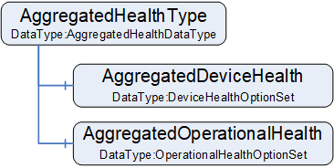
9.1.2 AggregatedHealthType definition
The AggregatedHealthType is formally defined in Table 120.
| Attribute | Value | ||||
| BrowseName | 3:AggregatedHealthType | ||||
| IsAbstract | False | ||||
| ValueRank | -1 (-1 = Scalar) | ||||
| DataType | 3:AggregatedHealthDataType | ||||
| References |
Node
Class | BrowseName | DataType | TypeDefinition | Other |
|---|---|---|---|---|---|
| Subtype of the 0:BaseDataVariableType defined in OPC 10000-5 | |||||
| 0:HasComponent | Variable | 3:AggregatedDeviceHealth | 3:DeviceHealthOptionSet | 0:BaseDataVariableType | M |
| 0:HasComponent | Variable | 3:AggregatedOperationalHealth | 3:OperationalHealthOptionSet | 0:BaseDataVariableType | M |
| ConformanceUnits | |||||
|---|---|---|---|---|---|
| UAFX AutomationComponent Base |
AggregatedDeviceHealth shall be the aggregation of the DeviceHealth of the AutomationComponent's top-level Assets. The aggregation rules are defined as follows:
If at least one top-level Asset has DeviceHealth set to Failure, the AggregatedDeviceHealth DeviceFailure bit shall be set.
If at least one top-level Asset has DeviceHealth set to Check_Function, the AggregatedDeviceHealth DeviceCheckFunction bit shall be set.
If at least one top-level Asset has DeviceHealth set to Maintenance_Required, the AggregatedDeviceHealth DeviceMaintenanceRequired bit shall be set.
If at least one top-level Asset has DeviceHealth set to Off_Spec, the AggregatedDeviceHealth DeviceOffSpec bit shall be set.
AggregatedOperationalHealth shall be the aggregation of the OperationalHealth of the AutomationComponent's top-level FunctionalEntities. The aggregation rule is defined as a logical OR of the OperationalHealth of all top-level FunctionalEntities.
9.2 ServerAddressType
9.2.1 Overview
The ServerAddressType is a subtype of the BaseVariableType and holds the information to be used for locating Servers. An instance of ServerAddressType describes the attributes to be applied to open secure communication to the Server. Multiple Connections may refer to the same instance of ServerAddressType.
The ServerAddressType is illustrated in Figure 52.
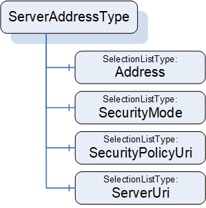
9.2.2 ServerAddressType definition
The ServerAddressType is formally defined in Table 121.
| Attribute | Value | ||||
| BrowseName | 4:ServerAddressType | ||||
| IsAbstract | False | ||||
| ValueRank | -1 (-1 = Scalar) | ||||
| DataType | ServerAddressDataType | ||||
| References |
Node
Class | BrowseName | DataType | TypeDefinition | Other |
|---|---|---|---|---|---|
| Subtype of the 0:BaseDataVariableType defined in OPC 10000-5 | |||||
| 0:HasComponent | Variable | 4:Address | 0:UriString | 0:SelectionListType | M |
| 0:HasComponent | Variable | 4:SecurityMode | 0:MessageSecurityMode | 0:SelectionListType | M |
| 0:HasComponent | Variable | 4:SecurityPolicyUri | 0:String | 0:SelectionListType | M |
| 0:HasComponent | Variable | 4:ServerUri | 0:UriString | 0:SelectionListType | M |
| ConformanceUnits | |||||
|---|---|---|---|---|---|
| UAFX ConnectionManager Base |
Address is specified as a DiscoveryUrl in the form
scheme://hostname[:port][/path]
as defined in OPC 10000-12. The SelectionListType (see 6.8.1) provides the option for an end user to either select or enter a DiscoveryUrl. As described in OPC 10000-4, a hostname may be an IP address or a name that would need to be resolved to an IP address. A ConnectionManager shall be able to resolve a name to an IP address. Any selected Address will be reflected in the ServerAddressDataType structure, which will be used for Connection establishment.
SecurityMode is the MessageSecurityMode to be used for establishing a secure communication to the Address. The SelectionListType (see 6.8.1) will provide the supported SecurityModes for this Connection. RestrictToList shall be set to TRUE. Any selected SecurityMode will be reflected in the ServerAddressDataType structure, which will be used for Connection establishment.
SecurityPolicyUri is a string that contains the security policy to use when establishing the secure communication. The SelectionListType (see 6.8.1) will provide the supported SecurityPolicyUris for this Connection. If the SelectionListType contains an empty string, the empty string results in the ConnectionManager using the best available SecurityPolicy that both the Server and ConnectionManager support. RestrictToList shall be set to TRUE. Any selected SecurityPolicyUri will be reflected in the ServerAddressDataType structure, which will be used for Connection establishment.
ServerUri is a string that reflects the ApplicationUri of the Server. It can be used to cryptographically verify the Server. The SelectionListType (see 6.8.1) provides the option for an end user to either select or enter a ServerUri. Any selected ServerUri will be reflected in the ServerAddressDataType structure, which will be used in Connection establishment. The ServerUri can also be a null string, in which case it will not be used to validate the Server.
9.3 SecurityKeyServerAddressType
9.3.1 Overview
The SecurityKeyServerAddressType is a subtype of the BaseVariableType and holds the information to be used for locating an SKS and whether to use the push or pull model.
The SecurityKeyServerAddressType is illustrated in Figure 53.
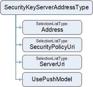
9.3.2 SecurityKeyServerAddressType definition
The SecurityKeyServerAddressType is formally defined in Table 122.
| Attribute | Value | ||||
| BrowseName | 4:SecurityKeyServerAddressType | ||||
| IsAbstract | False | ||||
| ValueRank | -1 (-1 = Scalar) | ||||
| DataType | 4:SecurityKeyServerAddressDataType | ||||
| References |
Node
Class | BrowseName | DataType | TypeDefinition | Other |
|---|---|---|---|---|---|
| Subtype of the 0:BaseDataVariableType defined in OPC 10000-5 | |||||
| 0:HasComponent | Variable | 4:Address | 0:UriString | 0:SelectionListType | M |
| 0:HasComponent | Variable | 4:SecurityPolicyUri | 0:String | 0:SelectionListType | M |
| 0:HasComponent | Variable | 4:ServerUri | 0:UriString | 0:SelectionListType | M |
| 0:HasComponent | Variable | 4:UsePushModel | 0:Boolean | 0:BaseDataVariableType | M |
| ConformanceUnits | |||||
|---|---|---|---|---|---|
| UAFX ConnectionManager Base |
Address specifies the address of the SKS as a DiscoveryUrl in the form:
scheme://hostname[:port][/path]
DiscoveryUrl is defined in OPC 10000-12. The SelectionListType (see 6.8.1) provides the option for an end user to either select or enter a DiscoveryUrl. As described in OPC 10000-4, a hostname may be an IP address or a name that would need to be resolved to an IP address. A ConnectionManager shall be able to resolve a name to an IP address. Any selected Address will be reflected in the SecurityKeyServerAddressDataType structure, which will be used in Connection establishment.
SecurityPolicyUri is a string that contains the security policy to use when establishing the secure communication. The SelectionListType (see 6.8.1) will provide the supported SecurityPolicyUris for this Connection. RestrictToList shall be set to TRUE. Any selected SecurityPolicyUri will be reflected in the SecurityKeyServerAddressDataType structure, which will be used in Connection establishment.
ServerUri is a string that reflects the ApplicationUri of the SKS. It can be used to cryptographically verify the SKS. The SelectionListType (see 6.8.1) provides the option for an end user to either select or enter a ServerUri. Any selected ServerUri will be reflected in the SecurityKeyServerAddressDataType structure, which will be used in Connection establishment.
If the SKS is co-located with the ConnectionManager, the ConnectionManager may use internal vendor-specific communication with the SKS. In this case, the Address, SecurityPolicyUri, and ServerUri may be set to null or empty.
UsePushModel if TRUE specifies that the SKS push model shall be used. Otherwise, the pull model shall be used. For more explanation of the SKS model, see OPC 10000-14.
10 OPC UA FX DataTypes
10.1 AggregatedHealthDataType
This structure DataType holds the information for an AggregatedHealthType Variable (see 9.1).
The AggregatedHealthDataType is formally defined in Table 123.
| Name | Type | Description |
| AggregatedHealthDataType | Structure | Subtype of Structure defined in OPC 10000-5 |
| AggregatedDeviceHealth | 3:DeviceHealthOptionSet | Aggregation of the DeviceHealth of the AutomationComponent's top-level Assets |
| AggregatedOperationalHealth | 3:OperationalHealthOptionSet | Aggregation of the OperationalHealth of the AutomationComponent's top-level FunctionalEntities |
The AggregatedHealthDataType representation in the AddressSpace is formally defined in Table 124.
| Attribute | Value | |||||
| BrowseName | 3:AggregatedHealthDataType | |||||
| IsAbstract | False | |||||
| References | NodeClass | BrowseName | DataType | TypeDefinition | Other | |
|---|---|---|---|---|---|---|
| Subtype of the 0:Structure defined in OPC 10000-5 | ||||||
| ConformanceUnits | ||||||
|---|---|---|---|---|---|---|
| UAFX AutomationComponent Base |
10.2 ApplicationId
The ApplicationId is used to store an identifier, which can be a Numeric, String, Guid, or ByteString.
The ApplicationId DataType is formally defined in Table 125.
| Name | Type | Description |
| ApplicationId | Union | Subtype of Union defined in OPC 10000-5 |
IdNumeric | 0:UInt32 | A numeric identifier |
IdString | 0:String | A string identifier limited to a max of 4096 characters |
IdGuid | 0:Guid | A GUID identifier. |
IdByteString | 0:ByteString | A ByteString identifier limited to a max of 4096 bytes |
The ApplicationId representation in the AddressSpace is formally defined in Table 126.
| Attribute | Value | |||||
| BrowseName | 3:ApplicationId | |||||
| IsAbstract | False | |||||
| References | NodeClass | BrowseName | DataType | TypeDefinition | Other | |
|---|---|---|---|---|---|---|
| Subtype of the 0:Union defined in OPC 10000-5 | ||||||
| ConformanceUnits | ||||||
|---|---|---|---|---|---|---|
| UAFX FunctionalEntity Base |
10.3 ApplicationIdentifierDataType
The ApplicationIdentifierDataType is used to represent identification parameters. The ApplicationIdentifierDataType is formally defined in Table 127.
| Name | Type | Description |
|---|---|---|
| ApplicationIdentifierDataType | Structure | Subtype of the Structure defined in OPC 10000-5 |
Name | 0:LocalizedText | This is a human-readable name of the identifier |
UniqueIdentifier | 3:ApplicationId | This is a unique identifier that can be compared programmatically. |
The ApplicationIdentifierDataType representation in the AddressSpace is formally defined in Table 128.
| Attribute | Value | |||||
| BrowseName | 3:ApplicationIdentifierDataType | |||||
| IsAbstract | False | |||||
| References | NodeClass | BrowseName | DataType | TypeDefinition | Other | |
|---|---|---|---|---|---|---|
| Subtype of the 0:Structure defined in OPC 10000-5 | ||||||
| ConformanceUnits | ||||||
|---|---|---|---|---|---|---|
| UAFX FunctionalEntity Base |
10.4 AssetVerificationModeEnum
This enumeration represents the mode for Asset verification.
The enumeration is formally defined in Table 129.
| Name | Value | Description |
| AssetCompatibility | 0 | Verify whether an Asset's functionality matches or is compatible with the expectation of system engineering. |
| AssetIdentity | 1 | Verify whether an Asset's identity meets the expectations of system engineering. |
| AssetIdentityAndCompatibility | 2 | Verify whether an Asset's identity meets the expectation of system engineering and whether its functionality matches or is compatible with the expectation of system engineering. |
The AssetVerificationModeEnum representation in the AddressSpace is formally defined in Table 130.
| Attribute | Value | |||||
| BrowseName | 2:AssetVerificationModeEnum | |||||
| IsAbstract | False | |||||
| References | NodeClass | BrowseName | DataType | TypeDefinition | Other | |
|---|---|---|---|---|---|---|
| Subtype of the 0:Enumeration defined in OPC 10000-5 | ||||||
| 0:HasProperty | Variable | 0:EnumValues | 0:EnumValueType[] | 0:PropertyType | ||
| ConformanceUnits | ||||||
|---|---|---|---|---|---|---|
| UAFX AutomationComponent Base | ||||||
| UAFX ConnectionManager Base |
10.5 AssetVerificationDataType
This structured DataType contains information required for Asset verification to be used as arguments in a Method Call (e.g., EstablishConnections).
It is semantically equivalent to the AssetVerificationType as defined in 6.15.2.
The structure is formally defined in Table 131.
| Name | Type | Description |
|---|---|---|
| AssetVerificationDataType | Structure | Subtype of Structure defined in OPC 10000-5 |
AssetToVerify | 0:NodeId | Node identifier of the Asset to verify. |
VerificationMode | 2:AssetVerificationModeEnum | The VerificationMode to use for verifying the Asset. |
ExpectedVerificationResult | 2:AssetVerificationResultEnum | Expected Asset compatibility and/or identity. |
ExpectedVerificationVariables | 0:KeyValuePair[] | A list of variables indicated by QualifiedName and their Value to be verified. |
ExpectedAdditionalVerificationVariables | 2:NodeIdValuePair[] | A list of variables indicated by NodeId and their Value to be verified. |
The AssetVerificationDataType representation in the AddressSpace is formally defined in Table 132.
| Attribute | Value | |||||
| BrowseName | 2:AssetVerificationDataType | |||||
| IsAbstract | False | |||||
| References | NodeClass | BrowseName | DataType | TypeDefinition | Other | |
|---|---|---|---|---|---|---|
| Subtype of the 0:Structure defined in OPC 10000-5 | ||||||
| ConformanceUnits | ||||||
|---|---|---|---|---|---|---|
| UAFX AutomationComponent Base | ||||||
| UAFX ConnectionManager Base |
10.6 AssetVerificationResultDataType
This structure contains the result of Asset verification returned by the Method Call (e.g., EstablishConnections).
The structure is formally defined in Table 133.
| Name | Type | Description |
|---|---|---|
| AssetVerificationResultDataType | Structure | Subtype of Structure defined in OPC 10000-5 |
| VerificationStatus | 0:StatusCode | Indicates the operational status of the Asset verification method. If VerificationStatus is Bad, VerificationResult shall be set to NotSet, and VerificationResult shall be ignored by a client. Also, VerificationVariablesErrors and VerificationAdditionalVariableErrors shall be set to null or empty and ignored by a client. |
| VerificationResult | 2:AssetVerificationResultEnum | Result of the Asset verification (see 10.7). |
| VerificationVariablesErrors | 0:StatusCode[] | If at least one element in ExpectedVerificationVariables caused an error (e.g., does not exist), this array will be of equal length to ExpectedVerificationVariables and contain corresponding StatusCodes (see 6.3.3). |
| VerificationAdditionalVariablesErrors | 0:StatusCode[] | If at least one element in ExpectedAdditionalVerificationVariables caused an error (e.g., does not exist), this array will be of equal length to ExpectedAdditionalVerificationVariables and contain corresponding StatusCodes (see 6.3.3). |
The AssetVerificationResultDataType representation in the AddressSpace is formally defined in Table 134.
| Attribute | Value | |||||
| BrowseName | 2:AssetVerificationResultDataType | |||||
| IsAbstract | False | |||||
| References | NodeClass | BrowseName | DataType | TypeDefinition | Other | |
|---|---|---|---|---|---|---|
| Subtype of the 0:Structure defined in OPC 10000-5 | ||||||
| ConformanceUnits | ||||||
|---|---|---|---|---|---|---|
| UAFX AutomationComponent Base | ||||||
| UAFX ConnectionManager Base |
10.7 AssetVerificationResultEnum
This enumeration represents the result of Asset verification.
The enumeration is formally defined in Table 135.
| Name | Value | Description |
| NotSet | 0 | The verification result is not set. |
| Match | 1 | Asset matches expectation. |
| Compatible | 2 | Asset does not match expectations but is compatible. |
| Mismatch | 3 | Asset does not match expectations and is not compatible. |
The AssetVerificationResultEnum representation in the AddressSpace is formally defined in Table 136.
| Attribute | Value | |||||
| BrowseName | 2:AssetVerificationResultEnum | |||||
| IsAbstract | False | |||||
| References | NodeClass | BrowseName | DataType | TypeDefinition | Other | |
|---|---|---|---|---|---|---|
| Subtype of the 0:Enumeration defined in OPC 10000-5 | ||||||
| 0:HasProperty | Variable | 0:EnumValues | 0:EnumValueType[] | 0:PropertyType | ||
| ConformanceUnits | ||||||
|---|---|---|---|---|---|---|
| UAFX ConnectionManager Base | ||||||
| UAFX AutomationComponent Base |
10.8 ClampKindEnum
This enumeration is the default enumeration for the Kind Variable in the ClampType (see 6.3.7) and ClampBlockType (see 6.3.8). The enumeration is formally defined in Table 137.
| Name | Value | Description |
| Screw | 0 | This is a screw connector |
| Thumb | 1 | This is a thumb connector |
The ClampKindEnum representation in the AddressSpace is formally defined in Table 138.
| Attribute | Value | ||||
| BrowseName | 3:ClampKindEnum | ||||
| IsAbstract | False | ||||
| References | NodeClass | BrowseName | DataType | TypeDefinition | Other |
|---|---|---|---|---|---|
| Subtype of the 0:Enumeration defined in OPC 10000-5 | |||||
| 0:HasProperty | Variable | 0:EnumValues | 0:EnumValueType[] | 0:PropertyType | |
| ConformanceUnits | |||||
|---|---|---|---|---|---|
| UAFX AssetConnector Clamp Base |
10.9 CommHealthOptionSet
This OptionSet defines flags indicating the health of the ConnectionEndpoints. The CommHealthOptionSet values are formally defined in Table 139.
| Value | Bit No. | Description |
| CommInitial | 0 | At least one of the ConnectionEndpoints has its Status set to Initial. |
| CommPreOperational | 1 | At least one of the ConnectionEndpoints has its Status set to PreOperational. |
| CommError | 2 | At least one of the ConnectionEndpoints has its Status set to Error. |
Bits 3:15 are reserved for future use. The CommHealthOptionSet representation in the AddressSpace is formally defined in Table 140.
| Attribute | Value | ||||
| BrowseName | 3:CommHealthOptionSet | ||||
| IsAbstract | False | ||||
| References | NodeClass | BrowseName | DataType | TypeDefinition | Other |
|---|---|---|---|---|---|
| Subtype of the 0:UInt16 type defined in OPC 10000-5 | |||||
| 0:HasProperty | Variable | 0:OptionSetValues | 0:LocalizedText[] | 0:PropertyType | |
| ConformanceUnits | |||||
|---|---|---|---|---|---|
| UAFX FunctionalEntity Base |
10.10 CommunicationConfigurationDataType
10.10.1 Overview
The CommunicationConfigurationDataType is an abstract structure used to provide the configuration of the communication model.
The CommunicationConfigurationDataType is illustrated in Figure 54.
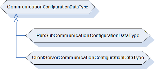
10.10.2 CommunicationConfigurationDataType definition
The CommunicationConfigurationDataType is an abstract type that has no fields and is expected to be subtyped. It is formally defined in Table 141.
| Attributes | Value | ||
| BrowseName | 2:CommunicationConfigurationDataType | ||
| IsAbstract | True | ||
| References | Node Class | BrowseName | Description |
|---|---|---|---|
| Subtype of the 0:Structure defined in OPC 10000-5 | |||
| HasSubtype | DataType | 2:PubSubCommunicationConfigurationDataType | Defined in 10.10.3 |
| ConformanceUnits | |||
|---|---|---|---|
| UAFX AutomationComponent Base | |||
| UAFX ConnectionManager Base |
10.10.3 PubSubCommunicationConfigurationDataType
The PubSubCommunicationConfigurationDataType contains configuration information for the PubSub communication model. It is formally defined in Table 142.
| Name | Type | Description |
|---|---|---|
| PubSubCommunicationConfigurationDataType | Structure | Subtype of CommunicationConfigurationDataType |
PubSubConfiguration | 0:PubSubConfiguration2DataType | The PubSubConfiguration to be applied. |
RequireCompleteUpdate | 0:Boolean | For the definition, see CloseAndUpdate defined in OPC 10000-14. |
ConfigurationReferences | 0:PubSubConfigurationRefDataType[] | For the definition, see CloseAndUpdate defined in OPC 10000-14. |
The PubSubCommunicationConfigurationDataType representation in the AddressSpace is formally defined in Table 143.
| Attributes | Value | |||
| BrowseName | 2:PubSubCommunicationConfigurationDataType | |||
| IsAbstract | False | |||
| References | NodeClass | BrowseName | IsAbstract | Description |
|---|---|---|---|---|
| Subtype of the 2:CommunicationConfigurationDataType | ||||
| ConformanceUnits | ||||
|---|---|---|---|---|
| UAFX AutomationComponent PubSub Connections | ||||
| UAFX ConnectionManager PubSubCommunicationFlowConfiguration |
10.10.4 ClientServerCommunicationConfigurationDataType
Provides the configuration information for the Client Server communication model.
This DataType will be specified in a future version of this document.
10.11 CommunicationConfigurationResultDataType
10.11.1 Overview
The CommunicationConfigurationResultDataType is an abstract structure used to provide information regarding communication model-specific results and properties at the EstablishConnections Method.
The CommunicationConfigurationResultDataType is illustrated in Figure 55.
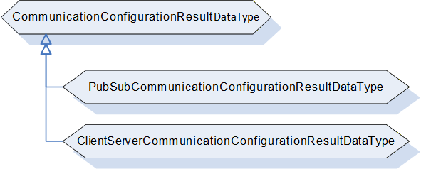
10.11.2 CommunicationConfigurationResultDataType definition
The CommunicationConfigurationResultDataType is an abstract type that has no structure and is expected to be subtyped. It is formally defined in Table 144.
| Attributes | Value | ||
| BrowseName | 2:CommunicationConfigurationResultDataType | ||
| IsAbstract | True | ||
| References | Node Class | BrowseName | Description |
|---|---|---|---|
| Subtype of the 0:Structure defined in OPC 10000-5 | |||
| HasSubtype | DataType | 2:PubSubCommunicationConfigurationResultDataType | Defined in 10.11.3 |
| ConformanceUnits | |||
|---|---|---|---|
| UAFX AutomationComponent Base | |||
| UAFX ConnectionManager Base |
10.11.3 PubSubCommunicationConfigurationResultDataType
The PubSubCommunicationConfigurationResultDataType is formally defined in Table 145.
| Name | Type | Description |
|---|---|---|
| PubSubCommunicationConfigurationResultDataType | Structure | Subtype of CommunicationConfigurationResultDataType |
| Result | 0:StatusCode | Status Code related to the overall configuration of the communication model. For the definition, see Table 19. |
| ChangesApplied | 0:Boolean | For the definition, see CloseAndUpdate defined in OPC 10000-14. If the command is aborted or rolled back, it shall be set to FALSE. |
| ReferenceResults | 0:StatusCode[] | For the definition, see CloseAndUpdate (Element Result Codes) defined in OPC 10000-14. On a rollback of an operation, these status codes shall retain their values from before the rollback. If the command is aborted before these values are generated, then this array shall be set to null or empty. |
| ConfigurationValues | 0:PubSubConfigurationValueDataType[] | For the definition, see CloseAndUpdate defined in OPC 10000-14. If the command is aborted or rolled back, it shall be set to null or empty. |
| ConfigurationObjects | 0:NodeId[] | For the definition, see CloseAndUpdate defined in OPC 10000-14. If the command is aborted or rolled back, it shall be set to null or empty. |
The PubSubCommunicationConfigurationResultDataType representation in the AddressSpace is formally defined in Table 146.
| Attribute | Value | |||||
| BrowseName | 2:PubSubCommunicationConfigurationResultDataType | |||||
| IsAbstract | False | |||||
| References | NodeClass | BrowseName | DataType | TypeDefinition | Other | |
|---|---|---|---|---|---|---|
| Subtype of the 2:CommunicationConfigurationResultDataType | ||||||
| ConformanceUnits | ||||||
|---|---|---|---|---|---|---|
| UAFX AutomationComponent PubSub Connections | ||||||
| UAFX ConnectionManager PubSubCommunicationFlowConfiguration |
10.11.4 ClientServerCommunicationConfigurationResultDataType
This DataType will be specified in a future version of this document.
10.12 CommunicationFlowQosDataType
This Structure DataType is used to describe an end-to-end QoS configuration for the CommunicationFlowConfiguration.
The CommunicationFlowQosDataType is formally defined in Table 147.
| Name | Type | Description |
Allow
Subtypes |
| CommunicationFlowQosDataType | Structure | Subtype of Structure defined in OPC 10000-5 | |
QosCategory | 0:String | Describes a QoS category, for example, best-effort or priority. For standard QosCategory values, see OPC 10000-14. Note that a null or empty QosCategory indicates best-effort. | False |
TransmitQos | 0:TransmitQosDataType[] | The TransmitQos describes QoS category-related parameters for the Publisher. This array shall be null or empty if no QoS-related parameters are required or if no Publisher is defined. For the defined parameters, see OPC 10000-14. | True |
ReceiveQos | 0:ReceiveQosDataType[] | The ReceiveQos describes QoS category-related parameters for the Subscriber. This array shall be null or empty if no QoS-related parameters are required or if no Subscriber is defined. For the defined parameters, see OPC 10000-14. | True |
The CommunicationFlowQosDataType representation in the AddressSpace is formally defined in Table 148.
| Attribute | Value | |||||
| BrowseName | 4:CommunicationFlowQosDataType | |||||
| IsAbstract | False | |||||
| References | NodeClass | BrowseName | DataType | TypeDefinition | Other | |
|---|---|---|---|---|---|---|
| Subtype of the 0:Structure defined in OPC 10000-5 | ||||||
| ConformanceUnits | ||||||
|---|---|---|---|---|---|---|
| UAFX ConnectionManager Base |
10.13 CommunicationLinkConfigurationDataType
10.13.1 Overview
The CommunicationLinkConfigurationDataType is an abstract structure used by the EstablishConnections Method to provide the configuration of references between ConnectionEndpoints and Object instances specific to the utilized communication model.
The CommunicationLinkConfigurationDataType is illustrated in Figure 56.
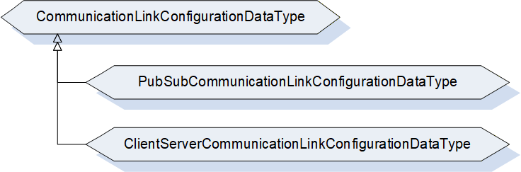
10.13.2 CommunicationLinkConfigurationDataType definition
The CommunicationLinkConfigurationDataType is an abstract type that has no structure and is expected to be subtyped. It is formally defined in Table 149.
| Attributes | Value | ||
| BrowseName | 2:CommunicationLinkConfigurationDataType | ||
| IsAbstract | True | ||
| References | Node Class | BrowseName | Description |
|---|---|---|---|
| Subtype of the 0:Structure defined in OPC 10000-5 | |||
| HasSubtype | DataType | 2:PubSubCommunicationLinkConfigurationDataType | Defined in 10.13.3 |
| ConformanceUnits | |||
|---|---|---|---|
| UAFX AutomationComponent Base | |||
| UAFX ConnectionManager Base |
10.13.3 PubSubCommunicationLinkConfigurationDataType
The PubSubCommunicationLinkConfigurationDataType is used by the EstablishConnections Method and provides the configuration of references between a ConnectionEndpoint and a DataSetReader and/or a DataSetWriter.
The PubSubCommunicationLinkConfigurationDataType is formally defined in Table 150.
| Name | Type | Description |
| PubSubCommunicationLinkConfigurationDataType | Structure | Subtype of CommunicationLinkConfigurationDataType |
| DataSetReaderRef | 0:PubSubConfigurationRefDataType | If not null, specifies the DataSetReader as supplied with the PubSubCommunicationConfigurationDataType. The ConfigurationMask shall contain a ReferenceReader bit only. |
| ExpectedSubscribedDataSetVersion | 0:ConfigurationVersionDataType | Specifies the expected ConfigurationVersion of the SubscribedDataSet's DataSetMetaData. For a heartbeat, the MajorVersion and the MinorVersion shall be set to 0. |
| DataSetWriterRef | 0:PubSubConfigurationRefDataType | If not null, specifies the DataSetWriter as supplied with the PubSubCommunicationConfigurationDataType. The ConfigurationMask shall contain a ReferenceWriter bit only. |
| ExpectedPublishedDataSetVersion | 0:ConfigurationVersionDataType | Specifies the expected ConfigurationVersion of the PublishedDataSet's DataSetMetaData. For a heartbeat, the MajorVersion and the MinorVersion shall be set to 0. |
The PubSubCommunicationLinkConfigurationDataType representation in the AddressSpace is formally defined in Table 151.
| Attribute | Value | |||||
| BrowseName | 2:PubSubCommunicationLinkConfigurationDataType | |||||
| IsAbstract | False | |||||
| References | NodeClass | BrowseName | DataType | TypeDefinition | Other | |
|---|---|---|---|---|---|---|
| Subtype of the 2:CommunicationLinkConfigurationDataType | ||||||
| ConformanceUnits | ||||||
|---|---|---|---|---|---|---|
| UAFX AutomationComponent PubSub Connections | ||||||
| UAFX ConnectionManager Base |
10.13.4 ClientServerCommunicationLinkConfigurationDataType
Provides the configuration of references between ConnectionEndpoints and Object instances specific to the Client Server communication model.
This DataType will be specified in a future version of this document.
10.14 ConnectionEndpointConfigurationDataType
This structure is semantically equivalent to the ConnectionEndpointConfigurationType as defined in 6.10.2.
The structure is formally defined in Table 152.
| Name | Type | Description |
Allow
Subtypes |
| ConnectionEndpointConfigurationDataType | Structure | Subtype of Structure defined in OPC 10000-5 | |
| FunctionalEntityNode | 0:NodeId | NodeId of the FunctionalEntity to connect. | False |
| ConnectionEndpoint | 2:ConnectionEndpointDefinitionDataType | Specifies either the information for the ConnectionEndpoint to be created or the NodeId of an existing ConnectionEndpoint. This ConnectionEndpoint is contained in the FunctionalEntity referenced by FunctionalEntityNode. If this parameter is to be omitted, it shall be set to null. | False |
| ExpectedVerificationVariables | 2:NodeIdValuePair[] | Specifies the expected verification variables for the FunctionalEntityNode. If this parameter is to be omitted, it shall be set to null or empty. | False |
| ControlGroups | 0:NodeId[] | Specifies the ControlGroups to be controlled by the ConnectionEndpoint. If this parameter is to be omitted, it shall be set to null or empty. | False |
| ConfigurationData | 2:NodeIdValuePair[] | Specifies the ConfigurationData to be applied. If this parameter is to be omitted, it shall be set to null or empty. | False |
| CommunicationLinks | 2:CommunicationLinkConfigurationDataType | Specifies the references to the communication model instances to be set for the ConnectionEndpoint. If this parameter is to be omitted, it shall be set to null. | True |
The ConnectionEndpointConfigurationDataType representation in the AddressSpace is formally defined in Table 153.
| Attribute | Value | ||||||
| BrowseName | 2:ConnectionEndpointConfigurationDataType | ||||||
| IsAbstract | False | ||||||
| References | NodeClass | BrowseName | DataType | TypeDefinition | Other | ||
|---|---|---|---|---|---|---|---|
| Subtype of the 0:Structure defined in OPC 10000-5 | |||||||
| ConformanceUnits | |||||||
|---|---|---|---|---|---|---|---|
| UAFX AutomationComponent Base | |||||||
| UAFX ConnectionManager Base | |||||||
For a definition of how this DataType shall be generated by the ConnectionManager, see 6.7.3. For a definition of how this DataType is interpreted by the EstablishConnections Method, see 6.2.4.
10.15 ConnectionEndpointConfigurationResultDataType
This structure contains the results returned from the ConnectionEndpoint configuration by the EstablishConnections Method. For a definition of how this DataType is used by the EstablishConnections Method, see 6.2.4.
The structure is formally defined in Table 154.
| Name | Type | Description |
| ConnectionEndpointConfigurationResultDataType | Structure | Subtype of Structure defined in OPC 10000-5 |
| ConnectionEndpointId | 0:NodeId | The NodeId of the ConnectionEndpoint. If the command is aborted or rolled back, it shall be set to null. |
| FunctionalEntityNodeResult | 0:StatusCode | StatusCode related to the FunctionalEntityNode. |
| ConnectionEndpointResult | 0:StatusCode | StatusCode related to the ConnectionEndpoint. |
| VerificationResult | 2:FunctionalEntityVerificationResultEnum | Result of the identity check. If CommandMask VerifyFunctionalEntityCmd is not set, it shall be set to NotSet. |
| VerificationStatus | 0:StatusCode | Operational status related to identity-check of the FunctionalEntityNode. If CommandMask VerifyFunctionalEntityCmd is not set, it shall be set to Good. |
| VerificationVariablesErrors | 0:StatusCode[] | Variables errors related to the identity-check of the FunctionalEntityNode. If CommandMask VerifyFunctionalEntityCmd is not set, it shall be null or empty. |
| EstablishControlResult | 0:StatusCode[] | StatusCodes related to EstablishControl on the ControlGroup(s). If CommandMask EstablishControlCmd is set, the length of this array shall match the length of ControlGroups, and each element shall contain the result of the corresponding element in ControlGroups. If CommandMask EstablishControlCmd is not set, it shall be null or empty. |
| ConfigurationDataResult | 0:StatusCode[] | StatusCodes related to applying ConfigurationData. If CommandMask SetConfigurationDataCmd is set, the length of this array shall match the length of ConfigurationData, and each element shall contain the result of the corresponding element in ConfigurationData. If CommandMask SetConfigurationDataCmd is not set, it shall be null or empty. |
| ReassignControlResult | 0:StatusCode[] | StatusCodes related to ReassignControl on the ControlGroup(s). If CommandMask ReassignControlCmd is set, the length of this array shall match the length of ControlGroups, and each element shall contain the result of the corresponding element in ControlGroups. If CommandMask ReassignControlCmd is not set, it shall be null or empty. |
| CommunicationLinksResult | 0:StatusCode | StatusCode related to establishing references into the communication model. If CommandMask SetCommunicationConfigurationCmd is not set, it shall be set to Good. |
| EnableCommunicationResult | 0:StatusCode | Status Code related to the overall enabling of the communication model. If CommandMask EnableCommunicationConfigurationCmd is not set, it shall be set to Good. |
The ConnectionEndpointConfigurationResultDataType representation in the AddressSpace is formally defined in Table 155.
| Attribute | Value | |||||
| BrowseName | 2:ConnectionEndpointConfigurationResultDataType | |||||
| IsAbstract | False | |||||
| References | NodeClass | BrowseName | DataType | TypeDefinition | Other | |
|---|---|---|---|---|---|---|
| Subtype of the 0:Structure defined in OPC 10000-5 | ||||||
| ConformanceUnits | ||||||
|---|---|---|---|---|---|---|
| UAFX AutomationComponent Base | ||||||
| UAFX ConnectionManager Base |
10.16 ConnectionEndpointDefinitionDataType
The ConnectionEndpointDefinitionDataType is formally defined in Table 156.
| Name | Type | Description |
Allow
Subtypes |
| ConnectionEndpointDefinitionDataType | Union | Subtype of Union defined in OPC 10000-5 | |
Parameter | 2:ConnectionEndpointParameterDataType | Parameter holds the parameters to be used for the creation of the ConnectionEndpoint or for the use of a preconfigured ConnectionEndpoint. This element is used when calling EstablishConnections with the CreateConnectionEndpointCmd. | True |
Node | 0:NodeId | The NodeId of the ConnectionEndpoint to use. This element is used when calling EstablishConnections without the CreateConnectionEndpointCmd (e.g., in a subsequent Call). | False |
The ConnectionEndpointDefinitionDataType representation in the AddressSpace is formally defined in Table 157.
| Attribute | Value | |||||
| BrowseName | 2:ConnectionEndpointDefinitionDataType | |||||
| IsAbstract | False | |||||
| References | NodeClass | BrowseName | DataType | TypeDefinition | Other | |
|---|---|---|---|---|---|---|
| Subtype of the 0:Union defined in OPC 10000-5 | ||||||
| ConformanceUnits | ||||||
|---|---|---|---|---|---|---|
| UAFX AutomationComponent Base | ||||||
| UAFX ConnectionManager Base |
10.17 ConnectionEndpointStatusEnum
This enumeration defines the values of the Status of a ConnectionEndpointType. The enumeration is formally defined in Table 158.
| Name | Value | Description |
| Initial | 0 | Initial status of the logical connection. No communication-model objects referenced. |
| Ready | 1 | Logical connection is ready to operate; communication-model objects are referenced but not enabled. |
| PreOperational | 2 | PreOperational status of the logical connection: Data output is active, but no input data received. |
| Operational | 3 | Operational status of the logical connection: Data output is active, and input data has been received. |
| Error | 4 | The logical connection has encountered an Error. |
The ConnectionEndpointStatusEnum representation in the AddressSpace is formally defined in Table 159.
| Attribute | Value | ||||
| BrowseName | 3:ConnectionEndpointStatusEnum | ||||
| IsAbstract | False | ||||
| References | NodeClass | BrowseName | DataType | TypeDefinition | Other |
|---|---|---|---|---|---|
| Subtype of the 0:Enumeration type defined in OPC 10000-5 | |||||
| 0:HasProperty | Variable | 0:EnumValues | 0:EnumValueType[] | 0:PropertyType | |
| ConformanceUnits | |||||
|---|---|---|---|---|---|
| UAFX AutomationComponent Base |
10.18 ConnectionEndpointParameterDataType
10.18.1 Overview
The ConnectionEndpointParameterDataType is an abstract structure used by the EstablishConnections Method to provide the information for the creation of a ConnectionEndpoint. It is semantically equivalent to the ConnectionEndpointParameterType as defined in 6.12.
The ConnectionEndpointParameterDataType is illustrated in Figure 57.
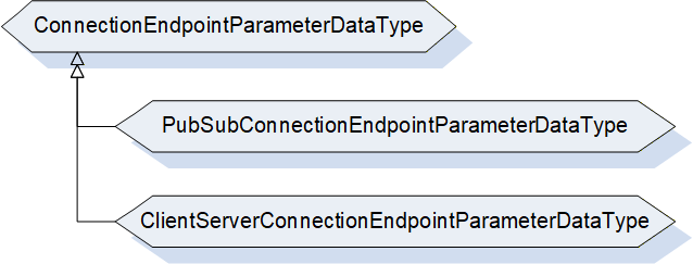
10.18.2 ConnectionEndpointParameterDataType definition
The ConnectionEndpointParameterDataType is formally defined in Table 160.
| Name | Type | Description |
| ConnectionEndpointParameterDataType | Structure | Subtype of Structure defined in OPC 10000-5 |
| Name | 0:String | Specifies the BrowseName of the ConnectionEndpoint. |
| ConnectionEndpointTypeId | 0:NodeId | Specifies the well-known NodeId of the type definition, which shall be used to create the ConnectionEndpoint. This can be any of the subtypes of the ConnectionEndpointType (for example, PubSubConnectionEndpointType) |
| InputVariableIds | 0:NodeId[] | Specifies a list of NodeIds that are inputs. If InputVariables are not provided, it shall be null or empty. |
| OutputVariableIds | 0:NodeId[] | Specifies a list of NodeIds that are outputs. If OutputVariables are not provided, it shall be null or empty. |
| IsPersistent | 0:Boolean | If TRUE, specifies that ConnectionEndpoint shall be persistent. |
| CleanupTimeout | 0:Duration | Specifies the value of the CleanupTimeout variable. |
| RelatedEndpoint | 2:RelatedEndpointDataType | Specifies the other endpoint this ConnectionEndpoint is connected to. |
| IsPreconfigured | 0:Boolean | If TRUE, specifies the ConnectionEndpoint is preconfigured. |
The ConnectionEndpointParameterDataType representation in the AddressSpace is formally defined in Table 161.
| Attribute | Value | |||
| BrowseName | 2:ConnectionEndpointParameterDataType | |||
| IsAbstract | True | |||
| References | NodeClass | BrowseName | Definition | |
|---|---|---|---|---|
| Subtype of the 0:Structure defined in OPC 10000-5 | ||||
| HasSubtype | DataType | PubSubConnectionEndpointParameterDataType | Defined in 10.18.3 | |
| ConformanceUnits | ||||
|---|---|---|---|---|
| UAFX AutomationComponent Base | ||||
| UAFX ConnectionManager Base |
10.18.3 PubSubConnectionEndpointParameterDataType
The PubSubConnectionEndpointParameterDataType is used by the EstablishConnections Method to create a PubSubConnectionEndpoint.
The PubSubConnectionEndpointParameterDataType is formally defined in Table 162.
| Name | Type | Description |
|---|---|---|
| PubSubConnectionEndpointParameterDataType | Structure | Subtype of ConnectionEndpointParameterDataType |
| Mode | 2:PubSubConnectionEndpointModeEnum | Indicates the intended mode of the ConnectionEndpoint. |
The PubSubConnectionEndpointParameterDataType representation in the AddressSpace is formally defined in Table 163.
| Attribute | Value | |||||
| BrowseName | 2:PubSubConnectionEndpointParameterDataType | |||||
| IsAbstract | False | |||||
| References | NodeClass | BrowseName | DataType | TypeDefinition | Other | |
|---|---|---|---|---|---|---|
| Subtype of the 2:ConnectionEndpointParameterDataType | ||||||
| ConformanceUnits | ||||||
|---|---|---|---|---|---|---|
| UAFX AutomationComponent Base | ||||||
| UAFX ConnectionManager Base |
10.18.4 ClientServerConnectionEndpointParameterDataType
The ClientServerConnectionEndpointParameterDataType is used by the EstablishConnections Method to create a ClientServerConnectionEndpoint.
This DataType will be specified in a future version of this document.
10.19 ConnectionDiagnosticsDataType
This Structure provides the status of a Connection in a ConnectionConfigurationSet.
The ConnectionDiagnosticsDataType is formally defined in Table 164.
| Name | Type | Description |
| ConnectionDiagnosticsDataType | Structure | Subtype of Structure defined in OPC 10000-5 |
| Name | 0:QualifiedName | BrowseName of the related <Connection> Node in the ConnectionConfigurationSet. |
| LastActivity | 4:LastActivityMask | The last activity taken by the ConnectionManager on the Connection indicated by Name, including results of the activity. A zero indicates no activity has been taken on this Connection. |
| ConnectionState | 4:ConnectionStateEnum | Current state of the Connection, indicated by Name. ConnectionStateEnum is defined in 10.20. |
| ErrorEndpoint1 | 4:FxErrorEnum | An enumeration that describes an error related to Endpoint1 in the Connection indicated by Name. FxErrorEnum is defined in 10.25. |
| Endpoint1Status | 0:StatusCode | A StatusCode associated with ErrorEndpoint1. In some cases, this will just be a generic Bad. The LogObject should be used for additional detail and the sequence of steps. If the value of ErrorEndpoint1 is NoError, this field shall be set to Good. |
| ErrorEndpoint2 | 4:FxErrorEnum | An enumeration that describes an error related to Endpoint2 in the Connection indicated by Name. FxErrorEnum is defined in 10.25. |
| Endpoint2Status | 0:StatusCode | A StatusCode associated with ErrorEndpoint2. In some cases, this will just be a generic Bad. The LogObject should be used for additional detail and the sequence of steps. If the value of ErrorEndpoint2 is NoError, this field shall be set to Good. |
The following rules apply to updating the LastActivity and all ConnectionEndpoint-related fields (ErrorEndpoint1, etc.).
When a ConnectionManager finishes processing a ConnectionConfigurationSet, it shall set the corresponding bit in the LastActivity and clear the remaining bits to indicate the kind of processing that just finished.
For all Connections for which all required operations were successfully finished, a ConnectionManager shall clear the Error bit in LastActivity and shall set ErrorEndpoint (1 and/or 2) to NoError and shall set EndpointStatus (1 and/or 2) to Good.
For all Connections for which not all operations required in the last processing were successfully finished, a ConnectionManager shall set the Error bit in the LastActivity.
For all Connections which were affected by any failure in the last processing, a ConnectionManager shall set the ErrorEndpoint (1 and/or 2) and EndpointStatus (1 and/or 2).
If, in the last processing, some operations related to a Connection were skipped due to a failure not directly related to this Connection, a ConnectionManager shall set the corresponding ErrorEndpoint (1 and/or 2) to ProcessingStopped and EndpointStatus (1 and/or 2) to Good.
If, in the last processing, a Connection was first successfully established but then removed due to rollback, a ConnectionManager shall set the Error bit in the LastActivity. Additionally, it shall set the corresponding ErrorEndpoint (1 and/or 2) to Rollback and EndpointStatus (1 and/or 2) to Good.
When a ConnectionManager detects an error not related to the processing of a ConnectionConfigurationSet, it can overwrite the ErrorEndpoint (1 and/or 2) and EndpointStatus (1 and/or 2) with specific error information at any time. This may include errors related to monitored ConnectionEndpoints (see FxErrorEnum RuntimeError) or errors related to the operation of a local SKS (see FxErrorEnum LocalSksKeyPushError).
The ConnectionDiagnosticsDataType representation in the AddressSpace is formally defined in Table 165.
| Attribute | Value | |||
| BrowseName | 4:ConnectionDiagnosticsDataType | |||
| IsAbstract | False | |||
| References | NodeClass | BrowseName | Definition | |
|---|---|---|---|---|
| Subtype of the 0:Structure defined in OPC 10000-5 | ||||
| ConformanceUnits | ||||
|---|---|---|---|---|
| UAFX ConnectionManager Diagnostics |
10.20 ConnectionStateEnum
The ConnectionStateEnum provides information about the current state of the Connection, as determined by the ConnectionManager. See 10.19 for a description of the ConnectionState. The ConnectionStateEnum values are formally defined in Table 166.
| Name | Value | Description |
| ConnectionNotMonitored | 0 | ConnectionManager does not monitor the state of the Connection |
| ConnectionNotEstablished | 1 | Connection does not exist |
| ConnectionInitial | 2 | Connection is being established, but the communication model is not linked to the ConnectionEndpoint. |
| ConnectionReady | 3 | Connection is established, but the communication model is disabled |
| ConnectionPreOperational | 4 | Connection is established and enabled, but communication has not started |
| ConnectionOperational | 5 | Connection is established, and communication is flowing |
| ConnectionError | 6 | Connection is established and enabled, but communication is not possible due to an endpoint error. |
ConnectionNotEstablished can result from any of the following:
ConnectionManager has not yet established the Connection;
ConnectionManager has successfully removed the Connection;
ConnectionManager detected that one or both ConnectionEndpoints have been removed (e.g., due to ConnectionEndpoint auto-cleanup or AutomationComponent power-cycle).
ConnectionStateEnum combines the Status of all ConnectionEndpoints participating in a Connection (see 10.20).
For Connection types bidirectional, unidirectional and unidirectional with heartbeat, the value is calculated according to Figure 58.
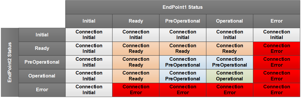
For Connection types autonomous publisher and autonomous subscriber, the value is calculated according to Figure 59.
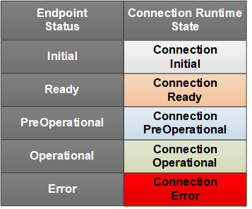
The ConnectionStateEnum representation in the AddressSpace is formally defined in Table 167.
| Attribute | Value | ||||
| BrowseName | 4:ConnectionStateEnum | ||||
| IsAbstract | False | ||||
| References | NodeClass | BrowseName | DataType | TypeDefinition | Other |
|---|---|---|---|---|---|
| Subtype of the 0:Enumeration defined in OPC 10000-5 | |||||
| 0:HasProperty | Variable | 0:EnumValues | 0:EnumValueType[] | 0:PropertyType | |
| ConformanceUnits | |||||
|---|---|---|---|---|---|
| UAFX ConnectionManager Diagnostics |
10.21 DeviceHealthOptionSet
This OptionSet defines flags indicating the aggregated health of the Assets. The DeviceHealthOptionSet values are formally defined in Table 168.
| Value | Bit No. | Description |
| DeviceFailure | 0 | At least one of the top-level Assets has its DeviceHealth set to Failure. |
| DeviceCheckFunction | 1 | At least one of the top-level Assets has its DeviceHealth set to Check_Function. |
| DeviceMaintenanceRequired | 2 | At least one of the top-level Assets has its DeviceHealth set to Maintenance_Required. |
| DeviceOffSpec | 3 | At least one of the top-level Assets has its DeviceHealth set to Off_Spec. |
Bits 4:15 are reserved for future use. The DeviceHealthOptionSet representation in the AddressSpace is formally defined in Table 169.
| Attribute | Value | ||||
| BrowseName | 3:DeviceHealthOptionSet | ||||
| IsAbstract | False | ||||
| References | NodeClass | BrowseName | DataType | TypeDefinition | Other |
|---|---|---|---|---|---|
| Subtype of the 0:UInt16 type defined in OPC 10000-5 | |||||
| 0:HasProperty | Variable | 0:OptionSetValues | 0:LocalizedText[] | 0:PropertyType | |
| ConformanceUnits | |||||
|---|---|---|---|---|---|
| UAFX AutomationComponent Base |
10.22 FunctionalEntityVerificationResultEnum
This enumeration represents the result of FunctionalEntity verification. The enumeration is formally defined in Table 170.
| Name | Value | Description |
| NotSet | 0 | The verification result is not set. |
| Match | 1 | FunctionalEntity matches expectations. |
| Mismatch | 2 | FunctionalEntity does not match expectations. |
The FunctionalEntityVerificationResultEnum representation in the AddressSpace is formally defined in Table 171.
| Attribute | Value | ||||
| BrowseName | 2:FunctionalEntityVerificationResultEnum | ||||
| IsAbstract | False | ||||
| References | NodeClass | BrowseName | DataType | TypeDefinition | Other |
|---|---|---|---|---|---|
| Subtype of the 0:Enumeration defined in OPC 10000-5 | |||||
| 0:HasProperty | Variable | 0:EnumValues | 0:EnumValueType[] | 0:PropertyType | |
| ConformanceUnits | |||||
|---|---|---|---|---|---|
| UAFX AutomationComponent Base | |||||
| UAFX ConnectionManager Base |
10.23 FxCommandMask
This OptionSet defines flags indicating the commands a ConnectionManager may use in its Call to the EstablishConnections Method.
The FxCommandMask values are formally defined in Table 172.
| Value | Bit No. | Description |
| VerifyAssetCmd | 0 | The addressed Server shall verify compatibility and/or identity for all requested Assets. |
| VerifyFunctionalEntityCmd | 1 | The addressed Server shall verify compatibility for all requested functional entities. |
| CreateConnectionEndpointCmd | 2 | The addressed Server shall create or modify ConnectionEndpoints. |
| EstablishControlCmd | 3 | The addressed Server shall establish control over the requested ControlGroups. |
| SetConfigurationDataCmd | 4 | The addressed Server shall apply the supplied application configuration. |
| ReassignControlCmd | 5 | The addressed Server shall reassign the requested ControlGroups |
| ReserveCommunicationIdsCmd | 6 | The addressed Server shall reserve identifiers for the communication model configuration. |
| SetCommunicationConfigurationCmd | 7 | The addressed Server shall apply the supplied communication model configuration. |
| EnableCommunicationCmd | 8 | The addressed Server shall enable the communication configuration. |
Bits 9:31 are reserved for future use. The FxCommandMask representation in the AddressSpace is formally defined in Table 173.
| Attribute | Value | ||||
| BrowseName | 2:FxCommandMask | ||||
| IsAbstract | False | ||||
| References | NodeClass | BrowseName | DataType | TypeDefinition | Other |
|---|---|---|---|---|---|
| Subtype of the 0:UInt32 type defined in OPC 10000-5 | |||||
| 0:HasProperty | Variable | 0:OptionSetValues | 0:LocalizedText[] | 0:PropertyType | |
| ConformanceUnits | |||||
|---|---|---|---|---|---|
| UAFX AutomationComponent Base | |||||
| UAFX ConnectionManager Base |
10.24 FxEditEnum
This enumeration defines the editing behaviour for a ConnectionManager. FxEditEnum is formally defined in Table 174.
| Name | Value | Description |
| StartEditing | 0 | The ConnectionManager shall allow editing of the ConnectionConfigurationSets. |
| CommitUpdates | 1 | The ConnectionManager shall commit all updates from the ConnectionConfigurationSets. |
| DiscardUpdates | 2 | The ConnectionManager shall discard the updates to the ConnectionConfigurationSets. |
The FxEditEnum representation in the AddressSpace is formally defined in Table 175.
| Attribute | Value | |||||
| BrowseName | 4:FxEditEnum | |||||
| IsAbstract | False | |||||
| References | NodeClass | BrowseName | DataType | TypeDefinition | Other | |
|---|---|---|---|---|---|---|
| Subtype of the 0:Enumeration type defined in OPC 10000-5 | ||||||
| 0:HasProperty | Variable | 0:EnumValues | 0:EnumValueType[] | 0:PropertyType | ||
| ConformanceUnits | ||||||
|---|---|---|---|---|---|---|
| UAFX ConnectionManager Base |
10.25 FxErrorEnum
This enumeration defines the summary errors that a ConnectionManager may report.
FxErrorEnum values are formally defined in Table 176.
| Name | Value | Description |
| NoError | 0 | This is returned if no processing has been done or no error exists. |
| UnknownStatus | 1 | The Connection is not monitored, and its status is unknown. |
| Rollback | 2 | The Connection was successfully established but was rolled back due to errors in related Connections in this ConnectionConfigurationSet. |
| ProcessingStopped | 3 | This Connection processing was stopped due to some other error in the ConnectionConfigurationSet. |
| ConnectionConfigurationSetInvalid | 4 | The ConnectionManager could not process this ConnectionConfigurationSet due to a configuration error. |
| GdsConnectionError | 5 | There was an error related to establishing a session with the GDS. |
| GdsProcessingError | 6 | There was an error related to processing commands with the GDS. |
| AliasNameProcessingError | 7 | There was an error related to resolving AliasNames. |
| ExternalSksConnectionError | 8 | There was an error related to establishing a session with the SKS. |
| ExternalSksProcessingError | 9 | There was an error related to configuring the SKS. |
| TargetServerConnectionError | 10 | There was an error related to establishing a session with the target Server. |
| ResolvingNamespacesError | 11 | There was an error resolving Namespaces. |
| ResolvingPathsError | 12 | There was an error resolving BrowsePaths. |
| VerifyAssetError | 13 | There was a verification error on an Asset. |
| VerifyFunctionalEntityError | 14 | There was a verification error on a FunctionalEntity. |
| CreateConnectionEndpointError | 15 | There was an error creating a ConnectionEndpoint. |
| EstablishControlError | 16 | There was an error establishing control of a FunctionalEntity. |
| SetConfigurationDataError | 17 | There was an error setting configuration information in the FunctionalEntity. |
| ReassignControlError | 18 | There was an error reassigning the control of a FunctionalEntity. |
| ReserveCommunicationIdsError | 19 | There was an error related to reserving ids. |
| SetCommunicationConfigurationError | 20 | There was an error related to configuring communication. |
| EnableCommunicationError | 21 | There was an error enabling communication. |
| CloseConnectionError | 22 | There was an error closing a connection. |
| LocalSksKeyPushError | 23 | The internal SKS is having a problem with pushing keys to a target Server. |
| RuntimeError | 24 | There was an error in a running operation. |
The FxErrorEnum representation in the AddressSpace is formally defined in Table 177.
Note: The Client should be aware that this enumeration may be extended in the future.
| Attribute | Value | |||||
| BrowseName | 4:FxErrorEnum | |||||
| IsAbstract | False | |||||
| References | NodeClass | BrowseName | DataType | TypeDefinition | Other | |
|---|---|---|---|---|---|---|
| Subtype of the 0:Enumeration type defined in OPC 10000-5 | ||||||
| 0:HasProperty | Variable | 0:EnumValues | 0:EnumValueType[] | 0:PropertyType | ||
| ConformanceUnits | ||||||
|---|---|---|---|---|---|---|
| UAFX ConnectionManager Diagnostics |
10.26 FxProcessEnum
This enumeration defines the processing behaviour of a ConnectionManager. FxProcessEnum is formally defined in Table 178.
| Name | Value | Description |
| ActionEstablishConnectionsEnabled | 0 | The ConnectionManager shall establish enabled Connections from the ConnectionConfigurationSets. |
| ActionEstablishConnectionsDisabled | 1 | The ConnectionManager shall establish disabled Connections from the ConnectionConfigurationSets. |
| ActionEstablishConnections | 2 | The ConnectionManager shall establish Connections from the ConnectionConfigurationSets. |
| ActionRemoveConnections | 3 | The ConnectionManager shall disable and remove Connections from the ConnectionConfigurationSets. |
| ActionEnableConnections | 4 | The ConnectionManager shall enable Connections from the ConnectionConfigurationSets. |
| ActionDisableConnections | 5 | The ConnectionManager shall disable Connections from the ConnectionConfigurationSets. |
The representation in the AddressSpace is formally defined in Table 179.
| Attribute | Value | |||||
| BrowseName | 4:FxProcessEnum | |||||
| IsAbstract | False | |||||
| References | NodeClass | BrowseName | DataType | TypeDefinition | Other | |
|---|---|---|---|---|---|---|
| Subtype of the 0:Enumeration type defined in OPC 10000-5 | ||||||
| 0:HasProperty | Variable | 0:EnumValues | 0:EnumValueType[] | 0:PropertyType | ||
| ConformanceUnits | ||||||
|---|---|---|---|---|---|---|
| UAFX ConnectionManager Base |
10.27 FxTimeUnitsEnum
This enumeration describes the support units of time. The enumeration is formally defined in Table 180.
| Name | Value | Description |
| Nanosecond | 0 | The unit of time is nanoseconds |
| Microsecond | 1 | The unit of time is microseconds |
| Millisecond | 2 | The unit of time is milliseconds |
| Second | 3 | The unit of time is seconds |
The FxTimeUnitsEnum representation in the AddressSpace is formally defined in Table 181.
| Attribute | Value | ||||
| BrowseName | 2:FxTimeUnitsEnum | ||||
| IsAbstract | False | ||||
| References | NodeClass | BrowseName | DataType | TypeDefinition | Other |
|---|---|---|---|---|---|
| Subtype of the 0:Enumeration type defined in OPC 10000-5 | |||||
| 0:HasProperty | Variable | 0:EnumStrings | 0:LocalizedText[] | 0:PropertyType | |
| ConformanceUnits | |||||
|---|---|---|---|---|---|
| UAFX AutomationComponent Base |
10.28 FxVersion
This structure contains version information that can be assigned to any Object or Variable that needs to store version information.
The FxVersion is formally defined in Table 182.
| Name | Type | Description |
| FxVersion | Structure | Subtype of Structure defined in OPC 10000-5 |
Major | 0:UInt16 | The major version number |
Minor | 0:UInt16 | The minor version number |
Build | 0:UInt16 | The build version number |
SubBuild | 0:UInt16 | The sub-build version number |
The FxVersion representation in the AddressSpace is formally defined in Table 183.
| Attribute | Value | |||||
| BrowseName | 3:FxVersion | |||||
| IsAbstract | False | |||||
| References | NodeClass | BrowseName | DataType | TypeDefinition | Other | |
|---|---|---|---|---|---|---|
| Subtype of the 0:Structure defined in OPC 10000-5 | ||||||
| ConformanceUnits | ||||||
|---|---|---|---|---|---|---|
| UAFX AutomationComponent AcDescriptor DescriptorIdentifier | ||||||
| UAFX FunctionalEntity Base |
10.29 IntervalRange
The IntervalRange is a structure used to define a range of timing intervals.
The IntervalRange is formally defined in Table 184.
| Name | Type | Description |
| IntervalRange | Structure | Subtype of Structure defined in OPC 10000-5 |
Min | 0:UInt32 | The minimum interval (in units). |
Max | 0:UInt32 | The maximum interval (in units). For linear ranges: Max = Min + N * Increment For exponential ranges: Max = Min * Multiplier Where N is an unsigned integer. |
Increment | 0:UInt16 | The increment from minimum to maximum. An Increment value greater than or equal to 1 indicates a linear IntervalRange; in this case, Multiplier shall be set to 1. 0 indicates no increment. |
Multiplier | 0:UInt16 | The multiplier that can be applied. Multiplier shall be greater than or equal to 1. A value of 2 or greater indicates an exponential IntervalRange; in this case, Increment shall be set to 0. 1 indicates no multiplier. |
Unit | 2:FxTimeUnitsEnum | Defines the units of Min, Max, and Increment. |
IntervalRange allows specifying
| linear ranges: | [Min, Min + Increment, Min + 2 * Increment, Min + 3 * Increment… Max] |
| exponential ranges: | [Min, Min * Multiplier, Min * Multiplier2, Min * Multiplier3, …, Max] |
| fixed range: | if Min is equal to Max. |
For example, an IntervalRange with Min=2, Max=16, Increment=2 and Unit=milliseconds result in the following linear range: [2 ms, 4 ms, 6 ms, 8 ms, 10 ms, 12 ms, 14 ms, 16 ms]. An IntervalRange with Min=125, Max=1000, Multiplier=2 and Unit=microseconds result in the following exponential range: [125 µs, 250 µs, 500 µs, 1000 µs].
A null IntervalRange is indicated by setting Min and Max to 0.
The IntervalRange representation in the AddressSpace is formally defined in Table 185.
| Attribute | Value | |||||
| BrowseName | 2:IntervalRange | |||||
| IsAbstract | False | |||||
| References | NodeClass | BrowseName | DataType | TypeDefinition | Other | |
|---|---|---|---|---|---|---|
| Subtype of the 0:Structure defined in OPC 10000-5 | ||||||
| ConformanceUnits | ||||||
|---|---|---|---|---|---|---|
| UAFX AutomationComponent Base | ||||||
| UAFX FunctionalEntity Base |
10.30 LastActivityMask
This OptionSet defines flags indicating the last activity taken by a ConnectionManager processing a given ConnectionConfigurationSet (and, in turn, on Connection configurations within). If the OptionSet is zero (no bits set), then no activity related to the given Connection in the given ConnectionConfigurationSet has been taken.
In this OptionSet, only one bit can be set except for the Error bit, which can be set with any of the other bits.
If the ConnectionManager supports the ProcessConnectionConfigurationSets Method, then the activities correspond to the described actions in the Method, but a ConnectionManager is not required to support the ProcessConnectionConfigurationSets Method, it could still have internal or application trigger activities that correspond to these actions.
The LastActivityMask values are formally defined in Table 186.
| Value | Bit No. | Description |
| EstablishEnabled | 0 | The last activity of the ConnectionManager was establishing a connection (enabled). |
| EstablishDisabled | 1 | The last activity of the ConnectionManager was establishing a connection (disabled). |
| Establish | 2 | The last activity of the ConnectionManager was establishing a connection. |
| Remove | 3 | The last activity of the ConnectionManager was to remove a connection. |
| Enable | 4 | The last activity of the ConnectionManager was to enable a connection. |
| Disable | 5 | The last activity of the ConnectionManager was to disable a connection. |
| Error | 15 | If this bit is set, then the last activity of the ConnectionManager failed; if this bit is cleared, then the last activity of the ConnectionManager was a success. |
The Establish, EstablishEnabled, and EstablishDisabled activities include resolving parameters related to a Connection, communicating with an SKS, calling the EstablishConnections Method, or any other activity related to establishing the Connection.
The LastActivityMask representation in the AddressSpace is formally defined in Table 187.
| Attribute | Value | ||||
| BrowseName | 4:LastActivityMask | ||||
| IsAbstract | False | ||||
| References | NodeClass | BrowseName | DataType | TypeDefinition | Other |
|---|---|---|---|---|---|
| Subtype of the 0:UInt16 type defined in OPC 10000-5 | |||||
| 0:HasProperty | Variable | 0:OptionSetValues | 0:LocalizedText[] | 0:PropertyType | |
| ConformanceUnits | |||||
|---|---|---|---|---|---|
| UAFX ConnectionManager Diagnostics |
10.31 NodeIdArray
This structured DataType is used to provide a NodeId and can specify a single element within a Variable that is of array type. One or more index values must be specified to identify the specific element.
The structure is formally defined in Table 188.
| Name | Type | Description |
| NodeIdArray | Structure | Subtype of Structure defined in OPC 10000-5. |
Node | 0:NodeId | The NodeId that is to be processed. |
ArrayIndex | 0:UInt32[] | If NodeId refers to a Node of array type, the ArrayIndex specifies the index for a specific value referenced by the NodeId (not the entire array, but a specific element in it). The size of ArrayIndex shall be equal to the number of dimensions of the Node. If NodeId is not of array type, or if all elements are referenced, then ArrayIndex shall be null or empty. |
The NodeIdArray representation in the AddressSpace is formally defined in Table 189.
| Attribute | Value | ||||
| BrowseName | 2:NodeIdArray | ||||
| IsAbstract | False | ||||
| References | NodeClass | BrowseName | DataType | TypeDefinition | Other |
|---|---|---|---|---|---|
| Subtype of the 0:Structure defined in OPC 10000-5 | |||||
| ConformanceUnits | |||||
|---|---|---|---|---|---|
| UAFX AutomationComponent Base | |||||
| UAFX ConnectionManager Base |
10.32 NodeIdValuePair
This structured DataType is used to provide a NodeId value pair. The NodeIdValuePair specifies a KeyValuePair with a NodeIdArray as key.
The structure is formally defined in Table 190.
| Name | Type | Description |
| NodeIdValuePair | Structure | Subtype of Structure defined in OPC 10000-5 |
Key | 2:NodeIdArray | The key to the item. To reference a single item or an array element, a scalar Value shall be provided. |
Value | 0:BaseDataType | Specifies the value, which can be of any DataType. If the value is an array, then the entire array is processed. |
The NodeIdValuePair representation in the AddressSpace is formally defined in Table 191.
| Attribute | Value | |||||
| BrowseName | 2:NodeIdValuePair | |||||
| IsAbstract | False | |||||
| References | NodeClass | BrowseName | DataType | TypeDefinition | Other | |
|---|---|---|---|---|---|---|
| Subtype of the 0:Structure defined in OPC 10000-5 | ||||||
| ConformanceUnits | ||||||
|---|---|---|---|---|---|---|
| UAFX AutomationComponent Base | ||||||
| UAFX ConnectionManager Base |
10.33 NodeIdTranslationDataType
This structured DataType is used to provide table entries for conversion of NodeId to PortableNodeIdentifier (see 6.16.3).
The structure is formally defined in Table 192.
| Name | Type | Description |
| NodeIdTranslationDataType | Structure | Subtype of Structure defined in OPC 10000-5 |
NodePlaceholder | 0:NodeId | NodeId to be converted to the result of resolving the PortableNodeIdentifier. |
PortableNode | 4:PortableNodeIdentifier | Specifies the PortableNodeIdentifier corresponding to the NodeId of the NodePlaceholder. |
The NodeIdTranslationDataType representation in the AddressSpace is formally defined in Table 193.
| Attribute | Value | |||||
| BrowseName | 4:NodeIdTranslationDataType | |||||
| IsAbstract | False | |||||
| References | NodeClass | BrowseName | DataType | TypeDefinition | Other | |
|---|---|---|---|---|---|---|
| Subtype of the 0:Structure defined in OPC 10000-5 | ||||||
| ConformanceUnits | ||||||
|---|---|---|---|---|---|---|
| UAFX ConnectionManager Base |
10.34 OperationalHealthOptionSet
This OptionSet defines flags indicating the health of a FunctionalEntity. The OperationalHealthOptionSet values are formally defined in Table 194.
| Value | Bit No. | Description |
| Reserved | 0:15 | Used by CommHealthOptionSet defined in 10.9 |
| OperationalWarning | 16 | FunctionalEntity indicates a warning. |
| OperationalError | 17 | FunctionalEntity indicates an error. |
| SubOperationalWarning | 18 | One of the SubFunctionalEntities indicates a warning. |
| SubOperationalError | 19 | One of the SubFunctionalEntities indicates an error. |
Bits 0:15 contain an aggregation of the CommHealthOptionSet (see 10.9) from the associated ConnectionEndpoints (definition is repeated here for tools). Bits 16-19 represent the FunctionalEntity status and, if present, from SubFunctionalEntities. Bits 20-31 are reserved for future use. The OperationalHealthOptionSet representation in the AddressSpace is formally defined in Table 195.
| Attribute | Value | ||||
| BrowseName | 3:OperationalHealthOptionSet | ||||
| IsAbstract | False | ||||
| References | NodeClass | BrowseName | DataType | TypeDefinition | Other |
|---|---|---|---|---|---|
| Subtype of the 0:UInt32 type defined in OPC 10000-5 | |||||
| 0:HasProperty | Variable | 0:OptionSetValues | 0:LocalizedText[] | 0:PropertyType | |
| ConformanceUnits | |||||
|---|---|---|---|---|---|
| UAFX AutomationComponent Base |
10.35 PortableKeyValuePair
This structured DataType is used to provide a portable key-value pair. The PortableKeyValuePair is used to store a KeyValuePair outside the context of where the Node is located, using a portable QualifiedName as a key.
The structure is formally defined in Table 196.
| Name | Type | Description |
| PortableKeyValuePair | Structure | Subtype of Structure defined in OPC 10000-5 |
Key | 0:PortableQualifiedName | The key of the value. |
Value | 0:BaseDataType | The value associated with the key. |
The PortableKeyValuePair representation in the AddressSpace is formally defined in Table 197.
| Attribute | Value | |||||
| BrowseName | 4:PortableKeyValuePair | |||||
| IsAbstract | False | |||||
| References | NodeClass | BrowseName | DataType | TypeDefinition | Other | |
|---|---|---|---|---|---|---|
| Subtype of the 0:Structure defined in OPC 10000-5 | ||||||
| ConformanceUnits | ||||||
|---|---|---|---|---|---|---|
| UAFX ConnectionManager Base |
10.36 PortableNodeIdentifier
The PortableNodeIdentifier is used to store an identification of a Node outside the context of where the Node is located, using a portable NodeId, an Alias, or a portable RelativePath.
The PortableNodeIdentifier DataType is formally defined in Table 198.
| Name | Type | Description |
| PortableNodeIdentifier | Union | Subtype of Union defined in OPC 10000-5 |
Node | 0:PortableNodeId | The NodeId of the item |
Alias | 0:String | The AliasName of the Item |
IdentifierBrowsePath | 4:PortableRelativePath | The IdentifierBrowsePath to the item. The starting node of the IdentifierBrowsePath shall be specified where this type is used. |
The PortableNodeIdentifier representation in the AddressSpace is formally defined in Table 199.
| Attribute | Value | |||||
| BrowseName | 4:PortableNodeIdentifier | |||||
| IsAbstract | False | |||||
| References | NodeClass | BrowseName | DataType | TypeDefinition | Other | |
|---|---|---|---|---|---|---|
| Subtype of the 0:Union defined in OPC 10000-5 | ||||||
| ConformanceUnits | ||||||
|---|---|---|---|---|---|---|
| UAFX ConnectionManager Base |
10.37 PortableNodeIdentifierValuePair
This structured DataType is used to provide a key-value pair for storage outside the context of where the Node is located, using a PortableNodeIdentifier as the key.
The structure is formally defined in Table 200.
| Name | Type | Description |
| PortableNodeIdentifierValuePair | Structure | Subtype of Structure defined in OPC 10000-5 |
Key | 4:PortableNodeIdentifier | The key to the item. |
ArrayIndex | 0:UInt32[] | If Key refers to a Node of array type, the ArrayIndex specifies the index for a specific value referenced by Key (Not the entire array, but a specific element in it). The ArrayIndex is required to have the same dimension as the dimension of the node. If Key is not of array type, or if no specific index is referenced, then the array shall be null or empty. |
Value | 0:BaseDataType | The value associated with the key/array item. |
The PortableNodeIdentifierValuePair representation in the AddressSpace is formally defined in Table 201.
| Attribute | Value | |||||
| BrowseName | 4:PortableNodeIdentifierValuePair | |||||
| IsAbstract | False | |||||
| References | NodeClass | BrowseName | DataType | TypeDefinition | Other | |
|---|---|---|---|---|---|---|
| Subtype of the 0:Structure defined in OPC 10000-5 | ||||||
| ConformanceUnits | ||||||
|---|---|---|---|---|---|---|
| UAFX ConnectionManager Base |
10.38 PortableRelativePath
This structure contains a PortableRelativePath, which defines a sequence of References and BrowseNames to follow for storing a relative path outside the context of where the target of the relative path is located. It is semantically equivalent to RelativePath.
The PortableRelativePath DataType is formally defined in Table 202.
| Name | Type | Description |
| PortableRelativePath | Structure | Subtype of Structure defined in OPC 10000-5 |
Elements | 4:PortableRelativePathElement[] | A sequence of References and BrowseNames to follow. This array defines a sequence of elements. Each element in the sequence is processed by finding the targets and then using those targets as the starting Nodes for the next element. The target of the final element is the target of the PortableRelativePath. |
A PortableRelativePath can be applied to any starting Node. The targets of the PortableRelativePath are the set of Nodes that are found by sequentially following the elements in PortableRelativePath.
A PortableRelativePath is set to null by setting Elements to null or empty.
The PortableRelativePath representation in the AddressSpace is formally defined in Table 203.
| Attribute | Value | |||||
| BrowseName | 4:PortableRelativePath | |||||
| IsAbstract | False | |||||
| References | NodeClass | BrowseName | DataType | TypeDefinition | Other | |
|---|---|---|---|---|---|---|
| Subtype of the 0:Structure defined in OPC 10000-5 | ||||||
| ConformanceUnits | ||||||
|---|---|---|---|---|---|---|
| UAFX ConnectionManager Base |
10.39 PortableRelativePathElement
This structure contains an element of the PortableRelativePath.
The PortableRelativePathElement DataType is formally defined in Table 204.
| Name | Type | Description |
| PortableRelativePathElement | Structure | Subtype of Structure defined in OPC 10000-5 |
ReferenceTypeId | 0:PortableNodeId | The type of Reference to follow from the current node. The current path cannot be followed any further if the ReferenceTypeId is not available on the Node instance. If not specified, then all References are included, and the parameter IncludeSubtypes is ignored. |
IsInverse | 0:Boolean | Only inverse references shall be followed if this value is TRUE. Only forward references shall be followed if this value is FALSE. |
IncludeSubtypes | 0:Boolean | Indicates whether subtypes of the ReferenceType should be followed. Subtypes are included if this value is TRUE. |
TargetName | 0:PortableQualifiedName | The BrowseName of the target node. The final element may have an empty TargetName. In this situation, all targets of the references identified by the ReferenceTypeId are the targets of the PortableRelativePathElement. The TargetName shall be specified for all other elements. The current path cannot be followed any further if no targets with the specified PortableQualifiedName exist. |
The PortableRelativePathElement representation in the AddressSpace is formally defined in Table 205.
| Attribute | Value | |||||
| BrowseName | 4:PortableRelativePathElement | |||||
| IsAbstract | False | |||||
| References | NodeClass | BrowseName | DataType | TypeDefinition | Other | |
|---|---|---|---|---|---|---|
| Subtype of the 0:Structure defined in OPC 10000-5 | ||||||
| ConformanceUnits | ||||||
|---|---|---|---|---|---|---|
| UAFX ConnectionManager Base |
10.40 PublisherQosDataType
This Structure DataType is used to describe a QoS capability.
The PublisherQosDataType is formally defined in Table 206.
| Name | Type | Description |
Allow
Subtypes |
| PublisherQosDataType | Structure | Subtype of Structure defined in OPC 10000-5 | |
QosCategory | 0:String | Describes a QoS category, for example, priority or deadline. For standard QosCategory values, see OPC 10000-14. Note that a null or empty QosCategory indicates that QoS is not configured via PubSubConfiguration. | False |
DatagramQos | 0:TransmitQosDataType[] | The DatagramQos describes QoS category-related parameters. This array shall be null or empty if no QoS-related parameters are needed. For the defined parameters, see OPC 10000-14. The array shall not contain multiple instances of a concrete subtype e.g. transmit PriorityLabel entry. | True |
The PublisherQosDataType representation in the AddressSpace is formally defined in Table 207.
| Attribute | Value | |||||
| BrowseName | 3:PublisherQosDataType | |||||
| IsAbstract | False | |||||
| References | NodeClass | BrowseName | DataType | TypeDefinition | Other | |
|---|---|---|---|---|---|---|
| Subtype of the 0:Structure defined in OPC 10000-5 | ||||||
| ConformanceUnits | ||||||
|---|---|---|---|---|---|---|
| UAFX AutomationComponent Base | ||||||
| UAFX FunctionalEntity Base |
.
10.41 PubSubConnectionEndpointModeEnum
This enumeration defines the possible values of the Mode of the PubSubConnectionEndpointType. The enumeration is formally defined in Table 208. The reference may be a Reference or a path if the PubSub configuration is not exposed.
| Name | Value | Description |
| PublisherSubscriber | 1 | reference to DataSetReader and DataSetWriter required. |
| Publisher | 2 | reference to DataSetWriter is required. |
| Subscriber | 3 | reference to DataSetReader is required. |
The PubSubConnectionEndpointModeEnum representation in the AddressSpace is formally defined in Table 209.
| Attribute | Value | |||||
| BrowseName | 2:PubSubConnectionEndpointModeEnum | |||||
| IsAbstract | False | |||||
| References | NodeClass | BrowseName | DataType | TypeDefinition | Other | |
|---|---|---|---|---|---|---|
| Subtype of the 0:Enumeration type defined in OPC 10000-5 | ||||||
| 0:HasProperty | Variable | 0:EnumValues | 0:EnumValueType[] | 0:PropertyType | ||
| ConformanceUnits | ||||||
|---|---|---|---|---|---|---|
| UAFX ConnectionEndpoint PubSub | ||||||
| UAFX ConnectionManager PubSubCommunicationFlowConfiguration |
10.42 RelatedEndpointDataType
This structure DataType holds the information for the related instance of ConnectionEndpointType, serving as the "other end" of the Connection.
The RelatedEndpointDataType is formally defined in Table 210.
A RelatedEndpointDataType is set to null by setting ConnectionEndpoint to null or empty and the Address to null.
The RelatedEndpointDataType representation in the AddressSpace is formally defined in Table 211.
10.43 ReserveCommunicationIdsResultDataType
10.43.1 Overview
The ReserveCommunicationIdsResultDataType is an abstract structure used to return the requested communication model-specific identifier from the EstablishConnections Method.
The ReserveCommunicationIdsResultDataType is illustrated in Figure 60.
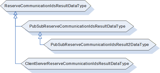
10.43.2 ReserveCommunicationIdsResultDataType definition
The ReserveCommunicationIdsResultDataType, formally defined in Table 212, is an abstract type that has no structure and is expected to be subtyped.
| Attributes | Value | ||
| BrowseName | 2:ReserveCommunicationIdsResultDataType | ||
| IsAbstract | True | ||
| References | Node Class | BrowseName | Description |
|---|---|---|---|
| Subtype of the 0:Structure defined in OPC 10000-5 | |||
| HasSubtype | DataType | 2:PubSubReserveCommunicationIdsResultDataType | Defined in 10.43.3 |
| ConformanceUnits | |||
|---|---|---|---|
| UAFX AutomationComponent Base | |||
| UAFX ConnectionManager Base |
10.43.3 PubSubReserveCommunicationIdsResultDataType
The PubSubReserveCommunicationIdsResultDataType is formally defined in Table 213.
| Name | Type | Description |
|---|---|---|
| PubSubReserveCommunicationIdsResultDataType | Structure | Subtype of the ReserveCommunicationIdsResultDataType |
| Result | 0:StatusCode | Indicates the overall result of reserving the IDs. |
| DefaultPublisherId | 0:BaseDataType | Indicates the default PublisherId of the addressed Server for the requested TransportProfileUri. |
| WriterGroupIds | 0:UInt16[] | Indicates the reserved IDs for WriterGroups for the requested TransportProfileUri. |
| DataSetWriterIds | 0:UInt16[] | Indicates the reserved IDs for DataSetWriters for the requested TransportProfileUri. |
The PubSubReserveCommunicationIdsResultDataType representation in the AddressSpace is formally defined in Table 214.
| Attribute | Value | |||||
| BrowseName | 2:PubSubReserveCommunicationIdsResultDataType | |||||
| IsAbstract | False | |||||
| References | NodeClass | BrowseName | DataType | TypeDefinition | Other | |
|---|---|---|---|---|---|---|
| Subtype of the 2:ReserveCommunicationIdsResultDataType | ||||||
| ConformanceUnits | ||||||
|---|---|---|---|---|---|---|
| UAFX AutomationComponent PubSub Connections | ||||||
| UAFX ConnectionManager PubSubCommunicationFlowConfiguration |
10.43.4 PubSubReserveCommunicationIdsResult2DataType
The PubSubReserveCommunicationIdsResult2DataType is formally defined in Table 215.
| Name | Type | Description |
|---|---|---|
| PubSubReserveCommunicationIdsResult2DataType | Structure | Subtype of the PubSubReserveCommunicationIdsResultDataType. |
| TransportSpecificInfo | 0:BaseDataType | Transport-profile-specific information needed by the ConnectionManager to create a valid PubSubConfiguration for an AutomationComponent. If transport-specific information was requested for UDP-UADP, this field shall contain the UDP port number used by the addressed AutomationComponent for receiving UDP unicast traffic, encoded as UInt16. If transport-specific information was not requested, or if AutomationComponent has no transport-specific info for the given TransportProfileUri, this field shall be set to null. |
The PubSubReserveCommunicationIdsResult2DataType representation in the AddressSpace is formally defined in Table 214.
| Attribute | Value | |||||
| BrowseName | 2:PubSubReserveCommunicationIdsResult2DataType | |||||
| IsAbstract | False | |||||
| References | NodeClass | BrowseName | DataType | TypeDefinition | Other | |
|---|---|---|---|---|---|---|
| Subtype of the 2:PubSubReserveCommunicationIdsResultDataType | ||||||
| ConformanceUnits | ||||||
|---|---|---|---|---|---|---|
| UAFX AutomationComponent PubSub Connections | ||||||
| UAFX ConnectionManager PubSubCommunicationFlowConfiguration |
10.43.5 ClientServerReserveCommunicationIdsResultDataType
This data type will be specified in a later version of this document.
10.44 ReserveCommunicationIdsDataType definition
The ReserveCommunicationIdsDataType is an abstract type that has no structure and is expected to be subtyped. It is formally defined in Table 217.
| Attributes | Value | ||
| BrowseName | 2:ReserveCommunicationIdsDataType | ||
| IsAbstract | True | ||
| References | Node Class | BrowseName | Description |
|---|---|---|---|
| Subtype of the 0:Structure defined in OPC 10000-5 | |||
| HasSubtype | DataType | 2:PubSubReserveCommunicationIdsDataType | Defined in 10.44.1 |
| ConformanceUnits | |||
|---|---|---|---|
| UAFX AutomationComponent Base | |||
| UAFX ConnectionManager Base |
10.44.1 PubSubReserveCommunicationIdsDataType
The PubSubReserveCommunicationIdsDataType is formally defined in Table 218.
| Name | Type | Description |
|---|---|---|
| PubSubReserveCommunicationIdsDataType | Structure | Subtype of ReserveCommunicationIdsDataType |
| TransportProfileUri | 0:String | See OPC 10000-14 for details |
| NumReqWriterGroupIds | 0:UInt16 | Indicates the number of requested node ids for WriterGroups. |
| NumReqDataSetWriterIds | 0:UInt16 | Indicates the number of requested node ids for DataSetWriter. |
The PubSubReserveCommunicationIdsDataType representation in the AddressSpace is formally defined in Table 219.
| Attribute | Value | |||||
| BrowseName | 2:PubSubReserveCommunicationIdsDataType | |||||
| IsAbstract | False | |||||
| References | NodeClass | BrowseName | DataType | TypeDefinition | Other | |
|---|---|---|---|---|---|---|
| Subtype of the 2:ReserveCommunicationIdsDataType | ||||||
| ConformanceUnits | ||||||
|---|---|---|---|---|---|---|
| UAFX AutomationComponent PubSub Connections | ||||||
| UAFX ConnectionManager PubSubCommunicationFlowConfiguration |
10.44.2 PubSubReserveCommunicationIds2DataType
The PubSubReserveCommunicationIds2DataType is formally defined in Table 221.
| Name | Type | Description |
|---|---|---|
| PubSubReserveCommunicationIds2DataType | Structure | Subtype of PubSubReserveCommunicationIdsDataType |
| RequestTransportSpecificInfo | 0:Boolean | Set this to TRUE to request transport profile-specific information from the AutomationComponent. For UDP-UADP, if this is set to TRUE, the AutomationComponent shall return the UDP port number used to receive UDP unicast traffic. |
The PubSubReserveCommunicationIds2DataType representation in the AddressSpace is formally defined in Table 221.
| Attribute | Value | |||||
| BrowseName | 2:PubSubReserveCommunicationIds2DataType | |||||
| IsAbstract | False | |||||
| References | NodeClass | BrowseName | DataType | TypeDefinition | Other | |
|---|---|---|---|---|---|---|
| Subtype of the 2:PubSubReserveCommunicationIdsDataType | ||||||
| ConformanceUnits | ||||||
|---|---|---|---|---|---|---|
| UAFX AutomationComponent Base | ||||||
| UAFX ConnectionManager Base |
10.44.3 ClientServerReserveCommunicationIdsDataType
This data type will be specified in a later version of this document.
10.45 SecurityKeyServerAddressDataType
This structure DataType holds the configuration information for a SecurityKeyServerAddressType Variable (see 9.3).
The SecurityKeyServerAddressDataType is formally defined in Table 222.
| Name | Type | Description |
| SecurityKeyServerAddressDataType | Structure | Subtype of Structure defined in OPC 10000-5 |
| Address | 0:UriString | Specifies the security key server's address as DiscoveryUrl in the form "scheme://hostname[:port][/path]" as defined in OPC 10000-12. |
| SecurityPolicyUri | 0:String | A string that contains the security policy to use when establishing the secure communication. |
| ServerUri | 0:UriString | The ApplicationUri of the SKS |
| UsePushModel | 0:Boolean | If TRUE, use the SKS push model. If FALSE, use the SKS pull model. For the SKS model, see OPC 10000-14. |
The SecurityKeyServerAddressDataType representation in the AddressSpace is formally defined in Table 223.
| Attribute | Value | |||||
| BrowseName | 4:SecurityKeyServerAddressDataType | |||||
| IsAbstract | False | |||||
| References | NodeClass | BrowseName | DataType | TypeDefinition | Other | |
|---|---|---|---|---|---|---|
| Subtype of the 0:Structure defined in OPC 10000-5 | ||||||
| ConformanceUnits | ||||||
|---|---|---|---|---|---|---|
| UAFX ConnectionManager Base |
10.46 ServerAddressDataType
This structure DataType holds the configuration information for a ServerAddressType Variable (see 9.2).
The ServerAddressDataType is formally defined in Table 224.
| Name | Type | Description |
| ServerAddressDataType | Structure | Subtype of Structure defined in OPC 10000-5 |
| Address | 0:UriString | Specifies the server's address as DiscoveryUrl in the form "scheme://hostname[:port][/path]" as defined in OPC 10000-12. |
| SecurityMode | 0:MessageSecurityMode | SecurityMode is the MessageSecurityMode to be used for establishing a secure communication to the Address. |
| SecurityPolicyUri | 0:String | SecurityPolicyUri is a string that contains the security policy to use when establishing the secure communication. |
| ServerUri | 0:UriString | The ApplicationUri of the Server that is being addressed; this URI may be null. |
The ServerAddressDataType representation in the AddressSpace is formally defined in Table 225.
| Attribute | Value | |||||
| BrowseName | 4:ServerAddressDataType | |||||
| IsAbstract | False | |||||
| References | NodeClass | BrowseName | DataType | TypeDefinition | Other | |
|---|---|---|---|---|---|---|
| Subtype of the 0:Structure defined in OPC 10000-5 | ||||||
| ConformanceUnits | ||||||
|---|---|---|---|---|---|---|
| UAFX ConnectionManager Base |
10.47 SocketKindEnum
This enumeration is the default enumeration for the Kind Variable in the SocketType (see 6.3.6). The enumeration is formally defined in Table 226.
| Name | Value | Description |
| RJ45 | 0 | This is an RJ45 connector |
| M12 | 1 | This is an M12 connector |
The SocketKindEnum representation in the AddressSpace is formally defined in Table 227.
| Attribute | Value | |||||
| BrowseName | 3:SocketKindEnum | |||||
| IsAbstract | False | |||||
| References | NodeClass | BrowseName | DataType | TypeDefinition | Other | |
|---|---|---|---|---|---|---|
| Subtype of the 0:Enumeration type defined in OPC 10000-5 | ||||||
| 0:HasProperty | Variable | 0:EnumStrings | 0:LocalizedText[] | 0:PropertyType | ||
| ConformanceUnits | ||||||
|---|---|---|---|---|---|---|
| UAFX AssetConnector Socket Base |
10.48 SubscriberQosDataType
This Structure DataType is used to describe a QoS capability.
The SubscriberQosDataType is formally defined in Table 228.
| Name | Type | Description |
Allow
Subtypes |
| SubscriberQosDataType | Structure | Subtype of Structure defined in OPC 10000-5 | |
QosCategory | 0:String | Describes a QoS category, for example, priority or deadline. For standard QosCategory values, see OPC 10000-14. Note that a null or empty QosCategory indicates that QoS is not configured via PubSubConfiguration. | False |
DatagramQos | 0:ReceiveQosDataType[] | The DatagramQos describes QoS-related parameters. This array shall be null or empty if no QoS-related parameters are needed. For the defined parameters, see OPC 10000-14. The array shall not contain multiple instances of a concrete subtype e.g. transmit PriorityLabel entry. | True |
The SubscriberQosDataType representation in the AddressSpace is formally defined in Table 229.
| Attribute | Value | |||||
| BrowseName | 3:SubscriberQosDataType | |||||
| IsAbstract | False | |||||
| References | NodeClass | BrowseName | DataType | TypeDefinition | Other | |
|---|---|---|---|---|---|---|
| Subtype of the 0:Structure defined in OPC 10000-5 | ||||||
| ConformanceUnits | ||||||
|---|---|---|---|---|---|---|
| UAFX AutomationComponent Base | ||||||
| UAFX FunctionalEntity Base |
11 OPC UA FX ReferenceTypes
11.1 ReferenceTypes overview
In this Information Model, a number of References are defined. These References are illustrated in Figure 61.
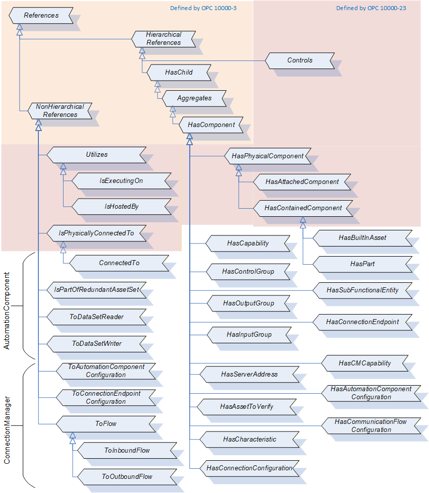
11.2 ConnectedTo ReferenceType
The ConnectedTo ReferenceType is a concrete ReferenceType and can be used directly. It is a subtype of IsPhysicallyConnectedTo ReferenceType.
The semantic of this ReferenceType is to link together Assets. This Reference indicates that the Asset the Reference points to is a part connected to the Asset, which is the starting point of the Reference by means of an electrical cable. Typically, the Assets are at different physical locations, even if the physical location is not a great distance. An example of this Reference is a sensor connected by a cable to an interface module or an electric motor connected to a drive inverter. Another example might be a monitor is ConnectedTo the PC, or the PC is ConnectedTo the Monitor.
The SourceNode of this ReferenceType shall be an instance of AssetConnectorType (or subtypes) or an Asset.
The TargetNode of this ReferenceType shall be an instance of AssetConnectorType (or subtypes) or an Asset.
The ConnectedTo ReferenceType is formally defined in Table 230.
| Attributes | Value | ||
| BrowseName | 3:ConnectedTo | ||
| InverseName | |||
| Symmetric | True | ||
| IsAbstract | False | ||
| References | NodeClass | BrowseName | Comment |
|---|---|---|---|
| Subtype of the 0:IsPhysicallyConnectedTo ReferenceType defined in OPC 10000-23 | |||
| ConformanceUnits | |||
|---|---|---|---|
| UAFX Asset Base |
11.3 DescribedInDescriptor ReferenceType
The DescribedInDescriptor ReferenceType is a concrete ReferenceType and can be used directly. It is a subtype of NonHierarchical ReferenceType.
The semantic of this ReferenceType is to link an Asset or a FunctionalEntity to a Descriptor.
The SourceNode of this ReferenceType shall be an instance of Asset or an Instance of FunctionalEntity.
The TargetNode of this ReferenceType shall be an instance of AcDescriptorType. This referenced Descriptor shall contain information related to the SourceNode.
The DescribedInDescriptor ReferenceType is formally defined in Table 231.
| Attributes | Value | ||
| BrowseName | 3:DescribedInDescriptor | ||
| InverseName | DescriptorDescribes | ||
| Symmetric | False | ||
| IsAbstract | False | ||
| References | NodeClass | BrowseName | Comment |
|---|---|---|---|
| Subtype of the 0:NonHierarchicalReferences defined in OPC 10000-5 | |||
| ConformanceUnits | |||
|---|---|---|---|
| UAFX AutomationComponent Descriptor |
11.4 HasAutomationComponentConfiguration ReferenceType
The HasAutomationComponentConfiguration ReferenceType is a concrete ReferenceType and can be used directly. It is a subtype of HasComponent ReferenceType.
The SourceNode of this ReferenceType shall be a ConnectionConfigurationSet.
The TargetNode of this ReferenceType shall be an instance of AutomationComponentConfigurationType.
The HasAutomationComponentConfiguration ReferenceType is formally defined in Table 232.
| Attributes | Value | ||
| BrowseName | 4:HasAutomationComponentConfiguration | ||
| InverseName | AutomationComponentConfigurationOf | ||
| Symmetric | False | ||
| IsAbstract | False | ||
| References | NodeClass | BrowseName | Comment |
|---|---|---|---|
| Subtype of the 0:HasComponent ReferenceType defined in OPC 10000-5 | |||
| ConformanceUnits | |||
|---|---|---|---|
| UAFX ConnectionManager Base |
11.5 HasBuiltInAsset ReferenceType
The HasBuiltInAsset ReferenceType is a concrete ReferenceType and can be used directly. It is a subtype of HasContainedComponent ReferenceType.
The semantic of this ReferenceType is to link together Assets. It indicates that the Asset the Reference points to is an integral part of the Asset, which is the starting point of the Reference. Asset information is provided for spare part handling of Assets that are related to the source Assets. HasBuiltInAsset also means that the Target cannot be extracted from the source by the user. For example, in a controller, the processor chip can be identified as a HasBuiltInAsset of the controller. It cannot be purchased separately, but the processor chip information is needed for maintenance.
The SourceNode of References of this type shall be an Asset.
The TargetNode of this ReferenceType shall be an Asset.
The HasBuiltInAsset ReferenceType is formally defined in Table 233.
| Attributes | Value | ||
| BrowseName | 3:HasBuiltInAsset | ||
| InverseName | BuiltInAssetOf | ||
| Symmetric | False | ||
| IsAbstract | False | ||
| References | NodeClass | BrowseName | Comment |
|---|---|---|---|
| Subtype of the 0:HasContainedComponent ReferenceType defined in OPC 10000-23 | |||
| ConformanceUnits | |||
|---|---|---|---|
| UAFX Asset Base |
11.6 HasAssetToVerify ReferenceType
The HasAssetToVerify ReferenceType is a concrete ReferenceType and can be used directly. It is a subtype of HasComponent ReferenceType.
The SourceNode of this ReferenceType shall be an instance of AutomationComponentConfigurationType.
The TargetNode of this ReferenceType shall be an instance of AssetVerificationType.
The HasAssetToVerify ReferenceType is formally defined in Table 234.
| Attributes | Value | ||
| BrowseName | 4:HasAssetToVerify | ||
| InverseName | AssetToVerifyOf | ||
| Symmetric | False | ||
| IsAbstract | False | ||
| References | NodeClass | BrowseName | Comment |
|---|---|---|---|
| Subtype of the 0:HasComponent ReferenceType defined in OPC 10000-5 | |||
| ConformanceUnits | |||
|---|---|---|---|
| UAFX ConnectionManager Base |
11.7 HasCapability ReferenceType
The HasCapability ReferenceType is a concrete ReferenceType and can be used directly. It is a subtype of HasComponent ReferenceType.
The SourceNode of this ReferenceType shall be an instance of AutomationComponentCapabilitiesType.
The TargetNode of this ReferenceType shall be an instance of BaseDataVariableType or a subtype of it.
The HasCapability ReferenceType is formally defined in Table 235.
| Attributes | Value | ||
| BrowseName | 3:HasCapability | ||
| InverseName | CapabilityOf | ||
| Symmetric | False | ||
| IsAbstract | False | ||
| References | NodeClass | BrowseName | Comment |
|---|---|---|---|
| Subtype of the 0:HasComponent ReferenceType defined in OPC 10000-5 | |||
| ConformanceUnits | |||
|---|---|---|---|
| UAFX AutomationComponent Base |
11.8 HasCharacteristic ReferenceType
The HasCharacteristic ReferenceType is a concrete ReferenceType and can be used directly. It is a subtype of HasComponent ReferenceType.
The SourceNode of this ReferenceType shall be an instance of AutomationComponentConfigurationType.
The TargetNode of this ReferenceType shall be an instance of BaseDataVariableType or a subtype of it.
The HasCharacteristic ReferenceType is formally defined in Table 236.
| Attributes | Value | ||
| BrowseName | 4:HasCharacteristic | ||
| InverseName | CharacteristicOf | ||
| Symmetric | False | ||
| IsAbstract | False | ||
| References | NodeClass | BrowseName | Comment |
|---|---|---|---|
| Subtype of the 0:HasComponent ReferenceType defined in OPC 10000-5 | |||
| ConformanceUnits | |||
|---|---|---|---|
| UAFX ConnectionManager Base |
11.9 HasCMCapability ReferenceType
The HasCMCapability ReferenceType is a concrete ReferenceType and can be used directly. It is a subtype of HasComponent ReferenceType.
The SourceNode of this ReferenceType shall be an instance of ConnectionManagerCapabilitiesType.
The TargetNode of this ReferenceType shall be an instance of BaseDataVariableType or a subtype of it.
The HasCMCapability ReferenceType is formally defined in Table 237.
| Attributes | Value | ||
| BrowseName | 4:HasCMCapability | ||
| InverseName | CMCapabilityOf | ||
| Symmetric | False | ||
| IsAbstract | False | ||
| References | NodeClass | BrowseName | Comment |
|---|---|---|---|
| Subtype of the 0:HasComponent ReferenceType defined in OPC 10000-5 | |||
| ConformanceUnits | |||
|---|---|---|---|
| UAFX ConnectionManager Base |
11.10 HasCommunicationFlowConfiguration ReferenceType
The HasCommunicationFlowConfiguration ReferenceType is a concrete ReferenceType and can be used directly. It is a subtype of HasComponent ReferenceType.
The SourceNode of this ReferenceType shall be a ConnectionConfigurationSet.
The TargetNode of this ReferenceType shall be an instance of CommunicationFlowConfigurationType or a subtype of it.
The HasCommunicationFlowConfiguration ReferenceType is formally defined in Table 238.
| Attributes | Value | ||
| BrowseName | 4:HasCommunicationFlowConfiguration | ||
| InverseName | CommunicationFlowConfigurationOf | ||
| Symmetric | False | ||
| IsAbstract | False | ||
| References | NodeClass | BrowseName | Comment |
|---|---|---|---|
| Subtype of the 0:HasComponent ReferenceType defined in OPC 10000-5 | |||
| ConformanceUnits | |||
|---|---|---|---|
| UAFX ConnectionManager Base |
11.11 HasConnectionConfiguration ReferenceType
The HasConnectionConfiguration ReferenceType is a concrete ReferenceType and can be used directly. It is a subtype of HasComponent ReferenceType.
The SourceNode of this ReferenceType shall be a ConnectionConfigurationSet.
The TargetNode of this ReferenceType shall be an instance of ConnectionConfigurationType or a subtype of it.
The HasConnectionConfiguration ReferenceType is formally defined in Table 239.
| Attributes | Value | ||
| BrowseName | 4:HasConnectionConfiguration | ||
| InverseName | ConnectionConfigurationOf | ||
| Symmetric | False | ||
| IsAbstract | False | ||
| References | NodeClass | BrowseName | Comment |
|---|---|---|---|
| Subtype of the 0:HasComponent ReferenceType defined in OPC 10000-5 | |||
| ConformanceUnits | |||
|---|---|---|---|
| UAFX ConnectionManager Base |
11.12 HasConnectionEndpoint ReferenceType
The HasConnectionEndpoint ReferenceType is a concrete ReferenceType and can be used directly. It is a subtype of HasComponent ReferenceType.
The SourceNode of this ReferenceType shall be an instance of ConnectionEndpointsFolderType.
The TargetNode of this ReferenceType shall be an instance of ConnectionEndpointType.
The HasConnectionEndpoint ReferenceType is formally defined in Table 240.
| Attributes | Value | ||
| BrowseName | 3:HasConnectionEndpoint | ||
| InverseName | ConnectionEndpointOf | ||
| Symmetric | False | ||
| IsAbstract | False | ||
| References | NodeClass | BrowseName | Comment |
|---|---|---|---|
| Subtype of the 0:HasComponent ReferenceType defined in OPC 10000-5 | |||
| ConformanceUnits | |||
|---|---|---|---|
| UAFX FunctionalEntity Base |
11.13 HasControlGroup ReferenceType
The HasControlGroup ReferenceType is a concrete ReferenceType and can be used directly. It is a subtype of HasComponent ReferenceType.
The SourceNode of this ReferenceType shall be a FunctionalEntity.
The TargetNode of this ReferenceType shall be an instance of ControlGroupType.
The HasControlGroup ReferenceType is formally defined in Table 241.
| Attributes | Value | ||
| BrowseName | 3:HasControlGroup | ||
| InverseName | ControlGroupOf | ||
| Symmetric | False | ||
| IsAbstract | False | ||
| References | NodeClass | BrowseName | Comment |
|---|---|---|---|
| Subtype of the 0:HasComponent ReferenceType defined in OPC 10000-5 | |||
| ConformanceUnits | |||
|---|---|---|---|
| UAFX FunctionalEntity Base |
11.14 HasInputGroup ReferenceType
The HasInputGroup ReferenceType is a concrete ReferenceType and can be used directly. It is a subtype of HasComponent ReferenceType. It provides for the nesting of InputGroups.
The SourceNode of this ReferenceType shall be an instance of InputsFolderType.
The TargetNode of this ReferenceType shall be an instance of InputsFolderType.
The HasInputGroup ReferenceType is formally defined in Table 242.
| Attributes | Value | ||
| BrowseName | 3:HasInputGroup | ||
| InverseName | InputGroupOf | ||
| Symmetric | False | ||
| IsAbstract | False | ||
| References | NodeClass | BrowseName | Comment |
|---|---|---|---|
| Subtype of the 0:HasComponent ReferenceType defined in OPC 10000-5 | |||
| ConformanceUnits | |||
|---|---|---|---|
| UAFX FunctionalEntity Base |
11.15 HasOutputGroup ReferenceType
The HasOutputGroup ReferenceType is a concrete ReferenceType and can be used directly. It is a subtype of HasComponent ReferenceType. It provides for the nesting of OutputGroups.
The SourceNode of this ReferenceType shall be an instance of OutputsFolderType.
The TargetNode of this ReferenceType shall be an instance of OutputsFolderType.
The HasOutputGroup ReferenceType is formally defined in Table 243.
| Attributes | Value | ||
| BrowseName | 3:HasOutputGroup | ||
| InverseName | OutputGroupOf | ||
| Symmetric | False | ||
| IsAbstract | False | ||
| References | NodeClass | BrowseName | Comment |
|---|---|---|---|
| Subtype of the 0:HasComponent ReferenceType defined in OPC 10000-5 | |||
| ConformanceUnits | |||
|---|---|---|---|
| UAFX FunctionalEntity Base |
11.16 HasPart ReferenceType
The HasPart ReferenceType is a concrete ReferenceType and can be used directly. It is a subtype of HasContainedComponent ReferenceType.
The semantic of this ReferenceType is to link together FxAssetType instances. This Reference indicates that the Asset the Reference points to is a removable part inside the Asset. This implies that the part is not visible from the outside of the Asset. To gain access to the Asset, removing a component of the Asset (e.g., a hatch) is typically necessary. Also, it implies that both Assets have the same physical location and, therefore, the same Asset location information. An example of this Reference is a PCI board plugged inside a PC. The PCI board is located inside the PC and is accessible after removing the PC housing.
The SourceNode of this ReferenceType shall be an Asset.
The TargetNode of this ReferenceType shall be an Asset.
The HasPart ReferenceType is formally defined in Table 244.
| Attributes | Value | ||
| BrowseName | 3:HasPart | ||
| InverseName | PartOf | ||
| Symmetric | False | ||
| IsAbstract | False | ||
| References | NodeClass | BrowseName | Comment |
|---|---|---|---|
| Subtype of the 0:HasContainedComponent ReferenceType defined in OPC 10000-23 | |||
| ConformanceUnits | |||
|---|---|---|---|
| UAFX Asset Base |
11.17 HasServerAddress ReferenceType
The HasServerAddress ReferenceType is a concrete ReferenceType and can be used directly. It is a subtype of HasComponent ReferenceType.
The SourceNode of this ReferenceType shall be a ConnectionConfigurationSet.
The TargetNode of this ReferenceType shall be an instance of ServerAddressType or a subtype of it.
The HasServerAddress ReferenceType is formally defined in Table 245.
| Attributes | Value | ||
| BrowseName | 4:HasServerAddress | ||
| InverseName | ServerAddressOf | ||
| Symmetric | False | ||
| IsAbstract | False | ||
| References | NodeClass | BrowseName | Comment |
|---|---|---|---|
| Subtype of the 0:HasComponent ReferenceType defined in OPC 10000-5 | |||
| ConformanceUnits | |||
|---|---|---|---|
| UAFX ConnectionManager Base |
11.18 HasSubFunctionalEntity ReferenceType
The HasSubFunctionalEntity ReferenceType is a concrete ReferenceType and can be used directly. It is a subtype of HasComponent ReferenceType.
The SourceNode of this ReferenceType shall be an instance of FunctionalEntityType or a subtype of it.
The TargetNode of this ReferenceType shall be an instance of FunctionalEntityType or a subtype of it.
The HasSubFunctionalEntity ReferenceType is formally defined in Table 246.
| Attributes | Value | ||
| BrowseName | 3:HasSubFunctionalEntity | ||
| InverseName | SubFunctionalEntityOf | ||
| Symmetric | False | ||
| IsAbstract | False | ||
| References | NodeClass | BrowseName | Comment |
|---|---|---|---|
| Subtype of the 0:HasComponent ReferenceType defined in OPC 10000-5 | |||
| ConformanceUnits | |||
|---|---|---|---|
| UAFX FunctionalEntity Base |
11.19 IsPartOfRedundantAssetSet ReferenceType
The IsPartOfRedundantAssetSet ReferenceType is a concrete ReferenceType and can be used directly. It is a symmetric Reference and is a subtype of NonHierarchicalReferences ReferenceType.
The semantic of this ReferenceType is to link Assets that are redundant. An Asset may have multiple IsPartOfRedundantAssetSet References. This Reference provides no additional information related to redundancy; it only indicates Assets that are part of a redundant set. It is illustrated in Figure 62.
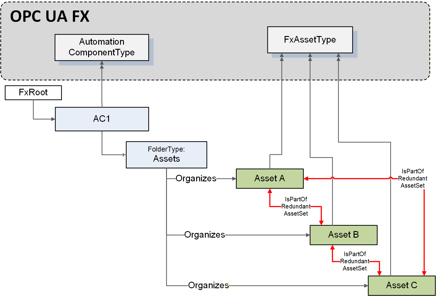
The SourceNode of this ReferenceType shall be an Asset.
The TargetNode of this ReferenceType shall be an Asset.
The IsPartOfRedundantAssetSet ReferenceType is formally defined in Table 247.
| Attributes | Value | ||
| BrowseName | 3:IsPartOfRedundantAssetSet | ||
| InverseName | |||
| Symmetric | True | ||
| IsAbstract | False | ||
| References | NodeClass | BrowseName | Comment |
|---|---|---|---|
| Subtype of the 0:NonHierarchicalReferences ReferenceType defined in OPC 10000-5 | |||
| ConformanceUnits | |||
|---|---|---|---|
| UAFX Asset Base |
11.20 ToAutomationComponentConfiguration ReferenceType
The ToAutomationComponentConfiguration ReferenceType is a concrete ReferenceType and can be used directly. It is a subtype of NonHierarchicalReferences ReferenceType.
The SourceNode of this ReferenceType shall be an instance of ServerAddressType.
The TargetNode of this ReferenceType shall be an instance of AutomationComponentConfigurationType.
The ToAutomationComponentConfiguration ReferenceType is formally defined in Table 248.
| Attributes | Value | ||
| BrowseName | 4:ToAutomationComponentConfiguration | ||
| InverseName | FromAutomationComponentConfiguration | ||
| Symmetric | False | ||
| IsAbstract | False | ||
| References | NodeClass | BrowseName | Comment |
|---|---|---|---|
| Subtype of the 0:NonHierarchicalReferences ReferenceType defined in OPC 10000-5 | |||
| ConformanceUnits | |||
|---|---|---|---|
| UAFX ConnectionManager Base |
11.21 ToConnectionEndpointConfiguration ReferenceType
The ToConnectionEndpointConfiguration ReferenceType is a concrete ReferenceType and can be used directly. It is a subtype of NonHierarchicalReferences ReferenceType.
The SourceNode of References of this type shall be an instance of AutomationComponentConfigurationType.
The TargetNode of this ReferenceType shall be an instance of ConnectionEndpointConfigurationType.
The ToConnectionEndpointConfiguration ReferenceType is formally defined in Table 249.
| Attributes | Value | ||
| BrowseName | 4:ToConnectionEndpointConfiguration | ||
| InverseName | FromConnectionEndpointConfiguration | ||
| Symmetric | False | ||
| IsAbstract | False | ||
| References | NodeClass | BrowseName | Comment |
|---|---|---|---|
| Subtype of the 0:NonHierarchicalReferences ReferenceType defined in OPC 10000-5 | |||
| ConformanceUnits | |||
|---|---|---|---|
| UAFX ConnectionManager Base |
11.22 ToDataSetReader ReferenceType
The ToDataSetReader ReferenceType is a concrete ReferenceType and can be used directly. It is a subtype of NonHierarchicalReferences ReferenceType.
The SourceNode of References of this type shall be an instance of PubSubConnectionEndpointType or a subtype of it.
The TargetNode of this ReferenceType shall be an instance of DataSetReaderType (see OPC 10000-14).
The ToDataSetReader ReferenceType is formally defined in Table 250.
| Attributes | Value | ||
| BrowseName | 3:ToDataSetReader | ||
| InverseName | FromDataSetReader | ||
| Symmetric | False | ||
| IsAbstract | False | ||
| References | NodeClass | BrowseName | Comment |
|---|---|---|---|
| Subtype of the 0:NonHierarchicalReferences ReferenceType defined in OPC 10000-5 | |||
| ConformanceUnits | |||
|---|---|---|---|
| UAFX ConnectionEndpoint PubSub |
11.23 ToDataSetWriter ReferenceType
The ToDataSetWriter ReferenceType is a concrete ReferenceType and can be used directly. It is a subtype of NonHierarchicalReferences ReferenceType.
The SourceNode of References of this type shall be an instance of PubSubConnectionEndpointType or a subtype of it.
The TargetNode of this ReferenceType shall be an instance of DataSetWriterType (see OPC 10000-14).
The ToDataSetWriter ReferenceType is formally defined in Table 251.
| Attributes | Value | ||
| BrowseName | 3:ToDataSetWriter | ||
| InverseName | FromDataSetWriter | ||
| Symmetric | False | ||
| IsAbstract | False | ||
| References | NodeClass | BrowseName | Comment |
|---|---|---|---|
| Subtype of the 0:NonHierarchicalReferences ReferenceType defined in OPC 10000-5 | |||
| ConformanceUnits | |||
|---|---|---|---|
| UAFX ConnectionEndpoint PubSub |
11.24 ToFlow ReferenceType
The ToFlow ReferenceType is a concrete ReferenceType. It is a subtype of NonHierarchicalReferences ReferenceType.
The SourceNode of this ReferenceType shall be an instance of ConnectionEndpointConfigurationType or a subtype of it.
The TargetNode of this ReferenceType shall be an instance of CommunicationFlowConfigurationType or a subtype of it.
The ToFlow ReferenceType is formally defined in Table 252.
| Attributes | Value | ||
| BrowseName | 4:ToFlow | ||
| InverseName | FromFlow | ||
| Symmetric | False | ||
| IsAbstract | False | ||
| References | NodeClass | BrowseName | Comment |
|---|---|---|---|
| Subtype of the 0:NonHierarchicalReferences ReferenceType defined in OPC 10000-5 | |||
| ConformanceUnits | |||
|---|---|---|---|
| UAFX ConnectionManager Base |
11.25 ToInboundFlow ReferenceType
The ToInboundFlow ReferenceType is a concrete ReferenceType. It is a subtype of ToFlow ReferenceType.
The SourceNode of this ReferenceType shall be an instance of ConnectionEndpointConfigurationType or a subtype of it.
The TargetNode of this ReferenceType shall be an instance of SubscriberConfigurationType or a subtype of it.
The ToInboundFlow ReferenceType is formally defined in Table 253.
| Attributes | Value | ||
| BrowseName | 4:ToInboundFlow | ||
| InverseName | FromInboundFlow | ||
| Symmetric | False | ||
| IsAbstract | False | ||
| References | NodeClass | BrowseName | Comment |
|---|---|---|---|
| Subtype of the 4:ToFlow ReferenceType defined in 11.24 | |||
| ConformanceUnits | |||
|---|---|---|---|
| UAFX ConnectionManager Base |
11.26 ToOutboundFlow ReferenceType
The ToOutboundFlow ReferenceType is a concrete ReferenceType. It is a subtype of ToFlow ReferenceType.
The SourceNode of this ReferenceType shall be an instance of ConnectionEndpointConfigurationType or a subtype of it.
The TargetNode of this ReferenceType shall be an instance of PubSubCommunicationFlowConfigurationType or a subtype of it.
The ToOutboundFlow ReferenceType is formally defined in Table 254.
| Attributes | Value | ||
| BrowseName | 4:ToOutboundFlow | ||
| InverseName | FromOutboundFlow | ||
| Symmetric | False | ||
| IsAbstract | False | ||
| References | NodeClass | BrowseName | Comment |
|---|---|---|---|
| Subtype of the 4:ToFlow ReferenceType defined in 11.24 | |||
| ConformanceUnits | |||
|---|---|---|---|
| UAFX ConnectionManager Base |
12 OPC UA FX Instances
12.1 Overview
The OPC UA FX Information Model defines well-known instances (see Table 255 and Table 256) that are used to group OPC UA FX Object instances. OPC UA FX Object instances may also exist in other Folders or in other groupings. Figure 63 provides an overview of these instances.
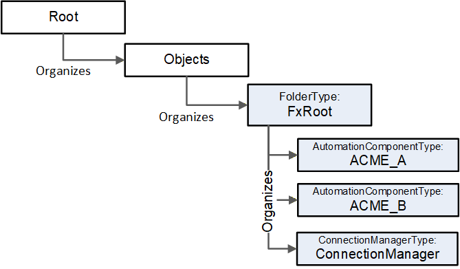
12.2 FxRoot
The following instance shall exist in all Servers that expose an OPC UA FX Information Model. It is formally defined in Table 255.
| Attribute | Value | |||
| BrowseName | 2:FxRoot | |||
| References | NodeClass | BrowseName | DataType | TypeDefinition |
|---|---|---|---|---|
| Organized by the Objects Folder defined in OPC UA Part 5 | ||||
| HasTypeDefinition | ObjectType | 0:FolderType | ||
| ConformanceUnits | ||||
|---|---|---|---|---|
| UAFX FxRoot |
The FxRoot is the standard entry point for all instances related to OPC UA FX. It may contain multiple AutomationComponents that include Assets and FunctionalEntities. It may also contain, at most, one ConnectionManager.
12.3 ConnectionManager
The following instance shall exist in all Servers that expose a ConnectionManager. It is formally defined in Table 256
| Attribute | Value | |||
| BrowseName | 4:ConnectionManager | |||
| References | NodeClass | BrowseName | DataType | TypeDefinition |
|---|---|---|---|---|
| Organized by the FxRoot defined in 12.2 | ||||
| HasTypeDefinition | ObjectType | 4:ConnectionManagerType | ||
| ConformanceUnits | ||||
|---|---|---|---|---|
| UAFX ConnectionManager Base |
The ConnectionManager is the well-known object that represents a ConnectionManager. A Server that supports a ConnectionManager will always have only one instance of this Node.
13 Client functionality for ConnectionManager
13.1 Overview
OPC UA FX requires more than just a Server with an OPC UA FX Information Model. All devices that implement the ConnectionManager are required to support Client functionality. This clause will describe the requirements for this Client functionality. Some additional key points related to establishing a connection are:
The Connection and security information may have changed since the engineering tool generated configuration information (ConnectionConfigurationSets).
The ConnectionManager may be local on one of the devices, i.e., on the same device that has one end of a logical connection.
The configuration might contain Nodes in any of the following formats: PortableNodeId, PortableRelativePath or AliasName, each of which has components that might have changed since they were generated by the engineering tool.
System in which OPC UA FX is deployed may contain Global Services (GDS) that a ConnectionManager may be required to interact with.
During the establishment of a logical connection (Connection), the ConnectionManager needs to locate the FunctionalEntities and the Servers on which they reside. The ConnectionConfigurationSets contain the information from which this location can be derived.
The ConnectionManager shall behave as a standard Client, including the ability to recover an interrupted Session if a Session is being used. A ConnectionManager may also use Session-less Service invocations in certain cases. The ConnectionManager is required to be able to issue Method Calls and also resolve Node information. Resolving Node information may require using View Services (Browse, TranslateBrowsePathsToNodeIds) and Attribute Services (Read). The details related to an application's configuration are provided in a Descriptor, but the engineering tool associated with a ConnectionManager may not be able to resolve Node information beyond what is in the Descriptor, which results in a ConnectionManager requiring support for all of the Node resolution options.
13.2 Connecting to a Server
13.2.1 Locating Server via GDS
If a GDS address (GlobalDiscoveryServers) is defined (see 6.7.2), the GDS is queried to find the Server. If an array of GDS addresses is provided each GDS in the list is tried until the Server is located. If the Server is not found, an error could be reported or the server could be contacted directly.
The Server is located following the standard procedure as defined in OPC 10000-12, i.e., QueryApplications, GetEndpoints, OpenSecureChannel, CreateSession and ActivateSession on the Server Address with the specified SecurityMode (see 9.2.2 for the description of the provided Server information).
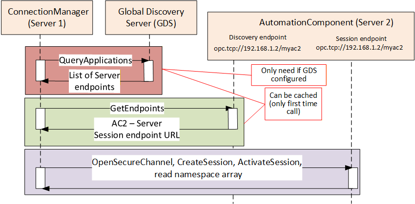
If the Server is the same Server that the ConnectionManager resides on, the EstablishConnections Method may be invoked by vendor-specific means, and all portable node identifiers can be resolved locally.
The Session established by the ConnectionManager shall support the use of authentication and/or encryption. This includes:
Application Authentication based on security mode and policy
The use of Roles (this may require user authentication or specific ApplicationInstance certificates)
If SecurityPolicyUri contains an empty or null string, the EndpointDescription on the Server with the highest SecurityLevel of the ones supported by the ConnectionManager and matching the requested SecurityMode (see 9.2.2) shall be chosen. If it is not an empty or null string, the EndpointDescription matching the requested SecurityMode and SecurityPolicyUri (see 9.2.2) shall be chosen. The complete process, including NodeId resolution, is illustrated in Figure 64.
13.2.2 Connecting to Server via LDS
All devices expose a LocalDiscoveryServer (FindServersOnNetwork) or the Server directly exposes the Discovery Services (FindServers). The Server is located following the standard procedure as defined in OPC 10000-4, (i.e. using FindServers, GetEndpoints, OpenSecureChannel, CreateSession and ActivateSession) on the Server Address with the specified SecurityMode (see 9.2.2 for the description of the provided Server information).
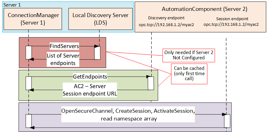
If the Server is the same Server that the ConnectionManager resides on, the EstablishConnections Method may be invoked by vendor-specific means, and all portable node identifiers can be resolved locally.
The Session established by the ConnectionManager shall support the use of authentication and/or encryption. This includes:
Application authentication based on security mode and policy.
The use of Roles (this may require user authentication or specific ApplicationInstance certificates)
If SecurityPolicyUri contains empty or null string, the EndpointDescription on the Server with the highest SecurityLevel of the ones supported by the ConnectionManager and matching the requested SecurityMode (see 9.2.2) shall be chosen. If not empty of null string, the EndpointDescription matching the requested SecurityMode and SecurityPolicyUri (see 9.2.2) shall be chosen. The complete process, including NodeId resolution, is illustrated in Figure 65.
13.2.3 Session-less Client connection
The Server can also be accessed via a Session-less Service invocation (illustrated in Figure 66). Session-less Service invocations still access the Server with security but create a one-time connection. This type of connection can only be used by ConnectionManager exchanges that do not require a saved state across multiple invocations. For example, it cannot be used for a ReserveCommunicationIdsCmd since the communication IDs are released when the Session ends.
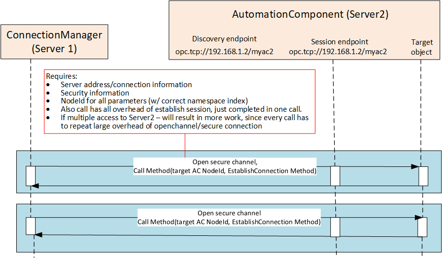
13.3 Locating Nodes
13.3.1 General
The Method Calls to establish a Connection require information from the ConnectionConfigurationSets and their components. That information may be represented as PortableNodeId, PortableRelativePath or AliasName. These all need to be resolved to NodeIds (illustrated in Figure 67 and described in Subclause 13.3.2, 13.3.3, and 13.3.4). This subclause contains figures and text that provide examples to help explain these concepts.
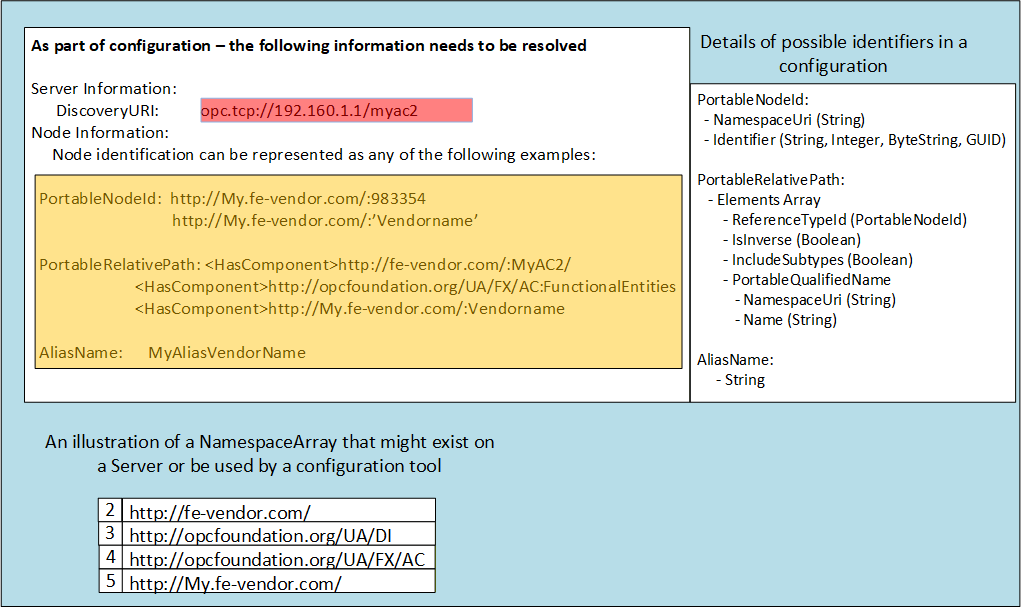
A ConnectionManager shall be able to resolve NodeIds using PortableNodeIds, PortableRelativePaths or AliasNames. The following provides an illustration of what needs to be done for each possible Node description in the ConnectionConfigurationSet. It is recommended that the ConnectionManager caches the results of these operations and that they are only performed on the initial start-up of the ConnectionManager or when a new configuration is provided to the ConnectionManager. This operation can also be repeated if changes in the model in a connected Server are detected or if an error occurs.
13.3.2 PortableNodeId provided
If the ConnectionConfigurationSets contain PortableNodeIds, then the ConnectionManager should perform the following steps (Figure 68 provides an overview of the configuration and actions):
Resolve the location of the Server and connect to it. This process is required for several of the node configuration options and is described in its own subclause (see 13.2).
Convert the PortableNodeIds into NodeIds. This is accomplished by connecting to the Server, reading the NamespaceArray from the Server, and matching all NamespaceUri from the NamespaceArray to the URI's store in the PortableNodeId and storing the Index of the URI in the table as the cached NodeId.
The cache shall also include the NamespaceArray of the target Server. This array can be checked before establishing a Connection to ensure it has not changed.
Repeat for all Servers.
When resolving NamespaceUri, if a null or empty NamespaceUri is encountered, the Server shall assume that it is a reference to NamespaceArray index 1. NamespaceArray index 1 is the local Server namespace, and the URI corresponding to the Server might not be known at configuration time. For additional details on Namespaces, see OPC 10000-3.
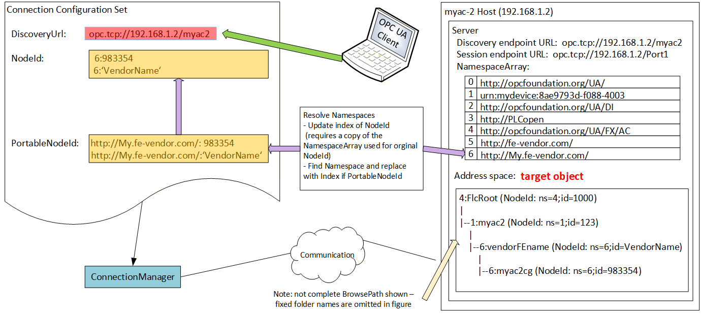
The process is illustrated in the sequence diagram shown in Figure 69.
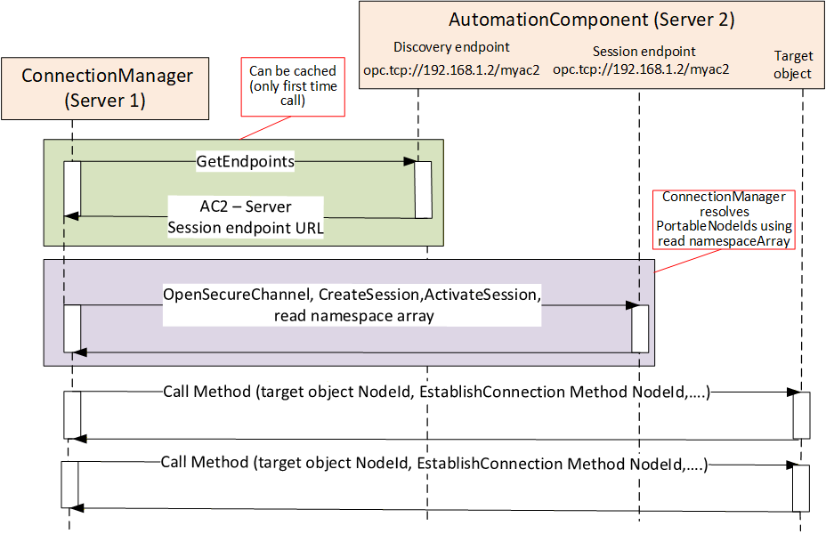
13.3.3 PortableRelativePath provided
If the ConnectionConfigurationSet contains PortableRelativePaths, then the Client should perform the following steps (Figure 70 provides an overview of the configuration and actions):
Resolve the location of the Server and connect to it. This process is required for several of the node configuration options and is described in its own subclause (see 13.2).
Convert PortableRelativePaths to BrowsePaths. This is accomplished by connecting to the Server, reading the NamespaceArray from the Server, and matching all NamespaceUri from the NamespaceArray to the URI's store in the PortableRelativePaths. PortableRelativePathElements and storing the Index of the URI in the table in the temporary BrowsePath. This will convert the PortableRelativePath to a BrowsePath.
Call the TranslateBrowsePathsToNodeIds Service with all of the BrowsePaths that are to be converted to NodeIds. Cache the resulting list of NodeIds.
The cache shall also include the NamespaceArray of the target Server. This array can be checked before establishing a Connection to ensure it has not changed. Additionally, the NamespaceMetadata (NamespacePublicationDate) shall be cached. This data can be used to check if the namespace has been updated. If the Namespace has been updated, the process for resolving BrowsePaths shall be repeated.
Repeat for all Servers.
When resolving NamespaceUri, if a null or empty NamespaceUri is encountered, the Server shall assume that it is a reference to NamespaceArray index 1. NamespaceArray index 1 is the local Server namespace, and the URI corresponding to the Server might not be known at configuration time. For additional details on Namespaces, see OPC 10000-3.
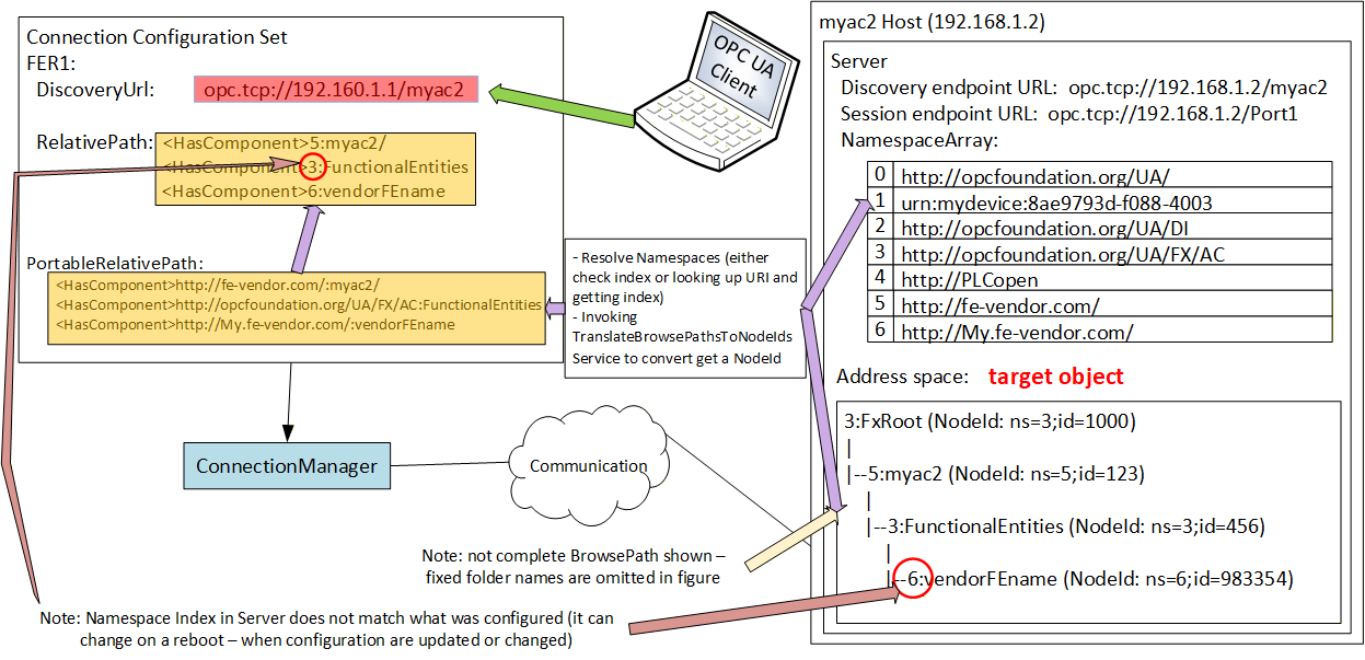
The process is illustrated in the sequence diagram shown in Figure 71.
The resolution of BrowsePaths to NodeIds can result in multiple NodesIds for a single BrowsePath. Configurations should try to produce unique BrowsePaths (see 6.4.4, 6.4.5 and 6.4.6 for recommendations). Clients shall be able to handle this condition by reporting an error.
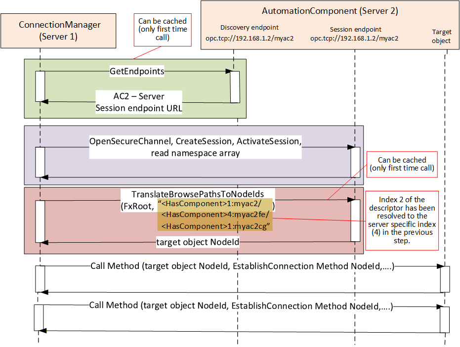
13.3.4 AliasName provided
If the ConnectionConfigurationSet contains AliasNames (Figure 72 provides an overview of the configuration), then the Client should perform the following steps:
Connect to the well-known GDS (or aggregating Server) that supports AliasNames. This is typically preconfigured in all Servers since the GDS also provides other functionality, such as certificate management or discovery. See 6.7.2 for additional information. If a GDS is not configured the configured Server can also be queried for AliasNames.
Call FindAlias with the provided AliasName(s), which will return the target Server and the NodeId.
A single Call to the GDS or AliasName Server can resolve all AliasNames in all records in the ConnectionConfigurationSet. The returned list of Servers (Connection information) and NodeIds should be cached.
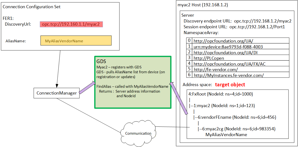
If an AliasName was used to obtain the Server information, the connection process might be slightly different (illustrated in Figure 73). The AliasName Server provides the information required to connect to the Server. Once connected, the EstablishConnections Call may be issued without any additional resolution step, assuming all Nodes were defined using AliasNames and resolved on an initial step.
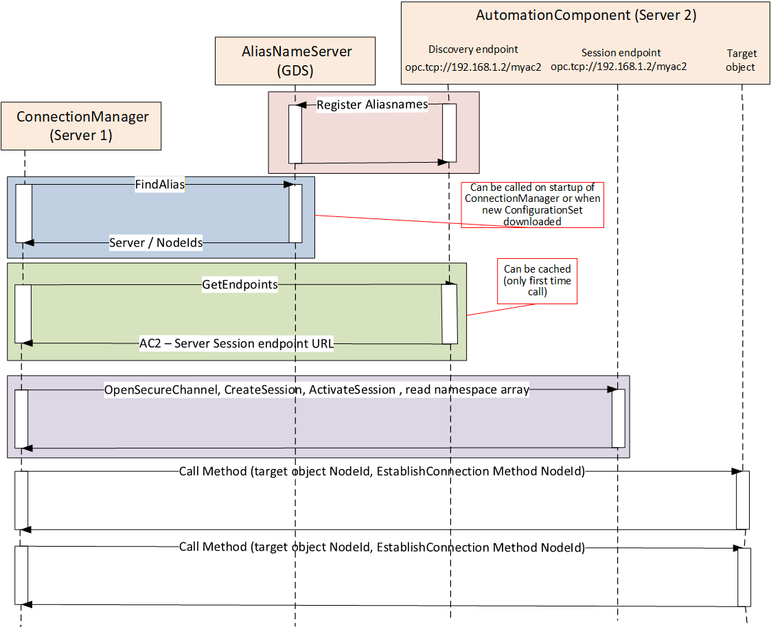
13.4 ConnectionManager and Security Key Server (SKS)
If a logical connection is configured to use secure PubSub communication, then a Security Key Server is required. An SKS is described in detail in OPC 10000-14. The SKS may be located on any Server in the network, including the Server where the ConnectionManager is located. A ConnectionManager shall be able to communicate with the designated SKS in all cases which require Client connections to a remotely located SKS Server. The SKS process is illustrated in Figure 74.
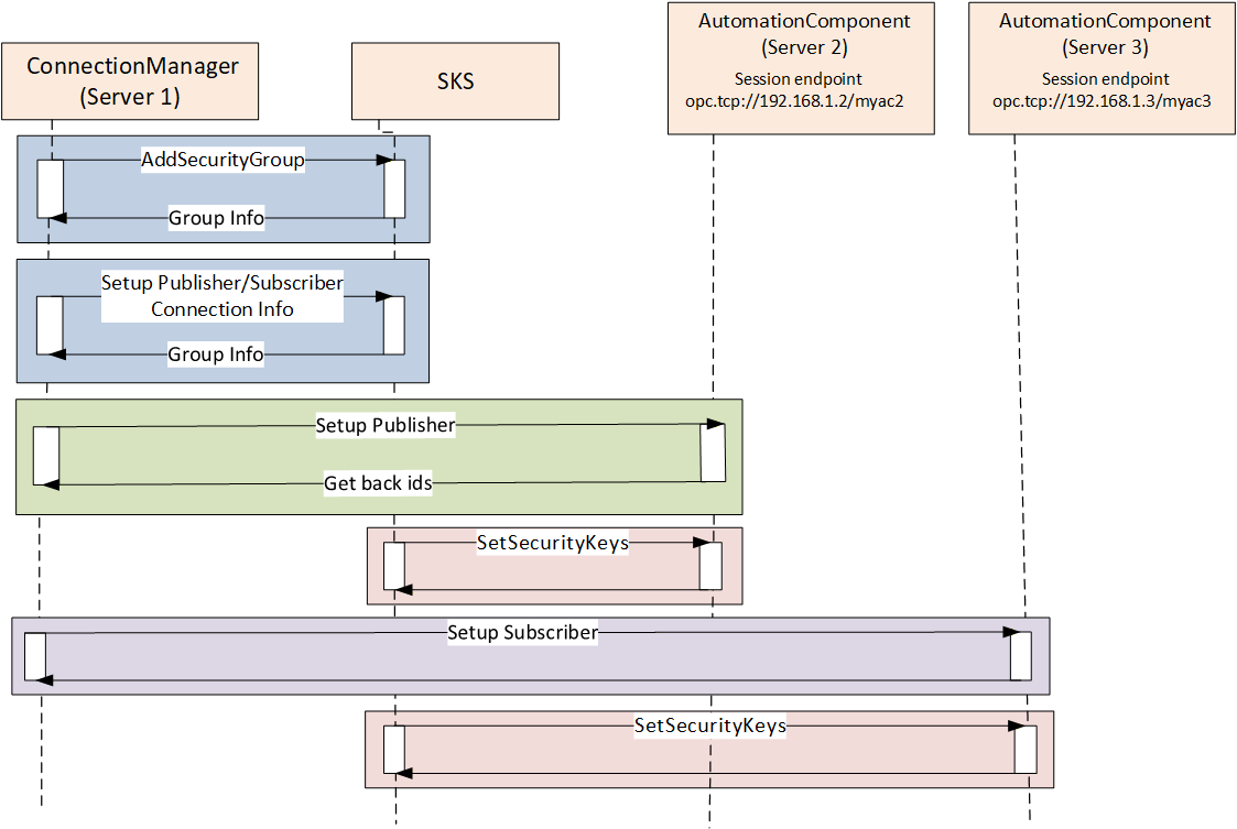
The ConnectionManager shall be able to configure the SKS for push distribution of security keys.
13.5 ConnectionManager error reporting
The ConnectionManager tracks errors for each ConnectionConfigurationSet by completing the ConnectionsDiagnostics array (see 10.19). These errors include any errors that result from the run time processing of the ConnectionConfigurationSet as described in this subclause, such as finding or connecting to a Server, resolving Node Information by AliasName lookup or TranslateBrowsePathToNodeId, or even for Namespace lookup issues. The ConnectionManager also report errors from interactions with an SKS (local or remote). The ConnectionManager reports errors related to interactions with AutomationComponents. This includes any errors that are reported to the ConnectionManager from invoking the EstablishConnections Method or the CloseConnections Method.
14 Namespaces
14.1 Namespace metadata
Table 257, Table 258 and Table 259 define the namespace metadata for this document. Table 257 defines DataTypes that are shared between the AutomationComponent and the ConnectionManager. Table 258 defines the namespace associated with an AutomationComponent. Table 259 defines the namespace associated with a ConnectionManager. The Objects are used to provide version information for the namespaces and an indication of static Nodes. Static Nodes are identical for all Attributes in all Servers, including the Value Attribute. See OPC 10000-5 for more details.
The information is provided as an Object of type NamespaceMetadataType. This Object is a component of the Namespaces Object that is part of the Server Object. The NamespaceMetadataType ObjectType and its Properties are defined in OPC 10000-5.
The version information is also provided as part of the ModelTableEntry in the UANodeSet XML file. The links to UANodeSet XML files are defined in Annex A. The UANodeSet XML schema is defined in OPC 10000-6.
| Attribute | Value | |
| BrowseName | 2:http://opcfoundation.org/UA/FX/Data/ | |
| Property | DataType | Value |
|---|---|---|
| NamespaceUri | 0:String | http://opcfoundation.org/UA/FX/Data/ |
| NamespaceVersion | 0:String | 1.00.04 |
| NamespacePublicationDate | 0:DateTime | 07/01/2026 12:00:00 PM |
| IsNamespaceSubset | 0:Boolean | False |
| StaticNodeIdTypes | 0:IdType[] | 0 |
| StaticNumericNodeIdRange | 0:NumericRange[] | 0:15000 |
| StaticStringNodeIdPattern | 0:String |
| Attribute | Value | |
| BrowseName | 3:http://opcfoundation.org/UA/FX/AC/ | |
| Property | DataType | Value |
|---|---|---|
| NamespaceUri | 0:String | http://opcfoundation.org/UA/FX/AC/ |
| NamespaceVersion | 0:String | 1.00.04 |
| NamespacePublicationDate | 0:DateTime | 07/01/2026 12:00:00 PM |
| IsNamespaceSubset | 0:Boolean | False |
| StaticNodeIdTypes | 0:IdType[] | 0 |
| StaticNumericNodeIdRange | 0:NumericRange[] | 0:15000 |
| StaticStringNodeIdPattern | 0:String |
| Attribute | Value | |
| BrowseName | 4:http://opcfoundation.org/UA/FX/CM/ | |
| Property | DataType | Value |
|---|---|---|
| NamespaceUri | 0:String | http://opcfoundation.org/UA/FX/CM/ |
| NamespaceVersion | 0:String | 1.00.04 |
| NamespacePublicationDate | 0:DateTime | 07/01/2026 12:00:00 PM |
| IsNamespaceSubset | 0:Boolean | False |
| StaticNodeIdTypes | 0:IdType[] | 0 |
| StaticNumericNodeIdRange | 0:NumericRange[] | 0:15000 |
| StaticStringNodeIdPattern | 0:String |
14.2 Handling of OPC UA namespaces
OPC UA uses namespaces to create unique identifiers across different naming authorities. The Attributes NodeId and BrowseName are identifiers. A Node in the UA AddressSpace is unambiguously identified using a NodeId. Unlike NodeIds, the BrowseName cannot be used to unambiguously identify a Node. Different Nodes may have the same BrowseName. They are used to build a browse path between two Nodes or to define a standard Property.
Servers may often choose to use the same namespace for the NodeId and the BrowseName. However, if they want to provide a standard Property, its BrowseName shall have the namespace of the standards body, although the namespace of the NodeId reflects something else, for example, the EngineeringUnits Property. All NodeIds of Nodes defined outside of this document shall not use the standard namespaces defined in this document.
Table 260 provides a list of mandatory and optional namespaces used in a Server supporting OPC UA FX.
| NamespaceURI | Description | Use |
| http://opcfoundation.org/UA/ | Namespace for NodeIds and BrowseNames defined in the OPC UA specification. This namespace shall have the namespace index 0. | Mandatory |
| Local Server URI | Namespace for Nodes defined in the local server. This may include types and instances used in an OPC UA FX application represented by the Server. This namespace shall have namespace index 1. | Mandatory |
| http://opcfoundation.org/UA/FX/Data/ | Namespace for common DataType that are shared between a ConnectionManager and an AutomationComponent. | Mandatory |
| http://opcfoundation.org/UA/FX/AC/ | Namespace for NodeIds and BrowseNames defined in the AutomationComponent-related part of this document. The namespace index is Server-specific. To be considered an OPC UA FX Server, a Server shall support either the AutomationComponent or the ConnectionManager. | Optional |
| http://opcfoundation.org/UA/FX/CM/ | Namespace for NodeIds and BrowseNames defined in the ConnectionManager-related part of this document. The namespace index is Server-specific. To be considered an OPC UA FX Server, a Server shall support either the AutomationComponent or the ConnectionManager. | Optional |
| http://opcfoundation.org/UA/DI/ | Namespace for NodeIds and BrowseNames defined in OPC UA Part 100. The namespace index is Server-specific. | Mandatory |
| Vendor-specific types | A Server may provide vendor-specific types, such as types derived from ObjectTypes defined in this document in a vendor-specific namespace. | Optional |
| Vendor-specific instances | A Server provides vendor-specific instances of the standard types or vendor-specific instances of vendor-specific types in a vendor-specific namespace. It is recommended to separate vendor-specific types and vendor-specific instances into two or more namespaces. | Mandatory |
Table 261 provides a list of namespaces and their index used for BrowseNames in this document. The NamespaceIndexes stated here are used as abbreviations throughout this document. Since NamespaceIndexes are dynamically assigned during the start of a Server, the NamespaceIndex, for example, for DI, may be different from 5 in a specific Server.
| NamespaceURI | Namespace Index | Example |
| http://opcfoundation.org/UA/ | 0 | 0:EngineeringUnits |
| http://opcfoundation.org/UA/FX/Data/ | 2 | 2:FxCommandMask |
| http://opcfoundation.org/UA/FX/AC/ | 3 | 3:AutomationComponentType |
| http://opcfoundation.org/UA/FX/CM/ | 4 | 4:ConnectionManagerType |
| http://opcfoundation.org/UA/DI/ | 5 | 5:DeviceRevision |
Annex A OPC UA FX Namespace and mappings (Normative)
A.1 Namespace and identifiers for OPC UA FX Information Model
The OPC UA FX Information Model is identified by the following NamespaceURIs:
http://opcfoundation.org/UA/FX/Data/
http://opcfoundation.org/UA/FX/AC/
http://opcfoundation.org/UA/FX/CM/
depending on whether it is common data, AutomationComponent, or ConnectionManager-related.
Online documentation for the NamespaceUris can be found here:
For Data-related, here à UAFX/opc.ua.fx.data.nodeset2.documentation.csv
For AutomationComponent-related, here à UAFX/opc.ua.fx.ac.nodeset2.documentation.csv
For ConnectionManager-related, here à UAFX/opc.ua.fx.cm.nodeset2.documentation.csv
The NodeSets associated with this version of the specification can be found here:
https://reference.opcfoundation.org/nodesets/?u=http://opcfoundation.org/UA/FX/Data/&v=1.00.04&i=1
https://reference.opcfoundation.org/nodesets/?u=http://opcfoundation.org/UA/FX/AC/&v=1.00.04&i=1
https://reference.opcfoundation.org/nodesets/?u=http://opcfoundation.org/UA/FX/CM/&v=1.00.04&i=1
The NodeSets associated with the latest version of the specification can be found here:
https://reference.opcfoundation.org/nodesets/?u=http://opcfoundation.org/UA/FX/Data/&i=1
https://reference.opcfoundation.org/nodesets/?u=http://opcfoundation.org/UA/FX/AC/&i=1
https://reference.opcfoundation.org/nodesets/?u=http://opcfoundation.org/UA/FX/CM/&i=1
Supplementary files for the OPC UA FX Information Model can be found here:
https://reference.opcfoundation.org/nodesets/?u=http://opcfoundation.org/UA/FX/Data/&v=1.00.04&i=2
https://reference.opcfoundation.org/nodesets/?u=http://opcfoundation.org/UA/FX/AC/&v=1.00.04&i=2
https://reference.opcfoundation.org/nodesets/?u=http://opcfoundation.org/UA/FX/CM/&v=1.00.04&i=2
The files associated with the latest version of the specification can be found here:
https://reference.opcfoundation.org/nodesets/?u=http://opcfoundation.org/UA/FX/Data/&i=2
https://reference.opcfoundation.org/nodesets/?u=http://opcfoundation.org/UA/FX/AC/&i=2
https://reference.opcfoundation.org/nodesets/?u=http://opcfoundation.org/UA/FX/CM/&i=2
Annex B Applying OPC UA FX to other Information Models (Informative)
B.1 Overview
There are three main approaches for applying OPC UA FX to existing Information Models.
Creating a new model based on the OPC UA FX Information Model (see B.2).
Extending an existing OPC UA Information Model with OPC UA FX (see B.3). This can be accomplished in several ways:
by a simple mapping
by using Interfaces (see B.3.2)
by using AddIns (see B.3.3)
Defining a parallel OPC UA FX model and linking it to an existing OPC UA Information Model (see B.3.4).
The three approaches can be used in combination, in that the asset model might use the first approach, and a FunctionalEntity might use the second or third approach or any combination.
B.2 Creating a new model based on OPC UA FX
This approach uses the OPC UA FX model type definitions as a starting point for the creation of a sub-model, as illustrated in Figure B.1. Objects can be derived from OPC UA FX base ObjectTypes to create new ObjectTypes.
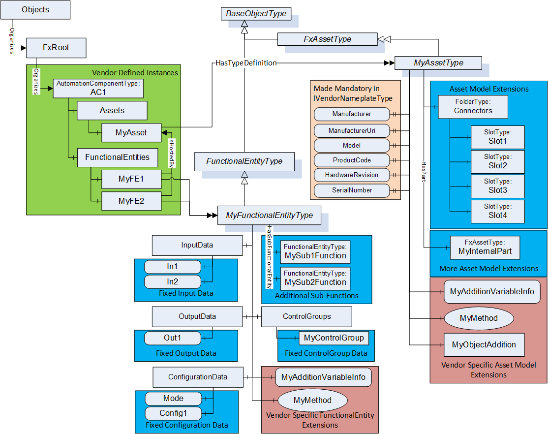
The subtypes might define a fixed set of optional items like in MyAssetType, which fixed optional IVendorNameplateType variables (i.e., making them mandatory). It could define a fixed structure of Connectors or a structure for the given Asset. Creating subtypes might also define fixed Variable(s) that all instances would contain, such as the ConfigurationData in MyFunctionalEntityType. It could define fixed ControlGroups or a fixed group of SubFunctionalEntities. Then, all instances of these types would include the provided structures, extensions, or other functionality. These subtypes might also contain Objects, Variables, or Methods that have no bearing on the OPC UA FX model.
When to use this approach:
Creating an Information Model for a new companion specification, where all instances of the new model are expected to provide the described functionality. OPC UA FX Facets like Motion and IO could provide their own derived types.
Creating an Information Model for a new vendor-specific specification. This is especially true for asset models, where a vendor would want to represent the hardware that they sell.
Creating a customer/application-specific Information Model. This would typically be related to functional models that would want to be standardized for use between multiple devices.
B.3 Extending an existing OPC UA model with OPC UA FX
B.3.1 Overview
There are different ways of extending an existing UA model without losing backwards compatibility. The existing model might be defined in a companion specification (or vendor specification), and the specification could be extended to include OPC UA FX as part of its model. These additions could be accomplished using Interfaces or via AddIns; examples of both are provided.
Figure B.2 illustrates the original model defined in the example specification. The illustration shows a model that uses an Interface from OPC 10000-100, but this would not be required. It is included to help illustrate a model that might already include some functionality used by OPC UA FX. The illustration also shows an instance of the type defined by the model and a folder structure for that instance that is part of the example specification model.
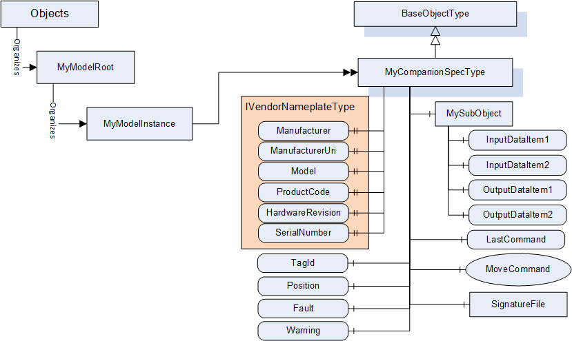
B.3.2 Extending existing OPC UA models using Interfaces
B.3.2.1 Extending an existing type
The Interfaces defined in the OPC UA FX Information Model can be added to an existing specification model to extend the model for providing the required UA FX functionality.
The illustrated model does not create a separate FunctionalEntity and Asset since the existing model did not differentiate between the asset part and the logical functionality. The resulting extended companion specification is illustrated in Figure B.3. In the illustration, the additions to the existing companion specification model have a background colour added to help visualize the additions.
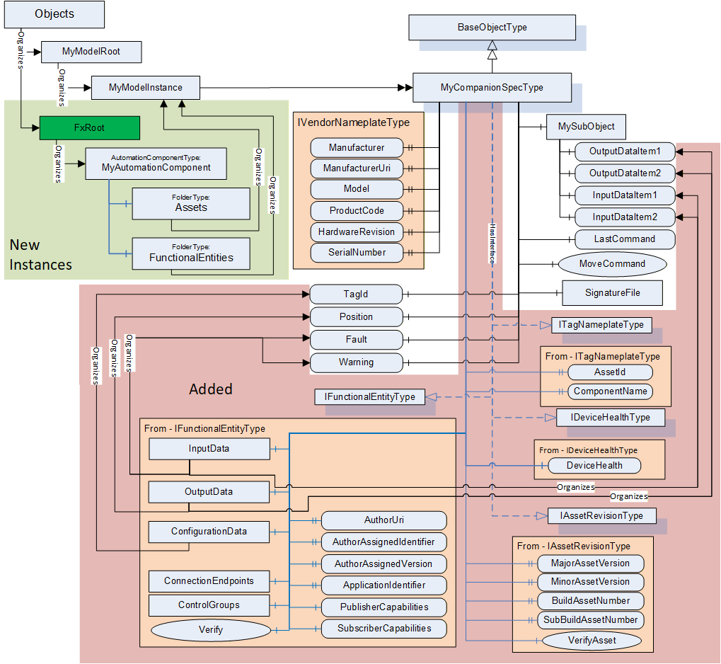
The new model includes the ITagNameplate Interface (defined in OPC 10000-100) that is required by OPC UA FX. It also includes the IAssetRevision Interface defined in this document. These two Interfaces, coupled with the already included IVendorNameplate Interface, fulfil the requirements for the asset model. The existing model already defines input/output/configuration data that would be required for a FunctionalEntity, but it does not include the communication aspect of a FunctionalEntity, so the IFunctionalEntity Interface was added to the model. The InputData, OutputData and ConfigurationData folders provided by the Interface were updated to include references to the already defined (existing) Variables in the MyCompanionSpec model.
The OPC UA FX specification provides a required instance model. This model would not be part of the companion specification model. The companion specification, in this case, also provides a required instance model. The figure illustrates this resulting instance model. This instance model would contain the instance as described in the companion specification, but it would also require the AutomationComponent instance that is required by UA FX. This AutomationComponent instance would just reference the existing MyModelInstance from both the Assets Folder and the FunctionalEntities Folder.
It is important to understand that this is just an illustration of one possible use of Interface in an existing type model. Interfaces could be added to separate objects if the companion specification separates functionality from assets.
When to use:
When it is important to extend an existing companion specification or vendor-specific specification with OPC UA FX and claim support for OPC UA FX. This type of update will allow the companion or vendor-specific specification to stay backwards compatible while publishing an Information Model that includes OPC UA FX. It does require a new version/release of the specification.
Adding an Interface to an existing type is also useful when the existing type already contains some of the required information, could already have one of the required Interfaces or is based on a type that might already include the required information (i.e., DeviceType from OPC 10000-100).
B.3.2.2 Extending an instance of an existing type
OPC UA allows an Interface to be applied to type objects or to instances. The OPC UA FX Information Model can be included via Interfaces into an instance of an existing Information Model. This type of update is illustrated in Figure B.4Figure 4.
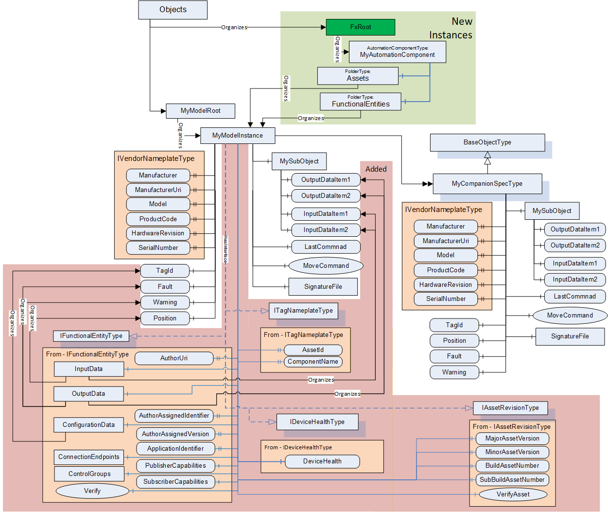
This set of extensions is very similar to what is described in Annex B.3.2.1, but the Interfaces are applied to the instance instead of the type. The instance will include each of the Interfaces. Furthermore, the references are added to provide the mapping to the existing Variables.
When to use:
Extending instances with Interfaces is used when an Information Model is already instantiated, and the type definition cannot be extended. Usually, this is instance-specific, and it is difficult to reused. It can be used in a device or application that wants to utilize an existing Information Model with OPC UA FX but does not plan on creating many instances of this Object. An example could be a device that ships with a single instance of this Object. It does not require any update to a companion or vendor specification.
B.3.3 Extending an existing OPC UA model using AddIns
B.3.3.1 General
Figure B.5 illustrates the base model used for illustrating AddIns. This base model is similar to the base model for Interface but it has removed the IVendorNameplateType.
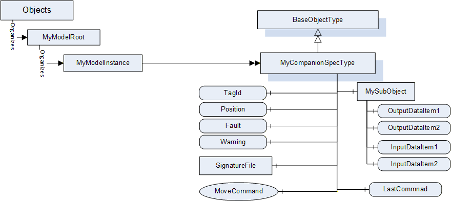
AddIns are used to attach OPC UA FX Information Model-specific content to an existing OPC UA Information Model. This is possible on the type definition level or the instance level. Only the type definition level is illustrated. The instance level would be identical, just applied to an instance instead of a type.
B.3.3.2 Extending an existing OPC UA model using AddIns
Extending the type definition with AddIns is done by adding the Reference HasAddIn to the FunctionalEntityType and FxAssetType. During instantiation, this leads to the creation of a new MyFunction instance and a new MyAsset instance, which are bound with these references to the OPC UA instance of the existing Information Model. This type of update is illustrated in Figure B.6Figure 4.
When to use:
When it is important to include OPC UA FX functionality in an existing Information Model and the model does not include any of the functionality defined in UA FX [for example, any of the FxAssetType interfaces - IVendorNameplateType, ITagNameplateType]. An AddIn also allows the function to be placed as a separate object, which might be easier to profile as included or omitted.
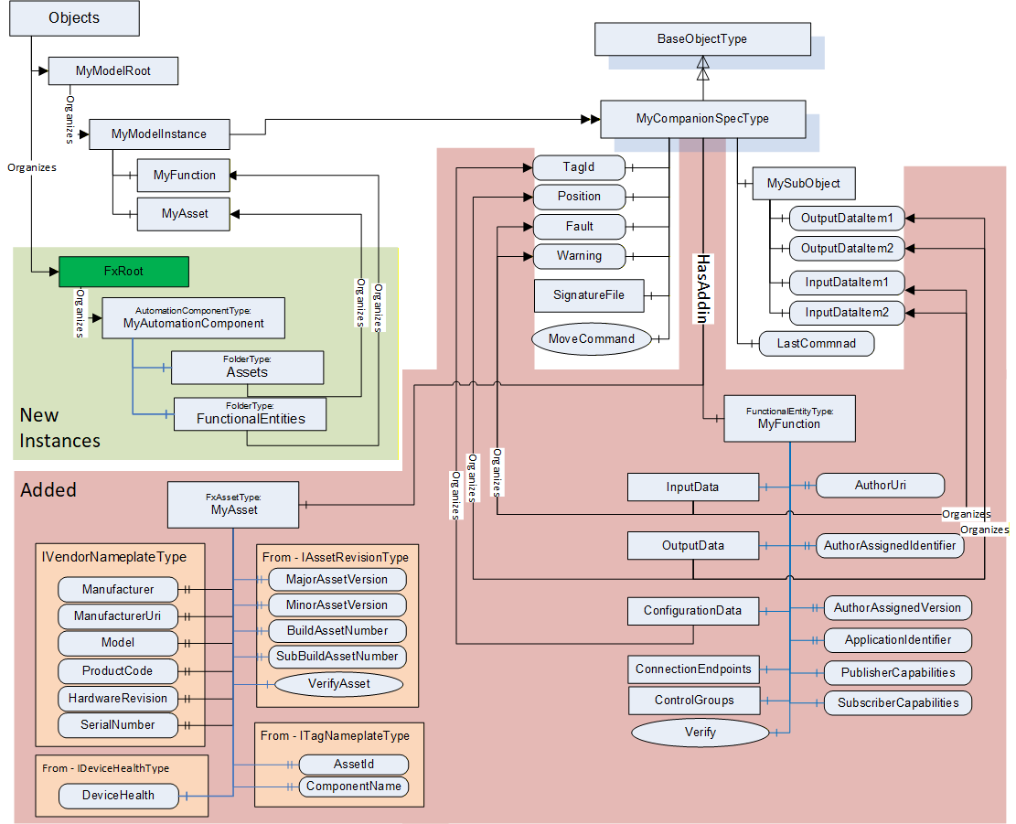
B.3.4 Parallel use of OPC UA FX and existing UA models
A device might implement both a companion specification Information Model as well as the OPC UA FX Information Model. In this case, no new type would be required, just instances of the two independent models. This is illustrated in Figure B.7. In the illustration, an AutomationComponent was created and populated with a FunctionalEntity as well as an instance of FxAssetType. The FunctionalEntity organizes in its InputData, OutputData, and ConfigurationData Variables, which are components of the MyModelInstance (derived from the MyCompanionSpecType).
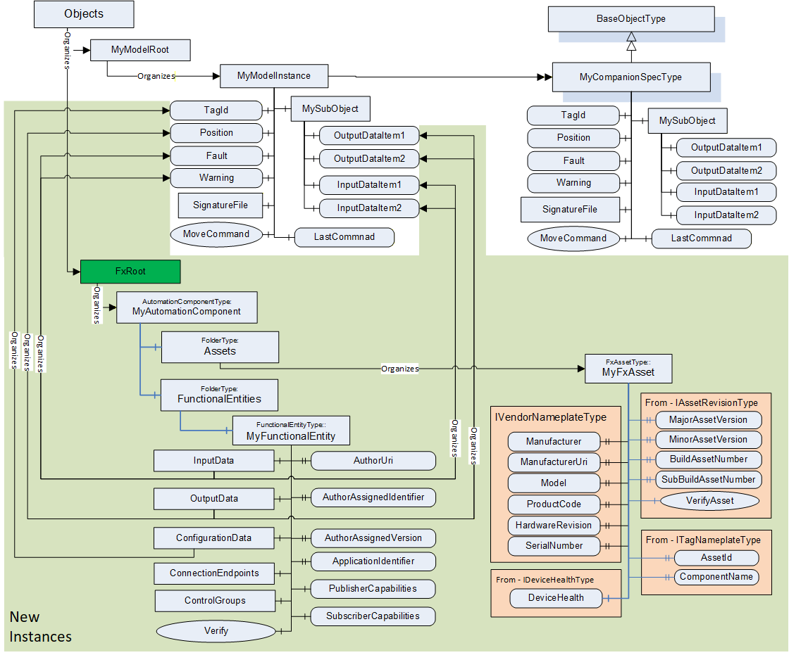
Another variance would be defining separate Variables in the FunctionalEntity, where the underlying device just references the same memory location for its value, as a Variable being a component of the MyModelInstance. This variance is advantageous if the OPC UA FX model has a sub-model where Variables have a different name but the same content, e.g., speed (OPC UA FX sub-model) and velocity (existing UA model). In the OPC UA AddressSpace, the Variables will be treated as different Variables, but the back end of the implementation ensures that they have the same content.
When to use:
When the existing model/companion specification cannot be updated or modified. This implementation could also be done by a third party that layers OPC UA FX on top of an existing application.
B.3.5 Summary
The examples provided in this annex are only some of the possible ways the OPC UA FX Information Model can be integrated into an existing model or used in conjunction with a new or existing model. The selection of which techniques are used should depend on other factors, such as:
Does the model already exist and have adoption? If yes, is backward compatibility essential?
Is it possible to extend the original Information Model (i.e. generate a new revision of the companion specification)?
Does the existing model contain an asset model?
Does it contain a functional model?
Does it contain nested sub-models?
This is just a partial list of questions that a developer might want to consider when investigating options for adding UAFX to an existing specification/controller/application.
The certification program will be able to certify any of the options to help assure interoperability and compatibility.
Annex C Use of OPC UA FX with OPC UA Safety (Informative)
C.1 OPC UA Safety Information Model
For the reader's convenience, some aspects of the OPC UA Safety Information Model are explained in this clause. For normative aspects, please refer to OPC 10000-15.
OPC UA Safety defines how to exchange safety data between AutomationComponents using either Client Server or PubSub as the underlying OPC UA communication model. Client Server support for logical connections will be specified in a future version of this document. The usage of PubSub is assumed for the following text.
As defined in OPC 10000-15, the SafetyProvider (representing the source for safety data, such as an emergency stop button) exposes:
a structured input Variable of DataType RequestSPDUDataType containing safety protocol elements (monitoring number, SafetyConsumer ID, etc.).
a structured output Variable of a DataType derived from the ResponseSPDUDataType, containing as a structured sub-element the safety application data (e.g., button pressed/released), safety protocol elements (monitoring number, CRC, etc.), and optionally additional non-safety related data.
The corresponding SafetyConsumer (representing the sink for safety data) mirrors input and output variables, e.g., the safety application data is contained in its input Variable. It exposes:
a structured input Variable of a DataType derived from the ResponseSPDUDataType. Note that SafetyProvider and SafetyConsumer have identical definitions of this DataType.
a structured output Variable of DataType RequestSPDUDataType.
Refer to OPC 10000-15 for the ResponseSPDUDataType definition and on how to calculate the value of OutCRC. Figure C.1 illustrates an Information Model for a SafetyProvider and its corresponding SafetyConsumer. Safety Variables are represented as dashed yellow boxes.
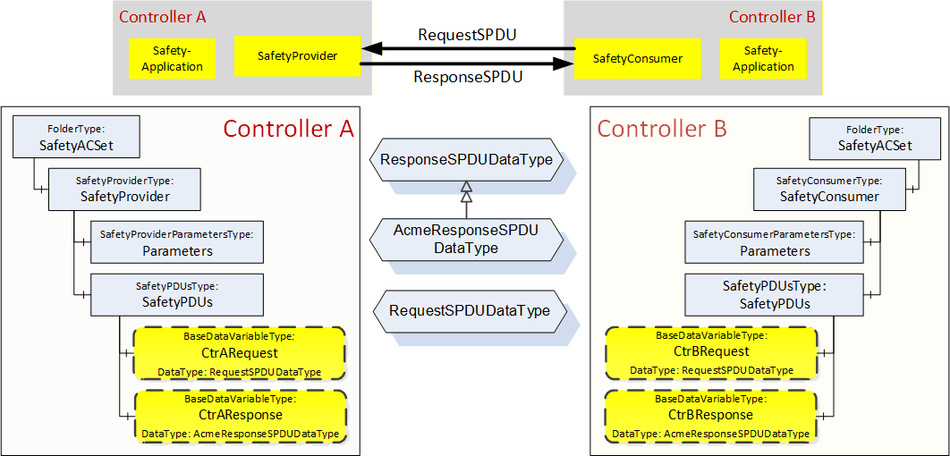
C.2 Usage of OPC UA safety Variables in a FunctionalEntity
Figure C.2 indicates a FunctionalEntity, which includes a SafetyProvider. The FunctionalEntity contains safety and non-safety Variables in its InputData and OutputData.
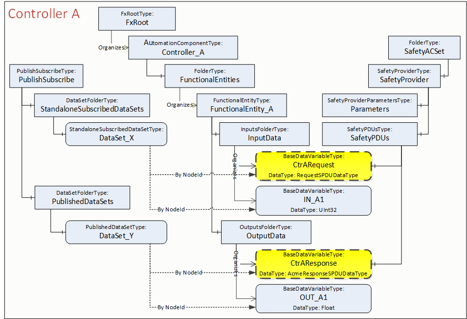
From a FunctionalEntity's perspective, the safety Variables CtrARequest and CtrAResponse are organized within the InputData and OutputData. In addition, these Variables are referenced by HasComponent References from the SafetyPDUs Object of the SafetyProvider (see also OPC 10000-15).
Safety and non-safety data can be referenced in a preconfigured PublishedDataSet or SubscribedDataSet.
C.3 Usage of OPC UA safety Variables in Connections
OPC UA Safety provides an application protocol using safety Variables, which is implemented by the SafetyProvider / SafetyConsumer. The communication layer is completely unaware that safety data is being transported.
Any logical connection could, reference any number of safety and non-safety Variables, even from different SafetyProviders or SafetyConsumers. There is nothing special in establishing a connection containing safety Variables. In fact, the connection establishment is unaware of safety data being transported.
Figure C.3 shows an example of a logical connection between FunctionalEntity_A and FunctionalEntity_B. The exchange of data is represented as dotted lines. The logical connection contains the unidirectional safety data exchange between the SafetyProvider on Controller A and the SafetyConsumer on Controller B (CtrBRequest à CtrARequest, CtrAResponse à CtrBResponse) and, in addition, data exchange between other Variables of these FunctionalEntities (e.g., Out_X5 IN_A1).
OPC 10000-15 uses the terms unidirectional and bidirectional from a safety application's point of view, referring to the flow of safety application data. From a communication perspective, however, data exchange is always bidirectional (ResponseSPDU containing the safety application data in one direction and RequestSPDU in the other direction), even for a unidirectional safety data exchange.
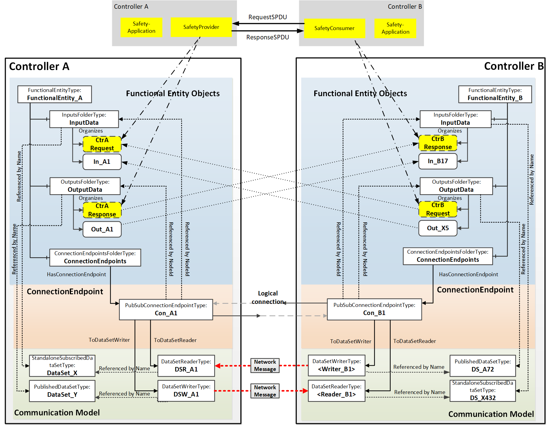
In many cases, safety communication between two controllers is a bidirectional safety data exchange. This data exchange could also be organized in one logical connection, as indicated in Figure C.4. It contains the bidirectional safety data exchange and additional data exchange of other Variables (e.g., Out_X5 IN_A1).
In this example, all output Variables, including the data related to the SafetyProvider and SafetyConsumer, share the same NetworkMessage.
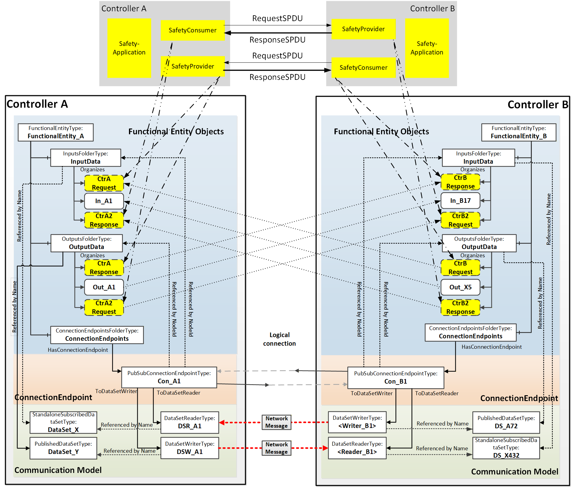
Annex D Information Model examples (Informative)
D.1 Overview
The Information Model defined for OPC UA FX can be applied in many different ways. To help illustrate some of these options, this annex provides examples for each part of the OPC UA FX Information Model. This includes individual Assets examples, individual FunctionalEntity examples and examples of an AutomationComponent that includes both Assets and FunctionalEntities.
D.2 Asset examples
D.2.1 Modelling of Asset relationships
The task of modelling an Asset is more than just describing a single simple Asset. It is modelling the relationships between the Assets. In OPC UA, relationships can be modelled as References, where a Reference provides semantics information about the relationship. OPC UA has defined a number of References in OPC 10000-23 that can be used for modelling Assets. This list is extended by this document. The following ReferenceTypes will be illustrated in various examples in this annex:
HasContainedComponent indicates that an Asset has another Asset contained in it.
HasBuiltInAsset indicates that an Asset has an integrated Asset, which is not removable.
HasPart indicates that an Asset has another Asset which can be removed.
HasAttachedComponent indicates that an Asset has physically/mechanically attached an Asset (this reference is a subtype of HasPhysicalComponent).
IsPhysicallyConnectedTo (symmetric) indicates that two Assets are physically connected to each other.
ConnectedTo (symmetric) indicates that two Assets are connected to each other by an electrical cable.
IsPartOfRedundantAssetSet indicates that an Asset is part of a group of Assets that form a redundant Asset.
Additional References can be defined or used to show additional relationships.
D.2.2 Example single board computer model
Figure D.1 shows a simple single-board computer, in this case, a Raspberry Pi ("Raspberry Pi is a trademark of Raspberry Pi Ltd"), that can be modelled as an asset. This simple single-board computer has multiple items that can be modelled. It has many connector options, including extension boards or external devices and cables. The figure also includes a possible base asset model for the Raspberry Pi. This model does not include all features of a Raspberry Pi but will be used to illustrate the available ReferenceTypes. This single-board computer could be modelled in many ways, and this illustrates just a possible model. Alternate models could exist and would not be wrong.
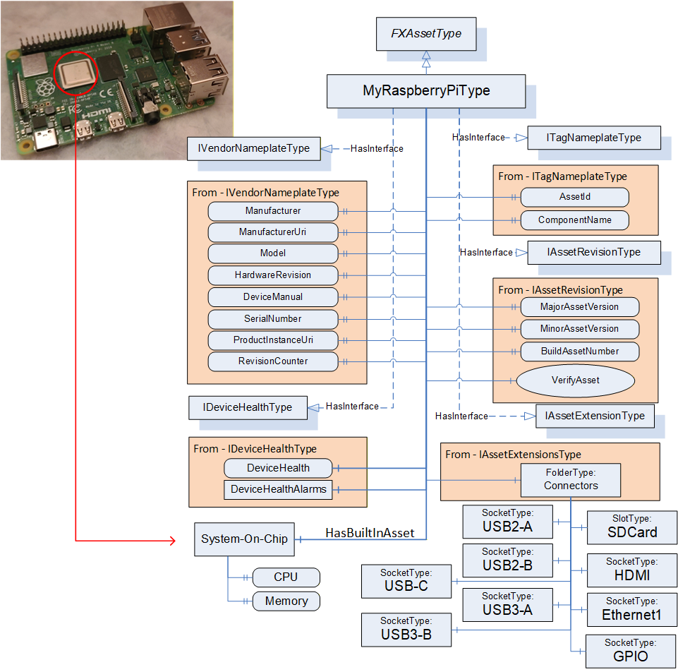
The MyRaspberryPiType is a subtype of FxAssetType. It mandates some of the Optional iVendorNameplateType Properties (all items listed), and it omits other Optional Properties from the interfaces that do not apply to MyRaspberryPiType. The model includes a number of Connectors that are used to add additional peripherals. The MyRaspberryPiType includes a System-On-Chip Object as an illustration of a HasBuiltInAsset. This Object contains information about the CPU and memory. It contains two Variables: one for the CPU Clock rate (can be 1.5 GHz or 1.8 GHz) that is used in the single board computer, and the other is an enumeration of the memory (can be 2, 4, or 8 GB).
The model does not include all the connectors that are available in a Raspberry Pi, but it does show the USB connectors and the external asset that is connected via a cable. See Figure D.2, showing the cable being attached to one of the USB ports. The figure also illustrates the resulting instance model. This figure only includes the instance information related to the ConnectedTo Reference; it does not include all of the other mandatory items that would be in the instance. The USB cable is represented by the ConnectedTo Reference. The Adaptor is its own Asset and might have its own configuration that is omitted here.
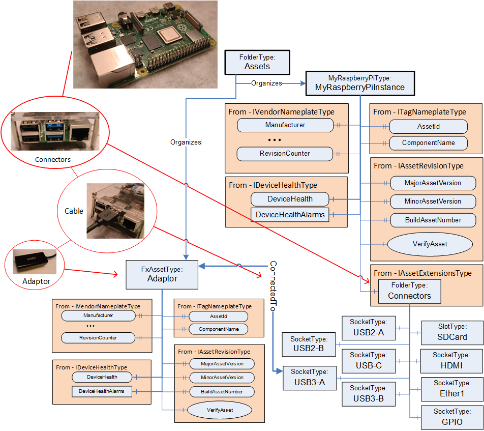
The Raspberry Pi also has a slot for an SD card, which is also modelled (see Figure D.3). The SD card is visible from the outside and can be removed. It is modelled as a HasPhysicalComponent. The SD card can also be updated; thus, the SD card model includes the optional SoftwareUpdate component. The SD card is not a top-level Asset, and thus, it does not implement the IDeviceHealthType interface.
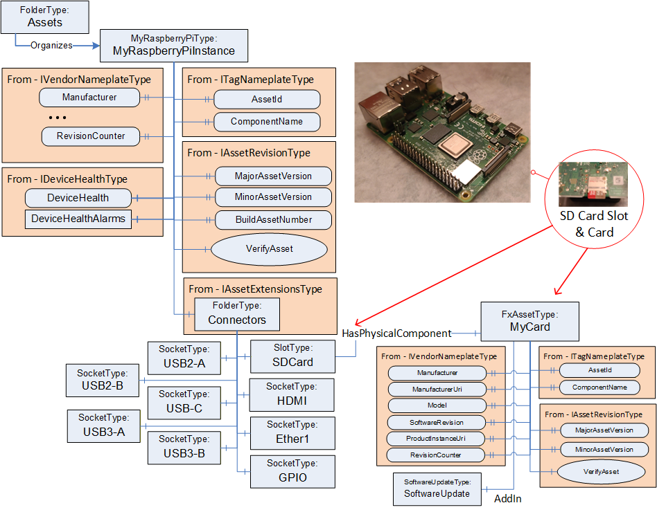
An alternate manner in which the SD Card could have been modelled is illustrated in Figure D.4. This model does not show the slot since it is assumed that the card is always present. Vendors can generate multiple models, all of which are correct.
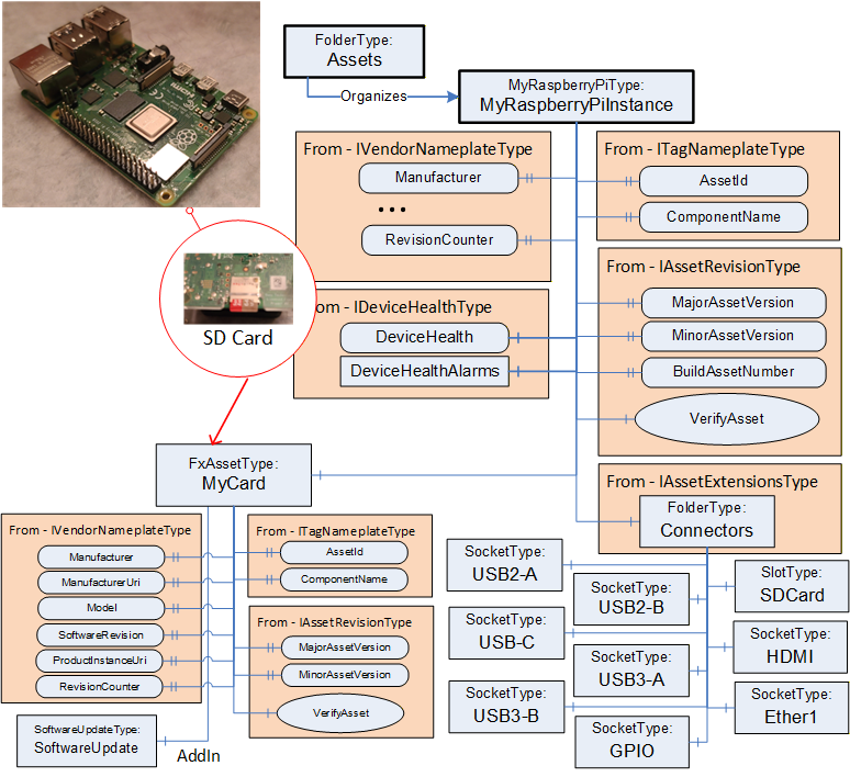
The Raspberry Pi might also include extension boards such as the Sense HAT (see https://www.raspberrypi.com/products/sense-hat/ for more information) that is illustrated in Figure D.5. This removable type of extension board could be modelled using a HasPart Reference. In the resulting model, the SenseHat is not a top-level Asset but just a child of the GPIO connector that it is attached to. This addition provides a number of sensors - a gyroscope, accelerometer, magnetometer, humidity sensor, barometric sensor, temperature sensor and an LED display.
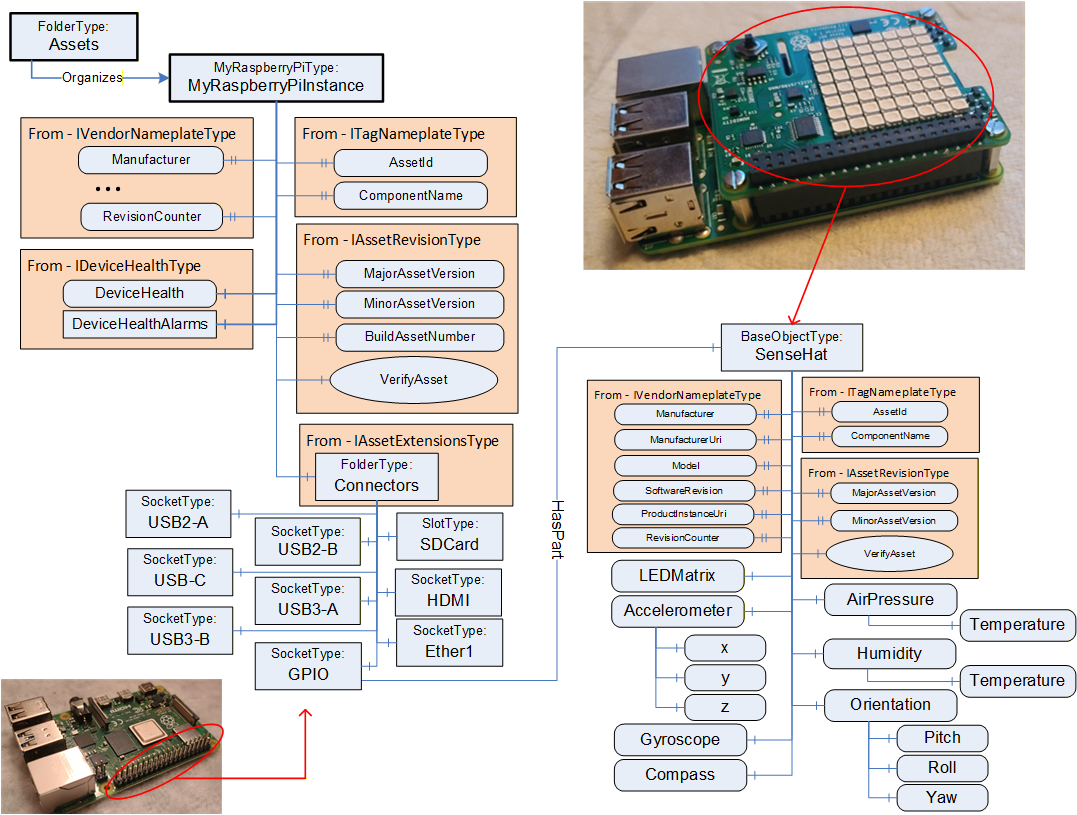
The Raspberry Pi can also be enclosed in a case which also contains a fan (see Figure D.6). The fan is wired to the single-board computer. Both the Raspberry Pi and the fan are physically attached to the case. The case is not modelled as an Asset, but it can still make use of the References defined in OPC 10000-23.
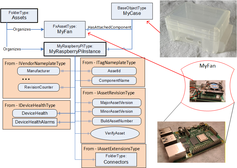
Figure D.7 illustrates the entire Information Model for the Raspberry Pi described in this annex.
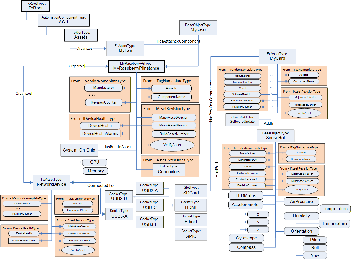
D.2.3 Example of a rack with controllers and I/O modules
Let's look at a possible asset model for a rack into which controllers, power supplies and I/O modules are inserted. The rack could be cabled to an extension rack, where the extension rack holds additional I/O modules. The rack is illustrated in Figure D.8.
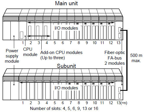
This main rack could be modelled in a number of ways. Figure D.9 illustrates one possibility. The figure is not complete in that not all subcomponents or details are included. The model has a base rack model (MyRackType) that can represent any rack, including the Subunit. The base rack does include redundant power supplies. The main unit is modelled (MyMainRackType) as a subtype of this rack. The main unit includes a CPU, which is mandatory and always sits in Slot1.
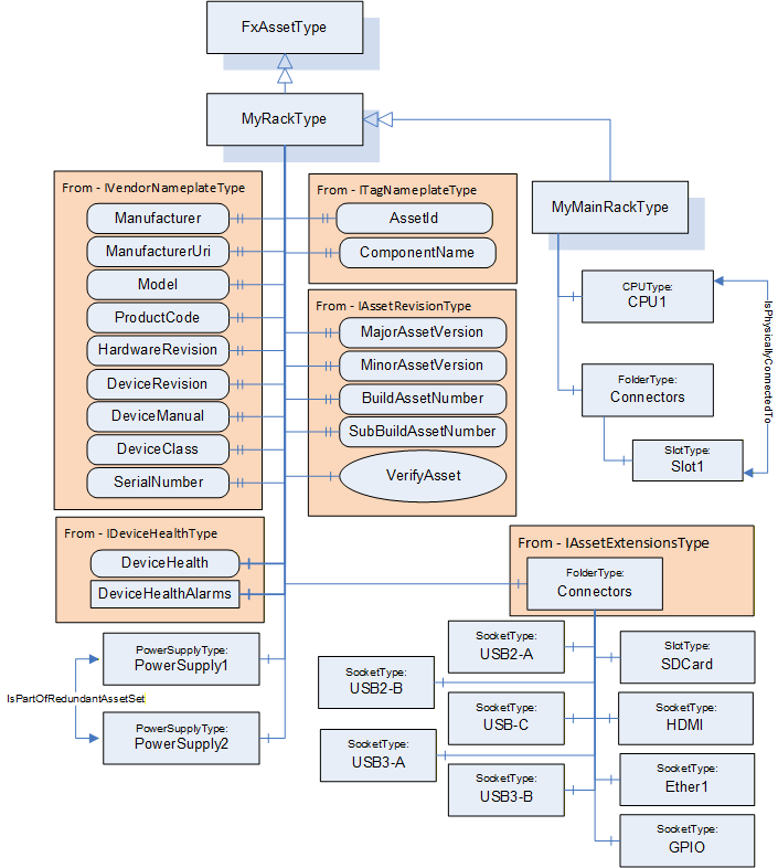
Figure D.10 illustrates the model for the CPU module. This model is based on interfaces and includes software update functionality. It also provides a variable that represents the temperature of the CPU (and the engineering units associated with the temperature). The CPU model also provides an enumeration that represents the status of the CPU module (Failed, Degraded, Normal). This status is used as an indicator light on the module.
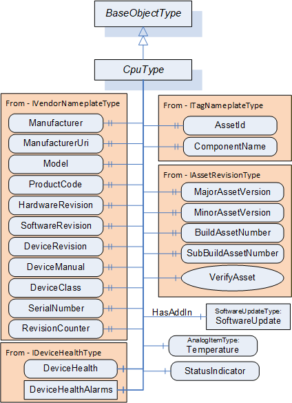
Figure D.11 illustrates the IO Module model. This IOModuleType is a subtype of FxAssetType. The model includes a StatusIndicator that behaves exactly the same as the CPU Model StatusIndicator (Figure D.10). The model also supports software updates. The model includes a folder for connectors, where the connector provides connections to external IO. These connectors can be of any type, depending on the type of connected IO device. It is expected to be further subtyped. This model reflects specific types of external IO connections and devices.
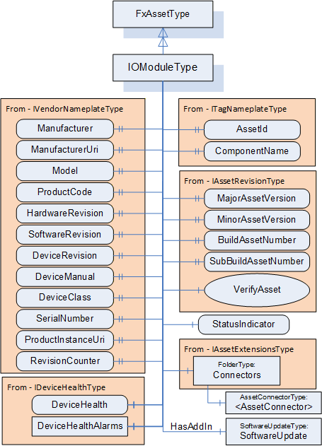
Figure D.12 illustrates the power supply module. This model is just a base object that exposes the required interfaces. The PowerSupplyType has a reduced set of IVendorNameplate properties. PowerSupplyType provides a Variable that reflects the power output of the supply. PowerSupplyType also has a variable that reflects the temperature. PowerSupplyType, as with all of the modules, includes a status indicator.
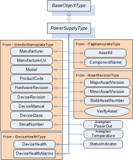
Figure D.13 provides an illustration of a deployment of this model. The instance provides an additional CPU and includes several IO modules. The figure also illustrates the values of some of the variables in the various models. The figure omits many variables and values for simplicity. These variables would exist in the actual complete model. The model does not describe the devices that are connected to the IOP modules. This model is used for additional examples.
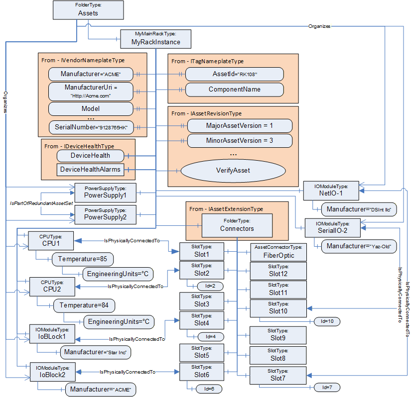
D.2.4 Verifying Assets
A Client verifies whether an Asset meets the expectations of system engineering. This example demonstrates how to use verification. It uses the rack example.
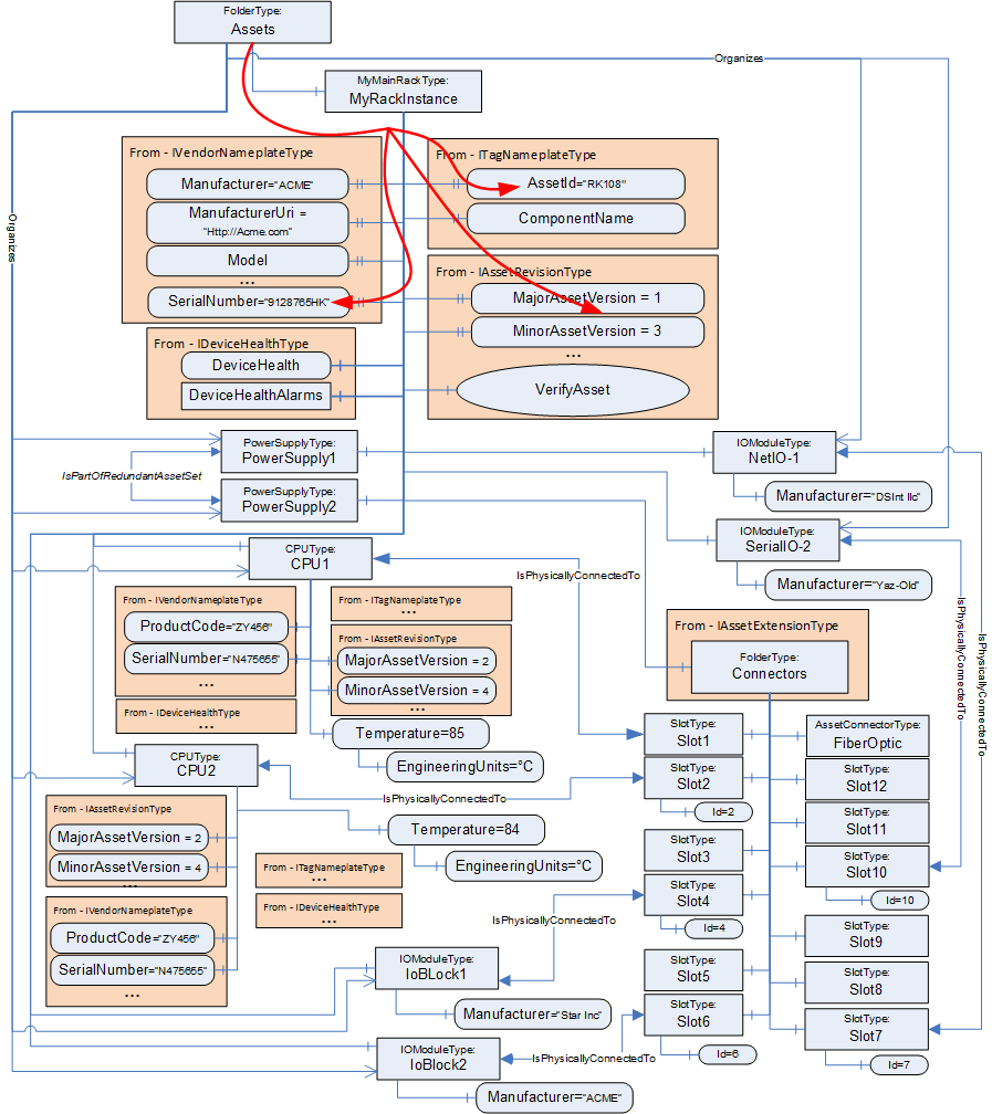
Figure D.14 illustrates the Assets of a rack-based controller. The vendor modelled a 12-slot rack with Connectors, a communications module, and two controllers (CPU) modules. The IsPhysicallyConnectedTo Reference indicates that the modules are plugged into slots 1 & 2, whereas slot 3 is unused. IO modules are plugged into slot 4, slot 6, slot 7 and slot 10.
Assume that all CPU Assets are manufactured by the same manufacturer as the rack and have their ManufacturerUri set "http://ACME.com".
Assume that the Descriptor contains for CPU1: ProductCode "ZY456", MajorAssetVersion "2", MinorAssetVersion"4", and SerialNumber "N475655", and for CPU2: ProductCode "YY544", MajorAssetVersion "2", MinorAssetVersion"7", and SerialNumber "Z234545".
A Client checking for compatibility of the Assets Controller1 and Controller2 by using VerificationMode AssetCompatibility will set the ExpectedVerificationVariables in VerifyAsset to the values as stated above, without the given SerialNumbers. The SerialNumbers should be added when using VerificationMode AssetIdentityAndCompatibility.
If the verified Assets match the expected values exactly, i.e., ManufacturerUri, ProductCode, MajorAssetVersion, and MinorAssetVersion are identical, Match will be returned. For example, if Controller2's actual MinorAssetVersion is set to "9" but the Asset is still compatible with MinorAssetVersion "7", Compatible will be returned.
The VerifyAsset Method allows doing additional verification besides verifying the Asset itself using ExpectedAdditionalVerificationVariables.
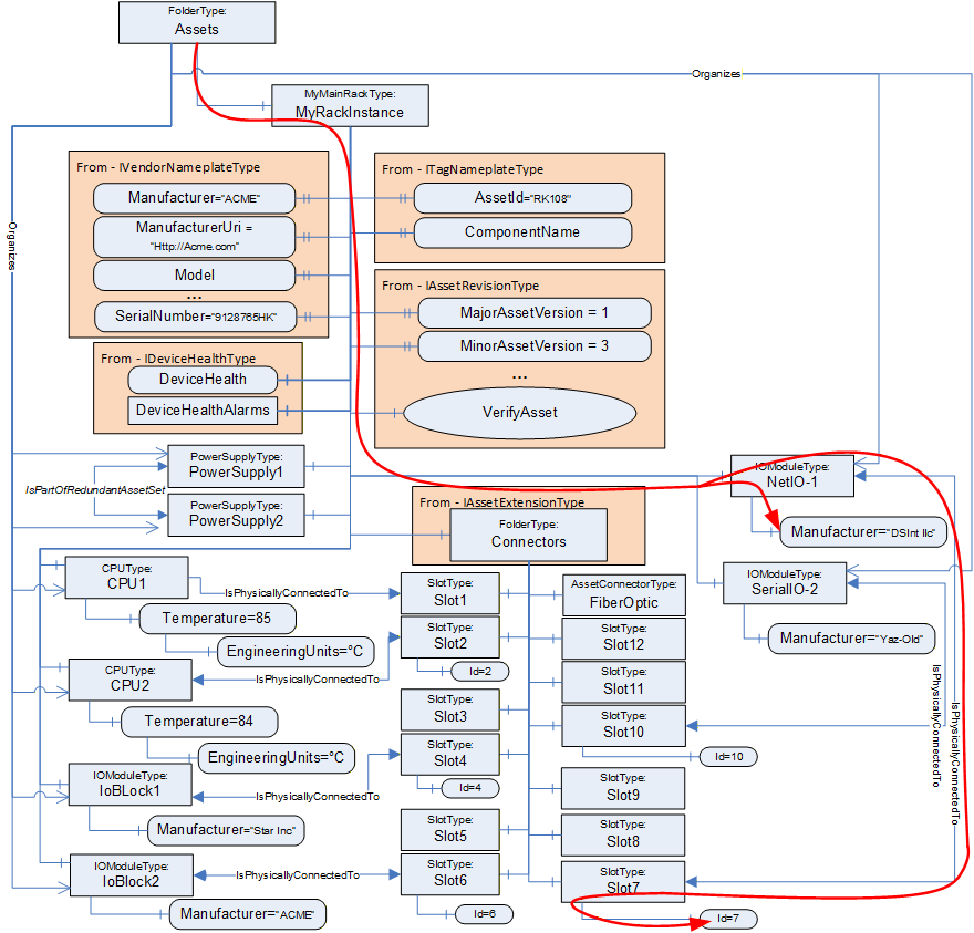
Consider, for example, verifying whether an IOModule (NetIO-1) is plugged into Slot7. This can be done, as illustrated in Figure D.15, by using a relative path as:
<HasComponent>Assets
<Organizes>NetIO-1
<IsPhysicallyConnectedTo>Slot7
<HasVariable>Id
The Client can verify that NetIo-1 is physically connected to Slot7 by resolving this relative path. The VerifyAsset Method can now be used by the Client to verify that the resolved Node has a value of 7.
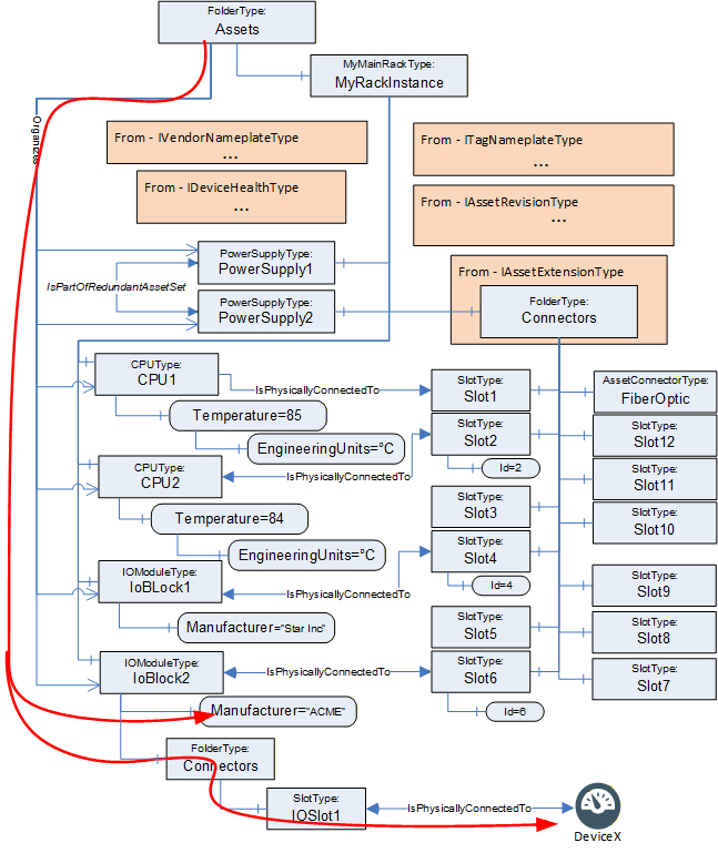
This same concept can also be used to verify Assets that might not be directly linked to the AutomationComponent, i.e., they are not in the Assets folder but only referenced from existing Assets (see Figure D.16). In this example, the BrowsePath would look like:
<HasComponent>Assets
<Organizes>IoBlock2
<HasComponent>Connectors
<HasComponent>IOSlot1
<IsPhysicallyConnectedTo>DeviceX
This process could also be used to verify the values of configuration settings such as EngineeringUnits.
D.3 Functional Entity examples
D.3.1 Overview
This clause provides examples of functionality that a FunctionalEntity might expose. This includes Inputs, Outputs, ControlGroups and the resulting Connections. It will also describe the use of pre-configured DataSets and dynamically created DataSets.
These examples are linked to the Asset examples in later subclauses to provide a more complete picture.
D.3.2 Modelling of FunctionalEntity relationships
The following types of References provided with this document and OPC 10000-23 are used for modelling FunctionalEntities:
HasSubFunctionalEntity indicates that a FunctionalEntity has a nested FunctionalEntity.
IsHostedBy indicates that a FunctionalEntity needs the referenced Asset to provide its functionality.
IsExecutingOn relates a FunctionalEntity to the execution environment it is currently executing on (e.g., hardware component, task or thread).
RepresentsSameEntityAs (symmetric) relates two entities which represent the same entity in the real world. This Reference can be used, for example, to relate a FunctionalEntity with its counterpart in the event of redundant logic. Another example might be a sensor that is dual-ported and wired to two different input signals. These two FunctionalEntities could be related with RepresentsSameEntityAs.
RepresentsSameFunctionalityAs (symmetric) relates two entities representing the same functionality. This Reference can be used, for example, to relate a FunctionalEntity with its counterpart in a companion specification.
D.3.3 FunctionBlock example
Figure D.17 provides an example FunctionalEntity model that could be applied to the single-board computer from the Asset example (MyRaspberryPi). The model shows a subtype of FunctionalEntityType that represents an execution engine that can run generic function blocks. The ExecutionEngineType includes the capability of loading libraries of function blocks, where each function block would be a FunctionalEntity. The model includes a Method that is used to load function block libraries and a Method to load a program that is executed by the ExecutionEngine. ExecutionEngineType will be used to illustrate various aspects of the FunctionalEntity model in the following subclauses.
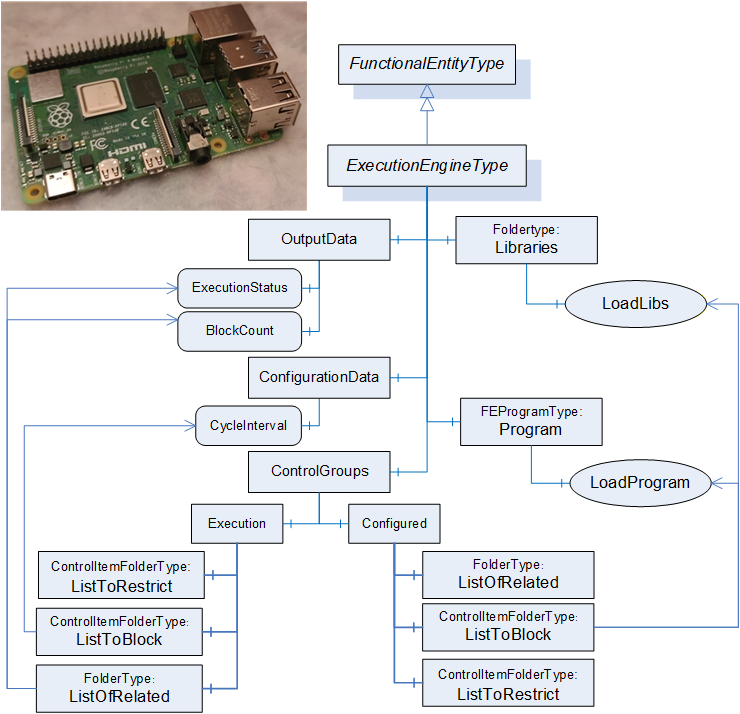
D.3.4 Examples of base aspects of FunctionalEntityType
Figure D.18 provides an example of an instance of the ExecutionEngineType. It is empty in that no libraries or programs have been loaded. The model does show the AuthorUri for the ExecutionEngine (Http://Opcfoundation.org), an AuthorAssignedIdentifier (FLCEx01) and an AuthorAssignedVersion (1.0.0.0). The ApplicationIdentifier is set for the empty ExecutionEngine (ExecEngine01 with a program code of 26). The execution engine also has a default setting for BlockCount, 0 - it is empty. CycleInterval in Millisecond of 100. The status also indicates nothing is loaded.
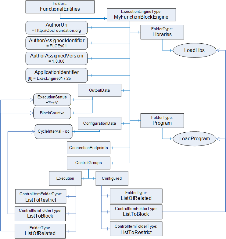
D.3.5 Example of nested FunctionalEntities
Figure D.19 illustrates an ExecutionEngine in which libraries have been loaded as well as a program. There are two libraries loaded. One that provides the functionality that comes with the SenseHat (note: not all functionality is illustrated) and another that provides calculation functions. These libraries can be thought of as a list of types that can be instantiated in programs. A program is also loaded, where the program is a sub-FunctionalEntity (MyApplicationProgram), and each execution block is represented by a separate FunctionalEntity (Temperature, Humidity, Calculation, and LED-Block).
Some key points in this example, the ApplicationIdentifier has been updated for each application that was loaded since each was provided by a different vendor. The Sub FunctionalEntities all have their own AuthorUri and other properties, but they are not illustrated for simplicity. Also, each FunctionBlock has a list of inputs, outputs and configuration data that is also not illustrated. This illustration will be used in later subclauses to illustrate other concepts.
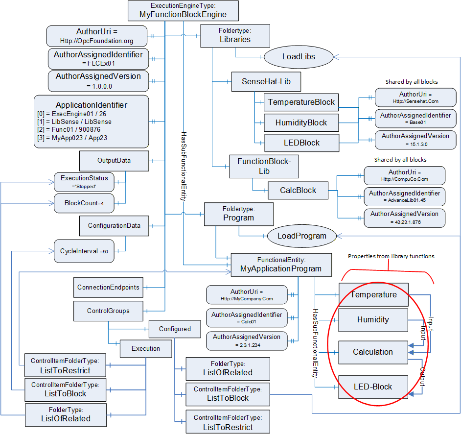
D.3.6 Modelling InputData and OutputData
D.3.6.1 Overview
InputData and OutputData can be modelled in various ways. The following subclauses show examples of their usage. Figure D.20 illustrates the subtype of FunctionalEntityType that is used in the example. All items listed are mandatory in this subtype, but not all of these items will be shown in the examples to simplify the example figures. The AcmeAnalogueInputModuleType illustrates a hardware module that collects data from external input devices, where this information is made available to the controller. This AcmeAnalogueInputModuleType is external to the FunctionalEntity model; think of it as an existing Information Model. The FunctionalEntity then publishes this data to another controller, HMI, or even other devices as needed.
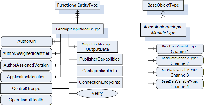
The following examples illustrate how InputData and OutputData can be joined with DataSets. Consider, for example, an analogue input module with four channels plugged into one of the slots of the rack illustrated in D.2.3. The FunctionalEntity related to this Asset will provide OutputData only. To keep the following examples simple, ConfigurationData (e.g., measurement range and unit) is not shown. The dashed lines in the figures in this subclause indicate "poor man's references" instead of an actual Reference. The line will indicate if the poor man's reference is using a NodeId or a Name.
D.3.6.2 Using preconfigured DataSets
The first variant, as illustrated in Figure D.21, assumes that the module can only exchange data using a preconfigured DataSet containing all four channels. In this case, a possible Information Model would organize the Variables in OutputData (the top-level folder). The preconfigured PublishedDataSet PDS_AI4 defines the fixed layout for the data exchange (indicated in PublisherCapabilities as one of the PreconfiguredPublishedDataSets). PreconfiguredDataSetOnly set to True indicates that the data contained in this folder can only be exchanged using the preconfigured PublishedDataSet.
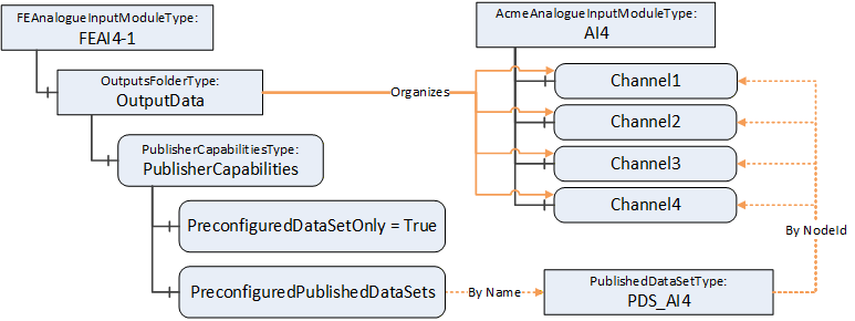
This has the consequence that a ConnectionEndpoint established on that FunctionalEntity can only use the preconfigured PublishedDataSet for communication, as illustrated in Figure D.22. Conn_A and the PubSub Objects, including DSW_A (referencing the preconfigured PDS_AI4) are in this example created during EstablishConnections. For simplicity, PubSubConnection and WriterGroup are not shown.
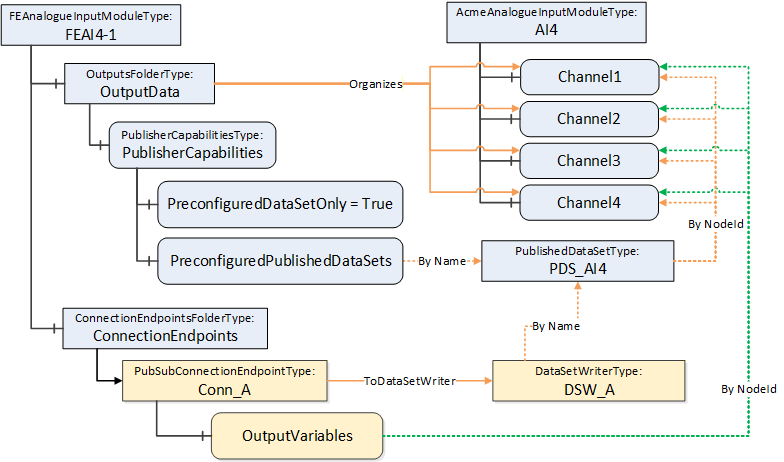
D.3.6.3 Using preconfigured and customized DataSets
The second variant assumes that the module can exchange data using a preconfigured DataSet containing all four channels but also allows data to be exchanged using a customized DataSet (e.g., Channel2 and Channel3 to one controller and Channel1 to another controller).
In this case, a possible Information Model looks like the one illustrated in Figure D.23. However, PreconfiguredDataSetOnly set to False indicates that the data can be exchanged using the preconfigured PublishedDataSet, but in addition using a customized DataSet. A customized PublishedDataSet will be created during the establishment of a connection.
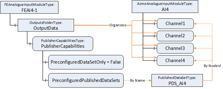
ConnectionEndpoints established on that FunctionalEntity can use a preconfigured or customized DataSet as illustrated in Figure D.24. Conn_A, Conn_B, DSW_A, DSW_B and PDS_B are created in this example during EstablishConnections. ControllerA, connected through Conn_A, will receive all channels using the preconfigured PublishedDataSet PDS_AI4. ControllerB, connected through Conn_B, will receive Channel2 and Channel3 using the customized PublishedDataSet PDS_B.
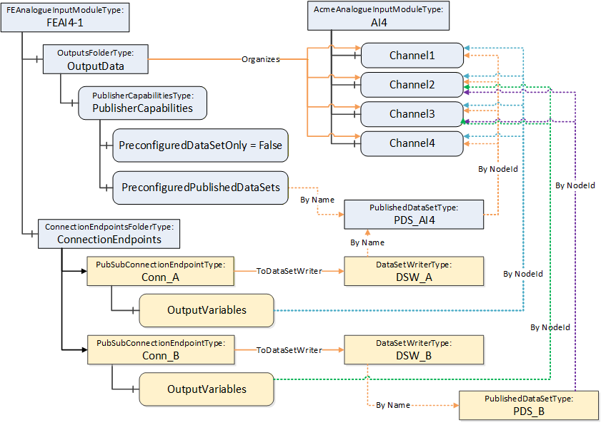
D.3.6.4 Using customized DataSets
A third variant assumes that the module supports data exchange with customized DataSets only.
In this case, a possible Information Model looks like the one illustrated in Figure D.25. However, the absence of PreconfiguredPublishedDataSets indicates that only customized DataSets are supported.
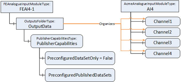
D.3.6.5 Using groups
Subfolders within the OutputData can be used, for example, to group data. Suppose that our sample module is an 8-channel input where a channel can be Int16 or Float. A possible Information Model is illustrated in Figure D.26.
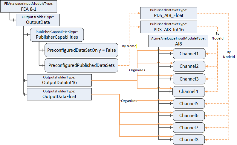
Again, as stated in the variants before, the module can choose to support preconfigured DataSets (e.g., one for all Int16 channels and one for all Float channels) and/or allow customized DataSets, depending on the setting of PreconfiguredDataSetOnly. A Connection can, for example, select Channel1 and Channel6. Figure D.27 illustrates this sample.
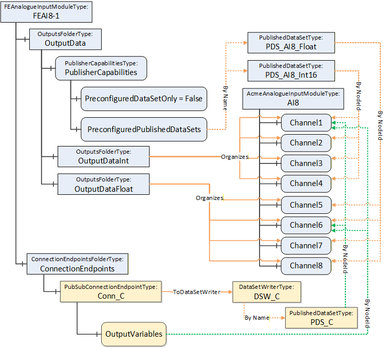
D.3.7 ControlGroup examples
D.3.7.1 Overview
ControlGroups can be used for many purposes. They can illustrate related functionality or be used to establish control. Establishing control of a ControlGroup can be done by calling the Method EstablishControl or by using the EstablishControlCmd with the EstablishConnections Method. The following subclauses provide examples of their usage.
D.3.7.2 Example of a simple ControlGroup
Figure D.28 shows the FunctionalEntity for a simple temperature monitor based on the Raspberry Pi Sense HAT (see Figure D.5). The FunctionalEntity provides the output Variable Temperature, indicating the current temperature. It also includes a Variable EngineeringUnits (e.g., °C, °F, °K…). This configuration variable allows the selection of the engineering unit for the Temperature.
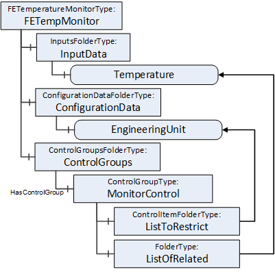
While using the Temperature, the EngineeringUnit for the Temperature should not change. To achieve this behaviour, the ControlGroup MonitorControl is provided. The EngineeringUnit is contained in the ListToRestrict to ensure that changes are restricted to the owner of the ControlGroup. Temperature is contained in the ListOfRelated to indicate that Temperature is part of the ControlGroup.
D.3.7.3 Example of a complex ControlGroup
Assume that the Raspberry Pi (see D.2.2) is used for an automated guided vehicle (AGV) using the Sense HAT and some motors attached through the connectors. Figure D.29 illustrates a sample FunctionalEntity representing this simplified AGV.
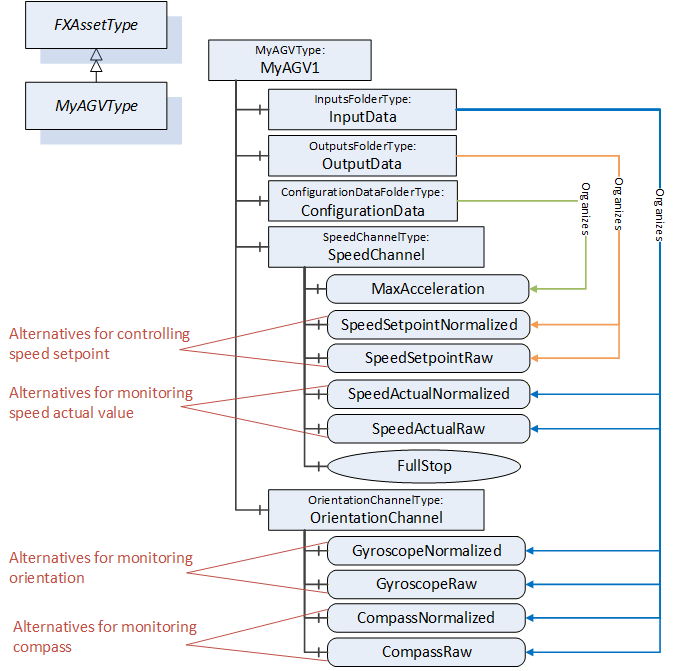
The Information Model offers two alternatives using a normalized value or raw data for controlling SpeedSetpoint and monitoring SpeedActual, Orientation, and Compass. Since both alternatives should not be used at the same time, two ControlGroups, ControlNormalized and ControlRaw, are added to the functional model (see Figure D.30).
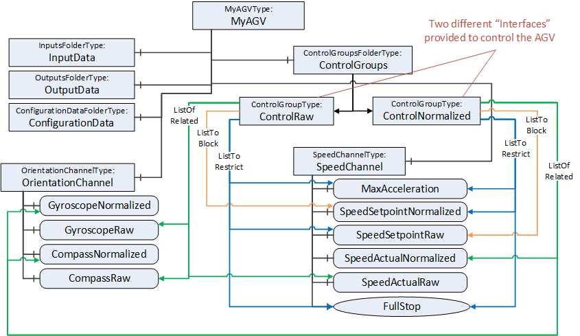
Each of the ControlGroups represents an interface provided by the FunctionalEntity to control and monitor the AGV using normalized or raw data. The interface is represented by the ListToRestrict and ListOfRelated References. By this, the InputData, OutputData, ConfigurationData, and all provided Methods belonging to the interface can be easily determined. The ListToBlock prevents the setting of specific data, for example, SpeedSetpointNormalized, when controlling the AGV with raw data. The ListToRestrict prevents usage of the Method and setting of MaxAcceleration and SpeedSetpoint from anyone except the owner when controlling the AGV.
Since ControlNormalized and ControlRaw share Variables in their ListToRestrict, usage of them at the same time is only possible with the same owner.
D.3.7.4 Using ControlGroups with Connections
ControlGroups can be used with Connections.
This example is an extension of the simple ControlGroup. Assume that the EngineeringUnits of Temperature (see Figure D.28) should not change during the lifetime of a Connection. A connection configuration to achieve this behaviour would establish the control of MonitorControl using the EstablishControlCmd, set the EngineeringUnits with the desired unit (e.g., °F) using the SetConfigurationDataCmd, and reassign control to the ConnectionEndpoint using ReassignControlCmd. Then as long as the connection is established, the EngineeringUnits are locked and cannot be changed.
D.3.7.5 Using ControlGroups to expose functionality.
ControlGroups can be used to expose functionality that is required to be used as a group. This example describes a pair of controllers that are part of a cascade control application (see Figure D.31). For a cascade control application, the PID controller is required to get feedback from the other controller as well as providing a setpoint to the other controller. This requires bidirectional communication.
In this example Controller B comes with preconfigured DataSets, one for the publisher and one for the subscriber.
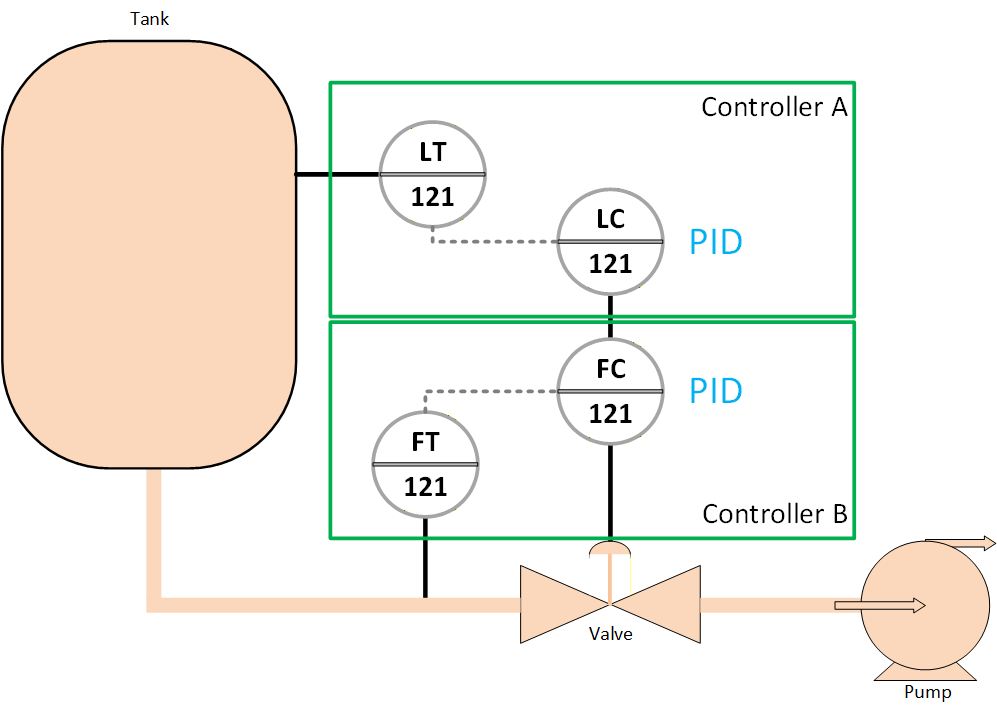
A ControlGroup can be created to indicate that if using the PID in cascade mode then the corresponding input variable and output variable are to be used.
The communication between Controller A and Controller B could be setup by the ConnectionManager in Controller A, it would see the ControlGroup and would utilize the preconfigured Dataset that are described in the ControlGroup.
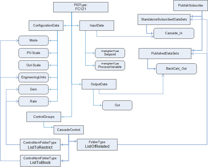
D.3.8 Verifying FunctionalEntities
A Client is able to verify whether a FunctionalEntity meets the expectation of system engineering. This example demonstrates how to use verification.
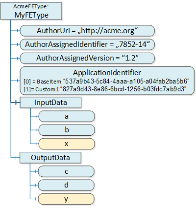
Figure D.33 illustrates a simple FunctionalEntity. The author defining the AcmeFEType provides mandatory input and output Variables (a, b, c, and d) and optional Variables x and y.
The author-defined type of a FunctionalEntity is uniquely identified by AuthorUri, AuthorAssignedIdentifier, and AuthorAssignedVersion. Therefore, a Client using the Verify Method can pass the following ExpectedVerificationVariables:
PortableNodeIdentifier="AuthorUri", Value="http://acme.org"
PortableNodeIdentifier="AuthorAssignedIdentifier", Value="7852-14"
PortableNodeIdentifier="AuthorAssignedVersion", Value="1.2"
Since the author decided to provide optional Variables, an instance of this type can or cannot provide x or y. To verify whether Variable x exists, a Client can pass the following ExpectedVerificationVariable:
PortableNodeIdentifier="x", Value=null
The ApplicationIdentifier allows the identification of a specific instance of a FunctionalEntity and (if provided) any customization by using a name (for user representation) and a unique ID (for verification). A sample for customization is a drive or a process automation device that was configured by a specific engineering tool. A Client can pass the following ExpectedVerificationVariable:
PortableNodeIdentifier="ApplicationIdentifier",[0] Value="537a9b43-5c84-4aaa-a105-a04fab2ba5b6" [1] Value="827a9d43-8e86-6bcd-1256-b03fdc7ab9d3".
Figure D.34 illustrates other items that might be validated.
Relative paths can also be used for verifying the FunctionalEntity. For example, a Client can verify whether CalcBlock is provided by the correct AuthorUri or that a configuration Variable is set to a correct value, as illustrated in Figure D.34.
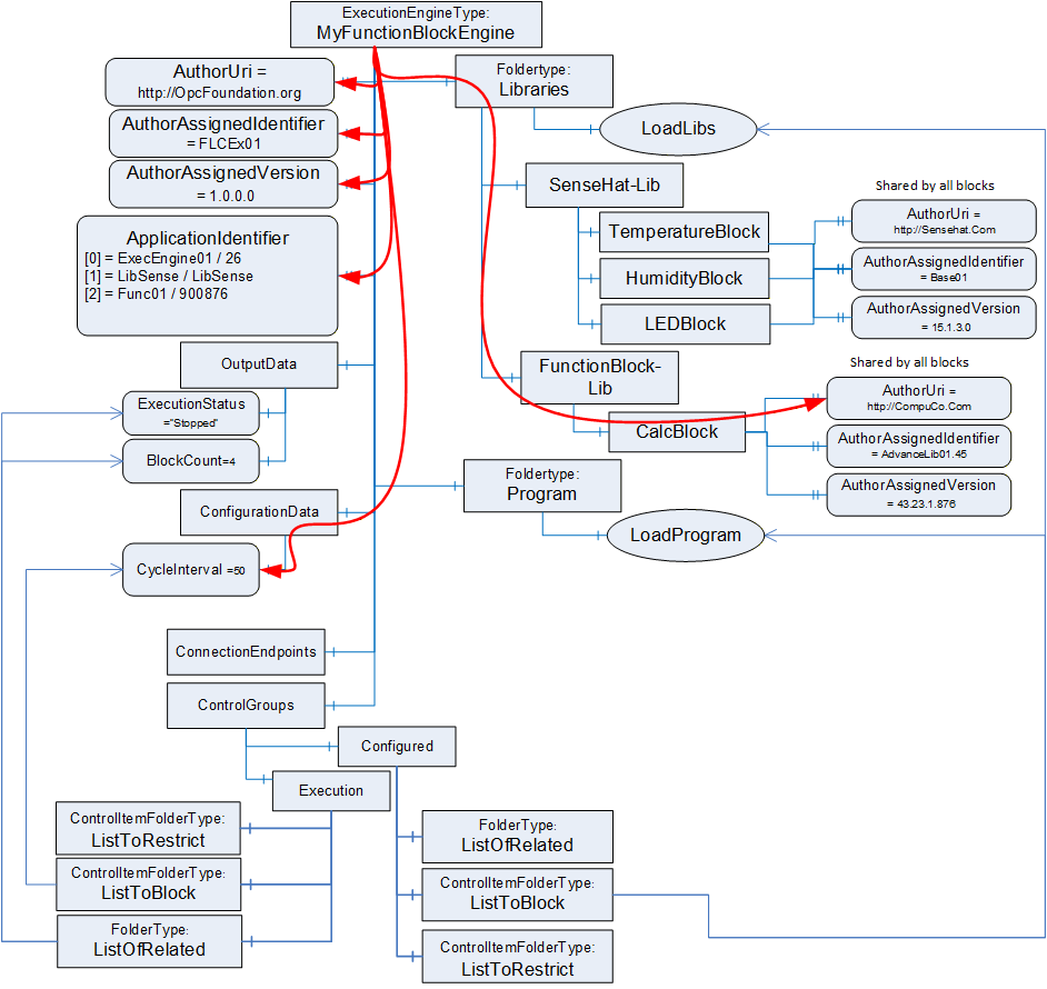
D.4 AutomationComponent examples
D.4.1 Raspberry Pi example
Figure D.35 provides an illustration of a full AutomationComponent. It omits some instances in nested Objects. This example links the Asset illustrated in D.2.2 for the SenseHat (Figure D.5) with the FunctionalEntity example in D.3.3 for the SenseHat (Figure D.19). It shows the IsExecutingOn Reference between the MyApplicationProgram FunctionalEntity and the MyRaspberryPiInstance Asset.
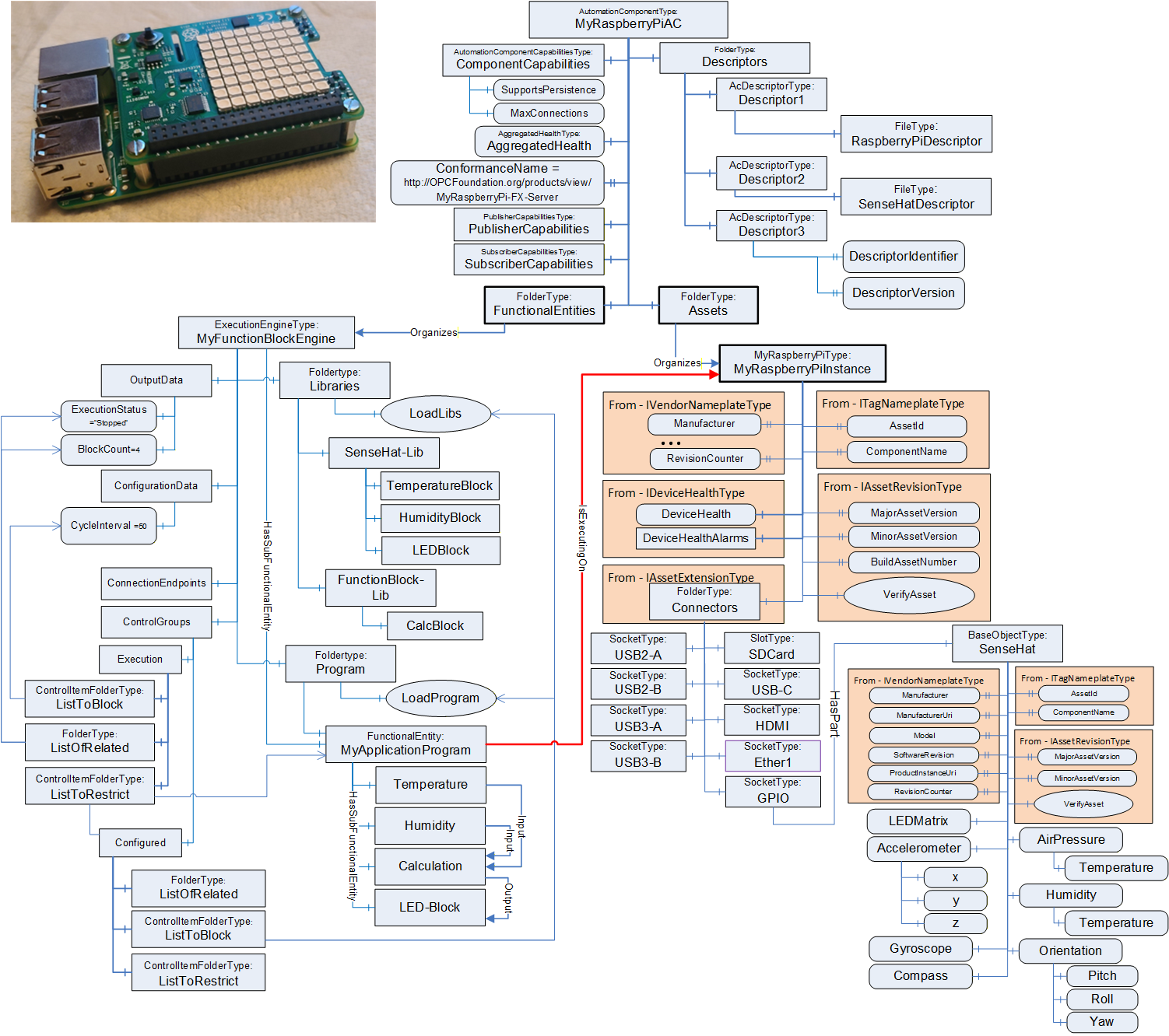
Figure D.36 provides a zoomed-in view of the AutomationComponent MyRaspberryPiAC. It illustrates the multiple Descriptors that the AC exposes. One for the original Raspberry Pi application, one for the SenseHat library that provides functionality, and one for the end user application (user program) that is loaded. It also illustrates the ConformanceName URL that points to the OPC Foundation listing for the product. Since this sample is a certified application, the URL would provide the details related to the Profile/Facets and optional ConformanceUnits related to this product's certification.
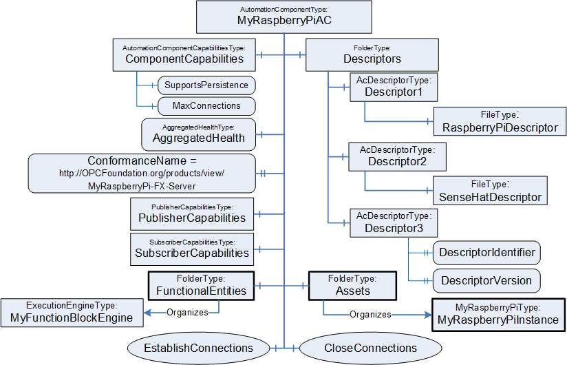
Annex E ConnectionManager examples (Informative)
E.1 ConnectionConfigurationSet examples
E.1.1 Overview
The ConnectionManager processes ConnectionConfigurationSets to establish connections. This clause contains examples for ConnectionConfigurationSets. A ConnectionConfigurationSet contains a set of logical connections, which the ConnectionManager establishes as a complete set.
A ConnectionConfigurationSet can contain
a single logical connection between two FunctionalEntities,
multiple logical connections between FunctionalEntities located on two AutomationComponents,
or multiple logical connections between FunctionalEntities located on multiple AutomationComponents.
The following examples illustrate the usage of ConnectionConfigurationSets. However, the usage of ConnectionConfigurationSets is not restricted to the examples.
E.1.2 Single logical connection
Figure E.1 depicts the configuration elements contained in a ConnectionConfigurationSet and their relation to each other for a single logical connection. The relation between the configuration elements (present on the ConnectionManager) and their resulting runtime elements (present or created on the AutomationComponents being part of the logical connection) is indicated by dashed arrows.
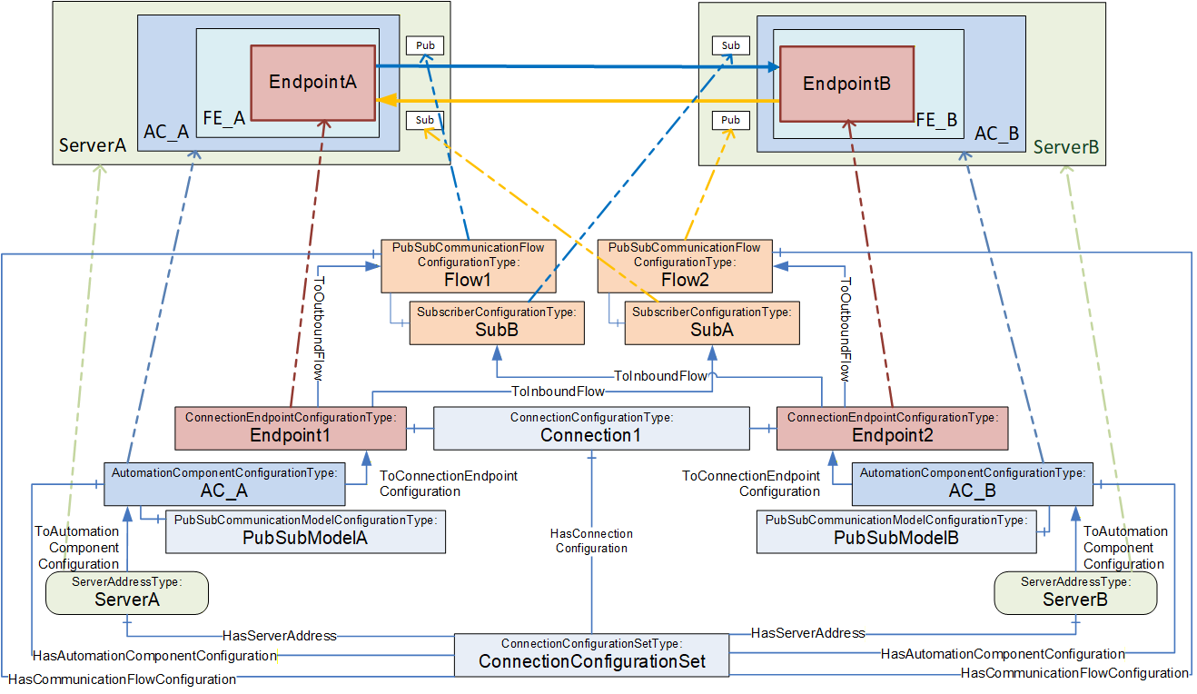
This ConnectionConfigurationSet contains one Connection configuration Connection1, which contains the configuration for a single logical connection.
Connection1 contains two ConnectionEndpointConfigurations for the two ConnectionEndpoints EndpointA and EndpointB. Each ConnectionEndpointConfiguration contains all parameters required for creating the ConnectionEndpoint, verifying the affected FunctionalEntity, requesting ControlGroups, and application configuration.
The ConnectionConfigurationSet provides two PubSubCommunicationFlowConfiguration Objects, Flow1 and Flow2. They provide communication configuration (e.g., interval, timeout or QoS) and are referenced by the Endpoints with ToOutboundFlow and ToInboundFlow References. While an Object of type SubscriberConfigurationType (SubA, SubB) contains configuration for the Subscriber only, its parent PubSubCommunicationFlowConfigurationType Object contains configuration relevant for both the Publisher and Subscriber. The configuration contained in Flow1 is used for setting up the Publisher on ServerA, and the configuration contained in SubB and Flow1 is for setting up the Subscriber on ServerB. Flow2 and SubA are used for setting up Publisher and Subscriber in the opposite direction.
EndpointA and EndpointB are each referenced by an AutomationComponentConfiguration AC_A and AC_B, which hold the FunctionalEntities involved in this logical connection. AC_A and AC_B contain the parameters for verifying Assets. AC_A and AC_B could optionally include the PubSubCommunicationModelConfiguration PubSubModelA and PubSubModelB.
AC_A and AC_B are each referenced by a ServerAddress ServerA and ServerB, containing the configuration required for the ConnectionManager to be able to establish a secure Session to ServerA and ServerB.
E.1.3 Multiple logical connections
E.1.3.1 Overview
Multiple logical connections can be configured between two or more AutomationComponents using unicast or multicast communication. Examples for each of the options are illustrated.
E.1.3.2 Multiple logical connections - two AutomationComponents
Figure E.2 depicts the configuration elements contained in a ConnectionConfigurationSet and their relation to each other for multiple logical connections between two AutomationComponents.
Often, traffic between two AutomationComponents will be optimized to use one NetworkMessage. EndpointA1 and EndpointA2 share PubSubCommunicationFlowConfiguration Flow1 with a ToOutboundFlow Reference and share SubscriberConfiguration SubA with a ToInboundFlow Reference to ensure the same set of parameters for the outbound and inbound NetworkMessage. The same applies to EndpointB1 and EndpointB2.
A variant of this scenario is illustrated in Figure E.3. In this example, one of the connections requires a fast PublishingInterval and Qos for the exchange of real-time data, and the other connection requires a slow PublishingInterval and best-effort for the exchange of status data.
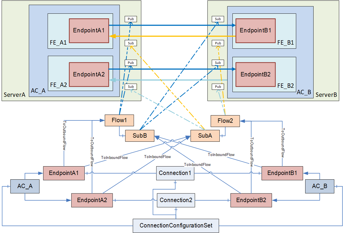
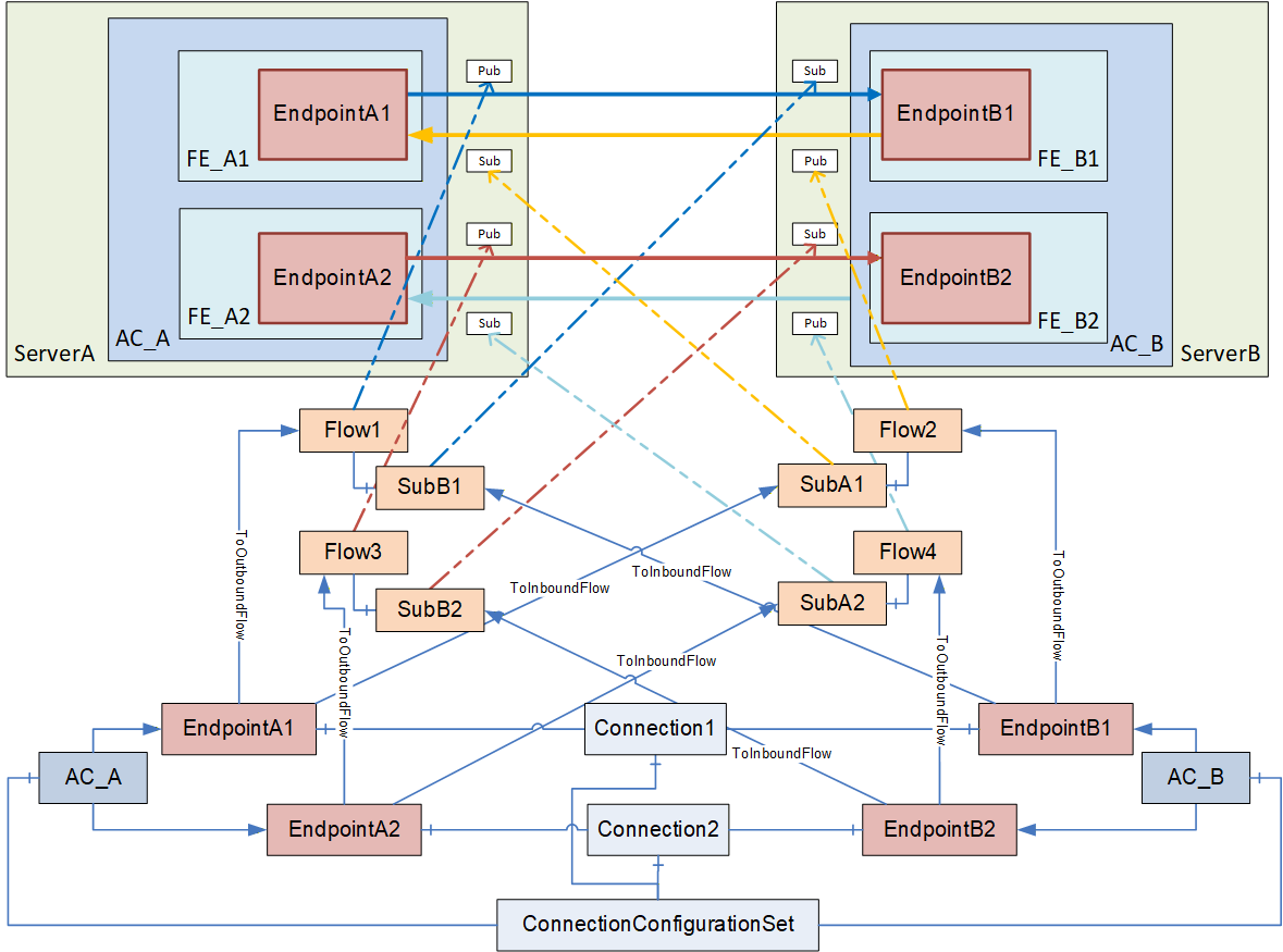
E.1.3.3 Multiple logical connections - multiple AutomationComponents
Figure E.4 depicts the configuration elements contained in a ConnectionConfigurationSet and their relation to each other for multiple logical connections among multiple AutomationComponents.
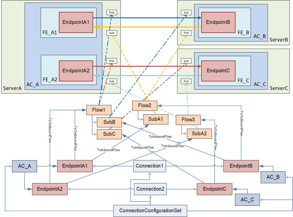
This ConnectionConfigurationSet contains two ConnectionConfigurations, Connection1 and Connection2.
Since outbound traffic from AC_A is using multicast in this scenario, both EndpointA1 and EndpointA2 refer to PubSubCommunicationFlowConfiguration Flow1 with a ToOutboundFlow Reference. Flow1 contains two SubscriberConfigurations, SubB and SubC. This allows, for example, EndpointB and EndpointC to have different settings for the MessageReceiveTimeout. EndpointB and EndpointC refer to their specific Subscriber configuration with ToInboundFlow. If EndpointB and EndpointC do not require different SubscriberConfigurations, both endpoints could also refer to a single instance of SubscriberConfigurationType.
The unicast traffic in the opposite direction can also be modelled in various ways. The example shown in Figure E.4 allows different configuration settings for the unicast traffic with the PubSubCommunicationFlowConfiguration Flow2 and Flow3.
A variant is shown in Figure E.5, which shares the same set of parameters for the unicast Publishers and Subscribers.
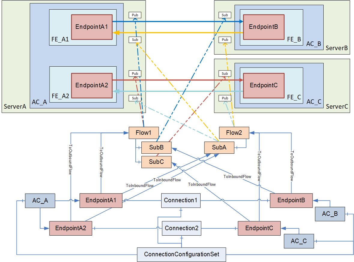
E.2 Establishing Connections
E.2.1 Overview
The ConnectionManager uses the information in the ConnectionConfigurationSet to establish all contained Connections. The configuration information required as input to call EstablishConnections on a particular AutomationComponent can be retrieved by following the References starting at each of the AutomationComponents listed in the ConnectionConfigurationSet.
The ConnectionManager iterates through the AutomationComponentConfigurations. The ConnectionManager establishes a secure Session based on the information contained in the ServerAddress (see 13.3.2) for each AutomationComponent. The ConnectionManager must resolve all PortableNodeIdentifiers contained in the configuration information (see 13.3.3).
If a PubSubCommunicationModelConfiguration was generated by the engineering tool generating the ConnectionConfigurationSet, the ConnectionManager must resolve the NodeIds contained in it (see 6.16.3.2). The ConnectionManager must ensure that the PubSubCommunicationFlowConfigurations and SubscriberConfigurations are reflected in the PubSubCommunicationModelConfiguration.
If the PubSubCommunicationModelConfiguration was not supplied by the engineering tool, the ConnectionManager must create one based on the information contained in the PubSubCommunicationFlowConfigurations.
The PubSubConfiguration contained in the PubSubCommunicationModelConfiguration could contain information:
which is targeted for the AutomationComponent (PublishedDataSets, Connections, SubscribedDataSets, ConfigurationProperties and defaultSecurityKeyServices), illustrated in Figure E.6 as red boxes with straight lines;
which is targeted for the SKS (SecurityGroups and PubSubKeyPushTargets), illustrated in Figure E.6 as green boxes with dashed lines;
and information which is ignored, illustrated in Figure E.6 as grey boxes with dashed double dotted lines (see CloseAndUpdate in OPC 10000-14).
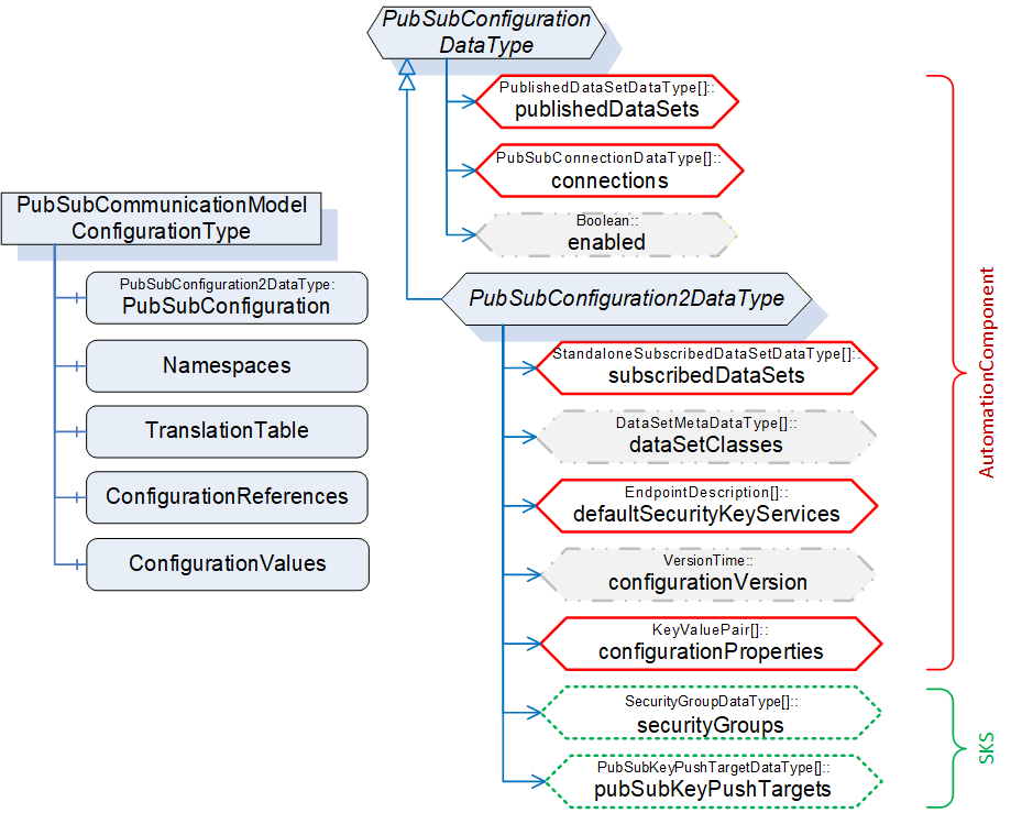
The ConnectionManager establishes all Connections by calling EstablishConnections on each AutomationComponent (see 6.2.4). This includes the communication model information targeted for the AutomationComponent (i.e., SecurityGroups and PubSubKeyPushTargets are omitted). If using PubSub, a specific sequence of calls could be required (see E.2.2).
If Connections require security (authorization or encryption), the ConnectionManager also configures the SKS (see E.5). It is recommended to hold the SKS configuration information (i.e., SecurityGroups and PubSubKeyPushTargets) in the ConnectionConfigurationSet (see 6.8.2). Alternatively, the PubSubCommunicationModelConfiguration of the AutomationComponent could be used.
A ConnectionManager typically stores (in a vendor-specific manner) all resolved NodeIds.
E.2.2 Interaction with the AutomationComponents
E.2.2.1 For logical connections between two AutomationComponents
For PubSub as a communication model, OPC 10000-14 requires certain configuration values (e.g., PublisherId, WriterGroupId, and DataSetWriterId) to match the Publisher and its corresponding Subscribers. However, unique IDs could be generated by the addressed AutomationComponent and are not be known by the ConnectionManager beforehand.
OPC 10000-14 provides two ways of generating unique IDs by the AutomationComponent, either by providing a null ID when configuring PubSub or by reserving IDs.
Assuming a simple example, where a ConnectionManager processes a ConnectionConfigurationSet containing logical connections between two AutomationComponents, the sequence illustrated in Figure E.7 could be used.
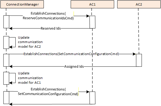
The ConnectionManager executes the following steps for establishing the Connections:
The ConnectionManager calls EstablishConnections on AC1 using the ReserveCommunicationIdsCmd to reserve WriterGroupIds and DataSetWriterIds for the publishing side (i.e., WriterGroups and DataSetWriters for AC1) and to retrieve the default PublisherId. This Call will typically contain the VerifyAssetCmd and the VerifyFunctionalEntityCmd if required; all further commands for AC1 are issued in step (3).
The ConnectionManager updates the communication configuration for AC2 regarding the subscribing side (DataSetReaders) using the IDs reserved in step (1). The ConnectionManager will set the publishing side of the communication configuration for AC2 to null IDs. The ConnectionManager calls EstablishConnections on AC2 using the SetCommunicationConfigurationCmd to add the updated communication configuration. AC2 assigns IDs to the publishing side of the communication configuration and returns the information. This Call will typically contain all other required commands.
The ConnectionManager updates the communication configuration for AC1 regarding the publishing side using the IDs reserved in step (1) and the subscribing side using the IDs returned from step (2). The ConnectionManager calls EstablishConnections on AC1 using the SetCommunicationConfigurationCmd to add the complete communication configuration. This Call will typically contain all further required commands.
E.2.2.2 For logical connections between multiple AutomationComponents
Multiple logical connections across multiple AutomationComponents could require more steps. Assume that a ConnectionManager must establish a ConnectionConfigurationSet containing logical connections between multiple AutomationComponents.
Figure E.8 illustrates an example of such a ConnectionConfigurationSet. For this scenario, the ConnectionManager could set up the logical connections as follows:
The ConnectionManager calls EstablishConnections on AC1, AC2, and AC3 using the ReserveCommunicationIdsCmd to reserve WriterGroupIds and DataSetWriterIds for the publishing side (i.e., WriterGroups, and DataSetWriters for AC1, AC2 and AC3) and to retrieve the default PublisherId.
The ConnectionManager updates the communication configuration for AC1, AC2, and AC3 regarding the publishing and subscribing side (DataSetReaders) using the IDs reserved in step (1). The ConnectionManager then calls EstablishConnections on AC1, AC2, and AC3 using the SetCommunicationConfigurationCmd to add the complete communication configuration.
The ConnectionManager could use the sequence illustrated in Figure E.8.
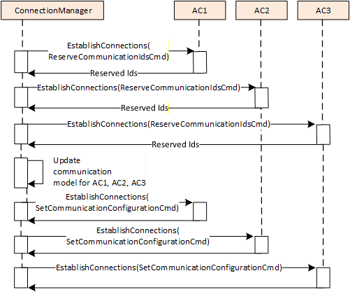
To set up this scenario, six Calls are needed in total (2 Calls per AutomationComponent). The Calls to different AutomationComponents can be issued in parallel.
If all logical connections are related to one AutomationComponent in our sample, this would be AC1. The sequence could be optimized as follows:
The ConnectionManager calls EstablishConnections on AC1 using the ReserveCommunicationIdsCmd to reserve WriterGroupIds and DataSetWriterIds for the publishing side (i.e., WriterGroups and DataSetWriters for AC1) and to retrieve the default PublisherId.
The ConnectionManager updates the communication configuration for AC2 and AC3 regarding the subscribing side (DataSetReaders) using the IDs reserved in step (1). The ConnectionManager will set the publishing side of the communication configuration for AC2 and AC3 to null IDs. The ConnectionManager calls EstablishConnections on AC1 and AC2 using the SetCommunicationConfigurationCmd to add the updated communication configuration. While adding the communication configuration, AC2 and AC3 assign IDs to the publishing side of the communication configuration and will return that information.
The ConnectionManager updates the communication configuration for AC1 regarding the publishing side using the IDs reserved in step (1) and the IDs returned from step (2). The ConnectionManager calls EstablishConnections on AC1 using the SetCommunicationConfigurationCmd to add the complete communication configuration.
This optimized sequence is illustrated in Figure E.9
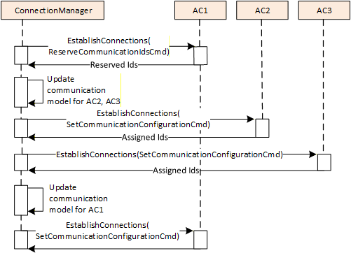
The ConnectionManager could also use a variant of the sequences above, for example, using SetCommunicationConfigurationCmd, with the publishing side of the communication configuration having null IDs instead of using the ReserveCommunicationIdsCmd. In this case, the subscribing side of the communication configuration will be added in a separate step.
E.3 Enable, disable, or remove Connections
The concepts for enable, disable, and remove are described in normative text (see 6.2.4 and 6.2.5), and since caching of NodeIds is vendor-specific, no example is provided.
E.4 Configuration of PubSub-based Connections
E.4.1 Overview
This clause describes the configuration settings for the connection types defined in Subclause 5.5.1 using PubSub as a communication model. For simplicity, all samples describe a single logical connection contained in the ConnectionConfigurationSet. Note, however, that as shown in E.1.3, a ConnectionConfigurationSet can contain multiple Connections, which could have different connection types.
The examples provide illustrations of how PubSub communication can be configured. The configuration contains various settings that have an influence on the communication model, including Address, PublishingInterval, QoS, MessageReceiveTimeout, ReceiveQos and SecurityMode (see 6.13.3 for additional details). Some of these settings can be complex to apply, such as the Address. Depending on the type of connection, this Address might contain a destination address, a receiving address, or a multicast address.
To set up the PubSubConfiguration for the bidirectional connection (illustrated in Figure E.1), information from multiple configuration elements is used, as illustrated in Figure E.10. For a simpler overview, configuration data not related to the communication model and the Endpoint2 are omitted.
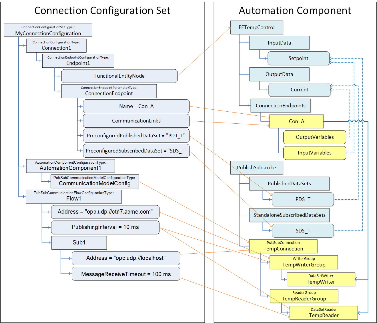
CommunicationModelConfig contains the PubSub configuration elements to be applied to the AutomationComponent. The ConnectionManager uses the configuration information in Flow1 and Sub1 to update the communication model. CommunicationLinks indicate which DataSetReader and DataSetWriter contained in the communication model are relevant for this ConnectionEndpoint. This information is also used to set up the ToDataSetReader and ToDataSetWriter References on Con_A.
This example exposes the PubSub configuration model, but if it were not exposed, the DataSetReaderPath and DataSetWriterPath in Con_A would contain the names illustrated in boxes (PubSubConnection, ReaderGroup, DataSetReader and PubSubConnection, WriterGroup, DataSetWriter) i.e. TempConnection, TempReaderGroup, TempReader for the DataSetReaderPath and TempConnection, TempWritergroup, TempWriter for the DataSetWriterPath.
E.4.2 Bidirectional connection
The Connection configuration for a bidirectional connection contains the following configuration information (see Figure E.11):
EndpointA, indicating InputVariables and OutputVariables,
EndpointB, indicating InputVariables and OutputVariables,
Flow1 and SubB describing the configuration for the information flow from EndpointA to EndpointB,
Flow2 and SubA for the information flow from EndpointB to EndpointA.

E.4.3 Unidirectional connection with heartbeat
The Connection configuration for a unidirectional connection with heartbeat contains the following configuration information (see Figure E.12):
EndpointA, indicating OutputVariables,
EndpointB, indicating InputVariables,
Flow1 and SubB describing the configuration for the information flow from EndpointA to EndpointB,
Flow2 and SubA for the heartbeat from EndpointB to EndpointA.
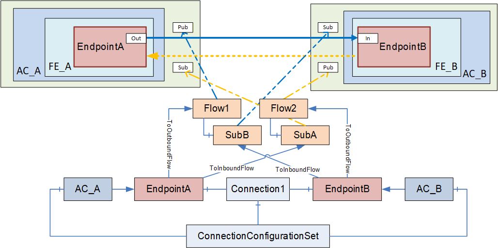
E.4.4 Unidirectional connection
The Connection configuration for a unidirectional connection contains the following configuration information (see Figure E.13):
EndpointA, indicating OutputVariables,
EndpointB, indicating InputVariables,
Flow1 and SubB describing the configuration for the information flow from EndpointA to EndpointB.
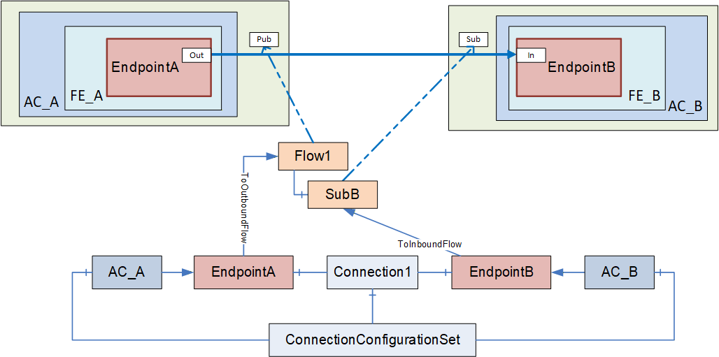
E.4.5 Autonomous publisher
The Connection configuration for an autonomous Publisher contains the following configuration information (see Figure E.14):
EndpointA, indicating OutputVariables;
Flow1, describing the configuration for the information flow from EndpointA to one or more unknown Subscribers.
For an autonomous publisher, no SubscriberConfiguration is required (see 6.13.3.2).
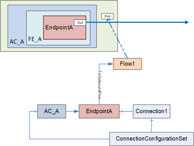
E.4.6 Autonomous subscriber
The Connection configuration for an autonomous subscriber contains the following configuration information (see Figure E.15):
EndpointA, indicating InputVariables,
Flow1 and SubA describing the configuration for the information flow from an unknown Publisher to EndpointA.
For an autonomous subscriber, no ToOutboundFlow Reference is required. Configuration which applies only to the Publisher of the information flow can be omitted, i.e., Address and TransmitQos (see E.4.1).
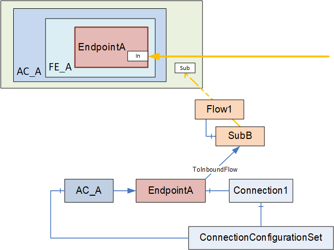
E.4.7 PubSub DataSets
This subclause provides an overview of PubSub communication options and the use of DataSets. For a complete description of PubSub communication, PubSub communication options, DataSets and DataSetMetaData, please see OPC 10000-14.
PubSub communication has multiple options that are defined by Profiles. To see what is defined in UAFX for a controller or device, see the UAFX-defined Profiles in the Profile database. When setting up communication between controllers, between a device and a controller, or even between devices, the engineering tool must ensure that the PubSub Profile to be used for the communication is available on the communicating devices. To ensure interoperability, the UAFX controller Profile require a specific PubSub Profile. Vendors are free to add additional PubSub Profiles.
At this point, UADP is required in UAFX Profiles, and thus, this discussion will focus on this communication protocol. Within a Profile, there are options related to the communication configuration. The engineering tools and/or ConnectionManager can make various selections. This can include optimizations which group multiple DataSetMessages into a single Network Message (see Figure E.16).
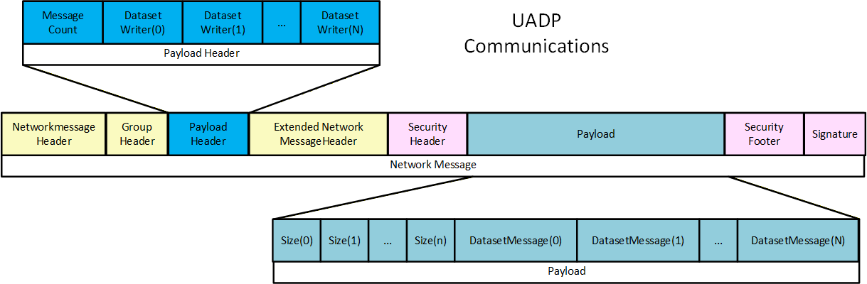
Many of the options are self-described in the UADP PubSub communication protocol, allowing a Subscriber to handle a larger range of published messages. The UADP communication includes header information that describes the overall DataSet. It can include information like a timestamp and/or status information (see Figure E.17).
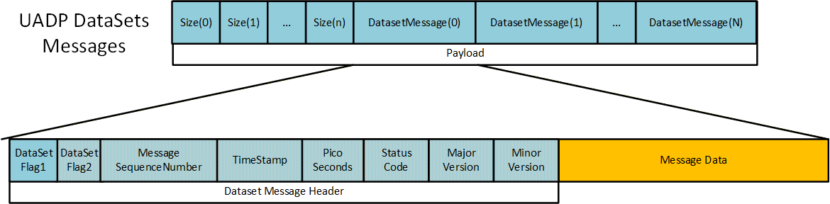
The DataSetMessage can use the periodic fixed mapping, depending on the communication options selected. It is a fixed structure where all items defined in the DataSet have a value that is returned in every message. The message only contains the values, so the Subscriber has to be aware of the order/mapping of Variables in the DataSet (see Figure E.18). The encoding of the value is also configurable. The period fixed profile requires the encoding as a raw value. Other profiles support a variant encoding (which allows for a status to be sent in the case of a bad status) or a DataValue (value, status, and timestamps) encoding.
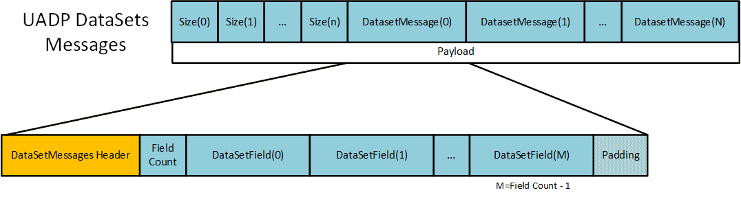
Other PubSub Profiles can include a dynamic layout. In this case, the DataSetMessage can also be a delta frame, which is very similar to Client Server communication, and only changed values are sent. In this type of DataSetMessage, an index and the value are packaged into the message. The index is only an index into the array of Variables defined in the DataSet (see Figure E.19).
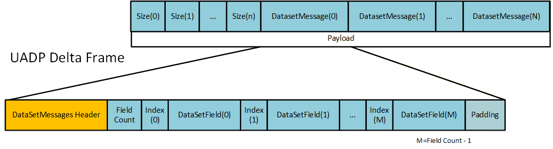
The DataSetMessage can also be an Event. Events are much like fixed DataSetMessages, except that they are always a structure that is encoded as a Variant (see Figure E.20).
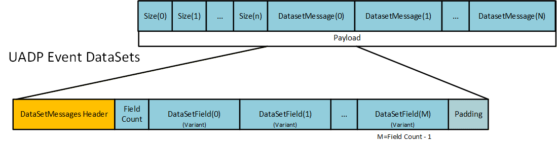
In this version of this document, Events are not used.
The configuration of a DataSet is defined as an array of a structure, where the structure lists the details of the item that is to be published, and the array provides the order in which they will be in the DataSet. These DataSets could be preconfigured or could be created at run time. Figure E.21 illustrates what is defined as part of a DataSet (both Publisher and Subscriber).
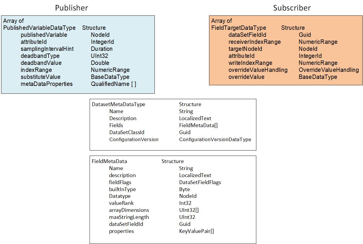
Preconfigured DataSets can be provided in UAFX as part of a FunctionalEntity or as part of an AutomationComponent.
For this version of the document, it is recommended to provide preconfigured DataSets as part of a FunctionalEntity. Use cases for DataSets as part of an AutomationComponent could be added in a later version of this document.
When establishing communication, the DataSet and the Publisher's DataSetMetaData define what is on the wire. This includes which Nodes are used for the Values, their DataTypes (on the wire and native), the size (if an array or string) and the possible pre-processing of the Values (filtering, error handling, etc.).
The DataSet definition on the Subscriber describes the mapping of fields in the DataSet to Variables in the Server. It includes error handling and allows for restricting the data field to a specific index in the field (fields that were arrays on the wire). The (Standalone-) SubscribedDataSet can select a subset of the transmitted fields, i.e., it can skip any values that it is not interested in.
In a ConnectionConfigurationSet, a specific Connection can use a preconfigured DataSet or dynamically create a DataSet for the Publisher or Subscriber. Regardless of whether the DataSet is preconfigured or dynamically configured, the important aspect for the engineering tool and the ConnectionManager is that the appropriate published Variable is mapped to the appropriate subscribed Variable. This also includes checking that the DataType of the Variables is correct (and matches) and that the engineering units or other metadata associated with the Variable also matches (see 5.5.6.2.5).
The verification of metadata and DataSet can be minimized if the ConnectionEndpointParameter contains ExpectedPublishedDataSetVersion and/or ExpectedSubscribedDataSetVersion. These Variables can be used to confirm that the current configuration matches what was defined in the engineering tool.
Three possible combinations of DataSets exist for an information flow on a Connection between two FunctionalEntities to be configured:
Preconfigured DataSets exist on both endpoints.
A preconfigured DataSet exists on just one of the endpoints.
Preconfigured DataSets do not exist on either endpoint.
For scenario (a), the engineering tool configuring the information flow uses the preconfigured DataSets.
For scenario (b), the engineering tool configuring the information flow creates a customized DataSet with DataSetMetaData matching the preconfigured DataSet for the desired variables. The engineering tool should provide (as in scenario (a) the name of the preconfigured DataSet for one ConnectionEndpoint but leave the name empty on the other ConnectionEndpoint.
For scenario (c), the engineering tool configuring the information flow creates customized DataSets with matching DataSetMetaData for both ConnectionEndpoints.
An engineering tool or the ConnectionManager could generate the PubSubConfiguration.
If the engineering tool generates the PubSubConfiguration, it will store customized DataSets within the PubSubConfiguration, e.g. for a published DataSet they are a PublishedDataSet in PublishedDataSets and for a subscribed DataSet they are a SubscribedDataSet in the DataSetReader. Preconfigured DataSets are used by setting the DataSetName in the DataSetWriter or DataSetReader to the name of the desired DataSet.
If the ConnectionManager is intended to generate the PubSubConfiguration, the engineering tool would add the names of preconfigured DataSets to be used in the ConnectionEndpointConfigurationParameter (e.g., PreconfiguredPublishedDataSetName or PreconfiguredSubscribedDataSetName). Customized DataSets can be stored in the PublishedDataSetData or SubscribedDataSetData (see F.1.5) or within the vendor-specific format.
A ConnectionConfigurationSet might contain multiple Connections that all need to be communicating as a set. In this case, the ConnectionManager and/or the engineering tool can also optimize communication by grouping Variables for multiple Connections into a single DataSet or into a single network message. For example, if the ConnectionConfigurationSet has three Connections between two AutomationComponents (different FunctionalEntities), the PubSub configuration might be a single DataSet with all the required Variables. Alternatively, it might be three DataSets in a single network message. If more AutomationComponents are in the set, it might even be a multicast network message that multiple AutomationComponents could be subscribing for. Please refer to Subclause 5.5.6.2 for further information.
E.5 Interaction with an SKS
The examples and illustration in this clause are related to an external SKS. An SKS that is internal (i.e. part of a ConnectionManager) would still be required to perform the same described functionality but may not implement the AddSecurityGroup and AddPushTarget Methods. Instead, it might use any internal method.
The usage of SecurityGroups is defined by OPC 10000-14 as follows:
The SKS is responsible for generating keys for its configured SecurityGroups. The SKS can expose the SecurityGroups in its Information Model.
A Publisher uses the current key to sign or sign and encrypt NetworkMessages, and Subscriber(s) to authenticate or authenticate and decrypt NetworkMessages. The past key, current key and a requested number of future keys are distributed from the SKS to the Publisher and the Subscriber(s) using the push or pull model. How past, current and future keys are stored and organized on the Publisher and Subscriber(s) is vendor-specific.
In the push model, the set of keys is pushed by the SKS to the AutomationComponents using SetSecurityKeys. In the pull model, the set of keys is pulled by the AutomationComponents from the SKS using GetSecurityKeys.
The SecurityGroupId links the key generation side (i.e., the SKS) and the key usage side (i.e., Publisher, Subscriber). If an AutomationComponent calls GetSecurityKeys on the SKS or an SKS calls SetSecurityKeys on the AutomationComponent with a specific SecurityGroupId, all WriterGroups and DataSetReaders utilizing the SecurityGroupId on the AutomationComponent will get the new set of keys.
PubSubKeyPushTargets are used on the SKS to manage the distribution of the keys for the push model. They have no equivalent on the key usage side. The SKS can expose the PubSubKeyPushTargets in its Information Model.
The SKS responsible for generating the security keys related to a ConnectionConfigurationSet is indicated in the ConnectionConfigurationSet by the SecurityKeyServer configuration. In addition, the SecurityKeyServer indicates whether to use the push or pull model for the distribution of the security keys.
Every UAFX implementation compliant with the "http://opcfoundation.org/UA-Profile/UAFX-Controller-Profile" supports the SKS push model. An AutomationComponent indicates support for the pull model by the Facets it includes in its ServerProfileArray ("http://opcfoundation.org/UA-Profile/Publisher/MessageSecurity" for a Publisher and "http://opcfoundation.org/UA-Profile/Subscriber/MessageSecurity" for a Subscriber). The ServerProfileArray can be retrieved online or from the Descriptor.
ConnectionManager and SKS could be located on the same Server. In this case, the ConnectionManager could use vendor-specific means to configure the SKS (not illustrated). If the ConnectionManager and SKS are located on different Servers, the SKS exposes its configuration model. A ConnectionManager could wish to optimize its communication with the external SKS. These examples illustrate this communication.
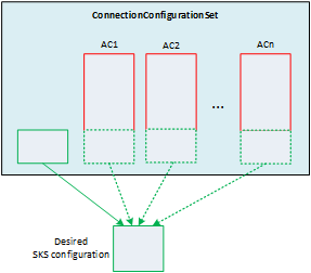
As illustrated in Figure E.22, the ConnectionManager constructs the desired configuration for the SKS from the set of SecurityGroups and PubSubKeyPushTargets in the ConnectionConfigurationSet Object and PubSubCommunicationModelConfigurations of all AutomationComponentConfigurations in the ConnectionConfigurationSet (see 6.16.3 and Figure E.6). It is recommended that only the ConnectionConfigurationSet Object is used for holding the desired SKS configuration.
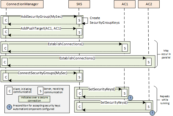
Figure E.23 illustrates the configuration of an external SKS for the push model.
The ConnectionManager applies the desired configuration on the SKS:
SecurityGroups are added to the SKS using AddSecurityGroup,
PubSubKeyPushTargets are added to the SKS using AddPushTarget and ConnectSecurityGroups.
The SKS will not return an error if the SecurityGroup or the PubSubKeyPushTarget (with the same parameters) is added multiple times.
After the SKS configuration is finished, the SKS will start to periodically push the keys to the AutomationComponents registered with the push targets. A push target will accept keys only if they are from an SKS that is trusted and the SecurityGroupId is known. SecurityGroupIds (for a Publisher in the WriterGroup and for a Subscriber in the ReaderGroup/DataSetReader) are configured by the ConnectionManager on the AutomationComponent as part of the EstablishConnections Call. If a push target rejects SetSecurityKeys, the SKS will continue to retry at RetryInterval. If a push target accepts SetSecurityKeys, the SKS will repeat pushing keys at a period of half KeyLifetime (see OPC 10000-14).
For a push model configuration, it is recommended that the ConnectionManager establishes the Connections on the AutomationComponents before updating the SKS. It is recommended to perform as much configuration as possible in parallel, which could mean that the SKS configuration completes before all of the Subscribers and Publishers are configured (each configuration is processed in a separate thread).
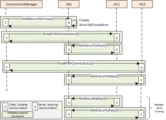
Figure E.24 illustrates the configuration of an external SKS for the pull model.
The ConnectionManager applies the desired configuration on the SKS:
SecurityGroups are added to the SKS using AddSecurityGroup.
SecurityKeyServer and SecurityGroupIds (for a Publisher in the WriterGroup and for a Subscriber in the ReaderGroup/DataSetReader) are configured by the ConnectionManager on the AutomationComponent as part of the EstablishConnections Call. After the AutomationComponent configuration is finished, the Publisher/Subscriber periodically accesses the SKS and pulls keys. The Publisher/Subscriber would have to have Client capabilities. The SKS will return keys only if it trusts the Client making the connection and the SecurityGroupId is known. The pull can be triggered on the Subscriber by the reception of a NetworkMessage using a new key from the Publisher. The Subscriber keeps a certain number of future keys, and when a new one is used by the Publisher, it is already cached and available.
For a pull model configuration, it is recommended that the ConnectionManager establishes the Connections on the AutomationComponents after updating the SKS. If the SKS rejects GetSecurityKeys (e.g., SecurityGroups have not yet been added to the SKS), the next GetSecurityKeys is repeated by the AutomationComponent using vendor-specific retry logic.
It is important to understand that end-to-end communication will not occur until all parties (Publisher, Subscriber, and SKS) have been configured by the ConnectionManager and current keys have been distributed to Publishers and Subscribers. For the push model, the SKS continues to retry pushing keys using SetSecurityKeys at the RetryInterval if an AutomationComponent is not yet configured. For the pull model, the AutomationComponent continues to retry pulling keys using GetSecurityKeys using vendor-specific retry logic if the SKS is not yet configured. Retry intervals can affect how fast communication starts for a Connection. Typically, a retry interval should be short enough to not delay communication but not so short that it overloads network traffic or the Server. See OPC 10000-14 for additional details on SecurityKeyServices.
E.6 ConnectionConfigurationSet and PubSubConfiguration
E.6.1 Overview
If using PubSub as a communication model, the ConnectionConfigurationSet contains a PubSubConfiguration Variable for each AutomationComponent's CommunicationModelConfig that has a DataType that is a large structure. This structure is passed to the EstablishConnections Method to provide the required information to the AutomationComponent to configure PubSub communication on that AutomationComponent. An OPC UA Client could adjust some information that is inside of this data structure (see 5.5.2). To facilitate this possible adjustment, some aspects of the large structure are exposed as Variables in the ConnectionConfigurationSet.
Figure E.25 illustrates the relation between elements in the ConnectionConfigurationSet and the PubSubConfiguration. Note that for clarity, parts of the ConnectionConfigurationSet are omitted. For an overview of all elements in the ConnectionConfigurationSet, please refer to 6.8.
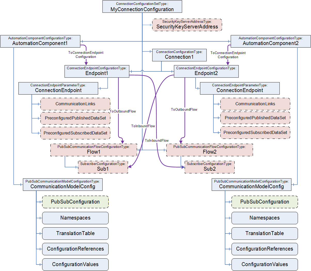
Each AutomationComponentConfiguration listed in the ConnectionConfigurationSet has its individual PubSubCommunicationModelConfiguration. The PubSubCommunicationModelConfiguration holds the PubSubConfiguration (highlighted in green with a dashed line).
The following elements within the ConnectionConfigurationSet are related to the PubSubConfiguration (highlighted in red with dashed-dotted lines):
ConnectionEndpointParameter Variables CommunicationLinks, PreconfiguredPublishedDataSet, and PreconfiguredSubscribedDataSet are related to DataSetReader and DataSetWriter in the PubSubConfiguration;
PubSubCommunicationFlowConfiguration Object including its SubscriberConfiguration child Objects and SecurityKeyServerAddress Object, contain Variables related to PubSubConnections, ReaderGroups and WriterGroups in the PubSubConfiguration.
All of the related Variables are of SelectionListType, which allows limiting the choice that can be made (see 6.8.1). After a ConnectionConfigurationSet is edited (see 6.7.4), the ConnectionManager reflects the changes into the PubSubConfiguration.
The PubSubConfiguration could be generated by an engineering tool or by the ConnectionManager.
Clause E.6 indicates PubSubConfiguration settings, which are based on using UDP-UADP as the transport Profile and UADP-Periodic-Fixed as the header layout Profile. Details for other transport or header layout Profiles could be added in a later version of this document.
E.6.2 ConnectionConfigurationSet and WriterGroup
As defined in OPC 10000-14, a WriterGroup defines the Publisher of a NetworkMessage. It is recommended that the PubSubConfiguration contains a WriterGroup for each instance of PubSubCommunicationFlowConfigurationType. For the example illustrated in Figure E.5, a WriterGroup in AC_A is generated based on the parameters in Flow1, and a WriterGroup is generated for each AC_B and AC_C based on the parameters in Flow2.
Figure E.26 illustrates the relation between the PubSubCommunicationFlowConfiguration and the PubSubConnection and WriterGroup within the PubSubConfiguration. If any changes are made to the PubSubCommunicationFlowConfiguration, the related PubSubConnection information, as illustrated in Figure E.26, will be updated.
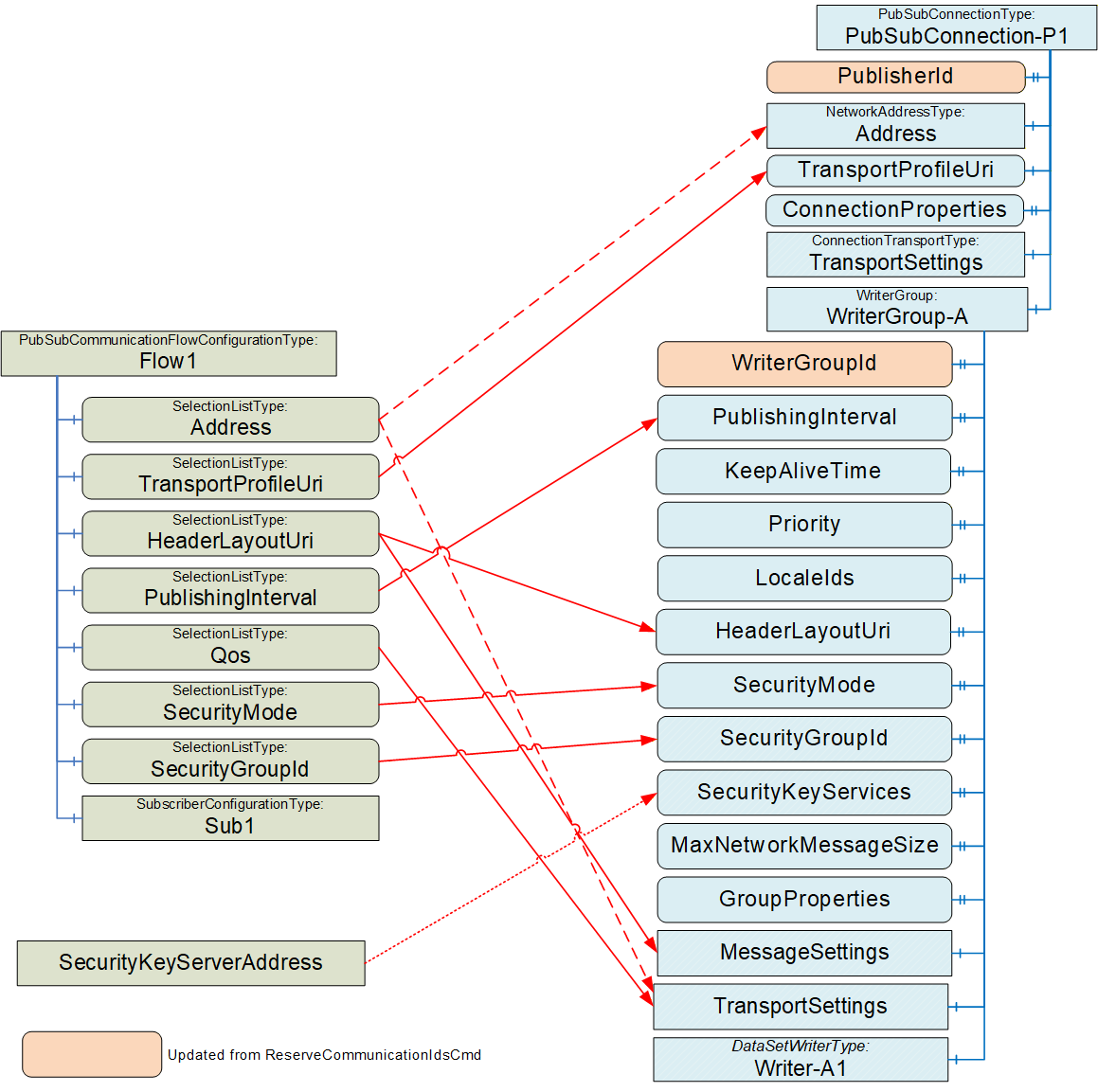
It is recommended to update WriterGroupId and PublisherId after issuing the ReserveCommunicationIdsCmd; see E.2 for details.
Depending on the transport profile and on the type of Address (unicast or multicast), the Address will be in the PubSubConnection or in the WriterGroup's TransportSettings; see OPC 10000-14 for details. As an example, if UDP-UADP is used as the transport profile, a unicast address is set in the WriterGroup, but a multicast address is set in the PubSubConnection.
TransportProfileUri is used to set up the information in the PubSubConnection, whereas HeaderLayoutUri, PublishingInterval, Qos, SecurityMode and SecurityGroupId are used to set up the information in the WriterGroup.
The PubSubConnection elements ConnectionProperties and TransportSettings are transport-specific. For the TransportProfileUri "http://opcfoundation.org/UA-Profile/Transport/pubsub-udp-uadp" (UDP-UADP), both are set to null.
The WriterGroup elements GroupProperties and TransportSettings are transport-specific. For UDP-UADP, GroupProperties is set to null. For UDP-UADP, the elements MessageDelay, MessageRepeatCount, Address, QosCategory, and DatagramQos are defined in TransportSettings. The value of MessageDelay and MessageRepeatCount depends on the header layout. For http://opcfoundation.org/UA/PubSub-Layouts/UADP-Periodic-Fixed" (UADP-Periodic-Fixed), both are set to 0. QosCategory and DatagramQos are derived from Qos.
The WriterGroup element MessageSettings is transport-specific. For UDP-UADP, the GroupVersion is defined by the generator of the ConnectionConfigurationSet. To ensure a consistent definition of the GroupVersion, it is recommended that the WriterGroup is configured completely within one ConnectionConfigurationSet. NetworkMessageContentMask and DataSetOrdering are derived from the HeaderLayoutUri. PublishingOffset and SamplingOffset can be set to a negative value, meaning not used. They could be used when additional Quality of Services are specified.
SecurityKeyServerAddress is set in the WriterGroup only if a pull model is to be configured (for additional details, see 9.3.2).
For MaxNetworkMessageSize, follow the recommendations in OPC 10000-14. For UADP-PeriodicFixed, KeepAliveTime should be set to PublishingInterval. LocaleIds can be set to a value different from null if the translation of Strings will be done by the Publisher. Priority can be used to set the relative priority of the WriterGroup for processing it.
E.6.3 ConnectionConfigurationSet and ReaderGroup
As defined in OPC 10000-14, DataSetReaders in a ReaderGroup can extract their DataSetMessages from different NetworkMessages. However, it is recommended that the PubSubConfiguration generated for an AutomationComponent contains a ReaderGroup for each PubSubCommunicationFlowConfiguration. By this, common parameters (e.g., SecurityGroupId, SecurityKeyServices, TransportSettings, or MessageSettings) are configured on the ReaderGroup and do not need to be repeated in each DataSetReader.
For the example illustrated in Figure E.5, a ReaderGroup in AC_A is generated based on the parameters in SubA, a ReaderGroup is generated for each AC_B based on the parameters in SubB, and a ReaderGroup is generated in AC_C based on the parameters in SubC.
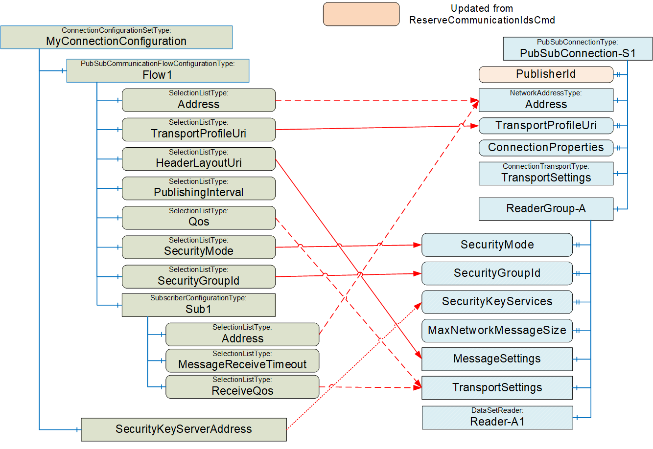
Figure E.27 illustrates the relation between the SubscriberConfiguration and the PubSubConnection and ReaderGroup within the PubSubConfiguration.
It is recommended to update PublisherId after issuing the ReserveCommunicationIdsCmd; see E.2 for details.
For a Subscriber, the Address will be in the PubSubConnection. See 6.13.3.3 on how to set the Address.
TransportProfileUri is used to set up the information in the PubSubConnection, whereas HeaderLayoutUri, PublishingInterval, Qos, SecurityMode and SecurityGroupId are used to set up the information in the ReaderGroup.
The PubSubConnection elements ConnectionProperties and TransportSettings are transport-specific. For the UDP-UADP, both are set to null.
SecurityKeyServerAddress is set in the ReaderGroup only if a pull model is to be configured (for additional details, see 9.3.2).
For MaxNetworkMessageSize, follow the recommendations in OPC 10000-14.
E.6.4 ConnectionConfigurationSet and DataSetWriter
As illustrated in Figure E.28, the configuration of the DataSetWriter can be derived from the ConnectionEndpointParameter and the PubSubCommunicationFlow.
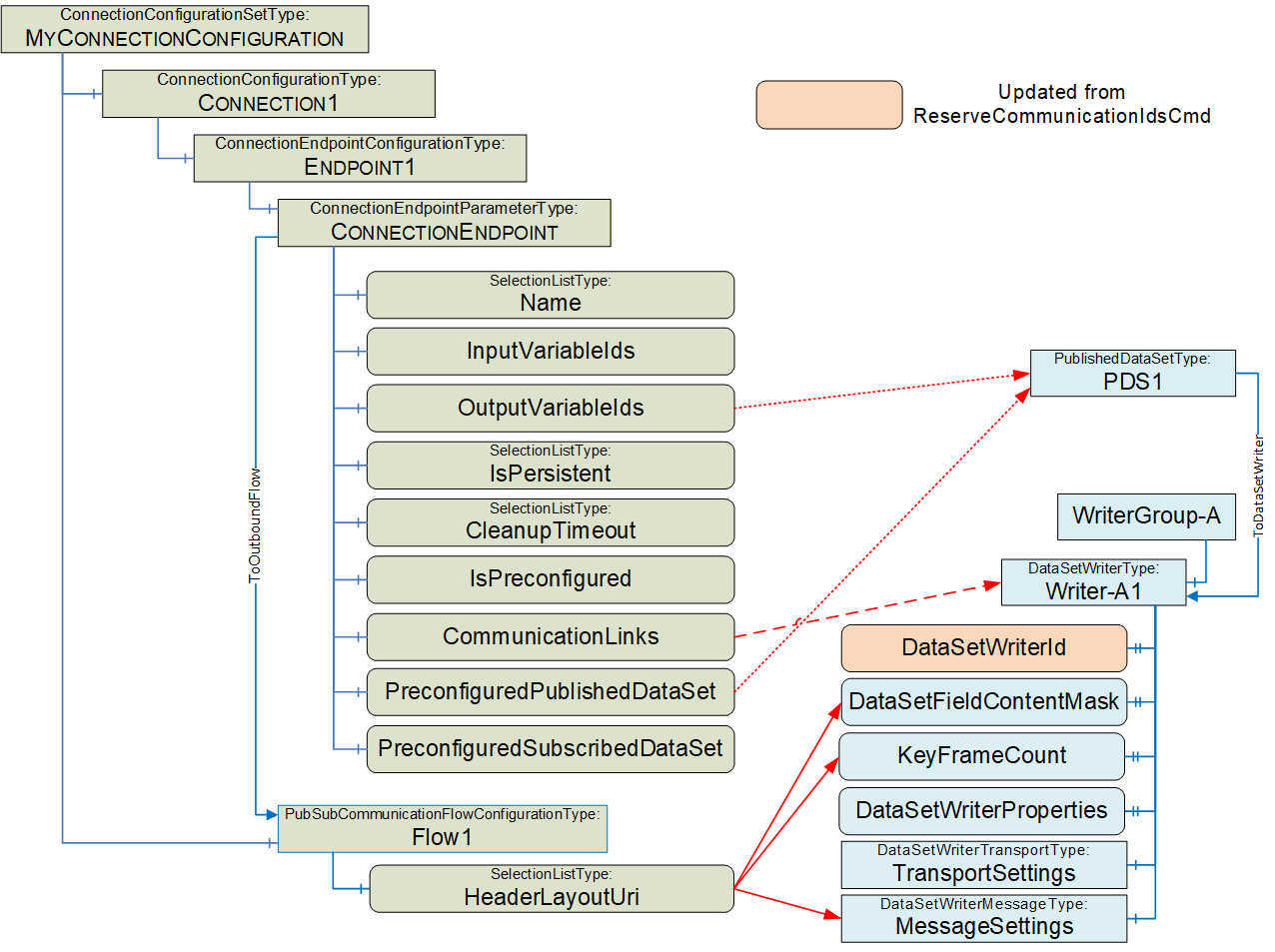
The ToDataSetWriter Reference can be derived from either the PreconfiguredPublishedDataSet or from a custom PublishedDataSet within the PubSubConfiguration. The PublishedDataSet contains the OutputVariableIds specified in the ConnectionEndpointParameter.
The DataSetWriter element MessageSettings is transport-specific. For UDP-UADP, the DataSetMessageContentMask, ConfiguredSize, NetworkMessageNumber, and DataSetOffset are derived from the HeaderLayoutUri. For UADP-Periodic-Fixed ConfiguredSize, NetworkMessageNumber and DataSetOffset of the DataSetMessage are determined by the generator of the PubSubConfiguration.
For UADP-Periodic-Fixed, the KeyFrameCount is set to 1.
For UDP_UADP, no DataSetWriterProperties or TransportSettings are defined.
E.6.5 ConnectionConfigurationSet and DataSetReader
As illustrated in Figure E.29, the configuration of the DataSetReader can be derived from the ConnectionEndpointParameter, the SubscriberConfiguration and its parent Object.
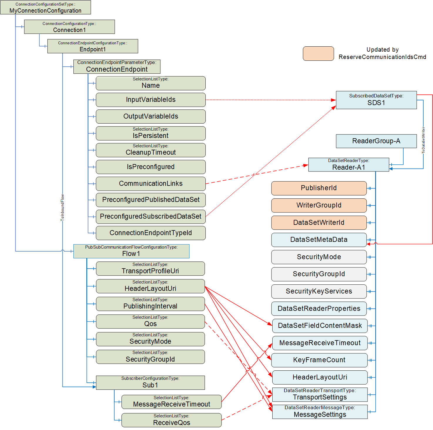
It is recommended to update PublisherId, WriterGroupId and DataSetWriterId after issuing the ReserveCommunicationIdsCmd; see E.2 for details. The values are set to correspond to the Publisher of the DataSetMessage.
The ToDataSetReader Reference can be derived from either the PreconfiguredSubscribedDataSet or from a custom SubscribedDataSet within the PubSubConfiguration. The SubscribedDataSet contains the InputVariableIds specified in the ConnectionEndpointParameter.
The DataSetReader element MessageSettings is transport-specific. For UDP-UADP, NetworkMessageNumber, DataSetOffset, NetworkMessageContentMask, and DataSetMessageContentMask are derived from the HeaderLayoutUri. For UADP-Periodic-Fixed, NetworkMessageNumber and DataSetOffset of the DataSetMessage are determined by the generator of the PubSubConfiguration. ReceiveOffset and ProcessingOffset can be set to a negative value, indicating that they are not used. They will be used when additional Quality of Services are specified. GroupVersion and PublishingInterval are set corresponding to the Publisher of the DataSetMessage. DataSetClassId can be set to null.
The DataSetReader element TransportSettings is transport-specific. For UDP-UADP, the Address is set to null. QosCategory and DatagramQos are derived from ReceiveQos and Qos; see 6.13.3.3 for details.
For UDP_UADP, no DataSetReaderProperties are defined.
E.6.6 Loading / Saving ConnectionConfigurationSets
The ConnectionConfigurationSet can contain a PubSubConfiguration, which has a datatype of PubSubConfiguration2DataType. The PubSubConfiguration2DataType is a complex structure that can include DataSets (published or subscribed) that would include fields that are of NodeId DataType. NodeIds contain a NamespaceIndex. The NamespaceIndex is an index into a NamespaceArray that contains the URI that describes the owner of the Node. On a Server, this NamespaceArray is in the Server Object and is used to resolve all Nodes on the Server. But in this case, the PublishedDataSet or SubscribedDataSet describes Variables that are on the Publisher or Subscriber Server, which is very likely to be a different Server. Depending on how the ConnectionConfigurationSet and PubSubConfiguration were generated, the Namespaces could not exist on the ConnectionManager Server.
This document describes how these NodeIds are to be resolved to the correct NamespaceIndex on the target Server before the structure is transmitted as part of an EstablishConnections (see 6.16.3.2). No issues exist in using the structure to set up a Connection, but if the configuration of the ConnectionManager Server is saved as a UANodeSet XML File or if the ConnectionConfigurationsSet is generated in an engineering tool and loaded into the ConnectionManager Server, problems could arise.
The general rules for processing UANodeSet XML file are described in OPC 10000-6 Annex F.14 This subclause provides the following instructions related to NodeIds:
"Variants can contain NodeIds, ExpandedNodeIds and QualifiedNames that must be modified, so the NamespaceIndexes and ServerIndexes reference the NamespaceUri and ServerUri tables in the UANodeSet."
When generating a UANodeSet XML file, the NamespaceArray is included at the top of the UANodeset XML file. The NamespaceIndex could be updated to match the list of Namespaces listed at the top of the generated file. But in this case, not all Namespace entries might be defined in the ConnectionManager Server. So, exporting a UANodeset XML from the Server could result in an error (if the index in a Node does not exist in the Server's NamespaceArray), or it could result in an incorrect Namespace being referenced. The simplest solution is to ensure that the ConnectionManager Server include all Namespaces in its NamespaceArray, even if the only Node using that Namespace is in the complex data structure.
When an engineering tool generates a ConnectionConfigurationSet, if it includes DataSets, then it will need to ensure that any NodeId it generates for its ConnectionManager's Server does not have a translation issue. Multiple options exist:
This could be done by ensuring that the ConnectionManager Server configuration includes all Namespaces used for all NodeIds, even if the NodeIds are not on the ConnectionManager's Server.
The ConnectionManager's Server could understand the ConnectionConfigurationSet PubSubConfiguration and bypass standard processing for the PubSubConfiguration (i.e., not map).
The engineering tool does not provide DataSets that include Variables, and the ConnectionManager generates the PubSubConfiguration.
The actual manner in which this is handled is vendor-specific, but the developer should be aware of these related issues.
Annex F Persistence of ConnectionConfigurationSets (Normative)
F.1 DataTypes for Connection Manager Configuration
F.1.1 Overview
This annex describes DataTypes that can be used to serialize the Objects that compose a ConnectionConfigurationSet (see 6.8 and 6.10) into a single structure (ConnectionConfigurationSetDataType). The ConnectionConfigurationSetDataType can, for example, be used for persisting a ConnectionConfigurationSet, for storing it within a File (see F.2), or for maintaining the configuration of a ConnectionManager (see F.3).
For the base principles used for the mapping, see Subclause F.1.2.
Figure F.1 depicts the different components of the ConnectionConfigurationSetDataType and their relation to each other.
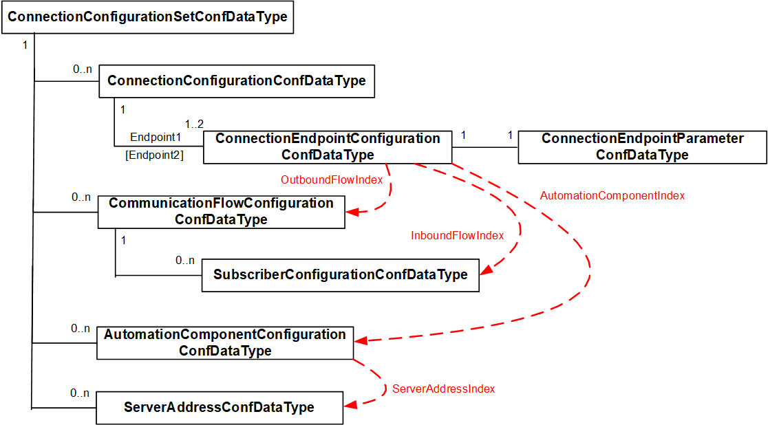
F.1.2 Base principles
F.1.2.1 References
References between Objects in different Object lists are mapped using an array index field for the related structure array. For example, the AutomationComponentConfigurationDataType has ServerAddressIndex that contains an index into the ServerAddress in the ConnectionConfigurationSetConfDataType. Indices are defined as Int32; a negative number indicates no Reference exists.
F.1.2.2 Namespaces
OPC UA uses Namespaces, and in a defined scope, all identifiers (NodeId, QualifiedName) use a NamespaceIndex instead of a NamespaceUri. The scope has a NamespaceArray with URIs where the NamespaceIndex is defined as an index into this array. For a Server, the scope is the complete Server. For a UANodeSet XML file, it is the file.
A ConnectionConfigurationSet (see 6.8.2) contains node identifiers related to different scopes, as illustrated in Figure F.2. In this illustration, the ConnectionConfigurationSet contains information for two different Servers. Node identifiers in the Information Model for the ConnectionManager (i.e., an instance of ConnectionConfigurationSetType) use PortableNodeIdentifier (see 10.36) to support the resolution for the dedicated scope (see also 13.3).
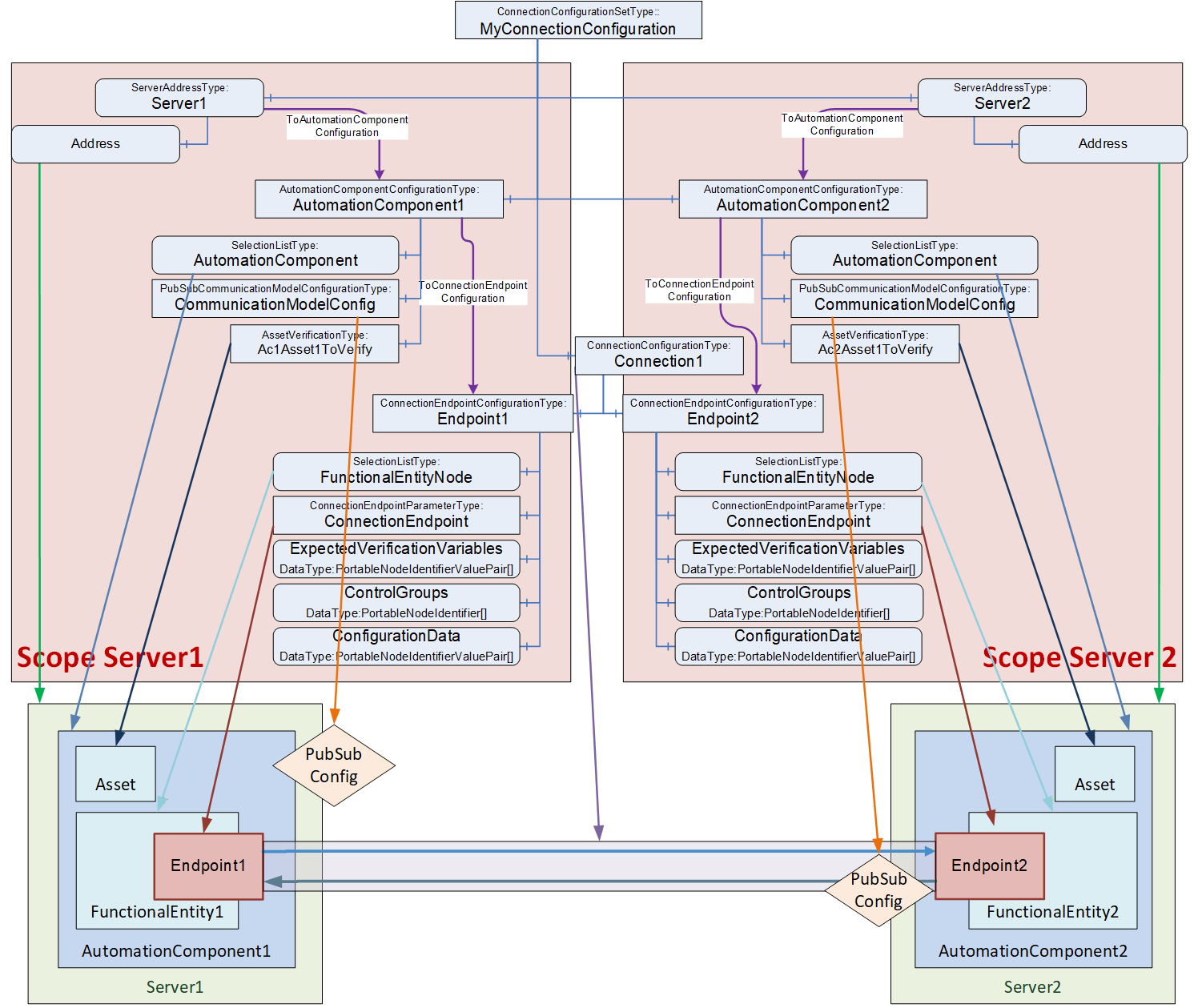
To reduce the overall size of the DataTypes defined in this subclause (i.e. ConnectionConfigurationSetConfDataType), NodeId, AliasName and RelativePath are used instead of their portable version. The scope of those identifiers is defined by the related ServerAddressConfDataType structure containing a Namespace array. The NamespaceIndex of a node identifier is used as an index into the Namespace array of the related ServerAddressConfDataType.
A ConnectionManager can map NodeId and RelativePath contained in the DataTypes to their portable versions using the NamespaceUri from the Namespace array when it loads the ConnectionConfigurationSet from the data structure.
F.1.2.3 SelectionListType
There is no generic DataType defined to represent a SelectionListType Variable. A generic definition would create additional overhead since the values can have different DataTypes.
To simplify the handling of SelectionListType, each Variable that is of SelectionListType is mapped to a structure with the following fields:
A Structure field with the corresponding DataType representing the current value. The field name is constructed from the Variable name (<Variable name>).
A Structure field with an array of the corresponding DataType representing the additional selection options (selectable values associated with the selection list - the list can contain only the current value if this selection list currently does not provide for modifications). The field name is constructed from the Variable name with 'Selection' suffix (<Variable name>Selection).
A Structure field with DataType Boolean indicates if the list of selectable values is enterable by a Client. The field is omitted if the specification requires that RestrictToList is set to TRUE (i.e. no values can be entered; only a selection is possible). The field name is constructed from the Variable name with 'Modify' suffix (<Variable name>Modify).
F.1.2.4 Extensibility
Structured DataTypes can only be extended by subtyping. This is a problem if Structures are embedded into other Structures, e.g., the ConnectionConfigurationSet-related Structure has an array of AutomationComponent related Structures. Therefore, each Structure has an additional field with an array of KeyValuePairs that can be used for potential future standardized or vendor-specific extensions.
F.1.2.5 Optional fields
Connection configuration and communication flow-related configuration Structures use Structures with optional fields to handle the optional Variables.
In other configuration Structures, AllowSubtypes is needed. Since AllowSubtypes cannot be combined with IsOptional, optional handling is done with empty arrays or null values for the used DataType.
F.1.3 ConnectionConfigurationSetConfDataType
This Structure DataType is used to hold the information for a ConnectionConfigurationSet.
It is semantically equivalent to the ConnectionConfigurationSetType as defined in 6.8.2 with the exception that the elements ConnectionConfigurationSetStateMachine, Edit, and Lock as defined in the ConnectionConfigurationSetType are not part of this DataType. If this DataType is converted to an Object, the ConnectionConfigurationSetStateMachine shall be in State Ready, the Edit shall be set to False, and the Lock shall be assigned to the ConnectionManager.
The ConnectionConfigurationSetConfDataType is formally defined in Table F.1.
| Name | Type | Description |
Allow
Subtypes |
| ConnectionConfigurationSetConfDataType | Structure | Subtype of Structure defined in OPC 10000-5 | |
| BrowseName | 0:String | String part of the BrowseName of the ConnectionConfigurationSet. | False |
| ConnectionConfigurationSetFolder | 0:String[] | Optional path of the ConnectionConfigurationSet folder used to group ConnectionConfigurationSets where each entry in the String array represents one level in the folder hierarchy. If no grouping is needed, the parameter is a null or empty String array. | False |
| Connections | 4:ConnectionConfigurationConfDataType[] | A list of Connection configurations to be established. | False |
| CommunicationFlows | 4:CommunicationFlowConfigurationConfDataType[] | A list of communication model-specific configurations to apply to Connections. | True |
| ServerAddresses | 4:ServerAddressConfDataType[] | A list of addressing information for AutomationComponents. | False |
| AutomationComponentConfigurations | 4:AutomationComponentConfigurationConfDataType[] | A list of AutomationComponents used for Connection establishment. | False |
| RollbackOnError | 0:Boolean | Indicates the behaviour that should be followed when there is an error on Connection establishment. If this Property is TRUE and an error occurs during the Connection establishment sequence, processing of the set will stop, and all established Connections that are part of this set shall be closed. | False |
| SecurityKeyServer | 4:SecurityKeyServerAddressConfDataType | The location of the SKS to be used for PubSub security configuration of this ConnectionConfigurationSet, including SecurityGroups and PubSubKeyPushTargets. If the optional SKS configuration is to be omitted, the field shall be set to null. | False |
| Version | 0:UInt32 | The version of the ConnectionConfigurationSet. | False |
| ConnectionConfigurationSetProperties | 0:KeyValuePair[] | The KeyValuePair array provides additional configuration properties for the ConnectionConfigurationSet. | False |
The ConnectionConfigurationSetConfDataType representation in the AddressSpace is formally defined in Table F.2.
| Attribute | Value | |||||
| BrowseName | 4:ConnectionConfigurationSetConfDataType | |||||
| IsAbstract | False | |||||
| References | NodeClass | BrowseName | DataType | TypeDefinition | ModellingRule | |
|---|---|---|---|---|---|---|
| Subtype of the 0:Structure defined in OPC 10000-5 | ||||||
| ConformanceUnits | ||||||
|---|---|---|---|---|---|---|
| UAFX ConnectionManager File Configuration |
F.1.4 ConnectionConfigurationConfDataType
This Structure DataType holds the information for a Connection configuration.
It is semantically equivalent to the ConnectionConfigurationType as defined in 6.10.2, except that the element ProcessingResult, as defined in the ConnectionConfigurationType, is not part of this DataType. If this DataType is converted to an Object, the ProcessingResult shall be set to Good.
The ConnectionConfigurationConfDataType is formally defined in Table F.3.
| Name | Type | Description | Optional |
| ConnectionConfigurationConfDataType | Structure | Subtype of Structure defined in OPC 10000-5 | |
| BrowseName | 0:String | BrowseName of the ConnectionConfiguration | False |
| Endpoint1 | 4:ConnectionEndpointConfigurationConfDataType | The configuration information for the first endpoint of the Connection. | False |
| Endpoint2 | 4:ConnectionEndpointConfigurationConfDataType | The configuration information for the optional second endpoint of the Connection. | True |
| ConnectionProperties | 0:KeyValuePair[] | The KeyValuePair array provides additional optional properties to configure the ConnectionConfigurationSet. | True |
The ConnectionConfigurationConfDataType representation in the AddressSpace is formally defined in Table F.4.
| Attribute | Value | |||||
| BrowseName | 4:ConnectionConfigurationConfDataType | |||||
| IsAbstract | False | |||||
| References | NodeClass | BrowseName | DataType | TypeDefinition | ModellingRule | |
|---|---|---|---|---|---|---|
| Subtype of the 0:Structure defined in OPC 10000-5 | ||||||
| ConformanceUnits | ||||||
|---|---|---|---|---|---|---|
| UAFX ConnectionManager File Configuration |
F.1.5 ConnectionEndpointConfigurationConfDataType
This Structure DataType holds the information for a ConnectionEndpoint configuration, including its parameters.
It is semantically equivalent to the ConnectionEndpointConfigurationType as defined in 6.11.2 and the ConnectionEndpointParameterType as defined in 6.12.2.
The ConnectionEndpointConfigurationConfDataType is formally defined in Table F.5.
| Name | Type | Description | Optional |
|---|---|---|---|
| ConnectionEndpointConfigurationConfDataType | Structure | Subtype of Structure defined in OPC 10000-5 | |
| FunctionalEntityNode | 4:NodeIdentifier | FunctionalEntityNode specifies the identifier of the FunctionalEntity to configure for the Connection. If a RelativePath is specified, the path shall be relative to FxRoot. | False |
| FunctionalEntityNodeSelection | 4:NodeIdentifier[] | Selection list options for FunctionalEntityNode. | True |
| FunctionalEntityNodeModify | 0:Boolean | Flag indicating if the FunctionalEntityNode options can be modified. | True |
| Name | 0:String | BrowseName of the ConnectionEndpoint to create in the AutomationComponent. | False |
| NameSelection | 0:String[] | Selection list options for the endpoint name. | True |
| NameModify | 0:Boolean | Flag indicating if the Name options can be modified. | True |
| ConnectionEndpointTypeId | 0:NodeId | ConnectionEndpointTypeId specifies the well-known NodeId of the type definition, which shall be used to create the ConnectionEndpoint. This can be any of the subtypes of the ConnectionEndpointType (for example, PubSubConnectionEndpointType). | False |
| InputVariableIds | 4:NodeIdentifier[] | InputVariableIds specifies a list of node identifiers to be used as inputs. If InputVariableIds is present, it shall contain at least one element. If the array is null or empty, the optional InputVariableIds node is not available. If a RelativePath is specified, the path shall be relative to the FunctionalEntityNode specified in the ConnectionEndpointConfigurations. | True |
| OutputVariableIds | 4:NodeIdentifier[] | OutVariableIds specifies a list of node identifiers to be used as outputs. If OutputVariableIds is present, it shall contain at least one element. If the array is null or empty, the optional OutputVariableIds node is not available. If a RelativePath is specified, the path shall be relative to the FunctionalEntityNode specified in the ConnectionEndpointConfigurations. | True |
| IsPersistent | 0:Boolean | IsPersistent, if TRUE, specifies the created ConnectionEndpoint shall be persistent. | False |
| CleanupTimeout | 0:Duration | CleanupTimeout specifies the value to be used for the clean-up timeout. A negative number indicates an infinite timeout. A zero indicates an immediate clean-up. | False |
| IsPreconfigured | 0:Boolean | IsPreconfigured, if TRUE, specifies the ConnectionEndpoint is preconfigured. | False |
| CommunicationLinks | 0:Structure | CommunicationLinks specifies the configuration data related to this ConnectionEndpoint within the CommunicationModelConfiguration. If this field is set, it shall contain a subtype of CommunicationLinkConfigurationDataType. | True |
| PreconfiguredPublishedDataSet | 0:String | If it is not an empty string, it specifies the name of a preconfigured PublishedDataSet to be used for connecting the OutputVariables. | True |
| PublishedDataSetData | 0:PublishedDataSetDataType | If not null, specifies a PublishedDataSet to be used for connecting the OutputVariables. If the OutputVariableIds are not configured with NodeIds, the source variable NodeIds shall be null. They must be filled in by the ConnectionManager after getting the NodeIds from the AutomationComponent during connection establishment. | True |
| PreconfiguredSubscribedDataSet | 0:String | If it is not an empty string, it specifies the name of a preconfigured StandaloneSubscribedDataSet to be used for connecting the InputVariables. | True |
| SubscribedDataSetData | 0:StandaloneSubscribedDataSetDataType | If not null, specifies a SubscribedDataSet to be used for connecting the InputVariables. If the InputVariableIds are not configured with NodeIds, the target variable NodeIds shall be null. They must be filled in by the ConnectionManager after getting the NodeIds from the AutomationComponent during connection establishment | True |
| ExpectedVerificationVariables | NodeIdentifierValuePair[] | Specifies the Variables and values to be verified. If a RelativePath is specified as Key, the path shall be relative to FunctionalEntityNode. If the array is null or empty or the field is not present, no Variables are verified. | True |
| ControlGroups | NodeIdentifier[] | Specifies the ControlGroups to be controlled. If a RelativePath is specified as Key, the path shall be relative to FunctionalEntityNode. If the array is null or empty or the field is not present, no ControlGroups are controlled. | True |
| ConfigurationData | NodeIdentifierValuePair[] | Specifies the parameters to apply for the configuration of the FunctionalEntityNode. If a RelativePath is specified as Key, the path shall be relative to FunctionalEntityNode. If the array is null or empty or the field is not present, no parameters are set. | True |
| EndpointProperties | 0:KeyValuePair[] | The KeyValuePair array provides additional configuration properties for the endpoint. | True |
| AutomationComponentIndex | 0:Int32 | Reference to the related AutomationComponent in the AutomationComponentConfigurations array of the connection set structure. | False |
| OutboundFlowIndex | 0:Int32 | Reference to the related communication flow in the CommunicationFlows array of the connection set structure. Any negative number indicates that no outbound is configured. | True |
| InboundFlowIndex | 0:Int32 [2] | Reference to the related communication flow in the CommunicationFlows array (Publisher configuration) of the connection set structure (first index in the array) and to the contained SubscriberConfiguration (second in index in the array). | True |
The ConnectionEndpointConfigurationConfDataType representation in the AddressSpace is formally defined in Table F.6.
| Attribute | Value | |||||
| BrowseName | 4:ConnectionEndpointConfigurationConfDataType | |||||
| IsAbstract | False | |||||
| References | NodeClass | BrowseName | DataType | TypeDefinition | ModellingRule | |
|---|---|---|---|---|---|---|
| Subtype of the 0:Structure defined in OPC 10000-5 | ||||||
| ConformanceUnits | ||||||
|---|---|---|---|---|---|---|
| UAFX ConnectionManager File Configuration |
F.1.6 CommunicationFlowConfigurationConfDataType
This abstract Structure DataType holds the information for an information flow.
It is semantically equivalent to the CommunicationFlowConfigurationType as defined in 6.13.2.
The CommunicationFlowConfigurationConfDataType is formally defined in Table F.7.
| Name | Type | Description | Optional |
| CommunicationFlowConfigurationConfDataType | Structure | Subtype of Structure defined in OPC 10000-5 | |
| BrowseName | 0:String | BrowseName of the information flow. | False |
| FlowProperties | 0:KeyValuePair[] | The KeyValuePair array provides additional configuration properties for the flow. | True |
The FlowProperties KeyValuePair array allows setting of optional configuration properties that extend the parameters defined for the CommunicationFlowConfigurationConfDataType.
The FlowProperties are defined in Table F.8
| Key | ValueType |
| AvailableRanges | 2:IntervalRange[] |
The AvailableRanges KeyValuePair corresponds to the subcomponent defined in Table 99.
The NamespaceIndex of the QualifiedName in the KeyValuePair for properties defined in this document shall be the namespace that has index 4 in this document. The Name of the QualifiedName is the property key from Table F.9. The DataType of the Value in the KeyValuePair shall be the DataType defined in Table F.9.
Table F.9 formally defines the CommunicationFlowConfigurationConfDataType configuration properties.
| Key | DataType | Description |
| 4:PubSubConnectionAddress | NetworkAddressDataType | Allows the configuration of the PubSubConnection Address for Publishers of a unidirectional connection without heartbeat or other cases where the Address configuration in the flow does not include the information needed to set the Address in the PubSubConnection. One example is a unidirectional connection without heartbeat using UDP unicast. |
The CommunicationFlowConfigurationConfDataType representation in the AddressSpace is formally defined in Table F.10.
| Attribute | Value | |||||
| BrowseName | 4:CommunicationFlowConfigurationConfDataType | |||||
| IsAbstract | True | |||||
| References | NodeClass | BrowseName | DataType | TypeDefinition | ModellingRule | |
|---|---|---|---|---|---|---|
| Subtype of the 0:Structure defined in OPC 10000-5 | ||||||
| ConformanceUnits | ||||||
|---|---|---|---|---|---|---|
| UAFX ConnectionManager File Configuration |
F.1.7 PubSubCommunicationFlowConfigurationConfDataType
This Structure DataType contains the configuration needed for both the publishing and subscribing of an information flow.
It is semantically equivalent to the PubSubCommunicationFlowConfigurationType as defined in 6.13.2.
The PubSubCommunicationFlowConfigurationConfDataType is formally defined in Table F.11.
| Name | Type | Description | Optional |
| PubSubCommunicationFlowConfigurationConfDataType | Structure | Subtype of CommunicationFlowConfigurationConfDataType defined in F.1.4 | |
| Address | 4:AddressSelectionDataType | Address specifies the destination network address to be used for transmission of NetworkMessages by the Publisher of the information flow. | True |
| TransportProfileUri | 0:String | Optional TransportProfileUri specifies the transport protocol mapping and the message mapping to be used. If TransportProfileUri is omitted, the default transport protocol for the Address shall be used. | True |
| TransportProfileUriSelection | 0:String[] | Selection list options for TransportProfileUri. | True |
| TransportProfileUriModify | 0:Boolean | Flag indicating if the TransportProfileUri options can be modified. | True |
| HeaderLayoutUri | 0:String | Optional HeaderLayoutUri specifies the UADP header formats for both NetworkMessages and DataSetMessages. If HeaderLayoutUri is omitted, a fixed layout for periodic data shall be used. | True |
| HeaderLayoutUriSelection | 0:String[] | Selection list options for HeaderLayoutUri. | True |
| HeaderLayoutUriModify | 0:Boolean | Flag indicating if the HeaderLayoutUri options can be modified. | True |
| PublishingInterval | 0:Duration | PublishingInterval specifies the interval to be used for publishing NetworkMessages. | True |
| PublishingIntervalSelection | 0:Duration[] | Selection list options for PublishingInterval. | True |
| PublishingIntervalModify | 0:Boolean | Flag indicating if the PublishingInterval options can be modified. | True |
| Qos | 4:CommunicationFlowQosDataType | The optional Qos specifies the Quality of Service to be used for the information flow. | True |
| QosSelection | 4:CommunicationFlowQosDataType[] | Selection list options for Qos. | True |
| QosModify | 0:Boolean | Flag indicating if the Qos options can be modified. | True |
| SecurityMode | 0:MessageSecurityMode | The optional SecurityMode specifies the security mode to be used for the information flow. | True |
| SecurityModeSelection | 0:MessageSecurityMode[] | Selection list options for SecurityMode. | True |
| SecurityModeModify | 0:Boolean | Flag indicating if the SecurityMode options can be modified. | True |
| SecurityGroupId | 0:String | The optional SecurityGroupId specifies the security group to be used for the information flow. | True |
| SecurityGroupIdSelection | 0:String[] | Selection list options for SecurityGroupId. | True |
| SecurityGroupIdModify | 0:Boolean | Flag indicating if the SecurityGroupId options can be modified. | True |
| SubscriberConfigurations | 4:SubscriberConfigurationConfDataType[] | Defines the configuration for Subscriber(s) of the information flow. | True |
The PubSubCommunicationFlowConfigurationConfDataType representation in the AddressSpace is formally defined in Table F.12.
| Attribute | Value | |||||
| BrowseName | 4:PubSubCommunicationFlowConfigurationConfDataType | |||||
| IsAbstract | False | |||||
| References | NodeClass | BrowseName | DataType | TypeDefinition | ModellingRule | |
|---|---|---|---|---|---|---|
| Subtype of the 4:CommunicationFlowConfigurationConfDataType defined in OPC 10000-5 | ||||||
| ConformanceUnits | ||||||
|---|---|---|---|---|---|---|
| UAFX ConnectionManager File Configuration |
F.1.8 SubscriberConfigurationConfDataType
This structure DataType describes the Subscriber-specific information for the Subscriber of an information flow.
It is semantically equivalent to the SubscriberConfigurationType as defined in 6.13.3.3.
The SubscriberConfigurationConfDataType is formally defined in Table F.13.
| Name | Type | Description | Optional |
| SubscriberConfigurationConfDataType | Structure | Subtype of Structure defined in OPC 10000-5 | |
| BrowseName | 0:String | BrowseName of the flow. | False |
| Address | 4:AddressSelectionDataType | Address specifies the network address to be used for the reception of NetworkMessages at the Subscriber of the information flow. | True |
| MessageReceiveTimeout | 0:Duration | MessageReceiveTimeout specifies the maximum acceptable time between DataSetMessages received by the Subscriber. | False |
| MessageReceiveTimeoutSelection | 0:Duration[] | Selection list options for MessageReceiveTimeout. | True |
| MessageReceiveTimeoutModify | 0:Boolean | Flag indicating if the MessageReceiveTimeout options can be modified. | True |
| ReceiveQos | 4:ReceiveQosSelectionDataType | The optional ReceiveQos specifies the Quality of Service to be used for the Subscriber of the information flow. It shall only be present if Qos is present in the parent Object. | True |
| SubscriberProperties | 0:KeyValuePair[] | The KeyValuePair array provides additional configuration properties for the flow. | True |
The SubscriberConfigurationConfDataType representation in the AddressSpace is formally defined in Table F.14.
| Attribute | Value | |||||
| BrowseName | 4:SubscriberConfigurationConfDataType | |||||
| IsAbstract | False | |||||
| References | NodeClass | BrowseName | DataType | TypeDefinition | ModellingRule | |
|---|---|---|---|---|---|---|
| Subtype of the 0:Structure defined in OPC 10000-5 | ||||||
| ConformanceUnits | ||||||
|---|---|---|---|---|---|---|
| UAFX ConnectionManager File Configuration |
F.1.9 AutomationComponentConfigurationConfDataType
This Structure DataType holds the information related to the AutomationComponent participating in a Connection.
It is semantically equivalent to the AutomationComponentConfigurationType as defined in 6.13.2.
The AutomationComponentConfigurationConfDataType is formally defined in Table F.15.
| Name | Type | Description | Allow Subtypes |
| AutomationComponentConfigurationConfDataType | Structure | Subtype of Structure defined in OPC 10000-5 | |
| BrowseName | 0:String | BrowseName of the AutomationComponent. | False |
| AutomationComponentNode | 4:NodeIdentifier | AutomationComponentNode specifies the AutomationComponent that is to be used for establishing Connections. If a RelativePath is specified, the path shall be relative to FxRoot. | False |
| AutomationComponentNodeSelection | 4:NodeIdentifier[] | Selection list options for AutomationComponentNode. | False |
| AutomationComponentNodeModify | 0:Boolean | Flag indicating if the AutomationComponentNode options can be modified. | False |
| CommandBundleRequired | 0:Boolean | CommandBundleRequired, when TRUE, specifies that the ConnectionManager shall bundle commands to this AutomationComponent. | False |
| AssetVerification | 4:AssetVerificationConfDataType[] | The Asset verification parameters for Assets associated with the AutomationComponent. If the optional AssetVerification is not available, the field is null. | False |
| CommunicationModelConfig | 4:CommunicationModelConfigurationDataType | Provides the ConfigurationData specific to the communication model utilized by the Connections. If the optional CommunicationModelConfig is to be omitted, the field shall be set to null. | True |
| AutomationComponentProperties | 0:KeyValuePair[] | The KeyValuePair array provides additional configuration properties for the AutomationComponent. | False |
| ServerAddressIndex | 0:Int32 | Reference to the related Server in the ServerAddresses array of the connection set structure. | False |
The AutomationComponentConfigurationConfDataType representation in the AddressSpace is formally defined in Table F.16.
| Attribute | Value | |||||
| BrowseName | 4:AutomationComponentConfigurationConfDataType | |||||
| IsAbstract | False | |||||
| References | NodeClass | BrowseName | DataType | TypeDefinition | ModellingRule | |
|---|---|---|---|---|---|---|
| Subtype of the 0:Structure defined in OPC 10000-5 | ||||||
| ConformanceUnits | ||||||
|---|---|---|---|---|---|---|
| UAFX ConnectionManager File Configuration |
F.1.10 SecurityKeyServerAddressConfDataType
This Structure DataType holds the information for the SecurityKeyServer.
The SecurityKeyServerAddressConfDataType is formally defined in Table F.17.
| Name | Type | Description | Optional |
| SecurityKeyServerAddressConfDataType | Structure | Subtype of Structure defined in OPC 10000-5 | |
| Address | 0:UriString | Address is specified as a DiscoveryUrl of the server to connect to for connection establishment. | False |
| AddressSelection | 0:UriString[] | Selection list options for Address. | True |
| AddressModify | 0:Boolean | Flag indicating if the Address options can be modified. | True |
| SecurityPolicyUri | 0:String | SecurityPolicyUri is a string that contains the security policy to use when establishing the secure communication. | False |
| SecurityPolicyUriSelection | 0:String[] | Selection list options for SecurityPolicyUri. | True |
| SecurityPolicyUriModify | 0:Boolean | Flag indicating if the SecurityPolicyUri options can be modified. | True |
| ServerUri | 0:UriString | ServerUri is a string that reflects the ApplicationUri of the Server. It can be used to cryptographically verify the Server. The ServerUri can also be a null string, in which case it will not be used to validate the Server. | False |
| ServerUriSelection | 0:UriString[] | Selection list options for ServerUri. | True |
| ServerUriModify | 0:Boolean | Flag indicating if the ServerUri options can be modified. | True |
| UsePushModel | 0:Boolean | If TRUE, use the SKS push model. If FALSE, use the SKS pull model. | False |
| SecurityGroups | 0:SecurityGroupDataType[] | Defines the security groups to be applied at the SKS for PubSub security configuration of this ConnectionConfigurationSet. | True |
| PubSubKeyPushTargets | 0:PubSubKeyPushTargetDataType[] | Defines the push key targets to be applied at the SKS for PubSub security configuration of this ConnectionConfigurationSet. | True |
| SksProperties | 0:KeyValuePair[] | The KeyValuePair array provides additional configuration properties for the SecurityKeyServer. | True |
The SecurityKeyServerAddressConfDataType representation in the AddressSpace is formally defined in Table F.18.
| Attribute | Value | |||||
| BrowseName | 4:SecurityKeyServerAddressConfDataType | |||||
| IsAbstract | False | |||||
| References | NodeClass | BrowseName | DataType | TypeDefinition | ModellingRule | |
|---|---|---|---|---|---|---|
| Subtype of the 0:Structure defined in OPC 10000-5 | ||||||
| ConformanceUnits | ||||||
|---|---|---|---|---|---|---|
| UAFX ConnectionManager File Configuration |
F.1.11 ServerAddressConfDataType
This Structure DataType holds the information for the Server address.
It is semantically equivalent to the ServerAddressType as defined in 9.2.2, except that the field Namespaces is added to the ServerAddressConfDataType. For the handling of this field, see F.1.2.2.
The ServerAddressConfDataType is formally defined in Table F.19.
| Name | Type | Description | Optional |
| ServerAddressConfDataType | Structure | Subtype of Structure defined in OPC 10000-5 | |
| BrowseName | 0:String | BrowseName of the Server address. | False |
| Address | 0:UriString | Address is specified as a DiscoveryUrl of the server to connect to for connection establishment. | False |
| AddressSelection | 0:UriString[] | Selection list options for Address. | True |
| AddressModify | 0:Boolean | Flag indicating if the Address options can be modified. | True |
| SecurityMode | 0:MessageSecurityMode | SecurityMode is the MessageSecurityMode to be used for establishing a secure communication to the Address. | False |
| SecurityModeSelection | 0:MessageSecurityMode[] | Selection list options for SecurityMode. | True |
| SecurityModeModify | 0:Boolean | Flag indicating if the SecurityMode options can be modified. | True |
| SecurityPolicyUri | 0:String | SecurityPolicyUri is a string that contains the security policy to use when establishing the secure communication. | False |
| SecurityPolicyUriSelection | 0:String[] | Selection list options for SecurityPolicyUri. | True |
| SecurityPolicyUriModify | 0:Boolean | Flag indicating if the SecurityPolicyUri options can be modified. | True |
| ServerUri | 0:UriString | ServerUri is a string that reflects the ApplicationUri of the Server. It can be used to cryptographically verify the Server. The ServerUri can also be a null string, in which case it will not be used to validate the Server. | False |
| ServerUriSelection | 0:UriString[] | Selection list options for ServerUri. | True |
| ServerUriModify | 0:Boolean | Flag indicating if the ServerUri options can be modified. | True |
| ServerProperties | 0:KeyValuePair[] | The KeyValuePair array provides additional configuration properties for the Server. | True |
| Namespaces | 0:String[] | Namespace table for translation of NodeIds and RelativePaths related to this Server. For further details, see F.1.2.2. | False |
The ServerAddressConfDataType representation in the AddressSpace is formally defined in Table F.20.
| Attribute | Value | |||||
| BrowseName | 4:ServerAddressConfDataType | |||||
| IsAbstract | False | |||||
| References | NodeClass | BrowseName | DataType | TypeDefinition | ModellingRule | |
|---|---|---|---|---|---|---|
| Subtype of the 0:Structure defined in OPC 10000-5 | ||||||
| ConformanceUnits | ||||||
|---|---|---|---|---|---|---|
| UAFX ConnectionManager File Configuration |
F.1.12 AssetVerificationConfDataType
The AssetVerificationDataConfType is used to store the information needed for Asset verification.
It is semantically equivalent to the AssetVerificationType as defined in 6.15.2.
The AssetVerificationConfDataType is formally defined in Table F.21.
| Name | Type | Description | Optional |
| AssetVerificationConfDataType | Structure | Subtype of Structure defined in OPC 10000-5 | |
| AssetToVerify | 4:NodeIdentifier | Specifies the expected Asset to be verified. If a RelativePath is specified, the path shall be relative to AutomationComponentNode. | False |
| VerificationMode | 2:AssetVerificationModeEnum | The mode to use for the verification (compatibility and/or identity). | False |
| ExpectedVerificationResult | 2:AssetVerificationResultEnum | The expected level of compatibility that this Asset shall provide | False |
| ExpectedVerificationVariables | 4:NodeIdentifierValuePair[] | The variables to be verified for compatibility and/or identity. If a RelativePath is specified, the path shall be relative to the expected Asset. | False |
| ExpectedAdditionalVerificationVariables | 4:NodeIdentifierValuePair[] | The additional variables to be verified for compatibility and/or identity. If a RelativePath is specified, the path shall be relative to the expected Asset. | False |
| AssetProperties | 0:KeyValuePair[] | The KeyValuePair array provides additional configuration properties for the Asset verification. | True |
The AssetVerificationConfDataType representation in the AddressSpace is formally defined in Table F.22.
| Attribute | Value | |||||
| BrowseName | 4:AssetVerificationConfDataType | |||||
| IsAbstract | False | |||||
| References | NodeClass | BrowseName | DataType | TypeDefinition | ModellingRule | |
|---|---|---|---|---|---|---|
| Subtype of the 0:Structure defined in OPC 10000-5 | ||||||
| ConformanceUnits | ||||||
|---|---|---|---|---|---|---|
| UAFX ConnectionManager File Configuration |
F.1.13 CommunicationModelConfigurationDataType
The CommunicationModelConfigurationDataType is formally defined in Table F.23.
It is semantically equivalent to the CommunicationModelConfigurationType as defined in 6.16.2.
| Name | Type | Description |
| CommunicationModelConfigurationDataType | Structure | Subtype of Structure defined in OPC 10000-5 |
The CommunicationModelConfigurationDataType representation in the AddressSpace is formally defined inTable F.24.
| Attribute | Value | |||||
| BrowseName | 4:CommunicationModelConfigurationDataType | |||||
| IsAbstract | True | |||||
| References | NodeClass | BrowseName | DataType | TypeDefinition | ModellingRule | |
|---|---|---|---|---|---|---|
| Subtype of the 0:Structure defined in OPC 10000-5 | ||||||
| ConformanceUnits | ||||||
|---|---|---|---|---|---|---|
| UAFX ConnectionManager File Configuration |
F.1.14 PubSubCommunicationModelConfigurationDataType
The PubSubCommunicationModelConfigurationDataType is formally defined in Table F.25.
It is semantically equivalent to the PubSubCommunicationModelConfigurationType as defined in 6.16.3.2.
| Name | Type | Description |
| PubSubCommunicationModelConfigurationDataType | Structure | Subtype of CommunicationModelConfigurationDataType defined in F.1.13. |
| PubSubConfiguration | 0:PubSubConfiguration2DataType | PubSub configuration for the addressed Server when establishing Connections. |
| TranslationTable | 4:NodeIdTranslationDataType[] | NodeIds contained in the PubSubConfiguration, which use the special namespace "http://opcfoundation.org/UA/FX/CM/Translation/", are not valid NodeIds but placeholders which shall be resolved before the ConnectionManager can use the PubSubConfiguration for connection establishment. |
| ConfigurationReferences | 0:PubSubConfigurationRefDataType[] | ConfigurationReferences points to elements within the PubSubConfiguration and indicates whether they are to be added, matched, modified, or removed. |
The PubSubCommunicationModelConfigurationDataType representation in the AddressSpace is formally defined in Table F.26.
| Attribute | Value | |||||
| BrowseName | 4:PubSubCommunicationModelConfigurationDataType | |||||
| IsAbstract | False | |||||
| References | NodeClass | BrowseName | DataType | TypeDefinition | ModellingRule | |
|---|---|---|---|---|---|---|
| Subtype of CommunicationModelConfigurationDataType defined in F.1.13 | ||||||
| ConformanceUnits | ||||||
|---|---|---|---|---|---|---|
| UAFX ConnectionManager File Configuration |
F.1.15 NodeIdentifier
The NodeIdentifier is used to store an identifier, where the identifier can be NodeId, Alias String, or a RelativePath.
It is semantically equivalent to the PortableNodeIdentifier as defined in 10.36, except it uses the optimization as described in F.1.2.2.
The NodeIdentifier DataType is formally defined in Table F.27.
| Name | Type | Description |
| NodeIdentifier | Union | Subtype of Union defined in OPC 10000-5 |
| Node | 0:NodeId | The NodeId of the Node. The NamespaceIndex of the NodeId relates to the Namespaces in the ServerAddressConfDataType (see F.1.11) of the related Server. |
| Alias | 0:String | The AliasName of the Node. |
| IdentifierBrowsePath | 0:RelativePath | The IdentifierBrowsePath to the Node. The starting Node of the IdentifierBrowsePath shall be specified where this type is used. A NamespaceIndex in the RelativePath relates to the Namespaces in the ServerAddressConfDataType (see F.1.11) of the related Server. |
The NodeIdentifier representation in the AddressSpace is formally defined in Table F.28.
| Attribute | Value | |||||
| BrowseName | 4:NodeIdentifier | |||||
| IsAbstract | False | |||||
| References | NodeClass | BrowseName | DataType | TypeDefinition | ModellingRule | |
|---|---|---|---|---|---|---|
| Subtype of the 0:Union defined in OPC 10000-5 | ||||||
| ConformanceUnits | ||||||
|---|---|---|---|---|---|---|
| UAFX ConnectionManager File Configuration |
F.1.16 NodeIdentifierValuePair
The NodeIdentifierValuePair is used to provide a key-value pair where the key is a Variable Node.
It is semantically equivalent to the PortableKeyValuePair as defined in 10.35 with the optimization as described in F.1.2.2.
The NodeIdentifierValuePair DataType is formally defined in Table F.29.
| Name | Type | Description |
| NodeIdentifierValuePair | Structure | Subtype of Structure defined in OPC 10000-5 |
| Key | 4:NodeIdentifier | The Key to the Variable. |
| ArrayIndex | 0:UInt32[] | If Key refers to a Variable with ValueRank >= 1, the ArrayIndex specifies the index for a specific value referenced by Key (Not the entire array, but a specific element in it). The ArrayIndex is required to have the same dimension as the dimension of the node. If Key is not of array type, or if no specific index shall be referenced, then the array shall be null or empty. |
| Value | 0:BaseDataType | The value associated with the key/array item. |
The NodeIdentifierValuePair representation in the AddressSpace is formally defined in Table F.30.
| Attribute | Value | |||||
| BrowseName | 4:NodeIdentifierValuePair | |||||
| IsAbstract | False | |||||
| References | NodeClass | BrowseName | DataType | TypeDefinition | ModellingRule | |
|---|---|---|---|---|---|---|
| Subtype of the 0:Structure defined in OPC 10000-5 | ||||||
| ConformanceUnits | ||||||
|---|---|---|---|---|---|---|
| UAFX ConnectionManager File Configuration |
F.1.17 NodeIdTranslationConfDataType
This NodeIdTranslationConfDataType is used to provide table entries for conversion of NodeId to NodeIdentifier (see F.1.15).
It is semantically equivalent to the NodeIdTranslationDataType as defined in 10.33 with the optimization as described in F.1.2.2.
The NodeIdTranslationConfDataType is formally defined in Table F.31.
| Name | Type | Description |
| NodeIdTranslationConfDataType | Structure | Subtype of Structure defined in OPC 10000-5 |
| NodePlaceholder | 0:NodeId | NodeId to be converted to the result of resolving the NodeIdentifier. |
| Node | 4:NodeIdentifier | Specifies the NodeIdentifier corresponding to the NodeId of the NodePlaceholder. |
The NodeIdTranslationConfDataType representation in the AddressSpace is formally defined in Table F.32.
| Attribute | Value | |||||
| BrowseName | 4:NodeIdTranslationConfDataType | |||||
| IsAbstract | False | |||||
| References | NodeClass | BrowseName | DataType | TypeDefinition | ModellingRule | |
|---|---|---|---|---|---|---|
| Subtype of the 0:Structure defined in OPC 10000-5 | ||||||
| ConformanceUnits | ||||||
|---|---|---|---|---|---|---|
| UAFX ConnectionManager File Configuration |
F.1.18 AddressSelectionDataType
The AddressSelectionDataType holds the selection list for a network address (see F.1.2.3). It allows the address selection to be optional, where this DataType is used (see F.1.7 and F.1.8).
The AddressSelectionDataType is formally defined in Table F.33.
| Name | Type | Description | Allow Subtypes |
| AddressSelectionDataType | Structure | Subtype of Structure defined in OPC 10000-5 | |
| Address | 0:NetworkAddressDataType | Network address configured. | True |
| AddressSelection | 0:NetworkAddressDataType[] | Selection list options for Address. | True |
| AddressModify | 0:Boolean | Flag indicating if the Address options can be modified. | False |
The AddressSelectionDataType representation in the AddressSpace is formally defined in Table F.34.
| Attribute | Value | |||||
| BrowseName | 4:AddressSelectionDataType | |||||
| IsAbstract | False | |||||
| References | NodeClass | BrowseName | DataType | TypeDefinition | ModellingRule | |
|---|---|---|---|---|---|---|
| Subtype of the 0:Structure defined in OPC 10000-5 | ||||||
| ConformanceUnits | ||||||
|---|---|---|---|---|---|---|
| UAFX ConnectionManager File Configuration |
F.1.19 ReceiveQosSelectionDataType
The ReceiveQosSelectionDataType holds the selection list for a receive QoS configuration (see F.1.2.3). It allows making the receive QoS selection optional, where this DataType is used (see F.1.7 and F.1.8).
The ReceiveQosSelectionDataType is formally defined in Table F.35.
| Name | Type | Description | Allow Subtypes |
| ReceiveQosSelectionDataType | Structure | Subtype of Structure defined in OPC 10000-5 | |
| ReceiveQos | 0:ReceiveQosDataType[] | The ReceiveQos configuration. | True |
| ReceiveQosSelection | 0:BaseDataType | Selection list options for ReceiveQos. The field will contain a matrix of subtypes of ReceiveQosDataType. If the field is not provided, it is null. | False |
| ReceiveQosModify | 0:Boolean | Flag indicating if the ReceiveQos options can be modified. | False |
The ReceiveQosSelection is of BaseDataType and thus requires a subtype to be used. The flag AllowSubtypes is only set if the type can be used as well as subtypes.
The ReceiveQosSelectionDataType representation in the AddressSpace is formally defined in Table F.36.
| Attribute | Value | |||||
| BrowseName | 4:ReceiveQosSelectionDataType | |||||
| IsAbstract | False | |||||
| References | NodeClass | BrowseName | DataType | TypeDefinition | ModellingRule | |
|---|---|---|---|---|---|---|
| Subtype of the 0:Structure defined in OPC 10000-5 | ||||||
| ConformanceUnits | ||||||
|---|---|---|---|---|---|---|
| UAFX ConnectionManager File Configuration |
F.2 ConnectionConfigurationSet file content
If ConnectionConfigurationSets are stored in a File, the UABinaryFileDataType and the related definitions in OPC 10000-5 shall be used to encode the file content. The structure of the UABinaryFileDataType file is illustrated in Table F.37. Its Body contains an array of ConnectionConfigurationSetConfDataType or a subtype of it.
| Field | Type | Typical Values |
| Namespaces | 0:String[] | Contains the namespaces used for the data that is contained in the Body of the File. As a minimum, the http://opcfoundation.org/UA/ and http://opcfoundation.org/UA/FX/CM/ namespace shall be included. |
| structureDataTypes | 0:StructureDescription[] | null or empty DataTypes used for configuration are defined by OPC UA FX. |
| enumDataTypes | 0:EnumDescription[] | null or empty DataTypes used for configuration are defined by OPC UA FX. |
| simpleDataTypes | 0:SimpleTypeDescription[] | null or empty DataTypes used for configuration are defined by OPC UA FX. |
| schemaLocation | 0:String | null or empty |
| fileHeader | 0:KeyValuePair[] | null or empty |
| Body | 0:BaseDataType[] | An array of ConnectionConfigurationSetConfDataType. |
F.3 ConnectionManagerConfigurationType
F.3.1 ConnectionManagerConfigurationType definition
This ObjectType represents a FileType that can be used to maintain ConnectionConfigurationSets. The content of this File shall correspond to F.2.
Reading the File allows the retrieval of the contents of the ConnectionConfigurationSets Folder of a ConnectionManager with one operation; writing it allows to add, remove, or replace ConnectionConfigurationSets.
The ConnectionManagerConfigurationType is formally defined in Table F.38.
| Attribute | Value | ||||
| BrowseName | 4:ConnectionManagerConfigurationType | ||||
| IsAbstract | False | ||||
| References | NodeClass | BrowseName | DataType | TypeDefinition | ModellingRule |
|---|---|---|---|---|---|
| Subtype of FileType defined in OPC 10000-20. | |||||
| HasComponent | Method | 4:CloseAndUpdate | Defined in F.3.2. | Mandatory | |
| ConformanceUnits | |||||
| UAFX ConnectionManager File Configuration | |||||
F.3.2 Open Method
The standard Open Method is used for file operations, but this specification does impose security restrictions. The Open Method shall not support modes other than Read (0x01) and Write + EraseExisting (0x06). The Client shall be authorized to modify the configuration for the ConnectionManager functionality when invoking this Method on the Server with modes Write + EraseExisting (0x06). For this mode, it is recommended that this Method be restricted to Client connections that have the well-known Role ConfigureAdmin (see 5.9).
F.3.3 CloseAndUpdate method
F.3.3.1 CloseAndUpdate signature
This Method closes the File and applies updates to the ConnectionConfigurationSets. It can only be called if the File was opened for writing. If the Close Method is called, any cached data is discarded, and the ConnectionManager configuration is not changed.
The file content shall be a UABinaryFileDataType as defined in Table F.37.
The Client shall be authorized to modify the configuration for the ConnectionManager functionality when invoking this Method on the Server. It is recommended that this Method be restricted to Client connections that have the well-known Role ConfigureAdmin (see 5.9). If the file also contains SKS configuration, then it is recommended that the Client also have the well-known Role SecurityKeyServerAdmin (see OPC 10000-14).
The signature of the Method is described below, and the arguments are described in Table F.39.
Signature
	CloseAndUpdate (
		[in]	UInt32				FileHandle,
		[in]	Boolean			RequireCompleteUpdate,
		[in]	ConnectionConfigurationSetOperation[]		Operations,
		[out]	Boolean			ChangesApplied,
		[out]	StatusCode[]			OperationResults,
		[out]	NodeId[]			ConfigurationObjects
		);
| Argument | Description |
| FileHandle | The handle of the previously opened file. |
| RequireCompleteUpdate | If TRUE, the modification is only applied if all changes can be applied to all objects. |
| Operations | Defines the operations to apply to a ConnectionManager's ConnectionConfigurationSets for the array of ConnectionConfigurationSetConfDataType elements in the written file. The length of the array and the order of its elements shall match the array of ConnectionConfigurationSetConfDataType in the written file. |
| ChangesApplied | If TRUE and RequireCompleteUpdate was set to TRUE, all changes were applied. If TRUE and RequireCompleteUpdate was set to FALSE, one or more changes were applied. If FALSE, no changes were applied. Detailed errors are provided in the OperationResults argument. |
| OperationResults | Results of the Operations. The length of the array and the order of its elements shall match the length and order of the Operations array. |
| ConfigurationObjects | NodeIds of the related Objects If NodeIds are returned, the length of the array and the order of its elements shall match the array contained in the written file. If the Server does not support the creation of NodeIds, the array is null or empty. |
The possible Method result codes are formally defined in Table F.40, and the OperationResult Element Result Codes are defined in Table F.41.
| ResultCode | Description |
| Bad_TypeMismatch | The file content is not a UABinaryFileDataType with an array of ConnectionConfigurationSetConfDataType as Body. |
| Bad_InvalidArgument | The FileHandle is not valid. |
| Bad_InvalidState | The File was not opened for write access. |
| Bad_UserAccessDenied | The Session user is not allowed to modify the ConnectionManager configuration. |
| Bad_NothingToDo | The array in the Body of the File is null or empty. |
| ResultCode | Description |
| Bad_BrowseNameDuplicated | A ConnectionConfigurationSet with the BrowseName already exists in the ConnectionConfigurationSetFolder. The ConnectionConfigurationSet cannot be added. |
| Bad_NoMatch | A ConnectionConfigurationSet with the BrowseName does not exist in the ConnectionConfigurationSetFolder. The ConnectionConfigurationSet cannot be removed or replaced. |
| Bad_NothingToDo | No ConnectionConfigurationSetOperation was specified. |
| Bad_InvalidArgument | An invalid combination of ConnectionConfigurationSetOperation was set, or a ConnectionConfigurationSetOperation unknown to the implementation. |
| Bad_UserAccessDenied | The user has no permissions to modify the ConnectionConfigurationSets. |
| Bad_InvalidState | A ConnectionConfigurationSet with the name is currently being processed or edited. The ConnectionConfigurationSet cannot be removed or replaced. |
The CloseAndUpdate Method representation in the AddressSpace is formally defined in Table F.42.
| Attribute | Value | ||||
| BrowseName | 4:CloseAndUpdate | ||||
| References | Node Class | BrowseName | DataType | TypeDefinition | Other |
|---|---|---|---|---|---|
| 0:HasProperty | Variable | 0:InputArguments | 0:Argument[] | 0:PropertyType | M |
| 0:HasProperty | Variable | 0:OutputArguments | 0:Argument[] | 0:PropertyType | M |
| ConformanceUnits | |||||
|---|---|---|---|---|---|
| UAFX ConnectionManager File Configuration |
F.3.3.2 CloseAndUpdate behaviour
F.3.3.2.1 Overview
The CloseAndUpdate Method allows to add, remove, or replace ConnectionConfigurationSets.
ConnectionConfigurationSets are addressed by BrowseName and ConnectionConfigurationSetFolder (see 6.7.2).
F.3.3.2.2 ElementAdd
The ConnectionConfigurationSetOperation ElementAdd adds the ConnectionConfigurationSet to the ConnectionConfigurationSets Folder tree in the Folder specified by the ConnectionConfigurationSetFolder. If Folders on the given path do not exist, they will be created.
The operation ElementAdd does not include processing the ConnectionConfigurationSet. Processing can be triggered either by a Client using the ProcessConnectionConfigurationSets Method (see 0) or by vendor-specific means.
F.3.3.2.3 ElementRemove
The ConnectionConfigurationSetOperation ElementRemove removes the ConnectionConfigurationSet from the ConnectionConfigurationSetFolder. For ElementRemove, all elements of the ConnectionConfigurationSetConfDataType except BrowseName and ConnectionConfigurationSetFolder are ignored and may be set to null or empty by the caller.
The ConnectionManager shall call the CloseConnections Method on all affected AutomationComponents (see 6.2.5) with Remove set to TRUE for all Connections contained in the ConnectionConfigurationSet.
F.3.3.2.4 ElementReplace
The ConnectionConfigurationSetOperation ElementReplace replaces the ConnectionConfigurationSet in the ConnectionConfigurationSetFolder.
The ConnectionManager shall call the CloseConnections Method on all affected AutomationComponents (see 6.2.5) with Remove set to TRUE for all contained Connections in the ConnectionConfigurationSet.
The operation ElementReplace does not include processing the new ConnectionConfigurationSet. Processing can be triggered either by a Client using the ProcessConnectionConfigurationSets Method (see 0) or by vendor-specific means.
F.3.4 ConnectionConfigurationSetOperation
This OptionSet defines flags indicating the operation on a ConnectionConfigurationSetConfDataType. The value of the OptionSet is null if none of the bits are set.
The possible element operations are ElementAdd, ElementRemove, and ElementReplace. Only one of the element operation bits shall be set. If more than one of these bits are set, the operation shall fail.
The ConnectionConfigurationSetOperation values are formally defined in Table F.43.
| Value | Bit No. | Description |
| ElementAdd | 0 | If this bit is set, the ConnectionConfigurationSet is added to the ConnectionManager configuration. |
| ElementRemove | 1 | If this bit is set, the ConnectionConfigurationSet is removed from the ConnectionManager configuration. The ConnectionConfigurationSet to be removed is identified via the string part of the BrowseName and the ConnectionConfigurationSetFolder. All other elements in the ConnectionConfigurationSetConfDataType are ignored in this case. It is recommended to set all arrays in the DataType to null or empty. |
| ElementReplace | 2 | If this bit is set, the ConnectionConfigurationSet is replaced in the ConnectionManager configuration. The ConnectionConfigurationSet to be replaced is identified via the string part of the BrowseName and the ConnectionConfigurationSetFolder. |
Bits 3:7 are reserved for future use. The ConnectionConfigurationSetOperation representation in the AddressSpace is formally defined in Table F.44.
| Attribute | Value | |||||
| BrowseName | 4:ConnectionConfigurationSetOperation | |||||
| IsAbstract | False | |||||
| References | NodeClass | BrowseName | DataType | TypeDefinition | ModellingRule | |
|---|---|---|---|---|---|---|
| Subtype of the Byte type defined in OPC 10000-3. | ||||||
| 0:HasProperty | Variable | OptionSetValues | LocalizedText[] | PropertyType | ||
| ConformanceUnits | ||||||
|---|---|---|---|---|---|---|
| UAFX ConnectionManager File Configuration |
Annex G Diagnostic Client (Informative)
G.1 Diagnostics Client
This Annex describes behaviour that a diagnostics Client needs to be aware of when looking at a system that is composed of multiple vendor / ConnectionManager implementations. The behaviour of a ConnectionManager is describe in 13.
A ConnectionManager could monitor both sides of Connection it has created, it could monitor only one side of a Connection (the side that is in the local AutomationComponent) or it could not monitor Connections at all (see Figure G.1). The ConnectionManager has capabilities (see 6.7.6) indicating the behaviour it supports. A diagnostics Client should be aware of the differences between each of the ConnectionManagers.
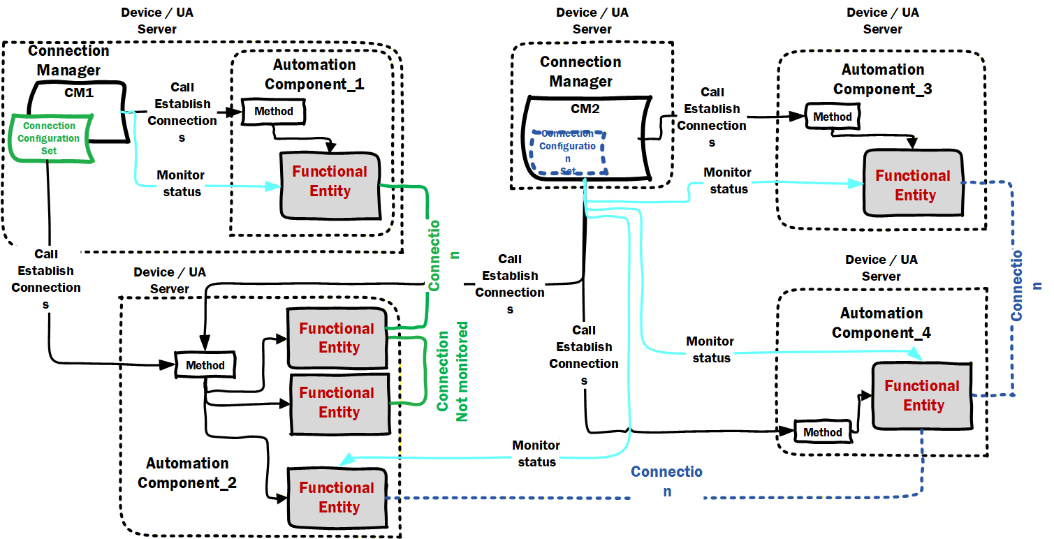
If collecting diagnostics from a ConnectionManager that monitors both sides of a connection(CM2 in illustration), the diagnostics Client will only need to subscribe to the AggregatedCurrentState reported by the ConnectionManager, it will not need to connect to each AutomationComponent. If collecting diagnostics from a ConnectionManager that monitors only one side of a Connection (CM1 in illustration), then the diagnostics Client will need to subscribe to status information from the remote AutomationComponent. If the ConnectionManager does not monitor Connection Status, then the diagnostics Client will have to obtain status from each of the AutomationComponents participating in the Connection (see AutomationComponent_2 internal connection in illustration).
If a ConnectionManager reports an error, then the diagnostics Client would then have to read the ConnectionDiagnostics array from each ConnectionConfigurationSet to determine which ConnectionConfigurationSet (and actual Connection) has encountered a problem.
For some error cases sufficient information is provided in the ConnectionDiagnostics array to diagnose the issue. In other cases the LogObject associated with the ConnectionManager would have to be used to retrieve the detailed error information.
ConnectionState describes the state of an established Connection. A Connection is considered to be established when all ConnectionEndpoints required by it (see 5.5.1) exist.
Bibliography
Agreement of Use
COPYRIGHT RESTRICTIONS
Any unauthorized use of this specification may violate copyright laws, trademark laws, and communications regulations and statutes. This document contains information which is protected by copyright. All Rights Reserved. No part of this work covered by copyright herein may be reproduced or used in any form or by any means--graphic, electronic, or mechanical, including photocopying, recording, taping, or information storage and retrieval systems--without permission of the copyright owner.
OPC Foundation members and non-members are prohibited from copying and redistributing this specification. All copies must be obtained on an individual basis, directly from the OPC Foundation Web site: http://www.opcfoundation.org.
PATENTS
The attention of adopters is directed to the possibility that compliance with or adoption of OPC specifications may require use of an invention covered by patent rights. OPC shall not be responsible for identifying patents for which a license may be required by any OPC specification, or for conducting legal inquiries into the legal validity or scope of those patents that are brought to its attention. OPC specifications are prospective and advisory only. Prospective users are responsible for protecting themselves against liability for infringement of patents.
WARRANTY AND LIABILITY DISCLAIMERS
WHILE THIS PUBLICATION IS BELIEVED TO BE ACCURATE, IT IS PROVIDED "AS IS" AND MAY CONTAIN ERRORS OR MISPRINTS. THE OPC FOUNDATION MAKES NO WARRANTY OF ANY KIND, EXPRESSED OR IMPLIED, WITH REGARD TO THIS PUBLICATION, INCLUDING BUT NOT LIMITED TO ANY WARRANTY OF TITLE OR OWNERSHIP, IMPLIED WARRANTY OF MERCHANTABILITY OR WARRANTY OF FITNESS FOR A PARTICULAR PURPOSE OR USE. IN NO EVENT SHALL THE OPC FOUNDATION BE LIABLE FOR ERRORS CONTAINED HEREIN OR FOR DIRECT, INDIRECT, INCIDENTAL, SPECIAL, CONSEQUENTIAL, RELIANCE OR COVER DAMAGES, INCLUDING LOSS OF PROFITS, REVENUE, DATA OR USE, INCURRED BY ANY USER OR ANY THIRD PARTY IN CONNECTION WITH THE FURNISHING, PERFORMANCE, OR USE OF THIS MATERIAL, EVEN IF ADVISED OF THE POSSIBILITY OF SUCH DAMAGES.
The entire risk as to the quality and performance of software developed using this specification is borne by you.
RESTRICTED RIGHTS LEGEND
This Specification is provided with Restricted Rights. Use, duplication or disclosure by the U.S. government is subject to restrictions as set forth in (a) this Agreement pursuant to DFARs 227.7202-3(a); (b) subparagraph (c)(1)(i) of the Rights in Technical Data and Computer Software clause at DFARs 252.227-7013; or (c) the Commercial Computer Software Restricted Rights clause at FAR 52.227-19 subdivision (c)(1) and (2), as applicable. Contractor / manufacturer are the OPC Foundation, 16101 N. 82nd Street, Suite 3B, Scottsdale, AZ, 85260-1830.
COMPLIANCE
The OPC Foundation shall at all times be the sole entity that may authorize developers, suppliers and sellers of hardware and software to use certification marks, trademarks or other special designations to indicate compliance with these materials. Products developed using this specification may claim compliance or conformance with this specification if and only if the software satisfactorily meets the certification requirements set by the OPC Foundation. Products that do not meet these requirements may claim only that the product was based on this specification and must not claim compliance or conformance with this specification.
Trademarks
Most computer and software brand names have trademarks or registered trademarks. The individual trademarks have not been listed here.
GENERAL PROVISIONS
Should any provision of this Agreement be held to be void, invalid, unenforceable or illegal by a court, the validity and enforceability of the other provisions shall not be affected thereby.
This Agreement shall be governed by and construed under the laws of the State of Minnesota, excluding its choice or law rules.
This Agreement embodies the entire understanding between the parties with respect to, and supersedes any prior understanding or agreement (oral or written) relating to, this specification.
ISSUE REPORTING
The OPC Foundation strives to maintain the highest quality standards for its published specifications; hence they undergo constant review and refinement. Readers are encouraged to report any issues and view any existing errata here: http://OPCFoundation.org/errata
Revision 1.00.04 Highlights
The following table includes the Mantis issues resolved with this revision.
| MantisID | Scope | Summary | Resolution |
| 7843 | Feature | Need to be able to indicate which descriptor describes a given Asset (or FunctionalEntity) | Added a reference Type that links a ACDescriptorType instance to an Asset or FunctionalEntity. |
| 9841 | Clarification | The use of the AddSecurityGroup and AddPushTarget methods is not required | Added text to explain that the illustration are for external SKS, an internal SKS could be configured in any manner. |
| 9803 | Clarification | Hierarchical Assets | Added additional text to point to examples |
| 9846 | Feature | Addition of GDS configuration to an ConnectionManager | Added a field for configuring a list of GDS addresses. Also update the GDS related examples |
| 10131 | Clarification | CM should (or shall) 'remember' and use same name when establishing same connection to an AC | Updated the ConnectionConfigurationSet to describe this in the connection Name Field |
| 10133 | Clarification | The PubSub Model does not expose a state for enable, the EnableCommunicationCmd should explain what is expected | Updated the description to indicate that a successful invocation of the command results in no object in the disabled state, but that the target of Operation might be affected by other factor. |
| 10142 | Errata | Figure 65 needed updating, also text related to GDS needs updating, also text related to besttavailable needs to be updated. | Added text to Clause 13 to include both a GDS and an LDS illustration , also clarified that an Empty /null string indicates the best security policy shall be used that is supported by both the Server and CM |
| 10144 | Errata | Need clarification for ReferenceTypes to be used in folders. | Fixed all FolderType object to have an OptionalPlaceholder that describe the reference type that should be used |
| 10145 | Feature | Provide an alternate to the requirement to always create references from an Endpoint to a Reader/Writer. | Added a variable that can expose a poor mans reference (i.e. an array of browse names that indicates the DatasetRead or DatasetWriter |
| 10161 | Clarification | Clarification on the CommuniationFlowQosDataType | Added text explain that this field is only used in multicast cases, were subscriber have different settings |
| 10264 | Clarification | Need CM event / log reporting for CM-as-a-server | Added text to explain LogRecord requirements in multiple places. |
| 10382 | Clarification | Clarify usage of QosDataType match Part 14 | Updated text to match what is in part 14 |
| 10388 | Clarification | Clarification needed for BestEffort vs. None/Untagged QoS capability. | Updated description to clearly describe QoS setting and it matches what is defined in part 14 |
| 10429 | Feature | Publishing interval in PubSubCommunicationFlowConfigurationType datatype issue | Added an AvailableInterval property to allow a client to prompt for interval that can be used in the selection list |
| 10430 | Clarification | All of the listed eventtype should be referenced from the object type | All EventType defined in the specification are referenced from at least one ObjectType |
| 10444 | Clarification | Subclause D.3.7.5 need more figures and explanation (ControlGroups) | Initial fixes applied, but more might be needed pending review (issue will be closed during RC) |
| 10573 | Feature | Protocol information (ETH,UDP,MQTT, etc. tag) for Publisher/Subscriber capabilities | Added new object to PublisherCapabilities and Subscribercapabilities |
| 10626 | Feature | The mandatory capabilities should allow omitting instance as needed. | Updated all capabilities to be Optional. Some will become mandatory via Profiles. Also removed text describing empty arrays [Note: this is a breaking change] |
| 10721 | Clarification | Which Interfaces are required for Assets? | Updated text to indicate that profiles define what interface are needed in an object to be an Asset (FXAsset definition). |
| 10812 | Errata | Remove the SystemStatusChangeEvent from AC | Removed this event - it is already required in a server and covered by existing server profiles, not needed in our information model |
| 10851 | Errata | Audit Events are missing | Added reference and definition as needed for Audit events |
| 10855 | Clarification | CleanupTimeout: Make usage of time delay period more clear | Changed text to: The time delay is reset to its original value when the Status changes back to Operational.as suggested in mantis issue |