
1 Scope
This document specifies an OPC UA Information Model for the representation of a machine vision system. OPC Machine Vision, part 1 aims at straightforward integration of a machine vision system into production control and IT systems. The scope is not only to complement or substitute existing interfaces between a machine vision system and its process environment by OPC UA, but also to create non-existent horizontal and vertical integration abilities to communicate relevant data to other authorized process participants, e.g. up to the IT enterprise level. To this end, the OPC Machine Vision interface allows for the exchange of information between a machine vision system and another machine vision system, a station PLC, a line controller, or any other software system in areas like MES, SCADA, ERP or data analytics systems.
2 Normative references
The following documents, in whole or in part, are normatively referenced in this document and are indispensable for its application. For dated references, only the edition cited applies. For undated references, the latest edition of the referenced document (including any amendments) applies.
OPC 10000-1, OPC Unified Architecture - Part 1: Overview and Concepts.
OPC 10000-1
OPC 10000-2, OPC Unified Architecture - Part 2: Security Model.
OPC 10000-2
OPC 10000-3, OPC Unified Architecture - Part 3: Address Space Model.
OPC 10000-3
OPC 10000-4, OPC Unified Architecture - Part 4: Services.
OPC 10000-4
OPC 10000-5, OPC Unified Architecture - Part 5: Information Model.
OPC 10000-5
OPC 10000-6, OPC Unified Architecture - Part 6: Mappings.
OPC 10000-6
OPC 10000-7, OPC Unified Architecture - Part 7: Profiles.
OPC 10000-7
OPC 10000-9, OPC Unified Architecture - Part 9: Alarms & Conditions.
OPC 10000-9
SEMI E10-0312: SEMI E10 Standard: Specification for Definition and Measurement of Equipment Reliability, Availability, and Maintainability (RAM) and Utilization).
3 Terms, definitions and conventions
3.1 Terms
| Term | Definition of Term |
| Camera | Vision sensor that is capable of extracting information from electro-magnetic waves. |
| Client | Receiver of information. Requests services from a server, usually OPC Machine Vision system. |
| Configuration | Information stored in a configuration ensures that different vision systems generate equal results if same recipe is used. |
| Environment | The set of external entities working with the vision system in one way or another, e.g. PLC, MES, etc. |
| External | Not part of the vision system or the OPC UA server; may refer to the automation system, the manufacturing execution system or other entities |
| Job | The main purpose of a machine vision system is to execute jobs. Job may be a simple task such as measurement of a part's diameter, or much more complex, like surface inspection of a long, continuous roll of a printing paper. |
| Machine Vision System | A system for machine vision is any complex information processing system / smart camera / vision sensor / other component which, in the production context, is capable of extracting information from electro-magnetic waves in accordance with a given image processing task. |
| Inline Machine Vision System | Denotes a machine vision system which is used in the manner of a system working continuously within a production line (hence the name). This can mean 100% quality inspection, as well as providing poses for robot-guidance for all parts or inspection of the entire area of a continuous material stream and other similar use cases. |
| Product | In an industrial environment a machine vision system is usually used to check products that are manufactured. The name of such a product is often used outside the machine vision system to reference recipes of the devices used to manufacture the product. This eliminates the need for the external production control systems to know the IDs of local recipes of each device. |
| Recipe | Properties, procedures and parameters that describe a machine vision job for the vision system are stored in a recipe. The actual content of the data structure is out of the scope of this specification. |
| Server | Information provider classified by the services it provides. Vision system commonly acts as OPC UA server. |
| State Machine | A finite-state machine (FSM) or simply a state machine, is a mathematical model of computation. It is an abstract machine that can be in exactly one of a finite number of states at any given time. The state machine can change from one state to another in response to some external inputs. The change from one state to another is called a transition. A state machine is defined by a list of its states, its initial state, and the conditions for each transition. |
| System-wide unique | Used in conjunction with identifiers and handles to denote that at any given time no other entity of the same type and meaning shall exist in the OPC UA server with the same value. No further assumptions about global or historical uniqueness are made; especially in the case of identifiers, however, globally unique identifiers are recommended. |
| Vision System | The underlying machine vision system for which the OPC UA server provides an abstracted view. |
| WebSocket | WebSocket is a computer communications protocol, providing full-duplex communication channels over a single TCP connection. |
3.2 Abbreviations
| Abbreviation | Definition of Abbreviation |
| AC | Alarm and Condition |
| BLOB | BLOB, a Binary Large Object is a collection of binary data stored as a single entity in a database management system. |
| DCS | DCS, a distributed control system is a computerised control system for a process or plant usually with a large number of control loops, in which autonomous controllers are distributed throughout the system, but there is central operator supervisory control. The DCS concept increases reliability and reduces installation costs by localising control functions near the process plant, with remote monitoring and supervision. |
| ERP | ERP, the Enterprise resource planning is the integrated management of core business processes, often in real-time and mediated by software and technology. |
| HMI | The user interface or human-machine interface is the part of the machine that handles the human-machine interaction. |
| HTTP | The Hypertext Transfer Protocol (HTTP) is an application protocol for distributed, collaborative, and hypermedia information systems. |
| ID | Identifer |
| MES | MES, manufacturing execution systems are computerized systems used in manufacturing, to track and document the transformation of raw materials to finished goods. MES provides information that helps manufacturing decision makers understand how current conditions on the plant floor can be optimized to improve production output. |
| PLC | PLC, a programmable logic controller, or programmable controller is an industrial digital computer which has been ruggedized and adapted for the control of manufacturing processes, such as assembly lines, or robotic devices, or any activity that requires high reliability control and ease of programming and process fault diagnosis. |
| PMS | PMS, the Product Manufacturing System is generally a non-critical system for manufacturing activities, as it establishes a communication with the board line systems that directly and physically handle production progress. |
| TCP/IP | The Internet protocol suite is the conceptual model and set of communications protocols used on the Internet and similar computer networks. It is commonly known as TCP/IP because the foundational protocols in the suite are the Transmission Control Protocol (TCP) and the Internet Protocol (IP). |
3.3 Conventions used in this document
3.3.1 Conventions for Node descriptions
Node definitions are specified using tables (see Table 4).
Attributes are defined by providing the Attribute name and a value, or a description of the value.
References are defined by providing the ReferenceType name, the BrowseName of the TargetNode and its NodeClass.
If the TargetNode is a component of the Node being defined in the table, the Attributes of the composed Node are defined in the same row of the table.
The DataType is only specified for Variables; "[number>]" indicates a single-dimensional array, for multi-dimensional arrays the expression is repeated for each dimension (e.g. [2][3] for a two-dimensional array). For all arrays the ArrayDimensions is set as identified by <number> values. If no <number> is set, the corresponding dimension is set to 0, indicating an unknown size. If no number is provided at all the ArrayDimensions can be omitted. If no brackets are provided, it identifies a scalar DataType and the ValueRank is set to the corresponding value (see OPC 10000-3). In addition, ArrayDimensions is set to null or is omitted. If it can be Any or ScalarOrOneDimension, the value is put into "{<value>}", so either "{Any}" or "{ScalarOrOneDimension}" and the ValueRank is set to the corresponding value (see OPC 10000-3) and the ArrayDimensions is set to null or is omitted. Examples are given in Table 3.
| Notation | DataType | ValueRank | ArrayDimensions | Description |
| Int32 | Int32 | -1 | omitted or null | A scalar Int32. |
| Int32[] | Int32 | 1 | omitted or {0} | Single-dimensional array of Int32 with an unknown size. |
| Int32[][] | Int32 | 2 | omitted or {0,0} | Two-dimensional array of Int32 with unknown sizes for both dimensions. |
| Int32[3][] | Int32 | 2 | {3,0} | Two-dimensional array of Int32 with a size of 3 for the first dimension and an unknown size for the second dimension. |
| Int32[5][3] | Int32 | 2 | {5,3} | Two-dimensional array of Int32 with a size of 5 for the first dimension and a size of 3 for the second dimension. |
| Int32{Any} | Int32 | -2 | omitted or null | An Int32 where it is unknown if it is scalar or array with any number of dimensions. |
| Int32{ScalarOrOneDimension} | Int32 | -3 | omitted or null | An Int32 where it is either a single-dimensional array or a scalar. |
The TypeDefinition is specified for Objects and Variables.
The TypeDefinition column specifies a symbolic name for a NodeId, i.e. the specified Node points with a HasTypeDefinitionReference to the corresponding Node.
The ModellingRule of the referenced component is provided by specifying the symbolic name of the rule in the ModellingRule column. In the AddressSpace, the Node shall use a HasModellingRuleReference to point to the corresponding ModellingRuleObject.
If the NodeId of a DataType is provided, the symbolic name of the Node representing the DataType shall be used.
Nodes of all other NodeClasses cannot be defined in the same table; therefore only the used ReferenceType, their NodeClass and their BrowseName are specified. A reference to another part of this document points to their definition.
Table 4 illustrates the table. If no components are provided, the DataType, TypeDefinition and ModellingRule columns may be omitted and only a Comment column is introduced to point to the Node definition.
| Attribute | Value | ||||
| Attribute name | Attribute value. If it is an optional Attribute that is not set "--" will be used. | ||||
| References | NodeClass | BrowseName | DataType | TypeDefinition | ModellingRule |
|---|---|---|---|---|---|
| ReferenceType name | NodeClass of the target Node. | BrowseName of the target Node. If the Reference is to be instantiated by the server, then the value of the target Node's BrowseName is "--". | DataType of the referenced Node, only applicable for Variables. | TypeDefinition of the referenced Node, only applicable for Variables and Objects. | Referenced ModellingRule of the referenced Object. |
| NOTE Notes referencing footnotes of the table content. | |||||
Components of Nodes can be complex that is containing components by themselves. The TypeDefinition, NodeClass, DataType and ModellingRule can be derived from the type definitions, and the symbolic name can be created as defined in Section 3.3.3.1. Therefore, those containing components are not explicitly specified; they are implicitly specified by the type definitions.
3.3.2 NodeIds and BrowseNames
3.3.2.1 NodeIds
The NodeIds of all Nodes described in this standard are only symbolic names. Annex B defines the actual NodeIds.
The symbolic name of each Node defined in this specification is its BrowseName, or, when it is part of another Node, the BrowseName of the other Node, a ".", and the BrowseName of itself. In this case "part of" means that the whole has a HasProperty or HasComponentReference to its part. Since all Nodes not being part of another Node have a unique name in this specification, the symbolic name is unique.
The namespace for all NodeIds defined in this specification is defined in Table 200. The namespace for this NamespaceIndex is Server-specific and depends on the position of the namespace URI in the server namespace table.
Note that this specification not only defines concrete Nodes, but also requires that some Nodes shall be generated, for example one for each Session running on the Server. The NodeIds of those Nodes are Server-specific, including the namespace. But the NamespaceIndex of those Nodes cannot be the NamespaceIndex used for the Nodes defined in this specification, because they are not defined by this specification but generated by the Server.
3.3.2.2 BrowseNames
The text part of the BrowseNames for all Nodes defined in this specification is specified in the tables defining the Nodes. The NamespaceIndex for all BrowseNames defined in this specification is defined in Annex A.
If the BrowseName is not defined by this specification, a namespace index prefix like '0:EngineeringUnits' or '2:DeviceRevision' is added to the BrowseName. This is typically necessary if a Property of another specification is overwritten or used in the OPC UA types defined in this specification. Table 200 provides a list of namespaces and their indexes as used in this specification.
3.3.3 Common Attributes
3.3.3.1 General
The Attributes of Nodes, their DataTypes and descriptions are defined in OPC 10000-3. Attributes not marked as optional are mandatory and shall be provided by a Server. The following tables define if the Attribute value is defined by this specification or if it is server-specific.
For all Nodes specified in this specification, the Attributes named in Table 5 shall be set as specified in the table.
| Attribute | Value |
| DisplayName | The DisplayName is a LocalizedText. Each server shall provide the DisplayName identical to the BrowseName of the Node for the LocaleId "en". Whether the server provides translated names for other LocaleIds is server-specific. |
| Description | Optionally a server-specific description is provided. |
| NodeClass | Shall reflect the NodeClass of the Node. |
| NodeId | The NodeId is described by BrowseNames as defined in 3.3.2.1. |
| WriteMask | Optionally the WriteMaskAttribute can be provided. If the WriteMaskAttribute is provided, it shall set all non-server-specific Attributes to not writable. For example, the DescriptionAttribute may be set to writable since a Server may provide a server-specific description for the Node. The NodeId shall not be writable, because it is defined for each Node in this specification. |
| UserWriteMask | Optionally the UserWriteMaskAttribute can be provided. The same rules as for the WriteMaskAttribute apply. |
| RolePermissions | Optionally server-specific role permissions can be provided. |
| UserRolePermissions | Optionally the role permissions of the current Session can be provided. The value is server-specifc and depend on the RolePermissionsAttribute (if provided) and the current Session. |
| AccessRestrictions | Optionally server-specific access restrictions can be provided. |
3.3.3.2 Objects
For all Objects specified in this specification, the Attributes named in Table 6 shall be set as specified in the table. The definitions for the Attributes can be found in OPC 10000-3.
| Attribute | Value |
| EventNotifier | Whether the Node can be used to subscribe to Events or not is server-specific. |
3.3.3.3 Variables
For all Variables specified in this specification, the Attributes named in Table 7 shall be set as specified in the table. The definitions for the Attributes can be found in OPC 10000-3.
| Attribute | Value |
| MinimumSamplingInterval | Optionally, a server-specific minimum sampling interval is provided. |
| AccessLevel | The access level for Variables used for type definitions is server-specific, for all other Variables defined in this specification, the access level shall allow reading; other settings are server-specific. |
| UserAccessLevel | The value for the UserAccessLevelAttribute is server-specific. It is assumed that all Variables can be accessed by at least one user. |
| Value | For Variables used as InstanceDeclarations, the value is server-specific; otherwise it shall represent the value described in the text. |
| ArrayDimensions | If the ValueRank does not identify an array of a specific dimension (i.e. ValueRank <= 0) the ArrayDimensions can either be set to null or the Attribute is missing. This behaviour is server-specific. If the ValueRank specifies an array of a specific dimension (i.e. ValueRank > 0) then the ArrayDimensionsAttribute shall be specified in the table defining the Variable. |
| Historizing | The value for the HistorizingAttribute is server-specific. |
| AccessLevelEx | If the AccessLevelExAttribute is provided, it shall have the bits 8, 9, and 10 set to 0, meaning that read and write operations on an individual Variable are atomic, and arrays can be partly written. |
3.3.3.4 VariableTypes
For all VariableTypes specified in this specification, the Attributes named in Table 8 shall be set as specified in the table. The definitions for the Attributes can be found in OPC 10000-3.
| Attributes | Value |
| Value | Optionally a server-specific default value can be provided. |
| ArrayDimensions | If the ValueRank does not identify an array of a specific dimension (i.e. ValueRank <= 0) the ArrayDimensions can either be set to null or the Attribute is missing. This behaviour is server-specific. If the ValueRank specifies an array of a specific dimension (i.e. ValueRank > 0) then the ArrayDimensionsAttribute shall be specified in the table defining the VariableType. |
3.3.3.5 Methods
For all Methods specified in this specification, the Attributes named in Table 9 shall be set as specified in the table. The definitions for the Attributes can be found in OPC 10000-3.
| Attributes | Value |
| Executable | All Methods defined in this specification shall be executable (ExecutableAttribute set to "True"), unless it is defined differently in the Method definition. |
| UserExecutable | The value of the UserExecutableAttribute is server-specific. It is assumed that all Methods can be executed by at least one user. |
4 General information on Machine Vision and OPC UA
4.1 Introduction to Machine Vision systems
Machine vision systems are immensely diverse. This specification is based on a conceptual model of what constitutes a machine vision system's functionality. Making good use of the specification requires an understanding of this conceptual model. It will be touched only briefly in this section, more details can be found in Annex B.
A machine vision system is any computer system, smart camera, vision sensor or even any other component that has the capability to record and process digital images or videostreams for the shop floor or other industrial markets, typically with the aim of extracting information from this data.
Digital images or video streams represent data in a general sense, comprising multiple spatial dimensions (e.g. 1D scanner lines, 2D camera images, 3D point clouds, image sequences, etc.) acquired by any kind of imaging technique (e.g. visible light, infrared, ultraviolet, x-ray, radar, ultrasonic, virtual imaging etc.).
With respect to a specific machine vision task, the output of a machine vision system can be raw or pre-processed images or any image-based measurements, inspection results, process control data, robot guidance data, etc.
Machine vision therefore covers a very broad range of systems as well as of applications.
System types range from small sensors and smart cameras to multi-computer setups with diverse sensoric equipment.
Applications include identification (like DataMatrix code, bar code or character recognition), pose determination (e.g. for robot guidance), assembly checks, gauging up to very high accuracy, surface inspection, color identification, etc.
In industrial production, a machine vision system is typically acting under the control and supervision of a machine control system, usually a PLC. There are many variations to this setup, depending on the type of product to be processed, e.g. individual parts or reel material, the organization of production etc.
A common situation in the production of individual work pieces is that a PLC informs the machine vision system about the arrival of a new part by sending a start signal, then waits until the machine vision system has answered with a result of some kind, e.g. a quality information (passed/failed), a measurement value (size), a position information (x- and y-coordinates, rotation, possibly z-coordinate, or full pose in the case of a 3D system), and then continues processing the work piece based on the information given by the vision system. Traditionally, the interfaces used for communication between a PLC and a machine vision system are digital I/O, the various types of field buses and industrial Ethernet systems on the market and also simply Ethernet for the transmission of bulk data.
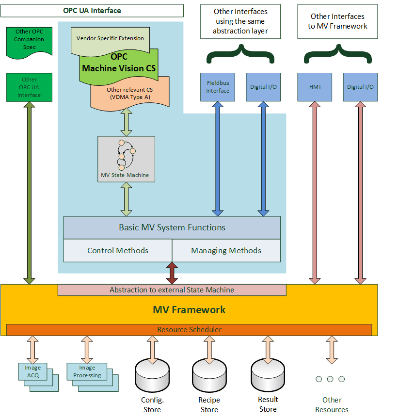
Figure 1 gives a generalized view on a machine vision system in the context of this companion specification. It assumes that there is some machine vision framework responsible for the acquisition and processing of the images. This framework is completely implementation specific to the system and is outside the scope of this companion specification.
This underlying system is currently presented to the "outside world", e.g. the PLC, by various interfaces like digital I/O or field bus, typically using vendor specific protocol definitions. The interface described in this specification may co-exist with these interfaces and offer an additional view on the system or it may be used as the only interface to the system, depending on the requirements of the particular application.
The system may also be exposed through OPC UA interfaces according to other companion specifications, for example, DataMatrix code readers are by their nature machine vision systems but can also be exposed as systems adhering to the Auto ID specification. And system vendors can of course add their own OPC UA interfaces.
This companion specification provides a particular abstraction of a system envisioned to be running in an automated production environment where "automated" is meant in a very broad sense. A test bank for analyzing individual parts can be viewed as automated in that the press of a button by the operator starts the task of the machine vision system.
This abstraction may reflect the inner workings of the machine vision framework or it may be a layer on top of the framework presenting a view of it which is only loosely related to its interior construction.
The basic assumption of the model is that a machine vision system in a production environment goes through a sequence of states which are of interest to and may be influenced by the outside world.
Therefore, a core element of this companion specification is a state machine view of the machine vision system.
Also, a machine vision system may require information from the outside world, in addition to the information it gathers itself by image acquisition, e.g. information about the type of product to be processed. And it will typically pass information to the outside world, e.g. results from the processing.
Therefore, in addition to the state machine, a set of methods and data types is required to allow for this flow of information. Due to the diverse nature of machine vision systems and their applications, these data types will have to allow for vendor- and application-specific extensions.
The intention of the state machine, the methods, as well as the data types, is to provide a framework allowing for standardized integration of machine vision systems into automated production systems, and guidance for filling in the application-specific areas.
Of course, vendors will always be able to extend this specification and provide additional services according to the specific capabilities of their systems and the particular applications.
4.2 Introduction to OPC Unified Architecture
4.2.1 What is OPC UA?
OPC UA is an open and royalty free set of standards designed as a universal communication protocol. While there are numerous communication solutions available, OPC UA has key advantages:
A state of art security model (see OPC 10000-2).
A fault tolerant communication protocol.
An information modelling framework that allows application developers to represent their data in a way that makes sense to them.
OPC UA has a broad scope which delivers for economies of scale for application developers. This means that a larger number of high quality applications at a reasonable cost are available. When combined with semantic models such as OPC Machine Vision, OPC UA makes it easier for end users to access data via generic commercial applications.
The OPC UA model is scalable from small devices to ERP systems. OPC UA Servers process information locally and then provide that data in a consistent format to any application requesting data - ERP, MES, PMS, Maintenance Systems, HMI, Smartphone or a standard Browser, for examples. For a more complete overview see OPC 10000-1.
4.2.2 Basics of OPC UA
As an open standard, OPC UA is based on standard internet technologies, like TCP/IP, HTTP, Web Sockets.
As an extensible standard, OPC UA provides a set of Services (see OPC 10000-4) and a basic information model framework. This framework provides an easy manner for creating and exposing vendor defined information in a standard way. More importantly all OPC UA Clients are expected to be able to discover and use vendor-defined information. This means OPC UA users can benefit from the economies of scale that come with generic visualization and historian applications. This specification is an example of an OPC UA Information Model designed to meet the needs of developers and users.
OPC UA Clients can be any consumer of data from another device on the network to browser based thin clients and ERP systems. The full scope of OPC UA applications is shown in Figure 2.

OPC UA provides a robust and reliable communication infrastructure having mechanisms for handling lost messages, failover, heartbeat, etc. With its binary encoded data, it offers a high-performing data exchange solution. Security is built into OPC UA as security requirements become more and more important especially since environments are connected to the office network or the internet and attackers are starting to focus on automation systems.
4.2.3 Information modelling in OPC UA
4.2.3.1 Concepts
OPC UA provides a framework that can be used to represent complex information as Objects in an AddressSpace which can be accessed with standard services. These Objects consist of Nodes connected by References. Different classes of Nodes convey different semantics. For example, a Variable Node represents a value that can be read or written. The Variable Node has an associated DataType that can define the actual value, such as a string, float, structure etc. It can also describe the Variable value as a variant. A Method Node represents a function that can be called. Every Node has a number of Attributes including a unique identifier called a NodeId and non-localized name called as BrowseName. An Object representing a 'Reservation' is shown in Figure 3.

Object and Variable Nodes represent instances and they always reference a TypeDefinition (ObjectType or VariableType) Node which describes their semantics and structure. Figure 4 illustrates the relationship between an instance and its TypeDefinition.
The type Nodes are templates that define all of the children that can be present in an instance of the type. In the example in Figure 4 the PersonType ObjectType defines two children: First Name and Last Name. All instances of PersonType are expected to have the same children with the same BrowseNames. Within a type the BrowseNames uniquely identify the children. This means Client applications can be designed to search for children based on the BrowseNames from the type instead of NodeIds. This eliminates the need for manual reconfiguration of systems if a Client uses types that multiple Servers implement.
OPC UA also supports the concept of sub-typing. This allows a modeller to take an existing type and extend it. There are rules regarding sub-typing defined in OPC 10000-3, but in general they allow the extension of a given type or the restriction of a DataType. For example, the modeller may decide that the existing ObjectType in some cases needs an additional Variable. The modeller can create a subtype of the ObjectType and add the Variable. A Client that is expecting the parent type can treat the new type as if it was of the parent type. Regarding DataTypes, subtypes can only restrict. If a Variable is defined to have a numeric value, a sub type could restrict it to a float.

References allow Nodes to be connected in ways that describe their relationships. All References have a ReferenceType that specifies the semantics of the relationship. References can be hierarchical or non-hierarchical. Hierarchical references are used to create the structure of Objects and Variables. Non-hierarchical are used to create arbitrary associations. Applications can define their own ReferenceType by creating subtypes of an existing ReferenceType. Subtypes inherit the semantics of the parent but may add additional restrictions. Figure 5 depicts several References, connecting different Objects.

The figures above use a notation that was developed for the OPC UA specification. The notation is summarized in Figure 6. UML representations can also be used; however, the OPC UA notation is less ambiguous because there is a direct mapping from the elements in the figures to Nodes in the AddressSpace of an OPC UA Server.
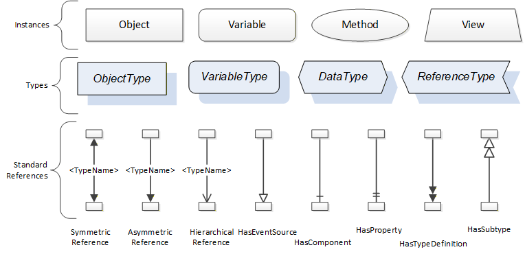
A complete description of the different types of Nodes and References can be found in OPC 10000-3 and the base structure is described in OPC 10000-5.
OPC UA specification defines a very wide range of functionality in its basic information model. It is not expected that all Clients or Servers support all functionality in the OPC UA specifications. OPC UA includes the concept of Profiles, which segment the functionality into testable certifiable units. This allows the definition of functional subsets (that are expected to be implemented) within a companion specification. The Profiles do not restrict functionality, but generate requirements for a minimum set of functionality (see OPC 10000-7)
4.2.3.2 Namespaces
OPC UA allows information from many different sources to be combined into a single coherent AddressSpace. Namespaces are used to make this possible by eliminating naming and id conflicts between information from different sources. Namespaces in OPC UA have a globally unique string called a NamespaceUri and a locally unique integer called a NamespaceIndex. The NamespaceIndex is only unique within the context of a Session between an OPC UA Client and an OPC UA Server. The Services defined for OPC UA use the NamespaceIndex to specify the Namespace for qualified values.
There are two types of values in OPC UA that are qualified with Namespaces: NodeIds and QualifiedNames. NodeIds are globally unique identifiers for Nodes. This means the same Node with the same NodeId can appear in many Servers. This, in turn, means Clients can have built in knowledge of some Nodes. OPC UA Information Models generally define globally unique NodeIds for the TypeDefinitions defined by the Information Model.
QualifiedNames are non-localized names qualified with a Namespace. They are used for the BrowseNames of Nodes and allow the same names to be used by different information models without conflict. TypeDefinitions are not allowed to have children with duplicate BrowseNames; however, instances do not have that restriction.
4.2.3.3 Companion Specifications
An OPC UA companion specification for an industry specific vertical market describes an Information Model by defining ObjectTypes, VariableTypes, DataTypes and ReferenceTypes that represent the concepts used in the vertical market, and potentially also well-defined Objects as entry points into the AddressSpace.
5 Use cases
A vision system assesses situations automatically through machine vision and machine evaluation. This document describes how a vision system is addressed via OPC UA and integrated in a superordinate or a peer to peer structure. The description covers all aspects relevant for operation.
Interaction of the client with the vision system
A vision system usually has the role of an OPC UA server, i.e. its states are exposed via an OPC UA server. This is what in this specification is described and defined.
The client system can control the vision system via OPC UA. The vision system may also be controlled by a different entity through a different interface.
The vision system reports important events - such as evaluation results and error states - automatically to a subscribed client.
However, the client can query data from the vision system at any time.
State Machine
The state machine model is an abstraction of a machine vision system, which maps the possible operational states of the machine vision system to a state model with a fixed number of states.
Each interaction of the client system with the vision system depends on the current state of the model and also the state and capabilities of the underlying vision system.
State changes are initiated by method calls from the client system or triggered by internal or external events. They may also be triggered by a secondary interface. Each state change is communicated to the client system.
The state machine is described in more detail in Section 8.
Recipe Management
The properties, procedures and parameters that describe a machine vision task for the vision system are stored in a recipe.
Usually there are multiple usable recipes on a vision system.
This specification provides methods for activating, loading, and saving recipes.
Recipes are handled as binary objects. The interpretation of a recipe is not part of this specification.
For a detailed description of Recipe Management, please refer to B.1.
Result Transfer
The image processing results are transmitted to the client system asynchronously. This transmission includes information on product assignment, times, and statuses.
The detailed data format of a result is not included in this specification.
Error Management
There is an interface for error notification and interactive error management.
6 OPC Machine Vision information model overview
Figure 7 shows the main objects types and the relations between them.
7 ObjectTypes for the Vision System in General
7.1 VisionSystemType
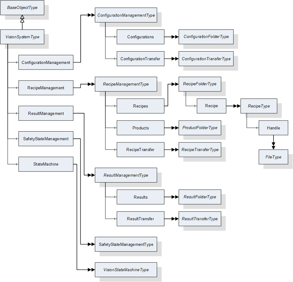
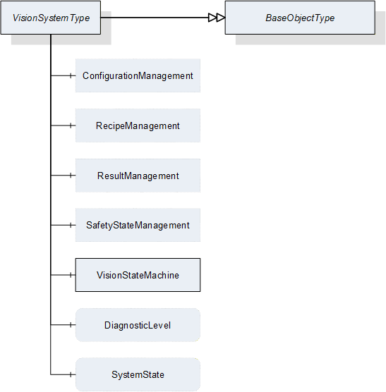
This ObjectType defines the representation of a machine vision system. Figure 8 shows the hierarchical structure and details of the composition. It is formally defined in Table 10.
Instances of this ObjectType provide a general communication interface for a machine vision system. This interface makes it possible to interact with this system independent of the knowledge of the internal structure and the underlying processes of the machine vision system.
System behavior is modeled with a mandatory hierarchical finite state machine.
VisionSystemType contains four optional management objects, RecipeManagement, ConfigurationManagement, ResultManagement, and SafetyStateManagement. All of these provide access to the exposed functionality of the machine vision system.
| Attribute | Value | ||||
| BrowseName | VisionSystemType | ||||
| IsAbstract | False | ||||
| References |
Node
Class | BrowseName | DataType | TypeDefinition |
Modelling
Rule |
|---|---|---|---|---|---|
| Subtype of the BaseObjectType defined in OPC 10000-5 | |||||
| HasComponent | Object | ConfigurationManagement | -- | ConfigurationManagementType | Optional |
| HasComponent | Object | RecipeManagement | -- | RecipeManagementType | Optional |
| HasComponent | Object | ResultManagement | -- | ResultManagementType | Optional |
| HasComponent | Object | SafetyStateManagement | -- | SafetyStateManagementType | Optional |
| HasComponent | Object | VisionStateMachine | -- | VisionStateMachineType | Mandatory |
| HasComponent | Variable | DiagnosticLevel | UInt16 | BaseDataVariableType | Optional |
| HasComponent | Variable | SystemState | SystemStateDescriptionDataType | BaseDataVariableType | Optional |
ConfigurationManagement providesConfigurationManagement provides methods and properties required for Section 7.2.
RecipeManagement provides functionality to add, remove, prepare, and retrieve vision system recipes. RecipeManagementType is described in Section 7.5.
ResultManagement provides methods and properties necessary for managing the results. ResultManagementType is described in Section 7.10.
SafetyStateManagement provides functionality to inform the vision system about the change of an external safety state. SafetyStateManagementType is described in Section 7.13.
StateMachine provides information about the current state of the vision system and methods for controlling it. VisionStateMachineType is defined in Section 8.2.
DiagnosticLevel specifies the threshold for the severity of diagnostic messages to be generated by the server. More information can be found in Section 11.3.
SystemState represents the system state in terms of the SEMI E10 standard. More information can be found in Section11.6.
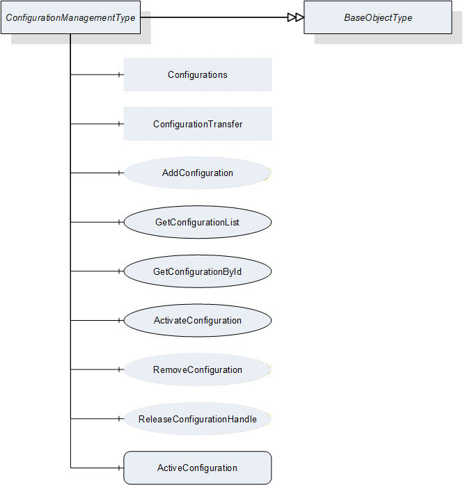
7.2 ConfigurationManagementType
7.2.1 Overview
This ObjectType defines the representation of the machine vision system configuration management. Figure 9 shows the hierarchical structure and details of the composition. It is formally defined in Table 11.
Even supposedly identical vision systems will differ in some details. In order to produce the same results the vision systems have to be adjusted individually e.g. calibrated. Within this document, the set of all parameters that are needed to get the system working is called a configuration. Configurations can be used to align different vision systems that have the same capabilities, so that these systems produce the same results for the same recipes.
Instances of this ObjectType handle all configurations that are exposed by the system. Only one configuration can be active at a time. This active configuration affects all recipes used in the machine vision system. The configurations can optionally also be exposed in a folder, in order to provide access to the client.
Configurations are handled as files, meta data of configurations can be directly viewed but not changed by the client. The interpretation of the configuration's content is not part of this specification.
| Attribute | Value | ||||
| BrowseName | ConfigurationManagementType | ||||
| IsAbstract | False | ||||
| References | NodeClass | BrowseName | DataType | TypeDefinition | ModellingRule |
|---|---|---|---|---|---|
| Subtype of the BaseObjectType defined in OPC 10000-5 | |||||
| HasComponent | Object | ConfigurationTransfer | -- | ConfigurationTransferType | Optional |
| HasComponent | Object | Configurations | -- | ConfigurationFolderType | Optional |
| HasComponent | Method | AddConfiguration | -- | -- | Optional |
| HasComponent | Method | GetConfigurationList | -- | -- | Mandatory |
| HasComponent | Method | GetConfigurationById | -- | -- | Mandatory |
| HasComponent | Method | ReleaseConfigurationHandle | -- | -- | Optional |
| HasComponent | Method | RemoveConfiguration | -- | -- | Optional |
| HasComponent | Method | ActivateConfiguration | -- | -- | Mandatory |
| HasComponent | Variable | ActiveConfiguration | ConfigurationDataType | BaseDataVariableType | Mandatory |
ConfigurationTransfer is an instance of the ConfigurationTransferType defined in Section 7.4 and it is used to transfer the contents of a configuration by the temporary file transfer method defined in OPC 10000-5, Annex C.4.
Configurations is an instance of the ConfigurationFolderType and it is used to organize variables of DataType ConfigurationDataType which is defined in Section 12.9. If the server chooses to expose configuration information in the Address Space, the Object may contain the set of all configurations available on the system. This is implementation-defined. If a server does not expose configuration information in the Address Space, this Object is expected to be non-existent.
The DataTypes used in the ConfigurationManagementType are defined in OPC 10000-5 and in Section 11.6 of this specification.
7.2.2 ConfigurationManagementType methods
7.2.2.1 AddConfiguration
7.2.2.1.1 Overview
This method is used to add a configuration to the configuration management of the vision system. It concerns itself only with the metadata of the configuration, the actual content is transferred by an object of ConfigurationTransferType which is defined in Section 7.4.
The intended behavior of this method for different input arguments is described in the following subsections.
Signature
AddConfiguration ([in] ConfigurationIdDataType externalId[out] ConfigurationIdDataType internalId[out] NodeId configuration[out] Boolean transferRequired[out] Int32 error);
| Argument | Description |
| externalId | Identification of the configuration used by the environment. This argument must not be empty. |
| internalId | System-wide unique ID for identifying a configuration. This ID is assigned by the vision system. |
| configuration | If the server chooses to represent the configuration in the Address Space, it shall return the NodeId of the newly created entry in the Configurations variable here. If the server uses only method-based configuration management, this shall be a null NodeId as defined in OPC 10000-3. |
| transferRequired | In this argument, the server returns whether the vision system assumes that a transfer of the file content of the configuration is required. Note that this is only a hint for the client. If the server returns TRUE, the client will have to assume that the vision system needs the configuration content and shall transfer it. If the server returns FALSE, the client may transfer the configuration content anyway. |
| error | 0 - OK Values > 0 are reserved for errors defined by this and future standards. Values < 0 shall be used for application-specific errors. |
| Attribute | Value | ||||
| BrowseName | AddConfiguration | ||||
| References | NodeClass | BrowseName | DataType | TypeDefinition | ModellingRule |
|---|---|---|---|---|---|
| HasProperty | Variable | InputArguments | Argument[] | PropertyType | Mandatory |
| HasProperty | Variable | OutputArguments | Argument[] | PropertyType | Mandatory |
7.2.2.1.2 New ExternalId
If AddConfiguration is called with an ExternalId not yet existing in the configuration management of the vision system, it is expected that the vision system creates an appropriate management structure with an InternalId which is unique on the system. The server then returns this InternalId.
If the server chooses to represent all or selected configurations in the Address Space and if the new configuration matches the current selection criteria, the server shall create a new entry in the Configurations folder in the Address Space.
The method will return TRUE in the TransferRequired argument. Since the ExternalId does not yet exist in the configuration management of the vision system, it is expected the configuration does not yet exist either in the local configuration storage of the vision system, and therefore needs to be transferred.
7.2.2.1.3 Identically Existing ExternalId with identical configuration
If AddConfiguration is called with an ExternalId already existing in the configuration management of the vision system, it is expected that the vision system checks whether an identical version of the configuration already exists, provided that the content of the ExternalId allows for such a check. (A way to perform this comparison without having to download the binary content first is offered by the optional hash value in the ExternalId. The idea is that the client computes a hash for the contents of the recipe and passes that hash in the ExternalId. The server can then check this hash against a hash transmitted earlier, or it can compute a hash by itself over the contents of the recipe currently stored on the vision system side. For this procedure, the server needs to know the hash algorithm used by the client which can be transmitted in the hashAlgorithm member of the ExternalId).
Note that the method has no way of checking this with the actual configuration content which is not yet known to the vision system.
The method will return FALSE in the TransferRequired argument if the method comes to the conclusion that the configuration already exists with identical content on the vision system. Note that the result is not binding for the client who may decide to transfer the configuration content anyway.
If the server represents configurations in the Address Space, no new entry shall be created in the configurations folder.
7.2.2.1.4 Identically Existing ExternalId with different configuration
If AddConfiguration comes to the conclusion that the content of the configuration to be transferred is different from the content already existing for this ExternalId, it shall return TRUE in the TransferRequired argument.
The behavior with respect to the management of the configuration metadata and configuration content is entirely application-defined. The vision system may decide to create a new management structure and add the configuration content to the local configuration store, or it may decide to re-use the existing ExternalId and overwrite the configuration content. In any case, the vision system shall create a new, system-wide unique InternalId for this configuration.
If the server chooses to represent configurations in the Address Space, the behavior with respect to these objects should mirror the behavior of the vision system in its internal configuration management.
7.2.2.1.5 Local creation or editing of configurations
This is not, strictly speaking, a use case of the method AddConfiguration, but results are comparable, and therefore the use case is described here.
If a configuration is created locally on the vision system or is loaded onto the vision system by a different interface than the OPC Machine Vision interface, i.e. the configuration is added without using method AddConfiguration, then this configuration shall have a system-wide unique InternalId, just like a configuration added through the method.
If an existing configuration which was uploaded to the vision system through the method AddConfiguration, is locally changed, the ExternalId shall be removed from the changed version and it shall receive a new system-wide unique InternalId so that the two configurations cannot be confused. The vision system may record the history from which configuration it was derived.
If the server exposes configurations in the Address Space and if the locally created or edited configurations match the current filter criteria, then they shall be represented as nodes in the Configurations folder, with their system-wide unique InternalIds, but without ExternalIds.
7.2.2.2 GetConfigurationById
This method is used to get the metadata for one configuration from a number of configurations.
Signature
GetConfigurationById ([in] ConfigurationIdDataType internalId[in] Int32 timeout[out] Handle configurationHandle[out] ConfigurationDataType configuration[out] Int32 error);
| Argument | Description |
| internalId | Identification of the configuration used by the vision system. This argument must not be empty. |
| Timeout | With this argument the client can give a hint to the server how long it will need access to the configuration data. A value > 0 indicates an estimated maximum time for processing the data in milliseconds. A value = 0 indicates that the client will not need anything besides the data returned by the method call. A value < 0 indicates that the client cannot give an estimate. The client cannot rely on the data being available during the indicated time period. The argument is merely a hint allowing the server to optimize its resource management. |
| configurationHandle | The client can use the handle returned by the server to call the ReleaseConfigurationHandle method to indicate to the server that it has finished processing the configuration data, allowing the server to optimize its resource management. If the server does not support the ReleaseConfigurationHandle method, this value shall be 0. The client cannot rely on the data being available until ReleaseConfigurationHandle is called. |
| configuration | Requested configuration. |
| error | 0 - OK Values > 0 are reserved for errors defined by this and future standards. Values < 0 shall be used for application-specific errors. |
| Attribute | Value | ||||
| BrowseName | GetConfigurationById | ||||
| References | NodeClass | BrowseName | DataType | TypeDefinition | ModellingRule |
|---|---|---|---|---|---|
| HasProperty | Variable | InputArguments | Argument[] | PropertyType | Mandatory |
| HasProperty | Variable | OutputArguments | Argument[] | PropertyType | Mandatory |
7.2.2.3 GetConfigurationList
This method is used to get a list of all configurations. It concerns itself only with the metadata of the configuration, the actual content is transferred by a ConfigurationTransferType object.
Signature
GetConfigurationList ([in] UInt32 maxResults[in] UInt32 startIndex[in] Int32 timeout[out] Boolean isComplete[out] UInt32 resultCount[out] Handle configurationHandle[out] ConfigurationDataType[] configurationList[out] Int32 error);
| Argument | Description |
| maxResults | Maximum number of configurations to return in one call; by passing 0, the client indicates that it does not put a limit on the number of configurations. |
| startIndex | Shall be 0 on the first call, multiples of maxResults on subsequent calls to retrieve portions of the entire list, if necessary. |
| timeout | With this argument the client can give a hint to the server how long it will need access to the configuration data. A value > 0 indicates an estimated maximum time for processing the data in milliseconds. A value = 0 indicates that the client will not need anything besides the data returned by the method call. A value < 0 indicates that the client cannot give an estimate. The client cannot rely on the data being available during the indicated time period. The argument is merely a hint allowing the server to optimize its resource management. |
| isComplete | Indicates whether there are more configurations in the entire list than retrieved according to startIndex and resultCount. |
| resultCount | Gives the number of valid results in configurationList. |
| configurationHandle | The server shall return to each client requesting configuration data a system-wide unique handle identifying the configuration set / client combination. The handle spans continuation calls, so on every call by the same client where startIndex is not 0, the same handle shall be returned. This handle canbe used by the client in a call to the ReleaseConfigurationHandle method, thereby indicating to the server that it has finished processing the configuration set, allowing the server to optimize its resource management. The client cannot rely on the data being available until the ReleaseConfigurationHandle method is called. If the server does no support ReleaseConfigurationHandle, this value shall be 0. |
| configurationList | List of configurations. |
| error | 0 - OK Values > 0 are reserved for errors defined by this and future standards. Values < 0 shall be used for application-specific errors. |
| Attribute | Value | ||||
| BrowseName | GetConfigurationList | ||||
| References | NodeClass | BrowseName | DataType | TypeDefinition | ModellingRule |
|---|---|---|---|---|---|
| HasProperty | Variable | InputArguments | Argument[] | PropertyType | Mandatory |
| HasProperty | Variable | OutputArguments | Argument[] | PropertyType | Mandatory |
The following cases must be considered with the respect to the number of available configurations:
The number of configurations to be returned is less or equal to maxResults; the first call, with startIndex=0, returns isComplete=TRUE, so the client knows that no further calls are necessary. resultCount gives the number of valid elements in the configurationList array.
The number of configurations to be returned is larger than maxResults; the first N calls (N > 0 with N ≤ (number of configurations) divisor MaxResults), with startIndex=(N-1)*maxResults, return isComplete=FALSE, so the client knows that further calls are necessary. The following call returns isComplete=TRUE, so the client knows, no further calls are necessary. resultCount gives the number of valid elements in the configurationList array (on each call, so on the first N calls, this should be maxResults).
7.2.2.4 ReleaseConfigurationHandle
This method is used to inform the server that the client has finished processing a given configuration set allowing the server to free resources managing this configuration set.
The server should keep the data of the configuration set available for the client until the ReleaseConfigurationHandle method is called or until a timeout given by the client has expired. However, the server is free to release the data at any time, depending on its internal resource management, so the client cannot rely on the data being available. ReleaseConfigurationHandle is merely a hint allowing the server to optimize its internal resource management. For timeout usage, see the description in Section 7.2.2.2.
Signature
ReleaseConfigurationHandle ([in] Handle configurationHandle[out] Int32 error);
| Argument | Description |
| configurationHandle | Handle returned by GetConfigurationById or GetConfigurationList, identifying the configuration set/client combination. |
| error | 0 - OK Values > 0 are reserved for errors defined by this and future standards. Values < 0 shall be used for application-specific errors. |
| Attribute | Value | ||||
| BrowseName | ReleaseConfigurationHandle | ||||
| References | NodeClass | BrowseName | DataType | TypeDefinition | ModellingRule |
|---|---|---|---|---|---|
| HasProperty | Variable | InputArguments | Argument[] | PropertyType | Mandatory |
| HasProperty | Variable | OutputArguments | Argument[] | PropertyType | Mandatory |
7.2.2.5 RemoveConfiguration
This method is used to remove a configuration from the configuration management of the vision system.
Application Note:
It may be required from a vision system - e.g. in pharmaceutical or other safety-critical applications - to keep a record of the prior existence of a removed configuration. This may be important in such systems for the meta information of results that were generated while the removed configuration was active. It serves to keep it comprehensible which configurations were available on the vision system
Signature
RemoveConfiguration ([in] ConfigurationIdDataType internalId[out] Int32 error);
| Argument | Description |
| internalId | Identification of the configuration used by the vision system. This argument must not be empty. |
| error | 0 - OK Values > 0 are reserved for errors defined by this and future standards. Values < 0 shall be used for application-specific errors. |
| Attribute | Value | ||||
| BrowseName | RemoveConfiguration | ||||
| References | NodeClass | BrowseName | DataType | TypeDefinition | ModellingRule |
|---|---|---|---|---|---|
| HasProperty | Variable | InputArguments | Argument[] | PropertyType | Mandatory |
| HasProperty | Variable | OutputArguments | Argument[] | PropertyType | Mandatory |
7.2.2.6 ActivateConfiguration
This method is used to activate a configuration from the configuration management of the vision system.
Since only a single configuration can be active at any time, this method shall deactivate any other configuration which may currently be active. From that point on until the next call to this method the vision system will conduct its operation according to the settings of the activated configuration.
Note that there is no way to deactivate a configuration except by activating another one to avoid having no active configuration on the system.
Signature
ActivateConfiguration ([in] ConfigurationIdDataType internalId[out] Int32 error);| Argument | Description |
| internalId | Identification of the configuration used by the vision system. This argument must not be empty. |
| error | 0 - OK Values > 0 are reserved for errors defined by this and future standards. Values < 0 shall be used for application-specific errors. |
| Attribute | Value | ||||
| BrowseName | ActivateConfiguration | ||||
| References | NodeClass | BrowseName | DataType | TypeDefinition | ModellingRule |
|---|---|---|---|---|---|
| HasProperty | Variable | InputArguments | Argument[] | PropertyType | Mandatory |
| HasProperty | Variable | OutputArguments | Argument[] | PropertyType | Mandatory |
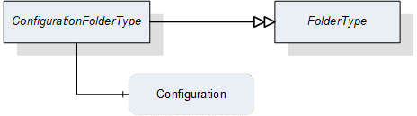
7.3 ConfigurationFolderType
This ObjectType is a subtype of the FolderType and is used to organize the configurations of a vision system. Figure 10 shows the hierarchical structure and details of the composition. It is formally defined in Table 24.
Instances of this ObjectType organize all available configurations of the vision system, which the server decides to expose in the Address Space. It may contain no configuration if no configuration is available, if the server does not expose configurations in the Address Space at all, or if no configuration matches the criteria of the server for exposure in the Address Space.
Note that the folder contains only metadata of the configurations, not the actual configuration data of the vision system.
| Attribute | Value | ||||
| BrowseName | ConfigurationFolderType | ||||
| IsAbstract | False | ||||
| References | NodeClass | BrowseName | DataType | TypeDefinition | ModellingRule |
|---|---|---|---|---|---|
| Subtype of the FolderType defined in OPC 10000-5 | |||||
| HasComponent | Variable | <Configuration> | ConfigurationDataType | BaseDataVariableType | OptionalPlaceholder |
The ConfigurationDataType used in the ConfigurationFolderType is defined in Section 12.12.
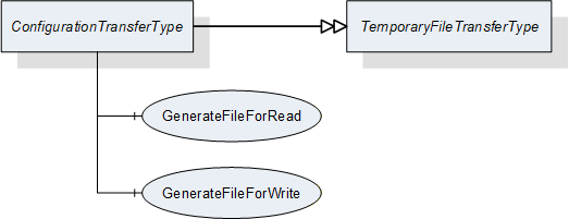
7.4 ConfigurationTransferType
7.4.1 Overview
This ObjectType is a subtype of the TemporaryFileTransferType defined in OPC 10000-5 and is used to transfer configuration data as a file.
The ConfigurationTransferType overwrites the Methods GenerateFileForRead and GenerateFileForWrite to specify the concrete type of the generateOptions Parameter of the Methods.
Figure 11 shows the hierarchical structure and details of the composition. It is formally defined in Table 25.
| Attribute | Value | ||||
| BrowseName | ConfigurationTransferType | ||||
| IsAbstract | False | ||||
| References | NodeClass | BrowseName | DataType | TypeDefinition | ModellingRule |
|---|---|---|---|---|---|
| Subtype of the TemporaryFileTransferType defined in OPC 10000-5 | |||||
| HasComponent | Method | 0:GenerateFileForRead | -- | -- | Mandatory |
| HasComponent | Method | 0:GenerateFileForWrite | -- | -- | Mandatory |
7.4.2 ConfigurationTransferType methods
7.4.2.1 GenerateFileForRead
This method is used to start the read file transaction. A successful call of this method creates a temporary FileType Object with the file content and returns the NodeId of this Object and the file handle to access the Object.
Signature
GenerateFileForRead ([in] ConfigurationTransferOptions generateOptions[out] NodeId fileNodeId[out] UInt32 fileHandle[out] NodeId completionStateMachine);
| Argument | Description |
| generateOptions | The structure used to define the generate options for the file. |
| fileNodeId | NodeId of the temporary file |
| fileHandle | The FileHandle of the opened TransferFile. The FileHandle can be used to access the TransferFile methods Read and Close. |
| completionStateMachine | If the creation of the file is completed asynchronously, the parameter returns the NodeId of the corresponding FileTransferStateMachineType Object. If the creation of the file is already completed, the parameter is null. If a FileTransferStateMachineType object NodeId is returned, the Read Method of the file fails until the TransferState changed to ReadTransfer. |
| Attribute | Value | ||||
| BrowseName | GenerateFileForRead | ||||
| References | NodeClass | BrowseName | DataType | TypeDefinition | ModellingRule |
|---|---|---|---|---|---|
| HasProperty | Variable | InputArguments | Argument[] | PropertyType | Mandatory |
| HasProperty | Variable | OutputArguments | Argument[] | PropertyType | Mandatory |
7.4.2.2 GenerateFileForWrite
This method is used to start the write file transaction. A successful call of this method creates a temporary FileType Object with the file content and returns the NodeId of this Object and the file handle to access the Object.
Signature
GenerateFileForWrite ([in] ConfigurationTransferOptions generateOptions[out] NodeId fileNodeId[out] UInt32 fileHandle);| Argument | Description |
| generateOptions | The structure used to define the generate options for the file. |
| fileNodeId | NodeId of the temporary file. |
| fileHandle | The fileHandle of the opened TransferFile. The fileHandle can be used to access the TransferFile methods Write and CloseAndCommit. |
| Attribute | Value | ||||
| BrowseName | GenerateFileForWrite | ||||
| References | NodeClass | BrowseName | DataType | TypeDefinition | ModellingRule |
|---|---|---|---|---|---|
| HasProperty | Variable | InputArguments | Argument[] | PropertyType | Mandatory |
| HasProperty | Variable | OutputArguments | Argument[] | PropertyType | Mandatory |
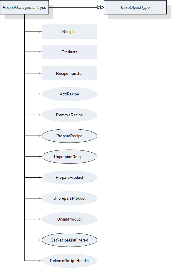
7.5 RecipeManagementType
7.5.1 Overview
This ObjectType defines the representation of the machine vision system recipe management (for a conceptual overview of recipe management see Section B.1, for a definition of recipes itself, see Section B.1.2.1). Figure 12 shows the hierarchical structure and details of the composition. It is formally defined in Table 30.
For the actual data transfer, RecipeManagementType makes use of the RecipeTransferType, derived from the TemporaryFileTransferType defined in OPC 10000-5, beginning with version 1.04.
If the server chooses to expose recipe data in the Address Space (see Section B.1.3.3) using the Recipes folder of this type, the FileType object component of the RecipeType objects in this folder can also be used directly for the data transfer.
| Attribute | Value | ||||
| BrowseName | RecipeManagementType | ||||
| IsAbstract | False | ||||
| References | Node Class | BrowseName | DataType | TypeDefinition | ModellingRule |
|---|---|---|---|---|---|
| Subtype of the BaseObjectType defined in OPC 10000-5 | |||||
| HasComponent | Method | AddRecipe | -- | -- | Optional |
| HasComponent | Method | PrepareRecipe | -- | -- | Mandatory |
| HasComponent | Method | UnprepareRecipe | -- | -- | Mandatory |
| HasComponent | Method | GetRecipeListFiltered | -- | -- | Mandatory |
| HasComponent | Method | ReleaseRecipeHandle | -- | -- | Optional |
| HasComponent | Method | RemoveRecipe | -- | -- | Optional |
| HasComponent | Method | PrepareProduct | -- | -- | Optional |
| HasComponent | Method | UnprepareProduct | -- | -- | Optional |
| HasComponent | Method | UnlinkProduct | -- | -- | Optional |
| HasComponent | Object | RecipeTransfer | -- | RecipeTransferType | Optional |
| HasComponent | Object | Recipes | -- | RecipeFolderType | Optional |
| HasComponent | Object | Products | -- | ProductFolderType | Optional |
RecipeTransfer is an instance of the RecipeTransferType defined in Section 7.6 and it is used to transfer the contents of a recipe by the temporary file transfer method defined in OPC 10000-5, Annex C.4.
Recipes is an instance of the RecipeFolderType that organizes RecipeType objects, if the server chooses to expose recipe information in the Address Space. In this case, it may contain the set of all recipes available on the system or a filtered subset, e.g. the set of all currently prepared recipes. This is implementation-defined. If a server does not expose recipe information in the Address Space, this folder is expected to be non-existent.
Products is an instance of the ProductFolderType that organizes ProductDataType variables, if the server chooses to expose product information in the Address Space. In this case, it may contain the set of all products available on the system or a filtered subset, e.g. the set of all products for which recipes are currently prepared. This is implementation-defined. If a server does not expose product information in the Address Space, this folder is expected to be non-existent.
7.5.2 RecipeManagementType Methods
7.5.2.1 AddRecipe
7.5.2.1.1 Overview
This method is used to add a recipe to the recipe management of the vision system. It concerns itself only with the metadata of the recipe, the actual content is transferred by a RecipeTransferType object.
The intended behavior of this method for different input arguments is described in the following subsections.
Signature
AddRecipe ([in] RecipeIdExternalDataType externalId[in] ProductIdDataType productId[out] RecipeIdInternalDataType internalId[out] NodeId recipe[out] NodeId product[out] Boolean transferRequired[out] Int32 error);| Argument | Description |
| externalId | Identification of the recipe used by the environment. This argument must not be empty. |
| productId | Identification of a product the recipe is to be used for. This argument may be empty. |
| internalId | Internal identification of the recipe. This identification shall be system-wide unique and must be returned. |
| recipe | If the server chooses to represent the recipe in the Address Space, it shall return the NodeId of the newly created entry in the Recipes folder here. If the server uses only method-based recipe management, this shall be null. Note that, even if the server uses the Recipes folder to expose recipe data in the Address Space, this may be empty, if the newly created recipe does not fit the selection criteria of the server for the entries in this folder. |
| product | If the server chooses to represent product information in the Address Space, it shall return the NodeId of a newly created entry in the Products folder here. If the server uses only method-based recipe management, this shall be null. Note that, even if the server uses the Products folder to expose product data in the Address Space, this may be null if the newly created product does not fit the selection criteria of the server for the entries in the Products folder. |
| transferRequired | In this argument, the server returns whether the vision system assumes that a transfer of the file content of the recipe is required. Note that this is only a hint for the client. If the server returns TRUE, the client will have to assume that the vision system needs the recipe content and shall transfer it. If the server returns FALSE, the client may transfer the recipe content anyway. |
| error | 0 - OK Values > 0 are reserved for errors defined by this and future standards. Values < 0 shall be used for application-specific errors. |
| Attribute | Value | ||||
| BrowseName | AddRecipe | ||||
| References | Node Class | BrowseName | DataType | TypeDefinition | ModellingRule |
|---|---|---|---|---|---|
| HasProperty | Variable | InputArguments | Argument[] | PropertyType | Mandatory |
| HasProperty | Variable | OutputArguments | Argument[] | PropertyType | Mandatory |
7.5.2.1.2 New ExternalId
If AddRecipe is called with an ExternalId not yet existing in the recipe management of the vision system, it is expected that the vision system creates an appropriate management structure with an InternalId which is system-wide unique. The server may then return this InternalId, however the client cannot rely on this.
If the server chooses to represent all or selected recipes in the Address Space and if the new recipe matches the current selection critieria, the server shall create a new entry in the Recipes folder in the Address Space.
The method will return TRUE in the TransferRequired argument. Since the ExternalId does not yet exist in the recipe management of the vision system, it is expected that the recipe content does not yet exist either in the local recipe storage of the vision system, and therefore needs to be transferred.
If the ProductId argument is non-empty, it is expected that the vision system creates an appropriate management structure linking the newly created recipe for use with this ProductId. If the ProductId does not yet exist on the vision system, it is expected that it is created.
If the ProductId argument is empty, no such linking takes place. Note that it will not be possible to start a job based on a ProductId not linked to a recipe.
If the server chooses to represent all or selected products in the Address Space and if the ProductId matches the selection criteria, the server shall create a new entry in the Products folder in the Address Space.
If the server chooses to represent all or selected recipes in the Address Space and if the given recipe matches the selection criteria, the ProductId shall be added to the list of products within the appropriate Recipe node.
7.5.2.1.3 Identically Existing ExternalId with identical recipe
If AddRecipe is called with an ExternalId already existing in the recipe management of the vision system, it is expected that the vision system checks whether an identical version of the recipe already exists, provided that the content of the ExternalId allows for such a check (most likely using the hash value).
Note that the method has no way of checking this with the actual recipe content which is not yet known to the vision system.
The method will return FALSE in the TransferRequired argument if the system comes to the conclusion that the recipe already exists with identical content on the vision system. Note that the result is not binding for the client who may decide to transfer the recipe content anyway.
If the server represents recipes in the Address Space, no new entry shall be created in the recipes folder.
The behavior with regard to the ProductId argument is as described above for a new ExternalId. This way of calling AddRecipe can be used to link an existing recipe with another product.
7.5.2.1.4 Identically Existing ExternalId with different recipe
If AddRecipe comes to the conclusion that the content of the recipe to be transferred is different from the content already existing for this ExternalId, it shall return TRUE in the TransferRequired argument.
The behavior with respect to the management of the recipe metadata and recipe content is entirely application-defined. The vision system may decide to create a new management structure with a new InternalId and add the recipe content to the local recipe store, or it may decide to re-use the existing ExternalId and overwrite the recipe content.
If the server chooses to represent recipes in the Address Space, the behavior with respect to these recipe objects should mirror the behavior of the vision system in its internal recipe management
The behavior with regard to the ProductId argument is as described above for a new ExternalId. If the vision system stores both recipe versions, it is implementation-defined whether both are linked to the ProductId or not.
Note that overwriting a recipe shall result in a change to the internalId of the recipe. The change may effect only the hash value, the identifier may remain the same. Historical storage is not required.
7.5.2.1.5 Local creation or editing of recipes
This is not, strictly speaking, a use-case of the method AddRecipe, but results are comparable, therefore, the use-case is described here.
If a recipe is created locally on the vision system or is loaded onto the vision system by a different interface than the OPC Machine Vision interface, i.e. the recipe is added without using the AddRecipe method, then this recipe shall have a system-wide unique InternalId, just like a recipe added through the method.
If an existing recipe which was uploaded to the vision system through AddRecipe is locally changed, the ExternalId shall be removed from the changed version and it shall receive a new system-wide unique InternalId so that the two recipes cannot be confused. Of course the vision system may record the history from which recipe it was derived.
If the server represents recipes in the Address Space and if the locally created or edited recipes match the current filter criteria, then they shall be represented as nodes in the Recipes folder, with their system-wide unique InternalIds, but without ExternalIds.
An important special case is the local editing of an already prepared recipe, described in Section B.1.2.3. Since after local editing, the already prepared recipe is different from before, effectively a new recipe has been prepared by the local editing. Therefore, a new RecipePrepared event shall be generated (see also Section 8.3.8.1).
7.5.2.2 PrepareRecipe
This method is used to prepare a recipe so that it can be used for starting a job on the vision system.
Signature
PrepareRecipe ([in] RecipeIdExternalDataType externalId[in] RecipeIdInternalDataType internalIdIn[out] RecipeIdInternalDataType internalIdOut[out] Boolean isCompleted[out] Int32 error);| Argument | Description |
| externalId | Identification of the recipe used by the environment which is to be prepared. |
| internalIdIn | Internal identification of the recipe which is to be prepared. The client can use either the externalId or the internalIdIn, leaving the other empty. If both are given, the InternalIdIn takes precedence. |
| internalIdOut | Internal identification of the recipe selected based on the given externalId or internalId. |
| isCompleted | Flag to indicate that the recipe has been completely prepared before the method returned. If False, the client needs either to check the properties of the recipe to determine when preparation has completed or wait for the RecipePrepared event. |
| Error | 0 - OK Values > 0 are reserved for errors defined by this and future standards. Values < 0 shall be used for application-specific errors. |
| Attribute | Value | ||||
| BrowseName | PrepareRecipe | ||||
| References | Node Class | BrowseName | DataType | TypeDefinition | ModellingRule |
|---|---|---|---|---|---|
| HasProperty | Variable | InputArguments | Argument[] | PropertyType | Mandatory |
| HasProperty | Variable | OutputArguments | Argument[] | PropertyType | Mandatory |
If the vision system is in state Initialized, it is expected to change into state Ready after successful preparation of the recipe and be able to execute jobs called by a Start method with the given ExternalId.
If the vision system is already in state Ready when PrepareRecipe is called, it is expected to be in state Ready again after successful preparation of the recipe and be able to execute jobs called by a Start method with the given ExternalId. Depending on the capabilities of the vision system, it may temporarily leave state Ready for state Initialized, then return to Ready, or, if the system is capable of preparing recipes in the background, it may stay in state Ready and react instantaneously to Start jobs for other, already prepared, recipes. Also depending on the capabilities of the vision system, preparing an additional recipe may unprepare others if the number of recipes being prepared at the same time is limited.
The preparation of a recipe may be a time-consuming operation. The client cannot necessarily assume that the recipe is completely prepared when the method returns. The client should therefore check the preparedness of the recipe after a reasonable amount of time or wait for a RecipePrepared event with the correct ExternalId to be fired. During the time required for preparing a recipe, the system may or may not be capable of reacting to a start method. However, the server is free to handle PrepareRecipe as a synchronous method, returning only after the recipe is completely prepared unless an error has occurred.
Not that the local editing of an already prepared recipe, as described in Sections 7.5.2.1.5 and B.1.2.3 is considered to be the same as the preparation of a new recipe, because after local editing, the already prepared recipe is different from before, so effectively a new recipe has been prepared by the local editing. Therefore, a new RecipePrepared event shall be generated (see also Section 8.3.8.1).
Some recipes may exclude each other from being in prepared state at the same time, for example, when there are mechanical movements involved. Having two such recipes prepared at the same time would mean that an instantaneous reaction to calling the Start method for a prepared recipe would not be possible. However, this is at the discretion of the vision system. The client may merely notice an unusually long reaction time between calling the Start method and the actual state change, or the vision system may prevent the simultaneous preparation by returning an error.
If there is more than one recipe with the identical ExternalId - e.g. due to local copying and modifying of recipes on the vision system - it is implementation-defined how this ambiguity will be handled. The vision system will prepare only a single one of these recipes, which may be the latest one or the latest externally defined one.
7.5.2.3 UnprepareRecipe
This method is used to revert the preparation of a recipe so that it can no longer be used for starting a job on the vision system.
Signature
UnprepareRecipe ([in] RecipeIdExternalDataType externalId[in] RecipeIdInternalDataType internalIdIn[out] RecipeIdInternalDataType internalIdOut[out] Int32 error);
| Argument | Description |
| externalId | Identification of the recipe used by the environment which is to be un-prepared. |
| internalIdIn | Internal identification of the recipe which is to be un-prepared. The client can use either the externalId or the internalIdIn, leaving the other empty. If both are given, the InternalIdIn takes precedence. |
| internalIdOut | Internal identification of the recipe selected based on a given externalId or internalId. This is for verification by the client. |
| error | 0 - OK Values > 0 are reserved for errors defined by this and future standards. Values < 0 shall be used for application-specific errors. |
| Attribute | Value | ||||
| BrowseName | UnprepareRecipe | ||||
| References | NodeClass | BrowseName | DataType | TypeDefinition | ModellingRule |
|---|---|---|---|---|---|
| HasProperty | Variable | InputArguments | Argument[] | PropertyType | Mandatory |
| HasProperty | Variable | OutputArguments | Argument[] | PropertyType | Mandatory |
If the vision system is in Ready state when UnprepareRecipe is called, and the recipe to be unprepared is the only recipe currently prepared, the vision system is expected to change into state Initialized after successful reversion of the preparation of the recipe.
If there are additional recipes in prepared state, the vision system is expected to remain in state Ready and be able to be called by a Start method with one of the remaining prepared recipes. Depending on the capabilities of the vision system, it may temporarily leave state Ready for state Initialized, then return to Ready.
If there is more than one recipe with the identical ExternalId - e.g. due to local copying and modifying of recipes on the vision system - it is implementation-defined how this ambiguity will be handled. However, it is expected that the vision system will handle the ambiguity in the same way as for method PrepareRecipe so that UnprepareRecipe is exactly reciprocal to PrepareRecipe.
7.5.2.4 GetRecipeListFiltered
This method is used to get a list of recipes matching certain filter criteria. It concerns itself only with the metadata of the recipe, the actual content is transferred by a RecipeTransferType object.
Signature
GetRecipeListFiltered ([in] RecipeIdExternalDataType externalId[in] ProductIdDataType productId[in] TriStateBooleanDataType isPrepared[in] UInt32 maxResults[in] UInt32 startIndex[in] Int32 timeout[out] Boolean isComplete[out] UInt32 resultCount[out] Handle recipeHandle[out] RecipeIdInternalDataType[] recipeList[out] Int32 error);| Argument | Description |
| externalId | Identification of the recipe used by the environment used as a filter. |
| productId | Identification of a product, used as a filter. |
| isPrepared | This argument is used to filter for prepared recipes (for value TRUE_1), non-prepared recipes (for value FALSE_0) or without regard for the preparedness of recipes (for value DONTCARE_2). |
| maxResults | Maximum number of recipes to return in one call; by passing 0, the client indicates that it does not put a limit on the number of recipes. |
| startIndex | Shall be 0 on the first call, multiples of maxResults on subsequent calls to retrieve portions of the entire list, if necessary. |
| Timeout | With this argument the client can give a hint to the server how long it will need access to the configuration data. A value > 0 indicates an estimated maximum time for processing the data in milliseconds. A value = 0 indicates that the client will not need anything besides the data returned by the method call. A value < 0 indicates that the client cannot give an estimate. The client cannot rely on the data being available during the indicated time period. The argument is merely a hint allowing the server to optimize its resource management. |
| isComplete | Indicates whether there are more results in the entire list than retrieved according to startIndex and resultCount. |
| resultCount | Gives the number of valid results in recipeList. |
| recipeHandle | The server shall return to each client requesting recipe data a system-wide unique handle identifying the recipe set / client combination. This handle has to be used by the client to release the recipe set. |
| recipeList | List of InternalIDs matching the filters. |
| error | 0 - OK Values > 0 are reserved for errors defined by this and future standards. Values < 0 shall be used for application-specific errors. |
| Attribute | Value | ||||
| BrowseName | GetRecipeListFiltered | ||||
| References | Node Class | BrowseName | DataType | TypeDefinition | ModellingRule |
|---|---|---|---|---|---|
| HasProperty | Variable | InputArguments | Argument[] | PropertyType | Mandatory |
| HasProperty | Variable | OutputArguments | Argument[] | PropertyType | Mandatory |
The input arguments are used as filters. Strings or TrimmedStrings as arguments or structure components of arguments can contain * and ? to be used as wildcards. Empty elements are considered to match everything, or in other words are not taken into account for filtering at all. The notion of emptiness is defined together with the respective DataTypes.
In RecipeList, the method returns a list of all recipes whose ExternalIds or ProductIds match the filters.
For RecipleList method there are the following cases with the respect to the number of results:
The number of recipes to be returned according to the filter is less or equal to maxResults; the first call, with nstartIndex=0, returns isComplete=TRUE, so the client knows that no further calls are necessary. resultCount gives the number of valid elements in the recipeList array.
The number of recipes to be returned is larger than maxResults; the first N calls (N > 0 with N ≤ (number of recipes) divisor MaxResults), with startIndex=(N-1)*maxResults, return isComplete=FALSE, so the client knows that further calls are necessary. The following call returns isComplete=TRUE, so the client knows, no further calls are necessary. resultCount gives the number of valid elements in the recipeList array (on each call, so on the first N calls, this should be maxResults).
7.5.2.5 ReleaseRecipeHandle
This method is used to inform the server that the client has finished processing a given recipe set allowing the server to free resources managing this recipe set.
The server should keep the data of the recipe set available for the client until the ReleaseRecipeHandle method is called or until a timeout given by the client has expired. However, the server is free to release the data at any time, depending on its internal resource management, so the client cannot rely on the data being available. ReleaseRecipeHandle is merely a hint allowing the server to optimize its internal resource management. For timeout usage see the description in Section 7.5.2.4.
Signature
ReleaseRecipeHandle ([in] Handle recipeHandle[out] Int32 error);
| Argument | Description |
| recipeHandle | Handle returned by GetRecipeById or GetRecipeListFiltered methods, identifying the recipe set/client combination. |
| error | 0 - OK Values > 0 are reserved for errors defined by this and future standards. Values < 0 shall be used for application-specific errors. |
| Attribute | Value | ||||
| BrowseName | ReleaseRecipeHandle | ||||
| References | Node Class | BrowseName | DataType | TypeDefinition | ModellingRule |
|---|---|---|---|---|---|
| HasProperty | Variable | InputArguments | Argument[] | PropertyType | Mandatory |
| HasProperty | Variable | OutputArguments | Argument[] | PropertyType | Mandatory |
7.5.2.6 RemoveRecipe
This method is used to remove a recipe from the recipe management of the vision system.
Signature
RemoveRecipe [([in] RecipeIdExternalDataType externalId[out] Int32 error);| Argument | Description |
| externalId | Identification of the recipe used by the environment. |
| error | 0 - OK Values > 0 are reserved for errors defined by this and future standards. Values < 0 shall be used for application-specific errors. |
| Attribute | Value | ||||
| BrowseName | RemoveRecipe | ||||
| References | NodeClass | BrowseName | DataType | TypeDefinition | ModellingRule |
|---|---|---|---|---|---|
| HasProperty | Variable | InputArguments | Argument[] | PropertyType | Mandatory |
| HasProperty | Variable | OutputArguments | Argument[] | PropertyType | Mandatory |
It is expected that the vision system removes the recipe matching the given ExternalId from its management structures. Whether the vision system also removes the actual recipe content is implementation-defined.
Application Note:
The removed recipe may still be referenced by stored results from the vision system. Therefore, it is strongly recommended that the InternalId of a removed recipe is not re-used by the vision system. Otherwise, traceability of results to recipes will be impaired and the vision system may no be able to fulfil certain external requirements, e.g.the FDA Part 11 requirements for pharmaceutical equipment.
However, this standard makes no requirements on the way the vision system creates and maintains its internal management data.
If there is more than one recipe with the identical ExternalId - e.g. due to local copying and modifying of recipes on the vision system - it is implementation-defined how this ambiguity will be handled. For example, the vision system may remove all these recipes or only the externally defined ones or any number of other possibilities.
If the server chooses to represent recipes in the Address Space, the server shall remove the recipe node in the same way as the vision system cleans up its management structures.
7.5.2.7 PrepareProduct
This method is used to prepare a product so that it can be used for starting a job on the vision system.
Signature
PrepareProduct ([in] ProductIdDataType productId[out] RecipeIdInternalDataType internalId[out] Int32 error);
| Argument | Description |
| productId | Identification of a product, which can be used in a Start method. |
| internalId | Internal identification of the recipe which is actually being used to work on the product. |
| error | 0 - OK Values > 0 are reserved for errors defined by this and future standards. Values < 0 shall be used for application-specific errors. |
| Attribute | Value | ||||
| BrowseName | PrepareProduct | ||||
| References | NodeClass | BrowseName | DataType | TypeDefinition | ModellingRule |
|---|---|---|---|---|---|
| HasProperty | Variable | InputArguments | Argument[] | PropertyType | Mandatory |
| HasProperty | Variable | OutputArguments | Argument[] | PropertyType | Mandatory |
In effect, the vision system will use a recipe to work on the product. Therefore, the vision system is expected to select a recipe linked to the given ProductId. If more than one recipe is linked to the product, the resolution of this ambiguity is implementation defined.
The vision system shall return the internal identification of the recipe selected. If there is more than one recipe linked to the given ProductId, it is implementation-defined how this ambiguity will be handled. It is expected that the resolution of the ambiguity will be implemented in a systematic manner throughout the vision system.
Since preparing a product is in effect the same as preparing a recipe which has been selected by the vision system on the basis of the ProductId, state handling is identical to the PrepareRecipe method.
7.5.2.8 UnprepareProduct
This method is used to revert the preparation of a product so that it can no longer be used for starting a job on the vision system.
Signature
UnprepareProduct ([in] ProductIdDataType productId[out] RecipeIdInternalDataType internalId[out] Int32 error);
| Argument | Description |
| productId | Identification of a product, which is to be unprepared. |
| internalId | Internal identification of the recipe which is actually unprepared. |
| error | 0 - OK Values > 0 are reserved for errors defined by this and future standards. Values < 0 shall be used for application-specific errors. |
| Attribute | Value | ||||
| BrowseName | UnprepareProduct | ||||
| References | NodeClass | BrowseName | DataType | TypeDefinition | ModellingRule |
|---|---|---|---|---|---|
| HasProperty | Variable | InputArguments | Argument[] | PropertyType | Mandatory |
| HasProperty | Variable | OutputArguments | Argument[] | PropertyType | Mandatory |
It is expected that the vision system will select a recipe based on the ProductId in the same way as in method PrepareProduct and then unprepare that recipe so that UnprepareProduct is exactly reciprocal to PrepareProduct.
Therefore, state handling is identical to UnprepareRecipe method.
7.5.2.9 UnlinkProduct
This method is used to remove the link between a recipe and a product in the vision system
Signature
UnlinkProduct ([in] RecipeIdInternalDataType internalId[in] ProductIdDataType productId[out] Int32 error);
| Argument | Description |
| internalId | Identification of the recipe used by the system. |
| productId | Identification of a product, the recipe is to be used for. |
| error | 0 - OK Values > 0 are reserved for errors defined by this and future standards. Values < 0 shall be used for application-specific errors. |
| Attribute | Value | ||||
| BrowseName | UnlinkProduct | ||||
| References | NodeClass | BrowseName | DataType | TypeDefinition | ModellingRule |
|---|---|---|---|---|---|
| HasProperty | Variable | InputArguments | Argument[] | PropertyType | Mandatory |
| HasProperty | Variable | OutputArguments | Argument[] | PropertyType | Mandatory |
It is expected that the vision system removes a link between recipes with the given InternalId and products with the given ProductId from its internal management structures.
UnlinkProduct uses the InternalId to ensure that it is unambiguous which recipe the link is removed from. If need be, the client can get the InternalIds for given ExternalIds using the GetRecipeListFiltered method (7.5.2.4).
Starting jobs based on this ProductId will no longer lead to this recipe being used. If there is no link left between this ProductId and any recipe, it will no longer be possible to start a job based on that ProductId.
If the server chooses to represent recipes in the Address Space, the server shall remove the given ProductId from the appropriate recipe node.
If the server chooses to represent products in the Address Space, and there are no recipes linked to a product anymore, it is expected that the server removes the corresponding product node.
7.6 RecipeTransferType
7.6.1 Overview
This ObjectType is a subtype of TemporaryFileTransferType defined in OPC 10000-5 and is used for transferring a recipe.
The RecipeTransferType overwrites the Methods GenerateFileForRead and GenerateFileForWrite to specify the concrete type of the generateOptions Parameter of the Methods.
Figure 13 shows the hierarchical structure and details of the composition. It is formally defined in Table 49.
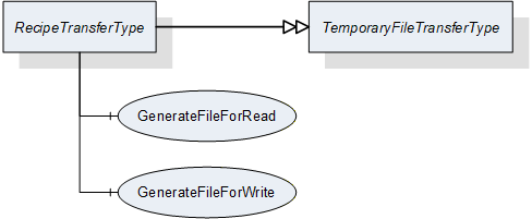
| Attribute | Value | ||||
| BrowseName | RecipeTransferType | ||||
| IsAbstract | False | ||||
| References | NodeClass | BrowseName | DataType | TypeDefinition | ModellingRule |
|---|---|---|---|---|---|
| Subtype of the TemporaryFileTransferType defined in OPC 10000-5 | |||||
| HasComponent | Method | 0:GenerateFileForRead | -- | -- | Mandatory |
| HasComponent | Method | 0:GenerateFileForWrite | -- | -- | Mandatory |
7.6.2 RecipeTransferType Methods
7.6.2.1 GenerateFileForRead
This method is used to start the read file transaction. A successful call of this method creates a temporary FileType Object with the file content and returns the NodeId of this Object and the file handle to access the Object.
Signature
GenerateFileForRead ([in] RecipeTransferOptions generateOptions[out] NodeId fileNodeId[out] UInt32 fileHandle[out] NodeId completionStateMachine);| Argument | Description |
| generateOptions | The structure used to define the generate options for the file, described in Section 12.11. |
| fileNodeId | NodeId of the temporary file |
| fileHandle | The fleHandle of the opened TransferFile. The fileHandle can be used to access the TransferFile methods Read and Close. |
| completionStateMachine | If the creation of the file is completed asynchronously, the parameter returns the NodeId of the corresponding FileTransferStateMachineType Object. If the creation of the file is already completed, the parameter is null. If a FileTransferStateMachineType object NodeId is returned, the Read Method of the file fails until the TransferState changed to ReadTransfer. |
| Attribute | Value | ||||
| BrowseName | GenerateFileForRead | ||||
| References | NodeClass | BrowseName | DataType | TypeDefinition | ModellingRule |
|---|---|---|---|---|---|
| HasProperty | Variable | InputArguments | Argument[] | PropertyType | Mandatory |
| HasProperty | Variable | OutputArguments | Argument[] | PropertyType | Mandatory |
7.6.2.2 GenerateFileForWrite
This method is used to start the write file transaction. A successful call of this method creates a temporary FileType Object with the file content and returns the NodeId of this Object and the file handle to access the Object.
Signature
GenerateFileForWrite ([in] RecipeTransferOptions generateOptions[out] NodeId fileNodeId[out] UInt32 fileHandle);| Argument | Description |
| generateOptions | The structure used to define the generate options for the file, described in Section 12.11. |
| fileNodeId | NodeId of the temporary file |
| fileHandle | The fleHandle of the opened TransferFile. The fileHandle can be used to access the TransferFile methods Write and CloseAndCommit. |
| Attribute | Value | ||||
| BrowseName | GenerateFileForWrite | ||||
| References | NodeClass | BrowseName | DataType | TypeDefinition | ModellingRule |
|---|---|---|---|---|---|
| HasProperty | Variable | InputArguments | Argument[] | PropertyType | Mandatory |
| HasProperty | Variable | OutputArguments | Argument[] | PropertyType | Mandatory |
7.7 RecipeType
7.7.1 Overview
This ObjectType defines the metadata for a recipe and methods for handling individual recipes.
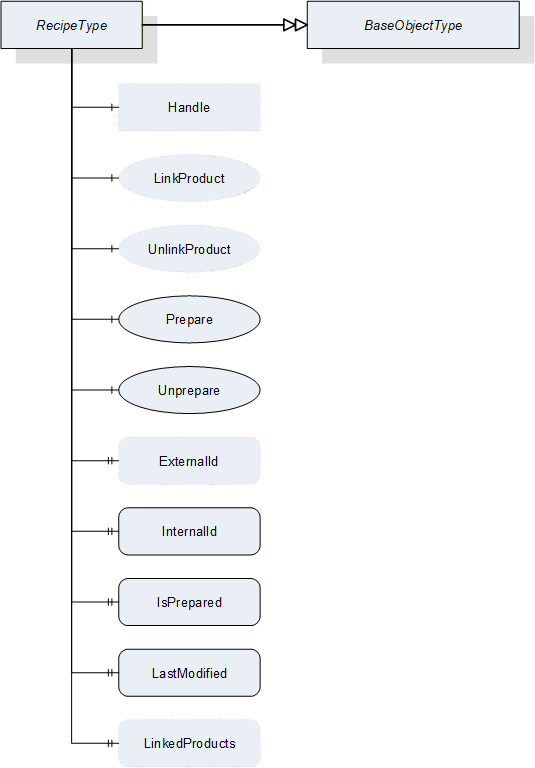
| Attribute | Value | ||||
| BrowseName | RecipeType | ||||
| IsAbstract | False | ||||
| References | NodeClass | BrowseName | DataType | TypeDefinition | ModellingRule |
|---|---|---|---|---|---|
| Subtype of the BaseObjectType defined in OPC 10000-5 | |||||
| HasProperty | Variable | ExternalId | RecipeIdExternalDataType | PropertyType | Optional |
| HasProperty | Variable | InternalId | RecipeIdInternalDataType | PropertyType | Mandatory |
| HasProperty | Variable | IsPrepared | Boolean | PropertyType | Mandatory |
| HasProperty | Variable | LastModified | UtcTime | PropertyType | Mandatory |
| HasProperty | Variable | LinkedProducts | ProductIdDataType[] | PropertyType | Optional |
| HasComponent | Object | Handle | -- | FileType | Optional |
| HasComponent | Method | LinkProduct | -- | -- | Optional |
| HasComponent | Method | UnlinkProduct | -- | -- | Optional |
| HasComponent | Method | Prepare | -- | -- | Mandatory |
| HasComponent | Method | Unprepare | -- | -- | Mandatory |
ExternalId
RecipeId for identifying the recipe outside the vision system. The ExternalId is only managed by the environment.
InternalId
System-wide unique ID for identifying a recipe. This ID is assigned by the vision system.
LastModified
The time, when this recipe was last modified in the recipe store of the vision system. It is assumed that this value is consistent between recipes on the system so that it can be used to order recipes on the system by modification time. As it is possible that the vision system may not be synchronized with a time server, this value may not be valid for comparisons between systems.
LinkedProducts
Array of ProductIds which this recipe is linked to. May be empty.
Handle
FileType object for handling transfer of recipe data between client and server. The data is treated as a binary blob by the server. This method is optional for clients not supporting transfer of the actual recipe contents.
7.7.2 RecipeType Methods
7.7.2.1 Overview
If recipes are exposed in the Address Space, the corresponding entries in the Recipes folder of the RecipeManagement object have to be created using the AddRecipe method of the RecipeManagement object. The recipe object cannot destroy itself as this would affect the data structures of the RecipeManagement object; therefore, removal has to take place using the Remove method of that object.
Operations other than AddRecipe can be carried out directly on the the RecipeType object as well as on he RecipeManagement object.
For data transfer, the FileType object contained in the RecipeType object can be used directly. Therefore, there is no need for a specific Get method.
7.7.2.2 LinkProduct
This method is used to create a link between the recipe and a product in the vision system
Signature
LinkProduct ([in] ProductIdDataType productId[out] Int32 error);
| Argument | Description |
| productId | Identification of a product, the recipe is to be used for. |
| error | 0 - OK Values > 0 are reserved for errors defined by this and future standards. Values < 0 shall be used for application-specific errors. |
| Attribute | Value | ||||
| BrowseName | LinkProduct | ||||
| References | NodeClass | BrowseName | DataType | TypeDefinition | ModellingRule |
|---|---|---|---|---|---|
| HasProperty | Variable | InputArguments | Argument[] | PropertyType | Mandatory |
| HasProperty | Variable | OutputArguments | Argument[] | PropertyType | Mandatory |
It is assumed that the given ProductId already exists in the vision system management structures, e.g. having been created with the AddProduct method of the RecipeManagementType. It is recommended that it also exists in the Products folder of the RecipeManagementType object to expose a consistent set of data in the Address Space.
In the case of a successful link, the server shall add the given ProductId to the LinkedProducts list of this RecipeType object.
The method shall fail if the product does not exist in the vision system management structures.
7.7.2.3 UnlinkProduct
This method is used to remove the link between the recipe and a product in the vision system
Signature
UnlinkProduct ([in] ProductIdDataType productId[out] Int32 error);
| Argument | Description |
| productId | Identification of a product, the recipe is to be used for. |
| error | 0 - OK Values > 0 are reserved for errors defined by this and future standards. Values < 0 shall be used for application-specific errors. |
| Attribute | Value | ||||
| BrowseName | UnlinkProduct | ||||
| References | NodeClass | BrowseName | DataType | TypeDefinition | ModellingRule |
|---|---|---|---|---|---|
| HasProperty | Variable | InputArguments | Argument[] | PropertyType | Mandatory |
| HasProperty | Variable | OutputArguments | Argument[] | PropertyType | Mandatory |
The server shall remove the given ProductId from the LinkedProducts list of this RecipeType object.
It is expected that the vision system removes a link between the recipe represented by this object and products with the given ProductId from its internal management structures.
Starting jobs based on this ProductId will no longer lead to this recipe being used. If there is no link left between this ProductId and any recipe, it will no longer be possible to start a job based on that ProductId.
7.7.2.4 Prepare
This method is used to prepare the recipe so that it can be used for starting a job on the vision system.
Signature
Prepare ([out] Boolean isCompleted[out] Int32 error);| Argument | Description |
| isCompleted | Flag to indicate that the recipe has been completely prepared before the method returned. If False, the client needs either to check the properties of the recipe to determine when preparation has completed or wait for the RecipePrepared event. |
| error | 0 - OK Values > 0 are reserved for errors defined by this and future standards. Values < 0 shall be used for application-specific errors. |
| Attribute | Value | ||||
| BrowseName | Prepare | ||||
| References | NodeClass | BrowseName | DataType | TypeDefinition | ModellingRule |
|---|---|---|---|---|---|
| HasProperty | Variable | OutputArguments | Argument[] | PropertyType | Mandatory |
The effects of the Prepare method of a RecipeType object on the VisionSystem shall be identical to those of the PrepareRecipe method of the RecipeManagementType object.
7.7.2.5 Unprepare
This method is used to revert the preparation of the recipe so that it can no longer be used for starting a job on the vision system.
Signature
Unprepare ([out] Int32 error);| Argument | Description |
| error | 0 - OK Values > 0 are reserved for errors defined by this and future standards. Values < 0 shall be used for application-specific errors. |
| Attribute | Value | ||||
| BrowseName | Unprepare | ||||
| References | NodeClass | BrowseName | DataType | TypeDefinition | ModellingRule |
|---|---|---|---|---|---|
| HasProperty | Variable | OutputArguments | Argument[] | PropertyType | Mandatory |
The effects of the Unprepare method of a RecipeType object on the VisionSystemAutomaticModeStateMachine shall be identical to those of the UnprepareRecipe method of the RecipeManagementType object.
7.7.2.6 Recipe transfer
There are no dedicated transfer methods on the RecipeType because it already contains a FileType object representing the content of the actual recipe in the vision system. Thus, transfer can be carried out using the standard Open, Read, Write, Close methods of the FileType object.
7.8 RecipeFolderType
This ObjectType is a subtype of the FolderType and is used to organize the recipes of a vision system. Figure 15 shows the hierarchical structure and details of the composition. It is formally defined in Table 63.
Instances of this ObjectType organize all available recipes of the vision system, which the server decides to expose in the Address Space. It may contain no recipe if no recipe is available, if the server does not expose recipes in the Address Space at all, or if no recipe matches the criteria of the server for exposure in the Address Space.
Note that the folder contains only metadata of the recipes, not the actual configuration data of the vision system.
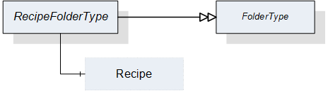
| Attribute | Value | ||||
| BrowseName | RecipeFolderType | ||||
| IsAbstract | False | ||||
| References | NodeClass | BrowseName | DataType | TypeDefinition | ModellingRule |
|---|---|---|---|---|---|
| Subtype of the FolderType defined in OPC 10000-5 | |||||
| HasComponent | Object | <Recipe> | -- | RecipeType | OptionalPlaceholder |
The RecipeType used in the RecipeFolderType is defined in Section 7.7.
7.9 ProductFolderType
This ObjectType is a subtype of the FolderType and is used to organize the products of a vision system. Figure 16 shows the hierarchical structure and details of the composition. It is formally defined in Table 64.
Instances of this ObjectType organize all available products of the vision system, which the server decides to expose in the Address Space. It may contain no product if no product is available, if the server does not expose products in the Address Space at all, or if no product matches the criteria of the server for exposure in the Address Space.
Note that the folder contains only metadata of the products, not the actual product data of the vision system.
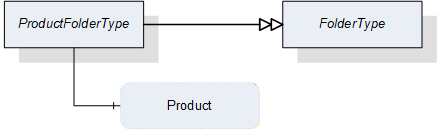
| Attribute | Value | ||||
| BrowseName | ProductFolderType | ||||
| IsAbstract | False | ||||
| References | NodeClass | BrowseName | DataType | TypeDefinition | ModellingRule |
|---|---|---|---|---|---|
| Subtype of the FolderType defined in OPC 10000-5 | |||||
| HasComponent | Variable | <Product> | ProductDataType | BaseDataVariableType | OptionalPlaceholder |
The ProductDataType used in the ProductFolderType is defined in Section 12.15.
7.10 ResultManagementType
7.10.1 Overview
This ObjectType defines the representation of the machine vision system result management. Figure 17 shows the hierarchical structure and details of the composition. It is formally defined in Table 65.
ResultManagementType provides methods to query the results generated by the underlying vision system. Results can be stored in a local result store. An event of ResultReadyEventType, which is defined in Section 8.3.8.4, shall be triggered when the system generates a new result.
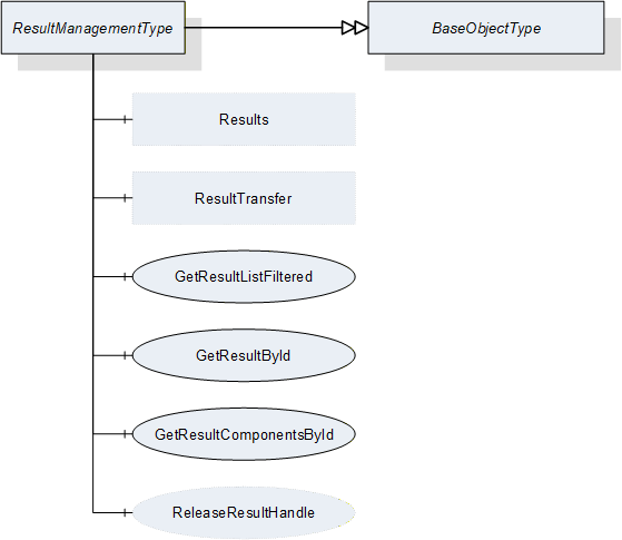
| Attribute | Value | ||||
| BrowseName | ResultManagementType | ||||
| IsAbstract | False | ||||
| References | NodeClass | BrowseName | DataType | TypeDefinition | ModellingRule |
|---|---|---|---|---|---|
| Subtype of the BaseObjectType defined in OPC 10000-5 | |||||
| HasComponent | Method | GetResultById | -- | -- | Mandatory |
| HasComponent | Method | GetResultComponentsById | -- | -- | Mandatory |
| HasComponent | Method | GetResultListFiltered | -- | -- | Mandatory |
| HasComponent | Method | ReleaseResultHandle | -- | -- | Optional |
| HasComponent | Object | ResultTransfer | -- | ResultTransferType | Optional |
| HasComponent | Object | Results | -- | ResultFolderType | Optional |
ResultTransfer is an instance of the ResultTransferType defined in Section 7.12 and it is used to transfer the contents of a result by the temporary file transfer method defined in OPC 10000-5, Annex C.4.
Results is an Object of the ResultFolderType that organizes variables of the DataType ResultDataType which is defined in Section 12.17. If the server chooses to expose result information in the Address Space, it may contain the set of all results available on the system or a filtered subset, e.g. the set of all currently finished results. This is implementation-defined. If a server does not expose result information in the Address Space, this variable is expected to be non-existent.
7.10.2 ResultManagementType methods
7.10.2.1 GetResultById
This method is used to retrieve a result from the vision system. Depending on the design of the vision system, the client may be informed by events of ResultReadyEventType that a new result is available. Then, the client might fetch this result using the information provided by events of ResultReadyEventType which is defined in Section 8.3.8.4.
Since the resultId is supposed to be system-wide unique, this method shall return only a single result. Since there may be additional result content to be retrieved by temporary file transfer, the server should keep result data available, resources permitting, until the client releases the handle ReleaseResult. However, the client cannot rely on the data to remain available until then.
Signature
GetResultById ([in] ResultIdDataType resultId[in] Int32 timeout[out] Handle resultHandle[out] ResultDataType result[out] Int32 error);
| Argument | Description |
| resultId | System-wide unique identifier for the result. |
| timeout | With this argument the client can give a hint to the server how long it will need access to the result data. A value > 0 indicates an estimated maximum time for processing the data in milliseconds. A value = 0 indicates that the client will not need anything besides the data returned by the method call. A value < 0 indicates that the client cannot give an estimate. The client cannot rely on the data being available during the indicated time period. The argument is merely a hint allowing the server to optimize its resource management. |
| resultHandle | The server shall return to each client requesting result data a system-wide unique handle identifying the result set / client combination. This handle should be used by the client to indicate to the server that the result data is no longer needed, allowing the server to optimize its resource handling . |
| result | The result including metadata. |
| error | 0 - OK Values > 0 are reserved for errors defined by this and future standards. Values < 0 shall be used for application-specific errors. |
| Attribute | Value | ||||
| BrowseName | GetResultById | ||||
| References | NodeClass | BrowseName | DataType | TypeDefinition | ModellingRule |
|---|---|---|---|---|---|
| HasProperty | Variable | InputArguments | Argument[] | PropertyType | Mandatory |
| HasProperty | Variable | OutputArguments | Argument[] | PropertyType | Mandatory |
7.10.2.2 GetResultComponentsById
This method is used to retrieve a result from the vision system. It is basically identical to the GetResultById method described in Section 7.10.2.1, but it returns the result not in a single output argument of ResultDataType but in individual output arguments corresponding to the elements of the ResultDataType structure.
The reason for providing this method is to facilitate the use of subtypes to the structures nested inside of ResultDataType. Since the NodeIds of structured DataTypes nested within a structured DataType are not transferred together with the DataType, subtyping these nested structures would then also necessitate subtyping ResultDataType. This is of course possible, but in the absence of such a subtype, the individual components can still be requested by this method.
Signature
GetResultComponentsById ([in] ResultIdDataType resultId[in] Int32 timeout[out] Boolean hasTransferableDataOnFile[out] Handle resultHandle[out] Boolean isPartial[out] Boolean isSimulated[out] ResultStateDataType resultState[out] MeasIdDataType measId[out] PartIdDataType partId[out] RecipeIdExternalDataType externalRecipeId[out] RecipeIdInternalDataType internalRecipeId[out] ProductIdDataType productId[out] ConfigurationIdDataType externalConfigurationId[out] ConfigurationIdDataType internalConfigurationId[out] JobIdDataType jobId[out] UtcTime creationTime[out] ProcessingTimesDataType processingTimes[out] BaseDataType[] resultContent[out] Int32 error);
| Argument | Description |
| resultId | System-wide unique identifier for the result |
| timeout | With this argument the client can give a hint to the server how long it will need access to the result data. A value > 0 indicates an estimated maximum time for processing the data in milliseconds. A value = 0 indicates that the client will not need anything besides the data returned by the method call. A value < 0 indicates that the client cannot give an estimate. The client cannot rely on the data being available during the indicated time period. The argument is merely a hint allowing the server to optimize its resource management. |
| hasTransferableDataOnFile | Indicates that TemporaryFileTransfer needs to be used to retrieve all data of the result content. |
| resultHandle | The server shall return to each client requesting result data a system-wide unique handle identifying the result set / client combination. This handle should be used by the client to indicate to the server that the result data is no longer needed, allowing the server to optimize its resource handling. |
| isPartial | Indicates whether the result is the partial result of a total result. |
| isSimulated | Indicates whether the system was in simulation mode when the job generating this result was created. |
| resultState | ResultState provides information about the current state of a result and the ResultStateDataType is defined in Section 12.19. |
| measId | This identifier is given by the client when starting a single or continuous execution and transmitted to the vision system. It is used to identify the respective result data generated for this job. Although the system-wide unique JobId would be sufficient to identify the job which the result belongs to, this makes for easier filtering on the part of the client without keeping track of JobIds. |
| partId | A PartId is given by the client when starting the job; although the system-wide unique JobId would be sufficient to identify the job which the result belongs to, this makes for easier filtering on the part of the client without keeping track of JobIds. |
| externalRecipeId | External identifier of the recipe in use which produced the result. This is only managed by the environment. |
| internalRecipeId | Internal identifier of the recipe in use which produced the result. This identifier is system-wide unique and it is assigned by the vision system. |
| productId | Identifier of the product in use which produced the result. This is only managed by the environment. |
| externalConfigurationId | External identifier of the configuration in use while the result was produced. |
| InternalConfigurationId | Internal identifier of the configuration in use while the result was produced. This identifier is system-wide unique and it is assigned by the vision system. |
| jobId | The identifier of the job, created by the transition from state Ready to state SingleExecution or to state ContinuousExecution which produced the result. |
| creationTime | CreationTime indicates the time when the result was created. |
| processingTimes | Collection of different processing times that were needed to create the result. |
| resultContent | Abstract data type to be subtyped from to hold the actual result content created by the job. |
| error | 0 - OK Values > 0 are reserved for errors defined by this and future standards. Values < 0 shall be used for application-specific errors. |
| Attribute | Value | ||||
| BrowseName | GetResultById | ||||
| References | NodeClass | BrowseName | DataType | TypeDefinition | ModellingRule |
|---|---|---|---|---|---|
| HasProperty | Variable | InputArguments | Argument[] | PropertyType | Mandatory |
| HasProperty | Variable | OutputArguments | Argument[] | PropertyType | Mandatory |
7.10.2.3 GetResultListFiltered
This method is used to get a list of results matching certain filter criteria.
Signature
GetResultListFiltered ([in] ResultStateDataType resultState[in] MeasIdDataType measId[in] PartIdDataType partId[in] RecipeIdExternalDataType externalRecipeId[in] RecipeIdInternalDataType internalRecipeId[in] ConfigurationIdDataType externalConfigurationId[in] ConfigurationIdDataType internalConfigurationId[in] ProductIdDataType productId[in] JobIdDataType jobId[in] UInt32 maxResults[in] UInt32 startIndex[in] Int32 timeout[out] Boolean isComplete[out] UInt32 resultCount[out] Handle resultHandle[out] ResultDataType[] resultList[out] Int32 error);
| Argument | Description |
| resultState | If not 0, only results having the specified state are returned. |
| measId | If not empty, only results corresponding to the given measId are returned |
| partId | If not empty, only results corresponding to the given partId are returned. |
| externalRecipeId | If not empty, only results corresponding to the given externalRecipeId are returned. |
| internalRecipeId | If not empty, only results corresponding to the given internalRecipeId are returned. |
| externalConfigurationId | If not empty, only results corresponding to the given externalConfigurationId are returned. |
| internalConfigurationId | If not empty, only results corresponding to the given internalConfigurationId are returned. |
| productId | If not empty, only results corresponding to the given productId are returned. |
| jobId | If not empty, only results corresponding to the given jobId are returned. |
| maxResults | Maximum number of results to return in one call; by passing 0, the client indicates that it does not put a limit on the number of results. |
| startIndex | Shall be 0 on the first call, multiples of maxResults on subsequent calls to retrieve portions of the entire list, if necessary. |
| timeout | With this argument the client can give a hint to the server how long it will need access to the result data. A value > 0 indicates an estimated maximum time for processing the data in milliseconds. A value = 0 indicates that the client will not need anything besides the data returned by the method call. A value < 0 indicates that the client cannot give an estimate. The client cannot rely on the data being available during the indicated time period. The argument is merely a hint allowing the server to optimize its resource management. |
| isComplete | Indicates whether there are more results in the entire list than retrieved according to startIndex and resultCount. |
| resultCount | Gives the number of valid results in ResultList. |
| resultHandle | The server shall return to each client requesting result data a system-wide unique handle identifying the result set / client combination. This handle has to be used by the client to release the result set. |
| resultList | List of results matching the Filter. |
| error | 0 - OK Values > 0 are reserved for errors defined by this and future standards. Values < 0 shall be used for application-specific errors. |
| Attribute | Value | ||||
| BrowseName | GetResultListFiltered | ||||
| References | NodeClass | BrowseName | DataType | TypeDefinition | ModellingRule |
|---|---|---|---|---|---|
| HasProperty | Variable | InputArguments | Argument[] | PropertyType | Mandatory |
| HasProperty | Variable | OutputArguments | Argument[] | PropertyType | Mandatory |
There are the following cases with the respect to the number of results:
The number of results to be returned according to the filter is less or equal to MaxResults; the first call, with startIndex=0, returns isComplete=TRUE, so the client knows that no further calls are necessary. resultCount gives the number of valid elements in the resultList array.
The number of results to be returned is larger than maxResults; the first N calls (N > 0 with N ≤ (number of results) divisor MaxResults), with startIndex=(N-1)*maxResults, return isComplete=FALSE, so the client knows that further calls are necessary. The following call returns isComplete=TRUE, so the client knows, no further calls are necessary. resultCount gives the number of valid elements in the resultList array (on each call, so on the first N calls, this should be maxResults).
7.10.2.4 ReleaseResultHandle
This method is used to inform the server that the client has finished processing a given result set allowing the server to free resources managing this result set.
The server should keep the data of the result set available for the client until the ReleaseResultHandle method is called or until a timeout given by the client has expired. However, the server is free to release the data at any time, depending on its internal resource management, so the client cannot rely on the data being available. ReleaseResultHandle is merely a hint allowing the server to optimize its internal resource management. For timeout usage see the description in Section 7.10.2.1.
Signature
ReleaseResultHandle ([in] Handle resultHandle[out] Int32 error);
| Argument | Description |
| resultHandle | Handle returned by GetResultById or GetResultList, identifying the result set/client combination. |
| Error | 0 - OK Values > 0 are reserved for errors defined by this and future standards. Values < 0 shall be used for application-specific errors. |
| Attribute | Value | ||||
| BrowseName | ReleaseResultHandle | ||||
| References | NodeClass | BrowseName | DataType | TypeDefinition | ModellingRule |
|---|---|---|---|---|---|
| HasProperty | Variable | InputArguments | Argument[] | PropertyType | Mandatory |
| HasProperty | Variable | OutputArguments | Argument[] | PropertyType | Mandatory |
7.11 ResultFolderType
This ObjectType is a subtype of FolderType and is used to organize available results of the vision system which the server decides to expose in the Address Space. It may contain no result if no result is available, if the server does not expose results in the Address Space at all or if no available result matches the criteria of the server for exposure in the Address Space. Figure 18 shows the hierarchical structure and details of the composition. It is formally defined in Table Table 74.
The ResultFolderType contains all results of the vision system, which are available and should be exposed in the Address Space. It may contain no result if no result is available or multiple if multiple results are available.
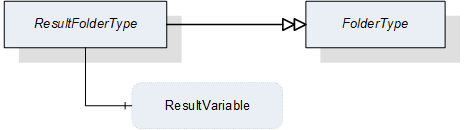
| Attribute | Value | ||||
| BrowseName | ResultFolderType | ||||
| IsAbstract | False | ||||
| References | NodeClass | BrowseName | DataType | TypeDefinition | ModellingRule |
|---|---|---|---|---|---|
| Subtype of the FolderType defined in OPC 10000-5 | |||||
| HasComponent | Variable | <ResultVariable> | ResultDataType | ResultType | OptionalPlaceholder |
The ResultType used in the ResultFolderType is defined in Section 9.1.
7.12 ResultTransferType
7.12.1 Overview
This ObjectType is a subtype of the TemporaryFileTransferType defined in OPC 10000-5 and is used to transfer result data as a file.
The ResultTransferType overwrites the Method GenerateFileForRead to specify the concrete type of the generateOptions Parameter of the Methods. It does not specialize the GenerateFileForWrite method of the base type as results are supposed to be only generated by the vision system, not received.
Figure 19 shows the hierarchical structure and details of the composition. It is formally defined in Table 75.
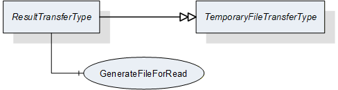
| Attribute | Value | ||||
| BrowseName | ResultTransferType | ||||
| IsAbstract | False | ||||
| References | NodeClass | BrowseName | DataType | TypeDefinition | ModellingRule |
|---|---|---|---|---|---|
| Subtype of the TemporaryFileTransferType defined in OPC 10000-5 | |||||
| HasComponent | Method | 0:GenerateFileForRead | -- | -- | Mandatory |
7.12.2 ResultTransferType methods
7.12.2.1 GenerateFileForRead
This method is used to start the read file transaction. A successful call of this method creates a temporary FileType Object with the file content and returns the NodeId of this Object and the file handle to access the Object.
Signature
GenerateFileForRead ([in] ResultTransferOptions generateOptions[out] NodeId fileNodeId[out] UInt32 fileHandle[out] NodeId completionStateMachine);
| Argument | Description |
| generateOptions | The structure used to define the generate options for the file. |
| fileNodeId | NodeId of the temporary file |
| fileHandle | The FileHandle of the opened TransferFile. The FileHandle can be used to access the TransferFile methods Read and Close. |
| completionStateMachine | If the creation of the file is completed asynchronously, the parameter returns the NodeId of the corresponding FileTransferStateMachineType Object. If the creation of the file is already completed, the parameter is null. If a FileTransferStateMachineType object NodeId is returned, the Read Method of the file fails until the TransferState changed to ReadTransfer. |
| Attribute | Value | ||||
| BrowseName | GenerateFileForRead | ||||
| References | NodeClass | BrowseName | DataType | TypeDefinition | ModellingRule |
|---|---|---|---|---|---|
| HasProperty | Variable | InputArguments | Argument[] | PropertyType | Mandatory |
| HasProperty | Variable | OutputArguments | Argument[] | PropertyType | Mandatory |
7.13 SafetyStateManagementType
7.13.1 Overview
This ObjectType provides a method to inform the vision system about the changes of an external safety state. The vision system itself gives feedback about the action which is taken to react on this state change. Figure 20 shows the hierarchical structure and details of the composition. It is formally defined in Table 78.
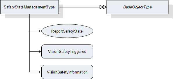
| Attribute | Value | ||||
| BrowseName | SafetyStateManagementType | ||||
| IsAbstract | False | ||||
| References | NodeClass | BrowseName | DataType | TypeDefinition | ModellingRule |
|---|---|---|---|---|---|
| Subtype of the BaseObjectType defined in OPC 10000-5 | |||||
| HasComponent | Method | ReportSafetyState | -- | -- | Mandatory |
| HasComponent | Variable | VisionSafetyTriggered | Boolean | BaseDataVariableType | Mandatory |
| HasComponent | Variable | VisionSafetyInformation | String | BaseDataVariableType | Mandatory |
VisionSafetyTriggered
Information about the current internal safety state.
VisionSafetyInformation
Textual information that can be provided by the vision system - e.g. "open safety door".
7.13.2 SafetyStateManagementType methods
7.13.2.1 ReportSafetyState
This method is used to provide information about the change of an external safety state. For example, safety doors which are not under supervision of a vision system are open and as a consequence it is not possible to switch on a laser source inside a vision system.
Important note: This is not to be used as a safety feature. It is only for information purposes.
Signature
ReportSafetyState ([in] Boolean safetyTriggered [in] String safetyInformation[out] Int32 error);
| Argument | Description |
| safetyTriggered | Information about the current external safety state. |
| safetyInformation | Information that can be provided to the vision system - e.g. opening safety door. |
| Error | 0 - OK Values > 0 are reserved for errors defined by this and future standards. Values < 0 shall be used for application-specific errors. |
| Attribute | Value | ||||
| BrowseName | ReportSafetyState | ||||
| References | NodeClass | BrowseName | DataType | TypeDefinition | ModellingRule |
|---|---|---|---|---|---|
| HasProperty | Variable | InputArguments | Argument[] | PropertyType | Mandatory |
| HasProperty | Variable | OutputArguments | Argument[] | PropertyType | Mandatory |
8 ObjectTypes for Vision System State Handling
8.1 State Machine overview
8.1.1 Introduction
All state machine types defined in this specification are mandatory unless explicitly stated otherwise. However, some states may be implemented as transient (do-nothing) states depending on the characteristics of the vision system.
To improve clarity and re-usability, this specification makes use of hierarchical state machines. This means that states of a state machine may have underlying SubStateMachines. The instantiation of a SubStateMachine for a particular state of the main state machine may be specified as optional.
8.1.2 Hierarchical state machines
8.1.2.1 Entering a SubStateMachine
OPC 10000-5, Annex B.4.9 defines several ways of entering a SubStateMachine:
If the SubStateMachine has an initial state (i.e., a state of type InitialStateType) this state is entered whenever the parent state is entered.
We make use of this principle for the VisionStepModelStateMachine defined in Section 8.4.
A SubStateMachine can also be entered by a direct transition from the parent state machine into one of its states, bypassing the initial state. In this case, the parent state machine goes automatically into the parent state of the SubStateMachine.
We make use of this principle for operation mode state machines like the VisionAutomaticModeStateMachine defined in Section 8.3.
If a SubStateMachine has no initial state and the parent state is entered directly, the state of the SubStateMachine is server-specific.
We make use of this principle for the error handling described in Section 8.2.2.4.
8.1.2.2 Leaving a SubStateMachine
The SubStateMachine types used here do not have transitions into specific states of the parent state machine so that they are not bound to a specific state machine, but can be used within states of any state machine. Therefore, the SubStateMachines are not left explicitly. Instead, the parent state machine may leave the parent state of the SubStateMachine in which case the SubStateMachine ceases to be active and will enter a Bad_StateNotActive state. In that case, the system actually transitions from a state of the SubStateMachine into an unrelated state of the main state machine, but this transition will not be explicitly shown or specified on the level of the SubStateMachine.
We make use of that principle especially for the error handling described in Section 8.2.2.4.
At present, this specification describes one such mode, the "Automatic" mode. All pertaining states are contained in a SubStateMachine of type VisionAutomaticModeStateMachine defined in Section VisionAutomaticModeStateMachineType. The reason for this naming is that this state machine is derived - but not restricted to - the typical application of a vision system in automatic operation on a production line.State machine type hierarchy
The following diagram shows the hierarchy of mandatory state machine types in this specification. All state machine types are derived from the FiniteStateMachineType, implying that all their states and transitions are pre-defined and cannot be changed or added to by sub-typing so that a client can detect all states and transitions and rely on these and only these states and transitions to exist on sub-types of the state machine type
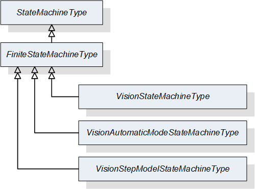
8.1.3 Automatic and triggered transitions and events
In the state machines specified here, most transitions can be caused by method calls and all transitions can be caused by internal decisions of the vision system. We call these "automatic" transitions.
In the state diagrams describing the state machines in the following sections, all transitions are shown individually. Transitions caused by methods are shown in black with the method name as the UML transition trigger. "Automatic" transitions are shown in orange without a trigger.
Upon entry into a new state, a StateChanged Event will be triggered indicating the transition.
Some transitions may trigger extra events. These events are shown in the state diagrams on the transition as a UML effect, preceded by a "/".
Some transitions may depend on conditions. Where they are semantically important, they have been put into the state diagrams as UML guards in "[]".
8.1.4 Preventing transitions
The server can prevent transitions from being carried out, e.g. due to the internal state of the vision system. A typical example would be to prevent leaving the parent state of a VisionStepModelStateMachine in order to avoid interrupting synchronization with an external system.
As automatic transitions are always done for internal reasons, the server will obviously simply not execute the transition in this case.
For method-triggered transitions, the server should set the Executable flag of the method in question to False to signal to clients that this method should currently not be called. If the method is called anyway, regardless of the Executable flag, the method shall fail with an appropriate error code.
8.2 VisionStateMachineType
8.2.1 Introduction
This ObjectType is a subtype of FiniteStateMachineType and represents the top-level behavior of the vision system. It is formally defined in Table 81.
The Operational state has a mandatory SubStateMachine for the "Automatic" mode of operation and may have additional SubStateMachines for other modes of operation.
The other state may have optional SubStateMachines of the VisionStepModelStateMachineType.
For clarity, transitions into states of SubStateMachines are not shown in the diagram.
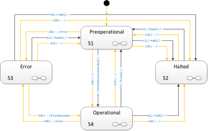
8.2.2 Operation of the VisionStateMachineType
8.2.2.1 Basic operation
After power-up the system goes into a Preoperational state. It is assumed that the vision system loads a configuration which is present on the system and marked as active. From there, it can be put into Operational state either automatically, due to internal initialization processes or by a SelectMode method call. The VisionStateMachineType provides one mandatory method, SelectModeAutomatic for transition into the "Automatic" mode SubStateMachine described in Section 8.3. Subtypes of VisionStateMachineType may offer additional SubStateMachines and thus additional SelectMode method calls.
The system stays in Operational mode, doing its job, until it is either resetted, halted or an error occurs which suspends normal operation until resolved.
8.2.2.2 Resetting the system
At any time, it may be necessary or desired to revert the vision system into its initial state after power-up, i.e., state Preoperational.
The vision system may decide this due to internal conditions, or by calling the Reset method on the VisionStateMachine in the OPC UA server.
The Reset method shall always be executable. If for some reason the vision system is not capable of carrying out this transition, the behavior is undefined. The underlying assumption is that, if the vision system cannot perform a reset, it cannot be assumed that it is capable of carrying out any other controlled transition, including a transition into the Error state.
Application Note:
There are basically two reasons for a reset in the state model of this specification.
Either the vision system is idle - reflected by, e.g. the Ready or Initialized state - and the intent of calling the Reset method is to return to Preoperational state in order to call a different SelectMode method to change the mode of operation. In that case, carrying out the transition should not be a problem.
The other situation is as an emergency measure because the vision system does no longer operate correctly. In that case, the method may fail with an internal error code like Bad_UnexpectedError or Bad_InvalidState, but since the vision system is in an incorrect internal state, it is uncertain that it can reach any other state, like Error.
The client can assume that Preoperational or Error states should be reached within a reasonable - application-specific - time-frame. If that is not the case, the client can conclude that intervention is necessary and issue an appropriate message and operator call.
8.2.2.3 Halting the system
A vision system will frequently make use of a number of resources, like camera drivers, files, databases etc. which will need to be properly closed before shutting down that system.
In Halted state, the system shall have put all resources into a state where it is safe to power down the system. However, not all operation is stopped, because the system can be brought out of Halted state by a call to the Reset method, transitioning to the Preoperational state.
The vision system may decide to enter Halted state due to internal conditions or by calling the Halt method on the OPC UA server.
The Halt method shall always be executable. If for some reason the system is not capable of carrying out the transition, the VisionStateMachine shall transition into the Error state.
8.2.2.4 Error handling
In every state of the VisionStateMachine or any of its SubStateMachines, an error may occur.
The system may also decide to enter state Error by means of an automatic operation if it cannot - or should not - continue its normal operation in the presence of an error. Note that the presence of an error condition does not necessarily cause the system to enter the Error state, it may be capable to continue normal operation in the presence of a signaled error condition. However, it the system does enter the Error state, it is mandatory that it indicates this by activating an error condition.
An error shall be signaled by an appropriate error condition. An arbitrary number of error conditions can be active at any time.
Error conditions are exposed as subtypes of the ConditionType defined in OPC 10000-9 and may have Acknowledge and Confirm methods and the appropriate state handling. It is expected that the calling of these methods has an effect upon the underlying system and/or that the underlying vision system monitors the state of the conditions and uses these in its internal decision making process whether to stay in the Error state or in which state to transition next.
It is assumed that the Acknowledge method will typically be called by a client automatically, indicated that the message has at least been received. The Confirm method will typically be caused by a human interaction, confirming that the cause of the error is remedied.
For convenience, the VisionStateMachine may offer the ConfirmAll method which shall confirm all conditions currently active. The effect on the internal decision making shall be the same as when the methods would have been called individually from the outside.
Thus, in Error state, the system decides either on its own or based on external input, like an acknowledgement or confirmation of the error, and other (non OPC UA) input signals, which state to transition to next.
Upon entering the Error state, an event of type ErrorEventType is triggered, upon leaving to some other state, an ErrorResolved event is triggered, if the error is actually resolved, in addition to the mandatory StateChanged events. Thus, a control system may listen only to the Error and ErrorResolved events monitoring the vision system.
The Error state can be left in the following ways:
By a call to the Halt or Reset method, transitioning to states Halted and Preoperational respectively. The condition(s) causing the Error state do not necessarily have to be resolved for this transition. Only if they are resolved, an ErrorResolvedEvent shall be triggered.
By an internal decision of the system to transition into the Halted or Preoperational states. As these states do not constitute normal productive operation of the system, the condition(s) causing the Error state do not necessarily have to be resolved for this transition. Only if they are resolved, an ErrorResolved event shall be triggered. Subsequent action, e.g. a call to ActivateConfiguration in these states may lead to the error being resolved and the system being capable of resuming normal productive operation.
By an internal decision of the system to transition into the Operational state. As this state constitutes normal productive operation, this transition is only allowed if the condition(s) leading to the Error state are actually resolved. Therefore, an ErrorResolved event shall be triggered in this case.
In the last case, the automatic transition into the Operational state due to the resolving of the error condition(s), the system will actually go into one of the states of the SubStateMachines of the Operational state, using the 3rd method for entering a SubStateMachine described in Section 8.1.2.1 by a server-specific decision about the state.
Thus, the vision system can decide, based on its internal conditions, in which actual state it will continue operation. It may decide that it can immediately continue a job interrupted by the error and return to the SingleExecution or ContinuousExecution states; it may decide that it can immediately take on the next job and return to the Ready state; it may decide that it needs a re-initialization of a recipe and return to the Initialized state. It may even decide that it can resume a synchronization with an external system and return to any state within a VisionStepModelStateMachine inside one of these states.
8.2.3 VisionStateMachineType Overview
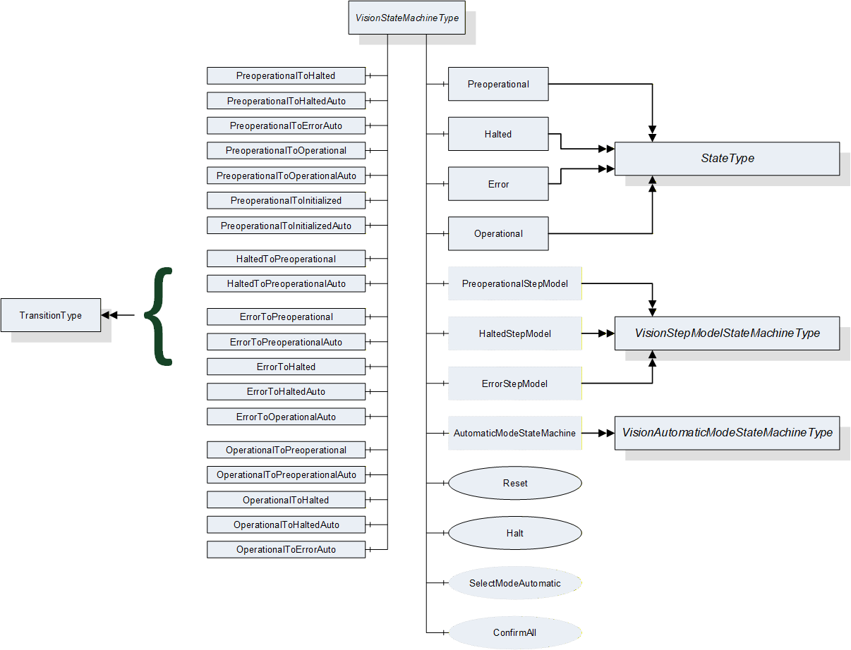
8.2.4 Modes of operation
One underlying idea of this specification is that a vision system may have different modes of operation with very different sets of states, methods and transitions.
Due to the high degree of individuality of vision system requirements and solutions, it does not appear possible to standardize each and every mode of operation of such systems. Therefore, vision systems according to this specification are free to implement additional state machines for such use cases.
However, this specification considers some states as universal for machine vision systems according to this specification and thus outside of these modes of operation, namely states related to powering up and shutting down the system and to error handling.
The system will in any case need to power up and enter some state automatically without outside intervention. From this state, a selection - either by method call or automatically based on internal and external circumstances - of the actual mode of operation can be made.
Conversely, the same holds for shutting down the system. Independent from the mode of operation, the system will need a way to enter a state from which it can safely be powered down.
And finally it will be of great advantage to all clients if the handling of errors is identical in all modes of operation.
Therefore, these states are mandatory in this specification as well as one state encompassing the actual operation of the system. Modes of operation shall be specified as SubStateMachines to this operational state.
8.2.5 VisionStateMachineType Definition
VisionStateMachineType is formally defined in Table 81.
| Attribute | Value | ||||
| Includes all attributes specified for the FiniteStateMachineType | |||||
| BrowseName | VisionStateMachineType | ||||
| IsAbstract | False | ||||
| References |
Node
Class | BrowseName | DataType | TypeDefinition | ModellingRule |
|---|---|---|---|---|---|
| Subtype of the FiniteStateMachineType defined in OPC 10000-5 Annex B.4.5 | |||||
| HasComponent | Object | Preoperational | -- | StateType | |
| HasComponent | Object | Halted | -- | StateType | |
| HasComponent | Object | Error | -- | StateType | |
| HasComponent | Object | Operational | -- | StateType | |
| HasComponent | Object | PreoperationalToHalted | -- | TransitionType | |
| HasComponent | Object | PreoperationalToHaltedAuto | -- | TransitionType | |
| HasComponent | Object | PreoperationalToErrorAuto | -- | TransitionType | |
| HasComponent | Object | PreoperationalToOperational | -- | TransitionType | |
| HasComponent | Object | PreoperationalToOperationalAuto | -- | TransitionType | |
| HasComponent | Object | PreoperationalToInitialized | -- | TransitionType | |
| HasComponent | Object | PreoperationalToInitializedAuto | -- | TransitionType | |
| HasComponent | Object | HaltedToPreoperational | -- | TransitionType | |
| HasComponent | Object | HaltedToPreoperationalAuto | -- | TransitionType | |
| HasComponent | Object | ErrorToPreoperational | -- | TransitionType | |
| HasComponent | Object | ErrorToPreoperationalAuto | -- | TransitionType | |
| HasComponent | Object | ErrorToHalted | -- | TransitionType | |
| HasComponent | Object | ErrorToHaltedAuto | -- | TransitionType | |
| HasComponent | Object | ErrorToOperationalAuto | -- | TransitionType | |
| HasComponent | Object | OperationalToPreoperational | -- | TransitionType | |
| HasComponent | Object | OperationalToPreoperationalAuto | -- | TransitionType | |
| HasComponent | Object | OperationalToHalted | -- | TransitionType | |
| HasComponent | Object | OperationalToHaltedAuto | -- | TransitionType | |
| HasComponent | Object | OperationalToErrorAuto | -- | TransitionType | |
| HasComponent | Method | Reset | -- | -- | Mandatory |
| HasComponent | Method | Halt | -- | -- | Mandatory |
| HasComponent | Method | SelectModeAutomatic | -- | -- | Optional |
| HasComponent | Method | ConfirmAll | -- | -- | Optional |
| HasComponent | Object | PreoperationalStepModel | -- | VisionStepModelStateMachineType | Optional |
| HasComponent | Object | HaltedStepModel | -- | VisionStepModelStateMachineType | Optional |
| HasComponent | Object | ErrorStepModel | -- | VisionStepModelStateMachineType | Optional |
| HasComponent | Object | AutomaticModeStateMachine | -- | VisionAutomaticModeStateMachineType | Optional |
8.2.6 VisionStateMachineType States
8.2.6.1 Introduction
Table 82 specifies the VisionStateMachine's state Objects. These state Objects are instances of the StateType defined in OPC 10000-5 - Annex B. Each state is assigned a unique StateNumber value. Subtypes of the VisionStateMachineType can add References from any state to a subordinate or nested StateMachine Object to extend the FiniteStateMachine. See Table 83 for a brief description of the states.
| BrowseName | References | Target BrowseName | Value | Target TypeDefinition | Notes |
| Preoperational | HasProperty | StateNumber | 1 | PropertyType | -- |
| FromTransition | HaltedToPreoperational | TransitionType | -- | ||
| FromTransition | HaltedToPreoperationalAuto | TransitionType | -- | ||
| FromTransition | ErrorToPreoperationalAuto | TransitionType | -- | ||
| FromTransition | ErrorToPreoperational | TransitionType | -- | ||
| FromTransition | OperationalToPreoperational | TransitionType | -- | ||
| FromTransition | OperationalToPreoperationalAuto | TransitionType | -- | ||
| ToTransition | PreoperationalToHalted | TransitionType | -- | ||
| ToTransition | PreoperationalToHaltedAuto | TransitionType | -- | ||
| ToTransition | PreoperationalToErrorAuto | TransitionType | -- | ||
| ToTransition | PreoperationalToOperational | TransitionType | -- | ||
| ToTransition | PreoperationalToOperationalAuto | TransitionType | -- | ||
| ToTransition | PreoperationalToInitialized | TransitionType | -- | ||
| ToTransition | PreoperationalToInitializedAuto | TransitionType | -- | ||
| HasSubStateMachine | PreoperationalStepModel | VisionStepModelState MachineType | -- | ||
| Halted | HasProperty | StateNumber | 2 | PropertyType | -- |
| FromTransition | PreoperationalToHalted | TransitionType | -- | ||
| FromTransition | PreoperationalToHaltedAuto | TransitionType | -- | ||
| FromTransition | ErrorToHalted | TransitionType | -- | ||
| FromTransition | ErrorToHaltedAuto | TransitionType | -- | ||
| FromTransition | OperationalToHalted | TransitionType | -- | ||
| FromTransition | OperationalToHaltedAuto | TransitionType | -- | ||
| ToTransition | HaltedToPreoperational | TransitionType | -- | ||
| ToTransition | HaltedToPreoperationalAuto | TransitionType | -- | ||
| HasSubStateMachine | HaltedStepModel | VisionStepModelState MachineType | -- | ||
| Error | HasProperty | StateNumber | 3 | PropertyType | -- |
| FromTransition | PreoperationalToErrorAuto | TransitionType | -- | ||
| FromTransition | OperationalToErrorAuto | TransitionType | -- | ||
| ToTransition | ErrorToPreoperational | TransitionType | -- | ||
| ToTransition | ErrorToPreoperationalAuto | TransitionType | -- | ||
| ToTransition | ErrorToHalted | TransitionType | -- | ||
| ToTransition | ErrorToHaltedAuto | TransitionType | -- | ||
| ToTransition | ErrorToOperationalAuto | TransitionType | -- | ||
| HasSubStateMachine | ErrorStepModel | VisionStepModelState MachineType | -- | ||
| Operational | HasProperty | StateNumber | 4 | PropertyType | -- |
| FromTransition | PreoperationalToOperational | TransitionType | -- | ||
| FromTransition | PreoperationalToOperationalAuto | TransitionType | -- | ||
| FromTransition | ErrorToOperationalAuto | TransitionType | -- | ||
| ToTransition | OperationalToPreoperational | TransitionType | -- | ||
| ToTransition | OperationalToPreoperationalAuto | TransitionType | -- | ||
| ToTransition | OperationalToHalted | TransitionType | -- | ||
| ToTransition | OperationalToHaltedAuto | TransitionType | -- | ||
| ToTransition | OperationalToErrorAuto | TransitionType | -- | ||
| HasSubStateMachine | AutomaticModeStateMachine | VisionAutomaticModeState MachineType | -- |
The brief state descriptions in Table 83 will be detailed in the following subsections.
| StateName | Description |
| Preoperational | This is the initial state of the system after power-up and the state after a Reset method call. From here the system has to be brought into Operational state by selecting a mode of operation. Alternatively it can be halted. |
| Halted | This state is intended as the final state in the operation of the system. All resources shall be in a state allowing for safe power-down. However, the system can be put back into operation by a Reset method call, going through the Preoperational state. |
| Error | This state intended for the indication and resolution of errors preventing normal operation of the system. |
| Operational | This is the state for normal operation of the system. It is always a composite state with the SubStateMachine modelling the current mode of operation. This specification describes only a single mode of operation, the "Automatic" mode, described in 8.3. Vendors can add other modes of operation by sub-typing VisionStateMachineType and adding other SubStateMachines for these modes of operation. See Section 8.3.9 for implementation remarks. |
8.2.6.2 Preoperational State
In this state, the system is characterized by the following properties:
System is powered on, this is the initial state after power on
No recipes are loaded
No mode of operation is selected
No error is detected
This state shall be entered automatically upon startup.
If an error is detected, the system shall transit to the Error state.
This state can be entered from any state, either by an automatic transition or caused by calling the Reset method.
From this state, all other states on this level can be reached, either by an automatic transition or by calling the Halt method for the Halted state or the SelectModeAutomatic method for sub-state Initialized of the Automatic mode SubStateMachine of state Operational. (see 8.3 for the description of the Automatic mode SubStateMachine and see 8.3.9 for implementation remarks on state machines derived from VisionStateMachineType for other modes of operation) or other SelectMode methods for other, vendor-specific, sub state machines of the Operational state.
This state can be a composite state with an optional VisionStepModelStateMachineType SubStateMachine.
8.2.6.3 Halted State
In this state, the system is characterized by the following properties:
The system has stopped all operations
The system can safely be powered down (e.g. all files are closed; all resources are released, …)
The OPC UA server shall still be running to allow for a transition to state Preoperational.
This state can be reached from any other state either by an automatic transition or by calling the Halt method. Calling the Halt method in this state will not have an effect.
From this state, only Preoperational state can be reached, either by an automatic transition or by calling the Reset method.
This state can be a composite state with an optional VisionStepModelStateMachineType SubStateMachine.
8.2.6.4 Error State
In this state, the system is characterized by the following properties:
An error has occurred which disrupts normal operation.
The system issues messages (in the form of Conditions) informing clients about the error; it awaits acknowledgement of these messages, i.e., the information that some client has received the message, and optionally confirmation, i.e., the information that some corrective action has been taken, typically by human intervention.
The system tries to resolve the error by internal means taking into account the (mandatory) acknowledgement and (optional) confirmation of the messages issued.
This state can be entered from any other state by an automatic transition due to an error detected by the system.
This state can be left by an automatic transition based on the result of the error resolution into any other state, or into Preoperational state by a Reset method call or into Halted state by a Halt method call, provided the requirements on Acknowledgement and Confirmation have been fulfilled. For details on signaling error conditions and on error resolution behavior see Section 11.4.6.
This state can be a composite state with an optional VisionStepModelStateMachineType SubStateMachine.
8.2.6.5 Operational State
State Operational is a composite state with a mandatory VisionAutomaticModeStateMachineType SubStateMachine.
In this state, the system is characterized by the following properties:
The system has been initialized so far that the normal operation intended for the given mode of operation can be carried out as well as various system management functions.
The system has not detected an error preventing it from carrying out this operation (by transitioning into state Error).
The system is in any of the states of the VisionAutomaticModeStateMachineType, carrying out its normal operation, or in a state of another state machine added by the vendor as an additional SubStateMachine of state Operational.
8.2.7 VisionStateMachineType Transitions
Transitions are instances of Objects of the TransitionType defined in OPC 10000-5 - Annex B which also includes the definitions of the ToState, FromState, HasCause, and HasEffect References used. Table 84 specifies the Transitions defined for the VisionStateMachineType. Each Transition is assigned a unique TransitionNumber.
| BrowseName | References | Target BrowseName | Value | Target TypeDefinition | Notes |
| PreoperationalToHalted | HasProperty | TransitionNumber | 121 | PropertyType | -- |
| FromState | Preoperational | StateType | -- | ||
| ToState | Halted | StateType | -- | ||
| HasCause | Halt | Method | -- | ||
| HasEffect | StateChangedEventType | -- | |||
| PreoperationalToHaltedAuto | HasProperty | TransitionNumber | 120 | PropertyType | -- |
| FromState | Preoperational | StateType | -- | ||
| ToState | Halted | StateType | -- | ||
| HasEffect | StateChangedEventType | -- | |||
| PreoperationalToErrorAuto | HasProperty | TransitionNumber | 130 | PropertyType | -- |
| FromState | Preoperational | StateType | -- | ||
| ToState | Error | StateType | -- | ||
| HasEffect | StateChangedEventType | -- | |||
| HasEffect | ErrorEventType | -- | |||
| PreoperationalToOperational | HasProperty | TransitionNumber | 141 | PropertyType | -- |
| FromState | Preoperational | StateType | -- | ||
| ToState | Operational | StateType | -- | ||
| HasCause | SelectModeAutomatic | Method | -- | ||
| HasEffect | StateChangedEventType | -- | |||
| PreoperationalToOperationalAuto | HasProperty | TransitionNumber | 140 | PropertyType | -- |
| FromState | Preoperational | StateType | -- | ||
| ToState | Operational | StateType | -- | ||
| HasEffect | StateChangedEventType | -- | |||
| PreoperationalToInitialized | HasProperty | TransitionNumber | 151 | PropertyType | -- |
| FromState | Preoperational | StateType | -- | ||
| ToState | AutomaticModeStateMachine.Initialized | StateType | -- | ||
| HasCause | SelectModeAutomatic | Method | -- | ||
| HasEffect | StateChangedEventType | -- | |||
| PreoperationalToInitializedAuto | HasProperty | TransitionNumber | 150 | PropertyType | -- |
| FromState | Preoperational | StateType | -- | ||
| ToState | AutomaticModeStateMachine.Initialized | StateType | -- | ||
| HasEffect | StateChangedEventType | -- | |||
| HaltedToPreoperational | HasProperty | TransitionNumber | 211 | PropertyType | -- |
| FromState | Halted | StateType | -- | ||
| ToState | Preoperational | StateType | -- | ||
| HasCause | Reset | Method | -- | ||
| HasEffect | StateChangedEventType | -- | |||
| HaltedToPreoperationalAuto | HasProperty | TransitionNumber | 210 | PropertyType | -- |
| FromState | Halted | StateType | -- | ||
| ToState | Preoperational | StateType | -- | ||
| HasEffect | StateChangedEventType | -- | |||
| ErrorToPreoperational | HasProperty | TransitionNumber | 311 | PropertyType | -- |
| FromState | Error | StateType | -- | ||
| ToState | Preoperational | StateType | -- | ||
| HasCause | Reset | Method | -- | ||
| HasEffect | StateChangedEventType | -- | |||
| ErrorToPreoperationalAuto | HasProperty | TransitionNumber | 310 | PropertyType | -- |
| FromState | Error | StateType | -- | ||
| ToState | Preoperational | StateType | -- | ||
| HasEffect | StateChangedEventType | ||||
| ErrorToHalted | HasProperty | TransitionNumber | 321 | PropertyType | -- |
| FromState | Error | StateType | -- | ||
| ToState | Halted | StateType | -- | ||
| HasCause | Halt | Method | -- | ||
| HasEffect | StateChangedEventType | -- | |||
| ErrorToHaltedAuto | HasProperty | TransitionNumber | 320 | PropertyType | -- |
| FromState | Error | StateType | -- | ||
| ToState | Halted | StateType | -- | ||
| HasEffect | StateChangedEventType | -- | |||
| ErrorToOperationalAuto | HasProperty | TransitionNumber | 340 | PropertyType | -- |
| FromState | Error | StateType | -- | ||
| ToState | Operational | StateType | -- | ||
| HasEffect | StateChangedEventType | -- | |||
| HasEffect | ErrorResolvedEventType | -- | |||
| OperationalToPreoperational | HasProperty | TransitionNumber | 411 | PropertyType | -- |
| FromState | Operational | StateType | -- | ||
| ToState | Preoperational | StateType | -- | ||
| HasCause | Reset | Method | -- | ||
| HasEffect | StateChangedEventType | -- | |||
| OperationalToPreoperationalAuto | HasProperty | TransitionNumber | 410 | PropertyType | -- |
| FromState | Operational | StateType | -- | ||
| ToState | Preoperational | StateType | -- | ||
| HasEffect | StateChangedEventType | -- | |||
| OperationalToHalted | HasProperty | TransitionNumber | 421 | PropertyType | -- |
| FromState | Operational | StateType | -- | ||
| ToState | Halted | StateType | -- | ||
| HasCause | Halt | Method | -- | ||
| HasEffect | StateChangedEventType | -- | |||
| OperationalToHaltedAuto | HasProperty | TransitionNumber | 420 | PropertyType | -- |
| FromState | Operational | StateType | -- | ||
| ToState | Halted | StateType | -- | ||
| HasEffect | StateChangedEventType | -- | |||
| OperationalToErrorAuto | HasProperty | TransitionNumber | 430 | PropertyType | -- |
| FromState | Operational | StateType | -- | ||
| ToState | Error | StateType | -- | ||
| HasEffect | StateChangedEventType | -- |
8.2.8 VisionStateMachineType Methods
8.2.8.1 Halt method
This method commands the system to go into the Halted state from where it is safe to power down the system without damage to system resources (like files, data bases, etc.); what the system does during this transition and how long it takes, is application-defined and may depend on the parameter given to the Halt method (e.g. to distinguish between a fast shutdown due to power-loss or a more gentle shutdown completing ongoing evaluations).
Signature
Halt ([in] Int32 cause[in] String causeDescription[out] Int32 error);
| Argument | Description |
| cause | Implementation-specific number denoting the reason for the Halt method call. |
| causeDescription | Text for said reason, e.g. for logging purposes. May be empty. |
| error | 0 - OK Values > 0 are reserved for errors defined by this and future standards. Values < 0 shall be used for application-specific errors. |
| Attribute | Value | ||||
| BrowseName | Halt | ||||
| References | NodeClass | BrowseName | DataType | TypeDefinition | ModellingRule |
|---|---|---|---|---|---|
| HasProperty | Variable | InputArguments | Argument[] | PropertyType | Mandatory |
| HasProperty | Variable | OutputArguments | Argument[] | PropertyType | Mandatory |
The cause argument given to the method can only be interpreted by the underlying vision system It can be used, for example, for logging purposes. It is expected that a value of 0 will be considered an "unspecified reason".
8.2.8.2 Reset method
This method commands the system to return to the Preoperational state where it has not parameterization for carrying out jobs (single or continuous), e.g. to reset the state of recipes; what the system does during this transition and how long it takes, is application-defined and may depend on the parameter given to the Reset method (e.g. to distinguish between a fast emergency reset due to an error or safety condition or a more gentle reset completing ongoing evaluations).
Signature
Reset ([in] Int32 cause[in] String causeDescription[out] Int32 error);
| Argument | Description |
| cause | Implementation-specific number denoting the reason for the Reset method call. |
| causeDescription | Text for said reason, e.g. for logging purposes. . May be empty. |
| error | 0 - OK Values > 0 are reserved for errors defined by this and future standards. Values < 0 shall be used for application-specific errors. |
| Attribute | Value | ||||
| BrowseName | Reset | ||||
| References | NodeClass | BrowseName | DataType | TypeDefinition | ModellingRule |
|---|---|---|---|---|---|
| HasProperty | Variable | InputArguments | Argument[] | PropertyType | Mandatory |
| HasProperty | Variable | OutputArguments | Argument[] | PropertyType | Mandatory |
The Cause argument given to the method can only be interpreted by the underlying vision system It can be used, for example, for logging purposes. It is expected that a value of 0 will be considered an "unspecified reason".
8.2.8.3 SelectModeAutomatic method
This method commands the system to enter the mandatory AutomaticModeStateMachine attached to Operational state, or, more precisely, the Initialized state of that SubStateMachine.
Signature
SelectModeAutomatic ([out] Int32 error);
| Argument | Description |
| error | 0 - OK Values > 0 are reserved for errors defined by this and future standards. Values < 0 shall be used for application-specific errors. |
| Attribute | Value | ||||
| BrowseName | SelectModeAutomatic | ||||
| References | NodeClass | BrowseName | DataType | TypeDefinition | ModellingRule |
|---|---|---|---|---|---|
| HasProperty | Variable | OutputArguments | Argument[] | PropertyType | Mandatory |
8.2.8.4 ConfirmAll method
With this method, a client can confirm all currently active conditions of the server derived from VisionConditionType. In analogy to the Confirm method of the AcknowledgeableConditionType it expects a LocalizedText as a comment, not, however an EventId as this would not make sense for multiple events.
Signature
ConfirmAll ([in] LocalizedText comment);
| Argument | Description |
| Comment | A localized text to be applied to the conditions. |
| Attribute | Value | ||||
| BrowseName | ConfirmAll | ||||
| References | NodeClass | BrowseName | DataType | TypeDefinition | ModellingRule |
|---|---|---|---|---|---|
| HasProperty | Variable | InputArguments | Argument[] | PropertyType | Mandatory |
8.2.9 VisionStateMachineType EventTypes
8.2.9.1 StateChangedEventType
StateChangedEventType is an EventType subtype of TransitionEventType, defined in OPC 10000-5. This event shall be triggered by the server whenever the system enters a new state.It is formally defined in Table 93. The event transports the NodeId of the state entered as well as the transition which is leading into that state.
| Attribute | Value | ||||
| BrowseName | StateChangedEventType | ||||
| IsAbstract | False | ||||
| References | NodeClass | BrowseName | DataType | TypeDefinition | ModellingRule |
|---|---|---|---|---|---|
| Subtype of the TransitionEventType defined in OPC 10000-5 | |||||
Refer to the TransitionEventType in OPC 10000-5 for the behavior and the transported information.
8.2.9.2 ErrorEventType
ErrorEventType is an EventType subtype of TransitionEventType, defined in OPC 10000-5. This event must be triggered when the vision system decides that the current conditions require it to suspend normal operation and enter state Error. Additional detail about the circumstances leading to the Error state shall be indicated by active ConditionType events. For more detail see Section 11.
It is formally defined in Table 94.
| Attribute | Value | ||||
| BrowseName | ErrorEventType | ||||
| IsAbstract | False | ||||
| References | NodeClass | BrowseName | DataType | TypeDefinition | ModellingRule |
|---|---|---|---|---|---|
| Subtype of the TransitionEventType defined in OPC 10000-5 | |||||
8.2.9.3 ErrorResolvedEventType
ErrorResolvedEventType is an EventType subtype of TransitionEventType, defined in OPC 10000-5. This event must be triggered when the vision system decides that the current conditions do not require state Error to be maintained and initiates the transition into whatever state it deemed appropriate under the circumstances.
It is formally defined in Table 95.
| Attribute | Value | ||||
| BrowseName | ErrorResolvedEventType | ||||
| IsAbstract | False | ||||
| References | NodeClass | BrowseName | DataType | TypeDefinition | ModellingRule |
|---|---|---|---|---|---|
| Subtype of the TransitionEventType defined in OPC 10000-5 | |||||
8.3 VisionAutomaticModeStateMachineType
8.3.1 Introduction
VisionAutomaticModeStateMachineType is an ObjectType subtype of FiniteStateMachineType and represents the behavior of a vision system in automatic operation.
The conceptual idea is that of a vision system installed on a production line for inline inspection or process control. This is taken in a very broad sense to cover other situations easily, like sample test stations where a human operator starts the inspection jobs or robot-mounted systems for position guidance. Thus, the state machine reflects the goal of specifying a system to be easily integrated into automated production and inspection systems.
The Operational state of the VisionStateMachineType has a mandatory SubStateMachine of the VisionAutomaticModeStateMachineType, indicating that this mode of operation shall always be present in a vision system conforming to this specification.
This SubStateMachine is typically entered by a transition from state Preoperational to its internal state Initialized, either an automatic transition or caused by the SelectModeAutomatic method
It can also be entered by automatic transitions from state Error to any of its internal states. These transitions exist to allow the vision system to try after resolving an error to resume operation with the "highest possible state". That means, when the error occurs in SingleExecution state, the vision system will try to resume and finish this operation. Failing that, it will try to return to Ready state for the next Start method; failing that, it will return to state Initialized to be made Ready again. Note however, that the method of resolving an error and resuming operation after the Error state is defined by the vision system, not this specification.
In the following state diagram, method-triggered transitions are again black with the method written as UML trigger; automatic transitions are orange with a possible event as UML effect introduced with a "/".
To clarify the entire context, the other main states are also shown in Figure 24. For clarity, transitions from the top-level VisionStateMachine into states of the VisionAutomaticModeStateMachine are not shown in the diagram.
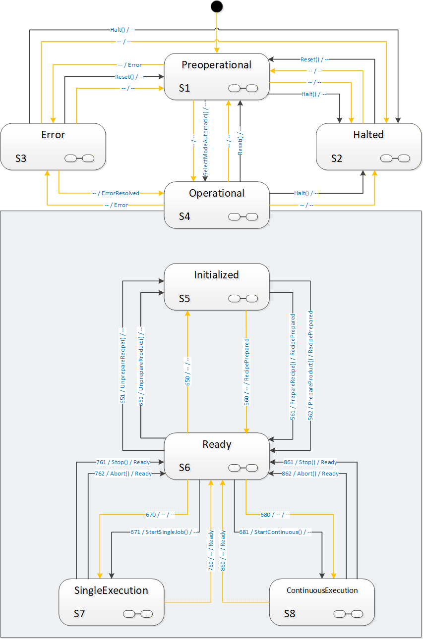
Interactions between external systems and the global "AutomaticMode" state machine are limited to few transitions in the model which we will see in detail in the description of methods and transitions. The most prominent points are obviously the Start-methods, typically used by a client to start operation of a vision system.
However, there is frequently a need to synchronize operations between the vision systems and external systems where the vision system remains conceptually in one of the states of the "AutomaticMode" state machine. The most obvious example is that of taking images of a part from various positions, either by moving the part relative to a camera system, handling it with a robot arm, or by moving the camera relative to the part, again possibly by a robot manipulator. This entire interaction would conceptually take place within SingleExecution state or ContinuousExecution state.
To enable all states in the "AutomaticMode" state machine to carry out such interactions, each is marked as a complex state by the  symbol, and has an optional SubStateMachine of the VisionStepModelStateMachineType.
8.3.2 Operation of the "AutomaticMode" state machine.
8.3.2.1 Introduction
The AutomaticMode state machine is entered from state Preoperational of the VisionStateMachineType either by an automatic operation or by the SelectModeAutomatic method.
A call to SelectModeAutomatic causes transition to state Initialized. Alternatively, the system can automatically transition into Initialized.
It is expected that within the states Initialized and Ready, the system can carry out management operations, with recipes and configurations. In order to carry out automatic evaluations, at least one recipe needs to be prepared in the system.
Recipe management is very system- and application-specific and correspondingly hard to generalize. Therefore, systems may exhibit different state transition behavior caused by recipe management methods, according to their capabilities. This is described in detail in Annex B.1 and the definition of the RecipeManagementType in chapter 7.5.
At some point, the system will be in Ready state. The simplest way will typically be a single call to AddRecipe and to PrepareRecipe to load and prepare a single recipe.
It is expected that in state Ready the system can at any time start an evaluation operation. This operation is denoted as a "job". The "AutomaticMode" state machine defines two distinct methods of carrying out evaluation, namely "single job" operation and "continuous" operation.
Typical examples for SingleJob operation are the inspection of individual work pieces. Typical examples for Continuous operation are web inspection, package sorting, etc. The main differences between these two types of jobs are:
With a SingleJob, the client starting the job can reasonably expect it to end after an application-specific, but finite time; a Continuous job will typically not end on its own, so the notion of a timeout is meaningless.
Within a SingleJob, typically an AcquisitionDone event will be triggered at some point, informing the environment that all required data has been acquired so that the inspection part can leave the field of view of the camera, either by moving the part or the camera.
The image processing operation is accordingly started by one of two start methods, StartSingleJob or StartContinuous.
In single job as well as in continuous operation, the system can produce an arbitrary number of results, all of them partial with the exception of the last one. Whenever a partial or final result is available, the system shall trigger a ResultReady event with a result ID.
The result can then be retrieved by one of the GetResult method calls or directly from the ResultContent Component of the ResultReady event if it is included in the event Typically, the result will be available through a GetResult method call even if included with the ResultReady event, however the client cannot make assumptions about the result management of the vision system. This has to be treated in an application-specific way.
8.3.2.2 Single job operation
A call to the StartSingleJob method will cause a transition into state SingleExecution, where the system will typically acquire data and, once it has finished acquiring data, will fire an AcquisitionDone event. Note that there is no temporal relationship between the system returning to the Ready state and the completion of image acquisition or processing for the job triggered by a Start method. The system can already have left state SingleExecution to Ready, it can even accept another Start method call and carry out the next job, before the AcquisitionDone event for the previous job occurs, if the system is capable of handling several image acquisitions and/or image evaluations simultaneously.
From the point of view of the OPC UA client, the state machine is always carrying out one job only. However, there may be evaluation process of several jobs running in parallel on the system and may trigger AcquisitionDone events as well as ResultReady events.
Whenever the system is ready for the next StartSingleJob method, it will transition into the Ready state again.
8.3.2.3 Continuous operation
A call to the StartContinuous method will cause a transition into state ContinuousExecution, where the system will continuously acquire and process data.
This state models the behavior of systems like textile inspection systeme, package sorting machines, monitoring and surveillance systems, which do not expect start commands for individual work pieces but constantly acquire and process data.
The system may go back to the Ready state, automatically due to internal conditions, or by calling the Abort or Stop methods.
8.3.2.4 General remarks on Stop and Abort methods
The Stop and Abort methods offer two different means of finishing operation in the "Executing" states, with the intention that the system transitions to the Ready state.
Both can be considered intended interruptions of a running system, in contrast to an error or the complete stopping of operations by Reset and Halt methods.
The difference between the two methods is:
In response to an Abort method call, the system is expected to end running operation and transition to the Ready state as fast as possible, without regard to acquired or computed data.
In response to a Stop method call, the system is expected to end running operation and transition to the Ready state as soon as possible while retaining as much result data as possible. It is expected that results will become available for all images acquired before the Stop method was called.
These methods shall always be executable. If for some reason the vision system is not capable of carrying out this transition, the method shall fail with an appropriate status code, typically Bad_InternalError, and the state machine shall transition into the Error state.
For example, depending on the camera / sensor used, it may not be possible to interrupt the acquisition process arbitrarily from the outside.
8.3.2.5 Entering the "AutomaticMode" state machine
As described in Section 8.1.2.1 the VisionAutomaticMode SubStateMachine of the Operational state can be entered in two different ways:
From the Preoperational state of the parent state machine through an automatic transition or a transition triggered by the SelectModeAutomatic method into the Initialized state of the VisionAutomaticModeStateMachine . In these cases, the parent state machine transitions into the parent state Operational implicitly.
From the Error state of the parent state machine through an automatic transition into the Operational state of the parent state machine. In this case the server will decide based on the conditions in the vision system in which state of the VisionAutomaticModeStateMachine the system ends up.
Figure 25 shows these ways; for clarity, all other transitions have been left out. The transitions from the Preoperational state are shown as solid lines as they are actually modelled in the type definition. The transitions from the Error state are shown in dashed lines as they are not explicitly modelled but only "virtual" transitions decided by the server internally.
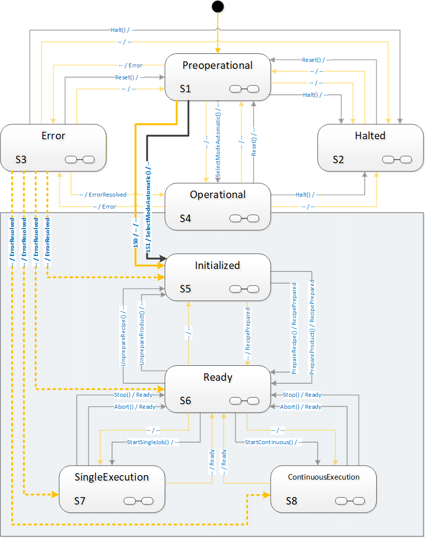
8.3.3 VisionAutomaticModeStateMachineType Overview
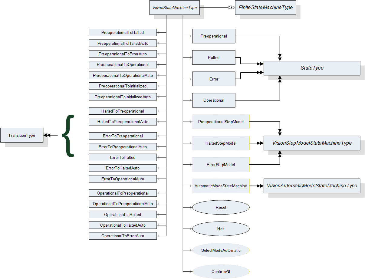
8.3.4 VisionAutomaticModeStateMachineType Definition
VisionAutomaticModeStateMachineType is formally defined in Table 96.
| Attribute | Value | ||||
| Includes all attributes specified for the FiniteStateMachineType | |||||
| BrowseName | VisionAutomaticModeStateMachineType | ||||
| IsAbstract | False | ||||
| References | NodeClass | BrowseName |
Data
Type | TypeDefinition | ModellingRule |
|---|---|---|---|---|---|
| Subtype of the FiniteStateMachineType defined in OPC 10000-5 Annex B.4.5 | |||||
| HasComponent | Object | Initialized | -- | StateType | |
| HasComponent | Object | Ready | -- | StateType | |
| HasComponent | Object | SingleExecution | -- | StateType | |
| HasComponent | Object | ContinuousExecution | -- | StateType | |
| HasComponent | Object | InitializedToReadyRecipe | -- | TransitionType | |
| HasComponent | Object | InitializedToReadyProduct | -- | TransitionType | |
| HasComponent | Object | InitializedToReadyAuto | -- | TransitionType | |
| HasComponent | Object | ReadyToInitializedRecipe | -- | TransitionType | |
| HasComponent | Object | ReadyToInitializedProduct | -- | TransitionType | |
| HasComponent | Object | ReadyToInitializedAuto | -- | TransitionType | |
| HasComponent | Object | ReadyToSingleExecution | -- | TransitionType | |
| HasComponent | Object | ReadyToSingleExecutionAuto | -- | TransitionType | |
| HasComponent | Object | ReadyToContinuousExecution | -- | TransitionType | |
| HasComponent | Object | ReadyToContinuousExecutionAuto | -- | TransitionType | |
| HasComponent | Object | SingleExecutionToReadyStop | -- | TransitionType | |
| HasComponent | Object | SingleExecutionToReadyAbort | -- | TransitionType | |
| HasComponent | Object | SingleExecutionToReadyAuto | -- | TransitionType | |
| HasComponent | Object | ContinuousExecutionToReadyStop | -- | TransitionType | |
| HasComponent | Object | ContinuousExecutionToReadyAbort | -- | TransitionType | |
| HasComponent | Object | ContinuousExecutionToReadyAuto | -- | TransitionType | |
| HasComponent | Method | Stop | -- | Mandatory | |
| HasComponent | Method | Abort | -- | Mandatory | |
| HasComponent | Method | StartSingleJob | -- | Mandatory | |
| HasComponent | Method | StartContinuous | -- | Mandatory | |
| HasComponent | Method | SimulationMode | -- | Optional | |
| HasComponent | Object | InitializedStepModel | -- | VisionStepModelStateMachineType | Optional |
| HasComponent | Object | ReadyStepModel | -- | VisionStepModelStateMachineType | Optional |
| HasComponent | Object | SingleExecutionStepModel | -- | VisionStepModelStateMachineType | Optional |
| HasComponent | Object | ContinuousExecutionStepModel | -- | VisionStepModelStateMachineType | Optional |
8.3.5 VisionAutomaticModeStateMachineType States
8.3.5.1 Introduction
Table 97 specifies the VisionAutomaticStateMachine's state Objects. These state Objects are instances of the StateType defined in OPC 10000-5 - Annex B. Each state is assigned a unique StateNumber value.
See Table 98 for a brief description of the states. The states will be detailed in the following subsections.
Browse Name | References | Target BrowseName | Value | Target Type Definition | Notes |
| Initialized | HasProperty | StateNumber | 5 | PropertyType | -- |
| FromTransition | ReadyToInitializedRecipe | TransitionType | -- | ||
| FromTransition | ReadyToInitializedProduct | TransitionType | -- | ||
| FromTransition | ReadyToInitialzedAuto | TransitionType | -- | ||
| ToTransition | InitializedToReadyRecipe | TransitionType | -- | ||
| ToTransition | InitializedToReadyProduct | TransitionType | -- | ||
| ToTransition | InitializedToReadyAuto | TransitionType | -- | ||
| HasSubstate Machine | InitializedStepModel | VisionStepModel StateMachineType | -- | ||
| Ready | HasProperty | StateNumber | 6 | PropertyType | -- |
| FromTransition | InitializedToReadyRecipe | TransitionType | -- | ||
| FromTransition | InitializedToReadyProduct | TransitionType | -- | ||
| FromTransition | InitlializedToReadyAuto | TransitionType | -- | ||
| FromTransition | SingleExecutionToReadyStop | TransitionType | -- | ||
| FromTransition | SingleExecutionToReadyAbort | TransitionType | -- | ||
| FromTransition | SingleExecutionToReadyAuto | TransitionType | -- | ||
| FromTransition | ContinuousExecutionToReadyStop | TransitionType | -- | ||
| FromTransition | ContinousExecutionToReadyAbort | TransitionType | -- | ||
| FromTransition | ContinousExecutionToReadyAuto | TransitionType | -- | ||
| ToTransition | ReadyToInitializedRecipe | TransitionType | -- | ||
| ToTransition | ReadyToInitializedProduct | TransitionType | -- | ||
| ToTransition | ReadyToInitializedAuto | TransitionType | -- | ||
| ToTransition | ReadyToSingleExecution | TransitionType | -- | ||
| ToTransition | ReadyToSingleExecutionAuto | TransitionType | -- | ||
| ToTransition | ReadyToContinuousExecution | TransitionType | -- | ||
| ToTransition | ReadyToContinuousExecutionAuto | TransitionType | -- | ||
| HasSubstate Machine | ReadyStepModel | VisionStepModel StateMachineType | -- | ||
| Single Execution | HasProperty | StateNumber | 7 | PropertyType | -- |
| FromTransition | ReadyToSingleExecution | TransitionType | -- | ||
| FromTransition | ReadyToSingleExecutionAuto | TransitionType | -- | ||
| ToTransition | SingleExecutionToReadyStop | TransitionType | -- | ||
| ToTransition | SingleExecutionToReadyAbort | TransitionType | -- | ||
| ToTransition | SingleExecutionToReadyAuto | TransitionType | -- | ||
| HasSubstate Machine | SingleExecutionStepModel | VisionStepModel StateMachineType | -- | ||
| Continuous Execution | HasProperty | StateNumber | 8 | PropertyType | -- |
| FromTransition | ReadyToContinuousExecution | TransitionType | -- | ||
| FromTransition | ReadyToContinuousExecutionAuto | TransitionType | -- | ||
| ToTransition | ContinuousExecutionToReadyStop | TransitionType | -- | ||
| ToTransition | ContinousExecutionToReadyAbort | TransitionType | -- | ||
| ToTransition | ContinousExecutionToReadyAuto | TransitionType | -- | ||
| HasSubstate Machine | ContinuousExecutionStepModel | VisionStepModel StateMachineType | -- |
| StateName | Description |
| Initialized | This state indicated that the vision system is sufficiently initialized so that management operations like configuration and recipe management can be carried out through the server, if the optional management objects exist. |
| Ready | This state indicates that the vision system is capable of being started to carry out jobs, e.g. through Start methods called on the server. |
| SingleExecution | This state indicates that the vision system will acquire the data required for carrying out a single inspection or measuring job and will finish whatever operations are necessary to return to the Ready state to accept the next job. |
| ContinuousExecution | This state indicates that the vision system continually acquires and processes data, until it is stopped by internal or external reasons, e.g. calling the Stop or Abort methods on the server. |
8.3.5.2 Initialized State
In this state, the system is characterized by the following properties:
The system is able to perform management and operations.
Configurations can be managed by methods detailed in Section 7.2.
Recipes can be managed by methods detailed in Sections 7.5, 7.6, 7.7.
One or more recipes can be prepared by the PrepareRecipe method such that these are ready to be used in processing operations.
Results can be pulled from the internal result-store by the methods detailed in Section 7.10.
The system can be put into simulation mode (see Section 8.3.7.5).
This state will be the first state entered in the VisionAutomaticModeStateMachine when the superior VisionStateMachine enters the Operational state either by an automatic transition from Preoperational or by a SelectModeAutomatic method call.
If an error is dectected which suspends normal operation, the system will change to the Error state in the VisionStateMachine.
This state can be left in the following ways:
Into Ready state by a PrepareRecipe method call.
Into Preoperational state of the VisionStateMachine by a Reset method call.
Into Halted state of the VisionStateMachine by a Halt method call.
Into Error state of the VisionStateMachine by an internal error.
All method-triggered transitions can also occur automatically upon an internal decision of the system.
This state can be a composite state with an optional VisionStepModelStateMachineType SubStateMachine.
8.3.5.3 Ready State
In this state, the system is characterized by the following properties:
The vision system has prepared one or more recipes such that they can be used for processing immediately upon a StartSingleJob or StartContinuous method call (unless it is a system without any recipe management).
The vision system is ready to accept either a StartSingleJob or a StartContinuous method to begin image processing operation.
Recipes can be added and retrieved by methods detailed in Sections 7.5, 7.6, 7.7.
Which recipes are ready for use can be changed by calling the PrepareRecipe method depending on the recipe handling capabilities of the system.
Results can be pulled from the internal result-store by the methods detailed in Section 7.5.
The vision system can be put into simulation mode (see Section 8.3.7.5).
Depending on the recipe handling capabilities of the vision system, calling an AddRecipe or PrepareRecipe method in this state may cause the system to fall back into Initialized state, temporarily preventing it from accepting Start methods.
If an error is dectected which suspends normal operation, the system will transition to Error state in the VisionStateMachine.
This state can be left in the following ways:
Into the SingleExecution state by a StartSingleJob method call.
Into the ContinuousExecution state by a StartContinuous method call.
Into the Initialized state by an UnprepareRecipe method call.
Into the Preoperational state of the VisionStateMachine by a Reset method call.
Into the Halted state of the VisionStateMachine by a Halt method call.
Into the Error state of the VisionStateMachine by an internal error.
All method-triggered transitions can also occur automatically upon an internal decision of the system.
This state can be a composite state with an optional VisionStepModelStateMachineType SubStateMachine.
8.3.5.4 SingleExecution State
In this state, the system is characterized by the following properties:
The vision system has received a command to begin the execution of an individual job (measuring, inspection, identifying, …), e.g. by a call to the StartSingleJob method on the server.
The vision system collects sensor data (i.e. acquiring single or multiple images, possibly awaiting triggers, often in hardware).
If data acquisition is a "multi-stage-process" (interaction with other devices) this may be modelled with a VisionStepModelType SubStateMachine (all states allow for this, but this is the most typical application, therefore we emphasize it here).
The vision system may indicate to the client by an AcquisitionDone event that acquisition has been finished, e.g. as a signal that the part can be removed from the camera's field of view, either by moving the part or he camera.
The vision system carries out the processing of the acquired data at least so far that the internal resources are available to transition into state Ready to accept the next start command.
Results can be pulled from the internal result-store by the methods detailed in Section 7.5 (depending on the capabilities of the system).
Note that the above description illustrates a typical behavior. The vision system is, however, in no way obliged to perform any particular operation - like image acquisition or processing - in this state. It can do completely different things or nothing at all before returning to Ready state. The point is rather that the difference between SingleExecution state and Ready state lies in the availability of the required resources for starting a job.
If an error is detected which suspends normal operation, the system will change to state Error in the VisionStateMachine.
This state can be left in the following ways:
into the Ready state by an automatic transition when the required resources are available. The system shall trigger a Ready event in this case. Note that this is in no way related to the vision system completing an image acquisition or evaluation and/or producing a result.
Into the Ready state by the methods Stop and Abort, see Section 8.3.2.4 for details.
Into the Preoperational state of the VisionStateMachine by a Reset method call.
Into the Halted state of the VisionStateMachine by a Halt method call.
Into the Error state of the VisionStateMachine by an internal error.
All method-triggered transitions can also occur automatically upon an internal decision of the system.
This state can be a composite state with an optional VisionStepModelStateMachineType SubStateMachine.
8.3.5.5 ContinuousExecution State
In this state, the system is characterized by the following properties:
The vision system has received a StartContinuous command to begin the execution of a continuous job
The vision system collects sensor data (i.e. acquiring single or multiple images, possibly awaiting triggers, often in hardware) and processes this in a continuously ongoing fashion.
Results can be pulled from the internal result-store by the methods detailed in Section 7.5 (depending on the capabilities of the system).
Note that the above description illustrates a typical behavior. The vision system is, however, in no way obliged to perform any particular operation - like image acquisition or processing - in this state. It can do completely different things or nothing at all before returning to Ready state. The point is rather that the difference between ContinuousExecution state and Ready state lies in the availability of the required resources for starting a job.
If an error is detected which suspends normal operation, the system will change to the Error state in the VisionStateMachine.
This state can be left in the following ways:
Into the Ready state by Stop and Abort method calls, see Section 8.3.2.4 for details.
Into the Preoperational state of the VisionStateMachineType by a Reset method call.
Into the Halted state of the VisionStateMachineType by a Halt method call.
Into the Error state of the VisionStateMachineType by an internal error.
All method-triggered transitions can also occur automatically upon an internal decision of the system.
This state can be a composite state with an optional VisionStepModelStateMachineType SubStateMachine.
8.3.6 VisionAutomaticModeStateMachineType Transitions
Transitions are instances of Objects of the TransitionType defined in OPC 10000-5 - Annex B which also includes the definitions of the ToState, FromState, HasCause, and HasEffect References used. Table 99 specifies the Transitions defined for the VisionStateMachineType. Each Transition is assigned a unique TransitionNumber.
| BrowseName | References | Target BrowseName | Value | Target TypeDefinition | Notes |
| InitializedToReadyRecipe | HasProperty | TransitionNumber | 561 | PropertyType | -- |
| FromState | Initialized | StateType | -- | ||
| ToState | Ready | StateType | -- | ||
| HasCause | PrepareRecipe | Method | -- | ||
| HasEffect | StateChangedEventType | -- | |||
| HasEffect | RecipePreparedEventType | -- | |||
| InitializedToReadyProduct | HasProperty | TransitionNumber | 562 | PropertyType | -- |
| FromState | Initialized | StateType | -- | ||
| ToState | Ready | StateType | -- | ||
| HasCause | PrepareProduct | Method | -- | ||
| HasEffect | StateChangedEventType | -- | |||
| HasEffect | RecipePreparedEventType | -- | |||
| InitializedToReadyAuto | HasProperty | TransitionNumber | 560 | PropertyType | -- |
| FromState | Initialized | StateType | -- | ||
| ToState | Ready | StateType | -- | ||
| HasEffect | StateChangedEventType | -- | |||
| ReadyToInitializedRecipe | HasProperty | TransitionNumber | 651 | PropertyType | -- |
| FromState | Ready | StateType | -- | ||
| ToState | Initialized | StateType | -- | ||
| HasCause | UnprepareRecipe | Method | -- | ||
| HasEffect | StateChangedEventType | -- | |||
| ReadyToInitializedProduct | HasProperty | TransitionNumber | 652 | PropertyType | -- |
| FromState | Ready | StateType | -- | ||
| ToState | Initialized | StateType | -- | ||
| HasCause | UnprepareProduct | Method | -- | ||
| HasEffect | StateChangedEventType | -- | |||
| ReadyToInitializedAuto | HasProperty | TransitionNumber | 650 | PropertyType | -- |
| FromState | Ready | StateType | -- | ||
| ToState | Initialized | StateType | -- | ||
| HasEffect | StateChangedEventType | -- | |||
| ReadyToSingleExecution | HasProperty | TransitionNumber | 671 | PropertyType | -- |
| FromState | Ready | StateType | -- | ||
| ToState | SingleExecution | StateType | -- | ||
| HasCause | StartSingleJob | Method | -- | ||
| HasEffect | StateChangedEventType | -- | |||
| HasEffect | JobStartedEventType | -- | |||
| ReadyToSingleExecutionAuto | HasProperty | TransitionNumber | 670 | PropertyType | -- |
| FromState | Ready | StateType | -- | ||
| ToState | SingleExecution | StateType | -- | ||
| HasEffect | StateChangedEventType | -- | |||
| HasEffect | JobStartedEventType | -- | |||
| ReadyToContinuousExecution | HasProperty | TransitionNumber | 681 | PropertyType | -- |
| FromState | Ready | StateType | -- | ||
| ToState | ContinuousExecution | StateType | -- | ||
| HasCause | StartContinuous | Method | -- | ||
| HasEffect | StateChangedEventType | -- | |||
| HasEffect | JobStartedEventType | -- | |||
| ReadyToContinuousExecutionAuto | HasProperty | TransitionNumber | 680 | PropertyType | -- |
| FromState | Ready | StateType | -- | ||
| ToState | ContinuousExecution | StateType | -- | ||
| HasEffect | StateChangedEventType | -- | |||
| HasEffect | JobStartedEventType | -- | |||
| SingleExecutionToReadyAuto | HasProperty | TransitionNumber | 760 | PropertyType | -- |
| FromState | SingleExecution | StateType | -- | ||
| ToState | Ready | StateType | -- | ||
| HasEffect | StateChangedEventType | -- | |||
| HasEffect | ReadyEventType | -- | |||
| SingleExecutionToReadyStop | HasProperty | TransitionNumber | 761 | PropertyType | |
| FromState | SingleExecution | StateType | -- | ||
| ToState | Ready | StateType | -- | ||
| HasCause | Stop | Method | -- | ||
| HasEffect | StateChangedEventType | -- | |||
| HasEffect | ReadyEventType | -- | |||
| SingleExecutionToReadyAbort | HasProperty | TransitionNumber | 762 | PropertyType | -- |
| FromState | SingleExecution | StateType | -- | ||
| ToState | Ready | StateType | -- | ||
| HasCause | Abort | Method | -- | ||
| HasEffect | StateChangedEventType | -- | |||
| HasEffect | ReadyEventType | -- | |||
| ContinuousExecutionToReadyAuto | HasProperty | TransitionNumber | 860 | PropertyType | -- |
| FromState | ContinuousExecution | StateType | -- | ||
| ToState | Ready | StateType | -- | ||
| HasEffect | StateChangedEventType | -- | |||
| HasEffect | ReadyEventType | -- | |||
| ContinuousExecutionToReadyStop | HasProperty | TransitionNumber | 861 | PropertyType | -- |
| FromState | ContinuousExecution | StateType | -- | ||
| ToState | Ready | StateType | -- | ||
| HasCause | Stop | Method | -- | ||
| HasEffect | StateChangedEventType | -- | |||
| HasEffect | ReadyEventType | -- | |||
| ContinuousExecutionToReadyAbort | HasProperty | TransitionNumber | 862 | PropertyType | -- |
| FromState | ContinuousExecution | StateType | -- | ||
| ToState | Ready | StateType | -- | ||
| HasCause | Abort | Method | -- | ||
| HasEffect | StateChangedEventType | -- | |||
| HasEffect | ReadyEventType | -- |
8.3.7 VisionAutomaticModeStateMachineType Methods
8.3.7.1 StartSingleJob method
Calling this method on the server is used to start a single execution type job in the vision system which will be reflected by transition from the Ready state to the SingleExecution state.
Signature
StartSingleJob ([in] MeasIdDataType measId,[in] PartIdDataType partId,[in] RecipeIdExternalDataType recipeId[in] ProductIdDataType productId[in] BaseDataType[] parameters[out] JobIdDataType jobId[out] Int32 error);| Argument | Description |
| measId | Identifies the measuring or inspection run from the point of view of the client. May be empty. |
| partId | Identifies the part to be measured or inspected from the point of view of the client. The partId may be identical on different measIDs, e.g. for repeat measurements in capability tests. May be empty. |
| recipeId | If not empty, it must be the ExternalId of a prepared recipe which is to be used by this job. |
| productId | It not empty, it must be the ProductId of a product for which a recipe has been prepared which is to be used by this job. |
| parameters | List of parameters for this particular execution of the recipe; number and type of the parameters are recipe-specific, so the client may need to re-browse the method signature after a change in recipe preparation. |
| jobId | A system-wide unique identification of the job. This argument must be returned. |
| error | 0 - OK Values > 0 are reserved for errors defined by this and future standards. Values < 0 shall be used for application-specific errors. |
| Attribute | Value | ||||
| BrowseName | StartSingleJob | ||||
| References | NodeClass | BrowseName | DataType | TypeDefinition | ModellingRule |
|---|---|---|---|---|---|
| HasProperty | Variable | InputArguments | Argument[] | PropertyType | Mandatory |
| HasProperty | Variable | OutputArguments | Argument[] | PropertyType | Mandatory |
It is expected that clients work either recipe-based or product-based, i.e. that a client gives either the RecipeId argument or the ProductId argument. Recipe and product management being the province of the vision system, it is implementation defined how the vision system reacts to none or both be given
Typical possibilities are that a system without recipe management or with only a single prepared recipe can use this recipe to execute a job and accept both parameters to be empty, whereas a system with multiple prepared recipes would probably consider it an error if both are empty and decide based on internal rules which takes precedence if both are given.
Results are to be marked with as many of the identification values as possible to allow for unique identification and flexible filtering, i.e., it is expected that the server uses all meta data elements provided by the client and supported by the server profile to mark the results, filter the results, and fill the ResultReady event.
The jobId is mandatory to be returned and to be included in results.
Restarting with the same measId can lead to identical or different jobIds, depending on the application. It is therefore not reliably possible to use multiple calls with the same measId to query for jobIds.
The parameters argument is intended for filling free parameters of a recipe with concrete values for the given job. Its structure is therefore dependent on the recipe used. The server will have to instantiate this method with an application-specific parameter structure before entering the Ready state. The server may re-instantiate this method with a different parameter structure after preparing a different recipe. In the case of several recipes being in prepared state at the same time, this structure is expected to be the superset of parameters required by the prepared recipes. The client will have to browse for the actual argument structure of the method at least once before calling a Start method (in the case of a system without recipe management) and application-specific potentially after each call to PrepareRecipe.
8.3.7.2 StartContinuous method
Calling this method on the server is used to start a continuous execution type job in the vision system which will be reflected by transition from the Ready state to the ContinuousExecution state. It has the same signature and semantics as method StartSingleJob described in Section 8.3.7.1.
| Attribute | Value | ||||
| BrowseName | StartContinuous | ||||
| References | NodeClass | BrowseName | DataType | TypeDefinition | ModellingRule |
|---|---|---|---|---|---|
| HasProperty | Variable | InputArguments | Argument[] | PropertyType | Mandatory |
| HasProperty | Variable | OutputArguments | Argument[] | PropertyType | Mandatory |
8.3.7.3 Abort method
In response to an Abort call on the server, the vision system is expected to end running operation and transition to the Ready state as fast as possible, without regard to acquired or computed data.
See the general remarks on Stop and Abort methods in Section 8.3.2.4 for further information on the behavior.
Signature
Abort ([in] Int32 cause[in] String causeDescription[out] Int32 error);| Argument | Description |
| cause | Implementation-specific number denoting the reason for the Abort command. |
| causeDescription | Text for said reason, e.g. for logging purposes. May be empty. |
| error | 0 - OK Values > 0 are reserved for errors defined by this and future standards. Values < 0 shall be used for application-specific errors. |
| Attribute | Value | ||||
| BrowseName | Abort | ||||
| References | NodeClass | BrowseName | DataType | TypeDefinition | ModellingRule |
|---|---|---|---|---|---|
| HasProperty | Variable | InputArguments | Argument[] | PropertyType | Mandatory |
| HasProperty | Variable | OutputArguments | Argument[] | PropertyType | Mandatory |
The cause argument given to the method can only be interpreted by the underlying vision system It can be used, for example, for logging purposes. It is expected that a value of 0 will be considered an "unspecified reason".
8.3.7.4 Stop method
In response to a Stop method call on the server, the vision system is expected to end running operation and transition to state Ready as soon as possible while retaining as much result data as possible.
See the general remarks on Stop and Abort in 8.3.2.4 for further information on the behavior.
Signature
Stop ([in] Int32 cause[in] String causeDescription[out] Int32 error);
| Argument | Description |
| cause | Implementation-specific number denoting the reason for the Stop command. |
| causeDescription | Text for said reason, e.g. for logging purposes. May be empty. |
| error | 0 - OK Values > 0 are reserved for errors defined by this and future standards. Values < 0 shall be used for application-specific errors. |
| Attribute | Value | ||||
| BrowseName | Stop | ||||
| References | NodeClass | BrowseName | DataType | TypeDefinition | ModellingRule |
|---|---|---|---|---|---|
| HasProperty | Variable | InputArguments | Argument[] | PropertyType | Mandatory |
| HasProperty | Variable | OutputArguments | Argument[] | PropertyType | Mandatory |
The cause argument given to the method can only be interpreted by the underlying vision system It can be used, for example, for logging purposes. It is expected that a value of 0 will be considered an "unspecified reason".
8.3.7.5 SimulationMode method
This method puts the system into a system-specific special mode of operation. It is expected that this mode does one or all of the following things:
Simulate hardware (for tests on notebook)
Produce simulated results (for tests within the line)
Simulate parts of a recipe
It is mandatory that each result produced by the system when simulation mode is on must be marked with a simulation flag.
Signature
SimulationMode ([in] Boolean activate[in] Int32 cause[in] String causeDescription[out] Int32 error);
| Argument | Description |
| activate | Switch simulation on (true) or off (false) |
| cause | Implementation specific number which the server can use, e.g. to control the simulation in a specific way |
| causeDescription | String describing the reason for the call, for logging purposes May be empty. |
| error | 0 - OK Values > 0 are reserved for errors defined by this and future standards. Values < 0 shall be used for application-specific errors. |
| Attribute | Value | ||||
| BrowseName | SimulationMode | ||||
| References | NodeClass | BrowseName | DataType | TypeDefinition | ModellingRule |
|---|---|---|---|---|---|
| HasProperty | Variable | InputArguments | Argument[] | PropertyType | Mandatory |
| HasProperty | Variable | OutputArguments | Argument[] | PropertyType | Mandatory |
8.3.8 VisionAutomaticModeStateMachineType Events
8.3.8.1 RecipePreparedEventType
RecipePreparedEventType is an EventType subtype of BaseEventType, defined in OPC 10000-5. This event shall be triggered by the server when the preparation of a recipe is completed on the vision system. Figure 27 defines the structure. It is formally defined in Table 109.
Typically, if the RecipeManagementType object is carried out by the server in a synchronous manner, this event will be triggered before the method returns, but there is no specified temporal relationship between the call to the PrepareRecipe method and the triggering of the event (except for the obvious that the event cannot occur before the call).
The same holds for the PrepareProduct method of the RecipeManagementType object which, in effect, also prepares a recipe.
An important special case, described in Section B.1.2.3, is local editing of an already prepared recipe. Since after local editing has finished, the recipe is a different one than before, effectively a new recipe has been prepared. Therefore, local editing of a prepared recipe shall generate a RecipePrepared event.
The RecipePrepared event transports the identification of the prepared recipe. If the event was caused by a PrepareProduct method call, it also transports the ProductId, otherwise the ProductId shall be empty.
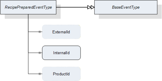
| Attribute | Value | ||||
| BrowseName | RecipePreparedEventType | ||||
| IsAbstract | False | ||||
| References | NodeClass | BrowseName | DataType | TypeDefinition | ModellingRule |
|---|---|---|---|---|---|
| Subtype of the BaseEventType defined in OPC 10000-5 | |||||
| HasProperty | Variable | ExternalId | RecipeIdExternalDataType | PropertyType | Optional |
| HasProperty | Variable | InternalId | RecipeIdInternalDataType | PropertyType | Mandatory |
| HasProperty | Variable | ProductId | ProductIdDataType | PropertyType | Optional |
8.3.8.2 JobStartedEventType
JobStartedEventType is an EventType subtype of BaseEventType, defined in OPC 10000-5. This event is to be triggered by the server when the state machine transitions from the Ready state to the SingleExecution or ContinuousExecution state. Figure 28 defines the structure. It is formally defined in Table 110.
It indicates to the client that the vision system has started the execution of a job, regardless whether the transition occurred due to a call to the StartSingleJob or StartContinuous method or automatically due, e.g. for a fieldbus start signal.
The event transports the jobId created upon the transition from state Ready to state SingleExecution or ContinuousExecution. This enables clients to maintain a time-sequential log of jobs, regardless whether this particular client started the job or whether the job was started by an OPC UA method call at all.
In the case of multiple running state machines in the same server, the client can use the Source property inherited from BaseEventType to identify the state machine instance the event originated from.

| Attribute | Value | ||||
| BrowseName | JobStartedEventType | ||||
| IsAbstract | False | ||||
| References | NodeClass | BrowseName | DataType | TypeDefinition | ModellingRule |
|---|---|---|---|---|---|
| Subtype of the BaseEventType defined in OPC 10000-5 | |||||
| HasProperty | Variable | JobId | JobIdDataType | PropertyType | Mandatory |
8.3.8.3 ReadyEventType
ReadyEventType is an EventType subtype of BaseEventType, defined in OPC 10000-5. This event is to be triggered by the server when the state machine transitions to the Ready state from one of the "Execution" states, i.e. SingleExecution or ContinuousExecution. Figure 29 defines the structure. It is formally defined in Table 111.
It indicates to the client that the vision system has the necessary resources available for executing the next job. The client still has to make sure that the state machine is actually in the Ready state before calling the StartSingleJob or StartContinuous method as the vision system may fall out of the Ready state due to internal reasons or other method calls
The event transports the jobId created upon the transition from state Ready to state SingleExecution or ContinuousExecution. Together with the JobStarted event this enables clients to maintain a time-sequential log of state changes for each job.
In the case of multiple running state machines in the same server, the client can use the Source property inherited from BaseEventType to identify the state machine instance the event originated from.
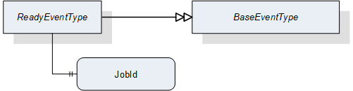
| Attribute | Value | ||||
| BrowseName | ReadyEventType | ||||
| IsAbstract | False | ||||
| References | NodeClass | BrowseName | DataType | TypeDefinition | ModellingRule |
|---|---|---|---|---|---|
| Subtype of the BaseEventType defined in OPC 10000-5 | |||||
| HasProperty | Variable | JobId | JobIdDataType | PropertyType | Mandatory |
8.3.8.4 ResultReadyEventType
ResultReadyEvent is an EventType subtype of BaseEventType, defined in OPC 10000-5. This event is to be triggered by the server when the vision system has a complete or partial result available for the client. Figure 30 defines the structure. It is formally defined in Table 112.
To enable access to a result, several properties of the result, which are generated by the system, are supplied. These properties can be used to query the results in the ResultManagement object. A sufficiently small result can also be provided in the ResultContent component of the event.
The ResultReadyEvent is not shown explicitly in the state machine as it is not connected to a state transition.
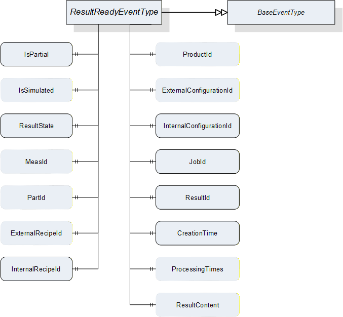
| Attribute | Value | ||||
| BrowseName | ResultReadyEventType | ||||
| IsAbstract | False | ||||
| References | NodeClass | BrowseName | DataType | TypeDefinition | ModellingRule |
|---|---|---|---|---|---|
| Subtype of the BaseEventType defined in OPC 10000-5 | |||||
| HasProperty | Variable | IsPartial | Boolean | PropertyType | Mandatory |
| HasProperty | Variable | IsSimulated | Boolean | PropertyType | Optional |
| HasProperty | Variable | ResultState | ResultStateDataType | PropertyType | Mandatory |
| HasProperty | Variable | MeasId | MeasIdDataType | PropertyType | Optional |
| HasProperty | Variable | PartId | PartIdDataType | PropertyType | Optional |
| HasProperty | Variable | ExternalRecipeId | RecipeIdExternalDataType | PropertyType | Optional |
| HasProperty | Variable | InternalRecipeId | RecipeIdInternalDataType | PropertyType | Mandatory |
| HasProperty | Variable | ProductId | ProductIdDataType | PropertyType | Optional |
| HasProperty | Variable | ExternalConfigurationId | ConfigurationIdDataType | PropertyType | Optional |
| HasProperty | Variable | InternalConfigurationId | ConfigurationIdDataType | PropertyType | Mandatory |
| HasProperty | Variable | JobId | JobIdDataType | PropertyType | Mandatory |
| HasProperty | Variable | ResultId | ResultIdDataType | PropertyType | Mandatory |
| HasProperty | Variable | CreationTime | UtcTime | PropertyType | Mandatory |
| HasProperty | Variable | ProcessingTimes | ProcessingTimesDataType | PropertyType | Optional |
| HasProperty | Variable | ResultContent | BaseDataType[] | PropertyType | Optional |
IsPartial
Indicates whether the result is the partial result of a total result.
IsSimulated
Indicates whether the system was in simulation mode when the job generating this result was created.
ResultState
Indicates at what processing state this result was generated.
MeasId, PartId, ExternalRecipeId, InternalRecipeId, ProductId, ExternalConfigurationId, InternalConfigurationId, JobId, ResultId
If the information is somehow linked to one of the (vision system) objects referenced by these Ids, these properties can transport this reference. In particular:
MeasId: This identifier is given by the client when starting a single or continuous execution and transmitted to the vision system. It is used to identify the respective result data generated for this job. Although the system-wide unique JobId would be sufficient to identify the job which the result belongs to, this makes for easier filtering on the part of the client without keeping track of JobIds.
PartId: A PartId is given by the client when starting the job; although the system-wide unique JobId would be sufficient to identify the job which the result belongs to, this makes for easier filtering on the part of the client without keeping track of JobIds.
ExternalRecipeId:
External Id of the recipe in use which produced the result. The ExternalId is only managed by the environment. This will typically be derived from the arguments of the Start method call which caused the result to be created.
InternalRecipeId:
Internal Id of the recipe in use which produced the result. This Id is system-wide unique and it is assigned by the vision system. This will typically be derived from the arguments of the Start method call which caused the result to be created.
ProductId: Id of the product selected to produce the result. This will typically be derived from the arguments of the Start method call which caused the result to be created.
ExternalConfigurationId: External Id of the configuration in effect in the system when the result was produced.
InternalConfigurationId: Internal Id of the configuration in effect in the system when the result was produced.
JobId:
The Id of the job, created by the transition from state Ready to state SingleExecution or to state ContinuousExecution which produced the result.
ResultId: vision-system-wide unique Id, which is assigned by the system. This Id can be used for fetching exactly this result using the methods detailed in Section 7.10.2.
CreationTime
CreationTime indicates the time when the result was created.
ProcessingTimes
Collection of different processing times that were needed to create the result.
ResultContent
Abstract data type to be subtyped from to hold result data created by the selected recipe.
8.3.8.5 AcquisitionDoneEventType
AcquisitionDoneEventType is an EventType subtype of BaseEventType, defined in OPC 10000-5. This event is to be triggered by the server. when the vision system finishes a data acquisition process for a job. Figure 31 shows the structure of the event. It is formally defined in Table 113.
It is not shown explicitly in the state machine diagram as it is not directly connected to a transition.
It indicates to the client that data acquisition for the specified job has finished. In many machines, this will be a signal that the work piece or camera can be moved. Triggering this event during a single or continuous execution is application-specific and not mandatory.
The event provides the JobId created upon the transition from the Ready state to the SingleExecution or ContinuousExecution state. This enables the client to maintain a time-sequential log of state changes for each job and also to match the event to the corresponding start signal.
In the case of multiple running state machines in the same server, the client can use the Source property inherited from BaseEventType to identify the state machine instance the event originated from.
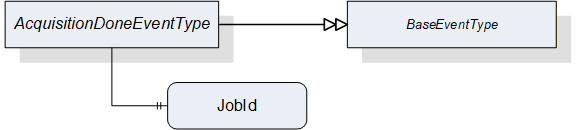
| Attribute | Value | ||||
| BrowseName | AcquisitionDoneEventType | ||||
| IsAbstract | False | ||||
| References | NodeClass | BrowseName | DataType | TypeDefinition | ModellingRule |
|---|---|---|---|---|---|
| Subtype of the BaseEventType defined in OPC 10000-5 | |||||
| HasProperty | Variable | JobId | JobIdDataType | PropertyType | Mandatory |
JobId
The Id of the job for which the event was triggered. The JobId is created by the transition from state Ready to state Acquiring.
8.3.9 Adding an operation mode
If a vendor wants to add a mode of operation, the following steps are required:
Define a SubType of FiniteStateMachineType describing the behavior of this operation mode, designated here as VendorModeStateMachineType. This SubType shall not have an InitialState to allow for selective activation of operation modes.
Define a SubType of VisionStateMachineType which
binds an instance of VendorModeStateMachineType as SubStateMachine to the Operational state of this SubType.
defines a SelectModeVendor method to trigger a transition into a desired starting state of this SubStateMachine.
binds the SelectModeVendor method as additional HasCause to the method-triggered transition from the Preoperational state to the Operational state, i.e., T141 in Table 84 (according to OPC 10000-5 B.4.18, adding causes to a transition is allowed, not however to introduce a new transition, so the existing transition ).
contains direct transitions from the Preoperational state into the desired starting state of the VendorModeStateMachine, typically an automatic one and one triggered by SelectModeVendor (again this is allowed by OPC 10000-5, B.4.18).
Take care that automatic transitions into the Operational state lead into states of the VendorModeStateMachine in a suitable way, especially for transitions from the Error state to facilitate the error handling described in Section 8.2.2.4.
The designation elements ModeStateMachineType and SelectMode shall be used as shown above. The Vendor part of the designations can be freely chosen.
8.4 VisionStepModelStateMachineType
8.4.1 Operation of the VisionStepModelStateMachine
Vision systems frequently require interaction with external systems during image acquisition. For example, it may be required to capture images in several different positions, i.e., moving the part between image capturing operations. In that case, the vision system will signal to the PLC when it has captured an image, so that the part may be safely moved, and the PLC will in turn signal to the vision system when the part is in the next position to capture the next image.
To enable the states of the VisionAutomaticModeStateMachineType to do such interaction, each is a complex state with an optional SubStateMachine of the VisionStepModelStateMachineType.
Figure 32 shows the entire SubStateMachine diagram.
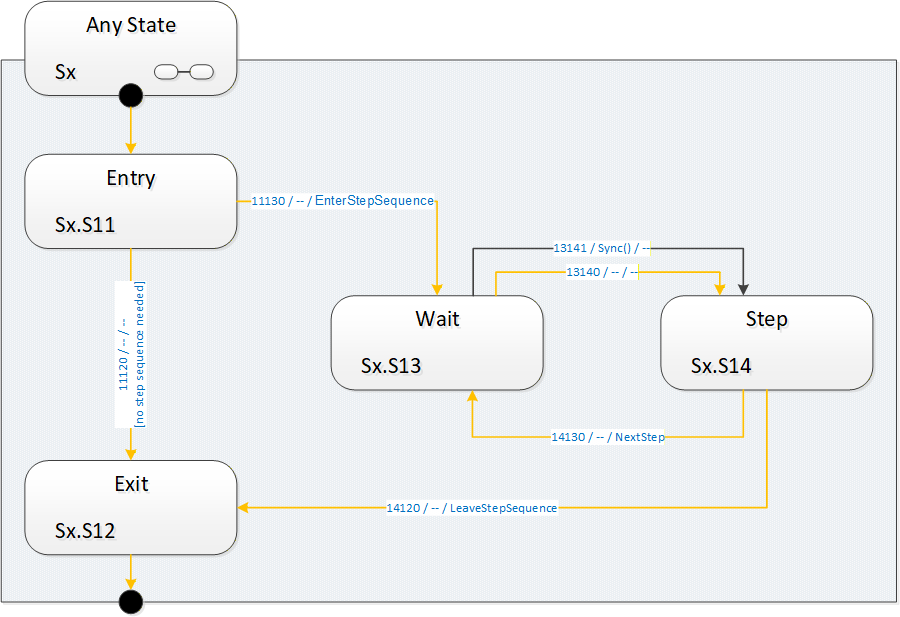
8.4.1.1 Entering the step model SubStateMachine
It is supposed that a SubStateMachine is entered automatically if it is present in the superior state. Since the Entry state is of InitialStateType it will be entered automatically.
Upon entering the SubStateMachine there is a check in the Entry state whether there is a step-sequence to execute. This is application-dependent and may depend on the situation (e.g. on the currently active recipe) and the way of determining this is application-specific.
8.4.1.2 Executing a step sequence
If in the Entry state the system decides that there is a step sequence to be executed, the SubStateMachine informs the client about this by firing an EnterStepSequence event. It then enters the Wait state to wait for a synchronization event.
The synchronization can occur by a Sync method call from an OPC UA client, typically the control system. The synchronization can also occur internally, typically due to communication events on other interfaces, e.g. a digital trigger.
The system then enters the Step state, where it does the actual work required in this state of the step model and decides whether there are any steps left in the step sequence. This is application-specific, as is the original decision to execute a step sequence at all.
The system indicates the need for another step-sequence cycle by firing a NextStep event and re-enters the Wait state. In this manner, an arbitrary and dynamic number of steps can be executed. It is not necessary to predefine the number of steps.
To use the common example of image acquisition: There may be one image acquisition in each Step state, but it is also possible that the step sequence is used only for mechanical synchronization and all acquisition is done in the Exit state.
8.4.1.3 Completing the SubStateMachine
If no step-sequence is to be executed at all, the system will transition into the Exit state directly from the Entry state and perform the actual task of the superior state. After the task is finished, the superior state will transition to whatever is its target state, thus de-activating the SubStateMachine.
When a step sequence is being executed and the system decides in the Step state that there are no more steps to execute in the step sequence, it fires a LeaveStepSequence event, transitions to the Exit state and proceeds as in the case without a step sequence.
How the work of the superior state and of the steps of the sequence is distributed between the states of the step model is application-specific.
8.4.1.4 Leaving the superior state
The superior state of a currently active VisionStepModelStateMachine is some state in the VisionStateMachineType or the VisionAutomaticModeStateMachineType.
Each of these states can be left due to internal causes (like error conditions) or external causes (like the Stop, Abort, Halt, Reset method calls). In that case, the SubStateMachine becomes inactive and will be in state Bad_StateNotActive, as explained in Section 8.1.2.
How and when these transitions take place is at the discretion of the vision system underlying the OPC UA server. In particular, the vision system can disable the Executable flag on each of these methods when the current operation does not allow for, e.g. an Abort command to be carried out.
8.4.2 VisionStepModelStateMachineType Overview
This ObjectType is a subtype of FiniteStateMachineType and it is used to represent interactions of the vision system with external components/systems for synchronization purposes. It is formally defined in Table 114.
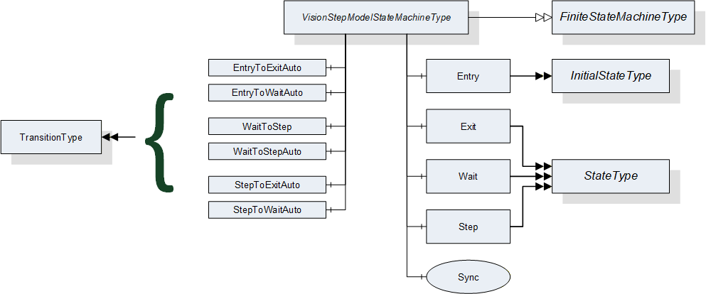
8.4.3 VisionStepModelStateMachineType Definition
VisionStepModelStateMachineType is formally defined in Table 114.
| Attribute | Value | ||||
| Includes all attributes specified for the FiniteStateMachineType | |||||
| BrowseName | VisionStepModelStateMachineType | ||||
| IsAbstract | False | ||||
| References | NodeClass | BrowseName | DataType | TypeDefinition | ModellingRule |
|---|---|---|---|---|---|
| Subtype of the FiniteStateMachineType defined in OPC 10000-5 Annex B.4.5 | |||||
| HasComponent | Object | Entry | -- | InitialStateType | -- |
| HasComponent | Object | Exit | -- | StateType | -- |
| HasComponent | Object | Wait | -- | StateType | -- |
| HasComponent | Object | Step | -- | StateType | -- |
| HasComponent | Object | EntryToExitAuto | -- | TransitionType | -- |
| HasComponent | Object | EntryToWaitAuto | -- | TransitionType | -- |
| HasComponent | Object | WaitToStep | -- | TransitionType | -- |
| HasComponent | Object | WaitToStepAuto | -- | TransitionType | -- |
| HasComponent | Object | StepToExitAuto | -- | TransitionType | -- |
| HasComponent | Object | StepToWaitAuto | -- | TransitionType | -- |
| HasComponent | Method | Sync | -- | -- | Mandatory |
8.4.4 VisionStepModelStateMachineType States
Table 115 lists the states of VisionStepModelStateMachineType. See Table 116 for a brief description of the states. These will be detailed in the following subsections.
| BrowseName | References | Target BrowseName | Value | Target TypeDefinition | Notes |
| Entry | HasProperty | StateNumber | 11 | PropertyType | -- |
| ToTransition | EntryToExitAuto | TransitionType | -- | ||
| ToTransition | EntryToWaitAuto | TransitionType | -- | ||
| Exit | HasProperty | StateNumber | 12 | PropertyType | -- |
| FromTransition | EntryToExitAuto | TransitionType | -- | ||
| FromTransition | StepToExitAuto | TransitionType | -- | ||
| Wait | HasProperty | StateNumber | 13 | PropertyType | -- |
| FromTransition | EntryToWaitAuto | TransitionType | -- | ||
| FromTransition | StepToWaitAuto | TransitionType | -- | ||
| ToTransition | WaitToStep | TransitionType | -- | ||
| ToTransition | WaitToStepAuto | TransitionType | -- | ||
| Step | HasProperty | StateNumber | 14 | PropertyType | -- |
| FromTransition | WaitToStep | TransitionType | -- | ||
| FromTransition | WaitToStepAuto | TransitionType | -- | ||
| ToTransition | StepToExitAuto | TransitionType | -- | ||
| ToTransition | StepToWaitAuto | TransitionType | -- |
| StateName | Description |
| Entry | If a superior state has a step model SubStateMachine, this state will be entered automatically. In this state, the step model SubStateMachine decides whether a step model execution is required or not. This decision may depend on the current recipe or other factors. |
| Exit | In this state, the SubStateMachine signals to the superior state that its work is finished so that the superior state can be completed and transition to its target state. The superior state may also be left at any time due to other reasons regardless of the current state of the step model. |
| Wait | In this state, the system waits for a synchronization event. This may be a call to the Sync method or other internal or external factor, e.g. communication via a different interface. |
| Step | In this state, the system carries out the work for the current step, then decides based on the current situation whether more steps are required, in which case the state machine transitions back into state Wait, or not, in which case the state machine transitions to the Exit state. |
8.4.5 VisionStepModelStateMachineType Transitions
Table 117 lists the transitions of VisionStepModelStateMachineType.
| BrowseName | References | Target BrowseName | Value | Target TypeDefinition | Notes |
| EntryToExitAuto | HasProperty | TransitionNumber | 11120 | PropertyType | -- |
| FromState | Entry | StateType | -- | ||
| ToState | Exit | StateType | -- | ||
| HasEffect | StateChangedEventType | -- | |||
| EntryToWaitAuto | HasProperty | TransitionNumber | 11130 | PropertyType | -- |
| FromState | Entry | StateType | -- | ||
| ToState | Wait | StateType | -- | ||
| HasEffect | EnterStepSequenceEventType | -- | |||
| HasEffect | StateChangedEventType | -- | |||
| WaitToStep | HasProperty | TransitionNumber | 13141 | PropertyType | -- |
| FromState | Wait | StateType | -- | ||
| ToState | Step | StateType | -- | ||
| HasCause | Sync | Method | -- | ||
| HasEffect | StateChangedEventType | -- | |||
| WaitToStepAuto | HasProperty | TransitionNumber | 13140 | PropertyType | -- |
| FromState | Wait | StateType | -- | ||
| ToState | Step | StateType | -- | ||
| HasEffect | StateChangedEventType | -- | |||
| StepToExitAuto | HasProperty | TransitionNumber | 14120 | PropertyType | -- |
| FromState | Step | StateType | -- | ||
| ToState | Exit | StateType | -- | ||
| HasEffect | LeaveStepSequenceEventType | -- | |||
| HasEffect | StateChangedEventType | -- | |||
| StepToWaitAuto | HasProperty | TransitionNumber | 14130 | PropertyType | -- |
| FromState | Step | StateType | -- | ||
| ToState | Wait | StateType | -- | ||
| HasEffect | NextStepEventType | -- | |||
| HasEffect | StateChangedEventType | -- |
8.4.6 VisionStepModelStateMachineType Methods
8.4.6.1 Sync method
This method can be called to cause a transition from the Wait state in the step model to the ExecuteStep state.
Signature
Sync ([in] Int32 cause[in] String causeDescription[out] Int32 error);| Argument | Description |
| cause | Implementation-specific number denoting circumstances of the command |
| causeDescription | Description of the circumstances, e.g. for logging purposes. May be empty. |
| error | 0 - OK Values > 0 are reserved for errors defined by this and future standards. Values < 0 shall be used for application-specific errors. |
| Attribute | Value | ||||
| BrowseName | Sync | ||||
| References | NodeClass | BrowseName | DataType | TypeDefinition | ModellingRule |
|---|---|---|---|---|---|
| HasProperty | Variable | InputArguments | Argument[] | PropertyType | Mandatory |
| HasProperty | Variable | OutputArguments | Argument[] | PropertyType | Mandatory |
The cause argument given to the method can only be interpreted by the underlying vision system It can be used, for example, for ending the step model prematurely.
8.4.7 VisionStepModelStateMachine Events
8.4.7.1 EnterStepSequenceEventType
EnterStepSequenceEventType is an EventType subtype of BaseEventType, defined in OPC 10000-5. This event is to be triggered by the server when in the Entry state the decision is taken that under the current circumstances (superior state, recipe etc.) a step sequence is to be executed and the transition into the first Wait state is initiated. The structure is defined in Figure 34. It is formally defined in Table 120.
Event properties
Steps: number of steps to expect. If the number of steps is not known, this should be -1. Even if this is a positive value, the client should not rely on it because circumstances occurring during execution of the step model may change the number of steps required, for example a call to the Sync method with a particular mode argument.
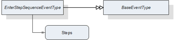
| Attribute | Value | ||||
| BrowseName | EnterStepSequenceEventType | ||||
| IsAbstract | False | ||||
| References | NodeClass | BrowseName | DataType | TypeDefinition | ModellingRule |
|---|---|---|---|---|---|
| Subtype of the BaseEventType defined in OPC 10000-5 | |||||
| HasProperty | Variable | Steps | Int32 | PropertyType | Mandatory |
8.4.7.2 NextStepEventType
NextStepEventType is an EventType subtype of BaseEventType, defined in OPC 10000-5. This event is to be triggered by the server when in the Step state the decision is reached that under the current circumstances (superior state, recipe, number of steps already taken, parameter of Sync method) another step has to be taken and the state machine must translate to the Wait state. It is formally defined in Table 121
Event properties
State NodeId
Running number of the step
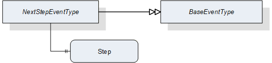
| Attribute | Value | ||||
| BrowseName | NextStepEventType | ||||
| IsAbstract | False | ||||
| References | NodeClass | BrowseName | DataType | TypeDefinition | ModellingRule |
|---|---|---|---|---|---|
| Subtype of the BaseEventType defined in OPC 10000-5 | |||||
| HasProperty | Variable | Step | Int32 | PropertyType | Mandatory |
8.4.7.3 LeaveStepSequenceEventType
LeaveStepSequenceEventType is an EventType subtype of BaseEventType, defined in OPC 10000-5, this event is to be triggered by the server when in the Step state the decision is reached that under the current circumstances (superior state, recipe, number of steps already taken, parameter of Sync method) no further steps have to be taken and the transition into the Exit state is initiated. It is formally defined in Table 122.

| Attribute | Value | ||||
| BrowseName | LeaveStepSequenceEventType | ||||
| IsAbstract | False | ||||
| References | NodeClass | BrowseName | DataType | TypeDefinition | ModellingRule |
|---|---|---|---|---|---|
| Subtype of the BaseEventType defined in OPC 10000-5 | |||||
9 VariableTypes for the Vision System
9.1 ResultType
This VariableType aggregates simple Variables using simple DataTypes that reflect the elements of the ResultDataType structure. Its DataVariables have the same semantics as defined in in 12.17.
It is formally defined in Table 123.
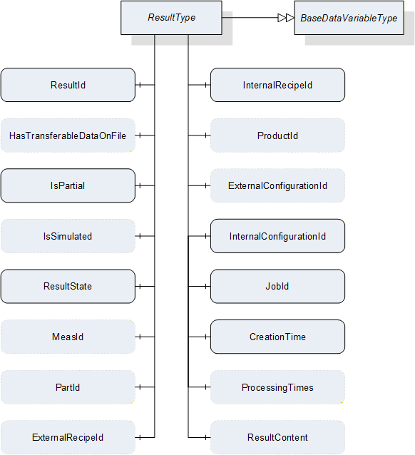
| Attribute | Value | |||
| BrowseName | ResultType | |||
| IsAbstract | False | |||
| ValueRank | -1 {Scalar} | |||
| DataType | ResultDataType | |||
| References | Node Class | BrowseName | DataType / TypeDefinition | ModellingRule |
|---|---|---|---|---|
| Subtype of the BaseDataVariableType defined in OPC 10000-5 | ||||
| HasComponent | Variable | ResultId |
ResultIdDataType
BaseDataVariableType | Mandatory |
| HasComponent | Variable | HasTransferableDataOnFile | Boolean BaseDataVariableType | Optional |
| HasComponent | Variable | IsPartial | Boolean BaseDataVariableType | Mandatory |
| HasComponent | Variable | IsSimulated | Boolean BaseDataVariableType | Optional |
| HasComponent | Variable | ResultState |
ResultStateDataType
BaseDataVariableType | Mandatory |
| HasComponent | Variable | MeasId |
MeasIdDataType
BaseDataVariableType | Optional |
| HasComponent | Variable | PartId |
PartIdDataType
BaseDataVariableType | Optional |
| HasComponent | Variable | ExternalRecipeId |
RecipeIdExternalDataType
BaseDataVariableType | Optional |
| HasComponent | Variable | InternalRecipeId |
RecipeIdInternalDataType
BaseDataVariableType | Mandatory |
| HasComponent | Variable | ProductId |
ProductIdDataType
BaseDataVariableType | Optional |
| HasComponent | Variable | ExternalConfigurationId |
ConfigurationIdDataType
BaseDataVariableType | Optional |
| HasComponent | Variable | InternalConfigurationId |
ConfigurationIdDataType
BaseDataVariableType | Mandatory |
| HasComponent | Variable | JobId |
JobIdDataType
BaseDataVariableType | Mandatory |
| HasComponent | Variable | CreationTime | UtcTime BaseDataVariableType | Mandatory |
| HasComponent | Variable | ProcessingTimes |
ProcessingTimesDataType
BaseDataVariableType | Optional |
| HasComponent | Variable | ResultContent | BaseDataType[] BaseDataVariableType | Optional |
Id
System-wide unique trimmed string, which is assigned by the system. This ID can be used for fetching exactly this result using the methods detailed in Section 7.10.2 and it is identical to the ResultId of the ResultReadyEventType defined in Section8.3.8.4.
IsPartial
Indicates whether the result is the partial result of a total result.
IsSimulated
Indicates whether the system was in simulation mode when the job generating this result was created.
ResultState
ResultState provides information about the current state of a result and the ResultStateDataType is defined in Section 12.18.
MeasId
This identifier is given by the client when starting asingle or continuous execution and transmitted to the vision system. It is used to identify the respective result data generated for this job. Although the system-wide unique JobId would be sufficient to identify the job which the result belongs to, this makes for easier filtering on the part of the client without keeping track of JobIds.
PartId
A PartId is given by the client when starting the job; although the system-wide unique JobId would be sufficient to identify the job which the result belongs to, this makes for easier filtering on the part of the client without keeping track of JobIds.
ExternalRecipeId
External Id of the recipe in use which produced the result. The ExternalID is only managed by the environment.
InternalRecipeId
Internal Id of the recipe in use which produced the result. This ID is system-wide unique and it is assigned by the vision system.
ProductId
productId which was used in starting the job which created the result.
ExternalConfigurationId
External Id of the configuration in use while the result was produced.
InternalConfigurationId
Internal Id of the configuration in use while the result was produced. This ID is system-wide unique and it is assigned by the vision system.
JobId
The ID of the job, created by the transition from state Ready to state SingleExecution or to state ContinuousExecution which produced the result.
CreationTime
CreationTime indicates the time when the result was created.
ProcessingTimes
Collection of different processing times that were needed to create the result.
ResultContent
Abstract data type to be subtyped from to hold result data created by the selected recipe.
10 EventTypes for the Vision System
10.1 VisionStateMachineType EventTypes
The VisionStateMachineType EventTypes lists all EventTypes that are part of the VisionStateMachineType. Table 124 shows all EventTypes and gives references to their descriptions and definitions in Section 8.2.8.3.
| Defined in chapter | BrowseName |
| 8.2.9.1 | StateChangedEventType |
| 8.2.9.2 | ErrorEventType |
| 8.2.9.3 | ErrorResolvedEventType |
10.2 VisionAutomaticModeStateMachineType EventTypes
The VisionAutomaticModeStateMachineType EventTypes lists all EventTypes that are part of the VisionAutomaticModeStateMachineType. Table 125 shows all EventTypes and gives references to their descriptions and definitions in Section 8.3.8.
| Defined in chapter | BrowseName |
| 8.3.8.1 | RecipePreparedEventType |
| 8.3.8.3 | ReadyEventType |
| 8.3.8.4 | ResultReadyEventType |
| 8.3.8.5 | AcquisitionDoneEventType |
10.3 VisionStepModelStateMachineType EventTypes
The VisionStepModelStateMachineType EventTypes lists all EventTypes that are part of the VisionStepModelStateMachineType. Table 126 shows all EventTypes and gives references to their descriptions and definitions in Section 8.4.7.
| Defined in chapter | BrowseName |
| 8.4.7.1 | EnterStepSequenceEventType |
| 8.4.7.2 | NextStepEventType |
| 8.4.7.3 | LeaveStepSequenceEventType |
10.4 Vision System State EventTypes and ConditionTypes
Table 127 shows all EventTypes and ConditionTypes used for signaling interior information about the vision system and gives references to their descriptions and definitions in Section 11.4.
| Defined in chapter | BrowseName |
| 11.4.1 | VisionEventType |
| 11.4.2 | VisionDiagnosticInfoEventType |
| 11.4.3 | VisionInformationEventType |
| 11.4.4 | VisionConditionType |
| 11.4.5 | VisionWarningConditionType |
| 11.4.6 | VisionErrorConditionType |
| 11.4.7 | VisionPersistentErrorConditionType |
| 11.4.8 | VisionSafetyEventType |
11 System States and Conditions for the Vision System
11.1 Introduction
Usually it is desirable to expose some information on the inner state of the machine vision framework to the outside world. A state machine only covers information on the current control state of the vision system. If an error occurs it transits to the Error state, but offers no information why this happened. Therefore we need additional communication elements that are capable of transporting error messages, warning messages to avoid the occurrence of an error, or any other kind of information helpful for the client.
The kind of errors that may occur and the additional information to be transported are highly application specific. Therefore it is out of scope for this standard to define such things. Instead we are defining a framework of rules on how to structure application specific messages and how messages should interact with the state machine. The goal for this is to make it possible that even a "generic" client without further knowledge of a specific application is able to get a basic picture of the current state of the vision system.
11.2 Client interaction
11.2.1 Introduction
In general each client is free to decide if it reads information from an OPC UA server. There is no mechanism for a server to enforce that a specific client gets a message. But OPC UA offers different levels of client / user interaction that may be selected for information being published.
11.2.2 No Interaction
The message is published at the interface and no feedback is expected to inform the server if the information has been read by any client.
11.2.3 Acknowledgement
After it is published on the interface the server waits for one client to acknowledge the reception of the message. Usually such an acknowledgement is automatically generated by a client PLC reading the information.
If a message requiring an acknowledgement has been published it will stay active till an acknowledgement has been received, even if the cause triggering this message has already been cleared.
Application Note:
As a Reset method call tries to bring the system back to an initial state it clears all active messages. If an error state could not be cleared the message will show up again after performing the reset.
11.2.4 Confirmation
After the message is published one of the receiving clients has to acknowledge the reception and afterward has to confirm that the server may clear the information. This mechanism is usually used to call for human assistance. The client PLC acknowledges the reception and shows a message on its HMI. After the operator gives the command to continue the PLC sends the confirmation to inform the server.
If the vision System has its own user console such a user confirmation may be entered there. Therefor it is allowed that the vision system may clear the message even without the confirmation received from a client. But it has to wait for the reception of an acknowledgement before doing so.
11.2.5 Confirm All
As a number of messages may be published at the same time the vision system may optionally offer a ConfirmAll method that sets the confirmation for all active messages.
11.3 Classes of Informational Elements
11.3.1 Overview
We are defining five classes of informational elements to be exposed on the interface. The classes are distinguished by their severity regarding the influence on the operation of the vision system.
Each message transports its severity represented as a value between 0 and 1000.
11.3.2 Diagnostic Information
This class of lowest severity carries messages for debugging and diagnostic purposes. It may safely be ignored by clients.
11.3.3 Information
This class may be used for messages that do not require that any client reads them for the normal operation. The vision system is able to safely continue normal operation even if this message is ignored.
11.3.4 Warning
A message of this class has a midlevel severity. The server can decide if for a specific message an acknowledgement, or acknowledgement and confirmation may be needed.
11.3.5 Error
If on the vision system side a condition arises that could affect the normal operation of the system a message of this class should be created. An error message requires an acknowledgement from the client side. The server may decide that also a confirmation is needed.
11.3.6 Persistent Error
This highest class of severity is used for error messages associated with problems that need human interaction. This kind of errors cannot automatically be solved, an operator has to do something in the physical world before the operation can go on. Acknowledgement and confirmation is mandatory for this class.
| Information Type | Severity | needs Acknowledge | needs Confirmation | OPC UA Type |
| Persistent Error | 801...1000 | yes | yes | VisionPersistentErrorConditionType |
| Error | 601...800 | yes | optional | VisionErrorConditionType |
| Warning | 401...600 | optional | optional | VisionWarningConditionType |
| Information | 201...400 | no | no | VisionInformationEventType |
| Diagnostic Information | 1…200 | no | no | VisionDiagnosticInfoEventType |
11.4 EventTypes for Informational Elements
11.4.1 VisionEventType
11.4.1.1 Overview
VisionEvents are generated to signal noteworthy events during the operation of the vision system which do not require interaction.
All non-inherited properties are optional and stay optional on the concrete sub-types because these EventTypes will be used under very different operational circumstances in the vision system; it is therefore not possible to specify that, e.g. a jobId shall be mandatory, since an event may be triggered during the preparation of a recipe, when no job is running.
However, the intention is for the server to provide as much information to the client as possible, i.e. fill as many properties as possible.
The EventType for VisionEvents is formally defined in Table 129.
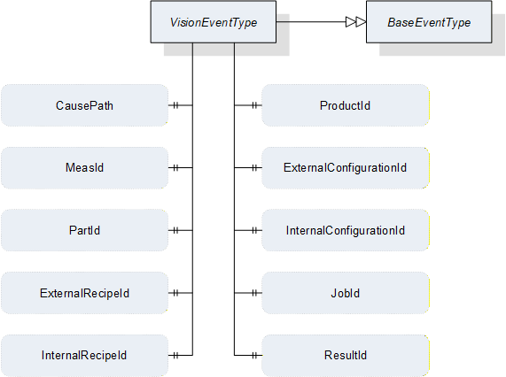
| Attribute | Value | ||||
| BrowseName | VisionEventType | ||||
| IsAbstract | True | ||||
| References | NodeClass | BrowseName | DataType | TypeDefinition | ModellingRule |
|---|---|---|---|---|---|
| Subtype of the BaseEventType defined in OPC 10000-5 | |||||
| HasSubtype | ObjectType | VisionDiagnosticInfoEventType | Defined in 11.4.2 | ||
| HasSubtype | ObjectType | VisionInformationEventType | Defined in 11.4.3 | ||
| HasProperty | Variable | CausePath | String | PropertyType | Optional |
| HasProperty | Variable | MeasId | MeasIdDataType | PropertyType | Optional |
| HasProperty | Variable | PartId | PartIdDataType | PropertyType | Optional |
| HasProperty | Variable | ExternalRecipeId | RecipeIdExternalDataType | PropertyType | Optional |
| HasProperty | Variable | InternalRecipeId | RecipeIdInternalDataType | PropertyType | Optional |
| HasProperty | Variable | ProductId | ProductIdDataType | PropertyType | Optional |
| HasProperty | Variable | ExternalConfigurationId | ConfigurationIdDataType | PropertyType | Optional |
| HasProperty | Variable | InternalConfigurationId | ConfigurationIdDataType | PropertyType | Optional |
| HasProperty | Variable | JobId | JobIdDataType | PropertyType | Optional |
| HasProperty | Variable | ResultId | ResultIdDataType | PropertyType | Optional |
11.4.1.2 Usage of inherited properties
The following properties are inherited from BaseEventType and shall be used in VisionEventType in the manner described here.
SourceNode
Reference to the source of the Message. This could be a failing method or, in case of an internally triggered message, the state machine object itself.
SourceName
Name of the Message source.
Severity
Severity of the Information within the boundaries defined by Table 128.
Message
A textual description of the error as a string.
11.4.1.3 Usage of additional properties
The following describes the usage of the properties added by VisionEventType with respect to BaseEventType.
CausePath
Path information string based on the E10 scheme described in 11.6 or an application specific expanded derivation of that.
MeasId, PartId, ExternalRecipeId, InternalRecipeId, ProductId, ExternalConfigurationId, InternalConfigurationId, JobId, ResultId
If the information is somehow linked to one of the (vision system) objects referenced by these Ids, these properties can transport this reference.
11.4.2 VisionDiagnosticInfoEventType
VisionDiagnosticInfoEvents are generated to signal events of the lowest severity class as described in Section 11.3.2.
The EventType for VisionDiagnosticInfoEvents is formally defined in Table 130.
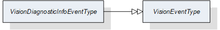
| Attribute | Value | ||||
| BrowseName | VisionDiagnosticInfoEventType | ||||
| IsAbstract | False | ||||
| References | NodeClass | BrowseName | DataType | TypeDefinition | ModellingRule |
|---|---|---|---|---|---|
| Subtype of the VisionEventType | |||||
11.4.3 VisionInformationEventType
VisionInformationEvents are generated to signal events of low severity class as described in Section 11.3.3.
The EventType for VisionInformationEvents is formally defined in Table 131.

| Attribute | Value | ||||
| BrowseName | VisionInformationEventType | ||||
| IsAbstract | False | ||||
| References | NodeClass | BrowseName | DataType | TypeDefinition | ModellingRule |
|---|---|---|---|---|---|
| Subtype of the VisionEventType | |||||
11.4.4 VisionConditionType
11.4.4.1 Overview
VisionConditions are generated to signal important events during the operation of the vision system which require interaction, i.e. conditions.
All non-inherited properties are optional and stay optional on the concrete sub-types because these ConditionTypes will be used under very different operational circumstances in the vision system; it is therefore not possible to specify that, e.g. a jobId shall be mandatory, since an error condition may be triggered during the preparation of a recipe, when no job is running.
However, the intention is for the server to provide as much information to the client as possible, i.e. fill as many properties as possible.
The EventType for VisionConditions is formally defined in Table 132.
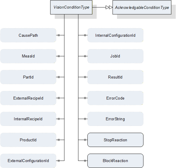
| Attribute | Value | |||||
| BrowseName | VisionConditionType | |||||
| IsAbstract | True | |||||
| References | NodeClass | BrowseName | DataType | TypeDefinition | ModellingRule | |
|---|---|---|---|---|---|---|
| Subtype of the AcknowledgeableConditionType defined in OPC 10000-9 | ||||||
| HasSubtype | ObjectType | VisionWarningConditionType | Defined in 11.4.5 | |||
| HasSubtype | ObjectType | VisionErrorConditionType | Defined in 11.4.6 | |||
| HasSubtype | ObjectType | VisionPersistentErrorConditionType | Defined in 11.4.7 | |||
| HasProperty | Variable | CausePath | String | PropertyType | Optional | |
| HasProperty | Variable | MeasId | MeasIdDataType | PropertyType | Optional | |
| HasProperty | Variable | PartId | PartIdDataType | PropertyType | Optional | |
| HasProperty | Variable | ExternalRecipeId | RecipeIdExternalDataType | PropertyType | Optional | |
| HasProperty | Variable | InternalRecipeId | RecipeIdInternalDataType | PropertyType | Optional | |
| HasProperty | Variable | ProductId | ProductIdDataType | PropertyType | Optional | |
| HasProperty | Variable | ExternalConfigurationId | ConfigurationIdDataType | PropertyType | Optional | |
| HasProperty | Variable | InternalConfigurationId | ConfigurationIdDataType | PropertyType | Optional | |
| HasProperty | Variable | JobId | JobIdDataType | PropertyType | Optional | |
| HasProperty | Variable | ResultId | ResultIdDataType | PropertyType | Optional | |
| HasProperty | Variable | ErrorCode | UInt64 | PropertyType | Optional | |
| HasProperty | Variable | ErrorString | String | PropertyType | Optional | |
| HasProperty | Variable | StopReaction | Boolean | PropertyType | Mandatory | |
| HasProperty | Variable | BlockReaction | Boolean | PropertyType | Mandatory | |
11.4.4.2 Usage of properties in common with VisionEventType
The properties which VisionConditionType has in common with VisionEventType have the same semantics and usage as described in Sections 11.4.1.2 and 11.4.1.3..
11.4.4.3 Usage of additional properties
The following describes the usage of the properties added by VisionConditionType with respect to AcknowledgeableConditionType.
ErrorString
A system specific string classifying the error / warning.
ErrorCode
A system specific numeric code classifying the error / warning.
StopReaction
If the system did stop normal operation because of this error (state machine did transit to error state) this property shall be set to true.
BlockReaction
If the system did stop normal operation and user interaction is needed because of this error this property shall be set to true.
11.4.5 VisionWarningConditionType
The VisionWarningConditionType is used to represent conditions in the vision system which the client should be warned about as described in Section 11.3.4.
The server can use the AckedState and ConfirmedState variables of the AcknowledgeableConditionType to control whether the vision system requires acknowledgement and confirmation of the condition as described in OPC 10000-9.
The VisionWarningConditionType is formally defined in Table 133.

| Attribute | Value | ||||
| BrowseName | VisionWarningConditionType | ||||
| IsAbstract | False | ||||
| References | NodeClass | BrowseName | DataType | TypeDefinition | ModellingRule |
|---|---|---|---|---|---|
| Subtype of the VisionConditionType | |||||
11.4.6 VisionErrorConditionType
The VisionErrorConditionType is used to represent error conditions in the vision system as described in Section 11.3.5.
The server can use the AckedState and ConfirmedState variables of the AcknowledgeableConditionType to control whether the vision system requires acknowledgement and confirmation of the condition as described in OPC 10000-9.
The VisionErrorConditionType is formally defined in Table 134.

| Attribute | Value | ||||
| BrowseName | VisionErrorConditionType | ||||
| IsAbstract | False | ||||
| References | NodeClass | BrowseName | DataType | TypeDefinition | ModellingRule |
|---|---|---|---|---|---|
| Subtype of the VisionConditionType | |||||
11.4.7 VisionPersistentErrorConditionType
The VisionPersistentErrorConditionType is used to represent error conditions in the vision system requiring outside interaction as described in Section 11.3.6.
The server can use the AckedState and ConfirmedState variables of the AcknowledgeableConditionType to control whether the vision system requires acknowledgement and confirmation of the condition as described in OPC 10000-9.
The VisionPersistentErrorConditionType is formally defined in Table 135.
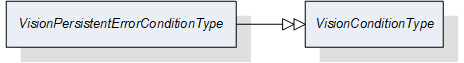
| Attribute | Value | ||||
| BrowseName | VisionPersistentErrorConditionType | ||||
| IsAbstract | False | ||||
| References | NodeClass | BrowseName | DataType | TypeDefinition | ModellingRule |
|---|---|---|---|---|---|
| Subtype of the VisionConditionType | |||||
11.4.8 VisionSafetyEventType
VisionSafetyEventType is an EventType subtype of BaseEventType, defined in OPC 10000-5. This event is to be triggered by the server when a safety-related incident occurs in the vision system. The structure is defined in Figure 45. It is formally defined in Table 136.
Event properties
VisionSafetyTrigger: flag indicating the current internal safety state
VisionSafetyInformation: information about the internal safety state provided by the vision system
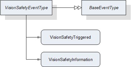
| Attribute | Value | ||||
| BrowseName | VisionSafetyEventType | ||||
| IsAbstract | False | ||||
| References | NodeClass | BrowseName | DataType | TypeDefinition | ModellingRule |
|---|---|---|---|---|---|
| Subtype of the BaseEventType defined in OPC 10000-5 | |||||
| HasProperty | Variable | VisionSafetyTriggered | Boolean | PropertyType | Mandatory |
| HasProperty | Variable | VisionSafetyInformation | String | PropertyType | Mandatory |
11.5 Interaction between Messages, State Machine, and Vision System
There is only a loose connection between the generation of messages and the exposed behavior of the vision system on the state machine level. The following mandatory behavior is defined:
As the OPC UA interface only offers a view to the underlying vision system each call of the defined methods may fail. The method may deliver some information on the cause of the fail, but this information is only visible for the client calling the method. If any other clients are interested in this kind of information there is no way for them to get it. Therefore we define that if a method call fails the vision system has to generate a message at least of the warning without acknowledgement type naming the failed method including the calling parameters.
As the definition of the vision system is out of the scope of this document this is also true for the detection of error states within the vision system. As a consequence of this the generation of messages signaling such conditions is not associated to a specific state of the state machine.
As a general rule the transition to the error state of the state machine should only be performed if this is inevitable for the operation. The creation of an error message does not require that the state machine transitions to the Error state. A problem may be detected in a part of the vision system that is not needed for the current task at hand. Only if in this situation a method is called that can't be performed because of this problem a transition to the Error state should occur.
On the other hand if the state machine does a transition to the Error state it is mandatory that a message of the error type or higher severity describing the cause is generated or already active.
It is up to the vision system to define if an internal error condition can be resolved immediately or if it has to wait for external acknowledgement / confirmation before trying to do so. Even if the system is successful in clearing the condition internally it has to wait for the reception of the acknowledgement of the corresponding message object if this is of an acknowledgeable type, before the message is cleared.
Application Note:
As the reception of an acknowledgement / confirmation can only take place once for each message object on the interface the vision system after reception has to check if the error condition is / can be resolved. If it is unable to resolve the error and interaction of the client / user side is required for resolving, it has to clear the message and create a new one to start a new resolving cycle.
Example:
During normal operation a vision system detects that it cannot accept a new job because the camera lens is dirty. It generates an error message informing the client on this with Ack and Conf required.
The client acknowledges the message and shows a message box on its console asking the operator to clean the lens.
The Operator presses the confirmation button without reading the message.
The client sends the confirmation for the message.
After reception of confirmation the vision System takes a test image and detects that the lens is still dirty. As there is still the need for user interaction the vision system has to decide what to do.
If it does nothing the client still sees the confirmed error message and therefore knows that it was not resolved. But as there are no additional confirmation options for the client the vision system will never get informed that if it may continue.
Therefore the vision system clears the confirmed message and creates a new one to start a new cleaning request with a hopefully better result.
The generation of large amounts of diagnostic messages may have impact on the performance of the vision system. As an OPC UA client can decide on its own if he reads such messages this is only a problem on the server side. It is common practice that the generation of such debugging / diagnostic messages can be suppressed within the vision System software. The server shall expose the information on suppressing of such messages in the following way. An integer variable DiagnosticLevel with a valid range between 1 … 200 is published showing that all diagnostic messages with a severity level lower or equal to this value are suppressed. Optionally this variable may be defined to be client writable to set a desired diagnostic level externally. For values lower than 150 it is not mandatory that the vision System is capable of upholding the performance expected for the application. The initial value of this variable on system start should be 200.
Application Note:
Example of a failing method call
Let's assume the vision system is in the Ready state with an activated recipe in its memory. A client can call the PrepareRecipe method to load a second recipe but with a wrong recipe name that is not present in the vision system.
The method call will fail with an error message informing the calling client that this is a unknown recipe.
The vision system issues a warning message with a severity of e.g. 503 containing the information that a call of the PrepareRecipe method for that Recipe name failed.
The vision system does not transit to the Error state as there is no need to do so, since normal operation is not compromised at the moment. The vision system is able to accept jobs using the already activated recipe.
If the client now calls the StartSingleJob method with the unknown recipe the vision system could consider this an error and transition to the Error state while issuing a message of the error class. This decision is application specific. It is also valid that it only lets the method call fail and issues a warning message without transition to the Error state.
An external recipe management system could receive such a warning message and push the missing recipe to the vision system using the AddRecipe method.
11.6 Structuring of Vision System State information
11.6.1 Overview
System state information is often used to benchmark the reliability of a system. Therefore on a time scale it is estimated how long the system was productive, defective or in maintenance. To support this, a system should be able to publish its current state in a way enabling a client to do such estimation.
This standard follows the scheme of 6 basic system states defined by SEMI E10 standard (SEMI E10: Specification for Definition and Measurement of Equipment Reliability, Availability, and Maintainability (RAM) and Utilization). The following diagram shows how the total time of existence of a system is divided into different categories. From the left to the right the model gets more detailed.
| E10 | |||||
| Total Time | Operations Time | Uptime | Manufacturing Time | Production | PRD |
| Standby | SBY | ||||
| Engineering | ENG | ||||
| Downtime | Scheduled Downtime | SDT | |||
| Unscheduled Downtime | UDT | ||||
| Nonscheduled Time | NST | ||||
If the optional SystemState variable exists on the server, the vision system shall continuously map its internal state to one of the six generic states on the right. This current state shall be published in the SystemState variable in the interface.
11.6.2 Production (PRD)
The vision system is currently working on a job.
11.6.3 Standby (SBY)
The vision system is ready to accept a command but is currently not executing a job. It could for example be waiting for a Start command or a user input.
11.6.4 Engineering (ENG)
The vision system is not working and not ready to accept a command because a user is currently working on the system. This could be for editing a recipe or changing the system configuration.
11.6.5 Scheduled Downtime (SDT)
The vision system is not available for production and this was planned in advance. This could be for cleaning, maintenance or calibration works.
11.6.6 Unscheduled Downtime (UDT)
The vision system is not available for production due to failure and repair. This covers all kinds of error states that might occur during operation.
11.6.7 Nonscheduled Time (NST)
The vision system is not working because no production was scheduled. This also covers things like operator training on the system.
Example:
An application specific extension of the base states:
| E10 | vendor / application specific extension | |
| PRD | Acquisition | ACQ CAM A |
| ACQ CAM B | ||
| Processing | ||
| SBY | Waiting for PREPARE | |
| Waiting for START | ||
| ENG | Recipe Editing | |
| Calibration | ||
| SDT | Maintenance | |
| Cleaning | Optics A | |
| Optics B | ||
| UDT | Software Related Error | |
| Hardware Related Error | ||
| NST | Powered Off | |
| Operator Training | ||
If the system is in state "ACQ CAM A" the current path would be
"PRD/Acquisition/ACQ CAM A"
The tree-like E10 scheme may be extended to the right by getting more specific on the current state of action the system is performing. As in the original E10 scheme, at every time the system has to choose exactly one state (rightmost field of a branch) it is currently in. To be compatible to clients understanding only the basic E10 states the system has to give the "/" separated path running along the branch of that tree starting from the base E10 state to the current state.
The same scheme should be used to structure error states. Every error information carries such path information to enable generic clients without deeper application knowledge to get a basic understanding of the possible error cause. The following basic error paths shall be used. As above this model may be expanded to the right as needed.
| UDT | Software Related Error | |
| Hardware Related Error | Computing Unit | |
| Sensor Unit | ||
| Controller Unit | ||
| Lighting Unit |
The system can only be in one specific state (leaf of the tree), although errors can occur in more than one leaf simultaneously. In this case the system still has to select exactly one system state to be published.
There are two different approaches possible:
The system selects the most severe error and publishes its path as the current system state.
The system truncates the path to the last element common for all active errors.
The system may select one approach fitting to the current application.
Example:
A system is in an Error State and there are currently two errors active. The system uses application specific extended error classes:
UDT/Hardware Related Error/ Sensor Unit/Camera A/Fan Fail
UDT/Hardware Related Error/Lighting Unit/LED A/Over Temperature
Possibility 1:
The system decides that an over temperature is the most severe error and publishes "UDT/Hardware Related Error/Lighting Unit/LED A/Over Temperature" as its system state.
Possibility 2:
The system publishes the truncated path "UDT/Hardware Related Error" as its current system state.
12 DataTypes for the Vision System
12.1 Handle
This Simple Data Type defines a UInt32 representing a handle to a collection of data managed by the server.
12.2 TrimmedString
This Simple Data Type defines a String with no leading or trailing whitespace, where whitespace means the Unicode characters defined as whitespace ("WSpace=Y", "WS") in the Unicode database.
Where a TrimmedString is specified as input argument to a method and the incoming string contains leading or trailing whitespace, the server is entitled to react with an error (Bad_TypeMismatch) or - preferably - silently trim the string internally before processing it.
12.3 TriStateBooleanDataType
This DataType is an enumeration that identifies the filtering of particular properties in requests for lists of results, recipes etc. Its values are defined in Table 139.
| Value | Description |
| FALSE_0 | The filtering function shall look for entities where the filtered value is FALSE. |
| TRUE_1 | The filtering function shall look for entities where the filtered value is TRUE. |
| DONTCARE_2 | The filtering function shall not take the value into account. |
12.4 ProcessingTimesDataType
This structure contains measured times that were generated during the execution of a recipe. These measured values provide information about the duration required by the various sub-functions.
| Name | Type | Description | O / M |
| ProcessingTimesDataType | structure | ||
| startTime | UtcTime | Contains the time when the vision system started execution of the recipe. | Mandatory |
| endTime | UtcTime | Contains the time when the vision system finished (or stopped/aborted) execution of the recipe. | Mandatory |
| acquisitionDuration | Duration | Time spent by the vision system acquiring images | Optional |
| processingDuration | Duration | Time spent by the vision system processing data | Optional |
12.5 MeasIdDataType
This structure is used by the client to pass an identification of the measurement to be carried out in a Start method. It is typically not changed by the server and is included in the meta data for identifying a result.
In its basic version here, the MeasIdDataType contains only a TrimmedString. It has been encapsulated in a structure for the purpose of easy sub-typing if more sophisticated identification is required.
A basic MeasIdDataType structure is considered empty when the id member has length 0. For sub-types of MeasIdDataType additional rules may apply., i.e., they shall always be considered empty, when the Id member has length 0, and may also be considered empty when other structure members fulfill particular conditions.
| Name | Type | Description | O / M |
| MeasIdDataType | structure | ||
| id | TrimmedString | Id is an identifier/name for identifying the measurement operation. This identifier is passed by the client to the vision system so no assumptions can be made about its uniqueness or other properties. | Mandatory |
| description | LocalizedText | Optional short human readable description of the measurement. | Optional |
12.6 PartIdDataType
This structure defines the identification of a part, i.e. a Unit Under Test. It is formally defined in Table 142.
PartId structures can be passed by the client with a Start method call and should be stored by he server in results pertaining to that part. Thus they describe the connection between a unit under test and a result, which was created during the processing of a recipe applied on this unit under test.
In its basic version here, the PartIdDataType contains only a TrimmedString. It has been encapsulated in a structure for the purpose of easy sub-typing if more sophisticated identification is required, e.g. including a batch or carrier Id.
A basic PartIdDataType structure is considered empty when the id member has length 0. For sub-types of PartIdDataType this can be defined differently.
| Name | Type | Description | O / M |
| PartIdDataType | structure | ||
| id | TrimmedString | Describes the connection between a unit under test and a result, which was created during the processing of a recipe applied on this unit under test. Usually passed by the client with a Start method call and not changed by the server. | Mandatory |
| description | LocalizedText | Optional short human readable description of the part. | Optional |
12.7 JobIdDataType
This structure is used to pass an identification of the measurement to be carried out following a Start method call. It is typically included in the meta data for identifying a result.
In its basic version here, the JobIdDataType contains only a TrimmedString. It has been encapsulated in a structure for the purpose of easy sub-typing if more sophisticated identification is required.
A basic JobIdDataType structure is considered empty when the id member has length 0. For sub-types of JobIdDataType additional rules may apply, i.e. they shall always be considered empty, when the Id member has length 0, and may also be considered empty when other structure members fulfill particular conditions.
| Name | Type | Description | O / M |
| JobIdDataType | structure | ||
| id | TrimmedString | Id is a system-wide unique identifier/name for identifying the job carried out. | Mandatory |
12.8 BinaryIdBaseDataType
This abstract DataType is the base data type for identifying binary data internally and externally. Its subtypes are used in objects of RecipeType which is defined in Section 7.7., of ConfigurationDataType which is defined in Section 12.12 and also in results. It is formally defined in Table 144.
The main rationale for introducing a base type and several (identical) subtypes is to facilitate a type-safe enforcing of the distinction between external and internal Ids in method arguments.
| Name | Type | Description | O / M |
| BinaryIdBaseDataType | structure | ||
| Id | TrimmedString | Id is a system-wide unique name for identifying the binary data. | Mandatory |
| Version | TrimmedString | Represents an optional version number of the identified binary data. It is recommended to be of the format Major.minor.patch.build or a subset thereof, but the actual format is implementation defined. | Optional |
| hash | ByteString | Represents an optional hash of the binary content of the actual data (as it would be transmitted by the transfer methods). The hash is supposed to be provided by the environment if existing. The environment shall use the same hash function on all binary data so that a difference in the hash indicates a difference in the binary data. It is recommended to use the SHA-256 algorithm for computing the hash, however, the actual algorithm is implementation-defined. | Optional |
| hashAlgorithm | String | Name of the hash function used. Required if internally and externally computed hashes are to be compared | Optional |
| description | LocalizedText | Optional short human readable description of the configuration | Optional |
12.9 RecipeIdExternalDataType
This structure is used for the external identification of recipes. It is identical to BinaryIdBaseDataType described in Section 12.8 except that it is not abstract.
12.10 RecipeIdInternalDataType
This structure is used for the internal identification of recipes. It is identical to BinaryIdBaseDataType described in Section 12.8 except that it is not abstract.
12.11 RecipeTransferOptions
This structure contains elements to control the transfer of the actual content of a vision system recipe by TemporaryFileTransfer using the GenerateFileForRead and GenerateFileForWrite methods of the RecipeTransferType ObjectType defined in Section 7.6. The structure is formally defined in Table 145Table 147.
| Name | Type | Description | O / M |
| RecipeTransferOptions | structure | ||
| internalId | RecipeIdInternalDataType | The InternalId of the recipe to be transferred to or from the client. | Mandatory |
If RecipeTransferOptions are used in connection with AddRecipe method, the InternalId returned by AddRecipe is to be used for generating the transfer file to have an unambiguous identification.
12.12 ConfigurationDataType
This structure is used to manage one external configuration. It has no knowledge of the internal structure of an external configuration. The actual configuration used by the machine vision system is a system-specific structure, which may be transferred using a TemporaryFileTransfer.
| Name | Type | Description | O / M |
| ConfigurationDataType | structure | ||
| hasTransferableDataOnFile | Boolean | Indicates that actual content of the configuration may be transferred through temporary file transfer method. | Optional |
| externalId | ConfigurationIdDataType | Identification of the configuration used by the environment. This argument must not be empty. | Optional |
| internalId | ConfigurationIdDataType | System-wide unique ID for identifying a configuration. This ID is assigned by the vision system. | Mandatory |
| lastModified | UtcTime | The time and date when this configuration was last modified. | Mandatory |
12.13 ConfigurationIdDataType
This structure is used for the identification of an object of ConfigurationDataType which is defined in Section 12.12. It is identical to BinaryIdBaseDataType described in Section 12.8 except that it is not abstract.
12.14 ConfigurationTransferOptions
This structure contains elements to control the transfer of the actual content of a vision system configuration by TemporaryFileTransfer using the GenerateFileForRead and GenerateFileForWrite methods of the ConfigurationTransferType ObjectType defined in Section 7.4. The structure is formally defined in Table 147.
| Name | Type | Description | O / M |
| ConfigurationTransferOptions | structure | ||
| internalId | ConfigurationIdDataType | The Id of the configuration to be transferred to or from the client. | Mandatory |
12.15 ProductDataType
This structure is used to reference one product known to the vision system. It has no knowledge of the actual manner of managing a product in the vision system, it merely signals that the vision system has knowledge of said product.
| Name | Type | Description | O / M |
| ProductDataType | Structure | ||
| externalId | ProductIdDataType | Identification of the product used by the environment. This argument must not be empty. | Mandatory |
12.16 ProductIdDataType
This structure is used for identifying an object of ProductDataType.
In its basic version here, the ProductIdDataType contains only a TrimmedString. It has been encapsulated in a structure for the purpose of easy sub-typing if more sophisticated identification is required.
A basic ProductIdDataType structure is considered empty when the id member has length 0. For sub-types of ProductIdDataType additional rules may apply. , i.e., they shall always be considered empty, when the Id member has length 0, and may also be considered empty when other structure members fulfill particular conditions.
| Name | Type | Description | O / M |
| ProductIdDataType | structure | ||
| id | TrimmedString | Id is a system-wide unique identifier/name for identifying the product. | Mandatory |
| description | LocalizedText | Optional short human readable description of the configuration | Optional |
12.17 ResultDataType
This structure contains properties that were created during the execution of a recipe. The Id is required to retrieve a result using the method GetResultById, which is defined in Section 7.10.2.1. A result may be a total or a partial result, which is defined by the value of the property IsPartial. The structure of the ResultContent which is generated by the vision system is application-specific and not defined at this time.
Note that this DataType contains nested structures, namely the Id types. If these are subtyped, the entire structure needs to be sub-typed also so that the client can recognize that fact.
| Name | Type | Description | O / M |
| ResultDataType | Structure | ||
| resultId | ResultIdDataType | System-wide unique identifier, which is assigned by the system. This ID can be used for fetching exactly this result using the methods detailed in Section 7.10.2 and it is identical to the ResultId of the ResultReadyEventType defined in Section8.3.8.4. | Mandatory |
| hasTransferableDataOnFile | Boolean | Indicates that additional data for this result can be retrieved by temporary file transfer | Optional |
| isPartial | Boolean | Indicates whether the result is the partial result of a total result. | Mandatory |
| isSimulated | Boolean | Indicates whether the system was in simulation mode when the result was created. | Optional |
| resultState | ResultStateDataType | ResultState provides information about the current state of a result and the ResultStateDataType is defined in Section 12.18. | Mandatory |
| measId | MeasIdDataType | This identifier is given by the client when starting asingle or continuous execution and transmitted to the vision system. It is used to identify the respective result data generated for this job. Although the system-wide unique JobId would be sufficient to identify the jobwhich the result belongs to, this makes for easier filtering on the part of the client without keeping track of JobIds. | Optional |
| partId | PartIdDataType | A PartId is given by the client when starting the job; although the system-wide unique JobId would be sufficient to identify the job which the result belongs to, this makes for easier filtering on the part of the client without keeping track of JobIds. | Optional |
| externalRecipeId | RecipeIdExternalDataType | External Id of the recipe in use which produced the result. The ExternalID is only managed by the environment. | Optional |
| internalRecipeId | RecipeIdInternalDataType | Internal Id of the recipe in use which produced the result. This ID is system-wide unique and it is assigned by the vision system. | Mandatory |
| productId | ProductIdDataType | productId which was used to trigger the job which created the result. | Optional |
| externalConfigurationId | ConfigurationIdDataType | External Id of the configuration in use while the result was produced. | Optional |
| internalConfigurationId | ConfigurationIdDataType | Internal Id of the configuration in use while the result was produced. This ID is system-wide unique and it is assigned by the vision system. | Mandatory |
| jobId | JobIdDataType | The ID of the job, created by the transition from state Ready to state SingleExecution or to state ContinuousExecution which produced the result. | Mandatory |
| creationTime | UtcTime | CreationTime indicates the time when the result was created. | Mandatory |
| processingTimes | ProcessingTimesDataType | Collection of different processing times that were needed to create the result. | Optional |
| resultContent | BaseDataType[] | Abstract data type to be subtyped from to hold result data created by the selected recipe. | Optional |
12.18 ResultIdDataType
This structure is used to pass an identification of a result generated by an operation of the vision system.
In its basic version here, the ResultIdDataType contains only a TrimmedString. It has been encapsulated in a structure for the purpose of easy sub-typing if more sophisticated identification is required.
A basic ResultIdDataType structure is considered empty when the id member has length 0. For sub-types of ResultIdDataType additional rules may apply, i.e. they shall always be considered empty, when the Id member has length 0, and may also be considered empty when other structure members fulfil particular conditions.
| Name | Type | Description | O / M |
| ResultIdDataType | structure | ||
| Id | TrimmedString | Id is a system-wide unique identifier/name for identifying the generated result. | Mandatory |
12.19 ResultStateDataType
This subtype of Int32 provides information about the current state of a result. This status can change during recipe processing.
It is deliberately not an Enumeration, allowing for system-specific extensions.
| Attribute | Value | ||||
| BrowseName | ResultStateDataType | ||||
| IsAbstract | False | ||||
| References |
Node
Class | BrowseName | DataType | TypeDefinition |
Modelling
Rule |
|---|---|---|---|---|---|
| Subtype of the Int32 DataType defined in OPC 10000-5 | |||||
| Allowed Value | Description |
| < 0 | Application-specific states |
| 0 | Undefined: Initialization value. When returned by access methods of ResultManagementType it indicates an error. |
| 1 | Completed: Processing was carried out correctly. |
| 2 | Processing: Processing has not been finished yet. |
| 3 | Aborted: Processing was stopped at some point before completion. |
| 4 | Failed: Processing failed in some way. |
12.20 ResultTransferOptions
This structure contains elements to control the transfer of the actual content of a vision system result by TemporaryFileTransfer using the GenerateFileForRead method of the ResultTransferType ObjectType defined in Section 7.12. The structure is formally defined in Table 154.
| Name | Type | Description | O / M |
| ResultTransferOptions | structure | ||
| id | ResultIdDataType | The Id of the result to be transferred to the client. | Mandatory |
12.21 SystemStateDataType
This DataType is an enumeration that identifies the pre-defined SEMI E10 states as described in Section 11.6. Its values are defined in Table 155.
| Value | Description |
| PRD_1 | Production: The vision system is currently working on a job. |
| SBY_2 | Stand by: The vision system is ready to accept a command but is currently not executing a job. It could for example be waiting for a Start command or a user input. |
| ENG_3 | Engineering: The vision system is not working and not ready to accept a command because a user is currently working on the system. This could be for editing a recipe or changing the system configuration. |
| SDT_4 | Scheduled downtime: The vision system is not available for production and this was planned in advance. This could be for cleaning, maintenance or calibration works. |
| UDT_5 | Unscheduled downtime: The vision system is not available for production due to failure and repair. This covers all kinds of error states that might occur during operation. |
| NST_6 | Nonscheduled time: The vision system is not working because no production was scheduled. This also covers things like operator training on the system. |
12.22 SystemStateDescriptionDataType
This structure is used to describe the system state as explained in Section 11.6.
| Name | Type | Description | O / M |
| SystemStateDescriptionDataType | Structure | ||
| state | SystemStateDataType | Denotes one of the basic SEMI E10 states | Mandatory |
| stateDescription | TrimmedString | Optional string describing the full state path, starting with the SEMI E10 state denoted by the state member; the string format is described in Section 11.6. | Optional |
13 Profiles and Namespaces
13.1 Namespace Metadata
Table 157 defines the namespace metadata for this specification. The Object is used to provide version information for the namespace and an indication about static Nodes. Static Nodes are identical for all Attributes in all Servers, including the Value Attribute. See OPC 10000-5 for more details.
The information is provided as Object of type NamespaceMetadataType. This Object is a component of the NamespacesObject that is part of the Server Object. The NamespaceMetadataType ObjectType and its Properties are defined in OPC 10000-5.
The version information is also provided as part of the ModelTableEntry in the UANodeSet XML file. The UANodeSet XML schema is defined in OPC 10000-6.
| Attribute | Value | |||
| BrowseName | http://opcfoundation.org/UA/MachineVision | |||
| References | BrowseName | DataType | Value | |
|---|---|---|---|---|
| HasProperty | NamespaceUri | String | http://opcfoundation.org/UA/MachineVision | |
| HasProperty | NamespaceVersion | String | 1.0 | |
| HasProperty | NamespacePublicationDate | DateTime | 2018-06-18 | |
| HasProperty | IsNamespaceSubset | Boolean | False | |
| HasProperty | StaticNodeIdTypes | IdType[] | ||
| HasProperty | StaticNumericNodeIdRange | NumericRange[] | ||
| HasProperty | StaticStringNodeIdPattern | String | ||
13.2 Conformance Units
13.2.1 Overview
This section defines Conformance Units that are specific to the OPC UA Machine Vision Information model. These Conformance Units are separated into Conformance Units that are Server specific and those that are Client specific.
13.2.2 Server
Table 158 defines the server based Conformance Units.
| Category | Title | Description |
| Server | Vision System - Basic Vision System | The VisionSystemType with all mandatory sub nodes is implemented by the server. |
| Server | Vision System - Basic Result Management | The Result Management node with all mandatory sub nodes is implemented by the server. |
| Server | Vision System - Basic Configuration Management | The ConfigurationManagement node with all mandatory sub nodes is implemented by the server. |
| Server | Vision System - Basic Recipe Management | The RecipeManagement node with all mandatory sub nodes is implemented by the server. |
| Server | Vision System - Safety State Management | The SafetyStateManagement node is implemented and VisionSafetyEvents are generated by the server. |
| Server | Vision System - System State Information | The SystemState node is implemented and used by the server to publish its current state. |
| Server | Vision System - Diagnostic Events | The DiagnosticLevel node is implemented, used by the server to publish the current diagnostic level, and can be written by the Client to set the current diagnostic level. VisionDiagnosticInfoEvents are generated by the server. |
| Server | Vision System - Information Events | VisionInformationEvents are generated by the server. |
| Server | Vision System - Error Conditions | VisionWarningConditions , VisionErrorConditions and VisionPersistentErrorConditions are generated by the server. |
| Server | Vision State Machine - Automatic Mode | The AutomaticModeStateMachine node with all mandatory sub nodes and the SelectModeAutomatic method are implemented by the server. |
| Server | Vision State Machine - Easy Confirmation | The ConfirmAll method is implemented by the server. |
| Server | Vision State Machine - Error Events | ErrorEvents and ErrorResolvedEvents are generated by the server. |
| Server | Vision State Machine - StepModel Preoperational | The PreoperationalStepModel state machine is implemented by the server. |
| Server | Vision State Machine - StepModel Halted | The HaltedStepModel state machine is implemented by the server. |
| Server | Vision State Machine - StepModel Error | The ErrorStepModel state machine is implemented by the server. |
| Server | Automatic Mode - Simulation | The SimulationMode method is implemented by the server. The isSimulated sub nodes of ResultReadyEvents, ResultDataType and ResultType are implemented and reflect the state of the simulation mode during creation of the job generaring this result; likewise, the isSimulated output arguments of methods GetResultComponentsById and GetResultById reflect this state. |
| Server | Automatic Mode - StepModel Initialized | The InitializedStepModel state machine is implemented by the server. |
| Server | Automatic Mode - StepModel Ready | The ReadyStepModel state machine is implemented by the server. |
| Server | Automatic Mode - StepModel SingleExecution | The SingleExecutionStepModel state machine is implemented by the server. |
| Server | Automatic Mode - StepModel ContinuousExecution | The ContinuousExecutionStepModel state machine is implemented by the server. |
| Server | Meta Data Handling - Measurement ID | The measId argument of methods StartSingleJob and StartContinuous is associated to the jobs started by calling these methods. Results arising from these jobs include the given MeasId. Therefore the server implements the MeasId sub node of all occurrences of ResultDataType and ResultType as well as within ResultReadyEvents, and returns it in the output argument of methods GetResultComponentsById and GetResultById as well as observing it in the input argument of method GetResultListFiltered. The server may additionally implement the MeasId sub node of VisionDiagnosticInfoEvents, VisionInformationEvents, VisionWarningConditions, VisionErrorConditions and VisionPersistentErrorConditions. |
| Server | Meta Data Handling - Part ID | The partId argument of methods StartSingleJob and StartContinuous is associated to the jobs started by calling these methods. Results arising from these jobs include the PartId. Therefore the server implements the PartId sub node of all occurrences of the ResultDataType and ResultType as well as within ResultReadyEvents, and returns it in the output argument of methods GetResultComponentsById and GetResultById as well as observing it in the input argument of method GetResultListFiltered method. The server may additionally implement the PartId sub node of VisionDiagnosticInfoEvents, VisionInformationEvents, VisionWarningConditions, VisionErrorConditions and VisionPersistentErrorConditions |
| Server | Meta Data Handling - Recipe ID External | The externalRecipeId argument of methods StartSingleJob and StartContinuous is associated to the jobs started by calling these methods. All results arising from these jobs include the ExternalRecipeId. Therefore the server implements the ExternalRecipeId sub node of all occurrences of the ResultDataType and ResultType as well as within ResultReadyEvents, and returns it in the output argument of methods GetResultComponentsById and GetResultById as well as observing it in the input argument of method GetResultListFiltered. The server may additionally implement the ExternalRecipeId sub node of VisionDiagnosticInfoEvents, VisionInformationEvents, VisionWarningConditions, VisionErrorConditions and VisionPersistentErrorConditions |
| Server | Meta Data Handling - Recipe Versioning | To enforce the uniqueness of recipe IDs, the server implements the calculation and comparison of hash values of the binary object representing a recipe. All occurrences of the RecipeIdExternalDataType and RecipeIdInternalDataType implement the sub nodes version, hash and hashAlgorithm. |
| Server | Meta Data Handling - Product ID | The productId argument of methods StartSingleJob and StartContinuous is associated to the jobs started by calling these methods. All results arising from these jobs include the ProductId. Therefore the server implements the ProductId sub node of all occurrences of the ResultDataType, ResultType and RecipeType as well as within ResultReadyEvents, and returns it in the output argument of methods GetResultComponentsById and GetResultById as well as observing it in the intput argument of method GetResultListFiltered. The server may additionally implement the ProductId sub node of VisionDiagnosticInfoEvents, VisionInformationEvents, VisionWarningConditions, VisionErrorConditions and VisionPersistentErrorConditions |
| Server | Meta Data Handling - Configuration ID External | The externalConfigurationId argument of methods StartSingleJob and StartContinuous is associated to the jobs started by calling these methods. All results arising from these jobs include the ExternalConfigurationId. Therefore the server implements the ExternalConfigurationId sub node of all occurrences of the ResultDataType and ResultType as well as within ResultReadyEvents, and returns it in the output argument of methods GetResultComponentsById and GetResultById as well as observing it in the intput argument of method GetResultListFiltered. The server may additionally implement the ExternalConfigurationId sub node of VisionDiagnosticInfoEvents, VisionInformationEvents, VisionWarningConditions, VisionErrorConditions and VisionPersistentErrorConditions |
| Server | Meta Data Handling - Configuration Versioning | To enforce the uniqueness of configuration IDs, the server implements the calculation and comparison of hash values of the binary object representing a configuration. All occurrences of the ConfigurationIdDataType implement the sub nodes version, hash and hashAlgorithm. |
| Server | Meta Data Handling - Processing Times | The server implements the logging of the start and end times of a job and associates these with the results of this job. Therefore the server implements the processingTimes sub node of all occurrences of the ResultDataType and ResultType as well as within ResultReadyEvents, and returns it in the output argument of methods GetResultComponentsById and GetResultById(). |
| Server | Meta Data Handling - Processing Times Extended | The server implements the logging of the start and end times of a job as well as the determination of the duration of acquisition and processing and associates these with the results of this job. Therefore the server implements the processingTimes sub node of all occurrences of the ResultDataType and ResultType as well as within ResultReadyEvents, and returns it in the output argument of methods GetResultComponentsById and GetResultById. |
| Server | Result Handling - Event Based Content | The server provides full or partial result content as sub node of ResultReadyEvents and provides a means for the client to interpret the application-specific structure of this node. |
| Server | Result Handling - Method Based Content | The server provides full or partial result content in the output argument of methods GetResultComponentsById GetResultById and provides a means for the client to interpret the application-specific structure of this argument. |
| Server | Result Handling - Result File | The server implements the ResultTransfer node to offer additional result content as a downloadable file. It implements the HasTransferableDataOnFile node within all occurrences of ResultDataType and ResultType and provides information about the existence of such content in these nodes and in the output argument of methods GetResultComponentsById and GetResultById. |
| Server | Result Handling - Result Folder | The server provides meta data and full or partial result content by implementing the Results folder node. |
| Server | Configuration Handling - Configuration File | The server allows upload and download of configuration objects. Therefore it implements the ConfigurationTransfer node as well as the AddConfiguration and RemoveConfiguration methods. Additionally it signals the availability of a local configuration object by using the hasTransferableDataOnFile node within all occurrences of the ConfigurationDataType. |
| Server | Configuration Handling - Configuration Folder | The server provides meta data on local configuration objects by implementing the Configurations folder node. |
| Server | Recipe Handling - Recipe File | The server allows upload and download of recipe objects. Therefore it implements the RecipeTransfer node as well as the AddRecipe and RemoveRecipe methods. Additionally it signals the availability of a local recipe object by using the Handle node within all occurrences of the RecipeType. |
| Server | Recipe Handling - Recipe Folder | The server provides meta data on local recipe objects by implementing the Recipes folder node. Additionally it returns the node id of the recipe object created in the folder by an AddRecipe method call. |
| Server | Recipe Handling - Product Folder | The server provides meta data on local product objects by implementing the Products folder node. Additionally it returns the node id of the product object created in the folder by an AddRecipe method call. |
13.2.3 Client
Table x defines the Client based Conformance Units.
| Category | Title | Description |
| Client | Vision System - System State Information Client | The Client is capable of monitoring the SystemState node if existing in the server including optional items. |
| Client | Vision System - Diagnostic Events Client | The Client is capable of reading and writing the DiagnosticLevel node if existing in the server and to monitor VisionDiagnosticInfoEvents generated by the server, including all possibly existing data elements of the events. |
| Client | Vision System - Information Events Client | The Client is capable of monitoring VisionInformationEvents generated by the server, including all possibly existing data elements of the events. |
| Client | Vision System - Error Conditions Client | The Client is capable of monitoring, acknowledging and confirming VisionWarningConditions, VisionErrorConditions and VisionPersistentErrorConditions generated by the server, including all possibly existing data elements of the conditions. |
| Client | Vision State Machine - State Machine Monitoring | The Client is capable of monitoring state and transitions of the mandatory VisionStateMachine. |
| Client | Vision State Machine - State Machine Events Monitoring | The Client is capable of monitoring the events generated by the mandatory VisionStateMachine. |
| Client | Vision State Machine - State Machine Control | The Client is capable of controlling the mandatory VisionStateMachine by calling its methods. |
| Client | Vision State Machine - StepModel Monitoring | The Client is capable of detecting the existence of StepModel state machines inside any state of any state machine in the server and monitor their states and transitions. |
| Client | Vision State Machine - StepModel Events Monitoring | The Client is capable of monitoring events generated by an active StepModel state machine in the server. |
| Client | Vision State Machine - StepModel Control | The Client is capable of controlling any StepModel state machine existing in the server by calling its Sync method. |
| Client | Vision Automatic Mode - Automatic Mode Selection | The Client is capable of calling the SelectAutomaticMode method and monitor the success of entering the VisionAutomaticModeStateMachine. |
| Client | Vision Automatic Mode - Safety Information Client | The Client is capable of monitoring VisionSafetyEvents and the SafetyStateManagement node and is capable of reporting safety information by using the ReportSafetyState method. |
| Client | Vision Automatic Mode - Easy Confirmation Client | The Client can call the ConfirmAll method if implemented by the server. |
| Client | Vision Automatic Mode - Simulation Mode Control | The Client is capable of calling the SimulationMode method. If the client processes vision system results, it takes appropriate action based on the value of the isSimulated flag included with the results. |
| Client | Vision Automatic Mode- Automatic Mode Monitoring | The Client is capable of monitoring state and transitions of the AutomaticModeStateMachine |
| Client | Vision Automatic Mode - Automatic Mode Events Monitoring | The Client is capable of monitoring the events generated by the AutomaticModeStateMachine. |
| Client | Vision Automatic Mode - Automatic Mode Control | The Client is capable of controlling the AutomaticModeStateMachine by calling its methods. |
| Client | Meta Data Handling - Client Job ID | The Client is capable of reading a jobId from methods providing one and to pass it to methods accepting one, provided the client implements the call of this method at all (as stated by other Conformance Units). The client is also capable of processing jobId information contained in vision system results. |
| Client | Meta Data Handling - Client Measurement ID | The Client is capable of providing a measId to all methods accepting one, provided the client implements the call of this method at all (as stated by other Conformance Units). The client is also capable of processing measId information contained in vision system results and events and returned by methods. |
| Client | Meta Data Handling - Client Part ID | The Client is capable of providing a partId to all methods accepting one, provided the client implements the call of this method at all (as stated by other Conformance Units). The client is also capable of processing partId information contained in vision system results and events and returned by methods. |
| Client | Meta Data Handling - Result IsSimulated | The client is capable of monitoring if the isSimulated flag included within ResultReadyEvents. |
| Client | Meta Data Handling - Client Recipe ID | The Client is capable of providing externalRecipeId or internalRecipeId arguments to methods requiring one (provided the client implements the call to that method at all, as stated by other Conformance Units) and of processing externalRecipeId and internalRecipeId information contained in vision system results and events and returned by methods. |
| Client | Meta Data Handling - Basic Client Recipe Versioning | The Client is capable of comparing version and hash information contained in externalRecipeId and internalRecipeId structures. |
| Client | Meta Data Handling - Full Client Recipe Versioning | The Client is capable of computing hash information on recipes based on the hashAlgorithm information optionally contained in externalRecipeId and internalRecipeId structures, provide the server with such information and process such information when returned from the server. |
| Client | Meta Data Handling - Client Product ID | The Client is capable of providing a productId to all methods accepting one, provided the client implements the call of this method at all (as stated by other Conformance Units). The client is also capable of processing productId information contained in vision system results and events and returned by methods. |
| Client | Meta Data Handling - Basic Client Configuration Versioning | The Client is capable of providing externalConfigurationId or internalConfigurationId arguments to methods requiring one (provided the client implements the call to that method at all, as stated by other Conformance Units) and of processing externalConfigurationId and internalConfigurationId information contained in vision system results and events and returned by methods. |
| Client | Meta Data Handling -Full Client Configuration Versioning | The Client is capable of comparing version information contained in externalConfigurationId and internalConfigurationId structures. |
| Client | Meta Data Handling - Client Processing Times | The Client is capable of processing basic ProcessingTimes information contained in vision systems results and events and returned by methods (provided the client implements calls to these methods at all, as stated by other Conformance Units). |
| Client | Meta Data Handling - Client Processing Times Extended | The Client is capable of processing extended ProcessingTimes information contained in vision systems results and events and returned by methods (provided the client implements calls to these methods at all, as stated by other Conformance Units). |
| Client | Result Handling - Client Event Based Content Basic | The Client is capable of monitoring ResultReady events generated by the server and extracting all provided meta data from the event. |
| Client | Result Handling - Client Event Based Content Extended | The Client is capable of monitoring ResultReady events generated by the server and extracting all provided meta data from the event, as well as extracting application-specific result content. |
| Client | Result Handling - Client Method Based Content Basic | The Client is capable of calling method GetResultListFiltered, GetResultById, GetResultComponentsById, ReleaseResultHandle. The client is further capable of processing the meta data for the returned results. |
| Client | Result Handling - Client Method Based Content Extended | The Client is capable of calling method GetResultListFiltered, GetResultById, GetResultComponentsById, ReleaseResultHandle. The client is further capable of processing the meta data for the returned results as well as extracting application-specific result content. |
| Client | Result Handling - Client Result File | The client is capable of using the ResultTransfer methods to obtain opaque result content based on resultId and hasTransferableDataOnFile information obtained from ResultReady events or method calls. |
| Client | Result Handling - Client Result Folder | The client is capable of obtaining result meta data from the Results folder node, if implemented by the server. |
| Client | Configuration Handling - Client Configuration Methods | The client is capable of calling the methods of the ConfigurationManagementType node to manage configuration information on the server. |
| Client | Configuration Handling - Client Configuration File | The client is capable of using the ConfigurationTransfer methods to upload and download opaque configuration content based on configurationId and hasTransferableDataOnFile information obtained from events or method calls. |
| Client | Configuration Handling - Client Configuration Folder | The client is capable of obtaining configuration meta data from the Configurations folder node if implemented by the server. |
| Client | Recipe Handling - Client Recipe Methods | The client is capable of calling the methods of the RecipeManagementType node to manage recipe and product information on the server. |
| Client | Recipe Handling - Client Recipe File | The client is capable of using the RecipeTransfer methods to upload and download opaque recipe content based on recipeId and hasTransferableDataOnFile information obtained from events or method calls. |
| Client | Recipe Handling - Client Recipe Folder | The client is capable of obtaining recipe meta data from the Recipes folder node if implemented by the server. |
| Client | Recipe Handling - Client Product Folder | The client is capable of obtaining product meta data from the Products folder node if implemented by the server. |
13.3 Facets and Profiles
13.3.1 Overview
Profiles and facets are named groupings of Conformance Units as defined in OPC 10000-7. This section describes the various facets and profiles on the server and the client side that are provided as part of the OPC UA Machine Vision companion specification information model.
13.3.2 Server
13.3.2.1 Overview
| Profile | Related Category | URI |
| Basic Vision System Server Facet | Machine Vision CS Server | http://opcfoundation.org/UA-Profile/External/Server/ MachineVision/BasicVisionSystemServerFacet |
| Inline Vision System Server Facet | Machine Vision CS Server | http://opcfoundation.org/UA-Profile/External/Server/ MachineVision/InlineVisionSystemServerFacet |
| Automatic Mode Server Facet | Machine Vision CS Server | http://opcfoundation.org/UA-Profile/External/Server/ MachineVision/AutomaticModeServerFacet |
| Processing Times Server Facet | Machine Vision CS Server | http://opcfoundation.org/UA-Profile/External/Server/ MachineVision/ProcessingTimesMetaDataHandlingServerFacet |
| File Transfer Server Facet | Machine Vision CS Server | http://opcfoundation.org/UA-Profile/External/Server/ MachineVision/FileTransferServerFacet |
| Basic Result Handling Server Facet | Machine Vision CS Server | http://opcfoundation.org/UA-Profile/External/Server/ MachineVision/BasicResultHandlingServerFacet |
| Inline Result Handling Server Facet | Machine Vision CS Server | http://opcfoundation.org/UA-Profile/External/Server/ MachineVision/InlineResultHandlingServerFacet |
| Full Result Handling Server Facet | Machine Vision CS Server | http://opcfoundation.org/UA-Profile/External/Server/ MachineVision/FullResultHandlingServerFacet |
| Standard Configuration Handling Server Facet | Machine Vision CS Server | http://opcfoundation.org/UA-Profile/External/Server/ MachineVision/StandardConfigurationHandlingServerFacet |
| Full Configuration Handling Server Facet | Machine Vision CS Server | http://opcfoundation.org/UA-Profile/External/Server/ MachineVision/FullConfigurationHandlingServerFacet |
| Standard Recipe Handling Server Facet | Machine Vision CS Server | http://opcfoundation.org/UA-Profile/External/Server/ MachineVision/StandardRecipeHandlingServerFacet |
| Full Recipe Handling Server Facet | Machine Vision CS Server | http://opcfoundation.org/UA-Profile/External/Server/ MachineVision/FullRecipeHandlingServerFacet |
| Basic Vision System Server Profile | Machine Vision CS Server | http://opcfoundation.org/UA-Profile/External/Server/ MachineVision/BasicVisionSystemServerProfile |
| Basic Vision System Server Profile without OPC UA Security | Machine Vision CS Server | http://opcfoundation.org/UA-Profile/External/Server/ MachineVision/BasicVisionSystemServerProfileWithoutOPCUASecurity |
| Simple Inline Vision System Server Profile | Machine Vision CS Server | http://opcfoundation.org/UA-Profile/External/Server/ MachineVision/SimpleInlineVisionSystemServerProfile |
| Simple Inline Vision System with File Transfer Server Profile | Machine Vision CS Server | http://opcfoundation.org/UA-Profile/External/Server/ MachineVision/SimpleInlineVisionSystemWithFileTransferServerProfile |
| Simple Inline Vision System with File Revisioning Server Profile | Machine Vision CS Server | http://opcfoundation.org/UA-Profile/External/Server/ MachineVision/SimpleInlineVisionSystemWithFileRevisioningServerProfile |
| Inline Vision System with File Transfer Server Profile | Machine Vision CS Server | http://opcfoundation.org/UA-Profile/External/Server/ MachineVision/InlineVisionSystemWithFileTransferServerProfile |
| Inline Vision System with File Revisioning Server Profile | Machine Vision CS Server | http://opcfoundation.org/UA-Profile/External/Server/ MachineVision/InlineVisionSystemWithFileRevisioningServerProfile |
| Full Vision System Server Profile | Machine Vision CS Server | http://opcfoundation.org/UA-Profile/External/Server/ MachineVision/FullVisionSystemServerProfile |
13.3.2.2 Facets
13.3.2.2.1 Basic Vision System Server Facet
This facet defines the elements for a very basic machine vision system. It shall implement the mandatory nodes and also some fundamental types and functionality concerning results, configurations and recipes
| Group | Conformance Unit / Profile Title | M / O |
| Vision System | Basic Vision System | Mandatory |
| Vision System | Basic Result Management | Mandatory |
| Vision System | Basic Configuration Management | Mandatory |
| Vision System | Basic Recipe Management | Mandatory |
13.3.2.2.2 Inline Vision System Server Facet
An "inline" machine vision system, as defined in Section 3.1, is used in the manner of a 100% inspection system within a production line (which does not necessarily mean that it is a quality inspection system at all).
This type of use typically takes place under the guidance and supervision of a control system which requires information about the current operating state of the vision system, error conditions and other diagnostic information, and may want to inform the vision system about safety-related events.
| Group | Conformance Unit / Profile Title | M / O |
| Vision System | Safety State Management | Optional |
| Vision System | System State Information | Mandatory |
| Vision System | Diagnostic Events | Mandatory |
| Vision System | Information Events | Mandatory |
| Vision System | Error Conditions | Mandatory |
13.3.2.2.3 Automatic Mode Server Facet
This facet gives a superior control system more detailed control over the behavior of the vision system. This is related to the notion of an inline machine vision system which will typically operate in automatic mode.
| Group | Conformance Unit / Profile Title | M / O |
| Vision State Machine | Automatic Mode | Mandatory |
| Vision State Machine | Easy Confirmation | Optional |
| Vision State Machine | Error Events | Mandatory |
| Vision State Machine | StepModel Preoperational | Optional |
| Vision State Machine | StepModel Halted | Optional |
| Vision State Machine | StepModel Error | Optional |
| Automatic Mode | Simulation | Mandatory |
| Automatic Mode | StepModel Initialized | Optional |
| Automatic Mode | StepModel Ready | Optional |
| Automatic Mode | StepModel SingleExecution | Optional |
| Automatic Mode | StepModel ContinuousExecution | Optional |
13.3.2.2.4 Processing Times Server Facet
This facet contains information about the basic start and end time of jobs as well as information about internal timing of jobs.
| Group | Conformance Unit / Profile Title | M / O |
| Meta Data Handling | Processing Times | Mandatory |
| Meta Data Handling | Processing Times Extended | Mandatory |
13.3.2.2.5 File Transfer Server Facet
This facet combines the various TemporaryFileTransfer definitions for the transfer of black-box data to and from the vision system.
| Group | Conformance Unit / Profile Title | M / O |
| Result Handling | Result File | Mandatory |
| Configuration Handling | Configuration File | Mandatory |
| Recipe Handling | Recipe File | Mandatory |
13.3.2.2.6 Basic Result Handling Server Facet
This facet contains the basic definitions for the handling of result content within the ResultDataType (the basic definitions for the identification of results are already contained in the Basic Vision System Facet in Section 13.3.2.2.1).
| Group | Conformance Unit / Profile Title | M / O |
| Result Handling | Event Based Content | Mandatory |
| Result Handling | Method Based Content | Optional |
13.3.2.2.7 Inline Result Handling Server Facet
This facet contains result handling functionality which will typically be expected from an inline vision system (see Section 13.3.2.2.2). Since such a system running within an automated production line will usually handle series of individual, often identifiable parts, and may need to buffer results for later collection, the conformance units Part ID and Result File are part of this facet.
| Group | Conformance Unit / Profile Title | M / O |
| Machine Vision CS Server Facet | Basic Result Handling Facet | Mandatory |
| Meta Data Handling | Measurement ID | Mandatory |
| Meta Data Handling | Part ID | Mandatory |
| Result Handling | Method Based Content | Mandatory |
| Result Handling | Result File | Mandatory |
13.3.2.2.8 Full Result Handling Server Facet
This facet adds the capability of exposing individual results in the address space inside the Results folder to the Inline Result Handling Facet (see Section 13.3.2.2.7).
| Group | Conformance Unit / Profile Title | M / O |
| Machine Vision CS Server Facet | Inline Result Handling Facet | Mandatory |
| Result Handling | Result Folder | Mandatory |
13.3.2.2.9 Standard Configuration Handling Server Facet
This facet combines the handling of configuration identification with the transfer of black-box configuration content by TemporaryFileTransfer objects.
| Group | Conformance Unit / Profile Title | M / O |
| Meta Data Handling | Configuration ID External | Mandatory |
| Configuration Handling | Configuration File | Mandatory |
13.3.2.2.10 Full Configuration Handling Server Facet
This facet adds the capability of exposing individual configurations in the address space inside the Configurations folder to the Standard Configuration Handling Facet (see Section 13.3.2.2.9).
| Group | Conformance Unit / Profile Title | M / O |
| Machine Vision CS Server Facet | Standard Configuration Handling Facet | Mandatory |
| Meta Data Handling | Configuration Versioning | Mandatory |
| Configuration Handling | Configuration Folder | Mandatory |
13.3.2.2.11 Standard Recipe Handling Server Facet
This facet combines the handling of recipe and product identification with the transfer of black-box recipe content by TemporaryFileTransfer objects.
| Group | Conformance Unit / Profile Title | M / O |
| Meta Data Handling | Recipe ID External | Mandatory |
| Meta Data Handling | Product ID | Mandatory |
| Recipe Handling | Recipe File | Mandatory |
13.3.2.2.12 Full Recipe Handling Server Facet
This facet adds the capability of exposing individual recipes and products in the address space inside the Recipes and Products folders to the Standard Recipe Handling Facet (see Section13.3.2.2.1113.3.2.2.11).
| Group | Conformance Unit / Profile Title | M / O |
| Machine Vision CS Server Facet | Standard Recipe Handling Facet | |
| Meta Data Handling | Recipe Versioning | Mandatory |
| Recipe Handling | Recipe Folder | Mandatory |
| Recipe Handling | Product Folder | Mandatory |
13.3.2.3 Profiles
13.3.2.3.1 Basic Vision System Server Profile
This Profile is a FullFeatured Profile intended for basic machine vision systems capable of limited handling of recipe and configuration information, provision of result information and content and executing the standard automatic mode as defined in Section 8.3.
It is built upon the Embedded 2017 UA Server Profile which provides Security conformance units.
| Group | Conformance Unit / Profile Title | M / O |
| Machine Vision CS Server | Basic Vision System Server Facet | Mandatory |
| Machine Vision CS Server | Basic Result Handling Server Facet | Mandatory |
| Vision System | Diagnostic Events | Optional |
| Vision System | Information Events | Optional |
| Vision State Machine | Automatic Mode | Mandatory |
| OPC UA | Embedded 2017 UA Server Profile | Mandatory |
13.3.2.3.2 Basic Vision System Server Profile without OPC UA Security
This profile is intended as fallback for very limited systems not capable of implementing OPC UA security functionality as required by the Embedded 2017 UA Server Profile used in all other profiles in this specification. We strongly recommend implementing OPC UA security whenever possible.
| Group | Conformance Unit / Profile Title | M / O |
| Machine Vision CS Server | Basic Vision System Server Facet | Mandatory |
| Machine Vision CS Server | Basic Result Handling Server Facet | Mandatory |
| Vision System | Diagnostic Events | Optional |
| Vision System | Information Events | Optional |
| Vision State Machine | Automatic Mode | Mandatory |
| OPC UA | Micro Embedded Device 2017 Server Profile | Mandatory |
13.3.2.3.3 Simple Inline Vision System Server Profile
In accordance with the notion of an "inline" machine vision system, used, as defined in Section 3.1 and Section 13.3.2.2.2, in the manner of a 100% inspection system within a production line, this is a FullFeatured Profile, providing the typical functionality required for a simple version of such a system: full automatic mode, diagnostic info required by a control system, basic result handling. It lacks the handling of client-supplied IDs included in the (not-simple) Inline Result Handling Facet in Section 13.3.2.2.7, leaving the part tracing to the superior control system.
| Group | Conformance Unit / Profile Title | M / O |
| Machine Vision CS Server | Basic Vision System Server Facet | Mandatory |
| Machine Vision CS Server | Inline Vision System Server Facet | Mandatory |
| Machine Vision CS Server | Automatic Mode Server Facet | Mandatory |
| Machine Vision CS Server | Basic Result Handling Server Facet | Mandatory |
| Meta Data Handling | Processing Times | Mandatory |
| OPC UA | Embedded 2017 UA Server Profile | Mandatory |
13.3.2.3.4 Simple Inline Vision System with File Transfer Profile
This FullFeatured Profile complements the Simple Inline Vision System with the handling of recipe and configuration identification and the black-box transfer of contents by TemporaryFileTransfer objects.
| Group | Conformance Unit / Profile Title | M / O |
| Machine Vision CS Server | Simple Inline Vision System Server Profile | Mandatory |
| Machine Vision CS Server | Standard Recipe Handling Server Facet | Mandatory |
| Machine Vision CS Server | Standard Configuration Handling Server Facet | Mandatory |
| Machine Vision CS Server | File Transfer Facet | Mandatory |
| Meta Data Handling | Processing Times | Mandatory |
13.3.2.3.5 Simple Inline Vision System with File Revisioning Server Profile
This FullFeatured Profile complements the Simple Inline Vision System with File Transfer by the capability of managing recipe and configuration versions.
| Group | Conformance Unit / Profile Title | M / O |
| Machine Vision CS Server | Simple Inline Vision System with File Transfer Server Profile | Mandatory |
| Meta Data Handling | Recipe Versioning | Mandatory |
| Meta Data Handling | Configuration Versioning | Mandatory |
13.3.2.3.6 Inline Vision System with File Transfer Server Profile
This FullFeatured Profile complements the Simple Inline Vision System with File Transfer by the complete ProcessingTimes information and the additional capability of handling result content and client-supplied IDs defined in the Inline Result Handling Facet in Section 13.3.2.2.7, and is thus suitable for sophisticated vision systems in automated production handling part traceability information.
| Group | Conformance Unit / Profile Title | M / O |
| Machine Vision CS Server | Simple Inline Vision System with File Transfer Server Profile | Mandatory |
| Machine Vision CS Server | Processing Times Server Facet | Mandatory |
| Machine Vision CS Server | Inline Result Handling Server Facet | Mandatory |
13.3.2.3.7 Inline Vision System with File Revisioning Server Profile
This FullFeatured Profile complements complements the Inline Vision System with File Transfer by the capability of managing recipe and configuration versions and is thus suitable for sophisticated vision systems in automated production handling a multitude of recipes and configurations changing over time.
| Group | Conformance Unit / Profile Title | M / O |
| Machine Vision CS Server | Inline Vision System with File Transfer Server Profile | Mandatory |
| Meta Data Handling | Recipe Versioning | Mandatory |
| Meta Data Handling | Recipe Versioning |
13.3.2.3.8 Full Vision System Server Profile
This FullFeatured Profile comprises the complete functionality of this specification and is thus suitable for the most complex vision systems.
| Group | Conformance Unit / Profile Title | M / O |
| Machine Vision CS Server | Inline Vision System with File Revisioning Server Profile | Mandatory |
| Machine Vision CS Server | Full Result Handling Server Facet | Mandatory |
| Machine Vision CS Server | Full Configuration Handling Server Facet | Mandatory |
| Machine Vision CS Server | Full Recipe Handling Server Facet | Mandatory |
13.3.3 Client
13.3.3.1 Overview
13.3.3.2 Facets
13.3.3.2.1 Basic Control Client Facet
This facet contains the basic functionality required for a client to monitor and control a vision system server using DataChange subscriptions and basic methods.
| Group | Conformance Unit / Profile Title | M / O |
| Vision System | System State Information Client | Mandatory |
| Vision System | Error Conditions Client | Optional |
| Vision State Machine | State Machine Monitoring | Mandatory |
| Vision State Machine | State Machine Control | Mandatory |
| Vision Automatic Mode | Automatic Mode Selection | Mandatory |
| Vision Automatic Mode | Automatic Mode Monitoring | Mandatory |
| Vision Automatic Mode | Automatic Mode Control | Mandatory |
13.3.3.2.2 Full Control Client Facet
This facet contains functionality required for in-depth control of a vision system including StateChanged and Error events and the StepModel methods and events.
| Group | Conformance Unit / Profile Title | M / O |
| Vision System | System State Information Client | Mandatory |
| Vision System | Error Conditions Client | Mandatory |
| Vision State Machine | State Machine Monitoring | Mandatory |
| Vision State Machine | State Machine Events Monitoring | Mandatory |
| Vision State Machine | State Machine Control | Mandatory |
| Vision State Machine | StepModel Monitoring | Mandatory |
| Vision State Machine | StepModel Events Monitoring | Mandatory |
| Vision State Machine | StepModel Control | Mandatory |
| Vision Automatic Mode | Automatic Mode Selection | Mandatory |
| Vision Automatic Mode | Simulation Mode Control | Mandatory |
| Vision Automatic Mode | Automatic Mode Monitoring | Mandatory |
| Vision Automatic Mode | Automatic Mode Events Monitoring | Mandatory |
| Vision Automatic Mode | Automatic Mode Control | Mandatory |
13.3.3.2.3 Basic Result Content Client Facet
This facet contains basic functionality required to monitor and access result information, including the distinction between real and simulated results.
| Group | Conformance Unit / Profile Title | M / O |
| Meta Data Handling | Client Result IsSimulated | Mandatory |
| Result Handling | Client Event Based Content Basic | Mandatory |
| Result Handling | Client Method Based Content Basic | Mandatory |
13.3.3.2.4 Simple Result Content Client Facet
This facet contains the same functionality as the Basic Result Content Client Facet in Section 13.3.3.2.3 and in addition the capability to process the - potentially dynamic - application-specific result content and to access black-box result content using TemporaryFileTransfer objects.
| Group | Conformance Unit / Profile Title | M / O |
| Meta Data Handling | Client Result IsSimulated | Mandatory |
| Result Handling | Client Event Based Content Basic | Mandatory |
| Result Handling | Client Event Based Content Extended | Optional |
| Result Handling | Client Method Based Content Basic | Mandatory |
| Result Handling | Client Method Based Content Extended | Optional |
| Result Handling | Client Result File | Mandatory |
13.3.3.2.5 Full Result Content Client Facet
This facet contains the same functionality as the Simple Result Content Client Facet in Section 13.3.3.2.4 and in addition the capability to access result nodes exposed by a server in the Results folder.
| Group | Conformance Unit / Profile Title | M / O |
| Meta Data Handling | Client Result IsSimulated | Mandatory |
| Result Handling | Client Event Based Content Basic | Mandatory |
| Result Handling | Client Event Based Content Extended | Mandatory |
| Result Handling | Client Method Based Content Basic | Mandatory |
| Result Handling | Client Method Based Content Extended | Mandatory |
| Result Handling | Client Result File | Mandatory |
| Result Handling | Client Result Folder | Optional |
13.3.3.2.6 Result Meta Data Client Facet
This facet contains functionality to process the entire range of meta data a vision system server can provide for a result.
| Group | Conformance Unit / Profile Title | M / O |
| Meta Data Handling | Client Job ID | Mandatory |
| Meta Data Handling | Client Measurement ID | Mandatory |
| Meta Data Handling | Client Part ID | Mandatory |
| Meta Data Handling | Client Result IsSimulated | Mandatory |
| Meta Data Handling | Client Recipe ID | Mandatory |
| Meta Data Handling | Basic Client Recipe Versioning | Optional |
| Meta Data Handling | Client Product ID | Mandatory |
| Meta Data Handling | Basic Client Configuration Versioning | Optional |
| Meta Data Handling | Client Processing Times | Mandatory |
| Meta Data Handling | Client Processing Times Extended | Mandatory |
13.3.3.2.7 Configuration Handling Client Facet
This facet contains the capabilities required to access the full potential range of configuration handling functionality potentially provided by a vision system server.
| Group | Conformance Unit / Profile Title | M / O |
| Meta Data Handling | Basic Client Configuration Versioning | Mandatory |
| Meta Data Handling | Full Client Configuration Versioning | Mandatory |
| Configuration Handling | Client Configuration Methods | Mandatory |
| Configuration Handling | Client Configuration File | Mandatory |
| Configuration Handling | Client Configuration Folder | Optional |
13.3.3.2.8 Recipe Handling Client Facet
This facet contains the capabilities required to access the full potential range of recipe handling functionality potentially provided by a vision system server.
| Group | Conformance Unit / Profile Title | M / O |
| Vision Automatic Mode | Automatic Mode Events Monitoring | Mandatory |
| Meta Data Handling | Client Recipe ID | Mandatory |
| Meta Data Handling | Basic Client Recipe Versioning | Mandatory |
| Meta Data Handling | Full Client Recipe Versioning | Mandatory |
| Meta Data Handling | Client Product ID | Mandatory |
| Recipe Handling | Client Recipe Methods | Mandatory |
| Recipe Handling | Client Recipe File | Mandatory |
| Recipe Handling | Client Recipe Folder | Optional |
| Recipe Handling | Client Product Folder | Optional |
13.3.3.2.9 Vision State Monitoring Client Facet
This facet contains the capabilities required to access the full potential range of state and condition information functionality potentially provided by a vision system server.
| Group | Conformance Unit / Profile Title | M / O |
| Vision System | System State Information Client | Mandatory |
| Vision System | Diagnostic Events Client | Mandatory |
| Vision System | Information Events Client | Mandatory |
| Vision System | Error Conditions Client | Mandatory |
| Vision State Machine | State Machine Monitoring | Mandatory |
| Vision State Machine | State Machine Events Monitoring | Mandatory |
| Vision State Machine | StepModel Monitoring | Mandatory |
| Vision State Machine | StepModel Events Monitoring | Mandatory |
| Vision Automatic Mode | Safety Information Client | Mandatory |
| Vision Automatic Mode | Easy Confirmation Client | Optional |
| Vision Automatic Mode | Automatic Mode Monitoring | Mandatory |
| Vision Automatic Mode | Automatic Mode Events Monitoring | Mandatory |
13.3.3.2.10 Production Quality Monitoring Client Facet
This facet contains the capabilities required to access production-quality relevant information potentially provided by a vision system server, including the distinction between real and simulated results, result contents and the processing times which can be an important indicator for problems in either production or vision system.
| Group | Conformance Unit / Profile Title | M / O |
| Meta Data Handling | Client Result IsSimulated | Mandatory |
| Meta Data Handling | Client Processing Times | Mandatory |
| Meta Data Handling | Client Processing Times Extended | Mandatory |
| Result Handling | Client Event Based Content Basic | Mandatory |
| Result Handling | Client Event Based Content Extended | Mandatory |
13.3.3.2.11 Data Backup Client Facet
This facet contains the capabilities required to manage the retrieval and organized backup of all types of data from a vision system server.
| Group | Conformance Unit / Profile Title | M / O |
| Meta Data Handling | Client Job ID | Mandatory |
| Meta Data Handling | Client Measurement ID | Mandatory |
| Meta Data Handling | Client Part ID | Mandatory |
| Meta Data Handling | Client Result IsSimulated | Mandatory |
| Meta Data Handling | Client Recipe ID | Mandatory |
| Meta Data Handling | Basic Client Recipe Versioning | Mandatory |
| Meta Data Handling | Full Client Recipe Versioning | Mandatory |
| Meta Data Handling | Client Product ID | Mandatory |
| Meta Data Handling | Basic Client Configuration Versioning | Mandatory |
| Meta Data Handling | Full Client Configuration Versioning | Mandatory |
| Meta Data Handling | Client Processing Times | Mandatory |
| Meta Data Handling | Client Processing Times Extended | Mandatory |
| Result Handling | Client Method Based Content Basic | Mandatory |
| Result Handling | Client Method Based Content Extended | Mandatory |
| Result Handling | Client Result File | Mandatory |
| Result Handling | Client Result Folder | Mandatory |
| Configuration Handling | Client Configuration Methods | Mandatory |
| Configuration Handling | Client Configuration File | Mandatory |
| Configuration Handling | Client Configuration Folder | Mandatory |
| Recipe Handling | Client Recipe Methods | Mandatory |
| Recipe Handling | Client Recipe File | Mandatory |
| Recipe Handling | Client Recipe Folder | Mandatory |
| Recipe Handling | Client Product Folder | Mandatory |
13.3.3.3 Profiles
13.3.3.3.1 Basic Control Client Profile
This FullFeatured Profile defines a client capable of basic monitoring and control of a vision system server and its results.
| Group | Conformance Unit / Profile Title | M / O |
| Machine Vision CS Client | Basic Control Client Facet | Mandatory |
| Machine Vision CS Client | Basic Result Content Client Facet | Mandatory |
| OPC UA | Standard UA Client 2017 Profile | Mandatory |
13.3.3.3.2 Simple Control Client Profile
This FullFeatured Profile defines a client capable of in-depth monitoring and control of a vision system server and full utilization of its results.
| Group | Conformance Unit / Profile Title | M / O |
| Machine Vision CS Client | Full Control Client Facet | Mandatory |
| Machine Vision CS Client | Simple Result Content Client Facet | Mandatory |
| Machine Vision CS Client | Vision State Monitoring Client Facet | Mandatory |
| OPC UA | Standard UA Client 2017 Profile | Mandatory |
13.3.3.3.3 Full Control Client Profile
This FullFeatured Profile defines a client capable of in-depth monitoring and control of a vision system server and full utilization of its results including all potentially provided result meta data.
| Group | Conformance Unit / Profile Title | M / O |
| Machine Vision CS Client | Full Control Client Facet | Mandatory |
| Machine Vision CS Client | Full Result Content Client Facet | Mandatory |
| Machine Vision CS Client | Result Meta Data Client Facet | Mandatory |
| Machine Vision CS Client | Vision State Monitoring Client Facet | Mandatory |
| OPC UA | Standard UA Client 2017 Profile | Mandatory |
13.3.3.3.4 Result Content Client Profile
This FullFeatured Profile defines a client capable of full utilization of the results of a vision system server including all potentially provided meta data. The intention of such a client is not control of the vision system server but observation and retrieval of its results.
| Group | Conformance Unit / Profile Title | M / O |
| Machine Vision CS Client | Full Result Content Client Facet | Mandatory |
| Machine Vision CS Client | Result Meta Data Client Facet | Mandatory |
| OPC UA | Standard UA Client 2017 Profile | Mandatory |
13.3.3.3.5 Monitoring Client Profile
This FullFeatured Profile defines a client capable of monitoring all aspects of the state of a vision system server as well as production-quality relevant data and events. The intention of such a client is not control of the vision system but observation and condition monitoring.
| Group | Conformance Unit / Profile Title | M / O |
| Machine Vision CS Client | Vision State Monitoring Client Facet | Mandatory |
| Machine Vision CS Client | Production Quality Monitoring Client Facet | Mandatory |
| OPC UA | Standard UA Client 2017 Profile | Mandatory |
13.3.3.3.6 Configuration Management Client Profile
This FullFeatured Profile defines a client capable of retrieving and providing all meta data and black-box data for vision system server configurations, recipes and results. The intention of such a client is not control of the vision system server, but management of all relevant data in connection with the server.
| Group | Conformance Unit / Profile Title | M / O |
| Machine Vision CS Client | Configuration Handling Client Facet | Mandatory |
| Machine Vision CS Client | Recipe Handling Client Facet | Mandatory |
| Machine Vision CS Client | Data Backup Client Facet | Mandatory |
| OPC UA | Standard UA Client 2017 Profile | Mandatory |
13.4 Handling of OPC UA Namespaces
Namespaces are used by OPC UA to create unique identifiers across different naming authorities. The AttributesNodeId and BrowseName are identifiers. A Node in the UA AddressSpace is unambiguously identified using a NodeId. Unlike NodeIds, the BrowseName cannot be used to unambiguously identify a Node. Different Nodes may have the same BrowseName. They are used to build a browse path between two Nodes or to define a standard Property.
Servers may often choose to use the same namespace for the NodeId and the BrowseName. However, if they want to provide a standard Property, its BrowseName shall have the namespace of the standards body although the namespace of the NodeId reflects something else, for example the EngineeringUnitsProperty. All NodeIds of Nodes not defined in this specification shall not use the standard namespaces.
Table 199 provides a list of mandatory and optional namespaces used in an MachineVision OPC UA Server.
| NamespaceURI | Description | Use |
| http://opcfoundation.org/UA/ | Namespace for NodeIds and BrowseNames defined in the OPC UA specification. This namespace shall have namespace index 0. | Mandatory |
| Local Server URI | Namespace for nodes defined in the local server. This may include types and instances used in an AutoID Device represented by the server. This namespace shall have namespace index 1. | Mandatory |
| http://opcfoundation.org/UA/MachineVision/ | Namespace for NodeIds and BrowseNames defined in this specification. The namespace index is server specific. | Mandatory |
| Vendor specific types and instances | A server may provide vendor-specific types like types derived from ObjectTypes defined in this specification or vendor-specific instances of those types in a vendor-specific namespace. | Optional |
Table 200 provides a list of namespaces and their index used for BrowseNames in this specification. The default namespace of this specification is not listed since all BrowseNames without prefix use this default namespace.
| NamespaceURI | Namespace Index | Example |
| http://opcfoundation.org/UA/ | 0 | 0:EngineeringUnits |
| http://opcfoundation.org/UA/MachineVision/ | 2 | 2:VisionSystem |
Annex A Machine Vision Namespace and mappings (Normative)
A.1 Namespace and identifiers for Machine Vision Information Model
This appendix defines the numeric identifiers for all of the numeric NodeIds defined in this specification. The identifiers are specified in a CSV file with the following syntax:
<SymbolName>, <Identifier>, <NodeClass>Where the SymbolName is either the BrowseName of a Type Node or the BrowsePath for an Instance Node that appears in the specification and the Identifier is the numeric value for the NodeId.
The BrowsePath for an Instance Node is constructed by appending the BrowseName of the instance Node to the BrowseName for the containing instance or type. An underscore character is used to separate each BrowseName in the path. Let's take for example, the <type> ObjectType Node which has the <propery> Property. The Name for the <property> InstanceDeclaration within the <type> declaration is: AutoIdDeviceType_DeviceLocation.
The NamespaceUri for all NodeIds defined here is http://opcfoundation.org/UA/MachineVision/
The CSV released with this version of the specification can be found here:
http://www.opcfoundation.org/UA/schemas/MachineVision/1.0/NodeIds.csv
NOTE The latest CSV that is compatible with this version of the specification can be found here:
http://www.opcfoundation.org/UA/schemas/MachineVision/NodeIds.csv
A computer processible version of the complete Information Model defined in this specification is also provided. It follows the XML Information Model schema syntax defined in OPC 10000-6.
The Information Model Schema released with this version of the specification can be found here:
http://www.opcfoundation.org/UA/schemas/MachineVision/1.0/Opc.Ua.MachineVision.NodeSet2.xml
A.2 Profile URIs for Machine Vision Information Model
Table A.1 defines the Profile URIs for the Machine Vision Information Model companion specification.
Table A.1 - Profile URIs
Annex B Conceptual Model (Informative)
B.1 Recipe management
B.1.1 Terms used in recipe management
In addition to terms defined in 3.1the following important terms are used in the description of the recipe management use case:
Recipe object: the OPC UA data structure containing meta data for a recipe and possibly a reference to the recipe itself
Recipe list: a list of recipe variables maintained in the VisionSystem object in the OPC UA server
External: not part of the vision system or the OPC UA server; may refer to the automation system, the manufacturing execution system or other entities
Environment: the set of external entities working with the vision system in one way or another, e.g. PLC, MES, etc.
ExternalId: OPC UA datatype identifying a recipe in the view of the environment
InternalId: OPC UA datatype identifying an instance of the recipe on the vision system
ProductId: OPC UA datatype identifying a product in the view of the environment
B.1.2 Recipes in general
B.1.2.1 Definition
Properties, procedures and parameters that describe a machine vision task for the vision system are stored in a recipe. Usually there are multiple usable recipes on a vision system. This specification provides methods for activating, loading, and saving recipes. Recipes are handled as binary objects.
B.1.2.2 Structure and management
Recipes are potentially complex entities. A recipe may contain (possibly nested) references to sub-recipes and it may be used for several products. The internal composition and interpretation of recipes - including the referencing of sub-recipes - is outside the scope of this specification.
Recipes are typically created and managed centrally, then rolled out to production, usually together with the information, what product(s) the recipe is to be used for, as it would not be practical to add this locally on every system.
Recipes may also be created and/or edited locally. So a local system may have additional recipes not known externally and different versions of recipes than those existing externally. This may or may not be known to the recipe management and thus to the client.
A recipe may be used for several products. Also, there may be several recipes for the same product, be it different versions of the recipe or different sub-sections of the complete recipe or different complete recipes that may be used under different circumstances.
B.1.2.3 Identification
This specification assumes that the vision system receives recipes from the environment identified by an ExternalId. Neither the vision system nor the server alter the ExternalId.
The environment uses only the ExternalId for managing recipes, and only the ExternalId or the ProductId for managing the operation of the vision system.
From the point of view of the vision system, the ExternalId identifies a recipe pushed to the system unambiguously. The vision system does not concern itself with a failure of the environment to keep the ExternalId unambiguous.
The ExternalId can achieve identifying a recipe unambiguously by using a recipe name, optionally in combination with a version number and/or a hash.
B.1.3 Recipes on the vision system
B.1.3.1 Existing and prepared recipes
This specification distinguishes between recipes which are merely present on the vision system and prepared recipes, which have then been activated in such a way that they can be immediately used for processing.
Thus, we have two conceptually distinct operations:
AddRecipe: Adds a new recipe to the vision system.
PrepareRecipe: Prepares one of the recipes on the vision system. It is expected that after successful preparation, the recipe can be immediately used by a Start method for processing.
This specification assumes that the client has no knowledge of the internal recipe management by the vision system. The only information provided by the client is the ExternalId and the ProductId.
In many cases, the automation system, represented here by the OPC UA client, will want to work only with the ProductId.
B.1.3.2 Recipe identification
This specification assumes that the client can achieve the objectives of recipe management solely by method calls.
It is therefore not required that the server exposes any recipe information beyond the objects required for the method calls in the Address Space. However, the server may choose to expose recipe information in the form of recipe metadata and references to the actual recipe contents for all recipes of the vision system or a subset thereof.
When the recipe is downloaded to the vision system via the OPC UA server, the underlying assumption is that an internal representation is created in the vision system with an InternalId that is unique in the scope of the vision system/server combination. This InternalId may comprise a hash useful for determining the binary identity of recipes.
This is especially useful in the case of recipes created or edited locally. A recipe may be locally edited. The behavior of the vision system/server combination in the case of local editing of recipes is implementation-defined. Among them (without any claim to completeness):
The original recipe is kept and an additional recipe is added with new metadata including a new InternalId.
The original recipe is overwritten with the edited version and the InternalId is changed to indicate the change (especially useful if it includes a hash); note that this may impair traceability in the results.
The original recipe is overwritten by the edited version and neither the ExternalId nor the InternalId are changed; note that this will impair traceability even more severely.
The remarks on traceablity notwithstanding, the recipe management of the vision system is outside the scope of this specification and the server merely reflects the internal recipe management.
An important case - independent of the various ways of handling versions and IDs described above - is local editing of an active recipe, i.e., a recipe that is currently prepared. In effect, after the local editing, a different recipe is now active than before, so this amounts to the same as preparing a different recipe. Therefore, local editing of an active recipe shall be indicated to clients by a new RecipePreparedEvent.
When a recipe is downloaded to the vision system via the server with an already existing ExternalId and different content from the recipe already present on the system, the behavior of the vision system is again implementation-defined. Among them (without any claim to completeness):
Keeping both the previous and the new version of the recipe under the same ExternalId with different InternalIds and employing some ambiguity resolution method to decide which recipe to use.
Overwriting the existing recipe with the new version without changing any Ids, again impairing traceability.
Note that this specification assumes that there may be several recipes on the vision system with the same ExternalId, but different content and different InternalIds, and that it is the responsibility of the vision system to decide which one to use in a given situation.
B.1.3.3 Recipes in the Address Space
This specification defines two methods of recipe handling:
Method-based
AddressSpace-based
The handling of recipes by calling methods is mandatory as it is expected to be easy to handle byclients. It uses the methods on the RecipeManagementType described in Section 0 to send/retrieve all recipe related information.
The handling of recipes in the Address Space allows for more flexibility on the part of the client as it can do its own browsing and filtering of recipes. On the other hand, it makes higher demands on client and server, and is therefore optional.
If the server offers handling of recipes in the Address Space, it will use the optional Recipes folder of the RecipeManagementType described in Section 7 to expose recipe information.
B.1.3.4 Client-side recipe handling
Information required by the client from the Server includes
Recipes existing on the vision system (identified by their ExternalIds)
The assignment between recipes on the vision system and ProductIds
Recipes currently prepared on the vision system (identified by their ExternalIds)
Preparedness of a particular recipe (identified by its ExternalId)
ExternalId of the recipe to a particular ProductId
Note that the OPC UA server is merely a view on the underlying vision system. How a vendor distributes recipe and identification management between the vision system and the server is implementation-defined and outside the scope of this specification.
As long as all data required by the client is available through method calls, it is not actually necessary - although possibly desirable - to expose this information in the OPC UA server Address Space. The OPC UA server will then have to execute a vision system function to retrieve the requested information and return it in an output parameter of the method. For example, the list of recipes existing on the vision system may be requested by a client using a method like GetRecipeListFiltered instead of being read directly from the Address Space.
Exposing meta information on recipes in the Address Space has the consequence that the data is kept in two places, i.e. in the OPC UA server Address Space and in the vision system itself. In this case the implementation has to take care that the data is always updated in both places (for example by the server polling the data).
Exposing recipe information in the Address Space also allows a sophisticated client to carry out requests not covered by pre-defined methods through browsing the data on its own.
Note that sophisticated vision systems may contain a large number of recipes so that exposing the entire recipe metadata information in the Address Space may lead to a quite large Address Space.
Note, also, that this specification does not require the server to expose this information and that the client thus cannot rely on the information being present nor on it being complete as it may cover only a subset of existing recipes, e.g. the list of currently prepared recipes.
B.1.4 Example for a recipe life cycle
To illustrate the above remarks on recipe management, here is a possible life cycle of a recipe: Note that the method signatures are not necessarily exact here.
A recipe for ProductId-m is created externally (often centrally).
The recipe is pushed to the vision system with ExternalId-1, ProductId-m using AddRecipe
It is stored there with ExternalId-1, InternalId-11.
It is linked to ProductId-m on the vision system.
There are further possible actions on the recipe without any particular order.
The recipe may be edited locally later, keeping its ExternalId-1 and receiving InternalId-12.
A (binary) different version of the recipe with the same ExternalId-1 may be pushed to the vision system later, receiving InternalId-13.
The recipe may be linked later to ProductId-n on the vision system Note that the external recipe management does not concern itself with the InternalIds of the recipes on different vision systems. If there are, due to one of these operations, several recipes on the vision system with identical ExternalIds but different InternalIds, the vision system/server combination has no means of telling which of these was targeted by the environment. It may choose to link all of them, or the newest one, or the latest one pushed (ignoring internally edited ones). This is outside the scope of this specification.
The automation system is undergoing a change-over process to a specific product, namely ProductId-m. It will re-tool the vision system
by calling PrepareRecipe on ExternalId-1); the vision system then selects one of the existing recipes with ExternalId-1 based on its internal rules.
by calling PrepareRecipe on ProductId-m; the vision system then selects one of the existing recipes linked to ProductId-m based on its internal rules.
The vision system is commanded to process a specific product
by calling a Start… method with ExternalId-1 the vision system then starts processing with the recipe prepared for ExternalId-1.
by calling a Start… method with ProductId-m the vision system then starts processing with the recipe prepared for ProductId-m.
by calling a Start… method with ExternalId-2 the vision system then throws an error because no such recipe has been added or prepared.
by calling a Start… method with ProductId-p the vision system then throws an error because no such recipe has been added or prepared.
If there is no error, the vision system carries out its task, going through the Executing state to return to
state Ready waiting for further instructions.
There are many other possibilities of errors, e.g. trying to prepare a recipe which is actually a sub-recipe, i.e., not capable of being processed by itself.
B.1.5 Recipes and the state of the vision system
B.1.5.1 Types of recipe management
Note that the capabilities of systems with respect to recipe management may be very different. In the following typical system setups are described without any claim to completeness. Note also that the behavior described is only one of several possibilities.
Preconfigured system: a system that is configured outside the scope of this specification, starts automatically through states Preoperational and Initialized into Ready. It will immediately react to Start method, ignoring a possible recipe or product argument.
Single recipe system: a system that can hold a single recipe; it may start through Preoperational into Initialized, then wait for a call to the AddRecipe method and immediately prepare this recipe and transition into Ready. It can immediately react to a Start method call, ignoring a possible recipe or product argument (or it will throw an error if this is not the current recipe/product).
Single program system: a system that can hold several recipes but can have only a single prepared or active recipe; it starts through Preoperational into Initialized, then waits for one or more AddRecipe method calls, staying in Initialized. Upon a call to the PrepareRecipe method it will transition into Ready. It will immediately react to a Start method call with the appropriate recipe or product argument, but throw an error if this is not the prepared recipe/product.
Multi program system: a system that can hold several recipes active; it behaves like a single program system until Ready. It will then allow for several additional recipes to be prepared (state handling is discussed later). For each of the prepared recipes, it will react to a Start method call immediately if the recipe or product is prepared and throw an error for a not-prepared recipe or product.
Note that all transitions are under the provision that no error occurs.
B.1.5.2 State handling for recipe management
The following explanation relates to the VisionAutomaticModeStateMachine described in Section 8.3. Vendor-specific mode state machines may behave differently.
Note that preparing a recipe may be an operation of considerable complexity taking a significant amount of time. During that time the system may or may not be capable of reacting to a start method. Some recipes may exclude each other from being prepared at the same time, for example, when there are mechanical movements involved. Having two such recipes prepared at the same time would mean that an instantaneous reaction to a Start method call for a prepared recipe would not be possible. However, this is at the discretion of the vision system. The client may merely notice an unusually long reaction time between calling the Start method and the actual state change, or the vision system may prevent the simultaneous preparation by returning an error.
Independent from the system types mentioned in the previous section, (with the exception of the Preconfigured System, for obvious reasons) is the capability of preparing a recipe in the background. This refers to the situation where PrepareRecipehas been called, the method has returned, but the preparation of the recipe is not yet finished. A system may stay in state Ready and react correctly to the previously prepared recipe or a different prepared recipe.
The server is free to handle PrepareRecipe as a synchronous method, i.e., when it returns it is assumed that the recipe in question is completely prepared and the IsCompleted output variable must be set to TRUE unless an error occurred.
Since recipe management is outside the scope of this specification and solely the province of the vision system itself, the server is entitled to any reaction that fits the internal recipe handling of the vision system. That means that calling the AddRecipe or PrepareRecipe methods in Ready state may result in
the system falling back into state Initialized, then returning automatically to state Ready, or (in the case of AddRecipe) waiting for PrepareRecipe. What recipe is then prepared is system-dependent; the client can use the GetRecipeListFiltered method with an appropriate filter to determine that.
the system staying in Ready state but returning an error when the client tries to call a Start method on the recipe
Thus, vision systems may behave in different ways, depending on their recipe management capabilities, and therefore exhibit different transitions for calls to the AddRecipe and PrepareRecipe methods. These variations are difficult to depict graphically; therefore, the state machine diagram shows those transition causes assumed to be typical.
It follows that the client cannot assume to be able to trigger a particular transition by calling one of these methods. Without a priori knowledge about the behavior of the vision system/server combination, the only way for the client to actually force a return to the Initialized state is by going through Preoperational state via a reset. It must be prepared however that the vision system may fall back to Initialized state upon any call to AddRecipe or PrepareRecipe methods, even depending on the recipe itself (e.g. when it requires to initialize or check for additional hardware for a particular recipe).
The client therefore should not actually be interested in the transition, but only in two questions:
Is the system Ready?
Is the recipe/product to be started already prepared?
B.1.5.3 Availability of recipe management methods
There are two possibilities to handle the situation of a preconfigured system not having any recipe management capabilities:
Set the Executable flags of the methods permanently to false.
Omit the methods completely.
It is recommended to use the second method as this makes the capabilities of the system much clearer to a (generic) client. Therefore, recipe management methods are optional in this specification.
A client should nevertheless always check the executability of a recipe management method before calling it since, depending on the state of the vision system, any of these methods may not be executable under certain circumstances.
B.1.6 Recipe-product relation
The basic idea of the operation of a vision system underlying this specification is using it for the inspection of particular products with settings contained in a recipe related to this product. Thus, there is a relationship between recipes and products. It may be an n:m relationship, meaning that one recipe can potentially be used for more than one product and that there may be more than one recipe for a specific product, e.g. depending on the circumstances of use.
The relationship between recipes and products will typically not be fixed or predefined as the set of available recipes and products to be processed will change over time. Therefore, some means must exist to establish links between products and recipes.
This specification uses different parameter combinations of the AddRecipe method of the RecipeManagementType to achieve the linking between recipes and products in the method-based approach and a LinkProduct method of the RecipeType in the address-space-based approach.
In the purely method-based approach, these links are only stored within the vision system and can be retrieved indirectly through the GetRecipeListFiltered method with appropriate filter settings.
In the address-space-based approach, the products a recipe is linked to are stored as a list within the RecipeType.
B.1.7 Recipe transfer
B.1.7.1 Introduction
This specification defines two fundamental methods of exchanging the actual recipe content between the client and the server/vision system combination, depending on whether the server exposes recipe information in the Address Space or not.
B.1.7.2 Method-based recipe management
As stated in Section B.1.3.3, Recipes in the , the RecipeManagementType has mandatory methods which allow for the management of recipes by the client, including data transfer of the recipe content in both directions.
In principle, this works as follows:
The client either creates a recipe entry with a new ExternalId on the vision system (using the AddRecipe method) or retrieves existing ExternalIds using the GetRecipeListFiltered or similar method and selects one of these.
The client uses the new or selected ExternalId in the generateOptions of the call to GenerateFileForRead or GenerateFileForWrite method of the RecipeTransferType component of the RecipeManagementType object to create a temporary file object for the transfer.
The client uses the NodeId and FileHandle of the created temporary file object to call its Read and Write methods to transfer the recipe content.
The client uses the Close or CloseAndCommit methods of the temporary file object to end the data transfer and close the temporary file object.
Note that this does not imply that the recipe is actually represented as a single file. In what way the vision system/server component uses and persists the transmitted data is implementation-defined.
B.1.7.3 Address Space-based recipe management
For a recipe exposed in the Address Space as an entry in the optional Recipes folder of the RecipeManagementType object, the client can perform the data transfer as follows:
The client browses through the Recipes folder to find the recipe with the desired ExternalId, or it uses the AddRecipe method to create a new recipe entry and uses the returned NodeId.
It uses Open method of the FileType component of the detected Recipe object to open the pertaining file object for reading or writing.
It uses the Read and Write methods of said component to transfer the data.
It uses the Close method of said component to end the data transfer.
Note that this does not imply that the recipe is actually represented as a single file. In what way the vision system/server component uses and persists the transmitted data is implementation-defined.
Agreement of Use
COPYRIGHT RESTRICTIONS
This document is provided "as is" by the OPC Foundation and the VDMA
Right of use for this specification is restricted to this specification and does not grant rights of use for referred documents.
Right of use for this specification will be granted without cost.
This document may be distributed through computer systems, printed or copied as long as the content remains unchanged and the document is not modified.
OPC Foundation and VDMA do not guarantee usability for any purpose and shall not be made liable for any case using the content of this document.
The user of the document agrees to indemnify OPC Foundation and VDMA and their officers, directors and agents harmless from all demands, claims, actions, losses, damages (including damages from personal injuries), costs and expenses (including attorneys' fees) which are in any way related to activities associated with its use of content from this specification.
The document shall not be used in conjunction with company advertising, shall not be sold or licensed to any party.
The intellectual property and copyright is solely owned by the OPC Foundation and the VDMA.
PATENTS
The attention of adopters is directed to the possibility that compliance with or adoption of OPC or VDMA specifications may require use of an invention covered by patent rights. OPC Foundation or VDMA shall not be responsible for identifying patents for which a license may be required by any OPC or VDMA specification, or for conducting legal inquiries into the legal validity or scope of those patents that are brought to its attention. OPC or VDMA specifications are prospective and advisory only. Prospective users are responsible for protecting themselves against liability for infringement of patents.
WARRANTY AND LIABILITY DISCLAIMERS
WHILE THIS PUBLICATION IS BELIEVED TO BE ACCURATE, IT IS PROVIDED "AS IS" AND MAY CONTAIN ERRORS OR MISPRINTS. THE OPC FOUDATION NOR VDMA MAKES NO WARRANTY OF ANY KIND, EXPRESSED OR IMPLIED, WITH REGARD TO THIS PUBLICATION, INCLUDING BUT NOT LIMITED TO ANY WARRANTY OF TITLE OR OWNERSHIP, IMPLIED WARRANTY OF MERCHANTABILITY OR WARRANTY OF FITNESS FOR A PARTICULAR PURPOSE OR USE. IN NO EVENT SHALL THE OPC FOUNDATION NOR VDMA BE LIABLE FOR ERRORS CONTAINED HEREIN OR FOR DIRECT, INDIRECT, INCIDENTAL, SPECIAL, CONSEQUENTIAL, RELIANCE OR COVER DAMAGES, INCLUDING LOSS OF PROFITS, REVENUE, DATA OR USE, INCURRED BY ANY USER OR ANY THIRD PARTY IN CONNECTION WITH THE FURNISHING, PERFORMANCE, OR USE OF THIS MATERIAL, EVEN IF ADVISED OF THE POSSIBILITY OF SUCH DAMAGES.
The entire risk as to the quality and performance of software developed using this specification is borne by the user of this specification.
RESTRICTED RIGHTS LEGEND
This Specification is provided with Restricted Rights. Use, duplication or disclosure by the U.S. government is subject to restrictions as set forth in (a) this Agreement pursuant to DFARs 227.7202-3(a); (b) subparagraph (c)(1)(i) of the Rights in Technical Data and Computer Software clause at DFARs 252.227-7013; or (c) the Commercial Computer Software Restricted Rights clause at FAR 52.227-19 subdivision (c)(1) and (2), as applicable. Contractor / manufacturer are the OPC Foundation, 16101 N. 82nd Street, Suite 3B, Scottsdale, AZ, 85260-1830
Trademarks
Most computer and software brand names have trademarks or registered trademarks. The individual trademarks have not been listed here.
GENERAL PROVISIONS
Should any provision of this Agreement be held to be void, invalid, unenforceable or illegal by a court, the validity and enforceability of the other provisions shall not be affected thereby.
This Agreement shall be governed by and construed under the laws of Germany.
This Agreement embodies the entire understanding between the parties with respect to, and supersedes any prior understanding or agreement (oral or written) relating to, this specification.
The following document OPC UA Companion Specification for Machine Vision, part 1 (short: OPC Machine Vision, part 1) is a joined document from VDMA and OPC Foundation.
It summarizes the results of the VDMA OPC Machine Vision Initiative, containing contributions from all its members.
| Carsten Born | VITRONIC Dr.-Ing. Stein Bildverarbeitungssysteme GmbH |
| Matthias Damm | ascolab GmbH |
| Bernd Fiebiger | KUKA Deutschland GmbH |
| Thomas Freundlich | VITRONIC Dr.-Ing. Stein Bildverarbeitungssysteme GmbH |
| Gerhard Helfrich | STEMMER IMAGING AG |
| Reinhard Heister | VDMA Robotics + Automation |
| Christian Hoffmann | PEER Group GmbH |
| Karlheinz Hohm | ISRA VISION AG |
| Ricardo Juárez Acuña | MVTec Software GmbH |
| Ralf Lay | Silicon Software GmbH |
| Christopher Leroi | VITRONIC Dr.-Ing. Stein Bildverarbeitungssysteme GmbH |
| Wolfgang Mahnke | ascolab GmbH |
| Axel Schröder | ASENTICS GmbH & Co. KG |
| Thomas Schüttler | ASENTICS GmbH & Co. KG |
| Jure Skvarc | Kolektor Group d.o.o. |
| Mirko Tänzler | SAC Sirius Advanced Cybernetics GmbH |
| Peter Waszkewitz | Robert Bosch Manufacturing Solutions GmbH |
Under the oversight of the Steering Committee of
| Horst Heinol-Heikkinen (Chairman) | ASENTICS GmbH & Co. KG |
| Heiko Frohn | VITRONIC Dr.-Ing. Stein Bildverarbeitungssysteme GmbH |
| Klaus-Henning Noffz | Silicon Software GmbH |
| Christian Ripperda | ISRA VISION AG |
Technological outline
Today's integration of machine vision systems into production control and IT systems is characterized by the development of proprietary (case by case / company by company) interfaces. In many cases, this means an interface development for every single machine vision project, which results in very time-consuming, costly and error-prone efforts.
Currently, no generic interface for machine vision systems on the application / solution level exists that might be used as basis for the companion specification. Therefore, an OPC UA Companion Specification for Machine Vision shall be developed as a standardization project with global reach under the G3 agreement.
OPC Unified Architecture is an industrial M2M communication technology for interoperability, providing secure, reliable and manufacturer-neutral transport of data and pre-processed information from the manufacturing level into IT, production planning or ERP systems. Domain groups are asked to develop companion specifications: i.e. to decide which domain specific services and information are offered, which information and data are to be transferred.
Benefits for the machine vision industry
Through the OPC UA interface, relevant data achieves a broader reach on all levels, e.g. Control Device, Station and Enterprise levels, as well as a managed data flow. In connection with the industry 4.0 movement the relevance of machine vision systems will increase in all their roles due to the rich data they can provide on products - for quality assurance, track and trace, etc. - as well as processes - for process guidance, optimization, digital twinning, data analytics and other applications which we may not even foresee yet. The OPC UA interface will also enable a plug and play integration of a machine vision system into its process environment. These benefits will significantly advance the growth and use of machine vision systems.
Benefits for machine vision users
Easy and widespread accessibility of relevant data and a managed data flow will benefit users of machine vision through new application abilities and business models. In addition, a commonly accepted interface with global reach will reduce implementation times and reduce development costs for system integrators and users of machine vision systems.
VDMA Machine Vision
The VDMA (Verband Deutscher Maschinen- und Anlagenbau, Mechanical Engineering Industry Association) represents over 3,200 mainly small and medium size member companies in the engineering industry, making it one of the largest and most important industrial associations in Europe. As part of the VDMA Robotics + Automation association, VDMA Machine Vision unites more than 115 members: companies offering machine vision systems and components (cameras, optics, illumination, software, etc.). The objective of this industry-driven platform is to support the machine vision industry through a wide spectrum of activities and services such as standardization, statistics, marketing, public relations, trade fair policy, networking events and representation of interests. As member of the G3 agreement, VDMA Machine Vision cooperates in the field of standardization with other international machine vision associations, such as AIA (USA), CMVU (China), EMVA (Europe), and JIIA (Japan).
OPC Foundation
Originally derived from the Windows technology OLE for Process Control, the acronym OPC today stands for Open Platform Communication.
The OPC Foundation was established in 1998 to manage a global organization in which users, vendors and consortia collaborate to create data transfer standards for interoperability in industrial automation.
To support this mission, the OPC Foundation:
Creates and maintains specifications
Ensures compliance with OPC specifications via certification testing
Collaborates with industry-leading standards organizations
The OPC Foundation has more than 450 OPC members, from small system integrators to the world's largest automation and industrial suppliers.
See https://opcfoundation.org/ for more information on the OPC Foundation and OPC UA; last visited May 4th, 2018)