
1 Scope
This part of the OPC UA specification is an extension of the overall OPC Unified Architecture specification series and defines the information model associated with Devices. This specification describes three models which build upon each other as follows:
The (base) Device Model is intended to provide a unified view of devices and their hardware and software parts irrespective of the underlying device protocols.
The Device Communication Model adds Network and Connection information elements so that communication topologies can be created.
The Device Integration Host Model finally adds additional elements and rules required for host systems to manage integration for a complete system. It enables reflecting the topology of the automation system with the devices as well as the connecting communication networks.
This document also defines AddIns that can be used for the models in this document but also for models in other specifications. They are:
Locking model - a generic AddIn to control concurrent access,
Software update model - an AddIn to manage software in a Device.
2 Normative references
The following documents, in whole or in part, are normatively referenced in this document and are indispensable for its application. For dated references, only the edition cited applies. For undated references, the latest edition of the referenced document (including any amendments and errata) applies.
3 Terms, definitions, abbreviated terms, and conventions
3.1 Terms and definitions
For the purposes of this document, the terms and definitions given in OPC 10000-1, OPC 10000-3, and OPC 10000-8 as well as the following apply.
3.1.1 Block
functional Parameter grouping entity
3.1.2 BlockMode
mode of operation (target mode, permitted modes, actual mode, and normal mode) for a Block
3.1.3 Communication Profile
fixed set of mapping rules to allow unambiguous interoperability between Devices or Applications, respectively
3.1.4 Connection Point
logical representation of the interface between a Device and a Network
3.1.5 Device
independent physical entity capable of performing one or more specified functions in a particular context and delimited by its interfaces
3.1.6 Device Integration Host
Server that manages integration of multiple Devices in an automation system
3.1.7 Device Topology
arrangement of Networks and Devices that constitute a communication topology
3.1.8 Fieldbus
communication system based on serial data transfer and used in industrial automation or process control applications
3.1.9 Parameter
variable of the Device that can be used for configuration, monitoring or control purposes
3.1.10 Network
means used to communicate with one specific protocol
3.1.11 Direct-Loading
update method where the original software is overwritten during the transfer
3.1.12 Cached-Loading
update method where the new software is stored in a separate area
3.1.13 File System based Loading
update method based on an accessible directory structure and a separate install method
3.1.14 Software Package
single file that contains the data for the software update in a device specific format
3.1.15 Software Update Client
update client that can be used for Devices of several vendors
3.1.16 Current Version
version information of the software that is currently installed
3.1.17 Pending Version
version information for a Software Package that was transferred before and is ready to be installed
3.1.18 Fallback Version
version information about an alternatively installable software that is located on the Server
3.2 Abbreviated terms
| ADI | Analyser Device Integration |
| ASiC-E | Associated Signature Container Extended (ZIP with signature, see ASiC-E) |
| BMP | Bitmap (image format) |
| CAdES | CMS Advanced Electronic Signatures (see CAdES) |
| CMS | Cryptographic Message Syntax |
| CP | Communication Processor (hardware module) |
| CPU | Central Processing Unit (of a Device) |
| DA | Data Access |
| DI | Device Integration (the short name for this specification) |
| ERP | Enterprise Resource Planning |
| FDI | Field Device Integration (standard for integrating field devices into host systems) |
| FPGA | Field Programmable Gate Array |
| GDS | Global Discovery Server |
| GIF | Graphics Interchange Format (image format) |
| GSD | General Station Description (device description file for PROFIBUS/PROFINET) |
| GUID | Globally Unique Identifier |
| HART | Highway Addressable Remote Transducer (protocol for smart field devices) |
| HMI | Human-Machine Interface |
| ID | Identifier |
| IO | Input / Output |
| IRDI | International Registration Data Identifier (see ISO 29002-5) |
| JPG | Joint Photographic Experts Group (image format) |
| JSON | JavaScript Object Notation |
| KPI | Key Performance Indicator |
| LAN | Local Area Network |
| LED | Light Emitting Diode |
| OEE | Overall Equipment Effectiveness |
| PKI | Public Key Infrastructure |
| PNG | Portable Network Graphics (image format) |
| SQL | Structured Query Language for databasesUA Unified Architecture |
| UI | User Interface |
| UML | Unified Modelling Language |
| URL | Uniform Resource Locator |
| WBM | Web-Based Management |
| XML | Extensible Mark-up Language |
3.3 Conventions used in this document
3.3.1 Conventions for Node descriptions
3.3.1.1 Node definitions
Node definitions are specified using tables (see Table 2).
Attributes are defined by providing the Attribute name and a value, or a description of the value.
References are defined by providing the ReferenceType name, the BrowseName of the TargetNode and its NodeClass.
If the TargetNode is a component of the Node being defined in the table the Attributes of the composed Node are defined in the same row of the table.
The DataType is only specified for Variables; "[<number>]" indicates a single-dimensional array, for multi-dimensional arrays the expression is repeated for each dimension (e.g. [2][3] for a two-dimensional array). For all arrays the ArrayDimensions is set as identified by <number> values. If no <number> is set, the corresponding dimension is set to 0, indicating an unknown size. If no number is provided at all the ArrayDimensions can be omitted. If no brackets are provided, it identifies a scalar DataType and the ValueRank is set to the corresponding value (see OPC 10000-3). In addition, ArrayDimensions is set to null or is omitted. If it can be Any or ScalarOrOneDimension, the value is put into "{<value>}", so either "{Any}" or "{ScalarOrOneDimension}" and the ValueRank is set to the corresponding value (see OPC 10000-3) and the ArrayDimensions is set to null or is omitted. Examples are given in Table 1.
| Notation | DataType | ValueRank | ArrayDimensions | Description |
| 0:Int32 | 0:Int32 | -1 | omitted or null | A scalar Int32. |
| 0:Int32[] | 0:Int32 | 1 | omitted or {0} | Single-dimensional array of Int32 with an unknown size. |
| 0:Int32[][] | 0:Int32 | 2 | omitted or {0,0} | Two-dimensional array of Int32 with unknown sizes for both dimensions. |
| 0:Int32[3][] | 0:Int32 | 2 | {3,0} | Two-dimensional array of Int32 with a size of 3 for the first dimension and an unknown size for the second dimension. |
| 0:Int32[5][3] | 0:Int32 | 2 | {5,3} | Two-dimensional array of Int32 with a size of 5 for the first dimension and a size of 3 for the second dimension. |
| 0:Int32{Any} | 0:Int32 | -2 | omitted or null | An Int32 where it is unknown if it is scalar or array with any number of dimensions. |
| 0:Int32{ScalarOrOneDimension} | 0:Int32 | -3 | omitted or null | An Int32 where it is either a single-dimensional array or a scalar. |
The TypeDefinition is specified for Objects and Variables.
The TypeDefinition column specifies a symbolic name for a NodeId, i.e. the specified Node points with a HasTypeDefinition Reference to the corresponding Node.
The ModellingRule of the referenced component is provided by specifying the symbolic name of the rule in the ModellingRule column. In the AddressSpace, the Node shall use a HasModellingRule Reference to point to the corresponding ModellingRule Object.
If the NodeId of a DataType is provided, the symbolic name of the Node representing the DataType shall be used.
Note that if a symbolic name of a different namespace is used, it is prefixed by the NamespaceIndex (see 3.3.2.2).
Nodes of all other NodeClasses cannot be defined in the same table; therefore, only the used ReferenceType, their NodeClass and their BrowseName are specified. A reference to another part of this document points to their definition.
Table 2 illustrates the table. If no components are provided, the DataType, TypeDefinition and Other columns can be omitted and only a Comment column is introduced to point to the Node definition.
| Attribute | Value | ||||
| Attribute name | Attribute value. If it is an optional Attribute that is not set "--" is used. | ||||
| References | NodeClass | BrowseName | DataType | TypeDefinition | Other |
|---|---|---|---|---|---|
| ReferenceType name | NodeClass of the target Node. | BrowseName of the target Node. | DataType of the referenced Node, only applicable for Variables. | TypeDefinition of the referenced Node, only applicable for Variables and Objects. | Additional characteristics of the TargetNode such as the ModellingRule or AccessLevel. |
| NOTE Notes referencing footnotes of the table content. | |||||
Components of Nodes can be complex that is containing components by themselves. The TypeDefinition, NodeClass and DataType can be derived from the type definitions, and the symbolic name can be created as defined in 3.3.3.1. Therefore, those containing components are not explicitly specified; they are implicitly specified by the type definitions.
The Other column defines additional characteristics of the Node. Examples of characteristics that can appear in this column are show in Table 3.
| Name | Short Name | Description |
| 0:Mandatory | M | The Node has the Mandatory ModellingRule. |
| 0:Optional | O | The Node has the Optional ModellingRule. |
| 0:MandatoryPlaceholder | MP | The Node has the MandatoryPlaceholder ModellingRule. |
| 0:OptionalPlaceholder | OP | The Node has the OptionalPlaceholder ModellingRule. |
| ReadOnly | RO | The AccessLevel has the CurrentRead bit set but not the CurrentWrite bit. |
| ReadWrite | RW | The AccessLevel has the CurrentRead and CurrentWrite bits set. |
| WriteOnly | WO | The AccessLevel has the CurrentWrite bit set but not the CurrentRead bit. |
If multiple characteristics are defined, they are separated by commas. The name or the short name can be used.
Each Node defined in this specification has ConformanceUnits defined in 11 that require the Node to be in the AddressSpace. If a Server supports a ConformanceUnit, it shall expose the Nodes related to the ConformanceUnit in its AddressSpace. If two Nodes are exposed, all References between the Nodes defined in this specification shall be exposed as well.
The relations between Nodes and ConformanceUnits are defined at the end of the tables defining Nodes, one row per ConformanceUnit. The ConformanceUnit is reflected with a Category element in the UANodeSet file (see OPC 10000-6).
The Nodes defined in a table are not only the Node defined on top level, for example an ObjectType, but also the Nodes that are referenced, as long as they are not defined in other tables. For example, the ObjectType TopologyElementType defines its InstanceDeclarations in the same table, so the InstanceDeclarations are also bound to the ConformanceUnits defined for the table. The table even indirectly defines additional InstanceDeclarations as components of the top-level InstanceDeclarations, that are not directly visible in the table. The TypeDefinitions and DataTypes used in the InstanceDeclarations, and the ReferenceTypes are defined in their individual tables and not in the table itself, therefore they are not bound to the ConformanceUnits of the table.
3.3.1.2 Additional References
To provide information about additional References, the format as shown in Table 4 is used.
| SourceBrowsePath | Reference Type | Is Forward | TargetBrowsePath |
| SourceBrowsePath is always relative to the TypeDefinition. Multiple elements are defined as separate rows of a nested table. | ReferenceType name | True = forward Reference. | TargetBrowsePath points to another Node, which can be a well-known instance or a TypeDefinition. You can use BrowsePaths here as well, which is either relative to the TypeDefinition or absolute. If absolute, the first entry shall refer to a type or well-known instance, uniquely identified within a namespace by the BrowseName. |
References can be to any other Node.
3.3.1.3 Additional sub-components
To provide information about sub-components, the format as shown in Table 5 is used.
| BrowsePath | References | NodeClass | BrowseName | DataType | TypeDefinition | Other |
| BrowsePath is always relative to the TypeDefinition. Multiple elements are defined as separate rows of a nested table | NOTE Same as for Table 2 | |||||
3.3.1.4 Additional Attribute values
The type definition table provides columns to specify the values for required Node Attributes for InstanceDeclarations. To provide information about additional Attributes, the format as shown in Table 6 is used.
| BrowsePath | <Attribute name> Attribute |
| BrowsePath is always relative to the TypeDefinition. Multiple elements are defined as separate rows of a nested table | The values of Attributes are converted to text by adapting the reversible JSON encoding rules defined in OPC 10000-6. If the JSON encoding of a value is a JSON string or a JSON number then that value is entered in the value field. Double quotes are not included. If the DataType includes a NamespaceIndex (QualifiedNames, NodeIds or ExpandedNodeIds) then the notation used for BrowseNames is used. If the value is an Enumeration the name of the enumeration value is entered. If the value is a Structure then a sequence of name and value pairs is entered. Each pair is followed by a newline. The name is followed by a colon. The names are the names of the fields in the DataTypeDefinition. If the value is an array of non-Structures then a sequence of values is entered where each value is followed by a newline. If the value is an array of Structures or a Structure with fields that are arrays or with nested Structures then the complete JSON array or JSON object is entered. |
There can be multiple columns to define more than one Attribute.
3.3.2 NodeIds and BrowseNames
3.3.2.1 NodeIds
The NodeIds of all Nodes described in this standard are only symbolic names. Annex A defines the actual NodeIds.
The symbolic name of each Node defined in this document is its BrowseName, or, when it is part of another Node, the BrowseName of the other Node, a ".", and the BrowseName of itself. In this case "part of" means that the whole has a HasProperty or HasComponent Reference to its part. Since all Nodes not being part of another Node have a unique name in this document, the symbolic name is unique.
The NamespaceUri for all NodeIds defined in this document is defined in Annex A. The NamespaceIndex for this NamespaceUri is vendor-specific and depends on the position of the NamespaceUri in the server namespace table.
Note that this document not only defines concrete Nodes, but also requires that some Nodes shall be generated, for example one for each Session running on the Server. The NodeIds of those Nodes are Server-specific, including the namespace. But the NamespaceIndex of those Nodes cannot be the NamespaceIndex used for the Nodes defined in this document, because they are not defined by this document but generated by the Server.
3.3.2.2 BrowseNames
The text part of the BrowseNames for all Nodes defined in this document is specified in the tables defining the Nodes. The NamespaceUri for all BrowseNames defined in this document is defined in Annex A.
For InstanceDeclarations of NodeClass Object and Variable that are placeholders (OptionalPlaceholder and MandatoryPlaceholder ModellingRule), the BrowseName and the DisplayName are enclosed in angle brackets (<>) as recommended in OPC 10000-3. If the BrowseName is not defined by this document, a namespace index prefix is added to the BrowseName (e.g., prefix '0' leading to '0:EngineeringUnits' or prefix '2' leading to '2:DeviceRevision'). This is typically necessary if a Property of another specification is overwritten or used in the OPC UA types defined in this document. Clause 12.2 provides a list of namespaces and their indexes as used in this document.
3.3.3 Common Attributes
3.3.3.1 General
The Attributes of Nodes, their DataTypes and descriptions are defined in OPC 10000-3. Attributes not marked as optional are mandatory and shall be provided by a Server. The following tables define if the Attribute value is defined by this document or if it is server-specific.
For all Nodes specified in this document, the Attributes named in Table 7 shall be set as specified in the table.
| Attribute | Value |
| DisplayName | The DisplayName is a LocalizedText. Each Server shall provide the DisplayName identical to the BrowseName of the Node for the LocaleId "en". Whether the server provides translated names for other LocaleIds are server-specific. |
| Description | Optionally a server-specific description is provided. |
| NodeClass | Shall reflect the NodeClass of the Node. |
| NodeId | The NodeId is described by BrowseNames as defined in 3.3.2.1. |
| WriteMask | Optionally the WriteMask Attribute can be provided. If the WriteMask Attribute is provided, it shall set all non-server-specific Attributes to not writable. For example, the Description Attribute can be set to writable since a Server can provide a server-specific description for the Node. The NodeId shall not be writable, because it is defined for each Node in this document. |
| UserWriteMask | Optionally the UserWriteMask Attribute can be provided. The same rules as for the WriteMask Attribute apply. |
| RolePermissions | Optionally server-specific role permissions can be provided. |
| UserRolePermissions | Optionally the role permissions of the current Session can be provided. The value is server-specific and depends on the RolePermissions Attribute (if provided) and the current Session. |
| AccessRestrictions | Optionally server-specific access restrictions can be provided. |
3.3.3.2 Objects
For all Objects specified in this document, the Attributes named in Table 8 shall be set as specified in the Table 8. The definitions for the Attributes can be found in OPC 10000-3.
| Attribute | Value |
| EventNotifier | Whether the Node can be used to subscribe to Events or not is server-specific. |
3.3.3.3 Variables
For all Variables specified in this document, the Attributes named in Table 9 shall be set as specified in the table. The definitions for the Attributes can be found in OPC 10000-3.
| Attribute | Value |
| MinimumSamplingInterval | Optionally, a server-specific minimum sampling interval is provided. |
| AccessLevel | The access level for Variables used for type definitions is server-specific, for all other Variables defined in this document, the access level shall allow reading; other settings are server-specific. |
| UserAccessLevel | The value for the UserAccessLevel Attribute is server-specific. It is assumed that all Variables can be accessed by at least one user. |
| Value | For Variables used as InstanceDeclarations, the value is server-specific; otherwise it shall represent the value described in the text. |
| ArrayDimensions | If the ValueRank does not identify an array of a specific dimension (i.e. ValueRank <= 0) the ArrayDimensions can either be set to null or the Attribute is missing. This behavior is server-specific. If the ValueRank specifies an array of a specific dimension (i.e. ValueRank > 0) then the ArrayDimensions Attribute shall be specified in the table defining the Variable. |
| Historizing | The value for the Historizing Attribute is server-specific. |
| AccessLevelEx | If the AccessLevelEx Attribute is provided, it shall have the bits 8, 9, and 10 set to 0, meaning that read and write operations on an individual Variable are atomic, and arrays can be partly written. |
3.3.3.4 VariableTypes
For all VariableTypes specified in this document, the Attributes named in Table 10 shall be set as specified in the table. The definitions for the Attributes can be found in OPC 10000-3.
| Attributes | Value |
| Value | Optionally a server-specific default value can be provided. |
| ArrayDimensions | If the ValueRank does not identify an array of a specific dimension (i.e. ValueRank <= 0) the ArrayDimensions can either be set to null or the Attribute is missing. This behavior is server-specific. If the ValueRank specifies an array of a specific dimension (i.e. ValueRank > 0) then the ArrayDimensions Attribute shall be specified in the table defining the VariableType. |
3.3.3.5 Methods
For all Methods specified in this document, the Attributes named in Table 11 shall be set as specified in the table. The definitions for the Attributes can be found in OPC 10000-3.
| Attributes | Value |
| Executable | All Methods defined in this document shall be executable (Executable Attribute set to "True"), unless it is defined differently in the Method definition. |
| UserExecutable | The value of the UserExecutable Attribute is server-specific. It is assumed that all Methods can be executed by at least one user. |
4 Device model
4.1 General
Figure 1 depicts the main ObjectTypes of the base device model and their relationship. The drawing is not intended to be complete. For the sake of simplicity only a few components and relations were captured to give a rough idea of the overall structure.
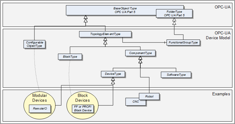
The boxes in this drawing show the ObjectTypes used in this specification as well as some elements from other specifications that help understand some modelling decisions. The upper grey box shows the OPC UA core ObjectTypes from which the TopologyElementType is derived. The grey box in the second level shows the main ObjectTypes that the device model introduces. The components of those ObjectTypes are illustrated only in an abstract way in this overall picture.
The grey box in the third level shows real-world examples as they will be used in products and plants. In general, such subtypes are defined by other organizations.
The TopologyElementType is the base ObjectType for elements in a device topology. Its most essential aspect is the functional grouping concept.
The ComponentType ObjectType provides a generic definition for a Device or parts of a Device where parts include mechanics and/or software. DeviceType is commonly used to represent field Devices.
Modular Devices are introduced to support subdevices and Block Devices to support Blocks. Blocks are typically used by field communication foundations as means to organize the functionality within a Device. Specific types of Blocks will therefore be specified by these foundations.
The ConfigurableObjectType is used as a general means to create modular topology units. If required an instance of this type will be added to the head object of the modular unit. Modular Devices, for example, will use this ObjectType to organize their modules. Block-oriented Devices use it to expose and organize their Blocks.
4.2 Usage guidelines
Annex C describes guidelines for the usage of the device model as base for creating companion specifications as well as guidelines on how to combine different aspects of the same device - defined in different companion specifications - in one OPC UA application.
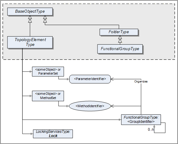
4.3 TopologyElementType
This ObjectType defines a generic model for elements in a device or component topology. Among others, it introduces FunctionalGroups, ParameterSet, and MethodSet. Figure 2 shows the TopologyElementType. It is formally defined in Table 12.
| Attribute | Value | ||||
| BrowseName | 1:TopologyElementType | ||||
| IsAbstract | True | ||||
| References | NodeClass | BrowseName | DataType | TypeDefinition | Other |
|---|---|---|---|---|---|
| Subtype of the 0:BaseObjectType defined in OPC 10000-5 | |||||
| 0:HasComponent | Object | 1:<GroupIdentifier> | 1:FunctionalGroupType | OP | |
| 0:HasComponent | Object | 1:Identification | 1:FunctionalGroupType | O | |
| 0:HasComponent | Object | 1:Lock | 1:LockingServicesType | O | |
| 0:HasComponent | Object | 1:ParameterSet | 0:BaseObjectType | O | |
| 0:HasComponent | Object | 1:MethodSet | 0:BaseObjectType | O | |
| Conformance Units | |||||
|---|---|---|---|---|---|
| DI Information Model |
The TopologyElementType is abstract. There will be no instances of a TopologyElementType itself, but there will be instances of subtypes of this type. In this specification, the term TopologyElement generically refers to an instance of any ObjectType derived from the TopologyElementType.
FunctionalGroups are an essential aspect introduced by the TopologyElementType. FunctionalGroups are used to structure Nodes like Properties, Parameters and Methods according to their application such as configuration, diagnostics, asset management, condition monitoring and others.
FunctionalGroups are specified in 4.4.
A FunctionalGroup called Identification can be used to organize identification information of this TopologyElement (see 4.4.2). Identification information typically includes the Properties defined by the VendorNameplate or TagNameplate Interfaces and additional application specific information.
TopologyElements can also support LockingServices (defined in 7).
Clients shall use the LockingServices if they require to make a set of changes (for example, several Write operations and Method invocations) and where a consistent state is available only after all of these changes have been performed. The main purpose of locking a TopologyElement is avoiding concurrent modifications.
The lock applies to the complete TopologyElement (including all components such as Blocks or modules). Servers can expose a Lock Object on a component TopologyElement to allow independent locking of components, if no lock is applied to the top-level TopologyElement.
If the Online/Offline model is supported (see 6.3), the lock always applies to both the online and the offline version.
ParameterSet and MethodSet are defined as standard containers for systems that have a flat list of Parameters or Methods with unique names. In such cases, the Parameters are components of the "ParameterSet" as a flat list of Parameters. The Methods are kept the same way in the "MethodSet".
The MethodSet is only available if it includes at least one Method.
The components of the TopologyElementType have additional references as defined in Table 13.
| Source Path | References | NodeClass | BrowseName | DataType | TypeDefinition | Other |
| 1:ParameterSet | 0:HasComponent | Variable | 1:<ParameterIdentifier> | 0:BaseDataType | 0:BaseDataVariableType | MP |
4.4 FunctionalGroupType
4.4.1 Model
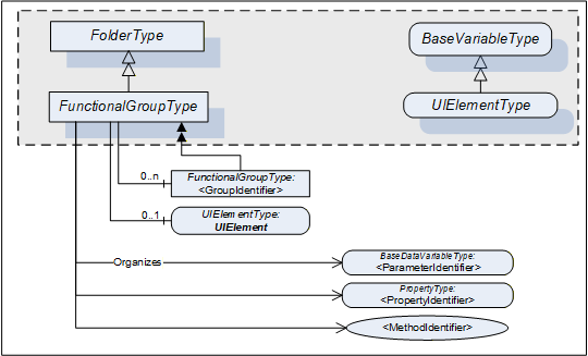
This subtype of the OPC UA FolderType is used to structure Nodes like Properties, Parameters and Methods according to their application (e.g. maintenance, diagnostics, condition monitoring). Organizes References should be used when the elements are components in other parts of the TopologyElement that the FunctionalGroup belongs to. This includes Properties, Variables, and Methods of the TopologyElement or in Objects that are components of the TopologyElement either directly or via a subcomponent. The same Property, Parameter or Method can be useful in different application scenarios and therefore referenced from more than one FunctionalGroup.
FunctionalGroups can be nested.
FunctionalGroups can directly be instantiated. In this case, the BrowseName of a FunctionalGroup should indicate its purpose. A list of well-known BrowseNames is in 4.4.2.
Figure 3 shows the FunctionalGroupType components. It is formally defined in Table 14.
| Attribute | Value | ||||
| BrowseName | 1:FunctionalGroupType | ||||
| IsAbstract | False | ||||
| References | NodeClass | BrowseName | DataType | TypeDefinition | Other |
|---|---|---|---|---|---|
| Subtype of the 0:FolderType defined in OPC 10000-5 | |||||
| 0:HasComponent | Object | 1:<GroupIdentifier> | 1:FunctionalGroupType | OP | |
| 0:HasComponent | Variable | 1:UIElement | 0:BaseDataType | 1:UIElementType | O |
| Conformance Units | |||||
|---|---|---|---|---|---|
| DI Information Model |
All BrowseNames for Nodes referenced by a FunctionalGroup with an Organizes Reference shall be unique.
The Organizes References can be present only at the instance, not the type. Depending on the current state of the TopologyElement the Server can decide to hide or unhide certain FunctionalGroups or (part of) their References. If a FunctionalGroup can be hidden on an instance the TypeDefinition shall use an appropriate ModellingRule like "Optional".
If desirable, Nodes can be also children of FunctionalGroups. If such Nodes are defined, it is recommended to define a subtype of the FunctionalGroupType.
UIElement is the user interface element for this FunctionalGroup. See 4.4.3 for the definition of UIElements.
Examples in Annex B.1 illustrate the use of FunctionalGroups.
4.4.2 Well-Known FunctionalGroup BrowseNames
Table 15 includes a list of FunctionalGroups with name and purpose. If Servers expose a FunctionalGroup that corresponds to the described purpose, they should use the well-known BrowseName with the Namespace of this specification.
| BrowseName | Purpose |
|---|---|
| Configuration | Parameters representing the configuration items of the TopologyElement. If the CurrentWrite bit is set in the AccessLevel Attribute they can be modified by Clients. |
| Tuning | Parameters and Methods to optimize the behavior of the TopologyElement. |
| Maintenance | Parameters and Methods useful for maintenance operations. |
| Diagnostics | Parameters and Methods for diagnostics. |
| Statistics | Parameters and Methods for statistics. |
| Status | Parameters which describe the general health of the TopologyElement. This can include diagnostic Parameters. |
| Operational | Parameters and Methods useful for during normal operation, like process data. |
| OperationCounters | Parameters representing numbers of interest when managing a TopologyElement while it is operated. Examples are the hours of operation, hours in standby, etc. Those are often the base to calculate KPIs (key performance indicators) like the OEE (overall equipment efficiency).
Parameters are often domain specific. Some common ones are defined in the OperationCounter Interface (see 4.5.5). |
| Identification | The Properties of the VendorNameplate Interface, like Manufacturer, SerialNumber or Properties of the TagNameplate will usually be sufficient as identification. If other Parameters or even Methods are required, all elements required shall be organized in a FunctionalGroup called "Identification". See Annex B.1 for an example. |
4.4.3 UIElement Type
Servers can expose UIElements providing user interfaces in the context of their FunctionalGroup container. Clients can load such a user interface and display it on the Client side. The hierarchy of FunctionalGroups represents the tree of user interface elements.
The UIElementType is abstract and is mainly used as filter when browsing a FunctionalGroup. Only subtypes can be used for instances. No concrete UIElements are defined in this specification. FDI (Field Device Integration, see IEC 62769) specifies two concrete subtypes
UIDs (UI Descriptions), descriptive user interface elements, and
UIPs (UI Plug-Ins), programmed user interface elements.
The UIElementType is specified in Table 16.
| Attribute | Value | ||||
| BrowseName | 1:UIElementType | ||||
| IsAbstract | True | ||||
| DataType | 0:BaseDataType | ||||
| References | NodeClass | BrowseName | DataType | TypeDefinition | Other |
|---|---|---|---|---|---|
| Subtype of the 0:BaseDataVariableType defined in OPC 10000-5. | |||||
| Conformance Units | |||||
|---|---|---|---|---|---|
| DI Information Model |
The Value attribute of the UIElement contains the user interface element. Subtypes have to define the DataType (e.g., XmlElement or ByteString).
4.5 Interfaces
4.5.1 Overview
This clause describes Interfaces with specific functionality that can be applied to multiple types at arbitrary positions in the type hierarchy.
Interfaces are defined in OPC 10000-3.
Figure 4 shows the Interfaces described in this specification.
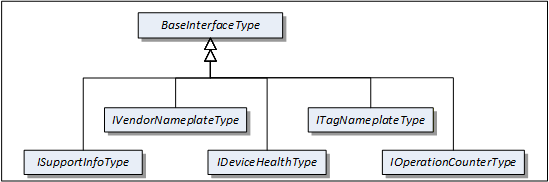
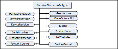
4.5.2 VendorNameplate Interface
IVendorNameplateType includes Properties that are commonly used to describe a TopologyElement from a manufacturer point of view. They can be used as part of the identification. The Values of these Properties are typically provided by the component vendor.
The VendorNameplate Interface is illustrated in Figure 5 and formally defined in Table 17.
| Attribute | Value | ||||
| BrowseName | 1:IVendorNameplateType | ||||
| IsAbstract | True | ||||
| References | NodeClass | BrowseName | DataType | TypeDefinition | Other |
|---|---|---|---|---|---|
| Subtype of the BaseInterfaceType defined in OPC 10000-5 | |||||
| Product-specific Properties | |||||
|---|---|---|---|---|---|
| 0:HasProperty | Variable | 1:Manufacturer | 0:LocalizedText | 0:PropertyType | O |
| 0:HasProperty | Variable | 1:ManufacturerUri | 0:String | 0:PropertyType | O |
| 0:HasProperty | Variable | 1:Model | 0:LocalizedText | 0:PropertyType | O |
| 0:HasProperty | Variable | 1:ProductCode | 0:String | 0:PropertyType | O |
| 0:HasProperty | Variable | 1:HardwareRevision | 0:String | 0:PropertyType | O |
| 0:HasProperty | Variable | 1:SoftwareRevision | 0:String | 0:PropertyType | O |
| 0:HasProperty | Variable | 1:DeviceRevision | 0:String | 0:PropertyType | O |
| 0:HasProperty | Variable | 1:DeviceManual | 0:String | 0:PropertyType | O |
| 0:HasProperty | Variable | 1:DeviceClass | 0:String | 0:PropertyType | O |
| Product instance-specific Properties | |||||
|---|---|---|---|---|---|
| 0:HasProperty | Variable | 1:SerialNumber | 0:String | 0:PropertyType | O |
| 0:HasProperty | Variable | 1:ProductInstanceUri | 0:String | 0:PropertyType | O |
| 0:HasProperty | Variable | 1:RevisionCounter | 0:Int32 | 0:PropertyType | O |
| 0:HasProperty | Variable | 1:SoftwareReleaseDate | 0:DateTime | 0:PropertyType | O |
| 0:HasProperty | Variable | 1:PatchIdentifiers | 0:String[] | 0:PropertyType | O |
| Conformance Units | |||||
|---|---|---|---|---|---|
| DI Nameplate |
Product type specific Properties:
Manufacturer provides the name of the company that manufactured the item this Interface is applied to. ManufacturerUri provides a unique identifier for this company. This identifier should be a fully qualified domain name; however, it can be a GUID or similar construct that ensures global uniqueness.
Model provides the name of the product.
ProductCode provides a unique combination of numbers and letters used to identify the product. It can be the order information displayed on type shields or in ERP systems.
HardwareRevision provides the revision level of the hardware. SemanticVersionString (a sub-type of String defined in OPC 10000-5) can be used when using the Semantic Versioning format.
SoftwareRevision provides the version or revision level of the software component, the software/firmware of a hardware component, or the software/firmware of the Device. SemanticVersionString (a sub-type of String defined in OPC 10000-5) can be used when using the Semantic Versioning format.
DeviceRevision provides the overall revision level of a hardware component or the Device. As an example, this Property can be used in ERP systems together with the ProductCode Property. SemanticVersionString (a sub-type of String defined in OPC 10000-5) can be used when using the Semantic Versioning format.
DeviceManual allows specifying an address of the user manual. It can be a pathname in the file system or a URL (Web address).
DeviceClass indicates in which domain or for what purpose a certain item for which the Interface is applied is used. Examples are "ProgrammableController", "RemoteIO", and "TemperatureSensor". This standard does not predefine any DeviceClass names. Companion standards that utilize this Interface (device models) will likely introduce such classifications.
Product instance specific Properties:
SerialNumber is a unique production number provided by the manufacturer. This is often stamped on the outside of a physical component and can be used for traceability and warranty purposes.
ProductInstanceUri is a globally unique resource identifier provided by the manufacturer. This is often stamped on the outside of a physical component and can be used for traceability and warranty purposes. The maximum length is 255 characters. If used as QR code, 80 characters is a reasonable size. The recommended syntax of the ProductInstanceUri is: <ManufacturerUri>/<any string> where <any string> is unique among all instances using the same ManufacturerUri.
Examples: "some-company.com/5ff40f78-9210-494f-8206-c2c082f0609c", "some-company.com/snr-16273849" or "some-company.com/model-xyz/snr-16273849".
RevisionCounter is an incremental counter indicating the number of times the configuration data has been modified. An example would be a temperature sensor where the change of the unit would increment the RevisionCounter but a change of the measurement value would not affect the RevisionCounter.
SoftwareReleaseDate defines the date when the software is released. If the version information is about patches, this should be the date of the latest patch. It is additional information for the user.
PatchIdentifiers identify the list of patches that are applied to a software version. The format and semantics of the strings are vendor-specific. The order of the strings shall not be relevant.
Companion specifications can specify additional semantics for the contents of these Properties.
Table 18 specifies the mapping of these Properties to the International Registration Data Identifiers (IRDI) defined in ISO/IEC 11179-6. They should be used if a Server wants to expose a dictionary reference as defined in OPC 10000-19.
| Property | IRDI | Legacy IRDI |
| Manufacturer | 0112/2///61360_7#CBA031 | 0112/2///61987#ABA565#007 |
| ManufacturerUri | 0112/2///61360_7#CBA032 | 0112/2///61987#ABN591#001 |
| Model | 0112/2///61360_7#CBA039 | 0112/2///61987#ABA567#007 |
| SerialNumber | 0112/2///61360_7#CBA050 | 0112/2///61987#ABA951#007 |
| HardwareRevision | 0112/2///61360_7#CBA047 | 0112/2///61987#ABA926#006 |
| SoftwareRevision | 0112/2///61360_7#CBA046 | 0112/2///61987#ABA601#006 |
| DeviceRevision | 0112/2///61987#ABP643#002 | |
| RevisionCounter | 0112/2///61987#ABN603#001 | |
| ProductCode | 0112/2///61360_7#CBA040 | 0112/2///61987#ABA300#006 |
| ProductInstanceUri | 0112/2///61360_7#CBA055 | 0112/2///61987#ABN590#001 |
| DeviceManual | - | - |
| DeviceClass | 0112/2///61360_7#CBA037 | 0112/2///61987#ABA566 - type of product |
| SoftwareReleaseDate | - | |
| PatchIdentifiers | - |
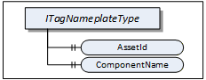
4.5.3 TagNameplate Interface
ITagNameplateType includes Properties that are commonly used to describe a TopologyElement from a user point of view.
The TagNameplate Interface is illustrated in Figure 6 and formally defined in Table 19.
| Attribute | Value | ||||
| BrowseName | 1:ITagNameplateType | ||||
| IsAbstract | True | ||||
| References | NodeClass | BrowseName | DataType | TypeDefinition | Other |
|---|---|---|---|---|---|
| Subtype of the BaseInterfaceType defined in OPC 10000-5 | |||||
| 0:HasProperty | Variable | 1:AssetId | 0:String | 0:PropertyType | O |
| 0:HasProperty | Variable | 1:ComponentName | 0:LocalizedText | 0:PropertyType | O |
| Conformance Units | |||||
|---|---|---|---|---|---|
| DI TagNameplate |
AssetId is a user writable alphanumeric character sequence uniquely identifying a component. The ID is provided by the integrator or user of the device. It contains typically an identifier in a branch, use case or user specific naming scheme. This could be for example a reference to an electric scheme.
ComponentName is a user writable name provided by the integrator or user of the component.
Table 20 specifies the mapping of these Properties to the International Registration Data Identifiers (IRDI) defined in ISO/IEC 11179-6. They should be used if a Server wants to expose a dictionary reference as defined in OPC 10000-19.
| Property | IRDI |
| AssetId | 0112/2///61987#ABA038 - identification code of device |
| ComponentName | 0112/2///61987#ABA251 - designation of device |
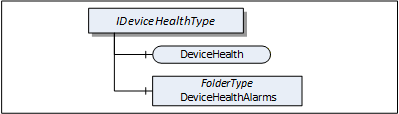
4.5.4 DeviceHealth Interface
The DeviceHealth Interface includes Properties and Alarms that are commonly used to expose the health status of a Device. It is illustrated in Figure 7 and formally defined in Table 21.
| Attribute | Value | ||||
| BrowseName | 1:IDeviceHealthType | ||||
| IsAbstract | True | ||||
| References | NodeClass | BrowseName | DataType | TypeDefinition | Other |
|---|---|---|---|---|---|
| Subtype of the 0:BaseInterfaceType defined in OPC 10000-5 | |||||
| 0:HasComponent | Variable | 1:DeviceHealth | 1:DeviceHealthEnumeration | 0:BaseDataVariableType | O |
| 0:HasComponent | Object | 1:DeviceHealthAlarms | 0:FolderType | O | |
| Conformance Units | |||||
|---|---|---|---|---|---|
| DI DeviceHealth |
DeviceHealth indicates the status as defined by NAMUR Recommendation NE107. Clients can read or monitor this Variable to determine the device condition.
The DeviceHealthEnumeration DataType is an enumeration that defines the device condition. Its values are defined in Table 22. Its representation in the AddressSpace is defined in Table 23.
| Name | Value | Description |
|---|---|---|
| NORMAL | 0 | The Device functions normally. |
| FAILURE | 1 | Malfunction of the Device or any of its peripherals. Typically caused device-internal or is process related. |
| CHECK_FUNCTION | 2 | Functional checks are currently performed. Examples: Change of configuration, local operation, and substitute value entered. |
| OFF_SPEC | 3 | "Off-spec" means that the Device is operating outside its specified range (e.g. measuring or temperature range) or that internal diagnoses indicate deviations from measured or set values due to internal problems in the Device or process characteristics. |
| MAINTENANCE_REQUIRED | 4 | Although the output signal is valid, the wear reserve is nearly exhausted or a function will soon be restricted due to operational conditions e.g. build-up of deposits. |
| Attribute | Value | |||||
| BrowseName | 1:DeviceHealthEnumeration | |||||
| IsAbstract | False | |||||
| References | NodeClass | BrowseName | DataType | TypeDefinition | Other | |
|---|---|---|---|---|---|---|
| Subtype of the 0:Enumeration type defined in OPC 10000-5 | ||||||
| 0:HasProperty | Variable | 0:EnumStrings | 0:LocalizedText [] | 0:PropertyType | ||
| Conformance Units | ||||||
|---|---|---|---|---|---|---|
| DI DeviceHealth |
DeviceHealthAlarms shall be used for instances of the DeviceHealth Alarm Types specified in 4.12 and any other subtypes of DeviceHealthDiagnosticAlarmType.
It is recommended to use the DeviceHealthAlarms folder also for Alarm instances that relate to the health condition of the Device and are not subtypes of DeviceHealthDiagnosticAlarmType
4.5.5 OperationCounter Interface
The IOperationCounterType defines counters for the duration of operation. It is formally defined in Table 24.
| Attribute | Value | ||||
| BrowseName | 1:IOperationCounterType | ||||
| IsAbstract | True | ||||
| Description | Interface defining counters for the duration of operation | ||||
| References | Node Class | BrowseName | DataType | TypeDefinition | Other |
|---|---|---|---|---|---|
| Subtype of the 0:BaseInterfaceType defined in OPC 10000-5 | |||||
| 0:HasProperty | Variable | 1:PowerOnDuration | 0:Duration | 0:PropertyType | O |
| 0:HasProperty | Variable | 1:OperationDuration | 0:Duration | 0:PropertyType | O |
| 0:HasProperty | Variable | 1:OperationCycleCounter | 0:UInteger | 0:PropertyType | O |
| Conformance Units | |||||
|---|---|---|---|---|---|
| DI OperationCounter Interface |
PowerOnDuration is the duration the Device has been powered. The main purpose is to determine the time in which degradation of the Device occurred. The details, when the time is counted, is implementation-specific. Companion specifications can define specific rules. Typically, when the Device has supply voltage and the main CPU is running, the time is counted. This can include any kind of sleep mode, but cannot include pure Wake on LAN. This value shall only increase during the lifetime of the Device and shall not be reset when the Device is restarted. The PowerOnDuration is provided as Duration, i.e., in milliseconds or even fractions of a millisecond. However, the Server is not expected to update the value in such a high frequency, but possibly once a minute or once an hour, depending on the application.
OperationDuration is the duration the Device has been powered and performing an activity. This counter is intended for Devices where a distinction is made between switched on and in operation. For example, a drive can be powered on but not operating. It is not intended for Devices always performing an activity like sensors always measuring data. This value shall only increase during the lifetime of the Device and shall not be reset when the Device is restarted. The OperationDuration is provided as Duration, i.e., in milliseconds or even fractions of a millisecond. However, the Server is not expected to update the value in such a high frequency, but possibly once a minute or once an hour, depending on the application.
OperationCycleCounter is counting the times the Device switches from not performing an activity to performing an activity. For example, each time a valve starts moving, is counted. This value shall only increase during the lifetime of the Device and shall not be reset when the Device is restarted.
The child Nodes of the IOperationCounterType have additional Attribute values defined in Table 25.
| BrowsePath | Description Attribute |
| PowerOnDuration | PowerOnDuration is the duration the Device has been powered. The main purpose is to determine the time in which degradation of the Device occurred. The details, when the time is counted, is implementation-specific. Companion specifications can define specific rules. Typically, when the Device has supply voltage and the main CPU is running, the time is counted. This can include any kind of sleep mode, but cannot include pure Wake on LAN. This value shall only increase during the lifetime of the Device and shall not be reset when the Device is restarted. The PowerOnDuration is provided as Duration, i.e., in milliseconds or even fractions of a millisecond. However, the Server is not expected to update the value in such a high frequency, but possibly once a minute or once an hour, depending on the application. |
| OperationDuration | OperationDuration is the duration the Device has been powered and performing an activity. This counter is intended for Devices where a distinction is made between switched on and in operation. For example, a drive can be powered on but not operating. It is not intended for Devices always performing an activity like sensors always measuring data. This value shall only increase during the lifetime of the Device and shall not be reset when the Device is restarted. The OperationDuration is provided as Duration, i.e., in milliseconds or even fractions of a millisecond. However, the Server is not expected to update the value in such a high frequency, but possibly once a minute or once an hour, depending on the application. |
| OperationCycleCounter | OperationCycleCounter is counting the times the Device switches from not performing an activity to performing an activity. For example, each time a valve starts moving, is counted. This value shall only increase during the lifetime of the Device and shall not be reset when the Device is restarted. |
Table 26 - OperationCounter Mapping to IRDIs specifies the mapping of these Properties to the International Registration Data Identifiers (IRDI) defined in ISO/IEC 11179-6. They should be used if a Server wants to expose a dictionary reference as defined in OPC 10000-19.
| Property | IRDI |
| PowerOnDuration | 0112/2///61987#ABP550 |
| OperationDuration | 0112/2///61987#ABN639#001 |
| OperationCycleCounter | 0112/2///61987#ABP545 |
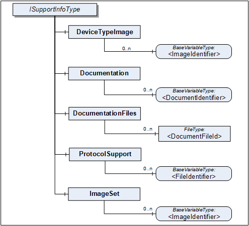
4.5.6 SupportInfo Interface
The SupportInfo Interface defines a number of additional data that a commonly exposed for Devices and their components. These include mainly images, documents, or protocol-specific data. The various types of information are organized into different folders. Each information element is represented by a read-only Variable. The information can be retrieved by reading the Variable value.

Figure 8 Illustrates the SupportInfo Interface. It is formally defined in Table 27.
| Attribute | Value | ||||
| BrowseName | 1:ISupportInfoType | ||||
| IsAbstract | True | ||||
| References | NodeClass | BrowseName | DataType | TypeDefinition | Other |
|---|---|---|---|---|---|
| Subtype of the BaseInterfaceType defined in OPC 10000-5 | |||||
| 0:HasComponent | Object | 1:DeviceTypeImage | 0:FolderType | O | |
| 0:HasComponent | Object | 1:Documentation | 0:FolderType | O | |
| 0:HasComponent | Object | 1:DocumentationFiles | 0:FolderType | O | |
| 0:HasComponent | Object | 1:ProtocolSupport | 0:FolderType | O | |
| 0:HasComponent | Object | 1:ImageSet | 0:FolderType | O | |
| Conformance Units | |||||
|---|---|---|---|---|---|
| DI DeviceSupportInfo |
Clients should be aware that the contents that these Variables represent can be large. Reading large values with a single Read operation can be impossible due to configured limits in either the Client or the Server stack. The default maximum size for an array of bytes is 1 MiB. It is recommended that Clients use the IndexRange in the OPC UA Read Service (see OPC 10000-4) to read these Variables in chunks, for example, one-megabyte chunks. It is up to the Client whether it starts without an index and repeats with an IndexRange only after an error or whether it always uses an IndexRange.
The components of the ISupportInfoType have additional references as defined in Table 28.
| Source Path | References |
Node
Class | BrowseName |
Data
Type | TypeDefinition | Other |
| 1:DeviceTypeImage | 0:HasComponent | Variable | 1:<ImageIdentifier> | 0:Image | 0:BaseDataVariableType | MP |
| 1:Documentation | 0:HasComponent | Variable | 1:<DocumentIdentifier> | 0:ByteString | 0:BaseDataVariableType | MP |
| 1:DocumentationFiles | 0:HasComponent | Object | 1:<DocumentFileId> | 0:FileType | MP | |
| 1:ProtocolSupport | 0:HasComponent | Variable | 1:<ProtocolSupportIdentifier> | 0:ByteString | 0:BaseDataVariableType | MP |
| 1:ImageSet | 0:HasComponent | Variable | 1:<ImageIdentifier> | 0:Image | 0:BaseDataVariableType | MP |
Pictures can be exposed as Variables organized in the DeviceTypeImage folder. There can be multiple images of different resolutions. Each image is a separate Variable.
All images are transferred as a ByteString. The DataType of the Variable specifies the image format. OPC UA defines BMP, GIF, JPG and PNG (see OPC 10000-3).
Documents in many cases will represent a product manual. They can be exposed as Variables or as FileType instances. Files are useful in particular for large documents.
Documents as Variables are represented as a ByteString and organized in the Documentation folder. The BrowseName of each Node will consist of the filename including the extension that can be used to identify the document type. Typical extensions are ".pdf" or ".txt".
Documents as FileType instances are organized in the DocumentationFiles folder. They are retrieved from the Server by using the FileType Methods. It is recommended to use the MimeType Property to specify the media type of the file based on RFC 2046.
Protocol support files are exposed as Variables organized in the ProtocolSupport folder. They can represent various types of information as defined by a protocol. For example a GSD file.
All protocol support files are transferred as a ByteString. The BrowseName of each Variable shall consist of the complete filename including the extension that can be used to identify the type of information.
Images that are used within UIElements are exposed as separate Variables rather than embedding them in the element. All image Variables will be aggregated by the ImageSet folder. The UIElement shall specify an image by its name that is also the BrowseName of the image Variable. Clients can cache images so they don't have to be transferred more than once.
The DataType of the Variable specifies the image format. OPC UA defines BMP, GIF, JPG and PNG (see OPC 10000-3).
4.5.7 AssetLocationIndication Interface
The asset location indication Interface provides a method for making a device emit visual signals (e.g., blinking LEDs) or audible signals (e.g., sounds) to facilitate its physical identification among other assets.
IAssetLocationIndicationType can be implemented by any object that represents a physical device and that is able to indicate its position by blinking and / or making a sound.
The minimal implementation supports turning a default indication on and off for a specified duration. Optionally a device can declare its supported indication types (audible, visual) and let the client select the used indication types (one or more).
The Interface is formally defined in Table 29.
| Attribute | Value | ||||
| BrowseName | 1:IAssetLocationIndicationType | ||||
| IsAbstract | True | ||||
| References | NodeClass | BrowseName | DataType | TypeDefinition | Other |
|---|---|---|---|---|---|
| Subtype of the BaseInterfaceType defined in OPC 10000-5 | |||||
| 0:HasComponent | Method | 1:StartLocationIndication | M | ||
| 0:HasComponent | Method | 1:StopLocationIndication | M | ||
| 0:HasProperty | Variable | 1:IsIndicating | 0:Boolean | 0:PropertyType | M |
| 0:HasProperty | Variable | 1:UsedIndicationType | 1:LocationIndicationType | 0:PropertyType | O |
| 0:HasProperty | Variable | 1:SupportedIndicationTypes | 1:LocationIndicationType | 0:PropertyType | O |
| Conformance Units | |||||
|---|---|---|---|---|---|
| DI AssetLocationIndication |
The read only Property IsIndicating is true when the indication is currently active.
The optional UsedIndicationType can be written to set the indication types that shall be used when StartLocationIndication is called.
4.5.7.1 StartLocationIndication Method
The StartLocationIndication Method is used to start the indication. As a result to this call the IsIndicating property is set to true.
The signature of this Method is specified below. Table 30 and Table 31 specify the Arguments and AddressSpace representation, respectively.
Signature
	StartLocationIndication(
[in] 0:Duration IndicationDuration);| Argument | Description |
| IndicationDuration | 0 => infinite duration or duration in milliseconds |
Method Result Codes (defined in Call Service)
| Result Code | Description |
| Bad_InvalidArgument | If the device does not support a duration other than infinite |
| Attribute | Value | ||||
| BrowseName | 1:StartLocationIndication | ||||
| References | NodeClass | BrowseName | DataType | TypeDefinition | Other |
|---|---|---|---|---|---|
| 0:HasProperty | Variable | 0:InputArguments | 0:Argument[] | 0:PropertyType | M |
| Conformance Units | |||||
|---|---|---|---|---|---|
| DI AssetLocationIndication |
4.5.7.2 StopLocationIndication Method
The StopLocationIndication Method is used to stop the indication. As a result to this call, the IsIndicating property is set to false. This method also can be called when the indication is already stopped (e.g., because the specified IndicationDuration is over).
The signature of this Method is specified below.
Signature
StopLocationIndication();4.5.8 LocationIndicationType OptionSet
This DataType is used together with the IAssetLocationIndication Interface. It defines flags for the type of location indication. The OptionSet is defined in Table 32. Its representation in the AddressSpace is defined in Table 33.
| Name | Bit No. | Description |
| Visual | 0 | Location indication through optical signals, such as blinking LEDs, if supported by the device. |
| Audible | 1 | Location indication through auditory signals, such as sounds or beeps, if supported by the device. |
| Attribute | Value | |||||
| BrowseName | 1:LocationIndicationType | |||||
| IsAbstract | False | |||||
| References | NodeClass | BrowseName | DataType | TypeDefinition | Other | |
|---|---|---|---|---|---|---|
| Subtype of the 0:UInt16 DataType defined in OPC 10000-5 | ||||||
| 0:HasProperty | Variable | 0:OptionSetValues | 0:LocalizedText [] | 0:PropertyType | ||
| Conformance Units | ||||||
|---|---|---|---|---|---|---|
| DI AssetLocationIndication |
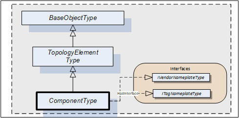
4.6 ComponentType
Compared to DeviceType the ComponentType is more universal. It includes the same components but does not mandate any Properties. This makes it usable for representation of a Device or parts of a Device. Parts include both mechanical and software parts.
The ComponentType applies the VendorNameplate and the TagNameplate Interface. Figure 9 Illustrates the ComponentType. It is formally defined in Table 34.
| Attribute | Value | ||||
| BrowseName | 1:ComponentType | ||||
| IsAbstract | True | ||||
| References | NodeClass | BrowseName | DataType | TypeDefinition | Other |
|---|---|---|---|---|---|
| Subtype of the TopologyElementType defined in 4.3. | |||||
| HasSubtype | ObjectType | 1:DeviceType | Defined in 4.7. | ||
| HasSubtype | ObjectType | 1:SoftwareType | Defined in 4.8. | ||
| HasInterface | ObjectType | 1:IVendorNameplateType | Defined in 4.5.2. | ||
| HasInterface | ObjectType | 1:ITagNameplateType | Defined in 4.5.3. | ||
| Applied from IVendorNameplateType | |||||
| 0:HasProperty | Variable | 1:Manufacturer | 0:LocalizedText | 0:PropertyType | O |
| 0:HasProperty | Variable | 1:ManufacturerUri | 0:String | 0:PropertyType | O |
| 0:HasProperty | Variable | 1:Model | 0:LocalizedText | 0:PropertyType | O |
| 0:HasProperty | Variable | 1:ProductCode | 0:String | 0:PropertyType | O |
| 0:HasProperty | Variable | 1:HardwareRevision | 0:String | 0:PropertyType | O |
| 0:HasProperty | Variable | 1:SoftwareRevision | 0:String | 0:PropertyType | O |
| 0:HasProperty | Variable | 1:DeviceRevision | 0:String | 0:PropertyType | O |
| 0:HasProperty | Variable | 1:DeviceManual | 0:String | 0:PropertyType | O |
| 0:HasProperty | Variable | 1:DeviceClass | 0:String | 0:PropertyType | O |
| 0:HasProperty | Variable | 1:SerialNumber | 0:String | 0:PropertyType | O |
| 0:HasProperty | Variable | 1:ProductInstanceUri | 0:String | 0:PropertyType | O |
| 0:HasProperty | Variable | 1:RevisionCounter | 0:Int32 | 0:PropertyType | O |
| Applied from ITagNameplateType | |||||
| 0:HasProperty | Variable | 1:AssetId | 0:String | 0:PropertyType | O |
| 0:HasProperty | Variable | 1:ComponentName | 0:LocalizedText | 0:PropertyType | O |
| Conformance Units | |||||
|---|---|---|---|---|---|
| DI Information Model |
The ComponentType is abstract. DeviceType and SoftwareType are subtypes of ComponentType. There will be no instances of a ComponentType itself, only of concrete subtypes.
IVendorNameplateType and its members are described in 4.5.2.
ITagNameplateType and its members are described in 4.5.3.
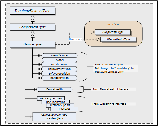
4.7 DeviceType
This ObjectType can be used to define the structure of a Device. Figure 10 shows the DeviceType. It is formally defined in Table 35.
| Attribute | Value | ||||
| BrowseName | 1:DeviceType | ||||
| IsAbstract | True | ||||
| References | NodeClass | BrowseName | DataType | TypeDefinition | Other |
|---|---|---|---|---|---|
| Subtype of the ComponentType defined in 4.5.7 | |||||
| HasInterface | ObjectType | 1:ISupportInfoType | Defined in 4.5.3. | ||
| HasInterface | ObjectType | 1:IDeviceHealthType | Defined in 4.5.3. | ||
| 0:HasComponent | Object | 1:<CPIdentifier> | 1:ConnectionPointType | OP | |
| 0:HasProperty | Variable | 1:SerialNumber | 0:String | 0:PropertyType | M |
| 0:HasProperty | Variable | 1:RevisionCounter | 0:Int32 | 0:PropertyType | M |
| 0:HasProperty | Variable | 1:Manufacturer | 0:LocalizedText | 0:PropertyType | M |
| 0:HasProperty | Variable | 1:Model | 0:LocalizedText | 0:PropertyType | M |
| 0:HasProperty | Variable | 1:DeviceManual | 0:String | 0:PropertyType | M |
| 0:HasProperty | Variable | 1:DeviceRevision | 0:String | 0:PropertyType | M |
| 0:HasProperty | Variable | 1:SoftwareRevision | 0:String | 0:PropertyType | M |
| 0:HasProperty | Variable | 1:HardwareRevision | 0:String | 0:PropertyType | M |
| 0:HasProperty | Variable | 1:DeviceClass | 0:String | 0:PropertyType | O |
| 0:HasProperty | Variable | 1:ManufacturerUri | 0:String | 0:PropertyType | O |
| 0:HasProperty | Variable | 1:ProductCode | 0:String | 0:PropertyType | O |
| 0:HasProperty | Variable | 1:ProductInstanceUri | 0:String | 0:PropertyType | O |
| Applied from IDeviceHealthType | |||||
| 0:HasComponent | Variable | 1:DeviceHealth | DeviceHealthEnumeration | 0:BaseDataVariableType | O |
| 0:HasComponent | Object | 1:DeviceHealthAlarms | 0:FolderType | O | |
| Applied from ISupportInfoType | |||||
| 0:HasComponent | Object | 1:DeviceTypeImage | 0:FolderType | O | |
| 0:HasComponent | Object | 1:Documentation | 0:FolderType | O | |
| 0:HasComponent | Object | 1:ProtocolSupport | 0:FolderType | O | |
| 0:HasComponent | Object | 1:ImageSet | 0:FolderType | O | |
| Conformance Units | |||||
|---|---|---|---|---|---|
| DI DeviceType |
DeviceType is a subtype of ComponentType which means it inherits all InstanceDeclarations.
The DeviceType ObjectType is abstract. There will be no instances of a DeviceType itself, only of concrete subtypes.
ConnectionPoints (see 5.4) represent the interface (interface card) of a DeviceType instance to a Network. Multiple ConnectionPoints can exist if multiple protocols and/or multiple Communication Profiles are supported.
The Interfaces and their members are described in 4.5. Some of the Properties inherited from the ComponentType are declared mandatory for backward compatibility.
Although mandatory, some of the Properties are not supported for certain types of Devices. In this case vendors shall provide the following defaults:
| Properties with DataType String: | empty string |
| Properties with DataType LocalizedText: | empty text field |
| RevisionCounter Property: | - 1 |
Clients can ignore the Properties when they have these defaults.
When Properties are not supported, Servers should initialize the corresponding Property declaration on the DeviceType with the default value. Relevant Browse Service requests can then return a Reference to this Property on the type definition. That way, no extra Nodes are required.
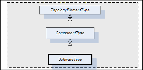
4.8 SoftwareType
This ObjectType can be used for software modules of a Device or a part of a Device. SoftwareType is a concrete subtype of ComponentType and can be used directly.
Figure 11 Illustrates the SoftwareType. It is formally defined in Table 36.
| Attribute | Value | ||||
| BrowseName | 1:SoftwareType | ||||
| IsAbstract | False | ||||
| References | NodeClass | BrowseName | DataType | TypeDefinition | Other |
|---|---|---|---|---|---|
| Subtype of the ComponentType defined in 4.5.7. | |||||
| 0:HasProperty | Variable | 1:Manufacturer | 0:LocalizedText | 0:PropertyType | M |
| 0:HasProperty | Variable | 1:Model | 0:LocalizedText | 0:PropertyType | M |
| 0:HasProperty | Variable | 1:SoftwareRevision | 0:String | 0:PropertyType | M |
| Conformance Units | |||||
|---|---|---|---|---|---|
| DI Software Component |
SoftwareType is a subtype of ComponentType which means it inherits all InstanceDeclarations.
The Properties Manufacturer, Model, and SoftwareRevision inherited from ComponentType are declared mandatory for SoftwareType instances.
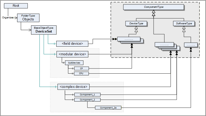
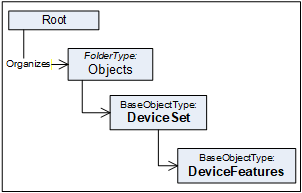
4.9 DeviceSet entry point
The DeviceSet Object is the starting point to locate Devices. It shall either directly or indirectly reference all instances of a subtype of ComponentType with a Hierarchical Reference. For complex Devices that are composed of various components that are also Devices, only the root instance shall be referenced from the DeviceSet Object. The components of such complex Devices shall be locatable by following Hierarchical References from the root instance. An example is the Modular Device defined in 9.4 and also illustrated in Figure 12.
Examples:
UA Server represents a monolithic or modular Device: DeviceSet only contains one instance
UA Server represents a host system that has access to a number of Devices that it manages: DeviceSet contains several instances that the host provides access to.
UA Server represents a gateway Device that acts as representative for Devices that it has access to: DeviceSet contains the gateway Device instance and instances for the Devices that it represents.
UA Server represents a robotic system consisting of mechanics and controls. DeviceSet only contains the instance for the root of the robotic system. The mechanics and controls are represented by ComponentType instances which are organized as sub-components of the root instance.
Figure 12 shows the AddressSpace organisation with this standard entry point and examples.
The DeviceSet Node is formally defined in Table 37.
| Attribute | Value | ||
| BrowseName | 1:DeviceSet | ||
| References | NodeClass | BrowseName | TypeDefinition |
|---|---|---|---|
| OrganizedBy by the 0:Objects Folder defined in OPC 10000-5 | |||
| 0:HasTypeDefinition | ObjectType | 0:BaseObjectType | |
| Conformance Units | |||
|---|---|---|---|
| DI DeviceSet |
4.10 DeviceFeatures entry point
The DeviceFeatures Object can be used to organize other functional entities that are related to the Devices referenced by the DeviceSet. Companion specifications can standardize such instances and their BrowseNames. Figure 13 shows the AddressSpace organisation with this standard entry point.
The DeviceFeatures Node is formally defined in Table 38.
| Attribute | Value | ||
| BrowseName | 1:DeviceFeatures | ||
| References | NodeClass | BrowseName | TypeDefinition |
|---|---|---|---|
| OrganizedBy by the DeviceSet Object defined in 4.9 | |||
| 0:HasTypeDefinition | ObjectType | 0:BaseObjectType | |
| Conformance Units | |||
|---|---|---|---|
| DI DeviceSet |
4.11 BlockType
This ObjectType defines the structure of a Block Object. Figure 14 depicts the BlockType hierarchy. It is formally defined in Table 39.
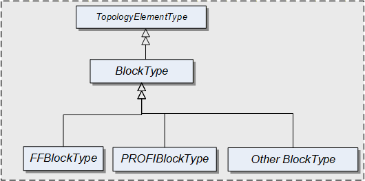
FFBlockType and PROFIBlockType are examples. They are not further defined in this specification. It is expected that industry groups will standardize general purpose BlockTypes.
| Attribute | Value | ||||
| BrowseName | 1:BlockType | ||||
| IsAbstract | True | ||||
| References | NodeClass | BrowseName | DataType | TypeDefinition | Other |
|---|---|---|---|---|---|
| Subtype of the TopologyElementType defined in 4.2 | |||||
| 0:HasProperty | Variable | 1:RevisionCounter | 0:Int32 | 0:PropertyType | O |
| 0:HasProperty | Variable | 1:ActualMode | 0:LocalizedText | 0:PropertyType | O |
| 0:HasProperty | Variable | 1:PermittedMode | 0:LocalizedText [] | 0:PropertyType | O |
| 0:HasProperty | Variable | 1:NormalMode | 0:LocalizedText [] | 0:PropertyType | O |
| 0:HasProperty | Variable | 1:TargetMode | 0:LocalizedText [] | 0:PropertyType | O |
| Conformance Units | |||||
|---|---|---|---|---|---|
| DI Blocks |
BlockType is a subtype of TopologyElementType and inherits the elements for Parameters, Methods and FunctionalGroups.
The BlockType is abstract. There will be no instances of a BlockType itself, but there will be instances of subtypes of this Type. In this specification, the term Block generically refers to an instance of any subtype of the BlockType.
The RevisionCounter is an incremental counter indicating the number of times the static data within the Block has been modified. A value of -1 indicates that no revision information is available.
The following Properties refer to the BlockMode (e.g., "Manual", "Out of Service").
The ActualMode Property reflects the current mode of operation.
The PermittedMode defines the modes of operation that are allowed for the Block based on application requirements.
The NormalMode is the mode the Block should be set to during normal operating conditions. Depending on the Block configuration, multiple modes can exist.
The TargetMode indicates the mode of operation that is desired for the Block. Depending on the Block configuration, multiple modes can exist.
4.12 DeviceHealth Alarm Types
4.12.1 General
The DeviceHealth Property defined in 4.5.4 provides a basic way to expose the health state of a device based on NAMUR NE 107.
This section defines AlarmTypes that can be used to indicate an abnormal device condition together with diagnostic information text as defined by NAMUR NE 107 as well as additional manufacturer specific information.
Figure 15 informally describes the AlarmTypes for DeviceHealth.
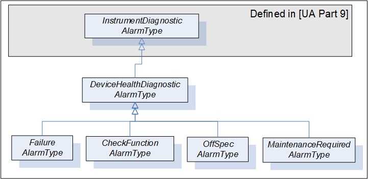
4.12.2 DeviceHealthDiagnosticAlarmType
The DeviceHealthDiagnosticAlarmType is a specialization of the InstrumentDiagnosticAlarmType intended to represent abnormal device conditions as defined by NAMUR NE 107. This type can be used in filters for monitored items. Only subtypes of this type will be used in actual implementations. The Alarm becomes active when the device condition is abnormal. It is formally defined in Table 40.
| Attribute | Value | ||||
| BrowseName | 1:DeviceHealthDiagnosticAlarmType | ||||
| IsAbstract | True | ||||
| References | NodeClass | BrowseName | DataType | TypeDefinition |
Modelling
Rule |
|---|---|---|---|---|---|
| Subtype of the 0:InstrumentDiagnosticAlarmType defined in OPC 10000-9. | |||||
| Conformance Units | |||||
|---|---|---|---|---|---|
| DI HealthDiagnosticsAlarm |
Conditions of subtypes of DeviceHealthDiagnosticAlarmType become active when the device enters the corresponding abnormal state.
The Message field in the Event notification shall be used for additional information associated with the health status (e.g. the possible cause of the abnormal state and suggested actions to return to normal).
A Device can be in more than one abnormal state at a time in which case multiple Conditions will be active.
4.12.3 FailureAlarmType
The FailureAlarmType is formally defined in Table 41. For description of the FAILURE state see Table 22.
| Attribute | Value | ||||
| BrowseName | 1:FailureAlarmType | ||||
| IsAbstract | False | ||||
| References | NodeClass | BrowseName | DataType | TypeDefinition | Other |
|---|---|---|---|---|---|
| Subtype of the 1:DeviceHealthDiagnosticAlarmType defined in 4.12.2. | |||||
| Conformance Units | |||||
|---|---|---|---|---|---|
| DI HealthDiagnosticsAlarm |
4.12.4 CheckFunctionAlarmType
The CheckFunctionAlarmType is formally defined in Table 42. For description of the CHECK_FUNCTION state see Table 22.
| Attribute | Value | ||||
| BrowseName | 1:CheckFunctionAlarmType | ||||
| IsAbstract | False | ||||
| References | NodeClass | BrowseName | DataType | TypeDefinition | Other |
|---|---|---|---|---|---|
| Subtype of the 1:DeviceHealthDiagnosticAlarmType defined in 4.12.2. | |||||
| Conformance Units | |||||
|---|---|---|---|---|---|
| DI HealthDiagnosticsAlarm |
4.12.5 OffSpecAlarmType
The OffSpecAlarmType is formally defined in Table 43. For description of the OFF_SPEC state see Table 22.
| Attribute | Value | ||||
| BrowseName | 1:OffSpecAlarmType | ||||
| IsAbstract | False | ||||
| References | NodeClass | BrowseName | DataType | TypeDefinition | Other |
|---|---|---|---|---|---|
| Subtype of the 1:DeviceHealthDiagnosticAlarmType defined in 4.12.2. | |||||
| Conformance Units | |||||
|---|---|---|---|---|---|
| DI HealthDiagnosticsAlarm |
4.12.6 MaintenanceRequiredAlarmType
The MaintenanceRequiredAlarmType is formally defined in Table 44. For description of the MAINTENANCE_REQUIRED state see Table 22.
| Attribute | Value | ||||
| BrowseName | 1:MaintenanceRequiredAlarmType | ||||
| IsAbstract | False | ||||
| References | NodeClass | BrowseName | DataType | TypeDefinition | Other |
|---|---|---|---|---|---|
| Subtype of the 1:DeviceHealthDiagnosticAlarmType defined in 4.12.2. | |||||
| Conformance Units | |||||
|---|---|---|---|---|---|
| DI HealthDiagnosticsAlarm |
5 Device communication model
5.1 General
Clause 5 introduces References, the ProtocolType, and basic TopologyElementTypes for creating a communication topology. The types for this model are illustrated in Figure 16.
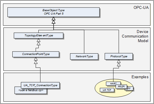
A ProtocolType ObjectType represents a specific communication protocol (e.g., FieldBus) implemented by a certain TopologyElement. Examples are shown in Figure 18.
The ConnectionPointType represents the logical interface of a Device to a Network.
A Network is the logical representation of wired and wireless technologies.
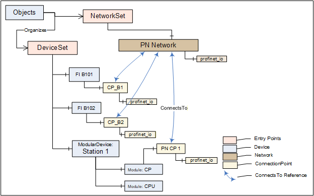
Figure 17 provides an overall example.
5.2 ProtocolType
The ProtocolType ObjectType and its subtypes are used to specify a specific communication (e.g., FieldBus) protocol that is supported by a Device (respectively by its ConnectionPoint) or Network. The BrowseName of each instance of a ProtocolType shall define the Communication Profile (see Figure 18).
Figure 18 shows the ProtocolType including some specific types and instances that represent Communication Profiles of that type. It is formally defined in Table 45.
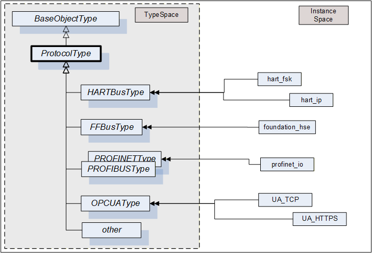
that represent specific communication profiles
| Attribute | Value | ||||
| BrowseName | 1:ProtocolType | ||||
| IsAbstract | False | ||||
| References | NodeClass | BrowseName | DataType | TypeDefinition | Other |
|---|---|---|---|---|---|
| Subtype of the 0:BaseObjectType defined in OPC 10000-5 | |||||
| Conformance Units | |||||
|---|---|---|---|---|---|
| DI Network | |||||
| DI Protocol |
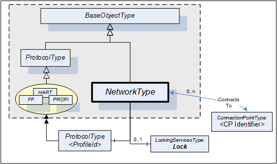
5.3 Network
A Network is the logical representation of wired and wireless technologies and represents the communication means for Devices that are connected to it. A Network instance is qualified by its Communication Profile components.
Figure 19 shows the type hierarchy and the NetworkType components. It is formally defined in Table 46.
| Attribute | Value | ||||
| BrowseName | 1:NetworkType | ||||
| IsAbstract | False | ||||
| References | NodeClass | BrowseName | DataType | TypeDefinition | Other |
|---|---|---|---|---|---|
| Subtype of the 0:BaseObjectType defined in OPC 10000-5. | |||||
| 0:HasComponent | Object | 1:<ProfileIdentifier> | 1:ProtocolType | MP | |
| ConnectsTo | Object | 1:<CPIdentifier> | 1:ConnectionPointType | OP | |
| 0:HasComponent | Object | 1:Lock | 1:LockingServicesType | O | |
| Conformance Units | |||||
|---|---|---|---|---|---|
| DI Network |
The <ProfileIdentifier> specifies the Protocol and Communication Profile that this Network is used for.
Clients shall use the LockingServices if they possibly make a set of changes (for example, several Write operations and Method invocations) and where a consistent state is available only after all of these changes have been performed. The main purpose of locking a Network is avoiding concurrent topology changes.
The lock on a Network applies to the Network, all connected TopologyElements and their components. If any of the connected TopologyElements provides access to a sub-ordinate Network (like a gateway), the sub-ordinate Network and its connected TopologyElements are locked as well.
If InitLock is requested for a Network, it will be rejected if any of the Devices connected to this Network or any sub-ordinate Network including their connected Devices is already locked.
If the Online/Offline model is supported (see 6.3), the lock always applies to both the online and the offline version.
5.4 ConnectionPoint
This ObjectType represents the logical interface of a Device to a Network. A specific subtype shall be defined for each protocol. Figure 20 shows the ConnectionPointType including some specific types.
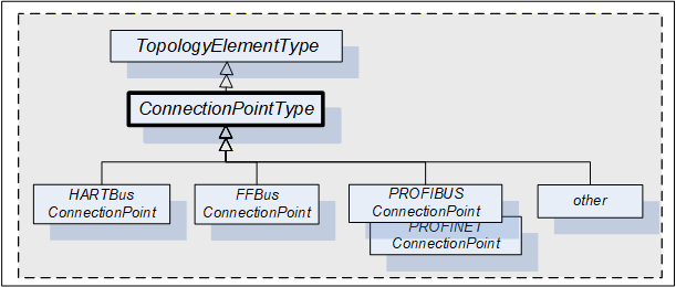
A Device can have more than one such interface to the same or to different Networks. Different interfaces usually exist for different protocols. Figure 21 shows the ConnectionPointType components. It is formally defined in Table 47.
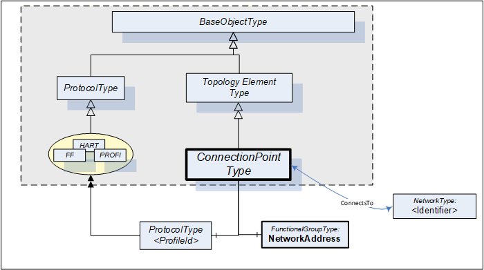
| Attribute | Value | ||||
| BrowseName | 1:ConnectionPointType | ||||
| IsAbstract | True | ||||
| References | NodeClass | BrowseName | DataType | TypeDefinition | Other |
|---|---|---|---|---|---|
| Subtype of the TopologyElementType defined in 4.2. | |||||
| 0:HasComponent | Object | 1:NetworkAddress | 1:FunctionalGroupType | M | |
| 0:HasComponent | Object | 1:<ProfileIdentifier> | 1:ProtocolType | MP | |
| ConnectsTo | Object | 1:<NetworkIdentifier> | 1:NetworkType | OP | |
| Conformance Units | |||||
|---|---|---|---|---|---|
| DI ConnectionPoint |
ConnectionPoints are components of a Device, represented by a subtype of ComponentType. To allow navigation from a Network to the connected Devices, the ConnectionPoints shall have the inverse Reference (ComponentOf) to the Device.
ConnectionPoints have Properties and other components that they inherit from the TopologyElementType.
The NetworkAddress FunctionalGroup includes all Parameters to specify the protocol-specific address information of the connected Device. These Parameters can be components of the NetworkAddress FunctionalGroup, of the ParameterSet, or another Object.
<ProfileIdentifier> identifies the Communication Profile that this ConnectionPoint supports. ProtocolType and Communication Profile are defined in 5.2. It implies that this ConnectionPoint can be used to connect Networks and Devices of the same Communication Profile.
ConnectionPoints are between a Network and a Device. The location in the topology is configured by means of the ConnectsTo ReferenceType. Figure 22 illustrates some usage models.
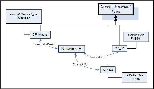
5.5 ConnectsTo and ConnectsToParent ReferenceTypes
The ConnectsTo ReferenceType is a concrete ReferenceType used to indicate that source and target Node have a topological connection. It is NonHierarchical and symmetric, because this is natural for this Reference. The ConnectsTo Reference exists between a Network and the connected Devices (or their ConnectionPoint, respectively). Browsing a Network returns the connected Devices; browsing from a Device, one can follow the ConnectsTo Reference from the Device's ConnectionPoint to the Network.
The ConnectsToParent ReferenceType is a concrete ReferenceType used to define the parent (i.e. the communication Device) of a Network. It is a subtype of the ConnectsTo ReferenceType.
The two ReferenceTypes are illustrated in Figure 23.
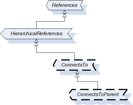
The representation in the AddressSpace is specified in Table 48 and Table 49.
| Attributes | Value | ||
| BrowseName | 1:ConnectsTo | ||
| Symmetric | True | ||
| IsAbstract | False | ||
| References | NodeClass | BrowseName | Comment |
|---|---|---|---|
| Subtype of 0:NonHierarchicalReferences ReferenceType defined in OPC 10000-5. | |||
| Conformance Units | |||
| DI ConnectsTo | |||
| Attributes | Value | ||
| BrowseName | 1:ConnectsToParent | ||
| Symmetric | True | ||
| IsAbstract | False | ||
| References | NodeClass | BrowseName | Comment |
|---|---|---|---|
| Subtype of 1:ConnectsTo ReferenceType | |||
| Conformance Units | |||
| DI ConnectsTo | |||
Figure 24 illustrates how this Reference can be used to express topological relationships and parental relationships. In this example two Devices are connected; the module DPcomm is the communication Device for the Network.
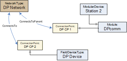
5.6 NetworkSet Object
All Networks shall be components of the NetworkSet Object.
The NetworkSet Node is formally defined in Table 50.
| Attribute | Value | ||
| BrowseName | 1:NetworkSet | ||
| References | NodeClass | BrowseName | TypeDefinition |
|---|---|---|---|
| OrganizedBy by the 0:Objects Folder defined in OPC 10000-5 | |||
| 0:HasTypeDefinition | ObjectType | 0:BaseObjectType | |
| Conformance Units | |||
|---|---|---|---|
| DI NetworkSet |
6 Device integration host model
6.1 General
A Device Integration Host is a Server that manages integration of multiple Devices in an automation system and provides Clients with access to information about Devices regardless of where the information is stored, for example, in the Device itself or in a data store. The Device communication is internal to the host and can be based on field-specific protocols.
The Information Model specifies the entities that can be accessed in a Device Integration Host. This standard does not define how these elements are instantiated. The host can use network scanning services, the OPC UA Node Management Services or proprietary configuration tools.
One of the main tasks of the Information Model is to reflect the topology of the automation system. Therefore, it represents the Devices of the automation system as well as the connecting communication networks including their properties, relationships, and the operations that can be performed on them.
Figure 25 and Figure 26 illustrate an example configuration and the configured topology as it will appear in the Server AddressSpace (details left out).

The PC in Figure 25 represents the Server (the Device Integration Host). The Server communicates with Devices connected to Network "A" via native communication, and it communicates with Devices connected to Network "B" via nested communication.
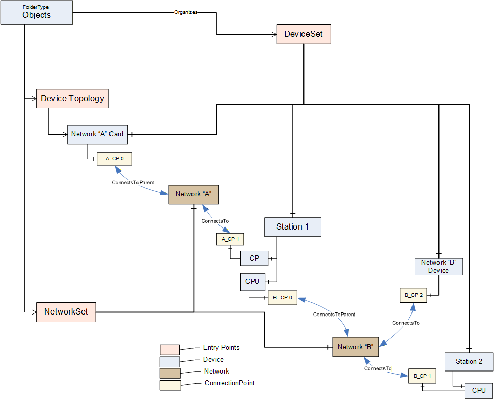
Coloured boxes are used to recognize the various types of information.
Entry points assure common behavior across different implementations:
DeviceTopology: Starting node for the topology configuration. See 6.2.
DeviceSet: See 4.9.
NetworkSet: See 5.6.
6.2 DeviceTopology Object
The Device Topology reflects the communication topology of the Devices. It includes Devices and the Networks. The entry point DeviceTopology is the starting point within the AddressSpace and is used to organize the communication Devices for the top-level Networks that provide access to all instances that constitute the Device Topology ((sub-)networks, devices and communication elements).
The DeviceTopology node is formally defined in Table 51.
| Attribute | Value | |||
| BrowseName | 1:DeviceTopology | |||
| References | NodeClass | BrowseName | DataType | TypeDefinition |
|---|---|---|---|---|
| OrganizedBy by the 0:Objects Folder defined in OPC 10000-5 | ||||
| 0:HasTypeDefinition | ObjectType | 0:BaseObjectType | Defined in OPC 10000-5. | |
| 0:HasProperty | Variable | 1:OnlineAccess | 0:Boolean | 0:PropertyType |
| Conformance Units | ||||
|---|---|---|---|---|
| DI DeviceTopology |
OnlineAccess provides a hint of whether the Server is currently able to communicate to Devices in the topology. "False" means that no communication is available.
6.3 Online/Offline
6.3.1 General
Management of the Device Topology is a configuration task, i.e., the elements in the topology (Devices, Networks, and Connection Points) are usually configured "offline" and - at a later time - will be validated against their physical representative in a real network.
To support explicit access to either the online or the offline information, each element can be represented by two instances that are schematically identical, i.e., there exist component Objects, FunctionalGroups, and so on. A Reference connects online and offline representations and allows to navigate between them.
This is illustrated in Figure 27.
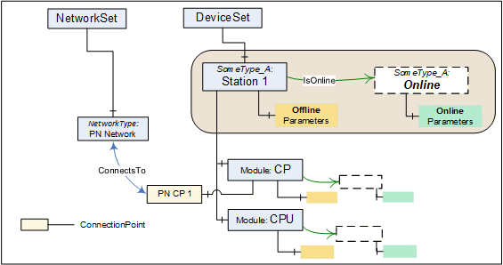
If Online/Offline is supported, the main (leading) instance represents the offline information. Its HasTypeDefinition Reference points to the concrete configured or identified ObjectType. All Parameters of this instance represent offline data points and reading or writing them will typically result in configuration database access. Properties will also represent offline information.
A Device can be engineered through the offline instance without online access.
The online data for a topology element are kept in an associated Object with the BrowseName Online as illustrated in Figure 27. The Online Object is referenced via an IsOnline Reference. It is always of the same ObjectType as the offline instance.
The online Parameter Nodes reflect values in a physical element (typically a Device), i.e., reading or writing to a Parameter value will then result in a communication request to this element. When elements are not connected, reading or writing to the online Parameter will return a proper status code (Bad_NotConnected).
The transfer of information (Parameters) between offline nodes and the physical device in correct order is supported through TransferToDevice, TransferFromDevice together with FetchTransferResultData. These Methods are exposed by means of an AddIn instance of TransferServicesType described in 6.4.2.
Both offline and online are created and driven by the same ObjectType. According to their usability, certain components (Parameters, Methods, and FunctionalGroups) can exist only in either the online or the offline element.
A Parameter in the offline ParameterSet and its corresponding counterpart in the online ParameterSet shall have the same BrowseName. Their NodeIds shall be different, though, since this is the identifier passed by the Client in read/write requests.
The Identification FunctionalGroup organizes Parameters that help identify a topology element. Clients can compare the values of these Parameters in the online and the offline instance to detect mismatches between the configuration data and the currently connected element.
6.3.2 IsOnline ReferenceType
The IsOnline ReferenceType is a concrete ReferenceType used to bind the offline representation of a Device to the online representation. The source and target Node of References of this type shall be an instance of the same subtype of a ComponentType. Each Device shall be the source of at most one Reference of type IsOnline.
The IsOnline ReferenceType is illustrated in Figure 28. Its representation in the AddressSpace is specified in Table 52.
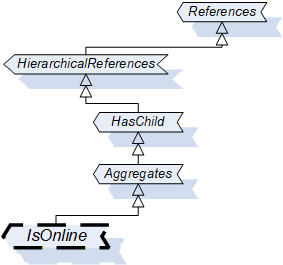
| Attributes | Value | ||
| BrowseName | 1:IsOnline | ||
| InverseName | OnlineOf | ||
| Symmetric | False | ||
| IsAbstract | False | ||
| References | NodeClass | BrowseName | Comment |
|---|---|---|---|
| Subtype of 0:Aggregates ReferenceType defined in OPC 10000-5. | |||
| Conformance Units | |||
| DI Offline | |||
6.4 Offline-Online data transfer
6.4.1 Definition
The "Online-offline data transfer" is based on the AddIn model specified in OPC 10000-3.
The transfer of information (Parameters) between offline nodes and the physical device is supported through OPC UA Methods. These Methods are built on device specific knowledge and functionality.
The transfer is usually terminated if an error occurs for any of the Parameters. No automatic retry will be conducted by the Server. However, whenever possible after a failure, the Server should bring the Device back into a functional state. The Client has to retry by calling the transfer Method again.
The transfer can involve thousands of Parameters so that it can take a long time (up to minutes), and with a result that can be too large for a single response. Therefore, the initiation of the transfer and the collection of result data are performed with separate Methods.
The Device shall have been locked by the Client prior to invoking these Methods (see 7).
6.4.2 TransferServices Type
The TransferServicesType provides the Methods to transfer data to and from the online Device. Figure 29 shows the TransferServicesType definition. It is formally defined in Table 53.
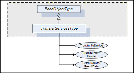
| Attribute | Value | ||||
| BrowseName | 1:TransferServicesType | ||||
| IsAbstract | False | ||||
| References | NodeClass | BrowseName | DataType | TypeDefinition | Other |
|---|---|---|---|---|---|
| Subtype of the 0:BaseObjectType defined in OPC 10000-5 | |||||
| 0:HasComponent | Method | 1:TransferToDevice | M | ||
| 0:HasComponent | Method | 1:TransferFromDevice | M | ||
| 0:HasComponent | Method | 1:FetchTransferResultData | M | ||
| Conformance Units | |||||
|---|---|---|---|---|---|
| DI Offline |
The StatusCode Bad_MethodInvalid shall be returned from the Call Service for Objects where locking is not supported. Bad_UserAccessDenied shall be returned if the Client User does not have the permission to call the Methods.
6.4.3 TransferServices Object
The support of TransferServices for an Object is declared by aggregating an instance of the TransferServicesType as illustrated in Figure 30.
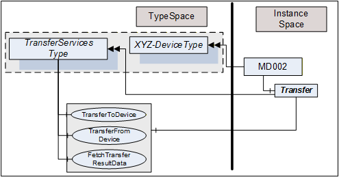
This Object is used as container for the TransferServices Methods and shall have the BrowseName Transfer. HasComponent is used to reference from a Device to its "TransferServices" Object.
The TransferServiceType and each instance can share the same Methods.
6.4.4 TransferToDevice Method
TransferToDevice initiates the transfer of offline configured data (Parameters) to the physical device. This Method has no input arguments. Which Parameters are transferred is based on Server-internal knowledge.
The Server shall ensure integrity of the data before starting the transfer. Once the transfer has been started successfully, the Method returns immediately with InitTransferStatus = 0. Any status information regarding the transfer itself has to be collected using the FetchTransferResultData Method.
The Server will reset any cached value for Nodes in the online instance representing Parameters affected by the transfer. That way the cache will be re-populated from the Device next time they are requested.
The signature of this Method is specified below. Table 54 and Table 55 specify the arguments and AddressSpace representation, respectively.
Signature
	TransferToDevice(

	  [out] 0:Int32                TransferID,
[out] 0:Int32 InitTransferStatus);| Argument | Description |
| TransferID | Transfer Identifier. This ID has to be used when calling FetchTransferResultData. |
| InitTransferStatus | Specifies if the transfer has been initiated. 0 - OK -1 - E_NotLocked - the Device is not locked by the calling Client -2 - E_NotOnline - the Device is not online / cannot be accessed |
| Attribute | Value | ||||
| BrowseName | 1:TransferToDevice | ||||
| References | NodeClass | BrowseName | DataType | TypeDefinition | Other |
|---|---|---|---|---|---|
| 0:HasProperty | Variable | 0:OutputArguments | 0:Argument[] | 0:PropertyType | M |
| Conformance Units | |||||
|---|---|---|---|---|---|
| DI Offline |
6.4.5 TransferFromDevice Method
TransferFromDevice initiates the transfer of values from the physical device to corresponding Parameters in the offline representation of the Device. This Method has no input arguments. Which Parameters are transferred is based on Server-internal knowledge.
Once the transfer has been started successfully, the Method returns immediately with InitTransferStatus = 0. Any status information regarding the transfer itself has to be collected using the FetchTransferResultData Method.
The signature of this Method is specified below. Table 56 and Table 57 specify the arguments and AddressSpace representation, respectively.
Signature
	TransferFromDevice(

	  [out] 0:Int32                TransferID,
[out] 0:Int32 InitTransferStatus);| Argument | Description |
| TransferID | Transfer Identifier. This ID has to be used when calling FetchTransferResultData. |
| InitTransferStatus | Specifies if the transfer has been initiated. 0 - OK -1 - E_NotLocked - the Device is not locked by the calling Client -2 - E_NotOnline - the Device is not online / cannot be accessed |
| Attribute | Value | ||||
| BrowseName | 1:TransferFromDevice | ||||
| References | NodeClass | BrowseName | DataType | TypeDefinition | Other |
|---|---|---|---|---|---|
| 0:HasProperty | Variable | 0:OutputArguments | 0:Argument[] | 0:PropertyType | M |
| Conformance Units | |||||
|---|---|---|---|---|---|
| DI Offline |
6.4.6 FetchTransferResultData Method
The TransferToDevice and TransferFromDevice Methods execute asynchronously after sending a response to the Client. Execution status and execution results are collected during execution and can be retrieved using the FetchTransferResultData Method. The TransferID is used as identifier to retrieve the data.
The Client is assumed to fetch the result data in a timely manner. However, because of the asynchronous execution and the possibility of data loss due to transmission errors to the Client, the Server shall wait some time (some minutes) before deleting data that have not been acknowledged. This should be even beyond Session termination, i.e., Clients that have to re-establish a Session after an error can try to retrieve missing result data.
Result data will be deleted with each new transfer request for the same Device.
FetchTransferResultData is used to request the execution status and a set of result data. If called before the transfer is finished it will return only partial data. The amount of data returned can be further limited if it would be too large. "Too large" in this context means that the Server is not able to return a larger response or that the number of results to return exceeds the maximum number of results that was specified by the Client when calling this Method.
Each result returned to the Client is assigned a sequence number. The Client acknowledges that it received the result by passing the sequence number in the new call to this Method. The Server can delete the acknowledged result and will return the next result set with a new sequence number.
Clients shall not call the Method before the previous one returned. If it returns with an error (e.g., Bad_Timeout), the Client can call the FetchTransferResultData with a sequence number 0. In this case the Server will resend the last result set.
The Server will return Bad_NothingToDo in the Method-specific StatusCode of the Call Service if the transfer is finished and no further result data are available.
The signature of this Method is specified below. Table 58 and Table 59 specify the arguments and AddressSpace representation, respectively.
Signature
	FetchTransferResultData(
	  [in]  0:Int32                 TransferID,
	  [in]  0:Int32                 SequenceNumber,
	  [in]  0:Int32                 MaxParameterResultsToReturn,
	  [in]  Boolean               OmitGoodResults,
[out] FetchResultType FetchResultData);| Argument | Description |
| TransferID | Transfer Identifier returned from TransferToDevice or TransferFromDevice. |
| SequenceNumber | The sequence number being acknowledged. The Server can delete the result set with this sequence number. "0" is used in the first call after initialising a transfer and also if the previous call of FetchTransferResultData failed. |
| MaxParameterResultsToReturn | The number of Parameters in TransferResult.ParameterDefs that the Client wants the Server to return in the response. The Server is allowed to further limit the response, but shall not exceed this limit. A value of 0 indicates that the Client is imposing no limitation. |
| OmitGoodResults | If TRUE, the Server will omit data for Parameters which have been correctly transferred. Note that this causes all good results to be released. |
| FetchResultData | Two subtypes are possible: TransferResultError Type is returned if the transfer failed completely TransferResultData Type is returned if the transfer was performed. Status information is returned for each transferred Parameter. |
| Attribute | Value | ||||
| BrowseName | 1:FetchTransferResultData | ||||
| References | NodeClass | BrowseName | DataType | TypeDefinition | Other |
|---|---|---|---|---|---|
| 0:HasProperty | Variable | 0:InputArguments | 0:Argument[] | 0:PropertyType | M |
| 0:HasProperty | Variable | 0:OutputArguments | 0:Argument[] | 0:PropertyType | M |
| Conformance Units | |||||
|---|---|---|---|---|---|
| DI Offline |
The FetchResultDataType is an abstract type. It is the base DataType for concrete result types of the FetchTransferResultData. Its elements are defined in Table 60.
| Attribute | Value | |||
| BrowseName | 1:FetchResultDataType | |||
| IsAbstract | True | |||
| Subtype of 0:Structure defined in OPC 10000-3 | ||||
| References | NodeClass | BrowseName | DataType | |
|---|---|---|---|---|
| Conformance Units | ||||
| DI Offline | ||||
The TransferResultErrorDataType is a subtype of the FetchResultDataType and represents an error result. It is defined in Table 61.
| Name | Type | Description |
|---|---|---|
| TransferResultErrorDataType | 0:Structure | This structure is returned in case of errors. No result data are returned. Further calls with the same TransferID are not possible. |
status | 0:Int32 | -1 - Invalid TransferID: The Id is unknown. Possible reason: all results have been fetched or the result can have been deleted. -2 - Transfer aborted: The transfer operation was aborted; no results exist. -3 - DeviceError: An error in the device or the communication to the Device occurred. "diagnostics" can contain device- or protocol-specific error information. -4 - UnknownFailure: The transfer failed. "diagnostics" can contain Device- or Protocol-specific error information. |
diagnostics | 0:DiagnosticInfo | Diagnostic information. This parameter is empty if diagnostics information was not requested in the request header or if no diagnostic information was encountered in processing of the request. The DiagnosticInfo type is defined in OPC 10000-4. |
Its representation in the AddressSpace is defined in Table 62.
| Attribute | Value | |||||
| BrowseName | 1:TransferResultErrorDataType | |||||
| IsAbstract | False | |||||
| References | NodeClass | BrowseName | DataType | TypeDefinition | Other | |
|---|---|---|---|---|---|---|
| Subtype of 1:FetchResultDataType. | ||||||
| Conformance Units | ||||||
|---|---|---|---|---|---|---|
| DI Offline |
The TransferResultData DataType is a subtype of the FetchResultDataType and includes parameter-results from the transfer operation. It is defined in Table 63.
| Name | Type | Description |
|---|---|---|
| TransferResultDataDataType | 0:Structure | A set of results from the transfer operation. |
sequenceNumber | 0:Int32 | The sequence number of this result set. |
endOfResults | 0:Boolean | TRUE - all result data have been fetched. Additional FetchTransferResultData calls with the same TransferID will return a FetchTransferError with status=InvalidTransferID. FALSE - further result data shall be expected. |
parameterDefs | 1:ParameterResult DataType [] | Specific value for each Parameter that has been transferred. If OmitGoodResults is TRUE, parameterDefs will only contain Parameters which have not been transferred correctly. |
NodePath | 0:QualifiedName[] | List of BrowseNames that represent the relative path from the Device Object to the Parameter following hierarchical references. The Client can use these names for TranslateBrowsePathsToNodeIds to retrieve the Parameter NodeId for the online or the offline representation. |
statusCode | 0:StatusCode | OPC UA StatusCode as defined in OPC 10000-4 and in OPC 10000-8. |
diagnostics | 0:DiagnosticInfo | Diagnostic information. This parameter is empty if diagnostics information was not requested in the request header or if no diagnostic information was encountered in processing of the request. The DiagnosticInfo type is defined in OPC 10000-4. |
Its representation in the AddressSpace is defined in Table 64.
| Attribute | Value | |||||
| BrowseName | 1:TransferResultDataDataType | |||||
| IsAbstract | False | |||||
| References | NodeClass | BrowseName | DataType | TypeDefinition | Other | |
|---|---|---|---|---|---|---|
| Subtype of 1:FetchResultDataType. | ||||||
| Conformance Units | ||||||
|---|---|---|---|---|---|---|
| DI Offline |
7 Locking model
7.1 Overview
The following Locking feature is based on the AddIn model specified in OPC 10000-3.
Locking is the means to avoid concurrent modifications to an Object by restricting access to the entity (often a Client but could also be an internal process) that initiated the lock. LockingServices are typically used to make a set of changes (for example, several Write operations and Method invocations) and where a consistent state is available only after all of these changes have been performed.
The context of the lock is specific to the ObjectType where it is applied to (subsequently named "lock-owner"). These specifics are to be described as part of this lock-owner ObjectType. See for example the section on lock in the TopologyElement (clause 4.3) and the Network (clause 5.3).
By default, a lock allows other Applications to view (navigate/read) the locked element. However, Servers can choose to implement an exclusive locking where other Applications have no access at all (e.g. in cases where even read operations require certain settings to Variables).
7.2 LockingServices Type
The LockingServicesType provides Methods to manage the lock and Properties with status information. This section describes the common semantic. The lock-owner ObjectTypes will often extend these semantics.
Figure 31 shows the LockingServicesType definition. It is formally defined in Table 65.
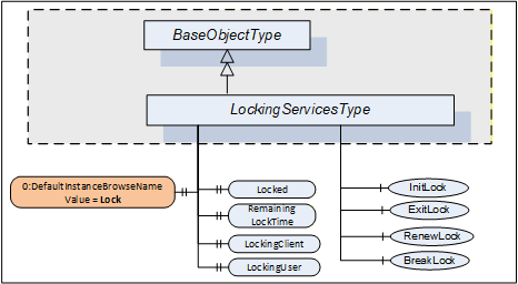
| Attribute | Value | ||||
| BrowseName | 1:LockingServicesType | ||||
| IsAbstract | False | ||||
| References | NodeClass | BrowseName | DataType | TypeDefinition | Other |
|---|---|---|---|---|---|
| Subtype of the 0:BaseObjectType defined in OPC 10000-5. | |||||
| 0:HasComponent | Method | 1:InitLock | Defined in 7.5 | M | |
| 0:HasComponent | Method | 1:RenewLock | Defined in 7.7 | M | |
| 0:HasComponent | Method | 1:ExitLock | Defined in 7.6 | M | |
| 0:HasComponent | Method | 1:BreakLock | Defined in 7.8 | M | |
| 0:HasProperty | Variable | 0:DefaultInstanceBrowseName | 0:QualifiedName | 0:PropertyType | |
| 0:HasProperty | Variable | 1:Locked | 0:Boolean | 0:PropertyType | M |
| 0:HasProperty | Variable | 1:LockingClient | 0:String | 0:PropertyType | M |
| 0:HasProperty | Variable | 1:LockingUser | 0:String | 0:PropertyType | M |
| 0:HasProperty | Variable | 1:RemainingLockTime | 0:Duration | 0:PropertyType | M |
| Conformance Units | |||||
|---|---|---|---|---|---|
| DI Locking |
The StatusCode Bad_MethodInvalid shall be returned from the Call Service for Objects where locking is not supported. Bad_UserAccessDenied shall be returned if the Client User does not have the permission to call the Methods.
The DefaultInstanceBrowseName Property - defined in OPC 10000-3 - is used to specify the recommended BrowseName for instances of the LockingServicesType. Its Value is defined in Table 66.
| Source Path | Value |
| 0:DefaultInstanceBrowseName | Lock |
A lock is typically initiated by a Client calling the InitLock Method and removed by calling the ExitLock Method. The lock-owner ObjectTypes can define mechanisms that automatically initiate and remove a lock.
A lock request will be rejected if operations are active that will be prevented by the lock.
The lock is automatically removed if the MaxInactiveLockTime has elapsed (see 7.4). The lock is also removed when the Session ends during inactivity. This is typically the case when the connection to the Client breaks and the Session times out.
The following LockingServices Properties offer lock-status information.
Locked when True indicates that this element has been locked by some Application and that no or just limited access is available for other Applications.
When the lock is initiated by a Client, LockingClient contains the ApplicationUri of the Client as provided in the CreateSession Service call (see OPC 10000-4). Other options to get this information can be specified on the lock-owner ObjectType.
LockingUser contains information to identify the user. When the lock is initiated by a Client it is obtained directly or indirectly from the UserIdentityToken passed by the Client in the ActivateSession Service call (see OPC 10000-4). Other options to get this information can be specified on the lock-owner ObjectType.
RemainingLockTime denotes the remaining time in milliseconds after which the lock will automatically be removed by the Server. This time is based upon MaxInactiveLockTime (see 7.4).
7.3 LockingServices Object
The support of LockingServices for an Object is declared by aggregating an instance of the LockingServicesType as illustrated in Figure 32.
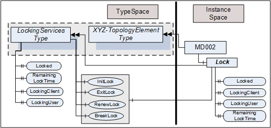
This Object is used as container for the LockingServices Methods and Properties and should have the BrowseName Lock. It shall be referenced using HasComponent or HasAddIn from the lock-owner Object (for example, a Device).
The LockingServicesType and each instance can share the same Methods. All Properties are distinct.
7.4 MaxInactiveLockTime Property
The MaxInactiveLockTime Property shall be added to the ServerCapabilities Object (see OPC 10000-5). It contains a Server-specific period of inactivity in milliseconds after which the Server will revoke the lock.
The Server will initiate a timer based on this time as part of processing the InitLock request and after the last activity caused by the initiator of the lock is finished. Calling the RenewLock Method shall reset the timer.
Inactivity for MaxInactiveLockTime will trigger a timeout. As a result, the Server will release the lock.
The MaxInactiveLockTime Property is formally defined in Table 67.
| References | NodeClass | BrowseName | DataType | TypeDefinition | Other |
| 0:HasProperty | Variable | 1:MaxInactiveLockTime | 0:Duration | 0:PropertyType | M |
7.5 InitLock Method
InitLock restricts access for other UA Applications.
A call of this Method for an element that is already locked will be rejected.
While locked, requests from other Applications to modify the locked element (e.g., writing to Variables, or invoking Methods) should be rejected with Bad_Locked. However, requests to read or navigate will typically work. Servers can choose to implement an exclusive locking where other Applications have no access at all.
The lock is removed when ExitLock is called. It is automatically removed when the MaxInactiveLockTime elapsed (see 7.4).
The signature of this Method is specified below. Table 68 and Table 69 specify the arguments and AddressSpace representation, respectively.
Signature
	InitLock(
	  [in]  0:String       Context,
[out] 0:Int32 InitLockStatus);| Argument | Description |
| Context | A string used to provide context information about the current activity going on in the Client. |
| InitLockStatus | 0 - OK -1 - E_AlreadyLocked - the element is already locked -2 - E_Invalid - the element cannot be locked |
| Attribute | Value | ||||
| BrowseName | 1:InitLock | ||||
| References | NodeClass | BrowseName | DataType | TypeDefinition | Other |
|---|---|---|---|---|---|
| 0:HasProperty | Variable | 0:InputArguments | 0:Argument[] | 0:PropertyType | M |
| 0:HasProperty | Variable | 0:OutputArguments | 0:Argument[] | 0:PropertyType | M |
| Conformance Units | |||||
|---|---|---|---|---|---|
| DI Locking |
7.6 ExitLock Method
ExitLock removes the lock. This Method can only be called from the same Application which initiated the lock.
The signature of this Method is specified below. Table 70 and Table 71 specify the arguments and AddressSpace representation, respectively.
Signature
	ExitLock(
[out] 0:Int32 ExitLockStatus);| Argument | Description |
| ExitLockStatus | 0 - OK -1 - E_NotLocked - the Object is not locked |
| Attribute | Value | ||||
| BrowseName | 1:ExitLock | ||||
| References | NodeClass | BrowseName | DataType | TypeDefinition | Other |
|---|---|---|---|---|---|
| 0:HasProperty | Variable | 0:OutputArguments | 0:Argument[] | 0:PropertyType | M |
| Conformance Units | |||||
|---|---|---|---|---|---|
| DI Locking |
7.7 RenewLock Method
The lock timer is automatically renewed whenever the initiator of the lock issues a request for the locked element or while Nodes of the locked element are subscribed to. RenewLock is used to reset the lock timer to the value of the MaxInactiveLockTime Property and prevent the Server from automatically removing the lock. This Method can only be called from the same Application which initiated the lock.
The signature of this Method is specified below. Table 72 and Table 73 specify the arguments and AddressSpace representation, respectively.
Signature
	RenewLock(
[out] 0:Int32 RenewLockStatus);| Argument | Description |
| RenewLockStatus | 0 - OK -1 - E_NotLocked - the Object is not locked |
| Attribute | Value | |||||
| BrowseName | 1:RenewLock | |||||
| References | NodeClass | BrowseName | DataType | TypeDefinition | Other | |
|---|---|---|---|---|---|---|
| 0:HasProperty | Variable | 0:OutputArguments | 0:Argument[] | 0:PropertyType | M | |
| Conformance Units | |||||
|---|---|---|---|---|---|
| DI Locking |
7.8 BreakLock Method
BreakLock allows a Client (with sufficiently high user rights) to break the lock. This Method will typically be available only to users with administrator privileges. BreakLock should be used with care as the locked element can be in an inconsistent state.
The signature of this Method is specified below. Table 74 and Table 75 specify the arguments and AddressSpace representation, respectively.
Signature
	BreakLock(
[out] 0:Int32 BreakLockStatus);| Argument | Description |
| BreakLockStatus | 0 - OK -1 - E_NotLocked - the Object is not locked |
| Attribute | Value | ||||
| BrowseName | 1:BreakLock | ||||
| References | NodeClass | BrowseName | DataType | TypeDefinition | Other |
|---|---|---|---|---|---|
| 0:HasProperty | Variable | 0:OutputArguments | 0:Argument[] | 0:PropertyType | M |
| Conformance Units | |||||
|---|---|---|---|---|---|
| DI Locking |
8 Software update model
8.1 Overview
The software update model defined in this clause is used to manage the software of a Device. This can include the installation of new software, the update of existing software, the update of a firmware and a limited backup and restore of parameters and firmware as far as it is required for the update. The specific steps to perform the actual installation are only known by the device. They are not exposed by this Information Model.
The use cases that were considered for this Information Model are described in 8.2. Several options that can be combined for a concrete SoftwareUpdateType instance are described in 8.3. Valid combinations of these options are defined in the profiles section. 8.3.5 describes how to implement a Software Update Client that has to deal with several options. The types for this model are formally defined in 8.4 and 8.4.12.
8.2 Use Cases
8.2.1 General
The software update model is used in several scenarios. The following subsections list common use cases that are considered by this model. There are also some use cases that that are not covered. A future version could possibly add features for them.
8.2.2 Supported Use Cases
8.2.2.1 Software Update of constrained devices
The model is intended to be applicable across devices with varying resources and constraints. This is achieved e.g. by various options for the server implementation (see 8.3.4).
8.2.2.2 Update Devices from different manufacturers with a Software Update Client
Allow devices to be updated via Software Update Client software. To address the domain specific constraints this can be a domain-specific client software. (In the manufacturing domain a machine often necessitates to be stopped before the update, whereas in process domain e.g., a redundant device will be activated.) 8.3.5 describes the workflow of a Software Update Client.
8.2.2.3 Update of underlying Devices (e.g., IO Link Devices)
Software update is applicable for any device or software component that is exposed in the Server AddressSpace. This can also represent other devices that are just connected to the device hosting the Server. This can be done using the AddIns described in 8.3.11.
8.2.2.4 Coordinated update of multiple Devices in a machine / plant
When updating several connected devices in a machine or plant the devices possibly are first set into a special "state" where they wait for the start of the update and don't start operating again. After that the updates can be installed in an order defined by the Client (e.g., sensors first, switches last). Finding the best sequence is task of the client implementation or the operator and not in scope of this specification.
The "state" is defined depending on the type of machine / plant. For factory automation this normally means that production and the software on the devices is stopped. For a sensor in process automation this could mean that a replacement value is configured in the controller for the value measured in the device. If a controller requires an update in process automation it often is the passive part of a redundant set of controllers.
It is also necessary that the Client considers the proper sequence when updating the devices. For example, if parts of the network become unreachable due to the update of an infrastructure device.
A server can support the prepare for update option (8.3.4.2) to enable this use case.
8.2.2.5 Partial update without stopping the software
For some updates it is not necessary to stop the software. This could be the case if parts of a software are replaced that are currently not used or if new software is installed. Whether an update can be installed like this is only known by the device and depends on the concrete update file. To support this, the Client can read the UpdateBehavior (8.5.2) to determine if stopping is required.
8.2.2.6 Scheduled update
In some cases, it is required to prepare the update and then plan the start for a later time or under some strategic conditions. In this case the software is transferred to the device first. Later (e.g., at the end of the shift or on the weekend) and under specific conditions (e.g. nothing to produce) the update Client can start the update. In this scenario the time and the conditions are known and checked by the update Client, not by the Server, so for the use of the software update options an established Client-Server connection is required. The scheduling is a task of the Client and not described in this specification.
8.2.2.7 Central distribution for later installation
It should be possible to distribute the software to several devices without actual installation. In this scenario a central tool can determine the required updates and distribute them to all devices. The actual installation can then be started later by a different Client. This is realized by separating the transfer (8.4.1.2) from the installation (8.3.4.6).
8.2.2.8 Update of individual parts of a software
Depending on the device there should be several options to partition a software. For example, it should be possible to structure the firmware of a device in a way that each part can be updated individually. Additionally, software update should be applicable to the firmware of devices and to the software of components. This is realized with the AddIn model (8.3.11).
If a Software Package becomes very large and only parts of it can be replaced, the Server maintains the individual files of the Software Package independently. When all desired files are on the Server, the installation can be started for the set of files. Here the FileSystem option (8.3.4.5) can be used.
8.2.2.9 Reliable update of Devices that are out of reach
Especially for devices that are not easy to access for a manual reset or replacement, the update shall always result in a working OPC UA Client - Server connection. This requires an additional confirmation by the update Client, so that the Server can do an automatic rollback if the communication cannot be established again after a reboot. A Server can support this with the confirmation option (8.3.4.9).
8.2.2.10 Backup and restore parameters that are lost during the update
Very constrained devices can lose parameters during the update. It is necessary that the update Client is aware of that and should be able to backup the parameters in advance. After the update - but before the device starts operating again - the parameters shall be restored. This can be supported using the Parameters object (8.3.4.8).
8.2.2.11 Selecting the correct version to install
An update client selects the correct version of the Software Package to install. The rules behind this decision can be complex and can include e.g., dependency checks or a release process of the distributor and / or operator of the machine. The Server can expose information about the device (8.3.11) and information about the Current Version (8.4.3.2) which is then used by the Client to select an update.
Selecting the new version is done by the user with the help of the update client before transfer and installation. Therefore, it is not in scope of this specification.
8.2.2.12 Installation of additional software
Some devices can run several software applications. The Information Model should allow the Client to transfer and install additional software applications if the Server supports this. This can be done using the FileSystem based Loading (8.3.4.5) or the SoftwareFolderType (8.4.12).
8.2.2.13 Pack software for distribution
An Update Client imports a software along with all metadata and all supporting files. These files can come from different vendors for different devices. For easier transport and handling, a single standardized container file is required.
8.2.2.14 Standard package format for transfer to the device
The Software Update AddIn supports atomic transfer of a single file to the server. To keep the metadata together with the transferred file a standard container file format is required.
Additionally, a server possibly wants to store multiple files (to prevent nesting ZIP in ZIP).
8.2.2.15 Standard package format for transfer from the device (prototype / backup)
If a working device is used as the prototype for other devices the Software Package of an application or configuration can be uploaded. Therefore, an embedded device should be able to create a Software Package and upload it using the SoftwareUpdate AddIn. This package can also be used for backup.
8.2.2.16 Select Software Packages for the SoftwareUpdate AddIn on the device
An Update Client identifies Software Packages that are installable to a SoftwareUpdate AddIn found on the server. For example, getting suitable firmware packages from a repository for a device, which is identified by ManufacturerUri and ProductCode.
8.2.2.17 Check package compatibility before transfer
An Update Client checks the compatibility before transfer anything to a device. This includes selecting the proper version as a valid update.
8.2.2.18 Validate dependencies to hardware, firmware, other software
An Update Client ensures that all dependent hardware / firmware / software components have suitable versions.
8.2.2.19 Support supplementary files in a Software Package
An Update Client presents additional files to the user. This can include release notes, license information, manuals.
8.2.2.20 Prove integrity and authenticity of a Software Package
An Update Client verifies the integrity and authenticity of the files within the Software Package.
8.2.2.21 Support approval by plant operator
In some plants it is required that only those Software Packages can be installed onto the devices that are tested and approved for use in that plant. In that cases the devices is configured to only accept Software Packages with a specific approval signature.
8.2.2.22 Combine Software Packages for a solution
At system design a combination of several devices or several software instances on a single device or machine or UA Server is defined and released. Example: modular devices like PLC, IO Island or Machine. For that case it shall be possible to sign this combination and transfer all related files in a single container. A target shall be configurable to only accept such combinations with a specific valid signature.
8.2.3 Unsupported Use Cases
8.2.3.1 Finding devices that provide the SoftwareUpdate AddIn within a Server
If an OPC UA Server abstracts several devices that support the SoftwareUpdate AddIn, the Information Model shall provide a defined entry point to find all these devices in an efficient manner.
This Use Case is expected to be addressed in other working groups or in a future version of this specification.
A possible solution would be to create a SWUpdate FolderType below DeviceFeatures as it is described in the DI specification. This folder could reference all SoftwareUpdate AddIns.
8.2.3.2 Explicit Restarting the device
In most update scenarios the device can restart automatically during or after the installation. However, there can be situations where it is required to explicitly restart the device by the Client.
This use case is not supported by the current version of this specification. Since this feature can be useful outside of software update it should be realized somewhere outside this specification.
8.2.3.3 Pulling software from an external source
Sometimes it is desirable to store all files required for software update at a central place and have the devices get the files on their own time and pace. In this case the Client would tell the Server only the location of the file. Then the actual transfer is initiated by the device.
There is no specific support for this use case in this specification. However, it is possible to use the described mechanisms to transfer a file that does not contain the actual software but the location of the external source(s) where the software file(s) should be pulled from.
8.3 General
8.3.1 System perspective
Besides specific Clients for specific devices, this specification also describes Software Update Clients that can update devices of various vendors (for additional details see 8.3.5).
For Devices in operational use, it is often necessary to consider the operation state of the software / machine / plant before performing the update (e.g. stop and start the operation). For this case a specialized Client can use additional domain-specific Information Models as part of the update process.
An update can be performed manually by a user for a single device. However, if a lot of devices are maintained on a regular basis an automatic update is desirable. For this scenario the Information Model also allows the transfer of software to the devices without starting the update process. For the installation a Client could control several devices simultaneously.
8.3.2 Types of software
This common model can describe several types of software that could necessitate to be updated or installed. This can be the firmware or operating system of a device but also be one or more software applications that require an update. Configuration can be maintained as software as well. Besides the update, it is also desired to install additional software. The Server can expose all software as a single component or separate it into several smaller components as it is illustrated in Figure 33.
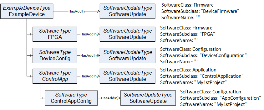
For precise identification of a specific software instance, the SoftwareUpdateType can support additional Properties: The SoftwareClass can be used to distinguish an application from a configuration or firmware. This can be further specialized by the SoftwareSubclass Property for example to identify the type of an application. Finally, the Property SoftwareName can be used to distinguish multiple instances of an application as illustrated in Figure 33 and Figure 34.

8.3.3 Types of Devices
Devices can have different requirements regarding a firmware update, depending on their type and available resource (e.g., memory).
Memory-constrained devices like sensors often cannot store an additional firmware. These devices install the new firmware while it is transferred to the device. In this specification this is called Direct-Loading (see 8.3.4.3).
Devices with more memory can store a new firmware in a separate memory without installing it which is referred as Cached-Loading in this specification (see 8.3.4.4). In this case the installation is separated from the file transfer and can be done later or with a different Client.
Some devices have two memory partitions for the operating system. One active partition that is used in the boot process and a second alternative fallback partition. These devices install the firmware into the fallback partition and then perform a restart after swapping the active partition. This has an advantage if the device detects an issue with the new firmware: The change can easily be reverted to the old version by switching the partitions again (with another reboot).
Constrained devices like sensors typically do not support a real file system. Devices with more memory often have a file system which can be used to store files like firmware, parameters and backups. This Information Model provides update mechanisms for both types of devices (see 8.3.4.5 for FileSystem based Loading).
8.3.4 Options for the Server
8.3.4.1 Overview
Updating software or firmware of a machine or plant is a complex task and different devices have different requirements to the update or installation of software. To support this, the SoftwareUpdateType provides several options where a vendor can select the parts that are necessary for the software update.
All these options are exposed as optional References of the SoftwareUpdateType. A Server can choose which options it wants to support (the Profiles section describes valid combinations of options).
This way the Server can choose between Direct-Loading, Cached-Loading or FileSystem based Loading and it can use additional optional features like manual power cycle, parameter backup / restore or confirmation.
It is necessary that a Software Update Client checks which options are exposed by the Server and how the Server behaves during the update (a Software Update Client is described in 8.3.5).
8.3.4.2 Prepare for update option
There are situations where it is preferable to prepare the device explicitly before the installation and resume operation explicitly after the installation. The PrepareForUpdateStateMachine, which is described in 8.4.7.9 can be used for this task.
This can be the case, when several devices of a machine should be updated at once. All devices have to be prepared first to ensure that all are waiting for an update. After that they can be updated by the Client. At the end after all individual updates are complete the devices can resume operation.
Or a device requires the behavior to enter a safe state (e.g., reaching a safe area) to be able to update the software.
If the installation comprises several steps (e.g., backup parameters, install firmware, restore parameters). The steps can be encapsulated by the Prepare and Resume Methods to ensure consistency between all the steps.
8.3.4.3 Direct-Loading option
The Direct-Loading option provides a model where the installation is part of the transfer. To support the Direct-Loading model the Server has to provide the Current Version. This includes parameters like the version number, a release date or patch identifiers. With this information the Client can decide if an update is required and which version to install.
The Software Package is transferred using the TemporaryFileTransferType (OPC 10000-5). This includes the installation itself so that the installation option is not used.
Note that if the Software Package is installed during the transfer, the server cannot verify the integrity of the complete Software Package before the installation. If this is required, Cached-Loading is a better alternative.
For Direct-Loading the DirectLoadingType is used, which is described in 8.4.4.
8.3.4.4 Cached-Loading option
The Cached-Loading option provides a model where the transfer of the Software Package and its installation are separate steps. To support the Cached-Loading model the Server has to provide the Current Version and the Pending Version. Optionally the Fallback Version can be supported.
With the Current Version the Client can decide if an update is required and which version to transfer. With the Pending Version the Client can ensure to install the desired version after the transfer of the Software Package. With the Fallback Version the Client can install an alternative version.
Software Packages are transferred using the TemporaryFileTransferType (OPC 10000-5). The new software can be transferred in the background without stopping the device. The actual installation of the software can be done later using the installation option.
Note: This loading option is the preferred option for best interoperability between Software Update Clients and Devices.
For Cached-Loading the CachedLoadingType is used, which is described in 8.4.5.
8.3.4.5 FileSystem option
The Cached-Loading option with a self-contained Software Package and concrete definition of the version information can be too restrictive for some devices. E.g., if new software should be installed. For this use case the FileSystem based Loading provides an open structure of files and directories where a Client can read and write. These files could be e.g., configuration, setup files or recipes.
Note: The FileSystem exposed in the AddressSpace is not necessarily congruent with the actual file system of the device.
Note: Since FileSystem based Loading supports adding new software and updating multiple parts with individual versions, there is no standard way to expose the current version number(s) of the system. Therefore, a Software Update Client requires additional vendor-specific information, or other companion specifications must define a more specific use. If the additional flexibility of FileSystem based Loading is not required, Cached-Loading should be preferred.
The purpose of the directories and files is not part of this specification. It is necessary, that Client and the Server know it. Other companion specifications could add this definition for specific types of devices. If accessed by a Software Update Client, the FileSystem root can be used to store and install the files.
For FileSystem based Loading the FileSystemLoadingType is used, which is described in 8.4.6.
8.3.4.6 Installation option
Using the Cached-Loading option or the FileSystem option, a transferred Software Package or file is installed explicitly (compared to the implicit installation of Direct-Loading). Therefore, the InstallationStateMachineType shall be used (see 8.4.9). It can either be used to install a Software Package (Cached-Loading) or a list of files from the FileSystem (File System based Loading).
8.3.4.7 UpdateStatus option
The update Clients are often operated by human users. Since an update normally is a long process, the user would like to see the current state. At a first glance the percentage can give a hint about completion of the update, especially if several devices are updated at the same time. But if there are unexpected delays or errors the user requies a detailed textual description about the current update action or issue.
This can be accomplished with the UpdateStatus Variable (see 8.4.1.8). A Client can subscribe to it for a user display. At least if a state machine is in an error state the UpdateStatus should provide a meaningful error message for the user.
8.3.4.8 Parameter backup / restore option
If the device cannot keep the parameters during the update, it shall support the Parameters Object of the SoftwareVersionType (see 8.4.1.7). If supported by the Server, the update Client should perform a backup of the parameters before and restore the parameters after the software update.
8.3.4.9 Confirmation option
The confirmation option supports the use case of 8.2.2.9: A Client can set a ConfirmationTimeout before the installation. After every reboot of the Server caused by the update, it shall wait this time for a call to the Confirm Method. If the call is not received the Server shall perform a rollback to enable a working Client - Server connection again. This state machine is defined in 8.4.11.
8.3.4.10 Power cycle option
The power cycle option is intended for devices where a manual power cycle is required. During the installation the state WaitingForPowerCycle informs the user that it is time to turn the power off and on again. The PowerCycleStateMachineType is defined in 8.4.10.
If an instance of the SoftwareUpdateType supports the power cycle option, the UpdateBehavior RequiresPowerCycle shall indicate if this can happen for an installation.
This power cycle state machine is used in combination with the installation. For Cached-Loading it can be used in the Installing state of the InstallationStateMachineType. For Direct-Loading it can be used during the transfer of the new software with the TemporaryFileTransferType (OPC 10000-5) of the DirectLoadingType.
8.3.5 Software Update Client
The first task of a Software Update Client is to find the components that support software update. After that it can execute the update of the components one by one or in parallel. The following activity diagrams illustrate how a Software Update Client can perform an update using the different update types. The first task is to detect what options are supported by browsing the references of the SoftwareUpdate AddIn. Then the Client can check the version information to determine whether an update is necessary. This is illustrated in Figure 35.
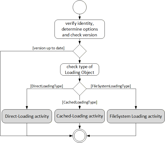
The activities of the different loading types are slightly different. With Cached-Loading the Client can check CurrentVersion and PendingVersion Objects to determine if the Software Package is already transferred. With the FileSystem based Loading the Client can browse the FileSystem to find out which files are already transferred. For Cached-Loading and File System based Loading the transfer can be done in advance. There are different ways to get the UpdateBehavior, because for Cached-Loading and File System based Loading this depends on the actual software that should be installed (with Direct-Loading the server has no information about the new software). For Direct-Loading and Cached-Loading the validation is done during the transfer. For File System based Loading this shall be done before the installation as an extra step. These steps are illustrated in Figure 36.
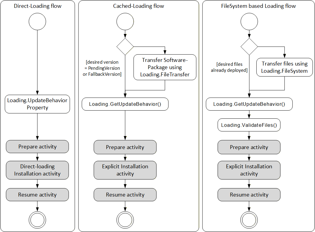
The prepare activity can be handled equal for all types of loading. This optionally includes a backup if the device cannot keep the parameters during update. The activity is shown in Figure 37.
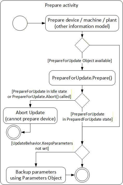
The actual installation of Direct-Loading is done during the transfer. At the end there can be a manual power cycle (option). In some cases (if the Server is on the device that is updated) the Server is rebooted and the Client is required to reconnect to complete the installation. This is illustrated in Figure 38.
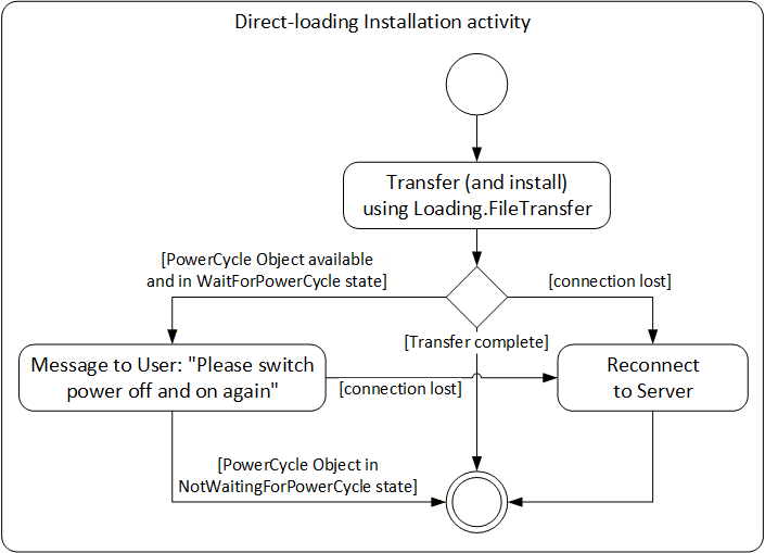
For Cached-Loading and File System based Loading the installation is done using the InstallationStateMachineType. For Cached-Loading the InstallSoftwarePackage Method is used and for File System based Loading the InstallFiles Method is used. During this installation there can also be a manual power cycle request requiring operator input. The Client possibly is required to reconnect one or more times due to automatic reboots. If the Confirmation Object is available, the Client can use it during the installation. This is illustrated in Figure 39.
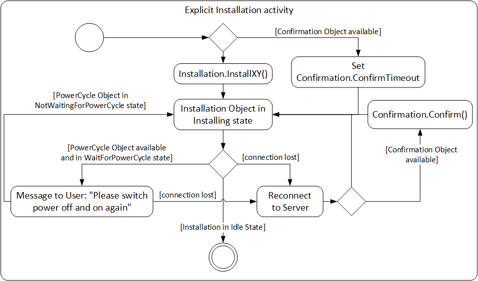
The resume activity can be handled equal for all types of loading. This optionally includes restore if the device cannot keep the parameters during update. The activity is shown in Figure 40.
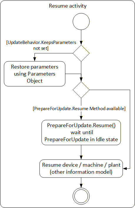
8.3.6 Safety considerations
Especially for safety critical devices the update Client shall inform the user before performing critical activities. This includes the information if a manual power cycle is required, if the device will reboot or if it will lose its parameters during the update. This information can be accessed before the actual update is started. For safety all security considerations also apply.
8.3.7 Security considerations
Security is a critical aspect of software update. The basic requirements can be solved with the existing UA security mechanisms (secure transport, authorization and role-based authentication). Only authorized users shall be able to install and manage updates.
It is necessary that the Client verifies the identity of the device. This can be accomplished by identification information provided by OPC UA, by this specification or by companion specifications.
It is necessary that the authenticity (integrity and source) of the Software Package is verified. These aspects can be implemented by the device in a vendor specific way e.g., verify a digital signature of the Software Package. These mechanisms are out of scope of this specification.
8.3.8 Update Behavior
The concrete process of the installation can depend on the device and on the software that is to be installed. Therfore the server provides the UpdateBehavior OptionSet (see 8.5.2). The UpdateBehavior can be determined with the UpdateBehavior Variable (see 8.4.4.3) of the DirectLoadingType or with one of the GetUpdateBehavior Methods of the CachedLoadingType (see 8.4.5.5) or the FileSystemLoadingType (see 8.4.6.3).
8.3.9 Installation of patches
Instead of updating the whole software with a new version, sometimes the software is "patched"; i.e. only a part of it is replaced. The installation of such a patch can be implemented in the same way as the installation of a complete version. The only difference is that the result is not a new SoftwareRevision but an additional entry in the list of patch-identifiers stored in the PatchIdentifiers Variable (see 8.4.7.5).
8.3.10 Incompatible parameters / settings
If parameters or settings of an old software do not work with the new software, the installation of the new software can complete but the device still cannot start as before. In this case the Server should treat the installation as successful. It can inform the incompatibility using e.g., the IDeviceHealthType Interface (see 4.5.4) of the device / component. This issue can be resolved later by a client that fixes or updates the parameters.
8.3.11 AddIn model
To support an individual software update for the devices of a Server AddressSpace the software update model is defined using the AddIn model as it is described in OPC 10000-3. An instance of SoftwareUpdateType shall be attached to either Objects that implement the Interface IVendorNameplateType (see 4.5.2) or Objects that support an Identification FunctionalGroup (see B.2) that implements IVendorNameplateType. For the AddIn instance the fixed BrowseName "SoftwareUpdate" shall be used. This model gives any device, hardware- or software-component the opportunity to support SoftwareUpdate.
With this mechanism it is also possible to update parts of a software independently: A Server could expose parts as additional software components with their own update AddIn.
To identify the device / component that is the target for the software update, the IVendorNameplateType Interface is used. In this Interface at least the Variables Manufacturer, ManufacturerUri, ProductCode and SoftwareRevision shall be supported and have valid values. Optionally Model and HardwareRevision should be supported. These Properties can be shown to the operator. ManufacturerUri, ProductCode and HardwareRevision should be used to identify the component.
Note that the Properties SoftwareRevision, Manufacturer and ManufacturerUri also appears in the CurrentVersion of the PackageLoadingType. Their values can be different, if the manufacturer of the Device is not the same as the manufacturer of the software. The SoftwareRevision Object shall be the same at both places.
The ComponentType (see 4.5.7) already implements the Interface IVendorNameplateType. This makes it a good candidate for a SoftwareUpdate AddIn as illustrated in the example in Figure 41.
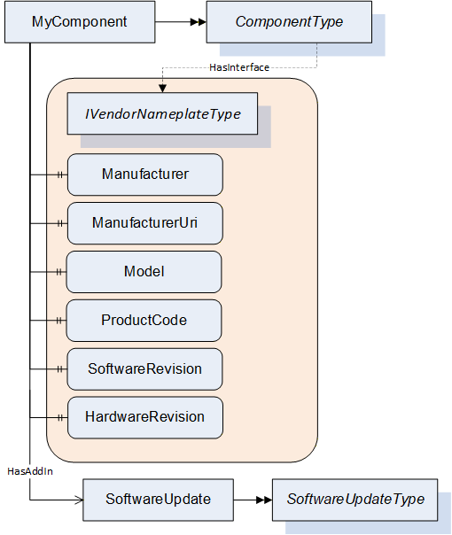
8.4 ObjectTypes
8.4.1 SoftwareUpdateType
8.4.1.1 Overview
The SoftwareUpdateType defines an AddIn which can be used to extend Objects with software update features. All software update options are exposed as references of this AddIn. This way a Client can check for the references of the AddIn to determine which options are provided by a Server. If an option is available, it shall be used as specified.
The SoftwareUpdateType is illustrated in Figure 42 and formally described in Table 76.
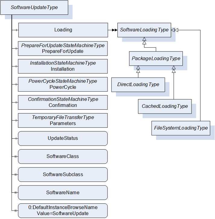
| Attribute | Value | ||||
| BrowseName | 1:SoftwareUpdateType | ||||
| IsAbstract | False | ||||
| References |
Node
Class | BrowseName | DataType | TypeDefinition | Other |
|---|---|---|---|---|---|
| Subtype of the 0:BaseObjectType defined in OPC 10000-5. | |||||
| 0:HasComponent | Object | 1:Loading | 1:SoftwareLoadingType | O | |
| 0:HasComponent | Object | 1:PrepareForUpdate | 1:PrepareForUpdateStateMachineType | O | |
| 0:HasComponent | Object | 1:Installation | 1:InstallationStateMachineType | O | |
| 0:HasComponent | Object | 1:PowerCycle | 1:PowerCycleStateMachineType | O | |
| 0:HasComponent | Object | 1:Confirmation | 1:ConfirmationStateMachineType | O | |
| 0:HasComponent | Object | 1:Parameters | 0:TemporaryFileTransferType | O | |
| 0:HasComponent | Variable | 1:UpdateStatus | 0:LocalizedText | 0:BaseDataVariableType | O |
| 0:HasProperty | Variable | 1:SoftwareClass | SoftwareClass | 0:PropertyType | O |
| 0:HasProperty | Variable | 1:SoftwareSubclass | 0:String | 0:PropertyType | O |
| 0:HasProperty | Variable | 1:SoftwareName | 0:String | 0:PropertyType | O |
| 0:HasProperty | Variable | 1:UnsignedPackageAllowed | 0:Boolean | 0:PropertyType | O |
| 0:HasComponent | Variable | 1:VendorErrorCode | 0:Int32 | 0:BaseDataVariableType | O |
| 0:HasProperty | Variable | 0:DefaultInstanceBrowseName | 0:QualifiedName | 0:PropertyType | |
| Conformance Units | |||||
|---|---|---|---|---|---|
| DI SU Software Update |
8.4.1.2 Loading
The optional Loading Object is of type SoftwareLoadingType, which is abstract. The Object can be one of the concrete sub-types DirectLoadingType (8.4.4), CachedLoadingType (8.4.5) or FileSystemLoadingType (8.4.6). SoftwareLoadingType is formally defined in 8.4.2.
The Loading Object is required for all variations of software installation, it is not required for read or restore of device parameters using the Parameters Object.
8.4.1.3 PrepareForUpdate
The optional PrepareForUpdate Object is of type PrepareForUpdateStateMachineType which is formally defined in 8.4.7.9.
8.4.1.4 Installation
This optional Installation Object is of type InstallationStateMachineType which is formally defined in 8.4.9.
8.4.1.5 PowerCycle
This optional PowerCycle Object is of type PowerCycleStateMachineType which is formally defined in 8.4.10.
8.4.1.6 Confirmation
This optional Confirmation Object is of type ConfirmationStateMachineType which is formally defined in 8.4.11.
8.4.1.7 Parameters
This optional Parameters Object is of type TemporaryFileTransferType (OPC 10000-5). It can be supported by devices that cannot retain parameters during update. If supported by the SoftwareUpdate AddIn a Client can read the parameters before the update and restore them after the update. This is not a general-purpose backup and restore function. It is intended to be used in the context of software update.
The GenerateFileForRead and GenerateFileForWrite Methods accept an unspecified generateOptions Parameter. This argument is not used, and Clients shall always pass null. Future versions of this specification can define concrete DataTypes.
If the restore of parameters succeeds but the software cannot run properly this should not be treated as an error of the restore. Instead, this should be indicated using the IDeviceHealthType Interface of the device / component.
8.4.1.8 UpdateStatus
This optional localized string provides status and error information for the update. This can be used whenever a long running update activity can provide detailed information to the user or when a state machine wants to provide error information to the user.
A Server can provide any text it wants to show to the operator of the software update. Important texts are the error messages in case anything went wrong, and the installation or preparation could not complete. These messages should explain what happened and how the operator could resolve the issue (e.g. "try again with a different version"). During preparation and installation, it is good practice to inform the operators about the current action to keep them patient and waiting for the completion. Also, if the installation gets stuck this text would help to find out the reason.
The UpdateStatus can be used together with the PrepareForUpdateStateMachineType (8.4.7.9), the InstallationStateMachineType (8.4.9) and for CachedLoadingType (8.4.5), DirectLoadingType (8.4.4) and FileSystemLoadingType (8.4.6) it can be used during the transfer of the Software Package.
8.4.1.9 SoftwareClass
The optional SoftwareClass Property is used to distinguish device firmware from executable applications and from supporting configuration. A Software Update Client can use this information together with the SoftwareSubclass and the SoftwareName to identify the associated component (See 8.3.2).
8.4.1.10 SoftwareSubclass
The optional SoftwareSubclass Property can be used to further specialize the type of software (See 8.3.2).
8.4.1.11 SoftwareName
If there can be more than one instance of a software, the optional SoftwareName Property can be used distinguish the individual instances (see 8.3.2).
8.4.1.12 UnsignedPackagesAllowed
This Property indicates whether the server accepts Software Packages that are not signed.
8.4.1.13 VendorErrorCode
The optional VendorErrorCode Property provides a machine-readable error code in case anything went wrong during the transfer, the installation, or the preparation. Comparable to an error message in UpdateStatus this Variable can provide additional information about the issue. The VendorErrorCode is an additional information for a Client. It is not required for normal operation and error handling.
The value 0 shall be interpreted as no error.
The VendorErrorCode can be used together with the PrepareForUpdateStateMachineType (8.4.7.9) for prepare and resume, in the InstallationStateMachineType (8.4.9) during the installation. For CachedLoadingType (8.4.5), DirectLoadingType (8.4.4) and FileSystemLoadingType (8.4.6) it can be used during the transfer of the Software Package.
8.4.1.14 DefaultInstanceBrowseName
The DefaultInstanceBrowseName Property - defined in OPC 10000-3 - is required for the AddIn model as specified in 8.3.11. It is used to specify the BrowseName of the instance of the SoftwareUpdateType. It always has the value "SoftwareUpdate".
| Source Path | Value |
| 0:DefaultInstanceBrowseName | SoftwareUpdate |
8.4.2 SoftwareLoadingType
8.4.2.1 Overview
The SoftwareLoadingType is the abstract base for all different kinds of loading. The concrete information and behavior is modeled in its sub-types.
The SoftwareLoadingType is formally defined in Table 78.
| Attribute | Value | ||||
| BrowseName | 1:SoftwareLoadingType | ||||
| IsAbstract | True | ||||
| References | NodeClass | BrowseName | DataType | TypeDefinition | Other |
|---|---|---|---|---|---|
| Subtype of the 0:BaseObjectType defined in OPC 10000-5 | |||||
| 0:HasSubtype | ObjectType | 1:PackageLoadingType | |||
| 0:HasSubtype | ObjectType | 1:FileSystemLoadingType | |||
| 0:HasComponent | Variable | 1:UpdateKey | 0:String | 0:BaseDataVariableType | O |
| Conformance Units | |||||
|---|---|---|---|---|---|
| DI SU Software Update |
8.4.2.2 UpdateKey
The optional write-only UpdateKey Object can be used if the underlying system requires some key to unlock the update feature. The format and where to get the key is vendor-specific and not described in this specification. If UpdateKey is supported, the Client shall set the key before the installation. If the PrepareForUpdateStateMachine is used, the UpdateKey shall be set before the Prepare Method is called. The Server shall not keep the value for more than one update.
8.4.3 PackageLoadingType
8.4.3.1 Overview
The PackageLoadingType provides information about the Current Version and allows transfer of a Software Package to and from the Server.
The PackageLoadingType is illustrated in Figure 43 and formally defined in Table 79.
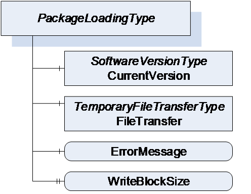
| Attribute | Value | ||||
| BrowseName | 1:PackageLoadingType | ||||
| IsAbstract | True | ||||
| References | NodeClass | BrowseName | DataType | TypeDefinition | Other |
|---|---|---|---|---|---|
| Subtype of the SoftwareLoadingType | |||||
| 0:HasComponent | Object | 1:CurrentVersion | 1:SoftwareVersionType | M | |
| 0:HasComponent | Object | 1:FileTransfer | 0:TemporaryFileTransferType | M | |
| 0:HasComponent | Variable | 1:ErrorMessage | 0:LocalizedText | 0:BaseDataVariableType | M |
| 0:HasProperty | Variable | 1:WriteBlockSize | 0:UInt32 | 0:PropertyType | O |
| 0:HasSubtype | ObjectType | 1:DirectLoadingType | |||
| 0:HasSubtype | ObjectType | 1:CachedLoadingType | |||
| Conformance Units | |||||
|---|---|---|---|---|---|
| DI SU Software Update |
8.4.3.2 CurrentVersion
To identify the Current Version, the CurrentVersion Object provides ManufacturerUri, SoftwareRevision and PatchIdentifiers along with other information that allows the user to identify the currently used software. With this information the Client can determine a suitable update.
Note: This version information is about the installed software. The Manufacturer is not necessarily the same as the Manufacturer of the physical device that executes the software.
8.4.3.3 FileTransfer
8.4.3.3.1 General
The FileTransfer Object is of type TemporaryFileTransferType as defined in OPC 10000-5. It is used to create temporary files for download and upload of the Software Package. See 8.7 for the definition of a standard packaging format.
In the TemporaryFileTransferType type the GenerateFileForRead and GenerateFileForWrite Methods take an unspecified generateOptions Parameter. For the FileTransfer Object an Enumeration of type SoftwareVersionFileType is used for this Parameter. It is used to select the file to upload or download. All allowed values are defined in Table 112. Additional Result Codes of the GenerateFileForRead and GenerateFileForWrite Methods are specified in Table 80.
| Result Code | Description |
| Bad_InvalidState | This result code is only used with DirectLoading. f the PrepareForUpdate is available, the UpdateBehavior requires preparation and the PrepareForUpdate state machine is not in the state PreparedForUpdate. |
| Bad_NotFound | If there is no file to read from the device. |
| Bad_NotSupported | If the device does not support to upload / download of the Software Package. |
For all errors that occur during the file transfer the ErrorMessage Variable should provide an error message for the user.
It is implementation dependent which version (see SoftwareVersionFileType in 8.5.1) is readable and which one is writable. Additional restrictions are defined in the concrete sub-types of PackageLoadingType.
8.4.3.3.2 Transfer to the device
The software is transferred as a single package. File type and content are device specific. If WriteBlockSize is supported, the Client shall write the file in chunks of this size.
The software should be validated during the transfer process. Errors shall be indicated either in the Write Method, the CloseAndCommit Method or an asynchronous completion of the file transfer. If the validation is performed synchronous, the Method returns Bad_InvalidArgument; if the validation is performed asynchronous, the error is indicated by the Error state of the FileTransferStateMachineType. If the ErrorMessage Variable is provided, it shall contain an error message representing the validation error.
8.4.3.3.3 Transfer from the device
The FileTransfer Object can optionally support the transfer of a Software Package from the device to the Client.
If this transfer is not supported, the Server shall return the Result Code Bad_NotSupported. If it is supported but there is currently no data, the Result Code Bad_NotFound shall be used instead.
8.4.3.4 ErrorMessage
This is a textual information about errors that can occur with the file transfer. Whenever a method of the TemporaryFileTransferType returns an error, the ErrorMessage Variable should provide a localized error message for the user. For every new file transfer the value should be reset to an empty string.
8.4.3.5 WriteBlockSize
Optional size of the Blocks (number of bytes) that a Client shall write to the file. The client shall write the Software Package in chunks of this size to the FileType object (the last Block can be smaller).
8.4.4 DirectLoadingType
8.4.4.1 Overview
The DirectLoadingType provides information about the Current Version and allows transfer of a Software Package to and from the Server. Transfer of the Software Package to the Server also includes the installation. The Direct-Loading option is described in 8.3.4.3.
The DirectLoadingType is illustrated in Figure 44 and formally defined in Table 81.
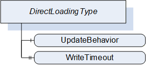
| Attribute | Value | ||||
| BrowseName | 1:DirectLoadingType | ||||
| IsAbstract | False | ||||
| References | NodeClass | BrowseName | DataType | TypeDefinition | Other |
|---|---|---|---|---|---|
| Subtype of the 1:PackageLoadingType | |||||
| 0:HasComponent | Variable | 1:UpdateBehavior | 1:UpdateBehavior | 0:BaseDataVariableType | M |
| 0:HasProperty | Variable | 1:WriteTimeout | 0:Duration | 0:PropertyType | O |
| Conformance Units | |||||
|---|---|---|---|---|---|
| DI SU DirectLoading |
8.4.4.2 FileTransfer
The FileTransfer Object is inherited from the PackageLoadingType. In this sub-type the Current version shall be writable (see SoftwareVersionFileType in 8.5.1). Writing to this file also includes the actual installation.
8.4.4.3 UpdateBehavior
The UpdateBehavior OptionSet informs the update Client about the specific behavior of the component during update via Direct-Loading.
8.4.4.4 WriteTimeout
Optional Property that informs the Client about the maximum duration of the call to the Write Method of FileType (maximum time the write of a block of data can take). If the write operation takes longer the Client can assume that the Server has an issue.
8.4.5 CachedLoadingType
8.4.5.1 Overview
The CachedLoadingType provides information about the Current Version, the Pending Version and the Fallback Version (if supported). Additionally, it allows upload and download of different versions of the software. The Cached-Loading option is described in 8.3.4.4.
The CachedLoadingType is illustrated in Figure 45 and formally defined in Table 82.
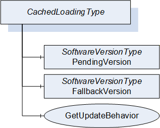
| Attribute | Value | ||||
| BrowseName | 1:CachedLoadingType | ||||
| IsAbstract | False | ||||
| References | NodeClass | BrowseName | DataType | TypeDefinition | Other |
|---|---|---|---|---|---|
| Subtype of the 1:PackageLoadingType | |||||
| 0:HasComponent | Object | 1:PendingVersion | 1:SoftwareVersionType | M | |
| 0:HasComponent | Object | 1:FallbackVersion | 1:SoftwareVersionType | O | |
| 0:HasComponent | Method | 1:GetUpdateBehavior | M | ||
| Conformance Units | |||||
|---|---|---|---|---|---|
| DI SU CachedLoading |
8.4.5.2 FileTransfer
The FileTransfer Object is inherited from the PackageLoadingType. In this sub-type the Current version shall not be writable and the Pending version shall be writable (see SoftwareVersionFileType in 8.5.1).
8.4.5.3 PendingVersion
The PendingVersion Object describes an already transferred new Software Package that is ready to be installed.
If there is no Software Package available, the values should be empty.
8.4.5.4 FallbackVersion
The optional FallbackVersion Object describes an alternate version on the device. This could be a factory default version or the version before the last update. Installing the Fallback Version can be used to revert to a reliable version of the software.
If a Fallback Version is supported by the device the object shall be available. If there is currently no Fallback Version on the device, the values should be empty.
8.4.5.5 GetUpdateBehavior Method
With this Method the Client can check the specific update behavior for a specified software version. To identify the version the GetUpdateBehavior Method requires the ManufacturerUri, SoftwareRevision and PatchIdentifiers Properties of the SoftwareVersionType.
Signature
	GetUpdateBehavior(
	  [in]	0:String		ManufacturerUri,
	  [in]	0:String		SoftwareRevision,
	  [in]	0:String[]		PatchIdentifiers,
	  [out]	UpdateBehavior	UpdateBehavior);
| Argument | Description |
| ManufacturerUri | ManufacturerUri Property of either the Pending or Fallback SoftwareVersionType that should be installed. |
| SoftwareRevision | SoftwareRevision Property of either the Pending or Fallback SoftwareVersionType that should be installed. |
| PatchIdentifiers | PatchIdentifiers Property of either the Pending or Fallback SoftwareVersionType that should be installed. (or empty array if not supported by the SoftwareVersionType instance) |
| UpdateBehavior | Update behavior option set for the specified SoftwareVersionType instance |
Method Result Codes (defined in Call Service)
| Result Code | Description |
| Bad_NotFound | If the Software Package, identified by the parameters, does not exist. |
| Attribute | Value | ||||
| BrowseName | 1:GetUpdateBehavior | ||||
| References | NodeClass | BrowseName | DataType | TypeDefinition | Other |
|---|---|---|---|---|---|
| 0:HasProperty | Variable | 0:InputArguments | 0:Argument[] | 0:PropertyType | M |
| 0:HasProperty | Variable | 0:OutputArguments | 0:Argument[] | 0:PropertyType | M |
| Conformance Units | |||||
|---|---|---|---|---|---|
| DI SU CachedLoading |
8.4.6 FileSystemLoadingType
8.4.6.1 Overview
The FileSystemLoadingType enables software update based on an open file system. This enables the FileSystem based Loading option of 8.3.4.5.
It is illustrated in Figure 46 and formally defined in Table 85.
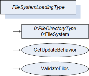
| Attribute | Value | ||||
| BrowseName | 1:FileSystemLoadingType | ||||
| IsAbstract | False | ||||
| References | NodeClass | BrowseName | DataType | TypeDefinition | Other |
|---|---|---|---|---|---|
| Subtype of the SoftwareLoadingType | |||||
| 0:HasComponent | Object | 0:FileSystem | 0:FileDirectoryType | M | |
| 0:HasComponent | Method | 1:GetUpdateBehavior | M | ||
| 0:HasComponent | Method | 1:ValidateFiles | O | ||
| Conformance Units | |||||
|---|---|---|---|---|---|
| DI SU FileSystem Loading |
8.4.6.2 FileSystem
The FileSystem Object is of type FileDirectoryType as it is defined in OPC 10000-5. It provides access to a hierarchy of directories and files of the device. The structure can be read and written by the Client however the device can restrict this for specific folders or files.
8.4.6.3 GetUpdateBehavior Method
This Method can be used to check the specific update behavior for a set of files. The files are identified by the NodeId of their FileType instance in the FileSystem.
Signature
	GetUpdateBehavior(
	  [in]  0:NodeId[]		NodeIds,
[out] UpdateBehavior UpdateBehavior);| Argument | Description |
| NodeIds | NodeIds of the files to install. |
| UpdateBehavior | Update behavior OptionSet for the files specified by NodeId |
Method Result Codes (defined in Call Service)
| Result Code | Description |
| Bad_NotFound | If one or more NodeIds are not found. |
| Attribute | Value | ||||
| BrowseName | 1:GetUpdateBehavior | ||||
| References | NodeClass | BrowseName | DataType | TypeDefinition | Other |
|---|---|---|---|---|---|
| 0:HasProperty | Variable | 0:InputArguments | 0:Argument[] | 0:PropertyType | M |
| 0:HasProperty | Variable | 0:OutputArguments | 0:Argument[] | 0:PropertyType | M |
| Conformance Units | |||||
|---|---|---|---|---|---|
| DI SU FileSystem Loading |
8.4.6.4 ValidateFiles Method
This Method can be used to check if the specified set of files are valid and complete for an installation. This should also include dependency checks if appropriate.
Note: In case of Direct-Loading or Cached-Loading these checks should be part of the transfer and this method shall not be supported since it is part of the file transfer (e.g., in CloseAndCommit).
Signature
	ValidateFiles(
	  [in] 0:NodeId[]		NodeIds,
	  [out] 0:Int32		ErrorCode,
[out] 0:LocalizedText ErrorMessage);| Argument | Description |
| NodeIds | NodeIds of the files to validate. |
| ErrorCode | 0 for success or device specific number for validation issues. |
| ErrorMessage | Message for the user that describes how to resolve the issue. |
Method Result Codes (defined in Call Service)
| Result Code | Description |
| Bad_NotFound | If one or more NodeIds are not found. |
| Attribute | Value | ||||
| BrowseName | 1:ValidateFiles | ||||
| References | NodeClass | BrowseName | DataType | TypeDefinition | Other |
|---|---|---|---|---|---|
| 0:HasProperty | Variable | 0:InputArguments | 0:Argument[] | 0:PropertyType | M |
| 0:HasProperty | Variable | 0:OutputArguments | 0:Argument[] | 0:PropertyType | M |
| Conformance Units | |||||
|---|---|---|---|---|---|
| DI SU FileSystem Loading |
8.4.7 SoftwareVersionType
8.4.7.1 Overview
The SoftwareVersionType identifies a concrete version of a software. It is used by the CachedLoadingType (8.4.5) and the DirectLoadingType (8.4.4) to store the version information.
The Description Attribute on the instances of the SoftwareVersionType should be used to provide additional information about the concrete version of the software to the user (e.g., change notes).
The SoftwareVersionType is illustrated in Figure 47 and formally defined in Table 90.
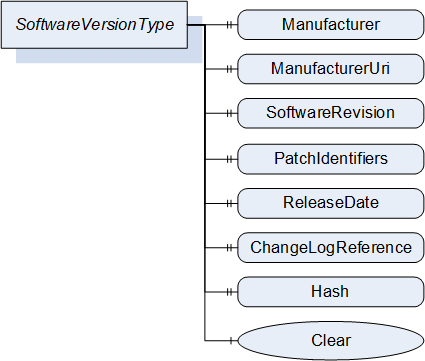
| Attribute | Value | ||||
| BrowseName | 1:SoftwareVersionType | ||||
| IsAbstract | False | ||||
| References | NodeClass | BrowseName | DataType | TypeDefinition | Other |
|---|---|---|---|---|---|
| Subtype of the 0:BaseObjectType defined in OPC 10000-5 | |||||
| 0:HasProperty | Variable | 1:Manufacturer | 0:LocalizedText | 0:PropertyType | M |
| 0:HasProperty | Variable | 1:ManufacturerUri | 0:String | 0:PropertyType | M |
| 0:HasProperty | Variable | 1:SoftwareRevision | 0:String | 0:PropertyType | M |
| 0:HasProperty | Variable | 1:PatchIdentifiers | 0:String[] | 0:PropertyType | O |
| 0:HasProperty | Variable | 1:ReleaseDate | 0:DateTime | 0:PropertyType | O |
| 0:HasProperty | Variable | 1:ChangeLogReference | 0:String | 0:PropertyType | O |
| 0:HasProperty | Variable | 1:Hash | 0:ByteString | 0:PropertyType | O |
| 0:HasComponent | Method | 1:Clear | O | ||
| Conformance Units | |||||
|---|---|---|---|---|---|
| DI SU Software Update |
8.4.7.2 Manufacturer
The read only Manufacturer Property provides the name of the company that created the software.
In case of the Pending Version this shall be empty if there is no pending software to install.
8.4.7.3 ManufacturerUri
The read only ManufacturerUri Property provides a unique identifier for the manufacturer of the software.
In case of the Pending Version this shall be empty if there is no pending software to install.
8.4.7.4 SoftwareRevision
The read only SoftwareRevision Property defines the version of the software. The format and semantics of the string is vendor-specific. SemanticVersionString (a sub-type of String defined in OPC 10000-5) can be used when using the Semantic Versioning format.
In case of the Pending Version this shall be empty if there is no pending software to install.
8.4.7.5 PatchIdentifiers
The read only PatchIdentifiers Property identifies the list of patches that are applied to a software version. The format and semantics of the strings are vendor-specific. The order of the strings shall not be relevant.
8.4.7.6 ReleaseDate
The read only ReleaseDate Property defines the date when the software is released. If the version information is about patches, this should be the date of the latest patch. It is additional information for the user.
8.4.7.7 ChangeLogReference
The read only ChangeLogReference Property can optionally provide a URL to a web site with detailed information about the particular version of the software (change notes). In case of a patched software, the web site should also inform about the patches.
8.4.7.8 Hash
The optional read only Hash Property can be read by a Client to get the hash of a previously transferred Software Package. The hash value is calculated by the Server with the SHA-256 algorithm. It can be used to verify if the transferred package matches the one at the Client.
8.4.7.9 Clear
This optional Method can be used to delete the previously transferred software from the device. For Pending and Fallback Versions this often makes sense to free memory. For configuration objects it can be possible to clear the Current Version. This Method supports the use case in 8.2.2.1.
Signature
Clear();Method Result Codes (defined in Call Service)
| Result Code | Description |
| Bad_InvalidState | The version object is already cleared. |
8.4.8 PrepareForUpdateStateMachineType
8.4.8.1 Overview
The PrepareForUpdateStateMachineType can be used if the device requires to be prepared before the update. Another option is to delay the resuming of normal operation until all update actions are executed. This supports to prepare for update option of 8.3.4.2.
If a Server implements this state machine, a Client shall use it except if the UpdateBehavior indicates that this is not necessary for the transferred software. If preparation is required, the installation is only allowed if the PrepareForUpdateStateMachine is in the PreparedForUpdate state.
The state machine is illustrated in Figure 48, Figure 49 and formally defined in Table 91. The transitions are formally defined in Table 93.
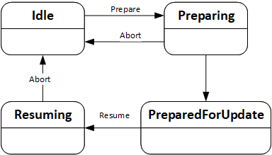
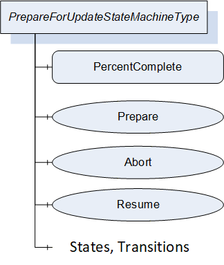
| Attribute | Value | ||||
| BrowseName | 1:PrepareForUpdateStateMachineType | ||||
| IsAbstract | False | ||||
| References |
Node
Class | BrowseName | DataType | TypeDefinition | Other |
|---|---|---|---|---|---|
| Subtype of the 0:FiniteStateMachineType defined in OPC 10000-5. | |||||
| 0:HasComponent | Variable | 1:PercentComplete | 0:Byte | 0:BaseDataVariableType | O |
| 0:HasComponent | Method | 1:Prepare | M | ||
| 0:HasComponent | Method | 1:Abort | M | ||
| 0:HasComponent | Method | 1:Resume | O | ||
| 0:HasComponent | Object | 1:Idle | 0:InitialStateType | ||
| 0:HasComponent | Object | 1:Preparing | 0:StateType | ||
| 0:HasComponent | Object | 1:PreparedForUpdate | 0:StateType | ||
| 0:HasComponent | Object | 1:Resuming | 0:StateType | ||
| 0:HasComponent | Object | 1:IdleToPreparing | 0:TransitionType | ||
| 0:HasComponent | Object | 1:PreparingToIdle | 0:TransitionType | ||
| 0:HasComponent | Object | 1:PreparingToPreparedForUpdate | 0:TransitionType | ||
| 0:HasComponent | Object | 1:PreparedForUpdateToResuming | 0:TransitionType | ||
| 0:HasComponent | Object | 1:ResumingToIdle | 0:TransitionType | ||
| Conformance Units | |||||
|---|---|---|---|---|---|
| DI SU PrepareForUpdate |
The component Variables of the PrepareForUpdateStateMachineType have additional Attributes defined in Table 92.
| BrowsePath | Value Attribute | ||
| 1 | ||
| 2 | ||
| 3 | ||
| 4 | ||
| 12 | ||
| 21 | ||
| 23 | ||
| 34 | ||
| 41 |
| SourceBrowsePath | Reference Type | Is Forward | TargetBrowsePath |
| Transitions | |||
|---|---|---|---|
| 1:IdleToPreparing | 0:FromState | True | 1:Idle |
| 0:ToState | True | 1:Preparing | |
| 0:HasCause | True | 1:Prepare | |
| 0:HasEffect | True | 0:TransitionEventType | |
| 1:PreparingToIdle | 0:FromState | True | 1:Preparing |
| 0:ToState | True | 1:Idle | |
| 0:HasCause | True | 1:Abort | |
| 0:HasEffect | True | 0:TransitionEventType | |
| 1:PreparingToPreparedForUpdate | 0:FromState | True | 1:Preparing |
| 0:ToState | True | 1:PreparedForUpdate | |
| 0:HasEffect | True | 0:TransitionEventType | |
| 1:PreparedForUpdateToResuming | 0:FromState | True | 1:PreparedForUpdate |
| 0:ToState | True | 1:Resuming | |
| 0:HasCause | True | 1:Resume | |
| 0:HasEffect | True | 0:TransitionEventType | |
| 1:ResumingToIdle | 0:FromState | True | 1:Resuming |
| 0:ToState | True | 1:Idle | |
| 0:HasCause | True | 1:Abort | |
| 0:HasEffect | True | 0:TransitionEventType | |
8.4.8.2 PercentComplete
This percentage is a number between 0 and 100 that informs about the progress in the Preparing or the Resuming States. It can be used whenever the activity takes longer and the user should be informed about the completion. If the state machine is in Idle or PreparedForUpdate State it shall have the value 0.
This information is for the user only. It shall not be used to detect completion of the transition.
8.4.8.3 Prepare Method
The Prepare Method can be called to prepare a device for an update. This call transitions the device into the state Preparing.
After the preparation is complete the state machine can perform an automatic transition to the state PreparedForUpdate.
If the preparation cannot complete and the device does not get prepared for update the state machine transitions back to Idle. In this case a message with the reason should be provided to the user via the UpdateStatus.
Signature
Prepare();Method Result Codes (defined in Call Service)
| Result Code | Description |
| Bad_InvalidState | If the PrepareForUpdateStateMachineType is not in Idle state. |
8.4.8.4 Abort Method
An update client can use the Abort Method to bring the state machine from Resuming or Preparing back to the Idle state. This can be necessary, if the preparation takes too long or does not complete at all because the required internal conditions are not met. This call transitions the device back to the Idle state.
Note: If the transition from Preparing to Idle cannot complete instantly a Client can subscribe for the events or the state variable of the PrepareForUpdateStateMachine.
Signature
Abort();Method Result Codes (defined in Call Service)
| Result Code | Description |
| Bad_InvalidState | If the PrepareForUpdateStateMachineType is not in Preparing state. |
8.4.8.5 Resume Method
A call to the optional Resume Method transitions the device into the state Resuming. After the resuming is complete the state machine performs an automatic transition to the Idle state. If the method is not supported, the transitions to Resuming and back to Idle shall be done by the Server automatically. If the method is supported, there shall not be an automatic transition to Resuming. Supporting this method enables the Client to group several activities like backup, install, restore on a single device or group the update of multiple devices before the devices are allowed to Resume their operation again.
Signature
Resume();Method Result Codes (defined in Call Service)
| Result Code | Description |
| Bad_InvalidState | If the PrepareForUpdateStateMachineType is not in PreparedForUpdate state or if the InstallationStateMachine is still in the state Installing. |
8.4.9 InstallationStateMachineType
8.4.9.1 Overview
The InstallationStateMachineType can be used if the device supports explicit installation (Cached-Loading or File System based Loading). This supports the installation option of 8.3.4.6. It is illustrated in Figure 50 and Figure 51 and formally defined in Table 94. The transitions are formally defined in Table 96.
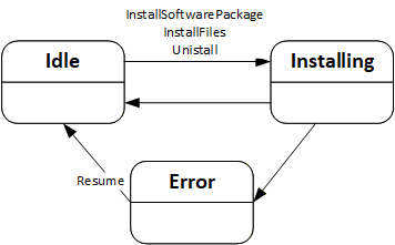
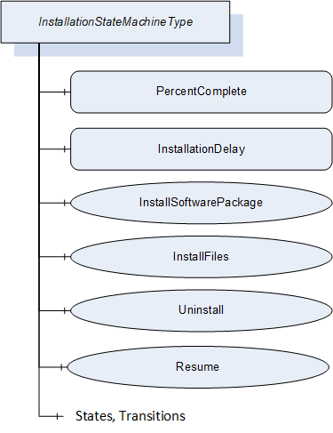
| Attribute | Value | ||||
| BrowseName | 1:InstallationStateMachineType | ||||
| IsAbstract | False | ||||
| References |
Node
Class | BrowseName | DataType | TypeDefinition | Other |
|---|---|---|---|---|---|
| Subtype of the 0:FiniteStateMachineType defined in OPC 10000-5. | |||||
| 0:HasComponent | Variable | 1:PercentComplete | 0:Byte | 0:BaseDataVariableType | O |
| 0:HasComponent | Variable | 1:InstallationDelay | 0:Duration | 0:BaseDataVariableType | O |
| 0:HasComponent | Method | 1:InstallSoftwarePackage | O | ||
| 0:HasComponent | Method | 1:InstallFiles | O | ||
| 0:HasComponent | Method | 1:Uninstall | O | ||
| 0:HasComponent | Method | 1:Resume | M | ||
| 0:HasComponent | Object | 1:Idle | 0:InitialStateType | ||
| 0:HasComponent | Object | 1:Installing | 0:StateType | ||
| 0:HasComponent | Object | 1:Error | 0:StateType | ||
| 0:HasComponent | Object | 1:IdleToInstalling | 0:TransitionType | ||
| 0:HasComponent | Object | 1:InstallingToIdle | 0:TransitionType | ||
| 0:HasComponent | Object | 1:InstallingToError | 0:TransitionType | ||
| 0:HasComponent | Object | 1:ErrorToIdle | 0:TransitionType | ||
| Conformance Units | |||||
|---|---|---|---|---|---|
| DI SU Software Update |
The component Variables of the InstallationStateMachineType have additional Attributes defined in Table 95.
| BrowsePath | Value Attribute | ||
| 1 | ||
| 2 | ||
| 3 | ||
| 12 | ||
| 21 | ||
| 23 | ||
| 31 |
| SourceBrowsePath | Reference Type | Is Forward | TargetBrowsePath |
| Transitions | |||
|---|---|---|---|
| 1:IdleToInstalling | 0:FromState | True | 1:Idle |
| 0:ToState | True | 1:Installing | |
| 0:HasCause | True | 1:InstallSoftwarePackage | |
| 0:HasCause | True | 1:InstallFiles | |
| 0:HasCause | True | 1:Uninstall | |
| 0:HasEffect | True | 0:TransitionEventType | |
| 1:InstallingToIdle | 0:FromState | True | 1:Installing |
| 0:ToState | True | 1:Idle | |
| 0:HasEffect | True | 0:TransitionEventType | |
| 1:InstallingToError | 0:FromState | True | 1:Installing |
| 0:ToState | True | 1:Error | |
| 0:HasEffect | True | 0:TransitionEventType | |
| 1:ErrorToIdle | 0:FromState | True | 1:Error |
| 0:ToState | True | 1:Idle | |
| 0:HasCause | True | 1:Resume | |
| 0:HasEffect | True | 0:TransitionEventType | |
8.4.9.2 PercentComplete
This percentage is a number between 0 and 100 that informs the user about the progress of an installation or uninstallation. It should be used whenever an update activity takes longer and the user should be informed about the completion. If the state machine is in Idle State it shall have the value 0. In case of an error the last value should be kept until the Resume is called.
This information is for the user only. It shall not be used to detect completion of the installation.
8.4.9.3 InstallationDelay
The optional InstallationDelay can be set by a Client to delay the actual installation after the call to InstallSoftwarePackage or InstallFiles is returned by the Server. This can be used when the installation is started on several devices in parallel and there is a risk that a reboot of one device could harm the connection to other devices. With a delay the install methods can be called on all devices before the devices actually start the installation. The InstallationDelay does not delay the transition from Idle to Installing.
This value could be preconfigured. If a Client wants to set this value it has to be done before the install method is called.
The Server is expected to stay operational at least during the delay.
8.4.9.4 InstallSoftwarePackage Method
With this Method the Client requests the installation of a Software Package. The package can be either the previously transferred Pending Version or the alternative Fallback Version. To identify the version and to prevent conflicts with a second Client that transfers a different version, the InstallSoftwarePackage Method requires the ManufacturerUri, the SoftwareRevision and PatchIdentifiers Properties of the SoftwareVersionType.
Optionally an additional hash value can be passed to the Method. This hash could be calculated by the Client or taken from a trusted source. Before installation the Server can compare the hash against the calculated hash of the Software Package. This mechanism can be used if there is a risk that the Software Package is altered during the transfer to the device and if the Server has no other mechanism to ensure that the Software Package is from a trustworthy source.
If the installation succeeds but the software cannot run properly this should not be treated as an error of the installation. Instead, this should be indicated using the IDeviceHealthType Interface of the device / component.
This Method shall not return before the state has changed to the Installing state.
Signature
	InstallSoftwarePackage(
	  [in] 0:String		ManufacturerUri,
	  [in] 0:String		SoftwareRevision,
	  [in] 0:String[]		PatchIdentifiers,
[in] 0:ByteString Hash);| Argument | Description |
| ManufacturerUri | ManufacturerUri Property of either the Pending or Fallback SoftwareVersionType that should be installed. |
| SoftwareRevision | SoftwareRevision Property of either the Pending or Fallback SoftwareVersionType that should be installed. |
| PatchIdentifiers | PatchIdentifiers Property of either the Pending or Fallback SoftwareVersionType that should be installed (or empty array if not supported on the SoftwareVersionType instance). |
| Hash | Hash of the Software Package that should be installed (or empty if not used). |
Method Result Codes (defined in Call Service)
| Result Code | Description |
| Bad_InvalidState | If the InstallationStateMachineType is not in Idle state or if the PrepareForUpdate Object is available and the PrepareForUpdate state machine is not in the state PreparedForUpdate. |
| Bad_NotFound | If the specified Software Package does not exist. |
| Bad_InvalidArgument | If the Hash does not match the calculated hash of the Software Package. |
| Attribute | Value | ||||
| BrowseName | 1:InstallSoftwarePackage | ||||
| References | NodeClass | BrowseName | DataType | TypeDefinition | Other |
|---|---|---|---|---|---|
| 0:HasProperty | Variable | 0:InputArguments | 0:Argument[] | 0:PropertyType | M |
| Conformance Units | |||||
|---|---|---|---|---|---|
| DI SU Software Update |
8.4.9.5 InstallFiles Method
This Method can be called to request the installation of one or more files. The files are identified by the NodeId of their FileType instance in the FileSystem.
If the installation succeeds but the software cannot run properly this should not be treated as an error of the installation. Instead, this should be indicated using the IDeviceHealthType Interface of the device / component.
Signature
	InstallFiles(
[in] 0:NodeId[] NodeIds);| Argument | Description |
| NodeIds | NodeIds of the files to install. |
Method Result Codes (defined in Call Service)
| Result Code | Description |
| Bad_InvalidState | If the InstallationStateMachineType is not in Idle state or if the PrepareForUpdate Object is available and the PrepareForUpdate state machine is not in the state PreparedForUpdate. |
| Bad_NotFound | If one or more NodeIds are not found. |
| Attribute | Value | ||||
| BrowseName | 1:InstallFiles | ||||
| References | NodeClass | BrowseName | DataType | TypeDefinition | Other |
|---|---|---|---|---|---|
| 0:HasProperty | Variable | 0:InputArguments | 0:Argument[] | 0:PropertyType | M |
| Conformance Units | |||||
|---|---|---|---|---|---|
| DI SU Software Update |
8.4.9.6 Uninstall Method
The Uninstall Method can be called to request the uninstallation of the current software. This can be necessary e.g. for a project when uncommissioning a device or before deleting an application or configuration from the device (see SoftwareFolderType in 8.4.12.2).
The signature and specific result codes of this Method are specified below.
Signature
Uninstall();Method Result Codes (defined in Call Service)
| Result Code | Description |
| Bad_InvalidState | If the InstallationStateMachineType is not in Idle state or if the PrepareForUpdate Object is available and the PrepareForUpdate state machine is not in the state PreparedForUpdate. |
8.4.9.7 Resume Method
This Method can be called to resume from the Error state. The Error state can be reached if there are issues during the installation. The state machine remains in this state until the Client calls the Resume Method to get back to the Idle state immediately.
Signature
Resume();Method Result Codes (defined in Call Service)
| Result Code | Description |
| Bad_InvalidState | If the InstallationStateMachineType is not in Error state. |
8.4.10 PowerCycleStateMachineType
The PowerCycleStateMachineType is used to inform the user to perform a manual power cycle.
When the server requires a manual power cycle it indicates that to the client by changing the state to WaitingForPowerCycle. After restart of the Device, it transitions to NotWaitingForPowerCycle automatically.
There are no methods, all transitions originate from the installation process. The state machine is illustrated in Figure 52 and formally defined in Table 101. The transitions are formally defined in Table 103.
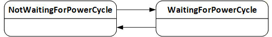
| Attribute | Value | ||||
| BrowseName | 1:PowerCycleStateMachineType | ||||
| IsAbstract | False | ||||
| References |
Node
Class | BrowseName | DataType | TypeDefinition | Other |
|---|---|---|---|---|---|
| Subtype of the 0:FiniteStateMachineType defined in OPC 10000-5. | |||||
| 0:HasComponent | Object | 1:NotWaitingForPowerCycle | 0:InitialStateType | ||
| 0:HasComponent | Object | 1:WaitingForPowerCycle | 0:StateType | ||
| 0:HasComponent | Object | 1:NotWaitingForPowerCycleToWaitingForPowerCycle | 0:TransitionType | ||
| 0:HasComponent | Object | 1:WaitingForPowerCycleToNotWaitingForPowerCycle | 0:TransitionType | ||
| Conformance Units | |||||
|---|---|---|---|---|---|
| DI SU Manual Power Cycle |
The component Variables of the PowerCycleStateMachineType have additional Attributes defined in Table 102.
| BrowsePath | Value Attribute | ||
| 1 | ||
| 2 | ||
| 12 | ||
| 21 |
| SourceBrowsePath | Reference Type | Is Forward | TargetBrowsePath |
| Transitions | |||
|---|---|---|---|
| 1:NotWaitingForPowerCycleToWaitingForPowerCycle | 0:FromState | True | 1:NotWaitingForPowerCycle |
| 0:ToState | True | 1:WaitingForPowerCycle | |
| 0:HasEffect | True | 0:TransitionEventType | |
| 1:WaitingForPowerCycleToNotWaitingForPowerCycle | 0:FromState | True | 1:WaitingForPowerCycle |
| 0:ToState | True | 1:NotWaitingForPowerCycle | |
| 0:HasEffect | True | 0:TransitionEventType | |
8.4.11 ConfirmationStateMachineType
8.4.11.1 Overview
The ConfirmationStateMachineType is used to prove a valid Client - Server connection after a restart of the OPC UA Server. This supports the confirmation option of 8.3.4.9.
If several instances of this state machine are provided on a device (due to several instances of the SoftwareUpdateType), all instances should behave as if it is only a single instance. In particular it is sufficient to call one of the confirm methods after reboot.
The ConfirmationStateMachineType is illustrated in Figure 53 and Figure 54 and formally defined in Table 104. The transitions are formally defined in Table 106.
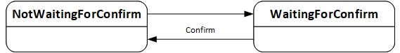
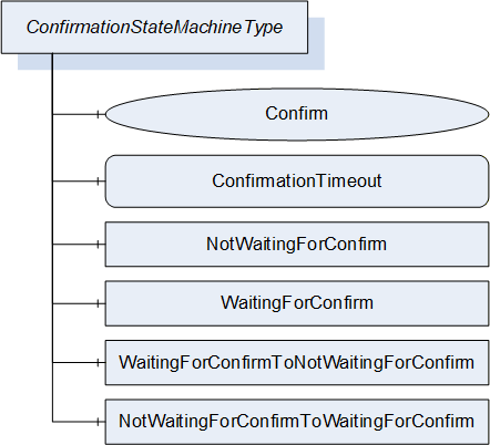
| Attribute | Value | ||||
| BrowseName | 1:ConfirmationStateMachineType | ||||
| IsAbstract | False | ||||
| References |
Node
Class | BrowseName | DataType | TypeDefinition | Other |
|---|---|---|---|---|---|
| Subtype of the 0:FiniteStateMachineType defined in OPC 10000-5. | |||||
| 0:HasComponent | Method | 1:Confirm | M | ||
| 0:HasComponent | Variable | 1:ConfirmationTimeout | 0:Duration | 0:BaseDataVariableType | M |
| 0:HasComponent | Object | 1:NotWaitingForConfirm | 0:InitialStateType | ||
| 0:HasComponent | Object | 1:WaitingForConfirm | 0:StateType | ||
| 0:HasComponent | Object | 1:NotWaitingForConfirmToWaitingForConfirm | 0:TransitionType | ||
| 0:HasComponent | Object | 1:WaitingForConfirmToNotWaitingForConfirm | 0:TransitionType | ||
| Conformance Units | |||||
|---|---|---|---|---|---|
| DI SU Update Confirmation |
The component Variables of the ConfirmationStateMachineType have additional Attributes defined in Table 105.
| BrowsePath | Value Attribute | ||
| 1 | ||
| 2 | ||
| 12 | ||
| 21 |
| SourceBrowsePath | Reference Type | Is Forward | TargetBrowsePath | |
| Transitions | ||||
|---|---|---|---|---|
| 1:NotWaitingForConfirmToWaitingForConfirm | 0:FromState | True | 1:NotWaitingForConfirm | |
| 0:ToState | True | 1:WaitingForConfirm | ||
| 0:HasEffect | True | 0:TransitionEventType | ||
| 1:WaitingForConfirmToNotWaitingForConfirm | 0:FromState | True | 1:WaitingForConfirm | |
| 0:ToState | True | 1:NotWaitingForConfirm | ||
| 0:HasCause | True | 1:Confirm | ||
| 0:HasEffect | True | 0:TransitionEventType | ||
8.4.11.2 ConfirmationTimeout
The ConfirmationTimeout can be set by a Client to a value other then 0 to enable the confirmation feature. If the value is not 0 and the Client - Server connection is lost, the ConfirmationTimeout represents the maximum time that the Client is required to reconnect and call the Confirm Method. The Server shall automatically reset the value to 0 when the installation is complete.
8.4.11.3 Confirm Method
After a reboot and with a ConfirmationTimeout other than 0 a Client shall call this Method to inform the Server that it has successfully reconnected. If this Method is not called after a lost connection the Server shall regard the update as unsuccessful and shall revert it. A Client is required to react within the time specified in the ConfirmationTimeout Variable.
Signature
Confirm();
8.4.12 SoftwareFolderType
The SoftwareFolderType is a subtype of FolderType. It allows adding and removing its items via the Add and Delete methods. With the SoftwareClass Variable the server exposes whether the folder holds a collection of applications or a collection of configurations. The ObjectType of the items is server specific, but the items shall at least support the SoftwareUpdate AddIn. They are identified by SoftwareSubclass and SoftwareName which is provided with the Add Method. After adding a new item, the SoftwareUpdate AddIn is used to transfer the initial software. After that it can be used to install updates. The SoftwareUpdate AddIn of each item shall support SoftwareClass, SoftwareSubclass and SoftwareName. SoftwareFolderType is defined in Table 107 and its usage is illustrated in Figure 55.
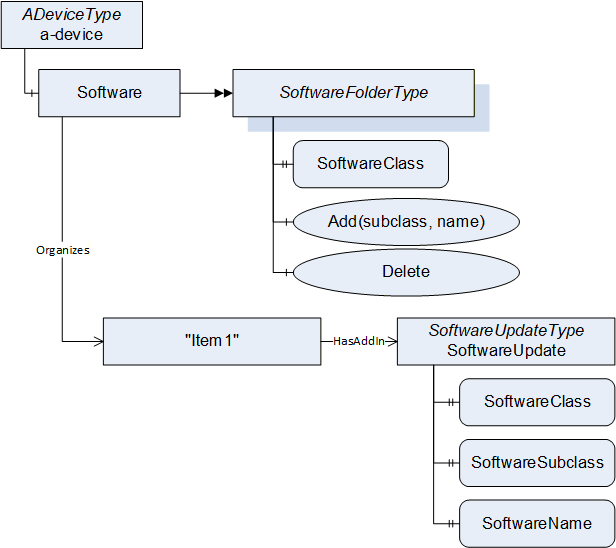
| Attribute | Value | ||||
| BrowseName | 1:SoftwareFolderType | ||||
| IsAbstract | False | ||||
| References |
Node
Class | BrowseName | DataType | TypeDefinition | Other |
|---|---|---|---|---|---|
| Subtype of the 0:FolderType defined in OPC 10000-5. | |||||
| 0:HasProperty | Variable | 1:SoftwareClass | 1:SoftwareClass | 0:PropertyType | M |
| 0:HasComponent | Method | 1:Add | M | ||
| 0:HasComponent | Method | 1:Delete | M | ||
| Conformance Units | |||||
|---|---|---|---|---|---|
| DI SU SoftwareFolder |
The SoftwareClass Property is a SoftwareClass enumeration. It declares what items are managed by the folder. The value shall either be Application or Configuration.
8.4.12.1 Add Method
The Add Method can be used to add a new item to the folder. The parameters Subclass and Name are exposed at the attached SoftwareUpdate AddIn as SoftwareSubclass and SoftwareName Properties. The Name shall be unique within the SoftwareFolderType.
Signature
	Add(
	[in] 0:String   Subclass,
	[in] 0:String   Name);
| Argument | Description |
| Subclass | Subclass of the new item. |
| Name | Name of the new item. |
| Attribute | Value | ||||
| BrowseName | 1:Add | ||||
| References | NodeClass | BrowseName | DataType | TypeDefinition | Other |
|---|---|---|---|---|---|
| 0:HasProperty | Variable | 0:InputArguments | 0:Argument[] | 0:PropertyType | M |
| Conformance Units | |||||
|---|---|---|---|---|---|
| DI SU SoftwareFolder |
8.4.12.2 Delete Method
The Delete Method can be used to delete an item from the folder. The Delete can require a call to Uninstall at the InstallationStateMachine (see 8.4.9).
Signature
	Delete(
	  [in] 0:NodeId   ObjectToDelete);
| Argument | Description |
| ObjectToDelete | NodeId of the item to delete. |
Method Result Codes (defined in Call Service)
| Result Code | Description |
| Bad_NotFound | The specified item does not exist. |
| Bad_InvalidState | If the item shall be uninstalled before deletion. (see InstallationStateMachineType 8.4.9). |
| Attribute | Value | ||||
| BrowseName | 1:Delete | ||||
| References | NodeClass | BrowseName | DataType | TypeDefinition | Other |
|---|---|---|---|---|---|
| 0:HasProperty | Variable | 0:InputArguments | 0:Argument[] | 0:PropertyType | M |
| Conformance Units | |||||
|---|---|---|---|---|---|
| DI SU SoftwareFolder |
8.5 DataTypes
8.5.1 SoftwareVersionFileType enumeration
This enumeration is used to identify the version in the methods of the TemporaryFileTransferType that is used in the PackageLoadingType (8.4.3). The Enumeration is defined in Table 112. Its representation in the AddressSpace is defined in Table 113.
| Name | Value | Description |
| Current | 0 | The currently used version of the software identified by the CurrentVersion Object. |
| Pending | 1 | The Pending Version of the software that could be installed identified by the PendingVersion Object. |
| Fallback | 2 | The Fallback Version of the software identified by the FallbackVersion Object. |
| Attribute | Value | |||||
| BrowseName | 1:SoftwareVersionFileType | |||||
| IsAbstract | False | |||||
| References | NodeClass | BrowseName | DataType | TypeDefinition | Other | |
|---|---|---|---|---|---|---|
| Subtype of the 0:Enumeration type defined in OPC 10000-5 | ||||||
| 0:HasProperty | Variable | 0:EnumStrings | 0:LocalizedText [] | 0:PropertyType | ||
| Conformance Units | ||||||
|---|---|---|---|---|---|---|
| DI SU Software Update |
8.5.2 UpdateBehavior OptionSet
The UpdateBehavior OptionSet is based on UInt32. It describes how the device can perform the update. All possible options are described in Table 114. All other values are reserved for future versions of this specification. The OptionSet is used in the UpdateBehavior Property of the DirectLoadingType (8.4.4.3) and in the GetUpdateBehavior Methods on the CachedLoadingType (8.4.5.5) and in the FileSystemLoadingType (8.4.6.3).
| Value | Bit No. | Description |
| KeepsParameters | 0 | If KeepsParameters is not set, the device will lose its configuration during update. The Client should do a backup of the parameters before the update and restore them afterwards. |
| WillDisconnect | 1 | If WillDisconnect is set, the OPC UA Server will restart during installation. This can be the case if the update is about the firmware of the device that hosts the OPC UA Server. |
| RequiresPowerCycle | 2 | If RequiresPowerCycle is set, the devices require a manual power off / power on for installation. |
| WillReboot | 3 | If WillReboot is set, the device will reboot during the update, inclusive of embedded infrastructure elements like an integrated switch. An update Client should take this into account since the devices behind an integrated switch are not reachable for that time. |
| NeedsPreparation | 4 | If NeedsPreparation is not set, the Client can install the update without maintaining the PrepareForUpdateStateMachine. This can be used to support an installation without stopping the software. |
The UpdateBehavior OptionSet representation in the AddressSpace is defined in Table 115.
| Attribute | Value | ||||
| BrowseName | 1:UpdateBehavior | ||||
| IsAbstract | False | ||||
| References | NodeClass | BrowseName | DataType | TypeDefinition | Other |
|---|---|---|---|---|---|
| Subtype of 0:UInt32 defined in OPC 10000-5. | |||||
| 0:HasProperty | Variable | 0:OptionSetValues | 0:LocalizedText[] | 0:PropertyType | |
| Conformance Units | |||||
|---|---|---|---|---|---|
| DI SU Software Update |
8.5.3 SoftwareClass enumeration
This Enumeration is used to classify components, where instances of SoftwareUpdateType can be attached (see 8.3.2). The Enumeration is defined in Table 116. Its representation in the AddressSpace is defined in Table 117.
| Name | Value | Description |
| Firmware | 0 | The software update is used for the firmware of a physical device. |
| Application | 1 | The software update is used for an executable software. |
| Configuration | 2 | The software update is used for the configuration of a device or application. |
| Solution | 3 | The software update is used to install a solution with several software package to several components. |
| Attribute | Value | |||||
| BrowseName | 1:SoftwareClass | |||||
| IsAbstract | False | |||||
| References | NodeClass | BrowseName | DataType | TypeDefinition | Other | |
|---|---|---|---|---|---|---|
| Subtype of the 0:Enumeration type defined in OPC 10000-5 | ||||||
| 0:HasProperty | Variable | 0:EnumStrings | 0:LocalizedText [] | 0:PropertyType | ||
| Conformance Units | ||||||
|---|---|---|---|---|---|---|
| DI SU Software Update |
8.6 ReferenceTypes
8.6.1 UpdateParent ReferenceType
The UpdateParent ReferenceType is a concrete ReferenceType and can be used directly. It is a subtype of HierarchicalReferences.
The semantic of this ReferenceType is to link related components that are target for software update. These references are used by an update client to find related components for compatibility checks (see 8.7.3).
SourceNode and TargetNode of References of this type shall be objects that implement IVendorNameplateType.
A server shall support browsing of this ReferenceType in both directions.
| Attributes | Value | ||
| BrowseName | 1:UpdateParent | ||
| InverseName | UpdateChild | ||
| Symmetric | False | ||
| IsAbstract | False | ||
| References | NodeClass | BrowseName | Comment |
|---|---|---|---|
| Subtype 0:HierarchicalReferences | |||
| Conformance Units | |||
|---|---|---|---|
| DI SU UpdateParent reference |
8.6.2 CanUpdate ReferenceType
The CanUpdate ReferenceType is a concrete ReferenceType and can be used directly. It is a subtype of HierarchicalReferences.
For components with SoftwareUpdate that accept Solution Packages this reference type is used to describe which subcomponents can be updated via the Solution Package. These references can be provided for use by clients to find related components when creating a Solution Package (see 8.7.5).
The source of this ReferenceType is a component that supports the SoftwareUpdate AddIn. The target of this ReferenceType is the component that can be updated.
SourceNode and TargetNode of References of this type shall be objects that implement IVendorNameplateType.
| Attributes | Value | ||
| BrowseName | 1:CanUpdate | ||
| InverseName | CanBeUpdatedBy | ||
| Symmetric | False | ||
| IsAbstract | False | ||
| References | NodeClass | BrowseName | Comment |
|---|---|---|---|
| Subtype 0:HierarchicalReferences | |||
| Conformance Units | |||
|---|---|---|---|
| DI SU CanUpdate reference |
8.7 Software Package file format
8.7.1 Overview
The Software Package file format describes a standard format to share files for the software update. This enables Update Clients to use software from different vendors (i.e., it supports identification of the package, compatibility with the device, storage of the deployment and of supplementary files).
The Software Package is shared as a single ZIP file with all the content described in this section. The recommended file extension is ".uadipkg". In some cases, parts of the ZIP file can be removed. For example, to retrieve just a lean metadata-only package with information about available updates without having to download many full Software Packages. Another example is removing the SUPPLEMENT folder to make the package smaller if the entire Software Package is deployed to the device.
8.7.2 Folder structure
On the root level, the Software Package can have the following folders:
The optional CONTENT folder holds the files or folders that are transferred to the device. The content of this folder is defined by the author of the Software Package. For Cached-Loading and Direct-Loading, this folder can contain a single file that shall be transferred to the device. Alternatively, it can contain multiple files, if the entire Software Package is sent to the device (see use case 8.2.2.14).
The mandatory META folder holds the Software Package's metadata. It shall at least have the file package_metadata.json. This file describes what's in the Software Package and to which components it is compatible (see use case 8.2.2.16).
The optional SUPPLEMENT folder can contain supplementary documents for use by the Update Client. These can include license details, release notes, or manuals related to the software. An Update Client can present them to the user as part of the software update (see use case 8.2.2.19).
The optional META-INF folder contains the digital signatures of the Software Package (see 8.7.4 8.2.2.20, 8.2.2.21).
In case of a Solution Package the optional SUBPACKAGES folder contains the content of the Software Packages that belong to the solution (see use case 8.2.2.22).
8.7.3 Package metadata
The package metadata file describes the identity of the Software Package, the target for the installation, the compatibility to the device and optionally the usage of individual files within the Software Package. The package_metadata.json is stored in the META folder.
The JSON schema for the package_metadata.json file associated with this version of the specification can be found here:
The JSON schema associated with the latest version of the specification can be found here:
The JSON schema follows the conventions for the Compact DataEncoding defined in OPC 10000-6.
The elements of the JSON schema are described in Table 120, Table 124, Table 126, Table 128, Table 130, Table 132, Table 134, Table 136, Table 138 and Table 140.
A Software Package is uniquely defined with the ManufacturerUri, PackageType, TargetProductCodes, PackageRevision and Name.
The PackageMetadata structure and all contained types are encoded using the JSON VerboseEncoding.
Note: The following tables describe the package_metadata.json with structures and enumerations as a separate OPC UA namespace. These types typically do not show up in the AddressSpace of an OPC UA Server.
| Name | Type | Description | Optional |
| PackageMetadata | 0:Structure | ||
| Name | 0:String | Names the package (the package file name can be changed) | False |
| Description | 0:String | Description of the content of the Software Package. | True |
| ManufacturerUri | 0:String | Identification of the manufacturer of the package (used with PackageType and SoftwareRevision to uniquely identify the package) | False |
| Manufacturer | 0:String | Manufacturer of the package (for display purposes) | False |
| PackageRevision | 0:String | Version of the software package | False |
| PackageType | 2:PackageType | Type of the Software Package. Other values are reserved for future use. | False |
| SoftwareSubClass | 0:String | Name of the application (in case of SoftwareClass Application) | True |
| DeployCompletePackage | 0:Boolean | If true the complete package shall be sent to the device. Otherwise only the contained files that are marked as DeploymentItem are deployed (default: false). | True |
| SoftwareRevision | 0:String | Version of the software in the package. Optional for solution packages. | True |
| ReleaseDate | 0:DateTime | Additional information for the user | True |
| TargetManufacturerUri | 0:String | Identification of the target Node on the device. Used to find suitable Software Packages for a device. | True |
| TargetManufacturer | 0:String | Manufacturer of the target (for display purposes). Used to find suitable Software Packages for a device. | True |
| UpdateTargets[] | 2:UpdateTarget | Identification of the target Node on the device Used to find suitable Software Packages for a device. Optional for solution packages. | True |
| Files[] | 2:FileDescriptor | Describes the files that require special treatment by the update client. | True |
| Compatibilities[] | 2:CompatibilityOption | List of options: At least one of them must match to be compatible. | True |
| Assignments[] | 2:Assignment | Assignments of Software Packages to components that support SoftwareUpdate Only for solution packages (see 8.7.5) | True |
| Attribute | Value | |||||
| BrowseName | 2:PackageMetadata | |||||
| IsAbstract | False | |||||
| References | NodeClass | BrowseName | DataType | TypeDefinition | Other | |
|---|---|---|---|---|---|---|
| Subtype of 0:Structure defined in OPC 10000-3 | ||||||
| Name | Type | Description | Optional |
| UpdateTarget | 0:Structure | ||
| ProductCode | 0:String | ProductCode of the target Node on the device. | False |
| Model | 0:String | Model of the target Node on the device. | False |
| Attribute | Value | |||||
| BrowseName | 2:UpdateTarget | |||||
| IsAbstract | False | |||||
| References | NodeClass | BrowseName | DataType | TypeDefinition | Other | |
|---|---|---|---|---|---|---|
| Subtype of 0:Structure defined in OPC 10000-3 | ||||||
| Name | Type | Description | Optional |
| FileDescriptor | 0:Structure | ||
| FileType | 2:FileType | Describes how the client shall use the file. | False |
| FileName | 0:String | Relative path and file name to the file in the ZIP package | False |
| MimeType | 0:String | Machine understandable type of file (default: "application/octet-stream") | True |
| Language | 0:String | Used to support multiple languages of the same document | True |
| Attribute | Value | |||||
| BrowseName | 2:FileDescriptor | |||||
| IsAbstract | False | |||||
| References | NodeClass | BrowseName | DataType | TypeDefinition | Other | |
|---|---|---|---|---|---|---|
| Subtype of 0:Structure defined in OPC 10000-3 | ||||||
| Name | Type | Description | Optional |
| CompatibilityOption | 0:Structure | One set of compatibility requirements | |
| CompatibilityRequirements[] | 2:CompatibilityRequirement | List of requirements: All of them must match to be compatible | False |
| Attribute | Value | |||||
| BrowseName | 2:CompatibilityOption | |||||
| IsAbstract | False | |||||
| References | NodeClass | BrowseName | DataType | TypeDefinition | Other | |
|---|---|---|---|---|---|---|
| Subtype of 0:Structure defined in OPC 10000-3 | ||||||
| Name | Type | Description | Optional |
| CompatibilityRequirement | 0:Structure | ||
| Variable | 0:String | Path to a variable to compare with Examples: variable of a component or its Identification functional group or its parent device or an application on that device… | False |
| Values[] | 0:BaseDataType | Comparison values (zero, one or more values depending on the comparison operator). Can be any Integer or String type. | False |
| Operation | 2:ComparisonOperation | Operation that is used to compare Variable and Values. | False |
| Attribute | Value | |||||
| BrowseName | 2:CompatibilityRequirement | |||||
| IsAbstract | False | |||||
| References | NodeClass | BrowseName | DataType | TypeDefinition | Other | |
|---|---|---|---|---|---|---|
| Subtype of 0:Structure defined in OPC 10000-3 | ||||||
| Name | Value | Description |
| Firmware | 0 | The Software Package contains the firmware of a physical device. |
| Application | 1 | The Software Package contains an executable software. |
| Configuration | 2 | The Software Package contains the configuration of a device or application. |
| Solution | 3 | The Software Package contains a solution with several software package. |
| Attribute | Value | |||||
| BrowseName | 2:PackageType | |||||
| IsAbstract | False | |||||
| References | NodeClass | BrowseName | DataType | TypeDefinition | Other | |
|---|---|---|---|---|---|---|
| Subtype of the 0:Enumeration type defined in OPC 10000-5 | ||||||
| 0:HasProperty | Variable | 0:EnumStrings | 0:LocalizedText [] | 0:PropertyType | ||
| Name | Value | Description |
| DeploymentItem | 0 | This file shall be deployed to the device. If Cached-Loading or Direct-Loading is used at most one file can be marked as DeploymentItem. If File System based Loading is used all files that are marked as DeploymentItem shall be copied to the server using the same file name. If the complete Software Package is deployed to the device the individual files are not marked explicitly. |
| ReleaseNotes | 1 | E.g. link for user to open the document |
| LicenseInfo | 2 | E.g. link for user to open the document |
| PreInstallNote | 3 | Text that shall be shown to the user at least once before installation |
| Attribute | Value | |||||
| BrowseName | 2:FileType | |||||
| IsAbstract | False | |||||
| References | NodeClass | BrowseName | DataType | TypeDefinition | Other | |
|---|---|---|---|---|---|---|
| Subtype of the 0:Enumeration type defined in OPC 10000-5 | ||||||
| 0:HasProperty | Variable | 0:EnumStrings | 0:LocalizedText [] | 0:PropertyType | ||
| Name | Value | Description |
| EqualTo | 0 | Value[0] = Variable |
| GreaterThan | 1 | Value[0] > Variable (proper comparison for SemanticVersionString shall be supported) |
| GreaterEqual | 2 | Value[0] >= Variable (proper comparison for SemanticVersionString shall be supported) |
| LessThen | 3 | Value[0] < Variable (proper comparison for SemanticVersionString shall be supported) |
| LessEqual | 4 | Value[0] <= Variable (proper comparison for SemanticVersionString shall be supported) |
| RegularExpression | 5 | Value[0] contains a regular expression which must match the value of the Variable |
| OneOf | 6 | The Values array must contain the value of the Variable |
| Exist | 7 | The Node that is described by the Variable must exist. The Values array shall be empty. |
| Attribute | Value | |||||
| BrowseName | 2:ComparisonOperation | |||||
| IsAbstract | False | |||||
| References | NodeClass | BrowseName | DataType | TypeDefinition | Other | |
|---|---|---|---|---|---|---|
| Subtype of the 0:Enumeration type defined in OPC 10000-5 | ||||||
| 0:HasProperty | Variable | 0:EnumStrings | 0:LocalizedText [] | 0:PropertyType | ||
The compatibility declaration describes the compatibility of a Software Package with a component on the server that supports the SoftwareUpdate AddIn.
This can be simple terms like a minimum SoftwareRevision or a specific HardwareRevision of the component. Or relations to other objects in the AddressSpace e.g. to describe the existence and version of an attached hardware or to restrict the use of an application to a specific firmware version of a device.
Typically, the compatibility declaration outlines the relationship between variables and the corresponding component on the server. However, certain compatibilities can only be articulated through associated components e.g. the device hosting the application or a necessarily attached hardware. For those cases the compatibility declaration can incorporate paths following the UpdateParentReferenceType references (see 8.6.1).
The UpdateParentReferenceType enables the definition of a tree of object on the server which is utilized to describe compatibility. Parent objects are referenced as ".." while child objects are indicated by the BrowseName of the node being referenced. The elements within this path are interconnected using a slash ("/").
Examples:
"ManufacturerUri", "ProductCode", "SoftwareRevision" identify properties of the component that should be updated.
"../ManufacturerUri" and "../ProductCode" identify a specific parent component (e.g. the device that hosts the application).
"../ProfinetExtension/SoftwareRevision" can identify the firmware version of a hardware which is connected to the parent.
8.7.4 Package signature
To prove authenticity and integrity the Software Packages can be signed.
Initially the Software Package should be signed by the author (e.g., the manufacturer signs a firmware for its devices when it is created). This signature proves that it is really from that author (authenticity) and that is not altered on the way to the client (integrity) (see use case 8.2.2.20).
The verification of these signatures can be done by the Update Client or by the device if the whole update package is deployed.
Typically, a PKI with a certificate hierarchy is used. In this case, the entire certificate chain shall be stored in the signature. Consequently, only the root certificate is required for verification.
Additional signatures can be added by machine builders or plant operators to approve a Software Package for use in a specific plant. With this in place the Update Client and OPC UA servers can be configured to only allow updates of Software Packages with an approval signature of a specific certificate hierarchy (see use case 8.2.2.21).
To create a signed Software Package, it is stored as a standard ASiC-E (Associated Signature Container) container and signed with a CAdES (CMS Advanced Electronic Signatures) signature.
Note: These *AdES signatures are commonly used for advanced digital signatures in engineering environments. Examples are FDI, Profinet or OPC UA FX descriptors. To be easier usable on constrained devices the Software Packages use the binary CAdES persistence instead of the XML based XAdES. ASiC-E is a minimalistic ZIP container from the same family of standards.
With ASiC-E the folder structure of the ZIP file does not change. ASiC-E adds one additional folder "META-INF" with the signature information and a mimetype file in the root folder. These signatures also remain intact if individual files are removed or if the folders are unzipped.
Depending on the industry and environment where the devices are used there are different requirements to the level of security of the signatures. Therefore, the CAdES signatures support different levels which all can be used for the Software Packages. The more advanced options extend the basic option so that all packages remain compatible and usable with any update client.
For the verification of the signature, all certificates up to the root certificate are required. To ensure ease of handling, the entire certificate chain should therefore be incorporated within the CAdES signature.
All security relevant details are described in the publicly available ETSI standards (see ASiC-E, CAdES).
Note: If the complete Software Package is transferred to the device the verification also shall be done on the device. For this case certificates are distributed and updated on all device in the plant. Solutions for certificate distribution are covered in detail in OPC 10000-12 and OPC 10000-21.
Note: To create and maintain keys and certificates for the signatures, a PKI (public key infrastructure) should be used. Since this has no impact on the singing and verification described in this document, it is out of scope of this specification.
8.7.5 Solution packages
A Solution Package can be used to combine several Software Packages. This can have several reasons:
Easier distribution of multiple Software Packages as a single file (e.g., a complete machine with several devices or one device with several updateable components).
Only a specific combination of Software Packages shall be installed (could be verified using a signature at the Solution Package).
A combination of several Software Packages shall be installed to a device as a single file. The device is then responsible for distribution / installation of the subpackages.
A Solution Package can include an assignment information that declares which subpackage shall be installed to which targets on the device. A target can be either a specific instance or a type. If a type is specified, the package should be installed to all instances of that type. Example: A FieldBus head with OPC UA Server manages the firmware update of the connected IO modules.
A Solution Package also contains the standard package_metadata.json file with manufacturer and optional version information about the solution. Here the PackageType shall be set to Solution.
If there are several components in a Device that support the Software Update the CanUpdateReferenceType can be used to describe which subcomponents can be updated via the Solution Package.
If a precise assignment of the contained Software Packages is required, the Assignments element of the PackageMetadata can be used. The structures for the Assignment are defined in Table 136.
| Name | Type | Description | Optional |
| Assignment | 0:Structure | ||
| Subpackage | 0:String | Name of the subfolder within the SUBPACKAGES folder. | False |
| InstallationOrder | 0:UInt32 | Optional order of installation (lower numbers shall be installed first). | True |
| Targets[] | 2:PackageTarget | List of targets for the Software Package with at least one element. | False |
Table 137 - Assignment definition
| Attribute | Value | |||||
| BrowseName | 2:Assignment | |||||
| IsAbstract | False | |||||
| References | NodeClass | BrowseName | DataType | TypeDefinition | Other | |
|---|---|---|---|---|---|---|
| Subtype of 0:Structure defined in OPC 10000-3 | ||||||
| Name | Type | Description | Optional |
| PackageTarget | 0:Structure | ||
| TargetType | 0:NodeId | Install to all instances of that ObjectType. | True |
| TargetNode | 0:NodeId | Install to specific node on the server. | True |
| ProductInstanceUri | 0:String | Specific target with the ProductInstanceUri (see 4.5.3). | True |
| AssetId | 0:String | Specific target with the AssetId (see 4.5.3). | True |
| ManufacturerUri | 0:String | ManufacturerUri (see 4.5.3). | True |
| ProductCode | 0:String | ProductCode (see 4.5.3). | True |
| SerialNumber | 0:String | SerialNumber (see 4.5.2). | True |
| FxPath[] | 2:FxPathElement | Path to a UA FX Asset (OPC 10000-81). | True |
| FxScope[] | 2:FxPathElement | The package shall only be installed to targets behind this node (OPC 10000-81). | True |
| BrowsePath[] | 0:RelativePathElement | BrowsePath to a concrete target node (see RelativePathElement of OPC 10000-5). | True |
| TargetServer | 0:String | ApplicationUri of a target OPC UA Server. | True |
| Attribute | Value | |||||
| BrowseName | 2:PackageTarget | |||||
| IsAbstract | False | |||||
| References | NodeClass | BrowseName | DataType | TypeDefinition | Other | |
|---|---|---|---|---|---|---|
| Subtype of 0:Structure defined in OPC 10000-3 | ||||||
| Name | Type | Description | Optional |
| FxPathElement | 0:Structure | Path based on OPC UA FX AssetConnectorTypes. | |
| AssetConnectorType | 0:NodeId | Connector type as defined in OPC 10000-81. Additionally either Id or Name shall be specified. | False |
| ConnectorId | 0:UInt16 | Id of the connector. | True |
| ConnectorName | 0:String | Name of the connector. | True |
| Attribute | Value | |||||
| BrowseName | 2:FxPathElement | |||||
| IsAbstract | False | |||||
| References | NodeClass | BrowseName | DataType | TypeDefinition | Other | |
|---|---|---|---|---|---|---|
| Subtype of 0:Structure defined in OPC 10000-3 | ||||||
PackageTarget can describe either a single or multiple targets for the subpackage. For example, TargetType describes multiple targets (all instances of that ObjectType), while the combination of SerialNumber, ProductCode, and ManufacturerUri uniquely identifies a single target. The following options can be used to filter the list of targets:
If no target is specified, the subpackage shall be installed on all matching target nodes.
If a TargetType is specified, all targes that are subtypes of the specified ObjectType shall be updated.
If a TargetNode is specified, only this node shall be updated.
If a ProductInstanceUri is specified, only the target with the specified ProductInstanceUri in its IVendorNameplateType shall be updated.
If AssetId is specified, only the target with the specified AssetId in its ITagNameplate shall be updated.
If ManufacturerUri and ProductCode are specified, all targets identified with these properties in its IVendorNameplateType shall be updated.
If ManufacturerUri, ProductCode and SerialNumber are specified, only the target identified with these properties in its IVendorNameplateType shall be updated.
If an FxPath is specified, the target is identified following the AssetConnectors (see OPC 10000-81) identified by its type and either its Id or its Name.
If AssetsTypes of OPC 10000-81 are used, TargetScope can be used to restrict the installation to targets which are connected to that asset. This can, for example, be combined with FxPath.
If a TargetBrowsePath is specified, the target is identified by the specified path. This path starts at the Objects Node and shall only result in a single node.
If the distribution of the packages is done by the Update Client and the package shall be installed on a specific server, the TargetServer contains the ApplicationUri of that server.
9 Specialized topology elements
9.1 General
This section defines specialized types that are commonly used for Field Devices. It makes use of the ConfigurableObjectType as a way to add functionality using composition.
9.2 Configurable components
9.2.1 General pattern
Subclause 9.2 defines a generic pattern to expose and configure components. It defines the following principles:
A configurable Object shall contain a folder called SupportedTypes that references the list of Types available for configuring components using Organizes References. Sub-folders can be used for further structuring of the set. The names of these sub-folders are vendor specific.
The configured instances shall be components of the configurable Object.
Figure 56 illustrates these principles.
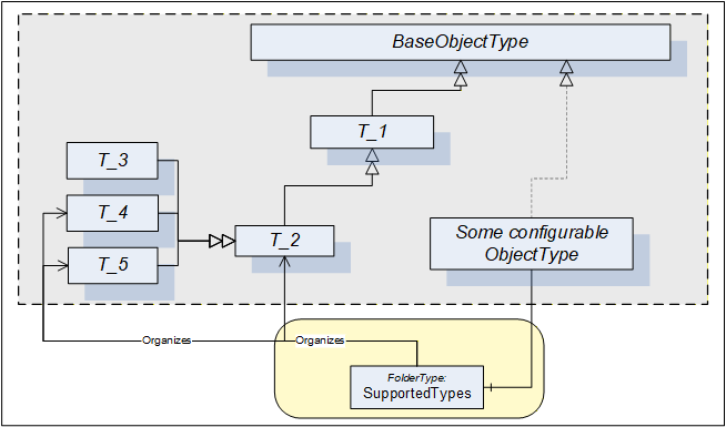
In some cases the SupportedTypes folder on the instance can be different to the one on the Type and can contain only a subset. It can be for example that only one instance of each Type can be configured. In this case the list of supported Types will shrink with each configured component.
9.2.2 ConfigurableObjectType
This ObjectType implements the configurable component pattern and is used when an Object or an instance declaration requires nothing but configuration capability. Figure 57 illustrates the ConfigurableObjectType. It is formally defined in Table 142. Concrete examples are in clauses 9.3 and 9.4.
| Attribute | Value | ||||
| BrowseName | 1:ConfigurableObjectType | ||||
| IsAbstract | False | ||||
| References | NodeClass | BrowseName | DataType | TypeDefinition | Other |
|---|---|---|---|---|---|
| Subtype of the 0:BaseObjectType defined in OPC 10000-5 | |||||
| 0:HasComponent | Object | 1:SupportedTypes | 0:FolderType | M | |
| 0:HasComponent | Object | 1:<ObjectIdentifier> | 0:BaseObjectType | OP | |
| Conformance Units | |||||
|---|---|---|---|---|---|
| DI Information Model |
The SupportedTypes folder is used to maintain the set of (subtypes of) BaseObjectTypes that can be instantiated in this configurable Object (the course of action to instantiate components is outside the scope of this specification).
The configured instances shall be components of the ConfigurableObject.
9.3 Block Devices
A Block-oriented Device can be composed using the modelling elements defined in this specification. A Block-oriented Device includes a configurable set of Blocks. Figure 58 shows the general structure of Block-oriented Devices.
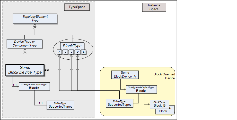
An Object called Blocks is used as a container for the actual BlockType instances. It is of the ConfigurableObjectType which includes the SupportedTypes folder. The SupportedTypes folder for Blocks is used to maintain the set of (subtypes of) BlockTypes that can be instantiated. The supported Blocks can be restricted by the Block-oriented Device. In Figure 58 the BlockTypes B and E have already been instantiated. In this example, only one instance of these types is allowed and the SupportedTypes folder therefore does not reference these types anymore. See 9.2.1 for the complete definition of the ConfigurableObjectType.
9.4 Modular Devices
A Modular Device is represented by a (subtype of) ComponentType that is composed of a top-Device and a set of subdevices (modules). The top-Device often is the head module with the program logic but a large part of the functionality depends on the used subdevices. The supported subdevices can be restricted by the Modular Device. Figure 59 shows the general structure of Modular Devices.
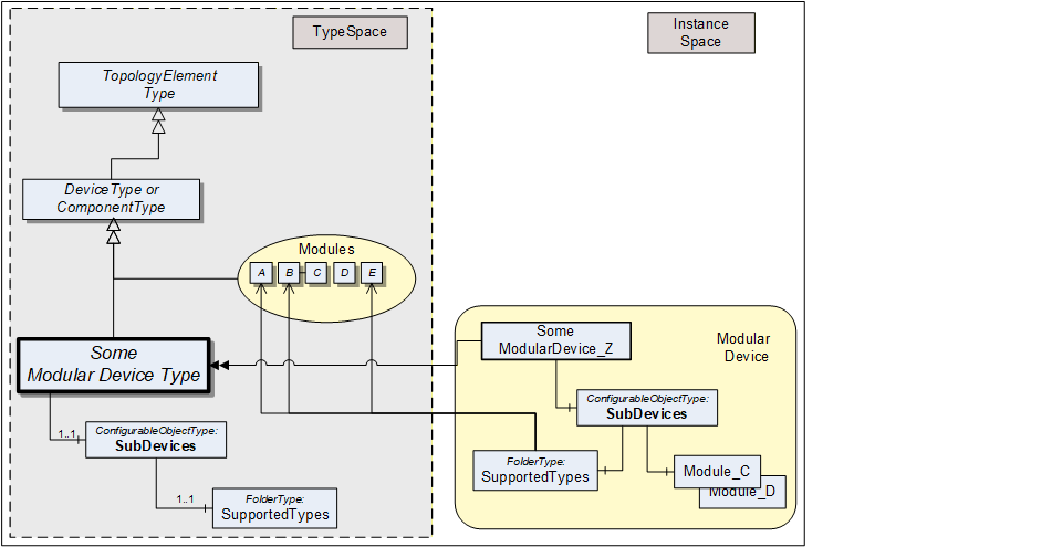
The modules (subdevices) of Modular Devices are aggregated in the SubDevices Object. It is of the ConfigurableObjectType, which includes the SupportedTypes folder. The SupportedTypes folder for SubDevices is used to maintain the set modules that can be added to the Modular Device. Modules are not in the DeviceSet Object.
Depending on the actual configuration, Modular Device instances can already have a set of pre-configured subdevices. Furthermore, the SupportedTypes folder possibly only refers to a subset of all possible subdevices for the Modular Device. In Figure 59 the modules C and D have already been instantiated. In this example, only one instance of these types is allowed and the SupportedTypes folder therefore does not reference these types anymore. See clause 9.2.1 for the complete definition of the ConfigurableObjectType.
Subdevices can themselves be Modular Devices.
10 Lifetime model
10.1 General
The lifetime model provides information about the lifetime, related limits and semantic of the lifetime of things like tools, material or machines.
Table 143 illustrates the model with two examples, showing the information that can be provided with the model defined in this clause. The Value of the LifetimeVariable provides the current value. The EngineeringUnits Property and the relation of the Indication to a classification ObjectType provide the semantic. The StartValue and LimitValue Properties indicate the range of the Value.
| Node | CertificateValidity | PartsProduced |
| LifetimeVariable | 200 | 553 |
| EngineeringUnits (M) | day | number of parts |
| StartValue (M) | 365 | 0 |
| WarningValues (O) | 10 | 950 |
| LimitValue (M) | 0 | 1000 |
| Indication (O) | TimeIndicationType | NumberOfPartsIndicationType |
For the CertificateValidity example, the instance of the LifetimeVariableType defines the remaining validity of a certificate with a unit of days and a classification of TimeIndication. The Value specifies 200 days - the remaining validity of a certificate. The initial value is 365 days with a warning level of 10 days. The certificate is invalid when the Value is zero.
For the PartsProduced example, the instance of the LifetimeVariableType defines the produced parts in the lifetime with a classification of NumberOfPartsIndication. The Value specifies 553 parts. The starting value is 0 parts and it is possible to produce up to 1000 parts with a warning indication if the number reaches 950.
10.2 LifetimeVariableType definition
The LifetimeVariableType defines Variables representing the remaining lifetime. It provides generically the remaining lifetime and can be used on anything; for example, on machines, actuators or sensors, but also on immaterial things like software. It is formally defined in Table 144.
| Attribute | Value | ||||
| BrowseName | 1:LifetimeVariableType | ||||
| IsAbstract | False | ||||
| ValueRank | -1 (-1 = Scalar) | ||||
| DataType | Number | ||||
| Description | Remaining lifetime | ||||
| References | Node Class | BrowseName | DataType | TypeDefinition | Other |
|---|---|---|---|---|---|
| Subtype of the 0:AnalogUnitType | |||||
| 0:HasProperty | Variable | 1:StartValue | 0:Number | 0:PropertyType | M |
| 0:HasProperty | Variable | 1:LimitValue | 0:Number | 0:PropertyType | M |
| 0:HasProperty | Variable | 1:Indication | 0:NodeId | 0:PropertyType | O |
| 0:HasProperty | Variable | 1:WarningValues | 0:Number{ScalarOrOneDimension} | 0:PropertyType | O |
| Conformance Units | |||||
|---|---|---|---|---|---|
| DI LT Lifetime Base |
The mandatory StartValue indicates the initial value, when there is still the full lifetime left. The engineering unit is the same as for the Value of the Variable, provided by the LifetimeVariableType's mandatory 0:EngineeringUnits, derived from the 0:AnalogUnitType. The DataType shall be the same as for the Value of the Variable.
The mandatory LimitValue indicates when the end of lifetime has been reached. The engineering unit is the same as for the Value of the Variable, provided by the LifetimeVariableType's mandatory 0:EngineeringUnits, derived from the 0:AnalogUnitType. The DataType shall be the same as for the Value of the Variable.
If the StartValue is larger than the LimitValue, the Value of the Variable is expected to move over the time downwards to the LimitValue, otherwise upwards to the LimitValue.
The optional Indication gives an indication of what is actually measured / represented by the Value of the Variable and the StartValue and LimitValue. The mandatory 0:EngineeringUnits, derived from the 0:AnalogUnitType already does this, to a certain degree. But for example, a length unit does not indicate what length is provided, like the cutting distance, the feed distance or the abraded length of a tool. The Indication contains a NodeId of the BaseLifetimeIndicationType or a subtype of it, providing a more detailed indication.
Note: It is expected that companion specifications or vendors define additional subtypes of BaseLifetimeIndicationType.
The optional WarningValues defines one or more limits when the end of lifetime is reached soon and can be used to inform the user. Servers can also generate Events when such a limit is reached. If provided, the WarningValues shall be between the StartValue and the LimitValue. If it contains more than one entry, the first array entry defines a warning level with lowest severity. The following entries increase the severity so that the highest entry defines the most serious level.
The engineering unit is the same as for the Value of the Variable, provided by the LifetimeVariableType's mandatory 0:EngineeringUnits, derived from the 0:AnalogUnitType. The DataType shall be the same as for the Value of the Variable.
This VariableType can be used in various cases. Examples include
The Variable just indicates the remaining lifetime as a percentage value. In that case, the 0:EngineeringUnits is percentage, the StartValue is 100 and the LimitValue is 0 (or vice versa if counted upwards).
The Variable represents the number of parts produced. In this case, the 0:EngineeringUnits is One, the StartValue is 0 and the LimitValue the maximum producible parts (e.g. 100 000); or vice versa if the number of remaining parts that still can be produced is provided.
The Variable represents the remaining time, for example until a software license becomes invalid. The 0:EngineeringUnits could be "Day", "Month", "Year", etc., the StartValue 0 and the LimitValue the overall duration, or vice versa if the remaining time is provided.
The child Nodes of the LifetimeVariableType have additional Attribute values defined in Table 145.
| BrowsePath | Description Attribute |
| 1:StartValue | StartValue indicates the initial value, when there is still the full lifetime left. |
| 1:LimitValue | LimitValue indicates when the end of lifetime has been reached. |
| 1:Indication | Indication gives an indication of what is actually measured / represented by the Value of the Variable and the StartValue and LimitValue. |
| 1:WarningValues | WarningValues indicates one or more levels when the end of lifetime is reached soon and can be used to inform the user when reached. |
10.3 BaseLifetimeIndicationType definition
The BaseLifetimeIndicationType ObjectType defines the base indication of a Variable of LifetimeVariableType, without defining any specific semantic. Servers should use a more specific subtype, if possible. It is formally defined in Table 146.
| Attribute | Value | ||||
| BrowseName | 1:BaseLifetimeIndicationType | ||||
| IsAbstract | True | ||||
| Description | Base indication type not further defining a semantic | ||||
| References | Node Class | BrowseName | DataType | TypeDefinition | Other |
|---|---|---|---|---|---|
| Subtype of the 0:BaseObjectType | |||||
| Conformance Units | |||||
|---|---|---|---|---|---|
| DI LT Lifetime Base |
10.4 TimeIndicationType definition
The TimeIndicationType ObjectType indicates the time the entity has been in use or can still be used. It is formally defined in Table 147.
| Attribute | Value | ||||
| BrowseName | 1:TimeIndicationType | ||||
| IsAbstract | True | ||||
| Description | Indicates the time the entity has been in use or can still be used | ||||
| References | Node Class | BrowseName | DataType | TypeDefinition | Other |
|---|---|---|---|---|---|
| Subtype of the 1:BaseLifetimeIndicationType | |||||
| Conformance Units | |||||
|---|---|---|---|---|---|
| DI LT Time Indication |
10.5 NumberOfPartsIndicationType definition
The NumberOfPartsIndicationType ObjectType indicates total number of parts that have been produced or can still be produced. It is formally defined in Table 148.
| Attribute | Value | ||||
| BrowseName | 1:NumberOfPartsIndicationType | ||||
| IsAbstract | True | ||||
| Description | Indicates the total number of parts that have been produced or can still be produced. | ||||
| References | Node Class | BrowseName | DataType | TypeDefinition | Other |
|---|---|---|---|---|---|
| Subtype of the 1:BaseLifetimeIndicationType | |||||
| Conformance Units | |||||
|---|---|---|---|---|---|
| DI LT Nb Of Parts Indication |
10.6 NumberOfUsagesIndicationType definition
The NumberOfUsagesIndicationType ObjectType indicates counting the process steps the entity has been used or can still be used for (for example usages of a punching tool). It is formally defined in Table 149.
| Attribute | Value | ||||
| BrowseName | 1:NumberOfUsagesIndicationType | ||||
| IsAbstract | True | ||||
| Description | Indicates counting the process steps the entity has been used or can still be used for (for example usages of a punching tool). | ||||
| References | Node Class | BrowseName | DataType | TypeDefinition | Other |
|---|---|---|---|---|---|
| Subtype of the 1:BaseLifetimeIndicationType | |||||
| Conformance Units | |||||
|---|---|---|---|---|---|
| DI LT Nb Of Usages Indication |
10.7 LengthIndicationType definition
The LengthIndicationType ObjectType indicates the abraded length, for example of a drill. It is formally defined in Table 150.
| Attribute | Value | ||||
| BrowseName | 1:LengthIndicationType | ||||
| IsAbstract | True | ||||
| Description | Indicates the abraded length, for example of a drill. | ||||
| References | Node Class | BrowseName | DataType | TypeDefinition | Other |
|---|---|---|---|---|---|
| Subtype of the 1:BaseLifetimeIndicationType | |||||
| Conformance Units | |||||
|---|---|---|---|---|---|
| DI LT Length Indication |
10.8 DiameterIndicationType definition
The DiameterIndicationType ObjectType indicates the abraded diameter, for example of a drill. It is formally defined in Table 151.
| Attribute | Value | ||||
| BrowseName | 1:DiameterIndicationType | ||||
| IsAbstract | True | ||||
| Description | Indicates the abraded diameter, for example of a drill. | ||||
| References | Node Class | BrowseName | DataType | TypeDefinition | Other |
|---|---|---|---|---|---|
| Subtype of the 1:BaseLifetimeIndicationType | |||||
| Conformance Units | |||||
|---|---|---|---|---|---|
| DI LT Diameter Indication |
10.9 SubstanceVolumeIndicationType definition
The SubstanceVolumeIndicationType ObjectType indicates the volume of a substance, for example of a liquid. It is formally defined in Table 152.
| Attribute | Value | ||||
| BrowseName | 1:SubstanceVolumeIndicationType | ||||
| IsAbstract | True | ||||
| Description | Indicates the volume of a substance, for example of a liquid. | ||||
| References | Node Class | BrowseName | DataType | TypeDefinition | Other |
|---|---|---|---|---|---|
| Subtype of the 1:BaseLifetimeIndicationType | |||||
| Conformance Units | |||||
|---|---|---|---|---|---|
| DI LT Substance Volume Indication |
11 Profiles and ConformanceUnits
Meaning and significance of Profiles and ConformanceUnits are described in OPC 10000-7.
The Profiles and ConformanceUnits for this specification are maintained in the online database and accessible via https://profiles.opcfoundation.org/?pg=DI%201.05.
12 Namespaces
12.1 Namespace Metadata
Table 153 defines the namespace metadata for this specification. The Object is used to provide version information for the namespace and an indication about static Nodes. Static Nodes are identical for all Attributes in all Servers, including the Value Attribute. See OPC 10000-5 for more details.
The information is provided as Object of type NamespaceMetadataType. This Object is a component of the Namespaces Object that is part of the Server Object. The NamespaceMetadataType ObjectType and its Properties are defined in OPC 10000-5.
The version information is also provided as part of the ModelTableEntry in the UANodeSet XML file. The UANodeSet XML schema is defined in OPC 10000-6.
| Attribute | Value | ||
| BrowseName | 1:http://opcfoundation.org/UA/DI/ | ||
| Property | DataType | Value | |
|---|---|---|---|
| 0:NamespaceUri | 0:String | http://opcfoundation.org/UA/DI/ | |
| 0:NamespaceVersion | 0:String | 1.05.0 | |
| 0:NamespacePublicationDate | 0:DateTime | 2025-11-15 | |
| 0:IsNamespaceSubset | 0:Boolean | False | |
| 0:StaticNodeIdTypes | 0:IdType[] | 0 | |
| 0:StaticNumericNodeIdRange | 0:NumericRange[] | ||
| 0:StaticStringNodeIdPattern | 0:String | ||
| Conformance Units | |||
|---|---|---|---|
| DI Information Model |
12.2 Handling of OPC UA namespaces
Namespaces are used by OPC UA to create unique identifiers across different naming authorities. The Attributes NodeId and BrowseName are identifiers. A Node in the UA AddressSpace is unambiguously identified using a NodeId. Unlike NodeIds, the BrowseName cannot be used to unambiguously identify a Node. Different Nodes can have the same BrowseName. They are used to build a browse path between two nodes or to define a standard Property.
Servers will often choose to use the same namespace for the NodeId and the BrowseName. However, if they want to provide a standard Property, its BrowseName shall have the namespace of the standards body although the namespace of the NodeId reflects something else, for example the EngineeringUnits Property. All NodeIds of Nodes not defined in this specification shall not use the standard namespaces.
Table 154 provides a list of mandatory and optional namespaces used in a DI OPC UA Server.
| NamespaceURI | Description | Use |
| http://opcfoundation.org/UA/ | Namespace for NodeIds and BrowseNames defined in the OPC UA specification. This namespace shall have namespace index 0. | Mandatory |
| Local Server URI | Namespace for Nodes defined in the local Server. This can include types and instances used in a Device represented by the Server. This namespace shall have namespace index 1. | Mandatory |
| http://opcfoundation.org/UA/DI/ | Namespace for NodeIds and BrowseNames defined in this specification. The namespace index is Server specific. | Mandatory |
| Vendor specific types and instances | A Server can provide vendor specific types like types derived from TopologyElementType or NetworkType or vendor-specific instances of those types in a vendor specific namespace. | Optional |
Table 155 provides a list of namespaces and their index used for BrowseNames in this specification. The default namespace of this specification is not listed since all BrowseNames without prefix use this default namespace.
| NamespaceURI | Namespace Index | Example |
| http://opcfoundation.org/UA/ | 0 | 0:EngineeringUnits |
| http://opcfoundation.org/UA/DI/ | 1 | 1:ComponentType |
| http://opcfoundation.org/UA/DI/PackageMetadata/ | 2 | 2:PackageMetadata |
Annex A Namespace and mappings (Normative)
A.1 NodeSet and Supplementary Files for DI Information Model
The DI Information Model is identified by the following URI:
http://opcfoundation.org/UA/DI/
Documentation for the NamespaceUri can be found here.
The NodeSet associated with this version of specification can be found here:
https://reference.opcfoundation.org/nodesets/?u=http://opcfoundation.org/UA/DI/&v=1.05.0&i=1
The NodeSet associated with the latest version of the specification can be found here:
https://reference.opcfoundation.org/nodesets/?u=http://opcfoundation.org/UA/DI/&i=1
The supplementary files associated with this version of specification can be found here:
https://reference.opcfoundation.org/nodesets/?u=http://opcfoundation.org/UA/DI/&v=1.05.0&i=2
The supplementary files associated with the latest version of the specification can be found here:
https://reference.opcfoundation.org/nodesets/?u=http://opcfoundation.org/UA/DI/&i=2
The NamespaceUri for the package_metadata.json with structures and enumerations used for Software Package files is:
http://opcfoundation.org/UA/DI/PackageMetadata/
Note: This namespace and the contained types typically do not show up in the AddressSpace of an OPC UA Server.
Annex B Examples (Informative)
This Annex includes examples referenced in the normative sections.
B.1 Functional Group usages
The examples in Figure B.1 and Figure B.2 illustrate the use of FunctionalGroups:
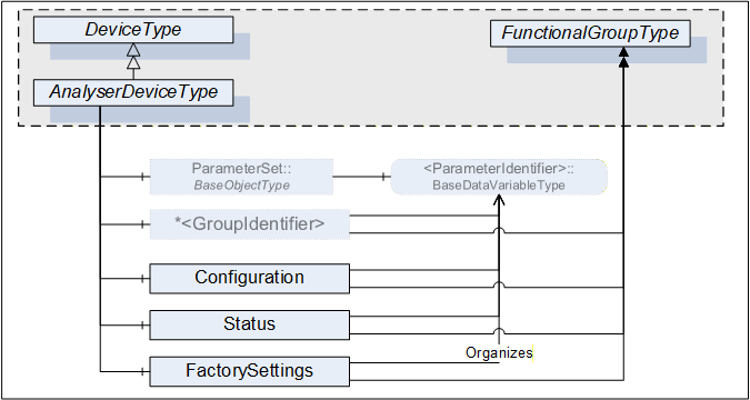
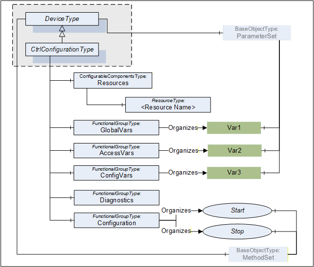
B.2 Identification Functional Group
The Properties of a TopologyElement, like Manufacturer, SerialNumber, will usually be sufficient as identification. If other Parameters or even Methods are required, all required elements shall be organized in a FunctionalGroup called Identification. Figure B.3 illustrates the Identification FunctionalGroup with an example.
Note that companion standards are expected to define the Identification contents for their model.
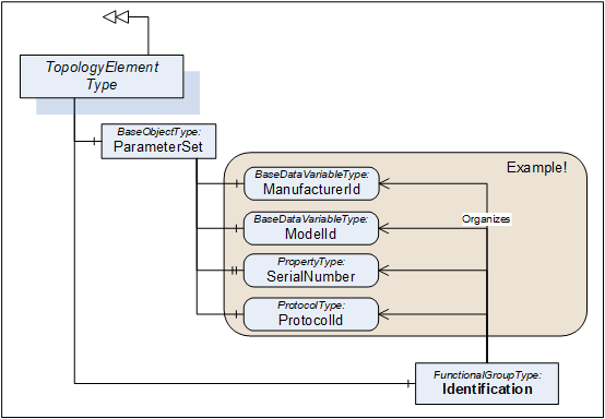
B.3 Software Update examples
B.3.1 Simple example using Cached-Loading
The software update model provides several options and variants for advanced use cases. The Update Client must be prepared for the option that the server provides (see 8.3.4.1) and how the concrete update behaves (see 8.3.8).
This example shows a typical application for a simple server with a minimal implementation. The subsequent examples additionally address generic clients and describe all the optional parts that can be supported.
This example uses the Cached-Loading option. If the memory is limited and the installation can be done during the transfer of the Software Package, the Direct-Loading model is another simple option.
First the client determines what version is currently installed by reading the Properties of CurrentVersion of the Loading object.
Then the client can transfer the Software Package to the device using the Loading.FileTransfer object. At the end of the transfer the server checks whether the new Software Package is compatible (FileTransfer.CloseAndCommit).
With a call to InstallSoftwarePackage() of the Installation state machine the actual installation is started. The end of the installation could be an automatic reboot of the device or the state machine transitions back to Idle. A transition to Error would indicate an issue during the installation.
During the whole installation, the progress and error messages for the user can be determined subscribing the UpdateStatus property.
To verify if the update was success the client verifies that Loading.CurrentVersion now describes the desired updated version.
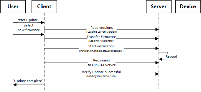
B.3.2 Factory Automation example
This example illustrates the use of software update of several devices from the Client point of view.
This is only one example for a specific domain. There will be different Clients for different types of systems or industries (e.g., for process domain the process will not be stopped and before a sensor is updated a replacement value is configured in the controller).
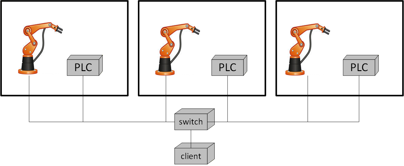
The example (illustrated in Figure B.5) describes a production line with several production cells. Each cell contains a robot and a main PLC that can be updated. A switch connects the cells and is also updateable via OPC UA.
A Client would perform the following steps:
Analyze the system
Determine the network topology with all devices.
Determine currently installed software and how the devices can perform the update (using IVendorNameplateType Interface and Loading Object).
Determine technical preconditions for the update. E.g., if the device uses Direct-, Cached- or File System based Loading (using the Loading Object).
Prepare installation
The user selects the software to be installed
Transfer the software and firmware updates to the PLCs, the robots and the switch, except for Direct-Loading (using CachedLoadingType, FileSystem).
Schedule installation (Client only)
Determine how the update can be executed (using GetUpdateBehavior Methods of CachedLoadingType and FileSystemLoadingType).
Wait for strategic condition (e.g., end of shift; no task in queue).
Plan the order of update (e.g., robots and PLCs first; infrastructure components last).
Prepare devices for installation
Stop production line software (using an application specific Information Model).
Bring the robots and PLCs into a state for update (using the PrepareForUpdate state machine and/or branch specific state machine).
Wait for technical starting conditions (e.g., robot in standstill) (using the PrepareForUpdate state machine).
Execute installation
Start the installation of all robots and all PLCs simultaneously (using the Installation state machine).
Update the switch when robots & PLCs are done (using the Installation state machine).
Restore device state after installation
Restart robots and PLCs (using the PrepareForUpdate state machine and/or branch specific state machine).
Restart production line software (using an application specific Information Model).
B.3.3 Update sequence using Direct-Loading
An example sequence of Direct-Loading is shown in Figure B.6.
If the Server does not implement the properties PrepareForUpdate, PowerCycle or Parameters of the SoftwareUpdateType, the associated options are not supported by the component and Client-Server interaction becomes simpler.
In the first steps the device identity and the kind of supported Server options of the device must be discovered as described in Figure 35.
How to look up and transfer files for an installation is described in Figure 36.
The preparation can be done as described in Figure 37.
The installation itself is described in Figure 38.
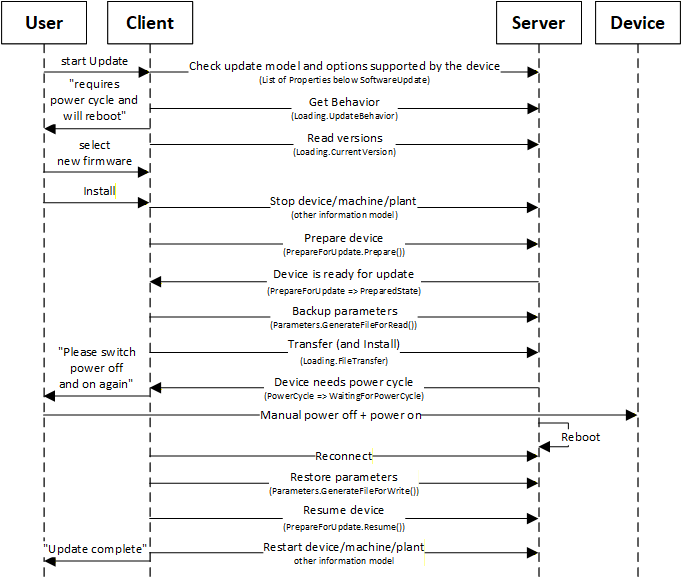
B.3.4 Update sequence using Cached-Loading
An example sequence of Cached-Loading is shown in Figure B.7.
If the Server does not implement the properties PrepareForUpdate, PowerCycle or Parameters of the SoftwareUpdateType, the associated options are not supported by the component and Client-Server interaction becomes simpler.
In the first steps the device identity and the kind of supported Server options of the device must be discovered as described in Figure 35.
How to look up and transfer files for an installation is described in Figure 36.
The preparation can be done as described in Figure 37.
The installation itself is described in Figure 39.
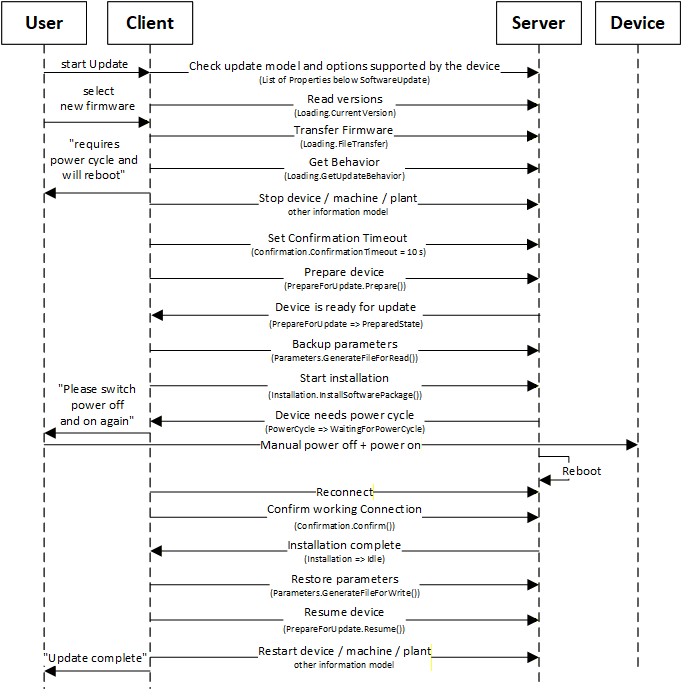
B.3.5 Update sequence using File System based Loading
An example sequence of File System based Loading is shown in Figure B.8.
In this example the server provides the PrepareForUpdate state machine and a preparation for an installation can only be done locally at the device. So, the Resume activity described in Figure 39 cannot be commanded by a Client.
In the first steps the device identity and the kind of supported Server options of the device must be discovered as described in Figure 35.
How to look up and transfer files for an installation is described in Figure 36.
The preparation can be done as described in Figure 37.
The installation itself is described in Figure 39.
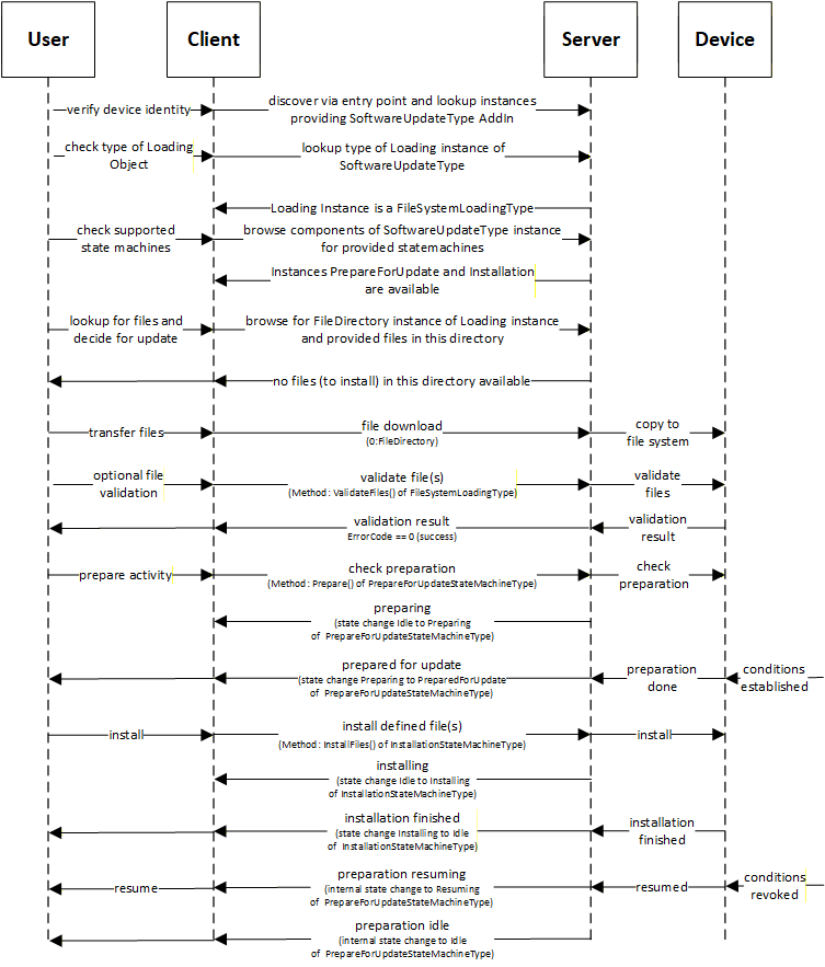
B.3.6 Update Sequence for optimized system/bulk firmware update for modular devices and machines
This example explains how an optimized firmware update for a modular device or machine can look like. Therefore, multiple firmware packages are gathered into one solution package and send to the OPC UA server all at once to avoid multiple transfer sequences.
A modular or complex device or a machine are consisting of several modules, components or sub-devices. Each of them has their own firmware (or even configuration). In the traditional way each of them has an own instance of the SoftwareUpdateType object and each of them requires a download and install activity for the firmware. This can lead to duplicated download firmware package and/or often executed sequentially, means each firmware packages are transferred separately by opening each a new connection/channel for the download, which takes a lot of time in cases of larger installations.
Following a standardized way of managing modular devices or device with multiple content to loaded all at once:
Create a solution package see 8.7.5 to put all firmware, configuration or application into one package.
The UA server contains a SoftwareUpdateType instance which is classified as SoftwareClass Solution to identify that a solution package download/handling is supported. The object has the loading type FileSystemLoadingType, due to optional version as a solution package may not have a version number.. The version check will be done with ValidateFiles operation, where device will check each sub-package against the assigned information.
Example of a UA address space "Modular Device":
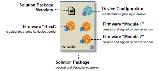
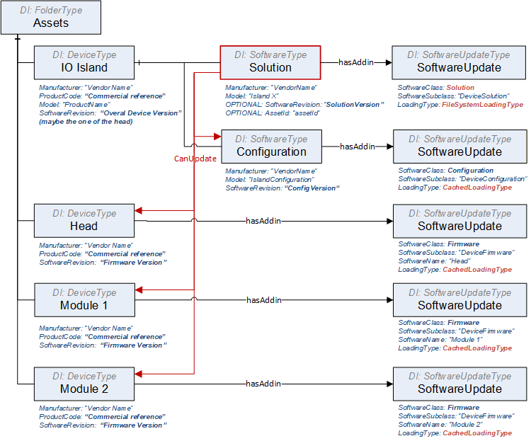
Example of a UA address space "Single Device":
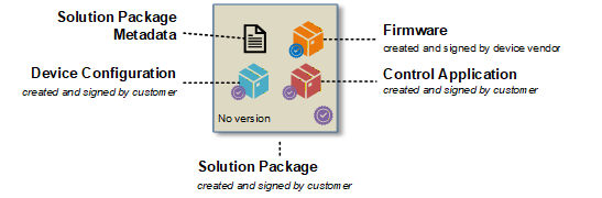
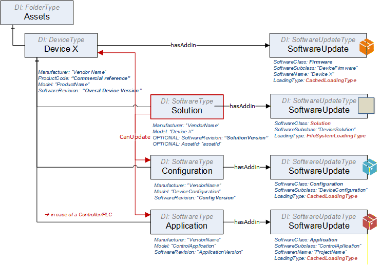
Example of a UA solution package metadata "Single Device" showing the assignment:
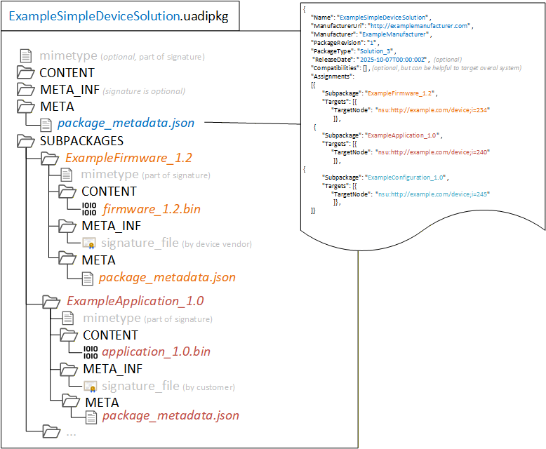
B.3.6.1 Update Sequence for Single Device - where solution package is created 'on the fly'
There is the situation that a tool is connecting to a device and need to create an individual update for this device solution, which may include just a subset of elements.
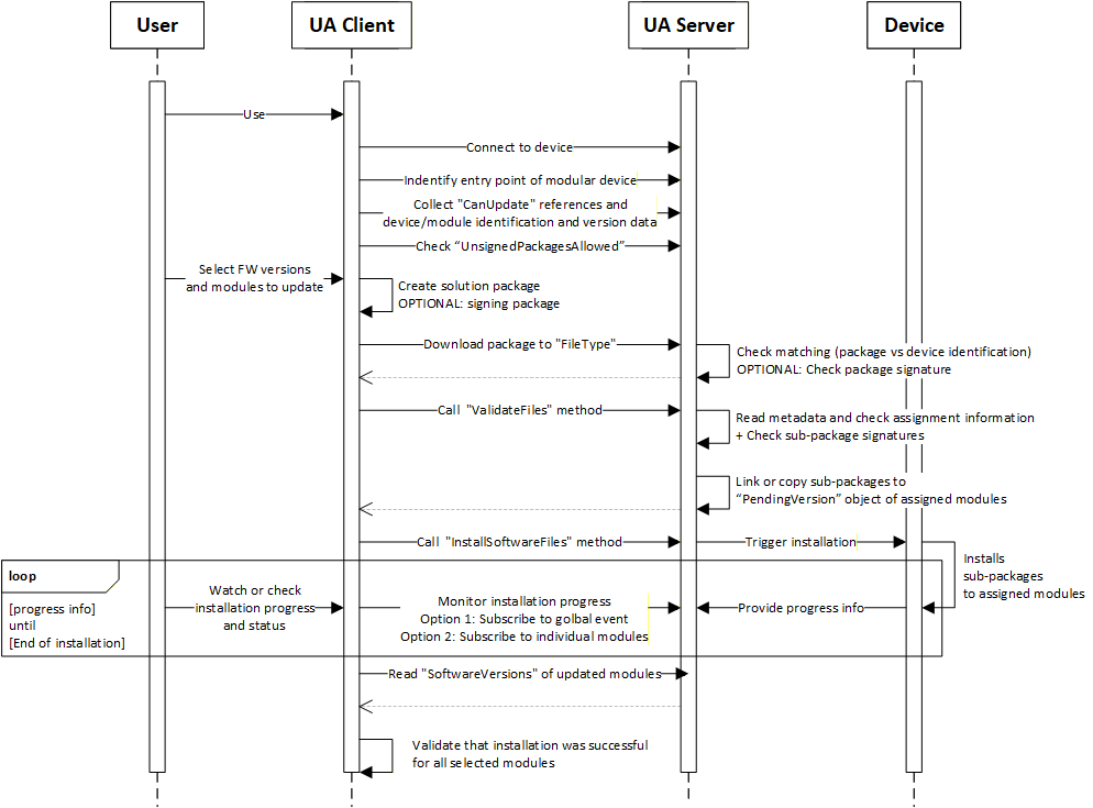
Steps of the workflow:
Connect to the device via the UA server.
The client finds the entry point of the modular device, that can happen by:
Knowing the structure such as UADI:DeviceType or UAFX:AssetType
Finding the object with software class "Solution" behind,
In cases of a sever hosting multiple devices, the user selects the right one or the client knows the identification of the target device.
Browse the references CanUpdate of the "Solution" object to know devices can be updated via a solution package. Afterwards read the identification of the linked modules.
Check the flag "UnsignedPackagesAllowed" to know if a solution package is required to be signed.
User selects the FW version or config/application and modules/targets that should be updated.
Client creates a new solution package with the selected content. It includes:
Creating of the solution package and pack the sub-packages into it.
Creating a package metadata file that contains the assignment information.
Optionally sign the solution package with a customer provided certificate or service.
Client downloads the solution package to the device.
Device is doing an overall check on the package level if its valid and intended for this device.
Optional checking the package signature
Client calls ValidateFiles to trigger a check of the metadata data about assignments
For the successful matched elements, the sub-packages are copied or linked to the SoftwareUpdate instances of each device into the PendingVersion.
Server is returning the info which elements are ready for update and which are not supported
Client tiggers the installation process by calling InstallSoftwareFiles. This triggers the real installation process on the device side.
Device is installing the selected version. That can happen in parallel or sequential or combined way depending on the device capabilities. This is up to the devices.
Client is subscribing to [a] or/and [b] to get progress and status of the installation process.
A global event (aggregates all progress and status updates via the module and update ID, so that the client can see the details on module is referred)
Each individual module
Device is sending the progress and status information.
After client received the message for end of installation, he is reading the module identification with software revision to check if installation was really successful.
B.3.6.2 Update Sequence for Modular Device - when getting a solution package from a 3rd instance.
A 3 rd instance has created a solution package. The assignment of sub-packages to target modules is in the package metadata.
Variation 1: The tool knows the solution package format and can check metadata and signature. The solution package is a Whitebox for the tool and the tool can make a pre-check on matching and compatibility before downloading the solution package to the device.
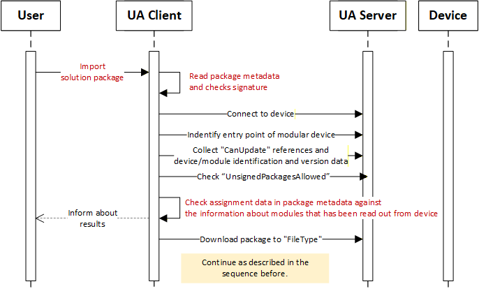
Variation 2: The tools is not able to process the solution package (unknown format), it can't check the package and it's package metadata. The solution package is a Blackbox for the tool. The solution package is loaded to the device without any pre-check, may the selection to target device needs to be done manually, and device is take over this part of doing match and compatibility check directly after receiving the solution package.
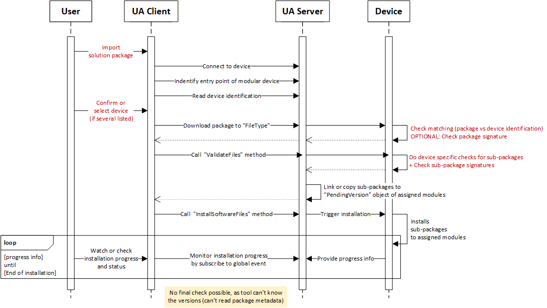
Variation 3: The tool knows the solution package format and can check metadata and signature. But in the package, there may be some sub-packages which the format is unknown (proprietary) to the tool, The tool can't process the sub-package and its metadata.
The main idea of the solution package is to create a consistent description of all the content that is gathered within the package to be able to do a pre-check before sending any content to a target, means there should be some description of each subpackage in terms of what it is and what to be checked by the tool to enable a successful execution of the package on the target.
Therefore, the unknown (proprietary) content or package need to be descripted at least with a minimal set of parameters. A full and final check needs to be done anyhow by the target itself. That means creating a kind of wrapper to this UA package format by adding a package metadata file, containing at least the minimal set of information to a description about what the package is and for whom is it made for.
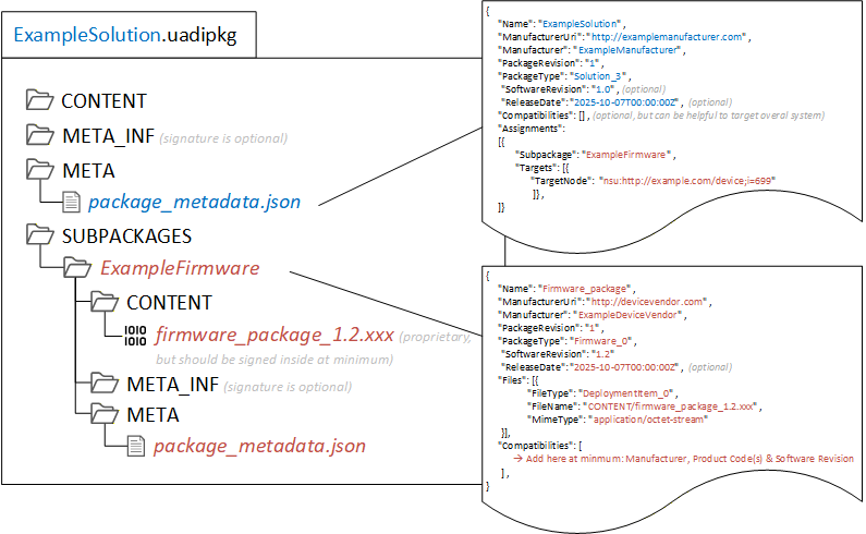
B.3.6.3 Managing a situation of an unsigned solution package
In case a solution Package is NOT signed, due to:
the user doesn't have the certificate from the device (individual creation of a solution package at customer site by the customer to update).
the device using customer specific certificates (tool that creates the solution package may not have access to these certificates).
no PKI infrastructure is available.
It represents a potential security risk and to mitigates it, following considerations has been done:
Sub-package(s) itself are still signed by the vendor such as firmware packages, means no execution of unsigned data in the server though the sub packages. Sub-packages that can't be signed by the vendor like configurations or applications, shall be signed by the customer or the tool shall inform the user about a usage unsigned content in a sub-package.
Trust relation between tool and server is in place based on UA connections and sessions.
Tool as trust anchor, similar as signature check outsourced by a PKI / GDS
Server is trusting the tool, allowing tool to do firmware update.
The tool has to authenticate and authorize itself through login/token and application trust list.
Solution packages is created by the tool that has this trust relation.
For 3rd instance created packages that has been imported, the tool should inform user Users shall be informed about possible risks when using this option of unsigned solution packages. (Informative)
The server can write to a log or send an event to the client
B.3.6.4 Extension for Signed Packages are Mandotory
Instruction for the need that a solution package must be signed:
Use an attribute "UnsignedPackagesAllowed" and set value to "FALSE".
Implement recommended security settings and behaviour that only an admin or security expert can change this setting
Annex C Guidelines for the usage of OPC UA for Devices as base for companion specifications (Informative)
This informative Annex describes guidelines for the usage of this specification as base for creating companion specifications as well as guidelines on how to combine different companion specifications based on this specification describing different aspects of the same device in one OPC UA application.
C.1 Overview
This specification is used as base for many other companion specifications like
OPC UA for IEC 61131-3
OPC UA Information Model for FDT Technology
AutoId
OPC UA for IO-Link.
Those companion specifications define different aspects of devices, for example
some specific functionality (like the scan operation of a RFID reader in the AutoId spec),
the view of the device accessed by a specific protocol (like IO-Link),
or the configuration capabilities of a device as defined in a vendor-specific device package (like FDI or FDT).
When an OPC UA application wants to combine those different aspects of one device in its AddressSpace, there are potential problems as shown in Figure C.1. The example shows the application of the AutoId specification as well as the FDT specification for the same device. For simplicity, only the base ObjectTypes are shown. In reality, there has to be a subtype of the abstract FdtDeviceType and there would be very likely a vendor-specific subtype of the RfidReaderDeviceType.
As shown in the figure, there are actually two Objects of different ObjectTypes representing different aspects of the same device in the real world.
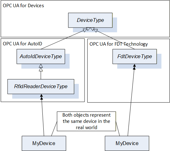
In order to avoid multiple-inheritance, which is not further defined in OPC UA, it is not possible to directly combine both ObjectTypes into one ObjectType containing all aspects of the device. And an Object cannot be defined by two ObjectTypes. Therefore, in order to expose the information, that both Objects actually represent different aspects of the same device, composition should be used as shown in Figure C.2.
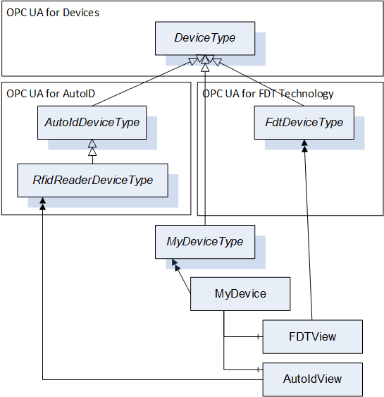
In this case, the device is represented by an Object "MyDevice" where the vendor of the OPC UA Application can provide its specific knowledge of the device. In addition, the Object has two components called FDTView and AutoIdView in the figure, containing the information as defined in the corresponding companion specifications.
C.2 Guidelines to define companion specifications based on OPC UA for Devices
As shown in the previous section, composition can be used to combine the ObjectTypes defined by various specifications describing aspects of a device in order to combine the information in one OPC UA application. This can lead, as shown in the example in Figure C.2, to the usage of several instances of the DeviceType to represent one device. In order to avoid this, it is recommended that companion specifications do not directly derive from the DeviceType but instead derive from the TopologyElementType or other subtypes of the TopologyElementType (but not the DeviceType). This allows an OPC UA application to represent the device by one instance of the DeviceType and compose potentially several other aspects without using the DeviceType again.
The DeviceType defines several Properties identifying the device as mandatory. By the approach described above, the Properties are repeated several times as required in the example in Figure C.2. Here, the mandatory SerialNumber is a Property of MyDevice, FDTView, and AutoIdView. However, companion specification can still define some of those Properties on their ObjectTypes, either optional in order to allow the usage of their ObjectTypes without an additional Object (for example if only one companion specification is supported by the OPC UA application) or mandatory, if a specific access-path to the information shall be exposed. For example, the SerialNumber accessed by a specific protocol can be different than the SerialNumber managed directly by the DeviceVendor. Whereas Profibus or IO-Link represent the SerialNumber as a String, the HART protocol uses three Bytes. So, if a companion specification should expose the SerialNumber accessed via HART, it can add it as mandatory Property to its ObjectType. To conclude, it is recommended that companion specification provide the Properties of the DeviceType by implementing the IVendorNameplateType, which adds all the Properties optionally to the ObjectType. If desired, they can make some of those Properties mandatory to force that a specific access path is used (e.g. via a specific protocol).
In order to easily identify the components representing different views on the device, it is recommended to use the AddIn concept to define a standardized BrowseName for the Object (DefaultInstanceBrowseName Property). In the example in Figure C.2 that would mean that FdtDeviceType would have defined a DefaultInstanceBrowseName "FDTView", and thus OPC UA Clients can easily find the FDT specific data of the device by looking for an Instance called "FDTView", for example by using the TranslateBrowsePathsToNodeIds Service.
C.3 Guidelines on how to combine different companion specifications based on OPC UA for Devices in one OPC UA application
When supporting several companion specifications in one OPC UA application it is recommended to use the composition approach as described in section C.1. To expose the possibilities further, the example is extended as shown in Figure C.3. Again, subtypes for the concrete type of device are not considered for simplicity. The IOLinkDeviceType is already not derived from DeviceType but TopologyElementType. As the FDT and AutoID specifications derive from DeviceType, the device is represented by several instances of the DeviceType.
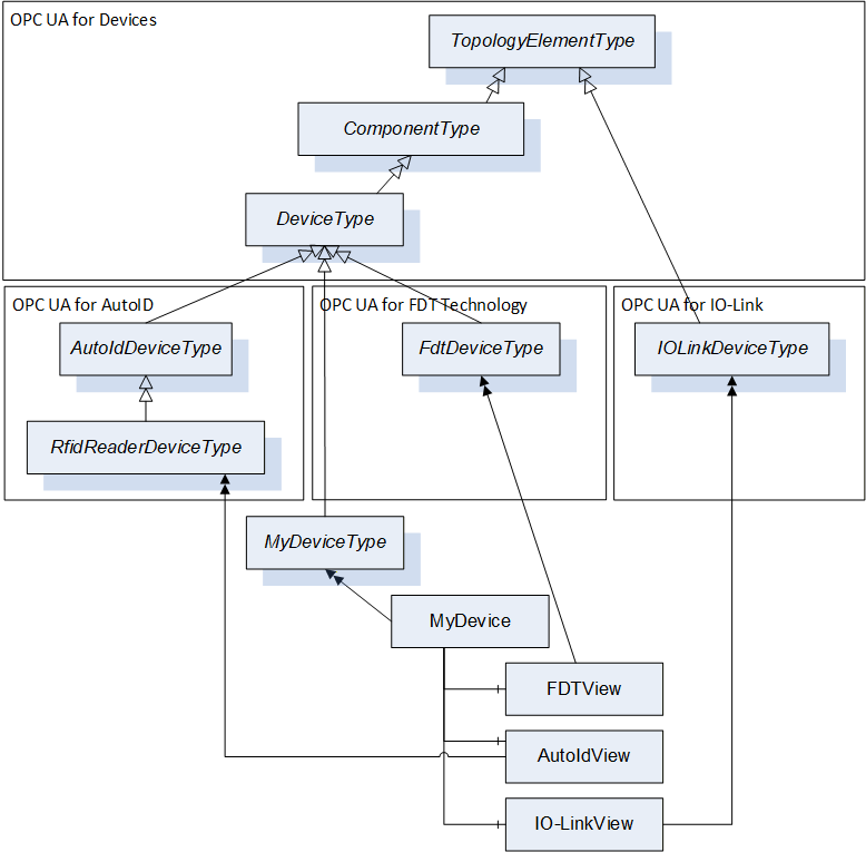
In order to limit the usage of DeviceType instances, an alternative approach is shown in Figure C.4. Here, the RfidReaderDeviceType is used as main Object to represent the device, and the objects defined by the other companion specifications are composed.
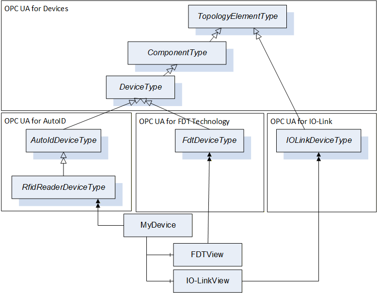
It is recommended to use one of the two approaches described above.
C.4 Guidelines to manage the same Variables defined in different places
Deploying several Information Models based on this specification on the same device can lead to the situation, that the same Variable (e.g., the Property SerialNumber) for the same device is used in several places.
When the Property is the same, and the value of the Property is the same, it is recommended to avoid, that the value is managed in the Server in two different places (see Figure C.5, left). One solution is, that the two Variables reference the same internal memory managing the value (see Figure C.5, middle). Another solution is, that the Variable is only managed once in the Server, just referenced from different places (see Figure C.5, right). The solution using the same Node is the most optimized one in terms of memory consumption.
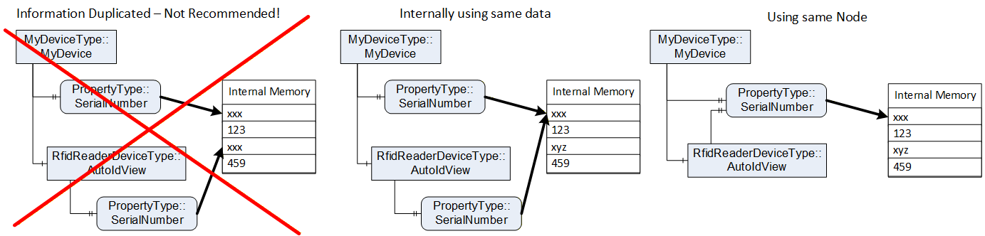
C.5 Guidelines on how to use functionality in companion specifications
In the previous sections it was shown how to use this specification when you want to use at least the TopologyElementType, providing you the capabilities to manage Parameters and Methods via ParameterSet and MethodSet and FunctionalGroups.
If the companion specification only wants to reuse other aspects of this specification, defined in the Interfaces in 4.5 or the AddIns "Locking" in 7 or software update in 8, the companion specification is not required to derive from the ObjectTypes defined in this specification. Instead of, it can just implement the Interfaces or use the AddIns in their ObjectTypes and build an ObjectType-Hierarchy independent of this specification.
In Figure C.5, an example is given. The companion specification defines an ObjectType hierarchy, and uses the AddIns in the appropriate places (Lock and Transfer). The Interfaces can either be implemented by the ObjectTypes directly (Figure C.5), or by a sub-component in order to group the functionality (Figure C.7). In the second approach, the RootType does not implement the IVendorNameplate directly, but uses a component (Identification) implementing the Interface. Here, the FunctionalGroupType and the predefined name Identification is used. The B_Type extends the Identification and also implements the ITagNameplateType.
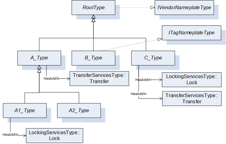
The advantage of the first approach is, that the content of the Interface is directly at the ObjectType, whereas the advantage of the second approach is, that the content of the Interface is grouped in the sub-component. When the content of the Interface and the additional content of the ObjectType and its expected subtypes is rather small, the first approach is recommended. If the content of the Interface or the additional content of the ObjectType or its subtypes is rather large, the additional grouping Object is recommended, as it does not provide a flat list of sub-components, but groups them accordingly and thus makes it easier to use.
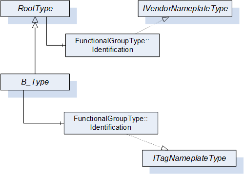
Bibliography
Agreement of Use
COPYRIGHT RESTRICTIONS
Any unauthorized use of this specification may violate copyright laws, trademark laws, and communications regulations and statutes. This document contains information which is protected by copyright. All Rights Reserved. No part of this work covered by copyright herein may be reproduced or used in any form or by any means - graphic, electronic, or mechanical, including photocopying, recording, taping, or information storage and retrieval systems - without permission of the copyright owner.
OPC Foundation members and non-members are prohibited from copying and redistributing this specification. All copies must be obtained on an individual basis, directly from the OPC Foundation Web site http://www.opcfoundation.org.
PATENTS
The attention of adopters is directed to the possibility that compliance with or adoption of OPC specifications may require use of an invention covered by patent rights. OPC shall not be responsible for identifying patents for which a license may be required by any OPC specification, or for conducting legal inquiries into the legal validity or scope of those patents that are brought to its attention. OPC specifications are prospective and advisory only. Prospective users are responsible for protecting themselves against liability for infringement of patents.
WARRANTY AND LIABILITY DISCLAIMERS
WHILE THIS PUBLICATION IS BELIEVED TO BE ACCURATE, IT IS PROVIDED "AS IS" AND MAY CONTAIN ERRORS OR MISPRINTS. THE OPC FOUDATION MAKES NO WARRANTY OF ANY KIND, EXPRESSED OR IMPLIED, WITH REGARD TO THIS PUBLICATION, INCLUDING BUT NOT LIMITED TO ANY WARRANTY OF TITLE OR OWNERSHIP, IMPLIED WARRANTY OF MERCHANTABILITY OR WARRANTY OF FITNESS FOR A PARTICULAR PURPOSE OR USE. IN NO EVENT SHALL THE OPC FOUNDATION BE LIABLE FOR ERRORS CONTAINED HEREIN OR FOR DIRECT, INDIRECT, INCIDENTAL, SPECIAL, CONSEQUENTIAL, RELIANCE OR COVER DAMAGES, INCLUDING LOSS OF PROFITS, REVENUE, DATA OR USE, INCURRED BY ANY USER OR ANY THIRD PARTY IN CONNECTION WITH THE FURNISHING, PERFORMANCE, OR USE OF THIS MATERIAL, EVEN IF ADVISED OF THE POSSIBILITY OF SUCH DAMAGES.
The entire risk as to the quality and performance of software developed using this specification is borne by you.
RESTRICTED RIGHTS LEGEND
This Specification is provided with Restricted Rights. Use, duplication or disclosure by the U.S. government is subject to restrictions as set forth in (a) this Agreement pursuant to DFARs 227.7202-3(a); (b) subparagraph (c)(1)(i) of the Rights in Technical Data and Computer Software clause at DFARs 252.227-7013; or (c) the Commercial Computer Software Restricted Rights clause at FAR 52.227-19 subdivision (c)(1) and (2), as applicable. Contractor / manufacturer are the OPC Foundation, 16101 N. 82nd Street, Suite 3B, Scottsdale, AZ, 85260-1830.
COMPLIANCE
The OPC Foundation shall at all times be the sole entity that may authorize developers, suppliers and sellers of hardware and software to use certification marks, trademarks or other special designations to indicate compliance with these materials. Products developed using this specification may claim compliance or conformance with this specification if and only if the software satisfactorily meets the certification requirements set by the OPC Foundation. Products that do not meet these requirements may claim only that the product was based on this specification and must not claim compliance or conformance with this specification.
Trademarks
Most computer and software brand names have trademarks or registered trademarks. The individual trademarks have not been listed here.
GENERAL PROVISIONS
Should any provision of this Agreement be held to be void, invalid, unenforceable or illegal by a court, the validity and enforceability of the other provisions shall not be affected thereby.
This Agreement shall be governed by and construed under the laws of the State of Minnesota, excluding its choice or law rules.
This Agreement embodies the entire understanding between the parties with respect to, and supersedes any prior understanding or agreement (oral or written) relating to, this specification.
ISSUE REPORTING
If an error or problem is found in this specification, the UaNodeSet, or any associated supplementary files, it should be reported as an issue.
The reporting process can be found here: https://opcfoundation.org/resources/issue-tracking/
The Link to the issue tracking project for this document is here:
https://mantis.opcfoundation.org/set_project.php?project_id=67&make_default=no
Revision 1.05 Highlights
The following table includes the Mantis issues resolved with this version.
| Mantis ID | Scope | Summary | Resolution |
| Editorial | Adjust to new template | Delete Profiles and Conformance Units and refer to profile database. Adjust Annex A - Namespace and mappings | |
| 9028 | Clarification | Remove references to amendments | Replaced by references to UA Parts where the amendments have been integrated in. |
| 8781 | Editorial | Typo in reference to ISO/IEC 11179-6 | Replaced ISO/ICE … with ISO/IEC …. |
| 8105 | Feature | Missing IRDIs | Added IRDIs for DeviceRevision Added IRDIs for OperationCounters |
| 6152 | Errata | Can hierarchical References be symmetric? | NO! This was wrong and not implementable. Has to be NonHierarchical. |
| 9051 | Feature | Add BrowseNames for Functional Group names. | According to the new CS template, the table is now called "Well-Known" FunctionalGroupType BrowseNames. The BrowseNames have been added to the NodeSet with Attribute "DesignToolOnly". |
| 8412 | Clarification | Contradiction between PrepareForUpdate and FileTransfer | Error description rephrased. |
| 9030 | Errata | Missing option to excape from endless Preparing state of PrepareForUpdate StateMachine | Added additional usage scenario for Abort Method |
| 9546 | Errata | Missing HasCause References in StateMachines for SoftwareUpdate | Missing references are added to all state machines |
| 9547 | Editorial | Drawings for StateMachines of Software Updates have more transitions then in the Model | Additional transitions removed from the diagrams |
| 10218 | Editorial | Missing SoftwareUpdate reference at ComponentType | Added optional SoftwareUpdate reference to ComponentType. |
| 10223 | Feature | Standardized folder to add / remove applications with software update support | Added new SoftwareFolderType. |
| 10222 | Clarification | Simpler example for software update | Additional example added to Annex B. |
| 10220 | Clarification | Clarify when to use which loading option of software update | Additional notes added to the description of each loading types. |
| 10219 | Feature | Information about the type of software for software update | Added new enumeration SoftwareClass and new Properties SoftwareClass, SoftwareSubClass and SoftwareName to the SoftwareUpdateType. |
| 10224 | Feature | Standard container format for Software Packages of the software update | Added new subsection for the Software Package file format. |
| 10221 | Feature | Missing information whether unsigned software packages are supported | Added new Property UnsignedPackageAllowed to the SoftwareUpdateType. |
| 10225 | Feature | Interface for asset location indication | Added new IAssetLocationIndication Interface. |
| 9029 | Feature | Missing method to remove a previously transferred software package | Clear method added |
| 10254 | Errata | Some terms are lower case in the definition but used with an uppercase first letter (e.g. device, block) | Fixed the terms to start with an uppercase first letter. |
| 10579 | Editorial | IEC harmonized the product identification. Some IRDIs in the VendorNameplate have been revised. | The revised IRDIs have been replaced in Table 18. In addition, those that have been superseded are listed in column "Legacy IRDI". |