
5 Device communication model
5.1 General
Clause 5 introduces References, the ProtocolType, and basic TopologyElementTypes for creating a communication topology. The types for this model are illustrated in Figure 16.
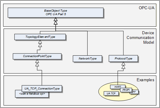
A ProtocolType ObjectType represents a specific communication protocol (e.g., FieldBus) implemented by a certain TopologyElement. Examples are shown in Figure 18.
The ConnectionPointType represents the logical interface of a Device to a Network.
A Network is the logical representation of wired and wireless technologies.
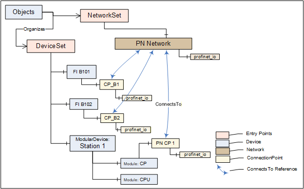
Figure 17 provides an overall example.
5.2 ProtocolType
The ProtocolType ObjectType and its subtypes are used to specify a specific communication (e.g., FieldBus) protocol that is supported by a Device (respectively by its ConnectionPoint) or Network. The BrowseName of each instance of a ProtocolType shall define the Communication Profile (see Figure 18).
Figure 18 shows the ProtocolType including some specific types and instances that represent Communication Profiles of that type. It is formally defined in Table 45.
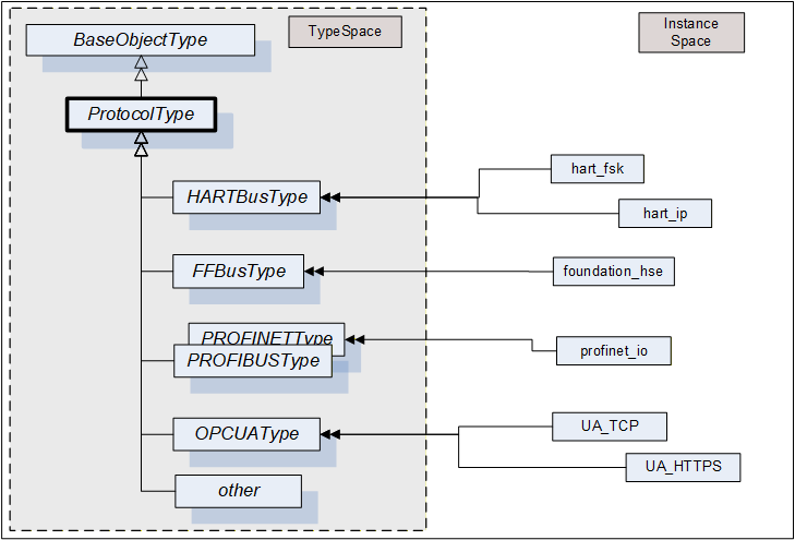
that represent specific communication profiles
| Attribute | Value | ||||
| BrowseName | 1:ProtocolType | ||||
| IsAbstract | False | ||||
| References | NodeClass | BrowseName | DataType | TypeDefinition | Other |
|---|---|---|---|---|---|
| Subtype of the 0:BaseObjectType defined in OPC 10000-5 | |||||
| Conformance Units | |||||
|---|---|---|---|---|---|
| DI Network | |||||
| DI Protocol |
5.3 Network
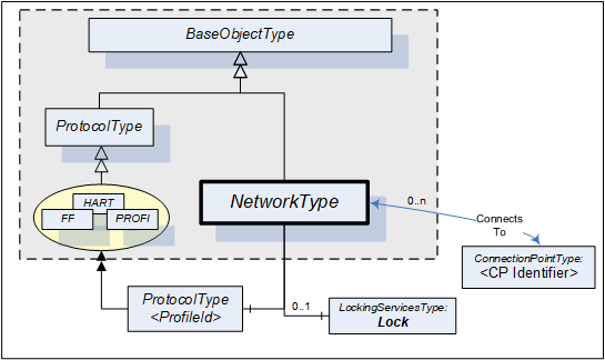
A Network is the logical representation of wired and wireless technologies and represents the communication means for Devices that are connected to it. A Network instance is qualified by its Communication Profile components.
Figure 19 shows the type hierarchy and the NetworkType components. It is formally defined in Table 46.
| Attribute | Value | ||||
| BrowseName | 1:NetworkType | ||||
| IsAbstract | False | ||||
| References | NodeClass | BrowseName | DataType | TypeDefinition | Other |
|---|---|---|---|---|---|
| Subtype of the 0:BaseObjectType defined in OPC 10000-5. | |||||
| 0:HasComponent | Object | 1:<ProfileIdentifier> | 1:ProtocolType | MP | |
| ConnectsTo | Object | 1:<CPIdentifier> | 1:ConnectionPointType | OP | |
| 0:HasComponent | Object | 1:Lock | 1:LockingServicesType | O | |
| Conformance Units | |||||
|---|---|---|---|---|---|
| DI Network |
The <ProfileIdentifier> specifies the Protocol and Communication Profile that this Network is used for.
Clients shall use the LockingServices if they possibly make a set of changes (for example, several Write operations and Method invocations) and where a consistent state is available only after all of these changes have been performed. The main purpose of locking a Network is avoiding concurrent topology changes.
The lock on a Network applies to the Network, all connected TopologyElements and their components. If any of the connected TopologyElements provides access to a sub-ordinate Network (like a gateway), the sub-ordinate Network and its connected TopologyElements are locked as well.
If InitLock is requested for a Network, it will be rejected if any of the Devices connected to this Network or any sub-ordinate Network including their connected Devices is already locked.
If the Online/Offline model is supported (see 6.3), the lock always applies to both the online and the offline version.
5.4 ConnectionPoint
This ObjectType represents the logical interface of a Device to a Network. A specific subtype shall be defined for each protocol. Figure 20 shows the ConnectionPointType including some specific types.
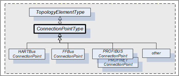
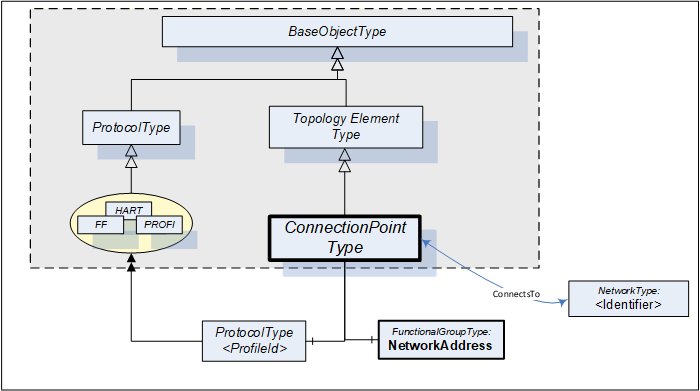
A Device can have more than one such interface to the same or to different Networks. Different interfaces usually exist for different protocols. Figure 21 shows the ConnectionPointType components. It is formally defined in Table 47.
| Attribute | Value | ||||
| BrowseName | 1:ConnectionPointType | ||||
| IsAbstract | True | ||||
| References | NodeClass | BrowseName | DataType | TypeDefinition | Other |
|---|---|---|---|---|---|
| Subtype of the TopologyElementType defined in 4.2. | |||||
| 0:HasComponent | Object | 1:NetworkAddress | 1:FunctionalGroupType | M | |
| 0:HasComponent | Object | 1:<ProfileIdentifier> | 1:ProtocolType | MP | |
| ConnectsTo | Object | 1:<NetworkIdentifier> | 1:NetworkType | OP | |
| Conformance Units | |||||
|---|---|---|---|---|---|
| DI ConnectionPoint |
ConnectionPoints are components of a Device, represented by a subtype of ComponentType. To allow navigation from a Network to the connected Devices, the ConnectionPoints shall have the inverse Reference (ComponentOf) to the Device.
ConnectionPoints have Properties and other components that they inherit from the TopologyElementType.
The NetworkAddress FunctionalGroup includes all Parameters to specify the protocol-specific address information of the connected Device. These Parameters can be components of the NetworkAddress FunctionalGroup, of the ParameterSet, or another Object.
<ProfileIdentifier> identifies the Communication Profile that this ConnectionPoint supports. ProtocolType and Communication Profile are defined in 5.2. It implies that this ConnectionPoint can be used to connect Networks and Devices of the same Communication Profile.
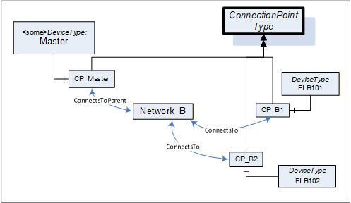
ConnectionPoints are between a Network and a Device. The location in the topology is configured by means of the ConnectsTo ReferenceType. Figure 22 illustrates some usage models.
5.5 ConnectsTo and ConnectsToParent ReferenceTypes
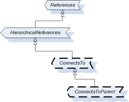
The ConnectsTo ReferenceType is a concrete ReferenceType used to indicate that source and target Node have a topological connection. It is NonHierarchical and symmetric, because this is natural for this Reference. The ConnectsTo Reference exists between a Network and the connected Devices (or their ConnectionPoint, respectively). Browsing a Network returns the connected Devices; browsing from a Device, one can follow the ConnectsTo Reference from the Device's ConnectionPoint to the Network.
The ConnectsToParent ReferenceType is a concrete ReferenceType used to define the parent (i.e. the communication Device) of a Network. It is a subtype of the ConnectsTo ReferenceType.
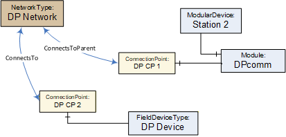
The two ReferenceTypes are illustrated in Figure 23.
The representation in the AddressSpace is specified in Table 48 and Table 49.
| Attributes | Value | ||
| BrowseName | 1:ConnectsTo | ||
| Symmetric | True | ||
| IsAbstract | False | ||
| References | NodeClass | BrowseName | Comment |
|---|---|---|---|
| Subtype of 0:NonHierarchicalReferences ReferenceType defined in OPC 10000-5. | |||
| Conformance Units | |||
| DI ConnectsTo | |||
| Attributes | Value | ||
| BrowseName | 1:ConnectsToParent | ||
| Symmetric | True | ||
| IsAbstract | False | ||
| References | NodeClass | BrowseName | Comment |
|---|---|---|---|
| Subtype of 1:ConnectsTo ReferenceType | |||
| Conformance Units | |||
| DI ConnectsTo | |||
Figure 24 illustrates how this Reference can be used to express topological relationships and parental relationships. In this example two Devices are connected; the module DPcomm is the communication Device for the Network.
5.6 NetworkSet Object
All Networks shall be components of the NetworkSet Object.
The NetworkSet Node is formally defined in Table 50.
| Attribute | Value | ||
| BrowseName | 1:NetworkSet | ||
| References | NodeClass | BrowseName | TypeDefinition |
|---|---|---|---|
| OrganizedBy by the 0:Objects Folder defined in OPC 10000-5 | |||
| 0:HasTypeDefinition | ObjectType | 0:BaseObjectType | |
| Conformance Units | |||
|---|---|---|---|
| DI NetworkSet |