
4.5 Interfaces
4.5.1 Overview
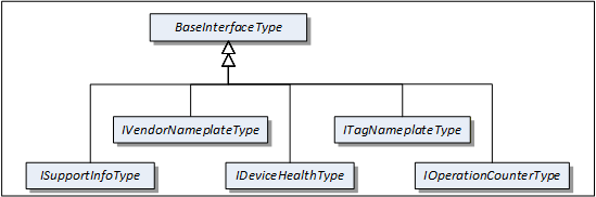
This clause describes Interfaces with specific functionality that can be applied to multiple types at arbitrary positions in the type hierarchy.
Interfaces are defined in OPC 10000-3.
Figure 4 shows the Interfaces described in this specification.
4.5.2 VendorNameplate Interface
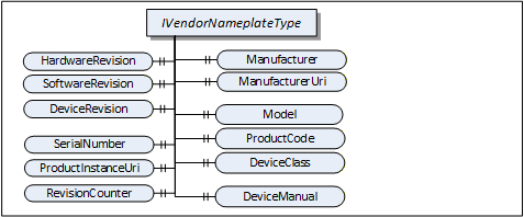
IVendorNameplateType includes Properties that are commonly used to describe a TopologyElement from a manufacturer point of view. They can be used as part of the identification. The Values of these Properties are typically provided by the component vendor.
The VendorNameplate Interface is illustrated in Figure 5 and formally defined in Table 17.
| Attribute | Value | ||||
| BrowseName | 1:IVendorNameplateType | ||||
| IsAbstract | True | ||||
| References | NodeClass | BrowseName | DataType | TypeDefinition | Other |
|---|---|---|---|---|---|
| Subtype of the BaseInterfaceType defined in OPC 10000-5 | |||||
| Product-specific Properties | |||||
|---|---|---|---|---|---|
| 0:HasProperty | Variable | 1:Manufacturer | 0:LocalizedText | 0:PropertyType | O |
| 0:HasProperty | Variable | 1:ManufacturerUri | 0:String | 0:PropertyType | O |
| 0:HasProperty | Variable | 1:Model | 0:LocalizedText | 0:PropertyType | O |
| 0:HasProperty | Variable | 1:ProductCode | 0:String | 0:PropertyType | O |
| 0:HasProperty | Variable | 1:HardwareRevision | 0:String | 0:PropertyType | O |
| 0:HasProperty | Variable | 1:SoftwareRevision | 0:String | 0:PropertyType | O |
| 0:HasProperty | Variable | 1:DeviceRevision | 0:String | 0:PropertyType | O |
| 0:HasProperty | Variable | 1:DeviceManual | 0:String | 0:PropertyType | O |
| 0:HasProperty | Variable | 1:DeviceClass | 0:String | 0:PropertyType | O |
| Product instance-specific Properties | |||||
|---|---|---|---|---|---|
| 0:HasProperty | Variable | 1:SerialNumber | 0:String | 0:PropertyType | O |
| 0:HasProperty | Variable | 1:ProductInstanceUri | 0:String | 0:PropertyType | O |
| 0:HasProperty | Variable | 1:RevisionCounter | 0:Int32 | 0:PropertyType | O |
| 0:HasProperty | Variable | 1:SoftwareReleaseDate | 0:DateTime | 0:PropertyType | O |
| 0:HasProperty | Variable | 1:PatchIdentifiers | 0:String[] | 0:PropertyType | O |
| Conformance Units | |||||
|---|---|---|---|---|---|
| DI Nameplate |
Product type specific Properties:
Manufacturer provides the name of the company that manufactured the item this Interface is applied to. ManufacturerUri provides a unique identifier for this company. This identifier should be a fully qualified domain name; however, it can be a GUID or similar construct that ensures global uniqueness.
Model provides the name of the product.
ProductCode provides a unique combination of numbers and letters used to identify the product. It can be the order information displayed on type shields or in ERP systems.
HardwareRevision provides the revision level of the hardware. SemanticVersionString (a sub-type of String defined in OPC 10000-5) can be used when using the Semantic Versioning format.
SoftwareRevision provides the version or revision level of the software component, the software/firmware of a hardware component, or the software/firmware of the Device. SemanticVersionString (a sub-type of String defined in OPC 10000-5) can be used when using the Semantic Versioning format.
DeviceRevision provides the overall revision level of a hardware component or the Device. As an example, this Property can be used in ERP systems together with the ProductCode Property. SemanticVersionString (a sub-type of String defined in OPC 10000-5) can be used when using the Semantic Versioning format.
DeviceManual allows specifying an address of the user manual. It can be a pathname in the file system or a URL (Web address).
DeviceClass indicates in which domain or for what purpose a certain item for which the Interface is applied is used. Examples are “ProgrammableController”, “RemoteIO”, and “TemperatureSensor”. This standard does not predefine any DeviceClass names. Companion standards that utilize this Interface (device models) will likely introduce such classifications.
Product instance specific Properties:
SerialNumber is a unique production number provided by the manufacturer. This is often stamped on the outside of a physical component and can be used for traceability and warranty purposes.
ProductInstanceUri is a globally unique resource identifier provided by the manufacturer. This is often stamped on the outside of a physical component and can be used for traceability and warranty purposes. The maximum length is 255 characters. If used as QR code, 80 characters is a reasonable size. The recommended syntax of the ProductInstanceUri is: <ManufacturerUri>/<any string> where <any string> is unique among all instances using the same ManufacturerUri.
Examples: “some-company.com/5ff40f78-9210-494f-8206-c2c082f0609c”, “some-company.com/snr-16273849” or “some-company.com/model-xyz/snr-16273849”.
RevisionCounter is an incremental counter indicating the number of times the configuration data has been modified. An example would be a temperature sensor where the change of the unit would increment the RevisionCounter but a change of the measurement value would not affect the RevisionCounter.
SoftwareReleaseDate defines the date when the software is released. If the version information is about patches, this should be the date of the latest patch. It is additional information for the user.
PatchIdentifiers identify the list of patches that are applied to a software version. The format and semantics of the strings are vendor-specific. The order of the strings shall not be relevant.
Companion specifications can specify additional semantics for the contents of these Properties.
Table 18 specifies the mapping of these Properties to the International Registration Data Identifiers (IRDI) defined in ISO/IEC 11179-6. They should be used if a Server wants to expose a dictionary reference as defined in OPC 10000-19.
| Property | IRDI | Legacy IRDI |
| Manufacturer | 0112/2///61360_7#CBA031 | 0112/2///61987#ABA565#007 |
| ManufacturerUri | 0112/2///61360_7#CBA032 | 0112/2///61987#ABN591#001 |
| Model | 0112/2///61360_7#CBA039 | 0112/2///61987#ABA567#007 |
| SerialNumber | 0112/2///61360_7#CBA050 | 0112/2///61987#ABA951#007 |
| HardwareRevision | 0112/2///61360_7#CBA047 | 0112/2///61987#ABA926#006 |
| SoftwareRevision | 0112/2///61360_7#CBA046 | 0112/2///61987#ABA601#006 |
| DeviceRevision | 0112/2///61987#ABP643#002 | |
| RevisionCounter | 0112/2///61987#ABN603#001 | |
| ProductCode | 0112/2///61360_7#CBA040 | 0112/2///61987#ABA300#006 |
| ProductInstanceUri | 0112/2///61360_7#CBA055 | 0112/2///61987#ABN590#001 |
| DeviceManual | - | - |
| DeviceClass | 0112/2///61360_7#CBA037 | 0112/2///61987#ABA566 - type of product |
| SoftwareReleaseDate | - | |
| PatchIdentifiers | - |
4.5.3 TagNameplate Interface
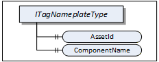
ITagNameplateType includes Properties that are commonly used to describe a TopologyElement from a user point of view.
The TagNameplate Interface is illustrated in Figure 6 and formally defined in Table 19.
| Attribute | Value | ||||
| BrowseName | 1:ITagNameplateType | ||||
| IsAbstract | True | ||||
| References | NodeClass | BrowseName | DataType | TypeDefinition | Other |
|---|---|---|---|---|---|
| Subtype of the BaseInterfaceType defined in OPC 10000-5 | |||||
| 0:HasProperty | Variable | 1:AssetId | 0:String | 0:PropertyType | O |
| 0:HasProperty | Variable | 1:ComponentName | 0:LocalizedText | 0:PropertyType | O |
| Conformance Units | |||||
|---|---|---|---|---|---|
| DI TagNameplate |
AssetId is a user writable alphanumeric character sequence uniquely identifying a component. The ID is provided by the integrator or user of the device. It contains typically an identifier in a branch, use case or user specific naming scheme. This could be for example a reference to an electric scheme.
ComponentName is a user writable name provided by the integrator or user of the component.
Table 20 specifies the mapping of these Properties to the International Registration Data Identifiers (IRDI) defined in ISO/IEC 11179-6. They should be used if a Server wants to expose a dictionary reference as defined in OPC 10000-19.
| Property | IRDI |
| AssetId | 0112/2///61987#ABA038 - identification code of device |
| ComponentName | 0112/2///61987#ABA251 - designation of device |
4.5.4 DeviceHealth Interface
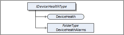
The DeviceHealth Interface includes Properties and Alarms that are commonly used to expose the health status of a Device. It is illustrated in Figure 7 and formally defined in Table 21.
| Attribute | Value | ||||
| BrowseName | 1:IDeviceHealthType | ||||
| IsAbstract | True | ||||
| References | NodeClass | BrowseName | DataType | TypeDefinition | Other |
|---|---|---|---|---|---|
| Subtype of the 0:BaseInterfaceType defined in OPC 10000-5 | |||||
| 0:HasComponent | Variable | 1:DeviceHealth | 1:DeviceHealthEnumeration | 0:BaseDataVariableType | O |
| 0:HasComponent | Object | 1:DeviceHealthAlarms | 0:FolderType | O | |
| Conformance Units | |||||
|---|---|---|---|---|---|
| DI DeviceHealth |
DeviceHealth indicates the status as defined by NAMUR Recommendation NE107. Clients can read or monitor this Variable to determine the device condition.
The DeviceHealthEnumeration DataType is an enumeration that defines the device condition. Its values are defined in Table 22. Its representation in the AddressSpace is defined in Table 23.
| Name | Value | Description |
|---|---|---|
| NORMAL | 0 | The Device functions normally. |
| FAILURE | 1 | Malfunction of the Device or any of its peripherals. Typically caused device-internal or is process related. |
| CHECK_FUNCTION | 2 | Functional checks are currently performed. Examples: Change of configuration, local operation, and substitute value entered. |
| OFF_SPEC | 3 | "Off-spec" means that the Device is operating outside its specified range (e.g. measuring or temperature range) or that internal diagnoses indicate deviations from measured or set values due to internal problems in the Device or process characteristics. |
| MAINTENANCE_REQUIRED | 4 | Although the output signal is valid, the wear reserve is nearly exhausted or a function will soon be restricted due to operational conditions e.g. build-up of deposits. |
| Attribute | Value | |||||
| BrowseName | 1:DeviceHealthEnumeration | |||||
| IsAbstract | False | |||||
| References | NodeClass | BrowseName | DataType | TypeDefinition | Other | |
|---|---|---|---|---|---|---|
| Subtype of the 0:Enumeration type defined in OPC 10000-5 | ||||||
| 0:HasProperty | Variable | 0:EnumStrings | 0:LocalizedText [] | 0:PropertyType | ||
| Conformance Units | ||||||
|---|---|---|---|---|---|---|
| DI DeviceHealth |
DeviceHealthAlarms shall be used for instances of the DeviceHealth Alarm Types specified in 4.12 and any other subtypes of DeviceHealthDiagnosticAlarmType.
It is recommended to use the DeviceHealthAlarms folder also for Alarm instances that relate to the health condition of the Device and are not subtypes of DeviceHealthDiagnosticAlarmType
4.5.5 OperationCounter Interface
The IOperationCounterType defines counters for the duration of operation. It is formally defined in Table 24.
| Attribute | Value | ||||
| BrowseName | 1:IOperationCounterType | ||||
| IsAbstract | True | ||||
| Description | Interface defining counters for the duration of operation | ||||
| References | Node Class | BrowseName | DataType | TypeDefinition | Other |
|---|---|---|---|---|---|
| Subtype of the 0:BaseInterfaceType defined in OPC 10000-5 | |||||
| 0:HasProperty | Variable | 1:PowerOnDuration | 0:Duration | 0:PropertyType | O |
| 0:HasProperty | Variable | 1:OperationDuration | 0:Duration | 0:PropertyType | O |
| 0:HasProperty | Variable | 1:OperationCycleCounter | 0:UInteger | 0:PropertyType | O |
| Conformance Units | |||||
|---|---|---|---|---|---|
| DI OperationCounter Interface |
PowerOnDuration is the duration the Device has been powered. The main purpose is to determine the time in which degradation of the Device occurred. The details, when the time is counted, is implementation-specific. Companion specifications can define specific rules. Typically, when the Device has supply voltage and the main CPU is running, the time is counted. This can include any kind of sleep mode, but cannot include pure Wake on LAN. This value shall only increase during the lifetime of the Device and shall not be reset when the Device is restarted. The PowerOnDuration is provided as Duration, i.e., in milliseconds or even fractions of a millisecond. However, the Server is not expected to update the value in such a high frequency, but possibly once a minute or once an hour, depending on the application.
OperationDuration is the duration the Device has been powered and performing an activity. This counter is intended for Devices where a distinction is made between switched on and in operation. For example, a drive can be powered on but not operating. It is not intended for Devices always performing an activity like sensors always measuring data. This value shall only increase during the lifetime of the Device and shall not be reset when the Device is restarted. The OperationDuration is provided as Duration, i.e., in milliseconds or even fractions of a millisecond. However, the Server is not expected to update the value in such a high frequency, but possibly once a minute or once an hour, depending on the application.
OperationCycleCounter is counting the times the Device switches from not performing an activity to performing an activity. For example, each time a valve starts moving, is counted. This value shall only increase during the lifetime of the Device and shall not be reset when the Device is restarted.
The child Nodes of the IOperationCounterType have additional Attribute values defined in Table 25.
| BrowsePath | Description Attribute |
| PowerOnDuration | PowerOnDuration is the duration the Device has been powered. The main purpose is to determine the time in which degradation of the Device occurred. The details, when the time is counted, is implementation-specific. Companion specifications can define specific rules. Typically, when the Device has supply voltage and the main CPU is running, the time is counted. This can include any kind of sleep mode, but cannot include pure Wake on LAN. This value shall only increase during the lifetime of the Device and shall not be reset when the Device is restarted. The PowerOnDuration is provided as Duration, i.e., in milliseconds or even fractions of a millisecond. However, the Server is not expected to update the value in such a high frequency, but possibly once a minute or once an hour, depending on the application. |
| OperationDuration | OperationDuration is the duration the Device has been powered and performing an activity. This counter is intended for Devices where a distinction is made between switched on and in operation. For example, a drive can be powered on but not operating. It is not intended for Devices always performing an activity like sensors always measuring data. This value shall only increase during the lifetime of the Device and shall not be reset when the Device is restarted. The OperationDuration is provided as Duration, i.e., in milliseconds or even fractions of a millisecond. However, the Server is not expected to update the value in such a high frequency, but possibly once a minute or once an hour, depending on the application. |
| OperationCycleCounter | OperationCycleCounter is counting the times the Device switches from not performing an activity to performing an activity. For example, each time a valve starts moving, is counted. This value shall only increase during the lifetime of the Device and shall not be reset when the Device is restarted. |
Table 26 – OperationCounter Mapping to IRDIs specifies the mapping of these Properties to the International Registration Data Identifiers (IRDI) defined in ISO/IEC 11179-6. They should be used if a Server wants to expose a dictionary reference as defined in OPC 10000-19.
| Property | IRDI |
| PowerOnDuration | 0112/2///61987#ABP550 |
| OperationDuration | 0112/2///61987#ABN639#001 |
| OperationCycleCounter | 0112/2///61987#ABP545 |
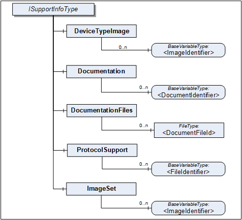
4.5.6 SupportInfo Interface
The SupportInfo Interface defines a number of additional data that a commonly exposed for Devices and their components. These include mainly images, documents, or protocol-specific data. The various types of information are organized into different folders. Each information element is represented by a read-only Variable. The information can be retrieved by reading the Variable value.

Figure 8 Illustrates the SupportInfo Interface. It is formally defined in Table 27.
| Attribute | Value | ||||
| BrowseName | 1:ISupportInfoType | ||||
| IsAbstract | True | ||||
| References | NodeClass | BrowseName | DataType | TypeDefinition | Other |
|---|---|---|---|---|---|
| Subtype of the BaseInterfaceType defined in OPC 10000-5 | |||||
| 0:HasComponent | Object | 1:DeviceTypeImage | 0:FolderType | O | |
| 0:HasComponent | Object | 1:Documentation | 0:FolderType | O | |
| 0:HasComponent | Object | 1:DocumentationFiles | 0:FolderType | O | |
| 0:HasComponent | Object | 1:ProtocolSupport | 0:FolderType | O | |
| 0:HasComponent | Object | 1:ImageSet | 0:FolderType | O | |
| Conformance Units | |||||
|---|---|---|---|---|---|
| DI DeviceSupportInfo |
Clients should be aware that the contents that these Variables represent can be large. Reading large values with a single Read operation can be impossible due to configured limits in either the Client or the Server stack. The default maximum size for an array of bytes is 1 MiB. It is recommended that Clients use the IndexRange in the OPC UA Read Service (see OPC 10000-4) to read these Variables in chunks, for example, one-megabyte chunks. It is up to the Client whether it starts without an index and repeats with an IndexRange only after an error or whether it always uses an IndexRange.
The components of the ISupportInfoType have additional references as defined in Table 28.
| Source Path | References |
Node
Class | BrowseName |
Data
Type | TypeDefinition | Other |
| 1:DeviceTypeImage | 0:HasComponent | Variable | 1:<ImageIdentifier> | 0:Image | 0:BaseDataVariableType | MP |
| 1:Documentation | 0:HasComponent | Variable | 1:<DocumentIdentifier> | 0:ByteString | 0:BaseDataVariableType | MP |
| 1:DocumentationFiles | 0:HasComponent | Object | 1:<DocumentFileId> | 0:FileType | MP | |
| 1:ProtocolSupport | 0:HasComponent | Variable | 1:<ProtocolSupportIdentifier> | 0:ByteString | 0:BaseDataVariableType | MP |
| 1:ImageSet | 0:HasComponent | Variable | 1:<ImageIdentifier> | 0:Image | 0:BaseDataVariableType | MP |
Pictures can be exposed as Variables organized in the DeviceTypeImage folder. There can be multiple images of different resolutions. Each image is a separate Variable.
All images are transferred as a ByteString. The DataType of the Variable specifies the image format. OPC UA defines BMP, GIF, JPG and PNG (see OPC 10000-3).
Documents in many cases will represent a product manual. They can be exposed as Variables or as FileType instances. Files are useful in particular for large documents.
Documents as Variables are represented as a ByteString and organized in the Documentation folder. The BrowseName of each Node will consist of the filename including the extension that can be used to identify the document type. Typical extensions are “.pdf” or “.txt”.
Documents as FileType instances are organized in the DocumentationFiles folder. They are retrieved from the Server by using the FileType Methods. It is recommended to use the MimeType Property to specify the media type of the file based on RFC 2046.
Protocol support files are exposed as Variables organized in the ProtocolSupport folder. They can represent various types of information as defined by a protocol. For example a GSD file.
All protocol support files are transferred as a ByteString. The BrowseName of each Variable shall consist of the complete filename including the extension that can be used to identify the type of information.
Images that are used within UIElements are exposed as separate Variables rather than embedding them in the element. All image Variables will be aggregated by the ImageSet folder. The UIElement shall specify an image by its name that is also the BrowseName of the image Variable. Clients can cache images so they don't have to be transferred more than once.
The DataType of the Variable specifies the image format. OPC UA defines BMP, GIF, JPG and PNG (see OPC 10000-3).
4.5.7 AssetLocationIndication Interface
The asset location indication Interface provides a method for making a device emit visual signals (e.g., blinking LEDs) or audible signals (e.g., sounds) to facilitate its physical identification among other assets.
IAssetLocationIndicationType can be implemented by any object that represents a physical device and that is able to indicate its position by blinking and / or making a sound.
The minimal implementation supports turning a default indication on and off for a specified duration. Optionally a device can declare its supported indication types (audible, visual) and let the client select the used indication types (one or more).
The Interface is formally defined in Table 29.
| Attribute | Value | ||||
| BrowseName | 1:IAssetLocationIndicationType | ||||
| IsAbstract | True | ||||
| References | NodeClass | BrowseName | DataType | TypeDefinition | Other |
|---|---|---|---|---|---|
| Subtype of the BaseInterfaceType defined in OPC 10000-5 | |||||
| 0:HasComponent | Method | 1:StartLocationIndication | M | ||
| 0:HasComponent | Method | 1:StopLocationIndication | M | ||
| 0:HasProperty | Variable | 1:IsIndicating | 0:Boolean | 0:PropertyType | M |
| 0:HasProperty | Variable | 1:UsedIndicationType | 1:LocationIndicationType | 0:PropertyType | O |
| 0:HasProperty | Variable | 1:SupportedIndicationTypes | 1:LocationIndicationType | 0:PropertyType | O |
| Conformance Units | |||||
|---|---|---|---|---|---|
| DI AssetLocationIndication |
The read only Property IsIndicating is true when the indication is currently active.
The optional UsedIndicationType can be written to set the indication types that shall be used when StartLocationIndication is called.
4.5.7.1 StartLocationIndication Method
The StartLocationIndication Method is used to start the indication. As a result to this call the IsIndicating property is set to true.
The signature of this Method is specified below. Table 30 and Table 31 specify the Arguments and AddressSpace representation, respectively.
Signature
	StartLocationIndication(
[in] 0:Duration IndicationDuration);| Argument | Description |
| IndicationDuration | 0 => infinite duration or duration in milliseconds |
Method Result Codes (defined in Call Service)
| Result Code | Description |
| Bad_InvalidArgument | If the device does not support a duration other than infinite |
| Attribute | Value | ||||
| BrowseName | 1:StartLocationIndication | ||||
| References | NodeClass | BrowseName | DataType | TypeDefinition | Other |
|---|---|---|---|---|---|
| 0:HasProperty | Variable | 0:InputArguments | 0:Argument[] | 0:PropertyType | M |
| Conformance Units | |||||
|---|---|---|---|---|---|
| DI AssetLocationIndication |
4.5.7.2 StopLocationIndication Method
The StopLocationIndication Method is used to stop the indication. As a result to this call, the IsIndicating property is set to false. This method also can be called when the indication is already stopped (e.g., because the specified IndicationDuration is over).
The signature of this Method is specified below.
Signature
StopLocationIndication();4.5.8 LocationIndicationType OptionSet
This DataType is used together with the IAssetLocationIndication Interface. It defines flags for the type of location indication. The OptionSet is defined in Table 32. Its representation in the AddressSpace is defined in Table 33.
| Name | Bit No. | Description |
| Visual | 0 | Location indication through optical signals, such as blinking LEDs, if supported by the device. |
| Audible | 1 | Location indication through auditory signals, such as sounds or beeps, if supported by the device. |
| Attribute | Value | |||||
| BrowseName | 1:LocationIndicationType | |||||
| IsAbstract | False | |||||
| References | NodeClass | BrowseName | DataType | TypeDefinition | Other | |
|---|---|---|---|---|---|---|
| Subtype of the 0:UInt16 DataType defined in OPC 10000-5 | ||||||
| 0:HasProperty | Variable | 0:OptionSetValues | 0:LocalizedText [] | 0:PropertyType | ||
| Conformance Units | ||||||
|---|---|---|---|---|---|---|
| DI AssetLocationIndication |