
1 Scope
This document defines the OPC UA MDIS companion specification. This standard is an Oil and Gas standard for interfacing the Subsea Production Control System (SPCS), with a Master Control Station (MCS) or a Subsea Gateway, to the Distributed Control System (DCS). This specification includes:
A description of common terms,
Supported architectures,
Information models representing the data that is shared between the systems,
Methods used in the flow of information,
Profile & ConformanceUnits describing the grouping of functionality,
Recommended Practices for the use of MDIS.
MDIS was created to define a standard object model that is transported on a common high performance efficient interface between topside and subsea systems in Oil and Gas installations. The selected protocol (OPC UA) includes independent third-party certification.
2 Concepts / Definitions
2.1 Introduction
This document makes use of a number of terms and concepts that are described in this section. OPC defined terms or terms defined in this document are in italics and camel case.
2.2 API Standard 17F concepts
DCS (Distributed Control System) is the production facility control system provides a centralised control system for the facility for the operators and is used to monitor and control the subsea production system. The DCS system will normally host the OPC UA Client.
MCS (Master Control Station) is the central control node containing application software required to control and monitor the subsea production system.
Subsea Gateway provides a communications interface on the surface to the subsea control equipment over the subsea vendor's communication system. The Subsea Gateway may form part of the overall MCS. The MCS or Subsea Gateway will normally host the OPC UA Server.
SCV (Subsea Controls Vendor) equipment refers to the subsea vendor supplied equipment and principally includes the subsea gateway in "Integrated" architecture or the subsea gateway and MCS in "Interfaced" architecture (see section 5.1 for additional details). It is intended to classify the functionality that is delivered by the subsea vendor whether it is implemented in the MCS or subsea gateway.
Note: The MCS may be supplied by a vendor other than the subsea or DCS vendor.
HPU (Hydraulic Power Unit) is the unit which provides low pressure and high-pressure hydraulic supplies for the control of subsea wells.
EPU (Electrical Power Unit) is the unit which provides power to the subsea system.
Interlocks (Permissive Logic) is permissive logic that needs to be satisfied before the action can initiate
The Customer is the end user, typically the "Operating Company".
The Operator is the human being executing an operation, not to be confused with the "Operating Company".
2.3 MDIS Mandatory & Optional Items / Objects
MDIS has standardised on the following definitions for Mandatory and Optional items. In all cases (Mandatory or Optional), if the item is available, the functionality described by the definition of the item must be correct and verifiable.
Mandatory
Objects specified as Mandatory will be required in all Objects and cannot be deleted. In OPC terms, a Mandatory item must exist on every Node of the NodeClass, for example if an MDISValveObjectType defines a Mandatory item Position then every instance of the MDISValveObjectType must have an item Position available.
Optional
Objects have functionality that may or may not be included; if they are included the OPC Client will know how to handle them. In OPC terms, an Optional item may or may not exist on every Node of the NodeClass, for example if an MDISValveObjectType defines an Optional item OpenTimeDuration then some instances of the MDISValveObjectType may contain an item OpenTimeDuration, but other instances may not. Clients are required to be able to handle the case where the item does not exist.
2.4 OPC Compliance & Certification
In regard to OPC Testing for Compliance and Certification the following concepts apply. The actual requirements for certification are defined on a project basis, but the standard third-party certification provided by the OPC Foundation provides the following:
Compliance - Assurance that the OPC UA Server or Client fulfils all functionality that it claims to support in terms of Profiles and that of all exposed interfaces function as defined in the specifications.
Interoperability - Testing of products against other products, this includes all functionality, data types and access rights.
Robustness - The testing of failure cases including handling of lost communication, communication recovery. All problems must not affect other connections, quality information must be correctly reported and audit entries are generated as needed. In short, end users are aware of any problem and problems are resolved automatically where possible.
Efficiency - The testing of products under load, forcing of noisy / bad communications and ensuring that products continue to work. Measuring CPU, RAM, threads, handles etc. and ensuring that even under the poor communications, heavily loaded Servers and Clients continue to function and not leak resources.
Usability - Verify that products are delivered with some level of documentation and that the documentation that is provided is accurate and understandable. Verify that the product functions as advertised and an end user would understand what is being provided.
Certification - Validation of Server or Client products. Certification includes compliance, interoperability, robustness, efficiency and usability testing and results in a seal of approval from an OPC Foundation test lab upon meeting or exceeding defined acceptance criteria.
3 Normative references
The following referenced documents are indispensable for the application of this document. For dated references, only the edition cited applies. For undated references, the latest edition of the referenced document (including any amendments and errata) applies.
4 Terms, abbreviated terms and conventions
It is assumed that basic concepts of OPC UA information modelling are understood in this document. This document will use these concepts to describe the MDIS Information Model.
4.1 MDIS definitions
Table 1 lists OPC UA definitions which are used in this document, they are included here as a reference. Additional information can be found in the reference documents listed in section 3.
| Term | Definition |
| AddressSpace | The collection of information that an OPC UA Server makes visible to its Clients. See OPC 10000-3 for a description of the contents and structure of the Server AddressSpace. |
| Attribute | A primitive characteristic of a Node. All Attributes are defined by OPC UA and may not be defined by Clients or Servers. Attributes are the only elements in the AddressSpace permitted to have data values. See OPC 10000-3 for additional details. |
| ConformanceUnit | As defined by the OPC Foundation: a specific set of OPC UA features that can be tested as a single entity. As it applies to MDIS a ConformanceUnit may describe a specific Object or part of a specific Object. It may also describe general functionality such as redundancy or performance. For each ConformanceUnit one or more test cases will exist to ensure that the defined functionality is provided. The test cases may be automatically executed in a Compliance Test Tool (CTT) or they may require some level of manual interaction. See OPC 10000-7 for additional details. |
| Facet | A Profile that describes a subset of functionality. This functionality must be paired with other Facets or Profiles to provide an operating Server or Client. See OPC 10000-7 for additional details. |
| InformationModel | An organisational framework that defines, characterises and relates information resources of a given system or set of systems. The core address space model supports the representation of InformationModels in the AddressSpace. See OPC 10000-5 for a description of the base OPC UA Information Model. |
| Method | A callable software function that is a component of an Object. See OPC 10000-4 for a basic definition. |
| Node | The fundamental component of an AddressSpace. See OPC 10000-3 for additional details. |
| NodeClass | The class of a Node in an AddressSpace. NodeClasses define the metadata for the components of the OPC UA Object Model. They also define constructs, such as Views, that are used to organise the AddressSpace. See OPC 10000-3 for additional details. |
| Object | Objects from an object-oriented technology point of view would have the following definition. Objects share two characteristics: They have state (Attribute) and behaviour (Method). A bicycle has states (current gear, current pedal cadence, current speed) and behaviour (changing gear, changing pedal cadence, applying brakes). An object stores its state in fields (Variables) and exposes its behaviour through functions (Methods). Functions operate on an object's internal state and serve as the primary mechanism for object-to-object communication. Hiding internal state and requiring all interaction to be performed through an object's functions is known as data encapsulation, a fundamental principle of object-oriented programming. In programming languages this object will have a third characteristic: The identity, which will help to find and use the object. From an OPC UA point of view the following definition is used: A Node that represents a physical or abstract element of a system. Objects are modelled using the OPC UA Object Model. Systems, subsystems and devices are examples of Objects. An Object is defined as an instance of an ObjectType. See OPC 10000-3 for additional details. |
| Object Instance | A synonym for Object. See OPC 10000-3 and OPC 10000-5 for additional details. |
| ObjectType | A Node that represents the TypeDefinition for an Object. See OPC 10000-3 and OPC 10000-5 for additional details. |
| Profile | A specific set of capabilities, to which a Server or Client may claim conformance. The capabilities are defined by a set of ConformanceUnits. Each Server or Client may claim conformance to more than one Profile. The OPC Foundation provides a base list of Server and Client Profiles and Facets in an online database which is also documented in an OPC UA specification, OPC 10000-7. The online database can be found here: |
| Property | A Variable that is a leaf and cannot have any children. See OPC 10000-3 and OPC 10000-5 for additional details. |
| Reference | An explicit relationship (a named pointer) from one Node to another. The Node that contains the Reference is the source Node and the referenced Node is the target Node. All References are defined by ReferenceTypes. See OPC 10000-3 and OPC 10000-5 for additional details. |
| ReferenceType | A Node that represents the TypeDefinition of a Reference. The ReferenceType specifies the semantics of a Reference. The name of a ReferenceType identifies how source Nodes are related to TargetNodes and generally reflects an operation between the two, such as "A contains B". See OPC 10000-3 and OPC 10000-5 for additional details. |
| UANodeSet | The root of the AddressSpace defined in an XML document. It defines a set of Nodes, their Attributes and References. See OPC 10000-5 for additional details. |
| Variable | Variable is a Node that contains a value and can have children. See OPC 10000-3 and OPC 10000-5 for additional details. |
| VariableType | A Node that represents the TypeDefinition for a Variable. See OPC 10000-3 and OPC 10000-5 for additional details. |
4.2 Abbreviated terms
The abbreviations, acronyms and definitions listed in Table 2 are typical and primarily focused on Subsea projects although some Topsides specific terms are also included.
| Abbreviations, Acronyms & Definitions | |
| API | American Petroleum Institute |
| CIMV | Chemical Injection Metering Valves |
| CSV | Comma Separated Values |
| DCS | Distributed Control System |
| EPU | Electrical Power Unit (Part of PCU) |
| ERP | Enterprise Resource Planning |
| EU | Engineering Units |
| FEED | Front End Engineering Design |
| HMI | Human Machine Interface |
| HTTP | Hypertext Transfer Protocol |
| IEC | International Electrotechnical Commission |
| JIP | Joint Industry Project |
| LVDT | Linear Variable Displacement (Differential) Transmitter |
| MCS | Master Control Station (Subsea Process Control System) |
| MDIS | MCS-DCS Interface Standardisation (Industry JIP) |
| MPFM | Multiphase Flow Meters |
| NTP | Network Time Protocol |
| OLE | Object Linking & Embedding |
| OPC | Open Process Control (original Classic was OLE for Process Control) |
| OPC UA | OPC Unified Architecture |
| ROV | Remotely Operated Vehicle |
| SCADA | Supervisory Control And Data Acquisition |
| SCV | Subsea Controls Vendor |
| SEM | Subsea Electronics Module |
| SIS | Safety Instrumented System |
| SPCS | Subsea Production Control System |
| TCP/IP | Transmission Control Protocol / Internet Protocol |
| UML | Unified Modelling Language |
| URL | Uniform Resource Locator |
| XML | Extensible Mark-up Language |
The OPC UA Specifications are also available from the IEC as IEC 62541
4.3 OPC UA Overview
4.3.1 Introduction
For the MDIS user who may not be familiar with OPC UA, the following section provides a brief overview of key features. It does not describe how MDIS makes use of these features it only describes the features available in OPC UA. MDIS specific functionality is specified in other sections of this document.
4.3.2 What is OPC UA?
OPC UA is an open and royalty free standard designed as a universal communications protocol. It is also available as IEC 62541.
OPC UA has a broad scope which delivers economies of scale for application developers. When combined with powerful semantic models, OPC UA makes it easier for end users to access data via generic commercial application. It provides an information modelling framework that allows application developers to represent their data in a way that makes sense to them.
The OPC UA model is scalable from small devices to Enterprise Resource Planning (ERP) systems. OPC UA devices process information locally and then provides that data in a consistent format to any application requesting data. For a more complete overview see OPC 10000-1.
4.3.3 Basics of OPC UA
As an Open Standard, OPC UA is based on standard Internet technologies, such as TCP/IP, HTTP, Ethernet and XML. OPC UA provides a set of services (see OPC 10000-4) and a basic information model framework.
As an Extensible Standard, OPC UA provides an information model framework which can expose vendor defined information in a standard way. More importantly all OPC UA Clients are expected to be able to discover and use vendor defined information. This means OPC UA users can benefit from the economies of scale that come with generic visualisation and interface applications. This specification is an example of an OPC UA InformationModel designed to meet the needs of developers and users in the offshore oil and gas industry.
OPC UA Clients can be any consumer of data, from devices / controllers on the network; browser based thin clients and higher level ERP systems. OPC UA applications are platform and development language dependant. The full scope of OPC UA applications are illustrated in Figure 1. For this companion specification the typical communication would be device to device or device to SCADA type communications.

OPC UA provides a robust and reliable communication infrastructure having mechanisms for handling lost messages, recovering from network interruptions, etc. With its binary encoded data it offers a high-performance data exchange solution. Security is built into OPC UA, security requirements are becoming more and more important as, increasingly, environments are connected to the office network or the internet and attackers are starting to focus on automation systems
4.3.4 Information Modelling in OPC UA
4.3.4.1 Concepts
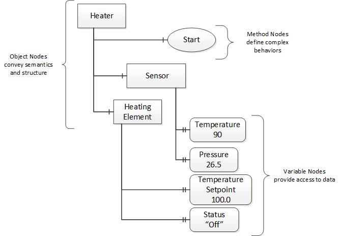
OPC UA provides a framework that can be used to represent complex information as Objects in an AddressSpace which can be accessed with standard web services. These consist of Nodes connected by References. Different classes of Nodes convey different semantics. For example, a Variable Node represents a value that can be read or written. The Variable Node has an associated DataType that can define the actual value, such as a string, float, structure etc. It can also describe the Variable value as a variant. A Method Node represents a function that can be called. Every Node has a number of Attributes including a unique identifier called a NodeId and non-localised name called a BrowseName. An Object representing a Heater is shown in Figure 2.
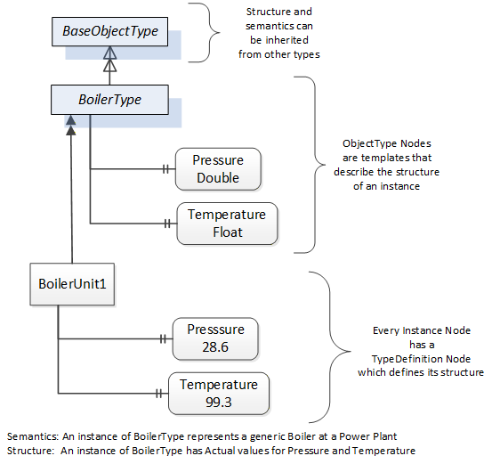
Object and Variable Nodes are called Instance Nodes and they always reference a TypeDefinition (ObjectType or VariableType) Node which describes their semantics and structure. Figure 3 illustrates the relationship between an instance and its TypeDefinition.
Type Nodes are templates that define all of the children that can be present in an instance of the type. In the example in Figure 3 the BoilerType ObjectType defines two sensors: Pressure and Temperature. All instances of BoilerType are expected to have the same children with the same BrowseNames. Within a type the BrowseNames uniquely identify the child. This means Client applications can be designed to search for children based on the BrowseNames from the type instead of NodeIds. This eliminates the need for manual reconfiguration of systems if a Client uses types that multiple devices implement.
OPC UA also supports the concept of subtyping. This allows a modeller to take an existing type and extend it. There are rules regarding subtyping defined in OPC 10000-3, but in general they allow the extension of a given type or the restriction of a DataType. For example, the modeller may decide that the existing ObjectType in some cases needs an additional Variable. The modeller can create a subtype of the Object and add the Variable. A Client that is expecting the parent type can treat the new type as if it was of the parent type. With regard to DataTypes, if a Variable is defined to have a numeric value, a subtype could restrict the value to a float. This standard adds additional rules for extensions.
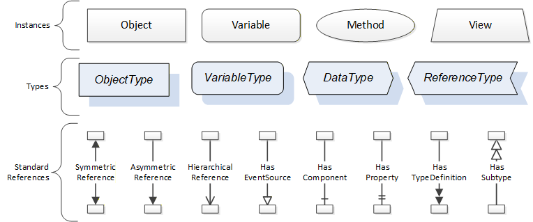
References allow Nodes to be connected together in ways that describe their relationships. All References have a ReferenceType that specifies the semantics of the relationship. References can be hierarchical or non-hierarchical. Hierarchical References are used to create the structure of Objects and Variables. Non-hierarchical References are used to create arbitrary associations. Applications can define their own ReferenceType by creating subtypes of the existing ReferenceType. Subtypes inherit the semantics of the parent but may add additional restrictions. Figure 4 depicts several References connecting different Objects.

The figures above use a notation that was developed for the OPC UA specification. The notation is summarised in Figure 5. UML representations can also be used; however, the OPC UA notation is less ambiguous because there is a direct mapping from the elements in the figures to Nodes in the AddressSpace of an OPC UA Server.
A complete description of the different types of Nodes and References can be found in OPC 10000-3 and the base OPC UA AddressSpace is described in OPC 10000-5.
The OPC UA specification defines a very wide range of functionality in its basic information model. It is not expected that all Clients or Servers support all functionality in the OPC UA specifications. OPC UA includes the concept of Profiles, which segment the functionality into testable certifiable units. This allows the development of companion specifications (such as OPC UA MDIS) that can describe the subset of functionality that is expected to be implemented. The Profiles do not restrict functionality but generate requirements for a minimum set of functionality (see OPC 10000-7).
The OPC Foundation also defines a set of InformationModels that provide a basic set of functionalities. The Data Access specification (see OPC 10000-8) provides a basic InformationModel for typical process or measured data. The Alarm and Condition specification (see OPC 10000-9) defines a standard InformationModel for Alarms and Conditions. The Programs specification (see OPC 10000-10) defines a standard InformationModel for extending the functionality available via Method calls and state machines. The Historical Access specification (see OPC 10000-11) defines the InformationModel associated with Historical Data and Historical Events. The aggregates specification (see OPC 10000-13) defines a series of standard aggregate functions that allow a Client to request summary data. Examples of aggregates include averages, minimums, time in state, standard deviation, etc.
4.3.4.2 Namespaces
OPC UA allows information from many different sources to be combined into a single coherent AddressSpace. Namespaces are used to make this possible by eliminating naming and id conflicts between information from different sources. Namespaces in OPC UA have a globally unique string called a NamespaceUri and a locally unique integer called a NamespaceIndex. The NamespaceIndex is only unique within the context of a Session between an OPC UA Client and an OPC UA Server. All of the web services defined for OPC UA use the NamespaceIndex to specify the Namespace for qualified values.
There are two types of values in OPC UA that are qualified with Namespaces: NodeIds and QualifiedNames. NodeIds are globally unique identifiers for Nodes. This means the same Node with the same NodeId can appear in many Servers. This, in turn, means Clients can have built in knowledge of some Nodes. OPC UA InformationModels generally define globally unique NodeIds for the TypeDefinitions defined by the InformationModel.
QualifiedNames are non-localised names qualified with a Namespace. They are used for the BrowseNames of Nodes and allow the same names to be used by different InformationModels without conflict. The BrowseName is used to identify the children within a TypeDefinition. Instances of a TypeDefinition are expected to have children with the same BrowseNames. TypeDefinitions are not allowed to have children with duplicate BrowseNames; however, instances do not have that restriction.
4.3.4.3 Companion Specifications
An OPC UA companion specification for an industry specific vertical market describes an InformationModel by defining ObjectTypes, VariableTypes, DataTypes and ReferenceTypes that represent the concepts used in the vertical market. Table 3 contains an example of an ObjectType definition.
| Attribute | Value | |||||
| BrowseName | BoilerType | |||||
| IsAbstract | False | |||||
| Reference | NodeClass | BrowseName | DataType | TypeDefinition | ModellingRule | |
|---|---|---|---|---|---|---|
| Subtype of the BaseObjectType from OPC 10000-3. | ||||||
| 0:HasProperty | Variable | Pressure | Double | 0:PropertyType | Mandatory | |
| 0:HasProperty | Variable | Temperature | Float | 0:PropertyType | Mandatory | |
| 0:HasProperty | Variable | Flow | Double | 0:PropertyType | Optional | |
The BrowseName is a non-localised name for an ObjectType.
IsAbstract is a flag indicating whether instances of the ObjectType can be created. If IsAbstract is FALSE then instances of this ObjectType may be created. If IsAbstract is TRUE then instances of the ObjectType cannot be created, the ObjectType must be subtyped.
The bottom of the table lists the child Nodes for the type. The Reference column is the type of Reference between the Object instance and the child Node. The NodeClass is the class of Node. The BrowseName is the non-localised name for the child. The DataType is the structure of the Value accessible via the Node (only used for Variable NodeClass Nodes) and the TypeDefinition is the ObjectType or VariableType for the child.
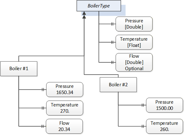
The ModellingRule indicates whether a child is Mandatory or Optional. It can also indicate cardinality. Note that the BrowseName is not defined if the cardinality is greater than 1. visually depicts the ObjectType defined in Table 3 along with two instances of the ObjectType. The first instance includes the Optional Property while the second does not.
5 Architectures
5.1 Overview
The following section describes the two architectures that are defined by this specification. The Object models defined in other sections of this specification are affected by these architectures (see Figure 7.)
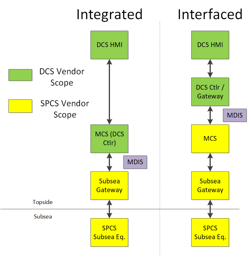
This narrative and associated architecture drawing are intended to identify and represent this interface in the majority of typical system implementations. It is not intended to mandate the detailed architecture of a DCS vendor or SPCS vendor's control system, nor is it intended to suggest or exclude a particular contracting / commercial strategy. This simplified version of the MDIS interface was used to facilitate development of the data objects and to define the data content between the DCS and SPCS vendor's system.
Two major architectures, "Integrated" or "Interfaced", are typically used throughout the industry and the choice will typically be decided by the Operating Company. Since the control aspects of the subsea system can be accomplished by both the DCS system or by the subsea system, the actual interface between the two systems may be different. In the Integrated architecture (Case 1), the controls system is an integrated system where all control is performed by the DCS vendor's hardware and the standard needs to support communication of all information between the subsea gateway and the DCS control system. This enables a single HMI (or set of HMIs) to control and monitor platform and subsea operations. In the Interfaced architecture (Case 2), the SPCS vendor provides the controls for the subsea aspects of the system and the DCS system is used for monitoring and set point control purposes of the subsea system, along with topside controls. The MDIS InformationModel is able to adapt to both of these architectures.
5.2 DCS Implemented Functions
5.2.1 Main Process Responsibility
The DCS is the primary user interface to the overall facility process including the subsea system. Process data management is handled by the DCS as well as all process alarming, alarm management and event / data archiving. Although an MCS may have an alarm or event queue, the primary facility alarm management occurs at the DCS level. Access, to the various subsea control functions, are managed by the DCS user access level rather than in the subsea system. The DCS also serves as the master for time synchronisation (for addition details see section 11).
5.2.2 Control and Monitoring of Subsea Equipment
Normal control and monitoring of the subsea production system is conducted at the DCS HMI. There may be a separate maintenance or configuration workstation used by the SCV, but it is not within the scope of the MDIS interface.
5.2.3 Subscriptions
OPC UA supports Subscription and polling (Read) manners of obtaining data. The Subscription based manner of obtaining data should be used by default. Subscription, which is exception reporting, typically provides improved performance over the polling interface.
5.3 DCS or SCV Implemented Functions
5.3.1 Introduction
The functional elements of the system either reside in the DCS or SPCS depending on a particular vendor's solution or customer's requirements. The "Operating Company" should specify where each of these optional functions should reside. See Figure 8 for an illustration.
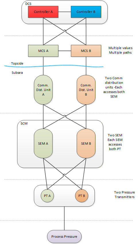
5.3.2 Data Arbitration
Data Arbitration is the system function that manages the reception and transmission of dual / redundant SPCS data.
If the Subsea system performs this function, only a single process value or operator command is typically passed between the SPCS and DCS system. If the DCS performs this function, both the A and B data values would typically be passed across the interface.
There are multiple types of data that could require arbitration. Instruments can be redundant; SEMs can be redundant and it is possible that the different types of data maybe arbitrated in different locations. I.e., in some projects, sensor data may be arbitrated by the DCS while the SEM may be arbitrated by the SPCS. Data Arbitration choices can also affect redundancy.
5.3.3 SEM Control Selection
Certain subsea instruments may only be powered by one SEM at a time, selectable by the operator. Also, a SEM may have various modes, such as ROV mode or maintenance mode, which can be selected.
5.3.4 Interlocks
5.3.4.1 Introduction
An Interlock is a control permissive that exists to prevent or warn an operator against potentially undesired operator commands being issued to the subsea system. Depending on an operator's access level, he / she may be able to override the interlock in order to perform the desired operation. Interlocks can be categorised into two types: process interlocks and product / system interlocks, though not all customers or SCV's make this distinction.
5.3.4.2 Process Interlocks
Process interlocks are interlocks which are specific to a particular project dependent on field layout, tree functionality, etc. These are often defined by the customer's process requirements or by regulatory agencies; e.g., prevention of opening the tree crossover valve if the production master valve and annulus master valve are open.
5.3.4.3 Product or System Interlocks
Interlocks defined by the SCV for the protection of the subsea system; for example, low hydraulic pressure inhibiting opening (pressurising) of a tree valve. These interlocks are typically not able to be overridden by an operator.
5.3.5 Shutdown Sequences
These are defined subsea valve operation sequences that take the subsea system to a safe state. They are initiated either by subsea process conditions, operator intervention or emergency conditions triggered from external interfaces such as the facility Safety Instrumented System (SIS).
5.3.6 Automated Control Sequences
These are multi-step control sequences triggered by the issuance of a single operator command, such as smart well (interval control valve) controls, hydrate prevention or preparation of a tree for start-up.
5.3.7 Determining Valve Statuses
This refers to determination of the status of a subsea valve by evaluating some or all of the following: hydraulic output function line pressure, hydraulic flow and last command received.
5.3.8 Determining / Updating Choke Calculated Position
This refers to the calculation of the assumed choke position based upon the number of step commands issued to the subsea choke. It may be maintained in percentage open or step position and is compared to the position transducer on the choke for calibration.
5.3.9 HPU Interface
The HPU interface may include HPU control capability, data monitoring and configuration such as Motor control setpoint changes.
5.3.10 EPU Interface
The interface to the EPU may include monitoring of the power supply to the subsea equipment including input voltage / current, umbilical voltage(s) / current(s), line insulation monitoring data and power alarm statuses (over-voltage and over-current).
5.3.11 Valve Profile / Signature Validation
A valve profile, or signature, is a representation of the performance of a subsea valve in terms of its hydraulic fluid pressure and flow characteristics as measured at the subsea control module. Valve Profile / Signature Validation is a software function that compares a current valve profile/signature to a baseline or template signature recorded previously, typically at subsea system commissioning. Not all systems have this functionality.
5.3.12 Topsides Chemical Injection System Interface
The chemical injection interface may include control and monitoring capability. Typically, the interface includes verification to the subsea system of chemical delivery (flow rate and / or pressure) from the topsides chemical injection system.
5.4 Subsea Controls Vendor-Implemented Functions
5.4.1 Introduction
These functions are assumed to be always implemented in the SPCS vendor's equipment. In the case that the MCS is provided by a third-party supplier, the references below to the DCS may also pertain to the MCS.
5.4.2 Managing Subsea Communications
The SCV's system will manage data traffic to and from the subsea system and issue device control commands. The protocol is typically proprietary for a particular SCV and the medium and redundancy requirements are dependent upon customer requirements. The interface from the subsea gateway to the subsea system is not within the scope of the MDIS interface.
5.4.3 Operation of Subsea Devices
Ultimate operation or actuation of a subsea device is executed by the SCV's system, whether requested locally, such as from an SCV engineering workstation, or remotely from the DCS.
5.4.4 Handing off Process Sensor Data to DCS
The SCV's system will provide current process data (e.g., pressures, temperatures, flow rates) and statuses (e.g., valve positions) to the DCS.
5.4.5 Configuration of Operational Parameters
This includes settings for low-level subsea system functionality, such as solenoid pulse timers, pressure check settings for evaluating valve position or unintended movement, timer setpoints for determining valve failure, etc.
5.4.6 Handing off Valve Profiles / Signatures
Valve Profiles are made available for transmission from the SCV system. The output format may vary among vendors and the data may be transmitted according to customer requirements, but MDIS provides a recommended format (see Annex E).
5.4.7 Calculation of Engineering Values
The SCV system typically calculates process engineering values if raw data is received from subsea devices, though there may be exceptions where raw data transmission is required.
5.4.8 Handing off Product Statuses
This refers to any available data in the subsea system not included within the definition of other objects that may be transmitted via a "generic" discrete or analogue object. This includes data that may have been considered "alarms" in legacy subsea systems, but are simply data points that are available to the DCS to manage as alarms, events or to be logged as desired. The SCV may also implement "roll-up" statuses that condense numerous statuses into fewer bits / words in order to optimise data transfer.
5.4.9 Handing Off Diagnostic Information
Diagnostic information in regard to the health of the subsea system is managed in the SCV's system. This data would typically not be transmitted to the DCS except for summary product status data as defined above. It would be transmitted via a "generic" discrete or analogue object as desired.
5.4.10 EPU Interface
The interface to the EPU may include monitoring of the power supply to the subsea equipment including input voltage / current, umbilical voltage(s) / current(s), line insulation monitoring data and power alarm statuses (over-voltage and over-current).
5.4.11 Subsea Control Paths / Network Routing
The SCV defines the subsea communications system architecture. Communications link control and monitoring is also performed by the SCV. Variable scan configurations (e.g., fast scan, normal scan, slow scan) may be implemented and configured by the SCV as required.
6 MDIS ObjectTypes
6.1 Overview
The following sections define the basic OPC UA Objects defined by MDIS. This includes Method definition as needed. The use cases / object interactions for each Object are defined in a separate section.
6.1.1 MDISBaseObjectType
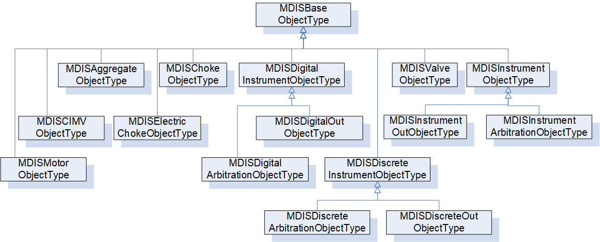
The MDISBaseObjectType (see 6.2) is a base object that all other MDIS objects are constructed from. It is an abstract ObjectType and instances of it shall not exist. This Object will be used to create subtypes.
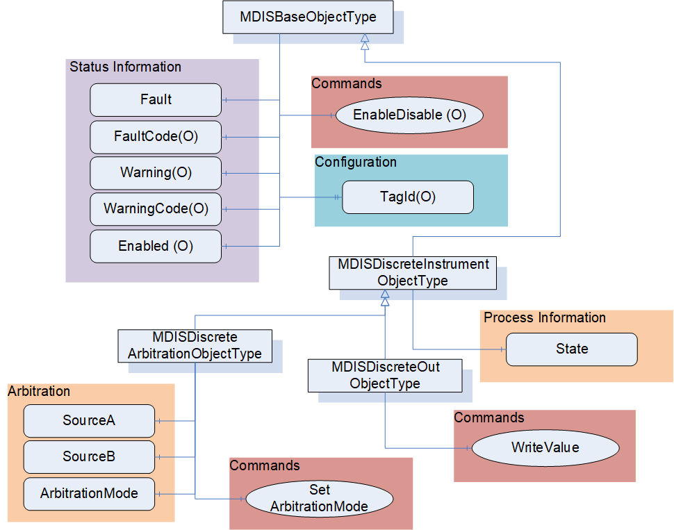
6.1.2 MDISDiscreteInstrumentObjectType
The MDISDiscreteInstrumentObjectType (see 6.3) is a base type and can be subtyped or instances of it can be directly created. The Object can be used with multi-state type of data (stopped, moving, faulted). It could also be used for instruments that report integer values. For a limit switch or on / off switch the MDISDigitalInstrumentObjectType should be used.
6.1.3 MDISDiscreteOutObjectType
The MDISDiscreteOutObjectType (see 6.3.4) is a subtype of MDISDiscreteInstrumentObjectType and can be subtyped or instance of it can be directly created. The Object can be used for Tristate or Multistate switches.
6.1.4 MDISDiscreteArbitrationObjectType
The MDISDiscreteArbitrationObjectType (see 6.3.6) is a subtype of MDISDiscreteInstrumentObjectType and can be subtyped or instance of it can be directly created. It adds inputs that can be selected according to the arbitration mode.
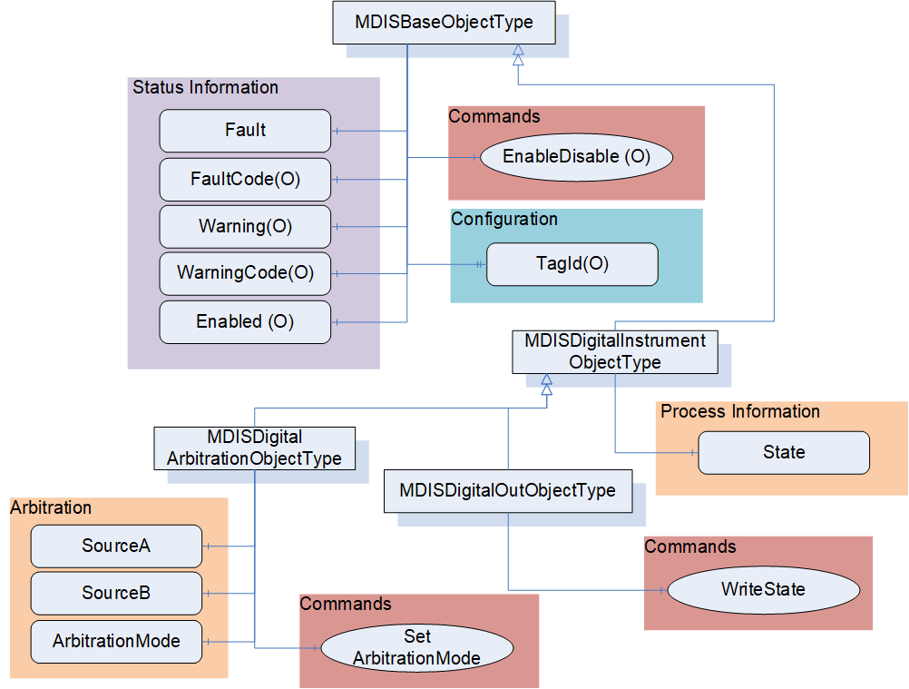
6.1.5 MDISDigitalInstrumentObjectType
The MDISDigitalInstrumentObjectType (see 6.4) is a base type and can be subtyped or instance of it can be directly created. The Object can be used to represent on / off type of functions.
6.1.6 MDISDigitalOutObjectType
The MDISDigitalOutObjectType (see 6.4.4) is a subtype of MDISDigitalInstrumentObjectType and can be subtyped or instance of it can be directly created. The Object can be used for switching on / off types.
6.1.7 MDISDigitalArbitrationObjectType
The MDISDigitalArbitrationObjectType (see 6.4.6) is a subtype of MDISDigitalInstrumentObjectType and can be subtyped or instance of it can be directly created. It adds inputs that can be selected according to the arbitration mode.
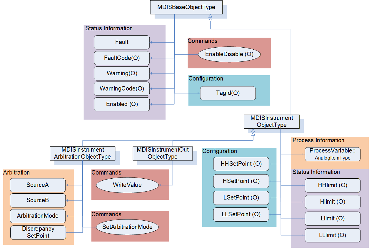
6.1.8 MDISInstrumentObjectType
The MDISInstrumentObjectType (see 6.5.3) is a base type and can be subtyped or instances of it can be directly created. The Object can be used for various types of analogues, e.g. pressure, temperatures, tank levels etc.
6.1.9 MDISInstrumentOutObjectType
The MDISInstrumentOutObjectType (see 6.5.4) is a subtype of MDISInstrumentObjectType and can be subtyped or instance of it can be directly created. The Object can be used for writing floating point values.
6.1.10 MDISInstrumentArbitrationObjectType
The MDISInstrumentArbitrationObjectType (see 6.5.6) is a subtype of MDISInstrumentObjectType and can be subtyped or instance of it can be directly created. It adds inputs that can be selected according to the arbitration mode.
6.1.11 MDISChokeObjectType
The MDISChokeObjectType (see 6.6.3) is a base type and can be subtyped or an instance of it can be directly created. A choke is a device that restricts the flow of a fluid (gases, liquids, fluidised solids, or slurries).
6.1.12 MDISElectricChokeObjectType
The MDISElectricChokeObjectType (see 6.7.3) is a base type and can be subtyped or an instance of it can be directly created. An electric choke is a device that restricts the flow of a fluid (gases, liquids, fluidised solids, or slurries) and can be positioned more precisely than a standard Choke.
6.1.13 MDISValveObjectType
The MDISValveObjectType (see 6.8.3) is a base type and can be subtyped or an instance of it can be directly created. A valve is a device that directs or controls the flow of a fluid (gases, liquids, fluidised solids, or slurries). The MDISValveObjectType represents a two-state valve type.
6.1.14 MDISCIMVObjectType
The MDISCIMVObjectType (see 6.9.3) is a base type and can be subtyped or an instance of it can be directly created. The CIMV (Chemical Injection Metering Valve) is used to regulate the flow of chemicals to a well. It can report optional housekeeping data.
6.1.15 MDISMotorObjectType
The MDISMotorObjectType (see 6.11.3) is a base type and can be subtyped or an instance of it can be directly created. A motor is a device that is used to power pump
6.1.16 MDISAggregateObjectType
The MDISAggregateObjectType (see 6.12.2) is an abstract type that all aggregate ObjectTypes shall be derived from. This ObjectType allows Clients to easily identify aggregate Objects. For more information about aggregation see 10.5
6.1.17 MDISCounterObjectType
The MDISCounterObjectType (see 6.10.3) is a base type, it is not envisioned that this object will be subtyped, but rather that this object is used as part of other aggregate objects. It provides the capability of resetting counters to some initial value.
6.1.18 MDISTimeSyncObjectType
The MDISTimeSyncObjectType (see 6.13.3) is a base ObjectType. An instance of this ObjectType shall be exposed as part of the MDISInformationObjectType, if the MDISTimeSyncObjectType is supported.
6.1.19 MDISInformationObjectType
The MDISInformationObjectType (see 6.14) is a base ObjectType. An instance of this ObjectType shall be exposed under the Objects folder. It provides information about the MDIS Information model that is supported by the Server. It can also expose additional information related to MDIS.
6.2 MDISBaseObjectType
6.2.1 Overview
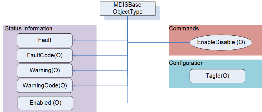
The following section details the MDIS generic properties for the MDISBaseObjectType. Implementations shall ensure adherence to Mandatory [M] aspects in order to comply with the MDIS interface standardisation. Optional [O] may or may not be implemented within a project. Figure 9 provides an overview of the MDISBaseObjectType as defined by MDIS. This Object is intended to be the base object for all other MDIS ObjectTypes (see Figure 10 for an overview of inherited types)
6.2.2 MDISBaseObjectType Definition
The Table 4 defines the structure of an MDISBaseObjectType.
| Attribute | Value | ||||
| BrowseName | MDISBaseObjectType | ||||
| IsAbstract | True | ||||
| References | Node Class | BrowseName | Data Type | TypeDefinition | Other |
|---|---|---|---|---|---|
| Subtype of the 0:BaseObjectType defined in OPC 10000-5 | |||||
| 0:HasComponent | Variable | Fault | 0:Boolean | 0:BaseDataVariableType | M, RO |
| 0:HasComponent | Variable | Warning | 0:Boolean | 0:BaseDataVariableType | O, RO |
| 0:HasComponent | Variable | Enabled | 0:Boolean | 0:BaseDataVariableType | O, RO |
| 0:HasProperty | Variable | TagId | 0:String | 0:PropertyType | O, RO |
| 0:HasComponent | Method | EnableDisable | See 6.2.3 | O | |
| 0:HasComponent | Variable | FaultCode | 0:UInt32 | 0:BaseDataVariableType | O, RO |
| 0:HasComponent | Variable | WarningCode | 0:UInt32 | 0:BaseDataVariableType | O, RO |
| 0:HasSubtype | ObjectType | MDISDigitalInstrumentObjectType | |||
| 0:HasSubtype | ObjectType | MDISDiscreteInstrumentObjectType | |||
| 0:HasSubtype | ObjectType | MDISChokeObjectType | |||
| 0:HasSubtype | ObjectType | MDISElectricChokeObjectType | |||
| 0:HasSubtype | ObjectType | MDISInstrumentObjectType | |||
| 0:HasSubtype | ObjectType | MDISValveObjectType | |||
| 0:HasSubtype | ObjectType | MDISCIMVObjectType | |||
| 0:HasSubtype | ObjectType | MDISMotorObjectType | |||
| 0:HasSubtype | ObjectType | MDISAggregateObjectType | |||
| ConformanceUnits | |||||
|---|---|---|---|---|---|
| MDIS Base Fault |
The RW column indicates if a Node of Variable NodeClass is readable, writeable or both readable and writeable. Other NodeClasses (Object, Method) do not support reading or writing and do not fill in this column.
By definition a Profile can require that an Optional item be provided, it cannot change the behaviour of an Object from what is described in this specification, which includes support for any Mandatory items. Profiles are described in section 14.3.
Fault - The status of the object, true if any fault exists.
Warning - The status of the object, true if any warnings exist. A warning does not require immediate operator action.
Enabled - This Variable is set as enabled (true) by default. When disabled the Object will not report any dynamic information other than a bad status code (Bad_InvalidState). It will still report configuration related information. It will disable execution of any method that might be defined as part of the Object. For the MDISBaseObjectType the default is that only the Enabled flag, TagId and EnableDisable Method report values or perform functions. Subtypes of this ObjectType may describe additional requirements for disabled Objects.
TagId - The TagId is a unique equipment identifier. This is additional information that can be used to help identify the Variable associated with the instance of this type. This field is intended to be used to store the tag id from the P&ID.
EnableDisable - This Method allows a Client to disable or enable the Object.
FaultCode - An unsigned integer that describes a fault code(s), zero indicates no fault. The FaultCode is a 32 bit mask, with 16 bits for standard defined codes and 16 bits for vendor defined codes. Each of the Subtypes of this ObjectType defined in this specification shall define a set standard FaultCodes that apply to that ObjectType (bits 0-15). In addition, the SPCS vendor may provide vendor specific bits (bits 16-31). Once a Bit is defined (given a name), then in all Objects that use that same named fault, the same bit number is used.
WarningCode - An unsigned integer that describes a warning code(s), zero indicates no warning. The SPCS vendor will provide a definition of what the number means The WarningCode is a 32 bit mask, with 16 bits for standard defined codes and 16 bits for vendor defined codes. Each of the subtypes of this ObjectType defined in this specification shall define a set standard WarningCodes that apply to that ObjectType (bits 0-15). In addition, the SPCS vendor may provide vendor specific bits (bits 16-31). Once a Bit is defined (given a name), then in all Objects that use that same named warning, the same bit number is used.
6.2.3 EnableDisable Method
EnableDisable is used to disable or enable an Object. The enable / disable operation applies to the Object in the UA Server. The call completes when the enable / disable operation is complete. The Server may or may not pass the enable / disable down to lower levels. This is Server specific behaviour.
Signature
	EnableDisable (
		[in] 0:Boolean Enable );
| Argument | Description |
| Enable | Boolean indicator of whether the Object is to be disabled or enabled. A true indicates that the Object is enabled. |
Method result codes are defined as part of the Call Service (see OPC 10000-4). They are described in Table 124 for ease of reference.
Comments
The EnableDisable Method will disable or enable this Object. Once the state of an Object is changed by this Method (i.e., disabled) the state will be maintained until this Method is called again to change the state (i.e., enable). The Method will report if any error occurs while disabling or enabling the Object. Table 6 specifies the AddressSpace representation for the EnableDisable Method.
| Attribute | Value | ||||
| BrowseName | EnableDisable | ||||
| References | Node Class | BrowseName | DataType | TypeDefinition | Other |
|---|---|---|---|---|---|
| 0:HasProperty | Variable | 0:InputArguments | 0:Argument[] | 0:PropertyType | M |
| ConformanceUnits | |||||
|---|---|---|---|---|---|
| MDIS Base Enabled |
6.3 MDISDiscreteInstrumentObjectType
6.3.1 Introduction
The following section details the generic MDISDiscreteInstrumentObjectType structure and defines the properties associated with it. Additional sections define a subtype MDISDiscreteOutObjectType that allows updates to the discrete value. This is in general a vendor and operator independent description, but all users of the MDISDiscreteInstrumentObjectType or MDISDiscreteOutObjectType can add vendor specific data. The vendor specific data should be defined as part of a subtype of the MDISDiscreteInstrumentObjectType or MDISDiscreteOutObjectType defined in this document. It is assumed that the subsea system is the Server and host of the instance of the MDISDiscreteInstrumentObjectType or MDISDiscreteOutObjectType. The DCS based system is the Client in the system. It is assumed that all interactions with the instance of the MDISDiscreteInstrumentObjectType are initiated by the Client and are directed to the Server.
6.3.2 Overview
The following section details the MDIS generic properties for the MDISDiscreteInstrumentObjectType. Implementation shall ensure adherence to Mandatory [M] aspects in order to comply with the MDIS interface standardisation. Optional [O] may or may not be implemented within a project. Figure 11 provides an overview of the MDISDiscreteInstrumentObjectType as defined by MDIS, including some nested types. This figure includes all items that are inherited from the MDISBaseObjectType.
6.3.3 MDISDiscreteInstrumentObjectType Definition
Table 7 defines the structure of an MDISDiscreteInstrumentObjectType. Any vendor specified properties that have been implemented within a project should be documented within a similar format and supplied to the DCS vendor. The addition of vendor specific properties will result in a subtype of the MDISDiscreteInstrumentObjectType.
| Attribute | Value | ||||
| BrowseName | MDISDiscreteInstrumentObjectType | ||||
| IsAbstract | False | ||||
| References | Node Class | BrowseName | DataType | TypeDefinition | Other |
|---|---|---|---|---|---|
| Subtype of the MDISBaseObjectType (see section 6.1.1) | |||||
| 0:HasComponent | Variable | State | 0:UInt32 | 0:BaseDataVariableType | M, RO |
| 0:HasSubtype | ObjectType | MDISDiscreteOutObjectType | |||
| 0:HasSubtype | ObjectType | MDISDiscreteArbitrationObjectType | |||
| ConformanceUnits | |||||
|---|---|---|---|---|---|
| MDIS Discrete Instrument Base |
State - The state of the instance of MDISDiscreteInstrumentObjectType. This state is represented as a UInt32.
The MDISDiscreteInstrumentObjectType is a subtype of MDISBaseObjectType and inherits the FaultCode Variable. The MDISDiscreteInstrumentObjectType defines the standard FaultCodes (for bits 0-15 as defined in 6.2.2) in Table 8. All subtypes of this the MDISDiscreteInstrumentObjectType will inherit all FaultCodes defined in this table. Subtypes may define additional FaultCodes in their own table.
| Value | Bit no. | Description |
| IOFault | 0 | Instrument has no usable value, there is an I/O fault. |
The MDISDiscreteInstrumentObjectType defines the standard WarningCodes (for bits 0-15 as defined in 6.2.2) in Table 9. All subtypes of this the MDISDiscreteInstrumentObjectType will inherits all WarningCodes defined in this table. Subtypes may define additional WarningCodes in their own table.
| Value | Bit no. | Description |
| SideAProblem | 0 | There is an issue with the A side of this instrument [note this only applies to instrument that are arbitrated] |
| SideBProblem | 1 | There is an issue with the B side of this instrument [note this only applies to instrument that are arbitrated] |
| Discrepancy | 2 | The values differ by more than is acceptable |
6.3.4 MDISDiscreteOutObjectType Definition
Table 10 defines the structure of an MDISDiscreteOutObjectType. Any vendor specified properties that have been implemented within a project should be documented within a similar format and supplied to the DCS vendor. The addition of vendor specific properties will result in a subtype of the MDISDiscreteOutObjectType.
| Attribute | Value | ||||
| BrowseName | MDISDiscreteOutObjectType | ||||
| IsAbstract | False | ||||
| References | Node Class | BrowseName | DataType | TypeDefinition | Other |
|---|---|---|---|---|---|
| Subtype of the MDISDiscreteInstrumentObjectType (see section 6.1.2) | |||||
| 0:HasComponent | Method | WriteValue | See 6.3.5 | M | |
| ConformanceUnits | |||||
|---|---|---|---|---|---|
| MDIS Discrete Out Base |
WriteValue - This Method allows a Client to change the value of State on an instance of MDISDiscreteOutObjectType. The Method will return any errors that occurred on setting the value. The Client shall verify that the State actually changed to confirm the update. If the instrument is disabled, an error Bad_InvalidState shall be returned.
6.3.5 WriteValue Method
WriteValue Method (defined in Table 11) is used to change the value of the State Variable in an instance of MDISDiscreteOutObjectType. The WriteValue operation applies to the object in the subsea system. The value of the State Variable shall only be updated once the subsea system has provided a new value. For Objects that are used as a command, the value of the State Variable shall be updated directly to the value provided by the State parameter of the Method. Some systems will be able to report any errors immediately others will only be able to report that the operation was not refused. Clients are expected to monitor the State and ensure that the operation completed. If an error occurs after the Method has returned, a Fault flag shall be set and an appropriate FaultCode will be returned. The Fault (and FaultCode) will reset on the next successful WriteValue Method invocation.
Signature:
	WriteValue (
		[in] 0:UInt32 State);
| Argument | Description |
| State | UInt32 value Variable, that indicates the target state of the Variable |
Method result codes are defined as part of the Call Service (see OPC 10000-4). They are described in Table 124 for ease of reference.
Comments
The WriteValue Method will result in a change the value of the State Variable. The Method will report if any error occurs while writing the state of the Object. Table 12 specifies the AddressSpace representation for the WriteValue Method.
| Attribute | Value | |||||
| BrowseName | WriteValue | |||||
| References | Node Class | BrowseName | DataType | TypeDefinition | Other | |
|---|---|---|---|---|---|---|
| 0:HasProperty | Variable | InputArguments | Argument[] | 0:PropertyType | M | |
| ConformanceUnits | ||||||
|---|---|---|---|---|---|---|
| MDIS Discrete Out Base |
6.3.6 MDISDiscreteArbitrationObjectType Definition
Table 13 defines the structure of an MDISDiscreteArbitrationObjectType. Any vendor specified properties that have been implemented within a project should be documented within a similar format and supplied to the DCS vendor. The addition of vendor specific properties will result in a subtype of the MDISDiscreteArbitrationObjectType.
| Attribute | Value | ||||
| BrowseName | MDISDiscreteArbitrationObjectType | ||||
| IsAbstract | False | ||||
| References | Node Class | BrowseName | DataType | TypeDefinition | Other |
|---|---|---|---|---|---|
| Subtype of the MDISDiscreteInstrumentObjectType | |||||
| 0:HasComponent | Variable | SourceA | 0:UInt32 | 0:BaseDataVariableType | M, RO |
| 0:HasComponent | Variable | SourceB | 0:UInt32 | 0:BaseDataVariableType | M, RO |
| 0:HasComponent | Variable | ArbitrationMode | ArbitrationModeEnum | 0:BaseDataVariableType | M, RO |
| 0:HasComponent | Method | SetArbitrationMode | Defined in section 6.3.7 | O | |
| ConformanceUnits | |||||
|---|---|---|---|---|---|
| MDIS Discrete Arbitration |
The MDISDiscreteArbitrationObjectType will select which instrument is healthy and report it. The arbitration object selects between the two sources, SourceA and SourceB base on the source and the selected ArbitrationMode. The result of the arbitration is shown in the State. The result can be either a selection of one source as default or forcing of one source (see 8.1.10 for additional details).
SourceA - a Variable that represents the value of the first source of a MDISDiscreteArbitrationObjectType.
SourceB - a Variable that represents the value of the second source of a MDISDiscreteArbitrationObjectType
ArbitrationMode - This enumeration provides information about the ArbitrationMode that is currently used (see section 8.1.10). The Average enumeration value does not apply to this arbitration ObjectType.
The MDISDiscreteArbitrationObjectType is a subtype of MDISDiscreteInstrumentObjectType and inherit the FaultCode Variable. The MDISDiscreteArbitrationObjectType defines the standard FaultCodes (for bits 0-15 as defined in 6.2.2) in Table 14 (currently empty, no additional fault codes defined). All subtypes of this the MDISDiscreteArbitrationObjectType will inherit all FaultCodes defined in this table. Subtypes may define additional FaultCodes in their own table.
| Value | Bit no. | Description |
The MDISDiscreteArbitrationObjectType defines the standard WarningCodes (for bits 0-15 as defined in 6.2.2) in Table 15 (currently empty, no additional warning codes defined). All subtypes of this the MDISDiscreteArbitrationObjectType will inherit all WarningCodes defined in this table. Subtypes may define additional WarningCodes in their own table.
| Value | Bit no. | Description |
6.3.7 SetArbitrationMode Method
SetArbitrationMode Method is used to change the arbitration strategy of the arbitration Object. If the mode cannot be changed the method shall return an error. This description applies to the following arbitration objects (MDISDigitalArbitrationObjectType, MDISDiscreteArbitrationObjectType, MDISInstrumentArbitrationObjectType).
Signature:
	SetArbitrationMode (
		[in] ArbitrationModeEnum ArbitrationMode);
| Argument | Description |
| ArbitrationMode | ArbitrationMode enumeration value Variable, that defines the new arbitration mode, see 8.1.10 |
Method result codes are defined as part of the Call Service (see OPC 10000-4). They are described in Table 124 for ease of reference. The following specific Method result codes are defined in Table 17.
| ResultCode | Description |
| Bad_NotSupported | The requested arbitration mode is not supported. |
Comments
The SetArbitrationMode Method will change the arbitration strategy. The Method will report if any error which occur while writing the value of the Object. Table 18 specifies the AddressSpace representation for the SetArbitrationMode Method.
| Attribute | Value | ||||
| BrowseName | SetArbitrationMode | ||||
| References | Node Class | BrowseName | DataType | TypeDefinition | Other |
|---|---|---|---|---|---|
| 0:HasProperty | Variable | 0:InputArguments | 0:Argument[] | 0:PropertyType | M |
| ConformanceUnits | |||||
|---|---|---|---|---|---|
| MDIS Discrete Arbitration | |||||
| MDIS Digital Arbitration | |||||
| MDIS Instrument Arbitration Base |
6.4 MDISDigitalInstrumentObjectType
6.4.1 Introduction
The following section describes the generic MDISDigitalInstrumentObjectType structure and defines the properties associated with it. Additional sections define a subtype MDISDigitalOutObjectType that allows updates to the digital value. This is in general a vendor and operator independent description, but all users of the MDISDigitalInstrumentObjectType or MDISDigitalOutObjectType can add vendor specific data. The vendor specific data should be defined as part of a subtype of the MDISDigitalInstrumentObjectType or MDISDigitalOutObjectType defined in this document. It is assumed that the subsea system is the Server and host of the instance of MDISDigitalInstrumentObjectType or MDISDigitalOutObjectType. The DCS based system is the Client in the system. It is assumed that all interactions with the instance of the MDISDigitalInstrumentObjectType are initiated by the Client and are directed to the Server.
6.4.2 Overview
The following section details the MDIS generic properties for the MDISDigitalInstrumentObjectType; implementation shall ensure adherence to Mandatory [M] aspects in order to comply with the MDIS interface standardisation. Optional [O] may or may not be implemented within a project.
Figure 12 provides an overview of the MDISDigitalInstrumentObjectType as defined by MDIS, including some nested types. This figure includes all items that are inherited from the MDISBaseObjectType.
6.4.3 MDISDigitalInstrumentObjectType Definition
Table 19 defines the structure of an MDISDigitalInstrumentObjectType. Any vendor specified properties that have been implemented within a project should be documented within a similar format and supplied to the DCS vendor. The addition of vendor specific properties will result in a subtype of the MDISDigitalInstrumentObjectType.
| Attribute | Value | ||||
| BrowseName | MDISDigitalInstrumentObjectType | ||||
| IsAbstract | False | ||||
| References | Node Class | BrowseName | DataType | TypeDefinition | Other |
|---|---|---|---|---|---|
| Subtype of the MDISBaseObjectType (see section 6.1.1) | |||||
| 0:HasComponent | Variable | State | 0:Boolean | 0:BaseDataVariableType | M, RO |
| 0:HasSubtype | ObjectType | MDISDigitalOutObjectType | |||
| 0:HasSubtype | ObjectType | MDISDigitalArbitrationObjectType | |||
| ConformanceUnits | |||||
|---|---|---|---|---|---|
| MDIS Digital Instrument Base |
State - The state of the instance of MDISDigitalInstrumentObjectType. This state is represented as a Boolean, where true indicates on and false indicates off.
The MDISDigitalInstrumentObjectType is a subtype of MDISBaseObjectType and inherit the FaultCode Variable. The MDISDigitalInstrumentObjectType defines the standard FaultCodes (for bits 0-15 as defined in 6.2.2) in Table 8. All subtypes of this the MDISDigitalInstrumentObjectType will inherit all FaultCodes defined in this table. Subtypes may define additional FaultCodes in their own table.
| Value | Bit no. | Description |
| IOFault | 0 | Instrument has no usable value, there is an I/O fault. |
The MDISDigitalInstrumentObjectType defines the standard WarningCodes (for bits 0-15 as defined in 6.2.2) in Table 9. All subtypes of this the MDISDigitalInstrumentObjectType will inherit all WarningCodes defined in this table. Subtypes may define additional WarningCodes in their own table.
| Value | Bit no. | Description |
| SideAProblem | 0 | There is an issue with the A side of this instrument [note this only applies to instrument that are arbitrated] |
| SideBProblem | 1 | There is an issue with the B side of this instrument [note this only applies to instrument that are arbitrated] |
| Discrepancy | 2 | The values differ [note this only applies to instrument that are arbitrated] |
6.4.4 MDISDigitalOutObjectType
Table 22 defines the structure of an MDISDigitalOutObjectType. Any vendor specified properties that have been implemented within a project should be documented within a similar format and supplied to the DCS vendor. The addition of vendor specific properties will result in a subtype of the MDISDigitalOutObjectType.
| Attribute | Value | ||||
| BrowseName | MDISDigitalOutObjectType | ||||
| IsAbstract | False | ||||
| References | Node Class | BrowseName | DataType | TypeDefinition | Other |
|---|---|---|---|---|---|
| Subtype of the MDISDigitalInstrumentObjectType | |||||
| 0:HasComponent | Method | WriteState | See 6.4.5 | M | |
| ConformanceUnits | |||||
|---|---|---|---|---|---|
| MDIS Digital Out Base |
WriteState - This Method allows a Client to change the value of State on an instance of MDISDigitalOutObjectType. The Method will return any errors that occurred on setting the value. The Client shall verify that the State actually changed to confirm the update. If the instrument is disabled, an error Bad_InvalidState shall be returned.
6.4.5 WriteState Method
WriteState Method (defined in Table 23) is used to change the state of the State Variable in an instance of MDISDigitalOutObjectType. The WriteState operation applies to the object in the subsea system. The value of the State Variable shall only be updated once the subsea system has provided a new value. For Objects that are used as a command, the value of the State Variable shall be updated directly to the value provided by the State parameter of the Method. Some systems will be able to report any errors immediately others will only be able to report that the operation was not refused. Clients are expected to monitor the State and ensure that the operation completed. If an error occurs after the Method has returned, a Fault flag shall be set and an appropriate FaultCode will be returned. The Fault (and FaultCode) will reset on the next successful WriteState Method invocation.
Signature:
	WriteState (
		[in] 0:Boolean State);
| Argument | Description |
| State | Boolean indicator of the target state of the variable |
Method result codes are defined as part of the Call Service (see OPC 10000-4). They are described in Table 124 for ease of reference.
Comments
The WriteState Method will result in a change the state of the State Variable. The Method will report if any error occurs while writing the state of the Object. Table 24 specifies the AddressSpace representation for the WriteState Method.
| Attribute | Value | ||||
| BrowseName | WriteState | ||||
| References | Node Class | BrowseName | DataType | TypeDefinition | Other |
|---|---|---|---|---|---|
| 0:HasProperty | Variable | 0:InputArguments | 0:Argument[] | 0:PropertyType | M |
| ConformanceUnits | |||||
|---|---|---|---|---|---|
| MDIS Digital Out Base |
6.4.6 MDISDigitalArbitrationObjectType Definition
Table 25 defines the structure of an MDISDigitalArbitrationObjectType. Any vendor specified properties that have been implemented within a project should be documented within a similar format and supplied to the DCS vendor. The addition of vendor specific properties will result in a subtype of the MDISDigitalArbitrationObjectType.
| Attribute | Value | ||||
| BrowseName | MDISDigitalArbitrationObjectType | ||||
| IsAbstract | False | ||||
| References | Node Class | BrowseName | DataType | TypeDefinition | Other |
|---|---|---|---|---|---|
| Subtype of the MDISDigitalInstrumentObjectType | |||||
| 0:HasComponent | Variable | SourceA | 0:Boolean | 0:BaseDataVariableType | M, RO |
| 0:HasComponent | Variable | SourceB | 0:Boolean | 0:BaseDataVariableType | M, RO |
| 0:HasComponent | Variable | ArbitrationMode | ArbitrationModeEnum | 0:BaseDataVariableType | M, RO |
| 0:HasComponent | Method | SetArbitrationMode | Defined in 6.3.7 | O | |
| ConformanceUnits | |||||
|---|---|---|---|---|---|
| MDIS Digital Arbitration |
The MDISDigitalArbitrationObjectType handles the Selection of two analog sources, SourceA and SourceB. The result of the arbitration is shown in the State. The result can be either a selection of one source as default or forcing of one source (see ArbitrationModeEnum for additional details). The arbitration object will select which instrument is healthy and report it.
SourceA - a Variable that represents the value of the first source of a MDISDigitalArbitrationObjectType.
SourceB - a Variable that represents the value of the second source of a MDISDigitalArbitrationObjectType.
ArbitrationMode - This enumeration provides information about the arbitration mode that is currently used (see section 8.1.10). For a MDISDigitalArbitrationObjectType, the average value does not apply and the High value indicates an "Or" of the two values while a low value indicates an "And' of the two values.
The MDISDigitalArbitrationObjectType is a subtype of MDISDigitalInstrumentObjectType and inherits the FaultCode Variable. The MDISDigitalArbitrationObjectType defines the standard FaultCodes (for bits 0-15 as defined in 6.2.2) in Table 26 (currently empty, no additional fault codes defined). All subtypes of this the MDISDigitalArbitrationObjectType will inherit all FaultCodes defined in this table. Subtypes may define additional FaultCodes in their own table.
| Value | Bit no. | Description |
The MDISDigitalArbitrationObjectType defines the standard WarningCodes (for bits 0-15 as defined in 6.2.2) in Table 27 (currently empty, no additional warning codes defined). All subtypes of this the MDISDigitalArbitrationObjectType will inherit all WarningCodes defined in this table. Subtypes may define additional WarningCodes in their own table.
| Value | Bit no. | Description |
6.5 MDISInstrumentObjectType
6.5.1 Introduction
The following section details the generic MDISInstrumentObjectType structure and defines the properties associated with it. Additional sections define a subtype MDISInstrumentOutObjectType that allows updates to the instrument value. This is in general a vendor and operator independent description, but all users of the MDISInstrumentObjectType or MDISInstrumentOutObjectType can add vendor specific data. The vendor specific data should be defined as part of a subtype of the MDISInstrumentObjectType defined in this document. It is assumed that the subsea system is the Server and host of the instance of the MDISInstrumentObjectType or MDISInstrumentOutObjectType. The DCS based system is the Client in the system. It is assumed that all interactions with the MDISInstrumentObjectType are initiated by the Client and are directed to the Server.
6.5.2 Overview
The following section details the MDIS generic properties for the MDISInstrumentObjectType. Implementation shall ensure adherence to Mandatory [M] aspects in order to comply with the MDIS interface standardisation. Optional [O] may or may not be implemented within a project. Figure 13 provides an overview of the MDISInstrumentObjectType as defined by MDIS, including some nested types. Figure 13 includes all of the items that are inherited from the MDISBaseObjectType.
6.5.3 MDISInstrumentObjectType Definition
Table 28 defines the structure of an MDISInstrumentObjectType. Any vendor specified properties that have been implemented within a project should be documented within a similar format and supplied to the DCS vendor. The addition of vendor specific properties will result in a subtype of the MDISInstrumentObjectType. If a MDISInstrumentObjectType instance is disabled, the MDISBaseObjectType defaults are followed and only the HHSetPoint, HSetPoint, LSetPoint and LLSetPoint object values will be available
| Attribute | Value | ||||
| BrowseName | MDISInstrumentObjectType | ||||
| IsAbstract | False | ||||
| References | Node Class | BrowseName | DataType | TypeDefinition | Other |
|---|---|---|---|---|---|
| Subtype of the MDISBaseObjectType (defined in 6.1.1) | |||||
| 0:HasComponent | Variable | ProcessVariable | 0:Float | 0:AnalogItemType | M, RO |
| 0:HasComponent | Variable | HHlimit | 0:Boolean | 0:BaseDataVariableType | O, RO |
| 0:HasComponent | Variable | Hlimit | 0:Boolean | 0:BaseDataVariableType | O, RO |
| 0:HasComponent | Variable | Llimit | 0:Boolean | 0:BaseDataVariableType | O, RO |
| 0:HasComponent | Variable | LLlimit | 0:Boolean | 0:BaseDataVariableType | O, RO |
| 0:HasProperty | Variable | HHSetPoint | 0:Float | 0:PropertyType | O, RW |
| 0:HasProperty | Variable | HSetPoint | 0:Float | 0:PropertyType | O, RW |
| 0:HasProperty | Variable | LSetPoint | 0:Float | 0:PropertyType | O, RW |
| 0:HasProperty | Variable | LLSetPoint | 0:Float | 0:PropertyType | O, RW |
| 0:HasSubtype | ObjectType | MDISInstrumentOutObjectType | |||
| 0:HasSubtype | ObjectType | MDISInstrumentArbitrationObjectType | |||
| ConformanceUnits | |||||
|---|---|---|---|---|---|
| MDIS Instrument Base |
ProcessVariable - a Variable in engineering units that represents the value of the instance of an MDISInstrumentObjectType. It includes properties that represent the engineering units; the engineering units range and optionally the instrument range, see OPC 10000-8. The components of the MDISInstrumentObjectType Type have additional subcomponents which are defined inTable 29.
| BrowsePath | References | NodeClass | BrowseName | DataType | TypeDefinition | Other |
| ProcessVariable | 0:HasProperty | Variable | 0:InstrumentRange | 0:Range | 0:PropertyType | O |
| ProcessVariable | 0:HasProperty | Variable | 0:EURange | 0:Range | 0:PropertyType | M |
| ProcessVariable | 0:HasProperty | Variable | 0:EngineeringUnits | 0:EUInformation | 0:PropertyType | M |
The EUInformation DataType is defined in OPC 10000-8.
HHlimit - The instrument HH state is active
Hlimit - The instrument H state is active
Llimit - The instrument L state is active
LLlimit - The instrument LL state is active
HHSetPoint - Configuration of HHSetPoint which will set HHlimit be TRUE when the ProcessVariable value is greater than "set point value". If this limit Variable exists on an object, but has not been configured, the HHSetPoint shall have a status code of Bad_ConfigurationError and Clients shall ignore the value. When the HHSetPoint has a Status of Bad_ConfigurationError, if the HHlimit exists, it shall have a status code of Bad_ConfigurationError and the value is ignored.
HSetPoint - Configuration of HSetPoint which will set Hlimit be TRUE when the ProcessVariable value is greater than "set point value". If this limit Variable exists on an object, but has not been configured, the HSetPoint shall have a status code of Bad_ConfigurationError and Clients shall ignore the value. When the HSetPoint is ignored, if the Hlimit exists, it shall have a status code of Bad_ConfigurationError and the value is ignored.
LSetPoint - Configuration of LSetPoint which will set Llimit be TRUE when the ProcessVariable value is less than "set point value". If this limit Variable exists on an object, but has not been configured, the LSetPoint shall have a status code of Bad_ConfigurationError and Clients shall ignore the value. When the LSetPoint is ignored, if the Llimit exists, it shall have a status code of Bad_ConfigurationError and the value is ignored.
LLSetPoint - Configuration of LLSetPoint which will set LLlimit be TRUE when the ProcessVariable value is less than "set point value". If this limit Variable exists on an object, but has not been configured, the LLSetPoint shall have a status code of Bad_ConfigurationError and Clients shall ignore the value. When the LLSetPoint is ignored, if the LLlimit exists, it shall have a status code of Bad_ConfigurationError and the value is ignored.
The MDISInstrumentObjectType is a subtype of MDISBaseObjectType and inherit the FaultCode Variable. The MDISInstrumentObjectType defines the standard FaultCodes (for bits 0-15 as defined in 6.2.2) in Table 8. All subtypes of this the MDISInstrumentObjectType will inherit all FaultCodes defined in this table. Subtypes may define additional FaultCodes in their own table.
| Value | Bit no. | Description |
| IOFault | 0 | Instrument has no usable value, there is an I/O fault. |
The MDISDigitalInstrumentObjectType defines the standard WarningCodes (for bits 0-15 as defined in 6.2.2) in Table 9. All subtypes of this the MDISDigitalInstrumentObjectType will inherit all WarningCodes defined in this table. Subtypes may define additional WarningCodes in their own table.
| Value | Bit No. | Description |
| SideAProblem | 0 | There is an issue with the A side of this instrument [note this only applies to instrument that are arbitrated] |
| SideBProblem | 1 | There is an issue with the B side of this instrument [note this only applies to instrument that are arbitrated] |
| Discrepancy | 2 | The values differ by more than is acceptable |
| OutOfRange | 3 | The value of the instrument is Out of range |
6.5.4 MDISInstrumentOutObjectType Definition
Table 32 defines the structure of an MDISInstrumentOutObjectType. Any vendor specified properties that have been implemented within a project should be documented within a similar format and supplied to the DCS vendor. The addition of vendor specific properties will result in a subtype of the MDISInstrumentOutObjectType.
| Attribute | Value | ||||
| BrowseName | MDISInstrumentOutObjectType | ||||
| IsAbstract | False | ||||
| References | Node Class | BrowseName | DataType | TypeDefinition | Other |
|---|---|---|---|---|---|
| Subtype of the MDISInstrumentObjectType | |||||
| 0:HasComponent | Method | WriteValue | See 6.5.5 | M | |
| ConformanceUnits | |||||
|---|---|---|---|---|---|
| MDIS Instrument Out Base |
WriteValue - This Method allows a Client to change the value of ProcessVariable on an instance of MDISInstrumentOutObjectType. The Method will return any errors that occurred on setting the value. If the Instrument is disabled, an error Bad_InvalidState shall be returned. The Client shall verify that the ProcessVariable actually changed to confirm the update.
6.5.5 Instrument WriteValue Method
Instrument WriteValue Method is used to change the value of the ProcessVariable in an instance of MDISInstrumentOutObjectType. The Instrument WriteValue Method operation applies to the object in the subsea system. The value of the ProcessVariable value will only update once the subsea system has provided a new value. Some systems will be able to report any errors immediately others will only be able to report that the operation was not refused. Clients are expected to monitor the ProcessVariable and ensure that the operation completed successfully. If an error occurs after the Method has returned, a Fault flag shall be set and an appropriate FaultCode will be returned. The Fault (and FaultCode) will reset on the next successful Instrument WriteValue Method invocation.
Signature:
	WriteValue (
		[in] 0:Float Value);
| Argument | Description |
| Value | Float value Variable, that indicates the target state of the Variable |
Method result codes are defined as part of the Call Service (see OPC 10000-4). They are described in Table 124 for ease of reference.
Comments
The WriteValue Method will result in a change the value of the ProcessVariable Variable. The Method will report if any error occurs while writing the value of the Object. Table 34 specifies the AddressSpace representation for the WriteValue
| Attribute | Value | ||||
| BrowseName | WriteValue | ||||
| References | Node Class | BrowseName | DataType | TypeDefinition | Other |
|---|---|---|---|---|---|
| 0:HasProperty | Variable | 0:InputArguments | 0:Argument[] | 0:PropertyType | M |
| ConformanceUnits | |||||
|---|---|---|---|---|---|
| MDIS Instrument Out Base |
6.5.6 MDISInstrumentArbitrationObjectType Definition
Table 35 defines the structure of an MDISInstrumentArbitrationObjectType. Any vendor specified properties that have been implemented within a project should be documented within a similar format and supplied to the DCS vendor. The addition of vendor specific properties will result in a subtype of the MDISInstrumentArbitrationObjectType.
| Attribute | Value | ||||
| BrowseName | MDISInstrumentArbitrationObjectType | ||||
| IsAbstract | False | ||||
| References | Node Class | BrowseName | DataType | TypeDefinition | Other |
|---|---|---|---|---|---|
| Subtype of the MDISInstrumentObjectType | |||||
| 0:HasComponent | Variable | SourceA | 0:Float | 0:BaseDataVariableType | M, RO |
| 0:HasComponent | Variable | SourceB | 0:Float | 0:BaseDataVariableType | M, RO |
| 0:HasComponent | Variable | ArbitrationMode | ArbitrationModeEnum | 0:BaseDataVariableType | M, RO |
| 0:HasProperty | Variable | DiscrepancySetPoint | 0:Float | 0:PropertyType | O, RW |
| 0:HasComponent | Method | SetArbitrationMode | Defined in 6.3.7 | O | |
| ConformanceUnits | |||||
|---|---|---|---|---|---|
| MDIS Instrument Arbitration Base |
The MDISInstrumentArbitrationObjectType provides for the selection between two analog sources, SourceA and SourceB. The result of the arbitration is shown in the ProcessVariable. The result can be either an average, a selection of one source as default or forcing of one source. See the ArbitrationModeEnum for a complete list of possible modes.
SourceA - a Variable in engineering units that represents the value of the first source of a MDISInstrumentArbitrationObjectType. The EngineeringUnits and Range of the ProcessVariable apply to this value.
SourceB - a Variable in engineering units that represents the value of the first source of a MDISInstrumentArbitrationObjectType. The EngineeringUnits and Range of the ProcessVariable apply to this value.
ArbitrationMode - this enumeration identifies the current arbitration mode. For the complete list of arbitration modes, see section 8.1.10. [note: the selected mode might be different than the current mode reflected in this parameter, for example in the case of a failure the current mode might indicate SourceA even if Average was selected, due to a SourceB failure]
DiscrepancySetPoint - the value represents the maximum allow difference between the SourceA and SourceB values expressed as a percentage based on the full range of the instrument. This value can only be between 0 and 100. For example, if SourceA was 10.0 and SourceB was 20.0 and the instrument range was 0 to 200, the percentage would be 5%.
The MDISInstrumentArbitrationObjectType is a subtype of MDISInstrumentObjectType and inherits the FaultCode Variable. The MDISInstrumentArbitrationObjectType defines the standard FaultCodes (for bits 0-15 as defined in 6.2.2) in Table 36 (currently empty, no additional fault codes defined). All subtypes of this the MDISInstrumentArbitrationObjectType will inherit all FaultCodes defined in this table. Subtypes may define additional FaultCodes in their own table.
| Value | Bit no. | Description |
The MDISInstrumentArbitrationObjectType defines the standard WarningCodes (for bits 0-15 as defined in 6.2.2) in Table 37 (currently empty, no additional warning codes defined). All subtypes of this the MDISInstrumentArbitrationObjectType will inherits all WarningCodes defined in this table. Subtypes may define additional WarningCodes in their own table.
| Value | Bit no. | Description |
6.6 MDISChokeObjectType
6.6.1 Introduction
The following section details the generic MDISChokeObjectType structure and defines the properties associated with it. This is in general a vendor and operator independent description, but all users of the MDISChokeObjectType can add vendor specific data. The vendor specific data should be defined as part of a subtype of the MDISChokeObjectType defined in this document. It is assumed that the subsea system is the Server and host of the instance of the MDISChokeObjectType. The DCS based system is the Client in the system. It is assumed that all interactions with the instance of the MDISChokeObjectType are initiated by the Client and are directed to the Server.
6.6.2 Overview
The MDISChokeObjectType is a basic component of any subsea control system. Subsea and surface trees have a choke valve and it is used for regulating the flow volume and with it the back pressure of liquids or gas. This document will address the hydraulic choke valve found in subsea production and water injection trees. Implementation shall ensure adherence to Mandatory [M] aspects in order to comply with the MDIS interface standardisation. Optional [O] may or may not be implemented within a project. Figure 14 provides an overview of the Choke Object as defined by MDIS. It includes all items that are defined by the MDISBaseObjectType. It illustrates that an interlock might have one or more <InterlockVariables> associated with it, or that they might not have an actual interlock associated.
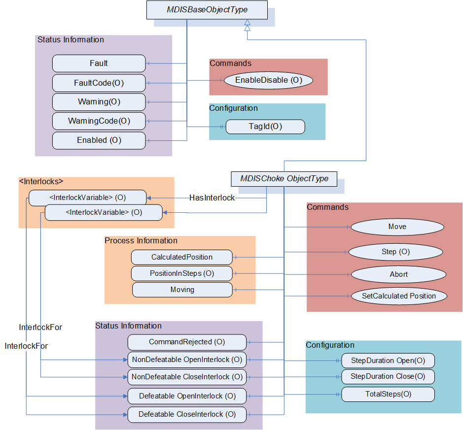
6.6.3 MDISChokeObjectType Definition
Table 38 defines the structure of an MDISChokeObjectType. Any vendor specified properties that have been implemented within a project should be documented within a similar format and supplied to the DCS vendor. The addition of vendor specific properties will result in a subtype of the MDISChokeObjectType. When an MDISChokeObjectType Instance is disabled the MDISBaseObjectType defaults are followed and only the StepDurationOpen, StepDurationClose and TotalSteps values will be available.
| Attribute | Value | ||||
| BrowseName | MDISChokeObjectType | ||||
| IsAbstract | False | ||||
| References | Node Class | BrowseName | DataType | TypeDefinition | Other |
|---|---|---|---|---|---|
| Subtype of the MDISBaseObjectType | |||||
| 0:HasComponent | Variable | CalculatedPosition | 0:Float | 0:BaseDataVariableType | M, RO |
| 0:HasComponent | Variable | SetCalculatedPositionStatus | SetCalculatedPositionEnum | 0:BaseDataVariableType | O, RO |
| 0:HasComponent | Variable | PositionInSteps | 0:Int16 | 0:BaseDataVariableType | O, RO |
| 0:HasComponent | Variable | Moving | ChokeMoveEnum | 0:BaseDataVariableType | M, RO |
| 0:HasComponent | Variable | CommandRejected | 0:Boolean | 0:BaseDataVariableType | O, RO |
| 0:HasComponent | Method | Move | See 6.6.4 | M | |
| 0:HasComponent | Method | Step | See 6.6.5 | O | |
| 0:HasComponent | Method | Abort | See 6.6.6 | M | |
| 0:HasComponent | Method | SetCalculatedPosition | See 6.6.7 | M | |
| 0:HasComponent | Variable | NonDefeatableOpenInterlock | 0:Boolean | 0:BaseDataVariableType | O, RO |
| 0:HasComponent | Variable | DefeatableOpenInterlock | 0:Boolean | 0:BaseDataVariableType | O, RO |
| 0:HasComponent | Variable | NonDefeatableCloseInterlock | 0:Boolean | 0:BaseDataVariableType | O, RO |
| 0:HasComponent | Variable | DefeatableCloseInterlock | 0:Boolean | 0:BaseDataVariableType | O, RO |
| 0:HasProperty | Variable | StepDurationOpen | 0:Duration | 0:PropertyType | O, RO |
| 0:HasProperty | Variable | StepDurationClose | 0:Duration | 0:PropertyType | O, RO |
| 0:HasProperty | Variable | TotalSteps | 0:UInt16 | 0:PropertyType | O, RO |
| HasInterlock | Variable | <InterlockPlaceholder> | 0:Boolean | InterlockVariableType | OP |
| ConformanceUnits | |||||
|---|---|---|---|---|---|
| MDIS Choke Base |
CalculatedPosition - A floating point number that represents the estimated percent open of the choke. This value can be updated using the SetCalculatedPosition Method.
SetCalculatedPositionStatus - an enumeration that reflect the status of a SetCalculatedPosition Command. This variable is present if the SetCalculatedPosition command can return asynchronously.
PositionInSteps - An Int16 that represents position in steps for the choke.
CommandRejected -- A flag that, if set to True, indicates that the choke has rejected the last command issued to it. The command could be rejected for a number of reasons. Possible reasons for rejecting a command include:
Loss of subsea communication reported by the SPCS.
An active interlock.
The choke is in the disabled state
Enabled - This Boolean reflects if the choke is available for control. The behaviour follows the MDISBaseObjectType.
Moving - An enumeration indicating the confirmed operation of the choke, (confirmed by SPCS Vendor). Possible status for a choke is moving and stopped.
Move - This Method allows an operator to increase or decrease the size of the opening in the choke. This command moves the choke to the percent value provided as part of the command.
Step - This Method allows an operator to increase or decrease the size of the opening in the choke. This command moves the choke the number of steps provided as part of the command.
Abort - This Method allows an operator to cancel any currently active move or step command.
SetCalculatedPosition - This Method is used to calibrate the CalculatedPosition. It can only be called when the choke is not moving.
EnableDisable - The choke, when disabled, places a non-defeatable interlock set on Move and Step functionality, in addition to the functionality described in the MDISBaseObjectType.
StepDurationOpen - SPCS open step duration period. This is the time in milliseconds for the choke to open one step.
StepDurationClose - SPCS close step duration period. This is the time in milliseconds for the choke to close one step.
TotalSteps - Total number of steps is the max steps of a choke.
<InterlockPlaceholder> - The number of interlock Variables will change based on the project and even choke instance. The Variables shall be of InterlockVariableType or a subtype of it. They will be referenced by a HasInterlock Reference and will contain an InterlockFor Reference. Clients can use this information to categorise the interlocks appropriately.
The following Variables indicate that an interlock is set (TRUE) or is not set (FALSE). The Variable shall be the target of an InterlockFor Reference from an instance of an InterlockVariableType that describes the actual interlock.
NonDefeatableOpenInterlock - The open choke command is interlocked and cannot be overridden.
DefeatableOpenInterlock - The open choke command is interlocked and can be overridden.
NonDefeatableCloseInterlock - The close choke command is interlocked and cannot be overridden.
DefeatableCloseInterlock - The close choke command is interlocked and can be overridden.
The MDISChokeObjectType is a subtype of MDISBaseObjectType and inherit the FaultCode Variable. The MDISChokeObjectType defines the standard FaultCodes (for bits 0-15 as defined in 6.2.2) in Table 39. All subtypes of this the MDISChokeObjectType will inherit all FaultCodes defined in this table. Subtypes may define additional FaultCodes in their own table.
| Value | Bit no. | Description |
| FailedToMove | 0 | The Choke failed to move in response to a command. |
| CommunicationFault | 1 | Not possible to operate the choke. |
The MDISChokeObjectType defines the standard WarningCodes (for bits 0-15 as defined in 6.2.2)in Table 40. All subtypes of this the MDISChokeObjectType will inherit all WarningCodes defined in this table. Subtypes may define additional WarningCodes in their own table.
| Value | Bit no. | Description |
| SideAProblem | 0 | There is an issue with the A side of the choke. |
| SideBProblem | 1 | There is an issue with the B side of the choke. |
| Discrepancy | 2 | There is a discrepancy between the calculated position and the measured position. |
| UncommandedChange | 3 | The choke position changed without a command. |
6.6.4 Choke Move Method
Move Method is used to adjust the opening size in a choke.
Signature:
	Move (
			[in] 0:Float		Position,
			[in] 0:Boolean	OverrideInterlocks,
			[in] SEMEnum		SEM);
| Argument | Description |
| Position | A number (in percent) indicating the percent open to be moved to when operated. |
| OverrideInterlocks | Boolean indicating if the open or close command should override any defeatable interlocks |
| SEM | The selection of which SEM to send the command to. |
Method result codes are defined as part of the Call Service (see OPC 10000-4). They are described in Table 124 for ease of reference.
Comments:
The Move Method initiates a move command. Parameters include the position value in percent, overriding of any interlocks and the SEM selection to use for the command. The Position Method argument value shall be between 0 and 100. The server shall return Bad_OutOfRange if the Position Method argument value is outside of this range. After receiving the new commanded position, the choke will start to move. The Method will complete when the command has been accepted. The move operation may or may not have completed when the Method returns. The Method returns errors only if the operation cannot be started. The Client must monitor the Moving Variable to determine when the move operation actually finishes.
If a Server does not support an Override of defeatable interlocks, then this parameter will be ignored by the Server. If any interlocks are active the appropriate error code is returned.
If a Server does not support the selection of SEM, this parameter is ignored.
Table 42 specifies the AddressSpace representation for the choke Move Method.
| Attribute | Value | ||||
| BrowseName | Move | ||||
| References | Node Class | BrowseName | DataType | TypeDefinition | Other |
|---|---|---|---|---|---|
| 0:HasProperty | Variable | 0:InputArguments | 0:Argument[] | 0:PropertyType | M |
| ConformanceUnits | |||||
|---|---|---|---|---|---|
| MDIS Choke Base | |||||
| MDIS Electric Choke Base |
6.6.5 Choke Step Method
Choke Step Method is used to adjust the opening size in a choke.
Signature
	Step (
			[in] ChokeCommandEnum		Direction,
			[in] 0:UInt16				Steps,
			[in] 0:Boolean			OverrideInterlocks,
			[in] SEMEnum				SEM);
| Argument | Description |
| Direction | Enumeration to indicate if an open request or close request is being initiated |
| Steps | The number of steps to either open or close the choke |
| OverrideInterlocks | Boolean indicating if the open or close command should override any defeatable interlocks |
| SEM | The selection of which SEM to send the command to. |
Method result codes are defined as part of the Call Service (see OPC 10000-4). They are described in Table 124 for ease of reference.
Comments
The choke Step Method initiates a move command. Parameters include the direction (open or close), the number of steps to step, overriding of any interlocks and the SEM selection to use for the command. After receiving the command, the choke will start to move. The Method will complete when the command has been accepted. The move operation may or may not have completed when the Method returns. The Method returns errors only if the operation cannot be started. The Client must monitor the Moving Variable to determine when the Step command actually finishes.
If a Server does not support an override of defeatable interlocks, then the OverrideInterlocks parameter will be ignored by the Server and if any interlocks are active the appropriate error code is returned.
If a Server does not support the selection of SEM, the SEM parameter is ignored.
Table 44 specifies the AddressSpace representation for the Choke Step Method.
| Attribute | Value | ||||
| BrowseName | Step | ||||
| References | Node Class | BrowseName | DataType | TypeDefinition | Othrer |
|---|---|---|---|---|---|
| 0:HasProperty | Variable | 0:InputArguments | 0:Argument[] | 0:PropertyType | M |
| ConformanceUnits | |||||
|---|---|---|---|---|---|
| MDIS Choke Step Method |
6.6.6 Choke Abort Method
Choke Abort Method is used to cancel any active move command in the Choke.
Signature:
Abort ();Method result codes are defined as part of the Call Service (see OPC 10000-4). They are described in Table 124 for ease of reference.
Comments
The choke Abort Method will try to cancel any active choke Move or Step commands. If no Move or Step command is in progress, the command will be ignored and return successful. The Method will complete when the command has been accepted. The abort operation may or may not have completed when the Method returns. The Method returns errors only if the operation cannot be started. The Client shall monitor the Moving and if provided the CommandRejected Variables to determine if the abort was successful or failed. Table 45 specifies the AddressSpace representation for the choke Abort Method.
| Attribute | Value | ||||
| BrowseName | Abort | ||||
| References | Node Class | BrowseName | DataType | TypeDefinition | Other |
|---|---|---|---|---|---|
| ConformanceUnits | ||||||
|---|---|---|---|---|---|---|
| MDIS Choke Base |
6.6.7 Choke SetCalculatedPosition Method
SetCalculatedPosition Method is used to synchronise the CalculatedPosition to the actual choke position.
Signature:
	SetCalculatedPosition (
			[in] 0:Float Position);
| Argument | Description |
| Position | A number (in percent) |
Method result codes are defined as part of the Call Service (see OPC 10000-4). They are described in Table 124 for ease of reference.
Comments:
The SetCalculatedPosition Method is used to set the CalculatedPosition. It can only be called when the choke is not moving. The parameter is the calculated position. This method may return when the CalculatedPosition has been updated or it may return a status of Completes_Asynchronously. If it returns Completes_Asynchronously the Client will have to monitor the SetCalculatedPositionStatus to determine if an error occurred or the command completed. The SetCalculatedPositionStatus will reset on the next successful SetCalculatedPosition Method invocation.
Table 47 specifies the AddressSpace representation for the SetCalculatedPosition Method.
| Attribute | Value | ||||
| BrowseName | SetCalculatedPosition | ||||
| References | Node Class | BrowseName | DataType | TypeDefinition | Other |
|---|---|---|---|---|---|
| 0:HasProperty | Variable | 0:InputArguments | 0:Argument[] | 0:PropertyType | M |
| ConformanceUnits | ||||||
|---|---|---|---|---|---|---|
| MDIS Choke Base |
6.7 MDISElectricChokeObjectType
6.7.1 Introduction
The following section details the generic MDISElectricChokeObjectType structure and defines the properties associated with it. This is in general a vendor and operator independent description, but all users of the MDISElectricChokeObjectType can add vendor specific data. The vendor specific data should be defined as part of a subtype of the MDISElectricChokeObjectType defined in this document. It is assumed that the subsea system is the Server and host of the instance of the MDISElectricChokeObjectType. The DCS based system is the Client in the system. It is assumed that all interactions with the instance of the MDISElectricChokeObjectType are initiated by the Client and are directed to the Server.
6.7.2 Overview
The MDISElectricChokeObjectType is a basic component of any subsea control system. Subsea and surface trees have a choke valve and it is used for regulating the flow volume and with it the back pressure of liquids or gas. This document will address the electric choke valve found in subsea production and water injection trees. Implementation shall ensure adherence to Mandatory [M] aspects in order to comply with the MDIS interface standardisation. Optional [O] may or may not be implemented within a project. Figure 14 provides an overview of the Choke Object as defined by MDIS. It includes all items that are defined by the MDISBaseObjectType. It illustrates that an interlock might have one or more Interlock variables associated with it, or that they might not have an actual interlock associated.
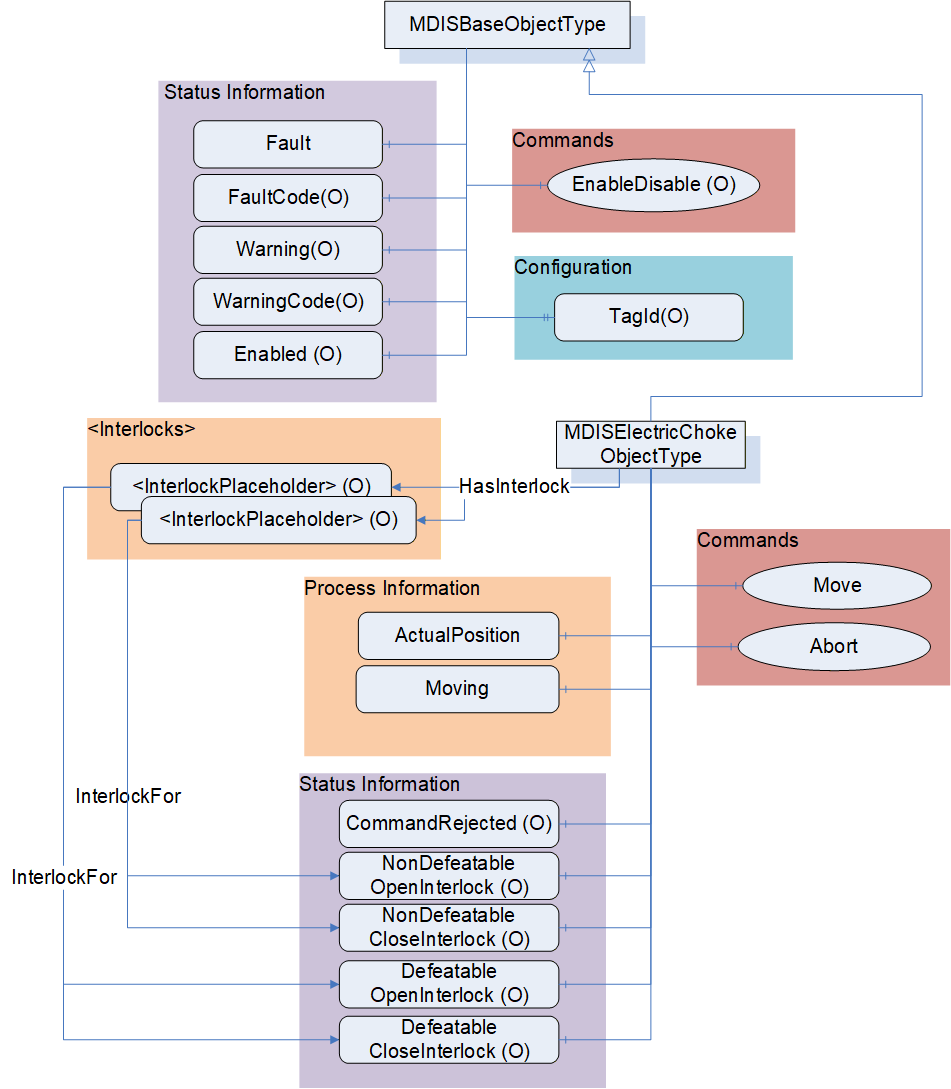
6.7.3 MDISElectricChokeObjectType Definition
Table 38 defines the structure of an MDISElectricChokeObjectType. Any vendor specified properties that have been implemented within a project should be documented within a similar format and supplied to the DCS vendor. The addition of vendor specific properties will result in a subtype of the MDISElectricChokeObjectType. When an MDISElectricChokeObjectType Instance is disabled the MDISBaseObjectType defaults are followed.
| Attribute | Value | ||||
| BrowseName | MDISElectricChokeObjectType | ||||
| IsAbstract | False | ||||
| References | Node Class | BrowseName | DataType | TypeDefinition | Other |
|---|---|---|---|---|---|
| Subtype of the MDISBaseObjectType | |||||
| 0:HasComponent | Variable | ActualPosition | 0:Float | 0:BaseDataVariableType | M, RO |
| 0:HasComponent | Variable | Moving | ChokeMoveEnum | 0:BaseDataVariableType | M, RO |
| 0:HasComponent | Variable | CommandRejected | 0:Boolean | 0:BaseDataVariableType | O, RO |
| 0:HasComponent | Method | Move | See 6.6.4 | M | |
| 0:HasComponent | Method | Abort | See 6.6.6 | M | |
| 0:HasComponent | Variable | NonDefeatableOpenInterlock | 0:Boolean | 0:BaseDataVariableType | O, RO |
| 0:HasComponent | Variable | DefeatableOpenInterlock | 0:Boolean | 0:BaseDataVariableType | O, RO |
| 0:HasComponent | Variable | NonDefeatableCloseInterlock | 0:Boolean | 0:BaseDataVariableType | O, RO |
| 0:HasComponent | Variable | DefeatableCloseInterlock | 0:Boolean | 0:BaseDataVariableType | O, RO |
| HasInterlock | Variable | <InterlockPlaceholder> | 0:Boolean | InterlockVariableType | OP |
| ConformanceUnits | |||||
|---|---|---|---|---|---|
| MDIS Electric Choke Base |
ActualPosition - A floating point number that represents the percent open of the choke.
CommandRejected - A flag that, if set to True, indicates that the choke has rejected the last command issued to it. The command could be rejected for a number of reasons. Possible reasons for rejecting a command include:
Loss of subsea communication reported by the SPCS.
An active interlock.
The choke is in the disabled state
Enabled - This Boolean reflects if the choke is available for control. The behaviour follows the MDISBaseObjectType.
Moving - An enumeration indicating the confirmed operation of the choke, (confirmed by SPCS Vendor). Possible status for a choke is moving and stopped.
Move - This Method allows an operator to increase or decrease the size of the opening in the choke. This command moves the choke to the percent value provided as part of the command.
Abort - This Method allows an operator to cancel any currently active move command.
EnableDisable - The choke, when disabled, places a non-defeatable interlock set on Move functionality, in addition to the functionality described in the MDISBaseObjectType.
<InterlockPlaceholder> - The number of interlock Variables will change based on the project and even choke instance. The Variables shall be of InterlockVariableType or a subtype of it. They will be referenced by a HasInterlock Reference and will contain an InterlockFor Reference. Clients can use this information to categorise the interlocks appropriately.
The following Variables indicate that an interlock is set (TRUE) or is not set (FALSE). The Variable shall be the target of an InterlockFor Reference from an instance of an InterlockVariableType that describes the actual interlock.
NonDefeatableOpenInterlock - The open choke command is interlocked and cannot be overridden.
DefeatableOpenInterlock - The open choke command is interlocked and can be overridden.
NonDefeatableCloseInterlock - The close choke command is interlocked and cannot be overridden.
DefeatableCloseInterlock - The close choke command is interlocked and can be overridden.
The MDISElectricChokeObjectType is a subtype of MDISBaseObjectType and inherit the FaultCode Variable. The MDISElectricChokeObjectType defines the standard FaultCodes (for bits 0-15 as defined in 6.2.2) in Table 49. All subtypes of this the MDISElectricChokeObjectType will inherit all FaultCodes defined in this table. Subtypes may define additional FaultCodes in their own table.
| Value | Bit no. | Description |
| FailedToMove | 0 | The Choke failed to move in response to a command. |
| CommunicationFault | 1 | Not possible to operate the choke. |
The MDISElectricChokeObjectType defines the standard WarningCodes (for bits 0-15 as defined in 6.2.2) in Table 50. All subtypes of this the MDISElectricChokeObjectType will inherit all WarningCodes defined in this table. Subtypes may define additional WarningCodes in their own table.
| Value | Bit no. | Description |
| SideAProblem | 0 | There is an issue with the A side of the choke. |
| SideBProblem | 1 | There is an issue with the B side of the choke. |
| UncommandedChange | 3 | The choke position changed without a command. |
| CalibrationRequired | 4 | The choke requires calibration |
6.8 MDISValveObjectType
6.8.1 Introduction
The following section details the generic MDISValveObjectType structure and defines the properties associated with it. This is in general a vendor and operator independent description, but all users of this MDISValveObjectType can add vendor specific data. The vendor specific data should be defined as part of a subtype of the MDISValveObjectType defined in this document. It is required that the subsea system is the Server and host of the valve Object. The DCS based system is the Client in the system. It is required that all interaction with the valve Object is initiated by the Client and is directed to the Server.
6.8.2 Overview
The valve Object is a basic component of any subsea control system. Subsea and surface trees have a large variety of valve configurations and combinations of manual and / or actuated (hydraulic or pneumatic) valves. Implementation shall ensure adherence to Mandatory [M] aspects in order to comply with the MDIS interface standardisation. Optional [O] may or may not be implemented within a project. Figure 16 provides an overview of the MDISValveObjectType as defined by MDIS. The figure includes all items inherited from the MDISBaseObjectType. It illustrates that an interlock might have one or more Interlock variables associated with it, or that they might not have an actual interlock associated.
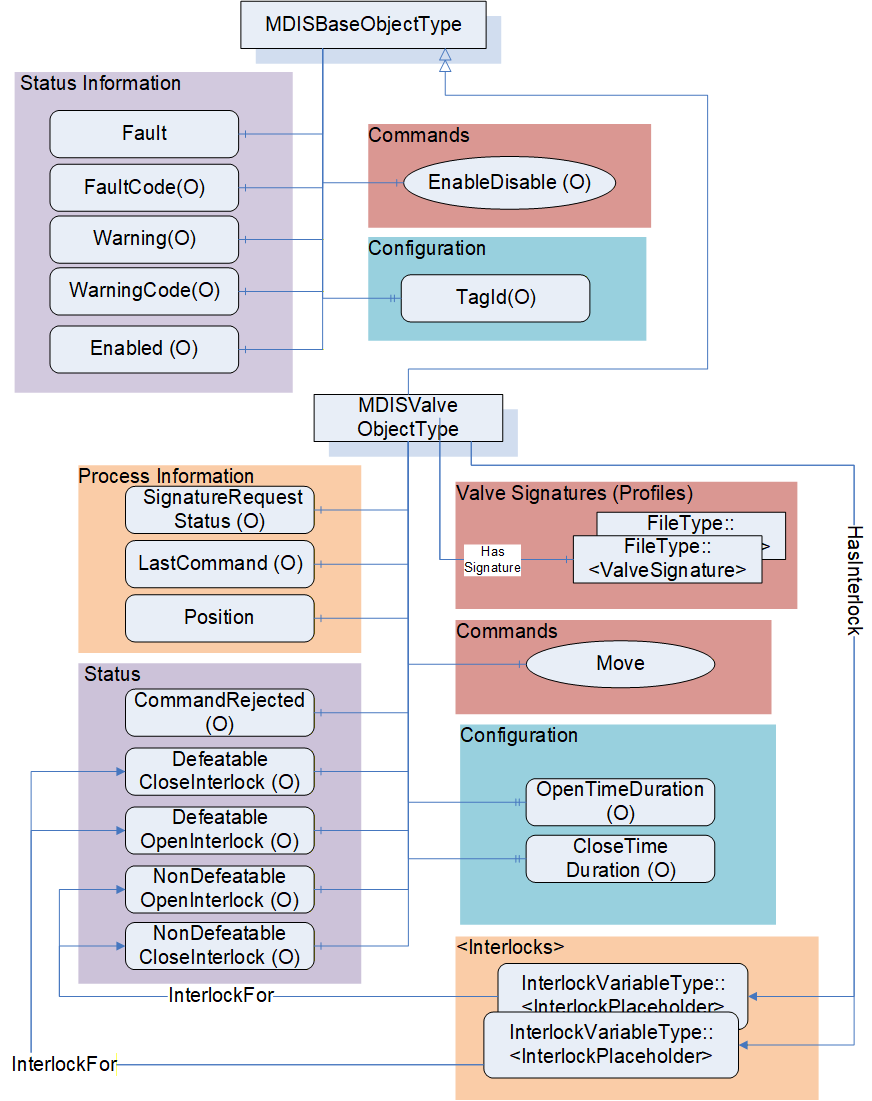
6.8.3 MDISValveObjectType Definition
Table 51 details the generic properties for the MDISValveObjectType. Any vendor specified properties that have been implemented within a project should be documented within a similar format and supplied to the DCS vendor. The addition of vendor specific properties will result in a subtype of the MDISValveObjectType. When an MDISValveObjectType Instance is disabled the MDISBaseObjectType defaults are followed and only the OpenTimeDuration and CloseTimeDuration values will be available.
| Attribute | Value | ||||
| BrowseName | MDISValveObjectType | ||||
| IsAbstract | False | ||||
| References | Node Class | BrowseName | DataType | TypeDefinition | Other |
|---|---|---|---|---|---|
| Subtype of the MDISBaseObjectType | |||||
| 0:HasComponent | Variable | Position | ValvePositionEnum | 0:BaseDataVariableType | M, R |
| 0:HasComponent | Variable | CommandRejected | 0:Boolean | 0:BaseDataVariableType | O, RO |
| 0:HasComponent | Variable | SignatureRequestStatus | SignatureStatusEnum | 0:BaseDataVariableType | O, RO |
| 0:HasComponent | Variable | LastCommand | CommandEnum | 0:BaseDataVariableType | O, RO |
| 0:HasComponent | Variable | NonDefeatableOpenInterlock | 0:Boolean | 0:BaseDataVariableType | O, RO |
| 0:HasComponent | Variable | DefeatableOpenInterlock | 0:Boolean | 0:BaseDataVariableType | O, RO |
| 0:HasComponent | Variable | NonDefeatableCloseInterlock | 0:Boolean | 0:BaseDataVariableType | O, RO |
| 0:HasComponent | Variable | DefeatableCloseInterlock | 0:Boolean | 0:BaseDataVariableType | O, RO |
| 0:HasComponent | Method | Move | See 6.8.4 | M | |
| HasInterlock | Variable | <InterlockPlaceholder> | 0:Boolean | InterlockVariableType | OP, RO |
| 0:HasProperty | Variable | OpenTimeDuration | 0:Duration | 0:PropertyType | O, RO |
| 0:HasProperty | Variable | CloseTimeDuration | 0:Duration | 0:PropertyType | O, RO |
| HasSignature | Object | <ValveSignature> | FileType | OP | |
| ConformanceUnits | |||||
|---|---|---|---|---|---|
| MDIS Valve Base |
The following items describe status information from the valve:
SignatureRequestStatus - The collection of data required for a valve signature may take some time after the completion of a Move command. The SignatureRequestStatus Variable indicates the status of the current signature request (see 8.1.4 for a description of the possible enumerations).
LastCommand - The enumeration reflects the last command sent to the equipment by the SPCS (see 8.1.5 for a description of the possible enumerations).
Enabled - This Boolean reflects if the valve is available for control. The behaviour follows the MDISBaseObjectType.
Position - This enumeration provides information about the current position of the valve (see section 8.1.7 for additional details).
CommandRejected - A flag that, if set to True, indicates that the valve has rejected the last command issued to it. The command could be rejected for a number of reasons. Possible reasons for rejecting a command include:
Loss of subsea communication reported by the SPCS.
An active interlock.
The valve is in the disabled state.
For any of the following Variables, if they are true, there shall be at least one instance of an InterlockVariableType that describes the active interlock.
NonDefeatableOpenInterlock - The open valve command is interlocked and cannot be overridden.
DefeatableOpenInterlock - The open valve command is interlocked and can be overridden.
NonDefeatableCloseInterlock - The close valve command is interlocked and cannot be overridden.
DefeatableCloseInterlock - The close valve command is interlocked and can be overridden.
The following items are related to valve control: These items allow information to flow from the DCS to the SPCS. All commands from the DCS to SPCS may require access controls to ensure that only appropriate personnel initiate them.
Move - This Method causes the valve to open or close (see 6.8.4 for additional details).
<InterlockPlaceholder> - The number of interlock Variables will change based on the project and even valve instance. The Variables shall be of InterlockVariableType or a subtype of it. The interlock contains an InterlockFor Reference to one of the previously described flags. Clients can use this information to categorise the interlocks appropriately. Figure 17 provides an example of how this interlock Variable is used and could be deployed.
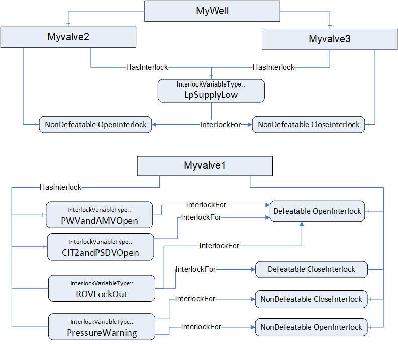
Note: in OPC UA it is allowed to have a Node which is the target of multiple 0:HasComponent References, this allows a single interlock to be shared between multiple Objects; such as a low pressure interlock that maybe shared by all of the valves and chokes in a system.
The following items describe configuration related items:
OpenTimeDuration - Estimated max time to travel to open position, used for DCS systems to indicate a move fail condition if time is exceeded. Time is provided in milliseconds. The OpenTimeDuration can be used for any kind of valve (hydraulic, electric, etc.). [Note: this time is an estimate and Clients may need to allow for additional delays in transmitting and receiving any move commands].
CloseTimeDuration - Estimated max time to travel to close position, used for DCS systems to indicate a move fail condition if time is exceeded. Time is provided in milliseconds. The CloseTimeDuration can be used for any kind of valve (hydraulic, electric, etc.) [Note: this time is an estimate and Clients may need to allow for additional delays in transmitting and receiving any Move commands].
<ValveSignature> - The reference shall point to an instance of FileType, where the file contains valve signature information. The name of this object is project or vendor specific, but it should be related to the name of the instance of the MDISValveObjectType. The name shall include a timestamp. The FileType ObjectType (defined in OPC 10000-5 (older version), OPC 10000-20 (newer versions)) includes two properties (illustrated below), for all MDIS instances both of these properties shall have the value False. For additional detail see 6.14.3.
| 0:HasProperty | Variable | 0:Writable | 0:Boolean | 0:PropertyType | Mandatory |
| 0:HasProperty | Variable | 0:UserWritable | 0:Boolean | 0:PropertyType | Mandatory |
Vendor specific subtypes of this ObjectType are allowed. They may add additional vendor specific information or may change some Optional items to Mandatory. A standard file content is defined in Annex E.
The MDISValveObjectType is a subtype of MDISBaseObjectType and inherit the FaultCode Variable. The MDISValveObjectType defines the standard FaultCodes (for bits 0-15 as defined in 6.2.2) in Table 52. All subtypes of this the MDISValveObjectType will inherit all FaultCodes defined in this table. Subtypes may define additional FaultCodes in their own table.
| Value | Bit no. | Description |
| CommunicationFault | 1 | Not possible to operate the valve. |
| FailedToOpen | 2 | Device failed to move open |
| FailedToClose | 3 | Device failed to move close |
| PressureFeedbackFailure | 4 | Pressure check feedback verification failed |
| FlowFeedbackFailure | 5 | Flow check feedback verification failed |
The MDISValveObjectType defines the standard WarningCodes (for bits 0-15 as defined in 6.2.2) in Table 53. All subtypes of this the MDISValveObjectType will inherit all WarningCodes defined in this table. Subtypes may define additional WarningCodes in their own table.
| Value | Bit no. | Description |
| SideAProblem | 0 | There is an issue with the A side of the valve |
| SideBProblem | 1 | There is an issue with the B side of the valve. |
| PositionDiscrepancy | 2 | The valve position has a discrepancy (Side A and Side B are different and neither is broken) |
| UncommandedChange | 3 | Position of valve changed without an authorized move |
| CalibrationRequired | 4 | The valve requires calibration |
6.8.4 Valve Move Method
Move Method is used to open or close a valve.
Signature
	Move (
			[in] CommandEnum		Direction,
			[in] 0:Boolean		OverrideInterlock,
			[in] SEMEnum			SEM,
			[in] 0:Boolean		Signature,
[in] 0:Boolean ShutdownRequest);| Argument | Description |
| Direction | The enumeration indicates whether the command is to open the valve or to close the valve |
| OverrideInterlock | Boolean indicating if the open or close command should override any defeatable interlocks |
| SEM | The enumeration indicates which SEM to send the command to. |
| Signature | Boolean indicating if a profile /signature should be generated by this move command request. If the optional Variable SignatureRequestStatus is not provided on the Object, this parameter is ignored by the Server. |
| ShutdownRequest | Boolean indicates that this command is part of a shutdown sequence. It should be noted that the responsibility for the shutdown is on the DCS and operator side. All non defeatable interlocks of the subsea system will be overridden which can cause damage to the subsea system. |
Method result codes are defined as part of the Call Service (see OPC 10000-4). They are described in Table 124 for ease of reference.
Comments:
The Move Method initiates a move operation. Parameters include opening or closing of the valve, overriding of any interlocks, the SEM selection to use for the command, if a profile / signature is being requested for this move operation or if a shutdown is being requested. The Method will complete when the command has been accepted. If the command has not been accepted by the Server, then the Method returns an error indicating the operation could not be performed. In the case when the Move command is accepted by the Server, the move operation may or may not be complete at the time the Method returns to the Client. Therefore, the Client must monitor the Position of the valve to determine when the Move command actually finishes.
The OverrideInterlocks, SEM, Signature and Shutdown are optional parameters, but OPC UA Methods do not allow for optional parameters. These parameters must always be provided. On a Server basis the parameter may be configured to not be utilised. If a Server is configured to not utilise a parameter, this is because the functionality is not required.
Table 55 specifies the AddressSpace representation for the Move Method.
| Attribute | Value | ||||
| BrowseName | Move | ||||
| References | Node Class | BrowseName | DataType | TypeDefinition | Other |
|---|---|---|---|---|---|
| 0:HasProperty | Variable | 0:InputArguments | 0:Argument[] | 0:PropertyType | M |
| ConformanceUnits | |||||
|---|---|---|---|---|---|
| MDIS Valve Base |
6.9 MDISCIMVObjectType
6.9.1 Introduction
The following section details the generic MDISCIMVObjectType and defines the properties associated with it. This is in general a vendor and operator independent description, but all users of the MDISCIMVObjectType can add vendor specific data. The vendor specific data should be defined as part of a subtype of the MDISCIMVObjectType defined in this document. It is assumed that the subsea system is the Server and host of the instance of the MDISCIMVObjectType. The DCS based system is the Client in the system. It is assumed that all interactions with the instance of the MDISCIMVObjectType are initiated by the Client and are directed to the Server.
6.9.2 Overview
The Chemical Injection Metering Valve (CIMV) is a basic component of any subsea control system. CIMVs regulate the flow of a chemical delivered to subsea production system. This document will address the CIMV found in subsea production trees. Implementation shall ensure adherence to Mandatory [M] aspects in order to comply with the MDIS interface standardisation. Optional [O] may or may not be implemented within a project. Figure 18 provides an overview of the CIMV Object as defined by MDIS and the MDISCIMVObjectType. It includes all items that are defined by the MDISBaseObjectType.
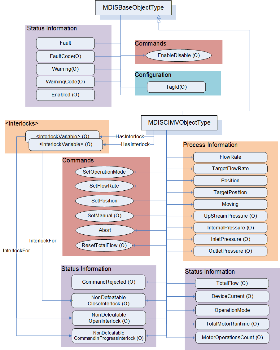
6.9.3 MDISCIMVObjectType Definition
Table 56 defines the structure of an MDISCIMVObjectType. Any vendor specified Properties that have been implemented within a project should be documented within a similar format and supplied to the DCS vendor. The addition of vendor specific properties will result in a subtype of the MDISCIMVObjectType. When an MDISCIMVObjectType Instance is disabled the MDISBaseObjectType defaults are followed - no additional values will be available.
| Attribute | Value | ||||
| BrowseName | MDISCIMVObjectType | ||||
| IsAbstract | False | ||||
| References | Node Class | BrowseName | DataType | TypeDefinition | Other |
|---|---|---|---|---|---|
| Subtype of the MDISBaseObjectType (define in 6.2.2) | |||||
| 0:HasComponent | Variable | OperationMode | CIMVOperationModeEnum | 0:BaseDataVariableType | M, RO |
| 0:HasComponent | Variable | FlowRate | 0:Float | 0:AnalogItemType | M, RO |
| 0:HasComponent | Variable | TargetFlowRate | 0:Float | 0:AnalogItemType | M, RO |
| 0:HasComponent | Variable | TotalFlow | 0:Float | 0:AnalogItemType | O, RO |
| 0:HasComponent | Method | ResetTotalFlow | See 6.9.9 | O | |
| 0:HasComponent | Variable | Position | 0:Float | 0:BaseDataVariableType | M, RO |
| 0:HasComponent | Variable | TargetPosition | 0:Float | 0:BaseDataVariableType | M, RO |
| 0:HasComponent | Variable | Moving | CIMVMoveEnum | 0:BaseDataVariableType | M, RO |
| 0:HasComponent | Object | TotalMotorRuntime | MDISCounterObjectType | O, RO | |
| 0:HasComponent | Object | MotorOperationsCount | MDISCounterObjectType | O, RO | |
| 0:HasComponent | Variable | DeviceCurrent | 0:Float | 0:AnalogItemType | O, RO |
| 0:HasComponent | Variable | InletPressure | 0:Float | 0:AnalogItemType | O, RO |
| 0:HasComponent | Variable | InternalPressure | 0:Float | 0:AnalogItemType | O, RO |
| 0:HasComponent | Variable | OutletPressure | 0:Float | 0:AnalogItemType | O, RO |
| 0:HasComponent | Variable | CommandRejected | 0:Boolean | 0:BaseDataVariableType | O, RO |
| 0:HasComponent | Method | SetOperationMode | See 6.9.4 | M | |
| 0:HasComponent | Method | SetFlowRate | See 6.9.5 | M | |
| 0:HasComponent | Method | SetPosition | See 6.9.6 | M | |
| 0:HasComponent | Method | SetManual | See 6.9.7 | O | |
| 0:HasComponent | Method | Abort | See 6.9.8 | M | |
| 0:HasComponent | Variable | NonDefeatableOpenInterlock | 0:Boolean | 0:BaseDataVariableType | O, RO |
| 0:HasComponent | Variable | NonDefeatableCloseInterlock | 0:Boolean | 0:BaseDataVariableType | O, RO |
| 0:HasComponent | Variable | NonDefeatableCommandInProgressInterlock | 0:Boolean | 0:BaseDataVariableType | O, RO |
| HasInterlock | Variable | <InterlockPlaceholder> | 0:Boolean | InterlockVariableType | OP, RO |
| ConformanceUnits | |||||
|---|---|---|---|---|---|
| MDIS CIMV Base |
The components of the MDISCIMVObjectType have additional references which are defined in Table 57.
| Source Path | References | NodeClass | BrowseName | DataType | TypeDefinition | Other |
| TotalMotorRuntime | 0:HasComponent | Variable | Count | 0:Duration | 0:BaseDataVariableType | M |
| TotalMotorRuntime | 0:HasComponent | Method | SetCount | M | ||
| MotorOperationsCount | 0:HasComponent | Variable | Count | 0:UInt32 | 0:BaseDataVariableType | M |
| MotorOperationsCount | 0:HasComponent | Method | SetCount | M | ||
| FlowRate | 0:HasProperty | Variable | 0:EngineeringUnits | 0:EUInformation | 0:PropertyType | M |
| TargetFlowRate | 0:HasProperty | Variable | 0:EngineeringUnits | 0:EUInformation | 0:PropertyType | M |
| TotalFlow | 0:HasProperty | Variable | 0:EngineeringUnits | 0:EUInformation | 0:PropertyType | M |
| DeviceCurrent | 0:HasProperty | Variable | 0:EngineeringUnits | 0:EUInformation | 0:PropertyType | M |
| InletPressure | 0:HasProperty | Variable | 0:EngineeringUnits | 0:EUInformation | 0:PropertyType | M |
| InternalPressure | 0:HasProperty | Variable | 0:EngineeringUnits | 0:EUInformation | 0:PropertyType | M |
| OutletPressure | 0:HasProperty | Variable | 0:EngineeringUnits | 0:EUInformation | 0:PropertyType | M |
OperationMode - An enumeration that reflects the current operating mode of the CIMV (see 8.1.8 for a description of the possible enumerations).
FlowRate - A float value that indicates the current inhibitor flow rate. It includes properties that represent the engineering units, the engineering units range and optionally the instrument range. Refer to table 16 for illustration.
TargetFlowRate - A float value that indicates the flow rate which the CIMV will automatically try to maintain when the OperationMode is set to "Flow" (refer to 8.1.8). It includes properties that represent the engineering units, the engineering units range and optionally the instrument range. Refer to table 16 for illustration. The SetFlowRate method (refer to 6.9.5) can be used to change this value.
TotalFlow - A float value that indicates the accumulated volume of inhibitor which has been injected since it was last reset. It includes properties that represent the engineering units, the engineering units range and optionally the instrument range. Refer to table 16 for illustration. If the TotalFlow is provided then the ResetTotalFlow Method shall also be provided.
Position - A Float that represents the current position in percent open for the CIMV.
TargetPosition - A Float that represents the position in percent open which the CIMV will automatically try to maintain when the OperationMode is set to "Position" (refer to 8.1.8). The SetPosition method (refer to 6.9.6) can be used to change this value.
Moving - An enumeration indicating the confirmed operation of the CIMV (confirmed by SPCS Vendor). (see 8.1.9 for a description of the possible enumerations)
TotalMotorRuntime - A value that indicates the accumulated duration of time that the motor has run since it was put into service. The object includes a reset method (see 6.10).
MotorOperationsCount - A value that indicates the total number of motor operations that have been completed since it was last reset. The object includes a reset method (see 6.10).
DeviceCurrent - The measure of the Electrical current being consumed by the device (e.g., motor operations). It includes properties that represent the engineering units, the engineering units range and optionally the instrument range. Refer to table 16 for illustration.
InletPressure - Current pressure on the upstream side of the throttling valve. Upstream in this case means closer to the source of the inhibitor chemical than the throttling valve. It includes properties that represent the engineering units, the engineering units range and optionally the instrument range. Refer to table 16 for illustration.
InternalPressure - Current pressure at the stem of the throttling valve. It includes properties that represent the engineering units, the engineering units range and optionally the instrument range. Refer to table 16 for illustration.
OutletPressure - Current pressure on the downstream side of the throttling valve. Downstream in this case means further from the source of the inhibitor chemical than the throttling valve. It includes properties that represent the engineering units, the engineering units range and optionally the instrument range. Refer to table 16 for illustration.
CommandRejected -- A flag that, if set to True, indicates that the CIMV has rejected the last command issued to it. The command could be rejected for a number of reasons. Possible reasons for rejecting a command include:
Loss of subsea communication reported by the SPCS.
An active interlock.
The CIMV is in the disabled state
Enabled - This Boolean reflects if the CIMV is available for control. The behaviour follows the MDISBaseObjectType.
SetOperationMode - This Method commands the CIMV into one of its operating modes - Position control mode, Flow control mode or Manual control mode.
SetFlowRate - This Method sets the CIMV flow rate when in flow control mode. The CIMV must be in flow control mode in order to invoke this method. It shall return an error if it is not in FlowControlMode
SetPosition - This Method sets the CIMV position when in position control mode. The CIMV must be in position mode in order to invoke this method. It shall return an error if it is not in PositionControlMode
SetManual - This Method allows an operator to open or close the CIMV to the specified percentage. The CIMV must be in manual mode in order to invoke this method. It shall return an error if it is not in ManualControlMode
Abort - This Method allows an operator to cancel any currently active SetOperationMode, SetFlowRate, SetPosition or Move command and return the operation mode to manual.
NonDefeatableCloseInterlock - The close CIMV command is interlocked and cannot be overridden.
NonDefeatableOpenInterlock - The open CIMV command is interlocked and cannot be overridden.
NonDefeatableCommandInProgressInterlock - A CIMV command is progress and no new commands can be issued until the current command ends or is stopped.
<InterlockPlaceholder> - The number of interlock Variables will change based on the project and even CIMV instance. The Variables shall be of InterlockVariableType or a subtype of it. They will be referenced by a HasInterlock Reference and will contain an InterlockFor Reference. Clients can use this information to categorise the interlocks appropriately.
The MDISCIMVObjectType is a subtype of MDISBaseObjectType and inherit the FaultCode Variable. The MDISCIMVObjectType defines the standard FaultCodes (for bits 0-15 as defined in 6.2.2) in Table 58. All subtypes of this the MDISCIMVObjectType will inherit all FaultCodes defined in this table. Subtypes may define additional FaultCodes in their own table.
| Value | Bit no. | Description |
| FailedToMove | 0 | The CIMV failed to move in response to a command. |
| CommunicationFault | 1 | Not possible to operate the valve. |
The MDISCIMVObjectType defines the standard WarningCodes (for bits 0-15 as defined in 6.2.2) in Table 59. All subtypes of this the MDISCIMVObjectType will inherit all WarningCodes defined in this table. Subtypes may define additional WarningCodes in their own table.
| Value | Bit no. | Description |
| SideAProblem | 0 | There is an issue with the A side of the valve |
| SideBProblem | 1 | There is an issue with the B side of the valve. |
| PositionDiscrepancy | 2 | The valve position has a discrepancy (Side A and Side B are different and neither is broken) |
| UncommandedChange | 3 | Position of valve changed without an authorized move |
6.9.4 SetOperationMode Method
SetOperationMode Method is used to change the operation mode of the CIMV.
Signature
	SetOperationMode (
			[in] CIMVOperationModeEnum		Mode,
			[in] SEMEnum					SEM,
[in] 0:Boolean ShutdownRequest);| Argument | Description |
| Mode | Enumeration indicating the requested operation mode |
| SEM | The selection of which SEM to send the command to |
| ShutdownRequest | Boolean indicates that this command is part of a shutdown sequence. |
Method result codes are defined as part of the Call Service (see OPC 10000-4). They are described in Table 124 for ease of reference.
Comments
The SetOperationMode Method initiates a change of operation mode command. Parameters include selection of operation mode and the SEM selection to use for the command. The method will complete when the command has been accepted. If the command has not been accepted by the Server, then the Method returns an error indicating the operation could not be performed. In the case when the SetOperationMode command is accepted by the Server, the operation may or may not be complete at the time the Method returns to the Client. Therefore, the Client must monitor the OperationMode of the CIMV to determine when the SetOperationMode command actually finishes. If the CIMV current OperationMode is the same as the mode specified in the SetOperationMode Method argument then the Server shall return a successful operation result but ignore the command. If the requested Mode is not support (i.e. Manual) the method shall return an error Bad_OutOfRange, indicating that the requested mode is not supported.
If a Server does not support the selection of SEM, the SEM parameter is ignored.
ShutdownRequest is a Boolean that indicates that this command is part of a shutdown sequence. It should be noted that the responsibility for the shutdown is on the DCS and operator side. All nondefeatable interlocks of the subsea system will be overridden which can cause damage to the subsea system.
Table 61 specifies the AddressSpace representation for the SetOperationMode Method.
| Attribute | Value | ||||
| BrowseName | SetOperationMode | ||||
| References | Node Class | BrowseName | DataType | TypeDefinition | Other |
|---|---|---|---|---|---|
| 0:HasProperty | Variable | 0:InputArguments | 0:Argument[] | 0:PropertyType | M |
| ConformanceUnits | ||||||
|---|---|---|---|---|---|---|
| MDIS CIMV Base |
6.9.5 SetFlowRate Method
SetFlowRate Method is used to set a target flow rate.
Signature
	SetFlowRate (
			[in] 0:Float		FlowRate,
			[in] SEMEnum		SEM,
			[in] 0:Boolean	ShutdownRequest);
| Argument | Description |
| FlowRate | Target flow rate. The CIMV will automatically maintain this target flow |
| SEM | The selection of which SEM to send the command to |
| ShutdownRequest | Boolean indicates that this command is part of a shutdown sequence. |
Method result codes are defined as part of the Call Service (see OPC 10000-4). They are described in Table 124 for ease of reference.
Comments
The SetFlowRate Method commands the CIMV to automatically maintain the given flow rate. Parameters include the requested flow rate, overriding of any interlocks and the SEM selection to use for the command. The FlowRate Method argument is of datatype float however the actual units are device specific. Refer to FlowRate and TargetFlowRate component of MDISCIMVObjectType discussed in 6.9.3. The Method will complete when the command has been accepted. After receiving the new commanded flow rate, the CIMV will update the TargetFlowRate to the value of the FlowRate input parameter and will automatically maintain the target rate. The CIMV must be in operation mode Flow (refer to 8.1.8) otherwise the Method shall return Bad_InvalidState. The operation may or may not have completed when the Method returns. The Method will return an error if the operation cannot be started.
If a Server does not support the selection of SEM, the SEM parameter is ignored.
ShutdownRequest is a Boolean that indicates that this command is part of a shutdown sequence. It should be noted that the responsibility for the shutdown is on the DCS and operator side. All nondefeatable interlocks of the subsea system will be overridden which can cause damage to the subsea system.
Table 63 specifies the AddressSpace representation for the SetFlowRate Method.
| Attribute | Value | ||||
| BrowseName | SetFlowRate | ||||
| References | Node Class | BrowseName | DataType | TypeDefinition | Other |
|---|---|---|---|---|---|
| 0:HasProperty | Variable | 0:InputArguments | 0:Argument[] | 0:PropertyType | M |
| ConformanceUnits | |||||
|---|---|---|---|---|---|
| MDIS CIMV Base |
6.9.6 SetPosition Method
SetPosition Method is used to set a target position.
Signature
	SetPosition (
			[in] 0:Float		Position,
			[in] SEMEnum		SEM
[in] 0:Boolean ShutdownRequest);| Argument | Description |
| Position | Target position as percent of open. The CIMV will automatically maintain this position |
| SEM | The selection of which SEM to send the command to |
| ShutdownRequest | Boolean indicates that this command is part of a shutdown sequence. |
Method result codes are defined as part of the Call Service (see OPC 10000-4). They are described in Table 124 for ease of reference.
Comments
The SetPosition Method commands the CIMV to move to and automatically maintain the position. Parameters include the requested position, overriding of any interlocks and the SEM selection to use for the command. The Position Method argument is of datatype float and represents percent of open. The Position Method argument value shall be between 0 and 100. The server shall return Bad_OutOfRange if the Position Method argument value is outside of this range. The Method will complete when the command has been accepted. After receiving the new commanded position, the CIMV will store the value of the input param Position in the TargetPosition and will automatically maintain the position. Refer to Position and TargetPosition component of MDISCIMVObjectType discussed in 6.9.3. The CIMV must be in operation mode Position_1 (refer to 8.1.8) otherwise the Method shall return Bad_InvalidState. The operation may or may not have completed when the Method returns. The Method will return an error if the operation cannot be started.
If a Server does not support the selection of SEM, the SEM parameter is ignored.
ShutdownRequest is a Boolean that indicates that this command is part of a shutdown sequence. It should be noted that the responsibility for the shutdown is on the DCS and operator side. All nondefeatable interlocks of the subsea system will be overridden which can cause damage to the subsea system.
Table 65 specifies the AddressSpace representation for the SetPosition Method.
| Attribute | Value | ||||
| BrowseName | SetPosition | ||||
| References | Node Class | BrowseName | DataType | TypeDefinition | Other |
|---|---|---|---|---|---|
| 0:HasProperty | Variable | 0:InputArguments | 0:Argument[] | 0:PropertyType | M |
| ConformanceUnits | |||||
|---|---|---|---|---|---|
| MDIS CIMV Base |
6.9.7 SetManual Method
CIMV SetManual Method is used to open or close the CIMV to a specified percent of open position.
Signature:
	SetManual (
		[in] CIMVMoveEnum		Direction,
		[in] 0:Float			Delta,
		[in] SEMEnum			SEM,
[in] 0:Boolean ShutdownRequest);| Argument | Description |
| Direction | Direction to move - Open or Close |
| Delta | A relative change in position from the current position as a percent. (i.e. if the position is at 50% and the delta is 5% and the direction is open , the result will be 55%) |
| SEM | The selection of which SEM to send the command to |
| ShutdownRequest | Boolean indicates that this command is part of a shutdown sequence. |
Method result codes are defined as part of the Call Service (see OPC 10000-4). They are described in Table 124 for ease of reference.
Comments
The SetManual Method commands the CIMV to move in the specified direction (open or close) the specified delta. Parameters include Direction 4 (refer to 8.1.9), the delta value in percent, overriding of any interlocks, the SEM selection to use for the command and if this is a shutdown request. After receiving the new commanded position, the CIMV will start to move. The server shall return Bad_OutOfRange when the Delta method argument value would result in the CIMV moving to a position less than 0 or greater than 100. For example, if the current position is 50, the method shall not be called with a Delta method argument value > 50 in either the open or close direction. The Method will complete when the command has been accepted. The move operation may or may not have completed when the Method returns. The CIMV must be in operation mode Manual_4 (refer to 8.1.8) otherwise the Method shall return Bad_InvalidState the Method returns an error if the operation cannot be started. The Client must monitor the Moving Variable to determine when the move operation actually finishes.
If a Server does not support the selection of SEM, the SEM parameter is ignored.
ShutdownRequest is a Boolean that indicates that this command is part of a shutdown sequence. It should be noted that the responsibility for the shutdown is on the DCS and operator side. All non defeatable interlocks of the subsea system will be overridden which can cause damage to the subsea system.
Table 67 specifies the AddressSpace representation for the Move Method.
| Attribute | Value | |||||
| BrowseName | SetManual | |||||
| References | Node Class | BrowseName | DataType | TypeDefinition | Other | |
|---|---|---|---|---|---|---|
| 0:HasProperty | Variable | 0:InputArguments | 0:Argument[] | 0:PropertyType | M | |
| ConformanceUnits | |||||||
|---|---|---|---|---|---|---|---|
| MDIS CIMV SetManual |
6.9.8 Abort Method
CIMV Abort Method is used to halt any in-progress command, hold current position and return the operation mode to manual.
Signature:
Abort ( );
Method result codes are defined as part of the Call Service (see OPC 10000-4). They are described in Table 124 for ease of reference.
Comments
In manual operation mode (refer to 8.1.8), the Abort Method will try to cancel any active CIMV Move command and hold current position. If no Move command is in progress, the command will be ignored and return successful. In position or flow operation mode (refer to 8.1.8), the Abort Method will try to cancel any activity associated with the current operation mode, hold current position and set the CIMV to manual operation mode. The Method will complete when the command has been accepted. The abort operation may or may not have completed when the Method returns. The Method returns errors only if the operation cannot be started. The Client shall monitor the Moving Variable and the OperationMode Variable and, if provided, the CommandRejected Variables to determine if the Abort command was successful or failed
Table 68 specifies the AddressSpace representation for the Abort Method.
| Attribute | Value | |||||
| BrowseName | Abort | |||||
| References | Node Class | BrowseName | DataType | TypeDefinition | Other | |
|---|---|---|---|---|---|---|
| ConformanceUnits | ||||||
| MDIS CIMV Base | ||||||
6.9.9 ResetTotalFlow Method
ResetTotalFlow Method is used to reset the TotalFlow counter.
Signature:
	ResetTotalFlow (
[in] 0:Float Initial);| Argument | Description |
| Initial | The value to initialize the TotalFlow to |
Method result codes are defined as part of the Call Service (see OPC 10000-4). They are described in Table 124 for ease of reference.
Comments
Table 68 specifies the AddressSpace representation for the ResetTotalFlow Method.
| Attribute | Value | |||||
| BrowseName | ResetTotalFlow | |||||
| References | Node Class | BrowseName | DataType | TypeDefinition | Other | |
|---|---|---|---|---|---|---|
| 0:HasProperty | Variable | 0:InputArguments | 0:Argument[] | 0:PropertyType | M | |
| ConformanceUnits | ||||||
|---|---|---|---|---|---|---|
| MDIS CIMV TotalFlow |
6.10 MDISCounterObjectType
6.10.1 Introduction
The following section details the generic MDISCounterObjectType structure. This ObjectType can be used as part of any aggregate that requires a duration to be included, such as TotalRunTime. This is in general a vendor and operator independent description, but all users of the MDISCounterObjectType can add vendor specific data. The vendor specific data should be defined as part of a subtype of the MDISCounterObjectType defined in this document. It is assumed that the subsea system is the Server and host of the instance of the MDISCounterObjectType. The DCS based system is the Client in the system. It is assumed that all interactions with the instance of the MDISCounterObjectType are initiated by the Client and are directed to the Server.
6.10.2 Overview
The following section details the MDIS generic properties for the MDISCounterObjectType. Implementation shall ensure adherence to Mandatory [M] aspects in order to comply with the MDIS interface standardisation. Optional [O] may or may not be implemented within a project. Figure 20 provides an overview of the MDISCounterObjectType as defined by MDIS.
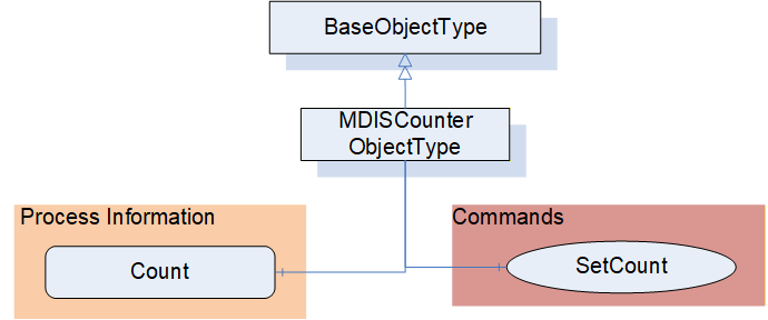
6.10.3 MDISCounterObjectType Definition
Table 71 defines the structure of an MDISCounterObjectType. Any vendor specified properties that have been implemented within a project should be documented with a similar format and supplied to the DCS vendor. The addition of vendor specific properties will result in a subtype of the MDISCounterObjectType.
| Attribute | Value | ||||
| BrowseName | MDISCounterObjectType | ||||
| IsAbstract | False | ||||
| References | Node Class | BrowseName | DataType | TypeDefinition | Other |
|---|---|---|---|---|---|
| Subtype of the 0:BaseObjectType | |||||
| 0:HasComponent | Variable | Count | 0:Number | 0:BaseDataVariableType | M, RO |
| 0:HasComponent | Method | SetCount | See 6.10.4 | O | |
| ConformanceUnits | |||||
|---|---|---|---|---|---|
| MDIS Counter Object | |||||
| MDIS CIMV Base |
How this value is calculated is server specific. The name of an instance of this ObjectType shall indicate what the object is, such as TotalMotorRuntime, for an example of how this Object is used see 6.9
6.10.4 SetCount Method
SetCount Method is used to Set the Count. This Count maybe any counter.
Signature:
	SetCount (
		[in] 0:Number Initial);
| Argument | Description |
| Initial | The value to initialize the Object Count to, default is 0 |
Method result codes are defined as part of the Call Service (see OPC 10000-4). They are described in Table 124 for ease of reference.
Comments
The SetCount Method command resets the value of the Count Variable. The Count Variable, may immediately start incrementing depending on how it is defined.
Table 73 specifies the AddressSpace representation for the SetCount Method.
| Attribute | Value | ||||
| BrowseName | SetCount | ||||
| References | Node Class | BrowseName | DataType | TypeDefinition | Other |
|---|---|---|---|---|---|
| 0:HasProperty | Variable | 0:InputArguments | 0:Argument[] | 0:PropertyType | M |
| ConformanceUnits | |||||
|---|---|---|---|---|---|
| MDIS Counter Object | |||||
| MDIS CIMV Base |
6.11 MDISMotorObjectType
6.11.1 Introduction
The following section details the generic MDISMotorObjectType structure and defines the properties associated with controlling a Motor. This is in general a vendor and operator independent description, but all users of the MDISMotorObjectType can add vendor specific data. The vendor specific data should be defined as part of a subtype of the MDISMotorObjectType defined in this document. It is assumed that the subsea system is the Server and host of the instance of the MDISMotorObjectType. The DCS based system is the Client in the system. It is assumed that all interactions with the instance of the MDISMotorObjectType are initiated by the Client and are directed to the Server.
6.11.2 Overview
The following section details the MDIS generic properties for the MDISMotorObjectType. Implementation shall ensure adherence to Mandatory [M] aspects in order to comply with the MDIS interface standardisation. Optional [O] may or may not be implemented within a project. Figure 20 provides an overview of the MDISMotorObjectType as defined by MDIS, including some nested types. Figure 20 includes all of the items that are inherited from the MDISBaseObjectType.
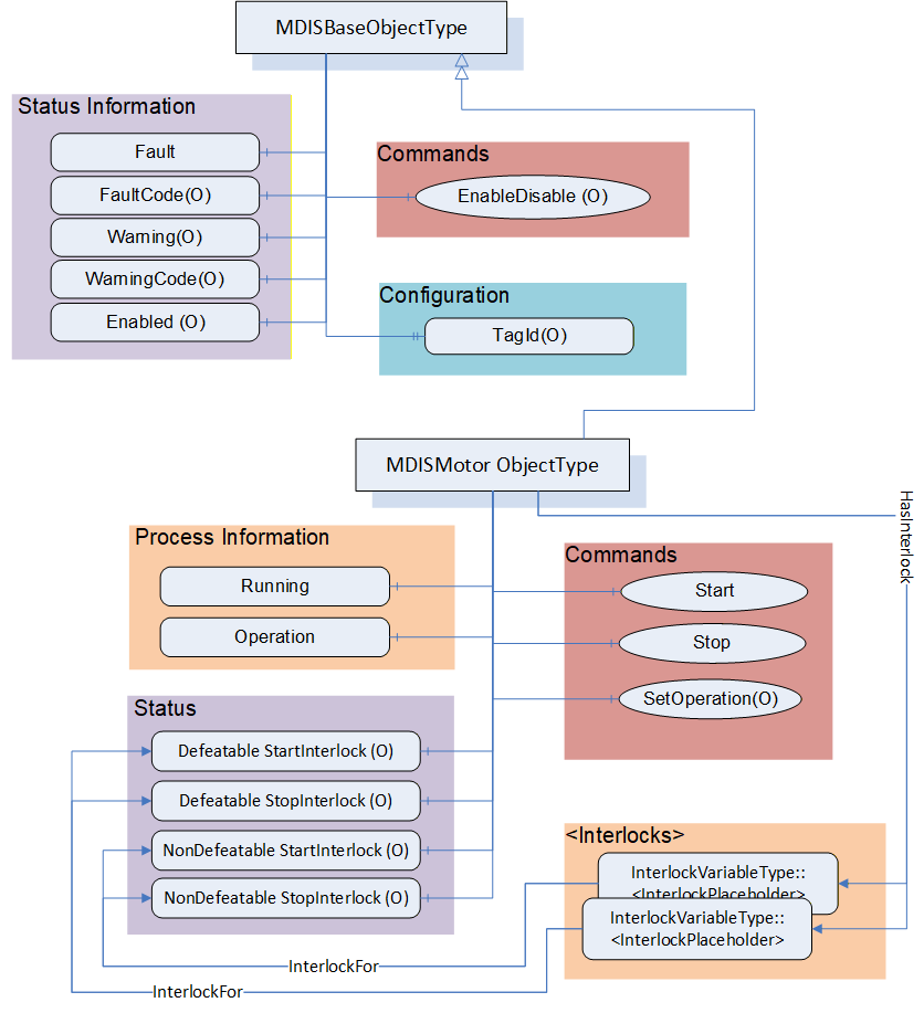
6.11.3 MDISMotorObjectType Definition
Table 74 defines the structure of an MDISMotorObjectType. Any vendor specified properties that have been implemented within a project should be documented with a similar format and supplied to the DCS vendor. The addition of vendor specific properties will result in a subtype of the MDISMotorObjectType. When an MDISMotorObjectType Instance is disabled the MDISBaseObjectType defaults are followed - no additional values will be available.
| Attribute | Value | |||||
| BrowseName | MDISMotorObjectType | |||||
| IsAbstract | False | |||||
| References | Node Class | BrowseName | DataType | TypeDefinition | Other | |
|---|---|---|---|---|---|---|
| Subtype of the MDISBaseObjectType | ||||||
| 0:HasComponent | Variable | Running | 0:Boolean | 0:BaseDataVariableType | M, RO | |
| 0:HasComponent | Variable | Operation | MotorOperationEnum | 0:BaseDataVariableType | M, RO | |
| 0:HasComponent | Variable | NonDefeatableStartInterlock | 0:Boolean | 0:BaseDataVariableType | O, RO | |
| 0:HasComponent | Variable | DefeatableStartInterlock | 0:Boolean | 0:BaseDataVariableType | O, RO | |
| 0:HasComponent | Variable | NonDefeatableStopInterlock | 0:Boolean | 0:BaseDataVariableType | O, RO | |
| 0:HasComponent | Variable | DefeatableStopInterlock | 0:Boolean | 0:BaseDataVariableType | O, RO | |
| HasInterlock | Variable | <InterlockPlaceholder> | 0:Boolean | InterlockVariableType | OP, RO | |
| 0:HasComponent | Method | Start | See 6.11.4 | O | ||
| 0:HasComponent | Method | Stop | See 6.11.5 | O | ||
| 0:HasComponent | Method | SetOperation | See 6.11.6 | O | ||
| ConformanceUnits | |||||
|---|---|---|---|---|---|
| MDIS Motor Base |
Running - Feedback from the motor if it is running (or not). If the motor is running it returns True.
Operation - There are three different operation modes: Auto, Manual and Off. In Auto operation the process sends the Start and Stop command automatically (not from an Operator). In Manual operation the Start and Stop process is executed by the operator manually (e.g. by using the Start and Stop methods). When the operation mode is set to Off, the motor may not be started either automatically or manually. If Manual Operation is supported, then the Start and Stop Methods shall be exposed.
NonDefeatableStartInterlock - The Start command is interlocked and cannot be overridden.
DefeatableStartInterlock - The Start command is interlocked and can be overridden.
NonDefeatableStopInterlock - The Stop command is interlocked and cannot be overridden.
DefeatableStopInterlock - The Stop command is interlocked and can be overridden.
<InterlockPlaceholder> - The number of interlock Variables will change based on the project and even Motor instance. The Variables shall be of InterlockVariableType or a subtype of it. They shall be referenced by a HasInterlock Reference and shall contain an InterlockFor Reference. Clients can use this information to categorise the interlocks appropriately.
The MDISMotorObjectType is a subtype of MDISBaseObjectType and inherit the FaultCode Variable. The MDISMotorObjectType defines the standard FaultCodes (for bits 0-15 as defined in 6.2.2) in Table 75 (currently empty, no additional warning codes defined). All subtypes of this the MDISMotorObjectType will inherit all FaultCodes defined in this table. Subtypes may define additional FaultCodes in their own table.
| Value | Bit no. | Description |
The MDISMotorObjectType defines the standard WarningCodes (for bits 0-15 as defined in 6.2.2) in Table 76 (currently empty, no additional warning codes defined). All subtypes of this the MDISMotorObjectType will inherit all WarningCodes defined in this table. Subtypes may define additional WarningCodes in their own table.
| Value | Bit no. | Description |
6.11.4 Motor Start Method
Start Method is used to start the Motor.
Signature:
	Start (
[in] 0:Boolean OverrideInterlocks);| Argument | Description |
| OverrideInterlocks | Boolean indicating if the Start command should override any interlocks |
Method result codes are defined as part of the Call Service (see OPC 10000-4). They are described in Table 124 for ease of reference. This method shall return Bad_InvalidState if it is invoked and the operation model is not Manual. If the motor is running this command is ignored.
Comments
The Start Method command tries to start the Motor.
Table 67 specifies the AddressSpace representation for the Start Method.
| Attribute | Value | ||||
| BrowseName | Start | ||||
| References | Node Class | BrowseName | DataType | TypeDefinition | Other |
|---|---|---|---|---|---|
| 0:HasProperty | Variable | 0:InputArguments | 0:Argument[] | 0:PropertyType | M |
| ConformanceUnits | ||||||
|---|---|---|---|---|---|---|
| MDIS Motor Start/Stop |
6.11.5 Motor Stop Method
Stop Method is used to stop the Motor.
Signature:
	Stop (
[in] 0:Boolean OverrideInterlocks);| Argument | Description |
| OverrideInterlocks | Boolean indicating if the Stop command should override any interlocks |
Method result codes are defined as part of the Call Service (see OPC 10000-4). They are described in Table 124 for ease of reference. This method shall return Bad_InvalidState if it is invoked and the operation model is not Manual. If the motor is not Running this command is ignored.
Comments
The Stop Method commands the Motor to stop.
Table 80 specifies the AddressSpace representation for the Stop Method.
| Attribute | Value | ||||
| BrowseName | Stop | ||||
| References | Node Class | BrowseName | DataType | TypeDefinition | Other |
|---|---|---|---|---|---|
| 0:HasProperty | Variable | 0:InputArguments | 0:Argument[] | 0:PropertyType | M |
| ConformanceUnits | ||||||
|---|---|---|---|---|---|---|
| MDIS Motor Start/Stop |
6.11.6 Motor SetOperation Method
SetOperation Method is used to set the Operation of the Motor.
Signature:
	SetOperation (
[in] MotorOperationEnum Mode);| Argument | Description |
| Mode | Mode to operate in (i.e., Auto, Manual or Off) |
Method result codes are defined as part of the Call Service (see OPC 10000-4). They are described in Table 124 for ease of reference.
Comments
The SetOperation Method commands the Operation.
Table 82 specifies the AddressSpace representation for the SetOperation Method.
| Attribute | Value | ||||
| BrowseName | SetOperation | ||||
| References | Node Class | BrowseName | DataType | TypeDefinition | Other |
|---|---|---|---|---|---|
| 0:HasProperty | Variable | 0:InputArguments | 0:Argument[] | 0:PropertyType | M |
| ConformanceUnits | ||||||
|---|---|---|---|---|---|---|
| MDIS Motor Operation |
6.12 MDISAggregateObjectType
6.12.1 Overview
The following tables detail the generic properties for the MDISAggregateObjectType; implementation shall ensure adherence to Mandatory [M] aspects to comply with the MDIS interface standardisation. Optional [O] may or may not be implemented within a project. Figure 21 provides an overview of the MDISAggregateObjectType as defined by MDIS. This Object is intended to be the base object for all aggregate ObjectTypes. See section 10.5 for additional details on data aggregation.
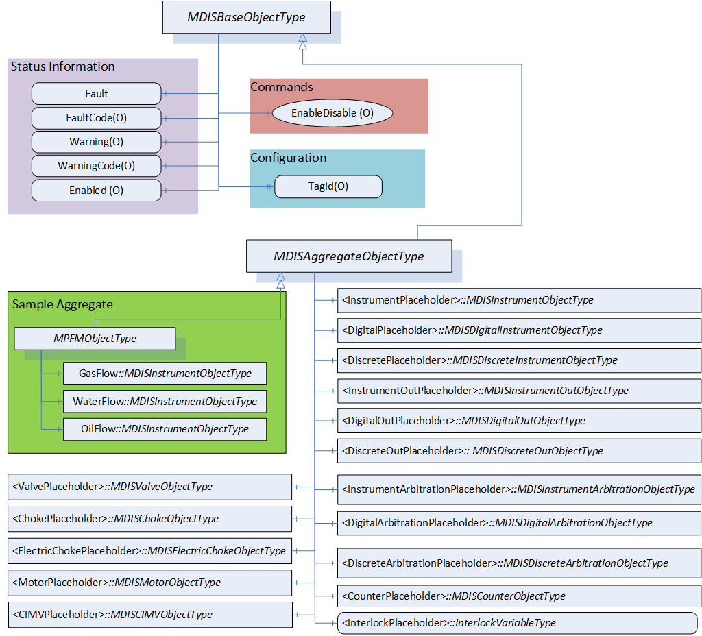
6.12.2 MDISAggregateObjectType Definition
Table 83 defines the structure of an MDISAggregateObjectType. The MDISAggregateObjectType is a subtype of MDISBaseObjectType and requires that all subtypes include, as a minimum, the Fault information. All other components are Optional and only components that are required by the aggregate are needed.
| Attribute | Value | |||||
| BrowseName | MDISAggregateObjectType | |||||
| IsAbstract | True | |||||
| References | Node Class | BrowseName | Data Type | TypeDefinition | Other |
|---|---|---|---|---|---|
| Subtype of the MDISBaseObjectType defined in section 6.1.1 | |||||
| 0:HasComponent | Object | <InstrumentPlaceholder> | MDISInstrumentObjectType | OP | |
| 0:HasComponent | Object | <InstrumentOutPlaceholder> | MDISInstrumentOutObjectType | OP | |
| 0:HasComponent | Object | <InstrumentArbitrationPlaceholder> | MDISInstrumentArbitrationObjectType | OP | |
| 0:HasComponent | Object | <DigitalPlaceholder> | MDISDigitalInstrumentObjectType | OP | |
| 0:HasComponent | Object | <DigitalOutPlaceholder> | MDISDigitalOutObjectType | OP | |
| 0:HasComponent | Object | <DigitalArbitrationPlaceholder> | MDISDigitalArbitrationObjectType | OP | |
| 0:HasComponent | Object | <DiscretePlaceholder> | MDISDiscreteInstrumentObjectType | OP | |
| 0:HasComponent | Object | <DiscreteOutPlaceholder> | MDISDiscreteOutObjectType | OP | |
| 0:HasComponent | Object | <DiscreteArbitrationPlaceholder> | MDISDiscreteArbitrationObjectType | OP | |
| 0:HasComponent | Object | <ValvePlaceholder> | MDISValveObjectType | OP | |
| 0:HasComponent | Object | <ChokePlaceholder> | MDISChokeObjectType | OP | |
| 0:HasComponent | Object | <ElectricChokePlaceholder> | MDISElectricChokeObjectType | OP | |
| 0:HasComponent | Object | <MotorPlaceholder> | MDISMotorObjectType | OP | |
| 0:HasComponent | Object | <CIMVPlaceholder> | MDISCIMVObjectType | OP | |
| 0:HasComponent | Object | <CounterPlaceholder> | MDISCounterObjectType | OP | |
| HasInterlock | Variable | <InterlockPlaceholder> | InterlockVariableType | OP | |
| ConformanceUnits | |||||
|---|---|---|---|---|---|
| MDIS Aggregate Object |
The MDISAggregateObjectType is an abstract ObjectType; instances of this ObjectType cannot be created. Object instances can only be created of subtypes of this ObjectType. In OPC UA it is legal to add additional Object or Variable Reference(s) to an instance of an Object, (i.e., add Variable or Object to an instance that are not defined in the type), but in MDIS we are restricting this in that a Client is not required to process or handle any Objects or Variables that are not part of a type.
The subtypes of MDISAggregateObjectType are allowed to include other subtypes of MDISAggregateObjectType. For example, a Well that is defined as a subtype of MDISAggregateObjectType might include an MPFMAggregateObjectType which is also a subtype of MDISAggregateObjectType.
<InstrumentPlaceholder> denotes that a subtype of this ObjectType may define any number of Objects of this type as part of a subtype. Each object instance shall have a unique BrowseName and must be of MDISInstrumentObjectType or a subtype of it.
<InstrumentOutPlaceholder> denotes that a subtype of this ObjectType may define any number of Objects of this type as part of a subtype. Each object instance shall have a unique BrowseName and must be of MDISInstrumentOutObjectType or a subtype of it.
<InstrumentArbitrationPlaceholder> denotes that a subtype of this ObjectType may define any number of Objects of this type as part of a subtype. Each object instance shall have a unique BrowseName and must be of MDISInstrumentArbitrationObjectType or a subtype of it.
<DigitalPlaceholder> denotes that a subtype of this ObjectType may define any number of Objects of this type as part of a subtype. Each object instance shall have a unique BrowseName and must be of MDISDigitalInstrumentObjectType or a subtype of it.
<DigitalOutPlaceholder> denotes that a subtype of this ObjectType may define any number of Objects of this type as part of a subtype. Each object instance shall have a unique BrowseName and must be of MDISDigitalOutObjectType or a subtype of it.
<DigitalArbitrationPlaceholder> denotes that a subtype of this ObjectType may define any number of Objects of this type as part of a subtype. Each object instance shall have a unique BrowseName and must be of MDISDigitalArbitrationObjectType or a subtype of it.
<DiscretePlaceholder> denotes that a subtype of this ObjectType may define any number of Objects of this type as part of a subtype. Each object instance shall have a unique BrowseName and must be of MDISDiscreteInstrumentObjectType or a subtype of it.
<DiscreteOutPlaceholder> denotes that a subtype of this ObjectType may define any number of Objects of this type as part of a subtype. Each object instance shall have a unique BrowseName and must be of MDISDiscreteOutObjectType or a subtype of it.
<DiscreteArbitrationPlaceholder> denotes that a subtype of this ObjectType may define any number of Objects of this type as part of a subtype. Each object instance shall have a unique BrowseName and must be of MDISDiscreteArbitrationObjectType or a subtype of it.
<ValvePlaceholder> denotes that a subtype of this ObjectType may define any number of Objects of this type as part of a subtype. Each object instance shall have a unique BrowseName and must be of MDISValveObjectType or a subtype of it.
<ChokePlaceholder> denotes that a subtype of this ObjectType may define any number of Objects of this type as part of a subtype. Each object instance shall have a unique BrowseName and must be of MDISChokeObjectType or a subtype of it.
<ElectricChokePlaceholder> denotes that a subtype of this ObjectType may define any number of Objects of this type as part of a subtype. Each object instance shall have a unique BrowseName and must be of MDISElectricChokeObjectType or a subtype of it.
<MotorPlaceholder> denotes that a subtype of this ObjectType may define any number of Objects of this type as part of a subtype. Each object instance shall have a unique BrowseName and must be of MDISMotorObjectType or a subtype of it.
<CIMVPlaceholder> denotes that a subtype of this ObjectType may define any number of Objects of this type as part of a subtype. Each object instance shall have a unique BrowseName and must be of MDISCIMVObjectType or a subtype of it.
<CounterPlaceholder> denotes that a subtype of this ObjectType may define any number of Objects of this type as part of a subtype. Each object instance shall have a unique BrowseName and must be of MDISCounterObjectType or a subtype of it.
<InterlockPlaceholder> denotes that a subtype of this VariableType may define any number of Variables of this type as part of a subtype. Each Variable instance shall have a unique BrowseName and must be of InterlockVariableType or a subtype of it.
6.13 MDISTimeSyncObjectType
6.13.1 Introduction
In some systems, a MDIS Server might be on an isolated network, one in which there is no NTP or other source of time synchronization signals. In these systems, the MDIS Server would need to be able to obtain a minimum time synchronization signal from the Client. This ObjectType and associated method is designed to allow this minimum time synchronization. It should only be used if a better time synchronization system, such as NTP, is not available. The accuracy of this type of time synchronization could be in the range of seconds.
If this Object is supported, a single instance of this Object shall exist on a Server. The Object shall have a name TimeSynchronization and the instance shall exist as part of the MDISInformationObject.
6.13.2 Overview
The following section details the MDISTimeSyncObjectType. This optional type allows a Client to provide time synchronization information to a Server. The Client can call the SetTime Method periodically to ensure the Server time does not drift. This Method does not return until the time on the Server has been updated or an error is returned.
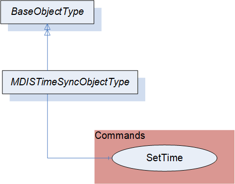
6.13.3 MDISTimeSyncObjectType Definition
Table 84 defines the structure of an MDISTimeSyncObjectType.
The current time on the Server is available as part of the ServerStatus provided by all OPC UA Servers.
| Attribute | Value | ||||
| BrowseName | MDISTimeSyncObjectType | ||||
| IsAbstract | False | ||||
| References | Node Class | BrowseName | DataType | TypeDefinition | Other |
|---|---|---|---|---|---|
| Subtype of the BaseObjectType | |||||
| 0:HasComponent | Method | SetTime | SetTime Method is defined in 6.13.4 | M | |
| ConformanceUnits | |||||
|---|---|---|---|---|---|
| MDIS Timesync Object |
SetTime - This method allows a Client to set time on the Server.
6.13.4 SetTime Method
SetTime Method (defined in Table 85) is used to set the time on the Server. If an error occurs this Method shall return an error code indicating the failure to set the time (see Table 87).
Signature:
	SetTime (
		[in] 0:UtcTime TargetTime );
| Argument | Description |
| TargetTime | The UTC Time that the Server shall use to update its internal clock. |
Method result codes are defined as part of the Call Service (see OPC 10000-4). They are described in Table 124 for ease of reference.
Comments
The SetTime Method will change the time on the Server. Table 86 specifies the AddressSpace representation for the SetTime Method.
| Attribute | Value | |||||
| BrowseName | SetTime | |||||
| References | Node Class | BrowseName | DataType | TypeDefinition | Other | |
|---|---|---|---|---|---|---|
| 0:HasProperty | Variable | 0:InputArguments | 0:Argument[] | 0:PropertyType | M | |
| ConformanceUnits | ||||||
|---|---|---|---|---|---|---|
| MDIS Timesync Object |
| Symbolic Id | Description |
| Bad_InvalidTimestamp | The timestamp is outside the range allowed by the Server or an error occurred setting the Server time. |
6.14 MDISInformationObjectType
6.14.1 Introduction
MDIS defines flags, general status information and other optional data collections that need to exist in a standard manner on MDIS Servers to allow for easier interoperation between Clients and Servers. This information is provided via the MDISInformationObjectType.
6.14.2 Overview
The following section details the MDISInformationObjectType. This ObjectType defines a standard structure for organization of some basic Server information. An instance of this object is required for all versions of MDIS Servers 1.2 and greater. An instance of this ObjectType shall exist under the Objects folder on all OPC UA MDIS Servers. Clients are required to be able to handle Servers which do not contain this object. The Client shall assume any Server that does not contain an instance of this ObjectType is a version 1.1 or 1.0 MDIS Server.
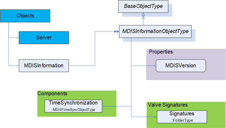
6.14.3 MDISInformationObjectType Definition
Table 88 defines the structure of an MDISInformationObjectType.
| Attribute | Value | ||||
| BrowseName | MDISInformationObjectType | ||||
| IsAbstract | False | ||||
| References | Node Class | BrowseName | DataType | TypeDefinition | Other |
|---|---|---|---|---|---|
| Subtype of the BaseObjectType (see OPC 10000-5) | |||||
| 0:HasComponent | Object | TimeSynchronization | MDISTimeSyncObjectType | O | |
| 0:HasComponent | Object | Signatures | 0:FolderType | O | |
| 0:HasComponent | Variable | MDISVersion | MDISVersionDataType | MDISVersionVariableType | M, RO |
| ConformanceUnits | |||||
|---|---|---|---|---|---|
| MDIS Information version |
TimeSynchronization - this is an instance of the MDISTimeSyncObjectType object, that allows a Client to provide time information to a Server if required. See 6.1.16 for additional details.
Signatures is a folder that contains all of the currently available signatures (profiles). The individual signature(s) are stored as FileObjects and the format of the file(s) is vendor specific.
MDISVersion provides information about the version of the MDIS specification that is implemented by the Server. This is provided to assist the Client in determining what should be available and can also be used for automated testing of the Server.
7 MDIS VariableTypes
7.1 InterlockVariableType Definition
This VariableType is a Boolean indicating if the interlock is active. The instance of a Variable of InterlockVariableType shall have a descriptive name (display name) and include a description. The description shall describe the type of interlock. On a project basis an optional summary that details active interlocks may be implemented to support understanding of the open / close interlock status within the Object. For a given instance of an Object, any number of referenced interlocks may exist, where each instance would represent a specific interlock. The number of interlocks is determined at configuration time of the Object and could be different for each Object in a given well. Each interlock variable shall contain an InterlockFor reference to at least one of the following:
NonDefeatableOpenInterlock,
DefeatableOpenInterlock,
NonDefeatableCloseInterlock,
DefeatableCloseInterlock.
A given instance of an InterlockVariableType might be referenced by more than one Object, but for all objects that reference a given instance of an InterlockVariableType there must be at least one InterlockFor reference.
| Attribute | Value | ||||
| BrowseName | InterlockVariableType | ||||
| IsAbstract | False | ||||
| ValueRank | -1 (-1 = Scalar) | ||||
| DataType | Boolean | ||||
| References | Node Class | BrowseName | DataType | TypeDefinition | Other |
|---|---|---|---|---|---|
| Subtype of the 0:BaseDataVariableType defined in OPC 10000-5. | |||||
| ConformanceUnits | ||||||
|---|---|---|---|---|---|---|
| MDIS Valve DefeatableCloseInterlock | ||||||
| MDIS Valve DefeatableOpenInterlock | ||||||
| MDIS Valve NonDefeatableCloseInterlock | ||||||
| MDIS Valve NonDefeatableOpenInterlock | ||||||
| MDIS Choke DefeatableCloseInterlock | ||||||
| MDIS Choke DefeatableOpenInterlock | ||||||
| MDIS Choke NonDefeatableCloseInterlock | ||||||
| MDIS Choke NonDefeatableOpenInterlock | ||||||
| MDIS Electric Choke DefeatableCloseInterlock | ||||||
| MDIS Electric Choke DefeatableOpenInterlock | ||||||
| MDIS Electric Choke NonDefeatableCloseInterlock | ||||||
| MDIS Electric Choke NonDefeatableOpenInterlock | ||||||
| MDIS CIMV NonDefeatableCloseInterlock | ||||||
| MDIS CIMV NonDefeatableOpenInterlock | ||||||
| MDIS CIMV NonDefeatableCommandInProgressInterlock | ||||||
| MDIS Motor DefeatableStartInterlock | ||||||
| MDIS Motor DefeatableStopInterlock | ||||||
| MDIS Motor NonDefeatableStartInterlock | ||||||
| MDIS Motor NonDefeatableStopInterlock | ||||||
7.2 MDISVersionVariableType Definition
This VariableType defines a standard representation of the version information that is related the MDIS Specification.
| Attribute | Value | ||||
| BrowseName | MDISVersionVariableType | ||||
| IsAbstract | False | ||||
| ValueRank | -1 (-1 = Scalar) | ||||
| DataType | MDISVersionDataType | ||||
| References | Node Class | BrowseName | DataType | TypeDefinition | Other |
|---|---|---|---|---|---|
| Subtype of the 0:BaseDataVariableType defined in OPC 10000-5. | |||||
| 0:HasProperty | Variable | MajorVersion | 0:Byte | 0:PropertyType | M, RO |
| 0:HasProperty | Variable | MinorVersion | 0:Byte | 0:PropertyType | M, RO |
| 0:HasProperty | Variable | Build | 0:Byte | 0:PropertyType | M, RO |
| ConformanceUnits | |||||
|---|---|---|---|---|---|
| MDIS Information version |
MajorVersion number is the major version of the MDIS OPC UA companion specification. For example, for version 1.2 of the MDIS Specification this will be a 1.
MinorVersion number is the minor version of the MDIS OPC UA companion specification. For example, for version 1.2 of the MDIS Specification this will be a 2.
Build number is additional version information that can be associated with minor updates, patches that could be provided by the MDIS organization related to the MDIS Information model NodeSet file. Typically, this will be 0.
8 MDIS DataTypes
8.1 Enumerations
8.1.1 ChokeMoveEnum
Table 91 defines the valid states for the ChokeMoveEnum.
| Name | Value | Description |
| Moving | 1 | The choke is currently moving (in progress) |
| Stopped | 2 | The move has stopped |
Its representation in the AddressSpace is defined in Table 94.
| Attribute | Value | ||||
| BrowseName | ChokeMoveEnum | ||||
| IsAbstract | False | ||||
| References | NodeClass | BrowseName | DataType | TypeDefinition | Other |
|---|---|---|---|---|---|
| Subtype of the Enumeration type defined in OPC 10000-5 | |||||
| 0:HasProperty | Variable | 0:EnumValues | 0:EnumValueType[] | 0:PropertyType | |
| ConformanceUnits | |||||
|---|---|---|---|---|---|
8.1.2 ChokeCommandEnum
Table 93 defines the valid states for the ChokeCommandEnum.
| Name | Value | Description |
| Close | 1 | The command to the Choke is Close |
| Open | 2 | The command to the Choke is Open |
Its representation in the AddressSpace is defined in Table 94.
| Attribute | Value | ||||
| BrowseName | ChokeCommandEnum | ||||
| IsAbstract | False | ||||
| References | NodeClass | BrowseName | DataType | TypeDefinition | Other |
|---|---|---|---|---|---|
| Subtype of the Enumeration type defined in OPC 10000-5 | |||||
| 0:HasProperty | Variable | 0:EnumValues | 0:EnumValueType[] | 0:PropertyType | |
| ConformanceUnits | |||||
|---|---|---|---|---|---|
| MDIS Choke Base |
8.1.3 SetCalculatedPositionEnum
Table 93 defines the valid states for the SetCalculatedPositionEnum.
| Name | Value | Description |
| Initial | 0 | no command (initial state) |
| Inprogress | 1 | command in progress |
| Complete | 2 | command completed |
| Fault | 4 | command fault |
Its representation in the AddressSpace is defined in Table 96.
| Attribute | Value | |||||
| BrowseName | SetCalculatedPositionEnum | |||||
| IsAbstract | False | |||||
| References | NodeClass | BrowseName | DataType | TypeDefinition | Other | |
|---|---|---|---|---|---|---|
| Subtype of the Enumeration type defined in OPC 10000-5 | ||||||
| 0:HasProperty | Variable | 0:EnumValues | 0:EnumValueType[] | 0:PropertyType | ||
| ConformanceUnits | ||||||
|---|---|---|---|---|---|---|
| MDIS Choke Base |
8.1.4 SignatureStatusEnum
Table 97 defines the valid states for the SignatureStatusEnum.
| Name | Value | Description |
| NotAvailable | 1 | The profile / signature is not available (in progress) |
| Completed | 2 | The profile / signature request has completed |
| Failed | 4 | The profile / signature request has failed |
Retrieval of a signature is outside of the scope of this interface. A NotAvailable_1 indicates that the current profile / signature request is not available.
Its representation in the AddressSpace is defined in Table 98.
| Attribute | Value | |||||
| BrowseName | SignatureStatusEnum | |||||
| IsAbstract | False | |||||
| References | NodeClass | BrowseName | DataType | TypeDefinition | Other | |
|---|---|---|---|---|---|---|
| Subtype of the Enumeration type defined in OPC 10000-5 | ||||||
| 0:HasProperty | Variable | 0:EnumValues | 0:EnumValueType[] | 0:PropertyType | ||
| ConformanceUnits | ||||||
|---|---|---|---|---|---|---|
| MDIS Valve SignatureRequestStatus |
8.1.5 CommandEnum
Table 99 defines the valid states for the CommandEnum. This might not be the actual state of the valve, it is just the last command sent to the valve.
| Name | Value | Description |
| Close | 1 | The last command to the valve was Close |
| Open | 2 | The last command to the valve was Open |
| None | 4 | No known command has been sent to the valve. The initial setting on start-up of a server. |
Its representation in the AddressSpace is defined in Table 100.
| Attribute | Value | |||||
| BrowseName | CommandEnum | |||||
| IsAbstract | False | |||||
| References | NodeClass | BrowseName | DataType | TypeDefinition | Other | |
|---|---|---|---|---|---|---|
| Subtype of the Enumeration type defined in OPC 10000-5 | ||||||
| 0:HasProperty | Variable | 0:EnumValues | 0:EnumValueType[] | 0:PropertyType | ||
| ConformanceUnits | ||||||
|---|---|---|---|---|---|---|
| MDIS Valve Base |
8.1.6 SEMEnum
Table 101 defines the valid states for the SEMEnum.
Its representation in the AddressSpace is defined in Table 102
8.1.7 ValvePositionEnum
Table 103 defines the valid states for the ValvePositionEnum.
| Name | Value | Description |
| Closed | 1 | The Valve is Closed |
| Open | 2 | The Valve is Open |
| Moving | 4 | The Valve is Moving |
| Unknown | 8 | The Valve is in an unknown state. This value can be used when a subsea vendor does not have any last command information and does not know the state of the valve. |
Its representation in the AddressSpace is defined in Table 104
| Attribute | Value | |||||
| BrowseName | ValvePositionEnum | |||||
| IsAbstract | False | |||||
| References | NodeClass | BrowseName | DataType | TypeDefinition | Other | |
|---|---|---|---|---|---|---|
| Subtype of the Enumeration type defined in OPC 10000-5 | ||||||
| 0:HasProperty | Variable | 0:EnumValues | 0:EnumValueType[] | 0:PropertyType | ||
| ConformanceUnits | ||||||
|---|---|---|---|---|---|---|
| MDIS Valve Base |
8.1.8 CIMVOperationModeEnum
Table 105 defines the valid states for the CIMVOperationModeEnum.
| Name | Value | Description |
| Position | 1 | The CIMV is in closed-loop Position control mode. Sending fix position |
| Flow | 2 | The CIMV is in closed-loop Flow control mode (auto regulate) |
| Manual | 4 | The CIMV is in open-loop Manual mode (compare it to step mode - i.e., move some increment relative to current). Note: some CIMV instance may not support this mode. |
Its representation in the AddressSpace is defined in Table 106.
| Attribute | Value | |||||
| BrowseName | CIMVOperationModeEnum | |||||
| IsAbstract | False | |||||
| References | NodeClass | BrowseName | DataType | TypeDefinition | Other | |
|---|---|---|---|---|---|---|
| Subtype of the Enumeration type defined in OPC 10000-5 | ||||||
| 0:HasProperty | Variable | 0:EnumValues | 0:EnumValueType[] | 0:PropertyType | ||
| ConformanceUnits | ||||||
|---|---|---|---|---|---|---|
8.1.9 CIMVMoveEnum
Table 107 defines the valid states for the CIMVMoveEnum.
| Name | Value | Description |
| MoveClose | 1 | The CIMV is moving in the close direction |
| MoveOpen | 2 | The CIMV is moving in the open direction |
| Stop | 4 | The CIMV is not moving |
Its representation in the AddressSpace is defined in Table 108.
| Attribute | Value | |||||
| BrowseName | CIMVMoveEnum | |||||
| IsAbstract | False | |||||
| References | NodeClass | BrowseName | DataType | TypeDefinition | Other | |
|---|---|---|---|---|---|---|
| Subtype of the Enumeration type defined in OPC 10000-5 | ||||||
| 0:HasProperty | Variable | 0:EnumValues | 0:EnumValueType[] | 0:PropertyType | ||
| ConformanceUnits | ||||||
|---|---|---|---|---|---|---|
| MDIS CIMV Base |
8.1.10 ArbitrationModeEnum
Table 107 defines the valid states for the ArbitrationModeEnum.
| Name | Value | Description |
| Average | 1 | Build the average of both values (if both available) |
| DefaultA | 2 | Select SourceA (if available), else SourceB |
| DefaultB | 4 | Select SourceB (if available), else SourceA |
| ForceA | 8 | Always select SourceA |
| ForceB | 16 | Always select SourceB |
| High | 32 | Highest Value (for digital this is an OR operation) |
| Low | 64 | Lowest Value (for digital this is an AND operation) |
Its representation in the AddressSpace is defined in Table 110
| Attribute | Value | |||||
| BrowseName | ArbitrationModeEnum | |||||
| IsAbstract | False | |||||
| References | NodeClass | BrowseName | DataType | TypeDefinition | Other | |
|---|---|---|---|---|---|---|
| Subtype of the Enumeration type defined in OPC 10000-5 | ||||||
| 0:HasProperty | Variable | 0:EnumValues | 0:EnumValueType[] | 0:PropertyType | ||
| ConformanceUnits | ||||||
|---|---|---|---|---|---|---|
| MDIS Instrument Arbitration Base |
8.1.11 MotorStateEnum
Table 107 defines the valid states for the MotorStateEnum.
| Name | Value | Description |
| Active | 1 | The Motor is in active state |
| NonActive | 2 | The Motor is not in active state |
Its representation in the AddressSpace is defined in Table 112.
| Attribute | Value | |||||
| BrowseName | MotorStateEnum | |||||
| IsAbstract | False | |||||
| References | NodeClass | BrowseName | DataType | TypeDefinition | Other | |
|---|---|---|---|---|---|---|
| Subtype of the Enumeration type defined in OPC 10000-5 | ||||||
| 0:HasProperty | Variable | 0:EnumValues | 0:EnumValueType[] | 0:PropertyType | ||
| ConformanceUnits | ||||||
|---|---|---|---|---|---|---|
| MDIS Motor Base |
8.1.12 MotorOperationEnum
Table 107 defines the valid states for the MotorOperationEnum.
| Name | Value | Description |
| Off | 1 | The Motor cannot be started either automatically or manually |
| Auto | 2 | The Motor works automatically |
| Manual | 4 | The Motor is controlled manually |
Its representation in the AddressSpace is defined in Table 114.
| Attribute | Value | |||||
| BrowseName | MotorOperationEnum | |||||
| IsAbstract | False | |||||
| References | NodeClass | BrowseName | DataType | TypeDefinition | Other | |
|---|---|---|---|---|---|---|
| Subtype of the Enumeration type defined in OPC 10000-5 | ||||||
| 0:HasProperty | Variable | 0:EnumValues | 0:EnumValueType[] | 0:PropertyType | ||
| ConformanceUnits | ||||||
|---|---|---|---|---|---|---|
| MDIS Motor Base |
8.2 Structures
8.2.1 MDISVersionDataType
The MDISVersionDataType provides a single structure that provides all of the version information for the Server. There is a corresponding variable structure that provides each of the elements.
This VariableType is defined in 7.2.
| Name | Type | Description |
| MDISVersionDataType | Structure | Information that describes MDIS Specification version. |
MajorVersion | 0:Byte | The Major Version number from the specification |
MinorVersion | 0:Byte | The minor version number from the specification |
Build | 0:Byte | The BuildNumber associated - typically always 0 |
9 MDIS ReferenceTypes
9.1 HasInterlock ReferenceType
The HasInterlock ReferenceType is a concrete ReferenceType that can be used directly. It is a subtype of the HasComponent ReferenceType.
The semantic is a part-of relationship. Figure 17 provides an illustration of how this ReferenceType is used. Multiple SourceNodes can reference the same TargetNode and a SourceNode can reference multiple TargetNodes.
Like all other ReferenceTypes, this ReferenceType does not specify anything about the ownership of the parts, although it represents a part-of relationship semantic. That is, it is not specified if the TargetNode of a Reference of the HasInterlock ReferenceType is deleted when the SourceNode is deleted.
The TargetNode of this ReferenceType shall be the InterlockVariableType or a Variable of InterlockVariableType or a subtype of InterlockVariableType.
The SourceNode shall be an instance of MDISChokeObjectType, MDISValveObjectType, MDISElectricChokeObjectType, MDISCIMVObjectType, MDISMotorObjectType or a subtype one of these. It may also be of a subtype of MDISAggregateObjectType that is being used for aggregation or one of these ObjectTypes.
| Attributes | Value | ||
| BrowseName | HasInterlock | ||
| InverseName | InterlockOf | ||
| Symmetric | False | ||
| IsAbstract | False | ||
| References | NodeClass | BrowseName | Comment |
|---|---|---|---|
| Subtype of the 0:HasComponent ReferenceType defined in OPC 10000-5 | |||
| ConformanceUnits | ||||
|---|---|---|---|---|
| MDIS Choke Base | ||||
| MDIS Electric Choke Base` | ||||
| MDIS Valve Base | ||||
| MDIS CIMV Base | ||||
| MDIS Motor Base |
9.2 InterlockFor
The InterlockFor ReferenceType is a concrete ReferenceType and can be used directly. It is a subtype of NonHierarchicalReferences. The inverse reference shall also exist for all uses of this ReferenceType.
The semantic of this ReferenceType is to relate InterlockVariableType Nodes to the Variable Node that represents an interlock flag.
The SourceNode of this ReferenceType shall be an instance of InterlockVariableType.
The TargetNode of this ReferenceType shall be a Variable that is one of:
NonDefeatableOpenInterlock,
DefeatableOpenInterlock,
NonDefeatableCloseInterlock,
DefeatableCloseInterlock,
DefeatableStartInterlock,
DefeatableStopInterlock,
NonDefeatableStartInterlock,
NonDefeatableStopInterlock,
NonDefeatableCommandInProgressInterlock
The Variable shall be part of an:
MDISValveObjectType
MDISChokeObjectType
MDISElectricChokeObjectType
MDISMotorObjectType
MDISCIMVObjectType
MDISAggregateObjectType,
Or a subtype of one of these types or an instance of one of these types.
| Attributes | Value | ||
| BrowseName | InterlockFor | ||
| InverseName | HasInterlockInformation | ||
| Symmetric | False | ||
| IsAbstract | False | ||
| References | NodeClass | BrowseName | Comment |
|---|---|---|---|
| Subtype of the 0:NonHierarchicalReferences ReferenceType defined in OPC 10000-5 | |||
| ConformanceUnits | ||||
|---|---|---|---|---|
| MDIS Choke Base | ||||
| MDIS Electric Choke Base` | ||||
| MDIS Valve Base | ||||
| MDIS CIMV Base | ||||
| MDIS Motor Base |
9.3 HasSignature ReferenceType
The HasSignature ReferenceType is a concrete ReferenceType that can be used directly. It is a subtype of the HasComponent ReferenceType.
The semantic is a part-of relationship. Figure 24 provides an illustration of how this ReferenceType is used. A TargetNode can be referenced by a single SourceNode and a SourceNode can reference multiple TargetNodes.
Like all other ReferenceTypes, this ReferenceType does not specify anything about the ownership of the parts, although it represents a part-of relationship semantic. That is, it is not specified if the TargetNode of a Reference of the HasSignature ReferenceType is deleted when the SourceNode is deleted.
The TargetNode of this ReferenceType shall be an instance of FileType. The FileType instance shall contain valve signature information.
The SourceNode shall be an instance of MDISValveObjectType or a subtype of MDISValveObjectType. It might also be a MDISChokeObjectType or any other MDIS ObjectType that might need to report a signature.
| Attributes | Value | ||
| BrowseName | HasSignature | ||
| InverseName | SignatureOf | ||
| Symmetric | False | ||
| IsAbstract | False | ||
| References | NodeClass | BrowseName | Comment |
|---|---|---|---|
| Subtype of the 0:HasComponent ReferenceType defined in OPC 10000-5 | |||
| ConformanceUnits | ||||
|---|---|---|---|---|
| MDIS Valve Base |
10 MDIS AddressSpace Information
10.1 Introduction
This section defines information related to Instance Objects, value handling, UANodeSet and customised Objects
10.2 Instance AddressSpace
An MDIS Server shall include an instance of the MDISInformationObjectType under the Objects folder.
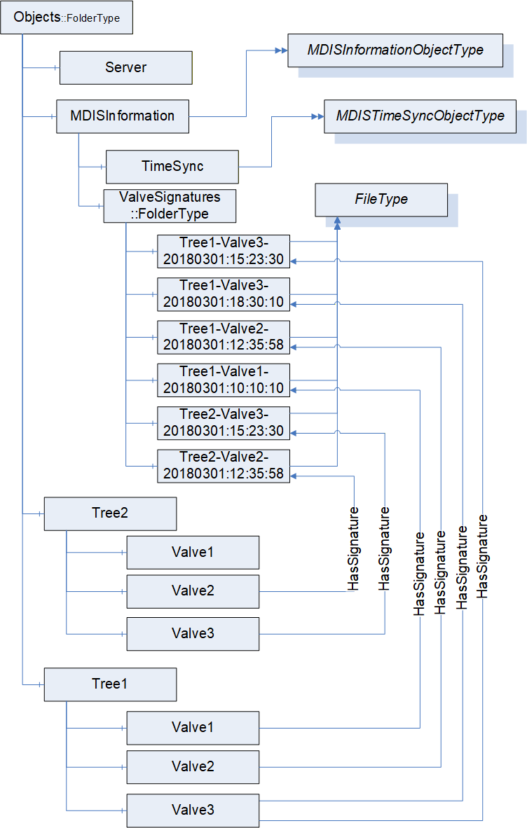
Any other structure under in the MDIS Server is vendor or project specific. Figure 24 provides an illustration of one possible instance structure, it is not the only available structure. Several of the items are optional and might not appear. The valve signature objects illustrate that valves might include multiple signatures for a given valve, no signatures for a given valve and that the single folder might contain signature from multiple trees. The naming use is project / vendor specific but might have to handle all of these cases. Signatures might also exist for other objects such as chokes.
The MDISInformation node is formally defined in Table 119.
| Attribute | Value | ||
| BrowseName | MDISInformation | ||
| References | NodeClass | BrowseName | TypeDefinition |
|---|---|---|---|
| OrganizedBy by the Objects Folder defined in OPC 10000-5 | |||
| HasTypeDefinition | ObjectType | MDISInformationObjectType | |
| ConformanceUnits | |||
|---|---|---|---|
10.3 Value reporting
Data overflow at the SPCS shall be detected by the Client. This shall be performed through the use of a queue size greater than 1 on subscriptions and monitoring of the overflow bit in all received values. If an overflow occurs the Client shall generate some notification, but the exact notification is Client vendor specific.
10.4 UANodeSet Development
In OPC UA an AddressSpace is separated into Namespaces, where each Namespace defines the owner of the address space contained in it. The MDIS Namespace shall not be modified in any manner, it is owned by MDIS. Any implementation (custom types / instances) shall be in a separate Namespace from the MDIS Namespace.
Any custom types or subtypes of the standard MDIS Types, as defined in Section 10.5.2 should be separated from instances via Namespaces. This enables custom types to be shared across DCS vendors and SPCS vendors during early phases of project development and allows the DCS vendors to begin implementation of the custom types within the DCS software. It also allows reuse of types between projects.
When UANodeSet files are passed from the SPCS vendors to the DCS vendors, the whole address space is to be exchanged (i.e. the exchanged UANodeSet files shall include the MDIS Namespace and any custom Namespaces). A Namespace can be in a single UANodeSet file and multiple files are provided or the entire address space can be in a single UANodeSet file. Having all Namespaces shall enable the DCS vendors to understand any forward References as forward References can create ambiguity within developed UANodeSet files.
The length of the namespace URLs used for defining Namespaces should be less than 128 characters. This is to enable smaller devices like controllers to be able to store Namespaces. NamespaceUri usually reference back to the company that is the owner of the Namespace.
The NodeIds should be integers. If using strings, the length of the NodeIds shall be less than 32 characters. This shall enable smaller devices like controllers to process NodeIds efficiently.
NodeIds shall be fixed. When a Server restarts NodeIds shall not be changed. NodeIds should not be reused on a project. Any change in NodeIds shall require Clients to reconfigure the connection based on new generated UANodeSet files. Once a Nodeset file is delivered to a DCS vendor from the SPCS vendor the NodeIds in the file are fixed. Future NodeSet files might add or delete nodes. But in any future Nodeset file shall not change the Nodeid of any Objects that have been delivered in the prior NodeSet file.
For custom types the instance hierarchy shall be represented via HasComponent (standard OPC UA Reference) or a custom ReferenceType that has been subtyped from HasComponent or Organizes References only.
10.5 Object Development
10.5.1 Introduction
This section provides guidance on creation of modified and composite objects for use in compliance with MDIS standards. Standard MDIS Objects defined in Section 6 shall be used wherever possible. In the event that standard Objects cannot represent a given subsea component or piece of equipment, a new Object shall be developed by collection, aggregation or extension of existing Objects. Use of collection, aggregation or extension to model subsea equipment is dependent on vendor implementations.
10.5.2 Object Collection, Aggregation and Extension Definition
Object collection shall be implemented using folders and should be used to group components or equipment that are physically grouped together in a common structure. Several examples of where object collection could be utilised would include modelling Subsea Electronics Modules, Electronic Power Units and Wells.
Object aggregation shall be implemented by creating a subtype of the MDISAggregateObjectType and should be used to group relevant objects to represent a complex piece of equipment that cannot be represented by a single MDIS Object. A specific example of where Object aggregation could be used would be modelling Multiphase Flow Meters (MPFMs). Aggregated Objects have specific rules, defined below, to allow Clients to be able to discover them and easily support them.
Object extension shall be implemented by creating a subtype of an existing MDIS Object and should be used when an existing MDIS Object, such as a valve Object, has additional information or functionality that needs to be represented. An example might be a vendor specific valve, that follows all of the rules associated with a MDISValveObjectType, but includes additional diagnostic information related to the vendor specific valve. Extension of Objects applies to models defined in section 6 and listed below:
MDISInstrumentObjectType
MDISInstrumentOutObjectType
MDISInstrumentArbitrationObjectType
MDISDigitalInstrumentObjectType
MDISDigitalOutObjectType
MDISDigitalArbitrationObjectType
MDISDiscreteInstrumentObjectType
MDISDiscreteOutObjectType
MDISDiscreteArbitrationObjectType
MDISValveObjectType
MDISChokeObjectType
MDISElectricChokeObjectType
MDISCIMVObjectType
MDISMotorObjectType
Subtyping MDISBaseObjectType and MDISCounterObjectType is not allowed.
Figure 25 illustrates an extension that adds a simple diagnostic variable.
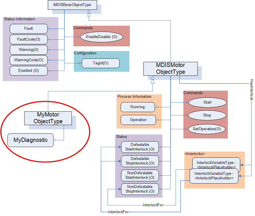
Rules for developing aggregated and extended objects are provided in Table 120. To minimise variability, when aggregating or extending objects only instances of the following VariableTypes and ObjectTypes shall be used:
Standard MDIS Objects defined in section 6.
BaseDataVariableType
DiscreteItemType (Variable)
AnalogItemType (Variable)
| Description | Aggregation | Extension |
| Require new NodeId on TypeDefinition level | Yes | Yes |
| 0) Define new ObjectType with any non-MDIS parent | No | No |
| 1) Define new ObjectType with any MDIS parent (subtyping MDIS ObjectTypes - MDISValveObjectType, MDISChokeObjectType, MDISElectricChokeObjectType, MDISMotorObjectType, MDISCIMVObjectType, MDISDigitalInstrumentObjectType, MDISInstrumentObjectType, MDISDiscreteInstrumentObjectType or any subtype of these types) | No | Yes |
| 2) Define new ObjectType with MDISAggregateObjectType as parent | Yes | No |
The operations described in Table 121 are valid operations in a generic OPC UA Server, but for an MDIS Server they are restricted as described in the table. All changes shall be based on type changes. Instance specific changes are not allowed.
| Description | Aggregation | Extension |
| Add MDIS Object instance to an instance of an existing MDIS ObjectType (or subtype). | No | No |
| Add non-MDIS Object instance to existing MDIS ObjectType (or subtype). | No | No |
| Add non-MDIS Object instance to an instance of an existing MDIS ObjectType (or subtype). | No | No |
| Add Method to an existing MDIS ObjectType (or subtype). | No | No |
| Add a Variable instance to an instance of an existing MDIS ObjectType (or subtype). | No | No |
| Add a Variable instance to an existing MDIS ObjectType. | No | No |
| Base MDIS Object's compliance to MDIS OPC UA specs shall be demonstrable (CTT). | Yes | Yes |
When extending an existing ObjectType, the rules described in
Table 122 apply to the MDIS Objects defined in Section 6. These rules apply to MDISValveObjectType, MDISChokeObjectType, MDISElectricChokeObjectType, MDISMotorObjectType, MDISCIMVObjectType, MDISInstrumentObjectType, MDISDigitalInstrumentObjectType, MDISDiscreteInstrumentObjectType or any subtype of these types; they do not apply to the MDISBaseObjectType and the MDISAggregateObjectType. The MDISBaseObjectType cannot be extended or subtyped by a vendor or project. Only the MDIS working group can extend the MDISBaseObjectType or create new a subtype of it. The MDISAggregateObjectType has its own set of rules. Extending existing ObjectTypes are restricted to limit available additions to allow Clients to pick up the new types without requiring coding changes to the Client.
| Description | Extension |
| Add a BaseDataVariableType instance to the newly create subtype of an MDIS ObjectType (MDISValveObjectType, MDISChokeObjectType, MDISElectricChokeObjectType, MDISCIMVObjectType, MDISMotorObjectType, MDISDigitalInstrumentObjectType, MDISDiscreteInstrumentObjectType, MDISInstrumentObjectType or any subtype of these types), with a DataType of one of the OPC BaseDataType excluding structure. | Yes |
| Add an instance of an AnalogItemType to the newly created subtype of an MDIS ObjectType. | Yes |
| Add an instance of a DiscreteItemType to the newly created subtype of an MDIS ObjectType. | Yes |
| Change ModellingRule from Optional -> Mandatory for any of existing properties or components. | Yes |
Table 123 describes rules for creating an aggregate object. They only apply as described.
Clients are expected to be able to handle new aggregate Objects, even if the Client only lists them as separate MDIS Objects and Variables of which they are composed. Clients are not required to handle an extension Object's additional Variables, but they are required to support instances of the extension object. Clients that are unable to handle the extension Object's additional Variables shall treat the extension object as an instance of the parent standard MDIS ObjectType. It is expected that some projects will require supporting the additional Variables defined in an extension Object.
10.5.3 Object Creation
ObjectTypes that are not an aggregated, extended or collection ObjectType can only be defined by the MDIS organisation. If a vendor (or group of vendors) determines that an ObjectType might be a candidate for creation as a new ObjectType, the proposed ObjectType needs to be submitted to or proposed to the MDIS organisation. If the MDIS organisation determines that a new ObjectType is to be created, it will be incorporated into the MDIS OPC UA Companion Specification. These new Objects shall be reviewed and validated by the MDIS organisation members.
10.5.4 Object Aggregation Example
The following is an example for creating an aggregated model of a simple MPFM Object. A generic model of a MPFM could have the following items:
GasFlow (32 bit, float)
WaterFlow (32 bit, float)
OilFlow (32 bit, float)
The following figure illustrates the resulting TypeDefinition with example Object instances. It includes three instances of MDISInstrumentObjectType Objects that represent the flows. As can be seen in the example figure, a common type definition allows for multiple identical Object instances to be created.
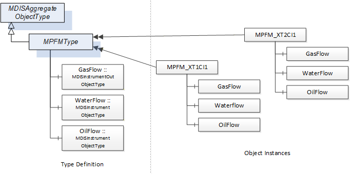
A vendor does not have to generate aggregate Objects; it can just provide a list of the base MDIS Objects that are being exposed. For example, a Well might not be configured as a subtype of MDISAggregateObjectType it might be a folder that contains the MDIS Objects that comprise the Well. If a structure is to be repeated, generating a subtype of the MDISAggregateObjectType for the structure can simplify testing and Client configuration work.
11 Time Synchronisation
MDIS expects system clocks to be time synchronised. NTP is the recommended method for time synchronisation; however use of alternate time synchronisation method is acceptable. For a system where NTP or other similar time synchronization is not available, the time on the Server can be set using the MDISTimeSyncObjectType defined in 6.1.16.
12 Redundancy
12.1 General
This section details requirements to standardise redundancy across the MDIS interface. SPCS and DCS should be connected using two segregated communication channels. Designation of the primary communication channel between the SPCS and DCS shall be controlled at the DCS. Automatic reconnection / recovery in the event of a failed communication channel shall be implemented. Failure of either channel shall generate an alarm at the DCS. Communication configurations other than what is defined here may be used. However, it should be specified elsewhere and should be agreed between all parties prior to implementation. Additional redundancy options including physical and logical configuration should be based on required project availability.
In general, redundant communication between the SPCS and DCS shall:
Facilitate active redundancy which enables a seamless transfer to a secondary controller in the event of a primary controller failure.
Prevent or minimise the loss of subsea production due to a single-component failure or common-mode failure.
The information model available in MDIS OPC UA servers is affected by data arbitration choices (see 5.3.2).
OPC Redundancy is described in the following section.
12.2 OPC UA Redundancy Overview
OPC UA redundancy provides a standard manner for OPC UA Clients to determine which OPC UA Servers are redundant and the status of the Servers. In OPC UA redundant system all redundant servers provide:
an identical information model,
an identical instance address space.
The structures, redundancy objects and redundancy behaviours are described in OPC 10000-4 and further defined in OPC 10000-5.
12.3 OPC UA MDIS Redundancy
The information model (list of Objects Variables…) between redundant Servers is always identical. In an MDIS system, the information (actual values) exposed in a redundant set of OPC UA servers may be identical in some cases. MDIS systems typically include arbitration which is described in Section 5.3.2. The arbitration process can result in Servers in which the Servers have an identical instance address space, but it can also result in Servers that do not have identical instance address space.
12.4 MDIS Minimum Requirements
In all MDIS redundant Servers, the standard Redundancy Objects as described in Part 4 and Part 5 shall be supported. In addition, depending on if the data is identical on the servers the following apply:
On Servers where all data is identical: The server pair shall support either TRANSPARENT_4 redundancy or HOT_3 redundancy or HOT_AND_MIRRORED_5 redundancy including all associated objects and behaviours as described in Part 4 and Part 5.
On Servers where not all data is identical: The Server redundancy type cannot be specified and redundancy support shall always identify as NONE_0.
In both cases the ServerArray in each Server in the redundant set shall list the URL's for all other Servers in the redundant set.
13 Common Information
13.1 Status Codes
Table 124 defines the list of standard Method call error codes generated by a MDIS Server.
| Result Code | Description |
| Good_Completes_Ascynchronously | See OPC 10000-4 for the description of this result code. (The Method id does not refer to a Method for the specified Object.) |
| Bad_MethodInvalid | See OPC 10000-4 for the description of this result code. (The Method id does not refer to a Method for the specified Object.) |
| Bad_NotImplemented | See OPC 10000-4 for the description of this result code. (Requested operation is not implemented.) |
| Bad_NodeIdUnknown | See OPC 10000-4 for the description of this result code. (Used to indicate that the specified Object is not valid) |
| Bad_ArgumentsMissing | See OPC 10000-4 for the description of this result code (The Client did not specify all of the input arguments for the Method.) |
| Bad_TooManyArguments | See OPC 10000-4 for the description of this result code (The Client specified more input arguments than defined for the Method.) |
| Bad_InvalidArgument | See OPC 10000-4 for the description of this result code. (Used to indicate in the operation level results that one or more of the input arguments are invalid. The inputArgumentResults contain the specific status code for each invalid argument.) |
| Bad_TypeMismatch | See OPC 10000-4 for the description of this result code. (Used to indicate that an input argument does not have the correct data type.) |
| Bad_OutOfRange | See OPC 10000-4 for the description of this result code. (Used to indicate that an input argument is outside the acceptable range.) |
| Bad_Timeout | See OPC 10000-4 for the description of this result code. (The operation timed out. - the Server did not respond to the command) |
| Bad_InvalidState | See OPC 10000-4 for the description of this result code. (The operation cannot be completed because the Object is closed, uninitialized or in some other invalid state.) |
| Bad_AccessDenied | See OPC 10000-4 for the description of this result code. (The operation cannot be completed because the server does not allow the client to perform the operation) |
14 Profiles and Conformance Units
14.1 Test requirements
All mandatory Profiles shall be certified and any optional Profiles that are supported should be certified by an OPC Foundation certification authority (see 2.4 for additional details).
14.2 ConformanceUnits
14.2.1 Overview
This section defines ConformanceUnits that are specific to the MDIS information model. These ConformanceUnits are separated into ConformanceUnits that are Server specific and those that are Client specific.
14.2.2 Server
Table 125 defines the Server based ConformanceUnits. These units are related to MDIS information models. Table 126 describes general functionality based ConformanceUnits.
| Category | Title | Description | |
| Server | MDIS Base Fault | Support the Fault flag | |
| Server | MDIS Base FaultCode | Support FaultCodes | |
| Server | MDIS Base Warning | Support the Warning flag | |
| Server | MDIS Base WarningCode | Support WarningCodes | |
| Server | MDIS Base Enabled | Support the Enabled flag and the EnableDisable Method to toggle the flag. | |
| Server | MDIS Base TagId | Support the TagId Property. | |
| Server | MDIS Base Functionality | Supports all required Namespaces, queue sizes greater than 1, notification of queue overflows, NodeId and Namespace restrictions | |
| Valve | |||
|---|---|---|---|
| Server | MDIS Valve Base | Supports the base required aspect of the MDISValveObjectType. This includes position information and the Move Method for basic functionality. The Move Method basic functionality includes Direction, OverrideInterlocks, SEM and ShutdownRequest. | |
| Server | MDIS Valve SignatureRequestStatus | Supports providing information about an existing signature/profile requests, including the request of a profile/signature via the Move command. | |
| Server | MDIS Valve CommandRejected | Supports the CommandRejected | |
| Server | MDIS Valve LastCommand | Supports the LastCommand. | |
| Server | MDIS Valve DefeatableCloseInterlock | Supports information related to DefeatableCloseInterlock. This includes DefeatableCloseInterlock flag and providing at least one InterlockFor reference to a Variable of InterlockVariableType. | |
| Server | MDIS Valve DefeatableOpenInterlock | Supports information related to DefeatableOpenInterlock. This includes DefeatableOpenInterlock flag and providing at least one InterlockFor reference to a Variable of InterlockVariableType. | |
| Server | MDIS Valve NonDefeatableCloseInterlock | Supports information related to NonDefeatableCloseInterlock. This includes NonDefeatableCloseInterlock flag and providing at least one InterlockFor reference to a Variable of InterlockVariableType. | |
| Server | MDIS Valve NonDefeatableOpenInterlock | Supports information related to NonDefeatableOpenInterlock. This includes NonDefeatableCloseInterlock flag and providing at least one InterlockFor reference to a variable of InterlockVariableType. | |
| Server | MDIS Valve Duration | Supports the inclusion of OpenTimeDuration and CloseTimeDuration duration information for the valve. | |
| Instrument | |||
|---|---|---|---|
| Server | MDIS Instrument Base | Supports the base required aspect of the MDISInstrumentObjectType. This includes the ProcessVariable. The ProcessVariable includes EURange and EngineeringUnits | |
| Server | MDIS Instrument Limits | Supports at least one of the following limit flags: HHlimit, Hlimit, Llimit, LLlimit. The actual list of supported limits is reported as part of the ConformanceUnit. | |
| Server | MDIS Instrument Setpoints | Supports at least one of the following set points: HHSetPoint, HSetPoint, LSetPoint, LLSetPoint. The actual list of supported setpoints is reported as part of the ConformanceUnit. | |
| Instrument Out | |||
|---|---|---|---|
| Server | MDIS Instrument Out Base | Supports the base required aspect of the MDISInstrumentOutObjectType. This includes the ProcessVariable of the Object and the WriteValue Method. | |
| Instrument Arbitration | |||
|---|---|---|---|
| Server | MDIS Instrument Arbitration Base | Supports the required aspect of the MDISInstrumentArbitrationObjectType. This includes the SourceA, SourceB and the ArbitrationMode of the Object. | |
| Server | MDIS Instrument Arbitration Mode | Supports the optional SetArbitrationMode Method of the MDISInstrumentArbitrationObjectType. | |
| Server | MDIS Instrument Arbitration Discrepancy | Supports the optional DiscrepancySetPoint of the MDISInstrumentArbitrationObjectType. | |
| Discrete Instrument | |||
|---|---|---|---|
| Server | MDIS Discrete Instrument Base | Supports the base required aspect of the MDISDiscreteInstrumentObjectType. This includes the State of the Object. | |
| Discrete Instrument Out | |||
|---|---|---|---|
| Server | MDIS Discrete Out Base | Supports the base required aspect of the MDISDiscreteOutObjectType. This includes the State of the Object and the WriteValue Method. | |
| Discrete Arbitration Instrument | |||
|---|---|---|---|
| Server | MDIS Discrete Arbitration | Supports the required aspect of the MDISDiscreteArbitrationObjectType. This includes the SourceA, SourceB and the ArbitrationMode of the Object | |
| Server | MDIS Discrete Arbitration Mode | Supports the SetArbitrationMode method in the MDISDiscreteArbitrationObjectType | |
| Digital Instrument | |||
|---|---|---|---|
| Server | MDIS Digital Instrument Base | Supports the base required aspect of the MDISDigitalInstrumentObjectType. This includes the State of the Object. | |
| Digital Instrument Out | |||
|---|---|---|---|
| Server | MDIS Digital Out Base | Supports the base required aspect of the MDISDigitalOutObjectType. This includes the State of the Object and the WriteState Method. | |
| Digital Arbitration Instrument | |||
|---|---|---|---|
| Server | MDIS Digital Arbitration | Supports the required aspect of the MDISDigitalArbitrationObjectType. This includes the SourceA, SourceBand the ArbitrationMode of the Object | |
| Server | MDIS Digital Arbitration Mode | Supports the SetArbitrationMode method in the MDISDigitalArbitrationObjectType | |
| Choke | |||
|---|---|---|---|
| Server | MDIS Choke Base | Supports the base required aspect of the MDISChokeObjectType. This includes CalculatedPosition information, Moving flag, the Move Method (ChokeMove Method), Abort Method (ChokeAbort Method), The Move Method basic functionality includes Position, OverrideInterlocks and SEM. The SetCalculatedPosition Method basic functionality includes CalculatedPosition and if required the SetCalculatedPositionStatus | |
| Server | MDIS Choke SetCalculatedPositionStatus | Supports the optional variable SetCalculatedPositionStatus | |
| Server | MDIS Choke CommandRejected | Supports the CommandRejected. | |
| Server | MDIS Choke DefeatableCloseInterlock | Supports the optional aspect of the MDISChokeObjectType related to DefeatableCloseInterlock. This includes DefeatableCloseInterlock flag and providing at least one InterlockFor reference to a Variable of InterlockVariableType. | |
| Server | MDIS Choke DefeatableOpenInterlock | Supports the optional aspect of the MDISChokeObjectType related to DefeatableOpenInterlock. This includes DefeatableOpenInterlock flag and providing at least one InterlockFor reference to a Variable of InterlockVariableType. | |
| Server | MDIS Choke NonDefeatableCloseInterlock | Supports the optional aspect of the MDISChokeObjectType related to NonDefeatableCloseInterlock. This includes NonDefeatableCloseInterlock flag and providing at least one InterlockFor reference to a Variable of InterlockVariableType. | |
| Server | MDIS Choke NonDefeatableOpenInterlock | Supports the optional aspect of the MDISChokeObjectType related to NonDefeatableOpenInterlock. This includes NonDefeatableOpenInterlock flag and providing at least one InterlockFor reference to a Variable of InterlockVariableType. | |
| Server | MDIS Choke Step Duration | Supports the inclusion of StepDurationOpen and StepDurationClose time information for the MDISChokeObjectType. | |
| Server | MDIS Choke Total Steps | Supports the inclusion of the TotalSteps for the MDISChokeObjectType. | |
| Server | MDIS Choke Step Method | Supports the inclusion of the Step (ChokeStepMethod) and the PositionInSteps for the MDISChokeObjectType. The Step Method basic functionality includes Direction, Steps, OverrideInterlocks and SEM. | |
| Electric Choke | |||
|---|---|---|---|
| Server | MDIS Electric Choke Base | Supports the base required aspect of the MDISElectricChokeObjectType. This includes ActualPosition information, Moving flag, the Move Method, Abort Method, The Move Method basic functionality includes Position, OverrideInterlocks and SEM. | |
| Server | MDIS Electric Choke CommandRejected | Supports the CommandRejected. | |
| Server | MDIS Electric Choke DefeatableCloseInterlock | Supports the optional aspect of the MDISElectricChokeObjectType related to DefeatableCloseInterlock. This includes DefeatableCloseInterlock flag and providing at least one InterlockFor reference to a Variable of InterlockVariableType. | |
| Server | MDIS Electric Choke DefeatableOpenInterlock | Supports the optional aspect of the MDISElectricChokeObjectType related to DefeatableOpenInterlock. This includes DefeatableOpenInterlock flag and providing at least one InterlockFor reference to a Variable of InterlockVariableType. | |
| Server | MDIS Electric Choke NonDefeatableCloseInterlock | Supports the optional aspect of the MDISElectricChokeObjectType related to NonDefeatableCloseInterlock. This includes NonDefeatableCloseInterlock flag and providing at least one InterlockFor reference to a Variable of InterlockVariableType. | |
| Server | MDIS Electric Choke NonDefeatableOpenInterlock | Supports the optional aspect of the MDISElectricChokeObjectType related to NonDefeatableOpenInterlock. This includes NonDefeatableOpenInterlock flag and providing at least one InterlockFor reference to a Variable of InterlockVariableType. | |
| Motor | |||
|---|---|---|---|
| Server | MDIS Motor Base | Supports the base required aspect of the MDISMotorObjectType. This includes running flag. | |
| Server | MDIS Motor SetOperation | Supports the optional aspect of the MDISMotorObjectType related to Operation, this includes the SetOperation Method. | |
| Server | MDIS Motor Start/Stop | Supports the optional Start and Stop Methods of the MDISMotorObjectType, this includes supporting Manual Operation. | |
| Server | MDIS Motor DefeatableStartInterlock | Supports the optional aspect of the MDISMotorObjectType related to DefeatableStartInterlock. This includes DefeatableStartInterlock flag and providing at least one InterlockFor reference to a Variable of InterlockVariableType. | |
| Server | MDIS Motor DefeatableStopInterlock | Supports the optional aspect of the MDISMotorObjectType related to DefeatableStopInterlock. This includes DefeatableStopInterlock flag and providing at least one InterlockFor reference to a Variable of InterlockVariableType. | |
| Server | MDIS Motor NonDefeatableStartInterlock | Supports the optional aspect of the MDISMotorObjectType related to NonDefeatableStartInterlock. This includes NonDefeatableStartInterlock flag and providing at least one InterlockFor reference to a Variable of InterlockVariableType. | |
| Server | MDIS Motor NonDefeatableStopInterlock | Supports the optional aspect of the MDISMotorObjectType related to NonDefeatableStopInterlock. This includes NonDefeatableStopInterlock flag and providing at least one InterlockFor reference to a Variable of InterlockVariableType. | |
| CIMV | |||
|---|---|---|---|
| Server | MDIS CIMV Base | Supports the OperationMode, FlowRate, TargetFlowRate, Position, TargetPosition and Moving variable, as well as the SetFlowRate, SetPosition and Stop methods. | |
| Server | MDIS CIMV TotalFlow | Supports the TotalFlow variable and the ResetTotalFlow method | |
| Server | MDIS CIMV TotalMotorRuntime | Supports the TotalMotorRuntime counter, include all feature of the MDISCounterObjectType | |
| Server | MDIS CIMV MotorOperationsCount | Supports the MotorOperationsCount counter, include all feature of the MDISCounterObjectType | |
| Server | MDIS CIMV DeviceCurrent | Supports the DeviceCurrent variable | |
| Server | MDIS CIMV InletPressure | Supports the InletPressure variable | |
| Server | MDIS CIMV InternalPressure | Supports the InternalPressure variable | |
| Server | MDIS CIMV OutletPressure | Supports the OutletPressure variable | |
| Server | MDIS CIMV CommandRejected | Supports the CommandRejected flag | |
| Server | MDIS CIMV SetManual | Supports the SetManual Method | |
| Server | MDIS CIMV NonDefeatableCloseInterlock | Supports the optional aspect of the MDISCIMVObjectType related to NonDefeatableCloseInterlock. This includes NonDefeatableCloseInterlock flag and providing at least one InterlockFor reference to a Variable of InterlockVariableType. | |
| Server | MDIS CIMV NonDefeatableOpenInterlock | Supports the optional aspect of the MDISCIMVObjectType related to NonDefeatableOpenInterlock. This includes NonDefeatableOpenInterlock flag and providing at least one InterlockFor reference to a Variable of InterlockVariableType. | |
| Server | MDIS CIMV NonDefeatableCommandInProgressInterlock | Supports the optional aspect of the MDISCIMVObjectType related to NonDefeatableCommandInProgressInterlock. This includes providing at least one InterlockFor reference to a Variable of InterlockVariableType.. | |
| Counter | |||
|---|---|---|---|
| Server | MDIS Counter Object | Supports the MDISCounterObjectType | |
| Server | MDIS Counter SetCount method | Supports the SetCount method in the MDISCounterObjectType | |
| TimeSync Object | |||
|---|---|---|---|
| Server | MDIS Timesync Object | Supports the MDISTimeSyncObjectType Object, including allowing a client to set the server time. | |
| Information | |||
|---|---|---|---|
| Server | MDIS Information version | Supports version information for the MDIS Server | |
| Server | MDIS Information Signatures | Supports providing Signatures as FileType Objects | |
| Server | MDIS Information Signature Validation | Supports the JSON schema for the Signature file objects. | |
| Performance | |||
|---|---|---|---|
| Server | MDIS Performance Datasheet | The server provides a datasheet that describes performance and the datasheet has been verified | |
| Category | Title | Description |
| Server | MDIS Redundancy Base | Supports one of the optional redundancy behaviours |
| Server | MDIS Redundancy None | Supports MDIS defined side by side redundancy. Server can provide side by side redundant data as specified including identical NodeIds or naming conventions as required. |
| Server | MDIS Redundancy Hot | Supports the OPC UA defined redundancy concept of "Hot" |
| Server | MDIS Redundancy HotPlusMirrored | Supports the OPC UA defined redundancy concept of "HotPlusMirrored" |
| Server | MDIS Redundancy Transparent | Supports the OPC UA defined redundancy concept of "Transparent" |
| Category | Title | Description |
| Server | MDIS Aggregate Object | The MDIS Server supports aggregate Objects based on MDISAggregateObjectType. |
| Server | MDIS Extension | The Server defines new ObjectTypes that are extensions of the existing MDIS ObjectTypes (MDISValveObjectType, MDISChokeObjectType, MDISDigitalInstrumentObjectType, MDISDiscreteInstrumentObjectType, MDISInstrumentObjectType or any subtype of these types). |
14.2.3 Client
Table 128 defines the Client based ConformanceUnits. These units are related to MDIS InformationModels.
Table 129 describes general functionality based ConformanceUnits
| Category | Title | Description |
| Client | MDIS Client Base Fault | The Client actively monitors the value of the Fault flag and reports the value. |
| Client | MDIS Client Base FaultCode | The Client displays or reports FaultCode. |
| Client | MDIS Client Base Warning | The Client makes use of and displays or reports the Warning flag. |
| Client | MDIS Client Base WarningCode | The Client displays or reports WarningCode. |
| Client | MDIS Client Base Enabled | The Client makes use of and displays or reports the Enabled flag and the EnableDisable Method. |
| Client | MDIS Client Base TagId | The Client can display or report the TagId Property. |
| Valve | ||
|---|---|---|
| Client | MDIS Valve Client Base | Uses the base required aspect of the MDISValveObjectType. This includes position information and the Move Method for basic functionality. The Move Method basic functionality includes Direction, OverrideInterlocks, SEM and ShutdownRequest. |
| Client | MDIS Valve Client CommandRejected | Makes use of CommandRejected. |
| Client | MDIS Valve Client SignatureRequestStatus | Makes use of signature/profile information and asks for signature/profile via the Move command. |
| Client | MDIS Valve Client LastCommand | Makes use of the LastCommand. |
| Client | MDIS Valve Client DefeatableCloseInterlock | Makes use of information related to DefeatableCloseInterlock. This includes DefeatableCloseInterlock flag and examining the instance of InterlockVariableType referenced by the InterlockFor reference. |
| Client | MDIS Valve Client DefeatableOpenInterlock | Makes use of information related to DefeatableOpenInterlock. This includes DefeatableOpenInterlock flag and examining the instance of InterlockVariableType reference by the InterlockFor reference. |
| Client | MDIS Valve Client NonDefeatableCloseInterlock | Makes use of information related to NonDefeatableCloseInterlock. This includes NonDefeatableCloseInterlock flag and examining the instance of InterlockVariableType reference by the InterlockFor reference. |
| Client | MDIS Valve Client NonDefeatableOpenInterlock | Makes use of information related to NonDefeatableOpenInterlock. This includes NonDefeatableOpenInterlock flag and examining the instance of InterlockVariableType reference by the InterlockFor reference. |
| Client | MDIS Valve Client Duration | Makes use of the OpenTimeDuration and CloseTimeDuration duration information for the valve. |
| Instrument | ||
|---|---|---|
| Client | MDIS Instrument Client Base | Makes use of the base required aspects of instance of the MDISInstrumentObjectType. This includes the ProcessVariable. |
| Client | MDIS Instrument Client Limits | Makes use of at least one of the following limit flags: HHlimit, Hlimit, Llimit, LLlimit. |
| Client | MDIS Instrument Client Setpoints | Makes use of at least one of the following set points: HHSetPoint, HSetPoint, LSetPoint, LLSetPoint. |
| Instrument Out | ||
|---|---|---|
| Client | MDIS Instrument Out Client Base | Makes use of the base required aspect of the MDISInstrumentOutObjectType. This includes the ProcessVariable of the Object and the WriteValue Method. |
| Instrument Arbitration | ||
|---|---|---|
| Client | MDIS Instrument Client Arbitration Base | Makes use of the base required aspect of the MDISInstrumentArbitrationObjectType. This includes the ProcessVariable, SourceA, SourceB and Mode of the Object and the SetArbitrationMode Method. |
| Client | MDIS Instrument Client Arbitration Mode | Make use of the optional SetArbitrationMode Method of the MDISInstrumentArbitrationObjectType. |
| Client | MDIS Instrument Client Arbitration Discrepancy | Makes use of the optional DiscrepancySetPoint of the MDISInstrumentArbitrationObjectType. |
| Discrete | ||
|---|---|---|
| Client | MDIS Discrete Instrument Client Base | Makes use of the base required aspect of the MDISDiscreteInstrumentObjectType. This includes the State of the Object. |
| Discrete Out | ||
|---|---|---|
| Client | MDIS Discrete Out Client Base | Makes use of the base required aspect of the MDISDiscreteOutObjectType. This includes the State of the Object and the WriteValue Method. |
| Discrete Arbitration | ||
| Client | MDIS Discrete Client Arbitration | Makes use of the required aspect of the MDISDiscreteArbitrationObjectType. This includes the SourceA, SourceB, SetArbitrationMode and the ArbitrationMode of the Object |
| Digital | ||
|---|---|---|
| Client | MDIS Digital Instrument Client Base | Makes use of the base required aspect of the MDISDigitalInstrumentObjectType. This includes the State of the Object. |
| Digital Out | ||
|---|---|---|
| Client | MDIS Digital Out Client Base | Makes use of the base required aspect of the MDISDigitalOutObjectType. This includes the State of the Object and the WriteState Method. |
| Digital Arbitration | ||
| Client | MDIS Digital Client Arbitration | Makes use of the required aspect of the MDISDigitalArbitrationObjectType. This includes the SourceA, SourceB, SetArbitrationMode and the ArbitrationMode of the Object |
| Choke | ||
|---|---|---|
| Client | MDIS Choke Client Base | Makes use of the base required aspect of the MDISChokeObjectType. This includes CalculatedPosition information, Moving flag, the Move (ChokeMoveMethod), Abort (ChokeAbortMethod), SetCalculatedPosition (ChokeSetCalculatedPositionMethod). The Move Method basic functionality includes Position, OverrideInterlocks and SEM, The SetCalculatedPosition Method basic functionality includes CalculatedPosition and if required the SetCalculatePositionStatus. |
| Client | MDIS Choke Client CommandRejected | Makes use of CommandRejected. |
| Client | MDIS Choke Client DefeatableCloseInterlock | Makes use of information related to DefeatableCloseInterlock. This includes DefeatableCloseInterlock flag and examining the instance of InterlockVariableType referenced by the InterlockFor reference. |
| Client | MDIS Choke Client DefeatableOpenInterlock | Makes use of information related to DefeatableOpenInterlock. This includes DefeatableOpenInterlock flag and examining the instance of InterlockVariableType referenced by the InterlockFor reference. |
| Client | MDIS Choke Client NonDefeatableCloseInterlock | Makes use of information related to NonDefeatableCloseInterlock. This includes NonDefeatableCloseInterlock flag and examining the instance of InterlockVariableType referenced by the InterlockFor reference. |
| Client | MDIS Choke Client NonDefeatableOpenInterlock | Makes use of information related to NonDefeatableOpenInterlock. This includes NonDefeatableOpenInterlock flags and examining the instance of InterlockVariableType referenced by the InterlockFor reference. |
| Client | MDIS Choke Client Step duration | Makes use of the StepDurationOpen and StepDurationClose time information for the MDISChokeObjectType. |
| Client | MDIS Choke Client Total Steps | Makes use of the TotalSteps for the MDISChokeObjectType. |
| Client | MDIS Choke Client Step method | Makes use of the Step (ChokeStep Method) and the PositionInSteps for the Choke. The Step Method basic functionality includes Direction, Steps, OverrideInterlocks and SEM. |
| Electric Choke | ||
| Client | MDIS Electric Choke Client Base | Makes use of the base required aspect of the MDISElectricChokeObjectType. This includes ActualPosition information, Moving flag, the Move Method, Abort Method, The Move Method basic functionality includes Position, OverrideInterlocks and SEM. |
| Client | MDIS Electric Choke Client CommandRejected | Makes use of CommandRejected. |
| Client | MDIS Electric Choke Client DefeatableCloseInterlock | Makes use of the optional aspect of the MDISElectricChokeObjectType related to DefeatableCloseInterlock. This includes examining the instance of DefeatableCloseInterlock referenced by InterlockFor ReferenceType |
| Client | MDIS Electric Choke Client DefeatableOpenInterlock | Makes use of the optional aspect of the MDISElectricChokeObjectType related to DefeatableOpenInterlock. This includes examining the instance of DefeatableOpenInterlock referenced by InterlockFor ReferenceType. |
| Client | MDIS Electric Choke Client NonDefeatableCloseInterlock | Makes use of the optional aspect of the MDISElectricChokeObjectType related to NonDefeatableCloseInterlock. This includes examining the instance of NonDefeatableCloseInterlock referenced by InterlockFor ReferenceType. |
| Client | MDIS Electric Choke Client NonDefeatableOpenInterlock | Makes use of the optional aspect of the MDISElectricChokeObjectType related to NonDefeatableOpenInterlock. This includes examining the instance of NonDefeatableOpenInterlock referenced by InterlockFor ReferenceType. |
| Motor | ||
| Client | MDIS Motor Client Base | Makes use of the base required aspect of the MDISMotorObjectType. This includes running flag. |
| Client | MDIS Motor Client SetOperation | Makes use of the optional aspect of the MDISMotorObjectType related to Operation, including the SetOperation Method. |
| Client | MDIS Motor Client Start/Stop | Makes use of the Start / Stop Method aspects of the MDISMotorObjectType |
| Client | MDIS Motor Client DefeatableStartInterlock | Makes use of the optional aspect of the MDISMotorObjectType related to DefeatableStartInterlock. This includes DefeatableStartInterlock flag and providing at least one InterlockFor reference to a Variable of InterlockVariableType. |
| Client | MDIS Motor Client DefeatableStopInterlock | Makes use of the optional aspect of the MDISMotorObjectType related to DefeatableStopInterlock. This includes DefeatableStopInterlock flag and providing at least one InterlockFor reference to a Variable of InterlockVariableType. |
| Client | MDIS Motor Client NonDefeatableStartInterlock | Makes use of the optional aspect of the MDISMotorObjectType related to NonDefeatableStartInterlock. This includes NonDefeatableStartInterlock flag and providing at least one InterlockFor reference to a Variable of InterlockVariableType. |
| Client | MDIS Motor Client NonDefeatableStopInterlock | Makes use of the optional aspect of the MDISMotorObjectType related to NonDefeatableStopInterlock. This includes NonDefeatableStopInterlock flag and providing at least one InterlockFor reference to a Variable of InterlockVariableType. |
| CIMV | ||
|---|---|---|
| Client | MDIS CIMV Client Base | Makes use of the OperationMode, FlowRate, TargetFlowRate, Position, TargetPosition and Moving variable, as well as the SetFlowRate, SetPosition and Stop methods. |
| Client | MDIS CIMV Client TotalFlow | Makes use of the TotalFlow variable and the ResetTotalFlow method |
| Client | MDIS CIMV Client TotalMotorRuntime | Makes use of the TotalMotorRuntime counter, include all feature of the MDISCounterObjectType |
| Client | MDIS CIMV Client MotorOperationsCount | Makes use of the MotorOperationsCount counter, include all feature of the MDISCounterObjectType |
| Client | MDIS CIMV Client DeviceCurrent | Makes use of the DeviceCurrent variable |
| Client | MDIS CIMV Client InletPressure | Makes use of the InletPressure variable |
| Client | MDIS CIMV Client InternalPressure | Makes use of the InternalPressure variable |
| Client | MDIS CIMV Client OutletPressure | Makes use of the OutletPressure variable |
| Client | MDIS CIMV Client CommandRejected | Makes use of the CommandRejected flag |
| Client | MDIS CIMV Client SetManual | Makes use of the SetManual Method |
| Client | MDIS CIMV Client NonDefeatableCloseInterlock | Makes use of the optional aspect of the MDISCIMVObjectType related to NonDefeatableCloseInterlock. This includes NonDefeatableCloseInterlock flag and providing at least one InterlockFor reference to a Variable of InterlockVariableType. |
| Client | MDIS CIMV Client NonDefeatableOpenInterlock | Makes use of the optional aspect of the MDISCIMVObjectType related to NonDefeatableOpenInterlock. This includes NonDefeatableOpenInterlock flag and providing at least one InterlockFor reference to a Variable of InterlockVariableType. |
| Client | MDIS CIMV Client NonDefeatableCommandInProgressInterlock | Makes use of the optional aspect of the MDISCIMVObjectType related to NonDefeatableCommandInProgressInterlock. This includes providing at least one InterlockFor reference to a Variable of InterlockVariableType. |
| Counter | ||
|---|---|---|
| Client | MDIS Counter Client Object | Makes use of the MDISCounterObjectType |
| Client | MDIS Counter Client SetCount method | Makes use of the SetCount method in the MDISCounterObjectType |
| TimeSync Object | ||
|---|---|---|
| Client | MDIS TimeSync Client | Can be configured to call the SetTime method on the MDISTimeSyncObjectType Object at a periodic rate, providing time synchronization to the server |
| Information | ||
|---|---|---|
| Client | MDIS Signature Client | The Client can access the instance of FileType objects to obtain signatures |
| Client | MDIS Information Client | The Client makes use of the version information to identify supported functionality of the server, including handling server that are of different versions. |
| Client | MDIS Information Client Signature Validation | The Client makes use of the JSON schema for the validation of Signature file objects. |
| Performance | ||
| Client | MDIS Performance Client Datasheet | The client provides a datasheet that describes performance and the datasheet has been verified |
| Category | Title | Description |
| Client | MDIS Client Redundancy | Can communicate with a MDIS Server that transmits data redundantly. Selecting appropriate channel, handling Server failovers and generally supporting all specified actions. |
| Category | Title | Description |
| Client | MDIS Client Aggregate | The Client can process and / or display information from an instance of an MDISAggregateObjectType subtype on a Server. |
| Client | MDIS Client Extension | The Client can process and / or display information from an instance of Extension types defined by the Server. This includes extension to all of the existing type and subtypes of them. |
| Client | MDIS Client Extension Extra | The Client can process and / or display information from the extended fields in an Extension Object defined in a Server, without programming changes, i.e. only requiring configuration changes |
14.3 Profiles
14.3.1 Profile list
The section describes the various Facets that are provided as part of the MDIS OPC UA InformationModel. These Facets include MDIS InformationModel ConformanceUnits, but they also include ConformanceUnits or Facets from the OPC 10000-7 specification. They are summarised in Table 131
14.3.2 Server Facets
14.3.2.1 MDIS Base Functionality Server Facet
Table 132 defines a Facet that describes the base characteristics that all OPC UA Servers shall support, if they support the MDIS companion specification.
| Group | Conformance Unit / Profile Title | Optional |
| Profile | Standard DataChange Subscription Server Facet | |
| Profile | Core Server Facet | |
| Profile | UA-TCP UA-SC UA Binary | |
| Profile | Data Access Server Facet | |
| Monitored Item Services | Monitor MinQueueSize_05 | False |
| Profile | Method Server Facet | |
| Profile | Security Time Synchronization | |
| MDIS Base | MDIS Base Functionality | False |
| MDIS Base | MDIS Information Version | True |
This Profile includes a number of Profiles and ConformanceUnits.
14.3.2.2 MDIS Valve Model Server Facet
Table 133 defines a Facet that describes the base characteristics for an OPC UA Server that is exposing the MDISValveObjectType model.
| Group | Conformance Unit / Profile Title | Optional |
| MDIS Base | MDIS Base Fault | False |
| MDIS Base | MDIS Base FaultCode | True |
| MDIS Base | MDIS Base Warning | True |
| MDIS Base | MDIS Base WarningCode | True |
| MDIS Base | MDIS Base Enabled | True |
| MDIS Base | MDIS Base TagId | True |
| MDIS Valve | MDIS Valve Base | False |
| MDIS Valve | MDIS Valve CommandRejected | True |
| MDIS Valve | MDIS Valve SignatureRequestStatus | True |
| MDIS Valve | MDIS Valve LastCommand | True |
| MDIS Valve | MDIS Valve DefeatableCloseInterlock | True |
| MDIS Valve | MDIS Valve DefeatableOpenInterlock | True |
| MDIS Valve | MDIS Valve NonDefeatableCloseInterlock | True |
| MDIS Valve | MDIS Valve NonDefeatableOpenInterlock | True |
| MDIS Valve | MDIS Valve Duration | True |
| MDIS Base | MDIS Information Signatures | True |
14.3.2.3 MDIS Instrument Model Server Facet
Table 134 defines a Facet that describes the base characteristics for an OPC UA Server that is exposing the MDISInstrumentObjectType model.
| Group | Conformance Unit / Profile Title | Optional |
| MDIS Base | MDIS Base Fault | False |
| MDIS Base | MDIS Base FaultCode | True |
| MDIS Base | MDIS Base Warning | True |
| MDIS Base | MDIS Base WarningCode | True |
| MDIS Base | MDIS Base Enabled | True |
| MDIS Base | MDIS Base TagId | True |
| MDIS Instrument | MDIS Instrument Base | False |
| MDIS Instrument | MDIS Instrument Limits | True |
| MDIS Instrument | MDIS Instrument Setpoints | True |
14.3.2.4 MDIS Instrument Out Model Server Facet
Table 135 defines a Facet that describes the base characteristics for an OPC UA Server that is exposing the MDISInstrumentOutObjectType model.
| Group | Conformance Unit / Profile Title | Optional |
| MDIS Base | MDIS Base Fault | False |
| MDIS Base | MDIS Base FaultCode | True |
| MDIS Base | MDIS Base Warning | True |
| MDIS Base | MDIS Base WarningCode | True |
| MDIS Base | MDIS Base Enabled | True |
| MDIS Base | MDIS Base TagId | True |
| MDIS Instrument | MDIS Instrument Out Base | False |
| MDIS Instrument | MDIS Instrument Limits | True |
| MDIS Instrument | MDIS Instrument Set points | True |
14.3.2.5 MDIS Instrument Arbitration Model Server Facet
Table 135 defines a Facet that describes the base characteristics for an OPC UA Server that is exposing the MDISInstrumentArbitrationObjectType model.
| Group | Conformance Unit / Profile Title | Optional |
| MDIS Base | MDIS Base Fault | False |
| MDIS Base | MDIS Base FaultCode | True |
| MDIS Base | MDIS Base Warning | True |
| MDIS Base | MDIS Base WarningCode | True |
| MDIS Base | MDIS Base Enabled | True |
| MDIS Base | MDIS Base TagId | True |
| MDIS Instrument | MDIS Instrument Arbitration Base | False |
| MDIS Instrument | MDIS Instrument Arbitration Mode | True |
| MDIS Instrument | MDIS Instrument Arbitration Discrepancy | True |
| MDIS Instrument | MDIS Instrument Limits | True |
| MDIS Instrument | MDIS Instrument Set points | True |
14.3.2.6 MDIS Discrete Model Server Facet
Table 137 defines a Facet that describes the base characteristics for an OPC UA Server that is exposing the MDISDiscreteInstrumentObjectType model.
| Group | Conformance Unit / Profile Title | Optional |
| MDIS Base | MDIS Base Fault | False |
| MDIS Base | MDIS Base FaultCode | True |
| MDIS Base | MDIS Base Warning | True |
| MDIS Base | MDIS Base WarningCode | True |
| MDIS Base | MDIS Base Enabled | True |
| MDIS Base | MDIS Base TagId | True |
| MDIS Instrument | MDIS Discrete Instrument Base | False |
14.3.2.7 MDIS Discrete Out Model Server Facet
Table 138 defines a Facet that describes the base characteristics for an OPC UA Server that is exposing the MDISDiscreteOutObjectType model.
| Group | Conformance Unit / Profile Title | Optional |
| MDIS Base | MDIS Base Fault | False |
| MDIS Base | MDIS Base FaultCode | True |
| MDIS Base | MDIS Base Warning | True |
| MDIS Base | MDIS Base WarningCode | True |
| MDIS Base | MDIS Base Enabled | True |
| MDIS Base | MDIS Base TagId | True |
| MDIS Instrument | MDIS Discrete Out Base | False |
14.3.2.8 MDIS Discrete Arbitration Model Server Facet
Table 138 defines a Facet that describes the base characteristics for an OPC UA Server that is exposing the MDISDiscreteArbitrationObjectType model.
| Group | Conformance Unit / Profile Title | Optional |
| MDIS Base | MDIS Base Fault | False |
| MDIS Base | MDIS Base FaultCode | True |
| MDIS Base | MDIS Base Warning | True |
| MDIS Base | MDIS Base WarningCode | True |
| MDIS Base | MDIS Base Enabled | True |
| MDIS Base | MDIS Base TagId | True |
| MDIS Instrument | MDIS Discrete Arbitration Base | False |
| MDIS Instrument | MDIS Discrete Arbitration Mode | True |
14.3.2.9 MDIS Digital Model Server Facet
Table 140 defines a Facet that describes the base characteristics for an OPC UA Server that is exposing the MDISDigitalInstrumentObjectType.
| Group | Conformance Unit / Profile Title | Optional |
| MDIS Base | MDIS Base Fault | False |
| MDIS Base | MDIS Base FaultCode | True |
| MDIS Base | MDIS Base Warning | True |
| MDIS Base | MDIS Base WarningCode | True |
| MDIS Base | MDIS Base Enabled | True |
| MDIS Base | MDIS Base TagId | True |
| MDIS Instrument | MDIS Digital Instrument Base | False |
| MDIS Instrument | MDIS Digital Arbitration Mode | True |
14.3.2.10 MDIS Digital Out Model Server Facet
Table 141 defines a Facet that describes the base characteristics for an OPC UA Server that is exposing the MDISDigitalOutObjectType.
| Group | Conformance Unit / Profile Title | Optional |
| MDIS Base | MDIS Base Fault | False |
| MDIS Base | MDIS Base FaultCode | True |
| MDIS Base | MDIS Base Warning | True |
| MDIS Base | MDIS Base WarningCode | True |
| MDIS Base | MDIS Base Enabled | True |
| MDIS Base | MDIS Base TagId | True |
| MDIS Instrument | MDIS Digital Out Base | False |
14.3.2.11 MDIS Digital Arbitration Model Server Facet
Table 141 defines a Facet that describes the base characteristics for an OPC UA Server that is exposing the MDISDigitalArbitrationObjectType.
| Group | Conformance Unit / Profile Title | Optional |
| MDIS Base | MDIS Base Fault | False |
| MDIS Base | MDIS Base FaultCode | True |
| MDIS Base | MDIS Base Warning | True |
| MDIS Base | MDIS Base WarningCode | True |
| MDIS Base | MDIS Base Enabled | True |
| MDIS Base | MDIS Base TagId | True |
| MDIS Instrument | MDIS Digital Arbitration Base | False |
14.3.2.12 MDIS Choke Model Server Facet
Table 143 defines a Facet that describes the base characteristics for an OPC UA Server that is exposing the MDISChokeObjectType.
| Group | Conformance Unit / Profile Title | Optional |
| MDIS Base | MDIS Base Fault | False |
| MDIS Base | MDIS Base FaultCode | True |
| MDIS Base | MDIS Base Warning | True |
| MDIS Base | MDIS Base WarningCode | True |
| MDIS Base | MDIS Base Enabled | True |
| MDIS Base | MDIS Base TagId | True |
| MDIS Choke | MDIS Choke Base | False |
| MDIS Choke | MDIS Choke DefeatableCloseInterlock | True |
| MDIS Choke | MDIS Choke DefeatableOpenInterlock | True |
| MDIS Choke | MDIS Choke NonDefeatableCloseInterlock | True |
| MDIS Choke | MDIS Choke NonDefeatableOpenInterlock | True |
| MDIS Choke | MDIS Choke Step Duration | True |
| MDIS Choke | MDIS Choke Total Steps | True |
| MDIS Choke | MDIS Choke Step method | True |
| MDIS Choke | MDIS Choke CommandRejected | True |
| MDIS Choke | MDIS Choke SetCalculatedPositionStatus | True |
14.3.2.13 MDIS Electric Choke Model Server Facet
Table 143 defines a Facet that describes the base characteristics for an OPC UA Server that is exposing the MDISElectricChokeObjectType.
| Group | Conformance Unit / Profile Title | Optional |
| MDIS Base | MDIS Base Fault | False |
| MDIS Base | MDIS Base FaultCode | True |
| MDIS Base | MDIS Base Warning | True |
| MDIS Base | MDIS Base WarningCode | True |
| MDIS Base | MDIS Base Enabled | True |
| MDIS Base | MDIS Base TagId | True |
| MDIS Electric Choke | MDIS Electric Choke Base | False |
| MDIS Electric Choke | MDIS Electric Choke DefeatableCloseInterlock | True |
| MDIS Electric Choke | MDIS Electric Choke DefeatableOpenInterlock | True |
| MDIS Electric Choke | MDIS Electric Choke NonDefeatableCloseInterlock | True |
| MDIS Electric Choke | MDIS Electric Choke NonDefeatableOpenInterlock | True |
| MDIS Electric Choke | MDIS Electric Choke CommandRejected | True |
14.3.2.14 MDIS Motor Model Server Facet
Table 143 defines a Facet that describes the base characteristics for an OPC UA Server that is exposing the MDISMotorObjectType.
| Group | Conformance Unit / Profile Title | Optional |
| MDIS Base | MDIS Base Fault | False |
| MDIS Base | MDIS Base FaultCode | True |
| MDIS Base | MDIS Base Warning | True |
| MDIS Base | MDIS Base WarningCode | True |
| MDIS Base | MDIS Base Enabled | True |
| MDIS Base | MDIS Base TagId | True |
| MDIS Motor | MDIS Motor Base | False |
| MDIS Motor | MDIS Motor DefeatableStartInterlock | True |
| MDIS Motor | MDIS Motor DefeatableStopInterlock | True |
| MDIS Motor | MDIS Motor NonDefeatableStartInterlock | True |
| MDIS Motor | MDIS Motor NonDefeatableStopInterlock | True |
| MDIS Motor | MDIS Motor Operation | True |
| MDIS Motor | MDIS Motor Start/Stop | True |
14.3.2.15 MDIS CIMV Model Server Facet
Table 143 defines a Facet that describes the base characteristics for an OPC UA Server that is exposing the MDISCIMVObjectType.
| Group | Conformance Unit / Profile Title | Optional |
| MDIS Base | MDIS Base Fault | False |
| MDIS Base | MDIS Base FaultCode | True |
| MDIS Base | MDIS Base Warning | True |
| MDIS Base | MDIS Base WarningCode | True |
| MDIS Base | MDIS Base Enabled | True |
| MDIS Base | MDIS Base TagId | True |
| MDIS CIMV | MDIS CIMV Base | False |
| MDIS CIMV | MDIS CIMV NonDefeatableCommandInProgressInterlock | True |
| MDIS CIMV | MDIS CIMV NonDefeatableCloseInterlock | True |
| MDIS CIMV | MDIS CIMV NonDefeatableOpenInterlock | True |
| MDIS CIMV | MDIS CIMV CommandRejected | True |
| MDIS CIMV | MDIS CIMV TotalFlow | True |
| MDIS CIMV | MDIS CIMV TotalMotorRuntime | True |
| MDIS CIMV | MDIS CIMV MotorOperationsCount | True |
| MDIS CIMV | MDIS CIMV DeviceCurrent | True |
| MDIS CIMV | MDIS CIMV InletPressure | True |
| MDIS CIMV | MDIS CIMV InternalPressure | True |
| MDIS CIMV | MDIS CIMV OutletPressure | True |
| MDIS CIMV | MDIS CIMV SetOperationMode | True |
| MDIS CIMV | MDIS CIMV SetManual | True |
| MDIS Counter | MDIS Counter Object | True |
| MDIS Counter | MDIS Counter SetCount method | True |
14.3.2.16 MDIS Redundancy Server Facet
Table 147 defines a Facet that describes Redundancy functionality that a Server would support. The Server must support at least one of the optional conformance units
| Group | Conformance Unit / Profile Title | Optional |
| MDIS Redundancy | MDIS Redundancy Base | False |
| MDIS Redundancy | MDIS Redundancy None | True |
| MDIS Redundancy | MDIS Redundancy Hot | True |
| MDIS Redundancy | MDIS Redundancy HotPlusMirrored | True |
| MDIS Redundancy | MDIS Redundancy Transparent | True |
14.3.2.17 MDIS Aggregate Object Server Facet
Table 148 defines a Facet that describes Aggregate functionality based on MDISAggregateObjectType that a Server would support.
| Group | Conformance Unit / Profile Title | Optional |
| MDIS Base | MDIS Aggregate Object | False |
14.3.2.18 MDIS Extension Object Server Facet
Table 149 defines a Facet that describes Object extension functionality that a Server would support.
| Group | Conformance Unit / Profile Title | Optional |
| MDIS Base | MDIS Extension | False |
14.3.2.19 MDIS Signature Transfer Server Facet
Table 150 defines a Facet that describes Signature transfer functionality that a Server would support.
| Group | Conformance Unit / Profile Title | Optional |
| MDIS Base | MDIS Information Signatures | False |
| MDIS Base | MDIS Information Signature Validation | False |
| Profile | File Access Server Facet |
14.3.2.20 MDIS TimeSync Object Server Facet
Table 151 defines a Facet that describes TimeSync Object extension functionality that a Server would support.
| Group | Conformance Unit / Profile Title | Optional |
| MDIS Base | MDIS Timesync Object | False |
14.3.3 Client Facets
14.3.3.1 MDIS Base Client Facet
Table 152 defines a Facet that describes the base characteristics for all OPC UA Clients that make use of this companion specification. Additional Profiles will define support for various object models that are part of this specification.
| Group | Conformance Unit / Profile Title | Optional |
| Profile | DataAccess Client Facet | |
| Profile | Method Client Facet | |
| Profile | UA-TCP UA-SC UA Binary | |
| Profile | Security Time Synchronisation | |
| Address Space Model | Address Space Client Base | False |
| Address Space Model | Address Space Client Dictionary Entries | True |
| Address Space Model | Address Space Client Atomicity | True |
| Address Space Model | Address Space Client Complex Data Dictionary | True |
| Address Space Model | Address Space Client DataTypeDefinition Attribute | True |
| Address Space Model | Address Space Client Full Array Only | True |
| Base Information | Base Info Client Basic | False |
| Base Information | Base Data Client ResendData Method | True |
| Base Information | Base Info Client GetMonitoredItems Method | True |
| View Services | View Client Basic Browse | True |
| View Services | View Client Basic ResultSet Filtering | True |
| View Services | View Client RegisterNodes | True |
| View Services | View Client Remote Nodes Browse | True |
| View Services | View Client Remote Nodes Translate Browse | True |
| View Services | View Client TranslateBrowsePath | True |
| Attribute Services | Attribute Client Read Base | False |
| Attribute Services | Attribute Client Read by Index | True |
| Attribute Services | Attribute Client Remote Nodes Attribute Access | True |
| Subscription Services | Subscription Client Basic | False |
| Subscription Services | Subscription Client Republish | False |
| Subscription Services | Subscription Client Modify | True |
| Subscription Services | Subscription Client Multiple | True |
| Monitored Item Services | Monitor Client Value Change | False |
| Monitored Item Services | Monitor Client by Index | True |
| Monitored Item Services | Monitor Client AbsoluteDeadband Filter | True |
| Monitored Item Services | Monitor Client Complex Value | True |
| Monitored Item Services | Monitor Client Modify | True |
| Monitored Item Services | Monitor Client PercentDeadband Filter | True |
| Monitored Item Services | Monitor Client Trigger | True |
| Session Services | Session Client Base | False |
| Session Services | Session Client Renew NodeIds | False |
| Session Services | Session Client KeepAlive | False |
| Session Services | Session Client Detect Shutdown | False |
| Session Services | Session Client Auto Reconnect | True |
| Session Services | Session Client Cancel | True |
| Session Services | Session Client Impersonate | True |
| MDIS Base | MDIS Information Client | False |
14.3.3.2 MDIS Valve Model Client Facet
Table 153 defines a Facet that describes the base characteristics for an OPC UA Client using the MDISValveObjectType model.
| Group | Conformance Unit / Profile Title | Optional |
| MDIS Base | MDIS Client Base Fault | False |
| MDIS Base | MDIS Client Base FaultCode | True |
| MDIS Base | MDIS Client Base Warning | True |
| MDIS Base | MDIS Client Base WarningCode | True |
| MDIS Base | MDIS Client Base Enabled | True |
| MDIS Base | MDIS Client Base TagId | True |
| MDIS Valve | MDIS Valve Client Base | False |
| MDIS Valve | MDIS Valve Client SignatureRequestStatus | True |
| MDIS Valve | MDIS Valve Client LastCommand | True |
| MDIS Valve | MDIS Valve Client DefeatableCloseInterlock | True |
| MDIS Valve | MDIS Valve Client DefeatableOpenInterlock | True |
| MDIS Valve | MDIS Valve Client NonDefeatableCloseInterlock | True |
| MDIS Valve | MDIS Valve Client NonDefeatableOpenInterlock | True |
| MDIS Valve | MDIS Valve Client Duration | True |
| MDIS Valve | MDIS Valve Client CommandRejected | True |
14.3.3.3 MDIS Instrument Model Client Facet
Table 154 defines a Facet that describes the base characteristics for an OPC UA Client using the MDISInstrumentObjectType model.
| Group | Conformance Unit / Profile Title | Optional |
| MDIS Base | MDIS Client Base Fault | False |
| MDIS Base | MDIS Client Base FaultCode | True |
| MDIS Base | MDIS Client Base Warning | True |
| MDIS Base | MDIS Client Base WarningCode | True |
| MDIS Base | MDIS Client Base Enabled | True |
| MDIS Base | MDIS Client Base TagId | True |
| MDIS Instrument | MDIS Instrument Client Base | False |
| MDIS Instrument | MDIS Instrument Client Limits | True |
| MDIS Instrument | MDIS Instrument Client Setpoints | True |
14.3.3.4 MDIS Instrument Out Model Client Facet
Table 155 defines a Facet that describes the base characteristics for an OPC UA Client using the MDISInstrumentOutObjectType model.
| Group | Conformance Unit / Profile Title | Optional |
| MDIS Base | MDIS Client Base Fault | False |
| MDIS Base | MDIS Client Base FaultCode | True |
| MDIS Base | MDIS Client Base Warning | True |
| MDIS Base | MDIS Client Base WarningCode | True |
| MDIS Base | MDIS Client Base Enabled | True |
| MDIS Base | MDIS Client Base TagId | True |
| MDIS Instrument | MDIS Instrument Client Base | False |
| MDIS Instrument | MDIS Instrument Client Limits | True |
| MDIS Instrument | MDIS Instrument Client Setpoints | True |
| MDIS Instrument | MDIS Instrument Out Client Base | False |
14.3.3.5 MDIS Instrument Arbitration Model Client Facet
Table 155 defines a Facet that describes the base characteristics for an OPC UA Client using the MDISInstrumentArbitrationObjectType model.
| Group | Conformance Unit / Profile Title | Optional |
| MDIS Base | MDIS Client Base Fault | False |
| MDIS Base | MDIS Client Base FaultCode | True |
| MDIS Base | MDIS Client Base Warning | True |
| MDIS Base | MDIS Client Base WarningCode | True |
| MDIS Base | MDIS Client Base Enabled | True |
| MDIS Base | MDIS Client Base TagId | True |
| MDIS Instrument | MDIS Instrument Client Base | False |
| MDIS Instrument | MDIS Instrument Client Limits | True |
| MDIS Instrument | MDIS Instrument Client Setpoints | True |
| MDIS Instrument | MDIS Instrument Arbitration Client Base | False |
14.3.3.6 MDIS Discrete Model Client Facet
Table 157 defines a Facet that describes the base characteristics for an OPC UA Client using the MDISDiscreteInstrumentObjectType model.
| Group | Conformance Unit / Profile Title | Optional |
| MDIS Base | MDIS Client Base Fault | False |
| MDIS Base | MDIS Client Base FaultCode | True |
| MDIS Basel | MDIS Client Base Warning | True |
| MDIS Base | MDIS Client Base WarningCode | True |
| MDIS Base | MDIS Client Base Enabled | True |
| MDIS Base | MDIS Client Base TagId | True |
| MDIS Instrument | MDIS Discrete Client Base | False |
14.3.3.7 MDIS Discrete Out Model Client Facet
Table 158 defines a Facet that describes the base characteristics for an OPC UA Client using the MDISDiscreteOutObjectType.
| Group | Conformance Unit / Profile Title | Optional |
| MDIS Base | MDIS Client Base Fault | False |
| MDIS Base | MDIS Client Base FaultCode | True |
| MDIS Base | MDIS Client Base Warning | True |
| MDIS Base | MDIS Client Base WarningCode | True |
| MDIS Base | MDIS Client Base Enabled | True |
| MDIS Base | MDIS Client Base TagId | True |
| MDIS Instrument | MDIS Discrete Client Base | False |
| MDIS Instrument | MDIS Discrete Out Client Base | False |
14.3.3.8 MDIS Discrete Arbitration Model Client Facet
Table 158 defines a Facet that describes the base characteristics for an OPC UA Client using the MDISDiscreteArbitrationObjectType.
| Group | Conformance Unit / Profile Title | Optional |
| MDIS Base | MDIS Client Base Fault | False |
| MDIS Base | MDIS Client Base FaultCode | True |
| MDIS Base | MDIS Client Base Warning | True |
| MDIS Base | MDIS Client Base WarningCode | True |
| MDIS Base | MDIS Client Base Enabled | True |
| MDIS Base | MDIS Client Base TagId | True |
| MDIS Instrument | MDIS Discrete Client Base | False |
| MDIS Instrument | MDIS Discrete Arbitration Client Base | False |
14.3.3.9 MDIS Digital Model Client Facet
Table 160 defines a Facet that describes the base characteristics for an OPC UA Client using the MDISDigitalInstrumentObjectType model.
| Group | Conformance Unit / Profile Title | Optional |
| MDIS Base | MDIS Client Base Fault | False |
| MDIS Base | MDIS Client Base FaultCode | True |
| MDIS Base | MDIS Client Base Warning | True |
| MDIS Base | MDIS Client Base WarningCode | True |
| MDIS Base | MDIS Client Base Enabled | True |
| MDIS Base | MDIS Client Base TagId | True |
| MDIS Instrument | MDIS Digital Instrument Client Base | False |
14.3.3.10 MDIS Digital Out Model Client Facet
Table 161 defines a Facet that describes the base characteristics for an OPC UA Client using the MDISDigitalOutObjectType model.
| Group | Conformance Unit / Profile Title | Optional |
| MDIS Base | MDIS Client Base Fault | False |
| MDIS Base | MDIS Client Base FaultCode | True |
| MDIS Base | MDIS Client Base Warning | True |
| MDIS Base | MDIS Client Base WarningCode | True |
| MDIS Base | MDIS Client Base Enabled | True |
| MDIS Base | MDIS Client Base TagId | True |
| MDIS Instrument | MDIS Digital Instrument Client Base | False |
| MDIS Instrument | MDIS Digital Out Client Base | False |
14.3.3.11 MDIS Digital Arbitration Model Client Facet
Table 161 defines a Facet that describes the base characteristics for an OPC UA Client using the MDISDigitalOutObjectType model.
| Group | Conformance Unit / Profile Title | Optional |
| MDIS Base | MDIS Client Base Fault | False |
| MDIS Base | MDIS Client Base FaultCode | True |
| MDIS Base | MDIS Client Base Warning | True |
| MDIS Base | MDIS Client Base WarningCode | True |
| MDIS Base | MDIS Client Base Enabled | True |
| MDIS Base | MDIS Client Base TagId | True |
| MDIS Instrument | MDIS Digital Instrument Client Base | False |
| MDIS Instrument | MDIS Digital Arbitration Client Base | False |
14.3.3.12 MDIS Choke Model Client Facet
Table 163 defines a Facet that describes the base characteristics for an OPC UA Client using the MDISChokeObjectType model.
| Group | Conformance Unit / Profile Title | Optional |
| MDIS Base | MDIS Client Base Fault | False |
| MDIS Base | MDIS Client Base FaultCode | True |
| MDIS Base | MDIS Client Base Warning | True |
| MDIS Base | MDIS Client Base WarningCode | True |
| MDIS Base | MDIS Client Base Enabled | True |
| MDIS Base | MDIS Client Base TagId | True |
| MDIS Choke | MDIS Choke Client Base | False |
| MDIS Choke | MDIS Choke Client DefeatableCloseInterlock | True |
| MDIS Choke | MDIS Choke Client DefeatableOpenInterlock | True |
| MDIS Choke | MDIS Choke Client NonDefeatableCloseInterlock | True |
| MDIS Choke | MDIS Choke Client NonDefeatableOpenInterlock | True |
| MDIS Choke | MDIS Choke Client Step duration | True |
| MDIS Choke | MDIS Choke Client Total Steps | True |
| MDIS Choke | MDIS Choke Client Step method | True |
| MDIS Choke | MDIS Choke Client CommandRejected | True |
14.3.3.13 MDIS Electric Choke Model Client Facet
Table 163 defines a Facet that describes the base characteristics for an OPC UA Client using the MDISElectricChokeObjectType model.
| Group | Conformance Unit / Profile Title | Optional |
| MDIS Base | MDIS Client Base Fault | False |
| MDIS Base | MDIS Client Base FaultCode | True |
| MDIS Base | MDIS Client Base Warning | True |
| MDIS Base | MDIS Client Base WarningCode | True |
| MDIS Base | MDIS Client Base Enabled | True |
| MDIS Base | MDIS Client Base TagId | True |
| MDIS Electric Choke | MDIS Electric Choke Client Base | False |
| MDIS Electric Choke | MDIS Electric Choke Client DefeatableCloseInterlock | True |
| MDIS Electric Choke | MDIS Electric Choke Client DefeatableOpenInterlock | True |
| MDIS Electric Choke | MDIS Electric Choke Client NonDefeatableCloseInterlock | True |
| MDIS Electric Choke | MDIS Electric Choke Client NonDefeatableOpenInterlock | True |
| MDIS Electric Choke | MDIS Electric Choke Client Command Rejected | True |
14.3.3.14 MDIS Motor Model Client Facet
Table 163 defines a Facet that describes the base characteristics for an OPC UA Client using the MDISMotorObjectType model.
| Group | Conformance Unit / Profile Title | Optional |
| MDIS Base | MDIS Client Base Fault | False |
| MDIS Base | MDIS Client Base FaultCode | True |
| MDIS Base | MDIS Client Base Warning | True |
| MDIS Base | MDIS Client Base WarningCode | True |
| MDIS Base | MDIS Client Base Enabled | True |
| MDIS Base | MDIS Client Base TagId | True |
| MDIS Motor | MDIS Motor Client Base | False |
| MDIS Motor | MDIS Motor Client DefeatableStartInterlock | True |
| MDIS Motor | MDIS Motor Client DefeatableStopInterlock | True |
| MDIS Motor | MDIS Motor Client NonDefeatableStartInterlock | True |
| MDIS Motor | MDIS Motor Client NonDefeatableStopInterlock | True |
| MDIS Motor | MDIS Motor Client Operation | True |
| MDIS Motor | MDIS Motor Client Start/Stop | True |
14.3.3.15 MDIS CIMV Model Client Facet
Table 163 defines a Facet that describes the base characteristics for an OPC UA Client using the MDISCIMVObjectType model.
| Group | Conformance Unit / Profile Title | Optional |
| MDIS Base | MDIS Client Base Fault | False |
| MDIS Base | MDIS Client Base FaultCode | True |
| MDIS Base | MDIS Client Base Warning | True |
| MDIS Base | MDIS Client Base WarningCode | True |
| MDIS Base | MDIS Client Base Enabled | True |
| MDIS Base | MDIS Client Base TagId | True |
| MDIS CIMV | MDIS CIMV Client Base | False |
| MDIS CIMV | MDIS Motor Client NonDefeatableCommandInProgressInterlock | True |
| MDIS CIMV | MDIS CIMV Client NonDefeatableOpenInterlock | True |
| MDIS CIMV | MDIS CIMV Client NonDefeatableCloseInterlock | True |
| MDIS CIMV | MDIS Motor Client Operation | True |
| MDIS CIMV | MDIS CIMV Client TotalFlow | True |
| MDIS CIMV | MDIS CIMV Client TotalMotorRuntime | True |
| MDIS CIMV | MDIS CIMV Client MotorOperationsCount | True |
| MDIS CIMV | MDIS CIMV Client DeviceCurrent | True |
| MDIS CIMV | MDIS CIMV Client InletPressure | True |
| MDIS CIMV | MDIS CIMV Client InternalPressure | True |
| MDIS CIMV | MDIS CIMV Client OutletPressure | True |
| MDIS CIMV | MDIS CIMV Client CommandRejected | True |
| MDIS CIMV | MDIS CIMV Client SetOperationMode | True |
| MDIS CIMV | MDIS CIMV Client SetManual | True |
| MDIS Counter | MDIS Counter Client SetManual | True |
| MDIS Counter | MDIS Counter Client SetCount method | True |
14.3.3.16 MDIS Redundancy Client Facet
Table 167 defines a Facet that describes Redundancy that a Client would support.
| Group | Conformance Unit / Profile Title | Optional |
| MDIS Redundancy | MDIS Client Redundancy | False |
14.3.3.17 MDIS Aggregate Object Client Facet
Table 168 defines a Facet that describes Aggregate Object functionality that a Client would support.
| Group | Conformance Unit / Profile Title | Optional |
| MDIS Base | MDIS Client Aggregate | False |
14.3.3.18 MDIS Extension Object Client Facet
Table 169 defines a Facet that describes Extension Object functionality that a Client would support.
| Group | Conformance Unit / Profile Title | Optional |
| MDIS Base | MDIS Client Extension | False |
14.3.3.19 MDIS Extension Extra Object Client Facet
Table 170 defines a Facet that describes Extension Object extra Fields's functionality that a Client would support.
| Group | Conformance Unit / Profile Title | Optional |
| MDIS Base | MDIS Client Extension Extra | False |
14.3.3.20 MDIS Signature Transfer Client Facet
Table 171 defines a Facet that describes signature transfer functionality that a Client would support.
| Group | Conformance Unit / Profile Title | Optional |
| MDIS Base | MDIS Signature Client | False |
| MDIS Base | MDIS Information Client Signature Validation | False |
14.3.3.21 MDIS TimeSync Object Client Facet
Table 172 defines a Facet that describes TimeSync functionality that a Client would support.
| Group | Conformance Unit / Profile Title | Optional |
| MDIS Base | MDIS TimeSync Client | False |
14.4 MDIS OPC UA Profiles
14.4.1 Overview
This specification has defined a number of individual Facets that a Server and / or a Client are expected to combine and utilise in an application. The following Profiles provide a recommended combination of functionality that a Server or Client should include. These are complete Profiles that include all required Profiles and ConformanceUnits to implement a Server or a Client.
14.4.2 MDIS Solution Client 1.3 Profile
Table 173 defines a Full Featured Profile that describes the characteristics for an OPC UA Client. The OPC UA Client may expose additional functionality as separate Profiles.
| Group | Conformance Unit / Profile Title | Optional |
| Profile | MDIS Base Functionality Client Facet | |
| Profile | MDIS Valve Model Client Facet | |
| Profile | MDIS Instrument Model Client Facet | |
| Profile | MDIS Choke Model Client Facet | |
| Profile | MDIS Electric Choke Model Client Facet | |
| Profile | MDIS Discrete Model Client Facet | |
| Profile | MDIS Digital Model Client Facet | |
| Profile | MDIS Motor Model Client Facet | |
| Profile | MDIS CIMV Model Client Facet | |
| MDIS Model | MDIS Performance Client Datasheet | False |
14.4.3 MDIS Solution Server 1.3 Profile
Table 174 defines a full featured Profile that describes the base characteristics for an OPC UA Server. The OPC UA Server may expose additional functionality as Profiles.
| Group | Conformance Unit / Profile Title | Optional |
| Profile | MDIS Base Functionality Server Facet | |
| Profile | MDIS Valve Model Server Facet | |
| Profile | MDIS Instrument Model Server Facet | |
| Profile | MDIS Choke Model Server Facet | |
| Profile | MDIS Electric Choke Model Server Facet | |
| Profile | MDIS Discrete Model Server Facet | |
| Profile | MDIS Digital Model Server Facet | |
| Profile | MDIS Motor Model Server Facet | |
| Profile | MDIS CIMV Model Server Facet | |
| MDIS Model | MDIS Performance Datasheet | False |
14.5 Equipment Certification
The MDIS interface shall be certified at an OPC Foundation Certification Test Laboratory on a product basis. Any major release of the product shall be recertified. Recertification can also be required if there are any changes to the standard or test cases defined by MDIS. The certification documentation shall include
a list of valid MDIS Profiles and optional ConformanceUnits for which the vendor equipment is certified,
vendor equipment information used for testing,
equipment architecture and configuration used for testing during the certification process.
Extensions or aggregate Objects added during a project do not need to be recertified.
15 Namespaces
15.1 Namespace Metadata
Table 175 defines the namespace metadata for this document. The Object is used to provide version information for the namespace and an indication about static Nodes. Static Nodes are identical for all Attributes in all Servers, including the Value Attribute. See for more details see OPC 10000-5, NamespaceMetadataType definition.
The information is provided as Object of type NamespaceMetadataType. This Object is a component of the Namespaces Object that is part of the Server Object. The NamespaceMetadataType ObjectType and its Properties are defined in Table 175.
The version information is also provided as part of the ModelTableEntry in the UANodeSet XML file. The UANodeSet XML schema is defined in 15.2.
| Attribute | Value | ||
| BrowseName | http://opcfoundation.org/UA/MDIS | ||
| Property | DataType | Value | |
|---|---|---|---|
| NamespaceUri | String | http://opcfoundation.org/UA/MDIS | |
| NamespaceVersion | String | 1.3 | |
| NamespacePublicationDate | DateTime | 2023-07-07 | |
| IsNamespaceSubset | Boolean | False | |
| StaticNodeIdTypes | IdType [] | 0 | |
| StaticNumericNodeIdRange | NumericRange [] | 0:5000 | |
| StaticStringNodeIdPattern | String | ||
Note: The IsNamespaceSubset Property is set to False as the UaNodeSet XML file contains the complete Namespace. Servers only exposing a subset of the Namespace need to change the value to True. The StaticNodeIdTypes are numeric (0).
15.2 Handling of OPC UA Namespaces
Namespaces are used by OPC UA to create unique identifiers across different naming authorities. The Attributes NodeId and BrowseName are identifiers. A Node in the UA AddressSpace is unambiguously identified using a NodeId. Unlike NodeIds, the BrowseName cannot be used to unambiguously identify a Node. Different Nodes may have the same BrowseName. They are used to build a browse path between two Nodes or to define a standard Property.
Servers may often choose to use the same namespace for the NodeId and the BrowseName. However, if they want to provide a standard Property, its BrowseName shall have the namespace of the standards body although the namespace of the NodeId reflects something else, for example the EngineeringUnits Property. All NodeIds of Nodes not defined in this specification shall not use the standard namespaces.
Table 176 provides a list of mandatory and optional namespaces used in an MDIS OPC UA Server.
| NamespaceURI | Description | Use |
| http://opcfoundation.org/UA/ | Namespace for NodeIds and BrowseNames defined in the OPC UA specification. This namespace shall have namespace index 0. | Mandatory |
| Local Server URI | Namespace for nodes defined in the local server. This may include types and instances used in an AutoID Device represented by the Server. This namespace shall have namespace index 1. | Mandatory |
| http://opcfoundation.org/UA/MDIS | Namespace for NodeIds and BrowseNames defined in This specification. The namespace index is Server specific. | Mandatory |
| Vendor specific types | A Server may provide vendor-specific types like types derived from ObjectTypes defined in this specification in a vendor-specific namespace. | Optional |
| Vendor specific instances | A Server provides vendor-specific instances of the standard types or vendor-specific instances of vendor-specific types in a vendor-specific namespace. It is recommended to separate vendor specific types and vendor specific instances into two or more namespaces. | Mandatory |
Table 177 provides a list of namespaces and their index used for BrowseNames in this specification. The default namespace of this specification is not listed since all BrowseNames without prefix use this default namespace.
| NamespaceURI | Namespace Index | Example |
| http://opcfoundation.org/UA/ | 0 | 0:EngineeringUnits |
Annex A MDIS Namespace and mappings (Normative)
A.1 NodeSet and Supplementary Files for MDIS Information Model
The MDIS Information Model is identified by the following URI:
http://opcfoundation.org/UA/MDIS
Documentation for the NamespaceUri can be found here.
The NodeSet associated with this version of specification can be found here:
https://reference.opcfoundation.org/nodesets/?u=http://opcfoundation.org/UA/MDIS&v=1.3&i=1
The NodeSet associated with the latest version of the specification can be found here:
https://reference.opcfoundation.org/nodesets/?u=http://opcfoundation.org/UA/MDIS&i=1
The supplementary files associated with this version of specification can be found here:
https://reference.opcfoundation.org/nodesets/?u=http://opcfoundation.org/UA/MDIS&v=1.3&i=2
The supplementary files associated with the latest version of the specification can be found here:
https://reference.opcfoundation.org/nodesets/?u=http://opcfoundation.org/UA/MDIS&i=2
A.2 Capability Identifier
The capability identifier for this document shall be:
MDISAnnex B Sequence Diagrams (Informative)
B.1 Introduction
The following section provides sample sequence diagrams for each of the MDIS ObjectTypes. These sample sequences are not mandated or the only valid variant.
B.2 MDIS Discrete Instrument Object Sequence Diagrams
B.2.1 Enable Disable

B.3 MDIS Digital Instrument Object Sequence Diagrams
B.3.1 Enable Disable
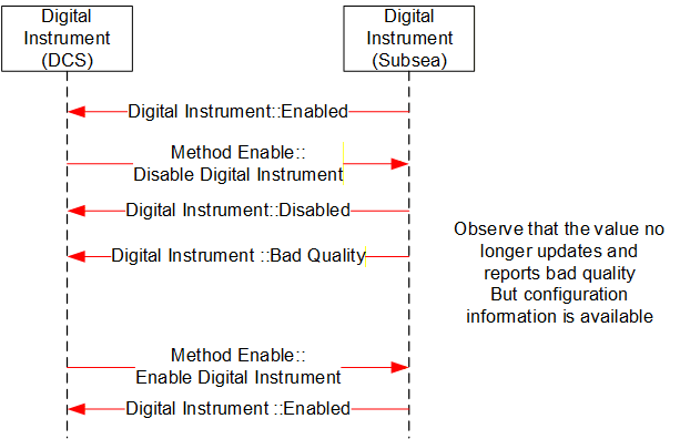
B.4 MDIS Instrument Object Sequence Diagrams
B.4.1 Enable Disable
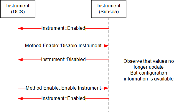
B.4.2 Write to Setpoint
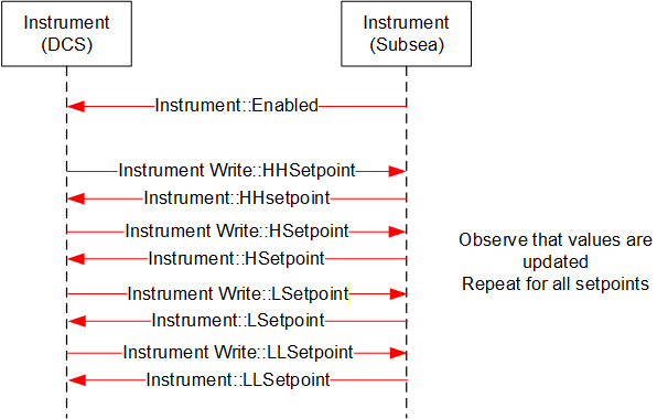
B.4.3 Display Limits
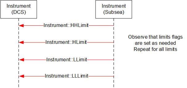
B.4.4 Display Engineering units
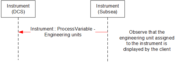
B.5 MDIS Choke Object Sequence Diagrams
B.5.1 Overview
The following sequence diagrams indicate the intended SPCS and DCS interface operational steps. The sequence diagrams are used only to visualise different choke operations and to provide helpful information for implementation of the MDISChokeObjectType in OPC UA.
B.5.2 Move to Position - Success
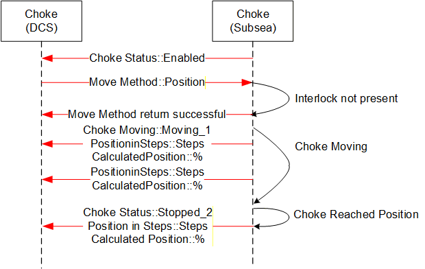
Sequence description; the above sequence details a successful execution of a Move to Position command [open or close] from the DCS to SPCS in addition to intermediate acknowledgements and states.
B.5.3 Move to Position - Fault
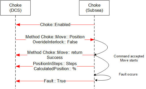
Sequence description; the above sequence details a Fault during the execution of a Move to Position command [open or close] from the DCS to SPCS in addition to intermediate states.
B.5.4 Move to Position - Failure, Interlock active
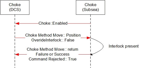
Sequence description; the above sequence details a failed execution of a Move to Position command [open or close] from the DCS to SPCS due to an Interlock being active.
B.5.5 Abort Choke (Position)
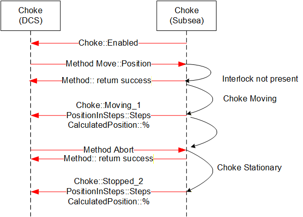
Sequence description; the above sequence details abort of a Move to Position command [open or close] from the DCS to SPCS.
B.5.6 Defeat / Override Interlock (Move)
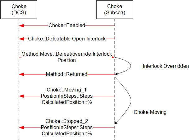
B.5.7 Fault - No Move Operation
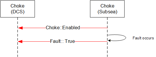
B.5.8 Step Open / Close - Success
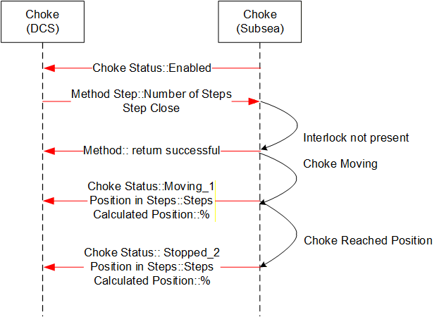
Sequence description; the above sequence details a successful execution of a Step Open / Close command from the DCS to SPCS in addition to intermediate acknowledgements and states. The sequence diagram also includes information from instruments such as the Linear Variable Displacement (Differential) Transmitter (LVDT) to help illustrate what the actual information flow is.
B.5.9 Step Open / Close - Failure, choke fault
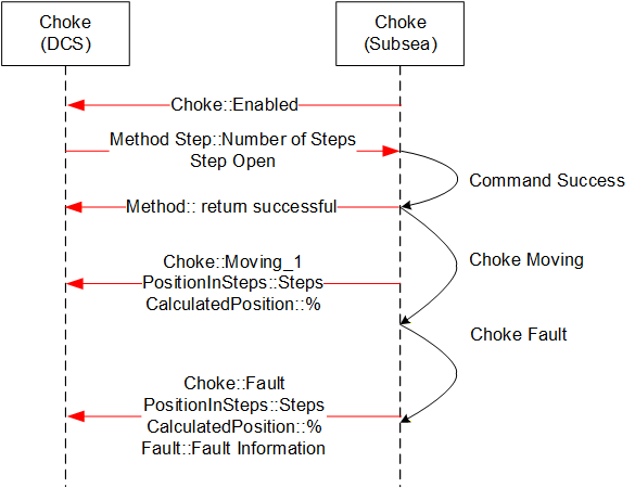
Sequence description; the above sequence details a failed execution of a Step Open / Close command from the DCS to SPCS due to a choke fault.
B.5.10 Abort Choke (Step)
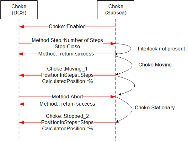
Sequence description; the above sequence details a successful execution of a Choke Abort command from the DCS to SPCS in addition to intermediate acknowledgements and states.
B.5.11 Set Calculated Position
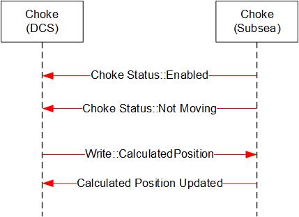
Sequence description; the above sequence details a successful execution of a Set Calculated Position command from the DCS to SPCS.
B.5.12 Enable Disable Choke
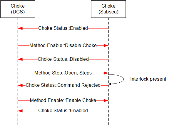
Sequence description; the above sequence details a successful execution of an Enable / Disable Choke from the DCS to SPCS in addition to intermediate acknowledgements and states.
B.5.13 Defeat / Override Interlock (Step)
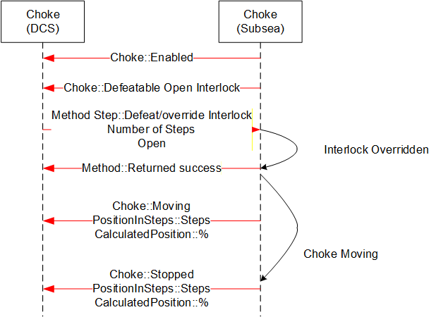
Sequence description; the above sequence details a successful execution of a Defeat / Override Interlock Choke command from the DCS to SPCS in addition to intermediate acknowledgements and states
B.6 MDIS Valve Object Sequence Diagrams
B.6.1 Overview
The general functionality of the valve is to control the flow, in that it is either open and flowing or closed and not flowing. The MDISValveObjectType provides the information available for valves and provides access to control and management functionality in the valve. The following sequence diagrams indicate the intended subsea and DCS interface operational requirements and should be used in conjunction with the MDISValveObjectType generic properties. The final result described in the sequence diagram will be held until the next command is issued to the Valve, or until the state of the Valve changes (Fault or Interlock clears).
[Note: in most of the failure cases described below, the Method call should not have been made. But the error case is still described, since the Server still needs to be able to correctly handle the case where a Client sends an inappropriate command. Warning states do not affect commands.]
B.6.2 Valve command - Success
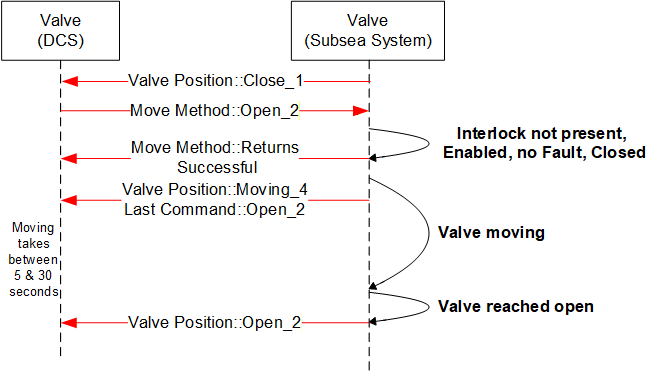
Sequence description; the above sequence details a successful execution of a command [Open or Close] from the DCS to SPCS in addition to intermediate state changes.
B.6.3 Valve command - Overridden Interlock
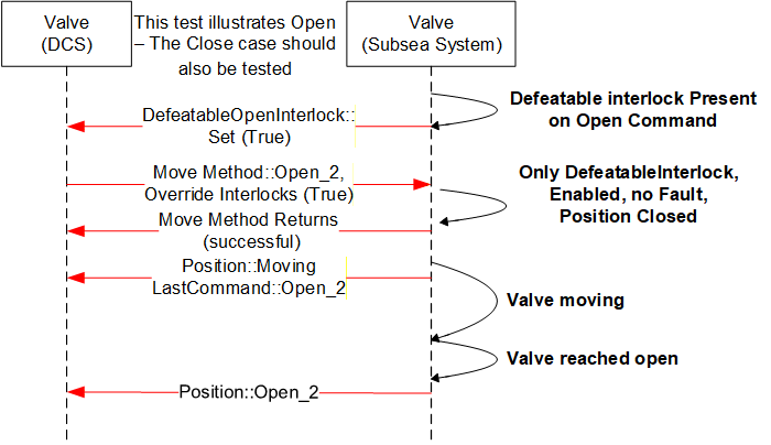
Sequence description; the above sequence details a successful execution of a command [Open or Close] with an interlock override active from the DCS to SPCS in addition to intermediate states changes. The Interlocks listed in the interlocks folder that are overridden are updated to reflect not interlocked.
B.6.4 Valve command -- Interlocked not overridden
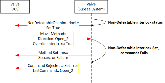
Sequence description; the above sequence details the rejection to execute a command [open or close] owing to a non-defeatable interlock active status in the subsea system. The interlock is one reason a command may be rejected but there are others.
B.6.5 Valve command - Disabled
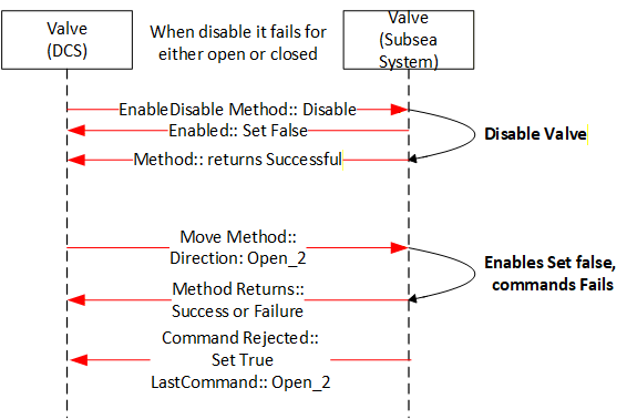
Sequence description; the above sequence details the rejection to execute a command [Open or Close] owing to the valve being disabled. The move Method may return successful or a failure depending on whether it knows if the valve is disabled.
B.6.6 Valve command - Failed - Fault case 1
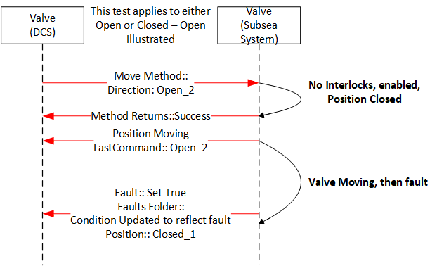
Sequence description; the above sequence is a failure of a command. The value fault maybe the result of the lack of action from the valve for a period of time greater that the OpenTimeDuration, it could also be some other fault that is reported from the subsea system.
B.6.7 Valve command - Failed - Fault case 2
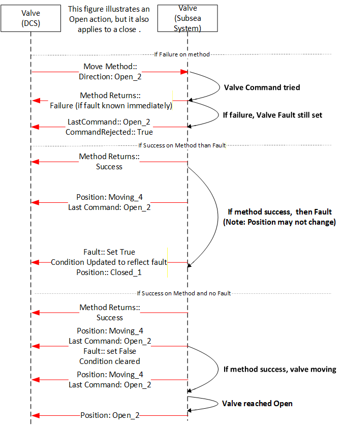
Sequence description; the above sequence details what the possible outcomes for moving a valve that has a fault set. The valve may immediately fault, may fault again after some time or the move may succeed. All outcomes are possible from a Client point of view. On some Servers only the last two may be possible.
B.6.8 Valve Signature Request - Completed
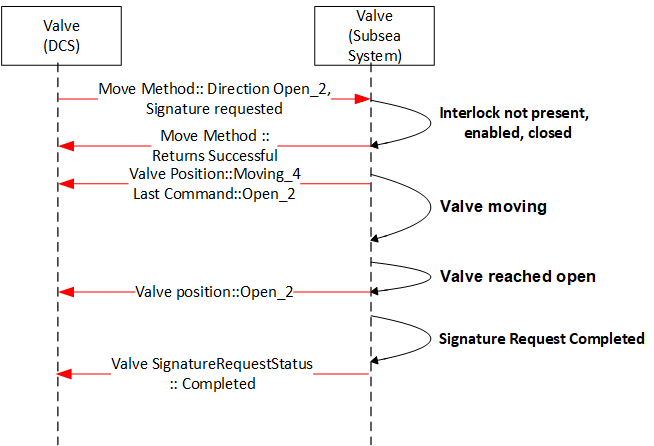
Sequence description; the above sequence details the valve signature request of a valve during operation [open or close] from the subsea system level. The valve may also report Failed or Not Available.
B.6.9 Valve command - Shutdown
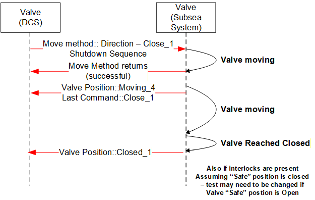
Sequence description; the above sequence details the execution of a Shutdown command [Open or Close]. The intermediate acknowledgements and states as applicable are indicated. The Shutdown command will attempt to override all interlocks, including any non-defeatable interlock if possible
Annex C Recommended Practice (Normative)
C.1 Introduction
This Recommended Practice provides guidance for use in specifying and implementing the OPC Unified Architecture (UA) for use as a standard communication interface for use between a Distributed Control System (DCS) and a Subsea Production Control System (SPCS) for control of subsea equipment.
Guidance for specifying minimum requirements when implementing MDIS are provided to ensure:
Equipment compatibility when integrating the MCS or Subsea Gateway with the DCS.
Safe and effective operation of equipment controlled by the MCS or Subsea Gateway from the DCS. Successful integration of the DCS with the MCS or Subsea Gateway during project execution.
These checklists and associated text maybe used directly in an RFQ, or maybe adjusted as needed.
C.2 Architecture Implementation
Physical architecture, defined in Section 5.1, should be specified. The location of the following minimum set of functionality, in the DCS or SPCS, is dependent on physical and "Operating Company" requirements and should be clearly specified prior to project execution:
Data Arbitration
Communication Channel Selection
SEM Control Selection
Process Interlocks
Product Interlocks
Shutdown Sequences
Automated Control Sequences
Valve Status Validation
Choke Position Validation
Interfacing with the HPU
Interfacing with the topside chemical injection system
Validation of Valve Profiles / Signatures
While functional logic has been prescribed by MDIS; implementation of specific functionality is not mandatory and should be specified on a project basis. As a minimum any MDIS implementation should ensure exchange of all required information required to safely line up, start up, operate and shutdown subsea equipment.
Interfaces with external interfaces with other third-party systems (i.e. historians) and external interfaces between SPCS and DCS for use other than for control and monitoring of subsea equipment are not specified through the use of the MDIS OPC UA Companion Specification and should be specified on a project basis.
C.3 Security
It is recommended that all encryption or application-level security requirements that are specified should be based on a network security assessment. If encryption on the protocol level is required, it is recommended to use encryption algorithms specified by OPC UA. Any advanced security features, if implemented, should have the option to be disabled and not adversely affect system performance.
No provision for user level security is considered for the MDIS Interface. The MDIS Interface is controller to controller communication and is not user restricted. All user level security should be implemented in the SPCS and DCS.
C.4 Performance
To maximise efficient use of bandwidth and performance, communication should be subscription based, by default.
The OPC UA interface is exception driven and a publishing interval of 2 seconds or less should be used between the SPCS and the DCS. Update rates from subsea to the SPCS is outside the scope of MDIS and can be much longer than 2 seconds. Maximum allowable update rates for individual controllers should be determined and based on system architecture and hardware capabilities.
It is expected that update rates will vary according to general categories of data. Critical data will have update rates that could be under 1 second while housekeeping data might have update rates in the 1-minute time range. These data rates shall be constant for the supported counts of Objects. i.e. if a device supports 3 wells (say 3000 critical values and 10,000 housekeeping values), the 1 second and 1 minute data rates will be support, not just for 1 well, but for the advertised 3 wells.
Conformance units provided general ranges of performance numbers that a product can be tested against. It is understood that performance will vary according to the hardware provided and the other loading on the hardware. The ConformanceUnits do not guarantee any performance, but they will point out performance issues earlier. i.e. a device that can support 5000 objects as part of a test is may not support 5000 when it is fully loaded with non-MDIS functionality, but it is likely that it would still be able to support 3000 objects. These conformance units are included to provide some general bench marks for performance.
Systems can be architected to include multiple server/devices to offset load. These number are targeted to allow better choice of configuration. For example, if 10,000 objects are desired and the software can only pass 5000 objects, the system should be architected to have at least 2 devices, but to allow for other factor, it might be a good idea to target 3 devices.
Requirements should be developed on a project basis to provide sufficient bandwidth between the SPCS and DCS to ensure all commands, issued both during normal operation and shutdowns, are passed across the interface effectively.
Evaluation of communication performance and testing requirements should take into account any latency or communication limitations due to physical system architecture constraints between SPCS and the DCS. (i.e. radio communication).
C.5 Data Priority
Data prioritisation should be considered on a system level by each project and should take into consideration functional requirements for safe and effective operation of control of subsea equipment.
Data exchange across the interface should, unless otherwise specified be prioritised in the following manner:
| High Priority: | Information required for process control. |
| Low Priority: | Information that is not required for process control (i.e. diagnostics, housekeeping). |
C.6 Documentation
An interface specification should be developed between the SPCS vendor, DCS vendor and the "Operating Company" prior to the implementation of MDIS. The interface specification should provide the required fidelity to ensure all project specific requirements have been met. During the development of this specification it is recommended to review the project check list in Section B.8.
The SPCS vendor shall maintain revision control of the UANodeSet file that is being utilised by the project.
External interfaces (i.e. historians, condition monitoring systems, etc.) should also be specified however are outside the scope of this specification.
C.7 Interface Testing
The MDIS communication link shall be verified between the SPCS and DCS. Testing shall include both normal operation and failure scenarios. Redundancy and performance requirements should be tested under full load (i.e. shutdown conditions). Time synchronisation should be verified.
Clients and Servers that have passed independent MDIS certification should require less integration testing. Integration testing should be focused on the project configuration rather than base MDIS functionality. It is recommended prior to any integration testing that the interface specification, defined in Section C.6 and OPC UA UANodeSet files be finalised and agreed between SPCS and DCS vendors as early as possible. Integration testing should only be attempted when the SPCS and DCS software has reached an acceptable level of maturity.
It is recommended that, during project execution, preliminary integration testing be performed to validate the data exchange across the MDIS Interface off critical path, prior to full onsite integration testing. In addition to validating data exchange, this testing should allow for verification of graphical displays, redundancy and data prioritisation. Validation of performance and full functionality, including shutdowns, sequences and interlocks, should be performed during full onsite integration testing using the hardware that will be supplied to the project.
C.8 Project Check List
C.8.1 Introduction
This Checklist provides general guidance for use in tender and development cycles for implementing the MDIS Interface between a Distributed Control System (DCS) and a Subsea Production Control System (SPCS) for control of subsea equipment.
C.8.2 Front End Engineering Design (FEED)
The following checklist is ordered by decisions and activities that should be defined during clarification and development of an MDIS interface specification interface.
| No | Item Description | Comments | √ |
| The Operator, DCS vendor and SPCS vendor should assign dedicated persons to develop requirements for the interface. | Knowledge of latest MDIS Specification is recommended. | ||
| Operator to schedule Kick-off or Workshop with DCS vendor and SPCS vendor to discuss checklist items. | For example System Introduction. Agree on weekly / biweekly regular meetings Lessons learned of previous implementations Checklist items | ||
| Agree on system architecture. The Operator shall decide which MDIS architecture (Integrated, Interfaced or Other) is applicable. The definition of architecture should document where all functional logic should reside, as per Section B.2. | |||
| Create an overview drawing of the hardware and network architecture. Decide on Interface setting (IP ranges and class). Define hardware components on both systems that are related for the interface. | |||
| Schedule Cyber Security Meeting for the MDIS Interface | |||
| DCS vendor to provide OPC Foundation accredited Test Lab certification report (OPC UA Client), if available, to the Operator. | |||
| SPCS vendor to provide OPC Foundation accredited Test Lab certification report (OPC UA Server), if available, to the Operator. | |||
| Select responsible Party (DCS or SPCS) for implementing shutdown Sequences. | |||
| Select responsible Party (DCS or SPCS) for implementing automated Sequences. | |||
| Select responsible Party (DCS or SPCS) for implementing Product Interlocks. | |||
| Select responsible Party (DCS or SPCS) for implementing Process Interlocks. | |||
| Select responsible Party (DCS or SPCS) for creation and managing the Product Alarms/Warnings. Specify detail level of product alarms (summary alarm or specific information) | SPCS Vendor should provide diagnostic information. | ||
| Select responsible Party for changing Setpoints for Alarms & Interlocks (if applicable) | |||
| SPCS Vendor to present specific Subsea Communication & Arbitration Philosophy | |||
| Select responsible Party (DCS or SPCS) for creation and managing Process Alarms/Warnings. | |||
| Define where information from redundant physical measurements is arbitrated. | Example: Should the SPCS or DCS be responsible for arbitrating information from redundant pressure / temperature transmitters that are measuring the same process variable? | ||
| Define where management of redundancy in subsea equipment is arbitrated. | Example: Should the SPCS or DCS be responsible for assigning which SEM is used to command valve actuation? Should the SPCS or DCS be responsible for assigning a "primary" or "backup" SEM? | ||
| Define where redundant information due to multiple communication channels is arbitrated. | Example: Dependent on system design a single process sensor value might be available through various communication channels. Should the SPCS or DCS be responsible for determining which value is used for display to the operator and used as input to interlocks and automated sequences? | ||
| Define the instance model for redundant systems | Example: Is the instance model on each OPC Server identical or do the instance models represent separate and redundant pathways to subsea equipment? See section 12 for more details. | ||
| Make a list of all MDIS Object types that will utilized on the project. | Object types that are not utilized on the project can be skipped from following optional item selection. | ||
| Operator, DCS and SPCS to select required optional References and Methods for all MDIS objects: - MDIS Discrete Instrument - MDIS DiscreteOut Instrument - MDIS Digital Instrument - MDIS DigitalOut Instrument - MDIS Instrument - MDIS InstrumentOut - MDIS Valve - MDIS Choke - Etc. | It is recommended to start discussions assuming all objects use all mandatory and optional References and Methods and remove items that are not project relevant. | ||
| Supported arguments for the MDIS Valve and MDIS Choke Move-Method calls should be documented. | Available Move-Method calls are defined in the MDIS Valve and MDIS Choke objects. | ||
| Faults and warning codes warning provided in SPCS system should be defined. Specific actions to be initiated by the DCS in the event of a fault or warning code should be documented. | For example: A workshop for specific alarms & actions should be conducted after interface specification is finalized. | ||
| Agree on standardised methodology for naming of Objects used on the interface (Hierarchy / Field structure) | Project specific equipment specific tag identifiers can be used on the interface to name equipment. | ||
| SPCS Vendor to prepare list of available MDIS Aggregated Objects and Vendor specific Subtypes of MDIS Objects. | This list should provide sufficient detail to allow development of software by both the DCS and SPCS provider. | ||
| The structure of address space across the interface (folder structure or MDIS Aggregated object) should be defined. | Address space structure should be clearly documented by the SPCS vendor and be reviewed by the DCS vendor to ensure no incompatibility. | ||
| A method for time Synchronization shall be defined. | |||
| FEED work should be documented to clarify expectations during project execution. |
C.8.3 Project Execution
The following checklist documents activities that should be considered during project execution.
| No | Item Description | Comments | √ |
| SPCS Vendor should create a project specific MDIS Interface specification for DCS. | This MDIS Interface specification should be based on documented FEED discussions. | ||
| SPCS Vendor to schedule date for delivery of MDIS NodesetFile(s) for DCS Vendor. | More than one date might be scheduled, where each date would provide a NodesetFile that includes additional object definitions. For example, an initial NodesetFile might contain just the first prototype of a well and subsequent NodesetFiles might contain a more detailed well and then multiple instances of the well. Also, some Objects might include additional optional items as the well model is finalized. | ||
| Schedule date for first MDIS interface connection Test. SPCS vendor, DCS vendor and Operator should agree on test cases for first MDIS interconnection test. | First interconnection test should cover test cases such as redundancy, time synchronization, performance, etc. | ||
| Check possibility/availability of an online SPCS OPC UA MDIS Server to support and accelerate interface development. | Operator to support/provide infrastructure (e.g. use own infrastructure or cloud systems) if link between SPCS and DCS Vendor cannot be established. | ||
| DCS Vendor to prepare Interface Test procedure. Schedule review cycle for Operator and SPCS vendor. | |||
| Schedule Date for final MDIS interface connection Test (full project configuration, including sequences and interlocks, etc.). |
C.8.4 Closeout
The following Checklist documents activities that should be completed complete as part of a project closeout.
| No | Item Description | Comments | √ |
| Feedback lessons learned and improvements from project execution to MDIS working group. | Feedback should be provided from all parties (Operator, DCS, SPCS). Feedback could include discussion of specification features, feedback on this checklist, future features that could be added to specification etc. |
Annex D Alternative MDIS Applications (Normative)
D.1 Introduction
OPC UA, through the MDIS Companion Specification, has been specified as a controls interface between the MCS and DCS. This normative guideline provides details on other potential applications of the MDIS standard and additions to standard MDIS implementations that are outside the original scope of MDIS. Concepts covered include:
Application of OPC UA and standard objects and concepts defined within the MDIS Companion Specification as "read only" interfaces for historian applications.
Additions to OPC UA MDIS implementations that can facilitate data transfer that are not specifically control related.
D.2 Read Only Interface
The MCS can provide "read only" interfaces to facilitate data to external databases, as specified on a project basis. In these cases, OPC UA can be specified and use of standard objects and concepts taken from the MDIS standard can be utilized based on project specific requirements.
To use the OPC UA interface as a "read only" interface it is recommended to that a Server be able to indicate that all writeable points (by definition have access restriction that denies write for all users and that no writeable ObjectType instance will exist in the address space. For all methods that allow writing, the user access rights should indicate not executable. The Server should be configurable to support this "read only" configuration. The server should not be able to be changed from this configuration without a restart.
D.3 Signature File Transfer
Valve signatures are files that contain high sample rate pressure profiles recorded during individual valve operations exposed by the subsea system. There are cases where valve signatures are required to be transferred from the SPCS to either the DCS or external historian interfaces.
A Server that supports transferring the valve signature via OPC UA shall expose a FileObject as part of the Valve Object Instance via the HasSignature ReferenceType. The valve Signature will also be provided in the MDIS folder under the MDISInformation Object. File formats and specific information captured within the valve signature files are outside the scope of this specification and should be specified on a project basis.
The items required are provided as part the individual ObjectTypes. This functionality is optional and covered in a separate profile.
Annex E Valve Signature File Format Annex (Normative)
E.1 File format definition
This section provides a file format definition for the valve signature files. It includes a file naming convention:
Filname:
'Date_Time_ValveTagId', where Date-Format: yyyyMMdd and Time-Format: HHmmss.
Time in filename is only to be used for file handling purposes. Accurate Valve-Signature time-stamp is given in TriggerTime variable.
Variables:
| BrowsePath | A browse path that uniquely identifies the valve in signature file (without namespace). | Mandatory |
| TagId | TagId of the Valve | Optional |
| Description | Valve description. | Mandatory |
| Command | "open", "close", "partial-stroke" | Mandatory |
| TriggerTime | Timestamp for signature, SEM time when valve movement started. the string should be in this format "1510835812.330" | Optional |
| Instrument | Instrument data start. | |
| InstrumentId | TagId or BrowseName for instrument. | Mandatory |
| InstrumentDescription | Description. | Mandatory |
| EUrangeHigh | High range for plot, may be different from actual instrument range. (example: for flow transmitter EUrangeHigh should correspond to valve volume not flow instrument max range) | Optional |
| EUrangeLow | Low range for plot, may be different from actual sensor range. | Optional |
| EngineeringUnits | Instrument Engineering unit, same unit as EngineeringUnits under ProcessVariable. | Mandatory |
| Samples | Sample values. | |
| Time | SEM time for sample. In OPC UA DateTime (see OPC 10000-5 section 5.2.2.5 DateTime)) the string should be in this format "1510835812.330" | Mandatory |
| Value | Instrument sample value. | Mandatory |
| Fault | Sensor fault. | Optional |
Additional comments:
First instrument sample value may be earlier in time than TriggerTime, dependent on subsea vendor SEM configuration, to include a pre-operation sample in the plot.
The normative definition of the JSON schema is available in the file found here:
For the latest version:
https://reference.opcfoundation.org/files/Profile-Schema.json?u=http://opcfoundation.org/UA/MDIS
Agreement of Use
COPYRIGHT RESTRICTIONS
Any unauthorized use of this specification may violate copyright laws, trademark laws, and communications regulations and statutes. This document contains information which is protected by copyright. All Rights Reserved. No part of this work covered by copyright herein may be reproduced or used in any form or by any means - graphic, electronic, or mechanical, including photocopying, recording, taping, or information storage and retrieval systems - without permission of the copyright owner.
OPC Foundation members and non-members are prohibited from copying and redistributing this specification. All copies must be obtained on an individual basis, directly from the OPC Foundation Web site
http://www.opcfoundation.org.
PATENTS
The attention of adopters is directed to the possibility that compliance with or adoption of OPC specifications may require use of an invention covered by patent rights. OPC shall not be responsible for identifying patents for which a license may be required by any OPC specification, or for conducting legal inquiries into the legal validity or scope of those patents that are brought to its attention. OPC specifications are prospective and advisory only. Prospective users are responsible for protecting themselves against liability for infringement of patents.
WARRANTY AND LIABILITY DISCLAIMERS
WHILE THIS PUBLICATION IS BELIEVED TO BE ACCURATE, IT IS PROVIDED "AS IS" AND MAY CONTAIN ERRORS OR MISPRINTS. THE OPC FOUDATION MAKES NO WARRANTY OF ANY KIND, EXPRESSED OR IMPLIED, WITH REGARD TO THIS PUBLICATION, INCLUDING BUT NOT LIMITED TO ANY WARRANTY OF TITLE OR OWNERSHIP, IMPLIED WARRANTY OF MERCHANTABILITY OR WARRANTY OF FITNESS FOR A PARTICULAR PURPOSE OR USE. IN NO EVENT SHALL THE OPC FOUNDATION BE LIABLE FOR ERRORS CONTAINED HEREIN OR FOR DIRECT, INDIRECT, INCIDENTAL, SPECIAL, CONSEQUENTIAL, RELIANCE OR COVER DAMAGES, INCLUDING LOSS OF PROFITS, REVENUE, DATA OR USE, INCURRED BY ANY USER OR ANY THIRD PARTY IN CONNECTION WITH THE FURNISHING, PERFORMANCE, OR USE OF THIS MATERIAL, EVEN IF ADVISED OF THE POSSIBILITY OF SUCH DAMAGES.
The entire risk as to the quality and performance of software developed using this specification is borne by you.
RESTRICTED RIGHTS LEGEND
This Specification is provided with Restricted Rights. Use, duplication or disclosure by the U.S. government is subject to restrictions as set forth in (a) this Agreement pursuant to DFARs 227.7202-3(a); (b) subparagraph (c)(1)(i) of the Rights in Technical Data and Computer Software clause at DFARs 252.227-7013; or (c) the Commercial Computer Software Restricted Rights clause at FAR 52.227-19 subdivision (c)(1) and (2), as applicable. Contractor / manufacturer are the OPC Foundation, 16101 N. 82nd Street, Suite 3B, Scottsdale, AZ, 85260-1830.
COMPLIANCE
The OPC Foundation shall at all times be the sole entity that may authorize developers, suppliers and sellers of hardware and software to use certification marks, trademarks or other special designations to indicate compliance with these materials. Products developed using this specification may claim compliance or conformance with this specification if and only if the software satisfactorily meets the certification requirements set by the OPC Foundation. Products that do not meet these requirements may claim only that the product was based on this specification and must not claim compliance or conformance with this specification.
Trademarks
Most computer and software brand names have trademarks or registered trademarks. The individual trademarks have not been listed here.
GENERAL PROVISIONS
Should any provision of this Agreement be held to be void, invalid, unenforceable or illegal by a court, the validity and enforceability of the other provisions shall not be affected thereby.
This Agreement shall be governed by and construed under the laws of the State of Minnesota, excluding its choice or law rules.
This Agreement embodies the entire understanding between the parties with respect to, and supersedes any prior understanding or agreement (oral or written) relating to, this specification.
Revision 1.3 Highlights
The following table includes the Mantis issues resolved with this revision.
| Mantis ID | Summary | Resolution |
| 4311 | The MDIS Specification need to provide a more standard set of error codes | Updated Fault and Warning codes to include a subset of standard defined codes and then still allow additional bits to be vendor specific |
| 4904 | Conflict when using Extensions and Aggregates | Updated text to indicate that subtypes are also allowed |
| 5269 | Add CIMV object definition | Added definition of new CIMV ObjectType |
| 5536 | Add MDIS Arbitration Object | Added individual Arbitration objects for all instruments |
| 5537 | Add MDIS Pump Object | Added Motor Object (for a more general pump object type) |
| 6045 | Wrong usage of HasProperty | Fixed incorrect definition using HasProperty |
| 7549 | WriteValue Method of InstrumentOut ObjectTypes (5.3.5, 5.4.5, 5.5.5): definition of the feedback value is unclear | updated the text in all three sections section 5.5.5 The value of the ProcessVariable value will only update once the subsea system has provided a new value. section 5.4.5 The value of the State value will only update once the subsea system has provided a new value. section 5.3.5 The value of the State value will only update once the subsea system has provided a new value. |
| 7808 | Handling of "State" variable when there is no feedback from subsea | Updated text as: The value of the State value Variable will shall only be updated once the subsea system has provided a new value. For Objects that are used as a command, the value of the State Variable shall be updated directly to the value provided by the State parameter of the Method. |
| 8005 | MDIS Client profile includes base specification facets that do not fully apply to MDIS-only client apps | Removed reference to base specification facets "AddressSpace Lookup Client Facet" and "DataChange Subscriber Client Facet" and instead listed the individual CUs which comprise those facets, indicating which are optional for MDIS clients |
| 8006 | SetArbitrationMode method is optional in MDISInstrumentArbitrationObjectType | Set it as optional in all objects |
| 8190 | Clarify CIMV behaviour when SetPosition and SetManual manual arguments are out of range | Updated CIMV section methods "SetPosition" Method "SetManual" |
| 8023 | Profile group names in the spec do not align with those in the profile database | Aligned profile group names with those in the profile database |
| 7982 | Documentation updates/clarifications for MDIS Motor object | Updated document to include a statement that the Start/Stop methods are required if Manual Operation is provided. |
| Note: Following Nodeset Issues were also addressed in this release | ||
|---|---|---|
| 3928 | Type of ProcessVariable Mismatch | The nodeset was updated to correctly use AnalogItemType not MDISAnalogItemType |
| 4425 | MDISAggregateObjectType is not defined correctly in the nodesetfile | Corrected Nodeset file to have correct types |
| 4990 | Fix spelling/Grammar problems in nodeset | Correct all indicated issue and review /corrected any other issues |
| 8090 | Add a third value to MotorOperationEnum, "Off_0" | Updated sections "MDISMotorObjectType Definition", "Motor SetOperation Method" and "MotorOperationEnum" |
| 7814 | What is the error result when setting the CIMV position >100% | Updated Choke Move method (Position argument) and CIMV SetManual method (Delta argument) |
| 8309 | Fix minimum version for OPC base specification to 1.03 | Updated Specification version |