
B.5 MDIS Choke Object Sequence Diagrams
B.5.1 Overview
The following sequence diagrams indicate the intended SPCS and DCS interface operational steps. The sequence diagrams are used only to visualise different choke operations and to provide helpful information for implementation of the MDISChokeObjectType in OPC UA.
B.5.2 Move to Position - Success
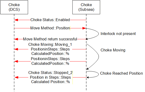
Sequence description; the above sequence details a successful execution of a Move to Position command [open or close] from the DCS to SPCS in addition to intermediate acknowledgements and states.
B.5.3 Move to Position - Fault
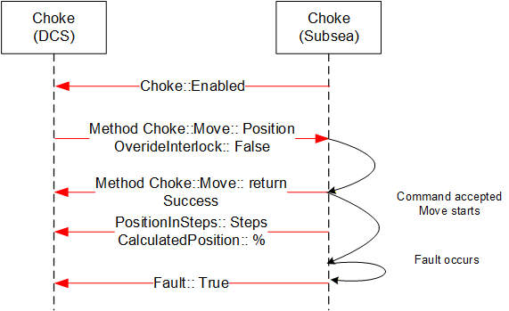
Sequence description; the above sequence details a Fault during the execution of a Move to Position command [open or close] from the DCS to SPCS in addition to intermediate states.
B.5.4 Move to Position - Failure, Interlock active
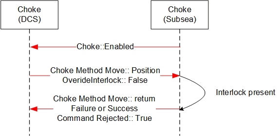
Sequence description; the above sequence details a failed execution of a Move to Position command [open or close] from the DCS to SPCS due to an Interlock being active.
B.5.5 Abort Choke (Position)
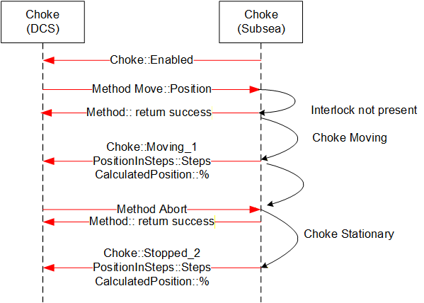
Sequence description; the above sequence details abort of a Move to Position command [open or close] from the DCS to SPCS.
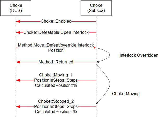
B.5.6 Defeat / Override Interlock (Move)
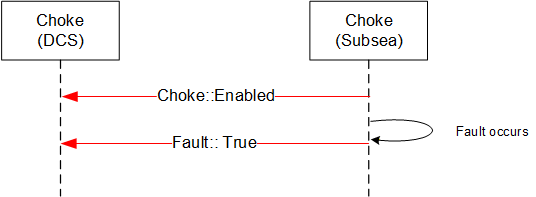
B.5.7 Fault - No Move Operation
B.5.8 Step Open / Close - Success
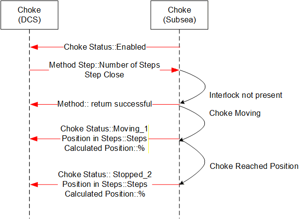
Sequence description; the above sequence details a successful execution of a Step Open / Close command from the DCS to SPCS in addition to intermediate acknowledgements and states. The sequence diagram also includes information from instruments such as the Linear Variable Displacement (Differential) Transmitter (LVDT) to help illustrate what the actual information flow is.
B.5.9 Step Open / Close - Failure, choke fault
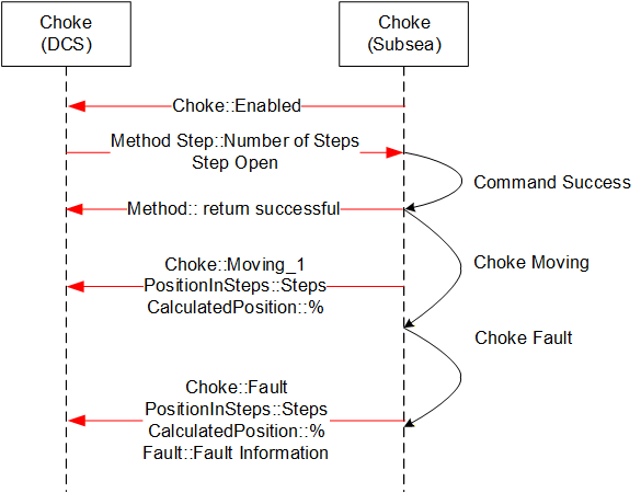
Sequence description; the above sequence details a failed execution of a Step Open / Close command from the DCS to SPCS due to a choke fault.
B.5.10 Abort Choke (Step)
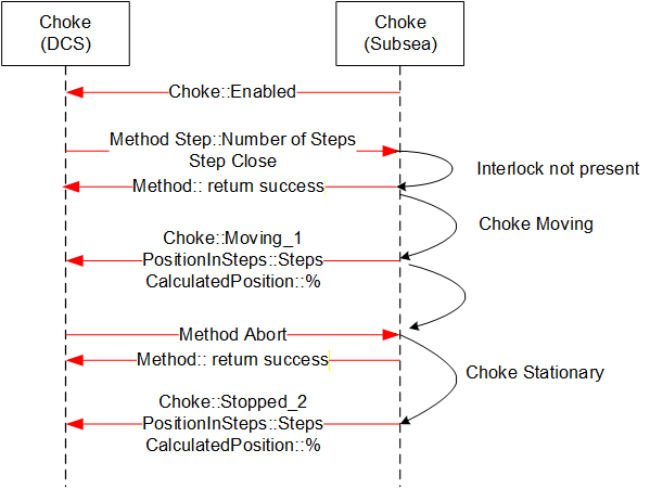
Sequence description; the above sequence details a successful execution of a Choke Abort command from the DCS to SPCS in addition to intermediate acknowledgements and states.
B.5.11 Set Calculated Position
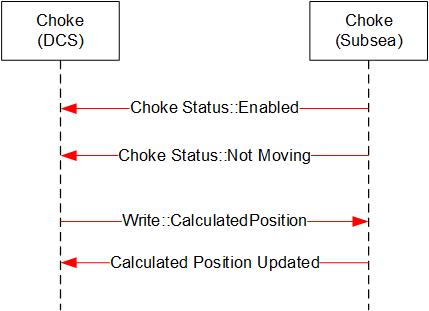
Sequence description; the above sequence details a successful execution of a Set Calculated Position command from the DCS to SPCS.
B.5.12 Enable Disable Choke
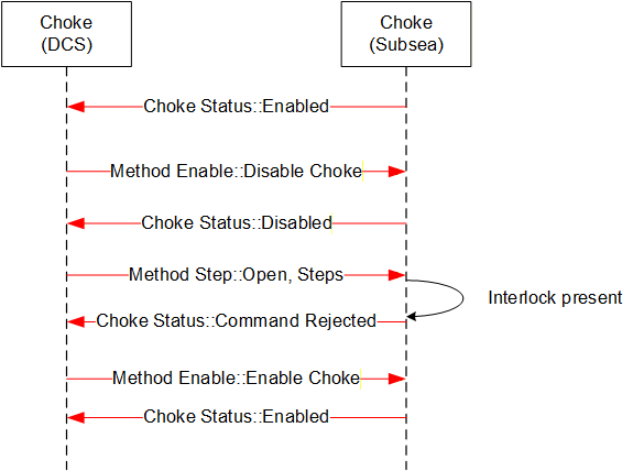
Sequence description; the above sequence details a successful execution of an Enable / Disable Choke from the DCS to SPCS in addition to intermediate acknowledgements and states.
B.5.13 Defeat / Override Interlock (Step)
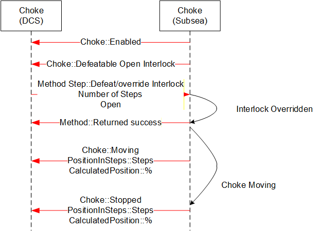
Sequence description; the above sequence details a successful execution of a Defeat / Override Interlock Choke command from the DCS to SPCS in addition to intermediate acknowledgements and states