
Annex B Sequence Diagrams (Informative)
B.1 Introduction
The following section provides sample sequence diagrams for each of the MDIS ObjectTypes. These sample sequences are not mandated or the only valid variant.
B.2 MDIS Discrete Instrument Object Sequence Diagrams
B.2.1 Enable Disable

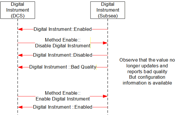
B.3 MDIS Digital Instrument Object Sequence Diagrams
B.3.1 Enable Disable
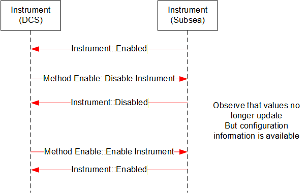
B.4 MDIS Instrument Object Sequence Diagrams
B.4.1 Enable Disable
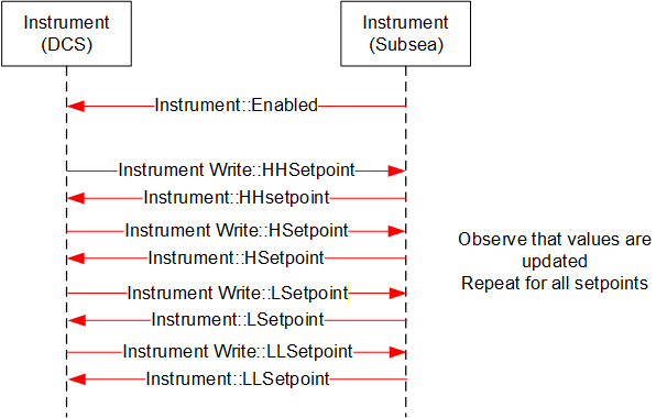
B.4.2 Write to Setpoint
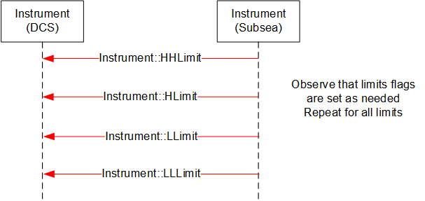
B.4.3 Display Limits
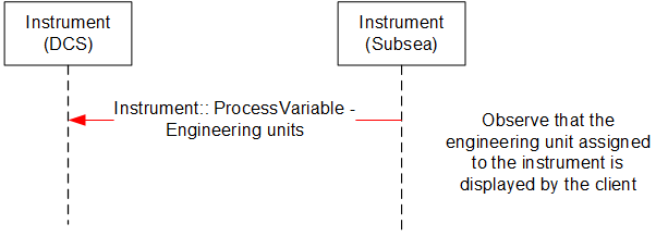
B.4.4 Display Engineering units
B.5 MDIS Choke Object Sequence Diagrams
B.5.1 Overview
The following sequence diagrams indicate the intended SPCS and DCS interface operational steps. The sequence diagrams are used only to visualise different choke operations and to provide helpful information for implementation of the MDISChokeObjectType in OPC UA.
B.5.2 Move to Position - Success
Sequence description; the above sequence details a successful execution of a Move to Position command [open or close] from the DCS to SPCS in addition to intermediate acknowledgements and states.
B.5.3 Move to Position - Fault
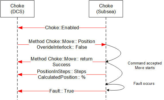
Sequence description; the above sequence details a Fault during the execution of a Move to Position command [open or close] from the DCS to SPCS in addition to intermediate states.
B.5.4 Move to Position - Failure, Interlock active
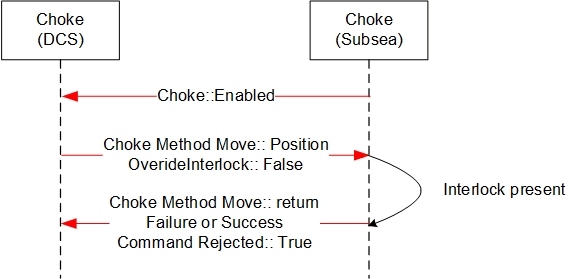
Sequence description; the above sequence details a failed execution of a Move to Position command [open or close] from the DCS to SPCS due to an Interlock being active.
B.5.5 Abort Choke (Position)
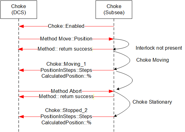
Sequence description; the above sequence details abort of a Move to Position command [open or close] from the DCS to SPCS.
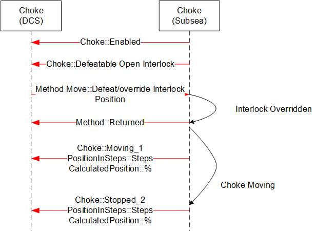
B.5.6 Defeat / Override Interlock (Move)
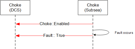
B.5.7 Fault - No Move Operation
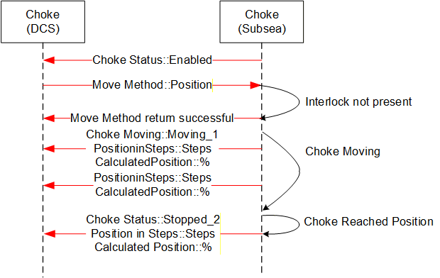
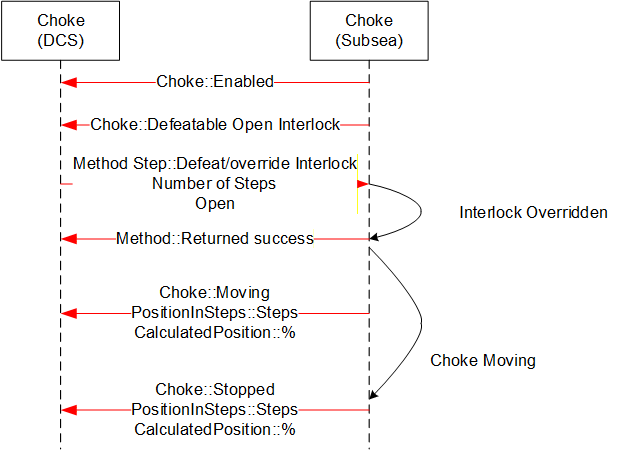
B.5.8 Step Open / Close - Success
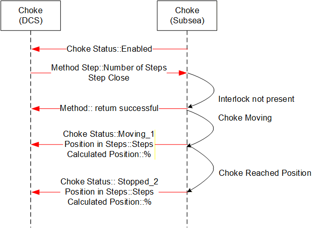
Sequence description; the above sequence details a successful execution of a Step Open / Close command from the DCS to SPCS in addition to intermediate acknowledgements and states. The sequence diagram also includes information from instruments such as the Linear Variable Displacement (Differential) Transmitter (LVDT) to help illustrate what the actual information flow is.
B.5.9 Step Open / Close - Failure, choke fault
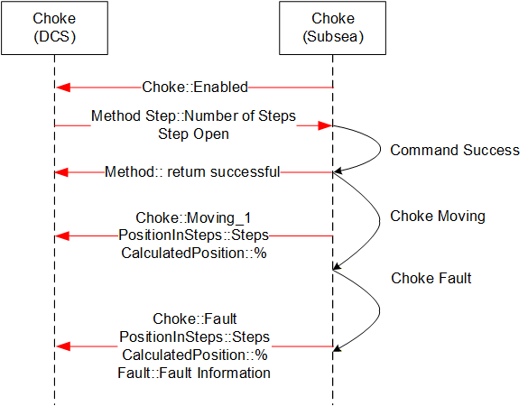
Sequence description; the above sequence details a failed execution of a Step Open / Close command from the DCS to SPCS due to a choke fault.
B.5.10 Abort Choke (Step)
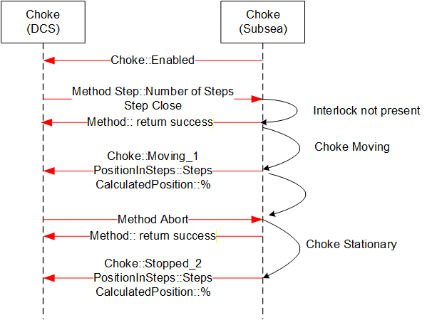
Sequence description; the above sequence details a successful execution of a Choke Abort command from the DCS to SPCS in addition to intermediate acknowledgements and states.
B.5.11 Set Calculated Position
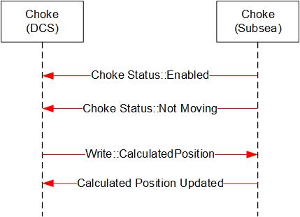
Sequence description; the above sequence details a successful execution of a Set Calculated Position command from the DCS to SPCS.
B.5.12 Enable Disable Choke
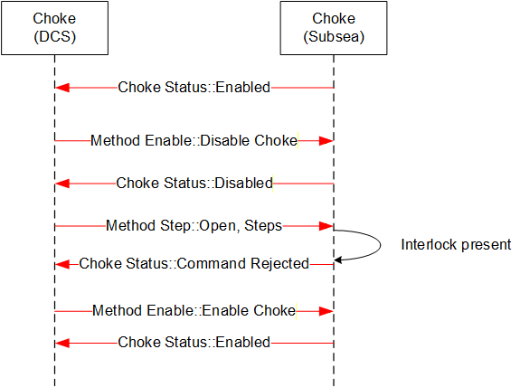
Sequence description; the above sequence details a successful execution of an Enable / Disable Choke from the DCS to SPCS in addition to intermediate acknowledgements and states.
B.5.13 Defeat / Override Interlock (Step)
Sequence description; the above sequence details a successful execution of a Defeat / Override Interlock Choke command from the DCS to SPCS in addition to intermediate acknowledgements and states
B.6 MDIS Valve Object Sequence Diagrams
B.6.1 Overview
The general functionality of the valve is to control the flow, in that it is either open and flowing or closed and not flowing. The MDISValveObjectType provides the information available for valves and provides access to control and management functionality in the valve. The following sequence diagrams indicate the intended subsea and DCS interface operational requirements and should be used in conjunction with the MDISValveObjectType generic properties. The final result described in the sequence diagram will be held until the next command is issued to the Valve, or until the state of the Valve changes (Fault or Interlock clears).
[Note: in most of the failure cases described below, the Method call should not have been made. But the error case is still described, since the Server still needs to be able to correctly handle the case where a Client sends an inappropriate command. Warning states do not affect commands.]
B.6.2 Valve command - Success
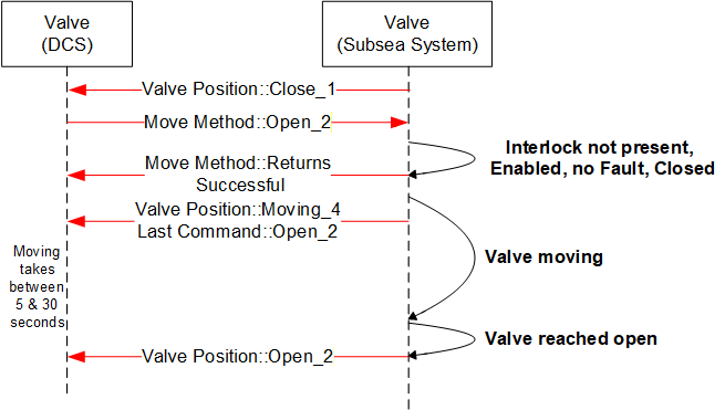
Sequence description; the above sequence details a successful execution of a command [Open or Close] from the DCS to SPCS in addition to intermediate state changes.
B.6.3 Valve command - Overridden Interlock
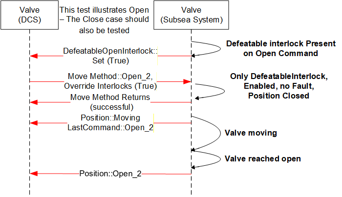
Sequence description; the above sequence details a successful execution of a command [Open or Close] with an interlock override active from the DCS to SPCS in addition to intermediate states changes. The Interlocks listed in the interlocks folder that are overridden are updated to reflect not interlocked.
B.6.4 Valve command -- Interlocked not overridden
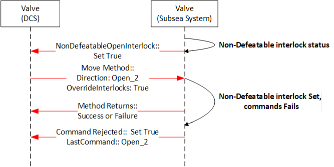
Sequence description; the above sequence details the rejection to execute a command [open or close] owing to a non-defeatable interlock active status in the subsea system. The interlock is one reason a command may be rejected but there are others.
B.6.5 Valve command - Disabled
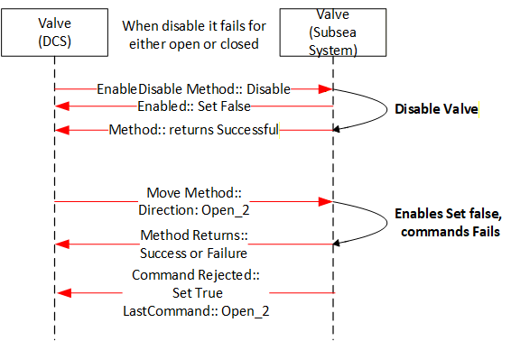
Sequence description; the above sequence details the rejection to execute a command [Open or Close] owing to the valve being disabled. The move Method may return successful or a failure depending on whether it knows if the valve is disabled.
B.6.6 Valve command - Failed - Fault case 1
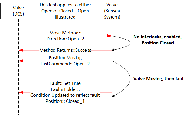
Sequence description; the above sequence is a failure of a command. The value fault maybe the result of the lack of action from the valve for a period of time greater that the OpenTimeDuration, it could also be some other fault that is reported from the subsea system.
B.6.7 Valve command - Failed - Fault case 2
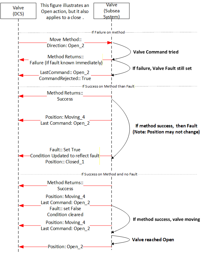
Sequence description; the above sequence details what the possible outcomes for moving a valve that has a fault set. The valve may immediately fault, may fault again after some time or the move may succeed. All outcomes are possible from a Client point of view. On some Servers only the last two may be possible.
B.6.8 Valve Signature Request - Completed
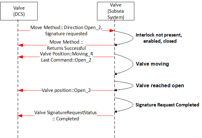
Sequence description; the above sequence details the valve signature request of a valve during operation [open or close] from the subsea system level. The valve may also report Failed or Not Available.
B.6.9 Valve command - Shutdown
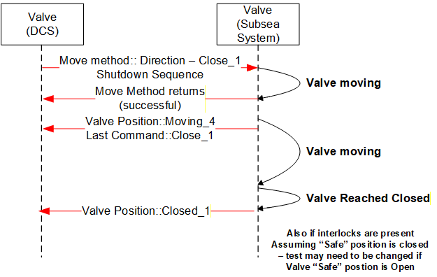
Sequence description; the above sequence details the execution of a Shutdown command [Open or Close]. The intermediate acknowledgements and states as applicable are indicated. The Shutdown command will attempt to override all interlocks, including any non-defeatable interlock if possible