
1 Scope
This specification was created by a joint working group of the OPC Foundation and FieldComm Group Project Group Device Information Model. It defines the OPC UA Information Model to represent and access Process Automation Devices.
OPC Foundation
OPC is the interoperability standard for the secure and reliable exchange of data and information in the industrial automation space and in other industries. It is platform independent and ensures the seamless flow of information among devices from multiple vendors. The OPC Foundation is responsible for the development and maintenance of this standard.
OPC UA is a platform independent service-oriented architecture that integrates all the functionality of the individual OPC Classic specifications into one extensible framework. This multi-layered approach accomplishes the original design specification goals of:
Platform independence: from an embedded microcontroller to cloud-based infrastructure
Secure: encryption, authentication, authorization and auditing
Extensible: ability to add new features including transports without affecting existing applications
Comprehensive information modelling capabilities: for defining any model from simple to complex
FieldComm Group
FieldComm Group is a global standards-based non-profit member organization consisting of leading process end users, manufacturers, universities and research organizations that work together to direct the development, incorporation and implementation of communication technologies for the process industries. Membership is open to anyone interested in the use of the technologies. In addition to HART and Foundation Fieldbus communication technologies, FieldComm Group is responsible for ongoing development of Field Device Integration (FDI) Technology.
2 Normative references
The following referenced documents are indispensable for the application of this specification. For dated references, only the edition cited applies. For undated references, the latest edition of the referenced document (including any amendments and errata) applies.
OPC 10000-1, OPC Unified Architecture - Part 1: Overview and Concepts
3 Terms, abbreviated terms and conventions
3.1 Overview
It is assumed that basic concepts of OPC UA information modelling are understood in this specification. This specification will use these concepts to describe the Process Automation Device Information Model. For the purposes of this document, the terms and definitions given in OPC 10000-1, OPC 10000-3, OPC 10000-4, OPC 10000-5, OPC 10000-7, OPC 10000-8, OPC 10000-19, and OPC 10000-100 as well as the following apply.
Note that OPC UA terms and terms defined in this specification are italicized in the specification.
3.2 OPC UA for PA-DIM terms
3.2.1 Process Automation Device
Industrial Process Automation Device for specific measuring tasks such as flow, level, pressure and temperature as well as for actuators.
3.3 Abbreviated terms
| CAS | Chemical Abstracts Service |
| CDD | Common Data Dictionary |
| DCS | Distributed Control Systems |
| FID | Flame Ionisation Detector |
| IRDI | International Registration Data Identifier |
| NDIR | NonDispersiveInfrared |
| NOA | NAMUR Open Architecture |
| PAT | Process Analyser Technology |
| TDL | Tunable Diode Laser |
| TOC | Total Organic Carbon |
3.4 Conventions used in this document
3.4.1 Conventions for Node descriptions
3.4.1.1 Node definitions
Node definitions are specified using tables (see Table 2).
Attributes are defined by providing the Attribute name and a value, or a description of the value.
References are defined by providing the ReferenceType name, the BrowseName of the TargetNode and its NodeClass.
If the TargetNode is a component of the Node being defined in the table the Attributes of the composed Node are defined in the same row of the table.
The DataType is only specified for Variables; "[<number>]" indicates a single-dimensional array, for multi-dimensional arrays the expression is repeated for each dimension (e.g. [2][3] for a two-dimensional array). For all arrays the ArrayDimensions is set as identified by <number> values. If no <number> is set, the corresponding dimension is set to 0, indicating an unknown size. If no number is provided at all the ArrayDimensions can be omitted. If no brackets are provided, it identifies a scalar DataType and the ValueRank is set to the corresponding value (see OPC 10000-3). In addition, ArrayDimensions is set to null or is omitted. If it can be Any or ScalarOrOneDimension, the value is put into "{<value>}", so either "{Any}" or "{ScalarOrOneDimension}" and the ValueRank is set to the corresponding value (see OPC 10000-3) and the ArrayDimensions is set to null or is omitted. Examples are given in Table 1.
The TypeDefinition is specified for Objects and Variables.
The TypeDefinition column specifies a symbolic name for a NodeId, i.e. the specified Node points with a HasTypeDefinition Reference to the corresponding Node.
The ModellingRule of the referenced component is provided by specifying the symbolic name of the rule in the ModellingRule column. In the AddressSpace, the Node shall use a HasModellingRule Reference to point to the corresponding ModellingRule Object.
| Notation | DataType | ValueRank | ArrayDimensions | Description |
| 0:Int32 | 0:Int32 | -1 | omitted or null | A scalar Int32. |
| 0:Int32[] | 0:Int32 | 1 | omitted or {0} | Single-dimensional array of Int32 with an unknown size. |
| 0:Int32[][] | 0:Int32 | 2 | omitted or {0,0} | Two-dimensional array of Int32 with unknown sizes for both dimensions. |
| 0:Int32[3][] | 0:Int32 | 2 | {3,0} | Two-dimensional array of Int32 with a size of 3 for the first dimension and an unknown size for the second dimension. |
| 0:Int32[5][3] | 0:Int32 | 2 | {5,3} | Two-dimensional array of Int32 with a size of 5 for the first dimension and a size of 3 for the second dimension. |
| 0:Int32{Any} | 0:Int32 | -2 | omitted or null | An Int32 where it is unknown if it is scalar or array with any number of dimensions. |
| 0:Int32{ScalarOrOneDimension} | 0:Int32 | -3 | omitted or null | An Int32 where it is either a single-dimensional array or a scalar. |
If the NodeId of a DataType is provided, the symbolic name of the Node representing the DataType shall be used.
Note that if a symbolic name of a different namespace is used, it is prefixed by the NamespaceIndex (see3.4.2.2).
Nodes of all other NodeClasses cannot be defined in the same table; therefore only the used ReferenceType, their NodeClass and their BrowseName are specified. A reference to another part of this document points to their definition. Table 2 illustrates the table. If no components are provided, the DataType, TypeDefinition and Other columns may be omitted and only a Comment column is introduced to point to the Node definition.
Each Type Node or well-known Instance Node defined shall have one or more ConformanceUnits defined in that require the Node to be in the AddressSpace.
The relations between Nodes and ConformanceUnits are defined at the end of the tables defining Nodes, one row per ConformanceUnit. The ConformanceUnits are reflected in the Category element for the Node definition in the UANodeSet (see OPC 10000-6).
The list of ConformanceUnits in the UANodeSet allows Servers to optimize resource consumption by using a list of supported ConformanceUnits to select a subset of the Nodes in an Information Model.
When a Node is selected in this way, all dependencies implied by the References are also selected.
Dependencies exist if the Node is the source of HasTypeDefinition, HasInterface, HasAddIn or any HierarchicalReference. Dependencies also exist if the Node is the target of a HasSubtype Reference. For Variables and VariableTypes, the value of the DataType Attribute is a dependency. For DataType Nodes, any DataTypes referenced in the DataTypeDefinition Attribute are also dependencies.
For additional details see OPC 10000-5.
| Attribute | Value | ||||
| Attribute name | Attribute value. If it is an optional Attribute that is not set "--" is used. | ||||
| References | NodeClass | BrowseName | DataType | TypeDefinition | Other |
|---|---|---|---|---|---|
| ReferenceType name | NodeClass of the target Node. | BrowseName of the target Node. If the Reference is to be instantiated by the server, then the value of the target Node's BrowseName is "--". | DataType of the referenced Node, only applicable for Variables. | TypeDefinition of the referenced Node, only applicable for Variables and Objects. | Additional characteristics of the TargetNode such as the ModellingRule or AccessLevel. |
| NOTE Notes referencing footnotes of the table content. | |||||
| Conformance Units | |||||
| Name of ConformanceUnit, one row per ConformanceUnit | |||||
Components of Nodes can be complex, that is containing components by themselves. The TypeDefinition, NodeClass and DataType can be derived from the type definitions, and the symbolic name can be created as defined in 3.4.3.1. Therefore, those contained components are not explicitly specified; they are implicitly specified by the type definitions.
The Other column defines additional characteristics of the Node. Examples of characteristics that can appear in this column are shown in Table 3.
| Name | Short Name | Description |
| 0:Mandatory | M | The Node has the Mandatory ModellingRule. |
| 0:Optional | O | The Node has the Optional ModellingRule. |
| 0:MandatoryPlaceholder | MP | The Node has the MandatoryPlaceholder ModellingRule. |
| 0:OptionalPlaceholder | OP | The Node has the OptionalPlaceholder ModellingRule. |
| ReadOnly | RO | The Node AccessLevel has the CurrentRead bit set but not the CurrentWrite bit. |
| ReadWrite | RW | The Node AccessLevel has the CurrentRead and CurrentWrite bits set. |
| WriteOnly | WO | The Node AccessLevel has the CurrentWrite bit set but not the CurrentRead bit. |
If multiple characteristics are defined they are separated by commas. The name or the short name may be used.
3.4.1.2 Additional References
To provide information about additional References, the format as shown in Table 4 is used.
| SourceBrowsePath | Reference Type | Is Forward | TargetBrowsePath |
| SourceBrowsePath is always relative to the TypeDefinition. Multiple elements are defined as separate rows of a nested table. | ReferenceType name | True = forward Reference. | TargetBrowsePath points to another Node, which can be a well-known instance or a TypeDefinition. You can use BrowsePaths here as well, which is either relative to the TypeDefinition or absolute. If absolute, the first entry needs to refer to a type or well-known instance, uniquely identified within a namespace by the BrowseName. |
References can be to any other Node.
3.4.1.3 Additional sub-components
To provide information about sub-components, the format as shown in Table 5 is used.
| BrowsePath | References | NodeClass | BrowseName | DataType | TypeDefinition | Others |
| BrowsePath is always relative to the TypeDefinition. Multiple elements are defined as separate rows of a nested table. | NOTE Same as for Table 2 | |||||
3.4.1.4 Additional Attribute values
This type of tables is used in this document to define the default values for specific nodes. The type definition table provides columns to specify the values for required Node Attributes for InstanceDeclarations. To provide information about additional Attributes, the format as shown in Table 6 is used.
| BrowsePath | <Attribute name> Attribute |
| BrowsePath is always relative to the TypeDefinition. Multiple elements are defined as separate rows of a nested table | The values of attributes are converted to text by adapting the reversible JSON encoding rules defined in OPC 10000-6. If the JSON encoding of a value is a JSON string or a JSON number then that value is entered in the value field. Double quotes are not included. If the DataType includes a NamespaceIndex (QualifiedNames, NodeIds or ExpandedNodeIds) then the notation used for BrowseNames is used. If the value is an Enumeration the name of the enumeration value is entered. If the value is a Structure then a sequence of name and value pairs is entered. Each pair is followed by a newline. The name is followed by a colon. The names are the names of the fields in the DataTypeDefinition. If the value is an array of non-structures then a sequence of values is entered where each value is followed by a newline. If the value is an array of Structures or a Structure with fields that are arrays or with nested Structures then the complete JSON array or JSON object is entered. |
There can be multiple columns to define more than one Attribute.
3.4.2 NodeIds and BrowseNames
3.4.2.1 NodeIds
The NodeIds of all Nodes described in this standard are only symbolic names. Annex A defines the actual NodeIds.
The symbolic name of each Node defined in this specification is its BrowseName, or, when it is part of another Node, the BrowseName of the other Node, a ".", and the BrowseName of itself. In this case "part of" means that the whole has a HasProperty or HasComponent Reference to its part. Since all Nodes not being part of another Node have a unique name in this specification, the symbolic name is unique.
The NamespaceUri for all NodeIds defined in this specification is defined in Annex A. The NamespaceIndex for this NamespaceUri is Server-specific and depends on the position of the NamespaceUri in the server namespace table.
Note that this specification not only defines concrete Nodes, but also requires that some Nodes shall be generated, for example one for each Session running on the Server. The NodeIds of those Nodes are Server-specific, including the namespace. But the NamespaceIndex of those Nodes cannot be the NamespaceIndex used for the Nodes defined in this specification, because they are not defined by this specification but generated by the Server.
3.4.2.2 BrowseNames
The text part of the BrowseNames for all Nodes defined in this specification is specified in the tables defining the Nodes. The NamespaceUri for all BrowseNames defined in this specification is defined in Annex A.
For InstanceDeclarations of NodeClass Object and Variable that are placeholders (OptionalPlaceholder and MandatoryPlaceholder ModellingRule), the BrowseName and the DisplayName are enclosed in angle brackets (<>) as recommended in OPC 10000-3. If the BrowseName is not defined by this specification, a namespace index prefix is added to the BrowseName (e.g., prefix '0' leading to '0:EngineeringUnits' or prefix '2' leading to '2:DeviceRevision'). This is typically necessary if a Property of another specification is overwritten or used in the OPC UA types defined in this specification. Table 290 and Table 291 provide a list of namespaces and their indexes as used in this specification.
3.4.3 Common Attributes
3.4.3.1 General
The Attributes of Nodes, their DataTypes and descriptions are defined in OPC 10000-3. Attributes not marked as optional are mandatory and shall be provided by a Server. The following tables define if the Attribute value is defined by this specification or if it is server-specific.
For all Nodes specified in this specification, the Attributes named in Table 7 shall be set as specified in the table.
| Attribute | Value |
| DisplayName | The DisplayName is a LocalizedText. Each Server shall provide the DisplayName identical to the BrowseName of the Node for the LocaleId "en" unless specified differently in the specification. Whether the Server provides translated names for other LocaleIds is server-specific. |
| Description | Optionally a server-specific description is provided. |
| NodeClass | Shall reflect the NodeClass of the Node. |
| NodeId | The NodeId is described by BrowseNames as defined in 3.4.2.1. |
| WriteMask | Optionally the WriteMask Attribute can be provided. If the WriteMask Attribute is provided, it shall set all non-server-specific Attributes to not writable. For example, the Description Attribute may be set to writable since a Server may provide a server-specific description for the Node. The NodeId shall not be writable, because it is defined for each Node in this specification. |
| UserWriteMask | Optionally the UserWriteMask Attribute can be provided. The same rules as for the WriteMask Attribute apply. |
| RolePermissions | Optionally server-specific role permissions can be provided. |
| UserRolePermissions | Optionally the role permissions of the current Session can be provided. The value is server-specific and depends on the RolePermissions Attribute (if provided) and the current Session. |
| AccessRestrictions | Optionally server-specific access restrictions can be provided. |
3.4.3.2 Objects
| Attribute | Value |
| EventNotifier | Whether the Node can be used to subscribe to Events or not is server-specific. |
3.4.3.3 Variables
For all Variables specified in this specification, the Attributes named in Table 9 shall be set as specified in the table. The definitions for the Attributes can be found in OPC 10000-3.
| Attribute | Value |
| MinimumSamplingInterval | Optionally, a server-specific minimum sampling interval is provided. |
| AccessLevel | The access level for Variables used for type definitions is server-specific, for all other Variables defined in this specification, the access level shall allow reading; other settings are server-specific. |
| UserAccessLevel | The value for the UserAccessLevel Attribute is server-specific. It is assumed that all Variables can be accessed by at least one user. |
| Value | For Variables used as InstanceDeclarations, the value is server-specific; otherwise it shall represent the value described in the text. |
| ArrayDimensions | If the ValueRank does not identify an array of a specific dimension (i.e. ValueRank <= 0) the ArrayDimensions can either be set to null or the Attribute is missing. This behaviour is server-specific. If the ValueRank specifies an array of a specific dimension (i.e. ValueRank > 0) then the ArrayDimensions Attribute shall be specified in the table defining the Variable. |
| Historizing | The value for the Historizing Attribute is server-specific. |
| AccessLevelEx | If the AccessLevelEx Attribute is provided, it shall have the bits 8, 9, and 10 set to 0, meaning that read and write operations on an individual Variable are atomic, and arrays can be partly written. |
3.4.3.4 VariableTypes
For all VariableTypes specified in this specification, the Attributes named in Table 10 shall be set as specified in the table. The definitions for the Attributes can be found in OPC 10000-3.
| Attributes | Value |
| Value | Optionally a server-specific default value can be provided. |
| ArrayDimensions | If the ValueRank does not identify an array of a specific dimension (i.e. ValueRank <= 0) the ArrayDimensions can either be set to null or the Attribute is missing. This behaviour is server-specific. If the ValueRank specifies an array of a specific dimension (i.e. ValueRank > 0) then the ArrayDimensions Attribute shall be specified in the table defining the VariableType. |
3.4.3.5 Methods
For all Methods specified in this specification, the Attributes named in Table 11 shall be set as specified in the table. The definitions for the Attributes can be found in OPC 10000-3.
| Attributes | Value |
| Executable | All Methods defined in this specification shall be executable (Executable Attribute set to "True"), unless it is defined differently in the Method definition. |
| UserExecutable | The value of the UserExecutable Attribute is server-specific. It is assumed that all Methods can be executed by at least one user. |
3.4.3.6 Structures
OPC 10000-3 differentiates between different kinds of Structures. The following conventions explain, how these Structures shall be defined.
The first kind are Structures without optional fields where none of the fields allows subtype (except fields with abstract DataTypes). Its definition is in Table 12.
| Name | Type | Description |
|---|---|---|
| <someStructure> | structure | Subtype of <someParentStructure> defined in … |
SP1 | 0:Byte[] | Setpoint 1 |
SP2 | 0:Byte[] | Setpoint 2 |
The second kind are Structures with optional fields where none of the fields allows subtypes (except fields with abstract DataTypes). Its definition is in Table 13.
Structures with fields that are optional have an "Optional" column. Fields that are optional have True set, otherwise False.
| Name | Type | Description | Optional |
|---|---|---|---|
| <someStructure> | structure | Subtype of <someParentStructure> defined in … | |
SP1 | 0:Byte[] | Setpoint 1 | False |
Optional Field_1 | 0:String | Some Text | True |
The third kind are Structures without optional fields where one or more of the fields allow subtypes. Its definition is in Table 14.
Structures with fields that allow subtypes have an "Allow Subtypes" column. Fields that allow subtypes have True set, otherwise False. Fields with abstract DataTypes can always be subtyped.
| Name | Type | Description | Allow Subtypes |
|---|---|---|---|
| <someStructure> | structure | Subtype of <someParentStructure> defined in … | |
SP1 | 0:Byte[] | Setpoint 1 | False |
Allow Subtypes | 0:ByteString | Some Bytestring | True |
4 General information about PA-DIM and OPC UA
4.1 Introduction to Process Automation Device
Process Automation Devices are used within Industrial Automation Systems of Chemicals, Oil & Gas, Food & Beverage, Power generation, Metals, Cement, Mining & Minerals, Pulp & Paper, Water & Waste Water and measure pressure, temperature, flow, level, etc. or position valves with control actuators. Process Automation Devices are often connected to Control Systems and Plant Asset Management.
For the lifecycle commissioning, operation or maintenance, a minimum common set of Process Automation Device parameters and functions is necessary. With the concepts of Industrie 4.0 and IoT, the lifecycle is extended and starts already with procurement, which uses Common Data Dictionaries (CDD) like IEC 61987 and ECLASS. Each property (variable, parameter, etc.) within a CDD has a unique identifier (e.g. an IRDI).
This Process Automation Device Companion Specification defines the fieldbus protocol independent Information Model. This model includes a minimum set of parameters to provide interoperability and interchangeability for the main use cases of:
Identification,
Diagnostics,
Process Values and
Configuration
for Pressure, Temperature, Flow, Level, Control Actuator/Positioner applications. This Model includes support for the entire lifecycle.
In relation to this companion specification, the IEC 62769, Field Device Integration (FDI) specification defines the device configuration (online/offline) with a PC tool or mobile device including the definition of the User Interface (UI).
The collaboration of FieldComm Group and OPC Foundation aim is a protocol independent information model.
4.2 Introduction to OPC Unified Architecture
4.2.1 What is OPC UA?
OPC UA is an open and royalty free set of standards designed as a universal communication protocol. While there are numerous communication solutions available, OPC UA has key advantages:
A state of art security model (see OPC 10000-2)
A fault tolerant communication protocol.
An information modelling framework that allows application developers to represent their data in a way that makes sense to them.
OPC UA has a broad scope which delivers for economies of scale for application developers. This means that a larger number of high-quality applications at a reasonable cost are available. When combined with semantic models such as OPC UA for Process Automation Devices - PA-DIM, OPC UA makes it easier for end users to access data via generic commercial applications.
The OPC UA model is scalable from small devices to ERP systems. OPC UA Servers process information locally and then provide that data in a consistent format to any application requesting data - ERP, MES, PMS, Maintenance Systems, HMI, Smartphone or a standard Browser, for examples. For a more complete overview see OPC 10000-1.
4.2.2 Basics of OPC UA
As an open standard, OPC UA is based on standard internet technologies, like TCP/IP, HTTP and Web Sockets.
As an extensible standard, OPC UA provides a set of Services (see OPC 10000-4) and a basic information model framework. This framework provides an easy manner for creating and exposing vendor-defined information in a standard way. More importantly all OPC UA Clients are expected to be able to discover and use vendor-defined information. This means OPC UA users can benefit from the economies of scale that come with generic visualization and historian applications. This specification is an example of an OPC UA Information Model designed to meet the needs of developers and users.
OPC UA Clients can be any consumer of data from another device on the network to browser based thin clients and ERP systems. The full scope of OPC UA applications is shown in Figure 1.
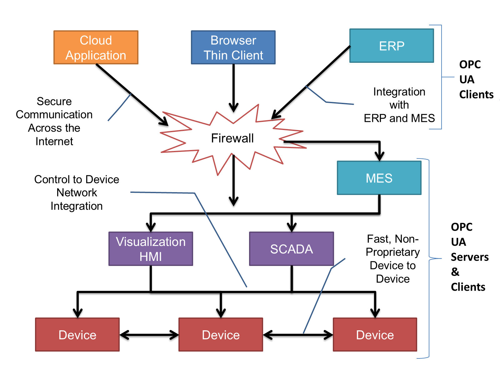
OPC UA provides a robust and reliable communication infrastructure having mechanisms for handling lost messages, failover, heartbeat, etc. With its binary encoded data, it offers a high-performing data exchange solution. Security is built into OPC UA as security requirements become more and more important especially since environments are connected to the office network or the internet and attackers are starting to focus on automation systems.
4.2.3 Information modelling in OPC UA
4.2.3.1 Concepts
OPC UA provides a framework that can be used to represent complex information as Objects in an AddressSpace which can be accessed with standard services. These Objects consist of Nodes connected by References. Different classes of Nodes convey different semantics. For example, a Variable Node represents a value that can be read or written. The Variable Node has an associated DataType that can define the actual value, such as a string, float, structure etc. It can also describe the Variable value as a variant. A Method Node represents a function that can be called. Every Node has a number of Attributes including a unique identifier called a NodeId and non-localized name called a BrowseName. An Object representing a 'Reservation' is shown in Figure 2.
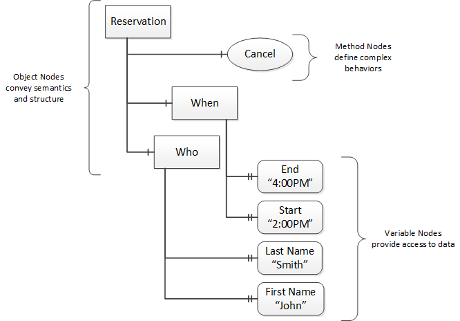
Object and Variable Nodes represent instances and they always have a HasTypeDefinition reference to a Node (ObjectType or VariableType Node) which describes their semantics and structure. Figure 3 illustrates the relationship between an instance and its TypeDefinition.
The type Nodes are templates that define all of the children that can be present in an instance of the type. In the example in Figure 3 the PersonType ObjectType defines two children: First Name and Last Name. All instances of PersonType are expected to have the same children with the same BrowseNames. Within a type the BrowseNames uniquely identify the children. This means Client applications can be designed to search for children based on the BrowseNames from the type instead of NodeIds. This eliminates the need for manual configuration of systems if a Client uses types that multiple Servers implement.
4.2.3.2 Namespaces
OPC UA allows information from many different sources to be combined into a single coherent AddressSpace. Namespaces are used to make this possible by eliminating naming and id conflicts between information from different sources. Each namespace in OPC UA has a globally unique string called a NamespaceUri which identifies a naming authority and a locally unique integer called a NamespaceIndex, which is an index into the Server's table of NamespaceUris. The NamespaceIndex is unique only within the context of a Session between an OPC UA Client and an OPC UA Server- the NamespaceIndex can change between Sessions and still identify the same item even though the NamespaceUri's location in the table has changed. The Services defined for OPC UA use the NamespaceIndex to specify the Namespace for qualified values.
There are two types of structured values in OPC UA that are qualified with NamespaceIndexes: NodeIds and QualifiedNames. NodeIds are locally unique (and sometimes globally unique) identifiers for Nodes. The same globally unique NodeId can be used as the identifier in a node in many Servers - the node's instance data may vary but its semantic meaning is the same regardless of the Server it appears in. This means Clients can have built-in knowledge of of what the data means in these Nodes. OPC UA Information Models generally define globally unique NodeIds for the TypeDefinitions defined by the Information Model.
QualifiedNames are non-localized names qualified with a Namespace. They are used for the BrowseNames of Nodes and allow the same names to be used by different information models without conflict. TypeDefinitions are not allowed to have children with duplicate BrowseNames; however, instances do not have that restriction.
4.2.3.3 Companion Specifications
An OPC UA companion specification for an industry specific vertical market describes an Information Model by defining ObjectTypes, VariableTypes, DataTypes and ReferenceTypes that represent the concepts used in the vertical market, and potentially also well-defined Objects as entry points into the AddressSpace.
5 Use cases
The use cases covered in this version are listed in Table 15. These use cases can be broken into Telemetric and Asset Management categories. Telemetric use cases publish dynamic data e.g. to a cloud application for remote monitoring. Asset Management use cases require client server interaction with the information model typically for on-premises applications.
| Use Case | Description |
| NOA: Health monitoring and diagnosis | Monitoring of the device health including status, possible cause and further details. |
| NOA: Device lifecycle Backup | Storing of NOA device parameters including their history. |
| NOA: Device dimensioning (for sensors & actuators) | Monitor devices over time for their operating range and verify, if their dimensioning is appropriate (e.g. not over dimensioned). |
| NOA: Unique Identification | Identify a device including Manufacturer, Model, SerialNumber, Hardware and Software Revision, Product Code and AssetID (Tag for Device). |
| NOA: Automated as Build | Verify that the installed devices and their configurations match with the engineered devices and configurations. |
| NOA: Read Multivariable process values | Read the process variables from multivariable devices. |
| Device Commissioning | Connecting and binding Process Automation Devices to the automation system. |
| Device Replacement | Replacing a device on a running system. |
| Device Repair | Analyzing device failures and providing actionable information e.g. using device dashboards |
| Device Calibration | Periodic automated calibration, tracking calibration history |
| SIS Proof Testing | Provide information that allows tracking proof test intervals, valve stroke tests, verifying availability on demand. |
| Batch Configuration | Downloading device configurations for a batch of devices |
| Regulatory audits | Verifying device versions and certifications |
Use cases define the content of this Device Information Model. NAMUR Open Architecture (NE175) defines uses cases with parameters, names and semantic ids, which are an important input for the definition of the PA-DIM. Additional details about these use cases can be found in the NAMUR descriptions found on their web site referenced in Section 2.
6 Process Automation Device Information Model overview
6.1 Overview
This specification describes a unified Process Automation Device Information Model (PA-DIM) that enables protocol and vendor independent data exchange. Figure 6 provides an example illustration of a system in which two Devices interact with several applications running in the cloud and accessing generic and product type data. The Information Model of these two devices includes a standardized device model based on PA-DIM. The model also exposes IEC 61987 semantic dictionary IDs. These IDs may be used by OPC UA clients to obtain the definition of vendor specific data the devices may contain.

PA-DIM makes use of the Dictionary Reference model defined in OPC 10000-19 and defines the proper International Registration Data Identifiers (IRDI) for entries in the IEC 61987 CDD. The OPC Foundation added an abstract DictionaryEntryType ObjectType to the OPC 10000-5 specification. It also introduced the IrdiDictionaryEntryType (Subtype of DictionaryEntryType) ObjectType for semantic information and the HasDictionaryEntry Non-Hierarchical ReferenceType to associate the dictionary entry object to any node.
The PA-DIM, illustrated in Figure 7, defines a base device concept and information model, which is intended to be used for Process Automation Devices. This PA-DIM OPC UA Companion Specification defines the OPC UA BrowseNames and corresponding IEC 61987 Semantic CDD Dictionary IDs. For each Node with a dictionary reference to the IEC 61987 Common Data Dictionary, the definition of the referenced IEC 61987 CDD entry applies. It is expected, that ECLASS semantic description will follow the IEC 61987 standardization where applicable.
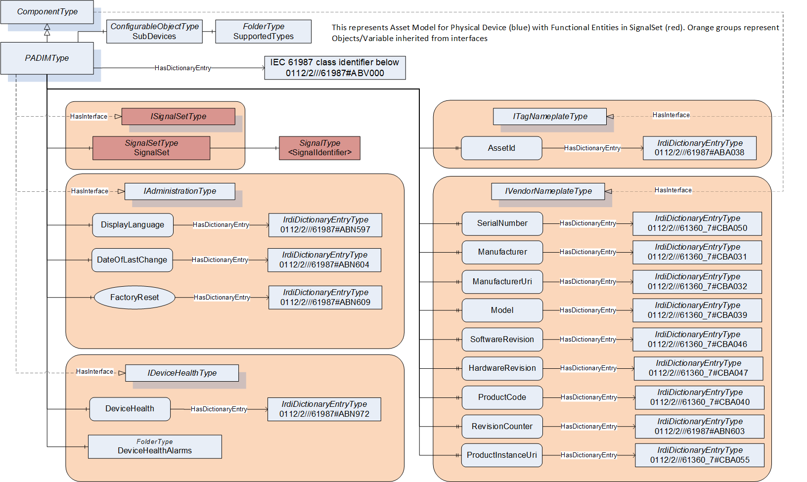
The PADIMType has a HasDictionaryEntry reference to an IRDI representing a class identifier within the IEC 61987 CDD (e.g. Coriolis Flowmeter, Pressure Transmitter, etc.).
The DisplayName Attribute for all Objects, Variables, and Methods with a DictionaryReference in this specification shall be according to the IEC 61987 attribute "Short name" for CDD properties or to the IEC 61987 attribute "Preferred name" for CDD classes. DisplayNames are used for configuration dialog displays and are defined within IEC 61987 CDD. NAMUR NE131 / NOA device parameter names are in line with IEC 61987 CDD.
PA-DIM defines the Interfaces IAdministrationType for administration purposes and ISignalSetType as a container for process variables (see7.1.2). The PADIMType includes these Interfaces, and additionally it includes the IDeviceHealthType, provided by OPC 10000-100OPC 10000-100. Furthermore PADIMType provides a reference to an IRDI dictionary entry to reference the device class (e.g. Pressure Transmitter or Coriolis Mass Flowmeter) and SubDevices Object for modular devices. In this version of PA-DIM the information model has been extended with additional objects and interfaces for Process Analysers. For more details see section 6.2.
Instances of PADIMType represent devices in the real-world. There might be other OPC UA companion specifications representing different aspects of the same real-world device, potentially represented in the same OPC UA Server. Therefore, the guidelines defined in the OPC UA for Devices specification (OPC 10000-100 Annex C) should be followed, when an OPC UA server represents several companion specifications for the same real-world device.
6.2 Process Analyser
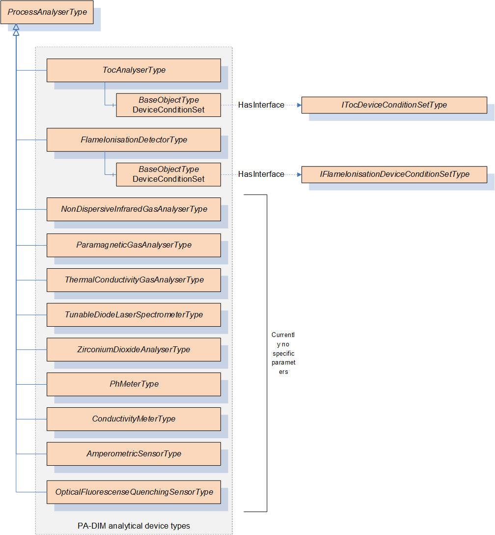
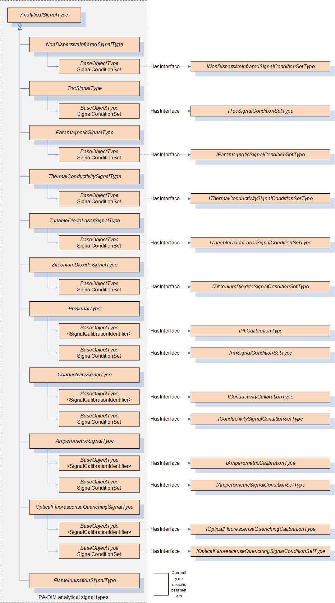
The Object Model for Process Analyser has been extended as shown in Figure 8. The blue marked boxes are from PA-DIM 1.00 and the orange boxes have been added for Process Analysers in version 1.01. Figure 9 and Figure 10 are the extension of Figure 8.
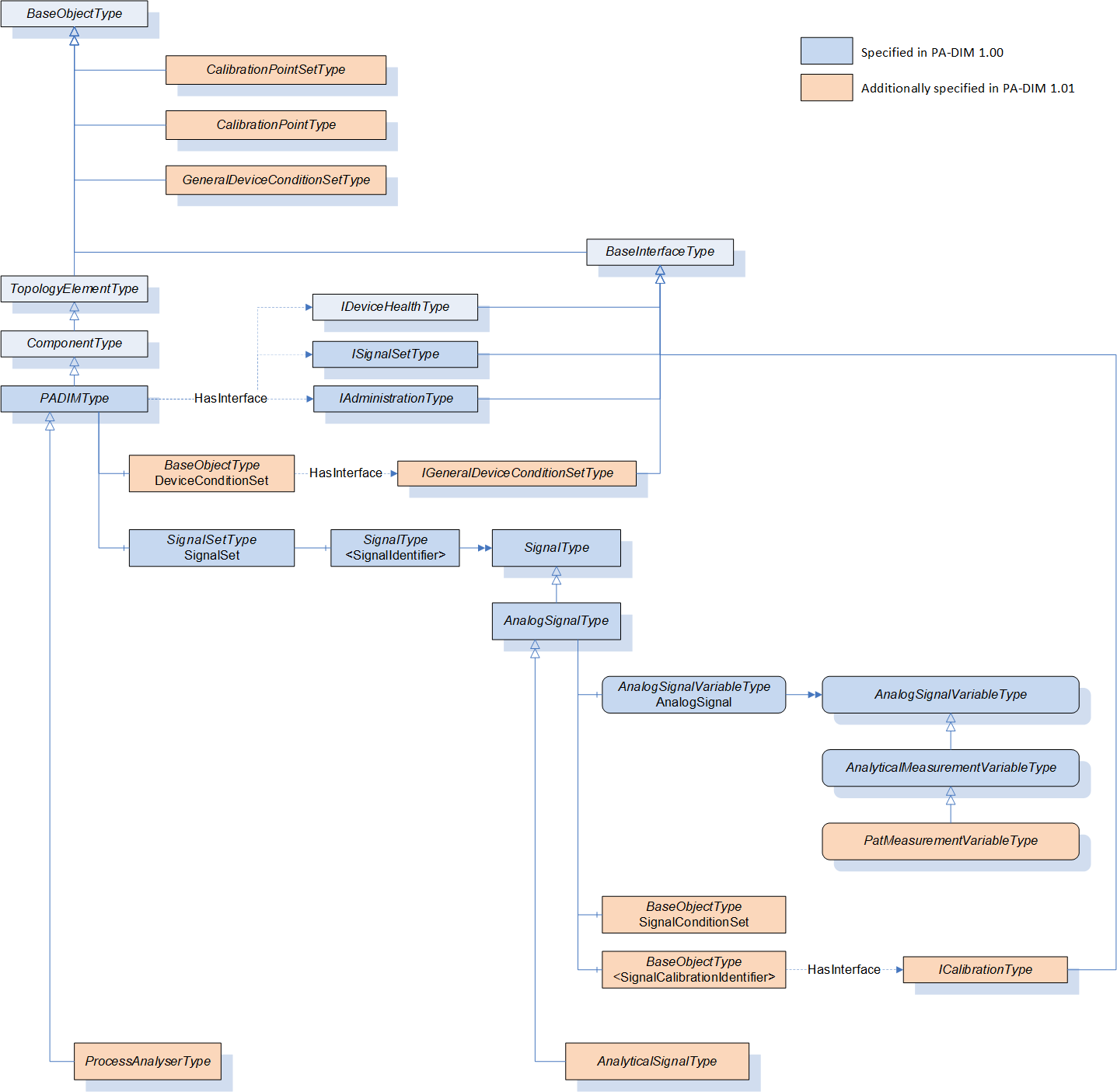
There are special Process Analyser Types and corresponding interfaces shown in Figure 9.
There are special Analytical Signal Types and corresponding interfaces for each Process Analyser, see Figure 10.
6.3 General rules
A device is required to provide mandatory functionality. Optional functionality is not required, but if it is provided, it shall be supported as defined.
The IEC 61987 CDD is the source for the definition of properties according to IEC 61987 specification, which have an IRDI dictionary entry. These definitions include a version at the end after the "#" (e.g. #001). For easier readability, some IRDI dictionary definitions have been copied and added to this specification. Although highly unlikely, the IRDI definitions in this specification may deviate from IEC definitions as the IEC specification may change. In such cases the IEC 61987 CDD specification has precedence over the definitions in this specification.
The IRDI dictionary entries are referenced from the TypeDefinitions in this specification. When instantiating the TypeDefinitions, the instances shall have the same IRDI dictionary entries as defined for the TypeDefinitions in this specification. If an instance is based on a subtype, it shall have all IRDI dictionary entries of the subtype, and of the supertypes, as defined in this specification. The same applies for InstanceDeclarations. All instances based on InstanceDeclarations shall have the same IRDI dictionary entries as their InstanceDeclaration. If the InstanceDeclaration is overridden, also the references to the IRDI dictionary entry objects of the supertypes shall be provided.
Note: As HasDictionaryEntry Reference is a non-hierarchical Reference and the IRDI Objects do not have ModellingRules, the OPC UA Information Model does not force the creation of HasDictionaryEntry references during instantiation automatically.
The primary unit according to IEC 61987 CDD should be used as default unit and may be modified if applicable.
7 PA-DIM Object Types
7.1 PA-DIM Interfaces
7.1.1 IAdministrationType
The IAdministrationType provides the interface to administration variables and methods of the device and is formally defined in Table 16.
| Attribute | Value | ||||
| BrowseName | IAdministrationType | ||||
| IsAbstract | True | ||||
| References | NodeClass | BrowseName | DataType | TypeDefinition | Other |
|---|---|---|---|---|---|
| Subtype of 0:BaseInterfaceType defined in OPC 10000-5, i.e. inheriting the InstanceDeclarations of that Node | |||||
| 0:HasComponent | Variable | DisplayLanguage | 0:LocaleId | 0:BaseDataVariableType | O |
| 0:HasComponent | Variable | DateOfLastChange | 0:DateTime | 0:BaseDataVariableType | O |
| 0:HasComponent | Method | FactoryReset | Defined in 9.1 | O | |
| Conformance Units | |||||
|---|---|---|---|---|---|
| PA-DIM IAdmin DisplayLanguage | |||||
| PA-DIM IAdmin DateOfChange | |||||
| PA-DIM IAdmin FactoryReset |
DisplayLanguage: is the language used for the local display of the device. ABN597#004 defines language or languages set on the display.
DateOfLastChange: ABN604#001 defines parameter indicating the date and time at which one of the device parameters was changed the last time.
FactoryReset: ABN609#002 property the value of which indicates the kind of reset function to be executed. Note: Properties can be variables or methods according IEC 61987 CDD.
The components of IAdministrationType have additional references which are defined in Table 17.
| SourceBrowsePath | Reference Type | Is Forward | TargetBrowsePath |
| DisplayLanguage | 0:HasDictionaryEntry | True | 3:0112/2///61987#ABN597#004 |
| DateOfLastChange | 0:HasDictionaryEntry | True | 3:0112/2///61987#ABN604#001 |
| FactoryReset | 0:HasDictionaryEntry | True | 3:0112/2///61987#ABN609#002 |
The child Nodes of the IAdministrationType have additional Attribute values defined in Table 18.
| BrowsePath | Value Attribute |
| DisplayLanguage | en |
| DateOfLastChange | 1/1/1601 12:00:00 AM |
7.1.2 ISignalSetType
The ISignalSetType provides the interface to process variables of the device and is formally defined in Table 19.
| Attribute | Value | ||||
| BrowseName | ISignalSetType | ||||
| IsAbstract | True | ||||
| References | NodeClass | BrowseName | DataType | TypeDefinition | Other |
|---|---|---|---|---|---|
| Subtype of 0:BaseInterfaceType defined in OPC 10000-5, i.e. inheriting the InstanceDeclarations of that Node | |||||
| 0:HasComponent | Object | SignalSet | SignalSetType | O | |
| Conformance Units | |||||
|---|---|---|---|---|---|
| PA-DIM ISignal |
SignalSet is a container object for the process variables of the device.
7.1.3 ICalibrationType
The ICalibrationType provides the interface to calibration variables of the sensor resp. signal and is formally defined in Table 20.
| Attribute | Value | ||||
| BrowseName | ICalibrationType | ||||
| IsAbstract | True | ||||
| References | NodeClass | BrowseName | DataType | TypeDefinition | Other |
|---|---|---|---|---|---|
| Subtype of 0:BaseInterfaceType defined in OPC 10000-5, i.e. inheriting the InstanceDeclarations of that Node | |||||
| 0:HasProperty | Variable | CalibrationTimestamp | 0:DateTime | 0:PropertyType | O |
| 0:HasComponent | Variable | TypeOfCalibration | 0:UInt32 | 0:MultiStateDictionaryEntryDiscreteType | O |
| 0:HasComponent | Object | CalibrationPointSet | CalibrationPointSetType | O | |
| Conformance Units | |||||
|---|---|---|---|---|---|
| PA-DIM ICalibration | |||||
| PA-DIM ICalibration CalibrationTimestamp | |||||
| PA-DIM ICalibration TypeOfCalibration | |||||
| PA-DIM ICalibration CalibrationPointSet |
CalibrationTimestamp is defined by IRDI as ABP544#001 which states "point in time when a measurement channel of a device was calibrated".
TypeOfCalibration is defined by IRDI as ABH609#002 which states "classification of a calibration according to its intended use".
CalibrationPointSet is a container object for calibration points of the sensor resp. signal.
The components of ICalibrationType have additional references which are defined in Table 21.
| SourceBrowsePath | Reference Type | Is Forward | TargetBrowsePath |
| CalibrationTimestamp | 0:HasDictionaryEntry | True | 3:0112/2///61987#ABP544#001 |
| TypeOfCalibration | 0:HasDictionaryEntry | True | 3:0112/2///61987#ABH609#002 |
The child Nodes of the ICalibrationType have additional Attribute values defined in Table 22.
| BrowsePath | Value Attribute | ||
| CalibrationTimestamp | 1/1/1601 12:00:00 AM | ||
| TypeOfCalibration | 0 | ||
| ns=3;s=0112/2///61987#ABP732#001 | ||
| adjustment |
7.1.4 IConductivityCalibrationType
The IConductivityCalibrationType provides the interface to conductivity measurement specific calibration variables of the sensor resp. signal and is formally defined in Table 23.
| Attribute | Value | ||||
| BrowseName | IConductivityCalibrationType | ||||
| IsAbstract | True | ||||
| References | NodeClass | BrowseName | DataType | TypeDefinition | Other |
|---|---|---|---|---|---|
| Subtype of 0:BaseInterfaceType defined in OPC 10000-5, i.e. inheriting the InstanceDeclarations of that Node | |||||
| 0:HasComponent | Variable | ConductivityCellConstant | 0:Float | 0:AnalogUnitType | O |
| Conformance Units | |||||
|---|---|---|---|---|---|
| PA-DIM PhSignalType |
ConductivityCellConstant is defined by IRDI as ABF161#001 which states "ratio of the distance between the electrodes to the electrode area".
The components of IConductivityCalibrationType have additional references which are defined in Table 24.
| SourceBrowsePath | Reference Type | Is Forward | TargetBrowsePath | |||||
| ConductivityCellConstant | 0:HasDictionaryEntry | True | 3:0112/2///61987#ABF161#001 | |||||
| 0:HasDictionaryEntry | True | 3:0112/2///61987#ABA968#004 | |||||
The child Nodes of the IConductivityCalibrationType have additional Attribute values defined in Table 25.
| BrowsePath | Value Attribute | ||
| ConductivityCellConstant | 0.0 | ||
| NamespaceUri: http://www.opcfoundation.org/UA/units/cdd/IEC62720 UnitId: 705744658 DisplayName: cm⁻¹ Description: reciprocal centimetre |
7.1.5 IAmperometricCalibrationType
The IAmperometricCalibrationType provides the interface to amperometric measurement specific calibration variables of the sensor resp. signal and is formally defined in Table 26.
| Attribute | Value | ||||
| BrowseName | IAmperometricCalibrationType | ||||
| IsAbstract | True | ||||
| References | NodeClass | BrowseName | DataType | TypeDefinition | Other |
|---|---|---|---|---|---|
| Subtype of 0:BaseInterfaceType defined in OPC 10000-5, i.e. inheriting the InstanceDeclarations of that Node | |||||
| 0:HasComponent | Variable | AmperometricSensorSlope | 0:Float | 0:AnalogUnitType | O |
| 0:HasComponent | Variable | AmperometricSensorZeroPoint | 0:Float | 0:AnalogUnitType | O |
| 0:HasComponent | Variable | AbsoluteAirPressure | 0:Float | 0:AnalogUnitType | O |
| 0:HasProperty | Variable | SensorT90 | 0:Float | 0:PropertyType | O |
| Conformance Units | |||||
|---|---|---|---|---|---|
| PA-DIM AmperometricSignalType | |||||
| PA-DIM IAmperometricCalibration AbsoluteAirPressure | |||||
| PA-DIM IAmperometricCalibration SensorT90 |
AmperometricSensorSlope is defined by IRDI as ABP572#001 which states "slope of an amperometric sensing element characteristic determined by the last calibration".
AmperometricSensorZeroPoint is defined by IRDI as ABP573#001 which states "zero point of an amperometric sensing element characteristic determined by the last calibration".
AbsoluteAirPressure is defined by IRDI as ABP574#001 which states "absolute air pressure under which the last calibration was performed".
SensorT90 is defined by IRDI as ABP569#001 which states "t90 settling time determined by the last calibration".
The components of IAmperometricCalibrationType have additional references which are defined in Table 27.
| SourceBrowsePath | Reference Type | Is Forward | TargetBrowsePath | ||
| AmperometricSensorSlope | 0:HasDictionaryEntry | True | 3:0112/2///61987#ABP572#001 | ||
| 0:HasDictionaryEntry | True | 3:0112/2///61987#ABA968#004 | ||
| AmperometricSensorZeroPoint | 0:HasDictionaryEntry | True | 3:0112/2///61987#ABP573#001 | ||
| 0:HasDictionaryEntry | True | 3:0112/2///61987#ABA968#004 | ||
| AbsoluteAirPressure | 0:HasDictionaryEntry | True | 3:0112/2///61987#ABP574#001 | ||
| 0:HasDictionaryEntry | True | 3:0112/2///61987#ABA968#004 | ||
| SensorT90 | 0:HasDictionaryEntry | True | 3:0112/2///61987#ABP569#001 |
The child Nodes of the IAmperometricCalibrationType have additional Attribute values defined in Table 28.
| BrowsePath | Value Attribute | ||
| AmperometricSensorZeroPoint | 0.0 | ||
| NamespaceUri: http://www.opcfoundation.org/UA/units/cdd/IEC62720 UnitId: 705750616 DisplayName: pA Description: picoampere | ||
| AbsoluteAirPressure | 0.0 | ||
| NamespaceUri: http://www.opcfoundation.org/UA/units/cdd/IEC62720 UnitId: 705746519 DisplayName: hPa Description: hectopascal | ||
| SensorT90 | 0.0 |
7.1.6 IOpticalFluorescenseQuenchingCalibrationType
The IOpticalFluorescenseQuenchingCalibrationType provides the interface to optical fluorescence quenching measurement specific calibration variables of the sensor resp. signal and is formally defined in Table 29.
| Attribute | Value | ||||
| BrowseName | IOpticalFluorescenseQuenchingCalibrationType | ||||
| IsAbstract | True | ||||
| References | NodeClass | BrowseName | DataType | TypeDefinition | Other |
|---|---|---|---|---|---|
| Subtype of 0:BaseInterfaceType defined in OPC 10000-5, i.e. inheriting the InstanceDeclarations of that Node | |||||
| 0:HasComponent | Variable | OpticalFluorescenseQuenchingSensorSlope | 0:Float | 0:AnalogUnitType | O |
| 0:HasComponent | Variable | OpticalFluorescenseQuenchingSensorZeroPoint | 0:Float | 0:AnalogUnitType | O |
| 0:HasComponent | Variable | AbsoluteAirPressure | 0:Float | 0:AnalogUnitType | O |
| 0:HasProperty | Variable | SensorT90 | 0:Float | 0:PropertyType | O |
| Conformance Units | |||||
|---|---|---|---|---|---|
| PA-DIM OpticalFluorescenseQuenchingSignalType | |||||
| PA-DIM IOpticalFluorescenseQuenchingCalibration AbsoluteAirPressure | |||||
| PA-DIM IOpticalFluorescenseQuenchingCalibration SensorT90 |
OpticalFluorescenseQuenchingSensorSlope is defined by IRDI as ABP586#001 which states "slope of an optical fluorescence quenching sensing element characteristic determined by the last calibration".
OpticalFluorescenseQuenchingSensorZeroPoint is defined by IRDI as ABP587#001 which states "zero point of an optical fluorescence quenching sensing element characteristic determined by the last calibration".
AbsoluteAirPressure is defined by IRDI as ABP574#001 which states "absolute air pressure under which the last calibration was performed".
SensorT90 is defined by IRDI as ABP569#001 which states "t90 settling time determined by the last calibration".
The components of IOpticalFluorescenseQuenchingCalibrationType have additional references which are defined in Table 30.
| SourceBrowsePath | Reference Type | Is Forward | TargetBrowsePath | ||
| OpticalFluorescenseQuenchingSensorSlope | 0:HasDictionaryEntry | True | 3:0112/2///61987#ABP586#001 | ||
| 0:HasDictionaryEntry | True | 3:0112/2///61987#ABA968#004 | ||
| OpticalFluorescenseQuenchingSensorZeroPoint | 0:HasDictionaryEntry | True | 3:0112/2///61987#ABP587#001 | ||
| 0:HasDictionaryEntry | True | 3:0112/2///61987#ABA968#004 | ||
| AbsoluteAirPressure | 0:HasDictionaryEntry | True | 3:0112/2///61987#ABP574#001 | ||
| 0:HasDictionaryEntry | True | 3:0112/2///61987#ABA968#004 | ||
| SensorT90 | 0:HasDictionaryEntry | True | 3:0112/2///61987#ABP569#001 |
The child Nodes of the IOpticalFluorescenseQuenchingCalibrationType have additional Attribute values defined in Table 31.
| BrowsePath | Value Attribute | ||
| OpticalFluorescenseQuenchingSensorZeroPoint | 0.0 | ||
| NamespaceUri: http://www.opcfoundation.org/UA/units/cdd/IEC62720 UnitId: 705741621 DisplayName: µs Description: microsecond | ||
| AbsoluteAirPressure | 0.0 | ||
| NamespaceUri: http://www.opcfoundation.org/UA/units/cdd/IEC62720 UnitId: 705746519 DisplayName: hPa Description: hectopascal | ||
| SensorT90 | 0.0 |
7.1.7 IGasChromatographCalibrationType
The IGasChromatographCalibrationType provides the interface to gaschromatograph measurement specific calibration variables of the sensor resp. signal and is formally defined in Table 32.
| Attribute | Value | ||||
| BrowseName | IGasChromatographCalibrationType | ||||
| IsAbstract | True | ||||
| References | NodeClass | BrowseName | DataType | TypeDefinition | Other |
|---|---|---|---|---|---|
| Subtype of 0:BaseInterfaceType defined in OPC 10000-5, i.e. inheriting the InstanceDeclarations of that Node | |||||
| 0:HasProperty | Variable | CalibrationRange1ResponseFactor | 0:Float | 0:PropertyType | O |
| 0:HasComponent | Variable | CalibrationRange1LowerRangeValue | 0:Float | 0:AnalogUnitType | O |
| 0:HasComponent | Variable | CalibrationRange1UpperRangeValue | 0:Float | 0:AnalogUnitType | O |
| 0:HasProperty | Variable | CalibrationRange2ResponseFactor | 0:Float | 0:PropertyType | O |
| 0:HasComponent | Variable | CalibrationRange2LowerRangeValue | 0:Float | 0:AnalogUnitType | O |
| 0:HasComponent | Variable | CalibrationRange2UpperRangeValue | 0:Float | 0:AnalogUnitType | O |
| 0:HasProperty | Variable | CalibrationRange3ResponseFactor | 0:Float | 0:PropertyType | O |
| 0:HasComponent | Variable | CalibrationRange3LowerRangeValue | 0:Float | 0:AnalogUnitType | O |
| 0:HasComponent | Variable | CalibrationRange3UpperRangeValue | 0:Float | 0:AnalogUnitType | O |
| Conformance Units | |||||
|---|---|---|---|---|---|
| PA-DIM GasChromatograph CalibrationRange1 | |||||
| PA-DIM GasChromatograph CalibrationRange2 | |||||
| PA-DIM GasChromatograph CalibrationRange3 |
CalibrationRange1ResponseFactor is defined by IRDI as ABQ024#001 which states "ratio between the concentration of a compound being analysed and the response of the detector to that compound for the calibration range 1".
CalibrationRange1LowerRangeValue is defined by IRDI as ABQ025#001 which states "volume concentration value assigned to the lower range end-value of calibration range 1".
CalibrationRange1UpperRangeValue is defined by IRDI as ABQ026#001 which states "volume concentration value assigned to the upper range end-value of calibration range 1".
CalibrationRange2ResponseFactor is defined by IRDI as ABQ027#001 which states "ratio between the concentration of a compound being analysed and the response of the detector to that compound for the calibration range 2".
CalibrationRange2LowerRangeValue is defined by IRDI as ABQ028#001 which states "volume concentration value assigned to the lower range end-value of calibration range 2".
CalibrationRange2UpperRangeValue is defined by IRDI as ABQ029#001 which states "volume concentration value assigned to the upper range end-value of calibration range 2".
CalibrationRange3ResponseFactor is defined by IRDI as ABQ030#001 which states "ratio between the concentration of a compound being analysed and the response of the detector to that compound for the calibration range 3".
CalibrationRange3LowerRangeValue is defined by IRDI as ABQ031#001 which states "volume concentration value assigned to the lower range end-value of calibration range 3".
CalibrationRange3UpperRangeValue is defined by IRDI as ABQ032#001 which states "volume concentration value assigned to the upper range end-value of calibration range 3".
The components of IGasChromatographCalibrationType have additional references which are defined in Table 33.
| SourceBrowsePath | Reference Type | Is Forward | TargetBrowsePath |
| CalibrationRange1ResponseFactor | 0:HasDictionaryEntry | True | 3:0112/2///61987#ABQ024#001 |
| CalibrationRange1LowerRangeValue | 0:HasDictionaryEntry | True | 3:0112/2///61987#ABQ025#001 |
| CalibrationRange1UpperRangeValue | 0:HasDictionaryEntry | True | 3:0112/2///61987#ABQ026#001 |
| CalibrationRange2ResponseFactor | 0:HasDictionaryEntry | True | 3:0112/2///61987#ABQ027#001 |
| CalibrationRange2LowerRangeValue | 0:HasDictionaryEntry | True | 3:0112/2///61987#ABQ028#001 |
| CalibrationRange2UpperRangeValue | 0:HasDictionaryEntry | True | 3:0112/2///61987#ABQ029#001 |
| CalibrationRange3ResponseFactor | 0:HasDictionaryEntry | True | 3:0112/2///61987#ABQ030#001 |
| CalibrationRange3LowerRangeValue | 0:HasDictionaryEntry | True | 3:0112/2///61987#ABQ031#001 |
| CalibrationRange3UpperRangeValue | 0:HasDictionaryEntry | True | 3:0112/2///61987#ABQ032#001 |
The child Nodes of the IGasChromatographCalibrationType have additional Attribute values defined in Table 34.
| BrowsePath | Value Attribute | ||
| CalibrationRange1ResponseFactor | 1.0 | ||
| CalibrationRange1LowerRangeValue | 0.0 | ||
| NamespaceUri: http://www.opcfoundation.org/UA/units/cdd/IEC62720 UnitId: 705848917 DisplayName: ppm Description: parts per million | ||
| CalibrationRange1UpperRangeValue | 100.0 | ||
| NamespaceUri: http://www.opcfoundation.org/UA/units/cdd/IEC62720 UnitId: 705848917 DisplayName: ppm Description: parts per million | ||
| CalibrationRange2ResponseFactor | 1.0 | ||
| CalibrationRange2LowerRangeValue | 0.0 | ||
| NamespaceUri: http://www.opcfoundation.org/UA/units/cdd/IEC62720 UnitId: 705848917 DisplayName: ppm Description: parts per million | ||
| CalibrationRange2UpperRangeValue | 100.0 | ||
| NamespaceUri: http://www.opcfoundation.org/UA/units/cdd/IEC62720 UnitId: 705848917 DisplayName: ppm Description: parts per million | ||
| CalibrationRange3ResponseFactor | 1.0 | ||
| CalibrationRange3LowerRangeValue | 0.0 | ||
| NamespaceUri: http://www.opcfoundation.org/UA/units/cdd/IEC62720 UnitId: 705848917 DisplayName: ppm Description: parts per million | ||
| CalibrationRange3UpperRangeValue | 100.0 | ||
| NamespaceUri: http://www.opcfoundation.org/UA/units/cdd/IEC62720 UnitId: 705848917 DisplayName: ppm Description: parts per million |
7.1.8 IPhCalibrationType
The IPhCalibrationType provides the interface to pH measurement specific calibration variables of the sensor resp. signal and is formally defined in .
| Attribute | Value | ||||
| BrowseName | IPhCalibrationType | ||||
| IsAbstract | True | ||||
| References | NodeClass | BrowseName | DataType | TypeDefinition | Other |
|---|---|---|---|---|---|
| Subtype of 0:BaseInterfaceType defined in OPC 10000-5, i.e. inheriting the InstanceDeclarations of that Node | |||||
| 0:HasComponent | Variable | SensorSlope | 0:Float | 0:AnalogUnitType | O |
| 0:HasComponent | Variable | SensorAsymmetryPotential | 0:Float | 0:AnalogUnitType | O |
| 0:HasProperty | Variable | SensorT90 | 0:Float | 0:PropertyType | O |
| Conformance Units | |||||
|---|---|---|---|---|---|
| PA-DIM PhSignalType | |||||
| PA-DIM IPhCalibration SensorT90 |
SensorSlope is defined by IRDI as ABP567#001 which states "slope of a pH sensing element characteristic, expressed as the voltage change of the pH sensor per pH value, determined by the last calibration".
SensorAsymmetryPotential is defined by IRDI as ABP568#001 which states "asymmetry potential of a pH sensing element characteristic determined by the last calibration".
SensorT90is defined by IRDI as ABP569#001 which states "t90 settling time determined by the last calibration".
The components of IPhCalibrationType have additional references which are defined in Table 36.
| SourceBrowsePath | Reference Type | Is Forward | TargetBrowsePath | ||
| SensorSlope | 0:HasDictionaryEntry | True | 3:0112/2///61987#ABP567#001 | ||
| 0:HasDictionaryEntry | True | 3:0112/2///61987#ABA968#004 | ||
| SensorAsymmetryPotential | 0:HasDictionaryEntry | True | 3:0112/2///61987#ABP568#001 | ||
| 0:HasDictionaryEntry | True | 3:0112/2///61987#ABA968#004 | ||
| SensorT90 | 0:HasDictionaryEntry | True | 3:0112/2///61987#ABP569#001 |
The child Nodes of the IPhCalibrationType have additional Attribute values defined in Table 37.
| BrowsePath | Value Attribute | ||
| SensorSlope | 0.0 | ||
| NamespaceUri: http://www.opcfoundation.org/UA/units/cdd/IEC62720 Description: millivolt | ||
| SensorAsymmetryPotential | 0.0 | ||
| NamespaceUri: http://www.opcfoundation.org/UA/units/cdd/IEC62720 DisplayName: mV Description: millivolt | ||
| SensorT90 | 0.0 |
7.1.9 IGeneralDeviceConditionSetType
The IGeneralDeviceConditionSetType provides the interface to condition variables of the device and its components and is formally defined in Table 38.
| Attribute | Value | ||||
| BrowseName | IGeneralDeviceConditionSetType | ||||
| IsAbstract | True | ||||
| References | NodeClass | BrowseName | DataType | TypeDefinition | Other |
|---|---|---|---|---|---|
| Subtype of 0:BaseInterfaceType defined in OPC 10000-5, i.e. inheriting the InstanceDeclarations of that Node | |||||
| 0:HasComponent | Object | GeneralDeviceConditions | GeneralDeviceConditionSetType | O | |
| 0:HasComponent | Object | DeviceComponentConditions | 0:BaseObjectType | O | |
| Conformance Units | |||||
|---|---|---|---|---|---|
| PA-DIM IGeneralDeviceConditionSet | |||||
| PA-DIM IGeneralDeviceConditionSet DeviceComponentConditions |
GeneralDeviceConditions is a container object for general condition variables of the device.
DeviceComponentConditions is a container object for condition variables of the device components.
| BrowsePath | References | NodeClass | BrowseName | DataType | TypeDefinition | Other |
| DeviceComponentConditions | 0:HasComponent | Object | <DeviceComponentIdentifier> | GeneralDeviceConditionSetType | OP |
<DeviceComponentIdentifier> is an optional placeholder for an object containing the condition variables related to a specific device component.
7.1.10 ITocDeviceConditionSetType
The ITocDeviceConditionSetType provides the interface to TOC device specific condition variables and is formally defined in Table 40.
| Attribute | Value | ||||
| BrowseName | ITocDeviceConditionSetType | ||||
| IsAbstract | True | ||||
| References | NodeClass | BrowseName | DataType | TypeDefinition | Other |
|---|---|---|---|---|---|
| Subtype of 0:BaseInterfaceType defined in OPC 10000-5, i.e. inheriting the InstanceDeclarations of that Node | |||||
| 0:HasComponent | Variable | CarrierGasVolumeFlow | 0:Float | 0:AnalogUnitType | O |
| 0:HasComponent | Variable | CarrierGasGaugePressure | 0:Float | 0:AnalogUnitType | O |
| 0:HasComponent | Variable | ReactorTemperature | 0:Float | 0:AnalogUnitType | O |
| 0:HasComponent | Variable | SampleWaterVolumeFlow | 0:Float | 0:AnalogUnitType | O |
| 0:HasComponent | Variable | ReferenceInjectionVolume | 0:Float | 0:AnalogUnitType | O |
| 0:HasComponent | Variable | ActualInjectedVolume | 0:Float | 0:AnalogUnitType | O |
| 0:HasComponent | Variable | CoolerTemperature | 0:Float | 0:AnalogUnitType | O |
| Conformance Units | |||||
|---|---|---|---|---|---|
| PA-DIM TocAnalyserType | |||||
| PA-DIM TocAnalyserType CarrierGasGaugePressure | |||||
| PA-DIM TocAnalyserType SampleWaterVolumeFlow | |||||
| PA-DIM TocAnalyserType ActualInjectedVolume |
CarrierGasVolumeFlow is defined by IRDI as ABP558#001 which states "volume flow of the auxiliary (compressed air) gas supply".
CarrierGasGaugePressure is defined by IRDI as ABP559#001 which states "overpressure of the auxiliary (compressed air) gas supply in the system due to flow resistance within the complete analytical system".
ReactorTemperature is defined by IRDI as ABP554#001 which states "measured temperature of a high temperature combustion system".
SampleWaterVolumeFlow is defined by IRDI as ABP561#001 which states "volume flow of a liquid sample inside the device".
ReferenceInjectionVolume is defined by IRDI as ABP563#001 which states "volume of liquid that should be injected by the injection system".
ActualInjectedVolume is defined by IRDI as ABP564#001 which states "volume of liquid that has been injected by the injection system".
CoolerTemperature is defined by IRDI as ABP555#001 which states "measured temperature of the gas cooler".
The components of ITocDeviceConditionSetType have additional references which are defined in Table 41.
| SourceBrowsePath | Reference Type | Is Forward | TargetBrowsePath | ||
| CarrierGasVolumeFlow | 0:HasDictionaryEntry | True | 3:0112/2///61987#ABP558#001 | ||
| 0:HasDictionaryEntry | True | 3:0112/2///61987#ABA968#004 | ||
| CarrierGasGaugePressure | 0:HasDictionaryEntry | True | 3:0112/2///61987#ABP559#001 | ||
| 0:HasDictionaryEntry | True | 3:0112/2///61987#ABA968#004 | ||
| ReactorTemperature | 0:HasDictionaryEntry | True | 3:0112/2///61987#ABP554#001 | ||
| 0:HasDictionaryEntry | True | 3:0112/2///61987#ABA968#004 | ||
| SampleWaterVolumeFlow | 0:HasDictionaryEntry | True | 3:0112/2///61987#ABP561#001 | ||
| 0:HasDictionaryEntry | True | 3:0112/2///61987#ABA968#004 | ||
| ReferenceInjectionVolume | 0:HasDictionaryEntry | True | 3:0112/2///61987#ABP563#001 | ||
| 0:HasDictionaryEntry | True | 3:0112/2///61987#ABA968#004 | ||
| ActualInjectedVolume | 0:HasDictionaryEntry | True | 3:0112/2///61987#ABP564#001 | ||
| 0:HasDictionaryEntry | True | 3:0112/2///61987#ABA968#004 | ||
| CoolerTemperature | 0:HasDictionaryEntry | True | 3:0112/2///61987#ABP555#001 | ||
| 0:HasDictionaryEntry | True | 3:0112/2///61987#ABA968#004 |
The child Nodes of the ITocDeviceConditionSetType have additional Attribute values defined in Table 42.
| BrowsePath | Value Attribute | ||
| CarrierGasVolumeFlow | 0.0 | ||
| NamespaceUri: http://www.opcfoundation.org/UA/units/cdd/IEC62720 UnitId: 705747637 DisplayName: l/h Description: litre per hour | ||
| CarrierGasGaugePressure | 0.0 | ||
| NamespaceUri: http://www.opcfoundation.org/UA/units/cdd/IEC62720 UnitId: 705749552 DisplayName: mbar Description: millibar | ||
| ReactorTemperature | 0.0 | ||
| NamespaceUri: http://www.opcfoundation.org/UA/units/cdd/IEC62720 UnitId: 705741427 DisplayName: °C Description: degree Celsius | ||
| SampleWaterVolumeFlow | 0.0 | ||
| NamespaceUri: http://www.opcfoundation.org/UA/units/cdd/IEC62720 Description: millilitre per minute | ||
| ReferenceInjectionVolume | 0.0 | ||
| NamespaceUri: http://www.opcfoundation.org/UA/units/cdd/IEC62720 UnitId: 705749652 Description: millilitre | ||
| ActualInjectedVolume | 0.0 | ||
| NamespaceUri: http://www.opcfoundation.org/UA/units/cdd/IEC62720 UnitId: 705749652 Description: millilitre | ||
| CoolerTemperature | 0.0 | ||
| NamespaceUri: http://www.opcfoundation.org/UA/units/cdd/IEC62720 UnitId: 705741427 DisplayName: °C Description: degree Celsius |
7.1.11 IFlameIonisationDeviceConditionSetType
The IFlameIonisationDeviceConditionSetType provides the interface to FID specific condition variables and is formally defined in Table 43.
| Attribute | Value | ||||
| BrowseName | IFlameIonisationDeviceConditionSetType | ||||
| IsAbstract | True | ||||
| References | NodeClass | BrowseName | DataType | TypeDefinition | Other |
|---|---|---|---|---|---|
| Subtype of 0:BaseInterfaceType defined in OPC 10000-5, i.e. inheriting the InstanceDeclarations of that Node | |||||
| 0:HasComponent | Variable | CatalystTemperature | 0:Float | 0:AnalogUnitType | O |
| 0:HasComponent | Variable | FuelGasPressure | 0:Float | 0:AnalogUnitType | O |
| 0:HasComponent | Variable | CombustionAirPressure | 0:Float | 0:AnalogUnitType | O |
| 0:HasComponent | Variable | BlockTemperature | 0:Float | 0:AnalogUnitType | O |
| Conformance Units | |||||
|---|---|---|---|---|---|
| PA-DIM FlameIonisationDetectorType CatalystTemperature | |||||
| PA-DIM FlameIonisationDetectorType FuelGasPressure | |||||
| PA-DIM FlameIonisationDetectorType CombustionAirPressure | |||||
| PA-DIM FlameIonisationDetectorType BlockTemperature |
CatalystTemperature is defined by IRDI as ABP576#001 which states "measured temperature of a catalyst".
FuelGasPressure is defined by IRDI as ABP578#001 which states "measured absolute pressure of the fuel gas".
CombustionAirPressure is defined by IRDI as ABP579#001 which states "measured absolute pressure of the combustion air".
BlockTemperature is defined by IRDI as ABP577#001 which states "measured temperature of a flame ionisation detector block".
The components of IFlameIonisationDeviceConditionSetType have additional references which are defined in Table 44.
| SourceBrowsePath | Reference Type | Is Forward | TargetBrowsePath | ||
| CatalystTemperature | 0:HasDictionaryEntry | True | 3:0112/2///61987#ABP576#001 | ||
| 0:HasDictionaryEntry | True | 3:0112/2///61987#ABA968#004 | ||
| FuelGasPressure | 0:HasDictionaryEntry | True | 3:0112/2///61987#ABP578#001 | ||
| 0:HasDictionaryEntry | True | 3:0112/2///61987#ABA968#004 | ||
| CombustionAirPressure | 0:HasDictionaryEntry | True | 3:0112/2///61987#ABP579#001 | ||
| 0:HasDictionaryEntry | True | 3:0112/2///61987#ABA968#004 | ||
| BlockTemperature | 0:HasDictionaryEntry | True | 3:0112/2///61987#ABP577#001 | ||
| 0:HasDictionaryEntry | True | 3:0112/2///61987#ABA968#004 |
The child Nodes of the IFlameIonisationDeviceConditionSetType have additional Attribute values defined in Table 45.
| BrowsePath | Value Attribute | ||
| CatalystTemperature | 0.0 | ||
| NamespaceUri: http://www.opcfoundation.org/UA/units/cdd/IEC62720 UnitId: 705741427 DisplayName: °C Description: degree Celsius | ||
| FuelGasPressure | 0.0 | ||
| NamespaceUri: http://www.opcfoundation.org/UA/units/cdd/IEC62720 UnitId: 705749552 DisplayName: mbar Description: millibar | ||
| CombustionAirPressure | 0.0 | ||
| NamespaceUri: http://www.opcfoundation.org/UA/units/cdd/IEC62720 UnitId: 705749552 DisplayName: mbar Description: millibar | ||
| BlockTemperature | 0.0 | ||
| NamespaceUri: http://www.opcfoundation.org/UA/units/cdd/IEC62720 UnitId: 705741427 DisplayName: °C Description: degree Celsius |
7.1.12 IGasChromatographDeviceConditionSetType
The IGasChromatographDeviceConditionSetType provides the interface to gas chromatograph device specific condition variables and is formally defined in Table 46
| Attribute | Value | ||||
| BrowseName | IGasChromatographDeviceConditionSetType | ||||
| IsAbstract | True | ||||
| References | NodeClass | BrowseName | DataType | TypeDefinition | Other |
|---|---|---|---|---|---|
| Subtype of 0:BaseInterfaceType defined in OPC 10000-5, i.e. inheriting the InstanceDeclarations of that Node | |||||
| 0:HasProperty | Variable | ValveName | 0:LocalizedText[] | 0:PropertyType | O |
| 0:HasProperty | Variable | ValveSwitchingCyclesCounter | 0:UInt32[] | 0:PropertyType | O |
| 0:HasComponent | Variable | TotalAreaMeasuredPeaks | 0:Float | 0:AnalogUnitType | O |
| 0:HasComponent | Variable | BaselineNoise | 0:Float | 0:AnalogUnitType | O |
| Conformance Units | |||||
|---|---|---|---|---|---|
| PA-DIM GasChromatographType | |||||
| PA-DIM GasChromatographType Valve | |||||
| PA-DIM GasChromatographType TotalAreaMeasuredPeaks | |||||
| PA-DIM GasChromatographType BaselineNoise |
ValveName is defined by IRDI as ABQ046#001 which states "name of the valve".
ValveSwitchingCyclesCounter is defined by IRDI as ABQ007#001 which states "number of opening or closing operations of a valve".
TotalAreaMeasuredPeaks is defined by IRDI as ABQ043#001 which states "integral of the area under the output peaks of all chromatogram substance signals in units defined by the manufacturer".
BaselineNoise is defined by IRDI as ABQ036#001 which states "short-term variation of the baseline from a straight line caused by electric signal fluctuations from the detector".
The components of IGasChromatographDeviceConditionSetType have additional references which are defined in Table 48.
| SourceBrowsePath | Reference Type | Is Forward | TargetBrowsePath |
| ValveName | 0:HasDictionaryEntry | True | 3:0112/2///61987#ABQ046#001 |
| ValveSwitchingCyclesCounter | 0:HasDictionaryEntry | True | 3:0112/2///61987#ABQ007#001 |
| TotalAreaMeasuredPeaks | 0:HasDictionaryEntry | True | 3:0112/2///61987#ABQ043#001 |
| BaselineNoise | 0:HasDictionaryEntry | True | 3:0112/2///61987#ABQ036#001 |
The child Nodes of the IGasChromatographDeviceConditionSetType have additional Attribute values defined in Table 48.
| BrowsePath | Value Attribute | ||
| TotalAreaMeasuredPeaks | 0.0 | ||
| NamespaceUri: http://www.opcfoundation.org/UA/units/cdd/IEC62720 UnitId: 705741328 DisplayName: % Description: percent | ||
| BaselineNoise | 0.0 | ||
| NamespaceUri: http://www.opcfoundation.org/UA/units/cdd/IEC62720 DisplayName: mV |
7.1.13 IFtnirOrFtirDeviceConditionSetType
The IFtnirOrFtirDeviceConditionSetType provides the interface to Fourier Transform Near-Infrared Spectroscopy or Fourier Transform Infrared Spectroscopy device specific condition variables and is formally defined in Table 49.
| Attribute | Value | ||||
| BrowseName | IFtnirOrFtirDeviceConditionSetType | ||||
| IsAbstract | True | ||||
| References | NodeClass | BrowseName | DataType | TypeDefinition | Other |
|---|---|---|---|---|---|
| Subtype of 0:BaseInterfaceType defined in OPC 10000-5, i.e. inheriting the InstanceDeclarations of that Node | |||||
| 0:HasProperty | Variable | Watchdog | 0:Boolean | 0:PropertyType | O |
| 0:HasProperty | Variable | RemainingDataStorageCapacity | 0:Float | 0:PropertyType | O |
| Conformance Units | |||||
|---|---|---|---|---|---|
| PA-DIM FtnirOrFtirSpectrometerType | |||||
| PA-DIM FtnirOrFtirSpectrometerType Watchdog | |||||
| PA-DIM FtnirOrFtirSpectrometerType RemainingDataStorageCapacity |
Watchdog is defined by IRDI as ABP996#002 which states "existence of a function for failure detection of installed hardware and software"
RemainingDataStorageCapacity is defined by IRDI as ABQ039#001 which states "amount of memory remaining for storage of device data, measured in terabytes".
The components of IFtnirOrFtirDeviceConditionSetType have additional references which are defined in Table 50.
| SourceBrowsePath | Reference Type | Is Forward | TargetBrowsePath |
| Watchdog | 0:HasDictionaryEntry | True | 3:0112/2///61987#ABP996#002 |
| RemainingDataStorageCapacity | 0:HasDictionaryEntry | True | 3:0112/2///61987#ABQ039#001 |
The child Nodes of the IFtnirOrFtirDeviceConditionSetType have additional Attribute values defined in Table 51.
| BrowsePath | Value Attribute |
| RemainingDataStorageCapacity | 0.0 |
7.1.14 IDiodeArrayDeviceConditionSetType
The IDiodeArrayDeviceConditionSetType provides the interface to Diode array spectrometer device specific condition variables and is formally defined in Table 52.
| Attribute | Value | ||||
| BrowseName | IDiodeArrayDeviceConditionSetType | ||||
| IsAbstract | True | ||||
| References | NodeClass | BrowseName | DataType | TypeDefinition | Other |
|---|---|---|---|---|---|
| Subtype of 0:BaseInterfaceType defined in OPC 10000-5, i.e. inheriting the InstanceDeclarations of that Node | |||||
| 0:HasProperty | Variable | Watchdog | 0:Boolean | 0:PropertyType | O |
| 0:HasProperty | Variable | RemainingDataStorageCapacity | 0:Float | 0:PropertyType | O |
| Conformance Units | |||||
|---|---|---|---|---|---|
| PA-DIM DiodeArraySpectrometerType | |||||
| PA-DIM DiodeArraySpectrometerType Watchdog | |||||
| PA-DIM DiodeArraySpectrometerType RemainingDataStorageCapacity | |||||
Watchdog is defined by IRDI as ABP996#002 which states "existence of a function for failure detection of installed hardware and software"
RemainingDataStorageCapacity is defined by IRDI as ABQ039#001 which states "amount of memory remaining for storage of device data, measured in terabytes".
The components of IDiodeArrayDeviceConditionSetType have additional references which are defined in Table 53.
| SourceBrowsePath | Reference Type | Is Forward | TargetBrowsePath |
| Watchdog | 0:HasDictionaryEntry | True | 3:0112/2///61987#ABP996#002 |
| RemainingDataStorageCapacity | 0:HasDictionaryEntry | True | 3:0112/2///61987#ABQ039#001 |
The child Nodes of the IDiodeArrayDeviceConditionSetType have additional Attribute values defined in Table 54.
| BrowsePath | Value Attribute |
| RemainingDataStorageCapacity | 0.0 |
7.1.15 IRamanDeviceConditionSetType
The IRamanDeviceConditionSetType provides the interface to Raman spectrometer device specific condition variables and is formally defined in Table 55.
| Attribute | Value | ||||
| BrowseName | IRamanDeviceConditionSetType | ||||
| IsAbstract | True | ||||
| References | NodeClass | BrowseName | DataType | TypeDefinition | Other |
|---|---|---|---|---|---|
| Subtype of 0:BaseInterfaceType defined in OPC 10000-5, i.e. inheriting the InstanceDeclarations of that Node | |||||
| 0:HasProperty | Variable | Watchdog | 0:Boolean | 0:PropertyType | O |
| 0:HasProperty | Variable | RemainingDataStorageCapacity | 0:Float | 0:PropertyType | O |
| Conformance Units | |||||
|---|---|---|---|---|---|
| PA-DIM RamanSpectrometerType | |||||
| PA-DIM RamanSpectrometerType Watchdog | |||||
| PA-DIM RamanSpectrometerType RemainingDataStorageCapacity | |||||
Watchdog is defined by IRDI as ABP996#002 which states "existence of a function for failure detection of installed hardware and software"
RemainingDataStorageCapacity is defined by IRDI as ABQ039#001 which states "amount of memory remaining for storage of device data, measured in terabytes".
The components of IRamanDeviceConditionSetType have additional references which are defined in Table 56.
| SourceBrowsePath | Reference Type | Is Forward | TargetBrowsePath |
| Watchdog | 0:HasDictionaryEntry | True | 3:0112/2///61987#ABP996#002 |
| RemainingDataStorageCapacity | 0:HasDictionaryEntry | True | 3:0112/2///61987#ABQ039#001 |
The child Nodes of the IRamanDeviceConditionSetType have additional Attribute values defined in Table 57.
| BrowsePath | Value Attribute |
| RemainingDataStorageCapacity | 0.0 |
7.1.16 INonDispersiveInfraredSignalConditionSetType
The INonDispersiveInfraredSignalConditionSetType provides the interface to NDIR measurement signal specific condition variables and is formally defined in Table 58.
| Attribute | Value | ||||
| BrowseName | INonDispersiveInfraredSignalConditionSetType | ||||
| IsAbstract | True | ||||
| References | NodeClass | BrowseName | DataType | TypeDefinition | Other |
|---|---|---|---|---|---|
| Subtype of 0:BaseInterfaceType defined in OPC 10000-5, i.e. inheriting the InstanceDeclarations of that Node | |||||
| 0:HasComponent | Variable | ChopperFrequencyDeviation | 0:Float | 0:BaseAnalogType | O |
| 0:HasComponent | Variable | AbsoluteSampleGasPressure | 0:Float | 0:AnalogUnitType | O |
| 0:HasComponent | Variable | SampleCellTemperature | 0:Float | 0:AnalogUnitType | O |
| 0:HasProperty | Variable | SourceResidualLife | 0:Float | 0:PropertyType | O |
| Conformance Units | |||||
|---|---|---|---|---|---|
| PA-DIM NonDispersiveInfraredSignalType ChopperFrequencyDeviation | |||||
| PA-DIM NonDispersiveInfraredSignalType | |||||
| PA-DIM NonDispersiveInfraredSignalType AbsoluteSampleGasPressure |
ChopperFrequencyDeviation is defined by IRDI as ABP553#001 which states "relative change in the chopper frequency of a detector during a measurement".
AbsoluteSampleGasPressure is defined by IRDI as ABP560#001 which states "absolute pressure of sample gas inside a detection system".
SampleCellTemperature is defined by IRDI as ABP556#001 which states "measured temperature of the sample cell".
SourceResidualLife is defined by IRDI as ABP552#001 which states "degradation of a radiation source expressed as a value between 1 (good) and 0 (bad)".
The components of INonDispersiveInfraredSignalConditionSetType have additional references which are defined in Table 59.
| SourceBrowsePath | Reference Type | Is Forward | TargetBrowsePath | ||
| ChopperFrequencyDeviation | 0:HasDictionaryEntry | True | 3:0112/2///61987#ABP553#001 | ||
| 0:HasDictionaryEntry | True | 3:0112/2///61987#ABA968#004 | ||
| AbsoluteSampleGasPressure | 0:HasDictionaryEntry | True | 3:0112/2///61987#ABP560#001 | ||
| 0:HasDictionaryEntry | True | 3:0112/2///61987#ABA968#004 | ||
| SampleCellTemperature | 0:HasDictionaryEntry | True | 3:0112/2///61987#ABP556#001 | ||
| 0:HasDictionaryEntry | True | 3:0112/2///61987#ABA968#004 | ||
| SourceResidualLife | 0:HasDictionaryEntry | True | 3:0112/2///61987#ABP552#001 |
The child Nodes of the INonDispersiveInfraredSignalConditionSetType have additional Attribute values defined in Table 60.
| BrowsePath | Value Attribute | ||
| ChopperFrequencyDeviation | 0.0 | ||
| NamespaceUri: http://www.opcfoundation.org/UA/units/cdd/IEC62720 UnitId: 705741328 DisplayName: % Description: percent | ||
| AbsoluteSampleGasPressure | 0.0 | ||
| NamespaceUri: http://www.opcfoundation.org/UA/units/cdd/IEC62720 UnitId: 705749552 DisplayName: mbar Description: millibar | ||
| SampleCellTemperature | 0.0 | ||
| NamespaceUri: http://www.opcfoundation.org/UA/units/cdd/IEC62720 UnitId: 705741427 DisplayName: °C Description: degree Celsius | ||
| SourceResidualLife | 1.0 |
7.1.17 ITocSignalConditionSetType
The ITocSignalConditionSetType provides the interface to TOC measurement signal specific condition variables and is formally defined in Table 61.
| Attribute | Value | ||||
| BrowseName | ITocSignalConditionSetType | ||||
| IsAbstract | True | ||||
| References | NodeClass | BrowseName | DataType | TypeDefinition | Other |
|---|---|---|---|---|---|
| Subtype of 0:BaseInterfaceType defined in OPC 10000-5, i.e. inheriting the InstanceDeclarations of that Node | |||||
| 0:HasComponent | Variable | ChopperFrequencyDeviation | 0:Float | 0:BaseAnalogType | O |
| 0:HasComponent | Variable | RelativeReagentLevel | 0:Float{Any} | 0:AnalogUnitType | O |
| 0:HasComponent | Variable | SampleCellTemperature | 0:Float | 0:AnalogUnitType | O |
| 0:HasComponent | Variable | DetectorZeroSignal | 0:Float | 0:AnalogUnitType | O |
| 0:HasProperty | Variable | SourceResidualLife | 0:Float | 0:PropertyType | O |
| 0:HasComponent | Variable | AbsoluteSampleGasPressure | 0:Float | 0:AnalogUnitType | O |
| 0:HasComponent | Variable | SampleGasVolumeFlow | 0:Float | 0:AnalogUnitType | O |
| Conformance Units | |||||
|---|---|---|---|---|---|
| PA-DIM TocSignalType | |||||
| PA-DIM TocSignalType ChopperFrequencyDeviation | |||||
| PA-DIM TocSignalType RelativeReagentLevel | |||||
| PA-DIM TocSignalType AbsoluteSampleGasPressure | |||||
| PA-DIM TocSignalType SampleGasVolumeFlow |
ChopperFrequencyDeviation is defined by IRDI as ABP553#001 which states "relative change in the chopper frequency of a detector during a measurement".
RelativeReagentLevel is defined by IRDI as ABP557#001 which states "relative filling level of auxiliary reagent".
SampleCellTemperature is defined by IRDI as ABP556#001 which states "measured temperature of the sample cell".
DetectorZeroSignal is defined by IRDI as ABP551#001 which states "offset signal of the detector prior to the injection of the sample".
SourceResidualLife is defined by IRDI as ABP552#001 which states "degradation of a radiation source expressed as a value between 1 (good) and 0 (bad)".
AbsoluteSampleGasPressure is defined by IRDI as ABP560#001 which states "absolute pressure of sample gas inside a detection system".
SampleGasVolumeFlow is defined by IRDI as ABP562#001 which states "volume flow of a sample gas through a detection system".
The components of ITocSignalConditionSetType have additional references which are defined in Table 62.
| SourceBrowsePath | Reference Type | Is Forward | TargetBrowsePath | ||
| ChopperFrequencyDeviation | 0:HasDictionaryEntry | True | 3:0112/2///61987#ABP553#001 | ||
| 0:HasDictionaryEntry | True | 3:0112/2///61987#ABA968#004 | ||
| RelativeReagentLevel | 0:HasDictionaryEntry | True | 3:0112/2///61987#ABP557#001 | ||
| 0:HasDictionaryEntry | True | 3:0112/2///61987#ABA968#004 | ||
| SampleCellTemperature | 0:HasDictionaryEntry | True | 3:0112/2///61987#ABP556#001 | ||
| 0:HasDictionaryEntry | True | 3:0112/2///61987#ABA968#004 | ||
| DetectorZeroSignal | 0:HasDictionaryEntry | True | 3:0112/2///61987#ABP551#001 | ||
| 0:HasDictionaryEntry | True | 3:0112/2///61987#ABA968#004 | ||
| SourceResidualLife | 0:HasDictionaryEntry | True | 3:0112/2///61987#ABP552#001 | ||
| AbsoluteSampleGasPressure | 0:HasDictionaryEntry | True | 3:0112/2///61987#ABP560#001 | ||
| 0:HasDictionaryEntry | True | 3:0112/2///61987#ABA968#004 | ||
| SampleGasVolumeFlow | 0:HasDictionaryEntry | True | 3:0112/2///61987#ABP562#001 | ||
| 0:HasDictionaryEntry | True | 3:0112/2///61987#ABA968#004 |
The child Nodes of the ITocSignalConditionSetType have additional Attribute values defined in Table 63.
| BrowsePath | Value Attribute | ||
| ChopperFrequencyDeviation | 0.0 | ||
| NamespaceUri: http://www.opcfoundation.org/UA/units/cdd/IEC62720 UnitId: 705741328 DisplayName: % Description: percent | ||
| RelativeReagentLevel | 0.0 | ||
| NamespaceUri: http://www.opcfoundation.org/UA/units/cdd/IEC62720 UnitId: 705741328 DisplayName: % Description: percent | ||
| SampleCellTemperature | 0.0 | ||
| NamespaceUri: http://www.opcfoundation.org/UA/units/cdd/IEC62720 UnitId: 705741427 DisplayName: °C Description: degree Celsius | ||
| DetectorZeroSignal | 0.0 | ||
| NamespaceUri: http://www.opcfoundation.org/UA/units/cdd/IEC62720 DisplayName: ppm Description: parts per million | ||
| SourceResidualLife | 1.0 | ||
| AbsoluteSampleGasPressure | 0.0 | ||
| NamespaceUri: http://www.opcfoundation.org/UA/units/cdd/IEC62720 UnitId: 705749552 DisplayName: mbar Description: millibar | ||
| SampleGasVolumeFlow | 0.0 | ||
| NamespaceUri: http://www.opcfoundation.org/UA/units/cdd/IEC62720 UnitId: 705747637 DisplayName: l/h Description: litre per hour |
7.1.18 IParamagneticSignalConditionSetType
The IParamagneticSignalConditionSetType provides the interface to paramagnetic measurement signal specific condition variables and is formally defined in Table 64.
| Attribute | Value | ||||
| BrowseName | IParamagneticSignalConditionSetType | ||||
| IsAbstract | True | ||||
| References | NodeClass | BrowseName | DataType | TypeDefinition | Other |
|---|---|---|---|---|---|
| Subtype of 0:BaseInterfaceType defined in OPC 10000-5, i.e. inheriting the InstanceDeclarations of that Node | |||||
| 0:HasComponent | Variable | SampleTemperature | 0:Float | 0:AnalogUnitType | O |
| 0:HasComponent | Variable | SensingElementTemperature | 0:Float | 0:AnalogUnitType | O |
| Conformance Units | |||||
|---|---|---|---|---|---|
| PA-DIM ParamagneticSignalType |
SampleTemperature is defined by IRDI as ABP575#001 which states "temperature of the sample at the point of measurement".
SensingElementTemperature is defined by IRDI as ABP565#001 which states "temperature measured at a sensing element".
The components of IParamagneticSignalConditionSetType have additional references which are defined in Table 65.
| SourceBrowsePath | Reference Type | Is Forward | TargetBrowsePath | ||
| SampleTemperature | 0:HasDictionaryEntry | True | 3:0112/2///61987#ABP575#001 | ||
| 0:HasDictionaryEntry | True | 3:0112/2///61987#ABA968#004 | ||
| SensingElementTemperature | 0:HasDictionaryEntry | True | 3:0112/2///61987#ABP565#001 | ||
| 0:HasDictionaryEntry | True | 3:0112/2///61987#ABA968#004 |
The child Nodes of the IParamagneticSignalConditionSetType have additional Attribute values defined in Table 66.
| BrowsePath | Value Attribute | ||
| SampleTemperature | 0.0 | ||
| NamespaceUri: http://www.opcfoundation.org/UA/units/cdd/IEC62720 UnitId: 705741427 DisplayName: °C Description: degree Celsius | ||
| SensingElementTemperature | 0.0 | ||
| NamespaceUri: http://www.opcfoundation.org/UA/units/cdd/IEC62720 UnitId: 705741427 DisplayName: °C Description: degree Celsius |
7.1.19 IThermalConductivitySignalConditionSetType
The IThermalConductivitySignalConditionSetType provides the interface to thermal conductivity measurement signal specific condition variables and is formally defined in Table 67.
| Attribute | Value | ||||
| BrowseName | IThermalConductivitySignalConditionSetType | ||||
| IsAbstract | True | ||||
| References | NodeClass | BrowseName | DataType | TypeDefinition | Other |
|---|---|---|---|---|---|
| Subtype of 0:BaseInterfaceType defined in OPC 10000-5, i.e. inheriting the InstanceDeclarations of that Node | |||||
| 0:HasComponent | Variable | SampleTemperature | 0:Float | 0:AnalogUnitType | O |
| Conformance Units | |||||
|---|---|---|---|---|---|
| PA-DIM ThermalConductivitySignalType |
SampleTemperature is defined by IRDI as ABP575#001 which states "temperature of the sample at the point of measurement".
The components of IThermalConductivitySignalConditionSetType have additional references which are defined in Table 68.
| SourceBrowsePath | Reference Type | Is Forward | TargetBrowsePath | ||
| SampleTemperature | 0:HasDictionaryEntry | True | 3:0112/2///61987#ABP575#001 | ||
| 0:HasDictionaryEntry | True | 3:0112/2///61987#ABA968#004 |
The child Nodes of the IThermalConductivitySignalConditionSetType have additional Attribute values defined in Table 69.
| BrowsePath | Value Attribute | ||
| SampleTemperature | 0.0 | ||
| NamespaceUri: http://www.opcfoundation.org/UA/units/cdd/IEC62720 UnitId: 705741427 DisplayName: °C Description: degree Celsius |
7.1.20 ITunableDiodeLaserSignalConditionSetType
The ITunableDiodeLaserSignalConditionSetType provides the interface to TDL measurement signal specific condition variables and is formally defined in Table 70.
| Attribute | Value | ||||
| BrowseName | ITunableDiodeLaserSignalConditionSetType | ||||
| IsAbstract | True | ||||
| References | NodeClass | BrowseName | DataType | TypeDefinition | Other |
|---|---|---|---|---|---|
| Subtype of 0:BaseInterfaceType defined in OPC 10000-5, i.e. inheriting the InstanceDeclarations of that Node | |||||
| 0:HasComponent | Variable | AbsoluteSampleGasPressure | 0:Float | 0:AnalogUnitType | O |
| 0:HasComponent | Variable | SampleTemperature | 0:Float | 0:AnalogUnitType | O |
| 0:HasComponent | Variable | TransmissionRatio | 0:Float | 0:DataItemType | O |
| 0:HasComponent | Variable | SignalNoiseRatio | 0:Float | 0:DataItemType | O |
| 0:HasComponent | Variable | LaserTemperature | 0:Float | 0:AnalogUnitType | O |
| 0:HasComponent | Variable | SignalFitQuality | 0:Float | 0:DataItemType | O |
| Conformance Units | |||||
|---|---|---|---|---|---|
| PA-DIM TunableDiodeLaserSignalType | |||||
| PA-DIM TunableDiodeLaserSignalType SignalFitQuality | |||||
| PA-DIM TunableDiodeLaserSignalType SignalNoiseRatio | |||||
| PA-DIM TunableDiodeLaserSignalType TransmissionRatio | |||||
| PA-DIM TunableDiodeLaserSignalType LaserTemperature | |||||
| PA-DIM TunableDiodeLaserSignalType AbsoluteSampleGasPressure |
AbsoluteSampleGasPressure is defined by IRDI as ABP560#001 which states "absolute pressure of sample gas inside a detection system".
SampleTemperature is defined by IRDI as ABP575#001 which states "temperature of the sample at the point of measurement".
TransmissionRatio is defined by IRDI as ABP582#001 which states "ratio of the value of a specified radiation quantity in the centre of a beam of specified radiation quality and under specified geometrical conditions after passage through a material to the value which would be present at the same position without this material in the beam".
SignalNoiseRatio is defined by IRDI as ABP581#001 which states "linear ratio of the signal level to the noise level as measured under specified conditions".
LaserTemperature is defined by IRDI as ABP583#001 which states "measured temperature of the element that defines the wavelength of a laser".
SignalFitQuality is defined by IRDI as ABP580#001 which states "degree of correlation between the calculated and the measured absorption signal".
The components of ITunableDiodeLaserSignalConditionSetType have additional references which are defined in Table 71.
| SourceBrowsePath | Reference Type | Is Forward | TargetBrowsePath | ||
| AbsoluteSampleGasPressure | 0:HasDictionaryEntry | True | 3:0112/2///61987#ABP560#001 | ||
| 0:HasDictionaryEntry | True | 3:0112/2///61987#ABA968#004 | ||
| SampleTemperature | 0:HasDictionaryEntry | True | 3:0112/2///61987#ABP575#001 | ||
| 0:HasDictionaryEntry | True | 3:0112/2///61987#ABA968#004 | ||
| TransmissionRatio | 0:HasDictionaryEntry | True | 3:0112/2///61987#ABP582#001 | ||
| SignalNoiseRatio | 0:HasDictionaryEntry | True | 3:0112/2///61987#ABP581#001 | ||
| LaserTemperature | 0:HasDictionaryEntry | True | 3:0112/2///61987#ABP583#001 | ||
| 0:HasDictionaryEntry | True | 3:0112/2///61987#ABA968#004 | ||
| SignalFitQuality | 0:HasDictionaryEntry | True | 3:0112/2///61987#ABP580#001 |
The child Nodes of the ITunableDiodeLaserSignalConditionSetType have additional Attribute values defined in Table 72.
| BrowsePath | Value Attribute | ||
| AbsoluteSampleGasPressure | 0.0 | ||
| NamespaceUri: http://www.opcfoundation.org/UA/units/cdd/IEC62720 UnitId: 705749552 DisplayName: mbar Description: millibar | ||
| SampleTemperature | 0.0 | ||
| NamespaceUri: http://www.opcfoundation.org/UA/units/cdd/IEC62720 UnitId: 705741427 DisplayName: °C Description: degree Celsius | ||
| TransmissionRatio | 0.0 | ||
| SignalNoiseRatio | 0.0 | ||
| LaserTemperature | 0.0 | ||
| NamespaceUri: http://www.opcfoundation.org/UA/units/cdd/IEC62720 UnitId: 705741427 DisplayName: °C Description: degree Celsius | ||
| SignalFitQuality | 0.0 |
7.1.21 IZirconiumDioxideSignalConditionSetType
The IZirconiumDioxideSignalConditionSetType provides the interface to Zirconium dioxide measurement signal specific condition variables and is formally defined in Table 73.
| Attribute | Value | ||||
| BrowseName | IZirconiumDioxideSignalConditionSetType | ||||
| IsAbstract | True | ||||
| References | NodeClass | BrowseName | DataType | TypeDefinition | Other |
|---|---|---|---|---|---|
| Subtype of 0:BaseInterfaceType defined in OPC 10000-5, i.e. inheriting the InstanceDeclarations of that Node | |||||
| 0:HasComponent | Variable | RelativeHeatOutput | 0:Float | 0:AnalogUnitType | O |
| 0:HasComponent | Variable | CellResistance | 0:Float | 0:AnalogUnitType | O |
| 0:HasProperty | Variable | SensingElementResidualLife | 0:Float | 0:PropertyType | O |
| 0:HasComponent | Variable | SensingElementTemperature | 0:Float | 0:AnalogUnitType | O |
| 0:HasComponent | Variable | SampleGasVolumeFlow | 0:Float | 0:AnalogUnitType | O |
| Conformance Units | |||||
|---|---|---|---|---|---|
| PA-DIM ZirconiumDioxideSignalType | |||||
| PA-DIM ZirconiumDioxideSignalType RelativeHeatOutput | |||||
| PA-DIM ZirconiumDioxideSignalType CellResistance | |||||
| PA-DIM ZirconiumDioxideSignalType SensingElementResidualLife | |||||
| PA-DIM ZirconiumDioxideSignalType SampleGasVolumeFlow |
RelativeHeatOutput is defined by IRDI as ABP585#001 which states "relative heat output referred to the maximum heat output to keep the sensor at its setpoint temperature during operation".
SensingElementResidualLife is defined by IRDI as ABP584#001 which states "degradation of a sensing element expressed as a value between 1 (good) and 0 (bad)".
SensingElementTemperature is defined by IRDI as ABP565#001 which states "temperature measured at a sensing element".
SampleGasVolumeFlow is defined by IRDI as ABP562#001 which states "volume flow of a sample gas through a detection system".
The components of IZirconiumDioxideSignalConditionSetType have additional references which are defined in Table 74.
| SourceBrowsePath | Reference Type | Is Forward | TargetBrowsePath | ||
| RelativeHeatOutput | 0:HasDictionaryEntry | True | 3:0112/2///61987#ABP585#001 | ||
| 0:HasDictionaryEntry | True | 3:0112/2///61987#ABA968#004 | ||
| CellResistance | 0:HasDictionaryEntry | True | 3:0112/2///61987#ABP596#001 | ||
| SensingElementResidualLife | 0:HasDictionaryEntry | True | 3:0112/2///61987#ABP584#001 | ||
| SensingElementTemperature | 0:HasDictionaryEntry | True | 3:0112/2///61987#ABP565#001 | ||
| 0:HasDictionaryEntry | True | 3:0112/2///61987#ABA968#004 | ||
| SampleGasVolumeFlow | 0:HasDictionaryEntry | True | 3:0112/2///61987#ABP562#001 | ||
| 0:HasDictionaryEntry | True | 3:0112/2///61987#ABA968#004 |
The child Nodes of the IZirconiumDioxideSignalConditionSetType have additional Attribute values defined in Table 75.
| BrowsePath | Value Attribute | ||
| RelativeHeatOutput | 0.0 | ||
| NamespaceUri: http://www.opcfoundation.org/UA/units/cdd/IEC62720 UnitId: 705741328 DisplayName: % Description: percent | ||
| CellResistance | 0.0 | ||
| SensingElementResidualLife | 1.0 | ||
| SensingElementTemperature | 0.0 | ||
| NamespaceUri: http://www.opcfoundation.org/UA/units/cdd/IEC62720 UnitId: 705741427 DisplayName: °C Description: degree Celsius | ||
| SampleGasVolumeFlow | 0.0 | ||
| NamespaceUri: http://www.opcfoundation.org/UA/units/cdd/IEC62720 UnitId: 705747637 DisplayName: l/h Description: litre per hour |
7.1.22 IPhSignalConditionSetType
The IPhSignalConditionSetType provides the interface to pH measurement signal specific condition variables and is formally defined in Table 76.
| Attribute | Value | ||||
| BrowseName | IPhSignalConditionSetType | ||||
| IsAbstract | True | ||||
| References | NodeClass | BrowseName | DataType | TypeDefinition | Other |
|---|---|---|---|---|---|
| Subtype of 0:BaseInterfaceType defined in OPC 10000-5, i.e. inheriting the InstanceDeclarations of that Node | |||||
| 0:HasComponent | Variable | PhMeasuringMethod | 0:UInt32 | 0:MultiStateDictionaryEntryDiscreteType | O |
| 0:HasComponent | Variable | SensingElementTemperature | 0:Float | 0:AnalogUnitType | O |
| 0:HasComponent | Variable | SensorNextCalibration | 0:UInt32 | 0:AnalogUnitType | O |
| 0:HasComponent | Variable | SensingElementImpedance | 0:Float | 0:AnalogUnitType | O |
| 0:HasComponent | Variable | SensorReferenceImpedance | 0:Float | 0:AnalogUnitType | O |
| 0:HasProperty | Variable | SensorCleaningsCounter | 0:UInt32 | 0:PropertyType | O |
| 0:HasProperty | Variable | SensorSterilisationsCounter | 0:UInt32 | 0:PropertyType | O |
| Conformance Units | |||||
|---|---|---|---|---|---|
| PA-DIM PhSignalType | |||||
| PA-DIM PhSignalType SensorNextCalibration | |||||
| PA-DIM PhSignalType SensingElementImpedance | |||||
| PA-DIM PhSignalType SensorReferenceImpedance | |||||
| PA-DIM PhSignalType SensorCleaningsCounter | |||||
| PA-DIM PhSignalType SensorSterilisationsCounter |
PhMeasuringMethod is defined by IRDI as ABP640#002 which states "physical measuring method of a pH sensor".
SensingElementTemperature is defined by IRDI as ABP565#001 which states "temperature measured at a sensing element".
SensorNextCalibration is defined by IRDI as ABP566#001 which states "time that can elapse until the next calibration, calculated from the configured calibration interval or estimated by the device".
SensingElementImpedance is defined by IRDI as ABP570#001 which states "absolute value of impedance for a pH sensing element, compensated for a temperature of 25°C".
SensorReferenceImpedance is defined by IRDI as ABP571#001 which states "absolute value of impedance for a pH reference system, compensated for a temperature of 25°C".
SensorCleaningsCounter is defined by IRDI as ABP546#001 which states "number of times a sensor has been cleaned in place".
SensorSterilisationsCounter is defined by IRDI as ABP547#001 which states "number of times a sensor has been sterilized in place".
The components of IPhSignalConditionSetType have additional references which are defined in Table 77.
| SourceBrowsePath | Reference Type | Is Forward | TargetBrowsePath | ||
| PhMeasuringMethod | 0:HasDictionaryEntry | True | 3:0112/2///61987#ABP640#002 | ||
| SensingElementTemperature | 0:HasDictionaryEntry | True | 3:0112/2///61987#ABP565#001 | ||
| 0:HasDictionaryEntry | True | 3:0112/2///61987#ABA968#004 | ||
| SensorNextCalibration | 0:HasDictionaryEntry | True | 3:0112/2///61987#ABP566#001 | ||
| 0:HasDictionaryEntry | True | 3:0112/2///61987#ABA968#004 | ||
| SensingElementImpedance | 0:HasDictionaryEntry | True | 3:0112/2///61987#ABP570#001 | ||
| 0:HasDictionaryEntry | True | 3:0112/2///61987#ABA968#004 | ||
| SensorReferenceImpedance | 0:HasDictionaryEntry | True | 3:0112/2///61987#ABP571#001 | ||
| 0:HasDictionaryEntry | True | 3:0112/2///61987#ABA968#004 | ||
| SensorCleaningsCounter | 0:HasDictionaryEntry | True | 3:0112/2///61987#ABP546#001 | ||
| SensorSterilisationsCounter | 0:HasDictionaryEntry | True | 3:0112/2///61987#ABP547#001 |
The child Nodes of the IPhSignalConditionSetType have additional Attribute values defined in Table 78.
| BrowsePath | Value Attribute | ||
| PhMeasuringMethod | 0 | ||
| ns=3;s=0112/2///61987#ABP718#001 | ||
| glass electrode | ||
| SensingElementTemperature | 0.0 | ||
| NamespaceUri: http://www.opcfoundation.org/UA/units/cdd/IEC62720 Description: degree Celsius | ||
| SensorNextCalibration | 0 | ||
| NamespaceUri: http://www.opcfoundation.org/UA/units/cdd/IEC62720 UnitId: 705745431 DisplayName: d Description: day | ||
| SensingElementImpedance | 0.0 | ||
| NamespaceUri: http://www.opcfoundation.org/UA/units/cdd/IEC62720 UnitId: 705741367 DisplayName: Ω Description: ohm | ||
| SensorReferenceImpedance | 0.0 | ||
| NamespaceUri: http://www.opcfoundation.org/UA/units/cdd/IEC62720 UnitId: 705741367 DisplayName: Ω Description: ohm | ||
| SensorCleaningsCounter | 0 | ||
| SensorSterilisationsCounter | 0 |
7.1.23 IConductivitySignalConditionSetType
The IConductivitySignalConditionSetType provides the interface to conductivity measurement signal specific condition variables and is formally defined in Table 79.
| Attribute | Value | ||||
| BrowseName | IConductivitySignalConditionSetType | ||||
| IsAbstract | True | ||||
| References | NodeClass | BrowseName | DataType | TypeDefinition | Other |
|---|---|---|---|---|---|
| Subtype of 0:BaseInterfaceType defined in OPC 10000-5, i.e. inheriting the InstanceDeclarations of that Node | |||||
| 0:HasComponent | Variable | ConductivityMeasuringMethod | 0:UInt32 | 0:MultiStateDictionaryEntryDiscreteType | O |
| 0:HasComponent | Variable | SensingElementTemperature | 0:Float | 0:AnalogUnitType | O |
| 0:HasComponent | Variable | TemperatureCompensationStyle | 0:UInt32 | 0:MultiStateDictionaryEntryDiscreteType | O |
| 0:HasProperty | Variable | SensorCleaningsCounter | 0:UInt32 | 0:PropertyType | O |
| 0:HasProperty | Variable | SensorSterilisationsCounter | 0:UInt32 | 0:PropertyType | O |
| Conformance Units | |||||
|---|---|---|---|---|---|
| PA-DIM PhSignalType | |||||
| PA-DIM ConductivitySignalType SensorCleaningsCounter | |||||
| PA-DIM ConductivitySignalType SensorSterilisationsCounter |
ConductivityMeasuringMethod is defined by IRDI as ABP641#002 which states "physical measuring method of a conductivity sensor".
SensingElementTemperature is defined by IRDI as ABP565#001 which states "temperature measured at a sensing element".
TemperatureCompensationStyle is defined by IRDI as ABP642#002 which states "method of temperature compensation that is offered by the device".
SensorCleaningsCounter is defined by IRDI as ABP546#001 which states "number of times a sensor has been cleaned in place".
SensorSterilisationsCounter is defined by IRDI as ABP547#001 which states "number of times a sensor has been sterilized in place".
The components of IConductivitySignalConditionSetType have additional references which are defined in Table 80.
| SourceBrowsePath | Reference Type | Is Forward | TargetBrowsePath | ||
| ConductivityMeasuringMethod | 0:HasDictionaryEntry | True | 3:0112/2///61987#ABP641#002 | ||
| SensingElementTemperature | 0:HasDictionaryEntry | True | 3:0112/2///61987#ABP565#001 | ||
| 0:HasDictionaryEntry | True | 3:0112/2///61987#ABA968#004 | ||
| TemperatureCompensationStyle | 0:HasDictionaryEntry | True | 3:0112/2///61987#ABP642#002 | ||
| SensorCleaningsCounter | 0:HasDictionaryEntry | True | 3:0112/2///61987#ABP546#001 | ||
| SensorSterilisationsCounter | 0:HasDictionaryEntry | True | 3:0112/2///61987#ABP547#001 |
The child Nodes of the IConductivitySignalConditionSetType have additional Attribute values defined in Table 81.
| BrowsePath | Value Attribute | ||
| ConductivityMeasuringMethod | 0 | ||
| ns=3;s=0112/2///61987#ABP721#001 | ||
| inductive | ||
| SensingElementTemperature | 0.0 | ||
| NamespaceUri: http://www.opcfoundation.org/UA/units/cdd/IEC62720 UnitId: 705741427 DisplayName: °C Description: degree Celsius | ||
| TemperatureCompensationStyle | 0 | ||
| ns=3;s=0112/2///61987#ABP724#001 | ||
| no temperature compensation | ||
| SensorCleaningsCounter | 0 | ||
| SensorSterilisationsCounter | 0 |
7.1.24 IAmperometricSignalConditionSetType
The IAmperometricSignalConditionSetType provides the interface to amperometric measurement signal specific condition variables and is formally defined in Table 82.
| Attribute | Value | ||||
| BrowseName | IAmperometricSignalConditionSetType | ||||
| IsAbstract | True | ||||
| References | NodeClass | BrowseName | DataType | TypeDefinition | Other |
|---|---|---|---|---|---|
| Subtype of 0:BaseInterfaceType defined in OPC 10000-5, i.e. inheriting the InstanceDeclarations of that Node | |||||
| 0:HasComponent | Variable | SensingElementTemperature | 0:Float | 0:AnalogUnitType | O |
| 0:HasComponent | Variable | SensorNextCalibration | 0:UInt32 | 0:AnalogUnitType | O |
| 0:HasProperty | Variable | SensorCleaningsCounter | 0:UInt32 | 0:PropertyType | O |
| 0:HasProperty | Variable | SensorSterilisationsCounter | 0:UInt32 | 0:PropertyType | O |
| Conformance Units | |||||
|---|---|---|---|---|---|
| PA-DIM AmperometricSignalType | |||||
| PA-DIM AmperometricSignalType SensorNextCalibration | |||||
| PA-DIM AmperometricSignalType SensorCleaningsCounter | |||||
| PA-DIM AmperometricSignalType SensorSterilisationsCounter |
SensingElementTemperature is defined by IRDI as ABP565#001 which states "temperature measured at a sensing element".
SensorNextCalibration is defined by IRDI as ABP566#001 which states "time that can elapse until the next calibration, calculated from the configured calibration interval or estimated by the device".
SensorCleaningsCounter is defined by IRDI as ABP546#001 which states "number of times a sensor has been cleaned in place".
SensorSterilisationsCounter is defined by IRDI as ABP547#001 which states "number of times a sensor has been sterilized in place".
The components of IAmperometricSignalConditionSetType have additional references which are defined in Table 83.
| SourceBrowsePath | Reference Type | Is Forward | TargetBrowsePath | ||
| SensingElementTemperature | 0:HasDictionaryEntry | True | 3:0112/2///61987#ABP565#001 | ||
| 0:HasDictionaryEntry | True | 3:0112/2///61987#ABA968#004 | ||
| SensorNextCalibration | 0:HasDictionaryEntry | True | 3:0112/2///61987#ABP566#001 | ||
| 0:HasDictionaryEntry | True | 3:0112/2///61987#ABA968#004 | ||
| SensorCleaningsCounter | 0:HasDictionaryEntry | True | 3:0112/2///61987#ABP546#001 | ||
| SensorSterilisationsCounter | 0:HasDictionaryEntry | True | 3:0112/2///61987#ABP547#001 |
The child Nodes of the IAmperometricSignalConditionSetType have additional Attribute values defined in Table 84.
| BrowsePath | Value Attribute | ||
| SensingElementTemperature | 0.0 | ||
| NamespaceUri: http://www.opcfoundation.org/UA/units/cdd/IEC62720 Description: degree Celsius | ||
| SensorNextCalibration | 0 | ||
| NamespaceUri: http://www.opcfoundation.org/UA/units/cdd/IEC62720 UnitId: 705745431 DisplayName: d Description: day | ||
| SensorCleaningsCounter | 0 | ||
| SensorSterilisationsCounter | 0 |
7.1.25 IAmperometricGasDetectorSignalConditionSetType
The IAmperometricGasDetectorSignalConditionSetType provides the interface to Amperometric Electrochemical signal specific condition variables and is formally defined in Table 85
| Attribute | Value | ||||
| BrowseName | IAmperometricGasDetectorSignalConditionSetType | ||||
| IsAbstract | True | ||||
| References | NodeClass | BrowseName | DataType | TypeDefinition | Other |
|---|---|---|---|---|---|
| Subtype of 0:BaseInterfaceType defined in OPC 10000-5, i.e. inheriting the InstanceDeclarations of that Node | |||||
| 0:HasComponent | Variable | SensingElementTemperature | 0:Float | 0:AnalogUnitType | O |
| 0:HasProperty | Variable | SensorNextCalibrationFixed | 0:Float | 0:PropertyType | O |
| 0:HasProperty | Variable | SensorNextCalibrationDynamic | 0:Float | 0:PropertyType | O |
| 0:HasProperty | Variable | PowerOnDurationSensor | 0:Duration | 0:PropertyType | O |
| 0:HasProperty | Variable | SensingElementResidualLife | 0:Float | 0:PropertyType | O |
| 0:HasProperty | Variable | RelativeGasFlowRate | 0:Float | 0:PropertyType | O |
| 0:HasProperty | Variable | ConsumedSensorCapacity | 0:Float | 0:PropertyType | O |
| 0:HasProperty | Variable | RangeExceedancePeakValue | 0:Float | 0:PropertyType | O |
| 0:HasProperty | Variable | RangeExceedanceDuration | 0: Duration | 0:PropertyType | O |
| 0:HasProperty | Variable | SensingElementResidualSensitivity | 0:Float | 0:PropertyType | O |
| Conformance Units | |||||
|---|---|---|---|---|---|
| PA-DIM AmperometricGasDetectorSignalType | |||||
| PA-DIM AmperometricGasDetectorSignalType SensorNextCalibrationFixed | |||||
| PA-DIM AmperometricGasDetectorSignalType SensorNextCalibrationDynamic | |||||
| PA-DIM AmperometricGasDetectorSignalType PowerOnDurationSensor | |||||
| PA-DIM AmperometricGasDetectorSignalType SensingElementResidualLife | |||||
| PA-DIM AmperometricGasDetectorSignalType RelativeGasFlowRate | |||||
| PA-DIM AmperometricGasDetectorSignalType ConsumedSensorCapacity | |||||
| PA-DIM AmperometricGasDetectorSignalType RangeExceedance | |||||
| PA-DIM AmperometricGasDetectorSignalType SensingElementResidualSensitivity |
SensingElementTemperature is defined by IRDI as ABP565#001 which states "temperature measured at a sensing element".
SensorNextCalibrationFixed is defined by IRDI as ABQ016#001 which states "time expressed in days that can elapse until the next calibration, calculated from the configured calibration interval".
SensorNextCalibrationDynamic is defined by IRDI as ABQ017#001 which states "time expressed in days that can elapse until the next calibration, estimated from operational or historical information".
PowerOnDurationSensor is defined by IRDI as ABQ010#001 which states "summed duration of time intervals for which the sensor was in an operating powered state".
SensingElementResidualLife is defined by IRDI as ABP584#001 which states "degradation of a sensing element expressed as a value between 1 (good) and 0 (bad)".
RelativeGasFlowRate is defined by IRDI as ABQ011#001 which states "flow rate of gas expressed as a value between 100 (good) and 0 (bad)".
ConsumedSensorCapacity is defined by IRDI as ABQ018#001 which states "accumulated gas dosage expressed in concentration multiplied by time of exposure".
RangeExceedancePeakValue is defined by IRDI as ABQ019#001 which states "extrapolated maximum gas concentration upon overload".
RangeExceedanceDuration is defined by IRDI as ABQ020#001 which states "accumulated duration of measurement time in overload condition".
SensingElementResidualSensitivity is defined by IRDI as ABQ040#001 which states "degradation of a sensing element expressed as a value between 1 (good) and 0 (bad) calculated during its calibration".
The components of IAmperometricGasDetectorSignalConditionSetType have additional references which are defined in Table 86.
| SourceBrowsePath | Reference Type | Is Forward | TargetBrowsePath |
| SensingElementTemperature | 0:HasDictionaryEntry | True | 3:0112/2///61987#ABP565#001 |
| SensorNextCalibrationFixed | 0:HasDictionaryEntry | True | 3:0112/2///61987#ABQ016#001 |
| SensorNextCalibrationDynamic | 0:HasDictionaryEntry | True | 3:0112/2///61987#ABQ017#001 |
| PowerOnDurationSensor | 0:HasDictionaryEntry | True | 3:0112/2///61987#ABQ010#001 |
| SensingElementResidualLife | 0:HasDictionaryEntry | True | 3:0112/2///61987#ABP584#001 |
| RelativeGasFlowRate | 0:HasDictionaryEntry | True | 3:0112/2///61987#ABQ011#001 |
| ConsumedSensorCapacity | 0:HasDictionaryEntry | True | 3:0112/2///61987#ABQ018#001 |
| RangeExceedancePeakValue | 0:HasDictionaryEntry | True | 3:0112/2///61987#ABQ019#001 |
| RangeExceedanceDuration | 0:HasDictionaryEntry | True | 3:0112/2///61987#ABQ020#001 |
| SensingElementResidualSensitivity | 0:HasDictionaryEntry | True | 3:0112/2///61987#ABQ040#001 |
The child Nodes of the IAmperometricGasDetectorSignalConditionSetType have additional Attribute values defined in Table 87.
| BrowsePath | Value Attribute |
| SensingElementTemperature | 0 |
| SensorNextCalibrationFixed | 0 |
| SensorNextCalibrationDynamic | 0 |
| PowerOnDurationSensor | 0 |
| SensingElementResidualLife | 1 |
| RelativeGasFlowRate | 0 |
| ConsumedSensorCapacity | 0 |
| RangeExceedancePeakValue | 0 |
| RangeExceedanceDuration | 0 |
| SensingElementResidualSensitivity | 1 |
7.1.26 IOpticalFluorescenseQuenchingSignalConditionSetType
The IOpticalFluorescenseQuenchingSignalConditionSetType provides the interface to optical fluorescence quenching measurement signal specific condition variables and is formally defined in Table 88.
| Attribute | Value | ||||
| BrowseName | IOpticalFluorescenseQuenchingSignalConditionSetType | ||||
| IsAbstract | True | ||||
| References | NodeClass | BrowseName | DataType | TypeDefinition | Other |
|---|---|---|---|---|---|
| Subtype of 0:BaseInterfaceType defined in OPC 10000-5, i.e. inheriting the InstanceDeclarations of that Node | |||||
| 0:HasComponent | Variable | SensingElementTemperature | 0:Float | 0:AnalogUnitType | O |
| 0:HasComponent | Variable | SensorNextCalibration | 0:UInt32 | 0:AnalogUnitType | O |
| 0:HasProperty | Variable | SensorCleaningsCounter | 0:UInt32 | 0:PropertyType | O |
| 0:HasProperty | Variable | SensorSterilisationsCounter | 0:UInt32 | 0:PropertyType | O |
| Conformance Units | |||||
|---|---|---|---|---|---|
| PA-DIM OpticalFluorescenseQuenchingSignalType | |||||
| PA-DIM OpticalFluorescenseQuenchingSignalType SensorNextCalibration | |||||
| PA-DIM OpticalFluorescenseQuenchingSignalType SensorCleaningsCounter | |||||
| PA-DIM OpticalFluorescenseQuenchingSignalType SensorSterilisationsCounter |
SensingElementTemperature is defined by IRDI as ABP565#001 which states "temperature measured at a sensing element".
SensorNextCalibration is defined by IRDI as ABP566#001 which states "time that can elapse until the next calibration, calculated from the configured calibration interval or estimated by the device".
SensorCleaningsCounter is defined by IRDI as ABP546#001 which states "number of times a sensor has been cleaned in place".
SensorSterilisationsCounter is defined by IRDI as ABP547#001 which states "number of times a sensor has been sterilized in place".
The components of IOpticalFluorescenseQuenchingSignalConditionSetType have additional references which are defined in Table 89.
| SourceBrowsePath | Reference Type | Is Forward | TargetBrowsePath | ||
| SensingElementTemperature | 0:HasDictionaryEntry | True | 3:0112/2///61987#ABP565#001 | ||
| 0:HasDictionaryEntry | True | 3:0112/2///61987#ABA968#004 | ||
| SensorNextCalibration | 0:HasDictionaryEntry | True | 3:0112/2///61987#ABP566#001 | ||
| 0:HasDictionaryEntry | True | 3:0112/2///61987#ABA968#004 | ||
| SensorCleaningsCounter | 0:HasDictionaryEntry | True | 3:0112/2///61987#ABP546#001 | ||
| SensorSterilisationsCounter | 0:HasDictionaryEntry | True | 3:0112/2///61987#ABP547#001 |
The child Nodes of the IOpticalFluorescenseQuenchingSignalConditionSetType have additional Attribute values defined in Table 90.
| BrowsePath | Value Attribute | ||
| SensingElementTemperature | 0.0 | ||
| NamespaceUri: http://www.opcfoundation.org/UA/units/cdd/IEC62720 Description: degree Celsius | ||
| SensorNextCalibration | 0 | ||
| NamespaceUri: http://www.opcfoundation.org/UA/units/cdd/IEC62720 UnitId: 705745431 DisplayName: d Description: day | ||
| SensorCleaningsCounter | 0 | ||
| SensorSterilisationsCounter | 0 |
7.1.27 IGasChromatographSignalConditionSetType
The IGasChromatographSignalConditionSetType provides the interface to gaschromatograph measurement signal specific condition variables and is formally defined in Table 91
| Attribute | Value | ||||
| BrowseName | IGasChromatographSignalConditionSetType | ||||
| IsAbstract | True | ||||
| References | NodeClass | BrowseName | DataType | TypeDefinition | Other |
|---|---|---|---|---|---|
| Subtype of 0:BaseInterfaceType defined in OPC 10000-5, i.e. inheriting the InstanceDeclarations of that Node | |||||
| 0:HasComponent | Variable | PeakWidth | 0:Float | 0:AnalogUnitType | O |
| 0:HasComponent | Variable | PeakHeight | 0:Float | 0:AnalogUnitType | O |
| 0:HasComponent | Variable | PeakArea | 0:Float | 0:AnalogUnitType | O |
| 0:HasProperty | Variable | TailingFactor | 0:Float | 0:PropertyType | O |
| 0:HasComponent | Variable | ExpectedRetentionTime | 0:Float | 0:AnalogUnitType | O |
| 0:HasComponent | Variable | ActualRetentionTime | 0:Float | 0:AnalogUnitType | O |
| 0:HasProperty | Variable | InjectionTime | 0:DateTime | 0:PropertyType | O |
| 0:HasProperty | Variable | ComponentName | 0:String | 0:PropertyType | O |
| Conformance Units | |||||
|---|---|---|---|---|---|
| PA-DIM GasChromatographSignalType | |||||
| PA-DIM GasChromatographSignalType Peak | |||||
| PA-DIM GasChromatographSignalType RetentionTime | |||||
| PA-DIM GasChromatographSignalType InjectionTime | |||||
| PA-DIM GasChromatographSignalType ComponentName |
PeakWidth is defined by IRDI as ABQ022#001 which states "width of a chromatogram peak in time units, measured at 10% of peak height".
PeakHeight is defined by IRDI as ABQ023#001 which states "magnitude of a Process GC output signal in units defined by the manufacturer, measured from the peak tip perpendicular to the baseline".
PeakArea is defined by IRDI as ABQ042#001 which states "integral of the area under the output peak of a chromatogram signal in units defined by the manufacturer".
TailingFactor is defined by IRDI as ABQ033#001 which states "asymmetry of a substance peak in a chromatogram expressed as the ratio of the back part to the front part of the peak, referred to the peak maximum, at 10 % peak height above the baseline".
ExpectedRetentionTime is defined by IRDI as ABQ034#001 which states "anticipated time a component needs between injection into the column and detection of the peak".
ActualRetentionTime is defined by IRDI as ABQ035#001 which states "measured time a component needs between injection into the column and detection of the peak".
InjectionTime is defined by IRDI as ABQ006#001 which states "time stamp of sample injection to the chromatograph".
ComponentName is defined by IRDI as ABQ045#001 which states "name of the medium".
The components of IGasChromatographSignalConditionSetType have additional references which are defined in Table 92.
| SourceBrowsePath | Reference Type | Is Forward | TargetBrowsePath |
| PeakWidth | 0:HasDictionaryEntry | True | 3:0112/2///61987#ABQ022#001 |
| PeakHeight | 0:HasDictionaryEntry | True | 3:0112/2///61987#ABQ023#001 |
| PeakArea | 0:HasDictionaryEntry | True | 3:0112/2///61987#ABQ042#001 |
| TailingFactor | 0:HasDictionaryEntry | True | 3:0112/2///61987#ABQ033#001 |
| ExpectedRetentionTime | 0:HasDictionaryEntry | True | 3:0112/2///61987#ABQ034#001 |
| ActualRetentionTime | 0:HasDictionaryEntry | True | 3:0112/2///61987#ABQ035#001 |
| InjectionTime | 0:HasDictionaryEntry | True | 3:0112/2///61987#ABQ006#001 |
| ComponentName | 0:HasDictionaryEntry | True | 3:0112/2///61987#ABQ045#001 |
The child Nodes of the IGasChromatographSignalConditionSetType have additional Attribute values defined in Table 93.
| BrowsePath | Value Attribute |
| PeakWidth | 0 |
| PeakHeight | 0 |
| PeakArea | 0 |
| TailingFactor | 1.0 |
| ExpectedRetentionTime | 0 |
| ActualRetentionTime | 0 |
| InjectionTime | 1/1/1601 12:00:00 AM |
| ComponentName |
7.1.28 IFtnirOrFtirSignalConditionSetType
The IFtnirOrFtirSignalConditionSetTypeprovides the interface to FT NIR or FT IR signal specific condition variables and is formally defined in Table 94
| Attribute | Value | ||||
| BrowseName | IFtnirOrFtirSignalConditionSetType | ||||
| IsAbstract | True | ||||
| References | NodeClass | BrowseName | DataType | TypeDefinition | Other |
|---|---|---|---|---|---|
| Subtype of 0:BaseInterfaceType defined in OPC 10000-5, i.e. inheriting the InstanceDeclarations of that Node | |||||
| 0:HasComponent | Variable | TransmissionRatio | 0:Float | 0:DataItemType | O |
| 0:HasComponent | Variable | SensingElementTemperature | 0:Float | 0:AnalogUnitType | O |
| 0:HasProperty | Variable | MahalanobisDistance | 0:Float | 0:PropertyType | O |
| 0:HasProperty | Variable | SpectralResidual | 0:Float | 0:PropertyType | O |
| 0:HasProperty | Variable | ElectronicsReadNoise | 0:Float | 0:PropertyType | O |
| 0:HasProperty | Variable | LaserResidualLife | 0:Float | 0:PropertyType | O |
| Conformance Units | |||||
|---|---|---|---|---|---|
| PA-DIM FtnirOrFtirSignalType | |||||
| PA-DIM FtnirOrFtirSignalType TransmissionRatio | |||||
| PA-DIM FtnirOrFtirSignalType MahalanobisDistance | |||||
| PA-DIM FtnirOrFtirSignalType SpectralResidual | |||||
| PA-DIM FtnirOrFtirSignalType ElectronicsReadNoise | |||||
| PA-DIM FtnirOrFtirSignalType LaserResidualLife |
TransmissionRatio is defined by IRDI as ABP582#001 which states "ratio of the value of a specified radiation quantity in the centre of a beam of specified radiation quality and under specified geometrical conditions after passage through a material to the value which would be present at the same position without this material in the beam".
SensingElementTemperature is defined by IRDI as ABP565#001 which states "temperature measured at a sensing element".
MahalanobisDistance is defined by IRDI as ABQ037#001 which states "measure of the distance between a point P and a distribution D".
SpectralResidual is defined by IRDI as ABQ038#001 which states "difference between the actual data and the data reconstructed by factor decomposition".
ElectronicsReadNoise is defined by IRDI as ABQ057#001 which states "total dark noise of the detector and spectrometer electronics, measured relative to the dynamic range of the spectrometer".
LaserResidualLife is defined by IRDI as ABQ044#001 which states "degradation of a laser expressed as a value between 1 (good) and 0 (bad)".
The components of IFtnirOrFtirSignalConditionSetType have additional references which are defined in Table 95.
| SourceBrowsePath | Reference Type | Is Forward | TargetBrowsePath |
| TransmissionRatio | 0:HasDictionaryEntry | True | 3:0112/2///61987#ABP582#001 |
| SensingElementTemperature | 0:HasDictionaryEntry | True | 3:0112/2///61987#ABP565#001 |
| MahalanobisDistance | 0:HasDictionaryEntry | True | 3:0112/2///61987#ABQ037#001 |
| SpectralResidual | 0:HasDictionaryEntry | True | 3:0112/2///61987#ABQ038#001 |
| ElectronicsReadNoise | 0:HasDictionaryEntry | True | 3:0112/2///61987#ABQ057#001 |
| LaserResidualLife | 0:HasDictionaryEntry | True | 3:0112/2///61987#ABQ044#001 |
The child Nodes of the IFtnirOrFtirSignalConditionSetType have additional Attribute values defined in Table 96.
| BrowsePath | Value Attribute |
| TransmissionRatio | 0.0 |
| SensingElementTemperature | 0.0 |
| MahalanobisDistance | 0.0 |
| SpectralResidual | 0.0 |
| ElectronicsReadNoise | 0.0 |
| LaserResidualLife | 1.0 |
7.1.29 IDiodeArraySignalConditionSetType
The IDiodeArraySignalConditionSetType provides the interface to Diode Array signal specific condition variables and is formally defined in Table 97
| Attribute | Value | ||||
| BrowseName | IDiodeArraySignalConditionSetType | ||||
| IsAbstract | True | ||||
| References | NodeClass | BrowseName | DataType | TypeDefinition | Other |
|---|---|---|---|---|---|
| Subtype of 0:BaseInterfaceType defined in OPC 10000-5, i.e. inheriting the InstanceDeclarations of that Node | |||||
| 0:HasProperty | Variable | SourceResidualLife | 0:Float | 0:PropertyType | O |
| 0:HasComponent | Variable | SensingElementTemperature | 0:Float | 0:AnalogUnitType | O |
| 0:HasProperty | Variable | MahalanobisDistance | 0:Float | 0:PropertyType | O |
| 0:HasProperty | Variable | SpectralResidual | 0:Float | 0:PropertyType | O |
| 0:HasProperty | Variable | ElectronicsReadNoise | 0:Float | 0:PropertyType | O |
| Conformance Units | |||||
|---|---|---|---|---|---|
| PA-DIM DiodeArraySignalType | |||||
| PA-DIM DiodeArraySignalType SourceResidualLife | |||||
| PA-DIM DiodeArraySignalType MahalanobisDistance | |||||
| PA-DIM DiodeArraySignalType SpectralResidual | |||||
| PA-DIM DiodeArraySignalType ElectronicsReadNoise |
SourceResidualLife is defined by IRDI as ABP552#001 which states "degradation of a radiation source expressed as a value between 1 (good) and 0 (bad)".
SensingElementTemperature is defined by IRDI as ABP565#001 which states "temperature measured at a sensing element".
MahalanobisDistance is defined by IRDI as ABQ037#001 which states "measure of the distance between a point P and a distribution D".
SpectralResidual is defined by IRDI as ABQ038#001 which states "difference between the actual data and the data reconstructed by factor decomposition".
The components of IDiodeArraySignalConditionSetType have additional references which are defined in Table 98.
| SourceBrowsePath | Reference Type | Is Forward | TargetBrowsePath |
| SourceResidualLife | 0:HasDictionaryEntry | True | 3:0112/2///61987#ABP552#001 |
| SensingElementTemperature | 0:HasDictionaryEntry | True | 3:0112/2///61987#ABP565#001 |
| MahalanobisDistance | 0:HasDictionaryEntry | True | 3:0112/2///61987#ABQ037#001 |
| SpectralResidual | 0:HasDictionaryEntry | True | 3:0112/2///61987#ABQ038#001 |
| ElectronicsReadNoise | 0:HasDictionaryEntry | True | 3:0112/2///61987#ABQ057#001 |
The child Nodes of the IFtnirOrFtirSignalConditionSetType have additional Attribute values defined in Table 99.
| BrowsePath | Value Attribute |
| SourceResidualLife | 1.0 |
| SensingElementTemperature | 0 |
| MahalanobisDistance | 0 |
| SpectralResidual | 0 |
| ElectronicsReadNoise | 0 |
7.1.30 IRamanSignalConditionSetType
The IRamanSignalConditionSetTypeprovides the interface to Raman signal specific condition variables and is formally defined in Table 100
| Attribute | Value | ||||
| BrowseName | IRamanSignalConditionSetType | ||||
| IsAbstract | True | ||||
| References | NodeClass | BrowseName | DataType | TypeDefinition | Other |
|---|---|---|---|---|---|
| Subtype of 0:BaseInterfaceType defined in OPC 10000-5, i.e. inheriting the InstanceDeclarations of that Node | |||||
| 0:HasProperty | Variable | SourceResidualLife | 0:Float | 0:PropertyType | O |
| 0:HasComponent | Variable | SensingElementTemperature | 0:Float | 0:AnalogUnitType | O |
| 0:HasProperty | Variable | MahalanobisDistance | 0:Float | 0:PropertyType | O |
| 0:HasProperty | Variable | SpectralResidual | 0:Float | 0:PropertyType | O |
| 0:HasProperty | Variable | ElectronicsReadNoise | 0:Float | 0:PropertyType | O |
| Conformance Units | |||||
|---|---|---|---|---|---|
| PA-DIM RamanSignalType | |||||
| PA-DIM RamanSignalType SourceResidualLife | |||||
| PA-DIM RamanSignalType SensingElementTemperature | |||||
| PA-DIM RamanSignalType MahalanobisDistance | |||||
| PA-DIM RamanSignalType SpectralResidual | |||||
| PA-DIM RamanSignalType ElectronicsReadNoise |
TransmissionRatio is defined by IRDI as ABP582#001 which states "ratio of the value of a specified radiation quantity in the centre of a beam of specified radiation quality and under specified geometrical conditions after passage through a material to the value which would be present at the same position without this material in the beam".
SensingElementTemperature is defined by IRDI as ABP565#001 which states "temperature measured at a sensing element".
MahalanobisDistance is defined by IRDI as ABQ037#001 which states "measure of the distance between a point P and a distribution D".
SpectralResidual is defined by IRDI as ABQ038#001 which states "difference between the actual data and the data reconstructed by factor decomposition".
ElectronicsReadNoise is defined by IRDI as ABQ057#001 which states "total dark noise of the detector and spectrometer electronics, measured relative to the dynamic range of the spectrometer".
The components of IRamanSignalConditionSetType have additional references which are defined in Table 101.
| SourceBrowsePath | Reference Type | Is Forward | TargetBrowsePath |
| SourceResidualLife | 0:HasDictionaryEntry | True | 3:0112/2///61987#ABP552#001 |
| SensingElementTemperature | 0:HasDictionaryEntry | True | 3:0112/2///61987#ABP565#001 |
| MahalanobisDistance | 0:HasDictionaryEntry | True | 3:0112/2///61987#ABQ037#001 |
| SpectralResidual | 0:HasDictionaryEntry | True | 3:0112/2///61987#ABQ038#001 |
| ElectronicsReadNoise | 0:HasDictionaryEntry | True | 3:0112/2///61987#ABQ057#001 |
The child Nodes of the IFtnirOrFtirSignalConditionSetType have additional Attribute values defined in Table 102.
| BrowsePath | Value Attribute |
| SourceResidualLife | 1.0 |
| SensingElementTemperature | 0.0 |
| MahalanobisDistance | 0.0 |
| SpectralResidual | 0.0 |
| ElectronicsReadNoise | 0.0 |
7.1.31 IInfraredSignalConditionSetType
The IInfraredSignalConditionSetType provides the interface to Infrared signal specific condition variables and is formally defined in Table 103
| Attribute | Value | ||||
| BrowseName | IInfraredSignalConditionSetType | ||||
| IsAbstract | True | ||||
| References | NodeClass | BrowseName | DataType | TypeDefinition | Other |
|---|---|---|---|---|---|
| Subtype of 0:BaseInterfaceType defined in OPC 10000-5, i.e. inheriting the InstanceDeclarations of that Node | |||||
| 0:HasComponent | Variable | SensingElementTemperature | 0:Float | 0:AnalogUnitType | O |
| 0:HasProperty | Variable | SourceResidualLife | 0:Float | 0:PropertyType | O |
| 0:HasProperty | Variable | TransmissionRatio | 0:Float | 0:PropertyType | O |
| 0:HasProperty | Variable | SensorNextCalibrationFixed | 0:Float | 0:PropertyType | O |
| 0:HasProperty | Variable | SensorNextCalibrationDynamic | 0:Float | 0:PropertyType | O |
| 0:HasProperty | Variable | PowerOnDurationSensor | 0: Duration | 0:PropertyType | O |
| 0:HasProperty | Variable | SensingElementResidualLife | 0:Float | 0:PropertyType | O |
| 0:HasProperty | Variable | RelativeGasFlowRate | 0:Float | 0:PropertyType | O |
| 0:HasProperty | Variable | SensingElementResidualSensitivity | 0:Float | 0:PropertyType | O |
| Conformance Units | |||||
|---|---|---|---|---|---|
| PA-DIM InfraredSignalType | |||||
| PA-DIM InfraredSignalType SourceResidualLife | |||||
| PA-DIM InfraredSignalType TransmissionRatio | |||||
| PA-DIM InfraredSignalType SensorNextCalibrationFixed | |||||
| PA-DIM InfraredSignalType SensorNextCalibrationDynamic | |||||
| PA-DIM InfraredSignalType PowerOnDurationSensor | |||||
| PA-DIM InfraredSignalType SensingElementResidualLife |
SensingElementTemperature is defined by IRDI as ABP565#001 which states "temperature measured at a sensing element".
SourceResidualLife is defined by IRDI as ABQ041#001 which states "degradation of an infrared radiation source expressed as a value between 1 (good) and 0 (bad)".
TransmissionRatio is defined by IRDI as ABP582#001 which states "ratio of the value of a specified radiation quantity in the centre of a beam of specified radiation quality and under specified geometrical conditions after passage through a material to the value which would be present at the same position without this material in the beam".
SensorNextCalibrationFixed is defined by IRDI as ABQ016#001 which states "time expressed in days that can elapse until the next calibration, calculated from the configured calibration interval".
SensorNextCalibrationDynamic is defined by IRDI as ABQ017#001 which states "time expressed in days that can elapse until the next calibration, estimated from operational or historical information".
PowerOnDurationSensor is defined by IRDI as ABQ010#001 which states "summed duration of time intervals for which the sensor was in an operating powered state".
SensingElementResidualLife is defined by IRDI as ABQ040#001 which states "degradation of a sensing element expressed as a value between 1 (good) and 0 (bad) calculated during its calibration".
RelativeGasFlowRate is defined by IRDI as ABQ011#001 which states "flow rate of gas expressed as a value between 100 (good) and 0 (bad)".
SensingElementResidualSensitivity is defined by IRDI as ABQ040#001 which states "degradation of a sensing element expressed as a value between 1 (good) and 0 (bad) calculated during its calibration".
The components of IInfraredSignalConditionSetType have additional references which are defined in Table 104.
| SourceBrowsePath | Reference Type | Is Forward | TargetBrowsePath |
| SensingElementTemperature | 0:HasDictionaryEntry | True | 3:0112/2///61987#ABP565#001 |
| SourceResidualLife | 0:HasDictionaryEntry | True | 3:0112/2///61987#ABQ041#001 |
| TransmissionRatio | 0:HasDictionaryEntry | True | 3:0112/2///61987#ABP582#001 |
| SensorNextCalibrationFixed | 0:HasDictionaryEntry | True | 3:0112/2///61987#ABQ016#001 |
| SensorNextCalibrationDynamic | 0:HasDictionaryEntry | True | 3:0112/2///61987#ABQ017#001 |
| PowerOnDurationSensor | 0:HasDictionaryEntry | True | 3:0112/2///61987#ABQ010#001 |
| SensingElementResidualLife | 0:HasDictionaryEntry | True | 3:0112/2///61987#ABP584#001 |
| RelativeGasFlowRate | 0:HasDictionaryEntry | True | 3:0112/2///61987#ABQ011#001 |
| SensingElementResidualSensitivity | 0:HasDictionaryEntry | True | 3:0112/2///61987#ABQ040#001 |
The child Nodes of the IInfraredSignalConditionSetType have additional Attribute values defined in Table 105.
| BrowsePath | Value Attribute |
| SensingElementTemperature | 0 |
| SourceResidualLife | 1.0 |
| TransmissionRatio | 0 |
| SensorNextCalibrationFixed | 0 |
| SensorNextCalibrationDynamic | 0 |
| PowerOnDurationSensor | 0 |
| SensingElementResidualLife | 1.0 |
| RelativeGasFlowRate | 0 |
| SensingElementResidualSensitivity | 1.0 |
7.1.32 ICatalyticBeadSignalConditionSetType
The I CatalyticBeadSignalConditionSetType provides the interface to Catalytic Bead signal specific condition variables and is formally defined in Table 106
| Attribute | Value | ||||
| BrowseName | ICatalyticBeadSignalConditionSetType | ||||
| IsAbstract | True | ||||
| References | NodeClass | BrowseName | DataType | TypeDefinition | Other |
|---|---|---|---|---|---|
| Subtype of 0:BaseInterfaceType defined in OPC 10000-5, i.e. inheriting the InstanceDeclarations of that Node | |||||
| 0:HasComponent | Variable | SensingElementTemperature | 0:Float | 0:AnalogUnitType | O |
| 0:HasProperty | Variable | SensorNextCalibrationFixed | 0:Float | 0:PropertyType | O |
| 0:HasProperty | Variable | SensorNextCalibrationDynamic | 0:Float | 0:PropertyType | O |
| 0:HasProperty | Variable | PowerOnDurationSensor | 0:Duration | 0:PropertyType | O |
| 0:HasProperty | Variable | SensingElementResidualLife | 0:Float | 0:PropertyType | O |
| 0:HasProperty | Variable | RelativeGasFlowRate | 0:Float | 0:PropertyType | O |
| 0:HasComponent | Variable | SensorValue | 0:Float | 0:AnalogUnitType | O |
| 0:HasProperty | Variable | SensingElementResidualSensitivity | 0:Float | 0:PropertyType | O |
| Conformance Units | |||||
|---|---|---|---|---|---|
| PA-DIM CatalyticBeadSignalType | |||||
| PA-DIM CatalyticBeadSignalType SensorNextCalibrationFixed | |||||
| PA-DIM CatalyticBeadSignalType SensorNextCalibrationDynamic | |||||
| PA-DIM CatalyticBeadSignalType PowerOnDurationSensor | |||||
| PA-DIM CatalyticBeadSignalType SensingElementResidualLife | |||||
| PA-DIM CatalyticBeadSignalType RelativeGasFlowRate | |||||
| PA-DIM CatalyticBeadSignalType SensorValue | |||||
| PA-DIM CatalyticBeadSignalType SensingElementResidualSensitivity |
SensingElementTemperature is defined by IRDI as ABP565#001 which states "temperature measured at a sensing element".
SensorNextCalibrationFixed is defined by IRDI as ABQ016#001 which states "time expressed in days that can elapse until the next calibration, calculated from the configured calibration interval".
SensorNextCalibrationDynamic is defined by IRDI as ABQ017#001 which states "time expressed in days that can elapse until the next calibration, estimated from operational or historical information".
PowerOnDurationSensor is defined by IRDI as ABQ010#001 which states "summed duration of time intervals for which the sensor was in an operating powered state".
SensingElementResidualLife is defined by IRDI as ABP584#001 which states "degradation of a sensing element expressed as a value between 1 (good) and 0 (bad)".
RelativeGasFlowRate is defined by IRDI as ABQ011#001 which states "flow rate of gas expressed as a value between 100 (good) and 0 (bad)".
SensingValue is defined by IRDI as ABQ021#001 which states "measured voltage across the Wheatstone bridge upon calibration".
SensingElementResidualSensitivity is defined by IRDI as ABQ040#001 which states "degradation of a sensing element expressed as a value between 1 (good) and 0 (bad) calculated during its calibration".
The components of ICatalyticBeadSignalType SignalConditionSetType have additional references which are defined in Table 107.
| SourceBrowsePath | Reference Type | Is Forward | TargetBrowsePath |
| SensingElementTemperature | 0:HasDictionaryEntry | True | 3:0112/2///61987#ABP565#001 |
| SensorNextCalibrationFixed | 0:HasDictionaryEntry | True | 3:0112/2///61987#ABQ016#001 |
| SensorNextCalibrationDynamic | 0:HasDictionaryEntry | True | 3:0112/2///61987#ABQ017#001 |
| PowerOnDurationSensor | 0:HasDictionaryEntry | True | 3:0112/2///61987#ABQ010#001 |
| SensingElementResidualLife | 0:HasDictionaryEntry | True | 3:0112/2///61987#ABP584#001 |
| RelativeGasFlowRate | 0:HasDictionaryEntry | True | 3:0112/2///61987#ABQ011#001 |
| SensorValue | 0:HasDictionaryEntry | True | 3:0112/2///61987#ABQ021#001 |
| SensingElementResidualSensitivity | 0:HasDictionaryEntry | True | 3:0112/2///61987#ABQ040#001 |
The child Nodes of the IAmperometricGasDetectorSignalConditionSetType have additional Attribute values defined in Table 108.
| BrowsePath | Value Attribute |
| SensingElementTemperature | 0 |
| SensorNextCalibrationFixed | 0 |
| SensorNextCalibrationDynamic | 0 |
| PowerOnDurationSensor | 0 |
| SensingElementResidualLife | 1 |
| RelativeGasFlowRate | 0 |
| SensorValue | 0 |
| SensingElementResidualSensitivity | 1 |
7.2 PADIMType
The PADIMType is a subtype of the ComponentType, defined in OPC 10000-100. It is formally defined in Table 109.
| Attribute | Value | ||||
| BrowseName | PADIMType | ||||
| IsAbstract | False | ||||
| References | NodeClass | BrowseName | DataType | TypeDefinition | Other |
|---|---|---|---|---|---|
| Subtype of 2:ComponentType defined in OPC 10000-100, i.e. inheriting the InstanceDeclarations of that Node | |||||
| Applied from IVendorNameplateType defined on ComponentType in OPC 10000-100 | |||||
| 0:HasProperty | Variable | 2:Manufacturer | 0:LocalizedText | 0:PropertyType | M |
| 0:HasProperty | Variable | 2:ManufacturerUri | 0:String | 0:PropertyType | M |
| 0:HasProperty | Variable | 2:Model | 0:LocalizedText | 0:PropertyType | M |
| 0:HasProperty | Variable | 2:SerialNumber | 0:String | 0:PropertyType | M |
| 0:HasProperty | Variable | 2:ProductCode | 0:String | 0:PropertyType | M |
| 0:HasProperty | Variable | 2:HardwareRevision | 0:String | 0:PropertyType | M |
| 0:HasProperty | Variable | 2:SoftwareRevision | 0:String | 0:PropertyType | M |
| 0:HasProperty | Variable | 2:DeviceRevision | 0:SemanticVersionString | 0:PropertyType | O |
| 0:HasProperty | Variable | 2:RevisionCounter | 0:Int32 | 0:PropertyType | M |
| 0:HasProperty | Variable | 2:ProductInstanceUri | 0:String | 0:PropertyType | M |
| Applied from ITagNameplateType defined on ComponentType | |||||
| 0:HasProperty | Variable | 2:AssetId | 0:String | 0:PropertyType | M |
| 0:HasInterface | ObjectType | 2:IDeviceHealthType | Defined in OPC 10000-100 | ||
| 0:HasInterface | ObjectType | IAdministrationType | Defined above, see chapter 7.1.1 | ||
| 0:HasInterface | ObjectType | ISignalSetType | Defined above, see chapter 7.1.2 | ||
| Applied from IDeviceHealthType defined in OPC 10000-100 | |||||
| 0:HasComponent | Variable | 2:DeviceHealth | 2:DeviceHealthEnumeration | 0:BaseDataVariableType | M |
| 0:HasComponent | Object | 2:DeviceHealthAlarms | 0:FolderType | O | |
| Applied from IAdministrationType | |||||
| 0:HasComponent | Variable | DisplayLanguage | 0:LocaleId | 0:BaseDataVariableType | O |
| 0:HasComponent | Variable | DateOfLastChange | 0:DateTime | 0:BaseDataVariableType | O |
| 0:HasComponent | Method | FactoryReset | See chapter 9.1 | O | |
| Applied from ISignalSetType | |||||
| 0:HasComponent | Object | SignalSet | SignalSetType | O | |
| 0:HasDictionaryEntry | Object | 3:<DictionaryEntryName> | 0:IrdiDictionaryEntryType | ||
| 0:HasComponent | Object | SubDevices | 2:ConfigurableObjectType | O | |
| 0:HasComponent | Object | DeviceConditionSet | BaseObjectType | O | |
| 0:HasProperty | Variable | 0:DefaultInstanceBrowseName | 0:QualifiedName | 0:PropertyType | |
| Conformance Units | |||||
|---|---|---|---|---|---|
| PA-DIM Base | |||||
| PA-DIM Base Alarming | |||||
| PA-DIM Browsable Alarms | |||||
| PA-DIM IAdmin DisplayLanguage | |||||
| PA-DIM IAdmin DateOfChange | |||||
| PA-DIM IAdmin FactoryReset | |||||
| PA-DIM ISignal | |||||
| PA-DIM SignalSet | |||||
| PA-DIM SubDevices | |||||
| PA-DIM DeviceRevision | |||||
| PA-DIM Device Condition Set | |||||
| PA-DIM IGeneralDeviceConditionSet Interface | |||||
| PA-DIM IGeneralDeviceConditionSet DeviceComponentConditions |
The DefaultInstanceBrowseName Property - defined in OPC 10000-3 - is used to specify the recommended BrowseName for instances of the PADIMType, see Figure 11. Its Value is defined in Table 112.
The following figure illustrates the usage of DefaultInstanceBrowseName.
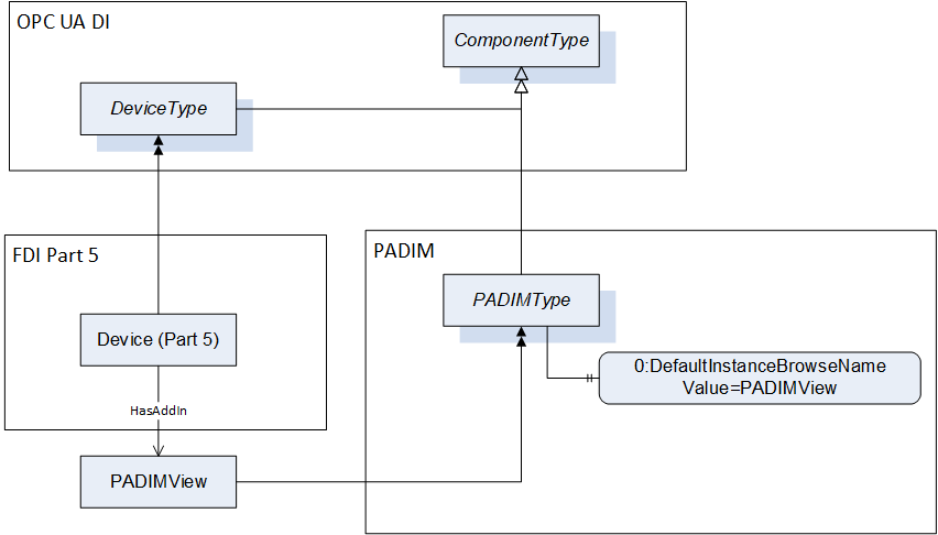
The IVendorNamePlateType Interface items that are listed are actually inherited from ComponentType and are listed here because the ModellingRule for these instances is revised to be mandatory (they are optional in ComponentType) or restrictions are introduced here (for 2:DeviceRevision).
DeviceRevision provides the overall revision level of a hardware component or the Device. As an example, this Property can be used in ERP systems together with the ProductCode Property. SemanticVersionString (a sub-type of String defined in OPC 10000-5) shall be used when using the Semantic Versioning format. Each of <major>, <minor>, <patch> shall be able to represent a two-byte integer.
The ITagNamePlateType Interface item that is listed is actually inherited from ComponentType and is listed here because the ModellingRule for the instance is revised to be mandatory, it is only optional in ComponentType.
The DateOfLastChange shall be timestamped in the OPC UA Server.
3:<DictionaryEntryName> is an optional placeholder for an object of IrdiDictionaryEntryType that defines a predefined group of one or more classes below ABV000, e.g. Final control element or Measuring instrument. ABV000 is defined in IEC 61987 Common Data Dictionary (CDD). A Measuring instrument could be e.g. a Coriolis mass flow transmitter with the IrdiIdentifier 3:0112/2///61987#ABA763#003.
The optional SubDevices Object is used to expose sub-devices. The contained SupportedTypes Object (see OPC 10000-100) shall only reference PADIMType or ObjectTypes that are subtypes of the PADIMType, and thus all subdevices shall be instances of PADIMType or subtypes.
DeviceConditionSet is a container object for the condition parameters of the device. It has a reference to IGeneralDeviceConditionSetType to add device specific condition variables.
The components of PADIMType have additional references which are defined in Table 110.
| SourceBrowsePath | Reference Type | Is Forward | TargetBrowsePath |
| 2:Manufacturer | 0:HasDictionaryEntry | True | 3:0112/2///61360_7#CBA031#001 |
| 2:ManufacturerUri | 0:HasDictionaryEntry | True | 3:0112/2///61360_7#CBA032#001 |
| 2:Model | 0:HasDictionaryEntry | True | 3:0112/2///61360_7#CBA039#001 |
| 2:SerialNumber | 0:HasDictionaryEntry | True | 3:0112/2///61360_7#CBA050#001 |
| 2:ProductCode | 0:HasDictionaryEntry | True | 3:0112/2///61360_7#CBA040#001 |
| 2:HardwareRevision | 0:HasDictionaryEntry | True | 3:0112/2///61360_7#CBA047#001 |
| 2:SoftwareRevision | 0:HasDictionaryEntry | True | 3:0112/2///61360_7#CBA046#001 |
| 2:DeviceRevision | 0:HasDictionaryEntry | True | 3:0112/2///61987#ABP643#002 |
| 2:RevisionCounter | 0:HasDictionaryEntry | True | 3:0112/2///61987#ABN603#002 |
| 2:ProductInstanceUri | 0:HasDictionaryEntry | True | 3:0112/2///61360_7#CBA055#001 |
| 2:AssetId | 0:HasDictionaryEntry | True | 3:0112/2///61987#ABA038#004 |
| 2:DeviceHealth | 0:HasDictionaryEntry | True | 3:0112/2///61987#ABN972#002 |
| BrowsePath | References | NodeClass | BrowseName | DataType | TypeDefinition | Others | ||
| DeviceConditionSet | 0:HasInterface | ObjectType | IGeneralDeviceConditionSetType | Defined above, see chapter 7.1.7 | ||||
| Applied from IGeneralDeviceConditionSetType | ||||||||
| DeviceConditionSet | 0:HasComponent | Object | GeneralDeviceConditions | GeneralDeviceConditionSetType | O | |||
| DeviceConditionSet | 0:HasComponent | Object | DeviceComponentConditions | BaseObjectType | O | |||
| 0:HasComponent | Object | <DeviceComponentIdentifier> | GeneralDeviceConditionSetType | OP | |||
The child Nodes of the PADIMType have additional Attribute values defined in Table 112. An empty field in the column "Value Attribute" means: the text field of the variable's value attribute has the length 0.
| BrowsePath | Value Attribute | |
| 2:Manufacturer | ||
| 2:ManufacturerUri | ||
| 2:Model | ||
| 2:SerialNumber | ||
| 2:ProductCode | ||
| 2:HardwareRevision | ||
| 2:SoftwareRevision | ||
| 2:DeviceRevision | 1.0.0 | |
| 2:RevisionCounter | 0 | |
| 2:ProductInstanceUri | ||
| 2:AssetId | ||
| 2:DeviceHealth | 0 | |
| DisplayLanguage | en | |
| DateOfLastChange | 1/1/1601 12:00:00 AM | |
| 0:DefaultInstanceBrowseName | PADIMView | |
7.3 ProcessAnalyserType
The ProcessAnalyserType is a subtype of the PADIMType. It is formally defined in Table 113.
| Attribute | Value | ||||
| BrowseName | ProcessAnalyserType | ||||
| IsAbstract | False | ||||
| References | NodeClass | BrowseName | DataType | TypeDefinition | Other |
|---|---|---|---|---|---|
| Subtype of PADIMType defined in 7.2, i.e. inheriting the InstanceDeclarations of that Node | |||||
| 0:HasDictionaryEntry | Object | 3:0112/2///61987#ABP397#002 | 0:IrdiDictionaryEntryType | ||
| Conformance Units | |||||
|---|---|---|---|---|---|
| PA-DIM ProcessAnalyserType |
3:0112/2///61987#ABP397#002 is an analytical device specific manifestation of the 3:<DictionaryEntryName> placeholder described in PADIMType.
ProcessAnalyserType is defined by IRDI as ABP397#002 which states "automation equipment that enables measurement of key quality and performance indicators in process materials and outputs a standard signal".
7.4 NonDispersiveInfraredGasAnalyserType
The NonDispersiveInfraredGasAnalyserType is a subtype of the ProcessAnalyserType. It is formally defined in Table 114.
| Attribute | Value | ||||
| BrowseName | NonDispersiveInfraredGasAnalyserType | ||||
| IsAbstract | False | ||||
| References | NodeClass | BrowseName | DataType | TypeDefinition | Other |
|---|---|---|---|---|---|
| Subtype of ProcessAnalyserType defined in 7.3, i.e. inheriting the InstanceDeclarations of that Node | |||||
| 0:HasDictionaryEntry | Object | 3:0112/2///61987#ABP425#002 | 0:IrdiDictionaryEntryType | ||
| Conformance Units | |||||
|---|---|---|---|---|---|
| PA-DIM NonDispersiveInfraredGasAnalyserType |
3:0112/2///61987#ABP425#002 is an NDIR photometer device specific manifestation of the 3:<DictionaryEntryName> placeholder described in PADIMType.
NonDispersiveInfraredGasAnalyserType is defined by IRDI as ABP425#002 which states "optical photometer that uses a light source operating in the IR spectral region that overlaps with the absorption region of the gas of interest in order to measure its concentration".
7.5 TocAnalyserType
The TocAnalyserType is a subtype of the ProcessAnalyserType. It is formally defined in Table 115.
| Attribute | Value | ||||
| BrowseName | TocAnalyserType | ||||
| IsAbstract | False | ||||
| References | NodeClass | BrowseName | DataType | TypeDefinition | Other |
|---|---|---|---|---|---|
| Subtype of ProcessAnalyserType defined in 7.3, i.e. inheriting the InstanceDeclarations of that Node | |||||
| 0:HasComponent | Object | DeviceConditionSet | 0:BaseObjectType | O | |
| 0:HasDictionaryEntry | Object | 3:0112/2///61987#ABP444#002 | 0:IrdiDictionaryEntryType | ||
| Conformance Units | |||||
|---|---|---|---|---|---|
| PA-DIM TocAnalyserType | |||||
| PA-DIM TocAnalyserType CarrierGasGaugePressure | |||||
| PA-DIM TocAnalyserType SampleWaterVolumeFlow | |||||
| PA-DIM TocAnalyserType ActualInjectedVolume |
3:0112/2///61987#ABP444#002 is a TOC analyser device specific manifestation of the 3:<DictionaryEntryName> placeholder described in PADIMType.
TocAnalyserType is defined by IRDI as ABP444#002 which states "sum parameter analyser for the determination of total organic carbon in water by oxidation".
DeviceConditionSet is a container object for the condition parameters of the device. It is inherited from PADIMType and has an additional interface reference to ITocDeviceConditionSetType to add TOC analyser device specific condition variables.
The components of TocAnalyserType have additional references which are defined in Table 116.
| SourceBrowsePath | Reference Type | Is Forward | TargetBrowsePath | |||
| DeviceConditionSet | 0:HasInterface | True | ITocDeviceConditionSetType | |||
| 0:HasDictionaryEntry | True | 3:0112/2///61987#ABA968#004 | |||
| 0:HasDictionaryEntry | True | 3:0112/2///61987#ABA968#004 | |||
| 0:HasDictionaryEntry | True | 3:0112/2///61987#ABA968#004 | |||
| 0:HasDictionaryEntry | True | 3:0112/2///61987#ABA968#004 | |||
| 0:HasDictionaryEntry | True | 3:0112/2///61987#ABA968#004 | |||
| 0:HasDictionaryEntry | True | 3:0112/2///61987#ABA968#004 | |||
| 0:HasDictionaryEntry | True | 3:0112/2///61987#ABA968#004 |
The components of TocAnalyserType have additional subcomponents which are defined in Table 117.
| BrowsePath | References | NodeClass | BrowseName | DataType | TypeDefinition | Others |
| Applied from ITocDeviceConditionSetType | ||||||
| DeviceConditionSet | 0:HasComponent | Variable | CarrierGasVolumeFlow | 0:Float | 0:AnalogUnitType | O |
| DeviceConditionSet | 0:HasComponent | Variable | CarrierGasGaugePressure | 0:Float | 0:AnalogUnitType | O |
| DeviceConditionSet | 0:HasComponent | Variable | ReactorTemperature | 0:Float | 0:AnalogUnitType | O |
| DeviceConditionSet | 0:HasComponent | Variable | SampleWaterVolumeFlow | 0:Float | 0:AnalogUnitType | O |
| DeviceConditionSet | 0:HasComponent | Variable | ReferenceInjectionVolume | 0:Float | 0:AnalogUnitType | O |
| DeviceConditionSet | 0:HasComponent | Variable | ActualInjectedVolume | 0:Float | 0:AnalogUnitType | O |
| DeviceConditionSet | 0:HasComponent | Variable | CoolerTemperature | 0:Float | 0:AnalogUnitType | O |
The child Nodes of the TocAnalyserType have additional Attribute values defined in Table 118.
| BrowsePath | Value Attribute | |||
| 0.0 | |||
| NamespaceUri: http://www.opcfoundation.org/UA/units/cdd/IEC62720 Description: litre per hour | |||
| 0.0 | |||
| NamespaceUri: http://www.opcfoundation.org/UA/units/cdd/IEC62720 Description: millibar | |||
| 0.0 | |||
| NamespaceUri: http://www.opcfoundation.org/UA/units/cdd/IEC62720 Description: degree Celsius | |||
| 0.0 | |||
| NamespaceUri: http://www.opcfoundation.org/UA/units/cdd/IEC62720 Description: millilitre per minute | |||
| 0.0 | |||
| NamespaceUri: http://www.opcfoundation.org/UA/units/cdd/IEC62720 UnitId: 705749652 Description: millilitre | |||
| 0.0 | |||
| NamespaceUri: http://www.opcfoundation.org/UA/units/cdd/IEC62720 UnitId: 705749652 Description: millilitre | |||
| 0.0 | |||
| NamespaceUri: http://www.opcfoundation.org/UA/units/cdd/IEC62720 Description: degree Celsius |
7.6 FlameIonisationDetectorType
The FlameIonisationDetectorType is a subtype of the ProcessAnalyserType. It is formally defined in Table 119.
| Attribute | Value | ||||
| BrowseName | FlameIonisationDetectorType | ||||
| IsAbstract | False | ||||
| References | NodeClass | BrowseName | DataType | TypeDefinition | Other |
|---|---|---|---|---|---|
| Subtype of ProcessAnalyserType defined in 7.3, i.e. inheriting the InstanceDeclarations of that Node | |||||
| 0:HasComponent | Object | DeviceConditionSet | 0:BaseObjectType | O | |
| 0:HasDictionaryEntry | Object | 3:0112/2///61987#ABP410#002 | 0:IrdiDictionaryEntryType | ||
| Conformance Units | |||||
|---|---|---|---|---|---|
| PA-DIM FlameIonisationDetectorType | |||||
| PA-DIM FlameIonisationDetectorType CatalystTemperature | |||||
| PA-DIM FlameIonisationDetectorType FuelGasPressure | |||||
| PA-DIM FlameIonisationDetectorType CombustionAirPressure | |||||
| PA-DIM FlameIonisationDetectorType BlockTemperature |
3:0112/2///61987#ABP410#002 is an FID device specific manifestation of the 3:<DictionaryEntryName> placeholder described in PADIMType.
FlameIonisationDetectorType is defined by IRDI as ABP410#002 which states "process analyser that uses flame ionisation to measure the concentration of one or more components in a gas phase by means of the resulting ionisation current".
DeviceConditionSet is a container object for the condition parameters of the device. It is inherited from PADIMType and has an additional interface reference to IFlameIonisationDeviceConditionSetType to add FID device specific condition variables.
The components of FlameIonisationDetectorType have additional references which are defined in Table 120.
| SourceBrowsePath | Reference Type | Is Forward | TargetBrowsePath | |||
| DeviceConditionSet | 0:HasInterface | True | IFlameIonisationDeviceConditionSetType | |||
| 0:HasDictionaryEntry | True | 3:0112/2///61987#ABA968#004 | |||
| 0:HasDictionaryEntry | True | 3:0112/2///61987#ABA968#004 | |||
| 0:HasDictionaryEntry | True | 3:0112/2///61987#ABA968#004 | |||
| 0:HasDictionaryEntry | True | 3:0112/2///61987#ABA968#004 |
The components of FlameIonisationDetectorType have additional subcomponents which are defined in Table 121.
| BrowsePath | References | NodeClass | BrowseName | DataType | TypeDefinition | Others |
| Applied from IFlameIonisationDeviceConditionSetType | ||||||
| DeviceConditionSet | 0:HasComponent | Variable | CatalystTemperature | 0:Float | 0:AnalogUnitType | O |
| DeviceConditionSet | 0:HasComponent | Variable | FuelGasPressure | 0:Float | 0:AnalogUnitType | O |
| DeviceConditionSet | 0:HasComponent | Variable | CombustionAirPressure | 0:Float | 0:AnalogUnitType | O |
| DeviceConditionSet | 0:HasComponent | Variable | BlockTemperature | 0:Float | 0:AnalogUnitType | O |
The child Nodes of the FlameIonisationDetectorType have additional Attribute values defined in Table 122.
| BrowsePath | Value Attribute | |||
| 0.0 | |||
| NamespaceUri: http://www.opcfoundation.org/UA/units/cdd/IEC62720 UnitId: 705741427 DisplayName: °C Description: degree Celsius | |||
| 0.0 | |||
| NamespaceUri: http://www.opcfoundation.org/UA/units/cdd/IEC62720 UnitId: 705749552 DisplayName: mbar Description: millibar | |||
| 0.0 | |||
| NamespaceUri: http://www.opcfoundation.org/UA/units/cdd/IEC62720 UnitId: 705749552 DisplayName: mbar Description: millibar | |||
| 0.0 | |||
| NamespaceUri: http://www.opcfoundation.org/UA/units/cdd/IEC62720 UnitId: 705741427 DisplayName: °C Description: degree Celsius |
7.7 ParamagneticGasAnalyserType
The ParamagneticGasAnalyserType is a subtype of the ProcessAnalyserType. It is formally defined in Table 123.
| Attribute | Value | ||||
| BrowseName | ParamagneticGasAnalyserType | ||||
| IsAbstract | False | ||||
| References | NodeClass | BrowseName | DataType | TypeDefinition | Other |
|---|---|---|---|---|---|
| Subtype of ProcessAnalyserType defined in 7.3, i.e. inheriting the InstanceDeclarations of that Node | |||||
| 0:HasDictionaryEntry | Object | 3:0112/2///61987#ABP436#002 | 0:IrdiDictionaryEntryType | ||
| Conformance Units | |||||
|---|---|---|---|---|---|
| PA-DIM ParamagneticGasAnalyserType |
3:0112/2///61987#ABP436#002 is a paramagnetic measurement device specific manifestation of the 3:<DictionaryEntryName> placeholder described in PADIMType.
ParamagneticGasAnalyserType is defined by IRDI as ABP436#002 which states "process analyser that uses the paramagnetic susceptibility of a gas to determine its concentration in a gas mixture".
7.8 ThermalConductivityGasAnalyserType
The ThermalConductivityGasAnalyserType is a subtype of the ProcessAnalyserType. It is formally defined in Table 124.
| Attribute | Value | ||||
| BrowseName | ThermalConductivityGasAnalyserType | ||||
| IsAbstract | False | ||||
| References | NodeClass | BrowseName | DataType | TypeDefinition | Other |
|---|---|---|---|---|---|
| Subtype of ProcessAnalyserType defined in 7.3, i.e. inheriting the InstanceDeclarations of that Node | |||||
| 0:HasDictionaryEntry | Object | 3:0112/2///61987#ABP453#002 | 0:IrdiDictionaryEntryType | ||
| Conformance Units | |||||
|---|---|---|---|---|---|
| PA-DIM ThermalConductivityGasAnalyserType |
3:0112/2///61987#ABP453#002 is a thermal conductivity measurement device specific manifestation of the 3:<DictionaryEntryName> placeholder described in PADIMType.
ThermalConductivityGasAnalyserType is defined by IRDI as ABP453#002 which states "process analyser that uses the equilibrium temperature of a heated sensing element to measure the concentration of a component of a process gas".
7.9 TunableDiodeLaserSpectrometerType
The TunableDiodeLaserSpectrometerType is a subtype of the ProcessAnalyserType. It is formally defined in Table 125.
| Attribute | Value | ||||
| BrowseName | TunableDiodeLaserSpectrometerType | ||||
| IsAbstract | False | ||||
| References | NodeClass | BrowseName | DataType | TypeDefinition | Other |
|---|---|---|---|---|---|
| Subtype of ProcessAnalyserType defined in 7.3, i.e. inheriting the InstanceDeclarations of that Node | |||||
| 0:HasDictionaryEntry | Object | 3:0112/2///61987#ABP435#002 | 0:IrdiDictionaryEntryType | ||
| Conformance Units | |||||
|---|---|---|---|---|---|
| PA-DIM TunableDiodeLaserSpectrometerType |
3:0112/2///61987#ABP435#002 is a TDL device specific manifestation of the 3:<DictionaryEntryName> placeholder described in PADIMType.
TunableDiodeLaserSpectrometerType is defined by IRDI as ABP435#002 which states "optical spectrometer that uses laser absorption spectrometry at different wavelengths from UV to far IR to measure the concentration of specific components".
7.10 ZirconiumDioxideAnalyserType
The ZirconiumDioxideAnalyserType is a subtype of the ProcessAnalyserType. It is formally defined in Table 126.
| Attribute | Value | ||||
| BrowseName | ZirconiumDioxideAnalyserType | ||||
| IsAbstract | False | ||||
| References | NodeClass | BrowseName | DataType | TypeDefinition | Other |
|---|---|---|---|---|---|
| Subtype of ProcessAnalyserType defined in 7.3, i.e. inheriting the InstanceDeclarations of that Node | |||||
| 0:HasDictionaryEntry | Object | 3:0112/2///61987#ABP409#002 | 0:IrdiDictionaryEntryType | ||
| Conformance Units | |||||
|---|---|---|---|---|---|
| PA-DIM ZirconiumDioxideAnalyserType |
3:0112/2///61987#ABP409#002 is a Zirconium dioxide measurement device specific manifestation of the 3:<DictionaryEntryName> placeholder described in PADIMType.
ZirconiumDioxideAnalyserType is defined by IRDI as ABP409#002 which states "electrochemical analyser that uses a zirconium dioxide cell as sensing element to measure the concentration of oxygen in gas phase".
7.11 PhMeterType
The PhMeterType is a subtype of the ProcessAnalyserType. It is formally defined in Table 127.
| Attribute | Value | ||||
| BrowseName | PhMeterType | ||||
| IsAbstract | False | ||||
| References | NodeClass | BrowseName | DataType | TypeDefinition | Other |
|---|---|---|---|---|---|
| Subtype of ProcessAnalyserType defined in 7.3, i.e. inheriting the InstanceDeclarations of that Node | |||||
| 0:HasDictionaryEntry | Object | 3:0112/2///61987#ABP440#002 | 0:IrdiDictionaryEntryType | ||
| Conformance Units | |||||
|---|---|---|---|---|---|
| PA-DIM PhMeterType |
3:0112/2///61987#ABP440#002 is a pH meter device specific manifestation of the 3:<DictionaryEntryName> placeholder described in PADIMType.
PhMeterType is defined by IRDI as ABP440#002 which states "process analyser that measures the concentration of hydrogen ions to determine the pH value or potentiometric properties of liquids".
7.12 ConductivityMeterType
The ConductivityMeterType is a subtype of the ProcessAnalyserType. It is formally defined in Table 128.
| Attribute | Value | ||||
| BrowseName | ConductivityMeterType | ||||
| IsAbstract | False | ||||
| References | NodeClass | BrowseName | DataType | TypeDefinition | Other |
|---|---|---|---|---|---|
| Subtype of ProcessAnalyserType defined in 7.3, i.e. inheriting the InstanceDeclarations of that Node | |||||
| 0:HasDictionaryEntry | Object | 3:0112/2///61987#ABP405#002 | 0:IrdiDictionaryEntryType | ||
| Conformance Units | |||||
|---|---|---|---|---|---|
| PA-DIM ConductivityMeterType |
3:0112/2///61987#ABP405#002 is a conductivity meter device specific manifestation of the 3:<DictionaryEntryName> placeholder described in PADIMType.
ConductivityMeterType is defined by IRDI as ABP405#002 which states "process analyser that measures the conductivity to determine the concentration of electrolytes in liquids".
7.13 AmperometricAnalyserType
The AmperometricAnalyserType is a subtype of the ProcessAnalyserType. It is formally defined in Table 129.
| Attribute | Value | ||||
| BrowseName | AmperometricAnalyserType | ||||
| IsAbstract | False | ||||
| References | NodeClass | BrowseName | DataType | TypeDefinition | Other |
|---|---|---|---|---|---|
| Subtype of ProcessAnalyserType defined in 7.3, i.e. inheriting the InstanceDeclarations of that Node | |||||
| 0:HasDictionaryEntry | Object | 3:0112/2///61987#ABP407#002 | 0:IrdiDictionaryEntryType | ||
| Conformance Units | |||||
|---|---|---|---|---|---|
| PA-DIM AmperometricAnalyserType |
3:0112/2///61987#ABP407#002 is an amperometric analyser specific manifestation of the 3:<DictionaryEntryName> placeholder described in PADIMType.
AmperometricAnalyserType is defined by IRDI as ABP407#002 which states "electrochemical analyser that uses a amperometric sensing element to measure a specific component in a sample".
7.14 OpticalFluorescenseQuenchingSensorType
The OpticalFluorescenseQuenchingSensorType is a subtype of the ProcessAnalyserType. It is formally defined in Table 130.
| Attribute | Value | ||||
| BrowseName | OpticalFluorescenseQuenchingSensorType | ||||
| IsAbstract | False | ||||
| References | NodeClass | BrowseName | DataType | TypeDefinition | Other |
|---|---|---|---|---|---|
| Subtype of ProcessAnalyserType defined in 7.3, i.e. inheriting the InstanceDeclarations of that Node | |||||
| 0:HasDictionaryEntry | Object | 3:0112/2///61987#ABP423#002 | 0:IrdiDictionaryEntryType | ||
| Conformance Units | |||||
|---|---|---|---|---|---|
| PA-DIM OpticalFluorescenseQuenchingSensorType |
3:0112/2///61987#ABP423#002 is an optical Fluorescence quenching sensor specific manifestation of the 3:<DictionaryEntryName> placeholder described in PADIMType.
OpticalFluorescenseQuenchingSensorType is defined by IRDI as ABP423#002 which states "process analyser that uses the optical fluorescence quenching method to measure the concentration of a component in a gas or liquid".
7.15 GasChromatographType
The GasChromatographType is a subtype of the ProcessAnalyserType. It is formally defined in Table 131.
| Attribute | Value | ||||
| BrowseName | GasChromatographType | ||||
| IsAbstract | False | ||||
| References | NodeClass | BrowseName | DataType | TypeDefinition | Other |
|---|---|---|---|---|---|
| Subtype of ProcessAnalyserType defined in 7.3, i.e. inheriting the InstanceDeclarations of that Node | |||||
| 0:HasComponent | Object | DeviceConditionSet | 0:BaseObjectType | O | |
| 0:HasDictionaryEntry | Object | 3:0112/2///61987#ABP400#002 | 0:IrdiDictionaryEntryType | ||
| Conformance Units | |||||
|---|---|---|---|---|---|
| PA-DIM GasChromatographSignalType | |||||
| PA-DIM GasChromatographSignalType Peak | |||||
| PA-DIM GasChromatographSignalType RetentionTime | |||||
| PA-DIM GasChromatographSignalType InjectionTime | |||||
| PA-DIM GasChromatographSignalType ComponentName |
3:0112/2///61987#ABP400#002 is a Gaschromatograph device specific manifestation of the 3:<DictionaryEntryName> placeholder described in PADIMType.
GasChromatographType is defined by IRDI as ABP400#002 which states "chromatograph that takes a gaseous sample or liquid samples that can be vaporized and separates the components in a gaseous phase".
The components of GasChromatographType have additional references which are defined in Table 132.
| SourceBrowsePath | Reference Type | Is Forward | TargetBrowsePath | |||
| DeviceConditionSet | 0:HasInterface | True | IGasChromatographDeviceConditionSetType | |||
| 0:HasDictionaryEntry | True | 3:0112/2///61987#ABQ046#001 | |||
| 0:HasDictionaryEntry | True | 3:0112/2///61987#ABQ007#001 | |||
| 0:HasDictionaryEntry | True | 3:0112/2///61987#ABA968#004 |
The components of GasChromatographType have additional subcomponents which are defined in Table 133.
| BrowsePath | References | NodeClass | BrowseName | DataType | TypeDefinition | Others |
| Applied from IGasChromatographDeviceConditionSetType | ||||||
| DeviceConditionSet | 0:HasProperty | Variable | ValveName | 0:LocalizedText[] | 0:PropertyType | O |
| DeviceConditionSet | 0:HasProperty | Variable | ValveSwitchingCyclesCounter | 0:UInt32[] | 0:PropertyType | O |
| DeviceConditionSet | 0:HasComponent | Variable | TotalAreaMeasuredPeaks | 0:Float | 0:AnalogUnitType | O |
| DeviceConditionSet | 0:HasComponent | Variable | BaselineNoise | 0:Float | 0:AnalogUnitType | O |
The child Nodes of the GasChromatographType have additional Attribute values defined in Table 134.
| BrowsePath | Value Attribute | |||
| ||||
| 0 | |||
| 0.0 | |||
| NamespaceUri: http://www.opcfoundation.org/UA/units/cdd/IEC62720 UnitId: 705741328 DisplayName: % Description: percent | |||
| 0.0 | |||
| NamespaceUri: http://www.opcfoundation.org/UA/units/cdd/IEC62720 DisplayName: mV |
7.16 InfraredSensorType
The InfraredSensorType is a subtype of the ProcessAnalyserType. It is formally defined in Table 135.
| Attribute | Value | ||||
| BrowseName | InfraredSensorType | ||||
| IsAbstract | False | ||||
| References | NodeClass | BrowseName | DataType | TypeDefinition | Other |
|---|---|---|---|---|---|
| Subtype of ProcessAnalyserType defined in 7.3, i.e. inheriting the InstanceDeclarations of that Node | |||||
| 0:HasComponent | Object | DeviceConditionSet | 0:BaseObjectType | O | |
| 0:HasDictionaryEntry | Object | 3:0112/2///61987#ABP413#002 | 0:IrdiDictionaryEntryType | ||
| Conformance Units | |||||
|---|---|---|---|---|---|
| PA-DIM InfraredSensorType | |||||
3:0112/2///61987#ABP413#002 is a Infrared sensor specific manifestation of the 3:<DictionaryEntryName> placeholder described in PADIMType.
InfraredSensorType is defined by IRDI as ABP413#002 which states "gas detector that uses a broadband IR light source and optical filter to select a narrow-band spectral region that overlaps with the absorption region of the gas of interest".
7.17 AmperometricGasDetectorType
The AmperometricGasDetectorType is a subtype of the ProcessAnalyserType. It is formally defined in Table 136.
| Attribute | Value | ||||
| BrowseName | AmperometricGasDetectorType | ||||
| IsAbstract | False | ||||
| References | NodeClass | BrowseName | DataType | TypeDefinition | Other |
|---|---|---|---|---|---|
| Subtype of ProcessAnalyserType defined in 7.3, i.e. inheriting the InstanceDeclarations of that Node | |||||
| 0:HasComponent | Object | DeviceConditionSet | 0:BaseObjectType | O | |
| 0:HasDictionaryEntry | Object | 3:0112/2///61987#ABP415#002 | 0:IrdiDictionaryEntryType | ||
| Conformance Units | |||||
|---|---|---|---|---|---|
| PA-DIM AmperometricGasDetectorType | |||||
ABP415#002 is an amperometric gas detector specific manifestation of the 3:<DictionaryEntryName> placeholder described in PADIMType.
AmperometricGasDetectorType is defined by IRDI as ABP415#002 which states "gas detector that uses a amperometric sensing element to measure oxygen or other gases".
7.18 CatalyticBeadSensorType
The CatalyticBeadSensorType is a subtype of the ProcessAnalyserType. It is formally defined in Table 137.
| Attribute | Value | ||||
| BrowseName | CatalyticBeadSensorType | ||||
| IsAbstract | False | ||||
| References | NodeClass | BrowseName | DataType | TypeDefinition | Other |
|---|---|---|---|---|---|
| Subtype of ProcessAnalyserType defined in 7.3, i.e. inheriting the InstanceDeclarations of that Node | |||||
| 0:HasComponent | Object | DeviceConditionSet | 0:BaseObjectType | O | |
| 0:HasDictionaryEntry | Object | 3:0112/2///61987#ABP412#002 | 0:IrdiDictionaryEntryType | ||
| Conformance Units | |||||
|---|---|---|---|---|---|
| PA-DIM CatalyticBeadSensorType | |||||
3:0112/2///61987#ABP412#002 is a catalytic bead sensor specific manifestation of the 3:<DictionaryEntryName> placeholder described in PADIMType.
CatalyticBeadSensorType is defined by IRDI as ABP412#002 which states "gas detector that uses catalytic bead principle for the detection of flammable gas in lower explosion level".
7.19 FtnirOrFtirSpectrometerType
The FtnirOrFtirSpectrometerType is a subtype of the ProcessAnalyserType. It is formally defined in Table 138.
| Attribute | Value | ||||
| BrowseName | FtnirOrFtirSpectrometerType | ||||
| IsAbstract | False | ||||
| References | NodeClass | BrowseName | DataType | TypeDefinition | Other |
|---|---|---|---|---|---|
| Subtype of ProcessAnalyserType defined in 7.3, i.e. inheriting the InstanceDeclarations of that Node | |||||
| 0:HasComponent | Object | DeviceConditionSet | 0:BaseObjectType | O | |
| 0:HasDictionaryEntry | Object | 3:0112/2///61987#ABP432#002 | 0:IrdiDictionaryEntryType | ||
| Conformance Units | |||||
|---|---|---|---|---|---|
| PA-DIM FtnirOrFtirSpectrometerType | |||||
| PA-DIM FtnirOrFtirSpectrometerType Watchdog | |||||
| PA-DIM FtnirOrFtirSpectrometerType RemainingDataStorageCapacity |
3:0112/2///61987#ABP432#002 is a fourier transform near infrared or fourier transform infrared specific manifestation of the 3:<DictionaryEntryName> placeholder described in PADIMType.
| FtnirOrFtirSpectrometerType is defined by IRDI as ABP432#002 which states "optical spectrometer operating in the near infrared or infrared spectral region that uses an interferometer and Fourier Transformation to measure the concentration of specific components". |
7.20 DiodeArraySpectrometerType
The DiodeArraySpectrometerType is a subtype of the ProcessAnalyserType. It is formally defined in Table 139.
| Attribute | Value | ||||
| BrowseName | DiodeArraySpectrometerType | ||||
| IsAbstract | False | ||||
| References | NodeClass | BrowseName | DataType | TypeDefinition | Other |
|---|---|---|---|---|---|
| Subtype of ProcessAnalyserType defined in 7.3, i.e. inheriting the InstanceDeclarations of that Node | |||||
| 0:HasComponent | Object | DeviceConditionSet | 0:BaseObjectType | O | |
| 0:HasDictionaryEntry | Object | 3:0112/2///61987#ABP433#002 | 0:IrdiDictionaryEntryType | ||
| Conformance Units | |||||
|---|---|---|---|---|---|
| PA-DIM DiodeArraySpectrometerType | |||||
3:0112/2///61987#ABP433#002 is a diode array spectrometer specific manifestation of the 3:<DictionaryEntryName> placeholder described in PADIMType.
| DiodeArraySpectrometerType is defined by IRDI as #ABP433#002 which states "optical spectrometer operating in the UV and/or visible and/or IR spectral region that uses a broadband light source, dispersive elements and a diode array detector to measure the concentration of specific components". |
7.21 RamanSpectrometerType
The RamanSpectrometerType is a subtype of the ProcessAnalyserType. It is formally defined in Table 140.
| Attribute | Value | ||||
| BrowseName | RamanSpectrometerType | ||||
| IsAbstract | False | ||||
| References | NodeClass | BrowseName | DataType | TypeDefinition | Other |
|---|---|---|---|---|---|
| Subtype of ProcessAnalyserType defined in 7.3, i.e. inheriting the InstanceDeclarations of that Node | |||||
| 0:HasComponent | Object | DeviceConditionSet | 0:BaseObjectType | O | |
| 0:HasDictionaryEntry | Object | 3:0112/2///61987#ABP434#002 | 0:IrdiDictionaryEntryType | ||
| Conformance Units | |||||
|---|---|---|---|---|---|
| PA-DIM RamanSpectrometerType | |||||
0112/2///61987#ABP434#002 is a Raman spectrometer specific manifestation of the 3:<DictionaryEntryName> placeholder described in PADIMType.
| RamanSpectrometerType is defined by IRDI as ABP434#002 which states "optical spectrometer operating in the UV, visible and IR spectral region that uses Raman scattering to measure the concentration of specific components". |
7.22 SignalSetType
The SignalSetType provides the signals of the device and is formally defined in Table 141.
| Attribute | Value | ||||
| BrowseName | SignalSetType | ||||
| IsAbstract | False | ||||
| References | NodeClass | BrowseName | DataType | TypeDefinition | Other |
|---|---|---|---|---|---|
| Subtype of 0:BaseObjectType defined in OPC 10000-5, i.e. inheriting the InstanceDeclarations of that Node | |||||
| 0:HasComponent | Object | <SignalIdentifier> | SignalType | OP | |
| Conformance Units | |||||
|---|---|---|---|---|---|
| PA-DIM SignalSet |
The child Nodes of the SignalSetType have additional Attribute values defined in Table 142. An empty field in the column "Value Attribute" means: the text field of the variable's value attribute has the length 0.
| BrowsePath | Value Attribute | ||
|
7.23 CalibrationPointSetType
The CalibrationPointSetType provides the calibration points of a sensor resp. signal and is formally defined in Table 143.
| Attribute | Value | ||||
| BrowseName | CalibrationPointSetType | ||||
| IsAbstract | False | ||||
| References | NodeClass | BrowseName | DataType | TypeDefinition | Other |
|---|---|---|---|---|---|
| Subtype of 0:BaseObjectType defined in OPC 10000-5, i.e. inheriting the InstanceDeclarations of that Node | |||||
| 0:HasComponent | Object | <CalibrationPointIdentifier> | CalibrationPointType | OP | |
| Conformance Units | |||||
|---|---|---|---|---|---|
| PA-DIM ICalibration CalibrationPointSet |
7.24 GeneralDeviceConditionSetType
The GeneralDeviceConditionSetType provides the general condition variables of the device ore one of its components and is formally defined in Table 144.
| Attribute | Value | ||||
| BrowseName | GeneralDeviceConditionSetType | ||||
| IsAbstract | False | ||||
| References | NodeClass | BrowseName | DataType | TypeDefinition | Other |
|---|---|---|---|---|---|
| Subtype of 0:BaseObjectType defined in OPC 10000-5, i.e. inheriting the InstanceDeclarations of that Node | |||||
| 0:HasComponent | Variable | InternalTemperature | 0:Float{Any} | 0:AnalogUnitType | O |
| 0:HasProperty | Variable | ResidualLife | 0:Float | 0:PropertyType | O |
| 0:HasInterface | ObjectType | 2:IOperationCounterType | Defined in OPC 10000-100 | ||
| Applied from IOperationCounterType defined in OPC 10000-100 | |||||
| 0:HasProperty | Variable | 2:PowerOnDuration | 0:Duration | 0:PropertyType | O |
| 0:HasProperty | Variable | 2:OperationDuration | 0:Duration | 0:PropertyType | O |
| 0:HasProperty | Variable | 2:OperationCycleCounter | 0:UInteger | 0:PropertyType | O |
| Conformance Units | |||||
|---|---|---|---|---|---|
| PA-DIM GeneralDeviceConditionSetType InternalTemperature | |||||
| PA-DIM GeneralDeviceConditionSetType ResidualLife | |||||
| PA-DIM GeneralDeviceConditionSetType PowerOnDuration | |||||
| PA-DIM GeneralDeviceConditionSetType OperationDuration | |||||
| PA-DIM GeneralDeviceConditionSetType OperationCycleCounter |
InternalTemperature is defined by IRDI as ABP591#001 which states "temperature measured at a relevant internal position defined by the manufacturer".
ResidualLife is defined by IRDI as ABP595#001 which states "degradation of a device or device component expressed as a value between 1 (good) and 0 (bad)".
PowerOnDuration is defined by IRDI as ABP550#001 which states "summed duration of time intervals for which an item was supplied with energy".
OperationDuration is defined by IRDI as ABN639#001 which states "summed duration of time intervals for which an item was in an active (non idle) operating state".
OperationCycleCounter is defined by IRDI as ABP545#001 which states "result of the addition of switching events from idle to active state of an object".
The components of GeneralDeviceConditionSetType have additional references which are defined in Table 145.
| SourceBrowsePath | Reference Type | Is Forward | TargetBrowsePath | ||
| InternalTemperature | 0:HasDictionaryEntry | True | 3:0112/2///61987#ABP591#001 | ||
| 0:HasDictionaryEntry | True | 3:0112/2///61987#ABA968#004 | ||
| ResidualLife | 0:HasDictionaryEntry | True | 3:0112/2///61987#ABP595#001 | ||
| 2:PowerOnDuration | 0:HasDictionaryEntry | True | 3:0112/2///61987#ABP550#001 | ||
| 2:OperationDuration | 0:HasDictionaryEntry | True | 3:0112/2///61987#ABN639#001 | ||
| 2:OperationCycleCounter | 0:HasDictionaryEntry | True | 3:0112/2///61987#ABP545#001 |
The child Nodes of the GeneralDeviceConditionSetType have additional Attribute values defined in Table 146.
| BrowsePath | Value Attribute | ||
| InternalTemperature | 0.0 | ||
| NamespaceUri: http://www.opcfoundation.org/UA/units/cdd/IEC62720 UnitId: 705741427 DisplayName: °C Description: degree Celsius | ||
| ResidualLife | 1.0 | ||
| 2:PowerOnDuration | 0.0 | ||
| 2:OperationDuration | 0.0 |
7.25 SignalType
The SignalType provides ObjectType to add analog and discrete signals and is formally defined in Table 147. In order to have a common approach, PA-DIM will always use Objects, even if no Method is needed for some types.
| Attribute | Value | ||||
| BrowseName | SignalType | ||||
| IsAbstract | False | ||||
| References | NodeClass | BrowseName | DataType | TypeDefinition | Other |
|---|---|---|---|---|---|
| Subtype of 0:BaseObjectType defined in OPC 10000-5, i.e. inheriting the InstanceDeclarations of that Node | |||||
| 0:HasProperty | Variable | SignalTag | 0:String | 0:PropertyType | M |
| Conformance Units | |||||
|---|---|---|---|---|---|
| PA-DIM SignalSet |
SignalTag is defined by IRDI as ABB271#009 which states "alphanumeric character sequence uniquely identifying a measuring or control point"
The components of SignalType have additional references which are defined in Table 148.
| SourceBrowsePath | Reference Type | Is Forward | TargetBrowsePath |
| SignalTag | 0:HasDictionaryEntry | True | 3:0112/2///61987#ABB271#009 |
The child Nodes of the SignalType have additional Attribute values defined in Table 149. An empty field in the column "Value Attribute" means: the text field of the variable's value attribute has the length 0.
| BrowsePath | Value Attribute |
| SignalTag |
7.26 AnalogSignalType
The AnalogSignalType provides ObjectType to add variables and ZeroPointAdjustment Method. It is formally defined in Table 150.
| Attribute | Value | ||||
| BrowseName | AnalogSignalType | ||||
| IsAbstract | False | ||||
| References | NodeClass | BrowseName | DataType | TypeDefinition | Other |
|---|---|---|---|---|---|
| Subtype of SignalType defined in 7.23, i.e. inheriting the InstanceDeclarations of that Node | |||||
| 0:HasComponent | Method | ZeroPointAdjustment | Defined in 9.2 | O | |
| 0:HasComponent | Variable | AnalogSignal | 0:Number{Any} | AnalogSignalVariableType | M |
| 0:HasComponent | Object | <SignalCalibrationIdentifier> | 0:BaseObjectType | OP | |
| 0:HasComponent | Object | SignalConditionSet | 0:BaseObjectType | O | |
| Conformance Units | |||||
|---|---|---|---|---|---|
| PA-DIM Analog Signal | |||||
| PA-DIM ZeroPointAdjustment method | |||||
| PA-DIM ICalibration | |||||
| PA-DIM ICalibration CalibrationTimestamp | |||||
| PA-DIM ICalibration TypeOfCalibration | |||||
| PA-DIM ICalibration CalibrationPointSet | |||||
| PA-DIM Signal Condition Set |
ZeroPointAdjustment: ABN614#002 defines property that initiates when set the TRUE (ON) state a procedure, which maybe automatic, to define or set the value zero of the output. Remark: properties can be variables or methods according to IEC 61987 CDD.
AnalogSignal provides the measured or readback process value. The unit of this value is provided by the EngineeringUnits property.
<SignalCalibrationIdentifier> is a container object for the calibration parameters of the signal. It has an interface reference to ICalibrationType in order to add general calibration variables. Since it is a placeholder, an instance of AnalogSignalType can have several calibration objects.
SignalConditionSet is a container object for the condition parameters of the signal.
The components of AnalogSignalType have additional references which are defined in Table 151.
| SourceBrowsePath | Reference Type | Is Forward | TargetBrowsePath | ||
| 0:HasDictionaryEntry | True | 3:0112/2///61987#ABA968#004 | ||
| <SignalCalibrationIdentifier> | 0:HasInterface | True | ICalibrationType | ||
| ZeroPointAdjustment | 0:HasDictionaryEntry | True | 3:0112/2///61987#ABN614#002 |
The components of AnalogSignalType have additional subcomponents which are defined in Table 152.
| BrowsePath | References | NodeClass | BrowseName | DataType | TypeDefinition | Others |
| Applied from ICalibrationType | ||||||
| <SignalCalibrationIdentifier> | 0:HasProperty | Variable | CalibrationTimestamp | 0:DateTime | 0:PropertyType | O |
| <SignalCalibrationIdentifier> | 0:HasComponent | Variable | TypeOfCalibration | 0:UInt32 | 0:MultiStateDictionaryEntryDiscreteType | O |
| <SignalCalibrationIdentifier> | 0:HasComponent | Object | CalibrationPointSet | CalibrationPointSetType | O | |
The child Nodes of the AnalogSignalType have additional Attribute values defined in Table 153.
| BrowsePath | Value Attribute | |||
| 1/1/1601 12:00:00 AM | |||
| 0 | |||
| ns=3;s=0112/2///61987#ABP732#001 | |||
| adjustment |
7.27 AnalyticalSignalType
The AnalyticalSignalType provides ObjectType to add analytical measurement specific variables. It is formally defined in Table 154.
| Attribute | Value | ||||
| BrowseName | AnalyticalSignalType | ||||
| IsAbstract | False | ||||
| References | NodeClass | BrowseName | DataType | TypeDefinition | Other |
|---|---|---|---|---|---|
| Subtype of AnalogSignalType defined in 7.26, i.e. inheriting the InstanceDeclarations of that Node | |||||
| 0:HasComponent | Variable | AnalogSignal | 0:Float | PatMeasurementVariableType | M |
| Conformance Units | |||||
|---|---|---|---|---|---|
| PA-DIM AnalyticalSignalType |
AnalogSignal is inherited from AnalogSignalType. In AnalyticalSignalType its TypeDefinition is specialized to PatMeasurementVariableType.
The components of AnalyticalSignalType have additional references which are defined in Table 155.
| SourceBrowsePath | Reference Type | Is Forward | TargetBrowsePath | ||
| 0:HasDictionaryEntry | True | 3:0112/2///61987#ABA968#004 |
7.28 NonDispersiveInfraredSignalType
The NonDispersiveInfraredSignalType provides ObjectType to add NDIR measurement specific variables. It is formally defined in Table 156.
| Attribute | Value | ||||
| BrowseName | NonDispersiveInfraredSignalType | ||||
| IsAbstract | False | ||||
| References | NodeClass | BrowseName | DataType | TypeDefinition | Other |
|---|---|---|---|---|---|
| Subtype of AnalyticalSignalType defined in 7.27, i.e. inheriting the InstanceDeclarations of that Node | |||||
| 0:HasComponent | Object | SignalConditionSet | 0:BaseObjectType | O | |
| Conformance Units | |||||
|---|---|---|---|---|---|
| PA-DIM NonDispersiveInfraredSignalType | |||||
| PA-DIM NonDispersiveInfraredSignalType ChopperFrequencyDeviation | |||||
| PA-DIM NonDispersiveInfraredSignalType AbsoluteSampleGasPressure |
SignalConditionSet is a container object for the condition parameters of the signal. It is inherited from AnalogSignalType and has an additional interface reference to INonDispersiveInfraredSignalConditionSetType to add NDIR signal specific condition variables. The components of NonDispersiveInfraredSignalType have additional references which are defined in Table 157.
| SourceBrowsePath | Reference Type | Is Forward | TargetBrowsePath | |||
| SignalConditionSet | 0:HasInterface | True | INonDispersiveInfraredSignalConditionSetType | |||
| 0:HasDictionaryEntry | True | 3:0112/2///61987#ABA968#004 | |||
| 0:HasDictionaryEntry | True | 3:0112/2///61987#ABA968#004 | |||
| 0:HasDictionaryEntry | True | 3:0112/2///61987#ABA968#004 |
The components of NonDispersiveInfraredSignalType have additional subcomponents which are defined in Table 158.
| BrowsePath | References | NodeClass | BrowseName | DataType | TypeDefinition | Others |
| Applied from INonDispersiveInfraredSignalConditionSetType | ||||||
| SignalConditionSet | 0:HasComponent | Variable | ChopperFrequencyDeviation | 0:Float | 0:BaseAnalogType | O |
| SignalConditionSet | 0:HasComponent | Variable | AbsoluteSampleGasPressure | 0:Float | 0:AnalogUnitType | O |
| SignalConditionSet | 0:HasComponent | Variable | SampleCellTemperature | 0:Float | 0:AnalogUnitType | O |
| SignalConditionSet | 0:HasProperty | Variable | SourceResidualLife | 0:Float | 0:PropertyType | O |
The child Nodes of the NonDispersiveInfraredSignalType have additional Attribute values defined in Table 159.
| BrowsePath | Value Attribute | |||
| 0.0 | |||
| NamespaceUri: http://www.opcfoundation.org/UA/units/cdd/IEC62720 UnitId: 705741328 DisplayName: % Description: percent | |||
| 0.0 | |||
| NamespaceUri: http://www.opcfoundation.org/UA/units/cdd/IEC62720 UnitId: 705749552 DisplayName: mbar Description: millibar | |||
| 0.0 | |||
| NamespaceUri: http://www.opcfoundation.org/UA/units/cdd/IEC62720 UnitId: 705741427 DisplayName: °C Description: degree Celsius | |||
| 1.0 |
7.29 TocSignalType
The TocSignalType provides ObjectType to add TOC measurement specific variables. It is formally defined in Table 160.
| Attribute | Value | ||||
| BrowseName | TocSignalType | ||||
| IsAbstract | False | ||||
| References | NodeClass | BrowseName | DataType | TypeDefinition | Other |
|---|---|---|---|---|---|
| Subtype of AnalyticalSignalType defined in 7.27, i.e. inheriting the InstanceDeclarations of that Node | |||||
| 0:HasComponent | Object | SignalConditionSet | 0:BaseObjectType | O | |
| Conformance Units | |||||
|---|---|---|---|---|---|
| PA-DIM TocSignalType | |||||
| PA-DIM TocSignalType ChopperFrequencyDeviation | |||||
| PA-DIM TocSignalType RelativeReagentLevel | |||||
| PA-DIM TocSignalType AbsoluteSampleGasPressure | |||||
| PA-DIM TocSignalType SampleGasVolumeFlow |
SignalConditionSet is a container object for the condition parameters of the signal. It is inherited from AnalogSignalType and has an additional interface reference to ITocSignalConditionSetType to add TOC signal specific condition variables.
The components of TocSignalType have additional references which are defined in Table 161.
| SourceBrowsePath | Reference Type | Is Forward | TargetBrowsePath | |||
| SignalConditionSet | 0:HasInterface | True | ITocSignalConditionSetType | |||
| 0:HasDictionaryEntry | True | 3:0112/2///61987#ABA968#004 | |||
| 0:HasDictionaryEntry | True | 3:0112/2///61987#ABA968#004 | |||
| 0:HasDictionaryEntry | True | 3:0112/2///61987#ABA968#004 | |||
| 0:HasDictionaryEntry | True | 3:0112/2///61987#ABA968#004 | |||
| 0:HasDictionaryEntry | True | 3:0112/2///61987#ABA968#004 | |||
| 0:HasDictionaryEntry | True | 3:0112/2///61987#ABA968#004 |
The components of TocSignalType have additional subcomponents which are defined in Table 162.
| BrowsePath | References | NodeClass | BrowseName | DataType | TypeDefinition | Others |
| Applied from ITocSignalConditionSetType | ||||||
| SignalConditionSet | 0:HasComponent | Variable | ChopperFrequencyDeviation | 0:Float | 0:BaseAnalogType | O |
| SignalConditionSet | 0:HasComponent | Variable | RelativeReagentLevel | 0:Float{Any} | 0:AnalogUnitType | O |
| SignalConditionSet | 0:HasComponent | Variable | SampleCellTemperature | 0:Float | 0:AnalogUnitType | O |
| SignalConditionSet | 0:HasComponent | Variable | DetectorZeroSignal | 0:Float | 0:AnalogUnitType | O |
| SignalConditionSet | 0:HasProperty | Variable | SourceResidualLife | 0:Float | 0:PropertyType | O |
| SignalConditionSet | 0:HasComponent | Variable | AbsoluteSampleGasPressure | 0:Float | 0:AnalogUnitType | O |
| SignalConditionSet | 0:HasComponent | Variable | SampleGasVolumeFlow | 0:Float | 0:AnalogUnitType | O |
The child Nodes of the TocSignalType have additional Attribute values defined in Table 163.
| BrowsePath | Value Attribute | |||
| 0.0 | |||
| NamespaceUri: http://www.opcfoundation.org/UA/units/cdd/IEC62720 UnitId: 705741328 DisplayName: % Description: percent | |||
| 0.0 | |||
| NamespaceUri: http://www.opcfoundation.org/UA/units/cdd/IEC62720 UnitId: 705741328 DisplayName: % Description: percent | |||
| 0.0 | |||
| NamespaceUri: http://www.opcfoundation.org/UA/units/cdd/IEC62720 UnitId: 705741427 DisplayName: °C Description: degree Celsius | |||
| 0.0 | |||
| NamespaceUri: http://www.opcfoundation.org/UA/units/cdd/IEC62720 UnitId: 705848917 DisplayName: ppm Description: parts per million | |||
| 1.0 | |||
| 0.0 | |||
| NamespaceUri: http://www.opcfoundation.org/UA/units/cdd/IEC62720 UnitId: 705749552 DisplayName: mbar Description: millibar | |||
| 0.0 | |||
| NamespaceUri: http://www.opcfoundation.org/UA/units/cdd/IEC62720 UnitId: 705747637 DisplayName: l/h Description: litre per hour |
7.30 ParamagneticSignalType
The ParamagneticSignalType provides ObjectType to add paramagnetic measurement specific variables. It is formally defined in Table 164.
| Attribute | Value | ||||
| BrowseName | ParamagneticSignalType | ||||
| IsAbstract | False | ||||
| References | NodeClass | BrowseName | DataType | TypeDefinition | Other |
|---|---|---|---|---|---|
| Subtype of AnalyticalSignalType defined in 7.27, i.e. inheriting the InstanceDeclarations of that Node | |||||
| 0:HasComponent | Object | SignalConditionSet | 0:BaseObjectType | O | |
| Conformance Units | |||||
|---|---|---|---|---|---|
| PA-DIM ParamagneticSignalType |
SignalConditionSet is a container object for the condition parameters of the signal. It is inherited from AnalogSignalType and has an additional interface reference to IParamagneticSignalConditionSetType to add paramagnetic signal specific condition variables.
The components of ParamagneticSignalType have additional references which are defined in Table 165.
| SourceBrowsePath | Reference Type | Is Forward | TargetBrowsePath | |||
| SignalConditionSet | 0:HasInterface | True | IParamagneticSignalConditionSetType | |||
| 0:HasDictionaryEntry | True | 3:0112/2///61987#ABA968#004 | |||
| 0:HasDictionaryEntry | True | 3:0112/2///61987#ABA968#004 |
The components of ParamagneticSignalType have additional subcomponents which are defined in Table 166.
| BrowsePath | References | NodeClass | BrowseName | DataType | TypeDefinition | Others |
| Applied from IParamagneticSignalConditionSetType | ||||||
| SignalConditionSet | 0:HasComponent | Variable | SampleTemperature | 0:Float | 0:AnalogUnitType | O |
| SignalConditionSet | 0:HasComponent | Variable | SensingElementTemperature | 0:Float | 0:AnalogUnitType | O |
The child Nodes of the ParamagneticSignalType have additional Attribute values defined in Table 167.
| BrowsePath | Value Attribute | |||
| 0.0 | |||
| NamespaceUri: http://www.opcfoundation.org/UA/units/cdd/IEC62720 UnitId: 705741427 DisplayName: °C Description: degree Celsius | |||
| 0.0 | |||
| NamespaceUri: http://www.opcfoundation.org/UA/units/cdd/IEC62720 UnitId: 705741427 DisplayName: °C Description: degree Celsius |
7.31 ThermalConductivitySignalType
The ThermalConductivitySignalType provides ObjectType to add thermal conductivity measurement specific variables. It is formally defined in Table 168.
| Attribute | Value | ||||
| BrowseName | ThermalConductivitySignalType | ||||
| IsAbstract | False | ||||
| References | NodeClass | BrowseName | DataType | TypeDefinition | Other |
|---|---|---|---|---|---|
| Subtype of AnalyticalSignalType defined in 7.27, i.e. inheriting the InstanceDeclarations of that Node | |||||
| 0:HasComponent | Object | SignalConditionSet | 0:BaseObjectType | O | |
| Conformance Units | |||||
|---|---|---|---|---|---|
| PA-DIM ThermalConductivitySignalType |
SignalConditionSet is a container object for the condition parameters of the signal. It is inherited from AnalogSignalType and has an additional interface reference to IThermalConductivitySignalConditionSetType to add thermal conductivity signal specific condition variables.
The components of ThermalConductivitySignalType have additional references which are defined in Table 169.
| SourceBrowsePath | Reference Type | Is Forward | TargetBrowsePath | |||
| SignalConditionSet | 0:HasInterface | True | IThermalConductivitySignalConditionSetType | |||
| 0:HasDictionaryEntry | True | 3:0112/2///61987#ABA968#004 |
The components of ThermalConductivitySignalType have additional subcomponents which are defined in Table 170.
| BrowsePath | References | NodeClass | BrowseName | DataType | TypeDefinition | Others |
| Applied from IThermalConductivitySignalConditionSetType | ||||||
| SignalConditionSet | 0:HasComponent | Variable | SampleTemperature | 0:Float | 0:AnalogUnitType | O |
The child Nodes of the ThermalConductivitySignalType have additional Attribute values defined in Table 171.
| BrowsePath | Value Attribute | |||
| 0.0 | |||
| NamespaceUri: http://www.opcfoundation.org/UA/units/cdd/IEC62720 UnitId: 705741427 DisplayName: °C Description: degree Celsius |
7.32 TunableDiodeLaserSignalType
The TunableDiodeLaserSignalType provides ObjectType to add TDL measurement specific variables. It is formally defined in Table 172.
| Attribute | Value | ||||
| BrowseName | TunableDiodeLaserSignalType | ||||
| IsAbstract | False | ||||
| References | NodeClass | BrowseName | DataType | TypeDefinition | Other |
|---|---|---|---|---|---|
| Subtype of AnalyticalSignalType defined in 7.27, i.e. inheriting the InstanceDeclarations of that Node | |||||
| 0:HasComponent | Object | SignalConditionSet | 0:BaseObjectType | O | |
| Conformance Units | |||||
|---|---|---|---|---|---|
| PA-DIM TunableDiodeLaserSignalType | |||||
| PA-DIM TunableDiodeLaserSignalType SignalFitQuality | |||||
| PA-DIM TunableDiodeLaserSignalType SignalNoiseRatio | |||||
| PA-DIM TunableDiodeLaserSignalType TransmissionRatio | |||||
| PA-DIM TunableDiodeLaserSignalType LaserTemperature | |||||
| PA-DIM TunableDiodeLaserSignalType AbsoluteSampleGasPressure |
SignalConditionSet is a container object for the condition parameters of the signal. It is inherited from AnalogSignalType and has an additional interface reference to ITunableDiodeLaserSignalConditionSetType to add TDL signal specific condition variables.
The components of TunableDiodeLaserSignalType have additional references which are defined in Table 173.
| SourceBrowsePath | Reference Type | Is Forward | TargetBrowsePath | |||
| SignalConditionSet | 0:HasInterface | True | ITunableDiodeLaserSignalConditionSetType | |||
| 0:HasDictionaryEntry | True | 3:0112/2///61987#ABA968#004 | |||
| 0:HasDictionaryEntry | True | 3:0112/2///61987#ABA968#004 | |||
| 0:HasDictionaryEntry | True | 3:0112/2///61987#ABA968#004 |
The components of TunableDiodeLaserSignalType have additional subcomponents which are defined in Table 174.
| BrowsePath | References | NodeClass | BrowseName | DataType | TypeDefinition | Others | |
| Applied from ITunableDiodeLaserSignalConditionSetType | |||||||
| SignalConditionSet | 0:HasComponent | Variable | AbsoluteSampleGasPressure | 0:Float | 0:AnalogUnitType | O | |
| SignalConditionSet | 0:HasComponent | Variable | SampleTemperature | 0:Float | 0:AnalogUnitType | O | |
| SignalConditionSet | 0:HasComponent | Variable | TransmissionRatio | 0:Float | 0:DataItemType | O | |
| SignalConditionSet | 0:HasComponent | Variable | SignalNoiseRatio | 0:Float | 0:DataItemType | O | |
| SignalConditionSet | 0:HasComponent | Variable | LaserTemperature | 0:Float | 0:AnalogUnitType | O | |
| SignalConditionSet | 0:HasComponent | Variable | SignalFitQuality | 0:Float | 0:DataItemType | O | |
The child Nodes of the TunableDiodeLaserSignalType have additional Attribute values defined in Table 175.
| BrowsePath | Value Attribute | |||
| 0.0 | |||
| NamespaceUri: http://www.opcfoundation.org/UA/units/cdd/IEC62720 UnitId: 705749552 DisplayName: mbar Description: millibar | |||
| 0.0 | |||
| NamespaceUri: http://www.opcfoundation.org/UA/units/cdd/IEC62720 UnitId: 705741427 DisplayName: °C Description: degree Celsius | |||
| 0.0 | |||
| 0.0 | |||
| 0.0 | |||
| NamespaceUri: http://www.opcfoundation.org/UA/units/cdd/IEC62720 UnitId: 705741427 DisplayName: °C Description: degree Celsius | |||
| 0.0 |
7.33 ZirconiumDioxideSignalType
The ZirconiumDioxideSignalType provides ObjectType to add Zirconium dioxide measurement specific variables. It is formally defined in Table 176.
| Attribute | Value | ||||
| BrowseName | ZirconiumDioxideSignalType | ||||
| IsAbstract | False | ||||
| References | NodeClass | BrowseName | DataType | TypeDefinition | Other |
|---|---|---|---|---|---|
| Subtype of AnalyticalSignalType defined in 7.27, i.e. inheriting the InstanceDeclarations of that Node | |||||
| 0:HasComponent | Object | SignalConditionSet | 0:BaseObjectType | O | |
| Conformance Units | |||||
|---|---|---|---|---|---|
| PA-DIM ZirconiumDioxideSignalType | |||||
| PA-DIM ZirconiumDioxideSignalType RelativeHeatOutput | |||||
| PA-DIM ZirconiumDioxideSignalType CellResistance | |||||
| PA-DIM ZirconiumDioxideSignalType SensingElementResidualLife | |||||
| PA-DIM ZirconiumDioxideSignalType SampleGasVolumeFlow |
SignalConditionSet is a container object for the condition parameters of the signal. It is inherited from AnalogSignalType and has an additional interface reference to IZirconiumDioxideSignalConditionSetType to add Zirconium dioxide signal specific condition variables.
The components of ZirconiumDioxideSignalType have additional references which are defined in Table 177.
| SourceBrowsePath | Reference Type | Is Forward | TargetBrowsePath | |||
| SignalConditionSet | 0:HasInterface | True | IZirconiumDioxideSignalConditionSetType | |||
| 0:HasDictionaryEntry | True | 3:0112/2///61987#ABA968#004 | |||
| 0:HasDictionaryEntry | True | 3:0112/2///61987#ABA968#004 | |||
| 0:HasDictionaryEntry | True | 3:0112/2///61987#ABA968#004 |
The components of ZirconiumDioxideSignalType have additional subcomponents which are defined in Table 178.
| BrowsePath | References | NodeClass | BrowseName | DataType | TypeDefinition | Others |
| Applied from IZirconiumDioxideSignalConditionSetType | ||||||
| SignalConditionSet | 0:HasComponent | Variable | RelativeHeatOutput | 0:Float | 0:AnalogUnitType | O |
| SignalConditionSet | 0:HasComponent | Variable | SensingElementTemperature | 0:Float | 0:AnalogUnitType | O |
| SignalConditionSet | 0:HasComponent | Variable | SampleGasVolumeFlow | 0:Float | 0:AnalogUnitType | O |
The child Nodes of the ZirconiumDioxideSignalType have additional Attribute values defined in Table 179.
| BrowsePath | Value Attribute | |||
| 0.0 | |||
| NamespaceUri: http://www.opcfoundation.org/UA/units/cdd/IEC62720 UnitId: 705741328 DisplayName: % Description: percent | |||
| 0.0 | |||
| NamespaceUri: http://www.opcfoundation.org/UA/units/cdd/IEC62720 UnitId: 705741427 DisplayName: °C Description: degree Celsius | |||
| 0.0 | |||
| NamespaceUri: http://www.opcfoundation.org/UA/units/cdd/IEC62720 UnitId: 705747637 DisplayName: l/h Description: litre per hour |
7.34 PhSignalType
The PhSignalType provides ObjectType to add pH measurement specific variables. It is formally defined in Table 180.
| Attribute | Value | ||||
| BrowseName | PhSignalType | ||||
| IsAbstract | False | ||||
| References | NodeClass | BrowseName | DataType | TypeDefinition | Other |
|---|---|---|---|---|---|
| Subtype of AnalyticalSignalType defined in 7.27, i.e. inheriting the InstanceDeclarations of that Node | |||||
| 0:HasComponent | Object | <SignalCalibrationIdentifier> | 0:BaseObjectType | OP | |
| 0:HasComponent | Object | SignalConditionSet | 0:BaseObjectType | O | |
| Conformance Units | |||||
|---|---|---|---|---|---|
| PA-DIM PhSignalType | |||||
| PA-DIM PhSignalType SensorNextCalibration | |||||
| PA-DIM PhSignalType SensingElementImpedance | |||||
| PA-DIM PhSignalType SensorReferenceImpedance | |||||
| PA-DIM PhSignalType SensorCleaningsCounter | |||||
| PA-DIM PhSignalType SensorSterilisationsCounter | |||||
| PA-DIM IPhCalibration SensorT90 |
<SignalCalibrationIdentifier> is a container object for the calibration parameters of the signal. It is inherited from AnalogSignalType and has an additional interface reference to IPhCalibrationType to add pH signal specific calibration variables. Since it is a placeholder, an instance of PhSignalType can have several calibration objects.
SignalConditionSet is a container object for the condition parameters of the signal. It is inherited from AnalogSignalType and has an additional interface reference to IPhSignalConditionSetType to add pH signal specific condition variables.
The components of PhSignalType have additional references which are defined in Table 181.
| SourceBrowsePath | Reference Type | Is Forward | TargetBrowsePath | |||
| <SignalCalibrationIdentifier> | 0:HasInterface | True | IPhCalibrationType | |||
| 0:HasDictionaryEntry | True | 3:0112/2///61987#ABA968#004 | |||
| 0:HasDictionaryEntry | True | 3:0112/2///61987#ABA968#004 | |||
| SignalConditionSet | 0:HasInterface | True | IPhSignalConditionSetType | |||
| 0:HasDictionaryEntry | True | 3:0112/2///61987#ABA968#004 | |||
| 0:HasDictionaryEntry | True | 3:0112/2///61987#ABA968#004 | |||
| 0:HasDictionaryEntry | True | 3:0112/2///61987#ABA968#004 | |||
| 0:HasDictionaryEntry | True | 3:0112/2///61987#ABA968#004 |
The components of PhSignalType have additional subcomponents which are defined in Table 182.
| BrowsePath | References | NodeClass | BrowseName | DataType | TypeDefinition | Others |
| Applied from IPhCalibrationType | ||||||
| <SignalCalibrationIdentifier> | 0:HasComponent | Variable | SensorSlope | 0:Float | 0:AnalogUnitType | O |
| <SignalCalibrationIdentifier> | 0:HasComponent | Variable | SensorAsymmetryPotential | 0:Float | 0:AnalogUnitType | O |
| <SignalCalibrationIdentifier> | 0:HasProperty | Variable | SensorT90 | 0:Float | 0:PropertyType | O |
| Applied from IPhSignalConditionSetType | ||||||
| SignalConditionSet | 0:HasComponent | Variable | PhMeasuringMethod | 0:UInt32 | 0:MultiStateDictionaryEntryDiscreteType | O |
| SignalConditionSet | 0:HasComponent | Variable | SensingElementTemperature | 0:Float | 0:AnalogUnitType | O |
| SignalConditionSet | 0:HasComponent | Variable | SensorNextCalibration | 0:UInt32 | 0:AnalogUnitType | O |
| SignalConditionSet | 0:HasComponent | Variable | SensingElementImpedance | 0:Float | 0:AnalogUnitType | O |
| SignalConditionSet | 0:HasComponent | Variable | SensorReferenceImpedance | 0:Float | 0:AnalogUnitType | O |
| SignalConditionSet | 0:HasProperty | Variable | SensorCleaningsCounter | 0:UInt32 | 0:PropertyType | O |
| SignalConditionSet | 0:HasProperty | Variable | SensorSterilisationsCounter | 0:UInt32 | 0:PropertyType | O |
The child Nodes of the PhSignalType have additional Attribute values defined in Table 183.
| BrowsePath | Value Attribute | |||
| 0.0 | |||
| NamespaceUri: http://www.opcfoundation.org/UA/units/cdd/IEC62720 DisplayName: mV | |||
| 0.0 | |||
| NamespaceUri: http://www.opcfoundation.org/UA/units/cdd/IEC62720 DisplayName: mV | |||
| 0.0 | |||
| 0 | |||
| ns=3;s=0112/2///61987#ABP718#001 | |||
| glass electrode | |||
| 0.0 | |||
| NamespaceUri: http://www.opcfoundation.org/UA/units/cdd/IEC62720 UnitId: 705741427 DisplayName: °C Description: degree Celsius | |||
| 0 | |||
| NamespaceUri: http://www.opcfoundation.org/UA/units/cdd/IEC62720 UnitId: 705745431 DisplayName: d Description: day | |||
| 0.0 | |||
| NamespaceUri: http://www.opcfoundation.org/UA/units/cdd/IEC62720 UnitId: 705741367 DisplayName: Ω Description: ohm | |||
| 0.0 | |||
| NamespaceUri: http://www.opcfoundation.org/UA/units/cdd/IEC62720 UnitId: 705741367 DisplayName: Ω Description: ohm | |||
| 0 | |||
| 0 |
7.35 ConductivitySignalType
The ConductivitySignalType provides ObjectType to add conductivity measurement specific variables. It is formally defined in Table 184.
| Attribute | Value | ||||
| BrowseName | ConductivitySignalType | ||||
| IsAbstract | False | ||||
| References | NodeClass | BrowseName | DataType | TypeDefinition | Other |
|---|---|---|---|---|---|
| Subtype of AnalyticalSignalType defined in 7.27, i.e. inheriting the InstanceDeclarations of that Node | |||||
| 0:HasComponent | Object | <SignalCalibrationIdentifier> | 0:BaseObjectType | OP | |
| 0:HasComponent | Object | SignalConditionSet | 0:BaseObjectType | O | |
| Conformance Units | |||||
|---|---|---|---|---|---|
| PA-DIM ConductivitySignalType | |||||
| PA-DIM ConductivitySignalType SensorCleaningsCounter | |||||
| PA-DIM ConductivitySignalType SensorSterilisationsCounter |
<SignalCalibrationIdentifier> is a container object for the calibration parameters of the signal. It is inherited from AnalogSignalType and has an additional interface reference to IConductivityCalibrationType to add conductivity signal specific calibration variables. Since it is a placeholder, an instance of ConductivitySignalType can have several calibration objects.
SignalConditionSet is a container object for the condition parameters of the signal. It is inherited from AnalogSignalType and has an additional interface reference to IConductivitySignalConditionSetType to add conductivity signal specific condition variables.
The components of ConductivitySignalType have additional references which are defined in Table 185.
| SourceBrowsePath | Reference Type | Is Forward | TargetBrowsePath | ||||
| <SignalCalibrationIdentifier> | 0:HasInterface | True | IConductivityCalibrationType | ||||
| 0:HasDictionaryEntry | True | 3:0112/2///61987#ABA968#004 | ||||
| SignalConditionSet | 0:HasInterface | True | IConductivitySignalConditionSetType | ||||
| 0:HasDictionaryEntry | True | 3:0112/2///61987#ABA968#004 | ||||
The components of ConductivitySignalType have additional subcomponents which are defined in Table 186.
| BrowsePath | References | NodeClass | BrowseName | DataType | TypeDefinition | Others |
| Applied from IConductivityCalibrationType | ||||||
| <SignalCalibrationIdentifier> | 0:HasComponent | Variable | ConductivityCellConstant | 0:Float | 0:AnalogUnitType | O |
| Applied from IConductivitySignalConditionSetType | ||||||
| SignalConditionSet | 0:HasComponent | Variable | ConductivityMeasuringMethod | 0:UInt32 | 0:MultiStateDictionaryEntryDiscreteType | O |
| SignalConditionSet | 0:HasComponent | Variable | SensingElementTemperature | 0:Float | 0:AnalogUnitType | O |
| SignalConditionSet | 0:HasComponent | Variable | TemperatureCompensationStyle | 0:UInt32 | 0:MultiStateDictionaryEntryDiscreteType | O |
| SignalConditionSet | 0:HasProperty | Variable | SensorCleaningsCounter | 0:UInt32 | 0:PropertyType | O |
| SignalConditionSet | 0:HasProperty | Variable | SensorSterilisationsCounter | 0:UInt32 | 0:PropertyType | O |
The child Nodes of the ConductivitySignalType have additional Attribute values defined in Table 187.
| BrowsePath | Value Attribute | |||
| 0.0 | |||
| NamespaceUri: http://www.opcfoundation.org/UA/units/cdd/IEC62720 UnitId: 705744658 DisplayName: cm⁻¹ Description: reciprocal centimetre | |||
| 0 | |||
| ns=3;s=0112/2///61987#ABP721#001 | |||
| inductive | |||
| 0.0 | |||
| NamespaceUri: http://www.opcfoundation.org/UA/units/cdd/IEC62720 UnitId: 705741427 DisplayName: °C Description: degree Celsius | |||
| 0 | |||
| ns=3;s=0112/2///61987#ABP724#001 | |||
| no temperature compensation | |||
| 0 | |||
| 0 |
7.36 AmperometricSignalType
The AmperometricSignalType provides ObjectType to add amperometric measurement specific variables. It is formally defined in Table 188.
| Attribute | Value | ||||
| BrowseName | AmperometricSignalType | ||||
| IsAbstract | False | ||||
| References | NodeClass | BrowseName | DataType | TypeDefinition | Other |
|---|---|---|---|---|---|
| Subtype of AnalyticalSignalType defined in 7.27, i.e. inheriting the InstanceDeclarations of that Node | |||||
| 0:HasComponent | Object | <SignalCalibrationIdentifier> | 0:BaseObjectType | OP | |
| 0:HasComponent | Object | SignalConditionSet | 0:BaseObjectType | O | |
| Conformance Units | |||||
|---|---|---|---|---|---|
| PA-DIM AmperometricSignalType | |||||
| PA-DIM AmperometricSignalType SensorNextCalibration | |||||
| PA-DIM AmperometricSignalType SensorCleaningsCounter | |||||
| PA-DIM AmperometricSignalType SensorSterilisationsCounter | |||||
| PA-DIM IAmperometricCalibration AbsoluteAirPressure | |||||
| PA-DIM IAmperometricCalibration SensorT90 |
<SignalCalibrationIdentifier> is a container object for the calibration parameters of the signal. It is inherited from AnalogSignalType and has an additional interface reference to IAmperometricCalibrationType to add amperometric signal specific calibration variables. Since it is a placeholder, an instance of AnalogSignalType can have several calibration objects.
SignalConditionSet is a container object for the condition parameters of the signal. It is inherited from AnalogSignalType and has an additional interface reference to IAmperometricSignalConditionSetType to add amperometric signal specific condition variables.
The components of AmperometricSignalType have additional references which are defined in Table 189.
| SourceBrowsePath | Reference Type | Is Forward | TargetBrowsePath | |||
| <SignalCalibrationIdentifier> | 0:HasInterface | True | IAmperometricCalibrationType | |||
| 0:HasDictionaryEntry | True | 3:0112/2///61987#ABA968#004 | |||
| 0:HasDictionaryEntry | True | 3:0112/2///61987#ABA968#004 | |||
| 0:HasDictionaryEntry | True | 3:0112/2///61987#ABA968#004 | |||
| SignalConditionSet | 0:HasInterface | True | IAmperometricSignalConditionSetType | |||
| 0:HasDictionaryEntry | True | 3:0112/2///61987#ABA968#004 | |||
| 0:HasDictionaryEntry | True | 3:0112/2///61987#ABA968#004 |
The components of AmperometricSignalType have additional subcomponents which are defined in Table 190.
| BrowsePath | References | NodeClass | BrowseName | DataType | TypeDefinition | Others |
| Applied from IAmperometricCalibrationType | ||||||
| <SignalCalibrationIdentifier> | 0:HasComponent | Variable | AmperometricSensorSlope | 0:Float | 0:AnalogUnitType | O |
| <SignalCalibrationIdentifier> | 0:HasComponent | Variable | AmperometricSensorZeroPoint | 0:Float | 0:AnalogUnitType | O |
| <SignalCalibrationIdentifier> | 0:HasComponent | Variable | AbsoluteAirPressure | 0:Float | 0:AnalogUnitType | O |
| <SignalCalibrationIdentifier> | 0:HasProperty | Variable | SensorT90 | 0:Float | 0:PropertyType | O |
| Applied from IAmperometricSignalConditionSetType | ||||||
| SignalConditionSet | 0:HasComponent | Variable | SensingElementTemperature | 0:Float | 0:AnalogUnitType | O |
| SignalConditionSet | 0:HasComponent | Variable | SensorNextCalibration | 0:UInt32 | 0:AnalogUnitType | O |
| SignalConditionSet | 0:HasProperty | Variable | SensorCleaningsCounter | 0:UInt32 | 0:PropertyType | O |
| SignalConditionSet | 0:HasProperty | Variable | SensorSterilisationsCounter | 0:UInt32 | 0:PropertyType | O |
The child Nodes of the AmperometricSignalType have additional Attribute values defined in Table 191.
| BrowsePath | Value Attribute | |||
| 0.0 | |||
| NamespaceUri: http://www.opcfoundation.org/UA/units/cdd/IEC62720 UnitId: 705750616 DisplayName: pA Description: picoampere | |||
| 0.0 | |||
| NamespaceUri: http://www.opcfoundation.org/UA/units/cdd/IEC62720 UnitId: 705746519 DisplayName: hPa Description: hectopascal | |||
| 0.0 | |||
| 0.0 | |||
| NamespaceUri: http://www.opcfoundation.org/UA/units/cdd/IEC62720 UnitId: 705741427 DisplayName: °C Description: degree Celsius | |||
| 0 | |||
| NamespaceUri: http://www.opcfoundation.org/UA/units/cdd/IEC62720 UnitId: 705745431 DisplayName: d Description: day | |||
| 0 | |||
| 0 |
7.37 AmperometricGasDetectorSignalType
The AmperometricGasDetectorSignalType provides ObjectType to add amperometric gas detector specific variables. It is formally defined in Table 188.
| Attribute | Value | ||||
| BrowseName | AmperometricGasDetectorSignalType | ||||
| IsAbstract | False | ||||
| References | NodeClass | BrowseName | DataType | TypeDefinition | Other |
|---|---|---|---|---|---|
| Subtype of AnalyticalSignalType defined in 7.27, i.e. inheriting the InstanceDeclarations of that Node | |||||
| 0:HasComponent | Object | <SignalCalibrationIdentifier> | 0:BaseObjectType | OP | |
| 0:HasComponent | Object | SignalConditionSet | 0:BaseObjectType | O | |
| Conformance Units | |||||
|---|---|---|---|---|---|
| PA-DIM AmperometricGasDetectorSignalType | |||||
<SignalCalibrationIdentifier> is a container object for the calibration parameters of the signal. It is inherited from AnalogSignalType and has an additional interface reference to IAmperometricCalibrationType to add amperometric signal specific calibration variables. Since it is a placeholder, an instance of AnalogSignalType can have several calibration objects.
SignalConditionSet is a container object for the condition parameters of the signal. It is inherited from AnalogSignalType and has an additional interface reference to IAmperometricSignalConditionSetType to add amperometric signal specific condition variables.
The components of AmperometricSignalType have additional references which are defined in Table 193.
| SourceBrowsePath | Reference Type | Is Forward | TargetBrowsePath | |||
| <SignalCalibrationIdentifier> | 0:HasInterface | True | IAmperometricCalibrationType | |||
| 0:HasDictionaryEntry | True | 3:0112/2///61987#ABA968#004 | |||
| 0:HasDictionaryEntry | True | 3:0112/2///61987#ABA968#004 | |||
| 0:HasDictionaryEntry | True | 3:0112/2///61987#ABA968#004 | |||
| SignalConditionSet | 0:HasInterface | True | IAmperometricGasDetectorSignalConditionSetType | |||
| 0:HasDictionaryEntry | True | 3:0112/2///61987#ABA968#004 |
The components of AmperometricGasDetectorSignalType have additional subcomponents which are defined in Table 194.
| BrowsePath | References | NodeClass | BrowseName | DataType | TypeDefinition | Others |
| Applied from IAmperometricGasDetectorCalibrationType | ||||||
| <SignalCalibrationIdentifier> | 0:HasComponent | Variable | AmperometricSensorSlope | 0:Float | 0:AnalogUnitType | O |
| <SignalCalibrationIdentifier> | 0:HasComponent | Variable | AmperometricSensorZeroPoint | 0:Float | 0:AnalogUnitType | O |
| <SignalCalibrationIdentifier> | 0:HasComponent | Variable | AbsoluteAirPressure | 0:Float | 0:AnalogUnitType | O |
| <SignalCalibrationIdentifier> | 0:HasProperty | Variable | SensorT90 | 0:Float | 0:PropertyType | O |
| Applied from IAmperometricSignalConditionSetType | ||||||
| SignalConditionSet | 0:HasComponent | Variable | SensingElementTemperature | 0:Float | 0:AnalogUnitType | O |
| SignalConditionSet | 0:HasProperty | Variable | SensorNextCalibrationFixed | 0:Float | 0:PropertyType | O |
| SignalConditionSet | 0:HasProperty | Variable | SensorNextCalibrationDynamic | 0:Float | 0:PropertyType | O |
| SignalConditionSet | 0:HasProperty | Variable | PowerOnDurationSensor | 0:Duration | 0:PropertyType | O |
| SignalConditionSet | 0:HasProperty | Variable | SensingElementResidualLife | 0:Float | 0:PropertyType | O |
The child Nodes of the AmperometricGasDetectorSignalType have additional Attribute values defined in Table 195.
| BrowsePath | Value Attribute | |||
| 0.0 | |||
| NamespaceUri: http://www.opcfoundation.org/UA/units/cdd/IEC62720 UnitId: 705750616 DisplayName: pA Description: picoampere | |||
| 0.0 | |||
| NamespaceUri: http://www.opcfoundation.org/UA/units/cdd/IEC62720 UnitId: 705746519 DisplayName: hPa Description: hectopascal | |||
| 0.0 | |||
| 0.0 | |||
| NamespaceUri: http://www.opcfoundation.org/UA/units/cdd/IEC62720 UnitId: 705741427 DisplayName: °C Description: degree Celsius | |||
| 0 | |||
| 0 |
7.38 OpticalFluorescenseQuenchingSignalType
The OpticalFluorescenseQuenchingSignalType provides ObjectType to add optical fluorescence quenching measurement specific variables. It is formally defined in Table 196.
| Attribute | Value | ||||
| BrowseName | OpticalFluorescenseQuenchingSignalType | ||||
| IsAbstract | False | ||||
| References | NodeClass | BrowseName | DataType | TypeDefinition | Other |
|---|---|---|---|---|---|
| Subtype of AnalyticalSignalType defined in 7.27, i.e. inheriting the InstanceDeclarations of that Node | |||||
| 0:HasComponent | Object | <SignalCalibrationIdentifier> | 0:BaseObjectType | OP | |
| 0:HasComponent | Object | SignalConditionSet | 0:BaseObjectType | O | |
| Conformance Units | |||||
|---|---|---|---|---|---|
| PA-DIM OpticalFluorescenseQuenchingSignalType | |||||
| PA-DIM OpticalFluorescenseQuenchingSignalType SensorNextCalibration | |||||
| PA-DIM OpticalFluorescenseQuenchingSignalType SensorCleaningsCounter | |||||
| PA-DIM OpticalFluorescenseQuenchingSignalType SensorSterilisationsCounter | |||||
| PA-DIM IOpticalFluorescenseQuenchingCalibration AbsoluteAirPressure | |||||
| PA-DIM IOpticalFluorescenseQuenchingCalibration SensorT90 |
<SignalCalibrationIdentifier> is a container object for the calibration parameters of the signal. It is inherited from AnalogSignalType and has an additional interface reference to IOpticalFluorescenseQuenchingCalibrationType to add optical fluorescence quenching signal specific calibration variables. Since it is a placeholder, an instance of AnalogSignalType can have several calibration objects.
SignalConditionSet is a container object for the condition parameters of the signal. It is inherited from AnalogSignalType and has an additional interface reference to IOpticalFluorescenseQuenchingSignalConditionSetType to add optical fluorescence quenching signal specific condition variables.
The components of OpticalFluorescenseQuenchingSignalType have additional references which are defined in Table 197.
| SourceBrowsePath | Reference Type | Is Forward | TargetBrowsePath | |||
| <SignalCalibrationIdentifier> | 0:HasInterface | True | IOpticalFluorescenseQuenchingCalibrationType | |||
| 0:HasDictionaryEntry | True | 3:0112/2///61987#ABA968#004 | |||
| 0:HasDictionaryEntry | True | 3:0112/2///61987#ABA968#004 | |||
| 0:HasDictionaryEntry | True | 3:0112/2///61987#ABA968#004 | |||
| SignalConditionSet | 0:HasInterface | True | IOpticalFluorescenseQuenchingSignalConditionSetType | |||
| 0:HasDictionaryEntry | True | 3:0112/2///61987#ABA968#004 | |||
| 0:HasDictionaryEntry | True | 3:0112/2///61987#ABA968#004 |
The components of OpticalFluorescenseQuenchingSignalType have additional subcomponents which are defined in Table 198.
| BrowsePath | References | NodeClass | BrowseName | DataType | TypeDefinition | Others |
| Applied from IOpticalFluorescenseQuenchingCalibrationType | ||||||
| <SignalCalibrationIdentifier> | 0:HasComponent | Variable | OpticalFluorescenseQuenchingSensorSlope | 0:Float | 0:AnalogUnitType | O |
| <SignalCalibrationIdentifier> | 0:HasComponent | Variable | OpticalFluorescenseQuenchingSensorZeroPoint | 0:Float | 0:AnalogUnitType | O |
| <SignalCalibrationIdentifier> | 0:HasComponent | Variable | AbsoluteAirPressure | 0:Float | 0:AnalogUnitType | O |
| <SignalCalibrationIdentifier> | 0:HasProperty | Variable | SensorT90 | 0:Float | 0:PropertyType | O |
| Applied from IOpticalFluorescenseQuenchingSignalConditionSetType | ||||||
| SignalConditionSet | 0:HasComponent | Variable | SensingElementTemperature | 0:Float | 0:AnalogUnitType | O |
| SignalConditionSet | 0:HasComponent | Variable | SensorNextCalibration | 0:UInt32 | 0:AnalogUnitType | O |
| SignalConditionSet | 0:HasProperty | Variable | SensorCleaningsCounter | 0:UInt32 | 0:PropertyType | O |
| SignalConditionSet | 0:HasProperty | Variable | SensorSterilisationsCounter | 0:UInt32 | 0:PropertyType | O |
The child Nodes of the OpticalFluorescenseQuenchingSignalType have additional Attribute values defined in Table 199.
| BrowsePath | Value Attribute | |||
| 0.0 | |||
| NamespaceUri: http://www.opcfoundation.org/UA/units/cdd/IEC62720 UnitId: 705741621 DisplayName: µs Description: microsecond | |||
| 0.0 | |||
| NamespaceUri: http://www.opcfoundation.org/UA/units/cdd/IEC62720 UnitId: 705746519 DisplayName: hPa Description: hectopascal | |||
| 0.0 | |||
| 0.0 | |||
| NamespaceUri: http://www.opcfoundation.org/UA/units/cdd/IEC62720 UnitId: 705741427 DisplayName: °C Description: degree Celsius | |||
| 0 | |||
| NamespaceUri: http://www.opcfoundation.org/UA/units/cdd/IEC62720 UnitId: 705745431 DisplayName: d Description: day | |||
| 0 | |||
| 0 |
7.39 GasChromatographSignalType
The GasChromatographSignalType provides ObjectType to add gaschromatograph measurement specific variables. It is formally defined in Table 200.
| Attribute | Value | ||||
| BrowseName | GasChromatographSignalType | ||||
| IsAbstract | False | ||||
| References | NodeClass | BrowseName | DataType | TypeDefinition | Other |
|---|---|---|---|---|---|
| Subtype of AnalyticalSignalType defined in 7.27, i.e. inheriting the InstanceDeclarations of that Node | |||||
| 0:HasComponent | Object | <SignalCalibrationIdentifier> | 0:BaseObjectType | OP | |
| 0:HasComponent | Object | SignalConditionSet | 0:BaseObjectType | O | |
| Conformance Units | |||||
|---|---|---|---|---|---|
| PA-DIM GasChromatographSignalType | |||||
| PA-DIM GasChromatographSignalType Peak | |||||
| PA-DIM GasChromatographSignalType RetentionTime | |||||
| PA-DIM GasChromatographSignalType InjectionTime | |||||
| PA-DIM GasChromatographSignalType ComponentName |
<SignalCalibrationIdentifier> is a container object for the calibration parameters of the signal. It is inherited from AnalogSignalType and has an additional interface reference to IGasChromatographCalibrationType to add Gaschromatograph signal specific calibration variables. Since it is a placeholder, an instance of GasChromatographSignalType can have several calibration objects.
SignalConditionSet is a container object for the condition parameters of the signal. It is inherited from AnalogSignalType and has an additional interface reference to IGasChromatographSignalConditionSetType to add Gaschromatograph signal specific condition variables.
The components of GasChromatographSignalType have additional references which are defined inTable 201.
| SourceBrowsePath | Reference Type | Is Forward | TargetBrowsePath | |||
| SignalConditionSet | 0:HasInterface | True | IGasChromatographSignalConditionSetType | |||
| 0:HasDictionaryEntry | True | 3:0112/2///61987#ABA968#004 | |||
| 0:HasDictionaryEntry | True | 3:0112/2///61987#ABA968#004 | |||
| 0:HasDictionaryEntry | True | 3:0112/2///61987#ABA968#004 | |||
| 0:HasDictionaryEntry | True | 3:0112/2///61987#ABA968#004 | |||
| 0:HasDictionaryEntry | True | 3:0112/2///61987#ABA968#004 |
The components of GasChromatographSignalType have additional subcomponents which are defined in Table 202.
| BrowsePath | References | NodeClass | BrowseName | DataType | TypeDefinition | Others |
| Applied from I GasChromatographSignalConditionSetType | ||||||
| SignalConditionSet | 0:HasComponent | Variable | PeakWidth | 0:Float | 0:AnalogUnitType | O |
| SignalConditionSet | 0:HasComponent | Variable | PeakHeight | 0:Float | 0:AnalogUnitType | O |
| SignalConditionSet | 0:HasComponent | Variable | PeakArea | 0:Float | 0:AnalogUnitType | O |
| SignalConditionSet | 0:HasProperty | Variable | TailingFactor | 0:Float | 0:PropertyType | O |
| SignalConditionSet | 0:HasComponent | Variable | ExpectedRetentionTime | 0:Float | 0:AnalogUnitType | O |
| SignalConditionSet | 0:HasComponent | Variable | ActualRetentionTime | 0:Float | 0:AnalogUnitType | O |
| SignalConditionSet | 0:HasProperty | Variable | InjectionTime | 0:DateTime | 0:PropertyType | O |
| SignalConditionSet | 0:HasProperty | Variable | ComponentName | 0:String | 0:PropertyType | O |
The child Nodes of the GasChromatographSignalType have additional Attribute values defined in Table 203.
| BrowsePath | Value Attribute | |||
| 0.0 | |||
| NamespaceUri: http://www.opcfoundation.org/UA/units/cdd/IEC62720 UnitId: 705750770 DisplayName: s Description: second | |||
| 0.0 | |||
| NamespaceUri: http://www.opcfoundation.org/UA/units/cdd/IEC62720 Description: volt | |||
| 0.0 | |||
| NamespaceUri: http://www.opcfoundation.org/UA/units/cdd/IEC62720 UnitId: 705741328 DisplayName: % Description: percent | |||
| 1.0 | |||
| 0.0 | |||
| NamespaceUri: http://www.opcfoundation.org/UA/units/cdd/IEC62720 UnitId: 705750770 DisplayName: s Description: second | |||
| 0.0 | |||
| NamespaceUri: http://www.opcfoundation.org/UA/units/cdd/IEC62720 UnitId: 705750770 DisplayName: s Description: second | |||
| 1/1/1601 12:00:00 AM | |||
|
7.40 FlameIonisationSignalType
The FlameIonisationSignalType provides ObjectType to add FID measurement specific variables. It is formally defined in Table 204.
| Attribute | Value | ||||
| BrowseName | FlameIonisationSignalType | ||||
| IsAbstract | False | ||||
| References | NodeClass | BrowseName | DataType | TypeDefinition | Other |
|---|---|---|---|---|---|
| Subtype of AnalyticalSignalType defined in 7.27, i.e. inheriting the InstanceDeclarations of that Node | |||||
| Conformance Units | |||||
|---|---|---|---|---|---|
| PA-DIM FlameIonisationSignalType |
7.41 InfraredSignalType
The InfraredSignalType provides ObjectType to add Infrared measurement specific variables. It is formally defined in Table 205.
| Attribute | Value | ||||
| BrowseName | InfraredSignalType | ||||
| IsAbstract | False | ||||
| References | NodeClass | BrowseName | DataType | TypeDefinition | Other |
|---|---|---|---|---|---|
| Subtype of AnalyticalSignalType defined in 7.27, i.e. inheriting the InstanceDeclarations of that Node | |||||
| 0:HasComponent | Object | SignalConditionSet | 0:BaseObjectType | O | |
| Conformance Units | |||||
|---|---|---|---|---|---|
| PA-DIM InfraredSignalType | |||||
| PA-DIM InfraredSignalType SourceResidualLife | |||||
| PA-DIM InfraredSignalType TransmissionRatio | |||||
| PA-DIM InfraredSignalType SensorNextCalibrationFixed | |||||
| PA-DIM InfraredSignalType SensorNextCalibrationDynamic | |||||
| PA-DIM InfraredSignalType PowerOnDurationSensor | |||||
| PA-DIM InfraredSignalType SensingElementResidualLife |
SignalConditionSet is a container object for the condition parameters of the signal. It is inherited from AnalogSignalType and has an additional interface reference to IInfraredSignalConditionSetType to add Infrared signal specific condition variables.
The components of InfraredSignalType have additional references which are defined in Table 206.
| SourceBrowsePath | Reference Type | Is Forward | TargetBrowsePath | |||
| SignalConditionSet | 0:HasInterface | True | IInfraredSignalConditionSetType | |||
| 0:HasDictionaryEntry | True | 3:0112/2///61987#ABA968#004 |
The components of InfraredSignalType have additional subcomponents which are defined in Table 207.
| BrowsePath | References | NodeClass | BrowseName | DataType | TypeDefinition | Others |
| Applied from I GasChromatographSignalConditionSetType | ||||||
| SignalConditionSet | 0:HasComponent | Variable | SensingElementTemperature | 0:Float | 0:AnalogUnitType | O |
| SignalConditionSet | 0:HasProperty | Variable | SourceResidualLife | 0:Float | 0:PropertyType | O |
| SignalConditionSet | 0:HasProperty | Variable | TransmissionRatio | 0:Float | 0:PropertyType | O |
| SignalConditionSet | 0:HasProperty | Variable | SensorNextCalibrationFixed | 0:Float | 0:PropertyType | O |
| SignalConditionSet | 0:HasProperty | Variable | SensorNextCalibrationDynamic | 0:Float | 0:PropertyType | O |
| SignalConditionSet | 0:HasProperty | Variable | PowerOnDurationSensor | 0:Duration | 0:PropertyType | O |
| SignalConditionSet | 0:HasProperty | Variable | SensingElementResidualLife | 0:Float | 0:PropertyType | O |
| SignalConditionSet | 0:HasProperty | Variable | RelativeGasFlowRate | 0:Float | 0:PropertyType | O |
| SignalConditionSet | 0:HasProperty | Variable | SensingElementResidualSensitivity | 0:Float | 0:PropertyType | O |
The child Nodes of the InfraredSignalType have additional Attribute values defined in Table 208.
| BrowsePath | Value Attribute | |||
| 0.0 | |||
| NamespaceUri: http://www.opcfoundation.org/UA/units/cdd/IEC62720 UnitId: 705741427 DisplayName: °C Description: degree Celsius | |||
| 1.0 | |||
| 0.0 | |||
| 0.0 | |||
| 0.0 | |||
| 0 | |||
| 1.0 | |||
| 0.0 | |||
| 1.0 |
7.42 CatalyticBeadSignalType
The CatalyticBeadSignalType provides ObjectType to add catalytic bead measurement specific variables. It is formally defined in Table 209.
| Attribute | Value | ||||
| BrowseName | CatalyticBeadSignalType | ||||
| IsAbstract | False | ||||
| References | NodeClass | BrowseName | DataType | TypeDefinition | Other |
|---|---|---|---|---|---|
| Subtype of AnalyticalSignalType defined in 7.27, i.e. inheriting the InstanceDeclarations of that Node | |||||
| 0:HasComponent | Object | SignalConditionSet | 0:BaseObjectType | O | |
| Conformance Units | |||||
|---|---|---|---|---|---|
| PA-DIM CatalyticBeadSignalType | |||||
| PA-DIM CatalyticBeadSignalType SensorNextCalibrationFixed | |||||
| PA-DIM CatalyticBeadSignalType SensorNextCalibrationDynamic | |||||
| PA-DIM CatalyticBeadSignalType PowerOnDurationSensor | |||||
| PA-DIM CatalyticBeadSignalType SensingElementResidualLife | |||||
| PA-DIM CatalyticBeadSignalType RelativeGasFlowRate | |||||
| PA-DIM CatalyticBeadSignalType SensorValue | |||||
| PA-DIM CatalyticBeadSignalType SensingElementResidualSensitivity |
<SignalCalibrationIdentifier> is a container object for the calibration parameters of the signal. It is inherited from AnalogSignalType and has an additional interface reference to ICatalyticBeadCalibrationType to add Catalytic Bead signal specific calibration variables. Since it is a placeholder, an instance of CatalyticBeadSignalType can have several calibration objects.
SignalConditionSet is a container object for the condition parameters of the signal. It is inherited from AnalogSignalType and has an additional interface reference to ICatalyticBeadSignalConditionSetType to add Catalytic Bead signal specific condition variables.
The components of CatalyticBeadSignalType have additional references which are defined in Table 210.
| SourceBrowsePath | Reference Type | Is Forward | TargetBrowsePath | |||
| SignalConditionSet | 0:HasInterface | True | ICatalyticBeadSignalConditionSetType | |||
| 0:HasDictionaryEntry | True | 3:0112/2///61987#ABA968#004 | |||
| 0:HasDictionaryEntry | True | 3:0112/2///61987#ABA968#004 |
The components of CatalyticBeadSignalType have additional subcomponents which are defined in Table 207
| BrowsePath | References | NodeClass | BrowseName | DataType | TypeDefinition | Others |
| Applied from I GasChromatographSignalConditionSetType | ||||||
| SignalConditionSet | 0:HasComponent | Variable | SensingElementTemperature | 0:Float | 0:AnalogUnitType | O |
| SignalConditionSet | 0:HasProperty | Variable | SensorNextCalibrationFixed | 0:Float | 0:PropertyType | O |
| SignalConditionSet | 0:HasProperty | Variable | SensorNextCalibrationDynamic | 0:Float | 0:PropertyType | O |
| SignalConditionSet | 0:HasProperty | Variable | PowerOnDurationSensor | 0:Duration | 0:PropertyType | O |
| SignalConditionSet | 0:HasProperty | Variable | SensingElementResidualLife | 0:Float | 0:PropertyType | O |
| SignalConditionSet | 0:HasProperty | Variable | RelativeGasFlowRate | 0:Float | 0:PropertyType | O |
| SignalConditionSet | 0:HasComponent | Variable | SensorValue | 0:Float | 0:AnalogUnitType | O |
| SignalConditionSet | 0:HasProperty | Variable | SensingElementResidualSensitivity | 0:Float | 0:PropertyType | O |
The child Nodes of the CatalyticBeadSignalType have additional Attribute values defined in Table 212.
| BrowsePath | Value Attribute | |||
| 0.0 | |||
| NamespaceUri: http://www.opcfoundation.org/UA/units/cdd/IEC62720 UnitId: 705741427 DisplayName: °C Description: degree Celsius | |||
| 0.0 | |||
| 0.0 | |||
| 0 | |||
| 1.0 | |||
| 0.0 | |||
| NamespaceUri: http://www.opcfoundation.org/UA/units/cdd/IEC62720 DisplayName: mV | |||
| 1.0 |
7.43 FtnirOrFtirSignalType
The FtnirOrFtirSignalType provides ObjectType to add FT NIR or FT IR specific variables. It is formally defined in Table 213.
| Attribute | Value | ||||
| BrowseName | FtnirOrFtirSignalType | ||||
| IsAbstract | False | ||||
| References | NodeClass | BrowseName | DataType | TypeDefinition | Other |
|---|---|---|---|---|---|
| Subtype of AnalyticalSignalType defined in 7.27, i.e. inheriting the InstanceDeclarations of that Node | |||||
| 0:HasComponent | Object | <SignalCalibrationIdentifier> | 0:BaseObjectType | OP | |
| 0:HasComponent | Object | SignalConditionSet | 0:BaseObjectType | O | |
| Conformance Units | |||||
|---|---|---|---|---|---|
| PA-DIM FtnirOrFtirSignalType | |||||
| PA-DIM FtnirOrFtirSignalType TransmissionRatio | |||||
| PA-DIM FtnirOrFtirSignalType MahalanobisDistance | |||||
| PA-DIM FtnirOrFtirSignalType SpectralResidual | |||||
| PA-DIM FtnirOrFtirSignalType ElectronicsReadNoise | |||||
| PA-DIM FtnirOrFtirSignalType LaserResidualLife |
<SignalCalibrationIdentifier> is a container object for the calibration parameters of the signal. It is inherited from AnalogSignalType. Since it is a placeholder, an instance of FtnirOrFtirSignalType can have several calibration objects.
SignalConditionSet is a container object for the condition parameters of the signal. It is inherited from AnalogSignalType and has an additional interface reference to IFtnirOrFtirSignalConditionSetType to add FtnirOrFtirSignalType signal specific condition variables.
The components of FtnirOrFtirSignalType have additional references which are defined in Table 214
| SourceBrowsePath | Reference Type | Is Forward | TargetBrowsePath | |||
| SignalConditionSet | 0:HasInterface | True | IFtnirOrFtirSignalConditionSetType | |||
| 0:HasDictionaryEntry | True | 3:0112/2///61987#ABA968#004 |
The components of FtnirOrFtirSignalType have additional subcomponents which are defined in Table 215.
| BrowsePath | References | NodeClass | BrowseName | DataType | TypeDefinition | Others |
| Applied from IFtnirOrFtirSignalConditionSetType | ||||||
| SignalConditionSet | 0:HasComponent | Variable | TransmissionRatio | 0:Float | 0:DataItemType | O |
| SignalConditionSet | 0:HasComponent | Variable | SensingElementTemperature | 0:Float | 0:AnalogUnitType | O |
| SignalConditionSet | 0:HasProperty | Variable | MahalanobisDistance | 0:Float | 0:PropertyType | O |
| SignalConditionSet | 0:HasProperty | Variable | SpectralResidual | 0:Float | 0:PropertyType | O |
| SignalConditionSet | 0:HasProperty | Variable | ElectronicsReadNoise | 0:Float | 0:PropertyType | O |
| SignalConditionSet | 0:HasProperty | Variable | LaserResidualLife | 0:Float | 0:PropertyType | O |
The child Nodes of the FtnirOrFtirSignalType have additional Attribute values defined in Table 216.
| BrowsePath | Value Attribute | |||
| 0.0 | |||
| 0.0 | |||
| NamespaceUri: http://www.opcfoundation.org/UA/units/cdd/IEC62720 UnitId: 705741427 DisplayName: °C Description: degree Celsius | |||
| 0.0 | |||
| 0.0 | |||
| 0.0 | |||
| 1.0 |
7.44 DiodeArraySignalType
The DiodeArraySignalType provides ObjectType to add Diode Array specific variables. It is formally defined in Table 217.
| Attribute | Value | ||||
| BrowseName | DiodeArraySignalType | ||||
| IsAbstract | False | ||||
| References | NodeClass | BrowseName | DataType | TypeDefinition | Other |
|---|---|---|---|---|---|
| Subtype of AnalyticalSignalType defined in 7.27, i.e. inheriting the InstanceDeclarations of that Node | |||||
| 0:HasComponent | Object | <SignalCalibrationIdentifier> | 0:BaseObjectType | OP | |
| 0:HasComponent | Object | SignalConditionSet | 0:BaseObjectType | O | |
| Conformance Units | |||||
|---|---|---|---|---|---|
| PA-DIM DiodeArraySignalType | |||||
| PA-DIM DiodeArraySignalType SourceResidualLife | |||||
| PA-DIM DiodeArraySignalType MahalanobisDistance | |||||
| PA-DIM DiodeArraySignalType SpectralResidual | |||||
| PA-DIM DiodeArraySignalType ElectronicsReadNoise |
<SignalCalibrationIdentifier> is a container object for the calibration parameters of the signal. It is inherited from AnalogSignalType. Since it is a placeholder, an instance of DiodeArraySignalType can have several calibration objects.
SignalConditionSet is a container object for the condition parameters of the signal. It is inherited from AnalogSignalType and has an additional interface reference to IDiodeArraySignalConditionSetType to add DiodeArraySignalType signal specific condition variables.
7.45 RamanSignalType
The RamanSignalType provides ObjectType to add Diode Array specific variables. It is formally defined in Table 217.
| Attribute | Value | ||||
| BrowseName | RamanSignalType | ||||
| IsAbstract | False | ||||
| References | NodeClass | BrowseName | DataType | TypeDefinition | Other |
|---|---|---|---|---|---|
| Subtype of AnalyticalSignalType defined in 7.27, i.e. inheriting the InstanceDeclarations of that Node | |||||
| 0:HasComponent | Object | <SignalCalibrationIdentifier> | 0:BaseObjectType | OP | |
| 0:HasComponent | Object | SignalConditionSet | 0:BaseObjectType | O | |
| Conformance Units | |||||
|---|---|---|---|---|---|
| PA-DIM RamanSignalType | |||||
| PA-DIM RamanSignalType SourceResidualLife | |||||
| PA-DIM RamanSignalType MahalanobisDistance | |||||
| PA-DIM RamanSignalType SpectralResidual | |||||
| PA-DIM RamanSignalType ElectronicsReadNoise |
<SignalCalibrationIdentifier> is a container object for the calibration parameters of the signal. It is inherited from AnalogSignalType. Since it is a placeholder, an instance of RamanSignalType can have several calibration objects.
SignalConditionSet is a container object for the condition parameters of the signal. It is inherited from AnalogSignalType and has an additional interface reference to IRamanSignalConditionSetType to add RamanSignalType signal specific condition variables.
7.46 ControlSignalType
The ControlSignalType provides ObjectType to add variables and an AutoAdjustPositioner Method. It is formally defined in Table 219.
| Attribute | Value | ||||
| BrowseName | ControlSignalType | ||||
| IsAbstract | False | ||||
| References | NodeClass | BrowseName | DataType | TypeDefinition | Other |
|---|---|---|---|---|---|
| Subtype of SignalType defined in 7.23, i.e. inheriting the InstanceDeclarations of that Node | |||||
| 0:HasComponent | Method | AutoAdjustPositioner | Defined in 9.3 | O | |
| 0:HasComponent | Variable | ControlSignal | 0:Float{Any} | ControlVariableType | M |
| Conformance Units | |||||
|---|---|---|---|---|---|
| PA-DIM Control Signal | |||||
| PA-DIM AutoAdjustPositioner method |
AutoAdjustPositioner: ABN726#002 defines a property the value of which indicates the kind of adjustment function to be executed.
ControlSignal provides the readback process value. This is the position of the final control element within the travel span (between OPEN and CLOSE position). The unit of this value is provided by the EngineeringUnits property.
The components of ControlSignalType have additional references which are defined in Table 220.
| SourceBrowsePath | Reference Type | Is Forward | TargetBrowsePath | |||
| 0:HasDictionaryEntry | True | 3:0112/2///61987#ABA968#004 | |||
| 0:HasDictionaryEntry | True | 3:0112/2///61987#ABA968#004 | |||
| AutoAdjustPositioner | 0:HasDictionaryEntry | True | 3:0112/2///61987#ABN726#002 |
The child Nodes of the ControlSignalType have additional Attribute values defined in Table 221.
| BrowsePath | Value Attribute | |||
| ControlSignal | 0.0 | |||
| NamespaceUri: http://www.opcfoundation.org/UA/units/cdd/IEC62720 UnitId: 705741328 DisplayName: % Description: percent | |||
| Low: 0 High: 100 | |||
| 0 | |||
| ns=3;s=0112/2///61987#ABN145#001 | |||
| sliding-stem linear | |||
| 0 | |||
| ns=3;s=0112/2///61987#ABL147#001 | |||
| direct | |||
| 0.0 | |||
| NamespaceUri: http://www.opcfoundation.org/UA/units/cdd/IEC62720 UnitId: 705741328 DisplayName: % Description: percent |
7.47 TwoStateDiscreteSignalType
The TwoStateDiscreteSignalType provides ObjectType to add variables. It is formally defined in Table 222.
| Attribute | Value | ||||
| BrowseName | TwoStateDiscreteSignalType | ||||
| IsAbstract | False | ||||
| References | NodeClass | BrowseName | DataType | TypeDefinition | Other |
|---|---|---|---|---|---|
| Subtype of SignalType defined in 7.23, i.e. inheriting the InstanceDeclarations of that Node | |||||
| 0:HasComponent | Variable | TwoStateDiscreteSignal | 0:Boolean{Any} | TwoStateDiscreteSignalVariableType | M |
| Conformance Units | |||||
|---|---|---|---|---|---|
| PA-DIM Two State Discrete Signal |
TwoStateDiscreteSignal provides the two-state discrete process value.
The child Nodes of the TwoStateDiscreteSignalType have additional Attribute values defined in Table 223.
| BrowsePath | Value Attribute | ||
| TwoStateDiscreteSignal | False | ||
| FALSE | ||
| TRUE |
7.48 MultiStateDiscreteSignalType
The MultiStateDiscreteSignalType provides ObjectType to add variables. It is formally defined in Table 224.
| Attribute | Value | ||||
| BrowseName | MultiStateDiscreteSignalType | ||||
| IsAbstract | False | ||||
| References | NodeClass | BrowseName | DataType | TypeDefinition | Other |
|---|---|---|---|---|---|
| Subtype of SignalType defined in 7.23, i.e. inheriting the InstanceDeclarations of that Node | |||||
| 0:HasComponent | Variable | MultiStateDiscreteSignal | 0:UInt32 | MultiStateDiscreteSignalVariableType | M |
| Conformance Units | |||||
|---|---|---|---|---|---|
| PA-DIM Multi State Discrete Signal |
MultiStateDiscreteSignal provides the multi-state discrete process value.
The child Nodes of the MultiStateDiscreteSignalType have additional Attribute values defined in Table 225.
| BrowsePath | Value Attribute | ||
| MultiStateDiscreteSignal | 7 | ||
| false |
7.49 DiscreteSignalType
The DiscreteSignalType provides ObjectType to add variables. It is formally defined in Table 226.
| Attribute | Value | ||||
| BrowseName | DiscreteSignalType | ||||
| IsAbstract | False | ||||
| References | NodeClass | BrowseName | DataType | TypeDefinition | Other |
|---|---|---|---|---|---|
| Subtype of SignalType defined in 7.23 , i.e. inheriting the InstanceDeclarations of that Node | |||||
| 0:HasComponent | Variable | DiscreteSignal | 0:BaseDataType{Any} | DiscreteSignalVariableType | M |
| Conformance Units | |||||
|---|---|---|---|---|---|
| PA-DIM Discrete Signal |
DiscreteSignal provides the discrete process value.
7.50 TwoStateDiscreteControlSignalType
The TwoStateDiscreteControlSignalType provides ObjectType to add variables related to two state discrete output. It is formally defined in Table 227.
| Attribute | Value | ||||
| BrowseName | TwoStateDiscreteControlSignalType | ||||
| IsAbstract | False | ||||
| References | NodeClass | BrowseName | DataType | TypeDefinition | Other |
|---|---|---|---|---|---|
| Subtype of SignalType defined in 7.25, i.e. inheriting the InstanceDeclarations of that Node | |||||
| 0:HasComponent | Variable | ControlSignal | 0:Boolean{Any} | TwoStateDiscreteControlVariableType | M |
| Conformance Units | |||||
|---|---|---|---|---|---|
| PA-DIM TwoStateDiscreteControl Signal |
ControlSignal provides the two-state discrete readback value.
The child Nodes of the TwoStateDiscreteControlSignalType have additional Attribute values defined in Table 228.
| BrowsePath | Value Attribute | |||
| ControlSignal | False | |||
| FALSE | |||
| TRUE | |||
| False | |||
| FALSE | |||
| TRUE | |||
| 0 | |||
| ns=3;s=0112/2///61987#ABL147#001 | |||
| direct |
7.51 MultiStateDiscreteControlSignalType
The MultiStateDiscreteControlSignalType provides ObjectType to add variables related to multi state discrete output. It is formally defined in Table 229.
| Attribute | Value | ||||
| BrowseName | MultiStateDiscreteControlSignalType | ||||
| IsAbstract | False | ||||
| References | NodeClass | BrowseName | DataType | TypeDefinition | Other |
|---|---|---|---|---|---|
| Subtype of SignalType defined in 7.25, i.e. inheriting the InstanceDeclarations of that Node | |||||
| 0:HasComponent | Variable | ControlSignal | 0:UInt32 | MultiStateDiscreteControlVariableType | M |
| Conformance Units | |||||
|---|---|---|---|---|---|
| PA-DIM MultiStateDiscreteControl Signal |
ControlSignal provides the multi-state discrete readback value.
The child Nodes of the MultiStateDiscreteControlSignalType have additional Attribute values defined in Table 230.
| BrowsePath | Value Attribute | |||
| ControlSignal | 7 | |||
| false | |||
| 7 | |||
| ns=3;s=0112/2///61987#ABN841#001 | |||
| false |
7.52 CalibrationPointType
The CalibrationPointType provides ObjectType to add calibration points of sensors resp. signals and is formally defined in Table 231.
| Attribute | Value | ||||
| BrowseName | CalibrationPointType | ||||
| IsAbstract | False | ||||
| References | NodeClass | BrowseName | DataType | TypeDefinition | Other |
|---|---|---|---|---|---|
| Subtype of 0:BaseObjectType defined in OPC 10000-5, i.e. inheriting the InstanceDeclarations of that Node | |||||
| 0:HasComponent | Variable | CalibrationSetpoint | 0:Float{Any} | 0:BaseDataVariableType | O |
| 0:HasComponent | Variable | CalibrationActualValue | 0:Float{Any} | 0:BaseDataVariableType | O |
| Conformance Units | |||||
|---|---|---|---|---|---|
| PA-DIM ICalibration CalibrationPointSet |
CalibrationSetpoint is defined as the input value of a calibration table for a concentration or liquid analysis measurement. Its specific definition depends on the specific type of measurement, e.g. input value of a mass concentration (per volume) table in case of mass concentration (per volume) measurement.
CalibrationActualValue is defined as the digital reading of a value representing a concentration or liquid analysis measurement variable. Its specific definition depends on the specific type of measurement, e.g. digital reading of a value representing a mass concentration (per volume) variable in case of mass concentration (per volume) measurement.
The components of CalibrationPointType have additional references which are defined in Table 232.
| SourceBrowsePath | Reference Type | Is Forward | TargetBrowsePath |
| CalibrationSetpoint | 0:HasDictionaryEntry | True | 3:<DictionaryEntryName> |
| CalibrationActualValue | 0:HasDictionaryEntry | True | 3:<DictionaryEntryName> |
3:<DictionaryEntryName> is a placeholder for an object of IrdiDictionaryEntryType that represents a property defined in IEC 61987 Common Data Dictionary (CDD). In instances of CalibrationPointType it shall be replaced by an object of IrdiDictionaryEntryType depending on the type of PAT measurement, following these rules:
For CalibrationSetpoint it shall be replaced by one of the following CDD properties: ABP597#001, ABP600#001, ABP603#001, ABP606#001, ABP609#001, ABP612#001, ABP615#001, ABP618#001 (input values for the calibration of PAT concentration measurement), ABP637#001, ABP621#001, ABP624#001, ABP627#001, ABP630#001, or ABP633#001 (input values for the calibration of PAT liquid analysis measurement). If further types of PAT measurements are defined in the CDD in the future, the corresponding properties of these measurement types will also be permitted.
For CalibrationActualValue it shall be replaced by one of the following CDD properties: ABP598#001, ABP601#001, ABP604#001, ABP607#001, ABP610#001, ABP613#001, ABP616#001, ABP619#001 (digital output values measured during the PAT concentration measurement calibration), ABP638#001, ABP622#001, ABP625#001, ABP628#001, ABP631#001, or ABP634#001 (digital output values measured during the PAT liquid analysis measurement calibration). If further types of PAT measurements are defined in the CDD in the future, the corresponding properties of these measurement types will also be permitted.
8 PA-DIM Variable Extensions
8.1 Overview
Figure 12 provides an overview of the signal model, which is an extension to the types defined in OPC 10000-8.
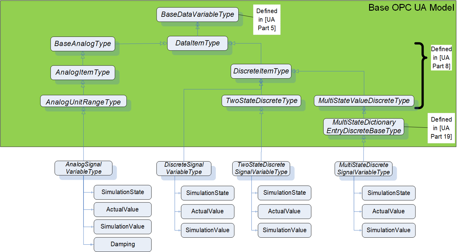
This specification adds new sub-types to each of the existing VariableTypes in OPC 10000-8.
8.2 AnalogSignalVariableType
8.2.1 Overview
The AnalogSignalVariableType is used for analog variables representing temperature, flow, pressure, etc.. The AnalogSignalVariableType is a subtype of the AnalogUnitRangeType and adds the optional components ActualValue, SimulationValue and Damping. The model and its subtypes are illustrated in Figure 13.
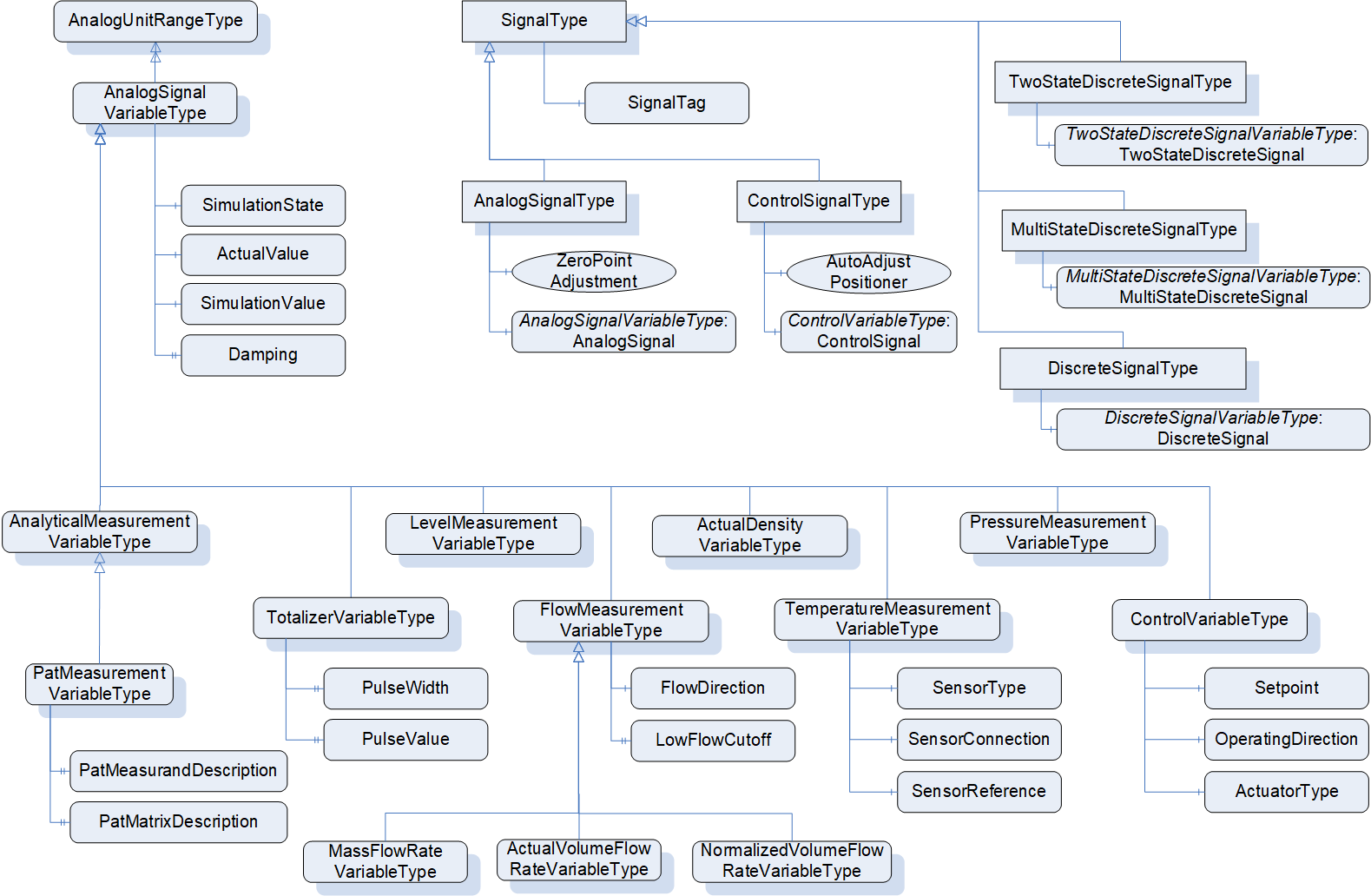
8.2.2 Definition
The AnalogSignalVariableType can be used to model any analog signal type. It extends the AnalogUnitRangeType defined in OPC 10000-8 to add additional information such as values for simulation and damping as well as dictionary references.
The ActualValue contains the unsimulated value during a simulation and SimulationValue contains the value to be used during simulation, as illustrated in Figure 14. The Value attribute always represents what is being reported by the Variable.
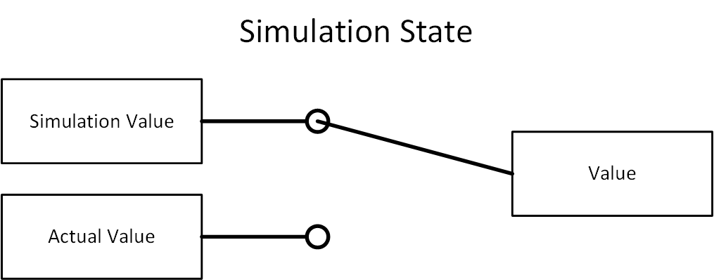
AnalogSignalVariableType is formally defined in Table 233.
| Attribute | Value | ||||
| BrowseName | AnalogSignalVariableType | ||||
| IsAbstract | False | ||||
| ValueRank | -2 (-2 = 'Any') | ||||
| DataType | Number | ||||
| References | NodeClass | BrowseName | DataType | TypeDefinition | Other |
|---|---|---|---|---|---|
| Subtype of 0:AnalogUnitRangeType defined in OPC 10000-8, i.e. inheriting the InstanceDeclarations of that Node | |||||
| 0:HasProperty | Variable | 0:EngineeringUnits | 0:EUInformation | 0:PropertyType | M |
| 0:HasComponent | Variable | ActualValue | 0:Number{Any} | 0:BaseDataVariableType | O |
| 0:HasComponent | Variable | SimulationValue | 0:Number{Any} | 0:BaseDataVariableType | O |
| 0:HasComponent | Variable | SimulationState | 0:Boolean | 0:BaseDataVariableType | O |
| 0:HasProperty | Variable | Damping | 0:Float | 0:PropertyType | O |
| 0:HasDictionaryEntry | Object | 3:0112/2///61987#ABN634#001 | 0:IrdiDictionaryEntryType | ||
| Conformance Units | |||||
|---|---|---|---|---|---|
| PA-DIM AnalogSignalVariableType | |||||
| PA-DIM AnalogSignalVariable Simulation | |||||
| PA-DIM AnalogSignalVariable Damping |
AnalogSignalVariableType also extends AnalogUnitRangeType by providing additional references. These references provide dictionary entries for all of the variables defined by this addition as well as dictionary references for fields in the parent AnalogUnitRangeType. See Table 234 for a complete definition.
The VariableType is extended in this definition to include the dictionary reference. The dictionary provides an additional description of Value which is copied here for clarity - "ABN634#001 defines parameter indicating the input or output value of a device using the units of measure of the process variable."
EngineeringUnits is the engineering unit associated with the value attribute of AnalogSignalVariableType, and as well with ActualValue and SimulationValue. It overwrites the EngineeringUnits property inherited from AnalogUnitRangeType.
ActualValue reflects the measured value independent of the simulation state. It is further described by dictionary entry ABN644#001 which states "parameter indicating the value of the not simulated process variable of a device using the units of measure of the process variable".
SimulationValue provides a value that substitutes Value if the simulation is enabled. It is further described by dictionary entry ABN613#001 which states "parameter indicating the simulated value of a variable using the units of measure of the simulated variable".
Damping provides a value in seconds that is used to flatten changes in the value. It is further described by dictionary entry ABH526#002 which states "for the output of a first-order system forced by a step or an impulse, the time required to complete 63.2% of the total rise or decay at any instant during the process".
SimulationState is defined by IRDI as ABN611#002 which states "parameter indicating the state of simulation". The value true means 'Simulation enabled', and false means 'Simulation disabled'.
The components of AnalogSignalVariableType have additional references which are defined in Table 234.
| SourceBrowsePath | Reference Type | Is Forward | TargetBrowsePath |
| 0:EngineeringUnits | 0:HasDictionaryEntry | True | 3:0112/2///61987#ABA968#004 |
| ActualValue | 0:HasDictionaryEntry | True | 3:0112/2///61987#ABN644#001 |
| SimulationValue | 0:HasDictionaryEntry | True | 3:0112/2///61987#ABN613#001 |
| Damping | 0:HasDictionaryEntry | True | 3:0112/2///61987#ABH526#002 |
| SimulationState | 0:HasDictionaryEntry | True | 3:0112/2///61987#ABN611#002 |
The child Nodes of the AnalogSignalVariableType have additional Attribute values defined in Table 235.
| BrowsePath | Value Attribute |
| SimulationState | False |
| Damping | 1.0 |
8.2.3 Engineering units with reference to IEC 61987 CDD
The Property EngineeringUnits - inherited from AnalogUnitRangeType (see OPC 10000-8 Amendment 1) - shall be used to define the unit for the AnalogSignalVariableType instance and also for its ActualValue and SimulationValue component Variables.
In addition, each EngineeringUnits Property shall provide a HasDictionaryEntry reference to the IEC Common Data Dictionary entry for "unit of measure" which is 3:0112/2///61987#ABA968#004. Figure 15 illustrates this with an example.
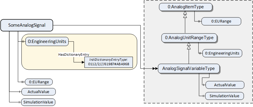
8.2.4 MultiStateDictionaryEntryDiscreteType with reference to IEC 61987 CDD
If MultiStateDictionaryEntryDiscreteType Variables reference an IEC 61987 CDD PROPERTY with a Value list, the following mapping applies:
For each possible element in the "Value list" map the Preferred name of the element to the "EnumValues" Property.
For each possible element in the "Value list" map the IRDI of the element to the "EnumDictionaryEntries" Property.
An example for the SensorConnection Property with IRDI 0112/2///61987#ABB091#003 is in Table 236:
| IEC 61987 CDD | ECLASS | OPC UA mapping | |
| "Value list" attribute | "Value list" attribute to be defined | "EnumValues" Property | "EnumDictionaryEntries" Property |
| 0112/2///61987#ABL113 - 4-wire | 0173-1#02-CCCnnn#00n | [0] -> "4-wire" | [0] -> 3:0112/2///61987#ABL113#001 |
| 0112/2///61987#ABL114 - 3-wire | 0173-1#02-CCCnnn#00n | [1] -> "3-wire" | [1] -> 3:0112/2///61987#ABL114#001 |
| 0112/2///61987#ABL115 - 2-wire | 0173-1#02-CCCnnn#00n | [2] -> "2-wire" | [2] -> 3:0112/2///61987#ABL115#001 |
| 0112/2///61987#ABI407 - others | 0173-1#02-CCCnnn#00n | [3] -> "others" | [3] -> 3:0112/2///61987#ABI407#004 |
8.3 TemperatureMeasurementVariableType
The TemperatureMeasurementVariableType is a subtype of the AnalogSignalVariableType. It is formally defined in Table 237.
| Attribute | Value | ||||
| BrowseName | TemperatureMeasurementVariableType | ||||
| IsAbstract | False | ||||
| ValueRank | -2 (-2 = 'Any') | ||||
| DataType | Float | ||||
| References | NodeClass | BrowseName | DataType | TypeDefinition | Other |
|---|---|---|---|---|---|
| Subtype of AnalogSignalVariableType defined in 8.2, i.e. inheriting the InstanceDeclarations of that Node | |||||
| 0:HasComponent | Variable | SensorType | 0:UInt32{Any} | 0:MultiStateDictionaryEntryDiscreteType | M |
| 0:HasComponent | Variable | SensorClass | 0:UInt32{Any} | 0:MultiStateDictionaryEntryDiscreteType | O |
| 0:HasComponent | Variable | SensorConnection | 0:UInt32{Any} | 0:MultiStateDictionaryEntryDiscreteType | O |
| 0:HasComponent | Variable | SensorReference | 0:UInt32{Any} | 0:MultiStateDictionaryEntryDiscreteType | O |
| 0:HasDictionaryEntry | Object | 3:0112/2///61987#ABA927#005 | 0:IrdiDictionaryEntryType | ||
| Conformance Units | |||||
|---|---|---|---|---|---|
| PA-DIM TemperatureMeasurementVariable | |||||
| PA-DIM TemperatureMeasurementVariable SensorClass | |||||
| PA-DIM TemperatureMeasurementVariable Connection | |||||
| PA-DIM TemperatureMeasurementVariable Reference |
This type defines temperature and is formally defined by ABA927#005.
ABA927#005 defines for a physical system exchanging quantities of heat with two bodies, during a reversible cycle, a positive state quantity characterizing each body and proportional to the quantity of heat exchanged with this body (Temperature).
For SensorType there are two possible IRDIs as target of the HasDictionaryEntry reference, depending on the kind of the connected sensor or chosen by SensorClass In case of RTD (thermoresistance) sensors the IRDI 3:0112/2///61987#ABB088#003 shall be referenced, in case of thermocouple sensors the IRDI 3:0112/2///61987#ABB092#003 shall be referenced. For mapping rules see 8.2.4.
SensorType: ABB088#003 defines classification of RTDs based on material and resistance used.
SensorType: ABB092#003 defines classification of a thermocouple according to the material pair or standard type code.
SensorClass: ABF288#004 defines setting of the sensing element type that is or should be connected to the device.
SensorConnection: ABB091#003 defines classification of an RTD or resistor connection based on the number of wires used. For mapping rules see 8.2.4.
SensorReference: ABB093#003 defines type of reference junction for a thermocouple. For mapping rules see 8.2.4.
The components of TemperatureMeasurementVariableType have additional references which are defined in Table 238.
| SourceBrowsePath | Reference Type | Is Forward | TargetBrowsePath |
| SensorClass | 0:HasDictionaryEntry | True | 3:0112/2///61987#ABF288#004 |
| SensorConnection | 0:HasDictionaryEntry | True | 3:0112/2///61987#ABB091#003 |
| SensorReference | 0:HasDictionaryEntry | True | 3:0112/2///61987#ABB093#003 |
The child Nodes of the TemperatureMeasurementVariableType have additional Attribute values defined in Table 239.
| BrowsePath | Value Attribute | ||
| SensorType | 8 | ||
| ns=3;s=0112/2///61987#ABK984#001 | ||
| Pt100 | ||
| SensorClass | 0 | ||
| ns=3;s=0112/2///61987#ABL238#001 | ||
| RTD | ||
| SensorConnection | 0 | ||
| ns=3;s=0112/2///61987#ABL113#001 | ||
| 4-wire | ||
| SensorReference | 1 | ||
| ns=3;s=0112/2///61987#ABN417#001 | ||
| internal cold junction |
8.4 FlowMeasurementVariableType
The FlowMeasurementVariableType is a subtype of the AnalogSignalVariableType. It is formally defined in Table 240.
| Attribute | Value | ||||
| BrowseName | FlowMeasurementVariableType | ||||
| IsAbstract | False | ||||
| ValueRank | -2 (-2 = 'Any') | ||||
| DataType | Float | ||||
| References | NodeClass | BrowseName | DataType | TypeDefinition | Other |
|---|---|---|---|---|---|
| Subtype of AnalogSignalVariableType defined in 8.2, i.e. inheriting the InstanceDeclarations of that Node | |||||
| 0:HasProperty | Variable | LowFlowCutOff | 0:Float{Any} | 0:PropertyType | M |
| 0:HasComponent | Variable | FlowDirection | 0:UInt32{Any} | 0:MultiStateDictionaryEntryDiscreteType | O |
| Conformance Units | |||||
|---|---|---|---|---|---|
| PA-DIM FlowMeasurementVariable | |||||
| PA-DIM FlowMeasurementVariable FlowDirection |
This type defines flow and is formally defined within the subtypes.
LowFlowCutOff: ABJ724#003 defines value of the flow below which the low flow cut-off is switched on, in units of the measuring span, which is fixed to percent. The default value is 1% of the high value of EURange.
FlowDirection: ABN594#003 defines configuration parameter of the value sign of the flow signal for forward flow. For mapping rules see 8.2.4.
The components of FlowMeasurementVariableType have additional references which are defined in Table 241.
| SourceBrowsePath | Reference Type | Is Forward | TargetBrowsePath |
| LowFlowCutOff | 0:HasDictionaryEntry | True | 3:0112/2///61987#ABJ724#003 |
| FlowDirection | 0:HasDictionaryEntry | True | 3:0112/2///61987#ABN594#003 |
The child Nodes of the FlowMeasurementVariableType have additional Attribute values defined in Table 242.
| BrowsePath | Value Attribute | ||
| FlowDirection | 0 | ||
| ns=3;s=0112/2///61987#ABM885#001 | ||
| positive |
8.5 PressureMeasurementVariableType
The PressureMeasurementVariableType is a subtype of the AnalogSignalVariableType. It is formally defined in Table 243.
| Attribute | Value | ||||
| BrowseName | PressureMeasurementVariableType | ||||
| IsAbstract | False | ||||
| ValueRank | -2 (-2 = 'Any') | ||||
| DataType | Float | ||||
| References | NodeClass | BrowseName | DataType | TypeDefinition | Other |
|---|---|---|---|---|---|
| Subtype of AnalogSignalVariableType defined in 8.2, i.e. inheriting the InstanceDeclarations of that Node | |||||
| 0:HasDictionaryEntry | Object | 3:0112/2///61987#ABN616#001 | 0:IrdiDictionaryEntryType | ||
| Conformance Units | |||||
|---|---|---|---|---|---|
| PA-DIM PressureMeasurementVariable |
This type defines pressure and is formally defined within ABN616#001.
ABN616#001 defines at a point of a surface, scalar quantity equal to the limit of the quotient of the magnitude of the component vector normal to the surface of the force acting at this point, by the area of a surface containing the point, when all the dimensions of that surface tend to zero (Pressure).
8.6 LevelMeasurementVariableType
The LevelMeasurementVariableType is a subtype of the AnalogSignalVariableType. It is formally defined in Table 244.
| Attribute | Value | ||||
| BrowseName | LevelMeasurementVariableType | ||||
| IsAbstract | False | ||||
| ValueRank | -2 (-2 = 'Any') | ||||
| DataType | Float | ||||
| References | NodeClass | BrowseName | DataType | TypeDefinition | Other |
|---|---|---|---|---|---|
| Subtype of AnalogSignalVariableType defined in 8.2, i.e. inheriting the InstanceDeclarations of that Node | |||||
| 0:HasDictionaryEntry | Object | 3:0112/2///61987#ABH329#002 | 0:IrdiDictionaryEntryType | ||
| Conformance Units | |||||
|---|---|---|---|---|---|
| PA-DIM LevelMeasurementVariable |
This type defines level and is formally defined within ABH329#001.
ABH329#002 defines height of process material in a tank, vessel, silo or other container.
8.7 MassFlowRateVariableType
The MassFlowRateVariableType is a subtype of the FlowMeasurementVariableType. It is formally defined in Table 245.
| Attribute | Value | ||||
| BrowseName | MassFlowRateVariableType | ||||
| IsAbstract | False | ||||
| ValueRank | -2 (-2 = 'Any') | ||||
| DataType | Float | ||||
| References | NodeClass | BrowseName | DataType | TypeDefinition | Other |
|---|---|---|---|---|---|
| Subtype of FlowMeasurementVariableType defined in 8.4, i.e. inheriting the InstanceDeclarations of that Node | |||||
| 0:HasDictionaryEntry | Object | 3:0112/2///61987#ABB290#005 | 0:IrdiDictionaryEntryType | ||
| Conformance Units | |||||
|---|---|---|---|---|---|
| PA-DIM MassFlowRateVariable |
This type defines mass flow and is formally defined within ABB290#005.
ABB290#005 defines mass of material flowing per unit time.
8.8 ActualVolumeFlowRateVariableType
The ActualVolumeFlowRateVariableType is a subtype of the FlowMeasurementVariableType. It is formally defined in Table 246.
| Attribute | Value | ||||
| BrowseName | ActualVolumeFlowRateVariableType | ||||
| IsAbstract | False | ||||
| ValueRank | -2 (-2 = 'Any') | ||||
| DataType | Float | ||||
| References | NodeClass | BrowseName | DataType | TypeDefinition | Other |
|---|---|---|---|---|---|
| Subtype of FlowMeasurementVariableType defined in 8.4, i.e. inheriting the InstanceDeclarations of that Node | |||||
| 0:HasDictionaryEntry | Object | 3:0112/2///61987#ABB291#005 | 0:IrdiDictionaryEntryType | ||
| Conformance Units | |||||
|---|---|---|---|---|---|
| PA-DIM ActualVolumeFlowRateVariable |
This type defines volume flow and is formally defined within ABB291#005.
ABB291#005 defines actual volume of fluid that passes a given point per unit time.
8.9 NormalizedVolumeFlowRateVariableType
The NormalizedVolumeFlowRateVariableType is a subtype of the FlowMeasurementVariableType. It is formally defined in Table 247.
| Attribute | Value | ||||
| BrowseName | NormalizedVolumeFlowRateVariableType | ||||
| IsAbstract | False | ||||
| ValueRank | -2 (-2 = 'Any') | ||||
| DataType | Float | ||||
| References | NodeClass | BrowseName | DataType | TypeDefinition | Other |
|---|---|---|---|---|---|
| Subtype of FlowMeasurementVariableType defined in 8.4, i.e. inheriting the InstanceDeclarations of that Node | |||||
| 0:HasDictionaryEntry | Object | 3:0112/2///61987#ABB292#005 | 0:IrdiDictionaryEntryType | ||
| Conformance Units | |||||
|---|---|---|---|---|---|
| PA-DIM NormalizedVolumeFlowRateVariable |
This type defines normalized volume flow and is formally defined within ABB292#005.
ABB292#001 defines volume of material flowing per unit time calculated to base conditions.
8.10 ActualDensityVariableType
The ActualDensityVariableType is a subtype of the AnalogSignalVariableType. It is formally defined in Table 248.
| Attribute | Value | ||||
| BrowseName | ActualDensityVariableType | ||||
| IsAbstract | False | ||||
| ValueRank | -2 (-2 = 'Any') | ||||
| DataType | Float | ||||
| References | NodeClass | BrowseName | DataType | TypeDefinition | Other |
|---|---|---|---|---|---|
| Subtype of AnalogSignalVariableType defined in 8.2, i.e. inheriting the InstanceDeclarations of that Node | |||||
| 0:HasDictionaryEntry | Object | 3:0112/2///61987#ABA946#004 | 0:IrdiDictionaryEntryType | ||
| Conformance Units | |||||
|---|---|---|---|---|---|
| PA-DIM ActualDensityVariable |
This type defines density and is formally defined within ABA946#004.
ABA946#001 defines density measured under operating conditions.
8.11 ControlVariableType
The ControlVariableType is a subtype of the AnalogSignalVariableType. It is formally defined in Table 249.
| Attribute | Value | ||||
| BrowseName | ControlVariableType | ||||
| IsAbstract | False | ||||
| ValueRank | -2 (-2 = 'Any') | ||||
| DataType | Float | ||||
| References | NodeClass | BrowseName | DataType | TypeDefinition | Other |
|---|---|---|---|---|---|
| Subtype of AnalogSignalVariableType defined in 8.2, i.e. inheriting the InstanceDeclarations of that Node | |||||
| 0:HasComponent | Variable | Setpoint | 0:Float{Any} | 0:BaseAnalogType | M |
| 0:HasComponent | Variable | OperatingDirection | 0:UInt32 | 0:MultiStateDictionaryEntryDiscreteType | M |
| 0:HasComponent | Variable | ActuatorType | 0:UInt32 | 0:MultiStateDictionaryEntryDiscreteType | M |
| 0:HasDictionaryEntry | Object | 3:0112/2///61987#ABP588#001 | 0:IrdiDictionaryEntryType | ||
| Conformance Units | |||||
|---|---|---|---|---|---|
| PA-DIM ControlVariable |
This type defines control which is used e.g. for an actuator, positioner.
ABP588#001 defines readback value of the position of an analog final control element within the travel span (between OPEN and CLOSE position). The unit of this value is provided by the EngineeringUnits property.
Setpoint: ABN607#002 defines set point for a valve position.
OperatingDirection: ABD740#003 defines output change to a given input signal. For mapping rules see 8.2.4.
ActuatorType: ABD742#003 defines classification of a positioner according to the actuator for which it can be used. For mapping rules see 8.2.4.
The components of ControlVariableType have additional references which are defined in Table 250.
| SourceBrowsePath | Reference Type | Is Forward | TargetBrowsePath | ||
| Setpoint | 0:HasDictionaryEntry | True | 3:0112/2///61987#ABN607#002 | ||
| 0:HasDictionaryEntry | True | 3:0112/2///61987#ABA968#004 | ||
| OperatingDirection | 0:HasDictionaryEntry | True | 3:0112/2///61987#ABD740#003 | ||
| ActuatorType | 0:HasDictionaryEntry | True | 3:0112/2///61987#ABD742#003 |
The child Nodes of the ControlVariableType have additional Attribute values defined in Table 251.
| BrowsePath | Value Attribute | ||
| Setpoint | 0.0 | ||
| NamespaceUri: http://www.opcfoundation.org/UA/units/cdd/IEC62720 UnitId: 705741328 DisplayName: % Description: percent | ||
| OperatingDirection | 0 | ||
| ns=3;s=0112/2///61987#ABL147#001 | ||
| direct | ||
| ActuatorType | 0 | ||
| ns=3;s=0112/2///61987#ABN145#001 | ||
| sliding-stem linear |
8.12 TotalizerVariableType
The TotalizerVariableType provides means to summarize pulses. The TotalizerVariableType is a subtype of the AnalogSignalVariableType. It is formally defined in Table 252.
| Attribute | Value | ||||
| BrowseName | TotalizerVariableType | ||||
| IsAbstract | False | ||||
| ValueRank | -2 (-2 = 'Any') | ||||
| DataType | Number | ||||
| References | NodeClass | BrowseName | DataType | TypeDefinition | Other |
|---|---|---|---|---|---|
| Subtype of AnalogSignalVariableType defined in 8.2, i.e. inheriting the InstanceDeclarations of that Node | |||||
| 0:HasProperty | Variable | PulseValue | 0:Number | 0:PropertyType | M |
| 0:HasProperty | Variable | PulseWidth | 0:Float | 0:PropertyType | M |
| Conformance Units | |||||
|---|---|---|---|---|---|
| PA-DIM TotalizerVariable |
This type defines a totalizer value.
For TotalizerVariableType there are more than one possible IRDIs as target of the HasDictionaryEntry reference, depending on the type of the totalized quantity. In case of mass totalization the IRDI 3:0112/2///61987#ABH327#001 shall be referenced, in case of actual volume totalization the IRDI 3:0112/2///61987#ABH328#001 shall be referenced. The related HasDictionaryEntry reference shall be defined after the concrete totalizer type is known.
PulseValue: ABA418#002 defines mass quantity assigned to one pulse. The default value is 1 pulse per 0.1 kg. The unit is fixed to kg.
PulseValue: ABE882#002 defines volume quantity assigned to one pulse. The default value is 1 pulse per 0.1 l. The unit is fixed to l.
PulseWidth: ABA635#003 defines setting of the pulse width. The unit is fixed to ms.
The components of TotalizerVariableType have additional references which are defined in Table 253.
| SourceBrowsePath | Reference Type | Is Forward | TargetBrowsePath |
| PulseWidth | 0:HasDictionaryEntry | True | 3:0112/2///61987#ABA635#003 |
For PulseValue there are more than one possible IRDIs as target of the HasDictionaryEntry reference, depending on the type of the totalized quantity. The dictionary entry for PulseValue shall be 3:0112/2///61987#ABA418#002 for mass flow and 3:0112/2///61987#ABE882#002 for volume flow.
The child Nodes of the TotalizerVariableType have additional Attribute values defined in Table 254.
| BrowsePath | Value Attribute |
| PulseWidth | 0.5 |
8.13 AnalyticalMeasurementVariableType
The AnalyticalMeasurementVariableType is a subtype of the AnalogSignalVariableType. It is formally defined in Table 255.
| Attribute | Value | ||||
| BrowseName | AnalyticalMeasurementVariableType | ||||
| IsAbstract | False | ||||
| ValueRank | -2 (-2 = 'Any') | ||||
| DataType | Float | ||||
| References | NodeClass | BrowseName | DataType | TypeDefinition | Other |
|---|---|---|---|---|---|
| Subtype of AnalogSignalVariableType defined in 8.2, i.e. inheriting the InstanceDeclarations of that Node | |||||
| Conformance Units | |||||
|---|---|---|---|---|---|
| PA-DIM AnalyticalMeasurementVariable |
This type defines an analytical measurement value.
8.14 PatMeasurementVariableType
The PatMeasurementVariableType is a subtype of the AnalyticalMeasurementVariableType. It is formally defined in Table 256.
| Attribute | Value | ||||
| BrowseName | PatMeasurementVariableType | ||||
| IsAbstract | False | ||||
| ValueRank | -1 (-1 = 'Scalar') | ||||
| DataType | Float | ||||
| References | NodeClass | BrowseName | DataType | TypeDefinition | Other |
|---|---|---|---|---|---|
| Subtype of AnalyticalMeasurementVariableType defined in 8.13, i.e. inheriting the InstanceDeclarations of that Node | |||||
| 0:HasProperty | Variable | PatMeasurandDescription | ChemicalSubstanceDataType | 0:PropertyType | O |
| 0:HasProperty | Variable | PatMatrixDescription | ChemicalSubstanceDataType[] | 0:PropertyType | O |
| 0:HasDictionaryEntry | Object | 3:<DictionaryEntryName> | 0:IrdiDictionaryEntryType | ||
| Conformance Units | |||||
|---|---|---|---|---|---|
| PA-DIM PatMeasurementVariableType | |||||
| PA-DIM PatMeasurementVariableType PatMatrixDescription |
This type defines a PAT measurement value.
PatMatrixDescription: The matrix is an array of all quantities that make up an entity of interest. Quantities are defined by an ID (from a dictionary like CAS or PAT, or defined by user resp. manufacturer) and an associated label.
PatMeasurandDescription: A Measurand is the quantity that is measured. Is it always a part of the matrix. Any quantity of the matrix can become a measurand within one analytical device. Measurands are defined by an ID (from a dictionary like CAS or PAT, or defined by user resp. manufacturer) and an associated label.
3:<DictionaryEntryName> is an optional placeholder for an object of IrdiDictionaryEntryType that defines a predefined group of one or more properties of the classes ABN688 (Concentration measurement variables) or ABN689 (Liquid analysis measurement variables), e.g. ABN628 - mass concentration (per volume) or ABN617 - pH value. ABN688 and ABN689 and their properties are defined in IEC 61987 Common Data Dictionary (CDD). They represent classes of analytical measurement variables.
The components of PatMeasurementVariableType have additional references which are defined in Table 257.
| SourceBrowsePath | Reference Type | Is Forward | TargetBrowsePath |
| PatMeasurandDescription | 0:HasDictionaryEntry | True | 3:0112/2///61987#ABP496#001 |
| PatMatrixDescription | 0:HasDictionaryEntry | True | 3:0112/2///61987#ABP495#001 |
8.15 TwoStateDiscreteSignalVariableType
The TwoStateDiscreteSignalVariableType is used for process variables, that can have two states, and illustrated in Figure 12. It is formally defined in Table 258.
| Attribute | Value | ||||
| BrowseName | TwoStateDiscreteSignalVariableType | ||||
| IsAbstract | False | ||||
| ValueRank | -2 (-2 = 'Any') | ||||
| DataType | Boolean | ||||
| References | NodeClass | BrowseName | DataType | TypeDefinition | Other |
|---|---|---|---|---|---|
| Subtype of 0:TwoStateDiscreteType defined in OPC 10000-8, i.e. inheriting the InstanceDeclarations of that Node | |||||
| 0:HasComponent | Variable | ActualValue | 0:Boolean{Any} | 0:BaseDataVariableType | O |
| 0:HasComponent | Variable | SimulationValue | 0:Boolean{Any} | 0:BaseDataVariableType | O |
| 0:HasComponent | Variable | SimulationState | 0:Boolean | 0:BaseDataVariableType | O |
| 0:HasDictionaryEntry | Object | 3:0112/2///61987#ABN635#002 | 0:IrdiDictionaryEntryType | ||
| Conformance Units | |||||
|---|---|---|---|---|---|
| PA-DIM TwoStateDiscreteVariable | |||||
| PA-DIM TwoStateDiscreteVariable Simulation |
ActualValue: ABN645#001 defines parameter indicating the binary value of a not simulated binary process variable of a device.
SimulationValue: ABN632#001 parameter indicating the simulated value of a binary variable.
SimulationState is defined by IRDI as ABN611#002 which states "parameter indicating the state of simulation" and used also to enable/disable simulation. The value true means 'Simulation enabled', and false means 'Simulation disabled'.
ABN635#001 defines parameter indicating the binary input or output value of a device.
The components of TwoStateDiscreteSignalVariableType have additional references which are defined in Table 259.
| SourceBrowsePath | Reference Type | Is Forward | TargetBrowsePath |
| ActualValue | 0:HasDictionaryEntry | True | 3:0112/2///61987#ABN645#002 |
| SimulationValue | 0:HasDictionaryEntry | True | 3:0112/2///61987#ABN632#002 |
| SimulationState | 0:HasDictionaryEntry | True | 3:0112/2///61987#ABN611#002 |
The child Nodes of the TwoStateDiscreteSignalVariableType have additional Attribute values defined in Table 260.
| BrowsePath | Value Attribute |
| ActualValue | False |
| SimulationValue | False |
| SimulationState | False |
8.16 MultiStateDiscreteSignalVariableType
The MultiStateDiscreteSignalVariableType is used for process variables that can have more than two states. It is formally defined in Table 261.
| Attribute | Value | |||||
| BrowseName | MultiStateDiscreteSignalVariableType | |||||
| IsAbstract | False | |||||
| ValueRank | -1 (-1 = 'Scalar') | |||||
| DataType | UInt32 | |||||
| References | NodeClass | BrowseName | DataType | TypeDefinition | Other | |
|---|---|---|---|---|---|---|
| Subtype of 0:MultiStateDictionaryEntryDiscreteBaseType defined in OPC 10000-19, i.e. inheriting the InstanceDeclarations of that Node | ||||||
| 0:HasComponent | Variable | ActualValue | 0:UInt32 | 0:BaseDataVariableType | O | |
| 0:HasComponent | Variable | SimulationValue | 0:UInt32 | 0:BaseDataVariableType | O | |
| 0:HasComponent | Variable | SimulationState | 0:Boolean | 0:BaseDataVariableType | O | |
| 0:HasDictionaryEntry | Object | 3:0112/2///61987#ABN636#002 | 0:IrdiDictionaryEntryType | |||
| Conformance Units | |||||
|---|---|---|---|---|---|
| PA-DIM MultiStateDiscreteVariable | |||||
| PA-DIM MultiStateDiscreteVariable Simulation |
ActualValue: ABN646#002 defines "parameter indicating the discrete value of the not simulated discrete process variable of a device".
SimulationValue: ABN637#002 defines "parameter indicating the simulated discrete value of a variable, which can have multiple states".
SimulationState; ABN611#002 defines "parameter indicating the state of simulation" and used also to enable/disable simulation. The value true means 'Simulation enabled', and false means 'Simulation disabled'.
ABN636#002 defines "parameter indicating the discrete input or output value out of multiple state of a device".
The components of MultiStateDiscreteSignalVariableType have additional references which are defined in Table 262.
| SourceBrowsePath | Reference Type | Is Forward | TargetBrowsePath |
| ActualValue | 0:HasDictionaryEntry | True | 3:0112/2///61987#ABN646#002 |
| SimulationValue | 0:HasDictionaryEntry | True | 3:0112/2///61987#ABN637#002 |
| SimulationState | 0:HasDictionaryEntry | True | 3:0112/2///61987#ABN611#002 |
The child Nodes of the MultiStateDiscreteSignalVariableType have additional Attribute values defined in Table 263.
| BrowsePath | Value Attribute |
| ActualValue | 0 |
| SimulationValue | 0 |
| SimulationState | False |
8.17 DiscreteSignalVariableType
8.17.1 Overview
The DiscreteSignalVariableType is used for process variables of any data type, Integer, UInteger, Boolean, Structure etc. E.g. the data type Structure can be for aggregation of multiple values into one signal variable. ActualValue contains the unsimulated value during a simulation and SimulationValue contains the value to be used during simulation.
8.17.2 Definition
The DiscreteSignalVariableType is a subtype of the DiscreteItemType defined in OPC 10000-8 and adds optionally ActualValue and SimulationValue components. It is formally defined in Table 264.
| Attribute | Value | ||||
| BrowseName | DiscreteSignalVariableType | ||||
| IsAbstract | False | ||||
| ValueRank | -2 (-2 = 'Any') | ||||
| DataType | BaseDataType | ||||
| References | NodeClass | BrowseName | DataType | TypeDefinition | Other |
|---|---|---|---|---|---|
| Subtype of 0:DiscreteItemType defined in OPC 10000-8, i.e. inheriting the InstanceDeclarations of that Node | |||||
| 0:HasComponent | Variable | ActualValue | 0:BaseDataType{Any} | 0:BaseDataVariableType | O |
| 0:HasComponent | Variable | SimulationValue | 0:BaseDataType{Any} | 0:BaseDataVariableType | O |
| 0:HasComponent | Variable | SimulationState | 0:Boolean | 0:BaseDataVariableType | O |
| Conformance Units | |||||
|---|---|---|---|---|---|
| PA-DIM DiscreteVariable | |||||
| PA-DIM DiscreteVariable Simulation |
ActualValue: ABN644#001 defines "parameter indicating the value of the not simulated discrete process variable of a device".
SimulationValue: ABN613#001 defines "parameter indicating the simulated value of a variable, which can have multiple states".
SimulationState: ABN611#002 defines "parameter indicating the state of simulation" and used also to enable/disable simulation. The value true means 'Simulation enabled', and false means 'Simulation disabled'.
The components of DiscreteSignalVariableType have additional references which are defined in Table 265.
| SourceBrowsePath | Reference Type | Is Forward | TargetBrowsePath |
| ActualValue | 0:HasDictionaryEntry | True | 3:0112/2///61987#ABN644#001 |
| SimulationValue | 0:HasDictionaryEntry | True | 3:0112/2///61987#ABN613#001 |
| SimulationState | 0:HasDictionaryEntry | True | 3:0112/2///61987#ABN611#002 |
The child Nodes of the DiscreteSignalVariableType have additional Attribute values defined in Table 266.
| BrowsePath | Value Attribute |
| SimulationState | False |
8.18 TwoStateDiscreteControlVariableType
The TwoStateDiscreteControlVariableType is a subtype of the TwoStateDiscreteSignalVariableType. It is formally defined in Table 267.
| Attribute | Value | ||||
| BrowseName | TwoStateDiscreteControlVariableType | ||||
| IsAbstract | False | ||||
| ValueRank | -2 (-2 = 'Any') | ||||
| DataType | Boolean | ||||
| References | NodeClass | BrowseName | DataType | TypeDefinition | Other |
|---|---|---|---|---|---|
| Subtype of TwoStateDiscreteSignalVariableType defined in 8.15, i.e. inheriting the InstanceDeclarations of that Node | |||||
| 0:HasComponent | Variable | Setpoint | 0:Boolean{Any} | 0:TwoStateDiscreteType | M |
| 0:HasComponent | Variable | OperatingDirection | 0:UInt32 | 0:MultiStateDictionaryEntryDiscreteType | M |
| 0:HasComponent | Variable | FaultState | 0:Boolean | 0:TwoStateDiscreteType | O |
| 0:HasDictionaryEntry | Object | 3:0112/2///61987#ABP541#002 | 0:IrdiDictionaryEntryType | ||
| Conformance Units | |||||
|---|---|---|---|---|---|
| PA-DIM TwoStateDiscreteControlVariable | |||||
| PA-DIM TwoStateDiscreteControlVariable FaultState |
This type defines control which is used for two state discrete output.
Setpoint: ABP542#001 defines in a control loop, the two-state target value the process value is intended to assume.
OperatingDirection: ABD740#003 defines output change to a given input signal, for example direct or reverse.
FaultState: ABP543#002 defines replacement value of a two-state output in the case of a failure.
ABP541#001 defines two-state readback value in a control loop. The components of TwoStateDiscreteControlVariableType have additional references which are defined in Table 268.
| SourceBrowsePath | Reference Type | Is Forward | TargetBrowsePath |
| Setpoint | 0:HasDictionaryEntry | True | 3:0112/2///61987#ABP542#002 |
| OperatingDirection | 0:HasDictionaryEntry | True | 3:0112/2///61987#ABD740#003 |
| FaultState | 0:HasDictionaryEntry | True | 3:0112/2///61987#ABP543#002 |
The child Nodes of the TwoStateDiscreteControlVariableType have additional Attribute values defined in Table 269.
| BrowsePath | Value Attribute | ||
| Setpoint | False | ||
| FALSE | ||
| TRUE | ||
| OperatingDirection | 0 | ||
| ns=3;s=0112/2///61987#ABL147#001 | ||
| direct | ||
| FaultState | False | ||
| FALSE | ||
| TRUE |
8.19 MultiStateDiscreteControlVariableType
The MultiStateDiscreteControlVariableType is a subtype of the MultiStateDiscreteSignalVariableType. It is formally defined in Table 270.
| Attribute | Value | ||||
| BrowseName | MultiStateDiscreteControlVariableType | ||||
| IsAbstract | False | ||||
| ValueRank | -1 (-1 = 'Scalar') | ||||
| DataType | UInt32 | ||||
| References | NodeClass | BrowseName | DataType | TypeDefinition | Other |
|---|---|---|---|---|---|
| Subtype of MultiStateDiscreteSignalVariableType defined in 8.16, i.e. inheriting the InstanceDeclarations of that Node | |||||
| 0:HasComponent | Variable | Setpoint | 0:UInt32 | 0:MultiStateDictionaryEntryDiscreteType | M |
| 0:HasComponent | Variable | OperatingDirection | 0:UInt32 | 0:MultiStateDictionaryEntryDiscreteType | O |
| 0:HasComponent | Variable | FaultState | 0:UInt32 | 0:MultiStateDictionaryEntryDiscreteType | O |
| 0:HasDictionaryEntry | Object | 3:0112/2///61987#ABP644#002 | 0:IrdiDictionaryEntryType | ||
| Conformance Units | |||||
|---|---|---|---|---|---|
| PA-DIM MultiStateDiscreteControlVariable | |||||
| PA-DIM MultiStateDiscreteControlVariable OperatingDirection | |||||
| PA-DIM MultiStateDiscreteControlVariable FaultState |
This type defines control which is used for multi state discrete output.
Setpoint: ABP645#002 defines in a control loop, the multi-state target value the process value is intended to assume.
OperatingDirection: ABD740#003 defines output change to a given input signal, for example direct or reverse.
FaultState: ABP651#002 defines replacement value of a multi-state output in the case of a failure.
ABP644#002 defines parameter indicating the discrete readback value in a control loop.
The components of MultiStateDiscreteControlVariableType have additional references which are defined in Table 271.
| SourceBrowsePath | Reference Type | Is Forward | TargetBrowsePath |
| Setpoint | 0:HasDictionaryEntry | True | 3:0112/2///61987#ABP645#002 |
| OperatingDirection | 0:HasDictionaryEntry | True | 3:0112/2///61987#ABD740#003 |
| FaultState | 0:HasDictionaryEntry | True | 3:0112/2///61987#ABP651#002 |
The child Nodes of the MultiStateDiscreteControlVariableType have additional Attribute values defined in Table 272.
| BrowsePath | Value Attribute | ||
| Setpoint | 7 | ||
| ns=3;s=0112/2///61987#ABN841#001 | ||
| false | ||
| OperatingDirection | 0 | ||
| ns=3;s=0112/2///61987#ABL147#001 | ||
| direct |
9 PA-DIM Methods
9.1 FactoryReset
FactoryReset is a method used to reset all or a predefined group of the device parameters to their factory settings. The desired reset mode is selected by the enumeration value of the input argument. Access to this method shall be restricted to authorized users.
The signature of this Method is specified below. Table 273 and Table 275 specify the Arguments and AddressSpace representation, respectively.
Signature
	FactoryReset (
		 [in] ResetModeEnum ResetMode
);| Argument | Description |
| ResetMode | The desired reset mode, see 10.1 for a definition of all available values. |
Method Result Codes are defined in Table 274.
| Result Code | Description |
| Bad_InvalidArgument | The input is not a valid reset code. |
| Bad_UserAccessDenied | The current user does not have the rights required. |
| Attribute | Value | ||||
| BrowseName | FactoryReset | ||||
| References | NodeClass | BrowseName | DataType | TypeDefinition | ModellingRule |
|---|---|---|---|---|---|
| 0:HasProperty | Variable | 0:InputArguments | 0:Argument[] | 0:PropertyType | 0:Mandatory |
9.2 ZeroPointAdjustment
ZeroPointAdjustment is a method used to initiate an automatic adjustment cycle to determine the zero point of a process variable. The adjustment procedure starts after the method has been called and ends automatically, when it has been finished. The method does not have any arguments. The adjustment procedure is device-specific. Access to this method shall be restricted to authorized users.
The signature of this Method is specified below. Table 277 specifies the AddressSpace representation.
Signature
	ZeroPointAdjustment (
		);
Method Result Codes are defined in Table 276.
| Result Code | Description |
| Bad_UserAccessDenied | The current user does not have the rights required. |
| Attribute | Value | ||||
| BrowseName | ZeroPointAdjustment | ||||
| References | NodeClass | BrowseName | DataType | TypeDefinition | ModellingRule |
|---|
9.3 AutoAdjustPositioner
AutoAdjustPositioner is a method used to initiate an automatic commissioning cycle of an actuator. The execution of the commissioning procedure can be started or aborted by calling the method using the appropriate input argument value. If the commissioning will not be aborted, it ends automatically after it has been finished. The commissioning procedure is manufacturer-specific. Access to this method shall be restricted to authorized users.
The signature of this Method is specified below. Table 278 and Table 280 specify the Arguments and AddressSpace representation, respectively.
Signature
	AutoAdjustPositioner (
		[in] ExecutionModeEnum ExecutionMode
);| Argument | Description |
| ExecutionMode | The desired execution mode, see 10.2 for a definition of all available values. |
Method Result Codes are defined in Table 279.
| Result Code | Description |
| Bad_InvalidArgument | The input is not a valid execution mode. |
| Bad_UserAccessDenied | The current user does not have the rights required. |
| Attribute | Value | ||||
| BrowseName | AutoAdjustPositioner | ||||
| References | NodeClass | BrowseName | DataType | TypeDefinition | ModellingRule |
|---|---|---|---|---|---|
| 0:HasProperty | Variable | 0:InputArguments | 0:Argument[] | 0:PropertyType | 0:Mandatory |
10 OPC UA DataTypes
10.1 ResetModeEnum
This enumeration defines the possible values of the input argument of the FactoryReset Method. The enumeration is defined in Table 281.
| Name | Value | Description |
| Application | 1 | Reset only the application device parameters to their factory settings |
| Communication | 2712 | Reset only the communication device parameters to their factory settings |
| Factory | 2713 | Reset all device parameters to their factory settings |
Its representation in the AddressSpace is defined in Table 282.
| Attribute | Value | ||||
| BrowseName | ResetModeEnum | ||||
| IsAbstract | False | ||||
| References | NodeClass | BrowseName | DataType | TypeDefinition | Other |
|---|---|---|---|---|---|
| Subtype of the 0:Enumeration type defined in OPC 10000-3 | |||||
| 0:HasProperty | Variable | 0:EnumValues | 0:EnumValueType[] | 0:PropertyType | |
| Conformance Units | |||||
|---|---|---|---|---|---|
| PA-DIM IAdmin FactoryReset |
10.2 ExecutionModeEnum
This enumeration defines the possible values of the input argument of the AutoAdjustPositioner Method. The enumeration is defined in Table 283.
| Name | Value | Description |
| Start | 2 | Start the commissioning procedure |
| Abort | 255 | Abort the commissioning procedure, if it is being executed |
Its representation in the AddressSpace is defined in Table 284.
| Attribute | Value | ||||
| BrowseName | ExecutionModeEnum | ||||
| IsAbstract | False | ||||
| References | NodeClass | BrowseName | DataType | TypeDefinition | Other |
|---|---|---|---|---|---|
| Subtype of the 0:Enumeration type defined in OPC 10000-3 | |||||
| 0:HasProperty | Variable | 0:EnumValues | 0:EnumValueType[] | 0:PropertyType | |
| Conformance Units | |||||
|---|---|---|---|---|---|
| PA-DIM AutoAdjustPositioner method |
10.3 PatDictionaryEnum
This enumeration defines the possible values of the PatDictionary element in the ChemicalSubstanceDataType structure. The enumeration is defined in Table 285.
| Name | Value | Description |
| CAS | 0 | Chemical Abstracts Service dictionary |
| PAT | 1 | Process Analyser Technology dictionary |
| User-defined | 2 | User/manufacturer defined |
Its representation in the AddressSpace is defined in Table 286.
| Attribute | Value | ||||
| BrowseName | PatDictionaryEnum | ||||
| IsAbstract | False | ||||
| References | NodeClass | BrowseName | DataType | TypeDefinition | Other |
|---|---|---|---|---|---|
| Subtype of the 0:Enumeration type defined in OPC 10000-3 | |||||
| 0:HasProperty | Variable | 0:EnumValues | 0:EnumValueType[] | 0:PropertyType | |
| Conformance Units | |||||
|---|---|---|---|---|---|
| PA-DIM PatMeasurementVariableType | |||||
| PA-DIM PatMeasurementVariableType PatMatrixDescription |
10.4 ChemicalSubstanceDataType
This structure contains a label and an ID describing a chemical substance. The structure is defined in Table 287.
| Name | Type | Description | Allow Subtypes |
|---|---|---|---|
| ChemicalSubstanceDataType | structure | Subtype of 0:Structure type defined in OPC 10000-3 | |
PatDictionary | PatDictionaryEnum | PatDictionary | True |
Label | 0:LocalizedText | Label | False |
Id | 0:LocalizedText | ID | False |
PatDictionary: identifier that determines the type of information given by the Id. It can obtain the following values given by its DataType PatDictionaryEnum:
0 (CAS): the Id is a CAS Registry Number for a chemical substance defined in the CAS Registry by the Chemical Abstracts Service
1 (PAT): the Id is a term that describes a measurand or matrix component related to a PAT device, that doesn't have a CAS number. PAT terms are defined in IEC CDD.
2 (user-defined): the Id is a term without definition. It is applied when neither CAS nor PAT terms match the measurement task.
Id: defined identification term that enables machine readability and comparability.
Label: non-defined descriptive term for the measurand or matrix. It can be adapted to the preferences and needs of manufacturers and users to achieve a common sense understanding of the measuring task.
Example: PatDictionary = 0 (CAS), Label = "O2", Id = "7782-44-7". This identifies oxygen.
Its representation in the AddressSpace is defined in Table 288.
| Attribute | Value | ||||
| BrowseName | ChemicalSubstanceDataType | ||||
| IsAbstract | False | ||||
| References | NodeClass | BrowseName | DataType | TypeDefinition | Other |
|---|---|---|---|---|---|
| Subtype of the 0:Structure type defined in OPC 10000-3 | |||||
| Conformance Units | |||||
|---|---|---|---|---|---|
| PA-DIM PatMeasurementVariableType | |||||
| PA-DIM PatMeasurementVariableType PatMatrixDescription |
11 Profiles and Conformance Units
Meaning and significance of Profiles and ConformanceUnits are described in OPC 10000-7.
The Profiles and ConformanceUnits for this specification are maintained in an online database and accessible via https://profiles.opcfoundation.org/?pg=PADIM%201.02.
12 Namespaces
12.1 Namespace Metadata
Table 289 defines the namespace metadata for this specification. The Object is used to provide version information for the namespace and an indication about static Nodes. Static Nodes are identical for all Attributes in all Servers, including the Value Attribute. See OPC 10000-5for more details.
The information is provided as Object of type NamespaceMetadataType. This Object is a component of the Namespaces Object that is part of the Server Object. The NamespaceMetadataType ObjectType and its Properties are defined in OPC 10000-5.
The version information is also provided as part of the ModelTableEntry in the UANodeSet XML file. The UANodeSet XML schema is defined in OPC 10000-6.
| Attribute | Value | ||
| BrowseName | http://opcfoundation.org/UA/PADIM/ | ||
| Property | DataType | Value | |
|---|---|---|---|
| 0:NamespaceUri | 0:String | http://opcfoundation.org/UA/PADIM/ | |
| 0:NamespaceVersion | 0:String | 1.02.0 | |
| 0:NamespacePublicationDate | 0:DateTime | 2025-11-26 | |
| 0:IsNamespaceSubset | 0:Boolean | False | |
| 0:StaticNodeIdTypes | 0:IdType[] | 0 | |
| 0:StaticNumericNodeIdRange | 0:NumericRange[] | ||
| 0:StaticStringNodeIdPattern | 0:String | ||
12.2 Handling of OPC UA Namespaces
Namespaces are used by OPC UA to create unique identifiers across different naming authorities. The Attributes NodeId and BrowseName are identifiers. A Node in the UA AddressSpace is unambiguously identified using a NodeId. Unlike NodeIds, the BrowseName cannot be used to unambiguously identify a Node. Different Nodes may have the same BrowseName. They are used to build a browse path between two Nodes or to define a standard Property.
Servers may often choose to use the same namespace for the NodeId and the BrowseName. However, if they want to provide a standard Property, its BrowseName shall have the namespace of the standards body although the namespace of the NodeId reflects something else, for example the EngineeringUnits Property. All NodeIds of Nodes not defined in this specification shall not use the standard namespaces.
Table 290 provides a list of mandatory namespaces used in a Process Automation Device OPC UA Server.
| NamespaceURI | Description | Use |
| http://opcfoundation.org/UA/ | Namespace for NodeIds and BrowseNames defined in the OPC UA specification. This namespace shall have namespace index 0. | Mandatory |
| Local Server URI | Namespace for nodes defined in the local server. This may include types and instances used in a PA-DIM Device represented by the server. This namespace shall have namespace index 1. | Mandatory |
| http://opcfoundation.org/UA/DI/ | Namespace for NodeIds and BrowseNames defined in OPC 10000-100. The namespace index is server specific. | Mandatory |
| http://opcfoundation.org/UA/Dictionary/IRDI | Namespace for NodeIds of IRDI objects using HasDictionaryEntry. The namespace index is server specific. | Optional |
| http://opcfoundation.org/UA/PADIM/ | Namespace for NodeIds and BrowseNames defined in this specification. The namespace index is server specific. | Mandatory |
| Vendor specific types and instances | A server may provide vendor-specific types like types derived from ObjectTypes defined in this specification or vendor-specific instances of those types in a vendor-specific namespace. | Mandatory |
Table 291 provides a list of namespaces and their index used for BrowseNames in this specification. The default namespace of this specification is not listed since all BrowseNames without prefix use this default namespace.
| NamespaceURI | Namespace Index | Example |
| http://opcfoundation.org/UA/ | 0 | 0:EngineeringUnits |
| http://opcfoundation.org/UA/DI/ | 2 | 2:DeviceRevision |
| http://opcfoundation.org/UA/Dictionary/IRDI | 3 | 3:0112/2///61987#ABH526#002, ns=3;s=0112/2///61987#ABN145#002 |
Annex A PA-DIM Namespace and mappings (Normative)
A.1 NodeSet and identifiers for PA-DIM Information Model
The PADIM Information Model is identified by the following URI:
http://opcfoundation.org/UA/PADIM/
Documentation for the NamespaceUri can be found here.
The NodeSet associated with this version of specification can be found here:
https://reference.opcfoundation.org/nodesets/?u=http://opcfoundation.org/UA/PADIM/&v=1.02.0&i=1
The NodeSet associated with the latest version of the specification can be found here:
https://reference.opcfoundation.org/nodesets/?u=http://opcfoundation.org/UA/PADIM/&i=1
Supplementary files for the PADIM Information Model can be found here:
https://reference.opcfoundation.org/nodesets/?u=http://opcfoundation.org/UA/PADIM/&v=1.02.0&i=2
The files associated with the latest version of the specification can be found here:
https://reference.opcfoundation.org/nodesets/?u=http://opcfoundation.org/UA/PADIM/&i=2
Agreement of Use
COPYRIGHT RESTRICTIONS
Any unauthorized use of this specification may violate copyright laws, trademark laws, and communications regulations and statutes. This document contains information which is protected by copyright. All Rights Reserved. No part of this work covered by copyright herein may be reproduced or used in any form or by any means--graphic, electronic, or mechanical, including photocopying, recording, taping, or information storage and retrieval systems--without permission of the copyright owner.
OPC Foundation members and non-members are prohibited from copying and redistributing this specification. All copies must be obtained on an individual basis, directly from the OPC Foundation Web site http://www.opcfoundation.org .
PATENTS
The attention of adopters is directed to the possibility that compliance with or adoption of OPC specifications may require use of an invention covered by patent rights. OPC shall not be responsible for identifying patents for which a license may be required by any OPC specification, or for conducting legal inquiries into the legal validity or scope of those patents that are brought to its attention. OPC specifications are prospective and advisory only. Prospective users are responsible for protecting themselves against liability for infringement of patents.
WARRANTY AND LIABILITY DISCLAIMERS
WHILE THIS PUBLICATION IS BELIEVED TO BE ACCURATE, IT IS PROVIDED "AS IS" AND MAY CONTAIN ERRORS OR MISPRINTS. THE OPC FOUDATION AND OMAC MAKES NO WARRANTY OF ANY KIND, EXPRESSED OR IMPLIED, WITH REGARD TO THIS PUBLICATION, INCLUDING BUT NOT LIMITED TO ANY WARRANTY OF TITLE OR OWNERSHIP, IMPLIED WARRANTY OF MERCHANTABILITY OR WARRANTY OF FITNESS FOR A PARTICULAR PURPOSE OR USE. IN NO EVENT SHALL THE OPC FOUNDATION OR OMAC BE LIABLE FOR ERRORS CONTAINED HEREIN OR FOR DIRECT, INDIRECT, INCIDENTAL, SPECIAL, CONSEQUENTIAL, RELIANCE OR COVER DAMAGES, INCLUDING LOSS OF PROFITS, REVENUE, DATA OR USE, INCURRED BY ANY USER OR ANY THIRD PARTY IN CONNECTION WITH THE FURNISHING, PERFORMANCE, OR USE OF THIS MATERIAL, EVEN IF ADVISED OF THE POSSIBILITY OF SUCH DAMAGES.
The entire risk as to the quality and performance of software developed using this specification is borne by you.
RESTRICTED RIGHTS LEGEND
This Specification is provided with Restricted Rights. Use, duplication or disclosure by the U.S. government is subject to restrictions as set forth in (a) this Agreement pursuant to DFARs 227.7202-3(a); (b) subparagraph (c)(1)(i) of the Rights in Technical Data and Computer Software clause at DFARs 252.227-7013; or (c) the Commercial Computer Software Restricted Rights clause at FAR 52.227-19 subdivision (c)(1) and (2), as applicable. Contractor / manufacturer are the OPC Foundation, 16101 N. 82nd Street, Suite 3B, Scottsdale, AZ, 85260-1830.
Trademarks
Most computer and software brand names have trademarks or registered trademarks. The individual trademarks have not been listed here.
GENERAL PROVISIONS
Should any provision of this Agreement be held to be void, invalid, unenforceable or illegal by a court, the validity and enforceability of the other provisions shall not be affected thereby.
This Agreement shall be governed by and construed under the laws of the State of Minnesota, excluding its choice or law rules.
This Agreement embodies the entire understanding between the parties with respect to, and supersedes any prior understanding or agreement (oral or written) relating to, this specification.
ISSUE REPORTING
If an error or problem is found in this specification, the UaNodeSet, or any associated supplementary files, it should be reported as an issue.
The reporting process can be found here: https://opcfoundation.org/resources/issue-tracking/
The Link to the issue tracking project for this document is here:
https://mantis.opcfoundation.org/set_project.php?project_id=149&make_default=no
Revision 1.02 Highlights
| Mantis ID | Scope | Summary | Resolution |
| Issues resolved with revision 1.02.0 | |||
| 9408 | Clarification | Nodeset corrected | Formal errors in the nodeset have been corrected. |
| Feature | New PADIM Devices needed | Support for the following devices have been added: AmperometricGasDetector CatalyticBeadSensor DiodeArraySpectrometer FtnirOrFtirSpectrometer GasChromatograph InfraredSensor RamanSpectrometer | |
| ERRATA | Some IRDIs are invalid | Outdated IRDIs have been updated | |
| Feature | Representation of units shall be done with IRDIs rather than UN ECE codes | All unit references have been updated | |
| Feature | Update product identification IRDIs to use IEC 61360-7 | All references to the legacy product identification IRDIs have been updated: Manufacturer 0112/2///61360_7#CBA031 (0112/2///61987#ABA565) ManufacturerUri 0112/2///61360_7#CBA032 (0112/2///61987#ABN591) SerialNumber 0112/2///61360_7#CBA050 (0112/2///61987#ABA951) HardwareRevision 0112/2///61360_7#CBA047 (0112/2///61987#ABA926) SoftwareRevision 0112/2///61360_7#CBA046 (0112/2///61987#ABA601) ProductInstanceUri 0112/2///61360_7#CBA055 (0112/2///61987#ABN590) | |