
1 Scope
This document provides information-modelling concepts and object libraries that can be applied to model a complete production workcentre or line. It covers machine configurations, product flows, production, set-up, service, live status as well as historical information. It applies to primary and secondary production, including conventional and heat-not-burn products.
This document aims at harmonizing data exchange and interoperability requirements for the common benefit of both cigarette manufacturers and OEMs.
OPC Foundation
OPC is the interoperability standard for the secure and reliable exchange of data and information in the industrial automation space and in other industries. It is platform independent and ensures the seamless flow of information among devices from multiple vendors. The OPC Foundation is responsible for the development and maintenance of this standard.
OPC UA is a platform independent service-oriented architecture that integrates all the functionality of the individual OPC Classic specifications into one extensible framework. This multi-layered approach accomplishes the original design specification goals of:
Platform independence: from an embedded microcontroller to cloud-based infrastructure
Secure: encryption, authentication, authorization and auditing
Extensible: ability to add new features including transports without affecting existing applications
Comprehensive information modelling capabilities: for defining any model from simple to complex
TMC Working Group
The Tobacco Machine Communication (TMC) Working Group was formed to help secondary machine manufacturers design their machines to meet the harmonised requirements of its clients, both in terms of machine-to-machine communication and in terms of machine-to-manufacturing system communication.
At the time of writing the TMC Working Group consists of the following members:
British American Tobacco
Imperial Tobacco Group
JT International
Philip Morris International
2 Normative references
The following referenced documents are indispensable for the application of this document. For dated references, only the edition cited applies. For undated references, the latest edition of the referenced document (including any amendments and errata) applies.
For OPC UA referenced documents, 1.04.7 is the minimum required version for the following OPC Unified Architecture parts.
OPC 10000-1, OPC Unified Architecture - Part 1: Overview and Concepts
OPC 10000-1
OPC 10000-2, OPC Unified Architecture - Part 2: Security Model
OPC 10000-2
OPC 10000-3, OPC Unified Architecture - Part 3: Address Space Model
OPC 10000-3
OPC 10000-4, OPC Unified Architecture - Part 4: Services
OPC 10000-4
OPC 10000-5, OPC Unified Architecture - Part 5: Information Model
OPC 10000-5
OPC 10000-6, OPC Unified Architecture - Part 6: Mappings
OPC 10000-6
OPC 10000-7, OPC Unified Architecture - Part 7: Profiles
OPC 10000-7
OPC 10000-8, OPC Unified Architecture - Part 8: Data Access
OPC 10000-8
OPC 10000-9, OPC Unified Architecture - Part 9: Alarms and Conditions
OPC 10000-9
OPC 10000-100, OPC Unified Architecture - Part 100: Devices
OPC 10000-100
OPC 30050, OPC Unified Architecture - Common Object Model: PackML
http://www.opcfoundation.org/UA/PackML
3 Terms, abbreviated terms and conventions
3.1 Overview
It is assumed that basic concepts of OPC UA information modelling are understood in this document. This document will use these concepts to describe the Tobacco Machine Communication Information Model. For the purposes of this document, the terms and definitions given in OPC 10000-1, OPC 10000-3, OPC 10000-4, OPC 10000-5, OPC 10000-7, OPC 10000-8, OPC 10000-16, OPC 10000-100, OPC 30050, as well as the following apply.
Additionally, the terms and definitions given in ISA 95 and ISA 88 apply.
Note that OPC UA terms and terms defined in this document are italicized in the document.
3.2 OPC UA for Tobacco Machine Communication terms
3.2.1 Untitled
A mechanical artifact that performs one or more elementary process steps in processing tobacco or manufacturing cigarettes, e.g. hopper, rod maker, etc.
3.3 Abbreviated terms
| AC | Alarm and Condition |
| ANSI | American National Standards Institute |
| API | Application Program Interface |
| DA | Data Access |
| DCS | Distributed Control Systems |
| ERP | Enterprise Resource Planning |
| HMI | Human-Machine Interface |
| HTTP | Hypertext Transfer Protocol |
| IEC | International Electrotechnical Commission |
| IP | Internet Protocol - RFC 791 |
| ISO | International Organization for Standardization |
| LAN | Local Area Network |
| MES | Manufacturing Execution System |
| MoM | Manufacturing Operation Management |
| NaN | "Not a Number", a unique binary pattern representing an invalid number |
| (see ANSI/IEEE 754-1985) | |
| NAT | Network Address Translation - RFC 2663 |
| PLC | Programable Logical Controller |
| PMS | Production Management System |
| TCP | Transmission Control Protocol |
| UA | Unified Architecture |
| UML | Unified Modelling Language |
| URI | Uniform Resource Identifier |
| UTC | Universal Time Coordinated |
| XML | Extensible Markup Language |
3.4 Conventions used in this document
3.4.1 Conventions for Node descriptions
3.4.1.1 Node definitions
Node definitions are specified using tables (see Table 2).
Attributes are defined by providing the Attribute name and a value, or a description of the value.
References are defined by providing the ReferenceType name, the BrowseName of the TargetNode and its NodeClass.
If the TargetNode is a component of the Node being defined in the table the Attributes of the composed Node are defined in the same row of the table.
The DataType is only specified for Variables; "[<number>]" indicates a single-dimensional array, for multi-dimensional arrays the expression is repeated for each dimension (e.g. [2][3] for a two-dimensional array). For all arrays the ArrayDimensions is set as identified by <number> values. If no <number> is set, the corresponding dimension is set to 0, indicating an unknown size. If no number is provided at all the ArrayDimensions can be omitted. If no brackets are provided, it identifies a scalar DataType and the ValueRank is set to the corresponding value (see OPC 10000-3). In addition, ArrayDimensions is set to null or is omitted. If it can be Any or ScalarOrOneDimension, the value is put into "{<value>}", so either "{Any}" or "{ScalarOrOneDimension}" and the ValueRank is set to the corresponding value (see OPC 10000-3) and the ArrayDimensions is set to null or is omitted. Examples are given in Table 1.
| Notation | DataType | ValueRank | ArrayDimensions | Description |
| 0:Int32 | 0:Int32 | -1 | omitted or null | A scalar Int32. |
| 0:Int32[] | 0:Int32 | 1 | omitted or {0} | Single-dimensional array of Int32 with an unknown size. |
| 0:Int32[][] | 0:Int32 | 2 | omitted or {0,0} | Two-dimensional array of Int32 with unknown sizes for both dimensions. |
| 0:Int32[3][] | 0:Int32 | 2 | {3,0} | Two-dimensional array of Int32 with a size of 3 for the first dimension and an unknown size for the second dimension. |
| 0:Int32[5][3] | 0:Int32 | 2 | {5,3} | Two-dimensional array of Int32 with a size of 5 for the first dimension and a size of 3 for the second dimension. |
| 0:Int32{Any} | 0:Int32 | -2 | omitted or null | An Int32 where it is unknown if it is scalar or array with any number of dimensions. |
| 0:Int32{ScalarOrOneDimension} | 0:Int32 | -3 | omitted or null | An Int32 where it is either a single-dimensional array or a scalar. |
The TypeDefinition is specified for Objects and Variables.
The TypeDefinition column specifies a symbolic name for a NodeId, i.e. the specified Node points with a HasTypeDefinition Reference to the corresponding Node.
The ModellingRule of the referenced component is provided by specifying the symbolic name of the rule in the ModellingRule column. In the AddressSpace, the Node shall use a HasModellingRule Reference to point to the corresponding ModellingRule Object.
If the NodeId of a DataType is provided, the symbolic name of the Node representing the DataType shall be used.
Note that if a symbolic name of a different namespace is used, it is prefixed by the NamespaceIndex (see 3.4.2.2).
Nodes of all other NodeClasses cannot be defined in the same table; therefore, only the used ReferenceType, their NodeClass and their BrowseName are specified. A reference to another part of this document points to their definition.
Table 2 illustrates the table. If no components are provided, the DataType, TypeDefinition and Other columns may be omitted and only a Comment column is introduced to point to the Node definition.
| Attribute | Value | ||||
| Attribute name | Attribute value. If it is an optional Attribute that is not set "--" is used. | ||||
| References | NodeClass | BrowseName | DataType | TypeDefinition | Other |
|---|---|---|---|---|---|
| ReferenceType name | NodeClass of the target Node. | BrowseName of the target Node. | DataType of the referenced Node, only applicable for Variables. | TypeDefinition of the referenced Node, only applicable for Variables and Objects. | Additional characteristics of the TargetNode such as the ModellingRule or AccessLevel. |
| NOTE Notes referencing footnotes of the table content. | |||||
Components of Nodes can be complex that is containing components by themselves. The TypeDefinition, NodeClass and DataType can be derived from the type definitions, and the symbolic name can be created as defined in 3.4.3.1. Therefore, those containing components are not explicitly specified; they are implicitly specified by the type definitions.
The Other column defines additional characteristics of the Node. Examples of characteristics that can appear in this column are show in Table 3.
| Name | Short Name | Description |
| 0:Mandatory | M | The Node has the Mandatory ModellingRule. |
| 0:Optional | O | The Node has the Optional ModellingRule. |
| 0:MandatoryPlaceholder | MP | The Node has the MandatoryPlaceholder ModellingRule. |
| 0:OptionalPlaceholder | OP | The Node has the OptionalPlaceholder ModellingRule. |
| ReadOnly | RO | The Node AccessLevel has the CurrentRead bit set but not the CurrentWrite bit. |
| ReadWrite | RW | The Node AccessLevel has the CurrentRead and CurrentWrite bits set. |
| WriteOnly | WO | The Node AccessLevel has the CurrentWrite bit set but not the CurrentRead bit. |
| History Read | HR | The Node history is readable. |
If multiple characteristics are defined they are separated by commas. The name or the short name may be used.
3.4.1.2 Additional References
To provide information about additional References, the format as shown in Table 4 is used.
| SourceBrowsePath | Reference Type | Is Forward | TargetBrowsePath |
| SourceBrowsePath is always relative to the TypeDefinition. Multiple elements are defined as separate rows of a nested table. | ReferenceType name | True = forward Reference. | TargetBrowsePath points to another Node, which can be a well-known instance or a TypeDefinition. You can use BrowsePaths here as well, which is either relative to the TypeDefinition or absolute. If absolute, the first entry needs to refer to a type or well-known instance, uniquely identified within a namespace by the BrowseName. |
References can be to any other Node.
3.4.1.3 Additional sub-components
To provide information about sub-components, the format as shown in Table 5 is used.
| BrowsePath | References | NodeClass | BrowseName | DataType | TypeDefinition | Others |
| BrowsePath is always relative to the TypeDefinition. Multiple elements are defined as separate rows of a nested table | NOTE Same as for Table 2 | |||||
3.4.1.4 Additional Attribute values
The type definition table provides columns to specify the values for required Node Attributes for InstanceDeclarations. To provide information about additional Attributes, the format as shown in Table 6 is used.
| BrowsePath | <Attribute name> Attribute |
| BrowsePath is always relative to the TypeDefinition. Multiple elements are defined as separate rows of a nested table | The values of attributes are converted to text by adapting the reversible JSON encoding rules defined in OPC 10000-6. If the JSON encoding of a value is a JSON string or a JSON number then that value is entered in the value field. Double quotes are not included. If the DataType includes a NamespaceIndex (QualifiedNames, NodeIds or ExpandedNodeIds) then the notation used for BrowseNames is used. If the value is an Enumeration the name of the enumeration value is entered. If the value is a Structure then a sequence of name and value pairs is entered. Each pair is followed by a newline. The name is followed by a colon. The names are the names of the fields in the DataTypeDefinition. If the value is an array of non-structures then a sequence of values is entered where each value is followed by a newline. If the value is an array of Structures or a Structure with fields that are arrays or with nested Structures then the complete JSON array or JSON object is entered. Double quotes are not included. |
There can be multiple columns to define more than one Attribute.
3.4.2 NodeIds and BrowseNames
3.4.2.1 NodeIds
The NodeIds of all Nodes described in this standard are only symbolic names. Annex A defines the actual NodeIds.
The symbolic name of each Node defined in this document is its BrowseName, or, when it is part of another Node, the BrowseName of the other Node, a ".", and the BrowseName of itself. In this case "part of" means that the whole has a HasProperty or HasComponent Reference to its part. Since all Nodes not being part of another Node have a unique name in this document, the symbolic name is unique.
The NamespaceUri for all NodeIds defined in this document is defined in Annex A. The NamespaceIndex for this NamespaceUri is vendor-specific and depends on the position of the NamespaceUri in the server namespace table.
Note that this document not only defines concrete Nodes, but also requires that some Nodes shall be generated, for example one for each Session running on the Server. The NodeIds of those Nodes are Server-specific, including the namespace. But the NamespaceIndex of those Nodes cannot be the NamespaceIndex used for the Nodes defined in this document, because they are not defined by this document but generated by the Server.
3.4.2.2 BrowseNames
The text part of the BrowseNames for all Nodes defined in this document is specified in the tables defining the Nodes. The NamespaceUri for all BrowseNames defined in this document is defined in 14.2.
For InstanceDeclarations of NodeClass Object and Variable that are placeholders (OptionalPlaceholder and MandatoryPlaceholder ModellingRule), the BrowseName and the DisplayName are enclosed in angle brackets (<>) as recommended in OPC 10000-3.If the BrowseName is not defined by this document, a namespace index prefix is added to the BrowseName (e.g., prefix '0' leading to '0:EngineeringUnits' or prefix '2' leading to '2:DeviceRevision'). This is typically necessary if a Property of another specification is overwritten or used in the OPC UA types defined in this document. Table 260 provides a list of namespaces and their indexes as used in this document.
3.4.3 Common Attributes
3.4.3.1 General
The Attributes of Nodes, their DataTypes and descriptions are defined in OPC 10000-3. Attributes not marked as optional are mandatory and shall be provided by a Server. The following tables define if the Attribute value is defined by this document or if it is server-specific.
For all Nodes specified in this document, the Attributes named in Table 7 shall be set as specified in the table.
| Attribute | Value |
| DisplayName | The DisplayName is a LocalizedText. Each Server shall provide the DisplayName identical to the BrowseName of the Node for the LocaleId "en". Whether the server provides translated names for other LocaleIds are server-specific. |
| Description | Optionally a server-specific description is provided. |
| NodeClass | Shall reflect the NodeClass of the Node. |
| NodeId | The NodeId is described by BrowseNames as defined in 3.4.2.1. |
| WriteMask | Optionally the WriteMask Attribute can be provided. If the WriteMask Attribute is provided, it shall set all non-server-specific Attributes to not writable. For example, the Description Attribute may be set to writable since a Server may provide a server-specific description for the Node. The NodeId shall not be writable, because it is defined for each Node in this document. |
| UserWriteMask | Optionally the UserWriteMask Attribute can be provided. The same rules as for the WriteMask Attribute apply. |
| RolePermissions | Optionally server-specific role permissions can be provided. |
| UserRolePermissions | Optionally the role permissions of the current Session can be provided. The value is server-specific and depends on the RolePermissions Attribute (if provided) and the current Session. |
| AccessRestrictions | Optionally server-specific access restrictions can be provided. |
3.4.3.2 Objects
For all Objects specified in this document, the Attributes named in Table 8 shall be set as specified in the Table 8. The definitions for the Attributes can be found in OPC 10000-3.
| Attribute | Value |
| EventNotifier | Whether the Node can be used to subscribe to Events or not is server-specific. |
3.4.3.3 Variables
For all Variables specified in this document, the Attributes named in Table 9 shall be set as specified in the table. The definitions for the Attributes can be found in OPC 10000-3.
| Attribute | Value |
| MinimumSamplingInterval | Optionally, a server-specific minimum sampling interval is provided. |
| AccessLevel | The access level for Variables used for type definitions is server-specific, for all other Variables defined in this document, the access level shall allow reading; other settings are server-specific. |
| UserAccessLevel | The value for the UserAccessLevel Attribute is server-specific. It is assumed that all Variables can be accessed by at least one user. |
| Value | For Variables used as InstanceDeclarations, the value is server-specific; otherwise it shall represent the value described in the text. |
| ArrayDimensions | If the ValueRank does not identify an array of a specific dimension (i.e. ValueRank <= 0) the ArrayDimensions can either be set to null or the Attribute is missing. This behaviour is server-specific. If the ValueRank specifies an array of a specific dimension (i.e. ValueRank > 0) then the ArrayDimensions Attribute shall be specified in the table defining the Variable. |
| Historizing | The value for the Historizing Attribute is server-specific. |
| AccessLevelEx | If the AccessLevelEx Attribute is provided, it shall have the bits 8, 9, and 10 set to 0, meaning that read and write operations on an individual Variable are atomic, and arrays can be partly written. |
3.4.3.4 VariableTypes
For all VariableTypes specified in this document, the Attributes named in Table 10 shall be set as specified in the table. The definitions for the Attributes can be found in OPC 10000-3.
| Attributes | Value |
| Value | Optionally a server-specific default value can be provided. |
| ArrayDimensions | If the ValueRank does not identify an array of a specific dimension (i.e. ValueRank <= 0) the ArrayDimensions can either be set to null or the Attribute is missing. This behaviour is server-specific. If the ValueRank specifies an array of a specific dimension (i.e. ValueRank > 0) then the ArrayDimensions Attribute shall be specified in the table defining the VariableType. |
3.4.3.5 Methods
For all Methods specified in this document, the Attributes named in Table 11 shall be set as specified in the table. The definitions for the Attributes can be found in OPC 10000-3.
The implementation of methods shall be such that, if the execution fails, the state of the underlying system will be rolled back to what it was before the execution of the method started. In other words, no partial execution is allowed for methods.
| Attributes | Value |
| Executable | All Methods defined in this document shall be executable (Executable Attribute set to "True"), unless it is defined differently in the Method definition. |
| UserExecutable | The value of the UserExecutable Attribute is server-specific. It is assumed that all Methods can be executed by at least one user. |
3.4.4 Conventions for Tobacco Machine Communication
3.4.4.1 Types and Instances
Instances of a type <Some>Type will be simply called <Some> singular or <Some>s plural according to the need. Please, note the Italic.
This short-hand form makes the text more readable while preserving disambiguation, as one can simply add the suffix Type to identify the type as defined in the present document.
For example, MachineModules identify instances of type MachineModuleType, MaterialLoadingPoints are instances of type MaterialLoadingPointType and so on and so forth.
4 General information to Tobacco Machine Communication and OPC UA
4.1 Introduction to Tobacco Machine Communication
In most tobacco factories the machine communication landscape, both in primary and in secondary, is highly fragmented, both for machine-to-machine and machine-to-higher systems data streams.
The fragmentation is evident on many levels: physical media, protocols, data formats, sometimes proprietary, have added up over time with the machines. Unnecessarily high integration efforts result.
Moreover, extracting manufacturing insights from the machine data is a valuable opportunity that is severely limited by the fragmentation.
The Tobacco Machine Communication specification aims at harmonizing data exchange and interoperability requirements for the common benefit of both tobacco manufacturers and OEMs.
The Tobacco Machine Communication specification provides information-modelling concepts and object libraries that can be applied to model a complete production workcentre or line. It covers machine configurations, product flows, production, set-up, service, live status as well as historical information. Its scope encompasses both primary and secondary production, including conventional and heat-not-born products.
4.2 Introduction to OPC Unified Architecture
4.2.1 What is OPC UA?
OPC UA is an open and royalty free set of standards designed as a universal communication protocol. While there are numerous communication solutions available, OPC UA has key advantages:
A state of art security model (see OPC 10000-2).
A fault tolerant communication protocol.
An information modelling framework that allows application developers to represent their data in a way that makes sense to them.
OPC UA has a broad scope which delivers for economies of scale for application developers. This means that a larger number of high-quality applications at a reasonable cost are available. When combined with semantic models such as the Tobacco Machine Communication, OPC UA makes it easier for end users to access data via generic commercial applications.
The OPC UA model is scalable from small devices to ERP systems. OPC UA Servers process information locally and then provide that data in a consistent format to any application requesting data - ERP, MES, PMS, Maintenance Systems, HMI, Smartphone or a standard Browser, for examples. For a more complete overview see OPC 10000-1.
4.2.2 Basics of OPC UA
As an open standard, OPC UA is based on standard internet technologies, like TCP/IP, HTTP, Web Sockets.
As an extensible standard, OPC UA provides a set of Services (see OPC 10000-4) and a basic information model framework. This framework provides an easy manner for creating and exposing vendor defined information in a standard way. More importantly all OPC UA Clients are expected to be able to discover and use vendor-defined information. This means OPC UA users can benefit from the economies of scale that come with generic visualization and historian applications. This specification is an example of an OPC UA Information Model designed to meet the needs of developers and users.
OPC UA Clients can be any consumer of data from another device on the network to browser based thin clients and ERP systems. The full scope of OPC UA applications is shown in Figure 1.

OPC UA provides a robust and reliable communication infrastructure having mechanisms for handling lost messages, failover, heartbeat, etc. With its binary encoded data, it offers a high-performing data exchange solution. Security is built into OPC UA as security requirements become more and more important especially since environments are connected to the office network or the internet and attackers are starting to focus on automation systems.
4.2.3 Information modelling in OPC UA
4.2.3.1 Concepts
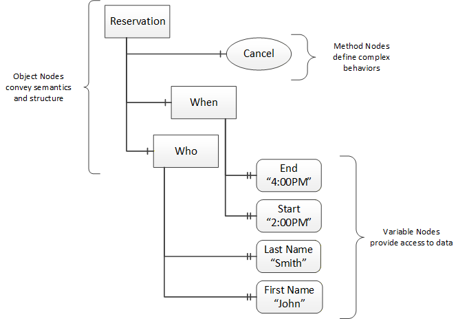
OPC UA provides a framework that can be used to represent complex information as Objects in an AddressSpace which can be accessed with standard services. These Objects consist of Nodes connected by References. Different classes of Nodes convey different semantics. For example, a Variable Node represents a value that can be read or written. The Variable Node has an associated DataType that can define the actual value, such as a string, float, structure etc. It can also describe the Variable value as a variant. A Method Node represents a function that can be called. Every Node has a number of Attributes including a unique identifier called a NodeId and non-localized name called as BrowseName. An Object representing a 'Reservation' is shown in Figure 2.
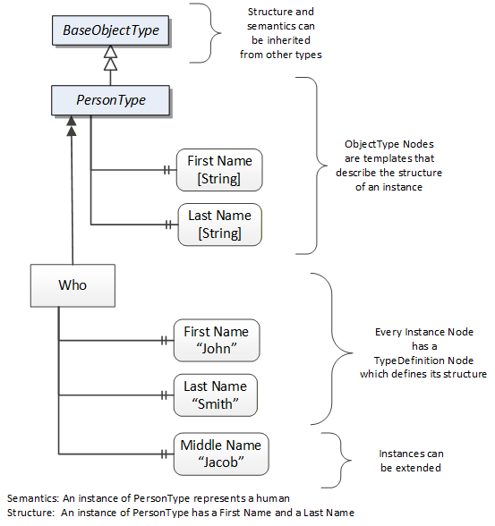
Object and Variable Nodes represent instances and they always reference a TypeDefinition (ObjectType or VariableType) Node which describes their semantics and structure. Figure 3 illustrates the relationship between an instance and its TypeDefinition.
The type Nodes are templates that define all of the children that can be present in an instance of the type. In the example in Figure 3 the PersonType ObjectType defines two children: First Name and Last Name. All instances of PersonType are expected to have the same children with the same BrowseNames. Within a type the BrowseNames uniquely identify the children. This means Client applications can be designed to search for children based on the BrowseNames from the type instead of NodeIds. This eliminates the need for manual reconfiguration of systems if a Client uses types that multiple Servers implement.
OPC UA also supports the concept of sub-typing. This allows a modeller to take an existing type and extend it. There are rules regarding sub-typing defined in OPC 10000-3, but in general they allow the extension of a given type or the restriction of a DataType. For example, the modeller may decide that the existing ObjectType in some cases needs an additional Variable. The modeller can create a subtype of the ObjectType and add the Variable. A Client that is expecting the parent type can treat the new type as if it was of the parent type. Regarding DataTypes, subtypes can only restrict. If a Variable is defined to have a numeric value, a sub type could restrict it to a float.
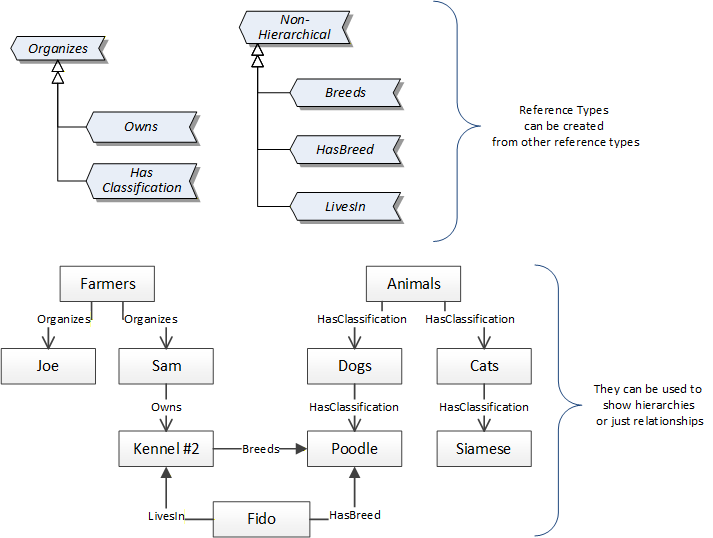
References allow Nodes to be connected in ways that describe their relationships. All References have a ReferenceType that specifies the semantics of the relationship. References can be hierarchical or non-hierarchical. Hierarchical references are used to create the structure of Objects and Variables. Non-hierarchical are used to create arbitrary associations. Applications can define their own ReferenceType by creating subtypes of an existing ReferenceType. Subtypes inherit the semantics of the parent but may add additional restrictions. Figure 4 depicts several References, connecting different Objects.
The figures above use a notation that was developed for the OPC UA specification. The notation is summarized in Figure 5. UML representations can also be used; however, the OPC UA notation is less ambiguous because there is a direct mapping from the elements in the figures to Nodes in the AddressSpace of an OPC UA Server.

A complete description of the different types of Nodes and References can be found in OPC 10000-3 and the base structure is described in OPC 10000-5.
OPC UA specification defines a very wide range of functionality in its basic information model. It is not required that all Clients or Servers support all functionality in the OPC UA specifications. OPC UA includes the concept of Profiles, which segment the functionality into testable certifiable units. This allows the definition of functional subsets (that are expected to be implemented) within a companion specification. The Profiles do not restrict functionality, but generate requirements for a minimum set of functionality (see OPC 10000-7)
4.2.3.2 Namespaces
OPC UA allows information from many different sources to be combined into a single coherent AddressSpace. Namespaces are used to make this possible by eliminating naming and id conflicts between information from different sources. Each namespace in OPC UA has a globally unique string called a NamespaceUri which identifies a naming authority and a locally unique integer called a NamespaceIndex, which is an index into the Server's table of NamespaceUris. The NamespaceIndex is unique only within the context of a Session between an OPC UA Client and an OPC UA Server- the NamespaceIndex can change between Sessions and still identify the same item even though the NamespaceUri's location in the table has changed. The Services defined for OPC UA use the NamespaceIndex to specify the Namespace for qualified values.
There are two types of structured values in OPC UA that are qualified with NamespaceIndexes: NodeIds and QualifiedNames. NodeIds are locally unique (and sometimes globally unique) identifiers for Nodes. The same globally unique NodeId can be used as the identifier in a node in many Servers - the node's instance data may vary but its semantic meaning is the same regardless of the Server it appears in. This means Clients can have built-in knowledge of of what the data means in these Nodes. OPC UA Information Models generally define globally unique NodeIds for the TypeDefinitions defined by the Information Model.
QualifiedNames are non-localized names qualified with a Namespace. They are used for the BrowseNames of Nodes and allow the same names to be used by different information models without conflict. TypeDefinitions are not allowed to have children with duplicate BrowseNames; however, instances do not have that restriction.
4.2.3.3 Companion Specifications
An OPC UA companion specification for an industry specific vertical market describes an Information Model by defining ObjectTypes, VariableTypes, DataTypes and ReferenceTypes that represent the concepts used in the vertical market, and potentially also well-defined Objects as entry points into the AddressSpace.
5 Use cases
This OPC UA companion specification provides support for multiple use cases connected to production machines running both in primary and secondary. Key use cases follow below:
Manage machine's Overall Equipment Effectiveness, including identifying downtime and its root causes both for machines and for complex lines where it is important to identify which machine is the root cause. To this end, TMC uses TMCStateMachineType, an enhanced PackML state machine, stop reasons and root causes for downtime.
Manage production yield, meaning that high-quality machine or line output data is provided altogether with consumption and dispensing information on the input end and material waste and rejections to compute the line mass balance.
To this end, TMC has its backbone in MaterialLoadingPointType, MaterialOutputPointType and MaterialRejectionPointType.
Manage defects, identifying material rejections and their causes, including defect detections and the root cause reasons for detections. To this end, TMC provides a multi-layered model consisting of DefectDetectionSensorType, SensorFunctionType and DefectReasonType.
Enforce MES-integrated production orders for workcentres, including the dispatching of recipe datasets and material lists, which are constantly monitored during execution for changes and material integrity. To this end, TMC provides core constructs such as DatasetType, MaterialListType and ProductionOrderType.
Enforce MES-integrated production orders for process cells, including the orderly execution of a production order among workcentres (units) connected in any non-loopy process cell layout. To this end, TMC provides the ProductionOrderOrchestrationLayerType, as well as MachineModuleProductionStateMachineType to enforce and monitor execution.
Feed a companywide IIoT data stack, including pervasive, structured, high-quality data collection with aggregation directly at the data source for fast changing signals. To this end ProcessItemType is the core construct in conjunction with multiple pre-defined data points for machine, production data and events.
Implement remote control loops, meaning external smart applications, e.g. AI powered, can increase the production quality by controlling remotely existing machines. To this end, TMC provides ProcessControlLoopType with the necessary watchdogs and remote alarming.
Connect centralised SCADA systems above the machine HMI, including visualization and control functionality in a standardised and uniform way according to the ISA 88 physical structure model. To this end, TMC provides EquipmentModuleType, ControlModuleType with the relevant status and alarming functions.
Support smart visualisation applications above the machine HMI, including visualization resources so that a smart visualisation system can programmatically build visualisation and control functions. To this end, TMC provides the UIInformationType.
6 Tobacco Machine Communication Information Model overview
The main construct is the MachineModuleType ObjectType which is derived from an OPC 10000-100 DeviceType containing additional Information, including MachineModuleHistoricalRecord (8.2), MachineModuleConfiguration (8.3), MachineModuleLiveStatus (8.4), MachineModuleProduction (8.5), MachineModuleSpecification (8.6) and MachineModuleSetup (8.7).
MachineModules describe the production flow by means of their MaterialLoadingPoints (8.8), MaterialOutputPoints (8.9), MaterialStorageBuffers (8.10) where product is stored during production and MaterialRejectionPoints (8.11). MaterialRejectionPoints are triggered by DefectDetectionSensors (8.12) which contain SensorFunctions (8.13) and DefectReasons (8.14).
Connecting the MaterialOutputPoints of MachineModules to the MaterialLoadingPoints of the downstream MachineModule provides the production graph.
As far as production is concerned, a MachineModule is functionally equivalent to a Unit in ISA 95/88 language. A collection of MachineModules and their production graph make a Process Cell as defined in ISA 95/88.
Production in a non-loopy Process Cell, i.e. no connections looping back in the production graph, is orchestrated by means of the ProductionOrderOrchestrationLayer (8.38).
A MachineModule may contain one or more EquipmentModules (8.15) or ControlModules (8.19). In turn EquipmentModules may contain one or more ControlModules. Typical ControlModules such as AnalogInputs (8.25), DigitalInputs (8.26), Motors (8.27), Sensors (8.28) and Valves (8.29) are also provided.
Most TMC objects are described by a suitable state machine, TMCMachineStateMachine (8.43) and production state machines (8.39 and 8.40), that inherit from the OMAC PackML standardization effort adding guards to the transitions.
ProcessControlLoops (8.46) may also be included in MachineModules or used alone to expose a control loop in control of the underlying system or remotely controlled.
7 TMC Guideline
7.1 Naming Convention
One of the key goals of OPC UA is to communicate information, not just data. In order to do so, it is important that meaningful metadata is attached, starting with object names.
The names of objects are intended to tell objects apart and straightforwardly clarify what the object is, i.e. they must be human readable avoiding serials, UIDs, uncommon acronyms and other prefixes and suffixes that limit the human understanding whenever possible.
Developers shall name objects according to the following rules and principles:
CamelCase: the CamelCase capitalisation practice will be used for all names. Moreover, the developer shall comply with the whitepaper OPC11030 UA Modeling Best Practices.
Names shall be unique at their hierarchy level: no two servers provided by the same OEM shall have the same name twice, no two machine modules in the same server shall have the same name twice, no two loading points in the same machine module will have the same name twice and so on.
For instance, applying the principles above, it is acceptable to name a server adding a suffix to the machine name with a machine serial or UID e.g. Maker123, Maker 456 because no other alternative ensuring uniqueness is given. Prefixing makes the name less readable and shall be avoided.
Like function, like name: functionally equivalent objects will carry the same name. For example, each instance of a paper loading point in different machine modules will be named PaperLoadingPoint.
If a machine contains multiple objects with the same name, then the name will be completed with a suffix that allows to distinguish the objects with the same function. To continue the previous example, PaperLoadingPoint1 and PaperLoadingPoint2 are acceptable. Please, note that two paper loading points, for tipping paper and cigarette paper, will not be specialised by a suffix but a functional prefix is required i.e. TippingPaperLoadingPoint, CigarettePaperLoadingPoint because their function is different.
Name for brevity: names shall not contain redundant information and in particular information that is carried by the name of a parent object. Thus the name of a component of the SomeMachineModule shall not contain SomeMachineModule or any other string (serial, UID or similar) identifying the machine module, because the information is already captured by the name of the parent object given the inherently hierarchical structure of the TMC nodeset.
The description property and display name that belong to each object/variable instance contained in a TMC server will provide a short phrase in plain English that explains what the instance is and that an average user familiar with the domain can understand.
7.2 Historization and Persistency
The value of Nodes with readable history (marked as HR in the Other column) shall be persisted for a period of 8 hours, meaning the last 8 (eight) hours of data will be available.
The server shall implement historization of events for all events, accessible by client via the OPC UA service history read. The historization internal storage shall be sized to persist at least 1 (one) hour of events generated at the average server generation rate.
The Value of Nodes with NodeClass Variable shall be persisted in the control system in such a way that, in case of a hardware failure or replacement, the TMC server values will not be reset.
7.3 NodeIds
Nodes are unambiguously identified using a constructed identifier called the NodeId. A Server shall persist the NodeId of a Node, that is, it shall not generate new NodeIds when rebooting. In case of an update, a Server shall not generate new NodeIds for Nodes that have not been added with the update.
8 OPC UA ObjectTypes
8.1 MachineModuleType ObjectType
8.1.1 Overview
The MachineModuleType represents a machine module or workcentre and is formally defined in the following table.
| Attribute | Value | ||||
| BrowseName | MachineModuleType | ||||
| IsAbstract | False | ||||
| References | Node Class | BrowseName | DataType | TypeDefinition | Other |
|---|---|---|---|---|---|
| Subtype of the TMCDeviceType, i.e. inheriting the Instance Declarations of that Node. | |||||
| 0:HasComponent | Object | Configuration | MachineModuleConfigurationType | M | |
| 0:HasComponent | Object | ControlModules | 0:FolderType | O | |
| 0:HasComponent | Object | DefectDetectionSensors | 0:FolderType | O | |
| 0:HasComponent | Object | EquipmentModules | 0:FolderType | O | |
| 0:HasComponent | Object | LiveStatus | MachineModuleLiveStatusType | M | |
| 0:HasComponent | Object | MaterialBuffers | 0:FolderType | O | |
| 0:HasComponent | Object | MaterialLoadingPoints | 0:FolderType | O | |
| 0:HasComponent | Object | MaterialLocations | 0:FolderType | O | |
| 0:HasComponent | Object | MaterialOutputPoints | 0:FolderType | O | |
| 0:HasComponent | Object | MaterialRejectionPoints | 0:FolderType | O | |
| 0:HasComponent | Object | PastSpecificationRecords | 0:FolderType | O | |
| 0:HasComponent | Object | ProcessControlLoops | 0:FolderType | O | |
| 0:HasComponent | Object | ProcessItems | 0:FolderType | O | |
| 0:HasComponent | Object | Production | MachineModuleProductionType | O | |
| 0:HasProperty | Variable | Remote | 0:Boolean | 0:PropertyType | M, RO |
| 0:HasComponent | Object | Setup | MachineModuleSetupType | O | |
| 0:HasComponent | Object | Specification | MachineModuleSpecificationType | O | |
| Conformance Units | |||||
|---|---|---|---|---|---|
| TMC Data Collection | |||||
| TMC Core Production | |||||
| TMC Process Variables Ingestion and Control | |||||
| TMC Intralogistics at the machine |
| BrowseName | Description |
| Configuration | The Configuration Object provides the descriptions (metadata) for settings, stop reasons and root causes of the machine module as well as affordances to make modifications. |
| ControlModules | The ControlModules folder provides control modules belonging to the machine module (and not belonging to an equipment module). |
| DefectDetectionSensors | The DefectDetectionSensors folder provides the sensor(s) and sensing systems fitted to the machine module that detect product defects. |
| EquipmentModules | The EquipmentModules folder provides equipment modules of the machine module. |
| LiveStatus | The LIveStatus Object provides information about the real time status of the machine module and provides affordances to control the machine module remotely in real time. |
| MaterialBuffers | The MaterialBuffers folder provides material storage buffers of the machine module. |
| MaterialLoadingPoints | The MaterialLoadingPoints folder provides the loading points and the materials being loaded, as well as the brand integrity checks required. |
| MaterialLocations | The MaterialLocations folder provides material locations used to deliver or retrieve materials to/from the machine. |
| MaterialOutputPoints | The MaterialOutputPoints folder provides the output(s) of the machine module. |
| MaterialRejectionPoints | The MaterialRejectionPoints folder provides rejection traps where material is discarded from the machine module. |
| PastSpecificationRecords | The PastSpecificationRecords folder contains the information about the machine as was operating in a previous period of time. |
| ProcessControlLoops | The ProcessControlLoops folder provides control loops of the machine module. |
| ProcessItems | The ProcessItems folder provides analog sensor values. |
| Production | The Production Object provides information about the current production order and quantity produced as well as affordances to start/stop a production order and reset totals for the machine module. |
| Remote | When Remote is True, all methods exposed by the machine module and contained objects are executed and all variables marked as RW can be written to. When Remote is False, the OEM may decide to not execute some qualified methods and/or not allow some qualified RW variables to be written to because of justified safety concerns. The justification shall be provided in the machine safety assessment provided to the customer. Lacking justification, the method shall be executable. For instance, informative methods such as (but not limited to) GetProductionOrder, GetDataSet, GetMaterialList, GetDataSetList, GetRootCauseGroupList, GetRootCauseList, GetStopReasonList, ValidateDataSet, ValidateMaterialList are executable regardless of the value of Remote. The invoking of qualified methods and/or writing of qualified RW variables can be disallowed only for the MachineModuleLiveStatus which includes the methods SendCommand and SetControlMode. When a method is not executed due to the Remote flag, the MethodExecutionFeedback shall report "The system is under local control. Please, switch to Remote to execute the method." When a RW variable is not allowed to be written to, the StatusCode "Bad_NotWritable" is produced. Remote is read-only because of safety concerns and because it is typically implemented as a physical rotary selector on the machine cabinet: it is the operator who will release the control to a remote system. |
| Setup | The SetUp Object contains the value of all the settings (including mechanical adjustments) required to run production as well as affordances to validate and load settings for the machine module. |
| Specification | The Specification Object contains the specification about the machine as currently operating including capabilities, internal buffers and loading points. |
The components of the MachineModuleType have additional subcomponents which are defined in the following table.
| BrowsePath | References | NodeClass | BrowseName | DataType | TypeDefinition | Others | ||
| ControlModules | 0:HasComponent | Object | AnalogInputs | 0:FolderType | O | |||
| 0:HasComponent | Object | <AnalogInput> | AnalogInputType | OP | |||
| ControlModules | 0:HasComponent | Object | DigitalInputs | 0:FolderType | O | |||
| 0:HasComponent | Object | <DigitalInput> | DigitalInputType | OP | |||
| ControlModules | 0:HasComponent | Object | Motors | 0:FolderType | O | |||
| 0:HasComponent | Object | <Motor> | MotorType | OP | |||
| ControlModules | 0:HasComponent | Object | Sensors | 0:FolderType | O | |||
| 0:HasComponent | Object | <Sensor> | SensorType | OP | |||
| ControlModules | 0:HasComponent | Object | Valves | 0:FolderType | O | |||
| 0:HasComponent | Object | <Valve> | ValveType | OP | |||
| DefectDetectionSensors | 0:HasComponent | Object | <DefectDetectionSensor> | DefectDetectionSensorType | OP | |||
| EquipmentModules | 0:HasComponent | Object | <EquipmentModule> | EquipmentModuleType | OP | |||
| MaterialBuffers | 0:HasComponent | Object | <MaterialStorageBuffer> | MaterialStorageBufferType | OP | |||
| MaterialLoadingPoints | 0:HasComponent | Object | <MaterialLoadingPoint> | MaterialLoadingPointType | OP | |||
| MaterialLocations | 0:HasComponent | Object | <MaterialLocation> | MaterialLocationType | OP | |||
| MaterialOutputPoints | 0:HasComponent | Object | <MaterialOutput> | MaterialOutputPointType | OP | |||
| MaterialRejectionPoints | 0:HasComponent | Object | <MaterialRejectionPoint> | MaterialRejectionPointType | OP | |||
| PastSpecificationRecords | 0:HasComponent | Object | <SpecificationRecord> | MachineModuleHistoricalRecordType | OP | |||
| ProcessControlLoops | 0:HasComponent | Object | <ProcessControlLoop> | ProcessControlLoopType | OP | |||
| ProcessItems | 0:HasComponent | Object | <ProcessItem> | ProcessItemType | OP | |||
| ProcessItems | 0:HasComponent | Object | <ProcessControlItem> | ProcessControlItemType | OP | |||
| ProcessItems | 0:HasComponent | Object | <ProcessControlItem> | ProcessControlItemType | OP | |||
Instances of the MachineModuleType are components of the DeviceSet Object as defined by OPC10000-100, 5.9 DeviceSet.
For additional clarity, MachineModuleType instances shall be grouped under the DeviceSet object.
8.2 MachineModuleHistoricalRecordType ObjectType
8.2.1 Overview
The MachineModuleHistoricalRecordType ObjectType contains the specifications of the machine module that have been valid in the past. When the machine module manufacturer modifies the machine in a way that impact the OPC UA server specification, the machine module manufacturer will save an object of type MachineModuleHistoricalType to the folder PastSpecificationRecords which is a component of the relevant MachineModule
The MachineModuleHistoricalRecordType is formally defined in the following table.
| Attribute | Value | ||||
| BrowseName | MachineModuleHistoricalRecordType | ||||
| IsAbstract | False | ||||
| References | Node Class | BrowseName | DataType | TypeDefinition | Other |
|---|---|---|---|---|---|
| Subtype of the BaseObjectType defined in OPC 10000-5 - Part 5: Information Model, i.e. inheriting the Instance Declarations of that Node. | |||||
| 0:HasComponent | Object | MachineModuleSpecification | MachineModuleSpecificationType | M | |
| 0:HasProperty | Variable | ValidUntil | 0:UtcTime | 0:PropertyType | M, RO |
| Conformance Units | |||||
|---|---|---|---|---|---|
| TMC Asset Management |
| BrowseName | Description |
| MachineModuleSpecification | The MachineModuleSpecification Object contains a specification that was valid in the past. |
| ValidUntil | The ValidUntil Propertyontains the date and time the MachineModuleSpecification was last valid. The Property ValidUntil shall be set by the OEM when changes that impact the machine module specification are made. |
8.3 MachineModuleConfigurationType ObjectType
8.3.1 Overview
The MachineModuleConfigurationType provides descriptions for settings, stop reasons and root causes as well as affordances to make modifications.
The MachineModuleConfigurationType is formally defined in the following table.
| Attribute | Value | |||||
| BrowseName | MachineModuleConfigurationType | |||||
| IsAbstract | False | |||||
| References | Node Class | BrowseName | DataType | TypeDefinition | Other | |
|---|---|---|---|---|---|---|
| Subtype of the BaseObjectType defined in OPC 10000-5 - Part 5: Information Model, i.e. inheriting the Instance Declarations of that Node. | ||||||
| 0:HasProperty | Variable | DataSetList | DataSetDefinitionType | 0:PropertyType | O, RO | |
| 0:HasComponent | Method | GetDataSetList | See below. | O | ||
| 0:HasComponent | Method | GetRootCauseGroupList | See below. | M | ||
| 0:HasComponent | Method | GetRootCauseList | See below. | M | ||
| 0:HasComponent | Method | GetStopReasonList | See below. | M | ||
| 0:HasProperty | Variable | LastChangeDate | 0:UtcTime | 0:PropertyType | M, RO | |
| 0:HasProperty | Variable | LongestMicroStopDuration | 0:Double | 0:PropertyType | M, RW | |
| 0:HasProperty | Variable | RootCauseGroupList | RootCauseGroupType[] | 0:PropertyType | M, RW | |
| 0:HasProperty | Variable | RootCauseList | RootCauseMessageType[] | 0:PropertyType | M, RW | |
| 0:HasProperty | Variable | RootCauseListInputIsMandatory | 0:Boolean | 0:PropertyType | M, RW | |
| 0:HasComponent | Method | SetDataSetListMESID | See below. | M | ||
| 0:HasComponent | Method | SetRootCauseLists | See below. | M | ||
| 0:HasProperty | Variable | StopReasonList | MessageType[] | 0:PropertyType | M, RO | |
| 0:GeneratesEvent | ObjectType | RootCauseGroupListChangeLogType | ||||
| 0:GeneratesEvent | ObjectType | RootCauseListChangeLogType | ||||
| 0:GeneratesEvent | ObjectType | StopReasonListChangeLogType | ||||
| Conformance Units | ||||||
|---|---|---|---|---|---|---|
| TMC Data Collection | ||||||
| TMC Single PO Production | ||||||
| TMC Multi PO Production |
| BrowseName | Description |
| DataSetList | The Property DataSetList of type DataSetDefinition contains the descriptors for all the parameters used to set up the machine. |
| LastChangeDate | The Property LastChangeDate is the date and time of the last change applied to the machine module configuration and the effective date of the modification. |
| LongestMicroStopDuration | The Property LongestMicroStopDuration is the maximum duration of a micro-stop in seconds, longer stops are not micro-stops. Operators are not required to enter a root cause for micro-stops. |
| RootCauseGroupList | The Property RootCauseGroupList is the list of groups that root causes can be grouped in. They are defined by the end user. Same as the RootCauseList property. The RootCauseGroupList is user defined. |
| RootCauseList | The Property RootCauseList is the complete list of the root causes that the end user has defined to classify and organize the downtime due to the machine module stops. The RootCauseList is user defined. |
| RootCauseGroupListIsMandatory | The Property RootCauseListInputIsMandatory is true when the operator is mandatorily required to select the root cause that best describes the current stop situation. For micro- stops such requirement does not apply. |
| StopReasonList | The Property StopReasonList is a list containing the descriptors for all the possible machine module messages, including alarms and warnings. Messages include their localization. The list is defined, created and maintained by the OEM. |
8.3.2 GetDataSetList Method
The GetDatasetList Method returns the list of descriptions for parameters of the dataset filtered by the dependency and subset created by the user.
The GetDatasetList Method is typically used for clients to visualize the parameters' descriptions and related metadata.
The signature of this Method is specified below. Table 16 specifies the Arguments representation.
Signature
	GetDataSetList (
	  [in]  ParameterDependencyEnumeration			Dependency,
	  [in]  0:Boolean								UserSubset,
	  [in]  0:Boolean       						CompleteSet,
	  [out] DataSetDefinitionType						DataSetList,
	  [out] MethodExecutionFeedbackType				ExecutionFeedback
);| Argument | Description |
| Dependency | Dependency specifies how to select (filter) a subset of the dataset based on dependency. |
| UserSubset | UserSubset specifies how to select (filter) a subset of the dataset based on the user-defined UserSubset. |
| CompleteSet | If CompleteSet is True, then the method returns the complete dataset without considering the input parameters Dependency and UserSubset. |
| DataSetList | The list of parameters filtered as per the input arguments Dependency and UserSubset. |
| ExecutionFeedback | The extended feedback returning a detailed message in case of execution failure. |
8.3.3 GetRootCauseGroupList Method
The GetRootCauseGroupList Method returns the complete list of root cause groups as persisted by the server.
The signature of this Method is specified below. Table 17 specifies the Arguments representation.
Signature
	GetRootCauseGroupList(
	  [out] RootCauseGroupType[]			RootCauseGroupList,
[out] MethodExecutionFeedbackType ExecutionFeedback);| Argument | Description |
| RootCauseGroupList | The complete list of root cause groups. |
| ExecutionFeedback | The extended feedback returning a detailed message in case of execution failure. |
8.3.4 GetRootCauseList Method
The GetRootCauseList Method returns the complete list of root causes as persisted by the server.
The signature of this Method is specified below. Table 18 specifies the Arguments representation.
Signature
	GetRootCauseList(
	  [out] RootCauseMessageType[]			RootCauseList,
[out] MethodExecutionFeedbackType ExecutionFeedback);| Argument | Description |
| RootCauseList | The complete list of root cause messages. |
| ExecutionFeedback | The extended feedback returning a detailed message in case of execution failure. |
8.3.5 GetStopReasonList Method
The GetStopReasonList Method returns the complete list of stop reasons as persisted by the server.
The signature of this Method is specified below. Table 19 specifies the Arguments representation.
Signature
	GetStopReasonList(
	  [out] MessageType[]					StopReasonList,
[out] MethodExecutionFeedbackType ExecutionFeedback);| Argument | Description |
| StopReasonList | The complete list of stop reason messages. |
| ExecutionFeedback | The extended feedback returning a detailed message in case of execution failure. |
8.3.6 SetDataSetListMESID Method
The SetDataSetListMESID Method sets the MES_ID of one or more items of the array Definitions contained in the DataSetList.
For clarity, the DataSetList is a Variable of type DataSetDefinitionType which contains Definitions, an array of structures of type DataDefinitionType. In turn DataDefinitionType is a subtype of DataDescriptionType, meaning it inherits MES_ID. The latter is set by SetDataSetListMESID.
Each item of Definitions is identified by its ID.
The signature of this Method is specified below. Table 20 specifies the Arguments representation.
Signature
	SetDataSetListMESID (
	  [in]  0:String[]						IDs,
	  [in]  0:String[]						MESIDs,
[out] MethodExecutionFeedbackType ExecutionFeedback);| Argument | Description |
| IDs | The IDs of the elements of the Definitions array whose MES_ID shall be changed if the method executes successfully. |
| MESIDs | The values of the MES_IDs to be set. |
| ExecutionFeedback | The extended feedback returning a detailed message in case of execution failure. |
8.3.7 SetRootCauseLists Method
The SetRootCauseLists Method sets both the RootCauseList and RootCauseGroupList according to the input arguments. The RootCauseList and RootCauseGroupList properties are set together to ensure consistency of root causes with the relevant groups.
The signature of this Method is specified below. Table 21 specifies the Arguments representation.
Signature
	SetRootCauseLists (
	  [in]  RootCauseMessageType[]			RootCauseList,
	  [in]  RootCauseGroupType[]			RootCauseGroupList,
[out] MethodExecutionFeedbackType ExecutionFeedback);| Argument | Description |
| RootCauseList | The list of root causes to be transferred to and used by the server. |
| RootCauseGroupList | The list of root cause groups to be transferred to and used by the server. |
| ExecutionFeedback | The extended feedback returning a detailed message in case of execution failure. |
8.4 MachineModuleLiveStatusType ObjectType
8.4.1 Overview
The MachineModuleLiveStatusType ObjectType contains information about the real time status of the machine module and provides affordances to control the machine module remotely in real time.
The MachineModuleLiveStatusType is formally defined in the following table.
| Attribute | Value | ||||
| BrowseName | MachineModuleLiveStatusType | ||||
| IsAbstract | False | ||||
| References | Node Class | BrowseName | DataType | TypeDefinition | Other |
|---|---|---|---|---|---|
| Subtype of the BaseObjectType defined in OPC 10000-5 - Part 5: Information Model, i.e. inheriting the Instance Declarations of that Node. | |||||
| 0:HasComponent | Method | AcknowledgeAlarms | See below. | M | |
| 0:HasComponent | Object | Alarms | 0:FolderType | M | |
| 0:HasProperty | Variable | ControlMode | ControlModeEnumeration | 0:PropertyType | M, RW |
| 0:HasComponent | Object | Data | 0:FolderType | O | |
| 0:HasProperty | Variable | IdleEnergySavingMode | 0:Boolean | 0:PropertyType | M, RW |
| 0:HasComponent | Method | ResetAggregates | See below. | M | |
| 0:HasComponent | Method | SendCommand | See below. | M | |
| 0:HasComponent | Method | SetControlMode | See below. | M | |
| 0:HasComponent | Method | SetIdleEnergySavingMode | See below. | M | |
| 0:HasProperty | Variable | State | StateEnumeration | 0:PropertyType | M, RO |
| 0:HasComponent | Object | StateMachine | TMCStateMachineType | O | |
| 0:GeneratesEvent | ObjectType | ControlModeChangeLogType | |||
| 0:GeneratesEvent | ObjectType | 0:DiscreteAlarmType | |||
| 0:GeneratesEvent | ObjectType | DowntimeLogType | |||
| 0:GeneratesEvent | ObjectType | ExternalAlarmType | |||
| 0:GeneratesEvent | ObjectType | StateChangeLogType | |||
| Conformance Units | |||||
|---|---|---|---|---|---|
| TMC Basic Machine Status | |||||
| TMC Advanced Machine Status |
| BrowseName | Description |
| ControlMode | The ControlMode property describes the current control mode of the machine. |
| IdleEnergySavingMode | The IdleEnergySavingMode Property is set to True when the energy saving mode during the idle phase is set. |
| State | The Property State describes the status of the state machine controlling the machine module. State provides a subset of the information of the state machine, when the latter is implemented. |
| StateMachine | The state machine describes the current state of the machine, the possible transitions and their conditions. |
| Alarms | The Alarms folder contains alarms of the machine module. |
| Data | The Data Folder contains additional data that is not identified elsewhere in this specification. |
The components of the MachineModuleLiveStatusType have additional subcomponents which are defined in the following table.
| BrowsePath | References | NodeClass | BrowseName | DataType | TypeDefinition | Others |
| Alarms | 0:HasComponent | Object | <Alarm> | 0:DiscreteAlarmType | OP | |
| Alarms | 0:HasComponent | Object | <ExternalAlarm> | ExternalAlarmType | OP | |
| Data | 0:HasComponent | Variable | <DataItem> | 0:BaseDataType | 0:BaseDataVariableType | OP, RO |
8.4.2 AcknowledgeAlarms Method
The AcknowledgeAlarms Method acknowledges all alarms of the machine module. The acknowledgement is cascades to other objects belonging to the machine module e.g., equipment modules and control modules.
The signature of this Method is specified below. Table 24 specifies the Arguments representation.
Signature
	AcknowledgeAlarms (
[out] MethodExecutionFeedbackType ExecutionFeedback);| Argument | Description |
| ExecutionFeedback | The extended feedback returning a detailed message in case of execution failure. |
8.4.3 ResetAggregates Method
The ResetAggregates resets all the aggregates for the objects contained in the ProcessItems and ProcessControlLoops of the machine module.
The signature of this Method is specified below. Table 25 specifies the Arguments representation.
Signature
	ResetAggregates (
[out] MethodExecutionFeedbackType ExecutionFeedback);| Argument | Description |
| ExecutionFeedback | The extended feedback returning a detailed message in case of execution failure. |
8.4.4 SendCommand Method
The Method SendCommand sends a command to change the state of the machine module state machine remotely.
The signature of this Method is specified below. Table 26 specifies the Arguments representation.
Signature
	SendCommand (
	  [in]  CommandEnumeration				Command,
[out] MethodExecutionFeedbackType ExecutionFeedback);| Argument | Description |
| Command | The command to be sent to the machine module. |
| ExecutionFeedback | The extended feedback returning a detailed message in case of execution failure. |
8.4.5 SetControlMode Method
The SetControlMode Method sets the control mode of the machine module.
The signature of this Method is specified below. Table 27 specifies the Arguments representation.
Signature
	SetControlMode (
	  [in]  ControlModeEnumeration			ControlMode,
[out] MethodExecutionFeedbackType ExecutionFeedback);| Argument | Description |
| ControlMode | The control mode to be set to the machine module. |
| ExecutionFeedback | The extended feedback returning a detailed message in case of execution failure. |
8.4.6 SetIdleEnergySavingMode Method
The Method SetIdleEnergySavingMode activates the energy saving mode when the machine module is idle.
The signature of this Method is specified below. Table 28 specifies the Arguments representation.
Signature
	SetIdleEnergySavingMode (
	  [in]  0:Boolean						IdleEnergySavingMode,
[out] MethodExecutionFeedbackType ExecutionFeedback);| Argument | Description |
| IdleEnergySavingMode | The energy saving mode to set. |
| ExecutionFeedback | The extended feedback returning a detailed message in case of execution failure. |
8.5 MachineModuleProductionType ObjectType
8.5.1 Overview
The MachineModuleProductionType Object provides information about the current production order and quantity produced as well as affordances to start/stop a production order and reset totals for the machine module.
The MachineModuleProductionType is formally defined in the table below.
| Attribute | Value | ||||
| BrowseName | MachineModuleProductionType | ||||
| IsAbstract | False | ||||
| References | Node Class | BrowseName | DataType | TypeDefinition | Other |
|---|---|---|---|---|---|
| Subtype of the BaseObjectType defined in OPC 10000-5 - Part 5: Information Model, i.e. inheriting the Instance Declarations of that Node. | |||||
| 0:HasComponent | Method | AbortProductionOrder | See below. | O | |
| 0:HasProperty | Variable | AssignedProductionOrders | ProductionOrderType[] | 0:PropertyType | O, RO |
| 0:HasComponent | Method | AssignProductionOrder | See below. | O | |
| 0:HasProperty | Variable | AutoComplete | 0:Boolean | 0:PropertyType | O, RW |
| 0:HasProperty | Variable | AutoStart | 0:Boolean | 0:PropertyType | O, RW |
| 0:HasComponent | Method | ClearProductionOrder | See below. | O | |
| 0:HasComponent | Method | CompleteProductionOrder | See below. | M | |
| 0:HasComponent | Object | Data | 0:FolderType | O | |
| 0:HasProperty | Variable | ProductionOrder | ProductionOrderHeaderType | 0:PropertyType | M, RO |
| 0:HasProperty | Variable | ProductionStatus | ProductionStatusEnumeration | 0:PropertyType | M, RO |
| 0:HasComponent | Method | ResetProductionTotals | See below. | M | |
| 0:HasComponent | Method | StartAssignedProductionOrder | See below. | O | |
| 0:HasComponent | Method | StartProductionOrder | See below. | M | |
| 0:HasComponent | Object | StateMachine | MachineModuleProductionStateMachineType | O | |
| 0:HasComponent | Method | UnassignProductionOrder | See below. | O | |
| 0:GeneratesEvent | ObjectType | POStartedLogType | |||
| 0:GeneratesEvent | ObjectType | POStoppedLogType | |||
| Conformance Units | |||||
|---|---|---|---|---|---|
| TMC Core Production | |||||
| TMC Single PO Production | |||||
| TMC Multi PO Production |
| BrowseName | Description |
| AssignedProductionOrders | The AssignedProductionOrders array contains the production orders that have been assigned to the machine module and have not yet been started or unassigned. |
| AutoComplete | The AutoComplete Boolean defines how to trigger the machine module to complete the execution of a production order. When AutoComplete is False, the completion of a production order at the machine module is triggered with the method CompleteProductionOrder. When AutoComplete is True, the machine module initiates the completion of the production order when all the active upstream machine modules running the production order are in state complete. |
| AutoStart | The Autostart Boolean defines how to trigger the machine module to start a production order. When AutoStart is True and AssignedProductionOrders[] contains one PO, the assigned machine module initiates the starting sequence automatically for the assigned production order. When AutoStart is False, the start of a production order at the machine module is triggered with the method StartProductionOrder. StartProductionOrder is also invoked when AutoStart is True and AssignedProductionOrders[] contains more than one production order. |
| Data | The Data folder provides additional production data that is not identified elsewhere in this specification. e.g. a shift report. |
| ProductionOrder | The production order header in execution at the machine module. |
| ProductionStatus | The execution status of the production order. |
| StateMachine | The StateMachine extends ProductionStatus and provides detailed production execution status as well as methods to trigger the transitions and events when the transitions occur. |
8.5.2 AbortProductionOrder Method
The AbortProductionOrder method is used to abnormally terminate, or abort, a production order that is in execution or starting or completing. Aborting cannot be reversed or undone.
The signature of this Method is specified below. Table 30 specifies the Arguments representation.
Signature
	AbortProductionOrder (
	  [in]  ProductionOrderHeaderType		POToAbort,
[out] MethodExecutionFeedbackType ExecutionFeedback);| Argument | Description |
| POToAbort | The production order to be aborted. The argument is unnecessary for execution (since at most one production order can be executed at any time in the machine module) but provided as a safety net since aborting cannot be reversed. |
| ExecutionFeedback | The extended feedback returning a detailed message in case of execution failure. |
8.5.3 AssignProductionOrder Method
The AssignProductionOrder Method is used to transfer the information of an upcoming production order to the machine module.
The signature of this Method is specified below. Table 31 specifies the Arguments representation.
Signature
	AssignProductionOrder (
	  [in]  ProductionOrderType			POToAssign,
	  [out] MethodExecutionFeedbackType		ExecutionFeedback);
| Argument | Description |
| POToAssign | The production order to assign to the machine module for later execution. |
| ExecutionFeedback | The extended feedback returning a detailed message in case of execution failure. |
8.5.4 ClearProductionOrder Method
The ClearProductionOrder method is used to positively confirm that the machine module where a production order is aborted has been cleared of the product or parts left by the aborted production order.
The signature of this Method is specified below. Table 32 specifies the Arguments representation.
Signature
	ClearProductionOrder (
[out] MethodExecutionFeedbackType ExecutionFeedback);| Argument | Description |
| ExecutionFeedback | The extended feedback returning a detailed message in case of execution failure. |
8.5.5 CompleteProductionOrder Method
The CompleteProductionOrder method is used to complete a production order in execution.
The signature of this Method is specified below. Table 33 specifies the Arguments representation.
Signature
	CompleteProductionOrder (
[out] MethodExecutionFeedbackType ExecutionFeedback);| Argument | Description |
| ExecutionFeedback | The extended feedback returning a detailed message in case of execution failure. |
When the StateMachine is in state Execute, the successful execution of the method causes the transition to state Completing.
When the method is invoked in any other state, the method property Executable is False and when the method is invoked, the status code Bad_NotSupported is returned.
8.5.6 StartAssignedProductionOrder Method
The StartAssignedProductionOrder Method starts a production order whose state is Assigned at the machine module.
The signature of this Method is specified below. Table 34 specifies the Arguments representation.
Signature
	StartAssignedProductionOrder (
	  [in]  ProductionOrderHeaderType	POHeaderToStart,
	  [in]  0:String[]					SourceMaterialLoadingPointIDs,
	  [in]  0:String[]				 DestinationMaterialOutputPointIDs,
[out] MethodExecutionFeedbackType ExecutionFeedback);| Argument | Description |
| POHeaderToStart | The header of the production order to be started. |
| SourceMaterialLoadingPointIDs | The list of material loading points that are going to be used by the production order to be started. |
| DestinationMaterialOutputPointIDs | The list of material output points that are going to be used by the production order to be started. |
| ExecutionFeedback | The extended feedback returning a detailed message in case of execution failure. |
8.5.7 StartProductionOrder Method
The StartProductionOrder Method starts a production order at the machine module.
The signature of this Method is specified below. Table 35 specifies the Arguments representation.
Signature
	StartProductionOrder (
	  [in]  ProductionOrderType			POToStart,
	  [in]  0:String[]					SourceMaterialLoadingPointIDs,
	  [in]  0:String[]				 DestinationMaterialOutputPointIDs,
[out] MethodExecutionFeedbackType ExecutionFeedback);| Argument | Description |
| POToStart | The production order to be started. |
| SourceMaterialLoadingPointIDs | The list of material loading points that are going to be used by the production order to be started. |
| DestinationMaterialOutputPointIDs | The list of material output points that are going to be used by the production order to be started. |
| ExecutionFeedback | The extended feedback returning a detailed message in case of execution failure. |
8.5.8 UnassignProductionOrder Method
The UnassignProductionOrder method is used to remove the specified production order from AssignedProductionOrders[] of an infeed machine module.
The signature of this Method is specified below. Table 36 specifies the Arguments representation.
Signature
	UnassignProductionOrder (
	  [in]  ProductionOrderHeaderType		POToUnassign,
[out] MethodExecutionFeedbackType ExecutionFeedback);| Argument | Description |
| POToUnassign | The production order to be unassigned at the machine module. |
| ExecutionFeedback | The extended feedback returning a detailed message in case of execution failure. |
8.5.9 ResetProductionTotals
The Method ResetProductionTotals simultaneously resets the totals of the machine components belonging to the following machine folders: DefectDetectionSensors, MaterialLoadingPoints, MaterialOutputPoints, MaterialRejectionPoints.
The master totals belonging to the same objects are not reset.
The signature of this Method is specified below. Table 37 specifies the Arguments representation.
Signature
	ResetProductionTotals (
[out] MethodExecutionFeedbackType ExecutionFeedback);| Argument | Description |
| ExecutionFeedback | The extended feedback returning a detailed message in case of execution failure. |
8.6 MachineModuleSpecificationType ObjectType
8.6.1 Overview
The MachineModuleSpecificationType provides the specification of the machine module as currently operating including capabilities, internal buffers and loading points.
This MachineModuleSpecificationType is formally defined in the table below.
| Attribute | Value | ||||
| BrowseName | MachineModuleSpecificationType | ||||
| IsAbstract | False | ||||
| References | Node Class | BrowseName | DataType | TypeDefinition | Other |
|---|---|---|---|---|---|
| Subtype of the BaseObjectType defined in OPC 10000-5 - Part 5: Information Model, i.e. inheriting the Instance Declarations of that Node. | |||||
| 0:HasComponent | Method | DeleteSpecificationRecord | See below. | M | |
| 0:HasComponent | Object | Documentation | 0:FolderType | M | |
| 0:HasComponent | Method | LoadMachineModuleDocumentation | See below. | M | |
| 0:HasProperty | Variable | LocationName | 0:String | 0:PropertyType | M, RW |
| 0:HasProperty | Variable | MaterialLoadingPoints | MaterialPointType[] | 0:PropertyType | M, RO |
| 0:HasProperty | Variable | MaterialOutputPoints | MaterialPointType[] | 0:PropertyType | M, RO |
| 0:HasProperty | Variable | MaterialRejectionPoints | MaterialPointType[] | 0:PropertyType | M, RO |
| 0:HasProperty | Variable | MaterialStorageBuffers | MaterialStorageBufferDataType[] | 0:PropertyType | M, RO |
| 0:HasComponent | Method | RemoveMachineModuleDocumentation | See below. | M | |
| 0:HasComponent | Method | SetNewSpecification | See below. | M | |
| 0:HasProperty | Variable | TimeZone | 0:TimeZoneDataType | 0:PropertyType | M, RW |
| 0:HasProperty | Variable | TotalRunningHours | 0:UInt64 | 0: PropertyType | M, RO |
| 0:HasProperty | Variable | UserMachineName | 0:String | 0:PropertyType | M, RW |
| 0:HasProperty | Variable | ValidSince | 0:UtcTime | 0:PropertyType | M, RO |
| 0:GeneratesEvent | ObjectType | MachineModuleSpecificationChangeLogType | |||
| Conformance Units | |||||
|---|---|---|---|---|---|
| TMC Single PO Production | |||||
| TMC Asset Management |
| BrowseName | Description |
| Documentation | The Object Documentation is the sole repository for the machine module documentation resources. The Documentation is accessed, for example, by clients and HMIs. |
| LocationName | The Property LocationName of type String contains the location of the machine module within the user production site. The Property LocationName will contain the following: Country/City/Department/Floor/Bay/Position. LocationName and UserMachineName uniquely identify the machine module in the user organization. |
| MaterialLoadingPoints | The Property MaterialLoadingPoints identifies the loading points of the machine module and their capability in terms of what materials can be loaded at a loading point. The Property MaterialLoadingPoints is defined as a list of objects of type MaterialPointType. |
| MaterialOutputPoints | The Property MaterialOutputPoints identifies the output points of the machine module and their capability in terms of what materials can be output The Property MaterialOutputPoints is defined as a list of objects of type MaterialPointType. |
| MaterialRejectionPoints | The Property MaterialRejectionPoints identifies the rejection points of the machine module and their capability in terms of what materials are rejected The Property MaterialRejectionPoints is defined as a list of objects of type MaterialPointType. |
| MaterialStorageBuffers | The Property MaterialStorageBuffers describes the buffers inside the machine module and their current status. The Property MaterialStorageBuffers is a list of objects of type MaterialStorageBufferDataType. |
| TimeZone | The local time zone where the machine operates. It is required to convert UTC times into local time. |
| TotalRunningHours | The Property TotalRunningHours counts the number of hours the machine module has been in operation since the last time its configuration was changed. More specifically, time is counted when the machine module state is different from: Stopping, Stopped, Aborting, Aborted, Clearing. |
| UserMachineName | The Property UserMachineName of type String contains the name used by the user to identify the machine module. LocationName and UserMachineName uniquely identify the machine module in the user organization. |
| ValidSince | The Property ValidSince is the date since the configuration was last modified. |
The components of the MachineModuleSpecificationType have additional subcomponents which are defined in the table below.
| BrowsePath | References | NodeClass | BrowseName | DataType | TypeDefinition | Others |
| Documentation | 0:HasProperty | Variable | <DocumentName> | 0:ByteString | 0:PropertyType | OP, RO |
8.6.2 DeleteSpecificationRecord Method
The DeleteSpecificationRecord Method deletes a specification record.
The signature of this Method is specified below. Table 40 specifies the Arguments representation.
Signature
	DeleteSpecificationRecord (
	[in]		0:NodeId							SpecificationRecord,
[out] MethodExecutionFeedbackType ExecutionFeedback);| Argument | Description |
| SpecificationRecord | The OPC UA unique node identifier for the specification to be deleted from the underlying system repository. |
| ExecutionFeedback | The extended feedback returning a detailed message in case of execution failure. |
8.6.3 LoadMachineModuleDocumentation Method
The LoadMachineModuleDocumentation Method allows to securely load any machine module documentation to the documentation repository Documentation folder where it can be reached by applications.
The signature of this Method is specified below. Table 41 specifies the Arguments representation.
Signature
	LoadMachineModuleDocumentation (
	[in]		0:ByteString						DocumentToBeLoaded,
	[in]		0:String							DocumentName,
[out] MethodExecutionFeedbackType ExecutionFeedback);| Argument | Description |
| DocumentToBeLoaded | The document, as a byte string, to be transferred to the Documentation folder. |
| DocumentName | The document name to be associated to the document in the underlying system. |
| ExecutionFeedback | The extended feedback returning a detailed message in case of execution failure. |
8.6.4 RemoveMachineModuleDocumentation Method
The RemoveMachineModuleDocumentation Method allows to securely remove, i.e. permanently delete, any machine module documentation from the documentation repository Documentation.
The signature of this Method is specified below. Table 42 specifies the Arguments representation.
Signature
	RemoveMachineModuleDocumentation (
	[in]		0:String							DocumentName,
[out] MethodExecutionFeedbackType ExecutionFeedback);| Argument | Description |
| DocumentName | The document name to be associated to the document in the underlying system. |
| ExecutionFeedback | The extended feedback returning a detailed message in case of execution failure. |
8.6.5 SetNewSpecification Method
The Method SetNewSpecification saves its arguments as the new specification for the machine module. Prior to that it saves the previous specification into the PastSpecification Records Object of the same machine module.
The signature of this Method is specified below. Table 43 specifies the Arguments representation.
Signature
	SetNewSpecification (
	[in]	MaterialPointType[]     			NewMaterialLoadingPoints,
	[in]	MaterialStorageBufferDataType[]	NewMaterialStorageBuffers,
	[in]	MaterialPointType[]     			NewMaterialOutputPoints,
	[in]	MaterialPointType[]     		   NewMaterialRejectionPoints,
[out] MethodExecutionFeedbackType ExecutionFeedback);| Argument | Description |
| NewMaterialLoadingPoints | The information about the material loading points that will be valid after the machine specification is changed. |
| NewMaterialStorageBuffers | The information about the storage buffers that will be valid after the machine specification is changed. |
| NewMaterialOutputPoints | The information about the material output points that will be valid after the machine specification is changed. |
| NewMaterialRejectionPoints | The information about the material rejection points that will be valid after the machine specification is changed. |
| ExecutionFeedback | The extended feedback returning a detailed message in case of execution failure. |
8.7 MachineModuleSetupType ObjectType
8.7.1 Overview
The MachineModuleSetupType ObjectType contains the value of all the settings (including mechanical adjustments) required to run production as well as affordances to validate and load settings for the machine module.
This MachineModuleSetupType is formally defined in the table below.
| Attribute | Value | ||||
| BrowseName | MachineModuleSetupType | ||||
| IsAbstract | False | ||||
| References | Node Class | BrowseName | DataType | TypeDefinition | Other |
|---|---|---|---|---|---|
| Subtype of the BaseObjectType defined in OPC 10000-5 - Part 5: Information Model, i.e. inheriting the Instance Declarations of that Node. | |||||
| 0:HasProperty | Variable | DataSet | DataSetType | 0:PropertyType | M, RW |
| 0:HasComponent | Method | LoadDataSet | See below. | O | |
| 0:HasComponent | Method | LoadMaterialList | See below. | O | |
| 0:HasProperty | Variable | MaterialList | MaterialListType | 0:PropertyType | M, RO |
| 0:HasComponent | Object | MechanicalAdjustments | 0:FolderType | M | |
| 0:HasComponent | Object | DataSetFolder | 0:FolderType | M | |
| 0:HasComponent | Method | ValidateDataSet | See below. | O | |
| 0:HasComponent | Method | ValidateMaterialList | See below. | O | |
| 0:GeneratesEvent | ObjectType | DataSetChangeLogType | M | ||
| Conformance Units | |||||
|---|---|---|---|---|---|
| TMC Single PO Production | |||||
| TMC Advanced Setup |
| BrowseName | Description |
| DataSet | DataSet contains all the digital settings (other than the mechanical settings stored in the folder MechanicalAdjustments) required by the machine module. |
| MaterialList | MaterialList contains the list of materials that are going to be used for the production of the current production order. |
| MechanicalAdjustments | The MechanicalAdjustments folder contains the non-digital settings required to setup the machine e.g. mechanical adjustments. |
| DataSetFolder | The DataSetFolder contains the DataSet including values and descriptions. It contains the same information as DataSet but in a way that is friendlier to simple clients. |
The components of the MachineModuleSetupType have additional subcomponents which are defined in the table below.
| BrowsePath | References | NodeClass | BrowseName | DataType | TypeDefinition | Others |
| MechanicalAdjustments | 0:HasProperty | Variable | <DocumentName> | 0:ByteString | 0:PropertyType | OP, RO |
| DataSetFolder | 0:HasComponent | Variable | DataSetID | 0:String | 0:DataItemType | M, RW |
| DataSetFolder | 0:HasComponent | Variable | DataSetDescription | 0:LocalizedText | 0:DataItemType | M, RW |
| DataSetFolder | 0:HasComponent | Variable | <DataSetValue> | 0:BaseDataType | 0:DataItemType | OP, RW |
8.7.2 LoadDataSet Method
The LoadDataSet Method loads the dataset to the underlying system after having validated that (a) the dataset is complete when IsCompleteDataset is True and (b) the dataset is valid.
When the validation is not passed, then the data set is not loaded to the underlying system rolling back any data change and a specific message shall be returned via ExecutionFeedback.
For detailed validation diagnostics, the Method ValidateDataSet shall be invoked.
The signature of this Method is specified below. Table 46 specifies the Arguments representation.
Signature
	LoadDataSet (
	[in]		DataSetType						DataSet,
	[in]		Boolean							IsCompleteDataSet,
[out] MethodExecutionFeedbackType ExecutionFeedback);| Argument | Description |
| DataSet | The dataset to be transferred to the underlying system. |
| IsCompleteDataSet | When true, the DataSet argument is a complete dataset, meaning all DataSet entries are included. |
| ExecutionFeedback | The extended feedback returning a detailed message in case of execution failure. |
8.7.3 LoadMaterialList Method
The LoadMaterialList Method loads the material list to the underlying system after having validated that (a) the material list is complete and (b) the material list is valid.
When the validation is not passed, then the material list is not loaded to the underlying system rolling back any data change and a specific message shall be returned via ExecutionFeedback.
For detailed validation diagnostics, the Method ValidateMaterialList shall be invoked.
The signature of this Method is specified below. Table 47 specifies the Arguments representation.
Signature
	LoadDataSet (
	[in]		MaterialListType				MaterialList,
[out] MethodExecutionFeedbackType ExecutionFeedback);| Argument | Description |
| MaterialList | The material list to be transferred to the underlying system. |
| ExecutionFeedback | The extended feedback returning a detailed message in case of execution failure. |
8.7.4 ValidateDataSet Method
The ValidateDataSet Method transfers a dataset, complete when IsCompleteDataSet is True, to the underlying system and returns the result of the validation, i.e. verifying that the dataset is complete and can run in production.
When the ValidateDataSet Method is executed, the DataSet variable is not affected. If the validation is not passed, the identifiers of the datapoints that did not pass are provided with the ExecutionFeedback.
The validation of the DataSet normally occurs before the DataSet is required, i.e. while production is running and using a different dataset. As a matter of fact, the ValidateDataSet Method is used to validate a DataSet beforehand giving time to the higher-level systems in charge to correct mistakes. Thus the underlying system is required to provide all affordances to perform the validation without disrupting running production orders.
The signature of this Method is specified below. Table 48 specifies the Arguments representation.
Signature
	ValidateDataSet (
	[in]		DataSetType					DataSet,
	[in] 	Boolean						IsCompleteDataSet,
	[out] 	DataSetEntryType[]	 		FailedValidationEntries,
	[out] 	MessageType[]					FailedValidationMessages,
[out] MethodExecutionFeedbackType ExecutionFeedback);| Argument | Description |
| DataSet | The dataset to be validated by the underlying system. |
| IsCompleteDataSet | When true, the DataSet argument is a complete dataset, meaning all DataSet entries are included. |
| FailedValidationEntries | The dataset items that failed the validation. |
| FailedValidationMessages | The detailed reasons the validation failed. |
| ExecutionFeedback | The extended feedback returning a detailed message in case of execution failure. |
8.7.5 ValidateMaterialList Method
The ValidateMaterialList Method transfers a material list to the underlying system and returns the result of the validation, i.e. verifying that the material list is complete and can run in production.
When the ValidateMaterialList is executed, the MaterialList variable is not affected. If the validation is not passed, the identifiers of the materials that did not pass are provided with the ExecutionFeedback.
The validation of the MaterialList normally occurs before the MaterialList is required, i.e. while production is running and using a different material list. As a matter of fact, the ValidateMaterialList Method is used to validate a MaterialList beforehand giving time to the higher-level systems in charge to correct mistakes. Thus the underlying system is required to provide all affordances to perform the validation without disrupting running production orders.
The signature of this Method is specified below. Table 49 specifies the Arguments representation.
Signature
	ValidateMaterialList (
	[in]		MaterialListType			MaterialList,
	[out] 	MaterialListItemType[] 		FailedValidationEntries,
	[out] 	MessageType[]				FailedValidationMessages,
[out] MethodExecutionFeedbackType ExecutionFeedback);| Argument | Description |
| MaterialList | The material list to be validated by the underlying system. |
| FailedValidationEntries | The material list items that failed the validation. |
| FailedValidationMessages | The detailed reasons the validation failed. |
| ExecutionFeedback | The extended feedback returning a detailed message in case of execution failure. |
8.8 MaterialLoadingPointType ObjectType
8.8.1 Overview
The MaterialLoadingPointType ObjectType describes the machine module part where materials are loaded (either manually or by means of an automated system or both) and the materials being loaded, as well as the brand integrity checks required.
The MaterialLoadingPointType is formally defined in the following table.
| Attribute | Value | ||||
| BrowseName | MaterialLoadingPointType | ||||
| IsAbstract | False | ||||
| References | Node Class | BrowseName | DataType | TypeDefinition | Other |
|---|---|---|---|---|---|
| Subtype of the TMCDeviceType i.e. inheriting the Instance Declarations of that Node. | |||||
| 0:HasComponent | Variable | ActualDispensingRate | 0:Double | MaterialRateType | M, RO, HR |
| 0:HasComponent | Variable | ConsumedMaterialMasterTotal | 0:Double | MaterialQuantityVariableType | M, RO |
| 0:HasComponent | Variable | ConsumedMaterialTotal | 0:Double | MaterialQuantityVariableType | M, RO, HR |
| 0:HasComponent | Variable | DispensedMaterialMasterTotal | 0:Double | MaterialQuantityVariableType | M, RO |
| 0:HasComponent | Variable | DispensedMaterialTotal | 0:Double | MaterialQuantityVariableType | M, RO, HR |
| 0:HasComponent | Variable | DispensingRateState | 0:LocalizedText | 0:StateVariableType | M, RO, HR |
| 0:HasProperty | Variable | ExpectedMaterials | MaterialSublotType[] | 0:PropertyType | M, RO |
| 0:HasComponent | Variable | LoadedMaterial | MaterialSublotType[] | 0:BaseDataVariableType | M, RO |
| 0:HasProperty | Variable | MaterialPointDefinition | MaterialPointType | 0:PropertyType | M, RO |
| 0:HasProperty | Variable | MaterialIntegrityAgent | MaterialIntegrityAgentEnumeration | 0:PropertyType | M, RW |
| 0:HasProperty | Variable | MES_ID | 0:String | 0:PropertyType | M, RW |
| 0:HasComponent | Variable | NominalDispensingRate | 0:Double | MaterialRateType | M, RO |
| 0:HasComponent | Variable | PresentedMaterial | MaterialSublotType | 0:BaseDataVariableType | M, RW |
| 0:HasComponent | Variable | PresentedMaterialValidationStatus | MaterialValidationStatusEnumeration | 0:BaseDataVariableType | M, RO |
| 0:HasComponent | Method | SetPresentedMaterialValidationStatus | See below. | M | |
| 0:HasProperty | Variable | AllowMixedLots | 0:Boolean | 0:PropertyType | M, RW |
| 0:HasProperty | Variable | UpstreamHold | 0:Boolean | 0:PropertyType | M, RO |
| 0:GeneratesEvent | ObjectType | IntegrityRejectedMaterialLogType | |||
| 0:GeneratesEvent | ObjectType | LoadingPointUnloadedLogType | |||
| 0:GeneratesEvent | ObjectType | MaterialConsumedLogType | |||
| 0:GeneratesEvent | ObjectType | MaterialDispensedLogType | |||
| 0:GeneratesEvent | ObjectType | MaterialUnloadingRequiredLogType | |||
| 0:GeneratesEvent | ObjectType | NewPresentedMaterialLogType | |||
| Conformance Units | |||||
|---|---|---|---|---|---|
| TMC Core Production |
| BrowseName | Description |
| ActualDispensingRate | The actual rate at which the input material is being dispensed. |
| ConsumedMaterialMasterTotal | The total quantity of material that entered the machine loading point. This total is never reset. |
| ConsumedMaterialTotal | The total quantity of material that entered the machine loading point. When the material is loaded, it may be immediately dispensed or may be stored and dispensed when required according to the machine logic. When the material is immediately dispensed, the consumed material quantity equals the dispensed material quantity (DispensedMaterialTotal). The quantity is reset by the successful execution of the ResetMachineTotals method, only. |
| DispensedMaterialMasterTotal | The total quantity of material dispensed at the machine after loading at the loading point. This total is never reset. |
| DispensedMaterialTotal | The total quantity of material dispensed at the machine after loading at the loading point. The quantity is reset by the successful execution of the ResetMachineTotals |
| DispensingRateState | The DispensingRateState provides information about the state of the dispensing rate justifying why the ActualDispensingRate is different from the NominalDispensingRate. At a minimum the list of states below shall be provided: Id=0, Speed is at Nominal value Id=1, Speed Changed by Operator Id=2, Speed Followed from Downstream Internal Id=3, Speed Reduced due to low input material Id=4, Speed Reduced due to internal high input material level Id=5, Speed Reduced due to Filling Mode Id=6, Speed Reduced due to internal procedure (e.g. calibration) Id=7, Speed Reduced due to input material change (e.g. foil splicing, inner frame bobbin change, etc.) Id=8, Speed Changed by Remote Host When the actual rate is not measured, Id=0 Speed is at Nominal value will be returned. The speed set by an external host, if any, is used as the NominalDispensingRate. Null speed is a speed reduction. The list may be extended for specific states not already covered in the list above. |
| ExpectedMaterials | The array of sublots of the material that are expected at the machine loading point for the current production. ExpectedMaterials is a set of MaterialListItems such that the UserMachineName in LoadingPoint matches the LoadingPointID of the MaterialListItem. |
| LoadedMaterial | An array of the sublots that entered the machine loading point. When a sublot is unloaded, it is also removed from the array. The sublot in the first position is the sublot from which the machine module is currently dispensing the material. The quantity of the sublot in the first position is decreased by an amount equal to the dispensing. |
| MaterialPointDefinition | The Property MaterialPointDefinition contains the identification of the material point and the material that is processed. |
| MaterialIntegrityAgent | MaterialIntegrityAgent defines how material validation is performed. The scenarios taken into consideration are defined by the MaterialIntegrityEnumeration: None: the material validation is not requested. In this case the underlying system sets MaterialValidationResult to None. External: an external system performs the material validation. The external system validates the PresentedMaterial and invokes the SetValidationResult method to transfer the validation results to the machine. Local: the underlying system performs the material validation on the PresentedMaterial and sets the result in MaterialValidationResult. When an unsupported value is written to the variable, the underlying system will overwrite it with a supported one. |
| MES_ID | Unique identifier for the material point in an external system, e.g. MES. |
| NominalDispensingRate | The nominal rate at which the input material is dispensed when the machine runs at design speed. |
| PresentedMaterial | The material presented to the material loading point, but not yet loaded. When the material is loaded, the underlying system resets the PresentedMaterial and the MaterialValidationStatus to Failed. When an upstream machine is connected, the material output from the upstream machine is the presented material. Read/Write to allow for external systems to request the validation of a material. When the PresentedMaterial changes, the validation system performs validation. |
| PresentedMaterialValidationStatus | The status of the validation of the presented material. When Passed, the presented material is loaded by the machine module; when Failed, the presented material will be removed from the loading point, either automatically or manually. When InProgress, the validation is in progress. When MaterialIntegrityAgent is None and MaterialPresented is empty, then the value is None. |
| AllowMixedLots | When AllowMixedLots is False and BatchManaged in the material definition of the ExpectedMaterials is True, then one material lot will be processed i.e. the first material lot received. |
| UpstreamHold | UpstreamHold is true when the loading point cannot receive more product and the upstream machine is required to stop loading, False when the loading point can receive product. |
8.8.2 SetPresentedMaterialValidationStatus Method
The SetPresentedMaterialValidationStatus Method provides a client with an affordance to perform the validation of the PresentedMaterial against the ExpectedMaterials and set the result of the validation in the PresentedMaterialValidationStatus variable.
The method is called by the material integrity agent, i.e. when MaterialIntegrityAgent is External.
The method is executed only when the MaterialValidationStatus is Waiting.
The signature of this Method is specified below. Table 51 specifies the Arguments representation.
Signature
	SetPresentedMaterialValidationStatus (
	  [in]  MaterialValidationStatusEnumeration		ValidationResult,
[out] MethodExecutionFeedbackType ExecutionFeedback);| Argument | Description |
| ValidationResult | The result of the validation of the PresentedMaterial. |
| ExecutionFeedback | The extended feedback returning a detailed message in case of execution failure. |
The material validation is performed checking (1) a sublot, (2) material lot of the sublot and (3) material definition of the PresentedMaterial against each material sublot in the ExpectedMaterials array. When one matches, the PresentedMaterial is valid and its ValidationStatus is set to True, otherwise False.
The PresentedMaterial is compared against a material sublot from the ExpectedMaterials array as follows being valid when all checks are True:
Sublot:
The PresentedMaterial sublot MES_ID is equal to the sublot MES_ID of a material sublot from the ExpectedMaterials. If the MES_ID of a material sublot from the ExpectedMaterials is Null, then the result of the check is true.
Material lot:
If AllowMixedLots is True, then the result of the check is True. If AllowMixedLots is False, then the result of the check is True for the first presented MaterialSublot and for all subsequent MaterialSublots of the same MaterialLot.
The PresentedMaterial MaterialStockStatus is Unrestricted or equal to the ExpectedMaterial MaterialStockStatus. For example, a ripping machine processes blocked material.
The BestUsedBeforeDate of the material sublot from the ExpectedMaterials is not greater than the current date. If BestUsedBeforeDate is NULL, then the result of this check is true.
Material Definition:
The PresentedMaterial material definition MES_ID is equal to an ExpectedMaterial material definition MES_ID. If the ExpectedMaterial MES_ID is Null, then the result of the check is true.
When the material is validated, the machine proceeds loading it. If it is not validated, the IntegrityRejectedMaterialLogType event is triggered and when the PresentedMaterial is unloaded and the loading procedure terminates, the LoadingPointUnloadedLogType event is generated. If the underlying system cannot reject the invalid material automatically, a MaterialUnloadingRequiredLogType event is generated.
8.9 MaterialOutputPointType ObjectType
8.9.1 Overview
This OPC UA MaterialOutputPointType ObjectType describes the capability and real time information about the hand-over point of material from one machine module to another.
The MaterialOutputPointType is formally defined in the following table.
| Attribute | Value | ||||
| BrowseName | MaterialOutputPointType | ||||
| IsAbstract | False | ||||
| References | Node Class | BrowseName | DataType | TypeDefinition | Other |
|---|---|---|---|---|---|
| Subtype of the TMCDeviceType i.e. inheriting the Instance Declarations of that Node. | |||||
| 0:HasProperty | Variable | DownstreamHeld | 0:Boolean | 0:PropertyType | M, RO |
| 0:HasComponent | Variable | NominalProductionRate | 0:Double | MaterialRateType | M, RO |
| 0:HasComponent | Variable | ProducedMaterialMasterTotal | 0:Double | MaterialQuantityVariableType | M, RO |
| 0:HasProperty | Variable | MaterialDefinition | MaterialDefinitionType | 0:PropertyType | M, RO |
| 0:HasProperty | Variable | MES_ID | 0:String | 0:PropertyType | M, RW |
| 0:HasComponent | Variable | ActualProductionRate | 0:Double | MaterialRateType | M, RO, HR |
| 0:HasComponent | Variable | ProducedMaterial | MaterialSublotType | 0:BaseDataVariableType | M, RO |
| 0:HasComponent | Variable | ProducedMaterialTotal | 0:Double | MaterialQuantityVariableType | M, RO, HR |
| 0:HasComponent | Variable | ProductionRateState | 0:LocalizedText | 0:StateVariableType | M, RO, HR |
| 0:HasProperty | Variable | MaterialPointDefinition | MaterialPointType | 0:PropertyType | M, RO |
| 0:GeneratesEvent | ObjectType | MaterialOutputProducedLogType | |||
| Conformance Units | |||||
|---|---|---|---|---|---|
| TMC Data Collection |
| BrowseName | Description |
| DownstreamHeld | When the downstream machine module cannot receive the product flow, the upstream machine is required to hold the transfer of product to the downstream machine module. The Variable DownstreamHeld is True when the corresponding Variable UpstreamHold in the connected MaterialLoadingPoint is True. |
| NominalProductionRate | The nominal rate at which the output is produced, a.k.a. the machine design speed. |
| ProducedMaterialMasterTotal | The total quantity of complete sublots created at the machine material output. The value is never reset. |
| MaterialDefinition | The material definition of the material that the material output is expected to produce. |
| MES_ID | A higher-level system e.g., MES, identification of the carrier. |
| ProducedMaterial | The sublot currently being produced by the material output. The sublot quantity is updated by the underlying system as output is generated. |
| ActualProductionRate | The actual rate at which the output is being produced. |
| ProducedMaterialTotal | The total quantity of complete sublots created at the machine material output. |
| ProductionRateState | The ProductionRateState provides information about the state of the production rate justifying why the ActualProductionRate is different from the NominalProductionRate. At a minimum the list of states below shall be provided: Id=0, Speed is at Nominal value Id=1, Speed Changed by Operator Id=2, Speed Followed from Downstream Machine Id=3, Speed Reduced due to high material level at outfeed Id=4, Speed Reduced due to internal low material level Id=5, Speed Reduced due to Emptying Mode Id=6, Speed Reduced due to internal procedure (e.g. calibration) Id=7, Speed Reduced due to input material change (e.g. foil splicing, inner frame bobbin change, etc.) Id=8, Speed Changed by Remote Host When the actual rate is not measured, Id=0 Speed is at Nominal value will be returned. The speed set by an external host, if any, is used as the NominalProductionRate. Null speed is a speed reduction. The list may be extended for specific states not already covered in the list above. |
| MaterialPointDefinition | The Property MaterialPointDefinition contains the identification of the material point and the material that is processed. |
8.10 MaterialStorageBufferType ObjectType
The MaterialStorageBufferType ObjectType describes locations where the product is stored in a machine module and the stored product.
The MaterialStorageBufferType representation in the AddressSpace is formally defined in the following table.
| Attribute | Value | |||||
| BrowseName | MaterialStorageBufferType | |||||
| IsAbstract | False | |||||
| References | NodeClass | BrowseName | DataType | TypeDefinition | Other | |
|---|---|---|---|---|---|---|
| Subtype of the TMCDeviceType, i.e. inheriting the Instance Declarations of that Node. | ||||||
| 0:HasComponent | Variable | ActualLoadingRate | 0:Double | MaterialRateType | M, RO, HR | |
| 0:HasComponent | Variable | LoadingRateState | 0:LocalizedText | 0:StateVariableType | M, RO, HR | |
| 0:HasProperty | Variable | MaterialPointDefinition | MaterialStorageBufferDataType | 0:PropertyType | M, RO | |
| 0:HasProperty | Variable | MES_ID | 0:String | 0:PropertyType | M, RW | |
| 0:HasProperty | Variable | MixingLogic | StorageMixingLogicEnumeration | 0:PropertyType | M, RW | |
| 0:HasComponent | Variable | NominalLoadingRate | 0:Double | MaterialRateType | M, RO | |
| 0:HasComponent | Variable | NominalUnloadingRate | 0:Double | MaterialRateType | M, RO | |
| 0:HasProperty | Variable | StorageLogic | StorageLogicEnumeration | 0:PropertyType | M, RO | |
| 0:HasComponent | Variable | StoredLot | 0:Double | MaterialLotVariableType | M, RO, HR | |
| 0:HasProperty | Variable | TotalStorageCapacity | 0:Double | 0:PropertyType | M, RW | |
| 0:HasComponent | Variable | ActualUnloadingRate | 0:Double | MaterialRateType | M, RO, HR | |
| 0:HasComponent | Variable | UnloadingRateState | 0:LocalizedText | 0:StateVariableType | M, RO, HR | |
| Conformance Units | ||||||
|---|---|---|---|---|---|---|
| TMC Core Production |
| BrowseName | Description |
| ID | The unique identifier for the material storage buffer. |
| ActualLoadingRate | The rate at which the material is loaded onto the material storage buffer. The variable ActualLoadingRate indicates the quantity of the material consumed in 60 seconds. |
| LoadingRateState | The LoadingRateState provides information about the state of the loading rate justifying why the ActualLoadingRate is different from the NominalLoadingRate. At a minimum the list of states below shall be provided: Id=0, Speed is at Nominal value Id=1, Speed Changed by Operator Id=2, Speed Followed from Upstream Internal Id=3, Speed Reduced due to Upstream Internal low material level Id=4, Speed Reduced due to internal high material level Id=5, Speed Reduced due to Filling Mode Id=6, Speed Reduced due to internal procedure (e.g. calibration) Id=7, Speed Reduced due to input material change (e.g. foil splicing, inner frame bobbin change, etc.) Id=8, Speed Changed by Remote Host When the actual rate is not measured, Id=0 Speed is at Nominal value will be returned. The speed set by an external host, if any, is used as the NominalLoadingRate. Null speed is a speed reduction. The list may be extended for specific states not already covered in the list above. |
| MaterialPointDefinition | The Property MaterialPointDefinition contains the identification of the material point and the material that is processed or stored in the buffer. |
| MES_ID | The unique identifier of the material buffer storage according to a higher-level system, e.g. MES or ERP. |
| MixingLogic | MixingLogic identifies if and how materials can be mixed in the MaterialStorageBuffer. |
| NominalLoadingRate | The MaterialStorageBuffer loading rate at nominal conditions. |
| NominalUnloadingRate | The MaterialStorageBuffer unloading rate at nominal conditions. |
| StorageLogic | The logic used at the buffer storage to store and retrieve material. |
| StoredLot | The material stored in the material storage buffer. |
| TotalStorageCapacity | The total capacity of the material storage buffer. |
| ActualUnloadingRate | The rate at which the material is unloaded from the material storage buffer. The variable ActualUnloadingRate indicates the quantity of the material consumed in 60 seconds. |
| UnloadingRateState | The UnloadingRateState provides information about the state of the unloading rate justifying why the ActualUnloadingRate is different from the NominalUnloadingRate. At a minimum the list of states below shall be provided: Id=0, Speed is at Nominal value Id=1, Speed Changed by Operator Id=2, Speed Followed from Downstream Internal Id=3, Speed Reduced due to low material level Id=4, Speed Reduced due to Downstream Internal high material level Id=5, Speed Reduced due to Emptying Mode Id=6, Speed Reduced due to internal procedure (e.g. calibration) Id=7, Speed Reduced due to input material change (e.g. foil splicing, inner frame bobbin change, etc.) Id=8, Speed Changed by Remote Host When the actual rate is not measured, Id=0 Speed is at Nominal value will be returned. The speed set by an external host, if any, is used as the NominalUnloadingRate. Null speed is a speed reduction. The list may be extended for specific states not already covered in the list above. |
8.11 MaterialRejectionPointType ObjectType
8.11.1 Overview
The MaterialRejectionPointType describes a device that is capable of rejecting product from the product flow. The MaterialRejectionPointType is formally defined in the following table.
| Attribute | Value | ||||
| BrowseName | MaterialRejectionPointType | ||||
| IsAbstract | False | ||||
| References | Node Class | BrowseName | DataType | TypeDefinition | Other |
|---|---|---|---|---|---|
| Subtype of the TMCDeviceType, i.e. inheriting the Instance Declarations of that Node. | |||||
| 0:HasProperty | Variable | MaterialDefinition | MaterialDefinitionType | 0:PropertyType | M, RO |
| 0:HasProperty | Variable | MES_ID | 0:String | 0:PropertyType | M, RW |
| 0:HasComponent | Variable | RejectedMaterialMasterTotal | 0:Double | MaterialQuantityVariableType | M, RO |
| 0:HasComponent | Variable | RejectedMaterialTotal | 0:Double | MaterialQuantityVariableType | M, RO, HR |
| 0:HasComponent | Variable | RejectedMaterialRatio | 0:Double | 0:BaseDataVariableType | M, RO |
| 0:HasComponent | Variable | RejectionCountMasterTotal | 0:UInt64 | 0:BaseDataVariableType | M, RO |
| 0:HasComponent | Variable | RejectionCountTotal | 0:UInt64 | 0:BaseDataVariableType | M, RO, HR |
| 0:HasProperty | Variable | RejectionMode | 0:Boolean | 0:PropertyType | M, RW |
| 0:HasProperty | Variable | MaterialPointDefinition | MaterialPointType | 0:PropertyType | M, RO |
| 0:HasComponent | Variable | RejectionsRatio | 0:Double | 0:BaseDataVariableType | M, RO, HR |
| 0:HasComponent | Method | SetRejectionMode | See below. | O | |
| 0:GeneratesEvent | ObjectType | MaterialRejectedLogType | |||
| 0:GeneratesEvent | ObjectType | RejectionModeChangeLogType | |||
| Conformance Units | |||||
|---|---|---|---|---|---|
| TMC Data Collection |
| BrowseName | Description |
| MaterialDefinition | The material definition for the material to be rejected at the rejection trap. |
| MES_ID | Unique identifier for the material point in an external system, e.g. MES. |
| RejectedMaterialMasterTotal | The total material quantity rejected at the rejection trap. The total is never reset to zero. |
| RejectedMaterialTotal | The total material quantity rejected at the rejection trap. The total is reset to zero only when the ResetRejecitonTotals is invoked. |
| RejectedMaterialRatio | The Variable MaterialRejectedRatio is the ratio of the total material rejected (MaterialRejectedTotal) over the total good product and is computed by the underlying system. |
| RejectionCountMasterTotal | The total number of times the rejection trap was triggered. The total is never reset to zero. |
| RejectionMode | When RejectionMode is True, the rejection trap discharges material when triggered, otherwise no material is rejected. |
| MaterialPointDefinition | The Property MaterialPointDefinition contains the identification of the material point and the material that is processed. |
| RejectionsRatio | The Variable RejectionsRatio is the ratio between the good product output total and the rejected quantity total. |
| RejectionCountTotal | The total number of times the rejection trap was triggered. The total is reset to zero only when the ResetRejectionTotals is invoked. |
8.11.2 SetRejectionMode Method
The Method SetRejectionMode enables or disables the rejection trap.
The signature of this Method is specified below. Table 55 specifies the Arguments representation.
Signature
	SetRejectionMode (
	  [in]  0:Boolean     					RejectionMode,
[out] MethodExecutionFeedbackType ExecutionFeedback);| Argument | Description |
| RejectionMode | When True, the rejection trap rejects.When False, the rejection trap does not reject. |
| ExecutionFeedback | The extended feedback returning a detailed message in case of execution failure. |
8.12 DefectDetectionSensorType ObjectType
8.12.1 Overview
The DefectDetectionSensorType represents a sensor or sensing system fitted to the machine module that detects product defects or a quality sampling point that can be triggered by an operator.
The DefectDetectionSensorType is formally defined in the following table.
| Attribute | Value | ||||
| BrowseName | DefectDetectionSensorType | ||||
| IsAbstract | False | ||||
| References | Node Class | BrowseName | DataType | TypeDefinition | Other |
|---|---|---|---|---|---|
| Subtype of the TMCDeviceType, i.e. inheriting the Instance Declarations of that Node. | |||||
| 0:HasComponent | Object | <SensorFunction> | SensorFunctionType | MP | |
| 0:HasComponent | Object | Data | 0:FolderType | O | |
| 0:HasComponent | Variable | DetectionCountMasterTotal | 0:UInt64 | 0:BaseDataVariableType | M, RO |
| 0:HasComponent | Variable | DetectionCountTotal | 0:UInt64 | 0:BaseDataVariableType | M, RO, HR |
| 0:HasProperty | Variable | DetectionMode | 0:Boolean | 0:PropertyType | M, RW |
| 0:HasComponent | Method | SetDetectionMode | See below. | O | |
| 0:GeneratesEvent | ObjectType | DetectionModeChangeLogType | |||
| Conformance Units | |||||
|---|---|---|---|---|---|
| TMC Quality Assurance and Control |
| BrowseName | Description |
| SensorFunction | The sensor functions that the defect detection sensor or system is measuring. |
| DetectionCountMasterTotal | The total number of times a detection occurred. The total is never reset to zero. |
| DetectionCountTotal | The total number of times a detection occurred. The total is reset to zero only when the ResetProductionTotals method in the MachineModuleProductionType is executed successfully. |
| DetectionMode | When DetectionMode is True, the defect detection sensor or system detects defects and the inner sensor functions are enabled, meaning they can be active or not. When DetectionMode is False, the inner sensor functions are also not active. |
The components of the DefectDetectionSensorType have additional subcomponents which are defined in the following table.
| BrowsePath | References | NodeClass | BrowseName | DataType | TypeDefinition | Others |
| Data | 0:HasComponent | Variable | <DataItem> | 0:BaseDataType | 0:BaseDataVariableType | OP, RO |
8.12.2 SetDetectionMode Method
The Method SetDetectionMode enables or disables the defect detection sensor.
The signature of this Method is specified below. Table 58 specifies the Arguments representation.
Signature
	SetDetectionMode (
	  [in]  0:Boolean     					Enable,
[out] MethodExecutionFeedbackType ExecutionFeedback);| Argument | Description |
| Enable | Specifies if the method enables, when True, or disables, when False, the defect detection sensor. |
| ExecutionFeedback | The extended feedback returning a detailed message in case of execution failure. |
The Method SetDetectionMode sets the DetectionMode of the defect detection sensor and of its components, i.e. sensor functions and defect reasons.
8.13 SensorFunctionType ObjectType
8.13.1 Overview
The SensorFunctionType describes a single measuring function or quality sampling function and is formally defined in the following table.
| Attribute | Value | ||||
| BrowseName | SensorFunctionType | ||||
| IsAbstract | False | ||||
| References | Node Class | BrowseName | DataType | TypeDefinition | Other |
|---|---|---|---|---|---|
| Subtype of the BaseObjectType defined in OPC 10000-5 - Part 5: Information Model, i.e. inheriting the Instance Declarations of that Node. | |||||
| 0:HasComponent | Object | <DefectReason> | DefectReasonType | OP | |
| 0:HasProperty | Variable | DetectionMode | 0:Boolean | 0:PropertyType | M, RW |
| 0:HasComponent | Method | LoadReferenceFeatures | See below. | O | |
| 0:HasComponent | Variable | SensorValue | 0:Number | 0:AnalogUnitType | O, RO |
| 0:HasComponent | Method | SetDetectionMode | See below. | O | |
| 0:HasComponent | Object | UIInfo | UIInformationType | O | |
| 0:GeneratesEvent | ObjectType | DetectionModeChangeLogType | |||
| Conformance Units | |||||
|---|---|---|---|---|---|
| TMC Quality Assurance and Control |
| BrowseName | Description |
| <DefectReason> | The defect reasons triggered by the sensor function. |
| DetectionMode | When DetectionMode is True, the sensor function measures the sensor value and the inner defect reasons are enabled, meaning they can be active or not. When DetectionMode is False, the inner defect reasons are also not active. |
| SensorValue | The value measured for the sensor function. |
| UIInfo | The visualization resources to display the SensorFunctionType on the User Interface. |
8.13.2 LoadReferenceFeatures Method
The Method LoadReferenceFeatures loads binary profiles to be used as references for defect detection.
The signature of this Method is specified below. Table 60 specifies the Arguments representation.
Signature
	LoadReferenceFeatures (
	  [in]  0:ByteString[]     				Features,
[out] MethodExecutionFeedbackType ExecutionFeedback);| Argument | Description |
| Features | The list of binary profiles used as references for a detection system. |
| ExecutionFeedback | The extended feedback returning a detailed message in case of execution failure. |
8.13.3 SetDetectionMode
The Method SetDetectionMode enables or disables the defect detection sensor.
The signature of this Method is specified below. Table 61 specifies the Arguments representation.
Signature
	SetDetectionMode (
	  [in]  0:Boolean     					Enable,
[out] MethodExecutionFeedbackType ExecutionFeedback);| Argument | Description |
| Enable | Specifies if the method enables, when True, or disables, when False, the sensor function. |
| ExecutionFeedback | The extended feedback returning a detailed message in case of execution failure. |
The Method SetDetectionMode sets the DetectionMode of the sensor function and of its components, i.e. the defect reasons.
8.14 DefectReasonType ObjectType
8.14.1 Overview
The DefectReasonType describes a defect reason that is monitored by a SensorFunction. The DefectReasonType is formally defined in the following table.
| Attribute | Value | ||||
| BrowseName | DefectReasonType | ||||
| IsAbstract | False | ||||
| References | Node Class | BrowseName | DataType | TypeDefinition | Other |
|---|---|---|---|---|---|
| Subtype of the BaseObjectType defined in OPC 10000-5 - Part 5: Information Model, i.e. inheriting the Instance Declarations of that Node. | |||||
| 0:HasProperty | Variable | DetectionMode | 0:Boolean | 0:PropertyType | M, RW |
| 0:HasComponent | Variable | DetectionCountMasterTotal | 0:UInt64 | 0:BaseDataVariableType | M, RO |
| 0:HasComponent | Variable | DetectionCountTotal | 0:UInt64 | 0:BaseDataVariableType | M, RO, HR |
| 0:HasComponent | Object | UIInfo | UIInformationType | O | |
| 0:HasComponent | Method | SetDetectionMode | See below. | O | |
| 0:GeneratesEvent | ObjectType | DetectionModeChangeLogType | |||
| 0:GeneratesEvent | ObjectType | DefectDetectedLogType | |||
| Conformance Units | |||||
|---|---|---|---|---|---|
| TMC Quality Assurance and Control |
| BrowseName | Description |
| DetectionMode | When DetectionMode is True, the defect reason is triggered. When DetectionMode is False, the defect reason is not active, i.e. never triggered. |
| DetectionCountMasterTotal | The total number of times the defect reason occurred. The total is never reset to zero. |
| DetectionCountTotal | The total number of times a defect reason occurred. The total is reset to zero only when the ResetProductionTotals method in the MachineModuleProductionType is executed successfully. |
| UIInfo | The visualization resources to display the DefectReasonType on the User Interface. |
8.14.2 SetDetectionMode
The Method SetDetectionMode enables or disables the defect detection sensor.
The signature of this Method is specified below. Table 63 specifies the Arguments representation.
Signature
	SetDetectionMode (
	  [in]  0:Boolean     					Enable,
[out] MethodExecutionFeedbackType ExecutionFeedback);| Argument | Description |
| Enable | Specifies if the method enables, when True, or disables, when False, the defect reason. |
| ExecutionFeedback | The extended feedback returning a detailed message in case of execution failure. |
8.15 EquipmentModuleType ObjectType
8.15.1 Overview
The EquipmentModuleType ObjectType represents an equipment module according to the ISA 95 Physical Structure.
The EquipmentModuleType is formally defined in the following table.
| Attribute | Value | ||||
| BrowseName | EquipmentModuleType | ||||
| IsAbstract | False | ||||
| References | Node Class | BrowseName | DataType | TypeDefinition | Other |
|---|---|---|---|---|---|
| Subtype of the TMCDeviceType, i.e. inheriting the Instance Declarations of that Node. | |||||
| 0:HasComponent | Object | Configuration | EquipmentModuleConfigurationType | M | |
| 0:HasComponent | Object | ControlModules | 0:FolderType | O | |
| 0:HasComponent | Object | LiveStatus | EquipmentModuleLiveStatusType | M | |
| 0:HasComponent | Object | ProcessControlLoops | 0:FolderType | O | |
| 0:HasComponent | Object | ProcessItems | 0:FolderType | O | |
| 0:HasComponent | Object | Setup | EquipmentModuleSetupType | M | |
| Conformance Units | |||||
|---|---|---|---|---|---|
| TMC Basic Visualisation and Control |
| BrowseName | Description |
| Configuration | The Configuration contains all digital settings, stop reasons and root causes of an equipment module. |
| ControlModules | The ControlModules folder contains the control modules belonging to the equipment module. |
| LiveStatus | The LiveStatus Object contains information about the real time status of the equipment module and provides affordances to control the equipment module remotely in real time. |
| ProcessControlLoops | The ProcessControlLoops folder contains process control loops of the equipment module. |
| ProcessItems | The ProcessItems folder contains process items of the equipment module. |
| Setup | The Setup Object contains the value of all the settings (including mechanical adjustments) required to run production as well as affordances to validate and load settings for the equipment module. |
The components of the EquipmentModuleType have additional subcomponents which are defined in the following table.
| BrowsePath | References | NodeClass | BrowseName | DataType | TypeDefinition | Others | ||
| ControlModules | 0:HasComponent | Object | <ControlModule> | ControlModuleType | OP | |||
| ControlModules | 0:HasComponent | Object | AnalogInputs | 0:FolderType | O | |||
| 0:HasComponent | Object | <AnalogInput> | AnalogInputType | OP | |||
| ControlModules | 0:HasComponent | Object | DigitalInputs | 0:FolderType | O | |||
| 0:HasComponent | Object | <DigitalInput> | DigitalInputType | OP | |||
| ControlModules | 0:HasComponent | Object | Motors | 0:FolderType | O | |||
| 0:HasComponent | Object | <Motor> | MotorType | OP | |||
| ControlModules | 0:HasComponent | Object | Sensors | 0:FolderType | O | |||
| 0:HasComponent | Object | <Sensor> | SensorType | OP | |||
| ControlModules | 0:HasComponent | Object | Valves | 0:FolderType | O | |||
| 0:HasComponent | Object | <Valve> | ValveType | OP | |||
| ProcessControlLoops | 0:HasComponent | Object | <ProcessControlLoop> | ProcessControlLoopType | OP | |||
| ProcessItems | 0:HasComponent | Object | <ProcessItem> | ProcessItemType | OP | |||
| ProcessItems | 0:HasComponent | Object | <ProcessControlItem> | ProcessControlItemType | OP |
8.16 EquipmentModuleConfigurationType ObjectType
8.16.1 Overview
The EquipmentModuleConfigurationType ObjectType contains all digital settings, stop reasons and root causes of an equipment module.
The EquipmentModuleConfigurationType is formally defined in the following table.
| Attribute | Value | ||||
| BrowseName | EquipmentModuleConfigurationType | ||||
| IsAbstract | False | ||||
| References | Node Class | BrowseName | DataType | TypeDefinition | Other |
|---|---|---|---|---|---|
| Subtype of the BaseObjectType defined in OPC 10000-5 - Part 5: Information Model, i.e. inheriting the Instance Declarations of that Node. | |||||
| 0:HasComponent | Variable | <ConfigurationItem> | 0:BaseDataType | 0:DataItemType | OP, RO |
| 0:HasProperty | Variable | LastChangeDate | 0:UtcTime | 0:PropertyType | M, RO |
| Conformance Units | |||||
|---|---|---|---|---|---|
| TMC Basic Visualisation and Control |
| BrowseName | Description |
| ConfigurationItem | A data item used for configuration of the equipment module such as for example a setting, stop reason, root cause or another editable field. The data item type is any BaseDataType, e.g., string, float, integer and so on, for maximum flexibility. |
| LastChangeDate | The UTC date and time when the configuration was last changed. |
8.17 EquipmentModuleLiveStatusType ObjectType
8.17.1 Overview
The EquipmentModuleLiveStatusType ObjectType contains information about the real time status of the equipment module and provides affordances to control the control module remotely in real time.
The EquipmentModuleLiveStatusType is formally defined in the following table.
| Attribute | Value | ||||
| BrowseName | EquipmentModuleLiveStatusType | ||||
| IsAbstract | False | ||||
| References | Node Class | BrowseName | DataType | TypeDefinition | Other |
|---|---|---|---|---|---|
| Subtype of the BaseObjectType defined in OPC 10000-5 - Part 5: Information Model, i.e. inheriting the Instance Declarations of that Node. | |||||
| 0:HasComponent | Method | AcknowledgeAlarms | See below. | O | |
| 0:HasComponent | Object | Alarms | 0:FolderType | M | |
| 0:HasProperty | Variable | ControlMode | ControlModeEnumeration | 0:PropertyType | M, RW |
| 0:HasComponent | Object | Data | 0:FolderType | O | |
| 0:HasComponent | Method | SendCommand | See below. | O | |
| 0:HasComponent | Method | SetControlMode | See below. | O | |
| 0:HasProperty | Variable | State | StateEnumeration | 0:PropertyType | M, RO |
| 0:HasComponent | Object | StateMachine | TMCStateMachineType | O | |
| 0:GeneratesEvent | ObjectType | DiscreteAlarmType | |||
| 0:GeneratesEvent | ObjectType | ControlModeChangeLogType | |||
| 0:GeneratesEvent | ObjectType | StateChangeLogType | |||
| Conformance Units | |||||
|---|---|---|---|---|---|
| TMC Basic Visualisation and Control |
| BrowseName | Description |
| Alarms | The Alarms folder contains alarms of the equipment module. |
| ControlMode | The ControlMode describes the current control mode of the equipment module. |
| Data | The Data folder provides additional production data that is not already identified by TMC. |
| State | The State Property describes the status of the state machine controlling the equipment module. State provides a subset of the information of the state machine when the latter is implemented. |
| StateMachine | The state machine describes the current state of the equipment module, the possible transitions, and their conditions. |
The components of the EquipmentModuleLiveStatusType have additional subcomponents which are defined in the following table.
| BrowsePath | References | NodeClass | BrowseName | DataType | TypeDefinition | Others |
| Alarms | 0:HasComponent | Object | <Alarm> | 0:DiscreteAlarmType | OP | |
| Data | 0:HasComponent | Variable | <DataItem> | 0:BaseDataType | 0:BaseDataVariableType | OP, RO |
8.17.2 AcknowledgeAlarms Method
The AcknowledgeAlarms method acknowledges the alarms of the equipment module and control modules belonging to it.
The signature of this Method is specified below. Table 69 specifies the Arguments representation.
Signature
	AcknowledgeAlarms (
[out] MethodExecutionFeedbackType ExecutionFeedback);| Argument | Description |
| ExecutionFeedback | The extended feedback returning a detailed message in case of execution failure. |
8.17.3 SendCommand Method
The Method SendCommand sends a command to change the state of the equipment module state machine remotely.
The signature of this Method is specified below. Table 70 specifies the Arguments representation.
Signature
	SendCommand (
	  [in]  CommandEnumeration				Command,
[out] MethodExecutionFeedbackType ExecutionFeedback);| Argument | Description |
| Command | The command to be sent to the machine module. |
| ExecutionFeedback | The extended feedback returning a detailed message in case of execution failure. |
8.17.4 SetControlMode Method
The SetControlMode Method sets the control mode of the equipment module.
The signature of this Method is specified below. Table 71 specifies the Arguments representation.
Signature
	SetControlMode (
	  [in]  ControlModeEnumeration			ControlMode,
[out] MethodExecutionFeedbackType ExecutionFeedback);| Argument | Description |
| ControlMode | The control mode to be set to the machine module. |
| ExecutionFeedback | The extended feedback returning a detailed message in case of execution failure. |
8.18 EquipmentModuleSetupType ObjectType
8.18.1 Overview
The EquipmentModuleSetupType ObjectType contains the value of all the settings required to run as well as affordances to validate and load settings for the equipment module.
The EquipmentModuleSetupType is formally defined in the following table.
| Attribute | Value | ||||
| BrowseName | EquipmentModuleSetupType | ||||
| IsAbstract | False | ||||
| References | Node Class | BrowseName | DataType | TypeDefinition | Other |
|---|---|---|---|---|---|
| Subtype of the BaseObjectType defined in OPC 10000-5 - Part 5: Information Model, i.e. inheriting the Instance Declarations of that Node. | |||||
| 0:HasComponent | Variable | <SetupItem> | 0:BaseDataType | 0:DataItemType | OP, RW |
| Conformance Units | |||||
|---|---|---|---|---|---|
| TMC Basic Visualisation and Control |
8.19 ControlModuleType ObjectType
8.19.1 Overview
The ControlModuleType ObjectType represents a control module according to the ISA 95 Physical Structure.
The ControlModuleType is formally defined in the following table.
| Attribute | Value | ||||
| BrowseName | ControlModuleType | ||||
| IsAbstract | False | ||||
| References | Node Class | BrowseName | DataType | TypeDefinition | Other |
|---|---|---|---|---|---|
| Subtype of the TMCDeviceType, i.e. inheriting the Instance Declarations of that Node. | |||||
| 0:HasComponent | Object | Aggregates | ControlModuleAggregatesType | O | |
| 0:HasComponent | Object | Configuration | ControlModuleConfigurationType | M | |
| 0:HasComponent | Object | LiveStatus | ControlModuleLiveStatusType | M | |
| 0:HasComponent | Object | Setup | ControlModuleSetupType | O | |
| Conformance Units | |||||
|---|---|---|---|---|---|
| TMC Basic Visualisation and Control |
| BrowseName | Description |
| Aggregates | Aggregates contains aggregate information for the control module e.g., running hours for a motor. |
| Configuration | Configuration provides configuration (i.e., seldom changing) settings, stop reasons and root causes of a control module. |
| LiveStatus | LiveStatus Object provides information about the real time status of the control module and affordances to control the control module remotely in real time. |
| Setup | Setup provides the value of all the digital settings required to run the control module. |
8.20 ControlModuleAggregatesType ObjectType
8.20.1 Overview
The ControlModuleAggregatesType ObjectType contains aggregated data for the control module e.g. running hours for a motor.
The ControlModuleAggregatesType is formally defined in the following table.
| Attribute | Value | ||||
| BrowseName | ControlModuleAggregatesType | ||||
| IsAbstract | False | ||||
| References | Node Class | BrowseName | DataType | TypeDefinition | Other |
|---|---|---|---|---|---|
| Subtype of the BaseObjectType defined in OPC 10000-5 - Part 5: Information Model, i.e. inheriting the Instance Declarations of that Node. | |||||
| 0:HasComponent | Variable | <AggregateItem> | 0:BaseDataType | 0:BaseDataVariableType | OP, RO |
| 0:HasComponent | Method | ResetAggregates | See below. | M | |
| 0:HasProperty | Variable | ValidSince | 0:UtcTime | 0:PropertyType | M, RO |
| Conformance Units | |||||
|---|---|---|---|---|---|
| TMC Basic Visualisation and Control |
| BrowseName | Description |
| AggregateItem | An aggregate data item computed by the control module. |
| ValidSince | The UTC date and time of the last aggregates reset. |
8.20.2 ResetAggregates Method
The ResetAggregates resets the aggregates of the control module.
The signature of this Method is specified below. Table 75 specifies the Arguments representation.
Signature
	ResetAggregates (
[out] MethodExecutionFeedbackType ExecutionFeedback);| Argument | Description |
| ExecutionFeedback | The extended feedback returning a detailed message in case of execution failure. |
8.21 ControlModuleConfigurationType ObjectType
8.21.1 Overview
The ControlModuleConfigurationType ObjectType contains all digital settings, stop reasons and root causes of a control module.
The ControlModuleConfigurationType is formally defined in the following table.
| Attribute | Value | ||||
| BrowseName | ControlModuleConfigurationType | ||||
| IsAbstract | False | ||||
| References | Node Class | BrowseName | DataType | TypeDefinition | Other |
|---|---|---|---|---|---|
| Subtype of the BaseObjectType defined in OPC 10000-5 - Part 5: Information Model, i.e. inheriting the Instance Declarations of that Node. | |||||
| 0:HasComponent | Variable | <ConfigurationItem> | 0:BaseDataType | 0:DataItemType | OP, RO |
| 0:HasProperty | Variable | DeviceLifeSpan | 0:UInt32 | 0:PropertyType | O, RO |
| 0:HasProperty | Variable | ValidSince | 0:UtcTime | 0:PropertyType | M, RO |
| Conformance Units | |||||
|---|---|---|---|---|---|
| TMC Basic Visualisation and Control |
| BrowseName | Description |
| ConfigurationItem | A digital setting for the control module e.g. parameter, stop reason or root cause. |
| DeviceLifeSpan | The control module expected life span duration. |
| ValidSince | The UTC date and time when the configuration was last changed. |
8.22 ControlModuleLiveStatusType ObjectType
8.22.1 Overview
The ControlModuleLiveStatusType ObjectType contains information about the real time status of the control module and provides affordances to control the control module remotely in real time.
The ControlModuleLiveStatusType is formally defined in the following table.
| Attribute | Value | ||||
| BrowseName | ControlModuleLiveStatusType | ||||
| IsAbstract | False | ||||
| References | Node Class | BrowseName | DataType | TypeDefinition | Other |
|---|---|---|---|---|---|
| Subtype of the BaseObjectType defined in OPC 10000-5 - Part 5: Information Model, i.e. inheriting the Instance Declarations of that Node. | |||||
| 0:HasComponent | Method | AcknowledgeAlarms | See below. | O | |
| 0:HasComponent | Object | Alarms | 0:FolderType | M | |
| 0:HasProperty | Variable | ControlMode | ControlModeEnumeration | 0:PropertyType | M, RW |
| 0:HasComponent | Object | Data | 0:FolderType | O | |
| 0:HasComponent | Object | Interlocks | 0:FolderType | O | |
| 0:HasComponent | Object | Measurements | 0:FolderType | O | |
| 0:HasComponent | Object | ProcessControlLoops | 0:FolderType | O | |
| 0:HasComponent | Method | SendCommand | See below. | O | |
| 0:HasComponent | Method | SetControlMode | See below. | O | |
| 0:HasProperty | Variable | State | StateEnumeration | 0:PropertyType | M, RO |
| 0:HasComponent | Object | StateMachine | TMCStateMachineType | O | |
| 0:GeneratesEvent | ObjectType | ControlModeChangeLogType | |||
| 0:GeneratesEvent | ObjectType | DiscreteAlarmType | |||
| 0:GeneratesEvent | ObjectType | StateChangeLogType | |||
| Conformance Units | |||||
|---|---|---|---|---|---|
| TMC Basic Visualisation and Control |
| BrowseName | Description |
| Alarms | The Alarms folder provides alarms of the control module. |
| ControlMode | The ControlMode describes the current control mode of the equipment module. |
| Data | The Data folder contains additional data whose structure and name are not known in advance. |
| Interlocks | The Interlocks Folder provides the interlocks that, when not True, do not allow the operation of the control module. |
| Measurements | The Measurement Folder provides measurement values produced by the control module that do not require a dedicated process item e.g., actual motor current. |
| ProcessControlLoops | The ProcessControlLoops Folder contains regulation systems of the control module e.g., servo drives. |
| State | The State Property describes the status of the state machine controlling the control module. State provides a subset of the information of the state machine, when the latter is implemented. |
| StateMachine | The StateMachine describes the current state of the control module, the possible transitions, and their conditions. |
The components of the ControlModuleLiveStatusType have additional subcomponents which are defined in the following table.
| BrowsePath | References | NodeClass | BrowseName | DataType | TypeDefinition | Others |
| Alarms | 0:HasComponent | Object | <Alarm> | 0:DiscreteAlarmType | OP | |
| Data | 0:HasComponent | Variable | <DataItem> | 0:BaseDataType | 0:BaseDataVariableType | OP, RO |
| Interlocks | 0:HasComponent | Variable | <InterlockConditionItem> | 0:Boolean | 0:BaseDataVariableType | OP, RO |
| Measurements | 0:HasComponent | Variable | <MeasurementItem> | 0:Number | 0:AnalogItemType | OP, RO |
| ProcessControlLoops | 0:HasComponent | Object | <ProcessControlLoop> | ProcessControlLoopType | OP |
8.22.2 AcknowledgeAlarms Method
The AcknowledgeAlarms Method acknowledges the alarms of the control module.
The signature of this Method is specified below. Table 79 specifies the Arguments representation.
Signature
	AcknowledgeAlarms (
[out] MethodExecutionFeedbackType ExecutionFeedback);| Argument | Description |
| ExecutionFeedback | The extended feedback returning a detailed message in case of execution failure. |
8.22.3 SendCommand Method
The Method SendCommand sends a command to change the state of the control module state machine remotely.
The signature of this Method is specified below. Table 80 specifies the Arguments representation.
Signature
	SendCommand (
	  [in]  CommandEnumeration				Command,
[out] MethodExecutionFeedbackType ExecutionFeedback);| Argument | Description |
| Command | The command to be sent to the machine module. |
| ExecutionFeedback | The extended feedback returning a detailed message in case of execution failure. |
8.22.4 SetControlMode Method
The SetControlMode Method sets the control mode of the control module.
The signature of this Method is specified below. Table 81 specifies the Arguments representation.
Signature
	SetControlMode (
	  [in]  ControlModeEnumeration			ControlMode,
[out] MethodExecutionFeedbackType ExecutionFeedback);| Argument | Description |
| ControlMode | The control mode to be set to the machine module. |
| ExecutionFeedback | The extended feedback returning a detailed message in case of execution failure. |
8.23 ControlModuleSetupType ObjectType
8.23.1 Overview
The ControlModuleSetupType ObjectType contains the value of all the settings required to run as well as affordances to validate and load settings for the control module.
The ControlModuleSetupType is formally defined in the following table.
| Attribute | Value | ||||
| BrowseName | ControlModuleSetupType | ||||
| IsAbstract | False | ||||
| References | Node Class | BrowseName | DataType | TypeDefinition | Other |
|---|---|---|---|---|---|
| Subtype of the BaseObjectType defined in OPC 10000-5 - Part 5: Information Model, i.e. inheriting the Instance Declarations of that Node. | |||||
| 0:HasComponent | Variable | <SetupItem> | 0:BaseDataType | 0:DataItemType | OP, RW |
| Conformance Units | |||||
|---|---|---|---|---|---|
| TMC Basic Visualisation and Control |
8.24 UIInformationType ObjectType
8.24.1 Overview
The UIInformationType provides graphical specifications required for creating faceplates to display the information made available by the OPC UA Server.
When the information described in the UIInformationType is provided, an OPC UA Client can render the visualisation without further configuration efforts. Thus a suitable zero-config, zero- engineering visualisation is possible.
The UIInformationType is formally defined in the following table.
| Attribute | Value | ||||
| BrowseName | UIInformationType | ||||
| IsAbstract | False | ||||
| References | Node Class | BrowseName | DataType | TypeDefinition | Other |
|---|---|---|---|---|---|
| Subtype of the BaseObjectType defined in OPC 10000-5 - Part 5: Information Model, i.e. inheriting the Instance Declarations of that Node. | |||||
| 0:HasComponent | Method | DeleteUIResource | See below. | M | |
| 0:HasComponent | Method | LoadUIResource | See below. | M | |
| 0:HasProperty | Variable | PositionX | 0:Double | 0:PropertyType | M, RW |
| 0:HasProperty | Variable | PositionY | 0:Double | 0:PropertyType | M, RW |
| 0:HasProperty | Variable | PositionZ | 0:Double | 0:PropertyType | M, RW |
| 0:HasProperty | Variable | Resizable | 0:Boolean | 0:PropertyType | M, RW |
| 0:HasComponent | Object | UIResources | 0:FolderType | M | |
| 0:HasProperty | Variable | Width | 0:Double | 0:PropertyType | M, RW |
| Conformance Units | |||||
|---|---|---|---|---|---|
| TMC Advanced Visualisation and Control |
| BrowseName | Description |
| PositionX | PositionX is the relative horizontal position of the top-left corner of the object rendering in the target visualization scope. |
| PositionY | PositionX is the relative vertical position of the top-left corner of the object rendering in the target visualization scope. |
| PositionZ | PositionZ is the depth of the object rendering in the target visualization scope. |
| Resizable | When Resizable is True, the UI resource Width is rescaled based on the actual display size. |
| UIResources | The UIResources folder contains any number of vectorial images of the object to be rendered in the status/mode defined by the name of the file, e.g. Running.svg is the representation of the object when the status is running. The server will persist external resources that a client will save into the folder. |
| Width | Width is the width of the object visualization in the target visualization scope. |
The components of the UIInformationType have additional subcomponents which are defined in the following table.
| BrowsePath | References | NodeClass | BrowseName | DataType | TypeDefinition | Others |
| UIResources | 0:HasProperty | Variable | <ResourceName> | 0:String | 0:PropertyType | OP, RW |
| UIResources | 0:HasProperty | Variable | Default | 0:String | 0:PropertyType | M, RW |
8.24.2 LoadUIResource Method
The Method LoadUIResource loads a UI resource in the underlying system for visualization. It will override the existing UI resource by the same name.
The signature of this Method is specified below. Table 85 specifies the Arguments representation.
Signature
	LoadUIResource (
	  [in] 	0:String							ResourceName,
	  [in] 	0:String							ResourceValue,
[out] MethodExecutionFeedbackType ExecutionFeedback);| Argument | Description |
| ResourceName | The name of the UI resource to be created in the underlying system. |
| ResourceValue | The value that the UI resource will obtain in the underlying system, i.e. the SVG file. |
| ExecutionFeedback | The extended feedback returning a detailed message in case of execution failure. |
8.24.3 DeleteUIResource Method
The Method DeleteUIResource permanently removes a UI resource from the underlying system memory.
The signature of this Method is specified below. Table 86 specifies the Arguments representation.
Signature
	DeleteUIResource (
	  [in]		0:String							ResourceName,
[out] MethodExecutionFeedbackType ExecutionFeedback);| Argument | Description |
| ResourceName | The name of the UI resource to be deleted from the underlying system. |
| ExecutionFeedback | The extended feedback returning a detailed message in case of execution failure. |
8.25 AnalogInputType ObjectType
The AnalogInputType ObjectType describes an analog input signal.
The AnalogInputType representation in the AddressSpace is formally defined in the following table.
| Attribute | Value | |||||
| BrowseName | AnalogInputType | |||||
| IsAbstract | False | |||||
| References | NodeClass | BrowseName | DataType | TypeDefinition | Other | |
|---|---|---|---|---|---|---|
| Subtype of the ControlModuleType, i.e. inheriting the Instance Declarations of that Node. | ||||||
| 0:HasComponent | Variable | RawValue | 0:Number | 0:AnalogItemType | M, RO | |
| 0:HasComponent | Object | Setup | AnalogInputSetupType | M | ||
| 0:HasComponent | Variable | Value | 0:Double | 0:AnalogItemType | M, RO | |
| Conformance Units | ||||||
|---|---|---|---|---|---|---|
| TMC Basic Visualisation and Control |
| BrowseName | Description |
| RawValue | The raw value of the analog input. |
| Setup | The settings to set up the analog input. |
| Value | The engineering unit value of the analog input. |
8.26 DigitalInputType ObjectType
The DigitalInputType ObjectType describes a digital input signal.
The DigitalInputType representation in the AddressSpace is formally defined in the following table.
| Attribute | Value | |||||
| BrowseName | DigitalInputType | |||||
| IsAbstract | False | |||||
| References | NodeClass | BrowseName | DataType | TypeDefinition | Other | |
|---|---|---|---|---|---|---|
| Subtype of the ControlModuleType, i.e. inheriting the Instance Declarations of that Node. | ||||||
| 0:HasComponent | Object | Setup | DigitalInputSetupType | M | ||
| 0:HasComponent | Variable | Value | 0:Boolean | 0:TwoStateDiscreteType | M, RO | |
| Conformance Units | ||||||
|---|---|---|---|---|---|---|
| TMC Basic Visualisation and Control |
| BrowseName | Description |
| Setup | The settings to set up the digital input. |
| Value | The raw value of the digital input. |
8.27 MotorType ObjectType
The MotorType ObjectType describes a motor.
The MotorType representation in the AddressSpace is formally defined in the following table.
| Attribute | Value | |||||
| BrowseName | MotorType | |||||
| IsAbstract | False | |||||
| References | NodeClass | BrowseName | DataType | TypeDefinition | Other | |
|---|---|---|---|---|---|---|
| Subtype of the ControlModuleType, i.e. inheriting the Instance Declarations of that Node. | ||||||
| 0:HasComponent | Object | Aggregates | MotorAggregatesType | M | ||
| 0:HasComponent | Object | Setup | MotorSetupType | M | ||
| Conformance Units | ||||||
|---|---|---|---|---|---|---|
| TMC Basic Visualisation and Control |
| BrowseName | Description |
| Aggregates | The aggregated data exposed by the motor. |
| Setup | The settings to set up the motor. |
8.28 SensorType ObjectType
The SensorType ObjectType describes a sensor.
The SensorType representation in the AddressSpace is formally defined in the following table.
| Attribute | Value | |||||
| BrowseName | SensorType | |||||
| IsAbstract | False | |||||
| References | NodeClass | BrowseName | DataType | TypeDefinition | Other | |
|---|---|---|---|---|---|---|
| Subtype of the ControlModuleType, i.e. inheriting the Instance Declarations of that Node. | ||||||
| 0:HasComponent | Object | Setup | ControlModuleSetupType | M | ||
| Conformance Units | ||||||
|---|---|---|---|---|---|---|
| TMC Basic Visualisation and Control |
| BrowseName | Description |
| Setup | The settings to set up the motor. |
8.29 ValveType ObjectType
The ValveType ObjectType describes a valve.
The ValveType representation in the AddressSpace is formally defined in the following table.
| Attribute | Value | |||||
| BrowseName | ValveType | |||||
| IsAbstract | False | |||||
| References | NodeClass | BrowseName | DataType | TypeDefinition | Other | |
|---|---|---|---|---|---|---|
| Subtype of the ControlModuleType, i.e. inheriting the Instance Declarations of that Node. | ||||||
| 0:HasComponent | Object | Aggregates | ValveAggregatesType | M | ||
| 0:HasComponent | Object | Configuration | ControlModuleConfigurationType | M | ||
| 0:HasComponent | Object | Setup | ValveSetupType | M | ||
| Conformance Units | ||||||
|---|---|---|---|---|---|---|
| TMC Basic Visualisation and Control |
| BrowseName | Description |
| Aggregates | The aggregated data exposed by the valve. |
| Configuration | The configuration settings for the valve. |
| Setup | The settings to set up the valve. |
8.30 ControlModuleAggregatesType ObjectType
The ControlModuleAggregatesType ObjectType provides aggregates computed by the underlying system for the control module.
The ControlModuleAggregatesType representation in the AddressSpace is formally defined in the following table.
| Attribute | Value | |||||
| BrowseName | ControlModuleAggregatesType | |||||
| IsAbstract | False | |||||
| References | NodeClass | BrowseName | DataType | TypeDefinition | Other | |
|---|---|---|---|---|---|---|
| Subtype of the BaseObjectType defined in OPC 10000-5 - Part 5: Information Model, i.e. inheriting the Instance Declarations of that Node. | ||||||
| 0:HasComponent | Variable | <AggregateItem> | 0:BaseDataType | 0:BaseDataVariableType | OP, RO | |
| 0:HasComponent | Method | ResetAggregates | See below. | M | ||
| 0:HasProperty | Variable | ValidSince | 0:UtcTime | 0:PropertyType | M, RO | |
| Conformance Units | ||||||
|---|---|---|---|---|---|---|
| TMC Basic Visualisation and Control |
| BrowseName | Description |
| AggregateItem | A single aggregate data point exposed by the control module. |
| ValidSince | The time of the last reset for the aggregates. |
8.30.1 ResetAggregates Method
The ResetAggregates Method resets the aggregates of the control module.
The signature of this Method is specified below. Table 93 specifies the Arguments representation.
Signature
	ResetAggregates (
[out] MethodExecutionFeedbackType ExecutionFeedback);| Argument | Description |
| ExecutionFeedback | The extended feedback returning a detailed message in case of execution failure. |
8.31 MotorAggregatesType ObjectType
The MotorAggregatesType ObjectType provides aggregates computed by the underlying system for an analog input.
The MotorAggregatesType representation in the AddressSpace is formally defined in the following table.
| Attribute | Value | |||||
| BrowseName | MotorAggregatesType | |||||
| IsAbstract | False | |||||
| References | NodeClass | BrowseName | DataType | TypeDefinition | Other | |
|---|---|---|---|---|---|---|
| Subtype of the ControlModuleAggregatesType, i.e. inheriting the Instance Declarations of that Node. | ||||||
| 0:HasComponent | Variable | TotalRunningHours | 0:UInt32 | 0:BaseDataVariableType | M, RO | |
| 0:HasComponent | Variable | TotalStartStopCounter | 0:UInt32 | 0:BaseDataVariableType | M, RO | |
| Conformance Units | ||||||
|---|---|---|---|---|---|---|
| TMC Basic Visualisation and Control |
| BrowseName | Description |
| TotalRunningHours | The total number of running hours for the motor. |
| TotalStartStopCounter | The total number of times the motor was started and stopped. |
8.32 ValveAggregatesType ObjectType
The ValveAggregatesType ObjectType provides aggregates computed by the underlying system for an analog input.
The ValveAggregatesType representation in the AddressSpace is formally defined in the following table.
| Attribute | Value | |||||
| BrowseName | ValveAggregatesType | |||||
| IsAbstract | False | |||||
| References | NodeClass | BrowseName | DataType | TypeDefinition | Other | |
|---|---|---|---|---|---|---|
| Subtype of the ControlModuleAggregatesType, i.e. inheriting the Instance Declarations of that Node. | ||||||
| 0:HasComponent | Variable | CycleCounter | 0:UInt32 | 0:BaseDataVariableType | M, RO | |
| Conformance Units | ||||||
|---|---|---|---|---|---|---|
| TMC Basic Visualisation and Control |
| BrowseName | Description |
| CycleCounter | The total number of times the solenoid valve was energized and de-energised. |
8.33 AnalogInputSetupType ObjectType
The AnalogInputSetupType ObjectType provides settings and other affordance to set up an analog input.
The AnalogInputSetupType representation in the AddressSpace is formally defined in the following table.
| Attribute | Value | |||||
| BrowseName | AnalogInputSetupType | |||||
| IsAbstract | False | |||||
| References | NodeClass | BrowseName | DataType | TypeDefinition | Other | |
|---|---|---|---|---|---|---|
| Subtype of the ControlModuleSetupType, i.e. inheriting the Instance Declarations of that Node. | ||||||
| 0:HasComponent | Variable | ForcedValue | 0:Double | 0:AnalogItemType | M, RW | |
| Conformance Units | ||||||
|---|---|---|---|---|---|---|
| TMC Basic Visualisation and Control |
| BrowseName | Description |
| ForcedValue | The value to set as the input value when control mode is manual. |
8.34 DigitalInputSetupType ObjectType
The DigitalInputSetupType ObjectType provides settings and other affordance to set up an analog input.
The DigitalInputSetupType representation in the AddressSpace is formally defined in the following table.
| Attribute | Value | |||||
| BrowseName | DigitalInputSetupType | |||||
| IsAbstract | False | |||||
| References | NodeClass | BrowseName | DataType | TypeDefinition | Other | |
|---|---|---|---|---|---|---|
| Subtype of the ControlModuleSetupType, i.e. inheriting the Instance Declarations of that Node. | ||||||
| 0:HasComponent | Variable | ForcedValue | 0:Boolean | 0:DataItemType | M, RW | |
| Conformance Units | ||||||
|---|---|---|---|---|---|---|
| TMC Basic Visualisation and Control |
| BrowseName | Description |
| ForcedValue | The value to set as the input value when control mode is manual. |
8.35 MotorSetupType ObjectType
The MotorSetupType ObjectType provides settings and other affordances to set up a motor.
The MotorSetupType representation in the AddressSpace is formally defined in the following table.
| Attribute | Value | |||||
| BrowseName | MotorSetupType | |||||
| IsAbstract | False | |||||
| References | NodeClass | BrowseName | DataType | TypeDefinition | Other | |
|---|---|---|---|---|---|---|
| Subtype of the ControlModuleSetupType, i.e. inheriting the Instance Declarations of that Node. | ||||||
| 0:HasComponent | Variable | Direction | MotorDirectionEnumeration | 0:DataItemType | O, RW | |
| Conformance Units | ||||||
|---|---|---|---|---|---|---|
| TMC Basic Visualisation and Control |
| BrowseName | Description |
| Direction | The rotation direction of the motor. |
8.36 ValveSetupType ObjectType
The ValveSetupType ObjectType provides aggregates computed by the underlying system for a valve.
The ValveSetupType representation in the AddressSpace is formally defined in the following table.
| Attribute | Value | |||||
| BrowseName | ValveSetupType | |||||
| IsAbstract | False | |||||
| References | NodeClass | BrowseName | DataType | TypeDefinition | Other | |
|---|---|---|---|---|---|---|
| Subtype of the ControlModuleSetupType, i.e. inheriting the Instance Declarations of that Node. | ||||||
| 0:HasComponent | Variable | PositionSetPoint | 0:Double | 0:AnalogItemType | O, RW | |
| Conformance Units | ||||||
|---|---|---|---|---|---|---|
| TMC Basic Visualisation and Control |
| BrowseName | Description |
| PositionSetPoint | The position set point for the valve to reach. |
8.37 UserInterfaceType ObjectType
8.37.1 Overview
The UserInterfaceType provides a generic User Interface description consisting of:
An overview display, modelled by OverVU;
A close-up, detail display, modelled by ZoomedVU;
A control-loop view where the connections (modelled by the LoopVUReferences) among objects belonging to the same control loop are shown;
An overlay display where KPIs are shown, modelled by KPIVU;
A control panel, where shown objects can be read only (modelled by ControlPanelVURO) or read-write (modelled by ControlPanelVURW);
The UserInterfaceType is formally defined in the following table.
| Attribute | Value | ||||
| BrowseName | UserInterfaceType | ||||
| IsAbstract | False | ||||
| References | Node Class | BrowseName | DataType | TypeDefinition | Other |
|---|---|---|---|---|---|
| Subtype of the BaseObjectType defined in OPC 10000-5 - Part 5: Information Model, i.e. inheriting the Instance Declarations of that Node. | |||||
| 0:HasComponent | Object | ControlPanelVURO | 0:Double | 0:BaseObjectType | M |
| 0:HasComponent | Object | ControlPanelVURW | 0:Double | 0:BaseObjectType | M |
| 0:HasComponent | Object | KPIVU | 0:Double | 0:BaseObjectType | M |
| 0:HasComponent | Object | LoopVUReferences | 0:Double | 0:BaseObjectType | M |
| 0:HasComponent | Object | OverVU | 0:Double | 0:BaseObjectType | M |
| 0:HasComponent | Object | ZoomedVU | 0:Double | 0:BaseObjectType | M |
| Conformance Units | |||||
|---|---|---|---|---|---|
| TMC Advanced Visualisation and Control |
| BrowseName | Description |
| ControlPanelVURO | The control panel area where read-only objects are shown. Objects connected to a ControlPanelVURO by means of a non-hierarchical reference of type IsDisplayedBy are shown in the control panel. |
| ControlPanelVURW | The control panel area where read-write objects are shown. Objects connected to a ControlPanelVURW by means of a non-hierarchical reference of type IsDisplayedBy are shown in the control panel. |
| KPIVU | The object collecting variables to be displayed in the KPI section. Objects connected to a KPIVU by means of a non-hierarchical reference of type IsDisplayedBy are shown in the KPI display area. |
| LoopVUReferences | The collection of references to control loops to be displayed. Non-hierarchical references connected to LoopVuReferences by means of a non-hierarchical reference of type IsDisplayedBy are shown in the control panel. |
| OverVU | The overview of the UI interface. Objects connected to an OverVU by means of a non-hierarchical reference of type IsDisplayedBy are shown in the overview display. |
| ZoomedVU | The zooned view of the UI interface. Objects connected to a ZoomedVU by means of a non-hierarchical reference of type IsDisplayedBy are shown in the zoomed in area. |
8.38 ProductionOrderOrchestrationLayerType ObjectType
8.38.1 Overview
The ProductionOrderOrchestrationLayerType (POOL) ObjectType consists of a set of variables, generated events and methods that are used to orchestrate production orders for a set of Machine Modules that implement the MachineModuleProductionType and are variously connected in a production line. The production line is also known as a Process Cell according to ANSI/ISA-88.00.01-2010 Physical Model.
The POOL ObjectType is an external application, i.e. it is not implemented by a machine module. Nonetheless it is of interest for machine modules and their implementations because of the tight connection and interaction.
The ProductionOrderOrchestrationLayerType is formally defined in the following table.
| Attribute | Value | |||||
| BrowseName | ProductionOrderOrchestrationLayerType | |||||
| IsAbstract | False | |||||
| References | Node Class | BrowseName | DataType | TypeDefinition | Other | |
|---|---|---|---|---|---|---|
| Subtype of the TMCDeviceType, i.e. inheriting the Instance Declarations of that Node. | ||||||
| 0:HasProperty | Variable | ProductionOrdersRetentionTime | 0:UInt32 | M, RW | ||
| 0:HasComponent | Object | ProductionOrders | 0:FolderType | M | ||
| 0:HasComponent | Method | AbortProductionOrder | See below. | M | ||
| 0:HasComponent | Method | AssignProductionOrder | See below. | M | ||
| 0:HasComponent | Method | CompleteProductionOrder | See below. | M | ||
| 0:HasComponent | Method | GetDataSet | See below. | M | ||
| 0:HasComponent | Method | GetMaterialList | See below. | M | ||
| 0:HasComponent | Method | GetProductionOrder | See below. | M | ||
| 0:HasComponent | Method | ReleaseProductionOrder | See below. | M | ||
| 0:HasComponent | Method | StartProductionOrder | See below. | M | ||
| 0:HasComponent | Method | UnassignProductionOrder | See below. | M | ||
| 0:HasComponent | Method | UnreleaseProductionOrder | See below. | M | ||
| Conformance Units | ||||||
|---|---|---|---|---|---|---|
| TMC Production Order Orchestration Layer |
The components of the ProductionOrderOrchestrationLayerType have additional subcomponents which are defined in the following table.
| BrowsePath | References | NodeClass | BrowseName | DataType | TypeDefinition | Others |
| ProductionOrders | 0:HasComponent | Object | <ProductionOrderNumber> | ProductionOrderExecutionStateMachineType | OP |
| BrowseName | Description |
| ProductionOrdersRetentionTime | The time in hours a ProductionOrderStateMachine is retained in memory after the production order is complete. When the ProductionOrdersRetentionTime is elapsed, the ProductionOrderExecutionStateMachine is discarded from memory and from the containing folder ProductionOrders. |
| ProductionOrders | ProductionOrders is a folder that organizes objects of type ProductionOrderExecutionStateMachineType i.e., one state machine per production order managed by POOL. Production orders are managed by POOL from their release by a higher-level system, e.g. MES, MOM, to their normal or abnormal completion or un-release and afterwards are persisted for a period of time defined by ProductionOrdersRetentionTime after which production orders are discarded from memory. |
The reader shall note that there is one production order state machine for any given production order for the entire process cell regardless of the number of machine modules, each having its own StateMachine of the Production object within the MachineModule. In ways that are defined in this section, ProductionOrderExecutionStateMachine consolidates and coordinates the state of all machine modules with respect to the production order.
8.38.2 AbortProductionOrder Method
The AbortProductionOrder Method is used to abort a production order that is in execution or starting or completing in the production line.
To execute the method, POOL will in turn invoke the AbortProductionOrder method at all the machine modules where the production order is present in the arrary AssignedProductionOrders.
The signature of this Method is specified below. Table 103 specifies the Arguments representation.
Signature
	AbortProductionOrder(
	  [in]  ProductionOrderHeaderType   	POToAbort,
[out] MethodExecutionFeedbackType ExecutionFeedback);| Argument | Description |
| POToAbort | The Production Order to be aborted. |
| ExecutionFeedback | The result of the execution of the method. |
8.38.3 AssignProductionOrder Method
The AssignProductionOrder Method is used to assign a production order to one infeed machine module where it shall be executed.
To execute the method, POOL will in turn invoke the AssignProductionOrder method at the machine modules identified by the argument MachineModulesToAssign.
Assignment is required and useful because there are generally many machine modules that can execute a production order so that it is necessary to identify which machine module will be executing the specific one. The attentive reader shall note that a production order may require many infeed machine modules to execute the production order.
The signature of this Method is specified below. Table 104 specifies the Arguments representation.
Signature
	AssignProductionOrder(
	  [in]  ProductionOrderHeaderType   	POToAssign,
	  [in]  0:String[]					     MachineModuleUserName,
[out] MethodExecutionFeedbackType ExecutionFeedback);| Argument | Description |
| POToAssign | The Production Order Header to be assigned. |
| MachineModuleUserName | The user name of the machine modules to which the PO is assigned. The machine module identifier is exposed in the UserName in the MachineModuleConfiguration of the machine module. |
| ExecutionFeedback | The result of the execution of the method. |
8.38.4 CompleteProductionOrder Method
The CompleteProductionOrder Method is used to complete a production order in execution.
To execute the method, POOL will in turn invoke the CompleteProductionOrder method at the machine module identified by the input argument MachineModuleToComplete.
The signature of this Method is specified below. Table 105 specifies the Arguments representation.
Signature
	CompleteProductionOrder(
	  [in]  ProductionOrderHeaderType		POToComplete,
	  [in]  0:String						MachineModuleUserName,
[out] MethodExecutionFeedbackType ExecutionFeedback);| Argument | Description |
| POToComplete | The Production Order Header to be completed. |
| MachineModuleUserName | The user name of the machine module where the PO is completed. The machine module identifier is exposed in the UserName in the MachineModuleConfiguration of the machine module. |
| ExecutionFeedback | The result of the execution of the method. |
8.38.5 GetDataSet Method
The signature of this Method is specified below. Table 106 specifies the Arguments representation.
Signature
	GetDataSet(
	 	[in]  ProductionOrderHeaderType		POHeader,
		[in]  0:String						MachineModuleUserName,
	[out] DataSetType					DataSet,
[out] MethodExecutionFeedbackType ExecutionFeedback);| Argument | Description |
| POHeader | The Production Order Header of the dataset to be retrieved. |
| MachineModuleUserName | The user name of the machine module for which the information is requested. The machine module identifier is exposed in the UserName in the MachineModuleConfiguration of the machine module. |
| DataSet | The DataSet for the production order with Production Order Header. |
| ExecutionFeedback | The result of the execution of the method. |
8.38.6 GetMaterialList Method
The GetMaterialList Method is used to retrieve the material list information from a production order header. The primary intended use is for a memory constrained underlying system to retrieve the production order information just in time without storing it for all assigned production orders.
The signature of this Method is specified below. Table 107 specifies the Arguments representation.
Signature
	GetMaterialList(
	 	[in]  ProductionOrderHeaderType		POHeader,
		[in]  0:String						MachineModuleUserName,
	[out] MaterialListType				MaterialList,
[out] MethodExecutionFeedbackType ExecutionFeedback);| Argument | Description |
| POHeader | The Production Order Header of the Material List to be retrieved. |
| MaterialList | The Material List for the production order with Production Order Header. |
| MachineModuleUserName | The user name of the machine module for which the information is requested. The machine module identifier is exposed in the UserName in the MachineModuleConfiguration of the machine module. |
| ExecutionFeedback | The result of the execution of the method. |
8.38.7 GetProductionOrder Method
The GetProductionOrder Method is used to retrieve the complete production order information starting with a production order header as an input argument. The primary intended use is for a memory constrained underlying system to retrieve the production order information just in time without storing it for many assigned production orders. In the memory constrained case, it is the responsibility of the underlying system to retrieve the production order information on time without delaying the production order execution start.
The signature of this Method is specified below. Table 108 specifies the Arguments representation.
Signature
	GetProductionOrder(
	 	[in]  ProductionOrderHeaderType		POHeader,
		[in]  0:String						MachineModuleUserName,
	[out] ProductionOrderType			ProductionOrder,
[out] MethodExecutionFeedbackType ExecutionFeedback);| Argument | Description |
| POHeader | The Production Order Header of the Material List to be retrieved. |
| MachineModuleUserName | The user name of the machine module for which the information is requested. The machine module identifier is exposed in the UserName in the MachineModuleConfiguration of the machine module. |
| ProductionOrder | The complete Production Order with header Production Order Header. |
| ExecutionFeedback | The result of the execution of the method. |
8.38.8 ReleaseProductionOrder Method
The ReleaseProductionOrder Method is used to make a production order available to a machine module for orchestrated execution in a production line (Process Cell according to ANSI/ISA-88.00.01-2010 Physical Model).
When the method is executed successfully, a new ProductionOrderExecutionStateMachine is instantiated for the released production order when not already existing.
When the ProductionOrderExecutionStateMachine is in state Unreleased, the successful execution of the method causes the state transition to Releasing.
The signature of this Method is specified below.
Signature
	ReleaseProductionOrder(
	 	[in]  OrchestrationProductionOrderType POToRelease,
	[in]  0:String						 MachineModuleUserName,
[out] MethodExecutionFeedbackType ExecutionFeedback);| Argument | Description |
| POToRelease | The Production Order Header for the Production Order to be released. |
| MachineModuleUserName | The user name of the machine module where the PO is released. The machine module identifier is exposed in the UserName in the MachineModuleConfiguration of the machine module. |
| ExecutionFeedback | The result of the execution of the method. |
8.38.9 StartProductionOrder Method
The StartProductionOrder Method is used to start the execution of a production order at a machine module specifying the loading points that input materials will be fed to and the output points where output will be directed.
To execute the method, POOL will in turn invoke the StartProductionOrder method at the machine module identified by the input argument MachineModuleToStart.
The signature of this Method is specified below.
Signature
	StartProductionOrder(
	 	[in]  ProductionOrderHeaderType	POToStart,
	[in]  0:String					MachineModuleUserName,
	[in]  0:String[]					SourceMaterialLoadingPointIDs,
	[in]  0:String[]				 DestinationMaterialOutputPointIDs,
[out] MethodExecutionFeedbackType ExecutionFeedback);| Argument | Description |
| POToStart | The Production Order Header for the Production Order to be started. |
| MachineModuleUserName | The user name of the machine module where the PO is started. The machine module identifier is exposed in the UserName in the MachineModuleConfiguration of the machine module. |
| SourceMaterialLoadingPointIDs | The MaterialLoadingPoints where input materials will be fed for the Production Order to be started. |
| DestinationMaterialOutputPointIDs | The MaterialOutputPoints where output materials will be directed to for the Production Order to be started. |
| ExecutionFeedback | The result of the execution of the method. |
8.38.10 UnassignProductionOrder Method
The UnAssignProductionOrder Method is used to unassign a production order previously assigned to an infeed machine module. It reverses the effect of the AssignProductionOrder method when the production order is not yet in execution.
To execute the method, POOL will in turn invoke the UnAssignProductionOrder method at all the machine modules where the production order is present in the AssignedProductionOrders.
The signature of this Method is specified below.
Signature
	UnassignProductionOrder(
	 	[in]  ProductionOrderHeaderType		 POToUnassign,
[out] MethodExecutionFeedbackType ExecutionFeedback);| Argument | Description |
| POToUnassign | The Production Order Header for the Production Order to be unassigned. |
| ExecutionFeedback | The result of the execution of the method. |
8.38.11 UnreleaseProductionOrder Method
The UnreleaseProductionOrder Method is used to reverse the effect of the ReleaseProductionOrder method and make a previously released production order unavailable for assignment and production.
For example, it is used prior to sending changes to an already released production order.
The signature of this Method is specified below. Table 109 specifies the Arguments representation.
Signature
	ReleaseProductionOrder(
	 	[in]  ProductionOrderHeaderType		 POToUnrelease,
[out] MethodExecutionFeedbackType ExecutionFeedback);| Argument | Description |
| POToUnrelease | The Production Order Header for the Production Order to be unreleased. |
| ExecutionFeedback | The result of the execution of the method. |
8.39 MachineModuleProductionStateMachineType Object Type
The MachineModuleProductionStateMachineType provides state information about the execution of a production order at a Machine Module.
The MachineModuleProductionStateMachineType is formally defined in the following table.
| Attribute | Value | |||||
| BrowseName | MachineModuleProductionStateMachineType | |||||
| IsAbstract | False | |||||
| References | Node Class | BrowseName | DataType | TypeDefinition | Other | |
|---|---|---|---|---|---|---|
| Subtype of the FiniteStateMachineType defined in OPC 10000-5 Annex B, i.e. inheriting the Instance Declarations of that Node. | ||||||
| 0:HasComponent | Object | Aborted | 0:StateType | |||
| 0:HasComponent | Object | AbortedToComplete | 0:TransitionType | |||
| 0:HasComponent | Variable | AbortedToCompleteGuard | 0:LocalizedText | BooleanGuardVariableType | M, RO | |
| 0:HasComponent | Object | Aborting | 0:StateType | |||
| 0:HasComponent | Object | AbortingToAborted | 0:TransitionType | |||
| 0:HasComponent | Variable | AbortingToAbortedGuard | 0:LocalizedText | BooleanGuardVariableType | M, RO | |
| 0:HasComponent | Object | Assigned | 0:StateType | |||
| 0:HasComponent | Object | AssignedToComplete | 0:TransitionType | |||
| 0:HasComponent | Variable | AssignedToCompleteGuard | 0:LocalizedText | BooleanGuardVariableType | M, RO | |
| 0:HasComponent | Object | AssignedToStarting | 0:TransitionType | |||
| 0:HasComponent | Variable | AssignedToStartingGuard | 0:LocalizedText | BooleanGuardVariableType | M, RO | |
| 0:HasComponent | Object | Complete | 0:InitialStateType | |||
| 0:HasComponent | Object | CompleteToAssigned | 0:TransitionType | |||
| 0:HasComponent | Variable | CompleteToAssignedGuard | 0:LocalizedText | BooleanGuardVariableType | M, RO | |
| 0:HasComponent | Object | Completing | 0:StateType | |||
| 0:HasComponent | Object | CompletingToAborting | 0:TransitionType | |||
| 0:HasComponent | Variable | CompletingToAbortingGuard | 0:LocalizedText | BooleanGuardVariableType | M, RO | |
| 0:HasComponent | Object | CompletingToComplete | 0:TransitionType | |||
| 0:HasComponent | Variable | CompletingToCompleteGuard | 0:LocalizedText | BooleanGuardVariableType | M, RO | |
| 0:HasComponent | Object | Execute | 0:StateType | |||
| 0:HasComponent | Object | ExecuteToAborting | 0:TransitionType | |||
| 0:HasComponent | Variable | ExecuteToAbortingGuard | 0:LocalizedText | BooleanGuardVariableType | M, RO | |
| 0:HasComponent | Object | ExecuteToCompleting | 0:TransitionType | |||
| 0:HasComponent | Variable | ExecuteToCompletingGuard | 0:LocalizedText | BooleanGuardVariableType | M, RO | |
| 0:HasComponent | Variable | LastTransition | 0:LocalizedText | 0:FiniteTransitionVariableType | M, RO | |
| 0:HasComponent | Object | Starting | 0:StateType | |||
| 0:HasComponent | Object | StartingToAborting | 0:TransitionType | |||
| 0:HasComponent | Variable | StartingToAbortingGuard | 0:LocalizedText | BooleanGuardVariableType | M, RO | |
| 0:HasComponent | Object | StartingToExecute | 0:TransitionType | |||
| 0:HasComponent | Variable | StartingToExecuteGuard | 0:LocalizedText | BooleanGuardVariableType | M, RO | |
| 0:GeneratesEvent | ObjectType | ProductionOrderTransitionLogType | ||||
| Conformance Units | |||||
|---|---|---|---|---|---|
| TMC Single PO Production |
| BrowseName | Description |
| Assigned | When the CurrentState of the StateMachine is Assigned, the information for at least one production order to be started is available. When the CurrentState of the StateMachine is Assigned and there is a production order in execution, i.e. ProductionOrder is not null, the state transitions to Starting. The variable ProductionOrder is set in the following cases: For infeed machine modules: the method StartProductionOrder method is executed successfully. For non-infeed machine modules with more than one assigned production order: when AssignedProductionOrders[] contains more than one production order, the method StartProductionOrder method is executed successfully. For non-infeed machine modules configured to start automatically: when the AssignedProductionOrders array contains one production order and the state of the upstream machine modules is Execute or Starting for the same production order. When the CurrentState of the StateMachine is Assigned and there are no assigned production orders, i.e. no elements in the array AssignedProductionOrders, the CurrentState of the MachineModuleProductionStateMachineType transitions to Complete. |
| Starting | When the CurrentState of the StateMachine is Starting, the underlying system performs the preparation to process product or parts according to the started production order. The machine module can receive input product(s) or parts from the loading points specified by the production order according to its machine specific sequence. For example, while the CurrentState of the StateMachine is Starting, the machine may be pre-filled, warmed up or cooled down according to the requirements of the production order. When the underlying system completes such machine specific sequence and starts processing product, the CurrentState of the StateMachine transitions to Execute. When the CurrentState of the StateMachine is Starting and the AbortProductionOrder method is successfully executed, the ProductionState state machine transitions to Aborting. The machine module shall not receive product from an upstream machine module processing a different production order. To this goal, the machine module underlying system will set UpstreamHold to True for the MaterialLoadingPoints connected to (1) non-active upstream machine modules and (2) active upstream machine modules with a different ProductionOrder. |
| Execute | When the CurrentState of the StateMachine is Execute, the production order is processed and input product(s) or parts are received. In order to further detail the processing phases, the StateMachine object within the object LiveStatus may be used. The states and transitions of the machine are defined according to the underlying system specifics. The machine module shall not receive product from an upstream machine module processing a different production order. To this end, the machine module will set UpstreamHold to True of the MaterialLoadingPoints connected to (1) non-active upstream machine modules and (2) active upstream machine modules with a different ProductionOrder. For machine modules with AutoComplete false, when the CurrentState of the StateMachine is Execute, the successful execution of the method CompleteProductionOrder causes the state transition to Completing. For machine modules with AutoComplete true, when the CurrentState of the StateMachine is Execute and the active upstream machine modules are in state Complete the CurrentState of the StateMachine transitions to Completing. The described logic implements production order propagation in a standardized and transparent way. |
| Completing | When the CurrentState of the StateMachine is Completing, the underlying system performs the preparation to complete the production order which is complete in the active upstream machine modules. When the underlying system completes such machine specific sequence, including checking that no more product(s) or parts are being received and that no more product(s) or parts that can be processed are in the machine module, and the active upstream machine modules' state is Complete, the CurrentState of the StateMachine transitions to Complete and the ProductionOrder is nulled. Likewise, when the CurrentState of the StateMachine is Execute and the active upstream machine modules are in state Assigned or Execute for a different production order. The machine module shall not receive product from an upstream machine module processing a different production order. To this end, the machine module will set UpstreamHold to True of the MaterialLoadingPoints connected to (1) non-active upstream machine modules and (2) active upstream machine modules with a different ProductionOrder. |
| Aborting | When the CurrentState of the StateMachine is Aborting, the machine module stops receiving additional product or parts from the active upstream machine modules in an orderly way. When the stopping sequence is complete the CurrentState of the StateMachine transitions to Aborted. |
| Aborted | When the CurrentState of the StateMachine is Aborted, the product(s) or parts present in the machine module are discharged from the machine, either through machine specific automatic sequences or manually by the operators. When the CurrentState of the StateMachine is Aborted and the ClearProductionOrder method is successfully executed, the state transitions to Complete. |
| Complete | When the CurrentState of the StateMachine is Complete, the machine module does not accept any more input product(s) or parts, the ProductionOrder is nulled and the machine is ready to execute a new production order. When the CurrentState of the StateMachine is Complete and there is at least one production order in the AssignedProductionOrders array, the CurrentState of the StateMachine transitions to Assigned. |
The components of the MachineModuleProductionStateMachineType have additional references which are defined in the following table.
| SourceBrowsePath | Reference Type | Is Forward | TargetBrowsePath |
| AbortedToComplete | 0:FromState | True | Aborted |
| 0:HasGuard | True | AbortedToCompleteGuard | |
| 0:ToState | True | Complete | |
| 0:HasEffect | True | ProductionOrderTransitionLogType | |
| AbortingToAborted | 0:FromState | True | Aborting |
| 0:HasGuard | True | AbortingToAbortedGuard | |
| 0:ToState | True | Aborted | |
| 0:HasEffect | True | ProductionOrderTransitionLogType | |
| AssignedToComplete | 0:FromState | True | Assigned |
| 0:HasGuard | True | AssignedToCompleteGuard | |
| 0:ToState | True | Complete | |
| 0:HasEffect | True | ProductionOrderTransitionLogType | |
| AssignedToStarting | 0:FromState | True | Assigned |
| 0:HasGuard | True | AssignedToStartingGuard | |
| 0:ToState | True | Starting | |
| 0:HasEffect | True | ProductionOrderTransitionLogType | |
| CompleteToAssigned | 0:FromState | True | Complete |
| 0:HasGuard | True | CompleteToAssignedGuard | |
| 0:ToState | True | Assigned | |
| 0:HasEffect | True | ProductionOrderTransitionLogType | |
| CompletingToAborting | 0:FromState | True | Completing |
| 0:HasGuard | True | CompletingToAbortingGuard | |
| 0:ToState | True | Aborting | |
| 0:HasEffect | True | ProductionOrderTransitionLogType | |
| CompletingToComplete | 0:FromState | True | Completing |
| 0:HasGuard | True | CompletingToCompleteGuard | |
| 0:ToState | True | Complete | |
| 0:HasEffect | True | ProductionOrderTransitionLogType | |
| ExecuteToAborting | 0:FromState | True | Execute |
| 0:HasGuard | True | ExecuteToAbortingGuard | |
| 0:ToState | True | Aborting | |
| 0:HasEffect | True | ProductionOrderTransitionLogType | |
| ExecuteToCompleting | 0:FromState | True | Execute |
| 0:HasGuard | True | ExecuteToCompletingGuard | |
| 0:ToState | True | Completing | |
| 0:HasEffect | True | ProductionOrderTransitionLogType | |
| StartingToAborting | 0:FromState | True | Starting |
| 0:HasGuard | True | StartingToAbortingGuard | |
| 0:ToState | True | Aborting | |
| 0:HasEffect | True | ProductionOrderTransitionLogType | |
| StartingToExecute | 0:FromState | True | Starting |
| 0:HasGuard | True | StartingToExecuteGuard | |
| 0:ToState | True | Execute | |
| 0:HasEffect | True | ProductionOrderTransitionLogType |
The component Variables of the MachineModuleProductionStateMachineType have additional Attributes defined in the following table.
| BrowsePath | Attribute Value | ||
| 1 | ||
| 2 | ||
| 3 | ||
| 4 | ||
| 5 | ||
| 6 | ||
| 7 |
8.40 ProductionOrderExecutionStateMachineType Object Type
The ProductionOrderExecutionStateMachineType provides state information about the execution of a production order at a production line.
The ProductionOrderExecutionStateMachineType is formally defined in the following table.
| Attribute | Value | ||||
| BrowseName | ProductionOrderExecutionStateMachineType | ||||
| IsAbstract | False | ||||
| References | Node Class | BrowseName | DataType | TypeDefinition | Other |
|---|---|---|---|---|---|
| Subtype of the FiniteStateMachineType defined in OPC 10000-5 Annex B, i.e. inheriting the Instance Declarations of that Node. | |||||
| 0:HasProperty | Variable | ProductionOrderHeader | ProductionOrderHeaderType | 0:PropertyType | M |
| 0:HasComponent | Object | MachineModuleProductionOrders | 0:FolderType | M | |
| 0:HasComponent | Object | Aborted | 0:StateType | ||
| 0:HasComponent | Object | Aborting | 0:StateType | ||
| 0:HasComponent | Object | Assigned | 0:StateType | ||
| 0:HasComponent | Object | Assigning | 0:StateType | ||
| 0:HasComponent | Object | Complete | 0:StateType | ||
| 0:HasComponent | Object | Completing | 0:StateType | ||
| 0:HasComponent | Object | Execute | 0:StateType | ||
| 0:HasComponent | Object | Released | 0:StateType | ||
| 0:HasComponent | Object | Releasing | 0:InitialStateType | ||
| 0:HasComponent | Object | Starting | 0:StateType | ||
| 0:HasComponent | Object | Unassigning | 0:StateType | ||
| 0:HasComponent | Object | Unreleased | 0:StateType | ||
| 0:HasComponent | Object | Unreleasing | 0:StateType | ||
| 0:HasComponent | Object | AbortingToAborted | 0:TransitionType | ||
| 0:HasComponent | Variable | AbortingToAbortedGuard | 0:LocalizedText | BooleanGuardVariableType | M, RO |
| 0:HasComponent | Object | AssignedToStarting | 0:TransitionType | ||
| 0:HasComponent | Variable | AssignedToStartingGuard | 0:LocalizedText | BooleanGuardVariableType | M, RO |
| 0:HasComponent | Object | AssignedToUnassigning | 0:TransitionType | ||
| 0:HasComponent | Variable | AssignedToUnassigningGuard | 0:LocalizedText | BooleanGuardVariableType | M, RO |
| 0:HasComponent | Object | AssignedToUnreleasing | 0:TransitionType | ||
| 0:HasComponent | Variable | AssignedToUnreleasingGuard | 0:LocalizedText | BooleanGuardVariableType | M, RO |
| 0:HasComponent | Object | AssigningToAssigned | 0:TransitionType | ||
| 0:HasComponent | Variable | AssigningToAssignedGuard | 0:LocalizedText | BooleanGuardVariableType | M, RO |
| 0:HasComponent | Object | CompletingToAborting | 0:TransitionType | ||
| 0:HasComponent | Variable | CompletingToAbortingGuard | 0:LocalizedText | BooleanGuardVariableType | M, RO |
| 0:HasComponent | Object | CompletingToComplete | 0:TransitionType | ||
| 0:HasComponent | Variable | CompletingToCompleteGuard | 0:LocalizedText | BooleanGuardVariableType | M, RO |
| 0:HasComponent | Object | ExecuteToAborting | 0:TransitionType | ||
| 0:HasComponent | Variable | ExecuteToAbortingGuard | 0:LocalizedText | BooleanGuardVariableType | M, RO |
| 0:HasComponent | Object | ExecuteToCompleting | 0:TransitionType | ||
| 0:HasComponent | Variable | ExecuteToCompletingGuard | 0:LocalizedText | BooleanGuardVariableType | M, RO |
| 0:HasComponent | Object | ReleasedToAssigning | 0:TransitionType | ||
| 0:HasComponent | Variable | ReleasedToAssigningGuard | 0:LocalizedText | BooleanGuardVariableType | M, RO |
| 0:HasComponent | Object | ReleasedToUnreleasing | 0:TransitionType | ||
| 0:HasComponent | Variable | ReleasedToUnreleasingGuard | 0:LocalizedText | BooleanGuardVariableType | M, RO |
| 0:HasComponent | Object | ReleasingToReleased | 0:TransitionType | ||
| 0:HasComponent | Variable | ReleasingToReleasedGuard | 0:LocalizedText | BooleanGuardVariableType | M, RO |
| 0:HasComponent | Object | ReleasingToUnreleasing | 0:TransitionType | ||
| 0:HasComponent | Variable | ReleasingToUnreleasingGuard | 0:LocalizedText | BooleanGuardVariableType | M, RO |
| 0:HasComponent | Object | StartingToAborting | 0:TransitionType | ||
| 0:HasComponent | Variable | StartingToAbortingGuard | 0:LocalizedText | BooleanGuardVariableType | M, RO |
| 0:HasComponent | Object | StartingToExecute | 0:TransitionType | ||
| 0:HasComponent | Variable | StartingToExecuteGuard | 0:LocalizedText | BooleanGuardVariableType | M, RO |
| 0:HasComponent | Object | UnassigningToReleased | 0:TransitionType | ||
| 0:HasComponent | Variable | UnassigningToReleasedGuard | 0:LocalizedText | BooleanGuardVariableType | M, RO |
| 0:HasComponent | Object | UnreleasedToReleased | 0:TransitionType | ||
| 0:HasComponent | Variable | UnreleasedToReleasedGuard | 0:LocalizedText | BooleanGuardVariableType | M, RO |
| 0:HasComponent | Object | UnreleasingToUnreleased | 0:TransitionType | ||
| 0:HasComponent | Variable | UnreleasingToUnreleasedGuard | 0:LocalizedText | BooleanGuardVariableType | M, RO |
| 0:HasComponent | Variable | LastTransition | 0:LocalizedText | 0:FiniteTransitionVariableType | M, RO |
| 0:GeneratesEvent | ObjectType | ProductionOrderTransitionLogType | M | ||
| Conformance Units | |||||
|---|---|---|---|---|---|
| TMC Production Order Orchestration Layer |
| BrowseName | Description |
| ProductionOrderHeader | The ProductionOrderHeader of the production order in execution. When no production order is in execution, the ProductionOrderNumber in the ProductionOrderHeader is an empty string. |
| MachineModuleProductionOrders | The production orders that have been released to the ProductionOrderExecutionLayer. The MachineModuleProductionOrders folder contains one production order for each required machine module having the ProductionOrderHeader (above). |
The components of the ProductionOrderExecutionStateMachineType have additional subcomponents which are defined in the following table.
| BrowsePath | References | NodeClass | BrowseName | DataType | TypeDefinition | Others |
| MachineModuleProductionOrders | 0:HasComponent | Variable | <MachineModuleUserName> | ProductionOrderType | 0:BaseDataVariableType | OP |
The components of the ProductionOrderExecutionStateMachineType have additional references which are defined in the following table.
| SourceBrowsePath | Reference Type | Is Forward | TargetBrowsePath |
| AbortingToAborted | 0:FromState | True | Aborting |
| 0:HasGuard | True | AbortingToAbortedGuard | |
| 0:ToState | True | Aborted | |
| 0:HasEffect | True | ProductionOrderTransitionLogType | |
| AssignedToStarting | 0:FromState | True | Assigned |
| 0:HasGuard | True | AssignedToStartingGuard | |
| 0:ToState | True | Starting | |
| 0:HasEffect | True | ProductionOrderTransitionLogType | |
| AssignedToUnassigning | 0:FromState | True | Assigned |
| 0:HasGuard | True | AssignedToUnassigningGuard | |
| 0:ToState | True | Unassigning | |
| 0:HasEffect | True | ProductionOrderTransitionLogType | |
| AssignedToUnreleasing | 0:FromState | True | Assigned |
| 0:HasGuard | True | AssignedToUnreleasingGuard | |
| 0:ToState | True | Unreleasing | |
| 0:HasEffect | True | ProductionOrderTransitionLogType | |
| AssigningToAssigned | 0:FromState | True | Assigning |
| 0:HasGuard | True | AssigningToAssignedGuard | |
| 0:ToState | True | Assigned | |
| 0:HasEffect | True | ProductionOrderTransitionLogType | |
| CompletingToAborting | 0:FromState | True | Completing |
| 0:HasGuard | True | CompletingToAbortingGuard | |
| 0:ToState | True | Aborting | |
| 0:HasEffect | True | ProductionOrderTransitionLogType | |
| CompletingToComplete | 0:FromState | True | Completing |
| 0:HasGuard | True | CompletingToCompleteGuard | |
| 0:ToState | True | Complete | |
| 0:HasEffect | True | ProductionOrderTransitionLogType | |
| ExecuteToAborting | 0:FromState | True | Execute |
| 0:HasGuard | True | ExecuteToAbortingGuard | |
| 0:ToState | True | Aborting | |
| 0:HasEffect | True | ProductionOrderTransitionLogType | |
| ExecuteToCompleting | 0:FromState | True | Execute |
| 0:HasGuard | True | ExecuteToCompletingGuard | |
| 0:ToState | True | Completing | |
| 0:HasEffect | True | ProductionOrderTransitionLogType | |
| ReleasedToAssigning | 0:FromState | True | Released |
| 0:HasGuard | True | ReleasedToAssigningGuard | |
| 0:ToState | True | Assigning | |
| 0:HasEffect | True | ProductionOrderTransitionLogType | |
| ReleasingToUnreleasing | 0:FromState | True | Releasing |
| 0:HasGuard | True | ReleasingToUnreleasingGuard | |
| 0:ToState | True | Unreleasing | |
| 0:HasEffect | True | ProductionOrderTransitionLogType | |
| ReleasingToReleased | 0:FromState | True | Releasing |
| 0:HasGuard | True | ReleasingToReleasedGuard | |
| 0:ToState | True | Released | |
| 0:HasEffect | True | ProductionOrderTransitionLogType | |
| StartingToAborting | 0:FromState | True | Starting |
| 0:HasGuard | True | StartingToAbortingGuard | |
| 0:ToState | True | Aborting | |
| 0:HasEffect | True | ProductionOrderTransitionLogType | |
| StartingToExecute | 0:FromState | True | Starting |
| 0:HasGuard | True | StartingToExecuteGuard | |
| 0:ToState | True | Execute | |
| 0:HasEffect | True | ProductionOrderTransitionLogType | |
| UnassigningToReleased | 0:FromState | True | Unassigning |
| 0:HasGuard | True | UnassigningToReleasedGuard | |
| 0:ToState | True | Released | |
| 0:HasEffect | True | ProductionOrderTransitionLogType | |
| UnreleasedToReleased | 0:FromState | True | Unreleased |
| 0:HasGuard | True | UnreleasedToReleasedGuard | |
| 0:ToState | True | Released | |
| 0:HasEffect | True | ProductionOrderTransitionLogType | |
| UnreleasingToUnreleased | 0:FromState | True | Unreleasing |
| 0:HasGuard | True | UnreleasingToUnreleasedGuard | |
| 0:ToState | True | Unreleased | |
| 0:HasEffect | True | ProductionOrderTransitionLogType |
The component Variables of the ProductionOrderEecutionStateMachineType have additional Attributes defined in the following table.
| BrowsePath | Value Attribute | ||
| 1 | ||
| 2 | ||
| 3 | ||
| 4 | ||
| 5 | ||
| 6 | ||
| 7 | ||
| 8 | ||
| 9 | ||
| 10 | ||
| 11 | ||
| 12 | ||
| 13 |
8.41 TMCStateMachineType ObjectType
8.41.1 Overview
The TMCStateMachineType describes the finite state machine of a complex automation item including a machine module, an equipment module and a control module.
The TMCStateMachineType is modelled and inherits from the PackMLBaseStateMachineType defined in OPC 30050 - UA for PackML (OMAC) v1.01 and provides additional TMCMachineStateMachineType and transition information by means of guards implemented by the BooleanGuardVariableType.
The TMCStateMachineType is formally defined in the following table.
| Attribute | Value | ||||
| BrowseName | TMCStateMachineType | ||||
| IsAbstract | False | ||||
| References | Node Class | BrowseName | DataType | TypeDefinition | Other |
|---|---|---|---|---|---|
| Subtype of the PackMLBaseStateMachineType defined in OPC 30050, i.e. inheriting the Instance Declarations of that Node. | |||||
| 0:HasComponent | Method | 3:Abort | See OPC 30050, PackMLStateMachineType. | O | |
| 0:HasComponent | Object | Aborted | 0:StateType | ||
| 0:HasComponent | Object | AbortedSubstate | StateMachineType | O | |
| 0:HasComponent | Object | AbortedToCleared | 0:TransitionType | ||
| 0:HasComponent | Variable | AbortedToClearedGuard | 0:LocalizedText | BooleanGuardVariableType | M, RW |
| 0:HasComponent | Object | Aborting | 0:StateType | ||
| 0:HasComponent | Object | AbortingToAborted | 0:TransitionType | ||
| 0:HasComponent | Variable | AbortingToAbortedGuard | 0:LocalizedText | BooleanGuardVariableType | M, RW |
| 0:HasComponent | Method | 3:Clear | See OPC 30050, PackMLStateMachineType. | O | |
| 0:HasComponent | Object | Cleared | 0:StateType | ||
| 0:HasComponent | Object | ClearedToAborting | 0:TransitionType | ||
| 0:HasComponent | Variable | ClearedToAbortingGuard | 0:LocalizedText | BooleanGuardVariableType | M, RW |
| 0:HasComponent | Variable | LastTransition | 0:LocalizedText | 0:FiniteTransitionVariableType | M, RO |
| 0:HasComponent | Object | MachineState | TMCMachineStateMachineType | M | |
| 0:GeneratesEvent | ObjectType | TransitionEventType | M | ||
| Conformance Units | |||||
|---|---|---|---|---|---|
| TMC Advanced Equipment Module and Control Module Status |
The component Variables of the TMCStateMachineType have additional Attributes defined in the following table.
| BrowsePath | Value Attribute | ||
| 9 | ||
| 8 | ||
| 19 |
The components of the TMCStateMachineType have additional references which are defined in the following table.
| SourceBrowsePath | Reference Type | Is Forward | TargetBrowsePath |
| Aborted | 0:HasSubStateMachine | True | AbortedSubstate |
| AbortedToCleared | 0:FromState | True | Aborted |
| 0:HasGuard | True | AbortedToClearedGuard | |
| 0:HasCause | True | 3:Clear | |
| 0:ToState | True | Cleared | |
| 0:HasEffect | True | TransitionEventType | |
| AbortingToAborted | 0:FromState | True | Aborting |
| 0:HasGuard | True | AbortingToAbortedGuard | |
| 0:ToState | True | Aborted | |
| 0:HasEffect | True | TransitionEventType | |
| ClearedToAborting | 0:FromState | True | Cleared |
| 0:HasGuard | True | ClearedToAbortingGuard | |
| 0:HasCause | True | 3:Abort | |
| 0:ToState | True | Aborting | |
| 0:HasEffect | True | TransitionEventType |
8.42 TMCExecuteStateMachineType ObjectType
8.42.1 Overview
The TMCExecuteStateMachineType is modelled and inherits from the PackMLExecuteStateMachineType defined in OPC 30050 - UA for PackML (OMAC) v1.01, and provides additional transition information by means of guards implemented by the BooleanGuardVariableType.
The TMCExecuteStateMachineType is formally defined in the following table.
| Attribute | Value | ||||
| BrowseName | TMCExecuteStateMachineType | ||||
| IsAbstract | False | ||||
| References | Node Class | BrowseName | DataType | TypeDefinition | Other |
|---|---|---|---|---|---|
| Subtype of the PackMLExecuteStateMachineType defined in OPC 30050, i.e. inheriting the Instance Declarations of that Node. | |||||
| 0:HasComponent | Object | Complete | 0:StateType | ||
| 0:HasComponent | Object | CompleteSubstate | StateMachineType | O | |
| 0:HasComponent | Object | CompleteToResetting | 0:TransitionType | ||
| 0:HasComponent | Variable | CompleteToResettingGuard | 0:LocalizedText | BooleanGuardVariableType | O, RO |
| 0:HasComponent | Object | Completing | 0:StateType | ||
| 0:HasComponent | Object | CompletingToComplete | 0:TransitionType | ||
| 0:HasComponent | Variable | CompletingToCompleteGuard | 0:LocalizedText | BooleanGuardVariableType | O, RO |
| 0:HasComponent | Object | Execute | 0:StateType | ||
| 0:HasComponent | Object | ExecuteSubstate | StateMachineType | O | |
| 0:HasComponent | Object | ExecuteToCompleting | 0:TransitionType | ||
| 0:HasComponent | Variable | ExecuteToCompletingGuard | 0:LocalizedText | BooleanGuardVariableType | O, RO |
| 0:HasComponent | Object | ExecuteToHolding | 0:TransitionType | ||
| 0:HasComponent | Variable | ExecuteToHoldingGuard | 0:LocalizedText | BooleanGuardVariableType | O, RO |
| 0:HasComponent | Object | ExecuteToSuspending | 0:TransitionType | ||
| 0:HasComponent | Variable | ExecuteToSuspendingGuard | 0:LocalizedText | BooleanGuardVariableType | O, RO |
| 0:HasComponent | Object | Held | 0:StateType | ||
| 0:HasComponent | Object | HeldToUnholding | 0:TransitionType | ||
| 0:HasComponent | Variable | HeldToUnholdingGuard | 0:LocalizedText | BooleanGuardVariableType | O, RO |
| 0:HasComponent | Method | 3:Hold | See OPC 30050, PackMLExecuteStateMachineType. | O | |
| 0:HasComponent | Object | Holding | 0:StateType | ||
| 0:HasComponent | Object | HoldingToHeld | 0:TransitionType | ||
| 0:HasComponent | Variable | HoldingToHeldGuard | 0:LocalizedText | BooleanGuardVariableType | O, RO |
| 0:HasComponent | Object | Idle | 0:StateType | ||
| 0:HasComponent | Object | IdleSubstate | StateMachineType | O | |
| 0:HasComponent | Object | IdleToStarting | 0:TransitionType | ||
| 0:HasComponent | Variable | IdleToStartingGuard | 0:LocalizedText | BooleanGuardVariableType | M, RO |
| 0:HasComponent | Variable | LastTransition | 0:LocalizedText | 0:FiniteTransitionVariableType | M, RO |
| 0:HasComponent | Method | 3:Reset | See OPC 30050, PackMLExecuteStateMachineType. | O | |
| 0:HasComponent | Object | Resetting | 0:StateType | ||
| 0:HasComponent | Object | ResettingToIdle | 0:TransitionType | ||
| 0:HasComponent | Variable | ResettingToIdleGuard | 0:LocalizedText | BooleanGuardVariableType | M, RO |
| 0:HasComponent | Method | 3:Start | See OPC 30050, PackMLExecuteStateMachineType. | O | |
| 0:HasComponent | Object | Starting | 0:StateType | ||
| 0:HasComponent | Object | StartingToExecute | 0:TransitionType | ||
| 0:HasComponent | Variable | StartingToExecuteGuard | 0:LocalizedText | BooleanGuardVariableType | M, RO |
| 0:HasComponent | Object | StartingToHolding | 0:TransitionType | ||
| 0:HasComponent | Variable | StartingToHoldingGuard | 0:LocalizedText | BooleanGuardVariableType | O, RO |
| 0:HasComponent | Method | 3:Suspend | See OPC 30050, PackMLExecuteStateMachineType. | O | |
| 0:HasComponent | Object | Suspended | 0:StateType | ||
| 0:HasComponent | Object | SuspendedToHolding | 0:TransitionType | ||
| 0:HasComponent | Variable | SuspendedToHoldingGuard | 0:LocalizedText | BooleanGuardVariableType | O, RO |
| 0:HasComponent | Object | SuspendedToUnsuspending | 0:TransitionType | ||
| 0:HasComponent | Variable | SuspendedToUnsuspendingGuard | 0:LocalizedText | BooleanGuardVariableType | O, RO |
| 0:HasComponent | Object | Suspending | 0:StateType | ||
| 0:HasComponent | Object | SuspendingToHolding | 0:TransitionType | ||
| 0:HasComponent | Variable | SuspendingToHoldingGuard | 0:LocalizedText | BooleanGuardVariableType | O, RO |
| 0:HasComponent | Object | SuspendingToSuspended | 0:TransitionType | ||
| 0:HasComponent | Variable | SuspendingToSuspendedGuard | 0:LocalizedText | BooleanGuardVariableType | O, RO |
| 0:HasComponent | Method | 3:ToComplete | See OPC 30050, PackMLExecuteStateMachineType. | O | |
| 0:HasComponent | Method | 3:Unhold | See OPC 30050, PackMLExecuteStateMachineType. | O | |
| 0:HasComponent | Object | Unholding | 0:StateType | ||
| 0:HasComponent | Object | UnholdingToExecute | 0:TransitionType | ||
| 0:HasComponent | Variable | UnholdingToExecuteGuard | 0:LocalizedText | BooleanGuardVariableType | O, RO |
| 0:HasComponent | Object | UnholdingToHolding | 0:TransitionType | ||
| 0:HasComponent | Variable | UnholdingToHoldingGuard | 0:LocalizedText | BooleanGuardVariableType | O, RO |
| 0:HasComponent | Method | 3:Unsuspend | See OPC 30050, PackMLExecuteStateMachineType. | O | |
| 0:HasComponent | Object | Unsuspending | 0:StateType | ||
| 0:HasComponent | Object | UnsuspendingToExecute | 0:TransitionType | ||
| 0:HasComponent | Variable | UnsuspendingToExecuteGuard | 0:LocalizedText | BooleanGuardVariableType | O, RO |
| 0:HasComponent | Object | UnsuspendingToHolding | 0:TransitionType | ||
| 0:HasComponent | Variable | UnsuspendingToHoldingGuard | 0:LocalizedText | BooleanGuardVariableType | O, RO |
| 0:GeneratesEvent | ObjectType | TransitionEventType | M | ||
| Conformance Units | |||||
|---|---|---|---|---|---|
| TMC Advanced Equipment Module and Control Module Status |
The component Variables of the TMCExecuteStateMachineType have additional Attributes defined in the following table.
| Source Path | Value Attribute | ||
| 17 | ||
| 16 | ||
| 6 | ||
| 11 | ||
| 10 | ||
| 4 | ||
| 15 | ||
| 3 | ||
| 5 | ||
| 13 | ||
| 12 | ||
| 14 |
The components of the TMCExecuteStateMachineType have additional references which are defined in the following table.
| SourceBrowsePath | Reference Type | Is Forward | TargetBrowsePath |
| Complete | 0:HasSubStateMachine | True | CompleteSubstate |
| Execute | 0:HasSubStateMachine | True | ExecuteSubstate |
| Idle | 0:HasSubStateMachine | True | IdleSubstate |
| CompleteToResetting | 0:FromState | True | Complete |
| 0:HasGuard | True | CompleteToResettingGuard | |
| 0:HasCause | True | 3:Reset | |
| 0:ToState | True | Resetting | |
| 0:HasEffect | True | TransitionEventType | |
| CompletingToComplete | 0:FromState | True | Completing |
| 0:HasGuard | True | CompletingToCompleteGuard | |
| 0:ToState | True | Complete | |
| 0:HasEffect | True | TransitionEventType | |
| ExecuteToCompleting | 0:FromState | True | Execute |
| 0:HasGuard | True | ExecuteToCompletingGuard | |
| 0:HasCause | True | 3:ToComplete | |
| 0:ToState | True | Completing | |
| 0:HasEffect | True | TransitionEventType | |
| ExecuteToHolding | 0:FromState | True | Execute |
| 0:HasGuard | True | ExecuteToHoldingGuard | |
| 0:HasCause | True | 3:Hold | |
| 0:ToState | True | Holding | |
| 0:HasEffect | True | TransitionEventType | |
| ExecuteToSuspending | 0:FromState | True | Execute |
| 0:HasGuard | True | ExecuteToSuspendingGuard | |
| 0:HasCause | True | 3:Suspend | |
| 0:ToState | True | Suspending | |
| 0:HasEffect | True | TransitionEventType | |
| HeldToUnholding | 0:FromState | True | Held |
| 0:HasGuard | True | HeldToUnholdingGuard | |
| 0:HasCause | True | 3:Unhold | |
| 0:ToState | True | Unholding | |
| 0:HasEffect | True | TransitionEventType | |
| HoldingToHeld | 0:FromState | True | Holding |
| 0:HasGuard | True | HoldingToHeldGuard | |
| 0:ToState | True | Held | |
| 0:HasEffect | True | TransitionEventType | |
| IdleToStarting | 0:FromState | True | Idle |
| 0:HasGuard | True | IdleToStartingGuard | |
| 0:HasCause | True | 3:Start | |
| 0:ToState | True | Starting | |
| 0:HasEffect | True | TransitionEventType | |
| ResettingToIdle | 0:FromState | True | Resetting |
| 0:HasGuard | True | ResettingToIdleGuard | |
| 0:ToState | True | Idle | |
| 0:HasEffect | True | TransitionEventType | |
| StartingToExecute | 0:FromState | True | Starting |
| 0:HasGuard | True | StartingToExecuteGuard | |
| 0:ToState | True | Execute | |
| 0:HasEffect | True | TransitionEventType | |
| StartingToHolding | 0:FromState | True | Starting |
| 0:HasGuard | True | StartingToHoldingGuard | |
| 0:HasCause | True | 3:Hold | |
| 0:ToState | True | Holding | |
| 0:HasEffect | True | TransitionEventType | |
| SuspendedToHolding | 0:FromState | True | Suspended |
| 0:HasGuard | True | SuspendedToHoldingGuard | |
| 0:HasCause | True | 3:Hold | |
| 0:ToState | True | Holding | |
| 0:HasEffect | True | TransitionEventType | |
| SuspendedToUnsuspending | 0:FromState | True | Suspended |
| 0:HasGuard | True | SuspendedToUnsuspendingGuard | |
| 0:HasCause | True | 3:Unsuspend | |
| 0:ToState | True | Unsuspending | |
| 0:HasEffect | True | TransitionEventType | |
| SuspendingToHolding | 0:FromState | True | Suspending |
| 0:HasGuard | True | SuspendingToHoldingGuard | |
| 0:HasCause | True | 3:Hold | |
| 0:ToState | True | Holding | |
| 0:HasEffect | True | TransitionEventType | |
| SuspendingToSuspended | 0:FromState | True | Suspending |
| 0:HasGuard | True | SuspendingToSuspendedGuard | |
| 0:ToState | True | Suspended | |
| 0:HasEffect | True | TransitionEventType | |
| UnholdingToExecute | 0:FromState | True | Unholding |
| 0:HasGuard | True | UnholdingToExecuteGuard | |
| 0:ToState | True | Execute | |
| 0:HasEffect | True | TransitionEventType | |
| UnholdingToHolding | 0:FromState | True | Unholding |
| 0:HasGuard | True | UnholdingToHoldingGuard | |
| 0:HasCause | True | 3:Hold | |
| 0:ToState | True | Holding | |
| 0:HasEffect | True | TransitionEventType | |
| UnsuspendingToExecute | 0:FromState | True | Unsuspending |
| 0:HasGuard | True | UnsuspendingToExecuteGuard | |
| 0:ToState | True | Execute | |
| 0:HasEffect | True | TransitionEventType | |
| UnsuspendingToHolding | 0:FromState | True | Unsuspending |
| 0:HasGuard | True | UnsuspendingToHoldingGuard | |
| 0:ToState | True | Holding | |
| 0:HasEffect | True | TransitionEventType |
8.43 TMCMachineStateMachineType ObjectType
8.43.1 Overview
The TMCMachineStateMachineType is modelled and inherits from the PackMLMachineStateMachineType defined in OPC 30050 - UA for PackML (OMAC) v1.01, and provides additional transition information by means of guards implemented by the BooleanGuardVariableType.
The TMCMachineStateMachineType is formally defined in the following table.
| Attribute | Value | |||||
| BrowseName | TMCMachineStateMachineType | |||||
| IsAbstract | False | |||||
| References | Node Class | BrowseName | DataType | TypeDefinition | Other | |
|---|---|---|---|---|---|---|
| Subtype of the PackMLMachineStateMachineType defined in OPC 30050, i.e. inheriting the Instance Declarations of that Node. | ||||||
| 0:HasComponent | Object | Clearing | 0:StateType | |||
| 0:HasComponent | Object | ClearingToStopped | 0:TransitionType | |||
| 0:HasComponent | Variable | ClearingToStoppedGuard | 0:LocalizedText | BooleanGuardVariableType | M, RO | |
| 0:HasComponent | Object | ExecuteState | TMCExecuteStateMachineType | M | ||
| 0:HasComponent | Variable | LastTransition | 0:LocalizedText | 0:FiniteTransitionVariableType | M, RO | |
| 0:HasComponent | Method | 3:Reset | See OPC 30050, PackMLMachineStateMachineType. | O | ||
| 0:HasComponent | Object | Running | 0:StateType | |||
| 0:HasComponent | Object | RunningToStopping | 0:TransitionType | |||
| 0:HasComponent | Variable | RunningToStoppingGuard | 0:LocalizedText | BooleanGuardVariableType | M, RO | |
| 0:HasComponent | Method | 3:Stop | See OPC 30050, PackMLMachineStateMachineType. | O | ||
| 0:HasComponent | Object | Stopped | 0:StateType | |||
| 0:HasComponent | Object | StoppedSubstate | StateMachineType | O | ||
| 0:HasComponent | Object | StoppedToRunning | 0:TransitionType | |||
| 0:HasComponent | Variable | StoppedToRunningGuard | 0:LocalizedText | BooleanGuardVariableType | M, RO | |
| 0:HasComponent | Object | Stopping | 0:StateType | |||
| 0:HasComponent | Object | StoppingToStopped | 0:TransitionType | |||
| 0:HasComponent | Variable | StoppingToStoppedGuard | 0:LocalizedText | BooleanGuardVariableType | M, RO | |
| 0:GeneratesEvent | ObjectType | TransitionEventType | M | |||
| Conformance Units | |||||
|---|---|---|---|---|---|
| TMC Advanced Machine Status |
The component Variables of the TMCMachineStateMachineType have additional Attributes defined in the following table.
| Source Path | Value Attribute | ||
| 1 | ||
| 18 | ||
| 2 | ||
| 7 |
The components of the TMCMachineStateMachineType have additional references which are defined in the following table.
| SourceBrowsePath | Reference Type | Is Forward | TargetBrowsePath |
| Stopped | 0:HasSubStateMachine | True | StoppedSubstate |
| ClearingToStopped | 0:FromState | True | Clearing |
| 0:HasGuard | True | ClearingToStoppedGuard | |
| 0:HasCause | True | 3:Stop | |
| 0:ToState | True | Stopped | |
| 0:HasEffect | True | TransitionEventType | |
| RunningToStopping | 0:FromState | True | Running |
| 0:HasGuard | True | RunningToStoppingGuard | |
| 0:HasCause | True | 3:Stop | |
| 0:ToState | True | Stopping | |
| 0:HasEffect | True | TransitionEventType | |
| StoppedToRunning | 0:FromState | True | Stopped |
| 0:HasGuard | True | StoppedToRunningGuard | |
| 0:HasCause | True | 3:Reset | |
| 0:ToState | True | Running | |
| 0:HasEffect | True | TransitionEventType | |
| StoppingToStopped | 0:FromState | True | Stopping |
| 0:HasGuard | True | StoppingToStoppedGuard | |
| 0:ToState | True | Stopped | |
| 0:HasEffect | True | TransitionEventType |
8.44 ProcessItemType ObjectType
8.44.1 Overview
The ProcessItemType is used to measure and monitor over time a measurement point. The ProcessItemType also provides aggregates (Avg, Max, Min, Std, Total) that are computed by the underlying system. The aggregates are computed over a time period or for a product quantity and can be configured by a client altogether with the sampling time.
The ProcessItemType is formally defined in the following table.
| Attribute | Value | ||||
| BrowseName | ProcessItemType | ||||
| IsAbstract | False | ||||
| References | Node Class | BrowseName | DataType | TypeDefinition | Other |
|---|---|---|---|---|---|
| Subtype of the BaseObjectType defined in OPC 10000-5 - Part 5: Information Model, i.e. inheriting the Instance Declarations of that Node. | |||||
| 0:HasProperty | Variable | AggregationWindow | 0:UInt32 | 0:PropertyType | M, RW |
| 0:HasComponent | Object | LimitAlarms | 0:NonExclusiveLevelAlarmType | M | |
| 0:HasComponent | Variable | Value | 0:Double | DisplayAnalogUnitType | M, RO, HR |
| 0:HasComponent | Variable | Avg | 0:Double | 0:BaseDataVariableType | M, RO, HR |
| 0:HasProperty | Variable | LastResetTime | 0:UtcTime | 0:PropertyType | M, RO |
| 0:HasComponent | Variable | Max | 0:Double | 0:BaseDataVariableType | M, RO |
| 0:HasComponent | Variable | Min | 0:Double | 0:BaseDataVariableType | M, RO |
| 0:HasComponent | Method | ResetAggregates | See below. | M | |
| 0:HasComponent | Variable | SamplingRate | 0:Double | 0:AnalogUnitRangeType | M, RW |
| 0:HasComponent | Variable | Std | 0:Double | 0:BaseDataVariableType | M, RO, HR |
| 0:HasComponent | Variable | Total | 0:Double | 0:BaseDataVariableType | M, RO |
| 0:HasComponent | Object | UIInfo | UIInformationType | O | |
| 0:GeneratesEvent | ObjectType | 0:NonExclusiveLevelAlarmType | |||
| 0:GeneratesEvent | ObjectType | ProcessItemResetLogType | |||
| Conformance Units | |||||
|---|---|---|---|---|---|
| TMC Process Variables Ingestion and Control |
| BrowseName | Description |
| AggregationWindow | Tthe number of samples over which the aggregates are computed. When the number of aggregated samples since the last reset exceeds the AggregationWindow, the aggregates are rolled over, i.e. computed over the last AggregationWindow number of samples. The value of the AggregationWindow can be set by a client to obtain the desired aggregation. If the written value is below (above) the minimum (maximum) value that can be managed by the underlying system, the underlying system will overwrite it with the minimum (maximum). |
| LimitAlarms | The deviation alarm with 4 thresholds: HighHigh, High, Low, LowLow. All 4 thresholds shall be supported. |
| Value | Value represents the current value measured by the sensor. |
| Avg | The average of valid values over the last AggregationWindow samples and after the last reset. It is only reset by the successful execution of the ResetAggregates method. |
| LastResetTime | The time (in UTC) when ResetAggregates was last successfully executed. |
| Max | The maximum valid value for the last AggregationWindow samples and after the last reset. It is only reset by the successful execution of the ResetAggregates method. |
| Min | The minimum valid value for the last AggregationWindow samples and after the last reset. It is only reset by the successful execution of the ResetAggregates method. |
| SamplingRate | The rate samples are collected for aggregation. The rate is referred to the either product or time, as indicated by the EURange property. For example, SamplingRate equal to 100 ms means that the value is measured and collected for aggregation every 100 ms. SamplingRate equal to 10 kg means that the value is measured and collected for aggregation every 10 kg of product. SamplingRate equal to 100 rods means that the value is measured and collected for aggregation every 100 rods of product. The EURange property of the SamplingRate is read only and defines both the unit of measure and the supported range. The value of the SamplingRate can be set by a client to obtain the desired sampling rate for aggregation. If the written value is below (above) the minimum (maximum) value that can be managed by the underlying system, the underlying system will overwrite it with the minimum (maximum). The underlying system will support equivalent sampling rates of 100ms or better. |
| Std | The standard deviation of the valid value for the last AggregationWindow samples and after the last reset. After reset, when only one value is available, the standard deviation is not defined and zero will be returned. It is only reset by the successful execution of the ResetAggregates method. |
| Total | The accumulated total of the valid value for the last AggregationWindow samples and after the last reset. It is only reset by the successful execution of the ResetAggregates method. |
| UIInfo | The visualization resources to display the ProcessItemType on the UserInterface. |
8.44.2 ResetAggregates Method
The ResetAggregates Method restarts from new the computation of aggregates performed by the underlying system.
The signature of this Method is specified below. Table 130 specifies the Arguments representation.
Signature
	ResetAggregates (
[out] MethodExecutionFeedbackType ExecutionFeedback);| Argument | Description |
| ExecutionFeedback | The extended feedback returning a detailed message in case of execution failure. |
When the ResetAggregates method is invoked, an event of type ProcessItemResetLogType is generated with the last value of the aggregate variables, then the aggregates are reset as specified and the LastResetTime is set at the time when the method completes successfully.
8.45 ProcessControlItem ObjectType
8.45.1 Overview
The ProcessItemType is formally defined in the following table.
| Attribute | Value | ||||
| BrowseName | ProcessControlItemType | ||||
| IsAbstract | False | ||||
| References | Node Class | BrowseName | DataType | TypeDefinition | Other |
|---|---|---|---|---|---|
| Subtype of the ProcessItemType, i.e. inheriting the Instance Declarations of that Node. | |||||
| 0:HasProperty | Variable | OperatorControl | 0:Boolean | 0:PropertyType | M, RO, HR |
| 0:HasProperty | Variable | RemoteControlEnable | 0:Boolean | 0:PropertyType | M, RO, HR |
| 0:HasComponent | Variable | RemoteValue | 0:Double | 0:BaseDataVariableType | M, RW, HR |
| 0:HasProperty | Variable | RemoteControl | 0:Boolean | 0:PropertyType | M, RW, HR |
| 0:HasComponent | Method | SetRemoteControl | See below. | M | |
| BrowseName | Description |
| RemoteValue | The value set by the client to override the object value. |
| RemoteControlEnable | The RemoteControlEnable variable exposes when the underlying system is ready to activate the RemoteControl upon a request by a client. When RemoteControlEnable is False, the underlying system is not ready and will not activate a request to remotely control the ProcessControlItem. |
| RemoteControl | The RemoteControl variable lets the underlying system expose which system is currently in control of the ProcessControlItem. More specifically, if RemoteControl is True, the underlying system copies the RemoteValue to the ProcesControlItem Value to drive it, i.e. the ProcessControlItem is remotely controlled. If RemoteControl is False, the underlying system is not using RemoteValue to drive the ProcessControlItem, but another value that is exposed as the ProcessControlItem Value, i.e. the ProcessControlItem is locally controlled. A client requests (resp. releases) control of the ProcessControlItem by setting RemoteControl to True (resp. False) preferably by invoking the SetRemoteControl Method. If the client does not support methods, then the client sets RemoteControl to True. The underlying system will reset RemoteControl to False if remote control is not activated. |
| OperatorControl | The OperatorControl variable qualifies the source of the ProcessControlItem Value when RemoteControl is False, otherwise OperatorControl is undefined. When OperatorControl is True, the underlying system exposes the information that the ProcessControlItem Value is modified by the operator with respect to the nominal value, e.g. NominalRate, a.k.a. design speed for a speed control loop. When OperatorControl is False, the underlying system exposes the information that the ProcessControlItem Value is not modified by the operator. |
8.45.2 SetRemoteControl Method
The SetRemoteControl Method enables or disables the remote control mode.
The signature of this Method is specified below. Table 132 specifies the Arguments representation.
Signature
	SetRemoteControl (
	  [in]		0:Boolean						Enable,
[out] MethodExecutionFeedbackType ExecutionFeedback);| Argument | Description |
| Enable | The flag enables (True) or disables (False) the remote control mode. |
| ExecutionFeedback | The extended feedback returning a detailed message in case of execution failure. |
When the method SetRemoteControl completes successfully with input argument Enable equal to True, RemoteControl is set to True and the RemoteAnalogMeasurement persistently overrides the ProcessControlItem value.
When the method SetRemoteControl completes successfully with input argument Enable equal to False, RemoteControl is set to False and the ProcessControlItem value is generated by the underlying system.
8.46 ProcessControlLoopType ObjectType
8.46.1 Overview
The ProcessControlLoopType is the general description of a control loop consisting of the desired value (SetPoint) for a measured value (ProcessValue) which is obtained by acting on an actuator (ControlValue).
The ProcessControlLoopType is formally defined in the following table.
| Attribute | Value | ||||
| BrowseName | ProcessControlLoopType | ||||
| IsAbstract | False | ||||
| References | Node Class | BrowseName | DataType | TypeDefinition | Other |
|---|---|---|---|---|---|
| Subtype of the TMCDeviceType, i.e. inheriting the Instance Declarations of that Node. | |||||
| 0:HasComponent | Objects | ControlValue | ProcessControlItemType | M | |
| 0:HasComponent | Objects | ProcessValue | ProcessControlItemType | M | |
| 0:HasComponent | Objects | SetPoint | ProcessControlItemType | O | |
| 0:HasProperty | Variable | WatchdogEnabled | 0:Boolean | 0:PropertyType | M, RW |
| 0:HasProperty | Variable | WatchdogTimeout | 0:Duration | 0:PropertyType | M, RW |
| 0:HasComponent | Object | ExternalAlarms | 0:FolderType | M | |
| 0:GeneratesEvent | ObjectType | ExternalAlarmType | |||
| Conformance Units | |||||
|---|---|---|---|---|---|
| TMC Process Variables Ingestion and Control |
| BrowseName | Description |
| ControlValue | The ControlValue is the output of the control loop function. The control value directly drives the actuator. |
| ProcessValue | The value read by a sensor or other analog measurement of the physical quantity that is monitored. |
| SetPoint | The value we aim to obtain from the ProcessValue by means of driving the control value. |
| WatchdogEnable | When WatchdogEnable is True, if a ProcessControlLoop component's RemoteControl is True and the time between two consecutive writes of the RemoteValue is longer than WatchdogTimeout, then the underlying system will generate an alarm, set RemoteControl to False and take control of the loop. When WatchdogEnable is False, no watchdog alarm is generated. |
| WatchdogTimeout | The longest time between two write actions before a watchdog alarm is generated by the underlying system. The value is expressed in milliseconds. If the written value is below (above) the minimum (maximum) value that can be managed by the underlying system, the underlying system will overwrite it with the minimum (maximum). |
| ExternalAlarms | The external alarms folder is used to organize external alarms. |
The components of the ProcessControlLoopType have additional subcomponents which are defined in the following table.
| BrowsePath | References | NodeClass | BrowseName | DataType | TypeDefinition | Others |
| ExternalAlarms | 0:HasComponent | Object | ExternalAlarm1 | ExternalAlarmType | M | |
| ExternalAlarms | 0:HasComponent | Object | ExternalAlarm2 | ExternalAlarmType | M | |
| ExternalAlarms | 0:HasComponent | Object | ExternalAlarm3 | ExternalAlarmType | M | |
| ExternalAlarms | 0:HasComponent | Object | ExternalAlarm4 | ExternalAlarmType | M | |
| ExternalAlarms | 0:HasComponent | Object | ExternalAlarm5 | ExternalAlarmType | M | |
| ExternalAlarms | 0:HasComponent | Object | ExternalAlarm6 | ExternalAlarmType | M | |
| ExternalAlarms | 0:HasComponent | Object | ExternalAlarm7 | ExternalAlarmType | M | |
| ExternalAlarms | 0:HasComponent | Object | ExternalAlarm8 | ExternalAlarmType | M | |
| ExternalAlarms | 0:HasComponent | Object | ExternalAlarm9 | ExternalAlarmType | M | |
| ExternalAlarms | 0:HasComponent | Object | ExternalAlarm10 | ExternalAlarmType | M | |
| ExternalAlarms | 0:HasComponent | Object | <ExternalAlarmN> | ExternalAlarmType | OP |
The ExternalAlarms folder provides 10 spare external alarms that are mandatorily implemented by the underlying system. Additional ones can be added via the ExternalAlarmN optional placeholder.
8.47 CarrierType ObjectType
8.47.1 Overview
The CarrierType ObjectType provides a description for a uniquely identified reusable carrier. Examples of CarrierType implementations are AGVs, trays with RFIDs, IBCs with RFIDs, bins with permanent bar codes.
The CarrierType is formally defined in the following table.
| Attribute | Value | ||||
| BrowseName | CarrierType | ||||
| IsAbstract | False | ||||
| References | Node Class | BrowseName | DataType | TypeDefinition | Other |
|---|---|---|---|---|---|
| Subtype of the BaseObjectType defined in OPC 10000-5 - Part 5: Information Model, i.e. inheriting the Instance Declarations of that Node. | |||||
| 0:HasComponent | Object | Data | 0:FolderType | O | |
| 0:HasComponent | Method | EndSubCarrierLoading | See below. | M | |
| 0:HasComponent | Method | EndSubCarrierUnloading | See below. | M | |
| 0:HasProperty | Variable | FormFactor | 0:String | 0:PropertyType | M, RO |
| 0:HasProperty | Variable | ID | 0:String | 0:PropertyType | M, RO |
| 0:HasComponent | Method | LoadSubCarrier | See below. | M | |
| 0:HasComponent | Method | LoadSublots | See below. | M | |
| 0:HasProperty | Variable | MES_ID | 0:String | 0:PropertyType | M, RW |
| 0:HasProperty | Variable | ParentCarrierID | 0:String | 0:PropertyType | M, RO |
| 0:HasComponent | Method | StartSubCarrierLoading | See below. | M | |
| 0:HasComponent | Method | StartSubCarrierUnloading | See below. | M | |
| 0:HasComponent | Object | SubCarriers | 0:FolderType | O | |
| 0:HasComponent | Variable | Sublots | MaterialSublotType[] | 0:BaseDataVariableType | O, RO |
| 0:HasComponent | Method | UnloadSubCarrier | See below. | M | |
| 0:HasComponent | Method | UnloadSublots | See below. | M | |
| 0:GeneratesEvent | ObjectType | CarrierSublotsChangeLogType | |||
| 0:GeneratesEvent | ObjectType | SubCarrierLoadedLogType | |||
| 0:GeneratesEvent | ObjectType | SubCarrierLoadingEndedLogType | |||
| 0:GeneratesEvent | ObjectType | SubCarrierLoadingStartedLogType | |||
| 0:GeneratesEvent | ObjectType | SubCarrierUnloadedLogType | |||
| 0:GeneratesEvent | ObjectType | SubCarrierUnloadingEndedLogType | |||
| 0:GeneratesEvent | ObjectType | SubCarrierUnloadingStartedLogType | |||
| Conformance Units | |||||
|---|---|---|---|---|---|
| TMC Intralogistics at the machine |
| BrowseName | Description |
| Data | The Data folder organizes implementation specific data for the carrier. |
| FormFactor | The form factor of the carrier e.g., trolley, AGV, core, IBC, etc. |
| ID | The underlying system identification of the carrier. |
| MES_ID | A higher-level system e.g., MES, identification of the carrier. |
| ParentCarrierID | The unique identifier of the carrier that contains the carrier in question. |
| SubCarriers | The SubCarriers folder organizes carriers contained in the carrier. |
| SubLots | The SubLots contained in the carrier. |
The components of the CarrierType have additional subcomponents which are defined in the following table.
| BrowsePath | References | NodeClass | BrowseName | DataType | TypeDefinition | Others |
| Data | 0:HasComponent | Variable | <DataItem> | 0:BaseDataType | 0:BaseDataVariableType | OP, RO |
| SubCarriers | 0:HasComponent | Object | <SubCarrier> | CarrierType | OP |
8.47.2 EndSubCarrierLoading Method
The EndSubCarrierLoading Method informs the underlying system that the loading of (sub) carriers into the carrier is complete.
The signature of this Method is specified below. Table 137 specifies the Arguments representation.
Signature
	EndSubCarrierLoading (
[out] MethodExecutionFeedbackType ExecutionFeedback);| Argument | Description |
| ExecutionFeedback | The extended feedback returning a detailed message in case of execution failure. |
8.47.3 EndSubCarrierUnloading Method
The EndSubCarrierUnloading Method informs the underlying system that the unloading of (sub) carriers into the carrier is complete.
The signature of this Method is specified below. Table 138 specifies the Arguments representation.
Signature
	EndSubCarrierUnloading (
[out] MethodExecutionFeedbackType ExecutionFeedback);| Argument | Description |
| ExecutionFeedback | The extended feedback returning a detailed message in case of execution failure. |
8.47.4 LoadSubCarrier Method
The LoadSubCarrier Method requests the underlying system to load a subcarrier into the carrier that is currently being loaded.
The signature of this Method is specified below. Table 139 specifies the Arguments representation.
Signature
	LoadSubCarrier (
	  [in]		0:String							ID,
	  [in]		0:String							MESID,
	  [in]		0:String							ParentCarrierID,
	  [in]		MaterialSublotType[]				Sublots,
[out] MethodExecutionFeedbackType ExecutionFeedback);| Argument | Description |
| ID | The unique identifier of the carrier to be loaded. |
| MESID | The higher-level system identifier for the carrier to be loaded. |
| ParentCarrierID | The unique identifier of the parent carrier i.e., the carrier containing the carrier. |
| Sublots | The material sublots to be loaded to the carrier. |
| ExecutionFeedback | The extended feedback returning a detailed message in case of execution failure. |
8.47.5 LoadSublots Method
The LoadSublots Method requests the underlying system to load one or more material sublots into the carrier that is currently being loaded.
The signature of this Method is specified below. Table 140 specifies the Arguments representation.
Signature
	LoadSublots (
	  [in]		MaterialSublotType[]				Sublots,
[out] MethodExecutionFeedbackType ExecutionFeedback);| Argument | Description |
| Sublots | The material sublots to be loaded to the carrier. |
| ExecutionFeedback | The extended feedback returning a detailed message in case of execution failure. |
8.47.6 StartSubCarrierLoading Method
The StartSubCarrierLoading Method informs the underlying system that the loading of (sub) carriers into the carrier has started.
The underlying system is expected to perform its own loading process while the (sub) carriers are loaded.
The signature of this Method is specified below. Table 141 specifies the Arguments representation.
Signature
	StartSubCarrierLoading (
[out] MethodExecutionFeedbackType ExecutionFeedback);| Argument | Description |
| ExecutionFeedback | The extended feedback returning a detailed message in case of execution failure. |
8.47.7 StartSubCarrierUnloading Method
The StartSubCarrierUnloading Method informs the underlying system that the unloading of (sub) carriers from the carrier has started.
The underlying system is expected to perform its own unloading process while the (sub) carriers are unloaded.
The signature of this Method is specified below. Table 142 specifies the Arguments representation.
Signature
	StartSubCarrierUnloading (
[out] MethodExecutionFeedbackType ExecutionFeedback);| Argument | Description |
| ExecutionFeedback | The extended feedback returning a detailed message in case of execution failure. |
8.47.8 UnloadSubCarrier Method
The UnloadSubCarrier Method requests the underlying system to unload a subcarrier from the carrier that is currently being unloaded.
The signature of this Method is specified below. Table 143 specifies the Arguments representation.
Signature
	LoadSubCarrier (
	  [in]		0:String							ID,
[out] MethodExecutionFeedbackType ExecutionFeedback);| Argument | Description |
| ID | The unique identifier of the carrier to be loaded. |
| ExecutionFeedback | The extended feedback returning a detailed message in case of execution failure. |
8.47.9 UnloadSublots Method
The UnloadSublots Method requests the underlying system to unload one or more sublots from the carrier that is currently being unloaded.
The signature of this Method is specified below. Table 144 specifies the Arguments representation.
Signature
	UnloadSublots (
	  [in]		0:String[]						SublotIDs,
[out] MethodExecutionFeedbackType ExecutionFeedback);| Argument | Description |
| SublotIDs | The unique identifiers of the material sublots to be unloaded. |
| ExecutionFeedback | The extended feedback returning a detailed message in case of execution failure. |
8.48 MaterialLocationType ObjectType
The MaterialLocationType ObjectType describes locations where material is stored around a machine module.
Examples of such locations are the designated areas on the floor where materials are delivered for consumption or where material produced by the machine is waiting to be collected. When the location where the material is stored is integral part of the mechanics or controls of the machine, the location shall be modelled as a MaterialStorageBuffer.
The MaterialLocationType representation in the AddressSpace is formally defined in the following table.
| Attribute | Value | |||||
| BrowseName | MaterialLocationType | |||||
| IsAbstract | False | |||||
| References | NodeClass | BrowseName | DataType | TypeDefinition | Other | |
|---|---|---|---|---|---|---|
| Subtype of the BaseObjectType defined in OPC 10000-5 - Part 5: Information Model, i.e. inheriting the Instance Declarations of that Node. | ||||||
| 0:HasProperty | Variable | CanReceive | 0:Boolean | 0:PropertyType | M, RO | |
| 0:HasProperty | Variable | CanSend | 0:Boolean | 0:PropertyType | M, RO | |
| 0:HasComponent | Object | Carriers | 0:FolderType | M | ||
| 0:HasComponent | Variable | Sublots | MaterialSublotType[] | 0:BaseDataVariableType | M, RO | |
| 0:HasProperty | Variable | ID | 0:String | 0:PropertyType | M, RO | |
| 0:HasProperty | Variable | MES_ID | 0:String | 0:PropertyType | M, RW | |
| 0:HasProperty | Variable | State | StateEnumeration | 0:PropertyType | O, RO | |
| 0:HasComponent | Object | StateMachine | TMCStateMachineType | O | ||
| 0:HasComponent | Object | UIInfo | UIInformationType | O | ||
| 0:GeneratesEvent | ObjectType | CarrierEnteredLogType | ||||
| 0:GeneratesEvent | ObjectType | CarrierReleasedLogType | ||||
| 0:GeneratesEvent | ObjectType | StateChangeLogType | ||||
| Conformance Units | ||||||
|---|---|---|---|---|---|---|
| TMC Intralogistics at the machine |
| BrowseName | Description |
| CanReceive | When True, material sublots or carriers can be stored in the material location. It is set by the underlying system to make the material location available for receiving. |
| CanSend | When True, material sublots or carriers can be removed in the material location. It is set by the underlying system to make the material location available for sending. |
| Carriers | The Carriers folder provides carriers that are stored in the material location. |
| Sublots | The Sublots array of MaterialSublotType provides carriers that are stored in the material location. |
| ID | The unique identifier for the material location. |
| MES_ID | The unique identifier of the material location according to a higher-level system, e.g. MES or ERP. |
| State | The state the material location is in. |
| StateMachine | The state machine describing the state and transitions of the material location. |
| UIInfo | The visualization resources to display the MaterialLocationType on the User Interface. |
| BrowsePath | References | NodeClass | BrowseName | DataType | TypeDefinition | Others |
| Carriers | 0:HasComponent | Object | <Carrier> | CarrierType | OP |
8.49 TMCDeviceType ObjectType
The TMCDeviceType ObjectType is used to include UIInfo and specify which DeviceType components are mandatory when used in compliance with TMC. The TMCDeviceType is abstract, meaning there will be no instances of the TMCDeviceType.
The TMCDeviceType representation in the AddressSpace is formally defined in the following table.
| Attribute | Value | |||||
| BrowseName | TMCDeviceType | |||||
| IsAbstract | True | |||||
| References | NodeClass | BrowseName | DataType | TypeDefinition | Other | |
|---|---|---|---|---|---|---|
| Subtype of the DeviceType defined in OPC 10000-100, i.e. inheriting the Instance Declarations of that Node. | ||||||
| 0:HasComponent | Object | UIInfo | UIInformationType | O | ||
| Conformance Units | ||||||
|---|---|---|---|---|---|---|
| TMC Advanced Visualisation and Control |
| BrowseName | Description |
| UIInfo | The visualization resources to display the Device on the User Interface. |
Instances of the TMCDeviceType and derived types are components of the DeviceSet Object as defined by OPC10000-100, 5.9 DeviceSet.
For additional clarity, TMCDeviceType instances and instances of derived types shall be grouped under the DeviceSet object.
9 OPC UA EventTypes
Servers shall generate events for the TMC defined objects according to the 0:GeneratesEvent reference in the model. The implementation of events is mandatory for all instances having such references.
9.1 LogbookEventType Event Type
The LogbookEventType is abstract. There will be no instances of a LogbookEventType itself, but there will be instances of its sub-types.
Subtypes of LogbookEventType provide detailed information on the event they are triggered by.
The LogbookEventType representation in the AddressSpace is formally defined in the following table.
| Attribute | Value | |||||
| BrowseName | LogbookEventType | |||||
| IsAbstract | True | |||||
| References | NodeClass | BrowseName | DataType | TypeDefinition | Other | |
|---|---|---|---|---|---|---|
| Subtype of the BaseEventType defined in OPC 10000-5: OPC Unified Architecture Part 5: Information Model, which means it inherits the Instance Declarations of that Node. Please note that Time and Message belong to BaseEventType. | ||||||
9.2 CarrierEnteredLogType EventType
The CarrierEnteredLogType event is generated when a carrier is identified by the underlying system.
The CarrierEnteredLogType representation in the AddressSpace is formally defined in the following table.
| Attribute | Value | |||||
| BrowseName | CarrierEnteredLogType | |||||
| IsAbstract | False | |||||
| References | NodeClass | BrowseName | DataType | TypeDefinition | Other | |
|---|---|---|---|---|---|---|
| Subtype of the LogbookEventType, which means it inherits the Instance Declarations of that Node. | ||||||
| 0:HasProperty | Variable | CarrierID | 0:String | 0:PropertyType | M, RO | |
| BrowseName | Description |
| CarrierID | The unique identifier for the carrier that has just entered. |
9.3 CarrierReleasedLogType EventType
The CarrierReleasedLogType event is generated when a carrier is released by the underlying system.
The CarrierReleasedLogType representation in the AddressSpace is formally defined in the following table.
| Attribute | Value | |||||
| BrowseName | CarrierReleasedLogType | |||||
| IsAbstract | False | |||||
| References | NodeClass | BrowseName | DataType | TypeDefinition | Other | |
|---|---|---|---|---|---|---|
| Subtype of the LogbookEventType, which means it inherits the Instance Declarations of that Node. | ||||||
| 0:HasProperty | Variable | CarrierID | 0:String | 0:PropertyType | M, RO | |
| BrowseName | Description |
| CarrierID | The unique identifier for the carrier that is released. |
9.4 CarrierSublotsChangeLogType EventType
The CarrierSublotsChangeLogType event is generated when the sublots in a carrier change.
The CarrierSublotsChangeLogType representation in the AddressSpace is formally defined in the following table.
| Attribute | Value | |||||
| BrowseName | CarrierSublotsChangeLogType | |||||
| IsAbstract | False | |||||
| References | NodeClass | BrowseName | DataType | TypeDefinition | Other | |
|---|---|---|---|---|---|---|
| Subtype of the LogbookEventType, which means it inherits the Instance Declarations of that Node. | ||||||
| 0:HasProperty | Variable | CarrierID | 0:String | 0:PropertyType | M, RO | |
| 0:HasProperty | Variable | Sublots | MaterialSublotType[] | 0:PropertyType | M, RO | |
| BrowseName | Description |
| CarrierID | The unique identifier for the carrier whose payload is modified. |
| Sublots | The sublots after the modification. |
9.5 SubCarrierLoadedLogType EventType
The SubCarrierLoadedLogType event is generated when a (sub)carrier or a material lot is loaded onto a carrier.
The SubCarrierLoadedLogType representation in the AddressSpace is formally defined in the following table.
| Attribute | Value | |||||
| BrowseName | SubCarrierLoadedLogType | |||||
| IsAbstract | False | |||||
| References | NodeClass | BrowseName | DataType | TypeDefinition | Other | |
|---|---|---|---|---|---|---|
| Subtype of the LogbookEventType, which means it inherits the Instance Declarations of that Node. | ||||||
| 0:HasProperty | Variable | CarrierID | 0:String | 0:PropertyType | M, RO | |
| 0:HasProperty | Variable | SubCarrierID | 0:String | 0:PropertyType | M, RO | |
| BrowseName | Description |
| CarrierID | The unique identifier of the carrier where the subcarrier is loaded. |
| SubCarrierID | The unique identifier for the subcarrier that is loaded on the carrier. |
9.6 SubCarrierLoadingEndedLogType EventType
The SubCarrierLoadingEndedLogType event is generated when the loading of a carrier is complete.
The SubCarrierLoadingEndedLogType representation in the AddressSpace is formally defined in the following table.
| Attribute | Value | |||||
| BrowseName | SubCarrierLoadingEndedLogType | |||||
| IsAbstract | False | |||||
| References | NodeClass | BrowseName | DataType | TypeDefinition | Other | |
|---|---|---|---|---|---|---|
| Subtype of the LogbookEventType, which means it inherits the Instance Declarations of that Node. | ||||||
| 0:HasProperty | Variable | CarrierID | 0:String | 0:PropertyType | M, RO | |
| BrowseName | Description |
| CarrierID | The unique identifier for the carrier that ended loading. |
9.7 SubCarrierLoadingStartedLogType EventType
The SubCarrierLoadingStartedLogType event is generated when the loading onto a carrier is started.
The SubCarrierLoadingStartedLogType representation in the AddressSpace is formally defined in the following table.
| Attribute | Value | |||||
| BrowseName | SubCarrierLoadingStartedLogType | |||||
| IsAbstract | False | |||||
| References | NodeClass | BrowseName | DataType | TypeDefinition | Other | |
|---|---|---|---|---|---|---|
| Subtype of the LogbookEventType, which means it inherits the Instance Declarations of that Node. | ||||||
| 0:HasProperty | Variable | CarrierID | 0:String | 0:PropertyType | M, RO | |
| BrowseName | Description |
| CarrierID | The unique identifier for the carrier that started loading. |
9.8 SubCarrierUnloadedLogType EventType
The SubCarrierUnloadedLogType event is generated when a (sub)carrier or a material sublot is unloaded from a carrier.
The SubCarrierUnloaadedLogType representation in the AddressSpace is formally defined in the following table.
| Attribute | Value | |||||
| BrowseName | SubCarrierUnloadedLogType | |||||
| IsAbstract | False | |||||
| References | NodeClass | BrowseName | DataType | TypeDefinition | Other | |
|---|---|---|---|---|---|---|
| Subtype of the LogbookEventType, which means it inherits the Instance Declarations of that Node. | ||||||
| 0:HasProperty | Variable | CarrierID | 0:String | 0:PropertyType | M, RO | |
| 0:HasProperty | Variable | SubCarrierID | 0:String | 0:PropertyType | M, RO | |
| BrowseName | Description |
| CarrierID | The unique identifier for the carrier that has been unloaded with the subcarrier. |
| SubCarrierID | The unique identifier for the subcarrier that has been unloaded. |
9.9 SubCarrierUnloadingEndedLogType EventType
The SubCarrierUnloadingEndedLogType event is generated when the unloading from a carrier is complete.
The SubCarrierUnloadingEndedLogType representation in the AddressSpace is formally defined in the following table.
| Attribute | Value | |||||
| BrowseName | SubCarrierUnloadingEndedLogType | |||||
| IsAbstract | False | |||||
| References | NodeClass | BrowseName | DataType | TypeDefinition | Other | |
|---|---|---|---|---|---|---|
| Subtype of the LogbookEventType, which means it inherits the Instance Declarations of that Node. | ||||||
| 0:HasProperty | Variable | CarrierID | 0:String | 0:PropertyType | M, RO | |
| BrowseName | Description |
| CarrierID | The unique identifier for the carrier that ended unloading. |
9.10 SubCarrierUnloadingStartedLogType EventType
The SubCarrierUnloadingStartedLogType event is generated when the unloading from a carrier is started.
The SubCarrierUnloadingStartedLogType representation in the AddressSpace is formally defined in the following table.
| Attribute | Value | |||||
| BrowseName | SubCarrierUnloadingStartedLogType | |||||
| IsAbstract | False | |||||
| References | NodeClass | BrowseName | DataType | TypeDefinition | Other | |
|---|---|---|---|---|---|---|
| Subtype of the LogbookEventType, which means it inherits the Instance Declarations of that Node. | ||||||
| 0:HasProperty | Variable | CarrierID | 0:String | 0:PropertyType | M, RO | |
| BrowseName | Description |
| CarrierID | The unique identifier for the carrier that started unloading. |
9.11 MachineContextLogType EventType
The MachineContextLogType event is abstract, meaning no instances of the event type will be created. The MachineContextLogType payload contains machine status context to the derived event types.
The MachineContextLogType representation in the AddressSpace is formally defined in the following table.
| Attribute | Value | |||||
| BrowseName | MachineContextLogType | |||||
| IsAbstract | True | |||||
| References | NodeClass | BrowseName | DataType | TypeDefinition | Other | |
|---|---|---|---|---|---|---|
| Subtype of the LogbookEventType, which means it inherits the Instance Declarations of that Node. | ||||||
| 0:HasProperty | Variable | ExecuteStateMachineStateNumber | 0:UInt32 | 0:PropertyType | M, RO | |
| 0:HasProperty | Variable | UserMachineName | 0:String | 0:PropertyType | M, RO | |
| 0:HasProperty | Variable | StateMachineStateNumber | 0:UInt32 | 0:PropertyType | M, RO | |
| BrowseName | Description |
| ExecuteStateMachineStateNumber | The value of the state number attribute for the ExecuteStateMachine of the object containing the event notifier. |
| UserMachineName | The name of the machine for the user. |
| StateMachineStateNumber | The value of the state number attribute for the TMCStateMachine of the object containing the event notifier. |
9.12 ControlModeChangeLogType EventType
The ControlModeChangeLogType event is generated when the control mode changes.
The ControlModeChangeLogType representation in the AddressSpace is formally defined in the following table.
| Attribute | Value | |||||
| BrowseName | ControlModeChangeLogType | |||||
| IsAbstract | False | |||||
| References | NodeClass | BrowseName | DataType | TypeDefinition | Other | |
|---|---|---|---|---|---|---|
| Subtype of the MachineContextLogType, which means it inherits the Instance Declarations of that Node. | ||||||
| 0:HasProperty | Variable | NewControlMode | ControlModeEnumeration | 0:PropertyType | M, RO | |
| 0:HasProperty | Variable | OldControlMode | ControlModeEnumeration | 0:PropertyType | M, RO | |
| BrowseName | Description |
| NewControlMode | The control mode after the change. |
| OldControlMode | The control mode prior to the change. |
9.13 MachineModuleSpecificationChangeLogType EventType
The MachineModuleSpecificationChangeLogType event is generated when the specification of a machine module is changed.
The MachineModuleSpecificationChangeLogType representation in the AddressSpace is formally defined in the following table.
| Attribute | Value | |||||
| BrowseName | MachineModuleSpecificationChangeLogType | |||||
| IsAbstract | False | |||||
| References | NodeClass | BrowseName | DataType | TypeDefinition | Other | |
|---|---|---|---|---|---|---|
| Subtype of the MachineContextLogType, which means it inherits the Instance Declarations of that Node. | ||||||
| 0:HasProperty | Variable | NewMaterialLoadingPoints | MaterialPointType[] | 0:PropertyType | M, RO | |
| 0:HasProperty | Variable | NewMaterialOutputPoints | MaterialPointType[] | 0:PropertyType | M, RO | |
| 0:HasProperty | Variable | NewMaterialRejectionPoints | MaterialPointType[] | 0:PropertyType | M, RO | |
| 0:HasProperty | Variable | NewMaterialStorageBuffers | MaterialStorageBufferDataType[] | 0:PropertyType | M, RO | |
| 0:HasProperty | Variable | NewValidSince | 0:UtcTime | 0:PropertyType | M, RO | |
| 0:HasProperty | Variable | OldMaterialLoadingPoints | MaterialPointType[] | 0:PropertyType | M, RO | |
| 0:HasProperty | Variable | OldMaterialOutputPoints | MaterialPointType[] | 0:PropertyType | M, RO | |
| 0:HasProperty | Variable | OldMaterialRejectionPoints | MaterialPointType[] | 0:PropertyType | M, RO | |
| 0:HasProperty | Variable | OldMaterialStorageBuffers | MaterialStorageBufferDataType[] | 0:PropertyType | M, RO | |
| BrowseName | Description |
| NewMaterialLoadingPoints | The specification of the material loading points after the change. |
| NewMaterialOutputPoints | The specification of the material output points after the change. |
| NewMaterialRejectionPoints | The specification of the material rejection points after the change. |
| NewMaterialStorageBuffers | The specification of the material storage buffers after the change. |
| NewValidSince | When the change to the specifications occurred. |
| OldMaterialLoadingPoints | The specification of the material loading points prior to the change. |
| OldMaterialRejectionPoints | The specification of the material rejection points prior to the change. |
| OldMaterialStorageBuffers | The specification of the material storage buffers prior to the change. |
9.14 RootCauseGroupListChangeLogType EventType
The RootCauseGroupListChangeLogType event is generated when the root cause group list is changed.
The RootCauseGroupListChangeLogType representation in the AddressSpace is formally defined in the following table.
| Attribute | Value | |||||
| BrowseName | RootCauseGroupListChangeLogType | |||||
| IsAbstract | False | |||||
| References | NodeClass | BrowseName | DataType | TypeDefinition | Other | |
|---|---|---|---|---|---|---|
| Subtype of the MachineContextLogType, which means it inherits the Instance Declarations of that Node. | ||||||
| 0:HasProperty | Variable | NewRootCauseGroups | RootCauseGroupType[] | 0:PropertyType | M, RO | |
| 0:HasProperty | Variable | OldRootCauseGroups | RootCauseGroupType[] | 0:PropertyType | M, RO | |
| BrowseName | Description |
| NewRootCauseGroups | The root cause groups after the change. |
| OldRootCauseGroups | The root cause groups prior to the change. |
9.15 RootCauseListChangeLogType EventType
The RootCauseListChangeLogType event is generated when the root cause list is changed.
The RootCauseListChangeLogType representation in the AddressSpace is formally defined in the following table.
| Attribute | Value | |||||
| BrowseName | RootCauseListChangeLogType | |||||
| IsAbstract | False | |||||
| References | NodeClass | BrowseName | DataType | TypeDefinition | Other | |
|---|---|---|---|---|---|---|
| Subtype of the MachineContextLogType, which means it inherits the Instance Declarations of that Node. | ||||||
| 0:HasProperty | Variable | NewRootCauseMessages | RootCauseMessageType[] | 0:PropertyType | M, RO | |
| 0:HasProperty | Variable | OldRootCauseMessages | RootCauseMessageType[] | 0:PropertyType | M, RO | |
| BrowseName | Description |
| NewRootCauseMessages | The list of modified root cause messages. |
| OldRootCauseMessages | The list of root cause messages prior to the change. Each old root cause message is in the same position in the array as the respective new root cause message. |
9.16 StopReasonListChangeLogType EventType
The StopReasonListChangeLogType event is generated when the stop reason list changes.
The StopReasonListChangeLogType representation in the AddressSpace is formally defined in the following table.
| Attribute | Value | |||||
| BrowseName | StopReasonListChangeLogType | |||||
| IsAbstract | False | |||||
| References | NodeClass | BrowseName | DataType | TypeDefinition | Other | |
|---|---|---|---|---|---|---|
| Subtype of the MachineContextLogType, which means it inherits the Instance Declarations of that Node. | ||||||
| 0:HasProperty | Variable | NewStopReasonMessages | MessageType[] | 0:PropertyType | M, RO | |
| 0:HasProperty | Variable | OldStopReasonMessages | MessageType[] | 0:PropertyType | M, RO | |
| BrowseName | Description |
| NewStopReasonMessages | The list of modified stop reasons. |
| OldStopReasonMessages | The list of stop reasons prior to the change. Each old stop reason is in the same position in the array as the respective new stop reason. |
9.17 ProductionContextLogType EventType
The ProductionContextLogType event is abstract, meaning no instances of the event type will be created. The ProductionContextLogType payload contains production status context to the derived event types.
The ProductionContextLogType representation in the AddressSpace is formally defined in the following table.
| Attribute | Value | |||||
| BrowseName | ProductionContextLogType | |||||
| IsAbstract | True | |||||
| References | NodeClass | BrowseName | DataType | TypeDefinition | Other | |
|---|---|---|---|---|---|---|
| Subtype of the MachineContextLogType, which means it inherits the Instance Declarations of that Node. | ||||||
| 0:HasProperty | Variable | PONumber | 0:String | 0:PropertyType | M, RO | |
| 0:HasProperty | Variable | ProductionStateMachineStateNumber | 0:UInt32 | 0:PropertyType | M, RO | |
| BrowseName | Description |
| PONumber | The PO number for the production order running in the machine module containing the node that generates the event. If no PO is running, then PONumber returns an empty string. |
| ProductionStateMachineStateNumber | The value of the state number attribute for the ProductionStateMachine of the machine module containing the event notifier. If no PO is running, then PONumber returns 0. |
9.18 DataSetChangeLogType EventType
The DataSetChangeLogType event is generated when the dataset changes.
The DataSetChangeLogType representation in the AddressSpace is formally defined in the following table.
| Attribute | Value | |||||
| BrowseName | DataSetChangeLogType | |||||
| IsAbstract | False | |||||
| References | NodeClass | BrowseName | DataType | TypeDefinition | Other | |
|---|---|---|---|---|---|---|
| Subtype of the ProductionContextLogType, which means it inherits the Instance Declarations of that Node. | ||||||
| 0:HasProperty | Variable | NewDataSetEntries | DataSetEntryType[] | 0: PropertyType | M, RO | |
| 0:HasProperty | Variable | NewDataSetID | 0:String | 0: PropertyType | M, RO | |
| 0:HasProperty | Variable | OldDataSetEntries | DataSetEntryType[] | 0: PropertyType | M, RO | |
| 0:HasProperty | Variable | OldDataSetID | 0:String | 0: PropertyType | M, RO | |
| BrowseName | Description |
| NewDataSetEntries | The list of modified dataset entries. |
| NewDataSetID | The unique identifier for the dataset after the modification. |
| OldDataSetEntries | The list of dataset entries prior to the change. Each old dataset entry is in the same position in the array as the respective modified dataset entry. |
| OldDataSetID | The unique identifier for the dataset before the modification. |
9.19 DefectDetectedLogType EventType
The DefectDetectedLogType event is generated when a defect is detected. Multiple defect detections can be grouped to generate a lower number of messages that is supported by the underlying system.
The DefectDetectedLogType representation in the AddressSpace is formally defined in the following table.
| Attribute | Value | |||||
| BrowseName | DefectDetectedLogType | |||||
| IsAbstract | False | |||||
| References | NodeClass | BrowseName | DataType | TypeDefinition | Other | |
|---|---|---|---|---|---|---|
| Subtype of the ProductionContextLogType, which means it inherits the Instance Declarations of that Node. | ||||||
| 0:HasProperty | Variable | DefectEU | 0:EUInformation[] | 0:PropertyType | O, RO | |
| 0:HasProperty | Variable | DefectPicture | 0:Image | 0:PropertyType | O, RO | |
| 0:HasProperty | Variable | DefectValue | 0:Double[] | 0:PropertyType | O, RO | |
| BrowseName | Description |
| DefectEU | The engineering units of the measurement of the defect. |
| DefectPicture | The picture relevant to the defect detected. |
| DefectValue | The measurement of the defects. |
9.20 DetectionModeChangeLogType EventType
The DetectionModeChangeLogType event is generated when the detection mode of a defect detection sensor changes.
The DetectionModeChangeLogType representation in the AddressSpace is formally defined in the following table.
| Attribute | Value | |||||
| BrowseName | DetectionModeChangeLogType | |||||
| IsAbstract | False | |||||
| References | NodeClass | BrowseName | DataType | TypeDefinition | Other | |
|---|---|---|---|---|---|---|
| Subtype of the ProductionContextLogType, which means it inherits the Instance Declarations of that Node. | ||||||
| 0:HasProperty | Variable | DetectionMode | 0:Boolean | 0:PropertyType | M, RO | |
| BrowseName | Description |
| DetectionMode | The detection mode after the change. |
9.21 DowntimeLogType EventType
The DowntimeLogType event is generated when a downtime event finishes and the machine restarts.
The DowntimeLogType representation in the AddressSpace is formally defined in the following table.
| Attribute | Value | |||||
| BrowseName | DowntimeLogType | |||||
| IsAbstract | False | |||||
| References | NodeClass | BrowseName | DataType | TypeDefinition | Other | |
|---|---|---|---|---|---|---|
| Subtype of the ProductionContextLogType, which means it inherits the Instance Declarations of that Node. | ||||||
| 0:HasProperty | Variable | Duration | 0:Duration | 0:PropertyType | M, RO | |
| 0:HasProperty | Variable | RootCauses | RootCauseMessageType[] | 0:PropertyType | O, RO | |
| 0:HasProperty | Variable | StopReasons | MessageType[] | 0:PropertyType | M, RO | |
| BrowseName | Description |
| Duration | The duration of the downtime in seconds until the machine restarts. |
| RootCauses | The root causes reported by the machine during the downtime. |
| StopReasons | The stop reasons reported by the machine during the downtime. |
9.22 POStartedLogType EventType
The POStartedLogType event is generated when a PO is started.
The POStartedLogType representation in the AddressSpace is formally defined in the following table.
| Attribute | Value | |||||
| BrowseName | POStartedLogType | |||||
| IsAbstract | False | |||||
| References | NodeClass | BrowseName | DataType | TypeDefinition | Other | |
|---|---|---|---|---|---|---|
| Subtype of the ProductionContextLogType, which means it inherits the Instance Declarations of that Node. | ||||||
9.23 POStoppedLogType EventType
The POStoppedLogType event is generated when the running production order changes in a machine module.
The POStoppedLogType representation in the AddressSpace is formally defined in the following table.
| Attribute | Value | |||||
| BrowseName | POStoppedLogType | |||||
| IsAbstract | False | |||||
| References | NodeClass | BrowseName | DataType | TypeDefinition | Other | |
|---|---|---|---|---|---|---|
| Subtype of the ProductionContextLogType, which means it inherits the Instance Declarations of that Node. | ||||||
9.24 ProcessItemResetLogType EventType
The ProcessItemResetLogType event is generated when the aggregates of a process item are reset.
The ProcessItemResetLogType representation in the AddressSpace is formally defined in the following table.
| Attribute | Value | |||||
| BrowseName | ProcessItemResetLogType | |||||
| IsAbstract | False | |||||
| References | NodeClass | BrowseName | DataType | TypeDefinition | Other | |
|---|---|---|---|---|---|---|
| Subtype of the ProductionContextLogType, which means it inherits the Instance Declarations of that Node. | ||||||
| 0:HasComponent | Variable | Avg | 0:Double | 0:BaseDataVariableType | M, RO | |
| 0:HasComponent | Variable | Max | 0:Double | 0:BaseDataVariableType | M, RO | |
| 0:HasComponent | Variable | Min | 0:Double | 0:BaseDataVariableType | M, RO | |
| 0:HasComponent | Variable | Std | 0:Double | 0:BaseDataVariableType | M, RO | |
| 0:HasComponent | Variable | Total | 0:Double | 0:BaseDataVariableType | M, RO | |
| 0:HasComponent | Variable | SamplingRate | 0:Double | 0:AnalogUnitRangeType | M, RO | |
| 0:HasProperty | Variable | AggregationWindow | 0:UInt32 | 0:PropertyType | M, RO | |
| 0:HasProperty | Variable | LastResetTime | 0:UtcTime | 0:PropertyType | M, RO | |
| BrowseName | Description |
| Avg | The average of valid values over the last AggregationWindow samples and after the last reset. It is only reset by the successful execution of the ResetAggregates method. |
| Max | The maximum valid value for the last AggregationWindow samples and after the last reset. It is only reset by the successful execution of the ResetAggregates method. |
| Min | The minimum valid value for the last AggregationWindow samples and after the last reset. It is only reset by the successful execution of the ResetAggregates method. |
| Std | The standard deviation of the valid value for the last AggregationWindow samples and after the last reset. After reset, when only one value is available, the standard deviation is not defined and zero will be returned. It is only reset by the successful execution of the ResetAggregates method. |
| Total | The accumulated total of the valid value for the last AggregationWindow samples and after the last reset. It is only reset by the successful execution of the ResetAggregates method. |
| SamplingRate | The rate samples are collected for aggregation. The rate is referred to the either product or time, as indicated by the EURange property. For example, SamplingRate equal to 100 ms means that the value is measured and collected for aggregation every 100 ms. SamplingRate equal to 10 kg means that the value is measured and collected for aggregation every 10 kg of product. SamplingRate equal to 100 rods means that the value is measured and collected for aggregation every 100 rods of product. The EURange property of the SamplingRate is read only and defines both the unit of measure and the supported range. The value of the SamplingRate can be set by a client to obtain the desired sampling rate for aggregation. If the written value is below (above) the minimum (maximum) value that can be managed by the underlying system, the underlying system will overwrite it with the minimum (maximum). The underlying system will support equivalent sampling rates of 100ms or better. |
| AggregationWindow | Tthe number of samples over which the aggregates are computed. When the number of aggregated samples since the last reset exceeds the AggregationWindow, the aggregates are rolled over, i.e. computed over the last AggregationWindow number of samples. The value of the AggregationWindow can be set by a client to obtain the desired aggregation. If the written value is below (above) the minimum (maximum) value that can be managed by the underlying system, the underlying system will overwrite it with the minimum (maximum). |
| LastResetTime | The time (in UTC) when ResetAggregates was last successfully executed. |
9.25 RejectionModeChangeLogType EventType
The RejectionModeChangeLogType event is generated when the rejection mode of a material rejection trap changes.
The RejectionModeChangeLogType representation in the AddressSpace is formally defined in the following table.
| Attribute | Value | |||||
| BrowseName | RejectionModeChangeLogType | |||||
| IsAbstract | False | |||||
| References | NodeClass | BrowseName | DataType | TypeDefinition | Other | |
|---|---|---|---|---|---|---|
| Subtype of the ProductionContextLogType, which means it inherits the Instance Declarations of that Node. | ||||||
| 0:HasProperty | Variable | RejectionMode | 0:Boolean | 0:PropertyType | M, RO | |
| BrowseName | Description |
| RejectionMode | The rejection mode after the change. |
9.26 StateChangeLogType EventType
The StateChangeLogType event is generated when the state in a LiveStatus object changes.
The StateChangeLogType representation in the AddressSpace is formally defined in the following table.
| Attribute | Value | |||||
| BrowseName | StateChangeLogType | |||||
| IsAbstract | False | |||||
| References | NodeClass | BrowseName | DataType | TypeDefinition | Other | |
|---|---|---|---|---|---|---|
| Subtype of the ProductionContextLogType, which means it inherits the Instance Declarations of that Node. | ||||||
| 0:HasProperty | Variable | NewState | StateEnumeration | 0:PropertyType | M, RO | |
| 0:HasProperty | Variable | OldState | StateEnumeration | 0:PropertyType | M, RO | |
| BrowseName | Description |
| NewState | The state after the change, |
| OldState | The state prior to the change, |
9.27 MaterialContextLogType EventType
The MaterialContextLogType event is abstract, meaning no instances of the event type will be created. The MaterialContextLogType payload contains the location of material production and consumption context to the derived event types.
The MaterialContextLogType representation in the AddressSpace is formally defined in the following table.
| Attribute | Value | |||||
| BrowseName | MaterialContextLogType | |||||
| IsAbstract | True | |||||
| References | NodeClass | BrowseName | DataType | TypeDefinition | Other | |
|---|---|---|---|---|---|---|
| Subtype of the ProductionContextLogType, which means it inherits the Instance Declarations of that Node. | ||||||
| 0:HasProperty | Variable | MaterialPointID | 0:String | 0:PropertyType | M, RO | |
| 0:HasProperty | Variable | MaterialPointMES_ID | 0:String | 0:PropertyType | M, RO | |
| BrowseName | Description |
| MaterialPointID | The unique identifier of the material point (loading point, rejection point or output point). |
| MaterialPointMES_ID | The higher-level system unique identifier of the material point (loading point, rejection point or output point). |
9.28 IntegrityRejectedMaterialLogType EventType
The IntegrityRejectedMaterialLogType event is generated when the validation of a presented material is negative.
The IntegrityRejectedMaterialLogType representation in the AddressSpace is formally defined in the following table.
| Attribute | Value | |||||
| BrowseName | IntegrityRejectedMaterialLogType | |||||
| IsAbstract | False | |||||
| References | NodeClass | BrowseName | DataType | TypeDefinition | Other | |
|---|---|---|---|---|---|---|
| Subtype of the MaterialContextLogType, which means it inherits the Instance Declarations of that Node. | ||||||
| 0:HasProperty | Variable | RejectedSublot | MaterialSublotType | 0:PropertyType | M, RO | |
| BrowseName | Description |
| RejectedSublot | The sublot of the rejected material. |
9.29 LoadingPointUnloadedLogType EventType
The LoadingPointUnloadedLogType event is generated when a presented material is removed from a loading point.
The LoadingPointUnloadedLogType representation in the AddressSpace is formally defined in the following table.
| Attribute | Value | |||||
| BrowseName | LoadingPointUnloadedLogType | |||||
| IsAbstract | False | |||||
| References | NodeClass | BrowseName | DataType | TypeDefinition | Other | |
|---|---|---|---|---|---|---|
| Subtype of the MaterialContextLogType, which means it inherits the Instance Declarations of that Node. | ||||||
| 0:HasProperty | Variable | MaterialSublot | MaterialSublotType | 0:PropertyType | M, RO | |
| BrowseName | Description |
| MaterialSublot | The material sublot unloaded from the loading point. |
9.30 MaterialConsumedLogType EventType
The MaterialConsumedLogType event is generated when a material sublot is consumed at a loading point.
The MaterialConsumedLogType representation in the AddressSpace is formally defined in the following table.
| Attribute | Value | |||||
| BrowseName | MaterialConsumedLogType | |||||
| IsAbstract | False | |||||
| References | NodeClass | BrowseName | DataType | TypeDefinition | Other | |
|---|---|---|---|---|---|---|
| Subtype of the MaterialContextLogType, which means it inherits the Instance Declarations of that Node. | ||||||
| 0:HasComponent | Variable | ConsumedMaterial | 0:Double | MaterialSublotVariableType | M, RO | |
| 0:HasComponent | Variable | ConsumedMaterialTotal | 0:Double | MaterialQuantityVariableType | M, RO | |
| BrowseName | Description |
| ConsumedMaterial | The last material sublot consumed. |
| ConsumedMaterialTotal | The total consumed material. |
9.31 MaterialDispensedLogType EventType
The MaterialDispensedLogType event is generated when some material is dispensed at a loading point.
The MaterialDispensedLogType representation in the AddressSpace is formally defined in the following table.
| Attribute | Value | |||||
| BrowseName | MaterialDispensedLogType | |||||
| IsAbstract | False | |||||
| References | NodeClass | BrowseName | DataType | TypeDefinition | Other | |
|---|---|---|---|---|---|---|
| Subtype of the MaterialContextLogType, which means it inherits the Instance Declarations of that Node. | ||||||
| 0:HasComponent | Variable | DispensedMaterial | 0:Double | MaterialSublotVariableType | M, RO | |
| 0:HasComponent | Variable | DispensedMaterialTotal | 0:Double | MaterialQuantityVariableType | M, RO | |
| BrowseName | Description |
| DispensedMaterial | The material dispensed from the last consumed sublot. |
| DispensedMaterialTotal | The total dispensed material. |
9.32 MaterialOutputProducedLogType EventType
The MaterialOutputProducedLogType event is generated when (a) a sublot of good product is produced or (b) some time elapsed.
If a sublot is not produced, events are generated anyway maximum every 5 seconds. A period of 1 second is recommended.
QuantityProduced is incremented every time an identified sublot is produced.
TotalProduced is incremented as product output is produced.
The MaterialOutputProducedLogType representation in the AddressSpace is formally defined in the following table.
| Attribute | Value | |||||
| BrowseName | MaterialOutputProducedLogType | |||||
| IsAbstract | False | |||||
| References | NodeClass | BrowseName | DataType | TypeDefinition | Other | |
|---|---|---|---|---|---|---|
| Subtype of the MaterialContextLogType, which means it inherits the Instance Declarations of that Node. | ||||||
| 0:HasComponent | Variable | ProducedMaterial | 0:Double | MaterialSublotVariableType | M, RO | |
| 0:HasComponent | Variable | ProducedMaterialTotal | 0:Double | MaterialQuantityVariableType | M, RO | |
| BrowseName | Description |
| ProducedMaterial | The material quantity last produced i.e. produced since the previous event of the same type. |
| ProducedMaterialTotal | The total material quantity. |
9.33 MaterialRejectedLogType EventType
The MaterialRejectedLogType event is generated when some material is rejected at a rejection trap.
Multiple material rejection can be grouped to generate a lower number of messages that is supported by the underlying system.
The MaterialRejectedLogType representation in the AddressSpace is formally defined in the following table.
| Attribute | Value | |||||
| BrowseName | MaterialRejectedLogType | |||||
| IsAbstract | False | |||||
| References | NodeClass | BrowseName | DataType | TypeDefinition | Other | |
|---|---|---|---|---|---|---|
| Subtype of the MaterialContextLogType, which means it inherits the Instance Declarations of that Node. | ||||||
| 0:HasComponent | Variable | RejectedMaterial | 0:Double | MaterialQuantityVariableType | M, RO | |
| 0:HasComponent | Variable | RejectedMaterialTotal | 0:Double | MaterialQuantityVariableType | M, RO | |
| BrowseName | Description |
| RejectedMaterial | The material quantity last rejected, i.e. rejected since the previous event of the same type. |
| RejectedMaterialTotal | The total material quantity rejected. |
9.34 MaterialUnloadingRequiredLogType EventType
The MaterialUnloadingRequiredLogType event is generated when some material is required to be removed from the machine module loading point.
The MaterialUnloadingRequiredLogType representation in the AddressSpace is formally defined in the following table.
| Attribute | Value | |||||
| BrowseName | MaterialUnloadingRequiredLogType | |||||
| IsAbstract | False | |||||
| References | NodeClass | BrowseName | DataType | TypeDefinition | Other | |
|---|---|---|---|---|---|---|
| Subtype of the MaterialContextLogType, which means it inherits the Instance Declarations of that Node. | ||||||
| 0:HasProperty | Variable | MaterialSublot | MaterialSublotType | 0:PropertyType | M, RO | |
| BrowseName | Description |
| MaterialSublot | The material sublot that is requested to be unloaded. |
9.35 NewPresentedMaterialLogType EventType
The NewPresentedMaterialLogType event is generated when a new material sublot is presented and identified at a machine module loading point.
The NewPresentedMaterialLogType representation in the AddressSpace is formally defined in the following table.
| Attribute | Value | |||||
| BrowseName | NewPresentedMaterialLogType | |||||
| IsAbstract | False | |||||
| References | NodeClass | BrowseName | DataType | TypeDefinition | Other | |
|---|---|---|---|---|---|---|
| Subtype of the MaterialContextLogType, which means it inherits the Instance Declarations of that Node. | ||||||
| 0:HasProperty | Variable | MaterialSublot | MaterialSublotType | 0:PropertyType | M, RO | |
| BrowseName | Description |
| MaterialSublot | The material sublot that is presented. |
9.36 ProductionOrderTransitionLogType EventType
The ProductionOrderTransitionLogType event is generated when there is a state transition in the machine module production order state machine.
The ProductionOrderTransitionLogType representation in the AddressSpace is formally defined in the following table.
| Attribute | Value | |||||
| BrowseName | ProductionOrderTransitionLogType | |||||
| IsAbstract | False | |||||
| References | NodeClass | BrowseName | DataType | TypeDefinition | Other | |
|---|---|---|---|---|---|---|
| Subtype of the TransitionEventType defined in OPC 10000-16, which means it inherits the Instance Declarations of that Node. | ||||||
| 0:HasProperty | Variable | UserMachineName | 0:String | 0:PropertyType | M, RO | |
| 0:HasProperty | Variable | PONumber | 0:String | 0:PropertyType | M, RO | |
| BrowseName | Description |
| UserMachineName | The user name for the machine producing the production order. |
| PONumber | The PO active when the production order state machine performed a transition. |
9.37 ExternalAlarmType Event Type
The ExternalAlarmType EventType is an alarm that is managed by the underlying system (display, acknowledge, retain, reset, etc) while the alarm condition is generated and set by an external system connected as a client.
The ExternalAlarmType representation in the AddressSpace is formally defined in the following table.
| Attribute | Value | |||||
| BrowseName | ExternalAlarmType | |||||
| IsAbstract | False | |||||
| References | NodeClass | BrowseName | DataType | TypeDefinition | Other | |
|---|---|---|---|---|---|---|
| Subtype of the DiscreteAlarmType defined in OPC 10000-9: OPC Unified Architecture Part 9: Alarms & Conditions, which means it inherits the Instance Declarations of that Node. | ||||||
| 0:HasProperty | Variable | ExternalAlarmCondition | 0:Boolean | 0:PropertyType | M, RW | |
| 0:HasComponent | Method | SetMessage | See below. | M | ||
| BrowseName | Description |
| ExternalAlarmCondition | The condition that causes the alarm. |
9.37.1 SetMessage Method
The Method SetMessage sets the Message that the underlying system will display for the alarm. Message is inherited from a parent type.
The signature of this Method is specified below. Table 185 specifies the Arguments representation.
Signature
	SetMessage (
	  [in]		0:LocalizedText				Message,
[out] MethodExecutionFeedbackType ExecutionFeedback);| Argument | Description |
| Message | The message that will be displayed for the external alarm. |
| ExecutionFeedback | The extended feedback returning a detailed message in case of execution failure. |
10 OPC UA VariableTypes
10.1 DisplayAnalogUnitType
The DisplayAnalogUnitType is a subtype of the AnalogUnitType. It is used to provide an analog signal as well as its display format.
DisplayAnalogUnitType is formally defined in the following table.
| Attribute | Value | ||||||||||
| BrowseName | DisplayAnalogUnitType | ||||||||||
| IsAbstract | False | ||||||||||
| ValueRank | -1 (-1 = Scalar) | ||||||||||
| DataType | 0:Number | ||||||||||
| References | NodeClass | BrowseName | DataType | TypeDefinition | Other | ||||||
|---|---|---|---|---|---|---|---|---|---|---|---|
| Subtype of the AnalogUnitType defined in OPC 10000-8, which means it inherits the Instance Declarations of that Node. | |||||||||||
| 0:HasProperty | Variable | DisplayFormat | 0:String | 0:PropertyType | M, RO | ||||||
| BrowseName | Description |
| DisplayFormat | Display format for visualization of the AnalogUnitType. The same display format shall be used in the HMI. DisplayFormat is a numeric format string as defined by the Microsoft .NET documentation (check link). |
10.2 MaterialQuantityVariableType
The MaterialQuantityVariableType is a subtype of the DisplayAnalogUnitType. It is used to provide a material quantity.
MaterialQuantityVariableType is formally defined in the following table.
| Attribute | Value | ||||||||||
| BrowseName | MaterialQuantityVariableType | ||||||||||
| IsAbstract | False | ||||||||||
| ValueRank | -1 (-1 = Scalar) | ||||||||||
| DataType | 0:Double | ||||||||||
| References | NodeClass | BrowseName | DataType | TypeDefinition | Other | ||||||
|---|---|---|---|---|---|---|---|---|---|---|---|
| Subtype of the DisplayAnalogUnitType defined in OPC 10000-8, which means it inherits the Instance Declarations of that Node. | |||||||||||
| 0:HasProperty | Variable | EURange | 0:Range | 0:PropertyType | M, RO | ||||||
| 0:HasComponent | Variable | ValueInBUoM | 0:Double | DisplayAnalogUnitType | M, RO | ||||||
| BrowseName | Description |
| EURange | The range for the material quantity value. |
| ValueInBUoM | The material quantity in base unit of measure. |
10.3 MaterialRateType
The MaterialRateType is a subtype of the MaterialQuantityVariableType. It is used to provide the rate for a material flow rate.
MaterialRateType is formally defined in the following table.
| Attribute | Value | |||||
| BrowseName | MaterialRateType | |||||
| IsAbstract | False | |||||
| ValueRank | -1 (-1 = Scalar) | |||||
| DataType | 0:Double | |||||
| References | NodeClass | BrowseName | DataType | TypeDefinition | Other | |
|---|---|---|---|---|---|---|
| Subtype of the MaterialQuantityVariableType, which means it inherits the Instance Declarations of that Node. | ||||||
10.4 MaterialLotVariableType
The MaterialLotVariableType is a subtype of the MaterialQuantityVariableType. It is used to provide the quantity for a material lot.
MaterialLotVariableType is formally defined in the following table.
| Attribute | Value | |||||||||
| BrowseName | MaterialLotVariableType | |||||||||
| IsAbstract | False | |||||||||
| ValueRank | -1 (-1 = Scalar) | |||||||||
| DataType | 0:Double | |||||||||
| References | NodeClass | BrowseName | DataType | TypeDefinition | Other | |||||
|---|---|---|---|---|---|---|---|---|---|---|
| Subtype of the MaterialQuantityVariableType, which means it inherits the Instance Declarations of that Node. | ||||||||||
| 0:HasProperty | Variable | MaterialLot | MaterialLotType | 0:PropertyType | M, RO | |||||
| BrowseName | Description |
| MaterialLot | The material definition for the lot. |
10.5 MaterialSublotVariableType
The MaterialSublotVariableType is a subtype of the MaterialQuantityVariableType. It is used to provide the quantity for a material sublot.
MaterialSublotVariableType is formally defined in the following table.
| Attribute | Value | ||||||
| BrowseName | MaterialSublotVariableType | ||||||
| IsAbstract | False | ||||||
| ValueRank | -1 (-1 = Scalar) | ||||||
| DataType | 0:Double | ||||||
| References | NodeClass | BrowseName | DataType | TypeDefinition | Other | ||
|---|---|---|---|---|---|---|---|
| Subtype of the MaterialQuantityVariableType, which means it inherits the Instance Declarations of that Node. | |||||||
| 0:HasProperty | Variable | CarrierID | 0:String | 0:PropertyType | O, RO | ||
| 0:HasProperty | Variable | ID | 0:String | 0:PropertyType | M, RO | ||
| 0:HasProperty | Variable | MaterialLot | MaterialLotType | 0:PropertyType | M, RO | ||
| 0:HasProperty | Variable | MaterialStorageLocationID | 0:String | 0:PropertyType | M, RO | ||
| 0:HasProperty | Variable | MES_ID | 0:String | 0:PropertyType | M, RO | ||
| 0:HasProperty | Variable | ParentSublotID | 0:String | 0:PropertyType | O, RO | ||
| 0:HasProperty | Variable | RelativePositionID | 0:String | 0:PropertyType | O, RO | ||
| 0:HasProperty | Variable | Sublots | MaterialSublotType[] | 0:PropertyType | O, RO | ||
| BrowseName | Description |
| CarrierID | The unique identifier of the carrier containing the material sublot. |
| ID | The unique identifier for the material sublot. |
| MaterialLot | The material lot of the material sublot. |
| MaterialStorageLocationID | The material storage location where the material sublot is located. |
| MES_ID | The unique identifier for the material sublot for a higher-level system e.g. MES. |
| ParentSublotID | The unique identified for the parent sublot, if any. |
| RelativePositionID | The relative position of the sublot within the carrier identified by CarrierID. |
| Sublots | The sublots contained in the sublot. |
10.6 BooleanGuardVariableType
The BooleanGuardVariableType is a subtype of the GuardVariableType. It is used to provide the conditions to trigger a transition in a state machine. Each Condition component is necessary. When all the Condition components are True, the transition is triggered (sufficient).
BooleanGuardVariableType is formally defined in the following table.
| Attribute | Value | ||||||
| BrowseName | BooleanGuardVariableType | ||||||
| IsAbstract | False | ||||||
| ValueRank | -1 (-1 = Scalar) | ||||||
| DataType | 0:LocalizedText | ||||||
| References | NodeClass | BrowseName | DataType | TypeDefinition | Other | ||
|---|---|---|---|---|---|---|---|
| Subtype of the GuardVariableType defined in OPC 10000-16, which means it inherits the Instance Declarations of that Node. | |||||||
| 0:HasProperty | Variable | <Condition> | 0:Boolean | 0:PropertyType | MP, RW | ||
| BrowseName | Description |
| Condition | A condition that is necessary to trigger a transition in a state machine. The description is the human-readable identification of the value of the Condition. The browse name is the human-readable identification subject to naming conventions and browse name limitations. |
11 OPC UA DataTypes
11.1 MaterialPointType Structure
The MaterialPointType structure provides the description of the capability of a material point.
The MaterialPointType structure is defined in the following table.
| Name | Type | Description | Other |
|---|---|---|---|
| MaterialPointType | Structure | Subtype of Structure defined in OPC 10000-5 | M |
ID | 0:String | Unique identifier for the material point type. | M |
Description | 0:LocalizedText | Description of the material point type. | M |
MaterialCapability | MaterialDefinitionType[] | The complete set of material definitions that the material point can process. | M |
ConnectedMaterialPoint | 0:ExpandedNodeId | The identifier for the node id of the connected material point. The connected material point may be exposed by a different OPC UA server. | M |
PropagatesProductionOrder | 0:Boolean | The material point propagates the production order with the ConnectedMaterialPoint. If the material point is a MaterialLoadingPointType, and PropagatesProductionOrder is True, then the material point receives a production order from the upstream ConnectedMaterialPoint. If the material point is a MaterialOutputPointType, and PropagatesProductionOrder is True, then the material point sends a production order to the downstream ConnectedMaterialPoint. If the material point is a MaterialRejectionPointType, and PropagatesProductionOrder is True, then the material point sends a production order to the downstream ConnectedMaterialPoint. This variable is defined by the end user and entered by the developer of the TMC server invoking the SetNewSpecification method. | M |
11.2 MaterialStorageBufferDataType Structure
The MaterialStorageBufferDataType structure provides the description of the capability of a material storage buffer.
The MaterialStorageBufferDataType structure is defined in the following table.
| Name | Type | Description | Other |
|---|---|---|---|
| MaterialStorageBufferDataType | Structure | Subtype of Structure defined in OPC 10000-5 | M |
ID | 0:String | Unique identifier for the material storage buffer. | M |
StoredMaterial | MaterialDefinitionType | The material definition for material that is stored in the material storage buffer. | M |
EngineeringUnits | 0:EUInformation | The unit of measure for the material stored in the buffer. | M |
TotalStorageCapacity | 0:Double | The total capacity of the material storage buffer. | M |
StorageLogic | StorageLogicEnumeration | The logic by which product is loaded and unloaded from the material storage buffer. | M |
MixingLogic | StorageMixingLogicEnumeration | How different materials loaded into the material storage buffer mix. | M |
11.3 MaterialDefinitionType Structure
The MaterialDefinitionType structure contains the definition of a material. It is harmonised with ISA 95 Material Definition.
The MaterialDefinitionType structure is defined in the following table.
| Name | Type | Description | Other |
|---|---|---|---|
| MaterialDefinitionType | Structure | Subtype of Structure defined in OPC 10000-5 | M |
ID | 0:String | Unique identifier for the material definition. | M |
MES_ID | 0:String | Unique identifier for the material definition in an external system, e.g. MES. | M |
Description | 0:LocalizedText | Description of the material definition. | M |
BaseUnitOfMeasure | 0:EUInformation | The base unit of measure for the material definition. | M |
BatchManaged | 0:Boolean | If BatchManaged is True, the material lots of this material definition require a unique identification, often called BatchID. The material lots are also called batches in some contexts. | M |
GroupID | 0:String | The material group the material definition belongs to. | O |
ParentGroupID | 0:String | The parent group of the material group the material definition belongs to. | O |
ShelfLife | 0:UInt32 | The number of days of usable life for the material definition. The usable life is counted from the production date. | O |
Properties | DataValueType[] | An array containing additional properties that can be additionally required for the material definition. | O |
11.4 MaterialLotType Structure
The MaterialLotType structure contains the material lot information. It is harmonised with ISA 95 Material Lot.
The MaterialLotType structure is defined in the following table.
| Name | Type | Description | Other |
|---|---|---|---|
| MaterialLotType | Structure | Subtype of Structure defined in OPC 10000-5 | M |
| ID | 0:String | Unique identifier for the material lot in the underlying system. | M |
| MES_ID | 0:String | The unique identifier for the material lot in higher level systems. In some production contexts the material lot is called a batch. When the material definition is batch managed, the MES_ID is mandatory and often named BatchID. | M |
| Description | 0:LocalizedText | Description of the material lot. | M |
| MaterialDefinition | MaterialDefinitionType | The material definition of the material lot. | M |
| Status | MaterialStockStatusEnumeration | The stock status of the material lot. | M |
| ProductionDate | 0:UtcTime | The date and time when the material lot was produced. | M |
| BestUsedBeforeDate | 0:UtcTime | The last date the material lot can be used. It is computed adding the material definition shelf life to the production date. | O |
| Properties | DataValueType[] | An array containing additional properties that can be additionally required for the material lot,. | O |
11.5 MaterialSublotType Structure
The MaterialSublotType structure contains the material sublot information. It is harmonised with ISA 95 Material Sublot.
The MaterialSublotType structure is defined in the following table.
| Name | Type | Description | Other |
|---|---|---|---|
| MaterialSublotType | Structure | Subtype of Structure defined in OPC 10000-5 | M |
| ID | 0:String | Unique identifier for the material sublot in the underlying system. | M |
| MES_ID | 0:String | The unique identifier for the material sublot in higher level systems. | M |
| MaterialLot | MaterialLotType | The material lot the sublot belongs to. | M |
| MaterialStorageLocationID | 0:String | Unique identifier for the location where the material is produced/stored. | M |
| Quantity | 0:Double | The quantity of the sublot in the base unit of measure defined in the MaterialDefinition. | M |
| CarrierID | 0:String | The ID of the carrier holding the sublot, for example the bobbin core fitted with an RFID. If the sublot is not contained in any carrier, then the CarrierID is NULL. | O |
| RelativePositionID | 0:String | The unique identifier of the relative position of the sublot in the carrier identified by CarrierID. If CarrierID is NULL, then the string is empty. | O |
| ParentSublotID | 0:String | The parent sublot ID is the unique identifier of the material sublot that contains the sublot structure in question. If the sublot is not contained in any sublot, then the ParentSublotID is NULL. | O |
| Sublots | MaterialSublotType[] | The material sublots contained in the material sublot in question. | O |
11.6 MaterialStockStatusEnumeration
The MaterialStockStatusEnumeration provides the stock status for a material lot.
The MaterialStockStatusEnumeration is defined in the following table.
| Name | Value | Description |
|---|---|---|
| Unrestricted | 0 | The parameter depends solely from the machine and does not vary with the brand. |
| QualityInspection | 1 | The parameter depends solely from the brand being produced and does not vary with the machine. |
| Blocked | 2 | The parameter depends both from the machine and the brand being produced. |
Its representation in the AddressSpace is defined in the following table.
| Attribute | Value | |||||
| BrowseName | MaterialStockStatusEnumeration | |||||
| IsAbstract | False | |||||
| References | NodeClass | BrowseName | DataType | TypeDefinition | Other | |
|---|---|---|---|---|---|---|
| Subtype of the Enumeration type defined in OPC 10000-5 | ||||||
| 0:HasProperty | Variable | 0:EnumValues | 0: EnumValueType [] | 0:PropertyType | ||
11.7 ParameterDependencyEnumeration
The ParameterDependencyEnumeration contains what a parameter is depending upon.
The ParameterDependencyEnumeration is defined in the following table.
| Name | Value | Description |
|---|---|---|
| Machine | 0 | The parameter depends solely from the machine and does not vary with the brand. |
| Brand | 1 | The parameter depends solely from the brand being produced and does not vary with the machine. |
| Machine and Brand | 2 | The parameter depends both from the machine and the brand being produced. |
Its representation in the AddressSpace is defined in the following table.
| Attribute | Value | |||||
| BrowseName | ParameterDependencyEnumeration | |||||
| IsAbstract | False | |||||
| References | NodeClass | BrowseName | DataType | TypeDefinition | Other | |
|---|---|---|---|---|---|---|
| Subtype of the Enumeration type defined in OPC 10000-5 | ||||||
| 0:HasProperty | Variable | 0:EnumValues | 0: EnumValueType [] | 0:PropertyType | ||
11.8 ControlModeEnumeration
The ControlModeEnumeration contains the PackML modes of operation of a machine.
The ControlModeEnumeration is defined in the following table.
| Name | Value | Description |
|---|---|---|
| OTHER | 0 | This state is used if no other state below applies. |
| PRODUCTION | 1 | Primary Mode used for all production activities, All PackML model states will be utilized. The unit/machine executes relevant logic in response to commands which are mainly coming from External Systems, or entered directly by the operator. |
| MAINTENANCE | 2 | Used for routine preventive Maintenance or planned maintenance. Shall be utilized to document planned maintenance occurrence and duration. This mode allows authorized personnel to run the unit/machine independent of other systems. This mode would typically be used for fault finding, machine trials, or testing operational improvements. For example: The cleaning of a print head is maintenance. |
| MANUAL | 3 | Used for fault diagnosis of unplanned technical intervention. |
| CHANGE OVER | 4 | Used specifically for format or recipe change over, includes "cleaning" operations. |
| CLEAN | 5 | Used for Routine Cleaning requirements example: as specified by factory maintenance procedures. |
| SET UP | 6 | Used for set up or adjustments example: mechanical adjustments and testing. |
| EMPTY OUT | 7 | Used to empty out machine example: end of a block of shifts prior to factory weekend shut down, empty out resident product within the machine that could be sent to finished product and minimize part finished "rework". |
| REMOTE SERVICE | 8 | Used when the machine is serviced remotely, which is a form of remote maintenance. Remark. The Remote Service mode fulfil the safety requirements of the harmonized norm EN415-10:2011 (Safety of packaging machines). |
Its representation in the AddressSpace is defined in the following table.
| Attribute | Value | |||||
| BrowseName | ControlModeEnumeration | |||||
| IsAbstract | False | |||||
| References | NodeClass | BrowseName | DataType | TypeDefinition | Other | |
|---|---|---|---|---|---|---|
| Subtype of the Enumeration type defined in OPC 10000-5 | ||||||
| 0:HasProperty | Variable | 0:EnumValues | 0: EnumValueType [] | 0:PropertyType | ||
11.9 StateEnumeration
The StateEnumeration contains the PackML states for a machine.
The underlying system will support the states that are required by the state machine.
The StateEnumeration is defined in the following table.
| Name | Value | Description |
|---|---|---|
| Stopped | 0 | The state of the machine module is stopped. |
| Resetting | 1 | The state of the machine module is resetting. |
| Idle | 2 | The state of the machine module is idle. |
| Starting | 3 | The state of the machine module is starting. |
| Execute | 4 | The state of the machine module is execute. |
| Completing | 5 | The state of the machine module is completing. |
| Complete | 6 | The state of the machine module is complete. |
| Aborting | 7 | The state of the machine module is aborting. |
| Aborted | 8 | The state of the machine module is aborted. |
| Stopping | 9 | The state of the machine module is stopping. |
| Clearing | 10 | The state of the machine module is clearing. |
| Suspending | 11 | The state of the machine module is suspending. |
| Suspended | 12 | The state of the machine module is suspended. |
| Unsuspending | 13 | The state of the machine module is unsuspending. |
| Holding | 14 | The state of the machine module is holding. |
| Held | 15 | The state of the machine module is held. |
| Unholding | 16 | The state of the machine module is unholding. |
Its representation in the AddressSpace is defined in the following table.
| Attribute | Value | |||||
| BrowseName | StateEnumeration | |||||
| IsAbstract | False | |||||
| References | NodeClass | BrowseName | DataType | TypeDefinition | Other | |
|---|---|---|---|---|---|---|
| Subtype of the Enumeration type defined in OPC 10000-5 | ||||||
| 0:HasProperty | Variable | 0:EnumValues | 0: EnumValueType [] | 0:PropertyType | ||
11.10 ProductionStatusEnumeration
The ProductionStatusEnumeration contains the production state of a machine module.
The ProductionStatusEnumeration is defined in the following table.
| Name | Value | Description |
|---|---|---|
| Other | 0 | None of the states below. |
| BrandChange | 1 | No production order is running, but some materials are being removed in preparation for a different brand. |
| Production | 2 | A production order is being produced. |
| NoProduction | 3 | No production order is running and no activity to remove materials is ongoing. |
Its representation in the AddressSpace is defined in the following table.
| Attribute | Value | |||||
| BrowseName | ProductionStatusEnumeration | |||||
| IsAbstract | False | |||||
| References | NodeClass | BrowseName | DataType | TypeDefinition | Other | |
|---|---|---|---|---|---|---|
| Subtype of the Enumeration type defined in OPC 10000-5 | ||||||
| 0:HasProperty | Variable | 0:EnumValues | 0: EnumValueType [] | 0:PropertyType | ||
11.11 MotorDirectionEnumeration
The MotorDirectionEnumeration provides the rotation direction of a motor.
The MotorDirectionEnumeration is defined in the following table.
| Name | Value | Description |
|---|---|---|
| Clockwise | 0 | The motor runs clockwise when energised. |
| CounterClockwise | 1 | The motor runs counter-clockwise when energised. |
Its representation in the AddressSpace is defined in the following table.
| Attribute | Value | |||||
| BrowseName | MotorDirectionEnumeration | |||||
| IsAbstract | False | |||||
| References | NodeClass | BrowseName | DataType | TypeDefinition | Other | |
|---|---|---|---|---|---|---|
| Subtype of the Enumeration type defined in OPC 10000-5 | ||||||
| 0:HasProperty | Variable | 0:EnumValues | 0: EnumValueType [] | 0:PropertyType | ||
11.12 StorageLogicEnumeration
The StorageLogicEnumeration describes standard loading and unloading material configurations.
The StorageLogicEnumeration is defined in the following table.
| Name | Value | Description |
|---|---|---|
| Other | 0 | None of the below options. |
| FIFO | 1 | First-In, First-Out. |
| LIFO | 2 | Last-In, First-Out. |
| FEFO | 3 | First-Expired, First-Out. |
Its representation in the AddressSpace is defined in the following table.
| Attribute | Value | |||||
| BrowseName | StorageLogicEnumeration | |||||
| IsAbstract | False | |||||
| References | NodeClass | BrowseName | DataType | TypeDefinition | Other | |
|---|---|---|---|---|---|---|
| Subtype of the Enumeration type defined in OPC 10000-5 | ||||||
| 0:HasProperty | Variable | 0:EnumValues | 0: EnumValueType [] | 0:PropertyType | ||
11.13 StorageMixingLogicEnumeration
The StorageMixingLogicEnumeration describes standard ways of mixing material in a material storage buffer.
The StorageMixingLogicEnumeration is defined in the following table.
| Name | Value | Description |
|---|---|---|
| Mixing | 0 | The material storage buffer containing a material accepts any other material. |
| NonMixingByProduct | 1 | The material storage buffer containing a material accepts other materials with the same MaterialDefinition. |
| NonMixingByBatch | 2 | The material storage buffer containing a material accepts other materials with the same MaterialLot. |
Its representation in the AddressSpace is defined in the following table.
| Attribute | Value | |||||
| BrowseName | StorageMixingLogicEnumeration | |||||
| IsAbstract | False | |||||
| References | NodeClass | BrowseName | DataType | TypeDefinition | Other | |
|---|---|---|---|---|---|---|
| Subtype of the Enumeration type defined in OPC 10000-5 | ||||||
| 0:HasProperty | Variable | 0:EnumValues | 0: EnumValueType [] | 0:PropertyType | ||
11.14 MaterialValidationStatusEnumeration
The MaterialValidationStatusEnumeration describes the status of the material validation process.
The MaterialValidationStatusEnumeration is defined in the following table.
| Name | Value | Description |
|---|---|---|
| None | 0 | No validation process status known. |
| Waiting | 1 | A material has been presented and not validation status is communicated by the material integrity agent. |
| Passed | 2 | The presented material is validated. |
| Failed | 3 | The presented material did not pass the validation. |
Its representation in the AddressSpace is defined in the following table.
| Attribute | Value | |||||
| BrowseName | MaterialValidationStatusEnumeration | |||||
| IsAbstract | False | |||||
| References | NodeClass | BrowseName | DataType | TypeDefinition | Other | |
|---|---|---|---|---|---|---|
| Subtype of the Enumeration type defined in OPC 10000-5 | ||||||
| 0:HasProperty | Variable | 0:EnumValues | 0: EnumValueType [] | 0:PropertyType | ||
11.15 DataDescriptionType Structure
The DataDescriptionType structure contains a metadata, i.e. a description.
The DataDescriptionType structure is defined in the following table.
| Name | Type | Description | Other |
|---|---|---|---|
| DataDescriptionType | structure | Subtype of Structure defined in OPC 10000-5 | |
ID | 0:String | Unique identifier for the metadata description. | M |
MES_ID | 0:String | Unique identifier for the metadata description in an external system, e.g. MES. | M |
Description | 0:LocalizedText | The metadata description. | M |
11.16 DataDefinitionType Structure
The DataDefinitionType structure contains the metadata that describes a parameter.
The DataDefinitionType structure is defined in the following table.
| Name | Type | Description |
|---|---|---|
| DataDefinitionType | structure | Subtype of DataDescriptionType. See above. |
EngineeringUnits | 0:EUInformation | Unit of measure for the parameter. |
DisplayFormat | 0:String | Display format for visualization. The same display format shall be used in the HMI. |
Dependency | ParameterDependencyEnumeration | The dependency of the parameter with respect to machine and brand. |
DataType | 0:String | Describes the data type of the data point, e.g. FLOAT, INT, STRING, etc. |
UserSubset | 0:Boolean | Used by the user to identify a subset of the dataset that is of interest. |
ControlRange | 0:Range | The range where the parameter actual values is considered in control. |
AlarmRange | 0:Range | Outside this range, the underlying system generates an alarm for the parameter. |
11.17 DataValueType Structure
The DataValueType structure contains a data value.
The DataValueType structure is defined in the following table.
| Name | Type | Description |
|---|---|---|
| DataValueType | Structure | Subtype of DataDescriptionType. See above. |
| Value | 0:BaseDataType | The value of the data. |
| EngineeringUnits | 0:EUInformation | The unit of measure of the value. |
11.18 DataSetDefinitionType Structure
The DataSetDefinitionType structure contains the description and other necessary metadata of the complete set of machine settings required for production.
The DataSetDefinitionType structure is defined in the following table.
| Name | Type | Description |
|---|---|---|
| DataSetDefinitionType | Structure | Subtype of Structure defined in OPC 10000-5 |
| ID | 0:String | Unique identifier for the whole data set list. |
| Description | 0:LocalizedText | Plain English description of the whole data set list. |
| Definitions | DataDefinitionType[] | An array containing the definition of each data point belonging to the data set. |
11.19 DataSetEntryType Structure
The DataSetEntryType structure contains the value of a single parameter, or data value.
The DatasSetEntryType structure is defined in the following table.
| Name | Type | Description |
|---|---|---|
| DataSetEntryType | Structure | Subtype of Structure defined in OPC 10000-5 |
| ID | 0:String | Unique identifier for the parameter value, or data value. |
| Value | 0:BaseDataType | The value of the parameter. |
11.20 DataSetType Structure
The DataSetType structure contains a set of data values.
The DataSetType structure is defined in the following table.
| Name | Type | Description |
|---|---|---|
| DataSetType | Structure | Subtype of Structure defined in OPC 10000-5 |
ID | 0:String | The unique Id of the dataset. |
Description | 0:LocalizedText | The human-readable description of the dataset. |
Values | DataSetEntryType[] | List of data values. |
11.21 MaterialListItemType Structure
The MaterialListItemType structure contains a single material to be processed.
The MaterialListItemType structure is defined in the following table.
| Name | Type | Description |
|---|---|---|
| MaterialListItemType | Structure | Subtype of Structure defined in OPC 10000-5 |
AssemblyID | 0:String | Unique identifier for the material list item. |
MaterialPointID | 0:String | The identifier of the material point where the material will be processed. |
MaterialPointMES_ID | 0:String | The higher level system identifier of the of the material point where the material will be processed. |
MaterialSublot | MaterialSublotType | The material sublot to be used. |
MaterialStockStatus | MaterialStockStatusEnumeration | The requested stock status for the material sublot. |
FollowUpMaterials | MaterialSublotType[] | A list of differently-coded materials that can be used alternatively, e.g. when switching to a different supplier. |
11.22 MaterialListType Structure
The MaterialListType structure contains a set of material list items.
The MaterialListType structure is defined in the following table.
| Name | Type | Description |
|---|---|---|
| MaterialListType | structure | Subtype of Structure defined in OPC 10000-5 |
ID | 0:String | The unique identifier of the material list. |
Description | 0:LocalizedText | The human-readable description of the material list. |
Items | MaterialListItemType[] | List of material list items. |
11.23 ProductionOrderHeaderType Structure
The ProductionOrderHeaderType structure contains the header information for a production order.
The ProductionOrderHeaderType structure is defined in the following table.
| Name | Type | Description |
|---|---|---|
| ProductionOrderHeaderType | structure | Subtype of Structure defined in OPC 10000-5 |
Number | 0:String | The production order number. |
ProducedMaterial | MaterialDefinitionType | The finished good that the material is produced by the production order. |
TargetQuantity | 0:Double | The quantity of ProducedMaterial that is requested by the production order. |
ContinueAtJobEnd | 0:Boolean | When ContinueAtJobEnd is True, then the operator may continue production (overproduction) after fulfilling the required TargetQuantity. |
TargetStartTime | 0:UtcTime | The planned start date and time. |
TargetEndTime | 0:UtcTime | The planned end date and time. |
DataSetID | 0:String | The identifier of the dataset to be used for the production order, when the dataset is late-bound. The DataSetID will be NULL when the dataset is not late-bound. |
DataSetDescription | 0:LocalizedText | The description of the dataset. |
MaterialListID | 0:String | The identifier of the material list to be used for the production order, when the material list is late-bound. The DataSetID will be NULL when the dataset is not late-bound. |
MaterialListDescription | 0:LocalizedText | The description of the material list. |
11.24 ProductionOrderType Structure
The ProductionOrderType structure contains the complete production order information.
The ProductionOrderType structure is defined in the following table.
| Name | Type | Description |
|---|---|---|
| ProductionOrderType | structure | Subtype of Structure defined in OPC 10000-5 |
Header | ProductionOrderHeaderType | The header of the production order. |
MaterialList | MaterialListType | The material list for the production order. |
DataSet | DataSetType | The dataset for the production order. |
11.25 OrchestrationProductionOrderType Structure
The OrchestrationProductionOrderType structure contains the complete production order information used by the Production Order Orchestration Layer.
The OrchestrationProductionOrderType structure is defined in the following table.
| Name | Type | Description |
|---|---|---|
| OrchestrationProductionOrderType | structure | Subtype of ProductionOrderType. |
| ActiveMachineModules | 0:String[] | The list of machine modules required for processing the production order. |
11.26 RootCauseMessageType Structure
The RootCauseMessageType structure contains a root cause message and its group identifier.
The RootCauseMessageType structure is defined in the following table.
| Name | Type | Description |
|---|---|---|
| RootCauseMessageType | Structure | Subtype of MessageType defined in OPC 10000-5 |
GroupID | 0:String | GroupID identifies uniquely each group of root causes which are grouped in families, e.g. electrical, mechanical, controls, etc. |
11.27 RootCauseGroupType Structure
The RootCauseGroupType structure contains a root cause message and its group identifier.
The RootCauseGropType structure is defined in the following table.
| Name | Type | Description |
|---|---|---|
| RootCauseGroupType | Structure | Subtype of Structure defined in OPC 10000-5 |
ID | 0:String | Unique identifier for the root cause group. |
ParentID | 0:String | The ID of the group containing the root cause group identified by Id. By means of the ParentID, multiple nested groups are allowed. |
Description | 0:LocalizedText | The human-readable description of the root cause group identified by the unique identifier. |
11.28 MessageType Structure
The MessageType provides a uniquely identified localised text.
The MessageType structure is defined in the following table.
| Name | Type | Description |
|---|---|---|
| MessageType | Structure | Subtype of Structure defined in OPC 10000-5 |
ID | 0:String | Unique identifier for the localised text. |
LocalText | 0:LocalizedText | The localized text. |
11.29 MethodExecutionFeedbackType Structure
The MethodExecutionFeedbackType provides suitable feedback, both positive and negative, to an OPC UA client invoking a method.
The MethodExecutionFeedbackType structure is defined in the following table.
| Name | Type | Description |
|---|---|---|
| MethodExecutionFeedbackType | Structure | Subtype of Structure defined in OPC 10000-5 |
Success | 0:Boolean | Returns True in case of successful execution. |
Message | MessageType[] | Array of detailed messages describing the reason for the unsuccessful execution or notice to the user. |
11.30 MaterialIntegrityAgentEnumeration
The MaterialIntegrityAgentEnumeration identifies the possible agents responsible for material integrity checking.
The MaterialIntegrityAgentEnumeration is defined in the following table.
| Name | Value | Description |
|---|---|---|
| None | 0 | The material validation is not requested. |
| Local | 1 | The underlying system performs the material validation. |
| External | 2 | An external system performs the material validation. |
Its representation in the AddressSpace is defined in the following table.
| Attribute | Value | |||||
| BrowseName | MaterialIntegrityAgentEnumeration | |||||
| IsAbstract | False | |||||
| References | NodeClass | BrowseName | DataType | TypeDefinition | Other | |
|---|---|---|---|---|---|---|
| Subtype of the Enumeration type defined in OPC 10000-5 | ||||||
| 0:HasProperty | Variable | 0:EnumValues | 0: EnumValueType [] | 0:PropertyType | ||
11.31 CommandEnumeration
The CommandEnumeration provides standardized commands that can be sent to a state machine.
The CommandEnumeration is defined in the following table.
| Name | Value | Description |
|---|---|---|
| Abort | 0 | The Abort command. |
| Start | 1 | The Start command. |
| Stop | 2 | The Stop command. |
| Reset | 3 | The Reset command. |
| Hold | 4 | The Hold command. |
| Unhold | 5 | The Unhold command. |
| Clear | 6 | The Clear command. |
| Suspend | 7 | The Suspend command. |
| Unsuspend | 8 | The Unsuspend command. |
Its representation in the AddressSpace is defined in the following table.
| Attribute | Value | |||||
| BrowseName | CommandEnumeration | |||||
| IsAbstract | False | |||||
| References | NodeClass | BrowseName | DataType | TypeDefinition | Other | |
|---|---|---|---|---|---|---|
| Subtype of the Enumeration type defined in OPC 10000-5 | ||||||
| 0:HasProperty | Variable | 0:EnumValues | 0: EnumValueType [] | 0:PropertyType | ||
12 OPC UA ReferenceTypes
12.1 FlowsTo ReferenceType
The FlowsTo ReferenceType is a concrete ReferenceType and can be used directly. It is a subtype of NonHierarchicalReferences.
The semantic of this ReferenceType is to link TMC objects according to the material flow, within a machine module and between machine modules.
The SourceNode of References of this type shall be of type: MaterialLoadingPointType, MaterialOutputPointType, MaterialRejectionPointType, MaterialStorageBufferType.
The TargetNode of this ReferenceType shall be of type: MaterialLoadingPointType, MaterialOutputPointType, MaterialRejectionPointType, MaterialStorageBufferType.
The FlowsTo ReferenceType is formally defined in the following table.
| Attributes | Value | ||
| BrowseName | FlowsTo | ||
| InverseName | FlowsFrom | ||
| Symmetric | False | ||
| IsAbstract | False | ||
| References | NodeClass | BrowseName | Comment |
|---|---|---|---|
| Subtype 0:NonHierarchicalReferences defined in OPC 10000-5 | |||
12.2 Precedes ReferenceType
The Precedes ReferenceType is a concrete ReferenceType and can be used directly. It is a subtype of NonHierarchicalReferences.
The semantic of this ReferenceType is to link upstream process values to downstream process values.
The SourceNode of References of this type shall be of type ProcessItemType ObjectType.
The TargetNode of this ReferenceType shall be of type ProcessItemType ObjectType.
The Precedes ReferenceType is formally defined in the following table.
| Attributes | Value | ||
| BrowseName | Precedes | ||
| InverseName | Follows | ||
| Symmetric | False | ||
| IsAbstract | False | ||
| References | NodeClass | BrowseName | Comment |
|---|---|---|---|
| Subtype 0:NonHierarchicalReferences defined in OPC 10000-5 | |||
12.3 HasUIShapeSelector ReferenceType
The HasUIShapeSelector is a concrete ReferenceType and can be used directly. It is a subtype of NonHierarchicalReferenceTypes.
The semantic of this ReferenceType is to link a UI resource to the conditions that will identify how it is displayed.
The SourceNode of References of this type shall be of type UIInformationType ObjectType.
The TargetNode of this ReferenceType shall be of NodeClass Variable.
The HasUIShapeSelector ReferenceType is formally defined in the following table.
| Attributes | Value | ||
| BrowseName | HasUIShapeSelector | ||
| InverseName | SelectsUIShape | ||
| Symmetric | False | ||
| IsAbstract | False | ||
| References | NodeClass | BrowseName | Comment |
|---|---|---|---|
| Subtype of NonHierarchicalReferences defined in OPC 10000-5 | |||
12.4 IsDisplayedBy ReferenceType
The IsDisplayedReferenceType is a concrete ReferenceType and can be used directly. It is a subtype of NonHierarchicalReferenceType.
The semantic of this ReferenceType is to link an OPC UA construct to its UI representation.
The SourceNode of References of this type shall be of type ObjectType, when the ObjectType has the component UIInfo of type UIInformationType.
The TargetNode of this ReferenceType shall be the Variable ZoomedVU or the Variable OverVU of the UserInterfaceType ObjectType.
The IsDisplayedBy ReferenceType is formally defined in the following table.
| Attributes | Value | ||
| BrowseName | IsDisplayedBy | ||
| InverseName | Displays | ||
| Symmetric | False | ||
| IsAbstract | False | ||
| References | NodeClass | BrowseName | Comment |
|---|---|---|---|
| Subtype NonHierarchicalReferences defined in OPC 10000-5 | |||
13 Profiles and Conformance Units
13.1 Conformance Units
The following table defines the ConformanceUnits for the OPC UA Information Model for TMC.
| Category | Title | Description |
| Server | TMC Data Collection | The CU supports the collection of basic data, including output counters and downtimes of machine modules. At least one instance of the MachineModuleType is required. The optional folders listed below and subcomponents are required for all instances of the MachineModuleType: MaterialRejectionPoints; MaterialOutputPoints. |
| Server | TMC Core Production | The CU supports production and the relevant flow of materials: from incoming raw materials to good output and rejects. The CU supports the minimum set of objects to capture which PO is running without datasets or material lists. In detail, the Conformance Unit requires the following TMC types: MachineModuleProductionType; The optional folders listed below and subcomponents are required mandatorily for all instances of the MachineModuleType: MaterialLoadingPoints; MaterialBuffers. |
| Client | TMC Client Single PO Production | The CU supports the management of a single production order at the machine module, including starting, aborting and completing a production order. In detail, the CU supports the following TMC types: MachineModuleSetupType; MachineModuleProductionType; MachineModuleSpecificationType. MachineModuleConfigurationType including optional subcomponents are required mandatorily for all instance of the MachineModuleType. The optional methods listed below are required mandatorily for all instances of the MachineModuleProductionType: AbortProductionOrder; ClearProductionOrder; |
| Server | TMC Single PO Production | The CU supports the management of a single production order at the machine module, including starting, aborting and completing a production order. In detail, the CU requires the following TMC types: MachineModuleSetupType; MachineModuleProductionType; MachineModuleSpecificationType. MachineModuleConfigurationType including optional subcomponents are required mandatorily for all instance of the MachineModuleType. The optional methods listed below are required mandatorily for all instances of the MachineModuleProductionType: AbortProductionOrder; ClearProductionOrder; |
| Server | TMC Advanced Setup | The CU supports additional methods to manage the dataset and material list. The optional methods of the MachineModuleSetup are required for all instances of the MachineModuleType. |
| Server | TMC Multi PO Production | The CU supports the management of multiple production orders at the machine module, a.k.a. batch control, including automatic batch propagation. In detail, the CU requires the following TMC types: MachineModuleSetupType; MachineModuleProductionType; MachineModuleConfigurationType including optional subcomponents are required mandatorily for all instance of the MachineModuleType. The optional components of the MachineModuleProductionType, including those listed below, are required mandatorily for all instances of the MachineModuleProductionType: AbortProductionOrder; AssignedProductionOrders; AssignProductionOrder; AutoComplete; AutoStart; ClearProductionOrder; StartAssignedProductionOrder; StateMachine; UnassignProductionOrder. |
| Client | TMC Client Multi PO Production | The CU supports the management of multiple production orders at the machine module, a.k.a. batch control, including automatic batch propagation. The optional components of the MachineModuleProductionType, including those listed below, shall be supported for all instances of the MachineModuleProductionType: AbortProductionOrder; AssignedProductionOrders; AssignProductionOrder; AutoComplete; AutoStart; ClearProductionOrder; StartAssignedProductionOrder; StateMachine; UnassignProductionOrder. |
| Server | TMC Asset Management | The CU supports the management of the machine asset digital information over its whole lifecycle. The optional components listed below and subcomponents are required mandatorily for all instances of the MachineModuleType: MachineModuleSpecification; PastSpecificationRecords. |
| Server | TMC Quality Assurance and Control | The CU supports the management of defects and quality control at the machine. The optional components listed below and subcomponents are required for all instances of the MachineModuleType: DefectDetectionSensors, including the contained SensorFunctions and DefectReasons. |
| Server | TMC Basic Machine Status | The CU supports the collection and control of live machine status. The CU requires the following TMC types: MachineModuleLiveStatusType. |
| Server | TMC Advanced Machine Status | The CU supports the advanced collection and control of live machine status, including complete state machines and transition conditions. The optional components listed below are required mandatorily for all instances of the MachineModuleLiveStatusType: StateMachine. |
| Server | TMC Basic Visualization and Control | The CU supports the visualization and control of equipment modules and control modules. The optional components listed below and subcomponents are required for all instances of the MachineModuleType: EquipmentModules; The instances of the types listed below shall be provided: EquipmentModuleType; EquipmentModuleConfigurationType; EquipmentModuleLiveStatusType; ControlModuleType; ControlModuleAggregatesType; ControlModuleConfigurationType; ControlModuleLiveStatusType; ControlModuleSetupType; AnalogInputType; DigitalInputType; MotorType; SensorType; ValveType; MotorAggregatesType; ValveAggregatesType; AnalogInputSetupType; DigitlaInputSetupType; MotorSetupType; ValveSetupType. |
| Server | TMC Advanced Visualization and Control | The CU supports advanced visualization and control by means of UI information exposed by the server enabling automatic generation of faceplates. The optional components listed below are required mandatorily for all instances of the TMCDeviceType: UIInfo |
| Server | TMC Process Variables Ingestion and Control | The CU supports the ingestion and control of process variables. The optional components listed below and subcomponents shall be supported for all instances of the MachineModuleType: ProcessItems; ProcessControlLoops. The instances of the types listed below are required: ProcessItemType; ProcessControlItemType; ProcessControlLoopType. |
| Server | TMC Intralogistics at the Machine | The CU supports the intralogistics around the machine, i.e. material locations and the delivery of materials via carriers. The optional components listed below and subcomponents shall be supported for all instances of the MachineModuleType: MaterialLocations; The instances of the types listed below and subcomponents are mandatorily required: CarrierObjectType; MaterialLocationType. |
| Server | TMC Production Order Orchestration Layer for Single PO | The CU supports the dispatching of single production orders to machine modules of a production cell, a.k.a. line. The CU supports the ProductionOrderOrchestrationLayerType with all its mandatory InstanceDeclarations, and optionally the optional InstanceDeclarations. |
| Server | TMC Production Order Orchestration Layer for Multi PO | The CU supports the centralized management of production orders at a production cell, a.k.a. line, including waiting lists. The CU supports the ProductionOrderOrchestrationLayerType with all its mandatory InstanceDeclarations, and also mandatorily the optional InstanceDeclarations. |
| Client | TMC Client Production Order Orchestration Layer | The CU supports the centralized management of production orders at a production cell, a.k.a. line. The CU supports the ProductionOrderOrchestrationLayerType with all its mandatory InstanceDeclarations, and also mandatorily the optional InstanceDeclarations. |
| Server | TMC Advanced Equipment Module and Control Module Status | The CU supports the collection and control of advanced live equipment module status by means of state machines and transition conditions. The CU supports the optional StateMachine component in the EquipmentModuleLiveStatusType and in the ControlModuleLiveStatusType. |
13.2 Profiles
13.2.1 Profile list
The following table lists all Profiles defined in this document and defines their URIs.
| Profile | URI | |
| TMC Core Production Server Facet | http://opcfoundation.org/UA-Profile/TMC/Server/CoreProduction | |
| TMC Asset Management Server Facet | http://opcfoundation.org/UA-Profile/TMC/Server/AssetManagement | |
| TMC Quality Assurance and Control Server Facet | http://opcfoundation.org/UA-Profile/TMC/Server/QualityAssuranceAndControl | |
| TMC Base Machine Status Server Facet | http://opcfoundation.org/UA-Profile/TMC/Server/BaseMachineStatus | |
| TMC Advanced Machine Status Server Facet | http://opcfoundation.org/UA-Profile/TMC/Server/AdvancedMachineStatus | |
| TMC Basic Visualization and Control Server Facet | http://opcfoundation.org/UA-Profile/TMC/Server/BasicVisualizationAndControl | |
| TMC Advanced Visualization and Control Server Facet | http://opcfoundation.org/UA-Profile/TMC/Server/AdvancedVisualizationAndControl | |
| TMC Process Variables Ingestion and Control Server Facet | http://opcfoundation.org/UA-Profile/TMC/Server/ProcessVariablesIngestionAndControl | |
| TMC Intralogistics at the Machine Server Facet | http://opcfoundation.org/UA-Profile/TMC/Server/IntralogisticsAtTheMachine | |
| TMC Advanced Equipment Module and Control Module Status Server Facet | http://opcfoundation.org/UA-Profile/TMC/Server/AdvancedEquipmentModuleAndControlModuleStatus | |
| TMC OPC UA Server Profile | http://opcfoundation.org/UA-Profile/TMC/Server/Base | |
| TMC OPC UA Client Profile | http://opcfoundation.org/UA-Profile/TMC/Client/Base | |
| TMC Data Collection Server Profile | http://opcfoundation.org/UA-Profile/TMC/Server/DataCollectionProfile | |
| TMC Single PO Production Server Profile | http://opcfoundation.org/UA-Profile/TMC/Server/SinglePOProductionProfile | |
| TMC Multi PO Production Profile | http://opcfoundation.org/UA-Profile/TMC/ MultiPOProductionProfile | |
| TMC Visualization and Control Profile | http://opcfoundation.org/UA-Profile/TMC/ VCProfile | |
| TMC Process Variables Ingestion and Control Profile | http://opcfoundation.org/UA-Profile/TMC/ PVIngestionAndControlProfile | |
| TMC Production Order Orchestration Layer Single PO Profile | http://opcfoundation.org/UA-Profile/TMC/ ProductionOrderOrchestrationLayerSinglePOProfile | |
| TMC Production Order Orchestration Layer Multi PO Profile | http://opcfoundation.org/UA-Profile/TMC/ ProductionOrderOrchestrationLayerMultiPOProfile | |
13.2.2 Server Facets
13.2.2.1 Overview
The following sections specify the Facets available for Servers that implement the TMC companion specification. Each section defines and describes a Facet or Profile.
Optional Conformance Units and Facets are requested on a case-by-case basis by the TMC Server or Client user.
13.2.2.2 TMC Core Production Server Facet
The following table defines a Facet that describes the production and the relevant flow of materials: from incoming raw materials to good output and rejects.
| Group | Conformance Unit / Profile Title | Mandatory / Optional |
| TMC | TMC Core Production | M |
| TMC | TMC Advanced Setup | O |
13.2.2.3 TMC Asset Management Server Facet
The following table defines a Facet that describes the management of the machine asset digital information over its whole lifecycle.
| Group | Conformance Unit / Profile Title | Mandatory / Optional |
| TMC | TMC Asset Management | M |
13.2.2.4 TMC Quality Assurance and Control Server Facet
The following table defines a Facet that describes the collection of quality and defect sensor data including reject reasons.
| Group | Conformance Unit / Profile Title | Mandatory / Optional |
| TMC | TMC Data Collection | M |
| TMC | TMC Core Production | M |
| TMC | TMC Quality Assurance and Control | M |
13.2.2.5 TMC Basic Machine Status Server Facet
The following table defines a Facet that describes the collection and control of live machine status.
| Group | Conformance Unit / Profile Title | Mandatory / Optional |
| TMC | TMC Core Production | M |
| TMC | TMC Basic Machine Status | M |
13.2.2.6 TMC Advanced Machine Status Server Facet
The following table defines a Facet that describes the advanced collection and control of live machine status, including complete state machines and transition conditions.
| Group | Conformance Unit / Profile Title | Mandatory / Optional |
| TMC | TMC Basic Machine Status | M |
| TMC | TMC Advanced Machine Status | M |
13.2.2.7 TMC Basic Visualization and Control Server Facet
The following table defines a Facet that describes the visualisation and control of equipment modules and control modules.
| Group | Conformance Unit / Profile Title | Mandatory / Optional |
| TMC | TMC Basic Visualization and Control | M |
13.2.2.8 TMC Advanced Visualization and Control Server Facet
The following table defines a Facet that describes the advanced visualization and control by means of UI information exposed by the server enabling automatic generation of faceplates.
| Group | Conformance Unit / Profile Title | Mandatory / Optional |
| TMC | TMC Basic Visualization and Control | M |
| TMC | TMC Advanced Visualization and Control | M |
13.2.2.9 TMC Process Variables Ingestion and Control Server Facet
The following table defines a Facet that describes the ingestion and control of process variables.
| Group | Conformance Unit / Profile Title | Mandatory / Optional |
| TMC | TMC Process Variables Ingestion and Control | M |
13.2.2.10 TMC Intralogistics at the Machine Server Facet
The following table defines a Facet that describes the intralogistics around the machine, i.e. material locations and the delivery of materials via carriers.
| Group | Conformance Unit / Profile Title | Mandatory / Optional |
| TMC | TMC Intralogistics at the Machine | M |
13.2.2.11 TMC Advanced Equipment Module and Control Module Status Server Facet
The following table defines a Facet that describes the collection and control of advanced live equipment module status by means of state machines and transition conditions.
| Group | Conformance Unit / Profile Title | Mandatory / Optional |
| TMC | TMC Advanced Equipment Module and Control Module Status | M |
13.2.2.12 TMC OPC UA Server Profile
The following table defines a Profile that includes the OPC UA facets and profiles required by the TMC servers.
| Group | Conformance Unit / Profile Title | Mandatory / Optional |
| Profile | 0:Standard 2017 UA Server Profile | M |
| Profile | 0:Base Server Behavior Facet | M |
| Profile | 0:Request Server State Change | O |
| Profile | 0:Documentation Server Facet | O |
| Profile | 0:Durable Subscription Server Facet | M |
| Profile | 0:Data Access Server Facet | M |
| Data Access | 0:Data Access PercentDeadband | O |
| Profile | 0:ComplexType 2017 Server Facet | M |
| Monitor Item Services | 0:Monitor Complex Value | M |
| Profile | 0:Standard Event Subscription Server Facet | M |
| Profile | 0:Address Space Event Notifier Server Facet | M |
| Profile | 0:Method Server Facet | M |
| Method Services | 0:Method Call Complex | M |
| Profile | 0:Historical Raw Data Server Facet | M |
| Profile | 0:Historical Data AtTime Server Facet | M |
| Profile | 0:Historical Access Structured Data Server Facet | M |
| Profile | 0:Base Historical Event Server Facet | M |
| Profile | 0:Security Policy [B] - Basic256Sha256 | M |
| Profile | 0:Security Time Synchronization | M |
| Profile | 0:Best Practice - Timeouts | M |
| Profile | 0:Subnet Discovery Server Facet | O |
| Profile | 0:Reverse Connect Server Facet | O |
| Profile | 0:Global Certificate Management Server Facet | M |
| Profile | 0:A & C CertificateExpiration Server Facet | M |
| Profile | 0:A & C Non-Exclusive Alarm Facet | M |
| Profile | 0:Auditing Server Facet | O |
13.2.2.13 TMC OPC UA Client Profile
The following table defines a Profile that includes the OPC UA facets and profiles required by the TMC servers.
| Group | Conformance Unit / Profile Title | Mandatory / Optional |
| Profile | 0:Standard UA Client 2017 Profile | M |
| Profile | 0:State Machine Client Facet | O |
| Profile | 0:Durable Subscription Client Facet | M |
| Profile | 0:Data Access Client Facet | M |
| Profile | 0:Event Subscriber Client Facet | M |
| Profile | 0:Historical Access Client Facet | O |
| Profile | 0:Subnet Discovery Client Facet | O |
| Profile | 0:Reverse Connect Client Facet | O |
| Profile | 0:Multi-Server Client Connection Facet | M |
| Profile | 0:A & C Certificate Expiration Client Facet | O |
| Profile | 0:Auditing Client Facet | O |
| Profile | 0:Advanced Type Programming Client Facet | O |
13.2.2.14 TMC Data Collection Server Profile
The following table defines a Profile that describes the collection of basic production data, including output counters and downtimes.
| Group | Conformance Unit / Profile Title | Mandatory / Optional |
| Profile | TMC OPC UA Server Profile | M |
| TMC | TMC Data Collection | M |
| TMC | TMC Core Production | O |
| TMC | TMC Single PO Production | O |
| TMC | TMC Multi PO Production | O |
| TMC | TMC Quality Assurance and Control | O |
| TMC | TMC Basic Machine Status | O |
| TMC | TMC Advanced Machine Status | O |
| TMC | TMC Process Variables Ingestion and Control | O |
| TMC | TMC Intralogistics at the Machine | O |
| TMC | TMC Asset Management | O |
13.2.2.15 TMC Single PO Production Server Profile
The following table defines a Profile that describes the production of a single production order at the machine module, including starting, aborting and completing a production order.
| Group | Conformance Unit / Profile Title | Mandatory / Optional |
| Profile | TMC OPC UA Server Profile | M |
| TMC | TMC Data Collection | M |
| TMC | TMC Core Production | M |
| TMC | TMC Single PO Production | M |
| TMC | TMC Multi PO Production | O |
| TMC | TMC Quality Assurance and Control | O |
| TMC | TMC Basic Machine Status | M |
| TMC | TMC Advanced Machine Status | O |
| TMC | TMC Process Variables Ingestion and Control | O |
| TMC | TMC Intralogistics at the Machine | O |
| TMC | TMC Asset Management | O |
13.2.2.16 TMC Multi PO Production Profile
The following table defines a Profile that describes the production of multiple production orders at the machine module, a.k.a. batch control, including automatic batch propagation.
| Group | Conformance Unit / Profile Title | Mandatory / Optional |
| Profile | TMC OPC UA Server Profile | M |
| Profile | TMC OPC UA Client Profile | M |
| TMC | TMC Data Collection | M |
| TMC | TMC Core Production | M |
| TMC | TMC Single PO Production | M |
| TMC | TMC Client Single PO Production | M |
| TMC | TMC Multi PO Production | M |
| TMC | TMC Quality Assurance and Control | O |
| TMC | TMC Basic Machine Status | M |
| TMC | TMC Advanced Machine Status | O |
| TMC | TMC Process Variables Ingestion and Control | O |
| TMC | TMC Intralogistics at the Machine | O |
| TMC | TMC Asset Management | O |
| TMC | TMC Client Multi PO Production | M |
13.2.2.17 TMC Process Variables Ingestion and Control Profile
The following table defines a Profile that describes the ingestion and control of process variables.
| Group | Conformance Unit / Profile Title | Mandatory / Optional |
| Profile | TMC OPC UA Server Profile | M |
| TMC | TMC Data Collection | M |
| TMC | TMC Basic Machine Status | M |
| TMC | TMC Advanced Machine Status | O |
| TMC | TMC Process Variables Ingestion and Control | M |
13.2.2.18 TMC Visualization and Control Profile
The following table defines a Profile that describes the visualization and control of a machine, including its subcomponents.
| Group | Conformance Unit / Profile Title | Mandatory / Optional |
| Profile | TMC OPC UA Server Profile | M |
| TMC | TMC Data Collection | M |
| TMC | TMC Core Production | O |
| TMC | TMC Single PO Production | O |
| TMC | TMC Multi PO Production | O |
| TMC | TMC Quality Assurance and Control | O |
| TMC | TMC Basic Machine Status | M |
| TMC | TMC Advanced Machine Status | O |
| TMC | TMC Process Variables Ingestion and Control | O |
| TMC | TMC Intralogistics at the Machine | O |
| TMC | TMC Asset Management | O |
| TMC | TMC Basic Visualization and Control | M |
| TMC | TMC Advanced Visualization and Control | O |
| TMC | TMC Advanced Equipment Module and Control Module Status | O |
13.2.2.19 TMC Production Order Orchestration Layer Profile
The following table defines a Profile that describes the centralized management of production orders at a production cell, a.k.a. line.
| Group | Conformance Unit / Profile Title | Mandatory / Optional |
| Profile | TMC OPC UA Server Profile | M |
| Profile | TMC OPC UA Client Profile | M |
| TMC | TMC Production Order Orchestration Layer | M |
| TMC | TMC Client Production Order Orchestration Layer | M |
14 Namespaces
14.1 Namespace Metadata
The following table defines the namespace metadata for this document. The Object is used to provide version information for the namespace and an indication about static Nodes. Static Nodes are identical for all Attributes in all Servers, including the Value Attribute. See OPC 10000-5 for more details.
The information is provided as Object of type NamespaceMetadataType. This Object is a component of the Namespaces Object that is part of the Server Object. The NamespaceMetadataType ObjectType and its Properties are defined in OPC 10000-5.
The version information is also provided as part of the ModelTableEntry in the UANodeSet XML file. The UANodeSet XML schema is defined in OPC 10000-6.
| Attribute | Value | ||
| BrowseName | http://opcfoundation.org/UA/TMC/v2/ | ||
| Property | DataType | Value | |
|---|---|---|---|
| NamespaceUri | String | http://opcfoundation.org/UA/TMC/v2/ | |
| NamespaceVersion | String | 2.00.1 | |
| NamespacePublicationDate | DateTime | 2022-07-25 | |
| IsNamespaceSubset | Boolean | False | |
| StaticNodeIdTypes | IdType [] | 0 | |
| StaticNumericNodeIdRange | NumericRange [] | ||
| StaticStringNodeIdPattern | String | ||
Note: The IsNamespaceSubset Property is set to False as the UaNodeSet XML file contains the complete Namespace. Servers only exposing a subset of the Namespace need to change the value to True.
14.2 Handling of OPC UA Namespaces
Namespaces are used by OPC UA to create unique identifiers across different naming authorities. The Attributes NodeId and BrowseName are identifiers. A Node in the UA AddressSpace is unambiguously identified using a NodeId. Unlike NodeIds, the BrowseName cannot be used to unambiguously identify a Node. Different Nodes may have the same BrowseName. They are used to build a browse path between two Nodes or to define a standard Property.
Servers may often choose to use the same namespace for the NodeId and the BrowseName. However, if they want to provide a standard Property, its BrowseName shall have the namespace of the standards body although the namespace of the NodeId reflects something else, for example the EngineeringUnits Property. All NodeIds of Nodes not defined in this document shall not use the standard namespaces.
The following table provides a list of mandatory and optional namespaces used in an TMC OPC UA Server.
| NamespaceURI | Description | Use |
| http://opcfoundation.org/UA/ | Namespace for NodeIds and BrowseNames defined in the OPC UA specification. This namespace shall have namespace index 0. | Mandatory |
| Local Server URI | Namespace for nodes defined in the local server. This namespace shall have namespace index 1. | Mandatory |
| http://opcfoundation.org/UA/DI/ | Namespace for NodeIds and BrowseNames defined in OPC 10000-100. The namespace index is Server specific. | Mandatory |
| http://opcfoundation.org/UA/TMC/v2/ | Namespace for NodeIds and BrowseNames defined in this document. The namespace index is Server specific. | Mandatory |
| Vendor specific types | A Server may provide vendor-specific types like types derived from ObjectTypes defined in this document in a vendor-specific namespace. | Optional |
| Vendor specific instances | A Server provides vendor-specific instances of the standard types or vendor-specific instances of vendor-specific types in a vendor-specific namespace. It is recommended to separate vendor specific types and vendor specific instances into two or more namespaces. | Mandatory |
The following table provides a list of namespaces and their indices used for BrowseNames in this document. The default namespace of this document is not listed since all BrowseNames without prefix use this default namespace.
| NamespaceURI | Namespace Index | Example |
| http://opcfoundation.org/UA/ | 0 | 0:EngineeringUnits |
| http://opcfoundation.org/UA/DI/ | 2 | 2:DeviceType |
| http://opcfoundation.org/UA/PackML/ | 3 | 3:PackMLMachineStateMachineType |
Annex A TMC Namespace and mappings (Normative)
A.1 Namespace and identifiers for TMC Information Model
This appendix defines the numeric identifiers for all the numeric NodeIds defined in this document. The identifiers are specified in a CSV file with the following syntax:
<SymbolName>, <Identifier>, <NodeClass>Where the SymbolName is either the BrowseName of a Type Node or the BrowsePath for an Instance Node that appears in the specification and the Identifier is the numeric value for the NodeId.
The BrowsePath for an Instance Node is constructed by appending the BrowseName of the instance Node to the BrowseName for the containing instance or type. An underscore character is used to separate each BrowseName in the path. Let's take for example, the <type> ObjectType Node which has the <property> Property. The Name for the <property> InstanceDeclaration within the <type> declaration is: <type>_<property>.
The NamespaceUri for all NodeIds defined here is http://opcfoundation.org/UA/TMC/v2/
The CSV released with this version of the specification can be found here:
http://www.opcfoundation.org/UA/schemas/TMC/2.0/NodeIds.csv
http://www.opcfoundation.org/UA/schemas/TMC/NodeIds.csv
A computer processible version of the complete Information Model defined in this document is also provided. It follows the XML Information Model schema syntax defined in OPC 10000-6.
The Information Model Schema for this version of the document (including any revisions, amendments or errata) can be found here:
http://www.opcfoundation.org/UA/schemas/TMC/2.0/Opc.Ua.TMC.NodeSet2.xml
http://www.opcfoundation.org/UA/schemas/TMC/Opc.Ua.TMC.NodeSet2.xml
_____________
Annex B (descriptive) TMC Reference Machine Example
B.1 Maker Reference Diagram
This appendix provides a reference diagram for a tobacco Maker.
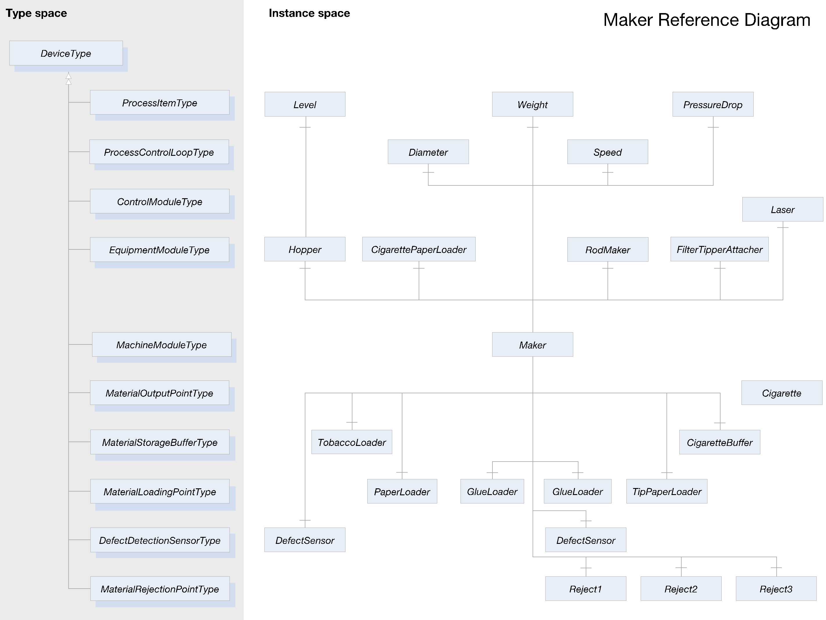
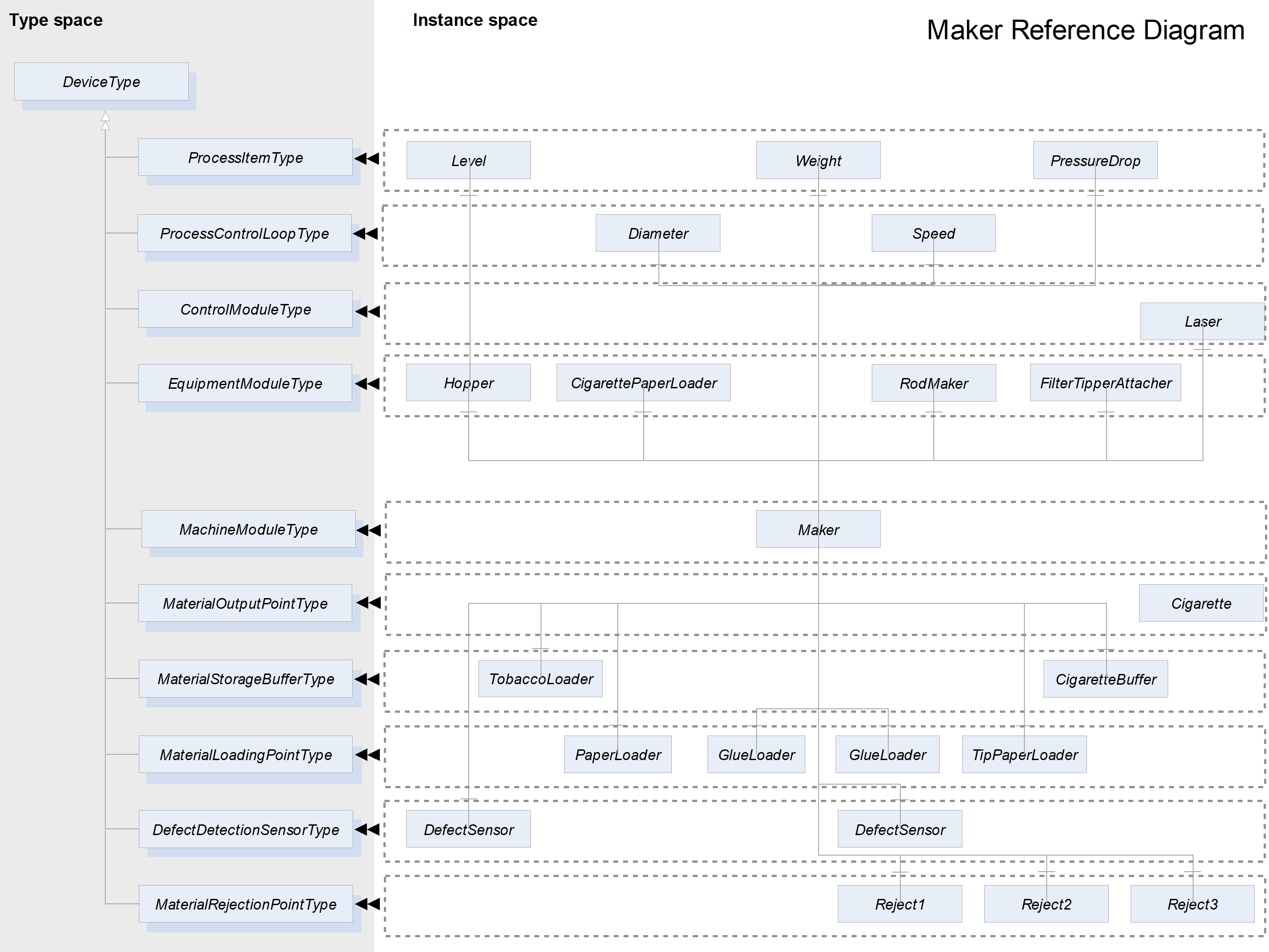
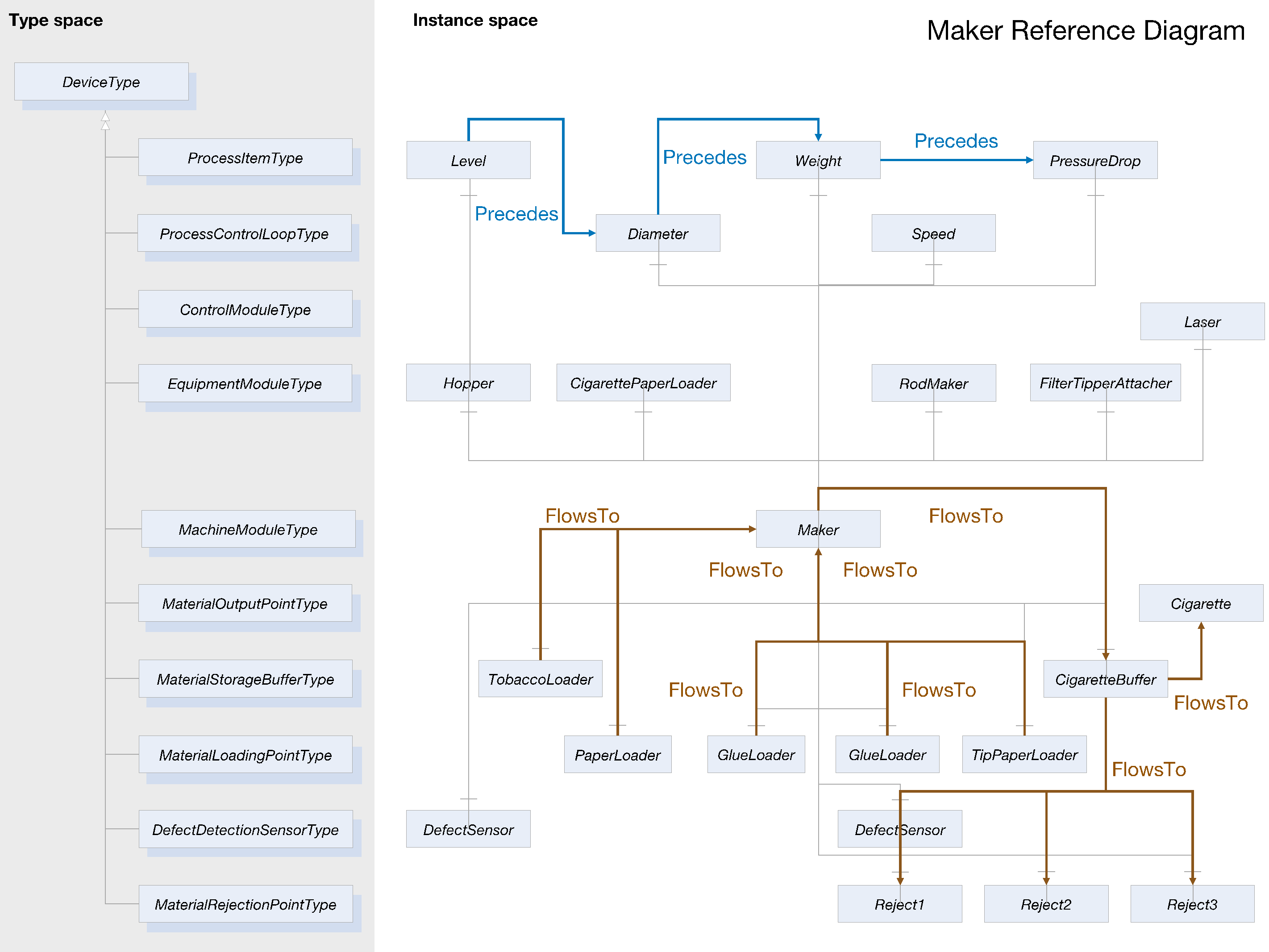
Agreement of Use
COPYRIGHT RESTRICTIONS
This document is provided "as is" by the OPC Foundation and the TMC Working Group.
Right of use for this specification is restricted to this specification and does not grant rights of use for referred documents.
Right of use for this specification will be granted without cost.
This document may be distributed through computer systems, printed or copied as long as the content remains unchanged and the document is not modified.
OPC Foundation and the TMC Working Group do not guarantee usability for any purpose and shall not be made liable for any case using the content of this document.
The user of the document agrees to indemnify OPC Foundation and TMC Working Group and their officers, directors and agents harmless from all demands, claims, actions, losses, damages (including damages from personal injuries), costs and expenses (including attorneys' fees) which are in any way related to activities associated with its use of content from this specification.
The document shall not be used in conjunction with company advertising, shall not be sold or licensed to any party.
The intellectual property and copyright is solely owned by the OPC Foundation and the TMC Working Group.
PATENTS
The attention of adopters is directed to the possibility that compliance with or adoption of OPC or TMC Working Group specifications may require use of an invention covered by patent rights. OPC Foundation or TMC Working Group shall not be responsible for identifying patents for which a license may be required by any OPC or TMC Working Group specification, or for conducting legal inquiries into the legal validity or scope of those patents that are brought to its attention. OPC or TMC Working Group specifications are prospective and advisory only. Prospective users are responsible for protecting themselves against liability for infringement of patents.
WARRANTY AND LIABILITY DISCLAIMERS
WHILE THIS PUBLICATION IS BELIEVED TO BE ACCURATE, IT IS PROVIDED "AS IS" AND MAY CONTAIN ERRORS OR MISPRINTS. THE OPC FOUDATION NOR TMC Working Group MAKES NO WARRANTY OF ANY KIND, EXPRESSED OR IMPLIED, WITH REGARD TO THIS PUBLICATION, INCLUDING BUT NOT LIMITED TO ANY WARRANTY OF TITLE OR OWNERSHIP, IMPLIED WARRANTY OF MERCHANTABILITY OR WARRANTY OF FITNESS FOR A PARTICULAR PURPOSE OR USE. IN NO EVENT SHALL THE OPC FOUNDATION NOR TMC Working Group BE LIABLE FOR ERRORS CONTAINED HEREIN OR FOR DIRECT, INDIRECT, INCIDENTAL, SPECIAL, CONSEQUENTIAL, RELIANCE OR COVER DAMAGES, INCLUDING LOSS OF PROFITS, REVENUE, DATA OR USE, INCURRED BY ANY USER OR ANY THIRD PARTY IN CONNECTION WITH THE FURNISHING, PERFORMANCE, OR USE OF THIS MATERIAL, EVEN IF ADVISED OF THE POSSIBILITY OF SUCH DAMAGES.
The entire risk as to the quality and performance of software developed using this specification is borne by you.
RESTRICTED RIGHTS LEGEND
This Specification is provided with Restricted Rights. Use, duplication or disclosure by the U.S. government is subject to restrictions as set forth in (a) this Agreement pursuant to DFARs 227.7202-3(a); (b) subparagraph (c)(1)(i) of the Rights in Technical Data and Computer Software clause at DFARs 252.227-7013; or (c) the Commercial Computer Software Restricted Rights clause at FAR 52.227-19 subdivision (c)(1) and (2), as applicable. Contractor / manufacturer are the OPC Foundation, 16101 N. 82nd Street, Suite 3B, Scottsdale, AZ, 85260-1830
COMPLIANCE
The combination of TMC Working Group and OPC Foundation shall at all times be the sole entities that may authorize developers, suppliers and sellers of hardware and software to use certification marks, trademarks or other special designations to indicate compliance with these materials as specified within this document. Products developed using this specification may claim compliance or conformance with this specification if and only if the software satisfactorily meets the certification requirements set by the TMC Working Group or the OPC Foundation. Products that do not meet these requirements may claim only that the product was based on this specification and must not claim compliance or conformance with this specification.
Trademarks
Most computer and software brand names have trademarks or registered trademarks. The individual trademarks have not been listed here.
GENERAL PROVISIONS
Should any provision of this Agreement be held to be void, invalid, unenforceable or illegal by a court, the validity and enforceability of the other provisions shall not be affected thereby.
This Agreement shall be governed by and construed under the laws of Germany.
This Agreement embodies the entire understanding between the parties with respect to, and supersedes any prior understanding or agreement (oral or written) relating to, this specification.
Revision 2.0 Highlights
Revision 2.0 is based on four years of experience in the modelling and development of TMC compliant OPC UA servers by the TMC Working Group and their business partners. It also includes improvements suggested by feedback from the OEMs.
Additionally, Revision 2.0 extends the scope of TMC to the following:
Primary production processes.
Production Orchestration in a Process Cell.
More transparent machine operations by means of state machines.
Support for Remote Control Loops.
Some constructs for intralogistics around the machine.
Material management aligned with ISA 95.