
1 Scope
For the communication between different machines, manufacturer independent information models are required. For plastics and rubber machinery, these information models are based on OPC UA, a communication framework developed and provided by the OPC Foundation. While OPC UA provides the technology for the transfer of information, the definition which information is transferred in which form is fixed in Companion Specifications.
This recommendation defines common ObjectTypes for plastics and rubber machines. The intention is that ObjectTypes which can be used for several machines and applications are defined only once. For specific applications (e.g. connection of injection moulding machines to MES), these ObjectTypes are used by specific Companion Specifications (e.g. OPC 40077).
2 Normative references
The following documents are referred to in the text in such a way that some or all of their content constitutes requirements of this document. For dated references, only the edition cited applies. For undated references, the latest edition of the referenced document (including any amendments) applies
OPC 10000-1, OPC Unified Architecture - Part 1: Overview and Concepts
OPC 10000-1
OPC 10000-2, OPC Unified Architecture - Part 2: Security Model
OPC 10000-2
OPC 10000-3, OPC Unified Architecture - Part 3: Address Space Model
OPC 10000-3
OPC 10000-4, OPC Unified Architecture - Part 4: Services
OPC 10000-4
OPC 10000-5, OPC Unified Architecture - Part 5: Information Model
OPC 10000-5
OPC 10000-6, OPC Unified Architecture - Part 6: Mappings
OPC 10000-6
OPC 10000-7, OPC Unified Architecture - Part 7: Profiles
OPC 10000-7
OPC 10000-8, OPC Unified Architecture - Part 8: Data Access
OPC 10000-8
OPC 10000-9, OPC Unified Architecture - Part 9: Alarms and Conditions
OPC 10000-9
OPC 10000-11, OPC Unified Architecture - Part 11: Historical Access
OPC 10000-11
OPC 10001-1, OPC Unified Architecture V1.04 - Amendment 1: AnalogItem Types
http://www.opcfoundation.org/UA/Amendment1/
OPC 10001-3, OPC Unified Architecture V1.04 - Amendment 3: Method Metadata
http://www.opcfoundation.org/UA/Amendment3/
OPC 10000-100, OPC Unified Architecture - Part 100: Devices
OPC 10000-100
3 Terms, definitions and conventions
3.1 Overview
It is assumed that basic concepts of OPC UA information modelling are understood in this specification. This specification will use these concepts to describe the OPC 40083 Information Model. For the purposes of this document, the terms and definitions given in the documents referenced in Clause 2 apply.
3.2 Conventions used in this document
3.2.1 Conventions for Node descriptions
Node definitions are specified using tables (see Table 2 ).
Attributes are defined by providing the Attribute name and a value, or a description of the value.
References are defined by providing the ReferenceType name, the BrowseName of the TargetNode and its NodeClass.
If the TargetNode is a component of the Node being defined in the table the Attributes of the composed Node are defined in the same row of the table.
The DataType is only specified for Variables; "[<number>]" indicates a single-dimensional array, for multi-dimensional arrays the expression is repeated for each dimension (e.g. [2][3] for a two-dimensional array). For all arrays the ArrayDimensions is set as identified by <number> values. If no <number> is set, the corresponding dimension is set to 0, indicating an unknown size. If no number is provided at all the ArrayDimensions can be omitted. If no brackets are provided, it identifies a scalar DataType and the ValueRank is set to the corresponding value (see OPC 10000-3). In addition, ArrayDimensions is set to null or is omitted. If it can be Any or ScalarOrOneDimension, the value is put into "{<value>}", so either "{Any}" or "{ScalarOrOneDimension}" and the ValueRank is set to the corresponding value (see OPC 10000-3) and the ArrayDimensions is set to null or is omitted. Examples are given in Table 1 .
| Notation | DataType | ValueRank | ArrayDimensions | Description |
| 0:Int32 | 0:Int32 | -1 | omitted or null | A scalar Int32. |
| 0:Int32[] | 0:Int32 | 1 | omitted or {0} | Single-dimensional array of Int32 with an unknown size. |
| 0:Int32[][] | 0:Int32 | 2 | omitted or {0,0} | Two-dimensional array of Int32 with unknown sizes for both dimensions. |
| 0:Int32[3][] | 0:Int32 | 2 | {3,0} | Two-dimensional array of Int32 with a size of 3 for the first dimension and an unknown size for the second dimension. |
| 0:Int32[5][3] | 0:Int32 | 2 | {5,3} | Two-dimensional array of Int32 with a size of 5 for the first dimension and a size of 3 for the second dimension. |
| 0:Int32{Any} | 0:Int32 | -2 | omitted or null | An Int32 where it is unknown if it is scalar or array with any number of dimensions. |
| 0:Int32{ScalarOrOneDimension} | 0:Int32 | -3 | omitted or null | An Int32 where it is either a single-dimensional array or a scalar. |
The TypeDefinition is specified for Objects and Variables.
The TypeDefinition column specifies a symbolic name for a NodeId, i.e. the specified Node points with a HasTypeDefinition Reference to the corresponding Node.
The ModellingRule of the referenced component is provided by specifying the symbolic name of the rule in the ModellingRule column. In the AddressSpace, the Node shall use a HasModellingRule Reference to point to the corresponding ModellingRule Object.
If the NodeId of a DataType is provided, the symbolic name of the Node representing the DataType shall be used.
Note that if a symbolic name of a different namespace is used, it is prefixed by the NamespaceIndex (see 3.2.2.2).
Nodes of all other NodeClasses cannot be defined in the same table; therefore only the used ReferenceType, their NodeClass and their BrowseName are specified. A reference to another part of this document points to their definition.
Table 2 illustrates the table. If no components are provided, the DataType, TypeDefinition and ModellingRule columns may be omitted and only a Comment column is introduced to point to the Node definition.
| Attribute | Value | ||||
| Attribute name | Attribute value. If it is an optional Attribute that is not set "--" will be used. | ||||
| References | NodeClass | BrowseName | DataType | TypeDefinition | Other |
|---|---|---|---|---|---|
| ReferenceType name | NodeClass of the TargetNode. | BrowseName of the target Node. If the Reference is to be instantiated by the server, then the value of the target Node's BrowseName is "--". | DataType of the referenced Node, only applicable for Variables. | TypeDefinition of the referenced Node, only applicable for Variables and Objects. | Additional characteristics of the TargetNode such as the ModellingRule or AccessLevel. |
| NOTE Notes referencing footnotes of the table content. | |||||
Components of Nodes can be complex that is containing components by themselves. The TypeDefinition, NodeClass and DataType can be derived from the type definitions, and the symbolic name can be created as defined in 3.2.3.1. Therefore, those containing components are not explicitly specified; they are implicitly specified by the type definitions.
The Other column defines additional characteristics of the Node. Examples of characteristics that can appear in this column are show in Table 3.
| Name | Short Name | Description |
| 0:Mandatory | M | The Node has the Mandatory ModellingRule. |
| 0:Optional | O | The Node has the Optional ModellingRule. |
| 0:MandatoryPlaceholder | MP | The Node has the MandatoryPlaceholder ModellingRule. |
| 0:OptionalPlaceholder | OP | The Node has the OptionalPlaceholder ModellingRule. |
| ReadOnly | RO | The Node AccessLevel has the CurrentRead bit set but not the CurrentWrite bit. |
| ReadWrite | RW | The Node AccessLevel has the CurrentRead and CurrentWrite bits set. |
| WriteOnly | WO | The Node AccessLevel has the CurrentWrite bit set but not the CurrentRead bit. |
If multiple characteristics are defined they are separated by commas. The name or the short name may be used.
3.2.2 NodeIds and BrowseNames
3.2.2.1 NodeIds
The NodeIds of all Nodes described in this standard are only symbolic names. Annex A defines the actual NodeIds.
The symbolic name of each Node defined in this document is its BrowseName, or, when it is part of another Node, the BrowseName of the other Node, a ".", and the BrowseName of itself. In this case "part of" means that the whole has a HasProperty or HasComponent Reference to its part. Since all Nodes not being part of another Node have a unique name in this document, the symbolic name is unique.
The NamespaceUri for all NodeIds defined in this document is defined in Annex A. The NamespaceIndex for this NamespaceUri is vendor-specific and depends on the position of the NamespaceUri in the server namespace table.
Note that this document not only defines concrete Nodes, but also requires that some Nodes shall be generated, for example one for each Session running on the Server. The NodeIds of those Nodes are Server-specific, including the namespace. But the NamespaceIndex of those Nodes cannot be the NamespaceIndex used for the Nodes defined in this document, because they are not defined by this document but generated by the Server.
3.2.2.2 BrowseNames
The text part of the BrowseNames for all Nodes defined in this document is specified in the tables defining the Nodes. The NamespaceUri for all BrowseNames defined in this document is defined in Annex A.
If the BrowseName is not defined by this document, a namespace index prefix like '0:EngineeringUnits' or '2:DeviceRevision' is added to the BrowseName. This is typically necessary if a Property of another specification is overwritten or used in the OPC UA types defined in this document. Table 167 provides a list of namespaces and their indexes as used in this document.
3.2.3 Common Attributes
3.2.3.1 General
The Attributes of Nodes, their DataTypes and descriptions are defined in OPC 10000-3. Attributes not marked as optional are mandatory and shall be provided by a Server. The following tables define if the Attribute value is defined by this specification or if it is server-specific.
For all Nodes specified in this specification, the Attributes named in Table 4 shall be set as specified in the table.
| Attribute | Value |
| DisplayName | The DisplayName is a LocalizedText. Each server shall provide the DisplayName identical to the BrowseName of the Node for the LocaleId "en". Whether the server provides translated names for other LocaleIds is server-specific. |
| Description | Optionally a server-specific description is provided. |
| NodeClass | Shall reflect the NodeClass of the Node. |
| NodeId | The NodeId is described by BrowseNames as defined in 3.2.2.1. |
| WriteMask | Optionally the WriteMask Attribute can be provided. If the WriteMask Attribute is provided, it shall set all non-server-specific Attributes to not writable. For example, the Description Attribute may be set to writable since a Server may provide a server-specific description for the Node. The NodeId shall not be writable, because it is defined for each Node in this specification. |
| UserWriteMask | Optionally the UserWriteMask Attribute can be provided. The same rules as for the WriteMask Attribute apply. |
| RolePermissions | Optionally server-specific role permissions can be provided. |
| UserRolePermissions | Optionally the role permissions of the current Session can be provided. The value is server-specifc and depend on the RolePermissions Attribute (if provided) and the current Session. |
| AccessRestrictions | Optionally server-specific access restrictions can be provided. |
3.2.3.2 Objects
For all Objects specified in this specification, the Attributes named in Table 5 shall be set as specified in the table. The definitions for the Attributes can be found in OPC 10000-3.
| Attribute | Value |
| EventNotifier | Whether the Node can be used to subscribe to Events or not is server-specific. |
3.2.3.3 Variables
For all Variables specified in this specification, the Attributes named in Table 6 shall be set as specified in the table. The definitions for the Attributes can be found in OPC 10000-3.
| Attribute | Value |
| MinimumSamplingInterval | Optionally, a server-specific minimum sampling interval is provided. |
| AccessLevel | The access level for Variables used for type definitions is server-specific, for all other Variables defined in this specification, the access level shall allow reading; other settings are server-specific. |
| UserAccessLevel | The value for the UserAccessLevel Attribute is server-specific. It is assumed that all Variables can be accessed by at least one user. |
| Value | For Variables used as InstanceDeclarations, the value is server-specific; otherwise it shall represent the value described in the text. |
| ArrayDimensions | If the ValueRank does not identify an array of a specific dimension (i.e. ValueRank <= 0) the ArrayDimensions can either be set to null or the Attribute is missing. This behaviour is server-specific. If the ValueRank specifies an array of a specific dimension (i.e. ValueRank > 0) then the ArrayDimensions Attribute shall be specified in the table defining the Variable. |
| Historizing | The value for the Historizing Attribute is server-specific. |
| AccessLevelEx | If the AccessLevelEx Attribute is provided, it shall have the bits 8, 9, and 10 set to 0, meaning that read and write operations on an individual Variable are atomic, and arrays can be partly written. |
3.2.3.4 VariableTypes
For all VariableTypes specified in this specification, the Attributes named in Table 7 shall be set as specified in the table. The definitions for the Attributes can be found in OPC 10000-3.
| Attributes | Value |
| Value | Optionally a server-specific default value can be provided. |
| ArrayDimensions | If the ValueRank does not identify an array of a specific dimension (i.e. ValueRank <= 0) the ArrayDimensions can either be set to null or the Attribute is missing. This behaviour is server-specific. If the ValueRank specifies an array of a specific dimension (i.e. ValueRank > 0) then the ArrayDimensions Attribute shall be specified in the table defining the VariableType. |
3.2.3.5 Methods
For all Methods specified in this specification, the Attributes named in Table 8 shall be set as specified in the table. The definitions for the Attributes can be found in OPC 10000-3.
| Attributes | Value |
| Executable | All Methods defined in this specification shall be executable (Executable Attribute set to "True"), unless it is defined differently in the Method definition. |
| UserExecutable | The value of the UserExecutable Attribute is server-specific. It is assumed that all Methods can be executed by at least one user. |
4 General information to OPC UA interfaces for plastics and rubber machinery and OPC UA
4.1 Introduction to OPC UA interfaces for plastics and rubber machinery
Industry 4.0 means exchange of data/information between machines for increasing the quality and efficiency of the production. This is only possible with standardised interfaces. Plastics and rubber machines are usually integrated in a production line and/or connected to superordinate systems like Manufacturing Execution Systems (MES). This is why, the joint working group OPC UA Plastics and Rubber Machinery develops Companion Specifications for both horizontal and vertical communication.
4.2 Introduction to OPC Unified Architecture
4.2.1 What is OPC UA?
OPC UA is an open and royalty free set of standards designed as a universal communication protocol. While there are numerous communication solutions available, OPC UA has key advantages:
A state of art security model (see OPC 10000-2).
A fault tolerant communication protocol.
An information modelling framework that allows application developers to represent their data in a way that makes sense to them.
OPC UA has a broad scope which delivers for economies of scale for application developers. This means that a larger number of high-quality applications at a reasonable cost are available. When combined with semantic models such as OPC UA interfaces for plastics and rubber machinery, OPC UA makes it easier for end users to access data via generic commercial applications.
The OPC UA model is scalable from small devices to ERP systems. OPC UA Servers process information locally and then provide that data in a consistent format to any application requesting data - ERP, MES, PMS, Maintenance Systems, HMI, Smartphone or a standard Browser, for examples. For a more complete overview see OPC 10000-1.
4.2.2 Basics of OPC UA
As an open standard, OPC UA is based on standard internet technologies, like TCP/IP, HTTP, Web Sockets.
As an extensible standard, OPC UA provides a set of Services (see OPC 10000-4) and a basic information model framework. This framework provides an easy manner for creating and exposing vendor defined information in a standard way. More importantly all OPC UA Clients are expected to be able to discover and use vendor-defined information. This means OPC UA users can benefit from the economies of scale that come with generic visualization and historian applications. This specification is an example of an OPC UA Information Model designed to meet the needs of developers and users.
OPC UA Clients can be any consumer of data from another device on the network to browser based thin clients and ERP systems. The full scope of OPC UA applications is shown in Figure 1.

OPC UA provides a robust and reliable communication infrastructure having mechanisms for handling lost messages, failover, heartbeat, etc. With its binary encoded data, it offers a high-performing data exchange solution. Security is built into OPC UA as security requirements become more and more important especially since environments are connected to the office network or the internet and attackers are starting to focus on automation systems.
4.2.3 Information modelling in OPC UA
4.2.3.1 Concepts
OPC UA provides a framework that can be used to represent complex information as Objects in an AddressSpace which can be accessed with standard services. These Objects consist of Nodes connected by References. Different classes of Nodes convey different semantics. For example, a Variable Node represents a value that can be read or written. The Variable Node has an associated DataType that can define the actual value, such as a string, float, structure etc. It can also describe the Variable value as a variant. A Method Node represents a function that can be called. Every Node has a number of Attributes including a unique identifier called a NodeId and non-localized name called as BrowseName. An Object representing a 'Reservation' is shown in Figure 2.

Object and Variable Nodes represent instances and they always reference a TypeDefinition (ObjectType or VariableType) Node which describes their semantics and structure. illustrates the relationship between an instance and its TypeDefinition.
The type Nodes are templates that define all of the children that can be present in an instance of the type. In the example in Figure 3 the PersonType ObjectType defines two children: First Name and Last Name. All instances of PersonType are expected to have the same children with the same BrowseNames. Within a type the BrowseNames uniquely identify the children. This means Client applications can be designed to search for children based on the BrowseNames from the type instead of NodeIds. This eliminates the need for manual reconfiguration of systems if a Client uses types that multiple Servers implement.
OPC UA also supports the concept of sub-typing. This allows a modeller to take an existing type and extend it. There are rules regarding sub-typing defined in OPC 10000-3, but in general they allow the extension of a given type or the restriction of a DataType. For example, the modeller may decide that the existing ObjectType in some cases needs an additional Variable. The modeller can create a subtype of the ObjectType and add the Variable. A Client that is expecting the parent type can treat the new type as if it was of the parent type. Regarding DataTypes, subtypes can only restrict. If a Variable is defined to have a numeric value, a sub type could restrict it to a float.

References allow Nodes to be connected in ways that describe their relationships. All References have a ReferenceType that specifies the semantics of the relationship. References can be hierarchical or non-hierarchical. Hierarchical references are used to create the structure of Objects and Variables. Non-hierarchical are used to create arbitrary associations. Applications can define their own ReferenceType by creating subtypes of an existing ReferenceType. Subtypes inherit the semantics of the parent but may add additional restrictions. Figure 4 depicts several References, connecting different Objects.

The figures above use a notation that was developed for the OPC UA specification. The notation is summarized in Figure 5. UML representations can also be used; however, the OPC UA notation is less ambiguous because there is a direct mapping from the elements in the figures to Nodes in the AddressSpace of an OPC UA Server.
Figure 5 - The OPC UA Information Model Notation
A complete description of the different types of Nodes and References can be found in OPC 10000-3 and the base structure is described in OPC 10000-5.
OPC UA specification defines a very wide range of functionality in its basic information model. It is not required that all Clients or Servers support all functionality in the OPC UA specifications. OPC UA includes the concept of Profiles, which segment the functionality into testable certifiable units. This allows the definition of functional subsets (that are expected to be implemented) within a companion specification. The Profiles do not restrict functionality, but generate requirements for a minimum set of functionality (see OPC 10000-7)
4.2.3.2 Namespaces
OPC UA allows information from many different sources to be combined into a single coherent AddressSpace. Namespaces are used to make this possible by eliminating naming and id conflicts between information from different sources. Each namespace in OPC UA has a globally unique string called a NamespaceUri which identifies a naming authority and a locally unique integer called a NamespaceIndex, which is an index into the Server's table of NamespaceUris. The NamespaceIndex is unique only within the context of a Session between an OPC UA Client and an OPC UA Server- the NamespaceIndex can change between Sessions and still identify the same item even though the NamespaceUri's location in the table has changed. The Services defined for OPC UA use the NamespaceIndex to specify the Namespace for qualified values.
There are two types of structured values in OPC UA that are qualified with NamespaceIndexes: NodeIds and QualifiedNames. NodeIds are locally unique (and sometimes globally unique) identifiers for Nodes. The same globally unique NodeId can be used as the identifier in a node in many Servers - the node's instance data may vary but its semantic meaning is the same regardless of the Server it appears in. This means Clients can have built-in knowledge of of what the data means in these Nodes. OPC UA Information Models generally define globally unique NodeIds for the TypeDefinitions defined by the Information Model.
QualifiedNames are non-localized names qualified with a Namespace. They are used for the BrowseNames of Nodes and allow the same names to be used by different information models without conflict. TypeDefinitions are not allowed to have children with duplicate BrowseNames; however, instances do not have that restriction.
4.2.3.3 Companion Specifications
An OPC UA companion specification for an industry specific vertical market describes an Information Model by defining ObjectTypes, VariableTypes, DataTypes and ReferenceTypes that represent the concepts used in the vertical market, and potentially also well-defined Objects as entry points into the AddressSpace.
5 Use cases
OPC 40083 provides Object, Data and Variable Type definitions to be used by specific companion specifications for plastics and rubber machinery. The intention is to create an interoperability between the different machines.
6 General requirements
6.1 NodeIds
The NodeIds of the Types defined in this specification are mandatory and fixed in the provided XML-file. This applies only to the Types themselves and not to the child elements. NodeIds of generated instances are not fixed and assigned by the individual OPC UA server. Therefore, the namespace of the NodeIds is the Local Server URI with namespace index 1 or a vendor specific namespace with vendor specific index. However, a Server shall persist the NodeIds of the generated Nodes, that is, it shall not generate new NodeIds when rebooting.
6.2 AnalogItemType
For this specification, wherever AnalogItemType is used, the property EngineeringUnits is mandatory. The unit system described in OPC UA Part 8 ("Codes for Units of Measurement (Recommendation N°. 20)" published by the "United Nations Centre for Trade Facilitation and Electronic Business" (see UN/CEFACT)) shall be used.
6.3 EventNotifier
If events are supported, the root node of the specific interface (e.g. IMM_MES_Interface for OPC 40077) shall set the SubscribeToEvents flag in the EventNotifier attribute.
If event history is supported, the root node of the specific interface (e.g. IMM_MES_Interface for OPC 40077) shall set the HistoryRead flag in the EventNotifier attribute.
6.4 Severity of events
Wherever a Severity property is used (e.g. in MESMessage in 14.4, all events based on BaseEventType), the following classification shall be used:
| Range of Severity | Description |
| 667 - 1000 | Messages of high urgency (Error) |
| 334 - 666 | Messages of medium urgency (Warning) |
| 1 - 333 | Messages of low urgency (Information) |
7 Container concept
Several objects can occur several times in the parent object (e.g. several moulds in one machine). For these, container objects are modelled. The benefit is that all instances are collected in one object so that changes can be easily recognized by using a Property NodeVersion which can be subscribed by clients. According to OPC UA, Part 3, the instances of the container objects shall also trigger a GeneralModelChangeEvent.
The following container types are defined:
Within these containers, the child elements have the modelling rule OptionalPlaceholder which allows to add and remove instances of the objects dynamically.
The BrowseNames of the child elements are created with numbers as suffixes starting with 1 (e.g. "Mould_1", "Mould_2" …). It is allowed to use numbers with leading zeros, e.g. "Mould_001" for better sorting. It is not mandatory to use successive numbers. That means there can be gaps and it is also allowed to have e.g. two instances with BrowseNames "Mould_042" and "Mould_099".
The objects have an IsPresent-flag. This allows to have a fixed number of instances prepared (e.g. if the maximum number of child components is limited by the design of the machine) and to indicate if the component is physically present. With this there are two possibilities: Dynamic creation of instances or fixed number of instances. However, a client which is interested in the contents of the container shall always subscribe the NodeVersion and/or ModelChangeEvents of the container object to get informed about changes.
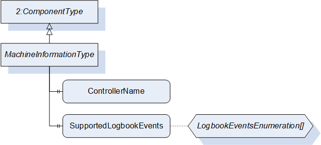
8 MachineInformationType
8.1 MachineInformationType Definition
This ObjectType represents the general description of a machine. The information is fixed by the manufacturer and not changeable by the user. It is formally defined in Table 10.
| Attribute | Value | ||||
| BrowseName | MachineInformationType | ||||
| IsAbstract | False | ||||
| References | Node Class | BrowseName | DataType | TypeDefinition | Other |
|---|---|---|---|---|---|
| Subtype of 2:ComponentType defined in OPC UA 10000-100 (Devices) | |||||
| 0:HasProperty | Variable | 2:DeviceClass | 0:String | 0:PropertyType | M, RO |
| 0:HasProperty | Variable | 2:Manufacturer | 0:LocalizedText | 0:PropertyType | M, RO |
| 0:HasProperty | Variable | 2:Model | 0:LocalizedText | 0:PropertyType | M, RO |
| 0:HasProperty | Variable | 2:SerialNumber | 0:String | 0:PropertyType | M, RO |
| 0:HasProperty | Variable | ControllerName | 0:String | 0:PropertyType | M, RO |
| 0:HasProperty | Variable | SupportedLogbookEvents | LogbookEventsEnumeration[] | 0:PropertyType | M, RO |
8.2 Properties included in ComponentType
The following parameters are already included in the ComponentType (defined in OPC UA Part 100).
8.3 DeviceClass
The DeviceClass Property indicates in which domain or for what purpose a certain Device is used. The Property is optional in OPC UA DI. Here it is overridden and made mandatory. The value is specified in the specific Companion Specification (e.g. "Injection Moulding Machine" for OPC 40077).
8.3.1 Manufacturer
The Manufacturer Property provides the name of the manufacturer of the machine (e.g. "Negri Bossi"). The Property is optional in OPC UA DI. Here it is overridden and made mandatory.
8.3.2 DeviceManual
The DeviceManual Property allows specifying an address of the user manual for the Device. It may be a pathname in the file system or a URL (Web address). If the manual is not directly accessible, it may also be a general web address (e.g. "netstal.com").
8.3.3 Model
The Model Property represents the name of the machine type (e.g. "KM 1000-2500", "Allrounder"). The Property is optional in OPC UA DI. Here it is overridden and made mandatory.
8.3.4 SoftwareRevision
The SoftwareRevision Property represents the software version used in the control unit (e.g. "nb2001v11B030").
8.3.5 SerialNumber
The SerialNumber Property represents the serial number of the machine (unique ID given by the manufacturer, e.g. "1240114"). The Property is optional in OPC UA DI. Here it is overridden and made mandatory.
8.3.6 DeviceRevision
The DeviceRevision Property provides the overall revision level of the Device.
8.3.7 HardwareRevision
The HardwareRevision Property provides the revision level of the hardware of the Device.
8.3.8 RevisionCounter
The RevisionCounter Property is an incremental counter indicating the number of times the static data within the Device has been modified.
8.4 Additional properties
The following parameters are defined to extend the ComponentType.
8.4.1 ControllerName
The ControllerName Property represents the name of the machine controller (e.g. "MC5").
8.4.2 SupportedLogbookEvents
This list of LogbookEventsEnumeration gives information which LogbookEvents (see 9) are supported by the machine.
The LogbookEventsEnumeration is defined in Table 11.
| Name | Value | Description |
| PARAMETER_CHANGE | 0 | Support of ParameterChangeLogType (see 9.5). The machine will fire events when production parameters are changed. |
| USER | 1 | Support of UserLogType (see 9.6). The machine will fire events when users log in or off at the machine HMI. |
| REMOTE_ACCESS | 2 | Support of RemoteAccessLogType (see 9.7). The machine will fire events when remote users log in or off. |
| SEQUENCE_CHANGE | 3 | Support of SequenceChangeLogType (see 9.8). The machine will fire events when there are changes in the production sequence. |
| MACHINE_MODE_CHANGE | 4 | Support of MachineModeChangeLogType (see 9.9). The machine will fire events when the machine mode is changed. |
| PRODUCTION_STATUS_CHANGE | 5 | Support of ProductionStatusChangeLogType (see 9.10). The machine will fire events when the production status is changed. |
| PRODUCTION_DATASET_CHANGE | 6 | Support of ProductionDatasetChangeLogType (see 9.11). The machine will fire events when the production dataset is changed. |
| PRODUCTION_DATASET_FROZEN | 7 | Support of ProductionDatasetFrozenLogType (see 9.12). The machine will fire events when the frozen status of the production dataset (see 20.3.4) is changed. |
| STANDSTILL_REASON | 8 | Support of StandstillReasonLogType (see 9.13). The machine will fire events when the standstill reason is changed. |
| MESSAGE | 9 | Support of MessageLogType (see 9.14). The machine will fire events for each fired MessageCondition. |
| USER_FEEDBACK | 10 | Support of UserFeedbackLogType (see 9.15). The machine will fire events for each message entered by the user. |
9 LogbookEvent
9.1 LogbookEvent Definition
Logbook events are fired by the machine for the documentation of relevant changes in the machine configuration/status. The LogbookEventType is formally defined in Table 12.
| Attribute | Value | ||||
| BrowseName | LogbookEventType | ||||
| IsAbstract | True | ||||
| References | Node Class | BrowseName | DataType | TypeDefinition | Other |
|---|---|---|---|---|---|
| Subtype of 0:BaseEventType defined in OPC UA Part 5 | |||||
| 0:HasComponent | Object | User | UserType | M | |
| 0:HasProperty | Variable | EventOriginator | EventOriginatorEnumeration | 0:PropertyType | M |
| 0:HasProperty | Variable | JobCycleCounter | 0:UInt64 | 0:PropertyType | O |
| 0:HasSubtype | ObjectType | ParameterChangeLogType | Defined in 9.5 | ||
| 0:HasSubtype | ObjectType | UserLogType | Defined in 9.6 | ||
| 0:HasSubtype | ObjectType | RemoteAccessLogType | Defined in 9.7 | ||
| 0:HasSubtype | ObjectType | SequenceChangeLogType | Defined in 9.8 | ||
| 0:HasSubtype | ObjectType | MachineModeChangeLogType | Defined in 9.9 | ||
| 0:HasSubtype | ObjectType | ProductionStatusChangeLogType | Defined in 9.10 | ||
| 0:HasSubtype | ObjectType | ProductionDatasetChangeLogType | Defined in 9.11 | ||
| 0:HasSubtype | ObjectType | ProductionDatasetFrozenLogType | Defined in 9.12 | ||
| 0:HasSubtype | ObjectType | StandstillReasonLogType | Defined in 9.13 | ||
| 0:HasSubtype | ObjectType | MessageLogType | Defined in 9.14 | ||
| 0:HasSubtype | ObjectType | UserFeedbackLogType | Defined in 9.15 | ||
The LogbookEventType is abstract. There will be no instances of a LogbookEventType itself, but there will be instances of its subtypes which provide detailed information.
The EventSource is the root node of the interface (e.g. instance of IMM_MES_InterfaceType for OPC 40077).
There shall be a buffer to be accessible via the OPC UA service history read (even when the machine has been switched off in the meantime). The minimum size is 100 LogbookEvents to be stored in a (persistent) ring buffer containing the recent 100 events (over all LogbookEvents).
9.2 User
This Object indicates the user who is responsible for the change that leads to the event. The fields of UserType (see 13.2) shall be null or emtpy if no user is directly responsible (e.g. for messages coming from the machine control system).
9.3 EventOriginator
This Property represents the originator of a logbook event. The EventOriginatorEnumeration is defined in Table 13.
| Name | Value | Description |
| OTHER | 0 | Undefined |
| MACHINE | 1 | The machine causes the event (e.g. an alarm) |
| OPERATOR | 2 | The operator of the machine causes the event (e.g. a parameter change) |
| MES | 3 | The MES causes the event (e.g. a MESMessage) |
| PERIPHERAL_DEVICE | 4 | A peripheral device causes the event (e.g. an alarm) |
9.4 JobCycleCounter
This Property represents the current value of JobCycleCounter in the ActiveJobValues Object when the event is fired (see 18.4.7.1). Only to be used for cyclic production (e.g. injection moulding).
9.5 ParameterChangeLogType
The ParameterChangeLogType is used for the logging of relevant changes in production parameters.
The decision which parameter is relevant for the production is done by the machine.
| Attribute | Value | ||||
| BrowseName | ParameterChangeLogType | ||||
| IsAbstract | True | ||||
| References | Node Class | BrowseName | DataType | TypeDefinition | Other |
|---|---|---|---|---|---|
| Subtype of LogbookEventType | |||||
| 0:HasProperty | Variable | ParameterId | 0:String | 0:PropertyType | M |
| 0:HasProperty | Variable | OldValue | 0:BaseDataType | 0:PropertyType | M |
| 0:HasProperty | Variable | OldValueUnit | 0:EUInformation | 0:PropertyType | O |
| 0:HasProperty | Variable | NewValue | 0:BaseDataType | 0:PropertyType | M |
| 0:HasProperty | Variable | NewValueUnit | 0:EUInformation | 0:PropertyType | O |
The ParameterId Property represents the Id of the changed parameter.
The OldValue Property represents the old value of the changed parameter.
The NewValue Property represents the new value of the changed parameter.
Depending on the changed parameter, the Datatype of OldValue and NewValue are subtypes of 0:BaseDataType (0:String, Number, …). Where the unit is important (e.g. temperatures, lengths…), also OldValueUnit and NewValueUnit shall be used (see OPC UA Part 5 for the definition of EUInformation).
9.6 UserLogType
The UserLogType is used for logging which users are logged in to the machine.
| Attribute | Value | ||||
| BrowseName | UserLogType | ||||
| IsAbstract | True | ||||
| References | Node Class | BrowseName | DataType | TypeDefinition | Other |
|---|---|---|---|---|---|
| Subtype of LogbookEventType | |||||
| 0:HasProperty | Variable | UserChange | UserChangeEnumeration | 0:PropertyType | M |
The UserChangeEnumeration is defined in Table 16.
| Name | Value | Description |
| LOG_ON | 0 | The User has logged on the machine. |
| LOG_OFF | 1 | The User has logged off the machine. |
9.7 RemoteAccessLogType
The RemoteAccessLogType is used for logging access from outside to the machine (e.g. remote service).
| Attribute | Value | ||||
| BrowseName | RemoteAccessLogType | ||||
| IsAbstract | True | ||||
| References | Node Class | BrowseName | DataType | TypeDefinition | Other |
|---|---|---|---|---|---|
| Subtype of LogbookEventType | |||||
| 0:HasProperty | Variable | RemoteUserName | 0:String | 0:PropertyType | M |
| 0:HasProperty | Variable | UserChange | UserChangeEnumeration | 0:PropertyType | M |
| 0:HasProperty | Variable | Origin | 0:String | 0:PropertyType | O |
RemoteUserName: Name of the remote user (e.g. name of the service employee doing remote service)
UserChange: The UserChangeEnumeration is the same used in UserLogType and is defined in Table 16.
Origin: Information about the origin of the remote access (e.g. "Headquarters").
9.8 SequenceChangeLogType
The SequenceChangeLogType is used for the logging changes in the production sequence.
| Attribute | Value | ||||
| BrowseName | SequenceChangeLogType | ||||
| IsAbstract | True | ||||
| References | Node Class | BrowseName | DataType | TypeDefinition | Other |
|---|---|---|---|---|---|
| Subtype of LogbookEventType | |||||
| 0:HasProperty | Variable | SequenceChange | SequenceChangeEnumeration | 0:PropertyType | M |
The SequenceChange Property allows classifying the changes. (A description of the changes is included in the Message Property of the LogBookEventType)
| Name | Value | Description |
| UPDATE | 0 | The sequence has been updated (e.g. when a new production dataset has been activated) |
| ADD | 1 | An element has been added to the sequence |
| MODIFY | 2 | An element of the sequence has been modified. |
| MOVE | 3 | An element of the sequence has been moved. |
| DELETE | 4 | An element of the sequence has been deleted. |
9.9 MachineModeChangeLogType
The MachineModeChangeLogType is used for logging changes of the machine mode.
| Attribute | Value | ||||
| BrowseName | MachineModeChangeLogType | ||||
| IsAbstract | True | ||||
| References | Node Class | BrowseName | DataType | TypeDefinition | Other |
|---|---|---|---|---|---|
| Subtype of LogbookEventType | |||||
| 0:HasProperty | Variable | OldMachineMode | MachineModeEnumeration | 0:PropertyType | M |
| 0:HasProperty | Variable | NewMachineMode | MachineModeEnumeration | 0:PropertyType | M |
The MachineModeEnumeration is defined in 12.4.
9.10 ProductionStatusChangeLogType
The ProductionStatusChangeLogType is used for logging changes of the production status.
| Attribute | Value | ||||
| BrowseName | ProductionStatusChangeLogType | ||||
| IsAbstract | True | ||||
| References | Node Class | BrowseName | DataType | TypeDefinition | Other |
|---|---|---|---|---|---|
| Subtype of LogbookEventType | |||||
| 0:HasProperty | Variable | OldProductionStatus | ProductionStatusEnumeration | 0:PropertyType | M |
| 0:HasProperty | Variable | NewProductionStatus | ProductionStatusEnumeration | 0:PropertyType | M |
The ProductionStatusEnumeration is defined in 14.7.1.
9.11 ProductionDatasetChangeLogType
The ProductionDatasetChangeLogType is used when a new production dataset is loaded and activated in the control system of the machine.
| Attribute | Value | ||||
| BrowseName | ProductionDatasetChangeLogType | ||||
| IsAbstract | True | ||||
| References | Node Class | BrowseName | DataType | TypeDefinition | Other |
|---|---|---|---|---|---|
| Subtype of LogbookEventType | |||||
| 0:HasProperty | Variable | OldProductionDatasetName | 0:String | 0:PropertyType | M |
| 0:HasProperty | Variable | NewProductionDatasetName | 0:String | 0:PropertyType | M |
9.12 ProductionDatasetFrozenLogType
The ProductionDatasetFrozenLogType is used when a production dataset is locked or unlocked (see 20.3.4).
| Attribute | Value | ||||
| BrowseName | ProductionDatasetFrozenLogType | ||||
| IsAbstract | True | ||||
| References | Node Class | BrowseName | DataType | TypeDefinition | Other |
|---|---|---|---|---|---|
| Subtype of LogbookEventType | |||||
| 0:HasProperty | Variable | OldValue | 0:Boolean | 0:PropertyType | M |
| 0:HasProperty | Variable | NewValue | 0:Boolean | 0:PropertyType | M |
9.13 StandstillReasonLogType
The StandstillReasonLogType is used for logging StandstillReasons.
| Attribute | Value | ||||
| BrowseName | StandstillReasonLogType | ||||
| IsAbstract | True | ||||
| References | Node Class | BrowseName | DataType | TypeDefinition | Other |
|---|---|---|---|---|---|
| Subtype of LogbookEventType | |||||
| 0:HasProperty | Variable | StandstillReasonId | 0:String | 0:PropertyType | M |
9.14 MessageLogType
The MessageLogType is used for logging MessageConditions (see 14.8).
| Attribute | Value | ||||
| BrowseName | MessageLogType | ||||
| IsAbstract | True | ||||
| References | Node Class | BrowseName | DataType | TypeDefinition | Other |
|---|---|---|---|---|---|
| Subtype of LogbookEventType | |||||
| 0:HasProperty | Variable | Id | 0:String | 0:PropertyType | M |
| 0:HasProperty | Variable | IsStandstillMessage | 0:Boolean | 0:PropertyType | M |
| 0:HasProperty | Variable | Classification | 0:Enumeration | 0:PropertyType | M |
Classification: Classification of the message. The valid values of the Enumeration are specified in the specific Companion Specification (e.g. IMMMessageClassificationEnumeration in OPC 40077).
9.15 UserFeedbackLogType
The UserFeedbackLogType is used for logging text messages entered by the user into the machine control system.
| Attribute | Value | ||||
| BrowseName | UserFeedbackLogType | ||||
| IsAbstract | True | ||||
| References | Node Class | BrowseName | DataType | TypeDefinition | Other |
|---|---|---|---|---|---|
| Subtype of LogbookEventType | |||||
| 0:HasProperty | Variable | Classification | 0:Enumeration | 0:PropertyType | M |
Classification: Classification of the message. The valid values of the Enumeration are specified in the specific Companion Specification (e.g. IMMMessageClassificationEnumeration in OPC 40077).
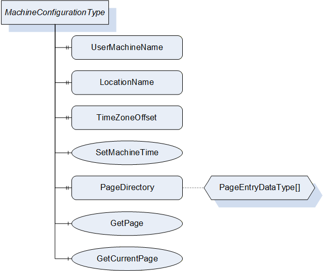
10 MachineConfigurationType
10.1 MachineConfigurationType Definition
This OPC UA ObjectType represents the current configuration of a machine. It is formally defined in Table 27.
| Attribute | Value | ||||
| BrowseName | MachineConfigurationType | ||||
| IsAbstract | False | ||||
| References | Node Class | BrowseName | DataType | TypeDefinition | Other |
|---|---|---|---|---|---|
| Subtype of 0:BaseObjectType defined in OPC UA Part 5 | |||||
| 0:HasProperty | Variable | UserMachineName | 0:String | 0:PropertyType | M, RW |
| 0:HasProperty | Variable | LocationName | 0:String | 0:PropertyType | M, RW |
| 0:HasProperty | Variable | TimeZoneOffset | 0:TimeZoneDataType | 0:PropertyType | M, RW |
| 0:HasComponent | Method | SetMachineTime | M | ||
| 0:HasProperty | Variable | PageDirectory | PageEntryDataType[] | 0:PropertyType | O, RO |
| 0:HasComponent | Method | GetPage | O | ||
| 0:HasComponent | Method | GetCurrentPage | O | ||
10.2 UserMachineName
The UserMachineName Property represents the description of the machine given by the machine operator or OPC client (e.g. "machine 42").
10.3 LocationName
The LocationName Property represents the description of the location of the machine given by the machine operator or OPC client (e.g. "plant 2, hall C").
10.4 TimeZoneOffset
The TimeZoneOffset Property represents the difference of the local time to Coordinated Universal Time (UTC) given by the machine operator or OPC client.
Information: TimeZoneDataType (as defined in OPC UA Part 3) is a structure with two components:
offset (0:UInt16): Time difference from UTC in minutes (e.g. 120 for daylight saving time in Berlin)
daylightSavingInOffset (0:Boolean): If TRUE, then daylight saving time (DST) is in effect and offset includes the DST correction. If FALSE, then the offset does not include DST correction and DST may or may not have been in effect.
10.5 SetMachineTime
The SetMachineTime Method allows setting the server time together with TimeZoneOffset.
Signature
	SetMachineTime (
		[in]	0:DateTime	DateTime
[in] 0:TimeZoneDataType TimeZoneOffset);| Argument | Description |
| DateTime | Date and time in UTC time |
| TimeZoneOffset | Time difference from UTC in minutes incl. daylight saving time |
| Attribute | Value | ||||
| BrowseName | SetMachineTime | ||||
| References | Node Class | BrowseName | DataType | TypeDefinition | Modelling Rule |
|---|---|---|---|---|---|
| 0:HasProperty | Variable | InputArguments | Argument[] | 0:PropertyType | M |
Example: A call with DateTime = "2021-04-30 12:00" (UTC time) and TimeZoneOffset = {120; true}, sets the (local) machine time to "30-04-2021 14:00" and the time zone to "UTC+2" with active daylight saving time.
10.6 PageDirectory
The PageDirectory Property is an array and represents a list of the pages that are implemented in the machine control system and are shown on the screen of the machine. The used PageEntryDataType is defined in Table 30.
| Name | Type | Description |
| PageEntryDataType | structure | Subtype of 0:Structure as defined in OPC UA 10000-3 |
Id | 0:String | Unique identifier defined by manufacturer |
Title | 0:LocalizedText | Page Name |
10.7 GetPage
Method for retrieving the image of a page of the control system.
Signature
	GetPage (
		[in]	0:String	Id
[out] 0:Image Page);| Argument | Description |
| Id | Id of the Page |
| Page | Image of a page of the control system (ImageBMP, ImageGIF, ImageJPG or ImagePNG) |
| Attribute | Value | ||||
| BrowseName | GetPage | ||||
| References | Node Class | BrowseName | DataType | TypeDefinition | Modelling Rule |
|---|---|---|---|---|---|
| 0:HasProperty | Variable | InputArguments | Argument[] | 0:PropertyType | M |
| 0:HasProperty | Variable | OutputArguments | Argument[] | 0:PropertyType | M |
10.8 GetCurrentPage
Method for retrieving a screenshot of the control system with the currently shown contents.
Signature
	GetCurrentPage (
		[in]	0:UInt32	VisualisationUnit
[out] 0:Image Page);| Argument | Description |
| VisualisationUnit | Number of the visualisation unit from which the image should be created, 0 = default unit |
| Page | Image of a page of the control system (ImageBMP, ImageGIF, ImageJPG or ImagePNG) |
| Attribute | Value | ||||
| BrowseName | GetCurrentPage | ||||
| References | Node Class | BrowseName | DataType | TypeDefinition | Modelling Rule |
|---|---|---|---|---|---|
| 0:HasProperty | Variable | InputArguments | Argument[] | 0:PropertyType | M |
| 0:HasProperty | Variable | OutputArguments | Argument[] | 0:PropertyType | M |
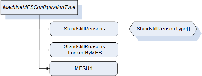
11 MachineMESConfigurationType
11.1 MachineMESConfigurationType Definition
This OPC UA ObjectType represents the current configuration of a machine related to a Manufacturing Execution System (MES). It is formally defined in Table 35.
| Attribute | Value | ||||
| BrowseName | MachineMESConfigurationType | ||||
| IsAbstract | False | ||||
| References | Node Class | BrowseName | DataType | TypeDefinition | Other |
|---|---|---|---|---|---|
| Subtype of 0:BaseObjectType defined in OPC UA Part 5 | |||||
| 0:HasProperty | Variable | StandstillReasons | StandstillReasonType[] | 0:PropertyType | M, RW |
| 0:HasProperty | Variable | StandstillReasonsLockedByMES | 0:Boolean | 0:PropertyType | M, RW |
| 0:HasProperty | Variable | MESUrl | 0:String | 0:PropertyType | O, RW |
11.2 StandstillReasons
The StandstillReasons Property represents an array with a list of the standstill reasons from which one is selected by the operator in the case of a standstill. The used StandstillReasonType is defined in Table 36.
| Name | Type | Description |
| StandstillReasonType | structure | Subtype of 0:Structure as defined in OPC UA 10000-3 |
Id | 0:String | Id of the standstill reason |
Text | 0:LocalizedText | Text of the standstill reason |
LockedByMES | 0:Boolean | LockedByMES means that this StandstillReason has been set or modified by the MES and so this may not be changed by the machine. |
StandstillReasons shall support at least 10 entries.
The MES shall be prepared, that the list includes standstill reasons not defined by the MES (e.g. added by the operator on the machine). The user of the interface shall ensure unique Ids among all standstill reasons. To ensure consistent statistics, a change of the meaning of already assigned standstill reasons should be avoided.
11.3 StandstillReasonsLockedByMES
The StandstillReasonsLockedByMES Property indicates if the list StandstillReasons has been modified by the MES and may not be changed by the machine.
11.4 MESUrl
The MESUrl Property represents a URL to display a webpage generated by the MES in a web browser integrated in the machine.
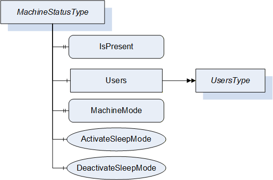
12 MachineStatusType
12.1 MachineStatusType Definition
This ObjectType represents the current status of a machine. It is formally defined in Table 37.
| Attribute | Value | ||||
| BrowseName | MachineStatusType | ||||
| IsAbstract | False | ||||
| References | Node Class | BrowseName | DataType | TypeDefinition | Other |
|---|---|---|---|---|---|
| Subtype of 0:BaseObjectType defined in OPC UA Part 5 | |||||
| 0:HasProperty | Variable | IsPresent | 0:Boolean | 0:PropertyType | M, RO |
| 0:HasComponent | Object | Users | UsersType | M | |
| 0:HasProperty | Variable | MachineMode | MachineModeEnumeration | 0:PropertyType | M, RO |
| 0:HasComponent | Method | ActivateSleepMode | O | ||
| 0:HasComponent | Method | DeactivateSleepMode | O | ||
12.2 IsPresent
This Property informs the client if the machine is physically present and connected. May be FALSE e.g. when an aggregation server is configured to provide data for several machines.
12.3 Users
This Object is a container for the user(s) of the machine. The UsersType itself is defined in chapter 13.1.
12.4 MachineMode
The MachineMode Property represents the current machine mode (as defined by mode selector on the machine). The MachineModeEnumeration is defined in Table 38:
| Name | Value | Description |
| OTHER | 0 | This state is used if none of the other states below apply. |
| AUTOMATIC | 1 | The machine is in automatic mode. |
| SEMI_AUTOMATIC | 2 | The machine is in semi-automatic mode. |
| MANUAL | 3 | The machine is in manual mode. |
| SETUP | 4 | The machine is in setup mode. |
| SLEEP | 5 | The machine is in sleep mode. Machine is still switched on, energy consumption reduced by e.g. reducing heating, switching drives off. Production is not possible. |
12.5 ActivateSleepMode, DeactivateSleepMode
These two Methods allow the client (e.g. MES) to activate or deactivate the sleep mode of the machine if provided.
Activation of sleep mode sets the MachineMode (see 12.4) to SLEEP_5.
Signatures
	ActivateSleepMode ();
	DeactivateSleepMode ();
The methods have no Input- or OutputArguments.
| Attribute | Value | ||||
| BrowseName | ActivateSleepMode | ||||
| References | Node Class | BrowseName | DataType | TypeDefinition | Modelling Rule |
|---|
| Attribute | Value | ||||
| BrowseName | DeactivateSleepMode | ||||
| References | Node Class | BrowseName | DataType | TypeDefinition | Modelling Rule |
|---|
13 Users
13.1 UsersType
This ObjectType is a container for the user(s). It is formally defined in Table 41.
| Attribute | Value | ||||
| BrowseName | UsersType | ||||
| IsAbstract | False | ||||
| References | Node Class | BrowseName | DataType | TypeDefinition | Other |
|---|---|---|---|---|---|
| Subtype of 0:BaseObjectType defined in OPC UA Part 5 | |||||
| 0:HasProperty | Variable | 0:NodeVersion | 0:String | 0:PropertyType | M, RO |
| 0:HasComponent | Object | User_<Nr> | UserType | OP | |
| 0:GeneratesEvent | ObjectType | 0:GeneralModelChangeEventType | |||
When instances for users are created, the BrowseNames shall be "User_<Nr>" (starting with 1).
13.2 UserType
The UserType represents information on the operator(s) of the machine. It is formally defined in Table 42.
| Attribute | Value | ||||
| BrowseName | UserType | ||||
| IsAbstract | False | ||||
| References | Node Class | BrowseName | DataType | TypeDefinition | Other |
|---|---|---|---|---|---|
| Subtype of 0:BaseObjectType defined in OPC UA Part 5 | |||||
| 0:HasProperty | Variable | Id | 0:String | 0:PropertyType | M, RO |
| 0:HasProperty | Variable | Name | 0:String | 0:PropertyType | M, RO |
| 0:HasProperty | Variable | IsPresent | 0:Boolean | 0:PropertyType | M, RO |
| 0:HasProperty | Variable | CardUid | 0:String | 0:PropertyType | O, RO |
| 0:HasProperty | Variable | UserLevel | 0:String | 0:PropertyType | O, RO |
| 0:HasProperty | Variable | UserRole | 0:String | 0:PropertyType | O, RO |
| 0:HasProperty | Variable | Language | LocaleId | 0:PropertyType | O, RO |
All fields may contain empty 0:Strings if not supported.
13.2.1 Id
The Id Property represent the Id of the user.
13.2.2 Name
The Name Property represent the Name of the user.
13.2.3 IsPresent
The machine can have instances for the maximum number of users that can be simultaneously logged in. TRUE if the instance of UserType represents a user that is currently logged in.
13.2.4 CardUid
This Property represents the Uid of the identification card used by the operator for logging in to the machine.
13.2.5 UserLevel
The UserLevel Property represent the level of the user (e.g. "1", "2"). The possible values are defined by the manufacturer of the machine.
13.2.6 UserRole
The UserRole Property represents the role of the user (e.g. "Administrator"). The possible values are defined by the manufacturer of the machine.
13.2.7 Language
The Language Property represents the currently selected language on the machine control unit. Indication of language with Language code = Alpha-3 (three-letter) code according to ISO 639-2/B and Country code = Alpha-2 (two-letter) code according to ISO 3166-1 (e.g. "eng-US")
14 MachineMESStatusType
14.1 MachineMESStatusType Definition
This ObjectType represents the current status of a machine related to the MES. It is formally defined in Table 43.
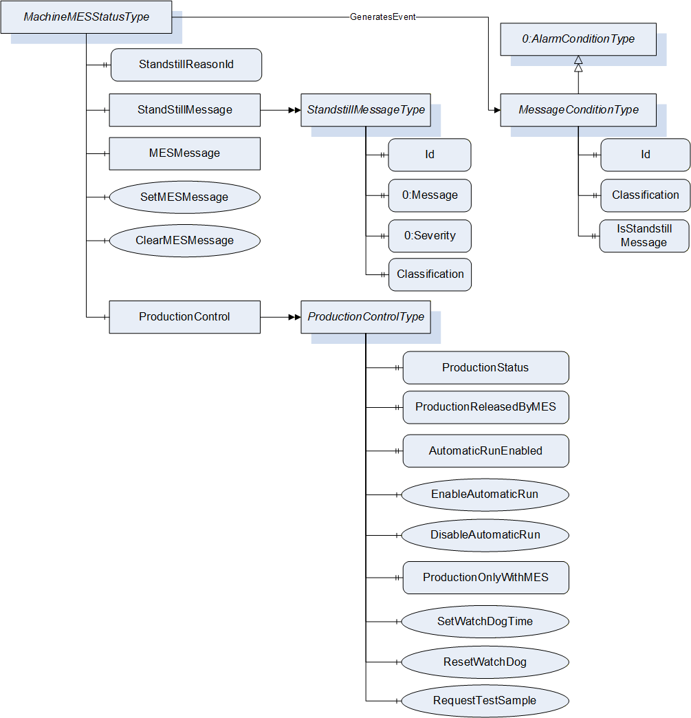
| Attribute | Value | ||||
| BrowseName | MachineMESStatusType | ||||
| IsAbstract | False | ||||
| References | Node Class | BrowseName | DataType | TypeDefinition | Other |
|---|---|---|---|---|---|
| Subtype of 0:BaseObjectType defined in OPC UA Part 5 | |||||
| 0:HasProperty | Variable | StandstillReasonId | 0:String | 0:PropertyType | M, RO |
| 0:HasComponent | Object | StandstillMessage | StandstillMessageType | M | |
| 0:HasComponent | Object | MESMessage | MESMessageType | M | |
| 0:HasComponent | Method | SetMESMessage | M | ||
| 0:HasComponent | Method | ClearMESMessage | M | ||
| 0:HasComponent | Object | ProductionControl | ProductionControlType | M | |
| GeneratesEvent | ObjectType | MessageConditionType | Defined in 14.8 | ||
14.2 StandstillReasonId
The StandstillReasonId Property represents the Id of the StandstillReason (see MachineConfiguration) set by the operator after a standstill occurs.
Default value: empty String (= no active standstill reason).
Set to an empty String by machine with starting of production.
14.3 StandstillMessage
The StandstillMessage Object represents the fault which causes standstill. This is set by machine control.
The StandstillMessageType is formally defined in Table 44.
| Attribute | Value | ||||
| BrowseName | StandstillMessageType | ||||
| IsAbstract | False | ||||
| References | Node Class | BrowseName | DataType | TypeDefinition | Other |
|---|---|---|---|---|---|
| Subtype of 0:BaseObjectType defined in OPC UA Part 5 | |||||
| 0:HasProperty | Variable | Id | 0:String | 0:PropertyType | M, RO |
| 0:HasProperty | Variable | 0:Message | 0:LocalizedText | 0:PropertyType | M, RO |
| 0:HasProperty | Variable | 0:Severity | 0:UInt16 | 0:PropertyType | M, RO |
| 0:HasProperty | Variable | Classification | 0:Enumeration | 0:PropertyType | M, RO |
Classification: Classification of the message. The valid values of the Enumeration are specified in the specific Companion Specification (e.g. IMMMessageClassificationEnumeration in OPC 40077).
If the machine is not in a standstill state, the values of the Properties shall be 0 or empty string.
14.4 MESMessage
The MESMessage Object represents a text message sent from the MES to be shown on the machine. The Properties of this Object shall only be set/changed by the MES OPC UA Client.
| Attribute | Value | |||||
| BrowseName | MESMessageType | |||||
| IsAbstract | False | |||||
| References | Node Class | BrowseName | DataType | TypeDefinition | Other | |
|---|---|---|---|---|---|---|
| Subtype of 0:BaseObjectType defined in OPC UA Part 5 | ||||||
| 0:HasProperty | Variable | Id | 0:String | 0:PropertyType | M, RO | |
| 0:HasProperty | Variable | Message | 0:String | 0:PropertyType | M, RO | |
| 0:HasProperty | Variable | 0:Severity | 0:UInt16 | 0:PropertyType | M, RO | |
14.5 SetMESMessage
Method for setting the MESMessage.
Signature
	SetMESMessage (
		[in]	0:String	Id
		[in]	0:String	Message
[in] 0:UInt16 Severity);| Argument | Description |
| Id | Id of the Message (can e.g. be used for automatic processing of the message) |
| Message | Text of Message |
| Severity | Severity as defined in the BaseEventType (1 = low - 1000 = high) |
| Attribute | Value | ||||
| BrowseName | SetMESMessage | ||||
| References | Node Class | BrowseName | DataType | TypeDefinition | Modelling Rule |
|---|---|---|---|---|---|
| 0:HasProperty | Variable | InputArguments | Argument[] | 0:PropertyType | Mandatory |
14.6 ClearMESMessage
Method for clearing the MESMessage. Calling this method sets the Properties Id and Message in MESMessage to empty string and Severity to 0.
Signature
ClearMESMessage ();The method has no Input- or OutputArguments.
| Attribute | Value | ||||
| BrowseName | ClearMESMessage | ||||
| References | Node Class | BrowseName | DataType | TypeDefinition | Modelling Rule |
|---|
14.7 ProductionControlType
The ProductionControl Object allows the MES to control the production of the machine. It is formally defined in Table 49.
| Attribute | Value | ||||
| BrowseName | ProductionControlType | ||||
| IsAbstract | False | ||||
| References | Node Class | BrowseName | DataType | TypeDefinition | Other |
|---|---|---|---|---|---|
| Subtype of 0:BaseObjectType defined in OPC UA Part 5 | |||||
| 0:HasProperty | Variable | ProductionStatus | ProductionStatusEnumeration | 0:PropertyType | M, RO |
| 0:HasProperty | Variable | ProductionReleasedByMES | 0:Boolean | 0:PropertyType | M, RW |
| 0:HasProperty | Variable | AutomaticRunEnabled | 0:Boolean | 0:PropertyType | M, RO |
| 0:HasComponent | Method | EnableAutomaticRun | M | ||
| 0:HasComponent | Method | DisableAutomaticRun | M | ||
| 0:HasProperty | Variable | ProductionOnlyWithMES | 0:Boolean | 0:PropertyType | O, RW |
| 0:HasComponent | Method | SetWatchDogTime | O | ||
| 0:HasComponent | Method | ResetWatchDog | O | ||
| 0:HasComponent | Method | RequestTestSample | O | ||
14.7.1 ProductionStatus
The ProductionStatus Property of DataType ProductionStatusEnumeration represents the production status when the machine is in automatic or semi-automatic mode. When the machine is in another mode, the value is not relevant (no production). The ProductionStatusEnumeration is formally defined in Table 50.
| Name | Value | Description |
| OTHER | 0 | This state is used if none of the other states below apply. |
| NO_PRODUCTION | 1 | The machine does not produce any parts/products. |
| START_UP | 2 | The machine is producing parts/products in the start-up phase. So the correct settings of the machines are not reached. |
| READY_FOR_PRODUCTION | 3 | The machine is producing parts/products, the correct settings of the machines are reached but the production is not yet released (e.g. waiting for release from quality assurance). |
| PRODUCTION | 4 | The machine is producing parts/products. In semi-automatic mode also during waiting time (e.g. for manual loading/unloading of parts) ProductionStatus remains in this state (time out possible if e.g. cycle time exceeds a pre-defined limit). |
| DRY_RUN | 5 | The machine is moving without material. |
The ProductionStatus is set by the machine/operator. The selection of the value PRODUCTION_4 can be prevented by the MES OPC UA client by setting ProductionReleasedByMES to FALSE.
14.7.2 ProductionReleasedByMES
The ProductionReleasedByMES Property indicates if ProductionStatus may have the value PRODUCTION_4. Default value is TRUE. If ProductionReleased is FALSE it also prevents that JobStatus (see 18.4.1) has the value JOB_IN_PRODUCTION_6.
If ProductionReleased is set from TRUE to FALSE when ProductionStatus has the value PRODUCTION_4, the value shall change to READY_FOR_PRODUCTION_3. If JobStatus has the value JOB_IN_PRODUCTION_6 it shall change to JOB_INTERRUPTED_7.
14.7.3 AutomaticRunEnabled, EnableAutomaticRun, DisableAutomaticRun
The AutomaticRunEnabled Property indicates if semi-automatic and automatic run of the machine is allowed by MES. If FALSE, the machine cannot start in semi-automatic or automatic mode.
The value is set to TRUE by the Method EnableAutomaticRun and to FALSE by the Method DisableAutomaticRun. The default value is TRUE.
Can e.g. be used if wrong mould is installed or to force the operator to enter a StandstillReason after machine stop.
If the machine is running in (semi-)automatic, a call of DisableAutomaticRun will stop the machine (if applicable at the end of the cycle). The machine should show a message to the operator why the machine has stopped.
Signatures
	EnableAutomaticRun ();
	DisableAutomaticRun ();
The methods have no Input- or OutputArguments.
| Attribute | Value | ||||
| BrowseName | EnableAutomaticRun | ||||
| References | Node Class | BrowseName | DataType | TypeDefinition | Modelling Rule |
|---|
| Attribute | Value | ||||
| BrowseName | DisableAutomaticRun | ||||
| References | Node Class | BrowseName | DataType | TypeDefinition | Modelling Rule |
|---|
14.7.4 ProductionOnlyWithMES
The optional Property ProductionOnlyWithMES indicates if production with the machine is only allowed when the MES is active. When ProductionOnlyWithMES is TRUE and the connection to the MES is lost, the machine may not have the ProductionStatus PRODUCTION_4 and not the JobStatus JOB_IN_PRODUCTION_6 (see 18.4.1).
The default value is FALSE.
Only one MES client shall write this Property.
14.7.5 SetWatchDogTime, ResetWatchDog
Some production jobs need 100% documentation of the production parameters. To ensure this, a WatchDog can be used. By setting the WatchDog time with the Method SetWatchDogTime the production is only released for the given time. The Method ResetWatchDog sets the timer to the value set by the last calling of SetWatchDogTime. This indicates to the machine that the MES is still connected and able to store the production parameters.
Only one MES client shall call these Methods to avoid overlapping.
When the defined time is exceeded without reset, the machine may not have the ProductionStatus PRODUCTION_4 and not the JobStatus JOB_IN_PRODUCTION_6 (see 18.4.1).
Signature
	SetWatchDogTime (
[in] 0:Int32 WatchDogTime);| Argument | Description |
| WatchDogTime | Time in seconds for which production is enabled by the watch dog |
Calling the method with WatchDogTime = -1 disables the watch dog and the machine can stay in production.
| Attribute | Value | ||||
| BrowseName | SetWatchDogTime | ||||
| References | Node Class | BrowseName | DataType | TypeDefinition | Modelling Rule |
|---|---|---|---|---|---|
| 0:HasProperty | Variable | InputArguments | Argument[] | 0:PropertyType | Mandatory |
Signature
ResetWatchDog ();The method has no Input- or OutputArguments.
| Attribute | Value | ||||
| BrowseName | ResetWatchDog | ||||
| References | Node Class | BrowseName | DataType | TypeDefinition | Modelling Rule |
|---|
14.7.6 RequestTestSample
The machine shall separate a test sample (e.g. for quality check). The size of the test sample depends on the product/machine configuration.
Signature
RequestTestSample ();The method has no Input- or OutputArguments.
| Attribute | Value | ||||
| BrowseName | RequestTestSample | ||||
| References | Node Class | BrowseName | DataType | TypeDefinition | Modelling Rule |
|---|
14.8 MessageConditionType
The MessageConditions represent text messages (incl. error messages) of the control system currently shown on the screen of the machine. The MessageConditionType is formally defined in Table 57.
| Attribute | Value | ||||
| BrowseName | MessageConditionType | ||||
| IsAbstract | False | ||||
| References | Node Class | BrowseName | DataType | TypeDefinition | Other |
|---|---|---|---|---|---|
| Subtype of 0:AlarmConditionType defined in OPC UA Part 9 | |||||
| 0:HasProperty | Variable | Id | 0:String | 0:PropertyType | M, RO |
| 0:HasProperty | Variable | Classification | 0:Enumeration | 0:PropertyType | M, RO |
| 0:HasProperty | Variable | IsStandstillMessage | 0:Boolean | 0:PropertyType | M, RO |
Id: Id of the message
Classification: Classification of the message. The valid values of the Enumeration are specified in the specific Companion Specification (e.g. IMMMessageClassificationEnumeration in OPC 40077).
IsStandstillMessage: Indication if the message has led to a standstill.
15 Moulds
15.1 MouldsType
This ObjectType is a container for the mould(s). It is formally defined in Table 58.
| Attribute | Value | ||||
| BrowseName | MouldsType | ||||
| IsAbstract | False | ||||
| References | Node Class | BrowseName | DataType | TypeDefinition | Other |
|---|---|---|---|---|---|
| Subtype of 0:BaseObjectType defined in OPC UA Part 5 | |||||
| 0:HasProperty | Variable | 0:NodeVersion | 0:String | 0:PropertyType | M, RO |
| 0:HasComponent | Object | Mould_<Nr> | MouldType | OP | |
| 0:GeneratesEvent | ObjectType | 0:GeneralModelChangeEventType | |||
When instances for moulds are created, the BrowseNames shall be "Mould_<Nr>" (starting with 1).
15.2 MouldType
15.2.1 MouldType Definition
This ObjectType represents the description and status of a mould (e.g. used in injection or blow moulding machines). It is formally defined in Table 59.
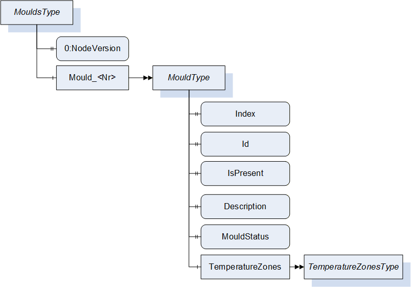
| Attribute | Value | ||||
| BrowseName | MouldType | ||||
| IsAbstract | False | ||||
| References | Node Class | BrowseName | DataType | TypeDefinition | Other |
|---|---|---|---|---|---|
| Subtype of BaseObjectType defined in OPC UA Part 5 | |||||
| 0:HasProperty | Variable | Index | 0:UInt32 | 0:PropertyType | M, RO |
| 0:HasProperty | Variable | Id | 0:String | 0:PropertyType | M, RO |
| 0:HasProperty | Variable | IsPresent | 0:Boolean | 0:PropertyType | M, RO |
| 0:HasProperty | Variable | Description | 0:String | 0:PropertyType | M, RO |
| 0:HasProperty | Variable | MouldStatus | MouldStatusEnumeration | 0:PropertyType | M, RO |
| 0:HasComponent | Object | TemperatureZones | TemperatureZonesType | MO | |
15.2.2 Index
The Index Property gives the number of the mould.
15.2.3 Id
The Id Property represents the Id of the installed mould. It is valid for a complete configuration of a mould incl. frames/inserts. If an insert is changed or deactivated, the mould gets a new Id.
15.2.4 IsPresent
This Property informs the client if the mould is physically present and connected. May be FALSE e.g. when instances for possible moulds are created (depending on the capabilities/connectors of the machine) which are currently not used.
15.2.5 Description
The Description Property represents a description of the installed mould.
15.2.6 MouldStatus
The MouldStatusProperty represents the current (physical) status of the mould related to the object instance. The MouldStatusEnumeration is defined in Table 60:
| Name | Value | Description |
| OTHER | 0 | This state is used if none of the other states below apply. |
| MOULD_NOT_INSTALLED | 1 | The mould is not installed on the machine. |
| MOULD_CHANGE | 2 | During installation or changing of the mould. |
| MOULD_INSTALLED | 3 | The mould is installed and ready for production. |
15.2.7 TemperatureZones
This Object is a container for the temperature zones of the mould zones. The TemperatureZonesType is formally defined in 17.1. Inside the container the MouldTemperatureZoneType as defined in 17.2.10.2 shall be used.
16 PowerUnits
16.1 PowerUnitsType
This ObjectType is a container for the power unit(s). It is formally defined in Table 61.
| Attribute | Value | ||||
| BrowseName | PowerUnitsType | ||||
| IsAbstract | False | ||||
| References | Node Class | BrowseName | DataType | TypeDefinition | Other |
|---|---|---|---|---|---|
| Subtype of 0:BaseObjectType defined in OPC UA Part 5 | |||||
| 0:HasProperty | Variable | 0:NodeVersion | 0:String | 0:PropertyType | M, RO |
| 0:HasComponent | Object | PowerUnit_<Nr> | PowerUnitType | OP | |
| 0:GeneratesEvent | ObjectType | 0:GeneralModelChangeEventType | |||
When instances for power units are created, the BrowseNames shall be "PowerUnit_<Nr>" (starting with 1).
16.2 PowerUnitType
16.2.1 PowerUnitType Definition
This ObjectType represents information on the hydraulic units and electric drives. It is formally defined in Table 62.
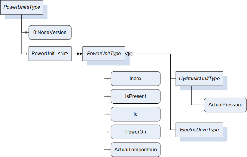
| Attribute | Value | ||||
| BrowseName | PowerUnitType | ||||
| IsAbstract | False | ||||
| References | Node Class | BrowseName | DataType | TypeDefinition | Other |
|---|---|---|---|---|---|
| Subtype of 0:BaseObjectType defined in OPC UA Part 5 | |||||
| 0:HasProperty | Variable | Index | 0:UInt32 | 0:PropertyType | M, RO |
| 0:HasProperty | Variable | IsPresent | 0:Boolean | 0:PropertyType | M, RO |
| 0:HasProperty | Variable | Id | 0:String | 0:PropertyType | M, RO |
| 0:HasProperty | Variable | PowerOn | 0:Boolean | 0:PropertyType | M, RO |
| 0:HasComponent | Variable | ActualTemperature | 0:Double | 0:AnalogItemType | O, RO |
| 0:HasSubtype | ObjectType | HydraulicUnitType | Defined in 16.2.7.1 | ||
| 0:HasSubtype | ObjectType | ElectricDriveType | Defined in 16.2.7.2 | ||
16.2.2 Index
The Index Property gives the number of the power unit.
16.2.3 IsPresent
This Property informs the client if the power unit is physically present and connected. May be FALSE e.g. when instances for possible power units are created (depending on the capabilities/connectors of the machine) which are currently not used.
16.2.4 Id
The Id Property represents the Id of the PowerUnit.
16.2.5 PowerOn
The PowerOn Property indicates if the PowerUnit is switched on.
16.2.6 ActualTemperature
The ActualTemperature Variable represents the current temperature of the PowerUnit.
16.2.7 Subtypes of PowerUnitType
There are two subtypes: HydraulicUnitType and ElectricDriveType.
16.2.7.1 HydraulicUnitType
| Attribute | Value | ||||
| BrowseName | HydraulicUnitType | ||||
| IsAbstract | False | ||||
| References | Node Class | BrowseName | DataType | TypeDefinition | Other |
|---|---|---|---|---|---|
| Subtype of PowerUnitType | |||||
| 0:HasComponent | Variable | ActualPressure | 0:Double | 0:AnalogItemType | O, RO |
The ActualPressure Variable represents the current pressure of the hydraulic unit.
16.2.7.2 ElectricDriveType
| Attribute | Value | ||||
| BrowseName | ElectricDriveType | ||||
| IsAbstract | False | ||||
| References | Node Class | BrowseName | DataType | TypeDefinition | Other |
|---|---|---|---|---|---|
| Subtype of PowerUnitType | |||||
This subtype has no additional child elements.
17 TemperatureZones
17.1 TemperatureZonesType
This ObjectType is a container for temperature zones. It is formally defined in Table 65.
| Attribute | Value | ||||
| BrowseName | TemperatureZonesType | ||||
| IsAbstract | False | ||||
| References | Node Class | BrowseName | DataType | TypeDefinition | Other |
|---|---|---|---|---|---|
| Subtype of 0:BaseObjectType defined in OPC UA Part 5 | |||||
| 0:HasProperty | Variable | 0:NodeVersion | 0:String | 0:PropertyType | M, RO |
| 0:HasComponent | Object | <TemperatureZone_Nr> | TemperatureZoneType | OP | |
| 0:GeneratesEvent | ObjectType | 0:GeneralModelChangeEventType | |||
When instances for temperature zones are created, the BrowseNames shall be "TemperatureZone_<Nr>" (starting with 1) or as specified for the subtypes of TemperatureZonesType (e.g. "BarrelTemperatureZone_<Nr>" for instances of BarrelTemperatureZoneType, see 17.2.10).
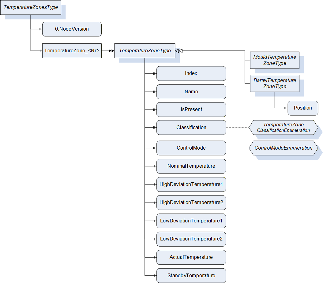
17.2 TemperatureZoneType
17.2.1 TemperatureZoneType Definition
This ObjectType represents a temperature zone e.g. on moulds and barrels. It is formally defined in Table 66.
| Attribute | Value | |||||
| BrowseName | TemperatureZoneType | |||||
| IsAbstract | False | |||||
| References | Node Class | BrowseName | DataType | TypeDefinition | Other | |
|---|---|---|---|---|---|---|
| Subtype of 0:BaseObjectType defined in OPC UA Part 5 | ||||||
| 0:HasProperty | Variable | Index | 0:UInt32 | 0:PropertyType | M, RO | |
| 0:HasProperty | Variable | Name | 0:String | 0:PropertyType | M, RO | |
| 0:HasProperty | Variable | IsPresent | 0:Boolean | 0:PropertyType | M, RO | |
| 0:HasProperty | Variable | Classification | TemperatureZone Classification Enumeration | 0:PropertyType | O, RO | |
| 0:HasProperty | Variable | ControlMode | ControlMode Enumeration | 0:PropertyType | M, RO | |
| 0:HasComponent | Variable | NominalTemperature | 0:Double | 0:AnalogItemType | M, RO | |
| 0:HasComponent | Variable | HighDeviationTemperature1 | 0:Double | 0:AnalogItemType | O, RO | |
| 0:HasComponent | Variable | HighDeviationTemperature2 | 0:Double | 0:AnalogItemType | O, RO | |
| 0:HasComponent | Variable | LowDeviationTemperature1 | 0:Double | 0:AnalogItemType | O, RO | |
| 0:HasComponent | Variable | LowDeviationTemperature2 | 0:Double | 0:AnalogItemType | O, RO | |
| 0:HasComponent | Variable | ActualTemperature | 0:Double | 0:AnalogItemType | M, RO | |
| 0:HasComponent | Variable | StandbyTemperature | 0:Double | 0:AnalogItemType | O, RO | |
| 0:HasSubtype | ObjectType | BarrelTemperatureZoneType | Defined in 17.2.10.1 | |||
| 0:HasSubtype | ObjectType | MouldTemperatureZoneType | Defined in 17.2.10.2 | |||
17.2.2 Index
The Index Property gives the number of the zone.
17.2.3 Name
The Name Property represents the name of the zone.
17.2.4 IsPresent
This Property informs the client if the temperature zone is physically present and connected. May be FALSE e.g. when instances for possible temperature zones are created (depending on the capabilities/connectors of the machine) which are currently not used.
17.2.5 Classification
This Property informs the client about the type of the temperature zone. The TemperatureZoneClassificationEnumeration is defined in Table 67.
| Name | Value | Description |
| OTHER | 0 | This value is used if none of the other values below apply. |
| HEATING | 1 | The zone is a heating zone |
| COOLING | 2 | The zone is a cooling zone |
| TEMPERATURE_CONTROL | 3 | The zone is controlled by a temperature control device |
| HOT_RUNNER | 4 | The zone is a hot runner zone |
| MEASURING | 5 | The zone has no heating or cooling, Only the temperature is measured. |
17.2.6 ControlMode
The ControlMode Property indicates how the temperature is currently controlled. The ControlModeEnumeration is defined in Table 68.
| Name | Value | Description |
| OTHER | 0 | This state is used if none of the other states below apply. |
| OFF | 1 | Control is switched off. |
| AUTOMATIC | 2 | The parameter is controlled automatically. |
| TUNING | 3 | Optimisation of the control circuit. |
| STANDBY | 4 | Parameter is controlled to stand by value. |
| OPEN_LOOP | 5 | Open loop control is used. |
| ONLY_MEASUREMENT | 6 | The sensors deliver the current value but there is no controlling. |
17.2.7 Temperatures
The following five temperatures for monitoring and controlling are defined:
| BrowseName | Description | Optional |
| NominalTemperature | Nominal value (absolute) (e.g. 200°C) | No |
| HighDeviationTemperature1 | Maximum value that is in the normal tolerance. A higher actual value may create a warning. Used for quality control. Relative value (e.g. +10°C). | Yes |
| LowDeviationTemperature1 | Minimum value that is in the normal tolerance. A lower actual value may create a warning. Used for quality control. Relative value (e.g. -15°C). | Yes |
| HighDeviationTemperature2 | Maximum tolerable value. A higher actual value may create an alarm. Relative value (e.g. +30°C). | Yes |
| LowDeviationTemperature2 | Minimum tolerable value. A lower actual value may create an alarm. Relative value (e.g. -25°C). | Yes |
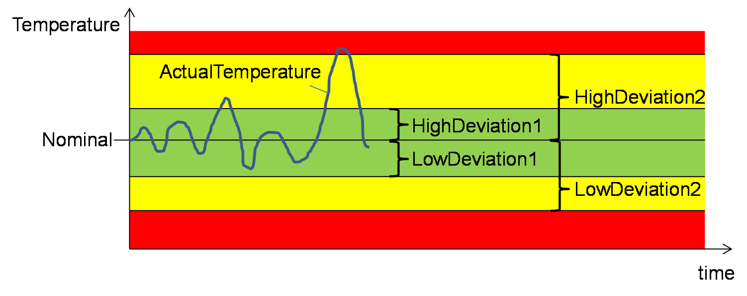
17.2.8 ActualTemperature
The ActualTemperature Property represents the current temperature of the Zone.
17.2.9 StandbyTemperature
The StandbyTemperature Property represents the standby temperature of the Zone.
17.2.10 Subtypes of TemperatureZoneType
The TemperatureZoneType has two subtypes to distinguish between temperature zones on barrels and in moulds.
17.2.10.1 BarrelTemperatureZoneType
| Attribute | Value | ||||
| BrowseName | BarrelTemperatureZoneType | ||||
| IsAbstract | False | ||||
| References | Node Class | BrowseName | DataType | TypeDefinition | Other |
|---|---|---|---|---|---|
| Subtype of TemperatureZoneType | |||||
| 0:HasProperty | Variable | Position | 0:UInt32 | 0:PropertyType | M, RO |
The Position Property represents the location of the temperature zone on a barrel. Counting starts with 1 beginning from the feeding. The highest position is at the nozzle.
When instances are created the BrowseNames shall be "BarrelTemperatureZone_<Nr>" (starting with 1).
17.2.10.2 MouldTemperatureZoneType
| Attribute | Value | ||||
| BrowseName | MouldTemperatureZoneType | ||||
| IsAbstract | False | ||||
| References | Node Class | BrowseName | DataType | TypeDefinition | Other |
|---|---|---|---|---|---|
| Subtype of TemperatureZoneType | |||||
The subtype has no additional child elements.
When instances are created the BrowseNames shall be "MouldTemperatureZone_<Nr>" (starting with 1).
18 JobsType
This clause defines ObjectsTypes for managing production jobs on the machine and for information on their status including process parameters (temperatures, pressures…).
18.1 JobsType Definition
This ObjectType represents the jobs (order to produce parts/process material) stored on the machine. It is formally defined in Table 72.
| Attribute | Value | ||||
| BrowseName | JobsType | ||||
| IsAbstract | False | ||||
| References | Node Class | BrowseName | DataType | TypeDefinition | Other |
|---|---|---|---|---|---|
| Subtype of 0:BaseObjectType defined in OPC UA Part 5 | |||||
| 0:HasComponent | Object | ActiveJob | JobInformationType | M | |
| 0:HasComponent | Object | JobInPreparation | JobInformationType | O | |
| 0:HasComponent | Method | SendJobList | O | ||
| 0:HasComponent | Method | SendCyclicJobList | O | ||
| 0:HasComponent | Object | ActiveJobValues | ActiveJobValuesType | M | |
| GeneratesEvent | ObjectType | RequestJobListEventType | Defined in 18.3.2 | ||
| GeneratesEvent | ObjectType | RequestCyclicJobListEventType | Defined in 18.3.4 | ||
ActiveJob represents the job that is currently active on the machine.
JobInPreparation represents a job that is in preparation. Background: Some manufacturers use two "layers" for job information in their control systems: one active information layer and one for preparation. So, during a running job, inputs for the following job are possible. By pressing a button on the control panel, data from the prepared job information can be set active.
ActiveJobValues represents the status of the current job. See 18.4.
SendJobList sends a list of jobs available on the client to the server. Can be triggered by the machine by the event RequestJobList (see 18.3.2). For cyclic processes SendCyclicJobList and RequestCyclicJobListEventType are used.
18.2 JobInformationType
18.2.1 JobInformationType Definition
This ObjectType represents the data of the job. It is formally defined in Table 73.
| Attribute | Value | ||||
| BrowseName | JobInformationType | ||||
| IsAbstract | True | ||||
| References | Node Class | BrowseName | DataType | TypeDefinition | Other |
|---|---|---|---|---|---|
| Subtype of 0:BaseObjectType defined in OPC UA Part 5 | |||||
| 0:HasProperty | Variable | JobName | 0:String | 0:PropertyType | M, RO |
| 0:HasProperty | Variable | JobDescription | 0:String | 0:PropertyType | M, RO |
| 0:HasProperty | Variable | CustomerName | 0:String | 0:PropertyType | M, RO |
| 0:HasProperty | Variable | ProductionDatasetName | 0:String | 0:PropertyType | M, RO |
| 0:HasProperty | Variable | ProductionDatasetDescription | 0:String | 0:PropertyType | M, RO |
| 0:HasProperty | Variable | Material | 0:String[] | 0:PropertyType | M, RO |
| 0:HasProperty | Variable | ProductName | 0:String[] | 0:PropertyType | M, RO |
| 0:HasProperty | Variable | ProductDescription | 0:String[] | 0:PropertyType | M, RO |
| 0:HasProperty | Variable | ContinueAtJobEnd | 0:Boolean | 0:PropertyType | M, RW |
| 0:HasSubtype | ObjectType | CyclicJobInformationType | |||
The JobInformationType is abstract. A derived concrete type, which includes a method for writing the Properties, must be used (e.g. CyclicJobInformationType).
18.2.2 JobName
The JobName Property represents the name of the job.
18.2.3 JobDescription
The JobDescription Property represents the description of the job.
18.2.4 CustomerName
The CustomerName Property represents the name of the customer for that the job is produced.
18.2.5 ProductionDatasetName
The ProductionDatasetName Property represents the name of the production dataset which is needed for the job.
18.2.6 ProductionDatasetDescription
The ProductionDatasetDescription Property includes an additional description of the production dataset which is needed for the job.
18.2.7 Material
The Material Property is an Array of material names used for the job.
18.2.8 ProductName
The ProductName Property is an Array of product names produced by the job. (More than one possible with multiple cavities)
18.2.9 ProductDescription
The ProductDescription Property is an Array of descriptions of the products produced by the job.
18.2.10 ContinueAtJobEnd
The ContinueAtJobEnd Property indicates if the machine continues the production even if the nominal output has been reached.
18.2.11 CyclicJobInformationType
Additional information on a job for cyclic production (e.g. injection moulding) are stored in the CyclicJobInformationType. It extends the JobInformationType. It is formally defined in Table 74.
| Attribute | Value | ||||
| BrowseName | CyclicJobInformationType | ||||
| IsAbstract | False | ||||
| References | Node Class | BrowseName | DataType | TypeDefinition | Other |
|---|---|---|---|---|---|
| Subtype of JobInformationType | |||||
| 0:HasProperty | Variable | NominalParts | 0:UInt64 | 0:PropertyType | M, RW |
| 0:HasProperty | Variable | NominalBoxParts | 0:UInt64 | 0:PropertyType | O, RW |
| 0:HasProperty | Variable | ExpectedCycleTime | 0:Duration | 0:PropertyType | O, RW |
| 0:HasProperty | Variable | MouldId | 0:String | 0:PropertyType | O, RO |
| 0:HasProperty | Variable | NumCavities | 0:UInt32 | 0:PropertyType | O, RO |
| 0:HasComponent | Method | SetCyclicJobData | M | ||
| GeneratesEvent | ObjectType | RequestCyclicJobWriteEventType | Defined in 18.2.11.7 | ||
18.2.11.1 NominalParts
The NominalParts Property indicates the total number (sum of all cavities) of parts that shall be produced by the job.
18.2.11.2 NominalBoxParts
In some productions, the parts are placed in several boxes. The NominalBoxParts Property indicates the number of parts that shall be put into one box.
18.2.11.3 ExpectedCycleTime
The ExpectedCycleTime Property indicates which cycle time is calculated for the job.
18.2.11.4 MouldId
The MouldId Property represents the Id of the Mould used for the job.
18.2.11.5 NumCavities
The NumCavities Property indicates the number of cavities in the Mould used for production.
18.2.11.6 SetCyclicJobData
With this Method the MES sets the job data for cyclic jobs.
Input arguments are all Properties of the CyclicJobInformationType.
Signature
	SetCyclicJobData (
		[in]	0:String	JobName
		[in]	0:String	JobDescription
		[in]	0:String	CustomerName
		[in]	0:String	ProductionDatasetName
		[in]	0:String	ProductionDatasetDescription
		[in]	0:String[]	Material
		[in]	0:String[]	ProductName
		[in]	0:String[]	ProductDescription
		[in]	0:Boolean	ContinueAtJobEnd
		[in]	0:UInt64	NominalParts
		[in]	0:UInt64	NominalBoxParts
		[in]	0:Duration	ExpectedCycleTime
		[in]	0:String	MouldId
		[in]	0:UInt32	NumCavities);
When optional Properties in CyclicJobInformationType (e.g. NominalBoxParts) are not used, the arguments have to be empty or equal to zero.
| Attribute | Value | ||||
| BrowseName | SetCyclicJobData | ||||
| References | Node Class | BrowseName | DataType | TypeDefinition | Modelling Rule |
|---|---|---|---|---|---|
| 0:HasProperty | Variable | InputArguments | Argument[] | 0:PropertyType | Mandatory |
18.2.11.7 RequestCyclicJobWrite
The Event RequestCyclicJobWriteEventType is used to initiate a call of the SetCyclicJobData Method by the client.
| Attribute | Value | ||||
| BrowseName | RequestCyclicJobWriteEventType | ||||
| IsAbstract | True | ||||
| References | Node Class | BrowseName | DataType | TypeDefinition | Modelling Rule |
|---|---|---|---|---|---|
| Subtype of 0:BaseEventType defined in OPC UA Part 5 | |||||
| 0:HasProperty | Variable | JobName | 0:String | 0:PropertyType | M |
18.3 Job Lists
The jobs for a machine can be planned in an MES. This clause defines methods and events to request and send a list of planned jobs.
18.3.1 SendJobList
This Method is used to send a list of jobs available on the client to the server. The server shall support to receive at least 10 jobs.
Signature
	SendJobList (
[in] JobListElementType[] JobList);| Argument | Description |
| JobList | Array of JobInformationType describing the available jobs in the client. |
| Attribute | Value | ||||
| BrowseName | SendJobList | ||||
| References | Node Class | BrowseName | DataType | TypeDefinition | Modelling Rule |
|---|---|---|---|---|---|
| 0:HasProperty | Variable | InputArguments | Argument[] | 0:PropertyType | Mandatory |
It is possible to call the Method without an InputArgument (length of the array JobList is zero) as an answer to the Event RequestJobList (see below), if no planned job is available.
The JobListElementType is defined in Table 79
| Name | Type | Description |
| JobListElementType | structure | Subtype of 0:Structure as defined in OPC UA 10000-3 |
JobName | 0:String | As defined in JobInformationType |
JobDescription | 0:String | |
JobClassification | 0:String | Classification of the job |
CustomerName | 0:String | As defined in JobInformationType |
ProductionDatasetName | 0:String | |
ProductionDatasetDescription | 0:String | |
Material | 0:String[] | |
ProductName | 0:String[] | |
ProductDescription | 0:String[] | |
JobPriority | 0:String | Priority of the job |
PlannedStart | 0:DateTime | Planned start of the job |
PlannedProductionTime | 0:Duration | Planned production time of the job |
LatestEnd | 0:DateTime | Latest end of the job |
The variables JobClassification, JobPriority, PlannedStart, PlannedProductionTime and LatestEnd are additional information only for the operator to be shown on the machine control. This may help the operator to decide which jobs to download/activate. PlannedStart and LatestEnd shall be given in UTC time.
The JobClassification can e.g. be used to present a maintenance job with planned time. The possible values are user dependent and not standardized by this specification.
18.3.2 RequestJobList
The instance of JobsType can fire an Event of RequestJobListEventType (without parameters) to initiate a call of SendJobList by the client. This can e.g. be triggered by an operator who wants to see the planned jobs for his machine.
| Attribute | Value | ||||
| BrowseName | RequestJobListEventType | ||||
| IsAbstract | True | ||||
| References | Node Class | BrowseName | DataType | TypeDefinition | Other |
|---|---|---|---|---|---|
| Subtype of 0:BaseEventType defined in OPC UA Part 5 | |||||
18.3.3 SendCyclicJobList
This Method is used instead of SendJobList in the case of cyclic production and includes the input parameters ExpectedCycleTime, NominalParts and NominalBoxParts.
Signature
	SendCyclicJobList (
[in] CyclicJobListElementType[] JobList);| Argument | Description |
| JobList | Array of CyclicJobInformationType describing the available cyclic jobs in the client. |
| Attribute | Value | ||||
| BrowseName | SendCyclicJobList | ||||
| References | Node Class | BrowseName | DataType | TypeDefinition | Modelling Rule |
|---|---|---|---|---|---|
| 0:HasProperty | Variable | InputArguments | Argument[] | 0:PropertyType | Mandatory |
It is possible to call the Method without an InputArgument (length of the array JobList is zero) as an answer to the Event RequestCyclicJobList (see below), if no planned job is available.
The CyclicJobListElementType is a subtype of JobListElementType and adds the elements defined in Table 83.
| Name | Type | Description |
| CyclicJobListElementType | structure | Subtype of JobListElementType |
NominalParts | 0:UInt64 | As defined in CyclicJobInformationType |
NominalBoxParts | 0:UInt64 | |
ExpectedCycleTime | 0:Duration | |
MouldId | 0:String | |
NumCavities | 0:UInt32 |
NominalBoxParts, MouldId and NumCavities may be empty or zero if not used.
18.3.4 RequestCyclicJobList
The instance of JobsType can fire an Event of RequestCyclicJobListEventType (without parameters) to initiate a call of SendCyclicJobList by the client. This can e.g. be triggered by an operator who wants to see the planned jobs for his machine.
| Attribute | Value | ||||
| BrowseName | RequestCyclicJobListEventType | ||||
| IsAbstract | True | ||||
| References | Node Class | BrowseName | DataType | TypeDefinition | Other |
|---|---|---|---|---|---|
| Subtype of 0:BaseEventType defined in OPC UA Part 5 | |||||
18.4 ActiveJobValuesType
This ObjectType represents values of the active job. It is formally defined in Table 85.
| Attribute | Value | ||||
| BrowseName | ActiveJobValuesType | ||||
| IsAbstract | False | ||||
| References | Node Class | BrowseName | DataType | TypeDefinition | Other |
|---|---|---|---|---|---|
| Subtype of 0:BaseObjectType defined in OPC UA Part 5 | |||||
| 0:HasProperty | Variable | JobStatus | JobStatusEnumeration | 0:PropertyType | M, RO |
| 0:HasComponent | Method | StartJob | M | ||
| 0:HasComponent | Method | InterruptJob | M | ||
| 0:HasComponent | Method | FinishJob | M | ||
| 0:HasProperty | Variable | CurrentLotName | 0:String | 0:PropertyType | M, RW |
| 0:HasProperty | Variable | BoxId | 0:String | 0:PropertyType | O, RW |
| 0:HasSubtype | ObjectType | ActiveCyclicJobValuesType | |||
18.4.1 JobStatus
The JobStatus Property represents the current status of the job.
| Name | Value | Description |
| OTHER | 0 | This state is used if none of the other states below apply. Set by operator. |
| TRANSFERRED_ASSIGNED | 1 | The job has been transferred to the machine and assigned as current job. |
| SET_UP_ACTIVE | 2 | The operator prepares the machine for the job. |
| SET_UP_INTERRUPTED | 3 | The operator has interrupted but not finished the preparation of the machine for the job. |
| SET_UP_FINISHED | 4 | The operator has finished the preparation of the machine for the job. |
| START_UP_ACTIVE | 5 | The operator is setting the machine in the start-up phase. |
| JOB_IN_PRODUCTION | 6 | The machine is producing parts/products for the job. |
| JOB_INTERRUPTED | 7 | The job is interrupted. The nominal output is not reached. |
| JOB_FINISHED | 8 | Nominal output reached. |
| TEAR_DOWN_ACTIVE | 9 | The operator tears the machine down. |
| TEAR_DOWN_INTERRUPTED | 10 | Tear-down is interrupted but not finished. |
| TEAR_DOWN_FINISHED | 11 | Tear-down is finished. |
The JobStatus is set by the machine/operator. This can be triggered by the methods StartJob, InterruptJob and FinishJob. The selection of the value JOB_IN_PRODUCTION_6 can be prevented by the client by setting ProductionReleased to FALSE (see 14.7.2).
18.4.2 StartJob
With this Method the client (e.g. MES) request the machine to change the JobStatus to JOB_IN_PRODUCTION_6. The following produced parts/products are counted for the job.
Signature
StartJob ();The method has no Input- or OutputArguments.
| Attribute | Value | ||||
| BrowseName | StartJob | ||||
| References | Node Class | BrowseName | DataType | TypeDefinition | Modelling Rule |
|---|
18.4.3 InterruptJob
With this Method the client (e.g. MES) requests the machine to change the JobStatus to JOB_INTERRUPTED_7. The following produced parts/products are not counted for the job.
Signature
InterruptJob ();The method has no Input- or OutputArguments.
| Attribute | Value | ||||
| BrowseName | InterruptJob | ||||
| References | Node Class | BrowseName | DataType | TypeDefinition | Modelling Rule |
|---|
18.4.4 FinishJob
With this Method the client (e.g. MES) requests the machine to change the JobStatus to JOB_FINISHED_8. If ContinueAtJobEnd (see 18.2.10) is FALSE, the machine stops. Otherwise a message to the operator shall be shown on the machine.
Signature
FinishJob ();The method has no Input- or OutputArguments.
| Attribute | Value | ||||
| BrowseName | FinishJob | ||||
| References | Node Class | BrowseName | DataType | TypeDefinition | Modelling Rule |
|---|
18.4.5 CurrentLotName
The CurrentLotName Property represents the current production lot. Although the modelling rule is mandatory, the 0:String can be empty.
18.4.6 BoxId
The BoxId Property represents the Id of the box in which the current production is put in.
18.4.7 ActiveCyclicJobValuesType
Additional information on the running job for cyclic production (e.g. injection moulding) is stored in the ActiveCyclicJobValuesType. It extends the ActiveJobValuesType. It is formally defined in Table 90.
| Attribute | Value | ||||
| BrowseName | ActiveCyclicJobValuesType | ||||
| IsAbstract | False | ||||
| References | Node Class | BrowseName | DataType | TypeDefinition | Other |
|---|---|---|---|---|---|
| Subtype of ActiveJobValuesType | |||||
| 0:HasComponent | Variable | JobCycleCounter | 0:UInt64 | 0:BaseDataVariableType | M, RO |
| 0:HasComponent | Variable | BoxCycleCounter | 0:UInt64 | 0:BaseDataVariableType | O, RO |
| 0:HasComponent | Variable | MachineCycleCounter | 0:UInt64 | 0:BaseDataVariableType | O, RO |
| 0:HasComponent | Variable | LastCycleTime | 0:Duration | 0:BaseDataVariableType | M, RO |
| 0:HasComponent | Variable | AverageCycleTime | 0:Duration | 0:BaseDataVariableType | O, RO |
| 0:HasComponent | Variable | JobPartsCounter | 0:UInt64 | 0:BaseDataVariableType | M, RO |
| 0:HasComponent | Variable | JobGoodPartsCounter | 0:UInt64 | 0:BaseDataVariableType | M, RO |
| 0:HasComponent | Variable | JobBadPartsCounter | 0:UInt64 | 0:BaseDataVariableType | M, RO |
| 0:HasComponent | Variable | JobTestSamplesCounter | 0:UInt64 | 0:BaseDataVariableType | M, RO |
| 0:HasComponent | Variable | BoxPartsCounter | 0:UInt64 | 0:BaseDataVariableType | O, RO |
| 0:HasComponent | Variable | BoxGoodPartsCounter | 0:UInt64 | 0:BaseDataVariableType | O, RO |
| 0:HasComponent | Variable | BoxBadPartsCounter | 0:UInt64 | 0:BaseDataVariableType | O, RO |
| 0:HasComponent | Variable | BoxTestSamplesCounter | 0:UInt64 | 0:BaseDataVariableType | O, RO |
| 0:HasComponent | Variable | LastPartId | 0:String[] | 0:BaseDataVariableType | O, RO |
| 0:HasComponent | Method | StopAtCycleEnd | M | ||
| 0:HasComponent | Method | ResetJobCounters | M | ||
| 0:HasComponent | Method | ResetBoxCounters | O | ||
| 0:HasComponent | Method | ResetAverageCycleTime | O | ||
18.4.7.1 JobCycleCounter
The JobCycleCounter Variable represents the number of finished cycles in the job.
18.4.7.2 BoxCycleCounter
The BoxCycleCounter Variable represents the number of finished cycles for the current box.
18.4.7.3 MachineCycleCounter
The MachineCycleCounter Variable represents the number of finished cycles in the machine life time.
18.4.7.4 LastCycleTime
The LastCycleTime Variable represents the cycle time (duration in milliseconds) of the recently finished cycle.
18.4.7.5 AverageCycleTime
The AverageCycleTime Variable represents the average cycle time. The calculation starts from the last calling of ResetActiveJobAverageCycleTime.
18.4.7.6 JobPartsCounter, JobGoodPartsCounter, JobBadPartsCounter, JobTestSamplesCounter
These Variables represent the total number of produced parts and the numbers of good, bad and test sample parts in the current job.
18.4.7.7 BoxPartsCounter, BoxGoodPartsCounter, BoxBadPartsCounter, BoxTestSamplesCounter
These Variables represent the total number of produced parts and the numbers of good, bad and test sample parts in the current box.
18.4.7.8 LastPartId
The LastPartId Variable is an array and represents the Ids of the parts produced in the recently finished cycle.
18.4.7.9 StopAtCycleEnd
With this Method, the MES directs the machine to stop at the end of the current cycle.
Signature
StopAtCycleEnd ();The method has no Input- or OutputArguments.
| Attribute | Value | ||||
| BrowseName | StopAtCycleEnd | ||||
| References | Node Class | BrowseName | DataType | TypeDefinition | Modelling Rule |
|---|
18.4.7.10 ResetJobCounters
Method for setting the cycle and parts counters for the job to 0.
Signature
ResetJobCounters ();The method has no Input- or OutputArguments.
| Attribute | Value | ||||
| BrowseName | ResetJobCounters | ||||
| References | Node Class | BrowseName | DataType | TypeDefinition | Modelling Rule |
|---|
18.4.7.11 ResetBoxCounters
Method for setting the cycle and parts counters for the current box to 0.
Signature
ResetBoxCounters ();The method has no Input- or OutputArguments.
| Attribute | Value | ||||
| BrowseName | ResetBoxCounters | ||||
| References | Node Class | BrowseName | DataType | TypeDefinition | Modelling Rule |
|---|
18.4.7.12 ResetAverageCycleTime
This Method initiates a new calculation of the average cycle time for the job.
Signature
ResetAverageCycleTime ();The method has no Input- or OutputArguments.
| Attribute | Value | ||||
| BrowseName | ResetAverageCycleTime | ||||
| References | Node Class | BrowseName | DataType | TypeDefinition | Modelling Rule |
|---|
19 CycleParametersEventType
The CycleParametersEventType represents information on a production cycle. It is fired after each finished cycle of the machine (this can be different from quality checks by downstream equipment).
The EventSource is the root node of the interface (e.g. instance of IMM_MES_InterfaceType for OPC 40077).
The CycleParametersEventType is formally defined in Table 95.
| Attribute | Value | ||||
| BrowseName | CycleParametersEventType | ||||
| IsAbstract | True | ||||
| References | Node Class | BrowseName | DataType | TypeDefinition | Other |
|---|---|---|---|---|---|
| Subtype of 0:BaseEventType defined in OPC UA Part 5 | |||||
| 0:HasProperty | Variable | JobName | 0:String | 0:PropertyType | M |
| 0:HasProperty | Variable | JobStatus | JobStatusEnumeration | 0:PropertyType | M |
| 0:HasProperty | Variable | CurrentLotName | 0:String | 0:PropertyType | M |
| 0:HasProperty | Variable | BoxId | 0:String | 0:PropertyType | O |
| 0:HasProperty | Variable | JobCycleCounter | 0:UInt64 | 0:PropertyType | M |
| 0:HasProperty | Variable | BoxCycleCounter | 0:UInt64 | 0:PropertyType | O |
| 0:HasProperty | Variable | MachineCycleCounter | 0:UInt64 | 0:PropertyType | O |
| 0:HasProperty | Variable | CycleTime | 0:Duration | 0:PropertyType | M |
| 0:HasProperty | Variable | AverageCycleTime | 0:Duration | 0:PropertyType | O |
| 0:HasProperty | Variable | JobPartsCounter | 0:UInt64 | 0:PropertyType | M |
| 0:HasProperty | Variable | JobGoodPartsCounter | 0:UInt64 | 0:PropertyType | M |
| 0:HasProperty | Variable | JobBadPartsCounter | 0:UInt64 | 0:PropertyType | M |
| 0:HasProperty | Variable | JobTestSamplesCounter | 0:UInt64 | 0:PropertyType | M |
| 0:HasProperty | Variable | BoxPartsCounter | 0:UInt64 | 0:PropertyType | O |
| 0:HasProperty | Variable | BoxGoodPartsCounter | 0:UInt64 | 0:PropertyType | O |
| 0:HasProperty | Variable | BoxBadPartsCounter | 0:UInt64 | 0:PropertyType | O |
| 0:HasProperty | Variable | BoxTestSamplesCounter | 0:UInt64 | 0:PropertyType | O |
| 0:HasProperty | Variable | CycleQuality | CycleQualityEnumeration | 0:PropertyType | M |
| 0:HasProperty | Variable | CavityCycleQuality | CavityCycleQualityEnumeration[] | 0:PropertyType | O |
| 0:HasProperty | Variable | PartId | 0:String [] | 0:PropertyType | O |
The CycleParametersEventType can be extended to include additional information. For this, a new subtype shall be derived in the OPC Server of the machine (Note: the namespace of the derived Type is then the Local Server URI with namespace index 1 or a vendor specific namespace with vendor specific index). The specifications for specific machines provide some standardized ObjectTypes that can be included (e.g. MouldCycleParametersType as defined in 19.14, InjectionUnitCycleParametersType as defined in OPC 40077).
19.1 JobName
The JobName Property represents the name of the job.
19.2 JobStatus
The JobStatus Property represents the current status of the job (see18.4.1).
19.3 CurrentLotName
The CurrentLotName Property represents the current production lot.
19.4 BoxId
The BoxId Property represents the Id of the box in which the current production is put in.
19.5 CycleCounter
The CycleCounter Property represents the number of the cycle in the job.
19.6 MachineCycleCounter
The MachineCycleCounter Property represents the number of finished cycles in the machine life time.
19.7 CycleTime
The CycleTime Variable represents the cycle time.
19.8 AverageCycleTime
The AverageCycleTime Variable represents the average cycle time. The calculation starts from the last calling of ResetActiveJobAverageCycleTime.
19.9 JobPartsCounter, JobGoodPartsCounter, JobBadPartsCounter, JobTestSamplesCounter
These Properties represent the total number of produced parts and the numbers of good, bad and test sample parts in the current job.
19.10 BoxPartsCounter, BoxGoodPartsCounter, BoxBadPartsCounter, BoxTestSamplesCounter
These Properties represent the total number of produced parts and the numbers of good, bad and test sample parts in the current box.
19.11 CycleQuality
The CycleQuality Property gives information on the quality of the whole cycle. The CycleQualityEnumeration is defined in Table 96.
| Name | Value | Description |
| GOOD_CYCLE | 0 | The machine has detected no failures during the cycle and the part quality (for all cavities) is assumed as good. |
| BAD_CYCLE | 1 | The quality of the part(s) is assumed as bad. If the machine is able to evaluate the cycle quality of each cavity, detailed information can be given in the CavityCycleQuality Property. Nevertheless, already a bad part in only one cavity leads to a BAD_CYCLE value for the CycleQuality. |
| TEST_SAMPLE_CYCLE | 2 | A cycle is separated as a test sample. Triggered by operator or MES. |
| FAILED_CYCLE | 3 | The machine has detected failures during the cycle and the part quality is assumed as bad. Further information is provided by the MessageCondition fired in this case. |
19.12 CavityCycleQuality
The CavityCycleQuality Property gives information on the quality of the cycle for each cavity if the machine is able to evaluate this.
| Name | Value | Description |
| NO_PART | 0 | There is no part in cavity. |
| GOOD_PART | 1 | The machine has detected no failures during the cycle for this cavity and the part quality is assumed as good. |
| BAD_PART | 2 | The machine has detected failures during the cycle for the cavity and the part quality is assumed as bad. |
| REWORK | 3 | The machine has detected failures during the cycle for the cavity which might be fixed by reworking the part |
19.13 PartId
The PartId Property is an array and represents the Ids of the parts produced in the cycle.
19.14 MouldCycleParametersType
The MouldCycleParametersType represents information on the production cycle related to a mould (mainly temperatures). As the number of moulds and the related temperature zones are varying, the EventType for the cycle parameters has to be derived from CycleParametersEventType by the OPC Server of the machine (Note: the namespace of the derived Type is then the Local Server URI with namespace index 1 or a vendor specific namespace with vendor specific index). When the MouldCycleParametersType is used, the BrowseNames of the additional objects shall be "MouldCycleParameters_<Nr>" (starting with 1)
| Attribute | Value | ||||
| BrowseName | ExampleCycleParametersEventType | ||||
| IsAbstract | False | ||||
| References | Node Class | BrowseName | DataType | TypeDefinition | Other |
|---|---|---|---|---|---|
| Subtype of CycleParametersEventType | |||||
| 0:HasComponent | Object | MouldCycleParameters_1 | Example1MouldCycle ParametersType | M | |
| 0:HasComponent | Object | MouldCycleParameters_2 | Example2MouldCycle ParametersType | M | |
The Types Example1MouldCycleParametersType and Example2MouldCycleParametersType used in the example are subtypes of the MouldCycleParametersType which is formally defined in Table 99.
| Attribute | Value | ||||
| BrowseName | MouldCycleParametersType | ||||
| IsAbstract | True | ||||
| References | Node Class | BrowseName | DataType | TypeDefinition | Other |
|---|---|---|---|---|---|
| Subtype of 0:BaseObjectType defined in OPC UA Part 5 | |||||
| 0:HasProperty | Variable | Index | 0:UInt32 | 0:PropertyType | M, RO |
The MouldCycleParametersType is abstract and the OPC server of the machine shall create a derived type with the additional instances of TemperatureZoneCycleParametersType for the temperature zones of the mould. The BrowseNames of the objects shall be "MouldTemperatureZone_<Nr>" (starting with 1 for each mould).
| Attribute | Value | ||||
| BrowseName | Example1MouldCycleParametersType | ||||
| IsAbstract | False | ||||
| References | Node Class | BrowseName | DataType | TypeDefinition | Other |
|---|---|---|---|---|---|
| Subtype of MouldCycleParametersType | |||||
| 0:HasComponent | Object | MouldTemperatureZone_1 | TemperatureZoneCycleParametersType | M | |
| 0:HasComponent | Object | MouldTemperatureZone_2 | TemperatureZoneCycleParametersType | M | |
| 0:HasComponent | Object | MouldTemperatureZone_3 | TemperatureZoneCycleParametersType | M | |
| 0:HasComponent | Object | MouldTemperatureZone_4 | TemperatureZoneCycleParametersType | M | |
19.15 TemperatureZoneCycleParametersType
This ObjectType is used for the temperatures in barrel and mould zones. When instances are created, the BrowseNames shall be "BarrelTemperatureZoneCycleParameters_<Nr>", respectively "MouldTemperatureZone_<Nr>" (starting with 1).
The TemperatureZoneCycleParametersEventType is formally defined in Table 101.
| Attribute | Value | ||||
| BrowseName | TemperatureZoneCycleParametersType | ||||
| IsAbstract | False | ||||
| References | Node Class | BrowseName | DataType | TypeDefinition | Other |
|---|---|---|---|---|---|
| Subtype of 0:BaseObjectType defined in OPC UA Part 5 | |||||
| 0:HasProperty | Variable | Index | 0:UInt32 | 0:PropertyType | M |
| 0:HasProperty | Variable | Name | 0:String | 0:PropertyType | M |
| 0:HasProperty | Variable | Classification | TemperatureZone ClassificationEnumeration | 0:PropertyType | O, RO |
| 0:HasComponent | Variable | ActualTemperature | 0:Double | 0:AnalogItemType | M |
The Index Property gives the number of the zone.
The Name Property represents the name of the zone.
The Classification Property represents the type of the zone. The TemperatureZoneClassificationEnumeration is defined in 17.2.5.
The ActualTemperature Variable represents the current temperature of the zone.
20 ProductionDatasetManagementType
20.1 General
Production datasets are used for the configuration of machines. They are stored in files which can be exchanged over the network (e.g. between a machine and MES). This chapter defines methods and events for the exchange of lists of available production datasets and for the transfer of the files themselves.
20.2 ProductionDatasetManagementType Definition
This ObjectType is a container for the functionalities related to the listing and exchange of production datasets. It is formally defined in Table 102.
| Attribute | Value | ||||
| BrowseName | ProductionDatasetManagementType | ||||
| IsAbstract | False | ||||
| References | Node Class | BrowseName | DataType | TypeDefinition | Other |
|---|---|---|---|---|---|
| Subtype of 0:BaseObjectType defined in OPC UA Part 5 | |||||
| 0:HasComponent | Object | ActiveProductionDatasetStatus | ProductionDatasetStatusType | M | |
| 0:HasComponent | Object | ProductionDatasetInPreparationStatus | ProductionDatasetStatusType | O | |
| 0:HasComponent | Object | ProductionDatasetLists | ProductionDatasetListsType | O | |
| 0:HasComponent | Object | ProductionDatasetTransfer | TemporaryFileTransferType | M | |
| 0:HasComponent | Method | GetProductionDatasetInformation | O | ||
| 0:HasComponent | Method | SendProductionDatasetInformation | O | ||
20.3 ProductionDatasetStatusType
20.3.1 ActiveProductionDatasetStatus, ProductionDatasetInPreparationStatus
This Object represents the status of the production dataset which is active in the control system of the machine or in preparation (in analogy to ActiveJob and JobInPreparation). The ProductionDatasetStatusType is formally defined in Table 103.
| Attribute | Value | ||||
| BrowseName | ProductionDatasetStatusType | ||||
| IsAbstract | False | ||||
| References | Node Class | BrowseName | DataType | TypeDefinition | Other |
|---|---|---|---|---|---|
| Subtype of 0:BaseObjectType defined in OPC UA Part 5 | |||||
| 0:HasProperty | Variable | Information | ProductionDatasetInformationType | 0:PropertyType | M, RO |
| 0:HasProperty | Variable | Modified | 0:Boolean | 0:PropertyType | O, RO |
| 0:HasProperty | Variable | Frozen | 0:Boolean | 0:PropertyType | O, RW |
| 0:HasComponent | Method | Load | O | ||
| 0:HasComponent | Method | Save | O | ||
20.3.2 Information
The Information Property represents a set of information on the production dataset.
20.3.3 Modified
The Modified Property informs if the production dataset has been changed after the last storage.
20.3.4 Frozen
The Frozen Property indicates whether changes in the production dataset are not allowed. If TRUE, no changes on the machine in the production dataset (change of process parameters) are allowed.
20.3.5 Load
The Method Load loads a production dataset from the file system of the machine to the control of the machine. As production datasets can contain parameter settings not only for the machine itself but also for peripheral equipment (e.g. robots/handling devices), the parts of the production dataset which shall be activated can be chosen.
Signature
	Load (
		[in]	0:String	Name
[in] 0:UInt16[] Components);| Argument | Description |
| Name | Name of the production dataset that should be loaded. |
| Components | Indication which parts of the production dataset shall be activated. See Table 115 for possible values If Components is not given (array length 0) then the complete Production dataset is activated. |
| Attribute | Value | ||||
| BrowseName | Load | ||||
| References | Node Class | BrowseName | DataType | TypeDefinition | Modelling Rule |
|---|---|---|---|---|---|
| 0:HasProperty | Variable | InputArguments | Argument[] | 0:PropertyType | Mandatory |
20.3.6 Save
The Method Save stores a production dataset from the control of the machine to the file system of the machine.
Signature
	Save (
[in] 0:String Name);| Argument | Description |
| Name | Name under which the production dataset that should be stored in the file system. |
| Attribute | Value | ||||
| BrowseName | Save | ||||
| References | Node Class | BrowseName | DataType | TypeDefinition | Modelling Rule |
|---|---|---|---|---|---|
| 0:HasProperty | Variable | InputArguments | Argument[] | 0:PropertyType | Mandatory |
20.4 ProductionDatasetLists
The Object ProductionDatasetLists is used to exchange information on the available production datasets on client and server.
| Attribute | Value | ||||
| BrowseName | ProductionDatasetListsType | ||||
| IsAbstract | False | ||||
| References | Node Class | BrowseName | DataType | TypeDefinition | Other |
|---|---|---|---|---|---|
| Subtype of 0:BaseObjectType defined in OPC UA Part 5 | |||||
| 0:HasComponent | Method | GetProductionDatasetList | M | ||
| 0:HasComponent | Method | SendProductionDatasetList | M | ||
| GeneratesEvent | ObjectType | RequestProductionDatasetListEventType | Defined in 20.4.3 | ||
The Object ProductionDatasetLists can fire an Event RequestProductionDatasetList to initiate a call of SendProductionDataList by the MES.
20.4.1 GetProductionDatasetList
This Method is used to read a list from the server which production datasets are available on the machine's file system (e.g. for a check before an activation or transfer of a production dataset is initiated). The NameFilter and MouldId can be used to reduce the length of the list or for a targeted search.
Signature
	GetProductionDatasetList (
		[in]	0:String	NameFilter
		[in]	0:String	MouldId
[out] ProductionDatasetInformationType[] ProductionDatasetList);| Argument | Description |
| NameFilter | The Filter can be used to reduce the length of the list or for a targeted search. The wildcards "*" and "?" may be used. NameFilter = "" requests a lists of all available production datasets, NameFilter = "300" requests only information on the production dataset with ProductionDatasetName "300" (if available), NameFilter = "3*" requests information on production datasets with a ProductionDatasetName starting with "3" (e.g. "300", "301", …). |
| MouldId | If MouldId<>"" only production datasets for the given MouldId are requested. |
| ProductionDatasetList | Array of ProductionDatasetInformationType (see 20.4.4) describing the available production datasets on the server. |
| Attribute | Value | ||||
| BrowseName | GetProductionDatasetList | ||||
| References | Node Class | BrowseName | DataType | TypeDefinition | Modelling Rule |
|---|---|---|---|---|---|
| 0:HasProperty | Variable | InputArguments | Argument[] | 0:PropertyType | Mandatory |
| 0:HasProperty | Variable | OutputArguments | Argument[] | 0:PropertyType | Mandatory |
20.4.2 SendProductionDatasetList
This Method is used to send a list of production datasets available on the client to the server.
Signature
	SendProductionDatasetList (
[in] ProductionDatasetInformationType[] ProductionDatasetList);| Argument | Description |
| ProductionDatasetList | Array of ProductionDatasetInformationType describing the available production datasets in the MES. |
| Attribute | Value | ||||
| BrowseName | SendProductionDatasetList | ||||
| References | Node Class | BrowseName | DataType | TypeDefinition | Modelling Rule |
|---|---|---|---|---|---|
| 0:HasProperty | Variable | InputArguments | Argument[] | 0:PropertyType | Mandatory |
It is possible to call the Method without an InputArgument (length of the array ProductionDatasetList is zero) as an answer to the Event RequestProductionDatasetList (see below) if no production dataset which fits the NameFilter and/or MouldId transferred with the event is available.
20.4.3 RequestProductionDatasetList
The Object ProductionDatasetLists can fire an Event RequestProductionDatasetListEventType to initiate a call of SendProductionDatasetList by the client. This can for example be triggered by an operator who wants to load a production dataset not existing on the server.
| Attribute | Value | ||||
| BrowseName | RequestProductionDatasetListEventType | ||||
| IsAbstract | True | ||||
| References | Node Class | BrowseName | DataType | TypeDefinition | Other |
|---|---|---|---|---|---|
| Subtype of 0:BaseEventType defined in OPC UA Part 5 | |||||
| 0:HasProperty | Variable | NameFilter | 0:String | 0:PropertyType | M |
| 0:HasProperty | Variable | MouldId | 0:String | 0:PropertyType | M |
The MouldFilter and MouldId parameters which can be used to reduce the length of the list or for a targeted search is used in the same way as in the Method GetProductionDatasetList defined in 20.4.1.
20.4.4 ProductionDatasetInformationType
This structure provides information on a production dataset. It does not contain the production dataset file itself.
| Name | Type | Description |
| ProductionDatasetInformationType | structure | Subtype of 0:Structure as defined in OPC UA 10000-3 |
Name | 0:String | Name of the production dataset (=identifier). |
Description | 0:String | Additional description of the production dataset. |
MESId | 0:String | Id of the production dataset file assigned by MES. |
CreationTimestamp | 0:DateTime | Time when the production dataset was originally created or saved with a new name (in UTC time). |
LastModificationTimestamp | 0:DateTime | Time of the last modification of the production dataset (in UTC time). |
LastSaveTimestamp | 0:DateTime | Time when the production dataset was saved to the file system of the machine (in UTC time). |
UserName | 0:String | Name of the user who has made the last parameter change on the machine. |
Components | 0:UInt16[] | Informs for which machines information is included in the file. The possible values are defined in Table 115. If the production dataset contains information for two machines of the same types, the enumeration value is repeated. Example: The production dataset contains information for 1 injection moulding machine and 2 robots: Components = [0 1 1]. |
Manufacturer | 0:String | These Properties are representing the values stored in the MachineInformation at the time the production dataset file is created. |
SerialNumber | 0:String | |
Model | 0:String | |
ControllerName | 0:String | |
UserMachineName | 0:String | These Properties are taken from the MachineConfiguration at the time the production dataset file is created. |
LocationName | 0:String | |
ProductName | 0:String[] | These Properties are in analogy with the Properties in the JobInformationType. MouldId and NumCavities are optional in the derived CyclicJobInformationType, so here empty 0:Strings / value zero are possible. |
MouldId | 0:String | |
NumCavities | 0:UInt32 |
| Name | Value | Description |
| IMM | 0 | Injection moulding machine |
| ROBOT | 1 | Robot or handling device |
| TCD | 2 | Temperature control device |
| HOT_RUNNER | 3 | Hot runner |
| LDS | 4 | LSR dosing system |
| EXTRUSION_LINE | 5 | Complete extrusion line |
| EXTRUDER | 6 | Extruder |
| HAUL_OFF | 7 | Haull-off (as part of an extrusion line) |
| MELT_PUMP | 8 | Melt pump (as part of an extrusion line) |
| FILTER | 9 | Filter (as part of an extrusion line) |
| DIE | 10 | Die (as part of an extrusion line) |
| PELLETIZER | 11 | Pelletizer (as part of an extrusion line) |
| CUTTER | 12 | Cutter (as part of an extrusion line) |
| CALIBRATOR | 13 | Calibrator (as part of an extrusion line) |
| CORRUGATOR | 14 | Corrugator (as part of an extrusion line) |
| CALENDER | 15 | Calender (as part of an extrusion line) |
20.5 ProductionDatasetTransfer
20.5.1 General
OPC UA Part 5 defines a TemporaryFileTransferType for the representation of file transfers. This Type is used for the transfer of production datasets.
20.5.2 GenerateOptions in GenerateFileForRead
For the GenerateOptions in the Method GenerateFileForRead the DataType ProductionDatasetReadOptionsType as defined below shall be used.
| Name | Type | Description |
| ProductionDatasetReadOptionsType | structure | Subtype of 0:Structure as defined in OPC UA 10000-3 |
Storage | StorageEnumeration | Indication from where the production dataset is read. Enumeration of Type StorageEnumeration. Although StorageEnumeration is defined as a Mask, here only the values 1, 2 and 4 are allowed (no combination). |
Name | 0:String | Name of the production dataset that should be transferred from the server to the client. This parameter is only relevant, if Storage is 4 (FILE_SYSTEM). In other cases, it shall be an empty 0:String. |
20.5.3 GenerateOptions in GenerateFileForWrite
For the GenerateOptions in the Method GenerateFileForWrite the DataType ProductionDatasetWriteOptionsType as defined below shall be used.
| Name | Type | Description |
| ProductionDatasetWriteOptionsType | structure | Subtype of 0:Structure as defined in OPC UA 10000-3 |
Storage | StorageEnumeration | Indication where the production dataset is written to. Enumeration of Type StorageEnumeration. |
Name | 0:String | Name of the production dataset that should be transferred from the client to the server. |
Components | 0:UInt16[] | Array which indicates which parts of the production dataset shall be activated in the machine control after writing. Only valid if Storage is PRODUCTION_1 or PREPARATION_2. Array of UInt16. See possible values in Table 115. If Components has the array length 0 then complete production dataset is activated. |
| Name | Value | Description |
| PRODUCTION | 1 | The production dataset is written directly to the (active layer of the) control system of the machine. |
| PREPARATION | 2 | The production dataset is written to the preparation layer of the control system of the machine (if supported). |
| FILE_SYSTEM | 4 | The production dataset is written to the file system of the machine for later activation. |
This Enumeration is defined as a Mask. With this, writing to several destinations with one Method call is possible (e.g. StorageEnumeration = 6 writes the production dataset to the file system and the preparation layer of the control system.
20.6 Events for ProductionDatasetTransfer
RequestProductionDatasetRead and RequestProductionDatasetWrite are Events to trigger a file transfer by the machine/server (e.g. initiated by the operator).
| Attribute | Value | ||||
| BrowseName | RequestProductionDatasetReadEventType | ||||
| IsAbstract | True | ||||
| References | Node Class | BrowseName | DataType | TypeDefinition | Other |
|---|---|---|---|---|---|
| Subtype of 0:BaseEventType defined in OPC UA Part 5 | |||||
| 0:HasProperty | Variable | Storage | StorageEnumeration | 0:PropertyType | M |
| 0:HasProperty | Variable | Name | 0:String | 0:PropertyType | M |
Storage: Indication from where the dataset is read. Although StorageEnumeration is defined as a Mask, here only the values 1, 2 and 4 are allowed (no combination).
Name: Name of the production dataset that should be transferred from the server to the client. This parameter is only relevant, if Storage is 4 (FILE_SYSTEM).
| Attribute | Value | ||||
| BrowseName | RequestProductionDatasetWriteEventType | ||||
| IsAbstract | True | ||||
| References | Node Class | BrowseName | DataType | TypeDefinition | Other |
|---|---|---|---|---|---|
| Subtype of 0:BaseEventType defined in OPC UA Part 5 | |||||
| 0:HasProperty | Variable | Storage | StorageEnumeration | 0:PropertyType | M |
| 0:HasProperty | Variable | Name | 0:String | 0:PropertyType | M |
| 0:HasProperty | Variable | Components | 0:UInt16[] | 0:PropertyType | M |
Name: Name of the production dataset that should be transferred from the client to the server.
Storage: Indication where the dataset is written to.
Components: Array which indicates which parts of the production dataset shall be activated in the machine control after writing. Only valid if Storage is CONTROL_SYSTEM_1 or FILE_AND_CONTROL_SYSTEM_2. Array of UInt16. See possible values in Table 115. If Components has the array length 0 then complete production dataset is activated.
20.7 GetProductionDatasetInformation
This Method allows reading the description of a production dataset during the file transfer from the server to the client with ProductionDatasetTransfer. It may only be called between receiving the fileHandle generated by GenerateFileForRead and closing the file.
Signature
	GetProductionDatasetInformation (
		[in]	0:UInt32	fileHandle
[out] ProductionDatasetInformationType Information);| Argument | Description |
| fileHandle | Value of fileHandle received by GenerateFileForRead in ProductionDatasetTransfer |
| Information | Description of the production dataset with ProductionDatasetInformationType (see 20.4.4) |
| Attribute | Value | ||||
| BrowseName | GetProductionDatasetInformation | ||||
| References | Node Class | BrowseName | DataType | TypeDefinition | Modelling Rule |
|---|---|---|---|---|---|
| 0:HasProperty | Variable | InputArguments | Argument[] | 0:PropertyType | Mandatory |
| 0:HasProperty | Variable | OutputArguments | Argument[] | 0:PropertyType | Mandatory |
20.8 SendProductionDatasetInformation
This Method allows sending of the description of a production dataset during the file transfer from the client to the server with ProductionDatasetTransfer. It may only be called between receiving the fileHandle generated by GenerateFileForWrite and closing the file.
Signature
	SendProductionDatasetInformation (
		[in]	0:UInt32	fileHandle
[in] ProductionDatasetInformationType Information);| Argument | Description |
| fileHandle | Value of fileHandle received by GenerateFileForRead in ProductionDatasetTransfer |
| Information | Description of the production dataset with ProductionDatasetInformationType (see 20.4.4) |
| Attribute | Value | ||||
| BrowseName | SendProductionDatasetInformation | ||||
| References | Node Class | BrowseName | DataType | TypeDefinition | Modelling Rule |
|---|---|---|---|---|---|
| 0:HasProperty | Variable | InputArguments | Argument[] | 0:PropertyType | Mandatory |
21 IdentificationType
The IdentificationType represents general information about a machine. The information is fixed by the manufacturer and not changeable by the user. It is used instead of the MachineInformationType where the detailed information of the MachineInformationType is not needed e.g. in a horizonal communication between machines in a production line.
| Attribute | Value | ||||
| BrowseName | IdentificationType | ||||
| IsAbstract | False | ||||
| References | Node Class | BrowseName | DataType | TypeDefinition | Other |
|---|---|---|---|---|---|
| Subtype of 2:ComponentType defined in OPC UA 10000-100 (Devices) | |||||
| 0:HasProperty | Variable | 2:DeviceClass | 0:String | 0:PropertyType | M, RO |
| 0:HasProperty | Variable | 2:Manufacturer | 0:LocalizedText | 0:PropertyType | M, RO |
| 0:HasProperty | Variable | 2:Model | 0:LocalizedText | 0:PropertyType | M, RO |
| 0:HasProperty | Variable | 2:SerialNumber | 0:String | 0:PropertyType | M, RO |
| 0:HasProperty | Variable | YearOfConstruction | 0:UInt16 | 0:PropertyType | O, RO |
21.1 Properties included in ComponentType
The following parameters are already included in the ComponentType (defined in OPC UA Part 100).
21.1.1 DeviceClass
The DeviceClass Property indicates in which domain or for what purpose a certain device is used. The Property is optional in OPC UA DI. Here it is overridden and made mandatory. The value is specified in the specific Companion Specification (e.g. "Hot Runner Device " for OPC 40082-2)
21.1.2 Manufacturer
The Manufacturer Property provides the name of the manufacturer of the machine (e.g. "Negri Bossi"). The Property is optional in OPC UA DI. Here it is overridden and made mandatory.
21.1.3 Model
The Model Property represents the name of the machine type (e.g. "KM 1000-2500", "Allrounder"). The Property is optional in OPC UA DI. Here it is overridden and made mandatory.
21.1.4 SerialNumber
The SerialNumber Property represents the serial number of the machine (unique ID given by the manufacturer, e.g. "1240114"). The Property is optional in OPC UA DI. Here it is overridden and made mandatory.
21.1.5 SoftwareRevision
The optional SoftwareRevision Property represents the software version used in the control unit (e.g. "nb2001v11B030").
21.1.6 ProductCode
The optional ProductCode Property represents the product code (e.g. article number) of the machine (e.g. "123.4567.89").
21.2 Additional property YearOfConstruction
The YearOfConstruction Property represents the year of construction of the machine (e.g. "2018").
22 MonitoredParameterType
The MonitoredParameterType is used for process parameters that are monitored by the client.
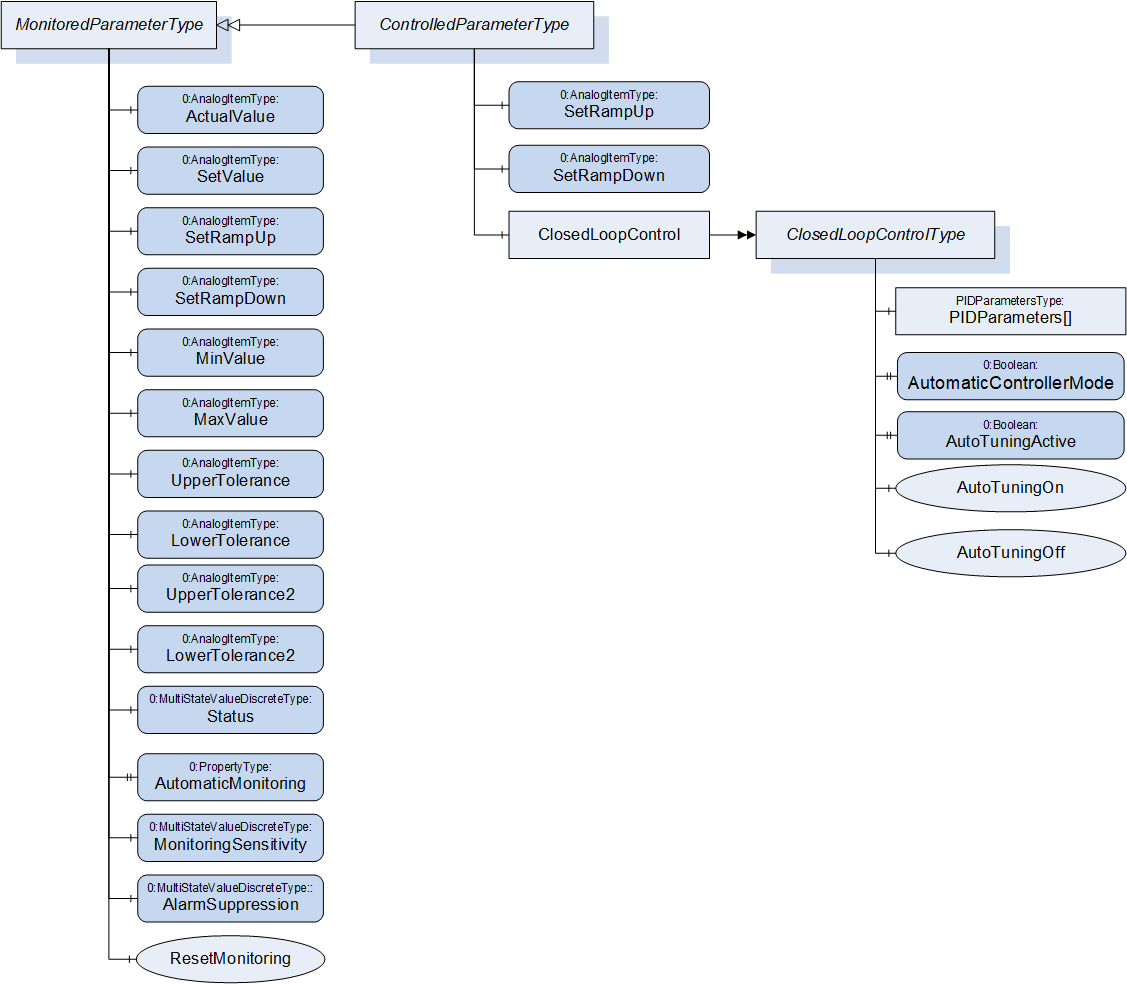
| Attribute | Value | ||||
| BrowseName | MonitoredParameterType | ||||
| IsAbstract | False | ||||
| References | Node Class | BrowseName | DataType | TypeDefinition | Other |
|---|---|---|---|---|---|
| Subtype of 0:BaseObjectType defined in OPC UA Part 5 | |||||
| 0:HasComponent | Variable | ActualValue | 0:Double | 0:AnalogItemType | M, RO |
| 0:HasComponent | Variable | SetValue | 0:Double | 0:AnalogItemType | O, RW |
| 0:HasComponent | Variable | SetRampUp | 0:Double | 0:AnalogItemType | O, RO |
| 0:HasComponent | Variable | SetRampDown | 0:Double | 0:AnalogItemType | O, RO |
| 0:HasComponent | Variable | MinValue | 0:Double | 0:AnalogItemType | O, RW |
| 0:HasComponent | Variable | MaxValue | 0:Double | 0:AnalogItemType | O, RW |
| 0:HasComponent | Variable | UpperTolerance | 0:Double | 0:AnalogItemType | O, RW |
| 0:HasComponent | Variable | LowerTolerance | 0:Double | 0:AnalogItemType | O, RW |
| 0:HasComponent | Variable | UpperTolerance2 | 0:Double | 0:AnalogItemType | O, RW |
| 0:HasComponent | Variable | LowerTolerance2 | 0:Double | 0:AnalogItemType | O, RW |
| 0:HasComponent | Variable | Status | 0:UInt16 | 0:MultiStateValueDiscreteType | O, RO |
| 0:HasProperty | Variable | AutomaticMonitoring | 0:Boolean | 0:PropertyType | O, RW |
| 0:HasComponent | Variable | MonitoringSensitivity | 0:UInt16 | 0:MultiStateValueDiscreteType | O, RW |
| 0:HasComponent | Variable | AlarmSuppression | 0:UInt16 | 0:MultiStateValueDiscreteType | O, RW |
| 0:HasComponent | Method | ResetMonitoring | O | ||
| 0:HasSubtype | ObjectType | ControlledParameterType | Defined in Clause 23 | ||
22.1 ActualValue
Actual value of the monitored parameter (unit given in AnalogItemType).
22.2 SetValue
Set/nominal/target value of the monitored parameter. The value of this variable is writeable by the client. As the MonitoredParameterType is not used to control parameters, this is only for information/Process monitoring and not for changing setting on the device.
22.3 SetRampUp
Indication if a SetValue that is higher than the actual value shall be reached as fast as possible (SetRampUp = 0) or within a given value change per time (e.g. SetRampUp = 2 K/s).
22.4 SetRampDown
Indication if SetValue that is lower than the actual value shall be reached as fast as possible (SetRampDown = 0) or within a given value change per time (e.g. SetRampDown = 2 K/s).
22.5 UpperTolerance, LowerTolerance, UpperTolerance2, LowerTolerance2, MinValue, MaxValue
These parameters are used to define limits for the monitored parameter. Exceeding the (relative) tolerance values creates a warning while exceeding the (absolute) Min/MaxValues leads to an alarm from type MonitoredParameterAlarmType and/or perhaps other actions on the machine (e.g. switching off the heating, stopping of movements) as defined by the severity level. With UpperTolerance2 and LowerTolerance2 a second tolerance band can be defined.
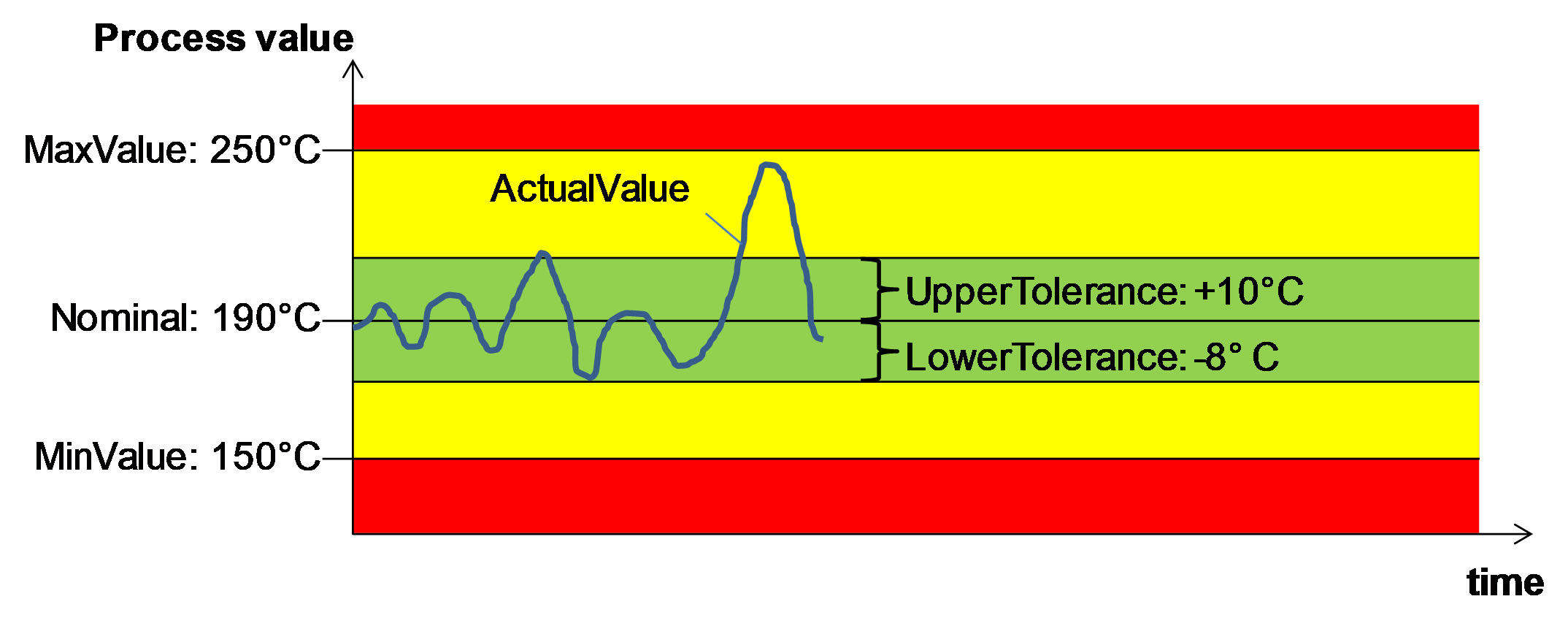
22.6 Status
Information if the ActualValue is within the tolerances or has passed a tolerance or min/max value. The TypeDefinition is MultiStateValueDiscreteType, so the Properties EnumValues and ValueAsText shall be filled with the supported values out of Table 127.
| EnumValue | ValueAsText | Description |
| 0 | NONE | No monitoring |
| 1 | UNKNOWN | Status not known, e.g. because of broken sensor |
| 2 | BELOW_MIN_VALUE | ActualValue is below MinValue |
| 3 | BELOW_LOWER_TOLERANCE2 | ActualValue is below LowerTolerance2 |
| 4 | BELOW_LOWER_TOLERANCE | ActualValue is below LowerTolerance |
| 5 | WITHIN_TOLERANCE | ActualValue is between LowerTolerance and UpperTolerance |
| 6 | ABOVE_UPPER_TOLERANCE | ActualValue is above UpperTolerance |
| 7 | ABOVE_UPPER_TOLERANCE2 | ActualValue is above UpperTolerance2 |
| 8 | ABOVE_MAX_VALUE | ActualValue is above MinValue |
22.7 AutomaticMonitoring
Determination if monitoring tolerance parameters are determined by auto-tuning itself (TRUE) or can be manually adjusted (FALSE). If TRUE the monitoring tolerance parameters are determined by auto-tuning regarding the set monitoring sensitivity (if used). In this case, the tolerance parameters shall then be not writeable.
22.8 MonitoringSensitivity
The monitoring sensitivity defines how closely the tolerances are set during the automatic limit setting. The TypeDefinition is MultiStateValueDiscreteType, so the Properties EnumValues and ValueAsText must be filled with the supported values out of Table 128.
| EnumValue | ValueAsText | Description |
| 0 | FINE | tight tolerances |
| 1 | MIDDLE | mean tolerances |
| 2 | ROUGH | large tolerances |
The absolute widths of the set tolerance bands are device dependent.
22.9 AlarmSuppression
The alarm suppression deactivates alarms of a monitored parameter e.g. during start up or a setpoint jump. The TypeDefinition is MultiStateValueDiscreteType, so the Properties EnumValues and ValueAsText must be filled with the supported values out of Table 129.
| EnumValue | ValueAsText | Description |
| 0 | OFF | no alarm suppression |
| 1 | HORN | suppressed only horn |
| 2 | COMPLETE | alarm contact, alarm via interface and horn suppressed |
22.10 ResetMonitoring
| Description: | With this method the tolerance values are set according to the actual value and the set monitoring sensitivity. This can be used e.g. after a process change with new SetValue to adapt the monitoring. |
Signature
ResetMonitoring ();The method has no Input- or OutputArguments.
| Attribute | Value | ||||
| BrowseName | ResetMonitoring | ||||
| References | Node Class | BrowseName | DataType | TypeDefinition | Modelling Rule |
|---|
23 ControlledParameterType
The ControlledParameterType is used for process parameters that are controlled by the client by writing a set value and optional ramps and parameters for closed loop control.
| Attribute | Value | ||||
| BrowseName | ControlledParameterType | ||||
| IsAbstract | False | ||||
| References | Node Class | BrowseName | DataType | TypeDefinition | Other |
|---|---|---|---|---|---|
| Subtype of MonitoredParameterType | |||||
| 0:HasComponent | Variable | SetRampUp | 0:Double | 0:AnalogItemType | O, RW |
| 0:HasComponent | Variable | SetRampDown | 0:Double | 0:AnalogItemType | O, RW |
| 0:HasComponent | Object | ClosedLoopControl | ClosedLoopControlType | O | |
The variables SetRampUp and SetRamp down, which are only readable in the MonitoredParameterType, are writable in the ControlledParameterType.
If SetValue (already writeable in MonitoredParameterType) is changed by the client within the ControlledParameterType, the device shall control its process to reach the new value (if applicable regarding the values of SetRampUp and SetRampDown).
24 ClosedLoopControlType
With the ClosedLoopControlType the client can do settings for the closed loop control on the device for a parameter.
| Attribute | Value | ||||
| BrowseName | ClosedLoopControlType | ||||
| IsAbstract | False | ||||
| References | Node Class | BrowseName | DataType | TypeDefinition | Other |
|---|---|---|---|---|---|
| Subtype of 0:BaseObjectType defined in OPC UA Part 5 | |||||
| 0:HasProperty | Variable | PIDParameters | PIDParametersDataType[] | 0:PropertyType | O, RW |
| 0:HasProperty | Variable | AutomaticControllerMode | 0:Boolean | 0:PropertyType | O, RW |
| 0:HasProperty | Variable | AutoTuningActive | 0:Boolean | 0:PropertyType | O, RO |
| 0:HasComponent | Method | AutoTuningOn | O | ||
| 0:HasComponent | Method | AutoTuningOff | O | ||
24.1 PIDParameters
PID Parameters as array if several input signals (sensors) are used for the control.
| Name | Type | Description |
| PIDParametersDataType | structure | Subtype of 0:Structure as defined in OPC UA 10000-3 |
P | 0:Double | P parameter |
I | 0:Double | I parameter |
D | 0:Double | D parameter |
24.2 AutomaticControllerMode
Determination if PID Parameters are determined by auto-tuning itself (TRUE) or can be manually adjusted (FALSE).
24.3 AutoTuningActive
This Property informs if the automatic tuning is currently active. TRUE during automatic tuning, FALSE when automatic tuning is finished (new PID parameters are set, if necessary). If an error occurs during automatic tuning, the PID parameters will not be changed, AutoTuningActive goes back to FALSE and an alarm may be sent.
24.4 AutoTuningOn
| Description: | Starts the self-optimisation of the controller. |
Signature
AutoTuningOn ();The method has no Input- or OutputArguments.
| Attribute | Value | ||||
| BrowseName | AutoTuningOn | ||||
| References | Node Class | BrowseName | DataType | TypeDefinition | Modelling Rule |
|---|
24.5 AutoTuningOff
| Description: | Stops an already active self-optimisation process (no control parameters are changed) |
Signature
AutoTuningOff ();The method has no Input- or OutputArguments.
| Attribute | Value | ||||
| BrowseName | AutoTuningOff | ||||
| References | Node Class | BrowseName | DataType | TypeDefinition | Modelling Rule |
|---|
25 MaintenanceType
The MaintenanceType provides information on the maintenance status. It can be used as child element of objects which represent the whole machine/device or single components, depending for which part the information is given.
| Attribute | Value | ||||
| BrowseName | MaintenanceType | ||||
| IsAbstract | False | ||||
| References | Node Class | BrowseName | DataType | TypeDefinition | Other |
|---|---|---|---|---|---|
| Subtype of 0:BaseObjectType defined in OPC UA Part 5 | |||||
| 0:HasProperty | Variable | Status | MaintenanceStatusEnumeration | 0:PropertyType | M, RO |
| 0:HasProperty | Variable | AdditionalInformation | 0:String | 0:PropertyType | O, RO |
| 0:HasComponent | Variable | Interval | 0:Double | 0:AnalogItemType | O, RO |
| 0:HasComponent | Variable | RemainingInterval | 0:Double | 0:AnalogItemType | O, RO |
| 0:HasComponent | Method | Reset | M | ||
| 0:HasComponent | Variable | TotalOperation | 0:Double | 0:AnalogItemType | O, RO |
25.1 Status
Maintenance status of the machine/device/component (represented by the parent element).
| Name | Value | Description |
| NOT_DUE | 0 | Maintenance of the device/component is not due |
| WARNING | 1 | Maintenance of the device/component is due in the near future |
| DUE | 2 | Maintenance of the device/component is due |
25.2 AdditionalInformation
Additional information on the necessary maintenance. Can be also a link to another document.
25.3 Interval
| Description: | Regular interval between two maintenances. Use of AnalogItemType for flexible units (e.g. months, days, operating hours, m). |
| Example: | 1000 h |
25.4 RemainingInterval
| Description: | Interval before next maintenance is due. |
| Example: | 300 h |
25.5 TotalOperation
Same unit as Interval. How long is the component running in total.
25.6 Reset
This Method sets the RemainingInterval to Interval and Status to NOT_DUE_0.
Signature
Reset ();The method has no Input- or OutputArguments.
| Attribute | Value | ||||
| BrowseName | Reset | ||||
| References | Node Class | BrowseName | DataType | TypeDefinition | Modelling Rule |
|---|
26 DataTypes for minimal error handling for devices without alarm support
26.1 ActiveErrorDataType
The ActiveErrorDataType is used for providing information about an active error in a device. It is used for minimal error handling for devices without alarm support.
| Name | Type | Description |
| ActiveErrorDataType | structure | Subtype of 0:Structure as defined in OPC UA 10000-3 |
Id | 0:String | Unique identifier defined by manufacturer |
Severity | 0:UInt16 | Severity as defined in the BaseEventType (1 = low - 1000 = high) |
Message | 0:LocalizedText | Message giving information about the error |
26.2 ClassifiedActiveErrorDataType
The ClassifiedActiveErrorDataType is a subtype of the ActiveErrorDataType and adds the elements defined in Table 140 for additional information about errors.
| Name | Type | Description |
| ClassifiedActiveErrorDataType | structure | Subtype of ActiveErrorDataType |
SourceNodes | 0:NodeId[] | NodeIds of the Nodes which cause the error. This can be a component of the machine (e.g. temperature zone) or a process parameter expressed as MonitoredParameterType (e.g. temperature) |
Classification | 0:UInt16 | Classification of the error, if a process parameter expressed as MonitoredParameterType is the cause of the error. As values (1 - 8), the same as defined in Table 127 are used. If the error is not caused by a specific process parameter (e.g. failure of an component), Classification = 0. |
27 Subtypes of HelpOffNormalAlarmType
27.1 HelpOffNormalAlarmType
The HelpOffNormalAlarmType can be used by devices, to inform the client about a Condition that is considered to be not normal. It is a subtype of the OffNormalAlarmType defined in OPC UA Part 9 and adds the Property Helptext to give some additional information to the operator.
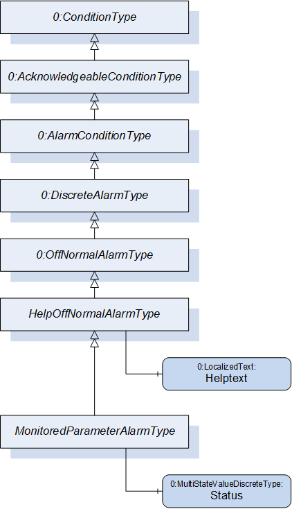
| Attribute | Value | ||||
| BrowseName | HelpOffNormalAlarmType | ||||
| IsAbstract | False | ||||
| References | Node Class | BrowseName | DataType | TypeDefinition | Other |
|---|---|---|---|---|---|
| Subtype of 0:OffNormalAlarmType defined in OPC UA Part 9 | |||||
| 0:HasProperty | Variable | HelpText | 0:LocalizedText | 0:PropertyType | M |
| 0:HasSubtype | ObjectType | MonitoredParameterAlarmType | |||
Servers can use the Property HelpText also in other server specific alarms which are not derived from OffNormalAlarmType.
27.2 MonitoredParameterAlarmType
The MonitoredParameterAlarmType is a subtype of the HelpOffNormalAlarmType and is used, if the cause of the alarm is a process variable expressed as MonitoredParameterType. It adds the Variable Status. As values, the same as defined in Table 127 are used.
| Attribute | Value | ||||
| BrowseName | MonitoredParameterAlarmType | ||||
| IsAbstract | False | ||||
| References | Node Class | BrowseName | DataType | TypeDefinition | Other |
|---|---|---|---|---|---|
| Subtype of HelpOffNormalAlarmType | |||||
| 0:HasComponent | Variable | Status | 0:UInt16 | 0:MultiStateValueDiscreteType | M |
The InputNode (defined in the AlarmConditionType) shall be set to the NodeId of the element of the MonitoredParameterType which causes the error (e.g. UpperTolerance2 if this value is exceeded by the ActualValue).
28 Configuration Parameters
Configuration parameters can be used for configuration of product variants (e.g. same type of foil with different thicknesses or widths). With this it is not necessary to create a separate production dataset for each different product variant and the central computer/MES can set selected parameters directly.
Which parameters are offered is manufacturer dependent and stored in an array of ConfigurationParameterType (the location of the instance is defined in the specific companion specifications).
| Name | Type | Description |
| ConfigurationParameterType | structure | Subtype of 0:Structure as defined in OPC UA 10000-3 |
Id | 0:UInt32 | Unique identifier |
Description | 0:LocalizedText | Description of the parameter |
DefaultValue | 0:BaseDataType | Default value of the parameter |
Unit | 0:EUInformation | Engineering unit of the parameter. If the Type of Defaultvalue is not a Number, then the Unit shall be empty |
Within the ContinuousJobInformationType the ParameterSetting Property sets the values for selected parameters. If a parameter is not included in the ParameterSetting Property, the default value defined in the instance of the ConfigurationParameterType is applied.
| Name | Type | Description |
| ParameterSettingType | structure | Subtype of 0:Structure as defined in OPC UA 10000-3 |
Id | 0:UInt32 | Unique identifier of the parameter as defined in the instance of the ConfigurationParametersType |
Value | 0:BaseDataType | Set value of the parameter |
Specific companion specifications can provide lists of standardized parameters for the specific applications.
29 MaterialListType
This ObjectType is used to provide a list of materials which are intended to be used on the machine.
| Attribute | Value | ||||
| BrowseName | MaterialListType | ||||
| IsAbstract | False | ||||
| References | Node Class | BrowseName | DataType | TypeDefinition | Other |
|---|---|---|---|---|---|
| Subtype of 0:BaseObjectType defined in OPC UA Part 5 | |||||
| 0:HasProperty | Variable | 0:NodeVersion | 0:String | 0:PropertyType | M, RO |
| 0:HasProperty | Variable | DensityUnit | 0:EUInformation | 0:PropertyType | M, RO |
| 0:HasComponent | Object | Material_<Nr> | MaterialType | OP | |
| 0:HasComponent | Method | AddMaterial | O | ||
| 0:HasComponent | Method | RemoveMaterialById | O | ||
| 0:GeneratesEvent | ObjectType | RequestAddMaterialEventType | Defined in 29.5 | ||
| 0:GeneratesEvent | ObjectType | 0:GeneralModelChangeEventType | |||
When instances for materials are created, the BrowseNames shall be "Material_<Nr>" where <Nr> is a three-digit number with leading zeros, starting with "001".
29.1 NodeVersion
The NodeVersion Property as defined in OPC UA Part 3 is used to inform the client about model changes. Here it informs about added or removed instances of MaterialType.
29.2 DensityUnit
In the MaterialType the Density has the TypeDefinition AnalogUnitType which includes the used unit. AnalogUnitType cannot be used as InputArgument of a method. Therefore, the MaterialListType has the Property DensityUnit and the unit given there is the basis for the Density InputArgument in the method AddMaterial.
29.3 AddMaterial
This method adds a material to the list.
Signature
	AddMaterial (
		[in]	0:String		Id
		[in]	0:LocalizedText		Name
[in] 0:Double Density);| Argument | Description |
| Id | Id of the material |
| Name | Name of the material (e.g. trade name) |
| Density | Density of the material in the unit given in the DensityUnit Property in the instance of MaterialListType |
| Attribute | Value | ||||
| BrowseName | AddMaterial | ||||
| References | Node Class | BrowseName | DataType | TypeDefinition | Modelling Rule |
|---|---|---|---|---|---|
| 0:HasProperty | Variable | InputArguments | Argument[] | 0:PropertyType | Mandatory |
29.4 RemoveMaterialById
This method removes a material from the list.
Signature
	RemoveMaterialById (
[in] 0:String Id);| Argument | Description |
| Id | Id of the material that shall be removed |
| Attribute | Value | ||||
| BrowseName | RemoveMaterialById | ||||
| References | Node Class | BrowseName | DataType | TypeDefinition | Modelling Rule |
|---|---|---|---|---|---|
| 0:HasProperty | Variable | InputArguments | Argument[] | 0:PropertyType | Mandatory |
Warning: Problems may occur when the Material Id is currently in use (in a job, hopper).
29.5 RequestAddMaterialEventType
With this EventType, the Server can request that the client shall add a material (by calling the method AddMaterial) with the specified Id. This can be used, e.g. when a material Id is used inside a new job, which is not included in the MaterialList).
| Attribute | Value | ||||
| BrowseName | RequestAddMaterialEventType | ||||
| IsAbstract | True | ||||
| References | Node Class | BrowseName | DataType | TypeDefinition | Other |
|---|---|---|---|---|---|
| Subtype of 0:BaseEventType defined in OPC UA Part 5 | |||||
| 0:HasProperty | Variable | Id | 0:String | 0:PropertyType | M |
Id: Id of the material that shall be added.
30 MaterialType
This ObjectType represent a single material (e.g. inside the MaterialList).
| Attribute | Value | ||||
| BrowseName | MaterialType | ||||
| IsAbstract | False | ||||
| References | Node Class | BrowseName | DataType | TypeDefinition | Other |
|---|---|---|---|---|---|
| Subtype of 0:BaseObjectType defined in OPC UA Part 5 | |||||
| 0:HasProperty | Variable | Id | 0:String | 0:PropertyType | M, RO |
| 0:HasProperty | Variable | Name | 0:LocalizedText | 0:PropertyType | M, RO |
| 0:HasComponent | Variable | Density | 0:Double | 0:AnalogUnitType | M, RO |
| Id: | Id of the material. |
| Name: | Name of the material (e.g. trade name) |
| Density: | Density of the material |
31 EnergyType
| Attribute | Value | ||||
| BrowseName | EnergyType | ||||
| IsAbstract | False | ||||
| References | Node Class | BrowseName | DataType | TypeDefinition | Other |
|---|---|---|---|---|---|
| Subtype of 0:BaseObjectType defined in OPC UA Part 5 | |||||
| 0:HasComponent | Variable | ActualPower | 0:Double | 0:AnalogUnitType | O, RO |
| 0:HasComponent | Variable | PowerConsumption | 0:Double | 0:AnalogUnitType | O, RO |
| 0:HasComponent | Variable | ActualSpecificEnergy | 0:Double | 0:AnalogUnitType | O, RO |
| 0:HasComponent | Variable | PowerFactor | 0:Double | 0:BaseDataVariableType | O, RO |
31.1 ActualPower
Actual (active) power in W (or kW, MW…) (depending on EngineeringUnit).
31.2 PowerConsumption
Power consumption (energy = power * time) (over total machine lifetime)
31.3 ActualSpecificEnergy
Actual specific energy consumption per output unit (e.g. kWh/kg, kWh/m,…)
31.4 PowerFactor
Ratio of the actual active power to the apparent power.
32 MeasuringDevices
32.1 MeasuringDevicesType
This ObjectType is a container for the measuring devices. It is formally defined inTable 153.
| Attribute | Value | ||||
| BrowseName | MeasuringDevicesType | ||||
| IsAbstract | False | ||||
| References | Node Class | BrowseName | DataType | TypeDefinition | Other |
|---|---|---|---|---|---|
| Subtype of 0:BaseObjectType defined in OPC UA Part 5 | |||||
| 0:HasProperty | Variable | 0:NodeVersion | 0:String | 0:PropertyType | M, RO |
| 0:HasComponent | Object | <Name>_<Nr> | MeasuringDeviceType | OP | |
| 0:GeneratesEvent | ObjectType | 0:GeneralModelChangeEventType | |||
32.2 MeasuringDeviceType
This object type describes a device which delivers a measured value (e.g. temperature, pressure)
| Attribute | Value | ||||
| BrowseName | MeasuringDeviceType | ||||
| IsAbstract | False | ||||
| References | Node Class | BrowseName | DataType | TypeDefinition | Other |
|---|---|---|---|---|---|
| Subtype of ControlledParameterType | |||||
| 0:HasProperty | Variable | Id | 0:String | 0:PropertyType | M, RO |
| 0:HasProperty | Variable | Name | 0:LocalizedText | 0:PropertyType | O, RO |
| 0:HasProperty | Variable | Position | 0:String | 0:PropertyType | O, RO |
| 0:HasProperty | Variable | IsPresent | 0:Boolean | 0:PropertyType | M, RO |
| 0:HasProperty | Variable | ControlMode | ControlModeEnumeration | 0:PropertyType | M, RO |
| 0:HasComponent | Object | StartDevice | StartDeviceType | O | |
| 0:HasComponent | Object | Maintenance | MaintenanceType | O | |
If writing SetValues are used, look at ControlMode.
32.2.1 Id
The Id Property gives the (unique) identification of the measuring device.
32.2.2 Name
Name of the measuring device.
32.2.3 Position
The Position Property indicates the physical position of the measuring device (e.g. position on a plastification barrel). With this Property it can be modelled, that several Measuring devices are placed at the same position.
32.2.4 IsPresent
The IsPresent Property provides information if the measuring device is physically installed and connected.
32.2.5 ControlMode
The ControlMode Property indicates how the measured value is currently controlled. The ControlModeEnumeration is defined in Clause 17.2.6.
32.2.6 MonitoredParameter
Measured value. The MonitoredParameterType, which also gives tolerance values, is defined in Clause 22.
33 StartDeviceType
This Object Type is used to give information on the starting status of a device and optional to switch devices on and off via the interface.
| Attribute | Value | |||||
| BrowseName | StartDeviceType | |||||
| IsAbstract | False | |||||
| References | Node Class | BrowseName | DataType | TypeDefinition | Other | |
|---|---|---|---|---|---|---|
| Subtype of 0:BaseObjectType defined in OPC UA Part 5 | ||||||
| 0:HasProperty | Variable | Status | StartEnumeration | 0:PropertyType | M, RO | |
| 0:HasComponent | Method | StartRequest | O | |||
| 0:HasComponent | Method | StopRequest | O | |||
| 0:HasProperty | Variable | StartBlockedByClient | 0:Boolean | 0:PropertyType | O, RW | |
The support of switching on/off devices via OPC UA shall be put in a separate facet in the specific interfaces.
Via the methods StartRequest and StopRequest (without arguments) the client can request to start/stop the device.
| Name | Value | Description |
| NOT_READY_TO_START | 0 | The device is not running/active. Starting is currently not possible. |
| START_BLOCKED_BY_CLIENT | 1 | The client has blocked the start. |
| READY_TO_START | 2 | The device is not running/active. Starting is possible. |
| START_REQUESTED | 3 | The server has received the request to start the device, but the device is not running/active yet. |
| STARTED | 4 | The device is not running/active. |
| STOP_REQUESTED | 5 | The server has received the request to stop the device, but the device is still running/active yet |
34 DriveType
This Object Type is used to give information about a drive.
| Attribute | Value | ||||
| BrowseName | DriveType | ||||
| IsAbstract | False | ||||
| References | Node Class | BrowseName | DataType | TypeDefinition | Other |
|---|---|---|---|---|---|
| Subtype of 0:BaseObjectType defined in OPC UA Part 5 | |||||
| 0:HasProperty | Variable | Position | 0:String | 0:PropertyType | O |
| 0:HasComponent | Object | StartDrive | StartDeviceType | O | |
| 0:HasComponent | Object | Speed | MonitoredParameterType | O | |
| 0:HasComponent | Object | Torque | MonitoredParameterType | O | |
| 0:HasComponent | Object | Energy | EnergyType | O | |
| 0:HasComponent | Object | AdditionalMeasuringDevices | MeasuringDevicesType | O | |
| 0:HasComponent | Object | Maintenance | MaintenanceType | O | |
Speed and torque are measured after a possibly existing gearbox.
If multiple drives are possible, a container of DrivesType shall be used.
| Attribute | Value | ||||
| BrowseName | DrivesType | ||||
| IsAbstract | False | ||||
| References | Node Class | BrowseName | DataType | TypeDefinition | Other |
|---|---|---|---|---|---|
| Subtype of 0:BaseObjectType defined in OPC UA Part 5 | |||||
| 0:HasProperty | Variable | 0:NodeVersion | 0:String | 0:PropertyType | M, RO |
| 0:HasComponent | Object | <Name>_<Nr> | DriveType | OP | |
| 0:GeneratesEvent | ObjectType | 0:GeneralModelChangeEventType | |||
35 DiagnosticsType
A Client can start and stop diagnostics via methods. The single diagnosis steps are vendor specific. After each completed step, the server may generate a DiagnosisStepEndEvent (Table 163).
The event keeps the result of the diagnosis step. After completion of all diagnosis functions, the server shall send a DiagnosisEndEvent (Table 164).
| Attribute | Value | ||||
| BrowseName | DiagnosticsType | ||||
| IsAbstract | False | ||||
| References | Node Class | BrowseName | DataType | TypeDefinition | Other |
|---|---|---|---|---|---|
| Subtype of 0:BaseObjectType defined in OPC UA Part 5 | |||||
| 0:HasProperty | Variable | Status | DiagnosticsStatus Enumeration | 0:PropertyType | M, RO |
| 0:HasComponent | Method | RunDiagnostics | M | ||
| 0:HasComponent | Method | StopDiagnostics | M | ||
| 0:GeneratesEvent | ObjectType | DiagnosisStepEndEventType | Defined in 35.4 | ||
| 0:GeneratesEvent | ObjectType | DiagnosisEndEventType | Defined in 35.5 | ||
35.1 Status
The status shows a client whether the diagnostic function is active or finished and if diagnosis detected at least one error.
| Name | Value | Description |
| OFF | 0 | Diagnostics inactive |
| ACTIVE_OK | 1 | Diagnostics active |
| ACTIVE_ERROR_DETECTED | 2 | Diagnostics active, at least one error detected |
| COMPLETE | 3 | Diagnostics completed successfully, result in variable "Result" available |
| COMPLETE_ERROR_DETECTED | 4 | Diagnostics completed detected some error |
35.2 RunDiagnostics
Method to start diagnostics functions from any Status. Status must change to an "active state" or stay in the current "active state" if diagnosis functions already running.
Signature
RunDiagnostics ();The method has no Input- or OutputArguments.
| Attribute | Value | ||||
| BrowseName | RunDiagnostics | ||||
| References | Node Class | BrowseName | DataType | TypeDefinition | Modelling Rule |
|---|
35.3 StopDiagnostics
Method to stop diagnostics functions from any Status.
If Status is "active", this method cancels active diagnosis functions. Status should change to "Off" after diagnostics stopped.
When diagnosis functions already done, Status changes immediately to "Off".
Signature
StopDiagnostics ();The method has no Input- or OutputArguments.
| Attribute | Value | ||||
| BrowseName | StopDiagnostics | ||||
| References | Node Class | BrowseName | DataType | TypeDefinition | Modelling Rule |
|---|
35.4 DiagnosisStepEndEventType
| Attribute | Value | ||||
| BrowseName | DiagnosisStepEndEventType | ||||
| IsAbstract | True | ||||
| References | Node Class | BrowseName | DataType | TypeDefinition | Other |
|---|---|---|---|---|---|
| Subtype of 0:BaseEventType defined in OPC UA Part 5 | |||||
| 0:HasProperty | Variable | Result | 0:Boolean | 0:PropertyType | M, R |
| 0:HasProperty | Variable | InputNode | NodeId | 0:PropertyType | M, R |
35.4.1 Result
The property is true if the device completes a diagnostic step without error detection.
35.4.2 InputNode
In the case of component-related diagnostic steps (e.g. different zones of a hotrunner), this Property holds the NodeID of the corresponding instance. For general information InputNode holds the NodeId of the root node.
The component information and the severity allow the machine to prevent the use of faulty components.
35.4.3 Inherited properties of BaseEventType
| Severity | in accordance with clause 6.4. |
| SourceNode | NodeId of the root Node of the specific interface. |
| Message | keeps the result of diagnostics as a vendor specific localized text. |
Examples:
"Wiring analysis of zone 1 completed successfully."
"Error detected, current consumption of zone 3 too high! "
35.5 DiagnosisEndEventType
| Attribute | Value | ||||
| BrowseName | DiagnosisEndEventType | ||||
| IsAbstract | True | ||||
| References | Node Class | BrowseName | DataType | TypeDefinition | Other |
|---|---|---|---|---|---|
| Subtype of 0:BaseEventType defined in OPC UA Part 5 | |||||
| 0:HasProperty | Variable | Status | DiagnosticsStatusEnumeration | 0:PropertyType | O, R |
35.5.1 Status
Status after completion of the diagnosis.
35.5.2 Inherited properties from BaseEventType
Severity in accordance with clause 6.4.
SourceNode contains the NodeId of the root Node of the specific interface.
Message keeps the result of diagnostics as a vendor specific localized text.
Examples:
"Successfully completed. System configuration is correct!"
"Diagnosis completed, 3 faulty zones detected. "
36 Profiles and Conformance Units
This specification does not define Profiles and Conformance Units. They are defined by the specific Companion Specifications for the several machine types (e.g. OPC 40077).
37 Namespaces
37.1 Namespace Metadata
Table 165 defines the namespace metadata for this document. The Object is used to provide version information for the namespace and an indication about static Nodes. Static Nodes are identical for all Attributes in all Servers, including the Value Attribute. See OPC 10000-5 for more details.
The information is provided as Object of type NamespaceMetadataType. This Object is a component of the Namespaces Object that is part of the Server Object. The NamespaceMetadataType ObjectType and its Properties are defined in OPC 10000-5.
The version information is also provided as part of the ModelTableEntry in the UANodeSet XML file. The UANodeSet XML schema is defined in OPC 10000-6.
| Attribute | Value | |||
| BrowseName | http://opcfoundation.org/UA/PlasticsRubber/GeneralTypes/ | |||
| Property | DataType | Value | ||
| NamespaceUri | String | http://opcfoundation.org/UA/PlasticsRubber/GeneralTypes/ | ||
| NamespaceVersion | String | 1.03 | ||
| NamespacePublicationDate | DateTime | 2021-05-10 12:00:00 | ||
| IsNamespaceSubset | Boolean | False | ||
| StaticNodeIdTypes | IdType [] | {Numeric} | ||
| StaticNumericNodeIdRange | NumericRange [] | Null | ||
| StaticStringNodeIdPattern | String | Null | ||
37.2 Handling of OPC UA Namespaces
Namespaces are used by OPC UA to create unique identifiers across different naming authorities. The Attributes NodeId and BrowseName are identifiers. A Node in the UA AddressSpace is unambiguously identified using a NodeId. Unlike NodeIds, the BrowseName cannot be used to unambiguously identify a Node. Different Nodes may have the same BrowseName. They are used to build a browse path between two Nodes or to define a standard Property.
Servers may often choose to use the same namespace for the NodeId and the BrowseName. However, if they want to provide a standard Property, its BrowseName shall have the namespace of the standards body although the namespace of the NodeId reflects something else, for example the EngineeringUnits Property. All NodeIds of Nodes not defined in this document shall not use the standard namespaces.
Table 166 provides a list of mandatory and optional namespaces used in an OPC 40083 OPC UA Server.
| NamespaceURI | Description | Use |
| http://opcfoundation.org/UA/ | Namespace for NodeIds and BrowseNames defined in the OPC UA specification. This namespace shall have namespace index 0. | Mandatory |
| Local Server URI | Namespace for nodes defined in the local server. This may include types and instances used in an AutoID Device represented by the Server. This namespace shall have namespace index 1. | Mandatory |
| http://opcfoundation.org/UA/DI/ | Namespace for NodeIds and BrowseNames defined in OPC 10000-100. The namespace index is Server specific. | Mandatory |
http://opcfoundation.org/UA/PlasticsRubber/ GeneralTypes/ | Namespace for NodeIds and BrowseNames defined in this document. The namespace index is Server specific. | Mandatory |
| Vendor specific types | A Server may provide vendor-specific types like types derived from ObjectTypes defined in this document in a vendor-specific namespace. | Optional |
| Vendor specific instances | A Server provides vendor-specific instances of the standard types or vendor-specific instances of vendor-specific types in a vendor-specific namespace. It is recommended to separate vendor specific types and vendor specific instances into two or more namespaces. | Mandatory |
Table 167 provides a list of namespaces and their index used for BrowseNames in this document. The default namespace of this document is not listed since all BrowseNames without prefix use this default namespace.
| NamespaceURI | Namespace Index | Example |
| http://opcfoundation.org/UA/ | 0 | 0:NodeVersion |
| http://opcfoundation.org/UA/DI/ | 2 | 2:DeviceClass |
Annex A OPC 40083 Namespace and mappings (Normative)
A.1 Namespace and identifiers for OPC 40083 Information Model
This appendix defines the numeric identifiers for all of the numeric NodeIds defined in this specification. The identifiers are specified in a CSV file with the following syntax:
<SymbolName>, <Identifier>, <NodeClass>Where the SymbolName is either the BrowseName of a Type Node or the BrowsePath for an Instance Node that appears in the specification and the Identifier is the numeric value for the NodeId.
The BrowsePath for an Instance Node is constructed by appending the BrowseName of the instance Node to the BrowseName for the containing instance or type. An underscore character is used to separate each BrowseName in the path. Let's take for example, the MachineInformationType ObjectType Node which has the ControllerName Property. The Name for the ControllerName InstanceDeclaration within the MachineInformationType declaration is: MachineInformationType_ControllerName.
The NamespaceUri for all NodeIds defined here is http://opcfoundation.org/UA/PlasticsRubber/GeneralTypes/
The CSV released with this version of the specification can be found here:
http://www.opcfoundation.org/UA/schemas/PlasticsRubber/GeneralTypes/1.03/NodeIds.csv
http://www.opcfoundation.org/UA/schemas/PlasticsRubber/GeneralTypes/NodeIds.csv
A computer processible version of the complete Information Model defined in this specification is also provided. It follows the XML Information Model schema syntax defined in Part 6.
The Information Model Schema released with this version of the specification can be found here:
___________
Agreement of Use
COPYRIGHT RESTRICTIONS
This document is provided "as is" by the OPC Foundation and EUROMAP.
Right of use for this specification is restricted to this specification and does not grant rights of use for referred documents.
Right of use for this specification will be granted without cost.
This document may be distributed through computer systems, printed or copied as long as the content remains unchanged and the document is not modified.
OPC Foundation and EUROMAP do not guarantee usability for any purpose and shall not be made liable for any case using the content of this document.
The user of the document agrees to indemnify OPC Foundation and EUROMAP and their officers, directors and agents harmless from all demands, claims, actions, losses, damages (including damages from personal injuries), costs and expenses (including attorneys' fees) which are in any way related to activities associated with its use of content from this specification.
The document shall not be used in conjunction with company advertising, shall not be sold or licensed to any party.
The intellectual property and copyright is solely owned by the OPC Foundation and EUROMAP.
PATENTS
The attention of adopters is directed to the possibility that compliance with or adoption of OPC or EUROMAP specifications may require use of an invention covered by patent rights. OPC Foundation or EUROMAP shall not be responsible for identifying patents for which a license may be required by any OPC or EUROMAP specification, or for conducting legal inquiries into the legal validity or scope of those patents that are brought to its attention. OPC or EUROMAP specifications are prospective and advisory only. Prospective users are responsible for protecting themselves against liability for infringement of patents.
WARRANTY AND LIABILITY DISCLAIMERS
WHILE THIS PUBLICATION IS BELIEVED TO BE ACCURATE, IT IS PROVIDED "AS IS" AND MAY CONTAIN ERRORS OR MISPRINTS. THE OPC FOUDATION NOR EUROMAP MAKES NO WARRANTY OF ANY KIND, EXPRESSED OR IMPLIED, WITH REGARD TO THIS PUBLICATION, INCLUDING BUT NOT LIMITED TO ANY WARRANTY OF TITLE OR OWNERSHIP, IMPLIED WARRANTY OF MERCHANTABILITY OR WARRANTY OF FITNESS FOR A PARTICULAR PURPOSE OR USE. IN NO EVENT SHALL THE OPC FOUNDATION NOR EUROMAP BE LIABLE FOR ERRORS CONTAINED HEREIN OR FOR DIRECT, INDIRECT, INCIDENTAL, SPECIAL, CONSEQUENTIAL, RELIANCE OR COVER DAMAGES, INCLUDING LOSS OF PROFITS, REVENUE, DATA OR USE, INCURRED BY ANY USER OR ANY THIRD PARTY IN CONNECTION WITH THE FURNISHING, PERFORMANCE, OR USE OF THIS MATERIAL, EVEN IF ADVISED OF THE POSSIBILITY OF SUCH DAMAGES.
The entire risk as to the quality and performance of software developed using this specification is borne by you.
RESTRICTED RIGHTS LEGEND
This Specification is provided with Restricted Rights. Use, duplication or disclosure by the U.S. government is subject to restrictions as set forth in (a) this Agreement pursuant to DFARs 227.7202-3(a); (b) subparagraph (c)(1)(i) of the Rights in Technical Data and Computer Software clause at DFARs 252.227-7013; or (c) the Commercial Computer Software Restricted Rights clause at FAR 52.227-19 subdivision (c)(1) and (2), as applicable. Contractor / manufacturer are the OPC Foundation, 16101 N. 82nd Street, Suite 3B, Scottsdale, AZ, 85260-1830
COMPLIANCE
The combination of EUROMAP and OPC Foundation shall at all times be the sole entities that may authorize developers, suppliers and sellers of hardware and software to use certification marks, trademarks or other special designations to indicate compliance with these materials as specified within this document. Products developed using this specification may claim compliance or conformance with this specification if and only if the software satisfactorily meets the certification requirements set by EUROMAP or the OPC Foundation. Products that do not meet these requirements may claim only that the product was based on this specification and must not claim compliance or conformance with this specification.
TRADEMARKS
Most computer and software brand names have trademarks or registered trademarks. The individual trademarks have not been listed here.
GENERAL PROVISIONS
Should any provision of this Agreement be held to be void, invalid, unenforceable or illegal by a court, the validity and enforceability of the other provisions shall not be affected thereby.
This Agreement shall be governed by and construed under the laws of Germany.
This Agreement embodies the entire understanding between the parties with respect to, and supersedes any prior understanding or agreement (oral or written) relating to, this specification.