
1 Scope
The OPC UA Companion Specification for Powertrain will be split into several specification parts. This first part of the specification provides a manufacturer-independent information model of the powertrain that enables asset management applications for the user. The interface standard claims to cover all types of electrical powertrain including mechanical transmission elements. It can be used for a powertrain consisting of a motor starter, motor and gearbox as well as for complex motion or multi-axis systems.
The first part of the OPC UA Companion Specification for Powertrain includes a basic description for every powertrain variant and its main scope is to provide essential technical data for asset management applications.
The information model contains an asset model that represents the physical assets (pieces of hardware that can be ordered) and soft assets (firmware and licences, that can be ordered) as well as their attributes (catalogue data). By use of specific references, the relationship of asset components can be represented.
Future parts will address the following topics:
Functional operation data
Information about the current status and operating values are required by vertical higher-level systems. They are used, for example, by the operator on a visualization, master controllers or MES to make process or management decisions. The information can also be used for further analytical functions in e.g. IoT gateways or cloud services.
Functional diagnosis
Diagnosis is the recognition and evaluative summary of symptoms to determine the root cause of a failure. For this purpose, the companion specification enables the configuration of diagnosis functions, the determination of the powertrain diagnostic state, the detection of actual error causes, the reading of an event log and the possibility to record data (data trace).
Condition monitoring
Condition monitoring is the process of determining the condition of machinery while in operation, in order to identify a significant change which is indicative of a developing fault. This is a major part of predictive maintenance where the maintenance is scheduled to shorten the downtime.
Commissioning
Commissioning includes activities to establish the operating condition of a powertrain. The OPC UA Companion Specification for Powertrain does not only focus on the commissioning of a single device. It provides interfaces which serve the commissioning of complete systems.
Backup & Restore
A prior backup is indispensable for the efficient replacement of devices or of entire systems. Here, the focus is also on a holistic approach to restore the data in the field.
2 Normative references
The following documents are referred to in the text in such a way that some or all of their content constitutes requirements of this document. For dated references, only the edition cited applies. For undated references, the latest edition of the referenced document (including any amendments and errata) applies.
There are no normative references in this document.
OPC 10000-1, OPC Unified Architecture - Part 1: Overview and Concepts
OPC 10000-1
OPC 10000-2, OPC Unified Architecture - Part 2: Security Model
OPC 10000-2
OPC 10000-3, OPC Unified Architecture - Part 3: Address Space Model
OPC 10000-3
OPC 10000-4, OPC Unified Architecture - Part 4: Services
OPC 10000-4
OPC 10000-5, OPC Unified Architecture - Part 5: Information Model
OPC 10000-5
OPC 10000-7, OPC Unified Architecture - Part 7: Profiles
OPC 10000-7
OPC 10000-23, Part 23 - Common ReferenceTypes
OPC 10000-23
OPC 10000-81, OPC Unified Architecture - Part 81: UAFX Connecting Devices and Information Model
http://www.opcfoundation.org/documents/10000-81/
OPC 10000-100, OPC Unified Architecture - Part 100: Devices
OPC 10000-100
OPC 40001-1, OPC UA for Machinery - Part 1: Basic Building Blocks
http://www.opcfoundation.org/documents/40001-1/
3 Terms, definitions and conventions
3.1 Overview
It is assumed that basic concepts of OPC UA information modelling and OPC for Machinery are understood in this specification. This specification will use these concepts to describe the powertrain information model. For the purposes of this document, the terms and definitions given in OPC 10000-1, OPC 10000-3, OPC 10000-4, OPC 10000-5, OPC 10000-7, OPC 10000-100, OPC 40001-1, OPC 10000-81 as well as the following apply.
3.2 OPC UA for Powertrain terms
| Name [en] | Definition [en] | Source |
| AC/AC converter | Electric energy converter that changes single-phase or polyphase alternating electric currents to single-phase or polyphase alternating current. | |
| Analog output | Terminal to which generates an analog voltage signal (e. g. -10 V ...+10 V) or current signal (e. g. 0 ... 20 mA). | |
| Analog input | Terminal which samples an analog voltage signal (e. g. -10 V ...+10 V) or current signal (e. g. 0 ... 20 mA). | |
| Auxiliary power supply module | Separately orderable hardware for power supply (e.g., 24V DC) for the electronics of the components of a power drive system (PDS). | Naming according to IEC 61800-2 |
| Axis | Logical element inside an automation system (e.g., a motion control system) that represents some form of movement. | DIN EN 61800-7-1:2016-11 |
| Basic drive module (BDM) | Electronic power converter and related control, connected between an electric supply and a motor. | IEC 61800-2:2015 [3.4]; DIN EN 61800-2 (VDE 0160-102):2016-08 |
| Braking resistor | Ohmic resistor that is connected with a brake chopper to the DC link. | |
| Communication interface | Interface to provide communication capabilities (e.g. RS-485, also known as TIA-485(-A) or EIA-485 and/or Ethernet with related support of communication protocols like e.g. CAN, PROFIBUS, PROFINET, vendor specific communication bus) of a device. The communication interface may be an integrated part of a device (e.g. control module, output converter, ...) or part of an additional extension board/module. | |
| Communication module | Separately orderable hardware that contains at least one communication interface. | |
| Complete drive module (CDM) | Drive module consisting of, but not limited to, the BDM and extensions such as protection devices, transformers and auxiliaries, but excluding the motor and the sensors which are mechanically coupled to the motor and/or to the load side of a powertrain. | IEC 61800-2:2015 [3.8] DIN EN 61800-2 (VDE 0160-102):2016-08 |
| Component | Constituent part of a device which cannot be physically divided into smaller parts without losing its particular function. | IEC 60050-151 [151-11-21] |
| Contactor | Element intended to carry electric current. | 195-01-07 MOD, see IEC 60050-121, 151-15-56. |
| Control module | Physical unit that contains - in a module/subassembly or device - an application program to control the BDM. | IEC 61800-7-1 3.2.7 for "control device" |
| DC bus | DC bus is a type of circuit that serves as a common pathway shared by several components, and which uses a direct current voltage level as a reference. | |
| DC bus module | Separately orderable component and serves as an interface between rectifier and DC/AC converter in electric drives. | |
| DC/DC converter | Electric energy converter that changes direct electric current to direct electric current of another voltage. | |
| DC link | Power DC circuit linking the input converter and the output converter of an indirect converter, consisting of capacitors and/or reactors to reduce DC voltage ripple or DC current ripple. | IEC 61800-2:2015 [3.11] |
| Device | Material element or assembly of such elements intended to perform a required function. NOTE - A device may form part of a larger device. | IEC 60050-151 [151-11-20] |
| Digital output | Terminal which samples a binary signal (characterized by the states "high" and "low"), with active signal (e.g., 24 V DC) or passive signal (e.g., via optocoupler) and if necessary configurable as switching, pulse, or frequency output. | |
| Digital input | Terminal which receives a binary signal (characterized by the states "high" and "low"), with active signal (e.g., 24 V DC) or passive signal (e.g., via optocoupler) and if necessary configurable as switching, pulse, or frequency input. | |
| Electric motor | Electric machine intended to transform electric energy into mechanical energy. Note to entry: For the purposes of this OPC UA Companion Specification, the motor includes all sensors which are mounted on it and which are relevant for supporting the operating mode and interacting with a CDM. | IEC 61800-2 [3.50] |
| Encoder interface | Interface for any velocity/position sensor input + optionally sensor emulation for output. The encoder interface may be an integrated part of a device (e.g. control module, output converter, ...) or part of an additional extension module. The encoder interface can also include an interface for additional sensor data (internal or external and a motor type plate). | |
| Encoder interface module | Separately orderable hardware that contains at least one encoder interface. | |
| Frequency converter | A device with open loop or/and closed loop control functions for changing the frequency and amplitude of an AC input voltage to control the torque/speed of at least one connected motor. Frequency converters are mainly used in applications with no/slow setpoint changes at their working point like in pumps, fans or conveyor belts. | |
| Gear | Part of machine to transfer and transform (transmission ratio) movements, energy and torques or forces. | |
| Input converter interface | Electric energy converter that changes single-phase or polyphase alternating electric currents to unidirectional direct electric current (non-regenerative) and optionally also direct electric current to single-phase or polyphase alternating electric currents (regenerative). | Based on "rectifier" acc. to IEC 60050-151-2001 [151.13.45] and active input converter acc. to IEC 61800-2 |
| Input converter | Separately orderable hardware that contains at least one input converter interface. | |
| Input filter | Input filters are filters in the CDM input which are designed to protect the supply network from harmonic loads and/or interference voltages created in the converter. Input filters can be passive or active filters for low-frequency harmonics. Input filters combined with an input reactor are designed to limit the cable-born electromagnetic interference caused by power units according to the specifications of the EMC regulations. Alternative name: Line filter | |
| Input reactor | Reactor between mains and input converter. Input reactors limit low-frequency network effects to permissible values. Alternative name: line reactor, input choke. | |
| Inverter/Drive | Electric energy converter that changes direct electric current to single-phase or polyphase alternating current | IEC 61800-2:2015 |
| Motor contactor | Switching device that is suitable for switching motors on and off. | |
| Motor starter | The combination of all the devices required to start and stop a motor in combination with suitable overload protection. | IEC 60947-4-1 |
| Operation | Combination of activities necessary to permit an installation to function. NOTE - Operation includes matters as switching, controlling, monitoring and maintenance as well as any work activities. | IEC 60050-151 [151-11-28] |
| Output converter | Separately orderable hardware that contains at least an output converter module interface. | |
| Output converter module interface | Electric energy converter that changes direct electric current to single-phase or polyphase alternating current. | Based on "output converter module interface" acc. to IEC 60050-151:2001 [151.13.46] for "inverter" |
| Output filter | Du/dt filter or sinus filter to limit high charging/discharging currents and overvoltage (du/dt) on the motor cable (cable between output converter and motor). Alternative name: Motor filter. | |
| Output reactor | Reactor (inductivity) in the converter or inverter output for reducing the capacitive charge/discharge currents of long motor cables. Alternative name: Motor reactor, choke. | |
| Powertrain | All asset components related to one or multiple motor(s)/axis system(s) including the drive equipment. | |
| Power drive system (PDS) | System consisting of one or more complete drive module(s) (CDM) and a motor or motors; any sensors which are mechanically coupled to the motor shaft are also part of the PDS, however the driven equipment is not included. | IEC 61800-2:2015 [3.79] DIN EN 61800-2 (VDE 0160-102):2016-08 |
| Rated value | Quantity value assigned, generally by a manufacturer, for a specified operating condition of a machine. Note 1 to entry: The rated voltage or voltage range is the rated voltage or voltage range between lines at the terminals. | IEC 60050-411:1996, 411-51-23 (also used in IEC 60034-1:2017) |
| Rated voltage range | Voltage range as declared by the manufacturer expressed by its lower and upper rated voltages. | IEC 60050-151: Amd 2 [151-16-49] |
| Resolver | Electromagnetic motor feedback device with one sine and cosine signal, respectively, are induced in two coils displaced by 90°. | |
| Safe torque off (STO) | Function to stop a PDS safely by preventing force-producing power from being provided to the motor and by preventing an unwanted restart of the motor (acc. to stop category 0 in EN 60204-1). | |
| Safety interface | Interface to provide (additional) functional safety capabilities (e.g. STO, SS1, SS2) of a CDM / motor starter. The safety interface may be an integrated part of a device (e.g. control module, output converter, ...) or of an additional extension board/module. The following standards deal with functional safety: IEC 62061, 61800-5-2, 61800-5-3, ISO 13849-2 | |
| Safety module | Separately orderable hardware that contains at least a safety interface. | |
| Servo drive | A device with at least open loop/closed loop control functions for changing the frequency and amplitude of an DC or AC input voltage to control the torque/speed of at least one connected motor. Servo drives are mainly used in applications in which it is required to follow a setpoint with a high dynamic, respectively where disturbances must be compensated dynamically. Servo drives usually control servo motors. The connected motor is not included in this definition of servo drive. | |
| Softstarter | A motor starter that offers a stepless, smooth starting with a limited starting torque and starting current. | |
| Transformer | Transformers are used to transform AC voltages and to separate two different voltage potentials. They consist of two coils (primary coil and secondary coil) that are coupled via a magnetic field. | |
| Variable speed drive | A device that converts the incoming electrical supply of fixed frequency and voltage into a variable frequency and variable voltage output to the motor with the purpose of corresponding the motor speed and torque. |
3.3 Abbreviated terms
| AC | Alternating Current |
| BDM | Basic Drive Module |
| BiSS | BiSS Association e.V. |
| CAN | Controller Area Network |
| CCC | China Compulsory Certificate |
| CC-Link | Control & Communication Link |
| CDM | Complete Drive Module |
| CE | Conformité Européenne |
| CEL | China Energy Label |
| CiA | CAN in Automation |
| CIP | Common Industrial Protocol |
| CNC | Computerized Numerical Control |
| CoE | CAN application Protocol over EtherCAT |
| DC | Direct Current |
| DIN | DIN e.V. (Deutsches Institut für Normung e.V.) |
| DoE | Department of Energy |
| DT | Delta Time |
| DV | Delta Voltage |
| EMC | Electromagnetic Compatibility |
| EIA-xxx | Electronic Industries Alliance |
| FF-SIS | Fieldbus Foundation Safety Instrumented Systems |
| FSoE | Fail Safe over EtherCAT |
| HTL | High-Threshold-Logic |
| I/O | Input/Output |
| IE | International Efficiency |
| IEC | International Electrotechnical Commission |
| IoT | Internet of Things |
| ISO | International Organization for Standardization |
| MES | Manufacturing Execution System |
| NPN | Negative, Positive, Negative |
| OPC UA FX | OPC UA Field eXchange |
| PDS | Power Drive System |
| PLC | Programmable Logic Controller |
| PNP | Positive, Negative, Positive |
| Profibus | Process Field Bus |
| Profinet | Process Field Network |
| RAPIEnet | Real-time Automation Protocols for Industrial Ethernet |
| RS-xxx | Recommended Standard |
| Sercos | Serial Realtime Communication System |
| SLS | Safely Limited Speed |
| SoE | Servodrive-Profile over EtherCAT |
| SSI | Synchronous Serial Interface |
| STO | Safe Torque Off |
| TSN | Time-Sensitive Networking |
| TIA-xxx | Telecommunications Industry Association |
| UKCA | UK Conformity Assessment |
| UL | Underwriters Laboratories |
| VDE | Verband der Elektrotechnik Elektronik Informationstechnik e.V. |
| VDMA | Machinery and Equipment Manufacturers Association |
3.4 Conventions used in this Document
3.4.1 Conventions for Node descriptions
3.4.1.1 Node definitions
Node definitions are specified using tables (see Table 3).
Attributes are defined by providing the Attribute name and a value, or a description of the value.
References are defined by providing the ReferenceType name, the BrowseName of the TargetNode and its NodeClass.
If the TargetNode is a component of the Node being defined in the table the Attributes of the composed Node are defined in the same row of the table.
The DataType is only specified for Variables; "[<number>]" indicates a single-dimensional array, for multi-dimensional arrays the expression is repeated for each dimension (e.g. [2][3] for a two-dimensional array). For all arrays the ArrayDimensions is set as identified by <number> values. If no <number> is set, the corresponding dimension is set to 0, indicating an unknown size. If no number is provided at all the ArrayDimensions can be omitted. If no brackets are provided, it identifies a scalar DataType and the ValueRank is set to the corresponding value (see OPC 10000-3). In addition, ArrayDimensions is set to null or is omitted. If it can be Any or ScalarOrOneDimension, the value is put into "{<value>}", so either "{Any}" or "{ScalarOrOneDimension}" and the ValueRank is set to the corresponding value (see OPC 10000-3) and the ArrayDimensions is set to null or is omitted. Examples are given in Table 2.
| Notation | DataType | ValueRank | ArrayDimensions | Description |
| 0:Int32 | 0:Int32 | -1 | omitted or null | A scalar Int32. |
| 0:Int32[] | 0:Int32 | 1 | omitted or {0} | Single-dimensional array of Int32 with an unknown size. |
| 0:Int32[][] | 0:Int32 | 2 | omitted or {0,0} | Two-dimensional array of Int32 with unknown sizes for both dimensions. |
| 0:Int32[3][] | 0:Int32 | 2 | {3,0} | Two-dimensional array of Int32 with a size of 3 for the first dimension and an unknown size for the second dimension. |
| 0:Int32[5][3] | 0:Int32 | 2 | {5,3} | Two-dimensional array of Int32 with a size of 5 for the first dimension and a size of 3 for the second dimension. |
| 0:Int32{Any} | 0:Int32 | -2 | omitted or null | An Int32 where it is unknown if it is scalar or array with any number of dimensions. |
| 0:Int32{ScalarOrOneDimension} | 0:Int32 | -3 | omitted or null | An Int32 where it is either a single-dimensional array or a scalar. |
The TypeDefinition is specified for Objects and Variables.
The TypeDefinition column specifies a symbolic name for a NodeId, i.e. the specified Node points with a HasTypeDefinition Reference to the corresponding Node.
The ModellingRule of the referenced component is provided by specifying the symbolic name of the rule in the ModellingRule column. In the AddressSpace, the Node shall use a HasModellingRule Reference to point to the corresponding ModellingRule Object.
If the NodeId of a DataType is provided, the symbolic name of the Node representing the DataType shall be used.
Note that if a symbolic name of a different namespace is used, it is prefixed by the NamespaceIndex (see 3.4.2.2).
Nodes of all other NodeClasses cannot be defined in the same table; therefore only the used ReferenceType, their NodeClass and their BrowseName are specified. A reference to another part of this document points to their definition.
Table 3 illustrates the table. If no components are provided, the DataType, TypeDefinition and ModellingRule columns may be omitted and only a Comment column is introduced to point to the Node definition.
| Attribute | Value | ||||
| Attribute name | Attribute value. If it is an optional Attribute that is not set "--" will be used. | ||||
| References | NodeClass | BrowseName | DataType | TypeDefinition | Other |
|---|---|---|---|---|---|
| ReferenceType name | NodeClass of the target Node. | BrowseName of the target Node. | DataType of the referenced Node, only applicable for Variables. | TypeDefinition of the referenced Node, only applicable for Variables and Objects. | Additional characteristics of the TargetNode such as the ModellingRule or AccessLevel. |
| NOTE Notes referencing footnotes of the table content. | |||||
Components of Nodes can be complex that is containing components by themselves. The TypeDefinition, NodeClass and DataType can be derived from the type definitions, and the symbolic name can be created as defined in 3.4.3.1. Therefore, those containing components are not explicitly specified; they are implicitly specified by the type definitions.
The Other column defines additional characteristics of the Node. Examples of characteristics that can appear in this column are show in Table 4.
| Name | Short Name | Description |
| 0:Mandatory | M | The Node has the Mandatory ModellingRule. |
| 0:Optional | O | The Node has the Optional ModellingRule. |
| 0:MandatoryPlaceholder | MP | The Node has the MandatoryPlaceholder ModellingRule. |
| 0:OptionalPlaceholder | OP | The Node has the OptionalPlaceholder ModellingRule. |
| ReadOnly | RO | The Node AccessLevel has the CurrentRead bit set but not the CurrentWrite bit. |
| ReadWrite | RW | The Node AccessLevel has the CurrentRead and CurrentWrite bits set. |
| WriteOnly | WO | The Node AccessLevel has the CurrentWrite bit set but not the CurrentRead bit. |
If multiple characteristics are defined they are separated by commas. The name or the short name may be used.
3.4.1.2 Additional References
To provide information about additional References, the format as shown in Table 5 is used.
The components of the ObjectType have additional references which are defined in Table 5.
| SourceBrowsePath | Reference Type | Is Forward | TargetBrowsePath |
| SourceBrowsePath is always relative to the TypeDefinition. Multiple elements are defined as separate rows of a nested table. | ReferenceType name | True = forward Reference | TargetBrowsePath points to another Node, which can be a well-known instance or a TypeDefinition. You can use BrowsePaths here as well, which is either relative to the TypeDefinition or absolute. If absolute, the first entry needs to refer to a type or well-known instance, uniquely identified within a namespace by the BrowseName. |
References can be to any other Node.
3.4.1.3 Additional sub-components
To provide information about sub-components, the format as shown in Table 6 is used.
| BrowsePath | Reference | NodeClass | BrowseName | DataType | TypeDefinition | Others |
| BrowsePath is always relative to the TypeDefinition. Multiple elements are defined as separate rows of a nested table | NOTE Same as for Table 3 | |||||
3.4.1.4 Additional Attribute values
The type definition table provides columns to specify the Attribute values for child Nodesrequired Node Attributes for InstanceDeclarations. To provide information about additional Attributes, the format as shown in Table 7 is used.
| BrowsePath | <Attribute name> Attribute |
| BrowsePath is always relative to the TypeDefinition. Multiple elements are defined as separate rows of a nested table | The values of attributes are converted to text by adapting the reversible JSON encoding rules defined in OPC 10000-6. If the JSON encoding of a value is a JSON string or a JSON number then that value is entered in the value field. Double quotes are not included. If the DataType includes a NamespaceIndex (QualifiedNames, NodeIds or ExpandedNodeIds) then the notation used for BrowseNames is used. If the value is an Enumeration the name of the enumeration value is entered. If the value is a Structure then a sequence of name and value pairs is entered. Each pair is followed by a newline. The name is followed by a colon. The names are the names of the fields in the DataTypeDefinition. If the value is an array of non-structures then a sequence of values is entered where each value is followed by a newline. If the value is an array of Structures or a Structure with fields that are arrays or with nested Structures then the complete JSON array or JSON object is entered. Double quotes are not included. |
There can be multiple columns to define more than one Attribute.
3.4.2 NodeIds and BrowseNames
3.4.2.1 NodeIds
The NodeIds of all Nodes described in this standard are only symbolic names. Annex A defines the actual NodeIds.
The symbolic name of each Node defined in this document is its BrowseName, or, when it is part of another Node, the BrowseName of the other Node, a ".", and the BrowseName of itself. In this case "part of" means that the whole has a HasProperty or HasComponent Reference to its part. Since all Nodes not being part of another Node have a unique name in this document, the symbolic name is unique.
The NamespaceUri for all NodeIds defined in this document is defined in Annex A. The NamespaceIndex for this NamespaceUri is vendor-specific and depends on the position of the NamespaceUri in the server namespace table.
Note that this document not only defines concrete Nodes, but also requires that some Nodes shall be generated, for example one for each Session running on the Server. The NodeIds of those Nodes are Server-specific, including the namespace. But the NamespaceIndex of those Nodes cannot be the NamespaceIndex used for the Nodes defined in this document, because they are not defined by this document but generated by the Server.
3.4.2.2 BrowseNames
The text part of the BrowseNames for all Nodes defined in this document is specified in the tables defining the Nodes. The NamespaceUri for all BrowseNames defined in this document is defined in Table 164.
For InstanceDeclarations of NodeClass Object and Variable that are placeholders (OptionalPlaceholder and MandatoryPlaceholder ModellingRule), the BrowseName and the DisplayName are enclosed in angle brackets (<>) as recommended in OPC 10000-3. If the BrowseName is not defined by this document, a namespace index prefix is added to the BrowseName (e.g., prefix '0' leading to '0:EngineeringUnits' or prefix '2' leading to '2:DeviceRevision'). This is typically necessary if a Property of another specification is overwritten or used in the OPC UA types defined in this document. Table 166 provides a list of namespaces and their indexes as used in this document.
3.4.3 Common Attributes
3.4.3.1 General
The Attributes of Nodes, their DataTypes and descriptions are defined in OPC 10000-3. Attributes not marked as optional are mandatory and shall be provided by a Server. The following tables define if the Attribute value is defined by this specification or if it is server-specific.
For all Nodes specified in this specification, the Attributes named in Table 8 shall be set as specified in the table.
| Attribute | Value |
| DisplayName | The DisplayName is a LocalizedText. Each server shall provide the DisplayName identical to the BrowseName of the Node for the LocaleId "en". Whether the server provides translated names for other LocaleIds is server-specific. |
| Description | Optionally a server-specific description is provided. |
| NodeClass | Shall reflect the NodeClass of the Node. |
| NodeId | The NodeId is described by BrowseNames as defined in 3.4.2.1. |
| WriteMask | Optionally the WriteMask Attribute can be provided. If the WriteMask Attribute is provided, it shall set all non-server-specific Attributes to not writable. For example, the Description Attribute may be set to writable since a Server may provide a server-specific description for the Node. The NodeId shall not be writable, because it is defined for each Node in this specification. |
| UserWriteMask | Optionally the UserWriteMask Attribute can be provided. The same rules as for the WriteMask Attribute apply. |
| RolePermissions | Optionally server-specific role permissions can be provided. |
| UserRolePermissions | Optionally the role permissions of the current Session can be provided. The value is server-specifc and depend on the RolePermissions Attribute (if provided) and the current Session. |
| AccessRestrictions | Optionally server-specific access restrictions can be provided. |
3.4.3.2 Objects
For all Objects specified in this specification, the Attributes named in Table 9 shall be set as specified in the table. The definitions for the Attributes can be found in OPC 10000-3.
| Attribute | Value |
| EventNotifier | Whether the Node can be used to subscribe to Events or not is server-specific. |
3.4.3.3 Variables
For all Variables specified in this specification, the Attributes named in Table 10 shall be set as specified in the table. The definitions for the Attributes can be found in OPC 10000-3.
| Attribute | Value |
| MinimumSamplingInterval | Optionally, a server-specific minimum sampling interval is provided. |
| AccessLevel | The access level for Variables used for type definitions is server-specific, for all other Variables defined in this specification, the access level shall allow reading; other settings are server-specific. |
| UserAccessLevel | The value for the UserAccessLevel Attribute is server-specific. It is assumed that all Variables can be accessed by at least one user. |
| Value | For Variables used as InstanceDeclarations, the value is server-specific; otherwise it shall represent the value described in the text. |
| ArrayDimensions | If the ValueRank does not identify an array of a specific dimension (i.e. ValueRank <= 0) the ArrayDimensions can either be set to null or the Attribute is missing. This behaviour is server-specific. If the ValueRank specifies an array of a specific dimension (i.e. ValueRank > 0) then the ArrayDimensions Attribute shall be specified in the table defining the Variable. |
| Historizing | The value for the Historizing Attribute is server-specific. |
| AccessLevelEx | If the AccessLevelEx Attribute is provided, it shall have the bits 8, 9, and 10 set to 0, meaning that read and write operations on an individual Variable are atomic, and arrays can be partly written. |
3.4.3.4 VariableTypes
For all VariableTypes specified in this specification, the Attributes named in Table 11 shall be set as specified in the table. The definitions for the Attributes can be found in OPC 10000-3.
| Attributes | Value |
| Value | Optionally a server-specific default value can be provided. |
| ArrayDimensions | If the ValueRank does not identify an array of a specific dimension (i.e. ValueRank <= 0) the ArrayDimensions can either be set to null or the Attribute is missing. This behaviour is server-specific. If the ValueRank specifies an array of a specific dimension (i.e. ValueRank > 0) then the ArrayDimensions Attribute shall be specified in the table defining the VariableType. |
3.4.3.5 Methods
For all Methods specified in this specification, the Attributes named in Table 12 shall be set as specified in the table. The definitions for the Attributes can be found in OPC 10000-3.
| Attributes | Value |
| Executable | All Methods defined in this specification shall be executable (Executable Attribute set to "True"), unless it is defined differently in the Method definition. |
| UserExecutable | The value of the UserExecutable Attribute is server-specific. It is assumed that all Methods can be executed by at least one user. |
4 General information to Powertrain and OPC UA
4.1 Introduction to Powertrain
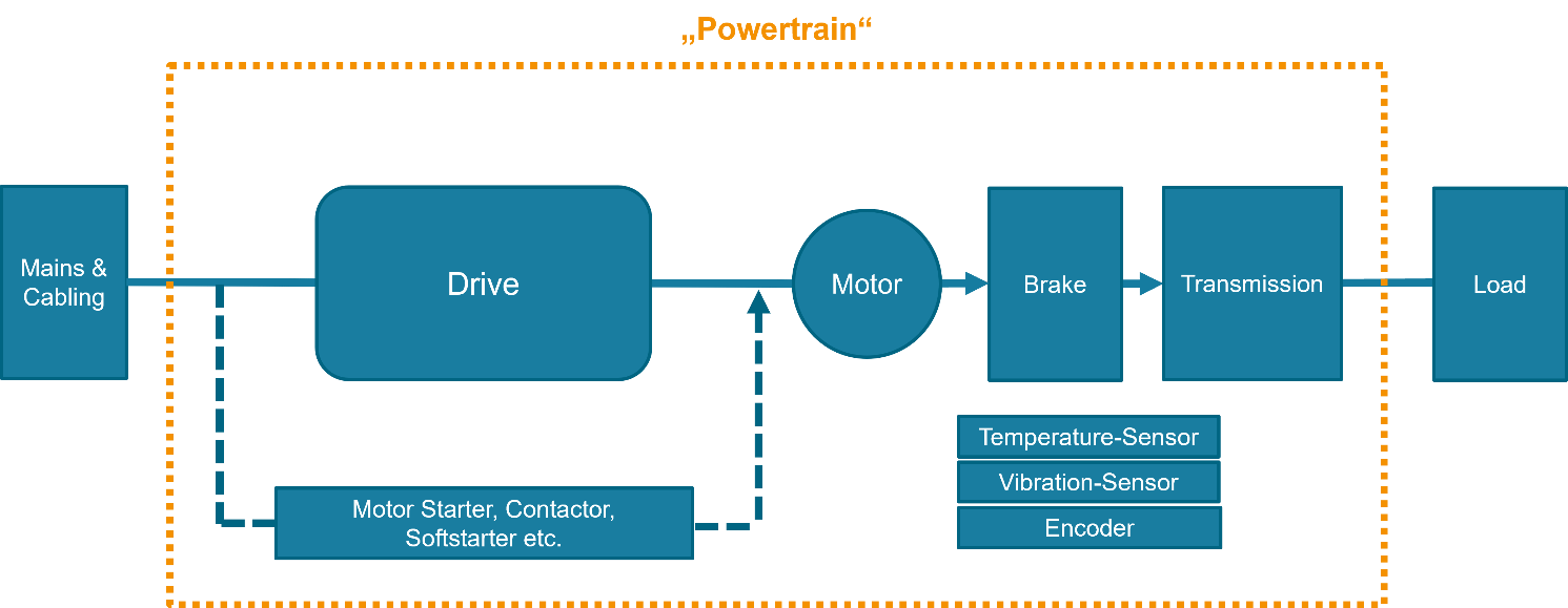
Powertrain stands for a system that includes electromechanical components e.g. one or more motor starter(s), complete drive module(s) (CDM), electric motor(s) as well as transmission elements.
4.2 Introduction to OPC Unified Architecture
4.2.1 What is OPC UA?
OPC UA is an open and royalty free set of standards designed as a universal communication protocol. While there are numerous communication solutions available, OPC UA has key advantages:
A state of art security model (see OPC 10000-2).
A fault tolerant communication protocol.
An information modelling framework that allows application developers to represent their data in a way that makes sense to them.
OPC UA has a broad scope which delivers for economies of scale for application developers. This means that a larger number of high-quality applications at a reasonable cost are available. When combined with semantic models such as powertrain, OPC UA makes it easier for end users to access data via generic commercial applications.
The OPC UA model is scalable from small devices to ERP systems. OPC UA Servers process information locally and then provide that data in a consistent format to any application requesting data - ERP, MES, PMS, Maintenance Systems, HMI, Smartphone or a standard Browser, for examples. For a more complete overview see OPC 10000-1.
4.2.2 Basics of OPC UA
As an open standard, OPC UA is based on standard internet technologies, like TCP/IP, HTTP, Web Sockets.
As an extensible standard, OPC UA provides a set of Services (see OPC 10000-4) and a basic information model framework. This framework provides an easy manner for creating and exposing vendor defined information in a standard way. More importantly all OPC UA Clients are expected to be able to discover and use vendor-defined information. This means OPC UA users can benefit from the economies of scale that come with generic visualization and historian applications. This specification is an example of an OPC UA Information Model designed to meet the needs of developers and users.
OPC UA Clients can be any consumer of data from another device on the network to browser based thin clients and ERP systems. The full scope of OPC UA applications is shown in Figure 1.

OPC UA provides a robust and reliable communication infrastructure having mechanisms for handling lost messages, failover, heartbeat, etc. With its binary encoded data, it offers a high-performing data exchange solution. Security is built into OPC UA as security requirements become more and more important especially since environments are connected to the office network or the internet and attackers are starting to focus on automation systems.
4.2.3 Information modelling in OPC UA
4.2.3.1 Concepts
OPC UA provides a framework that can be used to represent complex information as Objects in an AddressSpace which can be accessed with standard services. These Objects consist of Nodes connected by References. Different classes of Nodes convey different semantics. For example, a Variable Node represents a value that can be read or written. The Variable Node has an associated DataType that can define the actual value, such as a string, float, structure etc. It can also describe the Variable value as a variant. A Method Node represents a function that can be called. Every Node has a number of Attributes including a unique identifier called a NodeId and non-localized name called as BrowseName. An Object representing a 'Reservation' is shown in Figure 2.

Object and Variable Nodes represent instances and they always reference a TypeDefinition (ObjectType or VariableType) Node which describes their semantics and structure. Figure 3 illustrates the relationship between an instance and its TypeDefinition.
The type Nodes are templates that define all of the children that can be present in an instance of the type. In the example in the PersonType ObjectType defines two children: First Name and Last Name. All instances of PersonType are expected to have the same children with the same BrowseNames. Within a type the BrowseNames uniquely identify the children. This means Client applications can be designed to search for children based on the BrowseNames from the type instead of NodeIds. This eliminates the need for manual reconfiguration of systems if a Client uses types that multiple Servers implement.
OPC UA also supports the concept of sub-typing. This allows a modeller to take an existing type and extend it. There are rules regarding sub-typing defined in OPC 10000-3, but in general they allow the extension of a given type or the restriction of a DataType. For example, the modeller may decide that the existing ObjectType in some cases needs an additional Variable. The modeller can create a subtype of the ObjectType and add the Variable. A Client that is expecting the parent type can treat the new type as if it was of the parent type. Regarding DataTypes, subtypes can only restrict. If a Variable is defined to have a numeric value, a sub type could restrict it to a float.

References allow Nodes to be connected in ways that describe their relationships. All References have a ReferenceType that specifies the semantics of the relationship. References can be hierarchical or non-hierarchical. Hierarchical references are used to create the structure of Objects and Variables. Non-hierarchical are used to create arbitrary associations. Applications can define their own ReferenceType by creating subtypes of an existing ReferenceType. Subtypes inherit the semantics of the parent but may add additional restrictions. Figure 4 depicts several References, connecting different Objects.

The figures above use a notation that was developed for the OPC UA specification. The notation is summarized in Figure 5. UML representations can also be used; however, the OPC UA notation is less ambiguous because there is a direct mapping from the elements in the figures to Nodes in the AddressSpace of an OPC UA Server.

A complete description of the different types of Nodes and References can be found in OPC 10000-3 and the base structure is described in OPC 10000-5.
OPC UA specification defines a very wide range of functionality in its basic information model. It is not required that all Clients or Servers support all functionality in the OPC UA specifications. OPC UA includes the concept of Profiles, which segment the functionality into testable certifiable units. This allows the definition of functional subsets (that are expected to be implemented) within a companion specification. The Profiles do not restrict functionality, but generate requirements for a minimum set of functionality (see OPC 10000-7).
4.2.3.2 Namespaces
OPC UA allows information from many different sources to be combined into a single coherent AddressSpace. Namespaces are used to make this possible by eliminating naming and id conflicts between information from different sources. Each namespace in OPC UA has a globally unique string called a NamespaceUri which identifies a naming authority and a locally unique integer called a NamespaceIndex, which is an index into the Server's table of NamespaceUris. The NamespaceIndex is unique only within the context of a Session between an OPC UA Client and an OPC UA Server- the NamespaceIndex can change between Sessions and still identify the same item even though the NamespaceUri's location in the table has changed. The Services defined for OPC UA use the NamespaceIndex to specify the Namespace for qualified values.
There are two types of structured values in OPC UA that are qualified with NamespaceIndexes: NodeIds and QualifiedNames. NodeIds are locally unique (and sometimes globally unique) identifiers for Nodes. The same globally unique NodeId can be used as the identifier in a node in many Servers - the node's instance data may vary but its semantic meaning is the same regardless of the Server it appears in. This means Clients can have built-in knowledge of of what the data means in these Nodes. OPC UA Information Models generally define globally unique NodeIds for the TypeDefinitions defined by the Information Model.
QualifiedNames are non-localized names qualified with a Namespace. They are used for the BrowseNames of Nodes and allow the same names to be used by different information models without conflict. TypeDefinitions are not allowed to have children with duplicate BrowseNames; however, instances do not have that restriction.
4.2.3.3 Companion Specifications
An OPC UA companion specification for an industry specific vertical market describes an Information Model by defining ObjectTypes, VariableTypes, DataTypes and ReferenceTypes that represent the concepts used in the vertical market, and potentially also well-defined Objects as entry points into the AddressSpace.
5 Use cases
As an integral part of machines and plants, among other applications, drive technology determines their costs, energy efficiency, optimization potential and the manufacturing quality of the products in many ways. Also, for Industrie 4.0 applications and processes, too, electrical and mechanical drive components, as data source and as an active part of intelligent applications, are an essential building block.
In mechanical and plant engineering, a wide variety of drive components from a wide range of manufacturers are used, each of which must be integrated into comprehensive, complex systems with their supported fieldbus systems, interfaces and device profiles.
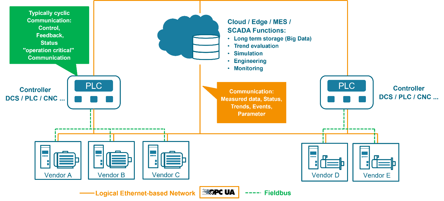
OPC UA makes it possible, based on user requirements, to soften this complexity and enable simplified, interoperable communication for powertrain components. Thereby an OPC UA information model has the capability to cover a powertrains complete functionality from simple device representation like motor, contactors up to field level communication and cloud connectivity (see Figure 6).
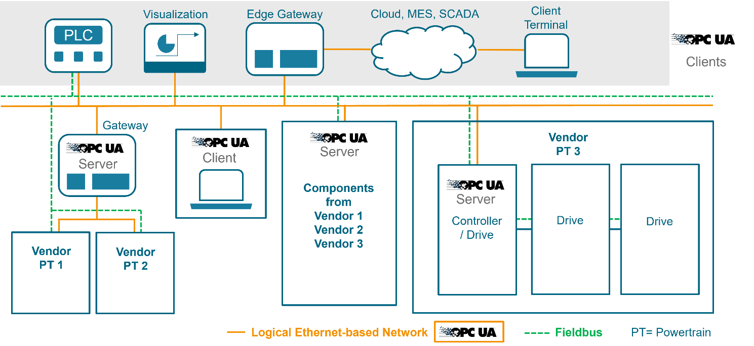
This specification does not target real-time control applications for the powertrain but addresses user-related non-real-time use cases based on vertical communication from the field level up to the cloud (see Figure 7).
Asset Management:
The use case chosen for the first part of the specification is asset management. This first part provides detailed information of the main electrical and mechanical assets like part number, manufacturer name, serial number, firmware version. Further powertrain specific attributes of assets are specified (catalog data). With these data e.g. maintenance and replacement of assets is possible because the technician knows in advance which parts need to be changed and can be prepared. Assets are defined as orderable parts of the powertrain, e. g. a motor, a brake or a servo inverter/drive.
Asset management can be detailed further into the following sub-use cases:
Asset identification
Assembly of assets
Tracking of changes of assets
Inventory, check and search for assets
Providing of information for the selection of compatible powertrain assets
Order a bunch of assets
Health indicator for assets
6 Powertrain Information Model Overview
6.1 Powertrain
A powertrain can be built up in many different configurations. In its simplest form it is just a motor contactor or motor starter and a motor (see Figure 8). Another configuration may be a variable speed drive driving two asynchronous motors simultaneously. The typical servo drive consists of inverter/drive and motor realizing closed loop position control by encoder feedback devices. An even more complex setup is to combine several motors to perform synchronized motion by means of a motion PLC or CNC and a fieldbus.
The scope of this document focuses on the elements of a drive system. This includes drive component related products (e.g., brake resistor, DC bus module, safety module, input/output filter), drive related products (e.g., contactor, motor starter, drive types) and motor/motor component related products (e.g., motor, gearmotor, encoder, sensors). Out of scope are mains and components of the load side.
6.2 Information Model Structure
Due to the complexity of real-world powertrains the information model must be highly modular. This means that OPC UA objects must be provided which are not too fine granular but enable to represent the majority of existing devices by combining them. The level of granularity was chosen to be on basic component level like motor, encoder and brake. These entities are called assets (PtAssetType) and have one or more components holding their asset attributes (PtAssetAttributesType). Also, it´s possible to model a software asset type e.g. firmware by using the PtAssetType.
The powertrain information model is based on two main object types:
| 1. |
PtAssetType
(powertrain asset type) | Represents an orderable part of the powertrain. It serves as a container for the asset's attributes. The most common attributes of asset types are added as mandatory components. e. g. motor and encoder for servo motor. |
| 2. |
PtAssetAttributesType
(powertrain asset attribute type) | Asset attributes are split into two categories. Some of the common asset attributes apply to all asset types (e.g., ambient temperature). Specific asset attributes apply only to some subset of asset types, (e.g., MotorPolePairs applies to several motor related asset types). |
Some asset types have a one-to-one relation to an PtAssetAttributesType like PtAssetEncoderType to PtEncoderAttributesType. Others have a one-to-many relation e. g. a gear motor PtAssetGearMotorRoteryType has mandatory properties of type PtGearAttributesType and PtMotorRoteryAttributesType. A complex asset like PtAssetServoDriveType has to be decomposed into the predefined component asset attributes like PtInputConverterAttributesType and PtOutputConverterAttributesType.
Figure 10 shows the powertrain information model basic structure. Subtypes of PtAssetType have attributes which are subtypes of PtAssetAttributesType.
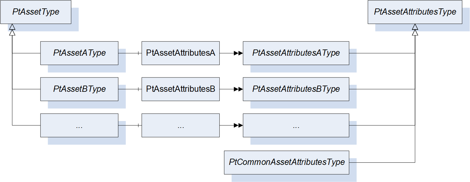
Besides the asset attributes which are directly associated to an asset there are also common asset attributes found in a powertrain which may be used in multiple assets. These are defined under PtCommonAssetAttributesType and cover domains like standards, hardware or ambient conditions.
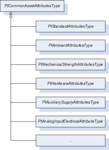
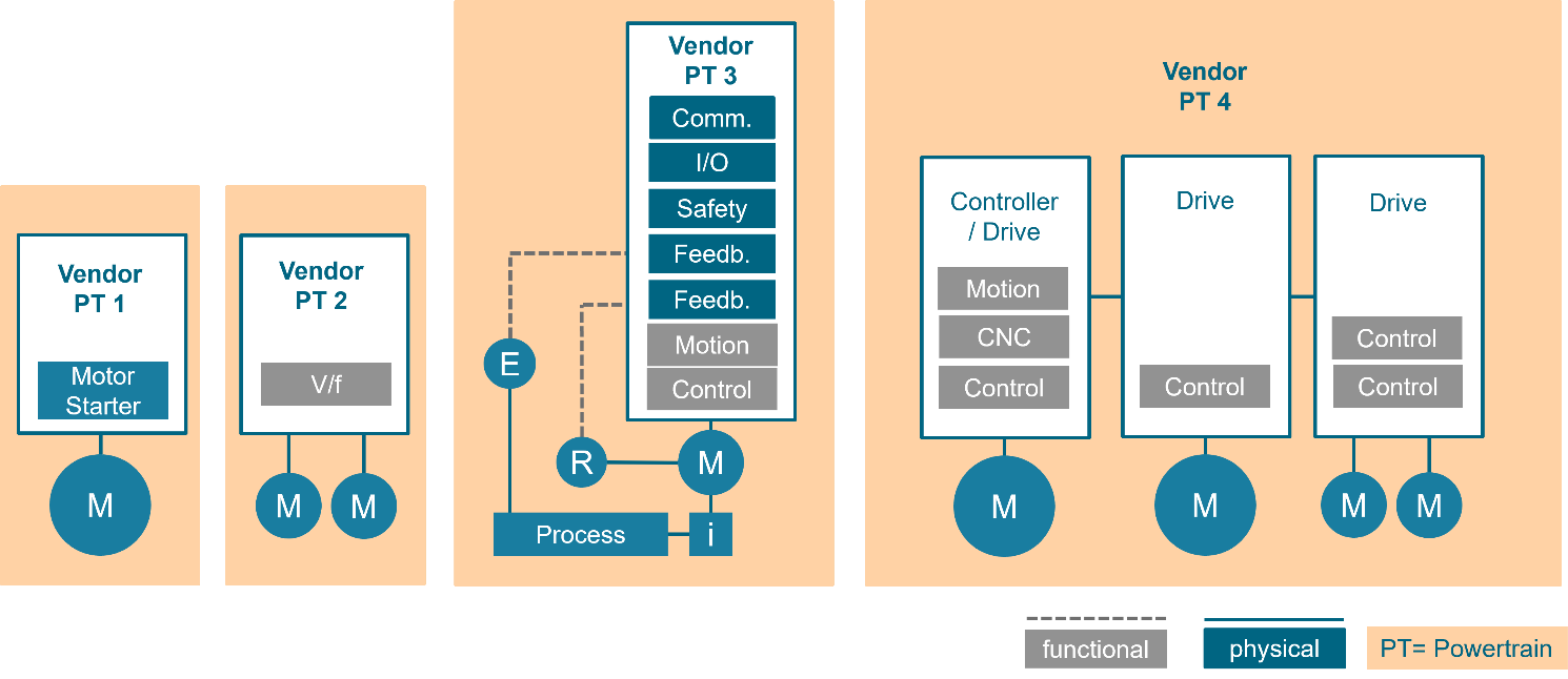
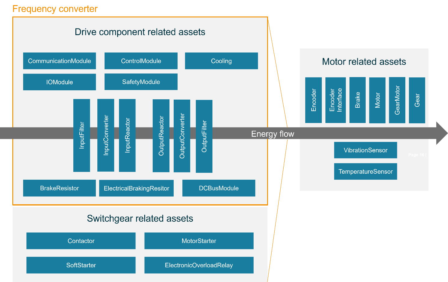
Figure 12 shows asset types grouped into drive component related, switchgear related and motor related assets. The swim lanes shall illustrate the energy flow through drive and motor. The frequency converter is shown with an orange frame and is split into assets like control module, input converter, DC bus and output converter. Below the low voltage switchgear related assets include e.g. a contactor that simply switches current on and off to the motor. A more complex setup uses a motor starter.
The following table gives an overview of the available asset types and their asset attributes. The asset terms are described in chapter 6.3.
Motor / Motor Components related AssetTypes
Motor component related asset types contain the motor itself and devices which are mounted near the motor to measure actual data or affect the motion output.
Drive Components related AssetTypes
Drive components related asset types contain building blocks of a drive like input and output converter and control module. These building blocks should be sufficient to compose a drive of any type.
Complete Drive Devices related AssetTypes
The PtAssetDriveType serves as a generic container while subtypes PtAssetFrequencyConverterType or PtAssetVariableSpeedDriveType are for the user's convenience to express a specific class of drives. Another intention is to make some components mandatory as PtAssetMotorRotaryType for PtAssetDriveIntegratedMotorType.
Switchgear related AssetTypes
Switchgear related PtAssetTypes contain devices that can be used to control, protect and monitor an asynchronous motor, and sometimes associated with a variable speed drive described in a separate section.
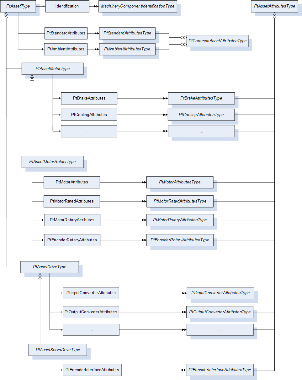
The modular approach of the information model is shown in an example in Figure 13. A PtAssetMotorRotaryType, representing a servo motor, has properties of PtAssetAttributesType for the rotary motor, rotary encoder and brake. A PtAssetServoDriveType is a subtype of PtAssetDriveType and has additional encoder asset attributes. Motor and servo drives can of course have arbitrary numbers of objects of the PtCommonAssetAttributesType.
6.3 PtAssetType and Identification
In the Table 18 the properties that are required for identifying assets of a powertrain are described. Since there are already several OPC UA specification existing that are covering similar topics, this specification shall reuse them where possible. The following specifications have been identified as relevant:
OPC 10000-100 - Device Integration
OPC 40001-1 - OPC UA for Machinery
OPC 10000-81 - Information Model and Connecting Devices
The general assumption is that any VDMA Companion Specification shall be in line with the OPC 40001-1. So that this approach is also followed here.
Additionally, this specification shall also be compliant to the OPC 10000-81 (Information Model & Connecting Devices) specification, since the defined PtAssetType shall be usable by the OPC UA FX Motion specification as well.
Objects are compliant to the FxAssetType if they are instances of the type FxAssetType, a subtype of it or if they implement the required interfaces which are IVendorNameplateType, ITagNameplateType of OPC 10000-100 and IAssetRevisionType of OPC 10000-81.
Since this specification shall be usable standalone and independent from OPC 10000-81 it follows the approach of implementing the interfaces to be compliant.
Figure 14 shows the overview of the PtAssetType and its identification concept including all related specifications and type definitions.
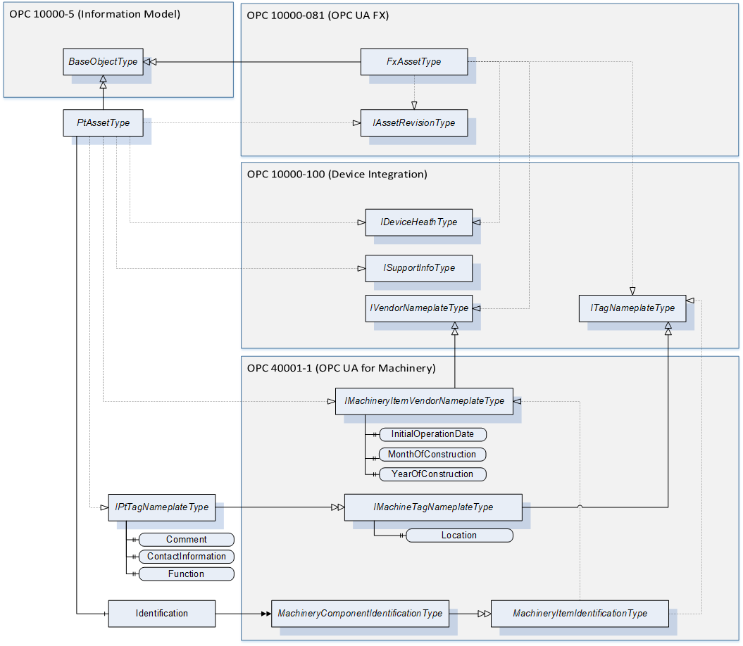
The PtAssetType references directly the IDeviceHealthType and the ISupportInfoType from OPC 10000-100.
By that it gets the property DeviceHealth as well as the folders for DeviceTypeImage, ImageSet, Documentation and ProtocolSupport.
It uses the IMachineryItemVendorNameplateType in order to get the InitialOperationDate property.
Further a new interface type called IPtTagNameplateType is defined. This is derived from the IMachineTagNameplateType in order to get the Location property. Further it adds the Comment, ContactInformation and Function properties.
Finally, to ensure the compatibility to OPC 10000-81 it implements the IAssetRevision interface.
The PtAssetType is a component in the sense of the OPC 40001-1 specification and therefore also be compliant to that. To ensure that compatibility the PtAssetType must provide an object called Identification which is an instance of the MachineryComponentIdentificationType or a subtype.
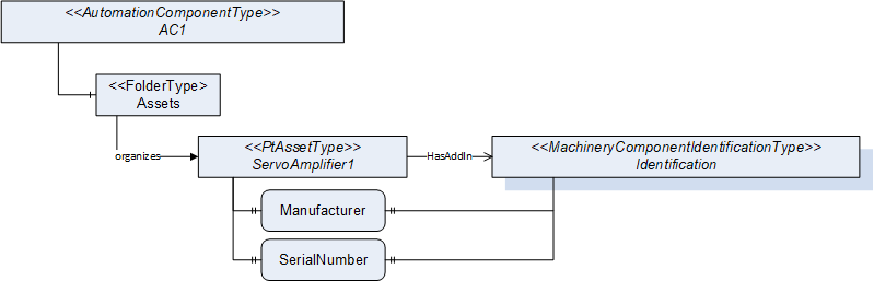
In OPC 10000-81 the identification properties are assembled below the asset whereas the OPC 40001-1 uses an object as and add-in for structuring. This specification shall bring both approaches together to be compatible to them. This concept is exemplary illustrated in Figure 15. Since both, the interfaces of OPC 10000-81 and the Identification add-in, are optional the model can be also used standalone.
7 OPC UA ObjectTypes
7.1 PtAssetType ObjectType Definition
7.1.1 Overview
The PtAssetType provides the properties that are required for identifying assets of a powertrain and is formally defined in Table 18.
| Attribute | Value | ||||
| BrowseName | PtAssetType | ||||
| IsAbstract | False | ||||
| References | Node Class | BrowseName | DataType | TypeDefinition | Other | |
|---|---|---|---|---|---|---|
| Subtype of the BaseObjectType defined in OPC 10000-5: OPC Unified Architecture | ||||||
| 0:HasProperty | Variable | 0:DefaultInstanceBrowseName | 0:QualifiedName | 0:PropertyType | ||
| 0:HasInterface | ObjectType | IPtTagNameplateType | ||||
| 0:HasInterface | ObjectType | 3:IMachineryItemVendorNameplateType | ||||
| 0:HasInterface | ObjectType | 2:IDeviceHealthType | ||||
| 0:HasInterface | ObjectType | 2:ISupportInfoType | ||||
| 0:HasInterface | ObjectType | 4:IAssetRevisionType | ||||
| 0:HasAddIn | Object | 2:Identification | 3:MachineryComponentIdentificationType | O | ||
| ||||||
| 0:HasProperty | Variable | 2:DeviceClass | 0:String | 0:PropertyType | O, RO | |
| 0:HasProperty | Variable | 2:DeviceManual | 0:String | 0:PropertyType | O, RO | |
| 0:HasProperty | Variable | 2:DeviceRevision | 0:String | 0:PropertyType | O, RO | |
| 0:HasProperty | Variable | 2:HardwareRevision | 0:String | 0:PropertyType | O, RO | |
| 0:HasProperty | Variable | 2:Manufacturer | 0:LocalizedText | 0:PropertyType | M, RO | |
| 0:HasProperty | Variable | 2:ManufacturerUri | 0:String | 0:PropertyType | O, RO | |
| 0:HasProperty | Variable | 2:Model | 0:LocalizedText | 0:PropertyType | O, RO | |
| 0:HasProperty | Variable | 2:ProductCode | 0:String | 0:PropertyType | O, RO | |
| 0:HasProperty | Variable | 2:ProductInstanceUri | 0:String | 0:PropertyType | O, RO | |
| 0:HasProperty | Variable | 2:RevisionCounter | 0:Int32 | 0:PropertyType | O, RO | |
| 0:HasProperty | Variable | 2:SerialNumber | 0:String | 0:PropertyType | M, RO | |
| 0:HasProperty | Variable | 2:SoftwareRevision | 0:String | 0:PropertyType | O, RO | |
| 0:HasProperty | Variable | 3:InitialOperationDate | 0:DateTime | 0:PropertyType | O, RO | |
| 0:HasProperty | Variable | 3:MonthOfConstruction | 0:Byte | 0:PropertyType | O, RO | |
| 0:HasProperty | Variable | 3:YearOfConstruction | 0:UInt16 | 0:PropertyType | O, RO | |
| 0:HasProperty | Variable | 2:SoftwareReleaseDate | 0:DateTime | 0:PropertyType | O, RO | |
| 0:HasProperty | Variable | 2:PatchIdentifiers | 0:String[] | 0:PropertyType | O, RO | |
| Applied from IPtTagNameplateType | ||||||
| 0:HasProperty | Variable | 2:AssetId | 0:String | 0:PropertyType | O, RW | |
| 0:HasProperty | Variable | 2:ComponentName | 0:LocalizedText | 0:PropertyType | O, RW | |
| 0:HasProperty | Variable | 3:Location | 0:String | 0:PropertyType | O, RW | |
| 0:HasProperty | Variable | Comment | 0:LocalizedText | 0:PropertyType | O, RW | |
| 0:HasProperty | Variable | ContactInformation | 0:String | 0:PropertyType | O, RW | |
| 0:HasProperty | Variable | Function | 0:String | 0:PropertyType | O, RW | |
| Applied from IDeviceHealthType defined in OPC 10000-100: Device Integration | ||||||
| 0:HasComponent | Variable | 2:DeviceHealth | 2:DeviceHealthEnumeration | 0:BaseDataVariableType | O, RO | |
| 0:HasComponent | Object | 2:DeviceHealthAlarms | 0:FolderType | O | ||
| Applied from 4:IAssetRevisionType defined in OPC 10000-81: Information Model and Connecting Devices | ||||||
| 0:HasProperty | Variable | 4:MajorAssetVersion | 0:UInt16 | 0:PropertyType | O | |
| 0:HasProperty | Variable | 4:MinorAssetVersion | 0:UInt16 | 0:PropertyType | O | |
| 0:HasProperty | Variable | 4:BuildAssetNumber | 0:UInt16 | 0:PropertyType | O | |
| 0:HasProperty | Variable | 4:SubBuildAssetNumber | 0:UInt16 | 0:PropertyType | O | |
| 0:HasComponent | Method | 4:VerifyAsset | Defined in 6.3.3 | O | ||
| Applied from ISupportInfoType defined in OPC 10000-100: Device Integration | ||||||
| 0:HasComponent | Object | 2:DeviceTypeImage | 0:FolderType | O, RO | ||
| 0:HasComponent | Object | 2:Documentation | 0:FolderType | O, RW | ||
| 0:HasComponent | Object | 2:DocumentationFiles | 0:FolderType | O | ||
| 0:HasComponent | Object | 2:ImageSet | 0:FolderType | O, RW | ||
| 0:HasComponent | Object | 2:ProtocolSupport | 0:FolderType | O, RO | ||
| Optionally addable CommonAttributesTypes | ||||||
| 0:HasComponent | Object | PtAmbientAttributes | PtAmbientAttributesType | O | ||
| 0:HasComponent | Object | <PtAnalogInputElectricalAttributes> | PtAnalogInputElectricalAttributesType | OP | ||
| 0:HasComponent | Object | <PtAnalogOutputElectricalAttributes> | PtAnalogOutputElectricalAttributesType | OP | ||
| 0:HasComponent | Object | PtAuxiliarySupplyAttributes | PtAuxiliarySupplyAttributesType | O | ||
| 0:HasComponent | Object | PtCertificateAttributes | PtCertificateAttributesType | O | ||
| 0:HasComponent | Object | PtHardwareAttributes | PtHardwareAttributesType | O | ||
| 0:HasComponent | Object | <PtDigitalInputElectricalAttributes> | PtDigitalInputElectricalAttributesType | OP | ||
| 0:HasComponent | Object | <PtDigitalOutputElectricalAttributes> | PtDigitalOutputElectricalAttributesType | OP | ||
| 0:HasComponent | Object | PtMechanicalStrengthAttributes | PtMechanicalStrengthAttributesType | O | ||
| 0:HasComponent | Object | PtProtectionClassAttributes | PtProtectionClassAttributesType | O | ||
| 0:HasComponent | Object | <PtStandardAttributes> | PtStandardAttributesType | OP | ||
| Conformance Units | |||||
|---|---|---|---|---|---|
| Powertrain Base System | |||||
| Powertrain Asset Identification | |||||
| Powertrain Asset Identification Writable Tag | |||||
| Powertrain Asset Attributes Types | |||||
| Powertrain Attributes Information |
7.1.2 Object Description
All common asset attributes types are defined and described within chapter 7.11.
Note to the optional property 2:DeviceClass applied from IMachineryItemVendorNameplateType defined in OPC 40001-1: OPC UA for Machinery: All asset types of this specification are defined as "Drive". If a manufacturer creates its own subtype of PtAssetType to represent a component for which none of the defined subtypes of PtAssetType can be used, the new subtype should also use the DeviceClass "Drive".
Note to the mandatory properties 2:Manufacturer and 2:SerialNumber: If there are assets where these values cannot be provided the use of a "empty string" is recommended.
7.1.3 InstanceDeclarations of the Subtypes of PtAssetType
The InstanceDeclarations of the subtypes of PtAssetType have a value for the DefaultInstanceBrowseName. The DefaultInstanceBrowseName value defines the recommended BrowseName for instances of the type. Instances use an additional enumeration (BrowseName_01) in the BrowseName. The extension of the BrowseName by XY starts with "01" for the first instance and should be continued accordingly for each further instance ("02", "03"......."10", etc.).
| BrowsePath | Value Attribute | Description Attribute | |||||
| 0:DefaultInstanceBrowseName | PtAsset_01 | ||||||
| PtAssetMotor_01 | ||||||
| PtAssetMotorRotary_01 | ||||||
| PtAssetMotorLinear_01 | ||||||
| PtAssetDriveIntegratedMotorRotary_01 | ||||||
| PtAssetDriveIntegratedMotorLinear_01 | ||||||
| PtAssetGearMotorRotary_01 | ||||||
| PtAssetGearMotorLinear_01 | ||||||
| PtAssetDriveIntegratedGearMotorRotary_01 | ||||||
| PtAssetDriveIntegratedGearMotorLinear_01 | ||||||
| PtAssetEncoder_01 | ||||||
| PtAssetEncoderRotary_01 | ||||||
| PtAssetEncoderLinear_01 | ||||||
| PtAssetBrake_01 | ||||||
| PtAssetGear_01 | ||||||
| PtAssetTemperatureSensor_01 | ||||||
| PtAssetVibrationSensor_01 | ||||||
| PtAssetEncoderInterfaceModule_01 | ||||||
| PtAssetBleed_01 | ||||||
| PtAssetElectricalBrakingModule_01 | ||||||
| PtAssetDcBusModule_01 | ||||||
| PtAssetInputConverter_01 | ||||||
| PtAssetOutputConverter_01 | ||||||
| PtAssetInputOutputConverter_01 | ||||||
| PtAssetInputFilter_01 | ||||||
| PtAssetInputReactor_01 | ||||||
| PtAssetOutputFilter_01 | ||||||
| PtAssetOutputReactor_01 | ||||||
| PtAssetCommunicationModule_01 | ||||||
| PtAssetControlModule_01 | ||||||
| PtAssetIoModule_01 | ||||||
| PtAssetSafetyModule_01 | ||||||
| PtAssetCooling_01 | ||||||
| PtAssetPrecharge_01 | ||||||
| PtAssetMotorStarter_01 | ||||||
| PtAssetDrive_01 | ||||||
| PtAssetFrequencyConverter_01 | ||||||
| PtAssetVariableSpeedDrive_01 | ||||||
| PtAssetServoDrive_01 | ||||||
| PtAssetContactor_01 | ||||||
| PtAssetElectricOverloadRelay_01 | ||||||
| PtAssetMotorStarter_01 | ||||||
| PtAssetSoftStarter_01 | ||||||
| PtAssetMotorManagementDevice_01 |
7.2 IPtTagNameplateType InterfaceType ObjectType Definition
7.2.1 Overview
The IPtTagNameplateType is a subtype of the 3:IMachineTagNameplateType defined in OPC 40001-1. It adds additional properties. It is formally defined in Table 20.
| Attribute | Value | ||||
| BrowseName | IPtTagNameplateType | ||||
| IsAbstract | False | ||||
| References | Node Class | BrowseName | DataType | TypeDefinition | Other |
|---|---|---|---|---|---|
| Subtype of the 3:IMachineTagNameplateType defined in OPC 40001-1, i.e. inheriting the InstanceDeclarations of that Node. | |||||
| 0:HasProperty | Variable | Comment | 0: LocalizedText | 0:PropertyType | O, RW |
| 0:HasProperty | Variable | ContactInformation | 0: LocalizedText | 0:PropertyType | O, RW |
| 0:HasProperty | Variable | Function | 0: LocalizedText | 0:PropertyType | O, RW |
| Conformance Units | |||||
|---|---|---|---|---|---|
| Powertrain Base System | |||||
| Powertrain Asset Identification | |||||
| Powertrain Asset Identification Writable Tag |
7.2.2 Object Definition
The Comment property allows user to store any individual additional information.
The ContactInformation property allows the description of the contact point (role, name, department) for this managed asset.
The Function property allows for each device or module within a plant a unique label if necessary for the identification of its function or task.
7.3 Motor / Motor Components related Asset Types
7.3.1 PtAssetMotorType ObjectType Definition
7.3.1.1 Overview
The PtAssetMotorType describes a common base object type for a motor in a powertrain and is formally defined in Table 21. The PtAssetMotorType is a subtype of the PtAssetType and therefore has mandatory identification attributes and optional asset attributes of PtCommonAssetAttributesType.
| Attribute | Value | ||||
| BrowseName | PtAssetMotorType | ||||
| IsAbstract | False | ||||
| References | Node Class | BrowseName | DataType | TypeDefinition | Other |
|---|---|---|---|---|---|
| Subtype of the PtAssetType defined in chapter 7.1 | |||||
| HasPtAttributes | Object | PtBrakeAttributes | PtBrakeAttributesType | O | |
| HasPtAttributes | Object | PtTemperatureSensorAttributes | PtTemperatureSensorAttributesType | O | |
| HasPtAttributes | Object | PtVibrationSensorAttributes | PtVibrationSensorAttributesType | O | |
| HasPtAttributes | Object | PtCoolingAttributes | PtCoolingAttributesType | O | |
| Conformance Units | |||||
|---|---|---|---|---|---|
| Powertrain Base System | |||||
| Powertrain Asset Identification | |||||
| Powertrain Asset Identification Writable Tag | |||||
| Powertrain Asset Attributes Types | |||||
| Powertrain Attributes Information |
7.3.1.2 Object Description
PtBrakeAttributes are formally defined in chapter 7.8.14.
PtTemperatureSensorAttributes are formally defined in chapter 7.8.15.
PtVibrationSensorAttributes are formally defined in chapter 7.8.16.
PtCoolingAttributes are formally defined in chapter 7.11.8.
7.3.2 PtAssetMotorRotaryType ObjectType Definition
7.3.2.1 Overview
The PtAssetMotorRotaryType describes a rotary electrical motor in a powertrain and is formally defined in Table 22. The PtAssetMotorRotaryType is a subtype of the PtAssetMotorType.
This type definition can be used to model different rotary motor variants. In these variants (e.g., a servomotor), the asset supports further functionalities such as encoder feedback or a brake in addition to the pure motor function.
| Attribute | Value | ||||
| BrowseName | PtAssetMotorRotaryType | ||||
| IsAbstract | False | ||||
| References | Node Class | BrowseName | DataType | TypeDefinition | Other |
|---|---|---|---|---|---|
| Subtype of the PtAssetMotorType defined in chapter 7.1 | |||||
| HasPtAttributes | Object | PtMotorRotaryAttributes | PtMotorRotaryAttributesType | M | |
| HasPtAttributes | Object | <PtMotorRotaryRatedAttributes> | PtMotorRotaryRatedAttributesType | MP | |
| HasPtAttributes | Object | <PtEncoderRotaryAttributes> | PtEncoderRotaryAttributesType | OP | |
| Conformance Units | |||||
|---|---|---|---|---|---|
| Powertrain Base System | |||||
| Powertrain Asset Identification | |||||
| Powertrain Asset Identification Writable Tag | |||||
| Powertrain Asset Attributes Types | |||||
| Powertrain Attributes Information |
7.3.2.2 Object Description
PtMotorRotaryAttributes are formally defined in chapter 7.8.2.
<PtMotorRotaryRatedAttributes> are formally defined in chapter 7.8.5.
<PtEncoderRotaryAttributes> are formally defined in chapter 7.8.10.
7.3.3 PtAssetMotorLinearType ObjectType Definition
7.3.3.1 Overview
The PtAssetMotorLinearType describes a linear electrical motor in a powertrain and is formally defined in Table 23. The PtAssetMotorLinearType is a subtype of the PtAssetMotorType.
This type definition can be used to model different linear motor variants. In these variants (e.g., a servomotor), the asset supports further functionalities such as encoder feedback or a brake in addition to the pure motor function.
| Attribute | Value | ||||
| BrowseName | PtAssetMotorLinearType | ||||
| IsAbstract | False | ||||
| References | Node Class | BrowseName | DataType | TypeDefinition | Other |
|---|---|---|---|---|---|
| Subtype of the PtAssetMotorType defined in chapter 7.1 | |||||
| HasPtAttributes | Object | PtMotorLinearAttributes | PtMotorLinearAttributesType | M | |
| HasPtAttributes | Object | <PtMotorLinearRatedAttributes> | PtMotorLinearRatedAttributesType | MP | |
| HasPtAttributes | Object | <PtEncoderLinearAttributes> | PtEncoderLinearAttributesType | OP | |
| Conformance Units | |||||
|---|---|---|---|---|---|
| Powertrain Base System | |||||
| Powertrain Asset Identification | |||||
| Powertrain Asset Identification Writable Tag | |||||
| Powertrain Asset Attributes Types | |||||
| Powertrain Attributes Information |
7.3.3.2 Object Description
PtMotorLinearAttributes are formally defined in chapter 7.8.2.
<PtMotorLinearRatedAttributes> are formally defined in chapter 7.8.5.
<PtEncoderLinearAttributes> are formally defined in chapter 7.8.10.
7.3.4 PtAssetDriveIntegratedMotorRotaryType ObjectType Definition
7.3.4.1 Overview
The PtAssetDriveIntegratedMotorRotaryType represents a rotary motor which has an inverter/drive integrated. It is formally defined in Table 24. The PtAssetDriveIntegratedMotorRotaryType is a subtype of the PtAssetMotorRotaryType and therefore has mandatory identification attributes and optional asset attributes.
| Attribute | Value | ||||
| BrowseName | PtAssetDriveIntegratedMotorRotaryType | ||||
| IsAbstract | False | ||||
| References | Node Class | BrowseName | DataType | TypeDefinition | Other |
|---|---|---|---|---|---|
| Subtype of the PtAssetMotorRotaryType defined in chapter 7.3.2 | |||||
| HasPtAttributes | Object | <PtOutputConverterAttributes> | PtOutputConverterAttributesType | OP | |
| HasPtAttributes | Object | PtInputFilterAttributes | PtInputFilterAttributesType | O | |
| HasPtAttributes | Object | PtReactorAttributes | PtReactorAttributesType | O | |
| HasPtAttributes | Object | PtFunctionalSafetyAttributes | PtFunctionalSafetyAttributesType | O | |
| HasPtAttributes | Object | PtInputConverterAttributes | PtInputConverterAttributesType | O | |
| HasPtAttributes | Object | <PtCommunicationInterfaceAttributes> | PtCommunicationInterfaceAttributesType | OP | |
| Conformance Units | |||||
|---|---|---|---|---|---|
| Powertrain Base System | |||||
| Powertrain Asset Identification | |||||
| Powertrain Asset Identification Writable Tag | |||||
| Powertrain Asset Attributes Types | |||||
| Powertrain Attributes Information |
7.3.4.2 Object Description
<PtOutputConverterAttributes> are formally defined in chapter 7.9.6.
PtInputFilterAttributes are formally defined in chapter 7.9.7.
PtReactorAttributes are formally defined in chapter 7.9.5.
PtFunctionalSafetyAttributes are formally defined in chapter 7.11.17.
PtInputConverterAttributes are formally defined in chapter 7.4.5.
<PtCommunicationInterfaceAttributes> are formally defined in chapter 7.11.7.
Note: The Input interface of the PtAssetMotorRotaryType is used to describe the connection to mains for the PtAssetIntegratedMotorRotaryType.
7.3.5 PtAssetDriveIntegratedMotorLinearType ObjectType Definition
7.3.5.1 Overview
The PtAssetDriveIntegratedMotorLinearType represents a rotary motor which has an inverter/drive integrated. It is formally defined in Table 25. The PtAssetDriveIntegratedMotorLinearType is a subtype of the PtAssetMotorLinearType and therefore has mandatory identification attributes and optional asset attributes.
| Attribute | Value | ||||
| BrowseName | PtAssetDriveIntegratedMotorLinearType | ||||
| IsAbstract | False | ||||
| References | Node Class | BrowseName | DataType | TypeDefinition | Other |
|---|---|---|---|---|---|
| Subtype of the PtAssetMotorLinearType defined in chapter 7.3.2 | |||||
| HasPtAttributes | Object | <PtOutputConverterAttributes> | PtOutputConverterAttributesType | OP | |
| HasPtAttributes | Object | PtInputFilterAttributes | PtInputFilterAttributesType | O | |
| HasPtAttributes | Object | PtReactorAttributes | PtReactorAttributesType | O | |
| HasPtAttributes | Object | PtFunctionalSafetyAttributes | PtFunctionalSafetyAttributesType | O | |
| HasPtAttributes | Object | PtInputConverterAttributes | PtInputConverterAttributesType | O | |
| HasPtAttributes | Object | <PtCommunicationInterfaceAttributes> | PtCommunicationInterfaceAttributesType | OP | |
| Conformance Units | |||||
|---|---|---|---|---|---|
| Powertrain Base System | |||||
| Powertrain Asset Identification | |||||
| Powertrain Asset Identification Writable Tag | |||||
| Powertrain Asset Attributes Types | |||||
| Powertrain Attributes Information |
7.3.5.2 Object Description
<PtOutputConverterAttributes> are formally defined in chapter 7.9.6.
PtInputFilterAttributes are formally defined in chapter 7.9.7.
PtReactorAttributes are formally defined in chapter 7.9.5.
PtFunctionalSafetyAttributes are formally defined in chapter 7.11.17.
PtInputConverterAttributes are formally defined in chapter 7.4.5.
<PtCommunicationInterfaceAttributes> are formally defined in chapter 7.11.7.
Note: The Input interface of the PtAssetMotorLinearType is used to describe the connection to mains for the PtAssetIntegratedMotorLinearType.
7.3.6 PtAssetGearMotorRotaryType ObjectType Definition
7.3.6.1 Overview
The PtAssetGearMotorRotaryType describes a rotary gear motor in a powertrain and is formally defined in Table 26. A rotary gear motor is a combination of a rotary motor and a gearbox in one asset. It is a subtype of the PtAssetMotorRotaryType with mandatory gear attributes.
| Attribute | Value | ||||
| BrowseName | PtAssetGearMotorRotaryType | ||||
| IsAbstract | False | ||||
| References | Node Class | BrowseName | DataType | TypeDefinition | Other |
|---|---|---|---|---|---|
| Subtype of the PtAssetMotorRotaryType defined in chapter 7.3.2 | |||||
| HasPtAttributes | Object | PtGearAttributes | PtGearAttributesType | M | |
| Conformance Units |
|---|
| Powertrain Base System |
| Powertrain Asset Identification |
| Powertrain Asset Identification Writable Tag |
| Powertrain Asset Attributes Types |
| Powertrain Attributes Information |
7.3.6.2 Object Description
PtGearAttributes are formally defined in chapter 7.8.8.
7.3.7 PtAssetGearMotorLinearType ObjectType Definition
7.3.7.1 Overview
The PtAssetGearMotorLinearType describes a linear gear motor in a powertrain and is formally defined in Table 27. A linear gear motor is a combination of a linear motor and a gearbox in one asset. It is a subtype of the PtAssetMotorLinearType with mandatory gear attributes.
| Attribute | Value | ||||
| BrowseName | PtAssetGearMotorLinearType | ||||
| IsAbstract | False | ||||
| References | Node Class | BrowseName | DataType | TypeDefinition | Other |
|---|---|---|---|---|---|
| Subtype of the PtAssetMotorLinearType defined in chapter 7.3.2 | |||||
| HasPtAttributes | Object | PtGearAttributes | PtGearAttributesType | M | |
| Conformance Units |
|---|
| Powertrain Base System |
| Powertrain Asset Identification |
| Powertrain Asset Identification Writable Tag |
| Powertrain Asset Attributes Types |
| Powertrain Attributes Information |
7.3.7.2 Object Description
PtGearAttributes are formally defined in chapter 7.8.8.
7.3.8 PtAssetDriveIntegratedGearMotorRotaryType ObjectType Definition
7.3.8.1 Overview
The PtAssetDriveIntegratedGearMotorRotaryType represents a rotary gear motor which has an inverter/drive integrated. It is formally defined in Table 28. The PtAssetDriveIntegratedGearMotorRotaryType is a subtype of the PtAssetDriveIntegratedMotorRotaryType and therefore has mandatory identification attributes and optional asset attributes.
| Attribute | Value | ||||
| BrowseName | PtAssetDriveIntegratedGearMotorRotaryType | ||||
| IsAbstract | False | ||||
| References | Node Class | BrowseName | DataType | TypeDefinition | Other |
|---|---|---|---|---|---|
| Subtype of the PtAssetDriveIntegratedMotorRotaryType defined in chapter 7.3.4 | |||||
| HasPtAttributes | Object | PtGearAttributes | PtGearAttributesType | M | |
| Conformance Units | |||||
|---|---|---|---|---|---|
| Powertrain Base System | |||||
| Powertrain Asset Identification | |||||
| Powertrain Asset Identification Writable Tag | |||||
| Powertrain Asset Attributes Types | |||||
| Powertrain Attributes Information |
7.3.8.2 Object Description
PtGearAttributes are formally defined in chapter 7.8.8.
Note: The Input interface of the PtAssetMotorRotaryType is used to describe the connection to mains for the PtAssetDriveIntegratedMotorRotaryType
7.3.9 PtAssetDriveIntegratedGearMotorLinearType ObjectType Definition
7.3.9.1 Overview
The PtAssetDriveIntegratedGearMotorLinearType represents a linear gear motor which has an inverter/drive integrated. It is formally defined in Table 28. The PtAssetDriveIntegratedGearMotorLinearType is a subtype of the PtAssetDriveIntegratedMotorLinearType and therefore has mandatory identification attributes and optional asset attributes.
| Attribute | Value | ||||
| BrowseName | PtAssetDriveIntegratedGearMotorLinearType | ||||
| IsAbstract | False | ||||
| References | Node Class | BrowseName | DataType | TypeDefinition | Other |
|---|---|---|---|---|---|
| Subtype of the PtAssetDriveIntegratedMotorLinearType defined in chapter 7.3.5 | |||||
| HasPtAttributes | Object | PtGearAttributes | PtGearAttributesType | M | |
| Conformance Units | |||||
|---|---|---|---|---|---|
| Powertrain Base System | |||||
| Powertrain Asset Identification | |||||
| Powertrain Asset Identification Writable Tag | |||||
| Powertrain Asset Attributes Types | |||||
| Powertrain Attributes Information |
7.3.9.2 Object Description
PtGearAttributes are formally defined in chapter 7.8.8.
Note: The Input interface of the PtAssetMotorLinearType is used to describe the connection to mains for the PtAssetDriveIntegratedMotorLinearType
7.3.10 PtAssetEncoderType ObjectType Definition
7.3.10.1 Overview
The PtAssetEncoderType describes a base object type for an encoder as an electro-mechanical device that is operated in a powertrain and is formally defined in Table 30. The PtAssetEncoderType is a subtype of the PtAssetType and therefore has mandatory identification attributes and optional asset attributes of PtCommonAssetAttributesType.
| Attribute | Value | ||||
| BrowseName | PtAssetEncoderType | ||||
| IsAbstract | False | ||||
| References | Node Class | BrowseName | DataType | TypeDefinition | Other |
|---|---|---|---|---|---|
| Subtype of the PtAssetType defined in chapter 7.1 | |||||
| HasPtAttributes | Object | PtEncoderInterfaceAttributes | PtEncoderInterfaceAttributesType | O | |
| HasPtAttributes | Object | PtFunctionalSafetyAttributes | PtFunctionalSafetyAttributesType | O | |
| HasPtAttributes | Object | <PtCommunicationInterfaceAttributes> | PtCommunicationInterfaceAttributesType | OP | |
| Conformance Units | |||||
|---|---|---|---|---|---|
| Powertrain Base System | |||||
| Powertrain Asset Identification | |||||
| Powertrain Asset Identification Writable Tag | |||||
| Powertrain Asset Attributes Types | |||||
| Powertrain Attributes Information |
7.3.10.2 Object Description
PtEncoderInterfaceAttributes are formally defined in chapter 7.8.13
PtFunctionalSafetyAttributes are formally defined in chapter 7.11.17
<PtCommunicationInterfaceAttributes> are formally defined in chapter 7.11.7.
7.3.11 PtAssetEncoderRotaryType ObjectType Definition
7.3.11.1 Overview
The PtAssetEncoderRotaryType describes a rotary encoder as an electro-mechanical device that is operated in a powertrain which converts the linear or angular position of a motion axis to output signals and is formally defined in Table 31. The PtAssetEncoderRotaryType is a subtype of the PtAssetEncoderType.
| Attribute | Value | ||||
| BrowseName | PtAssetEncoderRotaryType | ||||
| IsAbstract | False | ||||
| References | Node Class | BrowseName | DataType | TypeDefinition | Other |
|---|---|---|---|---|---|
| Subtype of the PtAssetEncoderType defined in chapter 7.1 | |||||
| HasPtAttributes | Object | PtEncoderRotaryAttributes | PtEncoderRotaryAttributesType | O | |
| Conformance Units | |||||
|---|---|---|---|---|---|
| Powertrain Base System | |||||
| Powertrain Asset Identification | |||||
| Powertrain Asset Identification Writable Tag | |||||
| Powertrain Asset Attributes Types | |||||
| Powertrain Attributes Information |
7.3.11.2 Object Description
PtEncoderRotaryAttributes are formally defined in chapter 7.8.10.
7.3.12 PtAssetEncoderLinearType ObjectType Definition
7.3.12.1 Overview
The PtAssetEncoderLinearType describes a linear encoder as an electro-mechanical device that is operated in a powertrain which converts the linear or angular position of a motion axis to output signals and is formally defined in Table 32. The PtAssetEncoderLinearType is a subtype of the PtAssetEncoderType.
| Attribute | Value | ||||
| BrowseName | PtAssetEncoderLinearType | ||||
| IsAbstract | False | ||||
| References | Node Class | BrowseName | DataType | TypeDefinition | Other |
|---|---|---|---|---|---|
| Subtype of the PtAssetEncoderType defined in chapter 7.1 | |||||
| HasPtAttributes | Object | PtEncoderLinearAttributes | PtEncoderLinearAttributesType | O | |
| Conformance Units | |||||
|---|---|---|---|---|---|
| Powertrain Base System | |||||
| Powertrain Asset Identification | |||||
| Powertrain Asset Identification Writable Tag | |||||
| Powertrain Asset Attributes Types | |||||
| Powertrain Attributes Information |
7.3.12.2 Object Description
PtEncoderLinearAttributes are formally defined in chapter 7.8.11.
7.3.13 PtAssetBrakeType ObjectType Definition
7.3.13.1 Overview
The PtAssetBrakeType describes a brake which is operated in a powertrain capable of reducing the rotor speed or stopping rotation of a motor and is formally defined in Table 33. The PtAssetBrakeType is a subtype of the PtAssetType and therefore has mandatory identification attributes.
| Attribute | Value | ||||
| BrowseName | PtAssetBrakeType | ||||
| IsAbstract | False | ||||
| References | Node Class | BrowseName | DataType | TypeDefinition | Other |
|---|---|---|---|---|---|
| Subtype of the PtAssetType defined in chapter 7.1 | |||||
| HasPtAttributes | Object | PtBrakeAttributes | PtBrakeAttributesType | M | |
| Conformance Units | |||||
|---|---|---|---|---|---|
| Powertrain Base System | |||||
| Powertrain Asset Identification | |||||
| Powertrain Asset Identification Writable Tag | |||||
| Powertrain Asset Attributes Types | |||||
| Powertrain Attributes Information |
7.3.13.2 Object Description
PtBrakeAttributes are formally defined in chapter 7.8.14.
7.3.14 PtAssetGearType ObjectType Definition
7.3.14.1 Overview
The PtAssetGearType describes a gear in a powertrain which transfers and transforms movements, energy and/or forces and is formally defined in Table 34. The PtAssetGearType is a subtype of the PtAssetType and therefore has mandatory identification attributes and optional asset attributes of PtCommonAssetAttributesType.
| Attribute | Value | ||||
| BrowseName | PtAssetGearType | ||||
| IsAbstract | False | ||||
| References | Node Class | BrowseName | DataType | TypeDefinition | Other |
|---|---|---|---|---|---|
| Subtype of the PtAssetType defined in chapter 7.1 | |||||
| HasPtAttributes | Object | PtGearAttributes | PtGearAttributesType | M | |
| HasPtAttributes | Object | PtTemperatureSensorAttributes | PtTemperatureSensorAttributesType | O | |
| HasPtAttributes | Object | PtVibrationSensorAttributes | PtVibrationSensorAttributesType | O | |
| Conformance Units |
| Powertrain Base System |
| Powertrain Asset Identification |
| Powertrain Asset Identification Writable Tag |
| Powertrain Asset Attributes Types |
| Powertrain Attributes Information |
7.3.14.2 Object Description
PtGearAttributes are formally defined in chapter 7.8.8.
PtTemperatureSensorAttributes are formally defined in chapter 7.8.15.
PtVibrationSensorAttributes are formally defined in chapter 7.8.16.
7.3.15 PtAssetTemperatureSensorType ObjectType Definition
7.3.15.1 Overview
The PtAssetTemperatureSensorType describes a device designed to respond to temperature providing an electrical signal or mechanical operation and that is operated in a powertrain and is formally defined in Table 35. The PtAssetTemperatureSensorType is a subtype of the PtAssetType and therefore has mandatory identification attributes.
| Attribute | Value | ||||
| BrowseName | PtAssetTemperatureSensorType | ||||
| IsAbstract | False | ||||
| References | Node Class | BrowseName | DataType | TypeDefinition | Other |
|---|---|---|---|---|---|
| Subtype of the PtAssetType defined in chapter 7.1 | |||||
| HasPtAttributes | Object | PtTemperatureSensorAttributes | PtTemperatureSensorAttributesType | M | |
| Conformance Units |
| Powertrain Base System |
| Powertrain Asset Identification |
| Powertrain Asset Identification Writable Tag |
| Powertrain Asset Attributes Types |
| Powertrain Attributes Information |
7.3.15.2 Object Description
PtTemperatureSensorAttributes are formally defined in chapter 7.8.15.
7.3.16 PtAssetVibrationSensorType ObjectType Definition
7.3.16.1 Overview
The PtAssetVibrationSensorType describes a device designed to detect any kind of vibrations and that is operated in a powertrain and is formally defined in Table 36. The PtAssetVibrationSensorType is a subtype of the PtAssetType and therefore has mandatory identification attributes.
| Attribute | Value | ||||
| BrowseName | PtAssetVibrationSensorType | ||||
| IsAbstract | False | ||||
| References | Node Class | BrowseName | DataType | TypeDefinition | Other |
|---|---|---|---|---|---|
| Subtype of the PtAssetType defined in chapter 7.1 | |||||
| HasPtAttributes | Object | PtVibrationSensorAttributes | PtVibrationSensorAttributesType | M | |
| Conformance Units |
| Powertrain Base System |
| Powertrain Asset Identification |
| Powertrain Asset Identification Writable Tag |
| Powertrain Asset Attributes Types |
| Powertrain Attributes Information |
7.3.16.2 Object Description
PtVibrationSensorAttributes are formally defined in chapter 7.8.16.
7.4 Drive Components related AssetsTypes
7.4.1 PtAssetEncoderInterfaceModuleType ObjectType Definition
7.4.1.1 Overview
The PtAssetEncoderInterfaceModuleType describes an encoder module that can be added to a drive in order to connect additional encoders to the drive and is formally defined in Table 37. The PtAssetEncoderInterfaceModuleType is a subtype of the PtAssetType and therefore has mandatory identification attributes and optional asset attributes of PtCommonAssetAttributesType.
| Attribute | Value | ||||
| BrowseName | PtAssetEncoderInterfaceModuleType | ||||
| IsAbstract | False | ||||
| References | Node Class | BrowseName | DataType | TypeDefinition | Other |
|---|---|---|---|---|---|
| Subtype of the PtAssetType defined in chapter 7.1 | |||||
| HasPtAttributes | Object | <PtEncoderInterfaceAttributes> | PtEncoderInterfaceAttributesType | MP | |
| HasPtAttributes | Object | PtFunctionalSafetyAttributes | PtFunctionalSafetyAttributesType | O | |
| Conformance Units | |||||
|---|---|---|---|---|---|
| Powertrain Base System | |||||
| Powertrain Asset Identification | |||||
| Powertrain Asset Identification Writable Tag | |||||
| Powertrain Asset Attributes Types | |||||
| Powertrain Attributes Information |
7.4.1.2 Object Description
<PtEncoderInterfaceAttributes> are formally defined in chapter 7.8.13.
PtFunctionalSafetyAttributes are formally defined in chapter 7.11.17.
7.4.2 PtAssetBleedType ObjectType Definition
7.4.2.1 Overview
The PtAssetBleedType consumes surplus energy and dissipate that consumed energy in the form of heat and is formally defined in Table 38. Thereby the bleed resistor asset mainly consists out of a high power resistor while the control of the energy flow through the bleed resistor is outside the bleed resistor component (asset). The PtAssetBleedType is a subtype of the PtAssetType and therefore has mandatory identification attributes.
| Attribute | Value | ||||
| BrowseName | PtAssetBleedType | ||||
| IsAbstract | False | ||||
| References | Node Class | BrowseName | DataType | TypeDefinition | Other |
|---|---|---|---|---|---|
| Subtype of the PtAssetType defined in chapter 7.1 | |||||
| HasPtAttributes | Object | PtBleedAttributes | PtBleedAttributesType | M | |
| Conformance Units |
| Powertrain Base System |
| Powertrain Asset Identification |
| Powertrain Asset Identification Writable Tag |
| Powertrain Asset Attributes Types |
| Powertrain Attributes Information |
7.4.2.2 Object Description
PtBleedAttributes are formally defined in chapter 7.9.1.
7.4.3 PtAssetElectricalBrakingModuleType ObjectType Definition
7.4.3.1 Overview
The PtAssetElectricalBrakingModuleType represents a specific module which is used for braking and is formally defined in Table 39. Thereby the electrical braking module asset typically contains a high-power resistor and additional electronics to control the energy flow through the resistor or for managing of the braking module. The PtAssetElectricalBrakingModuleType is a subtype of the PtAssetType and therefore has mandatory identification attributes and optional asset attributes of PtCommonAssetAttributesType.
| Attribute | Value | ||||
| BrowseName | PtAssetElectricalBrakingModuleType | ||||
| IsAbstract | False | ||||
| References | Node Class | BrowseName | DataType | TypeDefinition | Other |
|---|---|---|---|---|---|
| Subtype of the PtAssetType defined in chapter 7.1 | |||||
| HasPtAttributes | Object | PtBleedAttributes | PtBleedAttributesType | M | |
| HasPtAttributes | Object | PtCoolingAttributes | PtCoolingAttributesType | O | |
| HasPtAttributes | Object | PtDcBusAttributes | PtDcBusAttributesType | O | |
| Conformance Units |
| Powertrain Base System |
| Powertrain Asset Identification |
| Powertrain Asset Identification Writable Tag |
| Powertrain Asset Attributes Types |
| Powertrain Attributes Information |
7.4.3.2 Object Description
PtBleedAttributes are formally defined in chapter 7.9.1.
PtCoolingAttributes are formally defined in chapter 7.11.8.
PtDcBusAttributes is formally defined in chapter 7.9.2.
7.4.4 PtAssetDcBusModuleType ObjectType Definition
7.4.4.1 Overview
The PtAssetDcBusModuleType describes a DC bus module and is formally defined in Table 40. The PtAssetDcBusModuleType is a subtype of the PtAssetType and therefore has mandatory identification attributes and optional asset attributes of PtCommonAssetAttributesType.
| Attribute | Value | ||||
| BrowseName | PtAssetDcBusModuleType | ||||
| IsAbstract | False | ||||
| References | Node Class | BrowseName | DataType | TypeDefinition | Other |
|---|---|---|---|---|---|
| Subtype of the PtAssetType defined in chapter 7.1 | |||||
| HasPtAttributes | Object | PtDcBusAttributes | PtDcBusAttributesType | M | |
| HasPtAttributes | Object | PtCapacitanceAttributes | PtCapacitanceAttributesType | O | |
| Conformance Units |
| Powertrain Base System |
| Powertrain Asset Identification |
| Powertrain Asset Identification Writable Tag |
| Powertrain Asset Attributes Types |
| Powertrain Attributes Information |
7.4.4.2 Object Description
PtDcBusAttributes are formally defined in chapter 7.9.2.
PtCapacitanceAttributes are formally defined in chapter 7.9.3.
7.4.5 PtAssetInputConverterType ObjectType Definition
7.4.5.1 Overview
The PtAssetInputConverterType describes an input converter in a powertrain and is formally defined in Table 41. The input converter transforms energy from the mains line into the converter DC bus and vice versa if the input converter supports regenerative power functionality. The PtAssetInputConverterType is a subtype of the PtAssetType and therefore has mandatory identification attributes and optional asset attributes of PtCommonAssetAttributesType.
| Attribute | Value | ||||
| BrowseName | PtAssetInputConverterType | ||||
| IsAbstract | False | ||||
| References | Node Class | BrowseName | DataType | TypeDefinition | Other |
|---|---|---|---|---|---|
| Subtype of the PtAssetType defined in chapter 7.1 | |||||
| HasPtAttributes | Object | PtInputConverterAttributes | PtInputConverterAttributesType | O | |
| HasPtAttributes | Object | <PtInputInterfaceAttributes> | PtInputInterfaceAttributesType | MP | |
| HasPtAttributes | Object | <PtFuseAttributes> | PtFuseAttributesType | OP | |
| HasPtAttributes | Object | <PtCoolingAttributes> | PtCoolingAttributesType | OP | |
| HasPtAttributes | Object | PtInputFilterAttributes | PtInputFilterAttributesType | O | |
| HasPtAttributes | Object | PtReactorAttributes | PtReactorAttributesType | O | |
| HasPtAttributes | Object | PtDcBusAttributes | PtDcBusAttributesType | O | |
| HasPtAttributes | Object | PtFunctionalSafetyAttributes | PtFunctionalSafetyAttributesType | O | |
| HasPtAttributes | Object | <PtCommunicationInterfaceAttributes> | PtCommunicationInterfaceAttributesType | OP | |
| HasPtAttributes | Object | PtCapacitanceAttributes | PtCapacitanceAttributesType | O | |
| HasPtAttributes | Object | PtBleedAttributes | PtBleedAttributesType | O | |
| Conformance Units | |||||
|---|---|---|---|---|---|
| Powertrain Base System | |||||
| Powertrain Asset Identification | |||||
| Powertrain Asset Identification Writable Tag | |||||
| Powertrain Asset Attributes Types | |||||
| Powertrain Attributes Information |
7.4.5.2 Object Description
PtInputConverterAttributes are formally defined in chapter 7.9.4.
<PtInputInterfaceAttributes> are formally defined in chapter 7.11.13.
<PtFuseAttributes> are formally defined in chapter 7.11.12.
<PtCoolingAttributes> are formally defined in chapter 7.11.8.
PtInputFilterAttributes are formally defined in chapter 7.9.7.
PtReactorAttributes are formally defined in chapter 7.9.5.
PtDcBusAttributes are formally defined in chapter 7.9.2.
PtFunctionalSafetyAttributes are formally defined in chapter 7.11.17.
<PtCommunicationInterfaceAttributes> are formally defined in chapter 7.11.7.
PtCapacitanceAttributes are formally defined in chapter 7.9.3.
PtBleedAttributes are formally defined in chapter 7.9.1.
7.4.6 PtAssetOutputConverterType ObjectType Definition
7.4.6.1 Overview
The PtAssetOutputConverterType describes an output converter (also known as inverter/drive) as component in a powertrain and is formally defined in Table 42. The output converter transforms energy from the converter DC bus into the motor phase system and vice versa. The PtAssetOutputConverterType is a subtype of the PtAssetType and therefore has mandatory identification attributes and optional asset attributes of PtCommonAssetAttributesType.
| Attribute | Value | ||||
| BrowseName | PtAssetOutputConverterType | ||||
| IsAbstract | False | ||||
| References | Node Class | BrowseName | DataType | TypeDefinition | Other |
|---|---|---|---|---|---|
| Subtype of the PtAssetType defined in chapter 7.1 | |||||
| HasPtAttributes | Object | <PtOutputConverterAttributes> | PtOutputConverterAttributesType | MP | |
| HasPtAttributes | Object | PtOutputInterfaceAttributes | PtOutputInterfaceAttributesType | M | |
| HasPtAttributes | Object | PtDcBusAttributes | PtDcBusAttributesType | O | |
| HasPtAttributes | Object | <PtEncoderInterfaceAttributes> | PtEncoderInterfaceAttributesType | OP | |
| HasPtAttributes | Object | <PtCoolingAttributes> | PtCoolingAttributesType | OP | |
| HasPtAttributes | Object | <PtOutputFilterAttributes> | PtOutputFilterAttributesType | OP | |
| HasPtAttributes | Object | PtReactorAttributes | PtReactorAttributesType | O | |
| HasPtAttributes | Object | <PtFuseAttributes> | PtFuseAttributesType | OP | |
| HasPtAttributes | Object | <PtFunctionalSafetyAttributes> | PtFunctionalSafetyAttributesType | OP | |
| HasPtAttributes | Object | <PtCommunicationInterfaceAttributes> | PtCommunicationInterfaceAttributesType | OP | |
| HasPtAttributes | Object | PtCapacitanceAttributes | PtCapacitanceAttributesType | O | |
| Conformance Units | |||||
|---|---|---|---|---|---|
| Powertrain Base System | |||||
| Powertrain Asset Identification | |||||
| Powertrain Asset Identification Writable Tag | |||||
| Powertrain Asset Attributes Types | |||||
| Powertrain Attributes Information |
7.4.6.2 Object Description
<PtOutputConverterAttributes> are formally defined in chapter 7.9.6.
PtOutputInterfaceAttributes are formally defined in chapter 7.11.14.
PtDcBusAttributes are formally defined in chapter 7.9.2.
<PtEncoderInterfaceAttributes> are formally defined in chapter 7.8.13.
<PtCoolingAttributes> are formally defined in chapter 7.11.8.
<PtOutputFilterAttributes> are formally defined in chapter 7.9.8.
PtReactorAttributes are formally defined in chapter 7.9.5.
<PtFuseAttributes> are formally defined in chapter 7.11.12.
PtFunctionalSafetyAttributes are formally defined in chapter 7.11.17.
<PtCommunicationInterfaceAttributes> are formally defined in chapter 7.11.7.
PtCapacitanceAttributes are formally defined in chapter 7.9.3.
7.4.7 PtAssetInputOutputConverterType ObjectType Definition
7.4.7.1 Overview
The PtAssetInputOutputConverterType describes an input converter combined with an output converter in one asset. This asset does not execute control functions such as position control, velocity control or torque control. These functions are typically executed by a separate control module. The PtAssetInputOutputConverterType is formally defined in Table 43. The PtAssetInputOutputConverterType is a subtype of the PtAssetType and therefore has mandatory identification attributes and optional asset attributes of PtCommonAssetAttributesType.
| Attribute | Value | ||||
| BrowseName | PtAssetInputOutputConverterType | ||||
| IsAbstract | False | ||||
| References | Node Class | BrowseName | DataType | TypeDefinition | Other |
|---|---|---|---|---|---|
| Subtype of the PtAssetType defined in chapter 7.1 | |||||
| HasPtAttributes | Object | PtInputConverterAttributes | PtInputConverterAttributesType | M | |
| HasPtAttributes | Object | PtOutputConverterAttributes | PtOutputConverterAttributesType | M | |
| HasPtAttributes | Object | PtInputInterfaceAttributes | PtInputInterfaceAttributesType | M | |
| HasPtAttributes | Object | PtOutputInterfaceAttributes | PtOutputInterfaceAttributesType | M | |
| HasPtAttributes | Object | PtDcBusAttributes | PtDcBusAttributesType | O | |
| HasPtAttributes | Object | PtInputFilterAttributes | PtInputFilterAttributesType | O | |
| HasPtAttributes | Object | PtOutputFilterAttributes | PtOutputFilterAttributesType | O | |
| HasPtAttributes | Object | <PtEncoderInterfaceAttributes> | PtEncoderInterfaceAttributesType | OP | |
| HasPtAttributes | Object | <PtCoolingAttributes> | PtCoolingAttributesType | OP | |
| HasPtAttributes | Object | <PtReactorAttributes> | PtReactorAttributesType | OP | |
| HasPtAttributes | Object | <PtFuseAttributes> | PtFuseAttributesType | OP | |
| HasPtAttributes | Object | <PtFunctionalSafetyAttributes> | PtFunctionalSafetyAttributesType | OP | |
| HasPtAttributes | Object | <PtCommunicationInterfaceAttributes> | PtCommunicationInterfaceAttributesType | OP | |
| Conformance Units | |||||
|---|---|---|---|---|---|
| Powertrain Base System | |||||
| Powertrain Asset Identification | |||||
| Powertrain Asset Identification Writable Tag | |||||
| Powertrain Asset Attributes Types | |||||
| Powertrain Attributes Information |
7.4.7.2 Object Description
PtInputConverterAttributes are formally defined in chapter 7.9.4.
PtOutputConverterAttributes are formally defined in chapter 7.9.6.
PtInputInterfaceAttributes are formally defined in chapter 7.11.13.
PtOutputInterfaceAttributes are formally defined in chapter 7.11.14.
PtDcBusAttributes are formally defined in chapter 7.9.2.
PtInputFilterAttributes are formally defined in chapter 7.9.7.
PtOutputFilterAttributes are formally defined in chapter 7.9.8.
<PtEncoderInterfaceAttributes> are formally defined in chapter 7.8.12.
<PtCoolingAttributes> are formally defined in chapter 7.11.8.
<PtReactorAttributes> are formally defined in chapter 7.9.5.
<PtFuseAttributes> are formally defined in chapter 7.11.12.
<PtFunctionalSafetyAttributes> are formally defined in chapter 7.11.17.
<PtCommunicationInterfaceAttributes> are formally defined in chapter 7.11.7.
7.4.8 PtAssetInputFilterType ObjectType Definition
7.4.8.1 Overview
The PtAssetInputFilterType describes an input filter in a powertrain and is formally defined in Table 44. The input filter is intended to be placed on the mains side of the power drive system (PDS) in front of the converter or input converter. Its purpose is to suppress converter harmonics from entering the mains line. The PtAssetInputFilterType is a subtype of the PtAssetType and therefore has mandatory identification attributes and optional asset attributes of PtCommonAssetAttributesType.
| Attribute | Value | ||||
| BrowseName | PtAssetInputFilterType | ||||
| IsAbstract | False | ||||
| References | Node Class | BrowseName | DataType | TypeDefinition | Other |
|---|---|---|---|---|---|
| Subtype of the PtAssetType defined in chapter 7.1 | |||||
| HasPtAttributes | Object | PtInputFilterAttributes | PtInputFilterAttributesType | M | |
| HasPtAttributes | Object | PtReactorAttributes | PtReactorAttributesType | O | |
| HasPtAttributes | Object | PtInputInterfaceAttributes | PtInputInterfaceAttributesType | O | |
| Conformance Units |
| Powertrain Base System |
| Powertrain Asset Identification |
| Powertrain Asset Identification Writable Tag |
| Powertrain Asset Attributes Types |
| Powertrain Attributes Information |
7.4.8.2 Object Description
PtInputFilterAttributes are formally defined in chapter 7.9.7.
PtReactorAttributes are formally defined in chapter 7.9.5.
PtInputInterfaceAttributes are formally defined in chapter 7.11.13.
7.4.9 PtAssetInputReactorType ObjectType Definition
7.4.9.1 Overview
The PtAssetInputReactorType describes an input filter realized just of a reactor and is formally defined in Table 45. The input reactor is intended to be placed on the mains side of the powertrain in front of the converter or input converter. Its purpose is to suppress converter harmonics from entering the mains line and support of the converter commutation. The PtAssetInputReactorType is a subtype of the PtAssetType and therefore has mandatory identification attributes and optional asset attributes of PtCommonAssetAttributesType.
| Attribute | Value | ||||
| BrowseName | PtAssetInputReactorType | ||||
| IsAbstract | False | ||||
| References | Node Class | BrowseName | DataType | TypeDefinition | Other |
|---|---|---|---|---|---|
| Subtype of the PtAssetType defined in chapter 7.1 | |||||
| HasPtAttributes | Object | PtReactorAttributes | PtReactorAttributesType | M | |
| HasPtAttributes | Object | PtInputInterfaceAttributes | PtInputInterfaceAttributesType | O | |
| Conformance Units |
| Powertrain Base System |
| Powertrain Asset Identification |
| Powertrain Asset Identification Writable Tag |
| Powertrain Asset Attributes Types |
| Powertrain Attributes Information |
7.4.9.2 Object Description
PtReactorAttributes are formally defined in chapter 7.9.5.
PtInputInterfaceAttributes are formally defined in chapter 7.11.13.
7.4.10 PtAssetOutputFilterType ObjectType Definition
7.4.10.1 Overview
The PtAssetOutputFilterType describes an output filter in a powertrain and is formally defined in Table 46. The output filter is intended to be placed on the motor side of the PTS, after the converter or output converter. Its purpose is to suppress converter harmonics from entering the motor. The PtAssetOutputFilterType is a subtype of the PtAssetType and therefore has mandatory identification attributes and optional asset attributes of PtCommonAssetAttributesType.
| Attribute | Value | ||||
| BrowseName | PtAssetOutputFilterType | ||||
| IsAbstract | False | ||||
| References | Node Class | BrowseName | DataType | TypeDefinition | Other |
|---|---|---|---|---|---|
| Subtype of the PtAssetType defined in chapter 7.1 | |||||
| HasPtAttributes | Object | PtOutputFilterAttributes | PtOutputFilterAttributesType | M | |
| HasPtAttributes | Object | PtReactorAttributes | PtReactorAttributesType | O | |
| HasPtAttributes | Object | PtOutputInterfaceAttributes | PtOutputInterfaceAttributesType | O | |
| Conformance Units |
| Powertrain Base System |
| Powertrain Asset Identification |
| Powertrain Asset Identification Writable Tag |
| Powertrain Asset Attributes Types |
| Powertrain Attributes Information |
7.4.10.2 Object Description
PtOutputFilterAttributes are formally defined in chapter 7.9.8.
PtReactorAttributes are formally defined in chapter 7.9.5.
PtOutputInterfaceAttributes are formally defined in chapter 7.11.14.
7.4.11 PtAssetOutputReactorType ObjectType Definition
7.4.11.1 Overview
The PtAssetOutputReactorType describes an output reactor in a powertrain and is formally defined in Table 47. The output reactor is intended to be placed on the motor side of the powertrain, after the converter or output converter. Its purpose is to suppress converter harmonics from entering the motor and to support the converter commutation. The PtAssetOutputReactorType is a subtype of the PtAssetType and therefore has mandatory identification attributes and optional asset attributes of PtCommonAssetAttributesType.
| Attribute | Value | ||||
| BrowseName | PtAssetOutputReactorType | ||||
| IsAbstract | False | ||||
| References | Node Class | BrowseName | DataType | TypeDefinition | Other |
|---|---|---|---|---|---|
| Subtype of the PtAssetType defined in chapter 7.1 | |||||
| HasPtAttributes | Object | PtReactorAttributes | PtReactorAttributesType | M | |
| HasPtAttributes | Object | PtOutputInterfaceAttributes | PtOutputInterfaceAttributesType | O | |
| Conformance Units |
| Powertrain Base System |
| Powertrain Asset Identification |
| Powertrain Asset Identification Writable Tag |
| Powertrain Asset Attributes Types |
| Powertrain Attributes Information |
7.4.11.2 Object Description
PtReactorAttributes are formally defined in chapter 7.9.5.
PtOutputInterfaceAttributes are formally defined in chapter 7.11.14.
7.4.12 PtAssetCommunicationModuleType ObjectType Definition
7.4.12.1 Overview
The PtAssetCommunicationModuleType describes a device as add-in part of an inverter/drive which holds fieldbus and/or Ethernet network communication functionality. In addition, it may also hold other electrical interfaces and is formally defined in Table 48. The PtAssetCommunicationModuleType is a subtype of the PtAssetType and therefore has mandatory identification attributes and optional asset attributes of PtCommonAssetAttributesType.
| Attribute | Value | ||||
| BrowseName | PtAssetCommunicationModuleType | ||||
| IsAbstract | False | ||||
| References | Node Class | BrowseName | DataType | TypeDefinition | Other |
|---|---|---|---|---|---|
| Subtype of the PtAssetType defined in chapter 7.1 | |||||
| HasPtAttributes | Object | <PtCommunicationInterfaceAttributes> | PtCommunicationInterfaceAttributesType | MP | |
| HasPtAttributes | Object | PtFunctionalSafetyAttributes | PtFunctionalSafetyAttributesType | O | |
| Conformance Units | |||||
|---|---|---|---|---|---|
| Powertrain Base System | |||||
| Powertrain Asset Identification | |||||
| Powertrain Asset Identification Writable Tag | |||||
| Powertrain Asset Attributes Types | |||||
| Powertrain Attributes Information |
7.4.12.2 Object Description
<PtCommunicationInterfaceAttributes> are formally defined in chapter 7.11.7.
PtFunctionalSafetyAttributes are formally defined in chapter 7.11.17.
7.4.13 PtAssetControlModuleType ObjectType Definition
7.4.13.1 Overview
The PtAssetControlModuleType describes a device as part of an inverter/drive which holds the control functionality and mostly is realized by a microcontroller system and is formally defined in Table 49. In addition, it may also hold some electrical interfaces. The PtAssetControlModuleType is a subtype of the PtAssetType and therefore has mandatory identification attributes and optional asset attributes of PtCommonAssetAttributesType.
| Attribute | Value | ||||
| BrowseName | PtAssetControlModuleType | ||||
| IsAbstract | False | ||||
| References | Node Class | BrowseName | DataType | TypeDefinition | Other |
|---|---|---|---|---|---|
| Subtype of the PtAssetType defined in chapter 7.1 | |||||
| HasPtAttributes | Object | <PtCommunicationInterfaceAttributes> | PtCommunicationInterfaceAttributesType | OP | |
| HasPtAttributes | Object | PtFunctionalSafetyAttributes | PtFunctionalSafetyAttributesType | O | |
| HasPtAttributes | Object | <PtEncoderInterfaceAttributes> | PtEncoderInterfaceAttributesType | OP | |
| Conformance Units |
| Powertrain Base System |
| Powertrain Asset Identification |
| Powertrain Asset Identification Writable Tag |
| Powertrain Asset Attributes Types |
| Powertrain Attributes Information |
7.4.13.2 Object Description
<PtCommunicationInterfaceAttributes> are formally defined in chapter 7.11.7.
PtFunctionalSafetyAttributes are formally defined in chapter 7.11.17.
<PtEncoderInterfaceAttributes> are formally defined in chapter 7.8.13.
7.4.14 PtAssetIoModuleType ObjectType Definition
7.4.14.1 Overview
The PtAssetIoModuleType describes a device as part of an inverter/drive which holds input/output (I/O) functionality and electrical interfaces like digital or analog inputs and is formally defined in Table 50. The PtAssetIoModuleType is a subtype of the PtAssetType and therefore has mandatory identification attributes and optional asset attributes of PtCommonAssetAttributesType.
| Attribute | Value | ||||
| BrowseName | PtAssetIoModuleType | ||||
| IsAbstract | False | ||||
| References | Node Class | BrowseName | DataType | TypeDefinition | Other |
|---|---|---|---|---|---|
| Subtype of the PtAssetType defined in chapter 7.1 | |||||
| HasPtAttributes | Object | <PtEncoderInterfaceAttributes> | PtEncoderInterfaceAttributesType | OP | |
| HasPtAttributes | Object | PtFunctionalSafetyAttributes | PtFunctionalSafetyAttributesType | O | |
| Conformance Units | |||||
|---|---|---|---|---|---|
| Powertrain Base System | |||||
| Powertrain Asset Identification | |||||
| Powertrain Asset Identification Writable Tag | |||||
| Powertrain Asset Attributes Types | |||||
| Powertrain Attributes Information |
7.4.14.2 Object Description
<PtEncoderInterfaceAttributes> are formally defined in chapter 7.8.13.
PtFunctionalSafetyAttributes are formally defined in chapter 7.11.17.
7.4.15 PtAssetSafetyModuleType ObjectType Definition
7.4.15.1 Overview
The PtAssetSafetyModuleType describes a device which holds drive based safety functionality e.g. safe torque off (STO), SS1 (safe stop 1) or SLS (safely limited speed) and is formally defined in Table 51. The module may also hold safety related electrical interfaces (IOs) for controlling and monitoring of the drive-based safety functions. The PtAssetSafetyModuleType is a subtype of the PtAssetType and therefore has mandatory identification attributes and optional asset attributes of PtCommonAssetAttributesType.
| Attribute | Value | ||||
| BrowseName | PtAssetSafetyModuleType | ||||
| IsAbstract | False | ||||
| References | Node Class | BrowseName | DataType | TypeDefinition | Other |
|---|---|---|---|---|---|
| Subtype of the PtAssetType defined in chapter 7.1 | |||||
| HasPtAttributes | Object | PtFunctionalSafetyAttributes | PtFunctionalSafetyAttributesType | M | |
| HasPtAttributes | Object | <PtEncoderInterfaceAttributes> | PtEncoderInterfaceAttributesType | OP | |
| Conformance Units | |||||
|---|---|---|---|---|---|
| Powertrain Base System | |||||
| Powertrain Asset Identification | |||||
| Powertrain Asset Identification Writable Tag | |||||
| Powertrain Asset Attributes Types | |||||
| Powertrain Attributes Information |
7.4.15.2 Object Description
PtFunctionalSafetyAttributes are formally defined in chapter 7.11.17.
<PtEncoderInterfaceAttributes> are formally defined in chapter 7.8.13.
7.4.16 PtAssetCoolingType ObjectType Definition
7.4.16.1 Overview
The PtAssetCoolingType describes a device or component which is used as part of the power drive system (PDS) cooling system and is formally defined in Table 52. The PtAssetCoolingType is a subtype of the PtAssetType and therefore has mandatory identification attributes and optional asset attributes of PtCommonAssetAttributesType.
| Attribute | Value | ||||
| BrowseName | PtAssetCoolingType | ||||
| IsAbstract | False | ||||
| References | Node Class | BrowseName | DataType | TypeDefinition | Other |
|---|---|---|---|---|---|
| Subtype of the PtAssetType defined in chapter 7.1 | |||||
| HasPtAttributes | Object | <PtCoolingAttributes> | PtCoolingAttributesType | MP | |
| Conformance Units | |||||
|---|---|---|---|---|---|
| Powertrain Base System | |||||
| Powertrain Asset Identification | |||||
| Powertrain Asset Identification Writable Tag | |||||
| Powertrain Asset Attributes Types | |||||
| Powertrain Attributes Information |
7.4.16.2 Object Description
<PtCoolingAttributes> are formally defined in chapter 7.11.8.
7.4.17 PtAssetPrechargeType ObjectType Definition
7.4.17.1 Overview
The PtAssetPrechargeType controls initial charging of a DC bus. It may connect to the mains or it may connect to another voltage source used specifically for DC bus charging. The purpose of the pre-charge is to limit initial charging (inrush) currents to levels that all components can withstand. The PtAssetPrechargeType is formally defined in Table 53. The PtAssetPrechargeType is a subtype of the PtAssetType and therefore has mandatory identification attributes and optional asset attributes of PtCommonAssetAttributesType.
| Attribute | Value | ||||
| BrowseName | PtAssetPrechargeType | ||||
| IsAbstract | False | ||||
| References | Node Class | BrowseName | DataType | TypeDefinition | Other |
|---|---|---|---|---|---|
| Subtype of the PtAssetType defined in chapter 7.1 | |||||
| HasPtAttributes | Object | PtPrechargeAttributes | PtPrechargeAttributesType | M | |
| HasPtAttributes | Object | PtInputInterfaceAttributes | PtInputInterfaceAttributesType | M | |
| HasPtAttributes | Object | PtCoolingAttributes | PtCoolingAttributesType | O | |
| HasPtAttributes | Object | <PtFuseAttributes> | PtFuseAttributesType | OP | |
| HasPtAttributes | Object | <PtCommunicationInterfaceAttributes> | PtCommunicationInterfaceAttributesType | OP | |
| Conformance Units | |||||
|---|---|---|---|---|---|
| Powertrain Base System | |||||
| Powertrain Asset Identification | |||||
| Powertrain Asset Identification Writable Tag | |||||
| Powertrain Asset Attributes Types | |||||
| Powertrain Attributes Information |
7.4.17.2 Object Description
PtPrechargeAttributes are formally defined in chapter 7.9.9.
PtInputInterfaceAttributes are formally defined in chapter 7.11.13.
PtCoolingAttributes are formally defined in chapter 7.11.8.
<PtFuseAttributes> are formally defined in chapter 7.11.12.
<PtCommunicationInterfaceAttributes> are formally defined in chapter 7.11.7.
7.5 Complete Drive Devices related Asset Types
7.5.1 PtAssetDriveType ObjectType Definition
7.5.1.1 Overview
The PtAssetDriveType describes a drive in a powertrain and is formally defined in Table 54. The PtAssetDriveType is a subtype of the PtAssetType and therefore has mandatory identification attributes and optional asset attributes of PtCommonAssetAttributesType.
| Attribute | Value | ||||
| BrowseName | PtAssetDriveType | ||||
| IsAbstract | False | ||||
| References | Node Class | BrowseName | DataType | TypeDefinition | Other |
|---|---|---|---|---|---|
| Subtype of the PtAssetType defined in chapter 7.5.1 | |||||
| HasPtAttributes | Object | PtCommunicationInterfaceAttributes | PtCommunicationInterfaceAttributesType | O | |
| HasPtAttributes | Object | PtBleedAttributes | PtBleedAttributesType | O | |
| HasPtAttributes | Object | PtInputConverterAttributes | PtInputConverterAttributesType | O | |
| HasPtAttributes | Object | <PtOutputConverterAttributes> | PtOutputConverterAttributesType | MP | |
| HasPtAttributes | Object | PtInputReactorAttributes | PtReactorAttributesType | O | |
| HasPtAttributes | Object | <PtOutputReactorAttributes> | PtReactorAttributesType | OP | |
| HasPtAttributes | Object | PtInputFilterAttributes | PtInputFilterAttributesType | O | |
| HasPtAttributes | Object | <PtOutputFilterAttributes> | PtOutputFilterAttributesType | OP | |
| HasPtAttributes | Object | PtInputInterfaceAttributes | PtInputInterfaceAttributesType | O | |
| HasPtAttributes | Object | <PtOutputInterfaceAttributes> | PtOutputInterfaceAttributesType | OP | |
| HasPtAttributes | Object | PtSafetyFunctionsAttributes | PtSafetyFunctionsAttributesType | O | |
| HasPtAttributes | Object | PtDcBusAttributes | PtDcBusAttributesType | O | |
| Conformance Units | |||||
|---|---|---|---|---|---|
| Powertrain Base System | |||||
| Powertrain Asset Identification | |||||
| Powertrain Asset Identification Writable Tag | |||||
| Powertrain Asset Attributes Types | |||||
| Powertrain Attributes Information |
7.5.1.2 Object Description
PtBleedAttributes are formally defined in chapter 7.9.1.
PtInputConverterAttributes are formally defined in chapter 7.4.5.
<PtOutputConverterAttributes> are formally defined in chapter 7.4.6.
PtInputReactorAttributes are formally defined in chapter 7.4.9.
<PtOutputReactorAttributes> are formally defined in chapter 7.4.11.
PtInputFilterAttributes are formally defined in chapter 7.4.8.
<PtOutputFilterAttributes> are formally defined in chapter 7.4.10.
PtInputInterfaceAttributes are formally defined in chapter 7.11.13.
<PtOutputInterfaceAttributes> are formally defined in chapter 7.11.14.
PtSafetyFunctionsAttributes are formally defined in chapter 7.11.18.
PtDcBusAttributes are formally defined in chapter 7.9.2. Could be used for stand-alone servo drive (PtInputfilterAttributes) or for a distributed DC bus ServoDriveType (PtDcBusAttributes).
7.5.2 PtAssetFrequencyConverterType ObjectType Definition
7.5.2.1 Overview
The PtAssetFrequencyConverterType describes the most general type of an inverter/drive. Its output might be fixed frequency phase currents or even DC. It is formally defined in Table 55. The PtAssetFrequencyConverterType is a subtype of the PtAssetDriveType and includes all its properties.
| Attribute | Value | ||||
| BrowseName | PtAssetFrequencyConverterType | ||||
| IsAbstract | False | ||||
| References | Node Class | BrowseName | DataType | TypeDefinition | Other |
|---|---|---|---|---|---|
| Subtype of the PtAssetDriveType defined in chapter 7.5.1 | |||||
| Conformance Units | |||||
|---|---|---|---|---|---|
| Powertrain Base System | |||||
| Powertrain Asset Identification | |||||
| Powertrain Asset Identification Writable Tag | |||||
| Powertrain Asset Attributes Types | |||||
| Powertrain Attributes Information |
7.5.3 PtAssetVariableSpeedDriveType ObjectType Definition
7.5.3.1 Overview
The PtAssetVariableSpeedDriveType is an inverter/drive which can operate the motor at various speeds. It is formally defined in in Table 56. The PtAssetVariableSpeedDriveType is a subtype of the PtAssetDriveType and therefore has mandatory identification attributes and optional asset attributes.
| Attribute | Value | ||||
| BrowseName | PtAssetVariableSpeedDriveType | ||||
| IsAbstract | False | ||||
| References | Node Class | BrowseName | DataType | TypeDefinition | Other |
|---|---|---|---|---|---|
| Subtype of the PtAssetDriveType defined in chapter 7.5.2 | |||||
| HasPtAttributes | Object | <PtEncoderInterfaceAttributes> | PtEncoderInterfaceAttributesType | OP | |
| Conformance Units | |||||
|---|---|---|---|---|---|
| Powertrain Base System | |||||
| Powertrain Asset Identification | |||||
| Powertrain Asset Identification Writable Tag | |||||
| Powertrain Asset Attributes Types | |||||
| Powertrain Attributes Information |
7.5.3.2 Object Description
<PtEncoderInterfaceAttributes> are formally defined in chapter 7.8.13.
7.5.4 PtAssetServoDriveType ObjectType Definition
7.5.4.1 Overview
The PtAssetServoDriveType is an inverter/drive which operates a motor in a closed loop configuration to feature high dynamics and accuracy. It is formally defined in Table 57. The PtAssetServoSpeedDriveType is a subtype of the PtAssetDriveType and therefore has mandatory identification attributes and optional asset attributes.
| Attribute | Value | ||||
| BrowseName | PtAssetServoDriveType | ||||
| IsAbstract | False | ||||
| References | Node Class | BrowseName | DataType | TypeDefinition | Other |
|---|---|---|---|---|---|
| Subtype of the PtAssetDriveType defined in chapter 7.5.2 | |||||
| HasPtAttributes | Object | <PtEncoderInterfaceAttributes> | PtEncoderInterfaceAttributesType | MP | |
| Conformance Units | |||||
|---|---|---|---|---|---|
| Powertrain Base System | |||||
| Powertrain Asset Identification | |||||
| Powertrain Asset Identification Writable Tag | |||||
| Powertrain Asset Attributes Types | |||||
| Powertrain Attributes Information |
7.5.4.2 Object Description
<PtEncoderInterfaceAttributes> are formally defined in chapter 7.8.13.
7.6 Switchgear related Asset Types
7.6.1 PtAssetContactorType ObjectType Definition
7.6.1.1 Overview
The PtAssetContactorType describes a contactor as an electro-mechanical device that is operated in a powertrain and is formally defined in Table 58. The PtAssetContactorType is a subtype of the PtAssetType and therefore has mandatory identification attributes.
| Attribute | Value | ||||
| BrowseName | PtAssetContactorType | ||||
| IsAbstract | False | ||||
| References | Node Class | BrowseName | DataType | TypeDefinition | Other |
|---|---|---|---|---|---|
| Subtype of the PtAssetType defined in chapter 7.1 | |||||
| HasPtAttributes | Object | PtContactorAttributes | PtContactorAttributesType | M | |
| Conformance Units |
| Powertrain Base System |
| Powertrain Asset Identification |
| Powertrain Asset Identification Writable Tag |
| Powertrain Asset Attributes Types |
| Powertrain Attributes Information |
7.6.1.2 Object Description
PtContactorAttributes are formally defined in chapter 7.10.1.
7.6.2 PtAssetElectricOverloadRelayType ObjectType Definition
7.6.2.1 Overview
The PtAssetElectronicOverloadRelayType describes an overload relay in a powertrain and is formally defined in Table 59. The PtAssetElectronicOverloadRelayType is a subtype of the PtAssetType and therefore has mandatory identification attributes.
| Attribute | Value | ||||
| BrowseName | PtAssetElectricOverloadRelayType | ||||
| IsAbstract | False | ||||
| References | Node Class | BrowseName | DataType | TypeDefinition | Other |
|---|---|---|---|---|---|
| Subtype of the PtAssetType defined in chapter 7.1 | |||||
| HasPtAttributes | Object | PtElectronicOverloadRelayAttributes | PtElectronicOverloadRelayAttributesType | M | |
| HasPtAttributes | Object | PtCommunicationInterfaceAttributes | PtCommunicationInterfaceAttributesType | O | |
| Conformance Units |
| Powertrain Base System |
| Powertrain Asset Identification |
| Powertrain Asset Identification Writable Tag |
| Powertrain Asset Attributes Types |
| Powertrain Attributes Information |
7.6.2.2 Object Description
PtElectronicOverloadRelayAttributes are formally defined in chapter 7.10.2.
PtCommunicationInterfaceAttributes are formally defined in chapter 7.11.7.
7.6.3 PtAssetMotorStarterType ObjectType Definition
7.6.3.1 Overview
The PtAssetMotorStarterType describes a motor starter in a powertrain and is formally defined in Table 60. The PtAssetMotorStarterType is a subtype of the PtAssetType and therefore has mandatory identification attributes and optional asset attributes of PtCommonAssetAttributesType.
| Attribute | Value | ||||
| BrowseName | PtAssetMotorStarterType | ||||
| IsAbstract | False | ||||
| References | Node Class | BrowseName | DataType | TypeDefinition | Other |
|---|---|---|---|---|---|
| Subtype of the PtAssetType defined in chapter 7.1 | |||||
| HasPtAttributes | Object | PtMotorStarterAttributes | PtMotorStarterAttributesType | M | |
| HasPtAttributes | Object | PtCommunicationInterfaceAttributes | PtCommunicationInterfaceAttributesType | O | |
| Conformance Units | |||||
|---|---|---|---|---|---|
| Powertrain Base System | |||||
| Powertrain Asset Identification | |||||
| Powertrain Asset Identification Writable Tag | |||||
| Powertrain Asset Attributes Types | |||||
| Powertrain Attributes Information |
7.6.3.2 Object Description
PtMotorStarterAttributes are formally defined in chapter 7.10.3.
PtCommunicationInterfaceAttributes are formally defined in chapter 7.11.7.
7.6.4 PtAssetSoftStarterType ObjectType Definition
7.6.4.1 Overview
The PtAssetSoftStarterType describes a softstarter in a powertrain and is formally defined in Table 61. The PtAssetSoftStarterType is a subtype of the PtAssetType and therefore has mandatory identification attributes and optional asset attributes of PtCommonAssetAttributesType.
| Attribute | Value | ||||
| BrowseName | PtAssetSoftStarterType | ||||
| IsAbstract | False | ||||
| References | Node Class | BrowseName | DataType | TypeDefinition | Other |
|---|---|---|---|---|---|
| Subtype of the PtAssetType defined in chapter 7.1 | |||||
| HasPtAttributes | Object | PtSoftStarterAttributes | PtSoftStarterAttributesType | M | |
| HasPtAttributes | Object | PtCommunicationInterfaceAttributes | PtCommunicationInterfaceAttributesType | O | |
| Conformance Units | |||||
|---|---|---|---|---|---|
| Powertrain Base System | |||||
| Powertrain Asset Identification | |||||
| Powertrain Asset Identification Writable Tag | |||||
| Powertrain Asset Attributes Types | |||||
| Powertrain Attributes Information |
7.6.4.2 Object Description
PtSoftStarterAttributes are formally defined in chapter 7.10.4.
PtCommunicationInterfaceAttributes are formally defined in chapter 7.11.7.
7.6.5 PtAssetMotorManagementDeviceType ObjectType Definition
7.6.5.1 Overview
The PtAssetMotorManagementDeviceType describes a motor management device in a powertrain and is formally defined in Table 62. The PtAssetMotorManagementDeviceType is a subtype of the PtAssetType and therefore has mandatory identification attributes and optional asset attributes of PtCommonAssetAttributesType.
| Attribute | Value | ||||
| BrowseName | PtAssetMotorManagementDeviceType | ||||
| IsAbstract | False | ||||
| References | Node Class | BrowseName | DataType | TypeDefinition | Other |
|---|---|---|---|---|---|
| Subtype of the PtAssetType defined in chapter 7.1 | |||||
| HasPtAttributes | Object | PtMotorManagementDeviceAttributes | PtMotorManagementDeviceAttributesType | M | |
| HasPtAttributes | Object | PtCommunicationInterfaceAttributes | PtCommunicationInterfaceAttributesType | O | |
| Conformance Units | |||||
|---|---|---|---|---|---|
| Powertrain Base System | |||||
| Powertrain Asset Identification | |||||
| Powertrain Asset Identification Writable Tag | |||||
| Powertrain Asset Attributes Types | |||||
| Powertrain Attributes Information |
7.6.5.2 Object Description
PtMotorManagementDeviceAttributes are formally defined in chapter 7.10.5.
PtCommunicationInterfaceAttributes are formally defined in chapter 7.11.7.
7.7 PtAssetAttributesType ObjectType Definition
The PtAssetAttributesType provides asset attributes to the respective asset in a modular manner and is formally defined in Table 63.
| Attribute | Value | ||||
| BrowseName | PtAssetAttributesType | ||||
| IsAbstract | True | ||||
| References | Node Class | BrowseName | DataType | TypeDefinition | Other |
|---|---|---|---|---|---|
| Subtype of the BaseObjectType defined in in OPC Unified Architecture OPC 10000-5 | |||||
| 0:HasProperty | Variable | 0:DefaultInstanceBrowseName | 0:QualifiedName | 0:PropertyType | |
| Motor / Motor Components related asset attributes types are a subtype of PtAssetAttributesType | |||||
| 0:HasSubtype | ObjectType | PtMotorAttributesType | |||
| 0:HasSubtype | ObjectType | PtMotorRatedAttributesType | |||
| 0:HasSubtype | ObjectType | PtMotorDutyAttributesType | |||
| 0:HasSubtype | ObjectType | PtGearAttributesType | |||
| 0:HasSubtype | ObjectType | PtEncoderAttributesType | |||
| 0:HasSubtype | ObjectType | PtEncoderInterfaceAttributesType | |||
| 0:HasSubtype | ObjectType | PtEncoderInterfaceProtocolAttributesType | |||
| 0:HasSubtype | ObjectType | PtBrakeAttributesType | |||
| 0:HasSubtype | ObjectType | PtTemperatureSensorAttributesType | |||
| 0:HasSubtype | ObjectType | PtVibrationSensorAttributesType | |||
| Drive Components related asset attributes types are a subtype of PtAssetAttributesType | |||||
| 0:HasSubtype | ObjectType | PtBleedAttributesType | |||
| 0:HasSubtype | ObjectType | PtDcBusAttributesType | |||
| 0:HasSubtype | ObjectType | PtCapacitanceAttributesType | |||
| 0:HasSubtype | ObjectType | PtInputConverterAttributesType | |||
| 0:HasSubtype | ObjectType | PtReactorAttributesType | |||
| 0:HasSubtype | ObjectType | PtOutputConverterAttributesType | |||
| 0:HasSubtype | ObjectType | PtInputFilterAttributesType | |||
| 0:HasSubtype | ObjectType | PtOutputFilterAttributesType | |||
| 0:HasSubtype | ObjectType | PtPrechargeAttributesType | |||
| Switchgear related asset attributes types are a subtype of PtAssetAttributesType | |||||
| 0:HasSubtype | ObjectType | PtContactorAttributesType | |||
| 0:HasSubtype | ObjectType | PtElectronicOverloadRelayAttributesType | |||
| 0:HasSubtype | ObjectType | PtMotorStarterAttributesType | |||
| 0:HasSubtype | ObjectType | PtSoftStarterAttributesType | |||
| 0:HasSubtype | ObjectType | PtMotorManagementDeviceAttributesType | |||
| Common asset attributes type are a subtype of PtAssetAttributesType | |||||
| 0:HasSubtype | ObjectType | PtCommonAssetAttributesType | |||
| Conformance Units | |||||
|---|---|---|---|---|---|
| Powertrain Base System | |||||
| Powertrain Asset Identification | |||||
| Powertrain Asset Identification Writable Tag | |||||
| Powertrain Asset Attributes Types | |||||
| Powertrain Attributes Information |
The InstanceDeclarations of the subtypes of PtAssetAttributesType have a value for the DefaultInstanceBrowseName defined in Table 64. The DefaultInstanceBrowseName value defines the recommended BrowseName for instances of the type. Instances use an additional enumeration (BrowseName_01) in the BrowseName. The extension of the BrowseName by XY starts with "01" for the first instance and should be continued accordingly for each further instance ("02", "03"......."10", etc.). According to OPC 10000-3 - "AddIn model" the property DefaultInstanceBrowseName is only needed on type level.
| BrowsePath | Value Attribute | |||
| 0:DefaultInstanceBrowseName | PtAssetAttribute_01 | |||
| PtMotorAttributes_01 | |||
| PtMotorRotaryAttributes_01 | |||
| PtMotorLinearAttributes_01 | |||
| PtMotorRatedAttributes_01 | |||
| PtMotorRotaryRatedAttributes_01 | |||
| PtMotorLinearRatedAttributes_01 | |||
| PtMotorDutyAttributes_01 | |||
| PtGearAttributes_01 | |||
| PtEncoderAttributes_01 | |||
| PtEncoderRotaryAttributes_01 | |||
| PtEncoderLinearAttributes_01 | |||
| PtEncoderInterfaceAttributes_01 | |||
| PtEncoderInterfaceProtocolAttributes_01 | |||
| PtBrakeAttributes_01 | |||
| PtTemperatureSensorAttributes_01 | |||
| PtVibrationSensorAttributes_01 | |||
| PtBleedAttributes_01 | |||
| PtDcBusAttributes_01 | |||
| PtCapacitanceAttributes_01 | |||
| PtInputConverterAttributes_01 | |||
| PtReactorAttributes_01 | |||
| PtOutputConverterAttributes_01 | |||
| PtInputFilterAttributes_01 | |||
| PtOutputFilterAttributes_01 | |||
| PtPrechargeAttributes_01 | |||
| PtContactorAttributes_01 | |||
| PtElectronicOverloadRelayAttributes_01 | |||
| PtMotorStarterAttributes_01 | |||
| PtSoftStarterAttributes_01 | |||
| PtMotorManagementAttributes_01 |
7.8 Motor / Motor Components related AssetAttributesTypes
7.8.1 PtMotorAttributesType ObjectType Definition
7.8.1.1 Overview
The PtMotorAttributesType provides common asset attributes of a motor and is formally defined in Table 65.
| Attribute | Value | ||||
| BrowseName | PtMotorAttributesType | ||||
| IsAbstract | False | ||||
| References | Node Class | BrowseName | DataType | TypeDefinition | Other |
|---|---|---|---|---|---|
| Subtype of the PtAssetAttributesType defined in chapter 7.7 | |||||
| 0:HasSubtype | ObjectType | PtMotorRotaryAttributesType | |||
| 0:HasSubtype | ObjectType | PtMotorLinearAttributesType | |||
| 0:HasComponent | Variable | MotorType | 0:UInt16 | 0:MultiStateValueDiscreteType | O, RO |
| Conformance Units |
| Powertrain Attributes Information |
7.8.1.2 Object Description
MotorType provides which physical principle is used in the rotor design. The values of the MultiStateValueDiscreteType variable are defined in Table 66 and shall be used. The values 0-199 are reserved for future extensions of this specification. The values 200-299 shall be used for vendor-specific extensions of this variable.
| BrowsePath | Value Attribute | Description Attribute | ||
| [ { "Value":0, "DisplayName":"ASYNCHRONOUS", "Description":"Asynchronous motor" }, { "Value":1, "DisplayName":"PM_AC_SYNCHRONOUS", "Description":"Permanent magnet synchronous motor" }, { "Value":2, "DisplayName":"PM_AC_SYNCHRONOUS_IRONLESS", "Description":"Permanent magnet synchronous motor ironless" }, { "Value":3, "DisplayName":"DC_BRUSHLESS", "Description":"Brushless DC motor" }, { "Value":4, "DisplayName":"DC_BRUSHED", "Description":"Brushed DC motor" }, { "Value":5, "DisplayName":"PM_STEPPER", "Description":"Permanent magnet stepper motor" }, { "Value":6, "DisplayName":"HYBRID_STEPPER", "Description":"Hybrid stepper motor" }, { "Value":7, "DisplayName":"SYNC_RELUCTANCE", "Description":"Synchronous reluctance motor" } ] |
7.8.2 PtMotorRotaryAttributesType ObjectType Definition
7.8.2.1 Overview
The PtMotorRotaryAttributesType provides common asset attributes of a rotary motor and is formally defined in Table 67.
| Attribute | Value | ||||
| BrowseName | PtMotorRotaryAttributesType | ||||
| IsAbstract | False | ||||
| References | Node Class | BrowseName | DataType | TypeDefinition | Other |
|---|---|---|---|---|---|
| Subtype of the PtMotorAttributesType defined in chapter 7.8.1 | |||||
| 0:HasProperty | Variable | MotorPolePairs | 0:UInt16 | 0:PropertyType | O, RO |
| 0:HasComponent | Variable | MotorInertia | 0:Float | 0:AnalogUnitType | O, RO |
| 0:HasComponent | Variable | MotorBackEMF | 0:Float | 0:AnalogUnitType | O, RO |
| Conformance Units |
| Powertrain Attributes Information |
7.8.2.2 Object Description
MotorPolePairs provides the number of pole pairs of the fundamental magnetic field in the air gap generated by the stator winding. It is usable to calculate the speed over frequency.
MotorInertia provides the rotor moment of inertia of a rotational motor. The unit of this asset attribute shall be kilogram meter squared [kg m²].
MotorBackEMF provides the back electromotive force of a synchronous motor. It is the voltage induced by the air gap field in the stator winding related to the rotational speed. It is measured at the terminals. The unit of this asset attribute shall be volt per revolutions per minute [V/rpm].
7.8.3 PtMotorLinearAttributesType ObjectType Definition
7.8.3.1 Overview
The PtMotorLinearAttributesType provides common asset attributes of a linear motor and is formally defined in Table 68.
| Attribute | Value | ||||
| BrowseName | PtMotorLinearAttributesType | ||||
| IsAbstract | False | ||||
| References | Node Class | BrowseName | DataType | TypeDefinition | Other |
|---|---|---|---|---|---|
| Subtype of the PtMotorAttributesType defined in chapter 7.8.1 | |||||
| 0:HasComponent | Variable | MotorPolePairPitch | 0:Float | 0:AnalogUnitType | O, RO |
| 0:HasComponent | Variable | ForcerWeight | 0:Float | 0:AnalogUnitType | O, RO |
| 0:HasComponent | Variable | MotorBackEMF | 0:Float | 0:AnalogUnitType | O, RO |
| Conformance Units |
| Powertrain Attributes Information |
7.8.3.2 Object Description
MotorPolePairPitch provides the distance between two successive magnetic poles of the linear motor. The unit of this asset attribute shall be millimeter [mm].
ForcerWeight provides the weight of the forcer (coil) of the linear motor. The unit of this asset attribute shall be kilogram [kg].
MotorBackEMF provides the back electromotive force of a synchronous motor. It is the voltage induced by the air gap field in the stator winding related to the rotational speed. It is measured at the terminals. The unit of this asset attribute shall be volt per meter per second [V/(m/s)].
7.8.4 PtMotorRatedAttributesType ObjectType Definition
7.8.4.1 Overview
The PtMotorRatedAttributesType provides common operation modes and related asset attributes of a base motor type and is formally defined in Table 69. These rated asset attributes provide a consistent asset attribute set for a specific operation point of a motor.
| Attribute | Value | ||||
| BrowseName | PtMotorRatedAttributesType | ||||
| IsAbstract | False | ||||
| References | Node Class | BrowseName | DataType | TypeDefinition | Other |
|---|---|---|---|---|---|
| Subtype of the PtAssetAttributesType defined in chapter 7.7 | |||||
| 0:HasSubtype | ObjectType | PtMotorRotaryRatedAttributesType | |||
| 0:HasSubtype | ObjectType | PtMotorLinearRatedAttributesType | |||
| 0:HasComponent | Object | PtInputInterfaceAttributes | PtInputInterfaceAttributesType | M | |
| 0:HasComponent | Object | PtMotorDutyAttributes | PtMotorDutyAttributesType | O | |
| 0:HasComponent | Variable | MotorEfficiencyClass | 0:UInt16 | 0:MultiStateValueDiscreteType | O, RO |
| 0:HasComponent | Variable | MotorCurrentContinuousStall | 0:Float | 0:AnalogUnitType | O, RO |
| 0:HasComponent | Variable | MotorPowerRated | 0:Float | 0:AnalogUnitType | O, RO |
| 0:HasComponent | Variable | MotorPowerFactor | 0:Float | 0:AnalogUnitType | O, RO |
| 0:HasComponent | Variable | MotorWindingType | 0:UInt16 | 0:MultiStateValueDiscreteType | M, RO |
| 0:HasProperty | Variable | IsCooled | 0:Boolean | 0:PropertyType | O,RO |
| Conformance Units | |||||
|---|---|---|---|---|---|
| Powertrain Attributes Information |
7.8.4.2 Object Description
PtInputInterfaceAttributes is formally defined in chapter 7.11.13.
PtMotorDutyAttributes is formally defined in chapter 7.8.7.
MotorEfficiencyClass provides the efficiency class specified by the IEC 60034-1, IEC 60034-2 and IEC 61800-9-2. The values of the MultiStateValueDiscreteType variable are defined in Table 70 and shall be used. The values 0-199 are reserved for future extensions of this specification. The values 200-299 shall be used for vendor-specific extensions of this variable.
MotorCurrentContinuousStall provides the maximum continuous input current that occurs at stall torque and low speed without causing thermal damage. The unit shall be ampere [A].
MotorPowerRated provides the value of the output power specified by the manufacturer at which the motor can be operated continuously under normal conditions without damage or safety risks, or the power intended for normal operation. The unit shall be watt [W].
MotorPowerFactor provides the phase shift between voltage (RMS) and current (RMS), or the ratio of the amount of active power to the apparent power in the rated torque and speed operation point.
MotorWindingType provides how the three (or more) connections of the winding will be connected to the supporting grid. The values of the MultiStateValueDiscreteType variable are defined in Table 70 and shall be used. The values 0-199 are reserved for future extensions of this specification. The values 200-299 shall be used for vendor-specific extensions of this variable.
| BrowsePath | Value Attribute | Description Attribute | ||
| [ { "Value":0, "DisplayName":"IE1", "Description":"Standard Efficiency" }, { "Value":1, "DisplayName":"IE2", "Description":"High Efficiency" }, { "Value":2, "DisplayName":"IE3", "Description":"Premium Efficiency" }, { "Value":3, "DisplayName":"IE4", "Description":"Super Premium Efficiency" }, { "Value":4, "DisplayName":"IE5", "Description":"Ultra Premium Efficiency" }, { "Value":5, "DisplayName":"IES0", "Description":"Relative losses are higher than 20 % of the value defined by the RPDS" }, { "Value":6, "DisplayName":"IES1", "Description":"Relative losses are within ±20 % of the value defined by the RPDS" }, { "Value":7, "DisplayName":"IES2", "Description":"Relative losses are smaller than 20 % of the value defined by the RPDS" } ] | |||
| [ { "Value": 0, "DisplayName": "IE1", "Description": "Standard Efficiency" }, { "Value": 1, "DisplayName": "IE2", "Description": "High Efficiency" }, { "Value": 2, "DisplayName": "IE3", "Description": "Premium Efficiency" }, { "Value": 3, "DisplayName": "IE4", "Description": "Super Premium Efficiency" }, { "Value": 4, "DisplayName": "IE5", "Description": "Ultra Premium Efficiency" }, { "Value": 5, "DisplayName": "IES0", "Description": "Relative losses are higher than 20 % of the value defined by the RPDS" }, { "Value": 6, "DisplayName": "IES1", "Description": "Relative losses are within ±20 % of the value defined by the RPDS" }, { "Value": 7, "DisplayName": "IES2", "Description": "Relative losses are smaller than 20 % of the value defined by the RPDS" } ] |
IsCooled provides the information if a motor is cooled or not.
7.8.5 PtMotorRotaryRatedAttributesType ObjectType Definition
7.8.5.1 Overview
The PtMotorRotaryRatedAttributesType provides common operation modes and related asset attributes of a rotary motor and is formally defined in Table 71. These rated asset attributes provide a consistent asset attribute set for a specific operation point of a motor.
| Attribute | Value | ||||
| BrowseName | PtMotorRotaryRatedAttributesType | ||||
| IsAbstract | False | ||||
| References | Node Class | BrowseName | DataType | TypeDefinition | Other |
|---|---|---|---|---|---|
| Subtype of the PtMotorRatedAttributesType defined in chapter 7.8.4 | |||||
| 0:HasComponent | Variable | MotorSpeedMax | 0:Float | 0:AnalogUnitType | M, RO |
| 0:HasComponent | Variable | MotorSpeedRated | 0:Float | 0:AnalogUnitType | O, RO |
| 0:HasComponent | Variable | MotorTorqueMax | 0:Float | 0:AnalogUnitType | M, RO |
| 0:HasComponent | Variable | MotorTorqueRated | 0:Float | 0:AnalogUnitType | O, RO |
| 0:HasComponent | Variable | MotorTorqueContinuousStall | 0:Float | 0:AnalogUnitType | O, RO |
| 0:HasComponent | Variable | MotorTorqueConstant | 0:Float | 0:AnalogUnitType | O, RO |
| Conformance Units | |||||
|---|---|---|---|---|---|
| Powertrain Attributes Information |
7.8.5.2 Object Description
MotorSpeedMax provides the highest supported speed of the motor shaft. A higher speed can damage the motor. The unit shall be revolutions per minute [rpm].
MotorSpeedRated provides the speed that occurs at rated voltage, rated frequency, and rated torque. The unit shall be revolutions per minute [rpm].
MotorTorqueMax provides the maximum supported short-term torque. The unit shall be newton meter [Nm].
MotorTorqueRated provides the torque at rated speed and rated voltage. The unit shall be newton meter [Nm].
MotorTorqueContinuousStall provides the maximum torque a motor can generate continuously at low speed without causing thermal damage. The unit shall be newton meter [Nm].
MotorTorqueConstant provides the ratio of torque to current. It is only usable in the linear range.
7.8.6 PtMotorLinearRatedAttributesType ObjectType Definition
7.8.6.1 Overview
The PtMotorLinearRatedAttributesType provides common operation modes and related asset attributes of a linear motor and is formally defined in Table 72. These rated asset attributes provide a consistent asset attribute set for a specific operation point of a motor.
| Attribute | Value | ||||
| BrowseName | PtMotorLinearRatedAttributesType | ||||
| IsAbstract | False | ||||
| References | Node Class | BrowseName | DataType | TypeDefinition | Other |
|---|---|---|---|---|---|
| Subtype of the PtMotorRatedAttributesType defined in chapter 7.8.4 | |||||
| 0:HasComponent | Variable | MotorSpeedMax | 0:Float | 0:AnalogUnitType | M, RO |
| 0:HasComponent | Variable | MotorSpeedRated | 0:Float | 0:AnalogUnitType | O, RO |
| 0:HasComponent | Variable | MotorForceMax | 0:Float | 0:AnalogUnitType | O, RO |
| 0:HasComponent | Variable | MotorForceRated | 0:Float | 0:AnalogUnitType | O, RO |
| 0:HasComponent | Variable | MotorForceContinuousStall | 0:Float | 0:AnalogUnitType | O, RO |
| 0:HasComponent | Variable | MotorForceConstant | 0:Float | 0:AnalogUnitType | O, RO |
| Conformance Units | |||||
|---|---|---|---|---|---|
| Powertrain Attributes Information |
7.8.6.2 Object Description
MotorSpeedMax provides the highest supported speed of the motor shaft. A higher speed can damage the motor. The unit shall be meter per second [m/s].
MotorSpeedRated provides the speed that occurs at rated voltage, rated frequency, and rated torque. The unit shall be meter per second [m/s].
MotorForceMax provides the maximum supported short-term force. The unit shall be newton [N].
MotorForceRated provides the force at rated speed and rated voltage. The unit shall be newton [N].
MotorForceContinuousStall provides the maximum force a motor can generate continuously at low speed without causing thermal damage. The unit shall be newton [N].
MotorForceConstant provides the ratio of force to current. It is only usable in the linear range.
7.8.7 PtMotorDutyAttributesType ObjectType Definition
7.8.7.1 Overview
The PtMotorDutyAttributesType provides the rated operating mode of a motor and is formally defined in Table 73. It is a description of the load(s) to which the motor is subjected. The duty types are defined in the international standard IEC 60034-1.
In addition to the duty type, information such as the switching cycles per hour and the duty cycle is required to assess the suitability of a machine for an application.
Various PtMotorRatedAttributes variables, like MotorPowerRated, depend on the PtMotorDutyAttributes.
| Attribute | Value | ||||
| BrowseName | PtMotorDutyAttributesType | ||||
| IsAbstract | False | ||||
| References | Node Class | BrowseName | DataType | TypeDefinition | Other |
|---|---|---|---|---|---|
| Subtype of the PtAssetAttributesType defined in chapter 7.7 | |||||
| 0:HasComponent | Variable | DutyType | 0:UInt16 | 0:MultiStateValueDiscreteType | M, RO |
| 0:HasProperty | Variable | LoadProfile | 0:String[] | 0:PropertyType | O, RO |
| Conformance Units | |||||
|---|---|---|---|---|---|
| Powertrain Attributes Information |
7.8.7.2 Object Description
DutyType provides a rated operating mode of a motor. The duty types are defined in the international standard IEC 60034-1. Some of these duty types can specify the load profile in more detail by means of limit value specifications. The values of the MultiStateValueDiscreteType variable are defined in Table 74 and shall be used. Additional values will be added in the specification. Manufacturer-specific extensions are not foreseen.
| BrowsePath | Value Attribute | Description Attribute | ||
| [ { "Value": 0, "DisplayName": "S1", "Description": "Continuous duty" }, { "Value": 1, "DisplayName": "S2", "Description": "Short-time duty" }, { "Value": 2, "DisplayName": "S3", "Description": "Intermittent periodic duty" }, { "Value": 3, "DisplayName": "S4", "Description": "Intermittent periodic duty with starting" }, { "Value": 4, "DisplayName": "S5", "Description": "Intermittent periodic duty with electric braking" }, { "Value": 5, "DisplayName": "S6", "Description": "Continuous operation with intermittent load" }, { "Value": 6, "DisplayName": "S7", "Description": "Continuous operation periodic duty with electric braking" }, { "Value": 7, "DisplayName": "S8", "Description": "Continuous operation with periodic changes in load and speed" }, { "Value": 8, "DisplayName": "S9", "Description": "Duty with non-periodic load and speed variations" }, { "Value": 9, "DisplayName": "S10", "Description": "Duty with discrete constant loads and speeds" } ] |
LoadProfile provides a description for a duty type specific load profile according to IEC 60034-1. The load profiles may be described in a string array e.g. for the duty type S8. Clients should be aware of this. Examples are mentioned in Table 75.
| DutyType | LoadProfile-Example | LoadProfile -Description |
| S1 | Continuous duty | |
| S2 | 60 min | Short-time duty |
| S3 | 25 % | Intermittent periodic duty |
| S4 | 25 % Jm = 0,15 kg x m² Jext = 0,7 kg x m² | Intermittent periodic duty with starting |
| S5 | 25 % Jm = 0,15 kg x m² Jext = 0,7 kg x m² | Intermittent periodic duty with electric braking |
| S6 | 40 % | Continuous operation with intermittent load |
| S7 | Jm = 0,15 kg x m² Jext = 0,7 kg x m² | Continuous operation periodic duty with electric braking |
| S8 | Jm = 0,15 kg x m² Jext = 0,7 kg x m² 16 kW 740 min-1 30 % 40 kW 1460min-1 30 % 25 kW 980 min-1 40 % | Continuous operation with periodic changes in load and speed |
| S9 | Duty with non-periodic load and speed variations | |
| S10 | p/dt= 1,1/0,4; 1/0,3; 0,9/0,2; r/0,1 TL = 0,6 | Duty with discrete constant loads and speeds |
7.8.8 PtGearAttributesType ObjectType Definition
7.8.8.1 Overview
The PtGearAttributesType provides information about the gear component of a powertrain and is formally defined in Table 76.
| Attribute | Value | ||||
| BrowseName | PtGearAttributesType | ||||
| IsAbstract | False | ||||
| References | Node Class | BrowseName | DataType | TypeDefinition | Other |
|---|---|---|---|---|---|
| Subtype of the PtAssetAttributesType defined in chapter 7.7 | |||||
| 0:HasComponent | Variable | <GearRatio> | 0:Float | 0:AnalogUnitType | OP, RO |
| 0:HasComponent | Variable | Backlash | 0:Float | 0:AnalogUnitType | O, RO |
| 0:HasComponent | Variable | TorsionalRigidity | 0:Float | 0:AnalogUnitType | O, RO |
| 0:HasComponent | Variable | GearInertia | 0:Float | 0:AnalogUnitType | O, RO |
| 0:HasComponent | Variable | TorqueRated | 0:Float | 0:AnalogUnitType | O, RO |
| 0:HasComponent | Variable | SpeedRated | 0:Float | 0:AnalogUnitType | O, RO |
| 0:HasComponent | Variable | AxialForceMax | 0:Float | 0:AnalogUnitType | O, RO |
| 0:HasComponent | Variable | <Efficiency> | 0:Float | 0:AnalogUnitType | OP, RO |
| 0:HasComponent | Variable | GearType | 0:UInt16 | 0:MultiStateValueDiscreteType | O, RO |
| 0:HasComponent | Variable | LubricantType | 0:UInt16 | 0:MultiStateValueDiscreteType | O, RO |
| 0:HasProperty | Variable | LubricantInterval | 0:Float | 0:PropertyType | O, RO |
| Conformance Units | |||||
|---|---|---|---|---|---|
| Powertrain Attributes Information |
7.8.8.2 Object Description
GearRatio is the ratio of the speed of rotation of the powered gear of a gear train to that of the final or driven gear. In most gear types the gear ratio is a constant value. However, gears exist where the ratio can be changed manually or automatically. To address all types of gears the variable GearRatio is defined as optional placeholder.
Backlash is the play between gear input and output shaft. The unit shall be arcminute [arcmin].
TorsionalRigidity is the torsional stiffness of the input shaft if the output shaft is fixed. The unit shall be newton meter/arcminute [Nm/arcmin].
GearInertia is the total inertia of the gearbox seen by the input shaft. The unit shall be kilogram/square centimeter [kg cm²].
TorqueRated is the output torque that the gearbox can deliver continuously. The unit shall be newton meter [Nm].
SpeedRated is the output speed that the gearbox can deliver continuously. The unit shall be revolutions per minute [rpm].
AxialForceMax is the maximum allowable axial force applied to the output shaft of the gearbox. The unit shall be newton [N].
<Efficiency> is the ratio of output to input power of the gear. The unit shall be percent [%].
GearType provides the type of gear. The values of the MultiStateValueDiscreteType variable are defined in Table 77 and shall be used. The values 0-199 are reserved for future extensions of this specification. The values 200-299 shall be used for vendor-specific extensions of this variable.
| BrowsePath | Value Attribute | Description Attribute | ||
| [ { "Value": 0, "DisplayName": "PLANETARY_GEAR", "Description": "Gearbox with planetary gears" }, { "Value": 1, "DisplayName": "WORM_GEAR", "Description": "Gearbox with worm gear" }, { "Value": 2, "DisplayName": "SPUR_GEAR", "Description": "Gearbox with spur gears" }, { "Value": 3, "DisplayName": "HARMONIC_DRIVE_GEAR", "Description": "Gearbox with harmonic drive gears" }, { "Value": 4, "DisplayName": "SYNCHRONOUS_BELT", "Description": "Gearbox with synchronous belt" }, { "Value": 5, "DisplayName": "V_BELT", "Description": "Gearbox with V-belt" }, { "Value": 6, "DisplayName": "RACK_AND_PINION", "Description": "Gearbox with rack and pinion" }, { "Value": 7, "DisplayName": "SPINDLE_BALLSCREW", "Description": "Gearbox with spindle and ball screw" }, { "Value": 8, "DisplayName": "SPINDLE_THREAD", "Description": "Gearbox with spindle and thread" } ] | |||
| [ { "Value": 0, "DisplayName": "OTHER", "Description": "Other viscosity grade" }, { "Value": 1, "DisplayName": "ISO_VG_2", "Description": "International Organization for Standardization Viscosity Grade 2" }, { "Value": 2, "DisplayName": "ISO_VG_3", "Description": "International Organization for Standardization Viscosity Grade 3" }, { "Value": 3, "DisplayName": "ISO_VG_5", "Description": "International Organization for Standardization Viscosity Grade 5" }, { "Value": 4, "DisplayName": "ISO_VG_7", "Description": "International Organization for Standardization Viscosity Grade 7" }, { "Value": 5, "DisplayName": "ISO_VG_10", "Description": "International Organization for Standardization Viscosity Grade 10" }, { "Value": 6, "DisplayName": "ISO_VG_15", "Description": "International Organization for Standardization Viscosity Grade 15" }, { "Value": 7, "DisplayName": "ISO_VG_22", "Description": "International Organization for Standardization Viscosity Grade 22" }, { "Value": 8, "DisplayName": "ISO_VG_32", "Description": "International Organization for Standardization Viscosity Grade 32" }, { "Value": 9, "DisplayName": "ISO_VG_46", "Description": "International Organization for Standardization Viscosity Grade 46" }, { "Value": 10, "DisplayName": "ISO_VG_68", "Description": "International Organization for Standardization Viscosity Grade 68" }, { "Value": 11, "DisplayName": "ISO_VG_100", "Description": "International Organization for Standardization Viscosity Grade 100" }, { "Value": 12, "DisplayName": "ISO_VG_150", "Description": "International Organization for Standardization Viscosity Grade 150" }, { "Value": 13, "DisplayName": "ISO_VG_220", "Description": "International Organization for Standardization Viscosity Grade 220" }, { "Value": 14, "DisplayName": "ISO_VG_320", "Description": "International Organization for Standardization Viscosity Grade 320" }, { "Value": 15, "DisplayName": "ISO_VG_460", "Description": "International Organization for Standardization Viscosity Grade 460" }, { "Value": 16, "DisplayName": "ISO_VG_680", "Description": "International Organization for Standardization Viscosity Grade 680" }, { "Value": 17, "DisplayName": "ISO_VG_1000", "Description": "International Organization for Standardization Viscosity Grade 1000" }, { "Value": 18, "DisplayName": "ISO_VG_1500", "Description": "International Organization for Standardization Viscosity Grade 1500" }, { "Value": 19, "DisplayName": "NLGI_000", "Description": "National Lubricating Grease Institute_Class 000" }, { "Value": 20, "DisplayName": "NLGI_00", "Description": "National Lubricating Grease Institute_Class 00" }, { "Value": 21, "DisplayName": "NLGI_0", "Description": "National Lubricating Grease Institute_Class 0" }, { "Value": 22, "DisplayName": "NLGI_1", "Description": "National Lubricating Grease Institute_Class 1" }, { "Value": 23, "DisplayName": "NLGI_2", "Description": "National Lubricating Grease Institute_Class 2" }, { "Value": 24, "DisplayName": "NLGI_3", "Description": "National Lubricating Grease Institute_Class 3" }, { "Value": 25, "DisplayName": "NLGI_4", "Description": "National Lubricating Grease Institute_Class 4" }, { "Value": 26, "DisplayName": "NLGI_5", "Description": "National Lubricating Grease Institute_Class 5" }, { "Value": 27, "DisplayName": "NLGI_6", "Description": "National Lubricating Grease Institute_Class 6" } ] |
LubricantType provides the type of gear lubricant. The values of the MultiStateValueDiscreteType variable are defined in Table 77 and shall be used. The values 0-199 are reserved for future extensions of this specification. The values 200-299 shall be used for vendor-specific extensions of this variable.
LubricantInterval is the nominal time interval between gear lubrication. The unit shall be days [days].
7.8.9 PtEncoderAttributesType ObjectType Definition
7.8.9.1 Overview
The PtEncoderAttributesType provides the common asset attributes of an encoder and is formally defined in Table 81.
| Attribute | Value | ||||
| BrowseName | PtEncoderAttributesType | ||||
| IsAbstract | False | ||||
| References | Node Class | BrowseName | DataType | TypeDefinition | Other |
|---|---|---|---|---|---|
| Subtype of the PtAssetAttributesType defined in chapter 7.7 | |||||
| 0:HasSubtype | ObjectType | PtEncoderRotaryAttributesType | |||
| 0:HasSubtype | ObjectType | PtEncoderLinearAttributesType | |||
| 0:HasComponent | Variable | EncoderType | 0:UInt16 | 0:MultiStateValueDiscreteType | O, RO |
| 0:HasComponent | Variable | EncoderTechnology | 0:UInt16 | 0:MultiStateValueDiscreteType | O, RO |
| Conformance Units | |||||
|---|---|---|---|---|---|
| Powertrain Attributes Information |
7.8.9.2 Object Description
EncoderType provides the type of encoder. The values of the MultiStateValueDiscreteType variable are defined in Table 79 and shall be used. The values 0-199 are reserved for future extensions of this specification. The values 200-299 shall be used for vendor-specific extensions of this variable.
| BrowsePath | Value Attribute | Description Attribute | ||
| [ { "Value": 0, "DisplayName": "ROT_SINGLE_TURN", "Description": "Rotary absolute single-turn" }, { "Value": 1, "DisplayName": "ROT_MULTI_TURN", "Description": "Rotary absolute multi-turn" }, { "Value": 2, "DisplayName": "ROT_INCREMENTAL", "Description": "Rotary incremental" }, { "Value": 3, "DisplayName": "LINEAR_INCREMENTAL", "Description": "Linear incremental" }, { "Value": 4, "DisplayName": "LINEAR_ABSOLUTE", "Description": "Linear absolute" }, { "Value": 5, "DisplayName": "LINEAR_DIST_CODE", "Description": "Linear absolute distance coded" } ] | |||
| [ { "Value": 0, "DisplayName": "OPTICAL", "Description": "Optical encoder" }, { "Value": 1, "DisplayName": "MAGNETIC", "Description": "Magnetic encoder" }, { "Value": 2, "DisplayName": "INDUCTIVE", "Description": "Inductive encoder" }, { "Value": 3, "DisplayName": "CAPACITIVE", "Description": "Capacitive encoder" }, { "Value": 4, "DisplayName": "DRAW_WIRE", "Description": "Encoder with draw wire mechanics" }, { "Value": 5, "DisplayName": "MEASURING_WHEEL", "Description": "Encoder with measuring wheel mechanics" }, { "Value": 6, "DisplayName": "RESOLVER", "Description": "Resolver" } ] |
The value of the EncoderType have additional CDD entries which are defined in Table 80.
| 0:EnumValues | CLASS ID CDD Entry | PROPERTY ID CDD Entry | Value ID CDD Entry |
| ROT_SINGLE_TURN | 0112/2///62683#ACC540 | 0112/2///62683#ACE267 | 0112/2///62683#ACH005 |
| ROT_MULTI_TURN | 0112/2///62683#ACC540 | 0112/2///62683#ACE267 | 0112/2///62683#ACH006 |
| ROT_INCREMENTAL | 0112/2///62683#ACC540 | 0112/2///62683#ACE268 | 0112/2///62683#ACH319 |
| LINEAR_INCREMENTAL | 0112/2///62683#ACC541 | 0112/2///62683#ACE268 | 0112/2///62683#ACH319 |
| LINEAR_ABSOLUTE | 0112/2///62683#ACC541 | 0112/2///62683#ACE268 | 0112/2///62683#ACH318 |
| LINEAR_DIST_CODE | 0112/2///62683#ACC541 | 0112/2///62683#ACE268 | 0112/2///62683#ACH318 |
EncoderTechnology provides types of encoder technology. The values of the MultiStateValueDiscreteType variable are defined in Table 79and shall be used. The values 0-199 are reserved for future extensions of this specification. The values 200-299 shall be used for vendor-specific extensions of this variable.
7.8.10 PtEncoderRotaryAttributesType ObjectType Definition
7.8.10.1 Overview
The PtEncoderRotaryAttributesType provides the common asset attributes of an encoder and is formally defined in Table 81.
| Attribute | Value | ||||
| BrowseName | PtEncoderRotaryAttributesType | ||||
| IsAbstract | False | ||||
| References | Node Class | BrowseName | DataType | TypeDefinition | Other |
|---|---|---|---|---|---|
| Subtype of the PtEncoderAttributesType defined in chapter 7.8.9 | |||||
| 0:HasProperty | Variable | FeedbackResolverPolePairNumber | 0:UInt32 | 0:PropertyType | O, RO |
| 0:HasComponent | Variable | FeedbackResolverExcitationVoltage | 0:Float | 0:AnalogUnitType | O, RO |
| 0:HasComponent | Variable | FeedbackResolverExcitationFrequency | 0:Float | 0:AnalogUnitType | O, RO |
| 0:HasProperty | Variable | FeedbackResolverRatio | 0:Float | 0:PropertyType | O, RO |
| 0:HasComponent | Variable | EncoderRotarySpeedMax | 0:Float | 0:AnalogUnitType | O, RO |
| 0:HasComponent | Variable | ResolutionRotaryIncremental | 0:UInt32 | 0:AnalogUnitType | O, RO |
| 0:HasComponent | Variable | ResolutionSingleturnAbsolute | 0:UInt32 | 0:AnalogUnitType | O, RO |
| 0:HasComponent | Variable | ResolutionMultiturnAbsolute | 0:UInt32 | 0:AnalogUnitType | O, RO |
| 0:HasComponent | Variable | EncoderFlangeSize | 0:Float | 0:AnalogUnitType | O, RO |
| 0:HasComponent | Variable | EncoderFlangeType | 0:UInt16 | 0:MultiStateValueDiscreteType | O, RO |
| 0:HasComponent | Variable | EncoderShaftType | 0:UInt16 | 0:MultiStateValueDiscreteType | O, RO |
| 0:HasComponent | Variable | EncoderShaftSize | 0:Float | 0:AnalogUnitType | O, RO |
| Conformance Units | |||||
|---|---|---|---|---|---|
| Powertrain Attributes Information |
7.8.10.2 Object Description
FeedbackResolverPolePairNumber provides the number of pole pairs of the resolver.
FeedbackResolverExcitationVoltage provides the information of the excitation voltage as magnitude of the conversion from polar to rectangular coordinates. The unit shall be volt [V].
FeedbackResolverExcitationFrequency provides the excitation frequency of the system. The unit shall be hertz [Hz].
FeedbackResolverRatio provides the transformation ratio of the resolver. It is the ratio of the output voltage to the input voltage when the output voltage is at maximum magnetic coupling. It is a numerical value.
EncoderRotarySpeedMax provides the maximum value for rotational speed. Unit shall be revolution per minute [1/min].
ResolutionRotaryIncremental provides the number of pulses generated per revolution. The unit shall be pulses per revolution [ppr].
ResolutionSingleturnAbsolute provides the number of discrete positions generated by the encoder as unique angular positions of the shaft within one revolution. For example, 12 bits resolution provide 4096 unique angular position values per revolution. It is a numerical integer value.
ResolutionMultiturnAbsolute provides the total number of revolutions defining the total absolute range of the encoder. For example, 12 bit counts up to 4096 revolutions. It is a numerical integer value.
EncoderFlangeSize indicates on a shaft encoder the mounting diameter of the encoder flange, on a hollow shaft encoder the dimension of the pitch circle / the distance from the fixing point to the shaft center.
EncoderFlangeType defines the mechanical design of the flange relevant for the fixing of the encoder in order to avoid that the encoder rotates with the application shaft. For encoder which do not need a mechanical fixing to the application shaft choose "contactless encoder", this is commonly the case for kit-encoders or linear encoders. The values of the MultiStateValueDiscreteType variable are defined in Table 82 and shall be used. The values 0-199 are reserved for future extensions of this specification. The values 200-299 shall be used for vendor-specific extensions of this variable.
| BrowsePath | Value Attribute | Description Attribute | ||
| [ { "Value": 0, "DisplayName": "CONTACTLESS", "Description": "Contactless encoder" }, { "Value": 1, "DisplayName": "SYNCHRO", "Description": "Synchro flange" }, { "Value": 2, "DisplayName": "CLAMPING", "Description": "Clamping flange" }, { "Value": 3, "DisplayName": "HOLLOW_SHAFT", "Description": "Hollow shaft flange" }, { "Value": 4, "DisplayName": "BLIND_HOLLOW", "Description": "Blind hollow shaft flange" }, { "Value": 5, "DisplayName": "SERVO_FLANGE", "Description": "Centered flange mount" }, { "Value": 6, "DisplayName": "FACE_MOUNT", "Description": "Face mount with torque compensator" } ] | Contactless encoder | ||
| [ { "Value": 0, "DisplayName": "THROUGH-HOLLOW", "Description": "Through hollow shaft type" }, { "Value": 1, "DisplayName": "BLIND-HOLLOW", "Description": "Blind hollow shaft type" }, { "Value": 2, "DisplayName": "TAPERED", "Description": "Tapered shaft type" }, { "Value": 3, "DisplayName": "STRAIGHT", "Description": "Straight shaft type" }, { "Value": 4, "DisplayName": "SOLID", "Description": "Solid shaft type" }, { "Value": 5, "DisplayName": "CONE", "Description": "Cone shaft type" } ] |
EncoderShaftType mechanical design to connect rotary encoder to a powertrain shaft. The values of the MultiStateValueDiscreteType variable are defined in Table 82shall be used. The values 0-199 are reserved for future extensions of this specification. The values 200-299 shall be used for vendor-specific extensions of this variable.
The 0:EnumValues for the EncoderShaftType have additional CDD entries references which are defined in Table 83.
| SourceBrowsePath | TargetBrowsePath |
OTHER |
|
THROUGH-HOLLOW |
|
BLIND-HOLLOW |
|
SOLID |
|
CONE |
|
EncoderShaftSize provides the diameter value of the mounting shaft. The unit shall be millimeter [mm].
7.8.11 PtEncoderLinearAttributesType ObjectType Definition
7.8.11.1 Overview
The PtEncoderLinearAttributesType provides the common asset attributes of an encoder and is formally defined in Table 84.
| Attribute | Value | ||||
| BrowseName | PtEncoderLinearAttributesType | ||||
| IsAbstract | False | ||||
| References | Node Class | BrowseName | DataType | TypeDefinition | Other |
|---|---|---|---|---|---|
| Subtype of the PtEncoderAttributesType defined in chapter 7.8.9 | |||||
| 0:HasProperty | Variable | ResolutionLinearIncremental | 0:UInt32 | 0:PropertyType | O, RO |
| 0:HasComponent | Variable | ResolutionLinearAbsolute | 0:Float | 0:AnalogUnitType | O, RO |
| 0:HasComponent | Variable | RangeLinear | 0:UInt32 | 0:AnalogUnitType | O, RO |
| 0:HasProperty | Variable | EncoderMounting | 0:Float | 0:PropertyType | O, RO |
| 0:HasComponent | Variable | EncoderReadingDistance | 0:Float | 0:AnalogUnitType | O, RO |
| 0:HasComponent | Variable | EncoderSpeedLinearMax | 0:Float | 0:AnalogUnitType | O, RO |
| Conformance Units | |||||
|---|---|---|---|---|---|
| Powertrain Attributes Information |
7.8.11.2 Object Description
ResolutionLinearIncremental provides the number of pulses generated per linear scale. The unit shall be [1/mm] (pulses per mm).
ResolutionLinearAbsolute provides the number of increments generated per absolute linear scale. Unit shall be [1/mm].
RangeLinear provides the total range of the usable linear scale. The unit shall be [mm].
EncoderMounting provides the distance between two fixing points for the reading head in [mm].
EncoderReadingDistance provides the distance between measure and the reading head in [mm].
EncoderSpeedLinearMax provides the information of the maximum linear encoder speed in [m/s].
7.8.12 PtEncoderInterfaceAttributesType ObjectType Definition
7.8.12.1 Overview
The PtEncoderInterfaceAttributesType provides the common asset attributes of the encoder interface. Those asset attributes describe the protocols and signals that the encoder interface supports. It is formally defined in Table 85.
| Attribute | Value | ||||
| BrowseName | PtEncoderInterfaceAttributesType | ||||
| IsAbstract | False | ||||
| References | Node Class | BrowseName | DataType | TypeDefinition | Other |
|---|---|---|---|---|---|
| Subtype of the PtAssetAttributesType defined in chapter 7.7 | |||||
| HasPtAttributes | Object | <PtEncoderInterfaceProtocolAttributes> | PtEncoderInterfaceProtocolAttributesType | OP, RO | |
| HasComponent | Variable | EncoderSignal | 0:UInt16 | 0:MultiStateValueDiscreteType | O, RO |
| Conformance Units | |||||
|---|---|---|---|---|---|
| Powertrain Attributes Information |
7.8.12.2 Object Description
PtEncoderInterfaceProtocolAttributes are formally defined in chapter 7.8.13.
EncoderSignal provides encoder signal types for incremental information. The values of the MultiStateValueDiscreteType variable are defined in Table 86 and shall be used. The values 0-199 are reserved for future extensions of this specification. The values 200-299 shall be used for vendor-specific extensions of this variable.
| BrowsePath | Value Attribute | Description Attribute | ||
| [ { "Value": 0, "DisplayName": "RS-422_5V_TTL", "Description": "RS-422 (TTL - transistor transistor logic), 5 V signal level" }, { "Value": 1, "DisplayName": "RS-422_5-30V", "Description": "RS-422 signal level depend from entry level 5 V to 30 V" }, { "Value": 2, "DisplayName": "SINCOS_1VPP", "Description": "SinCos, 1 Vss output level" }, { "Value": 3, "DisplayName": "RESOLVER", "Description": "Resolver signal" }, { "Value": 4, "DisplayName": "HTL_PUSH-PULL", "Description": "High threshold logic (HTL), typically voltage ranges from 5 to 30 VDC" }, { "Value": 5, "DisplayName": "RS-485", "Description": "RS-485, signal is transmitted over a Sig+ line and a Sig- line" }, { "Value": 6, "DisplayName": "RS-485_SINCOS", "Description": "RS-485, sin-/cos-signal" }, { "Value": 7, "DisplayName": "RS-485_HTL", "Description": "RS-485, high threshold logic (HTL) signal" }, { "Value": 8, "DisplayName": "RS-485_TTL", "Description": "RS-485, transistor transistor logic (TTL) signal" } ] |
7.8.13 PtEncoderInterfaceProtocolAttributesType ObjectType Definition
7.8.13.1 Overview
The PtEncoderInterfaceProtocolAttributesType provides the common asset attributes of the encoder interface protocol and is formally defined in Table 87.
| Attribute | Value | ||||
| BrowseName | PtEncoderInterfaceProtocolAttributesType | ||||
| IsAbstract | False | ||||
| References | Node Class | BrowseName | DataType | TypeDefinition | Other |
|---|---|---|---|---|---|
| Subtype of the PtAssetAttributesType defined in chapter 7.7 | |||||
| 0:HasComponent | Variable | EncoderProtocol | 0:UInt16 | 0:MultiStateValueDiscreteType | O, RO |
| Conformance Units | |||||
|---|---|---|---|---|---|
| Powertrain Attributes Information |
7.8.13.2 Object Description
EncoderProtocol provides the types of encoder protocols for absolute information and other digital data. The values of the MultiStateValueDiscreteType variable are defined in Table 88 and shall be used. The values 0-199 are reserved for future extensions of this specification. The values 200-299 shall be used for vendor-specific extensions of this variable.
| BrowsePath | Value Attribute | Description Attribute | ||
| [ {"Value": 0, "DisplayName": "BISS_C", "Description": "BiSS interface continuous mode"}, {"Value": 1, "DisplayName": "ENDAT_2.1", "Description": "EnDat (encoder data), operating mode 2.1"}, {"Value": 2, "DisplayName": "ENDAT_2.2", "Description": "EnDat (encoder data), operating mode 2.2"}, {"Value": 3, "DisplayName": "ENDAT_3", "Description": "EnDat (encoder data), operating mode 3"}, {"Value": 4, "DisplayName": "HIPERFACE", "Description": "Hiperface"}, {"Value": 5, "DisplayName": "HIPERFACE_DSL", "Description": "Hiperface DSL (digital servo link)"}, {"Value": 6, "DisplayName": "SSI_BINARY", "Description": "Binary synchronous serial output (SSI)"}, {"Value": 7, "DisplayName": "SSI_GRAY_CODE", "Description": "Gray code synchronous serial output (SSI)"}, {"Value": 8, "DisplayName": "SCS_OPEN_LINK", "Description": "Single cable solution (open link)"}, {"Value": 9, "DisplayName": "DRIVE-CLIQ", "Description": "DRIVE-CLiQ"}, {"Value": 10, "DisplayName": "BISS_LINE", "Description": "BiSS Line"}, {"Value": 11, "DisplayName": "FANUC_37BIT_SERIAL_COMM", "Description": "Fanuc 37 bit serial interface"}, {"Value": 12, "DisplayName": "MITSUBISHI_40BIT_SERIAL_COMM", "Description": "Mitsubishi 40 bit serial interface"}, {"Value": 13, "DisplayName": "OMRON/PANASONIC_48BIT_SERIAL_COMM", "Description": "OMRON/Panasonic 48 bit serial interface"}, {"Value": 14, "DisplayName": "YASKAWA_36BIT_SERIAL_COMM", "Description": "Yaskawa 36 bit serial interface"} ] |
7.8.14 PtBrakeAttributesType ObjectType Definition
7.8.14.1 Overview
The PtBrakeAttributesType provides the common asset attributes of a brake and is formally defined in Table 89.
| Attribute | Value | ||||
| BrowseName | PtBrakeAttributesType | ||||
| IsAbstract | False | ||||
| References | Node Class | BrowseName | DataType | TypeDefinition | Other |
|---|---|---|---|---|---|
| Subtype of the PtAssetAttributesType defined in chapter 7.7 | |||||
| 0:HasComponent | Variable | BrakeType | 0:UInt16 | 0:MultiStateValueDiscreteType | M, RO |
| 0:HasComponent | Variable | BrakeDesignType | 0:UInt16 | 0:MultiStateValueDiscreteType | O, RO |
| 0:HasProperty | Variable | SafetyPropertySupported | 0:Boolean | 0:PropertyType | O, RO |
| 0:HasComponent | Variable | B10dValue | 0:UInt32 | 0:AnalogUnitType | O, RO |
| 0:HasComponent | Variable | BrakingEnergySingleEngagementMax | 0:Float | 0:AnalogUnitType | O, RO |
| 0:HasComponent | Variable | BrakeVoltageRated | 0:Float | 0:AnalogUnitType | O, RO |
| 0:HasComponent | Variable | BrakeAccelerationVoltage | 0:Float | 0:AnalogUnitType | O, RO |
| 0:HasComponent | Variable | BrakeHoldingVoltage | 0:Float | 0:AnalogUnitType | O, RO |
| 0:HasComponent | Variable | BrakeCurrentRated | 0:Float | 0:AnalogUnitType | O, RO |
| 0:HasComponent | Variable | BrakePowerRated | 0:Float | 0:AnalogUnitType | O, RO |
| 0:HasComponent | Variable | BrakeTurnOnDelay | 0:Float | 0:AnalogUnitType | O, RO |
| 0:HasComponent | Variable | BrakeTurnOffDelayAC | 0:Float | 0:AnalogUnitType | O, RO |
| 0:HasComponent | Variable | BrakeTurnOffDelayDC | 0:Float | 0:AnalogUnitType | O, RO |
| 0:HasProperty | Variable | BrakeVoltageType | 0:String | 0:PropertyType | O, RO |
| 0:HasComponent | Variable | BrakeTurnOffType | 0:UInt16 | 0:MultiStateValueDiscreteType | O, RO |
| 0:HasProperty | Variable | BrakingFrequencyOperation | 0:Int32 | 0:PropertyType | O, RO |
| 0:HasProperty | Variable | BrakeRectifierType | 0:String | 0:PropertyType | O, RO |
| 0:HasProperty | Variable | BrakeInsulationClass | 0:String | 0:PropertyType | O, RO |
| 0:HasComponent | Variable | BrakeSurroundingAirTemperature | 0:Float | 0:AnalogUnitType | O, RO |
| 0:HasProperty | Variable | BrakeWireTerminalCount | 0:Int16 | 0:PropertyType | O, RO |
| 0:HasComponent | Variable | BrakeTorqueRated | 0:Float | 0:AnalogUnitType | O, RO |
| 0:HasComponent | Variable | BrakeTorqueHolding | 0:Float | 0:AnalogUnitType | O, RO |
| 0:HasComponent | Variable | BrakeInertia | 0:Float | 0:AnalogUnitType | O, RO |
| 0:HasComponent | Variable | BrakeWearMaximum | 0:Float | 0:AnalogUnitType | O, RO |
| 0:HasProperty | Variable | BrakeEmergencySwitchOffCount | 0:Int16 | 0:PropertyType | O, RO |
| 0:HasProperty | Variable | BrakeVibrationClass | 0:String | 0:PropertyType | O, RO |
| 0:HasProperty | Variable | BrakeProtectionMechanicalImpact | 0:String | 0:PropertyType | O, RO |
| 0:HasProperty | Variable | BrakeDutyType | 0:String | 0:PropertyType | O, RO |
| 0:HasProperty | Variable | BrakeCoolingMethod | 0:String | 0:PropertyType | O, RO |
| Conformance Units |
| Powertrain Attributes Information |
7.8.14.2 Object Type Description
BrakeType provides the design types of brake in a powertrain device. The values of the MultiStateValueDiscreteType variable are defined in Table 90 and shall be used. Additional values will be added in the specification. Manufacturer-specific extensions are not foreseen.
| BrowsePath | Value Attribute | Description Attribute | ||
| [ { "Value": 0, "DisplayName": "STOPPING", "Description": "Stopping brake type" }, { "Value": 1, "DisplayName": "HOLDING", "Description": "Holding brake type" } ] | |||
| [ { "Value": 0, "DisplayName": "MAGNETIC", "Description": "Slow, prevent or stop the motion using electromagnetic force to apply friction" }, { "Value": 1, "DisplayName": "SPRING", "Description": "A spring continuously presses the friction brake against an armature and decreases, prevent or stop the motion" } ] | |||
| [ { "Value": 0, "DisplayName": "AC", "Description": "AC-operated brake" }, { "Value": 1, "DisplayName": "DC", "Description": "DC-operated brake" }, { "Value": 2, "DisplayName": "AC_DC", "Description": "AC- and DC-operated brake" } ] |
BrakeDesignType provides the design types of brake in a powertrain device. The values of the MultiStateValueDiscreteType variable are defined in Table 90and shall be used. Additional values will be added in the specification. Manufacturer-specific extensions are not foreseen.
SafetyPropertySupported provides the information if the brake is defined and used for functional safety applications.
B10dValue represents a similar quantity. According to ISO 13849-1, it indicates the number of switching cycles after which dangerous failures occur in 10 % of the units considered.
BrakingEnergySingleEngagementMax provides the maximum friction energy for a single brake cycle. The unit shall be joule [J].
BrakeVoltageRated provides the rated voltage of the brake. The unit shall be volt [V].
BrakeAccelerationVoltage provides the acceleration voltage of the brake in DC or AC. The unit shall be volt [V].
BrakeHoldingVoltage provides the holding voltage of the brake. The unit shall be volt [V].
BrakeCurrentRated provides the rated current of the brake. The unit shall be ampere [A].
BrakePowerRated provides the rated power of the brake. The unit shall be watt [W].
BrakeTurnOnDelay provides the time delay information until the brake turns on according to t2-time VDE 0580. The unit shall be second [s].
BrakeTurnOffDelayAC provides the time delay information until the brake turns off, according to t1 time VDE 0580, in case of slow/AC-side/free wheel diode switching off. The unit shall be second [s].
BrakeTurnOffDelayDC provides the time delay information until the brake turns off, according to t1 time VDE0580, in case of fast/DC side switching off. The unit shall be second [s].
BrakeVoltageType provides the information with which type of voltage the brake shall be operated.
BrakeTurnOffType provides types of operated brakes. The values of the MultiStateValueDiscreteType variable are defined in Table 90 and shall be used. The values 0-199 are reserved for future extensions of this specification. The values 200-299 shall be used for vendor-specific extensions of this variable.
BrakingFrequencyOperation provides the maximum cycles per hour with respect to heating caused by electrical power and friction power and energy. The unit shall be hertz [Hz].
BrakeRectifierType provides the information which rectifier type is used to convert an AC power supply to DC power.
BrakeInsulationClass provides the information to the isolation class of the brake.
BrakeSurroundingAirTemperature provides the information about the maximum surrounding air at the location of the brake. The unit shall be celsius [°C]
BrakeWireTerminalCount provides the number of wire terminals of the brake.
BrakeTorqueRated provides the rated torque of the brake. The unit shall be newton meter [Nm].
BrakeTorqueHolding provides the holding torque of the brake. The unit shall be newton meter [Nm].
BrakeInertia provides the mass moment of inertia of the brake. The unit shall be kilogram meter squared [kg m²].
BrakeWearMaximum provides information on the maximum wear. The unit shall be millimeter [mm].
BrakeEmergencySwitchOffCount provides information about the numbers of emergency stops with friction load.
BrakeVibrationClass provides the vibration class of the brake.
BrakeProtectionMechanicalImpact provides the IK code for Impact protection in accordance with the IEC 62262 standard.
BrakeDutyType provides the type of duty cycle of the brake, e.g. continuous (S1), short-time (S2) or intermittent (S3) operation.
BrakeCoolingMethod provides the information which cooling method is used to cool the brake.
7.8.15 PtTemperatureSensorAttributesType ObjectType Definition
7.8.15.1 Overview
The PtTemperatureSensorAttributesType provides the common asset attributes of a temperature sensor and is formally defined in Table 91.
| Attribute | Value | ||||
| BrowseName | PtTemperatureSensorAttributesType | ||||
| IsAbstract | False | ||||
| References | Node Class | BrowseName | DataType | TypeDefinition | Other |
|---|---|---|---|---|---|
| Subtype of the PtAssetAttributesType defined in chapter 7.7 | |||||
| 0:HasComponent | Variable | TemperatureSensorTechnology | 0:UInt16 | 0:MultiStateValueDiscreteType | M, RO |
| 0:HasProperty | Variable | TemperatureSensorType | 0:String | 0:PropertyType | O,RO |
| 0:HasComponent | Variable | Accuracy | 0:Float | 0:AnalogUnitType | O, RO |
| 0:HasComponent | Variable | TemperatureMin | 0:Float | 0:AnalogUnitType | M, RO |
| 0:HasComponent | Variable | TemperatureMax | 0:Float | 0:AnalogUnitType | M, RO |
| Conformance Units | |||||
|---|---|---|---|---|---|
| Powertrain Attributes Information |
7.8.15.2 Object Description
TemperatureSensorTechnology provides the type of the temperature sensor. The values of the MultiStateValueDiscreteType variable are defined in Table 92 and shall be used. The values 0-199 are reserved for future extensions of this specification. The values 200-299 shall be used for vendor-specific extensions of this variable.
| BrowsePath | Value Attribute | Description Attribute | ||
| [ { "Value": 0, "DisplayName": "THERMOCOUPLE", "Description": "Thermocouple" }, { "Value": 1, "DisplayName": "TEMPERATURE_DEPENDENT_RESITANCE", "Description": "Temperature dependent resistance" }, { "Value": 2, "DisplayName": "KTY", "Description": "Semiconductor temperature tensor" } ] |
TemperatureSensorType provides the information of the used type of temperature sensor.
Accuracy at ambient temperature. The unit shall be celcius [°C].
TemperatureMin provides the minimum operating temperature of the sensor. The unit shall be celcius [°C].
TemperatureMax provides the maximum operating temperature of the sensor. The unit shall be celcius [°C].
7.8.16 PtVibrationSensorAttributesType ObjectType Definition
7.8.16.1 Overview
The PtVibrationSensorAttributesType provides the common asset attributes of a vibration sensor and is formally defined in Table 93.
| Attribute | Value | ||||
| BrowseName | PtVibrationSensorAttributesType | ||||
| IsAbstract | False | ||||
| References | Node Class | BrowseName | DataType | TypeDefinition | Other |
|---|---|---|---|---|---|
| Subtype of the PtAssetAttributesType defined in chapter 7.7 | |||||
| 0:HasComponent | Variable | MeasuringRange | 0:Range | 0:BaseDataVariableType | M, RO |
| 0:HasComponent | Variable | FrequencyRange | 0:Range | 0:BaseDataVariableType | M, RO |
| HasComponent | Variable | DigitalInputElectricalType | 0:UInt16 | 0:MultiStateValueDiscreteType | O, RO |
| 0:HasComponent | Variable | DigitalOutputElectricalType | 0:UInt16 | 0:MultiStateValueDiscreteType | O, RO |
| 0:HasComponent | Variable | AnalogInputElectricalType | 0:UInt16 | 0:MultiStateValueDiscreteType | O, RO |
| 0:HasComponent | Variable | AnalogOutputElectricalType | 0:UInt16 | 0:MultiStateValueDiscreteType | O, RO |
| 0:HasComponent | Variable | OutputFunction | 0:UInt16 | 0:MultiStateValueDiscreteType | O, RO |
| 0:HasComponent | Variable | Accuracy | 0:Float | 0:AnalogUnitType | O, RO |
| 0:HasComponent | Variable | Linearity | 0:Float | 0:AnalogUnitType | O, RO |
| 0:HasComponent | Variable | OperatingVoltage | 0:Float | 0:AnalogUnitType | O, RO |
| 0:HasComponent | Variable | Resolution | 0:Float | 0:AnalogUnitType | O, RO |
| Conformance Units |
| Powertrain Attributes Information |
7.8.16.2 Object Description
MeasuringRange provides the measurement range between the minimum and maximum value. The unit shall be millimeters per square second [mm/s2].
FrequencyRange provides the frequency range between the minimum and maximum value. The unit shall be hertz [Hz].
DigitalInputElectricalType describes the supported digital electrical type of the sensor input. The values of the MultiStateValueDiscreteType variable are defined in Table 94 and shall be used. The values 0-199 are reserved for future extensions of this specification. The values 200-299 shall be used for vendor-specific extensions of this variable.
| BrowsePath | Value Attribute | Description Attribute | ||
| [ { "Value": 0, "DisplayName": "TTL", "Description": "Transistor-transistor logic (0..5 V)" }, { "Value": 1, "DisplayName": "HTL", "Description": "High threshold logic (0..24 V)" }, { "Value": 2, "DisplayName": "PNP", "Description": "PNP transistor type" }, { "Value": 3, "DisplayName": "NPN", "Description": "NPN transistor type" }, { "Value": 4, "DisplayName": "CONFIGURABLE", "Description": "Configurable" }, { "Value": 5, "DisplayName": "PULSE_TRAIN", "Description": "Pulse train" }, { "Value": 6, "DisplayName": "RELAY", "Description": "Electromechanical relay" } ] | |||
| [ { "Value": 0, "DisplayName": "TTL", "Description": "Transistor-transistor logic (0..5 V)" }, { "Value": 1, "DisplayName": "HTL", "Description": "High threshold logic (0..24 V)" }, { "Value": 2, "DisplayName": "PNP", "Description": "PNP transistor type" }, { "Value": 3, "DisplayName": "NPN", "Description": "NPN transistor type" }, { "Value": 4, "DisplayName": "CONFIGURABLE", "Description": "Configurable" }, { "Value": 5, "DisplayName": "PULSE_TRAIN", "Description": "Pulse train" }, { "Value": 6, "DisplayName": "RELAY", "Description": "Electromechanical relay" } ] | |||
| [ { "Value": 0, "DisplayName": "VOLTAGE_0-10V", "Description": "Voltage range 0-10 volt" }, { "Value": 1, "DisplayName": "VOLTAGE_-10-10V", "Description": "Voltage range -10-10 volt" }, { "Value": 2, "DisplayName": "CURRENT_0-20MA", "Description": "Current range 0-20 milliampere" }, { "Value": 3, "DisplayName": "CURRENT_4-20MA", "Description": "Current range 4-20 milliampere" }, { "Value": 4, "DisplayName": "TEMPERATURE_PT1000", "Description": "PT1000 temperature sensor" }, { "Value": 5, "DisplayName": "TEMPERATURE_PT100", "Description": "PT100 temperature sensor" }, { "Value": 6, "DisplayName": "TEMPERATURE_KTY", "Description": "KTY temperature sensor" }, { "Value": 7, "DisplayName": "TEMPERATURE_KTY84", "Description": "KTY84 temperature sensor" }, { "Value": 8, "DisplayName": "TEMPERATURE_PTC", "Description": "PTC temperature sensor" }, { "Value": 9, "DisplayName": "VOLTAGE", "Description": "Other voltage interface" }, { "Value": 10, "DisplayName": "CURRENT", "Description": "Other current interface" }, { "Value": 11, "DisplayName": "TEMPERATURE", "Description": "Other temperature interface" }, { "Value": 12, "DisplayName": "CONFIGURABLE", "Description": "Configurable" } ] | |||
| [ { "Value": 0, "DisplayName": "VOLTAGE_0-10V", "Description": "Voltage range 0-10 volt" }, { "Value": 1, "DisplayName": "VOLTAGE_-10-10V", "Description": "Voltage range -10-10 volt" }, { "Value": 2, "DisplayName": "CURRENT_0-20MA", "Description": "Current range 0-20 milliampere" }, { "Value": 3, "DisplayName": "CURRENT_4-20MA", "Description": "Current range 4-20 milliampere" }, { "Value": 4, "DisplayName": "TEMPERATURE_PT1000", "Description": "PT1000 temperature sensor" }, { "Value": 5, "DisplayName": "TEMPERATURE_PT100", "Description": "PT100 temperature sensor" }, { "Value": 6, "DisplayName": "TEMPERATURE_KTY", "Description": "KTY temperature sensor" }, { "Value": 7, "DisplayName": "TEMPERATURE_KTY84", "Description": "KTY84 temperature sensor" }, { "Value": 8, "DisplayName": "TEMPERATURE_PTC", "Description": "PTC temperature sensor" }, { "Value": 9, "DisplayName": "VOLTAGE", "Description": "Other voltage interface" }, { "Value": 10, "DisplayName": "CURRENT", "Description": "Other current interface" }, { "Value": 11, "DisplayName": "TEMPERATURE", "Description": "Other temperature interface" }, { "Value": 12, "DisplayName": "CONFIGURABLE", "Description": "Configurable" } ] | |||
| [ { "Value": 0, "DisplayName": "ACTIVE_OPEN", "Description": "Active function signal by open output" }, { "Value": 1, "DisplayName": "ACTIVE_CLOSED", "Description": "Active function signal by closed output" } ] |
DigitalOutputElectricalType describes the supported digital electrical type of the sensor output. he values of the MultiStateValueDiscreteType variable are defined in Table 94and shall be used. The values 0-199 are reserved for future extensions of this specification. The values 200-299 shall be used for vendor-specific extensions of this variable.
AnalogInputElectricalType describes the supported analog electrical type of the sensor input. The values of the MultiStateValueDiscreteType variable are defined in Table 94and shall be used. The values 0-199 are reserved for future extensions of this specification. The values 200-299 shall be used for vendor-specific extensions of this variable.
AnalogOutputElectricalType describes the supported analog electrical type of the sensor output. The values of the MultiStateValueDiscreteType variable are defined in Table 94 and shall be used. The values 0-199 are reserved for future extensions of this specification. The values 200-299 shall be used for vendor-specific extensions of this variable.
OutputFunction provides if the output is normally open or normally closed. he values of the MultiStateValueDiscreteType variable are defined in Table 94and shall be used. The values 0-199 are reserved for future extensions of this specification. The values 200-299 shall be used for vendor-specific extensions of this variable.
Accuracy provides the accuracy of the measured acceleration value. The unit shall be millimeters per square second [mm/s2].
Linearity provides an expression of the extent to which the actual measured curve of the vibration sensor departs from the ideal curve. The unit shall be percent [%].
OperatingVoltage specifies the operating voltage range of the vibration sensor. The unit shall be volt [V].
Resolution of the sensor with regards to voltage output in relationship to acceleration input. The unit shall be millivolts per meters per square second [mV/mm/s2].
The attributes of the PtVibrationSensorAttributesType have additional sub-attributes which are defined in Table 95.
| BrowsePath | References | NodeClass | BrowseName | DataType | TypeDefinition | Others |
| MeasuringRange | 0:HasProperty | Variable | 0:EngineeringUnits | EUInformation | 0:PropertyType | M |
| FrequencyRange | 0:HasProperty | Variable | 0:EngineeringUnits | EUInformation | 0:PropertyType | M |
7.9 Drive Components related AssetAttributesTypes
7.9.1 PtBleedAttributesType ObjectType Definition
7.9.1.1 Overview
The PtBleedAttributesType provides rating information about the bleeder resistor and is formally defined in Table 96.
| Attribute | Value | ||||
| BrowseName | PtBleedAttributesType | ||||
| IsAbstract | False | ||||
| References | Node Class | BrowseName | DataType | TypeDefinition | Other |
|---|---|---|---|---|---|
| Subtype of the PtAssetAttributesType defined in chapter 7.7 | |||||
| 0:HasComponent | Variable | <ResistanceValue> | 0:Float | 0:AnalogUnitType | OP, RO |
| 0:HasComponent | Variable | PowerRated | 0:Float | 0:AnalogUnitType | M, RO |
| Conformance Units |
| Powertrain Attributes Information |
7.9.1.2 Object Description
<ResistanceValue> represents the rated value of the resistance of the resistor device. The unit shall be ohm [Ω].
PowerRated represents the rated power for the braking resistor. The unit shall be kilowatts [kW].
7.9.2 PtDcBusAttributesType ObjectType Definition
7.9.2.1 Overview
The PtDcBusAttributesType provides basic information about the DC bus and is formally defined in Table 97.
| Attribute | Value | ||||
| BrowseName | PtDcBusAttributesType | ||||
| IsAbstract | False | ||||
| References | Node Class | BrowseName | DataType | TypeDefinition | Other |
|---|---|---|---|---|---|
| Subtype of the PtAssetAttributesType defined in chapter 7.7 | |||||
| 0:HasComponent | Variable | <DcBusVoltageRated> | 0:Float | 0:AnalogUnitType | OP, RO |
| 0:HasComponent | Variable | DcBusVoltageRange | 0:Range | 0:BaseDataVariableType | M, RO |
| Conformance Units | |||||
|---|---|---|---|---|---|
| Powertrain Attributes Information |
7.9.2.2 Object Description
<DcBusVoltageRated> is the rated voltage value of the DC bus. The unit shall be volt [V].
DcBusVoltageRange is a range value which describes the voltage range supported by the DC bus. Supported means the range in which the asset can operate/is designed for. Min/Max voltage that electrical components can handle. The unit shall be volt [V].
The attributes of the PtDcBusAttributesType have additional sub-attributes which are defined in Table 98.
| BrowsePath | References | NodeClass | BrowseName | DataType | TypeDefinition | Others |
| DcBusVoltageRange | 0:HasProperty | Variable | 0:EngineeringUnits | EUInformation | 0: PropertyType | M |
7.9.3 PtCapacitanceAttributesType ObjectType Definition
7.9.3.1 Overview
The PtCapacitanceAttributesType provides basic information about the capacitance and is formally defined in Table 99.
| Attribute | Value | ||||
| BrowseName | PtCapacitanceAttributesType | ||||
| IsAbstract | False | ||||
| References | Node Class | BrowseName | DataType | TypeDefinition | Other |
|---|---|---|---|---|---|
| Subtype of the PtAssetAttributesType defined in chapter 7.7 | |||||
| 0:HasComponent | Variable | Capacitance | 0:Float | 0:AnalogUnitType | M, RO |
| Conformance Units | |||||
|---|---|---|---|---|---|
| Powertrain Attributes Information |
7.9.3.2 Object Description
Capacitance is the ability of a component or circuit to collect and store energy in the form of an electrical charge. The unit shall be farads [F].
7.9.4 PtInputConverterAttributesType ObjectType Definition
7.9.4.1 Overview
The PtInputConverterAttributesType describes basic information for the input converter of a drive. This converts three-phase AC current or direct current to direct current for the intermediate DC link of the drive and is formally defined in Table 100.
| Attribute | Value | ||||
| BrowseName | PtInputConverterAttributesType | ||||
| IsAbstract | False | ||||
| References | Node Class | BrowseName | DataType | TypeDefinition | Other |
|---|---|---|---|---|---|
| Subtype of the PtAssetAttributesType defined in chapter 7.7 | |||||
| 0:HasComponent | Variable | PowerFactorCorrection | 0:Float | 0:AnalogUnitType | O, RO |
| 0:HasComponent | Variable | <PwmSwitchingFrequency> | 0:Float | 0:AnalogUnitType | OP, RO |
| 0:HasComponent | Variable | EfficiencyClass | 0:UInt16 | 0:MultiStateValueDiscreteType | O, RO |
| 0:HasComponent | Variable | InputConverterType | 0:UInt16 | 0:MultiStateValueDiscreteType | M, RO |
| 0:HasComponent | Variable | RegenerativePowerRated | 0:Float | 0:AnalogUnitType | O, RO |
| 0:HasProperty | Variable | RegenerativeFeedbackSupported | 0:Boolean | 0:PropertyType | O, RO |
| Conformance Units | |||||
|---|---|---|---|---|---|
| Powertrain Attributes Information |
7.9.4.2 Object Description
PowerFactorCorrection for the input converter is an information about the capability of the input converter of having a power factor correction.
<PwmSwitchingFrequency> is the switching frequency of the active input converter. The unit shall be hertz [Hz].
EfficiencyClass contains a description of the input converter efficiency after elimination of the losses. The values of the MultiStateValueDiscreteType variable are defined in Table 101 and shall be used. The values 0-199 are reserved for future extensions of this specification. The values 200-299 shall be used for vendor-specific extensions of this variable.
| BrowsePath | Value Attribute | Description Attribute | ||
| [ { "Value": 0, "DisplayName": "IE1", "Description": "Standard Efficiency" }, { "Value": 1, "DisplayName": "IE2", "Description": "High Efficiency" }, { "Value": 2, "DisplayName": "IE3", "Description": "Premium Efficiency" }, { "Value": 3, "DisplayName": "IE4", "Description": "Super Premium Efficiency" }, { "Value": 4, "DisplayName": "IE5", "Description": "Ultra Premium Efficiency" }, { "Value": 5, "DisplayName": "IES0", "Description": "Relative losses are higher than 20 % of the value defined by the RPDS" }, { "Value": 6, "DisplayName": "IES1", "Description": "Relative losses are within ±20 % of the value defined by the RPDS" }, { "Value": 7, "DisplayName": "IES2", "Description": "Relative losses are smaller than 20 % of the value defined by the RPDS" } ] | |||
| [ { "Value": 0, "DisplayName": "AC/DC_PASSIVE", "Description": "Passive AC/DC converter" }, { "Value": 1, "DisplayName": "AC/DC_ACTIVE", "Description": "Active AC/DC converter" }, { "Value": 2, "DisplayName": "DC/DC", "Description": "DC/DC converter" } ] |
InputConverterType provides the inputs converter type. he values of the MultiStateValueDiscreteType variable are defined in Table 94 and shall be used. Additional values will be added in the specification. Manufacturer-specific extensions are not foreseen.
RegenerativePowerRated contains the value of the nominal regenerative power in kVA units.
RegenerativeFeedbackSupported contains the expression of the fact that the input converter is regenerative or not.
7.9.5 PtReactorAttributesType ObjectType Definition
7.9.5.1 Overview
The PtReactorAttributesType describes the asset attributes of a reactor which is typically used in powertrains for the suppression of harmonics and support of commutation and is formally defined in Table 102.
| Attribute | Value | ||||
| BrowseName | PtReactorAttributesType | ||||
| IsAbstract | False | ||||
| References | Node Class | BrowseName | DataType | TypeDefinition | Other |
|---|---|---|---|---|---|
| Subtype of the PtAssetAttributesType defined in chapter 7.7 | |||||
| 0:HasComponent | Variable | Inductance | 0:Float | 0:AnalogUnitType | M, RO |
| Conformance Units |
| Powertrain Attributes Information |
7.9.5.2 Object Description
Inductance is a parameter of the inductor. The unit shall be henry [H].
7.9.6 PtOutputConverterAttributesType ObjectType Definition
7.9.6.1 Overview
The PtOutputConverterAttributesType describes an information model for the output converter of a drive. This element changes direct electric current to single-phase or polyphase alternating current for controlling a motor or for another frequency converting reason (e.g. for usage in another power supply) and is formally defined in Table 103.
| Attribute | Value | ||||
| BrowseName | PtOutputConverterAttributesType | ||||
| IsAbstract | False | ||||
| References | Node Class | BrowseName | DataType | TypeDefinition | Other |
|---|---|---|---|---|---|
| Subtype of the PtAssetAttributesType defined in chapter 7.7 | |||||
| 0:HasComponent | Variable | <PwmSwitchingFrequency> | 0:Float | 0:AnalogUnitType | MP, RO |
| 0:HasComponent | Variable | EfficiencyClass | 0:UInt16 | 0:MultiStateValueDiscreteType | O, RO |
| Conformance Units |
| Powertrain Attributes Information |
7.9.6.2 Object Description
<PwmSwitchingFrequency> is the switching (between on and off) frequency of the load (power, current, voltage) sent to the motor, by using a Power Width Modulation mechanism. The unit shall be hertz [Hz].
EfficiencyClass contains a description of the input converter efficiency after elimination of the losses. The values of the MultiStateValueDiscreteType variable are defined in Table 104 and shall be used. The values 0-199 are reserved for future extensions of this specification. The values 200-299 shall be used for vendor-specific extensions of this variable.
| BrowsePath | Value Attribute | Description Attribute | ||
| [ { "Value": 0, "DisplayName": "IE1", "Description": "Standard Efficiency" }, { "Value": 1, "DisplayName": "IE2", "Description": "High Efficiency" }, { "Value": 2, "DisplayName": "IE3", "Description": "Premium Efficiency" }, { "Value": 3, "DisplayName": "IE4", "Description": "Super Premium Efficiency" }, { "Value": 4, "DisplayName": "IE5", "Description": "Ultra Premium Efficiency" }, { "Value": 5, "DisplayName": "IES0", "Description": "Relative losses are higher than 20 % of the value defined by the RPDS" }, { "Value": 6, "DisplayName": "IES1", "Description": "Relative losses are within ±20 % of the value defined by the RPDS" }, { "Value": 7, "DisplayName": "IES2", "Description": "Relative losses are smaller than 20 % of the value defined by the RPDS" } ] |
7.9.7 PtInputFilterAttributesType ObjectType Definition
7.9.7.1 Overview
The PtInputFilterAttributesType provides typical asset attributes for line filter functionality and is formally defined in Table 105.
| Attribute | Value | ||||
| BrowseName | PtInputFilterAttributesType | ||||
| IsAbstract | False | ||||
| References | Node Class | BrowseName | DataType | TypeDefinition | Other |
|---|---|---|---|---|---|
| Subtype of the PtAssetAttributesType defined in chapter 7.7 | |||||
| 0:HasComponent | Variable | LineFilterPowerLoss | 0:Float | 0:AnalogUnitType | O, RO |
| 0:HasComponent | Variable | LineFilterEmcCategory | 0:UInt16 | 0:MultiStateValueDiscreteType | O, RO |
| 0:HasComponent | Variable | LineFilterEmcClass | 0:UInt16 | 0:MultiStateValueDiscreteType | O, RO |
| 0:HasComponent | Variable | LineFilterEmcGroup | 0:UInt16 | 0:MultiStateValueDiscreteType | O, RO |
| Conformance Units | |||||
|---|---|---|---|---|---|
| Powertrain Attributes Information |
7.9.7.2 Object Description
LineFilterPowerLoss contains the power loss for a 50 Hz line operated with rated current/power. The unit shall be watt [W].
LineFilterEmcCategory refers to the installation of the filter in one of the equipment categories specified by the IEC/EN 61800-3. The values of the MultiStateValueDiscreteType variable are defined in Table 106 and shall be used. Additional values will be added in the specification. Manufacturer-specific extensions are not foreseen.
| BrowsePath | Value Attribute | Description Attribute | ||
| [ { "Value": 0, "DisplayName": "OTHER", "Description": "Other" }, { "Value": 1, "DisplayName": "CATEGORY_C1", "Description": "Installed in an equipment of rated voltage less than 1000 V, intended for use in residential premises and establishments directly connected without intermediate transformers to a low-voltage power supply network which supplies buildings used for residential purposes" }, { "Value": 2, "DisplayName": "CATEGORY_C2", "Description": "Installed in an equipment of rated voltage less than 1000 V, which is neither a plug-in device nor a movable device and, when used as described for Category C1, is intended to be installed and commissioned only by a professional" }, { "Value": 3, "DisplayName": "CATEGORY_C3", "Description": "Installed in an equipment of rated voltage less than 1000 V, intended for use in establishments other than those directly connected to a low voltage power supply network which supplies buildings used for residential purposes" }, { "Value": 4, "DisplayName": "CATEGORY_C4", "Description": "Installed in an equipment of rated voltage equal to or above 1000 V, or rated current equal to or above 400 A, or intended for use in complex systems (in Industrial areas or technical areas of any building)" } ] | |||
| [ { "Value": 0, "DisplayName": "CLASS_A", "Description": "Installed in an equipment suitable for use in all locations other than those allocated in residential environments and those directly connected to a low voltage power supply network which supplies buildings used for domestic purposes" }, { "Value": 1, "DisplayName": "CLASS_B", "Description": "Installed in an equipment suitable for use in locations in residential environments and in establishments directly connected to a low voltage power supply network which supplies buildings used for domestic purposes" } ] | |||
| [ { "Value": 0, "DisplayName": "OTHER", "Description": "Other group" }, { "Value": 1, "DisplayName": "GROUP_1", "Description": "Installed in an equipment which is not covered by the one referred to in group 2" }, { "Value": 2, "DisplayName": "GROUP_2", "Description": "Installed in an equipment in which radio-frequency energy in the frequency range 9 kHz to 400 GHz is intentionally generated and used or only used locally, in the form of electromagnetic radiation, inductive and/or capacitive coupling, for the treatment of material, for inspection/analysis purposes, or for transfer of electromagnetic energy" } ] |
LineFilterEmcClass refers to the installation of the filter in one of the equipment classes specified by the EN 55011. The values of the MultiStateValueDiscreteType variable are defined in Table 106 and shall be used. Additional values will be added in the specification. Manufacturer-specific extensions are not foreseen.
LineFilterEmcGroup refers to the installation of the filter in one of the equipment groups specified by the EN 55011. The values of the MultiStateValueDiscreteType variable are defined in Table 106 and shall be used. Additional values will be added in the specification. Manufacturer-specific extensions are not foreseen.
7.9.8 PtOutputFilterAttributesType ObjectType Definition
7.9.8.1 Overview
The PtOutputFilterAttributesType provides typical asset attributes for load-side filter functionality and is formally defined in Table 107.
| Attribute | Value | ||||
| BrowseName | PtOutputFilterAttributesType | ||||
| IsAbstract | False | ||||
| References | Node Class | BrowseName | DataType | TypeDefinition | Other |
|---|---|---|---|---|---|
| Subtype of the PtAssetAttributesType defined in chapter 7.7 | |||||
| 0:HasComponent | Variable | OutputFilterType | 0:UInt16 | 0:MultiStateValueDiscreteType | M, RO |
| 0:HasComponent | Variable | OutputFilterPowerLoss | 0:Float | 0:AnalogUnitType | O, RO |
| Conformance Units | |||||
|---|---|---|---|---|---|
| Powertrain Attributes Information |
7.9.8.2 Object Description
OutputFilterType provides the type of output filter in a powertrain. The values of the MultiStateValueDiscreteType variable are defined in Table 108 and shall be used. The values 0-199 are reserved for future extensions of this specification. The values 200-299 shall be used for vendor-specific extensions of this variable.
| BrowsePath | Value Attribute | Description Attribute | ||
| [ { "Value": 0, "DisplayName": "SINE_WAVE_FILTER", "Description": "Component is a sine-wave filter" }, { "Value": 1, "DisplayName": "DV_DT_FILTER", "Description": "Component is a dv/dt filter" } ] |
OutputFilterPowerLoss contains the power loss for the filter operated with rated current/power. The unit shall be watt [W].
7.9.9 PtPrechargeAttributesType ObjectType Definition
7.9.9.1 Overview
The PtPrechargeAttributesType provides the attributes describing a pre-charge asset and is formally defined in Table 109.
| Attribute | Value | ||||
| BrowseName | PtPrechargeAttributesType | ||||
| IsAbstract | False | ||||
| References | Node Class | BrowseName | DataType | TypeDefinition | Other |
|---|---|---|---|---|---|
| Subtype of the PtAssetAttributesType defined in chapter 7.7 | |||||
| 0:HasComponent | Variable | PreChargeType | 0:UInt16 | 0:MultiStateValueDiscreteType | M, RO |
| 0:HasComponent | Variable | PreChargeTime | 0:Float | 0:AnalogUnitType | O,RO |
| 0:HasComponent | Variable | PreChargeTimeout | 0:Float | 0:AnalogUnitType | O,RO |
| 0:HasComponent | Variable | PrechargeThreshold | 0:Float | 0:AnalogUnitType | O,RO |
| 0:HasComponent | Variable | PreChargeMaximumCapacitance | 0:Float | 0:AnalogUnitType | O,RO |
| 0:HasComponent | Variable | PreChargeCycleTimeLimit | 0:Float | 0:AnalogUnitType | O,RO |
| Conformance Units | |||||
|---|---|---|---|---|---|
| Powertrain Attributes Information |
7.9.9.2 Object Description
PreChargeType defines if the pre-charge applies to AC or DC voltages. The values of the MultiStateValueDiscreteType variable are defined in Table 110 and shall be used. The values 0-199 are reserved for future extensions of this specification. The values 200-299 shall be used for vendor-specific extensions of this variable.
| BrowsePath | Value Attribute | Description Attribute | ||
| [ { "Value": 0, "DisplayName": "AC/DC", "Description": "AC input, DC output" }, { "Value": 1, "DisplayName": "DC/DC", "Description": "DC input, DC output" } ] |
PreChargeTime is the time required to increase pre-charge output voltage from zero to the PreChargeThreshold with a load of PreChargeMaximumCapacitance. The unit shall be seconds [s].
PreChargeThreshold is the pre-charge output voltage where the pre-charge function stops. The unit shall be volts [V].
PreChargeTimeout is the time limit of the pre-charge operation. The pre-charge starts operating when it detects an applied voltage and stops operating after this time regardless of the DC bus voltage. The unit shall be seconds [s].
PreChargeMaximumCapacitance is the maximum DC bus capacitance that can safely be charged and discharged over the PreChargeCycleTimeLimit time. The unit shall be farads [F].
PreChargeCycleTimeLimit is the minimum time period between making connections to the charging source. This time limit may be an average over some longer time period. The unit shall be seconds [s].
Note: The object definitions for PtCapacitanceAttributes differ from the capacitance defined here.
7.10 Switchgear related AssetAttributesTypes
7.10.1 PtContactorAttributesType ObjectType Definition
7.10.1.1 Overview
The PtContactorAttributesType provides the common asset attributes of a contactor and is formally defined in Table 111. Additional attributes can be found in IEC CDD 62683DB.
| Attribute | Value | ||||
| BrowseName | PtContactorAttributesType | ||||
| IsAbstract | False | ||||
| References | Node Class | BrowseName | DataType | TypeDefinition | Other |
|---|---|---|---|---|---|
| Subtype of the PtAssetAttributesType defined in chapter 7.7 | |||||
| 0:HasProperty | Variable | OperationalCurrentAC3At400VRated | 0:Float | 0:PropertyType | M, RO |
| 0:HasProperty | Variable | NumberofMainContactsNO | 0:UInt16 | 0:PropertyType | M, RO |
| 0:HasProperty | Variable | ControlVoltageAC50HzRangeRated | 0:Range | 0:PropertyType | M, RO |
| 0:HasProperty | Variable | NumberofAuxiliaryContactsNO | 0:UInt16 | 0:PropertyType | M, RO |
| 0:HasProperty | Variable | NumberofAuxiliaryContactsNC | 0:UInt16 | 0:PropertyType | M, RO |
| Conformance Units | |||||
|---|---|---|---|---|---|
| Powertrain Attributes Information |
7.10.1.2 Object Description
All PtContactorAttributesType properties are described in IEC CDD.
The properties of the PtContactorAttributesType have additional references which are defined in Table 112.
| SourceBrowsePath | Reference Type | Is Forward | TargetBrowsePath |
| OperationalCurrentAC3At400VRated | 0:HasDictionaryEntry | 0:True | 5:0112/2///62683#ACE434 |
| NumberofMainContactsNO | 0:HasDictionaryEntry | 0:True | 5:0112/2///62683#ACE404 |
| ControlVoltageAC50HzRangeRated | 0:HasDictionaryEntry | 0:True | 5:0112/2///62683#ACE602 |
| NumberofAuxiliaryContactsNO | 0:HasDictionaryEntry | 0:True | 5:0112/2///62683#ACE511 |
| NumberofAuxiliaryContactsNC | 0:HasDictionaryEntry | 0:True | 5:0112/2///62683#ACE508 |
7.10.2 PtElectronicOverloadRelayAttributesType ObjectType Definition
7.10.2.1 Overview
The PtElectronicOverloadRelayAttributesType provides the common asset attributes of a contactor and is formally defined in Table 113. Additional attributes can be found in IEC Common Data Dictionary (CDD) 62683DB.
| Attribute | Value | ||||
| BrowseName | PtElectronicOverloadRelayAttributesType | ||||
| IsAbstract | False | ||||
| References | Node Class | BrowseName | DataType | TypeDefinition | Other |
|---|---|---|---|---|---|
| Subtype of the PtAssetAttributesType defined in chapter 7.7 | |||||
| 0:HasProperty | Variable | OverloadCurrentSettingRange | 0:Range | 0:PropertyType | M, RO |
| 0:HasComponent | Variable | TripClass | 0:UInt16 | 0:MultiStateValueDiscreteType | M, RO |
| 0:HasProperty | Variable | VoltageRated | 0:UInt16 | 0:PropertyType | M, RO |
| 0:HasProperty | Variable | NumberofAuxiliaryContactsNC | 0:UInt16 | 0:PropertyType | M, RO |
| 0:HasProperty | Variable | PhaseLossSensitiveSupported | 0:Boolean | 0:PropertyType | M, RO |
| 0:HasProperty | Variable | JamDetectionSupported | 0:Boolean | 0:PropertyType | M, RO |
| 0:HasProperty | Variable | StallDetectionSuported | 0:Boolean | 0:PropertyType | M, RO |
| 0:HasProperty | Variable | GroundEarthFaultDetectionSupported | 0:Boolean | 0:PropertyType | M, RO |
| Conformance Units | |||||
|---|---|---|---|---|---|
| Powertrain Attributes Information |
7.10.2.2 Object Description
TripClass provides the classification for thermal protective devices regarding the value of the maximum tripping time in seconds. The values of the MultiStateValueDiscreteType variable are defined in Table 114 and shall be used. The values 0-199 are reserved for future extensions of this specification. The values 200-299 shall be used for vendor-specific extensions of this variable.
| BrowsePath | Value Attribute | Description Attribute | ||
| [ { "Value": 0, "DisplayName": "CLASS_2E", "Description": "Thermal protection class 2E" }, { "Value": 1, "DisplayName": "CLASS_3E", "Description": "Thermal protection class 3E" }, { "Value": 2, "DisplayName": "CLASS_5", "Description": "Thermal protection class 5" }, { "Value": 3, "DisplayName": "CLASS_5E", "Description": "Thermal protection class 5E" }, { "Value": 4, "DisplayName": "CLASS_10", "Description": "Thermal protection class 10" }, { "Value": 5, "DisplayName": "CLASS_10A", "Description": "Thermal protection class 10A" }, { "Value": 6, "DisplayName": "CLASS_10E", "Description": "Thermal protection class 10E" }, { "Value": 7, "DisplayName": "CLASS_20", "Description": "Thermal protection class 20" }, { "Value": 8, "DisplayName": "CLASS_20E", "Description": "Thermal protection class 20E" }, { "Value": 9, "DisplayName": "CLASS_30", "Description": "Thermal protection class 30" }, { "Value": 10, "DisplayName": "CLASS_30E", "Description": "Thermal protection class 30E" }, { "Value": 11, "DisplayName": "CLASS_40E", "Description": "Thermal protection class 40E" } ] |
The 0:EnumValues of the TripClass have additional CDD entries which are defined in Table 125.
| 0:EnumValues | CDD entries |
| CLASS_2E | 5:0112/2///62683#ACH020 |
| CLASS_3E | 5:0112/2///62683#ACH021 |
| CLASS_5 | 5:0112/2///62683#ACH022 |
| CLASS_5E | 5:0112/2///62683#ACH023 |
| CLASS_10 | 5:0112/2///62683#ACH024 |
| CLASS_10A | 5:0112/2///62683#ACH025 |
| CLASS_10E | 5:0112/2///62683#ACH026 |
| CLASS_20 | 5:0112/2///62683#ACH027 |
| CLASS_20E | 5:0112/2///62683#ACH028 |
| CLASS_30 | 5:0112/2///62683#ACH029 |
| CLASS_30E | 5:0112/2///62683#ACH030 |
| CLASS_40E | 5:0112/2///62683#ACH031 |
All other PtElectronicOverloadRelayAttributesType properties are described in IEC Common Data Dictionary (CDD).
The properties of the PtElectronicOverloadRelayAttributesType have additional references which are defined in Table 116.
| SourceBrowsePath | Reference Type | Is Forward | TargetBrowsePath |
| OverloadCurrentSettingRange | 0:HasDictionaryEntry | 0:True | 5:0112/2///62683#ACE741 |
| TripClass | 0:HasDictionaryEntry | 0:True | 5:0112/2///62683#ACE213 |
| VoltageRated | 0:HasDictionaryEntry | 0:True | 5:0112/2///62683#ACE457 |
| NumberofAuxiliaryContactsNC | 0:HasDictionaryEntry | 0:True | 5:0112/2///62683#ACE508 |
| PhaseLossSensitiveSupported | 0:HasDictionaryEntry | 0:True | 5:0112/2///62683#ACE749 |
| JamDetectionSupported | 0:HasDictionaryEntry | 0:True | 5:0112/2///62683#ACE222 |
| StallDetectionSuported | 0:HasDictionaryEntry | 0:True | 5:0112/2///62683#ACE221 |
| GroundEarthFaultDetectionSupported | 0:HasDictionaryEntry | 0:True | 5:0112/2///62683#ACE220 |
7.10.3 PtMotorStarterAttributesType ObjectType Definition
7.10.3.1 Overview
The PtMotorStarterAttributesType provides the common asset attributes of a motor starter and is formally defined in Table 117. Additional attributes can be found in IEC CDD 62683DB.
| Attribute | Value | ||||
| BrowseName | PtMotorStarterAttributesType | ||||
| IsAbstract | False | ||||
| References | Node Class | BrowseName | DataType | TypeDefinition | Other |
|---|---|---|---|---|---|
| Subtype of the PtAssetAttributesType defined in chapter 7.7 | |||||
| 0:HasProperty | Variable | OverloadCurrentSettingRange | 0:Range | 0:PropertyType | M, RO |
| 0:HasComponent | Variable | TripClass | 0:UInt16 | 0:MultiStateValueDiscreteType | M, RO |
| 0:HasProperty | Variable | OperationalCurrentAC3At400VRated | 0:Float | 0:PropertyType | M, RO |
| 0:HasProperty | Variable | NumberofMainContactsNO | 0:UInt16 | 0:PropertyType | M, RO |
| 0:HasProperty | Variable | ControlVoltageAC50HzRangeRated | 0:Range | 0:PropertyType | M, RO |
| 0:HasProperty | Variable | NumberofAuxiliaryContactsNO | 0:UInt16 | 0:PropertyType | M, RO |
| 0:HasProperty | Variable | NumberofAuxiliaryContactsNC | 0:UInt16 | 0:PropertyType | M, RO |
| Conformance Units | |||||
|---|---|---|---|---|---|
| Powertrain Attributes Information |
7.10.3.2 Object Description
TripClass provides the classification for thermal protective devices regarding the value of the maximum tripping time in seconds. The values of the MultiStateValueDiscreteType variable are defined in Table 118 and shall be used. The values 0-199 are reserved for future extensions of this specification. The values 200-299 shall be used for vendor-specific extensions of this variable.
| BrowsePath | Value Attribute | Description Attribute | ||
| [ { "Value": 0, "DisplayName": "CLASS_2E", "Description": "Thermal protection class 2E" }, { "Value": 1, "DisplayName": "CLASS_3E", "Description": "Thermal protection class 3E" }, { "Value": 2, "DisplayName": "CLASS_5", "Description": "Thermal protection class 5" }, { "Value": 3, "DisplayName": "CLASS_5E", "Description": "Thermal protection class 5E" }, { "Value": 4, "DisplayName": "CLASS_10", "Description": "Thermal protection class 10" }, { "Value": 5, "DisplayName": "CLASS_10A", "Description": "Thermal protection class 10A" }, { "Value": 6, "DisplayName": "CLASS_10E", "Description": "Thermal protection class 10E" }, { "Value": 7, "DisplayName": "CLASS_20", "Description": "Thermal protection class 20" }, { "Value": 8, "DisplayName": "CLASS_20E", "Description": "Thermal protection class 20E" }, { "Value": 9, "DisplayName": "CLASS_30", "Description": "Thermal protection class 30" }, { "Value": 10, "DisplayName": "CLASS_30E", "Description": "Thermal protection class 30E" }, { "Value": 11, "DisplayName": "CLASS_40E", "Description": "Thermal protection class 40E" } ] |
The 0:EnumValues of the TripClass have additional references to the CDD which are defined in Table 119.
| EnumValue | CDD Entry |
| CLASS_2E | 0112/2///62683#ACH020 |
| CLASS_3E | 0112/2///62683#ACH021 |
| CLASS_5 | 0112/2///62683#ACH022 |
| CLASS_5E | 0112/2///62683#ACH023 |
| CLASS_10 | 0112/2///62683#ACH024 |
| CLASS_10A | 0112/2///62683#ACH025 |
| CLASS_10E | 0112/2///62683#ACH026 |
| CLASS_20 | 0112/2///62683#ACH027 |
| CLASS_20E | 0112/2///62683#ACH028 |
| CLASS_30 | 0112/2///62683#ACH029 |
| CLASS_30E | 0112/2///62683#ACH030 |
| CLASS_40E | 0112/2///62683#ACH031 |
All other PtMotorStarterAttributesType properties are descripted in IEC Common Data Dictionary (CDD).
The properties of the PtMotorStarterAttributesType have additional references which are defined in Table 120.
| SourceBrowsePath | Reference Type | Is Forward | TargetBrowsePath |
| OverloadCurrentSettingRange | 0:HasDictionaryEntry | 0:True | 5: 0112/2///62683#ACE741 |
| TripClass | 0:HasDictionaryEntry | 0:True | 5: 0112/2///62683#ACE213 |
| OperationalCurrentAC3At400VRated | 0:HasDictionaryEntry | 0:True | 5: 0112/2///62683#ACE434 |
| NumberofMainContactsNO | 0:HasDictionaryEntry | 0:True | 5: 0112/2///62683#ACE404 |
| ControlVoltageAC50HzRangeRated | 0:HasDictionaryEntry | 0:True | 5: 0112/2///62683#ACE602 |
| NumberofAuxiliaryContactsNO | 0:HasDictionaryEntry | 0:True | 5: 0112/2///62683#ACE511 |
| NumberofAuxiliaryContactsNC | 0:HasDictionaryEntry | 0:True | 5: 0112/2///62683#ACE508 |
7.10.4 PtSoftStarterAttributesType ObjectType Definition
7.10.4.1 Overview
The PtSoftStarterAttributesType provides the common asset attributes of a soft-starter and is formally defined in Table 121. Additional attributes can be found in IEC CDD 62683DB.
| Attribute | Value | ||||
| BrowseName | PtSoftStarterAttributesType | ||||
| IsAbstract | False | ||||
| References | Node Class | BrowseName | DataType | TypeDefinition | Other |
|---|---|---|---|---|---|
| Subtype of the PtAssetAttributesType defined in chapter 7.7 | |||||
| 0:HasProperty | Variable | IntegratedByPassSupported | 0:Boolean | 0:PropertyType | M, RO |
| 0:HasProperty | Variable | OperationalCurrent40CRated | 0:Float | 0:PropertyType | M, RO |
| 0:HasProperty | Variable | OperationalVoltageRangeRated | 0:Range | 0:PropertyType | M, RO |
| 0:HasProperty | Variable | MotorOverloadProtectionIntegrated | 0:Boolean | 0:PropertyType | M, RO |
| Conformance Units | |||||
|---|---|---|---|---|---|
| Powertrain Attributes Information |
7.10.4.2 Object Description
PtSoftStarterAttributesType properties are descripted in IEC Common Data Dictionary (CDD).
The properties of the PtMotorStarterAttributesType have additional references which are defined in Table 122.
| SourceBrowsePath | Reference Type | Is Forward | TargetBrowsePath |
IntegratedByPassSupported | 0:HasDictionaryEntry | 0:True |
|
OperationalCurrent40CRated | 0:HasDictionaryEntry | 0:True |
|
OperationalVoltageRangeRated | 0:HasDictionaryEntry | 0:True |
|
MotorOverloadProtectionIntegrated | 0:HasDictionaryEntry | 0:True |
|
7.10.5 PtMotorManagementDeviceAttributesType ObjectType Definition
7.10.5.1 Overview
The PtMotorManagementDeviceAttributesType provides the common asset attributes of a motor management device and is formally defined in Table 123. Additional attributes can be found in IEC CDD 62683DB.
| Attribute | Value | ||||
| BrowseName | PtMotorManagementDeviceAttributesType | ||||
| IsAbstract | False | ||||
| References | Node Class | BrowseName | DataType | TypeDefinition | Other |
|---|---|---|---|---|---|
| Subtype of the PtAssetAttributesType defined in chapter 7.7 | |||||
| 0:HasProperty | Variable | OverloadCurrentSettingRange | 0:Range | 0:PropertyType | M, RO |
| 0:HasComponent | Variable | TripClass | 0:UInt16 | 0:MultiStateValueDiscreteType | M, RO |
| 0:HasProperty | Variable | PhaseLossSensitiveSupported | 0:Boolean | 0:PropertyType | M, RO |
| 0:HasProperty | Variable | JamDetectionSupported | 0:Boolean | 0:PropertyType | M, RO |
| 0:HasProperty | Variable | StallDetectionSuported | 0:Boolean | 0:PropertyType | M, RO |
| 0:HasProperty | Variable | GroundEarthFaultDetectionSupported | 0:Boolean | 0:PropertyType | M, RO |
| 0:HasProperty | Variable | LoadSheddingSupported | 0:Boolean | 0:PropertyType | M, RO |
| 0:HasProperty | Variable | OverUnderCurrentDetectionSupported | 0:Boolean | 0:PropertyType | M, RO |
| 0:HasProperty | Variable | OverUnderVoltageDetectionSupported | 0:Boolean | 0:PropertyType | M, RO |
| 0:HasProperty | Variable | CurrentImbalanceDetectionSupported | 0:Boolean | 0:PropertyType | M, RO |
| 0:HasProperty | Variable | PhaseReversalDetectionSupported | 0:Boolean | 0:PropertyType | M, RO |
| 0:HasProperty | Variable | CosPhiVariationDetectionSupported | 0:Boolean | 0:PropertyType | M, RO |
| 0:HasProperty | Variable | VoltageMonitoringSupported | 0:Boolean | 0:PropertyType | M, RO |
| 0:HasProperty | Variable | UnderPowerDetectionSupported | 0:Boolean | 0:PropertyType | M, RO |
| 0:HasProperty | Variable | NumberOfPtcThermistorInputs | 0:UInt16 | 0:PropertyType | M, RO |
| 0:HasProperty | Variable | NumberOfAnalogInputs | 0:UInt16 | 0:PropertyType | M, RO |
| 0:HasProperty | Variable | NumberOfDigitalOutputs | 0:UInt16 | 0:PropertyType | M, RO |
| 0:HasProperty | Variable | NumberOfDigitalInputs | 0:UInt16 | 0:PropertyType | M, RO |
| 0:HasProperty | Variable | ControlVoltageAC50HzRangeRated | 0:Range | 0:PropertyType | M, RO |
| 0:HasProperty | Variable | HMIPortSupported | 0:Boolean | 0:PropertyType | M, RO |
| Conformance Units | |||||
|---|---|---|---|---|---|
| Powertrain Attributes Information |
7.10.5.2 Object Description
TripClass provides the classification for thermal protective devices regarding the value of the maximum tripping time in seconds. The values of the MultiStateValueDiscreteType variable are defined in Table 124 and shall be used. The values 0-199 are reserved for future extensions of this specification. The values 200-299 shall be used for vendor-specific extensions of this variable.
| BrowsePath | Value Attribute | Description Attribute | ||
| [ { "Value": 0, "DisplayName": "CLASS_2E", "Description": "Thermal protection class 2E" }, { "Value": 1, "DisplayName": "CLASS_3E", "Description": "Thermal protection class 3E" }, { "Value": 2, "DisplayName": "CLASS_5", "Description": "Thermal protection class 5" }, { "Value": 3, "DisplayName": "CLASS_5E", "Description": "Thermal protection class 5E" }, { "Value": 4, "DisplayName": "CLASS_10", "Description": "Thermal protection class 10" }, { "Value": 5, "DisplayName": "CLASS_10A", "Description": "Thermal protection class 10A" }, { "Value": 6, "DisplayName": "CLASS_10E", "Description": "Thermal protection class 10E" }, { "Value": 7, "DisplayName": "CLASS_20", "Description": "Thermal protection class 20" }, { "Value": 8, "DisplayName": "CLASS_20E", "Description": "Thermal protection class 20E" }, { "Value": 9, "DisplayName": "CLASS_30", "Description": "Thermal protection class 30" }, { "Value": 10, "DisplayName": "CLASS_30E", "Description": "Thermal protection class 30E" }, { "Value": 11, "DisplayName": "CLASS_40E", "Description": "Thermal protection class 40E" } ] |
The 0:EnumValues of the TripClass have additional CDD entries which are defined in Table 125.
| 0:EnumValues | CDD entries |
| CLASS_2E | 5: 0112/2///62683#ACH020 |
| CLASS_3E | 5: 0112/2///62683#ACH021 |
| CLASS_5 | 5: 0112/2///62683#ACH022 |
| CLASS_5E | 5: 0112/2///62683#ACH023 |
| CLASS_10 | 5: 0112/2///62683#ACH024 |
| CLASS_10A | 5: 0112/2///62683#ACH025 |
| CLASS_10E | 5: 0112/2///62683#ACH026 |
| CLASS_20 | 5: 0112/2///62683#ACH027 |
| CLASS_20E | 5: 0112/2///62683#ACH028 |
| CLASS_30 | 5: 0112/2///62683#ACH029 |
| CLASS_30E | 5: 0112/2///62683#ACH030 |
| CLASS_40E | 5: 0112/2///62683#ACH031 |
All other PtMotorManagementDeviceAttributesType properties are descripted in IEC Common Data Dictionary (CDD). The properties of the PtMotorManagementDeviceType have additional references which are defined in Table 126.
| SourceBrowsePath | Reference Type | Is Forward | TargetBrowsePath |
| OverloadCurrentSettingRange | 0:HasDictionaryEntry | 0:True | 5: 0112/2///62683#ACE741 |
| TripClass | 0:HasDictionaryEntry | 0:True | 5: 0112/2///62683#ACE213 |
| PhaseLossSensitiveSupported | 0:HasDictionaryEntry | 0:True | 5: 0112/2///62683#ACE749 |
| JamDetectionSupported | 0:HasDictionaryEntry | 0:True | 5: 0112/2///62683#ACE222 |
| StallDetectionSuported | 0:HasDictionaryEntry | 0:True | 5: 0112/2///62683#ACE221 |
| GroundEarthFaultDetectionSupported | 0:HasDictionaryEntry | 0:True | 5: 0112/2///62683#ACE220 |
| LoadSheddingSupported | 0:HasDictionaryEntry | 0:True | 5: 0112/2///62683#ACE205 |
| OverUnderCurrentDetectionSupported | 0:HasDictionaryEntry | 0:True | 5: 0112/2///62683#ACE223 |
| OverUnderVoltageDetectionSupported | 0:HasDictionaryEntry | 0:True | 5: 0112/2///62683#ACE224 |
| CurrentImbalanceDetectionSupported | 0:HasDictionaryEntry | 0:True | 5: 0112/2///62683#ACE225 |
| PhaseReversalDetectionSupported | 0:HasDictionaryEntry | 0:True | 5: 0112/2///62683#ACE227 |
| CosPhiVariationDetectionSupported | 0:HasDictionaryEntry | 0:True | 5: 0112/2///62683#ACE302 |
| VoltageMonitoringSupported | 0:HasDictionaryEntry | 0:True | 5: 0112/2///62683#ACE301 |
| UnderPowerDetectionSupported | 0:HasDictionaryEntry | 0:True | 5: 0112/2///62683#ACE303 |
| NumberOfPtcThermistorInputs | 0:HasDictionaryEntry | 0:True | 5: 0112/2///62683#ACE334 |
| NumberOfAnalogInputs | 0:HasDictionaryEntry | 0:True | 5: 0112/2///62683#ACE331 |
| NumberOfDigitalOutputs | 0:HasDictionaryEntry | 0:True | 5: 0112/2///62683#ACE333 |
| NumberOfDigitalInputs | 0:HasDictionaryEntry | 0:True | 5: 0112/2///62683#ACE332 |
| ControlVoltageAC50HzRangeRated | 0:HasDictionaryEntry | 0:True | 5: 0112/2///62683#ACE602 |
| HMIPortSupported | 0:HasDictionaryEntry | 0:True | 5: 0112/2///62683#ACE362 |
7.11 PtCommonAssetAttributesType ObjectType Definition
7.11.1 Overview
The PtCommonAssetAttributesType provides asset attributes that are common and can be applied to the specific asset types and is formally defined in Table 127. All specified attributes (e.g., PtAmbientAttributes) and their properties (e.g., TemperatureRange) refer to the operating environment and not the storage.
| Attribute | Value | ||||
| BrowseName | PtCommonAssetAttributesType | ||||
| IsAbstract | True | ||||
| References | Node Class | BrowseName | DataType | TypeDefinition | Other |
|---|---|---|---|---|---|
| Subtype of the PtAssetAttributesType defined in chapter 7.7 | |||||
| 0:HasSubtype | ObjectType | PtAmbientAttributesType | Defined in chapter 7.11.2 | ||
| 0:HasSubtype | ObjectType | PtAnalogInputElectricalAttributesType | Defined in chapter 7.11.3 | ||
| 0:HasSubtype | ObjectType | PtAnalogOutputElectricalAttributesType | Defined in chapter 7.11.4 | ||
| 0:HasSubtype | ObjectType | PtAuxiliarySupplyAttributesType | Defined in chapter 7.11.5 | ||
| 0:HasSubtype | ObjectType | PtCertificateAttributesType | Defined in chapter 7.11.6 | ||
| 0:HasSubtype | ObjectType | PtCommunicationInterfaceAttributesType | Defined in chapter 7.11.7 | ||
| 0:HasSubtype | ObjectType | PtCoolingAttributesType | Defined in chapter 7.11.8 | ||
| 0:HasSubtype | ObjectType | PtHardwareAttributesType | Defined in chapter 7.11.9 | ||
| 0:HasSubtype | ObjectType | PtDigitalInputElectricalAttributesType | Defined in chapter 7.11.10 | ||
| 0:HasSubtype | ObjectType | PtDigitalOutputElectricalAttributesType | Defined in chapter 7.11.11 | ||
| 0:HasSubtype | ObjectType | PtFuseAttributesType | Defined in chapter 7.11.12 | ||
| 0:HasSubtype | ObjectType | PtInputInterfaceAttributesType | Defined in chapter 7.11.13 | ||
| 0:HasSubtype | ObjectType | PtOutputInterfaceAttributesType | Defined in chapter 7.11.14 | ||
| 0:HasSubtype | ObjectType | PtMechanicalStrengthAttributesType | Defined in chapter 7.11.15 | ||
| 0:HasSubtype | ObjectType | PtProtectionClassAttributesType | Defined in chapter 7.11.16 | ||
| 0:HasSubtype | ObjectType | PtFunctionalSafetyAttributesType | Defined in chapter 7.11.17 | ||
| 0:HasSubtype | ObjectType | PtSafetyFunctionsAttributesType | Defined in chapter 7.11.18 | ||
| 0:HasSubtype | ObjectType | PtStandardAttributesType | Defined in chapter 7.11.19 | ||
| Conformance Units | |||||
|---|---|---|---|---|---|
| Powertrain Attributes Information |
The InstanceDeclarations of the subtypes of PtCommonAssetAttributesType have a value for the DefaultInstanceBrowseName defined in Table 128. The DefaultInstanceBrowseName value defines the default BrowseName for instances of the type. According to the OPC 10000-3 - "AddIn model" the property DefaultInstanceBrowseName is only needed on type level.
| BrowsePath | Value Attribute | ||
| PtAmbientAttributes | ||
| PtAnalogInputElectricalAttributes | ||
| PtAnalogOutputElectricalAttributes | ||
| PtAuxiliarySupplyAttributes | ||
| PtCertificateAttributes | ||
| PtCommunicationInterfaceAttributes | ||
| PtCoolingAttributes | ||
| PtHardwareAttributes | ||
| PtDigitalInputElectricalAttributes | ||
| PtDigitalOutputElectricalAttributes | ||
| PtFuseAttributes | ||
| PtInputInterfaceAttributes | ||
| PtOutputInterfaceAttributes | ||
| PtMechanicalStrengthAttributes | ||
| PtProtectionClassAttributes | ||
| PtFunctionalSafetyAttributes | ||
| PtSafetyFunctionsAttributes | ||
| PtStandardAttributes |
7.11.2 PtAmbientAttributesType ObjectType Definition
7.11.2.1 Overview
The PtAmbientAttributesType provides related ambient conditions in which the equipment is guaranteed to function and is formally defined in Table 129.
| Attribute | Value | ||||
| BrowseName | PtAmbientAttributesType | ||||
| IsAbstract | False | ||||
| References | Node Class | BrowseName | DataType | TypeDefinition | Other |
|---|---|---|---|---|---|
| Subtype of the PtCommonAssetAttributesType defined in chapter 7.5.1 | |||||
| 0:HasComponent | Variable | TemperatureMin | 0:Float | 0:AnalogUnitType | M, RO |
| 0:HasComponent | Variable | TemperatureMax | 0:Float | 0:AnalogUnitType | M, RO |
| 0:HasComponent | Variable | HumidityMin | 0:Float | 0:AnalogUnitType | O, RO |
| 0:HasComponent | Variable | HumidityMax | 0:Float | 0:AnalogUnitType | O, RO |
| 0:HasComponent | Variable | PressureMin | 0:Float | 0:AnalogUnitType | O, RO |
| 0:HasComponent | Variable | PressureMax | 0:Float | 0:AnalogUnitType | O, RO |
| 0:HasComponent | Variable | AltitudeMax | 0:Float | 0:AnalogUnitType | O, RO |
| Conformance Units | |||||
|---|---|---|---|---|---|
| Powertrain Attributes Information |
7.11.2.2 Object Description
TemperatureMin provides the supported minimum temperature value of an asset. The unit shall be celsius [°C].
TemperatureMax provides the supported maximum temperature value of an asset. The unit shall be celsius [°C] without derating.
HumidityMin provides supported minimum humidity value of an asset without condensation conforming to IEC 61800-5-1. The unit shall be percent [%].
HumidityMax provides supported maximum humidity value of an asset without condensation conforming to IEC 61800-5-1. The unit shall be percent [%].
PressureMin indicates the minimum pressure value for which the asset is designed. The unit shall be pascal [PA].
PressureMax indicates the maximum pressure value for which the asset is designed. The unit shall be pascal [PA].
| AltitudeMax indicates the maximum altitude value above sea level for which the asset is designed. The unit shall be meter [m] without derating. |
|
7.11.3 PtAnalogInputElectricalAttributesType ObjectType Definition
7.11.3.1 Overview
The PtAnalogInputElectricalAttributesType provides the asset attributes describing the type of digital input and is formally defined in Table 130.
| Attribute | Value | ||||
| BrowseName | PtAnalogInputElectricalAttributesType | ||||
| IsAbstract | False | ||||
| References | Node Class | BrowseName | DataType | TypeDefinition | Other |
|---|---|---|---|---|---|
| Subtype of the PtCommonAssetAttributesType defined in chapter 7.11 | |||||
| 0:HasProperty | Variable | GalvanicIsolationSupported | 0:Boolean | 0:PropertyType | O, RO |
| 0:HasComponent | Variable | AnalogInputElectricalType | 0:UInt16 | 0:MultiStateValueDiscreteType | O, RO |
| 0:HasComponent | Variable | InputVoltageRange | 0:Range | 0:BaseDataVariableType | O, RO |
| 0:HasComponent | Variable | InputCurrentRange | 0:Range | 0:BaseDataVariableType | O, RO |
| 0:HasProperty | Variable | NumberOfChannels | 0:UInt16 | 0:PropertyType | O, RO |
| 0:HasProperty | Variable | Resolution | 0:Int32 | 0:PropertyType | O, RO |
| 0:HasComponent | Variable | InternalResistance | 0:Float | 0:AnalogUnitType | O, RO |
| Conformance Units | |||||
|---|---|---|---|---|---|
| Powertrain Attributes Information |
7.11.3.2 Object Description
GalvanicIsolationSupported provides the galvanic isolation of an asset.
AnalogInputElectricalType defines the analog input properties including the rated voltage range and/or rated current range. The values of the MultiStateValueDiscreteType variable are defined in Table 131 and shall be used. The values 0-199 are reserved for future extensions of this specification. The values 200-299 shall be used for vendor-specific extensions of this variable.
| BrowsePath | Value Attribute | Description Attribute | ||
| [ { "Value": 0, "DisplayName": "VOLTAGE_0-10V", "Description": "Voltage range 0-10 volt" }, { "Value": 1, "DisplayName": "VOLTAGE_-10-10V", "Description": "Voltage range -10-10 volt" }, { "Value": 2, "DisplayName": "CURRENT_0-20MA", "Description": "Current range 0-20 milliampere" }, { "Value": 3, "DisplayName": "CURRENT_4-20MA", "Description": "Current range 4-20 milliampere" }, { "Value": 4, "DisplayName": "TEMPERATURE_PT1000", "Description": "PT1000 temperature sensor" }, { "Value": 5, "DisplayName": "TEMPERATURE_PT100", "Description": "PT100 temperature sensor" }, { "Value": 6, "DisplayName": "TEMPERATURE_KTY", "Description": "KTY temperature sensor" }, { "Value": 7, "DisplayName": "TEMPERATURE_KTY84", "Description": "KTY84 temperature sensor" }, { "Value": 8, "DisplayName": "TEMPERATURE_PTC", "Description": "PTC temperature sensor" }, { "Value": 9, "DisplayName": "VOLTAGE", "Description": "Other voltage interface" }, { "Value": 10, "DisplayName": "CURRENT", "Description": "Other current interface" }, { "Value": 11, "DisplayName": "TEMPERATURE", "Description": "Other temperature interface" }, { "Value": 12, "DisplayName": "CONFIGURABLE", "Description": "Configurable" } ] |
InputVoltageRange provides the range of the input voltage. Preferably this information should be described by means of the AnalogInputElectricalTyp. InputVoltageRange can be used if the MultiStateValueDiscreteType is not applicable. The unit shall be volt [V].
InputCurrentRange provides the range of the input current. Preferably this information should be described by means of the AnalogInputElectricalType. InputCurrentRange can be used if the MultiStateValueDiscreteType is not applicable. The unit shall be ampere [A].
NumberOfChannels provides the number of channels of the analog input representation.
Resolution provides a number of bits (possibly adding the sign bit) for the analog input representation.
InternalResistance provides the size of the internal load resistor. The unit shall be ohm [Ω].
7.11.4 PtAnalogOutputElectricalAttributesType ObjectType Definition
7.11.4.1 Overview
The PtAnalogOutputElectricalAttributesType provides analog output asset attributes and is formally defined in Table 132.
| Attribute | Value | ||||
| BrowseName | PtAnalogOutputElectricalAttributesType | ||||
| IsAbstract | False | ||||
| References | Node Class | BrowseName | DataType | TypeDefinition | Other |
|---|---|---|---|---|---|
| Subtype of the PtCommonAssetAttributesType defined in chapter 7.11 | |||||
| 0:HasComponent | Variable | AnalogOutputElectricalType | 0:UInt16 | 0:MultiStateValueDiscreteType | O, RO |
| 0:HasProperty | Variable | NumberOfChannels | 0:UInt16 | 0:PropertyType | O, RO |
| 0:HasComponent | Variable | LoadResistance | 0:Float | 0:AnalogUnitType | O, RO |
| 0:HasComponent | Variable | FrequencyRange | 0:Range | 0:BaseDataVariableType | O, RO |
| Conformance Units | |||||
|---|---|---|---|---|---|
| Powertrain Attributes Information |
7.11.4.2 Object Description
AnalogOutputElectricalType provides the used analog output(s). The values of the MultiStateValueDiscreteType variable are defined in Table 133 and shall be used. The values 0-199 are reserved for future extensions of this specification. The values 200-299 shall be used for vendor-specific extensions of this variable.
| BrowsePath | Value Attribute | Description Attribute | ||
| [ { "Value": 0, "DisplayName": "VOLTAGE_0-10V", "Description": "Voltage range 0-10 volt" }, { "Value": 1, "DisplayName": "VOLTAGE_-10-10V", "Description": "Voltage range -10-10 volt" }, { "Value": 2, "DisplayName": "CURRENT_0-20MA", "Description": "Current range 0-20 milliampere" }, { "Value": 3, "DisplayName": "CURRENT_4-20MA", "Description": "Current range 4-20 milliampere" }, { "Value": 4, "DisplayName": "TEMPERATURE_PT1000", "Description": "PT1000 temperature sensor" }, { "Value": 5, "DisplayName": "TEMPERATURE_PT100", "Description": "PT100 temperature sensor" }, { "Value": 6, "DisplayName": "TEMPERATURE_KTY", "Description": "KTY temperature sensor" }, { "Value": 7, "DisplayName": "TEMPERATURE_KTY84", "Description": "KTY84 temperature sensor" }, { "Value": 8, "DisplayName": "TEMPERATURE_PTC", "Description": "PTC temperature sensor" }, { "Value": 9, "DisplayName": "VOLTAGE", "Description": "Other voltage interface" }, { "Value": 10, "DisplayName": "CURRENT", "Description": "Other current interface" }, { "Value": 11, "DisplayName": "TEMPERATURE", "Description": "Other temperature interface" }, { "Value": 12, "DisplayName": "CONFIGURABLE", "Description": "Configurable" } ] |
NumberOfChannels provides the number of channels of the analog output representation.
LoadResistance provides the minimum value of the load resistance. The unit shall be ohm [Ω].
FrequencyRange provides the range of frequencies usable for the analog output. The unit shall be hertz [Hz].
The attributes of the PtAnalogOutputElectricalAttributesType have additional subattributes which are defined in Table 134.
| BrowsePath | References | NodeClass | BrowseName | DataType | TypeDefinition | Others |
| FrequencyRange | 0:HasProperty | Variable | 0:EngineeringUnits | EUInformation | 0:PropertyType | M |
7.11.5 PtAuxiliarySupplyAttributesType ObjectType Definition
7.11.5.1 Overview
The PtAuxiliarySupplyAttributesType provides the asset attributes describing the electrical data for control electronics and is formally defined in Table 135.
| Attribute | Value | ||||
| BrowseName | PtAuxiliarySupplyAttributesType | ||||
| IsAbstract | False | ||||
| References | Node Class | BrowseName | DataType | TypeDefinition | Other |
|---|---|---|---|---|---|
| Subtype of the PtCommonAssetAttributesType defined in chapter 7.11 | |||||
| 0:HasComponent | Variable | SupplyVoltageDc | 0:Float | 0:AnalogUnitType | O, RO |
| 0:HasComponent | Variable | SupplyVoltageAc | 0:Float | 0:AnalogUnitType | O, RO |
| 0:HasComponent | Variable | CurrentMax | 0:Float | 0:AnalogUnitType | O, RO |
| 0:HasComponent | Variable | FuseProtectionCurrentMax | 0:Float | 0:AnalogUnitType | O, RO |
| 0:HasComponent | Variable | PowerConsumptionMax | 0:Float | 0:AnalogUnitType | O, RO |
| Conformance Units | |||||
|---|---|---|---|---|---|
| Powertrain Attributes Information |
7.11.5.2 Object Description
SupplyVoltageDc provides the external supply voltage DC for the information electronics. The unit shall be volt [V].
SupplyVoltageAc provides the external supply voltage AC for the information electronics. The unit shall be volt [V].
CurrentMax provides the maximum input current which may occur for the rated input voltage. The unit shall be ampere [A].
FuseProtectionCurrentMax provides the information to the maximum fuse protection. The unit shall be ampere [A].
PowerConsumptionMax provides the information to the maximum power loss of the asset. The unit shall be watt [W].
7.11.6 PtCertificateAttributesType ObjectType Definition
7.11.6.1 Overview
The PtCertificateAttributesType provides the list of all supported certificates and is formally defined in Table 136.
| Attribute | Value | ||||
| BrowseName | PtCertificateAttributesType | ||||
| IsAbstract | False | ||||
| References | Node Class | BrowseName | DataType | TypeDefinition | Other |
|---|---|---|---|---|---|
| Subtype of the PtCommonAssetAttributesType defined in chapter 7.11 | |||||
| 0:HasProperty | Variable | Certificates | 0:String[] | 0:PropertyType | O, RO |
| Conformance Units |
| Powertrain Attributes Information |
7.11.6.2 Object Description
Certificates provides all supported certificates of a powertrain asset. Examples are:
CE - Conformité Européenne
UL - Underwriters Laboratories
DoE - Department of Energy
CCC - China Compulsory Certificate
CEL - China Energy Label
UKCA - UK Conformity Assessment
ISI - Indian Standard Institute
7.11.7 PtCommunicationInterfaceAttributesType ObjectType Definition
7.11.7.1 Overview
The PtCommunicationInterfaceAttributesType provides information about a communication interface and is formally defined in Table 137.
| Attribute | Value | ||||
| BrowseName | PtCommunicationInterfaceAttributesType | ||||
| IsAbstract | False | ||||
| References | Node Class | BrowseName | DataType | TypeDefinition | Other |
|---|---|---|---|---|---|
| Subtype of the PtCommonAssetAttributesType defined in chapter 7.11 | |||||
| 0:HasComponent | Variable | ProtocolTypes | 0:UInt16[] | 0:MultiStateValueDiscreteType | M, RO |
| 0:HasComponent | Variable | ProfileTypes | 0:UInt16[] | 0:MultiStateValueDiscreteType | O, RO |
| 0:HasComponent | Variable | SafetyProtocolTypes | 0:UInt16[] | 0:MultiStateValueDiscreteType | O, RO |
| 0:HasProperty | Variable | CommunicationSpeed | 0:String | 0:PropertyType | O, RO |
| 0:HasProperty | Variable | NumberOfPorts | 0:UInt16 | 0:PropertyType | O, RO |
| Conformance Units |
| Powertrain Attributes Information |
7.11.7.2 Object Description
ProtocolTypes provides the information to the supported communication features, fieldbus interface or protocols. The values of the MultiStateValueDiscreteType variable are defined in Table 138 and shall be used. The values 0-199 are reserved for future extensions of this specification. The values 200-299 shall be used for vendor-specific extensions of this variable.
| BrowsePath | Value Attribute | Description Attribute | ||
| [ { { ] | |||
| [ { "Value": 0, "DisplayName": "CIA_402", "Description": "CANopen device profile for drives and motion control" }, { "Value": 1, "DisplayName": "PROFIDRIVE", "Description": "PROFIdrive is the modular, manufacturer-independent device profile for drive devices from Profibus & Profinet International" }, { "Value": 2, "DisplayName": "PROFIENERGY", "Description": "PROFIenergy is a profile for energy management in production plants" }, { "Value": 3, "DisplayName": "COE", "Description": "CANopen over EtherCAT" }, { "Value": 4, "DisplayName": "SOE", "Description": "Servo Drive Profile over EtherCAT" }, { "Value": 5, "DisplayName": "CIP_MOTION", "Description": "CIP motion technology provides application profiles that allow position, speed and torque loops to be set within a drive" }, { "Value": 6, "DisplayName": "SERCOS", "Description": "Serial Real-time Communication System" } ] | |||
| [ { "Value": 0, "DisplayName": "FF-SIS", "Description": "Fieldbus Foundation Safety Instrumented Systems" }, { "Value": 1, "DisplayName": "CIP_SAFTEY", "Description": "Common Industrial Protocol Safety" }, { "Value": 2, "DisplayName": "PROFISAFE", "Description": "Process field safety" }, { "Value": 3, "DisplayName": "INTERBUS_SAFETY", "Description": "INTERBUS Safety" }, { "Value": 4, "DisplayName": "CC-Link_SAFETY", "Description": "CC-Link Safety" }, { "Value": 5, "DisplayName": "FAIL_SAFE_OVER_ETHERCAT_", "Description": "FailSafe over EtherCAT (FSoE)" }, { "Value": 6, "DisplayName": "ETHERNET_POWERLINK_SAFTETY", "Description": "Ethernet POWERLINK Safety" }, { "Value": 7, "DisplayName": "EPASAFETY", "Description": "EPASafety" }, { "Value": 8, "DisplayName": "RAPIENET_SAFETY", "Description": "RAPIEnet Safety" }, { "Value": 9, "DisplayName": "SAFETYNET_P", "Description": "SafetyNET p" }, { "Value": 10, "DisplayName": "OPENSAFETY", "Description": "openSAFETY" } ] |
The 0:EnumValues of the FieldbusProtocolCategoryEnumeration have additional CDD entries which are defined inTable 139.
| EnumValue | CDD Entry |
| ETHERCAT | 5:0112/2///62683#ACH652#001 |
| PROFINET | 5:0112/2///62683#ACH663#001 |
| ETHERNET_IP | 5:0112/2///62683#ACH654#001 |
| PROFIBUS | 5:0112/2///62683#ACH506#001 |
| SERCOS | 5:0112/2///62683#ACH666#001 |
| CC_LINK | 5:0112/2///62683#ACH649#001 |
| CANOPEN | 5:0112/2///62683#ACH505#001 |
| MODBUS | 5:0112/2///62683#ACH569#001 |
| DEVICENET | 5:0112/2///62683#ACH507#001 |
| POWERLINK | 5:0112/2///62683#ACH653#001 |
| OPC_UA | 5:0112/2///62683#ACH662#001 |
| MQTT | 5:0112/2///62683#ACH661#001 |
| INTERBUS | 5:0112/2///62683#ACH657#001 |
| AS-I | 5:0112/2///62683#ACH508#001 |
ProfileTypes provides the information to the supported profiles. The values of the MultiStateValueDiscreteType variable are defined in Table 138 and shall be used. The values 0-199 are reserved for future extensions of this specification. The values 200-299 shall be used for vendor-specific extensions of this variable.
SafetyProtocolTypes provides the information to the supported functional safety protocol type. The values of the MultiStateValueDiscreteType variable are defined in Table 138 and shall be used. The values 0-199 are reserved for future extensions of this specification. The values 200-299 shall be used for vendor-specific extensions of this variable.
CommunicationSpeed provides the maximum supported bandwidth of the communication interface. The unit shall be bits per second [bps].
NumberOfPorts provides the number of physical ports of the communication interface.
7.11.8 PtCoolingAttributesType ObjectType Definition
7.11.8.1 Overview
The PtCoolingAttributesType provides information about the cooling type of the equipment and is formally defined in Table 140.
| Attribute | Value | ||||
| BrowseName | PtCoolingAttributesType | ||||
| IsAbstract | False | ||||
| References | Node Class | BrowseName | DataType | TypeDefinition | Other |
|---|---|---|---|---|---|
| Subtype of the PtCommonAssetAttributesType defined in chapter 7.11 | |||||
| 0:HasComponent | Variable | CoolingMethod | 0:UInt16 | 0:MultiStateValueDiscreteType | O, RO |
| Conformance Units | |||||
|---|---|---|---|---|---|
| Powertrain Attributes Information |
7.11.8.2 Object Description
CoolingMethod provides the cooling method of an equipment. The values of the MultiStateValueDiscreteType variable are defined in Table 141 and shall be used. The values 0-199 are reserved for future extensions of this specification. The values 200-299 shall be used for vendor-specific extensions of this variable.
| BrowsePath | Value Attribute | Description Attribute | ||
| [ { "Value": 0, "DisplayName": "AIR_COOLED_STATIC", "Description": "Cooled by just free ventilation openings" }, { "Value": 1, "DisplayName": "AIR_COOLED_FORCED", "Description": "Cooled using a fan" }, { "Value": 2, "DisplayName": "LIQUID_COOLED", "Description": "Cooled using liquid" } ] |
7.11.9 PtHardwareAttributesType ObjectType Definition
7.11.9.1 Overview
The PtHardwareAttributesType provides the information to the physical values and dimensions of an asset and is formally defined in Table 142.
| Attribute | Value | ||||
| BrowseName | PtHardwareAttributesType | ||||
| IsAbstract | False | ||||
| References | Node Class | BrowseName | DataType | TypeDefinition | Other |
|---|---|---|---|---|---|
| Subtype of the PtCommonAssetAttributesType defined in chapter 7.11 | |||||
| 0:HasComponent | Variable | Length | 0:Float | 0:AnalogUnitType | O, RO |
| 0:HasComponent | Variable | Width | 0:Float | 0:AnalogUnitType | O, RO |
| 0:HasComponent | Variable | Height | 0:Float | 0:AnalogUnitType | O, RO |
| 0:HasComponent | Variable | Weight | 0:Float | 0:AnalogUnitType | O, RO |
| 0:HasProperty | Variable | FrameSizeCoding | 0:String[] | 0:PropertyType | O, RO |
| 0:HasComponent | Variable | NoiseLevel | Float | 0:AnalogUnitType | O, RO |
| 0:HasComponent | Variable | HeatDissipationPower | Float | 0:AnalogUnitType | O, RO |
| Conformance Units | |||||
|---|---|---|---|---|---|
| Powertrain Attributes Information |
7.11.9.2 Object Description
Length provides the physical length of an asset. The unit shall be millimeter [mm].
Width provides the physical width of an asset. The unit shall be millimeter [mm].
Height provides the physical height of an asset. The unit shall be millimeter [mm].
Weight provides the physical weight of an asset. The unit shall be kilogram [kg].
FrameSizeCoding provides the producer's specific name for the enclosure size (e.g. motor size 56-400 [IEC 60072] or NEMA 56C [National Electrical Manufacturer's Association]).
NoiseLevel represents the maximum noise created by the asset. The unit shall be decibel [dB].
HeatDissipationPower represents the heat dissipation expected for the maximum load. The unit shall be kilowatts [kW].
7.11.10 PtDigitalInputElectricalAttributesType ObjectType Definition
7.11.10.1 Overview
The PtDigitalInputElectricalAttributesType provides the asset attributes describing the type of digital input and is formally defined in Table 143.
| Attribute | Value | ||||
| BrowseName | PtDigitalInputElectricalAttributesType | ||||
| IsAbstract | False | ||||
| References | Node Class | BrowseName | DataType | TypeDefinition | Other |
|---|---|---|---|---|---|
| Subtype of the PtCommonAssetAttributesType defined in chapter 7.11 | |||||
| 0:HasComponent | Variable | DigitalInputElectricalType | 0:UInt16 | 0:MultiStateValueDiscreteType | O, RO |
| 0:HasProperty | Variable | SafetyPropertySupported | 0:Boolean | 0:PropertyType | O, RO |
| 0:HasProperty | Variable | NumberOfChannels | 0:UInt16 | 0:PropertyType | O, RO |
| Conformance Units | |||||
|---|---|---|---|---|---|
| Powertrain Attributes Information |
7.11.10.2 Object Description
DigitalInputElectricalType provides the used digital input(s). The values of the MultiStateValueDiscreteType variable are defined in Table 144 and shall be used. The values 0-199 are reserved for future extensions of this specification. The values 200-299 shall be used for vendor-specific extensions of this variable.
| BrowsePath | Value Attribute | Description Attribute | ||
| [ { "Value": 1, "DisplayName": "TTL", "Description": "Transistor-transistor logic (0..5 V)" }, { "Value": 2, "DisplayName": "HTL", "Description": "High threshold logic (0..24 V)" }, { "Value": 3, "DisplayName": "PNP", "Description": "PNP transistor type" }, { "Value": 4, "DisplayName": "NPN", "Description": "NPN transistor type" }, { "Value": 5, "DisplayName": "CONFIGURABLE", "Description": "Configurable" }, { "Value": 6, "DisplayName": "PULSE_TRAIN", "Description": "Pulse train" }, { "Value": 7, "DisplayName": "RELAY", "Description": "Electromechanical relay" } ] |
SafetyPropertySupported true if the digital input has a safety property.
NumberOfChannels provides the number of channels of the digital input.
7.11.11 PtDigitalOutputElectricalAttributesType ObjectType Definition
7.11.11.1 Overview
The PtDigitalOutputElectricalAttributesType provides asset attribute describing the type of digital output and is formally defined in Table 145.
| Attribute | Value | ||||
| BrowseName | PtDigitalOutputElectricalAttributesType | ||||
| I89IsAbstract | False | ||||
| References | Node Class | BrowseName | DataType | TypeDefinition | Other |
|---|---|---|---|---|---|
| Subtype of the PtCommonAssetAttributesType defined in chapter 7.5.1 | |||||
| 0:HasComponent | Variable | DigitalOutputElectricalType | 0:UInt16 | 0:MultiStateValueDiscreteType | O, RO |
| 0:HasProperty | Variable | SafetyPropertySupported | Boolean | 0:PropertyType | O, RO |
| 0:HasComponent | Variable | OutputCurrentMax | 0:Float | 0:AnalogUnitType | O, RO |
| 0:HasProperty | Variable | NumberOfChannels | 0:UInt16 | 0:PropertyType | O, RO |
| Conformance Units | |||||
|---|---|---|---|---|---|
| Powertrain Attributes Information |
7.11.11.2 Object Decription
DigitalOutputElectricalType provides the used digital output(s). The values of the MultiStateValueDiscreteType variable are defined in Table 146 and shall be used. The values 0-199 are reserved for future extensions of this specification. The values 200-299 shall be used for vendor-specific extensions of this variable.
| BrowsePath | Value Attribute | Description Attribute | ||
| [ { "Value": 1, "DisplayName": "TTL", "Description": "Transistor-transistor logic (0..5 V)" }, { "Value": 2, "DisplayName": "HTL", "Description": "High threshold logic (0..24 V)" }, { "Value": 3, "DisplayName": "PNP", "Description": "PNP transistor type" }, { "Value": 4, "DisplayName": "NPN", "Description": "NPN transistor type" }, { "Value": 5, "DisplayName": "CONFIGURABLE", "Description": "Configurable" }, { "Value": 6, "DisplayName": "PULSE_TRAIN", "Description": "Pulse train" }, { "Value": 7, "DisplayName": "RELAY", "Description": "Electromechanical relay" } ] |
SafetyPropertySupported true if the digital output has a safety property.
OutputCurrentMax provides the information to the total output current limitation. The unit shall be ampere [A].
NumberOfChannels provides the number of channels of the digital output.
7.11.12 PtFuseAttributesType ObjectType Definition
7.11.12.1 Overview
The PtFuseAttributesType provides the asset attributes describing a fuse and is formally defined in Table 147.
| Attribute | Value | ||||
| BrowseName | PtFuseAttributesType | ||||
| IsAbstract | False | ||||
| References | Node Class | BrowseName | DataType | TypeDefinition | Other |
|---|---|---|---|---|---|
| Subtype of the PtCommonAssetAttributesType defined in chapter 7.5.1 | |||||
| 0:HasProperty | Variable | FuseIdentificationType | 0:String | 0:PropertyType | O, RO |
| 0:HasComponent | Variable | CurrentRated | 0:Float | 0:AnalogUnitType | O, RO |
| 0:HasComponent | Variable | VoltageRated | 0:Float | 0:AnalogUnitType | O, RO |
| 0:HasComponent | Variable | FuseElementSpeedMarking | 0:UInt16 | 0:MultiStateValueDiscreteType | O, RO |
| 0:HasComponent | Variable | BreakingCapacity | 0:Float | 0:AnalogUnitType | O, RO |
| Conformance Units | |||||
|---|---|---|---|---|---|
| Powertrain Attributes Information |
7.11.12.2 Object Description
FuseIdentificationType provides the information regarding the type of the fuse (e.g. part number).
CurrentRated provides the current carrying capacity of a fuse. The unit shall be ampere [A].
VoltageRated provides the maximum open circuit voltage in which a fuse can be used, yet safely interrupt an overcurrent. The unit shall be volt [V].
FuseElementSpeedMarking provides the marking of the corresponding speed of a fuse. The values of the MultiStateValueDiscreteType variable are defined in Table 148 and shall be used. The values 0-199 are reserved for future extensions of this specification. The values 200-299 shall be used for vendor-specific extensions of this variable.
| BrowsePath | Value Attribute | Description Attribute | ||
| [ { "Value": 0, "DisplayName": "FF", "Description": "Very fast acting" }, { "Value": 1, "DisplayName": "F", "Description": "Fast acting" }, { "Value": 2, "DisplayName": "M", "Description": "Medium acting" }, { "Value": 3, "DisplayName": "T", "Description": "Slow acting" }, { "Value": 4, "DisplayName": "TT", "Description": "Very slow acting" }, { "Value": 5, "DisplayName": "AR", "Description": "Partial-range breaking capacity (short-circuit protection only)" }, { "Value": 6, "DisplayName": "GR", "Description": "Full-range breaking capacity (overload and short-circuit protection)" }, { "Value": 7, "DisplayName": "GS", "Description": "Full-range breaking capacity (overload and short-circuit protection)" }, { "Value": 8, "DisplayName": "GRL", "Description": "Full-range breaking capacity (overload and short-circuit protection)" }, { "Value": 9, "DisplayName": "GG", "Description": "Full-range breaking capacity (overload and short-circuit protection) for general applications" }, { "Value": 10, "DisplayName": "GL", "Description": "Full-range breaking capacity (overload and short-circuit protection) for general applications" }, { "Value": 11, "DisplayName": "GF", "Description": "Full-range breaking capacity (overload and short-circuit protection) for general applications" }, { "Value": 12, "DisplayName": "AM", "Description": "Partial-range breaking capacity (short-circuit protection only) for the protection of motor circuits" }, { "Value": 13, "DisplayName": "GM", "Description": "Full-range breaking capacity (overload and short-circuit protection) for the protection of motor circuits" }, { "Value": 14, "DisplayName": "GPV", "Description": "Protection of solar photovoltaic arrays" }, { "Value": 15, "DisplayName": "GB", "Description": "Full-range breaking capacity (overload and short-circuit protection) robust for mining application" }, { "Value": 16, "DisplayName": "GTR", "Description": "Full-range breaking capacity (overload and short-circuit protection) for protection of transformers" }, { "Value": 17, "DisplayName": "GN", "Description": "North American general purpose for protection of conductors" }, { "Value": 18, "DisplayName": "GD", "Description": "North American general purpose, time delay" } ] |
BreakingCapacity provides the maximum approved current which the fuse can safely interrupt at rated voltage. The unit shall be volt [V].
7.11.13 PtInputInterfaceAttributesType ObjectType Definition
7.11.13.1 Overview
The PtInputInterfaceAttributesType provides the generic set of asset attributes of an input interface of a device belonging to a powertrain, in terms of electrical measures ratings and maximal values. This attribute type is used for assets connected to the mains and for an electrical motor asset as an input interface description. The asset attributes describing the interface to the mains line - electric energy converter that changes single-phase or polyphase alternating electric currents to unidirectional direct electric current (non-regenerative) and optionally also direct electric current to single-phase or polyphase alternating electric currents (regenerative). The PtInputInterfaceAttributesType is formally defined in Table 149.
| Attribute | Value | ||||
| BrowseName | PtInputInterfaceAttributesType | ||||
| IsAbstract | False | ||||
| References | Node Class | BrowseName | DataType | TypeDefinition | Other |
|---|---|---|---|---|---|
| Subtype of the PtCommonAssetAttributesType defined in chapter 7.5.1 | |||||
| 0:HasComponent | Variable | InputVoltageRated | 0:Float | 0:AnalogUnitType | O, RO |
| 0:HasComponent | Variable | InputVoltageMax | 0:Float | 0:AnalogUnitType | O, RO |
| 0:HasComponent | Variable | InputVoltageRange | 0:Range | 0:BaseDataVariableType | O, RO |
| 0:HasComponent | Variable | InputFrequencyRangeRated | 0:Range | 0:BaseDataVariableType | O, RO |
| 0:HasComponent | Variable | InputFrequencyMax | 0:Float | 0:AnalogUnitType | O, RO |
| 0:HasComponent | Variable | InputCurrentMax | 0:Float | 0:AnalogUnitType | O, RO |
| 0:HasComponent | Variable | InputCurrentRated | 0:Float | 0:AnalogUnitType | O, RO |
| 0:HasComponent | Variable | InputPowerMax | 0:Float | 0:AnalogUnitType | O, RO |
| 0:HasComponent | Variable | InputPowerRated | 0:Float | 0:AnalogUnitType | O, RO |
| 0:HasProperty | Variable | NumberOfInputPhases | 0:Byte | 0:PropertyType | M, RO |
| Conformance Units | |||||
|---|---|---|---|---|---|
| Powertrain Attributes Information |
7.11.13.2 Object Description
InputVoltageRated provides the rated value of the voltage at the input interface. The unit shall be volt [V].
InputVoltageMax provides the maximum value of the voltage at the input interface. The unit shall be volt [V].
InputVoltageRange provides the value range of the voltage at the input interface. The unit shall be volt [V]
InputFrequencyRangeRated provides the rated value range of the frequency at the input interface. The unit shall be hertz [Hz].
InputFrequencyMax provides the maximum value of the frequency at the input interface. The unit shall be hertz [Hz].
InputCurrentMax provides the maximum value of the current at the input interface. The unit shall be ampere [A].
InputCurrentRated provides the rated value of the current at the input interface. The unit shall be ampere [A].
InputPowerMax provides the maximum value of the power at the input interface. The unit shall be watt [W].
InputPowerRated provides the value of the rated power at the input interface. The unit shall be watt [W].
NumberOfInputPhases contains the description of the number of phases.
7.11.14 PtOutputInterfaceAttributesType ObjectType Definition
7.11.14.1 Overview
The PtOutputInterfaceAttributesType provides the asset attributes specific to a general output interface of a device belonging to a powertrain in terms of electrical measures, ratings and maximal values and is formally defined in Table 150.
| Attribute | Value | ||||
| BrowseName | PtOutputInterfaceAttributesType | ||||
| IsAbstract | False | ||||
| References | Node Class | BrowseName | DataType | TypeDefinition | Other |
|---|---|---|---|---|---|
| Subtype of the PtCommonAssetAttributesType defined in chapter 7.5.1 | |||||
| 0:HasComponent | Variable | InputVoltageRated | 0:Float | 0:AnalogUnitType | O, RO |
| 0:HasComponent | Variable | InputCurrentRated | 0:Float | 0:AnalogUnitType | O, RO |
| 0:HasComponent | Variable | OutputVoltageMax | 0:Float | 0:AnalogUnitType | O, RO |
| 0:HasComponent | Variable | OutputVoltageRated | 0:Float | 0:AnalogUnitType | O, RO |
| 0:HasComponent | Variable | OutputVoltageRange | 0:Range | 0:BaseDataVariableType | O, RO |
| 0:HasComponent | Variable | OutputFrequencyMax | 0:Float | 0:AnalogUnitType | O, RO |
| 0:HasComponent | Variable | OutputFrequencyRated | 0:Float | 0:AnalogUnitType | O, RO |
| 0:HasComponent | Variable | OutputCurrentMax | 0:Float | 0:AnalogUnitType | O, RO |
| 0:HasComponent | Variable | OutputCurrentRated | 0:Float | 0:AnalogUnitType | O, RO |
| 0:HasComponent | Variable | OutputPowerMax | 0:Float | 0:AnalogUnitType | O, RO |
| 0:HasComponent | Variable | OutputPowerRated | 0:Float | 0:AnalogUnitType | O, RO |
| 0:HasProperty | Variable | NumberOfOutputPhases | 0:Byte | 0:PropertyType | M, RO |
| Conformance Units | |||||
|---|---|---|---|---|---|
| Powertrain Attributes Information |
7.11.14.2 Object Description
InputVoltageRated provides the rated value of the input DC voltage of a stand-alone PtAssetOutputConverter. The unit shall be volt [V].
InputCurrentRated provides the rated value of the input DC current of a stand-alone PtAssetOutputConverter. The unit shall be ampere [A].
OutputVoltageMax provides the maximum value of the output voltage. The variable indicates the upper limit of the normal operating point. The unit shall be volt [V].
OutputVoltageRated provides the value of the rated output voltage. The unit shall be volt [V].
OutputVoltageRange provides the value range of the output voltage. The unit shall be volt [V].
OutputFrequencyMax provides the maximum value of the frequency. The unit shall be hertz [Hz].
OutputFrequencyRated provides the value of the rated frequency. The unit shall be hertz [Hz].
OutputCurrentMax provides the maximum value of the current. The unit shall be ampere [A].
OutputCurrentRated provides the value of the rated current. The unit shall be ampere [A].
OutputPowerMax provides the maximum value of the output power. The unit shall be watt [W].
OutputPowerRated provides the value of the rated current. The unit shall be watt [W].
NumberOfOutputPhases refers to the number of phases of the voltage which the output interface is capable of supporting.
7.11.15 PtMechanicalStrengthAttributesType ObjectType Definition
7.11.15.1 Overview
The PtMechanicalStrengthAttributesType provides asset attributes describing the mechanical strength during operation and is formally defined in Table 151.
| Attribute | Value | ||||
| BrowseName | PtMechanicalStrengthAttributesType | ||||
| IsAbstract | False | ||||
| References | Node Class | BrowseName | DataType | TypeDefinition | Other |
|---|---|---|---|---|---|
| Subtype of the PtCommonAssetAttributesType defined in chapter 7.11 | |||||
| 0:HasProperty | Variable | Shock | 0:String[] | 0:PropertyType | O, RO |
| 0:HasProperty | Variable | Vibration | 0:String[] | 0:PropertyType | O, RO |
| Conformance Units | |||||
|---|---|---|---|---|---|
| Powertrain Attributes Information |
7.11.15.2 Object Desciption
Shock provides the information to the shock resistance properties. A considerable number of standards exist with regard to the assessment of machine shock. Example:
Shock resistance according to EN 60068-2-27: ≤ 100 g (981 m/s2)
IEC 60068-2-27:2008 - Half-sine of 15 or 5 g peak amplitude and a duration of 11 or 30 msec.
Vibration provides the information to the vibration severity. A considerable number of standards exist with regard to the assessment of machine vibrations; the following list does not claim to be exhaustive:
Vibration resistance according to EN 60068-2-6 at 5Hz - 2kHz: ≤ 10 g (98.1 m/s2)
DIN ISO 5348 - Mechanical vibration and shock - Mechanical mounting of accelerometers
DIN ISO 10816 - Mechanical vibration - Evaluation of machine vibration by measurements on non-rotating parts
DIN ISO 7919-3 - Mechanical vibration - Evaluation of machine vibration by measurements on rotating shafts
DIN ISO 20816-1 - Mechanical vibration - Measurement and evaluation of machine vibration
7.11.16 PtProtectionClassAttributesType ObjectType Definition
7.11.16.1 Overview
The PtProtectionClassAttributesType provides the asset attributes describing the protection class and is formally defined in Table 152.
| Attribute | Value | ||||
| BrowseName | PtProtectionClassAttributesType | ||||
| IsAbstract | False | ||||
| References | Node Class | BrowseName | DataType | TypeDefinition | Other |
|---|---|---|---|---|---|
| Subtype of the PtCommonAssetAttributesType defined in chapter 7.11 | |||||
| 0:HasComponent | Variable | IpClass | 0:UInt16 | 0:MultiStateValueDiscreteType | O, RO |
| 0:HasProperty | Variable | ExClass | 0:String | 0:PropertyType | O, RO |
| Conformance Units | |||||
|---|---|---|---|---|---|
| Powertrain Attributes Information |
7.11.16.2 Object Description
IpClass provides the degree of protection provided by the enclosure (according to DIN EN 60529). The values of the MultiStateValueDiscreteType variable are defined in Table 153 and shall be used. The values 0-199 are reserved for future extensions of this specification. The values 200-299 shall be used for vendor-specific extensions of this variable.
| BrowsePath | Value Attribute | Description Attribute | ||
| [ { "Value": 0, "DisplayName": "IP00", "Description": "non-protected / non-protected" }, { "Value": 1, "DisplayName": "IP01", "Description": "non-protected / vertically dripping" }, { "Value": 2, "DisplayName": "IP02", "Description": "non-protected / dripping (15° tilted)" }, { "Value": 3, "DisplayName": "IP10", "Description": "≥ 50 mm diameter / non-protected" }, { "Value": 4, "DisplayName": "IP11", "Description": "≥ 50 mm diameter / vertically dripping" }, { "Value": 5, "DisplayName": "IP12", "Description": "≥ 50 mm diameter / dripping (15° tilted)" }, { "Value": 6, "DisplayName": "IP20", "Description": "≥ 12,5 mm diameter / non-protected" }, { "Value": 7, "DisplayName": "IP21", "Description": "≥ 12,5 mm diameter / vertically dripping" }, { "Value": 8, "DisplayName": "IP22", "Description": "≥ 12,5 mm diameter / dripping (15° tilted)" }, { "Value": 9, "DisplayName": "IP30", "Description": "≥ 2,5 mm diameter / non-protected" }, { "Value": 10, "DisplayName": "IP31", "Description": "≥ 2,5 mm diameter / vertically dripping" }, { "Value": 11, "DisplayName": "IP32", "Description": "≥ 2,5 mm diameter / dripping (15° tilted)" }, { "Value": 12, "DisplayName": "IP33", "Description": "≥ 2,5 mm diameter / spraying" }, { "Value": 13, "DisplayName": "IP40", "Description": "≥ 1,0 mm diameter / non-protected" }, { "Value": 14, "DisplayName": "IP41", "Description": "≥ 1,0 mm diameter / vertically dripping" }, { "Value": 15, "DisplayName": "IP42", "Description": "≥ 1,0 mm diameter / dripping (15° tilted)" }, { "Value": 16, "DisplayName": "IP43", "Description": "≥ 1,0 mm diameter / spraying" }, { "Value": 17, "DisplayName": "IP44", "Description": "≥ 1,0 mm diameter / splashing" }, { "Value": 18, "DisplayName": "IP45", "Description": "≥ 1,0 mm diameter / jetting" }, { "Value": 19, "DisplayName": "IP50", "Description": "dust-protected / non-protected" }, { "Value": 20, "DisplayName": "IP51", "Description": "dust-protected / vertically dripping" }, { "Value": 21, "DisplayName": "IP52", "Description": "dust-protected / dripping (15° tilted)" }, { "Value": 22, "DisplayName": "IP53", "Description": "dust-protected / spraying" }, { "Value": 23, "DisplayName": "IP54", "Description": "dust-protected / splashing" }, { "Value": 24, "DisplayName": "IP55", "Description": "dust-protected / jetting" }, { "Value": 25, "DisplayName": "IP56", "Description": "dust-protected / powerful jetting" }, { "Value": 26, "DisplayName": "IP57", "Description": "dust-protected / temporary immersion" }, { "Value": 27, "DisplayName": "IP58", "Description": "dust-protected / continuous immersion" }, { "Value": 28, "DisplayName": "IP60", "Description": "dust-tight / non-protected" }, { "Value": 29, "DisplayName": "IP61", "Description": "dust-tight / vertically dripping" }, { "Value": 30, "DisplayName": "IP62", "Description": "dust-tight / dripping (15° tilted)" }, { "Value": 31, "DisplayName": "IP63", "Description": "dust-tight / spraying" }, { "Value": 32, "DisplayName": "IP64", "Description": "dust-tight / splashing" }, { "Value": 33, "DisplayName": "IP65", "Description": "dust-tight / jetting" }, { "Value": 34, "DisplayName": "IP66", "Description": "dust-tight / powerful jetting" }, { "Value": 35, "DisplayName": "IP67", "Description": "dust-tight / temporary immersion" }, { "Value": 36, "DisplayName": "IP68", "Description": "dust-tight / continuous immersion" }, { "Value": 37, "DisplayName": "IP69", "Description": "dust-tight / high pressure and temperature water jet" }, { "Value": 38, "DisplayName": "IPX1", "Description": "not defined / vertically dripping" }, { "Value": 39, "DisplayName": "IPX2", "Description": "not defined / dripping (15° tilted)" }, { "Value": 40, "DisplayName": "IPX3", "Description": "not defined / spraying" }, { "Value": 41, "DisplayName": "IPX4", "Description": "not defined / splashing" }, { "Value": 42, "DisplayName": "IPX5", "Description": "not defined / jetting" }, { "Value": 43, "DisplayName": "IPX6", "Description": "not defined / powerful jetting" }, { "Value": 44, "DisplayName": "IPX7", "Description": "not defined / temporary immersion" }, { "Value": 45, "DisplayName": "IPX8", "Description": "not defined / continuous immersion" }, { "Value": 46, "DisplayName": "IP1X", "Description": "≥ 50 mm diameter / not defined" }, { "Value": 47, "DisplayName": "IP2X", "Description": "≥ 12,5 mm diameter / not defined" }, { "Value": 48, "DisplayName": "IP3X", "Description": "≥ 2,5 mm diameter / not defined" }, { "Value": 49, "DisplayName": "IP4X", "Description": "≥ 1,0 mm diameter / not defined" }, { "Value": 50, "DisplayName": "IP5X", "Description": "dust-protected / not defined" }, { "Value": 51, "DisplayName": "IP6X", "Description": "dust-tight / not defined" } ] |
The ExClass provides the information to the type of explosive protection (according to DIN EN IEC 60079-0). Value examples:
Ex ta (Protection by enclosure Ex t, Category 1 EPL a, very high level of protection)
Ex eb (Increased safety Ex e, Category 2 EPL b, high level of protection)
Ex ic (Intrinsic safety Ex i, Category 3 EPL c, normal level of protection)
7.11.17 PtFunctionalSafetyAttributesType ObjectType Definition
7.11.17.1 Overview
The PtFunctionalSafetyAttributesType provides the asset attributes describing the various safety functions, certifications and safety transport protocols and is formally defined in Table 154.
| Attribute | Value | ||||
| BrowseName | PtFunctionalSafetyAttributesType | ||||
| IsAbstract | False | ||||
| References | Node Class | BrowseName | DataType | TypeDefinition | Other |
|---|---|---|---|---|---|
| Subtype of the PtCommonAssetAttributesType defined in chapter 7.11 | |||||
| HasPtAttributes | Object | <SafetyFunctionsAttributes> | PtSafetyFunctionsAttributesType | OP, RO | |
| 0:HasProperty | Variable | SafetyAssessor | 0:String | 0:PropertyType | O, RO |
| 0:HasProperty | Variable | SafetyTransportProtocols | 0:String[] | 0:PropertyType | O, RO |
| Conformance Units | |||||
|---|---|---|---|---|---|
| Powertrain Attributes Information |
7.11.17.2 Object Description
<SafetyFunctionsAttributes> provides the information to safety functions, standards, safety integrity level (SIL), performance level,safety category and is formally defined in chapter 7.11.18.
SafetyAssessor provides the information to the existing assessor certificates. Examples are:
SGS Société Générale de Surveillance SA.
TÜV
DEKRA
SafetyTransportProtocols provides the information to the supported safety transport protocols. Value examples are:
FF-SIS
CIP Safety
PROFIsafe
INTERBUS Safety
CC-Link Safety
Fail Safe over EtherCAT (FSoE)
Ethernet POWERLINK Safety
EPASafety
RAPIEnet Safety
SafetyNET p
7.11.18 PtSafetyFunctionsAttributesType ObjectType Definition
7.11.18.1 Overview
The PtSafetyFunctionsAttributesType provides the asset attributes describing the safety functions, standards, safety integrity level (SIL), safety performance level and safety category and is formally defined in Table 155.
| Attribute | Value | ||||
| BrowseName | PtSafetyFunctionsAttributesType | ||||
| IsAbstract | False | ||||
| References | Node Class | BrowseName | DataType | TypeDefinition | Other |
|---|---|---|---|---|---|
| Subtype of the PtCommonAssetAttributesType defined in chapter 7.5.1 | |||||
| 0:HasComponent | Variable | SafetyFunctions | 0:UInt16 | 0:MultiStateValueDiscreteType | O, RO |
| 0:HasProperty | Variable | SafetyStandards | 0:String[] | 0:PropertyType | O, RO |
| 0:HasComponent | Variable | FunctionalSafetySilLevel | 0:UInt16 | 0:MultiStateValueDiscreteType | O, RO |
| 0:HasComponent | Variable | FunctionalSafetyPerformanceLevel | 0:UInt16 | 0:MultiStateValueDiscreteType | O, RO |
| 0:HasComponent | Variable | FunctionalSafetyCategory | 0:UInt16 | 0:MultiStateValueDiscreteType | O, RO |
| Conformance Units | |||||
|---|---|---|---|---|---|
| Powertrain Attributes Information |
7.11.18.2 Object Description
SafetyFunctions provides the supported safety functions. The values of the MultiStateValueDiscreteType variable are defined in Table 156 and shall be used. Additional values will be added in the specification. Manufacturer-specific extensions are not foreseen.
| BrowsePath | Value Attribute | Description Attribute | ||
| [ { "Value": 0, "DisplayName": "STO", "Description": "Safe torque off" }, { "Value": 1, "DisplayName": "SS1", "Description": "Safe stop 1" }, { "Value": 2, "DisplayName": "SS2", "Description": "Safe stop 2" }, { "Value": 3, "DisplayName": "SOS", "Description": "Safe operating stop" }, { "Value": 4, "DisplayName": "SLS", "Description": "Safely limited speed" }, { "Value": 5, "DisplayName": "SSM", "Description": "Safe speed monitor" }, { "Value": 6, "DisplayName": "SSR", "Description": "Safe speed range" }, { "Value": 7, "DisplayName": "SLP", "Description": "Safe limited position" }, { "Value": 8, "DisplayName": "SP", "Description": "Safe position" }, { "Value": 9, "DisplayName": "SDI", "Description": "Safe direction" }, { "Value": 10, "DisplayName": "SBC", "Description": "Safe brake control" }, { "Value": 11, "DisplayName": "SBT", "Description": "Safe brake test" }, { "Value": 12, "DisplayName": "S-DI", "Description": "Safe digital input" }, { "Value": 13, "DisplayName": "S-DO", "Description": "Safe digital output" }, { "Value": 14, "DisplayName": "S-AI", "Description": "Safe analog input" }, { "Value": 15, "DisplayName": "S-AO", "Description": "Safe analog output" } ] | |||
| [ { "Value": 0, "DisplayName": "SIL_1", "Description": "Safety integrity level 1" }, { "Value": 1, "DisplayName": "SIL_2", "Description": "Safety integrity level 2" }, { "Value": 2, "DisplayName": "SIL_3", "Description": "Safety integrity level 3" }, { "Value": 3, "DisplayName": "SIL_4", "Description": "Safety integrity level 4" } ] | |||
| [ { "Value": 0, "DisplayName": "PLA", "Description": "Performance level a" }, { "Value": 1, "DisplayName": "PLB", "Description": "Performance level b" }, { "Value": 2, "DisplayName": "PLC", "Description": "Performance level c" }, { "Value": 3, "DisplayName": "PLD", "Description": "Performance level d" }, { "Value": 4, "DisplayName": "PLE", "Description": "Performance level e" } ] | |||
| [ { "Value": 0, "DisplayName": "CAT_B", "Description": "Category B" }, { "Value": 1, "DisplayName": "CAT_1", "Description": "Category 1" }, { "Value": 2, "DisplayName": "CAT_2", "Description": "Category 2" }, { "Value": 3, "DisplayName": "CAT_3", "Description": "Category 3" }, { "Value": 4, "DisplayName": "CAT_4", "Description": "Category 4" } ] |
SafetyStandards provides the supported safety standards. Examples are:
IEC 61800-5
IEC 61508
FunctionalSafetySilLevel provides the information to the supported safety integrity level (SIL) according to IEC 61508 standard. The values of the MultiStateValueDiscreteType variable are defined Table 156 and shall be used. Additional values are added in the specification in according to the standard. Manufacturer-specific extensions are not foreseen.
FunctionalSafetyPerformanceLevel provides the value used to define the ability of safety-related parts of control systems to perform a safety function under foreseeable conditions. The values of the MultiStateValueDiscreteType variable are defined in Table 156and shall be used. Additional values are added in the specification in according to the EN ISO 13849 standard. Manufacturer-specific extensions are not foreseen.
FunctionalSafetyCategory provides the information to the existing functional safety category. The values of the MultiStateValueDiscreteType variable are defined in Table 156 and shall be used. Additional values are added in the specification in according to the ISO 13849-1 standard. Manufacturer-specific extensions are not foreseen.
7.11.19 PtStandardAttributesType ObjectType Definition
7.11.19.1 Overview
The PtStandardAttributesType provides the asset attributes of all supported standards and is formally defined in Table 157.
| Attribute | Value | ||||
| BrowseName | PtStandardAttributesType | ||||
| IsAbstract | False | ||||
| References | Node Class | BrowseName | DataType | TypeDefinition | Other |
|---|---|---|---|---|---|
| Subtype of the PtCommonAssetAttributesType defined in chapter 7.11 | |||||
| 0:HasProperty | Variable | Standards | 0:String[] | 0:PropertyType | O, RO |
| Conformance Units | |||||
|---|---|---|---|---|---|
| Powertrain Attributes Information |
7.11.19.2 Object Description
Standards provides all supported standards of a powertrain asset. Examples are:
DIN EN 61800
EN 63000:2018
EN ISO 13849
8 OPC UA ReferenceTypes
8.1 ReferenceTypes Overview
In this information model, one Reference is defined. This Reference is illustrated in Figure 16.
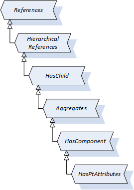
8.2 HasPtAttributes ReferenceType Definition
The HasPtAttributes ReferenceType is a concrete ReferenceType and can be used directly. It is a subtype of HasComponent ReferenceType.
It is used to link a PtAssetType with the attributes that are describing this asset.
The SourceNode of References of this type shall be an PtAssetType or any subtype of it.
The TargetNode of this ReferenceType shall be an PtAssetAttributesType or any subtype of it.
The HasPtAttributes ReferenceType is formally defined in Table 158.
| Attributes | Value | ||
| BrowseName | HasPtAttributes | ||
| InverseName | PtAttributesOf | ||
| Symmetric | False | ||
| IsAbstract | False | ||
| References | NodeClass | BrowseName | Comment |
|---|---|---|---|
| Subtype of the HasComponent ReferenceType defined in in OPC 10000-3. | |||
| ConformanceUnits |
|---|
9 Profiles and ConformanceUnits
9.1 Conformance Units
This chapter defines the corresponding Conformance Units for the OPC UA Information Model for Powertrain.
| Category | Title | Description |
| Server | Powertrain Base System | Implements at least one node of the PtAssetType (or subtype). |
| Server | Powertrain Asset Identification | Supports the PtAssetType (or subtype) and its mandatory properties (i.e. Manufacturer and SerialNumber). |
| Server | Powertrain Asset Identification Writable Tag | Supports the PtAssetType (or subtype) with all its writable properties, which are applied from IPtTagNameplate, IMachineTagNameplate and ITagNameplate (i.e. AssetId, ComponentName, Location, Comment, ContactPerson and Function). |
| Server | Powertrain Asset Attributes Types | Supports the PtAssetType (or subtype) with all its mandatory and optionally the optional InstanceDeclarations of PtAssetAttributesType (or subtype). The HasPtAttributes reference has to be used to reference the InstanceDeclarations to the asset type. |
| Server | Powertrain Attributes Information | Supports the mandatory variable Nodes of the PtAssetAttributesTypes (or subtypes). |
| Server | Powertrain Compliant Asset | Supports any ObjectType with mandatory properties and mandatory InstanceDeclarations of PtAssetAttributesType (or subtype) with the usage of the DefaultInstanceBrowseName. The HasPtAttributes reference has to be used to reference the InstanceDeclarations to the ObjectType. |
| Server | Powertrain Component Identification | Support the Machinery Component Identification Server Facet |
| Server | Powertrain IAsset Revision | Support the UAFX IAssetRevision Facet" |
9.2 Profiles
9.2.1 Profile list
Table 160 lists all Profiles defined in this document and defines their URIs.
| Profile | URI |
| Powertrain Base Asset Server Facet | http://opcfoundation.org/UA-Profile/Powertrain/Server/BaseAsset |
| Powertrain Base Asset Attributes Server Facet | http://opcfoundation.org/UA-Profile/Powertrain/Server/BaseAssetAttributes |
| Powertrain Compliant Asset Server Facet | http://opcfoundation.org/UA-Profile/Powertrain/Server/CompliantAsset |
9.2.2 Server Facets
9.2.2.1 Overview
The following sections specify the Facets available for Servers that implement the OPC UA Companion Specification for Powertrain. Each section defines and describes a Facet or Profile.
9.2.2.2 Powertrain Base Asset Server Facet
Table 161 defines a Facet that provides a base asset model for powertrains as well as the identification aspects provided by the manufacturer or writable by the user via the OPC UA interface.
| Group | Conformance Unit / Profile Title | M / O |
| Powertrain | Powertrain Base System | M |
| Powertrain | Powertrain Asset Identification | M |
| Powertrain | Powertrain Component Identification | O |
| Powertrain | Powertrain Asset Identification Writable Tag | O |
| Powertrain | Powertrain IAsset Revision | O |
9.2.2.3 Powertrain Base Asset Attributes Server Facet
Table 162 defines a Facet that provides a base asset model for powertrains with identification aspects as well as asset specific attributes.
| Group | Conformance Unit / Profile Title | M / O |
| Profile | Powertrain Base Asset Server Facet | M |
| Powertrain | Powertrain Asset Attributes Types | M |
| Powertrain | Powertrain Attributes Information | M |
9.2.2.4 Powertrain Compliant Asset Server Facet
Table 163 defines a Facet that enhance an existing information model with powertrain specific information to be compliant to this specification.
| Group | Conformance Unit / Profile Title | M / O |
| Powertrain | Powertrain Compliant Asset | M |
| Powertrain | Powertrain Attributes Information | M |
10 Namespaces
10.1 Namespace Metadata
Table 164 defines the namespace metadata for this document. The Object is used to provide version information for the namespace and an indication about static Nodes. Static Nodes are identical for all Attributes in all Servers, including the Value Attribute. See OPC 10000-5 for more details.
The information is provided as Object of type NamespaceMetadataType. This Object is a component of the Namespaces Object that is part of the Server Object. The NamespaceMetadataType ObjectType and its Properties are defined in OPC 10000-5.
The version information is also provided as part of the ModelTableEntry in the UANodeSet XML file. The UANodeSet XML schema is defined in Table 164.
| Attribute | Value | ||
| BrowseName | http://opcfoundation.org/UA/Powertrain/ | ||
| Property | DataType | Value | |
|---|---|---|---|
| NamespaceUri | String | http://opcfoundation.org/UA/Powertrain/ | |
| NamespaceVersion | String | 1.0.0 | |
| NamespacePublicationDate | DateTime | 2024-11-01 | |
| IsNamespaceSubset | Boolean | False | |
| StaticNodeIdTypes | IdType [] | 0 | |
| StaticNumericNodeIdRange | NumericRange [] | ||
| StaticStringNodeIdPattern | String | ||
10.2 Handling of OPC UA Namespaces
Namespaces are used by OPC UA to create unique identifiers across different naming authorities. The Attributes NodeId and BrowseName are identifiers. A Node in the UA AddressSpace is unambiguously identified using a NodeId. Unlike NodeIds, the BrowseName cannot be used to unambiguously identify a Node. Different Nodes may have the same BrowseName. They are used to build a browse path between two Nodes or to define a standard Property.
Servers may often choose to use the same namespace for the NodeId and the BrowseName. However, if they want to provide a standard Property, its BrowseName shall have the namespace of the standards body although the namespace of the NodeId reflects something else, for example the EngineeringUnits Property. All NodeIds of Nodes not defined in this document shall not use the standard namespaces.
Table 165 provides a list of mandatory and optional namespaces used in a powertrain OPC UA Server.
| NamespaceURI | Description | Use |
| http://opcfoundation.org/UA/ | Namespace for NodeIds and BrowseNames defined in the OPC UA specification. This namespace shall have namespace index 0. | Mandatory |
| Local Server URI | Namespace for nodes defined in the local server. This namespace shall have namespace index 1. | Mandatory |
| http://opcfoundation.org/UA/DI/ | Namespace for NodeIds and BrowseNames defined in OPC 10000-81, OPC Unified Architecture - Part 81: UAFX Connecting Devices and Information Model http://www.opcfoundation.org/documents/10000-81/ OPC 10000-100. The namespace index is Server specific. | Mandatory |
| http://opcfoundation.org/UA/Machinery/ | Namespace for NodeIds and BrowseNames defined in OPC 40001-1. The namespace index is Server specific. | Mandatory |
| http://opcfoundation.org/UA/FX/AC/ | Namespace for NodeIds and BrowseNames defined in OPC 10000-81. The namespace index is Server specific. | Optional |
| http://opcfoundation.org/UA/Dictionary/IRDI | Namespace for NodeIds of IRDI objects using HasDictionaryEntry. The namespace index is server specific. | Optional |
| http://opcfoundation.org/UA/Powertrain/ | Namespace for NodeIds and BrowseNames defined in this document. The namespace index is Server specific. | Mandatory |
| Vendor specific types | A Server may provide vendor-specific types like types derived from ObjectTypes defined in this document in a vendor-specific namespace. | Optional |
| Vendor specific instances | A Server provides vendor-specific instances of the standard types or vendor-specific instances of vendor-specific types in a vendor-specific namespace. It is recommended to separate vendor specific types and vendor specific instances into two or more namespaces. | Mandatory |
Table 166 provides a list of namespaces and their indices used for BrowseNames in this document. The default namespace of this document is not listed since all BrowseNames without prefix use this default namespace.
| NamespaceURI | Namespace Index | Example |
| http://opcfoundation.org/UA/ | 0 | 0:EngineeringUnits |
| http://opcfoundation.org/UA/DI/ | 2 | 2:DeviceRevision |
| http://opcfoundation.org/UA/Machinery/ | 3 | 3:IMachineryItemVendorNameplateType |
| http://opcfoundation.org/UA/FX/AC/ | 4 | 4:IAssetRevisionType |
| http://opcfoundation.org/UA/Dictionary/IRDI | 5 | 5:0112/2///62683#ACE455 |
Annex A Powertrain Namespace and mappings (Normative)
A.1 NodeSet and Supplementary Files for Powertrain Information Model
The Powertrain Information Model is identified by the following URI:
http://opcfoundation.org/UA/Powertrain/
Documentation for the NamespaceUri can be found here.
The NodeSet associated with this version of specification can be found here:
https://reference.opcfoundation.org/nodesets/?u=http://opcfoundation.org/UA/Powertrain/&v=1.0.0&ns=1
The NodeSet associated with the latest version of the specification can be found here:
https://reference.opcfoundation.org/nodesets/?u=http://opcfoundation.org/UA/Powertrain/&ns=1
The supplementary files associated with this version of specification can be found here:
https://reference.opcfoundation.org/nodesets/?u=http://opcfoundation.org/UA/Powertrain/&v=1.0.0&i=2
The supplementary files associated with the latest version of the specification can be found here:
https://reference.opcfoundation.org/nodesets/?u=http://opcfoundation.org/UA/Powertrain/&i=2
Annex B Type definition diagrams (Informative)
B.1 PtAssetMotorRotaryType
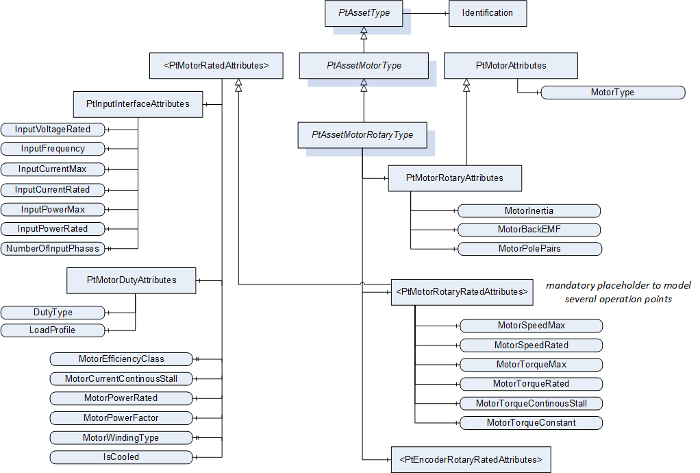
B.2 PtAssetMotorRotary Instance Example
The following motor nameplate (Figure 18) represents an example with identification attributes and rated attribute sets for various operating modes.
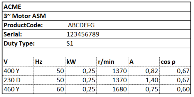
This motor nameplate can be modelled as followed (Figure 19). The instance MyMotor of PtAssetMotorRotaryType provides the operating mode independent identification properties and the general motor specific attributes of the PtMotorAttributesType and PtMotorRatedAttributesType.
In addition, the related attribute sets of PtMotorRotaryRatedAttributesType are referenced.
As an example, the model uses only one instance of the attributes PtMotorDutyAttributes and MotorPowerRated, which are constant in all three attribute sets.
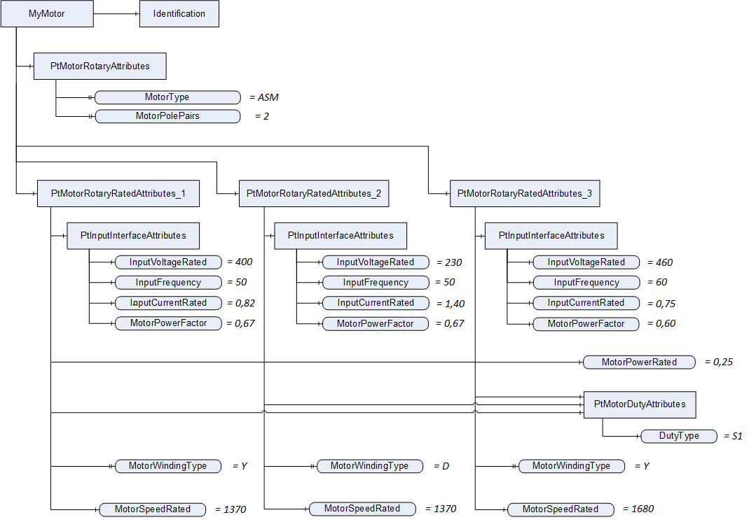
Annex C How to Use this Specification in Existing Models (Informative)
Modeling approaches are shown below that describe how the powertrain information model can be integrated into an existing instance or type information model.
There are different approaches, which have their advantages depending on the use case.
Modular enhancement of existing type model
Use case: An existing companion specification or manufacturer-specific type model is to be extended in a new version to include powertrain-specific modules.
Modular enhancement of existing instance model
Use case: An existing instance model which is already available via an OPC UA server is to be extended by powertrain specific modules.
Enhancement with whole asset type
Use case: An existing type or instance model is to be extended by the complete powertrain specific asset definition.
Parallel powertrain model with SameEntityAs-Reference
Use case: Parallel to an existing instance model, the powertrain-specific information model is represented on another hierarchy level. Both submodels are referenced to each other.
C.1 Modular enhancement of existing type model
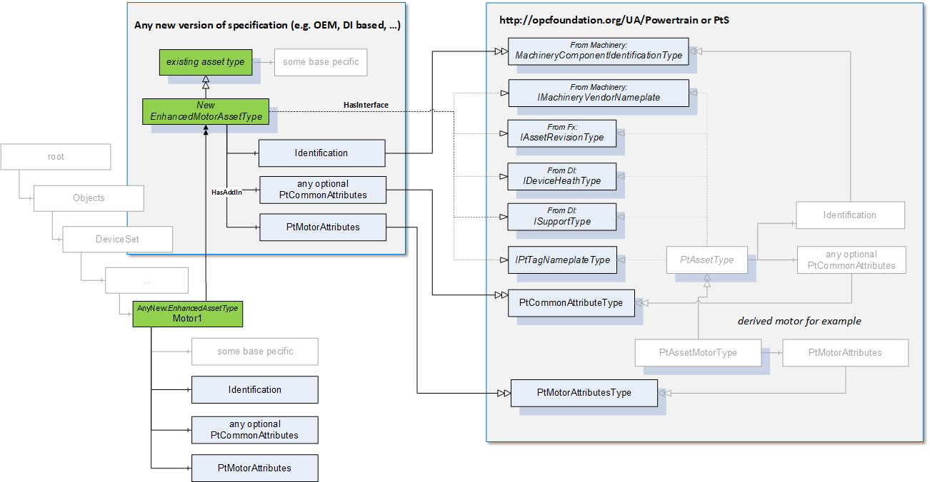
Use Case:
An existing companion specification or manufacturer-specific type model is to be extended in a new version to include powertrain-specific modules.
For this purpose, a type definition of the existing specification can be derived again. This is enriched with the necessary interfaces and objects of the PtAssetType or a sub-type, e.g. PtAssetMotorType. For this the references HasInterface or HasAddIn are used in general. To reference specific InstanceDeclarations of asset attributes the HasPtAttributes reference can be used.
The DefaultBrowsenames of the InstanceDeclarations (e.g. PtCommonAssetAttributesTypes or asset-specific AttributesTypes) are defined in this specification. This is to signal to a client the corresponding representation of a powertrain asset according to this specification e.g. a motor.
C.2 Modular enhancement of existing instance model
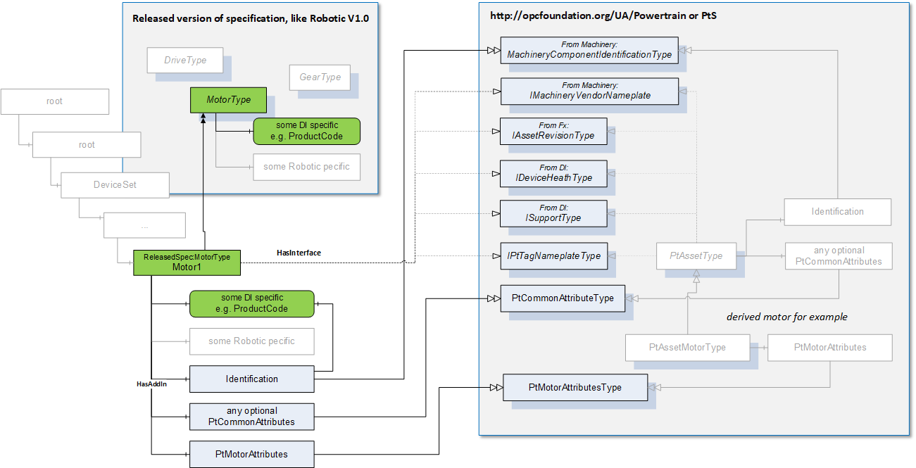
Use Case:
An existing instance model which is already available via an OPC UA server is to be extended by powertrain specific modules.
As for the use case from C.1, an existing object instance can be enriched with the necessary interfaces and objects of the PtAssetType or a sub-type, e.g. PtAssetMotorType.
C.3 Enhancement with whole asset type
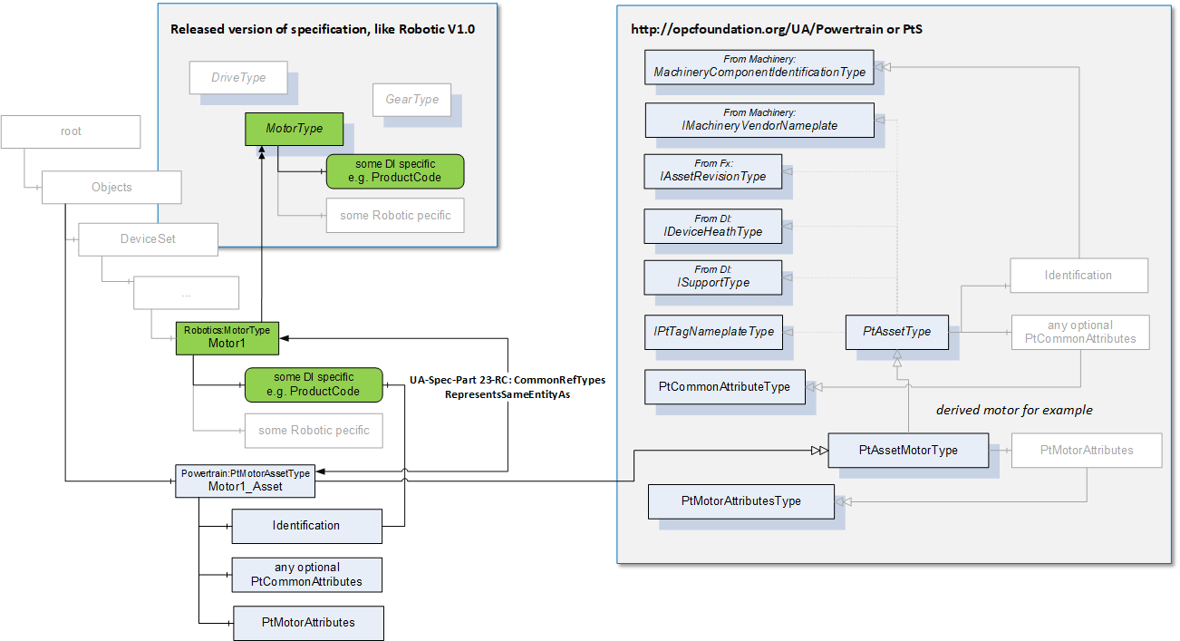
Use Case:
An existing type or instance model is to be extended by the complete powertrain specific asset definition.
In contrast to the use cases from C.1 and C.2, the complete powertrain asset definition is to be transferred to an existing model. Instead of taking over the individual Interfaces and AddIns, a new instance of the PtAssetType or a sub-type e.g. PtAssetMotorType is attached with a HasAddIn reference.
As in the previous use cases, the DefaultBrowsename of the PtAssetType definitions is also defined in this specification.
An advantage with this approach is the existence of an instance of a powertrain defined asset type, e.g. PtAssetMotorType. This gives the client confidence that it is an asset defined in this specification.
A disadvantage can be the additional hierarchy level in contrast to the approaches from C.1 and C.2.
In Figure 22 Enhancement with whole asset type only the enhancement on instance level is shown. Of course, this enhancement can also be done on type level.
C.4 Parallel Powertrain Model
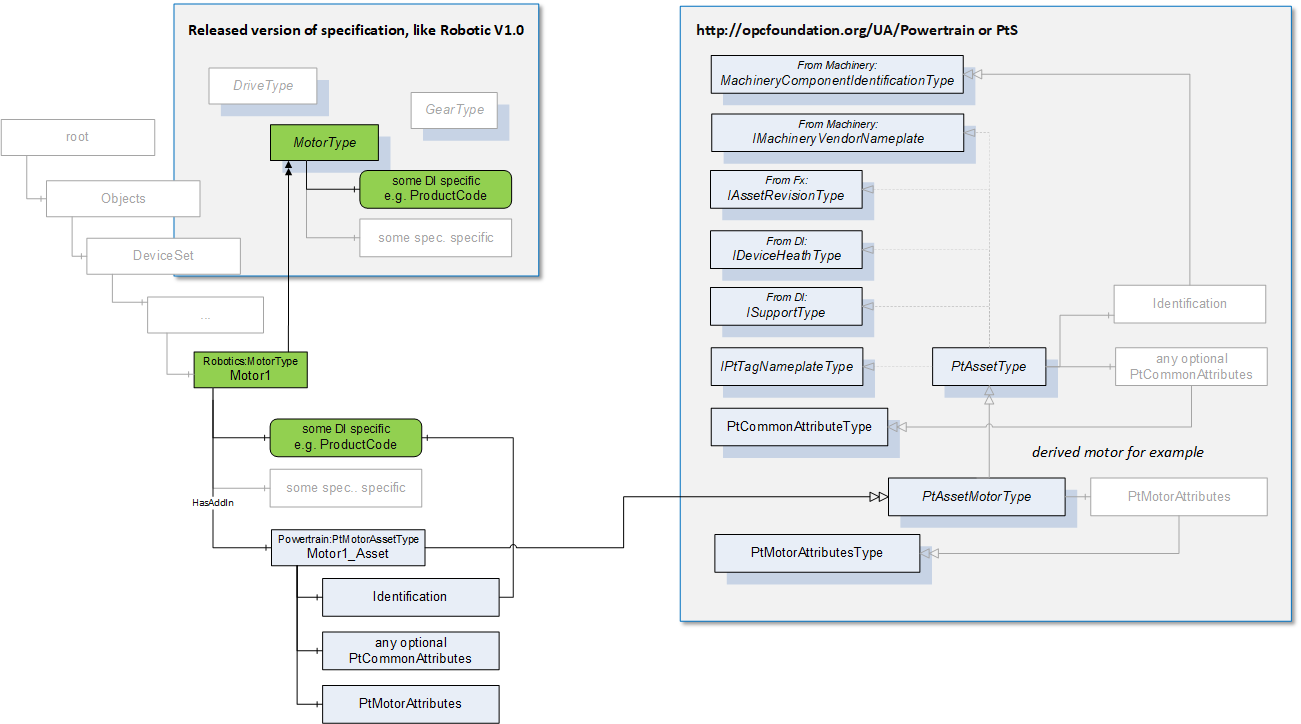
Use Case:
Parallel to an existing instance model, the powertrain specific information model is represented on another hierarchy level.
In contrast to the use case from C.3, an independent submodel is created here according to this powertrain specification. Thus, it is expected that instances of the PtAssetType are on a completely different and independent hierarchy level to existing asset objects from other specifications. Also, the Browsenames of the instances may be quite different here.
To signal to a client that two different nodes in the AddressSpace represent the same entity in the real world, the RepresentsSameEntity reference between these nodes can be used. This is defined in OPC 10000-23.
___________
Agreement of Use
COPYRIGHT RESTRICTIONS
This document is provided "as is" by the OPC Foundation and VDMA.
Right of use for this specification is restricted to this specification and does not grant rights of use for referred documents.
Right of use for this specification will be granted without cost.
This document may be distributed through computer systems, printed or copied as long as the content remains unchanged and the document is not modified.
OPC Foundation and VDMA do not guarantee usability for any purpose and shall not be made liable for any case using the content of this document.
The user of the document agrees to indemnify OPC Foundation and VDMA and their officers, directors and agents harmless from all demands, claims, actions, losses, damages (including damages from personal injuries), costs and expenses (including attorneys' fees) which are in any way related to activities associated with its use of content from this specification.
The document shall not be used in conjunction with company advertising, shall not be sold or licensed to any party.
The intellectual property and copyright is solely owned by the OPC Foundation and VDMA.
PATENTS
The attention of adopters is directed to the possibility that compliance with or adoption of OPC or VDMA specifications may require use of an invention covered by patent rights. OPC Foundation or VDMA shall not be responsible for identifying patents for which a license may be required by any OPC or VDMA specification, or for conducting legal inquiries into the legal validity or scope of those patents that are brought to its attention. OPC or VDMA specifications are prospective and advisory only. Prospective users are responsible for protecting themselves against liability for infringement of patents.
WARRANTY AND LIABILITY DISCLAIMERS
WHILE THIS PUBLICATION IS BELIEVED TO BE ACCURATE, IT IS PROVIDED "AS IS" AND MAY CONTAIN ERRORS OR MISPRINTS. THE OPC FOUDATION NOR VDMA MAKES NO WARRANTY OF ANY KIND, EXPRESSED OR IMPLIED, WITH REGARD TO THIS PUBLICATION, INCLUDING BUT NOT LIMITED TO ANY WARRANTY OF TITLE OR OWNERSHIP, IMPLIED WARRANTY OF MERCHANTABILITY OR WARRANTY OF FITNESS FOR A PARTICULAR PURPOSE OR USE. IN NO EVENT SHALL THE OPC FOUNDATION NOR VDMA BE LIABLE FOR ERRORS CONTAINED HEREIN OR FOR DIRECT, INDIRECT, INCIDENTAL, SPECIAL, CONSEQUENTIAL, RELIANCE OR COVER DAMAGES, INCLUDING LOSS OF PROFITS, REVENUE, DATA OR USE, INCURRED BY ANY USER OR ANY THIRD PARTY IN CONNECTION WITH THE FURNISHING, PERFORMANCE, OR USE OF THIS MATERIAL, EVEN IF ADVISED OF THE POSSIBILITY OF SUCH DAMAGES.
The entire risk as to the quality and performance of software developed using this specification is borne by you.
RESTRICTED RIGHTS LEGEND
This Specification is provided with Restricted Rights. Use, duplication or disclosure by the U.S. government is subject to restrictions as set forth in (a) this Agreement pursuant to DFARs 227.7202-3(a); (b) subparagraph (c)(1)(i) of the Rights in Technical Data and Computer Software clause at DFARs 252.227-7013; or (c) the Commercial Computer Software Restricted Rights clause at FAR 52.227-19 subdivision (c)(1) and (2), as applicable. Contractor / manufacturer are the OPC Foundation, 16101 N. 82nd Street, Suite 3B, Scottsdale, AZ, 85260-1830
COMPLIANCE
The combination of VDMA and OPC Foundation shall at all times be the sole entities that may authorize developers, suppliers and sellers of hardware and software to use certification marks, trademarks or other special designations to indicate compliance with these materials as specified within this document. Products developed using this specification may claim compliance or conformance with this specification if and only if the software satisfactorily meets the certification requirements set by VDMA or the OPC Foundation. Products that do not meet these requirements may claim only that the product was based on this specification and must not claim compliance or conformance with this specification.
TRADEMARKS
Most computer and software brand names have trademarks or registered trademarks. The individual trademarks have not been listed here.
GENERAL PROVISIONS
Should any provision of this Agreement be held to be void, invalid, unenforceable or illegal by a court, the validity and enforceability of the other provisions shall not be affected thereby.
This Agreement shall be governed by and construed under the laws of Germany.
This Agreement embodies the entire understanding between the parties with respect to, and supersedes any prior understanding or agreement (oral or written) relating to, this specification.