
1 Scope
This document specifies an OPC UA information model for the representation of a Joining System. This system can consist of Controllers, Tools, Servos, Memory Devices, Sensors, Cables, Batteries, Power Supplies, Feeders, Accessories, Software Components, and other Subcomponents. The aim of this specification is to obtain an interoperable interface for higher-level control and evaluation systems.
It focuses on joining systems and their components as assets and the monitoring of those systems and components, considering existing and emerging standards in these areas, like OPC UA for Device Integration, OPC UA for Machinery Basic Building Blocks, OPC UA for Machinery Result Transfer, OPC UA for Asset Management Basics, etc.
This version of the specification focuses on Asset Management, Condition Monitoring, Result Management, Event Management, Joining Process Management and Joint Management.
All the types defined in this specification can be extended for vendor, customer, or application specific use cases outside of this specification.
2 Normative references
The following documents are referred to in the text in such a way that some or all of their content constitutes requirements of this document. For dated references, only the edition cited applies. For undated references, the latest edition of the referenced document (including any amendments and errata) applies
OPC 10000-1, OPC Unified Architecture - Part 1: Overview and Concepts
http://www.opcfoundation.org/documents/10000-1/
OPC 10000-2, OPC Unified Architecture - Part 2: Security Model
http://www.opcfoundation.org/documents/10000-2/
OPC 10000-3, OPC Unified Architecture - Part 3: Address Space Model
http://www.opcfoundation.org/documents/10000-3/
OPC 10000-4, OPC Unified Architecture - Part 4: Services
http://www.opcfoundation.org/documents/10000-4/
OPC 10000-5, OPC Unified Architecture - Part 5: Information Model
http://www.opcfoundation.org/documents/10000-5/
OPC 10000-6, OPC Unified Architecture - Part 6: Mappings
http://www.opcfoundation.org/documents/10000-6/
OPC 10000-7, OPC Unified Architecture - Part 7: Profiles
http://www.opcfoundation.org/documents/10000-7/
OPC 10000-8, OPC Unified Architecture - Part 8: Data Access
http://www.opcfoundation.org/documents/10000-8/
OPC 10000-9, OPC Unified Architecture - Part 9: Alarms and Conditions
http://www.opcfoundation.org/documents/10000-9/
OPC 10000-100, OPC Unified Architecture - Part 100: Devices
http://www.opcfoundation.org/documents/10000-100/
OPC 10000-110, OPC Unified Architecture - Part 110: Asset Management Basics
http://www.opcfoundation.org/documents/10000-110/
OPC 10000-200, OPC Unified Architecture - Part 200: Industrial Automation
http://www.opcfoundation.org/documents/10000-200/
OPC 40001-1, OPC UA for Machinery - Part 1: Basic Building Blocks
http://www.opcfoundation.org/documents/40001-1/
OPC 40001-101, OPC UA for Machinery - Part 101: Result Transfer
http://www.opcfoundation.org/UA/Machinery/Result/
NAMUR Recommendation NE107: Self-monitoring and diagnosis of field devices
VDI-VDE 2862-2: Minimum requirements for application of fastening systems and tools
3 Terms, definitions and conventions
3.1 Overview
It is assumed that basic concepts of OPC UA information modelling are understood in this specification. This specification will use these concepts to describe the Joining System Information Model. For the purposes of this document, the terms and definitions given in OPC 10000-1, OPC 10000-3, OPC 10000-4, OPC 10000-5, OPC 10000-7, OPC 10000-8, OPC 10000-9, OPC 10000-100, OPC 10000-110, OPC 10000-200 OPC 40001-1, OPC 40001-101 as well as the following apply.
3.2 OPC UA for Joining System terms
| Term | Definition of Term |
| Environment | The set of external entities working with the joining system in one way or another. Examples: PLC, MES, etc. |
| External | Not part of the joining system or the OPC UA server. It may refer to the automation system, the manufacturing execution system, or other entities. |
| System-wide unique | Used in conjunction with identifiers and handles to denote that at any given time no other entity of the same type and meaning shall exist in the OPC UA server with the same value. No further assumptions about global or historical uniqueness are made; especially in the case of identifiers, however, globally unique identifiers are recommended. |
| Joining System | The underlying joining system for which the OPC UA server provides an abstracted view. |
| Joining Process | The concrete implementation of a set of information that a machine needs to execute a joining operation. |
| Joint | A joint defines the properties of the point where several parts are joined. |
3.3 Abbreviated terms
| Abbreviation | Definition of Abbreviation |
| AC | Alarm and Condition |
| BLOB | BLOB, a Binary Large Object, is a collection of binary data stored as a single entity in a database management system. |
| DCS | DCS, a distributed control system is a computerized control system for a process or plant usually with many control loops, in which autonomous controllers are distributed throughout the system, but there is central operator supervisory control. The DCS concept increases reliability and reduces installation costs by localizing control functions near the process plant, with remote monitoring and supervision. |
| ERP | ERP, the Enterprise resource planning, is the integrated management of core business processes, often in real-time and mediated by software and technology. |
| HMI | The user interface or human-machine interface is the part of the machine that handles the human-machine interaction. |
| HTTP | The Hypertext Transfer Protocol (HTTP) is an application protocol for distributed, collaborative, and hypermedia information systems. |
| ID | Identifer. |
| IJT | Industrial Joining Technologies. This is a work group under the VDMA Integrated Assembly Solutions Department. The purpose of IJT is to define standard specifications for various joining techniques such as Tightening, Gluing, Riveting, Flow Drill Fastening, etc. |
| MES | MES, manufacturing execution systems are computerized systems used in manufacturing, to track and document the transformation of raw materials to finished goods. MES provides information that helps manufacturing decision makers understand how current conditions on the plant floor can be optimized to improve production output. |
| PLC | PLC, a programmable logic controller, or programmable controller is an industrial digital computer which has been ruggedized and adapted for the control of manufacturing processes, such as assembly lines, or robotic devices, or any activity that requires high reliability control and ease of programming and process fault diagnosis. |
| TCP/IP | The Internet protocol suite is the conceptual model and set of communications protocols used on the Internet and similar computer networks. It is commonly known as TCP/IP because the foundational protocols in the suite are the Transmission Control Protocol (TCP) and the Internet Protocol (IP). |
3.4 Conventions used in this document
3.4.1 Conventions for Node descriptions
3.4.1.1 Node definitions
Node definitions are specified using tables (see Table 2).
Attributes are defined by providing the Attribute name and a value, or a description of the value.
References are defined by providing the ReferenceType name, the BrowseName of the TargetNode and its NodeClass.
If the TargetNode is a component of the Node being defined in the table the Attributes of the composed Node are defined in the same row of the table.
The DataType is only specified for Variables; "[<number>]" indicates a single-dimensional array, for multi-dimensional arrays the expression is repeated for each dimension (e.g. [2][3] for a two-dimensional array). For all arrays the ArrayDimensions is set as identified by <number> values. If no <number> is set, the corresponding dimension is set to 0, indicating an unknown size. If no number is provided at all the ArrayDimensions can be omitted. If no brackets are provided, it identifies a scalar DataType and the ValueRank is set to the corresponding value (see OPC 10000-3). In addition, ArrayDimensions is set to null or is omitted. If it can be Any or ScalarOrOneDimension, the value is put into "{<value>}", so either "{Any}" or "{ScalarOrOneDimension}" and the ValueRank is set to the corresponding value (see OPC 10000-3) and the ArrayDimensions is set to null or is omitted. Examples are given in Table 1.
| Notation | DataType | ValueRank | ArrayDimensions | Description |
| 0:Int32 | 0:Int32 | -1 | omitted or null | A scalar Int32. |
| 0:Int32{OneOrMoreDimensions} | 0:Int32 | 0 | omitted or null | The Int32 value is an array with one or more dimensions. |
| 0:Int32[] | 0:Int32 | 1 | omitted or {0} | Single-dimensional array of Int32 with an unknown size. |
| 0:Int32[][] | 0:Int32 | 2 | omitted or {0,0} | Two-dimensional array of Int32 with unknown sizes for both dimensions. |
| 0:Int32[3][] | 0:Int32 | 2 | {3,0} | Two-dimensional array of Int32 with a size of 3 for the first dimension and an unknown size for the second dimension. |
| 0:Int32[5][3] | 0:Int32 | 2 | {5,3} | Two-dimensional array of Int32 with a size of 5 for the first dimension and a size of 3 for the second dimension. |
| 0:Int32{Any} | 0:Int32 | -2 | omitted or null | An Int32 where it is unknown if it is scalar or array with any number of dimensions. |
| 0:Int32{ScalarOrOneDimension} | 0:Int32 | -3 | omitted or null | An Int32 where it is either a single-dimensional array or a scalar. |
The TypeDefinition is specified for Objects and Variables.
The TypeDefinition column specifies a symbolic name for a NodeId, i.e. the specified Node points with a HasTypeDefinition Reference to the corresponding Node.
The ModellingRule of the referenced component is provided by specifying the symbolic name of the rule in the ModellingRule column. In the AddressSpace, the Node shall use a HasModellingRule Reference to point to the corresponding ModellingRule Object.
If the NodeId of a DataType is provided, the symbolic name of the Node representing the DataType shall be used.
Note that if a symbolic name of a different namespace is used, it is prefixed by the NamespaceIndex (see 3.4.2.2).
Nodes of all other NodeClasses cannot be defined in the same table; therefore only the used ReferenceType, their NodeClass and their BrowseName are specified. A reference to another part of this document points to their definition. Table 2 illustrates the table. If no components are provided, the DataType, TypeDefinition and ModellingRule columns may be omitted and only a Comment column is introduced to point to the Node definition.
Each Type Node or well-known Instance Node defined shall have one or more ConformanceUnits defined in 11.1 that require the Node to be in the AddressSpace.
The relations between Nodes and ConformanceUnits are defined at the end of the tables defining Nodes, one row per ConformanceUnit. The ConformanceUnits are reflected in the Category element for the Node definition in the UANodeSet (see OPC 10000-6).
The list of ConformanceUnits in the UANodeSet allows Servers to optimize resource consumption by using a list of supported ConformanceUnits to select a subset of the Nodes in an Information Model.
When a Node is selected in this way, all dependencies implied by the References are also selected.
Dependencies exist if the Node is the source of HasTypeDefinition, HasInterface, HasAddIn or any HierarchicalReference. Dependencies also exist if the Node is the target of a HasSubtype Reference. For Variables and VariableTypes, the value of the DataType Attribute is a dependency. For DataType Nodes, any DataTypes referenced in the DataTypeDefinition Attribute are also dependencies.
For additional details see OPC 10000-5.
| Attribute | Value | ||||
| Attribute name | Attribute value. If it is an optional Attribute that is not set "--" will be used. | ||||
| References | NodeClass | BrowseName | DataType | TypeDefinition | Other |
|---|---|---|---|---|---|
| ReferenceType name | NodeClass of the target Node. | BrowseName of the target Node. | DataType of the referenced Node, only applicable for Variables. | TypeDefinition of the referenced Node, only applicable for Variables and Objects. | Additional characteristics of the TargetNode such as the ModellingRule or AccessLevel. |
| NOTE Notes referencing footnotes of the table content. | |||||
| Conformance Units | |||||
|---|---|---|---|---|---|
| Name of ConformanceUnit, one row per ConformanceUnit |
Components of Nodes can be complex that is containing components by themselves. The TypeDefinition, NodeClass and DataType can be derived from the type definitions, and the symbolic name can be created as defined in 3.4.3.1. Therefore, those containing components are not explicitly specified; they are implicitly specified by the type definitions.
The Other column defines additional characteristics of the Node. Examples of characteristics that can appear in this column are show in Table 3.
| Name | Short Name | Description |
| 0:Mandatory | M | The Node has the Mandatory ModellingRule. |
| 0:Optional | O | The Node has the Optional ModellingRule. |
| 0:MandatoryPlaceholder | MP | The Node has the MandatoryPlaceholder ModellingRule. |
| 0:OptionalPlaceholder | OP | The Node has the OptionalPlaceholder ModellingRule. |
| ReadOnly | RO | The Node AccessLevel has the CurrentRead bit set but not the CurrentWrite bit. |
| ReadWrite | RW | The Node AccessLevel has the CurrentRead and CurrentWrite bits set. |
| WriteOnly | WO | The Node AccessLevel has the CurrentWrite bit set but not the CurrentRead bit. |
If multiple characteristics are defined they are separated by commas. The name or the short name may be used.
3.4.1.2 Additional References
To provide information about additional References, the format as shown in Table 4 is used.
| SourceBrowsePath | Reference Type | Is Forward | TargetBrowsePath |
| SourceBrowsePath is always relative to the TypeDefinition. Multiple elements are defined as separate rows of a nested table. | ReferenceType name | True = forward Reference | TargetBrowsePath points to another Node, which can be a well-known instance or a TypeDefinition. You can use BrowsePaths here as well, which is either relative to the TypeDefinition or absolute. If absolute, the first entry needs to refer to a type or well-known instance, uniquely identified within a namespace by the BrowseName. |
References can be to any other Node.
3.4.1.3 Additional sub-components
To provide information about sub-components, the format as shown in Table 5 is used.
| BrowsePath | Reference | NodeClass | BrowseName | DataType | TypeDefinition | Others |
| BrowsePath is always relative to the TypeDefinition. Multiple elements are defined as separate rows of a nested table | NOTE Same as for Table 2 | |||||
3.4.1.4 Additional Attribute values
The type definition table provides columns to specify the values for required Node Attributes for InstanceDeclarations. To provide information about additional Attributes, the format as shown in Table 6 is used.
| BrowsePath | <Attribute name> Attribute |
| BrowsePath is always relative to the TypeDefinition. Multiple elements are defined as separate rows of a nested table | The values of attributes are converted to text by adapting the reversible JSON encoding rules defined in OPC 10000-6. If the JSON encoding of a value is a JSON string or a JSON number then that value is entered in the value field. Double quotes are not included. If the DataType includes a NamespaceIndex (QualifiedNames, NodeIds or ExpandedNodeIds) then the notation used for BrowseNames is used. If the value is an Enumeration the name of the enumeration value is entered. If the value is a Structure then a sequence of name and value pairs is entered. Each pair is followed by a newline. The name is followed by a colon. The names are the names of the fields in the DataTypeDefinition. If the value is an array of non-structures then a sequence of values is entered where each value is followed by a newline. If the value is an array of Structures or a Structure with fields that are arrays or with nested Structures then the complete JSON array or JSON object is entered. |
There can be multiple columns to define more than one Attribute.
3.4.2 NodeIds and BrowseNames
3.4.2.1 NodeIds
The NodeIds of all Nodes described in this standard are only symbolic names. Annex A defines the actual NodeIds.
The symbolic name of each Node defined in this document is its BrowseName, or, when it is part of another Node, the BrowseName of the other Node, a ".", and the BrowseName of itself. In this case "part of" means that the whole has a HasProperty or HasComponent Reference to its part. Since all Nodes not being part of another Node have a unique name in this document, the symbolic name is unique.
The NamespaceUri for all NodeIds defined in this document is defined in Annex A. The NamespaceIndex for this NamespaceUri is vendor-specific and depends on the position of the NamespaceUri in the server namespace table.
Note that this document not only defines concrete Nodes, but also requires that some Nodes shall be generated, for example one for each Session running on the Server. The NodeIds of those Nodes are Server-specific, including the namespace. But the NamespaceIndex of those Nodes cannot be the NamespaceIndex used for the Nodes defined in this document, because they are not defined by this document but generated by the Server.
3.4.2.2 BrowseNames
The text part of the BrowseNames for all Nodes defined in this document is specified in the tables defining the Nodes. The NamespaceUri for all BrowseNames defined in this document is defined in 12.2.
For InstanceDeclarations of NodeClass Object and Variable that are placeholders (OptionalPlaceholder and MandatoryPlaceholder ModellingRule), the BrowseName and the DisplayName are enclosed in angle brackets (<>) as recommended in OPC 10000-3.
If the BrowseName is not defined by this document, a namespace index prefix is added to the BrowseName (e.g., prefix '0' leading to '0:EngineeringUnits' or prefix '2' leading to '2:DeviceRevision'). This is typically necessary if a Property of another specification is overwritten or used in the OPC UA types defined in this document. Table 277 provides a list of namespaces and their indexes as used in this document.
3.4.3 Common Attributes
3.4.3.1 General
The Attributes of Nodes, their DataTypes and descriptions are defined in OPC 10000-3. Attributes not marked as optional are mandatory and shall be provided by a Server. The following tables define if the Attribute value is defined by this specification or if it is server-specific.
For all Nodes specified in this specification, the Attributes named in Table 7 shall be set as specified in the table.
| Attribute | Value |
| DisplayName | The DisplayName is a LocalizedText. Each server shall provide the DisplayName identical to the BrowseName of the Node for the LocaleId "en". Whether the server provides translated names for other LocaleIds is server-specific. |
| Description | Optionally a server-specific description is provided. |
| NodeClass | Shall reflect the NodeClass of the Node. |
| NodeId | The NodeId is described by BrowseNames as defined in 3.4.2.1. |
| WriteMask | Optionally the WriteMask Attribute can be provided. If the WriteMask Attribute is provided, it shall set all non-server-specific Attributes to not writable. For example, the Description Attribute may be set to writable since a Server may provide a server-specific description for the Node. The NodeId shall not be writable, because it is defined for each Node in this specification. |
| UserWriteMask | Optionally the UserWriteMask Attribute can be provided. The same rules as for the WriteMask Attribute apply. |
| RolePermissions | Optionally server-specific role permissions can be provided. |
| UserRolePermissions | Optionally the role permissions of the current Session can be provided. The value is server-specific and depend on the RolePermissions Attribute (if provided) and the current Session. |
| AccessRestrictions | Optionally server-specific access restrictions can be provided. |
3.4.3.2 Objects
For all Objects specified in this specification, the Attributes named in Table 8 shall be set as specified in the table. The definitions for the Attributes can be found in OPC 10000-3.
| Attribute | Value |
| EventNotifier | Whether the Node can be used to subscribe to Events or not is server-specific. |
3.4.3.3 Variables
For all Variables specified in this specification, the Attributes named in Table 9 shall be set as specified in the table. The definitions for the Attributes can be found in OPC 10000-3.
| Attribute | Value |
| MinimumSamplingInterval | Optionally, a server-specific minimum sampling interval is provided. |
| AccessLevel | The access level for Variables used for type definitions is server-specific, for all other Variables defined in this specification, the access level shall allow reading; other settings are server-specific. |
| UserAccessLevel | The value for the UserAccessLevel Attribute is server-specific. It is assumed that all Variables can be accessed by at least one user. |
| Value | For Variables used as InstanceDeclarations, the value is server-specific; otherwise it shall represent the value described in the text. |
| ArrayDimensions | If the ValueRank does not identify an array of a specific dimension (i.e. ValueRank <= 0) the ArrayDimensions can either be set to null or the Attribute is missing. This behaviour is server-specific. If the ValueRank specifies an array of a specific dimension (i.e. ValueRank > 0) then the ArrayDimensions Attribute shall be specified in the table defining the Variable. |
| Historizing | The value for the Historizing Attribute is server-specific. |
| AccessLevelEx | If the AccessLevelEx Attribute is provided, it shall have the bits 8, 9, and 10 set to 0, meaning that read and write operations on an individual Variable are atomic, and arrays can be partly written. |
3.4.3.4 VariableTypes
For all VariableTypes specified in this specification, the Attributes named in Table 10 shall be set as specified in the table. The definitions for the Attributes can be found in OPC 10000-3.
| Attributes | Value |
| Value | Optionally a server-specific default value can be provided. |
| ArrayDimensions | If the ValueRank does not identify an array of a specific dimension (i.e. ValueRank <= 0) the ArrayDimensions can either be set to null or the Attribute is missing. This behaviour is server-specific. If the ValueRank specifies an array of a specific dimension (i.e. ValueRank > 0) then the ArrayDimensions Attribute shall be specified in the table defining the VariableType. |
3.4.3.5 Methods
For all Methods specified in this specification, the Attributes named in Table 11 shall be set as specified in the table. The definitions for the Attributes can be found in OPC 10000-3.
| Attributes | Value |
| Executable | All Methods defined in this specification shall be executable (Executable Attribute set to "True"), unless it is defined differently in the Method definition. |
| UserExecutable | The value of the UserExecutable Attribute is server-specific. It is assumed that all Methods can be executed by at least one user. |
3.4.4 Structures
OPC 10000-3 differentiates between different kinds of Structures. The following conventions explain, how these Structures shall be defined.
The first kind are Structures without optional fields where none of the fields allows subtype (except fields with abstract DataTypes). Its definition is in Table 12.
| Name | Type | Description |
| <someStructure> | structure | Subtype of <someParentStructure> defined in … |
SP1 | 0:Byte[] | Setpoint 1 |
SP2 | 0:Byte[] | Setpoint 2 |
The second kind are Structures with optional fields where none of the fields allows subtypes (except fields with abstract DataTypes). Its definition is in Table 13.
Structures with fields that are optional have an "Optional" column. Fields that are optional have True set, otherwise False.
| Name | Type | Description | Optional |
| <someStructure> | structure | Subtype of <someParentStructure> defined in … | |
SP1 | 0:Byte[] | Setpoint 1 | False |
SP2 | 0:Byte[] | Setpoint 2 | True |
The third kind are Structures without optional fields where one or more of the fields allow subtypes. Its definition is in Table 14.
Structures with fields that allow subtypes have an "Allow Subtypes" column. Fields that allow subtypes have True set, otherwise False. Fields with abstract DataTypes can always be subtyped.
| Name | Type | Description | Allow SubTypes |
| <someStructure> | structure | Subtype of <someParentStructure> defined in … | |
SP1 | 0:Byte[] | Setpoint 1 | False |
Allow Subtypes | 0:ByteString | Some ByteString | True |
4 General information to Industrial Joining Technologies and OPC UA
4.1 Introduction to Industrial Joining Technologies (IJT)
This is a working group under VDMA Integrated Assembly Solutions department. The purpose of the IJT group is to define data models and data access standards for various joining techniques such as Tightening, Gluing, Riveting, Flow Drill Fastening, etc.
Assembling products by joining parts together is a key operation in many industries. There are obviously countless differences between gluing, welding, riveting, etc., but also surprisingly many characteristics are common as given below:
There is often a tool that executes the joining.
There are often some devices controlling the joining process such as a processor, computer, or PLC.
There is often a program of some sort that governs the joining process.
There is often a digital result of the joining process that may both influence the overlying assembly process and be stored to provide product traceability.
There could be an operator guidance system to help the operator determine the steps involved in the joining process.
There could be a representation of the joint as part of the digital twin of the product being assembled.
There is often a need from external systems to select or influence the joining operation, such an MES system, a station PLC, location system, or a barcode scanner.
The Industrial Joining Technologies companion specification endeavors to find the best balance between the models used in all joining technologies and the models specific to an area.
Joining is often tightly connected with other industrial processes such as vision (for identification), or robotics (for location), so special attention has been on harmonization with other VDMA companion specifications, to strive for seamless integration from a customer's perspective.
Every joining technique could define their own standard specification where the common types defined in the base specification will be re-used across the joining techniques.
Examples: Result Management, Asset Management, Event Management, Joining Process Management, Joint Management, etc. are common use cases for multiple joining technologies.
The following figure describes the taxonomy of the Industrial Joining Technologies workgroup.
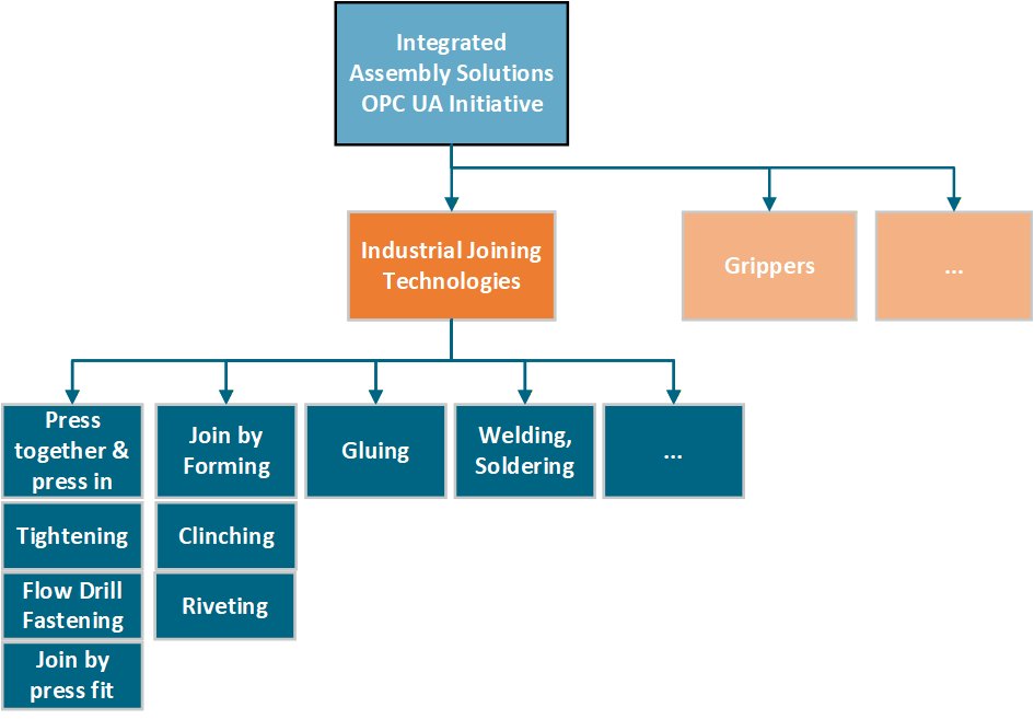
4.2 Joining System
The idea of a joining system is to represent different types of systems for each joining technique using a common interface.
Examples: Tightening, Riveting, Gluing, etc.
4.3 Introduction to OPC Unified Architecture
4.3.1 What is OPC UA?
OPC UA is an open and royalty free set of standards designed as a universal communication protocol. While there are numerous communication solutions available, OPC UA has key advantages:
A state of art security model (see OPC 10000-2).
A fault tolerant communication protocol.
An information modelling framework that allows application developers to represent their data in a way that makes sense to them.
OPC UA has a broad scope which delivers for economies of scale for application developers. This means that a larger number of high-quality applications at a reasonable cost are available. When combined with semantic models such as OPC UA for Joining Systems, OPC UA makes it easier for end users to access data via generic commercial applications.
The OPC UA model is scalable from small devices to ERP systems. OPC UA Servers process information locally and then provide that data in a consistent format to any application requesting data - ERP, MES, PMS, Maintenance Systems, HMI, Smartphone or a standard Browser, for examples. For a more complete overview see OPC 10000-1.
4.3.2 Basics of OPC UA
As an open standard, OPC UA is based on standard internet technologies, like TCP/IP, HTTP, Web Sockets.
As an extensible standard, OPC UA provides a set of Services (see OPC 10000-4) and a basic information model framework. This framework provides an easy manner for creating and exposing vendor defined information in a standard way. More importantly all OPC UA Clients are expected to be able to discover and use vendor-defined information. This means OPC UA users can benefit from the economies of scale that come with generic visualization and historian applications. This specification is an example of an OPC UA Information Model designed to meet the needs of developers and users.
OPC UA Clients can be any consumer of data from another device on the network to browser based thin clients and ERP systems. The full scope of OPC UA applications is shown in Figure 2.

OPC UA provides a robust and reliable communication infrastructure having mechanisms for handling lost messages, failover, heartbeat, etc. With its binary encoded data, it offers a high-performing data exchange solution. Security is built into OPC UA as security requirements become more and more important especially since environments are connected to the office network or the internet and attackers are starting to focus on automation systems.
4.3.3 Information modelling in OPC UA
4.3.3.1 Concepts
OPC UA provides a framework that can be used to represent complex information as Objects in an AddressSpace which can be accessed with standard services. These Objects consist of Nodes connected by References. Different classes of Nodes convey different semantics. For example, a Variable Node represents a value that can be read or written. The Variable Node has an associated DataType that can define the actual value, such as a string, float, structure etc. It can also describe the Variable value as a variant. A Method Node represents a function that can be called. Every Node has a number of Attributes including a unique identifier called a NodeId and non-localized name called as BrowseName. An Object representing a 'Reservation' is shown in Figure 3.

Object and Variable Nodes represent instances and they always reference a TypeDefinition (ObjectType or VariableType) Node which describes their semantics and structure. Figure 4 illustrates the relationship between an instance and its TypeDefinition.
The type Nodes are templates that define all of the children that can be present in an instance of the type. In the example in Figure 4 the PersonType ObjectType defines two children: First Name and Last Name. All instances of PersonType are expected to have the same children with the same BrowseNames. Within a type the BrowseNames uniquely identify the children. This means Client applications can be designed to search for children based on the BrowseNames from the type instead of NodeIds. This eliminates the need for manual reconfiguration of systems if a Client uses types that multiple Servers implement.
OPC UA also supports the concept of sub-typing. This allows a modeller to take an existing type and extend it. There are rules regarding sub-typing defined in OPC 10000-3, but in general they allow the extension of a given type or the restriction of a DataType. For example, the modeller may decide that the existing ObjectType in some cases needs an additional Variable. The modeller can create a subtype of the ObjectType and add the Variable. A Client that is expecting the parent type can treat the new type as if it was of the parent type. Regarding DataTypes, subtypes can only restrict. If a Variable is defined to have a numeric value, a sub type could restrict it to a float.

References allow Nodes to be connected in ways that describe their relationships. All References have a ReferenceType that specifies the semantics of the relationship. References can be hierarchical or non-hierarchical. Hierarchical references are used to create the structure of Objects and Variables. Non-hierarchical are used to create arbitrary associations. Applications can define their own ReferenceType by creating subtypes of an existing ReferenceType. Subtypes inherit the semantics of the parent but may add additional restrictions. Figure 5 depicts several References, connecting different Objects.

The figures above use a notation that was developed for the OPC UA specification. The notation is summarized in Figure 6. UML representations can also be used; however, the OPC UA notation is less ambiguous because there is a direct mapping from the elements in the figures to Nodes in the AddressSpace of an OPC UA Server.

A complete description of the different types of Nodes and References can be found in OPC 10000-3 and the base structure is described in OPC 10000-5.
OPC UA specification defines a very wide range of functionality in its basic information model. It is not required that all Clients or Servers support all functionality in the OPC UA specifications. OPC UA includes the concept of Profiles, which segment the functionality into testable certifiable units. This allows the definition of functional subsets (that are expected to be implemented) within a companion specification. The Profiles do not restrict functionality, but generate requirements for a minimum set of functionality (see OPC 10000-7)
4.3.3.2 Namespaces
OPC UA allows information from many different sources to be combined into a single coherent AddressSpace. Namespaces are used to make this possible by eliminating naming and id conflicts between information from different sources. Each namespace in OPC UA has a globally unique string called a NamespaceUri which identifies a naming authority and a locally unique integer called a NamespaceIndex, which is an index into the Server's table of NamespaceUris. The NamespaceIndex is unique only within the context of a Session between an OPC UA Client and an OPC UA Server- the NamespaceIndex can change between Sessions and still identify the same item even though the NamespaceUri's location in the table has changed. The Services defined for OPC UA use the NamespaceIndex to specify the Namespace for qualified values.
There are two types of structured values in OPC UA that are qualified with NamespaceIndexes: NodeIds and QualifiedNames. NodeIds are locally unique (and sometimes globally unique) identifiers for Nodes. The same globally unique NodeId can be used as the identifier in a node in many Servers - the node's instance data may vary but its semantic meaning is the same regardless of the Server it appears in. This means Clients can have built-in knowledge of what the data means in these Nodes. OPC UA Information Models generally define globally unique NodeIds for the TypeDefinitions defined by the Information Model.
QualifiedNames are non-localized names qualified with a Namespace. They are used for the BrowseNames of Nodes and allow the same names to be used by different information models without conflict. TypeDefinitions are not allowed to have children with duplicate BrowseNames; however, instances do not have that restriction.
4.3.3.3 Companion Specifications
An OPC UA companion specification for an industry specific vertical market describes an Information Model by defining ObjectTypes, VariableTypes, DataTypes and ReferenceTypes that represent the concepts used in the vertical market, and potentially also well-defined Objects as entry points into the AddressSpace.
5 Use cases
The use cases defined below are applicable to one or more roles in each factory or plant. Examples: Service technician, plant manager, quality engineer, machine integrator, factory planner, IT manager, etc.
5.1 Asset Management
| Name | Asset Management - Overview of System, Identification and Lifecycle Management of Assets. |
| Objective | To provide detailed information about the different assets in a system. It includes a standard organized way of accessing the list of assets from a given system. |
| Description | Joining System can contain multiple assets. For each asset in the joining system, it allows: get a list of assets in standard way from a given system. receive a unique identification of the asset. receive a standardized base identification information of the asset like serial number, manufacturer, product code, and revision information, etc. set and receive specific identification information that is tailored to the needs, like a user-specific name or identification. |
5.2 Condition Monitoring
| Name | Condition Monitoring - Health and Maintenance information of the asset. |
| Objective | To provide regular or permanent recording of the machine condition by measuring and analyzing physical quantities and other parameters. |
| Description | For each asset in the joining system, it allows to get the condition and health information like temperature, power on duration, error, service, calibration, etc. |
5.3 Result Management
| Name | Result Management - Standard result structure and interface to access the result data. |
| Objective | To provide standard content for result and standard methods, events, to access the result from a given system. |
| Description | For every operation in the joining system, the result information: provides a standard and flexible result model across various joining technologies and other domains. allows to get the process values in different levels of detail. This starts at the basic level with OK / NOT_OK up to values of each step and traces. provides a standard interface to access the result data. allows structured results from a joining system such as Single, Batch, Sync, Job, etc. |
5.4 Event Management
| Name | Event Management |
| Objective | To provide various system events and conditions in a standard way. |
| Description | The joining system allows: to send events or a condition with the standard payload. to filter based on the respective use case. to acknowledge the respective conditions. |
5.5 Joint Management
| Name | Joint Management |
| Objective | To manage the joint information in a standard way. |
| Description | The joining systems allows: to select a joint to perform the respective joining operation. to include the joint identifier in the results. to exchange the joint information between the joining system and external system. |
5.6 Joining Process Management
| Name | Joining Process Management |
| Objective | To manage the joining process in a standard way. |
| Description | The joining system allows: to perform the joining operations using standard set of methods to manage a joining process for use cases such as: single joining operation comprehensive joining process with sub-process(es) Examples: Batch Process, Synchronized Process, Job to exchange the joining process between joining system and external system. |
6 OPC UA Joining System Information Model Overview
6.1 Joining System
A joining system is a container to group set of information and methods into a logic unit.
Each joining system consists of various modules for Asset Management, Result Management, Joining Process Management, Joint Management and respective Events and Alarms. Each of the modules provides a set of methods for external systems to interact with the joining system.
6.2 Asset Management
Asset Management is a container to group a set of assets and the respective methods.
6.2.1 Assets
Assets is a container which provides all the assets in a joining system described in the following sections.
6.2.1.1 Overview
The assets are modelled using the generic object declaration BaseObjectType place holders to ensure interoperability from various other domain specifications.
This specification defines a set of interfaces for each type of asset and asset instances can be implemented by including the required interfaces defined in this specification. The asset instances can also be modelled by external interfaces from other companion specifications or vendor specific extensions with the help of open generic model.
Note: For Accessories and SubComponents, there can be other companion specifications (Example: Stack light) and these models could be implemented at instance level since the assets are modelled as BaseObjectType placeholders.
This version of the specification is limited to assets which can expose data.
6.2.1.2 Controllers
This is a container for the set of controllers in the system.
A controller can represent an entity that can control an aspect of the joining process. A controller can also be any kind of supervisory instance, which manages multiple tools. So, controller can be any kind of computation device which controls specific parts of the joining system and communicates to another system. A joining system may consist of multiple controller instances. The first controller in the list is intended to harbor the OPC UA communication for the Joining System information model.
6.2.1.3 Tools
This is a container for the set of tools in the system.
A tool represents a physical device that joins parts together. It can for example be a tool held by a human being, spindle attached to a robot or be part of a tool fixture.
Note: Spindle is a common term used in a fixtured system to represent a specific type of Tool.
6.2.1.4 Servos
This is a container for the set of servos in the system.
A servo amplifier represents a physical device that controls the motor in the tool. It is the physical power stage to deliver the power to the motor to perform the joining or some other movement in the system.
6.2.1.5 MemoryDevices
This is a container for the set of memory devices in the system.
A MemoryDevice (or Storage Device) stores data, such as, the system identity, the software of the system, licenses, joining programs, etc.
Those memory devices may be implemented, for example like memory cards or memory modules. Those are used to store data also during the power off phase of the device.
6.2.1.6 Sensors
This is a container for the set of sensors in the system.
A sensor is a physical device whose measurements can be transformed and processed within a given system.
Each sensor is responsible for one measurement signal. Therefore, it measures one quantity and delivers the value by doing so.
The sensor data may be used in the system to perform the joining but also can deliver other information of the system.
Besides the measured quantity the sensor may expose its calibration information, which may be useful for quality assessment.
6.2.1.7 Cables
This is a container for the set of cables in the system.
Cables interconnect certain parts of the system. Example: Cable from a tool to a controller.
Note: Cables are only modelled in the system if the required information can be provided by the system.
6.2.1.8 Batteries
This is a container for the set of batteries in the system.
Battery is a physical device which stores and provides energy to the required system.
Note: Batteries are only modelled in the system if the required information can be provided by the system.
6.2.1.9 PowerSupplies
This is a container for the set of power supplies in the system.
A power supply is a physical device which typically transforms or delivers power.
6.2.1.10 Feeders
This is a container for the set of feeders in the system.
A feeder supplies the material for the joining process. It may stock fasteners and separate the elements and makes them available at the joint position.
Examples: Bunker, bowl feeder, step feeder, etc.
6.2.1.11 Accessories
This is a container for the set of accessories in the system.
Accessory represents a physical device mounted on the tool or in the station to help understand or influence the workflow.
Examples: Stack lights, socket selectors, screens, scanners, location tags, reaction bars, operator panel, etc.
6.2.1.12 SubComponents
This is a container for the list of subcomponents in the system.
A subcomponent is a system-specific part that can be plug-in or permanently installed and enables the joining system to perform a specific task.
Note: These are the type of assets which cannot be modelled by the other assets defined in this specification.
Examples: Radio modules, fieldbus modules, etc.
6.2.1.13 SoftwareComponents
This is a container for the list of software in the system.
A software component is a system-specific software asset that can be part of any physical asset.
6.2.1.14 VirtualStations
This is a container for the list of virtual stations in the system.
A virtual station is a system-specific abstraction which can be used to group and manage processes and physical assets.
6.3 Condition Monitoring
The data related to condition monitoring is provided as part of the asset information model. Refer section 7.3.2 for details.
6.4 Event Management
This specification defines standard payload and classification for an event or condition from a joining system. Refer section 8 for details.
6.5 Result Management
Result is the outcome of the joining operation.
Joining Result includes optional elements such as step results, traces, errors, and additional information to reference the related objects like joining processes, joints, assets, etc.
The joining system can send a single result, or a group of results to evaluate the outcome of a joining process.
Note:
The Result Management model extends the model from OPC 40001-101 - Machinery Result Transfer specification.
For the systems which do not support multiple steps in a joining process, Result can be modelled as a single step.
6.6 Joining Process Management
It provides a standardized way to manage joining processes in a joining system by defining a generic container for various joining processes and set of methods to interact with the joining system.
6.7 Joint Management
It provides a standardized way to manage joints handled by the joining system by using a joint model and set of methods to interact with the joining system.
7 OPC UA ObjectTypes
7.1 JoiningSystemType ObjectType definition
7.1.1 Overview
The JoiningSystemType provides the overview of the information exposed from a given joining system.
Note:
An instance of the JoiningSystemType does not represent a specific asset. It is a container which represents an entry point for assets, results, etc. in the joining system.
An instance of a JoiningSystemType can be associated with other joining systems using AssociatedWith or any other reference type. It can be useful when there is an aggregation of multiple joining systems.
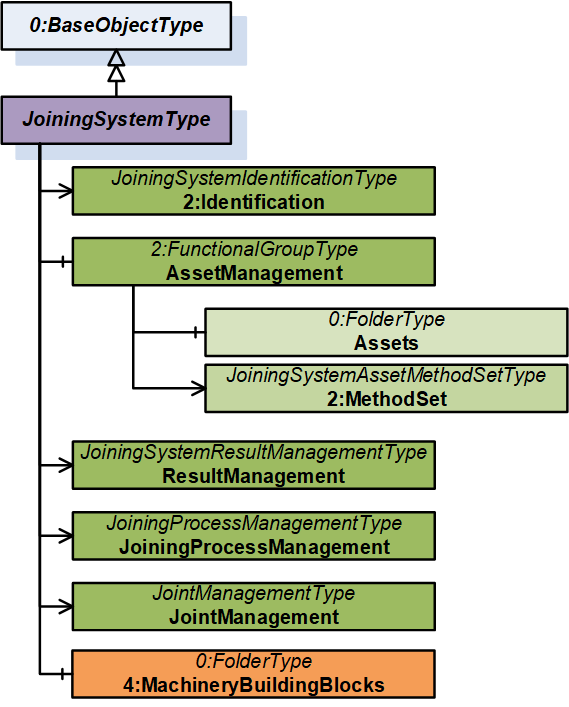
It is formally defined in Table 15.
7.1.2 JoiningSystemType definition
| Attribute | Value | ||||
| BrowseName | JoiningSystemType | ||||
| IsAbstract | False | ||||
| References | Node Class | BrowseName | DataType | TypeDefinition | Other |
|---|---|---|---|---|---|
| Subtype of the 0:BaseObjectType defined in OPC 10000-5, i.e., inheriting the InstanceDeclarations of that Node. | |||||
| 0:HasAddIn | Object | 2:Identification | - | JoiningSystemIdentificationType | M |
| 0:HasComponent | Object | AssetManagement | - | 2:FunctionalGroupType | O |
| 0:HasAddIn | Object | 5:ResultManagement | - | JoiningSystemResultManagementType | O |
| 0:HasAddIn | Object | JoiningProcessManagement | - | JoiningProcessManagementType | O |
| 0:HasAddIn | Object | JointManagement | - | JointManagementType | O |
| 0:HasComponent | Object | 4:MachineryBuildingBlocks | - | 0:FolderType | O |
| Conformance Units | |||||
|---|---|---|---|---|---|
| IJT Joining System Base | |||||
| IJT Joining System Identification | |||||
| IJT Joining System Machinery Building Blocks | |||||
| IJT Asset Management | |||||
| IJT Result Management | |||||
| IJT Joining Process Management | |||||
| IJT Joint Management |
The 2:Identification Object provides identification parameters of the joining system.
The AssetManagement Object is an instance of 2:FunctionalGroupType to group assets and related objects in the joining system.
The ResultManagement Object is an instance of JoiningSystemResultManagementType which provides mechanisms to access results generated by the joining system.
The JoiningProcessManagement Object is an instance of JoiningProcessManagementType which provides mechanisms to manage joining processes in the joining system.
The JointManagement Object is an instance of JointManagementType which provides mechanisms to manage joint and associated information.
4:MachineryBuildingBlocks contains building blocks from OPC UA for Machinery.
The components of the JoiningSystemType have additional subcomponents which are defined in Table 16.
| Source Path | Reference | NodeClass | BrowseName | DataType | TypeDefinition | Others |
| AssetManagement | 0:HasAddIn | Object | 2:MethodSet | JoiningSystemAssetMethodSetType | O |
2:MethodSet Object is an instance of JoiningSystemAssetMethodSetType which provides set of methods for various assets in a joining system.
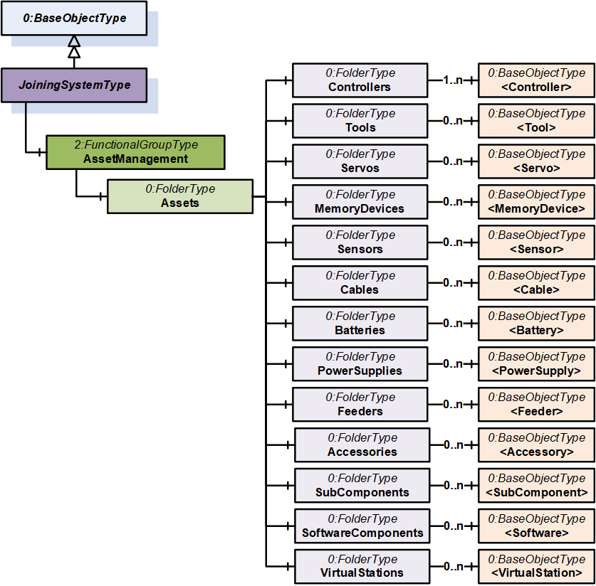
The components of the JoiningSystemType have additional subcomponents which are defined in Table 17.
| Source Path | Reference | NodeClass | BrowseName | DataType | TypeDefinition | Others | ||
| 0:HasComponent | Object | Controllers | 0:FolderType | M | |||
| 0:HasComponent | Object | Tools | 0:FolderType | O | |||
| 0:HasComponent | Object | Servos | 0:FolderType | O | |||
| 0:HasComponent | Object | MemoryDevices | 0:FolderType | O | |||
| 0:HasComponent | Object | Sensors | 0:FolderType | O | |||
| 0:HasComponent | Object | Cables | 0:FolderType | O | |||
| 0:HasComponent | Object | Batteries | 0:FolderType | O | |||
| 0:HasComponent | Object | PowerSupplies | 0:FolderType | O | |||
| 0:HasComponent | Object | Feeders | 0:FolderType | O | |||
| 0:HasComponent | Object | Accessories | 0:FolderType | O | |||
| 0:HasComponent | Object | SubComponents | 0:FolderType | O | |||
| 0:HasComponent | Object | SoftwareComponents | 0:FolderType | O | |||
| 0:HasComponent | Object | VirtualStations | 0:FolderType | O |
The components of the JoiningSystemType have additional subcomponents which are defined in Table 18.
| Source Path | Reference | NodeClass | BrowseName | DataType | TypeDefinition | Others | |||
| 0:HasComponent | Object | <Controller> | 0:BaseObjectType | MP | ||||
| 0:HasComponent | Object | <Tool> | 0:BaseObjectType | OP | ||||
| 0:HasComponent | Object | <Servo> | 0:BaseObjectType | OP | ||||
| 0:HasComponent | Object | <MemoryDevice> | 0:BaseObjectType | OP | ||||
| 0:HasComponent | Object | <Sensor> | 0:BaseObjectType | OP | ||||
| 0:HasComponent | Object | <Cable> | 0:BaseObjectType | OP | ||||
| 0:HasComponent | Object | <Battery> | 0:BaseObjectType | OP | ||||
| 0:HasComponent | Object | <Feeder> | 0:BaseObjectType | OP | ||||
| 0:HasComponent | Object | <PowerSupply> | 0:BaseObjectType | OP | ||||
| 0:HasComponent | Object | <Accessory> | 0:BaseObjectType | OP | ||||
| 0:HasComponent | Object | <SubComponent> | 0:BaseObjectType | OP | ||||
| 0:HasComponent | Object | <Software> | 0:BaseObjectType | OP | ||||
| 0:HasComponent | Object | <VirtualStation> | 0:BaseObjectType | OP |
The components of the JoiningSystemType have additional subcomponents which are defined in Table 19.
| Source Path | Reference | NodeClass | BrowseName | DataType | TypeDefinition | Others | ||||
| 0:HasInterface | ObjectType | IControllerType | |||||||
| 0:HasInterface | ObjectType | IToolType | |||||||
| 0:HasInterface | ObjectType | IServoType | |||||||
| 0:HasInterface | ObjectType | IMemoryDeviceType | |||||||
| 0:HasInterface | ObjectType | ISensorType | |||||||
| 0:HasInterface | ObjectType | ICableType | |||||||
| 0:HasInterface | ObjectType | IBatteryType | |||||||
| 0:HasInterface | ObjectType | IFeederType | |||||||
| 0:HasInterface | ObjectType | IPowerSupplyType | |||||||
| 0:HasInterface | ObjectType | IAccessoryType | |||||||
| 0:HasInterface | ObjectType | ISubComponentType | |||||||
| 0:HasInterface | ObjectType | ISoftwareType | |||||||
| 0:HasInterface | ObjectType | IVirtualStationType |
7.2 JoiningSystemIdentificationType ObjectType Definition
The JoiningSystemIdentificationType provides the identification parameters of the joining system and is formally defined in Table 20.
| Attribute | Value | ||||
| BrowseName | JoiningSystemIdentificationType | ||||
| IsAbstract | False | ||||
| References | Node Class | BrowseName | DataType | TypeDefinition | Other |
|---|---|---|---|---|---|
| Subtype of the 2:FunctionalGroupType defined in OPC 10000-100, i.e., inheriting the InstanceDeclarations of that Node. | |||||
| 0:HasProperty | Variable | 0:DefaultInstanceBrowseName | 0:QualifiedName | 0:PropertyType | |
| 0:HasProperty | Variable | 2:ProductInstanceUri | 0:String | 0:PropertyType | O |
| 0:HasProperty | Variable | Name | 0:String | 0:PropertyType | M |
| 0:HasProperty | Variable | IntegratorName | 0:String | 0:PropertyType | O |
| 0:HasProperty | Variable | Description | 0:LocalizedText | 0:PropertyType | O |
| 0:HasProperty | Variable | JoiningTechnology | 0:LocalizedText | 0:PropertyType | O |
| 0:HasProperty | Variable | 2:Manufacturer | 0:LocalizedText | 0:PropertyType | O |
| 0:HasProperty | Variable | 2:ManufacturerUri | 0:String | 0:PropertyType | O |
| 0:HasProperty | Variable | 2:Model | 0:LocalizedText | 0:PropertyType | O |
| 0:HasProperty | Variable | SystemId | 0:String | 0:PropertyType | O |
| 0:HasProperty | Variable | 4:Location | 0:String | 0:PropertyType | O |
| Conformance Units | |||||
|---|---|---|---|---|---|
| IJT Joining System Base | |||||
The component Variables of the JoiningSystemIdentificationType have additional Attributes defined in Table 21.
| BrowsePath | Value Attribute | Description Attribute |
| 0:DefaultInstanceBrowseName | 2:Identification | The default BrowseName for instances of the type. |
2: ProductInstanceUri is a globally unique resource identifier provided by the manufacturer.
Name is the name of the joining system. It is allowed to set it as the string part of the standard browse name of the instance of JoiningSystemType.
IntegratorName is the name of the system integrator.
Description is the description of the system which could be written by the customer to identify the system. It could be the purpose of the system in the assembly line.
Note: Although there is a description attribute at the node level in OPC UA, the Description property was added at the same level as the 2:Identification node for consistency.
JoiningTechnology is a human-readable text to identify the joining technology of the joining system.
2:Manufacturer provides a human-readable, localized name of the joining system manufacturer.
2:ManufacturerUri provides a unique identifier for this company. This identifier should be a fully qualified domain name; however, it may be a GUID or similar construct that ensures global uniqueness.
2:Model provides the type of the joining system. Examples: Fixtured System, Handheld System, etc.
SystemId is the system integrator specific identifier for the system. It represents a reference to the manufacturer's ERP system.
4:Location is the location of the given system in the given plant or factory in text format.
7.3 Joining System Asset Overview
7.3.1 Overview
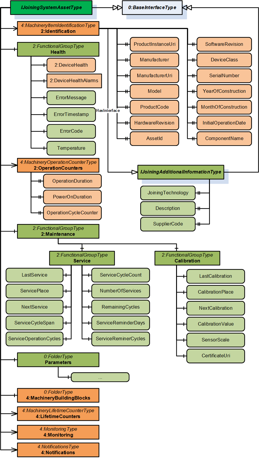
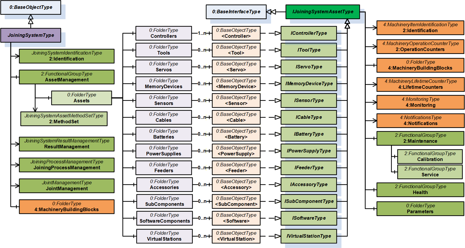
7.3.2 IJoiningSystemAssetType InterfaceType Definition
This is a generic interface common for all assets in the Joining System. The purpose of this interface is to provide the common information (Example: Identification, Health, Maintenance, etc.) of all the assets in a standardized way.
This interface has a standard MachineryItemIdentificationType add-in which can be assigned with MachineIdentificationType or MachineryComponentIdentificationType for an asset based on the requirement of the system.
Note: In a Joining System, Controller and Tool instances are generally considered as Machines and other assets can be modelled as components.
To determine if an asset is classified as Machine or Component is flexible and that is achieved using base add-in from OPC UA for Machinery specification MachineryItemIdentificationType which can be specialized using MachineIdentificationType or MachineryComponentIdentificationType.
The 2:Identification Object includes parameters from MachineryItemIdentificationType (which can be specialized to MachineIdentificationType or MachineryComponentIdentificationType) defined in .OPC 40001-1 It also implements IJoiningAdditionalInformationType.
| Attribute | Value | ||||
| BrowseName | IJoiningSystemAssetType | ||||
| IsAbstract | True | ||||
| References | Node Class | BrowseName | DataType | TypeDefinition | Other |
|---|---|---|---|---|---|
| Subtype of the BaseInterfaceType defined in OPC 10000-7. | |||||
| 0:HasAddIn | Object | 2:Identification | 4:MachineryItemIdentificationType | M | |
| 0:HasComponent | Object | Health | 2:FunctionalGroupType | O | |
| 0:HasAddIn | Object | 2:OperationCounters | 4:MachineryOperationCounterType | O | |
| 0:HasAddIn | Object | 4:LifetimeCounters | 4:MachineryLifetimeCounterType | O | |
| 0:HasComponent | Object | 2:Maintenance | 2:FunctionalGroupType | O | |
| 0:HasComponent | Object | Parameters | 0:FolderType | O | |
| 0:HasComponent | Object | 4:MachineryBuildingBlocks | 0:FolderType | O | |
| 0:HasAddIn | Object | 4:Monitoring | 4:MonitoringType | O | |
| 0:HasAddIn | Object | 4:Notifications | 4:NotificationsType | O | |
| Conformance Units | |||||
|---|---|---|---|---|---|
| 4:Machinery Machine Identification | |||||
| 4:Machinery Component Identification | |||||
| 4:Machinery Building Block Organization | |||||
| 4:Machinery Monitoring | |||||
| 4:Machinery Notifications | |||||
| IJT Asset Management Health | |||||
| IJT Asset Management Monitoring Health | |||||
| IJT Asset Management Operation Counters | |||||
| IJT Asset Management Service | |||||
| IJT Asset Management Calibration | |||||
| IJT Asset Management Machinery Building Blocks |
The components of the IJoiningSystemAssetType have additional subcomponents which are defined in Table 23.
| Source Path | Reference | NodeClass | BrowseName | DataType | TypeDefinition | Others | ||
| 2:Identification | 0:HasInterface | ObjectType | IJoiningAdditionalInformationType | |||||
| 2:Identification | 0:HasProperty | Variable | Description | 0:LocalizedText | 0:PropertyType | O, RO | ||
| 2:Identification | 0:HasProperty | Variable | JoiningTechnology | 0:LocalizedText | 0:PropertyType | O, RO | ||
| 2:Identification | 0:HasProperty | Variable | SupplierCode | 0:String | 0:PropertyType | O, RO | ||
| 2:OperationCounters | 0:HasProperty | Variable | 2:PowerOnDuration | 0:Duration | 0:PropertyType | O, RO | ||
| 2:OperationCounters | 0:HasProperty | Variable | 2:OperationDuration | 0:Duration | 0:PropertyType | O, RO | ||
| 2:OperationCounters | 0:HasProperty | Variable | 2:OperationCycleCounter | 0:UInteger | 0:PropertyType | O, RO | ||
| 4:LifetimeCounters | 0:HasComponent | Variable | <LifetimeVariable> | 0:Number | 2:LifetimeVariableType | O, RO | ||
| Health | 0:HasInterface | ObjectType | 2:IDeviceHealthType | |||||
| Health | 0:HasComponent | Variable | 2:DeviceHealth | 2:DeviceHealthEnum | 0:BaseDataVariableType | O, RO | ||
| Health | 0:HasComponent | Object | 2:DeviceHealthAlarms | 0:FolderType | O, RO | |||
| Health | 0:HasComponent | Variable | ErrorMessage | 0:LocalizedText | 0:BaseDataVariableType | O, RO | ||
| Health | 0:HasComponent | Variable | ErrorTimestamp | 0:UtcTime | 0:BaseDataVariableType | O, RO | ||
| Health | 0:HasComponent | Variable | ErrorCode | 0:Int64 | 0:BaseDataVariableType | O, RO | ||
| Health | 0:HasComponent | Variable | Temperature | 0:Double | JoiningDataVariableType | O, RO | ||
| 0:HasInterface | ObjectType | 2:IDeviceHealthType | |||||
| 0:HasComponent | Variable | 2:DeviceHealth | 2:DeviceHealthEnum | 0:BaseDataVariableType | O, RO | ||
| 0:HasComponent | Object | 2:DeviceHealthAlarms | 0:FolderType | O, RO | |||
| 0:HasComponent | Variable | ErrorMessage | 0:LocalizedText | 0:BaseDataVariableType | O, RO | ||
| 0:HasComponent | Variable | ErrorTimestamp | 0:UtcTime | 0:BaseDataVariableType | O, RO | ||
| 0:HasComponent | Variable | ErrorCode | 0:Int64 | 0:BaseDataVariableType | O, RO | ||
| 0:HasComponent | Variable | Temperature | 0:Double | JoiningDataVariableType | O, RO | ||
| 0:HasComponent | Variable | LastService | 0:UtcTime | 0:BaseDataVariableType | M, RO | ||
| 0:HasComponent | Variable | ServicePlace | 0:String | 0:BaseDataVariableType | M, RO | ||
| 0:HasComponent | Variable | NextService | 0:UtcTime | 0:BaseDataVariableType | O, RO | ||
| 0:HasComponent | Variable | ServiceCycleSpan | 0:Int32 | 0:BaseDataVariableType | O, RO | ||
| 0:HasComponent | Variable | ServiceCycleCount | 0:Int32 | 0:BaseDataVariableType | O, RO | ||
| 0:HasComponent | Variable | NumberOfServices | 0:Int32 | 0:BaseDataVariableType | O, RO | ||
| 0:HasComponent | Variable | ServiceReminderDays | 0:Int16 | 0:BaseDataVariableType | O, RO | ||
| 0:HasComponent | Variable | RemainingCycles | 0:Int32 | 0:BaseDataVariableType | O, RO | ||
| 0:HasComponent | Variable | ServiceReminderCycles | 0:Int32 | 0:BaseDataVariableType | O, RO | ||
| 0:HasComponent | Variable | ServiceOperationCycles | 0:UInt64 | 0:BaseDataVariableType | O, RO | ||
| 0:HasComponent | Variable | CalibrationValue | 0:Double | JoiningDataVariableType | O, RO | ||
| 0:HasComponent | Variable | LastCalibration | 0:UtcTime | 0:BaseDataVariableType | M, RO | ||
| 0:HasComponent | Variable | CalibrationPlace | 0:String | 0:BaseDataVariableType | O, RO | ||
| 0:HasComponent | Variable | NextCalibration | 0:UtcTime | 0:BaseDataVariableType | O, RO | ||
| 0:HasComponent | Variable | SensorScale | 0:Double | JoiningDataVariableType | O, RO | ||
| 0:HasComponent | Variable | CertificateUri | 0:UriString | 0:BaseDataVariableType | O, RO | ||
| Parameters | 0:HasComponent | Variable | Connected | 0:Boolean | 0:BaseDataVariableType | O, RO | ||
| Parameters | 0:HasComponent | Variable | Enabled | 0:Boolean | 0:BaseDataVariableType | O, RO | ||
| Parameters | 0:HasComponent | Variable | IOSignals | SignalDataType[] | 0:BaseDataVariableType | O, RO |
The 2:Identification Object, using the standardized name defined in OPC 10000-100, provides identification information about the asset. This is a mandatory place holder and any asset inheriting IJoiningSystemAssetType will replace it with MachineIdentificationType or MachineryComponentIdentificationType.
The 2:Identification Object implements IJoiningAdditionalInformationType interface with the following properties:
Description is the system specific description of the asset.
Note: Although there is a description attribute at the node level in OPC UA, the Description property was added at the same level as the 2:Identification node for consistency.
JoiningTechnology is a human readable text to identify the joining technology.
SupplierCode is the SAP or ERP Supplier Code of the asset.
The Health Object is an instance of 2:FunctionalGroupType to group health related parameters for all the assets in a Joining System. The parameters for Health Object are described below.
Note: The Health Object is obsolete and upgraded based on the Machinery Base Specification. The following parameters are recommended to be accessed using 4:Monitoring/Health object.
2: DeviceHealth indicates the status as defined by NAMUR Recommendation NE107. Clients can read or monitor this Variable to determine the device condition.
ErrorMessage is the user readable text of the error reported by the given asset.
ErrorTimestamp is the timestamp when the error occurred in the given asset.
ErrorCode is the system specific code for the error that occurred.
Temperature is the measured temperature of the asset.
The 2:OperationCounters Object is an instance of 4:MachineryOperationCounterType which provides information about the duration something is turned on and how long it performs an activity. The parameters for 2:OperationCounters Object are defined in OPC 40001-1.
Note: The data type of 2:OperationCycleCounter is 0:UInteger and it is recommended to use 0:UInt64 for instances of an asset in a joining system.
The 4:LifetimeCounters Object is an instance of 4:MachineryLifetimeCounterType which provides an entry point to various lifetime variables.
The <LifetimeVariable > can be used for any kind of lifetime variables.
The Maintenance Object is an instance of 2:FunctionalGroupType to group maintenance related parameters for the given asset in a Joining System. It has the following objects described below:
The Service Object provides a set of parameters related to the service operations performed on a given asset.
The Calibration Object provides a set of parameters related to the calibration operations performed on a given asset.
The parameters for the Service Object are described below.
LastService is the date when the last service was completed.
ServicePlace is the location where the last service was completed.
Note: LastService and ServicePlace should have the initial operation date and the place for new assets.
NextService is the date of the next planned service.
ServiceCycleSpan is the maximum allowed number of cycles between two services.
ServiceCycleCount is the total cycle counter since the last service.
NumberOfServices is the total number of services taken place.
ServiceReminderDays is the number of days before a service reminder should be sent.
RemainingCycles is the remaining cycles before the service or maintenance. It can go negative if a service is skipped to indicate overshoot cycles.
ServiceReminderCycles is the configured threshold for the number of remaining cycles before the service reminder is sent. This is calculated based on the RemainingCycles.
Example: If ServiceReminderCycles <= RemainingCycles, then a service reminder is sent.
ServiceOperationCycles is the value of the 2:OperationCycleCounter when the last service was performed.
The parameters for Calibration Object are described below.
CalibrationValue is the configured value of the calibration.
LastCalibration is the date when the last calibration was completed.
CalibrationPlace is the location where the last calibration was completed.
NextCalibration is the date of the next planned calibration.
SensorScale is the nominal scale of the sensor. It corresponds also with the measurement range of the sensor.
CertificateUri contains the URI of a certificate of the calibration target in case the calibration target is certified and the information available. Otherwise, the Variable should be omitted. The String shall be a URI as defined by RFC 3986. Example: MCE test document.
The Parameters Object is an instance of 0:FolderType to group set of common parameters of an asset in a joining system. It has the following parameters described below:
Enabled indicates if a given asset is enabled or disabled. It can change by the EnableAsset method or by some other external interface.
Connected indicates if a given asset is connected or disconnected. It can change by DisconnectAsset method or by some other external interface.
IOSignals is an array of signals available for the asset.
Note: The Parameters Object is overridden for the specific assets and contains a set of additional parameters of the given asset.
The MachineryBuildingBlocks contains building blocks from OPC UA for Machinery.
The 4:Monitoring Object is an instance of 4:MonitoringType which provides a base structure for monitoring information of an asset. It provides some sub-structures for grouping different monitoring information. It contains the following sub-structures:
4:Status is the entry point for status information of the asset. If this Object is provided, and the MachineryItemState is provided, it shall be referenced. If this Object is provided and the MachineryOperationMode is provided, it shall be referenced.
4:Health is the entry point of health information of the asset.
Note: This is the commended entry point for health information of the asset.
4:Process is the entry point for process information of the asset.
4:Consumption is the entry point for consumption information of the asset.
The 4:Notifications Object is an instance of 4:NotificationsType which provides the entry point into notifications of an asset. It allows to provide such notifications as Events by becoming an EventNotifier or providing specific Objects for notifications. This specification does not define any specific EventTypes or other ObjectTypes for notifications but just the base infrastructure.
7.3.3 IJoiningAdditionalInformationType InterfaceType Definition
The IJoiningAdditionalInformationType provides additional parameters for 2:Identification of a given asset and is formally defined in Table 24.
Note: The descriptions of the following properties are given in section 7.3.2.
| Attribute | Value | ||||
| BrowseName | IJoiningAdditionalInformationType | ||||
| IsAbstract | True | ||||
| References | Node Class | BrowseName | DataType | TypeDefinition | Other |
|---|---|---|---|---|---|
| Subtype of the BaseInterfaceType defined in OPC 10000-7. | |||||
| 0:HasProperty | Variable | Description | 0:LocalizedText | 0:PropertyType | O |
| 0:HasProperty | Variable | JoiningTechnology | 0:LocalizedText | 0:PropertyType | O |
| 0:HasProperty | Variable | SupplierCode | 0:String | 0:PropertyType | O |
| Conformance Units | |||||
|---|---|---|---|---|---|
| IJT Asset Management Additional Information |
7.3.4 IControllerType InterfaceType Definition
| Attribute | Value | ||||
| BrowseName | IControllerType | ||||
| IsAbstract | True | ||||
| References | Node Class | BrowseName | DataType | TypeDefinition | Other |
|---|---|---|---|---|---|
| Subtype of the IJoiningSystemAssetType, inheriting the InstanceDeclarations of that Node. | |||||
| 0:HasComponent | Object | Parameters | -- | 0:FolderType | M |
| Conformance Units | |||||
|---|---|---|---|---|---|
| IJT Asset Management Controller |
The components of the IControllerType have additional subcomponents which are defined in Table 26.
| Source Path | Reference | NodeClass | BrowseName | DataType | TypeDefinition | Others |
| Parameters | 0:HasComponent | Variable | Type | 0:Byte | 0:MultiStateDiscreteType | O, RO |
Type is the classification of a Controller. In Table 27, standardized values for EnumStrings are defined. Each instance of this type shall follow the defined sequence for the entries.
Note: Servers can add additional entries into the EnumStrings array and may provide translations of the texts in different locales.
| BrowsePath | Value Attribute | |||
| OTHER SUPERVISORY_CONTROLLER PLC COMPUTER JOINING_PROCESS_CONTROLLER COMMUNICATION_CONTROLLER FEEDING_CONTROLLER |
The descriptions for EnumStrings values corresponding to Type are given below:
OTHER
SUPERVISORY_CONTROLLER is a controller which is not executing the process or moving actuators. It manages other controllers and may be a node or hub to other controllers.
PLC is a Programmable Logic Controller which executes a sequence of operations. Examples would be part handling, providing fasteners, managing bit strokes.
COMPUTER is an information processing unit such as a PC.
JOINING_PROCESS_CONTROLLER is controller which is handling the joining process. It performs the joining and publishes its results.
COMMUNICATION_CONTROLLER is a controller which is mainly in charge of handling communications.
FEEDING_CONTROLLER is a controller which performs the fastener flow and provides the fastening elements.
7.3.5 IToolType InterfaceType Definition
It is a generic interface for any type of tool for various joining technologies. Examples: Tightening Tool, Gluing Applicator, etc.
Note: The respective joining technology specifications can define a sub-type of this interface for additional properties.
| Attribute | Value | ||||
| BrowseName | IToolType | ||||
| IsAbstract | True | ||||
| References | Node Class | BrowseName | DataType | TypeDefinition | Other |
|---|---|---|---|---|---|
| Subtype of the IJoiningSystemAssetType, inheriting the InstanceDeclarations of that Node. | |||||
| 0:HasComponent | Object | Parameters | -- | 0:FolderType | M |
| Conformance Units | |||||
|---|---|---|---|---|---|
| IJT Asset Management Tool | |||||
| IJT Asset Management Tool Operation Cycle Counter |
The components of the IToolType have additional subcomponents which are defined in Table 29.
| Source Path | Reference | NodeClass | BrowseName | DataType | TypeDefinition | Others |
| Parameters | 0:HasComponent | Variable | Type | 0:Byte | 0:MultiStateDiscreteType | M, RO |
Type is the classification of a Tool.
Note: Servers can add additional entries into the EnumStrings array and may provide translations of the texts in different locales.
| BrowsePath | Value Attribute | |||
| OTHER FIXTURED HANDHELD MANUAL |
7.3.6 IServoType InterfaceType Definition
| Attribute | Value | ||||
| BrowseName | IServoType | ||||
| IsAbstract | True | ||||
| References | Node Class | BrowseName | DataType | TypeDefinition | Other |
|---|---|---|---|---|---|
| Subtype of the IJoiningSystemAssetType, inheriting the InstanceDeclarations of that Node. | |||||
| 0:HasComponent | Object | Parameters | -- | 0:FolderType | M |
| Conformance Units | |||||
|---|---|---|---|---|---|
| IJT Asset Management Servo |
The components of the IServoType have additional subcomponents which are defined in Table 32.
| Source Path | Reference | NodeClass | BrowseName | DataType | TypeDefinition | Others |
| Parameters | 0:HasComponent | Variable | NodeNumber | 0:Int16 | 0:BaseDataVariableType | O, RO |
NodeNumber is the node identifier in multiple configurations. Examples: Cabinet with one controller and multiple servo/modules.
7.3.7 IMemoryDeviceType InterfaceType Definition
| Attribute | Value | ||||
| BrowseName | IMemoryDeviceType | ||||
| IsAbstract | True | ||||
| References | Node Class | BrowseName | DataType | TypeDefinition | Other |
|---|---|---|---|---|---|
| Subtype of the IJoiningSystemAssetType, inheriting the InstanceDeclarations of that Node. | |||||
| 0:HasComponent | Object | Parameters | -- | 0:FolderType | M |
| Conformance Units | |||||
|---|---|---|---|---|---|
| IJT Asset Management Memory Device |
The components of the IMemoryDeviceType have additional subcomponents which are defined in Table 34.
| Source Path | Reference | NodeClass | BrowseName | DataType | TypeDefinition | Others |
| Parameters | 0:HasComponent | Variable | Type | 0:String | 0:BaseDataVariableType | O, RO |
| Parameters | 0:HasComponent | Variable | StorageCapacity | 0:UInt64 | 0:BaseDataVariableType | O, RO |
| Parameters | 0:HasComponent | Variable | UsedSpace | 0:UInt64 | 0:BaseDataVariableType | O, RO |
Type is the type of memory device. It may define the form factor, interface, or technology. Examples: Flash, CFAST, USB, etc.
Note: Memory or storage devices can be classified based on various factors. Hence an open string is provided to make it generic.
StorageCapacity is the static information on the size of the storage in Bytes.
UsedSpace is the static information on the size of the used space in Bytes.
7.3.8 ISensorType InterfaceType Definition
| Attribute | Value | ||||
| BrowseName | ISensorType | ||||
| IsAbstract | True | ||||
| References | Node Class | BrowseName | DataType | TypeDefinition | Other |
|---|---|---|---|---|---|
| Subtype of the IJoiningSystemAssetType, inheriting the InstanceDeclarations of that Node. | |||||
| 0:HasComponent | Object | Parameters | -- | 0:FolderType | M |
| Conformance Units | |||||
|---|---|---|---|---|---|
| IJT Asset Management Sensor |
The components of the ISensorType have additional subcomponents which are defined in Table 36.
| Source Path | Reference | NodeClass | BrowseName | DataType | TypeDefinition | Others |
| Parameters | 0:HasComponent | Variable | Type | 0:Byte | 0:MultiStateDiscreteType | O, RO |
| Parameters | 0:HasComponent | Variable | OverloadCount | 0:Int64 | 0:BaseDataVariableType | O, RO |
| Parameters | 0:HasComponent | Variable | MeasuredValue | 0:Double | JoiningDataVariableType | O, RO |
Type is the classification of a Sensor. In Table 37, standardized values for the EnumStrings are defined. Each instance of this type shall follow the defined sequence for the entries.
Note: Servers can add additional entries into the EnumStrings array and may provide translations of the texts in different locales.
| BrowsePath | Value Attribute | |||
| OTHER TIME TORQUE ANGLE IMPULSE DISTANCE AREA VOLUME FORCE PRESSURE VOLTAGE CURRENT RESISTANCE POWER ENERGY MASS TEMPERATURE FREQUENCY JOLT VIBRATION NUMBER LINEAR_SPEED ANGULAR_SPEED LINEAR_ACCELERATION ANGULAR_ACCELERATION TORQUE_SPEED TORQUE_ACCELERATION |
OverloadCount is the number of overloads of the sensor, where the permissible load of the sensor was exceeded.
MeasuredValue is the actual measured value reported from a sensor.
Note: An instance of Sensor can be referenced to a respective Calibration Target which was used to calibrate the sensor. The standard models for Calibration Targets are defined in OPC 10000-200.
7.3.9 ICableType InterfaceType Definition
| Attribute | Value | ||||
| BrowseName | ICableType | ||||
| IsAbstract | True | ||||
| References | Node Class | BrowseName | DataType | TypeDefinition | Other |
|---|---|---|---|---|---|
| Subtype of the IJoiningSystemAssetType, inheriting the InstanceDeclarations of that Node. | |||||
| 0:HasComponent | Object | Parameters | -- | 0:FolderType | M |
| Conformance Units | |||||
|---|---|---|---|---|---|
| IJT Asset Management Cable | |||||
The components of the ICableType have additional subcomponents which are defined in Table 39.
| Source Path | Reference | NodeClass | BrowseName | DataType | TypeDefinition | Others |
| Parameters | 0:HasComponent | Variable | Type | 0:Byte | 0:MultiStateDiscreteType | O, RO |
| Parameters | 0:HasComponent | Variable | CableLength | 0:Double | JoiningDataVariableType | O, RO |
Type is the classification of the cable.
In Table 40, standardized values for the EnumStrings are defined. Each instance of this type shall follow the defined sequence for the entries.
Note: Servers can add additional entries into the EnumStrings array and may provide translations of the texts in different locales.
| BrowsePath | Value Attribute | |||
| OTHER TOOL_CABLE SENSOR_CABLE COMMUNICATION_CABLE POWER_CABLE IO_CABLE BUS_CABLE |
CableLength is the length of the cable.
7.3.10 IBatteryType InterfaceType Definition
| Attribute | Value | ||||
| BrowseName | IBatteryType | ||||
| IsAbstract | True | ||||
| References | Node Class | BrowseName | DataType | TypeDefinition | Other |
|---|---|---|---|---|---|
| Subtype of the IJoiningSystemAssetType, inheriting the InstanceDeclarations of that Node. | |||||
| 0:HasComponent | Object | Parameters | -- | 0:FolderType | M |
| Conformance Units | |||||
|---|---|---|---|---|---|
| IJT Asset Management Battery | |||||
| IJT Asset Management Battery Operation Cycle Counter |
The components of the IBatteryType have additional subcomponents which are defined in Table 42.
| Source Path | Reference | NodeClass | BrowseName | DataType | TypeDefinition | Others |
| Parameters | 0:HasComponent | Variable | NominalVoltage | 0:Double | JoiningDataVariableType | M, RO |
| Parameters | 0:HasComponent | Variable | Capacity | 0:Double | JoiningDataVariableType | M, RO |
| Parameters | 0:HasComponent | Variable | ChargeCycleCount | 0:Int64 | 0:BaseDataVariableType | O, RO |
| Parameters | 0:HasComponent | Variable | StateOfCharge | 0:Byte | 0:BaseDataVariableType | O, RO |
| Parameters | 0:HasComponent | Variable | StateOfHealth | 0:Byte | 0:BaseDataVariableType | O, RO |
| Parameters | 0:HasComponent | Variable | Type | 0:String | 0:BaseDataVariableType | O, RO |
NominalVoltage is the nominal DC voltage of the battery.
Capacity is the nominal capacity of the battery.
ChargeCycleCount is the number of times the battery has been charged since the initial operation date.
StateOfCharge is the state of charge (SOC) indicator functions as a sort of fuel gauge that displays the usable amount of energy. This helps determine optimal charging and discharging. It is given in percentage.
StateOfHealth is the State of Health is a measurement that reflects the general condition of a battery and its ability to deliver the specified performance compared with a fresh battery. It considers such factors as charge acceptance, internal resistance, voltage, and self-discharge. It is given in percentage.
Type is a user readable text to determine the type of battery such as pack type, technology, chemical composition, battery standard, etc.
7.3.11 IPowerSupplyType InterfaceType Definition
| Attribute | Value | ||||
| BrowseName | IPowerSupplyType | ||||
| IsAbstract | True | ||||
| References | Node Class | BrowseName | DataType | TypeDefinition | Other |
|---|---|---|---|---|---|
| Subtype of the IJoiningSystemAssetType, inheriting the InstanceDeclarations of that Node. | |||||
| 0:HasComponent | Object | Parameters | -- | 0:FolderType | M |
| Conformance Units | |||||
|---|---|---|---|---|---|
| IJT Asset Management Power Supply |
The components of the IPowerSupplyType have additional subcomponents which are defined in Table 44.
| Source Path | Reference | NodeClass | BrowseName | DataType | TypeDefinition | Others |
| Parameters | 0:HasComponent | Variable | InputSpecification | 0:String | 0:BaseDataVariableType | M, RO |
| Parameters | 0:HasComponent | Variable | OutputSpecification | 0:String | 0:BaseDataVariableType | O, RO |
| Parameters | 0:HasComponent | Variable | NominalPower | 0:Double | JoiningDataVariableType | O, RO |
| Parameters | 0:HasComponent | Variable | ActualPower | 0:Double | JoiningDataVariableType | O, RO |
InputSpecification is the input specification of the power supply. Example: 230 V, 50/60 Hz, 10 A.
OutputSpecification is the output specification of the power supply.
NominalPower is the maximum output power of the power supply.
ActualPower is the actual load consumption of the power supply.
Note: This value may not be exposed to the highest possible sample rate. This value is for information only and should not be used for real time processing.
7.3.12 IFeederType InterfaceType Definition
| Attribute | Value | ||||
| BrowseName | IFeederType | ||||
| IsAbstract | True | ||||
| References | Node Class | BrowseName | DataType | TypeDefinition | Other |
|---|---|---|---|---|---|
| Subtype of the IJoiningSystemAssetType, inheriting the InstanceDeclarations of that Node. | |||||
| 0:HasComponent | Object | Parameters | -- | 0:FolderType | M |
| Conformance Units | |||||
|---|---|---|---|---|---|
| IJT Asset Management Feeder |
The components of the IFeederType have additional subcomponents which are defined in Table 46.
| Source Path | Reference | NodeClass | BrowseName | DataType | TypeDefinition | Others |
| Parameters | 0:HasComponent | Variable | Type | 0:Byte | 0:MultiStateDiscreteType | O, RO |
| Parameters | 0:HasComponent | Variable | Material | 0:String | 0:BaseDataVariableType | M, RO |
| Parameters | 0:HasComponent | Variable | FillLevel | 0:Byte | 0:BaseDataVariableType | O, RO |
| Parameters | 0:HasComponent | Variable | FeedingSpeed | 0:Double | JoiningDataVariableType | O, RO |
Type is the classification of a Feeder. In Table 47, standardized values for the EnumStrings are defined. Each instance of this type shall follow the defined sequence for the entries.
Note: Servers can add additional entries into the EnumStrings array and may provide translations of the texts in different locales.
| BrowsePath | Value Attribute | |||
| OTHER BOWL BUNKER CONVEYOR DRUM LINEAR SWORD TAPE MAGAZINE |
Material is the type or name of the part which is supplied by the feeder.
FillLevel is the fill level in the feeder in percentage [%]. (0%=empty, 100% = full).
FeedingSpeed indicates the output in parts per time. Example: fasteners / second.
7.3.13 IAccessoryType InterfaceType Definition
| Attribute | Value | ||||
| BrowseName | IAccessoryType | ||||
| IsAbstract | True | ||||
| References | Node Class | BrowseName | DataType | TypeDefinition | Other |
|---|---|---|---|---|---|
| Subtype of the IJoiningSystemAssetType, inheriting the InstanceDeclarations of that Node. | |||||
| 0:HasComponent | Object | Parameters | -- | 0:FolderType | M |
| Conformance Units | |||||
|---|---|---|---|---|---|
| IJT Asset Management Accessory |
The components of the IAccessoryType have additional subcomponents which are defined in Table 49.
| Source Path | Reference | NodeClass | BrowseName | DataType | TypeDefinition | Others |
| Parameters | 0:HasComponent | Variable | Type | 0:String | 0:BaseDataVariableType | O, RO |
Type is a user readable open string to describe the type of accessory such as socket selector, operator panel, etc.
7.3.14 ISubComponentType InterfaceType Definition
| Attribute | Value | ||||
| BrowseName | ISubComponentType | ||||
| IsAbstract | True | ||||
| References | Node Class | BrowseName | DataType | TypeDefinition | Other |
|---|---|---|---|---|---|
| Subtype of the IJoiningSystemAssetType, inheriting the InstanceDeclarations of that Node. | |||||
| 0:HasComponent | Object | Parameters | -- | 0:FolderType | O |
| Conformance Units | |||||
|---|---|---|---|---|---|
| IJT Asset Management SubComponent |
The components of the ISubComponentType have additional subcomponents which are defined in Table 51.
| Source Path | Reference | NodeClass | BrowseName | DataType | TypeDefinition | Others |
| Parameters | 0:HasComponent | Variable | Type | 0:String | 0:BaseDataVariableType | O, RO |
Type is a user readable open string to describe the type of subcomponent such as network module, etc.
7.3.15 ISoftwareType InterfaceType Definition
| Attribute | Value | ||||
| BrowseName | ISoftwareType | ||||
| IsAbstract | True | ||||
| References | Node Class | BrowseName | DataType | TypeDefinition | Other |
|---|---|---|---|---|---|
| Subtype of the IJoiningSystemAssetType, inheriting the InstanceDeclarations of that Node. | |||||
| Conformance Units | |||||
|---|---|---|---|---|---|
| IJT Asset Management Software |
Note: The instance of a Software most likely contains only the following parameters from IJoiningSystemAssetType, other parameters may not be applicable.
Identification / ProductInstanceUri
Identification / Manufacturer
Identification / ManufacturerUri
Identification / Model
Identification / SoftwareRevision
Identification / ComponentName
Identification / ProductCode
Identification / SerialNumber
Identification / JoiningTechnology
7.3.16 IVirtualStationType InterfaceType Definition
| Attribute | Value | ||||
| BrowseName | IVirtualStationType | ||||
| IsAbstract | True | ||||
| References | Node Class | BrowseName | DataType | TypeDefinition | Other |
|---|---|---|---|---|---|
| Subtype of the IJoiningSystemAssetType, inheriting the InstanceDeclarations of that Node. | |||||
| Conformance Units | |||||
|---|---|---|---|---|---|
| IJT Asset Management Virtual Station |
Note: The instance of a Virtual Station most likely contains only the following parameters from IJoiningSystemAssetType, other parameters may not be applicable.
Identification / ProductInstanceUri
Identification / Manufacturer
Identification / ManufacturerUri
Identification / ComponentName
Identification / JoiningTechnology
Identification / SerialNumber
Note: SerialNumber is Mandatory from the MachineryItemIdentificationType and may not be applicable for a Virtual Station. Hence, it can be set to an empty value.
7.4 Joining System Methods Status Overview
The Method Result Codes (defined in Call Service) are defined in Table 54. It shows the possible values for the Method call result codes.
| Result Code | Description |
| Good | The Method execution was successful, and the Status parameter indicates the successful operation. |
| Uncertain | The Method execution was successful, and the Status parameter indicates an error. |
| Bad_UserAccessDenied | The user does not have the right to execute the Method. The client shall not evaluate the Status parameter. |
| Bad_UnexpectedError | The server is not able to execute the function because an unexpected error occurred. The Server might be temporarily unavailable or unreachable due to network failure. The client shall not evaluate the Status parameter. |
Table 55 shows the possible values for the Status parameter.
Note: The client shall not evaluate the Status parameter if the Method Result Code is Bad.
| Status | Description |
| < 0 | Shall be used for application-specific errors. |
| > 0 | Reserved for errors defined by this and future standards. |
| 0 | OK/Success. |
| 1 | NOT_OK - Generic Error. |
| 2 | ProductInstanceUri not found. |
| 3 | ProductInstanceUri not applicable. |
| 4 | Input identifier/entity not found. |
| 5 | Invalid input. |
7.5 JoiningSystemResultManagementType ObjectType
7.5.1 Overview
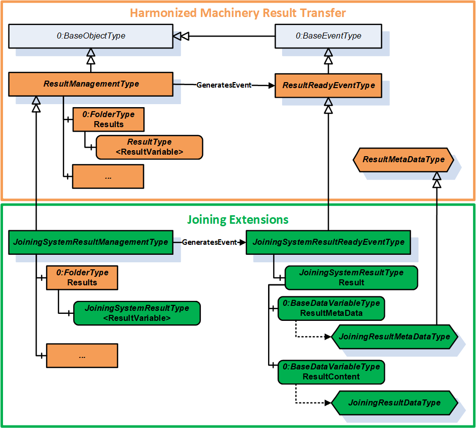
7.5.2 JoiningSystemResultManagementType ObjectType Definition
The JoiningSystemResultManagementType is a subtype of ResultManagementType and provides mechanism to access results generated by the underlying joining system. It is formally defined in Table 56.
| Attribute | Value | ||||
| BrowseName | JoiningSystemResultManagementType | ||||
| IsAbstract | False | ||||
| References | Node Class | BrowseName | DataType | TypeDefinition | Other |
|---|---|---|---|---|---|
| Subtype of the 5:ResultManagementType defined in OPC 40001-101, which means it inherits the InstanceDeclarations of that Node. | |||||
| 0:HasComponent | Object | 5:Results | 0:FolderType | O | |
| 0:GeneratesEvent | ObjectType | JoiningSystemResultReadyEventType | |||
| 0:GeneratesEvent | ObjectType | RequestedResultEventType | |||
| 0:HasComponent | Method | RequestResults | O | ||
| 0:HasComponent | Method | RequestUnacknowledgedResults | O | ||
| Conformance Units | |||||
|---|---|---|---|---|---|
| IJT Get Latest Result | |||||
| IJT Get Result by Id | |||||
| IJT Get Result with Filter Criteria | |||||
| IJT Result Variable Access | |||||
| IJT Result Event Access | |||||
| IJT Acknowledge Results | |||||
| IJT Requested Result Variable Access | |||||
| IJT Requested Result Event Access | |||||
| IJT Request Results | |||||
| IJT Request Unacknowledged Results | |||||
| IJT Self Contained Consolidated Result | |||||
| IJT Consolidated Result with References | |||||
| IJT Partial Consolidated Result |
Note:
5:ResultTransfer Object is not used in the Joining System.
The definition of the methods is available in OPC 40001-101.
The components of the JoiningSystemResultManagementType have additional subcomponents which are defined in Table 57.
| Source Path | Reference | NodeClass | BrowseName | DataType | TypeDefinition | Others |
| 5:Results | 0:HasComponent | Variable | <ResultVariable> | 5:ResultDataType | JoiningSystemResultType | OP |
| 5:Results | 0:HasComponent | Variable | <RequestedResultVariable> | 5:ResultDataType | JoiningSystemResultType | OP |
Each <ResultVariable> represents a result.
Note: It is recommended to use the BrowseName of the <ResultVariable> as "Result" if only one instance of the variable is exposed in the address space. The implementation of ResultVariable is application specific.
Each <RequestedResultVariable> represents a result returned by calling the RequestResults method or the RequestUnacknowledgedResults method.
Note: It is recommended to use the BrowseName of the <ResultVariable> as "RequestedResult" if only one instance of the variable is exposed in the address space. The implementation of RequestedResultVariable is application specific.
7.5.3 RequestResults
The Method RequestResults is used to receive stored results from the Server. A joining system can send live results or stored results.
The successful execution of this method will generate instances of RequestedResultEventType and update RequestedResultVariable.
The signature of this Method is specified below. Table 58 and Table 59 specify the Arguments and AddressSpace representation, respectively.
Signature
	RequestResults (
		[in]	0:UInt64	fromSequenceNumber,
		[in]	0:UInt64	toSequenceNumber,
		[in]	0:UtcTime	fromTime,
		[in]	0:UtcTime	toTime,
		[in]	0:Duration	requestedMinimumDurationBetweenResults,
		[out]	0:Duration	revisedMinimumDurationBetweenResults,
		[out]	0:Int64	status,
[out] 0:LocalizedText statusMessage)| Argument | Description |
| fromSequenceNumber | The starting sequence number for the Requested Results. It is a required argument if results are requested based on the input sequence number range. It shall be a valid value > 0. If 0, then fromTime and toTime are used. |
| toSequenceNumber | The ending sequence number of the Requested Results. It is a required argument if results are requested based on the input sequence number range. It shall be a valid value > 0 and shall be >= fromSequenceNumber. If 0, then fromTime and toTime are used. |
| fromTime | It is the start time for the Requested Results. This argument is considered only when fromSequenceNumber and toSequenceNumber are set as 0. |
| toTime | It is the end time for the Requested Results. This argument is considered only when fromSequenceNumber and toSequenceNumber are set as 0. |
| requestedMinimumDurationBetweenResults | The client can use this argument to configure a time interval between each Result to optimize the number of Results sent from the Server. The Server can return the revised interval if the requested interval is not supported. Note: It is only a requested minimum time interval by the client and the server could take additional time for processing. |
| revisedMinimumDurationBetweenResults | It is the minimum revised interval supported by the server. |
| status | It provides the status of the Method execution. Refer 7.4 for details. |
| statusMessage | It provides the high-level status information in a user-friendly text. |
| Attribute | Value | ||||
| BrowseName | RequestResults | ||||
| References | Node Class | BrowseName | DataType | TypeDefinition | ModellingRule |
|---|---|---|---|---|---|
| 0:HasProperty | Variable | 0:InputArguments | 0:Argument[] | 0:PropertyType | 0:Mandatory |
| 0:HasProperty | Variable | 0:OutputArguments | 0:Argument[] | 0:PropertyType | 0:Mandatory |
7.5.4 RequestUnacknowledgedResults
The Method RequestUnacknowledgedResults is used to receive unacknowledged results available in the joining system.
The successful execution of this method will generate instances of RequestedResultEventType and update RequestedResultVariable.
Note: It is recommended that this Method is used only by the Client that is responsible for exclusively storing the results.
The signature of this Method is specified below. Table 58 and Table 59 specify the Arguments and AddressSpace representation, respectively.
Signature
	RequestUnacknowledgedResults (
		[in]	0:UInt32	maxResults,
		[in]	0:Duration	requestedMinimumDurationBetweenResults,
		[out]	0:Duration	revisedMinimumDurationBetweenResults,
		[out]	0:UInt32	unacknowledgedResultCount,
		[out]	0:Int64	status,
[out] 0:LocalizedText statusMessage)| Argument | Description |
| maxResults | It is the maximum results requested by the Client. If 0, then the Server shall send all the unacknowledged results. |
| requestedMinimumDurationBetweenResults | The client can use this argument to configure a time interval between each Result to optimize the number of Results sent from the Server. The Server can return the revised interval if the requested interval is not supported. Note: It is only a requested minimum time interval by the client and the server could take additional time for processing. |
| revisedMinimumDurationBetweenResults | It is the minimum revised interval supported by the server. |
| unacknowledgedResultCount | It is the total count of unacknowledged results in the server. |
| status | It provides the status of the Method execution. Refer 7.4 for details. |
| statusMessage | It provides the high-level status information in a user-friendly text. |
| Attribute | Value | ||||
| BrowseName | RequestUnacknowledgedResults | ||||
| References | Node Class | BrowseName | DataType | TypeDefinition | ModellingRule |
|---|---|---|---|---|---|
| 0:HasProperty | Variable | 0:InputArguments | 0:Argument[] | 0:PropertyType | 0:Mandatory |
| 0:HasProperty | Variable | 0:OutputArguments | 0:Argument[] | 0:PropertyType | 0:Mandatory |
7.6 JoiningSystemAssetMethodSetType ObjectType Definition
7.6.1 Overview
The JoiningSystemAssetMethodSetType provides a set of methods for various assets in a joining system and is formally defined in Table 62.
| Attribute | Value | ||||
| BrowseName | JoiningSystemAssetMethodSetType | ||||
| IsAbstract | False | ||||
| References | Node Class | BrowseName | DataType | TypeDefinition | Other |
|---|---|---|---|---|---|
| Subtype of the 0:BaseObjectType defined in OPC 10000-5, i.e., inheriting the InstanceDeclarations of that Node. | |||||
| 0:HasProperty | Variable | 0:DefaultInstanceBrowseName | 0:QualifiedName | 0:PropertyType | |
| 0:HasComponent | Method | SetCalibration | O | ||
| 0:HasComponent | Method | EnableAsset | O | ||
| 0:HasComponent | Method | DisconnectAsset | O | ||
| 0:HasComponent | Method | RebootAsset | O | ||
| 0:HasComponent | Method | SendFeedback | O | ||
| 0:HasComponent | Method | GetFeedbackFileList | O | ||
| 0:HasComponent | Method | SetTime | O | ||
| 0:HasComponent | Method | SetOfflineTimer | O | ||
| 0:HasComponent | Method | SetIOSignals | O | ||
| 0:HasComponent | Method | GetIOSignals | O | ||
| 0:HasComponent | Method | SendIdentifiers | O | ||
| 0:HasComponent | Method | SendTextIdentifiers | O | ||
| 0:HasComponent | Method | GetIdentifiers | O | ||
| 0:HasComponent | Method | ResetIdentifiers | O | ||
| 0:HasComponent | Method | GetErrorInformation | O | ||
| 0:HasComponent | Method | ExecuteOperation | O | ||
| Conformance Units | |||||
|---|---|---|---|---|---|
| IJT Method Input Argument | |||||
| IJT Disconnect Asset | |||||
| IJT Enable Tool | |||||
| IJT Send Identifiers | |||||
| IJT Get Identifiers | |||||
| IJT Reset Identifiers | |||||
| IJT Set Calibration | |||||
| IJT Reboot Asset | |||||
| IJT Feedback Methods | |||||
| IJT IO Signals Methods | |||||
| IJT Get Error Information | |||||
| IJT Execute Operation | |||||
| IJT Set Time | |||||
| IJT Set Offline Timer |
The component Variables of the JoiningSystemAssetMethodSetType have additional Attributes defined in Table 63.
| BrowsePath | Value Attribute | Description Attribute |
| 0:DefaultInstanceBrowseName | 2:MethodSet | The default BrowseName for instances of the type. |
7.6.2 SetCalibration
The Method SetCalibration is used to set the calibration information of a given asset.
It is intended to set the basic calibration information and does not cover the certification process.
Note:
In a Joining System, calibration data is applicable primarily to a Sensor (if available), else it can be set for the Tool when the Sensor asset is not available.
The Server shall update the respective Calibration information of the asset after execution of this method.
The signature of this Method is specified below. Table 64 and Table 65 specify the Arguments and AddressSpace representation, respectively.
Signature
	SetCalibration (
		[in]	0:String		productInstanceUri,
		[in]	CalibrationDataType	calibrationData,
		[out]	0:Int64		status,
[out] 0:LocalizedText statusMessage)| Argument | Description |
| productInstanceUri | With this argument the Client can provide the identifier of the asset on which this method is applicable. It can be empty if the method is modelled directly under the required asset. If it is empty, the system can consider the identifier of the asset where the Server is running. |
| calibrationData | It is the input calibration data which needs to be configured for the asset. |
| status | It provides the status of the Method execution. Refer 7.4 for details. |
| statusMessage | It provides the high-level status information in a user-friendly text. |
| Attribute | Value | ||||
| BrowseName | SetCalibration | ||||
| References | Node Class | BrowseName | DataType | TypeDefinition | ModellingRule |
|---|---|---|---|---|---|
| 0:HasProperty | Variable | 0:InputArguments | 0:Argument[] | 0:PropertyType | 0:Mandatory |
| 0:HasProperty | Variable | 0:OutputArguments | 0:Argument[] | 0:PropertyType | 0:Mandatory |
7.6.3 EnableAsset
The Method EnableAsset is used to Enable or Disable a given asset. It is mostly applicable for Tool.
The Asset.Parameters.Enabled variable shall be updated with the enable status and generate an event of JoiningSystemEventType with ConditionClass = SystemConditionClassType and ConditionSubClass = AssetEnabledConditionClassType or AssetDisabledConditionClassType..
The signature of this Method is specified below. Table 66 and Table 67 specify the Arguments and AddressSpace representation, respectively.
Signature
	EnableAsset (
		[in]	0:String		productInstanceUri,
		[in]	0:Boolean		enable,
		[out]	0:Int64		status,
[out] 0:LocalizedText statusMessage)| Argument | Description |
| productInstanceUri | With this argument the Client can provide the identifier of the asset on which this method is applicable. It can be empty if the method is modelled directly under the required asset. If it is empty, the system can consider the identifier of the asset where the Server is running. |
| enable | If true, it will enable the asset, else it will disable the asset. The default value is false. Note: If the asset is performing the joining operation when the method is executed, then it shall disable the asset after the current operation. |
| status | It provides the status of the Method execution. Refer 7.4 for details. |
| statusMessage | It provides the high-level status information in a user-friendly text. |
| Attribute | Value | ||||
| BrowseName | EnableAsset | ||||
| References | Node Class | BrowseName | DataType | TypeDefinition | ModellingRule |
|---|---|---|---|---|---|
| 0:HasProperty | Variable | 0:InputArguments | 0:Argument[] | 0:PropertyType | 0:Mandatory |
| 0:HasProperty | Variable | 0:OutputArguments | 0:Argument[] | 0:PropertyType | 0:Mandatory |
7.6.4 DisconnectAsset
The Method DisconnectAsset is used to disconnect or connect the asset.
Note: It is intended to be used for physical assets connected with physical cables where an asset can be disconnected using the method before removing the cable connection.
Examples: Cable Tool connected to a Controller or a gateway, Robot docking.
The Asset.Parameters.Connected variable shall be updated with the connection status and generate an event of JoiningSystemEventType with ConditionClass = SystemConditionClassType and ConditionSubClass = AssetConnectedConditionClassType or AssetDisconnectedConditionClassType..
The signature of this Method is specified below. Table 68 and Table 69 specify the Arguments and AddressSpace representation, respectively.
Signature
	DisconnectAsset (
		[in]	0:String		productInstanceUri,
		[in]	0:Boolean		disconnect,
		[out]	0:Int64		status,
[out] 0:LocalizedText statusMessage)| Argument | Description |
| productInstanceUri | With this argument the Client can provide the identifier of the asset on which this method is applicable. It can be empty if the method is modelled directly under the required asset. If it is empty, the system can consider the identifier of the asset where the Server is running. |
| disconnect | If true, it will prepare the asset for disconnect. The default value is false. |
| status | It provides the status of the Method execution. Refer 7.4 for details. |
| statusMessage | It provides the high-level status information in a user-friendly text. |
| Attribute | Value | ||||
| BrowseName | DisconnectAsset | ||||
| References | Node Class | BrowseName | DataType | TypeDefinition | ModellingRule |
|---|---|---|---|---|---|
| 0:HasProperty | Variable | 0:InputArguments | 0:Argument[] | 0:PropertyType | 0:Mandatory |
| 0:HasProperty | Variable | 0:OutputArguments | 0:Argument[] | 0:PropertyType | 0:Mandatory |
7.6.5 RebootAsset
The Method RebootAsset is used to reboot an asset.
The signature of this Method is specified below. Table 70 and Table 71 specify the Arguments and AddressSpace representation, respectively.
Signature
	RebootAsset (
		[in]	0:String		productInstanceUri,
		[out]	0:Int64		status,
[out] 0:LocalizedText statusMessage)| Argument | Description |
| productInstanceUri | With this argument the Client can provide the identifier of the asset on which this method is applicable. It can be empty if the method is modelled directly under the required asset. If it is empty, the system can consider the identifier of the asset where the Server is running. |
| status | It provides the status of the Method execution. Refer 7.4 for details. |
| statusMessage | It provides the high-level status information in a user-friendly text. |
| Attribute | Value | ||||
| BrowseName | RebootAsset | ||||
| References | Node Class | BrowseName | DataType | TypeDefinition | ModellingRule |
|---|---|---|---|---|---|
| 0:HasProperty | Variable | 0:InputArguments | 0:Argument[] | 0:PropertyType | 0:Mandatory |
| 0:HasProperty | Variable | 0:OutputArguments | 0:Argument[] | 0:PropertyType | 0:Mandatory |
7.6.6 SendFeedback
The Method SendFeedback is used to send any type of feedback to a given asset. The feedback can be a text input or other types of feedback supported by the asset.
Note: The types of feedback files supported is application specific. Refer to the application documentation or configuration for the details of the feedback files.
The signature of this Method is specified below. Table 72 and
Table 73 specify the Arguments and AddressSpace representation, respectively.
Signature
	SendFeedback (
		[in]	0:String		productInstanceUri,
		[in]	0:Int16		feedbackType,
		[in]	0:String		feedbackText,
		[in]	0:String		feedbackFile,
		[out]	0:Int64		status,
[out] 0:LocalizedText statusMessage)| Argument | Description |
| productInstanceUri | With this argument the Client can provide the identifier of the asset on which this method is applicable. It can be empty if the method is modelled directly under the required asset. If it is empty, the system can consider the identifier of the asset where the Server is running. |
| feedbackType | It is the type of feedback and has the following pre-defined values: 0 - UNDEFINED 1 - OTHER 2 - TEXT 3 - VISUAL 4 - AUDIO 5 - VIBRATE |
| feedbackText | It is the text feedback if the feedbackType is TEXT. It is empty for any other feedback type. |
| feedbackFile | It is the file available in the asset which needs to be run for different types of feedback such as AUDIO, VIBRATE, etc. This can be retrieved using the GetFeedbackFileList method. It is optional and not applicable for text feedback. |
| status | It provides the status of the Method execution. Refer 7.4 for details. |
| statusMessage | It provides the high-level status information in a user-friendly text. |
| Attribute | Value | ||||
| BrowseName | SendFeedback | ||||
| References | Node Class | BrowseName | DataType | TypeDefinition | ModellingRule |
|---|---|---|---|---|---|
| 0:HasProperty | Variable | 0:InputArguments | 0:Argument[] | 0:PropertyType | 0:Mandatory |
| 0:HasProperty | Variable | 0:OutputArguments | 0:Argument[] | 0:PropertyType | 0:Mandatory |
7.6.7 GetFeedbackFileList
The Method GetFeedbackFileList is used to get the list of feedback files from the asset.
Note: The types of feedback files supported is application specific. Refer to the application documentation or configuration for the details of the feedback files.
The signature of this Method is specified below. Table 74 and Table 75 specify the Arguments and AddressSpace representation, respectively.
Signature
	GetFeedbackFileList (
		[in]	0:String		productInstanceUri,
		[out]	0:String[]		feedbackFileList,
		[out]	0:Int64		status,
[out] 0:LocalizedText statusMessage)| Argument | Description |
| productInstanceUri | With this argument the Client can provide the identifier of the asset on which this method is applicable. It can be empty if the method is modelled directly under the required asset. If it is empty, the system can consider the identifier of the asset where the Server is running. |
| feedbackFileList | It is the list of feedback files available in the system. It contains the feedback filenames or the file paths which can be used as an input in SendFeedback method. |
| status | It provides the status of the Method execution. Refer 7.4 for details. |
| statusMessage | It provides the high-level status information in a user-friendly text. |
| Attribute | Value | ||||
| BrowseName | GetFeedbackFileList | ||||
| References | Node Class | BrowseName | DataType | TypeDefinition | ModellingRule |
|---|---|---|---|---|---|
| 0:HasProperty | Variable | 0:InputArguments | 0:Argument[] | 0:PropertyType | 0:Mandatory |
| 0:HasProperty | Variable | 0:OutputArguments | 0:Argument[] | 0:PropertyType | 0:Mandatory |
7.6.8 SetTime
The Method SetTime is used to set the time of the asset manually. It is recommended to be used only when an asset does not have automated time synchronization.
The joining system can report a respective event when the time is configured manually using this method.
The signature of this Method is specified below. Table 76 and Table 77 specify the Arguments and AddressSpace representation, respectively.
Signature
	SetTime (
		[in]	0:String		productInstanceUri,
		[in]	0:UtcTime		inputTime,
		[out]	0:Int64		status,
[out] 0:LocalizedText statusMessage)| Argument | Description |
| productInstanceUri | With this argument the Client can provide the identifier of the asset on which this method is applicable. It can be empty if the method is modelled directly under the required asset. If it is empty, the system can consider the identifier of the asset where the Server is running. |
| inputTime | It is the input time to be configured in the asset. |
| status | It provides the status of the Method execution. Refer 7.4 for details. |
| statusMessage | It provides the high-level status information in a user-friendly text. |
| Attribute | Value | ||||
| BrowseName | SetTime | ||||
| References | Node Class | BrowseName | DataType | TypeDefinition | ModellingRule |
|---|---|---|---|---|---|
| 0:HasProperty | Variable | 0:InputArguments | 0:Argument[] | 0:PropertyType | 0:Mandatory |
| 0:HasProperty | Variable | 0:OutputArguments | 0:Argument[] | 0:PropertyType | 0:Mandatory |
7.6.9 SetOfflineTimer
The Method SetOfflineTimer is used to set the offline timer for the asset to determine how long the asset can perform the joining operations in an offline mode.
Note: If an asset performs the joining operation in offline mode after setting the offline timer, the corresponding results generated shall have the IsGeneratedOffline flag set to TRUE.
The signature of this Method is specified below. Table 78 and Table 79 specify the Arguments and AddressSpace representation, respectively.
Signature
	SetOfflineTimer (
		[in]	0:String		productInstanceUri,
		[in]	0:Duration		offlineTimer,
		[out]	0:Int64		status,
[out] 0:LocalizedText statusMessage)| Argument | Description |
| productInstanceUri | With this argument the Client can provide the identifier of the asset on which this method is applicable. It can be empty if the method is modelled directly under the required asset. If it is empty, the system can consider the identifier of the asset where the Server is running. |
| offlineTimer | It is the offlineTimer to be set. The behaviour of the asset when the timer is elapsed is application specific. |
| status | It provides the status of the Method execution. Refer 7.4 for details. |
| statusMessage | It provides the high-level status information in a user-friendly text. |
| Attribute | Value | ||||
| BrowseName | SetOfflineTimer | ||||
| References | Node Class | BrowseName | DataType | TypeDefinition | ModellingRule |
|---|---|---|---|---|---|
| 0:HasProperty | Variable | 0:InputArguments | 0:Argument[] | 0:PropertyType | 0:Mandatory |
| 0:HasProperty | Variable | 0:OutputArguments | 0:Argument[] | 0:PropertyType | 0:Mandatory |
7.6.10 SetIOSignals
The Method SetIOSignals is used to set a list of IO signals of the asset. The type of operations mapped to each signal is application specific.
The signature of this Method is specified below. Table 80 and Table 81 specify the Arguments and AddressSpace representation, respectively.
Signature
	SetIOSignals (
		[in]	0:String		productInstanceUri,
		[in]	SignalDataType[]		signalList,
		[out]	0:Int32[]		signalStatusList,
		[out]	0:Int64		status,
[out] 0:LocalizedText statusMessage)| Argument | Description |
| productInstanceUri | With this argument the Client can provide the identifier of the asset on which this method is applicable. It can be empty if the method is modelled directly under the required asset. If it is empty, the system can consider the identifier of the asset where the Server is running. |
| signalList | It is the list of signals which needs to be set in the asset. |
| signalStatusList | It is the list of status for each signal. 0 - OK Values > 0 are reserved for errors defined by this and future standards. Values < 0 shall be used for application-specific errors. |
| status | It provides the status of the Method execution. Refer 7.4 for details. |
| statusMessage | It provides the high-level status information in a user-friendly text. |
| Attribute | Value | ||||
| BrowseName | SetIOSignals | ||||
| References | Node Class | BrowseName | DataType | TypeDefinition | ModellingRule |
|---|---|---|---|---|---|
| 0:HasProperty | Variable | 0:InputArguments | 0:Argument[] | 0:PropertyType | 0:Mandatory |
| 0:HasProperty | Variable | 0:OutputArguments | 0:Argument[] | 0:PropertyType | 0:Mandatory |
7.6.11 GetIOSignals
The Method GetIOSignals is used to get the list of available signals from the asset.
Note: Client can also subscribe to IOSignals variable in the address space to get the list of signals.
The signature of this Method is specified below. Table 82 and Table 83 specify the Arguments and AddressSpace representation, respectively.
Signature
	GetIOSignals (
		[in]	0:String			productInstanceUri,
		[in]	0:TrimmedString[]		signalIdList,
		[out]	SignalDataType[]			signalList,
		[out]	0:Int64			status,
[out] 0:LocalizedText statusMessage)| Argument | Description |
| productInstanceUri | With this argument the Client can provide the identifier of the asset on which this method is applicable. It can be empty if the method is modelled directly under the required asset. If it is empty, the system can consider the identifier of the asset where the Server is running. |
| signalIdList | It is the list of signal identifiers requested. If it is empty, then all the available signals are returned from the asset. |
| signalList | It is the list of signals which are available in the asset based on the input signalIdList. If the signalIdList is empty, then all the available signals are sent from the asset. |
| status | It provides the status of the Method execution. Refer 7.4 for details. |
| statusMessage | It provides the high-level status information in a user-friendly text. |
| Attribute | Value | ||||
| BrowseName | GetIOSignals | ||||
| References | Node Class | BrowseName | DataType | TypeDefinition | ModellingRule |
|---|---|---|---|---|---|
| 0:HasProperty | Variable | 0:InputArguments | 0:Argument[] | 0:PropertyType | 0:Mandatory |
| 0:HasProperty | Variable | 0:OutputArguments | 0:Argument[] | 0:PropertyType | 0:Mandatory |
7.6.12 SendIdentifiers
The Method SendIdentifiers is used to send one or more identifiers to the joining system.
These identifiers can be used for selection of a joining process, etc.
These identifiers can often be part of the generated result.
The input argument to this method is an array of EntityDataType structure where every entity in the joining system can be associated to a specific type for filtering.
SendTextIdentifiers method can be used if identifiers cannot be sent as an array of EntityDataType.
Note: The decision on which set of identifiers are used for the selection of a joining process and which set of identifiers should be part of the generated result is application specific.
The signature of this Method is specified below. Table 84 and Table 85 specify the Arguments and AddressSpace representation, respectively.
Signature
	SendIdentifiers (
		[in]	0:String			productInstanceUri,
		[in]	EntityDataType[]			entityList,
		[out]	0:Int64			status,
[out] 0:LocalizedText statusMessage)| Argument | Description |
| productInstanceUri | With this argument the Client can provide the identifier of the asset on which this method is applicable. It can be empty if the method is modelled directly under the required asset. If it is empty, the system can consider the identifier of the asset where the Server is running. |
| entityList | It is the list of identifiers sent to the joining system. |
| status | It provides the status of the Method execution. Refer 7.4 for details. |
| statusMessage | It provides the high-level status information in a user-friendly text. |
| Attribute | Value | ||||
| BrowseName | SendIdentifiers | ||||
| References | Node Class | BrowseName | DataType | TypeDefinition | ModellingRule |
|---|---|---|---|---|---|
| 0:HasProperty | Variable | 0:InputArguments | 0:Argument[] | 0:PropertyType | 0:Mandatory |
| 0:HasProperty | Variable | 0:OutputArguments | 0:Argument[] | 0:PropertyType | 0:Mandatory |
7.6.13 SendTextIdentifiers
The Method SendTextIdentifiers is used to send one or more identifiers to a joining system.
These identifiers can be used for selection of a joining process, etc.
These identifiers can often be part of the generated result.
Note: The decision on which set of identifiers are used for the selection of a joining process and which set of identifiers should be part of the generated result is application specific.
This method can be used only to send the values of the identifiers but it is recommended that SendIdentifiers is used instead of this method.
The signature of this Method is specified below. Table 86 and Table 87 specify the Arguments and AddressSpace representation, respectively.
Signature
	SendTextIdentifiers (
		[in]	0:String			productInstanceUri,
		[in]	0:TrimmedString[]		identifierList,
		[out]	0:Int64			status,
[out] 0:LocalizedText statusMessage)| Argument | Description |
| productInstanceUri | With this argument the Client can provide the identifier of the asset on which this method is applicable. It can be empty if the method is modelled directly under the required asset. If it is empty, the system can consider the identifier of the asset where the Server is running. |
| identifierList | It is the list of identifiers sent to the joining system. |
| status | It provides the status of the Method execution. Refer 7.4 for details. |
| statusMessage | It provides the high-level status information in a user-friendly text. |
| Attribute | Value | ||||
| BrowseName | SendTextIdentifiers | ||||
| References | Node Class | BrowseName | DataType | TypeDefinition | ModellingRule |
|---|---|---|---|---|---|
| 0:HasProperty | Variable | 0:InputArguments | 0:Argument[] | 0:PropertyType | 0:Mandatory |
| 0:HasProperty | Variable | 0:OutputArguments | 0:Argument[] | 0:PropertyType | 0:Mandatory |
7.6.14 GetIdentifiers
The Method GetIdentifiers is used to get the list of identifiers available in the system which were managed by external systems. The list of identifiers reported includes the identifiers sent by a Client or any other external interface.
The signature of this Method is specified below. Table 88 and Table 89 specify the Arguments and AddressSpace representation, respectively.
Signature
	GetIdentifiers (
		[in]	0:String			productInstanceUri,
		[in]	0:TrimmedString[]		identifierNames,
		[out]	EntityDataType[]			entityList,
		[out]	0:Int64			status,
[out] 0:LocalizedText statusMessage)| Argument | Description |
| productInstanceUri | With this argument the Client can provide the identifier of the asset on which this method is applicable. It can be empty if the method is modelled directly under the required asset. If it is empty, the system can consider the identifier of the asset where the Server is running. |
| identifierNames | The list of names of the identifiers which are requested. If it is empty, then all available identifiers are returned. |
| entityList | It is the list of identifiers available in the joining system based on the input criteria. |
| status | It provides the status of the Method execution. Refer 7.4 for details. |
| statusMessage | It provides the high-level status information in a user-friendly text. |
| Attribute | Value | ||||
| BrowseName | GetIdentifiers | ||||
| References | Node Class | BrowseName | DataType | TypeDefinition | ModellingRule |
|---|---|---|---|---|---|
| 0:HasProperty | Variable | 0:InputArguments | 0:Argument[] | 0:PropertyType | 0:Mandatory |
| 0:HasProperty | Variable | 0:OutputArguments | 0:Argument[] | 0:PropertyType | 0:Mandatory |
7.6.15 ResetIdentifiers
The Method ResetIdentifiers is used to reset the specified identifiers.
The signature of this Method is specified below. Table 90 and Table 91 specify the Arguments and AddressSpace representation, respectively.
Signature
	ResetIdentifiers (
		[in]	0:String			productInstanceUri,
		[in]	0:TrimmedString[]		identifierList,
		[in]	0:Boolean			resetAll,
		[in]	0:Boolean			resetLatest,
		[out]	0:Int64			status,
[out] 0:LocalizedText statusMessage)| Argument | Description |
| productInstanceUri | With this argument the Client can provide the identifier of the asset on which this method is applicable. It can be empty if the method is modelled directly under the required asset. If it is empty, the system can consider the identifier of the asset where the Server is running. |
| identifierList | It is the list of names of the identifiers which are requested to be reset. If it is NOT empty, then resetAll and resetLatest flags are ignored. If it is empty, then the resetAll or resetLatest flag is used. |
| resetAll | If True, it will reset all the identifiers available in the joining system and resetLatest flag is ignored. If False and identifierList is empty then the resetLatest flag is used. |
| resetLatest | If True, it will reset the latest identifier available in the system. Note: This is provided for supporting legacy systems. The criteria to determine which identifier is latest is application specific. |
| status | It provides the status of the Method execution. Refer 7.4 for details. |
| statusMessage | It provides the high-level status information in a user-friendly text. |
| Attribute | Value | ||||
| BrowseName | ResetIdentifiers | ||||
| References | Node Class | BrowseName | DataType | TypeDefinition | ModellingRule |
|---|---|---|---|---|---|
| 0:HasProperty | Variable | 0:InputArguments | 0:Argument[] | 0:PropertyType | 0:Mandatory |
| 0:HasProperty | Variable | 0:OutputArguments | 0:Argument[] | 0:PropertyType | 0:Mandatory |
7.6.16 GetErrorInformation
The Method GetErrorInformation is used to get the error information based on the input identifier. The details returned from the joining system is application specific.
Examples: Log file, Detailed Error Information or Event Logs, or an actual file or reference to some other entity in the system.
The signature of this Method is specified below. Table 92 and Table 93 specify the Arguments and AddressSpace representation, respectively.
Signature
	GetErrorInformation (
		[in]	0:String			productInstanceUri,
		[in]	0:TrimmedString			errorId,
		[out]	0:BaseDataType			errorContent,
		[out]	0:Int64			status,
[out] 0:LocalizedText statusMessage)| Argument | Description |
| productInstanceUri | With this argument the Client can provide the identifier of the asset on which this method is applicable. It can be empty if the method is modelled directly under the required asset. If it is empty, the system can consider the identifier of the asset where the Server is running. |
| errorId | It is the identifier of the error. It could be available as part of the JoiningResult. It is a mandatory input argument. |
| errorContent | It is the detailed error information. Examples: Log file, Detailed Error Information or Event Logs, etc. |
| status | It provides the status of the Method execution. Refer 7.4 for details. |
| statusMessage | It provides the high-level status information in a user-friendly text. |
| Attribute | Value | ||||
| BrowseName | GetErrorInformation | ||||
| References | Node Class | BrowseName | DataType | TypeDefinition | ModellingRule |
|---|---|---|---|---|---|
| 0:HasProperty | Variable | 0:InputArguments | 0:Argument[] | 0:PropertyType | 0:Mandatory |
| 0:HasProperty | Variable | 0:OutputArguments | 0:Argument[] | 0:PropertyType | 0:Mandatory |
7.6.17 ExecuteOperation
The Method ExecuteOperation is an application specific interface to execute any generic operations supported by a joining system.
The signature of this Method is specified below. Table 94 and Table 95 specify the Arguments and AddressSpace representation, respectively.
Signature
	ExecuteOperation (
		[in]	0:String			productInstanceUri,
		[in]	0:Int32			operationType,
		[in]	0:String			operationText,
		[in]	0:String			vendorName,
		[out]	0:Int64			status,
[out] 0:LocalizedText statusMessage)| Argument | Description |
| productInstanceUri | With this argument the Client can provide the identifier of the asset on which this method is applicable. It can be empty if the method is modelled directly under the required asset. If it is empty, the system can consider the identifier of the asset where the Server is running. |
| operationType | It is the type of operation. The list of integer values corresponding to a specific operation is provided by the documentation or the joining system via some interface. |
| operationText | It is the optional text to provide information on the type of operation. |
| vendorName | It is the optional vendor's name provided to identify the type of operations supported. |
| status | It provides the status of the Method execution. Refer 7.4 for details. |
| statusMessage | It provides the high-level status information in a user-friendly text. |
| Attribute | Value | ||||
| BrowseName | ExecuteOperation | ||||
| References | Node Class | BrowseName | DataType | TypeDefinition | ModellingRule |
|---|---|---|---|---|---|
| 0:HasProperty | Variable | 0:InputArguments | 0:Argument[] | 0:PropertyType | 0:Mandatory |
| 0:HasProperty | Variable | 0:OutputArguments | 0:Argument[] | 0:PropertyType | 0:Mandatory |
7.7 JoiningProcessManagementType ObjectType Definition
7.7.1 Overview
The JoiningProcessManagementType provides access to various joining processes in a joining system and is formally defined in Table 96.
| Attribute | Value | ||||
| BrowseName | JoiningProcessManagementType | ||||
| IsAbstract | False | ||||
| References | Node Class | BrowseName | DataType | TypeDefinition | Other |
|---|---|---|---|---|---|
| Subtype of the 0:BaseObjectType defined in OPC 10000-5, i.e., inheriting the InstanceDeclarations of that Node. | |||||
| 0:HasProperty | Variable | 0:DefaultInstanceBrowseName | 0:QualifiedName | 0:PropertyType | |
| 0:HasComponent | Method | SendJoiningProcess | O | ||
| 0:HasComponent | Method | GetJoiningProcessList | O | ||
| 0:HasComponent | Method | GetJoiningProcessRevisionList | O | ||
| 0:HasComponent | Method | GetJoiningProcess | O | ||
| 0:HasComponent | Method | SetJoiningProcessMapping | O | ||
| 0:HasComponent | Method | SelectJoiningProcess | O | ||
| 0:HasComponent | Method | DeselectJoiningProcess | O | ||
| 0:HasComponent | Method | IncrementJoiningProcessCounter | O | ||
| 0:HasComponent | Method | DecrementJoiningProcessCounter | O | ||
| 0:HasComponent | Method | SetJoiningProcessCounter | O | ||
| 0:HasComponent | Method | SetJoiningProcessSize | O | ||
| 0:HasComponent | Method | ResetJoiningProcess | O | ||
| 0:HasComponent | Method | AbortJoiningProcess | O | ||
| 0:HasComponent | Method | StartJoiningProcess | O | ||
| 0:HasComponent | Method | StartSelectedJoining | O | ||
| 0:HasComponent | Method | DeleteJoiningProcess | O | ||
| 0:HasComponent | Method | GetSelectedJoiningProgram | O | ||
| Conformance Units | |||||
|---|---|---|---|---|---|
| IJT Method Input Argument | |||||
| IJT Joining Process Management | |||||
| IJT Get Joining Process List | |||||
| IJT Abort Joining Process | |||||
| IJT Start Selected Joining | |||||
| IJT Select Joining Process | |||||
| IJT Deselect Joining Process | |||||
| IJT Reset Joining Process | |||||
| IJT Increment Joining Process Counter | |||||
| IJT Decrement Joining Process Counter | |||||
| IJT Set Joining Process Size | |||||
| IJT Start Joining Process | |||||
| IJT Delete Joining Process | |||||
| IJT Get Selected Joining Program | |||||
| IJT Send Joining Process | |||||
| IJT Get Joining Process | |||||
| IJT Set Joining Process Counter | |||||
| IJT Set Joining Process Mapping | |||||
| IJT Get Joining Process Revision List |
The component Variables of the JoiningProcessManagementType have additional Attributes defined in Table 97.
| BrowsePath | Value Attribute | Description Attribute |
| 0:DefaultInstanceBrowseName | JoiningProcessManagement | The default BrowseName for instances of the type. |
7.7.2 SendJoiningProcess
The Method SendJoiningProcess is used to send a joining process to the joining system. It can be used to insert a joining program or joining batch or joining job or any other process applicable to a joining system. It shall overwrite the joining process if it already exists in the joining system.
Note: The Server includes the business logic to validate the received joining process.
The signature of this Method is specified below. Table 98 and Table 99 specify the Arguments and AddressSpace representation, respectively.
Signature
	SendJoiningProcess (
		[in]	0:String			productInstanceUri,
		[in]	JoiningProcessDataType	joiningProcess,
		[in]	0:TrimmedString			selectionName,
		[out]	0:Int64			status,
[out] 0:LocalizedText statusMessage)| Argument | Description |
| productInstanceUri | With this argument the Client can provide the identifier of the asset on which this method is applicable. It can be empty if the method is modelled directly under the required asset. If it is empty, the system can consider the identifier of the asset where the Server is running. |
| joiningProcess | With this argument the Client can provide the content of the joining process. |
| selectionName | With this argument the Client can provide the required selection name for the given joining process. It is optional and can be empty. |
| status | It provides the status of the Method execution. Refer 7.4 for details. |
| statusMessage | It provides the high-level status information in a user-friendly text. |
| Attribute | Value | ||||
| BrowseName | SendJoiningProcess | ||||
| References | Node Class | BrowseName | DataType | TypeDefinition | ModellingRule |
|---|---|---|---|---|---|
| 0:HasProperty | Variable | 0:InputArguments | 0:Argument[] | 0:PropertyType | 0:Mandatory |
| 0:HasProperty | Variable | 0:OutputArguments | 0:Argument[] | 0:PropertyType | 0:Mandatory |
7.7.3 GetJoiningProcessList
The Method GetJoiningProcessList is used to get the list of joining process meta data available in the system.
The signature of this Method is specified below. Table 100 and Table 101 specify the Arguments and AddressSpace representation, respectively.
Signature
	GetJoiningProcessList (
		[in]	0:String				productInstanceUri,
		[out]	JoiningProcessMetaDataType[]	joiningProcessList,
		[out]	0:Int64				status,
[out] 0:LocalizedText statusMessage)| Argument | Description |
| productInstanceUri | With this argument the Client can provide the identifier of the asset on which this method is applicable. It can be empty if the method is modelled directly under the required asset. If it is empty, the system can consider the identifier of the asset where the Server is running. |
| joiningProcessList | It is the list of joining process meta data available in the system. |
| status | It provides the status of the Method execution. Refer 7.4 for details. |
| statusMessage | It provides the high-level status information in a user-friendly text. |
| Attribute | Value | ||||
| BrowseName | GetJoiningProcessList | ||||
| References | Node Class | BrowseName | DataType | TypeDefinition | ModellingRule |
|---|---|---|---|---|---|
| 0:HasProperty | Variable | 0:InputArguments | 0:Argument[] | 0:PropertyType | 0:Mandatory |
| 0:HasProperty | Variable | 0:OutputArguments | 0:Argument[] | 0:PropertyType | 0:Mandatory |
7.7.4 GetJoiningProcessRevisionList
The Method GetJoiningProcessRevisionList is used to get the list available revisions of a specific joining process based on the joiningProcessOriginId.
The signature of this Method is specified below. Table 102 and Table 103 specify the Arguments and AddressSpace representation, respectively.
Signature
	GetJoiningProcessRevisionList (
		[in]	0:String				productInstanceUri,
		[in]	0:TrimmedString				joiningProcessOriginId,
		[out]	JoiningProcessMetaDataType[]	joiningProcessList,
		[out]	0:Int64				status,
[out] 0:LocalizedText statusMessage)| Argument | Description |
| productInstanceUri | With this argument the Client can provide the identifier of the asset on which this method is applicable. It can be empty if the method is modelled directly under the required asset. If it is empty, the system can consider the identifier of the asset where the Server is running. |
| joiningProcessOriginId | It is the origin identifier of the joining process which is used to manage the revisions of a given joining process. |
| joiningProcessList | It is the list of joining process meta data available in the system. |
| status | It provides the status of the Method execution. Refer 7.4 for details. |
| statusMessage | It provides the high-level status information in a user-friendly text. |
| Attribute | Value | ||||
| BrowseName | GetJoiningProcessRevisionList | ||||
| References | Node Class | BrowseName | DataType | TypeDefinition | ModellingRule |
|---|---|---|---|---|---|
| 0:HasProperty | Variable | 0:InputArguments | 0:Argument[] | 0:PropertyType | 0:Mandatory |
| 0:HasProperty | Variable | 0:OutputArguments | 0:Argument[] | 0:PropertyType | 0:Mandatory |
7.7.5 GetJoiningProcess
The Method GetJoiningProcess is used to get the joining process based on the input identifier.
The signature of this Method is specified below. Table 104 and Table 105 specify the Arguments and AddressSpace representation, respectively.
Signature
	GetJoiningProcess (
		[in]	0:String				productInstanceUri,
		[in]	0:TrimmedString				joiningProcessId,
		[out]	JoiningProcessDataType		joiningProcess,
		[out]	0:TrimmedString				selectionName,
		[out]	0:Int64				status,
[out] 0:LocalizedText statusMessage)| Argument | Description |
| productInstanceUri | With this argument the Client can provide the identifier of the asset on which this method is applicable. It can be empty if the method is modelled directly under the required asset. If it is empty, the system can consider the identifier of the asset where the Server is running. |
| joiningProcessId | It is the identifier of the joining process. |
| joiningProcess | It is the joining process available in the system. |
| selectionName | It is the selection name of the joining process configured in the system. |
| status | It provides the status of the Method execution. Refer 7.4 for details. |
| statusMessage | It provides the high-level status information in a user-friendly text. |
| Attribute | Value | ||||
| BrowseName | GetJoiningProcess | ||||
| References | Node Class | BrowseName | DataType | TypeDefinition | ModellingRule |
|---|---|---|---|---|---|
| 0:HasProperty | Variable | 0:InputArguments | 0:Argument[] | 0:PropertyType | 0:Mandatory |
| 0:HasProperty | Variable | 0:OutputArguments | 0:Argument[] | 0:PropertyType | 0:Mandatory |
7.7.6 SetJoiningProcessMapping
The Method SetJoiningProcessMapping is used to set the mapping of the joining process in a joining system. It can be used to map a joining process to a selection name.
The signature of this Method is specified below. Table 106 and Table 107 specify the Arguments and AddressSpace representation, respectively.
Signature
	SetJoiningProcessMapping (
		[in]	0:String				productInstanceUri,
		[in]	JoiningProcessIdentificationDataType
							joiningProcessIdentification,
		[out]	0:Int64				status,
[out] 0:LocalizedText statusMessage)| Argument | Description |
| productInstanceUri | With this argument the Client can provide the identifier of the asset on which this method is applicable. It can be empty if the method is modelled directly under the required asset. If it is empty, the system can consider the identifier of the asset where the Server is running. |
| joiningProcessIdentification | It is the identification information of the joining process which can be used to map the respective joiningProcessId with selectionName and joiningProcessOriginId. It shall at least contain the joiningProcessId and selectionName. |
| status | It provides the status of the Method execution. Refer 7.4 for details. |
| statusMessage | It provides the high-level status information in a user-friendly text. |
| Attribute | Value | ||||
| BrowseName | SetJoiningProcessMapping | ||||
| References | Node Class | BrowseName | DataType | TypeDefinition | ModellingRule |
|---|---|---|---|---|---|
| 0:HasProperty | Variable | 0:InputArguments | 0:Argument[] | 0:PropertyType | 0:Mandatory |
| 0:HasProperty | Variable | 0:OutputArguments | 0:Argument[] | 0:PropertyType | 0:Mandatory |
7.7.7 SelectJoiningProcess
The Method SelectJoiningProcess is used to select the joining process based on the input arguments.
The signature of this Method is specified below. Table 108 and Table 109 specify the Arguments and AddressSpace representation, respectively.
Signature
	SelectJoiningProcess (
		[in]	0:String				productInstanceUri,
		[in]	JoiningProcessIdentificationDataType
							joiningProcessIdentification,
		[out]	0:Int64				status,
[out] 0:LocalizedText statusMessage)| Argument | Description |
| productInstanceUri | With this argument the Client can provide the identifier of the asset on which this method is applicable. It can be empty if the method is modelled directly under the required asset. If it is empty, the system can consider the identifier of the asset where the Server is running. |
| joiningProcessIdentification | It is the identification information of the joining process which can be used to select the joiningProcess. If it includes joiningProcessId then it is used for the selection and other arguments are ignored. If it does not include joiningProcessId, then the system checks for joiningProcessOriginId which will be used for the selection. If joiningProcessId and joiningProcessOriginId are not available, then the system uses the selectionName for the selection of the joining process. |
| status | It provides the status of the Method execution. Refer 7.4 for details. |
| statusMessage | It provides the high-level status information in a user-friendly text. |
| Attribute | Value | ||||
| BrowseName | SelectJoiningProcess | ||||
| References | Node Class | BrowseName | DataType | TypeDefinition | ModellingRule |
|---|---|---|---|---|---|
| 0:HasProperty | Variable | 0:InputArguments | 0:Argument[] | 0:PropertyType | 0:Mandatory |
| 0:HasProperty | Variable | 0:OutputArguments | 0:Argument[] | 0:PropertyType | 0:Mandatory |
7.7.8 DeselectJoiningProcess
The Method DeselectJoiningProcess is used to deselect any selected joining process.
The signature of this Method is specified below. Table 110 and Table 111 specify the Arguments and AddressSpace representation, respectively.
Signature
	DeselectJoiningProcess (
		[in]	0:String				productInstanceUri,
		[out]	0:Int64				status,
[out] 0:LocalizedText statusMessage)| Argument | Description |
| productInstanceUri | With this argument the Client can provide the identifier of the asset on which this method is applicable. It can be empty if the method is modelled directly under the required asset. If it is empty, the system can consider the identifier of the asset where the Server is running. |
| status | It provides the status of the Method execution. Refer 7.4 for details. |
| statusMessage | It provides the high-level status information in a user-friendly text. |
| Attribute | Value | ||||
| BrowseName | DeselectJoiningProcess | ||||
| References | Node Class | BrowseName | DataType | TypeDefinition | ModellingRule |
|---|---|---|---|---|---|
| 0:HasProperty | Variable | 0:InputArguments | 0:Argument[] | 0:PropertyType | 0:Mandatory |
| 0:HasProperty | Variable | 0:OutputArguments | 0:Argument[] | 0:PropertyType | 0:Mandatory |
7.7.9 StartJoiningProcess
The Method StartJoiningProcess is used to start the input joining process.
Note: It is not intended to be used in a hard real-time use case.
The signature of this Method is specified below. Table 112 and Table 113 specify the Arguments and AddressSpace representation, respectively.
Signature
	StartJoiningProcess (
		[in]	0:String				productInstanceUri,
		[in]	JoiningProcessIdentificationDataType
							joiningProcessIdentification,
		[in] 	EntityDataType[]				associatedEntities,
		[out]	0:Int64				status,
[out] 0:LocalizedText statusMessage)| Argument | Description |
| productInstanceUri | With this argument the Client can provide the identifier of the asset on which this method is applicable. It can be empty if the method is modelled directly under the required asset. If it is empty, the system can consider the identifier of the asset where the Server is running. |
| joiningProcessIdentification | It is the identification information of the joining process which can be used to select the joiningProcess. If it includes joiningProcessId then it is used for the selection and other arguments are ignored. If it does not include joiningProcessId, then the system checks for joiningProcessOriginId which will be used for the selection. If joiningProcessId and joiningProcessOriginId are not available, then the system uses the selectionName for the selection of the joining process. |
| associatedEntities | It is the list of identifiers used for performing the joining operation. It is optional and can be empty. |
| status | It provides the status of the Method execution. Refer 7.4 for details. |
| statusMessage | It provides the high-level status information in a user-friendly text. |
| Attribute | Value | ||||
| BrowseName | StartJoiningProcess | ||||
| References | Node Class | BrowseName | DataType | TypeDefinition | ModellingRule |
|---|---|---|---|---|---|
| 0:HasProperty | Variable | 0:InputArguments | 0:Argument[] | 0:PropertyType | 0:Mandatory |
| 0:HasProperty | Variable | 0:OutputArguments | 0:Argument[] | 0:PropertyType | 0:Mandatory |
7.7.10 StartSelectedJoining
The Method StartSelectedJoining is used to start the selected joining. The joining operation can be selected using SelectJoiningProcess or SelectJoint.
Note: It is not intended to be used in a hard real-time use case.
The signature of this Method is specified below. Table 114 and Table 115 specify the Arguments and AddressSpace representation, respectively.
Signature
	StartSelectedJoining (
		[in]	0:String			productInstanceUri,
		[in]	0:Boolean			deselectAfterJoining,
		[out]	0:Int64			status,
[out] 0:LocalizedText statusMessage)| Argument | Description |
| productInstanceUri | With this argument the Client can provide the identifier of the asset on which this method is applicable. It can be empty if the method is modelled directly under the required asset. If it is empty, the system can consider the identifier of the asset where the Server is running. |
| deselectAfterJoining | If True, it will deselect the existing joining process after the joining operation is completed. The default value is False. Note: If deselection is not possible or fails, but the joining operation starts successfully, the status will be returned as successful. However, the statusMessage can include additional information. |
| status | It provides the status of the Method execution. Refer 7.4 for details. |
| statusMessage | It provides the high-level status information in a user-friendly text. |
| Attribute | Value | ||||
| BrowseName | StartSelectedJoining | ||||
| References | Node Class | BrowseName | DataType | TypeDefinition | ModellingRule |
|---|---|---|---|---|---|
| 0:HasProperty | Variable | 0:InputArguments | 0:Argument[] | 0:PropertyType | 0:Mandatory |
| 0:HasProperty | Variable | 0:OutputArguments | 0:Argument[] | 0:PropertyType | 0:Mandatory |
7.7.11 SetJoiningProcessSize
The Method SetJoiningProcessSize is used to set the size of the batch joining process.
The signature of this Method is specified below. Table 116 and Table 117 specify the Arguments and AddressSpace representation, respectively.
Signature
	SetJoiningProcessSize (
		[in]	0:String				productInstanceUri,
		[in]	JoiningProcessIdentificationDataType
							joiningProcessIdentification,
		[in]	0:UInt32				maxCounterSize,
		[out]	0:Int64				status,
[out] 0:LocalizedText statusMessage)| Argument | Description |
| productInstanceUri | With this argument the Client can provide the identifier of the asset on which this method is applicable. It can be empty if the method is modelled directly under the required asset. If it is empty, the system can consider the identifier of the asset where the Server is running. |
| joiningProcessIdentification | It is the identification information of the joining process which can be used to select the joiningProcess. If it includes joiningProcessId then it is used for the selection and other arguments are ignored. If it does not include joiningProcessId, then the system checks for joiningProcessOriginId which will be used for the selection. If joiningProcessId and joiningProcessOriginId are not available, then the system uses the selectionName for the selection of the joining process. |
| maxCounterSize | It is the maximum counter size for the joining process. |
| status | It provides the status of the Method execution. Refer 7.4 for details. |
| statusMessage | It provides the high-level status information in a user-friendly text. |
| Attribute | Value | ||||
| BrowseName | SetJoiningProcessSize | ||||
| References | Node Class | BrowseName | DataType | TypeDefinition | ModellingRule |
|---|---|---|---|---|---|
| 0:HasProperty | Variable | 0:InputArguments | 0:Argument[] | 0:PropertyType | 0:Mandatory |
| 0:HasProperty | Variable | 0:OutputArguments | 0:Argument[] | 0:PropertyType | 0:Mandatory |
7.7.12 IncrementJoiningProcessCounter
The Method IncrementJoiningProcessCounter is used to increment the counter of the sequential joining processes such as Job, etc.
The signature of this Method is specified below. Table 118 and Table 119 specify the Arguments and AddressSpace representation, respectively.
Signature
	IncrementJoiningProcessCounter (
		[in]	0:String				productInstanceUri,
		[in]	JoiningProcessIdentificationDataType
							joiningProcessIdentification,
		[in]	0:UInt32				incrementCount,
		[out]	0:Int64				status,
[out] 0:LocalizedText statusMessage)| Argument | Description |
| productInstanceUri | With this argument the Client can provide the identifier of the asset on which this method is applicable. It can be empty if the method is modelled directly under the required asset. If it is empty, the system can consider the identifier of the asset where the Server is running. |
| joiningProcessIdentification | It is the identification information of the joining process which can be used to select the joiningProcess. If it includes joiningProcessId then it is used for the selection and other arguments are ignored. If it does not include joiningProcessId, then the system checks for joiningProcessOriginId which will be used for the selection. If joiningProcessId and joiningProcessOriginId are not available, then the system uses the selectionName for the selection of the joining process. |
| incrementCount | It is the number of increments to be done for the joining process counter. The default value is 1 if it is not provided. |
| status | It provides the status of the Method execution. Refer 7.4 for details. |
| statusMessage | It provides the high-level status information in a user-friendly text. |
| Attribute | Value | ||||
| BrowseName | IncrementJoiningProcessCounter | ||||
| References | Node Class | BrowseName | DataType | TypeDefinition | ModellingRule |
|---|---|---|---|---|---|
| 0:HasProperty | Variable | 0:InputArguments | 0:Argument[] | 0:PropertyType | 0:Mandatory |
| 0:HasProperty | Variable | 0:OutputArguments | 0:Argument[] | 0:PropertyType | 0:Mandatory |
7.7.13 DecrementJoiningProcessCounter
The Method DecrementJoiningProcessCounter used to decrement the counter of the sequential joining processes such as Job, etc .
The signature of this Method is specified below. Table 120 and Table 121 specify the Arguments and AddressSpace representation, respectively.
Signature
	DecrementJoiningProcessCounter (
		[in]	0:String				productInstanceUri,
		[in]	JoiningProcessIdentificationDataType
							joiningProcessIdentification,
		[in]	0:UInt32				decrementCount,
		[out]	0:Int64				status,
		[out]	0:LocalizedText				statusMessage)
| Argument | Description |
| productInstanceUri | With this argument the Client can provide the identifier of the asset on which this method is applicable. It can be empty if the method is modelled directly under the required asset. If it is empty, the system can consider the identifier of the asset where the Server is running. |
| joiningProcessIdentification | It is the identification information of the joining process which can be used to select the joiningProcess. If it includes joiningProcessId then it is used for the selection and other arguments are ignored. If it does not include joiningProcessId, then the system checks for joiningProcessOriginId which will be used for the selection. If joiningProcessId and joiningProcessOriginId are not available, then the system uses the selectionName for the selection of the joining process. |
| decrementCount | It is the number of decrements to be done for the joining process counter. The default value is 1 if it is not provided. |
| status | It provides the status of the Method execution. Refer 7.4 for details. |
| statusMessage | It provides the high-level status information in a user-friendly text. |
| Attribute | Value | ||||
| BrowseName | DecrementJoiningProcessCounter | ||||
| References | Node Class | BrowseName | DataType | TypeDefinition | ModellingRule |
|---|---|---|---|---|---|
| 0:HasProperty | Variable | 0:InputArguments | 0:Argument[] | 0:PropertyType | 0:Mandatory |
| 0:HasProperty | Variable | 0:OutputArguments | 0:Argument[] | 0:PropertyType | 0:Mandatory |
7.7.14 SetJoiningProcessCounter
The Method SetJoiningProcessCounter is used to set the counter of a sequential joining processes (such as Job, etc.) to the given input value.
The signature of this Method is specified below. Table 122 and Table 123 specify the Arguments and AddressSpace representation, respectively.
Signature
	SetJoiningProcessCounter (
		[in]	0:String				productInstanceUri,
		[in]	JoiningProcessIdentificationDataType
							joiningProcessIdentification,
		[in]	0:UInt32				counterValue,
		[out]	0:Int64				status,
[out] 0:LocalizedText statusMessage)| Argument | Description |
| productInstanceUri | With this argument the Client can provide the identifier of the asset on which this method is applicable. It can be empty if the method is modelled directly under the required asset. If it is empty, the system can consider the identifier of the asset where the Server is running. |
| joiningProcessIdentification | It is the identification information of the joining process which can be used to select the joiningProcess. If it includes joiningProcessId then it is used for the selection and other arguments are ignored. If it does not include joiningProcessId, then the system checks for joiningProcessOriginId which will be used for the selection. If joiningProcessId and joiningProcessOriginId are not available, then the system uses the selectionName for the selection of the joining process. |
| counterValue | It is the new counter value for the joining process. |
| status | It provides the status of the Method execution. Refer 7.4 for details. |
| statusMessage | It provides the high-level status information in a user-friendly text. |
| Attribute | Value | ||||
| BrowseName | SetJoiningProcessCounter | ||||
| References | Node Class | BrowseName | DataType | TypeDefinition | ModellingRule |
|---|---|---|---|---|---|
| 0:HasProperty | Variable | 0:InputArguments | 0:Argument[] | 0:PropertyType | 0:Mandatory |
| 0:HasProperty | Variable | 0:OutputArguments | 0:Argument[] | 0:PropertyType | 0:Mandatory |
7.7.15 ResetJoiningProcess
The Method ResetJoiningProcess is used to reset/restart the sequential joining processes such as Job, etc.
The signature of this Method is specified below. Table 124 and Table 125 specify the Arguments and AddressSpace representation, respectively.
Signature
	ResetJoiningProcess (
		[in]	0:String				productInstanceUri,
		[in]	JoiningProcessIdentificationDataType
							joiningProcessIdentification,
		[out]	0:Int64				status,
[out] 0:LocalizedText statusMessage)| Argument | Description |
| productInstanceUri | With this argument the Client can provide the identifier of the asset on which this method is applicable. It can be empty if the method is modelled directly under the required asset. If it is empty, the system can consider the identifier of the asset where the Server is running. |
| joiningProcessIdentification | It is the identification information of the joining process which can be used to select the joiningProcess. If it includes joiningProcessId then it is used for the selection and other arguments are ignored. If it does not include joiningProcessId, then the system checks for joiningProcessOriginId which will be used for the selection. If joiningProcessId and joiningProcessOriginId are not available, then the system uses the selectionName for the selection of the joining process. |
| status | It provides the status of the Method execution. Refer 7.4 for details. |
| statusMessage | It provides the high-level status information in a user-friendly text. |
| Attribute | Value | ||||
| BrowseName | ResetJoiningProcess | ||||
| References | Node Class | BrowseName | DataType | TypeDefinition | ModellingRule |
|---|---|---|---|---|---|
| 0:HasProperty | Variable | 0:InputArguments | 0:Argument[] | 0:PropertyType | 0:Mandatory |
| 0:HasProperty | Variable | 0:OutputArguments | 0:Argument[] | 0:PropertyType | 0:Mandatory |
7.7.16 AbortJoiningProcess
The Method AbortJoiningProcess is used to abort the input joining process if it is under execution.
Note: It is not intended to be used in a hard real-time use case.
The signature of this Method is specified below. Table 126 and Table 127 specify the Arguments and AddressSpace representation, respectively.
Signature
	AbortJoiningProcess (
		[in]	0:String				productInstanceUri,
		[in]	JoiningProcessIdentificationDataType
							joiningProcessIdentification,
		[in]	0:LocalizedText				abortMessage,
		[out]	0:Int64				status,
[out] 0:LocalizedText statusMessage)| Argument | Description |
| productInstanceUri | With this argument the Client can provide the identifier of the asset on which this method is applicable. It can be empty if the method is modelled directly under the required asset. If it is empty, the system can consider the identifier of the asset where the Server is running. |
| joiningProcessIdentification | It is the identification information of the joining process which can be used to select the joiningProcess. If it includes joiningProcessId then it is used for the selection and other arguments are ignored. If it does not include joiningProcessId, then the system checks for joiningProcessOriginId which will be used for the selection. If joiningProcessId and joiningProcessOriginId are not available, then the system uses the selectionName for the selection of the joining process. |
| abortMessage | It is an optional message sent from the Client to the joining system to indicate the reason for aborting the joining operation. |
| status | It provides the status of the Method execution. Refer 7.4 for details. |
| statusMessage | It provides the high-level status information in a user-friendly text. |
| Attribute | Value | ||||
| BrowseName | AbortJoiningProcess | ||||
| References | Node Class | BrowseName | DataType | TypeDefinition | ModellingRule |
|---|---|---|---|---|---|
| 0:HasProperty | Variable | 0:InputArguments | 0:Argument[] | 0:PropertyType | 0:Mandatory |
| 0:HasProperty | Variable | 0:OutputArguments | 0:Argument[] | 0:PropertyType | 0:Mandatory |
7.7.17 DeleteJoiningProcess
The Method DeleteJoiningProcess is used to delete the input joining process.
The signature of this Method is specified below. Table 126 and Table 127 specify the Arguments and AddressSpace representation, respectively.
Signature
	DeleteJoiningProcess (
		[in]	0:String				productInstanceUri,
		[in]	JoiningProcessIdentificationDataType
							joiningProcessIdentification,
		[out]	0:Int64				status,
[out] 0:LocalizedText statusMessage)| Argument | Description |
| productInstanceUri | With this argument the Client can provide the identifier of the asset on which this method is applicable. It can be empty if the method is modelled directly under the required asset. If it is empty, the system can consider the identifier of the asset where the Server is running. |
| joiningProcessIdentification | It is the identification information of the joining process which can be used to select the joiningProcess. If it includes joiningProcessId then it is used for the selection and other arguments are ignored. If it does not include joiningProcessId, then the system checks for joiningProcessOriginId which will be used for the selection. If joiningProcessId and joiningProcessOriginId are not available, then the system uses the selectionName for the selection of the joining process. |
| status | It provides the status of the Method execution. Refer 7.4 for details. |
| statusMessage | It provides the high-level status information in a user-friendly text. |
| Attribute | Value | ||||
| BrowseName | DeleteJoiningProcess | ||||
| References | Node Class | BrowseName | DataType | TypeDefinition | ModellingRule |
|---|---|---|---|---|---|
| 0:HasProperty | Variable | 0:InputArguments | 0:Argument[] | 0:PropertyType | 0:Mandatory |
| 0:HasProperty | Variable | 0:OutputArguments | 0:Argument[] | 0:PropertyType | 0:Mandatory |
7.7.18 GetSelectedJoiningProgram
The Method GetSelectedJoiningProgram is used to get the selected joining program for a given asset.
The signature of this Method is specified below. Table 130 and Table 131 specify the Arguments and AddressSpace representation, respectively.
Signature
	GetSelectedJoiningProgram (
		[in]	0:String				productInstanceUri,
		[out]	JoiningProcessMetaDataType	selectedJoiningProgram,
		[out]	0:Int64				status,
[out] 0:LocalizedText statusMessage)| Argument | Description |
| productInstanceUri | With this argument the Client can provide the identifier of the asset on which this method is applicable. It can be empty if the method is modelled directly under the required asset. If it is empty, the system can consider the identifier of the asset where the Server is running. |
| selectedJoiningProgram | It is the selected joining program for the input asset. |
| status | It provides the status of the Method execution. Refer 7.4 for details. |
| statusMessage | It provides the high-level status information in a user-friendly text. |
| Attribute | Value | ||||
| BrowseName | GetSelectedJoiningProgram | ||||
| References | Node Class | BrowseName | DataType | TypeDefinition | ModellingRule |
|---|---|---|---|---|---|
| 0:HasProperty | Variable | 0:InputArguments | 0:Argument[] | 0:PropertyType | 0:Mandatory |
| 0:HasProperty | Variable | 0:OutputArguments | 0:Argument[] | 0:PropertyType | 0:Mandatory |
7.8 JointManagementType ObjectType Definition
7.8.1 Overview
The JointManagementType provides access to the Joint and associated information and is formally defined in Table 132.
| Attribute | Value | ||||
| BrowseName | JointManagementType | ||||
| IsAbstract | False | ||||
| References | Node Class | BrowseName | DataType | TypeDefinition | Other |
|---|---|---|---|---|---|
| Subtype of the 0:BaseObjectType defined in OPC 10000-5, i.e., inheriting the InstanceDeclarations of that Node. | |||||
| 0:HasProperty | Variable | 0:DefaultInstanceBrowseName | 0:QualifiedName | 0:PropertyType | |
| 0:HasComponent | Method | SendJoint | O | ||
| 0:HasComponent | Method | SendJointDesign | O | ||
| 0:HasComponent | Method | SendJointComponent | O | ||
| 0:HasComponent | Method | SelectJoint | O | ||
| 0:HasComponent | Method | GetJointList | O | ||
| 0:HasComponent | Method | GetJointRevisionList | O | ||
| 0:HasComponent | Method | GetJointDesignList | O | ||
| 0:HasComponent | Method | GetJointComponentList | O | ||
| 0:HasComponent | Method | GetJoint | O | ||
| 0:HasComponent | Method | GetJointDesign | O | ||
| 0:HasComponent | Method | GetJointComponent | O | ||
| 0:HasComponent | Method | DeleteJoint | O | ||
| 0:HasComponent | Method | DeleteJointDesign | O | ||
| 0:HasComponent | Method | DeleteJointComponent | O | ||
| Conformance Units | |||||
|---|---|---|---|---|---|
| IJT Method Input Argument | |||||
| IJT Joint Management | |||||
| IJT Send Joint | |||||
| IJT Get Joint List | |||||
| IJT Select Joint | |||||
| IJT Joint Data | |||||
| IJT Get Joint | |||||
| IJT Send Joint Design | |||||
| IJT Get Joint Design List | |||||
| IJT Get Joint Design | |||||
| IJT Joint Design Data | |||||
| IJT Send Joint Component | |||||
| IJT Get Joint Component List | |||||
| IJT Get Joint Component | |||||
| IJT Joint Component Data | |||||
| IJT Joint Management | |||||
| IJT Delete Joint | |||||
| IJT Delete Joint Design | |||||
| IJT Delete Joint Component | |||||
| IJT Get Joint Revision List |
The component Variables of the JointManagementType have additional Attributes defined in Table 133.
| BrowsePath | Value Attribute | Description Attribute |
| 0:DefaultInstanceBrowseName | JointManagement | The default BrowseName for instances of the type. |
7.8.2 SendJoint
The Method SendJoint is used to send a joint to a joining system. If the input joint already exists in the system, it shall be overwritten.
The signature of this Method is specified below. Table 134 and Table 135 specify the Arguments and AddressSpace representation, respectively.
Signature
	SendJoint (
		[in]	0:String	productInstanceUri,
		[in]	JointDataType	joint,
		[out]	0:Int64	status,
[out] 0:LocalizedText statusMessage)| Argument | Description |
| productInstanceUri | With this argument the Client can provide the identifier of the asset on which this method is applicable. It can be empty if the method is modelled directly under the required asset. If it is empty, the system can consider the identifier of the asset where the Server is running. |
| joint | With this argument the Client can provide the content of the joint. |
| status | It provides the status of the Method execution. Refer 7.4 for details. |
| statusMessage | It provides the high-level status information in a user-friendly text. |
| Attribute | Value | ||||
| BrowseName | SendJoint | ||||
| References | Node Class | BrowseName | DataType | TypeDefinition | ModellingRule |
|---|---|---|---|---|---|
| 0:HasProperty | Variable | 0:InputArguments | 0:Argument[] | 0:PropertyType | 0:Mandatory |
| 0:HasProperty | Variable | 0:OutputArguments | 0:Argument[] | 0:PropertyType | 0:Mandatory |
7.8.3 SendJointDesign
The Method SendJointDesign is used to send a joint design to a joining system. If the input joint design already exists in the system, it shall be overwritten.
The signature of this Method is specified below. Table 136 and Table 137 specify the Arguments and AddressSpace representation, respectively.
Signature
	SendJointDesign (
		[in]	0:String		productInstanceUri,
		[in]	JointDesignDataType	jointDesign,
		[out]	0:Int64		status,
[out] 0:LocalizedText statusMessage)| Argument | Description |
| productInstanceUri | With this argument the Client can provide the identifier of the asset on which this method is applicable. It can be empty if the method is modelled directly under the required asset. If it is empty, the system can consider the identifier of the asset where the Server is running. |
| jointDesign | With this argument the Client can provide the content of the joint design. |
| status | It provides the status of the Method execution. Refer 7.4 for details. |
| statusMessage | It provides the high-level status information in a user-friendly text. |
| Attribute | Value | ||||
| BrowseName | SendJointDesign | ||||
| References | Node Class | BrowseName | DataType | TypeDefinition | ModellingRule |
|---|---|---|---|---|---|
| 0:HasProperty | Variable | 0:InputArguments | 0:Argument[] | 0:PropertyType | 0:Mandatory |
| 0:HasProperty | Variable | 0:OutputArguments | 0:Argument[] | 0:PropertyType | 0:Mandatory |
7.8.4 SendJointComponent
The Method SendJointComponent is used to send a joint component to a joining system. If the input joint component already exists in the system, it shall be overwritten.
Examples: Threaded fastener, rivet, etc.
The signature of this Method is specified below. Table 138 and Table 139 specify the Arguments and AddressSpace representation, respectively.
Signature
	SendJointComponent (
		[in]	0:String			productInstanceUri,
		[in]	JointComponentDataType	jointComponent,
		[out]	0:Int64			status,
[out] 0:LocalizedText statusMessage)| Argument | Description |
| productInstanceUri | With this argument the Client can provide the identifier of the asset on which this method is applicable. It can be empty if the method is modelled directly under the required asset. If it is empty, the system can consider the identifier of the asset where the Server is running. |
| jointComponent | With this argument the Client can provide the joint component. |
| status | It provides the status of the Method execution. Refer 7.4 for details. |
| statusMessage | It provides the high-level status information in a user-friendly text. |
| Attribute | Value | ||||
| BrowseName | SendJointComponent | ||||
| References | Node Class | BrowseName | DataType | TypeDefinition | ModellingRule |
|---|---|---|---|---|---|
| 0:HasProperty | Variable | 0:InputArguments | 0:Argument[] | 0:PropertyType | 0:Mandatory |
| 0:HasProperty | Variable | 0:OutputArguments | 0:Argument[] | 0:PropertyType | 0:Mandatory |
7.8.5 SelectJoint
The Method SelectJoint is used to select the joint and the associated joining process.
The signature of this Method is specified below. Table 140 and Table 141 specify the Arguments and AddressSpace representation, respectively.
Signature
	SelectJoint (
		[in]	0:String		productInstanceUri,
		[in]	0:TrimmedString		jointId,
		[in]	0:TrimmedString		jointOriginId,
		[out]	0:Int64		status,
[out] 0:LocalizedText statusMessage)| Argument | Description |
| productInstanceUri | With this argument the Client can provide the identifier of the asset on which this method is applicable. It can be empty if the method is modelled directly under the required asset. If it is empty, the system can consider the identifier of the asset where the Server is running. |
| jointId | With this argument the Client can provide the identifier of the joint which should be selected for performing the next joining operation. |
| jointOriginId | With this argument the Client can provide the common identifier of the joint which should be selected for performing the next joining operation. It is optional and can be empty if the underlying system does not manage revisions of a joint. If jointId is provided, then this argument shall be ignored. |
| status | It provides the status of the Method execution. Refer 7.4 for details. |
| statusMessage | It provides the high-level status information in a user-friendly text. |
| Attribute | Value | ||||
| BrowseName | SelectJoint | ||||
| References | Node Class | BrowseName | DataType | TypeDefinition | ModellingRule |
|---|---|---|---|---|---|
| 0:HasProperty | Variable | 0:InputArguments | 0:Argument[] | 0:PropertyType | 0:Mandatory |
| 0:HasProperty | Variable | 0:OutputArguments | 0:Argument[] | 0:PropertyType | 0:Mandatory |
7.8.6 GetJointList
The Method GetJointList is used to get the list of available joints in the system.
The signature of this Method is specified below. Table 142 and Table 143 specify the Arguments and AddressSpace representation, respectively.
Signature
	GetJointList (
		[in]	0:String		productInstanceUri,
		[out]	JointDataType[]		jointList,
		[out]	0:Int64		status,
[out] 0:LocalizedText statusMessage)| Argument | Description |
| productInstanceUri | With this argument the Client can provide the identifier of the asset on which this method is applicable. It can be empty if the method is modelled directly under the required asset. If it is empty, the system can consider the identifier of the asset where the Server is running. |
| jointList | It is the list of joints available in the system. |
| status | It provides the status of the Method execution. Refer 7.4 for details. |
| statusMessage | It provides the high-level status information in a user-friendly text. |
| Attribute | Value | ||||
| BrowseName | GetJointList | ||||
| References | Node Class | BrowseName | DataType | TypeDefinition | ModellingRule |
|---|---|---|---|---|---|
| 0:HasProperty | Variable | 0:InputArguments | 0:Argument[] | 0:PropertyType | 0:Mandatory |
| 0:HasProperty | Variable | 0:OutputArguments | 0:Argument[] | 0:PropertyType | 0:Mandatory |
7.8.7 GetJointRevisionList
The Method GetJointRevisionList is used to get the list available revisions of a specific joint based on the jointOriginId.
The signature of this Method is specified below. Table 144 and Table 145 specify the Arguments and AddressSpace representation, respectively.
Signature
	GetJointRevisionList (
		[in]	0:String		productInstanceUri,
		[in]	0:TrimmedString		jointOriginId,
		[out]	JointDataType[]		jointList,
		[out]	0:Int64		status,
[out] 0:LocalizedText statusMessage)| Argument | Description |
| productInstanceUri | With this argument the Client can provide the identifier of the asset on which this method is applicable. It can be empty if the method is modelled directly under the required asset. If it is empty, the system can consider the identifier of the asset where the Server is running. |
| jointOriginId | It is the origin identifier of the joint which is used to manage the revisions of a given joint. |
| jointList | It is the list of joints available in the system. |
| status | It provides the status of the Method execution. Refer 7.4 for details. |
| statusMessage | It provides the high-level status information in a user-friendly text. |
| Attribute | Value | ||||
| BrowseName | GetJointRevisionList | ||||
| References | Node Class | BrowseName | DataType | TypeDefinition | ModellingRule |
|---|---|---|---|---|---|
| 0:HasProperty | Variable | 0:InputArguments | 0:Argument[] | 0:PropertyType | 0:Mandatory |
| 0:HasProperty | Variable | 0:OutputArguments | 0:Argument[] | 0:PropertyType | 0:Mandatory |
7.8.8 GetJointDesignList
The Method GetJointDesignList is used to get the list of available joint designs in the system.
The signature of this Method is specified below. Table 146 and
Table 147 specify the Arguments and AddressSpace representation, respectively.
Signature
	GetJointDesignList (
		[in]	0:String			productInstanceUri,
		[out]	JointDesignDataType[]	jointDesignList,
		[out]	0:Int64			status,
[out] 0:LocalizedText statusMessage)| Argument | Description |
| productInstanceUri | With this argument the Client can provide the identifier of the asset on which this method is applicable. It can be empty if the method is modelled directly under the required asset. If it is empty, the system can consider the identifier of the asset where the Server is running. |
| jointDesignList | It is the list of joint designs available in the system. |
| status | It provides the status of the Method execution. Refer 7.4 for details. |
| statusMessage | It provides the high-level status information in a user-friendly text. |
| Attribute | Value | ||||
| BrowseName | GetJointDesignList | ||||
| References | Node Class | BrowseName | DataType | TypeDefinition | ModellingRule |
|---|---|---|---|---|---|
| 0:HasProperty | Variable | 0:InputArguments | 0:Argument[] | 0:PropertyType | 0:Mandatory |
| 0:HasProperty | Variable | 0:OutputArguments | 0:Argument[] | 0:PropertyType | 0:Mandatory |
7.8.9 GetJointComponentList
The Method GetJointComponentList is used to get the list of available joint components in the system.
The signature of this Method is specified below. Table 148 and Table 149 specify the Arguments and AddressSpace representation, respectively.
Signature
	GetJointComponentList (
		[in]	0:String			productInstanceUri,
		[out]	JointComponentDataType[]	jointComponentList,
		[out]	0:Int64			status,
[out] 0:LocalizedText statusMessage)| Argument | Description |
| productInstanceUri | With this argument the Client can provide the identifier of the asset on which this method is applicable. It can be empty if the method is modelled directly under the required asset. If it is empty, the system can consider the identifier of the asset where the Server is running. |
| jointComponentList | It is the list of joint components available in the system. |
| status | It provides the status of the Method execution. Refer 7.4 for details. |
| statusMessage | It provides the high-level status information in a user-friendly text. |
| Attribute | Value | ||||
| BrowseName | GetJointComponentList | ||||
| References | Node Class | BrowseName | DataType | TypeDefinition | ModellingRule |
|---|---|---|---|---|---|
| 0:HasProperty | Variable | 0:InputArguments | 0:Argument[] | 0:PropertyType | 0:Mandatory |
| 0:HasProperty | Variable | 0:OutputArguments | 0:Argument[] | 0:PropertyType | 0:Mandatory |
7.8.10 GetJoint
The Method GetJoint is used to get the joint based on the input identifier.
The signature of this Method is specified below. Table 150 and Table 151 specify the Arguments and AddressSpace representation, respectively.
Signature
	GetJoint (
		[in]	0:String		productInstanceUri,
		[in]	0:TrimmedString		jointId,
		[out]	JointDataType		joint,
		[out]	0:Int64		status,
[out] 0:LocalizedText statusMessage)| Argument | Description |
| productInstanceUri | With this argument the Client can provide the identifier of the asset on which this method is applicable. It can be empty if the method is modelled directly under the required asset. If it is empty, the system can consider the identifier of the asset where the Server is running. |
| jointId | It is the identifier of the joint. |
| joint | It is the joint based on the input identifier. |
| status | It provides the status of the Method execution. Refer 7.4 for details. |
| statusMessage | It provides the high-level status information in a user-friendly text. |
| Attribute | Value | ||||
| BrowseName | GetJoint | ||||
| References | Node Class | BrowseName | DataType | TypeDefinition | ModellingRule |
|---|---|---|---|---|---|
| 0:HasProperty | Variable | 0:InputArguments | 0:Argument[] | 0:PropertyType | 0:Mandatory |
| 0:HasProperty | Variable | 0:OutputArguments | 0:Argument[] | 0:PropertyType | 0:Mandatory |
7.8.11 GetJointDesign
The Method GetJointDesign is used to get the joint design based on the input identifier.
The signature of this Method is specified below. Table 152 and Table 153 specify the Arguments and AddressSpace representation, respectively.
Signature
	GetJointDesign (
		[in]	0:String		productInstanceUri,
		[in]	0:TrimmedString		jointDesignId,
		[out]	JointDesignDataType	jointDesign,
		[out]	0:Int64		status,
[out] 0:LocalizedText statusMessage)| Argument | Description |
| productInstanceUri | With this argument the Client can provide the identifier of the asset on which this method is applicable. It can be empty if the method is modelled directly under the required asset. If it is empty, the system can consider the identifier of the asset where the Server is running. |
| jointDesignId | It is the identifier of the joint design |
| jointDesign | It is the joint design based on the input identifier. |
| status | It provides the status of the Method execution. Refer 7.4 for details. |
| statusMessage | It provides the high-level status information in a user-friendly text. |
| Attribute | Value | ||||
| BrowseName | GetJointDesign | ||||
| References | Node Class | BrowseName | DataType | TypeDefinition | ModellingRule |
|---|---|---|---|---|---|
| 0:HasProperty | Variable | 0:InputArguments | 0:Argument[] | 0:PropertyType | 0:Mandatory |
| 0:HasProperty | Variable | 0:OutputArguments | 0:Argument[] | 0:PropertyType | 0:Mandatory |
7.8.12 GetJointComponent
The Method GetJointComponent is used to get the joint component based on the input identifier.
The signature of this Method is specified below. Table 154 and Table 155 specify the Arguments and AddressSpace representation, respectively.
Signature
	GetJointComponent (
		[in]	0:String			productInstanceUri,
		[in]	0:TrimmedString			jointComponentId,
		[out]	JointComponentDataType	jointComponent,
		[out]	0:Int64			status,
[out] 0:LocalizedText statusMessage)| Argument | Description |
| productInstanceUri | With this argument the Client can provide the identifier of the asset on which this method is applicable. It can be empty if the method is modelled directly under the required asset. If it is empty, the system can consider the identifier of the asset where the Server is running. |
| jointComponentId | It is the identifier of the joint component. |
| jointComponent | It is the joint component based on the input identifier. |
| status | It provides the status of the Method execution. Refer 7.4 for details. |
| statusMessage | It provides the high-level status information in a user-friendly text. |
| Attribute | Value | ||||
| BrowseName | GetJointComponent | ||||
| References | Node Class | BrowseName | DataType | TypeDefinition | ModellingRule |
|---|---|---|---|---|---|
| 0:HasProperty | Variable | 0:InputArguments | 0:Argument[] | 0:PropertyType | 0:Mandatory |
| 0:HasProperty | Variable | 0:OutputArguments | 0:Argument[] | 0:PropertyType | 0:Mandatory |
7.8.13 DeleteJoint
The Method DeleteJoint is used to delete the joint based on the input identifier.
The signature of this Method is specified below. Table 150 and Table 151 specify the Arguments and AddressSpace representation, respectively.
Signature
	DeleteJoint (
		[in]	0:String		productInstanceUri,
		[in]	0:TrimmedString		jointId,
		[in]	0:TrimmedString		jointOriginId,
		[out]	0:Int64		status,
[out] 0:LocalizedText statusMessage)| Argument | Description |
| productInstanceUri | With this argument the Client can provide the identifier of the asset on which this method is applicable. It can be empty if the method is modelled directly under the required asset. If it is empty, the system can consider the identifier of the asset where the Server is running. |
| jointId | It is the identifier of the joint. |
| jointOriginId | With this argument the Client can provide the common identifier of the joint which should be selected for performing the next joining operation. It is optional and can be empty if the underlying system does not manage revisions of a joint. If jointId is provided, then this argument shall be ignored. |
| status | It provides the status of the Method execution. Refer 7.4 for details. |
| statusMessage | It provides the high-level status information in a user-friendly text. |
| Attribute | Value | ||||
| BrowseName | DeleteJoint | ||||
| References | Node Class | BrowseName | DataType | TypeDefinition | ModellingRule |
|---|---|---|---|---|---|
| 0:HasProperty | Variable | 0:InputArguments | 0:Argument[] | 0:PropertyType | 0:Mandatory |
| 0:HasProperty | Variable | 0:OutputArguments | 0:Argument[] | 0:PropertyType | 0:Mandatory |
7.8.14 DeleteJointDesign
The Method DeleteJointDesign is used to delete the joint design based on the input identifier.
The signature of this Method is specified below. Table 150 and Table 151 specify the Arguments and AddressSpace representation, respectively.
Signature
	DeleteJointDesign (
		[in]	0:String		productInstanceUri,
		[in]	0:TrimmedString		jointDesignId,
		[out]	0:Int64		status,
[out] 0:LocalizedText statusMessage)| Argument | Description |
| productInstanceUri | With this argument the Client can provide the identifier of the asset on which this method is applicable. It can be empty if the method is modelled directly under the required asset. If it is empty, the system can consider the identifier of the asset where the Server is running. |
| jointDesignId | It is the identifier of the joint design. |
| status | It provides the status of the Method execution. Refer 7.4 for details. |
| statusMessage | It provides the high-level status information in a user-friendly text. |
| Attribute | Value | ||||
| BrowseName | DeleteJointDesign | ||||
| References | Node Class | BrowseName | DataType | TypeDefinition | ModellingRule |
|---|---|---|---|---|---|
| 0:HasProperty | Variable | 0:InputArguments | 0:Argument[] | 0:PropertyType | 0:Mandatory |
| 0:HasProperty | Variable | 0:OutputArguments | 0:Argument[] | 0:PropertyType | 0:Mandatory |
7.8.15 DeleteJointComponent
The Method DeleteJointComponent is used to delete the joint component based on the input identifier.
The signature of this Method is specified below. Table 150 and Table 151 specify the Arguments and AddressSpace representation, respectively.
Signature
	DeleteJointComponent (
		[in]	0:String		productInstanceUri,
		[in]	0:TrimmedString		jointComponentId,
		[out]	0:Int64		status,
[out] 0:LocalizedText statusMessage)| Argument | Description |
| productInstanceUri | With this argument the Client can provide the identifier of the asset on which this method is applicable. It can be empty if the method is modelled directly under the required asset. If it is empty, the system can consider the identifier of the asset where the Server is running. |
| jointComponentId | It is the identifier of the joint component. |
| status | It provides the status of the Method execution. Refer 7.4 for details. |
| statusMessage | It provides the high-level status information in a user-friendly text. |
| Attribute | Value | ||||
| BrowseName | DeleteJointComponent | ||||
| References | Node Class | BrowseName | DataType | TypeDefinition | ModellingRule |
|---|---|---|---|---|---|
| 0:HasProperty | Variable | 0:InputArguments | 0:Argument[] | 0:PropertyType | 0:Mandatory |
| 0:HasProperty | Variable | 0:OutputArguments | 0:Argument[] | 0:PropertyType | 0:Mandatory |
8 OPC UA EventTypes
8.1 JoiningSystemResultReadyEventType
This EventType provides information of a complete or partial result from a joining system. Its representation in the AddressSpace is formally defined in Table 162.
| Attribute | Value | |||||
| BrowseName | JoiningSystemResultReadyEventType | |||||
| IsAbstract | True | |||||
| References | NodeClass | BrowseName | DataType | TypeDefinition | Other | |
|---|---|---|---|---|---|---|
| Subtype of the 5:ResultReadyEventType defined in OPC 40001-101, which means it inherits the InstanceDeclarations of that Node. | ||||||
| 0:HasComponent | Variable | 5:Result | 5:ResultDataType | JoiningSystemResultType | 0:Mandatory | |
| Conformance Units | ||||||
|---|---|---|---|---|---|---|
| IJT Result Event Access |
This EventType inherits all Properties of the 5:ResultReadyEventType.
The Result Variable contains the sub-variables as defined by the JoiningSystemResultType. Clients can select some of those individually when subscribing to Events. The Result represents a partial or complete result.
8.2 JoiningSystemEventType ObjectType Definition
The JoiningSystemEventType is used to send any type of events from a joining system.
Note: The type of event is determined by the usage of respective Condition Class(es) and Condition SubClass(es) properties defined in 0:BaseEventType.
It is formally defined in Table 163.
| Attribute | Value | ||||
| BrowseName | JoiningSystemEventType | ||||
| IsAbstract | True | ||||
| References | Node Class | BrowseName | DataType | TypeDefinition | Other |
|---|---|---|---|---|---|
| Subtype of the 0:BaseEventType defined in OPC 10000-5. | |||||
| 0:HasComponent | Variable | JoiningSystemEventContent | 0:BaseDataType | JoiningSystemEventContentType | O |
| Conformance Units | |||||
|---|---|---|---|---|---|
| IJT Event Payload | |||||
| IJT Event Condition Classes | |||||
| IJT Asset Connection Event | |||||
| IJT Enable State Event | |||||
| IJT Event Payload Associated Entities | |||||
| IJT Event Payload Reported Values | |||||
| IJT Identifiers Event | |||||
| IJT Select Process Event |
JoiningSystemEventContent is the common payload of the event from a joining system.
8.3 JoiningSystemConditionType ObjectType Definition
The JoiningSystemConditionType is used to send any type of events with acknowledgement mechanism from a joining system.
Note: The type of event is determined by the usage of respective Condition Class(es) and Condition SubClass(es) properties defined in 0:ConditionType.
It is formally defined in Table 164.
| Attribute | Value | ||||
| BrowseName | JoiningSystemConditionType | ||||
| IsAbstract | False | ||||
| References | Node Class | BrowseName | DataType | TypeDefinition | Other |
|---|---|---|---|---|---|
| Subtype of the 0:AcknowledgeableConditionType defined in OPC 10000-9. | |||||
| 0:HasComponent | Variable | JoiningSystemEventContent | 0:BaseDataType | JoiningSystemEventContentType | O |
| 0:HasInterface | ObjectType | 3:IRootCauseIndicationType | |||
| Conformance Units | |||||
|---|---|---|---|---|---|
| IJT Event Payload | |||||
| IJT Event Condition Classes | |||||
| IJT Event Payload Associated Entities | |||||
| IJT Event Payload Reported Values |
JoiningSystemEventContent is the common payload of the event from a joining system.
8.4 RequestedResultEventType
This EventType provides the requested results from the Server using RequestResults method or RequestUnacknowledgedResults method. Its representation in the AddressSpace is formally defined in Table 162.
| Attribute | Value | |||||
| BrowseName | RequestedResultEventType | |||||
| IsAbstract | True | |||||
| References | NodeClass | BrowseName | DataType | TypeDefinition | Other | |
|---|---|---|---|---|---|---|
| Subtype of the JoiningSystemResultReadyEventType, which means it inherits the InstanceDeclarations of that Node. | ||||||
| Conformance Units | ||||||
|---|---|---|---|---|---|---|
| IJT Requested Result Event Access |
This EventType inherits all Properties of the JoiningSystemResultReadyEventType. It does not contain any additional properties.
Note: JoiningSystemResultReadyEventType is used for sending live or latest results. RequestedResultEventType is used to send requested results from the Client. Based on the use case, the Client can subscribe to either of the Event Types.
8.5 Standardized categories of Events and Conditions
8.5.1 Overview
This specification defines JoiningSystemEventType and JoiningSystemConditionType with a common payload. The following set of categories defined as Condition Class and Condition SubClass shall be used to filter the type of events received from a joining system.
Note: It is recommended to use the combination of Condition Class and Condition SubClass to identify the type of event since it allows the clients to subscribe and filter various events based on the use case. The list of Condition Classes defined in this specification are recommended to be used as ConditionSubClass property along with ConditionClass defined in OPC UA base specifications.
Usage examples of the filter criteria are defined in Annex G.
8.5.2 AssetConnectedConditionClassType
The AssetConnectedConditionClassType is used to classify events or conditions related to the connection of an asset. It is formally defined in Table 166.
| Attribute | Value | ||||
| BrowseName | AssetConnectedConditionClassType | ||||
| IsAbstract | False | ||||
| References | Node Class | BrowseName | DataType | TypeDefinition | Other |
|---|---|---|---|---|---|
| Subtype of the 0:BaseConditionClassType defined in OPC 10000-9. | |||||
| Conformance Units | |||||
|---|---|---|---|---|---|
| IJT Event Condition Classes | |||||
| IJT Asset Connection Event | |||||
| IJT Asset Connection State Event |
8.5.3 AssetDisconnectedConditionClassType
The AssetDisconnectedConditionClassType is used to classify events or conditions related to the disconnection of an asset. It is formally defined in Table 167 .
| Attribute | Value | ||||
| BrowseName | AssetDisconnectedConditionClassType | ||||
| IsAbstract | False | ||||
| References | Node Class | BrowseName | DataType | TypeDefinition | Other |
|---|---|---|---|---|---|
| Subtype of the 0:BaseConditionClassType defined in OPC 10000-9. | |||||
| Conformance Units | |||||
|---|---|---|---|---|---|
| IJT Event Condition Classes | |||||
| IJT Asset Connection Event | |||||
| IJT Asset Connection State Event |
8.5.4 AssetEnabledConditionClassType
The AssetEnabledConditionClassType is used to classify events or conditions related to the enabled state of an asset. It is formally defined in Table 168.
| Attribute | Value | ||||
| BrowseName | AssetEnabledConditionClassType | ||||
| IsAbstract | False | ||||
| References | Node Class | BrowseName | DataType | TypeDefinition | Other |
|---|---|---|---|---|---|
| Subtype of the 0:BaseConditionClassType defined in OPC 10000-9. | |||||
| Conformance Units | |||||
|---|---|---|---|---|---|
| IJT Event Condition Classes | |||||
| IJT Asset Enable State Event |
8.5.5 AssetDisabledConditionClassType
The AssetDisabledConditionClassType is used to classify events or conditions related to the disabled state of an asset. It is formally defined in Table 169.
| Attribute | Value | ||||
| BrowseName | AssetDisabledConditionClassType | ||||
| IsAbstract | False | ||||
| References | Node Class | BrowseName | DataType | TypeDefinition | Other |
|---|---|---|---|---|---|
| Subtype of the 0:BaseConditionClassType defined in OPC 10000-9. | |||||
| Conformance Units | |||||
|---|---|---|---|---|---|
| IJT Event Condition Classes | |||||
| IJT Asset Enable State Event |
8.5.6 ConfigurationChangeConditionClassType
The ConfigurationChangeConditionClassType is used to classify events or conditions related to the configuration change in a joining system. It is formally defined in Table 170.
| Attribute | Value | ||||
| BrowseName | ConfigurationChangeConditionClassType | ||||
| IsAbstract | False | ||||
| References | Node Class | BrowseName | DataType | TypeDefinition | Other |
|---|---|---|---|---|---|
| Subtype of the 0:BaseConditionClassType defined in OPC 10000-9. | |||||
| Conformance Units | |||||
|---|---|---|---|---|---|
| IJT Event Condition Classes |
8.5.7 ThresholdViolationConditionClassType
The ThresholdViolationConditionClassType is used to classify events or conditions related to the violation of a threshold in a joining system. Examples: Violation of the limits of any physical quantity such as Temperature, Current, etc.
It is recommended to use the respective JoiningSystemResultReadyEventType for violations occurred in a joining operation.
It is formally defined in Table 171.
| Attribute | Value | ||||
| BrowseName | ThresholdViolationConditionClassType | ||||
| IsAbstract | False | ||||
| References | Node Class | BrowseName | DataType | TypeDefinition | Other |
|---|---|---|---|---|---|
| Subtype of the 0:BaseConditionClassType defined in OPC 10000-9. | |||||
| Conformance Units | |||||
|---|---|---|---|---|---|
| IJT Event Condition Classes |
8.5.8 ThresholdViolationResolvedConditionClassType
The ThresholdViolationResolvedConditionClassType is used to classify events or conditions related to the resolution of a threshold violation in a joining system. It is used along with ThresholdViolationConditionClassType to indicate that the reported violation is resolved in the underlying system.
It is formally defined in Table 172.
| Attribute | Value | ||||
| BrowseName | ThresholdViolationResolvedConditionClassType | ||||
| IsAbstract | False | ||||
| References | Node Class | BrowseName | DataType | TypeDefinition | Other |
|---|---|---|---|---|---|
| Subtype of the 0:BaseConditionClassType defined in OPC 10000-9. | |||||
| Conformance Units | |||||
|---|---|---|---|---|---|
| IJT Event Condition Classes |
8.5.9 JoiningSystemUserLoggedInConditionClassType
The JoiningSystemUserLoggedInConditionClassType is used to classify events or conditions related to log-in of a user in a joining system. It is formally defined in Table 173.
| Attribute | Value | ||||
| BrowseName | JoiningSystemUserLoggedInConditionClassType | ||||
| IsAbstract | False | ||||
| References | Node Class | BrowseName | DataType | TypeDefinition | Other |
|---|---|---|---|---|---|
| Subtype of the 0:BaseConditionClassType defined in OPC 10000-9. | |||||
| Conformance Units | |||||
|---|---|---|---|---|---|
| IJT Event Condition Classes |
8.5.10 JoiningSystemUserLoggedOutConditionClassType
The JoiningSystemUserLoggedOutConditionClassType is used to classify events or conditions related to log-out of a user in a joining system. It is formally defined in Table 174.
| Attribute | Value | ||||
| BrowseName | JoiningSystemUserLoggedOutConditionClassType | ||||
| IsAbstract | False | ||||
| References | Node Class | BrowseName | DataType | TypeDefinition | Other |
|---|---|---|---|---|---|
| Subtype of the 0:BaseConditionClassType defined in OPC 10000-9. | |||||
| Conformance Units | |||||
|---|---|---|---|---|---|
| IJT Event Condition Classes |
8.5.11 AssetLocationConditionClassType
The AssetLocationConditionClassType is used to classify events or conditions related to the change in location of an asset. It is formally defined in Table 175.
| Attribute | Value | ||||
| BrowseName | AssetLocationConditionClassType | ||||
| IsAbstract | False | ||||
| References | Node Class | BrowseName | DataType | TypeDefinition | Other |
|---|---|---|---|---|---|
| Subtype of the 0:BaseConditionClassType defined in OPC 10000-9. | |||||
| Conformance Units | |||||
|---|---|---|---|---|---|
| IJT Event Condition Classes |
8.5.12 LocationInZoneConditionClassType
The LocationInZoneConditionClassType is used to classify events or conditions related to the change of entity location from out-of-zone to in-zone. It is formally defined in Table 176.
| Attribute | Value | ||||
| BrowseName | LocationInZoneConditionClassType | ||||
| IsAbstract | False | ||||
| References | Node Class | BrowseName | DataType | TypeDefinition | Other |
|---|---|---|---|---|---|
| Subtype of the 0:BaseConditionClassType defined in OPC 10000-9. | |||||
| Conformance Units | |||||
|---|---|---|---|---|---|
| IJT Event Condition Classes |
8.5.13 LocationOutOfZoneConditionClassType
The LocationOutOfZoneConditionClassType is used to classify events or conditions related to the change of entity location from in-zone to out-of-zone. It is formally defined in Table 177.
| Attribute | Value | ||||
| BrowseName | LocationOutOfZoneConditionClassType | ||||
| IsAbstract | False | ||||
| References | Node Class | BrowseName | DataType | TypeDefinition | Other |
|---|---|---|---|---|---|
| Subtype of the 0:BaseConditionClassType defined in OPC 10000-9. | |||||
| Conformance Units | |||||
|---|---|---|---|---|---|
| IJT Event Condition Classes |
8.5.14 DataValidationFailureConditionClassType
The DataValidationFailureConditionClassType is used to classify events or conditions related to the data validation failure in a joining system. It is formally defined in Table 178.
| Attribute | Value | ||||
| BrowseName | DataValidationFailureConditionClassType | ||||
| IsAbstract | False | ||||
| References | Node Class | BrowseName | DataType | TypeDefinition | Other |
|---|---|---|---|---|---|
| Subtype of the 0:BaseConditionClassType defined in OPC 10000-9. | |||||
| Conformance Units | |||||
|---|---|---|---|---|---|
| IJT Event Condition Classes |
8.5.15 InputValidationFailureConditionClassType
The InputValidationFailureConditionClassType is used to classify events or conditions related to the input validation failure in a joining system. It is formally defined in Table 179.
| Attribute | Value | ||||
| BrowseName | InputValidationFailureConditionClassType | ||||
| IsAbstract | False | ||||
| References | Node Class | BrowseName | DataType | TypeDefinition | Other |
|---|---|---|---|---|---|
| Subtype of the 0:BaseConditionClassType defined in OPC 10000-9. | |||||
| Conformance Units | |||||
|---|---|---|---|---|---|
| IJT Event Condition Classes |
8.5.16 ErrorConditionClassType
The ErrorConditionClassType is used to classify events or conditions related to an error in a joining system. It is formally defined in Table 180.
| Attribute | Value | ||||
| BrowseName | ErrorConditionClassType | ||||
| IsAbstract | False | ||||
| References | Node Class | BrowseName | DataType | TypeDefinition | Other |
|---|---|---|---|---|---|
| Subtype of the 0:BaseConditionClassType defined in OPC 10000-9. | |||||
| Conformance Units | |||||
|---|---|---|---|---|---|
| IJT Event Condition Classes |
8.5.17 SoftwareConditionClassType
The SoftwareConditionClassType is used to classify events or conditions related to a software in a joining system. It is formally defined in Table 181.
| Attribute | Value | ||||
| BrowseName | SoftwareConditionClassType | ||||
| IsAbstract | False | ||||
| References | Node Class | BrowseName | DataType | TypeDefinition | Other |
|---|---|---|---|---|---|
| Subtype of the 0:BaseConditionClassType defined in OPC 10000-9. | |||||
| Conformance Units | |||||
|---|---|---|---|---|---|
| IJT Event Condition Classes |
8.5.18 HardwareConditionClassType
The HardwareConditionClassType is used to classify events or conditions related to a hardware in a joining system. It is formally defined in Table 182.
| Attribute | Value | ||||
| BrowseName | HardwareConditionClassType | ||||
| IsAbstract | False | ||||
| References | Node Class | BrowseName | DataType | TypeDefinition | Other |
|---|---|---|---|---|---|
| Subtype of the 0:BaseConditionClassType defined in OPC 10000-9. | |||||
| Conformance Units | |||||
|---|---|---|---|---|---|
| IJT Event Condition Classes |
8.5.19 CertificateConditionClassType
The CertificateConditionClassType is used to classify events or conditions related to a certificate in a joining system. It is formally defined in Table 183.
| Attribute | Value | ||||
| BrowseName | CertificateConditionClassType | ||||
| IsAbstract | False | ||||
| References | Node Class | BrowseName | DataType | TypeDefinition | Other |
|---|---|---|---|---|---|
| Subtype of the 0:BaseConditionClassType defined in OPC 10000-9. | |||||
| Conformance Units | |||||
|---|---|---|---|---|---|
| IJT Event Condition Classes |
8.5.20 LicenseConditionClassType
The LicenseConditionClassType is used to classify events or conditions related to a license in a joining system. It is formally defined in Table 184.
| Attribute | Value | ||||
| BrowseName | LicenseConditionClassType | ||||
| IsAbstract | False | ||||
| References | Node Class | BrowseName | DataType | TypeDefinition | Other |
|---|---|---|---|---|---|
| Subtype of the 0:BaseConditionClassType defined in OPC 10000-9. | |||||
| Conformance Units | |||||
|---|---|---|---|---|---|
| IJT Event Condition Classes |
8.5.21 AddedEntityConditionClassType
The AddedEntityConditionClassType is used to classify events or conditions to indicate that an entity is added in a joining system. It is formally defined in Table 185.
| Attribute | Value | ||||
| BrowseName | AddedEntityConditionClassType | ||||
| IsAbstract | False | ||||
| References | Node Class | BrowseName | DataType | TypeDefinition | Other |
|---|---|---|---|---|---|
| Subtype of the 0:BaseConditionClassType defined in OPC 10000-9. | |||||
| Conformance Units | |||||
|---|---|---|---|---|---|
| IJT Event Condition Classes |
8.5.22 UpdatedEntityConditionClassType
The UpdatedEntityConditionClassType is used to classify events or conditions to indicate that an entity is updated in a joining system. It is formally defined in Table 186.
| Attribute | Value | ||||
| BrowseName | UpdatedEntityConditionClassType | ||||
| IsAbstract | False | ||||
| References | Node Class | BrowseName | DataType | TypeDefinition | Other |
|---|---|---|---|---|---|
| Subtype of the 0:BaseConditionClassType defined in OPC 10000-9. | |||||
| Conformance Units | |||||
|---|---|---|---|---|---|
| IJT Event Condition Classes |
8.5.23 RemovedEntityConditionClassType
The RemovedEntityConditionClassType is used to classify events or conditions to indicate that an entity is removed in a joining system. It is formally defined in Table 187.
| Attribute | Value | ||||
| BrowseName | RemovedEntityConditionClassType | ||||
| IsAbstract | False | ||||
| References | Node Class | BrowseName | DataType | TypeDefinition | Other |
|---|---|---|---|---|---|
| Subtype of the 0:BaseConditionClassType defined in OPC 10000-9. | |||||
| Conformance Units | |||||
|---|---|---|---|---|---|
| IJT Event Condition Classes |
8.5.24 ReceivedEntityConditionClassType
The ReceivedEntityConditionClassType is used to classify events or conditions to indicate that an entity is received in a joining system. It is formally defined in Table 188.
| Attribute | Value | ||||
| BrowseName | ReceivedEntityConditionClassType | ||||
| IsAbstract | False | ||||
| References | Node Class | BrowseName | DataType | TypeDefinition | Other |
|---|---|---|---|---|---|
| Subtype of the 0:BaseConditionClassType defined in OPC 10000-9. | |||||
| Conformance Units | |||||
|---|---|---|---|---|---|
| IJT Event Condition Classes |
8.5.25 AcceptedEntityConditionClassType
The AcceptedEntityConditionClassType is used to classify events or conditions to indicate that an entity is accepted in a joining system. It is formally defined in Table 189.
| Attribute | Value | ||||
| BrowseName | AcceptedEntityConditionClassType | ||||
| IsAbstract | False | ||||
| References | Node Class | BrowseName | DataType | TypeDefinition | Other |
|---|---|---|---|---|---|
| Subtype of the 0:BaseConditionClassType defined in OPC 10000-9. | |||||
| Conformance Units | |||||
|---|---|---|---|---|---|
| IJT Event Condition Classes |
8.5.26 RejectedEntityConditionClassType
The RejectedEntityConditionClassType is used to classify events or conditions to indicate that an entity is rejected in a joining system. It is formally defined in Table 190.
| Attribute | Value | ||||
| BrowseName | RejectedEntityConditionClassType | ||||
| IsAbstract | False | ||||
| References | Node Class | BrowseName | DataType | TypeDefinition | Other |
|---|---|---|---|---|---|
| Subtype of the 0:BaseConditionClassType defined in OPC 10000-9. | |||||
| Conformance Units | |||||
|---|---|---|---|---|---|
| IJT Event Condition Classes |
8.5.27 MissingEntityConditionClassType
The MissingEntityConditionClassType is used to classify events or conditions to indicate that an entity is missing in a joining system. It is formally defined in Table 191.
| Attribute | Value | ||||
| BrowseName | MissingEntityConditionClassType | ||||
| IsAbstract | False | ||||
| References | Node Class | BrowseName | DataType | TypeDefinition | Other |
|---|---|---|---|---|---|
| Subtype of the 0:BaseConditionClassType defined in OPC 10000-9. | |||||
| Conformance Units | |||||
|---|---|---|---|---|---|
| IJT Event Condition Classes |
8.5.28 ExpiredEntityConditionClassType
The ExpiredEntityConditionClassType is used to classify events or conditions to indicate that an entity is expired in a joining system. It is formally defined in Table 192.
| Attribute | Value | ||||
| BrowseName | ExpiredEntityConditionClassType | ||||
| IsAbstract | False | ||||
| References | Node Class | BrowseName | DataType | TypeDefinition | Other |
|---|---|---|---|---|---|
| Subtype of the 0:BaseConditionClassType defined in OPC 10000-9. | |||||
| Conformance Units | |||||
|---|---|---|---|---|---|
| IJT Event Condition Classes |
8.5.29 InvalidEntityConditionClassType
The InvalidEntityConditionClassType is used to classify events or conditions to indicate that an entity is invalid in a joining system. It is formally defined in Table 193.
| Attribute | Value | ||||
| BrowseName | InvalidEntityConditionClassType | ||||
| IsAbstract | False | ||||
| References | Node Class | BrowseName | DataType | TypeDefinition | Other |
|---|---|---|---|---|---|
| Subtype of the 0:BaseConditionClassType defined in OPC 10000-9. | |||||
| Conformance Units | |||||
|---|---|---|---|---|---|
| IJT Event Condition Classes |
8.5.30 IncompatibleEntityConditionClassType
The IncompatibleEntityConditionClassType is used to classify events or conditions to indicate that an entity is incompatible in a joining system. It is formally defined in Table 194.
| Attribute | Value | ||||
| BrowseName | IncompatibleEntityConditionClassType | ||||
| IsAbstract | False | ||||
| References | Node Class | BrowseName | DataType | TypeDefinition | Other |
|---|---|---|---|---|---|
| Subtype of the 0:BaseConditionClassType defined in OPC 10000-9. | |||||
| Conformance Units | |||||
|---|---|---|---|---|---|
| IJT Event Condition Classes |
8.5.31 SelectedEntityConditionClassType
The SelectedEntityConditionClassType is used to classify events or conditions to indicate that an entity is selected in a joining system. It is formally defined in Table 195.
| Attribute | Value | ||||
| BrowseName | SelectedEntityConditionClassType | ||||
| IsAbstract | False | ||||
| References | Node Class | BrowseName | DataType | TypeDefinition | Other |
|---|---|---|---|---|---|
| Subtype of the 0:BaseConditionClassType defined in OPC 10000-9. | |||||
| Conformance Units | |||||
|---|---|---|---|---|---|
| IJT Event Condition Classes |
8.5.32 SelectedProcessConditionClassType
The SelectedProcessConditionClassType is used to classify events or conditions to indicate that a given joining process is selected in a joining system. It is formally defined in Table 196.
| Attribute | Value | ||||
| BrowseName | SelectedProcessConditionClassType | ||||
| IsAbstract | False | ||||
| References | Node Class | BrowseName | DataType | TypeDefinition | Other |
|---|---|---|---|---|---|
| Subtype of the 0:BaseConditionClassType defined in OPC 10000-9. | |||||
| Conformance Units | |||||
|---|---|---|---|---|---|
| IJT Event Condition Classes |
8.5.33 UnacknowledgedResultsConditionClassType
The UnacknowledgedResultsConditionClassType is used to classify events or conditions to indicate the result memory in a joining system is above the configured limit of unacknowledged results. It is formally defined in Table 197.
| Attribute | Value | ||||
| BrowseName | UnacknowledgedResultsConditionClassType | ||||
| IsAbstract | False | ||||
| References | Node Class | BrowseName | DataType | TypeDefinition | Other |
|---|---|---|---|---|---|
| Subtype of the 0:BaseConditionClassType defined in OPC 10000-9. | |||||
| Conformance Units | |||||
|---|---|---|---|---|---|
| IJT Event Condition Classes |
8.5.34 EntityExpiryWarningConditionClassType
The EntityExpiryWarningConditionClassType is used to classify events or conditions to indicate that an entity is about to expire in a joining system. It is formally defined in Table 198.
| Attribute | Value | ||||
| BrowseName | EntityExpiryWarningConditionClassType | ||||
| IsAbstract | False | ||||
| References | Node Class | BrowseName | DataType | TypeDefinition | Other |
|---|---|---|---|---|---|
| Subtype of the 0:BaseConditionClassType defined in OPC 10000-9. | |||||
| Conformance Units | |||||
|---|---|---|---|---|---|
| IJT Event Condition Classes |
8.5.35 StartedEntityConditionClassType
The StartedEntityConditionClassType is used to classify events or conditions to indicate that an entity is started in a joining system. It is formally defined in Table 199.
| Attribute | Value | ||||
| BrowseName | StartedEntityConditionClassType | ||||
| IsAbstract | False | ||||
| References | Node Class | BrowseName | DataType | TypeDefinition | Other |
|---|---|---|---|---|---|
| Subtype of the 0:BaseConditionClassType defined in OPC 10000-9. | |||||
| Conformance Units | |||||
|---|---|---|---|---|---|
| IJT Event Condition Classes |
8.5.36 StoppedEntityConditionClassType
The StoppedEntityConditionClassType is used to classify events or conditions to indicate that an entity is stopped in a joining system. It is formally defined in Table 200.
| Attribute | Value | ||||
| BrowseName | StoppedEntityConditionClassType | ||||
| IsAbstract | False | ||||
| References | Node Class | BrowseName | DataType | TypeDefinition | Other |
|---|---|---|---|---|---|
| Subtype of the 0:BaseConditionClassType defined in OPC 10000-9. | |||||
| Conformance Units | |||||
|---|---|---|---|---|---|
| IJT Event Condition Classes |
8.5.37 NotAvailableEntityConditionClassType
The NotAvailableEntityConditionClassType is used to classify events or conditions to indicate that an entity is not available in a joining system. It is formally defined in Table 201Table 191.
| Attribute | Value | ||||
| BrowseName | NotAvailableEntityConditionClassType | ||||
| IsAbstract | False | ||||
| References | Node Class | BrowseName | DataType | TypeDefinition | Other |
|---|---|---|---|---|---|
| Subtype of the 0:BaseConditionClassType defined in OPC 10000-9. | |||||
| Conformance Units | |||||
|---|---|---|---|---|---|
| IJT Event Condition Classes |
8.5.38 NotSupportedEntityConditionClassType
The NotSupportedEntityConditionClassType is used to classify events or conditions to indicate that an entity is not supported in a joining system. It is formally defined in Table 202.
| Attribute | Value | ||||
| BrowseName | NotSupportedEntityConditionClassType | ||||
| IsAbstract | False | ||||
| References | Node Class | BrowseName | DataType | TypeDefinition | Other |
|---|---|---|---|---|---|
| Subtype of the 0:BaseConditionClassType defined in OPC 10000-9. | |||||
| Conformance Units | |||||
|---|---|---|---|---|---|
| IJT Event Condition Classes |
9 OPC UA VariableTypes
9.1 JoiningDataVariableType
The JoiningDataVariableType is a subtype of the BaseDataVariableType. It is to describe common sematic required for variables in the system. In this version of the specification, it provides information about physical quantity and Engineering Units. It is formally defined in Table 203.
| Attribute | Value | ||||||
| BrowseName | JoiningDataVariableType | ||||||
| IsAbstract | False | ||||||
| ValueRank | -1 (-1 = Scalar) | ||||||
| DataType | BaseDataType | ||||||
| References | NodeClass | BrowseName | DataType | TypeDefinition | Other | ||
|---|---|---|---|---|---|---|---|
| Subtype of the 0:BaseDataVariableType defined in OPC 10000-5. | |||||||
| 0:HasComponent | Variable | PhysicalQuantity | 0:Byte | 0:MultiStateDiscreteType | O, RO | ||
| 0:HasProperty | Variable | 0:EngineeringUnits | 0:EUInformation | 0:PropertyType | O, RO | ||
| Conformance Units | |||||||
|---|---|---|---|---|---|---|---|
| IJT Engineering Units |
The component Variables of the JoiningDataVariableType have additional Attributes defined in Table 204.
| BrowsePath | Value Attribute | |||
| OTHER TIME TORQUE ANGLE IMPULSE DISTANCE AREA VOLUME FORCE PRESSURE VOLTAGE CURRENT RESISTANCE POWER ENERGY MASS TEMPERATURE FREQUENCY JOLT VIBRATION NUMBER LINEAR_SPEED ANGULAR_SPEED LINEAR_ACCELERATION ANGULAR_ACCELERATION TORQUE_SPEED TORQUE_PER_ANGLE_GRADIENT TORQUE_PER_ANGLE_GRADIENT2 |
PhysicalQuantity is to determine the type of the physical quantity associated to a given value(s). It has the following pre-defined values which shall be used for each instance of this type.
0 - OTHER
1 - TIME
2 - TORQUE
3 - ANGLE
4 - IMPULSE
5 - DISTANCE
6 - AREA
7 - VOLUME
8 - FORCE
9 - PRESSURE
10 - VOLTAGE
11 - CURRENT
12 - RESISTANCE
13 - POWER
14 - ENERGY
15 - MASS
16 - TEMPERATURE
17 - FREQUENCY
18 - JOLT
19 - VIBRATION
20 - NUMBER
21 - LINEAR_SPEED is the change of distance over time.
22 - ANGULAR_SPEED is the change of angle over time.
23 - LINEAR_ACCELERATION is the change of DISTANCE_SPEED over time.
24 - ANGULAR_ACCELERATION is the change of ANGULAR_SPEED over time.
25 - TORQUE_SPEED is the change of torque over time.
26 - TORQUE_ACCELERATION is change of TORQUE_SPEED over time.
27 - TORQUE_PER_ANGLE_GRADIENT is the change of torque over angle.
28 - TORQUE_PER_ANGLE_GRADIENT2 is the change of TORQUE_PER_ANGLE_GRADIENT over angle. Example: It is used for yield and snug detection. It represents the change of the slope in a torque over angle graph.
0:EngineeringUnits defines the engineering unit of the values.
Note: The quantity and units of the value is of importance, and it is going to be defined in harmonized way.
Note on Physical Quantity and Engineering Units
JoiningDataVariableType describes a minimal way to provide the PhysicalQuantity and EngineeringUnits properties for a given value.
An application can ensure that those are available by using a corresponding Conformance Unit defined for this use case.
If an application does not provide the EngineeringUnits for a given value, it is assumed to be in International System of Units (SI).
9.2 JoiningSystemResultType Definition
The JoiningSystemResultType is a subtype of 0:BaseVariableType. It is used to expose the information of the 5:ResultDataType in individual sub-variables. The 5:ResultMetaData have the same meaning as defined by the DataType in section 10.1.
It is formally defined in Table 205.
| Attribute | Value | ||||
| BrowseName | JoiningSystemResultType | ||||
| IsAbstract | False | ||||
| ValueRank | -1 (-1 = Scalar) | ||||
| DataType | 5:ResultDataType | ||||
| References | Node Class | BrowseName | DataType | TypeDefinition | Other |
|---|---|---|---|---|---|
| Subtype of the 5:ResultType defined in OPC 40001-101. | |||||
| 0:HasStructuredComponent | Variable | 5:ResultMetaData | JoiningResultMetaDataType | 0:BaseDataVariableType | M, RO |
| Conformance Units | |||||
|---|---|---|---|---|---|
| IJT Result Variable Access | |||||
| IJT Requested Result Variable Access |
The components of the JoiningSystemResultType have additional subcomponents which are defined in Table 206.
| Source Path | Reference | NodeClass | BrowseName | DataType | TypeDefinition | Others |
| 5:ResultMetaData | 0:HasStructuredComponent | Variable | JoiningTechnology | 0:LocalizedText | 0:BaseDataVariableType | O |
| 5:ResultMetaData | 0:HasStructuredComponent | Variable | SequenceNumber | 0:Int64 | 0:BaseDataVariableType | O |
| 5:ResultMetaData | 0:HasStructuredComponent | Variable | Name | 0:String | 0:BaseDataVariableType | O |
| 5:ResultMetaData | 0:HasStructuredComponent | Variable | Description | 0:LocalizedText | 0:BaseDataVariableType | O |
| 5:ResultMetaData | 0:HasStructuredComponent | Variable | Classification | 0:Byte | 0:BaseDataVariableType | O |
| 5:ResultMetaData | 0:HasStructuredComponent | Variable | OperationMode | 0:Byte | 0:BaseDataVariableType | O |
| 5:ResultMetaData | 0:HasStructuredComponent | Variable | AssemblyType | 0:Byte | 0:BaseDataVariableType | O |
| 5:ResultMetaData | 0:HasStructuredComponent | Variable | AssociatedEntities | EntityDataType[] | 0:BaseDataVariableType | O |
| 5:ResultMetaData | 0:HasStructuredComponent | Variable | ResultCounters | ResultCounterDataType[] | 0:BaseDataVariableType | O |
| 5:ResultMetaData | 0:HasStructuredComponent | Variable | InterventionType | 0:Byte | 0:BaseDataVariableType | O |
| 5:ResultMetaData | 0:HasStructuredComponent | Variable | IsGeneratedOffline | 0:Boolean | 0:BaseDataVariableType | O |
| 5:ResultMetaData | 0:HasStructuredComponent | Variable | ExtendedMetaData | KeyValueDataType[] | 0:BaseDataVariableType | O |
Refer section 10.1 for the descriptions of the variables.
9.3 JoiningSystemEventContentType ObjectType Definition
The JoiningSystemEventContentType is a subtype of 0:BaseVariableType. It is used JoiningSystemEventType and JoiningSystemConditionType.
It is formally defined in Table 207.
| Attribute | Value | ||||
| BrowseName | JoiningSystemEventContentType | ||||
| IsAbstract | False | ||||
| ValueRank | -1 (-1 = Scalar) | ||||
| DataType | 0:BaseDataType | ||||
| References | Node Class | BrowseName | DataType | TypeDefinition | Other |
|---|---|---|---|---|---|
| Subtype of the 0:BaseDataVariableType defined in OPC 10000-5. | |||||
| 0:HasComponent | Variable | JoiningTechnology | 0:LocalizedText | 0:BaseDataVariableType | O, RO |
| 0:HasComponent | Variable | AssociatedEntities | EntityDataType[] | 0:BaseDataVariableType | O, RO |
| 0:HasComponent | Variable | ReportedValues | ReportedValueDataType[] | 0:BaseDataVariableType | O, RO |
| 0:HasComponent | Variable | EventText | 0:LocalizedText | 0:BaseDataVariableType | O, RO |
| 0:HasComponent | Variable | EventCode | 0:Int64 | 0:BaseDataVariableType | O, RO |
| Conformance Units | |||||
|---|---|---|---|---|---|
| IJT Event Payload | |||||
| IJT Event Payload Associated Entities | |||||
| IJT Event Payload Reported Values |
JoiningTechnology is a human readable text to identify the joining technology which has triggered the event. Examples: Tightening, Gluing, Riveting, Flow Drill Fastening, etc.
AssociatedEntities is a list of identifiers of various entities/objects available in the given system. Example: An event maybe associated with Asset, Result, Joint, Error, etc.
EventText is a human readable text related to the context of the event.
EventCode is a system specific event code associated with the given event.
ReportedValues is a list of values associated with the given event payload. Example: If it is an over temperature event, then the ReportedValue can be the measured value along with the corresponding limits.
10 OPC UA DataTypes
10.1 JoiningResultMetaDataType
This structure is a subtype of 5:ResultMetaDataType. It is used to define additional meta data of a Result in a joining system. The structure is defined in Table 208.
|
Name | Type | Description | Optional |
| JoiningResultMetaDataType | structure | Subtype of the 5:ResultMetaDataType defined in OPC 40001-101. | True |
| JoiningTechnology | 0:LocalizedText | It is a human readable text to identify the joining technology. | True |
| SequenceNumber | 0:UInt64 | It is the cyclic counter. The cyclic counter shall be incremented for each joining operation. | True |
| Name | 0:String | It is the user-friendly name of the result. Examples: Job Result, Batch Result, etc. | True |
| Description | 0:LocalizedText | It is the additional information associated with the result. It can contain information on the ResultConent. | True |
| Classification | 0:Byte | It provides information on the classification of the result in the joining system. It has the following pre-defined values which shall be used for each instance of this type. 0 - UNDEFINED 1 - SINGLE_RESULT represents a single result. 2 - SYNC_RESULT represents a group of results from a synchronized process. 3 - BATCH_RESULT represents a group of results done with the same program. 4 - JOB_RESULT represents a group of results done with the different programs. 5 - STITCHING_RESULT represents a group of SYNC_RESULT. 6 - INTERVENTION_RESULT represents a result generated due to an intervention during the execution of the operation. Example: Manual Abort. 7 - TEXT_RESULT represents a simple text result of type 0:String. Note: ResultContent shall be populated with the following options based on the ResultMetaData.Classification value. Refer Annex F for detailed examples. Classification = SINGLE_RESULT ResultContent = An instance of JoiningResultDataType Classification = BATCH_RESULT or SYNC_RESULT or JOB_RESULT or STITCHING_RESULT ResultContent = One or more instances of ResultDataType where each element in the ResultContent is a sub-result of the parent Result. Classification = INTERVENTION_RESULT ResultContent = NULL or an instance of JoiningResultDataType if any measurement values are available. Classification = TEXT_RESULT ResultContent = One or more instances of 0:String. | True |
| OperationMode | 0:Byte | It provides information on how the joining operation was performed. It has the following pre-defined values which shall be used for each instance of this type. 0 - UNDEFINED 1 - AUTOMATIC indicates that the joining operation was performed automatically. 2 - MANUAL indicates that the joining operation was performed manually. | True |
| AssemblyType | 0:Byte | It provides the type of joining operation. It has the following pre-defined values which shall be used for each instance of this type. 0 - UNDEFINED 1 - ASSEMBLED 2 - DISASSEMBLED | True |
| AssociatedEntities | EntityDataType[] | It is a list of identifiers associated to the given result. Examples: ProductId, VIN, SocketId, JointId, JoiningProcessId, etc. | True |
| ResultCounters | ResultCounterDataType[] | It is a list of counters associated to the given result. Examples: Batch Counter, Retry Counter, Channel Counter, etc. | True |
| InterventionType | 0:Byte | It provides information on type of intervention which has occurred during the joining operation. It has the following pre-defined values which shall be used for each instance of this type. Note: It is only applicable when the Classification is INTERVENTION_RESULT. 0 - UNDEFINED 1 - OTHER 2 - INCREMENTED 3 - DECREMENTED 4 - BYPASSED 5 - ABORTED 6 - RESET 7 - MANUAL | True |
| IsGeneratedOffline | 0:Boolean | It indicates that the result is generated when the asset was offline. The default value is false. Note: The definition of offline status is application specific. Example: Wireless tool performing joining in radio shadow. | True |
| ExtendedMetaData | KeyValueDataType[] | It is used to send any additional meta data associated with the result. It is intended to be used for future and vendor-specific extensions. | True |
Its representation in the AddressSpace is defined in Table 209.
| Attribute | Value | ||||
| BrowseName | JoiningResultMetaDataType | ||||
| IsAbstract | False | ||||
| References | Node Class | BrowseName | DataType | TypeDefinition | Other |
|---|---|---|---|---|---|
| Subtype of 5:ResultMetaDataType defined in OPC 40001-101. | |||||
| Conformance Units | |||||
|---|---|---|---|---|---|
| IJT Basic Result | |||||
| IJT Single Result | |||||
| IJT Result Additional Data | |||||
| IJT Result Processing Times | |||||
| IJT Result Processing Times Durations | |||||
| IJT Batch Result | |||||
| IJT Batch Result Counters | |||||
| IJT Sync Result | |||||
| IJT Sync Result Counters | |||||
| IJT Job Result | |||||
| IJT Intervention Result | |||||
| IJT Result Internal Identifiers | |||||
| IJT Result External Identifiers | |||||
| IJT Result Extended Meta Data |
10.2 JoiningResultDataType
This structure represents the data associated with Joining Result and the corresponding measurement values. The structure is defined in Table 210.
| Name | Type | Description | Optional |
| JoiningResultDataType | structure | Subtype of the 0:Structure defined in OPC 10000-5. | |
| FailureReason | 0:Byte | It provides the primary reason for failure. If a violation is handled by a rework step resulting in a successful operation, then it is not reported as failure. It has the following pre-defined values which shall be used for each instance of this type. 0 - NOT_OK_REASON_UNDEFINED 1 - NOT_OK_REASON_PROGRAM indicates the failure of the operation is due to the violation of global program limits. Note: Refer OverallResultValues if this is the failure reason. 2 - NOT_OK_REASON_STEP indicates the failure of the operation is due to the violation of program step limits. Note: Refer StepResults if this is the failure reason. 3 - NOT_OK_REASON_ERROR indicates the failure of the operation is due to external factors which are outside the boundary of the joining operation. Example: Temperature Overheat, Tool Trigger Lost, etc. Note: Refer Errors list if this is the failure reason. | True |
| OverallResultValues | ResultValueDataType[] | It is an array of overall result values which contains the measurement values of different quantities like torque, angle, time, etc. based on the program or values which are common for multiple steps. Note: If the operation is terminated in the first step and no values are available to report, then this list may be empty. | False |
| StepResults | StepResultDataType[] | It is an array of step results corresponding to each step in the program. This parameter is used if the system provides one or more step results. | True |
| Errors | ErrorInformationDataType[] | It is an array of external errors which captures the failures outside the boundary of the program are captured as part of the Errors. It is up to the application to fill in the critical/primary error in the Errors list as top entry. | True |
| FailingStepResultId | 0:TrimmedString | It is the identifier of the step result which is the primary cause of failure. | True |
| Trace | JoiningTraceDataType | It is a structure to include the Joining Trace content. This can be NULL or empty and it is up to the application to send this as part of the Joining Result. | True |
Its representation in the AddressSpace is defined in Table 211.
| Attribute | Value | ||||
| BrowseName | JoiningResultDataType | ||||
| IsAbstract | False | ||||
| References | Node Class | BrowseName | DataType | TypeDefinition | Other |
|---|---|---|---|---|---|
| Subtype of the 0:Structure defined in OPC 10000-5. | |||||
| Conformance Units | |||||
|---|---|---|---|---|---|
| IJT Joining Result Failure Reason | |||||
| IJT Joining Result Overall Result Values | |||||
| IJT Joining Result Step Results | |||||
| IJT Joining Result Errors | |||||
| IJT Joining Result Trace | |||||
| IJT Result Content |
10.3 ResultValueDataType
It is used to report measurement values of the joining operation. Those are meant to characterize the quality of the process. It is used in JoiningResultDataType and StepResultDataType. The structure is defined in Table 212.
| Name | Type | Description | Optional |
| ResultValueDataType | structure | Subtype of the 0:Structure defined in OPC 10000-5. | |
| MeasuredValue | 0:Double | It is the measured value of the given result. The value corresponds to the PhysicalQuantity attribute of JoiningDataVariableType in the following section 9.1. | False |
| Name | 0:String | It is a user readable name of the given measurement value. | True |
| ResultEvaluation | 5:ResultEvaluationEnum | It indicates whether the measured value is as per the configured limits and corresponds to a successful result or not. | True |
| ValueId | 0:TrimmedString | It is the identifier of the given value if it is available in the system. | True |
| ValueTag | 0:Int16 | It is an associated tag to the given measurement value to classify it based on the joining domain. Examples: FINAL, YIELD, SNUG, etc. It has the following pre-defined values which shall be used for each instance of this type. < 0 - application specific extensions. 0 - UNDEFINED 1 - FINAL indicates the final reported measurement value. 2 - TORSION indicates the twisting of the joining system when applying the tightening torque. When a bolt is tightened, it is subjected to tensile stress as preload is introduced but also to torsion stress because of thread friction. 3 - SNUG or SEATING is the reported point where screw head touches the surface and all parts have mated. 4 - YIELD is the yield point is the reported point on a stress-strain curve that indicates the limit of elastic behaviour and the beginning of plastic behaviour. 5 - EXIT indicates a value sampled when the decision for the step transition is made. 6 - TRACE_START is the point that represents the offset from the start of the step to the FIRST reported trace value when a given trace is not beginning at the start of the step. 7 - TRACE_END is the point that represents the offset from the start of the step to the LAST reported trace value. 8 - MAX represents the maximum value of the given measurement. 9 - MIN represents the minimum value of the given measurement. 10 - TOOL_ANGLE_MOVEMENT represents the angle that handheld tool has moved until reaching the FINAL point, as registered by the internal GYRO. 11 - AVERAGE is the average value. 12 - EXIT_TRIGGER indicates that this value triggered the step transition. 13 - FIRST 14 - RUNDOWN 15 - PREVAILING 16 - SELFTAP 17 - SHUTOFF 18 - RESIDUAL 19 - RESCINDING 20 - PULSE_COUNT Note: Additional explanations and pictures describing of some of the ValugTag values are provided in Annex C. | True |
| TracePointIndex | 0:Int32 | It is the index to the trace sample array from which corresponds to this specific result. | True |
| TracePointTimeOffset | 0:Duration | It is the time offset to point out the absolute time point in the array of trace samples. This may or may not match an element in the TraceContent array. If it is not available in the TraceContent array, the value can be visualized in the trace graph via interpolation or some other plotting mechanisms. | True |
| ParameterIdList | 0:TrimmedString[] | It is an array of parameter identifiers configured in the Program which is being monitored or sampled. Note: In most common cases, it can be a single identifier. | True |
| ViolationType | 0:Byte | Indicates whether the measured value is above or below the configured limit. It is only relevant if program or step configuration is violated. It has the following pre-defined values which shall be used for each instance of this type. 0 - UNDEFINED 1 - ABOVE_LIMIT indicates that the measured value is above the configured limit. 2 - BELOW_LIMIT indicates that the measured value is below the configured limit. 3 - NOT_DECIDABLE indicates that the decision is not possible or applicable. | True |
| ViolationConsequence | 0:Byte | It provides information on the consequence occurred due to the violation of the configurable limits. Examples: Step Transition, Abort Joining Operation. Is the consequence repairable or not, etc. It has the following pre-defined values which shall be used for each instance of this type. 0 - UNDEFINED 1 - ABORT 2 - NORMAL_STEP_TRANSITION 3 - REPAIR_STEP_TRANSITION 4 - WARNING | True |
| SensorId | 0:TrimmedString | It is the system-wide unique identifier of the sensor which has reported the value. | True |
| LowLimit | 0:Double | It provides the lower limit of the measured value as per the program. | True |
| HighLimit | 0:Double | It provides the upper limit of the measured value as per the program. | True |
| TargetValue | 0:Double | It provides the target value of the specific measurement in the program step. | True |
| ResultStep | 0:String | It provides the step number or name of the program step which has generated the result. Note: This is not applicable for StepResultValues in StepResultDataType. This is added for OverallResultValues in JoiningResultDataType to get information of the step which has reported the specific value. | True |
| PhysicalQuantity | 0:Byte | It is to determine the type of the physical quantity associated to a given value(s). Refer section 9.1 for the pre-defined values. | True |
| EngineeringUnits | 0:EUInformation | It is the engineering unit of measured value. | True |
Its representation in the AddressSpace is defined in Table 213.
| Attribute | Value | ||||
| BrowseName | ResultValueDataType | ||||
| IsAbstract | False | ||||
| References | Node Class | BrowseName | DataType | TypeDefinition | Other |
|---|---|---|---|---|---|
| Subtype of the 0:Structure defined in OPC 10000-5. | |||||
| Conformance Units | |||||
|---|---|---|---|---|---|
| IJT Result Value Trace Point Index | |||||
| IJT Result Value Trace Point Time Offset | |||||
| IJT Result Value FINAL Tag | |||||
| IJT Engineering Units |
10.4 StepResultDataType
This structure represents the measurement values corresponding to a given step in the program. It is used in JoiningResultDataType. The structure is defined in Table 214.
| Name | Type | Description | Optional |
| StepResultDataType | structure | Subtype of the 0:Structure defined in OPC 10000-5. | |
| StepResultId | 0:TrimmedString | It is the system-wide unique identifier of the step result. | False |
| ProgramStepId | 0:TrimmedString | It is the system-wide unique identifier of the Program Step. | True |
| ProgramStep | 0:String | It is the step number or name of the program step. Sometimes the step id is like 2A, 3B based on number of branches. Hence a string place holder is needed instead of number. | True |
| Name | 0:String | It is the user-friendly name of the given step. This can be the name of the step in the configuration for ease of use and troubleshooting. | True |
| ResultEvaluation | 5:ResultEvaluationEnum | It indicates if the StepResult is successful or not. | True |
| StartTimeOffset | 0:Duration | It is the offset to the ProcessingTimes.StartTime in Result, this value can be used to order the steps in execution order if same step is run multiple times. | True |
| StepTraceId | 0:TrimmedString | It is the system-wide unique identifier of the StepTrace associated with the StepResult. | True |
| StepResultValues | ResultValueDataType[] | It is the set of values which needs to be measured as per the program step. | True |
Its representation in the AddressSpace is defined in Table 215.
| Attribute | Value | ||||
| BrowseName | StepResultDataType | ||||
| IsAbstract | False | ||||
| References | Node Class | BrowseName | DataType | TypeDefinition | Other |
|---|---|---|---|---|---|
| Subtype of the 0:Structure defined in OPC 10000-5. | |||||
| Conformance Units | |||||
|---|---|---|---|---|---|
| IJT Joining Result Step Results | |||||
| IJT Result Value FINAL Tag |
10.5 ErrorInformationDataType
This structure represents the errors that have occurred in the system which are outside the boundaries of the given program. It is used in JoiningResultDataType. The structure is defined in Table 216.
| Name | Type | Description | Optional |
| ErrorInformationDataType | structure | Subtype of the 0:Structure defined in OPC 10000-5. | |
| ErrorType | 0:Byte | It is the classification of type of errors due to external factors. Examples: Tool Trigger Lost is Operator error. Temperature overheat is hardware error, etc. It has the following pre-defined values which shall be used for each instance of this type. 0 - UNDEFINED 1 - OTHER 2 - HARDWARE 3 - PROCESS 4 - OPERATOR 5 - SYSTEM 6 - SAFETY | False |
| ErrorId | 0:TrimmedString | It is the system-wide unique identifier of the error in the system. This will be useful if system wants to provide an identifier where user can query the system and get more information for troubleshooting. It can also point to the respective EventId reported if available. | True |
| LegacyError | 0:String | It is the application or system specific error code. | True |
| ErrorMessage | 0:LocalizedText | It is user readable text message to describe the error. | True |
Its representation in the AddressSpace is defined in Table 217.
| Attribute | Value | ||||
| BrowseName | ErrorInformationDataType | ||||
| IsAbstract | False | ||||
| References | Node Class | BrowseName | DataType | TypeDefinition | Other |
|---|---|---|---|---|---|
| Subtype of the 0:Structure defined in OPC 10000-5. | |||||
| Conformance Units | |||||
|---|---|---|---|---|---|
| IJT Joining Result Errors |
10.6 TraceDataType
It is a base type to encapsulate common data for a Trace. The structure is defined in Table 218.
| Name | Type | Description | Optional |
| TraceDataType | structure | Subtype of the 0:Structure defined in OPC 10000-5. | |
| TraceId | 0:TrimmedString | It is the system-wide unique identifier of the Trace. | False |
| ResultId | 0:TrimmedString | It is the system-wide unique identifier of the associated result. This is useful to link Result and Trace instances when the Result and Trace are sent separately. | False |
Its representation in the AddressSpace is defined in Table 219.
| Attribute | Value | ||||
| BrowseName | TraceDataType | ||||
| IsAbstract | False | ||||
| References | Node Class | BrowseName | DataType | TypeDefinition | Other |
|---|---|---|---|---|---|
| Subtype of the 0:Structure defined in OPC 10000-5. | |||||
| Conformance Units | |||||
|---|---|---|---|---|---|
| IJT Joining Result Trace |
10.7 JoiningTraceDataType
This structure is to describe the content of traces for all the steps in the given program. It is used in JoiningResultDataType. The structure is defined in Table 220.
| Name | Type | Description | Optional |
| JoiningTraceDataType | structure | Subtype of the 0:Structure defined in OPC 10000-5. | |
| StepTraces | StepTraceDataType[] | It is an array of StepTraceDataType which provides trace content for each step in the given result. | False |
Its representation in the AddressSpace is defined in Table 221.
| Attribute | Value | ||||
| BrowseName | JoiningTraceDataType | ||||
| IsAbstract | False | ||||
| References | Node Class | BrowseName | DataType | TypeDefinition | Other |
|---|---|---|---|---|---|
| Subtype of the TraceDataType. | |||||
| Conformance Units | |||||
|---|---|---|---|---|---|
| IJT Joining Result Trace |
10.8 StepTraceDataType
It is to describe of the trace for a given program step. It is used in JoiningTraceDataType. The structure is defined in Table 222.
| Name | Type | Description | Optional |
| StepTraceDataType | structure | Subtype of the 0:Structure defined in OPC 10000-5. | |
| StepTraceId | 0:TrimmedString | It is the system-wide unique identifier of the step trace. | False |
| StepResultId | 0:TrimmedString | It is the system-wide unique identifier of the associated step result. | False |
| NumberOfTracePoints | 0:UInt32 | It is the total number of trace points to be sent for each quantity. | False |
| SamplingInterval | 0:Duration | It is the time between each sample in the given Trace array. This is required if applications want to reduce the amount of data by omitting the StepTraceContent array which represents TIME. | True |
| StartTimeOffset | 0:Duration | It is the offset to the ProcessingTimes.StartTime in the Result instance. This value can be used to order the steps in execution order if same step is run multiple times. | True |
| StepTraceContent | TraceContentDataType[] | It is an array of trace data which contains the samples of different quantities like torque, angle, time, etc. The array size of TraceContent array should be same for each quantity and that is determined by the NumberOfTracePoints value. | False |
Its representation in the AddressSpace is defined in Table 223.
| Attribute | Value | ||||
| BrowseName | StepTraceDataType | ||||
| IsAbstract | False | ||||
| References | Node Class | BrowseName | DataType | TypeDefinition | Other |
|---|---|---|---|---|---|
| Subtype of the 0:Structure defined in OPC 10000-5. | |||||
| Conformance Units | |||||
|---|---|---|---|---|---|
| IJT Joining Result Trace |
10.9 TraceContentDataType
It is to describe the trace samples for a given program step. It is used in StepTraceDataType. The structure is defined in Table 224.
| Name | Type | Description | Optional |
| TraceContentDataType | structure | Subtype of the 0:Structure defined in OPC 10000-5. | |
| Values | 0:Double[] | It is an array of trace samples. The values correspond to the PhysicalQuantity attribute. | False |
| SensorId | 0:TrimmedString | It is the system-wide unique identifier of the sensor which has reported the values. This will be useful for identifying the sensor when the same set of samples are reported by multiple sensors. | True |
| Name | 0:String | It is the user-friendly name for the given trace. | True |
| Description | 0:String | It is an additional text to describe the trace samples. | True |
| PhysicalQuantity | 0:Byte | It is to determine the type of the physical quantity associated to a given value(s). Refer section 9.1 for the pre-defined values. | True |
| EngineeringUnits | 0:EUInformation | It is the engineering unit of the values. | True |
Its representation in the AddressSpace is defined in Table 225.
| Attribute | Value | ||||
| BrowseName | TraceContentDataType | ||||
| IsAbstract | False | ||||
| References | Node Class | BrowseName | DataType | TypeDefinition | Other |
|---|---|---|---|---|---|
| Subtype of the 0:Structure defined in OPC 10000-5. | |||||
| Conformance Units | |||||
|---|---|---|---|---|---|
| IJT Joining Result Trace | |||||
| IJT Engineering Units |
10.10 EntityDataType
This structure provides the identification data for a given entity in the system. The structure is defined in Table 226.
| Name | Type | Description | Optional |
| EntityDataType | structure | Subtype of the 0:Structure defined in OPC 10000-5. | |
| Name | 0:String | It is the name of the entity identifier. Examples: VIN, Program Id, etc. Note: Application can send custom names which could be a combination of different terms in the system. | True |
| Description | 0:String | It is the description of the entity. Any additional information for the entity can be sent using this property. Examples: Name of the program in the given system. | True |
| EntityId | 0:TrimmedString | It is the identifier of the given entity. Examples: JoiningProcessId, JointId, etc. | False |
| EntityOriginId | 0:TrimmedString | It is the origin identifier of the given entity. It is provided only when it is applicable and available for a given entity. Examples: JoiningProcessOriginId, JointOriginId, etc. | True |
| IsExternal | 0:Boolean | It indicates if EntityId is provided by the external system or not. Example: VIN is provided by an external system. | True |
| EntityType | 0:Int16 | It provides the type of Entity. It has the following pre-defined values which shall be used for each instance of this type. Important Note: EntityType >=0 is defined as part of this specification. For application specific extensions, EntityType < 0 can be used. 0 - UNDEFINED 1 - OTHER 2 - ASSET 3 - CONTROLLER 4 - TOOL 5 - SERVO 6 - MEMORY_DEVICE 7 - SENSOR 8 - CABLE 9 - BATTERY 10 - POWER_SUPPLY 11 - FEEDER 12 - ACCESSORY 13 - SUB_COMPONENT 14 - SOFTWARE 15 - RESULT 16 - EVENT 17 - ERROR 18 - SYSTEM 19 - LOG 20 - VEHICLE 21 - PRODUCT 22 - PART 23 - JOINT 24 - MODEL 25 - ORDER 26 - JOINING_PROCESS 27 - PROGRAM 28 - JOB 29 - BATCH 30 - RECIPE 31 - TASK 32 - PROCESS 33 - CONFIGURATION 34 - SOCKET 35 - CHANNEL 36 - STATION 37 - PRODUCTION_LINE 38 - LOCATION 39 - USER 40 - PARENT 41 - VIRTUAL_STATION 42 - JOINT_COMPONENT | False |
Its representation in the AddressSpace is defined in Table 227.
| Attribute | Value | ||||
| BrowseName | EntityDataType | ||||
| IsAbstract | False | ||||
| References | Node Class | BrowseName | DataType | TypeDefinition | Other |
|---|---|---|---|---|---|
| Subtype of the 0:Structure defined in OPC 10000-5. | |||||
| Conformance Units | |||||
|---|---|---|---|---|---|
| IJT Result Internal Identifiers | |||||
| IJT Result External Identifiers | |||||
| IJT Event Payload Associated Entities | |||||
| IJT Start Joining Process |
10.11 ResultCounterDataType
This structure is used to provide various types of counters associated to a Result. These counters are related to a joining process with sub-processes. The structure is defined in Table 228.
| Name | Type | Description | Optional |
| ResultCounterDataType | structure | Subtype of the 0:Structure defined in OPC 10000-5. | |
| Name | 0:String | It is the name of the counter. | True |
| CounterValue | 0:UInt32 | It is the value of the counter. | False |
| CounterType | 0:Int16 | It is the type of the Counter. It has the following pre-defined values which shall be used for each instance of this type. 0 - UNDEFINED 1 - OTHER 2 - BATCH_SIZE 3 - BATCH_COUNT 4 - RETRY_COUNT 5 - SOCKET_NUMBER 6 - CHANNEL_NUMBER is the respective channel number in a fixtured system containing multiple channels. A channel is a servo and spindle together which has an associated identifier or an assigned number. 7 - SPINDLE_NUMBER is the respective spindle number in a fixtured system containing multiple spindles. A spindle is a Tool in a fixtured system. 8 - TOTAL_NUMBER_OF_CHANNELS 9 - TOTAL_NUMBER_OF_SPINDLES 10 - TOTAL_JOINING_PROCESS_SIZE is the total number of elements in the joining process that generated the result. 11 - JOB_SIZE is the number of immediate sub-joining processes. 12 - JOB_COUNT is incremented after the sub-joining process is completed. | False |
Its representation in the AddressSpace is defined in Table 229.
| Attribute | Value | ||||
| BrowseName | ResultCounterDataType | ||||
| IsAbstract | False | ||||
| References | Node Class | BrowseName | DataType | TypeDefinition | Other |
|---|---|---|---|---|---|
| Subtype of the 0:Structure defined in OPC 10000-5. | |||||
| Conformance Units | |||||
|---|---|---|---|---|---|
| IJT Batch Result Counters | |||||
| IJT Sync Result Counters |
10.12 ReportedValueDataType
This structure provides the given value and corresponding limits for a given physical quantity (if applicable). The structure is defined in Table 230.
Note: It is required that CurrentValue, PreviousValue, LowLimit, HighLimit have the same Engineering Units.
| Name | Type | Description | Optional |
| ReportedValueDataType | structure | Subtype of the 0:Structure defined in OPC 10000-5. | |
| PhysicalQuantity | 0:Byte | It is the physical quantity of value. Example: Torque, Angle, etc. Note: It may not be applicable for few reported values such as Software Version, etc. | True |
| Name | 0:String | It is the name of the given value. | True |
| CurrentValue | 0:BaseDataType | It is the current value. The data type can be any simple data type such as Integer, String, Double, DateTime, etc. If the value is corresponding to the physical quantity, then the recommended data type is Double. | False |
| PreviousValue | 0:BaseDataType | It is the previous value (if available). The data type can be any simple data type such as Integer, String, Double, DateTime, etc. If the value is corresponding to the physical quantity, then the data type should be Double. | True |
| LowLimit | 0:Double | It is the low limit of the given value. It is not applicable for values which does not have PhysicalQuantity. | True |
| HighLimit | 0:Double | It is the high limit of the given value. It is not applicable for values which does not have PhysicalQuantity. | True |
| EngineeringUnits | 0:EUInformation | It is the engineering unit of the CurrentValue, PreviousValue, LowLimit, HighLimit. It is not applicable for values which does not have PhysicalQuantity. | True |
Its representation in the AddressSpace is defined in Table 231.
| Attribute | Value | ||||
| BrowseName | ReportedValueDataType | ||||
| IsAbstract | False | ||||
| References | Node Class | BrowseName | DataType | TypeDefinition | Other |
|---|---|---|---|---|---|
| Subtype of the 0:Structure defined in OPC 10000-5. | |||||
| Conformance Units | |||||
|---|---|---|---|---|---|
| IJT Event Payload Reported Values | |||||
| IJT Engineering Units |
10.13 CalibrationDataType
This structure contains the Calibration information. It is used as an input argument in SetCalibration method.
Note: The input data sent in SetCalibration shall be updated in the respective parameters of the asset under Maintenance/Calibration.
The structure is defined in Table 232.
| Name | Type | Description | Optional |
| CalibrationDataType | structure | Subtype of the 0:Structure defined in OPC 10000-5. | |
| LastCalibration | 0:UtcTime | It is the date when the last calibration took place. Note: It can have the initial operation date for a new asset if it is not available. | False |
| CalibrationPlace | 0:String | It is the location where the last calibration took place. | True |
NextCalibration | 0:UtcTime | It is the date of the next planned calibration. | True |
| CalibrationValue | 0:Double | It is the actual measured value of the calibration. | True |
| SensorScale | 0:Double | It is the nominal scale of the sensor. It corresponds also with the measurement range of the sensor. | True |
| CertificateUri | 0:UriString | It contains the URI of a certificate of the calibration target in case the calibration target is certified and the information available. Otherwise, the Variable should be omitted. The String shall be a URI as defined by RFC 3986. Example: MCE test document. | True |
| EngineeringUnits | 0:EUInformation | It defines the engineering unit of the value. | True |
Its representation in the AddressSpace is defined in Table 233.
| Attribute | Value | ||||
| BrowseName | CalibrationDataType | ||||
| IsAbstract | False | ||||
| References | Node Class | BrowseName | DataType | TypeDefinition | Other |
|---|---|---|---|---|---|
| Subtype of the 0:Structure defined in OPC 10000-5. | |||||
| Conformance Units | |||||
|---|---|---|---|---|---|
| IJT Joining System Base | |||||
| IJT Engineering Units |
10.14 SignalDataType
This structure contains the signal information which is used in SetIOSignals and GetIOSignals methods.
The structure is defined in Table 234.
| Name | Type | Description | Allow Subtypes |
| SignalDataType | structure | Subtype of the 0:Structure defined in OPC 10000-5. | |
| SignalId | 0:TrimmedString | It is the identifier of the signal. | False |
| SignalValue | 0:Number | It is the value of the signal. | True |
| SignalDescription | 0:String | It is the description of the signal. | False |
| SignalType | 0:Int16 | It is the type of the signal. It has the following pre-defined values: < 0 - vendor specific extensions. 0 - UNDEFINED 1 - INPUT 2 - OUTPUT 3 - BOTH | False |
Its representation in the AddressSpace is defined in Table 235.
| Attribute | Value | ||||
| BrowseName | SignalDataType | ||||
| IsAbstract | False | ||||
| References | Node Class | BrowseName | DataType | TypeDefinition | Other |
|---|---|---|---|---|---|
| Subtype of the 0:Structure defined in OPC 10000-5. | |||||
| Conformance Units | |||||
|---|---|---|---|---|---|
| IJT Joining System Base |
10.15 JointDataType
This structure provides the joint information. Joint is the physical outcome of the joining operation which determines the properties of the point where multiple parts are assembled. Refer Annex H for examples.
The structure is defined in Table 236.
| Name | Type | Description | Optional |
| JointDataType | structure | Subtype of the 0:Structure defined in OPC 10000-5. | |
| JointId | 0:TrimmedString | It is the identifier of the joint. | False |
| JointOriginId | 0:TrimmedString | It is an identifier to track the changes made to the original instance in the system. Example: It can point to the identifier of the object when it was created for the first time. It should be an existing ID in the system if it is available else it can be NULL if it is not tracked in a joining system. | True |
| JointDesignId | 0:TrimmedString | It is the identifier of the associated joint design. | True |
| CreationTime | 0:UtcTime | It is the time when the joint was created. | True |
| LastUpdatedTime | 0:UtcTime | It is the time when the joint was updated last time. If it is not available, it can be same as CreationTime. | True |
| Name | 0:String | It is the name of the joint. | True |
| Description | 0:LocalizedText | It is the description of the joint. | True |
| Classification | 0:Int16 | It is the classification of the joint. It has the following pre-defined values. 0 - UNDEFINED 1 - OTHER 2 - CATEGORY_A is high risk, danger to life or environment. (VDI-VDE 2862-2). 3 - CATEGORY_B is medium risk, operational malfunction, or system shutdown. (VDI-VDE 2862-2). 4 - CATEGORY_C is low risk, non-critical. (VDI-VDE 2862-2). | True |
| ClassificationDetails | 0:LocalizedText | It is the details of the classification. It can also be used to provide any other type of classification. Examples: Safety Critical, etc. | True |
| JointStatus | 0:TrimmedString | It is the status of the joint. Examples: Ok, InUse, NotInUse, NotYetDone, etc. | True |
| AssociatedEntities | EntityDataType[] | It is the list of entities associated to the joint. Examples: JoiningProcessId, JobId, QualityProcessId, SimulationProcessId, etc. | True |
| JoiningTechnology | 0:LocalizedText | It is a human readable text to identify the joining technology. | True |
Its representation in the AddressSpace is defined in Table 237.
| Attribute | Value | ||||
| BrowseName | JointDataType | ||||
| IsAbstract | False | ||||
| References | Node Class | BrowseName | DataType | TypeDefinition | Other |
|---|---|---|---|---|---|
| Subtype of the 0:Structure defined in OPC 10000-5. | |||||
| Conformance Units | |||||
|---|---|---|---|---|---|
| IJT Send Joint | |||||
| IJT Get Joint List | |||||
| IJT Get Joint | |||||
| IJT Joint Data |
10.16 JointDesignDataType
This structure provides the design information of a given joint. Refer Annex H for examples.
The structure is defined in Table 238.
| Name | Type | Description | Optional |
| JointDesignDataType | structure | Subtype of the 0:Structure defined in OPC 10000-5. | |
| JointDesignId | 0:TrimmedString | It is the identifier of the joint design. | False |
| Name | 0:String | It is the name of the joint design. | True |
| Description | 0:LocalizedText | It is the description of the joint design. | True |
| JointDesignContent | DesignValueDataType[] | It is the list of design values. | True |
| JointComponentIdList | 0:TrimmedString[] | It is the list of joint components associated with the joint design. Examples: BoltId, RivetId, GasketId, etc. | True |
Its representation in the AddressSpace is defined in Table 239.
| Attribute | Value | ||||
| BrowseName | JointDesignDataType | ||||
| IsAbstract | False | ||||
| References | Node Class | BrowseName | DataType | TypeDefinition | Other |
|---|---|---|---|---|---|
| Subtype of the 0:Structure defined in OPC 10000-5. | |||||
| Conformance Units | |||||
|---|---|---|---|---|---|
| IJT Send Joint Design | |||||
| IJT Get Joint Design List | |||||
| IJT Get Joint Design | |||||
| IJT Joint Design Data |
10.17 JointComponentDataType
This structure is the base container for any joint component such as Bolt, Rivet, Gasket, Glue string, etc.
Note: The concrete definition of joint component is not defined in this version of the specification.
The structure is defined in Table 240.
| Name | Type | Description | Optional |
| JointComponentDataType | structure | Subtype of the 0:Structure defined in OPC 10000-5. | |
| JointComponentId | 0:TrimmedString | It is the identifier of the joint component. Examples: BoltId, RivetId, GasketId, etc. | False |
| Name | 0:String | It is the name of the joint component. | True |
| Description | 0:LocalizedText | It is the description of the joint component. | True |
| Manufacturer | 0:LocalizedText | It is the manufacturer of the joint component | True |
| ManufacturerUri | 0:String | It is the identifier of the manufacturer. | True |
| JointComponentContent | 0:BaseDataType | It is the content of the joint component. Examples: Bolt, Rivet, Gasket, etc. Note: The content is application specific. | True |
Its representation in the AddressSpace is defined in Table 241.
| Attribute | Value | ||||
| BrowseName | JointComponentDataType | ||||
| IsAbstract | False | ||||
| References | Node Class | BrowseName | DataType | TypeDefinition | Other |
|---|---|---|---|---|---|
| Subtype of the 0:Structure defined in OPC 10000-5. | |||||
| Conformance Units | |||||
|---|---|---|---|---|---|
| IJT Send Joint Component | |||||
| IJT Get Joint Component List | |||||
| IJT Get Joint Component | |||||
| IJT Joint Component Data |
10.18 DesignValueDataType
This structure provides the design value for a given physical quantity. It is used in JointDesignDataType.
The structure is defined in Table 242.
| Name | Type | Description | Optional |
| DesignValueDataType | structure | Subtype of the 0:Structure defined in OPC 10000-5. | |
| PhysicalQuantity | 0:Byte | It is the physical quantity of value. Example: Force, Angle, etc. | True |
| Name | 0:String | It is the name of the given value. | True |
| DesignValue | 0:BaseDataType | It is the design value. The data type can be any simple data type such as Integer, String, Double, DateTime, etc. If the value is corresponding to the physical quantity, then the data type should be Double. | True |
| EngineeringUnits | 0:EUInformation | It is the engineering unit of design value. | True |
Its representation in the AddressSpace is defined in Table 243.
| Attribute | Value | ||||
| BrowseName | DesignValueDataType | ||||
| IsAbstract | False | ||||
| References | Node Class | BrowseName | DataType | TypeDefinition | Other |
|---|---|---|---|---|---|
| Subtype of the 0:Structure defined in OPC 10000-5. | |||||
| Conformance Units | |||||
|---|---|---|---|---|---|
| IJT Joint Design Data | |||||
| IJT Engineering Units |
10.19 JoiningProcessDataType
This structure provides the base container for any joining process in a joining system.
Note: This specification defines the meta data of a JoiningProcess, and the actual content of the Joining Process is application specific.
The structure is defined in Table 244.
| Name | Type | Description | Allow Subtypes |
| JoiningProcessDataType | structure | Subtype of the 0:Structure defined in OPC 10000-5. | |
| JoiningProcessMetaData | JoiningProcessMetaDataType | It is the meta data of the joining process. | True |
| JoiningProcessContent | 0:BaseDataType[] | It is the actual content of the joining process which is defined by JoiningProcessMetaData.Classification property. Examples: Joining Program, Joining Job, etc. Note: The content is application-specific and is not defined in this version of the specification. | False |
Its representation in the AddressSpace is defined in Table 245.
| Attribute | Value | ||||
| BrowseName | JoiningProcessDataType | ||||
| IsAbstract | False | ||||
| References | Node Class | BrowseName | DataType | TypeDefinition | Other |
|---|---|---|---|---|---|
| Subtype of the 0:Structure defined in OPC 10000-5. | |||||
| Conformance Units | |||||
|---|---|---|---|---|---|
| IJT Joining Process Management | |||||
| IJT Select Joining Process |
10.20 JoiningProcessMetaDataType
This structure provides the meta data which describes the joining process.
The structure is defined in Table 246.
| Name | Type | Description | Optional |
| JoiningProcessMetaDataType | structure | Subtype of the 0:Structure defined in OPC 10000-5. | |
| JoiningProcessId | 0:TrimmedString | It is the system-wide unique identifier of the joining process. | False |
| JoiningProcessOriginId | 0:TrimmedString | It is an identifier to track the changes made to the original instance in the system. Example: It can point to the identifier of the object when it was created for the first time. It should be an existing ID in the system if it is available else it can be NULL if it is not tracked in a joining system. | True |
| CreationTime | 0:UtcTime | It is the time when the joining process was created. | True |
| LastUpdatedTime | 0:UtcTime | It is the time when the joining process was updated last time. If it is not available, it can be same as CreationTime. | True |
| Name | 0:String | It is the name of the joining process. | True |
| Description | 0:LocalizedText | It is the description of the joining process. | True |
| JoiningTechnology | 0:LocalizedText | It is a human readable text to identify the joining technology. | True |
| Classification | 0:Int16 | It is the classification of the joining process. < 0 is for vendor specific extensions. 0 - UNDEFINED 1 - OTHER 2 - JOINING_PROGRAM 3 - JOINING_SYNC 4 - JOINING_BATCH 5 - JOINING_JOB | True |
| AssociatedEntities | EntityDataType[] | It is the list of entities associated to the joining process. Examples: ProductInstanceUri of the Controller. | True |
Its representation in the AddressSpace is defined in Table 247.
| Attribute | Value | ||||
| BrowseName | JoiningProcessMetaDataType | ||||
| IsAbstract | False | ||||
| References | Node Class | BrowseName | DataType | TypeDefinition | Other |
|---|---|---|---|---|---|
| Subtype of the 0:Structure defined in OPC 10000-5. | |||||
| Conformance Units | |||||
|---|---|---|---|---|---|
| IJT Get Joining Process List | |||||
| IJT Get Selected Joining Program |
10.21 JoiningProcessIdentificationDataType
This structure contains the identification information of a Joining Process. It is used in set of methods defined in JoiningProcessManagementType.
The structure is defined in Table 248.
| Name | Type | Description | Optional |
| JoiningProcessIdentificationDataType | structure | Subtype of the 0:Structure defined in OPC 10000-5. | |
| JoiningProcessId | 0:TrimmedString | It is the system-wide unique identifier of the joining process. | True |
| JoiningProcessOriginId | 0:TrimmedString | It is an identifier to track the changes made to the original instance in the system. Example: It can point to the identifier of the object when it was created for the first time. It should be an existing ID in the system if it is available else it can be NULL if it is not tracked in the system. | True |
| SelectionName | 0:TrimmedString | It is the configured selection name of the joining process in the system. | True |
Its representation in the AddressSpace is defined in Table 249.
| Attribute | Value | ||||
| BrowseName | JoiningProcessIdentificationDataType | ||||
| IsAbstract | False | ||||
| References | Node Class | BrowseName | DataType | TypeDefinition | Other |
|---|---|---|---|---|---|
| Subtype of the 0:Structure defined in OPC 10000-5. | |||||
| Conformance Units | |||||
|---|---|---|---|---|---|
| IJT Abort Joining Process | |||||
| IJT Start Selected Joining | |||||
| IJT Select Joining Process | |||||
| IJT Deselect Joining Process | |||||
| IJT Reset Joining Process | |||||
| IJT Increment Joining Process Counter | |||||
| IJT Decrement Joining Process Counter | |||||
| IJT Set Joining Process Size | |||||
| IJT Start Joining Process | |||||
| IJT Delete Joining Process |
10.22 KeyValueDataType
This structure is similar to 0:KeyValuePair which uses 0:TrimmedString instead of 0:QualifiedName. The structure is defined in Table 248.
| Name | Type | Description | Optional |
| KeyValueDataType | structure | Subtype of the 0:Structure defined in OPC 10000-5. | |
| Key | 0:TrimmedString | It is the key of the value. | False |
| Value | 0:BaseDataType | It is the value associated with the key. | False |
Its representation in the AddressSpace is defined in Table 249.
| Attribute | Value | ||||
| BrowseName | KeyValueDataType | ||||
| IsAbstract | False | ||||
| References | Node Class | BrowseName | DataType | TypeDefinition | Other |
|---|---|---|---|---|---|
| Subtype of the 0:Structure defined in OPC 10000-5. | |||||
| Conformance Units | |||||
|---|---|---|---|---|---|
| IJT Result Extended Meta Data |
11 Profiles and ConformanceUnits
11.1 Conformance Units
This chapter defines the corresponding Conformance Units for the OPC UA Information Model for Joining System.
| Category | Title | Description |
| Server | IJT Joining System Base | The Server implements at least one instance of a JoiningSystemType. |
| Server | IJT Joining System Identification | The JoiningSystem includes the Identification AddIn of type JoiningSystemIdentificationType. The Identification AddIn includes the following optional properties: ProductInstanceUri, Manufacturer, ManufacturerUri. |
| Server | IJT Joining System Machinery Building Blocks | The JoiningSystem includes the optional MachineryBuildingBlocks. |
| Server | IJT Asset Management | The JoiningSystem includes support for the optional AssetManagement which includes the following: AssetManagement AssetManagement/Assets AssetManagement/Assets/All Sub-Folders AssetManagement/MethodSet of type JoiningSystemAssetMethodSetType |
| Server | IJT Result Management | The JoiningSystem includes support for the optional ResultManagement which includes ResultManagement/Results folder. |
| Server | IJT Single Result | The JoiningSystem supports generating Single Results where Result.ResultMetaData.Classification is SINGLE_RESULT. |
| Server | IJT Basic Result | The Server supports a Result instance which includes at least the following properties in Result.ResultMetaData: ResultId, Classification, IsSimulated, IsPartial, ResultEvaluation, JoiningTechnology, ResultState, SequenceNumber, CreationTime. |
| Server | IJT Result Additional Data | The Server supports a Result instance which includes at least the following properties in Result.ResultMetaData: Name, Description, ResultEvaluationCode, ResultEvaluationDetails, AssemblyType, OperationMode. |
| Server | IJT Result Extended Meta Data | The Server supports a Result instance which includes Result.ResultMetaData.ExtendedMetaData to send additional meta data. |
| Server | IJT Result Processing Times | The Server supports a Result instance which includes at least the following properties in Result.ResultMetaData: ProcessingTimes.StartTime and ProcessingTimes.EndTime. |
| Server | IJT Result Processing Times Durations | The Server supports a Result instance which includes the following durations in Result.ResultMetaData.ProcessingTimes: AcquisitionDuration and ProcessingDuration. |
| Server | IJT Result Event Access | The Server reports Results by generating events of the JoiningSystemResultReadyEventType. |
| Server | IJT Get Latest Result | The Server supports GetLatestResult method. |
| Server | IJT Get Result by Id | The Server supports GetResultById method. |
| Server | IJT Get Result with Filter Criteria | The Server supports GetResultIdListFiltered method to retrieve list of ResultIds based on at least Result.ResultMetaData.SequenceNumber or Result.ResultMetaData.CreationTime. |
| Server | IJT Result Variable Access | The Server reports Results as a ResultVariable value in the address space with at least Result.ResultMetaData as per JoiningSystemResultType. |
| Server | IJT Result Internal Identifiers | The Server supports at least one Result instance which includes the identifiers of the following entities in Result.ResultMetaData.AssociatedEntities property. Asset Identifiers: It includes the identifier of the asset where the OPC UA Server is running. It is primarily a CONTROLLER. It includes the identifier of the asset which performed the joining operation. It is primarily a TOOL. It also includes the identifiers of the MEMORY DEVICE, SERVO, etc. if these assets are exposed by the joining system and are associated with the generated result. Joining Process Identifiers: It includes the identifier of the Joining Process based on the JoiningProcess.JoiningProcessMetaData.Classification associated to ResultMetaData.Classification. Examples: 1. If the Result.ResultMetaData.Classification is SINGLE_RESULT, it includes the identifier of the Joining Program. 2. If the Result.ResultMetaData.Classification is JOB_RESULT, it includes the identifier of the Joining Job. |
| Server | IJT Result External Identifiers | The Server supports at least one Result instance which includes at least one of the following identifiers based on the EntityType: VEHICLE, PRODUCT, PART, JOINT, ORDER, MODEL in Result.ResultMetaData.AssociatedEntities[]. |
| Server | IJT Joining Result Failure Reason | The Server supports Single Result instances where if Result.ResultContent is an instance of JoiningResultDataType, then it provides FailureReason defined in JoiningResultDataType if Result.ResultMetaData.ResultEvaluation = NotOK. |
| Server | IJT Joining Result Overall Result Values | The Server supports Single Result instances where the instance of JoiningResultDataType contains OverallResultValues[] where each element of JoiningResultDataType.OverallResultValues[] includes MeasuredValue, PhysicalQuantity, Name, ResultEvaluation and includes ViolationType and ViolationConsequence if the ResultEvaluation is NotOK. |
| Server | IJT Joining Result Step Results | The Server supports Single Result instances with at least one element of JoiningResult.StepResults[] where each instance of StepResultDataType includes at least StepResultId, ProgramStepId or ProgramStep, Name, ResultEvaluation and StepTraceId, StartTimeOffset if traces are sent as part of the JoiningResult. Each element of JoiningResult.StepResults[].StepResultValues[] includes MeasuredValue, PhysicalQuantity, Name, ResultEvaluation and includes ViolationType, ViolationConsequence if the ResultEvaluation is NotOK. |
| Server | IJT Joining Result Errors | The Server supports Single Result instances where the instance of JoiningResultDataType contains the error information for each error as an instance of ErrorInformationDataType in JoiningResult.Errors. The instance of ErrorInformationDataType includes at least ErrorType, ErrorMessage. Examples: Tool Trigger Lost, Tool Overheat, etc. |
| Server | IJT Joining Result Trace | The Server supports Single Result instances where the instance of JoiningResultDataType includes the Trace of type JoiningTraceDataType. The Trace instance contains StepTraces which includes StepTraceContent. The number of elements in StepTraceContent is based on the configured Physical Quantities in the Joining Process. Each instance of JoiningTraceDataType includes TraceId, ResultId, StepTraces. Each instance of StepTraceDataType includes at least StepTraceId, StepResultId, NumberOfTracePoints, StepTraceContent. It includes StartTimeOffset and/or SamplingInterval. Each element of StepTraceContent includes at least Values, Name, PhysicalQuantity. |
| Server | IJT Result Value Trace Point Time Offset | The Server supports Single Result instances where it contains at least one element of JoiningResult.StepResults[] that includes StartTimeOffset and at least one element of JoiningResult.StepResults[].StepResultValues[] that includes TracePointOffset when TracePointIndex is not available. |
| Server | IJT Result Value Trace Point Index | The Server supports Single Result instances where it contains at least one element of JoiningResult.StepResults[].StepResultValues[] that includes TracePointIndex which can point to a specific sample in StepTraceContent[].Values[]. |
| Server | IJT Sync Result | The Server supports Sync Results where Result.ResultMetaData.Classification is SYNC_RESULT. |
| Server | IJT Sync Result Counters | The Server supports Sync Results where Result.ResultMetaData.ResultCounters[] contains at least one of the following counters. CHANNEL_NUMBER SPINDLE_NUMBER |
| Server | IJT Batch Result | The Server supports Batch Results where Result.ResultMetaData.Classification is BATCH_RESULT. |
| Server | IJT Intervention Result | The Server supports Intervention Results where Result.ResultMetaData.Classification is INTERVENTION_RESULT. Each instance of intervention result includes Result.ResultMetaData.InterventionType with appropriate value based on the joining operation. |
| Server | IJT Batch Result Counters | The Server supports Batch Results where Result.ResultMetaData.ResultCounters[] contains at least one of the following counters. BATCH_SIZE BATCH_COUNT |
| Server | IJT Job Result | The Server supports Job Results where Result.ResultMetaData.Classification is JOB_RESULT. |
| Server | IJT Result Value FINAL Tag | The Server supports Single Result instances where the instance of JoiningResultDataType contains at least one element of Torque and Angle Value JoiningResult.StepResults[].StepResultValues[] where the ValueTag = FINAL. It is allowed to include key ResultValues with ValueTag = FINAL in JoiningResult.OverallResultValues[]. |
| Server | IJT Self Contained Consolidated Result | The Server supports Consolidated or Combined Results where the Result.ResultMetaData.Classification = BATCH_RESULT or JOB_RESULT or SYNC_RESULT or STITCHING_RESULT. The Result.ResultContent contains the list of sub-results including both the ResultMetaData and ResultContent of each sub-result is populated. |
| Server | IJT Consolidated Result with References | The Server supports Consolidated or Combined Results where the Result.ResultMetaData.Classification = BATCH_RESULT or JOB_RESULT or SYNC_RESULT or STITCHING_RESULT. The Result.ResultContent contains the list of sub-results where only Result.ResultMetaData.ResultId and Result.ResultMetaData.Classification are included. Result.ResultContent of the sub-results is reported as an empty array. |
| Server | IJT Partial Consolidated Result | The Server supports a partial Consolidated or Combined Results during the processing of the joining operation where the Result.ResultMetaData.IsPartial is set to TRUE and Result.ResultMetaData.ResultState is set to Processing and Result.ResultMetaData.Classification = BATCH_RESULT or JOB_RESULT or SYNC_RESULT or STITCHING_RESULT. |
| Server | IJT Result Content | The Server supports Result instances which include Result.ResultContent based on Result.ResultMetaData.Classification as follows: If Result.ResultMetaData.Classification = SINGLE_RESULT then, Result.ResultContent = An instance of JoiningResultDataType If Result.ResultMetaData.Classification = BATCH_RESULT or SYNC_RESULT or JOB_RESULT or STITCHING_RESULT then, Result.ResultContent = One or more instances of ResultDataType where each element in the Result.ResultContent is a sub-result of the parent Result. If Result.ResultMetaData.Classification = INTERVENTION_RESULT Result.ResultContent = NULL or an instance of JoiningResultDataType if any measurement values are applicable. If Result.ResultMetaData.Classification = TEXT_RESULT Result.ResultContent = One or more instances of String. |
| Server | IJT Request Results | The Server supports RequestResults method which sends the stored results from the joining system using an instance of RequestedResultEventType or RequestedResultVariable value. |
| Server | IJT Requested Result Variable Access | The Server reports Results as RequestedResultVariable value for any results generated upon the successful execution of RequestResults or RequestUnacknowledgedResults method. |
| Server | IJT Requested Result Event Access | The Server reports generates an event of RequestedResultEventType for any results generated upon the successful execution of RequestResults or RequestUnacknowledgedResults method. |
| Server | IJT Acknowledge Results | The Server supports the AcknowledgeResults method to acknowledge the result set using the input list of result identifiers. |
| Server | IJT Request Unacknowledged Results | The Server supports RequestUnacknowledgedResults method which sends the stored results from the joining system using an instance of RequestedResultEventType or RequestedResultVariable value. |
| Server | IJT Asset Management Controller | The instance of Controllers folder includes at least one instance of a Controller which implements IControllerType interface and all its mandatory instance declarations. The Identification AddIn of the asset is of type MachineIdentificationType and includes at least the following properties: ProductInstanceUri, Manufacturer, ManufacturerUri, Model, DeviceClass, SerialNumber, ProductCode. The Parameters folder is includes at least the following properties: Type. |
| Server | IJT Asset Management Tool | The instance of Tools folder includes at least one instance of a Tool which implements IToolType interface and all its mandatory instance declarations. The Identification AddIn of the asset is of type MachineIdentificationType and includes at least the following properties: ProductInstanceUri, Manufacturer, ManufacturerUri, Model, DeviceClass, SerialNumber, ProductCode. The Parameters folder is include at least the following properties: Type. |
| Server | IJT Asset Management Servo | The instance of Servos folder includes at least one instance of a Servo which implements IServoType interface and all its mandatory instance declarations. The Identification AddIn of the asset is of type MachineryComponentIdentificationType and includes at least the following properties: ProductInstanceUri, Manufacturer, ManufacturerUri, Model, DeviceClass, SerialNumber, ProductCode. The Parameters folder is includes at least the following properties: NodeNumber. |
| Server | IJT Asset Management Memory Device | The instance of MemoryDevices folder includes at least one instance of a MemoryDevice which implements IMemoryDeviceType interface and all its mandatory instance declarations. The Identification AddIn of the asset is of type MachineryComponentIdentificationType and includes at least the following properties: ProductInstanceUri, Manufacturer, ManufacturerUri, Model, DeviceClass, SerialNumber, ProductCode. The Parameters folder is includes at least the following properties: Type. |
| Server | IJT Asset Management Cable | The instance of Cables folder includes at least one instance of a Cable which implements ICableType interface and all its mandatory instance declarations. The Identification AddIn of the asset is of type MachineryComponentIdentificationType and includes at least the following properties: ProductInstanceUri, Manufacturer, ManufacturerUri, Model, DeviceClass, SerialNumber, ProductCode. The Parameters folder is include at least the following properties: Type. |
| Server | IJT Asset Management Power Supply | The instance of PowerSupplies folder includes at least one instance of a PowerSupply which implements IPowerSupplyType interface and all its mandatory instance declarations. The Identification AddIn of the asset is of type MachineryComponentIdentificationType and includes at least the following properties: ProductInstanceUri, Manufacturer, ManufacturerUri, Model, DeviceClass, SerialNumber, ProductCode. The Parameters folder is includes at least the following properties: InputSpecification. |
| Server | IJT Asset Management Feeder | The instance of Feeders folder includes at least one instance of a Feeder which implements IFeederType interface and all its mandatory instance declarations. The Identification AddIn of the asset is of type MachineryComponentIdentificationType and includes at least the following properties: ProductInstanceUri, Manufacturer, ManufacturerUri, Model, DeviceClass, SerialNumber, ProductCode. The Parameters folder is includes at least the following properties: Type, Material. |
| Server | IJT Asset Management Battery | The instance of Batteries folder includes at least one instance of a Battery which implements IFeederType interface and all its mandatory instance declarations. The Identification AddIn of the asset is of type MachineryComponentIdentificationType and includes at least the following properties: ProductInstanceUri, Manufacturer, ManufacturerUri, Model, DeviceClass, SerialNumber, ProductCode. The Parameters folder is includes at least the following properties: Type, NominalVoltage, Capacity. |
| Server | IJT Asset Management Sensor | The instance of Sensors folder includes at least one instance of a Sensor which implements ISensorType interface and all its mandatory instance declarations. The Identification AddIn of the asset is of type MachineryComponentIdentificationType and includes at least the following properties: ProductInstanceUri, Manufacturer, ManufacturerUri, Model, DeviceClass, SerialNumber, ProductCode. The Parameters folder is includes at least the following properties: Type. |
| Server | IJT Asset Management Accessory | The instance of Accessories folder includes at least one instance of an Accessory which implements IAccessoryType interface and all its mandatory instance declarations. The Identification AddIn of the asset is of type MachineryComponentIdentificationType and includes at least the following properties: ProductInstanceUri, Manufacturer, ManufacturerUri, Model, DeviceClass, SerialNumber, ProductCode. The Parameters folder is include at least the following properties: Type. |
| Server | IJT Asset Management Software | The instance of SoftwareComponents folder includes at least one instance of a Software which implements ISoftwareType interface and all its mandatory instance declarations. The Identification AddIn of the asset is of type MachineryComponentIdentificationType and includes at least the following properties: ProductInstanceUri, Manufacturer, ManufacturerUri, Model, SerialNumber. |
| Server | IJT Asset Management SubComponent | The instance of SubComponents folder includes at least one instance of a SubComponent which implements ISubComponentType interface and all its mandatory instance declarations. The Identification AddIn of the asset is of type MachineryComponentIdentificationType and includes at least the following properties: ProductInstanceUri, Manufacturer, ManufacturerUri, Model, DeviceClass, SerialNumber, ProductCode. The Parameters folder is includes at least the following properties: Type. |
| Server | IJT Asset Management Virtual Station | The instance of VirtualStations folder includes at least one instance of a VirtualStation which implements IVirtualStationType interface and all its mandatory instance declarations. The Identification AddIn of the asset is of type MachineryComponentIdentificationType and includes at least the following properties: ProductInstanceUri, Manufacturer, ManufacturerUri, Model, SerialNumber. |
| Server | IJT Asset Management Operation Counters | The Server supports at least one asset instance which includes OperationCounters object of type MachineryOperationCounterType and that includes at least one counter. |
| Server | IJT Asset Management Tool Operation Cycle Counter | The Server supports Tool instances which includes OperationCounters object of type MachineryOperationCounterType and includes OperationCycleCounter property. |
| Server | IJT Asset Management Battery Operation Cycle Counter | The Server supports Battery instances which includes OperationCounters object of type MachineryOperationCounterType and includes OperationCycleCounter property. |
| Server | IJT Asset Management Health | The Server supports at least one asset instance which includes Health object which includes at least DeviceHealth property. |
| Server | IJT Asset Management Monitoring Health | The Server supports at least one asset instance which includes Monitoring.Health object which includes at least DeviceHealth property. |
| Server | IJT Asset Management Service | The Server supports at least one asset instance which includes Maintenance.Service object which includes at least LastService and ServicePlace properties. |
| Server | IJT Asset Management Calibration | The Server supports at least one asset instance which includes Maintenance.Calibration object which includes at least LastCalibration and CalibrationValue properties. The Calibration data from a Joining System is applicable primarily for Sensor. If a Sensor is not exposed by the Server in the given joining system, then it is allowed to provide the Calibration information as part of the Tool. |
| Server | IJT Asset Management Additional Information | The Server supports all the asset instances which implements the IJoiningAdditionalInformationType interface as part of Identification AddIn with at least the following property JoiningTechnology. |
| Server | IJT Asset Management Machinery Building Blocks | The Server supports all the asset instances which includes the optional MachineryBuildingBlocks. |
| Server | IJT Method Input Argument | The Server supports methods defined in the specification with following semantic for input argument ProductInstanceUri. If the input ProductInstanceUri is empty or NULL, then the Server can use the identifier of the asset where the Server is deployed. If the input ProductInstanceUri is NOT empty, then it is a valid ProductInstanceUri of any asset exposed by the Server. The Server reports appropriate error if ProductInstanceUri is not available in the Server or it is not applicable for the method. |
| Server | IJT Disconnect Asset | The Server supports the DisconnectAsset method. |
| Server | IJT Enable Tool | The Server supports the EnableAsset method for Tool instances. |
| Server | IJT Send Identifiers | The Server supports at least one of the following methods to configure the identifiers: SendIdentifiers SendTextIdentifiers StartJoiningProcess with associatedEntities in the input argument. The received set of identifiers are included as part of Result.ResultMetaData.AssociatedEntities[] for any result generated after the successful execution of the method. Each element of the AssociatedEntities[] sets IsExternal = TRUE for the received identifiers. |
| Server | IJT Get Identifiers | The Server supports GetIdentifiers method which returns the set of identifiers available for the current joining process in the output argument. The identifiers reported are sent by a Client or any other external interface. |
| Server | IJT Reset Identifiers | The Server supports ResetIdentifiers method which will reset the identifiers of the current joining process. It resets the identifiers where IsExternal = TRUE. |
| Server | IJT Set Calibration | The Server supports SetCalibration method. |
| Server | IJT Reboot Asset | The Server supports RebootAsset method. |
| Server | IJT Feedback Methods | The Server supports SendFeedback and GetFeedbackFileList methods for any type of feedback. The outcome of the GetFeedbackFileList method is used as input to SendFeedback for any type of feedback other than text. |
| Server | IJT Set Time | The Server supports SetTime method. |
| Server | IJT Set Offline Timer | The Server supports SetOfflineTimer method. |
| Server | IJT IO Signals Methods | The Server supports SendIOSignals, GetIOSignals methods for the asset. |
| Server | IJT Get Error Information | The Server supports GetErrorInformation method for the asset. |
| Server | IJT Execute Operation | The Server supports ExecuteOperation method for the asset. |
| Server | IJT Event Payload | The Server reporting any event or condition or alarm from a Joining System includes the common payload defined in JoiningSystemEventContentType with the following properties: JoiningTechnology, EventText, EventCode. |
| Server | IJT Event Condition Classes | The Server reporting any event or condition or alarm from a joining system contains the following properties for classification. ConditionClassId, ConditionClassName, ConditionSubClassId, ConditionSubClassName. If the ConditionClass is already a specific category, it is allowed to omit the ConditionSubClass. These properties are not applicable for specific type of events such as ResultReadyEventType, JoiningSystemResultReadyEventType, RequestedResultEventType. |
| Server | IJT Asset Connection Event | The Server generates an event of JoiningSystemEventType when any asset is connected or disconnected in a joining system. The following event properties are set as follows: ConditionClass = SystemConditionClassType ConditionSubClass = AssetConnectedConditionClassType if asset is connected. ConditionSubClass = AssetDisconnectedConditionClassType if asset is connected. |
| Server | IJT Asset Connection State Event | The Server generates an event of JoiningSystemEventType when an asset is connected or disconnected in a joining system for assets based on the value of Asset.Parameters.Connected variable. The following event properties are set as follows: ConditionClass = SystemConditionClassType ConditionSubClass = AssetConnectedConditionClassType if asset is connected. ConditionSubClass = AssetDisconnectedConditionClassType if asset is disconnected. |
| Server | IJT Asset Enable State Event | The Server generates an event of JoiningSystemEventType when any asset is enabled or disabled in a joining system. The following event properties are set as follows: ConditionClass = SystemConditionClassType ConditionSubClass = AssetEnabledConditionClassType if asset is enabled. ConditionSubClass = AssetDisabledConditionClassType if asset is disabled. |
| Server | IJT Event Payload Associated Entities | The Server reporting any event or condition or alarm from a Joining System contains the common payload defined in JoiningSystemEventContentType. The payload includes the list of identifiers associated with the event in JoiningSystemEventContent.AssociatedEntities[]. Examples: If an event is related to Asset Connected, it contains contain the associated identifier of the asset. If an event of condition is related to Joining Process, it contains the associated identifier of the joining process. |
| Server | IJT Event Payload Reported Values | The Server reporting any event or condition or alarm from a Joining System contains the common payload defined in JoiningSystemEventContentType. The payload includes one or more ReportedValues in JoiningSystemEventContent.ReportedValues[]. It corresponds to measurement values such as Temperature in Over Temperature Event, etc. If the ConditionSubClass is ThresholdViolationConditionClassType or ThresholdViolationResolvedConditionClassType, then it is required to include the respective ReportedValues. |
| Server | IJT Identifiers Event | The Server generates an event of JoiningSystemEventType with appropriate Condition Classes when an identifier is sent by SendIdentifiers or SendTextIdentifiers or StartJoiningProcess methods or another interface. The AssociatedEntities property in the event payload includes the identifiers received. |
| Server | IJT Select Process Event | The Server generates an event of JoiningSystemEventType when a joining process is selected in a joining system. The ConditionClass is ProcessConditionClassType and ConditionSubClass is SelectedProcessConditionClassType. The AssociatedEntities property in the event payload includes the identifier of the selected Joining Process. |
| Server | IJT Joining Process Management | The instances of JoiningSystemType contains an instance of JoiningProcessManagementType with the DefaultInstanceBrowseName. |
| Server | IJT Get Joining Process List | The Server supports GetJoiningProcessList method which returns the list of joining processes available in the joining system. Each instance of JoiningProcessMetaDataType returned in the output argument contains at least JoiningProcessId, CreationTime, LastUpdatedTime, Name, JoiningTechnology, Classification. |
| Server | IJT Abort Joining Process | The Server supports AbortJoiningProcess method. |
| Server | IJT Start Selected Joining | The Server supports StartSelectedJoining method. Pre-requisite: The device is pre-configured with remote start option and joining process is already selected using SelectJoiningProcess or SelectJoint or another interface. |
| Server | IJT Select Joining Process | The Server supports SelectJoiningProcess method. |
| Server | IJT Deselect Joining Process | The Server supports DeselectJoiningProcess method. |
| Server | IJT Reset Joining Process | The Server supports ResetJoiningProcess method. |
| Server | IJT Increment Joining Process Counter | The Server supports IncrementJoiningProcessCounter method. |
| Server | IJT Decrement Joining Process Counter | The Server supports DecrementJoiningProcessCounter method. |
| Server | IJT Set Joining Process Size | The Server supports SetJoiningProcessSize method. |
| Server | IJT Start Joining Process | The Server supports StartJoiningProcess method. Pre-requisite: The device is pre-configured with remote start option. |
| Server | IJT Delete Joining Process | The Server supports DeleteJoiningProcess method. |
| Server | IJT Get Selected Joining Program | The Server supports the GetSelectedJoiningProgram method. The instance of JoiningProcessMetaDataType returned in the output argument contains at least JoiningProcessId, CreationTime, LastUpdatedTime, Name, JoiningTechnology, Classification. |
| Server | IJT Send Joining Process | The Server supports SendJoiningProcess method. |
| Server | IJT Get Joining Process | The Server supports GetJoiningProcess method. |
| Server | IJT Set Joining Process Counter | The Server supports SetJoiningProcessCounter method. |
| Server | IJT Set Joining Process Mapping | The Server supports SetJoiningProcessMapping method. |
| Server | IJT Get Joining Process Revision List | The Server supports GetJoiningProcessRevisionList method. |
| Server | IJT Joint Management | The instances of JoiningSystemType contains an instance of JointManagementType with the DefaultInstanceBrowseName. |
| Server | IJT Send Joint | The Server supports SendJoint method. |
| Server | IJT Get Joint List | The Server supports GetJointList method. |
| Server | IJT Select Joint | The Server supports SelectJoint method. |
| Server | IJT Get Joint | The Server supports GetJoint method. |
| Server | IJT Joint Data | The joint instance used in SendJoint, GetJoint, GetJointList methods contains at least JointId and the at least the corresponding JoiningProcessId in the Joint.AssociatedEntities[]. It includes the Joint.JointDesignId, if JointDesign feature is supported. |
| Server | IJT Delete Joint | The Server supports DeleteJoint method. |
| Server | IJT Send Joint Design | The Server supports SendJointDesign method. |
| Server | IJT Get Joint Design List | The Server supports GetJointDesignList method. |
| Server | IJT Get Joint Design | The Server supports GetJointDesign method. |
| Server | IJT Joint Design Data | The joint design instance used in SendJointDesign, GetJointDesign, GetJointDesignList methods contains at least JointDesignId, JointDesignContent. It includes JointComponentIdList if JointComponent feature is supported. |
| Server | IJT Delete Joint Design | The Server supports DeleteJointDesign method. |
| Server | IJT Send Joint Component | The Server supports SendJointComponent method. |
| Server | IJT Get Joint Component List | The Server supports GetJointComponentList method. |
| Server | IJT Get Joint Component | The Server supports GetJointComponent method. |
| Server | IJT Joint Component Data | The joint component instance used SendJointComponent, GetJointComponent, GetJointComponentList method contains at least JointComponentId, Manufacturer, ManufacturerUri. It includes the JointComponentContent if the application supports the specific definition of JointComponent. Examples: Bolt, Rivet, etc. Note: The definition of JointComponentContent is application specific. |
| Server | IJT Delete Joint Component | The Server supports DeleteJointComponent method. |
| Server | IJT Get Joint Revision List | The Server supports GetJointRevisionList method. |
| Server | IJT Engineering Units | All the instances of ResultValueDataType, TraceContentDataType, ReportedValueDataType, DesignValueDataType, and any variable with TypeDefinition JoiningDataVariableType includes the EngineeringUnits property with an appropriate value. |
11.2 Profiles
11.2.1 Profile list
Table 253 lists all Profiles defined in this document and defines their URIs.
11.2.2 Server Facets
11.2.2.1 Overview
The following sections specify the Facets available for Servers that implement the Joining System companion specification. Each section defines and describes a Facet or Profile.
11.2.2.2 IJT Result Server Facet
Table 254 defines a Facet that describes the basic Result data and mechanism to access Results.
| Group | Conformance Unit / Profile Title | Mandatory / Optional |
| IJT Result Management | IJT Result Management | M |
| IJT Result Management | IJT Single Result | M |
| IJT Result Management | IJT Basic Result | M |
| IJT Result Management | IJT Result Event Access | M |
| IJT Result Management | IJT Result Processing Times | O |
| IJT Result Management | IJT Result Processing Times Durations | O |
| IJT Result Management | IJT Get Latest Result | O |
| IJT Result Management | IJT Get Result by Id | O |
| IJT Result Management | IJT Get Result with Filter Criteria | O |
| IJT Result Management | IJT Result Variable Access | O |
| IJT Result Management | IJT Result Additional Data | O |
| IJT Result Management | IJT Result Extended Meta Data | O |
11.2.2.3 IJT Joining Result Server Facet
Table 255 defines a Facet that describes the Joining Result data.
| Group | Conformance Unit / Profile Title | Mandatory / Optional |
| Profile | IJT Result Server Facet | M |
| IJT Result Management | IJT Joining Result Failure Reason | M |
| IJT Result Management | IJT Joining Result Overall Result Values | M |
| IJT Result Management | IJT Joining Result Errors | M |
| IJT Result Management | IJT Joining Result Step Results | O |
| IJT Result Management | IJT Joining Result Trace | O |
| IJT Result Management | IJT Result Value Trace Point Time Offset | O |
| IJT Result Management | IJT Result Value Trace Point Index | O |
11.2.2.4 IJT Sync Result Server Facet
Table 256 defines a Facet that describes the data reported from a Synchronized Process.
| Group | Conformance Unit / Profile Title | Mandatory / Optional |
| Profile | IJT Result Server Facet | M |
| IJT Result Management | IJT Sync Result | M |
| IJT Result Management | IJT Sync Result Counters | M |
11.2.2.5 IJT Batch Result Server Facet
Table 257 defines a Facet that describes the data reported from a Batch Process.
| Group | Conformance Unit / Profile Title | Mandatory / Optional |
| Profile | IJT Result Server Facet | M |
| IJT Result Management | IJT Batch Result | M |
| IJT Result Management | IJT Batch Result Counters | M |
| IJT Result Management | IJT Intervention Result | O |
11.2.2.6 IJT Stored Result Server Facet
Table 258 defines a Facet that describes the stored results in a joining system and mechanism to access the stored Results.
| Group | Conformance Unit / Profile Title | Mandatory / Optional |
| IJT Result Management | IJT Request Results | M |
| IJT Result Management | IJT Requested Result Variable Access | M |
| IJT Result Management | IJT Requested Result Event Access | M |
| IJT Result Management | IJT Acknowledge Results | O |
| IJT Result Management | IJT Request Unacknowledged Results | O |
11.2.2.7 IJT Asset Management Assets Server Facet
Table 259 defines a Facet that describes the Asset Management data for various assets.
| Group | Conformance Unit / Profile Title | Mandatory / Optional |
| IJT Asset Management | IJT Asset Management | M |
| IJT Asset Management | IJT Asset Management Controller | M |
| IJT Asset Management | IJT Asset Management Tool | M |
| IJT Asset Management | IJT Asset Management Servo | O |
| IJT Asset Management | IJT Asset Management Memory Device | O |
| IJT Asset Management | IJT Asset Management Cable | O |
| IJT Asset Management | IJT Asset Management Power Supply | O |
| IJT Asset Management | IJT Asset Management Feeder | O |
| IJT Asset Management | IJT Asset Management Battery | O |
| IJT Asset Management | IJT Asset Management Sensor | O |
| IJT Asset Management | IJT Asset Management Accessory | O |
| IJT Asset Management | IJT Asset Management Software | O |
| IJT Asset Management | IJT Asset Management SubComponent | O |
| IJT Asset Management | IJT Asset Management Virtual Station | O |
| IJT Asset Management | IJT Asset Management Operation Counters | O |
| IJT Asset Management | IJT Asset Management Tool Operation Cycle Counter | O |
| IJT Asset Management | IJT Asset Management Battery Operation Cycle Counter | O |
| IJT Asset Management | IJT Asset Management Health | O |
| IJT Asset Management | IJT Asset Management Monitoring Health | O |
| IJT Asset Management | IJT Asset Management Service | O |
| IJT Asset Management | IJT Asset Management Calibration | O |
| IJT Asset Management | IJT Asset Management Additional Information | O |
| IJT Asset Management | IJT Asset Management Machinery Building Blocks | O |
11.2.2.8 IJT Identifiers Methods Server Facet
Table 260 defines a Facet that describes the set of methods to manage identifiers in a joining system.
| Group | Conformance Unit / Profile Title | Mandatory / Optional |
| IJT Identifiers Methods | IJT Send Identifiers | M |
| IJT Identifiers Methods | IJT Get Identifiers | O |
| IJT Identifiers Methods | IJT Reset Identifiers | O |
11.2.2.9 IJT Additional Asset Methods Server Facet
Table 261 defines a Facet that describes the set of additional asset management methods in a joining system.
| Group | Conformance Unit / Profile Title | Mandatory / Optional |
| IJT Asset Management Additional Methods | IJT Set Time | M |
| IJT Asset Management Additional Methods | IJT Set Calibration | O |
| IJT Asset Management Additional Methods | IJT Reboot Asset | O |
| IJT Asset Management Additional Methods | IJT Feedback Methods | O |
| IJT Asset Management Additional Methods | IJT Set Offline Timer | O |
| IJT Asset Management Additional Methods | IJT IO Signals Methods | O |
| IJT Asset Management Additional Methods | IJT Get Error Information | O |
| IJT Asset Management Additional Methods | IJT Execute Operation | O |
11.2.2.10 IJT Event Management Server Facet
Table 262 defines a Facet that describes the payload of the event or condition reported from a joining system.
| Group | Conformance Unit / Profile Title | Mandatory / Optional |
| IJT Event Management | IJT Event Payload | M |
| IJT Event Management | IJT Event Condition Classes | M |
| IJT Event Management | IJT Asset Connection State Event | M |
| IJT Event Management | IJT Asset Connection Event | O |
| IJT Event Management | IJT Event Payload Associated Entities | O |
| IJT Event Management | IJT Event Payload Reported Values | O |
| IJT Event Management | IJT Identifiers Event | O |
| IJT Event Management | IJT Select Process Event | O |
11.2.2.11 IJT Enable Tool Server Facet
Table 263 defines a Facet that describes the usage and outcome of Enable Tool method and corresponding event.
| Group | Conformance Unit / Profile Title | Mandatory / Optional |
| IJT Asset Management | IJT Enable Tool | M |
| IJT Asset Management | IJT Asset Enable State Event | M |
11.2.2.12 IJT Asset Connection Server Facet
Table 264 defines a Facet that describes the usage and outcome of Disconnect Asset method and asset connection/disconnection event.
| Group | Conformance Unit / Profile Title | Mandatory / Optional |
| IJT Asset Management | IJT Disconnect Asset | M |
| IJT Asset Management | IJT Asset Connection State Event | M |
11.2.2.13 IJT Joining Process Base Server Facet
Table 265 defines a Facet that describes the minimal set of joining process management where the Server shall at least return the list of available joining processes in the system.
| Group | Conformance Unit / Profile Title | Mandatory / Optional |
| IJT Joining Process Management | IJT Joining Process Management | M |
| IJT Joining Process Management | IJT Get Joining Process List | M |
11.2.2.14 IJT General Process Operations Server Facet
Table 266 defines a Facet that describes the set of methods to perform general joining process operations.
| Group | Conformance Unit / Profile Title | Mandatory / Optional |
| Profile | IJT Joining Process Management Base Server Facet | M |
| IJT Joining Process Management | IJT Select Joining Process | M |
| IJT Joining Process Management | IJT Start Selected Joining | M |
| IJT Joining Process Management | IJT Deselect Joining Process | O |
| IJT Joining Process Management | IJT Abort Joining Process | O |
| IJT Joining Process Management | IJT Delete Joining Process | O |
| IJT Joining Process Management | IJT Get Selected Joining Program | O |
11.2.2.15 IJT Sequential Process Operations Server Facet
Table 267 defines a Facet that describes the set of methods to perform sequential joining process operations.
| Group | Conformance Unit / Profile Title | Mandatory / Optional |
| Profile | IJT Joining Process Management Base Server Facet | M |
| IJT Joining Process Management | IJT Reset Joining Process | M |
| IJT Joining Process Management | IJT Increment Joining Process Counter | M |
| IJT Joining Process Management | IJT Decrement Joining Process Counter | M |
| IJT Joining Process Management | IJT Set Joining Process Size | M |
11.2.2.16 IJT Additional Process Methods Server Facet
Table 268 defines a Facet that describes the set of additional joining process management methods in a joining system.
| Group | Conformance Unit / Profile Title | Mandatory / Optional |
| IJT Asset Management Additional Methods | IJT Set Joining Process Counter | M |
| IJT Asset Management Additional Methods | IJT Send Joining Process | O |
| IJT Asset Management Additional Methods | IJT Get Joining Process | O |
| IJT Asset Management Additional Methods | IJT Set Joining Process Mapping | O |
| IJT Asset Management Additional Methods | IJT Get Joining Process Revision List | O |
11.2.2.17 IJT Joint Server Facet
Table 269 defines a Facet that describes the base for Joint Management and set of methods to manage joints.
| Group | Conformance Unit / Profile Title | Mandatory / Optional |
| IJT Joint Management | IJT Joint Management | M |
| IJT Joint Management | IJT Send Joint | M |
| IJT Joint Management | IJT Get Joint List | M |
| IJT Joint Management | IJT Select Joint | M |
| IJT Joint Management | IJT Get Joint | M |
| IJT Joint Management | IJT Joint Data | M |
| IJT Joint Management | IJT Delete Joint | O |
| IJT Joint Management | IJT Get Joint Revision List | O |
11.2.2.18 IJT Joint Design Server Facet
Table 270 defines a Facet that describes the set of methods to manage joint designs.
| Group | Conformance Unit / Profile Title | Mandatory / Optional |
| IJT Joint Management | IJT Joint Management | M |
| IJT Joint Management | IJT Send Joint Design | M |
| IJT Joint Management | IJT Get Joint Design List | M |
| IJT Joint Management | IJT Get Joint Design | M |
| IJT Joint Management | IJT Joint Design Data | M |
| IJT Joint Management | IJT Delete Joint Design | O |
11.2.2.19 IJT Joint Component Server Facet
Table 271 defines a Facet that describes the set of methods to manage joint components.
| Group | Conformance Unit / Profile Title | Mandatory / Optional |
| IJT Joint Management | IJT Joint Management | M |
| IJT Joint Management | IJT Send Joint Component | M |
| IJT Joint Management | IJT Get Joint Component List | M |
| IJT Joint Management | IJT Get Joint Component | M |
| IJT Joint Management | IJT Joint Component Data | M |
| IJT Joint Management | IJT Delete Joint Component | O |
11.2.2.20 IJT Basic Joining System Server Facet
Table 272 defines a Facet that describes the basic joining system.
| Group | Conformance Unit / Profile Title | Mandatory / Optional |
| IJT Basic Joining System | IJT Joining System Base | M |
| IJT Basic Joining System | IJT Joining System Identification | M |
| IJT Basic Joining System | IJT Joining System Machinery Building Blocks | M |
| Profile | IJT Result Server Facet | M |
| Profile | IJT Asset Management Assets Server Facet | M |
11.2.2.21 IJT General Joining System Server Facet
Table 273 defines a Facet that describes the general joining system.
| Group | Conformance Unit / Profile Title | Mandatory / Optional |
| Profile | IJT Basic Joining System Server Facet | M |
| IJT General Joining System | IJT Result Content | M |
| Profile | IJT Joining Result Server Facet | M |
| IJT General Joining System | IJT Result Internal Identifiers | M |
| IJT General Joining System | IJT Result External Identifiers | M |
| Profile | IJT Event Management Server Facet | M |
| Profile | IJT Joining Process Base Server Facet | M |
| IJT General Joining System | IJT Method Input Argument | M |
| Profile | IJT Identifiers Methods Server Facet | M |
11.2.2.22 IJT Joining System Selectable Features Server Facet
Table 274 defines a Facet that describes the set of optional features in a joining system. These are selectable features based on the type of system that requires IJT General Joining System Server Facet support.
Note: A joining system could include additional server facets defined in the specification.
Examples: IJT Batch Result Server Facet, IJT Sync Result Server Facet, IJT General Process Operations Server Facet, IJT Joint Server Facet, IJT Stored Result Server Facet, etc.
| Group | Conformance Unit / Profile Title | Mandatory / Optional |
| Profile | IJT General Joining System Server Facet | M |
| IJT Joining System Selectable Features | IJT Job Result | O |
| IJT Joining System Selectable Features | IJT Partial Consolidated Result | O |
| IJT Joining System Selectable Features | IJT Self Contained Consolidated Result | O |
| IJT Joining System Selectable Features | IJT Consolidated Result with References | O |
| IJT Joining System Selectable Features | IJT Result Value FINAL Tag | M |
| IJT Joining System Selectable Features | IJT Start Joining Process | O |
| IJT Joining System Selectable Features | IJT Engineering Units | O |
12 Namespaces
12.1 Namespace Metadata
Table 275 defines the namespace metadata for this document. The Object is used to provide version information for the namespace and an indication about static Nodes. Static Nodes are identical for all Attributes in all Servers, including the Value Attribute. See OPC 10000-5 for more details.
The information is provided as Object of type NamespaceMetadataType. This Object is a component of the Namespaces Object that is part of the Server Object. The NamespaceMetadataType ObjectType and its Properties are defined in OPC 10000-5.
The version information is also provided as part of the ModelTableEntry in the UANodeSet XML file. The UANodeSet XML schema is defined in OPC 10000-6.
| Attribute | Value | ||
| BrowseName | http://opcfoundation.org/UA/IJT/Base/ | ||
| Property | DataType | Value | |
|---|---|---|---|
| NamespaceUri | String | http://opcfoundation.org/UA/IJT/Base/ | |
| NamespaceVersion | String | 1.01.0 | |
| NamespacePublicationDate | DateTime | 2025-10-06 | |
| IsNamespaceSubset | Boolean | False | |
| StaticNodeIdTypes | IdType [] | ||
| StaticNumericNodeIdRange | NumericRange [] | ||
| StaticStringNodeIdPattern | String | ||
12.2 Handling of OPC UA Namespaces
Namespaces are used by OPC UA to create unique identifiers across different naming authorities. The Attributes NodeId and BrowseName are identifiers. A Node in the UA AddressSpace is unambiguously identified using a NodeId. Unlike NodeIds, the BrowseName cannot be used to unambiguously identify a Node. Different Nodes may have the same BrowseName. They are used to build a browse path between two Nodes or to define a standard Property.
Servers may often choose to use the same namespace for the NodeId and the BrowseName. However, if they want to provide a standard Property, its BrowseName shall have the namespace of the standards body although the namespace of the NodeId reflects something else, for example the EngineeringUnits Property. All NodeIds of Nodes not defined in this document shall not use the standard namespaces.
Table 276 provides a list of mandatory and optional namespaces used in an OPC UA for Joining Systems Server.
| NamespaceURI | Description |
| http://opcfoundation.org/UA/ | Namespace for NodeIds and BrowseNames defined in the OPC UA specification. This namespace shall have namespace index 0. |
| Local Server URI | Namespace for nodes defined in the local server. This namespace shall have namespace index 1. |
| http://opcfoundation.org/UA/DI/ | Namespace for NodeIds and BrowseNames defined in OPC 10000-100. The namespace index is Server specific. |
| http://opcfoundation.org/UA/AMB/ | Namespace for NodeIds and BrowseNames defined in OPC UA for Asset Management Basics (OPC 10000-110). The namespace index is Server specific. |
| Namespace for NodeIds and BrowseNames defined in OPC 10000-200. The namespace index is Server-specific. | |
| http://opcfoundation.org/UA/Machinery/ | Namespace for NodeIds and BrowseNames defined in OPC UA for Machinery. The namespace index is Server specific. |
| http://opcfoundation.org/UA/Machinery/Result/ | Namespace for NodeIds and BrowseNames defined in OPC UA for Machinery - Result Transfer (OPC 40001-101). The namespace index is Server specific. |
| http://opcfoundation.org/UA/IJT/Base/ | Namespace for NodeIds and BrowseNames defined in this document. The namespace index is Server specific. |
| Vendor specific types | A Server may provide vendor-specific types like types derived from ObjectTypes defined in this document in a vendor-specific namespace. |
| Vendor specific instances | A Server provides vendor-specific instances of the standard types or vendor-specific instances of vendor-specific types in a vendor-specific namespace. It is recommended to separate vendor specific types and vendor specific instances into two or more namespaces. |
Table 277 provides a list of namespaces and their indices used for BrowseNames in this document. The default namespace of this document is not listed since all BrowseNames without prefix use this default namespace.
| NamespaceURI | Namespace Index | Example |
| http://opcfoundation.org/UA/ | 0 | 0:EngineeringUnits |
| http://opcfoundation.org/UA/DI/ | 2 | 2:DeviceRevision |
| http://opcfoundation.org/UA/AMB/ | 3 | 3:IRootCauseIndicationType |
| http://opcfoundation.org/UA/Machinery/ | 4 | 4:MachineIdentificationType |
| http://opcfoundation.org/UA/Machinery/Result/ | 5 | 5:ResultManagementType |
Annex A OPC UA for Joining Systems Namespace and mappings (Normative)
A.1 NodeSet and supplementary files for OPC UA for Joining Systems Information Model
The OPC UA for Joining Systems Information Model is identified by the following URI:
http://opcfoundation.org/UA/IJT/Base/
Documentation for the NamespaceUri can be found here.
The NodeSet associated with this version of specification can be found here:
https://reference.opcfoundation.org/nodesets/?u=http://opcfoundation.org/UA/IJT/Base/&v=1.01.0&i=1
The NodeSet associated with the latest version of the specification can be found here:
https://reference.opcfoundation.org/nodesets/?u=http://opcfoundation.org/UA/IJT/Base/&i=1
Supplementary files for the OPC UA for Joining Systems Information Model can be found here:
https://reference.opcfoundation.org/nodesets/?u=http://opcfoundation.org/UA/IJT/Base/&v=1.01.0&i=2
The files associated with the latest version of the specification can be found here:
https://reference.opcfoundation.org/nodesets/?u=http://opcfoundation.org/UA/IJT/Base/&i=2
A.2 Capability Identifier
The capability identifier for this document shall be:
IJT_BASE___________
Annex B Flexible Joining System Asset Model (Informative)
The following examples describe possible topologies based on different systems. There is no obligation to build the systems based on the following examples.
B.1 Handheld Joining System Example
The following figure describes a Handheld Joining System which consists of a handheld controller connected to a cable tool via a servo and cable. The controller has an attached memory device, and it is also connected to a socket selector.
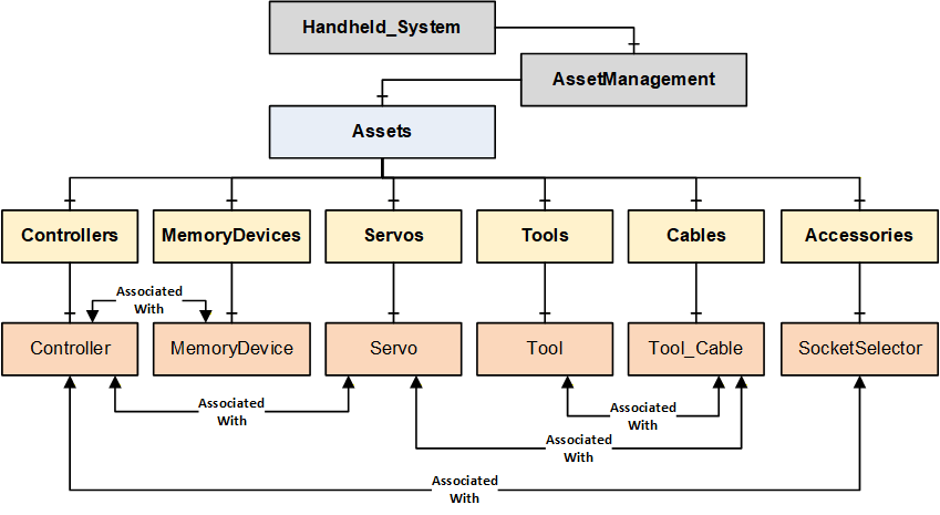
B.2 Handheld Joining System with Wireless Tool Example
The following figure describes a Handheld Joining System which consists of a handheld controller connected to a cable tool via a servo and cable and a wireless tool. The controller has an attached memory device, and it is also connected to a socket selector.
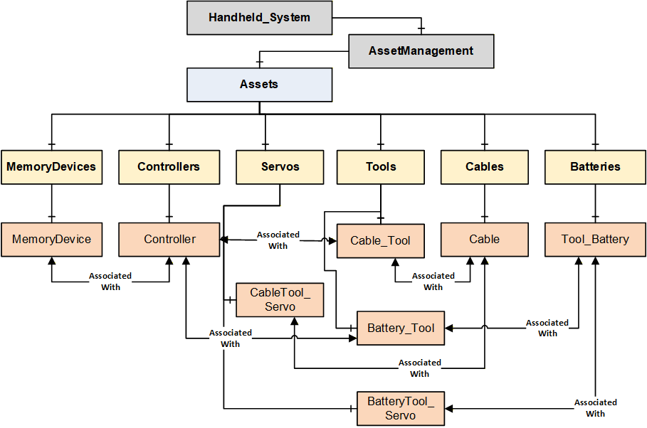
B.3 Fixtured Joining System Example
The following figure describes a Fixtured Joining System with two joining spindles. Both the spindles are managed by one controller, and it needs two servos to drive the two spindles. The controller has an attached memory device.
Note: This example does not model cables connected to spindles. There is no restriction in modeling a cable in the Fixtured Joining System.
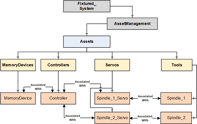
B.4 Intelligent Tool Joining System Example
The following figure describes an Intelligent Tool Joining System which consists of a Tool that has an embedded controller, servo, and an attached memory device.
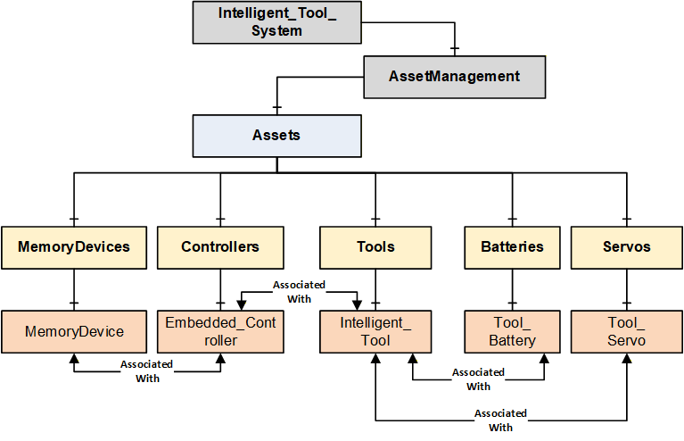
B.5 Flow Drill Joining System Example
The following figure describes a Flow Drill Joining System which consists of one spindle with one servo to drive in the screw. In the spindle there is a torque sensor to measure the torque at the screw and a depth sensor to measure the advancement of the screw into the part. Additionally, there is a feeding controller which ensures that the parts are available at the joining location. The feeder stocks the fasteners and separates them.
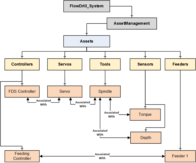
B.6 Handheld System with Virtual Stations Example
The following figure describes a Handheld System with Virtual Stations. Virtual Stations are an abstraction of the relation between a controller and a tool (or other assets).
A single virtual station can be mapped to one or more Tools and other devices in a station. The combination of virtual stations and the associated assets is application specific.
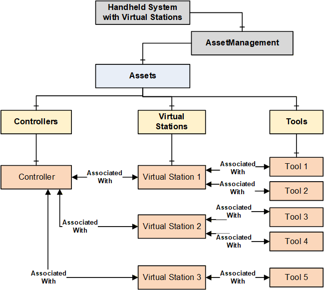
B.7 OPC UA References for Assets
An asset defined in the Joining System can reference other assets in multiple ways such as Logical Connection, Network Connection, Physical Connection, Component (Attached Component, Built-in Component, Sub-Part, etc.), ConnectsTo, IsConnectedTo, etc.
For this version of the specification, only a generic reference AssociatedWith is used to enable the topological infrastructure which will be used by the client applications to build required tree view or hierarchies or a mesh of inter-linked nodes. There is no restriction on adding additional references.
Note: The assets model defined in Joining System is flexible to cover various type of systems. For example, a Controller and MemoryDevice can have HasAttachedComponent or HasContainedComponent reference.
OPC UA base specifications provides standardized set of references which can be used at application level.
Note: Table 278 provides few examples as general information few examples.
| Source Object | Possible Reference Types | Target Object |
| Controller | AssociatedWith IsPhysicallyConnectedTo Requires Controls Utilizes | Tool |
| Controller | AssociatedWith IsPhysicallyConnectedTo Requires Controls Utilizes | Servo |
| Controller | IsPhysicallyConnectedTo Requires Controls Utilizes RepresentsSameFunctionalityAs IsHostedBy | Controller |
| Controller | HasAttachedComponent HasContainedComponent | MemoryDevice |
| Controller | IsPhysicallyConnectedTo Requires Controls Utilizes | Feeder |
| Controller | HasAttachedComponent HasContainedComponent | Sensor |
| Controller | IsPhysicallyConnectedTo Requires Controls Utilizes | Accessory |
| Controller | IsPhysicallyConnectedTo Requires Controls Utilizes HasAttachedComponent HasContainedComponent | SubComponent |
| Controller | AssociatedWith Utilizes Requires | VirtualStation |
| Tool | AssociatedWith Utilizes Requires | VirtualStation |
| Tool | IsPhysicallyConnectedTo Requires Controls Utilizes IsHostedBy | Controller |
| Tool | IsPhysicallyConnectedTo Requires Controls Utilizes HasAttachedComponent HasContainedComponent | Battery |
| Tool | IsPhysicallyConnectedTo Requires Controls Utilizes HasAttachedComponent HasContainedComponent | Sensor |
| Tool | IsPhysicallyConnectedTo Requires Controls Utilizes HasAttachedComponent HasContainedComponent | Accessory |
| Tool | IsPhysicallyConnectedTo Requires Controls Utilizes HasAttachedComponent HasContainedComponent | SubComponent |
| Servo | IsPhysicallyConnectedTo Requires Controls Utilizes | Tool |
| PowerSupply | IsPhysicallyConnectedTo Requires Controls Utilizes | Servo |
| Battery | IsPhysicallyConnectedTo Requires Utilizes | PowerSupply |
| Cable | IsPhysicallyConnectedTo | Controller |
| Cable | IsPhysicallyConnectedTo | Servo |
| Cable | IsPhysicallyConnectedTo | Tool |
| Cable | IsPhysicallyConnectedTo | Feeder |
| Cable | IsPhysicallyConnectedTo | PowerSupply |
| Cable | IsPhysicallyConnectedTo | Sensor |
| Cable | IsPhysicallyConnectedTo | Accessory |
| Cable | IsPhysicallyConnectedTo | SubComponent |
Annex C Value Tag Examples (Informative)
C.1 Overview
The intention of Value Tags is to point out reported values of special meaning in a result.
These special values are not present in all types of use cases, so ValueTag should only be added where it makes sense.
Refer to the following figure for example Figure 26.
Note: The below examples of Value Tag are described using Tightening technology. It can be similar to other joining technologies. These are used in ResultValueDataType.ValueTag.
C.2 Regarding ValueTagged angle values
Value Tagged angle values are more complex than for example torque values in the sense that it is a relative angle between the point of interest and a reference point. The reference point will be the origin in the angle coordinate system and every angle value before that point will have negative angle values.
This origin point can be configured differently on different systems and between different tightening programs. Some common cases of defining the origin are to
tie it to when a configured torque level is reached (in Figure 18), the dotted horizontal line would represent a configured torque level, and the angle would be just as in the picture), or
tie it to a step transition (in Figure 18), that would make the FINAL angle denote the angular difference between the solid line between the rundown step and the FINAL point), or
tie it to the snug point as described in the SNUG paragraph, or
tie it to the beginning of the tightening, thereby including the full rundown in a reported FINAL angle. (This would mean every reported angle would be positive unless it is a loosening)
C.3 FINAL
The FINAL ValueTag is most common in handheld systems and is intended to mark the point where the torque generated the clamp force that is left in the joint, after the tightening is completed.
There will often be up to three values associated to the final point: an angle value, a torque value, and a time value. All having the FINAL ValueTag.
The torque value is straightforward, denoting the torque left in the joint, from the tightening systems perspective.
The FINAL angle value is naturally relative to the defined origin as discussed above.
Note 1: The FINAL torque value is intended to represent what the tightening tool perceives as the torque applied to the joint. There are at least two physical phenomena that interact to make the result of a residual torque check report a different torque value. The first is the seating of the joint. Over time the material of the bolt settles causing the clamp force and torque resistance in the bolt getting lower. The second is the difference between static and dynamic friction. When the bolt is being tightened, the (dynamic) friction is lower than the (static) friction that should be overcome to start the bolt rotating. These two phenomena work against each other and are dependent on such things as temperature, material, lubrication, passed time, etc.
The seating of the joint takes place over time after the tightening. This often means that when a residual torque check is performed, the value will be lower than the reported FINAL torque of the tightening.
Note 2: Sometimes (according to configuration) the prevailing torque (the torque at the SNUG point) will be subtracted from the value before it is reported as FINAL torque. This is done to separate the torque needed overcome the friction/deformation of the joint from the torque used to create clamp force. In these cases, it is recommended to also include both the prevailing torque and the actual absolute max torque as reported values in the result.
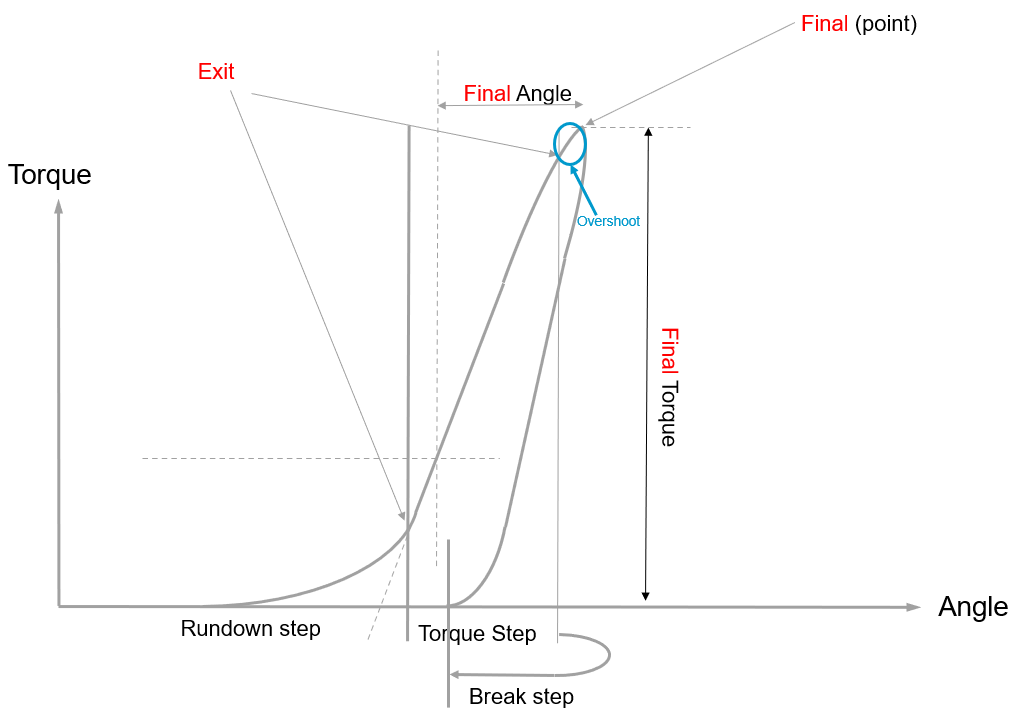
C.4 SNUG
The SNUG ValueTag is the reported point where screw head touches the surface and all parts have mated.
There is no common agreed definition of snug today in the industry. Until one is decided, this specification will use the SNUG ValueTag to denote the intersection of the linear approximation of the rundown and the tightening ramp. Most often the reported SNUG value is a rough approximation of this since the disturbance in the signal combined with the nature of the bended part of the curve makes it difficult to calculate exactly.
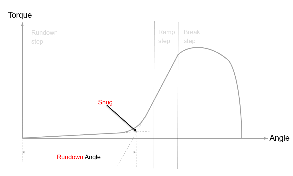
C.5 YIELD
The YIELD ValueTag is intended to denote the point where the material in the bolt goes beyond the state of elasticity and therefore undergoes plastic deformation, causing it to become permanently elongated.
The yield point is usually the area where the linear growth of torque versus angle is dropping.
Example: The picture below represents a tightening until the bolt breaks.
Just like SNUG, a YIELD point is difficult to calculate exactly, and the tightening system will report an approximation.
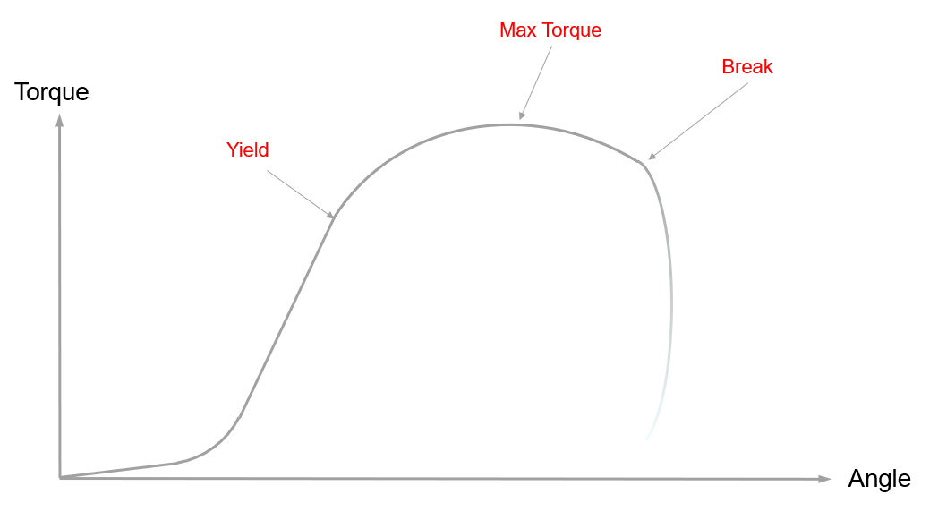
C.6 EXIT and EXIT_TRIGGER
A value with an EXIT ValueTag signifies that it is measured when the decision for the step transition is made.
A value with an EXIT_TRIGGER ValueTag signifies that it caused the step transition.
Example 1: Torque (used in Rundown) Step that transitions when it reaches a configured Target Torque and the Angle is monitored.
ResultValue1 (Torque):
MeasuredValue = 3.01
TargetValue = 3.0
ResultEvaluation = OK
ValueTag = EXIT_TRIGGER
HighLimit = 6.0
EngineeringUnits = Newton Metre
ResultValue2 (Angle):
MeasuredValue = 360
ResultEvaluation = OK
ValueTag = EXIT
LowLimit = 45
HighLimit = 400
EngineeringUnits = Degree
Example 2: Torque (used in Rundown) Step that exits when it violates the monitored angle and target torque is not reached.
ResultValue1 (Torque):
MeasuredValue = 0.1
TargetValue = 3.0
ResultEvaluation = NotDecidable
ValueTag = EXIT
HighLimit = 6.0
EngineeringUnits = Newton Metre
ResultValue2 (Angle):
MeasuredValue = 402
ResultEvaluation = NotOK
ValueTag = EXIT_TRIGGER
LowLimit = 45
HighLimit = 400
ViolationType = ABOVE_LIMIT
ViolationConsequence = ABORT
EngineeringUnits = Degree
C.7 MAX and MIN
A value can be tagged with MAX if it represents the highest occurrence within that step.
A MIN value consequently is used to denote the lowest occurrence within a step.
Note: MAX and MIN values are evaluated including the boundary values of the step.
Example: In the picture below, the origin has been set to the transition point between the torque and the break step.
MAX angle is reached shortly after the FINAL torque point and the value containing a MIN angle ValueTag would likely also contain the EXIT ValueTag.
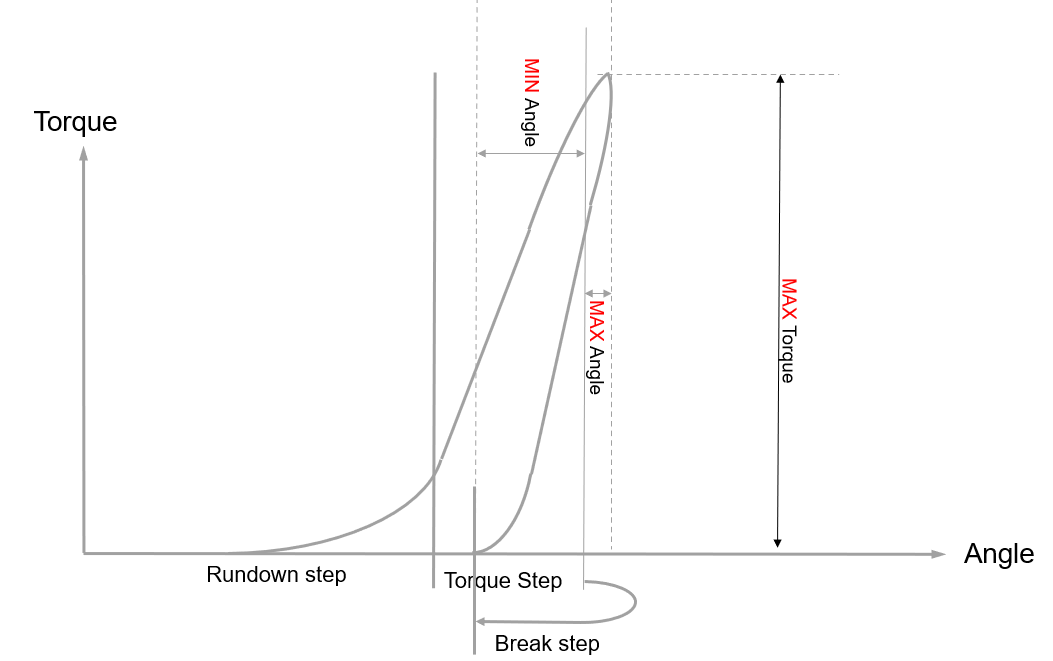
Annex D Joining Process Management (Informative)
D.1 Introduction
"Joining Process" is a generic container aimed at encapsulating various types of process definitions needed in a joining system. It ranges from a "simple joining program" to a "complex joining process with sub-processes".
Each such joining process should be able to generate corresponding results.
Example - Single Processes:
In this scenario, it provides the possibility to send or receive the joining processes from a joining system and execute the joining processes. The outcome of the executed processes will be represented as Results.
Example - Combined Processes:
In this scenario, a Joining process describes what should be done on a particular level of the system. It should have the capability to delegate sub-processes to controllers that can perform the joining operation without connectivity (Example: Radio shadow). When the connection is reestablished, the controllers report the corresponding results to the primary controller which combines the various results and reports the total result.
Note:
This specification does not define the content of joining process(es). It is assumed that the joining process is retrieved from the joining system or created using another system such as a configuration application.
This specification describes how a joining process is managed, i.e., sending, and receiving a joining process.
D.2 Types of Joining Processes
Joining Processes can be classified in two different ways as given below.
"Joining program" is an atomic process to perform a joining operation.
"Combined process" is a group of joining processes to perform combination of various sub-processes.
D.2.1 Joining Program or Atomic Process
Joining program is the lowest level of description to perform a specific joint where it is autonomously managed by the system.
Example: It is executed from the trigger press until the joining operation is completed.
A "single result" is generated for each execution of a joining program.
D.2.2 Combined Process
On the most abstract level, everything, except the atomic process, is just grouping operations together in different ways in many different layers when assembling a product. This requires a flexible model for different customer needs with respect to process control.
A combined process can be any of the following:
A "Job" is a collection of sub-processes which could also include a sub-job.
A "Batch Process" is a "Job" where all the operations are atomic and use the same joining program, and the operations are executed sequentially.
Example: The process of sequential assembly of two or more joints using the same program.
A "Synchronized Process (Sync)" is a "Job" where all the operations are executed in parallel by separate tools (spindles).
Example: In a fixtured system which consists of multiple spindles, the PLC sends a synchronized process to the Joining Process Controller to manage which spindles should run. When the execution is completed, then a combined result is sent back to the PLC.
A "Stitching Process" is a "Job" where several "Synchronized Processes" are done in a sequence.
D.3 Joining Process and Result Mapping
The result is mapped to a corresponding joining process. Figure 22 describes the following examples.
Examples:
Result (Single) is mapped to a Joining Program.
Result (Batch) is mapped to a Joining Batch.
Result (Job) is mapped to a Joining Job.
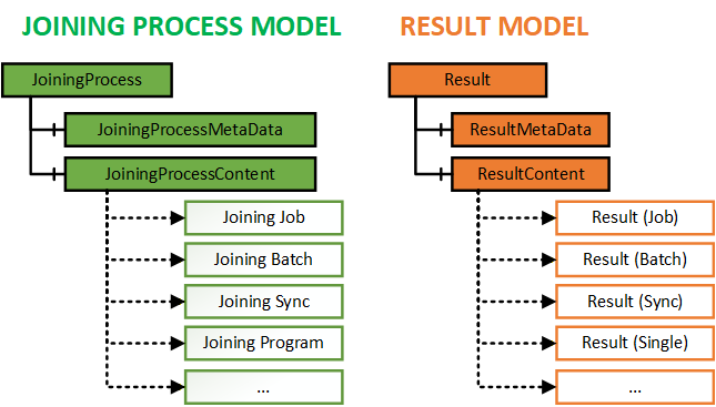
D.4 Joining Process Use Cases
The following are a few cases that describe various types of jobs in a joining system.
Note: Quality Process and Vision Process are not defined in this specification. The purpose of the below examples is to describe the flexible usage of the joining process model and result model which covers various combinations of processes and corresponding outcomes from different domains.
D.4.1 Use case 1: Station Process with Wireless Tools
D.4.1.1 Problem Statement
Imagine a station in a car manufacturing plant.
On the left side of the car,
a few joints need to be performed with the Joining Tool.
the outcome should be validated with a wrench.
On the right side,
another batch of joints needs to be performed.
the outcome should be validated by a wrench.
the outcome should be validated by a vision system.
The left and right sides of the car should be handled by two different operators independently in parallel.
The operators can occasionally enter a radio shadow but should still be able to carry out their tasks.
The MES wants to control the station as one unit and get the total result when all is done.
D.4.1.2 Structure
Figure 23 describes an example "Combined Process" (Job 1) with the following sub-processes.
A "batch" joining process for joining two fasteners. (Batch 1)
A "quality" process to validate the outcome. (Quality Process 1)
A nested "joining process" (Job 2) with
a "batch" of three joining operations. (Batch 2)
a "quality" process. (Quality Process 2)
a "vision" process. (Vision Process)
D.4.1.3 Workflow
"Combined Process" (Job 1) is done when all the sub-processes (Batch 1, Quality Process 1, Job 2) are done.
"Combined Process" (Job 2) is done when all the sub-processes (Batch 2, Quality Process 2, Vision Process) are done.
D.4.1.4 Outcome
Figure 23 describes the outcome from the "Combined Process" (Job 1) execution. The outcome is sent as a total result (Job Result) to the MES system.
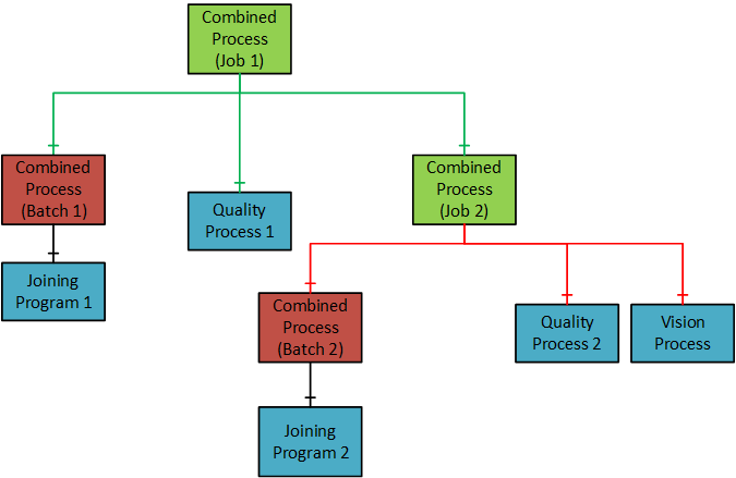
D.4.2 Use case 2: Automated assembly line directed by MES
D.4.2.1 Problem Statement
Imagine a plant with an automated assembly line, which is directed by an MES (Manufacturing Execution System) and operated by line/cell controllers (PLCs). The joining system is controlled by a PLC.
The MES directs the joining process of individual joints via PLCs, but the handling of results.
is limited via traditional communication channels, like fieldbus networks.
relies on propriety data channels that require different implementations depending on the manufacturer.
This use case can be applicable for the following communication setup:
Joining system with OPC UA and fieldbus interfaces.
Joining system with only OPC UA.
D.4.2.2 Pre-requisite
OPC UA interface and optionally an existing fieldbus network.
D.4.2.3 Workflow
The MES controls the flow of parts via
OPC UA
PLCs and their fieldbus interfaces (if available)
The MES/PLC sends the product/part identification (e.g. VIN), joining program and start signal via
OPC UA
Fieldbus
The joining system performs the joining operation.
The MES systems receive the (extensive) joining result via OPC UA, including the joint identification.
D.4.2.4 Outcome
The results received by the MES contain the following:
the simple result one would expect from a fieldbus interface.
the extensive result, containing optionally individual step results and/or trace data representing the whole joining process.
the product/part identification, allowing the MES to relate a set of results to specific parts and/or the individual joint.
Furthermore, the result is delivered in a standardized way, which is shared by different manufacturers.
Annex E Result Management - Single Result Examples (Informative)
E.1 Overview of Joining Result and Joining Trace
The following result and trace model are flexible to cover different types of joining systems.
Result and Trace instances have the required properties and references to link a result, step result and traces.
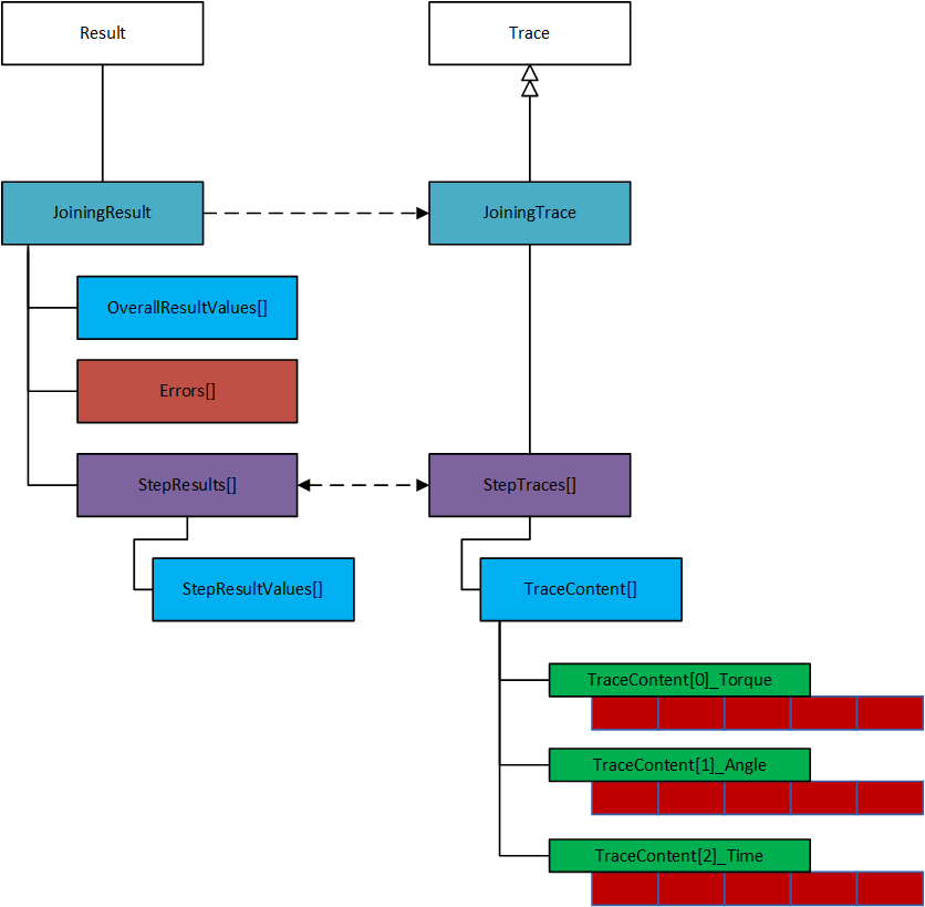
E.2 Overview of Result and Traces with Sample Data
The following figure illustrates a simple example of modeling the Result and Trace. For simplicity, only a few parameters are listed in the example.
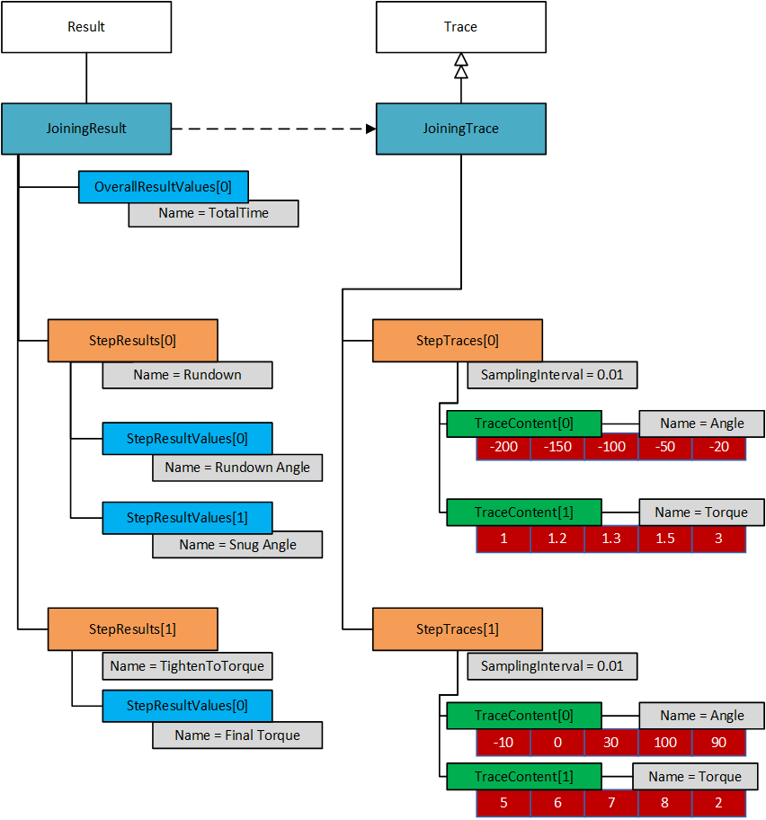
E.3 Result with OverallResultValues, Step Result Values and Value Tags
The following figure illustrates an example of OverallResultValues and StepResultValues for a three-step joining. Please note that most other parameters have been omitted to clarify the use of Result Values and Value Tags.
This example has three general values that are not tied to a particular step. These are MyTotalTime (the time from start to finish of the entire joining), MyTotalAngle (the angle from starts of rundown to highest achieved angle), and MyTemperature. The first two values have ValueTag = MAX to make it easier to understand that it is global maximum we are reporting. The temperature is tied to a single sampling, so it is included as a reported value without any ValueTag.
The result contains a rundown step, a simple torque step and a break step.
There are four values which contain an EXIT ValueTag, these represent the values as one step transition into the next. Two of them has a ViolationType value, meaning that they are the cause of the transition.
The last step (the break step) contains the angle and torque of the Final Torque point. Both have the FINAL ValueTag. To get hold of the FINAL values, the result consumer needs to loop through the Steps and the StepResultValues and look for the FINAL ValueTag.
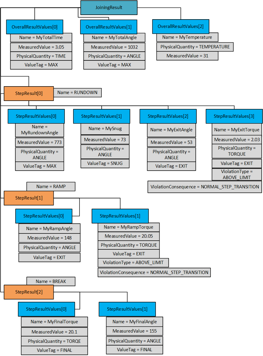
E.4 Linking a Joining Result and Joining Trace
The following figure illustrates an example to reference a point of interest (such as Final Torque, Final Angle, etc.) to a given trace sample in two different ways based on the use cases.
The Trace model is defined to have same number of trace points for different trace samples for a given Joining trace.
The following example represents a result generated from a two-step joining program and the reference of a specific point of interest is mapped from second step result to a second step trace based on TracePointIndex.
In some cases, a point of interest (Example: Final Torque point, etc.) could be an available value in the Trace sample array and in that case, the system can provide a specific index value in the ResultValueDataType structure using the TracePointIndex property.
In some cases, when a given point of interest (Example: Final Angle, Final Torque, etc.) is not available in the Trace sample array, an additional property TracePointTimeOffset can be used to map the given sample using the StartTime, StartTimeOffSet (of a given step) and TracePointTimeOffSet.
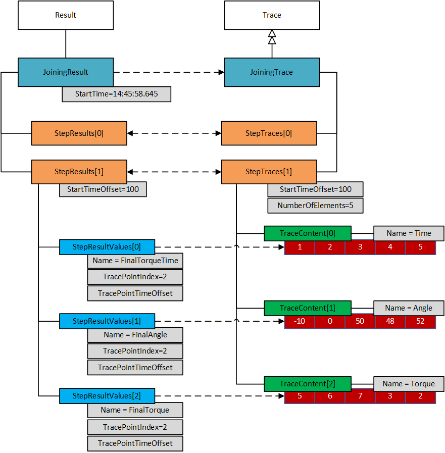
Annex F Result Management - Combined Results Examples (Informative)
F.1 Overview
A Combined Result (such as Batch Result, Job Result, Sync Result, etc.) can be sent in different ways based on the type of configuration as follows.
Option 1: A Result with references to sub-results is useful when the use case requires:
Shorter turn-around time.
Receive single results as soon as they are generated.
Smaller size on each message.
Option 2: A Result including the complete content of the sub-results is useful when the use case requires:
Self-contained result.
Note: It is not suitable for a large number of sub-results.
Note: A Result including partial content of the sub-results is useful when the use case requires:
Tracking of progress for a batch, sync or job process.
Recommendation:
Option 1 is the recommended option.
F.2 Batch Result with References
This example describes the usage of a Result (Batch) where the sub-results (already sent) with references are included in the parent result. The SYNC Result also can be modelled in a similar way where Classification = SYNC_RESULT.
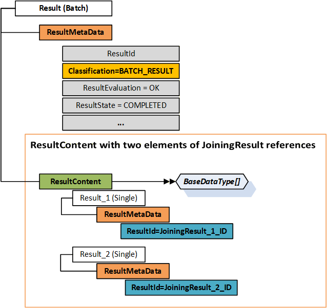
F.3 Batch Result with Sub-Results Content
This example describes the usage of a Result (Batch) where the content of the sub-results is included in the result. The SYNC Result also can be modelled in a similar way where Classification = SYNC_RESULT.
Note: This approach may not be suitable if there are several child results. It is recommended to use the Results with References approach for complex use cases.
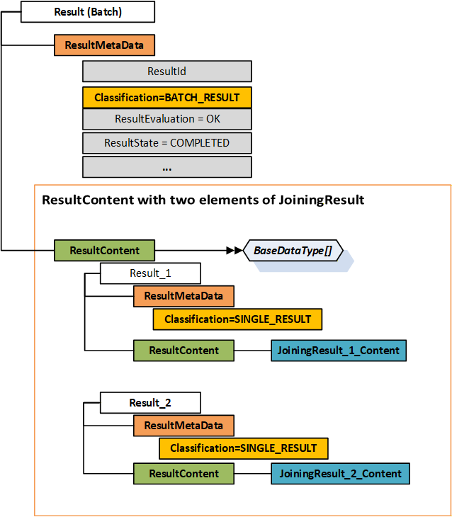
F.4 Partial Batch Result
A joining process that is not an atomic process, could be set up to generate a result either when it is done, or continuously send partial results as soon as a sub result is generated.
Example:
A dashboard close to the operator needs to point out the location of the product where the next operation should take place. Hence, the dashboard needs information on how many joining operations in a batch are completed.
This example describes the usage of a partial Batch Result (2 out of 8 results). As it is a partial result, the following properties IsPartial = True and ResultState = Processing in the below diagram.
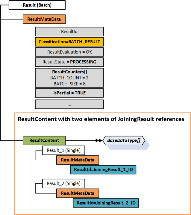
F.5 Job Result with sub-results
This example describes the usage of a Result (Job) where the content contains a Batch Result and a Single Result.
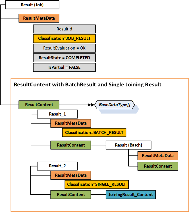
F.6 Result messages with sub-results as references
This is an example of how the result messages are sent separately using sub-results references.
Configuration: A Job with two batches as follows:
Batch 1 with Batch Size = 3, Program 1
Batch 2 with Batch Size = 2, Program 2
Meta Data Usage for Results
All Results shall contain Result.ResultMetaData.ResultId, Result.ResultMetaData.SequenceNumber, and Result.ResultMetaData.Classification.
Additional ResultMetaData such as Name, etc. can be set based on the context.
Single Results:
Single Result. ResultMetaData. Classification = SINGLE_RESULT
Single Result. ResultMetaData. ResultState = COMPLETED
Single Result. ResultMetaData. IsPartial = FALSE
Batch Results:
Batch Result. ResultMetaData. Classification = BATCH_RESULT
Batch Result. ResultMetaData. ResultState = Based on the context.
Batch Result. ResultMetaData. IsPartial = TRUE if it is in progress, otherwise, it is FALSE.
Each Batch Result MUST contain the following ResultCounters:
BATCH_COUNT and BATCH_SIZE
ResultContent is empty.
Job Results:
Job Result. ResultMetaData. Classification = JOB_RESULT
Job Result. ResultMetaData. ResultState = Based on the context.
Job Result. ResultMetaData. IsPartial = TRUE if it is in progress, otherwise, it is FALSE.
Each Job Result can contain the following ResultCounters:
JOB_SIZE and JOB_COUNT
ResultContent is empty.
Note: For a Combined Result (Batch or Job Result), if SequenceNumber is not available then it can be assigned to the sequence number of the LATEST/LAST single tightening it is referencing.
Example Result Structure Layout for a Batch Result with Batch Size = 2
Result
ResultMetaData
ResultId
Classification = BATCH_RESULT
...
ResultContent
[
{
Result
ResultMetaData
ResultId = Single Result 1 ID
Classification = SINGLE_RESULT
ResultContent = Empty array
}
{
Result
ResultMetaData
ResultId = Single Result 2 ID
Classification = SINGLE_RESULT
ResultContent = Empty array
}
]
Result Messages: Send Parent and Child Results (sub-results) separately with References as follows.
Send Single Result 1 of Batch 1
Send Batch Result 1 with Single Result 1 ID, and Batch Count = 1, Batch Size = 3
Send Job Result with Batch Result 1 ID
Send Single Result 2 of Batch 1
Send Batch Result 1 with Single Result 1 ID and Single Result 2 ID and Batch Count = 2
Send Single Result 3 of Batch 1
Send Batch Result 1 with Single Result 1 ID and Single Result 2 ID and Single Result 3 ID and Batch Count = 3
Send FINAL Batch Result 1 with IDENTIFIERS of all the Single Results
Send Single Result 1 of Batch 2
Send Batch Result 2 with Single Result 1 ID and Batch Count = 1, Batch Size = 2
Send Job Result with Batch Result 1 ID and Batch Result 2 ID.
Send Single Result 2 of Batch 2
Send Batch Result 2 with Single Result 1 ID and Single Result 2 ID and Batch Count = 2
Send FINAL Job Result with Identifiers of Batch Result 1 and Batch Result 2.
Note: Refer to the example result structure layout above.
F.7 Result messages with sub-results as references including intervention results
Context:
The primary purpose of the section is to describe that a separate intervention result is sent for any type of intervention such as INCREMENTED, DECREMENTED, ABORTED, etc.
The Intervention Result ID shall be part of Batch Result or Job Result based on the configuration and type of intervention.
Result Messages:
Send Single Result 1 of Batch 1
Send Batch Result 1 with Single Result 1 ID
Send Job Result with Batch Result 1 ID
Client or any other interface triggered an intervention.
Send Intervention Result with InterventionType.
Send Batch Result 1 with Single Result 1 ID, Intervention Result ID.
Continue the processing.
…
Annex G Event Management - Condition Class Usage (Informative)
G.1 Condition Class List
The following table provides a list of condition classes. Refer to the corresponding sections given below for more details.
OPC UA Base: OPC 10000-9.
Asset Management Basics: OPC 10000-110.
Joining System Specification: Section 8.5.
|
Condition Classes in
Base Specifications |
Condition Classes in
Joining System Specification |
| OPC UA Base | |
| BaseConditionClassType | AssetConnectedConditionClassType |
| ProcessConditionClassType | AssetDisconnectedConditionClassType |
| MaintenanceConditionClassType | AssetEnabledConditionClassType |
| SystemConditionClassType | AssetDisabledConditionClassType |
| SafetyConditionClassType | ThresholdViolationConditionClassType |
| HighlyManagedAlarmConditionClassType | ThresholdViolationResolvedConditionClassType |
| TrainingConditionClassType | JoiningSystemUserLoggedInConditionClassType |
| StatisticalConditionClass | JoiningSystemUserLoggedOutConditionClassType |
| TestingConditionClassType | AssetLocationConditionClassType |
| Asset Management Basics | LocationInZoneConditionClassType |
| ConnectionFailureConditionClassType | LocationOutOfZoneConditionClassType |
| OverTemperatureConditionClassType | DataValidationFailureConditionClassType |
| CalibrationDueConditionClassType | InputValidationFailureConditionClassType |
| SelfTestFailureConditionClassType | ConfigurationChangeConditionClassType |
| FlashUpdateInProgressConditionClassType | ErrorConditionClassType |
| FlashUpdatedFailedConditionClassType | SoftwareConditionClassType |
| BadConfigurationConditionClassType | HardwareConditionClassType |
| OutOfResourcesConditionClassType | CertificateConditionClassType |
| OutOfMemoryConditionClassType | LicenseConditionClassType |
| InspectionConditionClassType | MissingEntityConditionClassType |
| ExternalCheckConditionClassType | ExpiredEntityConditionClassType |
| ServicingConditionClassType | InvalidEntityConditionClassType |
| ImprovementConditionClassType | IncompatibleEntityConditionClassType |
| RepairConditionClassType | AcceptedEntityConditionClassType |
| RejectedEntityConditionClassType | |
| AddedEntityConditionClassType | |
| UpdatedEntityConditionClassType | |
| RemovedEntityConditionClassType | |
| ReceivedEntityConditionClassType | |
| SelectedEntityConditionClassType | |
| SelectedProcessConditionClassType | |
| UnacknowledgedResultsConditionClassType | |
| EntityExpiryWarningConditionClassType | |
| StartedEntityConditionClassType | |
| StoppedEntityConditionClassType | |
| NotAvailableEntityConditionClassType | |
| NotSupportedEntityConditionClassType |
G.2 Condition Class Usage Examples
The following tables explain example usage of Condition Class and Condition Sub Class(es) for a joining system.
| Use Case | Condition Class | Condition SubClass(es) |
| Asset Connected | SystemConditionClassType | AssetConnectedConditionClassType |
| Asset Disconnected | SystemConditionClassType | AssetDisconnectedConditionClassType |
| Asset Enabled | SystemConditionClassType | AssetEnabledConditionClassType |
| Asset Disabled | SystemConditionClassType | AssetDisabledConditionClassType |
| Asset leaving zone | SystemConditionClassType | AssetLocationConditionClassType LocationOutOfZoneConditionClassType |
| Asset entering zone | SystemConditionClassType | AssetLocationConditionClassType LocationInZoneConditionClassType |
| Asset calibration due | CalibrationDueConditionClassType | Empty or NULL |
| Asset service due | ServicingConditionClassType | Empty or NULL |
| Asset temperature overheat | OverTemperatureConditionClassType | HardwareConditionClassType ThresholdViolationConditionClassType ErrorConditionClassType |
| Asset temperature back to normal | SystemConditionClassType | HardwareConditionClassType ThresholdViolationResolvedConditionClassType |
| Asset low battery | SystemConditionClassType | HardwareConditionClassType ThresholdViolationConditionClassType |
| Asset feature license expired | SystemConditionClassType | LicenseConditionClassType ExpiredEntityConditionClassType |
| Incompatible hardware assets | SystemConditionClassType | HardwareConditionClassType IncompatibleEntityConditionClassType |
| Incompatible software assets | SystemConditionClassType | SoftwareConditionClassType IncompatibleEntityConditionClassType |
| Joining Process or Joint added in the system | ProcessConditionClassType | AddedEntityConditionClassType ConfigurationChangeConditionClassType |
| Joining Process or Joint Selected in the system | ProcessConditionClassType | SelectedProcessConditionClassType |
| Joining Process or Joint updated in the system | ProcessConditionClassType | UpdatedEntityConditionClassType ConfigurationChangeConditionClassType |
| Joining Process or Joint received from an external system | ProcessConditionClassType | ReceivedEntityConditionClassType |
| Invalid Joining Process or Joint sent from an external system | ProcessConditionClassType | InvalidEntityConditionClassType |
| Received valid identifiers such as VIN from an external system | ProcessConditionClassType | ReceivedEntityConditionClassType AcceptedEntityConditionClassType |
| Received invalid identifiers such as VIN from an external system | ProcessConditionClassType | ReceivedEntityConditionClassType RejectedEntityConditionClassType InvalidEntityConditionClassType |
| Unknown hardware error | SystemConditionClassType | HardwareConditionClassType ErrorConditionClassType |
| Unknown software error | SystemConditionClassType | SoftwareConditionClassType ErrorConditionClassType |
Annex H Joint Management (Informative)
H.1 Overview
The are two ways to describe how a joining operation can be managed.
Running a joining process such as Job, Batch Process, Sync Process, Joining Program, etc.
Selection of joints which need to be addressed where the joining system selects the required joining program.
The first approach (joining process model) is described in detail in section Annex D.
The second approach (joint model) is to allow the integrator to focus on which joints to be addressed, rather than how they are addressed.
The joint approach is useful for the following use cases:
Use Case 1: The manufacturing process has a high number of product variants or models, etc. which results in various joints.
Use Case 2: Analytics can be improved using the knowledge of the physical properties of a joint.
…
Note: The below examples are based on Tightening systems. It can be utilized for any other joining system.
H.2 Joint Model Overview
While assembling a product, a blueprint is used to describe how to make many instances of the product. The idea with the joint model is to capture the same type of data for a joint.
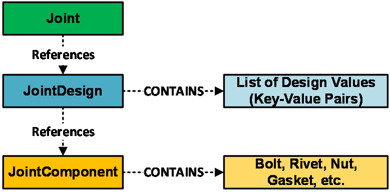
H.2.1 Joint
A joint is used to represent a point where several different parts on a particular product model should be joined together. Refer section 10.15 for joint structure.
H.2.2 Joint Design
Joint design represents the physical properties of a joint. It can contain the following data. Refer section 10.16 for joint design structure.
Torque, Torque tolerance, Torsion angle limits.
Residual torque, Clamping force, Tension.
…
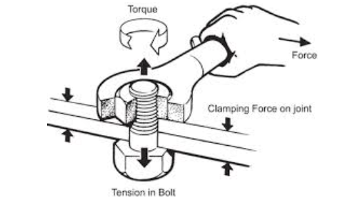
H.2.3 Joint Component
Joint component represents elements such as Bolts, Rivets, etc. Refer section 10.17 for joint component structure.
H.2.4 Joint Data Access
An external system can exchange joint data using the methods defined in section 7.8.
Selection of joints can be done using the method defined in section 7.8.5 which selects the joining process needed to perform the joining operation.
H.3 Use Cases Solution Details
In the previous sections, there are two use cases illustrating two problems. The models described in section H.2, are intended to solve the defined problems based on the following explanation.
Use Case 1 Explanation: As the joint model contains a relation between a joint identity and a joining program, it allows separation of the following responsibilities:
Which joints should be addressed in a specific station in the factory.
How such joining operations should be performed.
This results in independent management of changes on the production line which helps in handling the higher number of product variations.
Example:
Multiple joints can use the same joining program.
A joining system can assign all the possible joints to corresponding joining programs.
Use Case 2 Explanation: As the joint design model contains the physical properties of a joint, the system has access to more data to perform analytics which can be used to simplify and improve the production process.
Annex I Usage of Methods (Informative)
I.1 Input Argument Options
The methods defined for Asset Management, Joining Process Management and Joint Management have ProductInstanceUri as an input argument.
The usage of ProductInstanceUri could vary based on the type of system. The following options are possible from a Server.
Use Case 1: ProductInstanceUri is empty.
The Server should consider the ProductInstanceUri of the asset where it is deployed. If it does not apply for the specific method, then the Server should return the respective error code.
Examples: SendJoiningProcess, GetJoiningProcess, GetJoiningProcessList, etc.
Use Case 2: ProductInstanceUri is non-empty.
A Joining System with virtual stations.
In a joining system with one controller, multiple tools connected to the controller, multiple accessories, and multiple virtual stations:
OPC UA Server is deployed at controller.
Client should pass the ProductInstanceUri of the corresponding Virtual Station mapped in system or it is also allowed to pass the ProductInstanceUri of the physical asset.
Examples: SetCalibration, EnableAsset, RebootAsset, etc.
A Joining System without virtual stations.
In a joining system with one controller, multiple tools connected to the controller, multiple accessories:
OPC UA Server deployed at controller.
Client should pass the ProductInstanceUri of the corresponding physical asset connected to the Controller.
Examples: SetCalibration, EnableAsset, RebootAsset, etc.
I.2 Multiple Client Method Execution
The mutual exclusion mechanism to handle the execution of the same method from multiple clients should be handled by the Server application layer and is not defined in this specification.
Agreement of Use
COPYRIGHT RESTRICTIONS
This document is provided "as is" by the OPC Foundation and VDMA.
Right of use for this specification is restricted to this specification and does not grant rights of use for referred documents.
Right of use for this specification will be granted without cost.
This document may be distributed through computer systems, printed or copied as long as the content remains unchanged and the document is not modified.
OPC Foundation and VDMA do not guarantee usability for any purpose and shall not be made liable for any case using the content of this document.
The user of the document agrees to indemnify OPC Foundation and VDMA and their officers, directors and agents harmless from all demands, claims, actions, losses, damages (including damages from personal injuries), costs and expenses (including attorneys' fees) which are in any way related to activities associated with its use of content from this specification.
The document shall not be used in conjunction with company advertising, shall not be sold or licensed to any party.
The intellectual property and copyright is solely owned by the OPC Foundation and VDMA.
PATENTS
The attention of adopters is directed to the possibility that compliance with or adoption of OPC or VDMA specifications may require use of an invention covered by patent rights. OPC Foundation or VDMA shall not be responsible for identifying patents for which a license may be required by any OPC or VDMA specification, or for conducting legal inquiries into the legal validity or scope of those patents that are brought to its attention. OPC or VDMA specifications are prospective and advisory only. Prospective users are responsible for protecting themselves against liability for infringement of patents.
WARRANTY AND LIABILITY DISCLAIMERS
WHILE THIS PUBLICATION IS BELIEVED TO BE ACCURATE, IT IS PROVIDED "AS IS" AND MAY CONTAIN ERRORS OR MISPRINTS. THE OPC FOUDATION NOR VDMA MAKES NO WARRANTY OF ANY KIND, EXPRESSED OR IMPLIED, WITH REGARD TO THIS PUBLICATION, INCLUDING BUT NOT LIMITED TO ANY WARRANTY OF TITLE OR OWNERSHIP, IMPLIED WARRANTY OF MERCHANTABILITY OR WARRANTY OF FITNESS FOR A PARTICULAR PURPOSE OR USE. IN NO EVENT SHALL THE OPC FOUNDATION NOR VDMA BE LIABLE FOR ERRORS CONTAINED HEREIN OR FOR DIRECT, INDIRECT, INCIDENTAL, SPECIAL, CONSEQUENTIAL, RELIANCE OR COVER DAMAGES, INCLUDING LOSS OF PROFITS, REVENUE, DATA OR USE, INCURRED BY ANY USER OR ANY THIRD PARTY IN CONNECTION WITH THE FURNISHING, PERFORMANCE, OR USE OF THIS MATERIAL, EVEN IF ADVISED OF THE POSSIBILITY OF SUCH DAMAGES.
The entire risk as to the quality and performance of software developed using this specification is borne by you.
RESTRICTED RIGHTS LEGEND
This Specification is provided with Restricted Rights. Use, duplication or disclosure by the U.S. government is subject to restrictions as set forth in (a) this Agreement pursuant to DFARs 227.7202-3(a); (b) subparagraph (c)(1)(i) of the Rights in Technical Data and Computer Software clause at DFARs 252.227-7013; or (c) the Commercial Computer Software Restricted Rights clause at FAR 52.227-19 subdivision (c)(1) and (2), as applicable. Contractor / manufacturer are the OPC Foundation, 16101 N. 82nd Street, Suite 3B, Scottsdale, AZ, 85260-1830
COMPLIANCE
The combination of VDMA and OPC Foundation shall at all times be the sole entities that may authorize developers, suppliers and sellers of hardware and software to use certification marks, trademarks or other special designations to indicate compliance with these materials as specified within this document. Products developed using this specification may claim compliance or conformance with this specification if and only if the software satisfactorily meets the certification requirements set by VDMA or the OPC Foundation. Products that do not meet these requirements may claim only that the product was based on this specification and must not claim compliance or conformance with this specification.
TRADEMARKS
Most computer and software brand names have trademarks or registered trademarks. The individual trademarks have not been listed here.
GENERAL PROVISIONS
Should any provision of this Agreement be held to be void, invalid, unenforceable or illegal by a court, the validity and enforceability of the other provisions shall not be affected thereby.
This Agreement shall be governed by and construed under the laws of Germany.
This Agreement embodies the entire understanding between the parties with respect to, and supersedes any prior understanding or agreement (oral or written) relating to, this specification.
ISSUE REPORTING
If an error or problem is found in this specification, the UaNodeSet, or any associated supplementary files, it should be reported as an issue.
The reporting process can be found here: https://opcfoundation.org/resources/issue-tracking/
The Link to the issue tracking project for this document is here:
https://mantis.opcfoundation.org/set_project.php?project_id=180&make_default=no