
D.4 Joining Process Use Cases
The following are a few cases that describe various types of jobs in a joining system.
Note: Quality Process and Vision Process are not defined in this specification. The purpose of the below examples is to describe the flexible usage of the joining process model and result model which covers various combinations of processes and corresponding outcomes from different domains.
D.4.1 Use case 1: Station Process with Wireless Tools
D.4.1.1 Problem Statement
Imagine a station in a car manufacturing plant.
On the left side of the car,
a few joints need to be performed with the Joining Tool.
the outcome should be validated with a wrench.
On the right side,
another batch of joints needs to be performed.
the outcome should be validated by a wrench.
the outcome should be validated by a vision system.
The left and right sides of the car should be handled by two different operators independently in parallel.
The operators can occasionally enter a radio shadow but should still be able to carry out their tasks.
The MES wants to control the station as one unit and get the total result when all is done.
D.4.1.2 Structure
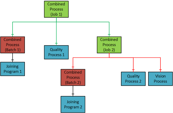
Figure 23 describes an example "Combined Process" (Job 1) with the following sub-processes.
A "batch" joining process for joining two fasteners. (Batch 1)
A "quality" process to validate the outcome. (Quality Process 1)
A nested "joining process" (Job 2) with
a "batch" of three joining operations. (Batch 2)
a "quality" process. (Quality Process 2)
a "vision" process. (Vision Process)
D.4.1.3 Workflow
"Combined Process" (Job 1) is done when all the sub-processes (Batch 1, Quality Process 1, Job 2) are done.
"Combined Process" (Job 2) is done when all the sub-processes (Batch 2, Quality Process 2, Vision Process) are done.
D.4.1.4 Outcome
Figure 23 describes the outcome from the "Combined Process" (Job 1) execution. The outcome is sent as a total result (Job Result) to the MES system.
D.4.2 Use case 2: Automated assembly line directed by MES
D.4.2.1 Problem Statement
Imagine a plant with an automated assembly line, which is directed by an MES (Manufacturing Execution System) and operated by line/cell controllers (PLCs). The joining system is controlled by a PLC.
The MES directs the joining process of individual joints via PLCs, but the handling of results.
is limited via traditional communication channels, like fieldbus networks.
relies on propriety data channels that require different implementations depending on the manufacturer.
This use case can be applicable for the following communication setup:
Joining system with OPC UA and fieldbus interfaces.
Joining system with only OPC UA.
D.4.2.2 Pre-requisite
OPC UA interface and optionally an existing fieldbus network.
D.4.2.3 Workflow
The MES controls the flow of parts via
OPC UA
PLCs and their fieldbus interfaces (if available)
The MES/PLC sends the product/part identification (e.g. VIN), joining program and start signal via
OPC UA
Fieldbus
The joining system performs the joining operation.
The MES systems receive the (extensive) joining result via OPC UA, including the joint identification.
D.4.2.4 Outcome
The results received by the MES contain the following:
the simple result one would expect from a fieldbus interface.
the extensive result, containing optionally individual step results and/or trace data representing the whole joining process.
the product/part identification, allowing the MES to relate a set of results to specific parts and/or the individual joint.
Furthermore, the result is delivered in a standardized way, which is shared by different manufacturers.