
1 Scope
This specification was created by a joint working group of the OPC Foundation and VDW. It defines an OPC UA Information Model to interface and exchange data with Computerized Numerical Control (CNC) systems.
OPC Foundation
The OPC Foundation defines standards for online data exchange between automation systems. They address access to current data (OPC DA), alarms and events (OPC A&E) and historical data (OPC HDA). Those standards are successfully applied in industrial automation.
The new OPC Unified Architecture (OPC UA) unifies the existing standards and brings them to state-of-the-art technology using service-oriented architecture (SOA). Platform-independent technology allows the deployment of OPC UA beyond current OPC applications only running on Windows-based PC systems. OPC UA can also run on embedded systems as well as Linux / UNIX based enterprise systems. The provided information can be generically modelled and therefore arbitrary information models can be provided using OPC UA.
German Machine Tool Builders' Association (VDW)
The VDW, based in Frankfurt/Main, represents the interests of the German machine tool industry. In this context VDW is interested in increasing the innovation and competitive capacity of machine tool builders and manufacturers of CNC systems by reducing the expenses for linking CNC Systems with other applications. This should be achieved by standardization of CNC interfaces.
2 Reference documents
OPC 10000-1, OPC Unified Architecture - Part 1: Overview
OPC 10000-3, OPC Unified Architecture - Part 3: Address Space Model
OPC 10000-5, OPC Unified Architecture - Part 5: Information Model
OPC 10000-6, OPC Unified Architecture - Part 6: Mappings
OPC 10000-9, OPC Unified Architecture - Part 9: Alarms and Conditions
DIN IEC 61131-3:2009-12, Programmable Controllers - Part 3: Programming languages
OPC 10030, UA Companion Specification for ISA-95 Common Object Model
3 Terms, definitions, and conventions
3.1 Use of terms
Defined terms of OPC UA specifications, types and their components defined in OPC UA specifications and in this specification are highlighted with italic in this document.
3.2 Abbreviations and symbols
| A&E | Alarms & Events |
| ANSI | American National Standards Institute |
| API | Application Program Interface |
| DA | Data Access |
| HDA | Historical Data Access |
| HMI | Human-Machine Interface |
| IEC | International Electrotechnical Commission |
| IP | Internet Protocol - RFC 791 |
| ISO | International Organization for Standardization |
| LAN | Local Area Network |
| MES | Manufacturing Execution System |
| NaN | "Not a Number", a unique binary pattern representing an invalid number |
| (see ANSI/IEEE 754-1985) | |
| NAT | Network Address Translation - RFC 2663 |
| UA | Unified Architecture |
| UTC | Universal Time Coordinated |
| XML | Extensible Markup Language |
| CNC | Computerized Numerical Control (also referred to as Computer Numerical Control) |
| ERP | Enterprise Resource Planning |
| PDA/MDA | Process Data Acquisitoin / Machine Data Acquisition |
| PLC | Programmable Logic Control |
| UI | User Interface |
| GUI | Graphical User Interface |
| I/O | Input/Output |
| SCADA | Supervisory Control and Data Acquisition |
3.3 Conventions used in this document
3.3.1 Conventions for Node descriptions
Node definitions are specified using tables (See Table 1)
| Attribute | Value | ||||
| Attribute name | Attribute value. If it is an optional Attribute that is not set "--" will be used. | ||||
| References | NodeClass | BrowseName | DataType | TypeDefinition | ModellingRule |
|---|---|---|---|---|---|
| ReferenceType name | NodeClass of the TargetNode. | BrowseName of the target Node. If the Reference is to be instantiated by the server, then the value of the target Node's BrowseName is "--". | Attributes of the referenced Node, only applicable for Variables and Objects. | Referenced ModellingRule of the referenced Object. | |
Notes - Notes referencing footnotes of the table content. | |||||
Attributes are defined by providing the Attribute name and a value, or a description of the value.
References are defined by providing the ReferenceType name, the BrowseName of the TargetNode and its NodeClass.
If the TargetNode is a component of the Node being defined in the table the Attributes of the composed Node are defined in the same row of the table.
The DataType is only specified for Variables; "[<number>]" indicates a single-dimensional array, for multi-dimensional arrays the expression is repeated for each dimension (e.g. [2][3] for a two-dimensional array). For all arrays the ArrayDimensions is set as identified by <number> values. If no <number> is set, the corresponding dimension is set to 0, indicating an unknown size. If no number is provided at all the ArrayDimensions can be omitted. If no brackets are provided, it identifies a scalar DataType and the ValueRank is set to the corresponding value (see OPC 10000-3). In addition, ArrayDimensions is set to null or is omitted. If it can be Any or ScalarOrOneDimension, the value is put into "{<value>}", so either "{Any}" or "{ScalarOrOneDimension}" and the ValueRank is set to the corresponding value (see OPC 10000-3) and the ArrayDimensions is set to null or is omitted. In Table 2 examples are given.
| Notation | DataType | ValueRank | ArrayDimensions | Description |
| Int32 | Int32 | -1 | omitted or NULL | A scalar Int32 |
| Int32[] | Int32 | 1 | omitted or {0} | Single-dimensional array of Int32 with an unknown size |
| Int32[][] | Int32 | 2 | omitted or {0,0} | Two-dimensional array of Int32 with unknown sizes for both dimensions |
| Int32[3][] | Int32 | 2 | {3,0} | Two-dimensional array of Int32 with a size of 3 for the first dimension and an unknown size for the second dimension |
| Int32[5][3] | Int32 | 2 | {5,3} | Two-dimensional array of Int32 with a size of 5 for the first dimension and a size of 3 for the second dimension |
| Int32{Any} | Int32 | -2 | omitted or NULL | An Int32 where it is unknown if it is scalar or array with any number of dimensions |
| Int32{ScalarOrOneDimension} | Int32 | -3 | omitted or NULL | An Int32 where it is either a single-dimensional array or a scalar |
The TypeDefinition is specified for Objects and Variables.
The TypeDefinition column specifies a NodeId of a TypeDefinitionNode, i.e. the specified Node points with a HasTypeDefinition Reference to the corresponding TypeDefinitionNode. The symbolic name of the NodeId is used in the table.
The ModellingRule of the referenced component is provided by specifying the symbolic name of the rule in the ModellingRule column. In the AddressSpace, the Node shall use a HasModellingRule Reference to point to the corresponding ModellingRule Object.
If the NodeId of a DataType is provided, the symbolic name of the Node representing the DataType shall be used.
Nodes of all other NodeClasses cannot be defined in the same table; therefore only the used ReferenceType, their NodeClass and their BrowseName are specified. A reference to another of this document points to their definition.
If no components are provided, the DataType, TypeDefinition and ModellingRule columns may be omitted and only a Comment column is introduced to point to the Node definition.
Components of Nodes can be complex, i.e. containing components by themselves. The TypeDefinition, NodeClass, DataType and ModellingRule can be derived from the type definitions, and the symbolic name can be created as defined in 3.3.2.1. Therefore those containing components are not explicitly specified; they are implicitly specified by the type definitions.
3.3.2 NodeIds and BrowseNames
3.3.2.1 NodeIds
The NodeIds of all Nodes described in this document are only symbolic names. Annex A defines the actual NodeIds.
The symbolic name of each Node defined in this document is its BrowseName, or, when it is part of another Node, the BrowseName of the other Node, a ".", and the BrowseName of itself. In this case "part of" means that the whole has a HasProperty or HasComponent Reference to its part. Since all Nodes not being part of another Node have a unique name in this document, the symbolic name is unique.
The namespace for this specification is defined in Annex A. The NamespaceIndex for all NodeIds defined in this specification is server specific and depends on the position of the namespace URI in the server namespace table.
Note: This specification does not only define concrete Nodes, but also requires that some Nodes have to be generated, for example one for each device type available in the frame application. The NodeIds of those Nodes are server-specific, including the Namespace. But the NamespaceIndex of those Nodes cannot be the NamespaceIndex used for the Nodes defined by this specification, because they are not defined by this specification but generated by the Server.
3.3.2.2 BrowseNames
The text part of the BrowseNames for all Nodes defined in this specification is specified in the tables defining the Nodes. The NamespaceIndex for all BrowseNames defined in this specification is server specific and depends on the position of the namespace URI defined in this specification in the server namespace table.
If the BrowseName is not defined by this specification, a namespace index prefix like '0:EngineeringUnits' is added to the BrowseName. This is typically necessary if a Property of another specification is overwritten or used in the OPC UA types defined in this specification. Table 39 provides a list of namespaces used in this specification.
3.3.3 Common Attributes
3.3.3.1 General
For all Nodes specified in this specification, the Attributes named in Table 3 shall be set as specified in the table.
| Attribute | Value |
| DisplayName | The DisplayName is a LocalizedText. Each server shall provide the DisplayName identical to the BrowseName of the Node for the LocaleId "en". Whether the server provides translated names for other LocaleIds is vendor specific. |
| Description | Optionally a vendor specific description is provided |
| NodeClass | Shall reflect the NodeClass of the Node |
| NodeId | The NodeId is described by BrowseNames as defined in 3.3.2.1 and defined in Annex A. |
| WriteMask | Optionally the WriteMask Attribute can be provided. If the WriteMask Attribute is provided, it shall set all Attributes to not writeable that are not said to be vendor-specific. For example, the Description Attribute may be set to writeable since a Server may provide a server-specific description for the Node. The NodeId shall not be writeable, because it is defined for each Node in this specification. |
| UserWriteMask | Optionally the UserWriteMask Attribute can be provided. The same rules as for the WriteMask Attribute apply. |
3.3.3.2 Objects
For all Objects specified in this specification, the Attributes named in Table 4 shall be set as specified in the table.
| Attribute | Value |
| EventNotifier | Whether the Node can be used to subscribe to Events or not is vendor specific |
3.3.3.3 Variables
For all Variables specified in this specification, the Attributes named in Table 5 shall be set as specified in the table.
| Attribute | Value |
| MinimumSamplingInterval | Optionally, a vendor-specific minimum sampling interval is provided |
| AccessLevel | The access level for Variables used for type definitions is vendor-specific, for all other Variables defined in this part, the access level shall allow a current read; other settings are vendor specific. |
| UserAccessLevel | The value for the UserAccessLevel Attribute is vendor-specific. It is assumed that all Variables can be accessed by at least one user. |
| Value | For Variables used as InstanceDeclarations, the value is vendor-specific; otherwise it shall represent the value described in the text. |
| ArrayDimensions | If the ValueRank does not identify an array of a specific dimension (i.e. ValueRank <= 0) the ArrayDimensions can either be set to null or the Attribute is missing. This behaviour is vendor-specific. If the ValueRank specifies an array of a specific dimension (i.e. ValueRank > 0) then the ArrayDimensions Attribute shall be specified in the table defining the Variable. |
3.3.3.4 VariableTypes
For all VariableTypes specified in this specification, the Attributes named in Table 6 shall be set as specified in the table.
| Attributes | Value |
| Value | Optionally a vendor-specific default value can be provided |
| ArrayDimensions | If the ValueRank does not identify an array of a specific dimension (i.e. ValueRank <= 0) the ArrayDimensions can either be set to null or the Attribute is missing. This behaviour is vendor-specific. If the ValueRank specifies an array of a specific dimension (i.e. ValueRank > 0) then the ArrayDimensions Attribute shall be specified in the table defining the VariableType. |
4 General information to CNC systems and OPC UA
4.1 Introduction to CNC systems
4.1.1 General
CNC systems are used to control machine tools and machining centers. The CNC system is mainly responsible for generating a relative movement between a tool (e.g cutting tool) and a workpiece. Therefore, the CNC system implements functionality to provide setpoints to a machine tool's drives that realize the generated movement physically.
CNC systems are in most cases executed in combination with Programmable Logic Controllers (PLC). Whereas the CNC is responsible for the tool path generation, the PLC implements auxiliary functionality (mostly logical operations like activating lubrication at a certain time) and controls the peripheral devices.
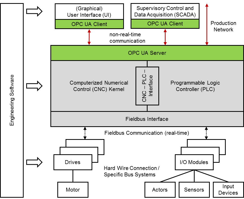
CNC systems as a whole consist of several hardware and software components as illustrated in Figure 1.
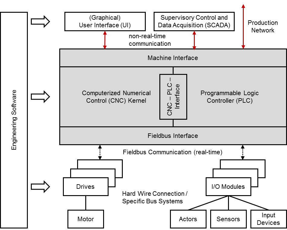
Computerized Numerical Control Kernel (CNC kernel): The CNC kernel realizes the core functionality of a CNC system. It implements functionality to generate the axes movement for machining workpieces based on a geometrical and technological description given in a CNC part program. Therefore it provides software functions for decoding, interpreting and processing data of a CNC part program, for path planning and setpoint generation considering given constraints and depending on the system's realization for positioning the machine's axes.
Programmable Logic Controller (PLC): The PLC handles all logical operations of a CNC system. It is closely coupled with the CNC kernel and enables to realize complex process sequences that involve different actors and sensors of the machine next to the machine's drives. The PLC may also realize monitoring and safety functions and processes input signals from certain devices or the user interface. PLC programs are often implemented according to IEC 61131-3.
CNC-PLC-Interface: The CNC-PLC-Interface links the CNC kernel and the PLC. Both modules have to be synchronized and therefore are closely coupled. The CNC-PLC-Interface is often realized as shared memory to allow high performing data exchange.
Machine Interface: The Machine Interface allows applications to exchange data with a CNC system. Thus, the CNC system can be configured, operated and monitored. The Machine Interface is used primarily by the User Interface (UI) but additionally by other applications like engineering and production management systems. Many CNC systems offer more than one Machine Interface connection point so that different communication mechanisms or protocols can be used at a time.
(Graphical) User Interface (UI): The UI, mostly realized as graphical user interface (GUI) is a software application that allows operators and commissioning engineers to interact with the CNC system and therefore to configure, operate and monitor the CNC system as well as the complete machine tool. The UI is connected to the Machine Interface of the CNC system. It may be executed on the same system platform than the CNC or on a separate device.
Fieldbus Interface: The peripheral devices and the drives of a machine tool are connected to the CNC system by a fieldbus. For that reason both CNC and hardware device provide a Fieldbus Interface for connecting one with another. Most fieldbus systems allow to communicate data in a cyclical, time deterministic behaviour, as well as in an asynchronous mode.
Drives and Motors: The drive unit, consisting of drive and motor, realizes physically the desired tool path, generated by the CNC kernel. The drive implements among others feedback controllers for current, velocity and mostly for position, as well. Generated setpoints are used for controlling the motor. The drive itself is connected to the CNC by a fieldbus to realize a time deterministic communication behaviour.
I/O-Modules and Actors, Sensors, Input Devices: Apart from the drives, other peripheral devices (actors, sensors and input devices) are connected directly or through I/O-Modules to the CNC by a fieldbus.
Machine tools and machining centers can constitute complex systems regarding their kinematic structure. To cope with this complexity CNC systems provide the possibility to fragment the control task by using a software construct organizing kinematic chains and additional moving machine tool components like tool changers. So called "channels" are responsible for controlling smaller portions of the machine tool kinematic and its additional components. In general, all axes within a channel are interpolated in common.
4.1.2 CNC Data
A CNC system provides data through the Machine Interface for external application systems like UIs, SCADA and engineering systems among others. This data has its origin within the CNC system itself or is collected from the drives and peripheral devices. All available data can be divided into the following categories:
Parameter: Configuration data of the CNC system, hardware devices and communication mechanisms. Parameters do not have any requirements regarding communication behaviour.
State data: States of the hardware devices, CNC kernel and PLC. States may be built within the PLC system itself by summarizing data.
Command data: Setpoint values and commands that are communicated from the Machine Interface to the CNC system as well as from the CNC system to the hardware devices. The first do not have requirements regarding the communication behaviour, the latter are communicated cyclically from the CNC system to the appropriate devices.
Process data: Actual values of the hardware devices. Values are communicated cyclically from the appropriate devices to the CNC system.
Alarms: Events of the CNC System, e.g. by the CNC kernel, the PLC, but as well by the UI, informing about errors or other notifications.
Files: Files are transferred from the Machine Interface to the CNC kernel or the PLC, maybe as well to the drives and peripheral devices holding configuration data (e.g. tool parameters) or process information in form of part programs or similar.
4.1.3 Production Network
CNC systems may be integrated in a network comprising various systems for controlling and supervising the production. Hence CNC systems may be connected next to UI and engineering software applications to different systems like
MES,
ERP systems,
PDA/MDA systems,
diagnosis and condition monitoring applications,
further external UI applications, e.g. smart device applications or similar.
A CNC system can be integrated into a production network using the appropriate interface, mostly the Machine Interface. Due to the diversity of systems and system manufacturers standardized interfaces could reduce efforts for linking these systems. This Information Model aims at achieving precisely this objective.
4.1.4 Restrictions
The focus of the "OPC UA Information Model for CNC systems" is on data that is situated within the CNC kernel but not within the PLC of a CNC system. This results out of the main objective of this Information Model to standardize an interface that provides and enables to access clearly defined raw data. Hence this Information Model addresses applications like UIs, PDA/MDA systems, diagnosis and monitoring applications, but not necessarily MES or ERP systems as the two latter ones mostly need summarized data.
For PLC data and in a wider context for MES and ERP data, please refer to suitable standards and OPC UA companion standards like OPC 30000 (PLCopen) or OPC 10030 (ISA 95).
4.2 Introduction to OPC Unified Architecture
4.2.1 General
The main use case for OPC standards is the online data exchange between devices and HMI or SCADA systems using Data Access functionality. In this use case the device data is provided by an OPC server and is consumed by an OPC client integrated into the HMI or SCADA system. OPC DA provides functionality to browse through a hierarchical namespaces containing data items and to read, write and to monitor these items for data changes. The classic OPC standards are based on Microsoft COM/DCOM technology for the communication between software components from different vendors. Therefore classic OPC server and clients are restricted to Windows PC based automation systems.
OPC UA incorporates all features of classic OPC standards like OPC DA, A&E and HDA but defines platform independent communication mechanisms and generic, extensible and object-oriented modelling capabilities for the information a system wants to expose.
The OPC UA network communication part defines different mechanisms optimized for different use cases. The first version of OPC UA is defining an optimized binary TCP protocol for high performance intranet communication as well as a mapping to accepted internet standards like Web Services. The abstract communication model does not depend on a specific protocol mapping and allows adding new protocols in the future. Features like security, access control and reliability are directly built into the transport mechanisms. Based on the platform independence of the protocols, OPC UA servers and clients can be directly integrated into devices and controllers.
The OPC UA Information Model provides a standard way for Servers to expose Objects to Clients. Objects in OPC UA terms are composed of other Objects, Variables and Methods. OPC UA also allows relationships to other Objects to be expressed.
The set of Objects and related information that an OPC UA Server makes available to Clients is referred to as its AddressSpace. The elements of the OPC UA Object Model are represented in the AddressSpace as a set of Nodes described by Attributes and interconnected by References. OPC UA defines eight classes of Nodes to represent AddressSpace components. The classes are Object, Variable, Method, ObjectType, VariableType, DataType, ReferenceType and View. Each NodeClass has a defined set of Attributes.
This specification makes use of three essential OPC UA NodeClasses: Objects, Methods and Variables.
Objects are used to represent components of a system. An Object is associated to a corresponding ObjectType that provides definitions for that Object.
Methods are used to represent commands or services of a system.
Variables are used to represent values. Two categories of Variables are defined, Properties and DataVariables.
Properties are Server-defined characteristics of Objects, DataVariables and other Nodes. Properties are not allowed to have Properties defined for them. An example for Properties of Objects is the Version Property of the CncInterfaceType.
DataVariables represent the contents of an Object. DataVariables may have component DataVariables. This is typically used by Servers to expose individual elements of arrays and structures. This specification uses DataVariables to represent parameters, state data, process and command data, for example ActSpeed of a Object of CncSpindleType.
4.2.2 Graphical Notation
OPC UA defines a graphical notation for an OPC UA AddressSpace. It defines graphical symbols for all NodeClasses and how different types of References between Nodes can be visualized. Figure 2 shows the symbols for the six NodeClasses used in this specification. NodeClasses representing types always have a shadow.
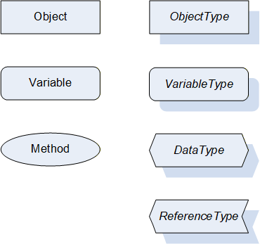
Figure 3 shows the symbols for the ReferenceTypes used in this specification. The Reference symbol is normally pointing from the source Node to the target Node. The only exception is the HasSubtype Reference. The most important References like HasComponent, HasProperty, HasTypeDefinition and HasSubtype have special symbols avoiding the name of the Reference. For other ReferenceTypes or derived ReferenceTypes the name of the ReferenceType is used together with the symbol.
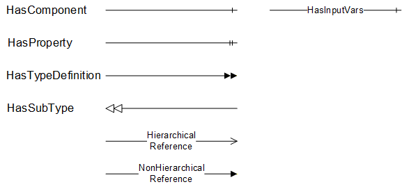
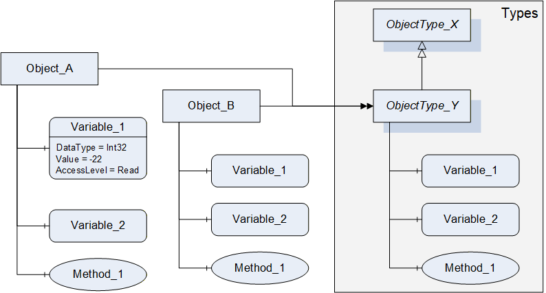
Figure 4 shows a typical example for the use of the graphical notation. Object_A and Object_B are instances of the ObjectType_Y indicated by the HasTypeDefinition References. The ObjectType_Y is derived from ObjectType_X indicated by the HasSubtype Reference. The Object_A has the components Variable_1, Variable_2 and Method_1.
To describe the components of an Object on the ObjectType the same NodeClasses and References are used on the Object and on the ObjectType like for ObjectType_Y in the example. The instance Nodes used to describe an ObjectType are instance declaration Nodes.
To provide more detailed information for a Node, a subset or all Attributes and their values can be added to a graphical symbol.
4.3 Use Cases
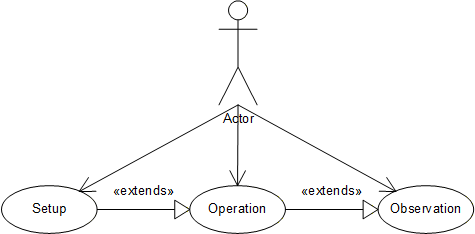
This companion standard is meant to be used for CNC data interfaces. It allows to access data provided by a CNC system, namely parameters, state data, process and command data, alarm notifications and files. Access covers both read and write access. Thus, the following use cases may be covered:
Setup: The CNC data interface provides data that can be used for setting up a production system controlled by a CNC. This refers first of all to production commissioning data (e.g. job description, tool data etc.) but implies to a certain extent as well CNC configuration data (e.g. axis parameters, cycle time etc.), as needed for engineering.
Operation: The CNC data interface may be used for operating a production system controlled by a CNC and therefore serves as a connection point for user interfaces.
Observation: The CNC data interface may be used for observing a production system controlled by a CNC and therefore serves as a connection point for monitoring and diagnosis applications and for user interfaces.
Figure 5 shows the use case diagram.
5 Information Model Overview
5.1 Modelling concepts
The main objective of this companion standard is to have an Information Model that results in a clearly defined and structured CNC data interface. That means that both data items and its composition are specified. Manufacturer and use case specific extensions shall be possible.
Regarding the data elements standard OPC UA Variable types shall be used as far as possible. There are two main categories of data items present: unit based items (e.g. position data in mm or inch) and items without unit (e.g. state data). Unit based items shall be realized as AnalogItemTypes, other data as DataItemTypes. Units shall be used as described in OPC 10000-8.
Regarding the structure of the CNC data interface it is intended to realize flat hierarchies. However, multiple referencing of Objects shall be used for exposing the assignment of components within the hardware or software system.
ObjectTypes shall be derived as far as possible from hardware and software components of a CNC system.
5.2 Model Overview
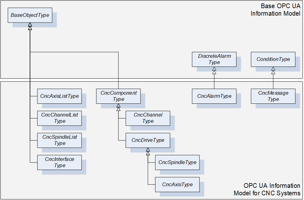
Based on the modelling concepts this chapter introduces the "OPC UA Information Model for CNC Systems".
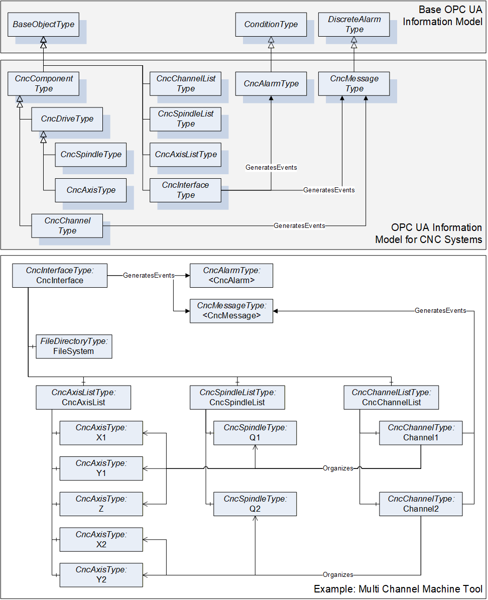
This Information Model provides the ObjectTypes as illustrated in Figure 6. There are ObjectTypes that are used as structuring elements of the CNC data interface (e.g. CncAxisListType) and ObjectTypes to define grouping elements related to hardware and software components of a CNC system (e.g. CncAxisType). Furthermore, this Information Model specifies EventTypes for alarm reporting (e.g. CncAlarmType).
The overall structure of the CNC data interface is illustrated in Figure 7. CncInterface represents the entry point to the CNC data interface. It contains next to the instances of the above mentioned ObjectTypes several Properties for specifying the data interface (e.g. Version, VendorName). One main objective of this Information Model is to provide first of all a fast and easy access to all components managed by the CNC data interface. Out of this reason there are lists provided by the CncInterface Object (e.g. CncAxisList) to allow accessing components without knowing about their affiliation within the logical structure of a machine tool or a CNC system (e.g. independent from their channel affiliation all axes can be accessed via the CncAxisList Object). However, logical structures are additionally modeled by using Hierarchical References (organizes). For instance, a CNC channel of type CncChannelType holds References to all axes and spindles that are assigned to this specific channel, see Figure 7.
The CncInterface Object is furthermore responsible for the alarm and event handling of the CNC data interface. It generates events of type CncAlarmType and CncMessageType for providing error and information messages.
Instances of CncChannelType can generate events of type CncMessageType for providing information messages.
FileSystem represents the entry point to the file system of the CNC data interface. It is subordinated to the CncInterface Object.
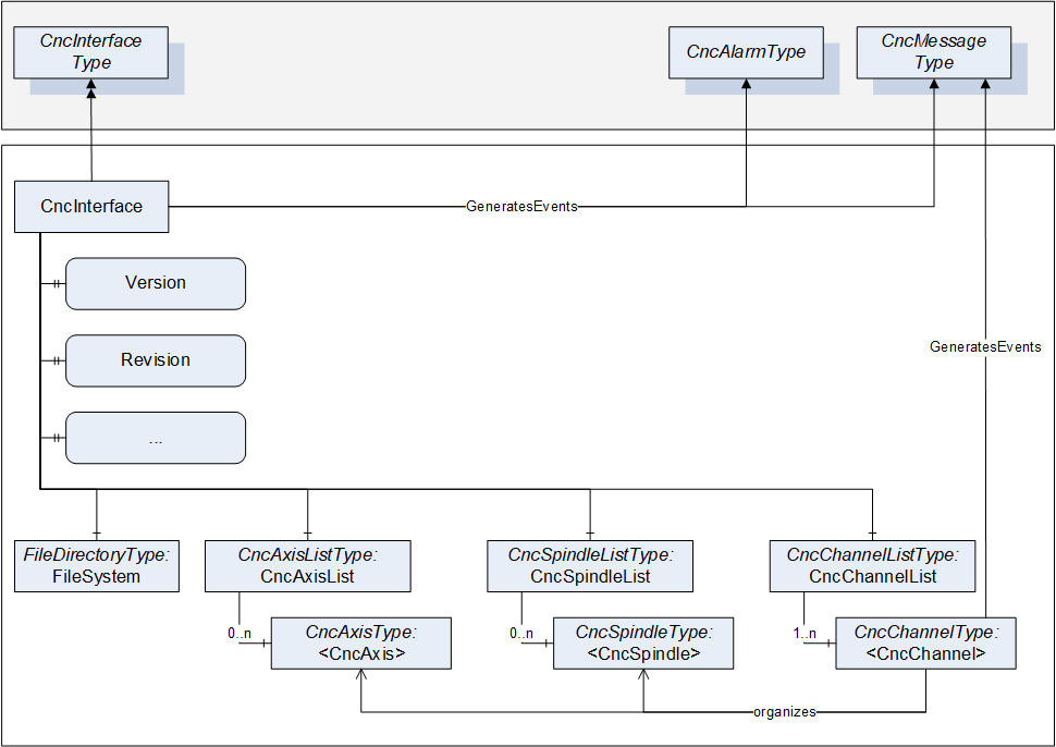
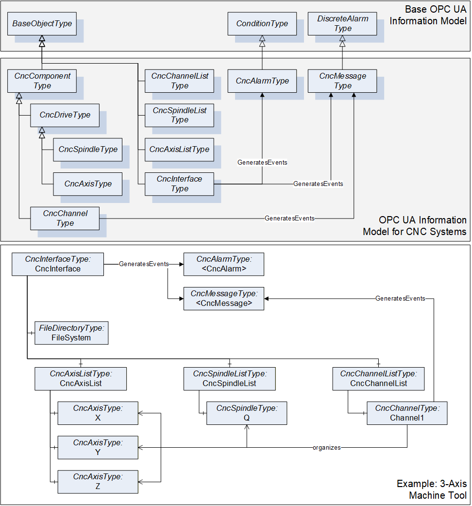
Figure 8 and Figure 9 serves as an example for this companion standard. The shown Information Model is built up for a three axis machine tool and a multi channel machine tool. For the sake of clarity only the ObjectTypes and its References are presented but not its Variables or Properties. For further information, the ObjectTypes are described in detail in chapter 6.
6 OPC UA ObjectTypes
6.1 CncInterfaceType
6.1.1 General
This OPC UA ObjectType represents a CNC Interface. CncInterfaceType is the entry point to the CNC data interface. It is mainly used for structuring the interface. But additionally this ObjectType holds Properties characterizing this interface (Version, VendorName etc.), as well as References to the specified EventTypes. There are two different types of events generated by an instance of CncInterfaceType: events of type CncMessageType and of type CncAlarmType.
Events of type CncAlarmType are used to provide CNC error messages.
Events of type CncMessageType are used to provide messages that are not an alarm but a non-critical information, e.g. a user created message out of the CNC part program.
CncInterfaceType is formally defined in Table 7.
6.1.2 ObjectType Definition
The CncInterfaceType is formally defined in Table 7.
| Attribute | Value | ||||
| BrowseName | CncInterfaceType | ||||
| IsAbstract | False | ||||
| References | NodeClass | BrowseName | DataType | TypeDefinition | ModellingRule |
|---|---|---|---|---|---|
| Inherit the components of the BaseObjectType | |||||
| GeneratesEvent | ObjectType | CncAlarmType | |||
| GeneratesEvent | ObjectType | CncMessageType | |||
| HasComponent | Object | CncAxisList | CncAxisListType | Mandatory | |
| HasComponent | Object | CncChannelList | CncChannelListType | Mandatory | |
| HasComponent | Object | CncSpindleList | CncSpindleListType | Mandatory | |
| HasComponent | Object | FileSystem | FileDirectoryType | Optional | |
| HasProperty | Variable | CncTypeName | String | PropertyType | Optional |
| HasProperty | Variable | Fix | String | PropertyType | Optional |
| HasProperty | Variable | VendorName | String | PropertyType | Mandatory |
| HasProperty | Variable | VendorRevision | String | PropertyType | Mandatory |
| HasProperty | Variable | Version | String | PropertyType | Mandatory |
6.1.3 ObjectType Description
6.1.3.1 CncAlarm
CncInterfaceType may generate events of type CncAlarmType to provide error messages.
6.1.3.2 CncMessage
CncInterfaceType may generate events of type CncMessageType to provide general CNC information messages.
6.1.3.3 CncAxisList
Group of CNC axis objects.
Adds child <CncAxis>.
6.1.3.4 CncChannelList
Group of CNC channel objects.
Adds child <CncChannel>.
6.1.3.5 CncSpindleList
Group of CNC spindle objects.
Adds child <CncSpindle>.
6.1.3.6 FileSystem
Entry point to system's file directory.
6.1.3.7 CncTypeName
Type or model name of the CNC that is represented by Information Model.
6.1.3.8 Fix
Manufacturer specific version of CNC interface considering changes in implementation (Bug Fix).
6.1.3.9 VendorName
Name of CNC system vendor. Format and content may be chosen by vendor.
6.1.3.10 VendorRevision
Vendor revision of CNC interface. Format and content may be chosen by vendor.
6.1.3.11 Version
CNC interface version - corresponds to the version of this OPC UA companion standard and has to be presented in the same format (e.g. 1.03) so that an OPC UA Client can evaluate the version programmatically.
6.2 CncAxisListType
6.2.1 General
This OPC UA ObjectType serves as a structuring element. Objects of type CncAxisListType comprise all axes that are subordinated to a CncInterface. It is formally defined in Table 8.
Objects of type CncAxisListType may generate events of type GeneralModelChangeEventType. These events are used to inform about changes in the Information Model related to an instance of CncAxisListType.
6.2.2 ObjectType Definition
The CncAxisListType is formally defined in Table 8.
| Attribute | Value | ||||
| BrowseName | CncAxisListType | ||||
| IsAbstract | False | ||||
| References | NodeClass | BrowseName | DataType | TypeDefinition | ModellingRule |
|---|---|---|---|---|---|
| Inherit the components of the BaseObjectType | |||||
| GeneratesEvent | ObjectType | GeneralModelChangeEventType | |||
| HasProperty | Variable | 0:NodeVersion | String | PropertyType | Optional |
| HasComponent | Object | <CncAxis> | CncAxisType | OptionalPlaceholder | |
6.2.3 ObjectType Description
6.2.3.1 GeneralModelChangeEvent
CncAxisListType may generate events of type GeneralModelChangeEventType defined in OPC 10000-3 to inform Clients when CncAxis Objects have been added or removed from a CncAcisListType instance.
6.2.3.2 NodeVersion
The optional Property NodeVersion shall be present if the Server emits GeneralModelChangeEvents for the Object of type CncAxisListType. The NodeVersion Property and the relation to GeneralModelChangeEvents are defined in OPC 10000-3.
6.2.3.3 CncAxis
CNC axis object.
6.3 CncSpindleListType
6.3.1 General
This OPC UA ObjectType serves as a structuring element. Objects of type CncSpindleListType comprise all spindles that are subordinated to a CncInterface. It is formally defined in Table 9.
Objects of type CncSpindleListType may generate events of type GeneralModelChangeEventType. These events are used to inform about changes in the Information Model related to an instance of CncSpindleListType.
6.3.2 ObjectType Definition
The CncSpindleListType is formally defined in Table 9.
| Attribute | Value | ||||
| BrowseName | CncSpindleListType | ||||
| IsAbstract | False | ||||
| References | NodeClass | BrowseName | DataType | TypeDefinition | ModellingRule |
|---|---|---|---|---|---|
| Inherit the components of the BaseObjectType | |||||
| GeneratesEvent | ObjectType | GeneralModelChangeEventType | |||
| HasProperty | Variable | 0:NodeVersion | String | PropertyType | Optional |
| HasComponent | Object | <CncSpindle> | CncSpindleType | OptionalPlaceholder | |
6.3.3 ObjectType Description
6.3.3.1 GeneralModelChangeEvent
CncSpindleListType may generate events of type GeneralModelChangeEventType defined in OPC 10000-3 to inform Clients when CncSpindle Objects have been added or removed from a CncSpindleListType instance.
6.3.3.2 NodeVersion
The optional Property NodeVersion shall be present if the Server emits GeneralModelChangeEvents for the Object of type CncSpindleListType. The NodeVersion Property and the relation to GeneralModelChangeEvents are defined in OPC 10000-3.
6.3.3.3 CncSpindle
CNC spindle object.
6.4 CncChannelListType
6.4.1 General
This OPC UA ObjectType serves as a structuring element. Objects of type CncChannelListType comprise all channels that are subordinated to a CncInterface. It is formally defined in Table 10.
Objects of type CncChannelListType may generate events of type GeneralModelChangeEventType. These events are used to inform about changes in the Information Model related to an instance of CncChannelListType.
6.4.2 ObjectType Definition
The CncChannelListType is formally defined in Table 10.
| Attribute | Value | ||||
| BrowseName | CncChannelListType | ||||
| IsAbstract | False | ||||
| References | NodeClass | BrowseName | DataType | TypeDefinition | ModellingRule |
|---|---|---|---|---|---|
| Inherit the components of the BaseObjectType | |||||
| GeneratesEvent | ObjectType | GeneralModelChangeEventType | |||
| HasProperty | Variable | 0:NodeVersion | String | PropertyType | Optional |
| HasComponent | Object | <CncChannel> | CncChannelType | OptionalPlaceholder | |
6.4.3 ObjectType Description
6.4.3.1 GeneralModelChangeEvent
CncChannelListType may generate events of type GeneralModelChangeEventType defined in OPC 10000-3 to inform Clients when CncChannel Objects have been added or removed from a CncChannelListType instance.
6.4.3.2 NodeVersion
The optional Property NodeVersion shall be present if the Server emits GeneralModelChangeEvents for the Object of type CncChannelListType. The NodeVersion Property and the relation to GeneralModelChangeEvents are defined in OPC 10000-3.
6.4.3.3 CncChannel
CNC channel object.
6.5 CncComponentType
6.5.1 General
This OPC UA ObjectType represents a CNC component. A CNC component may be a hardware or software component of a CNC system (e.g. an axis or a channel). CncComponentType serves as a basis for all components that are accessible through this interface, e.g. CncDriveType or CncChannelType are derived from this ObjectType, and therefore is an abstract type. CncComponentType holds elements that are common for all components of a CNC system. It is formally defined in Table 11.
6.5.2 ObjectType Definition
The CncComponentType is formally defined in Table 11.
| Attribute | Value | ||||
| BrowseName | CncComponentType | ||||
| IsAbstract | True | ||||
| References | NodeClass | BrowseName | DataType | TypeDefinition | ModellingRule |
|---|---|---|---|---|---|
| Inherit the components of the BaseObjectType | |||||
6.5.3 ObjectType Description
There are currently no components subordinated to this ObjectType. However, this Subtype may have components in the future or can be used for manufacturer specific rules or components.
6.6 CncChannelType
6.6.1 General
This OPC UA ObjectType represents a CNC channel with all its necessary elements. All Objects of Type CncChannelType are listed in the CncChannelList of the CncInterface Object.
Additionally to data that is relevant for a CNC Channel, CncChannelType organizes Objects of type CncAxisType and CncSpindleType. That is to indicate which components are currently administrated by this channel.
Objects of CncChannelType may generate two kinds of events: Events of type CncMessageType and of type GeneralModelChangeEventType.
Events of Type CncMessageType are used to provide channel specific messages that are not an alarm but an uncritical information, e.g. a user created message out of the CNC part program.
Events of type GeneralModelChangeEventType are used to inform about changes in the Information Model. Examples for the need of a model change event:
A CNC channel can administrate a different set of components during runtime, meaning that an axis or a spindle can change its channel affiliation during runtime of the CNC system; for instance this may be the case if one spindle is used in combination with different axis groups.
Spindles allow different kind of operation modes, for instance a spindle can change its mode of operation from speed to position control and therefore has to be represented once as spindle (CncSpindleType) and once as rotational axis (CncAxisType).
Instances of CncChannelType provide the position of the channel's tool center point in different coordinate systems. Therefore, the following definitions have to be considered:
Tool carrier zero point: The tool carrier zero point is a reference point on the tool carrier as illustrated in Figure 10.
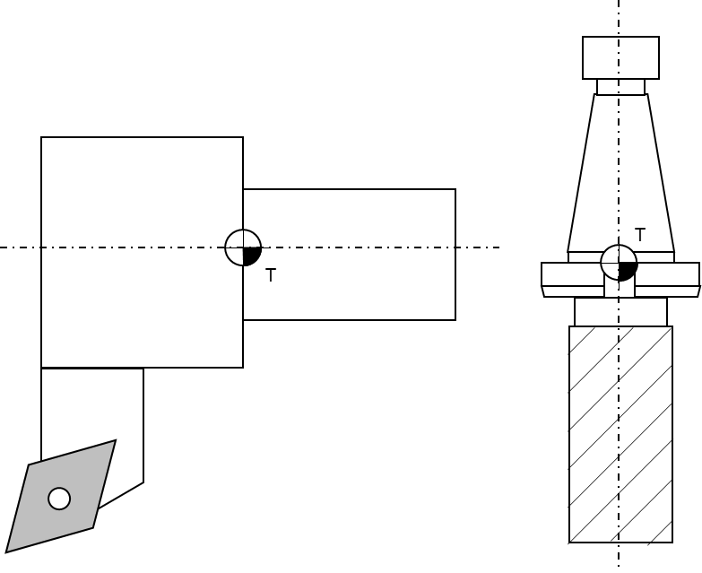
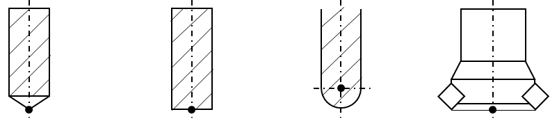
Tool center point: The tool center point of tools for milling operations is usually the intersection of the tool centerline and the lowest positioned cutting tip (edge). For turning operations the tool center point is an imaginary tool point of the cutting insert, because most tools have a cutting edge with a built-in radius. The tool center point of point-to-point tools, such as drills, is the extreme tip of the tool, as measured along the Z axis. Figure 11 and Figure 12 illustrate some common tool center points.

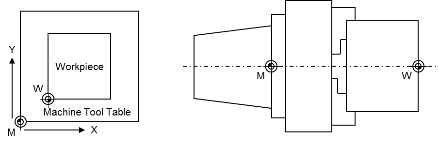
Machine tool coordinate systems: This companion standard refers to two coordinate systems (see Figure 13 for illustration):
Base coordinate system: The base coordinate system (BCS) is a coordinate system defined by the machine tool manufacturer. It has its origin within the machine tool's zero point M.
Workpiece coordinate system: The workpiece coordinate system (WCS) is a user defined coordinate system and allows considering the clamping position and orientation of a workpiece. It has its origin within the workpiece zero point W.
The coordinate systems are built based on the right-hand-rule, illustrated in Figure 14.
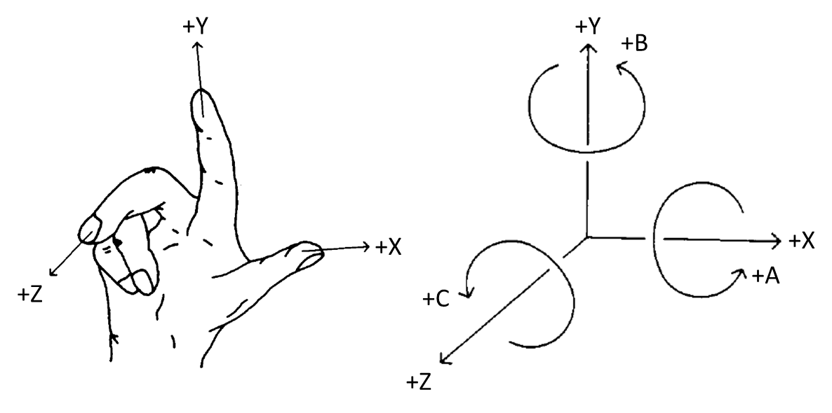
Figure 15 shows an overview for the CncChannelType. It is formally defined in Table 12.
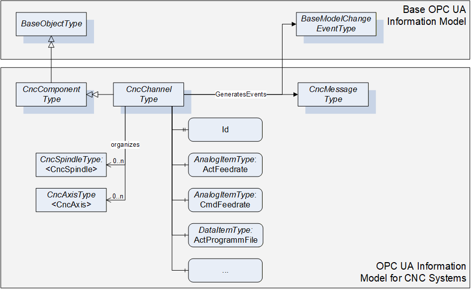
6.6.2 ObjectType Definition
The CncChannelType is formally defined in Table 12.
| Attribute | Value | ||||
| BrowseName | CncChannelType | ||||
| IsAbstract | False | ||||
| References | NodeClass | BrowseName | DataType | TypeDefinition | ModellingRule |
|---|---|---|---|---|---|
| Inherit the components of the CncComponentType | |||||
| GeneratesEvent | ObjectType | CncMessageType | |||
| GeneratesEvent | ObjectType | GeneralModel ChangeEventType | |||
| HasProperty | Variable | 0:NodeVersion | String | PropertyType | Optional |
| HasComponent | Object | <CncAxis> | CncAxisType | OptionalPlaceholder | |
| HasComponent | Object | <CncSpindle> | CncSpindleType | OptionalPlaceholder | |
| HasComponent | Variable | ActFeedrate | Double | AnalogItemType | Mandatory |
| HasComponent | Variable | ActGFunctions | UInt32[] | DataItemType | Mandatory |
| HasComponent | Variable | ActJogIncrement | Double | AnalogItemType | Mandatory |
| HasComponent | Variable | ActMainProgramFile | String | DataItemType | Mandatory |
| HasComponent | Variable | ActMainProgramFileOffset | UInt32 | DataItemType | Optional |
| HasComponent | Variable | ActMainProgramLine | String | DataItemType | Optional |
| HasComponent | Variable | ActMainProgramName | String | DataItemType | Mandatory |
| HasComponent | Variable | ActMFunctions | UInt32[] | DataItemType | Mandatory |
| HasComponent | Variable | ActModalOffsetFunction | UInt32 | DataItemType | Mandatory |
| HasComponent | Variable | ActOperationMode | CncOperationMode | DataItemType | Mandatory |
| HasComponent | Variable | ActOverride | Double | AnalogItemType | Mandatory |
| HasComponent | Variable | ActProgramBlock | String[] | DataItemType | Mandatory |
| HasComponent | Variable | ActProgramFile | String | DataItemType | Mandatory |
| HasComponent | Variable | ActProgramFileOffset | UInt32 | DataItemType | Optional |
| HasComponent | Variable | ActProgramLine | String | DataItemType | Optional |
| HasComponent | Variable | ActProgramName | String | DataItemType | Mandatory |
| HasComponent | Variable | ActProgramStatus | CncChannelProgStatus | DataItemType | Mandatory |
| HasComponent | Variable | ActStatus | CncChannelStatus | DataItemType | Mandatory |
| HasComponent | Variable | BlockMode | Boolean | DataItemType | Mandatory |
| HasComponent | Variable | CmdFeedrate | Double | AnalogItemType | Mandatory |
| HasComponent | Variable | CmdOverride | Double | AnalogItemType | Mandatory |
| HasComponent | Variable | DryRunFeed | Double | AnalogItemType | Mandatory |
| HasComponent | Variable | FeedHold | Boolean | DataItemType | Mandatory |
| HasProperty | Variable | Id | UInt32 | PropertyType | Mandatory |
| HasComponent | Variable | PosTcpBcsA | CncPositionDataType | CncPosition VariableType | Mandatory |
| HasComponent | Variable | PosTcpBcsB | CncPositionDataType | CncPosition VariableType | Mandatory |
| HasComponent | Variable | PosTcpBcsC | CncPositionDataType | CncPosition VariableType | Mandatory |
| HasComponent | Variable | PosTcpBcsX | CncPositionDataType | CncPosition VariableType | Mandatory |
| HasComponent | Variable | PosTcpBcsY | CncPositionDataType | CncPosition VariableType | Mandatory |
| HasComponent | Variable | PosTcpBcsZ | CncPositionDataType | CncPosition VariableType | Mandatory |
| HasComponent | Variable | PosTcpWcsA | CncPositionDataType | CncPosition VariableType | Mandatory |
| HasComponent | Variable | PosTcpWcsB | CncPositionDataType | CncPosition VariableType | Mandatory |
| HasComponent | Variable | PosTcpWcsC | CncPositionDataType | CncPosition VariableType | Mandatory |
| HasComponent | Variable | PosTcpWcsX | CncPositionDataType | CncPosition VariableType | Mandatory |
| HasComponent | Variable | PosTcpWcsY | CncPositionDataType | CncPosition VariableType | Mandatory |
| HasComponent | Variable | PosTcpWcsZ | CncPositionDataType | CncPosition VariableType | Mandatory |
| HasComponent | Variable | ToolId | UInt32 | DataItemType | Mandatory |
6.6.3 ObjectType Description
6.6.3.1 CncMessage
CncChannelType may generate events of type CncMessageType to provide channel specific information messages (for instance triggered out of CNC part program).
6.6.3.2 GeneralModelChangeEvent
CncChannelType may generate events of type GeneralModelChangeEventType defined in OPC 10000-3 to inform Clients when CncSpindle or CncAxis Objects have been added or removed from a CncChannelType instance.
6.6.3.3 NodeVersion
The optional Property NodeVersion shall be present if the Server emits GeneralModelChangeEvents for the Object of type CncChannelType. The NodeVersion Property and the relation to GeneralModelChangeEvents are defined in OPC 10000-3.
6.6.3.4 CncAxis
CNC axis object.
6.6.3.5 CncSpindle
CNC spindle object.
6.6.3.6 ActFeedrate
Feedrate actual value.
6.6.3.7 ActJogIncrement
Active JOG increment, i.e. a position increment that is executed with each user jog command. Usually, there are predefined increments given (1/10, 1/100, 1/1000 position increment in the selected physical unit), but a continuous jog mode and a jog mode with variable increment are possible, too. A continuous jog mode is indicated with a jog increment value of -1, all other jog increments are given as real increments in the appropriate units.
6.6.3.8 ActGFunctions
Array of active G functions; there can be several G functions active at a time (modal and non-modal G functions).
6.6.3.9 ActMainProgramFile
Path of active CNC main program.
6.6.3.10 ActMainProgramFileOffset
File offset of active CNC main program file (corresponds to the number of line feeds).
6.6.3.11 ActMainProgramName
Name of active CNC main program.
6.6.3.12 ActMainProgramLine
Line number of active CNC main program (usually defined as N<Number>).
6.6.3.13 ActMFunctions
Array of active M functions: there can be several M functions active at a time (modal and non-modal M functions).
6.6.3.14 ActModalOffsetFunction
Active zero offset function (usually G54, G55, G56 or G57; G53 repeals zero offsets).
6.6.3.15 ActOperationMode
Channel's active mode of operation. See 7.2.6 for further description of possible states.
6.6.3.16 ActOverride
Axis override actual value.
6.6.3.17 ActProgramBlock
Block of lines containing the previous, actual and subsequent lines of a CNC part program.
6.6.3.18 ActProgramFile
Path of active CNC part program file (main or subprogram).
6.6.3.19 ActProgramFileOffset
File offset of active CNC part program file (main or subprogram).
6.6.3.20 ActProgramLine
Line number of active CNC part program (main or subprogram).
6.6.3.21 ActProgramName
Name of active CNC part program (main or subprogram).
6.6.3.22 ActProgramStatus
Active channel program status. See 7.2.5 for further description of possible states.
6.6.3.23 ActStatus
Active status of channel. See 7.2.4 for further description of possible states.
6.6.3.24 BlockMode
Block mode status (true in case of block mode is active, else false). With block mode active, individual program blocks are processed one by one. Each step has to be triggered by the operator.
6.6.3.25 CmdFeedrate
Feedrate setpoint value.
6.6.3.26 CmdOverride
Override setpoint value.
6.6.3.27 DryRunFeed
Test federate.
6.6.3.28 FeedHold
Feed status (true in case of feed hold active, else false).
6.6.3.29 Id
Unique numeric channel identifier.
6.6.3.30 PosTcpBcsA
Actual position of the tool center point in machine's Cartesian base coordinate system. The tool center point is the reference point on a tool how it is considered by the CNC's tool compensation function. If there is no tool present, the tool center point is the tool carrier zero point.
6.6.3.31 PosTcpBcsB
Actual position of the tool center point in machine's Cartesian base coordinate system. The tool center point is the reference point on a tool how it is considered by the CNC's tool compensation function. If there is no tool present, the tool center point is the tool carrier zero point.
6.6.3.32 PosTcpBcsC
Actual position of the tool center point in machine's Cartesian base coordinate system. The tool center point is the reference point on a tool how it is considered by the CNC's tool compensation function. If there is no tool present, the tool center point is the tool carrier zero point.
6.6.3.33 PosTcpBcsX
Actual position of the tool center point in machine's Cartesian base coordinate system. The tool center point is the reference point on a tool how it is considered by the CNC's tool compensation function. If there is no tool present, the tool center point is the tool carrier zero point.
6.6.3.34 PosTcpBcsY
Actual position of the tool center point in machine's Cartesian base coordinate system. The tool center point is the reference point on a tool how it is considered by the CNC's tool compensation function. If there is no tool present, the tool center point is the tool carrier zero point.
6.6.3.35 PosTcpBcsZ
Actual position of the tool center point in machine's Cartesian base coordinate system. The tool center point is the reference point on a tool how it is considered by the CNC's tool compensation function. If there is no tool present, the tool center point is the tool carrier zero point.
6.6.3.36 PosTcpWcsA
Actual position of the tool center point in machine's Cartesian workpiece coordinate system. The tool center point is the reference point on a tool how it is considered by the CNC's tool compensation function. If there is no tool present, the tool center point is the tool carrier zero point. Hence, the position corresponds to the position programmed in the CNC part program.
6.6.3.37 PosTcpWcsB
Actual position of the tool center point in machine's Cartesian workpiece coordinate system. The tool center point is the reference point on a tool how it is considered by the CNC's tool compensation function. If there is no tool present, the tool center point is the tool carrier zero point. Hence, the position corresponds to the position programmed in the CNC part program.
6.6.3.38 PosTcpWcsC
Actual position of the tool center point in machine's Cartesian workpiece coordinate system. The tool center point is the reference point on a tool how it is considered by the CNC's tool compensation function. If there is no tool present, the tool center point is the tool carrier zero point. Hence, the position corresponds to the position programmed in the CNC part program.
6.6.3.39 PosTcpWcsX
Actual position of the tool center point in machine's Cartesian workpiece coordinate system. The tool center point is the reference point on a tool how it is considered by the CNC's tool compensation function. If there is no tool present, the tool center point is the tool carrier zero point. Hence, the position corresponds to the position programmed in the CNC part program.
6.6.3.40 PosTcpWcsY
Actual position of the tool center point in machine's Cartesian workpiece coordinate system. The tool center point is the reference point on a tool how it is considered by the CNC's tool compensation function. If there is no tool present, the tool center point is the tool carrier zero point. Hence, the position corresponds to the position programmed in the CNC part program.
6.6.3.41 PosTcpWcsZ
Actual position of the tool center point in machine's Cartesian workpiece coordinate system. The tool center point is the reference point on a tool how it is considered by the CNC's tool compensation function. If there is no tool present, the tool center point is the tool carrier zero point. Hence, the position corresponds to the position programmed in the CNC part program.
6.6.3.42 ToolId
ID of active tool that has been selected (e.g. calling "T1" in the CNC part program). Returns an empty string, if no tool is present.
6.7 CncDriveType
6.7.1 General
This OPC UA ObjectType represents a CNC drive. It serves as a basis for all drive component Objects that are accessible through this interface, e.g. CncAxisType and CncSpindleType are derived from this ObjectType, and therefore is an abstract type. CncDriveType holds elements that are common for all drive Objects of a CNC system. It is formally defined in Table 13.
6.7.2 ObjectType Definition
The CncDriveType is formally defined in Table 13.
| Attribute | Value | ||||
| BrowseName | CncDriveType | ||||
| IsAbstract | True | ||||
| References | NodeClass | BrowseName | DataType | TypeDefinition | ModellingRule |
|---|---|---|---|---|---|
| Inherit the components of the CncComponentType | |||||
| HasComponent | Variable | ActChannel | NodeId | DataItemType | Mandatory |
| HasComponent | Variable | ActLoad | Double | AnalogItemType | Mandatory |
| HasComponent | Variable | ActPower | Double | AnalogItemType | Mandatory |
| HasComponent | Variable | ActTorque | Double | AnalogItemType | Mandatory |
| HasComponent | Variable | CmdTorque | Double | AnalogItemType | Mandatory |
| HasComponent | Variable | IsInactive | Boolean | DataItemType | Mandatory |
| HasComponent | Variable | IsVirtual | Boolean | DataItemType | Mandatory |
6.7.3 ObjectType Description
6.7.3.1 ActChannel
NodeId of the channel object (CncChannelType) that administrates this drive to expose drive's channel affiliation. ActChannel remains empty in case of drives without channel affiliation.
6.7.3.2 ActLoad
Drive load actual value.
6.7.3.3 ActPower
Drive power actual value.
6.7.3.4 ActTorque
Drive torque actual value.
6.7.3.5 CmdTorque
Drive torque setpoint value.
6.7.3.6 IsInactive
Drive inactive state (true in case of inactive drive, else false).
6.7.3.7 IsVirtual
Virtual axis (no hardware present; true in case of virtual axis, else false).
6.8 CncAxisType
6.8.1 General
This OPC UA ObjectType represents a CNC axis. CNC axes can be subordinated to channels. They can change channel affiliation during runtime. For that reasons Objects of type CncAxisType may be referenced by Objects of CncChannelType to inform about their current channel affiliation. At the same time all axis Objects of a CNC system must be subordinated to the CncAxisList regardless of their channel affiliation.
Figure 16 shows an overview for the CncAxisType. It is formally defined in Table 14.
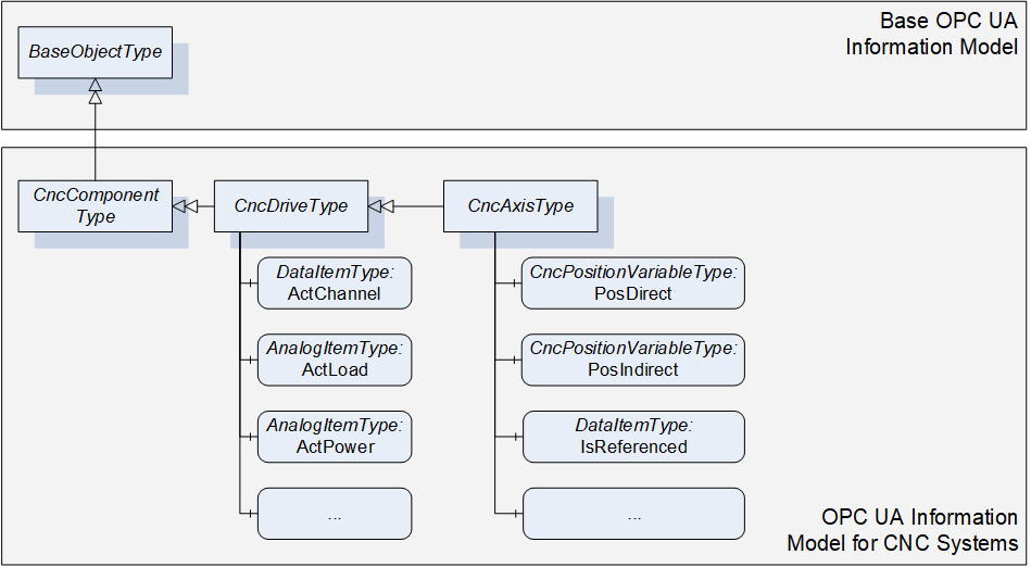
6.8.2 ObjectType Definition
The CncAxisType is formally defined in Table 14.
| Attribute | Value | ||||
| BrowseName | CncAxisType | ||||
| IsAbstract | False | ||||
| References | NodeClass | BrowseName | DataType | TypeDefinition | ModellingRule |
|---|---|---|---|---|---|
| Inherit the components of the CncDriveType | |||||
| HasComponent | Variable | ActStatus | CncAxisStatus | DataItemType | Mandatory |
| HasComponent | Variable | IsReferenced | Boolean | DataItemType | Mandatory |
| HasComponent | Variable | IsRotational | Boolean | DataItemType | Mandatory |
| HasComponent | Variable | PosDirect | CncPositionDataType | CncPositionVariableType | Mandatory |
| HasComponent | Variable | PosIndirect | CncPositionDataType | CncPositionVariableType | Mandatory |
| HasComponent | Variable | ZeroOffset | Double | AnalogItemType | Mandatory |
6.8.3 ObjectType Description
6.8.3.1 ActStatus
Actual axis state.
6.8.3.2 IsReferenced
Axis reference state (true in case of successfully referenced axis, else false).
6.8.3.3 IsRotational
Axis type (true in case of rotational axis, in case of linear type or other false).
6.8.3.4 PosDirect
Axis position values referring to axis' direct measurement system.
6.8.3.5 PosIndirect
Axis position values referring to axis' indirect measurement system.
6.8.3.6 ZeroOffset
Active axis zero offset.
6.9 CncSpindleType
6.9.1 General
This OPC UA ObjectType represents a CNC spindle. CNC spindles can be subordinated to channels. They can change channel affiliation during runtime. For that reasons Objects of type CncSpindleType may be referenced by Objects of CncChannelType to inform about their current channel affiliation. At the same time all spindle Objects of a CNC system must be subordinated to the CncSpindleList regardless of their channel affiliation.
Figure 17 shows an overview for the CncSpindleType. It is formally defined in Table 15.
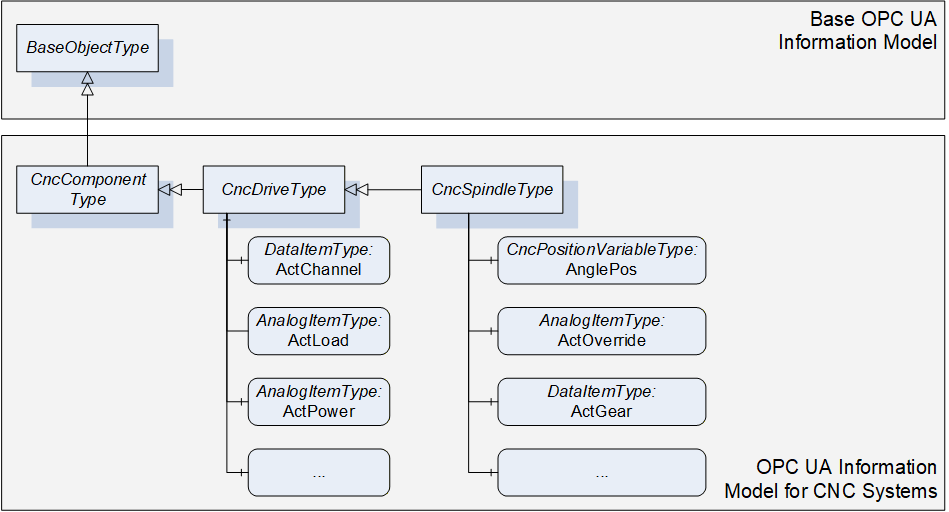
6.9.2 ObjectType Definition
The CncSpindleType is formally defined in Table 15.
| Attribute | Value | ||||
| BrowseName | CncSpindleType | ||||
| IsAbstract | False | ||||
| References | NodeClass | BrowseName | DataType | TypeDefinition | ModellingRule |
|---|---|---|---|---|---|
| Inherit the components of the CncDriveType | |||||
| HasComponent | Variable | ActGear | UInt32 | DataItemType | Mandatory |
| HasComponent | Variable | ActOverride | Double | AnalogItemType | Mandatory |
| HasComponent | Variable | ActSpeed | Double | AnalogItemType | Mandatory |
| HasComponent | Variable | ActStatus | CncSpindleStatus | DataItemType | Mandatory |
| HasComponent | Variable | ActTurnDirection | CncSpindleTurnDirection | DataItemType | Mandatory |
| HasComponent | Variable | AnglePos | CncPositionDataType | CncPositionVariableType | Mandatory |
| HasComponent | Variable | CmdGear | UInt32 | DataItemType | Mandatory |
| HasComponent | Variable | CmdOverride | Double | AnalogItemType | Mandatory |
| HasComponent | Variable | CmdSpeed | Double | AnalogItemType | Mandatory |
6.9.3 ObjectType Description
6.9.3.1 ActGear
Gear stage actual value.
6.9.3.2 ActOverride
Override actual value.
6.9.3.3 ActSpeed
Speed actual value
6.9.3.4 ActStatus
Actual spindle state.
6.9.3.5 ActTurnDirection
Turn direction actual value.
6.9.3.6 AnglePos
Spindle angular position values in case of interpolated (position controlled) spindle movement. Returns zeros in case of regular spindle operation (velocity controlled).
6.9.3.7 CmdGear
Gear stage setpoint value.
6.9.3.8 CmdOverride
Override setpoint value.
6.9.3.9 CmdSpeed
Speed setpoint value.
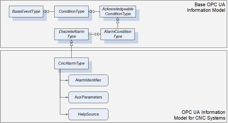
6.10 CncAlarmType
6.10.1 General
This OPC UA ObjectType must be used for reporting alarms of the CNC system. CncAlarmType must derived from DiscreteAlarmType.
The CncAlarmType extends the DiscreteAlarmType as followed:
HelpSource: To provide additional information to the alarm that is not covered by the message text (Message), the HelpSource parameter may be used. HelpSource is specified as BaseDataType. In case a URI is provided to reference additional information through an external source, the HelpSource has to be defined as String. In case a help text is provided, the data type shall be defined as LocalizedText.
AlarmIdentifier: CNC systems mostly provide a unique error number for all alarms. For this purpose AlarmIdentifier shall be used.
AuxParameters: CNC systems may want to provide information (e.g. textual or numerical) in dynamically changeable parts. As an example, this could be used to allow UIs to build their own alarm message by combining the different information fragments provided by this parameter.
As CncAlarmType is derived from the OPC UA DiscreteAlarmType, it shall be used in most parts as specified in OPC 10000-5. However, the following explanations give further instructions on how to specifically use the CncAlarmType.
| Severity is, as defined in OPC 10000-5, an indication of the urgency of the Event and ranges between a value of 1 and 1000. Regarding the severity levels, this OPC UA companion standard does not prescribe the severity levels in detail but expects the lowest alarm severity to be set to 1, the highest severity level to 1000. By this it is secured that the lowest and the highest alarm severity can be clearly identified without knowing about the precise realization of the severities. |
Example 1: If a CNC system uses three severity levels (e.g. Information, Warning, Error), the Information severity level is set to 1, the Warning severity level ranges between 2 and 999 and the Error severity level is set to 1000. Example 2: If a CNC system uses five severity levels (e.g. Information, Warning, Error, Critical, Fatal), the Information severity level is set to 1, the Warning severity level ranges from 2 to 333, the Error severity level ranges from 334 to 666, the Critical severity level ranges from 667 to 999 and the Fatal severity level is set to 1000. |
ConditionName provides alarm classification, so technically the textual alarm severity (e.g. Warning, Error, Fatal…).
SourceName and SourceNode: As described in chapter 4.1 several components constitute a CNC system. Contents of SourceName and SourceNode shall be as detailed as possible, meaning that if the alarm source and its name could explicitly be determined, SourceNode and SourceName should hold this information (e.g. SourceName is set to Channel1, SourceNode is referencing to the Channel1 Object). If it is not possible for a CNC system to provide this information in detail, the SourceName should provide the main component responsible for this alarm (e.g. CNC, PLC or even Channel), the SourceNode shall at least reference the root of the CNC machine interface (CncInterface Object).
AckedState may be set by default to true if no alarm acknowledge is required. If an alarm acknowledge is required AckedState is set to false and changes in case of the acknowledge action.
Retain and ActiveState shall be kept synchronized. Both parameters indicate that an alarm is still pending in case of true.
Figure 18 gives an overview on CncAlarmType. It is formally defined in Table 16.
6.10.2 ObjectType Definition
The CncAlarmType is formally defined in Table 16.
| Attribute | Value | ||||
| BrowseName | CncAlarmType | ||||
| IsAbstract | False | ||||
| References | NodeClass | BrowseName | DataType | TypeDefinition | ModellingRule |
|---|---|---|---|---|---|
| Inherit the components of the DiscreteAlarmType | |||||
| HasProperty | Variable | AlarmIdentifier | String | PropertyType | Mandatory |
| HasProperty | Variable | AuxParameters | String[] | PropertyType | Optional |
| HasProperty | Variable | HelpSource | String | PropertyType | Optional |
6.10.3 ObjectType Description
6.10.3.1 AlarmIdentifier
Unique alarm number.
6.10.3.2 AuxParameters
Array of auxiliary parameter for additional alarm description.
6.10.3.3 HelpSource
Additional information to message giving information on how to solve problem that caused the alarm.
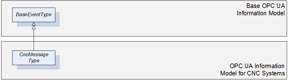
6.11 CncMessageType
6.11.1 General
This OPC UA ObjectType may be used for reporting simple information messages that do not represent an alarm. For instance some CNC systems offer the possibility to trigger messages out of the CNC part program for the purpose of tracking. This would be an example for using the CncMessageType.
As CncMessageType is derived from the OPC UA BaseEventType, it shall be used in most parts as specified in OPC 10000-5.
Figure 19 gives an overview on CncMessageType. It is formally defined in Table 17.
6.11.2 ObjectType Definition
The CncMessageType is formally defined in Table 17.
| Attribute | Value | ||||
| BrowseName | CncMessageType | ||||
| IsAbstract | False | ||||
| References | NodeClass | BrowseName | DataType | TypeDefinition | ModellingRule |
|---|---|---|---|---|---|
| Inherit the components of the BaseEventType | |||||
6.11.3 ObjectType Description
There are currently no components subordinated to this ObjectType.
6.12 FileSystem
It is highly recommended to use FileDirectoryType for accessing the file system of CNC systems. Refer to OPC 10000-5 for detailed information.
Entry point to the CNC file system is FileSystem attached to the Standard UA Namespace (0:http://opcfoundation.org/UA/).
7 Mapping of DataTypes
7.1 Primitive data types
This information model does not define additional primitive data types.
7.2 Enumeration DataTypes
When using the following enumeration DataTypes, one of the given enumeration values has to be used. Hence, manufacturer specific extensions are not possible.
7.2.1 CncAxisStatus
This DataType is an enumeration that describes possible states of a CNC axis. Its values are defined in Table 18.
| Value | Description |
| InPosition_0 | CNC Axis reached commanded position |
| Moving_1 | CNC Axis is moving to reach commanded position |
| Parked_2 | CNC Axis is configured but not active |
Its representation in the AddressSpace is defined in Table 19.
| Attribute | Value | ||||
| BrowseName | CncAxisStatus | ||||
| IsAbstract | False | ||||
| References | NodeClass | BrowseName | DataType | TypeDefinition | ModellingRule |
|---|---|---|---|---|---|
| Inherit the components of the Enumeration | |||||
| HasProperty | Variable | EnumValues | EnumValueType[] | PropertyType | Mandatory |
7.2.2 CncSpindleStatus
This DataType is an enumeration that describes possible states of a CNC spindle. Its values are defined in Table 20.
| Value | Description |
| Stopped_0 | CNC Spindle stopped |
| InTargetArea_1 | CNC Spindle reached commanded velocity |
| Accelerating_2 | CNC Spindle accelerating |
| Decelerating_3 | CNC Spindle decelerating |
| Parked_4 | CNC Spindle configured but not active |
Its representation in the AddressSpace is defined in Table 21.
| Attribute | Value | ||||
| BrowseName | CncSpindleStatus | ||||
| IsAbstract | False | ||||
| References | NodeClass | BrowseName | DataType | TypeDefinition | ModellingRule |
|---|---|---|---|---|---|
| Inherit the components of the Enumeration | |||||
| HasProperty | Variable | EnumValues | EnumValueType[] | PropertyType | Mandatory |
7.2.3 CncSpindleTurnDirection
This DataType is an enumeration that describes possible turn directions of a CNC spindle. Its values are defined in Table 22.
| Value | Description |
| None_0 | No rotation |
| CW_1 | Clockwise |
| CCW_2 | Counter Clockwise |
Its representation in the AddressSpace is defined in Table 23.
| Attribute | Value | ||||
| BrowseName | CncSpindleTurnDirection | ||||
| IsAbstract | False | ||||
| References | NodeClass | BrowseName | DataType | TypeDefinition | ModellingRule |
|---|---|---|---|---|---|
| Inherit the components of the Enumeration | |||||
| HasProperty | Variable | EnumValues | EnumValueType[] | PropertyType | Mandatory |
7.2.4 CncChannelStatus
This DataType is an enumeration that describes possible states of a CNC channel. Its values are defined in Table 24.
| Value | Description |
| Active_0 | Channel active (regular execution of CNC channel) |
| Interrupted_1 | Channel interrupted (e.g. due to an error) |
| Reset_2 | Channel resetting (activate initial state) |
Its representation in the AddressSpace is defined in Table 25.
| Attribute | Value | ||||
| BrowseName | CncChannelStatus | ||||
| IsAbstract | False | ||||
| References | NodeClass | BrowseName | DataType | TypeDefinition | ModellingRule |
|---|---|---|---|---|---|
| Inherit the components of the Enumeration | |||||
| HasProperty | Variable | EnumValues | EnumValueType[] | PropertyType | Mandatory |
7.2.5 CncChannelProgramStatus
This DataType is an enumeration that describes possible states of the CNC part program execution within a CNC channel. Its values are defined in Table 26.
| Value | Description |
| Stopped_0 | Active CNC part program in channel stopped (regular stop of CNC part program execution) |
| Running_1 | Active CNC part program in channel running (error-free execution of CNC part program) |
| Waiting_2 | Active CNC part program in channel in waiting state(e.g. dwell time or waiting for event) |
| Interrupted_3 | Active CNC part program in channel interrupted (e.g. due to M00 or M01 command programmed in CNC part program) |
| Canceled_4 | Active CNC part program in channel canceled (irregular stop of CNC part program execution) |
Its representation in the AddressSpace is defined in Table 27.
| Attribute | Value | ||||
| BrowseName | CncChannelProgramStatus | ||||
| IsAbstract | False | ||||
| References | NodeClass | BrowseName | DataType | TypeDefinition | ModellingRule |
|---|---|---|---|---|---|
| Inherit the components of the Enumeration | |||||
| HasProperty | Variable | EnumValues | EnumValueType[] | PropertyType | Mandatory |
7.2.6 CncOperationMode
This DataType is an enumeration that describes possible operation modes of a CNC channel. Its values are defined in Table 28.
| Value | Description |
| Manual_0 | Operation mode Manual -incremental axis movement triggered by user |
| MDA_1 | Operation mode MDA - manual data input and execution |
| Automatic_2 | Operation mode automatic - execute CNC part programs |
Its representation in the AddressSpace is defined in Table 29.
| Attribute | Value | ||||
| BrowseName | CncOperationMode | ||||
| IsAbstract | False | ||||
| References | NodeClass | BrowseName | DataType | TypeDefinition | ModellingRule |
|---|---|---|---|---|---|
| Inherit the components of the Enumeration | |||||
| HasProperty | Variable | EnumStrings | LocalizedText[] | PropertyType | Mandatory |
7.3 OPC UA Structure DataTypes
7.3.1 General
This section is for describing all structure data types.
7.3.2 CncPositionDataType
This DataType combines position values that are of common interest. CncPositionDataType comprises the current position value, the setpoint position value and the remaining distance to go for a positioning unit. The position values can be of any type (rotation, linear or similar). CncPositionDataType is defined in Table 30.
| Name | Type | Description |
| CncPositionDataType | Structure | Structure of position elements. |
ActPos | Double | Position current value. |
CmdPos | Double | Position setpoint value. |
RemDist | Double | Remaining distance. |
Its representation in the AddressSpace is defined in Table 31.
| Attributes | Value |
| BrowseName | CncPositionDataType |
CncPositionVariableType is based on the CncPositionDataType. It offers information for unit and range additionally to the different position values of CncPositionDataType. The unit and range information is valid for all three position values. CncPositionVariableType is formally defined in Table 32.
| Attribute | Value | ||||
| BrowseName | CncPositionVariableType | ||||
| IsAbstract | False | ||||
| ValueRank | -1 | ||||
| DataType | CncPositionDataType | ||||
| References | NodeClass | BrowseName | DataType | TypeDefinition | ModellingRule |
|---|---|---|---|---|---|
| Subtype of the BaseDataVariableType | |||||
| HasComponent | Variable | ActPos | Double | BaseDataVariableType | Mandatory |
| HasComponent | Variable | CmdPos | Double | BaseDataVariableType | Mandatory |
| HasProperty | Variable | 0:EngineeringUnits | EUInformation | PropertyType | Mandatory |
| HasProperty | Variable | 0:EURange | Range | PropertyType | Mandatory |
| HasComponent | Variable | RemDist | Double | BaseDataVariableType | Mandatory |
8 System Architecture and Profiles
8.1 Address space structure
An OPC UA Server must provide the CncInterface Object of type CncInterfaceType when supporting this companion standard. The CncInterface manages
a list containing all CNC axis Objects (CncAxisList of type CncAxisListType),
a list containing all CNC spindle Objects (CncSpindleList of type CncSpindleListType) and
a list containing all CNC channel Objects (CncChannelList of type CncChannelListType).
CNC Channel Objects shall reference all CNC drive Objects (axes, spindles) affiliated to this channel.
If a CNC system's OPC UA Server supports file access, the entry point to the file system is a FileSystem Object in the standard UA Namespace (0:http://opcfoundation.org/UA/) that must be subordinated to the CncInterface Object.
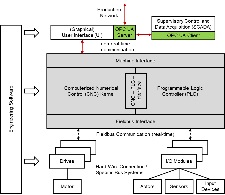
8.2 System Architecture
There are concepts for the system architecture of an OPC UA based CNC data interface illustrated in Figure 20 and Figure 21. Both enable to provide and realize the information model described in this document. However it has to be considered that there are OPC UA specific mechanisms used by this information model that need a closely coupled link to the CNC, e.g. the alarm and event mechanisms or the file access intents.
8.3 Namespace Metadata
Table 33 defines the namespace metadata for this specification. The Object is used to provide version information for the namespace and an indication about static Nodes. Static Nodes are identical for all Attributes in all Servers, including the Value Attribute. See OPC 10000-5 for more details.
The information is provided as Object of type NamespaceMetadataType. This Object is a component of the Namespaces Object that is part of the Server Object. The NamespaceMetadataType ObjectType and its Properties are defined in OPC 10000-5.
The version information is also provided as part of the ModelTableEntry in the UANodeSet XML file. The UANodeSet XML schema is defined in OPC 10000-6.
| Attribute | Value | |||
| BrowseName | http://opcfoundation.org/UA/CNC/ | |||
| References | BrowseName | DataType | Value | |
|---|---|---|---|---|
| HasProperty | NamespaceUri | String | http://opcfoundation.org/UA/CNC/ | |
| HasProperty | NamespaceVersion | String | 1.00 | |
| HasProperty | NamespacePublicationDate | DateTime | 2017-xx-xx | |
| HasProperty | IsNamespaceSubset | Boolean | False | |
| HasProperty | StaticNodeIdTypes | IdType[] | {Numeric} | |
| HasProperty | StaticNumericNodeIdRange | NumericRange[] | Null | |
| HasProperty | StaticStringNodeIdPattern | String | Null | |
8.4 OPC UA Conformance Units and Profiles
This chapter defines the corresponding Profiles and Conformance Units for the "OPC UA Information Model for CNC Systems". Profiles are named groupings of Conformance Units. Facets are Profiles that will be combined with other Profiles to define the complete functionality of an OPC UA Server or Client. The following tables specify the facets available for Servers that implement the "OPC UA Information Model for CNC systems" companion standard.
Table 34 describes the Conformance Units included in the minimum needed facet. It allows to realize the base mechanisms of this "OPC UA Information Model for CNC systems" companion standard, data access of simple and complex data types and the alarm and event mechanisms.
| Conformance Unit | Description | Optional/ Mandatory |
| CNC Basis Data Access | Support the interface structure and the access of all data provided by the CNC data interface. | Mandatory |
| CNC Alarming | Support the alarm and event types defined by this "OPC UA Information Model for CNC systems" companion standard. | Mandatory |
Table 35 defines a facet for the support of model change events to inform about model changes, e.g. change of the channel affiliation of a CNC axis.
| Conformance Unit | Description | Optional/ Mandatory |
| CNC Model Change | Support the model change event mechanisms proposed by this "OPC UA Information Model for CNC systems" companion standard. | Mandatory |
Table 36 defines a facet for the support of access of a CNC file system.
| Conformance Unit | Description | Optional/ Mandatory |
| CNC File Access | Support the file access mechanisms proposed by this "OPC UA Information Model for CNC systems" companion standard. | Mandatory |
Table 37 defines a facet available for Clients that implement the "OPC UA Information Model for CNC systems" standard.
| Conformance Unit | Description | Optional/ Mandatory |
| CNC Client Information Model | Consume objects that conform to the types specified in the "OPC UA Information Model for CNC systems" | Mandatory |
| CNC Client Model Change | Consume the model change event proposed in the "OPC UA Information Model for CNC systems". | Optional |
| CNC Client File Access | Transfer files bidirectional between the OPC UA Server of a CNC supporting this "OPC UA Information Model for CNC systems" and an OPC UA Client. | Optional |
8.5 Handling of OPC UA namespaces
Namespaces are used by OPC UA to create unique identifiers across different naming authorities. The NodeId and BrowseName Attributes are identifiers. A Node in the UA Address Space is unambiguously identified using a NodeId. Unlike NodeIds, the BrowseName cannot be used to unambiguously identify a Node. Different Nodes may have the same BrowseName. They are used to build a browse path between two Nodes or to define a standard Property.
Servers may often choose to use the same namespace for the NodeId and the BrowseName. However, if they want to provide a standard Property, its BrowseName shall have the namespace of the standards body although the namespace of the NodeId reflects something else, for example the EngineeringUnits Property. All NodeIds of nodes not defined in this specification shall not use the standard namespaces.
Table 38 provides a list of mandatory and optional namespaces used in an OPC UA Server of a CNC system.
| Namespace | Description | Use |
| http://opcfoundation.org/UA/ | Namespace for NodeIds and BrowsNames defined in the OPC UA specification. This namespace shall have namespace index 0. | Mandatory |
| Local Server URI | Namespace for Nodes defined in the local Server. This may include types and instances used in a device represented by the Server. This namespace shall have namespace index 1. | Mandatory |
| http://opcfoundation.org/UA/CNC/ | Namespace for NodeIds and BrowsNames defined in this specification. The namespace index is Server specific. | Mandatory |
Table 39 provides a list of namespaces and their index used for BrowseNames in this specification. The default namespace of this specification is not listed since all BrowseNames without prefix use this default namespace.
| Namespace | Namespace Index | Example |
| http://opcfoundation.org/UA/ | 0 | 0:EngineeringUnits |
Annex A (normative): Namespaces and Mappings
A.1 Namespace and identifiers for OPC UA Information Model for CNC Systems
This appendix defines the numeric identifiers for all of the numeric NodeIds defined in this standard. The identifiers are specified in a CSV file with the following syntax:
<SymbolName>, <Identifier>, <NodeClass>Where the SymbolName is either the BrowseName of a Type Node or the BrowsePath for an Instance Node that appears in the specification and the Identifier is the numeric value for the NodeId.
The BrowsePath for an Instance Node is constructed by appending the BrowseName of the instance Node to the BrowseName for the containing instance or type. An underscore character is used to separate each BrowseName in the path. Let's take for example, the CncInterfaceType ObjectType Node which has the Version Property. The Name for the Version InstanceDeclaration is: CncInterfaceType_Version.
The NamespaceUri for all NodeIds defined here is http://opcfoundation.org/UA/CNC/
The CSV released with this version of the standard can be found here:
http://www.opcfoundation.org/UA/CNC/1.0/NodeIds.csv
A computer processible version of the complete Information Model defined in this standard is also provided. It follows the XML Information Model schema syntax defined in OPC 10000-6.
The Information Model Schema released with this version of the standard can be found here:
http://www.opcfoundation.org/UA/CNC/1.0/Opc.Ua.CNC.NodeSet.xml
A.2 Profile URIs for OPC UA Information Model for CNC Systems
Table 40 defines the Profile URIs for the "OPC UA Information Model for CNC Systems" companion standard.
| Profile | Profile URI |
| CNC Base Data Interface Server Facet Definition | http://opcfoundation.org/UA/CNC/Profile/Server/BaseDataInterface |
| CNC Model Change Server Facet Definition | http://opcfoundation.org/UA/CNC/Profile/Server/ModelChange |
| CNC FileAccess Server Facet Definition | http://opcfoundation.org/UA/CNC/Profile/Server/FileAccess |
| CNC Data Interface Client Facet | http://opcfoundation.org/UA/CNC/Profile/Client/DataInterface |
Agreement of Use
COPYRIGHT RESTRICTIONS
This document is provided "as is" by the OPC Foundation and the VDW.
Right of use for the Mapping Document is restricted to the Mapping Document.
Right of use for the Mapping Document will be granted without cost.
The Mapping Document may be distributed through computer systems, printed or copied as long as the content remains unchanged and the document is not modified.
OPC Foundation and VDW do not guarantee usability for any purpose and shall not be made liable for any case using the content of this document.
The user of the document agrees to indemnify OPC Foundation and VDW and their officers, directors and agents harmless from all demands, claims, actions, losses, damages (including damages from personal injuries), costs and expenses (including attorneys' fees) which are in any way related to activities associated with its use of content from the Mapping Document.
The document shall not be used in conjunction with company advertising, shall not be sold or licensed to any party.
The intellectual property and copyright is solely owned by the OPC Foundation and VDW.
PATENTS
The attention of adopters is directed to the possibility that compliance with or adoption of OPC or VDW concepts and specifications may require use of an invention covered by patent rights. OPC Foundation or VDW shall not be responsible for identifying patents for which a license may be required by any OPC or VDW concept and specification, or for conducting legal inquiries into the legal validity or scope of those patents that are brought to its attention. OPC or VDW concepts and specifications are prospective and advisory only. Prospective users are responsible for protecting themselves against liability for infringement of patents.
WARRANTY AND LIABILITY DISCLAIMERS
WHILE THIS PUBLICATION IS BELIEVED TO BE ACCURATE, IT IS PROVIDED "AS IS" AND MAY CONTAIN ERRORS OR MISPRINTS. THE OPC FOUDATION NOR VDW MAKES NO WARRANTY OF ANY KIND, EXPRESSED OR IMPLIED, WITH REGARD TO THIS PUBLICATION, INCLUDING BUT NOT LIMITED TO ANY WARRANTY OF TITLE OR OWNERSHIP, IMPLIED WARRANTY OF MERCHANTABILITY OR WARRANTY OF FITNESS FOR A PARTICULAR PURPOSE OR USE. IN NO EVENT SHALL THE OPC FOUNDATION NOR VDW BE LIABLE FOR ERRORS CONTAINED HEREIN OR FOR DIRECT, INDIRECT, INCIDENTAL, SPECIAL, CONSEQUENTIAL, RELIANCE OR COVER DAMAGES, INCLUDING LOSS OF PROFITS, REVENUE, DATA OR USE, INCURRED BY ANY USER OR ANY THIRD PARTY IN CONNECTION WITH THE FURNISHING, PERFORMANCE, OR USE OF THIS MATERIAL, EVEN IF ADVISED OF THE POSSIBILITY OF SUCH DAMAGES.
The entire risk as to the quality and performance of software developed using this specification is borne by you.
RESTRICTED RIGHTS LEGEND
This Specification is provided with Restricted Rights. Use, duplication or disclosure by the U.S. government is subject to restrictions as set forth in (a) this Agreement pursuant to DFARs 227.7202-3(a); (b) subparagraph (c)(1)(i) of the Rights in Technical Data and Computer Software clause at DFARs 252.227-7013; or (c) the Commercial Computer Software Restricted Rights clause at FAR 52.227-19 subdivision (c)(1) and (2), as applicable. Contractor / manufacturer are the OPC Foundation, 16101 N. 82nd Street, Suite 3B, Scottsdale, AZ, 85260-1830
COMPLIANCE
The combination of VDW and OPC Foundation shall at all times be the sole entities that may authorize developers, suppliers and sellers of hardware and software to use certification marks, trademarks or other special designations to indicate compliance with these materials as specified within this document. Products developed using this specification may claim compliance or conformance with this specification if and only if the software satisfactorily meets the certification requirements set by VDW or the OPC Foundation. Products that do not meet these requirements may claim only that the product was based on this specification and must not claim compliance or conformance with this specification.
Trademarks
Most computer and software brand names have trademarks or registered trademarks. The individual trademarks have not been listed here.
GENERAL PROVISIONS
Should any provision of this Agreement be held to be void, invalid, unenforceable or illegal by a court, the validity and enforceability of the other provisions shall not be affected thereby.
This Agreement shall be governed by and construed under the laws of Germany.
This Agreement embodies the entire understanding between the parties with respect to, and supersedes any prior understanding or agreement (oral or written) relating to, this specification.