
6 OPC UA ObjectTypes
6.1 CncInterfaceType
6.1.1 General
This OPC UA ObjectType represents a CNC Interface. CncInterfaceType is the entry point to the CNC data interface. It is mainly used for structuring the interface. But additionally this ObjectType holds Properties characterizing this interface (Version, VendorName etc.), as well as References to the specified EventTypes. There are two different types of events generated by an instance of CncInterfaceType: events of type CncMessageType and of type CncAlarmType.
Events of type CncAlarmType are used to provide CNC error messages.
Events of type CncMessageType are used to provide messages that are not an alarm but a non-critical information, e.g. a user created message out of the CNC part program.
CncInterfaceType is formally defined in Table 7.
6.1.2 ObjectType Definition
The CncInterfaceType is formally defined in Table 7.
| Attribute | Value | ||||
| BrowseName | CncInterfaceType | ||||
| IsAbstract | False | ||||
| References | NodeClass | BrowseName | DataType | TypeDefinition | ModellingRule |
|---|---|---|---|---|---|
| Inherit the components of the BaseObjectType | |||||
| GeneratesEvent | ObjectType | CncAlarmType | |||
| GeneratesEvent | ObjectType | CncMessageType | |||
| HasComponent | Object | CncAxisList | CncAxisListType | Mandatory | |
| HasComponent | Object | CncChannelList | CncChannelListType | Mandatory | |
| HasComponent | Object | CncSpindleList | CncSpindleListType | Mandatory | |
| HasComponent | Object | FileSystem | FileDirectoryType | Optional | |
| HasProperty | Variable | CncTypeName | String | PropertyType | Optional |
| HasProperty | Variable | Fix | String | PropertyType | Optional |
| HasProperty | Variable | VendorName | String | PropertyType | Mandatory |
| HasProperty | Variable | VendorRevision | String | PropertyType | Mandatory |
| HasProperty | Variable | Version | String | PropertyType | Mandatory |
6.1.3 ObjectType Description
6.1.3.1 CncAlarm
CncInterfaceType may generate events of type CncAlarmType to provide error messages.
6.1.3.2 CncMessage
CncInterfaceType may generate events of type CncMessageType to provide general CNC information messages.
6.1.3.3 CncAxisList
Group of CNC axis objects.
Adds child <CncAxis>.
6.1.3.4 CncChannelList
Group of CNC channel objects.
Adds child <CncChannel>.
6.1.3.5 CncSpindleList
Group of CNC spindle objects.
Adds child <CncSpindle>.
6.1.3.6 FileSystem
Entry point to system's file directory.
6.1.3.7 CncTypeName
Type or model name of the CNC that is represented by Information Model.
6.1.3.8 Fix
Manufacturer specific version of CNC interface considering changes in implementation (Bug Fix).
6.1.3.9 VendorName
Name of CNC system vendor. Format and content may be chosen by vendor.
6.1.3.10 VendorRevision
Vendor revision of CNC interface. Format and content may be chosen by vendor.
6.1.3.11 Version
CNC interface version - corresponds to the version of this OPC UA companion standard and has to be presented in the same format (e.g. 1.03) so that an OPC UA Client can evaluate the version programmatically.
6.2 CncAxisListType
6.2.1 General
This OPC UA ObjectType serves as a structuring element. Objects of type CncAxisListType comprise all axes that are subordinated to a CncInterface. It is formally defined in Table 8.
Objects of type CncAxisListType may generate events of type GeneralModelChangeEventType. These events are used to inform about changes in the Information Model related to an instance of CncAxisListType.
6.2.2 ObjectType Definition
The CncAxisListType is formally defined in Table 8.
| Attribute | Value | ||||
| BrowseName | CncAxisListType | ||||
| IsAbstract | False | ||||
| References | NodeClass | BrowseName | DataType | TypeDefinition | ModellingRule |
|---|---|---|---|---|---|
| Inherit the components of the BaseObjectType | |||||
| GeneratesEvent | ObjectType | GeneralModelChangeEventType | |||
| HasProperty | Variable | 0:NodeVersion | String | PropertyType | Optional |
| HasComponent | Object | <CncAxis> | CncAxisType | OptionalPlaceholder | |
6.2.3 ObjectType Description
6.2.3.1 GeneralModelChangeEvent
CncAxisListType may generate events of type GeneralModelChangeEventType defined in OPC 10000-3 to inform Clients when CncAxis Objects have been added or removed from a CncAcisListType instance.
6.2.3.2 NodeVersion
The optional Property NodeVersion shall be present if the Server emits GeneralModelChangeEvents for the Object of type CncAxisListType. The NodeVersion Property and the relation to GeneralModelChangeEvents are defined in OPC 10000-3.
6.2.3.3 CncAxis
CNC axis object.
6.3 CncSpindleListType
6.3.1 General
This OPC UA ObjectType serves as a structuring element. Objects of type CncSpindleListType comprise all spindles that are subordinated to a CncInterface. It is formally defined in Table 9.
Objects of type CncSpindleListType may generate events of type GeneralModelChangeEventType. These events are used to inform about changes in the Information Model related to an instance of CncSpindleListType.
6.3.2 ObjectType Definition
The CncSpindleListType is formally defined in Table 9.
| Attribute | Value | ||||
| BrowseName | CncSpindleListType | ||||
| IsAbstract | False | ||||
| References | NodeClass | BrowseName | DataType | TypeDefinition | ModellingRule |
|---|---|---|---|---|---|
| Inherit the components of the BaseObjectType | |||||
| GeneratesEvent | ObjectType | GeneralModelChangeEventType | |||
| HasProperty | Variable | 0:NodeVersion | String | PropertyType | Optional |
| HasComponent | Object | <CncSpindle> | CncSpindleType | OptionalPlaceholder | |
6.3.3 ObjectType Description
6.3.3.1 GeneralModelChangeEvent
CncSpindleListType may generate events of type GeneralModelChangeEventType defined in OPC 10000-3 to inform Clients when CncSpindle Objects have been added or removed from a CncSpindleListType instance.
6.3.3.2 NodeVersion
The optional Property NodeVersion shall be present if the Server emits GeneralModelChangeEvents for the Object of type CncSpindleListType. The NodeVersion Property and the relation to GeneralModelChangeEvents are defined in OPC 10000-3.
6.3.3.3 CncSpindle
CNC spindle object.
6.4 CncChannelListType
6.4.1 General
This OPC UA ObjectType serves as a structuring element. Objects of type CncChannelListType comprise all channels that are subordinated to a CncInterface. It is formally defined in Table 10.
Objects of type CncChannelListType may generate events of type GeneralModelChangeEventType. These events are used to inform about changes in the Information Model related to an instance of CncChannelListType.
6.4.2 ObjectType Definition
The CncChannelListType is formally defined in Table 10.
| Attribute | Value | ||||
| BrowseName | CncChannelListType | ||||
| IsAbstract | False | ||||
| References | NodeClass | BrowseName | DataType | TypeDefinition | ModellingRule |
|---|---|---|---|---|---|
| Inherit the components of the BaseObjectType | |||||
| GeneratesEvent | ObjectType | GeneralModelChangeEventType | |||
| HasProperty | Variable | 0:NodeVersion | String | PropertyType | Optional |
| HasComponent | Object | <CncChannel> | CncChannelType | OptionalPlaceholder | |
6.4.3 ObjectType Description
6.4.3.1 GeneralModelChangeEvent
CncChannelListType may generate events of type GeneralModelChangeEventType defined in OPC 10000-3 to inform Clients when CncChannel Objects have been added or removed from a CncChannelListType instance.
6.4.3.2 NodeVersion
The optional Property NodeVersion shall be present if the Server emits GeneralModelChangeEvents for the Object of type CncChannelListType. The NodeVersion Property and the relation to GeneralModelChangeEvents are defined in OPC 10000-3.
6.4.3.3 CncChannel
CNC channel object.
6.5 CncComponentType
6.5.1 General
This OPC UA ObjectType represents a CNC component. A CNC component may be a hardware or software component of a CNC system (e.g. an axis or a channel). CncComponentType serves as a basis for all components that are accessible through this interface, e.g. CncDriveType or CncChannelType are derived from this ObjectType, and therefore is an abstract type. CncComponentType holds elements that are common for all components of a CNC system. It is formally defined in Table 11.
6.5.2 ObjectType Definition
The CncComponentType is formally defined in Table 11.
| Attribute | Value | ||||
| BrowseName | CncComponentType | ||||
| IsAbstract | True | ||||
| References | NodeClass | BrowseName | DataType | TypeDefinition | ModellingRule |
|---|---|---|---|---|---|
| Inherit the components of the BaseObjectType | |||||
6.5.3 ObjectType Description
There are currently no components subordinated to this ObjectType. However, this Subtype may have components in the future or can be used for manufacturer specific rules or components.
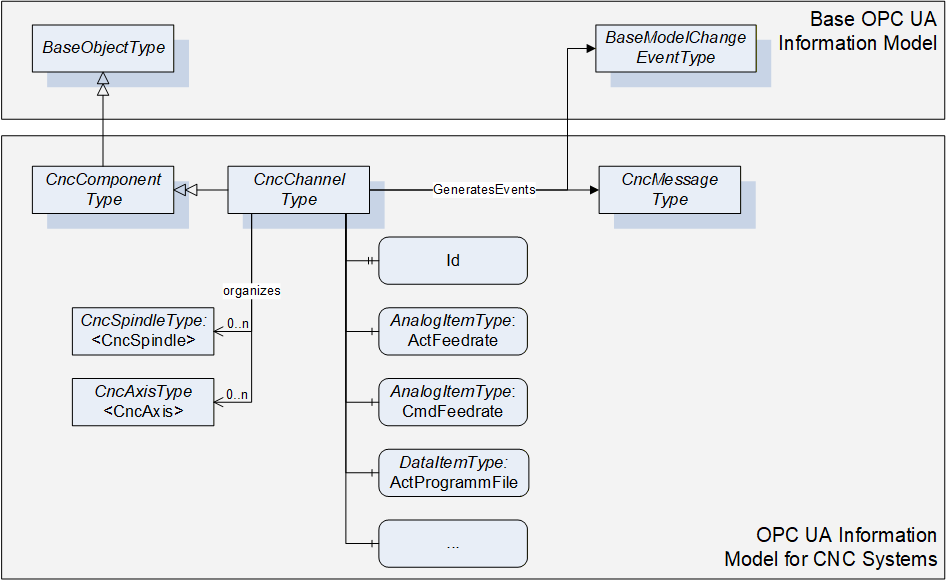
6.6 CncChannelType
6.6.1 General
This OPC UA ObjectType represents a CNC channel with all its necessary elements. All Objects of Type CncChannelType are listed in the CncChannelList of the CncInterface Object.
Additionally to data that is relevant for a CNC Channel, CncChannelType organizes Objects of type CncAxisType and CncSpindleType. That is to indicate which components are currently administrated by this channel.
Objects of CncChannelType may generate two kinds of events: Events of type CncMessageType and of type GeneralModelChangeEventType.
Events of Type CncMessageType are used to provide channel specific messages that are not an alarm but an uncritical information, e.g. a user created message out of the CNC part program.
Events of type GeneralModelChangeEventType are used to inform about changes in the Information Model. Examples for the need of a model change event:
A CNC channel can administrate a different set of components during runtime, meaning that an axis or a spindle can change its channel affiliation during runtime of the CNC system; for instance this may be the case if one spindle is used in combination with different axis groups.
Spindles allow different kind of operation modes, for instance a spindle can change its mode of operation from speed to position control and therefore has to be represented once as spindle (CncSpindleType) and once as rotational axis (CncAxisType).
Instances of CncChannelType provide the position of the channel's tool center point in different coordinate systems. Therefore, the following definitions have to be considered:
Tool carrier zero point: The tool carrier zero point is a reference point on the tool carrier as illustrated in Figure 10.
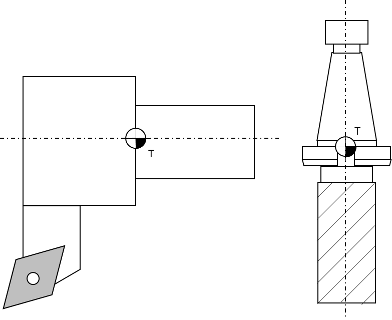
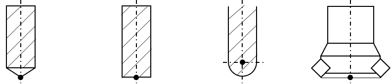
Tool center point: The tool center point of tools for milling operations is usually the intersection of the tool centerline and the lowest positioned cutting tip (edge). For turning operations the tool center point is an imaginary tool point of the cutting insert, because most tools have a cutting edge with a built-in radius. The tool center point of point-to-point tools, such as drills, is the extreme tip of the tool, as measured along the Z axis. Figure 11 and Figure 12 illustrate some common tool center points.

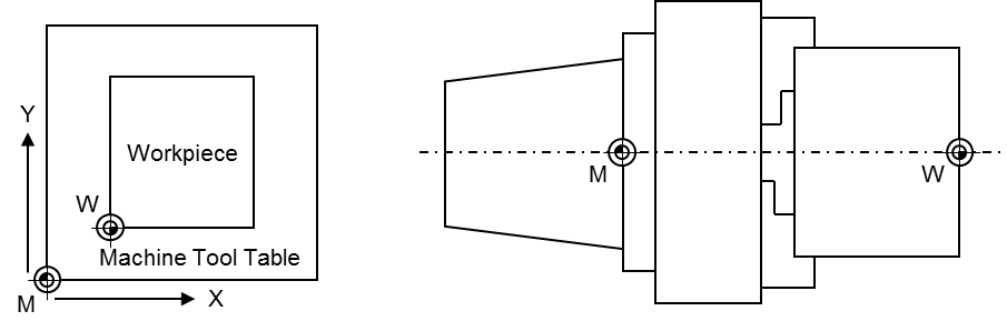
Machine tool coordinate systems: This companion standard refers to two coordinate systems (see Figure 13 for illustration):
Base coordinate system: The base coordinate system (BCS) is a coordinate system defined by the machine tool manufacturer. It has its origin within the machine tool's zero point M.
Workpiece coordinate system: The workpiece coordinate system (WCS) is a user defined coordinate system and allows considering the clamping position and orientation of a workpiece. It has its origin within the workpiece zero point W.
The coordinate systems are built based on the right-hand-rule, illustrated in Figure 14.
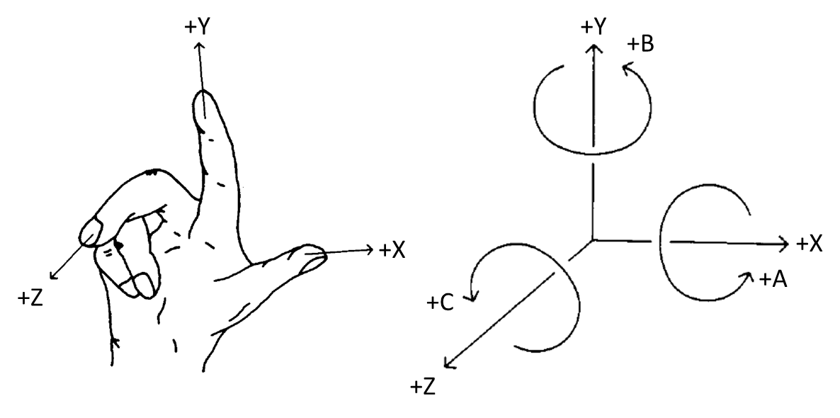
Figure 15 shows an overview for the CncChannelType. It is formally defined in Table 12.
6.6.2 ObjectType Definition
The CncChannelType is formally defined in Table 12.
| Attribute | Value | ||||
| BrowseName | CncChannelType | ||||
| IsAbstract | False | ||||
| References | NodeClass | BrowseName | DataType | TypeDefinition | ModellingRule |
|---|---|---|---|---|---|
| Inherit the components of the CncComponentType | |||||
| GeneratesEvent | ObjectType | CncMessageType | |||
| GeneratesEvent | ObjectType | GeneralModel ChangeEventType | |||
| HasProperty | Variable | 0:NodeVersion | String | PropertyType | Optional |
| HasComponent | Object | <CncAxis> | CncAxisType | OptionalPlaceholder | |
| HasComponent | Object | <CncSpindle> | CncSpindleType | OptionalPlaceholder | |
| HasComponent | Variable | ActFeedrate | Double | AnalogItemType | Mandatory |
| HasComponent | Variable | ActGFunctions | UInt32[] | DataItemType | Mandatory |
| HasComponent | Variable | ActJogIncrement | Double | AnalogItemType | Mandatory |
| HasComponent | Variable | ActMainProgramFile | String | DataItemType | Mandatory |
| HasComponent | Variable | ActMainProgramFileOffset | UInt32 | DataItemType | Optional |
| HasComponent | Variable | ActMainProgramLine | String | DataItemType | Optional |
| HasComponent | Variable | ActMainProgramName | String | DataItemType | Mandatory |
| HasComponent | Variable | ActMFunctions | UInt32[] | DataItemType | Mandatory |
| HasComponent | Variable | ActModalOffsetFunction | UInt32 | DataItemType | Mandatory |
| HasComponent | Variable | ActOperationMode | CncOperationMode | DataItemType | Mandatory |
| HasComponent | Variable | ActOverride | Double | AnalogItemType | Mandatory |
| HasComponent | Variable | ActProgramBlock | String[] | DataItemType | Mandatory |
| HasComponent | Variable | ActProgramFile | String | DataItemType | Mandatory |
| HasComponent | Variable | ActProgramFileOffset | UInt32 | DataItemType | Optional |
| HasComponent | Variable | ActProgramLine | String | DataItemType | Optional |
| HasComponent | Variable | ActProgramName | String | DataItemType | Mandatory |
| HasComponent | Variable | ActProgramStatus | CncChannelProgStatus | DataItemType | Mandatory |
| HasComponent | Variable | ActStatus | CncChannelStatus | DataItemType | Mandatory |
| HasComponent | Variable | BlockMode | Boolean | DataItemType | Mandatory |
| HasComponent | Variable | CmdFeedrate | Double | AnalogItemType | Mandatory |
| HasComponent | Variable | CmdOverride | Double | AnalogItemType | Mandatory |
| HasComponent | Variable | DryRunFeed | Double | AnalogItemType | Mandatory |
| HasComponent | Variable | FeedHold | Boolean | DataItemType | Mandatory |
| HasProperty | Variable | Id | UInt32 | PropertyType | Mandatory |
| HasComponent | Variable | PosTcpBcsA | CncPositionDataType | CncPosition VariableType | Mandatory |
| HasComponent | Variable | PosTcpBcsB | CncPositionDataType | CncPosition VariableType | Mandatory |
| HasComponent | Variable | PosTcpBcsC | CncPositionDataType | CncPosition VariableType | Mandatory |
| HasComponent | Variable | PosTcpBcsX | CncPositionDataType | CncPosition VariableType | Mandatory |
| HasComponent | Variable | PosTcpBcsY | CncPositionDataType | CncPosition VariableType | Mandatory |
| HasComponent | Variable | PosTcpBcsZ | CncPositionDataType | CncPosition VariableType | Mandatory |
| HasComponent | Variable | PosTcpWcsA | CncPositionDataType | CncPosition VariableType | Mandatory |
| HasComponent | Variable | PosTcpWcsB | CncPositionDataType | CncPosition VariableType | Mandatory |
| HasComponent | Variable | PosTcpWcsC | CncPositionDataType | CncPosition VariableType | Mandatory |
| HasComponent | Variable | PosTcpWcsX | CncPositionDataType | CncPosition VariableType | Mandatory |
| HasComponent | Variable | PosTcpWcsY | CncPositionDataType | CncPosition VariableType | Mandatory |
| HasComponent | Variable | PosTcpWcsZ | CncPositionDataType | CncPosition VariableType | Mandatory |
| HasComponent | Variable | ToolId | UInt32 | DataItemType | Mandatory |
6.6.3 ObjectType Description
6.6.3.1 CncMessage
CncChannelType may generate events of type CncMessageType to provide channel specific information messages (for instance triggered out of CNC part program).
6.6.3.2 GeneralModelChangeEvent
CncChannelType may generate events of type GeneralModelChangeEventType defined in OPC 10000-3 to inform Clients when CncSpindle or CncAxis Objects have been added or removed from a CncChannelType instance.
6.6.3.3 NodeVersion
The optional Property NodeVersion shall be present if the Server emits GeneralModelChangeEvents for the Object of type CncChannelType. The NodeVersion Property and the relation to GeneralModelChangeEvents are defined in OPC 10000-3.
6.6.3.4 CncAxis
CNC axis object.
6.6.3.5 CncSpindle
CNC spindle object.
6.6.3.6 ActFeedrate
Feedrate actual value.
6.6.3.7 ActJogIncrement
Active JOG increment, i.e. a position increment that is executed with each user jog command. Usually, there are predefined increments given (1/10, 1/100, 1/1000 position increment in the selected physical unit), but a continuous jog mode and a jog mode with variable increment are possible, too. A continuous jog mode is indicated with a jog increment value of -1, all other jog increments are given as real increments in the appropriate units.
6.6.3.8 ActGFunctions
Array of active G functions; there can be several G functions active at a time (modal and non-modal G functions).
6.6.3.9 ActMainProgramFile
Path of active CNC main program.
6.6.3.10 ActMainProgramFileOffset
File offset of active CNC main program file (corresponds to the number of line feeds).
6.6.3.11 ActMainProgramName
Name of active CNC main program.
6.6.3.12 ActMainProgramLine
Line number of active CNC main program (usually defined as N<Number>).
6.6.3.13 ActMFunctions
Array of active M functions: there can be several M functions active at a time (modal and non-modal M functions).
6.6.3.14 ActModalOffsetFunction
Active zero offset function (usually G54, G55, G56 or G57; G53 repeals zero offsets).
6.6.3.15 ActOperationMode
Channel's active mode of operation. See 7.2.6 for further description of possible states.
6.6.3.16 ActOverride
Axis override actual value.
6.6.3.17 ActProgramBlock
Block of lines containing the previous, actual and subsequent lines of a CNC part program.
6.6.3.18 ActProgramFile
Path of active CNC part program file (main or subprogram).
6.6.3.19 ActProgramFileOffset
File offset of active CNC part program file (main or subprogram).
6.6.3.20 ActProgramLine
Line number of active CNC part program (main or subprogram).
6.6.3.21 ActProgramName
Name of active CNC part program (main or subprogram).
6.6.3.22 ActProgramStatus
Active channel program status. See 7.2.5 for further description of possible states.
6.6.3.23 ActStatus
Active status of channel. See 7.2.4 for further description of possible states.
6.6.3.24 BlockMode
Block mode status (true in case of block mode is active, else false). With block mode active, individual program blocks are processed one by one. Each step has to be triggered by the operator.
6.6.3.25 CmdFeedrate
Feedrate setpoint value.
6.6.3.26 CmdOverride
Override setpoint value.
6.6.3.27 DryRunFeed
Test federate.
6.6.3.28 FeedHold
Feed status (true in case of feed hold active, else false).
6.6.3.29 Id
Unique numeric channel identifier.
6.6.3.30 PosTcpBcsA
Actual position of the tool center point in machine's Cartesian base coordinate system. The tool center point is the reference point on a tool how it is considered by the CNC's tool compensation function. If there is no tool present, the tool center point is the tool carrier zero point.
6.6.3.31 PosTcpBcsB
Actual position of the tool center point in machine's Cartesian base coordinate system. The tool center point is the reference point on a tool how it is considered by the CNC's tool compensation function. If there is no tool present, the tool center point is the tool carrier zero point.
6.6.3.32 PosTcpBcsC
Actual position of the tool center point in machine's Cartesian base coordinate system. The tool center point is the reference point on a tool how it is considered by the CNC's tool compensation function. If there is no tool present, the tool center point is the tool carrier zero point.
6.6.3.33 PosTcpBcsX
Actual position of the tool center point in machine's Cartesian base coordinate system. The tool center point is the reference point on a tool how it is considered by the CNC's tool compensation function. If there is no tool present, the tool center point is the tool carrier zero point.
6.6.3.34 PosTcpBcsY
Actual position of the tool center point in machine's Cartesian base coordinate system. The tool center point is the reference point on a tool how it is considered by the CNC's tool compensation function. If there is no tool present, the tool center point is the tool carrier zero point.
6.6.3.35 PosTcpBcsZ
Actual position of the tool center point in machine's Cartesian base coordinate system. The tool center point is the reference point on a tool how it is considered by the CNC's tool compensation function. If there is no tool present, the tool center point is the tool carrier zero point.
6.6.3.36 PosTcpWcsA
Actual position of the tool center point in machine's Cartesian workpiece coordinate system. The tool center point is the reference point on a tool how it is considered by the CNC's tool compensation function. If there is no tool present, the tool center point is the tool carrier zero point. Hence, the position corresponds to the position programmed in the CNC part program.
6.6.3.37 PosTcpWcsB
Actual position of the tool center point in machine's Cartesian workpiece coordinate system. The tool center point is the reference point on a tool how it is considered by the CNC's tool compensation function. If there is no tool present, the tool center point is the tool carrier zero point. Hence, the position corresponds to the position programmed in the CNC part program.
6.6.3.38 PosTcpWcsC
Actual position of the tool center point in machine's Cartesian workpiece coordinate system. The tool center point is the reference point on a tool how it is considered by the CNC's tool compensation function. If there is no tool present, the tool center point is the tool carrier zero point. Hence, the position corresponds to the position programmed in the CNC part program.
6.6.3.39 PosTcpWcsX
Actual position of the tool center point in machine's Cartesian workpiece coordinate system. The tool center point is the reference point on a tool how it is considered by the CNC's tool compensation function. If there is no tool present, the tool center point is the tool carrier zero point. Hence, the position corresponds to the position programmed in the CNC part program.
6.6.3.40 PosTcpWcsY
Actual position of the tool center point in machine's Cartesian workpiece coordinate system. The tool center point is the reference point on a tool how it is considered by the CNC's tool compensation function. If there is no tool present, the tool center point is the tool carrier zero point. Hence, the position corresponds to the position programmed in the CNC part program.
6.6.3.41 PosTcpWcsZ
Actual position of the tool center point in machine's Cartesian workpiece coordinate system. The tool center point is the reference point on a tool how it is considered by the CNC's tool compensation function. If there is no tool present, the tool center point is the tool carrier zero point. Hence, the position corresponds to the position programmed in the CNC part program.
6.6.3.42 ToolId
ID of active tool that has been selected (e.g. calling "T1" in the CNC part program). Returns an empty string, if no tool is present.
6.7 CncDriveType
6.7.1 General
This OPC UA ObjectType represents a CNC drive. It serves as a basis for all drive component Objects that are accessible through this interface, e.g. CncAxisType and CncSpindleType are derived from this ObjectType, and therefore is an abstract type. CncDriveType holds elements that are common for all drive Objects of a CNC system. It is formally defined in Table 13.
6.7.2 ObjectType Definition
The CncDriveType is formally defined in Table 13.
| Attribute | Value | ||||
| BrowseName | CncDriveType | ||||
| IsAbstract | True | ||||
| References | NodeClass | BrowseName | DataType | TypeDefinition | ModellingRule |
|---|---|---|---|---|---|
| Inherit the components of the CncComponentType | |||||
| HasComponent | Variable | ActChannel | NodeId | DataItemType | Mandatory |
| HasComponent | Variable | ActLoad | Double | AnalogItemType | Mandatory |
| HasComponent | Variable | ActPower | Double | AnalogItemType | Mandatory |
| HasComponent | Variable | ActTorque | Double | AnalogItemType | Mandatory |
| HasComponent | Variable | CmdTorque | Double | AnalogItemType | Mandatory |
| HasComponent | Variable | IsInactive | Boolean | DataItemType | Mandatory |
| HasComponent | Variable | IsVirtual | Boolean | DataItemType | Mandatory |
6.7.3 ObjectType Description
6.7.3.1 ActChannel
NodeId of the channel object (CncChannelType) that administrates this drive to expose drive's channel affiliation. ActChannel remains empty in case of drives without channel affiliation.
6.7.3.2 ActLoad
Drive load actual value.
6.7.3.3 ActPower
Drive power actual value.
6.7.3.4 ActTorque
Drive torque actual value.
6.7.3.5 CmdTorque
Drive torque setpoint value.
6.7.3.6 IsInactive
Drive inactive state (true in case of inactive drive, else false).
6.7.3.7 IsVirtual
Virtual axis (no hardware present; true in case of virtual axis, else false).
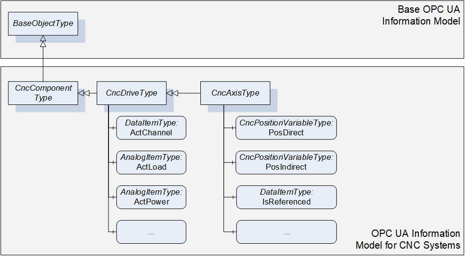
6.8 CncAxisType
6.8.1 General
This OPC UA ObjectType represents a CNC axis. CNC axes can be subordinated to channels. They can change channel affiliation during runtime. For that reasons Objects of type CncAxisType may be referenced by Objects of CncChannelType to inform about their current channel affiliation. At the same time all axis Objects of a CNC system must be subordinated to the CncAxisList regardless of their channel affiliation.
Figure 16 shows an overview for the CncAxisType. It is formally defined in Table 14.
6.8.2 ObjectType Definition
The CncAxisType is formally defined in Table 14.
| Attribute | Value | ||||
| BrowseName | CncAxisType | ||||
| IsAbstract | False | ||||
| References | NodeClass | BrowseName | DataType | TypeDefinition | ModellingRule |
|---|---|---|---|---|---|
| Inherit the components of the CncDriveType | |||||
| HasComponent | Variable | ActStatus | CncAxisStatus | DataItemType | Mandatory |
| HasComponent | Variable | IsReferenced | Boolean | DataItemType | Mandatory |
| HasComponent | Variable | IsRotational | Boolean | DataItemType | Mandatory |
| HasComponent | Variable | PosDirect | CncPositionDataType | CncPositionVariableType | Mandatory |
| HasComponent | Variable | PosIndirect | CncPositionDataType | CncPositionVariableType | Mandatory |
| HasComponent | Variable | ZeroOffset | Double | AnalogItemType | Mandatory |
6.8.3 ObjectType Description
6.8.3.1 ActStatus
Actual axis state.
6.8.3.2 IsReferenced
Axis reference state (true in case of successfully referenced axis, else false).
6.8.3.3 IsRotational
Axis type (true in case of rotational axis, in case of linear type or other false).
6.8.3.4 PosDirect
Axis position values referring to axis' direct measurement system.
6.8.3.5 PosIndirect
Axis position values referring to axis' indirect measurement system.
6.8.3.6 ZeroOffset
Active axis zero offset.
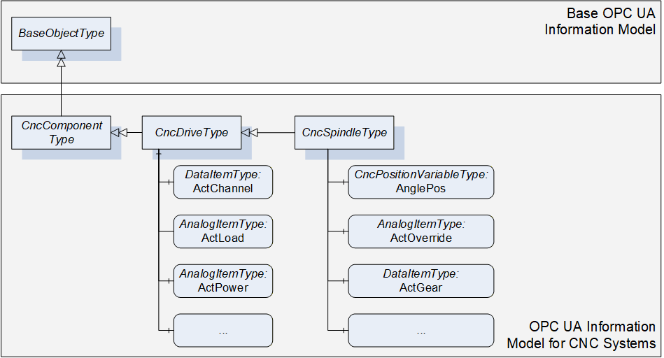
6.9 CncSpindleType
6.9.1 General
This OPC UA ObjectType represents a CNC spindle. CNC spindles can be subordinated to channels. They can change channel affiliation during runtime. For that reasons Objects of type CncSpindleType may be referenced by Objects of CncChannelType to inform about their current channel affiliation. At the same time all spindle Objects of a CNC system must be subordinated to the CncSpindleList regardless of their channel affiliation.
Figure 17 shows an overview for the CncSpindleType. It is formally defined in Table 15.
6.9.2 ObjectType Definition
The CncSpindleType is formally defined in Table 15.
| Attribute | Value | ||||
| BrowseName | CncSpindleType | ||||
| IsAbstract | False | ||||
| References | NodeClass | BrowseName | DataType | TypeDefinition | ModellingRule |
|---|---|---|---|---|---|
| Inherit the components of the CncDriveType | |||||
| HasComponent | Variable | ActGear | UInt32 | DataItemType | Mandatory |
| HasComponent | Variable | ActOverride | Double | AnalogItemType | Mandatory |
| HasComponent | Variable | ActSpeed | Double | AnalogItemType | Mandatory |
| HasComponent | Variable | ActStatus | CncSpindleStatus | DataItemType | Mandatory |
| HasComponent | Variable | ActTurnDirection | CncSpindleTurnDirection | DataItemType | Mandatory |
| HasComponent | Variable | AnglePos | CncPositionDataType | CncPositionVariableType | Mandatory |
| HasComponent | Variable | CmdGear | UInt32 | DataItemType | Mandatory |
| HasComponent | Variable | CmdOverride | Double | AnalogItemType | Mandatory |
| HasComponent | Variable | CmdSpeed | Double | AnalogItemType | Mandatory |
6.9.3 ObjectType Description
6.9.3.1 ActGear
Gear stage actual value.
6.9.3.2 ActOverride
Override actual value.
6.9.3.3 ActSpeed
Speed actual value
6.9.3.4 ActStatus
Actual spindle state.
6.9.3.5 ActTurnDirection
Turn direction actual value.
6.9.3.6 AnglePos
Spindle angular position values in case of interpolated (position controlled) spindle movement. Returns zeros in case of regular spindle operation (velocity controlled).
6.9.3.7 CmdGear
Gear stage setpoint value.
6.9.3.8 CmdOverride
Override setpoint value.
6.9.3.9 CmdSpeed
Speed setpoint value.
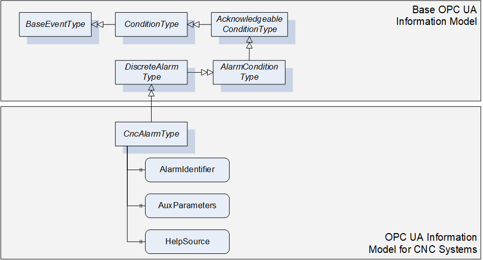
6.10 CncAlarmType
6.10.1 General
This OPC UA ObjectType must be used for reporting alarms of the CNC system. CncAlarmType must derived from DiscreteAlarmType.
The CncAlarmType extends the DiscreteAlarmType as followed:
HelpSource: To provide additional information to the alarm that is not covered by the message text (Message), the HelpSource parameter may be used. HelpSource is specified as BaseDataType. In case a URI is provided to reference additional information through an external source, the HelpSource has to be defined as String. In case a help text is provided, the data type shall be defined as LocalizedText.
AlarmIdentifier: CNC systems mostly provide a unique error number for all alarms. For this purpose AlarmIdentifier shall be used.
AuxParameters: CNC systems may want to provide information (e.g. textual or numerical) in dynamically changeable parts. As an example, this could be used to allow UIs to build their own alarm message by combining the different information fragments provided by this parameter.
As CncAlarmType is derived from the OPC UA DiscreteAlarmType, it shall be used in most parts as specified in OPC 10000-5. However, the following explanations give further instructions on how to specifically use the CncAlarmType.
| Severity is, as defined in OPC 10000-5, an indication of the urgency of the Event and ranges between a value of 1 and 1000. Regarding the severity levels, this OPC UA companion standard does not prescribe the severity levels in detail but expects the lowest alarm severity to be set to 1, the highest severity level to 1000. By this it is secured that the lowest and the highest alarm severity can be clearly identified without knowing about the precise realization of the severities. |
Example 1: If a CNC system uses three severity levels (e.g. Information, Warning, Error), the Information severity level is set to 1, the Warning severity level ranges between 2 and 999 and the Error severity level is set to 1000. Example 2: If a CNC system uses five severity levels (e.g. Information, Warning, Error, Critical, Fatal), the Information severity level is set to 1, the Warning severity level ranges from 2 to 333, the Error severity level ranges from 334 to 666, the Critical severity level ranges from 667 to 999 and the Fatal severity level is set to 1000. |
ConditionName provides alarm classification, so technically the textual alarm severity (e.g. Warning, Error, Fatal…).
SourceName and SourceNode: As described in chapter 4.1 several components constitute a CNC system. Contents of SourceName and SourceNode shall be as detailed as possible, meaning that if the alarm source and its name could explicitly be determined, SourceNode and SourceName should hold this information (e.g. SourceName is set to Channel1, SourceNode is referencing to the Channel1 Object). If it is not possible for a CNC system to provide this information in detail, the SourceName should provide the main component responsible for this alarm (e.g. CNC, PLC or even Channel), the SourceNode shall at least reference the root of the CNC machine interface (CncInterface Object).
AckedState may be set by default to true if no alarm acknowledge is required. If an alarm acknowledge is required AckedState is set to false and changes in case of the acknowledge action.
Retain and ActiveState shall be kept synchronized. Both parameters indicate that an alarm is still pending in case of true.
Figure 18 gives an overview on CncAlarmType. It is formally defined in Table 16.
6.10.2 ObjectType Definition
The CncAlarmType is formally defined in Table 16.
| Attribute | Value | ||||
| BrowseName | CncAlarmType | ||||
| IsAbstract | False | ||||
| References | NodeClass | BrowseName | DataType | TypeDefinition | ModellingRule |
|---|---|---|---|---|---|
| Inherit the components of the DiscreteAlarmType | |||||
| HasProperty | Variable | AlarmIdentifier | String | PropertyType | Mandatory |
| HasProperty | Variable | AuxParameters | String[] | PropertyType | Optional |
| HasProperty | Variable | HelpSource | String | PropertyType | Optional |
6.10.3 ObjectType Description
6.10.3.1 AlarmIdentifier
Unique alarm number.
6.10.3.2 AuxParameters
Array of auxiliary parameter for additional alarm description.
6.10.3.3 HelpSource
Additional information to message giving information on how to solve problem that caused the alarm.
6.11 CncMessageType
6.11.1 General
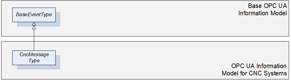
This OPC UA ObjectType may be used for reporting simple information messages that do not represent an alarm. For instance some CNC systems offer the possibility to trigger messages out of the CNC part program for the purpose of tracking. This would be an example for using the CncMessageType.
As CncMessageType is derived from the OPC UA BaseEventType, it shall be used in most parts as specified in OPC 10000-5.
Figure 19 gives an overview on CncMessageType. It is formally defined in Table 17.
6.11.2 ObjectType Definition
The CncMessageType is formally defined in Table 17.
| Attribute | Value | ||||
| BrowseName | CncMessageType | ||||
| IsAbstract | False | ||||
| References | NodeClass | BrowseName | DataType | TypeDefinition | ModellingRule |
|---|---|---|---|---|---|
| Inherit the components of the BaseEventType | |||||
6.11.3 ObjectType Description
There are currently no components subordinated to this ObjectType.
6.12 FileSystem
It is highly recommended to use FileDirectoryType for accessing the file system of CNC systems. Refer to OPC 10000-5 for detailed information.
Entry point to the CNC file system is FileSystem attached to the Standard UA Namespace (0:http://opcfoundation.org/UA/).