
1 Scope
This document specifies an OPC UA Information Model for the representation of a wire harness manufacturing system. It creates a common interface among different wire harness manufacturing technologies, manufacturers and model series. The OPC UA for Wire Harness Manufacturing interface allows the exchange of information between the wire harness manufacturing system and software systems like MES, SCADA, ERP or data analytics systems. The information model describes many different processes a wire harness manufacturing machine can perform.
The wire harness industry is an integrated system that consists of several production steps:
Wire cutting: Cutting, crimping and sealing of the individual wire strands that form the final product.
Harness assembly: All wire strands are placed together on an assembly board, placed in the proper casings and taped together
Testing: The quality and characteristics of raw materials, intermediate parts, and the final wire harness are tested throughout production to ensure that the final product meets quality standards and is produced in accordance with functional and non-functional requirements.
There are multiple types of equipment for manufacturing the final wire harness product. The most common categories include:
Cutting machines: Used to cut wires to specific lengths.
Stripping machines: Strip the insulation from the ends of wires.
Crimping machines: Used to attach terminals or connectors to the ends of wires.
Soldering/tinning stations: Used for soldering or tinning wire ends.
Wire twisting machines: Used to twist multiple wires together.
Wire marking machines: Mark wires for identification purposes.
Bundling machines: Bundle wires together into a harness.
Tie wraps and tubing machines: Used for applying tie wraps and shrinking tubing for additional wire protection.
Test machines: Perform various tests to ensure that raw materials, intermediate parts, and the final wire harness meet quality standards and are produced in accordance with functional and non-functional requirements.
Some machines combine multiple of these categories; some realize a combination of these categories and may include (partial) processes performed by the operator.
This Companion Specification focuses only on some of the processes in the wire cutting area of manufacturing, and only covers single core and single layer wire.
An overview of the relevant processes covered by this specification can be found in Section 4.1.4
2 Normative references
The following documents are referred to in the text in such a way that some or all of their content constitutes requirements of this document. For dated references, only the edition cited applies. For undated references, the latest edition of the referenced document (including any amendments and errata) applies.
OPC 10000-1, OPC Unified Architecture - Part 1: Overview and Concepts
http://www.opcfoundation.org/documents/10000-1/
OPC 10000-2, OPC Unified Architecture - Part 2: Security Model
http://www.opcfoundation.org/documents/10000-2/
OPC 10000-3, OPC Unified Architecture - Part 3: Address Space Model
http://www.opcfoundation.org/documents/10000-3/
OPC 10000-4, OPC Unified Architecture - Part 4: Services
http://www.opcfoundation.org/documents/10000-4/
OPC 10000-5, OPC Unified Architecture - Part 5: Information Model
http://www.opcfoundation.org/documents/10000-5/
OPC 10000-6, OPC Unified Architecture - Part 6: Mappings
http://www.opcfoundation.org/documents/10000-6/
OPC 10000-7, OPC Unified Architecture - Part 7: Profiles
http://www.opcfoundation.org/documents/10000-7/
OPC 10000-16, OPC Unified Architecture - Part 16: State Machines
http://www.opcfoundation.org/documents/10000-16/
OPC 10000-100, OPC Unified Architecture - Part 100: Devices
http://www.opcfoundation.org/documents/10000-100/
OPC 40001-1, OPC UA for Machinery - Part 1: Basic Building Blocks,V1.3
http://www.opcfoundation.org/documents/40001-1/
OPC 40001-3, OPC UA for Machinery - Part 3: Machinery Job Mgmt
http://www.opcfoundation.org/documents/40001-3/
OPC 40001-101, OPC UA for Machinery - Part 101: Machinery Result Transfer
http://www.opcfoundation.org/documents/40001-101/
OPC 10031-4, OPC UA for ISA-95 - Part 4: Job Control
http://www.opcfoundation.org/documents/10031-4/
Vehicle Electric Container (VEC) | ECAD WIKI (prostep.org)
3 Terms, definitions and conventions
3.1 Overview
It is assumed that the basic concepts of OPC UA information modelling and VEC are understood in this specification. This specification will use these concepts to describe the WireHarness Information Model. For the purposes of this document, the terms and definitions given in OPC 10000-1, OPC 10000-3, OPC 10000-4, OPC 10000-5, OPC 10000-7, OPC 10000-100 as well as the following apply.
3.2 OPC UA for WireHarness terms
3.2.1 Job
3.2.1.1 Untitled
A task or set of operations to be carried out by the machinery.
3.2.2 Material
A physical element that is related to a job (used or produced by the machine).
3.2.2.1 Untitled
3.2.3 Part
3.2.3.1 Untitled
A physical element that is used by the machine (input material).
3.2.4 Product
3.2.4.1 Untitled
A physical element that is produced by the machine (output material).
3.2.5 Article
3.2.5.1 Untitled
A description of the product that is manufactured by the machine.
3.2.6 ArticleSpec
A description of the product that shall be manufactured by the machine and the process input data that is to be followed.
3.2.6.1 Untitled
3.2.7 Process
3.2.7.1 Untitled
A specific, individual action or operation within the greater manufacturing sequence.
3.2.8 Process input data
3.2.8.1 Untitled
Additional process-specific details required for manufacturing that cannot be attributed to the Material or Article.
3.2.9 Results
3.2.9.1 Untitled
Measurement outcomes captured during the setup or execution of a process.
3.2.10 Job response
3.2.10.1 Untitled
The status of a Job, including State, Errors, Material Used, Number of Runs, etc.
3.2.11 Wire
A conductor, usually covered with an insulating material, that is used for carrying electrical current or signals.
3.2.12 Multi-core wire
A wire that consists of multiple conductors, each typically covered with its own insulating material, all encased together within a shared outer sheath.
3.2.12.1 Untitled
3.2.13 Verify
Quality assurance measuring actions which must be performed to ensure that all processes run correctly.
3.2.13.1 Untitled
3.2.14 Monitoring
3.2.14.1 Untitled
3.3 Abbreviated terms
VEC - Vehicle Electric Container
MES - Manufacturing Execution System
3.4 Conventions used in this document
3.4.1 Conventions for Node descriptions
3.4.1.1 Node definitions
Node definitions are specified using tables (see Table 2).
Attributes are defined by providing the Attribute name and a value, or a description of the value.
References are defined by providing the ReferenceType name, the BrowseName of the TargetNode and its NodeClass.
If the TargetNode is a component of the Node being defined in the table the Attributes of the composed Node are defined in the same row of the table.
The DataType is only specified for Variables; "[<number>]" indicates a single-dimensional array, for multi-dimensional arrays the expression is repeated for each dimension (e.g. [2][3] for a two-dimensional array). For all arrays the ArrayDimensions is set as identified by <number> values. If no <number> is set, the corresponding dimension is set to 0, indicating an unknown size. If no number is provided at all the ArrayDimensions can be omitted. If no brackets are provided, it identifies a scalar DataType and the ValueRank is set to the corresponding value (see OPC 10000-3). In addition, ArrayDimensions is set to null or is omitted. If it can be Any or ScalarOrOneDimension, the value is put into "{<value>}", so either "{Any}" or "{ScalarOrOneDimension}" and the ValueRank is set to the corresponding value (see OPC 10000-3) and the ArrayDimensions is set to null or is omitted. Examples are given in Table 1.
| Notation | DataType | ValueRank | ArrayDimensions | Description |
| 0:Int32 | 0:Int32 | -1 | omitted or null | A scalar Int32. |
| 0:Int32[] | 0:Int32 | 1 | omitted or {0} | Single-dimensional array of Int32 with an unknown size. |
| 0:Int32[][] | 0:Int32 | 2 | omitted or {0,0} | Two-dimensional array of Int32 with unknown sizes for both dimensions. |
| 0:Int32[3][] | 0:Int32 | 2 | {3,0} | Two-dimensional array of Int32 with a size of 3 for the first dimension and an unknown size for the second dimension. |
| 0:Int32[5][3] | 0:Int32 | 2 | {5,3} | Two-dimensional array of Int32 with a size of 5 for the first dimension and a size of 3 for the second dimension. |
| 0:Int32{Any} | 0:Int32 | -2 | omitted or null | An Int32where it is unknown if it is scalar or array with any number of dimensions. |
| 0:Int32{ScalarOrOneDimension} | 0:Int32 | -3 | omitted or null | An Int32 where it is either a single-dimensional array or a scalar. |
The TypeDefinition is specified for Objects and Variables.
The TypeDefinition column specifies a symbolic name for a NodeId, i.e. the specified Node points with a HasTypeDefinition Reference to the corresponding Node.
The ModellingRule of the referenced component is provided by specifying the symbolic name of the rule in the ModellingRule column. In the AddressSpace, the Node shall use a HasModellingRule Reference to point to the corresponding ModellingRule Object.
If the NodeId of a DataType is provided, the symbolic name of the Node representing the DataType shall be used.
Note that if a symbolic name of a different namespace is used, it is prefixed by the NamespaceIndex (see 3.4.2.2).
Nodes of all other NodeClasses cannot be defined in the same table; therefore only the used ReferenceType, their NodeClass and their BrowseName are specified. A reference to another part of this document points to their definition. Table 2 illustrates the table. If no components are provided, the DataType, TypeDefinition and ModellingRule columns may be omitted and only a Comment column is introduced to point to the Node definition.
Each Type Node or well-known Instance Node defined shall have one or more ConformanceUnits defined in 13.1 that require the Node to be in the AddressSpace.
The relations between Nodes and ConformanceUnits are defined at the end of the tables defining Nodes, one row per ConformanceUnit. The ConformanceUnits are reflected in the Category element for the Node definition in the UANodeSet (see OPC 10000-6).
The list of ConformanceUnits in the UANodeSet allows Servers to optimize resource consumption by using a list of supported ConformanceUnits to select a subset of the Nodes in an Information Model.
When a Node is selected in this way, all dependencies implied by the References are also selected.
Dependencies exist if the Node is the source of HasTypeDefinition, HasInterface, HasAddIn or any HierarchicalReference. Dependencies also exist if the Node is the target of a HasSubtype Reference. For Variables and VariableTypes, the value of the DataType Attribute is a dependency. For DataType Nodes, any DataTypes referenced in the DataTypeDefinition Attribute are also dependencies.
For additional details see OPC 10000-5.
| Attribute | Value | ||||
| Attribute name | Attribute value. If it is an optional Attribute that is not set "--" will be used. | ||||
| References | NodeClass | BrowseName | DataType | TypeDefinition | Other |
|---|---|---|---|---|---|
| ReferenceType name | NodeClass of the target Node. | BrowseName of the target Node. | DataType of the referenced Node, only applicable for Variables. | TypeDefinition of the referenced Node, only applicable for Variables and Objects. | Additional characteristics of the TargetNode such as the ModellingRule or AccessLevel. |
| NOTE Notes referencing footnotes of the table content. | |||||
| Conformance Units | |||||
|---|---|---|---|---|---|
| Name of ConformanceUnit, one row per ConformanceUnit |
Components of Nodes can be complex that is containing components by themselves. The TypeDefinition, NodeClass and DataType can be derived from the type definitions, and the symbolic name can be created as defined in 3.4.3.1. Therefore, those containing components are not explicitly specified; they are implicitly specified by the type definitions.
The Other column defines additional characteristics of the Node. Examples of characteristics that can appear in this column are show in Table 3.
| Name | Short Name | Description |
| 0:Mandatory | M | The Node has the Mandatory ModellingRule. |
| 0:Optional | O | The Node has the Optional ModellingRule. |
| 0:MandatoryPlaceholder | MP | The Node has the MandatoryPlaceholder ModellingRule. |
| 0:OptionalPlaceholder | OP | The Node has the OptionalPlaceholder ModellingRule. |
| ReadOnly | RO | The Node AccessLevel has the CurrentRead bit set but not the CurrentWrite bit. |
| ReadWrite | RW | The Node AccessLevel has the CurrentRead and CurrentWrite bits set. |
| WriteOnly | WO | The Node AccessLevel has the CurrentWrite bit set but not the CurrentRead bit. |
If multiple characteristics are defined they are separated by commas. The name or the short name may be used.
3.4.1.2 Additional References
To provide information about additional References, the format as shown in Table 4 is used.
| SourceBrowsePath | Reference Type | Is Forward | TargetBrowsePath |
| SourceBrowsePath is always relative to the TypeDefinition. Multiple elements are defined as separate rows of a nested table. | ReferenceType name | True = forward Reference | TargetBrowsePath points to another Node, which can be a well-known instance or a TypeDefinition. You can use BrowsePaths here as well, which is either relative to the TypeDefinition or absolute. If absolute, the first entry needs to refer to a type or well-known instance, uniquely identified within a namespace by the BrowseName. |
References can be to any other Node.
3.4.1.3 Additional sub-components
To provide information about sub-components, the format as shown in Table 5 is used.
| BrowsePath | Reference | NodeClass | BrowseName | DataType | TypeDefinition | Others |
| BrowsePath is always relative to the TypeDefinition. Multiple elements are defined as separate rows of a nested table | NOTE Same as for Table 2 | |||||
3.4.1.4 Additional Attribute values
The type definition table provides columns to specify the values for required Node Attributes for InstanceDeclarations. To provide information about additional Attributes, the format as shown in Table 6 is used.
| BrowsePath | <Attribute name> Attribute |
| BrowsePath is always relative to the TypeDefinition. Multiple elements are defined as separate rows of a nested table | The values of attributes are converted to text by adapting the reversible JSON encoding rules defined in OPC 10000-6. If the JSON encoding of a value is a JSON string or a JSON number then that value is entered in the value field.. Double quotes are not included. If the DataType includes a NamespaceIndex (QualifiedNames, NodeIds or ExpandedNodeIds) then the notation used for BrowseNames is used. If the value is an Enumeration the name of the enumeration value is entered. If the value is a Structure then a sequence of name and value pairs is entered. Each pair is followed by a newline. The name is followed by a colon. The names are the names of the fields in the DataTypeDefinition. If the value is an array of non-structures then a sequence of values is entered where each value is followed by a newline. If the value is an array of Structures or a Structure with fields that are arrays or with nested Structures then the complete JSON array or JSON object is entered. |
There can be multiplem columns to define more than one Attribute.
3.4.2 NodeIds and BrowseNames
3.4.2.1 NodeIds
The NodeIds of all Nodes described in this standard are only symbolic names. Annex A defines the actual NodeIds.
The symbolic name of each Node defined in this document is its BrowseName, or, when it is part of another Node, the BrowseName of the other Node, a ".", and the BrowseName of itself. In this case "part of" means that the whole has a HasProperty or HasComponent Reference to its part. Since all Nodes not being part of another Node have a unique name in this document, the symbolic name is unique.
The NamespaceUri for all NodeIds defined in this document is defined in Annex A. The NamespaceIndex for this NamespaceUri is vendor-specific and depends on the position of the NamespaceUri in the server namespace table.
Note that this document not only defines concrete Nodes, but also requires that some Nodes shall be generated, for example one for each Session running on the Server. The NodeIds of those Nodes are Server-specific, including the namespace. But the NamespaceIndex of those Nodes cannot be the NamespaceIndex used for the Nodes defined in this document, because they are not defined by this document but generated by the Server.
3.4.2.2 BrowseNames
The text part of the BrowseNames for all Nodes defined in this document is specified in the tables defining the Nodes. The NamespaceUri for all BrowseNames defined in this document is defined in 14.2.
For InstanceDeclarations of NodeClass Object and Variable that are placeholders (OptionalPlaceholder and MandatoryPlaceholder ModellingRule), the BrowseName and the DisplayName are enclosed in angle brackets (<>) as recommended in OPC 10000-3.
If the BrowseName is not defined by this document, a namespace index prefix is added to the BrowseName (e.g., prefix '0' leading to '0:EngineeringUnits' or prefix '2' leading to '2:DeviceRevision'). This is typically necessary if a Property of another specification is overwritten or used in the OPC UA types defined in this document. Table 7 provides a list of namespaces and their indexes as used in this document.
3.4.3 Common Attributes
3.4.3.1 General
The Attributes of Nodes, their DataTypes and descriptions are defined in OPC 10000-3. Attributes not marked as optional are mandatory and shall be provided by a Server. The following tables define if the Attribute value is defined by this specification or if it is server-specific.
For all Nodes specified in this specification, the Attributes named in Table 7 shall be set as specified in the table.
| Attribute | Value |
| DisplayName | The DisplayName is a LocalizedText. Each server shall provide the DisplayName identical to the BrowseName of the Node for the LocaleId "en". Whether the server provides translated names for other LocaleIds is server-specific. |
| Description | Optionally a server-specific description is provided. |
| NodeClass | Shall reflect the NodeClass of the Node. |
| NodeId | The NodeId is described by BrowseNames as defined in 3.4.2.1. |
| WriteMask | Optionally the WriteMask Attribute can be provided. If the WriteMask Attribute is provided, it shall set all non-server-specific Attributes to not writable. For example, the Description Attribute may be set to writable since a Server may provide a server-specific description for the Node. The NodeId shall not be writable, because it is defined for each Node in this specification. |
| UserWriteMask | Optionally the UserWriteMask Attribute can be provided. The same rules as for the WriteMask Attribute apply. |
| RolePermissions | Optionally server-specific role permissions can be provided. |
| UserRolePermissions | Optionally the role permissions of the current Session can be provided. The value is server-specifc and depend on the RolePermissions Attribute (if provided) and the current Session. |
| AccessRestrictions | Optionally server-specific access restrictions can be provided. |
3.4.3.2 Objects
For all Objects specified in this specification, the Attributes named in Table 8 shall be set as specified in the table. The definitions for the Attributes can be found in OPC 10000-3.
| Attribute | Value |
| EventNotifier | Whetherthe Node can be used to subscribe to Events or not is server-specific. |
3.4.3.3 Variables
For all Variables specified in this specification, the Attributes named in Table 9 shall be set as specified in the table. The definitions for the Attributes can be found in OPC 10000-3.
| Attribute | Value |
| MinimumSamplingInterval | Optionally, a server-specific minimum sampling interval is provided. |
| AccessLevel | The access level for Variables used for type definitions is server-specific, for, f all other Variables defined in this specification, the access level shall allow reading; other settings are server-specific. |
| UserAccessLevel | The value for the UserAccessLevel Attribute is server-specific. It is assumed that all Variables can be accessed by at least one user. |
| Value | For Variables used as InstanceDeclarations, the value is server-specific; otherwise it shall represent the value described in the text. |
| ArrayDimensions | If the ValueRank does not identify an array of a specific dimension (i.e. ValueRank <= 0) the ArrayDimensions can either be set to null or the Attribute is missing. This behaviour is server-specific. If the ValueRank specifies an array of a specific dimension (i.e. ValueRank > 0) then the ArrayDimensions Attribute shall be specified in the table defining the Variable. |
| Historizing | The value for the Historizing Attribute is server-specific. |
| AccessLevelEx | If the AccessLevelEx Attribute is provided, it shall have the bits 8, 9, and 10 set to 0, meaning that read and write operations on an individual Variable are atomic, and arrays can be partly written. |
3.4.3.4 VariableTypes
For all VariableTypes specified in this specification, the Attributes named in Table 10 shall be set as specified in the table. The definitions for the Attributes can be found in OPC 10000-3.
| Attributes | Value |
| Value | Optionally a server-specific default value can be provided. |
| ArrayDimensions | If the ValueRank does not identify an array of a specific dimension (i.e. ValueRank <= 0) the ArrayDimensions can either be set to null or the Attribute is missing. This behaviour is server-specific. If the ValueRank specifies an array of a specific dimension (i.e. ValueRank > 0) then the ArrayDimensions Attribute shall be specified in the table defining the VariableType. |
3.4.3.5 Methods
For all Methods specified in this specification, the Attributes named in Table 11 shall be set as specified in the table. The definitions for the Attributes can be found in OPC 10000-3.
| Attributes | Value |
| Executable | All Methods defined in this specification shall be executable (Executable Attribute set to "True"), unless it is defined differently in the Method definition. |
| UserExecutable | The value of the UserExecutable Attribute is server-specific. It is assumed that all Methods can be executed by at least one user. |
3.4.4 Structures
OPC 10000-3 differentiates between different kinds of Structures. The following conventions explain, how these Structures shall be defined.
The first kind are Structures without optional fields where none of the fields allows subtype (except fields with abstract DataTypes).. Its definition is in Table 12.
| Name | Type | Description |
| <someStructure> | structure | Subtype of <someParentStructure> defined in … |
SP1 | 0:Byte[] | Setpoint 1 |
SP2 | 0:Byte[] | Setpoint 2 |
The second kind are Structures with optional fields where none of the fields allows subtypes (except fields with abstract DataTypes).. Its definition is in Table 13.
Structures with fields that are optional have an "Optional" column. Fields that are optional have True set, otherwise False.
| Name | Type | Description | Optional |
| <someStructure> | structure | Subtype of <someParentStructure> defined in … | |
SP1 | 0:Byte[] | Setpoint 1 | False |
SP2 | 0:Byte[] | Setpoint 2 | True |
The third kind are Structures without optional fields where one or more of the fields allow subtypes. Its definition is in Table 14.
Structures with fields that allow subtypes have an "Allow Subtypes" column. Fields that allow subtypes have True set, otherwise False. Fields with abstract DataTypes can always be subtypedsubtyped.
| Name | Type | Description | Allow SubTypes |
| <someStructure> | structure | Subtype of <someParentStructure> defined in … | |
SP1 | 0:Byte[] | Setpoint 1 | False |
Allow Subtypes | 0:ByteString | Some Bytestring | True |
4 General information on Wire Harness Manufacturing and OPC UA
4.1 Introduction to Wire Harness Manufacturing
4.1.1 Overview
The standardization and depiction of the wire harness machinery rely on several fundamental building blocks, namely:
Identification
ItemState
ApplicationMode
Job Management
Result Management
In this sector-specific adaptation, both Job Management and Result Management are extended to meet unique industry needs, while the other building blocks are incorporated unchanged.
Figure 1 illustrates the schematic structure of a job in the wire harness domain and its interplay with the results and the actual assets involved.
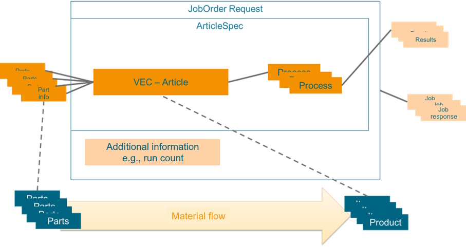
To execute, or run a job, multiple parts are supplied to the machine and processed into products. A product aligns with a specification, referred to as 'ArticleSpec.' An ArticleSpec contains process information, article information, and a reference to the parts used ("Part info" in the above image). Additionally, measurement results may be captured by the machine or the machine operator during setup and production. During setup, a set of verification measurements may be gathered that apply to the entire production lot. During production, a set of monitoring measurements may be collected for each item produced. The set of validation and monitoring processes are part of the article specification. These are understood within this specification to be processed on an instance-dependent basis. Each job can also have additional status information, which is stored in the Job Response (see OPC UA 40001-1).
4.1.2 Introduction to VEC (Vehicle Electric Container)
4.1.2.1 Overview
The Vehicle Electric Container (VEC) is a standardized data model that facilitates the exchange, collaboration, and archiving of electrical network, wiring harness and wiring harness component information in the automotive industry. It serves as a tool-independent digital representation of a vehicle's electrical system, supporting the conceptualization and design of logical mockups, the exchange of component data or the product specification of wiring harnesses. The VEC helps ensure traceability throughout the lifecycle of a vehicle's electrical system.
Developed under the guidance of the VDA and the prostep ivip Association, VEC is a standard in the automotive industry, and is published as VDA 4968 and PSI21.
4.1.2.2 VEC in context of this Companion Specification
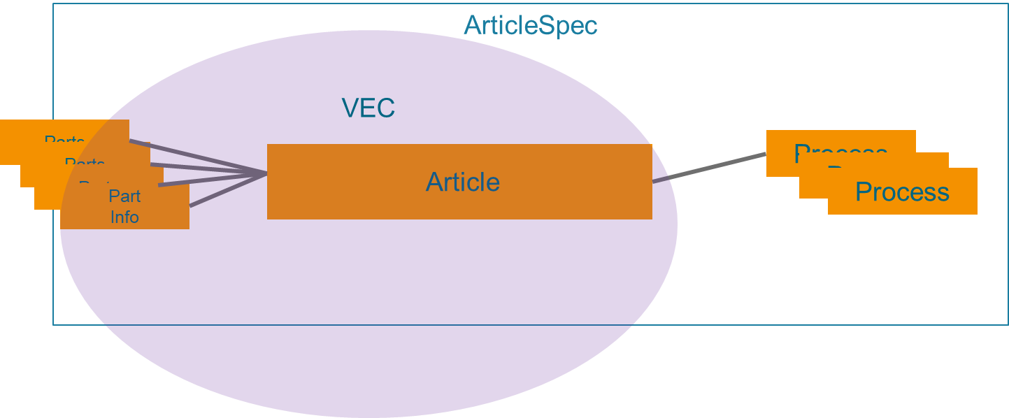
This Companion Specification utilizes subsets of the VEC data model for the description of 'Article' and 'Part' information (see Figure 2). There are multiple reasons for this:
It enhances interoperability and consistency in the exchange of data across different systems and equipment within the automotive industry. Article and Part information is used throughout the process, not only in communication with production machines.
Components for the wiring harness (Parts) and the wiring harness itself (Article) are diverse, with great variety and many facets. Reusing vetted modelling concepts for their description increases the quality of these aspects for this Companion Specification and enables accelerated and efficient definitions.
It allows this Companion Specification to focus on the additional aspects that are relevant to machine communication, such as job management, result data and process parameters.
Due to its scope as a common language in the wiring harness value chain, the VEC standard includes modelling concepts that are necessary in the design and engineering process, but not during production or for certain machine types (e.g., system schematics). The data model elements used in this Companion Specification are a subset of the complete data model defined by the VEC standard.
Concrete mapping between VEC and OPC UA is described in section 9.
4.1.2.3 Basic Structure of VEC Data
The key concepts of the VEC are DocumentVersion and 7:PartVersion (see Figure 3).
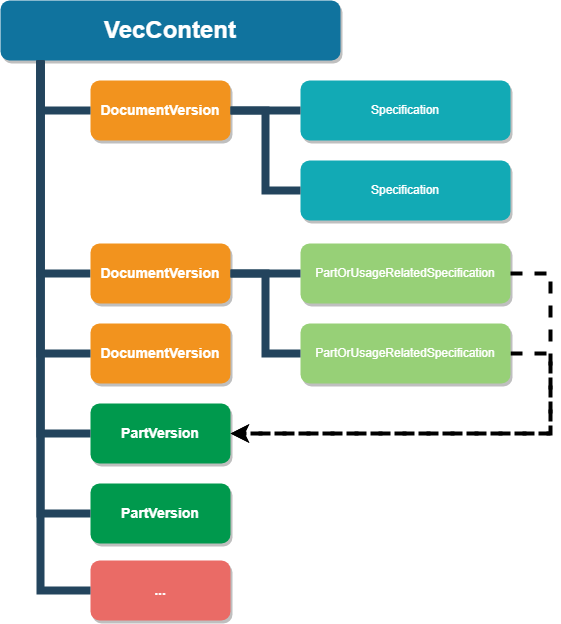
A 7:PartVersion in VEC is a unique identifier for a specific version/revision of a part. In VEC terms, a part is essentially anything that is used in the product or is created during production (a part can be composed of instances of other parts). This means that a 7:PartVersion in VEC applies to both the Part and Article in terms of this Companion Specification.
Note: A Part represents a type definition, not a specific instance of a Part; in other words, a Part is identified by a part or material number, not a serial number.
The term DocumentVersion goes back to the roots of VEC in the STEP standard and the document-oriented product development that prevailed at that time. In fact, DocumentVersion in the VEC stands for any piece of information or a data set that is clearly identifiable and whose changes can be tracked (e.g., a certain state of the properties of a connector, a terminal or a wire [Parts in this Companion Specification], or the definition of a lead set [Article in this Companion Specification]).
The content of a DocmentVersion is used to describe 7:PartVersions. They are represented by individual entities for the following reasons:
In general, a document can describe multiple parts at same time, whereas a part can also be described by multiple documents (e.g., a data sheet, a drawing, a 3D model).
Both can evolve independently, so tracking of changes & revisions must also be tracked inidividually (e.g., the data for a component can change without changing the physical component).
For example, in the context of this Companion Specification, this could mean that if a machine is sent a new 7:PartVersion, the input material has changed physically and the machine needs to be re-equipped for this new material. However, if only the content of a DocumentVersion changes, the same material processed, just in a different way.
The 7:PartVersion and DocumentVersion is a generic concept for tracking hardware and information changes. The information is described using specific subtypes of Specifications within a DocumentVersion.
Every subset of the VEC model that defines a specific aspect of the product has its own Specification; for example, a connector is described by a ConnectorHousingSpecification, a terminal by TerminalSpecification, etc. The same applies for more complex aspects of the article definition; e.g., the bill of materials is defined with a PartStructureSpecification, the contacting of wire ends with terminals with a ContactingSpecification, the basic structure of a wiring harness or leadset by a TopologySpecification, the geometric form by a BuildingBlockSpecification3D, etc.
4.1.3 Part and Article Structure
Parts and Articles within this Companion Specification are composed of structures from two distinct sources: the ISA-95 Material Model from ISA95, which is intended for generic use, and the domain-specific VEC (Vehicle Electric Container) model. As these have both been integrated within this Companion Specification, Part and Article always consist of two segments: the generic component derived from the ISA-95 model, and the wire harness-specific element from the VEC model.
When adding a Parts, Article, or Job, it must be fully described and only reference existing elements. For example, when a new Job is added, it must reference already existing Parts and Articles within the system. When deleting elements, the integrity of the remaining data must not be compromised. This means the system must always ensure there are no references to missing or not yet transferred elements. For instance, if an Article is deleted, the system must verify that no existing Jobs reference this Article to maintain data consistency.
4.1.4 Important types of Processes
4.1.4.1 Overview
The wire harness industry is characterized by a series of specialized and critical processes that ensure the production of high-quality and functional wire harnesses. These processes are integral to the manufacturing flow and are carefully designed to meet precise design requirements.
This section provides an overview of the relevant processes covered by this Companion Specification:
4.1.4.2 Crimp
Affixing metal connectors to wires with a tight deformation.
4.1.4.3 Cut
Cutting wires to specific lengths.
4.1.4.4 Seal
Applying protective materials to connections.
4.1.4.5 Slit
Longitudinal slitting of insulation along the wire.
4.1.4.6 Strip
Removing insulation from wire ends in preparation for connection via crimping or soldering.
4.1.5 Parts
4.1.5.1 Overview
The following is an overview of the categories of materials that are supported in this Companion Specification:
4.1.5.2 Housing
Provides the physical structure to support and protect connectors and wires, often made from durable plastics or metals.
4.1.5.3 Terminal
The component within a connector where the wire is attached, which can be designed for crimping, soldering, or other types of connections.
4.1.5.4 Seal
Materials used to prevent moisture, dust, and other environmental contaminants from affecting the connections and components within the harness.
4.1.5.5 Sleeve
Flexible, often tubular, material that is used to bundle, protect, and insulate wires within the harness, available in various materials for different protective qualities.
4.1.5.6 Wire
A conductor, usually covered with an insulating material, that is used for carrying electrical current or signals.
4.1.6 Example Workflow for Job Management
4.1.6.1 Overview
There are multiple categories of wire harness manufacturing machines, each with different capabilities. Yet many of them have a local data store to keep part, spec and article information. This means that there are multiple ways to send part, article and job information to a machine.
Job Management is based on ISA95 and Machinery Job Control. This section provides some examples for use in a wire harness. These examples illustrate the concept with consideration of domain-specific aspects, such as different ways to transfer data.
Other workflows, or a mix of these examples is also possible. This example also represents a simplified version of the model.
In general, it is important that all information needed for the process is available beforehand. This means that a job can only be stored if the article spec is available (or sent with the job). Likewise, the article spec can only be stored if the part information is already available (or sent with the article spec). Thus, the model does not further restrict the base specifications. Some aspects are not shown in this example.
Parts of the original model are omitted for illustrative purposes.
4.1.6.2 Workflow Variant with stored Part and Article information
This section describes a variant of the standardized workflow (other variants are possible) to store a Job within the framework of the Wire Harness Companion Specification, exemplified by the sequence diagrams in Figure 4. In this example, the part and article spec are stored on the machine before the Job is stored. The Part and Article can be stored via OPC UA (right side) or in another way, such as with a local HMI (left side).
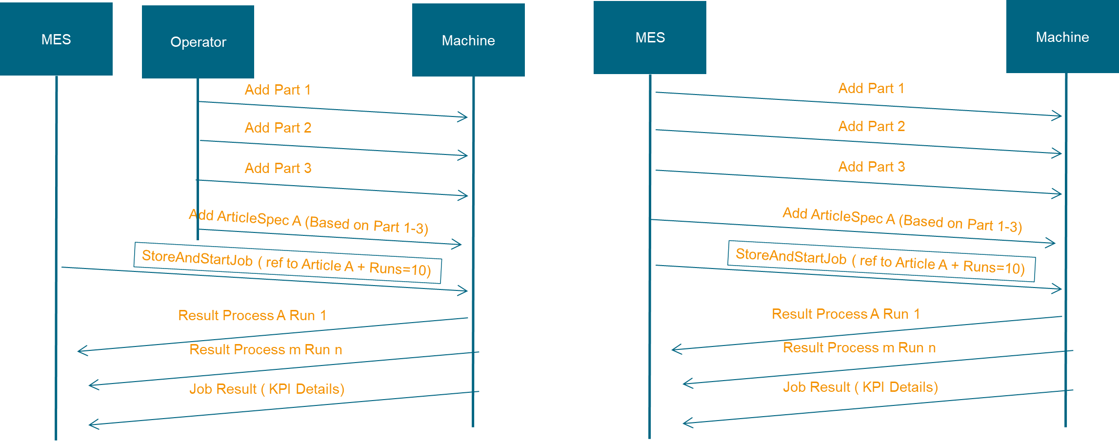
The workflow begins with the MES, which serves as the central control system overseeing the manufacturing operations, communicating with the MachineryItem responsible for executing the job:
Add Parts: The process initiates with the MES instructing the machine to add individual parts required for the job. In this case, 'Add Part 1,' 'Add Part 2,' and 'Add Part 3' are sequential steps that involve the MES sending commands to the machine to prepare the necessary components.
Add Article: After the parts are prepared, the MES instructs the machine to add 'Article A,' which is based on the assembly or combination of Parts 1-3. The article represents the blueprint or design specification for the final product.
StoreAndStartJob: With the parts and article prepared, the MES sends a StoreAndStartJob command. This includes the ArticleSpec and a directive to execute a set number of runs, which in this example is 10. This command effectively stores the job data and triggers the start of the production run.
Process Results: As the machine begins processing, it sends the results to the MES. These include 'Result Process A Run 1,' representing the outcome of the first run of process A, through 'Result Process m Run n,' denoting subsequent processes and runs. These results provide insight into the execution of each job run.
Job Result (KPI Details): Finally, after the job runs are completed, the machine sends a detailed report of the job results back to the MES. This report includes Key Performance Indicator (KPI) details, which are crucial for evaluating the efficiency and quality of the job execution.
4.1.6.3 Workflow Variant with included Part and Article Management
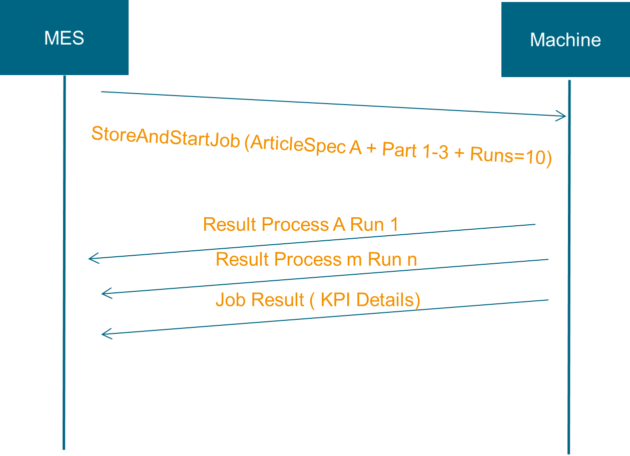
The sequence diagram in Figure 5 depicts a streamlined process for initiating a job on a wire harness machine. Unlike the previous example, where parts and article information were added in separate steps, this approach consolidates the workflow by sending all necessary information along with the job creation command.
StoreAndStartJob: The MES sends a single StoreAndStartJob command to the machine. This command is comprehensive, containing all necessary data required for the job: 'ArticleSpec A,' 'Part 1-3,' additional process input data, and the number of runs, which is set to 10 in this scenario. This encapsulation of data reduces the number of communication steps between the MES and the machine, leading to a more streamlined operation.
Processing and Feedback: As the job starts, the machine processes the information and begins the manufacturing runs. Feedback is then provided to the MES after each process is executed:
Result Process A Run 1: Details from the first run of Process A are sent back to the MES.
Result Process m Run n: As subsequent processes are completed, their results are also reported back to the MES in real time.
Job Result (KPI Details): At the conclusion of the job, a comprehensive report including KPI details is transmitted to the MES. These KPIs provide valuable insights into the performance, efficiency, and quality of the executed job.
4.2 Introduction to OPC UA
4.2.1 What is OPC UA?
OPC UA is an open and royalty free set of standards designed as a universal communication protocol. While there are numerous communication solutions available, OPC UA has key advantages:
A state of art security model (see OPC 10000-2).
A fault tolerant communication protocol.
An information modelling framework that allows application developers to represent their data in a way that makes sense to them.
OPC UA has a broad scope which delivers for economies of scale for application developers. This means that a larger number of high-quality applications at a reasonable cost are available. When combined with semantic models such as Wire Harness Manufacturing, OPC UA makes it easier for end users to access data via generic commercial applications.
The OPC UA model is scalable from small devices to ERP systems. OPC UA Servers process information locally and then provide that data in a consistent format to any application requesting data - ERP, MES, PMS, Maintenance Systems, HMI, Smartphone or a standard Browser, for examples. For a more complete overview see
OPC 10000-1.
4.2.2 Basics of OPC UA
As an open standard, OPC UA is based on standard internet technologies, like TCP/IP, HTTP, Web Sockets.
As an extensible standard, OPC UA provides a set of Services (see OPC 10000-4) and a basic information model framework. This framework provides an easy manner for creating and exposing vendor defined information in a standard way. More importantly all OPC UA Clients are expected to be able to discover and use vendor-defined information. This means OPC UA users can benefit from the economies of scale that come with generic visualization and historian applications. This specification is an example of an OPC UA Information Model designed to meet the needs of developers and users.
OPC UA Clients can be any consumer of data from another device on the network to browser based thin clients and ERP systems. The full scope of OPC UA applications is shown in Figure 6.

OPC UA provides a robust and reliable communication infrastructure having mechanisms for handling lost messages, failover, heartbeat, etc. With its binary encoded data, it offers a high-performing data exchange solution. Security is built into OPC UA as security requirements become more and more important especially since environments are connected to the office network or the internet and attackers are starting to focus on automation systems.
4.2.3 Information modelling in OPC UA
4.2.3.1 Concepts
OPC UA provides a framework that can be used to represent complex information as Objects in an AddressSpace which can be accessed with standard services. These Objects consist of Nodes connected by References. Different classes of Nodes convey different semantics. For example, a Variable Node represents a value that can be read or written. The Variable Node has an associated DataType that can define the actual value, such as a string, float, structure etc. It can also describe the Variable value as a variant. A Method Node represents a function that can be called. Every Node has a number of Attributes including a unique identifier called a NodeId and non-localized name called as BrowseName. An Object representing a 'Reservation' is shown in Figure 7.

Object and Variable Nodes represent instances and they always reference a TypeDefinition (ObjectType or VariableType) Node which describes their semantics and structure. Figure 8 illustrates the relationship between an instance and its TypeDefinition.
The type Nodes are templates that define all of the children that can be present in an instance of the type. In the example in Figure 8 the PersonType ObjectType defines two children: First Name and Last Name. All instances of PersonType are expected to have the same children with the same BrowseNames. Within a type the BrowseNames uniquely identify the children. This means Client applications can be designed to search for children based on the BrowseNames from the type instead of NodeIds. This eliminates the need for manual reconfiguration of systems if a Client uses types that multiple Servers implement.
OPC UA also supports the concept of sub-typing. This allows a modeller to take an existing type and extend it. There are rules regarding sub-typing defined in OPC 10000-3, but in general they allow the extension of a given type or the restriction of a DataType. For example, the modeller may decide that the existing ObjectType in some cases needs an additional Variable. The modeller can create a subtype of the ObjectType and add the Variable. A Client that is expecting the parent type can treat the new type as if it was of the parent type. Regarding DataTypes, subtypes can only restrict. If a Variable is defined to have a numeric value, a sub type could restrict it to a float.

References allow Nodes to be connected in ways that describe their relationships. All References have a ReferenceType that specifies the semantics of the relationship. References can be hierarchical or non-hierarchical. Hierarchical references are used to create the structure of Objects and Variables. Non-hierarchical are used to create arbitrary associations. Applications can define their own ReferenceType by creating subtypes of an existing ReferenceType. Subtypes inherit the semantics of the parent but may add additional restrictions. Figure 9 depicts several References, connecting different Objects.

The above figures utilize a notation that was developed for the OPC UA specification. The notation is summarized in Figure 10. UML representations can also be used; however, the OPC UA notation is less ambiguous because there is a direct mapping from the elements in the figures to Nodes in the AddressSpace of an OPC UA Server.

A complete description of the different types of Nodes and References can be found in OPC 10000-3 and the base structure is described in OPC 10000-5.
OPC UA specification defines a very wide range of functionality in its basic information model. It is not required that all Clients or Servers support all functionality in the OPC UA specifications. OPC UA includes the concept of Profiles, which segment the functionality into testable certifiable units. This allows the definition of functional subsets (that are expected to be implemented) within a companion specification. The Profiles do not restrict functionality, but generate requirements for a minimum set of functionality (see OPC 10000-7)
4.2.3.2 Namespaces
OPC UA allows information from many different sources to be combined into a single coherent AddressSpace. Namespaces are used to make this possible by eliminating naming and id conflicts between information from different sources. Each namespace in OPC UA has a globally unique string called a NamespaceUri which identifies a naming authority and a locally unique integer called a NamespaceIndex, which is an index into the Server's table of NamespaceUris. The NamespaceIndex is unique only within the context of a Session between an OPC UA Client and an OPC UA Server- the NamespaceIndex can change between Sessions and still identify the same item even though the NamespaceUri's location in the table has changed. The Services defined for OPC UA use the NamespaceIndex to specify the Namespace for qualified values.
There are two types of structured values in OPC UA that are qualified with NamespaceIndexes: NodeIds and QualifiedNames. NodeIds are locally unique (and sometimes globally unique) identifiers for Nodes. The same globally unique NodeId can be used as the identifier in a node in many Servers - the node's instance data may vary but its semantic meaning is the same regardless of the Server it appears in. This means Clients can have built-in knowledge of of what the data means in these Nodes. OPC UA Information Models generally define globally unique NodeIds for the TypeDefinitions defined by the Information Model.
QualifiedNames are non-localized names qualified with a Namespace. They are used for the BrowseNames of Nodes and allow the same names to be used by different information models without conflict. TypeDefinitions are not allowed to have children with duplicate BrowseNames; however, instances do not have that restriction.
4.2.3.3 Companion Specifications
An OPC UA Companion Specification for an industry-specific vertical market describes an Information Model by defining ObjectTypes, VariableTypes, DataTypes and ReferenceTypes that represent the concepts used in the vertical market. It may also potentially describe well-defined Objects as entry points into the AddressSpace.
5 Use cases
Use cases 5.1 - 5.5 are derived from OPC 40001-1; use cases 5.6 - 5.9 are derived from OPC 40001-3.
5.1 Machine Identification and Nameplate
As a client, I want to be able to list all modules installed on the server (including an AssetID) so that I can track my assets.
Information for this use case can be found in OPC 40001-1 (see Machine Identification and Nameplate) and section 9.7 of this Companion Specification.
5.2 Component Identification and Nameplate
As a client, I want to be able to list all modules installed on the server (including an AssetID) so that I can track my assets.
This information can be found in OPC 40001-1 (see Component Identification and Nameplate).
5.3 Operating State
As an MES client, I want to gather the values of the operating state (Executing, Not executing, Out of service, etc.) of the server so that I can calculate KPIs.
Information for this use case can be found in OPC 40001-1 (see MachineryItemState and MachineryOperationMode).
5.4 Job Order CRUD Operations
As an MES, I want to send/update/delete job orders identified with an ID to a specific machine to achieve my production goals.
Information for this use case can be found in OPC 10031-4 (entire document, but in particular according to ISA95JobOrderReceiverObjectType) and OPC 40001-3.
5.5 Running Job Information
As a dashboard-like client, I want to collect information about running jobs and the article currently being produced on the asset.
Information for this use case can be found in OPC 10031-4 (entire document, but in particular according toISA95JobResponseProviderObjectType) and OPC 40001-3.
5.6 Article Specifications Management
As an MES, I want to send article specifications to the machine so that the machine knows what to produce.
Information for this use case can be found in sections 4.1.2, 4.1.3, 4.1.6, 6.3, and 10.3 of this Companion Specification.
5.7 Job Status Monitoring
As a client, I want to know the status of a job I sent to the server to know if it is in production, paused, canceled, or finished so that I can keep track of my production resources.
Information for this use case can be found in OPC 10031-4 (entire document, but in particular according toISA95JobResponseProviderObjectType) and OPC 40001-3.
5.8 Material Consumption Tracking
As a client, I want to receive the material consumption statistics for a job so that I can calculate KPIs.
Information for this use case can be found in OPC 10031-4 (entire document, but in particular according to3:ISA95MaterialDataType, ISA95JobResponseProviderObjectType), OPC 40001-3 (Material), and sections 4.1.6 and 6.8 of this Companion Specification.
5.9 Verification Data Collection
As a client, I want to be able to collect verification results for decision making purposes.
Information for this use case can be found in OPC 40001-101 and sections 4.1.6, 6.1, 6.6, and 12.2 of this Companion Specification.
5.10 Production Locking
As an MES, I want to lock and unlock production at any time.
5.11 Identifiable Parts Management
As an MES, I want to manage identifiable parts (CRUD) for possible reuse in later articles by referring to them.
Information for this use case can be found in sections 4.1.2, 4.1.3, 4.1.6, 6.3, and 10.2 of this Companion Specification.
5.12 Multi-leadset Article Specification
As an MES, I want to specify multi-leadset articles to produce harnesses.
5.13 Maintenance Data Collection
As a client, I want to have counter and usage time (e.g., operating time) information from the server so that I can plan maintenance.
This information can be found in OPC 40001-1 (see Operation Counter).
5.14 Process Progress Monitoring
As a client, I want to see the progress of completed processes.
Information for this use case can be found in OPC 40001-101 and sections 4.1.6, 6.1, 6.6, and 12.2 of this Companion Specification.
6 General Recommendations and Tips for Implementation
6.1 Data Consistency in Job Management
Within the framework of job management, the flow and association of data are meticulously structured to ensure consistency and traceability throughout the production process. The connectivity of data is outlined as follows:
An Article is composed of multiple Parts.
Items represent specific instances of an Article.
Processes are defined abstractly.
Processes are the tangible implementations of a process. For instance, if a wire requires both ends to be crimped, the job will have two distinct processes of the type 'Crimp,' each with its own identifier.
Processes can reference corresponding elements in the ArticleSpec.
Results are uniquely identified using the Process ID (ArticleID and JobID are also given in the result but are not sufficient to clearly assign the result to the corresponding processes or parts). This ensures precise allocation and traceability of outcomes.
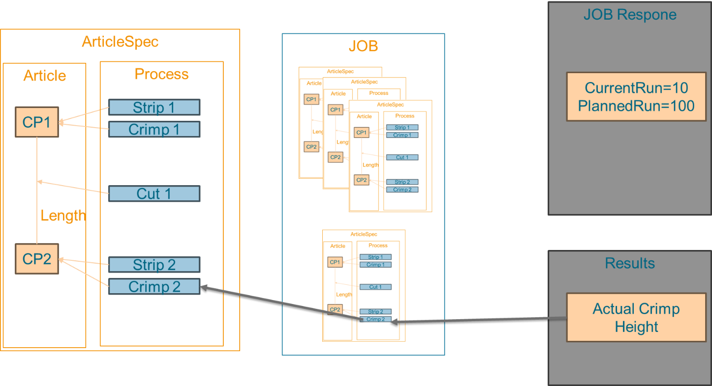
Figure 11 illustrates the thoroughness of data, from a measurement result to a Contact Point within an Article:
CP1 (Contact Point 1) and CP2 (Contact Point 2) are elements of a Part within the Article that need processing.
Strip 1, Crimp 1, Cut 1, Strip 2, and Crimp 2 represent individual tasks to be performed, tied to their respective Crimp points.
JOB Result: Results, such as 'Actual Crimp Height,' are the measurable outcomes from the execution of the job. Each result is linked back to the specific process instance, such as Crimp 1 or Crimp 2, ensuring that the measurement can be traced back to the corresponding action and Part within the Article.
The visualization of the process in the image underscores the seamless flow of data from the initial design of an Article through to the final measured result of a job. This integration is vital for maintaining the integrity of the manufacturing process, allowing for precise adjustments, quality control, and accountability across all stages of production. By establishing a clear linkage between Articles, jobs, process instances, and results, the system facilitates a robust and efficient manufacturing environment for wire harnesses.
6.2 Mapping Part Data
A Part in this Companion Specification is represented by a value of the 3:ISA95MaterialDataType which contains an entry in the Properties field. Table 15 lists all Parameters a needed by a Part element.
| ParameterName | DataType | Description |
| VECPartVersion | 7:PartVersion | Contains the master data of the part. Only the ID of the 7:PartVersion is mandatory. The Values of Company, PartNumber, 7:PartVersion are optional. |
| VECDocumentVersion | 7:DocumentVersion | Contains the master data of the article. The field Specification contains important specifications for that part. The kind of specification depends on the process of the machine. |
The MaterialDefinitionID represents the part number, which must be unique within the company.
The MaterialClassID is restricted to the value range of the VEC 7:PrimaryPartType. The table contains the MaterialClassID (7:PrimaryPartType) for the different processes.
| Process | MaterialClassID |
| Cut | Wire |
| Strip | Wire |
| Seal | CavitySeal, MultiCavitySeal |
| Crimp | Terminal, WireEndAccessory, PluggableTerminal, RingTerminal, WireEndAccessory, (SpliceTerminal, BoltTerminal, BridgeTerminal, OpenWireEndTerminal) |
The linkage between the 3:ISA95MaterialDataType and the VEC is established through the 7:PartVersion. The PartVersion.PartNumber must be the same as in MaterialDefinitionID.
The field Specification of the 7:DocumentVersions contains important specifications for the Part. The kind of specification depends on the processes of the machine. If a machine covers more than one process, all Specifications need to be implemented. Section 10.2 contains more information about the specification and the content which is needed.
| ProcessName | Specifications |
| Crimp | WireSpecification/ |
| Cut | WireSpecification |
| Seal | WireSpecification/ |
| Slit | WireSpecification |
| Strip | WireSpecification |
It is recommended that only one entry is used for each Part. If the quantity of the Part is more than one, the Quantity field should be used.
6.3 Mapping Article Spec Data
An Article in this Companion Specification is represented by a value of the 3:ISA95MaterialDataType which contains an entry in the Properties field. Table 18 lists all Parameters needed by an Article element.
| ParameterName | DataType | Description |
| VECPartVersion | 7:PartVersion | Contains the master data of the article. Only the ID of the 7:PartVersion is mandatory. The Values of Company, PartNumber, 7:PartVersion are optional. |
| VECDocumentVersion | 7:DocumentVersion | Contains the master data of the article. The field Specification contains important specifications for that article. The kind of specification depends on the process of the machine. |
| Processes | ProcessInputType[] | Contains the information of which processes should be done to create the article. The SubTypes of the ProcessInputType can contain process parameters and monitoring flags. |
The MaterialDefinitionID represents the article number, which must be unique within the company.
The MaterialClassID is restricted to the value "PartStructure".
The linkage between the 3:ISA95MaterialDataType and the VEC is established through the 7:PartVersion, where all attributes except for _id are optional.
| ProcessName | Specifications | Roles of the components in the CompositionSpecification |
| Crimp | PartStructureSpecification ContactingSpecification | WireRole TerminalRole |
| Cut | CompositionSpecification PartStructureSpecification | WireRole |
| Seal | CompositionSpecification PartStructureSpecification | WireRole CavityPartRole |
| Slit | CompositionSpecification PartStructureSpecification | WireRole |
| Strip | CompositionSpecification PartStructureSpecification | WireRole |
The details for the different Parts and Articles are described below.
6.4 Relevant Elements of ISA95JobOrderDataType
| Name | Type | Description |
| JobOrderID | 0:String | An identification of the Job Order. |
| JobOrderParameters | 3ISA95ParameterDataType[] | Key value pairs, not associated with a resource, that are provided as part of the job order; may be empty if not specified. |
| MaterialRequirements | 3:ISA95MaterialDataType[] | A specification of any material requirements associated with the job order; may be empty if not specified. Note: To comply with this Companion Specification, at least one material must be specified (including Article Specification and Quantity > 0), and the MaterialUse must be set to "material produced". |
| Name | Type | Description |
| PersonnelActuals | 3:ISA95PersonnelDataType[] | A specification of any personnel actuals associated with the job response, may be empty if not specified. |
6.5 Relevant Elements of ISA95JobResponseDataType
| Name | Type | Description |
| JobResponseID | 0:String | A unique identification of the Job Response. |
| JobOrderID | 0:String | An identification of the Job Order. |
| JobOrderParameters | 3:ISA95ParameterDataType[] | Key value pairs, not associated with a resource, that are provided as part of the job order; may be empty if not specified. |
| JobState | 3:ISA95StateDataType[] | The current state of the job. The array shall provide at least one entry representing the top-level state and, potentially, additional entries representing substates. The first entry shall be the top-level entry, having the BrowsePath set to null. The order of the substates is not defined. |
| MaterialActuals | 3:ISA95MaterialDataType[] | A specification of any material requirements associated with the job order; may be empty if not specified. Note: To comply with this Companion Specification, at least one material must be specified (including Article Specification and Quantity > 0), and the MaterialUse must be set to "material produced." |
| Name | Type | Description |
StartTime | 0:DateTime | The actual start time for the job order. |
EndTime | 0:DateTime | The actual end time for the job order; may be empty if the job has not yet completed. |
| PersonnelActuals | 3:ISA95PersonnelDataType[] | A specification of any personnel actuals associated with the job response, may be empty if not specified. |
6.6 Mapping JobManagement and Result Transfer Variables
For data consistency, the values of the Machinery Job Management and the Result Transfer must also be mapped. Table 24 defines the mapping between the values of the two models in the scope of this specification.
| ResultMetaData | JobManagement | Comment | Example |
| ResultId | No mapping defined | Result_123 | |
| StepId | ProcessInputDataType.id | strip_left_1_22 | |
| PartId | No mapping defined | wire_1234 | |
| ProductId | MaterialDefinitionID (of the article) | MySAP-Number-123 | |
| JobId | JobOrderId | MyJob-100pcs-0.75mm2-blue |
6.7 Relevant Elements of ResultDataType
| Name | Type | Description |
| ResultId | 0:TrimmedString | System-wide unique identifier, which is assigned by the system. This ID can be used for fetching exactly this result using the method GetResultById and is identical to the ResultId of the ResultReadyEventType. If the system does not manage ResultIds, it should always be set to "NA." |
| StepId | 0:TrimmedString | Identifies the step which produced the result. Although the system-wide unique JobId would be sufficient to identify the job which the result belongs to, this makes for easier filtering without keeping track of JobIds. This specification does not define how the StepId is transmitted to the system. Typically, it is provided by the Client when starting an execution. |
| PartId | 0:TrimmedString | Identifies the part used to produce the result. Although the system-wide unique JobId would be sufficient to identify the job which the result belongs to, this makes for easier filtering without keeping track of JobIds. This specification does not define how the PartId is transmitted to the system. Typically, it is provided by the Client when starting the job. |
| ProductId | 0:TrimmedString | Identifies the product used to produce the result. This specification does not define how the ProductId is transmitted to the system. Typically, it is provided by the Client. |
| JobId | 0:TrimmedString | Identifies the job which produced the result. This ID is unique within the system and is assigned by the system. |
| ResultEvaluation | 6:ResultEvaluationEnum | The ResultEvaluation indicates whether the result was within tolerance. |
| ProcessingTimes | 6:ProcessingTimesDataType | Collection of different processing times that were needed to create the result. |
6.8 Handling of Batches
There are different methods for handling batches in the JobOrderRequest. An order with batches can be managed via separate job orders or through one run for each batch. A run is treated as a JobOrder, but is not included in the workflow.
Example: A custom order should contain 40 articles (4 batches of 10 articles each). This can be managed as either 4 job orders on the machine, each with 10 articles, or as one job order with 10 articles and 4 runs.
6.9 Recommendations for the State Machines
The different state machines from the Machinery Basic Building Blocks and ISA-95 JobManagement work together. In this specification, the recommendations in Table 26 should be followed:
| Case | MachineryItemState | MachineryOperationMode | Job State Machine |
| Teach & Verify | All possible | Setup | Running |
| Verify Process in a production phase | Executing | Processing | Running |
7 Predefined Job-Order-Input and Job-Order-Response Information
7.1 Overview
ISA95 job control (OPC 10031-4) defines mechanisms to add job order information using the 3:ISA95JobOrderDataType and mechanisms for getting the result or status of the job order using the 3:ISA95JobResponseDataType. Both DataTypes define arrays of properties of a job order: general, personnel, equipment, physical assets, and material. The 3:ISA95JobOrderDataType uses the general properties to describe the job order and the other properties to define the requirements, whereas the 3:ISA95JobResponseDataType uses the general properties to describe the output and the other properties to provide information on what has been used.
OPC 40001-3 (Machinery Job Mgmt) standardizes some of these parameters, which are application-specific from the perspective of OPC 10031-4. This specification gives recommendations for using these parameters and defines additional parameters.
7.2 Relevant Predefined Parameters
The PlannedQuantityOfRuns should not be used. Instead, use Material.Quantity and RunsPlanned.
The PlannedOrderQuantity should not be used. Instead, use Material.Quantity and RunsPlanned.
The predefined 3:JobOrderParameters of OPC 40001-3 in Table 27 should be used if the relevant information is available:
| ID | DataType of Value | Description | EngineeringUnits | Sub-parameters | In | Out |
| JobName | 0:LocalizedText[] | Human readable name of the job. Array shall always contain the same text, potentially in different languages. | - | - | X | X |
| ProducedQuantity | 0:Double | The produced quantity reflects the quantity that a work unit has produced in relation to a production order, including the count of good quantity, scrap quantity, and rework quantity. [Source: ISO 22400] Corresponding ISO 22400 definition: PQ (produced quantity)] | Product-specific | x | ||
| GoodQuantity | 0:Double | The good quantity shall be the produced quantity that meets quality requirements. (Note: Measuring work units use good quantity as the number of successfully executed measurement programs.) [Source ISO 22400] A quantity is considered as good as long as there is no contradicting evidence. Note that such evidence may arise in subsequent processing steps (on different machines), even if a quantity was considered as good. In this case, the data on the OPC UA Server are not changed retrospectively. Corresponding ISO 22400 definition: GQ (good quantity) | Product-specific | x |
Table 28 provides predefined key-value pairs for 3:JobOrderParameters and 3:JobResponseData, and indicates the data structure in which the key-value pairs are expected to be used. An "X" in "In" indicates that it may be used in 3:JobOrderParameters; an "X" in "Out" indicates that it may be used in 3:JobResponseData.
| ID | DataType of Value | Description | EngineeringUnits | Sub-parameters | In | Out |
| JobGroup | 0:String | This value can be used to group different jobs together; e.g., different jobs such as the verification job and operation job that should appear as one job on the HMI. | - | - | X | X |
8 Wire Harness Manufacturing Information Model overview
This section introduces the "OPC UA Information Model for Wire Harness Manufacturing."
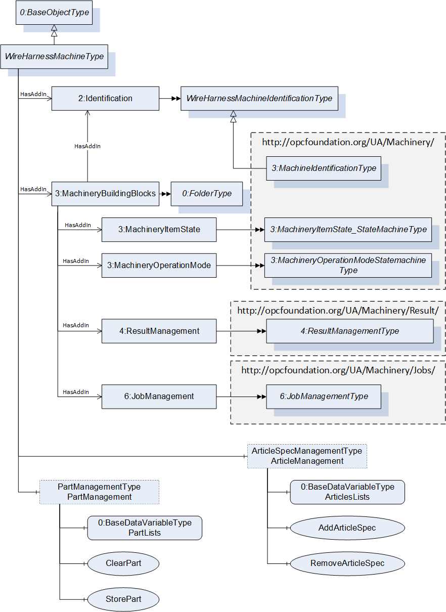
This Information Model provides the necessary ObjectTypes to model a wire harness manufacturing system interface in a structure, as illustrated in Figure 12. There are ObjectTypes that are used to identify the machine tool (WireHarnessIdentificationType), to monitor the machine (ItemState, Operation Mode), to manage the production (JobManagement with PartManagement and ArticleManagement) on the machine, and to transfer results.
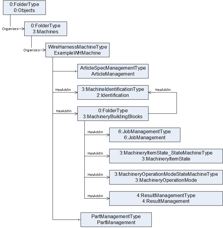
The entry point of a Server is an instance of the WireHarnessMachineType. A graphical overview of the WireHarnessMachineType is shown in Figure 13.
9 Mapping VEC to OPC UA
9.1 General
This section describes how the VEC model is transformed into OPC UA. This section describes the mapping concept. A complete description of the transformation can be found in the Annex.
9.2 Namespace
The namespace of the generated NodeSet is "http://opcfoundation.org/UA/WireHarness/VEC/".
9.3 VEC Classes to OPC UA DataTypes
Classes in VEC, declared as uml:Class in the UML model, are transformed into OPC UA DataTypes (UADataType). Abstract classes are assigned the attribute IsAbstract="true."
9.4 VEC Enumerations
Open and closed enumerations are handled as follows:
Closed Enumerations (ClosedEnumeration): These are transformed to the UADataType, with each enumeration included as a field within the definition.
Open Enumerations: These are transformed to the UADataType, with each enumeration included as a field within the definition. An extension as in VEC for Open Enumerations is not used, as this is not necessary in the
environment of the machines.
9.5 Properties and Associations
Simple Attributes: Attributes (ownedAttribute) without associations are defined as field elements in OPC UA.
Compositions and Associations: These are also transformed into field elements. Associations that are not compositions are assigned a string data type to represent References.
Exception: The data type vec:Unit for units has been replaced by the OPC UA data type 0:EUInformation.
9.6 Documentation and Comments
Comments (ownedComment): Comments are transferred as Documentation in OPC UA.
Embedding: Comments are embedded within the elements to which they belong and are output in CDATA format.
9.7 References
If the referenced element has an ID, a corresponding ID-based data structure is used instead of a simple string. If a 1:1 reference exists, the referenced element is directly included rather than being represented as a separate reference.This eliminates unnecessary indirections and ensures that the referenced object is embedded within its parent.
9.8 ID Mechanism:
If a VEC class has an ID, a corresponding IdDataType structure is generated in OPC UA. This IdDataType extends from IdBaseDataType, which acts as an abstract type for all ID-based elements. The IdDataType contains a field id with a TrimmedString. Each VEC class with an ID gets a dedicated UADataType definition for managing identification.
9.9 Excluded UML Stereotypes and Reduced Model
Certain elements from the VEC model are intentionally excluded from the OPC UA transformation to ensure that only relevant data for machine environments is retained. The reason for these exclusions is that many engineering-related data elements are not needed in the machine environment. Machine-oriented OPC UA models focus on runtime-relevant information that is essential for system operation. Engineering-specific metadata (such as design documentation, internal references, or abstract concepts) does not need to be transmitted to the OPC UA-based runtime environment. The filtering ensures that only the essential data structures required for real-time processing are included in the final OPC UA model.
This filtering follows two primary mechanisms:
9.9.1 Exclusion of Specific UML Stereotypes
Some UML stereotypes, such as MagicDraw_Profile:Legend, are explicitly ignored in the transformation. Classes or attributes tagged with these stereotypes are not converted into OPC UA elements.
9.9.2 Whitelist-Based Element Selection
The transformation relies on a whitelist mechanism (<def:class> entries) to determine which classes and attributes are mapped to OPC UA. If a VEC class is not explicitly listed in the whitelist, it is not included in the transformation. This also applies to attributes that are not defined as Field elements in the OPC UA mapping.
10 ObjectTypes
10.1 WireHarnessMachineIdentificationType Type definition
10.1.1 Overview
The WireHarnessMachineIdentificationType provides information about the MachineryItem and is formally defined in Table 29. This is a subtype of the 3:MachineryIdentificationType; the ModellingRule for 2:AssetID has changed.
10.1.2 ObjectType definition
| Attribute | Value | ||||
| BrowseName | WireHarnessMachineIdentificationType | ||||
| IsAbstract | False | ||||
| References | Node Class | BrowseName | DataType | TypeDefinition | Other |
|---|---|---|---|---|---|
| Subtype of the 4:MachineIdentificationType defined in OPC40001-1; i.e., inherits the InstanceDeclarations of that Node. | |||||
| HasProperty | Variable | 2:AssetId | String | PropertyType | Mandatory |
| Conformance Units | |||||
|---|---|---|---|---|---|
| WireHarness WireHarnessMachineIdentificationType |
10.2 PartManagementType Type definition
10.2.1 Overview
The PartManagementType contains a list of parts, as well as methods to add and remove parts from the Server. It is formally defined in Table 30.
The system must also be capable of managing local deletions, assuming that parts and articles can be removed from the local database while still existing in a central repository.
In cases of incorrect referencing (e.g., a missing part or article), the server must throw an error.
10.2.2 ObjectType definition
| Attribute | Value | ||||
| BrowseName | PartManagementType | ||||
| IsAbstract | False | ||||
| References | Node Class | BrowseName | DataType | TypeDefinition | Other |
|---|---|---|---|---|---|
| Subtype of the BaseObjectType defined in the OPC10000-3; i.e., inherits the InstanceDeclarations of that Node. | |||||
| HasComponent | Method | ClearPart | Mandatory | ||
| HasComponent | Variable | Terminals | 3:ISA95MaterialDataType[] | BaseDataVariableType | Optional |
| HasComponent | Variable | Seals | 3:ISA95MaterialDataType[] | BaseDataVariableType | Optional |
| HasComponent | Variable | Sleeves | 3:ISA95MaterialDataType[] | BaseDataVariableType | Optional |
| HasComponent | Variable | Wires | 3:ISA95MaterialDataType[] | BaseDataVariableType | Optional |
| HasComponent | Method | StorePart | Mandatory | ||
| HasComponent | Method | FindPartsByType | Optional | ||
| Conformance Units | |||||
|---|---|---|---|---|---|
| WireHarness PartManagementType |
Each Part represents an 3:ISA95MaterialDataType with the Properties shown in Table 15 (VECPartVersion and VECDocumentVersion).
Both Properties (VECPartVersion and VECDocumentVersion) must not provide by the server in the part Lists (Terminals, Seals, Sleeves, Wires) but need to be sent from the client to the server (in the method calls).
The Fields especially of the VECDocumentVersion structure depend on the kind of process and the Part. Table 31 - Table 33 show which fields need to be filled for each Part. The table has four columns. The first column displays the VEC attribute, the second provides an additional commonly used name, followed by a description and an indication of whether the parameter is always required or optional. The VEC attribute can be a direct child of the specification or a child of a subelement; in the latter case, it is separated by a "/".
Wires contain Part information for all wires. Table 31 contains the fields that must be given for this Parameter.
Terminals contain Part information for all terminals. Table 32 contains the fields that must be given for this Parameter.
Seals contain Part information for all seals. Table 33 contains the fields that must be given for this Parameter.
| Fields (VEC Attributes) | Alternative Name | Description | Optional/Mandatory field |
| WireElementSpecification/WireType | WireType | Defines the type of the wire. A wire must not have more than one type. This attribute allows more than one value because the same type can be expressed in multiple reference systems. WireType: Specifies a wire type. A wire type is always defined by a key value. Which wire type is meant by this key value is defined by a standard reference system. | Optional |
| ConductorSpecification/CrossSectionArea | CrossSection | Specifies the cross-section area of the conductor (e.g., 0.5 mm²). The cross-section area is a nominal value, which refers to the conducting properties of the conductor normalized to the properties of a full material core. | Mandatory |
| CoreSpecification/OutsideDiameter | ConductorDiameter | Specifies the outside diameter of the core. | Optional |
| WireElementSpecification/OutsideDiameter | IsoDiameter | Specifies the outside diameter of the WireElement. | Optional |
| InsulationSpecification/BaseColor | Color_1 | Specifies the base color of the outer insulation. | Optional |
| InsulationSpecification/FirstIdentificationColor | Color_2 | Specifies the first identification color of the outer insulation. | Optional |
| InsulationSpecification/SecondIdentificationColor | Color_3 | Specifies the second identification color of the outer insulation. | Optional |
| Fields | Alternative Name | Description | Optional/Mandatory field |
| WireReceptionSpecification/CrimpConnectionLength | OverallCrimpingLength | Distance from the conductor tip (in the direction of the center of the wire) to the beginning of the terminal. Specifies the length of the crimp area, conductor, and insulation crimp (wire reception, see diagram "Terminal Dimensions"). | Optional |
| TerminalSpecification/OverallLength | OverallTerminalLength | Used to circumnavigate obstacles. Specifies the overall length the terminal. | Optional |
| WireReceptionSpecification/CoreCrimpDetails/Size/Width | NominalCrimpWidth | Defines the expected size of the crimp. The height is measured in the direction of the crimp opening. The width is measured orthogonal to the height and orthogonal to the main axis of the terminal | Optional |
| WireReceptionSpecification/CoreCrimpDetails/Size/Width/Tolerance | NominalCrimpWidthRange | Specifies the tolerance for the CrimpWidth | Optional |
| GeneralTechnicalPartSpecification/BoundingBox | MaximalTerminalWidth | Defines the bounding box of the part. BoundingBox: The bounding box is defined for the processed state of the component, as it appears in the finished product. Therefore, it is valid to use the bounding box as simplified geometry of the component for viewing or simple DMU operations. For correct 3D positioning, the bounding may require transformation of the coordinate system of the component (see LocalGeometrySpecification.BoundingBoxPositioning). The bounding box defines the smallest cuboid (box) that can contain a described part completely. If a component has multiple variants, the bounding box is the smallest cuboid that can contain every variant, while maintaining the spatial orientation of the bounding box and component variants. It is valid to use the BoundingBox to describe the dimensions of a component, even if not all dimensions are known (e.g., only length and width). However, it must be possible to transform such a partial bounding box into a complete bounding box by adding the missing dimensions. Used to circumnavigate obstacles. The x,y,z coordinate of the Bouding Box are defined in the Figure 14. | Optional |
| 7:PartVersion/PrimaryPartType | TerminalType | For display purposes. | Optional |
| WireReceptionSpecification/InsulationDisplacementLength | NominalStrippingLength | Specifies the length of the insulation which must be stripped off to fit to this wire reception. This overrides stripping parameters such as StripStartPosition | Optional |
| WireReceptionSpecification/InsulationDisplacementLength/Tolerance | NominalStrippingLengthRange | Specifies the tolerance for the dimension. | Optional |
| Fields | Alternative Name | Description | Optional/Mandatory field |
| GeneralTechnicalPartSpecification/ColorInformation | SealColor | Specifies the color of the part. | Optional |
| GeneralTechnicalPartSpecification/BoundingBox | SealLength /GeometricSealWidth | Length of the seal | Mandatory |
10.2.3 StorePart Method
This method is used to add a new Part to a list.
The signature of this Method is specified below. Table 34 and Table 35 specify the Arguments and AddressSpace representation, respectively.
Signature
	StorePart(
[in] 3:ISA95MaterialDataType Part);| Argument | Description |
| Part | Information about the part. |
| Attribute | Value | ||||
| BrowseName | StorePart | ||||
| References | NodeClass | BrowseName | DataType | TypeDefinition | ModellingRule |
|---|---|---|---|---|---|
| 0:HasProperty | Variable | 0:InputArguments | 0:Argument[] | 0:PropertyType | 0:Mandatory |
10.2.4 FindPartsByType Method
This method returns all Parts of a Type.
The signature of this Method is specified below. Table 36 and Table 37 specify the Arguments and AddressSpace representation, respectively.
Signature
	FindPartsByType (
	  [in]	0:NodeId				TypeNodeId,
[out] 3:ISA95MaterialDataType[] Parts);| Argument | Description |
| TypeNodeId | NodeId of the list of parts that should be returned. The node must be a subtype of the PartDataType. |
| Parts | Information about the part. |
| Attribute | Value | ||||
| BrowseName | FindPartsByType | ||||
| References | NodeClass | BrowseName | DataType | TypeDefinition | ModellingRule |
|---|---|---|---|---|---|
| 0:HasProperty | Variable | 0:InputArguments | 0:Argument[] | 0:PropertyType | 0:Mandatory |
| 0:HasProperty | Variable | 0:OutputArguments | 0:Argument[] | 0:PropertyType | 0:Mandatory |
10.2.5 ClearPart Method
Theis method is used to remove a Part from the S.
The signature of this Method is specified below. Table 38 and Table 39 specify the Arguments and AddressSpace representation, respectively.
Note: The Data Integrity described in 4.1.3 must be considered.
Signature
	ClearPart (
[in] 3:ISA95MaterialDataType Part);| Argument | Description |
| Part | Information about the part. Either a MaterialClassID, or MaterialDefinitionID must be defined. Warning: If only the MaterialClassID is used, all entries of a MaterialClass (e.g., all wires) are cleared. |
| Attribute | Value | ||||
| BrowseName | ClearPart | ||||
| References | NodeClass | BrowseName | DataType | TypeDefinition | ModellingRule |
|---|---|---|---|---|---|
| 0:HasProperty | Variable | 0:InputArguments | 0:Argument[] | 0:PropertyType | 0:Mandatory |
10.3 ArticleSpecManagementType Type definition
10.3.1 Overview
The ArticleSpecManagementType contains a list of articles and methods to add and remove article specs from the server. It is formally defined in Table 43.
Each Article Spec represents to a 3:ISA95MaterialDataType with the Properties shown in Table 18 (VECPartVersion, VECDocumentVersion and Processes). The table has four columns. The first column displays the VEC attribute, the second provides an additional commonly used name, followed by a description and an indication of whether the parameter is always required or optional. The VEC attribute can be a direct child of the specification or a child of a subelement; in the latter case, it is separated by a "/".
The properties VECPartVersion, VECDocumentVersion and Processes may not be provided by the server in the ArticleList but need to be send from the client to the server (in the method calls). The Values depend on the kind of process and the Part. Table 40 - Table 42 show which fields need to be filled for each process the article spec should describe.
| Fields | Alternative Name | Description | Modelling Rule |
| WireElementReference/WireLength["Production"] | NominalLength | Specifies the target length of a wire according to the product specifications. | Mandatory |
| Fields | Alternative Name | Description | Modelling Rule |
| WireEnd/StrippingLength | StartPosition | Defines the position where insulation will be stripped relative to the WireEnd; e.g., a StripStartPosition of 20 mm means that this WireElementReference is stripped at 20 mm relative to the length of the whole wire, on the side of the defining WireEnd. Note: If a crimping process is to be performed, the NominalStrippingLength takes priority over this StripStartPosition. In other words, the StriptStartPosition is only used when no crimping process is selected. Note: Use ExtendedWireEnd DataType instead of WireEnd. | Mandatory |
| WireEnd | Reference to the WireEnd that should be stripped. This also represents information about the layer, as the WireElementReference (to which a WireEnd belongs) is associated with the structure of the wire. | Mandatory |
| Fields | Alternative Name | Description | Modelling Rule |
|---|---|---|---|
| ContactingSpecification/ContactPoint/WireMounting/MountedCavitySeal | HasSeal | References the cavity seal used for the wire mounting. | Mandatory |
| ContactingSpecification/ContactPoint/WireMounting/WireMountingDetail/CoreCrimpSize/Height | NominalCrimpHeight | Defines the expected size of the crimp. The height is measured in the direction of the crimp opening. The width is measured orthogonal to the height and orthogonal to the main axis of the terminal. | Optional |
| ContactingSpecification/ContactPoint/WireMounting/WireMountingDetail/CoreCrimpSize/Width | NominalCrimpWidth | Defines the expected size of the crimp. The height is measured in the direction of the crimp opening. The width is measured orthogonal to the height and orthogonal to the main axis of the terminal. | Optional |
| ContactingSpecification/ContactPoint/WireMounting/WireMountingDetail/CoreCrimpSize/Height/Tolerance | NominalCrimpHeightTolerance | Specifies the tolerance for the dimension. | Optional |
| ContactingSpecification/ContactPoint/WireMounting/WireMountingDetail/CoreCrimpSize/Width/Tolerance | NominalCrimpWidthTolerance | Specifies the tolerance for the dimension. | Optional |
| ContactingSpecification/ContactPoint/WireMounting/WireMountingDetail/InsulationCrimpSize/Height | NominalInsulationCrimpHeight | Defines the expected size of the crimp. The height is measured in the direction of the crimp opening. The width is measured orthogonal to the height and orthogonal to the main axis of the terminal | Optional |
| ContactingSpecification/ContactPoint/WireMounting/WireMountingDetail/InsulationCrimpSize/Height/Tolerance | NominalInsulationCrimpHeightTolerance | Specifies the tolerance for the dimension. | Optional |
| ContactingSpecification/ContactPoint/WireMounting/WireMountingDetail/ InsulationCrimpSize/Width | NominalInsulationCrimpWidth | Defines the expected size of the crimp. The height is measured in the direction of the crimp opening. The width is measured orthogonal to the height and orthogonal to the main axis of the terminal | Optional |
| ContactingSpecification/ContactPoint/WireMounting/WireMountingDetail/InsulationCrimpSize/Width/Tolerance | NominalInsulationCrimpWidthTolerance | Specifies the tolerance for the dimension. | Optional |
| ContactingSpecification/ContactPoint/WireMounting/WireMountingDetail/WireTipProtrusion | WireTipProtrusionRange | Defines the valid length range in which the protrusion of the conductor from the conductor crimp must be located. | Optional |
10.3.2 ObjectType definition
| Attribute | Value | ||||
| BrowseName | ArticleSpecManagementType | ||||
| IsAbstract | False | ||||
| References | Node Class | BrowseName | DataType | TypeDefinition | Other |
|---|---|---|---|---|---|
| Subtype of the 0:BaseObjectType defined in OPC 10000-3; i.e., inherits the InstanceDeclarations of that Node. | |||||
| HasComponent | Variable | ArticleSpecList | 3:ISA95MaterialDataType[] | BaseDataVariableType | Mandatory |
| HasComponent | Method | ClearArticleSpec | Mandatory | ||
| HasComponent | Method | StoreArticleSpec | Mandatory | ||
| Conformance Units | |||||
|---|---|---|---|---|---|
| WireHarness ArticleManagementType |
ArticleSpecList contains a list of all article specs known by the Server.
10.3.3 StoreArticleSpec Method
This method is used to add a new article to a list.
The signature of this Method is specified below. Table 44 and Table 45 specify the Arguments and AddressSpace representation, respectively.
Note: The data integrity described in 4.1.3 must be considered.
Signature
	StoreArticleSpec(
[in] 3:ISA95MaterialDataType ArticleSpec);| Argument | Description |
| ArticleSpec | Information about the article. The Parameter of Table 17 (VECPartVersion, VECDocumentVersion and Processes) needed be filled. |
| Attribute | Value | ||||
| BrowseName | StoreArticleSpec | ||||
| References | NodeClass | BrowseName | DataType | TypeDefinition | ModellingRule |
|---|---|---|---|---|---|
| 0:HasProperty | Variable | 0:InputArguments | 0:Argument[] | 0:PropertyType | 0:Mandatory |
10.3.4 ClearArticle Method
The method is used remove an article from the server.
The signature of this Method is specified below. Table 46 and Table 47 specify the Arguments and AddressSpace representation, respectively.
Note: The Data Integrity described in 4.1.3 must be considered.
Signature
	ClearArticleSpec (
[in] 3:ISA95MaterialDataType ArticleSpec);| Argument | Description |
| ArticleSpec | Information about the article. Either MaterialClassID or MaterialDefinitionID,must be defined. Warning: If only the MaterialClassID is used, all entries of a MaterialClass (e.g., all wires) are cleared. |
| Attribute | Value | ||||
| BrowseName | ClearArticleSpec | ||||
| References | NodeClass | BrowseName | DataType | TypeDefinition | ModellingRule |
|---|---|---|---|---|---|
| 0:HasProperty | Variable | 0:InputArguments | 0:Argument[] | 0:PropertyType | 0:Mandatory |
10.4 WireHarnessMachineType Type definition
10.4.1 Overview
The WireHarnessMachineType represents the entire wire harness machine interface of the information model. It is the entry point to the OPC UA interface of a wire harness machine. It gives a basic structure to the interface. An instance of this type aggregates all information related to one wire harness machine. The WireHarnessMachineType is formally defined in Table 48.
10.4.2 ObjectType definition
| Attribute | Value | ||||
| BrowseName | WireHarnessMachineType | ||||
| IsAbstract | False | ||||
| References | Node Class | BrowseName | DataType | TypeDefinition | Other |
|---|---|---|---|---|---|
| Subtype of the 0:BaseObjectType defined in OPC 10000-3; i.e., inherits the InstanceDeclarations of that Node. | |||||
| HasComponent | Object | ArticleSpecManagement | ArticleSpecManagementType | Optional | |
| HasComponent | Object | PartManagement | PartManagementType | Optional | |
| HasAddIn | Object | 2:Identification | WireHarnessMachineIdentificationType | Mandatory | |
| HasComponent | Object | 4:MachineryBuildingBlocks | 0:FolderType | Mandatory | |
| HasAddIn | Object | 4:Components | 4:MachineComponentsType | Optional | |
| Conformance Units | |||||
|---|---|---|---|---|---|
| WireHarness WireHarnessMachineType |
4:Identification provides properties to identify a Device.
4:Components contains the details of all components of the machine. See OPC 40001-1 for more information.
PartManagement contains the part list and the method to manage this list.
ArticleSpecManagement contains the article list and the method to manage this list.
MachineryBuildingBlocks are used as described in OPC 40001-1. This Companion Specification uses the following building blocks:
JobManagement
MachineryItemState
MachineryOperationMode
Components
ResultManagement
The components of the WireHarnessMachineType have additional subcomponents, which are defined in Table 49. The methods 5:Store, 5:Start, 5:Clear, 5:Abort are mandatory.
Note: The data integrity described in 4.1.3 must be considered, especially with the 5:Store method.
| BrowsePath | References | NodeClass | BrowseName | DataType | TypeDefinition | Others | |||
| 4:MachineryBuildingBlocks | 0:HasAddIn | Object | 4:MachineryItemState | 4:MachineryItemState_StateMachineType | M | ||||
| 4:MachineryBuildingBlocks | 0:HasAddIn | Object | 5:JobManagement | 5:JobManagementType | M | ||||
| 4:MachineryBuildingBlocks | 0:HasAddIn | Object | 6:ResultManagement | 6:ResultManagementType | O | ||||
| 4:MachineryBuildingBlocks | 0:HasAddIn | Object | 2:OperationCounters | 4:MachineryOperationCounterType | O | ||||
| 0:HasComponent | Method | 3:Store | M | |||||
| 0:HasComponent | Method | 3:Clear | M | |||||
| 0:HasComponent | Method | 3:Start | M | |||||
| 0:HasComponent | Method | 3:Abort | M |
11 OPC UA EventTypes
11.1 ProductFinishedEventType
This ProductFinishedEventType is send if a Product is finished.
Its representation in the AddressSpace is formally defined in Table 50.
| Attribute | Value | |||||
| BrowseName | ProductFinishedEventType | |||||
| IsAbstract | True | |||||
| References | NodeClass | BrowseName | DataType | TypeDefinition | Other | |
|---|---|---|---|---|---|---|
| Subtype of the 0:BaseEventType defined in OPC 10000-3, which means it inherits the InstanceDeclarations of that Node. | ||||||
| 0:HasProperty | Variable | JobOrderID | 0:String | 0:PropertyType | 0:Mandatory | |
| 0:HasProperty | Variable | MaterialDefinitionID | 0:String | 0:PropertyType | 0:Mandatory | |
| 0:HasProperty | Variable | ProductID | 0:String | 0:PropertyType | 0:Mandatory | |
| 0:HasProperty | Variable | ResultIDs | 0:TrimmedString[] | 0:PropertyType | 0:Mandatory | |
| 0:HasProperty | Variable | Run | 0:UInt32 | 0:PropertyType | 0:Mandatory | |
| 0:HasProperty | Variable | StartTime | 0:DateTime | 0:PropertyType | 0:Mandatory | |
| 0:HasProperty | Variable | EndTime | 0:DateTime | 0:PropertyType | 0:Mandatory | |
| 0:HasProperty | Variable | State | 5:JobResult | 0:PropertyType | 0:Mandatory | |
| Conformance Units | ||||||
|---|---|---|---|---|---|---|
| WireHarness ProductFinishedEventType |
JobOrderID contains the unique identifier of the production order that controls the manufacturing process.
MaterialDefinitionID contains the identifier for the material or material class used in the production process.
ProductID contains the unique identifier of the produced product.
ResultIDs contains the list of result identifiers related to quality or process data from production.
Run contains the specific execution instance of a job.
StartTime contains the timestamp when the production run or process started.
EndTime contains the timestamp when the production run or process finished
11.2 RunCompleteEventType
This RunCompleteEventType is send if a Run (a set of Products) is finished.
Its representation in the AddressSpace is formally defined in Table 50.
| Attribute | Value | |||||
| BrowseName | RunCompleteEventType | |||||
| IsAbstract | True | |||||
| References | NodeClass | BrowseName | DataType | TypeDefinition | Other | |
|---|---|---|---|---|---|---|
| Subtype of the 0:BaseEventType defined in OPC 10000-3., which means it inherits the InstanceDeclarations of that Node. | ||||||
| 0:HasProperty | Variable | EndTime | 0:DateTime | 0:PropertyType | 0:Mandatory | |
| 0:HasProperty | Variable | GoodQuantity | 0:Double | 0:PropertyType | 0:Mandatory | |
| 0:HasProperty | Variable | JobOrderID | 0:String | 0:PropertyType | 0:Mandatory | |
| 0:HasProperty | Variable | ProducedQuantity | 0:Double | 0:PropertyType | 0:Mandatory | |
| 0:HasProperty | Variable | ProductIDs | 0:String[] | 0:PropertyType | 0:Mandatory | |
| 0:HasProperty | Variable | Run | 0:UInt32 | 0:PropertyType | 0:Mandatory | |
| 0:HasProperty | Variable | StartTime | 0:DateTime | 0:PropertyType | 0:Mandatory | |
| Conformance Units | ||||||
|---|---|---|---|---|---|---|
| WireHarness RunCompleteEventType |
EndTime contains the timestamp when the production run or process finished.
GoodQuantity contains the number of produced units that meet quality requirements.
JobOrderID contains the unique identifier of the production order that controls the manufacturing process
ProducedQuantity contains the total number of produced units, including both good and defective ones.
ProductIDs contains the unique identifiers of the produced products.
Run contains the specific execution instance of a job
StartTime contains the timestamp when the production run or process started.
12 Wire Harness Manufacturing OPC UA DataTypes
12.1 Process related DataTypes
12.1.1 Overview
This section contains all DataTypes related to a process.
12.1.2 ProcessInputDataType
This structure contains information that is needed for all processes. Subtypes may add process-specific fields. The structure is defined in Table 52.
| Name | Type | Description | Allow Subtypes |
|---|---|---|---|
| ProcessInputDataType | structure | Subtype of 0:Structure defined in OPC 10000-3. | |
ToolType | 0:String[1] | Indicates the ideal process module or the preferred tool (e.g., the part version). | False |
ProcessDescription | 0:String[1] | A detailed explanation of the process, outlining its purpose, scope, and implementation steps. | False |
id | 0:TrimmedString | A unique identifier for the process, used for tracking and reference purposes. | False |
Its representation in the AddressSpace is defined in Table 53.
| Attribute | Value | |||||
| BrowseName | ProcessInputDataType | |||||
| IsAbstract | True | |||||
| References | NodeClass | BrowseName | DataType | TypeDefinition | Other | |
|---|---|---|---|---|---|---|
| Subtype of the 0:Structure defined in OPC 10000-3. | ||||||
| Conformance Units | ||||||
|---|---|---|---|---|---|---|
| WireHarness ProcessInputType |
12.1.3 CrimpInputDataType
This structure contains information needed for the crimping process. The structure is defined in Table 54.
| Name | Type | Description | Allow Subtypes |
|---|---|---|---|
| CrimpInputDataType | structure | Subtype of ProcessInputDataType defined in this specification. | |
ReferencedElement | 7:WireMountingIdDataType | References the product element for which this process is defined. | False |
VerifyCrimpHeight | 0:Boolean[1] | If set, the NominalCrimpHeight must be measured and returned during the verify and learn process, and the ActualCrimpHeight will be sent back. | False |
VerifyCrimpWidth | 0:Boolean[1] | If set, the NominalCrimpWidth must be measured and returned during the verify and learn process, and the ActualCrimpWidth will be sent back. | False |
VerifyInsulationCrimpHeight | 0:Boolean[1] | If set, the NominalInsulationCrimpHeight must be measured and returned during the verify and learn process, and the ActualInsulationCrimpHeight will be sent back. | False |
VerifyInsulationCrimpWidth | 0:Boolean[1] | If set, the NominalInsulationCrimpWidth must be measured and returned during the verify and learn process, and the ActualInsulationCrimpWidth will be sent back. | False |
VerifyPullOutForce | 0:Boolean[1] | If set, the PullOutForce must be measured and will be sent back. | False |
CrimpForceMonitoring | 0:Boolean[1] | If set, the CrimpForce is monitored. | False |
Its representation in the AddressSpace is defined in Table 55.
| Attribute | Value | |||||
| BrowseName | CrimpInputDataType | |||||
| IsAbstract | False | |||||
| References | NodeClass | BrowseName | DataType | TypeDefinition | Other | |
|---|---|---|---|---|---|---|
| Subtype of the ProcessInputDataType defined in this specification. | ||||||
| Conformance Units | ||||||
|---|---|---|---|---|---|---|
| WireHarness CrimpInputDataType |
12.1.4 CutInputDataType
This structure contains information needed for the cut process. The structure is defined in Table 56.
| Name | Type | Description | Allow Subtypes |
|---|---|---|---|
| CutInputDataType | structure | Subtype of ProcessInputDataType defined in this specification. | |
ReferencedElement | 7:WireElementReferenceIdDataType | References the product element for which this process is defined. | False |
VerifyWireLength | 0:Boolean[1] | The operator must verify the length of the wire | False |
Its representation in the AddressSpace is defined in Table 57.
| Attribute | Value | |||||
| BrowseName | CutInputDataType | |||||
| IsAbstract | False | |||||
| References | NodeClass | BrowseName | DataType | TypeDefinition | Other | |
|---|---|---|---|---|---|---|
| Subtype of the ProcessInputDataType defined in this specification. | ||||||
| Conformance Units | ||||||
|---|---|---|---|---|---|---|
| WireHarness CutInputDataType |
12.1.5 SealInputDataType
This structure contains information needed for the seal process. The structure is defined in Table 58.
| Name | Type | Description | Allow Subtypes |
|---|---|---|---|
| SealInputDataType | structure | Subtype of ProcessInputDataType defined in this specification. | |
ReferencedElement | 7:WireMountingIdDataType | References the product element for which this process is defined. | False |
MonitorSealPosition | 0:Boolean[1] | Triggers if the position should be monitored and the result returned. | False |
Its representation in the AddressSpace is defined in Table 59.
| Attribute | Value | |||||
| BrowseName | SealInputDataType | |||||
| IsAbstract | False | |||||
| References | NodeClass | BrowseName | DataType | TypeDefinition | Other | |
|---|---|---|---|---|---|---|
| Subtype of the ProcessInputDataType defined in this specification. | ||||||
| Conformance Units | ||||||
|---|---|---|---|---|---|---|
| WireHarness SealInputDataType |
12.1.6 StripInputDataType
This structure contains information needed for the strip process. The structure is defined in Table 60.
| Name | Type | Description | Optional |
|---|---|---|---|
| StripInputDataType | structure | Subtype of ProcessInputDataType defined in this specification. | |
ReferencedElement | 7:WireEndIdDataType | References the product element for which this process is defined. | False |
StrippingLengthMonitoring | 0:Boolean[1] | The operator must monitor the length of the strip. | False |
Its representation in the AddressSpace is defined in Table 61.
| Attribute | Value | |||||
| BrowseName | StripInputDataType | |||||
| IsAbstract | False | |||||
| References | NodeClass | BrowseName | DataType | TypeDefinition | Other | |
|---|---|---|---|---|---|---|
| Subtype of the ProcessInputDataType defined in this specification. | ||||||
| Conformance Units | ||||||
|---|---|---|---|---|---|---|
| WireHarness StripInputDataType |
12.2 Process result related DataTypes
12.2.1 Overview
This section contains all DataTypes related to a Part.
12.2.2 ProcessOutputDataType
This structure contains general result information for a process. Subtypes can add additional fields for process-specific output. This type can also be used by processes with no process-specific output. The structure is defined in Table 62.
The subtypes of the ProcessOutputDataType are used in the ResultData field of the ResultDataType.
If the ProcessOutputDataType (or a subtype of it) is used in the context of the ResultDataType, the ResultEvaluation must be used for the overall result.
| Name | Type | Description | Allow Subtypes |
|---|---|---|---|
| ProcessOutputDataType | structure | Subtype of the 0:Structure defined in OPC 10000-3. | |
ToolInstance | String | The actual serial number of the process module or tool (process module or tool), identifying the specific equipment used in the process. | False |
Its representation in the AddressSpace is defined in Table 63.
| Attribute | Value | |||||
| BrowseName | ProcessOutputDataType | |||||
| IsAbstract | False | |||||
| References | NodeClass | BrowseName | DataType | TypeDefinition | Other | |
|---|---|---|---|---|---|---|
| Subtype of the 0:Structure defined in OPC 10000-3. | ||||||
| Conformance Units | ||||||
|---|---|---|---|---|---|---|
| WireHarness ProcessOutputType |
12.2.3 ForceCurvePointDataType
This structure provides a data point for a curve. The structure is defined in Table 66.
| Name | Type | Description | Optional |
|---|---|---|---|
| ForceCurvePointDataType | structure | Subtype of the 0:Structure defined in OPC 10000-3. | |
X | 0:UInt32[] | Position on the X axis of this value | False |
Value | 0:UInt32[] | The value itself | False |
Its representation in the AddressSpace is defined in Table 67.
| Attribute | Value | |||||
| BrowseName | ForceCurvePointDataType | |||||
| IsAbstract | False | |||||
| References | NodeClass | BrowseName | DataType | TypeDefinition | Other | |
|---|---|---|---|---|---|---|
| Subtype of the 0:Structure defined in OPC 10000-3. | ||||||
| Conformance Units | ||||||
|---|---|---|---|---|---|---|
| WireHarness CrimpOutputDataType |
12.2.4 ForceCurveDataType
This structure provides data for a curve. The structure is defined in Table 66.
| Name | Type | Description | Optional |
|---|---|---|---|
| ForceCurveDataType | structure | Subtype of the 0:Structure defined in OPC 10000-3. | |
Points | ForceCurvePointDataType[] | Contains the points of the curve. | False |
EngineeringUnitsX | EUInformation | Contains the units of the x axis | False |
EngineeringUnitsValue | EUInformation | Contains the units of the value axis | False |
Its representation in the AddressSpace is defined in Table 67.
| Attribute | Value | |||||
| BrowseName | ForceCurveDataType | |||||
| IsAbstract | False | |||||
| References | NodeClass | BrowseName | DataType | TypeDefinition | Other | |
|---|---|---|---|---|---|---|
| Subtype of the 0:Structure defined in OPC 10000-3. | ||||||
| Conformance Units | ||||||
|---|---|---|---|---|---|---|
| WireHarness CrimpOutputDataType |
12.2.5 CrimpOutputDataType
This structure contains generated result information from the crimp process. The structure is defined in Table 68.
| Name | Type | Description | Allow Subtypes |
|---|---|---|---|
| CrimpOutputDataType | structure | Subtype of ProcessOutputDataType defined in this specification. | |
ActualCrimpHeight | 7:NumericalValue[1] | Measured value of the crimp height. | False |
ActualCrimpWidth | 7:NumericalValue[1] | Measured value of the crimp width. | False |
ActualInsulationCrimpHeight | 7:NumericalValue[1] | Measured insulation crimp height. | False |
ActualCrimpForceCurve | ForceCurveDataType[1] | The actual crimp force curve for each crimp process. The NominalCrimp curve is sent back during the learning process. | False |
ActualCrimpPullOutForce | 7:NumericalValue[1] | During the learning process, a reference wire will be measured using a destructive test and this value is assumed for the entire job. | False |
Its representation in the AddressSpace is defined in Table 69.
| Attribute | Value | |||||
| BrowseName | CrimpOutputDataType | |||||
| IsAbstract | False | |||||
| References | NodeClass | BrowseName | DataType | TypeDefinition | Other | |
|---|---|---|---|---|---|---|
| Subtype of the ProcessOutputDataType defined in this specification. | ||||||
| Conformance Units | ||||||
|---|---|---|---|---|---|---|
| WireHarness CrimpOutputDataType |
12.2.6 CutOutputDataType
This structure contains generated result information from the cut process. The structure is defined in Table 70.
| Name | Type | Description | Allow Subtypes |
|---|---|---|---|
| CutOutputDataType | structure | Subtype of CutOutputDataType defined in this specification. | |
ActualLength | 7:NumericalValue[1] | The actual length of the wire. | False |
Its representation in the AddressSpace is defined in Table 71.
| Attribute | Value | |||||
| BrowseName | CutOutputDataType | |||||
| IsAbstract | False | |||||
| References | NodeClass | BrowseName | DataType | TypeDefinition | Other | |
|---|---|---|---|---|---|---|
| Subtype of the ProcessOutputDataType defined in this specification. | ||||||
| Conformance Units | ||||||
|---|---|---|---|---|---|---|
| WireHarness CutProcessOutputType |
12.2.7 SealOutputDataType
This structure contains generated result information from the seal process. The structure is defined in Table 72.
| Name | Type | Description | Allow Subtypes |
|---|---|---|---|
| SealOutputDataType | structure | Subtype of ProcessOutputDataType defined in this specification. | |
ActualPosition | 7:NumericalValue[1] | Actual seal position, relative to the cable tip. | False |
Its representation in the AddressSpace is defined in Table 73.
| Attribute | Value | |||||
| BrowseName | SealOutputDataType | |||||
| IsAbstract | False | |||||
| References | NodeClass | BrowseName | DataType | TypeDefinition | Other | |
|---|---|---|---|---|---|---|
| Subtype of the ProcessOutputDataType defined in this specification. | ||||||
| Conformance Units | ||||||
|---|---|---|---|---|---|---|
| WireHarness SealOutputDataType |
12.2.8 StripOutputDataType
This structure contains generated result information from the strip process. The structure is defined in Table 74.
| Name | Type | Description | Allow Subtypes |
|---|---|---|---|
| StripOutputDataType | structure | Subtype of ProcessOutputDataType defined in this specification. | |
ActualStrippingLength | 7:NumericalValue[1] | Denotes the length of the wire that has been stripped. This measurement is crucial for subsequent processes and serves as a redundant definition used as an input parameter for strip monitoring processes. | False |
Its representation in the AddressSpace is defined in Table 75.
| Attribute | Value | |||||
| BrowseName | StripOutputDataType | |||||
| IsAbstract | False | |||||
| References | NodeClass | BrowseName | DataType | TypeDefinition | Other | |
|---|---|---|---|---|---|---|
| Subtype of the ProcessOutputDataType defined in this specification. | ||||||
| Conformance Units | ||||||
|---|---|---|---|---|---|---|
| WireHarness StripOutputDataType |
13 Profiles and ConformanceUnits
13.1 Conformance Units
This chapter defines the corresponding Conformance Units for the OPC UA Information Model for Wire Harness Manufacturing.
| Category | Title | Description |
| Server | WireHarness WireHarnessMachineType | The Server supports nodes that conform to the (subtypes of) WireHarnessMachineType. The WireHarnessMachineType node itself is available in the AddressSpace. Every instance of the (subtypes of) WireHarnessMachineType must include all mandatory components of the WireHarnessMachineType and may include the optional components. |
| Server | WireHarness WireHarnessMachineIdentificationType | The Server supports nodes that conform to the (subtypes of) WireHarnessMachineIdentificationType. The WireHarnessMachineIdentificationType node itself is available in the AddressSpace. Every instance of the (subtypes of) WireHarnessMachineIdentificationType must include all mandatory components of the WireHarnessMachineIdentificationType and may include the optional components. |
| Server | WireHarness PartManagementType | The Server supports nodes that conform to the (subtypes of) PartManagementType. The PartManagementType node itself is available in the AddressSpace. Every instance of the (subtypes of) PartManagementType must include all mandatory components of the PartManagementType and may include the optional components. |
| Server | WireHarness ArticleSpecManagementType | The Server supports nodes that conform to the (subtypes of) ArticleSpecManagementType. The ArticleSpecManagementType node itself is available in the AddressSpace. Every instance of the (subtypes of) ArticleSpecManagementType must include all mandatory components of the ArticleSpecManagementType and may include the optional components. |
| Server | WireHarness PartManagementType StorePart method | Supports the handling of the StorePart method of the PartManagementType as described in this specification. |
| Server | WireHarness PartManagementType ClearPart method | Supports the handling of the ClearPart method of the PartManagementType as described in this specification. |
| Server | WireHarness ArticleSpecManagementType StoreArticleSpec method | Supports the handling of the StoreArticleSpec method of the ArticleSpecManagementType as described in this specification. |
| Server | WireHarness ArticleSpecManagementType ClearArticleSpec method | Supports the handling of the ClearArticleSpec method of the ArticleSpecManagementType as described in this specification. |
| Server | WireHarness PartManagementType FindPartsByType method | Supports the handling of the FindPartsByType method of the PartManagementType as described in this specification. |
| Server | WireHarness Part Terminal | Supports the handling of Terminal parts in PartManagement (if implemented) and JobManagement. This includes all fields described in Table 32. |
| Server | WireHarness Part Seal | Supports the handling of Seal parts in PartManagement (if implemented) and JobManagement. This includes all fields described in |
| Server | WireHarness Part Wire | Supports the handling of Wire parts in PartManagement (if implemented) and JobManagement. This includes all fields described in Table 31. |
| Server | WireHarness ProductFinishedEventType | Exposes the ProductFinishedEventType and all its supertypes in the AddressSpace. Supports at least one instance of the 5:JobManagementType generating Events of ProductFinishedEventType. |
| Server | WireHarness RunCompleteEventType | Exposes the RunCompleteEventType and all its supertypes in the AddressSpace. Supports at least one instance of the 5:JobManagementType generating Events of RunCompleteEventType. |
| Server | WireHarness Article Crimp | Supports the handling of the Crimp process in the article spec in ArticleSpecManagement (if implemented) and JobManagement. This includes all fields described in Table 42. |
| Server | WireHarness Article Cut | Supports the handling of the Cut process in the article spec in ArticleSpecManagement (if implemented) and JobManagement. This includes all fields described in Table 40. |
| Server | WireHarness Article Strip | Supports the handling of the Strip process in the article spec in ArticleSpecManagement (if implemented) and JobManagement. This includes all fields described in Table 41. |
| Server | WireHarness Process Input | The Server supports variables that conform to the (subtypes of) ProcessInputType. The ProcessInputType node itself is available in the AddressSpace. |
| Server | WireHarness Process Input Crimp | The Server supports variables that conform to the (subtypes of) CrimpInputDataType. The CrimpInputDataType node itself is available in the AddressSpace. The ArticleSpec can contain Parameters of this type. |
| Server | WireHarness Process Input Cut | The Server supports variables that conform to the (subtypes of) CutInputDataType. The CutInputDataType node itself is available in the AddressSpace. The ArticleSpec can contain Parameters of this type. |
| Server | WireHarness Process Input Strip | The Server supports variables that conform to the (subtypes of) StripInputDataType. The StripInputDataType node itself is available in the AddressSpace. The ArticleSpec can contain Parameters of this type. |
| Server | WireHarness Process Input Seal | The Server supports variables that conform to the (subtypes of) SealInputDataType. The SealnputDataType node itself is available in the AddressSpace. The ArticleSpec can contain Parameters of this type. |
| Server | WireHarness Process Output | The Server supports variables that conform to the (subtypes of) ProcessOutputType. The ProcessOutputType node itself is available in the AddressSpace. |
| Server | WireHarness Process Output Crimp | The Server supports variables that conform to the (subtypes of) CrimpOutputType. The CrimpOutputDataType node itself is available in the AddressSpace. The ArticleSpec can contain Parameters of this type. |
| Server | WireHarness Process Output Cut | The Server supports variables that conform to the (subtypes of) CutOutputType. The CutOutputDataType node itself is available in the AddressSpace. The ArticleSpec can contain Parameters of this type. |
| Server | WireHarness Process Output Strip | The Server supports variables that conform to the (subtypes of) StripOutputDataType. The StripOutputDataType node itself is available in the AddressSpace. The ArticleSpec can contain Parameters of this type. |
| Server | WireHarness Process Output Seal | The Server supports variables that conform to the (subtypes of) SealOutputDataType. The SealOutputDataType node itself is available in the AddressSpace. The ArticleSpec can contain Parameters of this type. |
13.2 Profiles
13.2.1 Profile list
Table 77 lists all Profiles defined in this document and defines their URIs.
| Profile | URI |
| WireHarness BaseServer Server Profile | http://opcfoundation.org/UA-Profile/WireHarness/Server/BaseServer |
| WireHarness Result Server Profile | http://opcfoundation.org/UA-Profile/WireHarness/Server/Result |
| WireHarness Crimp Server Profile | http://opcfoundation.org/UA-Profile/WireHarness/Server/Crimp |
| WireHarness Cut Server Profile | http://opcfoundation.org/UA-Profile/WireHarness/Server/Cut |
| WireHarness Strip Server Profile | http://opcfoundation.org/UA-Profile/WireHarness/Server/Strip |
| WireHarness Seal Server Profile | http://opcfoundation.org/UA-Profile/WireHarness/Server/Seal |
13.2.2 Server Facets
13.2.2.1 Overview
The following sections specify the Facets available for Servers that implement this Wire Harness Companion Specification. Each section defines and describes a Facet or Profile.
13.2.2.2 WireHarness BaseServer Server Profile
Table 78 defines a Profile that describes the base profile of a wire harness machine.
| Group | Conformance Unit/Profile Title | Mandatory / Optional |
| Profile | 0:Core 2022 Server Facet http://opcfoundation.org/UA-Profile/Server/Core2022Facet | |
| Profile | 0:UA-TCP UA-SC UA Binary http://opcfoundation.org/UA-Profile/Transport/uatcp-uasc-uabinary | |
| Profile | 0:Data Access Server Facet http://opcfoundation.org/UA-Profile/Server/DataAccess | |
| Profile | 2:BaseDevice_Server_Facet | |
| Profile | 3:Machinery Job Management Base Server Facet | |
| Profile | 3:Machinery Machine Identification Server Facet | |
| Profile | 3:Machinery Component Identification Server Facet | |
| Profile | 3:Machinery State Server Facet | |
| Profile | 3:Machinery Operation Counter Server Facet | |
| Conformance Unit | WireHarness WireHarnessMachineType | M |
| Conformance Unit | WireHarness WireHarnessMachineIdentificationType | M |
| Conformance Unit | WireHarness PartManagementType | O |
| Conformance Unit | WireHarness ArticleSpecManagementType | O |
| Conformance Unit | WireHarness WireHarnessJobOrderReceiverSubStatesType | M |
| Conformance Unit | WireHarness PartManagementType StorePart method | O |
| Conformance Unit | WireHarness PartManagementType ClearPart method | O |
| Conformance Unit | WireHarness PartManagementType FindPartsByType method | O |
13.2.2.3 WireHarness Result Server Profile
Table 79defines a Profile that describes the base profile of a wire harness machine extended with the Machinery Result Tansfer.
| Group | Conformance Unit/Profile Title | Mandatory / Optional |
| Profile | WireHarness BaseServer Server Profile | |
| Profile | 3:Machinery-Result Result Transfer |
13.2.2.4 WireHarness Crimp Server Profile
Table 80 defines a Profile that describes the base profile of a wire harness machine with a crimp process.
| Group | Conformance Unit/Profile Title | Mandatory / Optional |
| Profile | WireHarness BaseServer Server Profile | M |
| Conformance Unit | WireHarness Part Terminal | M |
| Conformance Unit | WireHarness Part Wire | M |
| Conformance Unit | WireHarness Article Crimp | M |
| Conformance Unit | WireHarness Process Input | M |
| Conformance Unit | WireHarness Process Input Crimp | M |
| Conformance Unit | WireHarness Process Output | M |
| Conformance Unit | WireHarness Process Output Crimp | M |
13.2.2.5 WireHarness Cut Server Profile
Table 81 defines a Profile that describes the base profile of a wire harness machine with a cut process.
| Group | Conformance Unit/Profile Title | Mandatory / Optional |
| Profile | WireHarness BaseServer Server Profile | M |
| Conformance Unit | WireHarness Part Wire | M |
| Conformance Unit | WireHarness Article Cut | M |
| Conformance Unit | WireHarness Process Input | M |
| Conformance Unit | WireHarness Process Input Cut | M |
| Conformance Unit | WireHarness Process Output | M |
| Conformance Unit | WireHarness Process Output Cut | M |
13.2.2.6 WireHarness Strip Server Profile
Table 82 defines a Profile that describes the base profile of a wire harness machine with a strip process.
| Group | Conformance Unit/Profile Title | Mandatory / Optional |
| Profile | WireHarness BaseServer Server Profile | M |
| Conformance Unit | WireHarness Part Wire | M |
| Conformance Unit | WireHarness Article Strip | M |
| Conformance Unit | WireHarness Process Input | M |
| Conformance Unit | WireHarness Process Input Strip | M |
| Conformance Unit | WireHarness Process Output | M |
| Conformance Unit | WireHarness Process Output Strip | M |
13.2.2.7 WireHarness Strip Server Profile
Table 83 defines a Profile that describes the base profile of a wire harness machine with a seal process.
| Group | Conformance Unit/Profile Title | Mandatory / Optional |
| Profile | WireHarness BaseServer Server Profile | M |
| Conformance Unit | WireHarness Part Wire | M |
| Conformance Unit | WireHarness Article Seal | M |
| Conformance Unit | WireHarness Process Input | M |
| Conformance Unit | WireHarness Process Input Seal | M |
| Conformance Unit | WireHarness Process Output | M |
| Conformance Unit | WireHarness Process Output Seal | M |
14 Namespaces
14.1 Namespace Metadata
Table 94 and Table 85 define the namespace metadata for this document. Objects are used to provide version information for the namespace and an indication about static Nodes. Static Nodes are identical for all Attributes in all Servers, including the Value Attribute. See OPC 10000-5 for more details.
The information is provided as an Object of type NamespaceMetadataType. This Object is a component of the Namespaces Object that is part of the Server Object. The NamespaceMetadataType ObjectType and its Properties are defined in OPC 10000-5.
Version information is also provided as part of the ModelTableEntry in the UANodeSet XML file. The UANodeSet XML schema is defined in OPC 10000-6.
| Attribute | Value | ||
| BrowseName | http://opcfoundation.org/UA/WireHarness/ | ||
| Property | DataType | Value | |
|---|---|---|---|
| NamespaceUri | String | http://opcfoundation.org/UA/WireHarness/ | |
| NamespaceVersion | String | 1.0.0 | |
| NamespacePublicationDate | DateTime | 2025-04-01 | |
| IsNamespaceSubset | Boolean | False | |
| StaticNodeIdTypes | IdType [] | 0 | |
| StaticNumericNodeIdRange | NumericRange [] | ||
| StaticStringNodeIdPattern | String | ||
| Attribute | Value | ||
| BrowseName | 7:http://opcfoundation.org/UA/WireHarness/VEC/ | ||
| Property | DataType | Value | |
|---|---|---|---|
| NamespaceUri | String | http://opcfoundation.org/UA/WireHarness/VEC/ | |
| NamespaceVersion | String | 1.0.0 | |
| NamespacePublicationDate | DateTime | 2025-04-01 | |
| IsNamespaceSubset | Boolean | False | |
| StaticNodeIdTypes | IdType [] | 0 | |
| StaticNumericNodeIdRange | NumericRange [] | ||
| StaticStringNodeIdPattern | String | ||
14.2 Handling of OPC UA Namespaces
Namespaces are used by OPC UA to create unique identifiers across different naming authorities. The Attributes NodeId and BrowseName are identifiers. A Node in the UA AddressSpace is unambiguously identified using a NodeId. Unlike NodeIds, the BrowseName cannot be used to unambiguously identify a Node. Different Nodes may have the same BrowseName. They are used to build a browse path between two Nodes or to define a standard Property.
Servers may often choose to use the same namespace for the NodeId and the BrowseName. However, if they want to provide a standard Property, its BrowseName shall have the namespace of the standards body although the namespace of the NodeId reflects something else, for example the EngineeringUnits Property. All NodeIds of Nodes not defined in this document shall not use the standard namespaces.
Table 86 provides a list of mandatory and optional namespaces used in an OPC UA WireHarness Server.
| NamespaceURI | Description | Use |
| http://opcfoundation.org/UA/ | Namespace for NodeIds and BrowseNames defined in the OPC UA specification. This namespace shall have namespace index 0. | Mandatory |
| Local Server URI | Namespace for nodes defined in the local server. This namespace shall have namespace index 1. | Mandatory |
| http://opcfoundation.org/UA/DI/ | Namespace for NodeIds and BrowseNames defined in OPC 10000-100. The namespace index is Server specific. | Mandatory |
| http://opcfoundation.org/UA/ISA95-JOBCONTROL_V2/ | Namespace for NodeIds and BrowseNames defined in OPC UA for ISA95 Job Control (OPC UA 10031-4). The namespace index is Server specific. | Mandatory |
| http://opcfoundation.org/UA/Machinery/ | Namespace for NodeIds and BrowseNames defined in OPC UA for Machinery (OPC UA 40001-1). The namespace index is Server specific. | Mandatory |
| http://opcfoundation.org/UA/Machinery/Jobs/ | Namespace for NodeIds and BrowseNames defined in OPC UA for Machinery (OPC UA 40001-3). The namespace index is Server specific. | Mandatory |
| http://opcfoundation.org/UA/Machinery/Result/ | Namespace for NodeIds and BrowseNames defined in OPC UA for Machinery (OPC UA 40001-101). The namespace index is Server specific. | Mandatory |
| http://opcfoundation.org/UA/Machinery/WireHarness/VEC/ | Namespace for NodeIds and BrowseNames defined in this specification. The namespace index is Server specific. | Mandatory |
| http://opcfoundation.org/UA/Machinery/WireHarness/ | Namespace for NodeIds and BrowseNames defined in this specification. The namespace index is Server specific. | Mandatory |
| Vendor-specific types | A Server may provide vendor-specific types, such as types derived from ObjectTypes defined in this document in a vendor-specific namespace. | Optional |
| Vendor-specific instances | A Server provides vendor-specific instances of the standard types, or vendor-specific instances of vendor-specific types in a vendor-specific namespace. It is recommended to separate vendor-specific types and vendor-specific instances into two or more namespaces. | Mandatory |
Table 87 provides a list of namespaces and their indices used for BrowseNames in this document. The default namespace of this document is not listed, since all BrowseNames without prefix use this default namespace.
| NamespaceURI | Namespace Index | Example |
| http://opcfoundation.org/UA/ | 0 | 0:EngineeringUnits |
| http://opcfoundation.org/UA/DI/ | 2 | 2:DeviceRevision |
| http://opcfoundation.org/UA/ISA95-JOBCONTROL_V2/ | 3 | 3:JobOrderDataType |
| http://opcfoundation.org/UA/Machinery/ | 4 | 4:MachineIdentificationType |
| http://opcfoundation.org/UA/Machinery/Jobs/ | 5 | 5:JobManagementType |
| http://opcfoundation.org/UA/Machinery/Result/ | 6 | 6:ResultMetaDataType |
| http://opcfoundation.org/UA/WireHarness/VEC/ | 7 | 7:ExtendableElement |
Annex A WireHarness Namespace and mappings (Normative)
A.1 NodeSet and supplementary files for WireHarness Information Model
The WireHarness Information Model is identified by the following URIs:
http://opcfoundation.org/UA/WireHarness/
http://opcfoundation.org/UA/WireHarness/VEC/
depending on whether it is VEC-related or general data.
Documentation for the NamespaceUri can be found as follows:
For VEC, here.
For General, here.
The NodeSets associated with this version of the specification can be found here:
https://reference.opcfoundation.org/nodesets/?u=http://opcfoundation.org/UA/WireHarness/&v=1.0.0&i=1
The NodeSets associated with the latest version of the specification can be found here:
https://reference.opcfoundation.org/nodesets/?u=http://opcfoundation.org/UA/WireHarness/VEC/&i=1
https://reference.opcfoundation.org/nodesets/?u=http://opcfoundation.org/UA/WireHarness/&i=1
Supplementary files (including the VEC to OPC UA transformation) for the WireHarness Information Model can be found here:
https://reference.opcfoundation.org/nodesets/?u=http://opcfoundation.org/UA/WireHarness/&v=1.0.0&i=2
Files associated with the latest version of the specification can be found here:
https://reference.opcfoundation.org/nodesets/?u=http://opcfoundation.org/UA/WireHarness/VEC/&i=2
https://reference.opcfoundation.org/nodesets/?u=http://opcfoundation.org/UA/WireHarness/&i=2
A.2 Capability Identifier
The capability identifier for this document shall be:
wireharness___________
Annex B Implementation scenarios (Informative)
The wire harness manufacturing industry is known for having multiple types of machines, from simple benchtop machines that require a manual operator to the full-scale automatic machines capable of manufacturing a harness. The goal of this Companion Specification is to facilitate the integration of this disparaged set of equipment, and thus multiple implementation scenarios are possible.
The basic minimalistic scenario allows an OPC UA server to expose its nameplate information, a reduced set of equipment states, and a minimalistic job control to return the job results and possibly material consumption information. This scenario only needs to implement the minimal mandatory OPC Machinery and job control interfaces, and does not need to deal with advanced interfaces such as the VEC-derived data models. Note that this scenario requires the article and part definitions to be managed in the machine, as well as the order of the jobs to be managed by the operator at the machine, including delegating the validation of quality validation processes (see Figure 15).
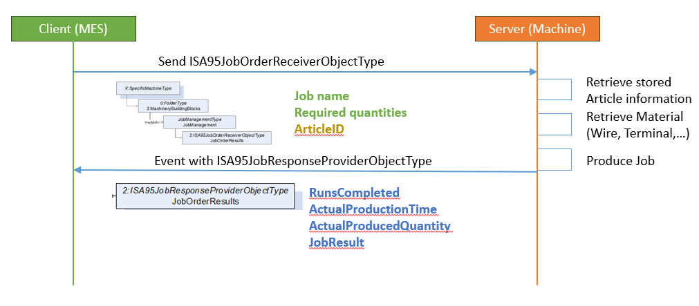
Figure 16 describes a simple scenario of the production of a single wire, two-sided crimped product:
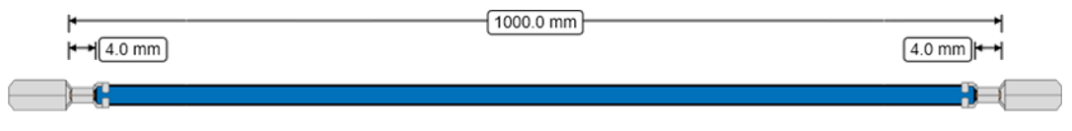
For illustration purposes, assume that we want the following production flow:
A verification job with 1 piece for quality control purposes
2 subsequent production batches of similar size.
The simplest workflow (see Figure 17) for this implementation would require the MES to define 3 jobs (it is possible to group these jobs in a job group, this will be discussed after this example):
Job1:
Quantity: 1 piece
Article ID (All parts and article information are already stored in the machine)
Verification parameters: VerifyWireLength, VerifyCrimpHeight side1, VerifyPullOutForce side1 VerifyCrimpHeight side2, VerifyPullOutForce side2
Machine produces the sample
Operator measures the requested parameters, including the pull-out force on both ends. The machine stores the reference CFA that will be needed in later production jobs.
Machine sends Job1 results, including measured values, back to MES
ActualLength
Side1.ActualCrimpHeight
Side1.ActualCrimpPullOutForce
Side2.ActualCrimpHeight
Side2.ActualCrimpPullOutForce
MES verifies that the results are within tolerances
MES sends Job 2
Quantity: 5 pieces
Article ID, referencing WireID, TerminalID1, TerminalID2
Monitoring: CFA
Machine produces Piece1
Machine measures CFA
Machine sends event: Piece1 produced with CFA values (or reference to data), and Timestamps
Machine produces Piece2
Machine measures CFA
Machine sends event: Piece2 produced with CFA values (or reference to data), and Timestamps
After all pieces are produced, the machine sends the job result.
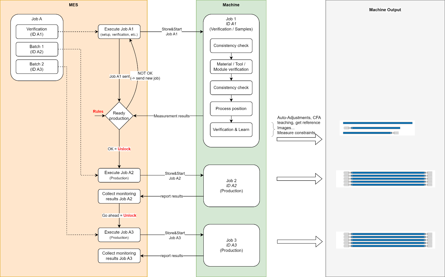
The concept of JobGroupID has been developed with the goal of allowing MES and production plants to keep their existing processes, using one ID to reference all parts in the above jobs using the same logical JobGroupID (see Figure 18).
The JobGroupID is an optional job parameter that allows the MES to define multiple jobs, as in the example above, and provide an execution order. This makes it possible to add re-verification or post-production jobs, if desired.
Note that this Companion Specification does not cover the scenario of changing materials (for example, when a wire trommel runs empty and needs to be replaced, which may require a new validation). These are jobs that are usually coordinated by the machine.
Also note that the first scenario above allows for a check step within the MES, required before the second job is stored and started. The JobGroupA scenario below only collects the validation values of the verification/sample job.
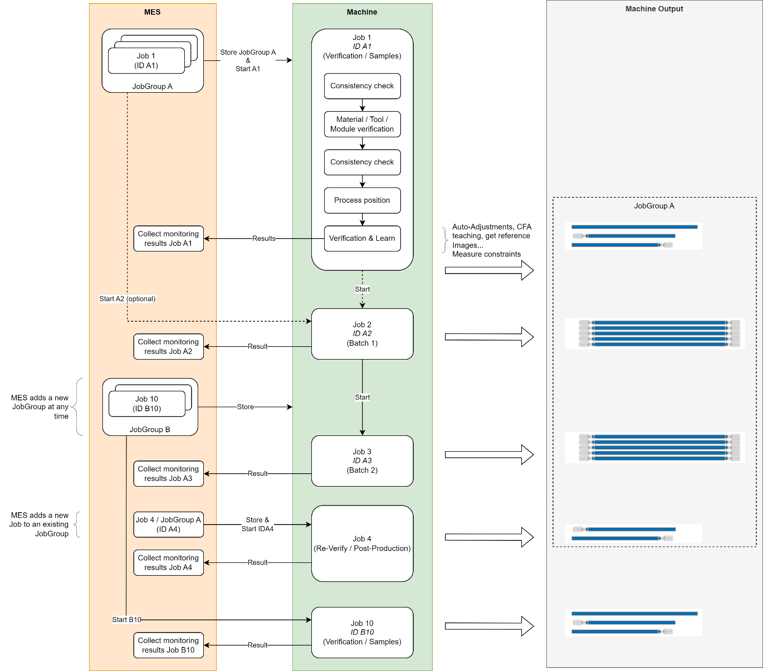
This simple implementation can be complemented by adding part management, using the VEC definition of input material such as Wire, Terminal, Seals, etc. An additional optional step would be to send the actual article specification definition. In such a scenario, the machine would be able to return verification and monitoring information for every node in the article description.
Types of clients:
A client can be as simple as a basic monitoring application that can display and aggregate the machine states to present KPI's on the usage of the machine, as well as list the jobs being produced at the machine. Or, it can be as complex as a full MES, providing part and article information to the machine to have control over several process parameters. Note that multiple clients could coordinate their activities to manage the complex data flows required for production. For example, one client could manage the parameters for all parts used in production, while another client could control the current production jobs.
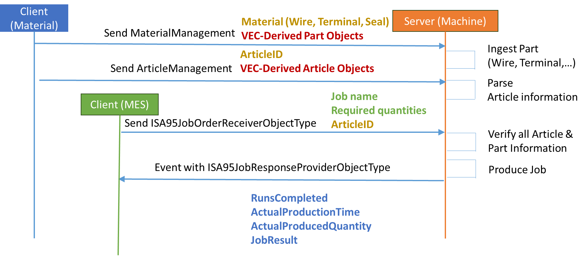
Some selected scenarios:
A simple server implementing the basic machinery and job control needs to implement:
Component identification and nameplate
Operating state
ISA95JobOrderReceiverObjectType with the store and clear methods
ISA95JobResponseProviderObjectType to parse the job production results
A server that wants to enable control of the validation of quality parameters during production must be aware of all the points mentioned above, plus:
VEC product definition for the harness to be manufactured
VEC part definition of the material used to produce the harness, including their specifications
Understanding of the article specification structure to understand which processes the client expects to be executed
Relevant ResultDataType to provide production monitoring results
A simple client with dashboard functionality, without the need for control, would implement the following:
Component identification and nameplate
Operating state
ISA95JobResponseProviderObject
Annex C Example of a job with part description and article specification (Informative)
This section details the entire job process, including the components, the article specifications, the job order or request, the job order response, and the result transfer. The example includes only the essential values and omits empty elements. Figure 16 shows an image of a wire that needs to be cut, stripped, and crimped at both ends. Figure 20 through Figure 25 show the example as data diagram.
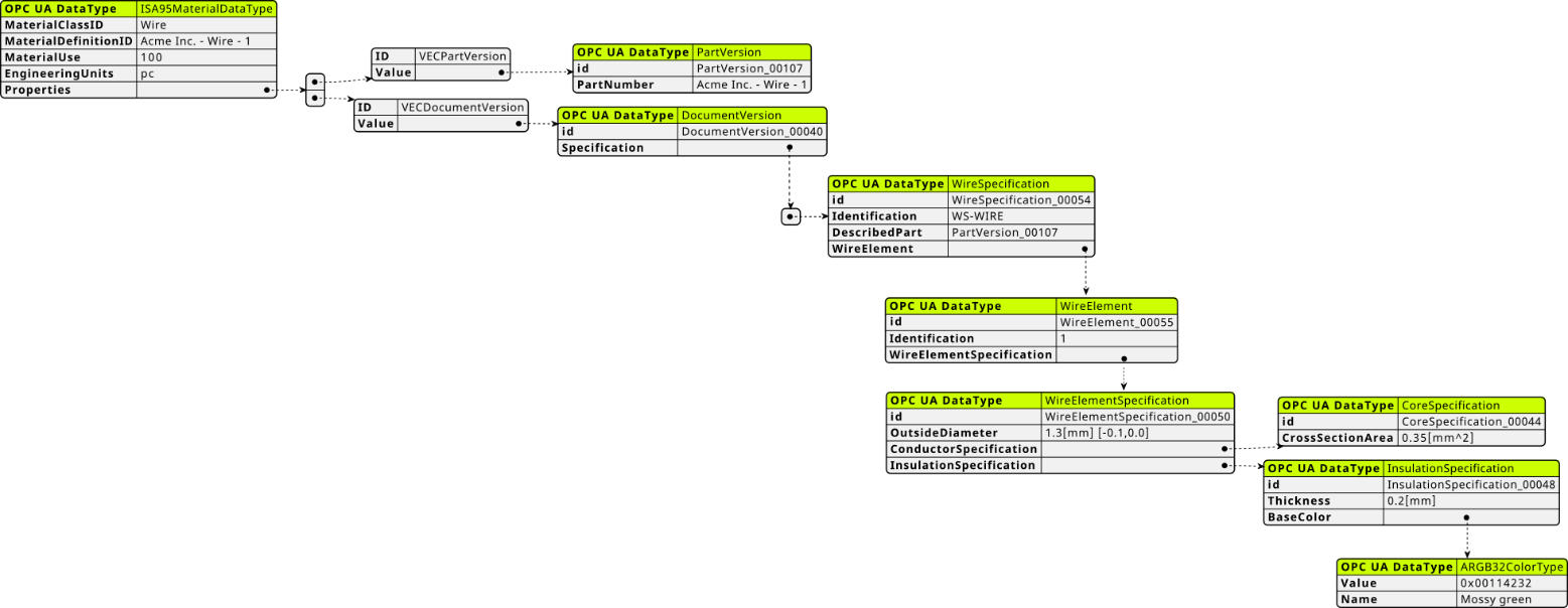
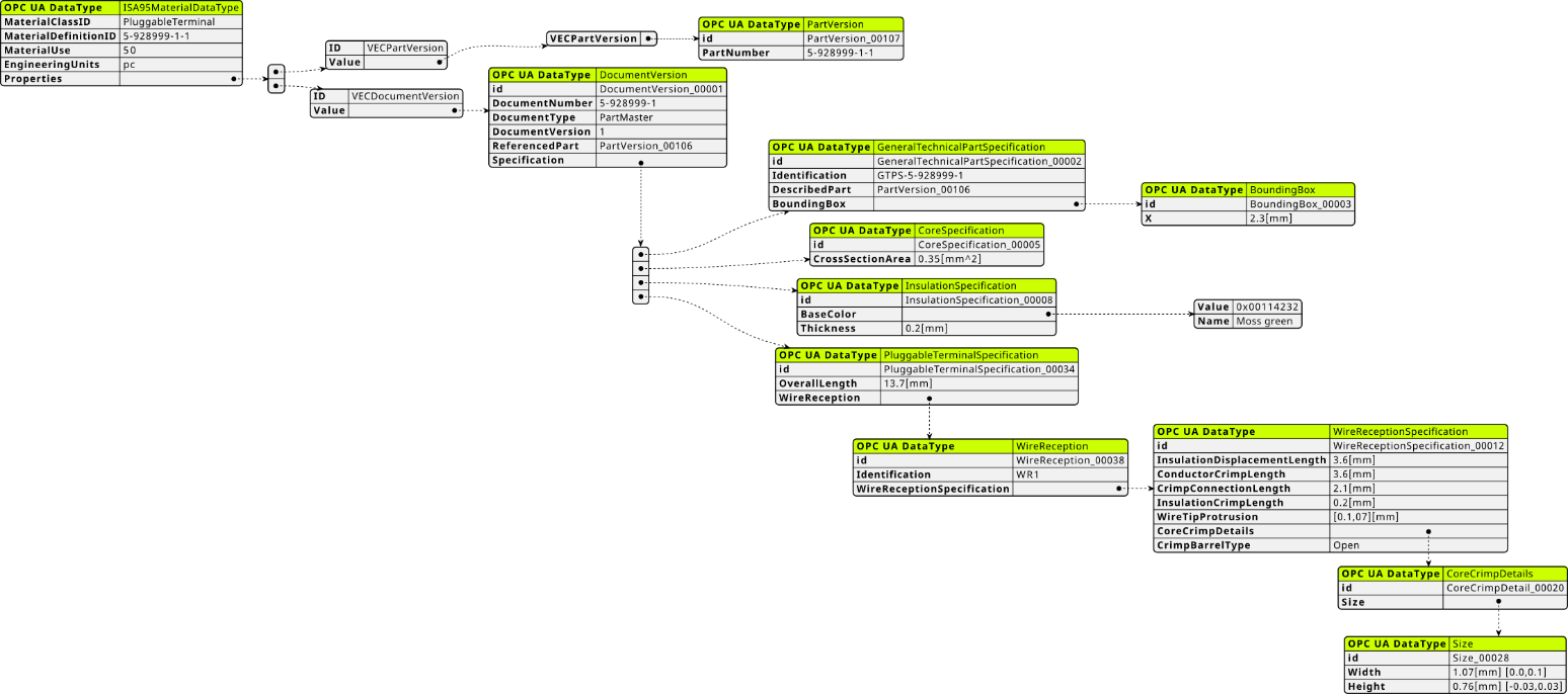
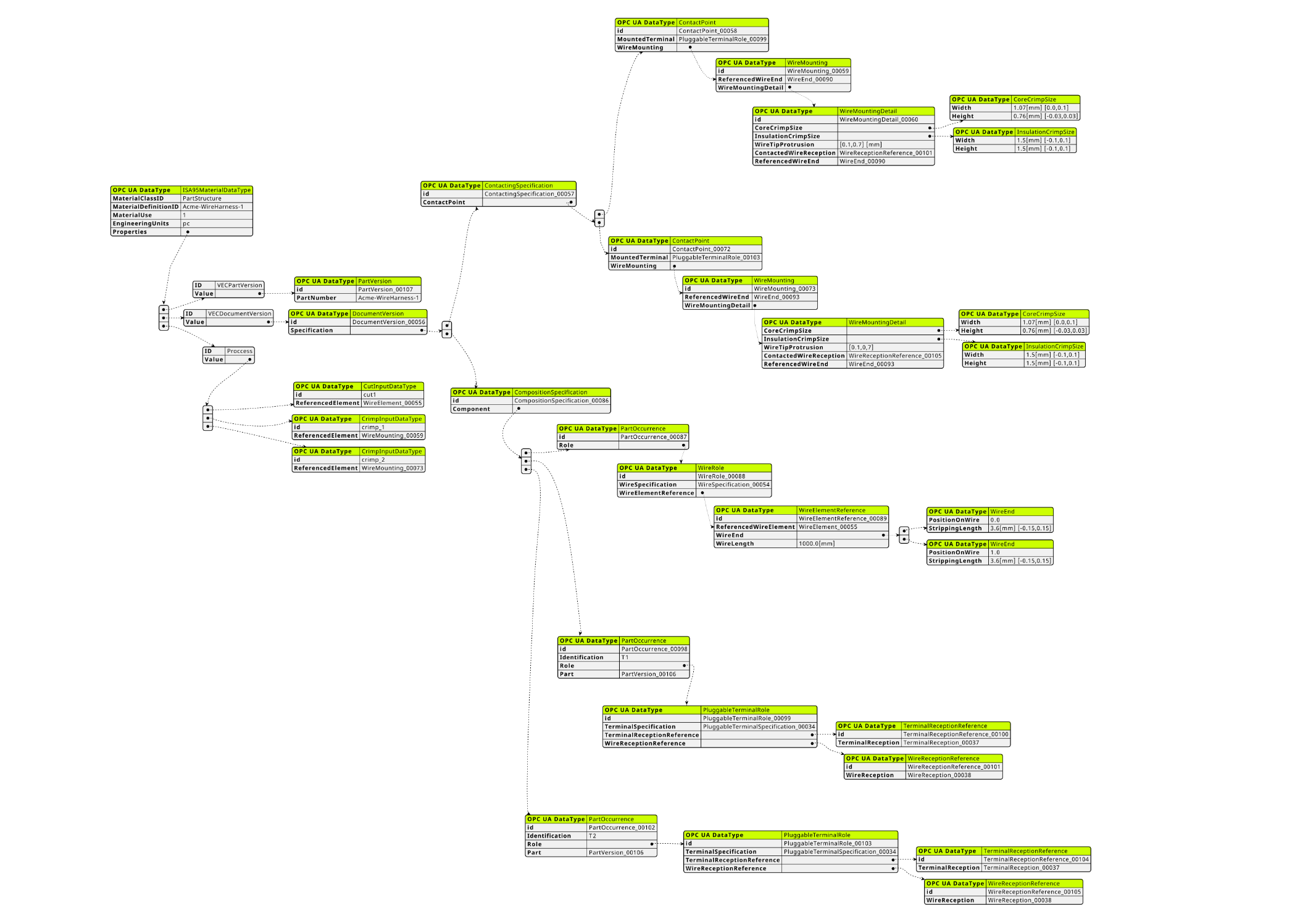
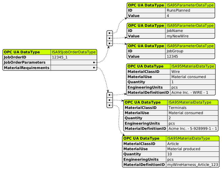
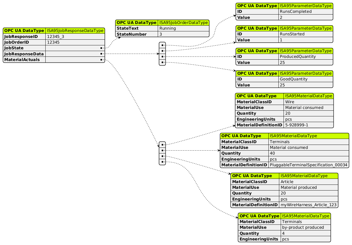
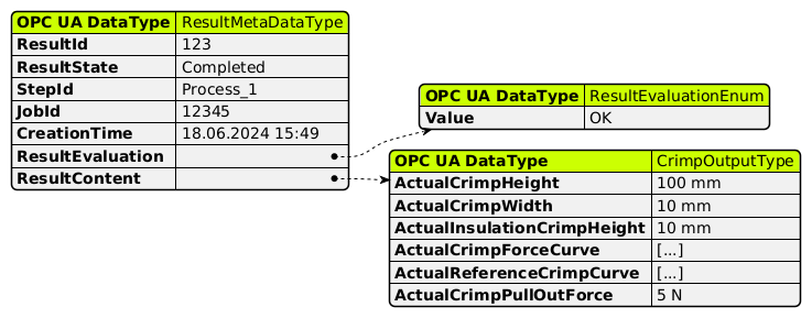
Annex D Description of the relevant data types of the VEC transformation (Informative)
This annex contains the DataType description of the relevant data types of the VEC transformation including a short description based on the VEC description. The detail description can be found in the VEC specification.
D.1 ConductorType
Specifies the type of the conductor, e.g. if it is rigid or stranded.
The Enumeration is defined in Table 88.
| VEC Name | Enum Value | Description |
|---|---|---|
Rigid | 0 | Used for conductors that are made of solid material. |
Stranded | 1 | Used for conductors that are made of multiple individual strands (used for most automotive cores). |
Foil | 2 | Used for conductors that are a foil (e.g. some shields). |
Braided | 3 | Used for conductors that are made of multiple individual strands that are braided together (often used for shields). |
D.2 CrimpBarrelType
This Enumeration describes with the CrimpBarrel is open or closed.
The Enumeration is defined in Table 89.
| VEC Name | Enum Value | Description |
|---|---|---|
Open | 0 | The CrimpBarrel is open |
Closed | 1 | The CrimpBarrel is closed. |
D.3 PrimaryPartType
The primary type of the part defines the type of the part (e.g. ConnectorHousing, Fixing, etc.) Since the VEC supports dual use parts (e.g. Fixing & WireProtection) the primary part type is necessary to define which specification associated to part is the primary character of the part. Therefore, all primary part types correspond to a PartOrUsageRelatedSpecification (e.g. ConnectorHousing --> ConnectorHousingSpecification).
The primary part type 'Other' is used if the PartVersion is not further specified by the VEC, which means it has no PartOrUsageRelatedSpecification, only a GeneralTechnicalPartSpecification or a direct instance of PartOrUsageRelatedSpecification.
The Enumeration is defined in Table 90.
| VEC Name | Enum Value | Description |
|---|---|---|
Antenna | 0 | |
Battery | 1 | |
BoltMountedFixing | 2 | |
BoltTerminal | 3 | |
BridgeTerminal | 4 | |
CableDuct | 5 | |
CableTie | 6 | |
Capacitor | 7 | |
CavityAccessory | 8 | |
CavityPlug | 9 | |
CavitySeal | 10 | |
ConnectorHousing | 11 | |
ConnectorHousingCap | 12 | |
ConnectorHousingCover | 13 | |
CorrugatedPipe | 14 | |
Diode | 15 | |
EdgeMountedFixing | 16 | |
EEComponent | 17 | |
Ferrite | 18 | |
Fitting | 19 | |
Fixing | 20 | |
Fuse | 21 | |
Grommet | 22 | |
HoleMountedFixing | 23 | |
MultiCavityPlug | 24 | |
MultiCavitySeal | 25 | |
MultiFuse | 26 | |
Other | 27 | The PrimaryPartType " Other " is used for parts that are described by a direct instance of PartOrUsageRelatedSpecification . These are parts that do not have a specific classification in the VEC and can be described with a PartOrUsageRelatedSpecification and CustomProperties. The corresponding Role is the SpecificRole. |
OpenWireEndTerminal | 28 | |
OpenWireEnd | 29 | |
PartStructure | 30 | The PrimaryPartType " PartStructure " has an inconsistency with VEC conventions for historical reasons, which is kept for backwards compatibility. The corresponding PartOrUsageRelatedSpecification is the PartStructureSpecification. However, the corresponding Role is the PartWithSubComponentsRole . |
PluggableTerminal | 31 | |
PotentialDistributor | 32 | |
Relay | 33 | |
RingTerminal | 34 | |
ShrinkableTube | 35 | |
SpliceTerminal | 36 | |
Stripe | 37 | |
Tape | 38 | |
Terminal | 39 | |
Tube | 40 | |
Wire | 41 | |
WireEndAccessory | 42 | |
WireProtection | 43 |
D.4 ARGB32ColorType
This structure contains a structure of a color.
The structure is defined in Table 91
| VEC Name | DataType | Description | Allow Subtypes |
|---|---|---|---|
| ARGB32ColorType | structure | Subtype of the 0:Structure defined in OPC 10000-3. | |
Value | UInt32 | The value of the color. It is given as ARGB. | False |
Name | String | A human readable name of the color. | False |
D.5 ExtendableElement
Abstract base class for extendable elements. Extendable elements have the possibility to define non-standard custom properties.
The structure is defined in Table 92
| VEC Name | DataType | Description | Allow Subtypes |
|---|---|---|---|
| ExtendableElement | structure | Subtype of the 0:Structure defined in OPC 10000-3. | |
id | TrimmedString | Abstract base class for extendable elements. Extendable elements have the possibility to define non-standard custom properties. | False |
D.6 BoundingBox
The bounding box is defined for the processed state of the component, as it appears in the finished product. Therefore, it is valid to use the bounding box as simplified geometry of the component for viewing or simple DMU operations. For correct 3D positioning, the bounding might require a transformation in the coordinate system of the component (see LocalGeometrySpecification.BoundingBoxPositioning ). The bounding box defines the smallest cuboid (box) that can contain a described part completely. If a component has multiple variants, the bounding box is the smallest cuboid that can contain every variant, while maintaining the spatial orientation of the bounding box and component variants. It is valid to use the BoundingBox to describe the dimensions of a component, even if not all dimensions are known (e.g. only length and width). However, it must be possible to transform such a partial bounding box into a complete bounding box by adding the missing dimensions.
The structure is defined in Table 139
| VEC Name | Type | Description | Allow Subtypes |
|---|---|---|---|
| BoundingBox | structure | Subtype of ExtendableElement defined in VEC | |
X | NumericalValue | Defines the extent of the bounding box in the direction of x (length). The bounding box is defined for the processed state of the component, as it appears in the finished product. Therefore, it is valid to use the bounding box as simplified geometry of the component for viewing or simple DMU operations. For correct 3D positioning, the bounding might require a transformation in the coordinate system of the component (see LocalGeometrySpecification.BoundingBoxPositioning ). The bounding box defines the smallest cuboid (box) that can contain a described part completely. If a component has multiple variants, the bounding box is the smallest cuboid that can contain every variant, while maintaining the spatial orientation of the bounding box and component variants. It is valid to use the BoundingBox to describe the dimensions of a component, even if not all dimensions are known (e.g. only length and width). However, it must be possible to transform such a partial bounding box into a complete bounding box by adding the missing dimensions. | False |
Y | NumericalValue | Defines the extent of the bounding box in the direction of y (width). The bounding box is defined for the processed state of the component, as it appears in the finished product. Therefore, it is valid to use the bounding box as simplified geometry of the component for viewing or simple DMU operations. For correct 3D positioning, the bounding might require a transformation in the coordinate system of the component (see LocalGeometrySpecification.BoundingBoxPositioning ). The bounding box defines the smallest cuboid (box) that can contain a described part completely. If a component has multiple variants, the bounding box is the smallest cuboid that can contain every variant, while maintaining the spatial orientation of the bounding box and component variants. It is valid to use the BoundingBox to describe the dimensions of a component, even if not all dimensions are known (e.g. only length and width). However, it must be possible to transform such a partial bounding box into a complete bounding box by adding the missing dimensions. | False |
Z | NumericalValue | Defines the extent of the bounding box in the direction of z (height). The bounding box is defined for the processed state of the component, as it appears in the finished product. Therefore, it is valid to use the bounding box as simplified geometry of the component for viewing or simple DMU operations. For correct 3D positioning, the bounding might require a transformation in the coordinate system of the component (see LocalGeometrySpecification.BoundingBoxPositioning ). The bounding box defines the smallest cuboid (box) that can contain a described part completely. If a component has multiple variants, the bounding box is the smallest cuboid that can contain every variant, while maintaining the spatial orientation of the bounding box and component variants. It is valid to use the BoundingBox to describe the dimensions of a component, even if not all dimensions are known (e.g. only length and width). However, it must be possible to transform such a partial bounding box into a complete bounding box by adding the missing dimensions. | False |
D.7 ConfigurableElement
Abstract base class for all elements which can be configured with a VariantConfiguration.
The structure is defined in Table 139
| VEC Name | Type | Description | Allow Subtypes |
|---|---|---|---|
| ConfigurableElement | structure | Subtype of ExtendableElement defined in VEC |
D.8 ContactPoint
A contact point defines the relationship between Terminals, Seals, Plugs, Cavities and Wires. It specifies a single contacting variant. This means that the contacting is manufactured, as specified by the Contact Point. Either all participants (Cavities, Terminals, Seals, Wires) set into a relationship by the ContactPoint exist in a specific harness or none. There is no requirement, to filter the participants of a contacting situation with information derived from VariantConfigurations or assembly / module associations in order to create a manufacturing variant. The ContactPoint represents a single potential. Consequently, all cavities and wires referencing / being referenced by a ContactPoint are short-circuited and have the same potential (even if the signals on the wires are named differently. If a contacting of a terminal has more than one potential (e.g. a coax-contact) one contact point for each potential is needed.
The structure is defined in Table 139
| VEC Name | Type | Description | Allow Subtypes |
|---|---|---|---|
| ContactPoint | structure | Subtype of 1:ConfigurableElement defined in VEC | |
Identification | String | Specifies a unique identification of the ContactPoint. The identification is guaranteed to be unique within the ContactingSpecification. A contact point defines the relationship between Terminals, Seals, Plugs, Cavities and Wires. It specifies a single contacting variant. This means that the contacting is manufactured, as specified by the Contact Point. Either all participants (Cavities, Terminals, Seals, Wires) set into a relationship by the ContactPoint exist in a specific harness or none. There is no requirement, to filter the participants of a contacting situation with information derived from VariantConfigurations or assembly / module associations in order to create a manufacturing variant. The ContactPoint represents a single potential. Consequently, all cavities and wires referencing / being referenced by a ContactPoint are short-circuited and have the same potential (even if the signals on the wires are named differently. If a contacting of a terminal has more than one potential (e.g. a coax-contact) one contact point for each potential is needed. | False |
MountedTerminal | TerminalRoleIdDataType | References the terminal that is used for contacting defined by the ContactPoint. A contact point defines the relationship between Terminals, Seals, Plugs, Cavities and Wires. It specifies a single contacting variant. This means that the contacting is manufactured, as specified by the Contact Point. Either all participants (Cavities, Terminals, Seals, Wires) set into a relationship by the ContactPoint exist in a specific harness or none. There is no requirement, to filter the participants of a contacting situation with information derived from VariantConfigurations or assembly / module associations in order to create a manufacturing variant. The ContactPoint represents a single potential. Consequently, all cavities and wires referencing / being referenced by a ContactPoint are short-circuited and have the same potential (even if the signals on the wires are named differently. If a contacting of a terminal has more than one potential (e.g. a coax-contact) one contact point for each potential is needed. | False |
WireMounting | WireMounting | Specifies the WireMouting defined by ContactPoint. More than one WireMounting is allowed in order to support variance. In concrete configuration the WireMounting with all referenced elements present is used. A contact point defines the relationship between Terminals, Seals, Plugs, Cavities and Wires. It specifies a single contacting variant. This means that the contacting is manufactured, as specified by the Contact Point. Either all participants (Cavities, Terminals, Seals, Wires) set into a relationship by the ContactPoint exist in a specific harness or none. There is no requirement, to filter the participants of a contacting situation with information derived from VariantConfigurations or assembly / module associations in order to create a manufacturing variant. The ContactPoint represents a single potential. Consequently, all cavities and wires referencing / being referenced by a ContactPoint are short-circuited and have the same potential (even if the signals on the wires are named differently. If a contacting of a terminal has more than one potential (e.g. a coax-contact) one contact point for each potential is needed. | False |
D.9 OccurrenceOrUsage
An OccurrenceOrUsage is an abstract appearance of a part in the harness. This can either be a concrete part (with a part number or something similar) or the description (specification / requirements) of a part that should be used at that position. In the first case it would be a PartOccurrence in the second case a PartUsage.
The structure is defined in Table 139
| VEC Name | Type | Description | Allow Subtypes |
|---|---|---|---|
| OccurrenceOrUsage | structure | Subtype of 1:ConfigurableElement defined in VEC | |
Identification | String | Specifies a unique identification of the OccurrenceOrUsage . The identification is guaranteed to be unique within the context. For all VEC-documents an OccurrenceOrUsage -instance can be trusted to be the same if the context-instance is the same and the identification of the OccurrenceOrUsage is the same. An OccurrenceOrUsage is an abstract appearance of a part in the harness. This can either be a concrete part (with a part number or something similar) or the description (specification / requirements) of a part that should be used at that position. In the first case it would be a PartOccurrence in the second case a PartUsage. | False |
Role | Role | Specifies the different roles of the OccurrenceOrUsage. An OccurrenceOrUsage is an abstract appearance of a part in the harness. This can either be a concrete part (with a part number or something similar) or the description (specification / requirements) of a part that should be used at that position. In the first case it would be a PartOccurrence in the second case a PartUsage. | False |
D.10 PartOccurrence
A PartOccurrence is an instance of a component with a specified part number (7:PartVersion).
The structure is defined in Table 139
| VEC Name | Type | Description | Allow Subtypes |
|---|---|---|---|
| PartOccurrence | structure | Subtype of 1:OccurrenceOrUsage defined in VEC | |
Part | 7:PartVersion | References the 7:PartVersion that is instantiated by this PartOccurrence. A PartOccurrence is an instance of a component with a specified part number (7:PartVersion). | False |
D.11 RoutableElement
A RoutableElement is an element that can be routed, which mean it is possible to assign it to a Path in the Topology.
The structure is defined in Table 139
| VEC Name | Type | Description | Allow Subtypes |
|---|---|---|---|
| RoutableElement | structure | Subtype of 1:ConfigurableElement defined in VEC |
D.12 WireElementReference
A WireElementReference represents the usage of a WireElement in the context of a PartUsage or PartOccurrence. For contacting purposes, a WireElementReference has WireEnds. KBLFRM-384
The structure is defined in Table 139
| VEC Name | Type | Description | Allow Subtypes |
|---|---|---|---|
| WireElementReference | structure | Subtype of 1:RoutableElement defined in VEC | |
Identification | String | Specifies a unique identification of the WireElementReference. The identification is guaranteed to be unique within the WireRole. A WireElementReference represents the usage of a WireElement in the context of a PartUsage or PartOccurrence. For contacting purposes, a WireElementReference has WireEnds. KBLFRM-384 | False |
ReferencedWireElement | WireElementIdDataType | References the WireElement that is represented by the WireElementReference. A WireElementReference represents the usage of a WireElement in the context of a PartUsage or PartOccurrence. For contacting purposes, a WireElementReference has WireEnds. KBLFRM-384 | False |
WireEnd | WireEnd | Specifies the ends of the WireElementReference for contacting purposes. A WireElementReference represents the usage of a WireElement in the context of a PartUsage or PartOccurrence. For contacting purposes, a WireElementReference has WireEnds. KBLFRM-384 | False |
WireLength | NumericalValue | Specifies the different length of a wire. A WireElementReference represents the usage of a WireElement in the context of a PartUsage or PartOccurrence. For contacting purposes, a WireElementReference has WireEnds. KBLFRM-384 | False |
D.13 CrimpDetail
Abstract base class for the definition of CrimpDetail- information. See CoreCrimpDetail & InsulationCrimpDetail .
The structure is defined in Table 139
| VEC Name | Type | Description | Allow Subtypes |
|---|---|---|---|
| CrimpDetail | structure | Subtype of ExtendableElement defined in VEC | |
Size | Size | Defines the expected size of the crimp. The height is measured in direction of the crimp opening. The width is measured in orthogonal to the height and orthogonal to main axis of the terminal ( TerminalSpecification.OverallLength ). Abstract base class for the definition of CrimpDetail- information. See CoreCrimpDetail & InsulationCrimpDetail . | False |
D.14 CoreCrimpDetail
The CoreCrimpDetail defines crimp values for a conductor crimp (wire crimp). The selection criteria to which the CoreCrimpDetail applies are defined by the referenced ConductorSpecification.
The structure is defined in Table 139
| VEC Name | Type | Description | Allow Subtypes |
|---|---|---|---|
| CoreCrimpDetail | structure | Subtype of 1:CrimpDetail defined in VEC | |
AppliesTo | ConductorSpecification | The CoreCrimpDetail defines crimp values for a conductor crimp (wire crimp). The selection criteria to which the CoreCrimpDetail applies are defined by the referenced ConductorSpecification. | False |
InsulationCrimpDetails | InsulationCrimpDetail | Defines the different InsulationCrimpDetails that are valid combinations for this CoreCrimpDetail. The CoreCrimpDetail defines crimp values for a conductor crimp (wire crimp). The selection criteria to which the CoreCrimpDetail applies are defined by the referenced ConductorSpecification. | False |
PullOffForce | NumericalValue | The minimum force that the completed crimp (core crimp only, insulation crimp non-functional) should withstand when wire is being pulled off the terminal. Above that force, the crimp can be expected to be destroyed at any time. The CoreCrimpDetail defines crimp values for a conductor crimp (wire crimp). The selection criteria to which the CoreCrimpDetail applies are defined by the referenced ConductorSpecification. | False |
D.15 InsulationCrimpDetail
The InsulationCrimpDetail defines crimp values for a insulation crimp. The selection criteria to which the InsulationCrimpDetail applies are defined by the referenced InsulationSpecification and the ConductorSpecification referenced by the containing CoreCrimpDetail.
The structure is defined in Table 139
| VEC Name | Type | Description | Allow Subtypes |
|---|---|---|---|
| InsulationCrimpDetail | structure | Subtype of 1:CrimpDetail defined in VEC | |
PullOffForce | NumericalValue | The minimum force that the completed crimp should withstand when wire is being pulled off the terminal. Above that force, the crimp can be expected to be destroyed at any time. The InsulationCrimpDetail defines crimp values for a insulation crimp. The selection criteria to which the InsulationCrimpDetail applies are defined by the referenced InsulationSpecification and the ConductorSpecification referenced by the containing CoreCrimpDetail. | False |
AppliesTo | InsulationSpecification | The InsulationCrimpDetail defines crimp values for a insulation crimp. The selection criteria to which the InsulationCrimpDetail applies are defined by the referenced InsulationSpecification and the ConductorSpecification referenced by the containing CoreCrimpDetail. | False |
D.16 ItemVersion
Abstract super-class for physical objects (e.g. a Terminal), virtual objects (e.g. a 150% Harness) as well as documents (e.g. a wiring diagram). In difference to AP 212 the VEC makes it only possible to describe/exchange information about Versions since Master-Objects cannot exist without one or more Versions.
The structure is defined in Table 139
| VEC Name | Type | Description | Allow Subtypes |
|---|---|---|---|
| ItemVersion | structure | Subtype of ExtendableElement defined in VEC | |
CompanyName | String | Defines the publishing company of the ItemVersion. The companyName is part of the main identifier of an ItemVersion together with the corresponding number (partNumber or documentNumber) and version (7:PartVersion or documentVersion). Abstract super-class for physical objects (e.g. a Terminal), virtual objects (e.g. a 150% Harness) as well as documents (e.g. a wiring diagram). In difference to AP 212 the VEC makes it only possible to describe/exchange information about Versions since Master-Objects cannot exist without one or more Versions. | False |
D.17 DocumentVersion
A DocumentVersion is a unique identifier for a piece of information in a company context. The DocumentVersion is one of the three anchors for PDM information in the VEC. All technical information about a 7:PartVersion is contained in one or more documents. The documents are containing the actual content of the VEC since all Specifications are an element of a document.
The structure is defined in Table 139
| VEC Name | Type | Description | Allow Subtypes |
|---|---|---|---|
| DocumentVersion | structure | Subtype of 1:ItemVersion defined in VEC | |
DocumentNumber | String | The documentNumber is the major identifier of a DocumentVersion. The format is user defined and respectively company specific. A DocumentVersion is a unique identifier for a piece of information in a company context. The DocumentVersion is one of the three anchors for PDM information in the VEC. All technical information about a 7:PartVersion is contained in one or more documents. The documents are containing the actual content of the VEC since all Specifications are an element of a document. | False |
DocumentVersion | String | The documentVersion specifies the version index of a document (see also documentNumber). A DocumentVersion is a unique identifier for a piece of information in a company context. The DocumentVersion is one of the three anchors for PDM information in the VEC. All technical information about a 7:PartVersion is contained in one or more documents. The documents are containing the actual content of the VEC since all Specifications are an element of a document. | False |
DigitalRepresentationIndex | String | An arbitrary change index that indicates if the digital representation (the content in VEC) of this DocumentVersion has been changed / regenerated. This can be for example an index, a timestamp or a checksum. This allows the detection of changes in the content, even when the DocumentNumber & DocumentVersion is the same. For a more detailed explanation in the context see "Parts & Documents". KBLFRM-837. A DocumentVersion is a unique identifier for a piece of information in a company context. The DocumentVersion is one of the three anchors for PDM information in the VEC. All technical information about a 7:PartVersion is contained in one or more documents. The documents are containing the actual content of the VEC since all Specifications are an element of a document. | False |
Specification | Specification | Specifies the Specifications contained in the DocumentVersion. All structured, technical information in the VEC is described by such Specifications. A DocumentVersion is a unique identifier for a piece of information in a company context. The DocumentVersion is one of the three anchors for PDM information in the VEC. All technical information about a 7:PartVersion is contained in one or more documents. The documents are containing the actual content of the VEC since all Specifications are an element of a document. | False |
D.18 PartVersion
A PartVersion is unique identifier for a part in a company context. A part can be any components within a vehicle. The PartVersion is one of the three anchors for PDM information in the VEC. All technical information about a PartVersion is contained in one or more documents. These describing elements are normally referencing to the PartVersion.
The structure is defined in Table 105
| VEC Name | Type | Description | Allow Subtypes |
|---|---|---|---|
| 7:PartVersion | structure | Subtype of 1:ItemVersion defined in VEC | |
PartNumber | String | The partNumber is the major identifier of a 7:PartVersion. The format is user defined and respectively company specific. For all VEC-documents a 7:PartVersion-instance can be trusted to be identical if the combination of partNumber, 7:PartVersion and companyName is identical. A 7:PartVersion is unique identifier for a part in a company context. A part can be any components within a vehicle. The 7:PartVersion is one of the three anchors for PDM information in the VEC. All technical information about a 7:PartVersion is contained in one or more documents. These describing elements are normally referencing to the 7:PartVersion. | False |
D.19 ResourceVersion
A ResourceVersion is unique identifier for a resource in a company context. Resources are elements used to produce, handle or service a harness, e.g. tools or machines, that do not end up in the product (see 7:PartVersion ). The ResourceVersion is one of the three anchors for PDM information in the VEC.
The structure is defined in Table 106.
| VEC Name | Type | Description | Allow Subtypes |
|---|---|---|---|
| ResourceVersion | structure | Subtype of 1:ItemVersion defined in VEC | |
ResourceNumber | String | The ResourceNumber is the major identifier of a ResourceVersion . The format is user defined and respectively company specific. For all VEC-documents a ResourceVersion-instance can be trusted to be identical if the combination of ResourceNumber , ResourceVersion and CompanyName is identical. A ResourceVersion is unique identifier for a resource in a company context. Resources are elements used to produce, handle or service a harness, e.g. tools or machines, that do not end up in the product (see 7:PartVersion ). The ResourceVersion is one of the three anchors for PDM information in the VEC. | False |
ResourceVersion | String | The ResourceVersion specifies the version index of a resource (see also ResourceNumber ). A ResourceVersion is unique identifier for a resource in a company context. Resources are elements used to produce, handle or service a harness, e.g. tools or machines, that do not end up in the product (see 7:PartVersion ). The ResourceVersion is one of the three anchors for PDM information in the VEC. | False |
D.20 Role
A Role is the corresponding mechanism for OccurrenceOrUsages to the PartOrUsageRelatedSpecifcations for 7:PartVersions or PartUsages. The PartOrUsageRelatedSpecifcations are describing a certain aspect of the master data of a part. A Role describes the corresponding properties and relationships for instances of a part (e.g. the usage specific properties of a wire occurrence like the length or the contacting).
The structure is defined in Table 107.
| VEC Name | Type | Description | Allow Subtypes |
|---|---|---|---|
| Role | structure | Subtype of ExtendableElement defined in VEC | |
Identification | String | Specifies a unique identification of the Role. The identification is guaranteed to be unique within the OccurrenceOrUsage. A Role is the corresponding mechanism for OccurrenceOrUsages to the PartOrUsageRelatedSpecifcations for 7:PartVersions or PartUsages. The PartOrUsageRelatedSpecifcations are describing a certain aspect of the master data of a part. A Role describes the corresponding properties and relationships for instances of a part (e.g. the usage specific properties of a wire occurrence like the length or the contacting). | False |
D.21 CavityPartRole
undefined
The structure is defined in Table 108.
| VEC Name | Type | Description | Allow Subtypes |
|---|---|---|---|
| CavityPartRole | structure | Subtype of 1:Role defined in VEC |
D.22 CavitySealRole
A CavitySealRole defines the instance specific properties and relationships of a cavity seal.
The structure is defined in Table 109.
| VEC Name | Type | Description | Allow Subtypes |
|---|---|---|---|
| CavitySealRole | structure | Subtype of 1:CavityPartRole defined in VEC | |
CavitySealSpecification | CavitySealSpecificationIdDataType | References the CavitySealSpecification that is instanced by this CavitySealRole. A CavitySealRole defines the instance specific properties and relationships of a cavity seal. | False |
D.23 TerminalRole
A TerminalRole defines the instance specific properties and relationships of a terminal.
The structure is defined in Table 110.
| VEC Name | Type | Description | Allow Subtypes |
|---|---|---|---|
| TerminalRole | structure | Subtype of 1:Role defined in VEC | |
TerminalSpecification | TerminalSpecificationIdDataType | References the TerminalSpecification that is instanced by this TerminalRole. A TerminalRole defines the instance specific properties and relationships of a terminal. | False |
WireReceptionReference | WireReceptionReference | Specifies the WireReceptionReferences of this TerminalRole. A TerminalRole defines the instance specific properties and relationships of a terminal. | False |
D.24 PluggableTerminalRole
A PluggableTerminalRole defines the instance specific properties and relationships of a pluggable terminal.
The structure is defined in Table 111.
| VEC Name | Type | Description | Allow Subtypes |
|---|---|---|---|
| PluggableTerminalRole | structure | Subtype of 1:TerminalRole defined in VEC |
D.25 WireRole
A WireRole defines the instance specific properties and relationships of a wire.
The structure is defined in Table 112.
| VEC Name | Type | Description | Allow Subtypes |
|---|---|---|---|
| WireRole | structure | Subtype of 1:Role defined in VEC | |
WireSpecification | WireSpecificationIdDataType | References the WireSpecification that is instanced by this WireRole. A WireRole defines the instance specific properties and relationships of a wire. | False |
WireElementReference | WireElementReference | Specifies the WireElementReferences used in the WireRole. For multi core wires more than one WireElementReference is needed. A WireRole defines the instance specific properties and relationships of a wire. | False |
D.26 Specification
Abstract super-class for all specifications. Every technical information exchanged with the VEC is contained in the different specializations of a specification.
The structure is defined in Table 113.
| VEC Name | Type | Description | Allow Subtypes |
|---|---|---|---|
| Specification | structure | Subtype of ExtendableElement defined in VEC | |
Identification | String | Specifies a unique identification of the specification. The identification is guaranteed to be unique within the document containing the specification. For all VEC-documents a Specification-instance can be trusted to be identical if the DocumentVersion-instance is the same (see DocumentVersion) and the identification of the Specification is the same. Abstract super-class for all specifications. Every technical information exchanged with the VEC is contained in the different specializations of a specification. | False |
D.27 CompositionSpecification
The CompositionSpecificiation is used to define a set of occurrences required to describe unambiguously the design of a composite part. This does not have to be necessarily the same occurrences which are building the bill of material. Example: A company might want to regard an antenna cable as one part out of a bill of material perspective. However, at the same time it may be useful for the company to be able to describe the contacting of the antenna cable within the VEC. (see also PartStructureSpecification)
The structure is defined in Table 114.
| VEC Name | Type | Description | Allow Subtypes |
|---|---|---|---|
| CompositionSpecification | structure | Subtype of 1:Specification defined in VEC | |
Component | PartOccurrence | Specifies the PartOccurrences defined in the CompositionSpecification. The CompositionSpecificiation is used to define a set of occurrences required to describe unambiguously the design of a composite part. This does not have to be necessarily the same occurrences which are building the bill of material. Example: A company might want to regard an antenna cable as one part out of a bill of material perspective. However, at the same time it may be useful for the company to be able to describe the contacting of the antenna cable within the VEC. (see also PartStructureSpecification) | False |
D.28 ConductorSpecification
Specification for the definition of conducting properties of a WireElement.
The structure is defined in Table 115.
| VEC Name | Type | Description | Allow Subtypes |
|---|---|---|---|
| ConductorSpecification | structure | Subtype of 1:Specification defined in VEC | |
CrossSectionArea | NumericalValue | Specifies the cross-section area of the conductor (e.g. 0,5 mm²). The cross-section area is a nominal value, which refers to the conducting properties of the conductor normalized to the properties of a full material core. Specification for the definition of conducting properties of a WireElement. | False |
Type | ConductorType | Specifies the type of the conductor, e.g. if it is rigid or stranded. Specification for the definition of conducting properties of a WireElement. | False |
D.29 CoreSpecification
Defines the properties of a circular conductor (core) which are specific for them.
The structure is defined in Table 116.
| VEC Name | Type | Description | Allow Subtypes |
|---|---|---|---|
| CoreSpecification | structure | Subtype of 1:ConductorSpecification defined in VEC | |
OutsideDiameter | NumericalValue | Specifies the outside diameter of the core. Defines the properties of a circular conductor (core) which are specific for them. | False |
D.30 ContactingSpecification
Specification for the description of the contacting. A contacting defines the relationships between Terminals, Seals, Plugs, Cavities and Wires.
The structure is defined in Table 117.
| VEC Name | Type | Description | Allow Subtypes |
|---|---|---|---|
| ContactingSpecification | structure | Subtype of 1:Specification defined in VEC | |
ContactPoint | ContactPoint | Specifies the ContactPoints defined by the ContactingSpecification. Specification for the description of the contacting. A contacting defines the relationships between Terminals, Seals, Plugs, Cavities and Wires. | False |
D.31 InsulationSpecification
Specification for the definition of insulation properties of a WireElement.
The structure is defined in Table 118.
| VEC Name | Type | Description | Allow Subtypes |
|---|---|---|---|
| InsulationSpecification | structure | Subtype of 1:Specification defined in VEC | |
BaseColor | ARGB32ColorType | Specifies the base color of the insulation. Specification for the definition of insulation properties of a WireElement. | False |
FirstIdentificationColor | ARGB32ColorType | Specifies the first identification color of the insulation. Specification for the definition of insulation properties of a WireElement. | False |
SecondIdentificationColor | ARGB32ColorType | Specifies the second identification color of the insulation. Specification for the definition of insulation properties of a WireElement. | False |
Thickness | NumericalValue | Specifies the thickness of the insulation. Specification for the definition of insulation properties of a WireElement. | False |
D.32 PartOrUsageRelatedSpecification
Base class for all specifications which are describing a 7:PartVersion or a PartUsage . A PartOrUsageRelatedSpecification specifies a certain aspect of the described part or usage (e.g. general technical part information, connector housing aspects or wire aspects).
The structure is defined in Table 119.
D.33 CavityPartSpecification
The CavityPartSpecification is an abstract class for common properties of non-electrical parts that are used in Cavities .
The structure is defined in Table 120.
| VEC Name | Type | Description | Allow Subtypes |
|---|---|---|---|
| CavityPartSpecification | structure | Subtype of 1:PartOrUsageRelatedSpecification defined in VEC |
D.34 CavitySealSpecification
Specification for the definition of cavity seals. A CavitySeal is a watertight non-electrical object to fill a populated Cavity.
The structure is defined in Table 121.
| VEC Name | Type | Description | Allow Subtypes |
|---|---|---|---|
| CavitySealSpecification | structure | Subtype of 1:CavityPartSpecification defined in VEC |
D.35 GeneralTechnicalPartSpecification
Specification for the definition of common properties for technical parts.
The structure is defined in Table 122.
| VEC Name | Type | Description | Allow Subtypes |
|---|---|---|---|
| GeneralTechnicalPartSpecification | structure | Subtype of 1:PartOrUsageRelatedSpecification defined in VEC | |
ColorInformation | ARGB32ColorType | Specifies the color of the part. Specification for the definition of common properties for technical parts. | False |
BoundingBox | BoundingBox | Defines the bounding box of the part. Specification for the definition of common properties for technical parts. | False |
D.36 TerminalSpecification
Specification for the definition of terminals. A terminal can own multiple WireReceptions & TerminalReceptions.
The structure is defined in Table 123.
| VEC Name | Type | Description | Allow Subtypes |
|---|---|---|---|
| TerminalSpecification | structure | Subtype of 1:PartOrUsageRelatedSpecification defined in VEC | |
ConnectionALength | NumericalValue | Specifies the length of the terminal between the contact area (terminal reception) and the crimp are (wire reception, see diagram "Terminal Dimensions"). Specification for the definition of terminals. A terminal can own multiple WireReceptions & TerminalReceptions. | False |
OverallLength | NumericalValue | Specifies the overall length the terminal (see diagram "Terminal Dimensions"). Specification for the definition of terminals. A terminal can own multiple WireReceptions & TerminalReceptions. | False |
WireReception | WireReception | Specifies the WireReceptions of the terminal described by the TerminalSpecification. Specification for the definition of terminals. A terminal can own multiple WireReceptions & TerminalReceptions. | False |
D.37 PluggableTerminalSpecification
Specification for the definition of pluggable terminals.
The structure is defined in Table 124.
| VEC Name | Type | Description | Allow Subtypes |
|---|---|---|---|
| PluggableTerminalSpecification | structure | Subtype of 1:TerminalSpecification defined in VEC |
D.38 WireSpecification
Specification for the definition of a wire. This can either be a complex multicore wire or a normal single core. In the VEC a wire is defined by one WireElement, which may be composed from other WireElements.
The structure is defined in Table 125.
| VEC Name | Type | Description | Allow Subtypes |
|---|---|---|---|
| WireSpecification | structure | Subtype of 1:PartOrUsageRelatedSpecification defined in VEC | |
WireElement | WireElement | Specifies the WireElement that represents the root of the WireSpecification . Specification for the definition of a wire. This can either be a complex multicore wire or a normal single core. In the VEC a wire is defined by one WireElement, which may be composed from other WireElements. | False |
D.39 WireElementSpecification
A WireElementSpecification is the basic element to describe a wire in the VEC. A WireElementSpecification can be atomic or composed recursively out of other WireElementSpecifications. A WireElementSpecification can reference an InsulationSpecification, if it has an insulation, a CoreSpecification, if it has a core or a WireGroupSpecification if it is a grouping of other WireElementSpecifications in the Wire (e.g. a multi-core wire with twisted pairs).
The structure is defined in Table 126.
| VEC Name | Type | Description | Allow Subtypes |
|---|---|---|---|
| WireElementSpecification | structure | Subtype of 1:Specification defined in VEC | |
OutsideDiameter | NumericalValue | Specifies the outside diameter of the WireElement. A WireElementSpecification is the basic element to describe a wire in the VEC. A WireElementSpecification can be atomic or composed recursively out of other WireElementSpecifications. A WireElementSpecification can reference an InsulationSpecification, if it has an insulation, a CoreSpecification, if it has a core or a WireGroupSpecification if it is a grouping of other WireElementSpecifications in the Wire (e.g. a multi-core wire with twisted pairs). | False |
ConductorSpecification | ConductorSpecification | If the WireElement has a core then the specification of the core is referenced here. A WireElementSpecification is the basic element to describe a wire in the VEC. A WireElementSpecification can be atomic or composed recursively out of other WireElementSpecifications. A WireElementSpecification can reference an InsulationSpecification, if it has an insulation, a CoreSpecification, if it has a core or a WireGroupSpecification if it is a grouping of other WireElementSpecifications in the Wire (e.g. a multi-core wire with twisted pairs). | False |
InsulationSpecification | InsulationSpecification | If the WireElement has an insulation then the specification of the insulation is referenced here. A WireElementSpecification is the basic element to describe a wire in the VEC. A WireElementSpecification can be atomic or composed recursively out of other WireElementSpecifications. A WireElementSpecification can reference an InsulationSpecification, if it has an insulation, a CoreSpecification, if it has a core or a WireGroupSpecification if it is a grouping of other WireElementSpecifications in the Wire (e.g. a multi-core wire with twisted pairs). | False |
D.40 WireReceptionSpecification
Specification for the definition of wire receptions. A WireReception is the area of a terminal where the contacting with a wire element (e.g. by crimping) takes place.
The structure is defined in Table 127.
| VEC Name | Type | Description | Allow Subtypes |
|---|---|---|---|
| WireReceptionSpecification | structure | Subtype of 1:Specification defined in VEC | |
InsulationDisplacementLength | NumericalValue | Specifies the length of the insulation which must be stripped off to fit to this wire reception. Specification for the definition of wire receptions. A WireReception is the area of a terminal where the contacting with a wire element (e.g. by crimping) takes place. | False |
ConductorCrimpLength | NumericalValue | Specifies the length of the conductor crimp (wire reception, see diagram "Terminal Dimensions"). Specification for the definition of wire receptions. A WireReception is the area of a terminal where the contacting with a wire element (e.g. by crimping) takes place. | False |
CrimpConnectionLength | NumericalValue | Specifies the length of the crimp area, conductor + insulation crimp (wire reception, see diagram "Terminal Dimensions"). Specification for the definition of wire receptions. A WireReception is the area of a terminal where the contacting with a wire element (e.g. by crimping) takes place. | False |
InsulationCrimpLength | NumericalValue | Specifies the length of the insulation crimp (wire reception, see diagram "Terminal Dimensions"). Specification for the definition of wire receptions. A WireReception is the area of a terminal where the contacting with a wire element (e.g. by crimping) takes place. | False |
WireTipProtrusion | ValueRange | Defines the valid length range in which the protrusion of the conductor from the conductor crimp must be located. Specification for the definition of wire receptions. A WireReception is the area of a terminal where the contacting with a wire element (e.g. by crimping) takes place. | False |
CoreCrimpDetails | CoreCrimpDetail | Defines the CrimpDetails for this WireReception. Specification for the definition of wire receptions. A WireReception is the area of a terminal where the contacting with a wire element (e.g. by crimping) takes place. | False |
CrimpBarrelType | CrimpBarrelType | When the crimp barrel is open, the wire can be laid into the terminal from above. If the crimp barrel is closed, the wire must be fed in from the front. Specification for the definition of wire receptions. A WireReception is the area of a terminal where the contacting with a wire element (e.g. by crimping) takes place. | False |
D.41 Tolerance
A Tolerance defines the permissible limit or limits of variation for defined values (e.g. a NumericalValue ). The tolerated value is defined by the context in which the Tolerance is contained / used. The values of the limits of the Tolerance , LowerBoundary and UpperBoundary , shall be interpreted as "modifiers" to the actual value. To obtain an absolute range of valid values, the values of boundaries shall be added to the actual value, regardless of the Upper or Lower prefix. For example, to define a value of 100 mm with a tolerated variation between 95mm and 105mm, the definition would be Value = 100 mm, LowerBoundary=-5, UpperBoundary=+5 . The Unit of the Tolerance boundaries is always the same as in the defining context.
The structure is defined in Table 128.
| VEC Name | Type | Description | Allow Subtypes |
|---|---|---|---|
| Tolerance | structure | Subtype of ExtendableElement defined in VEC | |
LowerBoundary | Double | Specifies the lower boundary for the tolerance. A Tolerance defines the permissible limit or limits of variation for defined values (e.g. a NumericalValue ). The tolerated value is defined by the context in which the Tolerance is contained / used. The values of the limits of the Tolerance , LowerBoundary and UpperBoundary , shall be interpreted as "modifiers" to the actual value. To obtain an absolute range of valid values, the values of boundaries shall be added to the actual value, regardless of the Upper or Lower prefix. For example, to define a value of 100 mm with a tolerated variation between 95mm and 105 mm, the definition would be Value = 100 mm, LowerBoundary=-5, UpperBoundary=+5 . The Unit of the Tolerance boundaries is always the same as in the defining context. | False |
UpperBoundary | Double | Specifies the upper boundary for the tolerance. A Tolerance defines the permissible limit or limits of variation for defined values (e.g. a NumericalValue ). The tolerated value is defined by the context in which the Tolerance is contained / used. The values of the limits of the Tolerance , LowerBoundary and UpperBoundary , shall be interpreted as "modifiers" to the actual value. To obtain an absolute range of valid values, the values of boundaries shall be added to the actual value, regardless of the Upper or Lower prefix. For example, to define a value of 100 mm with a tolerated variation between 95 mm and 105 mm, the definition would be Value = 100 mm, LowerBoundary=-5, UpperBoundary=+5 . The Unit of the Tolerance boundaries is always the same as in the defining context. | False |
D.42 WireElement
A WireElement specifies a WireElementSpecification in the context of a WireSpecification . This is necessary to define a unique identification of a WireElementSpecification in the context of a WireSpecification. Additionally, the WireElement serves as anchor for the instancing of a wire ( WireElementReference ) as the WireElementSpecifications are not uniquely related to a WireSpecification for reasons of reusability.
The structure is defined in Table 129.
| VEC Name | Type | Description | Allow Subtypes |
|---|---|---|---|
| WireElement | structure | Subtype of ExtendableElement defined in VEC | |
Identification | String | The identification of the WireElement. The identification is guaranteed to be unique within a wire and immutable. The identification is guaranteed to be the same for the same WireElement over different VEC documents. A WireElement specifies a WireElementSpecification in the context of a WireSpecification . This is necessary to define a unique identification of a WireElementSpecification in the context of a WireSpecification. Additionally, the WireElement serves as anchor for the instancing of a wire ( WireElementReference ) as the WireElementSpecifications are not uniquely related to a WireSpecification for reasons of reusability. | False |
WireElementSpecification | WireElementSpecification | Reference the WireElementSpecification that is represented by the WireElement. A WireElement specifies a WireElementSpecification in the context of a WireSpecification . This is necessary to define a unique identification of a WireElementSpecification in the context of a WireSpecification. Additionally, the WireElement serves as anchor for the instancing of a wire ( WireElementReference ) as the WireElementSpecifications are not uniquely related to a WireSpecification for reasons of reusability. | False |
SubWireElement | WireElement | Defines the subWireElements of this WireElement . The subWireElements shall be consistent with the subWireElementSpecifications of the WireElementSpecification referenced by this WireElement and shall resemble that hierarchy. A WireElement specifies a WireElementSpecification in the context of a WireSpecification . This is necessary to define a unique identification of a WireElementSpecification in the context of a WireSpecification. Additionally, the WireElement serves as anchor for the instancing of a wire ( WireElementReference ) as the WireElementSpecifications are not uniquely related to a WireSpecification for reasons of reusability. | False |
D.43 WireEnd
A WireEnd is the end of a wire. This class mainly needed for the definition of a contacting. As a wire can be contacted on more than two ends (e.g. IDC) the WireEnd has a position on the wire.
The structure is defined in Table 130.
| VEC Name | Type | Description | Allow Subtypes |
|---|---|---|---|
| WireEnd | structure | Subtype of ExtendableElement defined in VEC | |
Identification | String | Specifies a unique identification of the WireEnd. The identification is guaranteed to be unique within the WireElementReference. A WireEnd is the end of a wire. This class mainly needed for the definition of a contacting. As a wire can be contacted on more than two ends (e.g. IDC) the WireEnd has a position on the wire. | False |
PositionOnWire | Double | Specifies the order of the WireEnds on the WireElementReference . This must be a value between 0 and 1. The PositionOnWire is defined as a floating point number, to allow the ordering of an arbitrary number of WireEnds while having constant known values for the first and last WireEnd ("0.0" & "1.0"). The PositionOnWire is<u>not</u>defined as a relative factor with respect to the WireLength to determine an exact position of the WireEnd on the wire. This would not be defined unambiguously, since a WireElementReference can define multiple lengths of different WireLengthTypes . If such an interpretation can be made, it is tool or process specific definition. In case of WireRole with multiple WireElementReferences the ordering of the WireEnds shall be consistent for all WireElementReferences. That means that all WireEnds with PositionOnWire = 0.0 are on the same side of the WireRole. A WireEnd is the end of a wire. This class mainly needed for the definition of a contacting. As a wire can be contacted on more than two ends (e.g. IDC) the WireEnd has a position on the wire. | False |
StrippingLength | NumericalValue | Defines the length by which an insulation on this stripped relative to this WireEnd, defined by the cutBackLength . E.g. a cutBackLength of 20mm and a strippingLength of 10mm means, that this WireElementReference is cutback by 20mm relative to length of whole wire, on the side of the defining WireEnd. Form the remaining WireElementReference are then 10mm insulation removed. A WireEnd is the end of a wire. This class mainly needed for the definition of a contacting. As a wire can be contacted on more than two ends (e.g. IDC) the WireEnd has a position on the wire. | False |
InsulationPullbackLength | NumericalValue | Defines a partial stripping process in which the insulation is pulled back by the insulationPullbackLength after being cut at the strippingLength, and is left on the WireEnd e.g. for logistic reasons. The insulationPullbackLength must be shorter than the strippingLength; otherwise, it would not qualify as partial stripping. A WireEnd is the end of a wire. This class mainly needed for the definition of a contacting. As a wire can be contacted on more than two ends (e.g. IDC) the WireEnd has a position on the wire. | False |
D.44 WireMounting
A WireMounting defines the mounting of a wire end to terminal. If the contacting is required to be waterproof a cavity seal can be mounted additionally.
The structure is defined in Table 131.
| VEC Name | Type | Description | Allow Subtypes |
|---|---|---|---|
| WireMounting | structure | Subtype of ExtendableElement defined in VEC | |
MountedCavitySeal | CavitySealRoleIdDataType | References the cavity seal that is used for the wire mounting. A WireMounting defines the mounting of a wire end to terminal. If the contacting is required to be waterproof a cavity seal can be mounted additionally. | False |
ReferencedWireEnd | WireEndIdDataType | References the wire ends that are used for the wire mounting. The minimum cardinality is one, because a wire mounting without wire end makes no sense. The maximum cardinality is * in order to support multi crimps. A WireMounting defines the mounting of a wire end to terminal. If the contacting is required to be waterproof a cavity seal can be mounted additionally. | False |
WireMountingDetail | WireMountingDetail | Specifies the WireMoutingDetails, if a detailed description of the relationships between WireEnds and WireReceptions is needed. A WireMounting defines the mounting of a wire end to terminal. If the contacting is required to be waterproof a cavity seal can be mounted additionally. | False |
D.45 WireMountingDetail
With a WireMountingDetail it is possible to describe a detailed wire mounting. This is needed if the information which wire end is mounted onto which wire reception is important (e.g. coax contacts).
The structure is defined in Table 132.
| VEC Name | Type | Description | Allow Subtypes |
|---|---|---|---|
| WireMountingDetail | structure | Subtype of ExtendableElement defined in VEC | |
CoreCrimpSize | Size | Defines the required core crimp size (width & height) of this specific wire mounting situation. With a WireMountingDetail it is possible to describe a detailed wire mounting. This is needed if the information which wire end is mounted onto which wire reception is important (e.g. coax contacts). | False |
InsulationCrimpSize | Size | Defines the required insulation crimp size (width & height) of this specific wire mounting situation. With a WireMountingDetail it is possible to describe a detailed wire mounting. This is needed if the information which wire end is mounted onto which wire reception is important (e.g. coax contacts). | False |
WireTipProtrusion | ValueRange | Defines the valid length range in which the protrusion of the conductor from the conductor crimp must be located. With a WireMountingDetail it is possible to describe a detailed wire mounting. This is needed if the information which wire end is mounted onto which wire reception is important (e.g. coax contacts). | False |
ContactedWireReception | WireReceptionReferenceIdDataType | References the WireReception that is used for the WireMounting. With a WireMountingDetail it is possible to describe a detailed wire mounting. This is needed if the information which wire end is mounted onto which wire reception is important (e.g. coax contacts). | False |
ReferencedWireEnd | WireEndIdDataType | References the WireEnds that are mounted to referenced WireReception. A cardinality of more than one is allowed in order support parallel connectors, where multiple wire ends are placed on one side of the connector (one wire reception) and the other wire ends are placed on the other side of the connector (the other wire reception). With a WireMountingDetail it is possible to describe a detailed wire mounting. This is needed if the information which wire end is mounted onto which wire reception is important (e.g. coax contacts). | False |
AbsoluteSealPosition | NumericalValue | The absoluteSealPosition defines distance between the conductor tip and edge of the CavitySeal facing the conductor tip. With a WireMountingDetail it is possible to describe a detailed wire mounting. This is needed if the information which wire end is mounted onto which wire reception is important (e.g. coax contacts). | False |
CorePullOffForce | NumericalValue | The minimum force that the completed crimp (core crimp only, insulation crimp non-functional) should withstand when wire is being pulled off the terminal. Above that force, the crimp can be expected to be destroyed at any time. With a WireMountingDetail it is possible to describe a detailed wire mounting. This is needed if the information which wire end is mounted onto which wire reception is important (e.g. coax contacts). | False |
D.46 WireReception
A WireReception is the area of a terminal where the contacting with a wire element (e.g. by crimping) takes place. This class represents such an area on the terminal. Its description is done with a WireReceptionSpecification, which is independent from the TerminalSpecification. This allows the reuse of the specification of similar WireReception on different terminals.
The structure is defined in Table 133.
| VEC Name | Type | Description | Allow Subtypes |
|---|---|---|---|
| WireReception | structure | Subtype of ExtendableElement defined in VEC | |
Identification | String | Specifies a unique identification of the WireReception. The identification is guaranteed to be unique within the TerminalSpecification (this might be for example a reception number). A WireReception is the area of a terminal where the contacting with a wire element (e.g. by crimping) takes place. This class represents such an area on the terminal. Its description is done with a WireReceptionSpecification, which is independent from the TerminalSpecification. This allows the reuse of the specification of similar WireReception on different terminals. | False |
Rotation | NumericalValue | Defines the rotation of a WireReception relative to the TerminalReception. The rotation of the WireReception is the angle between the normal vector on base plane of the crimp area and the y-axis, which is a rotation around the z-axis (right hand rule, compare illustration in "Terminal Coordinate System" ). A WireReception is the area of a terminal where the contacting with a wire element (e.g. by crimping) takes place. This class represents such an area on the terminal. Its description is done with a WireReceptionSpecification, which is independent from the TerminalSpecification. This allows the reuse of the specification of similar WireReception on different terminals. | False |
WireReceptionSpecification | WireReceptionSpecification | References the WireReceptionSpecification that specifies the WireReception. A WireReception is the area of a terminal where the contacting with a wire element (e.g. by crimping) takes place. This class represents such an area on the terminal. Its description is done with a WireReceptionSpecification, which is independent from the TerminalSpecification. This allows the reuse of the specification of similar WireReception on different terminals. | False |
D.47 WireReceptionReference
A WireReceptionReference is an instance of a WireReception .
The structure is defined in Table 134.
| VEC Name | Type | Description | Allow Subtypes |
|---|---|---|---|
| WireReceptionReference | structure | Subtype of ExtendableElement defined in VEC | |
Identification | String | Specifies a unique identification of the WireReceptionReference . The identification is guaranteed to be unique within the TerminalRole (this might be for example a reception number). A WireReceptionReference is an instance of a WireReception . | False |
WireReception | WireReceptionIdDataType | References the WireReception that is instanced by this WireReceptionReference. A WireReceptionReference is an instance of a WireReception . | False |
D.48 Material
Allows the definition of material information. Attributes of the type Material normally have the multiplicity [0..*]. This means that such an attribute can have material values for different referenceSystems . It must not have multiple values for the same referenceSystems .
The structure is defined in Table 135.
| VEC Name | Type | Description | Allow Subtypes |
|---|---|---|---|
| Material | structure | Subtype of the 0:Structure defined in OPC 10000-3. | |
Key | String | The key of the material in the corresponding material reference system. Allows the definition of material information. Attributes of the type Material normally have the multiplicity [0..*]. This means that such an attribute can have material values for different referenceSystems . It must not have multiple values for the same referenceSystems . | False |
ReferenceSystem | String | The identification of the material reference system, which is defining possible values and the semantic of material keys. Allows the definition of material information. Attributes of the type Material normally have the multiplicity [0..*]. This means that such an attribute can have material values for different referenceSystems . It must not have multiple values for the same referenceSystems . | False |
D.49 Size
Defines the size of an element by width & height. Per definition is width > height.
The structure is defined in Table 136.
| VEC Name | Type | Description | Allow Subtypes |
|---|---|---|---|
| Size | structure | Subtype of the 0:Structure defined in OPC 10000-3. | |
Width | NumericalValue | The width of the element. Defines the size of an element by width & height. Per definition is width > height. | False |
Height | NumericalValue | The height of the element. Defines the size of an element by width & height. Per definition is width > height. | False |
D.50 ValueWithUnit
Abstract class either for a single numerical measure or a range of numerical measures with upper, lower, or upper and lower bounds.
The structure is defined in Table 137.
| VEC Name | Type | Description | Allow Subtypes |
|---|---|---|---|
| ValueWithUnit | structure | Subtype of the 0:Structure defined in OPC 10000-3. | |
UnitComponent | EUInformation | References the unit of the value. Abstract class either for a single numerical measure or a range of numerical measures with upper, lower, or upper and lower bounds. | False |
D.51 NumericalValue
A quantity expressed with a numerical value and a unit.
The structure is defined in Table 138.
| VEC Name | Type | Description | Allow Subtypes |
|---|---|---|---|
| NumericalValue | structure | Subtype of 1:ValueWithUnit defined in VEC | |
ValueComponent | Double | Specifies the value of the numerical value. A quantity expressed with a numerical value and a unit. | False |
Tolerance | Tolerance | Specifies the tolerance for the dimension. A quantity expressed with a numerical value and a unit. | False |
D.52 ValueRange
A pair of numerical values representing a value range.
The structure is defined in Table 139.
| VEC Name | Type | Description | Allow Subtypes |
|---|---|---|---|
| ValueRange | structure | Subtype of 1:ValueWithUnit defined in VEC | |
Minimum | Double | Lower bound of the value range. A pair of numerical values representing a value range. | False |
Maximum | Double | Upper bound of the value range. A pair of numerical values representing a value range. | False |
Agreement of Use
COPYRIGHT RESTRICTIONS
This document is provided "as is" by the OPC Foundation and VDMA.
Right of use for this specification is restricted to this specification and does not grant rights of use for referred documents.
Right of use for this specification will be granted without cost.
This document may be distributed through computer systems, printed or copied as long as the content remains unchanged and the document is not modified.
OPC Foundation and VDMA do not guarantee usability for any purpose and shall not be made liable for any case using the content of this document.
The user of the document agrees to indemnify OPC Foundation and VDMA and their officers, directors and agents harmless from all demands, claims, actions, losses, damages (including damages from personal injuries), costs and expenses (including attorneys' fees) which are in any way related to activities associated with its use of content from this specification.
The document shall not be used in conjunction with company advertising, shall not be sold or licensed to any party.
The intellectual property and copyright is solely owned by the OPC Foundation and VDMA.
PATENTS
The attention of adopters is directed to the possibility that compliance with or adoption of OPC or VDMA specifications may require use of an invention covered by patent rights. OPC Foundation or VDMA shall not be responsible for identifying patents for which a license may be required by any OPC or VDMA specification, or for conducting legal inquiries into the legal validity or scope of those patents that are brought to its attention. OPC or VDMA specifications are prospective and advisory only. Prospective users are responsible for protecting themselves against liability for infringement of patents.
WARRANTY AND LIABILITY DISCLAIMERS
WHILE THIS PUBLICATION IS BELIEVED TO BE ACCURATE, IT IS PROVIDED "AS IS" AND MAY CONTAIN ERRORS OR MISPRINTS. THE OPC FOUDATION NOR VDMA MAKES NO WARRANTY OF ANY KIND, EXPRESSED OR IMPLIED, WITH REGARD TO THIS PUBLICATION, INCLUDING BUT NOT LIMITED TO ANY WARRANTY OF TITLE OR OWNERSHIP, IMPLIED WARRANTY OF MERCHANTABILITY OR WARRANTY OF FITNESS FOR A PARTICULAR PURPOSE OR USE. IN NO EVENT SHALL THE OPC FOUNDATION NOR VDMA BE LIABLE FOR ERRORS CONTAINED HEREIN OR FOR DIRECT, INDIRECT, INCIDENTAL, SPECIAL, CONSEQUENTIAL, RELIANCE OR COVER DAMAGES, INCLUDING LOSS OF PROFITS, REVENUE, DATA OR USE, INCURRED BY ANY USER OR ANY THIRD PARTY IN CONNECTION WITH THE FURNISHING, PERFORMANCE, OR USE OF THIS MATERIAL, EVEN IF ADVISED OF THE POSSIBILITY OF SUCH DAMAGES.
The entire risk as to the quality and performance of software developed using this specification is borne by you.
RESTRICTED RIGHTS LEGEND
This Specification is provided with Restricted Rights. Use, duplication or disclosure by the U.S. government is subject to restrictions as set forth in (a) this Agreement pursuant to DFARs 227.7202-3(a); (b) subparagraph (c)(1)(i) of the Rights in Technical Data and Computer Software clause at DFARs 252.227-7013; or (c) the Commercial Computer Software Restricted Rights clause at FAR 52.227-19 subdivision (c)(1) and (2), as applicable. Contractor / manufacturer are the OPC Foundation, 16101 N. 82nd Street, Suite 3B, Scottsdale, AZ, 85260-1830
COMPLIANCE
The combination of VDMA and OPC Foundation shall at all times be the sole entities that may authorize developers, suppliers and sellers of hardware and software to use certification marks, trademarks or other special designations to indicate compliance with these materials as specified within this document. Products developed using this specification may claim compliance or conformance with this specification if and only if the software satisfactorily meets the certification requirements set by VDMA or the OPC Foundation. Products that do not meet these requirements may claim only that the product was based on this specification and must not claim compliance or conformance with this specification.
TRADEMARKS
Most computer and software brand names have trademarks or registered trademarks. The individual trademarks have not been listed here.
GENERAL PROVISIONS
Should any provision of this Agreement be held to be void, invalid, unenforceable or illegal by a court, the validity and enforceability of the other provisions shall not be affected thereby.
This Agreement shall be governed by and construed under the laws of Germany.
This Agreement embodies the entire understanding between the parties with respect to, and supersedes any prior understanding or agreement (oral or written) relating to, this specification.