
1 Scope
In their basic function of conveying fluids or gases, pumps and vacuum pumps perform elementary tasks in numerous technical processes in the process industry, building technology, the semiconductor and manufacturing industries, the food industry and water management. Additional functionalities, such as self-monitoring, the generation of status and diagnostic information, offer great potential for optimizing operating processes. Information for the identification of pumps is essential for device management, measured values for energy consumption are an important source for energy management applications, etc. Highly functional pumps are also multivariable devices (e.g. pressure, volume flow, temperature, etc.) because they require information about the process during operation. Their versatile use and special significance make pumps and vacuum pumps an important asset in the current developments around Industry 4.0 (I4.0).
I4.0 stands for the intelligent digital networking of products and processes to optimize the value chains of manufacturers and users. The central object of current developments is the I4.0-component, a composition of Administration Shell and asset. The Administration Shell represents the asset - e.g. a pump or vacuum pump - in the digital I4.0-world. Among other things, it consists of submodels that describe different aspects or functions of the asset in the form of standardized properties. They form the basis for a common language of pumps.
In 2019 pump manufacturers of the VDMA trade associations Pumps + Systems and Compressors, Compressed Air and Vacuum Technology have specified a manufacturer-independent Administration Shell for pumps and vacuum pumps for applications in the process industry, building technology, the semiconductor and manufacturing industries, the food industry and water management. The work focused on three main I4.0 application scenarios for the digital integration of pumps and vacuum pumps into the I4.0 information world: the support of continuous and dynamic engineering over the life cycle, optimized operation through transparency and adaptability of delivered products, and the provision of value-based services.
Based on acknowledged and applied National, European and International Standards the descriptions and definitions were used to develop submodels for pumps in the Administration Shell project. The developments are based on fundamental work in the I4.0 environment, which describes the general structure of the administration shell. On this basis, pump-specific submodels are developed. These are based on different standards which describe aspects and requirements of pumps. In this OPC UA Companion Specification the contents of the individual sumodels of the Asset Administration Shell were transferred to the information model of OPC UA.
Alongside the development of this OPC UA Companion Specification, the submodels and properties of the Asset Administration Shell for pumps and vacuum pumps were integrated into the product classification system ECLASS. Following the ECLASS Release 12.0 this OPC UA Companion Specification can be extended by the ECLASS references.
2 Normative references
OPC 10000-1, OPC Unified Architecture - Part 1: Overview and Concepts
OPC 10000-1
OPC 10000-2, OPC Unified Architecture - Part 2: Security Model
OPC 10000-2
OPC 10000-3, OPC Unified Architecture - Part 3: Address Space Model
OPC 10000-3
OPC 10000-4, OPC Unified Architecture - Part 4: Services
OPC 10000-4
OPC 10000-5, OPC Unified Architecture - Part 5: Information Model
OPC 10000-5
OPC 10000-6, OPC Unified Architecture - Part 6: Mappings
OPC 10000-6
OPC 10000-7, OPC Unified Architecture - Part 7: Profiles
OPC 10000-7
OPC 10000-8, OPC Unified Architecture - Part 8: Data Access
OPC 10000-8
OPC 10000-100, OPC Unified Architecture - Part 100: Devices
OPC 10000-100
OPC 40001-1, OPC UA for Machinery - Part 1: Basic Building Blocks
http://www.opcfoundation.org/UA/Machinery/
ISO 3529-2 - Vacuum technology - Vocabulary - Part 2: Vacuum pumps and related terms. ISO, 2018
ISO 6708 - Pipework components - Definition and selection of DN (nominal size). ISO, 1995
ISO 13372 - Condition monitoring and diagnostics of machines - Vocabulary. ISO, 2012
ISO 21360-2 - Vacuum technology - Standard methods for measuring vacuum-pump performance - Part 2: Positive displacement vacuum pumps. ISO, 2012
ISO/TR 25417 - Acoustics - Definitions of basic quantities and terms. ISO, 2007
IEC 62683-1 - Low-voltage switchgear and controlgear - Product data and properties for information exchange - Part 1: Catalogue data. VDE, 2017
DIN EN 61360-4 - Genormte Datenelementtypen mit Klassifikationsschema für elektrische Bauteile- Teil 4. Beuth Verlag, 2005
IEC 61987-1 - Industrial-process measurement and control - Data structures and elements in process equipment catalogues - Part 1: Measuring equipment with analogue and digital output. VDE, 2006
DIN EN 1333 - Flanges and their joints - Pipework components - Definition and selection of PN. Beuth-Verlag, 2006
DIN EN 13306 - Maintenance - Maintenance terminology. Beuth-Verlag, 2018
DIN EN 13460 - Maintenance - Documentation for maintenance; Beuth-Verlag, 2009
DIN EN ISO 17769 -1 - Liquid pumps and installation - General terms, definitions, quantities, letter symbols and units - Part 1: Liquid pumps. Beuth-Verlag, 2012
DIN EN ISO 17769 -2 - Liquid pumps and installation - General terms, definitions, quantities, letter symbols and units - Part 2: Pumping System. Beuth-Verlag, 2013
DIN 28400-2 - Vacuum technology; terms and definitions; vacuum pumps. Beuth-Verlag, 1980
DIN 28426-1 - Vacuum technology; acceptance specifications for rotary plunger vacuum pumps. Beuth-Verlag, 1983
IEC 60050-351 - International electrotechnical vocabulary -Part 351: Control technology. IEC, 2013
DIN EN ISO 80000-8 - Quantities and units - Part 8: Acoustics. Beuth-Verlag, 2020
VDMA 24223 - Device Profile for Liquid and Vacuum Pumps- Part I: Device Information Model, Universal Profile Elements Generic Pumps." 2006
VDMA 24223 - Device Profile for Liquid and Vacuum Pumps- Part IIA: Vacuum Pumps." 2006
VDI 3805-4 - Product data exchange in the building services (TGA) - Pumps. Beuth-Verlag, 1999
3 Terms, definitions and conventions
3.1 Overview
It is assumed that basic concepts of OPC UA information modelling, OPC Unified Architecture - Part 100, and OPC UA for Machinery - Part 1 are understood in this specification. This specification will use these concepts to describe the OPC UA for Pumps and Vacuum Pumps Information Model. For the purposes of this document, the terms and definitions given in OPC 10000-1, OPC 10000-3, OPC 10000-4, OPC 10000-5, OPC 10000-7, OPC 10000-100, OPC 40001-1, and VDMA 24223.
3.2 OPC UA for Pumps and Vacuum Pumps terms
3.2.1 PumpClass
Specific type of a Pump and value of the PumpClass Variable of an instance of the FunctionalGroup Design of a Pump.
| EXAMPLE 1 | The pump P1 is of the PumpClass positive displacement pump. |
| EXAMPLE 2 | The pump P2 is of the PumpClass turbo vacuum pump. |
3.2.2 FunctionalGroup
Instance of the 2:FunctionalGroupType or one of its subtypes.
Note 1 to entry: In this specification, FunctionalGroup usually refers to an instance of a Pump specific ObjectType like OperationalGroupType, ActuationType, or DesignType.
| EXAMPLE 1 | The pump P1 has the FunctionalGroups Identification, Design, and Operational. |
3.2.3 KindOfQuantity
aspect common to mutually comparable quantities
Note 1 to entry: The division of the concept of quantity into several kinds of quantity is to some extent arbitrary. Examples:
The quantities diameter, circumference, and wavelength, are generally considered to be quantities of the same kind, namely of the kind of quantity called length.
The quantities heat, kinetic energy, and potential energy, are generally considered to be quantities of the same kind, namely of the kind of quantity called energy.
Note 2 to entry: Quantities of the same kind within a given system of quantities have the same dimension of a quantity. However, quantities of the same dimension are not necessarily of the same kind.
Examples: The quantities moment of force and energy are not of the same kind, although they have the same dimension. Similarly for heat capacity and entropy, as well as for relative permeability and mass fraction.
Note 3 to entry: The term "kind" is mainly used in expressions such as "quantities of the same kind." Two quantities of the same kind are mutually comparable, so that they can be placed in order of magnitude. Length and mass are quantities of different kinds because they are not mutually comparable.
[SOURCE: ISO/IEC Guide 99:2007, 1.2, modified - Note 3 has been modified.]
3.2.4 Port
Connection point to a Pump used for fluids or auxiliary devices.
Note 1 to entry: Ports are described in chapter 6.2.
| EXAMPLE 1 | The pump P1 has its process fluid inlet connected at the Port InletConnectionPort. |
| EXAMPLE 2 | The pump P1 has its drive connected at the Port DrivePort. |
3.2.5 Pump
Asset of the DeviceClass Pump and representation of a pump or vacuum pump.
Note 1 to entry: This term includes all described pump types defined in this specification.
| EXAMPLE 1 | The pump P1 has the FunctionalGroups Identification, Design, and Operational. |
3.3 Conventions used in this document
3.3.1 Conventions for Node descriptions
Node definitions are specified using tables (see Table 2 ).
Attributes are defined by providing the Attribute name and a value, or a description of the value.
References are defined by providing the ReferenceType name, the BrowseName of the TargetNode and its NodeClass.
If the TargetNode is a component of the Node being defined in the table the Attributes of the composed Node are defined in the same row of the table.
The DataType is only specified for Variables; "[<number>]" indicates a single-dimensional array, for multi-dimensional arrays the expression is repeated for each dimension (e.g. [2][3] for a two-dimensional array). For all arrays the ArrayDimensions is set as identified by <number> values. If no <number> is set, the corresponding dimension is set to 0, indicating an unknown size. If no number is provided at all the ArrayDimensions can be omitted. If no brackets are provided, it identifies a scalar DataType and the ValueRank is set to the corresponding value (see OPC 10000-3). In addition, ArrayDimensions is set to null or is omitted. If it can be Any or ScalarOrOneDimension, the value is put into "{<value>}", so either "{Any}" or "{ScalarOrOneDimension}" and the ValueRank is set to the corresponding value (see OPC 10000-3) and the ArrayDimensions is set to null or is omitted. Examples are given in Table 1 .
| Notation | DataType | ValueRank | ArrayDimensions | Description |
| 0:Int32 | 0:Int32 | -1 | omitted or null | A scalar Int32. |
| 0:Int32[] | 0:Int32 | 1 | omitted or {0} | Single-dimensional array of Int32 with an unknown size. |
| 0:Int32[][] | 0:Int32 | 2 | omitted or {0,0} | Two-dimensional array of Int32 with unknown sizes for both dimensions. |
| 0:Int32[3][] | 0:Int32 | 2 | {3,0} | Two-dimensional array of Int32 with a size of 3 for the first dimension and an unknown size for the second dimension. |
| 0:Int32[5][3] | 0:Int32 | 2 | {5,3} | Two-dimensional array of Int32 with a size of 5 for the first dimension and a size of 3 for the second dimension. |
| 0:Int32{Any} | 0:Int32 | -2 | omitted or null | An Int32 where it is unknown if it is scalar or array with any number of dimensions. |
| 0:Int32{ScalarOrOneDimension} | 0:Int32 | -3 | omitted or null | An Int32 where it is either a single-dimensional array or a scalar. |
The TypeDefinition is specified for Objects and Variables.
The TypeDefinition column specifies a symbolic name for a NodeId, i.e. the specified Node points with a HasTypeDefinition Reference to the corresponding Node.
The ModellingRule of the referenced component is provided by specifying the symbolic name of the rule in the ModellingRule column. In the AddressSpace, the Node shall use a HasModellingRule Reference to point to the corresponding ModellingRule Object.
If the NodeId of a DataType is provided, the symbolic name of the Node representing the DataType shall be used.
Note that if a symbolic name of a different namespace is used, it is prefixed by the NamespaceIndex (see 3.3.2.2).
Nodes of all other NodeClasses cannot be defined in the same table; therefore only the used ReferenceType, their NodeClass and their BrowseName are specified. A reference to another part of this document points to their definition.
Table 2 illustrates the table. If no components are provided, the DataType, TypeDefinition and ModellingRule columns may be omitted and only a Comment column is introduced to point to the Node definition.
| Attribute | Value | ||||
| Attribute name | Attribute value. If it is an optional Attribute that is not set "--" will be used. | ||||
| References | NodeClass | BrowseName | DataType | TypeDefinition | Other |
| ReferenceType name | NodeClass of the TargetNode. | BrowseName of the target Node. If the Reference is to be instantiated by the server, then the value of the target Node's BrowseName is "--". | DataType of the referenced Node, only applicable for Variables. | TypeDefinition of the referenced Node, only applicable for Variables and Objects. | Additional characteristics of the TargetNode such as the ModellingRule or AccessLevel. |
| NOTE Notes referencing footnotes of the table content. | |||||
Components of Nodes can be complex that is containing components by themselves. The TypeDefinition, NodeClass and DataType can be derived from the type definitions, and the symbolic name can be created as defined in 3.3.3.1. Therefore, those containing components are not explicitly specified; they are implicitly specified by the type definitions.
The Other column defines additional characteristics of the Node. Examples of characteristics that can appear in this column are show in Table 3.
| Name | Short Name | Description |
| 0:Mandatory | M | The Node has the Mandatory ModellingRule. |
| 0:Optional | O | The Node has the Optional ModellingRule. |
| 0:MandatoryPlaceholder | MP | The Node has the MandatoryPlaceholder ModellingRule. |
| 0:OptionalPlaceholder | OP | The Node has the OptionalPlaceholder ModellingRule. |
| ReadOnly | RO | The Node AccessLevel has the CurrentRead bit set but not the CurrentWrite bit. |
| ReadWrite | RW | The Node AccessLevel has the CurrentRead and CurrentWrite bits set. |
| WriteOnly | WO | The Node AccessLevel has the CurrentWrite bit set but not the CurrentRead bit. |
If multiple characteristics are defined they are separated by commas. The name or the short name may be used.
3.3.2 NodeIds and BrowseNames
3.3.2.1 NodeIds
The NodeIds of all Nodes described in this standard are only symbolic names. Annex A defines the actual NodeIds.
The symbolic name of each Node defined in this document is its BrowseName, or, when it is part of another Node, the BrowseName of the other Node, a ".", and the BrowseName of itself. In this case "part of" means that the whole has a HasProperty or HasComponent Reference to its part. Since all Nodes not being part of another Node have a unique name in this document, the symbolic name is unique.
The NamespaceUri for all NodeIds defined in this document is defined in Annex A. The NamespaceIndex for this NamespaceUri is vendor-specific and depends on the position of the NamespaceUri in the server namespace table.
Note that this document not only defines concrete Nodes, but also requires that some Nodes shall be generated, for example one for each Session running on the Server. The NodeIds of those Nodes are Server-specific, including the namespace. But the NamespaceIndex of those Nodes cannot be the NamespaceIndex used for the Nodes defined in this document, because they are not defined by this document but generated by the Server.
3.3.2.2 BrowseNames
The text part of the BrowseNames for all Nodes defined in this document is specified in the tables defining the Nodes. The NamespaceUri for all BrowseNames defined in this document is defined in Annex A.
If the BrowseName is not defined by this document, a namespace index prefix like '0:EngineeringUnits' or '2:DeviceRevision' is added to the BrowseName. This is typically necessary if a Property of another specification is overwritten or used in the OPC UA types defined in this document. Table 158 provides a list of namespaces and their indexes as used in this document.
3.3.3 Common Attributes
3.3.3.1 General
The Attributes of Nodes, their DataTypes and descriptions are defined in OPC 10000-3. Attributes not marked as optional are mandatory and shall be provided by a Server. The following tables define if the Attribute value is defined by this specification or if it is server-specific.
For all Nodes specified in this specification, the Attributes named in Table 4 shall be set as specified in the table.
| Attribute | Value |
| DisplayName | The DisplayName is a LocalizedText. Each server shall provide the DisplayName identical to the BrowseName of the Node for the LocaleId "en". Whether the server provides translated names for other LocaleIds is server-specific. |
| Description | Optionally a server-specific description is provided. |
| NodeClass | Shall reflect the NodeClass of the Node. |
| NodeId | The NodeId is described by BrowseNames as defined in 3.3.2.1. |
| WriteMask | Optionally the WriteMask Attribute can be provided. If the WriteMask Attribute is provided, it shall set all non-server-specific Attributes to not writable. For example, the Description Attribute may be set to writable since a Server may provide a server-specific description for the Node. The NodeId shall not be writable, because it is defined for each Node in this specification. |
| UserWriteMask | Optionally the UserWriteMask Attribute can be provided. The same rules as for the WriteMask Attribute apply. |
| RolePermissions | Optionally server-specific role permissions can be provided. |
| UserRolePermissions | Optionally the role permissions of the current Session can be provided. The value is server-specific and depend on the RolePermissions Attribute (if provided) and the current Session. |
| AccessRestrictions | Optionally server-specific access restrictions can be provided. |
3.3.3.2 Objects
For all Objects specified in this specification, the Attributes named in Table 5 shall be set as specified in the table. The definitions for the Attributes can be found in OPC 10000-3.
| Attribute | Value |
| EventNotifier | Whether the Node can be used to subscribe to Events or not is server-specific. |
3.3.3.3 Variables
For all Variables specified in this specification, the Attributes named in Table 6 shall be set as specified in the table. The definitions for the Attributes can be found in OPC 10000-3.
| Attribute | Value |
| MinimumSamplingInterval | Optionally, a server-specific minimum sampling interval is provided. |
| AccessLevel | The access level for Variables used for type definitions is server-specific, for all other Variables defined in this specification, the access level shall allow reading; other settings are server-specific. |
| UserAccessLevel | The value for the UserAccessLevel Attribute is server-specific. It is assumed that all Variables can be accessed by at least one user. |
| Value | For Variables used as InstanceDeclarations, the value is server-specific; otherwise it shall represent the value described in the text. |
| ArrayDimensions | If the ValueRank does not identify an array of a specific dimension (i.e. ValueRank <= 0) the ArrayDimensions can either be set to null or the Attribute is missing. This behavior is server-specific. If the ValueRank specifies an array of a specific dimension (i.e. ValueRank > 0) then the ArrayDimensions Attribute shall be specified in the table defining the Variable. |
| Historizing | The value for the Historizing Attribute is server-specific. |
| AccessLevelEx | If the AccessLevelEx Attribute is provided, it shall have the bits 8, 9, and 10 set to 0, meaning that read and write operations on an individual Variable are atomic, and arrays can be partly written. |
3.3.3.4 VariableTypes
For all VariableTypes specified in this specification, the Attributes named in Table 7 shall be set as specified in the table. The definitions for the Attributes can be found in OPC 10000-3.
| Attributes | Value |
| Value | Optionally a server-specific default value can be provided. |
| ArrayDimensions | If the ValueRank does not identify an array of a specific dimension (i.e. ValueRank <= 0) the ArrayDimensions can either be set to null or the Attribute is missing. This behavior is server-specific. If the ValueRank specifies an array of a specific dimension (i.e. ValueRank > 0) then the ArrayDimensions Attribute shall be specified in the table defining the VariableType. |
3.3.3.5 Methods
For all Methods specified in this specification, the Attributes named in Table 8 shall be set as specified in the table. The definitions for the Attributes can be found in OPC 10000-3.
| Attributes | Value |
| Executable | All Methods defined in this specification shall be executable (Executable Attribute set to "True"), unless it is defined differently in the Method definition. |
| UserExecutable | The value of the UserExecutable Attribute is server-specific. It is assumed that all Methods can be executed by at least one user. |
4 General information to Pumps and Vacuum Pumps and OPC UA
4.1 Introduction to Pumps and Vacuum Pumps
Pumps are important industrial plant components in e.g. process industry, manufacturing industry and building engineering services. Due to a large installed basis, they allocate considerable capital and resources in numerous plants. An elementary task of pumps in operational process control engineering is to fulfill their basic function of conveying liquids or evacuating gases. Apart from the basic function, additional functionalities, e.g. self-monitoring, the generation of condition information and innovative diagnostics, open up a large potential for the optimization of the maintenance. To avoid breakdowns and to minimize downtimes of a production plant, self-monitoring and diagnostic functionalities are requested by plant operators. Information about the identification of pumps is essential for the audit trail and device management, the energy consumption is important for energy management applications etc. High-functional pumps are multivariable devices since they need information about the process. Such pumps are also a window to the process, an important source for additional information about the current process state [1].
Therefore, the integration of the informational bookkeeping of pumps into process control engineering is not only important for operational process control. Particularly its integration into a comprehensive plant asset management (e.g. foresighted maintenance) and plant energy management activates the full potential of pumps [1].
4.2 Introduction to OPC Unified Architecture
4.2.1 What is OPC UA?
OPC UA is an open and royalty free set of standards designed as a universal communication protocol. While there are numerous communication solutions available, OPC UA has key advantages:
A state of art security model (see OPC 10000-2).
A fault tolerant communication protocol.
An information modelling framework that allows application developers to represent their data in a way that makes sense to them.
OPC UA has a broad scope which delivers for economies of scale for application developers. This means that a larger number of high-quality applications at a reasonable cost are available. When combined with semantic models such as OPC UA for Pumps and Vacuum Pumps, OPC UA makes it easier for end users to access data via generic commercial applications.
The OPC UA model is scalable from small devices to ERP systems. OPC UA Servers process information locally and then provide that data in a consistent format to any application requesting data - ERP, MES, PMS, Maintenance Systems, HMI, Smartphone or a standard Browser, for examples. For a more complete overview see OPC 10000-1.
4.2.2 Basics of OPC UA
As an open standard, OPC UA is based on standard internet technologies, like TCP/IP, HTTP, Web Sockets.
As an extensible standard, OPC UA provides a set of Services (see OPC 10000-4) and a basic information model framework. This framework provides an easy manner for creating and exposing vendor defined information in a standard way. More importantly all OPC UA Clients are expected to be able to discover and use vendor-defined information. This means OPC UA users can benefit from the economies of scale that come with generic visualization and historian applications. This specification is an example of an OPC UA Information Model designed to meet the needs of developers and users.
OPC UA Clients can be any consumer of data from another device on the network to browser based thin clients and ERP systems. The full scope of OPC UA applications is shown in Figure 1.

OPC UA provides a robust and reliable communication infrastructure having mechanisms for handling lost messages, failover, heartbeat, etc. With its binary encoded data, it offers a high-performing data exchange solution. Security is built into OPC UA as security requirements become more and more important especially since environments are connected to the office network or the internet and attackers are starting to focus on automation systems.
4.2.3 Information modelling in OPC UA
4.2.3.1 Concepts
OPC UA provides a framework that can be used to represent complex information as Objects in an AddressSpace which can be accessed with standard services. These Objects consist of Nodes connected by References. Different classes of Nodes convey different semantics. For example, a Variable Node represents a value that can be read or written. The Variable Node has an associated DataType that can define the actual value, such as a string, float, structure etc. It can also describe the Variable value as a variant. A Method Node represents a function that can be called. Every Node has a number of Attributes including a unique identifier called a NodeId and non-localized name called as BrowseName. An Object representing a 'Reservation' is shown in Figure 2.

Object and Variable Nodes represent instances and they always reference a TypeDefinition (ObjectType or VariableType) Node which describes their semantics and structure. illustrates the relationship between an instance and its TypeDefinition.
The type Nodes are templates that define all of the children that can be present in an instance of the type. In the example in Figure 3 the PersonType ObjectType defines two children: First Name and Last Name. All instances of PersonType are expected to have the same children with the same BrowseNames. Within a type the BrowseNames uniquely identify the children. This means Client applications can be designed to search for children based on the BrowseNames from the type instead of NodeIds. This eliminates the need for manual reconfiguration of systems if a Client uses types that multiple Servers implement.
OPC UA also supports the concept of sub-typing. This allows a modeler to take an existing type and extend it. There are rules regarding sub-typing defined in OPC 10000-3, but in general they allow the extension of a given type or the restriction of a DataType. For example, the modeler may decide that the existing ObjectType in some cases needs an additional Variable. The modeler can create a subtype of the ObjectType and add the Variable. A Client that is expecting the parent type can treat the new type as if it was of the parent type. Regarding DataTypes, subtypes can only restrict. If a Variable is defined to have a numeric value, a sub type could restrict it to a float.

References allow Nodes to be connected in ways that describe their relationships. All References have a ReferenceType that specifies the semantics of the relationship. References can be hierarchical or non-hierarchical. Hierarchical references are used to create the structure of Objects and Variables. Non-hierarchical are used to create arbitrary associations. Applications can define their own ReferenceType by creating subtypes of an existing ReferenceType. Subtypes inherit the semantics of the parent but may add additional restrictions.
Figure 4 depicts several References, connecting different Objects.

The figures above use a notation that was developed for the OPC UA specification. The notation is summarized in Figure 5 - The OPC UA Information Model Notation. UML representations can also be used; however, the OPC UA notation is less ambiguous because there is a direct mapping from the elements in the figures to Nodes in the AddressSpace of an OPC UA Server.
A complete description of the different types of Nodes and References can be found in OPC 10000-3 and the base structure is described in OPC 10000-5.
OPC UA specification defines a very wide range of functionality in its basic information model. It is not required that all Clients or Servers support all functionality in the OPC UA specifications. OPC UA includes the concept of Profiles, which segment the functionality into testable certifiable units. This allows the definition of functional subsets (that are expected to be implemented) within a companion specification. The Profiles do not restrict functionality, but generate requirements for a minimum set of functionality (see OPC 10000-7)
4.2.3.2 Namespaces
OPC UA allows information from many different sources to be combined into a single coherent AddressSpace. Namespaces are used to make this possible by eliminating naming and id conflicts between information from different sources. Each namespace in OPC UA has a globally unique string called a NamespaceUri which identifies a naming authority and a locally unique integer called a NamespaceIndex, which is an index into the Server's table of NamespaceUris. The NamespaceIndex is unique only within the context of a Session between an OPC UA Client and an OPC UA Server- the NamespaceIndex can change between Sessions and still identify the same item even though the NamespaceUri's location in the table has changed. The Services defined for OPC UA use the NamespaceIndex to specify the Namespace for qualified values.
There are two types of structured values in OPC UA that are qualified with NamespaceIndexes: NodeIds and QualifiedNames. NodeIds are locally unique (and sometimes globally unique) identifiers for Nodes. The same globally unique NodeId can be used as the identifier in a node in many Servers - the node's instance data may vary but its semantic meaning is the same regardless of the Server it appears in. This means Clients can have built-in knowledge of what the data means in these Nodes. OPC UA Information Models generally define globally unique NodeIds for the TypeDefinitions defined by the Information Model.
QualifiedNames are non-localized names qualified with a Namespace. They are used for the BrowseNames of Nodes and allow the same names to be used by different information models without conflict. TypeDefinitions are not allowed to have children with duplicate BrowseNames; however, instances do not have that restriction.
4.2.3.3 Companion Specifications
An OPC UA companion specification for an industry specific vertical market describes an Information Model by defining ObjectTypes, VariableTypes, DataTypes and ReferenceTypes that represent the concepts used in the vertical market, and potentially also well-defined Objects as entry points into the AddressSpace.
5 Use cases
5.1 Device Identification
The use case Device Identification forms the basis for the operation of a Pump and the operators plant asset management, e.g. Documentation Management, Energy Management and Maintenance Management. For this purpose, the Pump shall provide properties for asset identification.
In addition to nameplate information of the Pump, the operator / integrator requires properties to describe its functional role and installation place.
5.2 Configuration
This use case describes the pre-configuration and commissioning of Pump based on standardized manufacturer and operator information. For this purpose, general characteristics about the pump type shall be provided by the manufacturer. Properties that describe operational requirements for Pumps during operation shall be specified by the operator. Additionally, manufacturer and operator information of a Pump shall be compared.
5.3 Maintenance Management
For the integration of Pump in an operator's maintenance management application, the Pump should provide properties for general maintenance and the three strategies breakdown maintenance, preventive maintenance, and condition based maintenance.
To support asset monitoring, the Pump collects and analyzes operational and historical data (e.g. current values, deviations, performance, wear). Since plant operators require a generalized health status of plant assets, the Pump shall provide a generalized health status, based on the NAMUR NE107 categories.
Additionally, the Pump shall provide maintenance documentation, e.g. for ordering maintenance and wear parts.
5.4 Operation
This use case specifies all properties that characterize the operation of a Pump (e.g. current measurement and control values). It is based on measurements, events, and further information from the Pump operation. These can be collected and analyzed by the manufacturer or operator. Based on this analysis, Pumps can be reconfigured or updated during operation. In addition, new services can be loaded into the Pump to optimize pump operation.
6 OPC UA for Pumps and Vacuum Pumps information model overview
6.1 Modelling Concepts
The content of this OPC UA Companion Specification is based on the asset administration shell for pumps and vacuum pumps. The asset administration shell and its submodels were modeled to describe the whole life cycle of a Pump.
The organization Plattform Industrie 4.0 published the specification Details [2] of the Asset Administration Shell to define the concept and metamodel for asset administration shells. The specification describes every aspect of asset administration shells in detail and should be used for reference purposes.
Figure 6 shows an abstract example on the composition of an I4.0 component and the content of an asset administration shell.
An asset administration shell is defined by the Plattform Industrie 4.0 organization as a "standardized digital representation of the asset, corner stone of the interoperability between the applications managing the manufacturing systems. It identifies the Administration Shell and the assets represented by it, holds digital models of various aspects (submodels) and describes technical functionality exposed by the Administration Shell or respective assets. " [2]
The content of an asset administration shells consists of submodels and properties. "Each submodel refers to a well-defined domain or subject matter. Submodels can become standardized and thus become submodels templates." [2]
This OPC UA Companion Specification transfers the contents of the asset administration shell for pumps and vacuum pumps into an OPC UA model by defining generic and specific ObjectTypes, VariableTypes and DataTypes. In general, submodels are modeled as subtypes of the 2:FunctionalGroupType of OPC 10000-100. The pump, i.e. the asset administration shell, is modeled as a subtype of the 2:TopologyElementType of OPC 10000-100.
For more information about the asset administration shell metamodel, it is recommended to consult the Details of the Asset Administration Shell specification [2].
6.2 Model Overview
In this OPC UA Companion Specification there are several subtypes of the 2:FunctionalGroupType and the 2:TopologyElementType defined. Figure 7 shows the general relationships between the PumpType and the FunctionalGroups.
6.2.1 Ports
A Pump has several Ports. While most Pumps have inlet and outlet Ports, the number of other Ports may vary. For this reason, the concept of Ports is introduced. Ports can be used to connect other components or systems to the Pump. In this specification, the input and output Ports, as well as the drive Port for the connection of the pump drive are defined. A port is not part of a submodel and therefore a port is modeled as a separate BaseObject and not, like submodels, as a FunctionalGroup. Figure 8 shows how the Port concept was integrated into this OPC UA Companion Specification.
6.2.2 Variables
In most cases Variables have the TypeDefinition 0:DataItemType or one of its subtypes. The optional Property Definition can be added to a Variable that uses such a TypeDefinition. This allows manufacturers to store a specific definitions for each Variable.
Variables defined in this specification that have the TypeDefinition 0:BaseAnalogType or one of its subtypes, usually have a predefined unit for the 0:EngineeringUnits Property. If no value is specified, the 0:EngineeringUnits Property should not be instantiated, or the Value Attribute shall be Null. To comply with this Companion Specification, the default values specified should be used for the 0:EngineeringUnits Property. The 0:EngineeringUnits should be sensible to the use of the application.
Variables that use the DataType Boolean are modelled with the TypeDefinition 0:TwoStateDiscreteType. Such Variables have the TrueState and FalseState Properties which shall be used for defining the actual states.
Variables that are children of the SupvervisionType or one of its subtypes represent supervision states. Such a supervision state is active if the Boolean value is True (see example 1).
Variables that are not children of SupvervisionType or one of its subtypes provide defined True and False states in their description (see Example 2).
| EXAMPLE 1 |
If the Value Attribute of the Variable RotorBlocked (see section 7.12) is True, this means that the rotor of a pump is blocked. If the Value Attribute of this Variable is False, it means that the rotor is not blocked. |
| EXAMPLE 2 |
The Variable ClockwiseRotation (see section 7.20) provides in the Description Attribute the Value Attributes for the mandatory Properties TrueState and FalseState. Description Attribute: Direction of rotation in which the shaft is seen to be turning in a clockwise direction when viewing the drive end of the shaft. A "True" status means that the rotation of pump is clockwise and a "False" status means that the rotation of pump is anticlockwise. |
6.2.3 FunctionalGroups
Where it made sense, the BrowseName of a FunctionalGroup was taken from the recommendation in OPC 10000-100.
A FunctionalGroup that would have no Variables, Objects, or Methods if instantiated shall not be instantiated.
6.3 Extending FunctionalGroups
The manufacturer or system integrator of a Pump may wish to add Variables, Objects, or Methods which are not yet defined by this specification. In such a case the additional Variables, Objects, or Methods shall be added to an appropriate FunctionalGroup of the component. It is important, that the Variables, Objects, or Methods which are added match the description of the FunctionalGroup they are added to. If there is no FunctionalGroup available the Variables, Objects, and Methods fit in, the manufacturer or system integrator shall create a new Object of the 2:FunctionalGroupType.
It is also possible to define a subtype of the 2:FunctionalGroupType or one of its subtypes to define a new collection of Variables, Objects, or Methods. When subtyping, the manufacturer or system integrator should keep in mind, that all Variables, Objects, and Methods of the supertype are also available to the new subtype.
In general, no new Variables, Objects, or Methods shall be created that are already available in this specification. If the manufacturer or system integrator wants to add already existing Variables, Objects, or Methods to another FunctionalGroup, the Organizes ReferenceType shall be used.
When creating new Variables that are not specified by this specification and are representing measurements the 0:BaseAnalogType should be used as TypeDefinition. If such a Variable can be matched to a physical quantity, this Variable should have the additional subcomponent KindOfQuantity that stores the physical quantity information (see chapter 7.32). If the new Variable has a predefined unit, for example hours or meters, the optional Property 0:EngineeringUnits should be used. The Property 0:Definition shall also be used to further clarify the intended purpose of the Variable.
7 OPC UA ObjectTypes
7.1 PumpType ObjectType Definition
The PumpType is the representation of a Pump and organizes its properties in FunctionalGroups. It is illustrated in Figure 9 and formally defined in Table 9.
| Attribute | Value | ||||
| BrowseName | PumpType | ||||
| IsAbstract | False | ||||
| References | Node Class | BrowseName | DataType | TypeDefinition | Other |
|---|---|---|---|---|---|
| Subtype of the 2:TopologyElementType defined in OPC 10000-100, i.e. inheriting the InstanceDeclarations of that Node. | |||||
| 0:HasComponent | Object | 2:Configuration | ConfigurationGroupType | O | |
| 0:HasComponent | Object | Documentation | DocumentationType | O | |
| 0:HasComponent | Object | Events | SupervisionType | O | |
| 0:HasComponent | Object | 2:Identification | PumpIdentificationType | M | |
| 0:HasComponent | Object | 2:Maintenance | MaintenanceGroupType | O | |
| 0:HasComponent | Object | 2:Operational | OperationalGroupType | O | |
| 0:HasComponent | Object | Ports | PortsGroupType | O | |
The PumpType ObjectType is a concrete type and shall be used directly.
To comply with the Finding all Machines in a Server use case of OPC UA for Machinery, all Pumps shall be added to the 3:Machines Object defined in (OPC 40001-1).
The optional FunctionalGroup 2:Configuration provides collections of Nodes for manufacturer data about the Pump and user data about the Pump's process environment, such as maximum operating temperature and minimum flow rate.
The optional FunctionalGroup Documentation provides Nodes that are used to store Pump documentation, such as an operating manual and an overview drawing.
The optional FunctionalGroup Events provides collections of Nodes that are used for Pump monitoring, such as failure states, alarms, and conditions.
The mandatory FunctionalGroup 2:Identification provides Nodes for Pump identification, such as the manufacturer, serial number, and article number.
The optional FunctionalGroup 2:Maintenance provides collections of Nodes used for Pump maintenance, such as mean time between failures and installation date.
The optional FunctionalGroup 2:Operational provides collections of Nodes for process data that is used during normal Pump operation, such as measurements, signals, and actuation.
The optional FunctionalGroup Ports provides Nodes for the representation of Pump Ports, such as the inlet, outlet, and drive port.
The InstanceDeclarations of the PumpType have additional Attributes defined in Table 10.
| BrowsePath | Description Attribute |
| 2:Configuration | Static design, system requirements, and implementation data of the pump. |
| Documentation | Static documentation files of a pump. |
| Events | States, alarms, and conditions of a pump. |
| 2:Identification | Identification information of a pump. |
| 2:Maintenance | Maintenance data of a pump. |
| 2:Operational | Process data for control, actuation, signals, and measurements of the pump. |
| Ports | Connection points of the pump. |
7.2 IPumpVendorNameplateType ObjectType Definition
The IPumpVendorNameplateType provides the capabilities to globally uniquely identify a Pump. It is a subtype of the 3:IMachineVendorNameplateType and extends it by Pump specific Objects and Variables.
The IPumpVendorNameplateType is formally defined in Table 11.
| Attribute | Value | ||||
| BrowseName | IPumpVendorNameplateType | ||||
| IsAbstract | True | ||||
| References | Node Class | BrowseName | DataType | TypeDefinition | Other |
|---|---|---|---|---|---|
| Subtype of the 3:IMachineVendorNameplateType defined in OPC 40001-1, i.e. inheriting the InstanceDeclarations of that Node. | |||||
| 0:HasProperty | Variable | ArticleNumber | 0:String | 0:PropertyType | O, RO |
| 0:HasProperty | Variable | CountryOfOrigin | 0:String | 0:PropertyType | O, RO |
| 0:HasProperty | Variable | DayOfConstruction | 0:Int32 | 0:PropertyType | O, RO |
| 0:HasProperty | Variable | FabricationNumber | 0:String | 0:PropertyType | O, RO |
| 0:HasProperty | Variable | GTINCode | 0:String | 0:PropertyType | O, RO |
| 0:HasProperty | Variable | NationalStockNumber | 0:String | 0:PropertyType | O, RO |
| 0:HasProperty | Variable | OrderProductCode | 0:String | 0:PropertyType | O, RO |
| 0:HasProperty | Variable | PhysicalAddress | PhysicalAddressDataType | 0:PropertyType | O, RO |
| 0:HasProperty | Variable | Supplier | 0:String | 0:PropertyType | O, RO |
| 0:HasProperty | Variable | TypeOfProduct | 0:String | 0:PropertyType | O, RO |
The InstanceDeclarations of the IPumpVendorNameplateType have additional Attributes defined in Table 12. The Variables and the associated Descriptions are based on the IEC Common Data Dictionary (CDD). The basis for this are the IEC 61360-4, 61987 and 62683 standards.
| BrowsePath | Description Attribute |
| ArticleNumber | Alphanumeric character sequence identifying a manufactured, non-configurable product. |
| CountryOfOrigin | Country in which the product is manufactured. |
| DayOfConstruction | The optional DayOfConstrucition provides the day of the month in which the manufacturing process of the machine has been completed. It shall be a number and never change during the life-cycle of a machine. |
| FabricationNumber | Alphanumeric character sequence assigned to a fabricated product, which allows the date, time and circumstances of fabrication to be traced. |
| GTINCode | Bar code number that identifies the device based on the Global Trade Item Number system. |
| NationalStockNumber | 13-digit numeric code, identifying all 'standardized material items of supply' as recognized by the United States Department of Defense. |
| OrderProductCode | Unique combination of numbers and letters used to order the device. |
| PhysicalAddress | Physical address of the manufacturer. |
| Supplier | Name of the supplier or vendor of a device. |
| TypeOfProduct | Characterization of the device based on its usage, operation principle, and its fabricated form. |
7.3 MarkingsType ObjectType Definition
The MarkingsType provides a placeholder Object for safety instructions for the safe use of an asset, such as CE marking, temperature and pressure resistance, electrostatic charge, high voltage, radioactivity or explosive protection.
| Attribute | Value | ||||
| BrowseName | MarkingsType | ||||
| IsAbstract | False | ||||
| References | Node Class | BrowseName | DataType | TypeDefinition | Other |
|---|---|---|---|---|---|
| Subtype of the 0:FolderType defined in OPC 10000-5, i.e. inheriting the InstanceDeclarations of that Node. | |||||
| 0:HasComponent | Object | <Marking> | 0:FileType | OP | |
The InstanceDeclarations of the MarkingsType have additional Attributes defined in Table 14.
| BrowsePath | Description Attribute |
| <Marking> | Placeholder for saving markings. |
7.4 PumpIdentificationType ObjectType Definition
The PumpIdentificationType provides Nodes for a globally unique identification, vendor defined information, and user-specific information of a Pump. It is illustrated in Figure 10 and formally defined in Table 15.

| Attribute | Value | ||||
| BrowseName | PumpIdentificationType | ||||
| IsAbstract | False | ||||
| References | Node Class | BrowseName | DataType | TypeDefinition | Other |
|---|---|---|---|---|---|
| Subtype of the 3:MachineIdentificationType defined in OPC 40001-1, i.e. inheriting the InstanceDeclarations of that Node. | |||||
| 0:HasInterface | ObjectType | IPumpVendorNameplateType | |||
| 0:HasComponent | Object | Markings | MarkingsType | O | |
| Applied from IPumpVendorNameplateType | |||||
| 0:HasProperty | Variable | ArticleNumber | 0:String | 0:PropertyType | O, RO |
| 0:HasProperty | Variable | CountryOfOrigin | 0:String | 0:PropertyType | O, RO |
| 0:HasProperty | Variable | DayOfConstruction | 0:Int32 | 0:PropertyType | O, RO |
| 0:HasProperty | Variable | FabricationNumber | 0:String | 0:PropertyType | O, RO |
| 0:HasProperty | Variable | GTINCode | 0:String | 0:PropertyType | O, RO |
| 0:HasProperty | Variable | NationalStockNumber | 0:String | 0:PropertyType | O, RO |
| 0:HasProperty | Variable | OrderProductCode | 0:String | 0:PropertyType | O, RO |
| 0:HasProperty | Variable | PhysicalAddress | PhysicalAddressDataType | 0:PropertyType | O, RO |
| 0:HasProperty | Variable | Supplier | 0:String | 0:PropertyType | O, RO |
| 0:HasProperty | Variable | TypeOfProduct | 0:String | 0:PropertyType | O, RO |
| The following nodes override nodes added by the 3:MachineIdentificationType | |||||
| 0:HasProperty | Variable | 2:DeviceClass | 0:String | 0:PropertyType | M, RO |
The optional Property 2:DeviceClass of the 3:MachineIdentificationType is overridden. The ModellingRule is changed to Mandatory and the Value Attribute is set to "Pump".
The InstanceDeclarations of the PumpIdentificationType have additional Attributes defined in Table 16.
| BrowsePath | Value | Description Attribute |
| Markings | Safety instructions for safe use, e.g. temperature and pressure resistance, electrostatic charge, high voltage, radioactivity, explosive protection. | |
| 2:DeviceClass | "Pump" | Domain or for what purpose this item is used. |
7.5 DocumentationType ObjectType Definition
The DocumentationType provides various FileType Objects for documents and Variables for links to documents that are used for maintenance operations. It is formally defined in Table 17.
| Attribute | Value | ||||
| BrowseName | DocumentationType | ||||
| IsAbstract | False | ||||
| References | Node Class | BrowseName | DataType | TypeDefinition | Other |
|---|---|---|---|---|---|
| Subtype of the 2:FunctionalGroupType defined in OPC 10000-100, i.e. inheriting the InstanceDeclarations of that Node. | |||||
| 0:HasComponent | Object | Arrangements | - | 0:FileType | O |
| 0:HasComponent | Variable | ArrangementsLink | 0:String | 0:DataItemType | O, RO |
| 0:HasComponent | Object | Certificates | - | 0:FileType | O |
| 0:HasComponent | Variable | CertificatesLink | 0:String | 0:DataItemType | O, RO |
| 0:HasComponent | Object | CircuitDiagram | - | 0:FileType | O |
| 0:HasComponent | Variable | CircuitDiagramLink | 0:String | 0:DataItemType | O, RO |
| 0:HasComponent | Object | ComponentsList | - | 0:FileType | O |
| 0:HasComponent | Variable | ComponentsListLink | 0:String | 0:DataItemType | O, RO |
| 0:HasComponent | Object | Detail | - | 0:FileType | O |
| 0:HasComponent | Variable | DetailLink | 0:String | 0:DataItemType | O, RO |
| 0:HasComponent | Object | DuringMaintenanceServicesRendered | - | 0:FileType | O |
| 0:HasComponent | Variable | DuringMaintenanceServicesRenderedLink | 0:String | 0:DataItemType | O, RO |
| 0:HasComponent | Object | ImplementationDescription | - | 0:FileType | O |
| 0:HasComponent | Variable | ImplementationDescriptionLink | 0:String | 0:DataItemType | O, RO |
| 0:HasComponent | Object | Layout | - | 0:FileType | O |
| 0:HasComponent | Variable | LayoutLink | 0:String | 0:DataItemType | O, RO |
| 0:HasComponent | Object | Location | - | 0:FileType | O |
| 0:HasComponent | Variable | LocationLink | 0:String | 0:DataItemType | O, RO |
| 0:HasComponent | Object | LogicDiagram | - | 0:FileType | O |
| 0:HasComponent | Variable | LogicDiagramLink | 0:String | 0:DataItemType | O, RO |
| 0:HasComponent | Object | LubricationMap | - | 0:FileType | O |
| 0:HasComponent | Variable | LubricationMapLink | 0:String | 0:DataItemType | O, RO |
| 0:HasComponent | Object | MaintenanceManual | - | 0:FileType | O |
| 0:HasComponent | Variable | MaintenanceManualLink | 0:String | 0:DataItemType | O, RO |
| 0:HasComponent | Object | OperationManual | - | 0:FileType | O |
| 0:HasComponent | Variable | OperationManualLink | 0:String | 0:DataItemType | O, RO |
| 0:HasComponent | Object | PersonnelRecording | - | 0:FileType | O |
| 0:HasComponent | Variable | PersonnelRecordingLink | 0:String | 0:DataItemType | O, RO |
| 0:HasComponent | Object | PipeAndInstrumentDiagram | - | 0:FileType | O |
| 0:HasComponent | Variable | PipeAndInstrumentDiagramLink | 0:String | 0:DataItemType | O, RO |
| 0:HasComponent | Object | ScopeOfWork | - | 0:FileType | O |
| 0:HasComponent | Variable | ScopeOfWorkLink | 0:String | 0:DataItemType | O, RO |
| 0:HasComponent | Object | SingleLineDiagram | - | 0:FileType | O |
| 0:HasComponent | Variable | SingleLineDiagramLink | 0:String | 0:DataItemType | O, RO |
| 0:HasComponent | Object | SparePartReference | - | 0:FileType | O |
| 0:HasComponent | Variable | SparePartReferenceLink | 0:String | 0:DataItemType | O, RO |
| 0:HasComponent | Object | Staff | - | 0:FileType | O |
| 0:HasComponent | Variable | StaffLink | 0:String | 0:DataItemType | O, RO |
| 0:HasComponent | Object | TechnicalData | - | 0:FileType | O |
| 0:HasComponent | Variable | TechnicalDataLink | 0:String | 0:DataItemType | O, RO |
| 0:HasComponent | Object | TestProgramReport | - | 0:FileType | O |
| 0:HasComponent | Variable | TestProgramReportLink | 0:String | 0:DataItemType | O, RO |
| 0:HasComponent | Object | UnitMaintenanceReport | - | 0:FileType | O |
| 0:HasComponent | Variable | UnitMaintenanceReportLink | 0:String | 0:DataItemType | O, RO |
The InstanceDeclarations of the DocumentationType have additional Attributes defined in Table 18. The Variables and the associated Descriptions are based on the standard DIN EN 13460.
| BrowsePath | Description Attribute |
| Arrangements | Drawing showing replacement components layout for an item. |
| ArrangementsLink | Drawing showing replacement components layout for an item. |
| Certificates | Specific safety and statutory regulations certificates for items (lifting equipment, steam boilers, pressure vessels,...). |
| CertificatesLink | Specific safety and statutory regulations certificates for items (lifting equipment, steam boilers, pressure vessels,...). |
| CircuitDiagram | Overall feeder and control circuits diagram. |
| CircuitDiagramLink | Overall feeder and control circuits diagram. |
| ComponentsList | Comprehensive list of items which constitute part of another one. |
| ComponentsListLink | Comprehensive list of items which constitute part of another one. |
| Detail | Drawing with part list to ensure dismantling, repair and assembly of items. |
| DetailLink | Drawing with part list to ensure dismantling, repair and assembly of items. |
| DuringMaintenanceServicesRendered | Final and/or interim report on services provided |
| DuringMaintenanceServicesRenderedLink | Final and/or interim report on services provided |
| ImplementationDescription | Explanation of the work carried out |
| ImplementationDescriptionLink | Explanation of the work carried out |
| Layout | Drawing showing all areas of a particular plant. |
| LayoutLink | Drawing showing all areas of a particular plant. |
| Location | Drawing showing the position of all field items within the considered area. |
| LocationLink | Drawing showing the position of all field items within the considered area. |
| LogicDiagram | System control diagram to clarify the overall system logic. |
| LogicDiagramLink | System control diagram to clarify the overall system logic. |
| LubricationMap | Drawing showing position of each item lubrication point, with lubrication data and specifications. |
| LubricationMapLink | Drawing showing position of each item lubrication point, with lubrication data and specifications. |
| MaintenanceManual | Technical instructions intended to preserve an item in, or restore it to, a state in which it can perform a required function. |
| MaintenanceManualLink | Technical instructions intended to preserve an item in, or restore it to, a state in which it can perform a required function. |
| OperationManual | Technical instructions to reach a proper item function performance according to its technical specifications and safety conditions. |
| OperationManualLink | Technical instructions to reach a proper item function performance according to its technical specifications and safety conditions. |
| PersonnelRecording | List of all activities (work order) performed by a technician. This list includes a predefined time period |
| PersonnelRecordingLink | List of all activities (work order) performed by a technician. This list includes a predefined time period |
| PipeAndInstrumentDiagram | Overall fluid conduction (air, steam, oil, fuel ...), and control diagram. |
| PipeAndInstrumentDiagramLink | Overall fluid conduction (air, steam, oil, fuel ...), and control diagram. |
| ScopeOfWork | The hours worked in the execution of the work order. The type of hours worked should be indicated: normal, in shifts, at night, overtime, etc. |
| ScopeOfWorkLink | The hours worked in the execution of the work order. The type of hours worked should be indicated: normal, in shifts, at night, overtime, etc. |
| SingleLineDiagram | Overall power distribution diagram (electrical, pneumatic, hydraulic). This kind of diagram includes switchboard circuits. |
| SingleLineDiagramLink | Overall power distribution diagram (electrical, pneumatic, hydraulic). This kind of diagram includes switchboard circuits. |
| SparePartReference | List of all spare parts used within the scope of the work order |
| SparePartReferenceLink | List of all spare parts used within the scope of the work order |
| Staff | List of all maintenance workers involved in the execution of the work order |
| StaffLink | List of all maintenance workers involved in the execution of the work order |
| TechnicalData | Manufacturer`s specification of the item. |
| TechnicalDataLink | Manufacturer`s specification of the item. |
| TestProgramReport | Commissioning report which demonstrates that an item is in compliance with specifications. |
| TestProgramReportLink | Commissioning report which demonstrates that an item is in compliance with specifications. |
| UnitMaintenanceReport | List of work orders for a particular unit. The list is created for a specified period of time |
| UnitMaintenanceReportLink | List of work orders for a particular unit. The list is created for a specified period of time |
7.6 MaintenanceGroupType ObjectType Definition
The MaintenanceGroupType provides FunctionalGroups for general maintenance and specific maintenance strategies, such as condition based maintenance, preventive maintenance, and breakdown maintenance. It is illustrated in Figure 11 and formally defined in Table 19.
| Attribute | Value | ||||
| BrowseName | MaintenanceGroupType | ||||
| IsAbstract | False | ||||
| References | Node Class | BrowseName | DataType | TypeDefinition | Other |
|---|---|---|---|---|---|
| Subtype of the 2:FunctionalGroupType defined in OPC 10000-100, i.e. inheriting the InstanceDeclarations of that Node. | |||||
| 0:HasComponent | Object | BreakdownMaintenance | BreakdownMaintenanceType | O | |
| 0:HasComponent | Object | ConditionBasedMaintenance | ConditionBasedMaintenanceType | O | |
| 0:HasComponent | Object | GeneralMaintenance | GeneralMaintenanceType | O | |
| 0:HasComponent | Object | PreventiveMaintenance | PreventiveMaintenanceType | O | |
The InstanceDeclarations of the MaintenanceGroupType have additional Attributes defined in Table 20.
| BrowsePath | Description Attribute |
| BreakdownMaintenance | Properties for breakdown maintenance. |
| ConditionBasedMaintenance | Properties for condition based maintenance. |
| GeneralMaintenance | General maintenance properties. |
| PreventiveMaintenance | Properties for preventive maintenance. |
7.7 GeneralMaintenanceType ObjectType Definition
The GeneralMaintenanceType provides Variables that are used for general maintenance applications and is formally defined in Table 21.
| Attribute | Value | ||||
| BrowseName | GeneralMaintenanceType | ||||
| IsAbstract | False | ||||
| References | Node Class | BrowseName | DataType | TypeDefinition | Other |
|---|---|---|---|---|---|
| Subtype of the 2:FunctionalGroupType defined in OPC 10000-100, i.e. inheriting the InstanceDeclarations of that Node. | |||||
| 0:HasComponent | Variable | ActiveMaintenanceTime | 0:Double | 0:BaseAnalogType | O, RO |
| 0:HasComponent | Variable | DownTime | 0:Double | 0:BaseAnalogType | O, RO |
| 0:HasComponent | Variable | ExternalDisabledTime | 0:Double | 0:BaseAnalogType | O, RO |
| 0:HasComponent | Variable | FailureRate | 0:Double | 0:BaseAnalogType | O, RO |
| 0:HasComponent | Variable | IdleTime | 0:Double | 0:BaseAnalogType | O, RO |
| 0:HasComponent | Variable | MaintenanceLevel | MaintenanceLevelEnum | 0:DataItemType | O, RO |
| 0:HasComponent | Variable | MaintenanceTime | 0:Double | 0:BaseAnalogType | O, RO |
| 0:HasComponent | Variable | MeanOperatingTimeBetweenFailures | 0:Double | 0:BaseAnalogType | O, RO |
| 0:HasComponent | Variable | MeanRepairTime | 0:Double | 0:BaseAnalogType | O, RO |
| 0:HasComponent | Variable | MeanTimeToRestauration | 0:Double | 0:BaseAnalogType | O, RO |
| 0:HasComponent | Variable | Obsolescence | 0:Boolean | 0:TwoStateDiscreteType | O, RO |
| 0:HasComponent | Variable | OperatingTime | 0:Double | 0:BaseAnalogType | O, RO |
| 0:HasComponent | Variable | OperatingTimeBetweenFailures | 0:Double | 0:BaseAnalogType | O, RO |
| 0:HasComponent | Variable | OperatingTimeToFailure | 0:Double | 0:BaseAnalogType | O, RO |
| 0:HasComponent | Variable | RepairTime | 0:Double | 0:BaseAnalogType | O, RO |
| 0:HasComponent | Variable | StandbyTime | 0:Double | 0:BaseAnalogType | O, RO |
| 0:HasComponent | Variable | StateOfTheItem | StateOfTheItemEnum | 0:DataItemType | O, RO |
| 0:HasComponent | Variable | TimeBetweenFailures | 0:Double | 0:BaseAnalogType | O, RO |
| 0:HasComponent | Variable | TimeToRestoration | 0:Double | 0:BaseAnalogType | O, RO |
| 0:HasComponent | Variable | UpTime | 0:Double | 0:BaseAnalogType | O, RO |
The InstanceDeclarations of the GeneralMaintenanceType have additional Attributes defined in Table 22. The Variables and the associated Descriptions are based on the standards ISO 13372 and DIN EN 13306.
| BrowsePath | Value Attribute | Description Attribute | ||
| ActiveMaintenanceTime | Part of the maintenance time when active maintenance is carried out on an item. | |||
| NamespaceUri: http://www.opcfoundation.org/UA/units/un/cefact UnitId: 4740434 DisplayName: h Description: hour | |||
| DownTime | Measured time interval throughout which an item is in a down state | |||
| NamespaceUri: http://www.opcfoundation.org/UA/units/un/cefact UnitId: 4740434 DisplayName: h Description: hour | |||
| ExternalDisabledTime | Measured time interval throughout which an item is in an external disabled state | |||
| NamespaceUri: http://www.opcfoundation.org/UA/units/un/cefact UnitId: 4740434 DisplayName: h Description: hour | |||
| FailureRate | Number of failures within a population divided by the number of life units used by that population | |||
| NamespaceUri: http://www.opcfoundation.org/UA/units/un/cefact UnitId: 20529 DisplayName: % Description: percent | |||
| IdleTime | Measured time interval throughout which an item is in an idle state | |||
| NamespaceUri: http://www.opcfoundation.org/UA/units/un/cefact UnitId: 4740434 DisplayName: h Description: hour | |||
| MaintenanceLevel | Maintenance task categorization by complexity | |||
| MaintenanceTime | Time interval when maintenance is carried out on an item including technical, logistic and internal administrative delays | |||
| NamespaceUri: http://www.opcfoundation.org/UA/units/un/cefact UnitId: 4740434 DisplayName: h Description: hour | |||
| MeanOperatingTimeBetweenFailures | Average of the operating times between failures | |||
| NamespaceUri: http://www.opcfoundation.org/UA/units/un/cefact UnitId: 4740434 DisplayName: h Description: hour | |||
| MeanRepairTime | Average of the repair times | |||
| NamespaceUri: http://www.opcfoundation.org/UA/units/un/cefact UnitId: 4740434 DisplayName: h Description: hour | |||
| MeanTimeToRestauration | Average of the time to restauration | |||
| NamespaceUri: http://www.opcfoundation.org/UA/units/un/cefact UnitId: 4740434 DisplayName: h Description: hour | |||
| Obsolescence | Inability of an item to be maintained due to the unavailability on the market of the necessary resources at acceptable technical and/or economic conditions. A "True" status means that the pump is obsolete and a "False" status means that the pump is not obsolete. | |||
| OperatingTimeBetweenFailures | Operating time between consecutive failures | |||
| NamespaceUri: http://www.opcfoundation.org/UA/units/un/cefact UnitId: 4740434 DisplayName: h Description: hour | |||
| OperatingTime | Measured time interval throughout which an item is in operating state | |||
| NamespaceUri: http://www.opcfoundation.org/UA/units/un/cefact UnitId: 4740434 DisplayName: h Description: hour | |||
| OperatingTimeToFailure | Operating time accumulated from the first use, or from restoration, until failure | |||
| NamespaceUri: http://www.opcfoundation.org/UA/units/un/cefact UnitId: 4740434 DisplayName: h Description: hour | |||
| RepairTime | Part of corrective maintenance time when repair is carried out on an item. | |||
| NamespaceUri: http://www.opcfoundation.org/UA/units/un/cefact UnitId: 4740434 DisplayName: h Description: hour | |||
| StandbyTime | Measured time interval throughout which an item is in a standby state | |||
| NamespaceUri: http://www.opcfoundation.org/UA/units/un/cefact UnitId: 4740434 DisplayName: h Description: hour | |||
| StateOfTheItem | Current state of the item | |||
| TimeBetweenFailures | Duration between consecutive failures | |||
| NamespaceUri: http://www.opcfoundation.org/UA/units/un/cefact UnitId: 4740434 DisplayName: h Description: hour | |||
| TimeToRestoration | Time interval, from the instant of failure, until restoration | |||
| NamespaceUri: http://www.opcfoundation.org/UA/units/un/cefact UnitId: 4740434 DisplayName: h Description: hour | |||
| UpTime | Measured time interval throughout which an item is in an up state | |||
| NamespaceUri: http://www.opcfoundation.org/UA/units/un/cefact UnitId: 4740434 DisplayName: h Description: hour |
7.8 ConditionBasedMaintenanceType ObjectType Definition
The ConditionBasedMaintenanceType provides Variables that are used for condition based maintenance and is formally defined in Table 23.
| Attribute | Value | ||||
| BrowseName | ConditionBasedMaintenanceType | ||||
| IsAbstract | False | ||||
| References | Node Class | BrowseName | DataType | TypeDefinition | Other |
|---|---|---|---|---|---|
| Subtype of the 2:FunctionalGroupType defined in OPC 10000-100, i.e. inheriting the InstanceDeclarations of that Node. | |||||
| 0:HasComponent | Variable | Availability | 0:Double | 0:BaseAnalogType | O, RO |
| 0:HasComponent | Variable | Durability | 0:Double | 0:BaseAnalogType | O, RO |
| 0:HasComponent | Variable | ExpectedReliability | 0:Double | 0:BaseAnalogType | O, RO |
| 0:HasComponent | Variable | InstantaneousAvailability | 0:Double | 0:BaseAnalogType | O, RO |
| 0:HasComponent | Variable | IntrinsicMaintainability | 0:Double | 0:BaseAnalogType | O, RO |
| 0:HasComponent | Variable | IntrinsicReliability | 0:Double | 0:BaseAnalogType | O, RO |
| 0:HasComponent | Variable | Maintainability | 0:Double | 0:BaseAnalogType | O, RO |
| 0:HasComponent | Variable | OperationalReliability | 0:Double | 0:BaseAnalogType | O, RO |
| 0:HasComponent | Variable | ProductionBasedAvailability | 0:Double | 0:BaseAnalogType | O, RO |
| 0:HasComponent | Variable | Reliability | 0:Double | 0:BaseAnalogType | O, RO |
| 0:HasComponent | Variable | TimeBasedAvailability | 0:Double | 0:BaseAnalogType | O, RO |
The InstanceDeclarations of the ConditionBasedMaintenanceType have additional Attributes defined in Table 24. The Variables and the associated Descriptions are based on the standards ISO 13372 and DIN EN 13306.
| BrowsePath | Value Attribute | Description Attribute | ||
| Availability | Probability that a machine will, when used under specified conditions, operate satisfactorily and effectively | |||
| NamespaceUri: http://www.opcfoundation.org/UA/units/un/cefact UnitId: 20529 DisplayName: % Description: percent | |||
| Durability | Actual reliability of an item considering operating modes, operating conditions and possible preventive maintenance actions carried out | |||
| NamespaceUri: http://www.opcfoundation.org/UA/units/un/cefact UnitId: 20529 DisplayName: % Description: percent | |||
| ExpectedReliability | Reliability of an item determined by design and manufacture under expected conditions of operation and maintenance | |||
| NamespaceUri: http://www.opcfoundation.org/UA/units/un/cefact UnitId: 20529 DisplayName: % Description: percent | |||
| InstantaneousAvailability | Probability that an item is in a state to perform as required at a given instant, under given conditions, assuming that the necessary external resources are provided | |||
| NamespaceUri: http://www.opcfoundation.org/UA/units/un/cefact UnitId: 20529 DisplayName: % Description: percent | |||
| IntrinsicMaintainability | Maintainability of an item determined by the design under expected conditions of maintenance and logistic support | |||
| NamespaceUri: http://www.opcfoundation.org/UA/units/un/cefact UnitId: 20529 DisplayName: % Description: percent | |||
| IntrinsicReliability | Reliability of an item determined by design and manufacture under expected conditions of operation assuming that no preventive maintenance task is carried out, excepting routine maintenance | |||
| NamespaceUri: http://www.opcfoundation.org/UA/units/un/cefact UnitId: 20529 DisplayName: % Description: percent | |||
| Maintainability | Ability of a machine or part of a system to be retained in, or restored to, a state in which it can perform the required function(s) | |||
| NamespaceUri: http://www.opcfoundation.org/UA/units/un/cefact UnitId: 20529 DisplayName: % Description: percent | |||
| OperationalReliability | Actual reliability of an item considering operating modes, operating conditions and possible preventive maintenance actions carried out | |||
| NamespaceUri: http://www.opcfoundation.org/UA/units/un/cefact UnitId: 20529 DisplayName: % Description: percent | |||
| ProductionBasedAvailability | Ratio of actual production to required production, or any other reference level, over a specified period of time | |||
| NamespaceUri: http://www.opcfoundation.org/UA/units/un/cefact UnitId: 20529 DisplayName: % Description: percent | |||
| Reliability | Probability that a machine will perform its required functions without failure for a specified time period when used under specified conditions | |||
| NamespaceUri: http://www.opcfoundation.org/UA/units/un/cefact UnitId: 20529 DisplayName: % Description: percent | |||
| TimeBasedAvailability | During a given period of time, percentage of the time during which an item was able to perform when required | |||
| NamespaceUri: http://www.opcfoundation.org/UA/units/un/cefact UnitId: 20529 DisplayName: % Description: percent |
7.9 PreventiveMaintenanceType ObjectType Definition
The PreventiveMaintenanceType provides Variables that are used for preventive maintenance and is formally defined in Table 25.
| Attribute | Value | ||||
| BrowseName | PreventiveMaintenanceType | ||||
| IsAbstract | False | ||||
| References | Node Class | BrowseName | DataType | TypeDefinition | Other |
|---|---|---|---|---|---|
| Subtype of the 2:FunctionalGroupType defined in OPC 10000-100, i.e. inheriting the InstanceDeclarations of that Node. | |||||
| 0:HasComponent | Variable | ActivePreventiveMaintenanceTime | 0:Double | 0:BaseAnalogType | O, RW |
| 0:HasComponent | Variable | InstallationDate | 0:DateTime | 0:DataItemType | O, RW |
| 0:HasComponent | Variable | LastInspectionDate | 0:DateTime | 0:DataItemType | O, RW |
| 0:HasComponent | Variable | LastServicingDate | 0:DateTime | 0:DataItemType | O, RW |
| 0:HasComponent | Variable | NextInspectionDate | 0:DateTime | 0:DataItemType | O, RW |
| 0:HasComponent | Variable | NextServicingDate | 0:DateTime | 0:DataItemType | O, RW |
| 0:HasComponent | Variable | PreventiveMaintenanceTime | 0:Double | 0:BaseAnalogType | O, RW |
The InstanceDeclarations of the PreventiveMaintenanceType have additional Attributes defined in Table 26. The Variables and the associated Descriptions are based on the standards DIN EN 13306 and VDMA 24223-1.
| BrowsePath | Value Attribute | Description Attribute | ||
| ActivePreventiveMaintenanceTime | This attribute indicates the date of installation or commissioning of the device. | |||
| NamespaceUri: http://www.opcfoundation.org/UA/units/un/cefact UnitId: 4740434 DisplayName: h Description: hour | |||
| InstallationDate | This attribute identifies the date when the device was last inspected. | |||
| LastInspectionDate | This attribute identifies the date when the device is scheduled for the next inspection. | |||
| LastServicingDate | This attribute identifies the date when the device is scheduled for the next servicing. | |||
| NextInspectionDate | This attribute identifies the date when the device was last serviced. | |||
| NextServicingDate | Part of maintenance time when preventive maintenance is carried out on an item, including technical, logistic and internal administrative delays | |||
| PreventiveMaintenanceTime | Part of the active maintenance time taken to perform a preventive maintenance | |||
| NamespaceUri: http://www.opcfoundation.org/UA/units/un/cefact UnitId: 4740434 DisplayName: h Description: hour |
7.10 BreakdownMaintenanceType ObjectType Definition
The BreakdownMaintenanceType provides Variables that are used for breakdown maintenance and is formally defined in Table 27.
| Attribute | Value | ||||
| BrowseName | BreakdownMaintenanceType | ||||
| IsAbstract | False | ||||
| References | Node Class | BrowseName | DataType | TypeDefinition | Other |
|---|---|---|---|---|---|
| Subtype of the 2:FunctionalGroupType defined in OPC 10000-100, i.e. inheriting the InstanceDeclarations of that Node. | |||||
| 0:HasComponent | Variable | CorrectiveMaintenanceTime | 0:Double | 0:BaseAnalogType | O, RO |
| 0:HasComponent | Variable | Criticality | 0:Double | 0:BaseAnalogType | O, RO |
| 0:HasComponent | Variable | Failure | 0:Boolean | 0:TwoStateDiscreteType | O, RO |
| 0:HasComponent | Variable | NumberOfFailures | 0:Int32 | 0:BaseAnalogType | O, RO |
| 0:HasComponent | Variable | Severity | 0:String | 0:DataItemType | O, RO |
The InstanceDeclarations of the PreventiveMaintenanceType have additional Attributes defined in Table 28. The Variables and the associated Descriptions are based on the standards ISO 13372 and DIN EN 13306.
| BrowsePath | Value Attribute | Description Attribute | ||
| CorrectiveMaintenanceTime | Part of the maintenance time when active corrective maintenance is carried out on an item, including technical, logistic and internal administrative delays | |||
| NamespaceUri: http://www.opcfoundation.org/UA/units/un/cefact UnitId: 4740434 DisplayName: h Description: hour | |||
| Criticality | Index of the severity of an effect combined with the probability of expected frequency of its occurrence | |||
| Failure | Termination of the ability of an item to perform a required function. A "True" status means that the pump has a failure and a "False" status means that the pump has no failure. | |||
| NumberOfFailures | Number of failures of an object | |||
| Severity | Extent of loss, damage or harm caused by a fault or failure |
7.11 SupervisionType ObjectType Definition
The SupervisionType provides collections of Variables used for Pump monitoring. It is illustrated in Figure 12 and formally defined in Table 29.
| Attribute | Value | ||||
| BrowseName | SupervisionType | ||||
| IsAbstract | False | ||||
| References | Node Class | BrowseName | DataType | TypeDefinition | Other |
|---|---|---|---|---|---|
| Subtype of the 2:FunctionalGroupType defined in OPC 10000-100, i.e. inheriting the InstanceDeclarations of that Node. | |||||
| 0:HasComponent | Object | SupervisionAuxiliaryDevice | SupervisionAuxiliaryDeviceType | O | |
| 0:HasComponent | Object | SupervisionElectronics | SupervisionElectronicsType | O | |
| 0:HasComponent | Object | SupervisionHardware | SupervisionHardwareType | O | |
| 0:HasComponent | Object | SupervisionMechanics | SupervisionMechanicsType | O | |
| 0:HasComponent | Object | SupervisionProcessFluid | SupervisionProcessFluidType | O | |
| 0:HasComponent | Object | SupervisionPumpOperation | SupervisionPumpOperationType | O | |
| 0:HasComponent | Object | SupervisionSoftware | SupervisionSoftwareType | O | |
The InstanceDeclarations of the SupervisionType have additional Attributes defined in Table 30.
| BrowsePath | Description Attribute |
| SupervisionAuxiliaryDevice | Supervision auxiliary device specifies information for monitoring an additional device. |
| SupervisionElectronics | Supervision Electrics specifies information for monitoring the electronics. |
| SupervisionHardware | Supervision hardware specifies supervising information related to device hardware. |
| SupervisionMechanics | Supervision mechanics specifies supervising information related to device mechanics. |
| SupervisionProcessFluid | Supervision process fluid specifies information for monitoring the fluid of a pump. |
| SupervisionPumpOperation | Supervision pump operation specifies information for monitoring the pump operation. |
| SupervisionSoftware | Supervision software specifies supervising information related to device software. |
7.12 SupervisionMechanicsType ObjectType Definition
The SupervisionMechanicsType provides Variables used for monitoring the Pump mechanics. It is illustrated in Figure 13 and formally defined in Table 31. For the generation of events, the SupervisionMechanicsType has references to the four Namur NE 107 statuses defined in OPC 10000-100. The InputNode Property of the Alarm shall contain the NodeId of the Component.
| Attribute | Value | ||||
| BrowseName | SupervisionMechanicsType | ||||
| IsAbstract | False | ||||
| References | Node Class | BrowseName | DataType | TypeDefinition | Other |
|---|---|---|---|---|---|
| Subtype of the 2:FunctionalGroupType defined in OPC 10000-100, i.e. inheriting the InstanceDeclarations of that Node. | |||||
| 0:HasComponent | Variable | AxialBearingAbrasion | 0:Boolean | 0:TwoStateDiscreteType | O, RO |
| 0:HasComponent | Variable | AxialBearingFault | 0:Boolean | 0:TwoStateDiscreteType | O, RO |
| 0:HasComponent | Variable | AxialBearingOverheat | 0:Boolean | 0:TwoStateDiscreteType | O, RO |
| 0:HasComponent | Variable | BearingFault | 0:Boolean | 0:TwoStateDiscreteType | O, RO |
| 0:HasComponent | Variable | BrakeChopper | 0:Boolean | 0:TwoStateDiscreteType | O, RO |
| 0:HasComponent | Variable | BrakeOverheat | 0:Boolean | 0:TwoStateDiscreteType | O, RO |
| 0:HasComponent | Variable | ExcessVibration | 0:Boolean | 0:TwoStateDiscreteType | O, RO |
| 0:HasComponent | Variable | GapWear | 0:Boolean | 0:TwoStateDiscreteType | O, RO |
| 0:HasComponent | Variable | MechanicalFault | 0:Boolean | 0:TwoStateDiscreteType | O, RO |
| 0:HasComponent | Variable | Misalignment | 0:Boolean | 0:TwoStateDiscreteType | O, RO |
| 0:HasComponent | Variable | RadialBearingAbrasion | 0:Boolean | 0:TwoStateDiscreteType | O, RO |
| 0:HasComponent | Variable | RadialBearingFault | 0:Boolean | 0:TwoStateDiscreteType | O, RO |
| 0:HasComponent | Variable | RadialBearingOverheat | 0:Boolean | 0:TwoStateDiscreteType | O, RO |
| 0:HasComponent | Variable | RotorBlocked | 0:Boolean | 0:TwoStateDiscreteType | O, RO |
| 0:HasComponent | Variable | RotorStationRubbing | 0:Boolean | 0:TwoStateDiscreteType | O, RO |
| 0:HasComponent | Variable | Unbalance | 0:Boolean | 0:TwoStateDiscreteType | O, RO |
| 0:GeneratesEvent | ObjectType | 2:CheckFunctionAlarmType | Defined in OPC 10000-100 | ||
| 0:GeneratesEvent | ObjectType | 2:FailureAlarmType | Defined in OPC 10000-100 | ||
| 0:GeneratesEvent | ObjectType | 2:MaintenanceRequiredAlarmType | Defined in OPC 10000-100 | ||
| 0:GeneratesEvent | ObjectType | 2:OffSpecAlarmType | Defined in OPC 10000-100 | ||
The InstanceDeclarations of the SupervisionMechanicsType have additional Attributes defined in Table 32. The Variables and the associated Descriptions are based on the standard VDMA 24223-1.
| BrowsePath | Description Attribute |
| AxialBearingAbrasion | This attribute indicates an unacceptable abrasion of the axial bearing. |
| AxialBearingFault | This attribute indicates a failure of the axial bearing. |
| AxialBearingOverheat | This attribute indicates an overheating of the axial bearing. |
| BearingFault | This attribute indicates a generic bearing failure. |
| BrakeChopper | This attribute indicates a problem of the brake chopper. |
| BrakeOverheat | This attribute indicates an overheating of a brake. |
| ExcessVibration | This attribute indicates unacceptable high mechanical vibration. |
| GapWear | This attribute indicates a mechanical wear at gap. |
| MechanicalFault | This attribute indicates a generic mechanical fault. |
| Misalignment | This attribute indicates a misalignment. |
| RadialBearingAbrasion | This attribute indicates an unacceptable abrasion of the radial bearing. |
| RadialBearingFault | This attribute indicates a failure of the radial bearing. |
| RadialBearingOverheat | This attribute indicates an overheating of the radial bearing. |
| RotorBlocked | This attribute indicates a blocked rotor. |
| RotorStationRubbing | This attribute indicates the rubbing of stator and rotor. |
| Unbalance | This attribute indicates an unbalance. |
7.13 SupervisionHardwareType ObjectType Definition
The SupervisionHardwareType provides Variables used for monitoring the Pump hardware. It is formally defined in Table 33. For the generation of events, the SupervisionHardwareType has references to the four Namur NE 107 statuses defined in OPC 10000-100. The InputNode Property of the Alarm shall contain the NodeId of the Component.
| Attribute | Value | ||||
| BrowseName | SupervisionHardwareType | ||||
| IsAbstract | False | ||||
| References | Node Class | BrowseName | DataType | TypeDefinition | Other |
|---|---|---|---|---|---|
| Subtype of the 2:FunctionalGroupType defined in OPC 10000-100, i.e. inheriting the InstanceDeclarations of that Node. | |||||
| 0:HasComponent | Variable | Communication | 0:Boolean | 0:TwoStateDiscreteType | O, RO |
| 0:HasComponent | Variable | ComputingCircuit | 0:Boolean | 0:TwoStateDiscreteType | O, RO |
| 0:HasComponent | Variable | ControlCircuit | 0:Boolean | 0:TwoStateDiscreteType | O, RO |
| 0:HasComponent | Variable | DCLinkSupply | 0:Boolean | 0:TwoStateDiscreteType | O, RO |
| 0:HasComponent | Variable | Eprom | 0:Boolean | 0:TwoStateDiscreteType | O, RO |
| 0:HasComponent | Variable | HardwareFault | 0:Boolean | 0:TwoStateDiscreteType | O, RO |
| 0:HasComponent | Variable | IONA | 0:Boolean | 0:TwoStateDiscreteType | O, RO |
| 0:HasComponent | Variable | MeasureCircuit | 0:Boolean | 0:TwoStateDiscreteType | O, RO |
| 0:HasComponent | Variable | MicroProcessor | 0:Boolean | 0:TwoStateDiscreteType | O, RO |
| 0:HasComponent | Variable | NetworkNA | 0:Boolean | 0:TwoStateDiscreteType | O, RO |
| 0:HasComponent | Variable | PowerSupply | 0:Boolean | 0:TwoStateDiscreteType | O, RO |
| 0:HasComponent | Variable | Ram | 0:Boolean | 0:TwoStateDiscreteType | O, RO |
| 0:GeneratesEvent | ObjectType | 2:CheckFunctionAlarmType | Defined in OPC 10000-100 | ||
| 0:GeneratesEvent | ObjectType | 2:FailureAlarmType | Defined in OPC 10000-100 | ||
| 0:GeneratesEvent | ObjectType | 2:MaintenanceRequiredAlarmType | Defined in OPC 10000-100 | ||
| 0:GeneratesEvent | ObjectType | 2:OffSpecAlarmType | Defined in OPC 10000-100 | ||
The InstanceDeclarations of the SupervisionHardwareType have additional Attributes defined in Table 34. The Variables and the associated Descriptions are based on the standard VDMA 24223-1.
| BrowsePath | Description Attribute |
| Communication | This attribute indicates a communication failure. |
| ComputingCircuit | This attribute indicates a failure in the computing elements of device hardware. |
| ControlCircuit | This attribute indicates a failure in the control elements of device hardware. |
| DCLinkSupply | This attribute indicates a failure in the dc power supply of device hardware. |
| Eprom | This attribute indicates a failure of an eprom. |
| HardwareFault | This attribute indicates a failure of device hardware. |
| IONA | This attribute indicates a disconnection between processing unit and device. |
| MeasureCircuit | This attribute indicates a failure in the measurement elements of device hardware. |
| MicroProcessor | This attribute indicates a failure of the micro processor. |
| NetworkNA | This attribute indicates a disconnection of the device. |
| PowerSupply | This attribute indicates a failure in the power supply of device hardware. |
| Ram | This attribute indicates a ram failure. |
7.14 SupervisionSoftwareType ObjectType Definition
The SupervisionSoftwareType provides Variables used for monitoring the Pump software. It is formally defined in Table 35. For the generation of events, the SupervisionSoftwareType has references to the four Namur NE 107 statuses defined in OPC 10000-100. The InputNode Property of the Alarm shall contain the NodeId of the Component.
| Attribute | Value | |||||
| BrowseName | SupervisionSoftwareType | |||||
| IsAbstract | False | |||||
| References | Node Class | BrowseName | DataType | TypeDefinition | Other | |
|---|---|---|---|---|---|---|
| Subtype of the 2:FunctionalGroupType defined in OPC 10000-100, i.e. inheriting the InstanceDeclarations of that Node. | ||||||
| 0:HasComponent | Variable | Application | 0:Boolean | 0:TwoStateDiscreteType | O, RO | |
| 0:HasComponent | Variable | Communication | 0:Boolean | 0:TwoStateDiscreteType | O, RO | |
| 0:HasComponent | Variable | Control | 0:Boolean | 0:TwoStateDiscreteType | O, RO | |
| 0:HasComponent | Variable | Memory | 0:Boolean | 0:TwoStateDiscreteType | O, RO | |
| 0:HasComponent | Variable | OS | 0:Boolean | 0:TwoStateDiscreteType | O, RO | |
| 0:HasComponent | Variable | Parameter | 0:Boolean | 0:TwoStateDiscreteType | O, RO | |
| 0:HasComponent | Variable | SoftwareFault | 0:Boolean | 0:TwoStateDiscreteType | O, RO | |
| 0:HasComponent | Variable | SoftwareReset | 0:Boolean | 0:TwoStateDiscreteType | O, RO | |
| 0:GeneratesEvent | ObjectType | 2:CheckFunctionAlarmType | Defined in OPC 10000-100 | |||
| 0:GeneratesEvent | ObjectType | 2:FailureAlarmType | Defined in OPC 10000-100 | |||
| 0:GeneratesEvent | ObjectType | 2:MaintenanceRequiredAlarmType | Defined in OPC 10000-100 | |||
| 0:GeneratesEvent | ObjectType | 2:OffSpecAlarmType | Defined in OPC 10000-100 | |||
The InstanceDeclarations of the SupervisionSoftwareType have additional Attributes defined in Table 36. The Variables and the associated Descriptions are based on the standard VDMA 24223-1.
| BrowsePath | Description Attribute |
| Application | This attribute indicates a failure in application software. |
| Communication | This attribute indicates a failure in communication software. |
| Control | This attribute indicates a failure in control software. |
| Memory | This attribute indicates a memory resource problem. |
| OS | This attribute indicates a failure of operation system software. |
| Parameter | This attribute indicates a parameter problem. |
| SoftwareFault | This attribute indicates a failure of device software. |
| SoftwareReset | This attribute indicates a software reset. |
7.15 SupervisionProcessFluidType ObjectType Definition
The SupervisionProcessFluidType provides Variables used for monitoring the Pump process fluid. It is formally defined in Table 37. For the generation of events, the SupervisionProcessFluidType has references to the four Namur NE 107 statuses defined in OPC 10000-100. The InputNode Property of the Alarm shall contain the NodeId of the Component.
| Attribute | Value | |||||
| BrowseName | SupervisionProcessFluidType | |||||
| IsAbstract | False | |||||
| References | Node Class | BrowseName | DataType | TypeDefinition | Other | |
|---|---|---|---|---|---|---|
| Subtype of the 2:FunctionalGroupType defined in OPC 10000-100, i.e. inheriting the InstanceDeclarations of that Node. | ||||||
| 0:HasComponent | Variable | Blockage | 0:Boolean | 0:TwoStateDiscreteType | O, RO | |
| 0:HasComponent | Variable | Cavitation | 0:Boolean | 0:TwoStateDiscreteType | O, RO | |
| 0:HasComponent | Variable | Condensation | 0:Boolean | 0:TwoStateDiscreteType | O, RO | |
| 0:HasComponent | Variable | Dry | 0:Boolean | 0:TwoStateDiscreteType | O, RO | |
| 0:HasComponent | Variable | Flow | 0:Boolean | 0:TwoStateDiscreteType | O, RO | |
| 0:HasComponent | Variable | Gas | 0:Boolean | 0:TwoStateDiscreteType | O, RO | |
| 0:HasComponent | Variable | Liquid | 0:Boolean | 0:TwoStateDiscreteType | O, RO | |
| 0:HasComponent | Variable | Pressure | 0:Boolean | 0:TwoStateDiscreteType | O, RO | |
| 0:HasComponent | Variable | ProcessFault | 0:Boolean | 0:TwoStateDiscreteType | O, RO | |
| 0:HasComponent | Variable | Solid | 0:Boolean | 0:TwoStateDiscreteType | O, RO | |
| 0:HasComponent | Variable | Stall | 0:Boolean | 0:TwoStateDiscreteType | O, RO | |
| 0:HasComponent | Variable | Temperature | 0:Boolean | 0:TwoStateDiscreteType | O, RO | |
| 0:HasComponent | Variable | Viscosity | 0:Boolean | 0:TwoStateDiscreteType | O, RO | |
| 0:GeneratesEvent | ObjectType | 2:CheckFunctionAlarmType | Defined in OPC 10000-100 | |||
| 0:GeneratesEvent | ObjectType | 2:FailureAlarmType | Defined in OPC 10000-100 | |||
| 0:GeneratesEvent | ObjectType | 2:MaintenanceRequiredAlarmType | Defined in OPC 10000-100 | |||
| 0:GeneratesEvent | ObjectType | 2:OffSpecAlarmType | Defined in OPC 10000-100 | |||
The InstanceDeclarations of the SupervisionProcessFluidType have additional Attributes defined in Table 38. The Variables and the associated Descriptions are based on the standard VDMA 24223-1.
| BrowsePath | Description Attribute |
| Blockage | This attribute indicates a closed valve operation. |
| Cavitation | This attribute indicates cavitation of the pump liquid. |
| Condensation | This attribute indicates abnormal condensation in flow medium. |
| Dry | This attribute indicates a dry running. |
| Flow | This attribute indicates an abnormal flow of the pump fluid. |
| Gas | This attribute indicates a significant amount of gas in the pump liquid. |
| Liquid | This attribute indicates a significant amount of liquid in the flow medium. |
| Pressure | This attribute indicates an abnormal pressure of the pump fluid. |
| ProcessFault | This attribute indicates a generic process problem. |
| Solid | This attribute indicates an significant amount of solid in the pump fluid. |
| Stall | This attribute indicates a stall of the pump liquid. |
| Temperature | This attribute indicates an abnormal temperature of the pump fluid. |
| Viscosity | This attribute indicates an abnormal viscosity of the pump liquid. |
7.16 SupervisionPumpOperationType ObjectType Definition
The SupervisionPumpOperationType provides Variables used for monitoring the Pump operation. It is formally defined in Table 39. For the generation of events, the SupervisionPumpOperationType has references to the four Namur NE 107 statuses defined in OPC 10000-100. The InputNode Property of the Alarm shall contain the NodeId of the Component.
| Attribute | Value | ||||
| BrowseName | SupervisionPumpOperationType | ||||
| IsAbstract | False | ||||
| References | Node Class | BrowseName | DataType | TypeDefinition | Other |
|---|---|---|---|---|---|
| Subtype of the 2:FunctionalGroupType defined in OPC 10000-100, i.e. inheriting the InstanceDeclarations of that Node. | |||||
| 0:HasComponent | Variable | AccessoryLiquidFlow | 0:Boolean | 0:TwoStateDiscreteType | O, RO |
| 0:HasComponent | Variable | AccessoryLiquidHigh | 0:Boolean | 0:TwoStateDiscreteType | O, RO |
| 0:HasComponent | Variable | AccessoryLiquidLow | 0:Boolean | 0:TwoStateDiscreteType | O, RO |
| 0:HasComponent | Variable | AccessoryLiquidOverheat | 0:Boolean | 0:TwoStateDiscreteType | O, RO |
| 0:HasComponent | Variable | AccessoryLiquidPressure | 0:Boolean | 0:TwoStateDiscreteType | O, RO |
| 0:HasComponent | Variable | AmbientTemperature | 0:Boolean | 0:TwoStateDiscreteType | O, RO |
| 0:HasComponent | Variable | CaseOverheat | 0:Boolean | 0:TwoStateDiscreteType | O, RO |
| 0:HasComponent | Variable | ControllerOverheat | 0:Boolean | 0:TwoStateDiscreteType | O, RO |
| 0:HasComponent | Variable | ConverterOverheat | 0:Boolean | 0:TwoStateDiscreteType | O, RO |
| 0:HasComponent | Variable | CoolantFlow | 0:Boolean | 0:TwoStateDiscreteType | O, RO |
| 0:HasComponent | Variable | CoolantHigh | 0:Boolean | 0:TwoStateDiscreteType | O, RO |
| 0:HasComponent | Variable | CoolantLow | 0:Boolean | 0:TwoStateDiscreteType | O, RO |
| 0:HasComponent | Variable | CoolantOverheat | 0:Boolean | 0:TwoStateDiscreteType | O, RO |
| 0:HasComponent | Variable | Deceleration | 0:Boolean | 0:TwoStateDiscreteType | O, RO |
| 0:HasComponent | Variable | DirtyImpeller | 0:Boolean | 0:TwoStateDiscreteType | O, RO |
| 0:HasComponent | Variable | DriveOverheat | 0:Boolean | 0:TwoStateDiscreteType | O, RO |
| 0:HasComponent | Variable | GeneratorOperation | 0:Boolean | 0:TwoStateDiscreteType | O, RO |
| 0:HasComponent | Variable | Leakage | 0:Boolean | 0:TwoStateDiscreteType | O, RO |
| 0:HasComponent | Variable | Lubricant | 0:Boolean | 0:TwoStateDiscreteType | O, RO |
| 0:HasComponent | Variable | MaximumNumberStarts | 0:Boolean | 0:TwoStateDiscreteType | O, RO |
| 0:HasComponent | Variable | MaximumOperationTime | 0:Boolean | 0:TwoStateDiscreteType | O, RO |
| 0:HasComponent | Variable | MaximumStartsAtTime | 0:Boolean | 0:TwoStateDiscreteType | O, RO |
| 0:HasComponent | Variable | MotorHumidity | 0:Boolean | 0:TwoStateDiscreteType | O, RO |
| 0:HasComponent | Variable | MotorOverheat | 0:Boolean | 0:TwoStateDiscreteType | O, RO |
| 0:HasComponent | Variable | OperationFault | 0:Boolean | 0:TwoStateDiscreteType | O, RO |
| 0:HasComponent | Variable | OverLoad | 0:Boolean | 0:TwoStateDiscreteType | O, RO |
| 0:HasComponent | Variable | OverSpeed | 0:Boolean | 0:TwoStateDiscreteType | O, RO |
| 0:HasComponent | Variable | PartialLoad | 0:Boolean | 0:TwoStateDiscreteType | O, RO |
| 0:HasComponent | Variable | Synchronisation | 0:Boolean | 0:TwoStateDiscreteType | O, RO |
| 0:HasComponent | Variable | TemperatureFault | 0:Boolean | 0:TwoStateDiscreteType | O, RO |
| 0:HasComponent | Variable | TimeOut | 0:Boolean | 0:TwoStateDiscreteType | O, RO |
| 0:HasComponent | Variable | TMSFailure | 0:Boolean | 0:TwoStateDiscreteType | O, RO |
| 0:HasComponent | Variable | TorqueLimit | 0:Boolean | 0:TwoStateDiscreteType | O, RO |
| 0:HasComponent | Variable | TurbineOperation | 0:Boolean | 0:TwoStateDiscreteType | O, RO |
| 0:HasComponent | Variable | UnderSpeed | 0:Boolean | 0:TwoStateDiscreteType | O, RO |
| 0:HasComponent | Variable | VelocityLimit | 0:Boolean | 0:TwoStateDiscreteType | O, RO |
| 0:HasComponent | Variable | WearReserveExhausted | 0:Boolean | 0:TwoStateDiscreteType | O, RO |
| 0:GeneratesEvent | ObjectType | 2:CheckFunctionAlarmType | Defined in OPC 10000-100 | ||
| 0:GeneratesEvent | ObjectType | 2:FailureAlarmType | Defined in OPC 10000-100 | ||
| 0:GeneratesEvent | ObjectType | 2:MaintenanceRequiredAlarmType | Defined in OPC 10000-100 | ||
| 0:GeneratesEvent | ObjectType | 2:OffSpecAlarmType | Defined in OPC 10000-100 | ||
The InstanceDeclarations of the SupervisionPumpOperationType have additional Attributes defined in Table 40. The Variables and the associated Descriptions are based on the standard VDMA 24223-1.
| BrowsePath | Description Attribute |
| AccessoryLiquidFlow | This attribute indicates a problem with the accessory liquid flow, e.g. the buffer fluid flow or operating fluid flow. |
| AccessoryLiquidHigh | This attribute indicates a high limited accessory liquid, e.g. the buffer fluid or operating fluid. |
| AccessoryLiquidLow | This attribute indicates a low limited accessory liquid, e.g. the buffer fluid or operating fluid. |
| AccessoryLiquidOverheat | This attribute indicates an overheating of the accessory liquid, e.g. the buffer fluid or operating fluid. |
| AccessoryLiquidPressure | This attribute indicates an abnormal pressure of the accessory liquid, e.g. the buffer fluid pressure or operating fluid pressure. |
| AmbientTemperature | This attribute indicates an abnormal ambient temperature. |
| CaseOverheat | This attribute indicates an overheating of the case. |
| ControllerOverheat | This attribute indicates an overheating of a controller. |
| ConverterOverheat | This property indicates an overheating of a converter. |
| CoolantFlow | This attribute indicates a problem with the coolant flow. |
| CoolantHigh | This attribute indicates that the coolant is high limited. |
| CoolantLow | This attribute indicates that the coolant is low limited. |
| CoolantOverheat | This attribute indicates an overheating of the coolant liquid. |
| Deceleration | This attribute indicates a deceleration of a pump. |
| DirtyImpeller | This attribute indicates a dirty impeller. |
| DriveOverheat | This attribute indicates an overheating of a drive. |
| GeneratorOperation | This attribute indicates that the pump is working as a generator (in flow). |
| Leakage | This attribute indicates a leakage problem, e.g. leakage of the mechanical seal. |
| Lubricant | This attribute indicates a problem with the lubricant. |
| MaximumNumberStarts | This attribute indicates that the maximum number of pump start cycles is exceeded. |
| MaximumOperationTime | This attribute indicates that the maximum time of pump operation is exceeded. |
| MaximumStartsAtTime | This attribute indicates that the maximum number of pump start cycles per timespan is exceeded. |
| MotorHumidity | This attribute indicates unacceptable humidity in the motor. |
| MotorOverheat | This attribute indicates an overheating of a motor. |
| OperationFault | This attribute indicates a generic operation problem of a pump. |
| OverLoad | This attribute indicates an over load. |
| OverSpeed | This attribute indicates that the pump operates over normal speed. |
| PartialLoad | This attribute indicates a partial load. |
| Synchronisation | This attribute indicates a synchronization problem of a pump. |
| TemperatureFault | This attribute indicates a generic temperature problem of a pump. |
| TimeOut | This attribute indicates a start up time out. |
| TMSFailure | This attribute indicates a failure of the temperature management system. |
| TorqueLimit | This attribute indicates a limitation problem of a pump. |
| TurbineOperation | This attribute indicates that the pump is working as a turbine (reverse flow). |
| UnderSpeed | This attribute indicates that the pump operates under normal speed. |
| VelocityLimit | This attribute indicates a limitation problem of a pump. |
| WearReserveExhausted | This attribute indicates that the wear reserve of the pump is exhausted. |
7.17 SupervisionAuxiliaryDeviceType ObjectType Definition
The SupervisionAuxiliaryDeviceType provides Variables used for monitoring the Pump auxiliary devices. It is formally defined in Table 41. For the generation of events, the SupervisionAuxiliaryDeviceType has references to the four Namur NE 107 statuses defined in OPC 10000-100. The InputNode Property of the Alarm shall contain the NodeId of the Component.
| Attribute | Value | ||||
| BrowseName | SupervisionAuxiliaryDeviceType | ||||
| IsAbstract | false | ||||
| References | Node Class | BrowseName | DataType | TypeDefinition | Other |
|---|---|---|---|---|---|
| Subtype of the 2:FunctionalGroupType defined in OPC 10000-100, i.e. inheriting the InstanceDeclarations of that Node. | |||||
| 0:HasComponent | Variable | ActuatorElement | 0:Boolean | 0:TwoStateDiscreteType | O, RO |
| 0:HasComponent | Variable | AmbientTemperature | 0:Boolean | 0:TwoStateDiscreteType | O, RO |
| 0:HasComponent | Variable | AuxiliaryDeviceFault | 0:Boolean | 0:TwoStateDiscreteType | O, RO |
| 0:HasComponent | Variable | AuxiliaryMediumAbsence | 0:Boolean | 0:TwoStateDiscreteType | O, RO |
| 0:HasComponent | Variable | AuxiliaryMediumInsufficiency | 0:Boolean | 0:TwoStateDiscreteType | O, RO |
| 0:HasComponent | Variable | AuxiliaryPowerPole | 0:Boolean | 0:TwoStateDiscreteType | O, RO |
| 0:HasComponent | Variable | AuxiliaryPowerRange | 0:Boolean | 0:TwoStateDiscreteType | O, RO |
| 0:HasComponent | Variable | CommunicationError | 0:Boolean | 0:TwoStateDiscreteType | O, RO |
| 0:HasComponent | Variable | Corrosion | 0:Boolean | 0:TwoStateDiscreteType | O, RO |
| 0:HasComponent | Variable | Deviation | 0:Boolean | 0:TwoStateDiscreteType | O, RO |
| 0:HasComponent | Variable | ElectromagneticInterference | 0:Boolean | 0:TwoStateDiscreteType | O, RO |
| 0:HasComponent | Variable | ElectronicFault | 0:Boolean | 0:TwoStateDiscreteType | O, RO |
| 0:HasComponent | Variable | EnergySupply | 0:Boolean | 0:TwoStateDiscreteType | O, RO |
| 0:HasComponent | Variable | EvaluationElectronics | 0:Boolean | 0:TwoStateDiscreteType | O, RO |
| 0:HasComponent | Variable | ExciterError | 0:Boolean | 0:TwoStateDiscreteType | O, RO |
| 0:HasComponent | Variable | Fouling | 0:Boolean | 0:TwoStateDiscreteType | O, RO |
| 0:HasComponent | Variable | HumidityElectronics | 0:Boolean | 0:TwoStateDiscreteType | O, RO |
| 0:HasComponent | Variable | Installation | 0:Boolean | 0:TwoStateDiscreteType | O, RO |
| 0:HasComponent | Variable | Interruption | 0:Boolean | 0:TwoStateDiscreteType | O, RO |
| 0:HasComponent | Variable | LineLength | 0:Boolean | 0:TwoStateDiscreteType | O, RO |
| 0:HasComponent | Variable | MaterialElectronics | 0:Boolean | 0:TwoStateDiscreteType | O, RO |
| 0:HasComponent | Variable | MeasuredMaterialElectronics | 0:Boolean | 0:TwoStateDiscreteType | O, RO |
| 0:HasComponent | Variable | MechanicalDamage | 0:Boolean | 0:TwoStateDiscreteType | O, RO |
| 0:HasComponent | Variable | OperatingConditions | 0:Boolean | 0:TwoStateDiscreteType | O, RO |
| 0:HasComponent | Variable | Other | 0:Boolean | 0:TwoStateDiscreteType | O, RO |
| 0:HasComponent | Variable | Overloading | 0:Boolean | 0:TwoStateDiscreteType | O, RO |
| 0:HasComponent | Variable | ParameterSetting | 0:Boolean | 0:TwoStateDiscreteType | O, RO |
| 0:HasComponent | Variable | Peripheral | 0:Boolean | 0:TwoStateDiscreteType | O, RO |
| 0:HasComponent | Variable | ProcessInfluence | 0:Boolean | 0:TwoStateDiscreteType | O, RO |
| 0:HasComponent | Variable | SensorElement | 0:Boolean | 0:TwoStateDiscreteType | O, RO |
| 0:HasComponent | Variable | StartUp | 0:Boolean | 0:TwoStateDiscreteType | O, RO |
| 0:HasComponent | Variable | TemperatureShock | 0:Boolean | 0:TwoStateDiscreteType | O, RO |
| 0:HasComponent | Variable | Vibration | 0:Boolean | 0:TwoStateDiscreteType | O, RO |
| 0:HasComponent | Variable | WearReserveOperation | 0:Boolean | 0:TwoStateDiscreteType | O, RO |
| 0:HasComponent | Variable | WearReserveWear | 0:Boolean | 0:TwoStateDiscreteType | O, RO |
| 0:GeneratesEvent | ObjectType | 2:CheckFunctionAlarmType | Defined in OPC 10000-100 | ||
| 0:GeneratesEvent | ObjectType | 2:FailureAlarmType | Defined in OPC 10000-100 | ||
| 0:GeneratesEvent | ObjectType | 2:MaintenanceRequiredAlarmType | Defined in OPC 10000-100 | ||
| 0:GeneratesEvent | ObjectType | 2:OffSpecAlarmType | Defined in OPC 10000-100 | ||
The InstanceDeclarations of the SupervisionAuxiliaryDeviceType have additional Attributes defined in Table 42. The Variables and the associated Descriptions are based on the standard VDMA 24223-1.
| BrowsePath | Description Attribute |
| ActuatorElement | This property indicates a fault in an actuator element. |
| AmbientTemperature | This property indicates an abnormal ambient temperature. |
| AuxiliaryDeviceFault | This property indicates a generic failure of an auxiliary device. |
| AuxiliaryMediumAbsence | This property indicates an absence of or wrong auxiliary medium. |
| AuxiliaryMediumInsufficiency | This property indicates an insufficiency of auxiliary medium. |
| AuxiliaryPowerPole | This property indicates an auxiliary power supply wrongly poled. |
| AuxiliaryPowerRange | This property indicates an off-spec of the auxiliary power range. |
| CommunicationError | This property indicates a communication error. |
| Corrosion | This property indicates corrosion/abrasion in parts in contact with medium. |
| Deviation | This property indicates an inadmissible deviation from measurement. |
| ElectromagneticInterference | This property indicates an abnormal electromagnetic interference. |
| ElectronicFault | This property indicates a fault in the device electronics. |
| EnergySupply | This property indicates an error in internal energy supply. |
| EvaluationElectronics | This property indicates an error in evaluation electronics. |
| ExciterError | This property indicates an error in the exciter of the sensor element. |
| Fouling | This property indicates a fouling on sensor element. |
| HumidityElectronics | This property indicates an abnormal amount of humidity in electronics area. |
| Installation | This property indicates an installation fault. |
| Interruption | This property indicates an interruption of signal path or short circuit. |
| LineLength | This property indicates that the maximum line length is exceeded. |
| MaterialElectronics | This property indicates a foreign material in electronics area. |
| MeasuredMaterialElectronics | This property indicates measured material in electronics area. |
| MechanicalDamage | This property indicates a mechanical damage. |
| OperatingConditions | This property indicates a fault due to non-compliance with specified operating conditions. |
| Other | This property indicates other faults. |
| Overloading | This property indicates an overloading. |
| ParameterSetting | This property indicates a parameter setting error. |
| Peripheral | This property indicates an error in peripherals. |
| ProcessInfluence | This property indicates a fault due to process influence. |
| SensorElement | This property indicates a fault in a sensor element. |
| StartUp | This property indicate an installation fault or fault during start-up. |
| TemperatureShock | This property indicates an excessive temperature shock. |
| Vibration | This property indicates an excessive vibration or impact load. |
| WearReserveOperation | This property indicates that the wear reserve is used up by operation. |
| WearReserveWear | This property indicates that the wear reserve is used up by wear. |
7.18 SupervisionElectronicsType ObjectType Definition
The SupervisionElectronicsType provides Variables used for monitoring the Pump electronics. It is formally defined in Table 43. For the generation of events, the SupervisionElectronicsType has references to the four Namur NE 107 statuses defined in OPC 10000-100. The InputNode Property of the Alarm shall contain the NodeId of the Component.
| Attribute | Value | ||||
| BrowseName | SupervisionElectronicsType | ||||
| IsAbstract | false | ||||
| References | Node Class | BrowseName | DataType | TypeDefinition | Other |
|---|---|---|---|---|---|
| Subtype of the 2:FunctionalGroupType defined in OPC 10000-100, i.e. inheriting the InstanceDeclarations of that Node. | |||||
| 0:HasComponent | Variable | ArmatureCircuit | 0:Boolean | 0:TwoStateDiscreteType | O, RO |
| 0:HasComponent | Variable | CurrentInsideDevice | 0:Boolean | 0:TwoStateDiscreteType | O, RO |
| 0:HasComponent | Variable | ElectricalFault | 0:Boolean | 0:TwoStateDiscreteType | O, RO |
| 0:HasComponent | Variable | FieldCircuit | 0:Boolean | 0:TwoStateDiscreteType | O, RO |
| 0:HasComponent | Variable | InstallationFault | 0:Boolean | 0:TwoStateDiscreteType | O, RO |
| 0:HasComponent | Variable | InsulationResistance | 0:Boolean | 0:TwoStateDiscreteType | O, RO |
| 0:HasComponent | Variable | PhaseFailure | 0:Boolean | 0:TwoStateDiscreteType | O, RO |
| 0:HasComponent | Variable | ShortCircuit | 0:Boolean | 0:TwoStateDiscreteType | O, RO |
| 0:HasComponent | Variable | ShortToEarth | 0:Boolean | 0:TwoStateDiscreteType | O, RO |
| 0:HasComponent | Variable | SupplyCurrent | 0:Boolean | 0:TwoStateDiscreteType | O, RO |
| 0:HasComponent | Variable | SupplyCurrentHigh | 0:Boolean | 0:TwoStateDiscreteType | O, RO |
| 0:HasComponent | Variable | SupplyCurrentLow | 0:Boolean | 0:TwoStateDiscreteType | O, RO |
| 0:HasComponent | Variable | SupplyFrequency | 0:Boolean | 0:TwoStateDiscreteType | O, RO |
| 0:HasComponent | Variable | SupplyFrequencyHigh | 0:Boolean | 0:TwoStateDiscreteType | O, RO |
| 0:HasComponent | Variable | SupplyFrequencyLow | 0:Boolean | 0:TwoStateDiscreteType | O, RO |
| 0:HasComponent | Variable | SupplyVoltage | 0:Boolean | 0:TwoStateDiscreteType | O, RO |
| 0:HasComponent | Variable | SupplyVoltageHigh | 0:Boolean | 0:TwoStateDiscreteType | O, RO |
| 0:HasComponent | Variable | SupplyVoltageLow | 0:Boolean | 0:TwoStateDiscreteType | O, RO |
| 0:HasComponent | Variable | VoltageInsideDevice | 0:Boolean | 0:TwoStateDiscreteType | O, RO |
| 0:HasComponent | Variable | WindingTemperature | 0:Boolean | 0:TwoStateDiscreteType | O, RO |
| 0:GeneratesEvent | ObjectType | 2:CheckFunctionAlarmType | Defined in OPC 10000-100 | ||
| 0:GeneratesEvent | ObjectType | 2:FailureAlarmType | Defined in OPC 10000-100 | ||
| 0:GeneratesEvent | ObjectType | 2:MaintenanceRequiredAlarmType | Defined in OPC 10000-100 | ||
| 0:GeneratesEvent | ObjectType | 2:OffSpecAlarmType | Defined in OPC 10000-100 | ||
The InstanceDeclarations of the SupervisionElectronicsType have additional Attributes defined in Table 44. The Variables and the associated Descriptions are based on the standard VDMA 24223-1.
| BrowsePath | Description Attribute |
| ArmatureCircuit | This property indicates a failure in armature circuit. |
| CurrentInsideDevice | This property indicates unacceptable current inside the device. |
| ElectricalFault | This property indicates a generic electrical fault. |
| FieldCircuit | This property indicates a failure in field circuit. |
| InstallationFault | This property indicates an unacceptable electrical installation, e.g. mixed up phases. |
| InsulationResistance | This property indicates an unacceptable low winding resistance. |
| PhaseFailure | This property indicates a phase failure. |
| ShortCircuit | This property indicates a short circuit. |
| ShortToEarth | This property indicates a short to earth. |
| SupplyCurrent | This property indicates a failure of supply current. |
| SupplyCurrentHigh | This property indicates too high supply current. |
| SupplyCurrentLow | This property indicates too low supply current. |
| SupplyFrequency | This property indicates unacceptable supply frequency. |
| SupplyFrequencyHigh | This property indicates too high supply frequency. |
| SupplyFrequencyLow | This property indicates too low supply frequency. |
| SupplyVoltage | This property indicates a failure of supply voltage. |
| SupplyVoltageHigh | This property indicates too high supply voltage. |
| SupplyVoltageLow | This property indicates too low supply voltage. |
| VoltageInsideDevice | This property indicates unacceptable voltage inside the device. |
| WindingTemperature | This property indicates an unacceptable winding temperature. |
7.19 ConfigurationGroupType ObjectType Definition
The ConfigurationGroupType provides FunctionalGroups for static manufacturer data about the Pump and user data about the Pump's process environment. General information on this use case can be found in chapter 5.2. It is formally defined in Table 45.
| Attribute | Value | ||||
| BrowseName | ConfigurationGroupType | ||||
| IsAbstract | False | ||||
| References | Node Class | BrowseName | DataType | TypeDefinition | Other |
|---|---|---|---|---|---|
| Subtype of the 2:FunctionalGroupType defined in OPC 10000-100, i.e. inheriting the InstanceDeclarations of that Node. | |||||
| 0:HasComponent | Object | Design | DesignType | O | |
| 0:HasComponent | Object | Implementation | ImplementationType | O | |
| 0:HasComponent | Object | SystemRequirements | SystemRequirementsType | O | |
The InstanceDeclarations of the ConfigurationGroupType have additional Attributes defined in Table 46.
| BrowsePath | Description Attribute |
| Design | Static design properties for a pump. |
| Implementation | Static implementation properties for a pump. |
| SystemRequirements | Static system requirement properties for a pump. |
7.20 DesignType ObjectType Definition
The DesignType provides static Variables for design properties, describing the limitations and working conditions of a Pump and is formally defined in Table 47.
| Attribute | Value | |||||
| BrowseName | DesignType | |||||
| IsAbstract | False | |||||
| References | Node Class | BrowseName | DataType | TypeDefinition | Other | |
|---|---|---|---|---|---|---|
| Subtype of the 2:FunctionalGroupType defined in OPC 10000-100, i.e. inheriting the InstanceDeclarations of that Node. | ||||||
| 0:HasComponent | Variable | AdditionalFieldbuses | 0:String [128] | 0:DataItemType | O, RO | |
| 0:HasComponent | Variable | BalancingRateOfFlow | 0:Double | 0:BaseAnalogType | O, RO | |
| 0:HasComponent | Variable | BasePressure | 0:Double | 0:BaseAnalogType | O, RO | |
| 0:HasComponent | Variable | ClearanceVolume | 0:Double | 0:BaseAnalogType | O, RO | |
| 0:HasComponent | Variable | ClockwiseRotation | 0:Boolean | 0:TwoStateDiscreteType | O, RO | |
| 0:HasComponent | Variable | Controllable | 0:Boolean | 0:TwoStateDiscreteType | O, RO | |
| 0:HasComponent | Variable | Cool_DownTimeForAVaporJetPumpOrADiffusionPump | 0:Double | 0:BaseAnalogType | O, RO | |
| 0:HasComponent | Variable | Counter_ClockwiseRotation | 0:Boolean | 0:TwoStateDiscreteType | O, RO | |
| 0:HasComponent | Variable | CriticalSpeed | 0:Double | 0:BaseAnalogType | O, RO | |
| 0:HasComponent | Variable | DeclarationOfConformity | 0:String | 0:DataItemType | O, RO | |
| 0:HasComponent | Variable | DeclarationOfConformityAvailable | 0:Boolean | 0:TwoStateDiscreteType | O, RO | |
| 0:HasComponent | Variable | DesignAxialLoad | 0:Double | 0:BaseAnalogType | O, RO | |
| 0:HasComponent | Variable | DesignRadialLoad | 0:Double | 0:BaseAnalogType | O, RO | |
| 0:HasComponent | Variable | DirectivesOfEUDeclarationOfConformity | DeclarationOfConformityOptionSet | 0:DataItemType | O, RO | |
| 0:HasComponent | Variable | DryCriticalSpeed | 0:Double | 0:BaseAnalogType | O, RO | |
| 0:HasComponent | Variable | ExplosionProtection | ExplosionProtectionOptionSet | 0:DataItemType | O, RO | |
| 0:HasComponent | Variable | GeometricalFlow | 0:Double | 0:BaseAnalogType | O, RO | |
| 0:HasComponent | Variable | GeometricDisplacementVolume | 0:Double | 0:BaseAnalogType | O, RO | |
| 0:HasComponent | Variable | HeadAtPeakPoint | 0:Double | 0:BaseAnalogType | O, RO | |
| 0:HasComponent | Object | InstallationNpshCurve | 0:FileType | O | ||
| 0:HasComponent | Variable | LeakageRateOfFlow | 0:Double | 0:BaseAnalogType | O, RO | |
| 0:HasComponent | Variable | MaximumAllowableAmbientTemperature | 0:Double | 0:BaseAnalogType | O, RO | |
| 0:HasComponent | Variable | MaximumAllowableCasingWorkingPressure | 0:Double | 0:BaseAnalogType | O, RO | |
| 0:HasComponent | Variable | MaximumAllowableContinuousSpeed | 0:Double | 0:BaseAnalogType | O, RO | |
| 0:HasComponent | Variable | MaximumAllowableHead | 0:Double | 0:BaseAnalogType | O, RO | |
| 0:HasComponent | Variable | MaximumAllowableRelativeHumidity | 0:Double | 0:BaseAnalogType | O, RO | |
| 0:HasComponent | Variable | MaximumAllowableTemperature | 0:Double | 0:BaseAnalogType | O, RO | |
| 0:HasComponent | Variable | MaximumAllowableThroughput | 0:Double | 0:BaseAnalogType | O, RO | |
| 0:HasComponent | Variable | MaximumAllowableWorkingPressure | 0:Double | 0:BaseAnalogType | O, RO | |
| 0:HasComponent | Variable | MaximumAxialLoad | 0:Double | 0:BaseAnalogType | O, RO | |
| 0:HasComponent | Variable | MaximumPumpPowerInput | 0:Double | 0:BaseAnalogType | O, RO | |
| 0:HasComponent | Variable | MaximumRadialLoad | 0:Double | 0:BaseAnalogType | O, RO | |
| 0:HasComponent | Variable | MaximumStaticSealingPressure | 0:Double | 0:BaseAnalogType | O, RO | |
| 0:HasComponent | Variable | MeanTimebetweenFailures | 0:Double | 0:BaseAnalogType | O, RO | |
| 0:HasComponent | Variable | MinimumAllowableAmbientTemperature | 0:Double | 0:BaseAnalogType | O, RO | |
| 0:HasComponent | Variable | MinimumAllowableContinuousSpeed | 0:Double | 0:BaseAnalogType | O, RO | |
| 0:HasComponent | Variable | MinimumAllowableHead | 0:Double | 0:BaseAnalogType | O, RO | |
| 0:HasComponent | Variable | MinimumAllowableRelativeHumidity | 0:Double | 0:BaseAnalogType | O, RO | |
| 0:HasComponent | Variable | MinimumAllowableTemperature | 0:Double | 0:BaseAnalogType | O, RO | |
| 0:HasComponent | Variable | MinimumAllowableThermalFlow | 0:Double | 0:BaseAnalogType | O, RO | |
| 0:HasComponent | Variable | MinimumContinuousStableFlow | 0:Double | 0:BaseAnalogType | O, RO | |
| 0:HasComponent | Variable | MinimumContinuousThermalFlow | 0:Double | 0:BaseAnalogType | O, RO | |
| 0:HasComponent | Variable | NetPositiveSuctionHeadRequired | 0:Double | 0:BaseAnalogType | O, RO | |
| 0:HasComponent | Variable | NetPositiveSuctionHeadRequiredForADropOf3Percent | 0:Double | 0:BaseAnalogType | O, RO | |
| 0:HasComponent | Variable | OfferedControlModes | OfferedControlModesOptionSet | 0:DataItemType | O, RO | |
| 0:HasComponent | Variable | OfferedFieldbuses | OfferedFieldbusesOptionSet | 0:DataItemType | O, RO | |
| 0:HasComponent | Variable | OptimumHead | 0:Double | 0:BaseAnalogType | O, RO | |
| 0:HasComponent | Variable | OptimumPumpPowerInput | 0:Double | 0:BaseAnalogType | O, RO | |
| 0:HasComponent | Variable | OptimumRateOfFlow | 0:Double | 0:BaseAnalogType | O, RO | |
| 0:HasComponent | Variable | PistonVelocity | 0:Double | 0:BaseAnalogType | O, RO | |
| 0:HasComponent | Variable | PossibleFluids | 0:String [] | 0:DataItemType | O, RO | |
| 0:HasComponent | Variable | Pre_ChargePressure | 0:Double | 0:BaseAnalogType | O, RO | |
| 0:HasComponent | Variable | PumpClass | PumpClassEnum | 0:DataItemType | O, RO | |
| 0:HasComponent | Object | PumpCurve | 0:FileType | O | ||
| 0:HasComponent | Object | PumpEfficiencyCurve | 0:FileType | O | ||
| 0:HasComponent | Object | PumpH_Q_Curve | 0:FileType | O | ||
| 0:HasComponent | Object | PumpNpshCurve | 0:FileType | O | ||
| 0:HasComponent | Object | PumpPowerInputCurve | 0:FileType | O | ||
| 0:HasComponent | Variable | Shut_OffHead | 0:Double | 0:BaseAnalogType | O, RO | |
| 0:HasComponent | Variable | Shut_OffPumpPowerInput | 0:Double | 0:BaseAnalogType | O, RO | |
| 0:HasComponent | Variable | SlipFlow | 0:Double | 0:BaseAnalogType | O, RO | |
| 0:HasComponent | Variable | SoundEnergy | 0:Double | 0:BaseAnalogType | O, RO | |
| 0:HasComponent | Variable | SoundEnergyLevel | 0:Double | 0:BaseAnalogType | O, RO | |
| 0:HasComponent | Variable | SoundPower | 0:Double | 0:BaseAnalogType | O, RO | |
| 0:HasComponent | Variable | SoundPowerLevel | 0:Double | 0:BaseAnalogType | O, RO | |
| 0:HasComponent | Variable | SoundPressure | 0:Double | 0:BaseAnalogType | O, RO | |
| 0:HasComponent | Variable | SoundPressureLevel | 0:Double | 0:BaseAnalogType | O, RO | |
| 0:HasComponent | Variable | SpecificSpeed | 0:Double | 0:BaseAnalogType | O, RO | |
| 0:HasComponent | Object | StablePumpH_Q_Curve | 0:FileType | O | ||
| 0:HasComponent | Variable | StandardGasFlowrate | 0:Double | 0:BaseAnalogType | O, RO | |
| 0:HasComponent | Variable | StartingPressure | 0:Double | 0:BaseAnalogType | O, RO | |
| 0:HasComponent | Variable | Suction_SpecificSpeed | 0:Double | 0:BaseAnalogType | O, RO | |
| 0:HasComponent | Variable | SweptVolume | 0:Double | 0:BaseAnalogType | O, RO | |
| 0:HasComponent | Variable | TripSpeed | 0:Double | 0:BaseAnalogType | O, RO | |
| 0:HasComponent | Variable | TypeNumber | 0:Double | 0:DataItemType | O, RO | |
| 0:HasComponent | Variable | VolumeFlowRate | 0:Double | 0:BaseAnalogType | O, RO | |
| 0:HasComponent | Variable | VolumeFlowRateOfBackingPump | 0:Double | 0:BaseAnalogType | O, RO | |
| 0:HasComponent | Variable | WarmUpTimeForAVaporJetPumpOrADiffusionPump | 0:Double | 0:BaseAnalogType | O, RO | |
| 0:HasComponent | Variable | WaterVaporTolerableLoad | 0:Double | 0:BaseAnalogType | O, RO | |
| 0:HasComponent | Variable | WetCriticalSpeed | 0:Double | 0:BaseAnalogType | O, RO | |
The optional Variable AdditionalFieldbuses is a one dimensional array with a limit of 128 entries.
The optional Variable PossibleFluids is a one dimensional array without a limit for possible entries.
The InstanceDeclarations of the DesignType have additional Attributes defined in Table 48. The Variables and the associated Descriptions are based on the standards DIN EN ISO 17769-1, DIN EN ISO 17769-2, DIN ISO 21360-1, ISO 3529-2, DIN 28400-2, DIN EN ISO 80000-8, ISO/TR 25417 and DIN EN 13306.
| BrowsePath | Value Attribute | Description Attribute | ||
| AdditionalFieldbuses | Additional fieldbuses supported by the product. | |||
| BalancingRateOfFlow | Rate of flow which is extracted to activate a balance device | |||
| NamespaceUri: http://www.opcfoundation.org/UA/units/un/cefact UnitId: 5067091 DisplayName: m³/s Description: cubic metre per second | |||
| BasePressure | Pressure obtained in the test dome after conditioning the vacuum pump and the test dome | |||
| NamespaceUri: http://www.opcfoundation.org/UA/units/un/cefact UnitId: 5259596 DisplayName: Pa Description: pascal | |||
| ClearanceVolume | Volume remaining unswept at the end of the discharge stroke. | |||
| NamespaceUri: http://www.opcfoundation.org/UA/units/un/cefact UnitId: 5067857 DisplayName: m³ Description: cubic metre | |||
| ClockwiseRotation | Direction of rotation in which the shaft is seen to be turning in a clockwise direction when viewing the drive end of the shaft. A "True" status means that the rotation of pump is clockwise and a "False" status means that the rotation of pump is anticlockwise. | |||
| Controllable | Indicates whether the product is a controllable pump or a self-controlling pump. A "True" status means that the pump is controllable and a "False" status means that the pump is not controllable. | |||
| Cool_DownTimeForAVaporJetPumpOrADiffusionPump | The cool-down time is the time required to cool the propellant from the working temperature to a temperature at which the propellant can be exposed to atmospheric air without risk after the heating has been switched off. | |||
| NamespaceUri: http://www.opcfoundation.org/UA/units/un/cefact UnitId: 5457219 DisplayName: s Description: second [unit of time] | |||
| Counter_ClockwiseRotation | Direction of rotation in which the shaft is seen to be turning in an anticlockwise direction, when viewing the drive end of the shaft. A "True" status means that the rotation of pump is anticlockwise and a "False" status means that the rotation of pump is clockwise. | |||
| CriticalSpeed | Speed of rotation at which the frequency of vibration (or its multiples) corresponds to the rotor resonant (lateral or torsional) | |||
| NamespaceUri: http://www.opcfoundation.org/UA/units/un/cefact UnitId: 4405559 DisplayName: s⁻¹ Description: reciprocal second | |||
| DeclarationOfConformity | Publicly accessible attestation of conformity, commonly available on websites. | |||
| DeclarationOfConformityAvailable | Whether or not a declaration of conformity exists. A "True" status means that the declaration exists and a "False" status means that there is no declaration available. | |||
| DesignAxialLoad | Residual axial thrust on the pump rotor on which the thrust-bearing selection is based. | |||
| NamespaceUri: http://www.opcfoundation.org/UA/units/un/cefact UnitId: 5129559 DisplayName: N Description: newton | |||
| DesignRadialLoad | Radial load of the pump rotor for which the bearing system is selected. | |||
| NamespaceUri: http://www.opcfoundation.org/UA/units/un/cefact UnitId: 5129559 DisplayName: N Description: newton | |||
| DirectivesOfEUDeclarationOfConformity | Set of directives on the basis of which conformity was determined. | |||
| DryCriticalSpeed | Rotor resonant frequency calculated assuming that the rotor is supported only at its bearings and that the bearings are of infinite stiffness | |||
| NamespaceUri: http://www.opcfoundation.org/UA/units/un/cefact UnitId: 4405559 DisplayName: s⁻¹ Description: reciprocal second | |||
| ExplosionProtection | Device category for explosion protection according to 2014/34/EU (ATEX). | |||
| GeometricalFlow | Product of geometrical displacement volume and speed of rotation or stroke frequency | |||
| NamespaceUri: http://www.opcfoundation.org/UA/units/un/cefact UnitId: 5067091 DisplayName: m³/s Description: cubic metre per second | |||
| GeometricDisplacementVolume | Displacement volume for one stroke or one cycle. | |||
| NamespaceUri: http://www.opcfoundation.org/UA/units/un/cefact UnitId: 5067857 DisplayName: m³ Description: cubic metre | |||
| HeadAtPeakPoint | Highest total head developed by a pump when this does not occur at a zero rate of flow | |||
| NamespaceUri: http://www.opcfoundation.org/UA/units/un/cefact UnitId: 5067858 DisplayName: m Description: metre | |||
| InstallationNpshCurve | Relationship between the net positive suction head available and the rate of flow at given operating conditions for a given liquid | |||
| LeakageRateOfFlow | Rate of flow leaking from shaft seals | |||
| NamespaceUri: http://www.opcfoundation.org/UA/units/un/cefact UnitId: 5067091 DisplayName: m³/s Description: cubic metre per second | |||
| MaximumAllowableAmbientTemperature | Highest allowable ambient temperature for which the equipment (or any part to which the term refers) is suitable | |||
| NamespaceUri: http://www.opcfoundation.org/UA/units/un/cefact UnitId: 4932940 DisplayName: K Description: kelvin | |||
| MaximumAllowableCasingWorkingPressure | Greatest outlet pressure at the specified operating temperature at which the pump casing can be used | |||
| NamespaceUri: http://www.opcfoundation.org/UA/units/un/cefact UnitId: 5259596 DisplayName: Pa Description: pascal | |||
| MaximumAllowableContinuousSpeed | Highest rotational speed for continuous operation recommended by the manufacturer | |||
| NamespaceUri: http://www.opcfoundation.org/UA/units/un/cefact UnitId: 4405559 DisplayName: s⁻¹ Description: reciprocal second | |||
| MaximumAllowableHead | Maximum permissible head at which the pump can be continuously operated without suffering damage | |||
| NamespaceUri: http://www.opcfoundation.org/UA/units/un/cefact UnitId: 5067858 DisplayName: m Description: metre | |||
| MaximumAllowableRelativeHumidity | Highest allowable relative humidity for which the equipment (or any part to which the term refers) is suitable | |||
| NamespaceUri: http://www.opcfoundation.org/UA/units/un/cefact UnitId: 20529 DisplayName: % Description: percent | |||
| MaximumAllowableTemperature | Highest allowable continuous fluid temperature for which the equipment (or any part to which the term refers) is suitable when handling the specified operating fluid at the specified operating pressure | |||
| NamespaceUri: http://www.opcfoundation.org/UA/units/un/cefact UnitId: 4932940 DisplayName: K Description: kelvin | |||
| MaximumAllowableThroughput | Maximum pV flow the pump can withstand without damage | |||
| NamespaceUri: http://www.opcfoundation.org/UA/units/un/cefact UnitId: 4665393 DisplayName: Pa·m³/s Description: pascal cubic metre per second | |||
| MaximumAllowableWorkingPressure | Pressure for a component on the basis of materials used and on the basis of calculation rules at the specified operating temperature | |||
| NamespaceUri: http://www.opcfoundation.org/UA/units/un/cefact UnitId: 5259596 DisplayName: Pa Description: pascal | |||
| MaximumAxialLoad | Greatest value of the residual axial thrust on the pump rotor resulting from operating the pump at any condition within its allowable operating range. | |||
| NamespaceUri: http://www.opcfoundation.org/UA/units/un/cefact UnitId: 5129559 DisplayName: N Description: newton | |||
| MaximumPumpPowerInput | Highest value of the pump power input at any rate of flow at any allowable operating condition | |||
| NamespaceUri: http://www.opcfoundation.org/UA/units/un/cefact UnitId: 5723220 DisplayName: W Description: watt | |||
| MaximumRadialLoad | Greatest radial load of the pump rotor resulting from operating the pump at any condition within its allowable operating range. | |||
| NamespaceUri: http://www.opcfoundation.org/UA/units/un/cefact UnitId: 5129559 DisplayName: N Description: newton | |||
| MaximumStaticSealingPressure | Highest pressure, excluding hydrostatic testing, to which the seal can be subjected while the pump is shut down | |||
| NamespaceUri: http://www.opcfoundation.org/UA/units/un/cefact UnitId: 5259596 DisplayName: Pa Description: pascal | |||
| MeanTimebetweenFailures | Average of the times between failures. | |||
| NamespaceUri: http://www.opcfoundation.org/UA/units/un/cefact UnitId: 4740434 DisplayName: h Description: hour | |||
| MinimumAllowableAmbientTemperature | Lowest allowable ambient temperature for which the equipment (or any part to which the term refers) is suitable | |||
| NamespaceUri: http://www.opcfoundation.org/UA/units/un/cefact UnitId: 4932940 DisplayName: K Description: kelvin | |||
| MinimumAllowableContinuousSpeed | Lowest speed for continuous operation recommended by the manufacturer | |||
| NamespaceUri: http://www.opcfoundation.org/UA/units/un/cefact UnitId: 4405559 DisplayName: s⁻¹ Description: reciprocal second | |||
| MinimumAllowableHead | Minimum permissible head at which the pump can be operated without suffering damage | |||
| NamespaceUri: http://www.opcfoundation.org/UA/units/un/cefact UnitId: 5067858 DisplayName: m Description: metre | |||
| MinimumAllowableRelativeHumidity | Lowest allowable relative humidity for which the equipment (or any part to which the term refers) is suitable | |||
| NamespaceUri: http://www.opcfoundation.org/UA/units/un/cefact UnitId: 20529 DisplayName: % Description: percent | |||
| MinimumAllowableTemperature | Lowest allowable continuous temperature for which the equipment (or any part to which the term refers) is suitable when handling the specified operating fluid at the specified operating pressure | |||
| NamespaceUri: http://www.opcfoundation.org/UA/units/un/cefact UnitId: 4932940 DisplayName: K Description: kelvin | |||
| MinimumAllowableThermalFlow | Lowest flow at which the pump can operate without its operation being impaired by the temperature rise of the pumped liquid | |||
| NamespaceUri: http://www.opcfoundation.org/UA/units/un/cefact UnitId: 5067091 DisplayName: m³/s Description: cubic metre per second | |||
| MinimumContinuousStableFlow | Lowest flow at which the pump can be operated without it adversely affecting its performance in terms of life expectancy, noise and vibrations | |||
| NamespaceUri: http://www.opcfoundation.org/UA/units/un/cefact UnitId: 5067091 DisplayName: m³/s Description: cubic metre per second | |||
| MinimumContinuousThermalFlow | Lowest flow at which the pump can operate without its operation being impaired by the temperature rise of the pumped liquid | |||
| NamespaceUri: http://www.opcfoundation.org/UA/units/un/cefact UnitId: 5067091 DisplayName: m³/s Description: cubic metre per second | |||
| NetPositiveSuctionHeadRequired | Minimum NPSH at the pump inlet connection required to give the rated or operating performance at the specified conditions | |||
| NamespaceUri: http://www.opcfoundation.org/UA/units/un/cefact UnitId: 5067858 DisplayName: m Description: metre | |||
| NetPositiveSuctionHeadRequiredForADropOf3Percent | NPSH required for a drop of 3 % in the total head of the first stage of the pump as a standard basis for use in performance curves | |||
| NamespaceUri: http://www.opcfoundation.org/UA/units/un/cefact UnitId: 5067858 DisplayName: m Description: metre | |||
| OfferedControlModes | Control modes supported by the manufacturer for the product. | |||
| OfferedFieldbuses | Fieldbuses supported by the manufacturer for the product. | |||
| OptimumHead | Total head developed by the pump at a rate of flow corresponding to the best efficiency | |||
| NamespaceUri: http://www.opcfoundation.org/UA/units/un/cefact UnitId: 5067858 DisplayName: m Description: metre | |||
| OptimumPumpPowerInput | Pump power input at the rate of flow corresponding to the best efficiency | |||
| NamespaceUri: http://www.opcfoundation.org/UA/units/un/cefact UnitId: 5723220 DisplayName: W Description: watt | |||
| OptimumRateOfFlow | Rate of flow at the point of best efficiency | |||
| NamespaceUri: http://www.opcfoundation.org/UA/units/un/cefact UnitId: 5067091 DisplayName: m³/s Description: cubic metre per second | |||
| PistonVelocity | Average speed given by the stroke length multiplied with the number of complete pumping cycles of the piston, plunger or piston attached to the diaphragm per minute (stroke per minute or pump crank speed) | |||
| NamespaceUri: http://www.opcfoundation.org/UA/units/un/cefact UnitId: 5067859 DisplayName: m/s Description: metre per second | |||
| PossibleFluids | Fluids that can be pumped by the pump. | |||
| Pre_ChargePressure | Pressure to which the pulsation dampener is charged with dry gas prior to start of operation | |||
| NamespaceUri: http://www.opcfoundation.org/UA/units/un/cefact UnitId: 5259596 DisplayName: Pa Description: pascal | |||
| PumpClass | Pump type according to functional principle and pumped fluid | |||
| PumpCurve | Representation of the pump head plotted against the flow rate | |||
| PumpEfficiencyCurve | Relationship between the pump efficiency and the rate of flow at given operating conditions of speed and liquid | |||
| PumpH_Q_Curve | Relationship between the total head of the pump and the rate of flow at given operating conditions /rated conditions of speed and liquid | |||
| PumpNpshCurve | Relationship between the net positive suction head required and the rate of flow at given operating conditions of speed and liquid | |||
| PumpPowerInputCurve | Relationship between the pump power input and the rate of flow given operating conditions of speed and liquid | |||
| Shut_OffHead | Total head developed by the pump in a zero rate of flow | |||
| NamespaceUri: http://www.opcfoundation.org/UA/units/un/cefact UnitId: 5067858 DisplayName: m Description: metre | |||
| Shut_OffPumpPowerInput | Pump power input at zero rate of flow | |||
| NamespaceUri: http://www.opcfoundation.org/UA/units/un/cefact UnitId: 5723220 DisplayName: W Description: watt | |||
| SlipFlow | Flow lost internally through clearances | |||
| NamespaceUri: http://www.opcfoundation.org/UA/units/un/cefact UnitId: 5067091 DisplayName: m³/s Description: cubic metre per second | |||
| SoundEnergy | Integral of the sound power, P, over a stated time interval of duration T (starting at t1 and ending at t2). | |||
| NamespaceUri: http://www.opcfoundation.org/UA/units/un/cefact UnitId: 4869973 DisplayName: J Description: joule | |||
| SoundEnergyLevel | Ten times the logarithm to the base 10 of the ratio of the sound energy, J, to a reference value, J0, expressed in decibels. | |||
| NamespaceUri: http://www.opcfoundation.org/UA/units/un/cefact UnitId: 12878 DisplayName: dB Description: decibel | |||
| SoundPower | Through a surface, product of the sound pressure, p, and the component of the particle velocity, un, at a point on the surface in the direction normal to the surface, integrated over that surface. | |||
| NamespaceUri: http://www.opcfoundation.org/UA/units/un/cefact UnitId: 5723220 DisplayName: W Description: watt | |||
| SoundPowerLevel | Ten times the logarithm to the base 10 of the ratio of the sound power of a source, P, to a reference value, P0, expressed in decibels. | |||
| NamespaceUri: http://www.opcfoundation.org/UA/units/un/cefact UnitId: 12878 DisplayName: dB Description: decibel | |||
| SoundPressure | Difference between instantaneous pressure and static pressure. | |||
| NamespaceUri: http://www.opcfoundation.org/UA/units/un/cefact UnitId: 5259596 DisplayName: Pa Description: pascal | |||
| SoundPressureLevel | Ten times the logarithm to the base 10 of the ratio of the square of the sound pressure, p, to the square of a reference value, p0, expressed in decibels. | |||
| NamespaceUri: http://www.opcfoundation.org/UA/units/un/cefact UnitId: 12878 DisplayName: dB Description: decibel | |||
| SpecificSpeed | Speed that characterizes a pump in terms of its speed, flow rate per impeller eye, i.e. total flow for single-flow impeller, half flow for double-flow impeller, at the best efficiency point and head per stage at maximum impeller diameter | |||
| NamespaceUri: http://www.opcfoundation.org/UA/units/un/cefact UnitId: 4405559 DisplayName: s⁻¹ Description: reciprocal second | |||
| StablePumpH_Q_Curve | Pump H(Q) curve where the maximum head and shut-off head are coincidental, and the total head declines continuously as the rate of flow increases | |||
| StandardGasFlowrate | Volume flow rate at standard reference conditions, i.e. 0 °C and 101 325 Pa | |||
| NamespaceUri: http://www.opcfoundation.org/UA/units/un/cefact UnitId: 5067091 DisplayName: m³/s Description: cubic metre per second | |||
| StartingPressure | The starting pressure is the pressure at which a vacuum pump can be switched on and a pumping effect is achieved without damage occurring. | |||
| NamespaceUri: http://www.opcfoundation.org/UA/units/un/cefact UnitId: 5259596 DisplayName: Pa Description: pascal | |||
| Suction_SpecificSpeed | Speed that characterizes a pump's cavitation performance in terms of its speed, optimum rate of flow per impeller eye at best efficiency point and NPSH3 at best efficiency point for the first stage at maximum impeller diameter | |||
| NamespaceUri: http://www.opcfoundation.org/UA/units/un/cefact UnitId: 4405559 DisplayName: s⁻¹ Description: reciprocal second | |||
| SweptVolume | Volume traversed by a single stroke of piston, plunger or diaphragm. | |||
| NamespaceUri: http://www.opcfoundation.org/UA/units/un/cefact UnitId: 5067857 DisplayName: m³ Description: cubic metre | |||
| TripSpeed | Speed at which the independent emergency overspeed devices operate to shut down a prime mover | |||
| NamespaceUri: http://www.opcfoundation.org/UA/units/un/cefact UnitId: 4405559 DisplayName: s⁻¹ Description: reciprocal second | |||
| TypeNumber | Pure number calculated at the point of best efficiency | |||
| VolumeFlowRate | Volume flow rate of the gas removed by the pump from the gas phase within the evacuated chamber. | |||
| NamespaceUri: http://www.opcfoundation.org/UA/units/un/cefact UnitId: 5067091 DisplayName: m³/s Description: cubic metre per second | |||
| VolumeFlowRateOfBackingPump | Maximum volume flow rate for which the conditions are defined in the instruction manual or in a specific standard for the particular vacuum pump | |||
| NamespaceUri: http://www.opcfoundation.org/UA/units/un/cefact UnitId: 5067091 DisplayName: m³/s Description: cubic metre per second | |||
| WarmUpTimeForAVaporJetPumpOrADiffusionPump | The warm-up time is the time required to heat the blowing agent in the boiling vessel to its working temperature. The initial temperature can either be equal to the ambient temperature or equal to the temperature at which the blowing agent of the vacuum pump can be exposed to atmospheric air without risk. | |||
| NamespaceUri: http://www.opcfoundation.org/UA/units/un/cefact UnitId: 5457219 DisplayName: s Description: second [unit of time] | |||
| WaterVaporTolerableLoad | The mass flow rate for water vapor, in a gas ballast pump, in continuous operation and under normal ambient conditions, if the pumped gas is pure water vapor. | |||
| NamespaceUri: http://www.opcfoundation.org/UA/units/un/cefact UnitId: 4933459 DisplayName: kg/s Description: kilogram per second | |||
| WetCriticalSpeed | Rotor resonant frequency calculated considering the additional support and damping produced by the action of the pumped fluid within rotor | |||
| NamespaceUri: http://www.opcfoundation.org/UA/units/un/cefact UnitId: 4405559 DisplayName: s⁻¹ Description: reciprocal second |
7.21 SystemRequirementsType ObjectType Definition
The SystemRequirementsType provides static Variables for parameters of the process in which the Pump is to be used and is formally defined in Table 49.
| Attribute | Value | ||||
| BrowseName | SystemRequirementsType | ||||
| IsAbstract | False | ||||
| References | Node Class | BrowseName | DataType | TypeDefinition | Other |
|---|---|---|---|---|---|
| Subtype of the 2:FunctionalGroupType defined in OPC 10000-100, i.e. inheriting the InstanceDeclarations of that Node. | |||||
| 0:HasComponent | Variable | CompressionRatio | 0:Double | 0:BaseAnalogType | O, RW |
| 0:HasComponent | Variable | ExplosionZone | ExplosionZoneOptionSet | 0:DataItemType | O, RW |
| 0:HasComponent | Variable | Fieldbus | FieldbusEnum | 0:DataItemType | O, RW |
| 0:HasComponent | Variable | Fluid | 0:String | 0:DataItemType | O, RW |
| 0:HasComponent | Variable | GasContent | 0:Double | 0:BaseAnalogType | O, RW |
| 0:HasComponent | Variable | HeightOfTheInletSideOfTheInstallation | 0:Double | 0:BaseAnalogType | O, RW |
| 0:HasComponent | Variable | HeightOfTheOutletSideOfTheInstallation | 0:Double | 0:BaseAnalogType | O, RW |
| 0:HasComponent | Variable | HeightOfThePump | 0:Double | 0:BaseAnalogType | O, RW |
| 0:HasComponent | Variable | MaximumAmbientTemperature | 0:Double | 0:BaseAnalogType | O, RW |
| 0:HasComponent | Variable | MaximumFlow | 0:Double | 0:BaseAnalogType | O, RW |
| 0:HasComponent | Variable | MaximumHead | 0:Double | 0:BaseAnalogType | O, RW |
| 0:HasComponent | Variable | MaximumInletPressure | 0:Double | 0:BaseAnalogType | O, RW |
| 0:HasComponent | Variable | MaximumOutletPressure | 0:Double | 0:BaseAnalogType | O, RW |
| 0:HasComponent | Variable | MaximumRelativeHumidity | 0:Double | 0:BaseAnalogType | O, RW |
| 0:HasComponent | Variable | MaximumTemperature | 0:Double | 0:BaseAnalogType | O, RW |
| 0:HasComponent | Variable | MeanTimeBetweenFailures | 0:Double | 0:BaseAnalogType | O, RW |
| 0:HasComponent | Variable | MinimumAmbientTemperature | 0:Double | 0:BaseAnalogType | O, RW |
| 0:HasComponent | Variable | MinimumFlow | 0:Double | 0:BaseAnalogType | O, RW |
| 0:HasComponent | Variable | MinimumHead | 0:Double | 0:BaseAnalogType | O, RW |
| 0:HasComponent | Variable | MinimumInletPressure | 0:Double | 0:BaseAnalogType | O, RW |
| 0:HasComponent | Variable | MinimumOutletPressure | 0:Double | 0:BaseAnalogType | O, RW |
| 0:HasComponent | Variable | MinimumRelativeHumidity | 0:Double | 0:BaseAnalogType | O, RW |
| 0:HasComponent | Variable | MinimumTemperature | 0:Double | 0:BaseAnalogType | O, RW |
| 0:HasComponent | Variable | Multi_Phase | 0:Boolean | 0:TwoStateDiscreteType | O, RW |
| 0:HasComponent | Variable | NetPositiveInletPressureAvailable | 0:Double | 0:BaseAnalogType | O, RW |
| 0:HasComponent | Variable | NormalFlow | 0:Double | 0:BaseAnalogType | O, RW |
| 0:HasComponent | Variable | NpshDatumPlane | 0:Double | 0:BaseAnalogType | O, RW |
| 0:HasComponent | Variable | OperatingMode | OperatingModeEnum | 0:DataItemType | O, RW |
| 0:HasComponent | Variable | RatedInletPressureOfTheInstallation | 0:Double | 0:BaseAnalogType | O, RW |
| 0:HasComponent | Variable | RatedPumpUnitTotalHead | 0:Double | 0:BaseAnalogType | O, RW |
| 0:HasComponent | Variable | ReferencePlane | 0:Double | 0:BaseAnalogType | O, RW |
| 0:HasComponent | Variable | RequiredControlMode | ControlModeEnum | 0:DataItemType | O, RW |
| 0:HasComponent | Variable | RequiredTime | 0:Double | 0:BaseAnalogType | O, RW |
| 0:HasComponent | Variable | SolidContent | 0:Double | 0:BaseAnalogType | O, RW |
| 0:HasComponent | Variable | Throughput | 0:Double | 0:BaseAnalogType | O, RW |
| 0:HasComponent | Variable | UltimatePressureOfAVacuumPump | 0:Double | 0:BaseAnalogType | O, RW |
| 0:HasComponent | Variable | WorkingTemperature | 0:Double | 0:BaseAnalogType | O, RW |
The InstanceDeclarations of the SystemRequirementsType have additional Attributes defined in Table 50. The Variables and the associated Descriptions are based on the standards DIN EN ISO 17769-1, DIN ISO 21360-1, ISO 3529-2, DIN 28400-2, DIN EN 13306 and VDI 3805-4.
| BrowsePath | Value Attribute | Description Attribute | ||
| CompressionRatio | Ratio of the backing pressure, p3, to the inlet pressure, p1, of the vacuum pump without throughput | |||
| ExplosionZone | Categories of explosion zones for devices according to 2014/34/EU (ATEX). | |||
| Fieldbus | Selected fieldbus for the product | |||
| Fluid | Fluid that is handled by the pump at specified operating conditions | |||
| GasContent | Proportion of gaseous substance in the liquid to be pumped, either as a contaminant or as vapor from the main body of liquid | |||
| NamespaceUri: http://www.opcfoundation.org/UA/units/un/cefact UnitId: 20529 DisplayName: % Description: percent | |||
| HeightOfTheInletSideOfTheInstallation | Height of the fluid level on the inlet side of the installation, or in the center of the inlet manifold | |||
| NamespaceUri: http://www.opcfoundation.org/UA/units/un/cefact UnitId: 5067858 DisplayName: m Description: metre | |||
| HeightOfTheOutletSideOfTheInstallation | Height of the fluid level on the outlet side of the installation or in the center of the outlet manifold | |||
| NamespaceUri: http://www.opcfoundation.org/UA/units/un/cefact UnitId: 5067858 DisplayName: m Description: metre | |||
| HeightOfThePump | Height of the center of the pump | |||
| NamespaceUri: http://www.opcfoundation.org/UA/units/un/cefact UnitId: 5067858 DisplayName: m Description: metre | |||
| MaximumAmbientTemperature | Highest ambient temperature to be expected under normal circumstances | |||
| NamespaceUri: http://www.opcfoundation.org/UA/units/un/cefact UnitId: 4932940 DisplayName: K Description: kelvin | |||
| MaximumFlow | Greatest rate of flow which is expected at operating conditions | |||
| NamespaceUri: http://www.opcfoundation.org/UA/units/un/cefact UnitId: 5067091 DisplayName: m³/s Description: cubic metre per second | |||
| MaximumHead | Highest total head developed by a pump at any rate of flow | |||
| NamespaceUri: http://www.opcfoundation.org/UA/units/un/cefact UnitId: 5067858 DisplayName: m Description: metre | |||
| MaximumInletPressure | Highest inlet pressure to which the pump is subjected during operation | |||
| NamespaceUri: http://www.opcfoundation.org/UA/units/un/cefact UnitId: 5259596 DisplayName: Pa Description: pascal | |||
| MaximumOutletPressure | Maximum possible pressure at outlet, due either to internal energy increase (rotodynamic pumps) or external downstream restrictions (volumetric pumps) | |||
| NamespaceUri: http://www.opcfoundation.org/UA/units/un/cefact UnitId: 5259596 DisplayName: Pa Description: pascal | |||
| MaximumRelativeHumidity | Highest relative humidity that can be expected under normal circumstances. | |||
| NamespaceUri: http://www.opcfoundation.org/UA/units/un/cefact UnitId: 20529 DisplayName: % Description: percent | |||
| MaximumTemperature | Highest fluid temperature to be expected under operating conditions | |||
| NamespaceUri: http://www.opcfoundation.org/UA/units/un/cefact UnitId: 4932940 DisplayName: K Description: kelvin | |||
| MeanTimeBetweenFailures | Average of the times between failures | |||
| NamespaceUri: http://www.opcfoundation.org/UA/units/un/cefact UnitId: 4740434 DisplayName: h Description: hour | |||
| MinimumAmbientTemperature | Lowest ambient temperature to be expected under normal circumstances | |||
| NamespaceUri: http://www.opcfoundation.org/UA/units/un/cefact UnitId: 4932940 DisplayName: K Description: kelvin | |||
| MinimumFlow | Smallest rate of flow which is expected at operating conditions | |||
| NamespaceUri: http://www.opcfoundation.org/UA/units/un/cefact UnitId: 5067091 DisplayName: m³/s Description: cubic metre per second | |||
| MinimumHead | Smallest total head developed by a pump at any rate of flow | |||
| NamespaceUri: http://www.opcfoundation.org/UA/units/un/cefact UnitId: 5067858 DisplayName: m Description: metre | |||
| MinimumInletPressure | Lowest inlet pressure that can occur during operation for the pump | |||
| NamespaceUri: http://www.opcfoundation.org/UA/units/un/cefact UnitId: 5259596 DisplayName: Pa Description: pascal | |||
| MinimumOutletPressure | Lowest outlet pressure that can occur during operation for the pump | |||
| NamespaceUri: http://www.opcfoundation.org/UA/units/un/cefact UnitId: 5259596 DisplayName: Pa Description: pascal | |||
| MinimumRelativeHumidity | Lowest relative humidity to be expected under normal circumstances. | |||
| NamespaceUri: http://www.opcfoundation.org/UA/units/un/cefact UnitId: 20529 DisplayName: % Description: percent | |||
| MinimumTemperature | Lowest fluid temperature to be expected under operating conditions | |||
| NamespaceUri: http://www.opcfoundation.org/UA/units/un/cefact UnitId: 4932940 DisplayName: K Description: kelvin | |||
| Multi_Phase | Comprising a fluid together with substances in solid or gaseous states, whether due to deliberate addition or a change of state caused by a change in conditions. A "True" status means that there is a possibility of multi-phase-fluid and a "False" status means that there is no possibility of multi-phase-fluid. | |||
| NetPositiveInletPressureAvailable | Total pressure (including velocity pressure) at the pump inlet connection less the liquid vapor pressure at the present temperature of the liquid | |||
| NamespaceUri: http://www.opcfoundation.org/UA/units/un/cefact UnitId: 5259596 DisplayName: Pa Description: pascal | |||
| NormalFlow | Rate of flow at which usual operation is expected | |||
| NamespaceUri: http://www.opcfoundation.org/UA/units/un/cefact UnitId: 5067091 DisplayName: m³/s Description: cubic metre per second | |||
| NpshDatumPlane | Horizontal plane through the center of the circle described by the external points of the entrance edges of the impeller blades, in the first stage in the case of multi-stage pumps | |||
| NamespaceUri: http://www.opcfoundation.org/UA/units/un/cefact UnitId: 5067858 DisplayName: m Description: metre | |||
| OperatingMode | Specifies whether the pump is to be operated in single, parallel or series connection. | |||
| RatedInletPressureOfTheInstallation | Inlet pressure of the installation for the working conditions | |||
| NamespaceUri: http://www.opcfoundation.org/UA/units/un/cefact UnitId: 5259596 DisplayName: Pa Description: pascal | |||
| RatedPumpUnitTotalHead | Difference of the total head, at the outlet side of the pump unit from the total head at the inlet side of the pump unit, at which usual operation is expected | |||
| NamespaceUri: http://www.opcfoundation.org/UA/units/un/cefact UnitId: 5067858 DisplayName: m Description: metre | |||
| ReferencePlane | Any horizontal plane for use as the datum for height measurement | |||
| NamespaceUri: http://www.opcfoundation.org/UA/units/un/cefact UnitId: 5067858 DisplayName: m Description: metre | |||
| RequiredControlMode | Specifies which control mode is to be used for the use case. | |||
| RequiredTime | Time interval throughout which an item is required to be in an up state | |||
| NamespaceUri: http://www.opcfoundation.org/UA/units/un/cefact UnitId: 4740434 DisplayName: h Description: hour | |||
| SolidContent | Proportion of solids contained in the fluid to be pumped, either as a contaminant or as a deliberate useful burden or suspension | |||
| NamespaceUri: http://www.opcfoundation.org/UA/units/un/cefact UnitId: 20529 DisplayName: % Description: percent | |||
| Throughput | Amount of fluid flowing through a duct | |||
| NamespaceUri: http://www.opcfoundation.org/UA/units/un/cefact UnitId: 4665393 DisplayName: Pa·m³/s Description: pascal cubic metre per second | |||
| UltimatePressureOfAVacuumPump | The ultimate pressure is the value to which the pressure in a standardized test dome approaches asymptotically during normal operation of the vacuum pump and without gas inlet. A difference can be made between the final pressure caused by gases and the final pressure caused by gases and vapors. | |||
| NamespaceUri: http://www.opcfoundation.org/UA/units/un/cefact UnitId: 5259596 DisplayName: Pa Description: pascal | |||
| WorkingTemperature | Temperature determined by the given application and fluid. | |||
| NamespaceUri: http://www.opcfoundation.org/UA/units/un/cefact UnitId: 4932940 DisplayName: K Description: kelvin |
7.22 ImplementationType ObjectType Definition
The ImplementationType provides static Variables for preconfiguring a Pump for the process in which the Pump is to be used and is formally defined in Table 51.
| Attribute | Value | ||||
| BrowseName | ImplementationType | ||||
| IsAbstract | False | ||||
| References | Node Class | BrowseName | DataType | TypeDefinition | Other |
|---|---|---|---|---|---|
| Subtype of the 2:FunctionalGroupType defined in OPC 10000-100, i.e. inheriting the InstanceDeclarations of that Node. | |||||
| 0:HasComponent | Variable | AtmosphericPressure | 0:Double | 0:BaseAnalogType | O, RW |
| 0:HasComponent | Variable | Density | 0:Double | 0:BaseAnalogType | O, RW |
| 0:HasComponent | Variable | DynamicViscosity | 0:Double | 0:BaseAnalogType | O, RW |
| 0:HasComponent | Variable | HeightOfTheInletManometer | 0:Double | 0:BaseAnalogType | O, RW |
| 0:HasComponent | Variable | HeightOfTheNpshDatumPlane | 0:Double | 0:BaseAnalogType | O, RW |
| 0:HasComponent | Variable | HeightOfTheOutletManometer | 0:Double | 0:BaseAnalogType | O, RW |
| 0:HasComponent | Variable | HydraulicEfficiency | 0:Double | 0:BaseAnalogType | O, RW |
| 0:HasComponent | Variable | InstallationTotalHead | 0:Double | 0:BaseAnalogType | O, RW |
| 0:HasComponent | Variable | KinematicViscosity | 0:Double | 0:BaseAnalogType | O, RW |
| 0:HasComponent | Variable | MaximumAllowableFlow | 0:Double | 0:BaseAnalogType | O, RW |
| 0:HasComponent | Variable | MaximumDynamicSealingPressure | 0:Double | 0:BaseAnalogType | O, RW |
| 0:HasComponent | Variable | RatedMeanVelocityAtInletAreaOfTheInstallation | 0:Double | 0:BaseAnalogType | O, RW |
| 0:HasComponent | Variable | RatedMeanVelocityAtOutletAreaOfTheInstallation | 0:Double | 0:BaseAnalogType | O, RW |
| 0:HasComponent | Variable | MechanicalEfficiency | 0:Double | 0:BaseAnalogType | O, RW |
| 0:HasComponent | Variable | MinimumAllowableFlow | 0:Double | 0:BaseAnalogType | O, RW |
| 0:HasComponent | Variable | MinimumAllowableStableFlow | 0:Double | 0:BaseAnalogType | O, RW |
| 0:HasComponent | Variable | NetPositiveSuctionHeadAvailable | 0:Double | 0:BaseAnalogType | O, RW |
| 0:HasComponent | Variable | OverallEfficiency | 0:Double | 0:BaseAnalogType | O, RW |
| 0:HasComponent | Variable | PumpBestEfficiency | 0:Double | 0:BaseAnalogType | O, RW |
| 0:HasComponent | Variable | PumpEfficiency | 0:Double | 0:BaseAnalogType | O, RW |
| 0:HasComponent | Variable | PumpMechanicalPowerLosses | 0:Double | 0:BaseAnalogType | O, RW |
| 0:HasComponent | Variable | PumpRatedPowerInput | 0:Double | 0:BaseAnalogType | O, RW |
| 0:HasComponent | Variable | PumpTotalHead | 0:Double | 0:BaseAnalogType | O, RW |
| 0:HasComponent | Variable | RatedDifferentialPressure | 0:Double | 0:BaseAnalogType | O, RW |
| 0:HasComponent | Variable | RatedFlow | 0:Double | 0:BaseAnalogType | O, RW |
| 0:HasComponent | Variable | RatedSpeed | 0:Double | 0:BaseAnalogType | O, RW |
| 0:HasComponent | Variable | TotalHeadAtInletAreaOfTheInstallation | 0:Double | 0:BaseAnalogType | O, RW |
| 0:HasComponent | Variable | TotalHeadAtOutletAreaOfTheInstallation | 0:Double | 0:BaseAnalogType | O, RW |
| 0:HasComponent | Variable | UsefulLife | 0:Double | 0:BaseAnalogType | O, RW |
| 0:HasComponent | Variable | ValveSeatVelocity | 0:Double | 0:BaseAnalogType | O, RW |
| 0:HasComponent | Variable | ValveSpillVelocity | 0:Double | 0:BaseAnalogType | O, RW |
| 0:HasComponent | Variable | VaporPressureOfThePumpedLiquid | 0:Double | 0:BaseAnalogType | O, RW |
| 0:HasComponent | Variable | VolumetricEfficiency | 0:Double | 0:BaseAnalogType | O, RW |
The InstanceDeclarations of the ImplementationType have additional Attributes defined in Table 52. The Variables and the associated Descriptions are based on the standards DIN EN ISO 17769-1 and DIN EN 13306.
| BrowsePath | Value Attribute | Description Attribute | ||
| AtmosphericPressure | Mean absolute pressure of the atmosphere measured at the place of installation (2.1.1.3) of the pump | |||
| NamespaceUri: http://www.opcfoundation.org/UA/units/un/cefact UnitId: 5259596 DisplayName: Pa Description: pascal | |||
| Density | Volumetric mass at a stated temperature | |||
| NamespaceUri: http://www.opcfoundation.org/UA/units/un/cefact UnitId: 4934993 DisplayName: kg/m³ Description: kilogram per cubic metre | |||
| DynamicViscosity | Ratio of the shear stress to the shear velocity acting in a liquid subjected to a plane shear motion | |||
| NamespaceUri: http://www.opcfoundation.org/UA/units/un/cefact UnitId: 4404789 DisplayName: Pa·s Description: pascal second | |||
| HeightOfTheInletManometer | Height of the zero or center position of the inlet manometer, or other point as defined by the manometer calibration | |||
| NamespaceUri: http://www.opcfoundation.org/UA/units/un/cefact UnitId: 5067858 DisplayName: m Description: metre | |||
| HeightOfTheNpshDatumPlane | Difference between the NPSH datum plane and the reference plane | |||
| NamespaceUri: http://www.opcfoundation.org/UA/units/un/cefact UnitId: 5067858 DisplayName: m Description: metre | |||
| HeightOfTheOutletManometer | Height of the zero or center position of the outlet manometer, or other point as defined by the manometer calibration | |||
| NamespaceUri: http://www.opcfoundation.org/UA/units/un/cefact UnitId: 5067858 DisplayName: m Description: metre | |||
| HydraulicEfficiency | Proportion of pump available power input, Pa, which is delivered as pump power output, Pu, after satisfying the losses resulting from friction due to the relative motion of internal surfaces and internal leakage | |||
| NamespaceUri: http://www.opcfoundation.org/UA/units/un/cefact UnitId: 20529 DisplayName: % Description: percent | |||
| InstallationTotalHead | Difference between the total head at the outlet side of the installation and the total head at the inlet side of the installation | |||
| NamespaceUri: http://www.opcfoundation.org/UA/units/un/cefact UnitId: 5067858 DisplayName: m Description: metre | |||
| KinematicViscosity | Ratio of the dynamic viscosity to the density of the pumped liquid | |||
| NamespaceUri: http://www.opcfoundation.org/UA/units/un/cefact UnitId: 21300 DisplayName: m²/s Description: square metre per second | |||
| MaximumAllowableFlow | Greatest rate of flow that the pump can be expected to deliver continuously without risk of internal damage when operated at the rated speed and on the liquid for which it was supplied | |||
| NamespaceUri: http://www.opcfoundation.org/UA/units/un/cefact UnitId: 5067091 DisplayName: m³/s Description: cubic metre per second | |||
| MaximumDynamicSealingPressure | Highest pressure expected at the shaft seals during any specified operating condition and during startup and shutdown | |||
| NamespaceUri: http://www.opcfoundation.org/UA/units/un/cefact UnitId: 5259596 DisplayName: Pa Description: pascal | |||
| RatedMeanVelocityAtInletAreaOfTheInstallation | Rated flow at the inlet area of the installation divided by the inlet area of the installation | |||
| NamespaceUri: http://www.opcfoundation.org/UA/units/un/cefact UnitId: 5067859 DisplayName: m/s Description: metre per second | |||
| RatedMeanVelocityAtOutletAreaOfTheInstallation | Rated flow at the outlet area of the installation divided by the inlet area of the installation | |||
| NamespaceUri: http://www.opcfoundation.org/UA/units/un/cefact UnitId: 5067859 DisplayName: m/s Description: metre per second | |||
| MechanicalEfficiency | Proportion of the pump power input, P, available after satisfying the mechanical power losses, PJ,ab, at given operating conditions | |||
| NamespaceUri: http://www.opcfoundation.org/UA/units/un/cefact UnitId: 20529 DisplayName: % Description: percent | |||
| MinimumAllowableFlow | Smallest rate of flow that the pump can be expected to deliver continuously without risk of internal damage when operated at the rated speed and on the liquid for which it was supplied | |||
| NamespaceUri: http://www.opcfoundation.org/UA/units/un/cefact UnitId: 5067091 DisplayName: m³/s Description: cubic metre per second | |||
| MinimumAllowableStableFlow | Lowest flow at which the pump can operate without exceeding the noise and vibration limits imposed in the order | |||
| NamespaceUri: http://www.opcfoundation.org/UA/units/un/cefact UnitId: 5067091 DisplayName: m³/s Description: cubic metre per second | |||
| NetPositiveSuctionHeadAvailable | Minimum NPSH available at the inlet area of the pump as determined by the conditions of the installation for a specified rate of flow | |||
| NamespaceUri: http://www.opcfoundation.org/UA/units/un/cefact UnitId: 5067858 DisplayName: m Description: metre | |||
| OverallEfficiency | Proportion of the driver power input, Pmot, delivered as pump power output, Pu | |||
| NamespaceUri: http://www.opcfoundation.org/UA/units/un/cefact UnitId: 20529 DisplayName: % Description: percent | |||
| PumpBestEfficiency | Greatest value of pump efficiency obtained at given operating conditions | |||
| NamespaceUri: http://www.opcfoundation.org/UA/units/un/cefact UnitId: 20529 DisplayName: % Description: percent | |||
| PumpEfficiency | Proportion of the pump power input, P, delivered as pump power output, Pu, at given operating conditions | |||
| NamespaceUri: http://www.opcfoundation.org/UA/units/un/cefact UnitId: 20529 DisplayName: % Description: percent | |||
| PumpMechanicalPowerLosses | Power absorbed by friction in bearings and shaft seal at given operating conditions of the pump | |||
| NamespaceUri: http://www.opcfoundation.org/UA/units/un/cefact UnitId: 5723220 DisplayName: W Description: watt | |||
| PumpRatedPowerInput | Power required by the pump at the rated conditions | |||
| NamespaceUri: http://www.opcfoundation.org/UA/units/un/cefact UnitId: 5723220 DisplayName: W Description: watt | |||
| PumpTotalHead | Difference between the total head at the outlet side of the pump and the total head at the inlet side of the pump | |||
| NamespaceUri: http://www.opcfoundation.org/UA/units/un/cefact UnitId: 5067858 DisplayName: m Description: metre | |||
| RatedDifferentialPressure | Differential pressure for the operating conditions at the guarantee point | |||
| NamespaceUri: http://www.opcfoundation.org/UA/units/un/cefact UnitId: 5259596 DisplayName: Pa Description: pascal | |||
| RatedFlow | Rate of flow at the guarantee point | |||
| NamespaceUri: http://www.opcfoundation.org/UA/units/un/cefact UnitId: 5067091 DisplayName: m³/s Description: cubic metre per second | |||
| RatedSpeed | Number of revolutions of the pump in a given time required to meet the rated conditions | |||
| NamespaceUri: http://www.opcfoundation.org/UA/units/un/cefact UnitId: 4405559 DisplayName: s⁻¹ Description: reciprocal second | |||
| TotalHeadAtInletAreaOfTheInstallation | Head observed at inlet area of the installation, corresponding to the sum of the height, pressure head and velocity head | |||
| NamespaceUri: http://www.opcfoundation.org/UA/units/un/cefact UnitId: 5067858 DisplayName: m Description: metre | |||
| TotalHeadAtOutletAreaOfTheInstallation | Head observed at outlet area of the installation, corresponding to the sum of the height, pressure head and velocity head | |||
| NamespaceUri: http://www.opcfoundation.org/UA/units/un/cefact UnitId: 5067858 DisplayName: m Description: metre | |||
| UsefulLife | Time interval from first use until the instant when a limiting state is reached | |||
| NamespaceUri: http://www.opcfoundation.org/UA/units/un/cefact UnitId: 4740434 DisplayName: h Description: hour | |||
| ValveSeatVelocity | Mean velocity of the flow through the valve seat at the specified operating conditions | |||
| NamespaceUri: http://www.opcfoundation.org/UA/units/un/cefact UnitId: 5067859 DisplayName: m/s Description: metre per second | |||
| ValveSpillVelocity | Mean velocity of the flow through the valve spill area | |||
| NamespaceUri: http://www.opcfoundation.org/UA/units/un/cefact UnitId: 5067859 DisplayName: m/s Description: metre per second | |||
| VaporPressureOfThePumpedLiquid | Absolute pressure at which the fluid vaporizes corresponding to the temperature of the liquid | |||
| NamespaceUri: http://www.opcfoundation.org/UA/units/un/cefact UnitId: 5259596 DisplayName: Pa Description: pascal | |||
| VolumetricEfficiency | Ratio of the actual delivered volume at maximum pressure to the geometric displacement volume | |||
| NamespaceUri: http://www.opcfoundation.org/UA/units/un/cefact UnitId: 20529 DisplayName: % Description: percent |
7.23 OperationalGroupType ObjectType Definition
The OperationalGroupType provides FunctionalGroups that collect Nodes for process data that is used during normal Pump operation, such as measurements, signals, and actuation. It is illustrated in Figure 14 and formally defined in Table 53.
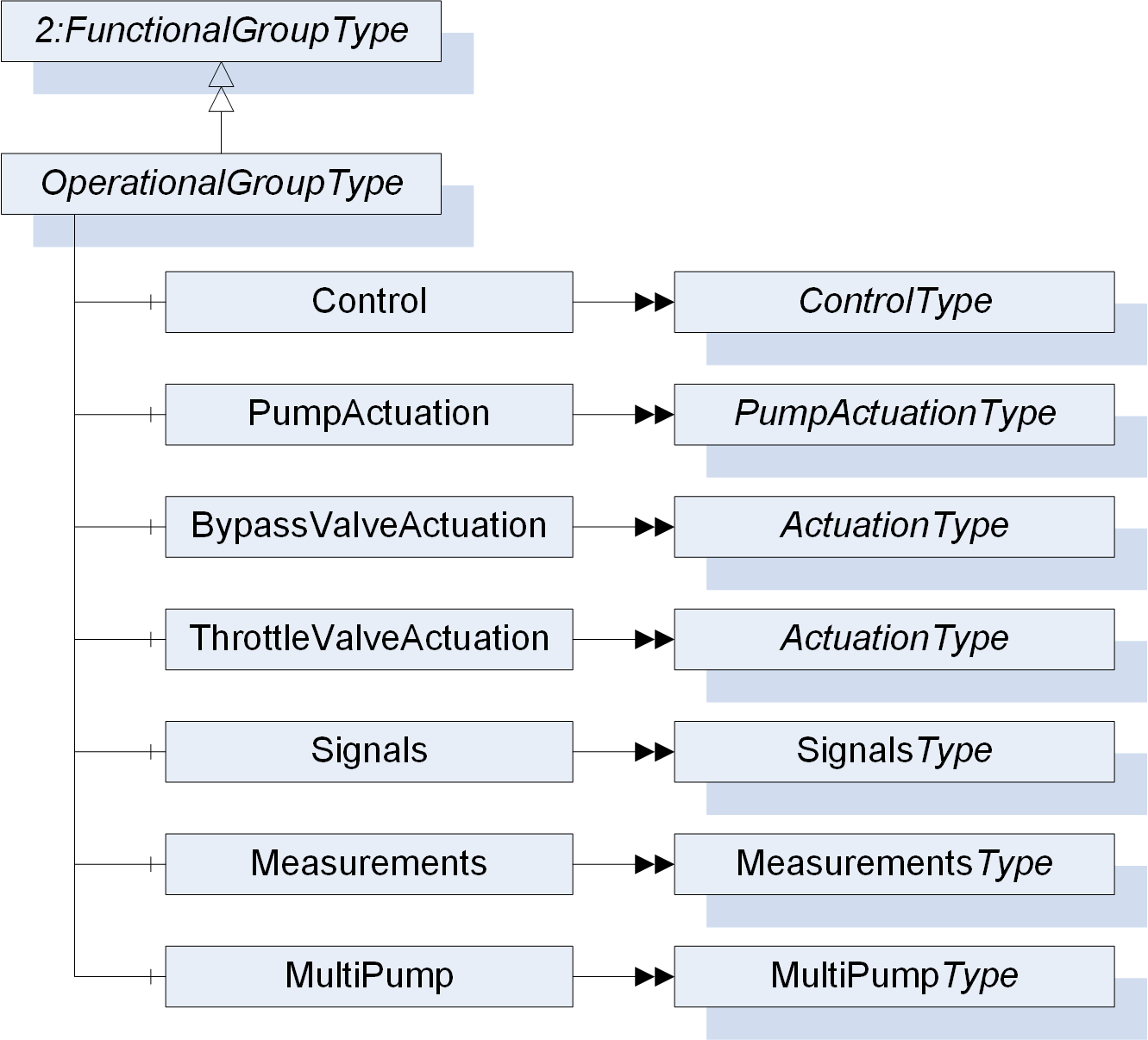
| Attribute | Value | ||||
| BrowseName | OperationalGroupType | ||||
| IsAbstract | False | ||||
| References | Node Class | BrowseName | DataType | TypeDefinition | Other |
|---|---|---|---|---|---|
| Subtype of the 2:FunctionalGroupType defined in OPC 10000-100, i.e. inheriting the InstanceDeclarations of that Node. | |||||
| 0:HasComponent | Object | BypassActuation | ActuationType | O | |
| 0:HasComponent | Object | Control | ControlType | O | |
| 0:HasComponent | Object | Measurements | MeasurementsType | O | |
| 0:HasComponent | Object | MultiPump | MultiPumpType | O | |
| 0:HasComponent | Object | PumpActuation | PumpActuationType | O | |
| 0:HasComponent | Object | Signals | SignalsType | O | |
| 0:HasComponent | Object | ThrottleValveActuation | ActuationType | O | |
The InstanceDeclarations of the OperationalGroupType have additional Attributes defined in Table 54.
| BrowsePath | Description Attribute |
| BypassActuation | Actuation parameters for a bypass valve of a pump. |
| Control | Control parameters for a pump. |
| Measurements | Measurements at a pump. |
| MultiPump | Properties for multi pump usage of a pump. |
| PumpActuation | Actuation parameters for a pump. |
| Signals | Signals of a pump. |
| ThrottleValveActuation | Actuation parameters for a throttle valve of a pump. |
7.24 ControlType ObjectType Definition
The ControlType provides Variables for precise control of a Pump according to DIN IEC 60050-351 and is formally defined in Table 55.
| Attribute | Value | ||||
| BrowseName | ControlType | ||||
| IsAbstract | False | ||||
| References | Node Class | BrowseName | DataType | TypeDefinition | Other |
|---|---|---|---|---|---|
| Subtype of the 2:FunctionalGroupType defined in OPC 10000-100, i.e. inheriting the InstanceDeclarations of that Node. | |||||
| 0:HasComponent | Variable | CommandVariable | 0:Double | 0:BaseAnalogType | O, RW |
| 0:HasComponent | Variable | ControlDifferenceVariable | 0:Double | 0:BaseAnalogType | O, RO |
| 0:HasComponent | Variable | ControlledVariable | 0:Double | 0:BaseAnalogType | O, RO |
| 0:HasComponent | Variable | ControllerOutputVariable | 0:Double | 0:BaseAnalogType | O, RO |
| 0:HasComponent | Variable | DeadTime | 0:Double | 0:BaseAnalogType | O, RW |
| 0:HasComponent | Variable | DerivativeActionCoefficient | 0:Double | 0:BaseAnalogType | O, RW |
| 0:HasComponent | Variable | FeedbackVariable | 0:Double | 0:BaseAnalogType | O, RO |
| 0:HasComponent | Variable | FinalControlledVariable | 0:Double | 0:BaseAnalogType | O, RW |
| 0:HasComponent | Variable | IntegralActionCoefficient | 0:Double | 0:BaseAnalogType | O, RW |
| 0:HasComponent | Variable | ManipulatedVariable | 0:Double | 0:BaseAnalogType | O, RW |
| 0:HasComponent | Variable | OperatingMode | 0:String | 0:DataItemType | O, RW |
| 0:HasComponent | Variable | ProportionalActionCoefficient | 0:Double | 0:BaseAnalogType | O, RW |
| 0:HasComponent | Variable | ReferenceVariable | 0:Double | 0:BaseAnalogType | O, RW |
The InstanceDeclarations of the ControlType have additional Attributes defined in Table 56. The Variables and the associated Descriptions are based on the standard DIN IEC 60050-351.
| BrowsePath | Value Attribute | Description Attribute | ||
| CommandVariable | Variable quantity, which is not influenced by the control but is introduced into the control system from outside with the aim of making the final controlled variable follow it in a given relationship | |||
| ControlDifferenceVariable | Difference between the reference variable and the feedback variable | |||
| ControlledVariable | Output variable of the controlled system that will be acted upon by one or more manipulated variables | |||
| ControllerOutputVariable | Output variable of the controlling element, which is deducted from the control difference variable and is also the input variable of the actuator | |||
| DeadTime | In a dead-time element the duration of the time interval by which the output variable is shifted relative to the input variable | |||
| NamespaceUri: http://www.opcfoundation.org/UA/units/un/cefact UnitId: 5457219 DisplayName: s Description: second [unit of time] | |||
| DerivativeActionCoefficient | For a derivative element, the quotient of the value of the output variable to the value of the time derivative of the input variable | |||
| FeedbackVariable | Variable quantity, which represents the controlled variable and is returned to the comparing element | |||
| FinalControlledVariable | Variable quantity which has, or combination of variable quantities which have, to be influenced by the control | |||
| IntegralActionCoefficient | For an integral element, the quotient of the time derivative of the output variable to the fixed value of the input variable | |||
| ManipulatedVariable | Output variable of the controlling system, which is also an input variable of the controlled system | |||
| OperatingMode | Characterization of the way and the extent to which the human operator intervenes in the control equipment | |||
| ProportionalActionCoefficient | For a proportional element, the quotient of the variation of the output variable to the corresponding variation of the input variable | |||
| ReferenceVariable | Input variable to a comparing element in a controlling system, which sets the desired value of the controlled variable and is deducted from the command variable |
7.25 ActuationType ObjectType Definition
The ActuationType provides general Variables for asset actuation. It is illustrated in Figure 15 and formally defined in Table 57.
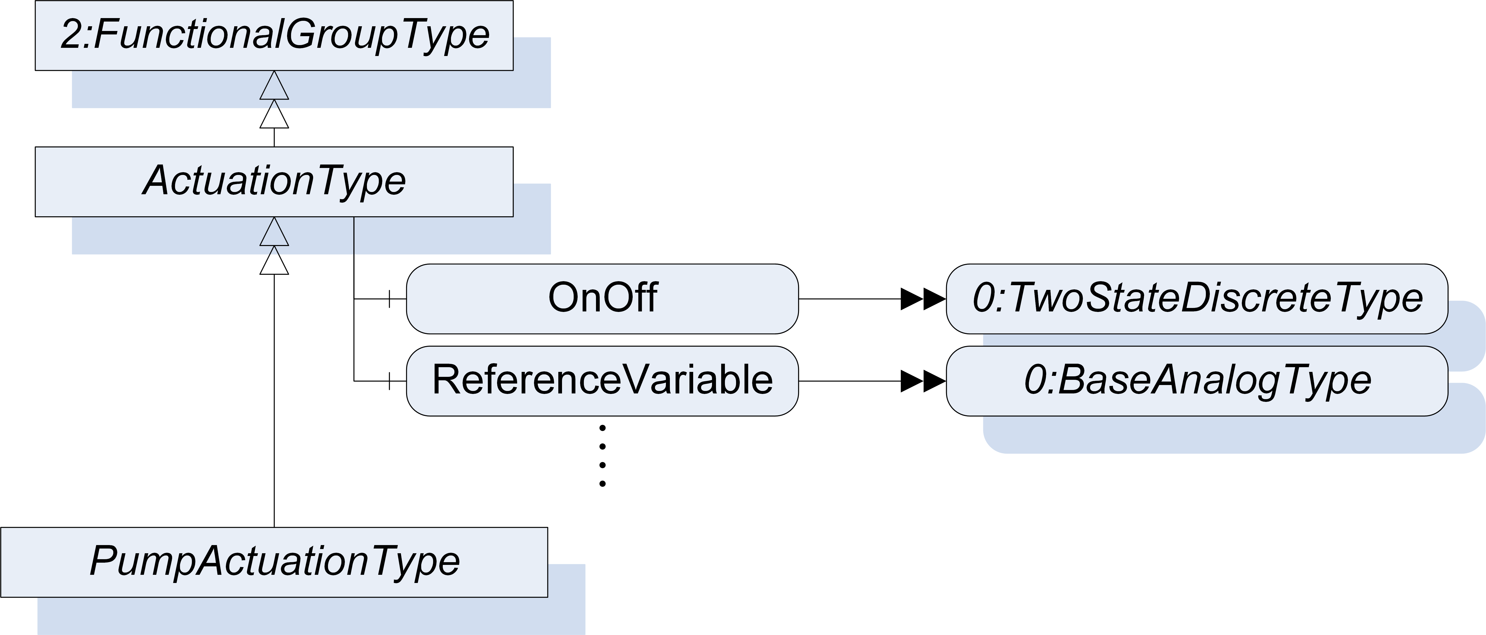
| Attribute | Value | ||||
| BrowseName | ActuationType | ||||
| IsAbstract | False | ||||
| References | Node Class | BrowseName | DataType | TypeDefinition | Other |
|---|---|---|---|---|---|
| Subtype of the 2:FunctionalGroupType defined in OPC 10000-100, i.e. inheriting the InstanceDeclarations of that Node. | |||||
| 0:HasSubtype | ObjectType | PumpActuationType | Defined in 7.26 | ||
| 0:HasComponent | Variable | FaultAction | 0:Boolean | 0:TwoStateDiscreteType | O, RW |
| 0:HasComponent | Variable | FaultValue | 0:Double | 0:BaseAnalogType | O, RW |
| 0:HasComponent | Variable | FeedbackVariable | 0:Double | 0:AnalogUnitType | O, RO |
| 0:HasComponent | Variable | ManipulatedValue | 0:Double | 0:BaseAnalogType | O, RW |
| 0:HasComponent | Variable | OnOff | 0:Boolean | 0:TwoStateDiscreteType | O, RW |
| 0:HasComponent | Variable | ReferenceVariable | 0:Double | 0:AnalogUnitType | O, RO |
| 0:HasComponent | Variable | Status | 0:Boolean | 0:TwoStateDiscreteType | O, RO |
The InstanceDeclarations of the ActuationType have additional Attributes defined in Table 58. The Variables and the associated Descriptions are based on the standards VDMA 24223-1 and DIN IEC 60050-351.
| BrowsePath | Value Attribute | Description Attribute | ||
| FaultAction | This property determines the action taken on variables in fault state. If the value is TRUE, the value of the property Fault value is used, if it is FALSE, the last valid value is used | |||
| FaultValue | This property specifies a user-defined value for use with Fault action property | |||
| FeedbackVariable | Variable quantity, which represents the controlled variable and is returned to the comparing element | |||
| NamespaceUri: http://www.opcfoundation.org/UA/units/un/cefact UnitId: 20529 DisplayName: % Description: percent | |||
| ManipulatedValue | Output variable of the controlling system, which is also an input variable of the controlled system | |||
| OnOff | This property enables the operation. | |||
| ReferenceVariable | Input variable to a comparing element in a controlling system, which sets the desired value of the controlled variable and is deducted from the command variable | |||
| NamespaceUri: http://www.opcfoundation.org/UA/units/un/cefact UnitId: 20529 DisplayName: % Description: percent | |||
| Status | This property contains the actual status of the element |
7.26 PumpActuationType ObjectType Definition
The PumpActuationType extends its supertype by Pump specific Objects and Variables for discrete outputs according to VDMA 24223. It is illustrated in Figure 16 and formally defined in Table 59.
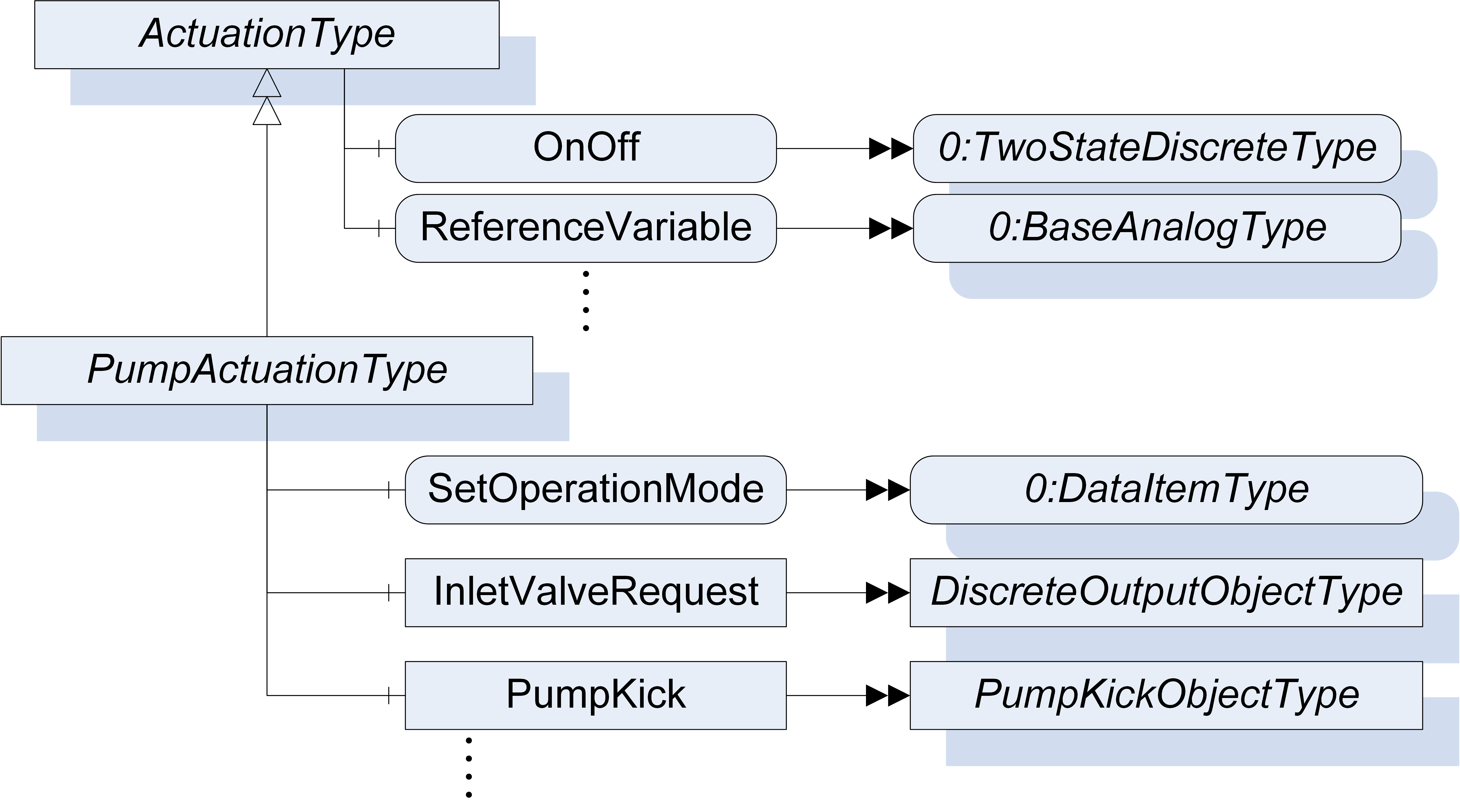
| Attribute | Value | ||||
| BrowseName | PumpActuationType | ||||
| IsAbstract | False | ||||
| References | Node Class | BrowseName | DataType | TypeDefinition | Other |
|---|---|---|---|---|---|
| Subtype of the ActuationType defined in 7.25, i.e. inheriting the InstanceDeclarations of that Node. | |||||
| 0:HasComponent | Variable | ActualControlMode | ControlModeEnum | 0:DataItemType | O, RO |
| 0:HasComponent | Variable | ActualOperationMode | OperationModeEnum | 0:DataItemType | O, RO |
| 0:HasComponent | Object | CleanValveRequest | DiscreteOutputObjectType | O | |
| 0:HasComponent | Variable | ControlInversion | 0:Boolean | 0:TwoStateDiscreteType | O, RW |
| 0:HasComponent | Variable | Enable | 0:Boolean | 0:TwoStateDiscreteType | O, RW |
| 0:HasComponent | Variable | ExternalSignal | 0:Boolean | 0:TwoStateDiscreteType | O, RW |
| 0:HasComponent | Object | FlushValveRequest | DiscreteOutputObjectType | O | |
| 0:HasComponent | Object | GasDilValveRequest | DiscreteOutputObjectType | O | |
| 0:HasComponent | Object | InletValveRequest | DiscreteOutputObjectType | O | |
| 0:HasComponent | Object | OutletValveRequest | DiscreteOutputObjectType | O | |
| 0:HasComponent | Object | PumpKick | PumpKickObjectType | O | |
| 0:HasComponent | Object | PumpStandByRequest | DiscreteOutputObjectType | O | |
| 0:HasComponent | Object | PurgeValveRequest | DiscreteOutputObjectType | O | |
| 0:HasComponent | Variable | ReverseRotatingDirection | 0:Boolean | 0:TwoStateDiscreteType | O, RO |
| 0:HasComponent | Variable | SetControlMode | ControlModeEnum | 0:DataItemType | O, RW |
| 0:HasComponent | Variable | SetOperationMode | OperationModeEnum | 0:DataItemType | O, RW |
| 0:HasComponent | Object | VentValveRequest | DiscreteOutputObjectType | O | |
The InstanceDeclarations of the PumpActuationType have additional Attributes defined in Table 60. The Variables and the associated Descriptions are based on the standard VDMA 24223-1.
| BrowsePath | Description Attribute |
| ActualControlMode | This property describes the actual control mode of the pump. |
| ActualOperationMode | This property describes the actual operation mode of the pump. |
| CleanValveRequest | This element offers a request for the opening of the clean valve. |
| ControlInversion | This property offers the inversion of the selected control mode in operation mode AutoControl. A "True" status means that the control mode inversion is activated and a "False" status means that the control mode inversion is deactivated. |
| Enable | This property activates of the control function. |
| ExternalSignal | This property offers the activation of an external electrical interface serving the setpoint of the control function by selecting the kind of electrical (analogue) signal. |
| FlushValveRequest | This element offers a request for the opening of the flush valve. |
| GasDilValveRequest | This element offers a request for the opening of the gas dilution valve. |
| InletValveRequest | This element offers a request for the opening of the inlet valve. |
| OutletValveRequest | This element offers a request for the opening of the outlet valve. |
| PumpKick | This element describes a periodical operation of a pump, avoiding blockage at non operation time. |
| PumpStandByRequest | This element offers a request for pump standby. |
| PurgeValveRequest | This element offers a request for the opening of the purge valve. |
| ReverseRotatingDirection | This property indicates the inversion of the standard rotating direction. |
| SetControlMode | This property describes the desired control mode of the pump. |
| SetOperationMode | This property describes the desired operation mode of the pump. |
| VentValveRequest | This element offers a request for the opening of the vent valve. |
7.27 DiscreteObjectType ObjectType Definition
The abstract DiscreteObjectType provides Variables for discrete inputs and outputs of a Pump. It is illustrated in Figure 17 and formally defined in Table 61.
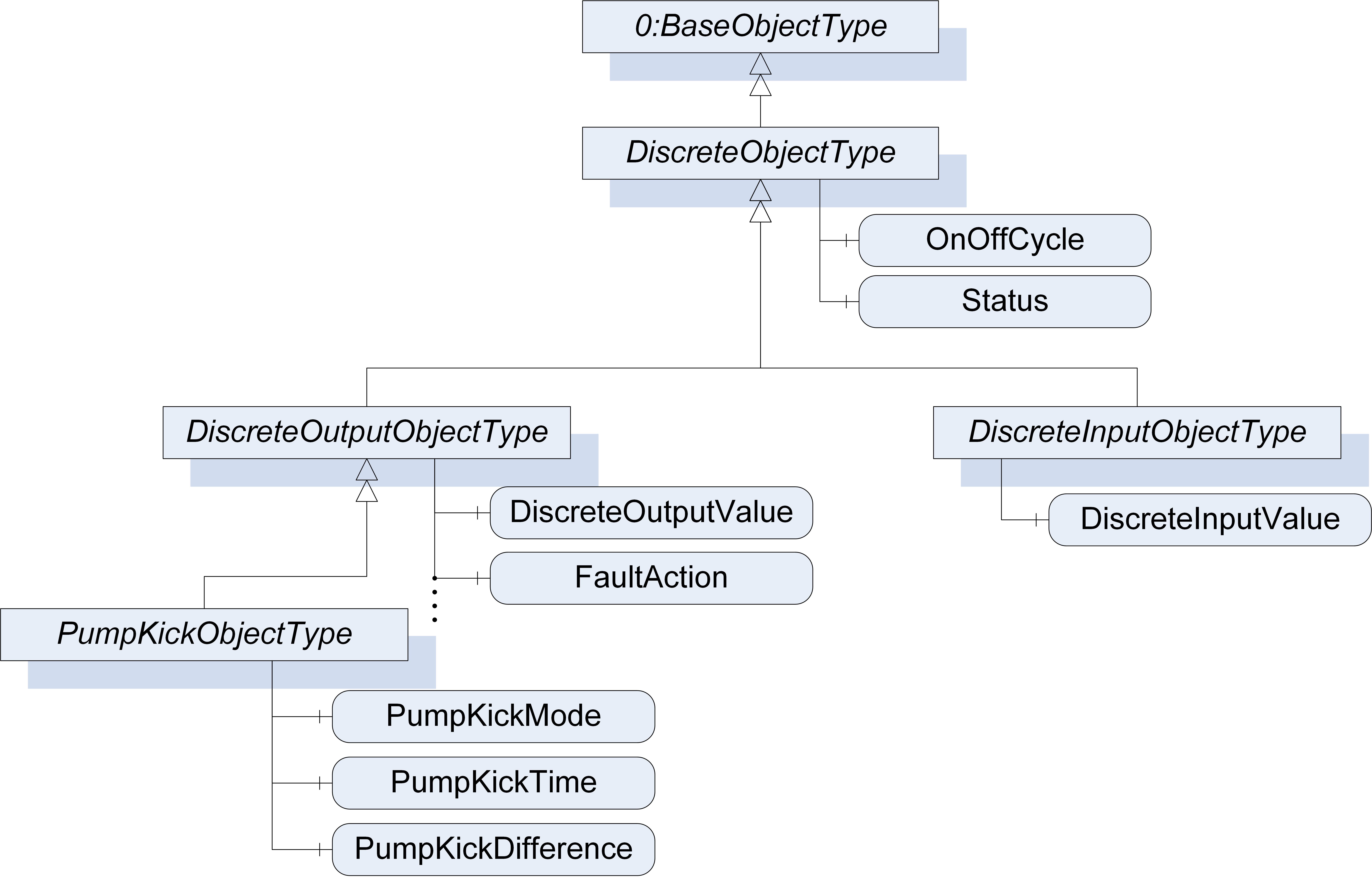
| Attribute | Value | ||||
| BrowseName | DiscreteObjectType | ||||
| IsAbstract | True | ||||
| References | Node Class | BrowseName | DataType | TypeDefinition | Other |
|---|---|---|---|---|---|
| Subtype of 0:BaseObjectType defined in OPC 10000-5. | |||||
| 0:HasSubtype | ObjectType | DiscreteInputObjectType | Defined in 7.28 | ||
| 0:HasSubtype | ObjectType | DiscreteOutputObjectType | Defined in 7.29 | ||
| 0:HasComponent | Variable | OnOffCycle | 0:UInt32 | 0:BaseAnalogType | O, RO |
| 0:HasComponent | Variable | Status | 0:Boolean | 0:TwoStateDiscreteType | O, RO |
The InstanceDeclarations of the DiscreteObjectType have additional Attributes defined in Table 62. The Variables and the associated Descriptions are based on the standard VDMA 24223-1.
| BrowsePath | Description Attribute |
| OnOffCycle | This property contains the total number of transitions of the value from the Off to the On state. |
| Status | This property contains the actual status of the element. |
7.28 DiscreteInputObjectType ObjectType Definition
The DiscreteInputObjectType extends its supertype by input specific Variables and is formally defined in Table 63.
| Attribute | Value | ||||
| BrowseName | DiscreteInputObjectType | ||||
| IsAbstract | False | ||||
| References | Node Class | BrowseName | DataType | TypeDefinition | Other |
|---|---|---|---|---|---|
| Subtype of the DiscreteObjectType defined in 7.27, i.e. inheriting the InstanceDeclarations of that Node. | |||||
| 0:HasComponent | Variable | DiscreteInputValue | 0:Boolean | 0:TwoStateDiscreteType | M, RO |
The InstanceDeclarations of the DiscreteInputObjectType have additional Attributes defined in Table 64. The Variables and the associated Descriptions are based on the standard VDMA 24223-1.
| BrowsePath | Description Attribute |
| DiscreteInputValue | This property contains the actual value of the discrete input unit. |
7.29 DiscreteOutputObjectType ObjectType Definition
The DiscreteOutputObjectType extends its supertype by output specific Variables and is formally defined in Table 65.
| Attribute | Value | ||||
| BrowseName | DiscreteOutputObjectType | ||||
| IsAbstract | False | ||||
| References | Node Class | BrowseName | DataType | TypeDefinition | Other |
|---|---|---|---|---|---|
| Subtype of the DiscreteObjectType defined in 7.270, i.e. inheriting the InstanceDeclarations of that Node. | |||||
| 0:HasSubtype | ObjectType | PumpKickObjectType | Defined in 7.30 | ||
| 0:HasComponent | Variable | DiscreteOutputValue | 0:Boolean | 0:TwoStateDiscreteType | M, RW |
| 0:HasComponent | Variable | FaultAction | 0:Boolean | 0:TwoStateDiscreteType | O, RW |
| 0:HasComponent | Variable | FaultValue | 0:Boolean | 0:TwoStateDiscreteType | O, RW |
The InstanceDeclarations of the DiscreteOutputObjectType have additional Attributes defined in Table 66. The Variables and the associated Descriptions are based on the standard VDMA 24223-1.
| BrowsePath | Description Attribute |
| DiscreteOutputValue | This property contains the actual value of the discrete output unit. |
| FaultAction | This property determines the action taken on variables in fault state. |
| FaultValue | This property specifies a user-defined value for use with Fault action property. |
7.30 PumpKickObjectType ObjectType Definition
The PumpKickObjectType extends its supertype by pump kick specific Variables and is formally defined in Table 67.
| Attribute | Value | ||||
| BrowseName | PumpKickObjectType | ||||
| IsAbstract | False | ||||
| References | Node Class | BrowseName | DataType | TypeDefinition | Other |
|---|---|---|---|---|---|
| Subtype of the DiscreteOutputObjectType defined in 7.29, i.e. inheriting the InstanceDeclarations of that Node. | |||||
| 0:HasComponent | Variable | PumpKickMode | PumpKickModeEnum | 0:DataItemType | O, RW |
| 0:HasComponent | Variable | PumpKickTime | 0:Double | 0:DataItemType | O, RW |
| 0:HasComponent | Variable | PumpKickTimeDifference | 0:Double | 0:AnalogUnitType | O, RW |
The InstanceDeclarations of the PumpKickObjectType have additional Attributes defined in Table 68. The Variables and the associated Descriptions are based on the standard VDMA 24223-1.
| BrowsePath | Value Attribute | Description | ||
| PumpKickMode | This property describes the pump kick mode of the pump. | |||
| PumpKickTime | This property determines the absolute time of a pump kick, if Pump Kick Mode is operator specific. The time for the next pump kick results of the sum of Pump Kick Time and Pump Kick Time Difference | |||
| PumpKickTimeDifference | This property determines the interval time of a pump kick, if Pump Kick Mode is operator specific. The time for the next pump kick results of the sum of Pump Kick Time and Pump Kick Time Difference | |||
| NamespaceUri: http://www.opcfoundation.org/UA/units/un/cefact UnitId: 5457219 DisplayName: s Description: second [unit of time] |
7.31 SignalsType ObjectType Definition
The SignalsType provides Objects to provide feedback on the current Pump state and is formally defined in Table 69.
| Attribute | Value | ||||
| BrowseName | SignalsType | ||||
| IsAbstract | False | ||||
| References | Node Class | BrowseName | DataType | TypeDefinition | Other |
|---|---|---|---|---|---|
| Subtype of the 2:FunctionalGroupType defined in OPC 10000-100, i.e. inheriting the InstanceDeclarations of that Node. | |||||
| 0:HasComponent | Object | Acceleration | DiscreteInputObjectType | O | |
| 0:HasComponent | Object | CleanValveOpen | DiscreteInputObjectType | O | |
| 0:HasComponent | Object | Deceleration | DiscreteInputObjectType | O | |
| 0:HasComponent | Object | FlushValveOpen | DiscreteInputObjectType | O | |
| 0:HasComponent | Object | GasDilValveOpen | DiscreteInputObjectType | O | |
| 0:HasComponent | Object | InletValveOpen | DiscreteInputObjectType | O | |
| 0:HasComponent | Object | NoRotation | DiscreteInputObjectType | O | |
| 0:HasComponent | Object | OutletValveOpen | DiscreteInputObjectType | O | |
| 0:HasComponent | Object | ProcessIsActive | DiscreteInputObjectType | O | |
| 0:HasComponent | Object | PumpActivation | DiscreteInputObjectType | O | |
| 0:HasComponent | Object | PumpDirection | DiscreteInputObjectType | O | |
| 0:HasComponent | Object | PumpOperation | DiscreteInputObjectType | O | |
| 0:HasComponent | Object | PumpPowerMax | DiscreteInputObjectType | O | |
| 0:HasComponent | Object | PumpSpeedMax | DiscreteInputObjectType | O | |
| 0:HasComponent | Object | PumpSpeedMin | DiscreteInputObjectType | O | |
| 0:HasComponent | Object | PurgeValveOpen | DiscreteInputObjectType | O | |
| 0:HasComponent | Object | RatedSpeed | DiscreteInputObjectType | O | |
| 0:HasComponent | Object | StandBy | DiscreteInputObjectType | O | |
| 0:HasComponent | Object | StandBySpeed | DiscreteInputObjectType | O | |
| 0:HasComponent | Object | TargetSpeed | DiscreteInputObjectType | O | |
| 0:HasComponent | Object | VentValveOpen | DiscreteInputObjectType | O | |
The InstanceDeclarations of the SignalsType have additional Attributes defined in Table 70. The Variables and the associated Descriptions are based on the standard VDMA 24223-1.
| BrowsePath | Description Attribute |
| Acceleration | This element serves a feedback that the pump rotation accelerates. |
| CleanValveOpen | This element serves a feedback about the open state of the cleaning valve. |
| Deceleration | This element serves a feedback that the pump rotation decelerates. |
| FlushValveOpen | This element serves a feedback about the open state of the flush valve. |
| GasDilValveOpen | This element serves a feedback about the open state of the gas dilution valve. |
| InletValveOpen | This element serves a feedback about the open state of the inlet valve. |
| NoRotation | This element serves a feedback that the pump stands still. |
| OutletValveOpen | This element serves a feedback about the open state of the outlet valve. |
| ProcessIsActive | This element serves a feedback that the process is active. |
| PumpActivation | This element serves a feedback about the activation state of the pump. The activation state takes into account that control mechanisms are active. Never the less the pump is not necessarily running |
| PumpDirection | This element serves a feedback of the pumps direction of rotation. |
| PumpOperation | This element serves a feedback about the operation state of the pump. In the operation state the pump rotor is rotating. |
| PumpPowerMax | This element serves a feedback of pump operating at maximum power. |
| PumpSpeedMax | This element serves a feedback of pump operating at maximum speed. |
| PumpSpeedMin | This element serves a feedback that the pump operates at minimum speed. |
| PurgeValveOpen | This element serves a feedback about the open state of the purge valve. |
| RatedSpeed | This element serves a feedback that the pump rotation is at rated speed. |
| StandBy | This element serves a feedback about the process standby of the pump. In the stand by state the pump is ready for operation. |
| StandBySpeed | This element serves a feedback that the pump rotation is at standby speed. |
| TargetSpeed | This element serves a feedback that the pump is at target speed. |
| VentValveOpen | This element serves a feedback about the open state of the vent valve. |
7.32 MeasurementsType ObjectType Definition
The MeasurementsType provides Objects and Variables used for measurements performed at a Pump. It is illustrated in Figure 18 and formally defined in Table 73. For the generation of events, the MeasurementsType has a reference to the 0:LimitAlarmType. The InputNode Property of the Alarm shall contain the NodeId of the Component. Measurements defined in this ObjectType have an additional Subcomponent with the TypeDefinition 0:PropertyType and the BrowseName KindOfQuantity defined in Table 72. In this Variables the measurements can be matched to a physical quantity. To comply with this Companion Specification, the default values for the Property 0:EngineeringUnits and the Property KindOfQuantity provided in Table 73 should be used. The values should be sensible to the use of the application.
| Attribute | Value | ||||
| BrowseName | MeasurementsType | ||||
| IsAbstract | False | ||||
| References | Node Class | BrowseName | DataType | TypeDefinition | Other |
|---|---|---|---|---|---|
| Subtype of the 2:FunctionalGroupType defined in OPC 10000-100, i.e. inheriting the InstanceDeclarations of that Node. | |||||
| 0:HasComponent | Object | <Vibration> | VibrationMeasurementType | OP | |
| 0:HasComponent | Variable | AmbientHumidity | 0:Double | 0:BaseAnalogType | O, RO |
| 0:HasComponent | Variable | AmbientTemperature | 0:Double | 0:BaseAnalogType | O, RO |
| 0:HasComponent | Variable | AxialLoadOfPumpRotor | 0:Double | 0:BaseAnalogType | O, RO |
| 0:HasComponent | Variable | AxialRotorPosition | 0:Double | 0:BaseAnalogType | O, RO |
| 0:HasComponent | Variable | BackPressure | 0:Double | 0:BaseAnalogType | O, RO |
| 0:HasComponent | Variable | BearingTemperature | 0:Double | 0:BaseAnalogType | O, RO |
| 0:HasComponent | Variable | ClearanceFlow | 0:Double | 0:BaseAnalogType | O, RO |
| 0:HasComponent | Variable | CoolantTemperature | 0:Double | 0:BaseAnalogType | O, RO |
| 0:HasComponent | Variable | Density | 0:Double | 0:BaseAnalogType | O, RO |
| 0:HasComponent | Variable | DifferentialPressure | 0:Double | 0:BaseAnalogType | O, RO |
| 0:HasComponent | Variable | DynamicViscosity | 0:Double | 0:BaseAnalogType | O, RO |
| 0:HasComponent | Variable | ElectronicTemperature | 0:Double | 0:BaseAnalogType | O, RO |
| 0:HasComponent | Variable | FluidTemperature | 0:Double | 0:BaseAnalogType | O, RO |
| 0:HasComponent | Variable | HousingTemperature | 0:Double | 0:BaseAnalogType | O, RO |
| 0:HasComponent | Variable | HydraulicEfficiency | 0:Double | 0:BaseAnalogType | O, RO |
| 0:HasComponent | Variable | InletPressureOfTheInstallation | 0:Double | 0:BaseAnalogType | O, RO |
| 0:HasComponent | Variable | InstallationTotalHead | 0:Double | 0:BaseAnalogType | O, RO |
| 0:HasComponent | Variable | KinematicViscosity | 0:Double | 0:BaseAnalogType | O, RO |
| 0:HasComponent | Variable | LeakageRateOfFlow | 0:Double | 0:BaseAnalogType | O, RO |
| 0:HasComponent | Variable | Level | 0:Double | 0:BaseAnalogType | O, RO |
| 0:HasComponent | Variable | LubricatingOilConsumption | 0:Double | 0:BaseAnalogType | O, RO |
| 0:HasComponent | Variable | LubricatingOilPressure | 0:Double | 0:BaseAnalogType | O, RO |
| 0:HasComponent | Variable | MassFlow | 0:Double | 0:BaseAnalogType | O, RO |
| 0:HasComponent | Variable | MeanVelocityAtThroat | 0:Double | 0:BaseAnalogType | O, RO |
| 0:HasComponent | Variable | MechanicalEfficiency | 0:Double | 0:BaseAnalogType | O, RO |
| 0:HasComponent | Variable | NetPositiveInletPressure | 0:Double | 0:BaseAnalogType | O, RO |
| 0:HasComponent | Variable | NetPositiveSuctionHead | 0:Double | 0:BaseAnalogType | O, RO |
| 0:HasComponent | Variable | NumberOfStarts | 0:UInt32 | 0:BaseAnalogType | O, RO |
| 0:HasComponent | Variable | OutletPressureOfTheInstallation | 0:Double | 0:BaseAnalogType | O, RO |
| 0:HasComponent | Variable | OverallEfficiency | 0:Double | 0:BaseAnalogType | O, RO |
| 0:HasComponent | Variable | PowerLossDueToInternalLeakage | 0:Double | 0:BaseAnalogType | O, RO |
| 0:HasComponent | Variable | ProcessPressure | 0:Double | 0:BaseAnalogType | O, RO |
| 0:HasComponent | Variable | PumpEfficiency | 0:Double | 0:BaseAnalogType | O, RO |
| 0:HasComponent | Variable | PumpHumidity | 0:Double | 0:BaseAnalogType | O, RO |
| 0:HasComponent | Variable | PumpPowerInput | 0:Double | 0:BaseAnalogType | O, RO |
| 0:HasComponent | Variable | PumpPowerOutput | 0:Double | 0:BaseAnalogType | O, RO |
| 0:HasComponent | Variable | PumpTemperature | 0:Double | 0:BaseAnalogType | O, RO |
| 0:HasComponent | Variable | PumpTotalHead | 0:Double | 0:BaseAnalogType | O, RO |
| 0:HasComponent | Variable | RadialLoadOfPumpRotor | 0:Double | 0:BaseAnalogType | O, RO |
| 0:HasComponent | Variable | SoundEnergy | 0:Double | 0:BaseAnalogType | O, RO |
| 0:HasComponent | Variable | SoundEnergyLevel | 0:Double | 0:BaseAnalogType | O, RO |
| 0:HasComponent | Variable | SoundPower | 0:Double | 0:BaseAnalogType | O, RO |
| 0:HasComponent | Variable | SoundPowerLevel | 0:Double | 0:BaseAnalogType | O, RO |
| 0:HasComponent | Variable | SoundPressure | 0:Double | 0:BaseAnalogType | O, RO |
| 0:HasComponent | Variable | SoundPressureLevel | 0:Double | 0:BaseAnalogType | O, RO |
| 0:HasComponent | Variable | Speed | 0:Double | 0:BaseAnalogType | O, RO |
| 0:HasComponent | Variable | Throughput | 0:Double | 0:BaseAnalogType | O, RO |
| 0:HasComponent | Variable | TotalHeadAtInletAreaOfTheInstallation | 0:Double | 0:BaseAnalogType | O, RO |
| 0:HasComponent | Variable | TotalHeadAtOutletAreaOfTheInstallation | 0:Double | 0:BaseAnalogType | O, RO |
| 0:HasComponent | Variable | VolumetricEfficiency | 0:Double | 0:BaseAnalogType | O, RO |
| 0:GeneratesEvent | ObjectType | 0:LimitAlarmType | Defined in OPC 10000-9 | ||
The OptionalPlaceholder Object Vibration is used for multiple vibration measurements at a Pump.
| Source Path | References | NodeClass | BrowseName | DataType | TypeDefinition | Other |
| AmbientHumidity | 0:HasProperty | Variable | KindOfQuantity | 0:String | 0:PropertyType | O, RO |
| AmbientTemperature | 0:HasProperty | Variable | KindOfQuantity | 0:String | 0:PropertyType | O, RO |
| AxialLoadOfPumpRotor | 0:HasProperty | Variable | KindOfQuantity | 0:String | 0:PropertyType | O, RO |
| AxialRotorPosition | 0:HasProperty | Variable | KindOfQuantity | 0:String | 0:PropertyType | O, RO |
| BackPressure | 0:HasProperty | Variable | KindOfQuantity | 0:String | 0:PropertyType | O, RO |
| BearingTemperature | 0:HasProperty | Variable | KindOfQuantity | 0:String | 0:PropertyType | O, RO |
| ClearanceFlow | 0:HasProperty | Variable | KindOfQuantity | 0:String | 0:PropertyType | O, RO |
| CoolantTemperature | 0:HasProperty | Variable | KindOfQuantity | 0:String | 0:PropertyType | O, RO |
| Density | 0:HasProperty | Variable | KindOfQuantity | 0:String | 0:PropertyType | O, RO |
| DifferentialPressure | 0:HasProperty | Variable | KindOfQuantity | 0:String | 0:PropertyType | O, RO |
| DynamicViscosity | 0:HasProperty | Variable | KindOfQuantity | 0:String | 0:PropertyType | O, RO |
| ElectronicTemperature | 0:HasProperty | Variable | KindOfQuantity | 0:String | 0:PropertyType | O, RO |
| FluidTemperature | 0:HasProperty | Variable | KindOfQuantity | 0:String | 0:PropertyType | O, RO |
| HousingTemperature | 0:HasProperty | Variable | KindOfQuantity | 0:String | 0:PropertyType | O, RO |
| HydraulicEfficiency | 0:HasProperty | Variable | KindOfQuantity | 0:String | 0:PropertyType | O, RO |
| InletPressureOfTheInstallation | 0:HasProperty | Variable | KindOfQuantity | 0:String | 0:PropertyType | O, RO |
| InstallationTotalHead | 0:HasProperty | Variable | KindOfQuantity | 0:String | 0:PropertyType | O, RO |
| KinematicViscosity | 0:HasProperty | Variable | KindOfQuantity | 0:String | 0:PropertyType | O, RO |
| LeakageRateOfFlow | 0:HasProperty | Variable | KindOfQuantity | 0:String | 0:PropertyType | O, RO |
| Level | 0:HasProperty | Variable | KindOfQuantity | 0:String | 0:PropertyType | O, RO |
| LubricatingOilConsumption | 0:HasProperty | Variable | KindOfQuantity | 0:String | 0:PropertyType | O, RO |
| LubricatingOilPressure | 0:HasProperty | Variable | KindOfQuantity | 0:String | 0:PropertyType | O, RO |
| MassFlow | 0:HasProperty | Variable | KindOfQuantity | 0:String | 0:PropertyType | O, RO |
| MeanVelocityAtThroat | 0:HasProperty | Variable | KindOfQuantity | 0:String | 0:PropertyType | O, RO |
| MechanicalEfficiency | 0:HasProperty | Variable | KindOfQuantity | 0:String | 0:PropertyType | O, RO |
| NetPositiveInletPressure | 0:HasProperty | Variable | KindOfQuantity | 0:String | 0:PropertyType | O, RO |
| NetPositiveSuctionHead | 0:HasProperty | Variable | KindOfQuantity | 0:String | 0:PropertyType | O, RO |
| NumberOfStarts | 0:HasProperty | Variable | KindOfQuantity | 0:String | 0:PropertyType | O, RO |
| OutletPressureOfTheInstallation | 0:HasProperty | Variable | KindOfQuantity | 0:String | 0:PropertyType | O, RO |
| OverallEfficiency | 0:HasProperty | Variable | KindOfQuantity | 0:String | 0:PropertyType | O, RO |
| PowerLossDueToInternalLeakage | 0:HasProperty | Variable | KindOfQuantity | 0:String | 0:PropertyType | O, RO |
| ProcessPressure | 0:HasProperty | Variable | KindOfQuantity | 0:String | 0:PropertyType | O, RO |
| PumpEfficiency | 0:HasProperty | Variable | KindOfQuantity | 0:String | 0:PropertyType | O, RO |
| PumpHumidity | 0:HasProperty | Variable | KindOfQuantity | 0:String | 0:PropertyType | O, RO |
| PumpPowerInput | 0:HasProperty | Variable | KindOfQuantity | 0:String | 0:PropertyType | O, RO |
| PumpPowerOutput | 0:HasProperty | Variable | KindOfQuantity | 0:String | 0:PropertyType | O, RO |
| PumpTemperature | 0:HasProperty | Variable | KindOfQuantity | 0:String | 0:PropertyType | O, RO |
| PumpTotalHead | 0:HasProperty | Variable | KindOfQuantity | 0:String | 0:PropertyType | O, RO |
| RadialLoadOfPumpRotor | 0:HasProperty | Variable | KindOfQuantity | 0:String | 0:PropertyType | O, RO |
| SoundEnergy | 0:HasProperty | Variable | KindOfQuantity | 0:String | 0:PropertyType | O, RO |
| SoundEnergyLevel | 0:HasProperty | Variable | KindOfQuantity | 0:String | 0:PropertyType | O, RO |
| SoundPower | 0:HasProperty | Variable | KindOfQuantity | 0:String | 0:PropertyType | O, RO |
| SoundPowerLevel | 0:HasProperty | Variable | KindOfQuantity | 0:String | 0:PropertyType | O, RO |
| SoundPressure | 0:HasProperty | Variable | KindOfQuantity | 0:String | 0:PropertyType | O, RO |
| SoundPressureLevel | 0:HasProperty | Variable | KindOfQuantity | 0:String | 0:PropertyType | O, RO |
| Speed | 0:HasProperty | Variable | KindOfQuantity | 0:String | 0:PropertyType | O, RO |
| Throughput | 0:HasProperty | Variable | KindOfQuantity | 0:String | 0:PropertyType | O, RO |
| TotalHeadAtInletAreaOfTheInstallation | 0:HasProperty | Variable | KindOfQuantity | 0:String | 0:PropertyType | O, RO |
| TotalHeadAtOutletAreaOfTheInstallation | 0:HasProperty | Variable | KindOfQuantity | 0:String | 0:PropertyType | O, RO |
| VolumetricEfficiency | 0:HasProperty | Variable | KindOfQuantity | 0:String | 0:PropertyType | O, RO |
The InstanceDeclarations of the MeasurementsType have additional Attributes defined in Table 73. The Variables and the associated Descriptions are based on the standards VDMA 24223, DIN EN 13306, DIN EN ISO 17769-1, DIN ISO 21360-1, ISO 2041, DIN EN ISO 80000-8, ISO/ TR 25417, ISO 7967-6, ISO 2710-1 and IEC61987.
| BrowsePath | Value Attribute | Description Attribute | ||
| <Vibration> | Properties characterizing dynamic data which are the result of an oscillation measurement at machines with rotating movements | |||
| AmbientHumidity | Measured ambient humidity | |||
| NamespaceUri: http://www.opcfoundation.org/UA/units/un/cefact UnitId: 20529 DisplayName: % Description: percent | |||
| "relative humidity" | Quotient of partial pressure of water vapor and partial pressure at its saturation | ||
| AmbientTemperature | Measured ambient temperature | |||
| NamespaceUri: http://www.opcfoundation.org/UA/units/un/cefact UnitId: 4932940 DisplayName: K Description: kelvin | |||
| "temperature" | Quantity representing a temperature value | ||
| AxialLoadOfPumpRotor | Measured residual thrust acting through the shaft derived from hydraulic or mechanical forces | |||
| NamespaceUri: http://www.opcfoundation.org/UA/units/un/cefact UnitId: 5129559 DisplayName: N Description: newton | |||
| "force" | Vector quantity describing interaction between bodies or particles | ||
| AxialRotorPosition | Measured position of the axial rotor in bearing. | |||
| "rational number" | Element of a set of mathematical entities that includes all integers and other entities, each defined as the quotient of two integers, such that the division is defined for any two entities, except zero as a divisor | ||
| BackPressure | Measured back pressure of the pump | |||
| NamespaceUri: http://www.opcfoundation.org/UA/units/un/cefact UnitId: 5259596 DisplayName: Pa Description: pascal | |||
| "pressure" | Quotient of the component of a force normal to a surface and its area | ||
| BearingTemperature | Measured temperature of the bearing | |||
| NamespaceUri: http://www.opcfoundation.org/UA/units/un/cefact UnitId: 4932940 DisplayName: K Description: kelvin | |||
| "temperature" | Quantity representing a temperature value | ||
| ClearanceFlow | Measured clearance flow between the housing and the impeller | |||
| NamespaceUri: http://www.opcfoundation.org/UA/units/un/cefact UnitId: 5067091 DisplayName: m³/s Description: cubic metre per second | |||
| "volume flow rate" | Scalar quantity characterizing the total flow through the two-dimensional domain A with the normal vector of a flowing fluid with velocity as an integral | ||
| CoolantTemperature | Measured temperature of the coolant. | |||
| NamespaceUri: http://www.opcfoundation.org/UA/units/un/cefact UnitId: 4932940 DisplayName: K Description: kelvin | |||
| "temperature" | Quantity representing a temperature value | ||
| Density | Measured density of the fluid | |||
| NamespaceUri: http://www.opcfoundation.org/UA/units/un/cefact UnitId: 4934993 DisplayName: kg/m³ Description: kilogram per cubic metre | |||
| "density" | Quantity representing the spatial distribution of mass of a continuous material | ||
| DifferentialPressure | Determined (actual) gain in total pressure between the pump inlet and pump outlet | |||
| NamespaceUri: http://www.opcfoundation.org/UA/units/un/cefact UnitId: 5259596 DisplayName: Pa Description: pascal | |||
| "pressure" | Quotient of the component of a force normal to a surface and its area | ||
| DynamicViscosity | Measured kinematic viscosity of the fluid | |||
| NamespaceUri: http://www.opcfoundation.org/UA/units/un/cefact UnitId: 4665393 DisplayName: Pa·m³/s Description: pascal cubic metre per second | |||
| "dynamic viscosity" | For laminar flows, proportionality constant between shear stress in a fluid moving with a velocity and gradient perpendicular to the plane of shear | ||
| ElectronicTemperature | Measured temperature of the electronic | |||
| NamespaceUri: http://www.opcfoundation.org/UA/units/un/cefact UnitId: 4932940 DisplayName: K Description: kelvin | |||
| "temperature" | Quantity representing a temperature value | ||
| FluidTemperature | Measured internal temperature of pump fluid. | |||
| NamespaceUri: http://www.opcfoundation.org/UA/units/un/cefact UnitId: 4932940 DisplayName: K Description: kelvin | |||
| "temperature" | Quantity representing a temperature value | ||
| HousingTemperature | Measured temperature of the housing | |||
| NamespaceUri: http://www.opcfoundation.org/UA/units/un/cefact UnitId: 4932940 DisplayName: K Description: kelvin | |||
| "temperature" | Quantity representing a temperature value | ||
| HydraulicEfficiency | Determined proportion of pump available power input, Pa, which is delivered as pump power output, Pu, after satisfying the losses resulting from friction due to the relative motion of internal surfaces and internal leakage | |||
| NamespaceUri: http://www.opcfoundation.org/UA/units/un/cefact UnitId: 20529 DisplayName: % Description: percent | |||
| "ratio" | Quotient of two numbers or two quantities of the same kind | ||
| InletPressureOfTheInstallation | Measured pressure at the inlet area of the installation. | |||
| NamespaceUri: http://www.opcfoundation.org/UA/units/un/cefact UnitId: 5259596 DisplayName: Pa Description: pascal | |||
| "pressure" | Quotient of the component of a force normal to a surface and its area | ||
| InstallationTotalHead | Determined difference between the total head at the outlet side of the installation and the total head at the inlet side of the installation | |||
| NamespaceUri: http://www.opcfoundation.org/UA/units/un/cefact UnitId: 5067858 DisplayName: m Description: metre | |||
| "length" | Linear extent in space between any two points | ||
| KinematicViscosity | Measured dynamic viscosity of the fluid | |||
| NamespaceUri: http://www.opcfoundation.org/UA/units/un/cefact UnitId: 21300 DisplayName: m²/s Description: square metre per second | |||
| "kinematic viscosity" | Quotient of dynamic viscosity and mass density of a fluid | ||
| LeakageRateOfFlow | Measured rate of flow leaking from shaft seals | |||
| NamespaceUri: http://www.opcfoundation.org/UA/units/un/cefact UnitId: 5067091 DisplayName: m³/s Description: cubic metre per second | |||
| "volume flow rate" | Scalar quantity characterizing the total flow through the two-dimensional domain A with the normal vector of a flowing fluid with velocity as an integral | ||
| Level | Measured level | |||
| NamespaceUri: http://www.opcfoundation.org/UA/units/un/cefact UnitId: 5067858 DisplayName: m Description: metre | |||
| "length" | Linear extent in space between any two points | ||
| LubricatingOilConsumption | Measured oil consumption of the lubricating system | |||
| NamespaceUri: http://www.opcfoundation.org/UA/units/un/cefact UnitId: 5067857 DisplayName: m³ Description: cubic metre | |||
| "volume" | Extent of a three dimensional geometrical shape | ||
| LubricatingOilPressure | Measured oil pressure of the lubrication system | |||
| NamespaceUri: http://www.opcfoundation.org/UA/units/un/cefact UnitId: 5259596 DisplayName: Pa Description: pascal | |||
| "pressure" | Quotient of the component of a force normal to a surface and its area | ||
| MassFlow | Measure mass flow from the outlet area of the pump | |||
| NamespaceUri: http://www.opcfoundation.org/UA/units/un/cefact UnitId: 4933459 DisplayName: kg/s Description: kilogram per second | |||
| "mass flow" | Vector quantity characterizing a flowing fluid by the product of its local mass density and local velocity | ||
| MeanVelocityAtThroat | Measured rate of flow passing through the exit from the volute divided by the throat area | |||
| NamespaceUri: http://www.opcfoundation.org/UA/units/un/cefact UnitId: 5067859 DisplayName: m/s Description: metre per second | |||
| "velocity" | Vector quantity giving the rate of change of a position vector | ||
| MechanicalEfficiency | Determined proportion of the pump power input, P, available after satisfying the mechanical power losses, PJ, ab, at given operating conditions | |||
| NamespaceUri: http://www.opcfoundation.org/UA/units/un/cefact UnitId: 20529 DisplayName: % Description: percent | |||
| "ratio" | Quotient of two numbers or two quantities of the same kind | ||
| NetPositiveInletPressure | Total pressure (including velocity pressure) at the pump inlet connection less the liquid vapor pressure at the present temperature of the liquid | |||
| NamespaceUri: http://www.opcfoundation.org/UA/units/un/cefact UnitId: 5259596 DisplayName: Pa Description: pascal | |||
| "pressure" | Quotient of the component of a force normal to a surface and its area | ||
| NetPositiveSuctionHead | Amount of the absolute value of the total head above the head, equivalent to the vapor pressure of the liquid at the particular temperature, with reference to the NPSH datum plane | |||
| NamespaceUri: http://www.opcfoundation.org/UA/units/un/cefact UnitId: 5067858 DisplayName: m Description: metre | |||
| "length" | Linear extent in space between any two points | ||
| NumberOfStarts | Total number of starts | |||
| "rational number" | Element of a set of mathematical entities that includes all integers and other entities, each defined as the quotient of two integers, such that the division is defined for any two entities, except zero as a divisor | ||
| OutletPressureOfTheInstallation | Measured pressure at the outlet area of the installation. | |||
| NamespaceUri: http://www.opcfoundation.org/UA/units/un/cefact UnitId: 5259596 DisplayName: Pa Description: pascal | |||
| "pressure" | Quotient of the component of a force normal to a surface and its area | ||
| OverallEfficiency | Determined proportion of the driver power input, Pmot, delivered as pump power output, Pu | |||
| NamespaceUri: http://www.opcfoundation.org/UA/units/un/cefact UnitId: 20529 DisplayName: % Description: percent | |||
| "ratio" | Quotient of two numbers or two quantities of the same kind | ||
| PowerLossDueToInternalLeakage | Determined power loss due clearance flows | |||
| NamespaceUri: http://www.opcfoundation.org/UA/units/un/cefact UnitId: 5723220 DisplayName: W Description: watt | |||
| "power" | Derivative with respect to time t of energy E being transferred or transformed | ||
| ProcessPressure | Measured process pressure of the pump | |||
| NamespaceUri: http://www.opcfoundation.org/UA/units/un/cefact UnitId: 5259596 DisplayName: Pa Description: pascal | |||
| "pressure" | Quotient of the component of a force normal to a surface and its area | ||
| PumpEfficiency | Determined proportion of the pump power input, P, delivered as pump power output, Pu, at given operating conditions | |||
| NamespaceUri: http://www.opcfoundation.org/UA/units/un/cefact UnitId: 20529 DisplayName: % Description: percent | |||
| "ratio" | Quotient of two numbers or two quantities of the same kind | ||
| PumpHumidity | Measured humidity inside the pump | |||
| NamespaceUri: http://www.opcfoundation.org/UA/units/un/cefact UnitId: 20529 DisplayName: % Description: percent | |||
| "relative humidity" | Quotient of partial pressure of water vapor and partial pressure at its saturation | ||
| PumpPowerInput | Measured power transmitted to the pump by its driver | |||
| NamespaceUri: http://www.opcfoundation.org/UA/units/un/cefact UnitId: 5723220 DisplayName: W Description: watt | |||
| "mechanical power" | Scalar product of force acting to a body and its velocity | ||
| PumpPowerOutput | Measured useful mechanical power transferred to the fluid during its passage through the pump | |||
| NamespaceUri: http://www.opcfoundation.org/UA/units/un/cefact UnitId: 5723220 DisplayName: W Description: watt | |||
| "mechanical power" | Scalar product of force acting to a body and its velocity | ||
| PumpTemperature | Measured temperature of the pump | |||
| NamespaceUri: http://www.opcfoundation.org/UA/units/un/cefact UnitId: 4932940 DisplayName: K Description: kelvin | |||
| "temperature" | Quantity representing a temperature value | ||
| PumpTotalHead | Determined difference between the total head at the outlet side of the pump and the total head at the inlet side of the pump | |||
| NamespaceUri: http://www.opcfoundation.org/UA/units/un/cefact UnitId: 5067858 DisplayName: m Description: metre | |||
| "length" | Linear extent in space between any two points | ||
| RadialLoadOfPumpRotor | Measured residual force acting at right angles to the line of the shaft and derived from hydraulic forces | |||
| NamespaceUri: http://www.opcfoundation.org/UA/units/un/cefact UnitId: 5129559 DisplayName: N Description: newton | |||
| "force" | Vector quantity describing interaction between bodies or particles | ||
| SoundEnergy | Determined integral of the sound power, P, over a stated time interval of duration T (starting at t1 and ending at t2) | |||
| NamespaceUri: http://www.opcfoundation.org/UA/units/un/cefact UnitId: 4869973 DisplayName: J Description: joule | |||
| "energy" | Ability of a system to do work | ||
| SoundEnergyLevel | Determined ten times the logarithm to the base 10 of the ratio of the sound energy, J, to a reference value, J0, expressed in decibels | |||
| NamespaceUri: http://www.opcfoundation.org/UA/units/un/cefact UnitId: 12878 DisplayName: dB Description: decibel | |||
| "sound level" | Logarithm of the ratio of a given sound pressure to the reference sound pressure of 20 μPa, the sound pressure being obtained with a standard frequency weighting and with a standard exponential time weighting. Sound level in decibels is twenty times the logarithm to the base ten of that ratio | ||
| SoundPower | Determined through a surface, product of the sound pressure, p, and the component of the particle velocity, un, at a point on the surface in the direction normal to the surface, integrated over that surface | |||
| NamespaceUri: http://www.opcfoundation.org/UA/units/un/cefact UnitId: 5723220 DisplayName: W Description: watt | |||
| "power" | Derivative with respect to time t of energy E being transferred or transformed | ||
| SoundPowerLevel | Determined ten times the logarithm to the base 10 of the ratio of the sound power of a source, P, to a reference value, P0, expressed in decibels | |||
| NamespaceUri: http://www.opcfoundation.org/UA/units/un/cefact UnitId: 12878 DisplayName: dB Description: decibel | |||
| "sound level" | Logarithm of the ratio of a given sound pressure to the reference sound pressure of 20 μPa, the sound pressure being obtained with a standard frequency weighting and with a standard exponential time weighting. Sound level in decibels is twenty times the logarithm to the base ten of that ratio | ||
| SoundPressure | Measured difference between instantaneous pressure and static pressure | |||
| NamespaceUri: http://www.opcfoundation.org/UA/units/un/cefact UnitId: 5259596 DisplayName: Pa Description: pascal | |||
| "pressure" | Quotient of the component of a force normal to a surface and its area | ||
| SoundPressureLevel | Determined ten times logarithm to the base 10 of the ratio of the square of the sound pressure, p, to the square of a reference value, p0, expressed in decibels | |||
| NamespaceUri: http://www.opcfoundation.org/UA/units/un/cefact UnitId: 12878 DisplayName: dB Description: decibel | |||
| "sound level" | Logarithm of the ratio of a given sound pressure to the reference sound pressure of 20 μPa, the sound pressure being obtained with a standard frequency weighting and with a standard exponential time weighting. Sound level in decibels is twenty times the logarithm to the base ten of that ratio | ||
| Speed | Measured number of rotations or movements made by the shaft, coupling or impeller in a given time | |||
| NamespaceUri: http://www.opcfoundation.org/UA/units/un/cefact UnitId: 4405559 DisplayName: s⁻¹ Description: reciprocal second | |||
| "frequency" | Inverse of one cycle of a periodic event | ||
| Throughput | Measured throughput of the vacuum pump | |||
| NamespaceUri: http://www.opcfoundation.org/UA/units/un/cefact UnitId: 4665393 DisplayName: Pa·m³/s Description: pascal cubic metre per second | |||
| "volume flow rate" | Scalar quantity characterizing the total flow through the two-dimensional domain A with the normal vector of a flowing fluid with velocity as an integral | ||
| TotalHeadAtInletAreaOfTheInstallation | Determined total head at the inlet area of the installation, which corresponds to the sum of geodetic head, pressure head and velocity head | |||
| NamespaceUri: http://www.opcfoundation.org/UA/units/un/cefact UnitId: 5067858 DisplayName: m Description: metre | |||
| "length" | Linear extent in space between any two points | ||
| TotalHeadAtOutletAreaOfTheInstallation | Determined total head at the outlet area of the installation, which corresponds to the sum of geodetic head, pressure head and velocity head | |||
| NamespaceUri: http://www.opcfoundation.org/UA/units/un/cefact UnitId: 5067858 DisplayName: m Description: metre | |||
| "length" | Linear extent in space between any two points | ||
| VolumetricEfficiency | Determined ratio of the actual delivered volume at maximum pressure to the geometric displacement volume | |||
| NamespaceUri: http://www.opcfoundation.org/UA/units/un/cefact UnitId: 20529 DisplayName: % Description: percent | |||
| "ratio" | Quotient of two numbers or two quantities of the same kind. |
7.33 VibrationMeasurementType ObjectType Definition
The VibrationMeasurementType provides Variables for Pump vibration measurements according to IEC61987 and is formally defined in Table 74.
| Attribute | Value | ||||
| BrowseName | VibrationMeasurementType | ||||
| IsAbstract | False | ||||
| References | Node Class | BrowseName | DataType | TypeDefinition | Other |
|---|---|---|---|---|---|
| Subtype of the 2:FunctionalGroupType defined in OPC 10000-100, i.e. inheriting the InstanceDeclarations of that Node. | |||||
| 0:HasComponent | Variable | 1XPhase | 0:Double | 0:BaseAnalogType | O, RO |
| 0:HasComponent | Variable | 1XRelativeShaftVibrationP_P | 0:Double | 0:BaseAnalogType | O, RO |
| 0:HasComponent | Variable | 2XPhase | 0:Double | 0:BaseAnalogType | O, RO |
| 0:HasComponent | Variable | 2XRelativeShaftVibrationP_P | 0:Double | 0:BaseAnalogType | O, RO |
| 0:HasComponent | Variable | BearingIndex | 0:Double | 0:BaseAnalogType | O, RO |
| 0:HasComponent | Variable | BearingIndexPerG | 0:Double | 0:BaseAnalogType | O, RO |
| 0:HasComponent | Variable | BroadbandCavitationAccelerationPerG_RMS | 0:Double | 0:BaseAnalogType | O, RO |
| 0:HasComponent | Variable | BroadbandCavitationAccelerationRMS | 0:Double | 0:BaseAnalogType | O, RO |
| 0:HasComponent | Variable | GapVoltage | 0:Double | 0:BaseAnalogType | O, RO |
| 0:HasComponent | Variable | Not1XRelativeShaftVibrationP_P | 0:Double | 0:BaseAnalogType | O, RO |
| 0:HasComponent | Variable | OverallVibrationAcceleration0_P | 0:Double | 0:BaseAnalogType | O, RO |
| 0:HasComponent | Variable | OverallVibrationAccelerationP_P | 0:Double | 0:BaseAnalogType | O, RO |
| 0:HasComponent | Variable | OverallVibrationAccelerationPerG0_P | 0:Double | 0:BaseAnalogType | O, RO |
| 0:HasComponent | Variable | OverallVibrationAccelerationPerG_RMS | 0:Double | 0:BaseAnalogType | O, RO |
| 0:HasComponent | Variable | OverallVibrationAccelerationPerGP_P | 0:Double | 0:BaseAnalogType | O, RO |
| 0:HasComponent | Variable | OverallVibrationAccelerationRMS | 0:Double | 0:BaseAnalogType | O, RO |
| 0:HasComponent | Variable | OverallVibrationDisplacementP_P | 0:Double | 0:BaseAnalogType | O, RO |
| 0:HasComponent | Variable | OverallVibrationDisplacementRMS | 0:Double | 0:BaseAnalogType | O, RO |
| 0:HasComponent | Variable | OverallVibrationVelocity0_P | 0:Double | 0:BaseAnalogType | O, RO |
| 0:HasComponent | Variable | OverallVibrationVelocityP_P | 0:Double | 0:BaseAnalogType | O, RO |
| 0:HasComponent | Variable | OverallVibrationVelocityRMS | 0:Double | 0:BaseAnalogType | O, RO |
| 0:HasComponent | Variable | ReferenceStandardForVibrationMeasurement | 0:String | 0:DataItemType | O, RO |
| 0:HasComponent | Variable | RotationalPhase1X | 0:Double | 0:BaseAnalogType | O, RO |
| 0:HasComponent | Variable | RotationalPhase2X | 0:Double | 0:BaseAnalogType | O, RO |
| 0:HasComponent | Variable | SpeedOfRotation | 0:Double | 0:BaseAnalogType | O, RO |
| 0:HasComponent | Variable | ThrustPosition | 0:Double | 0:BaseAnalogType | O, RO |
| 0:HasComponent | Variable | VibrationAmplitudeAtTheBearingDefectFrequencies | 0:Double | 0:BaseAnalogType | O, RO |
| 0:HasComponent | Variable | VibrationAmplitudeAtTheBearingDefectFrequenciesPerG | 0:Double | 0:BaseAnalogType | O, RO |
| 0:HasComponent | Variable | VibrationAmplitudeAtTheBladePassFrequency | 0:Double | 0:BaseAnalogType | O, RO |
| 0:HasComponent | Variable | VibrationAmplitudeAtTheFirstHarmonicOfTheRotationFrequency2X | 0:Double | 0:BaseAnalogType | O, RO |
| 0:HasComponent | Variable | VibrationAmplitudeAtTheGearMeshingFrequency | 0:Double | 0:BaseAnalogType | O, RO |
| 0:HasComponent | Variable | VibrationAmplitudeAtTheGearMeshingFrequencyPerG | 0:Double | 0:BaseAnalogType | O, RO |
| 0:HasComponent | Variable | VibrationAmplitudeAtTheHarmonicsOfTheRotationFrequencyNx | 0:Double | 0:BaseAnalogType | O, RO |
| 0:HasComponent | Variable | VibrationAmplitudeAtTheRotationFrequency1X | 0:Double | 0:BaseAnalogType | O, RO |
| 0:HasComponent | Variable | VibrationAmplitudeAtTheSidebandsOfTheGearMeshingFrequency | 0:Double | 0:BaseAnalogType | O, RO |
| 0:HasComponent | Variable | VibrationAmplitudeAtTheSidebandsOfTheGearMeshingFrequencyPerG | 0:Double | 0:BaseAnalogType | O, RO |
The InstanceDeclarations of the VibrationMeasurementType have additional Attributes defined in Table 75. The Variables and the associated Descriptions are based on the standard IEC61987.
| BrowsePath | Value Attribute | Description Attribute | ||
| 1XPhase | Phase of the 1X relative shaft vibration related to a reference point of time. The reference point of time for the phase is defined by a so called phase reference sensor. | |||
| NamespaceUri: http://www.opcfoundation.org/UA/units/un/cefact UnitId: 17476 DisplayName: ° Description: degree [unit of angle] | |||
| 1XRelativeShaftVibrationP_P | Oscillation range at the rotation frequency of the shaft under consideration, expressed as displacement. | |||
| NamespaceUri: http://www.opcfoundation.org/UA/units/un/cefact UnitId: 13384 DisplayName: µm Description: micrometre (micron) | |||
| 2XPhase | Phase of the 2X relative shaft vibration related to a reference point of time. The reference point of time for the phase is defined by a so called phase reference sensor. | |||
| NamespaceUri: http://www.opcfoundation.org/UA/units/un/cefact UnitId: 17476 DisplayName: ° Description: degree [unit of angle] | |||
| 2XRelativeShaftVibrationP_P | Oscillation range at the double rotation frequency of the shaft under consideration, expressed as displacement. | |||
| NamespaceUri: http://www.opcfoundation.org/UA/units/un/cefact UnitId: 13384 DisplayName: µm Description: micrometre (micron) | |||
| BearingIndex | Amplitude of the oscillation envelope after high pass filtering, expressed as acceleration. The parameter for the high pass filtering and oscillation envelope are regularly defined by the user. | |||
| NamespaceUri: http://www.opcfoundation.org/UA/units/un/cefact UnitId: 5067595 DisplayName: m/s² Description: metre per second squared | |||
| BearingIndexPerG | Amplitude of the oscillation envelope after high pass filtering, expressed as acceleration in units of the acceleration of gravity g. The parameter for the high pass filtering and oscillation envelope are regularly defined by the user. | |||
| BroadbandCavitationAccelerationPerG_RMS | Root mean square of the oscillation signal due to cavitation within a defined frequency range, expressed as acceleration in units of the acceleration of gravity g. The frequency range is regularly defined by the user. | |||
| BroadbandCavitationAccelerationRMS | Root mean square of the oscillation signal due to cavitation within a defined frequency range, expressed as acceleration. The frequency range is regularly defined by the user. | |||
| NamespaceUri: http://www.opcfoundation.org/UA/units/un/cefact UnitId: 5067595 DisplayName: m/s² Description: metre per second squared | |||
| GapVoltage | Sum value of the oscillation ranges of the vibration at all frequencies except the rotation frequency of the shaft under consideration, expressed as displacement. Regularly, only the frequency range below the rotational frequency is considered. | |||
| NamespaceUri: http://www.opcfoundation.org/UA/units/un/cefact UnitId: 5655636 DisplayName: V Description: volt | |||
| Not1XRelativeShaftVibrationP_P | Phase of the 2X relative shaft vibration related to a reference point of time. The reference point of time for the phase is defined by a so called phase reference sensor. | |||
| NamespaceUri: http://www.opcfoundation.org/UA/units/un/cefact UnitId: 13384 DisplayName: µm Description: micrometre (micron) | |||
| OverallVibrationAcceleration0_P | Maximum oscillation amplitude, expressed as acceleration. The oscillation range is the difference between the minimum and maximum value within the time range under consideration. | |||
| NamespaceUri: http://www.opcfoundation.org/UA/units/un/cefact UnitId: 5067595 DisplayName: m/s² Description: metre per second squared | |||
| OverallVibrationAccelerationP_P | Oscillation range, expressed as acceleration. The oscillation range is the difference between the minimum and maximum value within the time range under consideration. | |||
| NamespaceUri: http://www.opcfoundation.org/UA/units/un/cefact UnitId: 5067595 DisplayName: m/s² Description: metre per second squared | |||
| OverallVibrationAccelerationPerG0_P | Maximum oscillation amplitude, expressed as acceleration in units of the acceleration of gravity g. The oscillation range is the difference between the minimum and maximum value within the time range under consideration. | |||
| OverallVibrationAccelerationPerG_RMS | Root mean square of the oscillation displacement, expressed as acceleration in units of the acceleration of gravity g | |||
| OverallVibrationAccelerationPerGP_P | Oscillation range, expressed as acceleration in units of the acceleration of gravity g. The oscillation range is the difference between the minimum and maximum value within the time range under consideration. | |||
| OverallVibrationAccelerationRMS | Root mean square of the oscillation displacement, expressed as acceleration | |||
| NamespaceUri: http://www.opcfoundation.org/UA/units/un/cefact UnitId: 5067595 DisplayName: m/s² Description: metre per second squared | |||
| OverallVibrationDisplacementP_P | Oscillation range, expressed as local displacement. The oscillation range is the difference between the minimum and maximum value within the time range under consideration. | |||
| NamespaceUri: http://www.opcfoundation.org/UA/units/un/cefact UnitId: 13384 DisplayName: µm Description: micrometre (micron) | |||
| OverallVibrationDisplacementRMS | Root mean square of oscillation range, expressed as local displacement. The oscillation range is the difference between the minimum and maximum value within the time range under consideration. | |||
| NamespaceUri: http://www.opcfoundation.org/UA/units/un/cefact UnitId: 13384 DisplayName: µm Description: micrometre (micron) | |||
| OverallVibrationVelocity0_P | Maximum oscillation amplitude, expressed as velocity. The oscillation range is the difference between the minimum and maximum value within the time range under consideration. | |||
| NamespaceUri: http://www.opcfoundation.org/UA/units/un/cefact UnitId: 4403510 DisplayName: mm/s Description: millimetre per second | |||
| OverallVibrationVelocityP_P | Oscillation range, expressed as velocity. The oscillation range is the difference between the minimum and maximum value within the time range under consideration. | |||
| NamespaceUri: http://www.opcfoundation.org/UA/units/un/cefact UnitId: 4403510 DisplayName: mm/s Description: millimetre per second | |||
| OverallVibrationVelocityRMS | Root mean square of the oscillation displacement expressed as velocity | |||
| NamespaceUri: http://www.opcfoundation.org/UA/units/un/cefact UnitId: 4403510 DisplayName: mm/s Description: millimetre per second | |||
| ReferenceStandardForVibrationMeasurement | Standard to which statements on vibration measurement refer. | |||
| RotationalPhase1X | Phase of the vibration amplitude at the rotation frequency (1X) of the object under consideration related to a reference point of time. The reference point of time for the phase is defined by a so called phase reference sensor. | |||
| NamespaceUri: http://www.opcfoundation.org/UA/units/un/cefact UnitId: 17476 DisplayName: ° Description: degree [unit of angle] | |||
| RotationalPhase2X | Phase of the vibration amplitude at the first harmonic of the rotation frequency (2X) of the object under consideration related to a reference point of time. The reference point of time for the phase is defined by a so called phase reference sensor. | |||
| NamespaceUri: http://www.opcfoundation.org/UA/units/un/cefact UnitId: 17476 DisplayName: ° Description: degree [unit of angle] | |||
| SpeedOfRotation | Number of revolutions per time. | |||
| NamespaceUri: http://www.opcfoundation.org/UA/units/un/cefact UnitId: 4405559 DisplayName: s⁻¹ Description: reciprocal second | |||
| ThrustPosition | Measure for the distance between the sensor and the shaft, expressed as device output voltage | |||
| NamespaceUri: http://www.opcfoundation.org/UA/units/un/cefact UnitId: 5066068 DisplayName: mm Description: millimetre | |||
| VibrationAmplitudeAtTheBearingDefectFrequencies | Amplitude of the oscillation envelope at the roller bearing defect frequencies after high pass filtering, expressed as acceleration. The parameter for the high pass filtering and oscillation envelope are regularly defined by the user. | |||
| NamespaceUri: http://www.opcfoundation.org/UA/units/un/cefact UnitId: 5067595 DisplayName: m/s² Description: metre per second squared | |||
| VibrationAmplitudeAtTheBearingDefectFrequenciesPerG | Amplitude of the oscillation envelope at the roller bearing defect frequencies after high pass filtering, expressed as acceleration in units of the acceleration of gravity g. The parameter for the high pass filtering and oscillation envelope are regularly defined by the user. | |||
| VibrationAmplitudeAtTheBladePassFrequency | Performance indicator of vibration calculated from the oscillation amplitude at the rotation frequency of the shaft multiplied with the number of blades mounted at the shaft, expressed as velocity. | |||
| NamespaceUri: http://www.opcfoundation.org/UA/units/un/cefact UnitId: 4403510 DisplayName: mm/s Description: millimetre per second | |||
| VibrationAmplitudeAtTheFirstHarmonicOfTheRotationFrequency2X | Oscillation amplitude at the double rotation frequency of the object under consideration, expressed as velocity. | |||
| NamespaceUri: http://www.opcfoundation.org/UA/units/un/cefact UnitId: 4403510 DisplayName: mm/s Description: millimetre per second | |||
| VibrationAmplitudeAtTheGearMeshingFrequency | Performance indicator of vibration calculated from the oscillation amplitude at the rotation frequency of the shaft, multiplied with the number of teeth of the gear mounted at the shaft, expressed as acceleration. | |||
| NamespaceUri: http://www.opcfoundation.org/UA/units/un/cefact UnitId: 5067595 DisplayName: m/s² Description: metre per second squared | |||
| VibrationAmplitudeAtTheGearMeshingFrequencyPerG | Performance indicator of vibration calculated from the oscillation amplitude at the rotation frequency of the shaft, multiplied with the number of teeth of the gear mounted at the shaft, expressed as acceleration in units of the acceleration of gravity g. | |||
| VibrationAmplitudeAtTheHarmonicsOfTheRotationFrequencyNx | Performance indicator of vibration calculated from the oscillation amplitude at the harmonics of the rotation frequency of the object under consideration, expressed as velocity. | |||
| NamespaceUri: http://www.opcfoundation.org/UA/units/un/cefact UnitId: 4403510 DisplayName: mm/s Description: millimetre per second | |||
| VibrationAmplitudeAtTheRotationFrequency1X | Oscillation amplitude at the rotation frequency of the object under consideration, expressed as velocity. | |||
| NamespaceUri: http://www.opcfoundation.org/UA/units/un/cefact UnitId: 4403510 DisplayName: mm/s Description: millimetre per second | |||
| VibrationAmplitudeAtTheSidebandsOfTheGearMeshingFrequency | Root mean square of the oscillation signal within defined frequency ranges, which include the side bands of the mesh frequency above and below the mesh frequency, expressed as acceleration. | |||
| NamespaceUri: http://www.opcfoundation.org/UA/units/un/cefact UnitId: 5067595 DisplayName: m/s² Description: metre per second squared | |||
| VibrationAmplitudeAtTheSidebandsOfTheGearMeshingFrequencyPerG | Root mean square of the oscillation signal within defined frequency ranges, which include the side bands of the mesh frequency above and below the mesh frequency, expressed as acceleration in units of the acceleration of gravity g. |
7.34 MultiPumpType ObjectType Definition
The MultiPumpType provides Variables for Pump operation in a system with several Pumps and is formally defined in Table 76.
| Attribute | Value | ||||
| BrowseName | MultiPumpType | ||||
| IsAbstract | False | ||||
| References | Node Class | BrowseName | DataType | TypeDefinition | Other |
|---|---|---|---|---|---|
| Subtype of the 2:FunctionalGroupType defined in OPC 10000-100, i.e. inheriting the InstanceDeclarations of that Node. | |||||
| 0:HasComponent | Variable | DistributionPriority | 0:String [] | 0:DataItemType | O, RW |
| 0:HasComponent | Variable | DistributionType | DistributionTypeEnum | 0:DataItemType | O, RW |
| 0:HasComponent | Variable | ExchangeMode | ExchangeModeEnum | 0:DataItemType | O, RW |
| 0:HasComponent | Variable | ExchangeTime | 0:DateTime | 0:DataItemType | O, RW |
| 0:HasComponent | Variable | ExchangeTimeDifference | 0:Double | 0:AnalogUnitType | O, RW |
| 0:HasComponent | Variable | MaximumNumberOfPumpsInOperation | 0:UInt32 | 0:DataItemType | O, RW |
| 0:HasComponent | Variable | MultiPumpOperationMode | MultiPumpOperationModeEnum | 0:DataItemType | O, RW |
| 0:HasComponent | Variable | NumberOfPumps | 0:UInt32 | 0:DataItemType | O, RW |
| 0:HasComponent | Variable | PumpCollectiveIDs | 0:String [] | 0:DataItemType | O, RW |
| 0:HasComponent | Variable | PumpRole | PumpRoleEnum | 0:DataItemType | O, RW |
| 0:HasComponent | Variable | RedundantPumpIDs | 0:String [] | 0:DataItemType | O, RW |
The optional Variables PumpCollectiveIDs, RedundantPumpIDs, and DistributionPriority are one dimensional arrays without a limit for possible entries.
The InstanceDeclarations of the MultiPumpType have additional Attributes defined in Table 77. The Variables and the associated Descriptions are based on the standard VDMA 24223.
| BrowsePath | Value Attribute | Description Attribute | ||
| DistributionPriority | This property describes in ascending order the priority of pumps in addition operation mode. | |||
| DistributionType | This property describes the share of operation time of different pumps of the pump system in addition operation mode. | |||
| ExchangeMode | This property specifies the exchange mode of the pump | |||
| ExchangeTime | This property specifies the determination of the absolute time for the next exchange of the pump, if operator specific Pump Exchange Mode is activated. | |||
| ExchangeTimeDifference | This property specifies the determination of the time for the next exchange of the pump relative to ExchangeTime, if operator specific Pump Exchange Mode is activated. | |||
| NamespaceUri: http://www.opcfoundation.org/UA/units/un/cefact UnitId: 5457219 DisplayName: s Description: second [unit of time] | |||
| MaximumNumberOfPumpsInOperation | This property specifies the maximum number of pumps in operation. The difference between NumberOfPumps and MaximumNumberOfPumpsInOperation identifies the redundant pumps. | |||
| MultiPumpOperationMode | This property specifies the actual multi pump operation mode. In redundant operation mode a pump fulfils the process function of another pump. Addition operation mode characterizes the supplementary fulfilling of the process function. The mixed mode characterizes both operation tasks. | |||
| NumberOfPumps | This property identifies the number of pumps in multi pump management | |||
| PumpCollectiveIDs | This element identifies the pumps within the pump system | |||
| PumpRole | This property identifies the role rsp. task of the pump within the multi pump management. | |||
| RedundantPumpIDs | This property identifies the actual redundant pumps within the pump system |
7.35 PortsGroupType ObjectType Definition
The PortsGroupType provides Objects for the representation of Pump Ports, such as the inlet, outlet, and drive port. It is formally defined in Table 78.
| Attribute | Value | ||||
| BrowseName | PortsGroupType | ||||
| IsAbstract | False | ||||
| References | Node Class | BrowseName | DataType | TypeDefinition | Other |
|---|---|---|---|---|---|
| Subtype of the 2:FunctionalGroupType defined in OPC 10000-100, i.e. inheriting the InstanceDeclarations of that Node. | |||||
| 0:HasComponent | Object | <Drive> | DrivePortType | OP | |
| 0:HasComponent | Object | <InletConnection> | InletConnectionPortType | OP | |
| 0:HasComponent | Object | <OutletConnection> | OutletConnectionPortType | OP | |
The InstanceDeclarations of the PortsGroupType have additional Attributes defined in Table 79.
| BrowsePath | Description Attribute |
| <Drive> | Port for the connection of the drive. |
| <InletConnection> | Port for the inlet connection. |
| <OutletConnection> | Port for the outlet connection. |
7.36 PortType ObjectType Definition
The abstract PortType provides Variables for identification and specification of a Pump Port. It is illustrated in Figure 19 and formally defined in Table 80.
| Attribute | Value | ||||
| BrowseName | PortType | ||||
| IsAbstract | True | ||||
| References | Node Class | BrowseName | DataType | TypeDefinition | Other |
|---|---|---|---|---|---|
| Subtype of 0:BaseObjectType defined in OPC 10000-5. | |||||
| 0:HasSubtype | ObjectType | DrivePortType | Defined in 0 | ||
| 0:HasSubtype | ObjectType | InletConnectionPortType | Defined in 7.38 | ||
| 0:HasSubtype | ObjectType | OutletConnectionPortType | Defined in 0 | ||
| 0:HasComponent | Variable | Category | 0:String | 0:DataItemType | O, RW |
| 0:HasComponent | Variable | Direction | PortDirectionEnum | 0:DataItemType | O, RW |
| 0:HasComponent | Variable | IdCarrier | 0:String | 0:DataItemType | O, RW |
The InstanceDeclarations of the PortType have additional Attributes defined in Table 81. The Variables and the associated Descriptions are based on the AutomationML semantic.
| BrowsePath | Description Attribute |
| Category | The category property describes the Port type. The value of this attribute is user-defined. Only ports with the same category value are allowed to be connected. |
| Direction | Ports with the direction "In" can only be connected to ports with the direction "Out" or "InOut" and ports with the direction "Out" can only be connected with ports with the direction "In" or "InOut". Ports with the direction "InOut" can be connected to Ports of arbitrary direction. |
| IdCarrier | This property contains the ID of the asset to which the port is assigned. |
7.37 DrivePortType ObjectType Definition
The DrivePortType extends its supertype by FunctionalGroups for Pump drive specific Objects and Variables and is formally defined in Table 82.
| Attribute | Value | ||||
| BrowseName | DrivePortType | ||||
| IsAbstract | False | ||||
| References | Node Class | BrowseName | DataType | TypeDefinition | Other |
|---|---|---|---|---|---|
| Subtype of the PortType defined in 7.36, i.e. inheriting the InstanceDeclarations of that Node. | |||||
| 0:HasComponent | Object | Design | DriveDesignType | O | |
| 0:HasComponent | Object | Measurements | DriveMeasurementsType | O | |
The InstanceDeclarations of the DrivePortType have additional Attributes defined in Table 83.
| BrowsePath | Description Attribute |
| Design | Manufacturer's properties that describe the rudimentary data of the drive. |
| Measurements | All operation measurements that describe the drive. |
7.38 InletConnectionPortType ObjectType Definition
The InletConnectionPortType extends its supertype by FunctionalGroups for Pump inlet specific Objects and Variables and is formally defined in Table 84.
| Attribute | Value | ||||
| BrowseName | InletConnectionPortType | ||||
| IsAbstract | False | ||||
| References | Node Class | BrowseName | DataType | TypeDefinition | Other |
|---|---|---|---|---|---|
| Subtype of the PortType defined in 7.36, i.e. inheriting the InstanceDeclarations of that Node. | |||||
| 0:HasComponent | Object | Design | InletConnectionDesignType | O | |
| 0:HasComponent | Object | Implementation | InletConnectionImplementationType | O | |
| 0:HasComponent | Object | Measurements | InletConnectionMeasurementsType | O | |
| 0:HasComponent | Object | SystemRequirements | InletConnectionSystemRequirementsType | O | |
The InstanceDeclarations of the InletConnectionPortType have additional Attributes defined in Table 85.
| BrowsePath | Description Attribute |
| Design | Manufacturer's properties that describe the rudimentary data of the inlet connection. |
| Implementation | Properties that describe the specific installation and operational situation of the inlet connection. |
| Measurements | All measurements of the operation which describe the inlet connection. |
| SystemRequirements | Buyer's properties that describe the installation situation of the inlet port. |
7.39 OutletConnectionPortType ObjectType Definition
The OutletConnectionPortType extends its supertype by FunctionalGroups for Pump outlet specific Objects and Variables and is formally defined in Table 86.
| Attribute | Value | ||||
| BrowseName | OutletConnectionPortType | ||||
| IsAbstract | False | ||||
| References | Node Class | BrowseName | DataType | TypeDefinition | Other |
|---|---|---|---|---|---|
| Subtype of the PortType defined in 7.36, i.e. inheriting the InstanceDeclarations of that Node. | |||||
| 0:HasComponent | Object | Design | OutletConnectionDesignType | O | |
| 0:HasComponent | Object | Implementation | OutletConnectionImplementationType | O | |
| 0:HasComponent | Object | Measurements | OutletConnectionMeasurementsType | O | |
| 0:HasComponent | Object | SystemRequirements | OutletConnectionSystemRequirementsType | O | |
The InstanceDeclarations of the OutletConnectionPortType have additional Attributes defined in Table 87.
| BrowsePath | Description Attribute |
| Design | Manufacturer's properties that describe the rudimentary data of the outlet connection. |
| Implementation | Properties that describe the specific installation and operational situation of the outlet connection. |
| Measurements | All measurements of the operation which describe the outlet connection. |
| SystemRequirements | Buyer's properties that describe the installation situation of the outlet port. |
7.40 ConnectionDesignType ObjectType Definition
The abstract ConnectionDesignType provides static Variables for Pump inlet and outlet connection design properties. It is illustrated in Figure 20 and formally defined in Table 88.
| Attribute | Value | ||||
| BrowseName | ConnectionDesignType | ||||
| IsAbstract | True | ||||
| References | Node Class | BrowseName | DataType | TypeDefinition | Other |
|---|---|---|---|---|---|
| Subtype of the 2:FunctionalGroupType defined in OPC 10000-100, i.e. inheriting the InstanceDeclarations of that Node. | |||||
| 0:HasSubtype | ObjectType | InletConnectionDesignType | Defined in 7.41 | ||
| 0:HasSubtype | ObjectType | OutletConnectionDesignType | Defined in 7.42 | ||
| 0:HasComponent | Variable | NominalPressure | 0:String | 0:DataItemType | O, RO |
The InstanceDeclarations of the ConnectionDesignType have additional Attributes defined in Table 89. The Variables and the associated Descriptions are based on the standard DIN EN 1333.
| BrowsePath | Description Attribute |
| NominalPressure | Alphanumeric parameter for reference purposes, referring to a combination of mechanical and dimensional properties of a component of a piping system. It comprises the letters PN followed by a dimensionless number. |
7.41 InletConnectionDesignType ObjectType Definition
The InletConnectionDesignType extends its supertype by Pump inlet connection specific Variables and is formally defined in Table 90.
| Attribute | Value | ||||
| BrowseName | InletConnectionDesignType | ||||
| IsAbstract | False | ||||
| References | Node Class | BrowseName | DataType | TypeDefinition | Other |
|---|---|---|---|---|---|
| Subtype of the ConnectionDesignType defined in 7.40, i.e. inheriting the InstanceDeclarations of that Node. | |||||
| 0:HasComponent | Variable | CriticalBackingPressure | 0:Double | 0:BaseAnalogType | O, RO |
| 0:HasComponent | Variable | InletAreaOfThePump | 0:Double | 0:BaseAnalogType | O, RO |
| 0:HasComponent | Variable | MaximumAllowableInletPressure | 0:Double | 0:BaseAnalogType | O, RO |
| 0:HasComponent | Variable | MaximumTolerableWaterVaporInletPressure | 0:Double | 0:BaseAnalogType | O, RO |
| 0:HasComponent | Variable | MaximumWorkingPressure | 0:Double | 0:BaseAnalogType | O, RO |
| 0:HasComponent | Variable | MinimumAllowableInletPressure | 0:Double | 0:BaseAnalogType | O, RO |
| 0:HasComponent | Variable | NetPositiveInletPressureRequired | 0:Double | 0:BaseAnalogType | O, RO |
| 0:HasComponent | Variable | WaterVaporCapacity | 0:Double | 0:BaseAnalogType | O, RO |
The InstanceDeclarations of the InletConnectionDesignType have additional Attributes defined in Table 91. The Variables and the associated Descriptions are based on the standards DIN EN ISO 17769-1, DIN 28426-1, ISO 3529-2 and ISO 21360-2.
| BrowsePath | Value Attribute | Description Attribute | ||
| CriticalBackingPressure | Maximum backing pressure for which the conditions are defined in the instruction manual or in a specific standard for the particular vacuum pump. | |||
| NamespaceUri: http://www.opcfoundation.org/UA/units/un/cefact UnitId: 5259596 DisplayName: Pa Description: pascal | |||
| InletAreaOfThePump | Free cross-sectional area of the entry opening in the inlet connection of the pump. | |||
| NamespaceUri: http://www.opcfoundation.org/UA/units/un/cefact UnitId: 5067851 DisplayName: m² Description: square metre | |||
| MaximumAllowableInletPressure | Highest value of inlet pressure at which the pump or component is capable of functioning on the basis of the materials used. | |||
| NamespaceUri: http://www.opcfoundation.org/UA/units/un/cefact UnitId: 5259596 DisplayName: Pa Description: pascal | |||
| MaximumTolerableWaterVaporInletPressure | The highest water vapor inlet pressure at which a gas ballast pump, under normal ambient conditions, can pump and exhaust pure water vapor in continuous Operation. | |||
| NamespaceUri: http://www.opcfoundation.org/UA/units/un/cefact UnitId: 5259596 DisplayName: Pa Description: pascal | |||
| MaximumWorkingPressure | instantaneous inlet pressure with adequate margin above the minimum liquid vapor pressure expected. | |||
| NamespaceUri: http://www.opcfoundation.org/UA/units/un/cefact UnitId: 5259596 DisplayName: Pa Description: pascal | |||
| MinimumAllowableInletPressure | Lowest value of inlet pressure at which the pump or component is capable of functioning on the basis of the materials used. | |||
| NamespaceUri: http://www.opcfoundation.org/UA/units/un/cefact UnitId: 5259596 DisplayName: Pa Description: pascal | |||
| NetPositiveInletPressureRequired | Total inlet pressure required to ensure there is enough margin to maintain the minimum. | |||
| NamespaceUri: http://www.opcfoundation.org/UA/units/un/cefact UnitId: 5259596 DisplayName: Pa Description: pascal | |||
| WaterVaporCapacity | Mass of water which can be conveyed by the pump without condensation per time. | |||
| NamespaceUri: http://www.opcfoundation.org/UA/units/un/cefact UnitId: 4600375 DisplayName: g/h Description: gram per hour |
7.42 OutletConnectionDesignType ObjectType Definition
The OutletConnectionDesignType extends its supertype by Pump outlet connection specific Variables and is formally defined in Table 92.
| Attribute | Value | ||||
| BrowseName | OutletConnectionDesignType | ||||
| IsAbstract | False | ||||
| References | Node Class | BrowseName | DataType | TypeDefinition | Other |
|---|---|---|---|---|---|
| Subtype of the ConnectionDesignType defined in 7.40, i.e. inheriting the InstanceDeclarations of that Node. | |||||
| 0:HasComponent | Variable | MaximumAllowableOutletPressure | 0:Double | 0:BaseAnalogType | O, RO |
| 0:HasComponent | Variable | MinimumAllowableOutetPressure | 0:Double | 0:BaseAnalogType | O, RO |
| 0:HasComponent | Variable | OutletAreaOfThePump | 0:Double | 0:BaseAnalogType | O, RO |
| 0:HasComponent | Variable | ReliefValveAccumulationPressure | 0:Double | 0:BaseAnalogType | O, RO |
| 0:HasComponent | Variable | ReliefValveBackPressure | 0:Double | 0:BaseAnalogType | O, RO |
| 0:HasComponent | Variable | ReliefValveReseatPressure | 0:Double | 0:BaseAnalogType | O, RO |
| 0:HasComponent | Variable | ReliefValveSetPressure | 0:Double | 0:BaseAnalogType | O, RO |
The InstanceDeclarations of the OutletConnectionDesignType have additional Attributes defined in Table 93. The Variables and the associated Descriptions are based on the standard DIN EN ISO 17769-1.
| BrowsePath | Value Attribute | Description Attribute | ||
| MaximumAllowableOutletPressure | Highest value of outlet pressure at which the pump or component is capable of functioning on the basis of the materials used. | |||
| NamespaceUri: http://www.opcfoundation.org/UA/units/un/cefact UnitId: 5259596 DisplayName: Pa Description: pascal | |||
| MinimumAllowableOutetPressure | Lowest value of outlet pressure at which the pump or component is capable of functioning on the basis of the materials used. | |||
| NamespaceUri: http://www.opcfoundation.org/UA/units/un/cefact UnitId: 5259596 DisplayName: Pa Description: pascal | |||
| OutletAreaOfThePump | Free cross-sectional area of the orifice in the outlet connection of the pump. | |||
| NamespaceUri: http://www.opcfoundation.org/UA/units/un/cefact UnitId: 5067851 DisplayName: m² Description: square metre | |||
| ReliefValveAccumulationPressure | Outlet pressure at which the relief valve will pass the total pump flow. | |||
| NamespaceUri: http://www.opcfoundation.org/UA/units/un/cefact UnitId: 5259596 DisplayName: Pa Description: pascal | |||
| ReliefValveBackPressure | Pressure at the outlet of the relief valve when the valve is closed. | |||
| NamespaceUri: http://www.opcfoundation.org/UA/units/un/cefact UnitId: 5259596 DisplayName: Pa Description: pascal | |||
| ReliefValveReseatPressure | Outlet pressure at which the relief valve will close after passing the total pump flow. | |||
| NamespaceUri: http://www.opcfoundation.org/UA/units/un/cefact UnitId: 5259596 DisplayName: Pa Description: pascal | |||
| ReliefValveSetPressure | Outlet pressure at which the relief valve begins to open. | |||
| NamespaceUri: http://www.opcfoundation.org/UA/units/un/cefact UnitId: 5259596 DisplayName: Pa Description: pascal |
7.43 DriveDesignType ObjectType Definition
The DriveDesignType provides static Variables for Pump drive design properties and is formally defined in Table 94.
| Attribute | Value | ||||
| BrowseName | DriveDesignType | ||||
| IsAbstract | False | ||||
| References | Node Class | BrowseName | DataType | TypeDefinition | Other |
|---|---|---|---|---|---|
| Subtype of the 2:FunctionalGroupType defined in OPC 10000-100, i.e. inheriting the InstanceDeclarations of that Node. | |||||
| 0:HasComponent | Variable | EnergyEfficiencyClassOfMotor | 0:String | 0:DataItemType | O, RO |
| 0:HasComponent | Variable | MaxNominalFrequency | 0:Double | 0:BaseAnalogType | O, RO |
| 0:HasComponent | Variable | MinNominalFrequency | 0:Double | 0:BaseAnalogType | O, RO |
| 0:HasComponent | Variable | MotorEfficiency | 0:Double | 0:BaseAnalogType | O, RO |
| 0:HasComponent | Variable | NominalFrequency | 0:Double | 0:BaseAnalogType | O, RO |
| 0:HasComponent | Variable | NominalPowerConsumption | 0:Double | 0:BaseAnalogType | O, RO |
| 0:HasComponent | Variable | NominalVoltage | 0:Double | 0:BaseAnalogType | O, RO |
| 0:HasComponent | Variable | PowerFactor | 0:Double | 0:BaseAnalogType | O, RO |
| 0:HasComponent | Variable | ProtectionClass | 0:String | 0:DataItemType | O, RO |
| 0:HasComponent | Variable | RatedCurrent | 0:Double | 0:BaseAnalogType | O, RO |
| 0:HasComponent | Variable | RatedSpeed | 0:Double | 0:BaseAnalogType | O, RO |
| 0:HasComponent | Variable | TorqueAtNominalSpeedOfDrive | 0:Double | 0:BaseAnalogType | O, RO |
The InstanceDeclarations of the DriveDesignType have additional Attributes defined in
Table 95. The Variables and the associated Descriptions are based on the standard DIN EN ISO 17769-1 and ECLASS entries.
| BrowsePath | Value Attribute | Description Attribute | ||
| EnergyEfficiencyClassOfMotor | Characterization of the energy efficiency of electric motors according to international standards. | |||
| MaxNominalFrequency | A suitable, maximum (usually rounded) value of a frequency to describe, designate or identify a component, device, resource, facility or equipment. | |||
| NamespaceUri: http://www.opcfoundation.org/UA/units/un/cefact UnitId: 4740186 DisplayName: Hz Description: hertz | |||
| MinNominalFrequency | A suitable minimum (usually rounded) value of a frequency to describe, designate or identify a component, device, resource, facility or equipment. | |||
| NamespaceUri: http://www.opcfoundation.org/UA/units/un/cefact UnitId: 4740186 DisplayName: Hz Description: hertz | |||
| MotorEfficiency | Proportion of the motor power input P_mot delivered as pump power input P_mot, u. | |||
| NamespaceUri: http://www.opcfoundation.org/UA/units/un/cefact UnitId: 20529 DisplayName: % Description: percent | |||
| NominalFrequency | Design of the object at a certain frequency, which is repeated regularly. | |||
| NamespaceUri: http://www.opcfoundation.org/UA/units/un/cefact UnitId: 4740186 DisplayName: Hz Description: hertz | |||
| NominalPowerConsumption | Indication of the rated power consumption in watts. | |||
| NamespaceUri: http://www.opcfoundation.org/UA/units/un/cefact UnitId: 5723220 DisplayName: W Description: watt | |||
| NominalVoltage | Rated voltage is the value of the electrical voltage in normal operation specified by the manufacturer or supplier. | |||
| NamespaceUri: http://www.opcfoundation.org/UA/units/un/cefact UnitId: 5655636 DisplayName: V Description: volt | |||
| PowerFactor | Ratio of the amount of active power to apparent power. | |||
| NamespaceUri: http://www.opcfoundation.org/UA/units/un/cefact UnitId: 20529 DisplayName: % Description: percent | |||
| ProtectionClass | Protection class of an enclosure, expressed as NEMA or IP rating. | |||
| RatedCurrent | Appropriate (usually rounded) value of a current to describe, designate or identify a component, device, resource, facility or equipment. | |||
| NamespaceUri: http://www.opcfoundation.org/UA/units/un/cefact UnitId: 4279632 DisplayName: A Description: ampere | |||
| RatedSpeed | Speed corresponding to the rated data of the motor used. | |||
| NamespaceUri: http://www.opcfoundation.org/UA/units/un/cefact UnitId: 4405559 DisplayName: s⁻¹ Description: reciprocal second | |||
| TorqueAtNominalSpeedOfDrive | The torque transmittable by the equipment. | |||
| NamespaceUri: http://www.opcfoundation.org/UA/units/un/cefact UnitId: 5129559 DisplayName: N Description: newton |
7.44 InletConnectionSystemRequirementsType ObjectType Definition
The InletConnectionSystemRequirementsType provides static Variables for Pump inlet connection specific parameters of the process in which the Pump is to be used and is formally defined in Table 96.
| Attribute | Value | ||||
| BrowseName | InletConnectionSystemRequirementsType | ||||
| IsAbstract | False | ||||
| References | Node Class | BrowseName | DataType | TypeDefinition | Other |
|---|---|---|---|---|---|
| Subtype of the 2:FunctionalGroupType defined in OPC 10000-100, i.e. inheriting the InstanceDeclarations of that Node. | |||||
| 0:HasComponent | Variable | InletPressure | 0:Double | 0:BaseAnalogType | O, RW |
The InstanceDeclarations of the InletConnectionSystemRequirementsType have additional Attributes defined in Table 97. The Variables and the associated Descriptions are based on the standard DIN ISO 21360-1.
| BrowsePath | Value Attribute | Description Attribute | ||
| InletPressure | Pressure at the inlet of the pump, measured at a defined location in the test dome. | |||
| NamespaceUri: http://www.opcfoundation.org/UA/units/un/cefact UnitId: 5259596 DisplayName: Pa Description: pascal |
7.45 OutletConnectionSystemRequirementsType ObjectType Definition
The OutletConnectionSystemRequirementsType provides static Variables for Pump outlet connection specific parameters of the process in which the Pump is to be used and is formally defined in Table 98.
| Attribute | Value | ||||
| BrowseName | OutletConnectionSystemRequirementsType | ||||
| IsAbstract | False | ||||
| References | Node Class | BrowseName | DataType | TypeDefinition | Other |
|---|---|---|---|---|---|
| Subtype of the 2:FunctionalGroupType defined in OPC 10000-100, i.e. inheriting the InstanceDeclarations of that Node. | |||||
| 0:HasComponent | Variable | BackingPressure | 0:Double | 0:BaseAnalogType | O, RW |
The InstanceDeclarations of the OutletConnectionSystemRequirementsType have additional Attributes defined in Table 99. The Variables and the associated Descriptions are based on the standard DIN ISO 21360-1.
| BrowsePath | Value Attribute | Description Attribute | ||
| BackingPressure | Pressure at the outlet of a vacuum pump. | |||
| NamespaceUri: http://www.opcfoundation.org/UA/units/un/cefact UnitId: 5259596 DisplayName: Pa Description: pascal |
7.46 ConnectionImplementationType ObjectType Definition
The abstract ConnectionImplementationType provides static Variables for preconfiguring a Pump connection for the process in which the Pump is to be used. It is illustrated in Figure 21 and formally defined in Table 100.
| Attribute | Value | ||||
| BrowseName | ConnectionImplementationType | ||||
| IsAbstract | True | ||||
| References | Node Class | BrowseName | DataType | TypeDefinition | Other |
|---|---|---|---|---|---|
| Subtype of the 2:FunctionalGroupType defined in OPC 10000-100, i.e. inheriting the InstanceDeclarations of that Node. | |||||
| 0:HasSubtype | ObjectType | InletConnectionImplementationType | Defined in 7.47 | ||
| 0:HasSubtype | ObjectType | OutletConnectionImplementationType | Defined in 7.48 | ||
| 0:HasComponent | Variable | NominalSize | 0:String | 0:DataItemType | O, RW |
The InstanceDeclarations of the ConnectionImplementationType have additional Attributes defined in Table 101. The Variables and the associated Descriptions are based on the standard ISO 6708.
| BrowsePath | Description Attribute |
| NominalSize | An alphanumeric designation of size for components of a pipework system, which is used for reference purposes. It comprises the letters DN followed by a dimensionless whole number which is indirectly related to the physical size, in millimeters, of the bore or outside diameter of the end connections. |
7.47 InletConnectionImplementationType ObjectType Definition
The InletConnectionImplementationType extends its supertype by Pump inlet connection specific Variables and is formally defined in Table 102.
| Attribute | Value | ||||
| BrowseName | InletConnectionImplementationType | ||||
| IsAbstract | False | ||||
| References | Node Class | BrowseName | DataType | TypeDefinition | Other |
|---|---|---|---|---|---|
| Subtype of the ConnectionImplementationType defined in 7.46, i.e. inheriting the InstanceDeclarations of that Node. | |||||
| 0:HasComponent | Variable | HeightOfTheInletConnection | 0:Double | 0:BaseAnalogType | O, RW |
| 0:HasComponent | Variable | MeanRatedVelocityAtInlet | 0:Double | 0:BaseAnalogType | O, RW |
| 0:HasComponent | Variable | RatedInletPressure | 0:Double | 0:BaseAnalogType | O, RW |
| 0:HasComponent | Variable | TotalHeadAtInletAreaOfThePump | 0:Double | 0:BaseAnalogType | O, RW |
The InstanceDeclarations of the InletConnectionImplementationType have additional Attributes defined in Table 103. The Variables and the associated Descriptions are based on the standard DIN EN ISO 17769-1.
| BrowsePath | Value Attribute | Description Attribute | ||
| HeightOfTheInletConnection | Height of the center of the inlet connection of the pump | |||
| NamespaceUri: http://www.opcfoundation.org/UA/units/un/cefact UnitId: 5067858 DisplayName: m Description: metre | |||
| MeanRatedVelocityAtInlet | Rated flow at pump inlet connection divided by the inlet area of the pump | |||
| NamespaceUri: http://www.opcfoundation.org/UA/units/un/cefact UnitId: 5067859 DisplayName: m/s Description: metre per second | |||
| RatedInletPressure | Inlet pressure of the operating conditions at the guarantee point | |||
| NamespaceUri: http://www.opcfoundation.org/UA/units/un/cefact UnitId: 5259596 DisplayName: Pa Description: pascal | |||
| TotalHeadAtInletAreaOfThePump | Head observed at inlet area of the pump, corresponding to the sum of the height, pressure head and velocity head | |||
| NamespaceUri: http://www.opcfoundation.org/UA/units/un/cefact UnitId: 5067858 DisplayName: m Description: metre |
7.48 OutletConnectionImplementationType ObjectType Definition
The OutletConnectionImplementationType extends its supertype by Pump inlet connection specific Variables and is formally defined in Table 104.
| Attribute | Value | ||||
| BrowseName | OutletConnectionImplementationType | ||||
| IsAbstract | False | ||||
| References | Node Class | BrowseName | DataType | TypeDefinition | Other |
|---|---|---|---|---|---|
| Subtype of the ConnectionImplementationType defined in 7.46, i.e. inheriting the InstanceDeclarations of that Node. | |||||
| 0:HasComponent | Variable | HeightOfTheOutletConnection | 0:Double | 0:BaseAnalogType | O, RW |
| 0:HasComponent | Variable | MeanRatedVelocityAtOutlet | 0:Double | 0:BaseAnalogType | O, RW |
| 0:HasComponent | Variable | RatedOutletPressure | 0:Double | 0:BaseAnalogType | O, RW |
| 0:HasComponent | Variable | TotalHeadAtOutletAreaOfThePump | 0:Double | 0:BaseAnalogType | O, RW |
The InstanceDeclarations of the OutletConnectionImplementationType have additional Attributes defined in Table 105. The Variables and the associated Descriptions are based on the standard DIN EN ISO 17769-1.
| BrowsePath | Value Attribute | Description Attribute | ||
| HeightOfTheOutletConnection | Height of the center of the outlet connection of the pump. | |||
| NamespaceUri: http://www.opcfoundation.org/UA/units/un/cefact UnitId: 5067858 DisplayName: m Description: metre | |||
| MeanRatedVelocityAtOutlet | Rated flow at pump outlet connection divided by the inlet area of the pump. | |||
| NamespaceUri: http://www.opcfoundation.org/UA/units/un/cefact UnitId: 5067859 DisplayName: m/s Description: metre per second | |||
| RatedOutletPressure | Outlet pressure of the pump at the guarantee point with rated flow and rated speed, as well as rated inlet pressure, for rotodynamic pumps only. | |||
| NamespaceUri: http://www.opcfoundation.org/UA/units/un/cefact UnitId: 5259596 DisplayName: Pa Description: pascal | |||
| TotalHeadAtOutletAreaOfThePump | Head observed at outlet area of the pump, corresponding to the sum of the height, pressure head and velocity head. | |||
| NamespaceUri: http://www.opcfoundation.org/UA/units/un/cefact UnitId: 5067858 DisplayName: m Description: metre |
7.49 DriveMeasurementsType ObjectType Definition
The DriveMeasurementsType provides Variables used for measurements performed at a Pump drive and is formally defined in Table 106. For the generation of events, the DriveMeasurementsType has a reference to the 0:LimitAlarmType. The InputNode Property of the Alarm shall contain the NodeId of the Component. Measurements defined in this ObjectType have an additional Subcomponent with the TypeDefinition 0:PropertyType and the BrowseName KindOfQuantity defined in Table 107. In this Variables the measurements can be matched to a physical quantity. To comply with this Companion Specification, the default values for the Property 0:EngineeringUnits and the Property KindOfQuantity provided in Table 108 should be used. The values should be sensible to the use of the application.
| Attribute | Value | ||||
| BrowseName | DriveMeasurementsType | ||||
| IsAbstract | False | ||||
| References | Node Class | BrowseName | DataType | TypeDefinition | Other |
|---|---|---|---|---|---|
| Subtype of the 2:FunctionalGroupType defined in OPC 10000-100, i.e. inheriting the InstanceDeclarations of that Node. | |||||
| 0:HasComponent | Variable | Current | 0:Double | 0:BaseAnalogType | O, RO |
| 0:HasComponent | Variable | DCLinkCurrent | 0:Double | 0:BaseAnalogType | O, RO |
| 0:HasComponent | Variable | DCLinkVoltage | 0:Double | 0:BaseAnalogType | O, RO |
| 0:HasComponent | Variable | DriverPowerInput | 0:Double | 0:BaseAnalogType | O, RO |
| 0:HasComponent | Variable | EnergyConsumption | 0:Double | 0:BaseAnalogType | O, RO |
| 0:HasComponent | Variable | Frequency | 0:Double | 0:BaseAnalogType | O, RO |
| 0:HasComponent | Variable | MotorCurrent | 0:Double | 0:BaseAnalogType | O, RO |
| 0:HasComponent | Variable | MotorEfficiency | 0:Double | 0:BaseAnalogType | O, RO |
| 0:HasComponent | Variable | MotorTemperature | 0:Double | 0:BaseAnalogType | O, RO |
| 0:HasComponent | Variable | MotorVoltage | 0:Double | 0:BaseAnalogType | O, RO |
| 0:HasComponent | Variable | PowerFactor | 0:Double | 0:BaseAnalogType | O, RO |
| 0:HasComponent | Variable | Torque | 0:Double | 0:BaseAnalogType | O, RO |
| 0:HasComponent | Variable | Voltage | 0:Double | 0:BaseAnalogType | O, RO |
| 0:GeneratesEvent | ObjectType | 0:LimitAlarmType | Defined in OPC 10000-9 | ||
| Source Path | References | NodeClass | BrowseName | DataType | TypeDefinition | Other |
| Current | 0:HasProperty | Variable | KindOfQuantity | 0:String | 0:PropertyType | O, RO |
| DCLinkCurrent | 0:HasProperty | Variable | KindOfQuantity | 0:String | 0:PropertyType | O, RO |
| DCLinkVoltage | 0:HasProperty | Variable | KindOfQuantity | 0:String | 0:PropertyType | O, RO |
| DriverPowerInput | 0:HasProperty | Variable | KindOfQuantity | 0:String | 0:PropertyType | O, RO |
| EnergyConsumption | 0:HasProperty | Variable | KindOfQuantity | 0:String | 0:PropertyType | O, RO |
| Frequency | 0:HasProperty | Variable | KindOfQuantity | 0:String | 0:PropertyType | O, RO |
| MotorCurrent | 0:HasProperty | Variable | KindOfQuantity | 0:String | 0:PropertyType | O, RO |
| MotorEfficiency | 0:HasProperty | Variable | KindOfQuantity | 0:String | 0:PropertyType | O, RO |
| MotorTemperature | 0:HasProperty | Variable | KindOfQuantity | 0:String | 0:PropertyType | O, RO |
| MotorVoltage | 0:HasProperty | Variable | KindOfQuantity | 0:String | 0:PropertyType | O, RO |
| PowerFactor | 0:HasProperty | Variable | KindOfQuantity | 0:String | 0:PropertyType | O, RO |
| Torque | 0:HasProperty | Variable | KindOfQuantity | 0:String | 0:PropertyType | O, RO |
| Voltage | 0:HasProperty | Variable | KindOfQuantity | 0:String | 0:PropertyType | O, RO |
The InstanceDeclarations of the DriveMeasurementsType have additional Attributes defined in Table 108. The Variables and the associated Descriptions are based on the standards VDMA 24223 and DIN EN ISO 17769-1.
| BrowsePath | Value Attribute | Description Attribute | ||
| Current | Measured consumed mains current of the whole unit of the motor. | |||
| NamespaceUri: http://www.opcfoundation.org/UA/units/un/cefact UnitId: 4279632 DisplayName: A Description: ampere | |||
| "electric current" | Scalar quantity equal to the flux of the electric current density J through a given directed surface S | ||
| DCLinkCurrent | Measured actual electrical dc current of the converter. | |||
| NamespaceUri: http://www.opcfoundation.org/UA/units/un/cefact UnitId: 4279632 DisplayName: A Description: ampere | |||
| "electric current" | Scalar quantity equal to the flux of the electric current density J through a given directed surface S | ||
| DCLinkVoltage | Measured actual electrical dc voltage of the converter. | |||
| NamespaceUri: http://www.opcfoundation.org/UA/units/un/cefact UnitId: 5655636 DisplayName: V Description: volt | |||
| "voltage" | Scalar quantity equal to the line integral of the electric field strength E along a specific path linking two points a and b | ||
| DriverPowerInput | Measured power absorbed by the motor. | |||
| NamespaceUri: http://www.opcfoundation.org/UA/units/un/cefact UnitId: 5723220 DisplayName: W Description: watt | |||
| "power" | Derivative with respect to time t of energy E being transferred or transformed | ||
| EnergyConsumption | Measured energy consumption of the unit of the motor. | |||
| NamespaceUri: http://www.opcfoundation.org/UA/units/un/cefact UnitId: 4869973 DisplayName: J Description: joule | |||
| "energy" | Ability of a system to do work | ||
| Frequency | Measured output frequency of the frequency converter. | |||
| NamespaceUri: http://www.opcfoundation.org/UA/units/un/cefact UnitId: 4740186 DisplayName: Hz Description: hertz | |||
| "frequency" | Inverse of one cycle of a periodic event | ||
| MotorCurrent | Measured actual motor current. | |||
| NamespaceUri: http://www.opcfoundation.org/UA/units/un/cefact UnitId: 4279632 DisplayName: A Description: ampere | |||
| "electric current" | Scalar quantity equal to the flux of the electric current density J through a given directed surface S | ||
| MotorEfficiency | Determined proportion of the motor power input P_mot delivered as pump power input P_mot, u | |||
| NamespaceUri: http://www.opcfoundation.org/UA/units/un/cefact UnitId: 20529 DisplayName: % Description: percent | |||
| "ratio" | Quotient of two numbers or two quantities of the same kind | ||
| MotorTemperature | Measured temperature of the motor. | |||
| NamespaceUri: http://www.opcfoundation.org/UA/units/un/cefact UnitId: 4932940 DisplayName: K Description: kelvin | |||
| "temperature" | Quantity representing a temperature value | ||
| MotorVoltage | Measured actual motor voltage. | |||
| NamespaceUri: http://www.opcfoundation.org/UA/units/un/cefact UnitId: 5655636 DisplayName: V Description: volt | |||
| "voltage" | Scalar quantity equal to the line integral of the electric field strength E along a specific path linking two points a and b | ||
| PowerFactor | Determined power factor of the motor. | |||
| "rational number" | Element of a set of mathematical entities that includes all integers and other entities, each defined as the quotient of two integers, such that the division is defined for any two entities, except zero as a divisor | ||
| Torque | Measured torque of the motor. | |||
| NamespaceUri: http://www.opcfoundation.org/UA/units/un/cefact UnitId: 20053 DisplayName: N·m Description: newton metre | |||
| "moment of force" | Vector quantity described by the vector product M=r * F where r is position vector with respect to the axis of rotation and F is force | ||
| Voltage | Measured actual mains voltage of the motor. | |||
| NamespaceUri: http://www.opcfoundation.org/UA/units/un/cefact UnitId: 5655636 DisplayName: V Description: volt | |||
| "voltage" | Scalar quantity equal to the line integral of the electric field strength E along a specific path linking two points a and b |
7.50 InletConnectionMeasurementsType ObjectType Definition
The InletConnectionMeasurementsType provides Variables used for measurements performed at a Pump inlet connection and is formally defined in Table 109. For the generation of events, the InletConnectionMeasurementsType has a reference to the 0:LimitAlarmType. The InputNode Property of the Alarm shall contain the NodeId of the Component. Measurements defined in this ObjectType have an additional Subcomponent with the TypeDefinition 0:PropertyType and the BrowseName KindOfQuantity defined in Table 110. In this Variables the measurements can be matched to a physical quantity. To comply with this Companion Specification, the default values for the Property 0:EngineeringUnits and the Property KindOfQuantity provided in Table 111 should be used. The values should be sensible to the use of the application.
| Attribute | Value | ||||
| BrowseName | InletConnectionMeasurementsType | ||||
| IsAbstract | False | ||||
| References | Node Class | BrowseName | DataType | TypeDefinition | Other |
|---|---|---|---|---|---|
| Subtype of the 2:FunctionalGroupType defined in OPC 10000-100, i.e. inheriting the InstanceDeclarations of that Node. | |||||
| 0:HasComponent | Variable | InletTemperatureOfThePump | 0:Double | 0:BaseAnalogType | O, RO |
| 0:HasComponent | Variable | MeanVelocityAtInlet | 0:Double | 0:BaseAnalogType | O, RO |
| 0:GeneratesEvent | ObjectType | 0:LimitAlarmType | Defined in OPC 10000-9 | ||
| Source Path | References | NodeClass | BrowseName | DataType | TypeDefinition | Other |
| InletTemperatureOfThePump | 0:HasProperty | Variable | KindOfQuantity | 0:String | 0:PropertyType | O, RO |
| MeanVelocityAtInlet | 0:HasProperty | Variable | KindOfQuantity | 0:String | 0:PropertyType | O, RO |
The InstanceDeclarations of the InletConnectionMeasurementsType have additional Attributes defined in Table 111. The Variables and the associated Descriptions are based on the standard DIN EN ISO 17769-1.
| BrowsePath | Value Attribute | Description Attribute | ||
| InletTemperatureOfThePump | Measured temperature acting at the inlet area of the pump. | |||
| NamespaceUri: http://www.opcfoundation.org/UA/units/un/cefact UnitId: 4932940 DisplayName: K Description: kelvin | |||
| "temperature" | Quantity representing a temperature value | ||
| MeanVelocityAtInlet | Measured rate of flow at pump inlet connection divided by the inlet area of the pump. | |||
| NamespaceUri: http://www.opcfoundation.org/UA/units/un/cefact UnitId: 5067859 DisplayName: m/s Description: metre per second | |||
| "velocity" | Vector quantity giving the rate of change of a position vector |
7.51 OutletConnectionMeasurementsType ObjectType Definition
The OutletConnectionMeasurementsType provides Variables used for measurements performed at a Pump outlet connection and is formally defined in Table 112. For the generation of events, the OutletConnectionMeasurementsType has a reference to the 0:LimitAlarmType. The InputNode Property of the Alarm shall contain the NodeId of the Component. Measurements defined in this ObjectType have an additional Subcomponent with the TypeDefinition 0:PropertyType and the BrowseName KindOfQuantity defined in Table 113. In this Variables the measurements can be matched to a physical quantity. To comply with this Companion Specification, the default values for the Property 0:EngineeringUnits and the Property KindOfQuantity provided in Table 114 should be used. The values should be sensible to the use of the application.
| Attribute | Value | ||||
| BrowseName | OutletConnectionMeasurementsType | ||||
| IsAbstract | False | ||||
| References | Node Class | BrowseName | DataType | TypeDefinition | Other |
|---|---|---|---|---|---|
| Subtype of the 2:FunctionalGroupType defined in OPC 10000-100, i.e. inheriting the InstanceDeclarations of that Node. | |||||
| 0: HasComponent | Variable | MeanVelocityAtOutlet | 0:Double | 0:BaseAnalogType | O, RO |
| 0:HasComponent | Variable | OutletTemperatureOfThePump | 0:Double | 0:BaseAnalogType | O, RO |
| 0:GeneratesEvent | ObjectType | 0:LimitAlarmType | Defined in OPC 10000-9 | ||
| Source Path | References | NodeClass | BrowseName | DataType | TypeDefinition | Other |
| MeanVelocityAtOutlet | 0:HasProperty | Variable | KindOfQuantity | 0:String | 0:PropertyType | O, RO |
| OutletTemperatureOfThePump | 0:HasProperty | Variable | KindOfQuantity | 0:String | 0:PropertyType | O, RO |
The InstanceDeclarations of the OutletConnectionMeasurementsType have additional Attributes defined in Table 114. The Variables and the associated Descriptions are based on the standard DIN EN ISO 17769-1.
| BrowsePath | Value Attribute | Description Attribute | ||
| MeanVelocityAtOutlet | Measured rate of flow at pump outlet connection divided by the outlet area of the pump. | |||
| NamespaceUri: http://www.opcfoundation.org/UA/units/un/cefact UnitId: 5067859 DisplayName: m/s Description: metre per second | |||
| "velocity" | Vector quantity giving the rate of change of a position vector | ||
| OutletTemperatureOfThePump | Measured temperature acting at the outlet area of the pump. | |||
| NamespaceUri: http://www.opcfoundation.org/UA/units/un/cefact UnitId: 4932940 DisplayName: K Description: kelvin | |||
| "temperature" | Quantity representing a temperature value |
8 OPC UA DataTypes
8.1 PhysicalAddressDataType
The structure PhysicalAddressDataType defines parameters for the physical address of the manufacturer in Table 115.
| Name | Type | Description |
| PhysicalAddressDataType | structure | Subtype of 0:Structure defined in OPC 10000-5. |
Street | 0:LocalizedText | Street name where the manufacturer is located. |
Number | 0:LocalizedText | Street number where the manufacturer is located. |
City | 0:LocalizedText | City where the manufacturer is located. |
PostalCode | 0:LocalizedText | Postal code where the manufacturer is located. |
State | 0:LocalizedText | State where the manufacturer is located. |
Country | 0:LocalizedText | Country where the manufacturer is located. |
8.2 DeclarationOfConformityOptionSet
The DeclarationOfConformityOptionSet defines flags for directives on the basis of which conformity was determined in Table 116.
| Value | Bit No. | Description |
| 2006_42_EC | 0 | Directives of the EU Declaration of Conformity - 2006/ 42/ EG, concerning machinery and amending Directive 95/16/EG |
| 2009_125_EC | 1 | Directives of the EU Declaration of Conformity - 2009/ 125/ EC, establishing a framework for the setting of ecodesign requirements for energy-related products |
| 2011_65_EU | 2 | Directives of the EU Declaration of Conformity - 2011/ 65/ EU, restriction of the use of certain hazardous substances in electrical and electronic equipment |
| 2014_35_EU | 3 | Directives of the EU Declaration of Conformity - 2014/ 35/ EU, harmonization of the laws of the Member States on the provision of electrical equipment for use within certain voltage limits on the market |
| 2014_34_EU | 4 | Directives of the SEU Declaration of Conformity - 2014/ 34/ EU, harmonization of the laws of the Member States concerning equipment and protective systems intended for use in potentially explosive atmospheres |
| 2014_30_EU | 5 | Directives of the EU Declaration of Conformity - 2014/ 30/ EU, harmonization of the laws of the Member States on electromagnetic compatibility |
| 2014_68_EU | 6 | Directives of the EU Declaration of Conformity - 2014/ 68/ EU, harmonization of Member States' legislation on the provision of pressure equipment on the market |
| 2014_29_EU | 7 | Directives of the EU Declaration of Conformity - 2014/ 29/ EU, harmonization of the laws of the Member States relating to the making available on the market of simple pressure vessels |
The DeclarationOfConformityOptionSet representation in the AddressSpace is formally defined in Table 117.
| Attribute | Value | ||||
| BrowseName | DeclarationOfConformityOptionSet | ||||
| IsAbstract | False | ||||
| References | NodeClass | BrowseName | DataType | TypeDefinition | Other |
|---|---|---|---|---|---|
| Subtype of the OptionSet DataType defined in OPC 10000-5 | |||||
| 0:HasProperty | Variable | OptionSetValues | 0:LocalizedText[] | 0:PropertyType | M, RO |
8.3 ExplosionProtectionOptionSet
The ExplosionProtectionOptionSet defines flags for the category of explosion protection for devices according to EU Directive 2014/34/EU (ATEX) in Table 118.
| Value | Bit No. | Description |
| M1 | 0 | This category is intended for use in underground mines and their surface installations which may be endangered by firedamp and/or combustible dust. Category 1 comprises devices designed to be capable of functioning in conformity with the parameters specified by the manufacturer and ensuring a very high level of safety. (2014/34/EU) |
| M2 | 1 | This category is intended for use in underground mines and their surface installations which may be endangered by firedamp and/or combustible dust. Category 2 comprises devices designed to be capable of functioning in conformity with the parameters specified by the manufacturer and ensuring a high level of safety. (2014/34/EU) |
| 1G | 2 | Devices in this category are intended for use in areas in which an explosive atmosphere consisting of a mixture of air and gases, vapors or mists is present. Category 1 comprises devices designed to be capable of functioning in conformity with the parameters specified by the manufacturer and ensuring a very high level of safety. (2014/34/EU) |
| 2G | 3 | Devices in this category are intended for use in areas in which an explosive atmosphere consisting of a mixture of air and gases, vapors or mists is present. Category 2 comprises devices designed to be capable of functioning in conformity with the parameters specified by the manufacturer and ensuring a high level of safety. (2014/34/EU) |
| 3G | 4 | Devices in this category are intended for use in areas in which an explosive atmosphere consisting of a mixture of air and gases, vapors or mists is present. Category 3 comprises devices designed to be capable of functioning in conformity with the parameters specified by the manufacturer and ensuring a normal level of safety. (2014/34/EU) |
| 1D | 5 | Devices in this category are intended for use in areas in which an explosive atmosphere consisting of a mixture of air and dust is present. Category 1 comprises devices designed to be capable of functioning in conformity with the parameters specified by the manufacturer and ensuring a very high level of safety. (2014/34/EU) |
| 2D | 6 | Devices in this category are intended for use in areas in which an explosive atmosphere consisting of a mixture of air and dust is present. Category 2 comprises devices designed to be capable of functioning in conformity with the parameters specified by the manufacturer and ensuring a high level of safety. (2014/34/EU) |
| 3D | 7 | Devices in this category are intended for use in areas in which an explosive atmosphere consisting of a mixture of air and dust is present. Category 3 comprises devices designed to be capable of functioning in conformity with the parameters specified by the manufacturer and ensuring a normal level of safety. (2014/34/EU) |
The ExplosionProtectionOptionSet representation in the AddressSpace is formally defined in Table 119.
| Attribute | Value | ||||
| BrowseName | ExplosionProtectionOptionSet | ||||
| IsAbstract | False | ||||
| References | NodeClass | BrowseName | DataType | TypeDefinition | Other |
|---|---|---|---|---|---|
| Subtype of the OptionSet DataType defined in OPC 10000-5 | |||||
| 0:HasProperty | Variable | OptionSetValues | 0:LocalizedText[] | 0:PropertyType | M, RO |
8.4 ExplosionZoneOptionSet
The ExplosionZoneOptionSet defines flags for the category of explosion zones for Pumps according to definitions from the hazardous substances ordinance (GefStoffV) in Table 120.
| Value | Bit No. | Description |
| Zone 0 | 0 | A zone in which an explosive atmosphere consisting of a mixture with air of flammable substances in the form of gas, vapor or mist is present continuously or for long periods or frequently. |
| Zone 1 | 1 | A zone in which an explosive atmosphere consisting of a mixture with air of flammable substances in the form of gas, vapor or mist is likely to occur in normal operation occasionally. |
| Zone 2 | 2 | A zone in which an explosive atmosphere consisting of a mixture with air of flammable substances in the form of gas, vapor or mist is not likely to occur in normal operation but, if it does occur, will persist for a short period only. |
| Zone 20 | 3 | A zone in which an explosive atmosphere in the form of a cloud of combustible dust in air is present continuously, for long periods or frequently. |
| Zone 21 | 4 | A zone in which an explosive atmosphere in the form of a cloud of combustible dust in air is likely to occur in normal operation occasionally. |
| Zone 22 | 5 | A zone in which an explosive atmosphere in the form of a cloud of combustible dust in air is not likely to occur in normal operation but, if it does occur, will persist for a short period only. |
The ExplosionZoneOptionSet representation in the AddressSpace is formally defined in Table 121.
| Attribute | Value | ||||
| BrowseName | ExplosionZoneOptionSet | ||||
| IsAbstract | False | ||||
| References | NodeClass | BrowseName | DataType | TypeDefinition | Other |
|---|---|---|---|---|---|
| Subtype of the OptionSet DataType defined in OPC 10000-5 | |||||
| 0:HasProperty | Variable | OptionSetValues | 0:LocalizedText[] | 0:PropertyType | M, RO |
8.5 OfferedControlModesOptionSet
The OfferedControlModesOptionSet defines flags for offered control modes supported by the manufacturer of a Pump in Table 122. The Values and the associated Descriptions are based on the standard VDMA 24223.
| Value | Bit No. | Description |
| Constant pressure control | 0 | Constant pressure control mode |
| Constant temperature control | 1 | Constant temperature control mode |
| Differential pressure control | 2 | Differential pressure control mode |
| Constant differential pressure control | 3 | Constant differential pressure control mode |
| Variable differential pressure control | 4 | Variable differential pressure control mode |
| Flow_dependent differential pressure control | 5 | Flow-dependent differential pressure control mode |
| Return flow temperature control | 6 | Return flow temperature control mode |
| Flow temperature control | 7 | Flow temperature control mode |
| Flow rate control | 8 | Flow rate control mode |
| Automatic | 9 | Automatic control mode |
| Uncontrolled | 10 | None / uncontrolled mode |
| Speed control | 11 | Speed control mode |
The OfferedControlModesOptionSet representation in the AddressSpace is formally defined in Table 123.
| Attribute | Value | ||||
| BrowseName | OfferedControlModesOptionSet | ||||
| IsAbstract | False | ||||
| References | NodeClass | BrowseName | DataType | TypeDefinition | Other |
|---|---|---|---|---|---|
| Subtype of the OptionSet DataType defined in OPC 10000-5 | |||||
| 0:HasProperty | Variable | OptionSetValues | 0:LocalizedText[] | 0:PropertyType | M, RO |
8.6 OfferedFieldbusesOptionSet
The OfferedFieldbusesOptionSet defines flags for fieldbuses supported by the manufacturer of a Pump in Table 124.
| Value | Bit No. | Description |
| Other | 0 | Additional fieldbuses listed in the AdditionalFieldbuses variable |
| ARCNET | 1 | ARCNET |
| AS_Interface | 2 | AS-Interface |
| BACnet_IP | 3 | BACnet/IP |
| BACnet_MSTP | 4 | BACnet/MSTP |
| Bluetooth | 5 | Bluetooth |
| Bluetooth Low Energy | 6 | Bluetooth Low Energy |
| CAN | 7 | CAN |
| CANopen | 8 | CANopen |
| CC_Link | 9 | CC-Link |
| ControlNet | 10 | ControlNet |
| DALI | 11 | DALI |
| DECT ULE | 12 | DECT ULE |
| DeviceNet | 13 | DeviceNet |
| DMX | 14 | DMX |
| KNX | 15 | KNX |
| EnOcean | 16 | EnOcean |
| EtherCAT | 17 | EtherCAT |
| Ethernet_IP | 18 | Ethernet/IP |
| Ethernet TCP_IP | 19 | Ethernet TCP/IP |
| IEEE1588 | 20 | IEEE1588 |
| GSM | 21 | GSM |
| Interbus | 22 | Interbus |
| IO_Link | 23 | IO-Link |
| HART | 24 | HART |
| LON | 25 | LON |
| LoRaWAN | 26 | LoRaWAN |
| LIN_Bus | 27 | LIN-Bus |
| LTE | 28 | LTE |
| LTE_M | 29 | LTE-M |
| M_Bus | 30 | M-Bus |
| Modbus TCP | 31 | Modbus TCP |
| Modbus RTU | 32 | Modbus RTU |
| MP_Bus | 33 | MP-Bus |
| NB_IOT | 34 | NB-IOT |
| NFC | 35 | NFC |
| OPC UA | 36 | OPC UA |
| OPC DA | 37 | OPC DA |
| PROFIBUS DP | 38 | PROFIBUS DP |
| PROFINET RT | 39 | PROFINET RT |
| Powerlink | 40 | Powerlink |
| SERCOS | 41 | SERCOS |
| SMI | 42 | SMI |
| Thread | 43 | Thread |
| UMTS | 44 | UMTS |
| WIFI | 45 | WIFI |
| X2X_Link | 46 | X2X-Link |
| VARAN | 47 | VARAN |
| ZigBee | 48 | ZigBee |
| Z_Wave | 49 | Z-Wave |
Other on Bit 0 is used to indicate that the manufacturer has added specific fieldbuses in the AdditionalFieldbuses Variable.
The OfferedFieldbusesOptionSet representation in the AddressSpace is formally defined in Table 125.
| Attribute | Value | ||||
| BrowseName | OfferedFieldbusesOptionSet | ||||
| IsAbstract | False | ||||
| References | NodeClass | BrowseName | DataType | TypeDefinition | Other |
|---|---|---|---|---|---|
| Subtype of the OptionSet DataType defined in OPC 10000-5 | |||||
| 0:HasProperty | Variable | OptionSetValues | 0:LocalizedText[] | 0:PropertyType | M, RO |
8.7 ControlModeEnum
The enumeration ControlModeEnum defines possible Pump control modes in Table 126.
| Name | Value | Description |
| ConstantPressureControl | 0 | Constant pressure control mode |
| ConstantTemperatureControl | 1 | Constant temperature control mode |
| DifferentialPressureControl | 2 | Differential pressure control mode |
| ConstantDifferentialPressureControl | 3 | Constant differential pressure control mode |
| VariableDifferentialPressureControl | 4 | Variable differential pressure control mode |
| FlowDependentDifferentialPressureControl | 5 | Flow-dependent differential pressure control mode |
| ReturnFlowTemperatureControl | 6 | Return flow temperature control mode |
| FlowTemperatureControl | 7 | Flow temperature control mode |
| FlowRateControl | 8 | Flow rate control mode |
| SpeedControl | 9 | Speed control mode |
| Automatic | 10 | Automatic control mode |
| Uncontrolled | 11 | None / uncontrolled mode |
The ControlModeEnum representation in the AddressSpace is formally defined in Table 127.
| Attribute | Value | ||||
| BrowseName | ControlModeEnum | ||||
| IsAbstract | False | ||||
| References | Node Class | BrowseName | DataType | TypeDefinition | Other |
|---|---|---|---|---|---|
| Subtype of 0:Enumeration defined in OPC 10000-5. | |||||
| 0:HasProperty | Variable | 0:EnumValues | 0:EnumValueType[] | 0:PropertyType | |
8.8 PumpClassEnum
The enumeration PumpClassEnum defines possible Pump PumpClasss in Table 128.
| Name | Value | Description |
| RotodynamicPump | 0 | Rotodynamic pump |
| PositiveDisplacementPump | 1 | Positive displacement pump |
| ProcessVacuumPump | 2 | Process vacuum pump |
| TurboVacuumPump | 3 | Turbo vacuum pump |
| VacuumPump | 4 | Vacuum pump |
| LiquidPump | 5 | Liquid pump |
| Pump | 6 | Pump |
The PumpClassEnum representation in the AddressSpace is formally defined in Table 129.
| Attribute | Value | ||||
| BrowseName | PumpClassEnum | ||||
| IsAbstract | False | ||||
| References | Node Class | BrowseName | DataType | TypeDefinition | Other |
|---|---|---|---|---|---|
| Subtype of 0:Enumeration defined in OPC 10000-5. | |||||
| 0:HasProperty | Variable | 0:EnumValues | 0:EnumValueType[] | 0:PropertyType | |
8.9 DistributionTypeEnum
The enumeration DistributionTypeEnum defines possible Pump distributions in Table 130. The Values and the associated Descriptions are based on the standard VDMA 24223.
| Name | Value | Description |
| ManufacturerSpecific | 0 | Manufacturer specific distribution of operation time |
| OperatorSpecific | 1 | Operator specific distribution of operation time |
| ConcerningTimeDistribution | 2 | Equivalent distribution of operation time, concerning time distribution |
| ConcerningLoadDistribution | 3 | Equivalent distribution of operation time, concerning load distribution |
The DistributionTypeEnum representation in the AddressSpace is formally defined in Table 131.
| Attribute | Value | ||||
| BrowseName | DistributionTypeEnum | ||||
| IsAbstract | False | ||||
| References | Node Class | BrowseName | DataType | TypeDefinition | Other |
|---|---|---|---|---|---|
| Subtype of 0:Enumeration defined in OPC 10000-5. | |||||
| 0:HasProperty | Variable | 0:EnumValues | 0:EnumValueType[] | 0:PropertyType | |
8.10 ExchangeModeEnum
The enumeration ExchangeModeEnum defines possible Pump exchange modes in Table 132. The Values and the associated Descriptions are based on the standard VDMA 24223.
| Name | Value | Description |
| ManufacturerSpecific | 0 | Manufacturer specific pump exchange mode |
| ExchangeDisabled | 1 | Pump exchange disabled |
| OperatorSpecific | 2 | Operator specific pump exchange mode |
The ExchangeModeEnum representation in the AddressSpace is formally defined in Table 133.
| Attribute | Value | ||||
| BrowseName | ExchangeModeEnum | ||||
| IsAbstract | False | ||||
| References | Node Class | BrowseName | DataType | TypeDefinition | Other |
|---|---|---|---|---|---|
| Subtype of the 0:Enumeration type defined in OPC 10000-5. | |||||
| 0:HasProperty | Variable | 0:EnumValues | 0:EnumValueType[] | 0:PropertyType | |
8.11 FieldbusEnum
The enumeration FieldbusEnum defines possible Pump fieldbuses in Table 134.
| Name | Value | Description |
| Other | 0 | Fieldbus is not specified in this enumeration |
| ARCNET | 1 | ARCNET |
| AS-Interface | 2 | AS-Interface |
| BACnet/IP | 3 | BACnet/IP |
| BACnet/MSTP | 4 | BACnet/MSTP |
| Bluetooth | 5 | Bluetooth |
| BluetoothLowEnergy | 6 | Bluetooth Low Energy |
| CAN | 7 | CAN |
| CANopen | 8 | CANopen |
| CC-Link | 9 | CC-Link |
| ControlNet | 10 | ControlNet |
| DALI | 11 | DALI |
| DECTULE | 12 | DECT ULE |
| DeviceNet | 13 | DeviceNet |
| DMX | 14 | DMX |
| KNX | 15 | KNX |
| EnOcean | 16 | EnOcean |
| EtherCAT | 17 | EtherCAT |
| Ethernet/IP | 18 | Ethernet/IP |
| EthernetTCP/IP | 19 | Ethernet TCP/IP |
| IEEE1588 | 20 | IEEE1588 |
| GSM | 21 | GSM |
| Interbus | 22 | Interbus |
| IO-Link | 23 | IO-Link |
| HART | 24 | HART |
| LON | 25 | LON |
| LoRaWAN | 26 | LoRaWAN |
| LIN-Bus | 27 | LIN-Bus |
| LTE | 28 | LTE |
| LTE-M | 29 | LTE-M |
| M-Bus | 30 | M-Bus |
| ModbusTCP | 31 | Modbus TCP |
| ModbusRTU | 32 | Modbus RTU |
| MP-Bus | 33 | MP-Bus |
| NB-IOT | 34 | NB-IOT |
| NFC | 35 | NFC |
| OPCUA | 36 | OPC UA |
| OPCDA | 37 | OPC DA |
| PROFIBUSDP | 38 | PROFIBUS DP |
| PROFINETRT | 39 | PROFINET RT |
| Powerlink | 40 | Powerlink |
| SERCOS | 41 | SERCOS |
| SMI | 42 | SMI |
| Thread | 43 | Thread |
| UMTS | 44 | UMTS |
| WIFI | 45 | WIFI |
| X2X-Link | 46 | X2X-Link |
| VARAN | 47 | VARAN |
| ZigBee | 48 | ZigBee |
| Z-Wave | 49 | Z-Wave |
Manufacturer specific on Value 0 is used to indicate that a manufacturer specific fieldbus is needed.
The FieldbusEnum representation in the AddressSpace is formally defined in Table 135.
| Attribute | Value | ||||
| BrowseName | FieldbusEnum | ||||
| IsAbstract | False | ||||
| References | Node Class | BrowseName | DataType | TypeDefinition | Other |
|---|---|---|---|---|---|
| Subtype of 0:Enumeration defined in OPC 10000-5. | |||||
| 0:HasProperty | Variable | 0:EnumValues | 0:EnumValueType[] | 0:PropertyType | |
8.12 MaintenanceLevelEnum
The enumeration MaintenanceLevelEnum defines possible Pump maintenance levels in Table 136. The Values and the associated Descriptions are based on the standard DIN EN 13306.
| Name | Value | Description |
| Level1 | 0 | Level 1 is characterized by simple actions carried out with minimal training |
| Level2 | 1 | Level 2 is characterized by basic actions which have to be carried out by qualified personnel using detailed procedures |
| Level3 | 2 | Level 3 is characterized by complex actions carried out by qualified technical personnel using detailed procedures |
| Level4 | 3 | Level 4 is characterized by actions which imply the know-how of a technique or a technology and carried out by specialized technical personnel |
| Level5 | 4 | Level 5 is characterized by actions which imply a knowledge held by the manufacturer or a specialized company with industrial logistic support equipment |
The MaintenanceLevelEnum representation in the AddressSpace is formally defined in Table 137.
| Attribute | Value | ||||
| BrowseName | MaintenanceLevelEnum | ||||
| IsAbstract | False | ||||
| References | Node Class | BrowseName | DataType | TypeDefinition | Other |
|---|---|---|---|---|---|
| Subtype of 0:Enumeration defined in OPC 10000-5. | |||||
| 0:HasProperty | Variable | 0:EnumValues | 0:EnumValueType[] | 0:PropertyType | |
8.13 MultiPumpOperationModeEnum
The enumeration MultiPumpOperationModeEnum defines possible multi Pump operation modes in Table 138. The Values and the associated Descriptions are based on the standard VDMA 24223.
| Name | Value | Description |
| Standalone | 0 | Standalone mode |
| RedundancyOperation | 1 | pump fulfils the process function of another pump |
| AdditionOperation | 2 | supplementary fulfilling of the process function |
| MixedRedundancy | 3 | Redundancy and addition operation mixed |
The MultiPumpOperationModeEnum representation in the AddressSpace is formally defined in Table 139.
| Attribute | Value | ||||
| BrowseName | MultiPumpOperationModeEnum | ||||
| IsAbstract | False | ||||
| References | Node Class | BrowseName | DataType | TypeDefinition | Other |
|---|---|---|---|---|---|
| Subtype of 0:Enumeration defined in OPC 10000-5. | |||||
| 0:HasProperty | Variable | 0:EnumValues | 0:EnumValueType[] | 0:PropertyType | |
8.14 OperatingModeEnum
The enumeration OperatingModeEnum Pump operating modes in Table 140.
| Name | Value | Description |
| SingleOperation | 0 | Single operating mode |
| SeriesOperation | 1 | Series operating mode |
| ParallelOperation | 2 | Parallel operating mode |
The OperatingModeEnum representation in the AddressSpace is formally defined in Table 141.
| Attribute | Value | ||||
| BrowseName | OperatingModeEnum | ||||
| IsAbstract | False | ||||
| References | Node Class | BrowseName | DataType | TypeDefinition | Other |
|---|---|---|---|---|---|
| Subtype of 0:Enumeration defined in OPC 10000-5. | |||||
| 0:HasProperty | Variable | 0:EnumValues | 0:EnumValueType[] | 0:PropertyType | |
8.15 OperationModeEnum
The enumeration OperationModeEnum defines possible Pump operation modes in Table 142. The Values and the associated Descriptions are based on the standard VDMA 24223.
| Name | Value | Description |
| AutoControl | 0 | standard control algorithm, not configurable |
| ClosedLoopStandardPID | 1 | pid algorithm, control parameters configurable in functional element ControlPID |
| Advanced | 2 | manufacturer specific control algorithm, control parameters configurable |
| StandBy | 3 | ready for operation |
| OpenLoopMin | 4 | open loop operation at minimum characteristic |
| OpenLoopValue | 5 | open loop operation at set point value |
| OpenLoopMax | 6 | open loop operation at maximum characteristic |
| ClosedLoopMin | 7 | closed loop operation at minimum characteristic |
| ClosedLoopMax | 8 | closed loop operation at maximum characteristic |
| Test | 9 | Test operation |
| Calibration | 10 | Calibration mode |
The OperationModeEnum representation in the AddressSpace is formally defined in Table 143.
| Attribute | Value | ||||
| BrowseName | OperationModeEnum | ||||
| IsAbstract | False | ||||
| References | Node Class | BrowseName | DataType | TypeDefinition | Other |
|---|---|---|---|---|---|
| Subtype of 0:Enumeration defined in OPC 10000-5. | |||||
| 0:HasProperty | Variable | 0:EnumValues | 0:EnumValueType[] | 0:PropertyType | |
8.16 PortDirectionEnum
The enumeration PortDirectionEnum defines possible Port directions in Table 144. The Values and the associated Descriptions are based on the AutomationML semantic.
| Name | Value | Description |
| In | 0 | Ports with the direction "In" can only be connected to ports with the direction "Out" or "InOut". |
| Out | 1 | Ports with the direction "Out" can only be connected to ports with the direction "In" or "InOut". |
| InOut | 2 | Ports with the direction "InOut" can be connected to ports with arbitrary directions. |
The PortDirectionEnum representation in the AddressSpace is formally defined in Table 145.
| Attribute | Value | ||||
| BrowseName | PortDirectionEnum | ||||
| IsAbstract | False | ||||
| References | Node Class | BrowseName | DataType | TypeDefinition | Other |
|---|---|---|---|---|---|
| Subtype of 0:Enumeration defined in OPC 10000-5. | |||||
| 0:HasProperty | Variable | 0:EnumValues | 0:EnumValueType[] | 0:PropertyType | |
8.17 PumpKickModeEnum
The enumeration PumpKickModeEnum defines possible Pump kick modes in Table 146. The Values and the associated Descriptions are based on the standard VDMA 24223.
| Name | Value | Description |
| ManufacturerSpecific | 0 | Manufacturer specific pump kick mode |
| Disabled | 1 | Pump kick mode disabled |
| OperatorSpecific | 2 | Operator specific pump kick mode |
The PumpKickModeEnum representation in the AddressSpace is formally defined in Table 147.
| Attribute | Value | ||||
| BrowseName | PumpKickModeEnum | ||||
| IsAbstract | False | ||||
| References | Node Class | BrowseName | DataType | TypeDefinition | Other |
|---|---|---|---|---|---|
| Subtype of 0:Enumeration defined in OPC 10000-5. | |||||
| 0:HasProperty | Variable | 0:EnumValues | 0:EnumValueType[] | 0:PropertyType | |
8.18 PumpRoleEnum
The enumeration PumpRoleEnum defines possible Pump roles in Table 148. The Values and the associated Descriptions are based on the standard VDMA 24223.
| Name | Value | Description |
| Slave | 0 | Slave |
| Master | 1 | Master |
| SlaveAndAuxiliaryMaster | 2 | Slave and auxiliary master |
The PumpRoleEnum representation in the AddressSpace is formally defined in Table 149.
| Attribute | Value | ||||
| BrowseName | PumpRoleEnum | ||||
| IsAbstract | False | ||||
| References | Node Class | BrowseName | DataType | TypeDefinition | Other |
|---|---|---|---|---|---|
| Subtype of 0:Enumeration defined in OPC 10000-5. | |||||
| 0:HasProperty | Variable | 0:EnumValues | 0:EnumValueType[] | 0:PropertyType | |
8.19 StateOfTheItemEnum
The enumeration StateOfTheItemEnum defines possible Pump states in Table 150. The Values and the associated Descriptions are based on the standard DIN EN 13306.
The StateOfTheItemEnum representation in the AddressSpace is formally defined in Table 151.
9 Profiles and ConformanceUnits
9.1 Conformance Units
This chapter defines the corresponding Conformance Units for the OPC UA Information Model for Pumps and Vacuum Pumps.
| Category | Title | Description |
| Server | Base System | The PumpType is implemented by the server. |
| Server | Historizing | The Historizing Attribute and the HistoryRead Attribute is True for at least one Quantity. |
| Server | Limit Alarm Status | The ObjectTypes MeasurementsType, DriveMeasurementsType, InletConnectionMeasurementsType and OutletConnectionMeasurementsType have a 0:GeneratesEvent reference targeting one of the subtypes of the 0:LimitAlarmType. |
| Server | PumpClass Data | The PumpClass Property of the Design FunctionalGroup is instantiated for all instantiated Pumps and carries a legal value. |
| Server | Pump Connection Port | At least one of the InletConnectionPortType or the OutletConnectionPortType is implemented by the Server. |
| Server | Pump Control | At least one of ControlType, ActuationType or one of subtypes of ActuationType is implemented by the Server. |
| Server | Pump Drive Port | The DrivePortType is implemented by the server. |
| Server | Pump Identification | Supports the PumpIdentificationType with all its mandatory InstanceDeclarations, and optionally the optional InstanceDeclarations with read access. |
| Server | Pump PumpType Mandatory Nodes | All nodes declared as mandatory in the PumpType are available in the AdressSpace. |
| Server | Supervision Health Status | Every instance of a variable of type 0:TwoStateDiscreteType in the subtypes of SupervisionType has a GeneratesEvent reference targeting one of the subtypes of the 2:DeviceHealthDiagnosticAlarmType. |
9.2 Profiles
9.2.1 Profile list
Table 153 lists all Profiles defined in this document and defines their URIs.
| Profile | URI |
| Pump Base Server Profile | http://opcfoundation.org/UA-Profile/Pumps/Server/Base |
| Pump Advanced Server Profile | http://opcfoundation.org/UA-Profile/Pumps/Server/Advanced |
9.2.2 Server Facets
9.2.2.1 Overview
The following sections specify the Facets available for Servers that implement the OPC UA for Pumps and Vacuum Pumps companion specification. Each section defines and describes a Facet or Profile.
9.2.2.2 Pump Base Server Profile
This Profile defines the elements for a Pump Server which supports basic functionality like the configuration of the Pump, perform various analyses, and provide machine identification.
| Group | Conformance Unit / Profile Title | M / O |
| Profile | 0:Embedded 2017 UA Server Profile | M |
| Profile | 0:Data Access Server Facet | M |
| Profile | 0:ComplexType 2017 Server Facet | M |
| Profile | 0:Aggregate Subscription Server Facet http://opcfoundation.org/UA-Profile/Server/AggregateSubscription | M |
| Profile | 3:Machine Identification Writable Server Facet http://opcfoundation.org/UA-Profile/Machinery/Server/MachineIdentificationWritable | M |
| Pump | Pump PumpType Mandatory Nodes | M |
| Pump | Base System | M |
9.2.2.3 Pump Advanced Server Profile
This Profile defines the elements for a Pump Server which supports advanced functionality like the control of the pump, provide health and limit status in the AddressSpace and provide ports.
| Group | Conformance Unit / Profile Title | M / O |
| Profile | 0:Address Space Notifier Server Facet http://opcfoundation.org/UA-Profile/Server/AddressSpaceNotifier | M |
| Profile | 0:A & C Address Space Instance Server Facet http://opcfoundation.org/UA-Profile/Server/ACAddressSpaceInstance | M |
| Profile | 0:A & C Exclusive Alarming Server Facet http://opcfoundation.org/UA-Profile/Server/ACExclusiveAlarming | M |
| Profile | 0:Base Historical Event Server Facet http://opcfoundation.org/UA-Profile/Server/BaseHistoricalEvent | M |
| Profile | 0:Historical Raw Data Server Facet http://opcfoundation.org/UA-Profile/Server/HistoricalRawData | M |
| Profile | 0:Historical Aggregate Server Facet http://opcfoundation.org/UA-Profile/Server/AggregateHistorical | M |
| Profile | Pump Base Server Profile | M |
| Pumps | Historizing | O |
| Pumps | Limit Alarm Status | O |
| Pumps | PumpClass Data | O |
| Pumps | Pump Connection Port | O |
| Pumps | Pump Control | O |
| Pumps | Pump Drive Port | O |
| Pumps | Supervision Health Status | O |
9.2.3 Client Facets
This version of the specification does not define any Client Facets.
10 Namespaces
10.1 Namespace Metadata
Table 156 defines the namespace metadata for this document. The Object is used to provide version information for the namespace and an indication about static Nodes. Static Nodes are identical for all Attributes in all Servers, including the Value Attribute. See OPC 10000-5 for more details.
The information is provided as Object of type NamespaceMetadataType. This Object is a component of the Namespaces Object that is part of the Server Object. The NamespaceMetadataType ObjectType and its Properties are defined in OPC 10000-5.
The version information is also provided as part of the ModelTableEntry in the UANodeSet XML file. The UANodeSet XML schema is defined in OPC 10000-6.
| Attribute | Value | |
| BrowseName | http://opcfoundation.org/UA/Pumps/ | |
| Property | DataType | Value |
|---|---|---|
| NamespaceUri | String | http://opcfoundation.org/UA/Pumps/ |
| NamespaceVersion | String | 1.0.0 |
| NamespacePublicationDate | DateTime | 2021-04-19 |
| IsNamespaceSubset | Boolean | False |
| StaticNodeIdTypes | IdType [] | 0 |
| StaticNumericNodeIdRange | NumericRange [] | |
| StaticStringNodeIdPattern | String |
10.2 Handling of OPC UA Namespaces
Namespaces are used by OPC UA to create unique identifiers across different naming authorities. The Attributes NodeId and BrowseName are identifiers. A Node in the UA AddressSpace is unambiguously identified using a NodeId. Unlike NodeIds, the BrowseName cannot be used to unambiguously identify a Node. Different Nodes may have the same BrowseName. They are used to build a browse path between two Nodes or to define a standard Property.
Servers may often choose to use the same namespace for the NodeId and the BrowseName. However, if they want to provide a standard Property, its BrowseName shall have the namespace of the standards body although the namespace of the NodeId reflects something else, for example the 0:EngineeringUnits Property. All NodeIds of Nodes not defined in this document shall not use the standard namespaces.
Table 157 provides a list of mandatory and optional namespaces used in a Pumps and Vacuum Pumps OPC UA Server.
| NamespaceURI | Description | Use |
| http://opcfoundation.org/UA/ | Namespace for NodeIds and BrowseNames defined in the OPC UA specification. This namespace shall have namespace index 0. | Mandatory |
| Local Server URI | Namespace for nodes defined in the local server. This may include types and instances used in an AutoID Device represented by the Server. This namespace shall have namespace index 1. | Mandatory |
| http://opcfoundation.org/UA/DI/ | Namespace for NodeIds and BrowseNames defined in OPC 10000-100. The namespace index is Server specific. | Mandatory |
| http://opcfoundation.org/UA/Machinery/ | Namespace for NodeIds and BrowseNames defined in this document. The namespace index is Server specific. | Mandatory |
| http://opcfoundation.org/UA/Pumps/ | Namespace for NodeIds and BrowseNames defined in this document. The namespace index is Server specific. | Mandatory |
| Vendor specific types | A Server may provide vendor-specific types like types derived from ObjectTypes defined in this document in a vendor-specific namespace. | Optional |
| Vendor specific instances | A Server provides vendor-specific instances of the standard types or vendor-specific instances of vendor-specific types in a vendor-specific namespace. It is recommended to separate vendor specific types and vendor specific instances into two or more namespaces. | Mandatory |
Table 158 provides a list of namespaces and their index used for BrowseNames in this document. The default namespace of this document is not listed since all BrowseNames without prefix use this default namespace.
| NamespaceURI | Namespace Index | Example |
| http://opcfoundation.org/UA/ | 0 | 0:EngineeringUnit |
| http://opcfoundation.org/UA/DI/ | 2 | 2:DeviceRevision |
| http://opcfoundation.org/UA/Machinery/ | 3 | 3:Location |
11 Annex B(informative) Example
B.1 Overview
This appendix provides an informal example on how the PumpType defined in this specification can be used.
B.2 Instantiation of the PumpType
Figure 22 shows an example that illustrates an instantiated PumpType with the BrowseName "FluidPump". According to OPC UA for Machinery, the instance is organized in the "3:Machines" folder.
The "FluidPump" has the four functional groups "4:Documentation", "4:Events", "2:Operational" and the mandatory "2:Identification".
12 Annex C(informative) Bibliography
Annex A OPC UA for Pumps and Vacuum Pumps Namespace and mappings (Normative)
A.1 Namespace and identifiers for OPC UA for Pumps and Vacuum Pumps Information Model
This appendix defines the numeric identifiers for all of the numeric NodeIds defined in this specification. The identifiers are specified in a CSV file with the following syntax:
<SymbolName>, <Identifier>, <NodeClass>Where the SymbolName is either the BrowseName of a Type Node or the BrowsePath for an Instance Node that appears in the specification and the Identifier is the numeric value for the NodeId.
The BrowsePath for an Instance Node is constructed by appending the BrowseName of the instance Node to the BrowseName for the containing instance or type. An underscore character is used to separate each BrowseName in the path. Let's take for example, the PumpIdentificationType ObjectType Node which has the ArticleNumber Property. The Name for the ArticleNumber InstanceDeclaration within the PumpIdentificationType declaration is: PumpIdentificationType_ArticleNumber.
The NamespaceUri for all NodeIds defined here is http://opcfoundation.org/UA/Pumps/
The CSV released with this version of the specification can be found here:
http://www.opcfoundation.org/UA/schemas/Pumps/1.0/Opc.Ua.Pumps.NodeIds.csv
NOTE The latest CSV that is compatible with this version of the specification can be found here:
http://www.opcfoundation.org/UA/schemas/Pumps/Opc.Ua.Pumps.NodeIds.csv
A computer processible version of the complete Information Model defined in this specification is also provided.
It follows the XML Information Model schema syntax defined in OPC 10000-6.
The Information Model Schema for this version of the document can be found here:
http://www.opcfoundation.org/UA/schemas/Pumps/1.0/Opc.Ua.Pumps.NodeSet2.xml
| NOTE | The latest Information Model schema that is compatible with this version of the specification can be found here: |
http://www.opcfoundation.org/UA/schemas/Pumps/Opc.Ua.Pumps.NodeSet2.xml
Agreement of Use
COPYRIGHT RESTRICTIONS
This document is provided "as is" by the OPC Foundation and VDMA.
Right of use for this specification is restricted to this specification and does not grant rights of use for referred documents.
Right of use for this specification will be granted without cost.
This document may be distributed through computer systems, printed or copied as long as the content remains unchanged and the document is not modified.
OPC Foundation and VDMA do not guarantee usability for any purpose and shall not be made liable for any case using the content of this document.
The user of the document agrees to indemnify OPC Foundation and VDMA and their officers, directors and agents harmless from all demands, claims, actions, losses, damages (including damages from personal injuries), costs and expenses (including attorneys' fees) which are in any way related to activities associated with its use of content from this specification.
The document shall not be used in conjunction with company advertising, shall not be sold or licensed to any party.
The intellectual property and copyright is solely owned by the OPC Foundation and VDMA.
PATENTS
The attention of adopters is directed to the possibility that compliance with or adoption of OPC or VDMA specifications may require use of an invention covered by patent rights. OPC Foundation or VDMA shall not be responsible for identifying patents for which a license may be required by any OPC or VDMA specification, or for conducting legal inquiries into the legal validity or scope of those patents that are brought to its attention. OPC or VDMA specifications are prospective and advisory only. Prospective users are responsible for protecting themselves against liability for infringement of patents.
WARRANTY AND LIABILITY DISCLAIMERS
WHILE THIS PUBLICATION IS BELIEVED TO BE ACCURATE, IT IS PROVIDED "AS IS" AND MAY CONTAIN ERRORS OR MISPRINTS. THE OPC FOUDATION NOR VDMA MAKES NO WARRANTY OF ANY KIND, EXPRESSED OR IMPLIED, WITH REGARD TO THIS PUBLICATION, INCLUDING BUT NOT LIMITED TO ANY WARRANTY OF TITLE OR OWNERSHIP, IMPLIED WARRANTY OF MERCHANTABILITY OR WARRANTY OF FITNESS FOR A PARTICULAR PURPOSE OR USE. IN NO EVENT SHALL THE OPC FOUNDATION NOR VDMA BE LIABLE FOR ERRORS CONTAINED HEREIN OR FOR DIRECT, INDIRECT, INCIDENTAL, SPECIAL, CONSEQUENTIAL, RELIANCE OR COVER DAMAGES, INCLUDING LOSS OF PROFITS, REVENUE, DATA OR USE, INCURRED BY ANY USER OR ANY THIRD PARTY IN CONNECTION WITH THE FURNISHING, PERFORMANCE, OR USE OF THIS MATERIAL, EVEN IF ADVISED OF THE POSSIBILITY OF SUCH DAMAGES.
The entire risk as to the quality and performance of software developed using this specification is borne by you.
RESTRICTED RIGHTS LEGEND
This Specification is provided with Restricted Rights. Use, duplication or disclosure by the U.S. government is subject to restrictions as set forth in (a) this Agreement pursuant to DFARs 227.7202-3(a); (b) subparagraph (c)(1)(i) of the Rights in Technical Data and Computer Software clause at DFARs 252.227-7013; or (c) the Commercial Computer Software Restricted Rights clause at FAR 52.227-19 subdivision (c)(1) and (2), as applicable. Contractor / manufacturer are the OPC Foundation, 16101 N. 82nd Street, Suite 3B, Scottsdale, AZ, 85260-1830
COMPLIANCE
The combination of VDMA and OPC Foundation shall at all times be the sole entities that may authorize developers, suppliers and sellers of hardware and software to use certification marks, trademarks or other special designations to indicate compliance with these materials as specified within this document. Products developed using this specification may claim compliance or conformance with this specification if and only if the software satisfactorily meets the certification requirements set by VDMA or the OPC Foundation. Products that do not meet these requirements may claim only that the product was based on this specification and must not claim compliance or conformance with this specification.
TRADEMARKS
Most computer and software brand names have trademarks or registered trademarks. The individual trademarks have not been listed here.
GENERAL PROVISIONS
Should any provision of this Agreement be held to be void, invalid, unenforceable or illegal by a court, the validity and enforceability of the other provisions shall not be affected thereby.
This Agreement shall be governed by and construed under the laws of Germany.
This Agreement embodies the entire understanding between the parties with respect to, and supersedes any prior understanding or agreement (oral or written) relating to, this specification.