
14 (informative) Flexible Joining System Asset Model
The following examples describe possible topologies based on different systems. There is no obligation to build the systems based on the following examples.
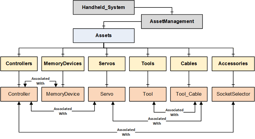
Handheld Joining System Example
The following figure describes a Handheld Joining System which consists of a handheld controller connected to a cable tool via a servo and cable. The controller has an attached memory device, and it is also connected to a socket selector.
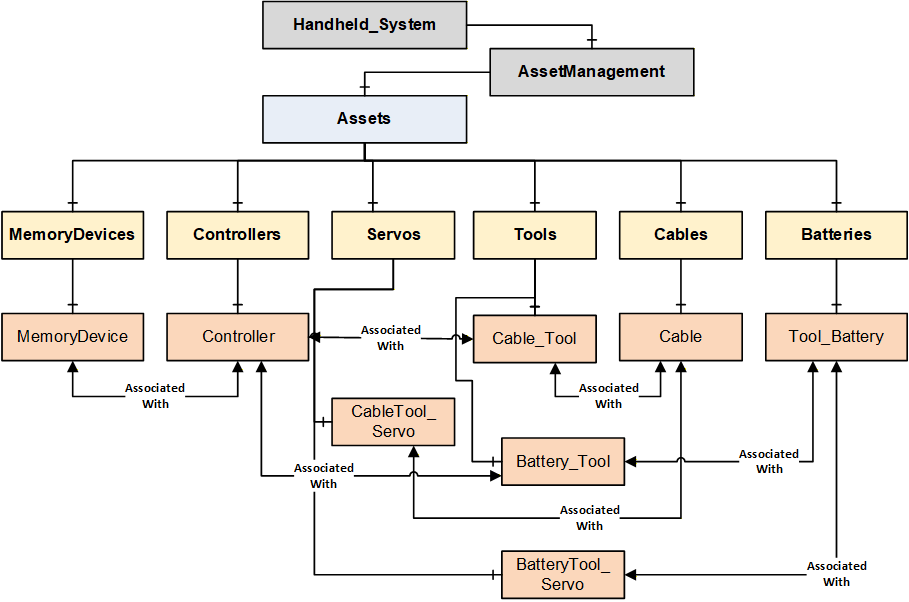
Handheld Joining System with Wireless Tool Example
The following figure describes a Handheld Joining System which consists of a handheld controller connected to a cable tool via a servo and cable and a wireless tool. The controller has an attached memory device, and it is also connected to a socket selector.
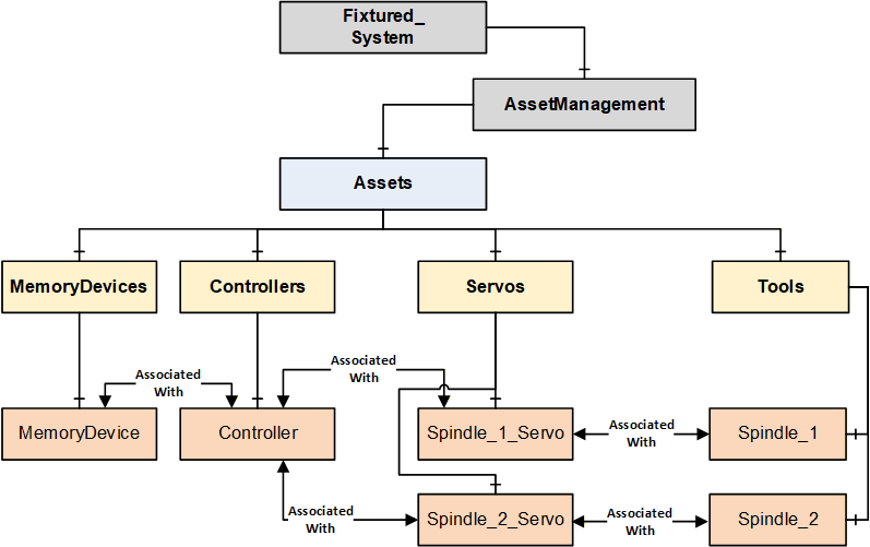
Fixtured Joining System Example
The following figure describes a Fixtured Joining System with two joining spindles. Both the spindles are managed by one controller, and it needs two servos to drive the two spindles. The controller has an attached memory device.
Note: This example does not model cables connected to spindles. There is no restriction in modeling a cable in the Fixtured Joining System.
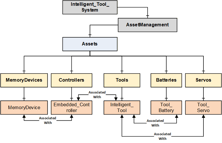
Intelligent Tool Joining System Example
The following figure describes an Intelligent Tool Joining System which consists of a Tool that has an embedded controller, servo, and an attached memory device.
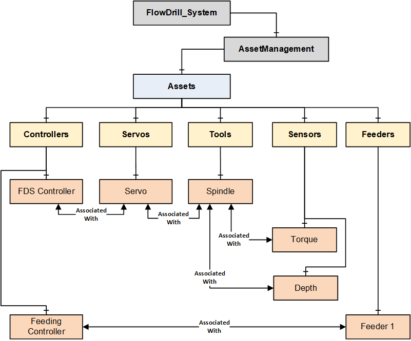
Flow Drill Joining System Example
The following figure describes a Flow Drill Joining System which consists of one spindle with one servo to drive in the screw. In the spindle there is a torque sensor to measure the torque at the screw and a depth sensor to measure the advancement of the screw into the part. Additionally, there is a feeding controller which ensures that the parts are available at the joining location. The feeder stocks the fasteners and separates them.
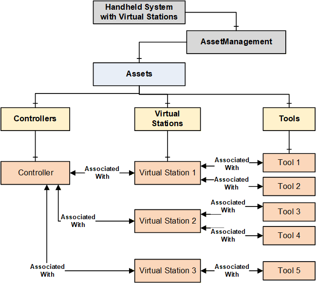
Handheld System with Virtual Stations Example
The following figure describes a Handheld System with Virtual Stations. Virtual Stations are an abstraction of the relation between a controller and a tool (or other assets).
A single virtual station can be mapped to one or more Tools and other devices in a station. The combination of virtual stations and the associated assets is application specific.
OPC UA References for Assets
An asset defined in the Joining System can reference other assets in multiple ways such as Logical Connection, Network Connection, Physical Connection, Component (Attached Component, Built-in Component, Sub-Part, etc.), ConnectsTo, IsConnectedTo, etc.
For this version of the specification, only a generic reference AssociatedWith is used to enable the topological infrastructure which will be used by the client applications to build required tree view or hierarchies or a mesh of inter-linked nodes. There is no restriction on adding additional references.
Note: The assets model defined in Joining System is flexible to cover various type of systems. For example, a Controller and MemoryDevice can have HasAttachedComponent or HasContainedComponent reference.
OPC UA base specifications provides standardized set of references which can be used at application level.
Note: Table 278 provides few examples as general information few examples.
| Source Object | Possible Reference Types | Target Object |
| Controller | AssociatedWith IsPhysicallyConnectedTo Requires Controls Utilizes | Tool |
| Controller | AssociatedWith IsPhysicallyConnectedTo Requires Controls Utilizes | Servo |
| Controller | IsPhysicallyConnectedTo Requires Controls Utilizes RepresentsSameFunctionalityAs IsHostedBy | Controller |
| Controller | HasAttachedComponent HasContainedComponent | MemoryDevice |
| Controller | IsPhysicallyConnectedTo Requires Controls Utilizes | Feeder |
| Controller | HasAttachedComponent HasContainedComponent | Sensor |
| Controller | IsPhysicallyConnectedTo Requires Controls Utilizes | Accessory |
| Controller | IsPhysicallyConnectedTo Requires Controls Utilizes HasAttachedComponent HasContainedComponent | SubComponent |
| Controller | AssociatedWith Utilizes Requires | VirtualStation |
| Tool | AssociatedWith Utilizes Requires | VirtualStation |
| Tool | IsPhysicallyConnectedTo Requires Controls Utilizes IsHostedBy | Controller |
| Tool | IsPhysicallyConnectedTo Requires Controls Utilizes HasAttachedComponent HasContainedComponent | Battery |
| Tool | IsPhysicallyConnectedTo Requires Controls Utilizes HasAttachedComponent HasContainedComponent | Sensor |
| Tool | IsPhysicallyConnectedTo Requires Controls Utilizes HasAttachedComponent HasContainedComponent | Accessory |
| Tool | IsPhysicallyConnectedTo Requires Controls Utilizes HasAttachedComponent HasContainedComponent | SubComponent |
| Servo | IsPhysicallyConnectedTo Requires Controls Utilizes | Tool |
| PowerSupply | IsPhysicallyConnectedTo Requires Controls Utilizes | Servo |
| Battery | IsPhysicallyConnectedTo Requires Utilizes | PowerSupply |
| Cable | IsPhysicallyConnectedTo | Controller |
| Cable | IsPhysicallyConnectedTo | Servo |
| Cable | IsPhysicallyConnectedTo | Tool |
| Cable | IsPhysicallyConnectedTo | Feeder |
| Cable | IsPhysicallyConnectedTo | PowerSupply |
| Cable | IsPhysicallyConnectedTo | Sensor |
| Cable | IsPhysicallyConnectedTo | Accessory |
| Cable | IsPhysicallyConnectedTo | SubComponent |