
1 Scope
This specification was created by a joint working group of the OPC Foundation and IO-Link Community. It defines an OPC UA Information Model to represent and access IO-Link Devices and IO-Link Masters.
OPC Foundation
OPC is the interoperability standard for the secure and reliable exchange of data and information in the industrial automation space and in other industries. It is platform independent and ensures the seamless flow of information among devices from multiple vendors. The OPC Foundation is responsible for the development and maintenance of this standard.
Initially, the OPC standard was restricted to the Windows operating system. As such, the acronym OPC was borne from OLE (object linking and embedding) for Process Control. These specifications, which are now known as OPC Classic, have enjoyed widespread adoption across multiple industries, including manufacturing, building automation, oil and gas, renewable energy and utilities, among others.
OPC UA is a platform independent service-oriented architecture that integrates all the functionality of the individual OPC Classic specifications into one extensible framework. This multi-layered approach accomplishes the original design specification goals of:
Platform independence: from an embedded microcontroller to cloud-based infrastructure
Secure: encryption, authentication, authorization and auditing
Extensible: ability to add new features including transports without affecting existing applications
Comprehensive information modelling capabilities: for defining any model from simple to complex
IO-Link Community
Goal of the IO-Link Community is to develop and market IO-Link as a technology. The IO-Link Community works as a Committee C IO-Link (C) organized within the Profibus Nutzerorganisation e.V. (PNO). The IO-Link interface is in principle to be seen as being independent of the fieldbus systems of the PNO (PROFIBUS and PROFINET).
IO-Link is the first standardized IO technology worldwide (IEC 61131-9) for the communication with sensors and also actuators. The powerful point-to-point communication is based on the long established 3-wire sensor and actuator connection without additional requirements regarding the cable material. So, IO-Link is no fieldbus but the further development of the existing, tried-and-tested connection technology for sensors and actuators.
Each IO-Link device has an IODD (IO Device Description). This is a device description file which contains information about the manufacturer, article number, functionality etc. This information can be easily read and processed by the user. Each device can be unambiguously identified via the IODD as well as via an internal device ID.
2 Normative References
The following referenced documents are indispensable for the application of this specification. For dated references, only the edition cited applies. For undated references, the latest edition of the referenced document (including any amendments) applies.
OPC 10000-1: OPC Unified Architecture - Part 1: Overview and Concepts
OPC 10000-2, OPC Unified Architecture - Part 2: Security Model
OPC 10000-3, OPC Unified Architecture - Part 3: Address Space Model
OPC 10000-4, OPC Unified Architecture - Part 4: Services
OPC 10000-5, OPC Unified Architecture - Part 5: Information Model
OPC 10000-6, OPC Unified Architecture - Part 6: Mappings
OPC 10000-7, OPC Unified Architecture - Part 7: Profiles
OPC 10000-8, OPC Unified Architecture - Part 8: Data Access
OPC 10000-9, OPC Unified Architecture - Part 9: Alarms & Conditions
OPC 10000-100, OPC Unified Architecture - OPC UA for Devices
IO-Link Specification: IO-Link Interface and System Specification, Version 1.1.2, July 2013
IO-Link Addendum: IO-Link Addendum 2017 related to IO-Link Interface and System Specification V1.1.2, Version 2.0, December 2017
IODD Specification:
IO Device Description, Version 1.1, August 2011
IO Device Description, Version 1.0.1, March 2010
IO-Link Common Profile: IO-Link Common Profile Specification Version 1.0 July 2017
3 Terms, Definitions, and Conventions
3.1 Overview
It is assumed that basic concepts of OPC UA information modelling and IO-Link are understood in this specification. This specification will use these concepts to describe the OPC UA for IO-Link Information Model. For the purposes of this document, the terms and definitions given in OPC 10000-1, OPC 10000-3, OPC 10000-4, OPC 10000-5, OPC 10000-7, OPC 10000-100, IO-Link Specification, and IODD Specification as well as the following apply.
3.2 OPC UA for IO-Link Information Model Terms
3.2.1 IO-Link Device
Device as defined in IO-Link Specification
3.2.2 IO-Link Master
Master as defined in IO-Link Specification
3.3 Abbreviations and Symbols
| ERP | Enterprise Resource Planning |
| HMI | Human-Machine Interface |
| HTTP | Hypertext Transfer Protocol |
| IODD | IO-Link Device Description |
| IP | Internet Protocol |
| ISDU | Indexed Service Data Unit |
| MES | Manufacturing Execution System |
| PMS | Production Management System |
| SCADA | Supervisory Control And Data Acquisition |
| TCP | Transmission Control Protocol |
| UA | Unified Architecture |
| XML | Extensible Markup Language |
3.4 Conventions used in this Document
3.4.1 Conventions for Terms
Terms in this document are written in CamelCase. Only the first occurrence of a term is written in italic.
3.4.2 Conventions for Node Descriptions
Node definitions are specified using tables (see Table 2).
Attributes are defined by providing the Attribute name and a value, or a description of the value.
References are defined by providing the ReferenceType name, the BrowseName of the TargetNode and its NodeClass.
If the TargetNode is a component of the Node being defined in the table the Attributes of the composed Node are defined in the same row of the table.
The DataType is only specified for Variables; "[<number>]" indicates a single-dimensional array, for multi-dimensional arrays the expression is repeated for each dimension (e.g. [2][3] for a two-dimensional array). For all arrays the ArrayDimensions is set as identified by <number> values. If no <number> is set, the corresponding dimension is set to 0, indicating an unknown size. If no number is provided at all the ArrayDimensions can be omitted. If no brackets are provided, it identifies a scalar DataType and the ValueRank is set to the corresponding value (see OPC 10000-3). In addition, ArrayDimensions is set to null or is omitted. If it can be Any or ScalarOrOneDimension, the value is put into "{<value>}", so either "{Any}" or "{ScalarOrOneDimension}" and the ValueRank is set to the corresponding value (see OPC 10000-3) and the ArrayDimensions is set to null or is omitted. Examples are given in Table 1.
| Notation | DataType | ValueRank | ArrayDimensions | Description |
| Int32 | Int32 | -1 | omitted or null | A scalar Int32. |
| Int32[] | Int32 | 1 | omitted or {0} | Single-dimensional array of Int32 with an unknown size. |
| Int32[][] | Int32 | 2 | omitted or {0,0} | Two-dimensional array of Int32 with unknown sizes for both dimensions. |
| Int32[3][] | Int32 | 2 | {3,0} | Two-dimensional array of Int32 with a size of 3 for the first dimension and an unknown size for the second dimension. |
| Int32[5][3] | Int32 | 2 | {5,3} | Two-dimensional array of Int32 with a size of 5 for the first dimension and a size of 3 for the second dimension. |
| Int32{Any} | Int32 | -2 | omitted or null | An Int32 where it is unknown if it is scalar or array with any number of dimensions. |
| Int32{ScalarOrOneDimension} | Int32 | -3 | omitted or null | An Int32 where it is either a single-dimensional array or a scalar. |
The TypeDefinition is specified for Objects and Variables.
The TypeDefinition column specifies a symbolic name for a NodeId, i.e. the specified Node points with a HasTypeDefinition Reference to the corresponding Node.
The ModellingRule of the referenced component is provided by specifying the symbolic name of the rule in the ModellingRule column. In the AddressSpace, the Node shall use a HasModellingRule Reference to point to the corresponding ModellingRule Object.
If the NodeId of a DataType is provided, the symbolic name of the Node representing the DataType shall be used.
Nodes of all other NodeClasses cannot be defined in the same table; therefore only the used ReferenceType, their NodeClass and their BrowseName are specified. A reference to another part of this document points to their definition.
Table 2 illustrates the table. If no components are provided, the DataType, TypeDefinition and ModellingRule columns may be omitted and only a Comment column is introduced to point to the Node definition.
| Attribute | Value | ||||
| Attribute name | Attribute value. If it is an optional Attribute that is not set "--" will be used. | ||||
| References | NodeClass | BrowseName | DataType | TypeDefinition | ModellingRule |
|---|---|---|---|---|---|
| ReferenceType name | NodeClass of the TargetNode. | BrowseName of the target Node. If the Reference is to be instantiated by the server, then the value of the target Node's BrowseName is "--". | DataType of the referenced Node, only applicable for Variables. | TypeDefinition of the referenced Node, only applicable for Variables and Objects. | Referenced ModellingRule of the referenced Object. |
| NOTE Notes referencing footnotes of the table content. | |||||
Components of Nodes can be complex that is containing components by themselves. The TypeDefinition, NodeClass, DataType and ModellingRule can be derived from the type definitions, and the symbolic name can be created as defined in Annex A. Therefore, those containing components are not explicitly specified; they are implicitly specified by the type definitions.
3.4.3 NodeIds and BrowseNames
3.4.3.1 NodeIds
The NodeIds of all Nodes described in this standard are only symbolic names. Annex A defines the actual NodeIds.
The symbolic name of each Node defined in this specification is its BrowseName, or, when it is part of another Node, the BrowseName of the other Node, a ".", and the BrowseName of itself. In this case "part of" means that the whole has a HasProperty or HasComponent Reference to its part. Since all Nodes not being part of another Node have a unique name in this specification, the symbolic name is unique.
The NamespaceUri for all NodeIds defined in this specification is defined in Annex A. The NamespaceIndex for this NamespaceUri is vendor-specific and depends on the position of the NamespaceUri in the server namespace table.
Note that this specification not only defines concrete Nodes, but also requires that some Nodes shall be generated, for example one for each Session running on the Server. The NodeIds of those Nodes are vendor-specific, including the NamespaceUri. But the NamespaceUri of those Nodes cannot be the NamespaceUri used for the Nodes defined in this specification, because they are not defined by this specification but generated by the Server.
3.4.3.2 BrowseNames
The text part of the BrowseNames for all Nodes defined in this specification is specified in the tables defining the Nodes. The NamespaceUri for all BrowseNames defined in this specification is defined in Annex A.
If the BrowseName is not defined by this specification, a namespace index prefix like '0:EngineeringUnits' is added to the BrowseName. This is typically necessary if a Property of another specification is overwritten or used in the OPC UA types defined in this specification. Table 83 provides a list of namespaces used in this specification.
3.4.4 Common Attributes
3.4.4.1 General
The Attributes of Nodes, their DataTypes and descriptions are defined in OPC 10000-3. Attributes not marked as optional are mandatory and shall be provided by a Server. The following tables define if the Attribute value is defined by this specification or if it is vendor-specific.
For all Nodes specified in this specification, the Attributes named in Table 3 shall be set as specified in the table.
| Attribute | Value |
| DisplayName | The DisplayName is a LocalizedText. Each server shall provide the DisplayName identical to the BrowseName of the Node for the LocaleId "en". Whether the server provides translated names for other LocaleIds is vendor-specific. |
| Description | Optionally a vendor-specific description is provided. |
| NodeClass | Shall reflect the NodeClass of the Node. |
| NodeId | The NodeId is described by BrowseNames as defined in 3.4.3.1 |
| WriteMask | Optionally the WriteMask Attribute can be provided. If the WriteMask Attribute is provided, it shall set all non-vendor-specific Attributes to not writable. For example, the Description Attribute may be set to writable since a Server may provide a vendor-specific description for the Node. The NodeId shall not be writable, because it is defined for each Node in this specification. |
| UserWriteMask | Optionally the UserWriteMask Attribute can be provided. The same rules as for the WriteMask Attribute apply. |
| RolePermissions | Optionally vendor-specific role permissions can be provided. |
| UserRolePermissions | Optionally the role permissions of the current Session can be provided. The value is vendor-specific and depend on the RolePermissions Attribute (if provided) and the current Session. |
| AccessRestrictions | Optionally vendor-specific access restrictions can be provided. |
3.4.4.2 Objects
For all Objects specified in this specification, the Attributes named in Table 4 shall be set as specified in the table. The definitions for the Attributes can be found in OPC 10000-3.
| Attribute | Value |
| EventNotifier | Whether the Node can be used to subscribe to Events or not is vendor-specific. |
3.4.4.3 Variables
For all Variables specified in this specification, the Attributes named in Table 5 shall be set as specified in the table. The definitions for the Attributes can be found in OPC 10000-3.
| Attribute | Value |
| MinimumSamplingInterval | Optionally, a vendor-specific minimum sampling interval is provided. |
| AccessLevel | The access level for Variables used for type definitions is vendor-specific, for all other Variables defined in this specification, the access level shall allow reading; other settings are vendor-specific. |
| UserAccessLevel | The value for the UserAccessLevel Attribute is vendor-specific. It is assumed that all Variables can be accessed by at least one user. |
| Value | For Variables used as InstanceDeclarations, the value is vendor-specific; otherwise it shall represent the value described in the text. |
| ArrayDimensions | If the ValueRank does not identify an array of a specific dimension (i.e. ValueRank <= 0) the ArrayDimensions can either be set to null or the Attribute is missing. This behaviour is vendor-specific. If the ValueRank specifies an array of a specific dimension (i.e. ValueRank > 0) then the ArrayDimensions Attribute shall be specified in the table defining the Variable. |
| Historizing | The value for the Historizing Attribute is vendor-specific. |
| AccessLevelEx | If the AccessLevelEx Attribute is provided, it shall have the bits 8, 9, and 10 set to 0, meaning that read and write operations on an individual Variable are atomic, and arrays can be partly written. |
3.4.4.4 VariableTypes
For all VariableTypes specified in this specification, the Attributes named in Table 6 shall be set as specified in the table. The definitions for the Attributes can be found in OPC 10000-3.
| Attributes | Value |
| Value | Optionally a vendor-specific default value can be provided. |
| ArrayDimensions | If the ValueRank does not identify an array of a specific dimension (i.e. ValueRank <= 0) the ArrayDimensions can either be set to null or the Attribute is missing. This behaviour is vendor-specific. If the ValueRank specifies an array of a specific dimension (i.e. ValueRank > 0) then the ArrayDimensions Attribute shall be specified in the table defining the VariableType. |
3.4.4.5 Methods
For all Methods specified in this specification, the Attributes named in Table 7 shall be set as specified in the table. The definitions for the Attributes can be found in OPC 10000-3.
| Attributes | Value |
| Executable | All Methods defined in this specification shall be executable (Executable Attribute set to "True"), unless it is defined differently in the Method definition. |
| UserExecutable | The value of the UserExecutable Attribute is vendor-specific. It is assumed that all Methods can be executed by at least one user. |
4 General Information on IO-Link and OPC UA
4.1 Introduction to IO-Link
4.1.1 What is IO-Link?
IO-Link is the first standardized IO technology worldwide (IEC 61131-9) for the communication with sensors and actuators. The powerful point-to-point communication is based on the long established 3-wire sensor and actuator connection without additional requirements regarding the cable material. So, IO-Link is no fieldbus but the further development of the existing, tried-and-tested connection technology for sensors and actuators.
4.1.2 Basics of IO-Link
An IO-Link system consists of an IO-Link Master, IO-Link Devices and the cables that connect the IO-Link Devices to the IO-Link Master's ports. The IO-Link Master establishes the connection between the IO-Link Devices and the automation system and maintains point-to-point connections to the IO-Link Devices. Figure 1 gives an example of a system architecture with IO-Link.
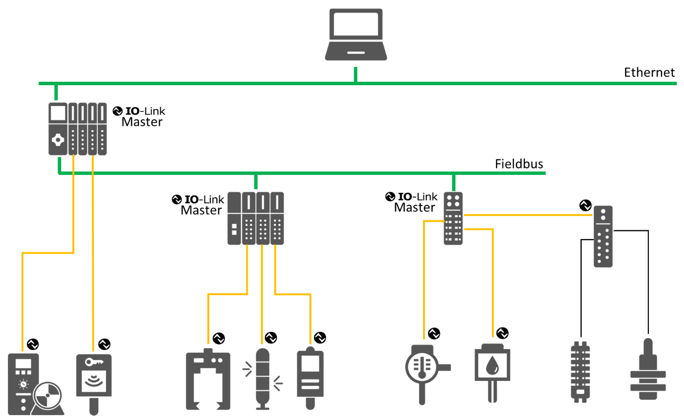
Figure 1 uses the following colour code: Green for Ethernet and Fieldbus connections, orange for IO-Link connections and black for non-IO-Link sensor/actuator connections. Note that IO‑Link Masters can be implemented at different levels of the hierarchy and be combined with different kinds of devices such as fieldbus masters, gateways, etc.
4.1.3 Device Description
Each IO-Link Device has an IODD (IO Device Description). This is a device description file which contains information about the manufacturer, article number, functionality etc. This information can be easily read and processed by the user. Each device can be unambiguously identified via the IODD as well as via an internal device ID.
4.2 Introduction to OPC Unified Architecture
4.2.1 What is OPC UA?
OPC UA is an open and royalty free set of standards designed as a universal communication protocol. While there are numerous communication solutions available, OPC UA has key advantages:
A state of art security model (see OPC 10000-2).
A fault tolerant communication protocol.
An information modelling framework that allows application developers to represent their data in a way that makes sense to them.
OPC UA has a broad scope which delivers for economies of scale for application developers. This means that a larger number of high quality applications at a reasonable cost are available. When combined with semantic models such as OPC UA for IO-Link, OPC UA makes it easier for end users to access data via generic commercial applications.
The OPC UA model is scalable from small devices to ERP systems. OPC UA Servers process information locally and then provide that data in a consistent format to any application requesting data - ERP, MES, PMS, Maintenance Systems, HMI, Smartphone or a standard Browser, for examples. For a more complete overview see OPC 10000-1.
4.2.2 Basics of OPC UA
As an open standard, OPC UA is based on standard internet technologies, like TCP/IP, HTTP, Web Sockets.
As an extensible standard, OPC UA provides a set of Services (see OPC 10000-4) and a basic information model framework. This framework provides an easy manner for creating and exposing vendor defined information in a standard way. More importantly all OPC UA Clients are expected to be able to discover and use vendor-defined information. This means OPC UA users can benefit from the economies of scale that come with generic visualization and historian applications. This specification is an example of an OPC UA Information Model designed to meet the needs of developers and users.
OPC UA Clients can be any consumer of data from another device on the network to browser based thin clients and ERP systems. The full scope of OPC UA applications is shown in Figure 2.

OPC UA provides a robust and reliable communication infrastructure having mechanisms for handling lost messages, failover, heartbeat, etc. With its binary encoded data, it offers a high-performing data exchange solution. Security is built into OPC UA as security requirements become more and more important especially since environments are connected to the office network or the internet and attackers are starting to focus on automation systems.
4.2.3 Information Modelling in OPC UA
4.2.3.1 Concepts
OPC UA provides a framework that can be used to represent complex information as Objects in an AddressSpace which can be accessed with standard services. These Objects consist of Nodes connected by References. Different classes of Nodes convey different semantics. For example, a Variable Node represents a value that can be read or written. The Variable Node has an associated DataType that can define the actual value, such as a string, float, structure etc. It can also describe the Variable value as a variant. A Method Node represents a function that can be called. Every Node has a number of Attributes including a unique identifier called a NodeId and non-localized name called as BrowseName.
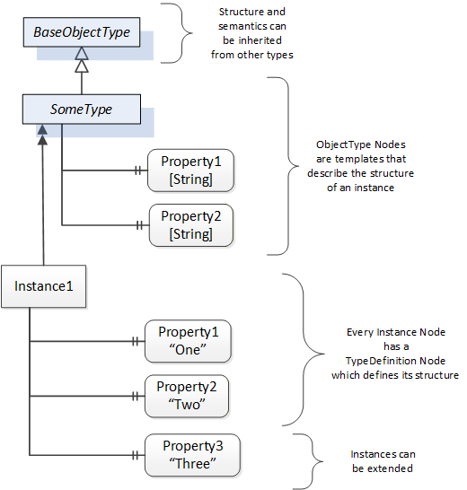
Object and Variable Nodes represent instances and they always reference a TypeDefinition (ObjectType or VariableType) Node which describes their semantics and structure. Figure 3 illustrates the relationship between an instance and its TypeDefinition.
The type Nodes are templates that define all the children that can be present in an instance of the type. In the example in Figure 3 the SomeType ObjectType defines two Properties: Property1 and Property2. All instances of SomeType are expected to have the same children with the same BrowseNames. Within a type the BrowseNames uniquely identify the children. This means Client applications can be designed to search for children based on the BrowseNames from the type instead of NodeIds. This eliminates the need for manual reconfiguration of systems if a Client uses types that multiple Servers implement.
OPC UA also supports the concept of sub-typing. This allows a modeller to take an existing type and extend it. There are rules regarding sub-typing defined in OPC 10000-3, but in general they allow the extension of a given type or the restriction of a DataType. For example, the modeller may decide that the existing ObjectType in some cases needs an additional Variable. The modeller can create a subtype of the ObjectType and add the Variable. A Client that is expecting the parent type can treat the new type as if it was of the parent type. Regarding DataTypes, subtypes can only restrict. If a Variable is defined to have a numeric value, a sub type could restrict it to a float.
References allow Nodes to be connected in ways that describe their relationships. All References have a ReferenceType that specifies the semantics of the relationship. References can be hierarchical or non-hierarchical. Hierarchical references are used to create the structure of Objects and Variables. Non-hierarchical are used to create arbitrary associations. Applications can define their own ReferenceType by creating subtypes of an existing ReferenceType. Subtypes inherit the semantics of the parent but may add additional restrictions.
4.2.3.2 Graphical Notation
Figure 3 uses a notation that was developed for the OPC UA specification. The notation is summarized in Figure 4. UML representations can also be used; however, the OPC UA notation is less ambiguous because there is a direct mapping from the elements in the figures to Nodes in the AddressSpace of an OPC UA Server.
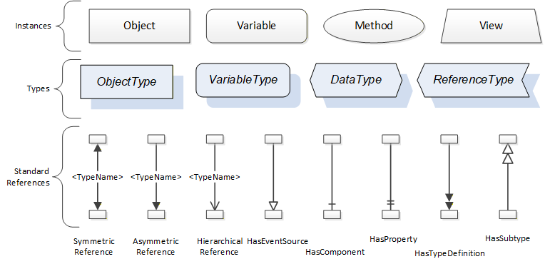
A complete description of the different types of Nodes and References can be found in OPC 10000-3 and the base structure is described in OPC 10000-5.
4.2.4 OPC UA Profiles
OPC UA specification defines a very wide range of functionality in its basic information model. It is not expected that all Clients or Servers support all functionality in the OPC UA specifications. OPC UA includes the concept of Profiles, which segment the functionality into testable certifiable units. This allows the definition of functional subsets (that are expected to be implemented) within a companion specification. The Profiles do not restrict functionality, but generate requirements for a minimum set of functionalities (see OPC 10000-7).
4.2.5 Namespaces
OPC UA allows information from many different sources to be combined into a single coherent AddressSpace. Namespaces are used to make this possible by eliminating naming and id conflicts between information from different sources. Namespaces in OPC UA have a globally unique string called a NamespaceUri and a locally unique integer called a NamespaceIndex. The NamespaceIndex is only unique within the context of a Session between an OPC UA Client and an OPC UA Server. The Services defined for OPC UA use the NamespaceIndex to specify the Namespace for qualified values.
There are two types of values in OPC UA that are qualified with Namespaces: NodeIds and QualifiedNames. NodeIds are globally unique identifiers for Nodes. This means the same Node with the same NodeId can appear in many Servers. This, in turn, means Clients can have built in knowledge of some Nodes. OPC UA Information Models generally define globally unique NodeIds for the TypeDefinitions defined by the Information Model.
QualifiedNames are non-localized names qualified with a Namespace. They are used for the BrowseNames of Nodes and allow the same names to be used by different information models without conflict. TypeDefinitions are not allowed to have children with duplicate BrowseNames; however, instances do not have that restriction.
4.2.6 Companion Specifications
An OPC UA companion specification for an industry specific vertical market describes an Information Model by defining ObjectTypes, VariableTypes, DataTypes and ReferenceTypes that represent the concepts used in the vertical market, and potentially also well-defined Objects as entry points into the AddressSpace.
5 Combining OPC UA and IO-Link
5.1 System Architecture
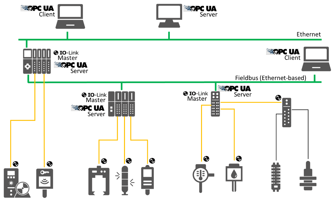
This specification defines an Information Model for IO-Link Masters and Devices. An example of a system architecture, providing different deploy options for OPC UA applications, is shown in Figure 5. The OPC UA Server can directly be deployed on an IO-Link Master or a PLC connected to the IO-Link Master or another platform like a PC. The OPC UA Client can directly be connected to the OPC UA Server running on the IO-Link Master, it can be connected to the PLC running the OPC UA Server, or the PLC can forward the traffic from an OPC UA Client on top of the PLC to the OPC UA Server running on the IO-Link Master beneath the PLC. More deploy options are possible and not limited by this specification.
5.2 Use Cases
The use cases that shall be fulfilled by this specification were defined by the IO-Link / OPC UA Integration Requirements Version 1.0.0 document. This section summarizes the use cases in scope.
5.2.1 UC.001: Configure an IO-Link Master
Preparing the IO-Link Master for the respective application by adjusting its parameters. This use case is of relevance, if the IO-Link Master is not connected to a fieldbus and a PLC.
5.2.2 UC.002: Find IO-Link Masters
The user would like to know which IO-Link Masters are used in the plant/machine. He would like to find IO-Link Masters of all types and vendors in the same way using his SW-Tool. No vendor-specific implementation shall be needed.
5.2.3 UC.003: Find IO-Link Devices
To be able to parameterize the connected IO-Link Devices it must be possible to request the IO-Link Master to give the information about connected devices to each of its ports.
5.2.4 UC.004: Initial commissioning of IO-Link Device
The user wants to parameterize the IO-Link Device for its application.
5.2.5 UC.005: Configure device metadata
Add metadata to identify the role and position of a device in the machine or process. If the IO-Link Device does not support the IO-Link Common Profile with Application Specific Tag, Function Tag and Location Tag, these parameters shall be virtually provided in the OPC UA Server.
5.2.6 UC.006: Configure IO-Link subscriptions
Setup data subscriptions to master or device variables and events to be able to:
Calculate operation KPIs (e.g. OEE)
Generate SPC (statistical process control) charts
Measure process data for process optimization
5.2.7 UC.007: Disconnection of IO-Link Device
The user (OPC UA Client) gets informed that a certain subscription is not available anymore, i.e. due to a disconnected IO-Link Device, to identify reasons for gaps in logs.
5.2.8 UC.008: Read product identification
The user of an OPC UA Client can uniquely identify all connected IO-Link Masters by their serial number information and devices by vendor and device ID to recognize the status of the devices and facilitate the exchange. For each IO-Link Device and the IO-Link Master, the following data are provided for reading only:
IO-Link DeviceType Version (mandatory)
IO-Link Protocol Version (mandatory)
Vendor Name (mandatory)
Product Name (mandatory)
Product ID (mandatory)
Serial Number (mandatory)
Hardware Revision (optional)
Software Revision (optional)
Vendor Text (optional)
Product Text (optional)
Application Specific Tag (mandatory - see UC.005)
Function Tag (optional)
Location Tag (optional)
Implicit topology information (address of IO-Link Master and port number, where the IO-Link Device is connected to)
5.2.9 UC.009: Read diagnostics data
User shall have access to logged diagnosis events. General and specific access to diagnostic data after authorization. OPC UA Client may collect event information sent to him in a logging buffer. If the IO-Link Master provides event logging, this information should be accessible via OPC UA.
5.2.10 UC.010: Read operating and failure statistics
The maintenance staff would like to use the productivity of used devices to determine the characteristics of the device during the period of use and the number of failures to obtain a statement about plant availability.
The maintenance staffs receive data on the operating time and the failure times of the connected devices.
The data are generated in the IO-Link Master and updated on the OPC UA Server.
The IO-Link Master records for each connected IO-Link Device
the duration the device is connected
the duration the device has communicated without error
the duration the device was not communicable
how often the device has been plugged in
how often the device has been changed
how often the device was not accessible
The master cyclically updates the data on the OPC UA Server and stores it persistently.
The data has a resolution in seconds.
The duration refers to the time of the last reset (usually during commissioning).
5.2.11 UC.011: Reset operating and failure statistics
The maintenance staff can reset the operating and failure statistics.
5.2.12 UC.012: Optimize machine settings
A machine in production needs to be optimized. This can be done by changing parameters of IO-Link Devices (e.g. limit values).
5.2.13 UC.013: Plant and machine status supervision
The operator staff would like to get immediately informed by the machine regarding process productivity and plant availability. In case of degradation, the possible location or source of problem shall also be reported.
Every plant subsystem with OPC UA Server connectivity sends an event if a critical condition has been detected or a configured threshold has been reached. The subsystem can also contain IO-Link Master and Devices, where IO-Link Events are translated into OPC UA events. The reported events from these subsystems shall consist of:
the origin identity of the event
the unambiguous identity of the event
the absolute time of occurrence according to the subsystems time base
if the occurrence is temporal, the duration of the erroneous condition
if possible, the identity of the processed item
On the application level, the following is derived on this raw data:
an availability signal in traffic light encoding
notification towards the operator staff
5.2.14 UC.014: Faulty device replacement
The user would like to replace an IO-Link Master or IO-Link Device with transfer of the previous configuration to the new device.
5.2.15 UC.015: Firmware update
Update device firmware individually and in groups of identical devices for IO-Link Masters and IO-Link Devices.
Note: Due to ongoing work in the OPC UA for Devices working group to standardize the firmware update, this version of the specification intentionally does not address the firmware update.
5.2.16 UC.016: Asset Management
Manage all the assets in an automation network.
Maintenance staff is called to adjust one or more settings.
5.2.17 UC.017: Cloud-connectivity at Edge Gateway
For Industry 4.0 application, an OPC UA Server will be the virtual interface between the cloud and the sensors in the field.
Therefore, the OPC UA Server has to apply the following functions:
Find all IO-Link Masters
Find IO-Link Devices
Download IODD of connected devices
Build up information model
Record all replacement of connected devices and update information model
Capture the status of connected devices
Read cyclic IO data
Read ISDU parameter sets
The Edge Gateway must find IO-Link Masters of all types and vendors in the same way. No vendor-specific implementation shall be necessary.
6 IO-Link Information Model Overview
6.1 Modelling Concepts
6.1.1 IO-Link Master
The configuration of the IO-Link Master is done by representing the IO-Link Master as Object having several Variables and Methods to view and to change the configuration. The ports of the IO-Link Master are modelled as individual Objects.
6.1.2 IO-Link Port
The configuration of an IO-Link Port is done by representing the IO-Link Port as Object having several Variables and Methods to view and to change the configuration. If the IO-Link Port has a connected or configured IO-Link Device, the device is referenced from the IO-Link Port.
6.1.3 IO-Link Device
The IO-Link Device is represented as Object having several Variables and Methods to view and to change the configuration. There is a generic ObjectType representing the common functionality of an IO-Link Device, and subtypes of it for the IODD extensions describing the type of a specific IO-Link Device in more detail and providing more intuitive configuration options.
6.1.4 IO-Link Events
Events can occur for different reasons. An IO-Link Master can generate vendor-specific Events; an IO-Link Port generates Events when the communication to the device fails, the device gets exchanged, etc.
The IO-Link Device itself provides event information. The IO-Link Master shall observe the event flag provided with each message. In case it is set, the IO-Link Master shall receive the event information via the acyclic communication mechanisms of IO-Link and forward it to the OPC UA Server and the server provides the received events via the OPC UA interface.
Events provided as IO-Link "Error" or "Warning" are mapped to OPC UA Alarms (see OPC 10000-9), events provided as IO-Link "Notification" as OPC UA Events.
Additional to the observation of the event flag there is the possibility to get information about the status of a stateful IO-Link Event (that is mapped to OPC UA Alarms) by using the DiagEntries of PortStatusList as defined in the SMI (see IO-Link Addendum) and the DetailedDeviceStatus (ISDU Index 0x0025).
6.1.5 Block operations: Up- and Download
An IO-Link Device can be configured by writing ISDU parameters. When a parameter of an IO-Link Device is written, the content is checked for consistency. This is useful, because it can happen that certain value combinations of some parameters are not valid configuration options.
When a single parameter is written, its value is checked against the other parameters that were configured before (or had this value by default). If the check fails, an error is returned. This behaviour causes problems if you want to change set of interdependent parameters.
Because of this, IO-Link provides block operations. If a device is set into the download state (via a system command) the device allows to write many parameters to the device without checking for consistency. When the block parameterization is finished (by sending another system command) the consistency of all changed parameters is checked as a whole. If all parameters are consistent, all changes are accepted, else all changes are rejected.
If the block operations are used to read several parameters, the device does not allow parameters to be changed during this time.
The needed IO-Link system commands (see IO-Link Specification) are mapped to OPC UA Methods.
To avoid concurrent access from different OPC UA Clients while the block operation is used by one OPC UA Client, the OPC UA Client should lock the IO-Link Device using the Lock Object defined in OPC 10000-100.
6.1.6 Managing IODDs
IODDs are managed as ObjectTypes in the server. A specific, well-defined Object called IODDManagement having well-defined Methods is used to load new IODDs to the Server (and thereby creating new ObjectTypes) or to delete IODDs from the Server.
6.1.7 Relating IO-Link Devices to IO-Link Ports
Depending on the configuration of an IO-Link Port and whether a physical IO-Link Device is connected to the IO-Link Port, either an Object representing the IO-Link Device is connected to the IO-Link Port or not. The following state machine describes, whether such an Object is there, and what ObjectType is used.
The top-level state machine defines the states "Port not configured as IO-Link" and "Select Device Instance Type". In the first state the IO-Link Port is configured that no IO-Link Device is used (PortMode is either DEACTIVATED, DI_C/Q or DO_C/Q) and the optional Device Object is not available. In the second state the IO-Link-Port is configured to be an IO-Link Device (PortMode is either IOL_AUTOSTART or IOL_MANUAL) and the substates indicate whether a Device Object exists as well as the used ObjectType. Changes of the PortMode trigger transitions between the states. For the second state, additional transitions are defined that trigger the re-entrance of the state and thus the re-evaluation whether a Device Object exists as well as the used ObjectType. Those transitions include plugging in or off devices, changing the UseIODD Property or changes of IO-Link Port configuration Parameters.
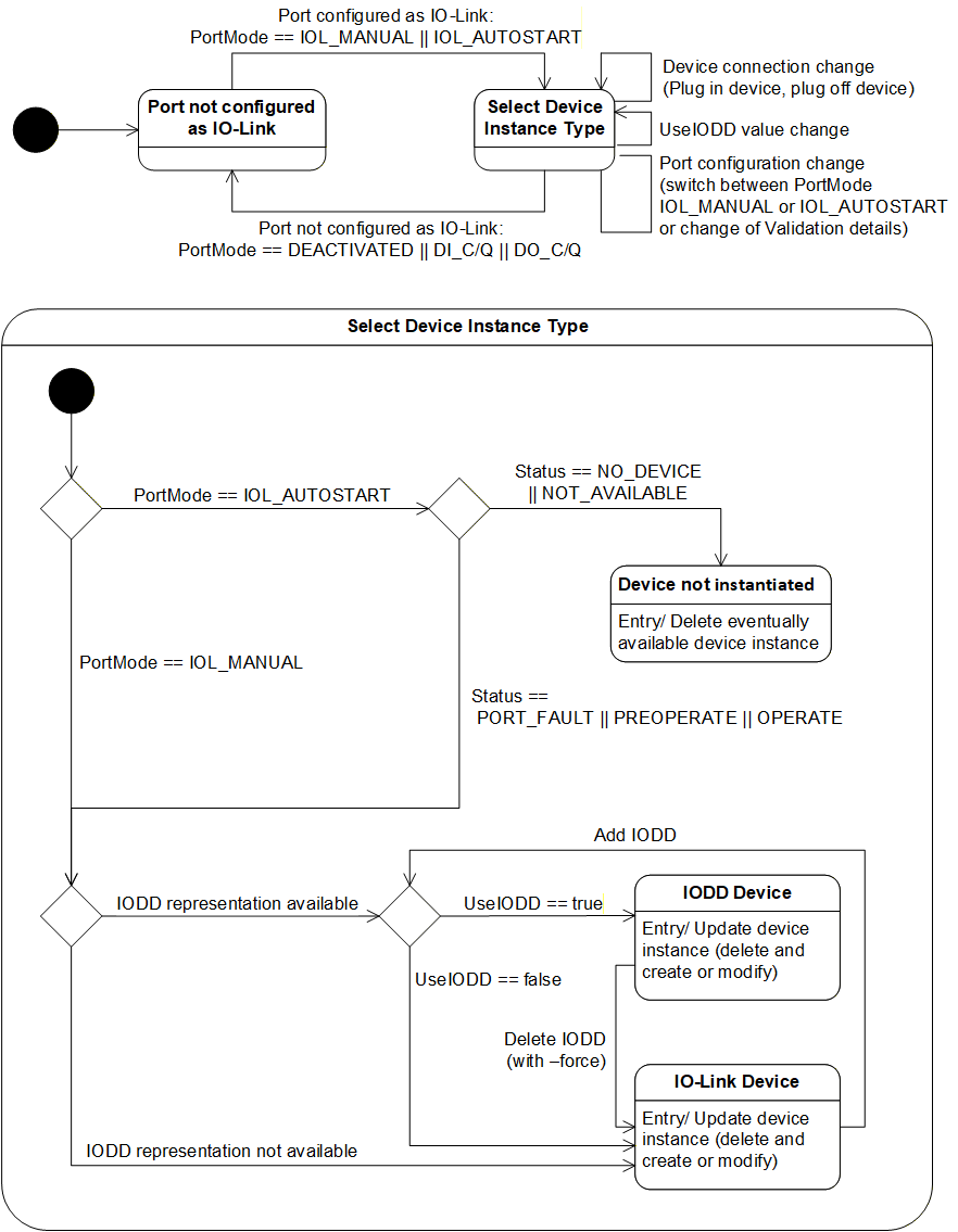
The sub-state-machine of the "Select Device Instance Type" describes three states indicating, whether the Device Object exists and what ObjectType is used.
"Device not instantiated" indicates that the optional Device Object does not exist.
"IODD Device" indicates that the Device Object exists and the IODD is used and therefore the concrete ObjectType related to the IODD is used.
"IO-Link Device" indicates that the Device Object exists and the IOLinkDeviceType is used.
The sub-state-machine defines different choices to find the correct state.
When the PortMode is IOL_AUTOSTART but no device is connected, the "Device not instantiated" state is used.
When the PortMode is IOL_AUTOSTART and a device is connected, or the PortMode is IOL_MANUAL it is further decided if the "IODD Device" or the "IO-Link Device" state is used.
When the IODD representing the IO-Link Device is available in the server and the UseIODD Parameter is "True", the "IODD Device" state is used, otherwise the "IO-Link Device" state is used.
Note that if an IO-Link Device is connected, the information of the connected IO-Link Device is used to identify the IODD, even if the IO-Link Port has a different device configured (Status = INCORRECT_DEVICE). Only when the PortMode is IOL_MANUAL and no device is connected (Status == NO_DEVICE || NOT_AVAILABLE) the configured device information is used to identify the IODD.
When the IO-Link Port is in the "IODD Device" state and the IODD is deleted (e.g. by the Method RemoveIODD using the force option) it changes to the "IO-Link Device" state.
When the IO-Link Port is in the "IO-Link Device" state and the IODD representing the IO-Link Device is added to the server (e.g. by the Method TransferIODD) and the UseIODD Parameter is "True" it changes to the "IODD Device" state.
Note that there can be limitations on what Variables can be accessed and what Methods can be executed from the Device Object (states "IO-Link Device" or "IODD Device").
When the PortMode is IOL_MANUAL and no device is connected (Status == NO_DEVICE || NOT_AVAILABLE) the Device Object is available so OPC UA Clients can already be configured to use the configured IO-Link Device, but since no physical IO-Link Device is connected, all access to Variables or Methods requiring device access will fail (bad code). Providing the structure of the configured IO-Link Device is especially helpful if an IODD is used, since the structure defined by the IODD is already available to the OPC UA Client (specific Parameters etc.).
When the PortMode is IOL_MANUAL but the incorrect IO-Link Device is connected (Status == INCORRECT_DEVICE) accessing the Variables representing the process data (e.g. ProcessDataInput, ProcessDataOutput) will fail (bad code).
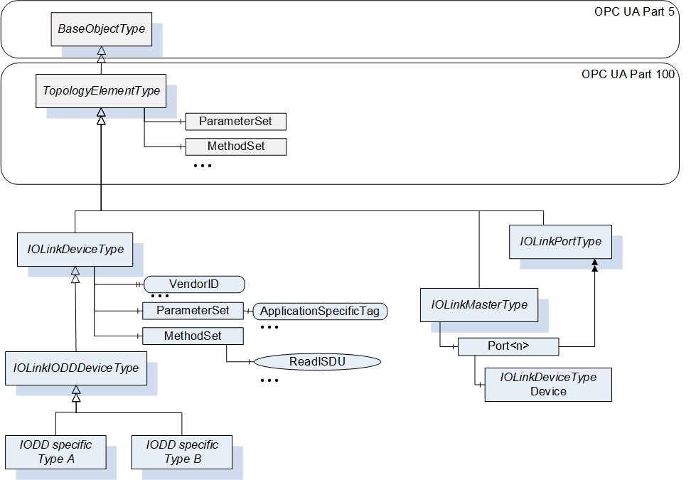
6.2 Model Overview
In Figure 7 an overview of the IO-Link Information Model is given. The IOLinkDeviceType represents IO-Link Devices. In case no IODD is available, this type shall directly be used to represent an IO-Link Device. If an IODD is available, a subtype is used representing the concrete IODD and providing the additional parameters, system commands, etc. defined in the IODD (see section 7.3). The IOLinkDeviceType inherits from TopologyElementType defined in OPC 10000-100 and thus provides basic grouping mechanisms (ParameterSet for parameters and MethodSet for Methods). It also uses basic Properties of a device like SerialNumber defined in OPC 10000-100. Section 7.1 defines details on those Properties and additional Properties like VendorId, Parameters like ApplicationSpecificTag and Methods like ReadISDU. The IO-Link Master is represented by an Object of IOLinkMasterType (see section 7.5). This ObjectType also inherits from the TopologyElementType and defines basic Properties, Parameters and Methods. For each port the IO-Link Master contains an Object of type IOLinkPortType (see section 7.6). The IOLinkPortType inherits from the TopologyElementType and thereby uses the same grouping mechanisms for Parameters and Variables. It defines Properties, Parameters and Methods for the IO-Link Port. If the port has an IO-Link Device connected, the IO-Link Device (Object of type IOLinkDeviceType) is connected to the port.
Instances of IOLinkDeviceType generate Events of type IOLinkDeviceEventType (see section 9.3) and IOLinkDeviceAlarmType (see section 9.8). An OPC UA Server might provide instances of the IOLinkDeviceAlarmType or its subtypes as Objects under the Alarms Object (see Figure 8).
Instances of IOLinkMasterType generate Events of type IOLinkMasterEventType (see section 9.6) and IOLinkMasterAlarmType (see section 9.11). Ports generate events of type IOLinkPortEventType (see section 9.5) and IOLinkPortAlarmType (see section 9.10). Both can provide instances of the IOLinkMasterAlarmType respectively IOLinkPortAlarmType under the Alarms Object (see Figure 8).
In the ObjectType hierarchy the mentioned events are grouped under the IOLinkEventType and the alarms under the IOLinkAlarmType (see Figure 8).
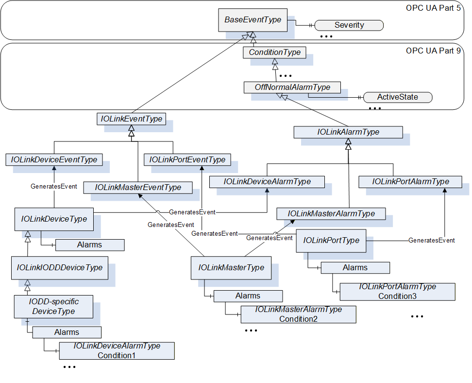
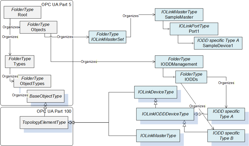
Figure 9 shows the entry points into the AddressSpace. The IOLinkMasterSet provides direct access to the Objects representing IO-Link Masters and indirectly to the Objects representing the IO-Link Devices connected to the Master. The IODDManagement Object contains the Object named IODDs pointing to all ObjectTypes representing an IODD.
Note: In order to figure out how many IO-Link Masters an OPC UA Server currently manages, an OPC UA Client can browse the IOLinkMasterSet and count all Objects of IOLinkMasterType or a subtype of it.
6.3 Mapping IODD information to OPC UA ObjectTypes
This section gives a rough overview on how IODD information is mapped to an OPC UA ObjectType. The formal definition is given in section 7.3.
An IODD consists of an IODevice containing meta data like DocumentInfo and ProfileHeader describing an IO-Link Device. In addition, it contains information about data types (DatatypeCollection), variables accessed acyclic (VariableCollection), process data (ProcessDataCollection), errors (ErrorTypeCollection), events (EventCollection) and menus to group information in user interfaces (UserInterface).
The user interface information consists of entry points for three different user roles (Observer, Maintenance, and Specialist), each one containing an identification menu and optionally parameter, observation, and diagnostics menus. Those menus can reference other menus or variables. Optionally, the user interface information also provides information how to display the process data directly (ProcessDataRefCollection).
The three entry points for the user roles are mapped to OPC UA FunctionalGroups. Each menu that is referenced directly or indirectly as part of such an entry point is also mapped as FunctionalGroup, referenced from its parent FunctionalGroup.
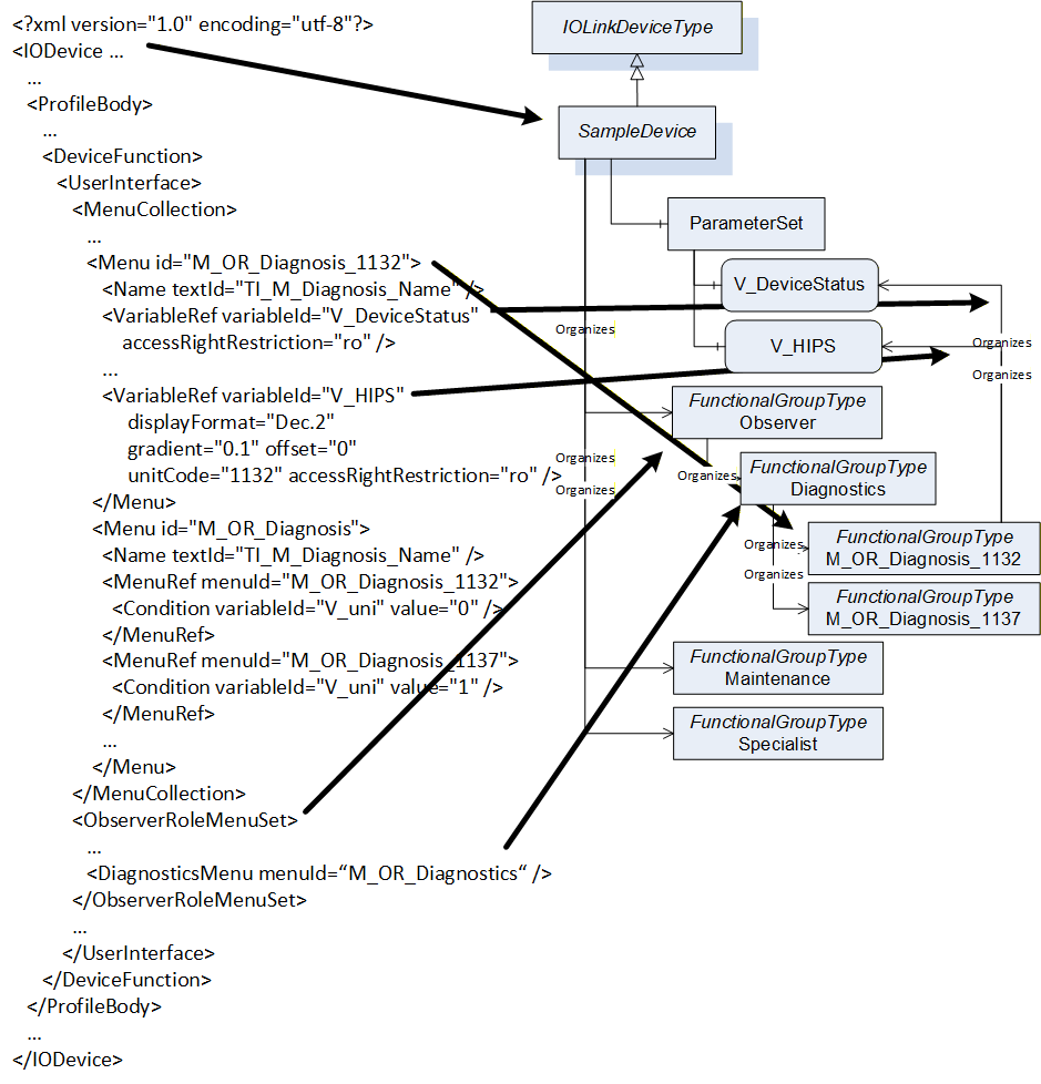
In Figure 10, an example of such a mapping is given. On the left hand, parts of an IODD are shown. On the right, the representation as ObjectType in OPC UA is shown. The IODevice is mapped to an ObjectType. The UserInterface information is mapped mainly to Objects of FunctionalGroupType. The Observer Object is directly connected to the ObjectType, its submenu Diagnostics is referenced by the Observer Object. The Diagnostics menu contains two conditional menus in the IODD, which are both mapped as optional Objects under the Diagnostics Object. The M_OR_Diagnosis_1132 menu references two Variables. This is mapped by referencing the corresponding variables of the ParameterSet. Some details of the mapping like handling conditions or additional information for Variables like EngineeringUnits are not shown in the figure and defined in section 7.3.
7 OPC UA ObjectTypes
7.1 IOLinkDeviceType ObjectType Definition
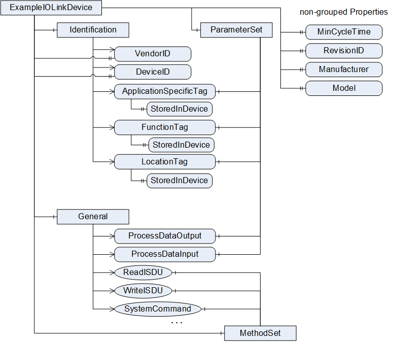
7.1.1 Example
In Figure 11 an example of an instance of the IOLinkDeviceType is shown. This example is using only the mandatory InstanceDeclarations, and excluding several mandatory Methods, in order to give an overview on the ObjectType. Several Properties are directly connected to the Object, whereas the Parameters are connected via the ParameterSet, Methods via the MethodSet and both organized via different FunctionalGroups (Identification and General).
7.1.2 Overview
The IOLinkDeviceType provides the generic information of an IO-Link Device and is formally defined in Table 8.
| Attribute | Value | |||||
| BrowseName | IOLinkDeviceType | |||||
| IsAbstract | False | |||||
| References | Node Class | BrowseName | DataType | TypeDefinition | Modelling Rule | |
|---|---|---|---|---|---|---|
| Subtype of TopologyElementType defined in OPC 10000-100. | ||||||
| HasComponent | Object | 2:ParameterSet | BaseObjectType | Mandatory | ||
| HasComponent | Object | 2:MethodSet | BaseObjectType | Mandatory | ||
| HasComponent | Object | 2:Identification | FunctionalGroupType | Mandatory | ||
| HasComponent | Object | General | FunctionalGroupType | Mandatory | ||
| HasProperty | Variable | 2:SerialNumber | String | PropertyType | Optional | |
| HasProperty | Variable | 2:Manufacturer | LocalizedText | PropertyType | Mandatory | |
| HasProperty | Variable | 2:Model | LocalizedText | PropertyType | Mandatory | |
| HasProperty | Variable | 2:HardwareRevision | String | PropertyType | Optional | |
| HasProperty | Variable | 2:SoftwareRevision | String | PropertyType | Optional | |
| HasComponent | Variable | 2:DeviceHealth | DeviceHealthEnum | BaseDataVariableType | Optional | |
| HasProperty | Variable | MinCycleTime | Duration | PropertyType | Mandatory | |
| HasProperty | Variable | RevisionID | String | PropertyType | Mandatory | |
| HasProperty | Variable | VendorID | UInt16 | PropertyType | Mandatory | |
| HasProperty | Variable | DeviceID | UInt32 | PropertyType | Mandatory | |
| HasProperty | Variable | DeviceAccessLocks | UInt16 | PropertyType | Optional | |
| HasProperty | Variable | ProfileCharacteristic | UInt16[] | PropertyType | Optional | |
| HasProperty | Variable | VendorText | String | PropertyType | Optional | |
| HasProperty | Variable | ProductID | String | PropertyType | Optional | |
| HasProperty | Variable | ProductText | String | PropertyType | Optional | |
| HasComponent | Object | Alarms | FolderType | Optional | ||
| GeneratesEvent | ObjectType | IOLinkDeviceEventType | Defined in 9.3. | |||
| GeneratesEvent | ObjectType | IOLinkDeviceAlarmType | Defined in 9.8 | |||
The IOLinkDeviceType ObjectType is a concrete type and can be used directly, if the server does not have an IODD describing the device. If the server has such an IODD, a subtype shall be created representing the concrete IODD (see section 7.3 for details).
The ObjectType inherits the following InstanceDeclarations directly or indirectly from the TopologyElementType defined in OPC 10000-100.
The optional Object ParameterSet is used to reference all Parameters and shall be provided. Therefore, the ObjectType overrides the Object and changes the ModellingRule to Mandatory.
The optional Object MethodSet is used to reference all Methods and shall be provided. Therefore, the ObjectType overrides the Object and changes the ModellingRule to Mandatory.
The optional Object Identification shall be provided and shall reference the Parameters defined in Table 9. Those Parameters together uniquely identify the device (see OPC 10000-100 for details). Therefore, the ObjectType overrides the Object and changes the ModellingRule to Mandatory.
| References | BrowseName | Comment |
| Organizes | DeviceID | Variable defined in Table 8. |
| Organizes | VendorID | Variable defined in Table 8. |
| Organizes | 2:SerialNumber | Variable defined in Table 8. |
| Organizes | ApplicationSpecificTag | Variable defined in Table 12. |
| Organizes | FunctionTag | Variable defined in Table 12. |
| Organizes | LocationTag | Variable defined in Table 12. |
The Object <GroupIdentifier> has the ModellingRule OptionalPlaceholder and is intended to group the Parameters. It is already used in the ObjectType to define the General Object.
The optional Object Lock can be supported by a server to provide locking capabilities (see OPC 10000-100 for details). This is intended to prevent different clients and users to configure an IO-Link Device at the same time. The DeviceAccessLocks is used to disable the configuration of an IO-Link Device in general while it is set.
The ObjectType uses some InstanceDeclarations the same way as the DeviceType defined in OPC 10000-100.
The Variable SerialNumber of DataType String shall be mapped to ISDU Index 0x0015 (Serial Number). If the device does not support this ISDU Index, the Variable shall not be provided.
The Variable Manufacturer of DataType LocalizedText shall be mapped to ISDU Index 0x0010 (Vendor Name). As the name is intended to be locale-agnostic in IO-Link, the server may provide it with any LocaleId, the string shall be mapped to the text part of the LocalizedText. If the device does not support this ISDU Index, the VendorID (0x07 and 0x08 of Direct Parameter Page 1) shall be used, and either provided as integer representation in the text-part or by translating it internally to the Vendor Name managed by the IO-Link Community.
The Variable Model of DataType LocalizedText shall be mapped to ISDU Index 0x0012 (Product Name). As the name is intended to be locale-agnostic in IO-Link, the server may provide it with any LocaleId, the string shall be mapped to the text part of the LocalizedText. If the device does not support this ISDU Index, the DeviceID (0x09, 0x0A and 0x0B of Direct Parameter Page 1) shall be used, and provided as integer representation in the text-part.
The Variable HardwareRevision of DataType String shall be mapped to ISDU Index 0x0016 (Hardware Revision). If the device does not support this ISDU Index, the Variable shall not be provided.
The Variable SoftwareRevision of DataType String shall be mapped to ISDU Index 0x0017 (Firmware Revision). If the device does not support this ISDU Index, the Variable shall not be provided.
The Variable DeviceHealth of DataType DeviceHealthEnum shall be mapped to ISDU Index 0x0024 (Device Status). If the device does not support this ISDU Index, the Variable shall not be provided. The mapping of the concrete values is defined in Table 10.
| Device Status | DeviceHealth |
| 0 (Device is operating properly) | NORMAL_0 |
| 1 (Maintenance-Required) | MAINTENANCE_REQUIRED_4 |
| 2 (Out-of-Specification) | OFF_SPEC_3 |
| 3 (Functional-Check) | CHECK_FUNCTION_2 |
| 4 (Failure) | FAILURE_1 |
| 5 - 255 (Reserved) | - (would return a bad code) |
The ObjectType defines additional InstanceDeclarations:
The mandatory Object General shall reference the Parameters and Methods defined in Table 11. It provides Parameters and Methods that are generally available on IO-Link Devices based on the IO-Link Specification.
| References | BrowseName | Comment |
| Organizes | ApplicationSpecificTag | Variable defined in Table 12. |
| Organizes | FunctionTag | Variable defined in Table 12. |
| Organizes | LocationTag | Variable defined in Table 12. |
| Organizes | ErrorCount | Variable defined in Table 12. |
| Organizes | DetailedDeviceStatus | Variable defined in Table 12. |
| Organizes | ProcessDataOutput | Variable defined in Table 12. |
| Organizes | ProcessDataInput | Variable defined in Table 12. |
| Organizes | OffsetTime | Variable defined in Table 12. |
| Organizes | ReadISDU | Method defined in Table 16. |
| Organizes | WriteISDU | Method defined in Table 16. |
| Organizes | SystemCommand | Method defined in Table 16. |
| Organizes | ParamUploadFromDeviceStart | Method defined in Table 16. |
| Organizes | ParamUploadFromDeviceStop | Method defined in Table 16. |
| Organizes | ParamDownloadToDeviceStart | Method defined in Table 16. |
| Organizes | ParamDownloadToDeviceStop | Method defined in Table 16. |
| Organizes | ParamDownloadToDeviceStore | Method defined in Table 16. |
| Organizes | ParamBreak | Method defined in Table 16. |
| Organizes | DeviceReset | Method defined in Table 16. |
| Organizes | ApplicationReset | Method defined in Table 16. |
| Organizes | RestoreFactorySettings | Method defined in Table 16. |
The read-only Variable MinCycleTime shall be mapped to address 0x02 of Direct Parameter Page 1. The value shall be mapped to Duration (see 12.2.7.2 for details).
The read-only Variable RevisionID shall be mapped to address 0x04 of Direct Parameter Page 1. The value (one byte) shall be mapped to a String using the following rules: The MajorRev (Bit 4 to 7) shall be mapped to an Integer without leading zeros, the MinorRev (Bit 0 to 3) shall be mapped to an Integer without leading zeros and composed to a String as "<MajorRev>.<MinorRev>". For example, the RevisionID for IO-Link 1.1 shall become the String "1.1".
The read-only Variable VendorID shall be mapped to address 0x07 and 0x08 of Direct Parameter Page 1. The value (two bytes) shall be mapped to an UInt16, using Big Endian and 0x07 being the most significant byte (MSB).
The read-only Variable DeviceID shall be mapped to address 0x09, 0x0A and 0x0B of Direct Parameter Page 1. The value (three bytes) shall be mapped to an UInt32 (using the lowest three bytes), using Big Endian and 0x09 being the MSB.
The writable, optional Variable DeviceAccessLocks shall be mapped to ISDU Index 0x000C. The value (RecordT of BooleanT of length 16) shall be mapped to an UInt16, where the lowest bit represents the first Boolean of the record. The Variable gives information whether the parameterization of the device is locked in general, the local parameterization or the local user interface is locked (details see IO-Link Specification). By writing the Variable the locks can also be changed. If the device supports the ISDU Index, the server shall provide the Variable, otherwise it shall not provide the Variable.
The read-only Variable ProfileCharacteristic shall be mapped to ISDU Index 0x000D. The value (array of UIntegerT16) shall be mapped to an array of UInt16. If the device supports the ISDU Index, the server shall provide the Variable, otherwise it shall not provide the Variable.
The read-only Variable VendorText shall be mapped to ISDU Index 0x0011. The value (StringT) shall be mapped to a String. If the device supports the ISDU Index, the server shall provide the Variable, otherwise it shall not provide the Variable.
The read-only Variable ProductID shall be mapped to ISDU Index 0x0013. The value (StringT) shall be mapped to a String. If the device supports the ISDU Index, the server shall provide the Variable, otherwise it shall not provide the Variable.
The read-only Variable ProductText shall be mapped to ISDU Index 0x0014. The value (StringT) shall be mapped to a String. If the device supports the ISDU Index, the server shall provide the Variable, otherwise it shall not provide the Variable.
The optional Alarms Object is used to group all alarms of the instance, in case the server supports representing the alarms as Objects in the AddressSpace. If the server does not support this, the Object shall not be provided.
7.1.3 Variables of ParameterSet
In Table 12, the Parameters of the ObjectType, referenced via the ParameterSet Object, are defined.
| References | Node Class | BrowseName | DataType | TypeDefinition | Modelling Rule |
| The following Parameters are also referenced by the Identification Object | |||||
| HasComponent | Variable | ApplicationSpecificTag | String | BaseDataVariableType | Mandatory |
| HasComponent | Variable | FunctionTag | String | BaseDataVariableType | Mandatory |
| HasComponent | Variable | LocationTag | String | BaseDataVariableType | Mandatory |
| The following Parameters are also referenced by the General Object | |||||
| HasComponent | Variable | ErrorCount | UInt16 | BaseDataVariableType | Optional |
| HasComponent | Variable | DetailedDeviceStatus | Byte[][3] | BaseDataVariableType | Optional |
| HasComponent | Variable | ProcessDataOutput | Byte[] | ProcessDataVariableType | Mandatory |
| HasComponent | Variable | ProcessDataInput | Byte[] | ProcessDataVariableType | Mandatory |
| HasComponent | Variable | OffsetTime | Duration | BaseDataVariableType | Optional |
The writeable Variable ApplicationSpecificTag shall be mapped to ISDU Index 0x0018. If the device does not support this ISDU Index, the server shall provide the Variable nevertheless as it can be written by the client. The server shall persist the value, i.e. the value shall still be available after restart of the server. It is recommended to use the default value "***". To allow clients to distinguish if the ApplicationSpecificTag is managed in the device or by the server, the Variable contains the read-only Property StoredInDevice as defined in Table 13. The value shall be "True" if the IO-Link Device supports the Index, and "False" otherwise.
Note: If the ISDU Index 0x0018 exists but its value is not permanently stored in the device, the server shall nevertheless not store the value persistently.
| References | Node Class | BrowseName | DataType | TypeDefinition | Modelling Rule |
| HasProperty | Variable | StoredInDevice | Boolean | PropertyType | Mandatory |
The writeable Variable FunctionTag shall be mapped to ISDU Index 0x0019. If the device does not support this ISDU Index, the server shall provide the Variable nevertheless as it can be written by the client. The server shall persist the value, i.e. the value shall still be available after restart of the server. It is recommended to use the default value "***". To allow clients to distinguish if the FunctionTag is managed in the device or by the server, the Variable contains the read-only Property StoredInDevice as defined in Table 14. The value shall be "True" if the device supports the Index, and "False" otherwise.
Note: If the ISDU Index 0x0019 exists but its value is not permanently stored in the device, the server shall nevertheless not store the value persistently.
| References | Node Class | BrowseName | DataType | TypeDefinition | Modelling Rule |
| HasProperty | Variable | StoredInDevice | Boolean | PropertyType | Mandatory |
The writeable Variable LocationTag shall be mapped to ISDU Index 0x001A. If the device does not support this ISDU Index, the server shall provide the Variable nevertheless as it can be written by the client. The server shall persist the value, i.e. the value shall still be available after restart of the server. It is recommended to use the default value "***". To allow clients to distinguish if the LocationTag is managed in the device or by the server, the Variable contains the read-only Property StoredInDevice as defined in Table 15. The value shall be "True" if the device supports the Index, and "False" otherwise.
Note: If the ISDU Index 0x001A exists but its value is not permanently stored in the device, the server shall nevertheless not store the value persistently.
| References | Node Class | BrowseName | DataType | TypeDefinition | Modelling Rule |
| HasProperty | Variable | StoredInDevice | Boolean | PropertyType | Mandatory |
The read-only Variable ErrorCount shall be mapped to ISDU Index 0x0020. The value (UIntegerT of length 16) shall be mapped to an UInt16. If the device supports the ISDU Index, the server shall provide the Variable, otherwise it shall not provide the Variable.
The read-only Variable DetailedDeviceStatus shall be mapped to ISDU Index 0x0025. The value (ArrayT of OctetStringT3) shall be mapped to an Array of an Array of Bytes having the length of 3 (the inner Array). (The OctetStringT3 is mapped to an Array of Bytes of length 3 and the ArrayT to an Array.) The first entry in the inner Array is the first octet. If the device supports the ISDU Index, the server shall provide the Variable, otherwise it shall not provide the Variable.
The read-only Variable ProcessDataInput shall be mapped to the cyclically data transferred from the device. The value shall be mapped to a Byte[]. The Variable is of type ProcessDataVariableType (see section 10.1). The ProcessDataLength Variable of ProcessDataVariableType shall be mapped to address 0x05 of Direct Parameter Page 1. The PDDescriptor Variable of ProcessDataVarableType shall be mapped to ISDU Index 0x000E if the device supports the ISDU Index, otherwise the optional Variable shall not be provided. If the PD status of the cyclic communication is set to 1 (invalid data), the StatusCode of the ProcessDataInput shall become a bad code.
The Variable ProcessDataOutput shall be mapped to the cyclically data transferred to the device. It is vendor-specific, if the Variable is writeable. The value shall be mapped to a Byte[]. The Variable is of type ProcessDataVariableType (see section 10.1). The ProcessDataLength Variable of ProcessDataVariableType shall be mapped to address 0x06 of Direct Parameter Page 1. The PDDescriptor Variable of ProcessDataVarableType shall be mapped to ISDU Index 0x000F if the device supports the ISDU Index, otherwise the optional Variable shall not be provided. If the IO-Link Device has not received the IO-Link Master command 'ProcessDataOutputOperate', the StatusCode of the ProcessDataOutput shall become a bad code
The optional, writable Variable OffsetTime shall be mapped to ISDU Index 0x0030. The value shall be mapped to Duration (see 12.2.7.2 for details). If the device supports the ISDU Index, the server shall provide the Variable, otherwise it shall not provide the Variable.
7.1.4 Methods of MethodSet
In Table 16, the Methods of the ObjectType, referenced via the MethodSet Object are defined. The first three Methods provide access rather on the protocol level and require the user calling the Methods to understand those protocol-level data transfers. The other Methods are specific IO-Link system commands mapped to OPC UA Methods.
| References | Node Class | BrowseName | Modelling Rule |
| The following Methods are also referenced by the General Object | |||
| HasComponent | Method | ReadISDU | Mandatory |
| HasComponent | Method | WriteISDU | Mandatory |
| HasComponent | Method | SystemCommand | Mandatory |
| HasComponent | Method | ParamUploadFromDeviceStart | Mandatory |
| HasComponent | Method | ParamUploadFromDeviceStop | Mandatory |
| HasComponent | Method | ParamDownloadToDeviceStart | Mandatory |
| HasComponent | Method | ParamDownloadToDeviceStop | Mandatory |
| HasComponent | Method | ParamDownloadToDeviceStore | Mandatory |
| HasComponent | Method | ParamBreak | Mandatory |
| HasComponent | Method | DeviceReset | Mandatory |
| HasComponent | Method | ApplicationReset | Mandatory |
| HasComponent | Method | RestoreFactorySettings | Mandatory |
7.1.4.1 ReadISDU
The Method ReadISDU reads parameters from the device using the ISDU mechanism.
Signature
	ReadISDU (
		[in]	UInt16		Index,
		[in]	Byte			SubIndex,
		[out]	Byte[]		Result,
		[out]	UInt16		ErrorType,
		[out]	Int32			Status
		);
| Argument | Description |
| Index | Index, 8-bit index and 16-bit index are both mapped to UInt16 |
| SubIndex | SubIndex, set to 0 if not used |
| Result | Hex Values returned as data in case of a successful operation. Data needs to be interpreted according to the IO-Link Specification. Empty array if operation was not successful. |
| ErrorType | Hex Values converted to UInt16 returned as ErrorType in case the operation was not successful. Data needs to be interpreted according to the IO-Link Specification. 0 if the operation was successful. |
| Status | Returns the status of the operation. 0: OK, operation successful -1: Operation already running, either by same or different ISDU read or write -2: Device not active, either device not connected, not in operation mode or port is configured not to be in IO-Link mode -3: Operation executed but error code returned from device, details are provided in ErrorType |
7.1.4.2 WriteISDU
The Method WriteISDU writes parameters on the device using the ISDU mechanism.
Signature
	WriteISDU (
		[in]	UInt16		Index,
		[in]	Byte			SubIndex,
		[in]	Byte[]		Data,
		[out]	UInt16		ErrorType,
		[out]	Int32			Status
		);
| Argument | Description |
| Index | Index, 8-bit index and 16-bit index are both mapped to UInt16 |
| SubIndex | SubIndex, set to 0 if not used |
| Data | Hex Values that need to be composed according to the IO-Link Specification |
| ErrorType | Hex Values converted to UInt16 returned as ErrorType in case the operation was not successful. Data needs to be interpreted according to the IO-Link Specification. 0 if the operation was successful. |
| Status | Returns the status of the operation. 0: OK, operation successful -1: Operation already running, either by same or different ISDU read or write -2: Device not active, either device not connected, not in operation mode or port is configured not to be in IO-Link mode -3: Operation executed but error code returned from device, details are provided in ErrorType |
7.1.4.3 SystemCommand
The method SystemCommand executes an IO-Link SystemCommand as defined in IO-Link Specification.
IO-Link SystemCommands shall be executed by an ISDU write request on Index 0x0002, or, in case ISDUs are not supported, via a write on Index 0x0F on Direct Parameter Page 1.
Signature
	SystemCommand (
		[in]	Byte				Cmd,
		[out]	UInt16			ErrorType,
		[out]	Int32				Status
		);
| Argument | Description |
| Cmd | Index of the SystemCommand |
| ErrorType | Hex Values converted to UInt16 returned as ErrorType in case the operation was not successful. Data needs to be interpreted according to the IO-Link Specification. 0 if the operation was successful. Note that in case the device supports no ISDUs and the SystemCommand is triggered via writing Parameter Page 1, no indication of a positive or negative response is provided and the ErrorType is always 0. Note that the SystemCommand is optional. In case the IO-Link Device does not support it, the ErrorType returned by the IO-Link Device shall be returned. |
| Status | Returns the status of the operation. 0: OK, operation successful -1: Operation already running, either by same or different ISDU read or write -2: Device not active, either device not connected, not in operation mode or port is configured not to be in IO-Link mode -3: Operation executed but error code returned from device, details are provided in ErrorType |
7.1.4.4 ParamUploadFromDeviceStart
This method executes the SystemCommand 0x01.
Signature
	ParamUploadFromDeviceStart (
		[out]	UInt16			ErrorType,
		[out]	Int32				Status
		);
| Argument | Description |
| ErrorType | Hex Values converted to UInt16 returned as ErrorType in case the operation was not successful. Data needs to be interpreted according to the IO-Link Specification. 0 if the operation was successful. Note that in case the device supports no ISDUs and the SystemCommand is triggered via writing Parameter Page 1, no indication of a positive or negative response is provided and the ErrorType is always a 0. |
| Status | Returns the status of the operation. 0: OK, operation successful -1: Operation already running, either by same or different ISDU read or write -2: Device not active, either device not connected, not in operation mode or port is configured not to be in IO-Link mode -3: Operation executed but error code returned from device, details are provided in ErrorType |
7.1.4.5 ParamUploadFromDeviceStop
This method executes the SystemCommand 0x02. The same argument description as for ParamUploadFromDeviceStart (see 7.1.4.4) applies.
Signature
	ParamUploadFromDeviceStop (
		[out]	UInt16			ErrorType,
		[out]	Int32				Status
		);
7.1.4.6 ParamDownloadToDeviceStart
This method executes the SystemCommand 0x03. The same argument description as for ParamUploadFromDeviceStart (see 7.1.4.4) applies.
Signature
	ParamDownloadToDeviceStart (
		[out]	UInt16			ErrorType,
		[out]	Int32				Status
		);
7.1.4.7 ParamDownloadToDeviceStop
This method executes the SystemCommand 0x04. The same argument description as for ParamUploadFromDeviceStart (see 7.1.4.4) applies.
Signature
	ParamDownloadToDeviceStop (
		[out]	UInt16			ErrorType,
		[out]	Int32				Status
		);
7.1.4.8 ParamDownloadToDeviceStore
This method executes the SystemCommand 0x05. The same argument description as for ParamUploadFromDeviceStart (see 7.1.4.4) applies.
Signature
	ParamDownloadToDeviceStore (
		[out]	UInt16			ErrorType,
		[out]	Int32				Status
		);
7.1.4.9 ParamBreak
This method executes the SystemCommand 0x06. The same argument description as for ParamUploadFromDeviceStart (see 7.1.4.4) applies.
Signature
	ParamBreak (
		[out]	UInt16			ErrorType,
		[out]	Int32				Status
		);
7.1.4.10 DeviceReset
This method executes the SystemCommand 0x80. The same argument description as for ParamUploadFromDeviceStart (see 7.1.4.4) applies.
Signature
	DeviceReset (
		[out]	UInt16			ErrorType,
		[out]	Int32				Status
		);
7.1.4.11 ApplicationReset
This method executes the SystemCommand 0x81. The same argument description as for ParamUploadFromDeviceStart (see 7.1.4.4) applies.
Signature
	ApplicationReset (
		[out]	UInt16			ErrorType,
		[out]	Int32				Status
		);
7.1.4.12 RestoreFactorySettings
This method executes the SystemCommand 0x82. The same argument description as for ParamUploadFromDeviceStart (see 7.1.4.4) applies.
Signature
	RestoreFactorySettings (
		[out]	UInt16			ErrorType,
		[out]	Int32				Status
		);
7.2 IOLinkIODDDeviceType
7.2.1 General information on IODDs
IODDs are defined in IODD Specification. When referencing this specification, we include the XML schema files defining IODDs and the standard definitions XML documents. By default, the IODD Specification Version 1.1 is referenced. If there are deviations between the Version 1.1 and Version 1.0.1, this is indicated in this specification.
When referencing parts of an IODD the following notation is used:
Refencing an XML element of another XML element: <parent element>/<child element>, for example DeviceIdentity/VendorUrl.
Referencing an XML attribute of an XML element <parent element>/@<attribute>, for example DeviceIdentity/@vendorId.
There are places where instances of an XML type are referenced, for example instances of VariableT or MenuT. In that case we reference to IODD Variables or IODD Menus.
7.2.2 Example
In Figure 12 an example of an instance of the IOLinkIODDDeviceType is shown. This example is using only the mandatory InstanceDeclarations, in order to give an overview on the ObjectType. Several Properties are directly connected to the Object, whereas the Parameters are connected via the ParameterSet, Methods via the MethodSet and both organized via different FunctionalGroups (Identification, General and Profiles).
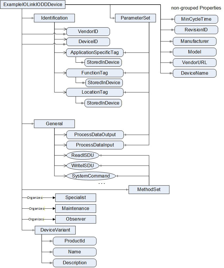
7.2.3 Overview
The IOLinkIODDDeviceType provides the structure that all ObjectTypes generated based on IODDs have to provide and is formally defined in Table 17.
| Attribute | Value | |||||
| BrowseName | IOLinkIODDDeviceType | |||||
| IsAbstract | True | |||||
| References | Node Class | BrowseName | DataType | TypeDefinition | Modelling Rule | |
|---|---|---|---|---|---|---|
| Subtype of IOLinkDeviceType defined in 7.1. | ||||||
| HasComponent | Object | 2:ParameterSet | BaseObjectType | Mandatory | ||
| Organizes | Object | Specialist | FunctionalGroupType | Mandatory | ||
| Organizes | Object | Maintenance | FunctionalGroupType | Mandatory | ||
| Organizes | Object | Observer | FunctionalGroupType | Mandatory | ||
| HasComponent | Object | IODDInformation | FolderType | - | ||
| HasComponent | Object | DeviceVariants | FolderType | - | ||
| HasComponent | Object | DeviceVariant | DeviceVariantType | Mandatory | ||
| HasProperty | Variable | VendorURL | String | Property | Mandatory | |
| HasProperty | Variable | DeviceName | LocalizedText | Property | Mandatory | |
| HasProperty | Variable | VendorLogo | Image | Property | Optional | |
| HasComponent | Object | 2:DeviceTypeImage | FolderType | Optional | ||
The IOLinkIODDDeviceType ObjectType is an abstract type. Concrete subtypes are generated for concrete IODDs (see section 7.3 for details).
The mandatory Object ParameterSet is inherited from the supertype and overridden in order to add parameters defined in section 7.2.4.
The mandatory Object Specialist groups all menus of the SpecialistRoleMenuSet defined in an IODD.
The mandatory Object Maintenance groups all menus of the MaintenanceRoleMenuSet defined in an IODD.
The mandatory Object Observer groups all menus of the ObserverRoleMenuSet defined in an IODD.
The Object IODDInformation provides information about the IODD and is only provided on the ObjectType, not the instances of the ObjectType. Therefore, it does not have a ModellingRule. Its content is defined in 7.2.5.
The Object DeviceVariants provides information about the IO-Link Device variants supported by the ObjectType. It references all device variants (Objects of Type DeviceVariantType) with a HasComponent Reference. Device variants are defined by the subtypes of this ObjectType.
The mandatory Object DeviceVariant provides information about the currently used device variant on the instance.
The mandatory read-only Property VendorURL maps to the IODD DeviceIdentity/VendorURL element.
The mandatory read-only Property DeviceName maps to the IODD DeviceIdentity/DeviceName element. Localization should be considered. In IODD Specification Version 1.0.1 there is no IODD DeviceIdentity/DeviceName element defined. Instead of, the IODD DeviceVariant/ProductName element shall be used. Localization should be considered.
The optional read-only Property VendorLogo maps to the IODD DeviceIdentity/VendorLogo element, if the optional element is provided.
The optional Object DeviceTypeImage defined in OPC 10000-100 is overridden in order to reference Images of the DeviceVariant Object (see section 7.2.6).
7.2.4 Variables of the ParameterSet Object
In Table 18, the Variables of the ParameterSet Object of the IOLinkIODDDeviceType, are defined.
| References | Node Class | BrowseName | DataType | TypeDefinition | Modelling Rule |
| HasComponent | Variable | SupportedAccessLocks | Byte | OptionSetType | Optional |
The optional, read-only Variable SupportedAccessLocks maps to the IODD Features/SupportedAccessLocks element. The lowest bit of the Byte references to parameter, the next to dataStorage, the next to localParamaterization and the next to localUserInterface as defined in SupportedAccessLocksT. The OptionSetValues Property shall be filled with those names for locale "en". Servers might provide translations to other languages. In IODD Specification Version 1.0.1 there is no IODD Features/SupportedAccessLocks element. Therefore, the OPC UA Variable SupportedAccessLocks is not provided for IODDs following the IODD Specification Version 1.0.1.
7.2.5 Variables of the IODDInformation Object
In Table 19 the Variables of the IODDInformation Object of the IOLinkIODDDeviceType are defined.
| References | Node Class | BrowseName | DataType | TypeDefinition | Modelling Rule |
| HasProperty | Variable | Version | String | PropertyType | Mandatory |
| HasProperty | Variable | ReleaseDate | String | PropertyType | Mandatory |
| HasProperty | Variable | Copyright | String | PropertyType | Mandatory |
| HasProperty | Variable | IOLinkRevision | String | PropertyType | Mandatory |
The mandatory, read-only Property Version maps to the IODD DocumentInfo/@version attribute.
The mandatory, read-only Property ReleaseDate maps to the IODD DocumentInfo/@releaseDate attribute.
The mandatory, read-only Property Copyright maps to the IODD DocumentInfo/@copyright attribute.
The mandatory, read-only Property IOLinkRevision maps to the IODD ProfileHeader/ProfileRevision element.
7.2.6 Variables of the DeviceTypeImage Object
In Table 20, references of the DeviceTypeImage Object of the IOLinkIODDDeviceType, are defined.
| References | Node Class | BrowseName | DataType | TypeDefinition | Modelling Rule |
| HasComponent | Variable | DeviceIcon | References Variable DeviceIcon of DeviceVariant Object | ||
| HasComponent | Variable | DeviceSymbol | References Variable DeviceSymbol of DeviceVariant Object | ||
7.3 ObjectTypes generated based on IODDs
7.3.1 General
This clause defines how ObjectTypes shall be generated based on IODDs. For each IODD managed by the Server, the Server shall have an ObjectType as subtype of the IOLinkIODDDeviceType (see section 7.2).
The IsAbstract Attribute of the generated ObjectType shall be set to "False".
The BrowseName Attribute of the generated ObjectType shall be mapped to the IODD DeviceIdentity/DeviceName element using the default language. The DisplayName should use the localization provided by the DeviceName.
The optional Description Attribute is vendor-specific and might be omitted.
7.3.2 NodeId of generated ObjectTypes and their InstanceDeclarations
Each NodeId that is used to describe the generated ObjectTypes shall use the Namespace "http://opcfoundation.org/UA/IOLink/IODD" and the identifierType String. The String of the NodeId of the ObjectType shall be composed of the VendorId, the DeviceId (in DeviceIdentity) and the version of the IODD (in DocumentInfo) using the format: "<VendorId>|<DeviceId>|<version>" like "888|67335|V1.1". The InstanceDeclarations use this prefix followed by the BrowsePath. Variables and Methods, which might have several BrowsePaths use the BrowsePath coming from ParameterSet respectively MethodSet, Objects representing menus use the first BrowsePath that is defined in the IODD. The format is: "<ObjectTypeNodeId>||<BrowseName>[:<BrowseName>]". The BrowseName only contains the String part, not the NamespaceIndex. An example is "888|67335|V1.1||ParameterSet:V_LifeTimeYears" as string-part of the NodeId of a Variable.
Defining the NodeIds of ObjectTypes based on IODDs is necessary so that OPC UA Clients accessing different OPC UA Servers implementing this specification and using the same IODDs can identify that they actually deal with the same types.
7.3.3 Namespace of the BrowseNames
The BrowseNames used when generating ObjectTypes and their InstanceDeclarations shall use the Namespace "http://opcfoundation.org/UA/IOLink/IODD".
7.3.4 Mapping to InstanceDeclarations inherited from IOLinkIODDDeviceType
In general, on the instance all rules defined on the IOLinkIODDDeviceType or its supertypes shall apply. When a new ObjectType is created, some InstanceDeclarations of the supertype are overridden in order to provide information from the IODD like VendorId.
The VendorID shall be filled with the IODD DeviceIdentity/@vendorId.
The DeviceID shall be filled with the IODD DeviceIdentity/@deviceId.
The Manufacturer shall be filled with the IODD DeviceIdentity/@vendorName.
The VendorText shall be filled with the IODD DeviceIdentity/VendorText, taking the default language.
The DeviceClass shall be filled with the IODD DeviceIdentity/DeviceFamily.
7.3.5 Mapping of IODD Menus
For each menu of the IODD UserInterface/MenuCollection that is referenced directly or indirectly form the IODD UserInterface/ObserverRoleMenuSet, the IODD UserInterface/MaintenanceRoleMenuSet or the IODD UserInterface/SpecialistRoleMenuSet, an Object of ObjectType FunctionalGroupType is created.
The BrowseName of the Object shall be the Id of the IODD Menu. The DisplayName shall be the Name of the IODD Menu. Localization should be considered. The optional Description Attribute is vendor-specific and might be omitted.
For each IdentificationMenu reference (UIMenuSimpleRefT) from the IODD UserInterface/ObserverRoleMenuSet, the IODD UserInterface/MaintenanceRoleMenuSet and the IODD UserInterface/SpecialistRoleMenuSet a HasIdentificationMenu Reference shall be created from the corresponding Object defined in section 7.2. The referenced Object shall have the ModellingRule Mandatory.
For each ParameterMenu reference (UIMenuSimpleRefT) from the IODD UserInterface/ObserverRoleMenuSet, the IODD UserInterface/MaintenanceRoleMenuSet and the IODD UserInterface/SpecialistRoleMenuSet a HasParameterMenu Reference shall be created from the corresponding Object defined in section 7.2. The referenced Object shall have the ModellingRule Mandatory.
For each ObservationMenu reference (UIMenuSimpleRefT) from the IODD UserInterface/ObserverRoleMenuSet, the IODD UserInterface/MaintenanceRoleMenuSet and the IODD UserInterface/SpecialistRoleMenuSet a HasObservationMenu Reference shall be created from the corresponding Object defined in section 7.2. The referenced Object shall have the ModellingRule Mandatory.
For each DiagnosisMenu reference (UIMenuSimpleRefT) from the IODD UserInterface/ObserverRoleMenuSet, the IODD UserInterface/MaintenanceRoleMenuSet and the IODD UserInterface/SpecialistRoleMenuSet an HasDiagnosisMenu Reference shall be created from the corresponding Object defined in section 7.2. The referenced Object shall have the ModellingRule Mandatory.
In Figure 13 an example of how to map IODD menus is shown. On the left, an excerpt of an IODD is shown, and on the right, the OPC UA representation.
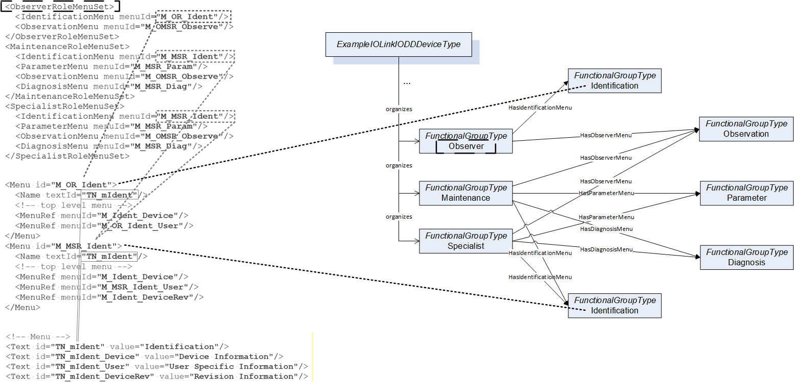
For each IODD Menu that has been added all MenuRefs shall reference the corresponding Objects with an Organizes Reference. If at least one IODD UIMenuRef does not provide an IODD MenuRef/Condition element, the ModellingRule shall be Mandatory, otherwise it shall be Optional.
In Figure 14 another example of how to map IODD menus is shown. On the left, an excerpt of an IODD is shown, and on the right, the OPC UA representation. In this example, IODD Menus contain other IODD Menus.
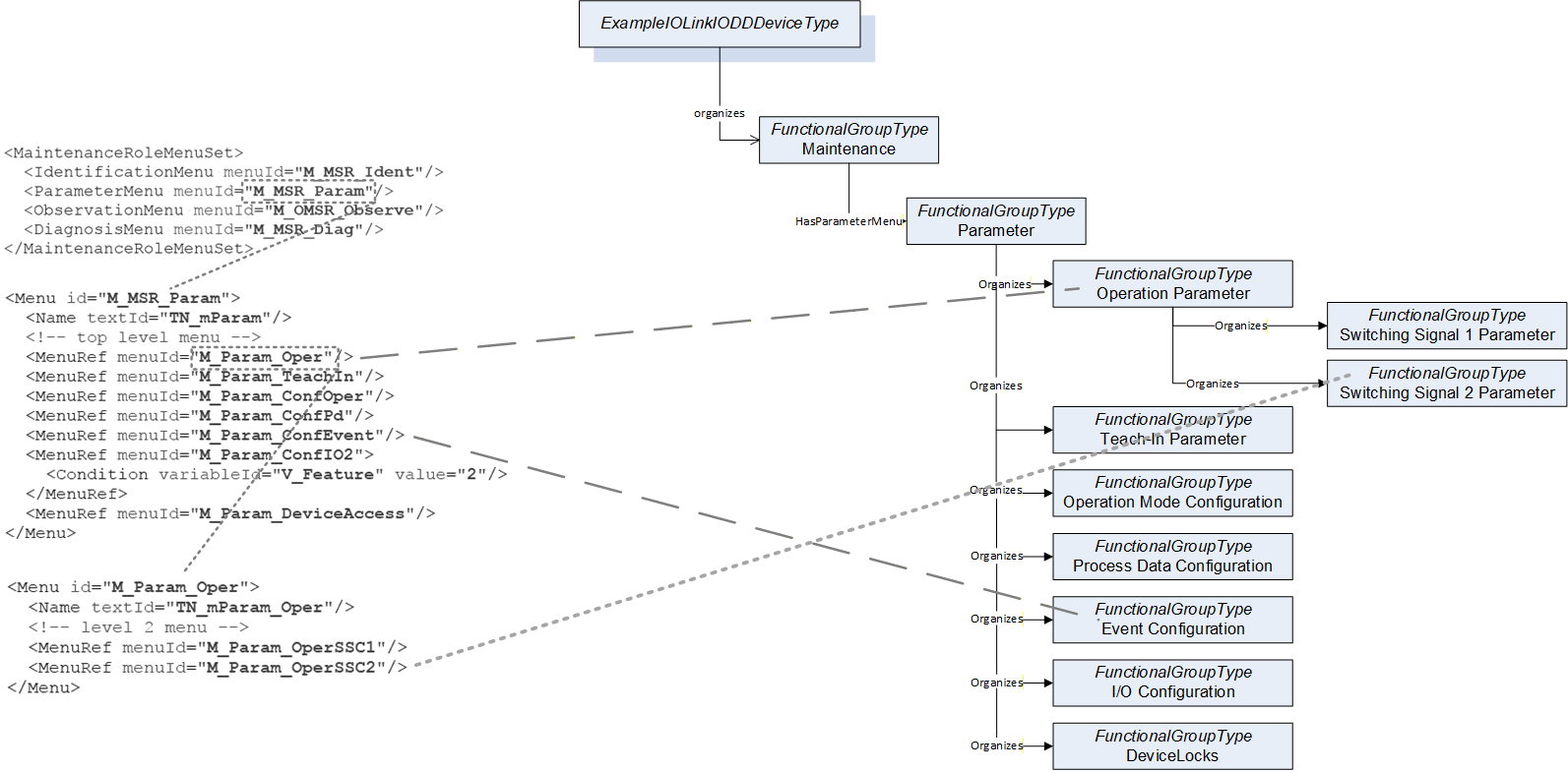
7.3.6 Mapping of IODD Variables
For each IODD Variable defined in the IODD an OPC UA Variable is created that is referenced from the ParameterSet with a HasComponent Reference. The ModellingRule shall be Mandatory for each of those Variables.
Each Object representing a menu referencing the Variable via a VariableRef not defining a Button shall reference the Variable with an Organizes Reference.
Each Object representing a menu referencing the Variable via a RecordItemRef not defining a Button shall reference the corresponding Sub-Variable with an Organizes Reference.
The BrowseName of the Variable shall be the Id of IODD Variable and the DisplayName the Name of the IODD Variable. Localization should be considered. The Description Attribute shall be the Description of IODD Variable. Localization should be considered.
The VariableType, DataType, ValueRank and ArrayDimensions are set according to section 12 depending on the Datatype or DatatypeRef. In addition, the VariableRef or RecordItemRef defines some characteristics that need to be considered.
If at least one VariableRef contains a unitCode the Variable shall have the Property EngineeringUnits. If more than one VariableRef references the IODD Variable and all VariableRefs contain the unitCode, the EngineeringUnits shall have the ModellingRule Mandatory, otherwise the ModellingRule Optional. The value of EngineeringUnits is vendor-specific because several VariableRefs might define different unitCodes. It might be omitted on the InstanceDeclaration.
If at least one VariableRef contains a displayFormat the Variable shall have the Property DisplayFormat (see section 13.6). If all VariableRefs contain the displayFormat, the DisplayFormat shall have the ModellingRule Mandatory, otherwise the ModellingRule Optional. The value of DisplayFormat is vendor-specific. It might be omitted on the InstanceDeclaration.
The same rules apply for the sub-variables referenced based on the RecordItemRefs.
The accessRightRestriction is ignored on the ObjectType and only considered on the instances.
In Figure 15 an example is shown of how to map IODD Variables referenced from an IODD Menu to OPC UA.
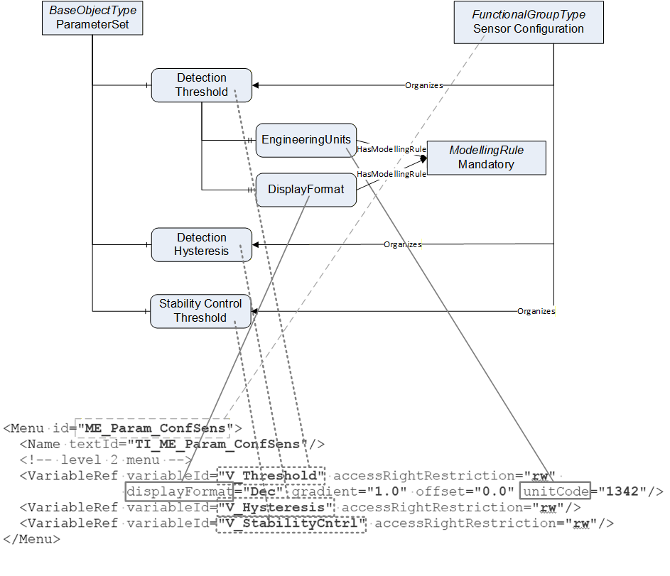
In Figure 16 another example is shown. In this example, the VariableRefs to the same IODD Variable contain different information.
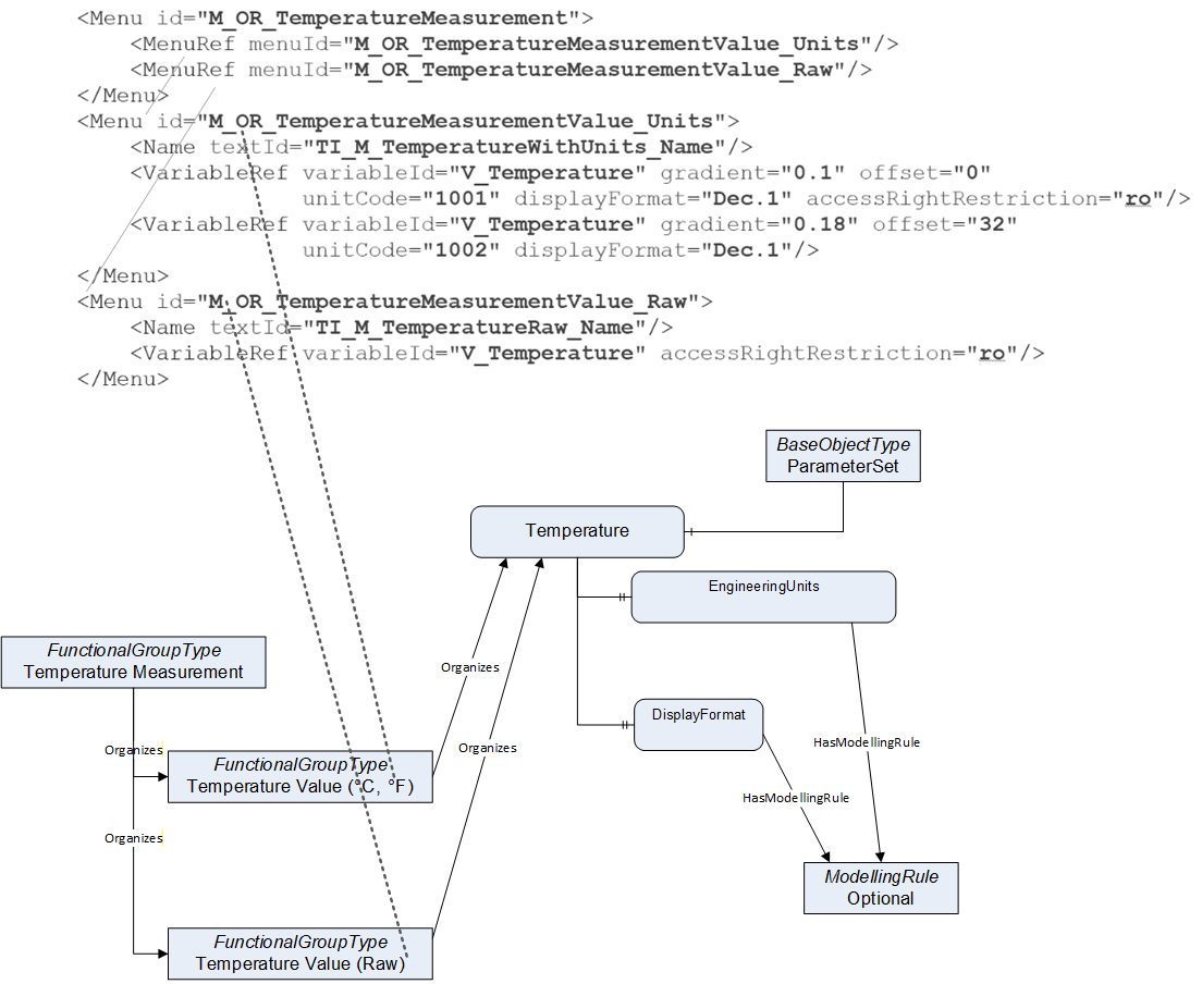
In Figure 17 an example on how to map RecordItemRefs is shown.
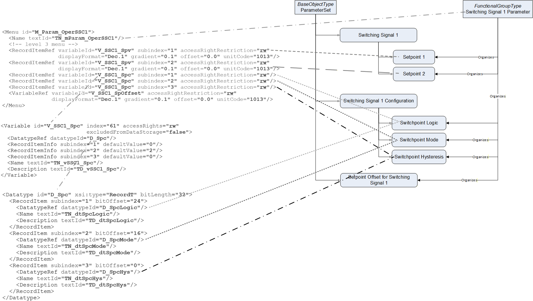
7.3.7 Mapping of Methods from IODD Menus
VariableRefs and RecordItemRefs can define Buttons. Those IODD Buttons are mapped to OPC UA Methods.
For each Button-defining VariableRef or RecordItemRef from an IODD Menu that is used in the mapping (see section 7.3.5) an OPC UA Method is created, that is referenced with a HasComponent Reference from the MethodSet Object.
In case several VariableRefs or RecordItemRefs have the same characteristics (Description, ActionStartedMessage, buttonValue, and in case of RecordItemRefs same subindex), only one Method is created.
The Objects representing the IODD Menus shall reference the corresponding Methods with Organizes References.
If at least one Object representing an IODD Menu referencing the Method has the ModellingRule Mandatory the Method shall have the ModellingRule Mandatory, otherwise Optional.
The BrowseName of the Method shall be the Id of the IODD Variable combined with the buttonValue. The format is "<Id>|<buttonValue>". In the unlikely case that the IODD Variable is referenced several times as Button with the same buttonValue but different other characteristics (Description and ActionStartedMessage), the additional Methods have a BrowseName postfixed by a number using the format "<Id>|<buttonValue>_<n>" where "n" is the occurrence in the order of the IODD, starting with a 2 for the second occurrence.
The DisplayName shall be the Description of the IODD Button, if a Description is provided. Localization should be considered. If no Description is provided, the DisplayName should be the BrowseName. The optional Description Attribute is vendor-specific and might be omitted.
The Methods shall not have input- or output-arguments. If the optional ActionStartedMessage of the IODD Button is provided, there shall be a Property with BrowseName "ActionStartedMessage" and the DataType String, providing the ActionStartedMessage of the IODD Button.
Note: The way a button is modelled inside an IODD VariableRef element changed from IODD Specification Version 1.0.1 to Version 1.1. The information modelled in IODD Specification Version 1.1 in the elements Description and ActionStartedMessage is not provided in IODD Specification Version 1.0.1.
The server-internal implementation of the Method shall implement the IODD Button according to the IODD Specification.
An example on how to map IODD Buttons to OPC UA Methods is shown in Figure 18.
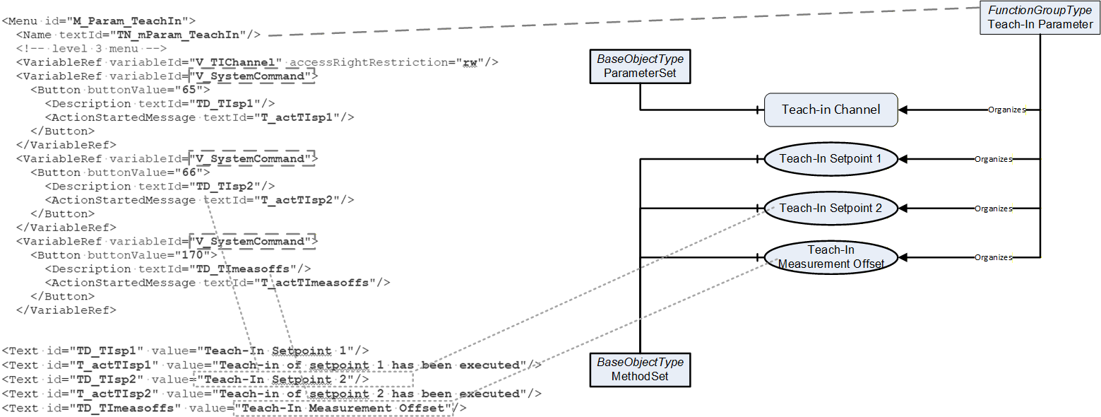
7.3.8 Mapping of StdVariableRef and StdRecordItemRef
The StdVariableRefs (standard variable references) reference to standardized information, that is already defined in the IOLinkDeviceType. In Table 21, an overview of the mapping is given.
| StdVariableRef | InstanceDeclaration |
| V_SystemCommand | MethodSet/SystemCommand |
| V_DeviceAccessLocks | DeviceAccessLocks |
| V_VendorName | Manufacturer |
| V_VendorText | VendorText |
| V_ProductName | Model |
| V_ProductID | ProductID |
| V_ProductText | ProductText |
| V_SerialNumber | SerialNumber |
| V_HardwareRevision | DeviceRevision |
| V_FirmwareRevision | SoftwareRevision |
V_ApplicationSpecificTag (V_ApplicationSpecificName for IODDs based on IODD Specification 1.01) | ParameterSet/ApplicationSpecificTag |
| V_ErrorCount | ParameterSet/ErrorCount |
V_DeviceStatus (not defined in IODD Specification 1.01) | ParameterSet/DeviceHealth |
V_DetailedDeviceStatus (not defined in IODD Specification 1.01) | ParameterSet/DetailedDeviceStatus |
V_ProcessDataInput (V_ProcessDataIn for IODDs based on IODD Specification 1.01) | ParameterSet/ProcessDataInput |
V_ProcessDataOutput (V_PrcoessDataOut for IODDs based on IODD Specification 1.01) | ParameterSet/ProcessDataOutput |
| V_OffsetTime | ParameterSet/OffsetTime |
The StdRecordItemRefs (standard record item references) reference to standardized information, that is already defined in the IOLinkDeviceType. In Table 22, an overview of the mapping is given.
| StdRecordItemRef | InstanceDeclaration | |
| V_DirectParameters_1 | STD_TN_MasterCycleTime | - |
| V_DirectParameters_1 | STD_TN_MinCycleTime | MinCycleTime |
| V_DirectParameters_1 | STD_TN_M-SequenceCapability | - |
| V_DirectParameters_1 | STD_TN_RevisionID | RevisionID |
| V_DirectParameters_1 | STD_TN_ProcessDataIn | ParameterSet/ProcessDataInput/ProcessDataLength |
| V_DirectParameters_1 | STD_TN_ProcessDataOut | ParameterSet/ProcessDataOutput/ProcessDataLength |
| V_DirectParameters_1 | STD_TN_VendorID1 | VendorID |
| V_DirectParameters_1 | STD_TN_VendorID2 | VendorID |
| V_DirectParameters_1 | STD_TN_DeviceID1 | DeviceID |
| V_DirectParameters_1 | STD_TN_DeviceID2 | DeviceID |
| V_DirectParameters_1 | STD_TN_DeviceID3 | DeviceID |
| V_DirectParameters_1 | STD_TN_SystemCommand | - |
| V_DirectParameters_2 | STD_TN_DeviceSpecific_1 | - |
| V_DirectParameters_2 | STD_TN_DeviceSpecific_2 | - |
| V_DirectParameters_2 | STD_TN_DeviceSpecific_3 | - |
| V_DirectParameters_2 | STD_TN_DeviceSpecific_4 | - |
| V_DirectParameters_2 | STD_TN_DeviceSpecific_5 | - |
| V_DirectParameters_2 | STD_TN_DeviceSpecific_6 | - |
| V_DirectParameters_2 | STD_TN_DeviceSpecific_7 | - |
| V_DirectParameters_2 | STD_TN_DeviceSpecific_8 | - |
| V_DirectParameters_2 | STD_TN_DeviceSpecific_9 | - |
| V_DirectParameters_2 | STD_TN_DeviceSpecific_10 | - |
| V_DirectParameters_2 | STD_TN_DeviceSpecific_11 | - |
| V_DirectParameters_2 | STD_TN_DeviceSpecific_12 | - |
| V_DirectParameters_2 | STD_TN_DeviceSpecific_13 | - |
| V_DirectParameters_2 | STD_TN_DeviceSpecific_14 | - |
| V_DirectParameters_2 | STD_TN_DeviceSpecific_15 | - |
| V_DirectParameters_2 | STD_TN_DeviceSpecific_16 | - |
In both cases, the following rule applies.
If there is an InstanceDeclaration on the IOLinkDeviceType:
If the StdVariableRef or StdRecordItemRef is not defining a Button and the InstanceDeclaration is a Variable, the InstanceDeclaration shall be overridden in the new created type and referenced from all Objects representing IODD Menus having such a reference. If a default value is defined, the OPC UA Server shall use this as Value of the Variable, if several different default values are defined, the first one defined in the IODD shall be used. Other characteristics defined on the StdVariableRef of StdRecordItemRef are ignored.
For VendorID and DeviceID there are two resp. three StdRecordItemRefs used. In the mapping, whenever an IODD Menu references at least one of them, the whole Variable (VendorID or DeviceID) is referenced.
If the StdVariableRef or StdRecordItemRef is defining a Button, the rules defined in 7.3.7 apply.
If there is no InstanceDeclaration on the IOLinkDeviceType defined, the same rules as for VariableRef and RecordItemRef defined in 7.3.6 and 7.3.7 apply.
Note that for V_SystemCommand the mapping described in this section applies, although there is a representation in the IOLinkDeviceType (SystemCommand Method), because the IODD provides useful new information about the supported system commands.
7.3.9 Mapping of ProcessDataCollection and ProcessDataRefCollection
The ProcessDataCollection gives an interpretation of the input and / or output process data.
For each entry of the collection (IODD ProcessData) having an IODD ProcessDataOut of type ProcessDataItemT, for each IODD ProcessDataOut, a new sub-variable of the OPC UA Variable ProcessDataOutput is created, having the BrowseName composed of the ProcessData id and the ProcessDataItem id ("<ProcessData id>|<ProcessDataItem id>"). If the ProcessData has a Condition, the Variable becomes optional, otherwise mandatory. In order to add a sub-variable to the ProcessDataOutput Variable defined on the IOLinkDeviceType, the ProcessDataOutput Variable needs to be overridden on the new created IODD-based subtype.
For each entry of the collection (IODD ProcessData) having a ProcessDataIn of type ProcessDataItemT, for each ProcessDataIn, a new sub-variable of ProcessDataInput is created, having the BrowseName composed of the ProcessData id and the ProcessDataItem id ("<ProcessData id>|<ProcessDataItem id>"). If the ProcessData has a Condition, the Variable becomes optional, otherwise mandatory. In order to add a sub-variable to the ProcessDataInput Variable defined on the IOLinkDeviceType, the ProcessDataInput Variable needs to be overridden on the new created IODD-based subtype.
In both cases the DisplayName shall be the Name element of the ProcessDataItem. Localization should be considered. The DataType is chosen for the Datatype element or DatatypeRef element according to section 12.
The ProcessDataRefCollection can provide additional characteristics for the created Variables, like unitCode and displayFormat. Note that the optional ProcessDataRefCollection and its child elements are not supported by IODD Specification Version 1.0.1.
If the ProcessDataRef contains a unitCode the Variable shall have the Property EngineeringUnits as mandatory. The value shall be as defined in the ProcessDataRef (see Annex C).
If the ProcessDataRef contains a displayFormat the Variable shall have the Property DisplayFormat (see 13.6) as mandatory. The value shall be as defined in the ProcessDataRef.
In Figure 19 an example is shown on how to map an IODD ProcessDataCollection.
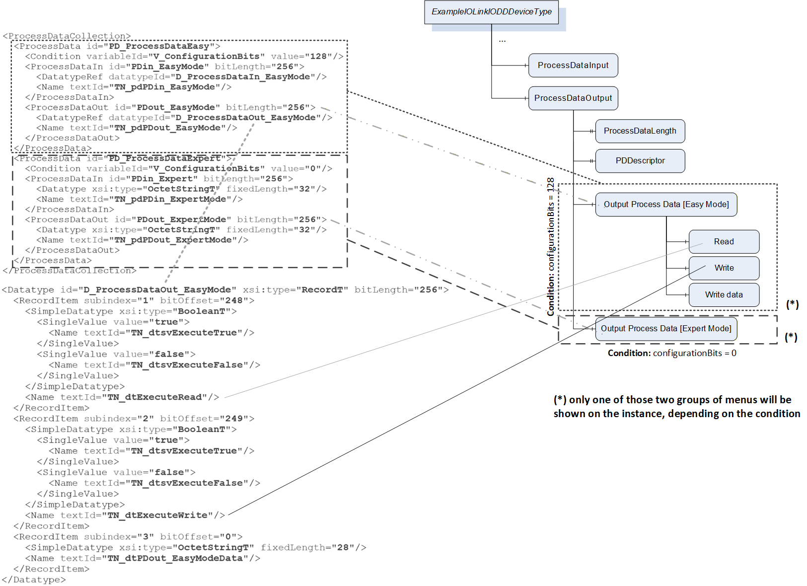
7.3.10 Mapping of DirectParameterOverlay
In case the DirectParameterOverlay is defined in the IODD, the mapping shall be the same as for Variables with respect to the DataType (RecordT). The BrowseName shall be "DirectParameterPage2", and the DisplayName the same for locale "en" and might provide translations. A vendor-specific Description might be provided.
7.3.11 Mapping of Default Values
In different places of the IODD default values can be defined.
The DirectParameterOverlay can define default values for the individual entries
The StdVariableRef can define default values
The Variable can define default values
The RecordItemInfo and StdRecordItemRef can define default values
In all cases the default value shall be provided as value of the corresponding Variables on the ObjectType. In case of StdVariableRefs the Variables are already defined in the supertype and need to be overridden on the IODD-based type in order to provide the default value.
An example on how to map DefaultValues is shown in Figure 20.
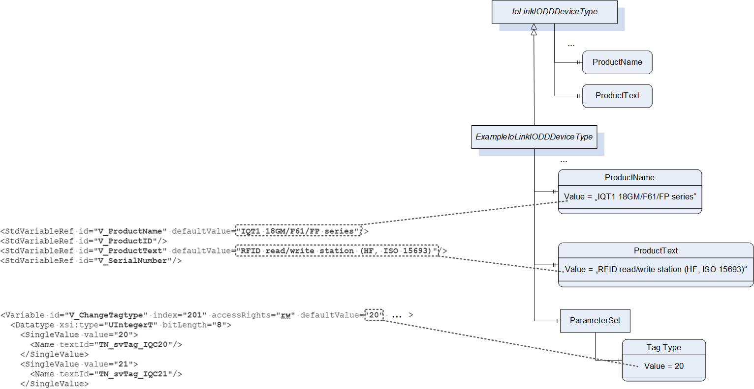
7.3.12 Mapping of DeviceVariantCollection
All entries of the DeviceVariantCollection are mapped to instances of DeviceVariantType according to section 7.7. The Objects are referenced from the DeviceVariants Object with a HasComponent Reference.
The first entry of the DeviceVariantCollection is also mapped to the DeviceVariant Object.
In Figure 21 an example is given.
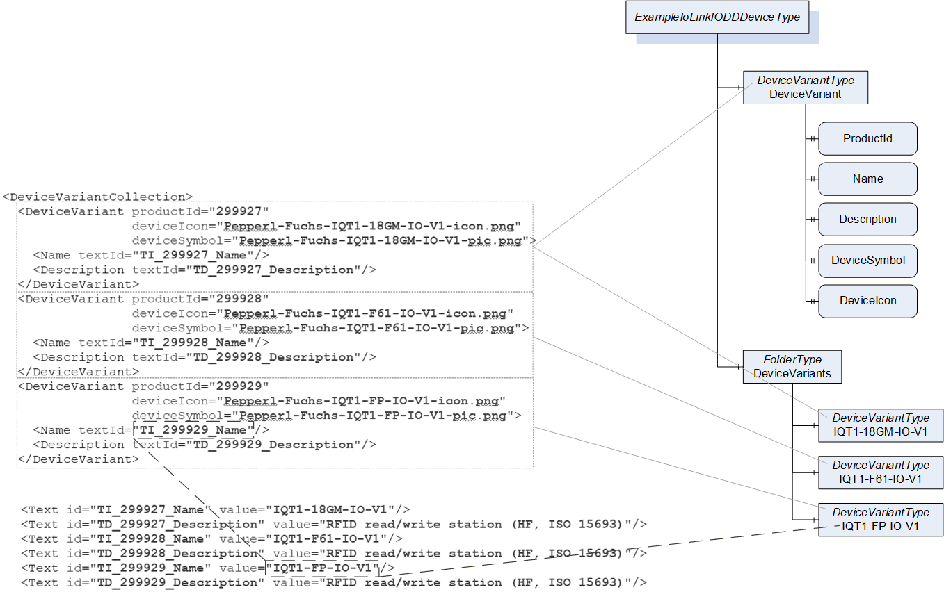
7.3.13 Mapping of EventCollection
Information about Events (Notification) is not mapped to additional EventTypes, but the IOLinkIODDDeviceEventType is used.
When an IO-Link Device sends a Notification, and the server manages the IODD for the IO-Link Device, an Event of the IOLinkIODDDeviceEventType is generated according to the EventType definition.
Information about Alarms (Warning and Error) is not mapped to additional EventTypes, but the IOLinkIODDDeviceAlarmType is used. If the OPC UA server supports Alarm Objects represented in the AddressSpace, the server may provide the Alarms Object on the ObjectType and provide all possible Alarms as Objects based on the IODD.
When an IO-Link Device sends a Warning or Error, and the server manages the IODD for the IO-Link Device, an Event of the IOLinkIODDDeviceAlarmType is generated according to the EventType definition.
7.4 Creation of Instances based on ObjectTypes generated out of IODDs
When an instance is created based on an ObjectType generated out of an IODD, two scenarios need to be considered.
Either an IO-Link Device is connected and thus conditions can be evaluated or
no IO-Link Device is connected but the IO-Link Port is configured in IOL_MANUAL (see section 6.1.7).
In the second case all optional Objects, Variables and Methods are omitted and only the mandatory Objects, Variables and Methods are provided. Except for VendorID and DeviceID, which shall expose the configured DeviceID and VendorID on the IO-Link Port, all Variables cannot be read or written and all Methods cannot be executed. The server shall report a Bad_NoCommunication StatusCode in those cases.
In the first case the Conditions on the MenuRefs and ProcessData are evaluated and the Objects and Variables are only provided when they are referenced (either directly or indirectly) based on the Condition evaluation.
Some characteristics of a Variable like the unitCode (see Annex C), displayFormat (see section 13.6) and additional accessRightRestriction are defined in the VariableRef of the IODD. A Variable can be referenced by several VariableRefs. Typically, in an IODD all valid VariableRefs (from menus which are active based on the Condition) to the same Variable use the same characteristics. But this is not required. Since the characteristics are exposed in OPC UA on the Variable, and not the reference to the Variable, the following rules apply for creating an instance.
The Variable referenced from the ParameterSet Object uses the characteristics as defined by the first active menu in the MenuCollection of the IODD. For a VariableRef with different characteristics a new Variable is defined referenced by the initially created Variable with a HasComponent Reference. It provides the different characteristics and uses the same BrowseName and mapping as the initial Variable. All VariableRefs that have characteristics that already have a Variable representing the characteristics shall reference that Variable.
In addition to the AccessLevel defined in section 12, the accessRightRestriction of the VariableRef and the accessRights on the IODD Variable shall be considered. Also, the offset and gradient to change the raw value coming from the IO-Link Device shall be considered.
In case the raw value is changed in the Variable (offset and/or gradient are defined in the IODD), there shall be a Sub-Variable on the OPC UA Variable instance with the BrowseName "RawValue" providing the raw value from the IO-Link Device.
When the IODD provides default values for a Variable in OPC UA, and the server has not already read the value from the IO-Link Device, the default value should be provided with StatusCode Uncertain_InitialValue.
The DeviceVariant Object is filled with the DeviceVariant according to the ProductID of the IO-Link Device. If the IO-Link Device does not provide this optional parameter or ProductID does not correspond to a DeviceVariant specified in the IODD, the OPC UA Server shall use the first DeviceVariant defined in the IODD.
If the optional DeviceSymbol or DeviceIcon Variable exist on the DeviceVariant Object, the DeviceTypeImage Folder defined in OPC 10000-100 shall be provided. The DeviceTypeImage Folder shall reference the DeviceSymbol and the DeviceIcon with a HasComponent Reference if those Variables are provided on the DeviceVariant Object.
When the blockParameter attribute is defined and set to "False" in the IODD, the Methods ParamUploadFromDeviceStart, ParamUploadFromDeviceStop, ParamDownloadToDeviceStart, ParamDownloadToDeviceStop, and ParamBreak shall have the Executable Attribute set to "False".
When the dataStorage attribute is defined and set to "False" in the IODD, the Method ParamDownloadToDeviceStore shall have the Executable Attribute set to "False".
In Figure 22 an example of an Object based on an IODD is shown.
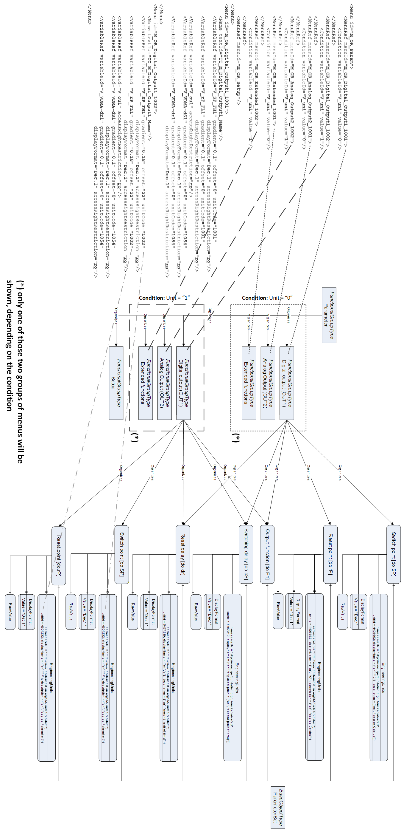
In Figure 23, an example of an Object based on an IODD is shown, where an IODD Variable is referenced by VariableRefs with different characteristics.
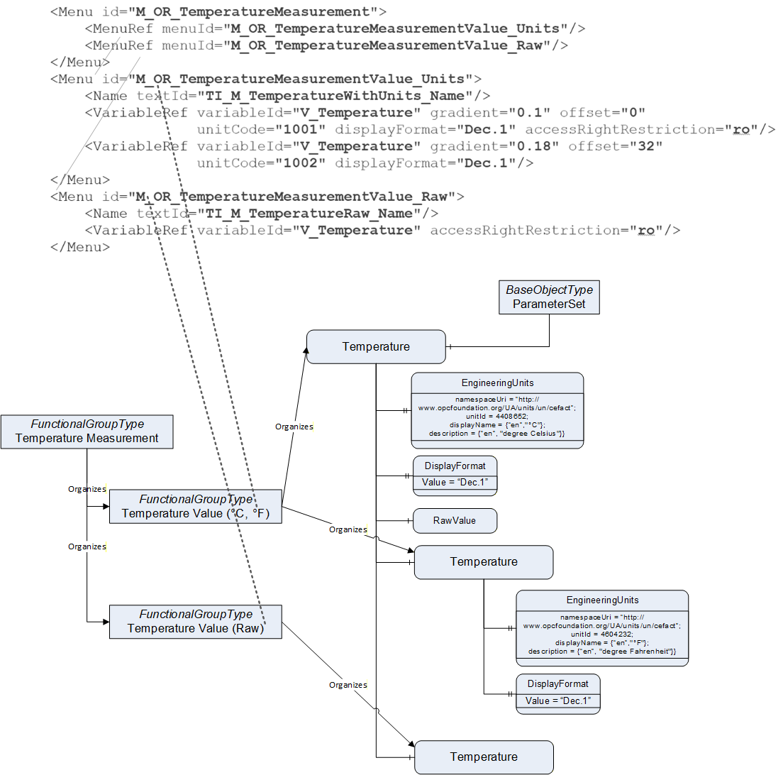
7.5 IOLinkMasterType ObjectType Definition
7.5.1 Example
In Figure 24 an example of an instance of the IOLinkMasterType is shown. The example is using only the mandatory InstanceDeclarations, in order to give an overview on the ObjectType. Several Properties are directly connected to the Object, whereas the Parameters are connected via the ParameterSet, Methods via the MethodSet and both are organized via different FunctionalGroups (Identification, Capabilities, Statistics and Management).
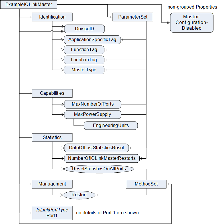
7.5.2 Overview
The IOLinkMasterType provides information of an IO-Link Master and is formally defined in Table 23.
| Attribute | Value | ||||
| BrowseName | IOLinkMasterType | ||||
| IsAbstract | False | ||||
| References | Node Class | BrowseName | DataType | TypeDefinition | Modelling Rule |
|---|---|---|---|---|---|
| Subtype of TopologyElementType defined in OPC 10000-100. | |||||
| HasComponent | Object | 2:ParameterSet | BaseObjectType | Mandatory | |
| HasComponent | Object | 2:MethodSet | BaseObjectType | Mandatory | |
| HasComponent | Object | 2:Identification | FunctionalGroupType | Mandatory | |
| HasComponent | Object | Capabilities | FunctionalGroupType | Mandatory | |
| HasComponent | Object | Management | FunctionalGroupType | Mandatory | |
| HasComponent | Object | Statistics | FunctionalGroupType | Mandatory | |
| HasProperty | Variable | DeviceID | UInt32 | PropertyType | Mandatory |
| HasProperty | Variable | ProductID | String | PropertyType | Optional |
| HasProperty | Variable | ProductText | String | PropertyType | Optional |
| HasProperty | Variable | RevisionID | String | PropertyType | Optional |
| HasProperty | Variable | VendorID | UInt16 | PropertyType | Optional |
| HasProperty | Variable | VendorURL | String | PropertyType | Optional |
| HasProperty | Variable | IOLinkStackRevision | String | PropertyType | Optional |
| HasProperty | Variable | MasterConfigurationDisabled | Boolean | PropertyType | Mandatory |
| HasComponent | Object | Port<n> | IOLinkPortType | Mandatory‑Placeholder | |
| HasComponent | Object | Alarms | FolderType | Optional | |
| GeneratesEvent | ObjectType | IOLinkMasterEventType | Defined in 9.6. | ||
| GeneratesEvent | ObjectType | IOLinkMasterAlarmType | Defined in 9.11. | ||
The IOLinkMasterType ObjectType is a concrete type and can be used directly. Vendors may create subtypes of the IOLinkMasterType to add vendor-specific extensions.
The ObjectType inherits the following InstanceDeclarations directly or indirectly from the TopologyElementType defined in OPC 10000-100.
The optional Object ParameterSet is used to reference all Parameters and shall be provided. Therefore, the ObjectType overrides the Object and changes the ModellingRule to Mandatory.
The optional Object MethodSet is used to reference all Methods and shall be provided. Therefore, the ObjectType overrides the Object and changes the ModellingRule to Mandatory.
The optional Object Identification shall be provided and shall reference the Parameters defined in Table 24. Those Parameters together uniquely identify the IO-Link Master (see OPC 10000-100 for details). Therefore, the ObjectType overrides the Object and changes the ModellingRule to Mandatory.
| References | BrowseName | Comment |
| Organizes | DeviceID | Variable defined in Table 23. |
| Organizes | VendorID | Variable defined in Table 23. |
| Organizes | ApplicationSpecificTag | Variable defined in Table 28. |
| Organizes | FunctionTag | Variable defined in Table 28. |
| Organizes | LocationTag | Variable defined in Table 28. |
| Organizes | MasterType | Variable defined in Table 28. |
The Object <GroupIdentifier> has the ModellingRule OptionalPlaceholder and is intended to group the Parameters. It is already used in this ObjectType by adding the Objects Capabilities, Management and Statistics. Vendors may add vendor-specific Objects to group additional Parameters.
The optional Object Lock can be supported by a server to provide locking capabilities (see OPC 10000-100 for details). This is intended to prevent different clients and users to configure an IO-Link Master at the same time. Locking an IOLinkMasterType Object includes locking all its ports and the IOLinkDeviceType Objects connected to the ports.
The ObjectType defines additional InstanceDeclarations:
The mandatory Object Capabilities shall reference the Parameters defined in Table 25. Servers may add vendor-specific Parameters or Methods to this Object.
| References | BrowseName | Comment |
| Organizes | MaxNumberOfPorts | Variable defined in Table 28. |
| Organizes | MaxPowerSupply | Variable defined in Table 28. |
The mandatory Object Management shall reference the Methods defined in Table 26. Servers may add vendor-specific Parameters or Methods to the Object.
| References | BrowseName | Comment |
| Organizes | Restart | Method defined in Table 30. |
The mandatory Object Statistics shall reference the Parameters and Methods defined in Table 26. Servers may add vendor-specific Parameters or Methods to the Object.
| References | BrowseName | Comment |
| Organizes | ResetStatisticsOnAllPorts | Method defined in Table 30. |
| Organizes | NumberOfIOLinkMasterStarts | Variable defined in Table 28. |
| Organizes | DateOfLastStatisticsReset | Variable defined in Table 28. |
The mandatory, read-only Variable DeviceID shall be mapped to MasterID of the MasterIdent structure defined in the SMI (see IO-Link Addendum). The value (three bytes) shall be mapped to an UInt32, using Big Endian.
The optional, read-only Variable ProductID provides a vendor-specific product or type identification like the ProductID of the IOLinkDeviceType. The implementation is vendor-specific.
The optional, read-only Variable ProductText provides additional, vendor-specific product information like the ProductText of the IOLinkDeviceType. The implementation is vendor-specific.
The optional, read-only Variable RevisionID contains the IO-Link protocol version supported by the IO-Link Master, like the RevisionID of the IOLinkDeviceType. The same rules as defined for RevisionID in IOLinkDeviceType apply (see section 7.1).
The optional, read-only Variable VendorID of type UInt16 shall be mapped to VendorID of the MasterIdent structure defined in the SMI (see IO-Link Addendum), using the same type.
The optional Variable VendorURL provides a link to the website of the vendor of the IO-Link Master. The implementation is vendor-specific.
The optional read-only Variable IOLinkStackRevision provides the revision of the IO-Link stack implementation used by the IO-Link Master. The implementation is vendor-specific.
The mandatory Variable MasterConfigurationDisabled indicates whether configuration changes are allowed via OPC UA. If set to "True", nearly all configuration settings become read-only and cannot be changed via OPC UA anymore. The Variable setting is vendor-specific, including whether it can be changed via OPC UA. For example, if a fieldbus is currently active on the IO-Link Master, a server might set this Variable to "True".
That includes in detail following rules:
The Method Restart of the IO-Link Master becomes not executable.
For all Ports of the IO-Link Master the Method UpdateConfiguration becomes not executable.
For all Ethernet configurations connected to the Fieldbus the configuration becomes read-only.
The Method ResetStatistics on the Port and ResetStatisticsOnAllPorts on the IO-Link Master shall still be executable.
There is no direct relation between the MasterConfigurationDisabled Variable and the Lock Object. The Lock Objects prevents different OPC UA Clients to configure the IO-Link Master at the same time whereas the MasterConfigurationDisabled Variable indicates that the IO-Link Master is in a state within it cannot be configured by any OPC UA Client. When the MasterConfigurationDisabled Variable is set to "True" Servers may prevent the usage of the Lock Object for all Clients.
The Port<n> Object of ModellingRule MandatoryPlaceholder represents the ports of the IO-Link Master. For each port of the IO-Link Master one Object of type IOLinkPortType shall be provided, where <n> represents the number of the port. For example, a master having two ports has the Objects Port1 and Port2. How the counting starts (e.g. Port0 or Port1) is vendor-specific.
The optional Alarms Object is used to group all alarms of the instance, in case the server supports representing the alarms as Objects in the AddressSpace. If the server does not support this, the Object shall not be provided.
7.5.3 Variables of ParameterSet
In Table 28, the Parameters of the ObjectType, referenced via the ParameterSet Object, are defined.
| References | Node Class | BrowseName | DataType | TypeDefinition | Modelling Rule |
| The following Parameters are also referenced by the Capabilities Object | |||||
| HasComponent | Variable | MaxNumberOfPorts | Byte | BaseDataVariableType | Mandatory |
| HasComponent | Variable | MaxPowerSupply | Double | BaseDataVariableType | Mandatory |
| The following Parameters are also referenced by the Identification Object | |||||
| HasComponent | Variable | ApplicationSpecificTag | String | BaseDataVariableType | Mandatory |
| HasComponent | Variable | FunctionTag | String | BaseDataVariableType | Mandatory |
| HasComponent | Variable | LocationTag | String | BaseDataVariableType | Mandatory |
| HasProperty | Variable | MasterType | Byte | MultiStateDiscreteType | Mandatory |
| The following Parameters are also referenced by the Statistics Object | |||||
| HasComponent | Variable | DateOfLastStatisticsReset | DateTime | BaseDataVariableType | Optional |
| HasComponent | Variable | NumberOfIOLinkMasterStarts | UInt32 | BaseDataVariableType | Optional |
The mandatory, read-only Variable MaxNumberOfPorts shall be mapped to MaxNumberOfPorts of the MasterIdent structure defined in the SMI interface (see IO-Link Addendum).
The mandatory, read-only Variable MaxPowerSupply shall provide the overall amount of power provided together on all ports of the IO-Link Master in ampere. For example, a 4-port IO-Link Master may provide max. 2 A on each port but an overall MaxPowerSupply of 6 A, so not each port can consume 2 A at the same time. The Variable shall provide the EngineeringUnits Property defined in OPC 10000-3, having the value set to {namespaceUri = "http://www.opcfoundation.org/UA/units/un/cefact"; unitId = 4279632; displayName = {"en","A"}; description = {"en", "ampere"}} (for ampere). The Property shall be read-only and have the ModellingRule Mandatory, so it is reflected on all instances.
The mandatory, writeable Variable ApplicationSpecificTag provides the same information as the ApplicationSpecificTag defined for an IO-Link Device on the IO-Link Master level. The server shall manage the value in a persistent manner. If a fieldbus mapping of the IO-Link Master exists providing the same information, consistency shall be provided by the OPC UA Server.
The mandatory, writeable Variable FunctionTag provides the same information as the FunctionTag defined on an IO-Link Device on the IO-Link Master level. The server shall manage the value in a persistent manner. If a fieldbus mapping of the IO-Link Master exists providing the same information, consistency shall be provided by the OPC UA Server.
The mandatory, writeable Variable LocationTag provides the same information as the LocationTag defined for an IO-Link Device on the IO-Link Master level. The server shall manage the value in a persistent manner. If a fieldbus mapping of the IO-Link Master exists providing the same information, consistency shall be provided by the OPC UA Server.
The mandatory, read-only Variable MasterType shall be mapped to MasterType of the MasterIdent structure defined in the SMI (see IO-Link Addendum). The Unsigned8 is mapped directly to the DataType Byte. The Variable is of VariableType MultiStateDiscreteType defined in OPC 10000-8. The mandatory Property EnumStrings of the VariableType, which is an array of LocalizedText, shall contain the content as defined in Table 29.
| Element number (starting with 0) | Message (for locale "en") |
| 0 | Unspecific |
| 1 | Master acc. V1.0 |
| 2 | Master acc. V1.1 |
Servers are allowed to add additional entries into the EnumStrings array. Servers may provide translations of the texts in different locales.
The optional, read-only Variable DateOfLastStatisticsReset contains the timestamp of the answer to the last call of the Method ResetStatisticsOnAllPorts. The timestamp information shall be as precise as possible. If the ResetStatisticsOnAllPorts Method was never called then DateOfLastStatisticsReset indicates the startup time. The optional Variable shall be provided when the optional Method ResetStatisticsOnAllPorts is provided.
The following Variable indicates the incidents since DateOfLastStatisticsReset. The server should persist statistics, also when the IO-Link Master or the OPC UA Server is restarted. However, if the statistics become inconsistent, the server is allowed to do an internal reset. This will result in the update of DateOfLastStatisticsReset. If the value of a counting Variable becomes larger than the maximum value of the DataType, the value shall remain on the maximum value.
The optional, read-only Variable NumberOfIOLinkMasterStarts indicates how often the IO-Link Master was started since DateOfLastStatisticsReset. This includes starts on power up as well as warm starts and restarts due to errors. This variable is reset with the Method ResetStatisticsOnAllPorts to 0. When the IO-Link Master starts for the very first time, the value is 1 as it has started once.
7.5.4 Methods of MethodSet
In Table 30, the Methods of the ObjectType, referenced via the MethodSet Object are defined.
| References | Node Class | BrowseName | Modelling Rule |
| The following Methods are also referenced by the Management Object | |||
| HasComponent | Method | Restart | Mandatory |
| The following Methods are also referenced by the Statistics Object | |||
| HasComponent | Method | ResetStatisticsOnAllPorts | Optional |
7.5.4.1 Restart
The Method Restart restarts the IO-Link Master.
Signature
	Restart (
		[in]	Duration		Delay,
		[out]	Int32			Status
		);
| Argument | Description |
| Delay | Time before the restart becomes effective. |
| Status | Returns the status of the operation. 0: OK, operation successful -1: Operation already running -2: Operation cannot be executed -3: Operation cannot be executed because master reconfiguration is disabled. |
7.5.4.2 ResetStatisticsOnAllPorts
The optional Method ResetStatisticsOnAllPorts resets all statistic data, including statistic data of the ports of the IO-Link Master. Statistic data of a port are all Parameters referenced by the Statistics Object of the IOLinkPortType Object starting with "NumberOf" and potentially vendor-specific extensions. Statistic data directly on the IO-Link Master includes the Variable NumberOfIOLinkMasterStarts and potential vendor-specific extensions. As soon as statistic data is provided by the server, the optional Method shall be provided.
Signature
	ResetStatisticsOnAllPorts (
		[out]	Int32			Status
		);
| Argument | Description |
| Delay | Time before the reset becomes effective. |
| Status | Returns the status of the operation. 0: OK, operation successful -1: Operation already running -2: Operation cannot be executed. |
7.6 IOLinkPortType ObjectType Definition
7.6.1 Example
In Figure 25 an example of an instance of the IOLinkPortType is shown, using only the mandatory InstanceDeclarations, in order to give an overview on the ObjectType. The Object does not have Properties, its Parameters are connected via the ParameterSet, Methods via the MethodSet and both organized via different FunctionalGroups (Capabilities, Statistics, SIOProcessData, Configuration (containing another FunctionalGroup ConfiguredDevice), and Information). Note that SIOProcessData only points to optional Parameters not used in this example.
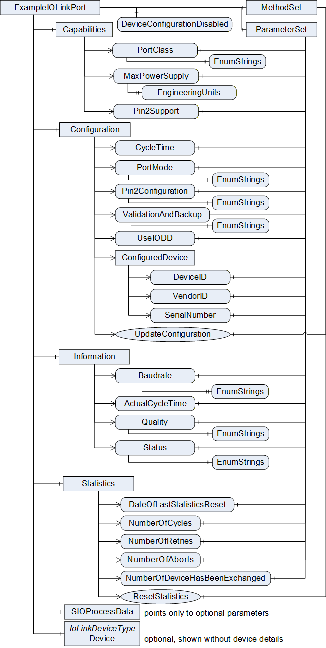
7.6.2 Overview
The IOLinkPortType provides information of one port of an IO-Link Master and is formally defined in Table 8.
| Attribute | Value | ||||
| BrowseName | IOLinkPortType | ||||
| IsAbstract | False | ||||
| References | Node Class | BrowseName | DataType | TypeDefinition | Modelling Rule |
|---|---|---|---|---|---|
| Subtype of TopologyElementType defined in OPC 10000-100. | |||||
| HasComponent | Object | 2:ParameterSet | BaseObjectType | Mandatory | |
| HasComponent | Object | 2:MethodSet | BaseObjectType | Mandatory | |
| HasProperty | Variable | DeviceConfigurationDisabled | Boolean | PropertyType | Mandatory |
| HasComponent | Object | Capabilities | FunctionalGroupType | Mandatory | |
| HasComponent | Object | Information | FunctionalGroupType | Mandatory | |
| HasComponent | Object | Statistics | FunctionalGroupType | Mandatory | |
| HasComponent | Object | Configuration | FunctionalGroupType | Mandatory | |
| HasComponent | Object | SIOProcessData | FunctionalGroupType | Mandatory | |
| HasComponent | Object | Device | IOLinkDeviceType | Optional | |
| HasComponent | Object | Alarms | FolderType | Optional | |
| GeneratesEvent | ObjectType | IOLinkPortEventType | Defined in 9.5. | ||
| GeneratesEvent | ObjectType | IOLinkPortAlarmType | Defined in 9.10 | ||
The IOLinkPortType ObjectType is a concrete type and can be used directly. Vendors may create subtypes of the IOLinkPortType to add vendor-specific extensions.
The ObjectType inherits the following InstanceDeclarations directly or indirectly from the TopologyElementType defined in OPC 10000-100.
The optional Object ParameterSet is used to reference all Parameters and shall be provided. Therefore, the ObjectType overrides the Object and changes its ModellingRule to Mandatory.
The optional Object MethodSet is used to reference all Methods and shall be provided. Therefore, the ObjectType overrides the Object and changes its ModellingRule to Mandatory.
The optional Object Identification is not used in this ObjectType.
The Object <GroupIdentifier> has the ModellingRule OptionalPlaceholder and is intended to group the Parameters. It is already used in this ObjectType by adding various FunctionalGroupType Objects. Vendors may add vendor-specific Objects to group additional Parameters.
The optional Object Lock can be supported by a server to provide locking capabilities (see OPC 10000-100 for details). This is intended to prevent different clients and users to configure an IO-Link Master at the same time. Locking the Port also locks the connected IO-Link Device.
The ObjectType defines additional InstanceDeclarations:
The mandatory Variable DeviceConfigurationDisabled indicates whether configuration changes of the connected IO-Link Device (Device Object) are allowed via OPC UA. If set to "True", nearly all configuration settings become read-only and cannot be changed via OPC UA anymore. The Variable setting is vendor-specific, including whether it can be changed via OPC UA. For example, if a fieldbus is currently active on the IO-Link Master, a server might set this Variable to "True" on all its ports.
That includes in detail following rules:
For the IO-Link Device connected to the IO-Link Port (Device Object) all Parameters become read-only.
For the IO-Link Device connected to the IO-Link Port (Device Object) all Methods defined in the IOLinkDeviceType except ReadISDU become not executable.
For the IO-Link Device connected to the IO-Link Port (Device Object) all Methods created based on the IODD become not executable unless the Methods only trigger the reading of ISDUs.
The Method ResetStatistics on the IO-Link Port and ResetStatisticsOnAllPorts on the IO-Link Master shall still be executable.
There is no direct relation between the DeviceConfigurationDisabled Variable and the Lock Object on the IOLinkDeviceType. The Lock Object prevents different OPC UA Clients to configure the IO-Link Device at the same time whereas the DeviceConfigurationDisabled Variable indicates that the IO-Link Master is in a state that does not allow the IO-Link Device to be configured by any OPC UA Client. When the DeviceConfigurationDisabled Variable is set to "True" Servers may prevent the usage of the Lock Object for all Clients.
The mandatory Object Capabilities shall reference the Parameters defined in Table 32. Servers may add vendor-specific Parameters to the Object.
| References | BrowseName | Comment |
| Organizes | PortClass | Variable defined in Table 38. |
| Organizes | MaxPowerSupply | Variable defined in Table 38. |
| Organizes | Pin2Support | Variable defined in Table 38. |
The mandatory Object Configuration shall reference the Parameters and Methods defined in Table 33. Servers may add vendor-specific Parameters and Methods to the Object.
| References | BrowseName | Comment |
| Organizes | CycleTime | Variable defined in Table 38. |
| Organizes | ValidationAndBackup | Variable defined in Table 38. |
| Organizes | PortMode | Variable defined in Table 38. |
| Organizes | Pin2Configuration | Variable defined in Table 38. |
| Organizes | UseIODD | Variable defined in Table 38. |
| Organizes | ConfiguredDevice | Object of type FunctionalGroupType with ModellingRule Mandatory, its references are defined in Table 34. |
| Organizes | UpdateConfiguration | Method defined in Table 43. |
The mandatory Object ConfiguredDevice of the Configuration Object shall reference the Parameters defined in Table 34. Servers may add vendor-specific Parameters to the Object.
| References | BrowseName | Comment |
| Organizes | DeviceID | Variable defined in Table 38. |
| Organizes | VendorID | Variable defined in Table 38. |
The mandatory Object Information shall reference the Parameters defined in Table 35. Servers may add vendor-specific Parameters to the Object.
| References | BrowseName | Comment |
| Organizes | Baudrate | Variable defined in Table 38. |
| Organizes | ActualCycleTime | Variable defined in Table 38. |
| Organizes | Quality | Variable defined in Table 38. |
| Organizes | Status | Variable defined in Table 38. |
The mandatory Object SIOProcessData shall reference the Parameters defined in Table 36. Servers may add vendor-specific Parameters to the Object.
| References | BrowseName | Comment |
| Organizes | Pin2ProcessData | Variable defined in Table 38. |
| Organizes | Pin4ProcessData | Variable defined in Table 38. |
The mandatory Object Statistics shall reference the Parameters defined in Table 37. Servers may add vendor-specific Parameters to the Object.
| References | BrowseName | Comment |
| Organizes | DateOfLastStatisticsReset | Variable defined in Table 38. |
| Organizes | NumberOfAborts | Variable defined in Table 38. |
| Organizes | NumberOfCycles | Variable defined in Table 38. |
| Organizes | NumberOfDeviceHasBeenExchanged | Variable defined in Table 38. |
| Organizes | NumberOfRetries | Variable defined in Table 38. |
| Organizes | ResetStatistics | Method defined in Table 43. |
The optional Alarms Object is used to group all alarms of the instance, in case the server supports representing the alarms as Objects in the AddressSpace. If the server does not support this, the Object shall not be provided.
7.6.3 Variables of ParameterSet
In Table 38, the Parameters of the ObjectType, referenced via the ParameterSet Object, are defined.
| References | Node Class | BrowseName | DataType | TypeDefinition | Modelling Rule |
| The following Parameters are also referenced by the Capabilities Object | |||||
| HasComponent | Variable | PortClass | Byte | MultiStateDiscreteType | Mandatory |
| HasComponent | Variable | MaxPowerSupply | Double | BaseDataVariableType | Mandatory |
| HasComponent | Variable | Pin2Support | Boolean | BaseDataVariableType | Mandatory |
| The following Parameters are also referenced by the Configuration Object | |||||
| HasComponent | Variable | CycleTime | Duration | BaseDataVariableType | Mandatory |
| HasComponent | Variable | ValidationAndBackup | Byte | MultiStateDiscreteType | Mandatory |
| HasComponent | Variable | PortMode | Byte | MultiStateDiscreteType | Mandatory |
| HasComponent | Variable | Pin2Configuration | Byte | MultiStateDiscreteType | Mandatory |
| HasComponent | Variable | UseIODD | Boolean | BaseDataVariableType | Mandatory |
| The following Parameters are also referenced by the ConfiguredDevice Object, which is part of the Configuration Object | |||||
| HasComponent | Variable | DeviceID | UInt32 | BaseDataVariableType | Mandatory |
| HasComponent | Variable | VendorID | UInt16 | BaseDataVariableType | Mandatory |
| The following Parameters are also referenced by the Information Object | |||||
| HasComponent | Variable | Baudrate | Byte | MultiStateDiscreteType | Mandatory |
| HasComponent | Variable | ActualCycleTime | Duration | BaseDataVariableType | Mandatory |
| HasComponent | Variable | Quality | Byte | OptionSetType | Mandatory |
| HasComponent | Variable | Status | Byte | MultiStateDiscreteType | Mandatory |
| The following Parameters are also referenced by the SIOProcessData Object | |||||
| HasComponent | Variable | Pin2ProcessData | BaseDataType | BaseDataVariableType | Optional |
| HasComponent | Variable | Pin4ProcessData | Boolean | BaseDataVariableType | Optional |
| The following Parameters are also referenced by the Statistics Object | |||||
| HasComponent | Variable | DateOfLastStatisticsReset | DateTime | BaseDataVariableType | Optional |
| HasComponent | Variable | NumberOfAborts | UInt32 | BaseDataVariableType | Optional |
| HasComponent | Variable | NumberOfCycles | UInt32 | BaseDataVariableType | Optional |
| HasComponent | Variable | NumberOfDevice-HasBeenExchanged | UInt32 | BaseDataVariableType | Optional |
| HasComponent | Variable | NumberOfRetries | UInt32 | BaseDataVariableType | Optional |
The mandatory, read-only Variable PortClass shall be mapped to the corresponding entry in PortTypes of the MasterIdent structure defined in the SMI (see IO-Link Addendum). The Unsigned8 is mapped directly to the DataType Byte. The Variable is of VariableType MultiStateDiscreteType defined in OPC 10000-8. The mandatory Property EnumStrings of the VariableType, which is an array of LocalizedText, shall contain the following content, defined in Table 39.
| Element number (starting with 0) | Message (for locale "en") |
| 0 | CLASS A |
| 1 | "" (= Empty String) |
| 2 | CLASS B |
Servers are only allowed to add additional entries into the EnumStrings array according to the IO-Link Addendum or updates to the IO-Link Specification, also updating element number 1 once it is defined. Servers may provide translations of the texts in different locales.
The mandatory, read-only Variable MaxPowerSupply shall provide the maximum amount of power provided on the port. The Variable shall provide the EngineeringUnits Property defined in OPC 10000-3, having the value set to {namespaceUri = "http://www.opcfoundation.org/UA/units/un/cefact"; unitId = 4279632; displayName = {"en","A"}; description = {"en", "ampere"}} (for ampere). The Property shall be read-only and have the ModellingRule Mandatory, so it is reflected on all instances. Note that the IOLinkMasterType also provides a MaxPowerSupply and potentially not all ports can consume the MaxPowerSupply at the same time.
The mandatory, read-only Variable Pin2Support indicates whether the port does support Pin2 at all. "False" means it is not supported, "True" means it can be supported. If it is supported, the Parameter Pin2Configuration can be used to configure how to use it and in case it is used to read or write values the Parameter Pin2ProcessData can be used to access the value.
All Variables provided directly under the Configuration Object are read-only. To change the configuration, the UpdateConfiguration Method defined in Table 43 needs to be executed. The Method call ensures that all configuration data is provided at once by the client in a consistent state.
The mandatory, read-only Variable CycleTime shall be mapped to the PortCycleTime of the PortConfigList structure defined in the SMI (see IO-Link Addendum). The data type mapping is defined in 12.2.7.2, having "0" as special meaning for "as fast as possible".
The mandatory, read-only Variable ValidationAndBackup shall be mapped to "Validation&Backup" of the PortConfigList structure defined in the SMI (see IO-Link Addendum). The Unsigned8 is mapped directly to the Byte DataType. The Variable is of VariableType MultiStateDiscreteType defined in OPC 10000-8. The mandatory Property EnumStrings of the VariableType, which is an array of LocalizedText, shall contain for locale "en" exactly the text as defined in the SMI. Servers are not allowed to add additional entries into the EnumStrings array, only based on updates of the IO-Link Specification. Servers may provide translations of the texts in different locales.
The mandatory, read-only Variable PortMode shall be mapped to PortMode of the PortConfigList structure defined in the SMI (see IO-Link Addendum). The Unsigned8 is mapped directly to the DataType Byte. The Variable is of VariableType MultiStateDiscreteType defined in OPC 10000-8. The mandatory Property EnumStrings of the VariableType, which is an array of LocalizedText, shall contain the following content, defined in Table 40.
| Element number (starting with 0) | Message (for locale "en") |
| 0 | DEACTIVATED |
| 1 | IOL_MANUAL |
| 2 | IOL_AUTOSTART |
| 3 | DI_C/Q (Pin4) |
| 4 | DO_C/Q (Pin4) |
Servers are allowed to add additional entries into the EnumStrings array. Servers may provide translations of the texts in different locales.
The mandatory, read-only Variable Pin2Configuration shall be mapped to "I/Q behaviour" of the PortConfigList structure defined in the SMI (see IO-Link Addendum). The Unsigned8 is mapped directly to the Byte DataType. The Variable is of VariableType MultiStateDiscreteType defined in OPC 10000-8. The mandatory Property EnumStrings of the VariableType, which is an array of LocalizedText, shall contain for locale "en" exactly the text as defined in the SMI. Servers are not allowed to add additional entries into the EnumStrings array, only based on updates of the IO-Link Specification. Servers may provide translations of the texts in different locales.
The mandatory, read-only Variable UseIODD defines whether the server shall use an IODD for the connected IO-Link Device or not. Details on the selection process are defined in section 6.1.7.
The mandatory, read-only Variable DeviceID shall be mapped to DeviceID of the PortConfigList structure defined in the SMI (see IO-Link Addendum), both of data type UInt32.
The mandatory, read-only Variable VendorID shall be mapped to VendorID of the PortConfigList structure defined in the SMI (see IO-Link Addendum), both of data type UInt16.
The mandatory, read-only Variable Baudrate shall be mapped to TransmissionRate of the PortStatusList structure defined in the SMI (see IO-Link Addendum). The UInteger8 shall directly be mapped to the Byte DataType. The EnumStrings Property of the MultiStateDiscreteType shall be used according to the values defined for the TransmissionRate in IO-Link Addendum, and shall at least provide all valid Values supported by the IO-Link Master.
The mandatory, read-only Variable ActualCycleTime shall be mapped to the MasterCycleTime of the PortStatusList structure defined in the SMI (see IO-Link Addendum). The data type mapping is defined in 12.2.7.2.
The mandatory, read-only Variable Quality shall be mapped to "PortQualityInfo" of the PortStatusList structure defined in the SMI (see IO-Link Addendum). The Unsigned8 is mapped directly to the Byte DataType. The Variable is of VariableType OptionSetType defined in OPC 10000-5. The mandatory Property OptionSetValues of the VariableType, which is an array of LocalizedText, shall contain the following content, defined in Table 41. Servers are not allowed to add additional entries into the OptionSetValues array, only based on updates of the IO-Link Specification. Servers may provide translations of the texts in different locales.
| Element number (starting with 0) | Text (for locale "en") |
| 0 | PDIn invalid |
| 1 | PDOut invalid |
The mandatory, read-only Variable Status shall be mapped to PortStatusInfo of the PortStatusList structure defined in the SMI (see IO-Link Addendum). The Unsigned8 is mapped directly to the Byte DataType. The Variable is of VariableType MultiStateDiscreteType defined in OPC 10000-8. The mandatory Property EnumStrings of the VariableType, which is an array of LocalizedText, shall contain the following content, defined in Table 42.
| Element number (starting with 0) | Text (for locale "en") |
| 0 | NO_DEVICE |
| 1 | DEACTIVATED |
| 2 | INCORRECT_DEVICE |
| 3 | PREOPERATE |
| 4 | OPERATE |
| 5 | DI_C/Q (Pin4) |
| 6 | DO_C/Q (Pin4) |
| 7-253 | "" (= Empty String) |
| 254 | PORT_FAULT |
| 255 | NOT_AVAILABLE |
Servers may update the values for 7-253 when the IO-Link Specification gets updated. Servers may provide translations of the texts in different locales.
The date since connection is running or not running is shown in SourceTimestamp of the Status. Because of this a server that supports persistent statistics shall not change the SourceTimestamp of Status on restart of the IO-Link Master or OPC UA Server.
The optional Variable Pin2ProcessData provides the process data value of the Pin2. The DataType is vendor-specific.
The optional Variable Pin4ProcessData provides the process data value of the Pin4. The Variable shall only be provided when the PortMode is set to "DI_C/Q (Pin4)" or "DO_C/Q (Pin4)".
The optional, read-only Variable DateOfLastStatisticsReset contains the timestamp of the answer to the last call of the Method ResetStatistics, respectively ResetStatisticsOnAllPorts defined on the IOLinkMasterType. The timestamp information shall be as precise as possible. If the reset Methods were never called then DateOfLastStatisticsReset indicates the startup time. The optional Variable shall be provided when the optional Method ResetStatistics is provided.
The following Variables indicate the incidents since DateOfLastStatisticsReset. The server should persist statistics, also when the IO-Link Master or the OPC UA Server is restarted. However, if the statistics become inconsistent, the server is allowed to do an internal reset. This will result in the update of DateOfLastStatisticsReset. If the value of a counting Variable becomes larger than the maximum value of the DataType, the value shall remain on the maximum value.
The optional, read-only Variable NumberOfCycles contains the number of IO-Link frames on the wire since DateOfLastStatisticsReset. One cycle consists out of one request and response pair.
There are several reasons for the case that an IO-Link Master cannot receive a valid response of an IO-Link Device. It could be that electromagnetic interference (EMI) destroys a packet or that the device is not communicating or that the device was plugged off. If a master cannot receive a valid response, it sends the same frame once more (first retry) and if it gets no answer to this repetition, it sends the frame a third time (second retry). If there is no answer to the second retry, the communication is aborted.
The optional, read-only Variable NumberOfRetries contains the number of retries since DateOfLastStatisticsReset.
The optional, read-only Variable NumberOfAborts contains the number of times the communication was aborted since DateOfLastStatisticsReset.
The optional, read-only Variable NumberOfDeviceHasBeenExchanged contains the number of times a device with different RevisionID, VendorID, DeviceID or SerialNumber has been plugged in since DateOfLastStatisticsReset.
The SourceTimestamp of the counting Variables shall contain the time when the incident occurred and shall not change on restart of the OPC UA Server. This allows Clients to figure out when the variable changed the last time, e.g. when there was the last retry.
7.6.4 Methods of MethodSet
In Table 43, the Methods of the ObjectType, referenced via the MethodSet Object are defined.
| References | Node Class | BrowseName | Modelling Rule |
| The following Methods are also referenced by the Statistics Object | |||
| HasComponent | Method | ResetStatistics | Optional |
| The following Methods are also referenced by the Configuration Object | |||
| HasComponent | Method | UpdateConfiguration | Mandatory |
7.6.4.1 ResetStatistics
The optional Method ResetStatistics resets all statistic data of the ports. Statistic data of a port are Parameters referenced by the Statistics Object of the IOLinkPortType Object starting with "NumberOf" and potentially vendor-specific extensions. As soon as statistic data is provided by the server, the optional Method shall be provided.
Signature
	ResetStatistics (
		[out]	Int32			Status
		);
| Argument | Description |
| Status | Returns the status of the operation. 0: OK, operation successful -1: Operation already running -2: Operation cannot be executed. |
7.6.4.2 UpdateConfiguration
The Method UpdateConfiguration takes all configuration data as input and updates the configuration of the port. The Method execution ensures that a client provides all configuration data at the same time in a consistent way and thus the server can deploy the configuration in one operation. If the configuration is not valid, the server returns a corresponding Status. As defined in the SMI (see IO-Link Addendum) depending on the configuration some arguments are treated as "don't care". For example, when the PortMode is IOL_AUTOSTART, the DeviceID, VendorID and ValidationAndBackup are ignored. The server shall not check those arguments and accept configurations with all possible values.
Signature
	UpdateConfiguration (
	 (
		[in]	Duration		CycleTime,
		[in]	Byte			ValidationAndBackup,
		[in]	Byte			PortMode,
		[in]	Byte			Pin2Configuration,
		[in]	Boolean		UseIODD,
		[in]	UInt32		DeviceID,
		[in]	UInt16		VendorID,
		[out]	Int32			Status
		);
| Argument | Description |
| CycleTime | Maps to CycleTime Variable defined in Table 38. |
| ValidationAndBackup | Maps to ValidationAndBackup Variable defined in Table 38. Only the numeric values defined for the Variable are allowed. |
| PortMode | Maps to PortMode Variable defined in Table 38. Only the numeric values defined for the Variable are allowed. |
| Pin2Configuration | Maps to Pin2Configuration Variable defined in Table 38. Only the numeric values defined for the Variable are allowed. |
| UseIODD | Maps to UseIODD Variable defined in Table 38. |
| DeviceID | Maps to DeviceID Variable defined in Table 38. |
| VendorID | Maps to VendorID Variable defined in Table 38. |
| Status | Returns the status of the operation. 0: OK, operation successful -1: Operation already running -2: Operation cannot be executed -3: Invalid configuration |
7.7 DeviceVariantType
The DeviceVariantType provides information of a specific IO-Link Device variant as defined in the IODD. It is formally defined in Table 44.
| Attribute | Value | |||||
| BrowseName | DeviceVariantType | |||||
| IsAbstract | False | |||||
| References | Node Class | BrowseName | DataType | TypeDefinition | Modelling Rule | |
|---|---|---|---|---|---|---|
| Subtype of BaseObjectType defined in OPC 10000-5. | ||||||
| HasProperty | Variable | ProductId | String | PropertyType | Mandatory | |
| HasProperty | Variable | Name | LocalizedText | PropertyType | Mandatory | |
| HasProperty | Variable | Description | LocalizedText | PropertyType | Mandatory | |
| HasComponent | Variable | DeviceSymbol | Image | BaseDataVariableType | Optional | |
| HasComponent | Variable | DeviceIcon | Image | BaseDataVariableType | Optional | |
An instance of DeviceVariantType maps to an IODD DeviceVariant.
The mandatory, read-only Property ProductId maps to the IODD DeviceVariant/@productId attribute.
The mandatory, read-only Property Name maps to the IODD DeviceVariant/Name element. Localization should be considered. For IODDs following the IODD Specification Version 1.0.1 the IODD DeviceVariant/ProductName element shall be used. Localization should be considered.
The mandatory, read-only Property Description maps to the IODD DeviceVariant/ Description. Localization should be considered. For IODDs following the IODD Specification Version 1.0.1 the IODD DeviceVariant/ProductText element shall be used. Localization should be considered.
The optional, read-only Variable DeviceSymbol maps to the IODD DeviceVariant/@deviceSymbol attribute. The defined path to an image in deviceSymbol shall be resolved and the file shall be provided as Image.
The optional, read-only Variable DeviceIcon maps to the IODD DeviceVariant/@deviceIcon attribute. The defined path to an image in deviceIcon shall be resolved and the file shall be provided as Image.
8 OPC UA Objects, Variables and Methods
8.1 General
This section defines Objects, Variables and Methods with NodeIds defined in this specification. Clients can directly use those NodeIds to access the instances, and use the functionality.
8.2 IODDManagement Object
The IODDManagement Object is used to manage IODDs. It contains Methods to load IODDs into the server and to remove IODDs. An example of an AddressSpace containing the IODDManagement Object and several IODD-based ObjectTypes is shown in Figure 26.
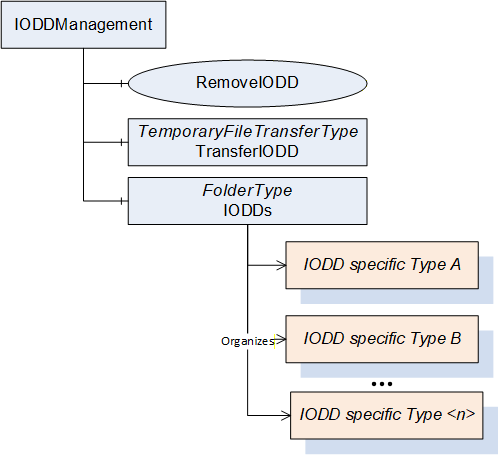
The IODDManagement Object is formally defined in Table 45. The IODDManagement Object shall be referenced from the Objects Object defined in OPC 10000-5 with an Organizes Reference.
| Attribute | Value | ||||
| BrowseName | IODDManagement | ||||
| References | NodeClass | BrowseName | TypeDefinition | Comment | |
|---|---|---|---|---|---|
| HasTypeDefinition | ObjectType | FolderType | Defined in OPC 10000-5. | ||
| HasComponent | Method | RemoveIODD | Defined in 8.3 | ||
| HasComponent | Object | TransferIODD | TemporaryFileTransferType | Defined in OPC 10000-5. | |
| Organizes | Object | IODDs | FolderType | ||
The TransferIODD Object is used for a temporary file transfer (see OPC 10000-5 for details on the TemporaryFileTransferType). It is used to load new IODDs into the server, and, optionally, to read IODDs managed in the server.
The IODD provided by a vendor can consist of several files, providing the main XML-based file as well as optionally language files and images referenced in the main file (see IODD Specification). For loading and reading IODDs those files shall always be zipped into one file, representing the full IODD information of the device.
To load an IODD into the server, a new temporary file shall be created using the GenerateFileForWrite Method (defined in OPC 10000-5 as part of the TemporaryFileTransferType). The generateOptions argument of the Method shall be left as BaseDataType, meaning the Client shall pass a Null for that argument. After the file is written to the server, the Client shall call the CloseAndCommit Method (defined OPC 10000-5). Depending on the server implementation, the result of the operation is either directly returned in the Method call or via a state machine (see OPC 10000-5 for details).
The following rules for loading IODDs apply:
Servers shall reject IODDs they cannot interpret (e.g. using an unsupported version or invalid XML).
Server may reject an IODD if the checksum is invalid (see IODD Specification for details).
If the IODD to be loaded is already managed in the server (same DeviceID and VendorID).
The server may reject the loading operation if the IODD is used (there is an Instance of the ObjectType in the AddressSpace).
If the server loads the IODD it shall remove the previous version of the IODD (meaning removing the ObjectType) and assign potential Instances to the new ObjectType). In that case, the NodeIds of the Instances, including all Instances derived from InstanceDeclarations, shall not change.
If the server cannot manage the IODD due to limited resources it shall reject the loading.
Rejecting an IODD after calling the CloseAndCommit Method means that either the CloseAndCommit call directly returns a bad code or the returned completionStateMachine ends in the Error State (see OPC 10000-5 for details).
Note that the successful loading of an IODD typically leads to creating a corresponding ObjectType in this server. This is the recommended behaviour. However, it is allowed that servers do not create such an ObjectType before the ObjectType is used (e.g. by connecting a corresponding IO-Link Device to the IO-Link Master) due to limited resources of the server.
The server may also provide the capability to read an IODD managed by the server. In this case, the GenerateFileForRead Method (defined OPC 10000-5 as part of the TemporaryFileTransferType) is used to create a temporary file. This Method is mandatory on the TemporaryFileTransferType. If the server does not support reading an IODD the Executable Attribute of the Method shall be set to "False". The generateOptions argument of the GenerateFileForRead Method shall be set to NodeId. The Client shall provide the NodeId of the ObjectType representing the IODD to create a temporary file for that IODD. Depending on the server implementation, the result of the operation is either directly returned in the Method call or via a state machine (see OPC 10000-5 for details). If the server supports this operation, a zipped file like for loading an IODD is returned.
The IODDs Object is used to group all ObjectTypes representing IODDs managed in the server. It shall reference all those ObjectTypes directly with an Organizes Reference.
8.3 RemoveIODD Method
The Method RemoveIODD removes an IODD from the server and is used by the IODDManagement Object (see 8.2).
The following rules for deleting IODDs apply:
If the IODD is used (meaning there is an instance of the ObjectType in the AddressSpace of the Server) and the force flag is set to "False" the operation shall fail. Clients need to remove the usage of the IODD first before it can be deleted.
If the IODD is used (meaning there is an instance of the ObjectType in the AddressSpace of the Server) and the force flag is set to "True" the operation shall succeed and remove all instances of the corresponding ObjectType in the AddressSpace.
Signature
	RemoveIODD (
		[in]	NodeId		IODD,
		[in]	Boolean		Force,
		[out]	Int32			Status
		);
| Argument | Description |
| IODD | NodeId of the ObjectType representing an IODD description. The Node shall be referenced by the IODDs Object with an Organizes Reference. |
| Force | If "True": Force the immediate deletion of instances of the ObjectType in the AddressSpace. |
| Status | Returns the status of the operation. 0: OK, operation successful -1: NodeId invalid for this operation - no NodeId of an IODD representation -2: IODD in use and cannot be deleted |
Method Result Codes (defined in Call Service)
| Result Code | Description |
| Bad_UserAccessDenied | See OPC 10000-4 for a general description. |
8.4 IOLinkMasterSet Object
The IOLinkMasterSet Object is referencing all Objects of IOLinkMasterType managed in the Server with an Organizes Reference (see Figure 9). It is formally defined in Table 46. The IOLinkMasterSet Object shall be referenced from the Objects Object defined in OPC 10000-5 with an Organizes Reference.
Since later versions of this specification might change the parent of this Object, Clients aware of this standardized Object shall not access it via its parent but directly via its standardized NodeId.
| Attribute | Value | ||||
| BrowseName | IOLinkMasterSet | ||||
| References | NodeClass | BrowseName | TypeDefinition | Comment | |
|---|---|---|---|---|---|
| HasTypeDefinition | ObjectType | FolderType | Defined in OPC 10000-5. | ||
9 OPC UA EventTypes
9.1 General
The IOLinkEventType defines the base structure for all EventTypes providing simple Events (Notifications) defined in this specification. Subtypes are defined to distinguish between events originating from IO-Link Device, IO-Link Masters and ports of the IO-Link Masters.
The IOLinkAlarmType defines the base structure for all EventTypes providing alarms (Errors and Warnings) defined in this specification. Subtypes are defined to distinguish between alarms originating from IO-Link Device, IO-Link Masters and ports of the IO-Link Masters.
9.2 IOLinkEventType
The IOLinkEventType is the base EventType for Events generated from IO-Link Devices or IO-Link Masters. It is formally defined in Table 47.
| Attribute | Value | ||||
| BrowseName | IOLinkEventType | ||||
| IsAbstract | True | ||||
| References | Node Class | BrowseName | DataType | TypeDefinition | Modelling Rule |
|---|---|---|---|---|---|
| Subtype of BaseEventType defined in OPC 10000-5. | |||||
| HasSubtype | ObjectType | IOLinkDeviceEventType | |||
| HasSubtype | ObjectType | IOLinkPortEventType | |||
| HasSubtype | ObjectType | IOLinkMasterEventType | |||
| HasProperty | Variable | IOLinkEventCode | UInt16 | PropertyType | Mandatory |
The EventType inherits the Properties of the BaseEventType.
The mandatory Property EventId is a vendor-specific unique identification of the Event.
The mandatory Property EventType reflects the type of Event, so either the NodeId of the IOLinkEventType or a subtype.
The content of the Properties SourceNode, SourceName, Time, ReceiveTime, and Message is defined by its subtypes.
The optional Property LocalTime shall not be provided.
The Property Severity reflects the mode of IO-Link events. The IOLinkEventType or subtypes shall only be used for "Notification" and the severity shall be "200".
The Property IOLinkEventCode is defined by the subtypes of the EventType.
9.3 IOLinkDeviceEventType
The IOLinkDeviceEventType is the base EventType for Events generated from IO-Link Devices. It is formally defined in Table 48.
| Attribute | Value | ||||
| BrowseName | IOLinkDeviceEventType | ||||
| IsAbstract | True | ||||
| References | Node Class | BrowseName | DataType | TypeDefinition | Modelling Rule |
|---|---|---|---|---|---|
| Subtype of IOLinkEventType defined in section 9.2. | |||||
| HasSubtype | ObjectType | IOLinkIODDDeviceEventType | |||
The following rules for the inherited Properties apply.
The mandatory Property SourceNode shall be the NodeId of the object representing the IO-Link Device the event originates from.
The mandatory Property SourceName shall be the string part of the BrowseName of the Object representing the IO-Link Device the Event originates from.
The mandatory Property Time shall be the time the IO-Link Master receives the Event from the IO-Link Device.
Note that the event might have been generated already at an earlier time (more than communication delays) in the IO-Link Device, before it was received by the IO-Link Master.
The mandatory Property ReceiveTime shall be set to the time the OPC UA Server receives the event. In case the OPC UA Server runs on the IO-Link Master, this might be the same value as the value of Property Time.
In case the IO-Link event code is not described in an IODD, the mandatory Property Message shall be set to "IO-Link EventCode: 0x<xxxx>" for the English locale, where xxxx is the event code as hexadecimal representation. For example, for event code 0x18FF the message shall be "IO-Link EventCode: 0x18FF". The server may provide different locales containing a translation of that string. In case the IO-Link Specification defines a specific string (Table D.1 of IO-Link Specification) for a specific event code, the server may also use that string instead of the generic message. For example, for event code 0x4000 the string "Temperature fault - Overload" is defined and can be used alternatively as Message.
The mandatory Property IOLinkEventCode shall provide the two-octet event code of the IO-Link Device as UInt16.
9.4 IOLinkIODDDeviceEventType
The IOLinkIODDDeviceEventType is the EventType for Events generated from IO-Link Devices based on IODD information. It is formally defined in Table 49.
| Attribute | Value | |||||
| BrowseName | IOLinkIODDDeviceEventType | |||||
| IsAbstract | True | |||||
| References | Node Class | BrowseName | DataType | TypeDefinition | Modelling Rule | |
|---|---|---|---|---|---|---|
| Subtype of IOLinkDeviceEventType defined in section 9.3. | ||||||
| HasProperty | Variable | Name | LocalizedText | PropertyType | Mandatory | |
The following rules for the inherited Properties apply.
The mandatory Property Message shall be mapped to the corresponding IODD Event/Description element. Localization should be considered. If the optional element Description is not provided, the mandatory element Name shall be used.
The mandatory Property Name shall be mapped to the corresponding IODD Event/Name element. Localization should be considered.
9.5 IOLinkPortEventType
The IOLinkPortEventType represents Events triggered by a concrete port of an IO-Link Master. It is formally defined in Table 48.
| Attribute | Value | ||||
| BrowseName | IOLinkPortEventType | ||||
| IsAbstract | True | ||||
| References | Node Class | BrowseName | DataType | TypeDefinition | Modelling Rule |
|---|---|---|---|---|---|
| Subtype of IOLinkEventType | |||||
The following rules for the inherited Properties apply.
The mandatory Property SourceNode shall be the NodeId of the Object of IOLinkPortType the event originates from.
The mandatory Property SourceName shall start with the string part of the BrowseName of the Object of IOLinkMasterType the IO-Link Port is connected to, followed by a "." and the string part of the BrowseName of the Object of IOLinkPortType the Event originates from.
The mandatory Property Time shall be the time the Event occurred on the IO-Link Master.
The mandatory Property ReceiveTime shall be set to the time the OPC UA Server receives the event. In case the OPC UA Server runs on the IO-Link Master, this might be the same value as the value of Property Time.
The allowed IOLinkPortEvents are defined in IO-Link Addendum as port specific events. The EventCode ID shall be mapped to the IOLinkEventCode. In case of a vendor-specific EventCode ID the Message is vendor-specific. In case of all other EventCode IDs the descriptive text of IO-Link Addendum shall be used as Message for locale "en". For EventCode IDs 0xFF21 to 0xFFFF no text is defined. For those, the following Message texts defined in Table 51 shall be used for locale "en". Servers may provide translations for all Message texts in other languages.
| IOLinkEventCode | Message (for locale "en") |
| 0xFF21 | New Device |
| 0xFF22 | Device not available - communication lost |
| 0xFF23 | Invalid backup - Data Storage identification mismatch |
| 0xFF24 | Invalid backup - Data Storage buffer overflow |
| 0xFF25 | Invalid backup - Data Storage parameter access denied |
| 0xFF31 | Event lost - incorrect Event signaling |
9.6 IOLinkMasterEventType
The IOLinkMasterEventType is the base EventType for Events generated from an IO-Link Master. It is formally defined in Table 52.
| Attribute | Value | ||||
| BrowseName | IOLinkMasterEventType | ||||
| IsAbstract | True | ||||
| References | Node Class | BrowseName | DataType | TypeDefinition | Modelling Rule |
|---|---|---|---|---|---|
| Subtype of IOLinkEventType | |||||
The following rules for the inherited Properties apply.
The mandatory Property SourceNode shall be the NodeId of the object representing the IO-Link Master the event originates from.
The mandatory Property SourceName shall be the string part of the BrowseName of the Object representing the IO-Link Master the Event originates from.
The mandatory Property Time shall be the time the Event occurred on the IO-Link Master.
The mandatory Property ReceiveTime shall be set to the time the OPC UA Server receives the event. In case the OPC UA Server runs on the IO-Link Master, this might be the same value as the value of Property Time.
The Properties IOLinkEventCode and Message are vendor-specific. Vendors may also create subtypes of this EventType to add vendor-specific Properties or to categorize the events generated by the IO-Link Master.
9.7 IOLinkAlarmType
The IOLinkAlarmType is the base EventType for alarms generated from IO-Link Devices or IO-Link Masters. It is formally defined in Table 53.
| Attribute | Value | |||||
| BrowseName | IOLinkAlarmType | |||||
| IsAbstract | True | |||||
| References | Node Class | BrowseName | DataType | TypeDefinition | Modelling Rule | |
|---|---|---|---|---|---|---|
| Subtype of OffNormalAlarmType defined in OPC 10000-9. | ||||||
| HasSubtype | ObjectType | IOLinkDeviceAlarmType | ||||
| HasSubtype | ObjectType | IOLinkPortAlarmType | ||||
| HasSubtype | ObjectType | IOLinkMasterAlarmType | ||||
| HasProperty | Variable | IOLinkEventCode | UInt16 | PropertyType | Mandatory | |
The EventType inherits the InstanceDeclarations of the OffNormalAlarmType.
The mandatory Property EventId is a vendor-specific unique identification of the Event.
The mandatory Property EventType reflects the type of Event, so either the NodeId of the IOLinkAlarmType or a subtype.
The content of the Properties SourceNode, SourceName, Time, ReceiveTime, and Message is defined by its subtypes.
The optional Property LocalTime shall not be provided.
The Property Severity reflects the mode of IO-Link events. In case of "Warning" it shall be "500" and in case of "Error" it shall be "700".
The mandatory Variable EnabledState reflects if the alarm has enabled. It is vendor-specific. If the server does not support disabling of IO-Link alarms it shall always be set to enabled.
The mandatory Variable AckedState reflects if the alarm has been acknowledged. It is vendor-specific. If the server does not support acknowledgment of IO-Link alarms it shall always be set to acknowledged.
The mandatory Variable ActiveState reflects if the alarm is active or not. The ActiveState is set to active when an IO-Link event APPEARS, and set to inactive when an IO-Link event DISAPPEARS.
The behaviour of all Methods defined on the supertypes are vendor-specific, according to the defined behaviour in OPC 10000-9. If a server does not support specific functionality like disabling or acknowledging IO-Link alarms, those Method calls shall fail.
Note: The ConditionRefresh and ConditionRefresh2 Methods are not defined as InstanceDeclarations and shall behave as defined in OPC 10000-9.
Whether the optional Variables defined on the supertypes are provided is vendor-specific. If they are provided, the content shall be according to OPC 10000-9.
The content of the mandatory Variables defined on the supertypes is vendor-specific, according to OPC 10000-9.
The mandatory Properties InputNode and NormalState are vendor-specific and typically set to the NULL NodeId.
The mandatory Property SuppressedOrShelved is vendor-specific and typically set to "False".
The Property IOLinkEventCode is defined by the subtypes of the EventType.
9.8 IOLinkDeviceAlarmType
The IOLinkDeviceAlarmType is the base EventType for alarms generated from IO-Link Devices. It is formally defined in Table 54.
| Attribute | Value | |||||
| BrowseName | IOLinkDeviceAlarmType | |||||
| IsAbstract | False | |||||
| References | Node Class | BrowseName | DataType | TypeDefinition | Modelling Rule | |
|---|---|---|---|---|---|---|
| Subtype of IOLinkAlarmType defined in 9.7. | ||||||
| HasSubtype | ObjectType | IOLinkIODDDeviceAlarmType | ||||
The following rules for the inherited Properties apply.
The mandatory Property SourceNode shall be the NodeId of the object representing the IO-Link Device the event originates from.
The mandatory Property SourceName shall be the string part of the BrowseName of the Object representing the IO-Link Device the Event originates from.
The mandatory Property Time shall be the time the IO-Link Master receives the Event from the IO-Link Device.
Note that the event might have been generated already at an earlier time (more than communication delays) in the IO-Link Device, before it was received by the IO-Link Master.
The mandatory Property ReceiveTime shall be set to the time the OPC UA Server receives the event. In case the OPC UA Server runs on the IO-Link Master, this might be the same value as the value of Property Time.
In case the IO-Link event code is not described in an IODD, the mandatory Property Message shall be set to "IO-Link EventCode: 0x<xxxx>" for the English locale, where xxxx is the event code as hexadecimal representation. For example, for event code 0x18FF the message shall be "IO-Link EventCode: 0x18FF". The server may provide different locales containing a translation of that string. In case the IO-Link Specification defines a specific string (Table D.1 of IO-Link Specification) for a specific event code, the server may also use that string instead of the generic message. For example, for event code 0x4000 the string "Temperature fault - Overload" is defined, and can be used alternatively as Message.
The mandatory Property IOLinkEventCode shall provide the two-octet event code of the IO-Link Device as UInt16.
9.9 IOLinkIODDDeviceAlarmType
The IOLinkIODDDeviceAlarmType is the EventType for Alarms generated from IO-Link Devices based on IODD information. It is formally defined in Table 55.
| Attribute | Value | |||||
| BrowseName | IOLinkIODDDeviceAlarmType | |||||
| IsAbstract | False | |||||
| References | Node Class | BrowseName | DataType | TypeDefinition | Modelling Rule | |
|---|---|---|---|---|---|---|
| Subtype of IOLinkAlarmType defined in 9.8. | ||||||
| HasProperty | Variable | Name | LocalizedText | PropertyType | Mandatory | |
The following rules for the inherited Properties apply.
The mandatory Property Message shall be mapped to the corresponding IODD Event/Description element. Localization should be considered. If the optional element Description is not provided, the mandatory element Name shall be used.
The mandatory Property Name shall be mapped to the corresponding IODD Event/Name element. Localization should be considered.
9.10 IOLinkPortAlarmType
The IOLinkPortAlarmType represents alarms triggered by a concrete port of an IO-Link Master. It is formally defined in Table 56.
| Attribute | Value | ||||
| BrowseName | IOLinkPortAlarmType | ||||
| IsAbstract | False | ||||
| References | Node Class | BrowseName | DataType | TypeDefinition | Modelling Rule |
|---|---|---|---|---|---|
| Subtype of IOLinkAlarmType | |||||
The following rules for the inherited Properties apply.
The mandatory Property SourceNode shall be the NodeId of the Object of IOLinkPortType the event originates from.
The mandatory Property SourceName shall start with the string part of the BrowseName of the Object of IOLinkMasterType the IO-Link Port is connected to, followed by a "." and the string part of the BrowseName of the Object of IOLinkPortType the Event originates from.
The mandatory Property Time shall be the time the Event occurred on the IO-Link Master.
The mandatory Property ReceiveTime shall be set to the time the OPC UA Server receives the event. In case the OPC UA Server runs on the IO-Link Master, this might be the same value as the value of Property Time.
The allowed IOLinkPortAlarms are defined in IO-Link Addendum as port specific events. The EventCode ID shall be mapped to the IOLinkEventCode. In case of a vendor-specific EventCode ID the Message is vendor-specific. In case of all other EventCode IDs the descriptive text of IO-Link Addendum shall be used as Message for locale "en". For EventCode IDs 0xFF21 to 0xFFFF no text is defined. For those, the following Message texts defined in Table 51 shall be used for locale "en". Servers may provide translations for all Message texts in other languages.
9.11 IOLinkMasterAlarmType
The IOLinkMasterAlarmType is the base EventType for alarms generated from an IO-Link Master. It is formally defined in Table 57.
| Attribute | Value | ||||
| BrowseName | IOLinkMasterAlarmType | ||||
| IsAbstract | False | ||||
| References | Node Class | BrowseName | DataType | TypeDefinition | Modelling Rule |
|---|---|---|---|---|---|
| Subtype of IOLinkAlarmType | |||||
The following rules for the inherited Properties apply.
The mandatory Property SourceNode shall be the NodeId of the object representing the IO-Link Master the event originates from.
The mandatory Property SourceName shall be the string part of the BrowseName of the Object representing the IO-Link Master the Event originates from.
The mandatory Property Time shall be the time the Event occurred on the IO-Link Master.
The mandatory Property ReceiveTime shall be set to the time the OPC UA Server receives the event. In case the OPC UA Server runs on the IO-Link Master, this might be the same value as the value of Property Time.
The Properties IOLinkEventCode and the Message are vendor-specific. Vendors may also create subtypes of this EventType to add vendor-specific Properties or to categorize the alarms generated by the IO-Link Master.
10 OPC UA VariableTypes
10.1 ProcessDataVariableType
This VariableType is used to represent the process data input and output of an IO-Link Device. The Properties defined by this type define the length of the Variable as well as a descriptor of the structure. The ProcessVariableType is formally defined in Table 58.
| Attribute | Value | ||||
| BrowseName | ProcessDataVariableType | ||||
| IsAbstract | False | ||||
| ValueRank | 1 (1 = OneDimension) | ||||
| DataType | Byte | ||||
| References | Node Class | BrowseName | DataType | TypeDefinition | Modelling Rule |
|---|---|---|---|---|---|
| Subtype of the BaseDataVariableType defined in OPC 10000-5. | |||||
| HasProperty | Variable | ProcessDataLength | Byte | PropertyType | Mandatory |
| HasProperty | Variable | PDDescriptor | Byte[][3] | PropertyType | Optional |
The read-only Variable ProcessDataLength is representing the structure ProcessDataIn defined in IO-Link Specification, B.1.6, and contains information about the length of the ProcessData. The value (one byte) shall directly be mapped to the Byte DataType.
The optional read-only Variable PDDescriptor is representing the structure PD Input Descriptor or PD Output Descriptor defined in IO-Link Common Profile, B.5.2 and B.5.3. The value shall be mapped to an array of an array of Bytes of length three.
NOTE: The PDDescriptor defines the structure of the ProcessData by defining the data type, length and offset in the data of potentially several data entries in the ProcessData (see IO-Link Common Profile). It is not further mapped to OPC UA information (e.g. by providing sub-variables for each entry with the concrete value based on the ProcessData) as this can potentially change dynamically and this is not recognizable in time by the OPC UA Server.
11 OPC UA ReferenceTypes
11.1 HasIdentificationMenu
The HasIdentificationMenu ReferenceType is a concrete ReferenceType that can be used directly. It is a subtype of the Organizes ReferenceType.
The semantic is to identify that the referenced Object represents the IdentificationMenu as defined by MenuSetT of the IODD Specification.
The SourceNode of this ReferenceType shall be an Object of type FunctionalGroupType defined in OPC 10000-100 or one of its subtypes.
The TargetNode of this ReferenceType shall be an Object or type FunctionalGroupType defined in OPC 10000-100 or one of its subtypes. Its representation in the AddressSpace is specified in Table 59.
11.2 HasParameterMenu
The HasParameterMenu ReferenceType is a concrete ReferenceType that can be used directly. It is a subtype of the Organizes ReferenceType.
The semantic is to identify that the referenced Object represents the ParameterMenu as defined by MenuSetT of the IODD Specification.
The SourceNode of this ReferenceType shall be an Object of type FunctionalGroupType defined in OPC 10000-100 or one of its subtypes.
The TargetNode of this ReferenceType shall be an Object or type FunctionalGroupType defined in OPC 10000-100 or one of its subtypes. Its representation in the AddressSpace is specified in Table 60.
11.3 HasObservationMenu
The HasObservationMenu ReferenceType is a concrete ReferenceType that can be used directly. It is a subtype of the Organizes ReferenceType.
The semantic is to identify that the referenced Object represents the ObservationMenu as defined by MenuSetT of the IODD Specification.
The SourceNode of this ReferenceType shall be an Object of type FunctionalGroupType defined in OPC 10000-100 or one of its subtypes.
The TargetNode of this ReferenceType shall be an Object or type FunctionalGroupType defined in OPC 10000-100 or one of its subtypes. Its representation in the AddressSpace is specified in Table 61.
11.4 HasDiagnosisMenu
The HasDiagnosisMenu ReferenceType is a concrete ReferenceType that can be used directly. It is a subtype of the Organizes ReferenceType.
The semantic is to identify that the referenced Object represents the DiagnosisMenu as defined by MenuSetT of the IODD Specification.
The SourceNode of this ReferenceType shall be an Object of type FunctionalGroupType defined in OPC 10000-100 or one of its subtypes.
The TargetNode of this ReferenceType shall be an Object or type FunctionalGroupType defined in OPC 10000-100 or one of its subtypes. Its representation in the AddressSpace is specified in Table 62.
12 Mapping of DataTypes
12.1 Overview
This section defines the mapping of data types defined in the IODD as well as the mapping of the representation of a duration used in various places of IO-Link which are mapped to OPC UA. It always defines the usage of an appropriate OPC UA DataType, and in some cases in addition the use of specific VariableTypes, or specific Properties of the Variable to represent specific meta data that cannot directly be mapped to OPC UA DataTypes.
12.2 Primitive DataTypes
12.2.1 Boolean DataType
The IODD data type BooleanT is mapped to the OPC UA DataType Boolean. The "True" value of IODD (0xFF) is mapped to the "True" value of OPC UA, and the "False" value of IODD ("0x00") is mapped to the "False" value of OPC UA.
In case both SingleValue elements are provided in the IODD, and the value can directly be mapped to a Variable (see 12.3), the VariableType TwoStateDiscreteType is used. The TrueState Property contains the SingleValue representing "True" (see 13) and the FalseState Property contains the SingleValue representing "False".
In case only one SingleValue element is provided in the IODD, and the value can directly be mapped to a Variable (see 12.3), the VariableType TwoStateDiscreteType is used as described above, with the limitation, that the text field of the Property representing the missing state contains an empty string.
In case no SingleValue element is provided in the IODD, and the value can directly be mapped to a Variable (see 12.3), the VariableType BaseDataVariableType is used.
12.2.2 Integer DataTypes
The IODD data types IntegerT and UIntegerT are mapped to OPC UA DataTypes in different ways, depending on various elements of the IODD.
If no SingleValue and no ValueRange is defined the DataType depends on the bitLength according to Table 63. If the value can directly be mapped to a Variable (see 12.3), the VariableType BaseDataVariableType is used. If the bitLength does not directly fit into an OPC UA DataType (all bitLengths except 8, 16, 32 and 64) the Variable shall contain a Property called InstrumentRange as defined in OPC 10000-8 for AnalogItemVariableType using the same BrowseName and DataType. In case of an unsigned integer the low value shall be 0 and the high value according to the bitLength (e.g. 127 for bitLength 7). In case of a signed integer the low and high value shall be according to the bitLength (e.g. bitLength 7 leads to low = -63 and high = 63).
| IO-Link data type | IO-Link bitLength | OPC UA DataType |
| UIntegerT | 2..8 | Byte |
| 9..16 | UInt16 | |
| 17..32 | UInt32 | |
| 33..64 | UInt64 | |
| IntegerT | 2..8 | SByte |
| 9..16 | Int16 | |
| 17..32 | Int32 | |
| 33..64 | Int64 |
If no SingleValue and exactly one ValueRange is defined, the same mapping as defined in (1) is used, except for the InstrumentRange Property. The InstrumentRange shall always be provided and be filled according to the ValueRange definition.
If at least one SingleValue is defined and no ValueRange is defined:
If all SingleValue values fit into the range of an Int32, an OPC UA Enumeration DataType is created, containing all SingleValue entries of the IODD definition in the EnumValues Property (see section 13). If the value can directly be mapped to a Variable (see section 12.3), the VariableType BaseDataVariableType shall be used
If not all SingleValue values fit into the range of an Int32, the same mapping as defined in (1) is used with the following exceptions. If the value can directly be mapped to a Variable (see section 12.3), the VariableType MultiStateValueDiscreteType shall be used, and the EnumValues are filled according to the SingleValue entries (see section 13). The InstrumentRange Property is provided as according to (1).
If no SingleValue and more than one ValueRange is defined the same mapping as defined in (1) is used with the following exceptions. If the value can directly be mapped to a Variable (see section 12.3), in addition to potentially providing the InstrumentRange Property (depending on the bitLength) another Property InstrumentRanges (see section 13) is provided, containing an array of ranges, one entry for each ValueRange defined in the IODD.
If at least one SingleValue and exactly one ValueRange is defined the same mapping as defined in (2) is used with the following exceptions. If the value can directly be mapped to a Variable (see section 12.3), an additional Property EnumValues (same as defined on MultiStateValueDiscreteType in OPC 10000-8) is provided, with one entry for each SingleValue (see 13).
If at least one SingleValue and more than one ValueRange is defined the same mapping as defined in (1) is used with the following exceptions. If the value can directly be mapped to a Variable (see section 12.3), an additional Property EnumValues (same as defined on MultiStateValueDiscreteType in OPC 10000-8) is provided, with one entry for each SingleValue defined in the IODD, and in addition to potentially providing the InstrumentRange Property (depending on the bitLength) another Property InstrumentRanges (see section 13) is provided, containing an array of ranges, one entry for each ValueRange defined in the IODD.
12.2.3 Float DataType
The IODD data type FloatT and the OPC UA DataType Float follow the same specification and can directly be mapped.
In case the value can directly be mapped to a Variable (see section 12.3) the following rules apply:
If no SingleValue and no ValueRange is defined, the VariableType BaseDataVariableType is used.
If no SingleValue and exactly one ValueRange is defined, the VariableType BaseDataVariableType is used. The Variable shall have the additional Property InstrumentRange as defined in OPC 10000-8 for AnalogItemVariableType using the same BrowseName and DataType. The InstrumentRange shall be filled according to the ValueRange definition.
If at least one SingleValue is defined and no ValueRange is defined, the VariableType MultiStateValueDiscreteType shall be used, and the EnumValues filled according to the SingleValue entries (see section 13).
If no SingleValue and more than one ValueRange is defined the VariableType BaseDataVariableType is used. The Variable shall have a Property InstrumentRanges (see section 13), containing an array of ranges, one entry for each ValueRange defined in the IODD.
If at least one SingleValue and exactly one ValueRange is defined the same mapping as defined in (2) is used with the following exception: An additional Property EnumValues (same as defined on MultiStateValueDiscreteType in OPC 10000-8) is provided, with one entry for each SingleValue (see section 13).
If at least one SingleValue and more than one ValueRange is defined the same mapping as defined in (4) is used with the following exception: An additional Property EumValues (same as defined on MultiStateValueDiscreteType in OPC 10000-8) is provided, with one entry for each SingleValue (see section 13).
12.2.4 String DataType
The IODD data type StringT can either use ASCII or UTF-8 encoding. It is always mapped to an OPC UA DataType String, which is UTF-8 encoded.
The mapping requires that IO-Link ASCII based strings are converted to UTF-8. Mapping an ASCII string to UTF-8 can always be done but mapping an UTF-8 string to ASCII may fail (when writing a UTF-8 string to an IO-Link Device expecting only ASCII strings). In case the OPC UA Server cannot do a transformation, the operation shall fail.
If the value can directly be mapped to a Variable (see section 12.3), the BaseDataVariableType is used, and the mandatory element fixedLength is mapped to the Property MaxStringLength defined in OPC 10000-3, and the element encoding to the Property Encoding (see section 13). If the Variable is referenced by a StdVariableRef, and the fixedLengthRestriction is defined, this needs to be used instead.
12.2.5 Byte[] DataType
The IODD data type OctetStringT is mapped to an array of the OPC UA DataType Byte. This mapping, instead of using the OPC UA DataType ByteString, allows to always provide the length of the array. The OctetStringT provides the mandatory element fixedLength which is directly mapped to the ArrayDimensions Attribute. If the value can directly be mapped to a Variable (see section 12.3), the VariableType BaseDataVariableType is used with no additional Properties.
12.2.6 DateTime DataType
12.2.6.1 Overview
The IODD data type TimeT is mapped to an OPC UA DataType DateTime.
The IODD data type TimeT has a length of 8 bytes, consisting of two 32-bit unsigned integers. The bytes 1 to 4 represent the seconds starting from 1900-01-01 0.00,00 (UTC) and the bytes 5 to 8 represent the fractional part of the current second in seconds. Because the time range before 1984-01-01 0:00,00 (UTC) is in the past (where IO-Link did not exist), the time values (seconds) from 0x00000000 to 0x9DFF4400 (exclusive) are mapped to the time after 2036-02-07 6.28,16 (UTC). See IO-Link Specification for more details.
The OPC UA DataType DateTime consists of a 64-bit signed integer which represents the number of 100 nanosecond intervals ( seconds) since January 1, 1601 (UTC).
The OPC UA DataType provides a larger range whereas the IO-Link data type provides a higher precision. Therefore, the following conversion rules shall apply (see OPC 10000-6). Implementers shall ensure that the time value mappings are done as exactly as possible.
12.2.6.2 Conversion from IO-Link TimeT to OPC UA DateTime
Consider the borders of the IO-Link TimeT value range:
If the IO-Link TimeT value is equal to the smallest possible IO-Link time value (1984-01-01 0:00,00 (UTC), seconds value: 0x9DFF4400, fractional seconds value: 0), the OPC UA DateTime value shall be 0.
If the IO-Link TimeT value is equal to the highest possible IO-Link time value (2120-02-07 6:28,15 (UTC), seconds value: 0x9DFF4399, fractional seconds value 0xFFFFFFFF), the OPC UA DateTime value shall be 0x7FFFFFFFFFFFFFFF (maximum value for 64-bit signed integer).
If none of the rules above apply, the IO-Link TimeT rollover has to be considered:
If the IO-Link TimeT value is smaller than (1984-01-01 0:00,00 (UTC), seconds value: 0x9DFF4400, fractional seconds value: 0), the time base offset has to be the difference between 1601-01-01 0:00:00 and 2036-02-07 6.28,16 (UTC).
If the IO-Link TimeT value is bigger than (1984-01-01 0:00,00 (UTC)), the time base offset has to be the difference between 1601-01-01 0:00:00 (UTC) and 1901-01-01 0:00:00 (UTC).
The time value conversion works according to the following formula:
12.2.6.3 Conversion from OPC UA DateTime to IO-Link TimeT
Consider the borders of the IO-Link TimeT value range:
If the OPC UA DateTime value is equal or greater than 2120-02-07 6:28,15 (UTC), the IO-Link TimeT value shall be 2120-02-07 6:28,15 (UTC), seconds value: 0x9DFF4399, fractional seconds value 0xFFFFFFFF).
If the OPC UA DateTime value is equal or smaller than 1984-01-01 0:00,00 (UTC), the IO-Link TimeT value shall be 1984-01-01 0:00,00 (UTC), seconds value: 0x9DFF4400, fractional seconds value: 0).
If none of the rules above apply, the IO-Link TimeT rollover has to be considered:
If the OPC UA DateTime value is equal or greater than 2036-02-07 6.28,16 (UTC), the time base offset has to be the difference between 1601-01-01 0:00:00 and 2036-02-07 6.28,16 (UTC).
If the OPC UA DateTime value is smaller than 2036-02-07 6.28,16 (UTC), the time base offset has to be the difference between 1601-01-01 0:00:00 and 1901-01-01 0:00:00 (UTC).
The time value conversion works according to the following formulas:
12.2.6.4 Conversion of special values (Summary)
Table 64 and Table 65 list some special values and their conversion to the other time data type. They can be used as a base set to test the conversion algorithm implementation (together with other input-output pairs).
| Input (OPC UA DateTime) | Output (IO-Link TimeT) | |
| Seconds value | Description | Seconds value |
| Date/time value before 1984/01/01 0:00:00,000AM (inclusive) | Date/time value is "truncated" | 1984/01/01 00:00:00,000AM |
| Date/time value after 2120/02/07 06:28:15,999AM (inclusive) | Date/time value is "truncated" | 2120/02/07 06:28:15,999AM |
| 0 | Minimal OPC UA DateTime value = 1601/01/01 12:00:00,000AM | 1984/01/01 00:00:00,000AM |
| INT64_MAX (0x7FFFFFFFFFFFFFFF) | Maximal OPC UA DateTime value = 9999/12/31 11:59:59,000PM | 2120/02/07 06:28:15,999AM |
| Input (IO-Link TimeT) | Output (OPC UA DateTime) | |
| Seconds value | Description | Seconds value |
| 1984/01/01 00:00:00,000AM | Minimal IO-Link TimeT value | 0 |
| 2120/02/07 06:28:15,000AM | Maximal IO-Link TimeT value | INT64_MAX |
| 0 | First number after IO-Link TimeT rollover | 2036/02/07 06:28:17,000AM |
| seconds = UINT32_MAX, fSeconds = UINT32_MAX | Last number before IO-Link TimeT rollover | 2036/02/07 06:28:16,999AM |
12.2.7 Duration DataType
12.2.7.1 Duration DataType used for TimeSpanT
12.2.7.1.1 Overview
The IODD data type TimeSpanT is mapped to the OPC UA DataType Duration.
The IODD data type TimeSpanT consists of 8 bytes representing fractions of a second (seconds). See IODD Specification for more details.
The OPC UA DataType Duration consists of a Double variable representing the number of milliseconds. Fractions can be used to represent fractions of milliseconds. See OPC 10000-3 for more details.
The following rules for conversion apply. Implementers shall ensure that the time span value mappings are done as exactly as possible.
12.2.7.1.2 Conversion from IO-Link TimeSpanT to OPC UA Duration
As the range of the OPC UA Duration values is bigger than the IO-Link TimeSpanT value, the following conversion formula can be applied without restrictions:
12.2.7.1.3 Conversion from OPC UA Duration to IO-Link TimeSpanT
If the OPC UA Duration value is bigger than the maximum IO-Link TimeSpanT value () converted to milliseconds (), the IO-Link TimeSpanT value has to be the maximum value for 64-bit unsigned integer 0xFFFFFFFFFFFFFFFF.
If the OPC UA Duration value fits into this range, the following conversion formula shall be applied:
12.2.7.2 Duration DataType used for values coded with 1 byte
IO-Link uses in several places an octet to represent a duration in ms (e.g. MasterCycleTime and OffsetTime). As a time base and a multiplier is used, not all possible values are represented. The OPC UA DataType Duration uses a higher resolution.
If the client writes a value that cannot exactly be mapped, the server shall use the next possible lower value.
If the client tries to write a value outside the allowed range (either because of the larger size of the DataType or based on further limitations defined by the IO-Link Specification), the server shall return the error code "Bad_OutOfRange".
12.3 Mapping of Records and Arrays
12.3.1 Overview
In IODDs data types can either be used to represent the structure of a variable and this variable is mapped to an OPC UA Variable (see section 7.3.6), or an IODD data type is used in the context of an array or record. The following subsections describe the mapping, including whether an OPC UA Variable is used as sub-variable.
12.3.2 Structure DataType
For each IODD Record a new OPC UA DataType as subtype of Structure is created.
The NodeId of the new DataType is composed of the NodeId of the ObjectType generated for the IODD (see section 7.3.2) and the Record/@id ("<ObjectTypeId>||<Record id>").
The BrowseName and DisplayName are server-specific. It is recommended to use the Name element of the Variable in the IODD (default language English resolved textId) and "DataType" as postfix. For example, when the Variable Name has the textId "V_N_autosafeparameter", which is defined as "autosafe parameter" in the IODD as default, the DataType BrowseName is "autosafe parameterDataType". The DisplayName is LocalizedText, thus also different locales can be provided, using the corresponding texts of the IODD for the different locales.
The DataType shall use OPC Binary Encoding as definition. The DataTypeDefinition Attribute shall describe the structure according to the IODD and the rules defined next.
In the StructureDefinition (DataTypeDefinition Attribute) the field defaultEncodingId shall be "Default Binary", the field baseDataType shall be "Structure", and the field structureType "Structure_0".
The array of fields (of type StructureField) shall be filled: For each IODD RecordItem defined in the IODD an entry shall be made with the following rules:
The Name of the IODD RecordItem (default language English resolved textId) shall map to the field name of StructureField
The Description of the IODD RecordItem shall map to the field description of StructureField
The data type of the IODD RecordItem shall map to the dataType of StructureField following Table 66
| IO-Link data type | OPC UA DataType | Remark |
| IntegerT | Specific Integer or Enumeration DataType | Details see section 12.2.2 |
| UIntegerT | Specific UInteger or Enumeration DataType | Details see section 12.2.2 |
| Float32T | Float | Details see section 12.2.3 |
| BooleanT | Boolean | Details see section 12.2.1 |
| OctetStringT | Byte[] | Details see section 12.2.5 |
| StringT | String | Details see section 12.2.4 |
| TimeT | DateTime | Details see section 12.2.6 |
| TimeSpanT | Duration | Details see section 12.2.7.2 |
The field valueRank shall be "Scalar"
The field arrayDimensions shall be null, except for the OctetStringT data type mapping, where the fixedLength element is mapped to arrayDimensions
The field maxStringLength shall contain the fixedLength for Strings, otherwise "0"
The field isOptional shall be "False"
In addition to the structured DataType more things need to be considered. If the new defined Structure DataType is used in an OPC UA Variable, the following rules apply.
If all entries of the IODD Record are readable (RO or RW), the Variable becomes readable, otherwise the Variable as such is not readable.
If all entries of the IODD Record are writable (WO or RW), the Variable becomes writeable, otherwise the Variable as such is not writeable.
If the IODD Record has "subindexAccessSupported" to "True", each entry of the structure is also exposed as subvariables following the general rules (e.g. for IntegerT, which might lead to an Enum DataType or usage of specific VariableTypes). If the individual entry is readable, the Variable becomes readable, if the individual entry is writable the Variable becomes writeable.
If the IODD Record has "subindexAccessSupported" to "False", but it contains entries that would map to Variables with additional Properties, those entries shall be exposed as subvariables following the general rules (because of the meta data). If the whole record is readable, they shall become readable but not writeable, otherwise they become neither readable nor writeable. Such subvariables shall be created for all StringT, and some IntegerT, UIntegerT, FloatT, and BooleanT (depending whether the concrete mapping would create a Property on the Variable). If does not need to be provided for OctetStringT, TimeT, and TimeSpanT.
If an entry of the IODD Record is referenced by a RecordItemRef it shall be exposed as sub-variable, even if the RecordItemRef is in an optional IODD Menu.
Note that a VariableRef and RecordItemRef defines additional characteristics (see 7.3). Those need to be considered as well.
12.3.3 Array DataTypes
An IODD variable having the IODD data type ArrayT is mapped to an OPC UA Variable with ValueRank OneDimensionalArray.
The data type used in the array of the IODD is the base for the mapping of the data type to OPC UA (see 12.2). That does include the VariableType to use and what Properties on the Variable shall exist.
The ValueRank Attribute of the OPC UA Variable shall be OneDimensionalArray.
The ArrayDimensions Attribute of the OPC UA Variable shall be an array with exactly one entry. The value of that entry shall be the size element of the IODD Variable.
12.4 Enumeration and OptionSet DataTypes
12.4.1 EncodingEnum
This DataType is an enumeration that defines the encoding of the string used in the IO-Link Device. Its values are defined in Table 67.
| Value | Description |
|---|---|
| ASCII_0 | The string is encoded as ASCII. |
| UTF8_1 | The string is encoded as UTF-8. |
Its representation in the AddressSpace is defined in Table 68.
| Attributes | Value |
| BrowseName | EncodingEnum |
| Subtype of the Enumeration DataType defined in OPC 10000-5 | |
13 Standardized Properties and Mapping to the Properties
13.1 InstrumentRange
InstrumentRange is defined in OPC 10000-8 as Property of the AnalogItemType. In this specification the Property is used for Variables, independent of the VariableType.
The Property uses the DataType Range defined in OPC 10000-8 having a low and a high value. The mapping of an IODD ValueRange to the OPC UA Range is defined in Table 69.
| IODD attribute | OPC UA field |
|---|---|
| lowerValue | low |
| upperValue | high |
13.2 InstrumentRanges
The InstrumentRanges Property is defined by this specification and used for Variables, independent of the VariableType. The BrowseName is "InstrumentRanges" and the DataType an array of Range (defined in OPC 10000-8).
The mapping of IODD ValueRange to Range is defined in 13.1
13.3 EnumValues
EnumValues is defined in OPC 10000-8 as Property of the MultiStateValueDiscreteType. In this specification the Property is used for Variables, independent of the VariableType.
The Property uses an array the EnumValueType. When an IODD defined SingleValue is mapped to an entry of the array, the following rules apply:
The IODD value is mapped to the OPC UA value.
The IODD name is mapped to the OPC UA displayName. The IODD value contains a TextRefT referencing a text, potentially in several languages. The displayName is LocalizedText, thus also different locales can be provided. The localeId shall contain the corresponding language, and the text the referenced text.
The OPC UA description shall be left empty.
13.4 TrueState and FalseState
The TrueState and FalseState are defined in OPC 10000-8 as Properties of the TwoStateDiscreteType.
Each Property uses a LocalizedText. When an IODD defined SingleValue is mapped to such a LocalizedText, the name of the SingleValue containing a TextRefT referencing a text, potentially in several languages. The localeId shall contain the corresponding language, and the text the referenced text.
13.5 Encoding
The Encoding Property is defined by this specification and used for Variables, independent of the VariableType. The BrowseName is "Encoding" and the DataType an EncodingEnum (see 12.4.1).
When the IODD CharacterEncodingT is mapped to the Property, the UA-ASCII value shall be mapped to ASCII_0 and the UTF-8 value to UTF8_1.
13.6 DisplayFormat
The DisplayFormat Property is defined by this specification and used for Variables, independent of the VariableType. The BrowseName is "DisplayFormat" and the DataType a String. It contains the String as defined in the IODD as displayFormat.
14 ISDU Error Handling
14.1 Overview
This section describes the handling of ISDU errors (ErrorTypes). IO-Link Errors are not to be confused with IO-Link Events.
14.2 Occurrence of ISDU Errors
There are two ways how this OPC UA Mapping can trigger IO-Link ISDU requests:
Executing some OPC UA Methods (like ReadISDU, WriteISDU, SystemCommand, etc.).
Reading or writing some OPC UA Variables (which trigger an ISDU request).
In both access ways an ISDU request can fail and IO-Link will respond with an ISDU error. In case of error the OPC UA Service response (of Services like Read, Write or Call) should contain information about the error in diagnosticInfos[] as specified in the following paragraphs. If an ISDU error occurs and the ISDU request was triggered with an OPC UA Method, the output parameter "ErrorType" contains the raw ISDU error as well.
| NOTE | To get content in the field diagnosticInfos[] an OPC UA Client has to indicate in the OPC UA Service RequestHeader that diagnostic info associated with the operation of the Service has to be returned. This is done by setting the appropriate bits of returnDiagnostics, a field of the OPC UA Service RequestHeader. (See OPC 10000-4 for more details). |
14.3 Mapping of ISDU Errors in DiagnosticInfo
If an ISDU error occurs the OPC UA Service Response array diagnosticInfos[] shall contain at least one element of DataType DiagnosticInfo.
The following rules apply to fill the fields of the DiagnosticInfo structure. The DiagnosticInfo structure does not contain the Strings itself (except additionalInfo), but an index of the position of the String in the stringTable.
| DiagnosticInfo structure element | ISDU Error related description | example | |
| namespaceUri | IO-Link ErrorType Namespace | "http://opcfoundation.org/UA/IOLink/" | |
| symbolicId | Error Code and Additional Code as 4-digit hex number | "0x8012" | |
| locale | Locale of localizedText | "en" | |
| localizedText | String that describes the symbolicId | "Subindex not available" | |
| additionalInfo | Vendor-specific diagnostic information | "" | |
The field namespaceUri contains the IO-Link ErrorType Namespace: "http://opcfoundation.org/UA/IOLink/".
The field symbolicId contains the IO-Link Error Code and Additional Code (as described in the IO-Link Specification) as 4-digit hex number converted to a String.
The field locale contains the country and region description of the language that is used in localizedText.
The field localizedText contains a verbal description of the error codes (symbolicId).
Note: This is a String, but not the built-in OPC UA DataType LocalizedText! The content of localizedText is specified in 14.4.
The content of additionalInfo is specified in 14.4.
14.4 Content of localizedText in DiagnosticInfo
14.4.1 No IODD information available
If the combination of IO-Link Error Code and Additional Code is listed in the IO-Link Specification, the sever shall use the text of Table C.1 or Table C.2 in column "Incident" as localizedText. Default locale is "en". Servers may provide vendor-specific translations to other languages. (In this case they have to adjust the value of locale as well.)
If the combination of IO-Link Error Code and Additional Code is vendor-specific (0x8101 to 0x81FF) no string shall be provided at all. This is indicated by giving stringTable index -1 as localizedText.
The content of additionalInfo is vendor-specific, but usually an empty string.
14.4.2 IODD information available
If the combination of IO-Link Error Code and Additional Code is listed in the IODD StandardDefinitions (see IODD Specification), the server shall use text specified there with the appropriate locale as localizedText. Servers may provide vendor-specific translations to other languages. (In this case they have to adjust the value of locale as well.)
If the combination of IO-Link Error Code and Additional Code is vendor-specific (0x8101 to 0x81FF) the IODD should contain an entry in its ErrorTypeCollection.
If the IODD does not contain a corresponding entry in its ErrorTypeCollection no string shall be provided at all. This is indicated by giving stringTable index -1 as localizedText. Note: IODDs following IODD Specification 1.0.1 do not have an ErrorTypeCollection at all.
If the IODD contains a corresponding entry in its ErrorTypeCollection, the localizedText contains the text referenced by the XML property "Name" of the XML element "ErrorType". The additionalInfo contains the text referenced by the XML property "Description" of the XML element "ErrorType", if the description is available. In all other cases the content of additionalInfo is vendor-specific, but usually an empty string.
As a result of this, the StdErrorTypeRef elements of the ErrorTypeCollection in the IODD might be ignored by the OPC UA server.
15 Profiles and Namespaces
15.1 Namespace Metadata
15.1.1 Namespace http://opcfoundation.org/UA/IOLink/
Table 71 defines the namespace metadata for this specification. The Object is used to provide version information for the namespace and an indication about static Nodes. Static Nodes are identical for all Attributes in all Servers, including the Value Attribute. See OPC 10000-5 for more details.
The information is provided as Object of type NamespaceMetadataType. This Object is a component of the Namespaces Object that is part of the Server Object. The NamespaceMetadataType ObjectType and its Properties are defined in OPC 10000-5.
The version information is also provided as part of the ModelTableEntry in the UANodeSet XML file. The UANodeSet XML schema is defined in OPC 10000-6.
| Attribute | Value | |||
| BrowseName | http://opcfoundation.org/UA/IOLink/ | |||
| References | BrowseName | DataType | Value | |
|---|---|---|---|---|
| HasProperty | NamespaceUri | String | http://opcfoundation.org/UA/IOLink/ | |
| HasProperty | NamespaceVersion | String | 1.0 | |
| HasProperty | NamespacePublicationDate | DateTime | 2018-12-01 | |
| HasProperty | IsNamespaceSubset | Boolean | Vendor-specific | |
| HasProperty | StaticNodeIdTypes | IdType[] | Null | |
| HasProperty | StaticNumericNodeIdRange | NumericRange[] | {0:9999} | |
| HasProperty | StaticStringNodeIdPattern | String | Null | |
15.1.2 Namespace http://opcfoundation.org/UA/IOLink/IODD/
Table 72 defines the namespace metadata for the namespace http://opcfoundation.org/UA/IOLink/IODD/. The Object is used to provide version information for the namespace and an indication about static Nodes. Static Nodes are identical for all Attributes in all Servers, including the Value Attribute. See OPC 10000-5 for more details.
The information is provided as Object of type NamespaceMetadataType. This Object is a component of the Namespaces Object that is part of the Server Object. The NamespaceMetadataType ObjectType and its Properties are defined in OPC 10000-5.
The version information is also provided as part of the ModelTableEntry in the UANodeSet XML file. The UANodeSet XML schema is defined in OPC 10000-6.
| Attribute | Value | |||
| BrowseName | http://opcfoundation.org/UA/IOLink/IODD/ | |||
| References | BrowseName | DataType | Value | |
|---|---|---|---|---|
| HasProperty | NamespaceUri | String | http://opcfoundation.org/UA/IOLink/IODD/ | |
| HasProperty | NamespaceVersion | String | 1.0 | |
| HasProperty | NamespacePublicationDate | DateTime | 2018-12-01 | |
| HasProperty | IsNamespaceSubset | Boolean | Vendor-specific | |
| HasProperty | StaticNodeIdTypes | IdType[] | {NUMERIC_0, STRING_1} | |
| HasProperty | StaticNumericNodeIdRange | NumericRange[] | Null | |
| HasProperty | StaticStringNodeIdPattern | String | Null | |
15.2 Conformance Units and Profiles
This chapter defines the corresponding Profiles and Conformance Units for the OPC UA for IO Link Information Model. Profiles are named groupings of Conformance Units. Facets are Profiles that will be combined with other Profiles to define the complete functionality of an OPC UA Server or Client.
15.3 Server Facets
The following tables specify the Facets available for Servers that implement the OPC UA for IO-Link Information Model companion specification.
15.3.1 IO-Link Event Facet
The "IO-Link Event Facet" defines a Facet for the functionality necessary for IO-Link Events derived from Type IOLinkEventType (see 9.2).
The content of the Profile if defined in Table 73.
| Conformance Unit | Description | Optional/ Mandatory |
| IO-Link Events | Supports Events derived from the IOLinkEventType. | M |
| Profiles | ||
|---|---|---|
Standard Event Subscription Server Facet http://opcfoundation.org/UA-Profile/Server/StandardEventSubscription |
In addition, OPC UA Servers supporting this Facet may optionally also support the Facets defined in Table 74.
| Profiles |
Address Space Notifier Server Facet http://opcfoundation.org/UA-Profile/Server/AddressSpaceNotifier |
Auditing Server Facet |
15.3.2 IO-Link Base Condition Facet
The "IO-Link Base Condition Facet" defines a Facet for the functionality necessary for IO-Link Conditions derived from Type IOLinkAlarmType (see 9.7).
The content of the Facet if defined in Table 75.
| Conformance Unit | Description | Optional/ Mandatory |
| IO-Link Alarms | Supports Events and Objects derived from the IOLinkAlarmType. | M |
| Profiles | ||
|---|---|---|
A & C Base Condition Server Facet |
In addition, OPC UA Servers supporting this Facet may optionally also support the Facets defined in Table 76.
| Profiles |
A & C Refresh2 Server Facet |
A & C Enable Server Facet |
A & C Previous Instances Server Facet http://opcfoundation.org/UA-Profile/Server/ACPreviousInstances |
A & C Dialog Server Facet |
A & C CertificateExpiration Server Facet http://opcfoundation.org/UA-Profile/Server/ACCertificateExpiration |
15.3.3 IO-Link Alarm Facet
The "IO-Link Alarm Facet" defines a Facet for the functionality necessary for IO-Link Alarms derived from Type IOLinkAlarmType (see 9.7).
The content of the Facet if defined in Table 77.
| Conformance Unit | Description | Optional/ Mandatory |
| IO-Link Alarms | Supports Events and Objects derived from the IOLinkAlarmType. | M |
| Profiles | ||
|---|---|---|
A & C Alarm Server Facet |
In addition, OPC UA Servers supporting this Facet may optionally also support the Facets defined in Table 78.
| Profiles |
A & C Acknowledgeable Alarm Server Facet |
A & C Exclusive Alarming Server Facet http://opcfoundation.org/UA-Profile/Server/ACExclusiveAlarming |
A & C Non-Exclusive Alarming Server Facet http://opcfoundation.org/UA-Profile/Server/ACNon-ExclusiveAlarming |
15.4 Server Profiles
The following tables specify the Profiles available for IO-Link Devices and Masters that implement the OPC UA for IO-Link Information Model companion specification.
15.4.1 IO-Link Base Profile
This Profile supports the information for IO-Link Masters and IO-Link Devices. It does not include support for IO-Link Device Description file handling.
This Profile is intended to be used of OPC UA servers with limited resources. It is built upon the "Micro Embedded Device 2017 Server Profile" Profile, which supports subscriptions and at least two sessions.
The content of the Profile if defined in Table 79.
| Conformance Unit | Description | Optional/ Mandatory |
| Generic IO-Link Device, IO-Link Master | Supports all mandatory ObjectTypes that are connected with the ObjectTypes IOLinkDeviceType and IOLinkMasterType (excluding subtypes defined in this specification). | M |
| DiagnosticInfos Support | Supports delivering DiagnosticInfos in the OPC UA response header. This is used to get additional information about the IO-Link errors. | O |
| Profiles | ||
|---|---|---|
Micro Embedded Device 2017 Server Profile http://opcfoundation.org/UA-Profile/Server/MicroEmbeddedDevice2017 | M | |
Method Server Facet | M | |
| BaseDevice_Server_Facet (defined in OPC 10000-100) | M | |
In addition, OPC UA Servers supporting this Facet may optionally also support the Facets defined in Table 80.
| Profiles |
| IO-Link Event Facet (see 15.3.1) |
| IO-Link Base Condition Facet (see 15.3.2) |
| IO-Link Standard Alarm Facet (see 15.3.3) |
15.4.2 IO-Link Advanced Profile
This Profile supports the communication with IO-Link Masters and IO-Link Devices via OPC UA. It includes support for IO-Link Device Description file handling and includes all features of the "IO-Link Base Profile".
This Profile builds upon the "Embedded 2017 UA Server Profile". In comparison to the "Micro Embedded Device 2017 Server Profile" it adds for example support for Security Policies and the "Standard DataChange Subscription Server Facet".
The content of the Profile if defined in Table 81.
| Conformance Unit | Description | Optional/ Mandatory |
| Handling of IO-Link Device Descriptions | Supports Handling of IO-Link Device Descriptions - Supports all mandatory ObjectTypes that are connected with the IOLinkIODDDeviceType. | M |
| Management of IO-Link Device Descriptions | Supports standardized management of IODDs via OPC UA - The optional object IODDManagement with its containing objects and methods shall be mandatory. | O |
| Profiles | ||
|---|---|---|
Embedded 2017 UA Server Profile | M | |
ComplexType 2017 Server Facet | M | |
| IO-Link Base Profile (see 15.4.1) | M | |
15.5 Client Facets
This specification does not define any Client Facets.
15.6 Handling of OPC UA namespaces
Namespaces are used by OPC UA to create unique identifiers across different naming authorities. The Attributes NodeId and BrowseName are identifiers. A Node in the AddressSpace is unambiguously identified using a NodeId. Unlike NodeIds, the BrowseName cannot be used to unambiguously identify a Node. Different Nodes may have the same BrowseName. They are used to build a browse path between two Nodes or to define a standard Property.
Servers may often choose to use the same namespace for the NodeId and the BrowseName. However, if they want to provide a standard Property, its BrowseName shall have the namespace of the standards body although the namespace of the NodeId reflects something else, for example the EngineeringUnits Property. All NodeIds of Nodes not defined in this specification shall not use the standard namespaces.
Table 82 provides a list of mandatory and optional namespaces used in an OPC UA for IO-Link Server.
| NamespaceURI | Description | Use |
| http://opcfoundation.org/UA/ | Namespace for NodeIds and BrowseNames defined in the OPC UA specification. This namespace shall have namespace index 0. | Mandatory |
| Local Server URI | Namespace for nodes defined in the local server. This may include types and instances used in an AutoID Device represented by the server. This namespace shall have namespace index 1. | Mandatory |
| http://opcfoundation.org/UA/DI/ | Namespace for NodeIds and BrowseNames defined in OPC 10000-100. The namespace index is vendor-specific. | Mandatory |
| http://opcfoundation.org/UA/IOLink/ | Namespace for NodeIds and BrowseNames defined in this specification. The namespace index is vendor-specific. | Mandatory |
| http://opcfoundation.org/UA/IOLink/IODD/ | Namespace for NodeIds and BrowseNames for Nodes generated based on IODDs. | Optional |
| Vendor-specific types and instances | A server may provide vendor-specific types like types derived from ObjectTypes defined in this specification or vendor-specific instances of those types in a vendor-specific namespace. | Optional |
Table 83 provides a list of namespaces and their index used for BrowseNames in this specification. The default namespace of this specification is not listed since all BrowseNames without prefix use this default namespace.
| NamespaceURI | Namespace Index | Example |
| http://opcfoundation.org/UA/ | 0 | 0:EngineeringUnits |
| http://opcfoundation.org/UA/DI/ | 2 | 2:DeviceRevision |
Annex A (normative): OPC UA for IO-Link Namespace and Mappings
A.1 Namespace and identifiers for OPC UA for IO-Link Information Model
This appendix defines the numeric identifiers for all the numeric NodeIds defined in this specification. The identifiers are specified in a CSV file with the following syntax:
<SymbolName>, <Identifier>, <NodeClass>Where the SymbolName is either the BrowseName of a Type Node or the BrowsePath for an Instance Node that appears in the specification and the Identifier is the numeric value for the NodeId.
The BrowsePath for an Instance Node is constructed by appending the BrowseName of the instance Node to the BrowseName for the containing instance or type. An underscore character is used to separate each BrowseName in the path. Let's take for example, the IOLinkDeviceType ObjectType Node which has the RevisionID Property. The Name for the RevisionID InstanceDeclaration within the IOLinkDeviceType declaration is: IOLinkDeviceType_RevisionID.
The NamespaceUri for all NodeIds defined here is http://opcfoundation.org/UA/IOLink/
The CSV released with this version of the specification can be found here:
http://www.opcfoundation.org/UA/schemas/IOLink/1.0/Opc.Ua.IOLink.NodeIds.csv
http://www.opcfoundation.org/UA/schemas/IOLink/Opc.Ua.IOLink.NodeIds.csv
A computer processible version of the complete Information Model defined in this specification is also provided. It follows the XML Information Model schema syntax defined in OPC 10000-6.
The Information Model Schema released with this version of the specification can be found here:
http://www.opcfoundation.org/UA/schemas/IOLink/1.0/Opc.Ua.IOLink.NodeSet2.xml
http://www.opcfoundation.org/UA/schemas/IOLink/Opc.Ua.IOLink.NodeSet2.xml
The NamespaceUri for all NodeIds generated based on an IODD is http://opcfoundation.org/UA/IOLink/IODD/
The CSV released with this version of the specification for this NamespaceUri can be found here:
http://www.opcfoundation.org/UA/schemas/IOLink/1.0/Opc.Ua.IOLinkIODD.NodeIds.csv
http://www.opcfoundation.org/UA/schemas/IOLink/Opc.Ua.IOLinkIODD.NodeIds.csv
A computer processible version of the Information Model for managing IODDs is also provided. It follows the XML Information Model schema syntax defined in OPC 10000-6.
The Information Model Schema released with this version of the specification can be found here:
http://www.opcfoundation.org/UA/schemas/IOLink/1.0/Opc.Ua.IOLinkIODD.NodeSet2.xml
http://www.opcfoundation.org/UA/schemas/IOLink/Opc.Ua.IOLinkIODD.NodeSet2.xml
A.2 Profile URIs for OPC UA for IO-Link Information Model
Table 84 defines the Profile URIs for the OPC UA for IO-Link Information Model companion specification.
| Profile | Profile URI |
| IO-Link Event Facet | http://opcfoundation.org/UA-Profile/External/IOLink/IOLinkEventFacet |
| IO-Link Base Condition Facet | http://opcfoundation.org/UA-Profile/External/IOLink/IOLinkBaseConditionFacet |
| IO-Link Alarm Facet | http://opcfoundation.org/UA-Profile/External/IOLink/IOLinkAlarmFacet |
| IO-Link Base Profile | http://opcfoundation.org/UA-Profile/External/IOLink/IOLinkBaseProfile |
| IO-Link Advanced Profile | http://opcfoundation.org/UA-Profile/External/IOLink/IOLinkAdvancedProfile |
Annex B (informative): Aggregation as System Architecture Option
B.1 Overview
This specification defines an OPC UA AddressSpace to manage IO-Link Masters and their connected IO-Link Devices. To manage the IO-Link Devices without detailed knowledge of the device an IODD is needed to interpret the structures provided by the device. However, managing IODDs might be hard for servers running on small embedded devices with very limited resources. Therefore, this specification defines a server facet only providing the basic functionality without IODD interpretation (see section 15.4.1). This allows the implementation of such a facet with very limited resources, but requires that the client has knowledge about the device, either implemented in the client or implicitly by the user of the client.
The following section describes a solution to combine the benefit of an IODD interpretation and thus allowing full device access without detailed knowledge of the device by the user and the implementation of an OPC UA Server on very limited resources, by adding an aggregating server into the system providing the IODD based access.
B.2 System Architecture
The basic implementation of an OPC UA Server without IODD (see section 15.4.1) is done on very limited resources, like for example the IO-Link Master itself. A system likely will have several of those simple servers. In addition, an aggregating server implementing the IODD management and interpretation capabilities (see section 15.4.2) as well accesses the simple servers and adds the IODD management and interpretation capabilities on top. As the simple server interface already allows ISDU access, the ISDU logic can be triggered by the aggregating server. This aggregating server typically would have enough resources to manage a large amount of IODDs, potentially even having access to get more IODDs by using tools like the IODD finder. Users would access the aggregating server to get the IODD based information of all connected IO-Link Masters. Figure 27 gives an example for such an architecture.
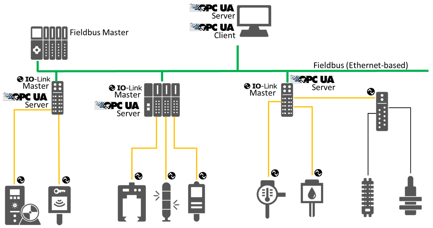
Several variations of that approach are possible. The aggregating server might, in addition to the OPC UA based sources also proprietarily access IO-Link Masters. There might be several aggregating servers in a system, etc.
Annex C (normative): EngineeringUnits
C.1 Overview
OPC UA defines a preferred namespace for EngineeringUnits. The mapping of IO-Link unitCode to OPC UA EngineeringUnits uses the EngineeringUnits of the preferred OPC UA namespace, when they are also defined. Otherwise, it uses its own namespace. The mapping is defined in a CSV document.
The CSV released with this version of the specification can be found here:
http://www.opcfoundation.org/UA/schemas/IOLink/1.0/EngineeringUnits.csv
http://www.opcfoundation.org/UA/schemas/IOLink/EngineeringUnits.csv
Agreement of Use
COPYRIGHT RESTRICTIONS
This document is provided "as is" by the OPC Foundation and the IO-Link Community.
Right of use for this specification is restricted to this specification and does not grant rights of use for referred documents.
Right of use for this specification will be granted without cost.
This document may be distributed through computer systems, printed or copied as long as the content remains unchanged and the document is not modified.
OPC Foundation and IO-Link Community do not guarantee usability for any purpose and shall not be made liable for any case using the content of this document.
The user of the document agrees to indemnify OPC Foundation and IO-Link Community and their officers, directors and agents harmless from all demands, claims, actions, losses, damages (including damages from personal injuries), costs and expenses (including attorneys' fees) which are in any way related to activities associated with its use of content from this specification.
The document shall not be used in conjunction with company advertising, shall not be sold or licensed to any party.
The intellectual property and copyright is solely owned by the OPC Foundation and the IO-Link Community.
PATENTS
The attention of adopters is directed to the possibility that compliance with or adoption of OPC or IO-Link Community specifications may require use of an invention covered by patent rights. OPC Foundation or IO-Link Community shall not be responsible for identifying patents for which a license may be required by any OPC or IO-Link Community specification, or for conducting legal inquiries into the legal validity or scope of those patents that are brought to its attention. OPC or IO-Link Community specifications are prospective and advisory only. Prospective users are responsible for protecting themselves against liability for infringement of patents.
WARRANTY AND LIABILITY DISCLAIMERS
WHILE THIS PUBLICATION IS BELIEVED TO BE ACCURATE, IT IS PROVIDED "AS IS" AND MAY CONTAIN ERRORS OR MISPRINTS. THE OPC FOUDATION NOR IO-Link Community MAKES NO WARRANTY OF ANY KIND, EXPRESSED OR IMPLIED, WITH REGARD TO THIS PUBLICATION, INCLUDING BUT NOT LIMITED TO ANY WARRANTY OF TITLE OR OWNERSHIP, IMPLIED WARRANTY OF MERCHANTABILITY OR WARRANTY OF FITNESS FOR A PARTICULAR PURPOSE OR USE. IN NO EVENT SHALL THE OPC FOUNDATION NOR IO-Link Community BE LIABLE FOR ERRORS CONTAINED HEREIN OR FOR DIRECT, INDIRECT, INCIDENTAL, SPECIAL, CONSEQUENTIAL, RELIANCE OR COVER DAMAGES, INCLUDING LOSS OF PROFITS, REVENUE, DATA OR USE, INCURRED BY ANY USER OR ANY THIRD PARTY IN CONNECTION WITH THE FURNISHING, PERFORMANCE, OR USE OF THIS MATERIAL, EVEN IF ADVISED OF THE POSSIBILITY OF SUCH DAMAGES.
The entire risk as to the quality and performance of software developed using this specification is borne by you.
RESTRICTED RIGHTS LEGEND
This Specification is provided with Restricted Rights. Use, duplication or disclosure by the U.S. government is subject to restrictions as set forth in (a) this Agreement pursuant to DFARs 227.7202-3(a); (b) subparagraph (c)(1)(i) of the Rights in Technical Data and Computer Software clause at DFARs 252.227-7013; or (c) the Commercial Computer Software Restricted Rights clause at FAR 52.227-19 subdivision (c)(1) and (2), as applicable. Contractor / manufacturer are the OPC Foundation, 16101 N. 82nd Street, Suite 3B, Scottsdale, AZ, 85260-1830
COMPLIANCE
The combination of IO-Link Community and OPC Foundation shall at all times be the sole entities that may authorize developers, suppliers and sellers of hardware and software to use certification marks, trademarks or other special designations to indicate compliance with these materials as specified within this document. Products developed using this specification may claim compliance or conformance with this specification if and only if the software satisfactorily meets the certification requirements set by IO-Link Community or the OPC Foundation. Products that do not meet these requirements may claim only that the product was based on this specification and must not claim compliance or conformance with this specification.
Trademarks
Most computer and software brand names have trademarks or registered trademarks. The individual trademarks have not been listed here.
GENERAL PROVISIONS
Should any provision of this Agreement be held to be void, invalid, unenforceable or illegal by a court, the validity and enforceability of the other provisions shall not be affected thereby.
This Agreement shall be governed by and construed under the laws of Germany.
This Agreement embodies the entire understanding between the parties with respect to, and supersedes any prior understanding or agreement (oral or written) relating to, this specification.