
1 Scope
The purpose of this document is to define a data format for the sharing of AutomationComponent information between the participants in the OfflineEngineering workflow.
OfflineEngineering is a design phase activity. The configuration for AutomationComponents is planned (typically without the hardware available), implemented, and later deployed to the physical/logical elements in the commissioning phase at a plant.
This document defines the concept of a Descriptor as a means for capturing the information for using and configuring AutomationComponents in the OfflineEngineering phase, including the Information Model defined in OPC 10000-81.
This document outlines the OfflineEngineering processes and required functionality where the Descriptor is consumed or produced by the engineering tools. How engineering tools implement the processes and functionality for the internal handling of Descriptors is left to the engineering tool vendors.
2 Normative references
The following referenced documents are indispensable for the application of this document. For dated references, only the edition cited applies. For undated references, the latest edition of the referenced document (including any amendments and errata) applies.
OPC 10000-1: OPC Unified Architecture - Part 1: Overview and Concepts
3 Terms, definitions, abbreviated terms, and conventions
3.1 Terms and definitions
3.2 Abbreviated terms
| AC | AutomationComponent |
| AML | AutomationML |
| ATL | AttributeTypeLibrary |
| CA | Certificate Authority |
| CAEX | Computer Aided Engineering eXchange |
| MIME | Multipurpose Internet Mail Extension |
| PLC | Programmable Logic Controller |
| RCL | RoleClassLibrary |
| SUC | SystemUnitClass |
| URI | Uniform Resource Identifier |
4 Overview
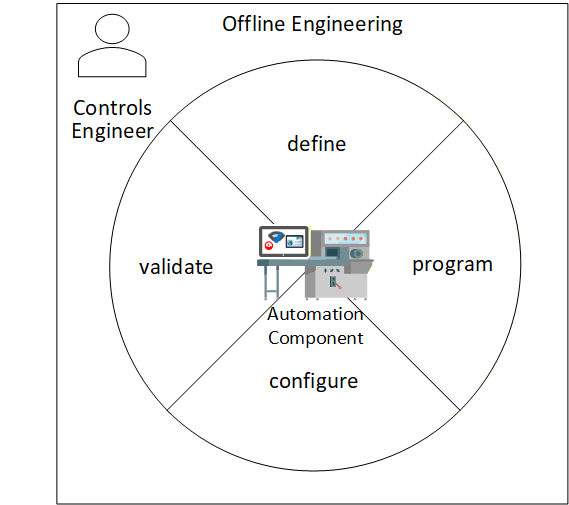
OfflineEngineering is an essential phase in the lifecycle of an AutomationComponent. By allowing the Controls Engineer to define, program, configure and partially validate the operation of an AutomationComponent before deploying the AutomationComponent in physical hardware, the Controls Engineer will be more confident that the AutomationComponent performs the automation functions reliably and correctly once the physical AutomationComponent is in place. This can be seen in Figure 1.
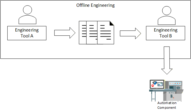
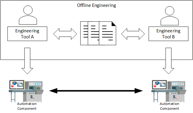
An important task of the OfflineEngineering phase is the definition of the Information Model of an AutomationComponent. In this task, Controls Engineers design, edit, share, store, and provision Information Models of an AutomationComponent. This task can take several steps, where Controls Engineers design the Information Model of an AutomationComponent in iterations and pass it from one engineering tool to another (Figure 2). They also share Information Models of AutomationComponents (Figure 3).
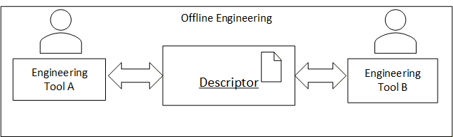
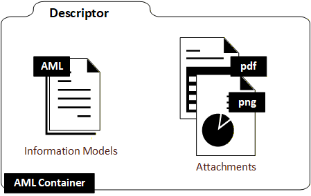
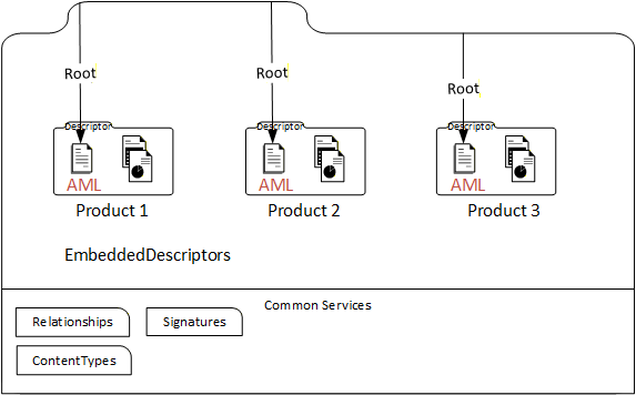
In order to facilitate the exchange and storage of Information Models and data between Controls Engineers, the concept of "Descriptor" is introduced, as shown in Figure 4. The Descriptor takes the shared information and organizes the information in a formal electronic format with defined properties. The Descriptor allows for standardized exchange of data between Controls Engineers and engineering tools.
5 Descriptor fundamentals
5.1 Descriptor fundamentals overview
An OPC UA FX Descriptor defines the information for using and configuring one or more AutomationComponents. This information may contain data provided by the vendor of the AutomationComponent or configuration data produced by Controls Engineers in the OfflineEngineering phase.
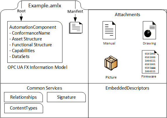
A Descriptor is a digitally signed multi-document file (AML Container) containing Information Model files in the AutomationML language and other artefacts such as manuals, drawings, product pictures, binary files, certificates for authorship and conformance, etc. This is shown in Figure 5. An introduction to AutomationML is provided in Annex H.
5.2 Descriptor organization
A Descriptor is based on the AML Container format and the Open Packaging Conventions standard. It has the file name extension ".amlx".
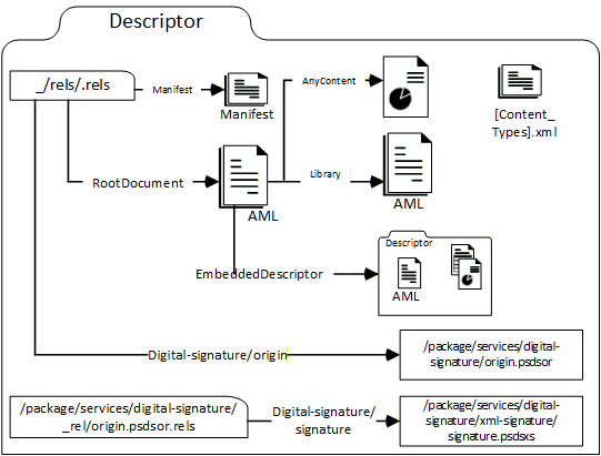
A descriptor comprises up to five kinds of files (see Figure 6). It contains a Descriptor manifest file and Information Model file(s) and can contain attachment files, embedded Descriptors, or Common Services.
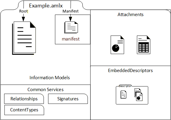
The Descriptor manifest contains metadata information such as an identifier, a version number for the content and a version number for the format.
The Information Model files contain AML representations of UAFX Information Models. A worked-out example of the configuration of the Information Model of an AutomationComponent using the UAFX Information Model can be found in Annex F.
Attachment files contain information useful for understanding and using the AutomationComponent in engineering, operation, or another phase of the AutomationComponent life cycle. This information can be considered supplemental to the information from the Information Model files. There is no specific format required for these files - these could be PDF, XML, image files, certificates, or even software binaries (e.g., for firmware updates).
Embedded Descriptors are useful for including information that is available in other Descriptors. For example, product-specific information could be available as a Descriptor created by the AutomationComponent vendor and embedded in a Descriptor created by an engineering tool.
Common Services files support the organization of the Descriptor content as specified by the Open Packaging Conventions standard. The Common Services can also be vendor-specific. They describe the file types present in the AML Container, the relationships between files, and the digital signatures.
A Descriptor has one or more Root AML Files. Root AML Files are the entry points from where engineering tools can parse and browse the content. The path of a Root AML File can be found by looking up a special Open Packaging Conventions relationship in the package relationship file of the Descriptor. This is explained further in 7.4.
More than one Root AML File can be used, for example, if more than one AutomationComponent is defined in a Descriptor.
5.3 References in a Descriptor
The Descriptor concept supports URI-based references as the mechanism to link files and content together.
References can be used to link to content included in a Descriptor (internal references) or to reference resources outside the Descriptor (external references).
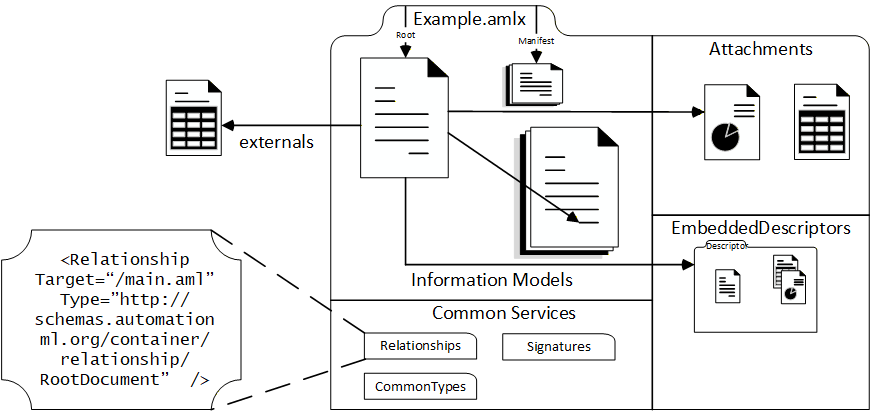
For example, a Descriptor created by a Controls Engineer containing configuration information for an AutomationComponent usually contains a reference to a Descriptor with the product information provided by the AutomationComponent vendor by either including the Descriptor with product information as an embedded Descriptor or by defining an external reference to it with a URI or URL. The example is shown in Figure 7.
With external references, it is possible to reduce the size of the Descriptor. On the other hand, in this case, the Descriptor is not self-contained and external references can be broken. Therefore, it is recommended to only use external references for well-defined and stable URIs.
There are three means to implement references in a Descriptor:
Open Packaging Conventions define "Relationships" (Annex G.3). Relationships are encoded in special management files (with the file name extension ".rels"). Relationships can be used for internal or external file references and for identifying a file. As an example, the Descriptor manifest file or a Root AML File can be identified by specific relationships in the package relationship file of the Descriptor.
AutomationML ExternalReferences are used to link AutomationML content within and between Information Model files (see 7.5.2).
AutomationML ExternalDataReference interfaces can be used to reference attachments. The target of an AutomationML reference can be either a file or an object in an XML-based file (see 7.5.3).
5.4 OPC UA FX AML Information Model files
A Descriptor shall contain at least one AML Information Model file. An OPC UA FX AML Information Model file is an AML file that contains an Information Model based on the OPC UA FX AML libraries.
The OPC UA FX AML libraries define OPC UA type information in the AML. The OPC UA FX AML libraries corresponding to a subset of the OPC 10000 series standards, including UAFX, DI and Safety, are described in this document. Other OPC UA FX AML libraries can be constructed by following the rules in Annex A.
Typically, a Root AML File is an OPC UA FX AML file with an Information Model of the AutomationComponent.
The OPC UA FX AML libraries that are used in an Information Model file can either be included in the Descriptor or externally referenced from the Descriptor. Included libraries can be present in the Information Model file, in a separate referenced file included in the Descriptor, or in an embedded Descriptor. External libraries are referenced by an Open Packaging Conventions relationship.
An external reference for referencing the OPC UA FX AML libraries can be used to optimise the Descriptor file size. Annex B, Annex C, Annex D, and Annex E are where the locations for OPC UA FX AML libraries are defined.
5.5 Digital signature fundamentals
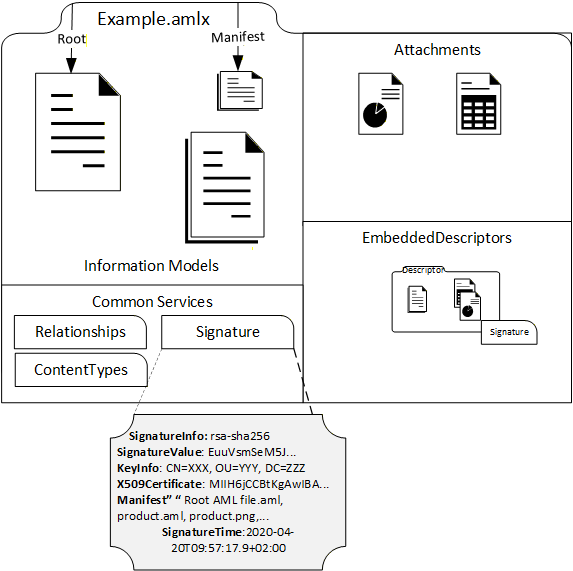
In order to provide integrity and authenticity for the Descriptor's content, a Descriptor contains one or more digital signatures.
Digital signatures do not prevent the data of the Descriptor from being changed. However, engineering tools using the Descriptor can detect whether the content has been altered and notify the user.
A Descriptor contains at least one digital signature for the whole content. The last editor of the Descriptor usually creates this signature. This can be useful if part of the content is provided by another party or the creator of the Descriptor is different from the user that applies a change to it.
Digital signatures are also present in embedded Descriptors.
The digital signature as it resides inside a Descriptor is detailed in Figure 8.
6 Descriptor examples
6.1 Descriptor examples overview
The following subclauses describe some examples of Descriptors being used in OfflineEngineering. These subclauses are not introductions to special definitions of Descriptors. The intention is to demonstrate that a Descriptor, depending on the use case, can contain different information.
6.2 Descriptor with product information
When starting a project in OfflineEngineering, a Controls Engineer needs access to product information for the AutomationComponents that have been selected. Traditionally, this information is available on the vendor's website, on a storage medium provided by the vendor or in the vendor's engineering tool.
Typically, the product information contains an Information Model of the AutomationComponent that can be used to start the configuration and supplemental documentation, like user manuals, drawings, pictures, firmware files or even software tools that are useful for understanding and using the product.
In OPC UA FX, the information of the AutomationComponent product contains the Asset and functional structure, (pre-configured) DataSets, capabilities, and the property name defined in OPC 10000-81.
In the Information Model, there can be variations depending on the type of the AutomationComponent:
for a controller product, the functional structure is typically empty;
for IO and field devices, the functional structure is typically defined.
In the case of a modular device, that asset structure contains some flexibility, e.g., connectors and slots that can be attached to a defined set of modules. A Descriptor with product information is usually created by the AutomationComponent vendor. It contains the vendor's digital signature, which makes it possible to validate the integrity of the content and, if a Public Key Infrastructure is in place, to check the authenticity and trust of the creator of the Descriptor.
For accessing a Descriptor with product information, the vendor could make it available on the vendor's website, include it in the database of the vendor's engineering tool or deliver it on a storage medium together with the physical AutomationComponent.
There is also the possibility of getting the Descriptor for the AutomationComponent product from an online AutomationComponent. The OPC UA FX Information Model defines a folder Descriptors in the AutomationComponentType, which can contain instances of AcDescriptorType. AcDescriptorType is fully defined in OPC 10000-81.
An example of a Descriptor for a product can be seen in Figure 9.
6.3 Descriptor with configuration information
A Descriptor with configuration information contains the Information Model that incorporates the configuration of AutomationComponent. The product information can also be part of a Descriptor with configuration information, for example, in the case where the product information is relevant to understanding and using the configuration information.
The configuration information provided may be different, depending on the type of the AutomationComponent or the use case for sharing.
Configuration information dependent on the type of AutomationComponent:
Controller configurations typically contain the FunctionalEntities together with input and output Variables, DataSets, and the publisher and subscriber capabilities.
For IO and field devices, the configuration typically contains the values for the parameters for the built-in FunctionalEntities, the built-in DataSets, and the publisher and subscriber capabilities. For modular devices, the configuration may also include the definitions for the Asset structure, e.g., installed modules.
For machines and modular process skids that are supplied as a single product, the configuration may be similar to field and IO devices, i.e., fixing some or restricting some configuration parameters for functions and communication.
For machines and modular process skids that are not available as products, the configuration may include the full assembly of the hardware from other AutomationComponents, together with the configuration for each part.
Configuration information dependent on use cases for information sharing:
When engineering the same AutomationComponent by multiple Controls Engineers, a Descriptor with configuration information may contain a full snapshot of the configuration state. For example, the saved work of one Controls Engineer can be used for the continuation of the work of the next Controls Engineer.
When a Connection needs to be defined between two Controllers, the two Controls Engineers may provide information about the communication interfaces to each other using a Descriptor. This information would include the respective FunctionalEntities, DataSets and the publisher and subscriber capabilities, whereas non-relevant information would not be included.
For configuration of the Connections, a special set of configuration information is needed that describes the ConnectionConfigurationSets. This can be provided with a Descriptor. The use case here is that a System Integrator has created ConnectionConfigurationSets information, and the System Integrator wants to provide it to the Controls Engineer, who is configuring the ConnectionManager component that is responsible for the connection establishment.
A Descriptor with configuration information is typically built based on data from Descriptors with product information. In this case, the relevant Descriptors with product information are either included or referenced by the Descriptor with the configuration information.
The configuration information included in a Descriptor may be incomplete. It is possible that a Descriptor only contains a partial configuration for an AutomationComponent. This can be useful when a Controls Engineer wants to share only the relevant information with another Controls Engineer.
Figure 10 shows a Descriptor with configuration information for a Controller stored in the configuration.aml file. The Descriptor with product information is included.
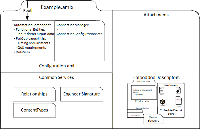
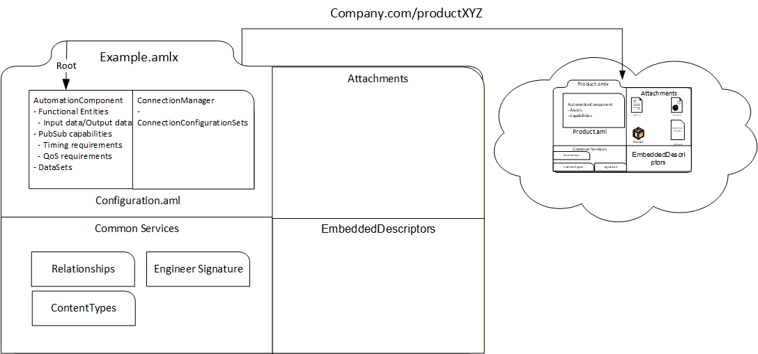
Figure 11 shows a Descriptor with configuration information and product information for a Controller. The Descriptor has an external reference to the Descriptor with product information instead of including it in an EmbeddedDescriptors file.
6.4 Descriptor with product family information
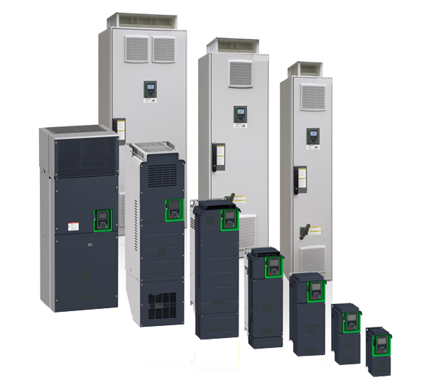
A Descriptor can also be used to share the product information of AutomationComponents building a product family. By a product family, one usually understands a range of similar products that have a set of common features but are distinct in certain aspects, like size and performance. There is no clear rule on how small or big the common feature part is or on how many individual products a product family contains. A product family may also be split into subfamilies.
Drives are an example of a product family, as shown in Figure 12. The drives have the same basic features and a similar look and feel. The product dimensions, power, voltage, and other drive features will vary within the family, but the general structure, operation and application are the same.
There are two examples of designing product family information with Descriptors.
Each member of a product family or subfamily is described by its own Descriptor with product information. All these Descriptors are embedded in a new Descriptor for the product family, and the Root AML Files of the embedded Descriptors become Root AML Files of this new Descriptor. This is shown in Figure 13.
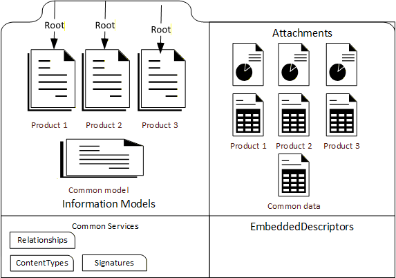
However, this approach leads to duplication of the common part of the family data. Therefore, another example of creating a Descriptor for a product family is to combine the common part data into one OPC UA FX Information Model file and create one file for each product family member with the individual features, e.g., product identification data and distinct capabilities. This can be done either by adding the features to the common part or changing (overriding) a common part (default) feature. This is shown in Figure 14.
6.5 Descriptor for modular AutomationComponents
In this example, the product information for a modular AutomationComponent that has been pre-configured with a known set of allowable modules is considered. In this example, the modular AutomationComponent consists of a head end and a number of modules that can be either attached to the head end or to slots in a chassis.
A Descriptor with product information for this modular AutomationComponent can contain the following elements:
one or more Information Model AML files or one embedded Descriptor for the head end and chassis;
one or more Information Model AML files or one embedded Descriptor for each module that can be attached;
documentation and pictures.
Figure 15 shows the situation where the head end and the modules are described with Information Model files.
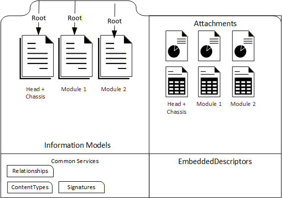
Figure 16 shows the situation where the head end and the modules are described with embedded Descriptors.
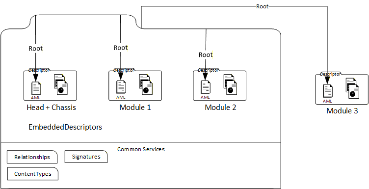
In Figure 16, a module can also exist outside of the modular device Descriptor. In this case, there is a reference from the modular device Descriptor to the external module Descriptor.
7 Descriptor structure
7.1 Overview
This clause gives the formal definitions for the Descriptor concept.
7.2 File format
A Descriptor shall be an AutomationML Container file with the file name extension ".amlx".
7.3 Descriptor and folder content
7.3.1 Overview
The Descriptor content is organized into files and folders.
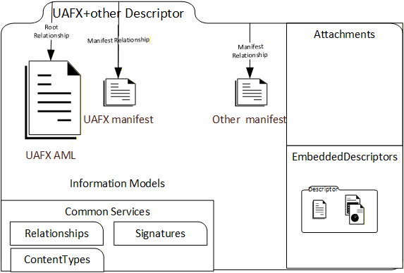
A Descriptor contains several kinds of files: The Descriptor manifest, Information Model files, attachment files, embedded Descriptors, and Common Services files. This is illustrated in Figure 17.
There is no prescribed folder structure for the Descriptor. The files of a specific kind are identified by Open Packaging Conventions relationships (see 7.5.2).
7.3.2 Descriptor manifest
The UAFX Descriptor manifest is an XML file that defines the metadata for a Descriptor.
The UAFX Descriptor manifest is structured according to the schema defined in Annex J. The UAFX Descriptor manifest file shall be identified by an Open Packaging Conventions relationship of type "" stored in the container relationship file "_rels/.rels". There shall be exactly one UAFX Descriptor manifest in a Descriptor.
The Descriptor manifest shall have exactly one "DescriptorInfo" XML element, which defines the XML sub-elements "DescriptorIdentifier", "DescriptorVersion", and "OpcUaFxVersion", as defined in Table 1.
| Tag | Type | Description |
| DescriptorIdentifier | xs:anyURI | URI of the Descriptor. Defines a globally unique identifier for the Descriptor. |
| DescriptorVersion | 4 integers of type xs:short | Descriptor version. Defines the version numbers of the Descriptor. |
| OpcUaFxVersion | xs:string | Version of the OPC UA FX standard taken from the NodeSet file the Descriptor adheres to. |
If a Descriptor is stored in an AcDescriptorType instance in the online Information Model and a value for the DescriptorIdentifier or the DescriptorVersion Variable of the instance is provided, this value will match the respective content of the DescriptorIdentifier or DescriptorVersion element in the DescriptorInfo XML element of the Descriptor manifest. (See OPC 10000-81, FxAssetType definition)
Example 1 shows the relationship element for a new UAFX Descriptor manifest in the container relationship file "_rels/.rels".
<Relationship Target= "{path to manifest file}" Type="" Id="{id-attribute of manifest file}"/>Example 2 shows a "DescriptorInfo" XML element.
<DescriptorInfo>
     <DescriptorIdentifier>urn:company:factory:plant_project:automation_
     component:1.0.0</DescriptorIdentifier>
     <DescriptorVersion>
          <Major>1</Major>
          <Minor>0</Minor>
          <Build>0</Build>
          <SubBuild>0</SubBuild>
     </DescriptorVersion>
     <OpcUaFxVersion>1.0.0</OpcUaFxVersion>
</DescriptorInfo>
Example 3 shows the case where more than one manifest file is contained in a Descriptor. Other standardization organisations may define their own manifest file format and manifest relationship, as shown in Figure 18.
7.3.3 Information Model files
UAFX Information Model files are AutomationML files based on the OPC UA FX AML libraries defined in this document. UAFX Information Model files may also include or reference AutomationML content that is based on AML libraries other than the OPC UA FX AML libraries.
There shall be at least one Information Model file present in a Descriptor. The organization of the Information Model files is explained in 5.4 and 7.5.2. The content of the Descriptor shall correspond to the online UAFX Information Model Profiles as described in the UAFX Offline Descriptor Profile (see OPC 10000-84 and http://opcfoundation.org/UA-Profile/UAFX-Offline-Descriptor-Profile).
Information Model and AutomationML files providing Information Model content are identified by an Open Packaging Conventions relationship of type "http://schemas.automationml.org/container/relationship/Library".In the use case that other Information Model files from other standardization bodies are contained in the Descriptor, UAFX Information Model files shall be identified by an Open Packaging Conventions relationship of type "http://schemas.opcfoundation.org/container/relationship/UafxInformationModel".
Figure 19 shows an example of Information Model files from different standardization bodies in a Descriptor.
7.3.4 Attachment files
A Descriptor may include one or more Attachment files. Attachment files are any files that are neither manifest files, Information Model files, Embedded Descriptors, or common service files. Attachment files are useful for providing additional information for the understanding and usage of the AutomationComponent.
No specific format is required for attachment files.
The file name extension and the content type of an attachment file shall be listed in the [Content_Types].xml file of a Descriptor. (See 7.6)
Attachment files are identified by an Open Packaging Conventions relationship of type "http://schemas.automationml.org/container/relationship/AnyContent".7.3.5 Embedded Descriptors
A Descriptor may include one or more Embedded Descriptors.
Embedded Descriptors shall be compliant with all Descriptor requirements defined in the UAFX Offline Descriptor Profile (see OPC 10000-84).
Embedded Descriptor files shall be identified by an Open Packaging Conventions relationship of type "".7.3.6 Common Services files
The following Common Services files shall be present in a Descriptor:
"[Content_Types].xml" file is located in the top-level folder "/";
relationship file ".rels" is located in the folder "/_rels";
the "origin.psdor" file is located in the folder "/package/service/digital-signature";
the relationship file "origin.psdor.rels", which lists the digital signatures, is located in the folder "/package/service/digital-signature/_rels";
at least one digital signature file with the file name extension .psdsxs is located in the folder "/package/service/digital-signature/xml-signature".
7.4 Root AML Files
The entry points into the content of a Descriptor are the Root AML Files, as they are defined by the AML Container format (see IEC 62714-1).
A Root AML file shall be an OPC UA FX Information Model file.
A Descriptor shall have at least one Root AML file.
Root AML Files are identified by an Open Packaging Conventions relationship of type "http://schemas.automationml.org/container/relationship/RootDocument" stored in the container relationship file "_rels/.rels".
Example:    <Relationship Target="{path-to-Root AML file}"Type="http://schemas.automationml.org/container/relationship/RootDocument" Id="{Id of root aml file}"/>
7.5 Descriptor References
7.5.1 Overview
Descriptor references have targets that are either in the Descriptor (internal references) or outside of the Descriptor (external references). The target of a Descriptor reference can be a file or content element in an XML file.
Three mechanisms are used for file and content references in a Descriptor:
Open Packaging Conventions relationships which can be used for internal and external references,
AutomationML ExternalDataReference interfaces,
AutomationML External References.
7.5.2 Open Packaging Conventions Relationships
Relationship references define references between files and are located in special Common Services files with the file name extension ".rels". The reference source is defined by the file name where the relationship definition is located. The URI syntax is used for the reference targets. The reference targets can be internal or external to the Descriptor. This is denoted by the "TargetMode" attribute. Every relationship reference shall have a valid XML identifier of type xs:ID (see ISO/IEC 29500-2:2021 clause 6.5.3.4).
All Information Model attachments and embedded Descriptors in a Descriptor shall be the target of a relationship reference, and all these files shall be reachable from the Root AML files via relationship references. The relationship references in a Descriptor shall form a Directed Acyclic Graph with the Root AML files as the starting points and with all Information Model, attachments, and embedded Descriptors in a Descriptor referenced from the Root AML files either directly or indirectly (i.e., over a chain of references). There shall be no circular dependencies between the files in a Descriptor. For more details, see IEC 62714-1.
For relationship references to a Descriptor, the Pack URI syntax shall be used to reference individual files in the container.
Some examples for relationship references:
Example of an internal relationship reference from a file "configuration.AML" to a file "library.AML" (The relationship is contained in the file "configuration.AML.rels"):
<Relationship Type="http://schemas.automationml.org/container/relationship/Library" Target="" TargetMode="Internal" Id="R725e8e211760485b"/>The same example for an external relationship reference:
<Relationship Type="http://schemas.automationml.org/container/relationship/Library" Target="" TargetMode="External" Id="725e8e211760486b"/>Example of an internal relationship reference from a file "configuration.AML" to an attachment file "manual.pdf" (The relationship is contained in the file "configuration.AML.rels"):
<Relationship Type="http://schemas.automationml.org/container/relationship/AnyContent" Target="file:///attachments/manual.pdf" TargetMode="Internal" Id="725e8e211760486c"/>Example of an external relationship reference from a file "configuration.AML" to a Descriptor "SensorProduct.amlx" (The relationship is contained in the file "configuration.AML.rels").
<Relationship Type="http://schemas.automationml.org/container/relationship/AnyContent" Target="http://vendor.org/SensorProduct.amlx" TargetMode="External" Id="R725e8e211760487b"/>Example of an external relationship reference from a file "configuration.AML" to a file contained in the Descriptor "SensorProduct.amlx" (The relationship is contained in the file "configuration.AML.rels").
<Relationship Type="http://schemas.automationml.org/container/relationship/AnyContent" Target="pack://http%3c, ,vendor.org,SensorProduct.amlx/attachments/sensor.jpg"TargetMode="External" Id="R725e8e211760488b"/>7.5.3 AutomationML ExternalDataReferences interfaces
AutomationML ExternalDataReferences interfaces allow one to define references from XML content inside of an AML file to non-AML files.
ExternalDataReferences interfaces shall be used if the reference target is not an AML file. The target can be inside or outside of the Descriptor.
The URI syntax, including the Pack URI syntax for reference targets contained in Descriptors, shall be used to define the reference target.
For a concrete reference, an interface shall be used that is either an ExternalDataReference or derived from ExternalDataReference.
An example of an ExternalDataReference to a document contained in a Descriptor is shown in Figure 20, with the code following the figure.
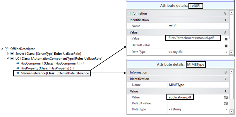
<ExternalInterface
 Name="ManualReference"
 ID="4db4782f-98f2-42a0-a10b-11b3ac7d014d"
 RefBaseClassPath="AutomationMLInterfaceClassLib/AutomationMLBaseInterface/
  ExternalDataConnector/ExternalDataReference" xmlns="">
 <Attribute
    Name="refURI"
    AttributeDataType="xs:anyURI"
    RefAttributeType="AutomationMLBaseAttributeTypeLib/refURI">
    <Value>>
 </Attribute>
 <Attribute
    Name="MIMEType"
    AttributeDataType="xs:string"
    RefAttributeType="AutomationMLBaseAttributeTypeLib/MIMEType">
    <Value>application/pdf</Value>
 </Attribute>
</ExternalInterface>
7.5.4 AutomationML ExternalReference
For references between AutomationML Information Model files, the ExternalReference mechanism of AutomationML shall be used.
ExternalReference is defined in the CAEX specification (IEC 62424:2016, A.2.12, CAEX).
ExternalReferences are contained in the AutomationML file from where the reference starts.
The target of an ExternalReference is an AML object contained in an AML file. The target can be inside or outside of the Descriptor.
For defining the reference target, each ExternalReference shall provide a valid URI to the AML file and an alias, which shall be unique within the file where the reference starts. The URI can also be a Pack URI syntax for reference targets that are contained in Descriptors.
The alias may be used to reference classes or instances. In this case, the reference tag shall begin with the alias name, followed by the alias separator "@", followed by the path to the referenced class or the ID of the referenced InternalElement or ExternalInterface.
Example of an ExternalReference definition in an AutomationML file to an external AML library file:
	<ExternalReference Path="" Alias="Library" />
	The alias is used as an abbreviation when a reference is defined, as shown in the next example:
	<InternalElement Name="test" ID="a1762231-6647-49a3-bbee-5a7df47d738a" RefBaseSystemUnitPath="Library @[SUC_http://opcfoundation.org/UA/FX/AC]/[AutomationComponentType]">
Example of an ExternalReference definition in an AutomationML file to an SUC in an OPC UA FX AML library file that is contained in a Descriptor that is stored externally:
<ExternalReference Path="pack://http%3c, ,test.org,OpcUaFxAmlLibraries.amlx/MyOpcUaFxAmlLibrary.AML"Alias="MyOpcUaFxAmlLibrary" />The alias is used as an abbreviation when a reference is defined, as shown in the next example:
<InternalElement Name="test" ID="a1762231-6647-49a3-bbee-5a7df47d738a" RefBaseSystemUnitPath="MyOpcUaFxAmlLibrary@[SUC_http://MyNamespace.org/UA/FX/AC]/[MyAutomationComponentType] ">…7.6 Content Types
The Open Packaging Conventions standard requires that the file name extensions of the files contained in a Descriptor are registered in the "[Content_Types].xml" file. Only file name extensions used in a Descriptor shall be present in the "[Content_Types].xml" file of the Descriptor.
A list of IANA registered content types is given at: https://www.iana.org/assignments/media-types/media-types.xhtml.
Table 2 gives some examples of file name extension content types.
| File name extension | Content type |
| aml | application/automationml-aml+xml |
| amlx | application/automationml-amlx+zip |
| xml | text/xml |
| application/pdf | |
| png | image/png |
The use of vendor-specific file name extensions is allowed. The vendor-specific file name extensions and content types may or may not be registered with IANA.
7.7 OpcAmlMetaModel and OPC UA FX AML Libraries
The creation of OPC UA FX Information Models is supported by the OpcAmlMetaModel libraries and by AML libraries that are derived from OPC UA types. The OpcAmlMetaModel libraries are defined in A.2. The AML libraries derived from OPC UA types are called OPC UA FX AML Libraries. The structure of an OPC UA FX AML Library is defined in Annex B. Each OPC UA FX AML Library contains AML Libraries for RoleClasses, InterfaceClasses, AttributeTypes and SystemUnitClasses.
This document provides an initial set of AML Libraries, the OPC UA FX AML Libraries, consisting of AML types that are generated from the types defined in the OPC 10000 series - see Annex B, Annex C, Annex D, and Annex E.
OPC UA FX Information Model AML files shall be based on the OPC UA FX AML Libraries defined in this document.
In the case where there is a need to supplement the available OPC UA FX AML Libraries with content not contained within them, then it is possible to generate new AML types (RoleClasses, InterfaceClasses, AttributeTypes and SystemUnitClasses) derived from the types from existing OPC UA FX AML Libraries and create a new OPC UA FX AML Library.
An OPC UA FX AML Library shall contain the AML type libraries (SystemUnitClass, InterfaceClassLibrary, RoleClassLibrary, AttributeTypeLibrary) of exactly one OPC UA Namespace.
For OPC UA FX AML Libraries, the following rules apply:
The new types of an OPC UA FX AML Library should be defined according to Annex B of this document. The new types shall derive directly or indirectly (i.e., over a derivation chain) from the types of the OPC UA FX AML Core Libraries.
	The name of an OPC UA FX AML Library shall be according to the scheme XXX_<<ModelUri>>, where XXX stands for ICL for an InterfaceClass library, RCL for a RoleClass library, ATL for an AttributeType library and SUC for a SystemUnitClass library and <ModelUri> is the OPC UA Namespace of the corresponding OPC UA NodeSet file.
	In an OPC UA FX AML Library, the Namespace URI, the version, and the publication date are deduced from the "<Model>" XML element of the corresponding NodeSet file. This shall be documented with an OpcUaLibInfo XML element in the "Additional Information" sections of the AML library header. The schema for the OpcUaLibInfo XML element is defined in Annex K. An example is shown next:
	<AdditionalInformation>
	     <OpcUaLibInfo
	         Xmlns="">
		<OpcUaNamespaceUri>
		URI>
		      <ModelVersion>1.0.0</ModelVersion>      <ModelPublicationDate>2021-06-
		      16T04:53:39Z</ModelPublicationDate>
          </OpcUaLibInfo>
     </AdditionalInformation>
An OPC UA FX AML Library shall be distributed as a digitally signed AML Container.
If types from an OPC UA FX AML Library are used in a Descriptor, the library shall be made available in the Descriptor, either by including it as a file or by providing an AutomationML external reference. In the case of a vendor-specific OPC UA FX AML Library, a direct inclusion as either an internal or external reference shall be required. For referencing an OPC UA FX AML Library with a relationship reference, a "Library" relationship type shall be used. Usage dependencies from an OPC UA FX AML Library to other OPC UA FX AML Libraries shall be documented with an ExternalReference. See 7.5.4.
7.8 Descriptor digital signature
7.8.1 General
Digital signatures for Descriptors are based on the XML Signature specification and shall follow the structure and requirements defined in ISO/IEC 29500-2:2021, Clause 13.
A Descriptor shall have at least one digital signature.
The signing scope of each Descriptor signature shall include the following:
the Manifest,
all Information Model files,
all attachment files,
.rels files,
all Embedded Descriptors,
and all Common Services files.
The links to the external references, if any, in a Descriptor shall be included in the signature of the Descriptor. Content of external references shall not be included in this signature and should be digitally signed separately from the Descriptor signature.
There are two exceptions for including Common Services files into the scope of a digital signature:
[Content_Types].xml describing the used file name extensions is not included;
The relationship file of the digital signature origin file (e.g., "/package/services/digital-signature/_rels/origin.psdsor.rels" ) listing the contained digital signatures is not included. This allows adding a signature to the Descriptor without invalidating the existing ones.
Each Descriptor signature shall contain an X.509 certificate, which can be used for signature authentication.
The certificate can be associated with the identity of an individual, an engineering tool, a host, or an organization.
The certificate shall either be signed by a certificate authority or be self-signed.
If the certificate is not self-signed, the intermediate certificate chain shall be included in the X.509 Data element. The root certificate should be included (see 7.8.2), and the signing certificate shall be included.
Descriptors shall only use cryptographic mechanisms from OfflineEngineering security Profiles defined in OPC 10000-84.
Descriptor signatures shall be validated as specified in ISO/IEC 29500-2:2021.
According to ISO/IEC 29500-2:2021, each digital signature shall contain, in the SignatureProperty element, a timestamp indicating the time when the digital signature was created.
NOTE The timestamp can be set to arbitrary values (within the validity period of the signing certificate) by the signer. The validity period check-in procedure (see Table 3) assumes that the signer is trusted to not backdate the timestamp.
An engineering tool importing a Descriptor should support X.509 certificate technology for signer authentication. See Clause 8 for details on X.509 certificate technology usage.
Each digital signature is stored in a file with file name extension psdsxs in the folder "/package/services/digital-signature/xml-signature" in the Descriptor.
The folder "/package/services/digital-signature/_rels" contains the relationship file origin.psdsor.rels, which holds the relationship references to the signature files.
The following shows an example of a relationship reference to a digital signature file.
<Relationship Type="http://schemas.openxmlformats.org/package/2006/relationships/digital-signature/signature" Target="/package/services/digital-signature/xml-signature/a4c483fa3305415e9e691039665d9c67.psdsxs" Id="R292d9a91d8f94796" />The digital signature file contains XML Signature markup with a subset of elements and attributes of the XML Digital Signature specification, e.g., the elements SignedInfo, SignatureValue, KeyInfo, X509Data and Manifest. The Manifest element lists the files of the signature scope.
An example of a digital signature is given in Annex I.
7.8.2 Certificate validation
Engineering tools should never import a Descriptor that they do not trust. An engineering tool decides if a Descriptor is trusted by checking whether each certificate associated with the digital signature of the Descriptor is trusted. A certificate is only trusted if its chain can be validated. Trust can be established by following the validation steps of Table 3 or by manually establishing trust in case the validation steps fail by deliberately suppressing an error. More information on certificates and certificate enrolment can be found in Annex L.
Engineering tools should rely on lists of certificates provided by the administrator to determine trust. There are two separate lists: a list of trusted certificates and a list of issuer certificates. The list of trusted certificates may contain a certificate issued to another entity, or it may be a certificate belonging to a CA. The list of issuer certificates contains CA certificates needed for chain validation that are not in the list of trusted certificates.
When building a chain, each certificate in the chain shall be validated back to a CA with a self-signed certificate (i.e., a root CA). If any validation error occurs, then the trust check fails. Some validation errors are non-critical, which means they may be suppressed by a user of an engineering tool with appropriate privileges. Suppressed validation errors should be reported via log messages.
Determining trust requires access to all certificates in the chain. The certificate used to sign the Descriptor and all intermediate certificates shall be provided with the Descriptor. Validation fails if a certificate in the chain cannot be found. A certificate is trusted if the certificate or at least one of the certificates in the chain is in the list of trusted certificates for the engineering tool and the chain is valid.
Table 3 specifies the steps used to validate a certificate in the order that they shall be followed. These steps are repeated for each certificate in the chain. Each validation step has a unique error log message that shall be reported if the check fails. Validation check failures shall be displayed to the user unless suppressed. It shall be possible for the user to suppress validation check failures individually or permanently.
Details on the validation steps in Table 3 are in IETF RFC 5280, 6.
| Step | Description |
| Certificate Structure | The certificate structure is verified. |
| Build Certificate Chain | The trust chain for the certificate is created. |
| Signature | A certificate with an invalid signature shall always be rejected. A certificate signature is invalid if the issuer certificate is unknown. A self-signed certificate is its own issuer. |
| Security Policy Check | A certificate signature shall comply with the CertificateSignatureAlgorithm, MinAsymmetricKeyLength and MaxAsymmetricKeyLength requirements for the used SecurityPolicy defined in OPC 10000-84. |
| Trust List Check | If the certificate signing the Descriptor is not trusted, and none of the CA certificates in the chain are trusted, the certificate validation shall fail. |
| Validity Period | The current time shall be after the start of the validity period. The time at which the signature was created shall be after the start of the validity period and before the end. |
| Certificate Usage | Each certificate has a set of uses for the certificate. For the certificate signing the Descriptor, the keyUsage shall include digitalSignature. The certificate shall not have a Basic Constraints extension with the CA flag set to TRUE. For CA certificates, the uses shall match use as a CA certificate (see OPC-10000-6). If the validation fails, it shall be reported if the usage is mandatory. |
| Find Revocation List | Each CA certificate may have a revocation list. This check fails if this list is not available (e.g., a network interruption prevents the engineering tool from accessing the list). No error is reported if the Security Administrator disables revocation checks for a CA certificate. |
| Revocation Check | Whether a certificate is revoked shall be checked as specified in IETF RFC 5280, 6.3. |
8 Engineering tools
8.1 Engineering tools overview
In order to create, read, write, edit and manage Descriptors, some tooling is required in OfflineEngineering. This clause provides a brief overview of the tooling functions that can be used for this purpose.
8.2 Requirements for engineering tools
Since the Information Model for an AutomationComponent in a Descriptor is modelled as an AML InternalElement within an AML InstanceHierarchy or an AML SystemUnitClass, the tools that work directly with the Information Model shall support the use of AML constructs and the OPC UA FX AML Libraries.
Engineering tools should support the import or export of a Descriptor.
Any tool that exports a Descriptor shall require that the Descriptor be digitally signed at the end of the export cycle. The use of X.509 certificate technology is required to ensure the ability to authenticate the signature for further use by other tools. The tool shall allow the user to select an X.509 certificate to create the digital signature, which can be either self-signed or CA-signed and taken from a file or a certificate store. The tool is required to check the validity of the certificate or certificates.
A tool that allows importing a Descriptor shall validate all digital signatures included in the Descriptor and ask the tool user to trust the certificates used for signing if the signing certificate is not already trusted by the tool. The user is not required to accept this trust and can block the import action.
When a signature cannot be fully validated or if no signature is present, and the tool is operating without a user interface, the import shall fail, and the tool should generate a log message.
When a signature cannot be fully validated or if no signature is present, and the tool operates with a user interface, meaningful warnings and error messages shall be displayed, and the tool should generate a log message. The import shall fail unless the user overrides the validation failure.
8.3 Engineering tool architecture
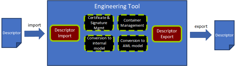
Figure 21 presents the architecture of a hypothetical engineering tool for OPC UA FX OfflineEngineering, which has two main functions: "Descriptor Export" and "Descriptor Import" and four supporting functions for working with a Descriptor. Other functionality of an engineering tool, e.g., managing signal lists, writing control applications, modifying/extending Descriptor content, or designing safety applications, is left out of the figure for simplification.
8.3.1 Descriptor Export
The Descriptor Export function "exports" a Descriptor from an engineering tool.
Use cases for the export of a Descriptor are:
The types of vendor-specific AutomationComponent products are made available in a Descriptor as OPC UA FX AML types for usage in OfflineEngineering projects.
An OPC UA FX Information Model of an AutomationComponent configuration is provided in a Descriptor for further sharing with other engineering tools.
The Descriptor Export function uses the support functions stated in 8.3.3, 8.3.4, and 8.3.6.
Important tasks for Descriptor Export are:
Convert the internal model of the AutomationComponent to an OPC UA FX AML Information Model (8.3.6);
Collect and select the files (AML files, attachment files, embedded Descriptors) and place their files into a file structure. Part of this step is also to decide which files are included in the Descriptor or accessible by external references. (8.3.3);
Select the Root AML files and create the Descriptor manifest (8.3.3);
Create the Common Services files with the relationship references and content types as required by the Open Packaging Conventions (8.2.3);
Create the AML Container with an archiving function in the ZIP format. (8.3.3);
Sign the Descriptor with a valid certificate and add the digital signature to the Descriptor (8.3.4).
8.3.2 Descriptor Import
The Descriptor Import function "imports" a Descriptor to an engineering tool.
The Descriptor Import function uses the support functions stated in 8.3.3, 8.3.5, and 8.3.6
Important tasks for Descriptor Import are:
Open and decompress the Descriptor to a temporary folder or in memory. (8.3.3);
Validate the digital signatures and certificates. (8.3.4);
Parse the Descriptor Manifest and check for the OpcUaFxVersion element (8.3.3);
Build up the file navigation structure by identifying the Root AML files and the relationship references (8.3.3);
Parse the data of the Information Model files and convert the OPC UA FX Information Model to an internal representation of the engineering tool (8.3.5).
The two main use cases for import are the import of an OPC UA FX Information Model of an AutomationComponent product and the import of an AutomationComponent configuration.
Before starting the engineering work, a Controls Engineer must select and procure the product data information for an AutomationComponent. Typically, the selection and procurement of the production data information will be made in one of three different options, as described below.
One option for procurement is to download a Descriptor with product information from the vendor's website.
Another option exists if the Descriptor for a product can be exposed as a file or as a reference to it in the online Information Model of the AutomationComponent. A Controls Engineer who wants to see this information can retrieve this data from the online AutomationComponent by browsing the Descriptors folder and reading the AcDescriptorType instances.
A third option would be the engineering tool that already has the product information for the AutomationComponent available in its database.
Another use case for importing a Descriptor with configuration information arises in the sharing of work between Control Engineers. Engineer A exports a Descriptor with configuration information for Controller A and sends it to Engineer B. Engineer B needs to know what data Controller A is providing or is required for the Connections. After receiving the Descriptor, Engineer B imports it into an engineering tool and uses the Information Model of Controller A to complete the Information Model for Controller B, e.g., defining the complementary FunctionalEntity, InputData and OutputData information for Controller B. The exchange of a Descriptor between Controls Engineers is further described in detail in 8.4.
8.3.3 AML Container management
AML Container management is a support function for handling AML Container and Open Packaging Conventions packages.
An overview of the tasks for container management is given here:
Identification of the Descriptor manifest, AML files, attachment files, embedded Descriptor and Common Services files;
Finding and defining the Root AML files;
Browsing the references of a Descriptor starting from the Root AML files and building a structure for navigating through the content;
Resolving external relationship references;
Creating and managing the file system of a Descriptor;
Adding and removing AML modelling files;
Adding and removing attachment files;
Adding and removing embedded Descriptor;
Updating the [Content_Types].xml file;
Compression method(s) to produce the final output;
Managing relationships, ExternalReferences, and ExternalDataReferences between the files and the content.
8.3.4 Certificate and signature management
Certificate and signature management is a support function for dealing with certificates and signature methods needed for signing a Descriptor and validating digital signatures.
An overview of the tasks for certificate and signature management follows:
Access certificates either on a file system or on a certificate store;
Secure handling of authentication factor(s), e.g., the password that may be needed for accessing a private key associated with a certificate;
Creating digital signatures according to the Open Packaging Conventions standard;
Validating a Descriptor digital signature by checking the validity of all involved certificates as defined in 7.8.2 and checking the signature hash against the hash of the content;
Ability to create a self-signed certificate that can be used if no CA-signed certificate is available;
Warning the user of signature errors (non-valid certificates, non-matching signatures);
Reporting of the scope of each digital signature of a Descriptor (which files are signed with a signature).
8.3.5 Conversion to an internal model
Conversion to an internal model is a support function for parsing the data of the Information Model AML files into the internal representation of the AutomationComponent used by the engineering tool.
An overview of the tasks for conversion to an internal model is below:
AML parser for reading the content of an AML file;
Ability to fetch additional AML libraries from links in the AML file if these libraries are not already present in the engineering tool;
Creating the objects and relationships in the internal model of the engineering tool from the parsed information.
8.3.6 Conversion to an OPC UA FX AML Information Model
Conversion to OPC UA FX AML Information Model is a support function that converts the internal model of an engineering tool to an OPC UA FX AML model, which can be serialized to a Descriptor.
The main steps for conversion are:
Ability to produce OPC UA FX AML content from the configuration done in the internal model of an engineering tool;
Serialize the model into AML files.
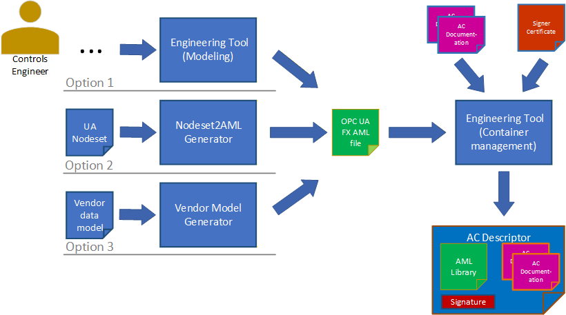
There are three options for producing the OPC UA FX AML content. This is shown in Figure 22.
The Controls Engineer creates the AML model directly using an engineering tool that allows the creation and editing of AML structures using the OPC UA FX AML Libraries. In this case, no conversion to AML is needed, but the serialization step is still needed.
The Control Engineer starts with the OPC UA FX Information Model in NodeSet format and uses a conversion tool to create an OPC UA FX AML file.
An existing Information Model in a vendor-specific format is converted into an OPC UA FX AML file using a vendor-specific conversion tool. For developing vendor-specific conversion tools, a software library for the creation of AML files (AMLEngine) is available from the AML Association.
8.4 Example workflow for sharing a Descriptor in OfflineEngineering
The import of a Descriptor with configuration information arises in the sharing of work between Controls Engineers: one Controls Engineer exports a Descriptor and sends it to another Controls Engineer for further usage.
The import could be for adding or changing the configuration of a Descriptor in a subsequent engineering step for the same AutomationComponent or using the information of the exported Descriptor for the configuration of another AutomationComponent, e.g., for configuring InputData from the OutputData information in a Controller-to-Controller communication scenario.
In both cases, the exported Descriptor with configuration information will be imported into an engineering tool. For the import, the same rules as in 8.3.2 apply.
In the case of subsequent engineering on the same AutomationComponent, data that was configured in a previous step may need to be changed.
The OPC UA FX Connection Configuration workflow for a Controller-to-Controller application is illustrated in Figure 23.
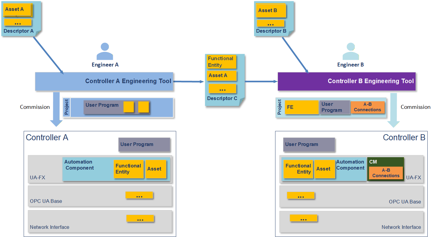
Figure 21 shows an engineering workflow where the task is to create a shared application where data is exchanged between Controller A and Controller B. It is assumed that the Controllers may be from different vendors or the same vendor.
In Figure 23, Descriptors are shared between the engineering tools in an export/import manner. The engineering tools consume the Descriptors. Descriptor C contains configuration information that shares the information it can provide to an AutomationComponent to allow meaningful communication. The yellow and orange boxes represent the information taken from the Descriptors by the engineering tools and downloaded together with the user programs into the Controllers.
The yellow FunctionalEntity and Asset boxes represent the Information Model of the AutomationComponent(s) in the Controllers. The FunctionalEntities contain input groups, output groups, data types, names, capabilities and other information (see OPC 10000-81 for full details). This information could contain the ranges and communication options available in the FunctionalEntities. The data types used in the communication must match between the Controllers.
The yellow boxes with the three dots contain additional information to be shared, e.g., information on network interfaces.
Engineer A creates a Descriptor with configuration information from Controller A's configuration data. This is done to share data with Engineer B to design the exchange of data between the AutomationComponents (e.g., Controller-to-Controller communication). Engineering tools are expected to support the engineer in this task. Engineer B can also share Descriptor information with Engineer A. This can be an iterative step that Controls Engineers can repeat several times as more information is added or changed during the creation process.
8.5 Version compatibility between engineering tools and Descriptors
In handling Descriptors with different OPC UA FxVersions, the following rules apply:
Engineering tools shall document the supported OPC UA FxVersion.
Engineering tools that are able to export or import Descriptors of a specific OPC UA FxVersion shall also be able to export or import Descriptors of a previous OPC UA FxVersion (backward compatibility).
Engineering tools that are able to import Descriptors of a specific OPC UA FxVersion shall be able to import Descriptors of a newer OPC UA FxVersion in a best-effort way, i.e. features that are available in the older OPC UA FxVersion can be imported, while newer features shall be ignored. Ignored features should be logged.
Annex A OPC UA Metamodel Mapping to AML for configuration (Normative)
A.1 Overview
OPC UA Servers and the underlying systems that they expose can be conveniently configured using AutomationML (AML) through the use of standardised AML libraries built to mirror the OPC UA modelling concepts defined in OPC 10000-3 and OPC 10000-5. Table A.1 shows the OPC UA modelling concept and the AML modelling concept used to realize the OPC UA counterpart in the AML libraries.
| UA Modelling Concept | AML Modelling Concept |
|---|---|
| DataType | AttributeType |
| ObjectType | SystemUnitClass |
| VariableType | SystemUnitClass |
| Method | SystemUnitClass |
| InterfaceType | RoleClass plus SystemUnitClass |
| ReferenceType | InterfaceClass(es) |
These mappings are general rules and are not always explicitly followed due to mismatches in the capabilities of OPC UA vs. AML. For instance, ReferenceTypes in OPC UA can be used to connect any two nodes in the UA AddressSpace, but AML InterfaceClasses can only be used within nodes of the InstanceHierarchy or between nodes in a single SystemUnitClass. These mismatches lead to occasional exceptions to these rules and shall be explicitly denoted whenever they occur.
OPC UA Objects, Variables and Methods used in instance declarations are mapped to AML InternalElements in the respective SystemUnitClass.
A.2 OpcAmlMetaModel libraries
A.2.1 OpcAmlMetaModel libraries Overview
To provide a clean mapping between AML and OPC model concepts, it is convenient to introduce OpcAmlMetaModel AML libraries to imply semantics that do not correspond to a Node in some UA Namespace and hence do not belong in the other generated AML libraries that are each based on a single UA Namespace.
A.2.2 RCL_OpcAmlMetaModel library
The AML best practice is for all SystemUnitClasses to implement at least one Role. The RCL_OpcAmlMetaModel library contains one RoleClass UaBaseRole that all OPC UA-derived SUCs shall implement. The UaBaseRole derives from the standard AutomationMLBaseRoleClassLib/AutomationMLBaseRole.
A.2.3 ATL_OpcAmlMetaModel library
The ATL_OpcAmlMetaModel library contains attributes that represent enumerations that come from the OPC UA metamodel and hence have no corresponding Node in the UA Namespace. The following enumeration-based attributes are provided:
AttributeId,
BuiltInType, and
ModellingRuleType.
Additionally, the ATL_OpcAmlMetaModel library contains the following AttributeTypes used to compose the specialized mapping of NodeId described in A.3.7:
NamespaceUri - An AttributeType with a data type of xs:anyURI to hold a NamespaceUri of a NodeId.
ExplicitNodeId - The primitive form of an absolute NodeId with the attributes shown in Figure A.1.
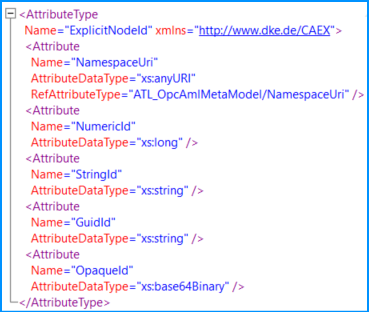
When an instance of ExplicitNodeId is used, only one of the four "Id" fields shall have a value, and the remaining three shall be deleted.
Alias - Represents an OPC UA Alias with the attributes shown in Figure A.2.
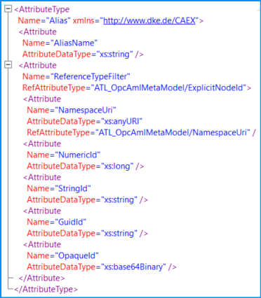
The ReferenceTypeFilter attribute is optional, and when omitted, the ReferenceType "AliasFor" shall be assumed. See the FindAlias Method in OPC 10000-17.
A.2.4 SUC_OpcAmlMetaModel library
Methods in OPC UA do not have a base class from which they all derive; they just all conform to the Method NodeClass. In AML, it is desirable to have a base SUC UaMethodNodeClass that represents the AML base SUC from which all UA Methods are instantiated. Since there is no Node that represents the Method NodeClass in a UA Namespace (because it is built-in to the UA meta-model), the SUC UaMethodNodeClass is defined in this metamodel library.
A.3 DataType mapping
A.3.1 DataType mapping overview
For every OPC UA Namespace, an AML Attribute Type Library exists that defines a corresponding AML AttributeType for each OPC UA DataType. The name of the AML AttributeType Library is composed of the string "ATL_" followed by the OPC UA Namespace name.
Each AML AttributeType has a NodeId Attribute, which matches the NodeId of the OPC UA DataType. The NodeId Attribute does not appear on data type instances and contains an "OPC:TypeOnly" entry in the Additional Information collection of the Attribute Header.
The name of each AML AttributeType shall match the string portion of OPC UA DataType BrowseName.
A.3.2 Built-in Types
Table A.2 shows the mapping of the simple built-in DataTypes in OPC UA that correspond to simple XML schema types used in AML. Each of the built-in UA DataTypes is defined as an AML AttributeType in the AttributeType Library for the base OPC UA Namespace.
| UA DataType | XML Schema type used in AML |
|---|---|
| Boolean | xs:boolean |
| SByte | xs:byte |
| Byte | xs:unsignedByte |
| Int16 | xs:short |
| UInt16 | xs:unsignedShort |
| Int32 | xs:int |
| UInt32 | xs:unsignedInt |
| Int64 | xs:long |
| UInt64 | xs:unsignedLong |
| Float | xs:float |
| Double | xs:double |
| String | xs:string |
| DateTime | xs:dateTime |
| ByteString | xs:base64Binary |
A.3.3 Structures
OPC UA Structures are defined as AML AttributeTypes. Structures in OPC UA can be derived from other Structures and composed of any other OPC UA DataTypes. Similarly, AML AttributeTypes can be derived from other AML AttributeTypes and composed of any other AttributeTypes. This allows all OPC UA DataTypes (including Structures) to appear as AML AttributeTypes with the same derivation and composition structure as seen in OPC UA.
A.3.4 Arrays
Arrays are most naturally represented as lists in XML, so in AML, array DataTypes are represented as XML lists. The AML AttributeType Library of an OPC UA Namespace defines a number of lists for arrays of UA DataTypes, of which a subset is shown in Figure A.3. The same pattern shall be used to construct arrays of any derived DataTypes.
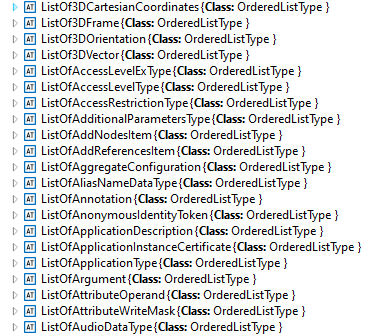
The "ListOf" attributes are all derived from the OrderedListType attributes in the standard AutomationMLBaseAttributeTypeLib.
A.3.5 Enumerations
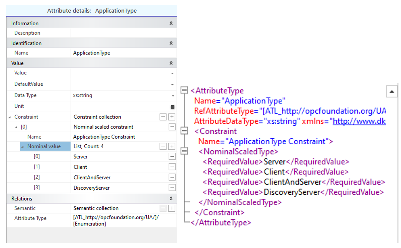
Enumerations in OPC UA shall be represented as xs:string types in AML with a constraint to limit the values to those defined by the Enumeration. Figure A.4 shows the enumeration for the OPC UA DataType "ApplicationType" in AML.
A.3.6 OptionSets and Bit masks
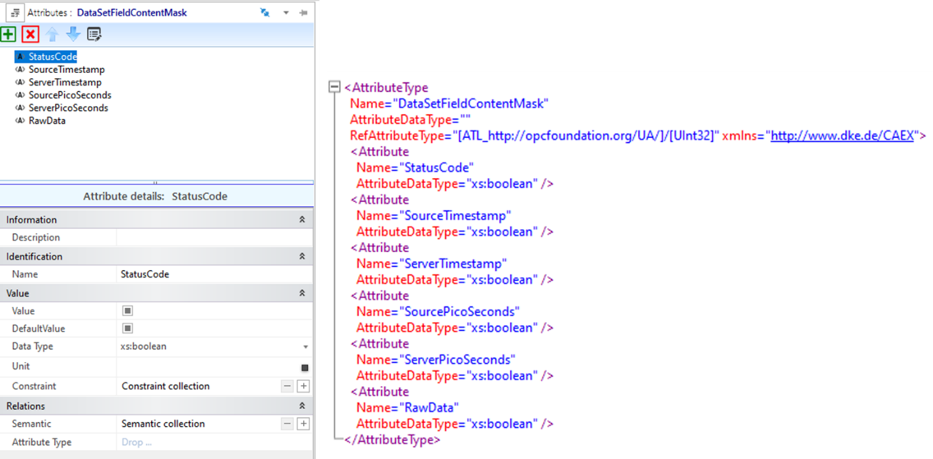
OptionSets and bit masks in OPC UA are Integer types where each bit is an independent named field with a Boolean value. In AutomationML, this is mapped to an AttributeType with a set of contained attributes of type xs:Boolean, where the name of each contained attribute matches the field name in the bit mask or option set. Figure A.5 shows an example of OptionSet's mapping.
A.3.7 DataTypes with special mappings
The following complex DataTypes have special mappings that are non-intuitive.
A.3.7.1 QualifiedName DataType
QualifiedName - The integer NamespaceIndex used in OPC UA is replaced by a NamespaceUri in AutomationML. In AutomationML, the full URI is always used, and there is never an index. Wherever NamespaceUri is used, the AutomationML datatype is always xs:anyURI.
A.3.7.2 LocalizedText DataType
LocalizedText - An xs:string AttributeType with contained attributes that derive from AutomationMLBaseAttributeTypeLib/LocalizedAttribute and follows the standard AutomationML rules.
A.3.7.3 NodeId DataType
NodeId - NodeIds in running OPC UA Servers are represented as an ID and a NamespaceIndex. In order to make reference to Nodes in the offline AutomationML file, a more flexible way to reference a Node is needed, both directly and indirectly, possibly long before the real Node is present in a running Server. The NodeId AML AttributeType is defined with four top-level attributes, as shown in Figure A.6
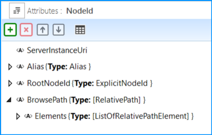
ServerInstanceUri - an optional attribute used to indicate the ServerInstanceUri of the Server containing the NodeId. If empty or missing, the context should be assumed to be the "local" Server. The type is xs:anyURI.
Alias - An indirect reference to a NodeId to be resolved by an alias Server at runtime. The Alias attribute type is defined in A.2.3.
RootNodeId - An ExplicitNodeId from which to traverse the BrowsePath in case the BrowsePath is not empty. The ExplicitNodeId attribute type is defined in A.2.3. If the BrowsePath is empty or not present, the node is identified by the RootNodeId or the NodeId resolved from the alias.
BrowsePath - An optional RelativePath to follow from either the RootNodeId or the NodeId resolved from the Alias. See the definition of the RelativePath structure in OPC 10000-4.
If a BrowsePath is present and not empty in a NodeId, then the RootNodeId should be a well-known NodeId like the NodeId of the Root Object (NS=UA, i=84) or the NodeId of the FxRoot Object (NS=UAFX, i=71).
Either the Alias attribute or the RootNodeId attribute shall be present. If both are present, the Alias attribute shall be ignored.
A.3.7.3.1 NodeId - BrowsePath Example
A typical use case for the BrowsePath in a Descriptor is to reference the corresponding variable in the AddressSpace from the PublishedData of a PublishedDataSet if the variable does not contain a real NodeId. The RootNodeId attribute of the NodeId AttributeType refers to the starting point of the BrowsePath, and the Elements of the BrowsePath direct to the target. Figure A.7 shows an example.
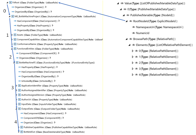
The formal definition of the BrowsePath is given in Table A.3.
| 0 | ReferenceTypeId | NamespaceUri | http://opcfoundation.org/UA/ |
| NumericId | 35 | ||
| IncludeSubTypes | False | ||
| IsInverse | False | ||
| TargetName | NamespaceUri | https://www.acme.com/BottleMachineProject/ | |
| Name | ME_BottleMachineProject | ||
| 1 | ReferenceTypeId | NamespaceUri | http://opcfoundation.org/UA/ |
| NumericId | 47 | ||
| IncludeSubTypes | False | ||
| IsInverse | False | ||
| TargetName | NamespaceUri | http://opcfoundation.org/UA/FX/AC/ | |
| Name | FunctionalEntities | ||
| 2 | ReferenceTypeId | NamespaceUri | http://opcfoundation.org/UA/ |
| NumericId | 35 | ||
| IncludeSubTypes | False | ||
| IsInverse | False | ||
| TargetName | NamespaceUri | https://www.acme.com/BottleMachineProject/ | |
| Name | BottleMachineFE | ||
| 3 | ReferenceTypeId | NamespaceUri | http://opcfoundation.org/UA/ |
| NumericId | 47 | ||
| IncludeSubTypes | False | ||
| IsInverse | False | ||
| TargetName | NamespaceUri | http://opcfoundation.org/UA/FX/AC/ | |
| Name | OutputData | ||
| 4 | ReferenceTypeId | NamespaceUri | http://opcfoundation.org/UA/ |
| NumericId | 35 | ||
| IncludeSubTypes | False | ||
| IsInverse | False | ||
| TargetName | NamespaceUri | https://www.acme.com/BottleMachineProject/ | |
| Name | BottleIdOut | ||
A.3.7.4 ExpandedNodeId data type
ExpandedNodeId - ExpandedNodeId has the same definition as NodeId since NodeId can already express an ExpandedNodeId as well.
A.3.7.5 PortableNodeId data type
PortableNodeId - The identifier field of PortableNodeId has the same definition as NodeId. The NamespaceUri information of the PortableNodeId is already present in the identifier and, therefore, redundant.
A.3.7.6 RelativePathElement data type
RelativePathElement - This attribute type is created using the standard mapping rules, except the ReferenceTypeId attribute is of type ExplicitNodeId defined in A.2.3, rather than NodeId. Table A.4 indicates the default value to use if the indicated attribute is missing.
| attribute | Default value used if attribute is missing |
|---|---|
| ReferenceTypeId | nsu=http://opcfoundation.org/UA/;i=22 (i.e. HierarchicalReferences) |
| IsInverse | FALSE |
| IncludeSubtypes | TRUE |
A.3.7.7 Guid data type
Guid - An xs:string AttributeType where the string shall be formatted in the standard notation for UUIDs per ISO/IEC 9834-8.
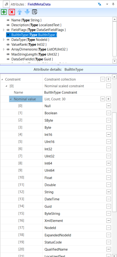
A.3.7.8 Byte data type
Byte - Where the UA DataType Byte is used in builtInType fields, the AML AttributeType is changed to derive from ATL_OpcAmlMetaModel/BuiltInType with constraints to match the enumeration as shown in Figure A.8.
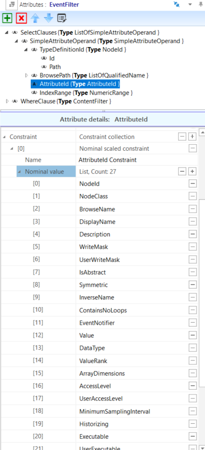
A.3.7.9 IntegerId data type
IntegerId - Where the UA DataType IntegerId is used in fields named "AttributeId", the AML AttributeType is changed to derive from ATL_OpcAmlMetaModel/AttributeId with constraints to match the enumeration as shown in Figure A.9.
A.4 NodeClass mapping
The OPC UA metamodel uses the concept of NodeClasses to define sets of primitive attributes that are present on different types of nodes in the UA address space. This NodeClass concept is not mapped directly in AutomationML. Instead, the relevant attributes are first introduced in the SystemUnitClass, where they would appear on an ObjectType or VariableType or an object or variable after instantiation.
In OPC UA, the attributes that appear on a type are different from the attributes that appear on an instance of that type (although there is a large overlap). In AutomationML, the SystemUnitClasses contain the union of the relevant attributes for both the type and instance. This simplification leads to the possibility of attributes appearing in AML that make no sense. In this case, they should ideally be deleted, and if not deleted, they should be ignored. For example, in OPC UA, the ObjectType and VariableType NodeClasses contain an attribute IsAbstract that indicates if direct instances of that type are allowed. In AutomationML, the IsAbstract attribute could appear on both types and instances, but if it appears on an instance, it has no meaning and thus should be deleted (ideally by the engineering tool without user interaction) or at least ignored.
The attributes defined on the SystemUnitClasses are almost always optional and can be deleted in cases where there is no desire to configure a specific value. When such attributes are not present in the SystemUnitClass or an AML instance but are required in OPC UA, then the rules stated in this document will be used to set appropriate values as noted.
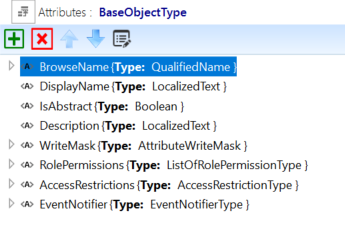
The OPC UA Base NodeClass contains a set of attributes that appear on all OPC UA Nodes. In AML, their equivalent may appear in the SystemUnitClasses UaMethodNodeClass, BaseObjectType and BaseVariableType according to the mapping defined in Table A.5.
| OPC UA Attribute name | Included in SystemUnitClasses or Instances | Notes |
|---|---|---|
| NodeId | X | If the NamespaceUri portion of the NodeId or the entire NodeId is not present, then the AML object contains an AML attribute UaNodeNamespaceUri that represents the OPC UA Namespace of the corresponding OPC UA Node. If the NodeId and UaNodeNamespaceUri are empty or not present, then the presumed value is either the OPC UA Namespace referenced by the AML library containing the AML object or the default OPC UA Server Namespace (depending on the context of the Node). If the NodeId is not present on an AML object, it can be derived by constructing a BrowsePath from a well-known RootNodeId as described in A.3.7. See the example in A.3.7.1. |
| NodeClass | NodeClass is never present in the AML SUC. The appropriate UA NodeClass is inferred by the SUC, and the OPC UA Namespace is referenced by the SUC library containing the SUC. . | |
| BrowseName | X | If the Name sub-attribute of the BrowseName AML attribute is not present (i.e. missing or empty) in the AML, then the Name portion of the BrowseName is inferred by the AML object Name. If the NamespaceUri sub-attribute of the BrowseName AML attribute is not present and the AML Object is contained in an AML library, the NamespaceUri portion of the BrowseName is the OPC UA Namespace referenced in the AML library definition. If the NamespaceUri sub-attribute of the BrowseName AML attribute is not present and the AML Object is in an AML InstanceHierarchy, then the NamespaceUri portion of the BrowseName is the default OPC UA server Namespace (Namespace index equals one). |
| DisplayName | X | If not present in the AML, the OPC UA DisplayName is inferred by the AML object Name. If the OPC UA DisplayName is present and has multiple localizations, the localizations are mapped to additional localized sub-attributes of the DisplayName AML attribute. All DisplayNames that are present in the Server shall be present in the AML file. The DisplayName that exists in the AML file may not be present in the Server due to memory reasons. |
| Description | X | If not present in the AML, the OPC UA Description is inferred by the Description XML attribute in the Header of the AML object. If the OPC UA Description is present and has multiple localizations, the localizations are mapped to additional localized sub-attributes of the Description AML attribute. All Descriptions that are present in the Server shall be included in the AML file. The Description that exists in the AML file may not be present in the Server due to memory reasons. |
| WriteMask | X | If the WriteMask is present in the AML, it shall also be present in the Server. If sub-attributes of the WriteMask Attribute are part of the AML, their values shall match the corresponding bits in the Server. If a sub-attribute of the WriteMask is not present in the AML, then the value of the field is unknown. |
| UserWriteMask | UserWriteMask is never present in the AML SUC. | |
| RolePermissions | X | If not present in the AML SUC, the attribute is also omitted in OPC UA. |
| UserRolePermissions | UserRolePermissions is never present in the AML SUC. | |
| AccessRestrictions | X | If the AccessRestrictions is present in the AML, it shall also be present in the Server. If sub-attributes of the AccessRestrictions Attribute are part of the AML, their values shall match the corresponding bits in the Server. If a sub-attribute of the AccessRestrictions is not present in the AML, then the value of the field is unknown. |
| Executable | Executable is never present in the AML SUC. | |
| UserExecutable | UserExecutable is never present in the AML SUC. | |
| NOTE The "X" marks indicate all of the OPC attributes allowed in the AML mapping. However, the SUCs in the AML Libraries described in Annex B through Annex E may only contain a chosen subset. Engineering tools are free to delete any unused attributes or add any allowed attributes as needed. | ||
A.5 ObjectType mapping
The OPC UA BaseObjectType is modelled in AML as a SystemUnitClass with the same name. The BaseObjectType SUC contains attributes that mimic the attributes of the OPC UA Object and ObjectType NodeClasses, as shown in Figure A.10.
In OPC UA, the set of attributes appears on the type as well as the instances and the values on the types are often used to convey a default value on the instance. In AML, only one set of attributes is used since both a Value and DefaultValue can be specified for every attribute in AML.
Table A.6 shows the additional attributes introduced by the BaseObjectType SUC.
| Attribute name | Included in SUC or Instances | Notes |
|---|---|---|
| IsAbstract | X | If not present in the AML SUC type, the value is assumed to be FALSE. In instances, this attribute has no meaning and should be deleted or ignored. |
| EventNotifier | X | If not present in the AML Object, the value of all fields is unknown. OPC UA Servers may override some or all of the configured values |
A.6 VariableType mapping
All the rules in A.5 for ObjectTypes also apply to VariableTypes with these notable differences:
The base AML SUC for OPC UA VariableTypes is BaseVariableType;
VariableTypes have a "Value" attribute and other attributes related to Value.
In BaseVariableType, the Value attribute has the DataType BaseDataType, as shown in Figure A.11.
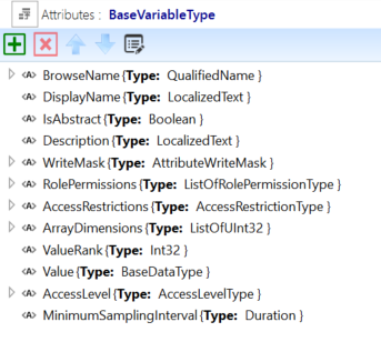
Table A.7 shows the additional attributes introduced by the BaseVariableType SUC.
| Attribute name | Included in SUC or Instances | Notes |
|---|---|---|
| IsAbstract | X | If not present in the AML SUC type, the value shall be FALSE. In some instances, this attribute has no meaning and should be deleted or ignored. |
| Value | X | If not present in the AML Object, the attribute value is NULL in OPC UA. |
| DataType | Never present in the AML Object. The UA DataType is inferred by the DataType of the AML Value attribute. | |
| ValueRank | X | If not present in the AML Object, the value in OPC UA shall be Scalar (‑1). |
| ArrayDimensions | X | If not present in the AML Object, the attribute is also omitted in OPC UA. |
| AccessLevel | X | If not present in the AML Object, the value of all fields is unknown. OPC UA Servers may override some or all of the configured values |
| UserAccessLevel | Never present in the AML Object. | |
| MinimumSamplingInterval | X | If not present in the AML Object, the attribute is also omitted in OPC UA. |
| Historizing | Never present in the AML Object. | |
| AccessLevelEx | X | The bit fields of AccessLevelEx that are also contained in AccessLevel are not mapped to AML. If not present in the AML Object, the value of all fields is unknown. OPC UA Servers may override some or all of the configured values. |
BaseDataType is the root abstract DataType from which all other OPC UA DataTypes derive. The semantic implied by this is that the Value of an instance can be any valid DataType. Typically, VariableTypes that derive from BaseVariable type will alter the DataType of Value to be more restrictive. This could be other abstract DataTypes like the Number AttributeType or a concrete AttributeType from an OPC UA-based AML AttributeTypeLibrary, or an allowed built-in DataType from Table A.2. Figure A.12, Figure A.13, and Figure A.14 show some examples of derived VariableTypes with more restrictive DataTypes.
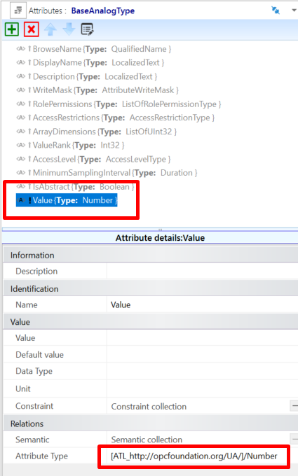
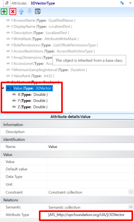
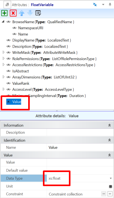
A.7 ReferenceType mapping
OPC UA ReferenceTypes are modelled in AML as InterfaceClasses. All AML InterfaceClasses that represent OPC UA ReferenceTypes shall derive directly or indirectly from the Reference's InterfaceClass in the ICL_http://opcfoundation.org/UA/ InterfaceClassLibrary. OPC UA ReferenceTypes that are symmetric or have the same forward and inverse name shall be represented by a single AML InterfaceClass with the same name. All other ReferenceTypes shall be represented by a pair of AML InterfaceClasses where one element of the pair represents the source endpoint, and the other represents the destination endpoint corresponding to the forward and inverse names. This pair of AML InterfaceClasses are organized in a hierarchy, see Figure A.15. In Figure A.15, the OPC UA ReferenceTypes References and HierarchicalReferences are represented by a single AML InterfaceClass, but the ReferenceType Organizes is represented by a pair of AML Organizes/OrganizedBy.
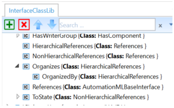
The base References InterfaceClass contains the Attributes shown in Table A.8.
| Attribute name | Type | Notes |
|---|---|---|
| NodeId | NodeId | In instances, this attribute has no meaning and should be deleted or ignored.This Attribute only appears on InterfaceClasses that represent the forward or symmetric Reference( i.e not on inverse references). This Attribute only appears on the InterfaceClass type and is marked with the Modelling Rule "OPC:TypeOnly" (see A.11.2.2). |
| InverseName | LocalizedText | For non-symmetric References, this is the name of the other interface class in the pair. It has no meaning for symmetric References. This Attribute only appears on the InterfaceClass type and is marked with the Modelling Rule "OPC:TypeOnly" (see A.11.2.2). |
| IsAbstract | Boolean | Indicates if the Reference is abstract according to the UA model. The default value for this attribute is FALSE. If the attribute is missing, then the default value is assumed. This Attribute only appears on the InterfaceClass type and is marked with the Modelling Rule "OPC:TypeOnly" (see A.11.2.2). |
| IsSource | xs:boolean | For non-symmetric References, TRUE shall indicate that this interface represents the source endpoint of the Reference, and FALSE shall indicate that this interface represents the destination endpoint of the Reference. It has no meaning for symmetric References. The default value for this attribute is FALSE. If the attribute is missing, then the default value is assumed. This Attribute only appears on the InterfaceClass type and is marked with the Modelling Rule "OPC:TypeOnly" (see A.11.2.2). |
| ModellingRule | ModellingRuleType | Present on the destination interface to indicate the UA ModellingRule of the destination. If missing, the ModellingRule "Optional" shall be assumed. |
| RefClassConnectsToPath | xs:string | Indicates the AML path to the only other InterfaceClass that this interface shall be allowed to connect to. For symmetric References, this is a path to its own InterfaceClass. For non-symmetric References, this is the path to the other InterfaceClass in the pair. This Attribute only appears on the InterfaceClass type and is marked with the Modelling Rule "OPC:TypeOnly" (see A.11.2.2). |
| Symmetric | Boolean | Indicates if the Reference is symmetric according to the UA model. The default value for this attribute is FALSE. If the attribute is missing, then the default value is assumed. This Attribute only appears on the InterfaceClass type and is marked with the Modelling Rule "OPC:TypeOnly" (see A.11.2.2). |
The InterfaceClasses are used in two ways:
Within an SUC to represent the UA relationships between the InternalElements of a Type within the SUC;
Within the InstanceHierarchy to show UA relationships between InternalElements.
When used within an SUC, the destination InterfaceClass contains a ModellingRule attribute that can be used to specify the UA ModellingRule used during instantiation. Figure A.16 Shows that the ModellingRule for the NodeVersion Property is explicitly set to "Mandatory".
Figure A.17 shows an example of InterfaceClasses connected in an InstanceHierarchy.
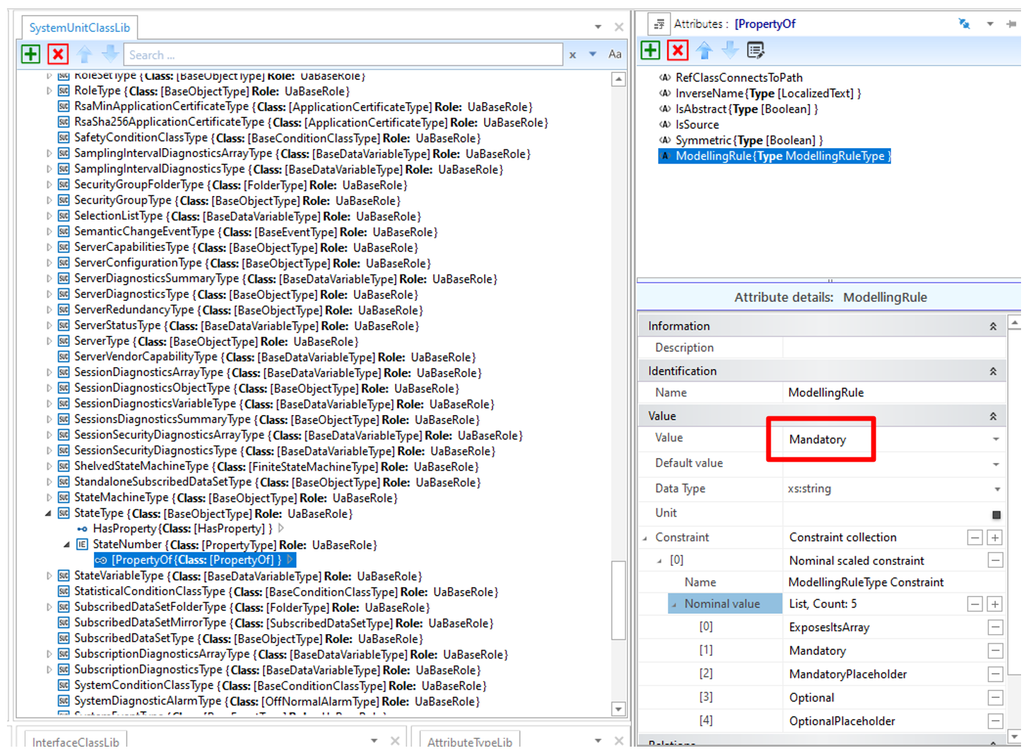
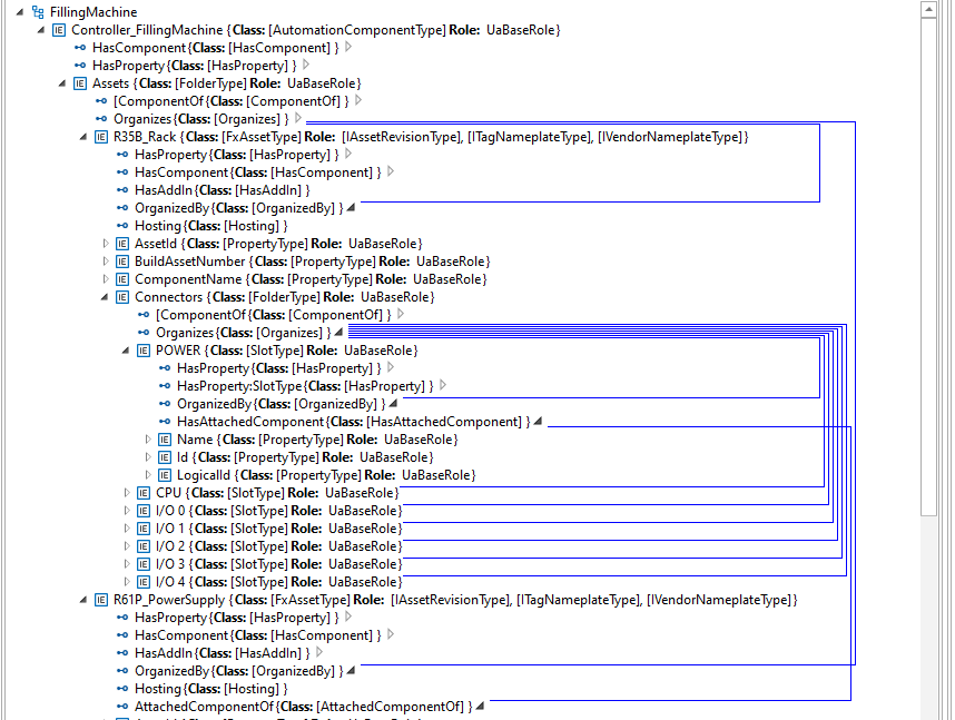
A.8 InterfaceType mapping
OPC UA Interfaces are used to add a defined group of elements to an Object in an alternate way than containment or inheritance, similar to the way interfaces do in an object-oriented programming (OOP) language. Interfaces in OOP and OPC UA help alleviate some of the limitations of a single inheritance model by allowing an Object to "implement" multiple interfaces.
AML Role Classes serve a similar purpose in that an instance or an SUC can fulfil one or more Roles. For this reason, OPC UA InterfaceTypes are represented as Role Classes in AML in addition to being represented in the SUC as they naturally occur (since all OPC UA InterfaceTypes derive from the supertype BaseObjectType).
The AML RoleClasses that correspond to the UA InterfaceTypes contain no additional attributes. They only serve the purpose of annotating the SUCs that implement the Interfaces. Figure A.18 shows an example of an SUC (UA ObjectType) that implements several Roles that correspond to UA InterfaceTypes.
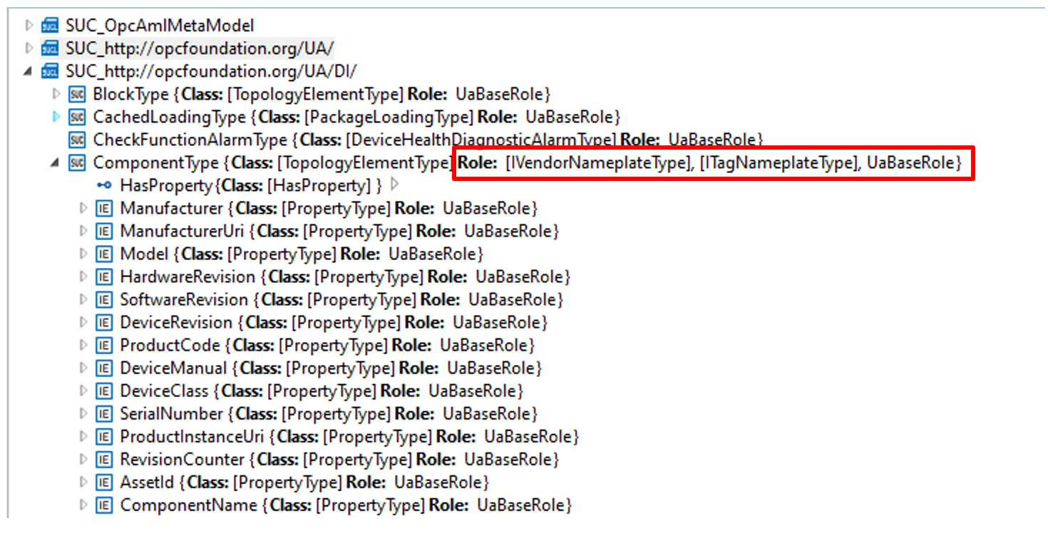
A.9 Instance mapping
OPC UA Instance Nodes shall map to AutomationML InternalElements in an AutomationML InstanceHierarchy, as shown in Figure A.19.
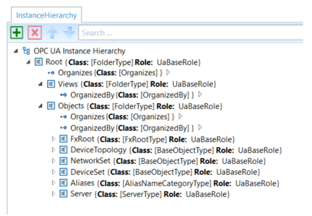
Note that the example hierarchy shown in Figure A.19 was created using the OPC2AML Conversion Tool that mimics the full OPC UA instance tree as specified in the NodeSet files, minus the standard OPC UA Types folder since the equivalent type objects are contained in the AutomationML Libraries. Engineering tools may organize instance elements in alternate hierarchies (utilizing AutomationML MirrorElements) in addition to the way they would appear in an OPC UA Server.
When SUCs are instantiated in the AutomationML InstanceHierarchy, care must be given to setting the URIs properly to reflect the correct NamespaceUri for both the BrowseName and the Node. In the InstanceHierarchy, an empty or missing NamespaceUri (of the BrowseName) or UaNodeNamespaceUri shall imply the default NamespaceUri of the OPC UA Server (i.e. Namespace index 1). In all other cases, the URI attributes shall contain valid URIs that reflect the correct Node and BrowseName URIs.
A.10 Limitations on AML to OPC UA conversion
The following information in an OPC UA NodeSet is lost when converting to OPC UA FX AML:
NamespaceIndexes: OPC UA FX AML does not use NamespaceIndexes. It always uses the NamespaceUri as a string;
Bit order in OptionSets and Bitmasks: In OPC UA FX AML, OptionSet and bit masks are defined with an unordered list of boolean AML attributes;
builtinType values are defined as string and not as integer;
AttributeId values are defined as string and not as integer.
When creating a NodeSet from an OPC UA FX AML file, the missing information needs to be taken from the NodeSet files that define the types used in the OPC UA FX AML file.
A.11 Modelling guidelines
A.11.1 AutomationComponent
An AutomationComponent is either modelled as AML InternalElement as part of an AML InstanceHierarchy or as AML SystemUnitClass (SUC).
If the AutomationComponent is modelled as InternalElement (IE), it shall be either a direct or indirect instance of the SUC AutomationComponentType. If modelled as an SUC, it shall be a subclass of the SUC AutomationComponentType.
A.11.2 Modelling rules
A.11.2.1 Modelling rules for InternalElements
AutomationML does not have modelling rules, like mandatory, optional or no modelling rule, that guide the creation of instances. Instantiating an SUC usually results in the creation of all InternalElements that are modelled as instance declarations on the type. However, since the UA modelling rules are present on the SUC of the OPC UA FX Libraries, engineering tools could do automatic postprocessing and delete the optional IEs from the type or let the user decide which optional IEs should be removed.
A.11.2.2 Modelling rules for Attributes
In OPC UA models, there are also attributes that only appear on data types and reference types that do not get propagated to instances, but in AML, the corresponding AML attribute types and AML interface classes, when instantiated propagate all the attributes associated with the type. In cases where the value of an attribute only has meaning on a type, the attribute shall contain an entry in the Additional Information collection of the Header "OPC:TypeOnly" to indicate that the attribute only has meaning on the type and can ideally be deleted or at least ignored on instances as shown in Figure A.20. Engineering tools should delete attributes marked "OPC:TypeOnly" when creating instances on export. Engineering tools shall ignore attributes marked "OPC:TypeOnly" on import in cases where the exporting tool fails to delete them when creating the instance.
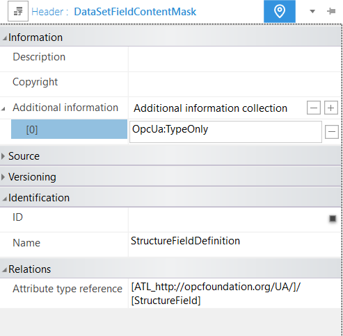
A.11.3 InternalElements
When making changes to an already existing AML InternalElement, two strategies can be followed:
Change the InternalElement directly. Here, every operation (add, change, delete) is possible as long as it does not violate a rule from the OPC UA standard. However, in these cases, the original instance is not kept.
Convert the InternalElement to an SUC, make the SUC a subclass of the SUC from which the InternalElement was created, and make an instance from this new SUC for further editing. This allows the original InternalElement to be kept as an SUC in the type system. If this is done repeatedly, an instantiation step is followed by an SUC-conversion step, and the work history is available in the derivation chain of the modelled SUCs.
A.11.4 OPC UA FX Libraries
If an ObjectType, VariableType, DataType, or ReferenceType is used in an OPC UA FX Information Model that is not defined in the libraries listed in Annex B, Annex C, Annex D, and Annex E, a definition of the object type, variable type, data type, or reference type shall exist in an OPC UA FX Library, and this library shall be included in the Descriptor. The OPC UA FX AML Core Libraries are those libraries defined in this document.
For modelling of safety information for a Descriptor, the OPC UA FX AML Safety library shall be used (see Annex E).
Annex B AML libraries for OPC UA configuration (Normative)
B.1 UA Library
B.1.1 UA library overview
The core libraries defined in this annex correspond to the types defined in the base OPC UA Specifications (i.e., those defined in Namespace 0, "http://opcfoundation.org/UA/"). AML libraries for all other OPC UA Information Models can be created by deriving new AML types from the types in this AML library, just as new OPC UA types are derived from the OPC UA types defined in the base OPC Specifications.
The AutomationML libraries that mirror the types defined in the OPC UA Namespace http://opcfoundation.org/UA/ are provided in a single digitally signed AML Container here:
https://reference.opcfoundation.org/nodesets/?u=http://opcfoundation.org/UA/FX/Data/&v=1.00.03&i=2.
Each of the libraries described in A.9 shall contain an "Additional information collection" in the header of the Library with the XML Element "OpcUaLibInfo" with the sub-element "OpcUaNamespaceUri" with the value http://opcfoundation.org/UA/ and additional sub-elements ModelVersion and ModelPublicationDate, of which an example is shown in Figure B.1 for the AttributeTypeLibrary.
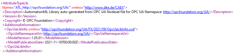
B.1.2 UA RoleClass Library
The RoleClass Library "RCL_http://opcfoundation.org/UA/" defines the RoleClasses that correspond to their equivalent OPC UA ApplicationType. See A.8.
B.1.3 UA InterfaceClass Library
The InterfaceClass Library "ICL_http://opcfoundation.org/UA/" defines the InterfaceClasses that correspond to their equivalent OPC UA ReferenceTypes. See A.7.
B.1.4 UA AttributeType Library
The Attribute Library "ATL_http://opcfoundation.org/UA/" defines the AttributeTypes that correspond to their equivalent OPC UA DataTypes. See A.2.
B.1.5 UA SystemUnitClass Library
The SystemUnitClass Library "SUC_http://opcfoundation.org/UA/" defines the SystemUnitClasses that correspond to their equivalent OPC UA ObjectTypes and VariableTypes. See A.5 and A.6.
Annex C AML Libraries for OPC UA DI Configuration (Normative)
C.1 DI Library
C.1.1 DI Library Overview
The AutomationML libraries that mirror the types defined in the OPC UA Namespace http://opcfoundation.org/UA/DI/ are provided in a single digitally signed AML Container
https://reference.opcfoundation.org/nodesets/?u=http://opcfoundation.org/UA/FX/Data/&v=1.00.03&i=2.
DI RoleClass Library
The RoleClass Library "RCL_http://opcfoundation.org/UA/DI/" defines the RoleClasses that correspond to their equivalent OPC DI InterfaceTypes.
C.1.2 DI InterfaceClass Library
The InterfaceClass Library "ICL_http://opcfoundation.org/UA/DI/" defines the InterfaceClasses that correspond to their equivalent OPC DI ReferenceTypes.
C.1.3 DI AttributeType Library
The Attribute Library "ATL_http://opcfoundation.org/UA/DI/" defines the AttributeTypes that correspond to their equivalent OPC DI DataTypes.
C.1.4 DI SystemUnitClass Library
The SystemUnitClass Library "SUC_http://opcfoundation.org/UA/DI/" defines the SystemUnitClasses that correspond to their equivalent OPC DI ObjectTypes and VariableTypes.
Annex D AML Libraries for OPC UA FX configuration (Normative)
D.1 OPC UA FX Library
D.1.1 OPC UA FX Library Overview
The AutomationML libraries that mirror the types and instances defined in the OPC UA Namespaces http://opcfoundation.org/UA/FX/* are provided in the following digitally signed AML Containers
https://reference.opcfoundation.org/nodesets/?u=http://opcfoundation.org/UA/FX/Data/&v=1.00.03&i=2.
OPC UA FX RoleClass Library
The RoleClass Library "RCL_http://opcfoundation.org/UA/FX/AC" defines the RoleClasses that correspond to their equivalent OPC UA FX InterfaceTypes.
D.1.2 OPC UA FX InterfaceClass Libraries
The InterfaceClass Libraries "ICL_http://opcfoundation.org/UA/FX/AC" and "ICL_http://opcfoundation.org/UA/FX/CM" define the InterfaceClasses that correspond to their equivalent OPC UA FX ReferenceTypes.
D.1.3 OPC UA FX AttributeType Libraries
The Attribute Libraries "ATL_http://opcfoundation.org/UA/FX/Data", "ATL_http://opcfoundation.org/UA/FX/AC", and "ATL_http://opcfoundation.org/UA/FX/CM" define the AttributeTypes that correspond to their equivalent OPC UA FX DataTypes. OPC UA FX SystemUnitClass Libraries
The SystemUnitClass Libraries "SUC_http://opcfoundation.org/UA/FX/AC", "SUC_http://opcfoundation.org/UA/FX/CM", and "SUC_http://opcfoundation.org/UA/FX/Data" define the SystemUnitClasses that correspond to their equivalent OPC UA FX ObjectTypes and VariableTypes.
Annex E AML Libraries for OPC UA Safety (Normative)
E.1 UA Safety Library
E.1.1 UA Safety Library Overview
The AutomationML libraries that mirror the types defined in the OPC UA Namespace http://opcfoundation.org/UA/Safety/ are provided in a single digitally signed AML Container
https://reference.opcfoundation.org/nodesets/?u=http://opcfoundation.org/UA/FX/Data/&v=1.00.03&i=2.
Safety RoleClass Library
| There is no RoleClass Library defined for safety. |
E.2 Safety InterfaceClass Library
There is no InterfaceClass Library defined for safety.
E.3 Safety AttributeType Library
The Attribute Library "ATL_http://opcfoundation.org/UA/Safety/" defines the AttributeTypes that correspond to their equivalent OPC UA Safety DataTypes.
E.4 Safety SystemUnitClass Library
The SystemUnitClass Library "SUC_http://opcfoundation.org/UA/Safety/" defines the SystemUnitClasses that correspond to their equivalent OPC UA Safety ObjectTypes and VariableTypes.
Annex F AutomationComponent modelling (Informative)
F.1 AutomationComponent modelling
F.1.1 AutomationComponent modelling example
This annex provides a worked-out example of the configuration of the Information Model of an AutomationComponent using the UAFX Information Model.
This modelling process is described in an abstract way, without referencing tools or roles for the creation or editing of the model. In a concrete example, suitable or adapted engineering tools are expected to support the modelling process.
Figure F.1 is an AML Information Model example of a modular Controller for a filling machine for liquids. The figure shows the assets of the Controller: A backplane chassis, a power module "POW", a CPU module "CPU", an analogue input module in slot "0", and a digital output module in slot "1".
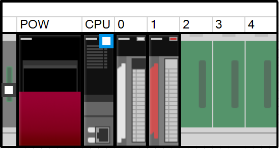
The Information Model of the filling machine is modelled with three FunctionalEntities: one for the fill level measurement, one for the actuation of the valve that supplies the liquid, and one for the control algorithm.
The creation of the AML Information Model can be divided into four steps:
Instantiation of the AutomationComponentType;
Creation of the Asset structure;
Creation of the FunctionalEntity structure;
Creation of the (preconfigured) DataSets.
The AML Information Model does not need to be complete at this stage in the development. The model only needs to have enough data to be ready to be handed off to the next stage in development. Each stage of the development will add more information to the model. The current stage could involve incorporating all the product data. The next stage may include the configuration data, such that the AutomationComponent can be set up and commissioned. The current stage is complete when the model has all the information needed in preparation for the next stage.
F.1.2 Instantiation of the AutomationComponentType
The modelling starts with the creation of an instance of the AutomationComponentType SystemUnitClass (SUC). This type is part of the OPC UA FX AML Core Libraries. One way of doing this is to directly instantiate the AutomationComponentType SUC. This is shown in Figure F.2.
A more convenient way is to start from a vendor-specific subtype of the AutomationComponentType SUC, which provides product-related data and structure in the type. This requires that the Controller vendor provides a vendor-specific OPC UA FX AML library.
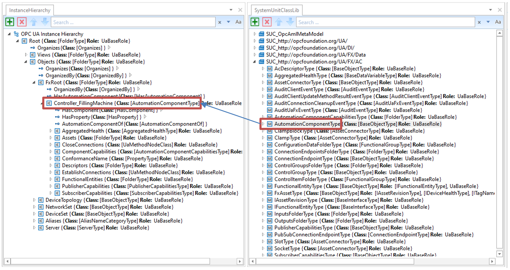
The top level of the AutomationComponent instance contains important Variables for product data:
ConformanceName: Provides the URL to the product's listing on the OPC Foundation website under which the result of the conformance test can be found;
ComponentCapabilities: Describes limits on the functionality provided by an AutomationComponent (e.g., number of supported logical connections, etc.);
PublisherCapabilities and SubscriberCapabilities: Limits on the AutomationComponent for the communication functions.
F.1.3 Creation of the Asset structure
In the next step, the Asset structure of the modular Controller is created using the FxAssetType SUC, which is provided by the OPC UA FX AML Libraries.
In Figure F.3, the Asset structure is shown. The first Asset is the backplane chassis R35_Rack, which can host modules through connector slots.
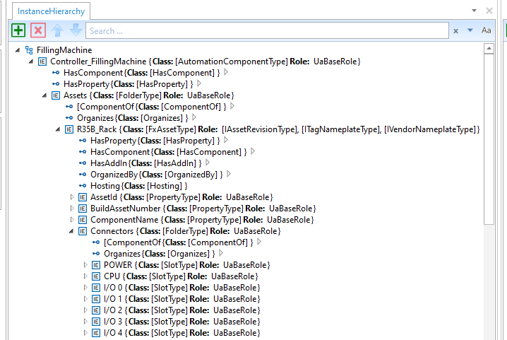
After the creation of the backplane chassis, the modules are created as instances of FxAssetType: A power supply module (R61P_PowerSupply), a CPU module (R04CPU_PLC), an analogue input module (R60AD4_AnalogInput) and a digital output module (RY10R2_DigitalOutput). See Figure F.4.
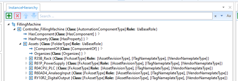
After the creation of the modules, the available data for the identification of the Asset that is defined in the IVendorNamePlate OPC UA Interface should be added. See Figure F.5.
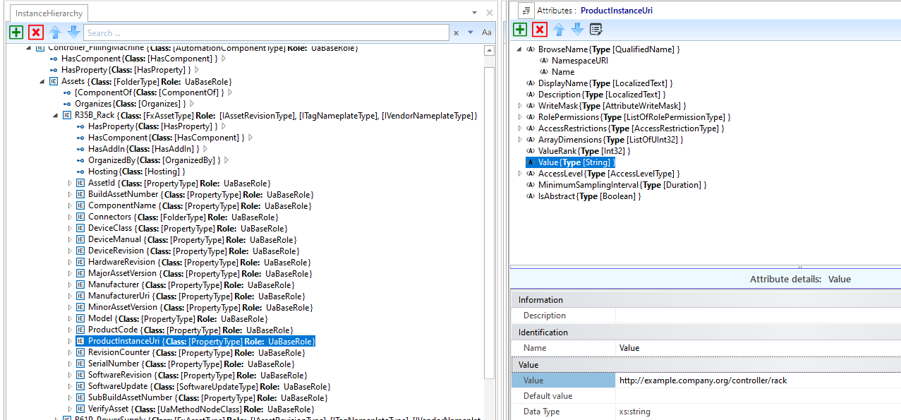
In the final step for configuring the Asset structure, the modules are associated with the connector slots using HasAttachedComponent references, as shown in Figure F.6:
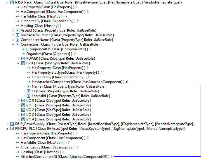
F.1.4 Creation of the FunctionalEntity structure
In this step of the example, the FunctionalEntity sub-model is created. See Figure F.7.
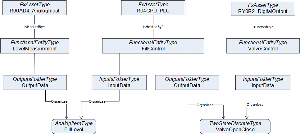
The following steps are needed to define the FunctionalEntities:
Creation of the FunctionalEntityType instances (The OPC UA FX AML Core Libraries provide the FunctionalEntityType SUC for defining a FunctionalEntity).
Within each FunctionalEntity, define variables for the input, output, and configuration variables, and link the variables to the FunctionalEntity using Organizes references.
Set or restrict the values in the PublisherCapabilities and SubscriberCapabilities structure. The PublisherCapabilities and SubscriberCapabilities structure exists in the FunctionalEntity sub-model at three levels: AutomationComponent, FunctionalEntity and InputData and OutputData levels.
In Figure F.8, a FunctionalEntity "FillControl" is created that represents an application for controlling a valve based on input data from a level measurement. The "FillControl" FunctionalEntity is hosted by the CPU module "R04CPU_PLC".
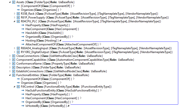
"FillControl" uses an analogue value input, "FillLevel", and a digital output variable, "ValveOpenClose". Both Variables are organized as InputData and OutputData of the FunctionalEntity, "FillControl".The "FillLevel" signal is coming from a FunctionalEntity, "LevelMeasurement", that is hosted by the analogue input module, "R60AD4_AnalogInput", while the "ValveOpenClose" signal is sent to a FunctionalEntity, "ValveControl", hosted by the digital output module, "RY0R2_DigitalOutput".
This is shown in Figure F.9.
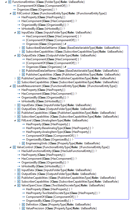
After setting up InputData and OutputData, the capabilities of the communication are defined. For example, the SubscriberCapabilities Variables for the "FillLevel" input signals are defined as in Figure F.10:
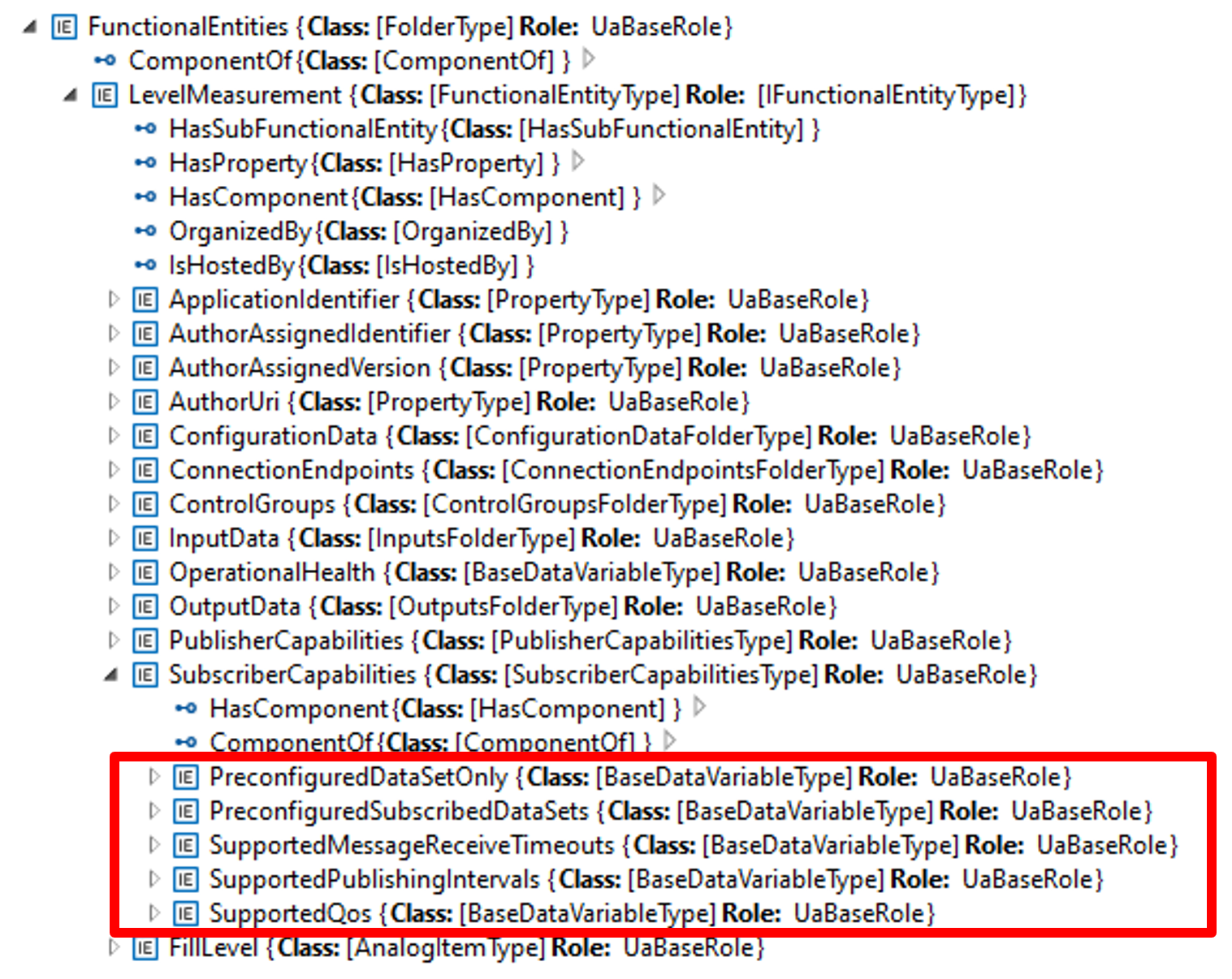
Table F.1 shows the values of the Variables used in the example:
| Variable | Value |
| PreConfiguredDataSetOnly | True |
| PreConfiguredSubscribedDataSets | ["FillLevelDataSet"] |
| SupportedMessageReceiveTimeouts | min:200, max:20000, increment:50, multiplier:1; unit:milliseconds |
| SupportedPublishingIntervals | min:50, max:5000, increment:50, multiplier:1; unit:milliseconds |
| SupportedQoS | QosCategory: opc.qos.cat://priority, DatagrammQos: opc.qos.lbl://green |
F.1.5 Creation of the Data Sets
Since the example is using pre-configured DataSets, the DataSets for the communication of the "FillLevel" and "ValveOpenClose" signals are defined in the next step. This is shown in Figure F.11:
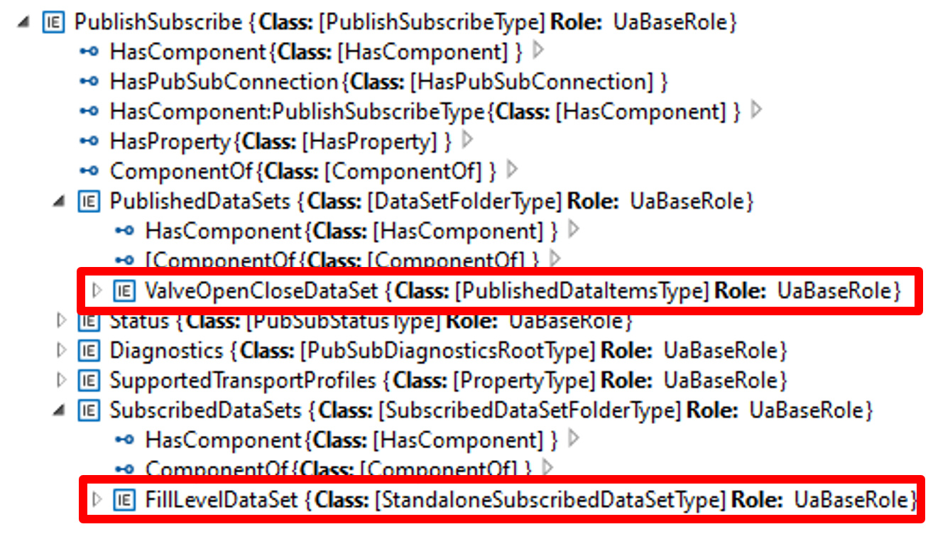
Two DataSets are defined:
A publication dataset, "ValveOpenCloseDataSet", for the valve control messages;
A subscription dataset, "FillLevelDataSet", for the level measurement messages.
Figure F.12 shows the "ValveOpenCloseDataSet", which contains the following variables:
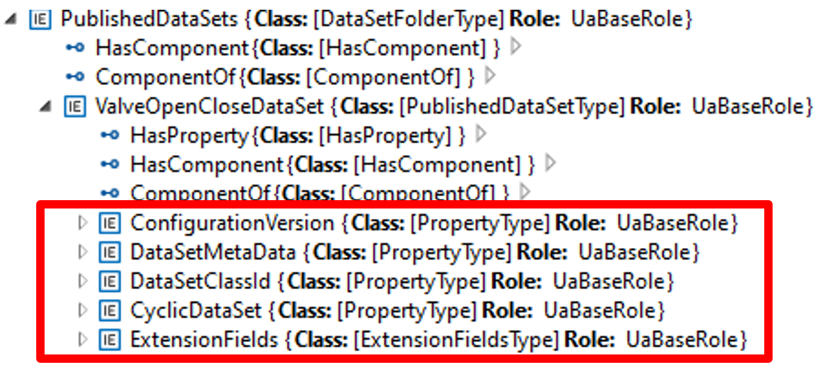
Table F.2 describes the values of the variables.
| Variable | Value |
| ConfigurationVersion | Structure with MajorVersion and MinorVersion with the VersionTime timestamp of the dataset configuration |
| DataSetMetaData | (only data elements relevant to the example are shown): Fields: [ Name: ValveOpenClose, BuiltinType: Boolean, DataType:Boolean, ValueRank:-1, ArrayDimensions: Not specified, MaxStringLength: Not specified ] |
DataSetMetaData DataSetWriter Id | Not specified |
| ExtensionFields | Not specified |
| CyclicDataSet | True |
| PublishedData | [ PublishedVariable: ValveOpenClose, AttributeId: Value, SamplingInterval: Not specified, DeadbandType: Not specified, DeadbandValue: Not specified IndexRange: Not specified, SubstituteValue: Not specified, MetaDataProperties: Not specified] |
F.1.6 Usage of the Descriptor in subsequent engineering
After the offline configuration of the Filling machine, the configuration is exported to a Descriptor and further used in system engineering to set up a production line.
In this phase, as shown in Figure F.13, a System Integrator defines the ITagNameplate information, custom DataSets (if allowed), the connections between machines in the production, the communications intervals and Quality of Service (QoS) being used and Networking configuration (e.g., IP addresses, VLAN Ids).
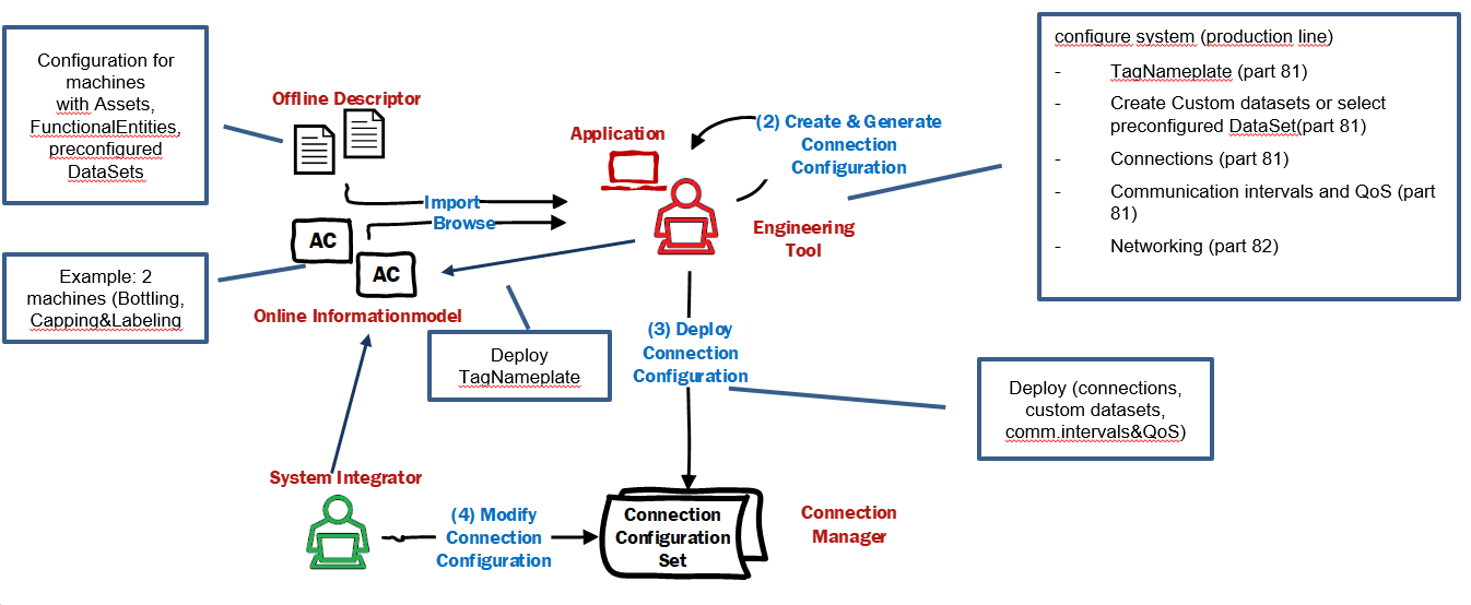
As the final step, the connection information, including custom DataSets, the communication intervals and QoS, is deployed to the ConnectionManager(s), which is responsible for establishing the connections. Other information, like ITagNamePlate and Networking configuration, is deployed directly to the machines.
Annex G Open Packaging Conventions (Informative)
G.1 Overview
The Open Packaging Conventions is specified in ISO/IEC 29500-2:2021 and ECMA-376. It is a container-file technology. The Open Packaging Conventions use a Package model that holds a collection of Parts. ZIP archives that contain XML, binary, and other types of files make up an Open Package Conventions-based document. The independent files (or Parts) remain intact in the document and are compressed into a single file container. This provides the advantages of file independence, smaller file size, and a single integrated document for storage.
An Open Package Conventions Package, shown in Figure G.1, is an aggregate of Parts and References. A Part is the application data files, such as binary files or text files. Relationships are references between Parts in the Package and resources outside the Package.
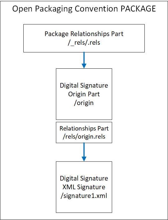
G.2 Parts
Parts in an Open Packaging Conventions Package may contain any type of data. This may include text, images, binaries, XML and other data. Parts are analogous to a folder in a file system. The organization of this "filing system" is left to the user, and it may be whatever is convenient for the application.
The name of a Part must be unique and URI-addressable. The content of the Part is described using a MIME-style media type. The media types of the Part, referred to as the Content_Types in the ISO/IEC 29500-2:2021 specification, are stored in the Package in an XML file named "/[Content_Types].xml".
The content stored in a Part is identified by the Content-Type. Every Part of a Package has a Content-Type.
G.3 Relationships
G.3.1 General
Relationships are used to navigate the Package, much like a directory. Relationships connect a source to a target, where the source is either the Package itself or a Part of the Package. The target is any URI-addressable resource inside or outside of the Package. This allows for flexibility in a Package such that there are no hardcoded dependencies of the content.
Random access to the Package content is provided by the use of Relationships through the use of directed graph associations. Tools and applications can take advantage of the Relationships to access information in a standardized and predictable manner.
The Relationship Element has four attributes:
the identifier (Id, xs:ID, required);
a relationship type (Type, xs:anyURI, required) (URI defining the role of the relationship);
the target (Target, xs:anyURI, required) (URI reference pointing to a target resource);
the target mode (TargetMode, ST_TargetMode, optional) (Internal or External resource);
The relationships are stored in XML files with the extension ".rels" within subfolders named "/_rels".
The following is an XML markup that defines the relationship identified as "???", which establishes the association between the Package or Part and the target. ""
<Relationship Id=""
<Relationship Id="???"
    Type="  "
    Type="  "/>
Each Part may have its own relationships. If the part has relationships, they will be stored in an XML file within the _rels folder that is associated with that Part. That file takes the Part name with a .rels appended to it.
G.3.2 Package Relationships
The root-level /_rels folder stores the relationships for the package as a whole. The /_rels folder normally contains a file named .rels, an XML file where the starting package-level relationships are stored.
G.4 Open Package Convention Additional features
G.4.1 Core Properties
ISO/IEC 29500-2:2021 states that "Core properties enable users to get and set well-known and common sets of property metadata within packages". The core properties are the category of the Package, the status of the content, the resource creation date, the creator, a description of the content, an identifier, a set of keywords, the language of the content, the last modifier, date and time of the last printing, modification date, revision, subject (or topic) of the content, a title, and the version. These properties can be empty or omitted. The entire Core Properties Part can be omitted if no core properties are present.
G.4.2 Thumbnails
Thumbnails are images that are to be used to help end-users identify Parts of a Package or a Package as a whole, as stated in ISO/IEC 29500-2:2021, 12.
G.4.3 Digital Signatures for Open Packaging Conventions
Digital signatures can be used to enable consumers to validate the integrity of the contents as stated in ISO/IEC 29500-2:202121, 13.
Annex H AutomationML (Informative)
H.1 Overview
AutomationML (AML) is an international standard governed by the AutomationML association (legally AutomationML e.V., see AutomationML.org). AutomationML is a data exchange solution focusing on automation engineering. The data exchange format is defined in the IEC 62714-1series, "Engineering data exchange format for use in industrial automation systems engineering".
The goal of AutomationML is to interconnect the engineering software tools from the different phases of the lifecycle and overall industrial automation disciplines (mechanical, electrical, process engineering, process control, HMI development, controller programming, etc.). It thereby forms an interoperable data space from a heterogeneous landscape. Using an object-oriented paradigm, AutomationML stores engineering information from the different disciplines to allow the modelling of physical and logical AutomationComponents.
An object in AutomationML is the data representation of an automation object or a group of automation objects. An object can consist of other sub-objects and may even be a part of a larger object. AutomationML supports many different hierarchies of objects. These objects can be representations of plant automation supporting information topology, geometry, kinematics, etc. Logical objects generally represent sequencing, behaviour, control, etc.
At the top level, AutomationML uses the CAEX data format, which provides the mechanisms for modelling user-defined data. Overall, AutomationML uses many industry data formats designed for the storage and exchange of different aspects of engineering information. These data formats are not changed for use in AutomationML but rather are used "as-is" from their respective specifications. CAEX is used to interconnect the different data formats.
An AutomationML Container is used to transport an AutomationML project consisting of multiple AutomationML documents and other non_AutomationML documents (supplemental information). Open Packaging Conventions specification is used as the container format. The file extension for an AutomationML Container is ".amlx".
For the reader's convenience, this informative appendix introduces a few basic concepts of AutomationML in a very concise manner. Further and more detailed information for AutomationML can be found at AutomationML.org. The reference white paper "AutomationML in a Nutshell" provides a primer for AutomationML. Note that all AutomationML whitepapers and recommendations are available to the general public free of charge at AutomationML.org.
H.2 General AutomationML modelling concepts
AutomationML is a data format that uses XML files to convey data. While the basis of the AutomationML file follows CAEX in its makeup (see H.3), an important feature of AutomationML is its extensibility. AutomationML objects can link to other objects inside the same or other AutomationML files. Furthermore, it is possible to link to any other URI-addressable external resource from an AutomationML file. This allows for easy incorporation of proprietary formats into AutomationML since the language itself does not need to be expanded in order to link to any sources.
In addition, AutomationML is inherently robust to extension. AutomationML-compatible tools are required to ignore any data they come across that they cannot process. Thus, a heterogeneous mass of engineering data can be conveyed in a single format. Any tool that cannot process PLC programs, e.g., will ignore the sections of a file devoted to this kind of data. This, again, makes using AutomationML for new applications easy, as compatibility with existing tools does not have to be ensured in any specific way to keep engineering toolchains intact. The only issue that has to be addressed is, of course, the ability of tools to ingest the information they are supposed to ingest.
H.3 Basic AutomationML/CAEX language concepts
As mentioned above, AutomationML uses the concepts of CAEX for its base structure and thus has an object-oriented approach. What computer scientists should be aware of is that the inheritance CAEX and, thereby, AutomationML use is a template-instance concept as opposed to a generalization concept like higher programming languages like C++/C# or Java use it. AutomationML objects can inherit from other objects. However, the fact that an inheritance took place does not guarantee the presence of certain attributes in objects. In AutomationML, it is legal for attributes of objects to be erased and altered over the course of the engineering process. For more information on this, consult the AutomationML Whitepaper.
AutomationML objects fall into four different categories. Each of these categories allows for attributes to be contained in the object. The categories have inherent meaning in the correlation of AutomationML objects. Internal Elements are used to represent a concrete entity on a shop floor. System Unit Classes, on the other hand, are templates that can be used for instantiating Internal Elements, so this category can be used for types of products, e.g., Role Classes represent abstract automation objects such as electric motors in general, modelling their relevant attributes without the need to refer to a concrete device. The fourth category is Interface Classes, which model relationships between objects in the other categories. Interface classes can have attributes that allow the representation of complex relationships between AutomationML objects.
Again, if you are seeking more information on these concepts, "Whitepaper AutomationML in a Nutshell" from AutomationML.org provides a good starting point and is freely available.
Annex I Example Digital Signature (Informative)
I.1 Example of Digital Signature with a separate certificate
<?xml version="1.0" encoding="utf-8" standalone="yes"?>
<Signature Id="SignatureIdValue" xmlns="http://www.w3.org/2000/09/xmldsig#">
    <SignedInfo>
        <CanonicalizationMethod Algorithm="http://www.w3.org/2006/12/xml-c14n11"/>
        <SignatureMethod Algorithm="http://www.w3.org/2001/04/xmldsig-more#rsa-
	  sha256"/>
        <Reference URI="#idPackageObject" Type="http://www.w3.org/2000/09/xmldsig#Object">
            <DigestMethod Algorithm="http://www.w3.org/2001/04/xmlenc#sha256"/>
            <DigestValue>…</DigestValue>
        </Reference>
    </SignedInfo>
    <SignatureValue>…</SignatureValue>
    <Object Id="idPackageObject">
        <Manifest xmlns:opc="http://schemas.openxmlformats.org/package/2006/digital-
	  signature">
            <Reference URI="/CAEX_ClassModel_V.3.0.xsd?ContentType=text/xml">
                <DigestMethod Algorithm="http://www.w3.org/2001/04/xmlenc#sha256"/>
                <DigestValue>…</DigestValue>
            </Reference>
            <Reference URI="/MyDescriptor2.aml?ContentType= application/automationml-aml+xml">
                <DigestMethod Algorithm="http://www.w3.org/2001/04/xmlenc#sha256"/>
                <DigestValue>…</DigestValue>
            </Reference>
            <Reference URI="/_rels/.rels?ContentType=application/vnd.openxmlformats-
	      package.relationships+xml">
                <Transforms>
                    <Transform Algorithm="http://www.w3.org/2006/12/xml-c14n11"/>
                </Transforms>
                <DigestMethod Algorithm="http://www.w3.org/2001/04/xmlenc#sha256"/>
                <DigestValue>…</DigestValue>
            </Reference>
        </Manifest>
        <SignatureProperties>
            <SignatureProperty Id="idSignatureTime" Target="#SignatureIdValue">
                <SignatureTime xmlns="http://schemas.openxmlformats.org/package/2006/digital-signature">
                    <Format>YYYY-MM-DDThh:mm:ss.sTZD</Format>
                    <Value>2022-02-10T14:40:52.5+01:00</Value>
                </SignatureTime>
            </SignatureProperty>
        </SignatureProperties>
    </Object>
</Signature>
I.2 Example of Digital Signature with embedded certificate
<?xml version="1.0" encoding="utf-8" standalone="yes"?>
<Signature Id="SignatureIdValue" xmlns="http://www.w3.org/2000/09/xmldsig#">
    <SignedInfo>
        <CanonicalizationMethod Algorithm="http://www.w3.org/2006/12/xml-c14n11"/>
        <SignatureMethod Algorithm="http://www.w3.org/2001/04/xmldsig-more#rsa-
	sha256"/>
        <Reference URI="#idPackageObject" Type="http://www.w3.org/2000/09/xmldsig#Object">
            <DigestMethod Algorithm="http://www.w3.org/2001/04/xmlenc#sha256"/>
            <DigestValue>…</DigestValue>
        </Reference>
    </SignedInfo>
    <SignatureValue>…</SignatureValue>
    <KeyInfo>
        <X509Data>
            <X509Certificate>…</X509Certificate>
        </X509Data>
    </KeyInfo>
    <Object Id="idPackageObject">
        <Manifest xmlns:opc="http://schemas.openxmlformats.org/package/2006/digital-
	  signature">
            <Reference URI="/CAEX_ClassModel_V.3.0.xsd?ContentType=text/xml">
                <DigestMethod Algorithm="http://www.w3.org/2001/04/xmlenc#sha256"/>
                <DigestValue>…</DigestValue>
            </Reference>
            <Reference URI="/MyDescriptor2.aml?ContentType= application/automationml-aml+xml">
                <DigestMethod Algorithm="http://www.w3.org/2001/04/xmlenc#sha256"/>
                <DigestValue>…</DigestValue>
            </Reference>
            <Reference URI="/_rels/.rels?ContentType=application/vnd.openxmlformats-
	      package.relationships+xml">
                <Transforms>
                    <Transform Algorithm="http://www.w3.org/2006/12/xml-c14n11"/>
                </Transforms>
                <DigestMethod Algorithm="http://www.w3.org/2001/04/xmlenc#sha256"/>
                <DigestValue>…</DigestValue>
            </Reference>
        </Manifest>
        <SignatureProperties>
            <SignatureProperty Id="idSignatureTime" Target="#SignatureIdValue">
                <SignatureTime xmlns="http://schemas.openxmlformats.org/package/2006/digital-signature">
                    <Format>YYYY-MM-DDThh:mm:ss.sTZD</Format>
                    <Value>2022-02-10T14:36:33.4+01:00</Value>
                </SignatureTime>
            </SignatureProperty>
        </SignatureProperties>
    </Object>
</Signature>
I.3 Example of 2nd Digital Signature with embedded certificate
<?xml version="1.0" encoding="utf-8" standalone="yes"?>
<Signature Id="SignatureIdValue"
    xmlns="http://www.w3.org/2000/09/xmldsig#">
    <SignedInfo>
        <CanonicalizationMethod Algorithm="http://www.w3.org/2006/12/xml-c14n11" />
        <SignatureMethod Algorithm="http://www.w3.org/2001/04/xmldsig-more#rsa-sha256" />
        <Reference URI="#idPackageObject" Type="http://www.w3.org/2000/09/xmldsig#Object">
            <DigestMethod Algorithm="http://www.w3.org/2001/04/xmlenc#sha256" />
            <DigestValue>…</DigestValue>
        </Reference>
    </SignedInfo>
    <SignatureValue>…</SignatureValue>
    <KeyInfo>
        <X509Data>
            <X509Certificate>…</X509Certificate>
        </X509Data>
    </KeyInfo>
    <Object Id="idPackageObject">
        <Manifest xmlns:opc="http://schemas.openxmlformats.org/package/2006/digital-signature">
            <Reference URI="/CAEX_ClassModel_V.3.0.xsd?ContentType=text/xml">
                <DigestMethod Algorithm="http://www.w3.org/2001/04/xmlenc#sha256" />
                <DigestValue>…</DigestValue>
            </Reference>
            <Reference URI="/manifest.xml?ContentType=text/xml">
                <DigestMethod Algorithm="http://www.w3.org/2001/04/xmlenc#sha256" />
                <DigestValue>…</DigestValue>
            </Reference>
            <Reference URI="/MyDescriptor.aml?ContentType=application/automationml-aml+xml">
                <DigestMethod Algorithm="http://www.w3.org/2001/04/xmlenc#sha256" />
                <DigestValue>…</DigestValue>
            </Reference>
            <Reference URI="/package/services/digital-signature/origin.psdsor?ContentType=application/vnd.openxmlformats-package.digital-signature-origin">
                <DigestMethod Algorithm="http://www.w3.org/2001/04/xmlenc#sha256" />
                <DigestValue>…</DigestValue>
            </Reference>
            <Reference URI="/package/services/digital-signature/xml-signature/761bce75914e4d8484fb8f83389b674f.psdsxs?ContentType=application/vnd.openxmlformats-package.digital-signature-xmlsignature+xml">
                <Transforms>
                    <Transform Algorithm="http://www.w3.org/2006/12/xml-c14n11" />
                </Transforms>
                <DigestMethod Algorithm="http://www.w3.org/2001/04/xmlenc#sha256" />
                <DigestValue>…</DigestValue>
            </Reference>
            <Reference URI="/_rels/.rels?ContentType=application/vnd.openxmlformats-package.relationships+xml">
                <Transforms>
                    <Transform Algorithm="http://www.w3.org/2006/12/xml-c14n11" />
                </Transforms>
                <DigestMethod Algorithm="http://www.w3.org/2001/04/xmlenc#sha256" />
                <DigestValue>…</DigestValue>
            </Reference>
        </Manifest>
        <SignatureProperties>
            <SignatureProperty Id="idSignatureTime" Target="#SignatureIdValue">
                <SignatureTime xmlns="http://schemas.openxmlformats.org/package/2006/digital-signature">
                    <Format>YYYY-MM-DDThh:mm:ss.sTZD</Format>
                    <Value>2023-08-14T10:37:10.2+02:00</Value>
                </SignatureTime>
            </SignatureProperty>
        </SignatureProperties>
    </Object>
</Signature>
Annex J DescriptorInfo XML Schema (Normative)
<?xml version="1.0" encoding="UTF-8"?>
<xs:schema xmlns:fx="http://opcfoundation.org/UA/FX/2021/08/DescriptorInfo.xsd" xmlns:xs="http://www.w3.org/2001/XMLSchema" targetNamespace="http://opcfoundation.org/UA/FX/2021/08/DescriptorInfo.xsd" elementFormDefault="qualified" attributeFormDefault="unqualified">
    <xs:element name="DescriptorInfo">
        <xs:annotation>
            <xs:documentation>Metadata of an FX Descriptor defined in the manifest</xs:documentation>
        </xs:annotation>
        <xs:complexType>
            <xs:sequence>
                <xs:element name="DescriptorIdentifier" type="xs:anyURI"/>
                <xs:element name="DescriptorVersion" type="fx:VersionType"/>
                <xs:element name="OpcUaFxVersion" type="xs:string"/>
            </xs:sequence>
        </xs:complexType>
    </xs:element>
    <xs:complexType name="VersionType">
        <xs:annotation>
            <xs:documentation>Type for the versioning of an FX Descriptor</xs:documentation>
        </xs:annotation>
        <xs:sequence>
            <xs:element name="Major" type="xs:unsignedShort"/>
            <xs:element name="Minor" type="xs:unsignedShort"/>
            <xs:element name="Build" type="xs:unsignedShort"/>
            <xs:element name="SubBuild" type="xs:unsignedShort"/>
        </xs:sequence>
    </xs:complexType>
</xs:schema>
Annex K OpcUaLibInfo Schema (Normative)
<?xml version="1.0" encoding="UTF-8"?>
<xs:schema xmlns="http://opcfoundation.org/UA/FX/2021/08/OpcUaLibInfo.xsd" xmlns:xs="http://www.w3.org/2001/XMLSchema" targetNamespace="http://opcfoundation.org/UA/FX/2021/08/OpcUaLibInfo.xsd" elementFormDefault="qualified" attributeFormDefault="unqualified">
    <xs:element name="OpcUaLibInfo">
        <xs:annotation>
            <xs:documentation>AdditionalInformation for an OPC UA Library.</xs:documentation>
        </xs:annotation>
        <xs:complexType>
            <xs:sequence>
                <xs:element name="OpcUaNamespaceUri" type="xs:string"/>
                <xs:element name="ModelVersion" type="xs:string"/>
                <xs:element name="ModelPublicationDate" type="xs:dateTime"/>
            </xs:sequence>
        </xs:complexType>
    </xs:element>
</xs:schema>
Annex L Certificate Enrollment (Informative)
L.1 Overview
The certificate used to create the signature needs to be linked to a trusted certificate authority (CA) certificate through a chain of trust to establish trust in the authenticity of a Descriptor's digital signature. Since the root CA certificate has not been issued by another CA - it is by definition at the tip of the trust chain - trust in it is not established through technical means but through organisational measures.
The root certificates of a number of commercially operated CAs are included in operating system installations and are trusted by default, although users may decide to mark some of these root certificates untrusted (thereby revoking trust in them). A digital signature that can be linked to such a certificate is the most reliable way to establish trust in a Descriptor's authenticity.
A company may also decide to operate an in-house root CA and share its root CA certificate with its customers, who then import it into their store of trusted certificates.
An engineering tool needs the capability to create a signing certificate and enrol it with a CA, thereby linking it to the CA's certificate, to create digital signatures that can be trusted by parties other than the signer. The CA the certificate is enrolled with is typically a sub-CA of either a commercially operated or an in-house root CA.
While using a self-signed certificate in an engineering tool can be useful in special situations, it puts the burden of establishing trust in the certificate on the receiver of the Descriptor. Ideally, this is limited to scenarios where the signer has a secure way to transmit the certificate to the receiver of the Descriptor, e.g., by handing it over in person on a physical medium.
L.2 Certificate Enrollment Protocols
Several options exist for protocols to enrol a certificate with a CA:
Simple Certificate Enrollment Protocol (SCEP) is a general-purpose enrollment protocol specified in RFC 8894.
Enrollment over Secure Transport (EST) is an enrollment protocol that uses HTTPS as transport and relies on TLS for its security. Due to its reliance on HTTPS, it can be integrated into complex environments requiring the use of proxies. It is specified in RFC 7030.
Certificate Management Protocol (CMP) is a complex but flexible enrollment protocol that provides end-to-end security. It is specified in RFC 4210 and RFC 4211.
Certificate Management over CMS (CMC) is similar to CMP. It is specified in RFC 5272 and RFC 5273.
L.3 Remote Signing
As an alternative to managing a private key and certificate itself, an engineering tool may make use of a remote signing service to digitally sign a Descriptor. In this case, a hash value representing the Descriptor's content is submitted to the service along with some form of authorisation. Provided the submitter is authorised, the service replies with a matching digital signature. The private key and certificate are maintained by the signing service instead of the engineering tool.
Communication between the engineering tool and the signing service may be automated by deploying a remote signing protocol. Such a protocol is specified by the Cloud Signature Consortium (https://cloudsignatureconsortium.org). It uses HTTPS as the transport protocol and OAuth 2.0 as the authorization protocol and fulfils the requirements of the EU's electronic identification and trust services (eIDAS) regulation. While it is primarily intended for public signing services, it can be implemented as an in-house service as well.
Bibliography
Agreement of Use
COPYRIGHT RESTRICTIONS
Any unauthorized use of this specification may violate copyright laws, trademark laws, and communications regulations and statutes. This document contains information which is protected by copyright. All Rights Reserved. No part of this work covered by copyright herein may be reproduced or used in any form or by any means--graphic, electronic, or mechanical, including photocopying, recording, taping, or information storage and retrieval systems--without permission of the copyright owner.
OPC Foundation members and non-members are prohibited from copying and redistributing this specification. All copies must be obtained on an individual basis, directly from the OPC Foundation Web site
http://www.opcfoundation.org.
PATENTS
The attention of adopters is directed to the possibility that compliance with or adoption of OPC specifications may require use of an invention covered by patent rights. OPC shall not be responsible for identifying patents for which a license may be required by any OPC specification, or for conducting legal inquiries into the legal validity or scope of those patents that are brought to its attention. OPC specifications are prospective and advisory only. Prospective users are responsible for protecting themselves against liability for infringement of patents.
WARRANTY AND LIABILITY DISCLAIMERS
WHILE THIS PUBLICATION IS BELIEVED TO BE ACCURATE, IT IS PROVIDED "AS IS" AND MAY CONTAIN ERRORS OR MISPRINTS. THE OPC FOUNDATION MAKES NO WARRANTY OF ANY KIND, EXPRESSED OR IMPLIED, WITH REGARD TO THIS PUBLICATION, INCLUDING BUT NOT LIMITED TO ANY WARRANTY OF TITLE OR OWNERSHIP, IMPLIED WARRANTY OF MERCHANTABILITY OR WARRANTY OF FITNESS FOR A PARTICULAR PURPOSE OR USE. IN NO EVENT SHALL THE OPC FOUNDATION BE LIABLE FOR ERRORS CONTAINED HEREIN OR FOR DIRECT, INDIRECT, INCIDENTAL, SPECIAL, CONSEQUENTIAL, RELIANCE OR COVER DAMAGES, INCLUDING LOSS OF PROFITS, REVENUE, DATA OR USE, INCURRED BY ANY USER OR ANY THIRD PARTY IN CONNECTION WITH THE FURNISHING, PERFORMANCE, OR USE OF THIS MATERIAL, EVEN IF ADVISED OF THE POSSIBILITY OF SUCH DAMAGES.
The entire risk as to the quality and performance of software developed using this specification is borne by you.
RESTRICTED RIGHTS LEGEND
This Specification is provided with Restricted Rights. Use, duplication or disclosure by the U.S. government is subject to restrictions as set forth in (a) this Agreement pursuant to DFARs 227.7202-3(a); (b) subparagraph (c)(1)(i) of the Rights in Technical Data and Computer Software clause at DFARs 252.227-7013; or (c) the Commercial Computer Software Restricted Rights clause at FAR 52.227-19 subdivision (c)(1) and (2), as applicable. Contractor / manufacturer are the OPC Foundation. 16101 N. 82nd Street, Suite 3B, Scottsdale, AZ, 85260-1830.
COMPLIANCE
The OPC Foundation shall at all times be the sole entity that may authorize developers, suppliers and sellers of hardware and software to use certification marks, trademarks or other special designations to indicate compliance with these materials. Products developed using this specification may claim compliance or conformance with this specification if and only if the software satisfactorily meets the certification requirements set by the OPC Foundation. Products that do not meet these requirements may claim only that the product was based on this specification and must not claim compliance or conformance with this specification.
Trademarks
Most computer and software brand names have trademarks or registered trademarks. The individual trademarks have not been listed here.
GENERAL PROVISIONS
Should any provision of this Agreement be held to be void, invalid, unenforceable or illegal by a court, the validity and enforceability of the other provisions shall not be affected thereby.
This Agreement shall be governed by and construed under the laws of the State of Minnesota, excluding its choice or law rules.
This Agreement embodies the entire understanding between the parties with respect to, and supersedes any prior understanding or agreement (oral or written) relating to, this specification.
ISSUE REPORTING
The OPC Foundation strives to maintain the highest quality standards for its published specifications; hence they undergo constant review and refinement. Readers are encouraged to report any issues and view any existing errata here: http://www.opcfoundation.org/errata.
Revision 1.00.03 Highlights
The following table includes the Mantis issues resolved with this revision.
| Mantis ID | Scope | Summary | Resolution |
| 8266 | Clarification | Missing requirement to validate Certificate Revocation List (CRL) | Updated the Revocation List description in Table 3. |
| 9117 | Clarification | Describe how to define configuration of individual variables are constants or stored in non-volatile memory | Added AccessLevelEx to Table A.6. |
| 9214 | Clarification | Table "Mapping UA Base NodeClass attributes to SUC UaMethodNodeClass, BaseObjectType ... attributes" is not updated | Updated chapter A.4 with additions to the content of the OPC UA Base NodeClass and the NodeId attribute in Table A.4. |
| 9231 | Clarification | Handling of nodeids for interfaceclasses of inverse referencetypes | Added to the NodeId row in table A.8: "This Attribute only appears on InterfaceClasses that represent the forward or symmetric Reference ( i.e not on inverse references). " |
| 9264 | Errata | Invalid characters are used in Annex J "DescriptorInfo XML Schema" and Annex K "OpcUaLibInfo Schema" | Corrected the quotation marks used in Annex J and Annex K to use the (U+0022) font. |
| 9322 | Clarification | References using ExplicitNodeId (e.g., NodeId, BrowsePath) are not according to AutomationML concepts | NodeIds are now included in DataTypes with updates to chapter A.7. |
| 9352 | Clarification | Allow RSASSA_PSS padding scheme for Descriptor signatures | Updated the links in Annex I for the CanonicaliationMethod algorithm and the Transform alogorithm to use the RFC 9231 version 1,1. |
| 9449 | Clarification | Addresses the use of BrowsePath that is present and not empty | Updated chapter A.3.7 to explain the use of BrowsePath in a NodeId that is present and not empty and the use of the RootNodeId. Added new paragraph section A.11.5 to show an example of the use of BrowsePath and NodeId. Also, broke paragraph section A.11 in to other sub-sections. |
| 9457 | Clarification | Need to clarify "one manfest" rule in part 83 | This was resolved in Mantis issue 9545 |
| 9514 | Clarification | Structure field information missing in AML | Added text to Part 83 draft in A.11.2 to explain the "OPC:TypeOnly" rules. |
| 9517 | Clarification | Explains how the NodeId relates to a BrowsePath that is empty or not present is identified | Updated chapter A.3.7 to explain how the NodeID relates to a BrowseParth that is empty or not present in identified. |
| 9532 | Clarification | Allow RSASSA_PSS padding scheme for Descriptor signatures | Updated the XML Signature Syntax reference. |
| 9545 | Clarification | Implement recommendations of OPAS-UAFX OE Harmonization group | Updated chapter 7.3.2 to explicitly state there will be exactly one UAFX Descriptor manifest in a Descriptor. Explains how to handle embedded Descriptor manifests from other consortia outside of UAFX. |
| 9561 | Clarification | NodeId of data types are not available for AML attribute types | NodeIds are now included in DataTypes with updates to chapter A.7. |
| 9610 | Clarification | Reference Type Mapping - Which attributes should be used on an instance | Added text to Part 83 draft in A.11.2 to explain the "OPC:TypeOnly" rules. |
| 9613 | Clarification | Usage of the attribute UaNodeNamespaceUri is unclear | Changed the header is column 1 of Table A.4 to "OPC UA Attribute". Reworded A.3.7.1 QualifiedName DataType |
| 9614 | Clarification | The attribute NodeId isn't marked that it may be included in SystemUnitClass and/or instances | Updated Table A.4 to show the NodId may be included in the SystemUnitClass and/or instances. |
| 9615 | Clarification | Usage of the attribute UaNodeNamespaceUri is unclear | Changed the row heading in Table A.4 from Attribute name to OPC UA Attribute name. UaNodeNamespaceUri is not an OPC UA Attribute name. |
| 9657 | Clarification | Clarify usage of sub-attributes for BrowseName | The handling of BrowseName sub-attributes was updated. |
| 10010 | Clarification | Added text in Table A.4 to DisplayName and Description | DisplayNames and Descriptions included in the server must be present in the AML. Updated the notes column for each. |
| 10011 | Clarification | Review (or define) default values for AccessLevel and AccessLevelEx | Added AccessLevelEx to Table A.6. |
| 10012 | Clarification | Added text in Table A.4 to the WriteMask and AccessRestrictions | The notes in Table A,4 for WriteMask and AccessRestrictions were updated to state the usage more clearly |
| 10013 | Clarification | Clarify usage of EventNotifier attribute | added a statement ay beginning of A.4 on how that check marks in the table should be interpreted. |
| 10014 | Clarification | Clarify usage of ValueRank attribute in AM | Added clarification to the wording for ValueRank in Table A.6. |
| 10155 | Clarification | ValueRank default value differs between Nodeset and AML. | The attribute ValueRank in Table A.7 was changed to -1 to match the ValueRank default value used in the Nodeset file schema. |
| 10271 | Clarification | All Attributes of all InterfaceClasses should be marked "TypeOnly" | Update the Notes in Table A.8 for all attributes except ModelingRule. |