
F.1.4 Creation of the FunctionalEntity structure
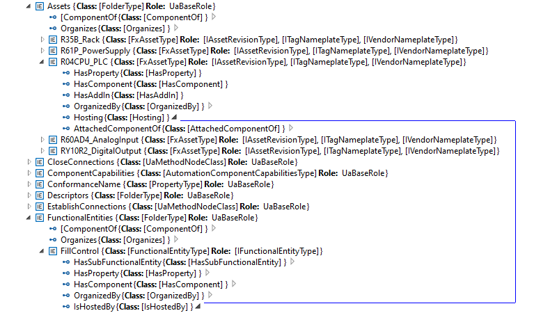
In this step of the example, the FunctionalEntity sub-model is created. See Figure F.7.
The following steps are needed to define the FunctionalEntities:
Creation of the FunctionalEntityType instances (The OPC UA FX AML Core Libraries provide the FunctionalEntityType SUC for defining a FunctionalEntity).
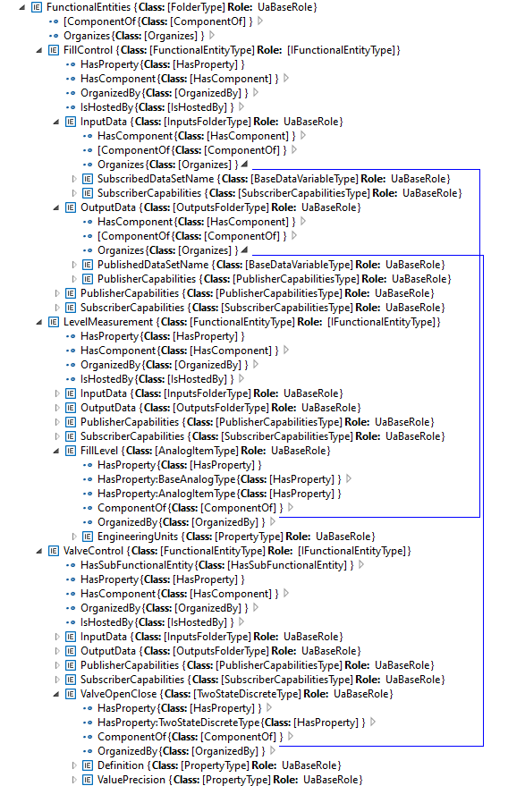
Within each FunctionalEntity, define variables for the input, output, and configuration variables, and link the variables to the FunctionalEntity using Organizes references.
Set or restrict the values in the PublisherCapabilities and SubscriberCapabilities structure. The PublisherCapabilities and SubscriberCapabilities structure exists in the FunctionalEntity sub-model at three levels: AutomationComponent, FunctionalEntity and InputData and OutputData levels.
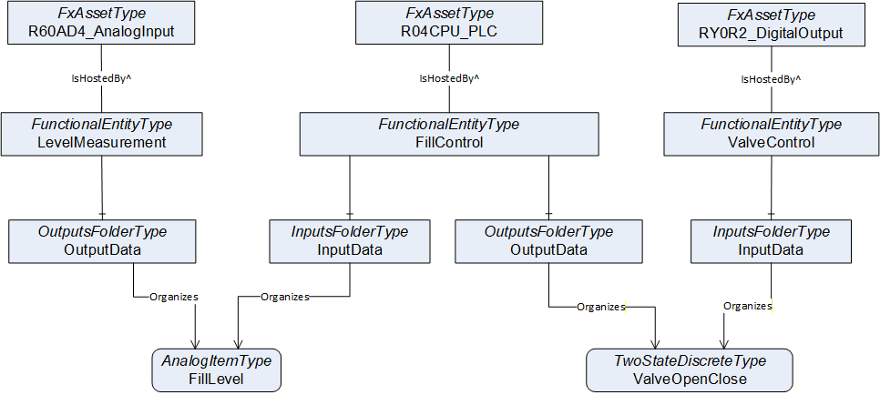
In Figure F.8, a FunctionalEntity "FillControl" is created that represents an application for controlling a valve based on input data from a level measurement. The "FillControl" FunctionalEntity is hosted by the CPU module "R04CPU_PLC".
"FillControl" uses an analogue value input, "FillLevel", and a digital output variable, "ValveOpenClose". Both Variables are organized as InputData and OutputData of the FunctionalEntity, "FillControl".The "FillLevel" signal is coming from a FunctionalEntity, "LevelMeasurement", that is hosted by the analogue input module, "R60AD4_AnalogInput", while the "ValveOpenClose" signal is sent to a FunctionalEntity, "ValveControl", hosted by the digital output module, "RY0R2_DigitalOutput".
This is shown in Figure F.9.
After setting up InputData and OutputData, the capabilities of the communication are defined. For example, the SubscriberCapabilities Variables for the "FillLevel" input signals are defined as in Figure F.10:
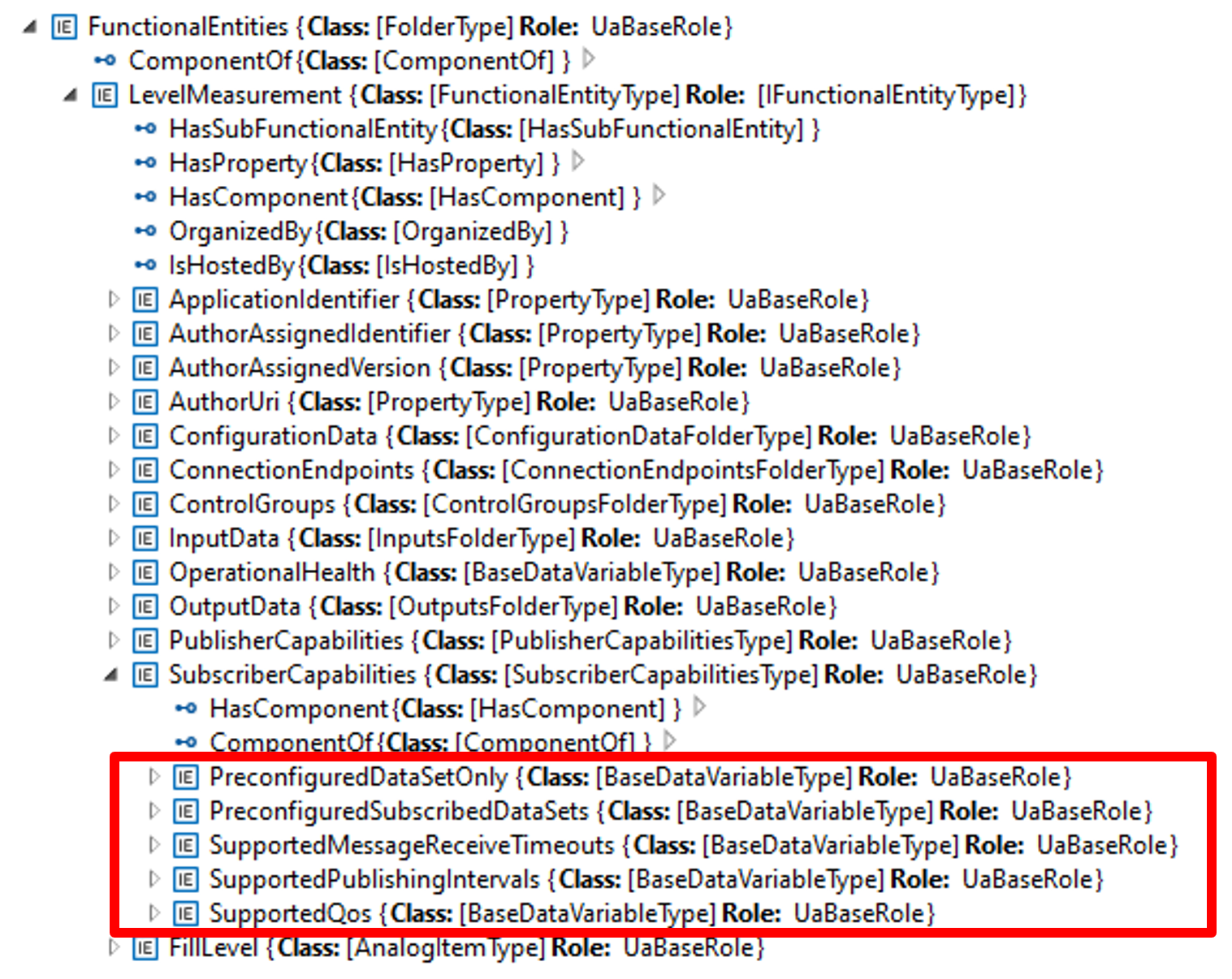
Table F.1 shows the values of the Variables used in the example:
| Variable | Value |
| PreConfiguredDataSetOnly | True |
| PreConfiguredSubscribedDataSets | ["FillLevelDataSet"] |
| SupportedMessageReceiveTimeouts | min:200, max:20000, increment:50, multiplier:1; unit:milliseconds |
| SupportedPublishingIntervals | min:50, max:5000, increment:50, multiplier:1; unit:milliseconds |
| SupportedQoS | QosCategory: opc.qos.cat://priority, DatagrammQos: opc.qos.lbl://green |