
1 Scope
This document specifies an OPC UA Information Model for the representation of a complete motion device system as an interface for higher-level control and evaluation systems. A motion device system consists out of one or more motion devices, which can be any existing or future robot type (e.g. industrial robots, mobile robots), kinematics or manipulator as well as their control units and other peripheral components.
Additionally, this document shows in Annex C the use of the OPC 40001-1 - UA CS for Machinery Part 1 - Basic Building Blocks together with the Information Model described in this part.
2 Normative references
The following documents, in whole or in part, are normatively referenced in this document and are indispensable for its application. For dated references, only the edition cited applies. For undated references, the latest edition of the referenced document (including any amendments) applies.
ISO 8373 Robots and robotic devices - Vocabulary
ISO 10218-1 Robots and robotic devices - Safety requirements for industrial robots - Part 1: Robots
OPC 10000-3, OPC Unified Architecture - Part 3: Address Space Model
OPC 10000-3
OPC 10000-4, OPC Unified Architecture - Part 4: Services
OPC 10000-4
OPC 10000-5, OPC Unified Architecture - Part 5: Information Model
OPC 10000-5
OPC 10000-100, OPC Unified Architecture - Part 100: Devices
OPC 10000-100
OPC 40001-1: OPC UA for Machinery - Basic Building Blocks
http://opcfoundation.org/UA/Machinery/
3 Terms, definitions, and conventions
For the purposes of this document, the following terms and definitions apply.
3.1 Overview
It is assumed that the reader of this document understands the basic concepts of OPC UA information modelling and the referenced documents. This specification will use these concepts to describe the Robotics Information Model.
Note that OPC UA terms and terms defined in this specification are written in italics in the specification.
3.2 Terms
| Term | Definition of Term |
| Asset management | The management of the maintenance of physical assets of an organization throughout each asset's lifecycle. |
| Automatic mode | Operational mode in which the robot control system operates in accordance with the task programme (ISO 10218). |
| Axis | The mechanical joint (ISO 8373). Joint is used as a synonym for axis. |
| Condition monitoring | Acquisition and processing of information and data that indicate the state of a machine over time (ISO 13372:2012). |
| Controller | Controlling unit of one or more motion devices. A controller can be e.g. a specific control cabinet or a PLC. |
| Industrial robot | Automatically controlled, reprogrammable multipurpose manipulator, programmable in three or more axes, which can be either fixed in place or mobile for use in industrial automation applications (ISO 10218). |
| Industrial Robot System | system comprising industrial robot, end effectors and any machinery, equipment, devices, external auxiliary axes or sensors supporting the robot performing its task (ISO 8373) |
| Joint | See Axis definition. |
| Manipulator | Machine in which the mechanism usually consists of a series of segments, jointed or sliding relative to one another, for the purpose of grasping and/or moving objects (pieces or tools) usually in several degrees of freedom (ISO 8373) |
| Manual mode | Control state that allows for the direct control by an operator (ISO 10218). |
| Motion device | A motion device has as least one axis and is a multifunctional manipulator designed to move material, parts, tools, or specialized devices through variable programmed motions for the performance of a variety of tasks. Examples are an industrial robot, positioner, or mobile platform. |
| Motion device system | The entire system in which one or more motion devices and one or more controllers are integrated, e.g. a robot system. |
| Operating mode | State of the robot control system (ISO 8373), i.e. Controller |
| Operational mode | ISO 10218-1:2011 Ch.5.7 Operational Modes |
| Operator | Person designated to start, monitor, and stop the intended operation of a robot or robot system (ISO 8373). |
| Teach pendant | Hand-held unit linked to the control system with which a robot can be programmed or moved (ISO 8373). |
| Power train | The composition of switch gears, fuses, transformers, converters, drives, motors, encoders and gears to convert power to motion of one or more axis. |
| Predictive maintenance | Maintenance performed as governed by condition monitoring programmes (ISO 13372:2012) |
| Preventive maintenance | Maintenance performed according to a fixed schedule, or according to a prescribed criterion, that detects or prevents degradation of a functional structure, system or component, in order to sustain or extend its useful life. |
| Protective stop | Type of interruption of operation that allows a cessation of motion for safeguarding purposes, and which retains the programme logic to facilitate a restart (ISO 10218). |
| Safe state | A defined state of the robot which is free of hazards |
| Safety function | A safety rated function which will signal the controller to bring motion devices to a safe state, e.g. emergency stop, protective stop |
| Safety states | Set of safety functions and states which are related to a motion device system. |
| Software | Runtime software or firmware of the controller. In ISO 8373, this is called control program, and is defined like this: Inherent set of control instructions which defines the capabilities, actions and responses of a robot or robot system NOTE This type of program is usually generated before installation and can only be modified thereafter by the manufacturer. |
| Task control | Execution engine that loads and runs task programs. Synonyms for a task control are a sequence control or a flow control. |
| Task module | A module is a self-contained unit of code that can be reused across different parts of a program or in different programs. |
| Task program | Program running on the task control. From ISO 8373: Set of instructions for motion and auxiliary functions that define the specific intended task of the robot or robot system NOTE 1 This type of program is usually generated after the installation of the robot and can be modified by a trained person under defined conditions. NOTE 2 An application is a general area of work; a task is specific within the application. |
| Tool center point | Point defined for a given application with regards to the mechanical interface coordinate system (ISO 8373) |
| User level | Current assigned user role. |
| User roles | User roles consist of specific permissions to access features within a software. Users can be assigned to roles. |
| Virtual axis | Virtual axis has no power trains directly assigned. |
Annex B contains examples of the described terms.
3.3 Abbreviations
| Abbreviation | Definition of Abbreviation |
| CPU | Central Processing Unit |
| DOF | Degrees of freedom |
| ERP | Enterprise Resource Planning |
| HMI | Human Machine Interface |
| HTTP | Hypertext Transfer Protocol |
| MES | Manufacturing Execution System |
| OPC | Open Platform Communications |
| OPC UA | OPC Unified Architecture |
| OPC 10000-100 | OPC Unified Architecture for Devices (DI) OPC Unified Architecture - Part 100 - Devices |
| PLC | Programmable logic controller |
| PMS | Preventive Maintenance System |
| TCP | Tool center point |
| TCP/IP | Transmission Control Protocol/Internet Protocol |
| TCS | Tool Coordinate System |
| UPS | Uninterruptible Power Supply |
| URI | A uniform resource identifier (URI) is a string of characters used to identify names or resources on the Internet. The URI describes the mechanism used to access resources, the computers on which resources are housed and the names of the resources on each computer. |
| URL | Uniform resource locator |
| VDMA | The Mechanical Engineering Industry Association (VDMA) represents more than 3,200 member companies in the SME-dominated mechanical and systems engineering industry in Germany and Europe. |
3.4 Conventions used in this document
3.4.1 Conventions for Node descriptions
Node definitions are specified using tables (see Table 4).
Attributes are defined by providing the Attribute name and a value, or a description of the value.
References are defined by providing the ReferenceType name, the BrowseName of the TargetNode and its NodeClass.
If the TargetNode is a component of the Node being defined in the table, the Attributes of the composed Node are defined in the same row of the table.
The DataType is only specified for Variables; "[<number>]" indicates a single-dimensional array, for multi-dimensional arrays the expression is repeated for each dimension (e.g. [2][3] for a two-dimensional array). For all arrays, the ArrayDimensions is set as identified by <number> values. If no <number> is set, the corresponding dimension is set to 0, indicating an unknown size. If no number is provided at all the ArrayDimensions can be omitted. If no brackets are provided, it identifies a scalar DataType and the ValueRank is set to the corresponding value (see OPC 10000-3). In addition, ArrayDimensions is set to null or is omitted. If it can be Any or ScalarOrOneDimension, the value is put into "{<value>}", so either "{Any}" or "{ScalarOrOneDimension}" and the ValueRank is set to the corresponding value (see OPC 10000-3) and the ArrayDimensions is set to null or is omitted. Examples are given Table 3.
| Notation | DataType | ValueRank | ArrayDimensions | Description |
| Int32 | Int32 | -1 | omitted or null | A scalar Int32. |
| Int32[] | Int32 | 1 | omitted or {0} | Single-dimensional array of Int32 with an unknown size. |
| Int32[][] | Int32 | 2 | omitted or {0,0} | Two-dimensional array of Int32 with unknown sizes for both dimensions. |
| Int32[3][] | Int32 | 2 | {3,0} | Two-dimensional array of Int32 with a size of 3 for the first dimension and an unknown size for the second dimension. |
| Int32[5][3] | Int32 | 2 | {5,3} | Two-dimensional array of Int32 with a size of 5 for the first dimension and a size of 3 for the second dimension. |
| Int32{Any} | Int32 | -2 | omitted or null | An Int32 where it is unknown if it is scalar or array with any number of dimensions. |
| Int32{ScalarOrOneDimension} | Int32 | -3 | omitted or null | An Int32 where it is either a single-dimensional array or a scalar. |
The TypeDefinition is specified for Objects and Variables.
The TypeDefinition column specifies a symbolic name for a NodeId, i.e. the specified Node points with a HasTypeDefinition Reference to the corresponding Node.
The ModellingRule of the referenced component is provided by specifying the symbolic name of the rule in the ModellingRule column. In the AddressSpace, the Node shall use a HasModellingRule Reference to point to the corresponding ModellingRule Object.
If the NodeId of a DataType is provided, the symbolic name of the Node representing the DataType shall be used.
Nodes of all other NodeClasses cannot be defined in the same table; therefore, only the used ReferenceType, their NodeClass and their BrowseName are specified. A reference to another part of this document points to their definition.
Table 4 illustrates the table. If no components are provided, the DataType, TypeDefinition and ModellingRule columns may be omitted and only a Comment column is introduced to point to the Node definition.
| Attribute | Value | ||||
| Attribute name | Attribute value. If it is an optional Attribute that is not set "-" will be used. | ||||
| References | NodeClass | BrowseName | DataType | TypeDefinition | ModellingRule |
|---|---|---|---|---|---|
| ReferenceType name | NodeClass of the TargetNode. | BrowseName of the target Node. If the Reference is to be instantiated by the server, then the value of the target Node's BrowseName is "-". | DataType of the referenced Node, only applicable for Variables. | TypeDefinition of the referenced Node, only applicable for Variables and Objects. | Referenced ModellingRule of the referenced Object. |
| NOTE Notes referencing footnotes of the table content. | |||||
Components of Nodes can be complex that is containing components by themselves. The TypeDefinition, NodeClass, DataType and ModellingRule can be derived from the type definitions, and the symbolic name can be created as defined in chapter 3.4.3.1. Therefore, those containing components are not explicitly specified; they are implicitly specified by the type definitions.
3.4.2 NodeIds and BrowseNames
3.4.2.1 NodeIds
The NodeIds of all Nodes described in this standard are only symbolic names. Annex A defines the actual NodeIds.
The symbolic name of each Node defined in this specification is its BrowseName, or, when it is part of another Node, the BrowseName of the other Node, a ".", and the BrowseName of itself. In this case "part of" means that the whole has a HasProperty or HasComponent Reference to its part. Since all Nodes not being part of another Node have a unique name in this specification, the symbolic name is unique.
The namespace for all NodeIds defined in this specification is defined in Annex A. The namespace for this NamespaceIndex is Server-specific and depends on the position of the namespace URI in the server namespace table.
Note that this specification not only defines concrete Nodes, but also requires that some Nodes shall be generated, for example one for each Session running on the Server. The NodeIds of those Nodes are Server-specific, including the namespace. But the NamespaceIndex of those Nodes cannot be the NamespaceIndex used for the Nodes defined in this specification, because they are not defined by this specification but generated by the Server.
3.4.2.2 BrowseNames
The text part of the BrowseNames for all Nodes defined in this specification is specified in the tables defining the Nodes. The NamespaceIndex for all BrowseNames defined in this specification is defined in Annex A.
If the BrowseName is not defined by this specification, a namespace index prefix like '0:EngineeringUnits' or '2:DeviceRevision' is added to the BrowseName. This is typically necessary if a property of another specification is overwritten or used in the OPC UA types defined in this specification. Table 130 provides a list of namespaces and their indexes as used in this specification.
3.4.3 Common Attributes
3.4.3.1 General
The Attributes of Nodes, their DataTypes and descriptions are defined in OPC 10000-3. Attributes not marked as optional are mandatory and shall be provided by a Server. The following tables define if the Attribute value is defined by this specification or if it is server specific.
For all Nodes specified in this specification, the Attributes named in Figure 5 shall be set as specified in the table.
| Attribute | Value |
| DisplayName | The DisplayName is a LocalizedText. Each server shall provide the DisplayName identical to the BrowseName of the Node for the LocaleId "en". Whether the server provides translated names for other LocaleIds is server specific. |
| Description | Optionally a server-specific description is provided. |
| NodeClass | Shall reflect the NodeClass of the Node. |
| NodeId | The NodeId is described by BrowseNames as defined in 3.4.2.1. |
| WriteMask | Optionally the WriteMask Attribute can be provided. If the WriteMask Attribute is provided, it shall set all non-server-specific Attributes to not writable. For example, the Description Attribute may be set to writable since a Server may provide a server-specific description for the Node. The NodeId shall not be writable, because it is defined for each Node in this specification. |
| UserWriteMask | Optionally the UserWriteMask Attribute can be provided. The same rules as for the WriteMask Attribute apply. |
| RolePermissions | Optionally server-specific role permissions can be provided. |
| UserRolePermissions | Optionally the role permissions of the current Session can be provided. The value is server-specific and depend on the RolePermissions Attribute (if provided) and the current Session. |
| AccessRestrictions | Optionally server-specific access restrictions can be provided. |
3.4.3.2 Objects
For all Objects specified in this specification, the Attributes named in Table 6 shall be set as specified in the table. The definitions for the Attributes can be found in OPC 10000-3.
| Attribute | Value |
| EventNotifier | Whether the Node can be used to subscribe to Events or not is server specific. |
3.4.3.3 Variables
For all Variables specified in this specification, the Attributes named in Table 7 shall be set as specified in the table. The definitions for the Attributes can be found in OPC 10000-3.
| Attribute | Value |
| MinimumSamplingInterval | Optionally, a server-specific minimum sampling interval is provided. |
| AccessLevel | The access level for Variables used for type definitions is server-specific, for all other Variables defined in this specification, the access level shall allow reading; other settings are server-specific. |
| UserAccessLevel | The value for the UserAccessLevel Attribute is server specific. It is assumed that all Variables can be accessed by at least one user. |
| Value | For Variables used as InstanceDeclarations, the value is server-specific; otherwise, it shall represent the value described in the text. |
| ArrayDimensions | If the ValueRank does not identify an array of a specific dimension (i.e. ValueRank <= 0) the ArrayDimensions can either be set to null or the Attribute is missing. This behaviour is server specific. If the ValueRank specifies an array of a specific dimension (i.e. ValueRank > 0) then the ArrayDimensions Attribute shall be specified in the table defining the Variable. |
| Historizing | The value for the Historizing Attribute is server specific. |
| AccessLevelEx | If the AccessLevelEx Attribute is provided, it shall have the bits 8, 9, and 10 set to 0, meaning that read and write operations on an individual Variable are atomic, and arrays can be partly written. |
3.4.3.4 VariableTypes
For all VariableTypes specified in this specification, the Attributes named in Table 8 be set as specified in the table. The definitions for the Attributes can be found in OPC 10000-3.
| Attributes | Value |
| Value | Optionally a server-specific default value can be provided. |
| ArrayDimensions | If the ValueRank does not identify an array of a specific dimension (i.e. ValueRank <= 0) the ArrayDimensions can either be set to null or the Attribute is missing. This behaviour is server specific. If the ValueRank specifies an array of a specific dimension (i.e. ValueRank > 0) then the ArrayDimensions Attribute shall be specified in the table defining the VariableType. |
3.4.3.5 Methods
For all Methods specified in this specification, the Attributes named in Table 9 shall be set as specified in the table. The definitions for the Attributes can be found in OPC 10000-3.
| Attributes | Value |
| Executable | All Methods defined in this specification shall be executable (Executable Attribute set to "True") unless it is defined differently in the Method definition. |
| UserExecutable | The value of the UserExecutable Attribute is server specific. It is assumed that all Methods can be executed by at least one user. |
3.4.3.6 Expanding conventions
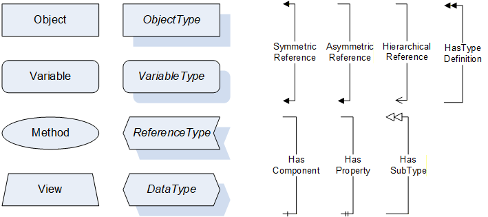
For the following illustrations, the legend is as follows:
Additional definitions:
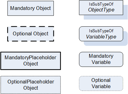
Table 10 describes the additional definitions.
| Node element | Graphical representation | Definition of node element |
| Mandatory Object | Rectangular Frame | A mandatory object with its type definition |
| Optional Object | Rectangular bold dashed Frame | An optional object with its type definition |
| Mandatory Placeholder Object | Rectangular bold Frame | A mandatory placeholder for objects with its type definition |
| Optional Placeholder Object | Rectangular dotted Frame | An optional placeholder for objects with its type definition |
| ObjectType | Rectangular Frame with shadow | An object type with its type definition |
| VariableType | Rounded rectangular Frame with shadow | A variable type with its type definition |
| Mandatory Variable | Rectangular Frame with rounded corners | A mandatory variable with its type definition |
| Optional Variable | Dotted rectangular Frame with rounded corners | An optional variable with its type definition |
3.4.3.7 Handling of not supported properties
In case of not supported Properties the following default shall be provided:
Properties with DataType String: empty string
Properties with DataType LocalizedText: empty text field
RevisionCounter Property: - 1
4 General information to OPC Robotics and OPC UA
4.1 Introduction to OPC Robotics
The OPC Robotics specification describes an information model, which aims to cover all current and future robotic systems such as:
Industrial robots
Mobile robots
Several control units
Peripheral devices, which do not have their own OPC UA server.
Part 1 provides information for asset management and condition monitoring. In future parts, the information model will be extended to cover more use cases.
The following functionalities are covered:
Provision of asset configuration and runtime data of a running motion device system and its components e.g. manipulators, axes, motors, controllers, and software
Following functions are not included and might be covered in future parts:
A messaging mechanism covered by events and alarms to provide conditions.
A state machine to inform about the status of task controls and to interact via methods.
The possibility for the operator to store customer specific information inside the motion device system e.g. location, cost centre, ERP data, ...
4.2 Introduction to OPC Unified Architecture
4.2.1 What is OPC UA?
OPC UA is an open and royalty free set of standards designed as a universal communication protocol. While there are numerous communication solutions available, OPC UA has key advantages:
A state of art security model (see OPC 10000-2).
A fault tolerant communication protocol.
An information modelling Framework that allows application developers to represent their data in a way that makes sense to them.
OPC UA has a broad scope which delivers for economies of scale for application developers. This means that a larger number of high-quality applications at a reasonable cost are available.
The OPC UA model is scalable from small devices to ERP systems. OPC UA Servers process information locally and then provide that data in a consistent format to any application requesting data - ERP, MES, PMS, Maintenance Systems, HMI, Smartphone, or a standard Browser, for example. For a more complete overview see OPC 10000-1.
4.2.2 Basics of OPC UA
As an open standard, OPC UA is based on standard internet technologies, like TCP/IP, HTTP, Web Sockets.
As an extensible standard, OPC UA provides a set of Services (see OPC 10000-4) and a basic information model Framework. This Framework provides an easy manner for creating and exposing vendor defined information in a standard way. More importantly all OPC UA Clients are expected to be able to discover and use vendor-defined information. This means OPC UA users can benefit from the economies of scale that come with generic visualization and historical applications. This specification is an example of an OPC UA Information Model designed to meet the needs of developers and users.
OPC UA Clients can be any consumer of data from another device on the network to browser based thin clients and ERP systems. The full scope of OPC UA applications is shown in Figure 3.
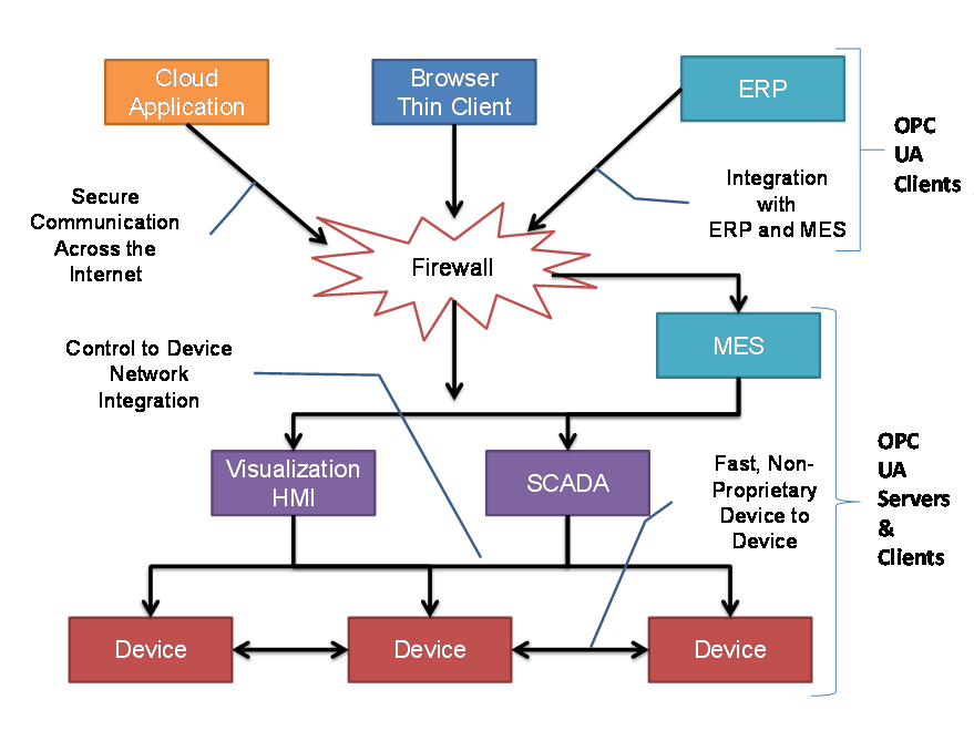
OPC UA provides a robust and reliable communication infrastructure having mechanisms for handling lost messages, failover, heartbeat, etc. With its binary encoded data, it offers a high-performing data exchange solution. Security is built into OPC UA as security requirements become increasingly important especially since environments are connected to the office network or the internet and attackers are starting to focus on automation systems.
4.2.3 Information modelling in OPC UA
4.2.3.1 Concepts
OPC UA provides a Framework that can be used to represent complex information as Objects in an AddressSpace which can be accessed with standard services. These Objects consist of Nodes connected by References. Different classes of Nodes convey different semantics. For example, a Variable Node represents a value that can be read or written. The Variable Node has an associated DataType that can define the actual value, such as a string, float, structure etc. It can also describe the Variable value as a variant. A Method Node represents a function that can be called. Every Node has a number of Attributes including a unique identifier called NodeId and non-localized name called BrowseName. An Object representing a 'Reservation' is shown in Figure 4.

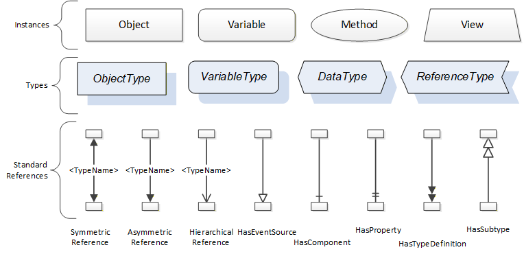
Object and Variable Nodes represent instances and they always reference a TypeDefinition (ObjectType or VariableType) Node which describes their semantics and structure. Figure 5 illustrates the relationship between an instance and its TypeDefinition.
The type Nodes are templates that define all the children that can be present in an instance of the type. In the example in Figure 5 the PersonType ObjectType defines two children: First Name and Last Name. All instances of PersonType are expected to have the same children with the same BrowseNames. Within a type the BrowseNames uniquely identifies the children. This means Client applications can be designed to search for children based on the BrowseNames from the type instead of NodeIds. This eliminates the need for manual reconfiguration of systems if a Client uses types that multiple Servers implement.
OPC UA also supports the concept of sub-typing. This allows a modeller to take an existing type and extend it. There are rules regarding sub-typing defined in OPC 10000-3, but in general they allow the extension of a given type or the restriction of a DataType. For example, the modeller may decide that the existing ObjectType in some cases needs an additional Variable. The modeller can create a subtype of the ObjectType and add the Variable. A Client that is expecting the parent type can treat the new type as if it were of the parent type. Regarding DataTypes, subtypes can only restrict. If a Variable is defined to have a numeric value, a sub type could restrict it to a float.

References allow Nodes to be connected in ways that describe their relationships. All References have a ReferenceType that specifies the semantics of the relationship. References can be hierarchical or non-hierarchical. Hierarchical references are used to create the structure of Objects and Variables. Non-hierarchical are used to create arbitrary associations. Applications can define their own ReferenceType by creating subtypes of an existing ReferenceType. Subtypes inherit the semantics of the parent but may add additional restrictions. Figure 6 depicts several References, connecting different Objects.

The figures above use a notation that was developed for the OPC UA specification. The notation is summarized in Figure 7. UML representations can also be used; however, the OPC UA notation is less ambiguous because there is a direct mapping from the elements in the figures to Nodes in the AddressSpace of an OPC UA Server.
A complete description of the different types of Nodes and References can be found in OPC 10000-3 and the base structure is described in OPC 10000-5.
OPC UA specification defines a very wide range of functionality in its basic information model. It is not expected that all Clients or Servers support all functionality in the OPC UA specifications. OPC UA includes the concept of Profiles, which segment the functionality into testable certifiable units. This allows the definition of functional subsets (that are expected to be implemented) within a companion specification. The Profiles do not restrict functionality but generate requirements for a minimum set of functionality (see OPC 10000-7).
4.2.3.2 Namespaces
OPC UA allows information from many different sources to be combined into a single coherent AddressSpace. Namespaces are used to make this possible by eliminating naming and id conflicts between information from different sources. Namespaces in OPC UA have a globally unique string called a NamespaceUri and a locally unique integer called a NamespaceIndex. The NamespaceIndex is only unique within the context of a Session between an OPC UA Client and an OPC UA Server. The Services defined for OPC UA use the NamespaceIndex to specify the Namespace for qualified values.
There are two types of values in OPC UA that are qualified with Namespaces: NodeIds and QualifiedNames. NodeIds are globally unique identifiers for Nodes. This means the same Node with the same NodeId can appear in many Servers. This, in turn, means Clients can have built in knowledge of some Nodes. OPC UA Information Models define globally unique NodeIds for the TypeDefinitions defined by the Information Model.
QualifiedNames are non-localized names qualified with a Namespace. They are used for the BrowseNames of Nodes and allow the same names to be used by different information models without conflict. TypeDefinitions are not allowed to have children with duplicate BrowseNames; however, instances do not have that restriction.
4.2.3.3 Companion Specifications
An OPC UA companion specification for an industry specific vertical market describes an Information Model by defining ObjectTypes, VariableTypes, DataTypes and ReferenceTypes that represent the concepts used in the vertical market, and potentially also well-defined Objects as entry points into the AddressSpace.
5 Use Cases
Part 1 of this companion specification describes an interface that provides access to asset management and condition monitoring data of motion device systems. Based on the provided data the following use cases are supported:
Supervision: With the provided data by the companion specification the robot system can be supervised and monitored. Functional analysis of individual robot systems within the factory ground is possible. During production phase the companion specification provides data about the operational and safety states as well as process data.
Condition monitoring: Condition monitoring is the process of determining the condition of machinery while in operation, to identify a significant change which is indicative of a developing fault. This is a major component of Predictive Maintenance where the maintenance is scheduled to shorten the downtime. The typical parameters needed for condition monitoring like motor temperature, load, on time are provided by the companion specification for robotics.
Asset management: The companion specification for robotics provides detailed information of the main electrical and mechanical parts like part number, brand name, serial number etc. With these data an effective maintenance is possible because the technician knows in advance which parts need to be changed and can be prepared.
Remote operation: The companion specification provides state machines at the controller and the task control level to provide remote operation capability via OPC UA. This includes, upload, download, loading, unloading, starting, stopping of robot programs, handling conditions etc.
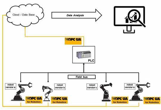
Figure 8 shows the communication structure with OPC UA.
6 OPC Robotics Information Model overview
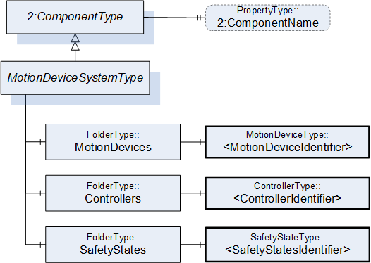
The MotionDeviceSystemType as a subtype of the ComponentType (OPC UA for Devices) is used as the root object representing the motion device system with all its subcomponents, see Figure 10.
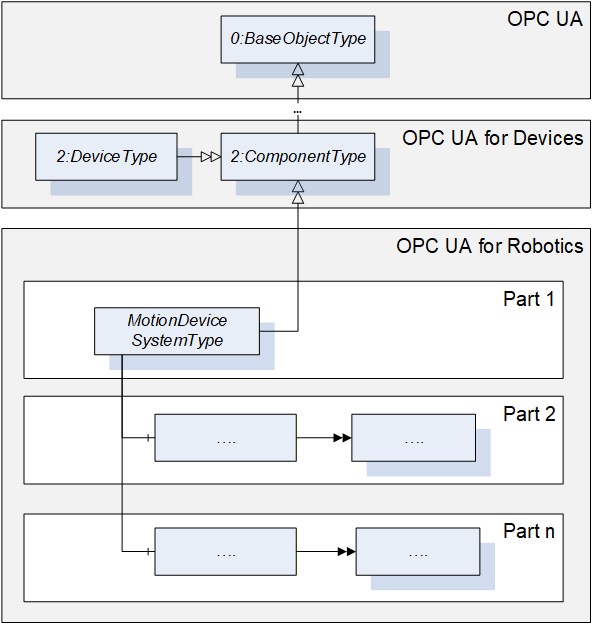
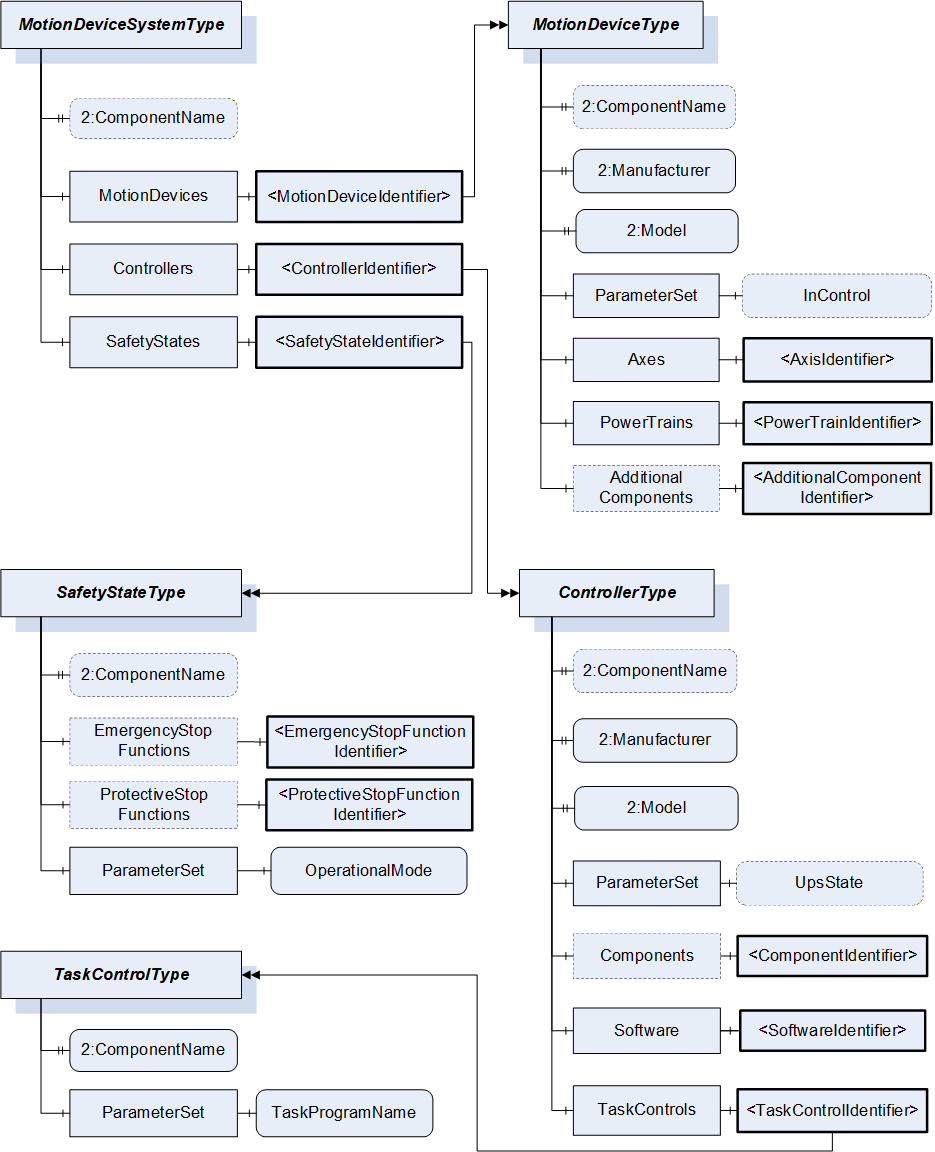
Figure 11 shows the main objects and the relations between them in an abstract view.
In Part 1 in general all variables and properties are read only unless stated otherwise in the description. A vendor can decide to provide variables or properties as writeable by client side as well.
7 OPC UA ObjectTypes
7.1 MotionDeviceSystemType ObjectType Definition
7.1.1 Overview
The MotionDeviceSystemType provides a representation of a motion device system as an entry point to the OPC UA device set. At least one instance of a MotionDeviceSystemType must be instantiated in the DeviceSet. This instance organises the information model of a complete robotics system using instances of the described ObjectTypes. The MotionDeviceSystemType is formally defined in Table 11.
7.1.2 MotionDeviceSystemType definition
| Attribute | Value | ||||
| BrowseName | MotionDeviceSystemType | ||||
| IsAbstract | False | ||||
| References | Node Class | BrowseName | DataType | TypeDefinition | Other |
|---|---|---|---|---|---|
| Subtype of the ComponentType defined in OPC Unified Architecture for Devices (DI), inheriting the InstanceDeclarations of that Node | |||||
| 0:HasComponent | Object | MotionDevices | 0:FolderType | M | |
| 0:HasComponent | Object | Controllers | 0:FolderType | M | |
| 0:HasComponent | Object | SafetyStates | 0:FolderType | M | |
| 0:HasProperty | Variable | 2:ComponentName | 0:LocalizedText | 0:PropertyType | O |
| Conformance Units | |||||
|---|---|---|---|---|---|
| Rob MotionDeviceSystem Base |
The components of the MotionDeviceSystemType have additional subcomponents which are defined in Table 12.
| Source Path | Reference | NodeClass | BrowseName | DataType | TypeDefinition | Others |
| MotionDevices | 0:HasComponent | Object | <MotionDeviceIdentifier> | MotionDeviceType | MP | |
| Controllers | 0:HasComponent | Object | <ControllerIdentifier> | ControllerType | MP | |
| SafetyStates | 0:HasComponent | Object | <SafetyStateIdentifier> | SafetyStateType | MP |
A motion device system may consist of multiple motion devices, controllers, and safety systems. References are used to describe the relations between those subsystems. Examples are described in Annex B.
The ComponentName property provides a user writeable name provided by the vendor, integrator, or user of the device. The ComponentName may be a default name given by the vendor. This property is defined by ComponentType defined in OPC 10000-100.
MotionDevices is a container for one or more instances of the MotionDeviceType.
Controllers is a container for one or more instances of the ControllerType.
SafetyStates is a container for one or more instances of the SafetyStatesType.
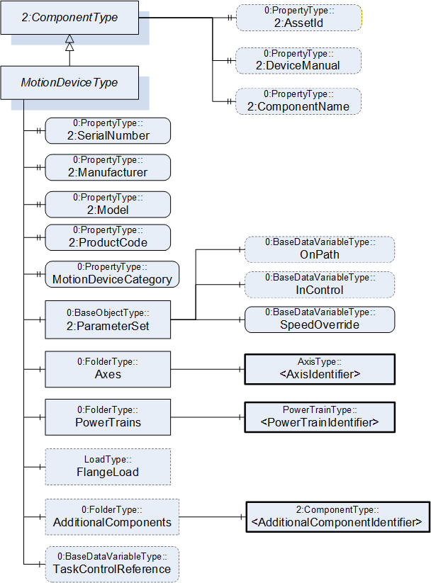
7.2 MotionDeviceType ObjectType Definition
7.2.1 Overview
The MotionDeviceType describes one independent motion device, e.g. a manipulator, a turn table, or a linear axis. Examples are described in Annex B.
A MotionDevice shall have at least one axis and one power train. The MotionDeviceType is formally defined in 7.2.2
7.2.2 MotionDeviceType definition
| Attribute | Value | ||||
| BrowseName | MotionDeviceType | ||||
| IsAbstract | False | ||||
| References | Node Class | BrowseName | DataType | TypeDefinition | Other |
|---|---|---|---|---|---|
| Subtype of the ComponentType defined in OPC Unified Architecture for Devices (DI), inheriting the InstanceDeclarations of that Node | |||||
| 0:HasProperty | Variable | 2:SerialNumber | 0:String | 0:PropertyType | M |
| 0:HasProperty | Variable | 2:Manufacturer | 0:LocalizedText | 0:PropertyType | M |
| 0:HasProperty | Variable | 2:Model | 0:LocalizedText | 0:PropertyType | M |
| 0:HasProperty | Variable | 2:ProductCode | 0:String | 0:PropertyType | M |
| 0:HasProperty | Variable | MotionDeviceCategory | MotionDeviceCategoryEnumeration | 0:PropertyType | M |
| 0:HasComponent | Variable | TaskControlReference | 0:NodeId | 0:BaseDataVariableType | O |
| 0:HasComponent | Object | 2:ParameterSet | 0:BaseObjectType | M | |
| 0:HasComponent | Object | Axes | 0:FolderType | M | |
| 0:HasComponent | Object | PowerTrains | 0:FolderType | M | |
| 0:HasComponent | Object | FlangeLoad | LoadType | O | |
| 0:HasComponent | Object | AdditionalComponents | 0:FolderType | O | |
| 0:HasProperty | Variable | 2:AssetId | 0:String | 0:PropertyType | O |
| 0:HasProperty | Variable | 2:DeviceManual | 0:String | 0:PropertyType | O |
| 0:HasProperty | Variable | 2:ComponentName | 0:LocalizedText | 0:PropertyType | O |
| Conformance Units | |||||
|---|---|---|---|---|---|
| Rob MotionDeviceSystem Base | |||||
| Rob MotionDevice AM Extended | |||||
| Rob MotionDevice CM Extended | |||||
| Rob MotionDevice Flangeload | |||||
| Rob TC Relationship |
The components of the MotionDeviceType have additional subcomponents which are defined in Table 14.
| Source Path | Reference | NodeClass | BrowseName | DataType | TypeDefinition | Other |
| 2:ParameterSet | 0:HasComponent | Variable | OnPath | 0:Boolean | 0:BaseDataVariableType | O |
| 2:ParameterSet | 0:HasComponent | Variable | InControl | 0:Boolean | 0:BaseDataVariableType | O |
| 2:ParameterSet | 0:HasComponent | Variable | SpeedOverride | 0:Double | 0:BaseDataVariableType | M |
| Axes | 0:HasComponent | Object | <AxisIdentifier> | AxisType | MP | |
| PowerTrains | 0:HasComponent | Object | <PowerTrainIdentifier> | PowerTrainType | MP | |
| AdditionalComponents | 0:HasComponent | Object | <AdditionalComponentIdentifier> | 0:BaseObjectType | MP |
The SerialNumber property is a unique production number assigned by the manufacturer of the device. This is often stamped on the outside of the device and may be used for traceability and warranty purposes. This property is derived from ComponentType defined in OPC 10000-100.
The Manufacturer property provides the name of the company that manufactured the device. This property is derived from ComponentType defined in OPC 10000-100.
The Model property provides the name of the product. This property is derived from ComponentType defined in OPC 10000-100.
The ProductCode property provides a unique combination of numbers and letters used to identify the product. It may be the order information displayed on type shields or in ERP systems. This property is derived from ComponentType defined in OPC 10000-100.
The AssetId property is a user writable alphanumeric character sequence uniquely identifying a component. The vendor, integrator or user of the device provides the ID. It contains typically an identifier in a branch, use case or user specific naming scheme. This could be for example a reference to an electric scheme. For electric schemes typically EN 81346-2 is used. A use case could be to build up a location-oriented view in a spare part management client software. It enables to identify parts with the same article number which is not possible if this entry is not used. This property is defined by ComponentType defined in OPC 10000-100.
The DeviceManual property allows specifying an address of the user manual for the device. It may be a pathname in the file system or a URL (Web address). This property is defined by ComponentType defined in OPC 10000-100.
The ComponentName property provides a user writeable name provided by the vendor, integrator, or user of the device. The ComponentName may be a default name given by the vendor. This property is defined by ComponentType defined in OPC 10000-100.
FlangeLoad provides data for the load at the flange or mounting point of the motion device.
The variable MotionDeviceCategory provides the kind of motion device defined by MotionDeviceCategoryEnumeration based on ISO 8373 (10.1).
The Variable TaskControlReference provides a NodeId pointing to the instance of TaskControlOperationType defined in 7.15, which controls this motion device in combination with the loaded program.
Description of ParameterSet of MotionDeviceType:
Variable OnPath: The variable OnPath is true if the motion device is on or near enough the planned program path such that program execution can continue. If the MotionDevice deviates too much from this path in case of errors or an emergency stop, this value becomes false. If OnPath is false, the motion device needs repositioning to continue program execution.
Variable InControl: The variable InControl provides the information if the actuators (in most cases a motor) of the motion device are powered up and in control: "true". The motion device might be in a standstill.
Variable SpeedOverride: The SpeedOverride provides the current speed setting in percent of programmed speed (0 - 100%).
Axes is a container for one or more instances of the AxisType (7.3).
PowerTrains is a container for one or more instances of the PowerTrainType.
AdditionalComponents is a container for one or more instances of any other ObjectType (any subtype of 0:BaseObjectType). The listed components are installed at the motion device, e.g. an IO-board.
NOTE: Components like motors or gears of a motion device are placed inside the power train object and not inside this AdditionalComponents container. The intention of this folder is to integrate devices which are defined in companion specifications that use OPC 10000-100 ComponentType. From this specification, only instances of AuxiliaryComponentType and DriveType can be used in this container.
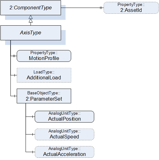
7.3 AxisType ObjectType Definition
7.3.1 Overview
The AxisType describes an axis of a motion device. It is formally defined in Table 15.
7.3.2 AxisType definition
| Attribute | Value | ||||
| BrowseName | AxisType | ||||
| IsAbstract | False | ||||
| References | Node Class | BrowseName | DataType | TypeDefinition | Other |
|---|---|---|---|---|---|
| Subtype of the ComponentType defined in OPC Unified Architecture for Devices (DI), inheriting the InstanceDeclarations of that Node | |||||
| 0:HasProperty | Variable | MotionProfile | AxisMotionProfileEnumeration | 0:PropertyType | M |
| 0:HasComponent | Object | AdditionalLoad | LoadType | O | |
| 0:HasComponent | Object | 2:ParameterSet | 0:BaseObjectType | M | |
| Requires | Object | <PowerTrainIdentifier> | PowerTrainType | OP | |
| 0:HasProperty | Variable | 2:AssetId | 0:String | 0:PropertyType | O |
| Conformance Units | |||||
|---|---|---|---|---|---|
| Rob MotionDeviceSystem Base | |||||
| Rob Axis AM Extended | |||||
| Rob Axis CM Extended | |||||
| Rob Axis AdditionalLoad |
The components of the AxisType have additional subcomponents which are defined in Table 16.
| Source Path | Reference | NodeClass | BrowseName | DataType | TypeDefinition | Others |
| 2:ParameterSet | 0:HasComponent | Variable | ActualPosition | 0:Double | 0:AnalogUnitType | M |
| 2:ParameterSet | 0:HasComponent | Variable | ActualSpeed | 0:Double | 0:AnalogUnitType | O |
| 2:ParameterSet | 0:HasComponent | Variable | ActualAcceleration | 0:Double | 0:AnalogUnitType | O |
The AssetId property is a user writable alphanumeric character sequence uniquely identifying a component. The vendor, integrator or user of the device provides the ID. It contains typically an identifier in a branch, use case or user specific naming scheme. This could be for example a reference to an electric scheme. For electric schemes typically EN 81346-2 is used. The AssetId of the AxisType provides a manufacturer-specific axis identifier within the control system. This property is defined by ComponentType defined in OPC 10000-100.
The MotionProfile property provides the kind of axis motion as defined by the AxisMotionProfileEnumeration (10.2)
AdditionalLoad provides data for the load that is mounted on this axis, e.g., a transformer for welding.
The Requires reference provides the relationship of axes to power trains. For complex kinematics this does not need to be a one-to-one relationship, because more than one power train might influence the motion of one axis. This reference connects all power trains to an axis that must be actively driven when only this axis should move and all other axes should stand still.
Virtual axes that are not actively driven by a power train do not have this reference. The InverseName is IsRequiredBy.
Description of ParameterSet of AxisType:
Variable ActualPosition: The ActualPosition variable provides the current position of the axis and may have limits. If the axis has physical limits, the EURange property of the AnalogUnitType shall be provided.
Variable ActualSpeed: The ActualSpeed variable provides the axis speed. Applicable speed limits of the axis shall be provided by the EURange property of the AnalogUnitType.
Variable ActualAcceleration: The ActualAcceleration variable provides the axis acceleration. Applicable acceleration limits of the axis shall be provided by the EURange property of the AnalogUnitType.
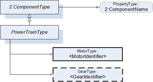
7.4 PowerTrainType ObjectType Definition
7.4.1 Overview
A power train typically consists of one motor and gear to provide the required torque. Often there is a one-to-one relation between axes and power trains, but it is also possible to have axis coupling and thus one power train can move multiple axes and one axis can be moved by multiple power trains. One power train can have multiple drives, motors, and gears when these components move logically the same axes, for example in a master/slave setup. Examples are described in Annex B. The PowerTrainType represents instances of power trains of a motion device and is formally defined in
Table 17.
7.4.2 PowerTrainType definition
| Attribute | Value | ||||
| BrowseName | PowerTrainType | ||||
| IsAbstract | False | ||||
| References | Node Class | BrowseName | DataType | TypeDefinition | Other |
|---|---|---|---|---|---|
| Subtype of the ComponentType defined in OPC Unified Architecture for Devices (DI), inheriting the InstanceDeclarations of that Node | |||||
| 0:HasComponent | Object | <MotorIdentifier> | MotorType | MP | |
| 0:HasComponent | Object | <GearIdentifier> | GearType | OP | |
| Moves | Object | <AxisIdentifier> | AxisType | OP | |
| HasSlave | Object | <PowerTrainIdentifier> | PowerTrainType | OP | |
| 0:HasProperty | Variable | 2:ComponentName | 0:LocalizedText | 0:PropertyType | O |
| Conformance Units | |||||
|---|---|---|---|---|---|
| Rob MotionDeviceSystem Base | |||||
| Rob PowerTrain AM Extended |
The ComponentName property provides a user writable name provided by the vendor, integrator, or user of the device. The ComponentName may be a default name given by the vendor.
The ComponentName of the PowerTrainType provides a manufacturer-specific power train identifier within the control system.
This property is defined by ComponentType defined in OPC 10000-100.
<MotorIdentifier> indicates that a power train contains one or more motors represented by MotorType instances.
The IsConnectedTo ReferenceType defined in 8.6 is intended to provide the relationship between a motor and a gear of a power train.
<GearIdentifier> indicates that a power train may contain one or more gears represented by GearType instances.
The IsConnectedTo ReferenceType defined in 8.6 is intended to provide the relationship between a motor and a gear of a power train.
Moves is a reference to provide the relationship of power trains to axes. For complex kinematics this does not need to be a one-to-one relationship, because a power train might influence the motion of more than one axis. This reference connects all axis to a power train that that move when only this power train moves and all other powertrains stand still. The InverseName is IsMovedBy.
HasSlave is a reference to provide the master-slave relationship of power trains which provide torque for a common axis. The InverseName is IsSlaveOf.
7.5 MotorType ObjectType Definition
7.5.1 Overview
The MotorType describes a motor in a power train. It is formally defined in Table 18.
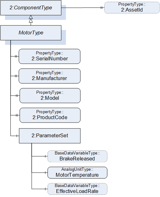
7.5.2 MotorType definition
| Attribute | Value | ||||
| BrowseName | MotorType | ||||
| IsAbstract | False | ||||
| References | Node Class | BrowseName | DataType | TypeDefinition | Other |
|---|---|---|---|---|---|
| Subtype of the ComponentType defined in OPC Unified Architecture for Devices (DI), inheriting the InstanceDeclarations of that Node | |||||
| 0:HasProperty | Variable | 2:SerialNumber | 0:String | 0:PropertyType | M |
| 0:HasProperty | Variable | 2:Manufacturer | 0:LocalizedText | 0:PropertyType | M |
| 0:HasProperty | Variable | 2:Model | 0:LocalizedText | 0:PropertyType | M |
| 0:HasProperty | Variable | 2:ProductCode | 0:String | 0:PropertyType | M |
| 0:HasComponent | Object | 2:ParameterSet | 0:BaseObjectType | M | |
| IsDrivenBy | Object | <DriveIdentifier> | 0:BaseObjectType | OP | |
| 0:HasProperty | Variable | 2:AssetId | 0:String | 0:PropertyType | O |
| Conformance Units | |||||
|---|---|---|---|---|---|
| Rob MotionDeviceSystem Base | |||||
| Rob Motor AM Extended | |||||
| Rob Motor CM Extended |
The components of the MotorType have additional subcomponents which are defined in Table 19.
| Source Path | Reference | NodeClass | BrowseName | DataType | TypeDefinition | Others |
| 2:ParameterSet | 0:HasComponent | Variable | BrakeReleased | 0:Boolean | 0:BaseDataVariableType | O |
| 2:ParameterSet | 0:HasComponent | Variable | MotorTemperature | 0:Double | AnalogUnitType | M |
| 2:ParameterSet | 0:HasComponent | Variable | EffectiveLoadRate | 0:UInt16 | 0:BaseDataVariableType | O |
The SerialNumber property is a unique production number assigned by the manufacturer of the device. This is often stamped on the outside of the device and may be used for traceability and warranty purposes. This property is derived from ComponentType defined in OPC 10000-100.
The Manufacturer property provides the name of the company that manufactured the device. This property is derived from ComponentType defined in OPC 10000-100.
The Model property provides the name of the product. This property is derived from ComponentType defined in OPC 10000-100.
The ProductCode property provides a unique combination of numbers and letters used to identify the product. It may be the order information displayed on type shields or in ERP systems. This property is derived from ComponentType defined in OPC 10000-100.
The AssetId property is a user writable alphanumeric character sequence uniquely identifying a component. The vendor, integrator or user of the device provides the ID. It contains typically an identifier in a branch, use case or user specific naming scheme.
This could be for example a reference to an electric scheme. For electric schemes typically EN 81346-2 is used.
A use case could be to build up a location-oriented view in a spare part management client software. It enables to identify parts with the same article number which is not possible if this entry is not used.
This property is defined by ComponentType defined in OPC 10000-100.
IsDrivenBy is a reference to provide a relationship from a motor to a drive, which can be a multi-slot-drive or single slot drive. The TypeDefinition of the reference destination as BaseObjectType provides the possibility to point to a slot of a multi-slot-drive or a motor-integrated-drive. If this reference points to a physical drive (and not a drive slot) it should point to an DriveType.
Annex B.10 shows different possibilities of usage.
Description of ParameterSet of MotorType:
Variable BrakeReleased: The BrakeReleased is an optional variable used only for motors with brakes. If BrakeReleased is TRUE the motor is free to run. FALSE means that the motor shaft is locked by the brake.
Variable MotorTemperature: The MotorTemperature provides the temperature of the motor. If there is no temperature sensor the value is set to "null".
Variable EffectiveLoadRate: EffectiveLoadRate is expressed as a percentage of maximum continuous load. The Joule integral is typically used to calculate the current load, i.e.:
| Duration should be defined and documented by the vendor. |
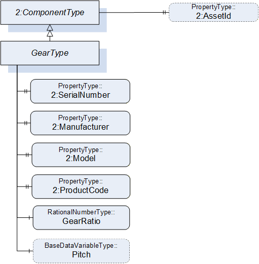
7.6 GearType Definition
7.6.1 Overview
The GearType describes a gear in a power train, e.g. a gear box or a spindle. It is formally defined in Table 20.
7.6.2 GearType definition
| Attribute | Value | ||||
| BrowseName | GearType | ||||
| IsAbstract | False | ||||
| References | Node Class | BrowseName | DataType | TypeDefinition | Other |
|---|---|---|---|---|---|
| Subtype of the ComponentType defined in OPC Unified Architecture for Devices (DI), inheriting the InstanceDeclarations of that Node | |||||
| 0:HasProperty | Variable | 2:SerialNumber | 0:String | 0:PropertyType | M |
| 0:HasProperty | Variable | 2:Manufacturer | 0:LocalizedText | 0:PropertyType | M |
| 0:HasProperty | Variable | 2:Model | 0:LocalizedText | 0:PropertyType | M |
| 0:HasProperty | Variable | 2:ProductCode | 0:String | 0:PropertyType | M |
| 0:HasComponent | Variable | GearRatio | 0:RationalNumber | 0:RationalNumberType | M |
| 0:HasComponent | Variable | Pitch | 0:Double | 0:BaseDataVariableType | O |
| 0:HasProperty | Variable | 2:AssetId | 0:String | 0:PropertyType | O |
| Conformance Units | |||||
|---|---|---|---|---|---|
| Rob Gear CM Extended | |||||
| Rob Gear AM Extended |
In case of a one-to-one relation between powertrains and axes, gear ratio and pitch may reflect the relation between motor and axis velocities. This is not possible when axis coupling is involved because different ratios for all motor-axis combinations may be needed. Additionally, there could be a nonlinear coupling between the load side of the gear box and the axis. Thus, GearRatio and Pitch only reflect the properties of the physical gear box and it may not be possible to use these values to transform between axis and motor movements.
The SerialNumber property is a unique production number assigned by the manufacturer of the device. This is often stamped on the outside of the device and may be used for traceability and warranty purposes. This property is derived from ComponentType defined in OPC 10000-100.
The Manufacturer property provides the name of the company that manufactured the device. This property is derived from ComponentType defined in OPC 10000-100.
The Model property provides the name of the product. This property is derived from ComponentType defined in OPC 10000-100.
The ProductCode property provides a unique combination of numbers and letters used to identify the product. It may be the order information displayed on type shields or in ERP systems. This property is derived from ComponentType defined in OPC 10000-100.
The AssetId property is a user writable alphanumeric character sequence uniquely identifying a component. The vendor, integrator or user of the device provides the ID. It contains typically an identifier in a branch, use case or user specific naming scheme. This could be for example a reference to an electric scheme. For electric schemes typically EN 81346-2 is used. A use case could be to build up a location-oriented view in a spare part management client software. It enables to identify parts with the same article number which is not possible if this entry is not used. This property is defined by ComponentType defined in OPC 10000-100.
GearRatio is the transmission ratio of the gear expressed as a fraction as input velocity (motor side) by output velocity (load side).
Pitch describes the distance covered in millimetres (mm) for linear motion per one revolution of the output side of the driving unit. Pitch is used in combination with GearRatio to describe the overall transmission from input to output of the gear.
Calculation formula:
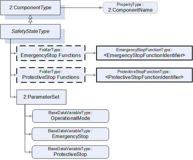
7.7 SafetyStateType ObjectType Definition
7.7.1 Overview
SafetyStateType describes the safety states of the motion devices and controllers. One motion device system is associated with one or more instances of the SafetyStateType.
The SafetyStateType was modelled directly in the MotionDeviceSystemType for the following reasons:
The manufacturers of systems have different concepts where safety is functional located, e.g. the hardware and software implementation.
The safety state typically applies to the entire robotic system. If multiple safety state instances are implemented in robotic systems, these can be represented by individual instances of the SafetyStateType and associated with the controller by reference.
The safety state is for informational purpose only and not intended for use with functional safety applications as defined in IEC 61508.
The SafetyStateType is formally defined in Table 21.
7.7.2 SafetyStateType definition
| Attribute | Value | ||||
| BrowseName | SafetyStateType | ||||
| IsAbstract | False | ||||
| References | Node Class | BrowseName | DataType | TypeDefinition | Other |
|---|---|---|---|---|---|
| Subtype of the ComponentType defined in OPC Unified Architecture for Devices (DI), inheriting the InstanceDeclarations of that Node | |||||
| 0:HasComponent | Object | EmergencyStopFunctions | 0:FolderType | O | |
| 0:HasComponent | Object | ProtectiveStopFunctions | 0:FolderType | O | |
| 0:HasComponent | Object | 2:ParameterSet | 0:BaseObjectType | M | |
| 0:HasProperty | Variable | 2:ComponentName | 0:LocalizedText | 0:PropertyType | O |
| Conformance Units | |||||
|---|---|---|---|---|---|
| Rob MotionDeviceSystem Base | |||||
| Rob Emergency Stop Function | |||||
| Rob Protective Stop Function |
| Source Path | Reference | NodeClass | BrowseName | DataType | TypeDefinition | Others |
| EmergencyStopFunctions | 0:HasComponent | Object | <EmergencyStopFunctionIdentifier> | EmergencyStopFunctionType | MP | |
| ProtectiveStopFunctions | 0:HasComponent | Object | <ProtectiveStopFunctionIdentifier> | ProtectiveStopFunctionType | MP | |
| 2:ParameterSet | 0:HasComponent | Variable | OperationalMode | OperationalModeEnumeration | 0:BaseDataVariableType | M |
| 2:ParameterSet | 0:HasComponent | Variable | EmergencyStop | 0:Boolean | 0:BaseDataVariableType | M |
| 2:ParameterSet | 0:HasComponent | Variable | ProtectiveStop | 0:Boolean | 0:BaseDataVariableType | M |
The ComponentName property provides a user writable name provided by the vendor, integrator, or user of the device. The ComponentName may be a default name given by the vendor. This property is defined by ComponentType defined in OPC 10000-100.
EmergencyStopFunctions is a container for one or more instances of the EmergencyStopFunctionType. The number and names of emergency stop functions is vendor specific. When provided, this object contains a list of all emergency stop functions with names and current state. See description of EmergencyStopFunctionType for examples of emergency stop functions.
ProtectiveStopFunctions is a container for one or more instances of the ProtectiveStopFunctionType. The number and names of protective stop functions is vendor specific. When provided, this object contains a list of all protective stop functions with names and current state. See description of ProtectiveStopFunctionType for examples of protective stop functions.
Description of ParameterSet of SafetyStateType:
The OperationalMode variable provides information about the current operational mode. Allowed values are described in OperationalModeEnumeration (10.4).
The EmergencyStop variable is TRUE if one or more of the emergency stop functions in the robot system are active, FALSE otherwise. If the EmergencyStopFunctions object is provided, then the value of this variable is TRUE if one or more of the listed emergency stop functions are active.
The ProtectiveStop variable is TRUE if one or more of the enabled protective stop functions in the system are active, FALSE otherwise. If the ProtectiveStopFunctions object is provided, then the value of this variable is TRUE if one or more of the listed protective stop functions are enabled and active.
7.8 EmergencyStopFunctionType ObjectType Definition
7.8.1 Overview
According to ISO 10218-1:2011 Ch.5.5.2 Emergency stop, the robot shall have one or more emergency stop functions. This shall be done with the help of the EmergencyStopFunctionType is defined in Table 23.
7.8.2 EmergencyStopFunctionType definition
| Attribute | Value | ||||
| BrowseName | EmergencyStopFunctionType | ||||
| References |
Node
Class | BrowseName | DataType | TypeDefinition |
Modelling
Rule |
|---|---|---|---|---|---|
| Subtype of the BaseObjectType defined in OPC Unified Architecture | |||||
| 0:HasProperty | Variable | Name | 0:String | 0:PropertyType | M |
| 0:HasComponent | Variable | Active | 0:Boolean | 0:BaseDataVariableType | M |
| Conformance Units | |||||
|---|---|---|---|---|---|
| Rob Emergency Stop Function |
The Name of the EmergencyStopFunctionType provides a manufacturer-specific emergency stop function identifier within the safety system. The only named emergency stop function in the ISO 10218-1:2011 standard is the "Pendant emergency stop function". Other than that, the standard does not give any indication on naming of emergency stop functions.
The Active variable is TRUE if this emergency stop function is active, e.g. that the emergency stop button is pressed, FALSE otherwise.
7.9 ProtectiveStopFunctionType ObjectType Definition
7.9.1 Overview
According to ISO 10218-1:2011 Ch.5.5.3 the robot shall have one or more protective stop functions designed for the connection of external protective devices. This type is formally defined in Table 24
7.9.2 ProtectiveStopFunctionType definition
| Attribute | Value | ||||
| BrowseName | ProtectiveStopFunctionType | ||||
| References | NodeClass | BrowseName | DataType | TypeDefinition | Others |
|---|---|---|---|---|---|
| Subtype of the BaseObjectType defined in OPC Unified Architecture | |||||
| 0:HasProperty | Variable | Name | 0:String | 0:PropertyType | M |
| 0:HasComponent | Variable | Enabled | 0:Boolean | 0:BaseDataVariableType | M |
| 0:HasComponent | Variable | Active | 0:Boolean | 0:BaseDataVariableType | M |
| Conformance Units | |||||
|---|---|---|---|---|---|
| Rob Protective Stop Function |
The Name of the ProtectiveStopFunctionType provides a manufacturer-specific protective stop function identifier within the safety system.
The Enabled variable is TRUE if this protective stop function is currently supervising the system, FALSE otherwise. A protective stop function may or may not be always enabled, e.g. the protective stop function of the safety doors is typically enabled in automatic operational mode and disabled in manual mode. On the other hand, for example, the protective stop function of the teach pendant enabling device is enabled in manual modes and disabled in automatic modes.
The Active variable is TRUE if this protective stop function is active, i.e. that a stop is initiated, FALSE otherwise. If Enabled is FALSE then Active shall be FALSE.
Examples
The table below shows an example with a door interlock function. In this example, the door is only monitored during automatic modes. During manual modes, the operators may open the door without causing a protective stop.
| Automatic Mode | Manual Mode | |||
| Door interlock | Enabled | Active | Enabled | Active |
| Door closed | TRUE | FALSE | FALSE | FALSE |
| Door open | TRUE | TRUE | FALSE | FALSE |
The next example shows how the three-position enabling device normally found on teach pendants is processed. In this case it does not matter if the enabling device is pressed or not during automatic modes, while in manual modes, a protective stop is active if the enabling device is released or fully pressed.
| Automatic Mode | Manual Mode | |||
| Teach Pendant Enabling Device | Enabled | Active | Enabled | Active |
| Released | FALSE | FALSE | TRUE | TRUE |
| Middle position | FALSE | FALSE | TRUE | FALSE |
| Fully pressed (panic) | FALSE | FALSE | TRUE | TRUE |
7.10 OperationStateMachineType Definition
The OperationStateMachineType provides an abstract state machine for operation. The state machine can be used for entities whose states can be represented by Idle, Ready or Executing and which can be started and stopped.
At the system and task control levels, concrete state machine types are derived from the OperationStateMachineType. The states of these state machines can be further enhanced with Substate machines.
The overview of the state machine with all transitions is shown in Figure 19.
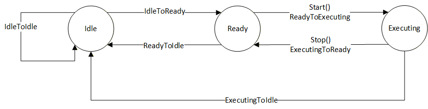
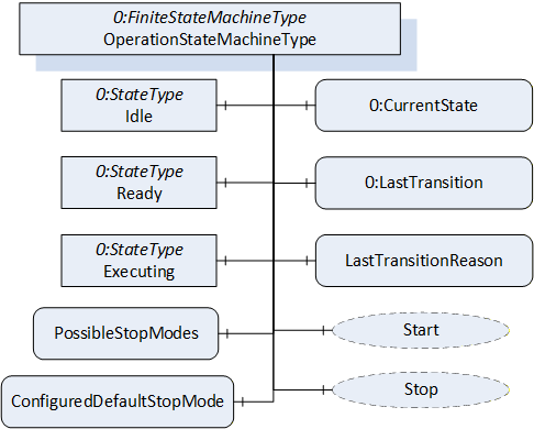
Figure 20 shows the OPC UA representation of the OperationStateMachineType, the transitions between the states have not been shown for the sake of simplicity. The OperationStateMachineType is formally defined in Table 65.
| Attribute | Value | ||||
| BrowseName | OperationStateMachineType | ||||
| IsAbstract | True | ||||
| References | Node Class | BrowseName | DataType | TypeDefinition | Other |
|---|---|---|---|---|---|
| Subtype of the FiniteStateMachineType defined in OPC 10000-5. | |||||
| 0:HasComponent | Variable | LastTransitionReason | 0:Int16 | 0:MultiStateValueDiscreteType | M |
| 0:HasComponent | Variable | PossibleStopModes | 0:EnumValueType[] | 0:BaseDataVariableType | O |
| 0:HasComponent | Variable | ConfiguredDefaultStopMode | 0:Int16 | 0:BaseDataVariableType | O |
| 0:HasComponent | Object | Idle | 0:StateType | ||
| 0:HasComponent | Object | Ready | 0:StateType | ||
| 0:HasComponent | Object | Executing | 0:StateType | ||
| 0:HasComponent | Object | ReadyToIdle | 0:TransitionType | ||
| 0:HasComponent | Object | IdleToReady | 0:TransitionType | ||
| 0:HasComponent | Object | ExecutingToReady | 0:TransitionType | ||
| 0:HasComponent | Object | ReadyToExecuting | 0:TransitionType | ||
| 0:HasComponent | Object | ExecutingToIdle | 0:TransitionType | ||
| 0:HasComponent | Object | IdleToIdle | 0:TransitionType | ||
| 0:HasComponent | Method | Start | O | ||
| 0:HasComponent | Method | Stop | O | ||
| Inherited from FiniteStateMachineType | |||||
| 0:HasComponent | Variable | LastTransition | 0:LocalizedText | 0:FiniteTransitionVariableType | M |
| 0:GeneratesEvent | ObjectType | TransitionEventType | O | ||
The states of the OperationStateMachineType are described in Table 28.
The component Variables of the OperationStateMachineType have additional Attributes defined in Table 30.
| StateName | Description |
| Idle | Entity is not in a condition to start execution. |
| Ready | Entity is in a condition to start execution. |
| Executing | Entity is in a condition of execution. |
The Variable LastTransitionReason provides the reason for the LastTransition. The EnumValue and ValueAsText of this 0:MultiStateValueDiscreteType are described in Table 29. This specification does not define an explicit error state. The LastTransitionReason indicates if a state change was caused due to an error.
| EnumValue | ValueAsText | Description |
| 0 | Unknown | Caused by an unknown reason |
| 1 | External | Caused by external operation |
| 2 | Direct | Caused by direct operation |
| 3 | System | Caused by system specific behaviour |
| 4 | Error | Caused by an error |
| 5 | Application | Caused explicitly by end user program logic |
The component Variables of the OperationStateMachineType have additional Attributes defined in Table 30.
| BrowsePath | Value Attribute | Description Attribute | ||
| [ {"Value":0,"DisplayName":"Unknown","Description":"Caused by an unknown reason"}, {"Value":1,"DisplayName":"External","Description":"Caused by external operation"}, {"Value":2,"DisplayName":"Direct","Description":"Caused by direct operation"}, {"Value":3,"DisplayName":"System","Description":"Caused by system specific behavior"}, {"Value":4,"DisplayName":"Error", "Description": "Caused by an error"}, {"Value":5,"DisplayName":"Application","Description":"Caused explicitly by end user program logic"} ] |
LastTransitionReason EnumValues 1 and 2 describe where an operation was initiated, which reasoned the last transition. External means that the operation was initiated by a control station, which is not part of the robot system, e.g a cell PLC. Direct means that the operation was initiated by a control station, which is part of the robot system, e.g. the teach pendant.
The Variable PossibleStopModes is an array of EnumValueType, which contains a list of supported stop modes (see Table 31).
| Nr. | Stop Mode | Description |
| 1 | OnPath | Stop program execution in a controlled manner along the programmed path. |
| 2 | EndOfCycle | Stop program execution when the current production cycle has been finished. |
| 3 | ProcessStop | Application dependent stop instruction that stops program execution at a "favourable" point for the application, e.g. at the end of a paint stroke or sealing bead. |
| 4 | QuickStop | This stop is performed by ramping down motion as fast as possible using optimum motor performance. The robot may not stay on the path. |
| 5 | EndOfInstruction | This stop can be used to stop the program execution when the current instruction is completed. |
| >=1000 | Reserved for other OPC UA Companion Specifications | |
| >=2000 | Used for vendor specific stop modes |
| BrowsePath | Value Attribute | Description Attribute |
| PossibleStopModes | [ {"Value": 1, "DisplayName": "OnPath", "Description": "Stop program execution in a controlled manner along the programmed path"}, {"Value": 2, "DisplayName": "EndOfCycle", "Description": "Stop program execution when the current production cycle has been finished"}, {"Value": 3, "DisplayName": "ProcessStop", "Description": "Application dependent stop instruction that stops program execution at a favourable point for the application, e.g. at the end of a paint stroke or sealing bead"}, {"Value": 4, "DisplayName": "QuickStop", "Description": "This stop is performed by ramping down motion as fast as possible using optimum motor performance. The robot may not stay on the path"}, {"Value": 5, "DisplayName": "EndOfInstruction", "Description": "This stop can be used to stop the program execution when the current instruction is completed"} ] |
The Variable ConfiguredDefaultStopMode is an integer, which contains the value of the configured stop mode for this system. This shall be one of the values in the PossibleStopModes array.
The Variable LastTransition, inherited from the FiniteStateMachineType, is defined as mandatory in the OperationStateMachineType.
The transitions of the OperationStateMachineType are described in Table 33.
| TransitionName | Description |
| IdleToReady | Changes from Idle to Ready. |
| IdleToIdle | Changes from Idle to Idle. |
| ReadyToIdle | Changes from Ready to Idle. |
| ReadyToExecuting | Changes from Ready to Executing. |
| ExecutingToReady | Changes from Executing to Ready. |
| ExecutingToIdle | Changes from Executing to Idle. |
The components of the OperationStateMachineType have additional references which are defined in Table 69.
| SourceBrowsePath | Reference Type | Is Forward | TargetBrowsePath |
| IdleToIdle | 0:FromState | True | Idle |
| 0:ToState | True | Idle | |
| 0:HasEffect | True | TransitionEventType | |
| IdleToReady | 0:FromState | True | Idle |
| 0:ToState | True | Ready | |
| 0:HasEffect | True | TransitionEventType | |
| ReadyToIdle | 0:FromState | True | Ready |
| 0:ToState | True | Idle | |
| 0:HasEffect | True | TransitionEventType | |
| ReadyToExecuting | 0:FromState | True | Ready |
| 0:ToState | True | Executing | |
| 0:HasCause | True | Start | |
| 0:HasEffect | True | TransitionEventType | |
| ExecutingToReady | 0:FromState | True | Executing |
| 0:ToState | True | Ready | |
| 0:HasCause | True | Stop | |
| 0:HasEffect | True | TransitionEventType | |
| ExecutingToIdle | 0:FromState | True | Executing |
| 0:ToState | True | Idle | |
| 0:HasEffect | True | TransitionEventType |
The component Variables of the OperationStateMachine have additional Attributes defined in the table below.
| BrowsePath | Value Attribute | ||
| 1 | ||
| 2 | ||
| 3 | ||
| 1 | ||
| 2 | ||
| 3 | ||
| 4 | ||
| 5 | ||
| 6 |
7.10.1 Start Method
The signature of this Method is specified below.
Signature
	Start (
	[out]	0:Int32	Status
	);
The Start Method is called by a Client to start execution of the entity which is represented by the state machine.
| Argument | Description |
| Status | 0 - OK Values > 0 are reserved for errors defined by this and future standards. Values < 0 shall be used for application-specific errors. |
The possible Method result codes are formally defined in Table 37.
| Result Code | Description |
| Good | The operation succeeded |
| Bad_InternalError | The operation failed because of an internal error |
| Bad_ResourceUnavailable | The Method cannot be executed because a required resource is locked. |
| Bad_UserAccessDenied | The caller is not allowed to execute this Method. |
The Start Method representation in the AddressSpace is formally defined in table below.
| Attribute | Value | ||||
| BrowseName | Start | ||||
| References | NodeClass | BrowseName | DataType | TypeDefinition | ModellingRule |
|---|---|---|---|---|---|
| 0:HasProperty | Variable | 0:OutputArguments | 0:Argument[] | 0:PropertyType | 0:Mandatory |
7.10.2 Stop Method
The signature of this Method is specified below.
Signature
	Stop (
	[in]	0:Int64 	StopMode
	[out]	0:Int32	Status
	);
The Stop Method is called by a Client to stop execution of the entity which is represented by the state machine.
| Argument | Description |
| StopMode | provides a way to differentiate between different stop modes. This parameter should correspond to one of the values in the PossibleStopModes array. |
| Status | 0 - OK Values > 0 are reserved for errors defined by this and future standards. Values < 0 shall be used for application-specific errors. |
The possible Method result codes are formally defined in Table 40.
| Result Code | Description |
| Good | The operation succeeded |
| Bad_InternalError | The operation failed because of an internal error |
| Bad_ResourceUnavailable | The Method is locked by another Client/Clientgroup |
| Bad_UserAccessDenied | The caller is not allowed to call this Method. |
The Stop Method representation in the AddressSpace is formally defined in the table below.
| Attribute | Value | ||||
| BrowseName | Stop | ||||
| References | NodeClass | BrowseName | DataType | TypeDefinition | Others |
|---|---|---|---|---|---|
| 0:HasProperty | Variable | 0:InputArguments | 0:Argument[] | 0:PropertyType | M |
| 0:HasProperty | Variable | 0:OutputArguments | 0:Argument[] | 0:PropertyType | M |
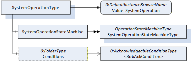
7.11 SystemOperationType ObjectType
7.11.1 Overview
The SystemOperationType is an AddIn Type to extend instances of ControllerType described in 7.18. The SystemOperationType provides a state machine to monitor and/or command the controller behaviour at the system level and is formally defined in Table 42.
Robot systems may have conditions that must be acknowledged before some operational commands can be executed.
The system has two possibilities to enable the Client to acknowledge conditions.
By exposing at least one instance of AcknowledgeableConditionType inside the Server's AddressSpace located within the Conditions folder as defined in the ConformanceUnit RobAckCondInstance.
By handling such conditions using the OPC UA Eventing mechanisms as defined in the ConformanceUnit RobAckCondEventing.
7.11.2 SystemOperationType definition
The SystemOperationType is formally defined in Table 42.
| Attribute | Value | ||||
| BrowseName | SystemOperationType | ||||
| IsAbstract | False | ||||
| References | Node Class | BrowseName | DataType | TypeDefinition | Other |
|---|---|---|---|---|---|
| Subtype of the BaseObjectType defined in OPC 10000-5. | |||||
| 0:HasComponent | Object | SystemOperationStateMachine | SystemOperationStateMachineType | M | |
| 0:HasComponent | Object | Conditions | 0:FolderType | O | |
| 0:HasProperty | Variable | 0:DefaultInstanceBrowseName | 0:QualifiedName | 0:PropertyType | |
| ConformanceUnits | |||||
|---|---|---|---|---|---|
| Rob System Monitor | |||||
| Rob System Operation | |||||
| Rob RobAckCondInstance |
The Object SystemOperationStateMachine provides a state machine to monitor or command the controller at the system level. The SystemOperationStateMachineType is inherited from the OperationStateMachineType.
The folder Conditions (part of the ConformanceUnit RobAckCondInstance) provides instances of AcknowledgeableConditionType for the acknowledgement of single conditions or instances of MultiAcknowledgeableConditionType (see 8.1) for the acknowledgement of multiple conditions.
The Property 0:DefaultInstanceBrowseName of the SystemOperationType has an additional Attribute defined in
Table 44.
| BrowsePath | References | NodeClass | BrowseName | DataType | TypeDefinition | Others |
| Conditions | Organizes | Object | <AcknowledgeableCondition> | AcknowledgeableConditionType | MP |
| BrowsePath | Value Attribute | Description Attribute |
| 0:DefaultInstanceBrowseName | SystemOperation |
7.12 SystemOperationStateMachineType
The SystemOperationStateMachineType represents the behaviour of a controller at the system level and can be used for monitoring and for external or direct operation. In robot systems, a distinction is typically made between external and direct operation, depending on the OperationalMode (see 7.7.2).
If the system takes a significant amount of time to transition from the Idle State to the Ready State, the Idle State can be extended by the sub state machine IdleSubstateMachine. Alternatively, a vendor/application specific Substate machine may also be used.
For certain stop modes, the transition from the Executing State to the Ready State can take a significant amount of time. In such cases, the Executing State can be extended by the sub state machine ExecutingSubstateMachine. Alternatively, an application or vendor specific Substate machine may also be used.
The Substate machines enable the client to get more information during the transition.
The SystemMonitor Server Facet supports monitoring of the activities performed by the operator or system internally. (e.g. monitor condition changes and base causes) The SystemOperation Server Facet extends on the SystemMonitor Server Facet and adds support to operate the system.
The overview of the SystemOperationStateMachine with the IdleSubstateMachine as Substate machine of Idle State and the ExecutingSubstateMachine as Substate machine of Executing State with all transitions is shown in Figure 8.
The transitions in this state machine can occur due to internal processes of the system or they may be triggered by a method call. In case the transition is triggered by a method call, the transition might not occur immediately (e.g. it will be delayed until internal conditions are met).
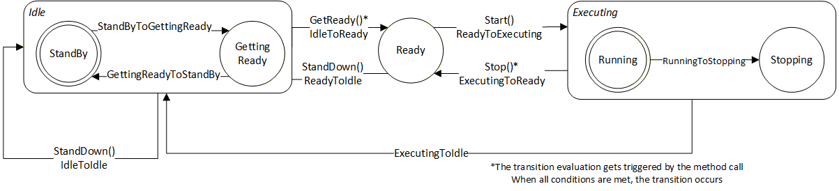
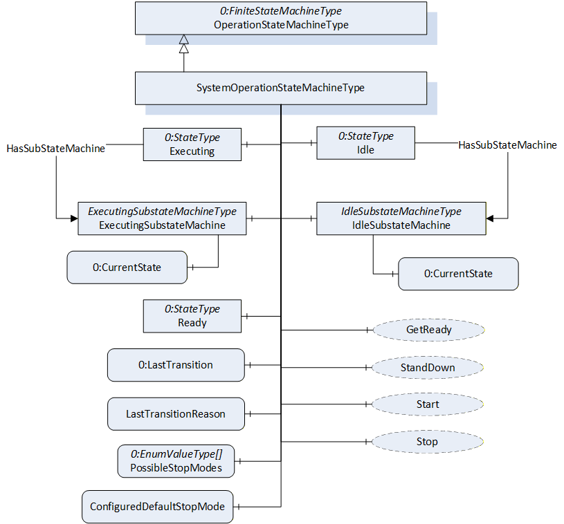
The SystemOperationStateMachineType is formally defined in Table 45.
| Attribute | Value | ||||
| BrowseName | SystemOperationStateMachineType | ||||
| IsAbstract | False | ||||
| References | Node Class | BrowseName | DataType | TypeDefinition | Other |
|---|---|---|---|---|---|
| Subtype of the OperationStateMachineType | |||||
| 0:HasComponent | Object | IdleSubstateMachine | IdleSubstateMachineType | O | |
| 0:HasComponent | Object | ExecutingSubstateMachine | ExecutingSubstateMachineType | O | |
| Inherited from OperationStateMachineType | |||||
| 0:HasComponent | Variable | LastTransitionReason | 0:Int16 | 0:MultiStateValueDiscreteType | M |
| 0:HasComponent | Variable | PossibleStopModes | 0:EnumValueType[] | 0:BaseDataVariableType | O |
| 0:HasComponent | Variable | ConfiguredDefaultStopMode | 0:Int16 | 0:BaseDataVariableType | O |
| 0:HasComponent | Object | Idle | 0:StateType | ||
| 0:HasComponent | Object | Ready | 0:StateType | ||
| 0:HasComponent | Object | Executing | 0:StateType | ||
| 0:HasComponent | Object | ReadyToIdle | 0:TransitionType | ||
| 0:HasComponent | Object | IdleToReady | 0:TransitionType | ||
| 0:HasComponent | Object | ExecutingToReady | 0:TransitionType | ||
| 0:HasComponent | Object | ReadyToExecuting | 0:TransitionType | ||
| 0:HasComponent | Object | ExecutingToIdle | 0:TransitionType | ||
| 0:HasComponent | Object | IdleToIdle | 0:TransitionType | ||
| 0:HasComponent | Method | Start | O | ||
| 0:HasComponent | Method | Stop | O | ||
| 0:HasComponent | Method | StandDown | O | ||
| 0:HasComponent | Method | GetReady | O | ||
| 0:HasComponent | Variable | LastTransition | 0:LocalizedText | 0:FiniteTransitionVariableType | M |
| 0:GeneratesEvent | ObjectType | TransitionEventType | O | ||
| ConformanceUnits | |||||
|---|---|---|---|---|---|
| Rob System Monitor | |||||
| Rob System Operation | |||||
| Rob System Events | |||||
| Rob System Idle Substate | |||||
| Rob System ExecutingSubstate |
The Idle State of SystemOperationStatemachineType has additional subcomponents which are defined in Table 46
| Source Path | Reference | Node Class | BrowseName | DataType | TypeDefinition | Other |
| Idle | 0:HasSubStateMachine | Object | IdleSubstateMachine | IdleSubstateMachineType | O | |
| Executing | 0:HasSubStateMachine | Object | ExecutingSubstateMachine | ExecutingSubstateMachineType | O |
To acknowledge the state changes in a system the Conditions within the Conditions folder of SystemOperationType must be taken under consideration. A client might need to acknowledge them so that the robot system can be activated. (e.g. operational mode change requires acknowledgement to start the system)
| StateName | Description |
| Idle | The system is available, but cannot be started because preparation is needed |
| Ready | The system is ready to start execution. |
| Executing | The system is executing. Typically, at least one task control is executing, however it is a system specific behaviour. |
| TransitionName | Description |
| IdleToIdle | Occurs in response to StandDown(), internal events, or when preparations to get the system ready are unsuccessful. |
| IdleToReady | Occurs in response to GetReady() or internal events, when preparations to get the system ready are successful. |
| ReadyToIdle | Occurs in response to StandDown() or internal events. |
| ReadyToExecuting | Occurs in response to Start() or internal events. |
| ExecutingToReady | Occurs in response to Stop() or internal events when the system has come to a stop |
| ExecutingToIdle | Occurs in response to internal events (typically in case of an error) |
The components of the SystemOperationStateMachineType have additional references which are defined in the table below.
| SourceBrowsePath | Reference Type | Is Forward | TargetBrowsePath |
| IdleToIdle | 0:FromState | True | Idle |
| 0:ToState | True | Idle | |
| 0:HasCause | True | StandDown | |
| 0:HasEffect | True | TransitionEventType | |
| IdleToReady | 0:FromState | True | Idle |
| 0:ToState | True | Ready | |
| 0:HasCause | True | GetReady | |
| 0:HasEffect | True | TransitionEventType | |
| ReadyToIdle | 0:FromState | True | Ready |
| 0:ToState | True | Idle | |
| 0:HasCause | True | StandDown | |
| 0:HasEffect | True | TransitionEventType | |
| ReadyToExecuting | 0:FromState | True | Ready |
| 0:ToState | True | Executing | |
| 0:HasCause | True | Start | |
| 0:HasEffect | True | TransitionEventType | |
| ExecutingToIdle | 0:FromState | True | Executing |
| 0:ToState | True | Idle | |
| 0:HasEffect | True | TransitionEventType | |
| ExecutingToReady | 0:FromState | True | Executing |
| 0:ToState | True | Ready | |
| 0:HasCause | True | Stop | |
| 0:HasEffect | True | TransitionEventType |
The component Variables of the SystemOperationStateMachineType have additional Attributes defined in the table below.
| BrowsePath | Value Attribute | ||
| 1 | ||
| 2 | ||
| 3 | ||
| 1 | ||
| 2 | ||
| 3 | ||
| 4 | ||
| 5 | ||
| 6 |
7.12.1 Start Method
The signature of this Method is specified below.
Signature
	Start (
	[out]	0:Int32	Status
	);
The Start Method is called by a Client to start execution of the system that is represented by the state machine. If the method is successfully called, the method should return with a Good or Uncertain result code.
The Start Method allows an authorized Client to command the system to the Executing State.
| Argument | Description |
| Status | 0 - OK - Everything is OK 1 - E_SystemState - The system is not in correct state for this operation 2 - E_UnexpectedError - Unexpected Error during the Method call 3 - E_ActiveAlarm - An Active Alarm prevents the system start 4 - E_AcknowledgeRequired - Condition needs to be acknowledged <0 - shall be used for vendor-specific errors. >0 - are reserved for errors defined by this and future standards |
The possible Method result codes are formally defined in Table 52
| Result Code | Description |
| Good | The system level operation succeeded |
| Uncertain | The value is uncertain. A concrete reason is defined in the Status Output-Argument. |
| Bad_InternalError | The Method could not be called due to an internal error |
| Bad_ResourceUnavailable | The Method is locked by another Client/Clientgroup |
| Bad_UserAccessDenied | The caller is not allowed to call this Method. |
The Start Method representation in the AddressSpace is formally defined in Table 53.
| Attribute | Value | ||||
| BrowseName | Start | ||||
| References | NodeClass | BrowseName | DataType | TypeDefinition | Others |
|---|---|---|---|---|---|
| 0:HasProperty | Variable | 0:OutputArguments | 0:Argument[] | 0:PropertyType | M |
| ConformanceUnits | |||||
|---|---|---|---|---|---|
| Rob System Operation |
7.12.2 Stop Method
The signature of this Method is specified below.
Signature
	Stop (
	[in]	0:Int64 	StopMode
	[out]	0:Int32	Status
	);
The Stop Method allows an authorized Client to command the system to stop executing and leave the Executing state.
In conjunction with the usage of this method, the transient states can be expressed with Substate machines within the Executing state (e.g. the ExecutingSubstateMachine in 7.14)
The input argument StopMode must be either 0 or one of those listed in the PossibleStopModes Variable (see Table 31). If not, then a Bad_InvalidArgument Result Code is returned.
| Argument | Description |
| StopMode | must either be 0 or one of those listed in the PossibleStopModes Variable (see Table 31) |
| Status | 0 - OK - Everything is OK 1 - E_SystemState - The system is not in correct state for this operation 2 - E_UnexpectedError - Unexpected Error during the Method call <0 - shall be used for vendor-specific errors. >0 - are reserved for errors defined by this and future standards |
The possible Method result codes are formally defined in Table 55
| Result Code | Description |
| Good | The system level operation succeeded |
| Bad_InternalError | The system level operation failed because of an internal error |
| Bad_ResourceUnavailable | The Method is locked by another Client/Clientgroup |
| Bad_UserAccessDenied | The caller is not allowed to call this Method. |
| Bad_InvalidArgument | The input argument is invalid |
The Stop Method representation in the AddressSpace is formally defined in Table 56
| Attribute | Value | ||||
| BrowseName | Stop | ||||
| References | NodeClass | BrowseName | DataType | TypeDefinition | Others |
|---|---|---|---|---|---|
| 0:HasProperty | Variable | 0:InputArguments | 0:Argument[] | 0:PropertyType | M |
| 0:HasProperty | Variable | 0:OutputArguments | 0:Argument[] | 0:PropertyType | M |
| ConformanceUnits | |||||
|---|---|---|---|---|---|
| Rob System Operation |
7.12.3 GetReady Method
The signature of this Method is specified below.
Signature
	GetReady (
	[out]	0:Int32	Status
	);
The GetReady Method allows an authorized Client to request the system to transition from the Idle state to the Ready state. Internally the system prepares to get started in the next step (e.g. switching on the intermediate circuit). If the internal preparations for this transition are successful, the system will transition from Idle to Ready. If the internal preparations are unsuccessful then the IdleToIdle transition occurs.
In conjunction with the usage of this method, the transient states can be expressed with Substate machines within the Idle state (e.g. the IdleSubstateMachine in 7.13)
| Argument | Description |
| Status | 0 - OK - Everything is OK 1 - E_SystemState - The system is not in correct state for this operation 2 - E_UnexpectedError - Unexpected Error during the Method call 3 - E_ActiveAlarm - An Active Alarm prevents the system start 4 - E_AcknowledgeRequired - Condition needs to be acknowledged <0 - shall be used for vendor-specific errors. >0 - are reserved for errors defined by this and future standards |
The possible Method result codes are formally defined in Table 58
| Result Code | Description |
| Good | The system level operation succeeded |
| Bad_InternalError | The system level operation failed because of an internal error |
| Bad_ResourceUnavailable | The Method is locked by another Client/Clientgroup |
| Bad_UserAccessDenied | The caller is not allowed to call this Method. |
The Start Method representation in the AddressSpace is formally defined in Table 59.
| Attribute | Value | ||||
| BrowseName | GetReady | ||||
| References | NodeClass | BrowseName | DataType | TypeDefinition | Others |
|---|---|---|---|---|---|
| 0:HasProperty | Variable | 0:OutputArguments | 0:Argument[] | 0:PropertyType | M |
| ConformanceUnits | |||||
|---|---|---|---|---|---|
| Rob System Operation |
7.12.4 StandDown Method
The signature of this Method is specified below.
Signature
	StandDown (
	[out]	0:Int32	Status
	);
The StandDown method allows an authorized Client to request the system to:
transition from the Ready state to the Idle state or
cancel an ongoing preparation of the system and causes the IdleToIdle transition.
| Argument | Description |
| Status | 0 - OK - Everything is OK 1 - E_SystemState - The system is not in correct state for this operation 2 - E_UnexpectedError - Unexpected Error during the Method call <0 - shall be used for vendor-specific errors. >0 - are reserved for errors defined by this and future standards |
In conjunction with the usage of this method, the transient states can be expressed with Substate machines within the Idle state (e.g. the IdleSubstateMachine in 7.13)
The possible Method result codes are formally defined in Table 61.
| Result Code | Description |
| Good | The system level operation succeeded |
| Bad_InternalError | The system level operation failed because of an internal error |
| Bad_ResourceUnavailable | The Method is locked by another Client/Clientgroup |
| Bad_UserAccessDenied | The caller is not allowed to call this Method. |
The StandDown Method representation in the AddressSpace is formally defined in Table 62.
| Attribute | Value | ||||
| BrowseName | StandDown | ||||
| References | NodeClass | BrowseName | DataType | TypeDefinition | ModellingRule |
|---|---|---|---|---|---|
| 0:HasProperty | Variable | 0:OutputArguments | 0:Argument[] | 0:PropertyType | M |
| ConformanceUnits | |||||
|---|---|---|---|---|---|
| Rob System Operation |
7.13 IdleSubstateMachineType
The IdleSubstateMachineType, a Substate machine of the Idle State of the SystemOperationStateMachine, represents a mechanism to prepare a system in a way that it will reach Ready State of the SystemOperationStateMachine after preparation.
The overview of the IdleSubstateMachine with all transitions is shown in Figure 24.
Figure 24 - IdleSubstateMachine
7.13.1 Overview
Figure 25 - IdleSubstateMachineType Overview
The IdleSubstateMachineType is formally defined in Table 63.
| Attribute | Value | ||||
| BrowseName | IdleSubstateMachineType | ||||
| IsAbstract | False | ||||
| References | Node Class | BrowseName | DataType | TypeDefinition | Other |
|---|---|---|---|---|---|
| Subtype of the FiniteStateMachineType defined in OPC 10000-5 | |||||
| 0:HasComponent | Variable | LastTransitionReason | 0:Int16 | 0:MultiStateValueDiscreteType | M |
| 0:HasComponent | Object | StandBy | 0:InitialStateType | ||
| 0:HasComponent | Object | GettingReady | 0:StateType | ||
| 0:HasComponent | Object | StandByToGettingReady | 0:TransitionType | ||
| 0:HasComponent | Object | GettingReadyToStandBy | 0:TransitionType | ||
| 0:HasComponent | Variable | LastTransition | 0:LocalizedText | 0:FiniteTransitionVariableType | M |
| 0:GeneratesEvent | ObjectType | TransitionEventType | O | ||
| ConformanceUnits | |||||
|---|---|---|---|---|---|
| Rob System IdleSubstate | |||||
| Rob System Events |
The Variable LastTransitionReason provides the reason for the LastTransition. The EnumValue and ValueAsText of this 0:MultiStateValueDiscreteType are described in the table below.
Table 64 - IdleSubstateMachineType Attribute values for child nodes
| BrowsePath | Value Attribute | Description Attribute | ||
| [ {"Value":0,"DisplayName":"Unknown","Description":"Caused by an unknown reason"}, {"Value":1,"DisplayName":"External","Description":"Caused by external operation"}, {"Value":2,"DisplayName":"Direct","Description":"Caused by direct operation"}, {"Value":3,"DisplayName":"System","Description":"Caused by system specific behavior"}, {"Value":4,"DisplayName":"Error", "Description": "Caused by an error"}, {"Value":5,"DisplayName":"Application","Description":"Caused explicitly by end user program logic"} ] |
The states of the IdleSubstateMachineType are described in Table 65.
Table 65 - IdleSubstateMachineType State Descriptions
| StateName | Description |
| StandBy | The system is available, but cannot be started because a preparation is needed |
| GettingReady | The system was commanded to get ready (internally or via GoToReady() and the needed preparation to get ready is done in this state by the system. In the GettingReady state the system prepares what is to be done (e.g. switching on intermediate circuit) to be ready to start execution in a next step. Typically, all task controls which participate in system functionality are in in Ready (or Executing) state before calling the GoToReady() method on system level. When the preparation is done successfully the IdleSubstateMachine will be left and the Ready state of the SystemOperationStateMaschine will be entered. The ongoing preparation can be interrupted by calling the GoToStandBy Method. |
The transitions are described in .
Table 66 - IdleSubstateMachineType Transition Descriptions
| TransitionName | Description |
| StandByToGettingReady | Changes from StandBy to GettingReady because the preparation was initiated. |
| GettingReadyToStandBy | Changes from GettingReady to StandBy because the preparation was aborted. |
The components of the IdleSubstateMachineType have additional references which are defined in Table 67.
| SourceBrowsePath | Reference Type | Is Forward | TargetBrowsePath |
| StandByToGettingReady | 0:FromState | True | StandBy |
| 0:ToState | True | GettingReady | |
| 0:HasEffect | True | TransitionEventType | |
| GettingReadyToStandBy | 0:FromState | True | GettingReady |
| 0:ToState | True | StandBy | |
| 0:HasEffect | True | TransitionEventType |
The component Variables of the IdleSubstateMachineType have additional Attributes defined in Table 68.
| BrowsePath | Value Attribute | ||
| 1 | ||
| 2 | ||
| 1 | ||
| 2 |
7.14 ExecutingSubstateMachineType
The ExecutingSubstateMachineType, a Substate machine of Executing State of the SystemOperationStateMachine, represents a mechanism for describing the stopping behaviour of the system. This can be used to display the stopping behaviour in more detail depending on the StopMode commanded.
The overview of the ExecutingSubstateMachine with all transitions is shown in Figure 8.
Figure 26 - ExecutingSubstateMachine
7.14.1 Overview
Figure 27 - ExecutingSubstateMachineType Overview
The ExecutingSubstateMachineType is formally defined in the table below.
| Attribute | Value | ||||
| BrowseName | ExecutingSubstateMachineType | ||||
| IsAbstract | False | ||||
| References | Node Class | BrowseName | DataType | TypeDefinition | Other |
|---|---|---|---|---|---|
| Subtype of the FiniteStateMachineType defined in OPC 10000-5 | |||||
| 0:HasComponent | Variable | LastTransitionReason | 0:Int16 | 0:MultiStateValueDiscreteType | M |
| 0:HasComponent | Object | Running | 0:InitialStateType | ||
| 0:HasComponent | Object | Stopping | 0:StateType | ||
| 0:HasComponent | Object | RunningToStopping | 0:TransitionType | ||
| Inherited from FiniteStateMachineType | |||||
| 0:HasComponent | Variable | LastTransition | 0:LocalizedText | 0:FiniteTransitionVariableType | M |
| 0:GeneratesEvent | ObjectType | TransitionEventType | O | ||
| ConformanceUnits | |||||
|---|---|---|---|---|---|
| Rob System ExecutingSubstate | |||||
| Rob System Events |
The Variable LastTransitionReason provides the reason for the LastTransition. The EnumValues of this 0:MultiStateValueDiscreteType are described in Table 70.
Table 70 - ExecutingSubstateMachineType Attribute values for child nodes
| BrowsePath | Value Attribute | Description Attribute | ||
| [ {"Value":0,"DisplayName":"Unknown","Description":"Caused by an unknown reason"}, {"Value":1,"DisplayName":"External","Description":"Caused by external operation"}, {"Value":2,"DisplayName":"Direct","Description":"Caused by direct operation"}, {"Value":3,"DisplayName":"System","Description":"Caused by system specific behavior"}, {"Value":4,"DisplayName":"Error", "Description": "Caused by an error"}, {"Value":5,"DisplayName":"Application","Description":"Caused explicitly by end user program logic"} ] |
The states of the ExecutingSubstateMachineType are described in Table 71.
Table 71 - ExecutingSubstateMachineType State Descriptions
| StateName | Description |
| Running | The system is available, but cannot started because a preparation is needed |
| Stopping | The system was commanded to stop (internally or via Stop() and the needs some time for necessary background processes before entering the Ready state. |
The transitions are described in .
Table 72 - ExecutingSubstateMachineType Transition Descriptions
| TransitionName | Description |
| RunningToStopping | Changes from Running to Stopping because a system stop was initiated. |
The components of the ExecutingSubstateMachineType have additional references which are defined in the table below.
| SourceBrowsePath | Reference Type | Is Forward | TargetBrowsePath |
| RunningToStopping | 0:FromState | True | Running |
| 0:ToState | True | Stopping | |
| 0:HasEffect | True | TransitionEventType |
The component Variables of the IdleSubstateMachineType have additional Attributes defined in the table below.
| BrowsePath | Value Attribute | ||
| 1 | ||
| 2 | ||
| 1 |
7.15 TaskControlOperationType ObjectType
The TaskControlOperationType is an AddIn to extend instances of TaskControlType described in 7.21. It provides the possibility to handle programs with designated task controls. The task controls may be started manually or in a system context by use of SystemOperation.
The TaskControlOperationType provides a state machine to monitor or control a task control and information about which motion devices are controlled by this task control and is formally defined in Table 63.
7.15.1 Overview
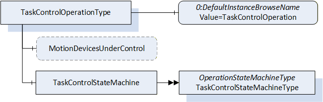
| Attribute | Value | ||||
| BrowseName | TaskControlOperationType | ||||
| IsAbstract | False | ||||
| References | Node Class | BrowseName | DataType | TypeDefinition | Other |
|---|---|---|---|---|---|
| Subtype of the BaseObjectType defined in OPC 10000-5. | |||||
| 0:HasProperty | Variable | MotionDevicesUnderControl | 0:NodeId[] | 0:PropertyType | O, RO |
| 0:HasComponent | Object | TaskControlStateMachine | TaskControlStateMachineType | M | |
| 0:HasProperty | Variable | 0:DefaultInstanceBrowseName | 0:QualifiedName | 0:PropertyType | |
| ConformanceUnits | |||||
|---|---|---|---|---|---|
| Rob Task Control Monitor | |||||
| Rob Task Control Operation | |||||
| Rob TC MD Relationship |
The optional Variable MotionDevicesUnderControl provides an array of NodeIds pointing to instances of MotionDeviceType described in 7.2, which are under control of this task control, in combination with the loaded program.
The Object TaskControlStateMachine provides a state machine to monitor or to control the task controls which instantiated the TaskControlOperationType.
The Property 0:DefaultInstanceBrowseName of the TaskControlOperationType has an additional Attribute defined in Table 64.
| BrowsePath | Value Attribute | Description Attribute |
| 0:DefaultInstanceBrowseName | TaskControlOperation |
7.16 TaskControlStateMachineType
The TaskControlStateMachineType represents the behaviour of a task control and can be used for monitoring or for remote control.
To provide information about the condition of a program loaded inside a task control and the possibility to reset the loaded program the Ready State can be extended by the ReadySubstateMachineType.
The Task Control Monitor ConformanceUnit supports monitoring of the activities done by the operator or system internally. The Task Control Operation ConformanceUnit supports additional operations by Methods.
The overview of the state machine with all transitions is shown in
When the state machine changes from Executing State to Ready State caused by internal behaviour of the task control (e.g. because program is ended) it is expected that the task control can be started immediately again e.g. by the Start() method. So, the application may set the loaded program to its entry point (like the ResetToProgramStart() Method) while transition ExecutingToReady or when the Start() Method is called, that no additional reset of the program is needed.
Figure 29 - TaskControl State Machine with ReadySubstateMachine in Ready State
7.16.1 Overview
Figure 30 - TaskControlStateMachineType with the ReadySubstateMachine
The TaskControlStateMachineType is formally defined in Table 65.
| Attribute | Value | ||||
| BrowseName | TaskControlStateMachineType | ||||
| IsAbstract | False | ||||
| References | Node Class | BrowseName | DataType | TypeDefinition | Other |
|---|---|---|---|---|---|
| Subtype of the OperationStateMachineType | |||||
| 0:HasComponent | Object | ReadySubstateMachine | ReadySubstateMachineType | O | |
| 0:HasComponent | Method | LoadByNodeId | O | ||
| 0:HasComponent | Method | LoadByName | O | ||
| 0:HasComponent | Method | UnloadProgram | O | ||
| 0:HasComponent | Method | UnloadByNodeId | O | ||
| 0:HasComponent | Method | UnloadByName | O | ||
| Inherited from OperationStateMachineType | |||||
| 0:HasComponent | Variable | LastTransitionReason | 0:Int16 | 0:MultiStateValueDiscreteType | M |
| 0:HasComponent | Variable | PossibleStopModes | 0:EnumValueType[] | 0:BaseDataVariableType | O |
| 0:HasComponent | Variable | ConfiguredDefaultStopMode | 0:Int16 | 0:BaseDataVariableType | O |
| 0:HasComponent | Object | Idle | 0:StateType | ||
| 0:HasComponent | Object | Ready | 0:StateType | ||
| 0:HasComponent | Object | Executing | 0:StateType | ||
| 0:HasComponent | Object | IdleToIdle | 0:TransitionType | ||
| 0:HasComponent | Object | ReadyToIdle | 0:TransitionType | ||
| 0:HasComponent | Object | IdleToReady | 0:TransitionType | ||
| 0:HasComponent | Object | ExecutingToReady | 0:TransitionType | ||
| 0:HasComponent | Object | ReadyToExecuting | 0:TransitionType | ||
| 0:HasComponent | Object | ExecutingToIdle | 0:TransitionType | ||
| 0:HasComponent | Method | Start | O | ||
| 0:HasComponent | Method | Stop | O | ||
| 0:HasComponent | Variable | LastTransition | 0:LocalizedText | 0:FiniteTransitionVariableType | M |
| 0:GeneratesEvent | ObjectType | TransitionEventType | O | ||
| ConformanceUnits | |||||
|---|---|---|---|---|---|
| Rob Task Control Monitor | |||||
| Rob Task Control Operation | |||||
| Rob Task Control ReadySubstate | |||||
| Rob System Events |
The Ready State of TaskControlStateMachineType has additional subcomponents which are defined in Table 66.
| Source Path | Reference | NodeClass | BrowseName | DataType | TypeDefinition | Others |
| Ready | 0:HasSubStateMachine | Object | ReadySubstateMachine | ReadySubstateMachineType | O |
The states of the TaskControlStateMachineType are described in Table 67.
| StateName | Description |
| Idle | The task control is not loaded with a program. |
| Ready | The task control is loaded with a program and is not executing the program. |
| Executing | The task control is loaded with a program and is executing the program. If the task control automatically starts the program at the beginning, after reaching the end, it shall stay in Executing state (continuously executing). |
The transitions are described in the table below.
| TransitionName | Description |
| IdleToIdle | Occurs if the program could not be loaded correctly. |
| IdleToReady | Occurs in response to LoadProgram() or internal events, when loading a program to the task control. |
| ReadyToIdle | Occurs in response to UnloadProgram() or internal events, when unloading a program from the task control. |
| ReadyToExecuting | Occurs in response to Start() or internal events, when starting a loaded program in the task control. |
| ExecutingToReady | Occurs in response to Stop() or internal events, when stopping a loaded program in the task control. |
| ExecutingToIdle | Occurs in response to internal events, when stopping a loaded program in the task control and unloading the task control. |
The components of the TaskControlStateMachineType have additional references which are defined in Table 69.
| SourceBrowsePath | Reference Type | Is Forward | TargetBrowsePath |
| IdleToIdle | 0:FromState | True | Idle |
| 0:ToState | True | Idle | |
| 0:HasEffect | True | TransitionEventType | |
| IdleToReady | 0:FromState | True | Idle |
| 0:ToState | True | Ready | |
| 0:HasCause | True | LoadByNodeId | |
| 0:HasCause | True | LoadByName | |
| 0:HasEffect | True | TransitionEventType | |
| ReadyToIdle | 0:FromState | True | Ready |
| 0:ToState | True | Idle | |
| 0:HasCause | True | UnloadProgram | |
| 0:HasCause | True | UnloadByNodeId | |
| 0:HasCause | True | UnloadByName | |
| 0:HasEffect | True | TransitionEventType | |
| ReadyToExecuting | 0:FromState | True | Ready |
| 0:ToState | True | Executing | |
| 0:HasCause | True | Start | |
| 0:HasEffect | True | TransitionEventType | |
| ExecutingToReady | 0:FromState | True | Executing |
| 0:ToState | True | Ready | |
| 0:HasCause | True | Stop | |
| 0:HasEffect | True | TransitionEventType | |
| ExecutingToIdle | 0:FromState | True | Executing |
| 0:ToState | True | Idle | |
| 0:HasEffect | True | TransitionEventType |
The component Variables of the TaskControlStateMachineType have additional Attributes defined in Table 70.
| BrowsePath | Value Attribute | ||
| 1 | ||
| 2 | ||
| 3 | ||
| 1 | ||
| 2 | ||
| 3 | ||
| 4 | ||
| 5 | ||
| 6 |
7.16.2 LoadByNodeId Method
The signature of this Method is specified below.
Signature
	LoadByNodeId (
		[in]	0:ExpandedNodeId	 Id
	   [out]	0:Int32	 Status
	);
Table 71 specifies the Arguments.
| Argument | Description |
| Id | ExpandedNodeId pointing to an instance of FileType representing a task control program or module |
| Status | 0 - OK - Everything is OK 1 - E_SystemState - The system is not in correct state for this operation 2 - E_UnexpectedError - Unexpected Error during the method call 3 - E_ActiveAlarm - An Active Alarm prevents the system start 4 - E_AcknowledgeRequired - Condition needs to be acknowledged <0 - shall be used for vendor-specific errors. >0 - are reserved for errors defined by this and future standards |
The LoadByNodeId Method is called by a Client to load a program or a module into a task control.
For the storage of programs, the Server may support the Programs folder defined within the ControllerType. (see 7.18). This method can be used to load the program or module into the Task Control if the program or module itself is available in the address space (e.g. within the Programs folder). The Id input argument shall be used to identify the program in the address space. This method can be a synchronous or an asynchronous method. In case it is a synchronous method, the return output arguments may contain more information about the Success or Failure of the method call. If the system is in the Idle state when the method is called, and something goes wrong internally then instead of the IdleToReady transition, the IdleToIdle transition shall be observed by the client. If the system is already in the Ready state and the LoadByNodeId is called and fails, it is system dependent, whether the system goes back to the Idle state or remains in the Ready state. Calling LoadByNodeId in the Executing state will fail in normal circumstances.
The possible Method result codes are formally defined in Table 72. Some of these StatusCodes correspond to the ProgramId input argument.
Clients may inspect the Status output argument to determine if the program was successfully loaded or if it failed.
| Result Code | Description |
| Good | The task control operation succeeded |
| Bad_InternalError | The task control operation failed because of an internal error |
| Bad_ResourceUnavailable | The Method is locked by another Client/Clientgroup |
| Bad_UserAccessDenied | The caller is not allowed to call this Method. |
| Bad_NodeIdUnknown | The NodeId refers to a non-existent TCProgram. |
| Bad_NodeIdInvalid | The syntax of the NodeId is not valid. |
The LoadByNodeId Method representation in the AddressSpace is formally defined in Table 73.
| Attribute | Value | ||||
| BrowseName | LoadByNodeId | ||||
| References | NodeClass | BrowseName | DataType | TypeDefinition | ModellingRule |
|---|---|---|---|---|---|
| 0:HasProperty | Variable | 0:InputArguments | 0:Argument[] | 0:PropertyType | M |
| 0:HasProperty | Variable | 0:OutputArguments | 0:Argument[] | 0:PropertyType | M |
| ConformanceUnits | |||||
|---|---|---|---|---|---|
| Rob Task Control Operation |
7.16.3 LoadByName Method
The signature of this Method is specified below.
Signature
	LoadByName (
		[in]	0:String	Name
	   [out]	0:Int32	Status
	);
The table below specifies the Arguments.
| Argument | Description |
| Name | Name to identify a task control program or module |
| Status | 0 - OK - Everything is OK 1 - E_SystemState - The system is not in correct state for this operation 2 - E_UnexpectedError - Unexpected Error during the method call 3 - E_ActiveAlarm - An Active Alarm prevents the system start 4 - E_AcknowledgeRequired - Condition needs to be acknowledged <0 - shall be used for vendor-specific errors. >0 - are reserved for errors defined by this and future standards |
The LoadByName Method is called by a Client to load a program or module to a task control. The controller uses the Name input argument to identify the program or module to load into the task control. The behaviour of this method is identical to the LoadByNodeId (see 7.16.2).
The possible Method result codes are formally defined in the table below. Some of these StatusCodes correspond to the Name input argument.
Clients may inspect the Status output argument to determine if the program was successfully loaded or if it failed.
| Result Code | Description |
| Good | The task control operation succeeded |
| Bad_InternalError | The task control operation failed because of an internal error |
| Bad_ResourceUnavailable | The Method is locked by another Client/Clientgroup |
| Bad_UserAccessDenied | The caller is not allowed to call this Method. |
The LoadByName Method representation in the AddressSpace is formally defined in the table below.
| Attribute | Value | ||||
| BrowseName | LoadByName | ||||
| References | NodeClass | BrowseName | DataType | TypeDefinition | ModellingRule |
|---|---|---|---|---|---|
| 0:HasProperty | Variable | 0:InputArguments | 0:Argument[] | 0:PropertyType | 0:Mandatory |
| 0:HasProperty | Variable | 0:OutputArguments | 0:Argument[] | 0:PropertyType | 0:Mandatory |
| ConformanceUnits | |||||
|---|---|---|---|---|---|
| Rob Task Control Operation |
7.16.4 UnloadProgram Method
The signature of this Method is specified below.
Signature
	UnloadProgram (
		[out]	0:Int32	    Status
	);
The table below specifies the Arguments.
| Argument | Description |
| Status | 0 - OK - Everything is OK 1 - E_SystemState - The system is not in correct state for this operation 2 - E_UnexpectedError - Unexpected Error during the method call 3 - E_ActiveAlarm - An Active Alarm prevents the system start 4 - E_AcknowledgeRequired - Condition needs to be acknowledged <0 - shall be used for vendor-specific errors. >0 - are reserved for errors defined by this and future standards |
The UnloadProgram Method is called by a Client to unload the program from a task control.
The possible Method result codes are formally defined in the table below.
| Result Code | Description |
| Good | The task control operation succeeded |
| Bad_InternalError | The task control operation failed because of an internal error |
| Bad_ResourceUnavailable | The Method is locked by another Client/Clientgroup |
| Bad_UserAccessDenied | The caller is not allowed to call this Method. |
The UnloadProgram Method representation in the AddressSpace is formally defined in the table below.
| Attribute | Value | ||||
| BrowseName | UnloadProgram | ||||
| References | NodeClass | BrowseName | DataType | TypeDefinition | ModellingRule |
|---|---|---|---|---|---|
| 0:HasProperty | Variable | 0:OutputArguments | 0:Argument[] | 0:PropertyType | 0:Mandatory |
| ConformanceUnits | |||||
|---|---|---|---|---|---|
| Rob Task Control Operation |
7.16.5 UnloadByNodeId Method
The signature of this Method is specified below.
Signature
	UnloadByNodeId (
	   [in]    0:ExpandedNodeId    Id
		[out]	0:Int32	    Status
	);
Table 80 specifies the Arguments.
| Argument | Description |
| Id | Expanded NodeId of the module to be unloaded |
| Status | 0 - OK - Everything is OK 1 - E_SystemState - The system is not in correct state for this operation 2 - E_UnexpectedError - Unexpected Error during the method call 3 - E_ActiveAlarm - An Active Alarm prevents the system start 4 - E_AcknowledgeRequired - Condition needs to be acknowledged <0 - shall be used for vendor-specific errors. >0 - are reserved for errors defined by this and future standards |
The UnloadByNodeId Method is called by a Client to unload a task module from a task control. This only works if the task modules are expressed in the address space (7.22).
The possible Method result codes are formally defined in the table below.
| Result Code | Description |
| Good | The task control operation succeeded |
| Bad_InternalError | The task control operation failed because of an internal error |
| Bad_ResourceUnavailable | The Method is locked by another Client/Clientgroup |
| Bad_UserAccessDenied | The caller is not allowed to call this Method. |
The UnloadByNodeId Method representation in the AddressSpace is formally defined in Table 82. This method might not always result in a state change from Ready to Idle.
| Attribute | Value | ||||
| BrowseName | UnloadByNodeId | ||||
| References | NodeClass | BrowseName | DataType | TypeDefinition | ModellingRule |
|---|---|---|---|---|---|
| 0:HasProperty | Variable | 0:InputArguments | 0:Argument[] | 0:PropertyType | 0:Mandatory |
| 0:HasProperty | Variable | 0:OutputArguments | 0:Argument[] | 0:PropertyType | 0:Mandatory |
| ConformanceUnits | |||||
|---|---|---|---|---|---|
| Rob Task Control Operation |
7.16.6 UnloadByName Method
The signature of this Method is specified below.
Signature
	UnloadByName (
	   [in]    0:String    Name
		[out]	0:Int32      Status
	);
Table 83 specifies the Arguments.
| Argument | Description |
| Name | Name of the module to be unloaded |
| Status | 0 - OK - Everything is OK 1 - E_SystemState - The system is not in correct state for this operation 2 - E_UnexpectedError - Unexpected Error during the method call 3 - E_ActiveAlarm - An Active Alarm prevents the system start 4 - E_AcknowledgeRequired - Condition needs to be acknowledged <0 - shall be used for vendor-specific errors. >0 - are reserved for errors defined by this and future standards |
The UnloadByName Method is called by a Client to unload a module from a task control. This can be used to unload the task modules if they are not expressed in the address space and internal logic is used to find the module to be unloaded based on the Name input argument.
This method might not always result in a state change from Ready to Idle.
The possible Method result codes are formally defined in the table below.
| Result Code | Description |
| Good | The task control operation succeeded |
| Bad_InternalError | The task control operation failed because of an internal error |
| Bad_ResourceUnavailable | The Method is locked by another Client/Clientgroup |
| Bad_UserAccessDenied | The caller is not allowed to call this Method. |
The UnloadByName Method representation in the AddressSpace is formally defined in the table below.
| Attribute | Value | ||||
| BrowseName | UnloadByName | ||||
| References | NodeClass | BrowseName | DataType | TypeDefinition | ModellingRule |
|---|---|---|---|---|---|
| 0:HasProperty | Variable | 0:InputArguments | 0:Argument[] | 0:PropertyType | 0:Mandatory |
| 0:HasProperty | Variable | 0:OutputArguments | 0:Argument[] | 0:PropertyType | 0:Mandatory |
| ConformanceUnits | |||||
|---|---|---|---|---|---|
| Rob Task Control Operation |
7.16.7 Start Method
The signature of this Method is specified below.
Signature
	Start (
		[out]	0:Int32	Status
	);
Table 86 specifies the Arguments.
| Argument | Description |
| Status | 0 - OK - Everything is OK 1 - E_SystemState - The system is not in correct state for this operation 2 - E_UnexpectedError - Unexpected Error during the method call 3 - E_ActiveAlarm - An Active Alarm prevents the system start 4 - E_AcknowledgeRequired - Condition needs to be acknowledged <0 - shall be used for vendor-specific errors. >0 - are reserved for errors defined by this and future standards |
The Start method can only be successfully called when the task control is in the Ready state. Depending on the program pointer, the system shall attempt to start executing from the beginning of the program or continue executing from where it was suspended (see Substate machine description of this state in 7.17).
The possible Method result codes are formally defined in Table 87.
| Result Code | Description |
| Good | The task control operation succeeded |
| Bad_InternalError | The task control operation failed because of an internal error |
| Bad_ResourceUnavailable | The Method is locked by another Client/Clientgroup |
| Bad_UserAccessDenied | The caller is not allowed to call this Method. |
The Start Method representation in the AddressSpace is formally defined in Table 88.
| Attribute | Value | ||||
| BrowseName | Start | ||||
| References | NodeClass | BrowseName | DataType | TypeDefinition | Others |
|---|---|---|---|---|---|
| 0:HasProperty | Variable | 0:OutputArguments | 0:Argument[] | 0:PropertyType | M |
| ConformanceUnits | |||||
|---|---|---|---|---|---|
| Rob Task Control Operation |
7.16.8 Stop Method
The signature of this Method is specified below.
Signature
	Stop (
	[in]	0:Int64 	StopMode
	[out]	0:Int32	Status
	);
Table 89 specifies the Arguments.
| Argument | Description |
| StopMode | must either be 0 or one of those listed in the PossibleStopModes Variable (see Table 31) |
| Status | 0 - OK - Everything is OK 1 - E_SystemState - The system is not in correct state for this operation 2 - E_UnexpectedError - Unexpected Error during the method call 3 - E_ActiveAlarm - An Active Alarm prevents the system start 4 - E_AcknowledgeRequired - Condition needs to be acknowledged <0 - shall be used for vendor-specific errors. >0 - are reserved for errors defined by this and future standards |
The Stop Method allows an authorized Client to command the task control to stop executing and leave the Executing state and go to the Ready state. If the ReadySubstateMachine (see 7.17) is present, the task control shall be in the Suspended state of the Substate machine.
The input argument StopMode must be either 0 or one of those listed in the PossibleStopModes Variable (see Section). If not, then a Bad_InvalidArgument Result Code is returned.
The possible Method result codes are formally defined in the table below.
| Result Code | Description |
| Good | The task control operation succeeded |
| Bad_InternalError | The task control operation failed because of an internal error |
| Bad_ResourceUnavailable | The Method is locked by another Client/Clientgroup |
| Bad_UserAccessDenied | The caller is not allowed to call this Method. |
The Stop Method representation in the AddressSpace is formally defined in Table 91.
| Attribute | Value | ||||
| BrowseName | Stop | ||||
| References | NodeClass | BrowseName | DataType | TypeDefinition | ModellingRule |
|---|---|---|---|---|---|
| 0:HasProperty | Variable | 0:InputArguments | 0:Argument[] | 0:PropertyType | 0:Mandatory |
| 0:HasProperty | Variable | 0:OutputArguments | 0:Argument[] | 0:PropertyType | 0:Mandatory |
| ConformanceUnits | |||||
|---|---|---|---|---|---|
| Rob Task Control Operation |
7.17 ReadySubstateMachineType
The ReadySubstateMachineType represents the condition of a program loaded into a task control (TaskControlStateMachine is in Ready State). The state machine has two states to distinguish whether the program pointer is at an initial program position (AtProgramStart) or anywhere else in the program (Suspended). It provides the information whether the program pointer is at the start or in the middle of the program. The method ResetToProgramStart can be used to set the program pointer to the start of the program. The state after entering this state machine depends on the program pointer position.
The TaskControlReadyMonitor ConformanceUnit defines monitoring of the ReadySubstateMachine. The TaskControlReadyReinitalize ConformanceUnit defines additionally the reinitialization of the program by a method.
The overview of the state machine with all transitions is shown in .
Figure 31 - ReadySubstateMachine
7.17.1 Overview
Figure 32 - ReadySubstateMachineType Overview
The ReadySubstateMachineType is formally defined in Table 104.
Table 104 - ReadySubstateMachineType Definition
| Attribute | Value | ||||
| BrowseName | ReadySubstateMachineType | ||||
| IsAbstract | False | ||||
| References | Node Class | BrowseName | DataType | TypeDefinition | Other |
|---|---|---|---|---|---|
| Subtype of the FiniteStateMachineType defined in OPC 1000-5 | |||||
| 0:HasComponent | Variable | LastTransitionReason | 0:Int16 | 0:MultiStateValueDiscreteType | M |
| 0:HasComponent | Object | AtProgramStart | 0:StateType | ||
| 0:HasComponent | Object | Suspended | 0:StateType | ||
| 0:HasComponent | Object | ProgramStartToSuspended | 0:TransitionType | ||
| 0:HasComponent | Object | SuspendedToProgramStart | 0:TransitionType | ||
| 0:HasComponent | Method | ResetToProgramStart | O | ||
| Inherited from FiniteStateMachineType | |||||
| 0:HasComponent | Variable | LastTransition | 0:LocalizedText | 0:FiniteTransitionVariableType | M |
| 0:GeneratesEvent | ObjectType | TransitionEventType | O | ||
| ConformanceUnits | |||||
|---|---|---|---|---|---|
| Rob Task Control ReadySubstate | |||||
| Rob Task Control Ready Reset |
The Variable LastTransitionReason provides the reason for the LastTransition. The EnumValue and ValueAsText of this 0:MultiStateValueDiscreteType are described in .
Table 105 - ReadySubstateMachineType Attribute values for child nodes
| BrowsePath | Value Attribute | Description Attribute | ||
| [ {"Value":0,"DisplayName":"Unknown","Description":"Caused by an unknown reason"}, {"Value":1,"DisplayName":"External","Description":"Caused by external operation"}, {"Value":2,"DisplayName":"Direct","Description":"Caused by direct operation"}, {"Value":3,"DisplayName":"System","Description":"Caused by system specific behavior"}, {"Value":4,"DisplayName":"Error", "Description": "Caused by an error"}, {"Value":5,"DisplayName":"Application","Description":"Caused explicitly by end user program logic"} ] |
The states of the ReadySubstateMachineType are described in Table 106.
Table 106 - ReadySubstateMachineType State Descriptions
| StateName | Description |
| AtProgramStart | The program pointer of the program loaded in the task control is at the starting point. |
| Suspended | The program pointer of the program loaded in the task control is anywhere in the program, but not at starting point. |
The components of the ReadySubstateMachineType have additional references which are defined in Table 107.
| SourceBrowsePath | Reference Type | Is Forward | TargetBrowsePath |
| ProgramStartToSuspended | 0:FromState | True | AtProgramStart |
| 0:ToState | True | Suspended | |
| 0:HasEffect | True | TransitionEventType | |
| SuspendedToProgramStart | 0:FromState | True | Suspended |
| 0:ToState | True | AtProgramStart | |
| 0:HasEffect | True | TransitionEventType | |
| 0:HasCause | True | ResetToProgramStart |
The transitions are described in Table 108 - ReadySubstateMachineType Transition Descriptions.
Table 108 - ReadySubstateMachineType Transition Descriptions
| TransitionName | Description |
| ProgramStartToSuspended | Changes from AtProgramStart to Suspended. |
| SuspendedToProgramStart | Changes from Suspended to AtProgramStart because program was restarted. (Direct, External, System) |
The component Variables of the ReadySubstateMachineType have additional Attributes defined in Table 109.
| BrowsePath | Value Attribute | ||
| 1 | ||
| 2 | ||
| 1 | ||
| 2 |
7.17.2 ResetToProgramStart Method
The signature of this Method is specified below.
Signature
	ResetToProgramStart  (
		[out]	0:Int32	Status
	);
Table 92 specifies the Arguments.
| Argument | Description |
| Status | 0 - OK - Everything is OK 1 - E_SystemState - The system is not in correct state for this operation 2 - E_UnexpectedError - Unexpected Error during the method call 3 - E_ActiveAlarm - An Active Alarm prevents the system start 4 - E_AcknowledgeRequired - Condition needs to be acknowledged <0 - shall be used for vendor-specific errors. >0 - are reserved for errors defined by this and future standards |
The ResetToProgramStart Method is called by a Client to set the program pointer to the starting point of the program.
The possible Method result codes are formally defined in the table below.
| Result Code | Description |
| Good | The operation succeeded |
| Bad_InternalError | The operation failed because of an internal error |
| Bad_ResourceUnavailable | The Method is locked by another Client/Clientgroup |
| Bad_UserAccessDenied | The caller is not allowed to call this Method. |
The ResetToProgramStart Method representation in the AddressSpace is formally defined in Table 94.
| Attribute | Value | ||||
| BrowseName | ResetToProgramStart | ||||
| References | NodeClass | BrowseName | DataType | TypeDefinition | ModellingRule |
|---|---|---|---|---|---|
| 0:HasProperty | Variable | 0:OutputArguments | 0:Argument[] | 0:PropertyType | M |
| ConformanceUnits | |||||
|---|---|---|---|---|---|
| Task Control Ready Reset |
7.18 ControllerType ObjectType Definition
7.18.1 Overview
The ControllerType describes the control unit of motion devices. One motion device system can have one or more instances of the ControllerType. The ControllerType is formally defined in Table 95.
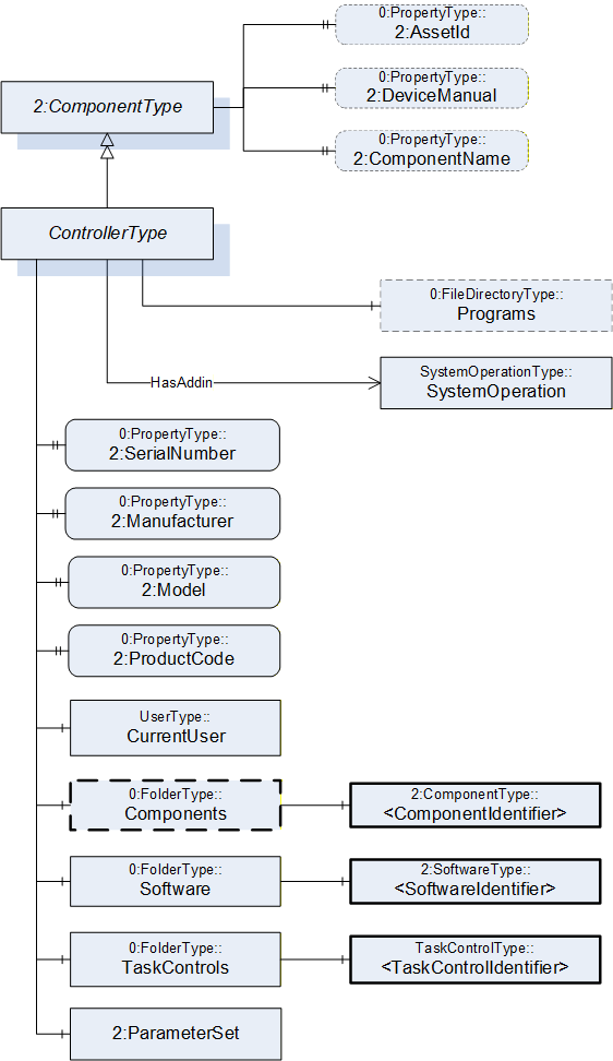
7.18.2 ControllerType definition
| Attribute | Value | ||||
| BrowseName | ControllerType | ||||
| IsAbstract | False | ||||
| References |
Node
Class | BrowseName | DataType | TypeDefinition |
Modelling
Rule |
|---|---|---|---|---|---|
| Subtype of the ComponentType defined in OPC Unified Architecture for Devices (DI) | |||||
| 0:HasProperty | Variable | 2:SerialNumber | 0:String | 0:PropertyType | M |
| 0:HasProperty | Variable | 2:Manufacturer | 0:LocalizedText | 0:PropertyType | M |
| 0:HasProperty | Variable | 2:Model | 0:LocalizedText | 0:PropertyType | M |
| 0:HasProperty | Variable | 2:ProductCode | 0:String | 0:PropertyType | M |
| 0:HasComponent | Object | CurrentUser | UserType | M | |
| 0:HasComponent | Object | Components | 0:FolderType | O | |
| 0:HasComponent | Object | Software | 0:FolderType | M | |
| 0:HasComponent | Object | TaskControls | 0:FolderType | M | |
| 0:HasComponent | Object | 2:ParameterSet | 0:BaseObjectType | O | |
| HasSafetyStates | Object | <SafetyStatesIdentifier> | SafetyStateType | OP | |
| 0:HasComponent | Object | Programs | 0:FileDirectoryType | O | |
| 0:HasAddIn | Object | SystemOperation | SystemOperationType | O | |
| Controls | Object | <MotionDeviceIdentifier> | MotionDeviceType | OP | |
| 0:HasProperty | Variable | 2:AssetId | 0:String | 0:PropertyType | O |
| 0:HasProperty | Variable | 2:DeviceManual | 0:String | 0:PropertyType | O |
| 0:HasProperty | Variable | 2:ComponentName | 0:LocalizedText | 0:PropertyType | O |
| Conformance Units | |||||
|---|---|---|---|---|---|
| Rob System Monitor | |||||
| Rob System Operation | |||||
| Rob Program File Directory | |||||
| Rob System Events | |||||
| Rob Controller AM Extended | |||||
| Rob Controller AM Extended | |||||
| Rob MotionDeviceSystem Base |
| Source Path | Reference | NodeClass | BrowseName | DataType | TypeDefinition | Others |
| Components | 0:HasComponent | Object | <ComponentIdentifier> | 2:ComponentType | MP | |
| Software | 0:HasComponent | Object | <SoftwareIdentifier> | 2:SoftwareType | MP | |
| TaskControls | 0:HasComponent | Object | <TaskControlIdentifier> | TaskControlType | MP | |
| 2:ParameterSet | 0:HasComponent | Variable | TotalPowerOnTime | 0:DurationString | 0:BaseDataVariableType | O |
| 2:ParameterSet | 0:HasComponent | Variable | StartUpTime | 0:DateTime | 0:BaseDataVariableType | O |
| 2:ParameterSet | 0:HasComponent | Variable | UpsState | 0:String | 0:BaseDataVariableType | O |
| 2:ParameterSet | 0:HasComponent | Variable | TotalEnergyConsumption | 0:Double | 0:AnalogUnitType | O |
| 2:ParameterSet | 0:HasComponent | Variable | CabinetFanSpeed | 0:Double | 0:AnalogUnitType | O |
| 2:ParameterSet | 0:HasComponent | Variable | CPUFanSpeed | 0:Double | 0:AnalogUnitType | O |
| 2:ParameterSet | 0:HasComponent | Variable | InputVoltage | 0:Double | 0:AnalogUnitType | O |
| 2:ParameterSet | 0:HasComponent | Variable | Temperature | 0:Double | 0:AnalogUnitType | O |
The SerialNumber property is a unique production number assigned by the manufacturer of the device. This is often stamped on the outside of the device and may be used for traceability and warranty purposes. This property is derived from ComponentType defined in OPC 10000-100.
The Manufacturer property provides the name of the company that manufactured the device. This property is derived from ComponentType defined in OPC 10000-100.
The Model property provides the name of the product. This property is derived from ComponentType defined in OPC 10000-100.
The ProductCode property provides a unique combination of numbers and letters used to identify the product. It may be the order information displayed on type shields or in ERP systems. This property is derived from ComponentType defined in OPC 10000-100.
The AssetId property is a user writable alphanumeric character sequence uniquely identifying a component. The vendor, integrator or user of the device provides the ID. It contains typically an identifier in a branch, use case or user specific naming scheme. This could be for example a reference to an electric scheme. For electric schemes typically EN 81346-2 is used. A use case could be to build up a location-oriented view in a spare part management client software. It enables to identify parts with the same article number which is not possible if this entry is not used. This property is defined by ComponentType defined in OPC 10000-100.
The DeviceManual property allows specifying an address of the user manual for the controller. It may be a pathname in the file system or a URL (Web address). This property is defined by ComponentType defined in OPC 10000-100.
The ComponentName property provides a user writeable name provided by the vendor, integrator, or user of the device. The ComponentName may be a default name given by the vendor. This property is defined by ComponentType defined in OPC 10000-100.
The CurrentUser object provides information about the active vendor specific user level of the controller.
Components is a container for one or more instances of subtypes of ComponentType defined in OPC 10000-100. The listed components are installed in the motion device system, e.g. a processing-unit, a power-supply, an IO-board, or a drive, and have an electrical interface to the controller.
NOTE: This specification recommends using the 3:Components folder defined in OPC 40001-1 instead of the one defined in this specification above.
| Attribute | Value | ||||
| BrowseName | Components | ||||
| References |
Node
Class | BrowseName | DataType | TypeDefinition |
Modelling
Rule |
|---|---|---|---|---|---|
| 0:HasComponent | Object | <ComponentIdentifier> | 2:ComponentType | MandatoryPlaceholder |
The AuxiliaryComponentType and DriveType are the only subtypes of ComponentType for use in this container which are described in this specification. The intention is to integrate inside this container devices which are defined in other companion specifications using DI.
| Software is a container for one or more instances of SoftwareType defined in OPC 10000-100. Each controller has at least one software installed. |
TaskControls is a container for one or more instances of TaskControlType.
Description of ParameterSet of ControllerType:
Variable TotalPowerOnTime: The TotalPowerOnTime variable provides the total accumulated time the controller was powered on.
Variable StartUpTime: The StartUpTime variable provides the date and time of the last start-up of the controller.
Variable UpsState: The UpsState variable provides the vendor specific status of an integrated uninterruptible power supply or accumulator system.
Variable TotalEnergyConsumption: The TotalEnergyConsumption variable provides total accumulated energy consumed by the motion devices related with this controller instance.
Variable CabinetFanSpeed: The CabinetFanSpeed variable provides the speed of the cabinet fan.
Variable CPUFanSpeed: The CPUFanSpeed variable provides the speed of the CPU fan.
Variable InputVoltage: The InputVoltage variable provides the input voltage of the controller which can be a configured value. To distinguish between an AC or DC supply the optional property Definition of the base type DataItemType shall be used.
Variable Temperature: The Temperature variable provides the controller temperature given by a temperature sensor inside of the controller.
To transfer programs for task controls from or to the controller a file directory named Programs can be extended to instances of the ControllerType, which is the entry point for organizing programs. Within this file directory programs can be organized in underlaying file directories. This file directory is a virtual folder, so it does not need to be mapped to a folder naming and structure of the file system on the controller.
The HasSafetyStates reference provides the relationship of safety states to a controller. The InverseName is SafetyStatesOf.
The Controls reference provides the relationship of a motion device and controller. The InverseName is IsControlledBy.
7.19 AuxiliaryComponentType ObjectType Definition
7.19.1 Overview
The AuxiliaryComponentType describes components mounted in a controller cabinet or a motion device e.g. an IO-board or a power supply.
It is formally defined in Table 98.
This type should not be used for instances of components which represent a motor, a gear, or a drive For these components this specification describes specific types.
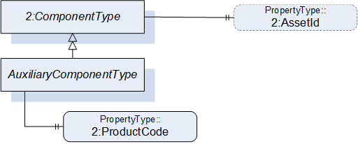
7.19.2 AuxiliaryComponentType definition
| Attribute | Value | ||||
| BrowseName | AuxiliaryComponentType | ||||
| IsAbstract | False | ||||
| References |
Node
Class | BrowseName | DataType | TypeDefinition | Others |
|---|---|---|---|---|---|
| Subtype of the ComponentType defined in OPC Unified Architecture for Devices (DI) | |||||
| 0:HasProperty | Variable | 2:ProductCode | 0:String | 0:PropertyType | M |
| 0:HasProperty | Variable | 2:AssetId | 0:String | 0:PropertyType | O |
The ProductCode property provides a unique combination of numbers and letters used to identify the product. It may be the order information displayed on type shields or in ERP systems. This property is derived from ComponentType defined in OPC 10000-100.
The AssetId property is a user writable alphanumeric character sequence uniquely identifying a component. The vendor, integrator or user of the device provides the ID. It contains typically an identifier in a branch, use case or user specific naming scheme. This could be for example a reference to an electric scheme. For electric schemes typically EN 81346-2 is used. A use case could be to build up a location-oriented view in a spare part management client software. It enables to identify parts with the same article number which is not possible if this entry is not used. This property is defined by ComponentType defined in OPC 10000-100.
7.20 DriveType ObjectType Definition
7.20.1 Overview
The DriveType describes drives (multi-slot or single-slot axis amplifier) mounted in a controller cabinet or a motion device. When used inside a motion device it should be part of a power train. It is formally defined in Table 99.
B.10.1 shows different possibilities of usage.
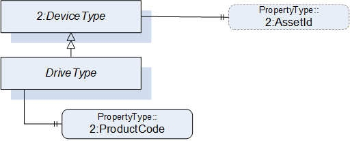
7.20.2 DriveType definition
| Attribute | Value | ||||
| BrowseName | DriveType | ||||
| IsAbstract | False | ||||
| References |
Node
Class | BrowseName | DataType | TypeDefinition |
Modelling
Rule |
|---|---|---|---|---|---|
| Subtype of the ComponentType defined in OPC Unified Architecture for Devices (DI) | |||||
| 0:HasProperty | Variable | 2:ProductCode | 0:String | 0:PropertyType | M |
| The following instance declarations are not defined by this type, but by the supertype ComponentType are repeated here for better readability | |||||
| 0:HasProperty | Variable | 2:AssetId | 0:String | 0:PropertyType | O |
The ProductCode property provides a unique combination of numbers and letters used to identify the product. It may be the order information displayed on type shields or in ERP systems. This property is derived from ComponentType defined in OPC 10000-100.
The AssetId property is a user writable alphanumeric character sequence uniquely identifying a component. The vendor, integrator or user of the device provides the ID. It contains typically an identifier in a branch, use case or user specific naming scheme. This could be for example a reference to an electric scheme. For electric schemes typically EN 81346-2 is used. A use case could be to build up a location-oriented view in a spare part management client software. It enables to identify parts with the same article number which is not possible if this entry is not used. This property is defined by ComponentType defined in OPC 10000-100.
7.21 TaskControlType ObjectType Definition
7.21.1 Overview
TaskControlType represents instances of task controls of a controller and is formally defined in Table 100.
The task control describes an execution engine that loads and runs task programs. One task runs one task program at the time. The system should instantiate the maximum allowed number of task controls.
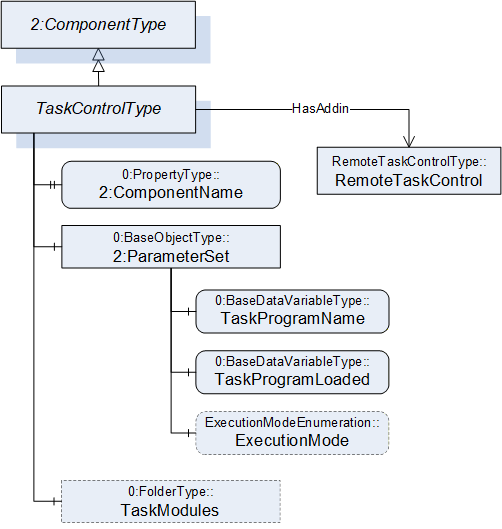
7.21.2 TaskControlType definition
| Attribute | Value | ||||
| BrowseName | TaskControlType | ||||
| IsAbstract | False | ||||
| References |
Node
Class | BrowseName | DataType | TypeDefinition |
Modelling
Rule |
|---|---|---|---|---|---|
| Subtype of the ComponentType defined in OPC Unified Architecture for Devices (DI) | |||||
| 0:HasProperty | Variable | 2:ComponentName | 0:LocalizedText | 0:PropertyType | M |
| 0:HasComponent | Object | 2:ParameterSet | 0:BaseObjectType | M | |
| Controls | Object | <MotionDeviceIdentifier> | MotionDeviceType | OP | |
| 0:HasAddIn | Object | TaskControlOperation | TaskControlOperationType | O | |
| 0:HasComponent | Object | TaskModules | 0:FolderType | O | |
| Conformance Units | |||||
|---|---|---|---|---|---|
| Rob Task Control CM Extended | |||||
| Rob Task Control Monitor | |||||
| Rob Task Control Operation | |||||
| Rob Task Control Modules | |||||
| Rob MotionDeviceSystem Base |
| Source Path | Reference | NodeClass | BrowseName | DataType | TypeDefinition | Others |
| 2:ParameterSet | 0:HasComponent | Variable | TaskProgramName | 0:String | 0:BaseDataVariableType | M |
| 2:ParameterSet | 0:HasComponent | Variable | TaskProgramLoaded | 0:Boolean | 0:BaseDataVariableType | M |
| 2:ParameterSet | 0:HasComponent | Variable | ExecutionMode | ExecutionModeEnumeration | 0:BaseDataVariableType | O |
| TaskModules | 0:Organizes | Object | <TaskModule> | TaskModuleType | OP |
The ComponentName property provides a user writeable name provided by the vendor, integrator, or user of the device. The ComponentName of the TaskControlType provides a customer given identifier for the task control or a default name given by the vendor. This property is derived from ComponentType defined in OPC 10000-100.
Object TaskModules is a folder of TaskModuleType (see 7.22) instances that provides more information about the loaded task modules.
Description of ParameterSet of TaskControlType:
| Variable TaskProgramName: The TaskProgramName variable provides a customer given identifier for the task program. |
Variable TaskProgramLoaded: The TaskProgramLoaded variable is TRUE if a task program is loaded in the task control, FALSE otherwise.
Variable ExecutionMode: The ExecutionMode variable tells how the task control executes the task program (see 10.3).
Controls is a reference to provide the relationship between a task control and a motion device. The InverseName is IsControlledBy.
7.22 TaskModuleType ObjectType Definition
7.22.1 Overview
TaskModuleType provides information about modules loaded on to the TaskControl. It is formally defined in Table 100.
7.22.2 TaskModuleType definition
| Attribute | Value | ||||
| BrowseName | TaskModuleType | ||||
| IsAbstract | False | ||||
| References |
Node
Class | BrowseName | DataType | TypeDefinition |
Modelling
Rule |
|---|---|---|---|---|---|
| Subtype of the BaseObjectType defined in OPC Unified Architecture | |||||
| 0:HasProperty | Variable | Name | 0:String | 0:PropertyType | M |
| 0:HasProperty | Variable | Version | 0:String | 0:PropertyType | O |
| 0:HasProperty | Variable | IsReferenced | 0:Boolean | 0:PropertyType | O |
| Conformance Units | |||||
|---|---|---|---|---|---|
| Rob Task Control Modules |
| Variable Name provides a name for the task module. |
Variable Version provides a version information for the task module.
Variable IsReferenced provides a boolean flag to indicate if the module is referenced in other modules and/or the program. This information can be useful to determine if the unloading of a module is possible.
7.23 LoadType ObjectType Definition
7.23.1 Overview
The LoadType is for describing loads mounted on the motion device typically by an integrator or a customer and is formally defined in Table 103. Instances of this ObjectType definition are used to describe the load mounted on one of several mounting points. A common mounting point is the flange of a motion device. Typically, a motion device has additional mounting points on some of the axis. The provided values can either be determined by the robot controller or can be set up by an operator.
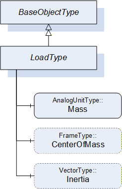
7.23.2 LoadType definition
| Attribute | Value | ||||
| BrowseName | LoadType | ||||
| IsAbstract | False | ||||
| References |
Node
Class | BrowseName | DataType | TypeDefinition |
Modelling
Rule |
|---|---|---|---|---|---|
| Subtype of the 0:BaseObjectType defined in OPC Unified Architecture | |||||
| 0:HasComponent | Variable | Mass | 0:Double | AnalogUnitType | M |
| 0:HasComponent | Variable | CenterOfMass | 0:3DFrame | 3DFrameType | O |
| 0:HasComponent | Variable | Inertia | 0:3DVector | 3DVectorType | O |
The variable Mass provides the weight of the load mounted on one mounting point. The EngineeringUnits of the Mass shall be provided.
The variable CenterOfMass provides the position and orientation of the center of the mass related to the mounting point using a 3DFrameType. X, Y, Z define the position of the center of gravity relative to the mounting point coordinate system. A, B, C define the orientation of the principal axes of inertia relative to the mounting point coordinate system. Orientation A, B, C can be "0" for systems which do not need these values.
If the instance of the LoadType describes the flange load of a motion device the mounting point coordinate system is the flange coordinate system. If the instance of the LoadType describes an additional load of an axis the mounting point coordinate system is vendor specific and it is up to the vendor to model this coordinate system.
The variable Inertia uses the 3DVectorType to describe the three values of the principal moments of inertia with respect to the mounting point coordinate system. If inertia values are provided for rotary axis the CenterOfMass shall be provided as well.
Table 104 describes the possible degrees of modelling from a minimal one e.g. only the weight of the mass to a complete one comprising weight, center of mass, principal axes, and inertia.
| Mass | CenterOfMass | Inertia | ||
| X, Y, Z | A, B, C | |||
| Mass only | Used | - | - | - |
| Mass with center of gravity | Used | Used | 0, 0, 0 | - |
| Mass with inertia | Used | Used | Used | Used |
7.24 UserType ObjectType Definition
7.24.1 Overview
The UserType ObjectType describes information of the registered user groups within the control system.
It is formally defined in Table 105.
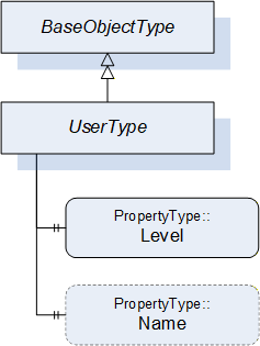
7.24.2 UserType definition
| Attribute | Value | ||||
| BrowseName | UserType | ||||
| IsAbstract | False | ||||
| References |
Node
Class | BrowseName | DataType | TypeDefinition |
Modelling
Rule |
|---|---|---|---|---|---|
| Subtype of the BaseObjectType defined in OPC Unified Architecture | |||||
| 0:HasProperty | Variable | Level | 0:String | 0:PropertyType | M |
| 0:HasProperty | Variable | Name | 0:String | 0:PropertyType | O |
| Conformance Units | |||||
|---|---|---|---|---|---|
| Rob MotionDeviceSystem Base |
The Level property provides information about the access rights and determines what can be viewed, updated, or deleted by a user. Depending on the user level different functionalities are available. The robot vendors might use different descriptions and access levels for the users and might require authentication.
The Name property provides the name for the current user within the control system.
8 OPC UA ReferenceTypes
8.1 General
This section defines the ReferenceTypes that are inherent to the present companion specification. Figure 31 describes informally the hierarchy of these Reference Types. OPC UA Reference Types are defined in OPC 10000-3.
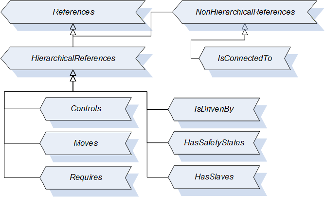
8.2 Controls (IsControlledBy) Reference Type
The OPC UA ReferenceType Controls is used to describe dependencies between objects which have a controlling character. The BrowseName Controls and the InverseName IsControlledBy describe semantically the hierarchical dependency e.g. a controlling device Controls a controlled machine module.
Example for usage in this companion specification: If one controller Controls several motion devices, each motion device IsControlledBy the same controller.
The SourceNode of this type shall be an ObjectType or Object and the TargetNode shall be an Object.
| Attributes | Value | ||||
| BrowseName | Controls | ||||
| InverseName | IsControlledBy | ||||
| Symmetric | False | ||||
| IsAbstract | False | ||||
| Subtype of the HierarchicalReferences defined in OPC Unified Architecture Part 5 | |||||
| References | NodeClass | BrowseName | DataType | TypeDefinition | ModellingRule |
|---|
8.3 Moves (IsMovedBy) Reference Type
The OPC UA ReferenceType Moves is used to describe the coupling between a power train and the axes from the power train point of view. A power train has a Moves reference to all axis that are moving when only this powertrain moves.
For examples see B.9.
The SourceNode of this type shall be an ObjectType or Object and the TargetNode shall be an Object.
| Attributes | Value | ||||
| BrowseName | Moves | ||||
| InverseName | IsMovedBy | ||||
| Symmetric | False | ||||
| IsAbstract | False | ||||
| Subtype of the HierarchicalReferences defined in OPC Unified Architecture Part 5 | |||||
| References | NodeClass | BrowseName | DataType | TypeDefinition | ModellingRule |
|---|
8.4 Requires (IsRequiredBy) Reference Type
The OPC UA ReferenceType Requires is used to describe the coupling between a power train and axes from the axis point of view. An axis has a Requires reference to all powertrains that need to move such that only this single axis moves.
For examples see Annex B.9.
The SourceNode of this type shall be an ObjectType or Object and the TargetNode shall be an Object.
| Attributes | Value | ||||
| BrowseName | Requires | ||||
| InverseName | IsRequiredBy | ||||
| Symmetric | False | ||||
| IsAbstract | False | ||||
| Subtype of the HierarchicalReferences defined in OPC Unified Architecture Part 5 | |||||
| References | NodeClass | BrowseName | DataType | TypeDefinition | ModellingRule |
|---|
8.5 IsDrivenBy (Drives) Reference Type
The OPC UA ReferenceType IsDrivenBy is used to describe dependencies between objects which have a driving or powering character. The BrowseName IsDrivenBy and the InverseName Drives describe semantically the hierarchical dependency.
Example for usage in this companion specification: an electrical motor IsDrivenBy and servo amplifier (drive) and an internal drive of a motion device or a drive as a component of a controller Drives a motor.
The SourceNode of this type shall be an ObjectType or Object and the TargetNode shall be an Object.
| Attributes | Value | ||||
| BrowseName | IsDrivenBy | ||||
| InverseName | Drives | ||||
| Symmetric | False | ||||
| IsAbstract | False | ||||
| Subtype of the HierarchicalReferences defined in OPC Unified Architecture Part 5 | |||||
| References | NodeClass | BrowseName | DataType | TypeDefinition | ModellingRule |
|---|
8.6 IsConnectedTo Reference Type
The OPC UA ReferenceType IsConnectedTo is used to describe dependencies between objects which are mounted or mechanically linked or connected to each other. The IsConnectedTo reference is symmetric and has no InverseName.
Example for usage in this companion specification: a motor IsConnectedTo to a gear and vice versa.
Typically, the reference is used to describe the relationships of motors and gears within the same powertrain.
The SourceNode of this type shall be an ObjectType or Object and the TargetNode shall be an Object.
| Attributes | Value | ||||
| BrowseName | IsConnectedTo | ||||
| InverseName | |||||
|---|---|---|---|---|---|
| Symmetric | True | ||||
| IsAbstract | False | ||||
| Subtype of the NonHierarchicalReferences defined in OPC Unified Architecture Part 5 | |||||
| References | NodeClass | BrowseName | DataType | TypeDefinition | ModellingRule |
|---|
8.7 HasSafetyStates (SafetyStatesOf) Reference Type
The OPC UA ReferenceType HasSafetyStates is used to describe dependencies between objects to show which (controller) object is responsible for the execution of the safety-functionality. The BrowseName HasSafetyStates and the InverseName SafetyStatesOf describe semantically the hierarchical dependency.
Example for usage in this companion specification: a controller HasSafetyStates and the reference shows to an instance of SafetyStatesType. It is possible that there are two controller in one motion device system.
The SourceNode of this type shall be an ObjectType or Object and the TargetNode shall be an Object.
| Attributes | Value | ||||
| BrowseName | HasSafetyStates | ||||
| InverseName | SafetyStatesOf | ||||
| Symmetric | False | ||||
| IsAbstract | False | ||||
| Subtype of the HierarchicalReferences defined in OPC Unified Architecture Part 5 | |||||
| References | NodeClass | BrowseName | DataType | TypeDefinition | ModellingRule |
|---|
8.8 HasSlave (IsSlaveOf) Reference Type
The OPC UA ReferenceType HasSlave is a reference to provide the master-slave relationship of power trains which provide torque for a common axis. The InverseName is IsSlaveOf.
The SourceNode of this type shall be an ObjectType or Object and the TargetNode shall be an Object.
| Attributes | Value | ||||
| BrowseName | HasSlave | ||||
| InverseName | IsSlaveOf | ||||
| Symmetric | False | ||||
| IsAbstract | False | ||||
| Subtype of the HierarchicalReferences defined in OPC Unified Architecture Part 5 | |||||
| References | NodeClass | BrowseName | DataType | TypeDefinition | ModellingRule |
|---|
9 OPC UA EventTypes
9.1 MultiAcknowledgeableConditionType
Before commanding robot actions, a control source may need to acknowledge certain conditions first. The information model provides two possibilities for a Client to acknowledge conditions of the system, either with Instances of specific Events in the Address space or with the standard OPC UA Eventing mechanism. The MultiAcknowledgeableConditionType may be used to simplify the handling of multiple conditions, which need to be acknowledged by a Client to use the SystemOperationStateMachine or IdleSubstateMachine. Its representation in the AddressSpace is formally defined in Table 131.
| Attribute | Value | |||||
| BrowseName | MultiAcknowledgeableConditionType | |||||
| IsAbstract | False | |||||
| References | NodeClass | BrowseName | DataType | TypeDefinition | Other | |
|---|---|---|---|---|---|---|
| Subtype of the AcknowledgeableConditionType defined in OPC 10000-9, it inherits the InstanceDeclarations of that Node. | ||||||
| 0:HasProperty | Variable | ConditionDescriptions | 0:LocalizedText[] | 0:PropertyType | M | |
| Conformance Units | ||||||
|---|---|---|---|---|---|---|
| Rob RobAckCondInstance |
The MultiAcknowledgeableConditionType inherits all Properties of the AcknowledgeableConditionType.
The Variable ConditionDescriptions provides in an Array of descriptions of all conditions, which need acknowledgement.
When a Client calls the Acknowledge Method, the system tries to acknowledge all conditions described in the ConditionDescriptions array at once. If a condition cannot be acknowledged (e.g. cable is broken) and the condition is still active, the instance of the MultiAcknowledgeableConditionType stays in AckedState False and the ConditionDescriptions are updated with all pending conditions.
There is a race condition here with respect to keeping the ConditionDescriptions array up to date, however it is assumed that the logic behind starting the system will never be solely dependent on this variable, but there will be internal checks to make sure that the system can safely start.
Confirmation of the MultiAcknowledgeableConditionType instances (using the optional Confirm method, inherited from the AcknowledgeableConditionType) is undefined and out of scope.
10 OPC UA DataTypes
10.1 MotionDeviceCategoryEnumeration
MotionDeviceCategoryEnumeration provides the kind of motion device based on ISO 8373. It is defined in Table 114.
| Name | Value | Description |
| OTHER | 0 | Any motion-device which is not defined by the MotionDeviceCategoryEnumeration |
| ARTICULATED_ROBOT | 1 | This robot design features rotary joints and can range from simple two joint structures to 10 or more joints. The arm is connected to the base with a twisting joint. The links in the arm are connected by rotary joints. |
| SCARA_ROBOT | 2 | Robot has two parallel rotary joints to provide compliance in a selected plane |
| CARTESIAN_ROBOT | 3 | Cartesian robots have three linear joints that use the Cartesian coordinate system (X, Y, and Z). They also may have an attached wrist to allow for rotational movement. The three prismatic joints deliver a linear motion along the axis. |
| SPHERICAL_ROBOT | 4 | The arm is connected to the base with a twisting joint and a combination of two rotary joints and one linear joint. The axes form a polar coordinate system and create a spherical-shaped work envelope. |
| PARALLEL_ROBOT | 5 | These spider-like robots are built from jointed parallelograms connected to a common base. The parallelograms move a single end of arm tooling in a dome-shaped work area. |
| CYLINDRICAL_ROBOT | 6 | The robot has at least one rotary joint at the base and at least one prismatic joint to connect the links. The rotary joint uses a rotational motion along the joint axis, while the prismatic joint moves in a linear motion. Cylindrical robots operate within a cylindrical-shaped work envelope. |
Its representation in the AddressSpace is defined in the table below.
| Attribute | Value | |||||
| BrowseName | MotionDeviceCategoryEnumeration | |||||
| IsAbstract | False | |||||
| References | NodeClass | BrowseName | DataType | TypeDefinition | Other | |
|---|---|---|---|---|---|---|
| Subtype of the 0:Enumeration type defined in OPC 10000-5 | ||||||
| 0:HasProperty | Variable | 0:EnumStrings | 0:LocalizedText [] | 0:PropertyType | ||
10.2 AxisMotionProfileEnumeration
The AxisMotionProfileEnumeration provides the kind of axis motion as defined in Table 116.
| Name | Value | Description |
| OTHER | 0 | Any motion-profile which is not defined by the AxisMotionProfileEnumeration |
| ROTARY | 1 | Rotary motion is a rotation along a circular path with defined limits. Motion movement is not going always in the same direction. Control unit is degree. |
| ROTARY_ENDLESS | 2 | Rotary motion is a rotation along a circular path with no limits. Motion movement is going endless in the same direction. Control unit is degree. |
| LINEAR | 3 | Linear motion is a one-dimensional motion along a straight line with defined limits. Motion movement is not going always in the same direction. Control unit is mm. |
| LINEAR_ENDLESS | 4 | Linear motion is a one-dimensional motion along a straight line with no limits. Motion movement is going endless in the same direction. Control unit is mm. |
Its representation in the AddressSpace is defined in the table below.
| Attribute | Value | |||||
| BrowseName | AxisMotionProfileEnumeration | |||||
| IsAbstract | False | |||||
| References | NodeClass | BrowseName | DataType | TypeDefinition | Other | |
|---|---|---|---|---|---|---|
| Subtype of the 0:Enumeration type defined in OPC 10000-5 | ||||||
| 0:HasProperty | Variable | 0:EnumStrings | 0:LocalizedText [] | 0:PropertyType | ||
10.3 ExecutionModeEnumeration
The ExecutionModeEnumeration is defined in Table 118.
| Name | Value | Description |
| CYCLE | 0 | Single execution of a task program according to ISO 8373 |
| CONTINUOUS | 1 | Task program is executed continuously and starts again automatically |
| STEP | 2 | Task program is executed in steps |
Its representation in the AddressSpace is defined in the table below.
| Attribute | Value | |||||
| BrowseName | ExecutionModeEnumeration | |||||
| IsAbstract | False | |||||
| References | NodeClass | BrowseName | DataType | TypeDefinition | Other | |
|---|---|---|---|---|---|---|
| Subtype of the 0:Enumeration type defined in OPC 10000-5 | ||||||
| 0:HasProperty | Variable | 0:EnumStrings | 0:LocalizedText [] | 0:PropertyType | ||
10.4 OperationalModeEnumeration
ISO 10218-1:2011 Ch.5.7 defines the different possible Operational Modes. This enumeration is defined in Table 120.
| Name | Value | Description |
| OTHER | 0 | This value is used when there is no valid operational mode. Examples are: - During system-boot - The system is not calibrated (and hence cannot verify cartesian position values) - There is a failure in the safety system itself |
| MANUAL_REDUCED_SPEED | 1 | "Manual reduced speed" - name according to ISO 10218-1:2011 |
| MANUAL_HIGH_SPEED | 2 | "Manual high speed" - name according to ISO 10218-1:2011 |
| AUTOMATIC | 3 | "Automatic" - name according to ISO 10218-1:2011 |
| AUTOMATIC_EXTERNAL | 4 | "Automatic external" - Same as "Automatic" but with external control, e.g. by a PLC |
Its representation in the AddressSpace is defined in the table below.
| Attribute | Value | |||||
| BrowseName | OperationalModeEnumeration | |||||
| IsAbstract | False | |||||
| References | NodeClass | BrowseName | DataType | TypeDefinition | Other | |
|---|---|---|---|---|---|---|
| Subtype of the 0:Enumeration type defined in OPC 10000-5 | ||||||
| 0:HasProperty | Variable | 0:EnumStrings | 0:LocalizedText [] | 0:PropertyType | ||
11 Profiles and ConformanceUnits
11.1 Conformance Units
This chapter defines the corresponding Conformance Units for the OPC UA Information Model for Robotics.
| Category | Title | Description |
| Server | Rob MotionDeviceSystem Base | Supports the MotionDeviceSystemType with all its mandatory instance declarations and optionally the optional InstanceDeclarations with read access, thereby supporting the base functionality defined in the Robotics Information Model. There is at least one instance of the MotionDeviceSystemType (or a subtype) with all its mandatory elements. The mandatory elements shall in-turn implement all of their mandatory elements recursively. |
| Server | Rob MotionDevice AM Extended | Supports the MotionDeviceType with all its mandatory instance declarations and optionally the optional InstanceDeclarations with read access. There is at least one instance of the MotionDeviceType (or a subtype) with all its mandatory elements. The Properties 2:AssetId, 2:ComponentName and 2:DeviceManual shall be provided for at least one instance of the MotionDeviceType or its subtypes. |
| Server | Rob MotionDevice CM Extended | Supports the MotionDeviceType with all its mandatory instance declarations and optionally the optional InstanceDeclarations with read access. There is at least one instance of the MotionDeviceType (or a subtype) with all its mandatory elements. All Variables within the 2:ParameterSet of at least one MotionDeviceType instance shall also be implemented. |
| Server | Rob MotionDevice Flangeload | Supports the MotionDeviceType with all its mandatory instance declarations and optionally the optional InstanceDeclarations with read access. There is at least one instance of the MotionDeviceType (or a subtype) with all its mandatory elements. The FlangeLoad Object shall be provided for all instances of the MotionDeviceType or its subtypes. |
| Server | Rob TC Relationship | Supports the MotionDeviceType with all its mandatory instance declarations and optionally the optional InstanceDeclarations with read access. There is at least one instance of the MotionDeviceType (or a subtype) with all its mandatory elements. The Variable TaskControlReference shall be provided for all instances of the MotionDeviceType or its subtypes. |
| Server | Rob Axis AM Extended | Supports the AxisType with all its mandatory instance declarations and optionally the optional InstanceDeclarations with read access. There is at least one instance of the AxisType (or a subtype) with all its mandatory elements. The Property 2:AssetId shall be provided for at least one instance of the AxisType or its subtypes. |
| Server | Rob Axis CM Extended | Supports the AxisType with all its mandatory instance declarations and optionally the optional InstanceDeclarations with read access. There is at least one instance of the AxisType (or a subtype) with all its mandatory elements. All Variables within the 2:ParameterSet of at least one instance of AxisType shall also be implemented. |
| Server | Rob Axis AdditionalLoad | Supports the AxisType with all its mandatory instance declarations and optionally the optional InstanceDeclarations with read access. There is at least one instance of the AxisType (or a subtype) with all its mandatory elements. The AdditionalLoad Object shall be provided for at least one instance of the AxisType or its subtypes. |
| Server | Rob PowerTrain AM Extended | Supports the PowerTrainType with all its mandatory instance declarations and optionally the optional InstanceDeclarations with read access. There is at least one instance of the PowerTrainType (or a subtype) with all its mandatory elements. The Property 2:ComponentName shall be provided for at least one instance of the PowerTrainType or its subtypes. |
| Server | Rob Motor AM Extended | Supports the MotorType with all its mandatory instance declarations and optionally the optional InstanceDeclarations with read access. There is at least one instance of the MotorType (or a subtype) with all its mandatory elements. The Property 2:AssetId shall be provided for at least one instance of the MotorType or its subtypes. |
| Server | Rob Motor CM Extended | Supports the MotorType with all its mandatory instance declarations and optionally the optional InstanceDeclarations with read access. There is at least one instance of the MotorType (or a subtype) with all its mandatory elements. All Variables within the 2:ParameterSet of at least one instance of MotorType shall also be implemented. |
| Server | Rob Gear AM Extended | Supports the GearType with all its mandatory instance declarations and optionally the optional InstanceDeclarations with read access. There is at least one instance of the GearType (or a subtype) with all its mandatory elements. The Property 2:AssetId shall be provided for at least one instance of the GearType or its subtypes. |
| Server | Rob Gear CM Extended | Supports the GearType with all its mandatory instance declarations and optionally the optional InstanceDeclarations with read access. There is at least one instance of the GearType (or a subtype) with all its mandatory elements. The Property Pitch shall be provided for at least one instance of the GearType or its subtypes. |
| Server | Rob Emergency Stop Function | Supports the EmergencyStopFunctionType with all its mandatory instance declarations and optionally the optional InstanceDeclarations with read access. There is at least one instance of the EmergencyStopFunctionType (or a subtype) with all its mandatory elements in the EmergencyStopFunctions folder (instance of FolderType) of an instance of SafetyStateType. |
| Server | Rob Protective Stop Function | Supports the ProtectiveStopFunctionType with all its mandatory instance declarations and optionally the optional InstanceDeclarations with read access. There is at least one instance of the ProtectiveStopFunctionType (or a subtype) with all its mandatory elements in the ProtectiveStopFunctions folder (instance of FolderType) of an instance of SafetyStateType. |
| Server | Rob Controller AM Extended | Supports the ControllerType with all its mandatory instance declarations and optionally the optional InstanceDeclarations with read access. There is at least one instance of the ControllerType (or a subtype) with all its mandatory elements. The Property 2:AssetId, 2:DeviceManual and 2:ComponentName shall be provided for at least one instance of the ControllerType or its subtypes. |
| Server | Rob Controller CM Extended | Supports the ControllerType with all its mandatory instance declarations and optionally the optional InstanceDeclarations with read access. There is at least one instance of the ControllerType (or a subtype) with all its mandatory elements. The 2:ParameterSet with all Variables within the 2:ParameterSet of at least one instance of ControllerType shall be implemented. |
| Server | Rob System Monitor | Supports the SystemOperationType with all its mandatory instance declarations and optionally the optional InstanceDeclarations. There is at least one instance of the SystemOperationType (or a subtype) connected to a ControllerType instance with a 0:HasAddIn Reference. |
| Server | Rob System Operation | Supports the SystemOperationType with all its mandatory instance declarations and optionally the optional InstanceDeclarations. There is at least one instance of the SystemOperationType (or a subtype) connected to a ControllerType instance with a 0:HasAddIn Reference. Each instance of the SystemOperationStateMachineType shall implement the methods defined within the SystemOperationStateMachineType. |
| Server | Rob RobAckCondInstance | Supports the SystemOperationType with all its mandatory instance declarations and optionally the optional InstanceDeclarations. There is at least one instance of the SystemOperationType (or a subtype) connected to a ControllerType instance with a 0:HasAddIn Reference. Each instance of the SystemOperationType shall implement the Conditions InstanceDeclaration defined within the SystemOperationType. The MultiAcknowledgeableConditionType is supported with all its mandatory instance declarations and optionally the optional InstanceDeclarations. At least once instance of MultiAcknowledgeableConditionType shall be provided within the Conditions InstanceDeclaration defined within the SystemOperationType. |
| Server | Rob System Events | The OPC UA Server supports eventing and shall support the Events from the MotionDeviceSystemType instance. |
| Server | Rob System IdleSubstate | Supports the SystemOperationStateMachineType with all its mandatory instance declarations and optionally the optional InstanceDeclarations. There is at least one instance of the SystemOperationStateMachineType (or a subtype). At least one instance of the SystemOperationStateMachineType shall implement the IdleSubstateMachine InstanceDeclaration defined within the SystemOperationStateMachineType. |
| Server | Rob System ExecutingSubstate | Supports the SystemOperationStateMachineType with all its mandatory instance declarations and optionally the optional InstanceDeclarations. There is at least one instance of the SystemOperationStateMachineType (or a subtype). At least one instance of the SystemOperationStateMachineType shall implement the ExecutingSubstateMachine InstanceDeclaration defined within the SystemOperationStateMachineType. |
| Server | Rob Task Control CM Extended | Supports the TaskControlType with all its mandatory instance declarations and optionally the optional InstanceDeclarations with read access. There is at least one instance of the TaskControlType (or a subtype) with all its mandatory elements. The Variable ExecutionMode within the 2:ParameterSet, shall be provided for at least one instance of instances of the TaskControlType or its subtypes. |
| Server | Rob Task Control Monitor | Supports the TaskControlOperationType with all its mandatory instance declarations and optionally the optional InstanceDeclarations. There is at least one instance of the TaskControlOperationType (or a subtype) connected to a TaskControlType instance with a 0:HasAddIn Reference. |
| Server | Rob Task Control Operation | Supports the TaskControlOperationType with all its mandatory instance declarations and optionally the optional InstanceDeclarations. There is at least one instance of the TaskControlOperationType (or a subtype) connected to a TaskControlType instance with a 0:HasAddIn Reference. Each instance of the TaskControlOperationStateMachineType shall implement the methods defined within the TaskControlOperationStateMachineType. |
| Server | Rob TC MD Relationship | Supports the TaskControlOperationType with all its mandatory instance declarations and optionally the optional InstanceDeclarations. There is at least one instance of the TaskControlOperationType (or a subtype) connected to a TaskControlType instance with a 0:HasAddIn Reference. Each instance of the TaskControlOperationType shall implement the MotionDevicesUnterControl Property defined within the TaskControlOperationType. |
| Server | Rob Task Control ReadySubstate | Supports the TaskControlOperationStateMachineType with all its mandatory instance declarations and optionally the optional InstanceDeclarations. There is at least one instance of the TaskControlOperationStateMachineType (or a subtype). At least one instance of the TaskControlOperationStateMachineType shall implement the ReadySubstateMachine InstanceDeclaration defined within the TaskControlOperationStateMachineType. |
| Server | Task Control Ready Reset | Supports the TaskControlOperationStateMachineType with all its mandatory instance declarations and optionally the optional InstanceDeclarations. There is at least one instance of the TaskControlOperationStateMachineType (or a subtype). Each instance of the TaskControlOperationStateMachineType shall implement the ReadySubstateMachine InstanceDeclaration defined within the TaskControlOperationStateMachineType. At least one instance of the ReadySubstateMachine shall implement the ResetToProgramStart method defined within the ReadySubstateMachineType. |
| Server | Rob Program File Directory | At least one instance of the ControllerType shall implement the Programs InstanceDeclaration defined within the ControllerType. |
| Server | Rob Task Control Modules | At least one instance of the TaskControlType shall implement the TaskModules InstanceDeclaration defined within the TaskControlType. If a TaskControlType instance implements the TaskModules InstanceDeclaration (defined within the TaskControlType), then all TaskControlType instances (in the TaskControls folder) of that ControllerType instance, shall implement the TaskModules InstanceDeclaration. |
11.2 Profiles
11.2.1 Profile list
Table 123 lists all Profiles defined in this document and defines their URIs.
| Profile | URI |
| Robotics Base Server Facet | http://opcfoundation.org/UA-Profile/Robotics/Server/RobBase |
| Robotics MDS Operation Server Facet | http://opcfoundation.org/UA-Profile/Robotics/Server/RobOperation |
| Robotics AM Extended Server Facet | http://opcfoundation.org/UA-Profile/Robotics/Server/RobAMExtended |
| Robotics CM Extended Server Facet | http://opcfoundation.org/UA-Profile/Robotics/Server/RobCMExtended |
11.2.2 Server Facets
11.2.2.1 Overview
The following sections specify the Facets available for Servers that implement the OPC UA for Robotics companion specification. Each section defines and describes a Facet or Profile.
11.2.2.2 Robotics Base Server Facet
Table 124 defines a Facet that describes the Robotics Base Server Facet.
| Group | Conformance Unit / Profile Title | Mandatory / Optional |
| Address Space Model | 0:Address Space Base | M |
| Address Space Model | 0:Address Space Interfaces | M |
| Address Space Model | 0:Address Space AddIn Reference | M |
| Address Space Model | 0:Address Space AddIn DefaultInstanceBrowsename | M |
| View Services | 0:View Basic | M |
| View Services | 0:View TranslateBrowsePath | M |
| View Services | 0:View Minimum Continuation Point 01 | M |
| Attribute Services | 0:Attribute Read | M |
| Robotics | Rob MotionDeviceSystem Base | M |
11.2.2.3 Robotics MDS Operation Server Facet
Table 125 defines a Facet that describes the Robotics MDS Operation Server Facet.
| Group | Conformance Unit / Profile Title | Mandatory / Optional |
| Profile | Robotics Base Server Facet | M |
| Robotics | Rob System Operation | M |
| Robotics | Rob Task Control Operation | O |
| Robotics | Rob RobAckCondInstance | O |
| Robotics | Rob Task Control ReadySubstate | O |
| Robotics | Task Control Ready Reset | O |
| Robotics | Rob Program File Directory | O |
| Robotics | Rob Task Control Modules | O |
11.2.2.4 Robotics AM Extended Server Facet
Table 126 defines a Facet that describes the Robotics AM Extended Server Facet.
| Group | Conformance Unit / Profile Title | Mandatory / Optional |
| Robotics | Rob MotionDeviceSystem Base | M |
| Robotics | Rob MotionDevice AM Extended | M |
| Robotics | Rob MotionDevice Flangeload | O |
| Robotics | Rob TC Relationship | O |
| Robotics | Rob Axis AM Extended | M |
| Robotics | Rob Axis AdditionalLoad | O |
| Robotics | Rob PowerTrain AM Extended | M |
| Robotics | Rob Gear AM Extended | M |
| Robotics | Rob Emergency Stop Function | O |
| Robotics | Rob Protective Stop Function | O |
| Robotics | Rob Controller AM Extended | M |
| Robotics | Rob TC MD Relationship | O |
| Robotics | Rob Program File Directory | O |
| Robotics | Rob Task Control Modules | O |
11.2.2.5 Robotics CM Extended Server Facet
Table 127 defines a Facet that describes the Robotics CM Extended Server Facet.
| Group | Conformance Unit / Profile Title | Mandatory / Optional |
| Robotics | Rob MotionDeviceSystem Base | M |
| Robotics | Rob MotionDevice CM Extended | M |
| Robotics | Rob Axis CM Extended | M |
| Robotics | Rob PowerTrain CM Extended | M |
| Robotics | Rob Gear CM Extended | M |
| Robotics | Rob Controller CM Extended | M |
| Robotics | Rob System Monitor | O |
| Robotics | Rob System Events | O |
| Robotics | Rob System IdleSubstate | O |
| Robotics | Rob System ExecutingSubstate | O |
| Robotics | Rob Task Control CM Extended | M |
| Robotics | Rob Task Control Monitor | O |
| Robotics | Rob RobAckCondInstance | O |
12 Namespaces
12.1 Namespace Metadata
Table 128 defines the namespace metadata for this document. The Object is used to provide version information for the namespace and an indication about static Nodes. Static Nodes are identical for all Attributes in all Servers, including the Value Attribute. See OPC 10000-5 for more details.
The information is provided as Object of type NamespaceMetadataType. This Object is a component of the Namespaces Object that is part of the Server Object. The NamespaceMetadataType ObjectType and its Properties are defined in OPC 10000-5.
The version information is also provided as part of the ModelTableEntry in the UANodeSet XML file. The UANodeSet XML schema is defined in Table 128.
| Attribute | Value | ||
| BrowseName | http://opcfoundation.org/UA/Robotics/ | ||
| Property | DataType | Value | |
|---|---|---|---|
| NamespaceUri | String | http://opcfoundation.org/UA/Robotics/ | |
| NamespaceVersion | String | 1.02 | |
| NamespacePublicationDate | DateTime | 2025-09-08 | |
| IsNamespaceSubset | Boolean | False | |
| StaticNodeIdTypes | IdType [] | 0 | |
| StaticNumericNodeIdRange | NumericRange [] | ||
| StaticStringNodeIdPattern | String | ||
12.2 Handling of OPC UA Namespaces
Namespaces are used by OPC UA to create unique identifiers across different naming authorities. The Attributes NodeId and BrowseName are identifiers. A Node in the UA AddressSpace is unambiguously identified using a NodeId. Unlike NodeIds, the BrowseName cannot be used to unambiguously identify a Node. Different Nodes may have the same BrowseName. They are used to build a browse path between two Nodes or to define a standard Property.
Servers may often choose to use the same namespace for the NodeId and the BrowseName. However, if they want to provide a standard Property, its BrowseName shall have the namespace of the standards body although the namespace of the NodeId reflects something else, for example the EngineeringUnits Property. All NodeIds of Nodes not defined in this document shall not use the standard namespaces.
Table 129 provides a list of mandatory and optional namespaces used in an OPC UA for Robotics Server.
| NamespaceURI | Description | Use |
| http://opcfoundation.org/UA/ | Namespace for NodeIds and BrowseNames defined in the OPC UA specification. This namespace shall have namespace index 0. | Mandatory |
| Local Server URI | Namespace for nodes defined in the local server. This namespace shall have namespace index 1. | Mandatory |
| http://opcfoundation.org/UA/DI/ | Namespace for NodeIds and BrowseNames defined in OPC 10000-100. The namespace index is Server specific. | Mandatory |
| http://opcfoundation.org/UA/Machinery/ | Namespace for NodeIds and BrowseNames defined in OPC UA for Machinery. The namespace index is Server specific. | Optional |
| http://opcfoundation.org/UA/Robotics/ | Namespace for NodeIds and BrowseNames defined in this document. The namespace index is Server specific. | Mandatory |
| Vendor specific types | A Server may provide vendor-specific types like types derived from ObjectTypes defined in this document in a vendor-specific namespace. | Optional |
| Vendor specific instances | A Server provides vendor-specific instances of the standard types or vendor-specific instances of vendor-specific types in a vendor-specific namespace. It is recommended to separate vendor specific types and vendor specific instances into two or more namespaces. | Mandatory |
Table 130 provides a list of namespaces and their indices used for BrowseNames in this document. The default namespace of this document is not listed since all BrowseNames without prefix use this default namespace.
| NamespaceURI | Namespace Index | Example |
| http://opcfoundation.org/UA/ | 0 | 0:EngineeringUnits |
| http://opcfoundation.org/UA/DI/ | 2 | 2:DeviceRevision |
| http://opcfoundation.org/UA/Machinery/ | 3 | 3:MachineIdentificationType |
Annex A OPC UA for Robotics Namespace and mappings (Normative)
A.1 Namespace and identifiers for Robotics Information Model
The Robotics Information Model is identified by the following URI:
http://opcfoundation.org/UA/Robotics/
Documentation for the NamespaceUri can be found here.
The NodeSet associated with this version of specification can be found here:
https://reference.opcfoundation.org/nodesets/?u=http://opcfoundation.org/UA/Robotics/&v=1.02&i=1
The NodeSet associated with the latest version of the specification can be found here:
https://reference.opcfoundation.org/nodesets/?u=http://opcfoundation.org/UA/Robotics/&i=1
Supplementary files for the Robotics Information Model can be found here:
https://reference.opcfoundation.org/nodesets/?u=http://opcfoundation.org/UA/Robotics/&v=1.02&i=2
The files associated with the latest version of the specification can be found here:
https://reference.opcfoundation.org/nodesets/?u=http://opcfoundation.org/UA/Robotics/&i=2
A.2 Capability Identifier
The capability identifier for this document shall be:
Robotics___________
Annex B Examples (Informative)
B.1 Overview
This chapter describes examples for motion device systems, motion devices, axes, and power trains.
In addition, this chapter contains examples of how to use the references contained in this specification.
B.2 Example for motion device systems
Typically, a motion device system consists of at least one manipulator and one control unit. Manipulators shown in Figure B.1, Figure B.2, Figure B.3, Figure B.4, Figure B.5, Figure B.6 and Figure B.7 normally have only one control unit.
Figure B.8 shows an example with four motion devices which can be controlled by one control unit.
The motion device system illustrated in Figure B.9 consists of three motion devices and may have one or more control units regarding the motion devices. When a safety PLC is integrated in this motion device system, it can be described as an own instance of a ControllerType. This Instance would have no Reference to an instance of a motion device because the safety PLC doesn´t control a manipulator. It could however have a Reference to the instantiated SafetyStates.
B.3 Examples for motion devices and controllers in a motion device system
The motion devices shown in Figure B.8 are typically controlled by one controller unit. Each motion device IsControlledBy the same controller.
The system illustrated in Figure B.9 may have two control units. For example, one controller Controls both articulated robots and the mobile platform IsControlledBy the other controller.
B.4 Examples for motion devices
A motion device can be any manipulator e.g. a robot, a linear unit, or a turn table. For each motion device which has an own type plate an instance of a MotionDeviceType shall be created.
The kind of motion device shall be described with the Property MotionDeviceCategory of the ParameterSet of the MotionDeviceType by the MotionDeviceCategoryEnumeration, which is based on definitions of ISO 8373:2012.
The Figures Figure B.1 and Figure B.2 show examples of cartesian manipulators.
Figure B.2 shows a portal manipulator, a variant of a cartesian manipulator. Axis 1 in this example is driven with master-slave and a robot-hand is mounted at the flange of the cartesian manipulator.
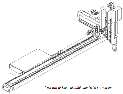
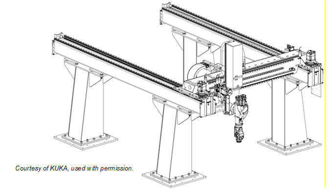
Figure B.3 shows an example of a parallel manipulator. So called delta robots, as shown in Figure B.4, are also parallel manipulators.
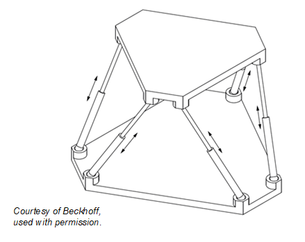
Figure B.4 shows an abstract example of a delta robot.
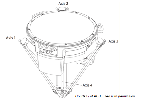
Figure B.5 shows an abstract example of a SCARA robot.
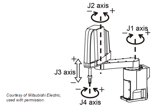
A typical example of an articulated robot is shown in Figure B.6.
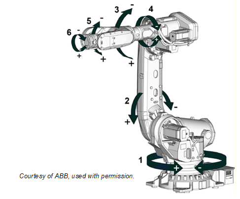
Another example of an articulated robot is a so-called humanoid robot as Figure B.7 schematically shows.
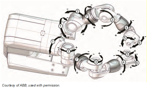
B.5 Examples of combinations of motion devices in a motion device system
Figure B.8 shows four motion devices integrated in one motion device system: an articulated robot on a linear unit with two turntables.
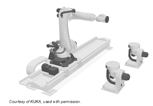
Figure B.9 shows three motion devices in one motion device system: two articulated robots on a mobile platform.
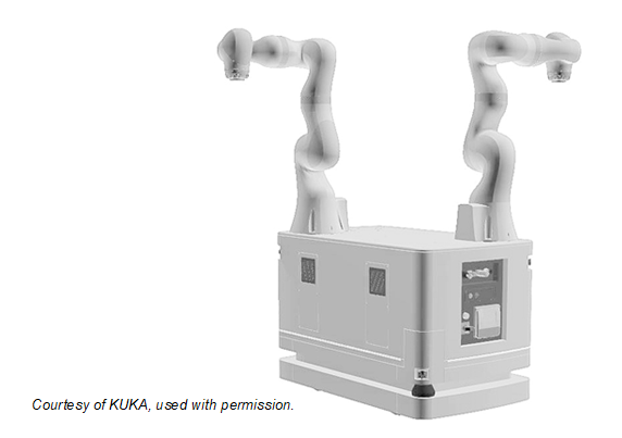
B.6 Axes and power trains
An axis of a motion device is the mechanical joint of a manipulator that performs a linear or a rotational movement.
Power trains, consisting of gears, motors, and drives, are responsible for the movement of axes. Drives can be integrated in the manipulator or inside a controller cabinet. References describe the relationships between the components of the power train.
Figure B.10 shows two possibilities for a realization of a linear two-dimensional motion device. While in the left figure there is a 1:1 relation between power train and mechanical axis in the right figure power train 1 and power train 2 have effect on the movement of axis 1 and on axis 2. An additional load is located on the mechanical axis 2 but has effect on both power trains.
References describe the relationships between the movement of axes and the power trains that initiate the movement.
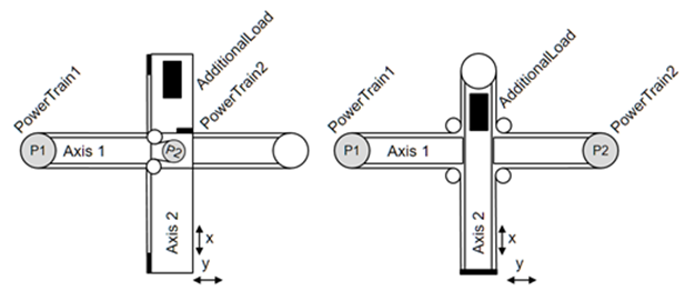
B.7 Virtual Axes
If there is the need to show information about virtual axes, which are not actively run by a power train, then these axes shall be provided, but they don´t have References to a power train. An example for a virtual axis is, when a robot control calculates the movement of an external axis in accordance with the robot movement, e.g. for a servo welding gun mounted at the robot flange, but doesn´t control actively the movement of this axis with an internal power train.
Another example for a virtual axis can be found in a delta robot. When the fourth axis is driven through a telescope shaft and cardan joints, then the length of the telescope shaft is depending on the positions of axes 1, 2 and 3. This length can be seen as a virtual axis, as it has constraints similar to a real axis, e.g. position limits. But it is not possible to actively move this axis.
B.8 Examples for axes and power trains
Figure B.1 and Figure B.2 show different versions of Cartesian robots. Figure B.1 shows a three-axis robot which has one dedicated power train for each axis: A power train Moves exactly one axis and so an axis only Requires one dedicated power train. One motor of a power train IsDrivenBy a drive and IsConnectedTo a gear.
Figure B.2 shows a three-axis robot with a master-slave driven axis 1. The first and second power train Moves axis 1. The first power train HasSlave the second power train. Axis 1 Requires the first and the second power train. For axis 2 and 3 one power train Moves exactly one axis and so an axis only Requires one dedicated power train.
B.9 Examples for the use of references regarding axes and power trains
B.9.1 Example articulated six-axis industrial robot.
The typical six-axis industrial robot shown in Figure B.6 normally has 6 power trains for the movement of the 6 axes. Due to the robot hand design, various power trains initiate internal compensation movements. When only the motor of power train 4 is rotating then axes 4, 5, and 6 are moving. When only axis 4 should be moved and axes 5 and 6 should stand still then power trains 5 and 6 must compensate the movement of these axes. Thus a movement of only axis 4 requires rotation of the motors of the power trains 4, 5 and 6. The complete set of references is depicted in Figure B.11.
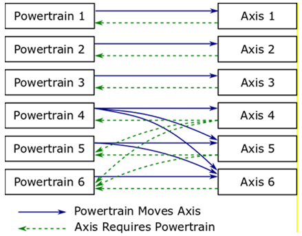
A power train Moves an axis means that if the motor of only this power train moves then there will be an effect on the position of the axis.
Power train 1 Moves axis 1
Power train 2 Moves axis 2
Power train 3 Moves axis 3
Power train 4 Moves axis 4, axis 5 and axis 6
Power train 5 Moves axis 5 and axis 6
Power train 6 Moves axis 6
Description regarding iv.: When only the motor of power train 4 is moving there is an effect on the position of axis 4, axis 5 and axis 6.
An axis IsMovedBy a power trains means, that actions of these power trains have an influence on the axis position. It is the inverse of the Moves reference.
Axis 1 IsMovedBy power train 1
Axis 2 IsMovedBy power train 2
Axis 3 IsMovedBy power train 3
Axis 4 IsMovedBy power train 4
Axis 5 IsMovedBy power train 5 and power train 4
Axis 6 IsMovedBy power train 6, power train 5 and power train 4
Description regarding vi.: Axis 6 movement is depending on movement from power train 6, power train 5 and power train 4.
An axis Requires the movement of a motor of a power train to position but also other power trains might be involved by this movement to compensation movements of affected axes.
Axis 1 Requires power train 1
Axis 2 Requires power train 2
Axis 3 Requires power train 3
Axis 4 Requires power train 4, power train 5 and power train 6
Axis 5 Requires power train 5 and power train 6
Axis 6 Requires power train 6
Description regarding iv.: When only axis 4 should be moved compensation movements of power train 5 and power train 6 are necessary to ensure a standstill of axis 5 and axis 6.
A power train IsRequiredBy axes means that this power train is active when only the referenced axis should be moved and all other axes should stand still. It is the inverse of the Requires reference.
Power train 1 IsRequiredBy axis 1
Power train 2 IsRequiredBy axis 2
Power train 3 IsRequiredBy axis 3
Power train 4 IsRequiredBy axis 4
Power train 5 IsRequiredBy axis 4 and axis 5
Power train 6 IsRequiredBy axis 4, axis 5 and axis 6
Description regarding vi: Power train 6 participates in positioning of axis 4, axis 5 and axis 6.
B.9.2 Example articulated six-axis industrial robot with 3 leader-follower axes
A high-payload six-axis industrial robot shown in Figure B.6 can have nine power trains for the movement of the six axes. In this example the axes 1 to 3 are each driven by two power trains with leader-follower configuration.
Figure B.12 shows the use of the HasSlave reference in addition to the power train to axis references.
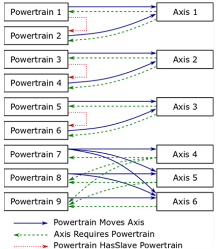
A power train HasSlave a power train means that one power train is the master of a leader-follower-configuration and he references HasSlave to power train which is slave coupled.
HasSlave References:
Power train 1 HasSlave power train 2
Power train 3 HasSlave power train 4
Power train 5 HasSlave power train 6
For this leader-follower configuration the Moves and Requires references :
Power train 1 Moves axis 1
Power train 2 Moves axis 1
Power train 3 Moves axis 2
Power train 4 Moves axis 2
Power train 5 Moves axis 3
Power train 6 Moves axis 3
Power train 7 Moves axis 4, axis 5 and axis 6
Power train 8 Moves axis 5 and axis 6
Power train 9 Moves axis 6
Axis 1 Requires power train 1 and power train 2
Axis 2 Requires power train 3 and power train 4
Axis 3 Requires power train 5 and power train 6
Axis 4 Requires power train 7, power train 8 and power train 9
Axis 5 Requires power train 8 and power train 9
Axis 6 Requires power train 9
B.9.3 Example linear two-dimensional motion device
For the left motion device in Figure B.10 the References between axes and power trains are shown in Figure B.13.
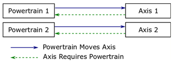
Moves References:
Power train 1 Moves axis 1
Power train 2 Moves axis 2
Axis 1 IsMovedBy power train 1
Axis 2 IsMovedBy power train 2
Requires References from power train to axis
Axis 1 Requires power train 1
Axis 2 Requires power train 2
Power Train 1 IsRequiredBy axis 1
Power Train 2 IsRequiredBy axis 2
For the right motion device in Figure B.10 the References between axes and power trains are shown in Figure B.14.
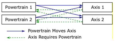
Moves References:
Power train 1 Moves axis 1 and axis 2
Power train 2 Moves axis 1 and axis 2
Axis 1 IsMovedBy power train 1 and power train 2
Axis 2 IsMovedBy power train 1 and power train 2
Requires References from power train to axis
Axis 1 Requires power train 1 and power train 2
Axis 2 Requires power train 1 and power train 2
Power Train 1 IsRequiredBy axis 1 and axis 2
Power Train 2 IsRequiredBy axis 1 and axis 2
B.10 Representations of exemplary server implementations
This chapter describes different examples for the usage of DriveType or a SubType of ComponentType defined in OPC 10000-100 inclusive the references described in this specification.
All views show only the instances and references necessary to better illustrate the examples described.
B.10.1 ObjectTypes and references used with DriveType instances
Figure B.15 describes the usage of DriveType as an instance of a single-slot drive regarding the manipulator showed Figure B.10 on the left side.
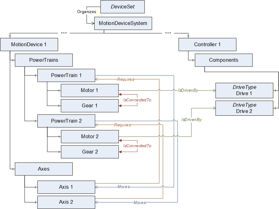
B.10.2 ObjectTypes and references used with instances of vendor specific subtypes of BaseObjectType for drive-channels
Figure B.16 describes the usage of slots or channels of a multi-slot-drive. The instance of the slot is a vendor specific subtype of BaseObjectType.
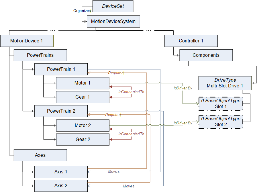
B.10.3 ObjectTypes and references used with instances DriveType for drives with drive-channels
Figure B.17 describes the usage of DriveType for a multi-slot-drive if deeper information of slot definition is not available.
It is allowed that several instances of MotorType reference IsDrivenBy to one multi-slot-drive.
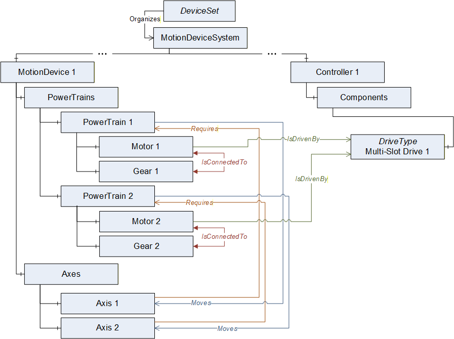
B.10.4 ObjectTypes and references used with instances of vendor specific subtypes of BaseObjectType for motor-integrated-drives
Figure B.18 describes the usage with a motor-integrated-drive as one physical device. The instance MyDrive is a vendor specific subtype of BaseObjectType. Identification properties of this physical device shall be defined within the referenced MotorType.
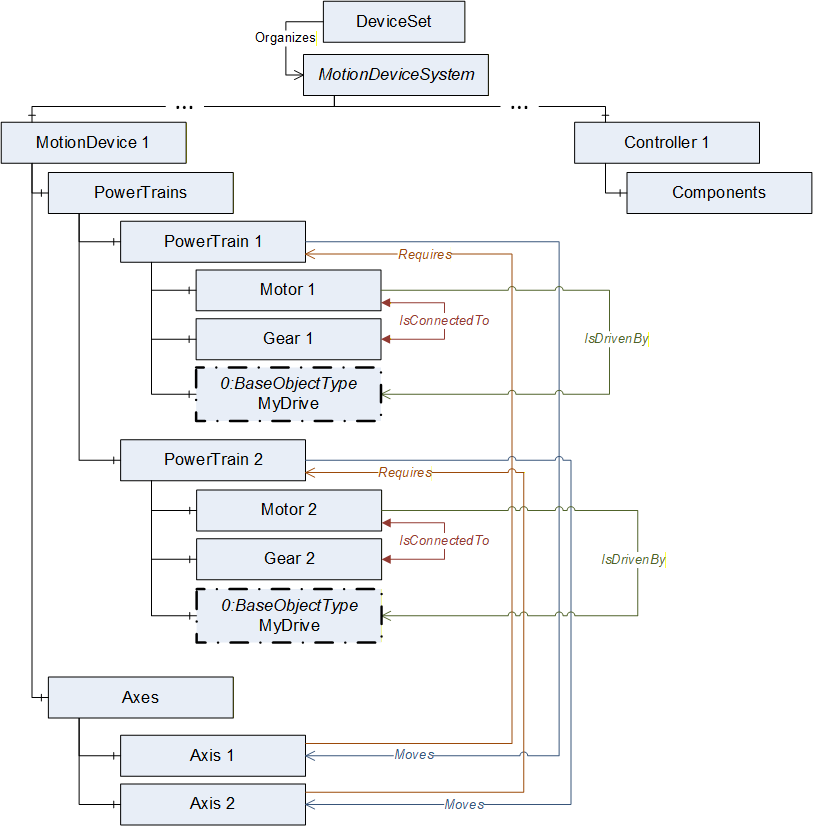
B.10.5 Abstract example of a six-axis robot with master-slave axis and drive-slots
Figure B.19 describes an example view on a server with the instances of ObjectTypes and references of a six-axis robot with master-slave axis and drive-slots described in Annex B.9.2.
If a leader-follower configuration only has one gear this shall be placed inside the leader-powertrain.
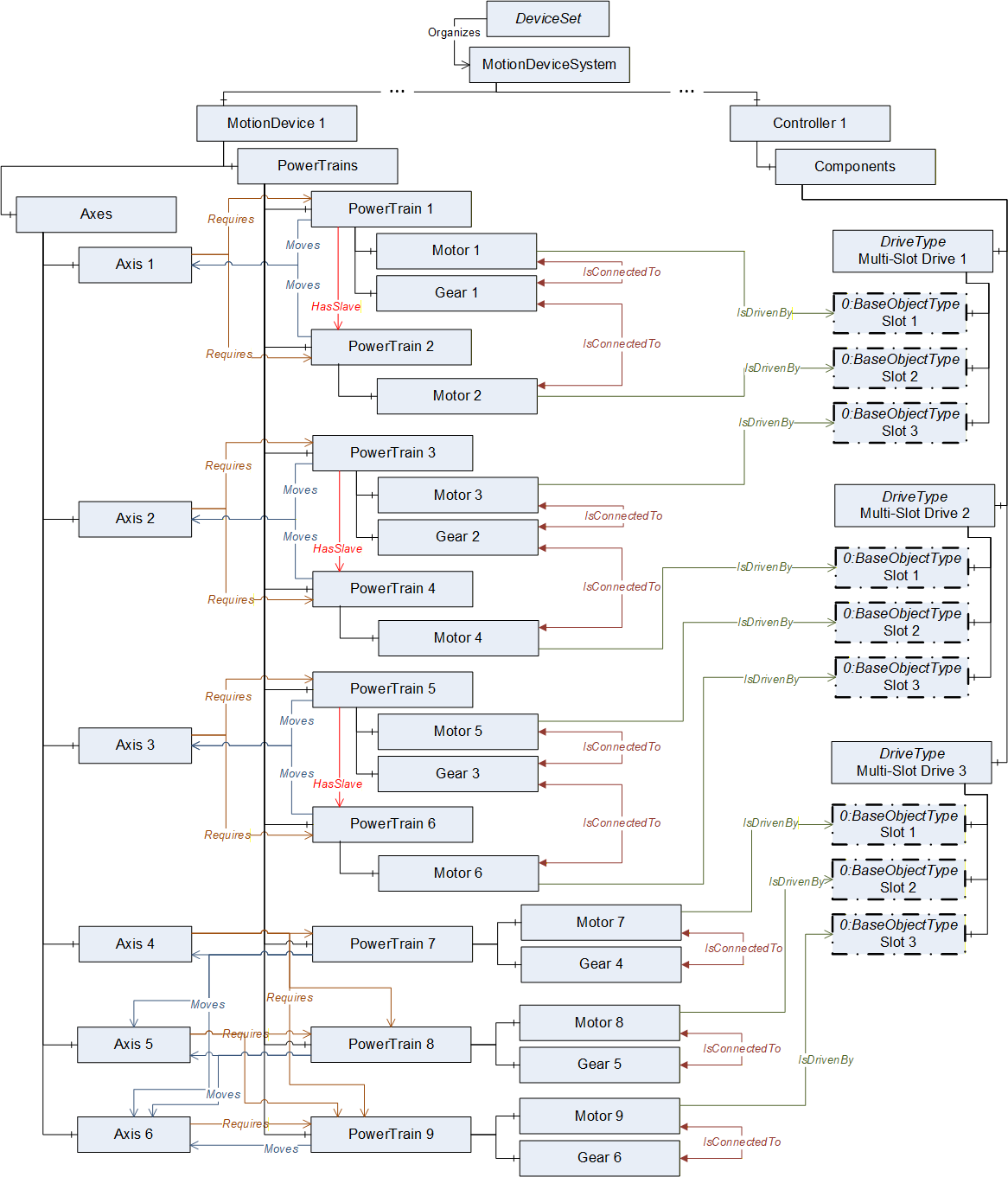
B.10.6 Abstract example of a motion device system with three motion devices
Figure B.20 describes an example view on a server with the instances of ObjectTypes and references of a motion device system consisting of a six-axis robot, a linear unit and a turntable which are controlled by one controller.
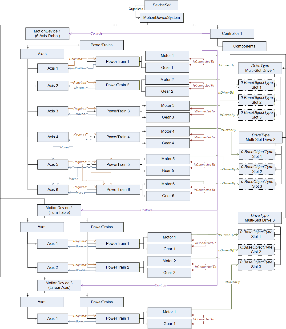
Annex C Usage with OPC 40001-1 UA CS for Machinery Part 1 - Basic Building Blocks (Informative)
C.1 Overview
This appendix provides informal examples on how the building blocks defined in OPC UA for Machinery
Part 1: Basic Building Blocks can be used merged with the Robotics Information Model.
Apart from the Machine and Component Identification building blocks, the usage of which are shown in C.2 and C.3 respectively, this companion specification recommends the use of the Operation Counters building block defined in OPC UA for Machinery. The entities in the Motion Device System address place that can make good use of the Operation Counters has been left to the judgement and discretion of the implementer.
C.2 Identification and Finding Machines
In Figure C.21 an example is given, showing the identification and Nameplate and Finding all Machines in Server use cases. The server provides information about a Robotics system.
As this Robotics specification Part 1 already defines some Properties for identification directly, those are only referenced from the Identification functional group.
Note that a Robotics system typically contains several machine parts with own nameplates. E.g. the Declaration of Incorporation of Partly Completed Machinery according Machinery Directive 2006/42/EU for robots provides the Model and the SerialNumber for the robot and for the controller.
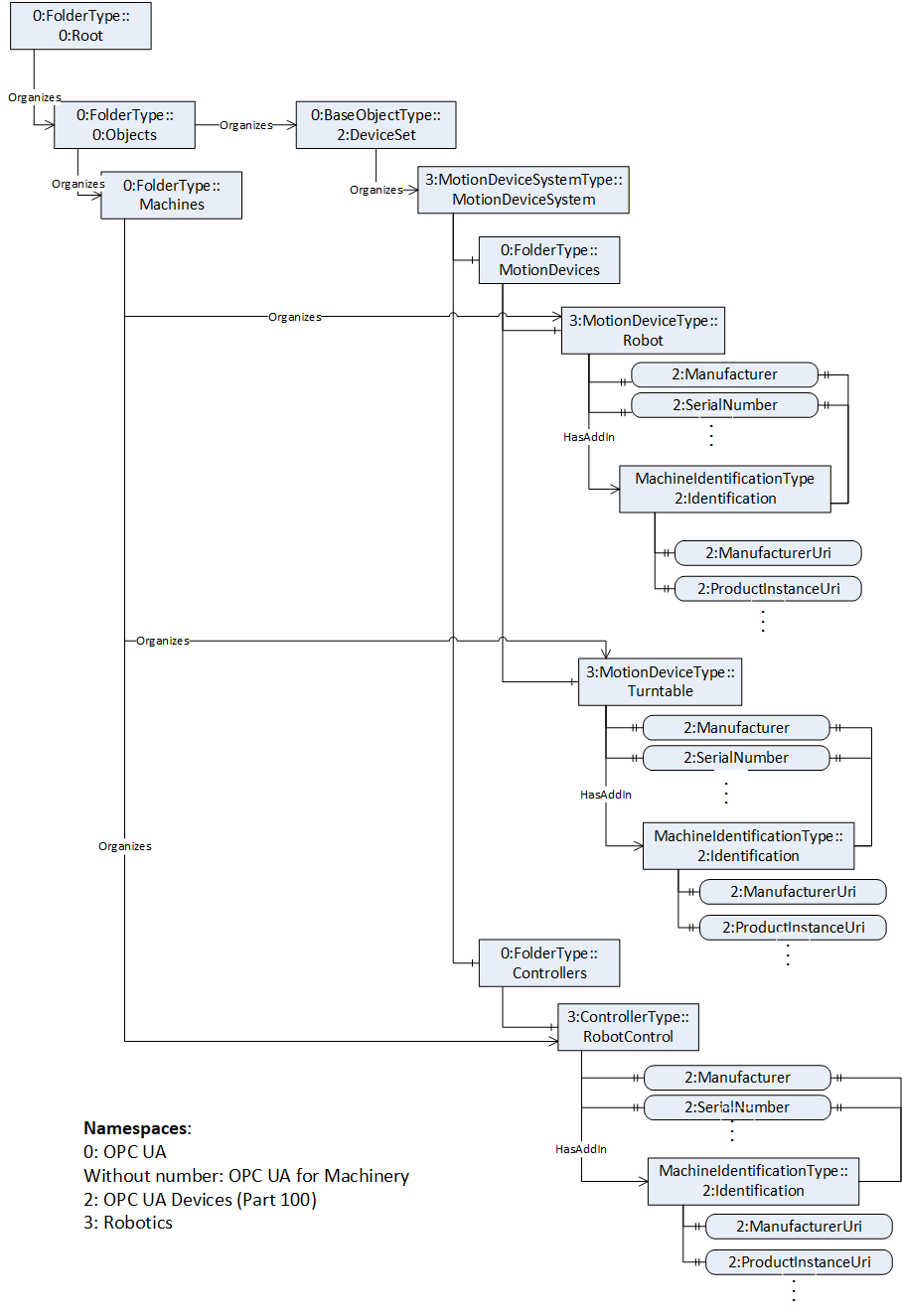
C.3 Component Identification and Finding Components of a Machine
In Figure C.22, a partially view on an example Robotics system is shown and the components are organized according to the Robotics specification. And in addition, the figure shows according to the OPC UA for Machinery Part 1: Basic Building Blocks the Component Identification and Nameplate and Finding all Components and Machines of a Robotics system.
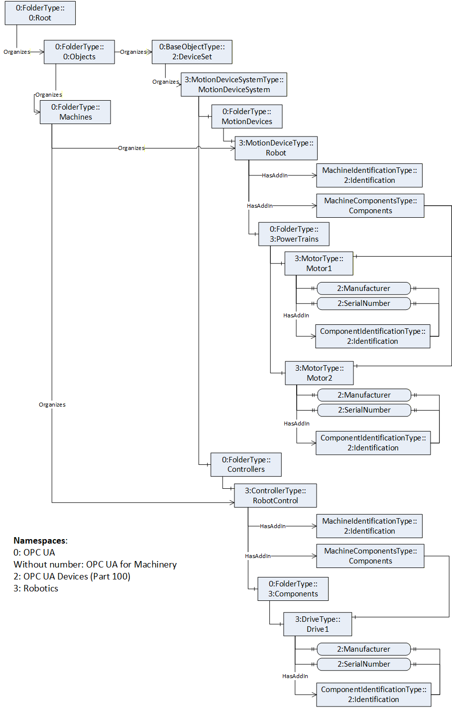
Agreement of Use
COPYRIGHT RESTRICTIONS
This document is provided "as is" by the OPC Foundation and VDMA.
Right of use for this specification is restricted to this specification and does not grant rights of use for referred documents.
Right of use for this specification will be granted without cost.
This document may be distributed through computer systems, printed or copied as long as the content remains unchanged and the document is not modified.
OPC Foundation and VDMA do not guarantee usability for any purpose and shall not be made liable for any case using the content of this document.
The user of the document agrees to indemnify OPC Foundation and VDMA and their officers, directors and agents harmless from all demands, claims, actions, losses, damages (including damages from personal injuries), costs and expenses (including attorneys' fees) which are in any way related to activities associated with its use of content from this specification.
The document shall not be used in conjunction with company advertising, shall not be sold or licensed to any party.
The intellectual property and copyright is solely owned by the OPC Foundation and VDMA.
PATENTS
The attention of adopters is directed to the possibility that compliance with or adoption of OPC or VDMA specifications may require use of an invention covered by patent rights. OPC Foundation or VDMA shall not be responsible for identifying patents for which a license may be required by any OPC or VDMA specification, or for conducting legal inquiries into the legal validity or scope of those patents that are brought to its attention. OPC or VDMA specifications are prospective and advisory only. Prospective users are responsible for protecting themselves against liability for infringement of patents.
WARRANTY AND LIABILITY DISCLAIMERS
WHILE THIS PUBLICATION IS BELIEVED TO BE ACCURATE, IT IS PROVIDED "AS IS" AND MAY CONTAIN ERRORS OR MISPRINTS. THE OPC FOUNDATION NOR VDMA MAKES NO WARRANTY OF ANY KIND, EXPRESSED OR IMPLIED, WITH REGARD TO THIS PUBLICATION, INCLUDING BUT NOT LIMITED TO ANY WARRANTY OF TITLE OR OWNERSHIP, IMPLIED WARRANTY OF MERCHANTABILITY OR WARRANTY OF FITNESS FOR A PARTICULAR PURPOSE OR USE. IN NO EVENT SHALL THE OPC FOUNDATION NOR VDMA BE LIABLE FOR ERRORS CONTAINED HEREIN OR FOR DIRECT, INDIRECT, INCIDENTAL, SPECIAL, CONSEQUENTIAL, RELIANCE OR COVER DAMAGES, INCLUDING LOSS OF PROFITS, REVENUE, DATA OR USE, INCURRED BY ANY USER OR ANY THIRD PARTY IN CONNECTION WITH THE FURNISHING, PERFORMANCE, OR USE OF THIS MATERIAL, EVEN IF ADVISED OF THE POSSIBILITY OF SUCH DAMAGES.
The entire risk as to the quality and performance of software developed using this specification is borne by you.
RESTRICTED RIGHTS LEGEND
This Specification is provided with Restricted Rights. Use, duplication or disclosure by the U.S. government is subject to restrictions as set forth in (a) this Agreement pursuant to DFARs 227.7202-3(a); (b) subparagraph (c)(1)(i) of the Rights in Technical Data and Computer Software clause at DFARs 252.227-7013; or (c) the Commercial Computer Software Restricted Rights clause at FAR 52.227-19 subdivision (c)(1) and (2), as applicable. Contractor / manufacturer are the OPC Foundation, 16101 N. 82nd Street, Suite 3B, Scottsdale, AZ, 85260-1830.
COMPLIANCE
The combination of VDMA and OPC Foundation shall at all times be the sole entities that may authorize developers, suppliers and sellers of hardware and software to use certification marks, trademarks or other special designations to indicate compliance with these materials as specified within this document. Products developed using this specification may claim compliance or conformance with this specification if and only if the software satisfactorily meets the certification requirements set by VDMA or the OPC Foundation. Products that do not meet these requirements may claim only that the product was based on this specification and must not claim compliance or conformance with this specification.
TRADEMARKS
Most computer and software brand names have trademarks or registered trademarks. The individual trademarks have not been listed here.
GENERAL PROVISIONS
Should any provision of this Agreement be held to be void, invalid, unenforceable or illegal by a court, the validity and enforceability of the other provisions shall not be affected thereby.
This Agreement shall be governed by and construed under the laws of Germany.
This Agreement embodies the entire understanding between the parties with respect to, and supersedes any prior understanding or agreement (oral or written) relating to, this specification.
ISSUE REPORTING
If an error or problem is found in this specification, the UaNodeSet, or any associated supplementary files, it should be reported as an issue.
The reporting process can be found here: https://opcfoundation.org/resources/issue-tracking/
The Link to the issue tracking project for this document is here:
https://mantis.opcfoundation.org/set_project.php?project_id=109&make_default=no