
1 Scope
This document specifies an OPC UA Information Model to create a device standard for analytical and laboratory instruments. This document provides a manufacturer-independent open standard, which comprehensively addresses the requirements of various branches, disciplines, and business processes, and is sustainable and adaptable to future requirements in the field of digitalization and automation.
This specification has been developed as a collaborative effort among OPC Foundation, Spectaris, and VDMA. More details on these organizations are provided below.
"Part 1: LADS Base System" is the first in a series of planned documents that will collectively form the Laboratory and Analytical Device Standard (LADS). While the exact structure and content of future parts are yet to be fully defined, they are anticipated to cover additional aspects of laboratory and analytical device standardization. Potential topics for future parts could include:
Dictionary References - This part would focus on referencing to dictionaries and ontologies (e.g., Allotrope Taxonomies Domain Model) so that the semantics of the OPC UA information are preserved throughout the data lifecycle and between the different levels.
Publish-Subscribe (PubSub) - This part would detail the use of the OPC UA PubSub communication model within the context of laboratory and analytical devices.
Alias Names - This part would establish standardized (handling of) alias names for common elements.
Samples and Consumables - This part would define how samples and consumables are represented and managed within the information model.
OPC Foundation
OPC is the interoperability standard for the secure and reliable exchange of data and information in the industrial automation space and in other industries. It is platform independent and ensures the seamless flow of information among devices from multiple vendors. The OPC Foundation is responsible for the development and maintenance of this standard.
OPC UA is a platform-independent, service-oriented architecture that integrates all the functionality of the individual OPC Classic specifications into one extensible framework. This multi-layered approach accomplishes the original design specification goals of:
Platform independence: from an embedded microcontroller to cloud-based infrastructure
Secure: encryption, authentication, authorization, and auditing
Extensible: ability to add new features including transports without affecting existing applications
Comprehensive information modelling capabilities: for defining any model from simple to complex.
SPECTARIS
SPECTARIS is the German industry association for the high-tech midsized business sector and a representative body in the areas of medical technology, consumer optics, analytical, bio and laboratory technology, as well as photonics. Innovation and growth characterize the different industry sectors and their 330,000-strong workforce. Technologies developed here are used in almost all branches of industry, making them an essential motor for the German economy.
SPECTARIS pools the interests of around 400 member companies from Germany, associated into four different sector-specific branches. Through its political activities, campaigns, services and technical support, the association helps its members in overcoming business barriers and opens up new markets.
Machinery and Equipment Manufacturers Association (VDMA)
The VDMA represents over 3,200 predominantly small and medium-sized member companies in the engineering industry, making it one of the largest and most important industrial associations in Europe. The VDMA covers the entire process chain of mechanical engineering - everything from components and plant manufacturers, system suppliers and system integrators through to service providers.
2 Normative references
The following documents are referred to in the text in such a way that some or all of their content constitutes requirements of this document. For dated references, only the edition cited applies. For undated references, the latest edition of the referenced document (including any amendments and errata) applies.
OPC 10000-1, OPC Unified Architecture - Part 1: Overview and Concepts
http://www.opcfoundation.org/documents/10000-1/
OPC 10000-2, OPC Unified Architecture - Part 2: Security Model
http://www.opcfoundation.org/documents/10000-2/
OPC 10000-3, OPC Unified Architecture - Part 3: Address Space Model
http://www.opcfoundation.org/documents/10000-3/
OPC 10000-4, OPC Unified Architecture - Part 4: Services
http://www.opcfoundation.org/documents/10000-4/
OPC 10000-5, OPC Unified Architecture - Part 5: Information Model
http://www.opcfoundation.org/documents/10000-5/
OPC 10000-6, OPC Unified Architecture - Part 6: Mappings
http://www.opcfoundation.org/documents/10000-6/
OPC 10000-7, OPC Unified Architecture - Part 7: Profiles
http://www.opcfoundation.org/documents/10000-7/
OPC 10000-8, OPC Unified Architecture - Part 8: Data Access
http://www.opcfoundation.org/documents/10000-8/
OPC 10000-16, OPC Unified Architecture - Part 16: State Machines
http://www.opcfoundation.org/documents/10000-16/
OPC 10000-19, OPC Unified Architecture - Part 19: Dictionary References
http://www.opcfoundation.org/documents/10000-19/
OPC 10000-100, OPC Unified Architecture - Part 100: Devices
http://www.opcfoundation.org/documents/10000-100/
OPC 10000-110, OPC Unified Architecture - Part 110: Asset Management Basics
http://www.opcfoundation.org/documents/10000-110/
OPC 40001-1, OPC UA for Machinery - Part 1: Basic Building Blocks
http://www.opcfoundation.org/documents/40001-1/
3 Terms, abbreviations, and conventions
3.1 Overview
It is assumed that the basic concepts of OPC UA information modelling are understood in this document. This specification will use these concepts to describe the OPC UA LADS Information Model. For the purposes of this document, the terms and definitions given in OPC 10000-1, OPC 10000-2, OPC 10000-3, OPC 10000-4, OPC 10000-5, OPC 10000-6, OPC 10000-7, OPC 10000-8, OPC 10000-100, OPC 40001-1 as well as the following apply.
Note that OPC UA terms and terms defined in this document are italicized in the document.
3.2 OPC UA LADS Terms
3.2.1 Device
Analytical or laboratory device, also known as an instrument.
3.2.2 Lab(oratory) Device
Instrument used in a laboratory to carry out specific tasks and generate the results of an analysis.
3.2.3 Analytical Device
Instrument to study scientific data and provide analytical results.
3.2.4 Component
Component of a device. (See OPC 10000-100.)
3.2.5 Remote
Non-local location in the lab network or the Internet.
3.2.6 Functional Unit
Aggregation of functions to achieve a specific outcome. (Typically utilized by only one user at a time, it exposes its current state via a state machine and might optionally include a Program Manager.)
3.2.7 Function
Action to achieve a specific outcome, organized by a Functional Unit. (Typical functions include but are not limited to sensors, controllers, actuators, timers, etc. They may utilize one or more tangible components.)
3.2.8 Program Manager
Organization of objects to manage program templates, run programs, and manage results.
3.2.9 Program Template
General configuration of settings or formats to be used as a basis for further definition of individual programs.
3.2.10 Actuator
Asset that causes a machine or other device to operate.
3.2.11 Controller
Asset that directs or regulates something.
3.2.12 Sensor
Asset that detects or measures a physical property.
3.2.13 Timer
Asset that measures or records the amount of time taken by a process or activity.
3.2.14 Alarm
Acoustic or electronic warning that is issued to signal an abnormal condition.
3.2.15 Notification
Alert issued to notify a user of an event or condition.
3.2.16 Supervisory System
System that oversees and coordinates operations of lower-level subsystems or processes.
3.2.17 SupervisoryTaskId
Unique identifier for a task within the supervisory system.
3.2.17.1 Untitled
3.2.18 DeviceProgramRunId
Unique identifier for a specific program execution on a device.
3.2.18.1 Untitled
3.2.19 SupervisoryJobId
Unique identifier for a job.
3.3 Abbreviations
| CS | Companion Specification |
| ELN | Electronic Laboratory Notebook |
| ERP | Enterprise Resource Planning |
| HMI | Human Machine Interface |
| LES | Laboratory Execution System |
| LIMS | Laboratory Information Management System |
| MES | Manufacturing Execution System |
| PID | Proportional Integral Derivative controller |
| PMS | Production Management System |
| SCADA | Supervisory Control and Data Acquisition |
3.4 Conventions used in this document
3.4.1 Conventions for Node descriptions
3.4.1.1 Node definitions
Node definitions are specified using tables (see Table 2).
Attributes are defined by providing the Attribute name and a value, or a description of the value.
References are defined by providing the ReferenceType name, the BrowseName of the TargetNode and its NodeClass.
If the TargetNode is a component of the Node being defined in the table, the Attributes of the composed Node are defined in the same row of the table.
The DataType is only specified for Variables; "[<number>]" indicates a single-dimensional array, for multi-dimensional arrays the expression is repeated for each dimension (e.g.,[2][3] for a two-dimensional array). For all arrays, the ArrayDimensions is set as identified by <number> values. If no <number> is set, the corresponding dimension is set to 0, indicating an unknown size. If no number is provided at all the ArrayDimensions can be omitted. If no brackets are provided, it identifies a scalar DataType and the ValueRank is set to the corresponding value (see OPC 10000-3). In addition, ArrayDimensions is set to null or is omitted. If it can be Any or ScalarOrOneDimension, the value is put into "{<value>}", so either "{Any}" or "{ScalarOrOneDimension}", the ValueRank is set to the corresponding value (see OPC 10000-3), and ArrayDimensions is set to null or omitted. Examples are given in Table 1.
| Notation | DataType | ValueRank | ArrayDimensions | Description |
| 0:Int32 | 0:Int32 | -1 | omitted or null | A scalar Int32. |
| 0:Int32{OneOreMoreDimensions} | 0:Int32 | 0 | Omitted or null | An int32 array with one or more dimensions. |
| 0:Int32[] | 0:Int32 | 1 | omitted or {0} | Single-dimensional array of Int32 with an unknown size. |
| 0:Int32[][] | 0:Int32 | 2 | omitted or {0,0} | Two-dimensional array of Int32 with unknown sizes for both dimensions. |
| 0:Int32[3][] | 0:Int32 | 2 | {3,0} | Two-dimensional array of Int32 with a size of 3 for the first dimension and an unknown size for the second dimension. |
| 0:Int32[5][3] | 0:Int32 | 2 | {5,3} | Two-dimensional array of Int32 with a size of 5 for the first dimension and a size of 3 for the second dimension. |
| 0:Int32{Any} | 0:Int32 | -2 | omitted or null | An Int32 where it is unknown if it is scalar or array with any number of dimensions. |
| 0:Int32{ScalarOrOneDimension} | 0:Int32 | -3 | omitted or null | An Int32 where it is either a single-dimensional array or scalar. |
The TypeDefinition is specified for Objects and Variables.
The TypeDefinition column specifies a symbolic name for a NodeId; i.e., the specified Node points with a HasTypeDefinition Reference to the corresponding Node.
The ModellingRule of the referenced component is provided by specifying the symbolic name of the rule in the ModellingRule column. In the AddressSpace, the Node shall use a HasModellingRule Reference to point to the corresponding ModellingRule Object.
If the NodeId of a DataType is provided, the symbolic name of the Node representing the DataType shall be used.
Note that if a symbolic name of a different Namespace is used, it is prefixed by the NamespaceIndex (see 3.4.2.2).
Nodes of different NodeClasses cannot be defined in the same table; therefore, only the used ReferenceType, their NodeClass and their BrowseName are specified. A reference to another part of this document points to their definition. This is illustrated in Table 2. If no components are provided, the DataType, TypeDefinition and Other columns may be omitted and only a Comment column is introduced to point to the Node definition.
Each Type Node or well-known Instance Node defined shall have one or more ConformanceUnits defined in 9.1 that require the Node to be in the AddressSpace.
The relations between Nodes and ConformanceUnits are defined at the end of the tables defining the Nodes, with one row per ConformanceUnit. The ConformanceUnits are reflected in the Category element for the Node definition in the UANodeSet (see OPC 10000-6).
The list of ConformanceUnits in the UANodeSet allows Servers to optimize resource consumption by using a list of supported ConformanceUnits to select a subset of the Nodes in an Information Model.
When a Node is selected in this way, all dependencies implied by the References are also selected.
Dependencies exist if the Node is the source of a HasTypeDefinition, HasInterface, HasAddIn or any HierarchicalReference. Dependencies also exist if the Node is the target of a HasSubtype Reference. For Variables and VariableTypes, the value of the DataType Attribute is a dependency. For DataType Nodes, any DataTypes referenced in the DataTypeDefinition Attribute are also dependencies.
For additional details see OPC 10000-5.
Table 2 provides an example of the table format. If no components are provided, the DataType, TypeDefinition and ModellingRule columns may be omitted and only a Comment column is introduced to point to the Node definition.
| Attribute | Value | ||||
| Attribute name | Attribute value. If it is an optional Attribute that is not set "--" is used. | ||||
| References | NodeClass | BrowseName | DataType | TypeDefinition | Other |
|---|---|---|---|---|---|
| ReferenceType name | NodeClass of the target Node. | BrowseName of the target Node. | DataType of the referenced Node, only applicable for Variables. | TypeDefinition of the referenced Node, only applicable for Variables and Objects. | Additional characteristics of the TargetNode such as the ModellingRule or AccessLevel. |
| NOTE Notes referencing footnotes of the table content. | |||||
| Conformance Units | |||||
|---|---|---|---|---|---|
| Name of ConformanceUnit, one row per ConformanceUnit |
Components of Nodes can be complex; that is, containing components themselves. The TypeDefinition, NodeClass and DataType can be derived from the Type definitions, and the symbolic name can be created as defined in 3.4.3.1. Therefore, those Nodes containing components are not explicitly specified; they are implicitly specified by the Type definitions.
The Other column defines additional characteristics of the Node. Examples of characteristics that can appear in this column are shown in Table 3.
| Name | Short Name | Description |
| 0:Mandatory | M | The Node has the Mandatory ModellingRule. |
| 0:Optional | O | The Node has the Optional ModellingRule. |
| 0:MandatoryPlaceholder | MP | The Node has the MandatoryPlaceholder ModellingRule. |
| 0:OptionalPlaceholder | OP | The Node has the OptionalPlaceholder ModellingRule. |
| ReadOnly | RO | The Node AccessLevel has the CurrentRead bit set but not the CurrentWrite bit. |
| ReadWrite | RW | The Node AccessLevel has the CurrentRead and CurrentWrite bits set. |
| WriteOnly | WO | The Node AccessLevel has the CurrentWrite bit set but not the CurrentRead bit. |
If multiple characteristics are defined, they are separated by commas. The name or the short name may be used.
3.4.1.2 Additional References
To provide information about additional References, the format as shown in Table 4 is used.
| SourceBrowsePath | Reference Type | Is Forward | TargetBrowsePath |
| SourceBrowsePath is always relative to the TypeDefinition. Multiple elements are defined as separate rows of a nested table. | ReferenceType name | True = forward Reference. | TargetBrowsePath points to another Node, which can be a well-known instance or a TypeDefinition. You can use BrowsePaths here as well, which are either relative to the TypeDefinition or absolute. If absolute, the first entry needs to refer to a Type or well-known instance, uniquely identified within a Namespace by the BrowseName. |
References can be made to any other Node.
3.4.1.3 Additional sub-components
To provide information about sub-components, the format as shown in Table 5 is used.
| BrowsePath | References | NodeClass | BrowseName | DataType | TypeDefinition | Others |
| BrowsePath is always relative to the TypeDefinition. Multiple elements are defined as separate rows of a nested table | NOTE: Same as for Table 2 | |||||
3.4.1.4 Additional Attribute values
The Type definition table provides columns to specify the values for required Node Attributes for InstanceDeclarations. To provide information about additional Attributes, the format as shown in Table 6 is used.
| BrowsePath | <Attribute name> Attribute |
| BrowsePath is always relative to the TypeDefinition. Multiple elements are defined as separate rows of a nested table | The values of attributes are converted to text by applying the reversible JSON encoding rules defined in OPC 10000-6. If the JSON encoding of a value is a JSON string or a JSON number, that value is entered in the value field. Quotation marks are not included. If the DataType includes a NamespaceIndex (QualifiedNames, NodeIds or ExpandedNodeIds), the notation used for BrowseNames is used. If the value is an Enumeration, the name of the enumeration value is entered. If the value is a Structure, a sequence of name and value pairs is entered. Each pair is followed by a new line. The name is followed by a colon. The names are the names of the fields in the DataTypeDefinition. If the value is an array of non-structures, a sequence of values is entered. Each value is followed by a new line. If the value is an array of Structures or a Structure with fields that are arrays or with nested Structures, the complete JSON array or JSON object is entered. Quotation marks are not included. |
There can be multiple columns to define more than one Attribute.
3.4.2 NodeIds and BrowseNames
3.4.2.1 NodeIds
The NodeIds of all Nodes described in this standard are only symbolic names. Annex A defines the actual NodeIds.
The symbolic name of each Node defined in this document is its BrowseName, or, when it is part of another Node, the BrowseName of the other Node, followed by "." and its own BrowseName. In this case, "part of" means that the whole has a HasProperty or HasComponent Reference to its part. Since all Nodes which are not part of another Node have a unique name in this document, the symbolic name is unique.
The NamespaceUri for all NodeIds defined in this document is defined in Annex A. The NamespaceIndex for this NamespaceUri is vendor specific and depends on the position of the NamespaceUri in the server Namespace table.
Note that this document not only defines concrete Nodes, but also requires for some Nodes to be generated; for example, one for each Session running on the Server. The NodeIds of those Nodes are Server specific, including the Namespace. However, the NamespaceIndex of those Nodes cannot be the NamespaceIndex used for the Nodes defined in this document, as they are not defined by this document but are generated by the Server.
3.4.2.2 BrowseNames
The text part of the BrowseNames for all Nodes defined in this document is specified in the tables defining the Nodes. The NamespaceUri for all BrowseNames defined in this document is defined in 10.2.
For InstanceDeclarations of NodeClass Objects and Variables that are placeholders (OptionalPlaceholder and MandatoryPlaceholder ModellingRule), the BrowseName and the DisplayName are enclosed in angle brackets (<>) as recommended in OPC 10000-3.
If a BrowseName is not defined by this document, a Namespace index prefix is added to the BrowseName (e.g., prefix '0' leading to '0:EngineeringUnits' or prefix '2' leading to '2:DeviceRevision'). This is typically necessary if a Property of another specification is overwritten or used in the OPC UA types defined in this document. Table 146 provides a list of Namespaces and their indexes as used in this document.
3.4.3 Common Attributes
3.4.3.1 General
The Attributes of Nodes, their DataTypes and descriptions are defined in OPC 10000-3. Attributes not marked as optional are mandatory and shall be provided by a Server. The following tables define whether the Attribute value is defined by this document or if it is server specific.
For all Nodes specified in this document, the Attributes named in Table 7 shall be set as specified in the table.
| Attribute | Value |
| DisplayName | The DisplayName is a LocalizedText. Each Server shall provide the DisplayName identical to the BrowseName of the Node for the LocaleId "en" unless specified differently in the specification. Whether the Server provides translated names for other LocaleIds is server specific. |
| Description | Optionally a server-specific description is provided. |
| NodeClass | Shall reflect the NodeClass of the Node. |
| NodeId | The NodeId is described by BrowseNames as defined in 3.4.2.1. |
| WriteMask | Optionally the WriteMask Attribute can be provided. If the WriteMask Attribute is provided, it shall set all non-server-specific Attributes to not writeable. For example, the Description Attribute may be set to writeable since a Server may provide a server-specific description for the Node. The NodeId shall not be writeable, because it is defined for each Node in this document. |
| UserWriteMask | Optionally the UserWriteMask Attribute can be provided. The same rules as for the WriteMask Attribute apply. |
| RolePermissions | Optionally server-specific role permissions can be provided. |
| UserRolePermissions | Optionally the role permissions of the current Session can be provided. The value is server specific and depends on the RolePermissions Attribute (if provided) and the current Session. |
| AccessRestrictions | Optionally server-specific access restrictions can be provided. |
3.4.3.2 Objects
For all Objects specified in this document, the Attributes named in Table 8 shall be set as specified in the table. The definitions for the Attributes can be found in OPC 10000-3.
| Attribute | Value |
| EventNotifier | Whether or not the Node can be used to subscribe to Events is server specific. |
3.4.3.3 Variables
For all Variables specified in this document, the Attributes named in Table 9 shall be set as specified in the table. The definitions for the Attributes can be found in OPC 10000-3.
| Attribute | Value |
| MinimumSamplingInterval | Optionally, a server-specific minimum sampling interval is provided. |
| AccessLevel | The access level for Variables used for Type definitions is server specific, for all other Variables defined in this document, the access level shall allow reading; other settings are server specific. |
| UserAccessLevel | The value for the UserAccessLevel Attribute is server specific. It is assumed that all Variables can be accessed by at least one user. |
| Value | For Variables used as InstanceDeclarations, the value is server specific; otherwise, it shall represent the value described in the text. |
| ArrayDimensions | If the ValueRank does not identify an array of a specific dimension (i.e., ValueRank <= 0) the ArrayDimensions can either be set to null or the Attribute is missing. This behaviour is server specific. If the ValueRank specifies an array of a specific dimension (i.e., ValueRank > 0) then the ArrayDimensions Attribute shall be specified in the table defining the Variable. |
| Historizing | The value for the Historizing Attribute is server specific. |
| AccessLevelEx | If the AccessLevelEx Attribute is provided, it shall have the bits 8, 9, and 10 set to 0, meaning that read and write operations on an individual Variable are atomic, and arrays can be partly written. |
3.4.3.4 VariableTypes
For all VariableTypes specified in this document, the Attributes named in Table 10 shall be set as specified in the table. The definitions for the Attributes can be found in OPC 10000-3.
| Attributes | Value |
| Value | Optionally a server-specific default value can be provided. |
| ArrayDimensions | If the ValueRank does not identify an array of a specific dimension (i.e., ValueRank <= 0) the ArrayDimensions can either be set to null or the Attribute is missing. This behaviour is server specific. If the ValueRank specifies an array of a specific dimension (i.e., ValueRank > 0) then the ArrayDimensions Attribute shall be specified in the table defining the VariableType. |
3.4.3.5 Methods
For all Methods specified in this document, the Attributes named in Table 11 shall be set as specified in the table. The definitions for the Attributes can be found in OPC 10000-3.
| Attributes | Value |
| Executable | All Methods defined in this document shall be executable (Executable Attribute set to "True") unless it is defined differently in the Method definition. |
| UserExecutable | The value of the UserExecutable Attribute is server specific. It is assumed that all Methods can be executed by at least one user. |
3.4.4 Structures
OPC 10000-3 differentiates between different kinds of Structures. The following conventions explain how these Structures shall be defined.
The first kind is Structures without optional fields, where none of the fields allow subtypes (except fields with abstract DataTypes). This is defined in Table 12.
| Name | Type | Description |
|---|---|---|
| <someStructure> | structure | Subtype of <someParentStructure> defined in … |
SP1 | 0:Byte[] | Setpoint 1 |
SP2 | 0:Byte[] | Setpoint 2 |
The second kind is Structures with optional fields, where none of the fields allow subtypes (except fields with abstract DataTypes). This is defined in Table 13.
Structures with fields that are optional have an "Optional" column. Fields that are optional have "True" set, otherwise "False".
| Name | Type | Description | Optional |
|---|---|---|---|
| <someStructure> | structure | Subtype of <someParentStructure> defined in … | |
SP1 | 0:Byte[] | Setpoint 1 | False |
Optional Field_1 | 0:String | Some Text | True |
The third kind is Structures without optional fields, where one or more of the fields allow subtypes. This is defined in Table 14.
Structures with fields that allow subtypes have an "Allow Subtypes" column. Fields that allow subtypes have "True" set, otherwise "False". Fields with abstract DataTypes can always have subtypes.
| Name | Type | Description | Allow Subtypes |
|---|---|---|---|
| <someStructure> | structure | Subtype of <someParentStructure> defined in … | |
SP1 | 0:Byte[] | Setpoint 1 | False |
Allow Subtypes | 0:ByteString | Some Bytestring | True |
4 General information on LADS and OPC UA
4.1 Introduction to LADS
4.1.1 Overview
LADS, an acronym for Laboratory and Analytical Device Standard, is a manufacturer-independent, open standard for analytical and laboratory equipment. It comprehensively encapsulates various customer industries and their respective workflows, providing a sustainable application that also caters to the future demands of digitalization and automation. LADS is built upon OPC UA, an open communication platform developed and promoted by the international non-profit OPC Foundation. OPC UA facilitates cross-vendor communication and interoperability in industrial automation processes.
The benefits of the LADS standard are listed below:
Manufacturer-independent standard
Open standard, capable of integrating instruments in different workflows
Plug and play interoperability of Lab and Analytical Devices
Covers a wide range of different Lab and Analytical devices through device-type-agnostic design principles
Future versions may allow machine-readable semantic contextualization of LADS patterns by linking nodes within the information model to suitable taxonomies and ontologies (utilizing Dictionary References OPC 10000-19)
4.1.2 Introduction to the structure of a LADS Device
The Laboratory and Analytical Device Standard (LADS) Companion Specification provides a comprehensive framework for modelling and managing analytical and laboratory equipment. It does this by defining two primary views: the Hardware View and the Functional View.
4.1.2.1 Hardware View - Devices & Components
The Hardware View focuses on the physical aspects of the devices and their components. This view is essential for various use cases related to asset management, including enhanced serviceability.
Key features of the Hardware View are introduced in the following subsections.
4.1.2.1.1 Devices
These are modelled with properties such as nameplates, installation dates, condition monitoring, and calibration & validation status.
4.1.2.1.2 Components
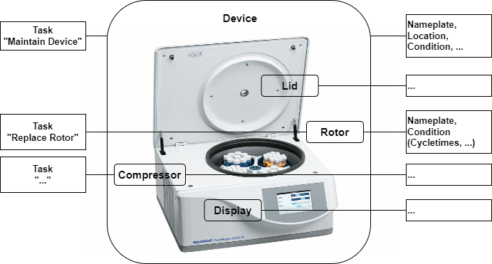
Hardware components like the Lid, Rotor, Drive, and Compressor are modelled in a sub-tree. Each component exposes its individual nameplate and maintenance-related information, similar to the device itself, and can also have components itself.
4.1.2.1.3 Tasks
Recurrent tasks that affect either the entire device or individual components (such as inspection, maintenance, calibration, validation, cleaning, etc.) can be organized via LADS.
4.1.2.1.4 Example of a Hardware View of a centrifuge
Figure 1 shows a centrifuge, including various components and the corresponding component data.
4.1.2.2 Functional View
The Functional View deals with data relevant for the operation, automation, and orchestration of an instrument.
Key aspects of the Functional View are introduced in the following subsections.
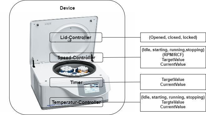
4.1.2.2.1 Functions
Actions to achieve a specific outcome. (Typical functions include but are not limited to sensors, controllers, actuators, timers, etc. They may utilize one or more tangible components.)
The complete list of Functions can be found in section 7.4
Figure 2 shows a centrifuge, including various components and the corresponding component data.
4.1.2.2.2 Programs
Many laboratory and analytical devices allow the user to define and run programs, also called methods. The Program Manager organizes program templates, runs programs, and manages the result data generated during a run, providing device-level orchestration.
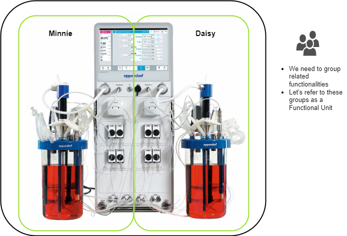
4.1.2.2.3 Functional Units
Functional Units are aggregations of functions designed to achieve a specific outcome. Typically, a Functional Unit is utilized by only one user at a time and exposes its current state. It may optionally include a Program Manager. A Functional Unit can be seen as a virtual device within a LADS Device, grouping together several (potentially redundant) functions. This concept is particularly useful when a LADS Device contains multiple functions that can be grouped as virtual devices or behave as separate devices. In such cases, a LADS Device can be divided into multiple Functional Units, with each Functional Unit representing a virtual device.
For instance, consider a bioreactor vessel with two separate interfaces (see Figure 3). Each container has its own functions, such as a temperature sensor and a motor, and its own program. This setup allows the bioreactor to be split into two Functional Units, each representing a separate container with its own program and set of functions.
4.1.3 Introduction to the state machines and Device status variables used
4.1.3.1 Overview
This section provides an overview of the state machines and device status variables used in the LADS Companion Specification. It explains the relationship between various state machines and status variables in the context of a LADS Device, its Components, and Functional Units.
The relationship between these state machines and status variables is crucial for understanding the operation and management of a LADS Device. The state of the LADS Device state machine and the FunctionalUnit state machines come first and form the basis for the MachineryItemState. The MachineryOperationMode provides additional context about the type of Tasks being performed. The DeviceHealth and DeviceHealthAlarms provide information about the device's condition and any Alarms that may have been triggered.
Refer to Annex B for proposed mappings between the DeviceStateMachine, the FunctionalUnit state machines, the MachineryItemState and the DeviceHealth.
4.1.3.2 Device State Machines
The DeviceStateMachine provides a domain-specific view of the device's state. It reflects the condition of the Device itself.
4.1.3.3 MachineryItemState
The MachineryItemState provides a harmonized state machine across various domains, particularly in mechanical engineering. It serves as a semantic stack light, providing a high-level system with a quick overview of the device's operational status.
4.1.3.4 MachineryOperationMode
The MachineryOperationMode indicates the type of Tasks being performed by the Device. It may not be known by the MachineryItem itself and might need to be provided by an external source, like an MES system or the operator.
4.1.3.5 FunctionalUnit State Machines
Each FunctionalUnit within a LADS Device has an independent FunctionalUnit state machine. For instance, a device with three FunctionalUnits will have three separate FunctionalUnit state machines. These state machines are process oriented and can operate independently. They may also include sub-state machines for the running state. These state machines come first, and their states form the basis for the MachineryItemState.
4.1.3.6 ControlFunction state machines
ControlFunctions also have a FunctionStateMachine, similar to the FunctionalUnitStateMachine. This state machine provides a detailed view of the operational state of the ControlFunctions.
4.1.3.7 DeviceHealth and ComponentDeviceHealth
The DeviceHealth and DeviceHealthAlarms provide information about the device's condition and any Alarms that may have been triggered. They are optional and can be implemented at both the Device and Component levels. The DeviceHealth status variable provides a quick overview of the device's health status, while the DeviceHealthAlarms variable provides detailed information about any specific Alarms that may have been triggered.
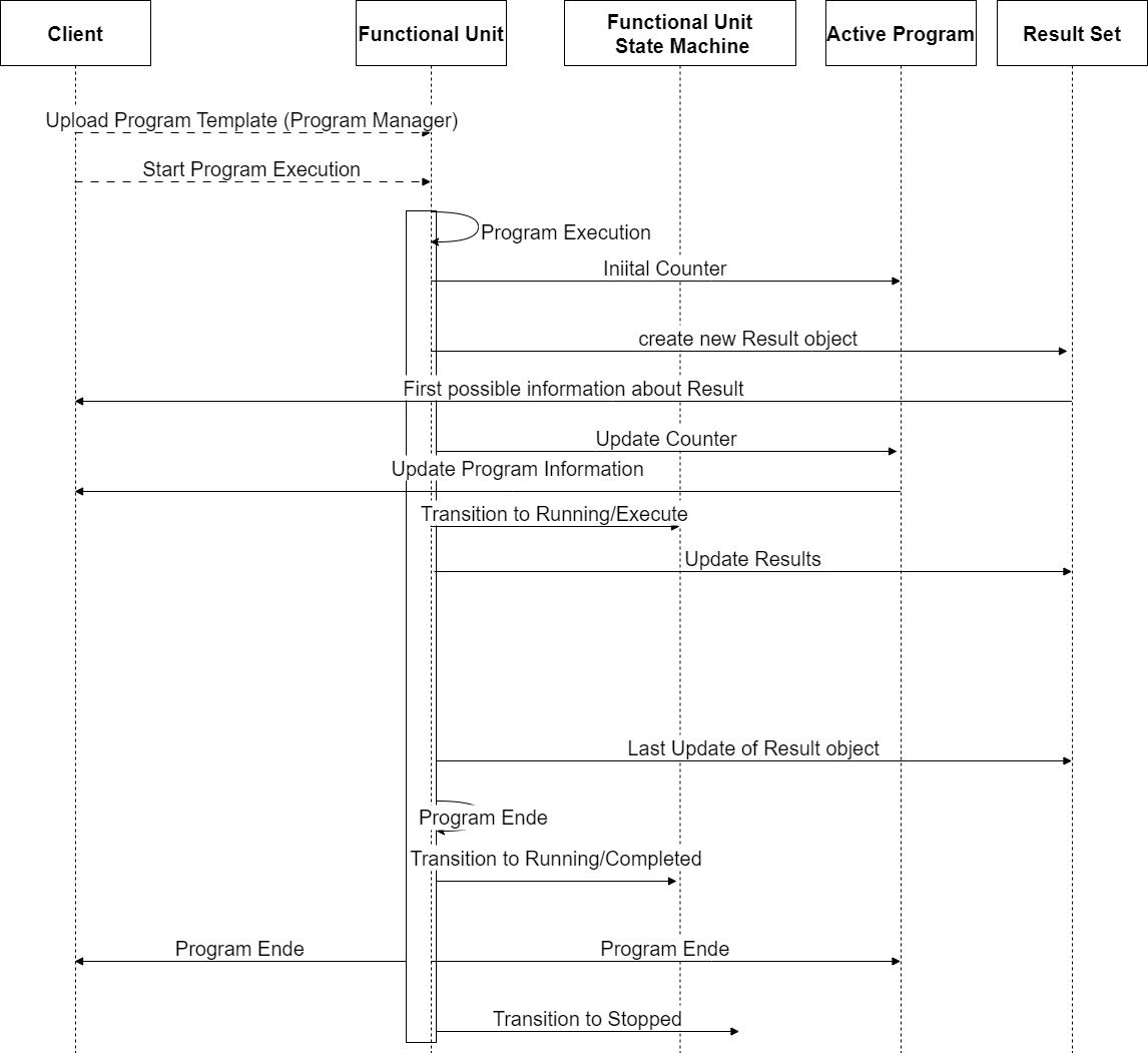
4.1.4 Program and result lifetime of a LADS Device
The lifetime of a program, from uploading a program template to the creation of the result, including additional information about the ActiveProgramType and the RunningStateMachineType, is as follows:
Uploading Program Template: The client uploads the ProgramTemplate to the ProgramTemplateSet of the ProgramManager using the Upload Method.
Starting the Program Execution: The program can be started either externally by a Client application using the Start or StartProgram Method or internally by the Device itself based on internal/process reasons.
Program Execution: The program execution progresses through various states defined in the FunctionalStateMachineType. During program execution, the ActiveProgramType provides information about the current state and runtime of the program. The CurrentPauseTime and CurrentRuntime properties indicate the current pause time and runtime of the program run, respectively. The CurrentStepName and CurrentStepNumber properties provide information about the current step being executed. The EstimatedRuntime, EstimatedStepNumbers, and EstimatedStepRuntime properties provide estimated information about the program's total runtime and steps.
Creating Results: As the program is executed, the FunctionalUnit generates data and results during the run. These results are collected in a result object which is managed in the ResultSet, which includes information about the program's initiator, the template used with additional parameters, samples, and contextual information to link and trace the results. The result object can provide the results either as files in the FileSet or as OPC UA variables in the VariableSet.
Program Completion: The program execution continues until it reaches the completion state (e.g., complete state) in the RunningStateMachineType. Once the program is complete, the results in the ResultSet are considered complete and are available for further processing and analysis.
Please note that the program's lifetime and states may vary based on the specific implementation and context of the OPC UA Companion Specification being used. The provided overview is a general outline of the program's lifetime and the high-level information about the ActiveProgramType and ResultSet based on the description provided.
This is illustrated in Figure 4
4.2 Introduction to OPC Unified Architecture
4.2.1 What is OPC UA?
OPC UA is an open and royalty free set of standards designed as a universal communication protocol. While there are numerous communication solutions available, OPC UA has key advantages:
A state-of-the-art security model (see OPC 10000-2).
A fault-tolerant communication protocol.
An information modelling framework that allows application developers to represent their data in a way that makes sense to them.
OPC UA has a broad scope which delivers economies of scale for application developers. This means that a larger number of high-quality applications are available at a reasonable cost. When combined with semantic models such as LADS, OPC UA makes it easier for end users to access data via generic commercial applications.
The OPC UA model is scalable from small devices to ERP systems. OPC UA Servers process information locally and then provide that data in a consistent format to any application requesting data - ERP, MES, PMS, maintenance systems, HMI, smartphone, or a standard browser, for example. For a more complete overview see OPC 10000-1
4.2.2 Basics of OPC UA
As an open standard, OPC UA is based on standard internet technologies, like TCP/IP, HTTP, Web Sockets.
As an extensible standard, OPC UA provides a set of Services (see OPC 10000-4) and a basic information model framework. This framework provides an easy means for creating and exposing vendor-defined information in a standard way. More importantly all OPC UA Clients are expected to be able to discover and use vendor-defined information. This means OPC UA users can benefit from the economies of scale that come with generic visualisation and historian applications. This specification is an example of an OPC UA Information Model designed to meet the needs of developers and users.
OPC UA Clients can be any consumer of data, from another Device on the network to browser-based thin clients and ERP systems. The full scope of OPC UA applications is shown in Figure 5.

OPC UA provides a robust and reliable communication infrastructure with mechanisms for handling lost messages, failover, heartbeat, etc. With its binary encoded data, it offers a high-performing data exchange solution. Security is built into OPC UA as security requirements become more and more important, especially since environments are connected to the office network or the internet and attackers are starting to focus on automation systems.
4.2.3 Information Modelling in OPC UA
4.2.3.1 Concepts
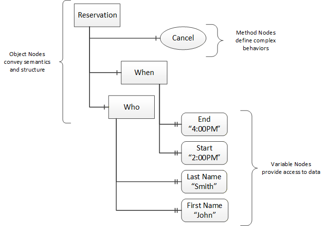
OPC UA provides a framework that can be used to represent complex information as Objects in an AddressSpace which can be accessed with standard services. These Objects consist of Nodes connected by References. Different classes of Nodes convey different semantics. For example, a Variable Node represents a value that can be read or written. The Variable Node has an associated DataType that can define the actual value, such as a string, float, structure etc. It can also describe the Variable value as a variant. A Method Node represents a Function that can be called. Every Node has a number of Attributes, including a unique identifier called a NodeId and non-localized name called a BrowseName. An Object representing a "Reservation" is shown in Figure 6.
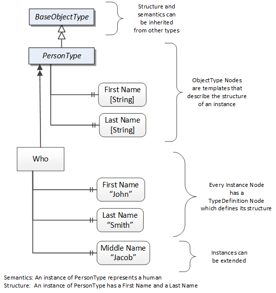
Object and Variable Nodes represent instances and always reference a TypeDefinition (ObjectType or VariableType) Node which describes their semantics and structure. Figure 7 illustrates the relationship between an instance and its TypeDefinition.
Type Nodes are templates that define all the children that can be present in an instance of the type. In the example in Figure 7 the "PersonType" ObjectType defines two children: First Name and Last Name. All instances of "PersonType" are expected to have the same children with the same BrowseNames. Within a type, the BrowseNames uniquely identify the children. This means Client applications can be designed to search for children based on the BrowseNames from the type instead of NodeIds. This eliminates the need for manual reconfiguration of systems if a Client uses types that are implemented on multiple Servers.
OPC UA also supports the concept of subtyping. This allows a modeller to take an existing type and extend it. Rules regarding subtyping are defined in OPC 10000-3, but in general they allow the extension of a given type or the restriction of a DataType. For example, the modeller may decide that the existing ObjectType needs an additional Variable in some cases. The modeller can create a subtype of the ObjectType and add the Variable. A Client that is expecting the parent type can treat the new type as if it were of the parent type. Regarding DataTypes, subtypes can only restrict. If a Variable is defined to have a numeric value, a subtype could restrict it to a float.
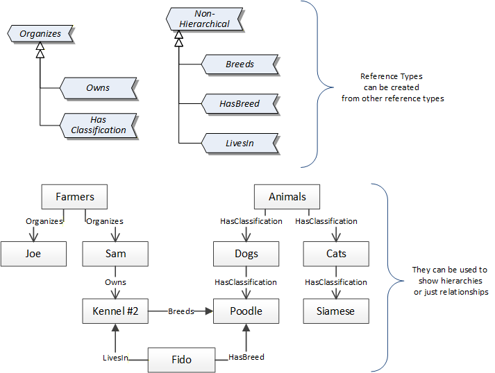
References allow Nodes to be connected in ways that describe their relationships. All References have a ReferenceType that specifies the semantics of the relationship. References can be hierarchical or non-hierarchical. Hierarchical references are used to create the structure of Objects and Variables, non-hierarchical references are used to create arbitrary associations. Applications can define their own ReferenceType by creating subtypes of an existing ReferenceType. Subtypes inherit the semantics of the parent but may add additional restrictions. Figure 8 depicts several References connecting different Objects.
The figures above use a notation that was developed for the OPC UA specification. This notation is summarized in Figure 9. UML representations can also be used; however, the OPC UA notation is less ambiguous because there is a direct mapping from the elements in the figures to Nodes in the AddressSpace of an OPC UA Server.

A complete description of the different types of Nodes and References can be found in OPC 10000-3 and the base structure is described in OPC 10000-5.
The OPC UA specification defines a very wide range of functionalities in its basic information model. It is not required that all Clients or Servers support all functionalities in the OPC UA specifications. OPC UA includes the concept of Profiles, which segment the functionality into testable certifiable units. This allows the definition of functional subsets (that are expected to be implemented) within a companion specification. Profiles do not restrict functionality, but they generate requirements for a minimum set of functionalities (see OPC 10000-7).
4.2.3.2 Namespaces
OPC UA allows information from many different sources to be combined into a single coherent AddressSpace. Namespaces make this possible by eliminating naming and ID conflicts between information from different sources. Each Namespace in OPC UA has a globally unique string called a NamespaceUri which identifies a naming authority, and a locally unique integer called a NamespaceIndex which is an index into the Server's table of NamespaceUris. The NamespaceIndex is unique only within the context of a Session between an OPC UA Client and an OPC UA Server - the NamespaceIndex can change between Sessions and still identify the same item even though the NamespaceUri's location in the table has changed. The Services defined for OPC UA use the NamespaceIndex to specify the Namespace for qualified values.
There are two types of structured values in OPC UA that are qualified with NamespaceIndexes: NodeIds and QualifiedNames. NodeIds are locally unique (and sometimes globally unique) identifiers for Nodes. The same globally unique NodeId can be used as the identifier in a Node in many Servers - the Node's instance data may vary but its semantic meaning is the same regardless of the Server it appears in. This means Clients can have built-in knowledge of what the data means in these Nodes. OPC UA Information Models generally define globally unique NodeIds for the TypeDefinitions defined by the Information Model.
QualifiedNames are non-localized names qualified with a Namespace. They are used for the BrowseNames of Nodes and allow the same names to be used by different information models without conflict. TypeDefinitions are not allowed to have children with duplicate BrowseNames; however, instances do not have that restriction.
4.2.3.3 Companion Specifications
An OPC UA companion specification for an industry-specific vertical market describes an Information Model by defining ObjectTypes, VariableTypes, DataTypes and ReferenceTypes that represent the concepts used in the vertical market, as well as potentially well-defined Objects as entry points into the AddressSpace.
5 Use cases
This section introduces the use cases addressed by the LADS specification.
5.1 Automation
5.1.1 Remote monitoring, Alarms, Notifications
Description
Remote monitoring, Alarms and Events form the foundation of any basic automation functionality. If no information is available regarding the current values of function states, operation modes, process variables, set-points, parameters, etc. it is not possible to make decisions and take action. For selected values, such as Sensor or process values, the optional provision of time-series history services is recommended.
Remote monitoring entails the capability to measure a physical/chemical/biological property. It comprises of a "raw" measurement value provided by the sensing element, a calibration function, optional signal processing/filtering and the final Sensor value which represents a real-world physical/chemical/biological property.
The remote monitoring of a property may be augmented by Alarm and Notification functionalities which update the user regarding the monitored property value matching determined conditions (e.g., out of limits).
History services are supported to retrieve historic information on the observed properties.
Addressed in Sections: 7.1
5.1.2 Function-based remote control
Description
Function-based remote control enables a user to remotely perform an action, change parameters or setpoints, or start and stop Functions. It includes the remote invocation of Methods to perform Functions on a Device. For example, to start or stop device-specific Functions, open and close covers, as well as change parameters like Alarm limits, control and calibration values, or closed-loop control set-point values.
Addressed in Sections: 7.4 , 7.6 , 7.4.2
5.1.3 Program-based remote control
Description
Program-based remote control covers the orchestration of one or more instruments along a lab or analytical workflow. It enables a supervising system (e.g., LIMS) to manage and execute programs on a Device as part of a greater workflow.
Furthermore, it covers the capability to retrieve the Program Templates on the Device, select a program to be executed, start a program run and monitor the program's progress.
The combined program-management and result-management use-cases are the basis for orchestration of several instruments along workflows.
Addressed in Section: 7.1.10
5.1.4 Results management
Description
A Device performing a specific Function may generate results. These results are typically consumed by one or more applications which may not run on the Device itself.
The generating Device exposes the results such that they can be retrieved by the application via OPC UA. The results data include the results themselves, but also metadata such as results templates, user information, timestamps, action identifiers, and sample Ids.
A Device can also provide the capability to observe intermediate/partial results, such that an application can monitor the execution of a Function on the Device.
There may be specific cases in which a consuming application may need to retrieve the results via an alternative interface. In these cases, the Device exposes the URI where the results reside and can be accessed via authenticated access. The possibility to retrieve intermediate/partial results via an alternative interface is outside the scope of this specification.
Addressed in Sections: 7.1.10 , 7.2.2 , 7.2.3
5.2 Service and asset management
5.2.1 Device and fleet management
Description
Devices typically come with a set of properties that identify them for discovery, management, and maintenance purposes. This set of properties is commonly summarized using the term "nameplate". The information available includes (but it is not limited to) device name, identifiers, serial number, manufacturer, hardware and software versions, and product URI. A nameplate for a device is required to be recognized correctly in the server.
Furthermore, a Device is composed of different Components. Each of these Components can have a nameplate itself. The definition of Components is up to the implementer of the Device.
It should be possible to represent an individual Device as an OPC UA Server or aggregate multiple Devices into the same OPC UA Server. Therefore, an OPC UA Server can represent an arbitrary number of Devices. The following scenarios are envisioned to be covered by this specification:
Single Devices incorporating an OPC UA Server,
Gateway Devices representing a set of Devices, including OPC UA capable Devices as well as non-OPC UA capable Devices (e.g., a simple analogue Sensor or legacy device using a different communication protocol),
Devices serving both of the above roles.
Addressed in Section: 7.1
5.2.2 Condition monitoring and maintenance
Description
The condition of a Device or a Component of a device is useful for understanding its health status and performance, as well as possible maintenance actions needed. For these reasons, the following information is envisioned to be represented for a Device or Component:
Indicators of health status,
Indicators of operating time and number of actions performed since installation or maintenance,
Indicators of (estimated) remaining lifetime based on the device information provided by suppliers,
Device modes (e.g., operating, sleep, maintenance, off) and Methods to trigger changes.
For maintenance purposes, the possibility to trigger, record, and retrieve information related to maintenance activities is seen as valuable.
Maintenance activities can be recurrent, periodic, or ad-hoc. They can be vendor defined (e.g., yearly maintenance) or user defined (e.g., calibration). Maintenance activities may be initiated based on specific conditions related to the health and condition of a Device or a Component. History with dates and details of actions performed on a Device or a Component should be available.
Addressed in Sections: 0 7.1.1 ,
5.2.3 Location
Description
The location of a Device is of interest for multiple purposes. These include:
Finding a Device position for asset management and service needs
Enabling autonomous robots to navigate within a lab facility or across multiple lab facilities
Sample location tracking (future).
A Device location can include different information, including:
Geographical
Address
Organizational
Indoor coordinates
GPS coordinates.
Addressed in Section: 7.1
6 LADS Information Model Overview
This Companion Specification is based on OPC 10000-100 (Devices), OPC 10000-110 (Asset Management Basics) and OPC 40001-1 (OPC UA for Machinery). These Companion Specifications create an entry point for Devices or machines in the AddressSpace. Instances of a LADSDeviceType shall either directly or indirectly referenced with a Hierarchical Reference to the DeviceSet and can be referenced from Machines with an Organizes Reference.
A LADSDeviceType may have both References (to DeviceSet and Machines), depending on the environment of the Device. Both References are needed if the LADSDeviceType is used in a production environment or in a laboratory close to production.
Figure 10 shows an example representation of a LADSDeviceType instance in the AddressSpace.
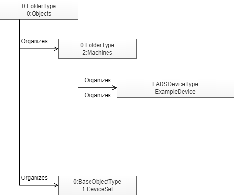
Figure 11 shows the type definition of the LADSDeviceType.
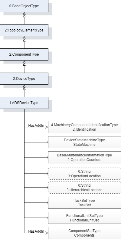
Figure 12 shows the type definition of the LadsComponentType.
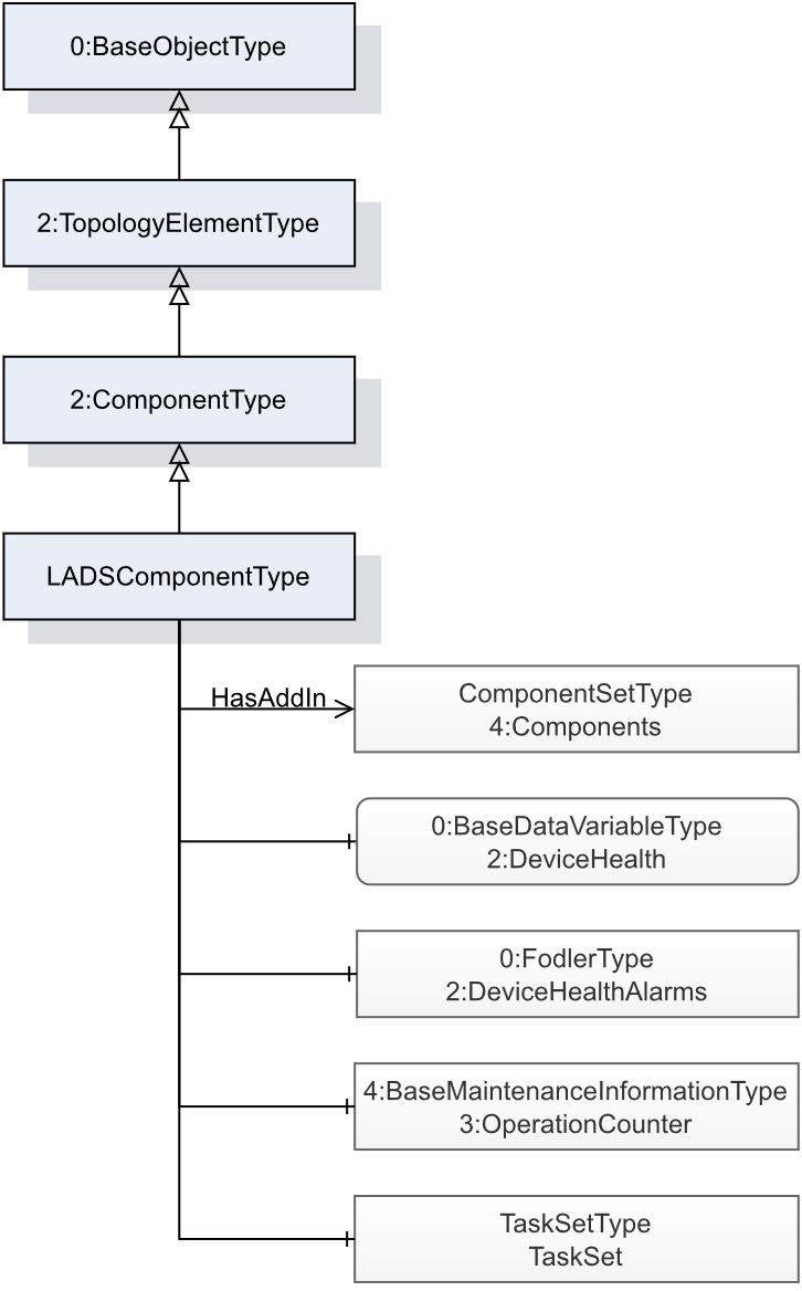
Figure 13 shows the FunctionType inheritance in the LADS type space.
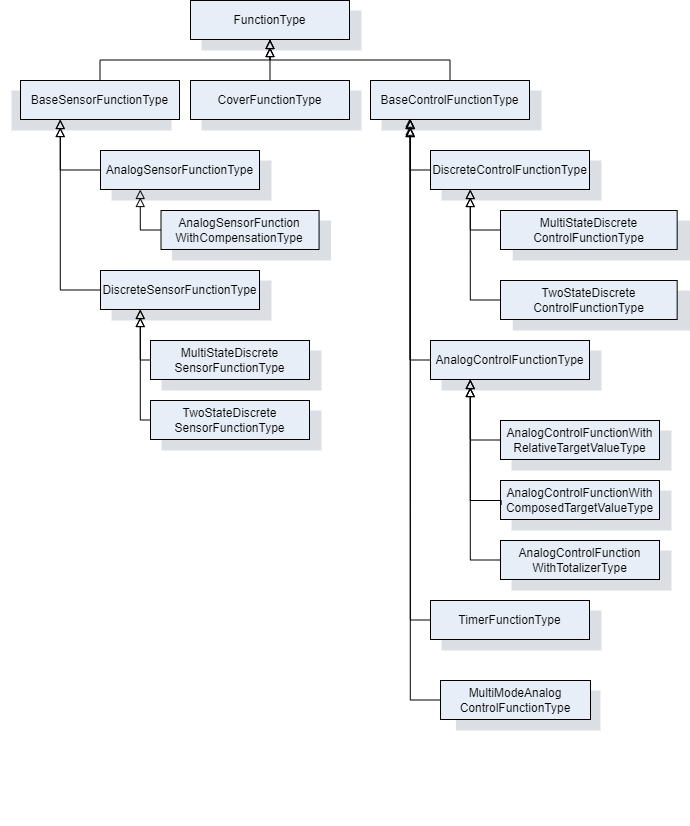
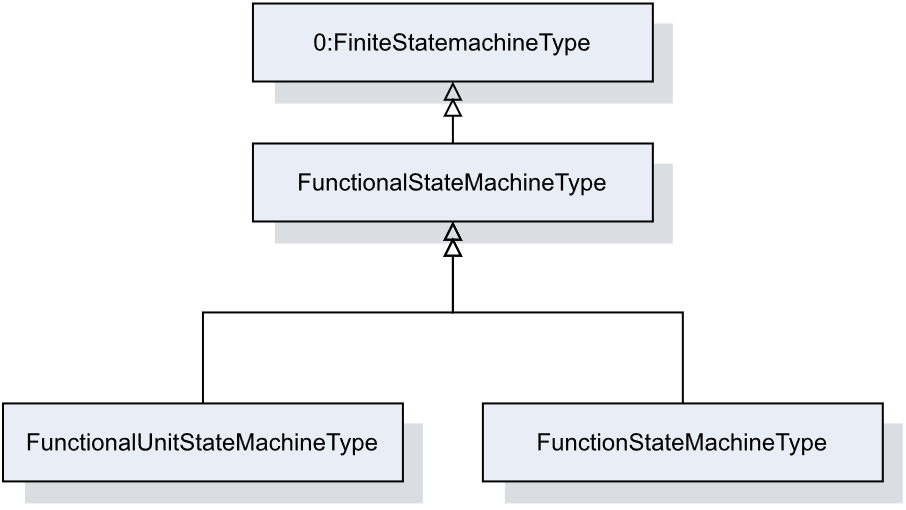
Figure 14 shows the FunctionalStateMachineType inheritance.
7 OPC UA ObjectTypes
7.1 Type for Devices, Components and FunctionalUnits
7.1.1 LADSDeviceType ObjectType Definition
The LADSDeviceType provides a base class for Laboratory and Analytical Devices. It is formally defined in Table 15.
| Attribute | Value | ||||
| BrowseName | LADSDeviceType | ||||
| IsAbstract | False | ||||
| References | Node Class | BrowseName | DataType | TypeDefinition | Other |
|---|---|---|---|---|---|
| Subtype of the DeviceType defined in OPC 10000-100 | |||||
| 0:HasAddIn | Object | 4:Components | LADSComponentsType | O | |
| 0:HasComponent | Object | FunctionalUnitSet | FunctionalUnitSetType | M | |
| 0:HasProperty | Variable | 3:HierarchicalLocation | 0:String | 0:PropertyType | O |
| 0:HasAddIn | Object | 2:Identification | 4:MachineIdentificationType | M | |
| 0:HasProperty | Variable | 3:OperationalLocation | 0:String | 0:PropertyType | O |
| 0:HasComponent | Object | DeviceState | LADSDeviceStateMachineType | M | |
| 0:HasComponent | Object | Maintenance | MaintenanceSetType | O | |
| 0:Organizes | Object | 4:MachineryBuildingBlocks | 0:FolderType | O | |
| 0:HasAddIn | Object | 4:MachineryItemState | 4:MachineryItemState_StateMachineType | O | |
| 0:HasAddIn | Object | 4:MachineryOperationMode | LADSOperationModeStateMachineType | O | |
| 0:HasAddIn | Object | 2:OperationCounters | 4:MachineryOperationCounterType | O | |
| 0:HasAddIn | Object | 4:LifetimeCounters | 4:MachineryLifetimeCounterType | O | |
| Conformance Units | |||||
|---|---|---|---|---|---|
| LADS LADSDeviceType | |||||
Components is a generic set of identifiable sub-components of the Device as mandated by OPC 40001-1.
FunctionalUnitSet contains the Functional Units of this Device.
HierarchicalLocation provides the hierarchical location of the LADS Device. The structure within the string may expose several levels. How this is exposed, which delimiters are used, etc. is vendor specific. Examples of such strings are "FactoryA/BuildingC/Floor1" or "Area1-ProcessCell17-Unit4" (see OPC UA OPC 10000-110 for more details).
OperationalLocation provides the operational location of the LADS Device. The structure within the string may expose several levels. How this is exposed, which delimiters are used, etc. is vendor specific. Examples of such strings are "Warehouse1/Sheet3" or "StainlessSteelTote3" (see OPC UA OPC 10000-110 for more details).
Recommendations for both hierarchical and operational locations have been proposed:
For instances where the location definition encompasses multiple levels, these levels should be separated by the delimiter character "/". An instance of a location definition with multiple levels separated by the delimiting character "/" is "US-NY-NYC-Building101/Floor35/Room10.1".
For additional use cases not covered by the aforementioned properties, it is recommended to employ the additional location formats NmeaCoordinateString, LocalCoordinate, and WGS84Coordinate as delineated in the OPC UA for AutoId Devices Release 1.01.1 (2021-07-13) specification.
Identification provides properties to identify a Device.
Recommendations for the Identification:
If the device consists solely of software with no hardware, the SoftwareRevision should be provided, and the HardwareRevision should be omitted.
If the device consists solely of hardware with no software, the HardwareRevision should be provided, and the SoftwareRevision should be omitted.
If the device consists of both hardware and software, the HardwareRevision should be provided. The SoftwareRevision should be provided if there are no device components providing a SoftwareRevision. Otherwise, the SoftwareRevision may be provided to represent the overall revision of all software components.
If a ProductInstanceUri can be created, this property should be part of the Identification.
OperationCounters for monitoring the operation of a LADSDeviceType, including parameters of the OperationCounters interface and lifetime variables (see OPC UA for Devices for more information).
DeviceState StateMachine that controls and represents the Device's current state.
Maintenance is a set containing all maintenance tasks of a Device.
The MachineryBuildingBlocks folder contains all machinery building blocks, especially the MachineryItemState, MachineryOperationMode, OperationCounter and Lifetime Counter.
Refer to Annex B for proposed mappings between the DeviceStateMachine, the FunctionalUnit state machines, the MachineryItemState and the DeviceHealth.
MachineryItemState indicates the current state of the device and is comparable with the LADS Device state machine.
MachineryOperationMode indicates the type of Tasks being performed by the Device.
OperationCounter provides information on how long a MachineryItem has been turned on and how long it performed an activity. It uses the 2:IOperationCounterType interface and the predefined functional group 2:OperationCounters defined in OPC 10000-100.
Lifetime Counter provides information about the past and estimated remaining lifetime of a MachineryItem, or other aspects of a MachineryItem such as a software license. It is based on the 2:LifetimeVariableType defined in OPC 10000-100.
Children of the LADSDeviceType have additional References, which are defined in Table 16.
| SourceBrowsePath | Reference Type | Is Forward | TargetBrowsePath | ||
| 4:MachineryBuildingBlocks | 0:HasAddIn | True |
| ||
| 4:MachineryBuildingBlocks | 0:HasAddIn | True |
| ||
| 4:MachineryBuildingBlocks | 0:HasAddIn | True |
| ||
| 4:MachineryBuildingBlocks | 0:HasAddIn | True |
| ||
| 4:MachineryBuildingBlocks | 0:HasAddIn | True |
| ||
| 4:MachineryBuildingBlocks | 0:HasAddIn | True |
|
7.1.2 LADSDeviceStateMachineType ObjectType Definition
7.1.2.1 Overview
The LADSDeviceStateMachineType state machine represents the Device's current state. It is inspired by the AnalyserDeviceStateMachineType from the Analyzer Devices Specification.
The LADSDeviceStateMachine is depicted in Figure 15
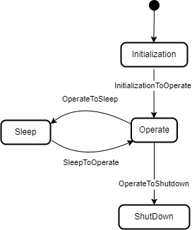
The LADSDeviceStateMachineType is formally defined in Table 17.
| Attribute | Value | ||||
| BrowseName | LADSDeviceStateMachineType | ||||
| IsAbstract | False | ||||
| References | Node Class | BrowseName | DataType | TypeDefinition | Other |
|---|---|---|---|---|---|
| Subtype of the FiniteStateMachineType defined in OPC 10000-5 | |||||
| 0:HasComponent | Method | GotoOperate | O | ||
| 0:HasComponent | Method | GotoShutdown | O | ||
| 0:HasComponent | Method | GotoSleep | O | ||
| 0:HasComponent | Object | Operate | StateType | ||
| 0:HasComponent | Object | OperateToShutdown | TransitionType | ||
| 0:HasComponent | Object | OperateToSleep | TransitionType | ||
| 0:HasComponent | Object | Initialization | InitialStateType | ||
| 0:HasComponent | Object | InitializationToOperate | TransitionType | ||
| 0:HasComponent | Object | Shutdown | StateType | ||
| 0:HasComponent | Object | Sleep | StateType | ||
| 0:HasComponent | Object | SleepToOperate | TransitionType | ||
| Conformance Units | |||||
|---|---|---|---|---|---|
| LADS LADSDeviceStateMachineType | |||||
There are four Device states, as follows:
Initialization: The Device is in its initializing sequence and cannot perform any other Task.
Operate: The Device is in Operating mode. The LADS Client uses this mode for normal operation: configuration, control, and data collection.
Sleep: The Device is still powered on and its OPC UA Server is still running, but it is not ready to perform any Tasks until it transitions to the Operate state. This state can be used to represent a PowerSave state where a Device may shut down some of its Components, such as the GUI. It can also be used to represent a Sleep state, where a Device is running with minimal services but ready to be triggered to transition into the Operate state.
Shutdown: The Device is in its power-down sequence and cannot perform any other Task. Optionally, there are devices that can be powered off via physical means, especially simpler ones. The electronics are turned off immediately; therefore, such devices do not transition into a Shutdown state.
Note: Shutdown is the state in which the LADS Device waits for the completion of the power down sequence. Its sub-states are out of scope of the LADS specification.
Children of the LADSDeviceStateMachineType have additional References, which are defined in Table 18.
| SourceBrowsePath | Reference Type | Is Forward | TargetBrowsePath |
| InitializationToOperate | 0:FromState | True | Initialization |
| 0:ToState | True | Operate | |
| 0:HasEffect | True | TransitionEventType | |
| OperateToSleep | 0:FromState | True | Operate |
| 0:ToState | True | Sleep | |
| 0:HasCause | True | GotoSleep | |
| 0:HasEffect | True | TransitionEventType | |
| SleepToOperate | 0:FromState | True | Sleep |
| 0:ToState | True | Operate | |
| 0:HasCause | True | GotoOperate | |
| 0:HasEffect | True | TransitionEventType | |
| OperateToShutdown | 0:FromState | True | Operate |
| 0:ToState | True | Shutdown | |
| 0:HasCause | True | GotoShutdown | |
| 0:HasEffect | True | TransitionEventType |
The Component Variables of the LADSDeviceStateMachineType have additional Attributes, as defined in Table 19.
| BrowsePath | Value Attribute | ||
| 1 | ||
| 2 | ||
| 3 | ||
| 4 | ||
| 3 | ||
| 4 | ||
| 2 | ||
| 1 |
7.1.2.2 GotoOperate
The GotoOperate Method is used to set the Device into an operating mode. The signature of this Method is specified below. Table 20 specifies its representation in the AddressSpace.
Signature
GotoOperate ()| Attribute | Value | ||||
| BrowseName | GotoOperate | ||||
| References | Node Class | BrowseName | DataType | TypeDefinition | ModellingRule |
|---|
7.1.2.3 GotoShutdown
The GotoShutdown Method is used to shut down the Device. The signature of this Method is specified below. Table 21 specifies its representation in the AddressSpace.
Signature
GotoShutdown ()| Attribute | Value | ||||
| BrowseName | GotoShutdown | ||||
| References | Node Class | BrowseName | DataType | TypeDefinition | ModellingRule |
|---|---|---|---|---|---|
7.1.2.4 GotoSleep
The GotoSleep Method is used to set the Device to Sleep. The signature of this Method is specified below. Table 22 specifies its representation in the AddressSpace.
Signature
GotoSleep ()| Attribute | Value | ||||
| BrowseName | GotoSleep | ||||
| References | Node Class | BrowseName | DataType | TypeDefinition | ModellingRule |
|---|
7.1.3 LADSComponentType ObjectType Definition
Devices may be composed of tangible subcomponents. A Component is represented by the LADSComponentType. A Component itself may also have subcomponents. The LADSComponentType is formally defined in Table 23.
| Attribute | Value | ||||
| BrowseName | LADSComponentType | ||||
| IsAbstract | False | ||||
| References | Node Class | BrowseName | DataType | TypeDefinition | Other |
|---|---|---|---|---|---|
| Subtype of the 2:ComponentType defined in OPC 10000-100 | |||||
| 0:HasAddIn | Object | Components | LADSComponentsType | O | |
| 0:HasAddIn | Object | 2:Identification | M | ||
| 0:HasComponent | Object | Maintenance | MaintenanceSetType | O | |
| 0:HasProperty | Variable | 3:OperationalLocation | 0:String | 0:PropertyType | O |
| 0:HasProperty | Variable | 3:HierarchicalLocation | 0:String | 0:PropertyType | O |
| 0:Organizes | Object | 4:MachineryBuildingBlocks | 0:FolderType | O | |
| 0:HasAddIn | Object | 2:OperationCounters | 4:MachineryOperationCounterType | O | |
| 0:HasAddIn | Object | 4:LifetimeCounters | 4:MachineryLifetimeCounterType | O | |
| 0:HasInterface | ObjectType | 2:IDeviceHealthType | |||
| Applied from 2:IDeviceHealthType | |||||
| 0:HasComponent | Variable | 2:DeviceHealth | 2:DeviceHealthEnumeration | 0:BaseDataVariableType | O |
| 0:HasComponent | Object | 2:DeviceHealthAlarms | 0:FolderType | O | |
| Conformance Units | |||||
|---|---|---|---|---|---|
| LADS LADSComponentType | |||||
Components is a generic set of identifiable subcomponents of the device as mandated by OPC 40001-1.
Identification provides the properties to identify a device.
Recommendations for Identification:
• If the Component consists solely of software with no hardware, the SoftwareRevision should be provided and the HardwareRevision should be omitted.
• If the Component consists solely of hardware with no software, the HardwareRevision should be provided and the SoftwareRevision should be omitted.
• If the Component consists of both hardware and software, the HardwareRevision should be provided. The SoftwareRevision should be provided if there are no subcomponents providing a SoftwareRevision. Otherwise, the SoftwareRevision may be provided to represent the overall revision of all software components.
HierarchicalLocation provides the hierarchical location of the LADS Device. The structure inside the string may expose several levels. How this is exposed, which delimiters are used, etc. is vendor specific. Examples of such strings are "FactoryA/BuildingC/Floor1" or "Area1-ProcessCell17-Unit4" (see OPC 10000-110 for more Details).
OperationalLocation provides the operational location of the LADS Device. The structure within the string may expose several levels. How this is exposed, which delimiters are used, etc. is vendor specific. Examples of such strings are "Warehouse1/Sheet3" or "StainlessSteelTote3" (see OPC 10000-110 for more Details).
Recommendations for both hierarchical and operational locations have been proposed:
For instances where the location definition encompasses multiple levels, these levels should be separated by the delimiter character "/". An instance of a location definition with multiple levels separated by the delimiting character "/" is "US-NY-NYC-Building101/Floor35/Room10.1".
For additional use cases not covered by the aforementioned properties, it is recommended to employ the additional location formats NmeaCoordinateString, LocalCoordinate, and WGS84Coordinate as delineated in the OPC UA for AutoId Devices Release 1.01.1 (2021-07-13) specification.
DeviceHealth indicates the health status of a Device as defined by NAMUR Recommendation NE 107 (see OPC 10000-100 for more Details).
DeviceHealthAlarms groups all instances of Device health-related Alarms.
OperationCounters for monitoring the operation of a LADSDeviceType, including parameters of the OperationCounters interface and lifetime variables (see OPC 10000-100 for more information).
Maintenance is a set containing all maintenance tasks of a Device.
The MachineryBuildingBlocks folder contains all machinery building blocks, especially the OperationCounter, and Lifetime Counter.
OperationCounter provides information on how long a MachineryItem has been turned on and how long it performed an activity. It uses the 2:IOperationCounterType interface and the predefined functional group 2:OperationCounters defined in OPC 10000-100.
Lifetime Counter provides information about the past and estimated remaining lifetime of a MachineryItem, or other aspects of a MachineryItem such as a software license. It is based on the 2:LifetimeVariableType defined in OPC 10000-100.
Children of the LADSComponentsType have additional References, which are defined in Table 24.
| SourceBrowsePath | Reference Type | Is Forward | TargetBrowsePath | ||
| 4:MachineryBuildingBlocks | 0:HasAddIn | True |
| ||
| 4:MachineryBuildingBlocks | 0:HasAddIn | True |
| ||
| 4:MachineryBuildingBlocks | 0:HasAddIn | True |
|
7.1.4 FunctionalUnitType ObjectType Definition
The FunctionalUnitType represents a functional unit of a Laboratory or Analytical Device. It is formally defined in Table 25.
| Attribute | Value | ||||
| BrowseName | FunctionalUnitType | ||||
| IsAbstract | False | ||||
| References | Node Class | BrowseName | DataType | TypeDefinition | Other |
| Subtype of the TopologyElementType defined in OPC 10000-100 | |||||
| 0:HasComponent | Object | ProgramManager | ProgramManagerType | O | |
| 0:HasComponent | Object | FunctionalUnitState | FunctionalUnitStateMachineType | M | |
| 0:HasComponent | Object | SupportedPropertiesSet | SupportedPropertiesSetType | O | |
| 0:HasComponent | Object | FunctionSet | FunctionSetType | O | |
| 0:HasComponent | Object | Operational | 1:FunctionalGroupType | O | |
| 0:HasInterface | ObjectType | 2:ITagNameplateType | |||
| Implements the 2:ITagNameplateType | |||||
| 0:HasProperty | Variable | 2:AssetId | 0:String | 0:PropertyType | O |
| 0:HasProperty | Variable | 2:ComponentName | LocalizedText | 0:PropertyType | O |
| Conformance Units | |||||
| LADS FunctionalUnitType | |||||
AssetId is a user-writeable alphanumeric character sequence that uniquely identifies a FunctionalUnit (see OPC UA 10000-100).
ComponentName is a user-writeable name provided by the integrator or user of the FunctionalUnit.
FunctionSet contains the Functions of the FunctionalUnit.
Program Manager manages the programs and results of the FunctionalUnit.
FunctionalUnitState the StateMachine that is used for this FunctionalUnit.
Operational Functional Group that organizes Properties and Methods for this FunctionalUnit.
SupportedPropertiesSet provides references to variables of sub-ordinate Functions of the FunctionalUnit whose values can be specified as input Arguments when calling the FunctionalUnit.FunctionalUnitState.Start() or ProgramManager.ActiveProgram.StateMachine.Start() Methods.
7.1.5 FunctionalStateMachineType ObjectType Definition
7.1.5.1 Overview
The FunctionalStateMachineType is the top level StateMachine for the LADS ActiveProgram, FunctionalUnit or Function. The basic idea behind this architecture is that the instances of the FunctionalStateMachineType, the ActiveProgramStateMachineType, the FunctionalUnitStateMachineType and the FunctionStateMachineType use the same states, Transitions and Methods, but add their own Start Methods with different Method Signatures to trigger the StoppedToRunning Transition from a Client.
The FunctionalStateMachineType defines the available states in a LADS system.
The FunctionalStateMachineType is formally defined in Table 26. StateTypes and TransitionTypes only exist in the type system, thus they do not have a modelling rule.
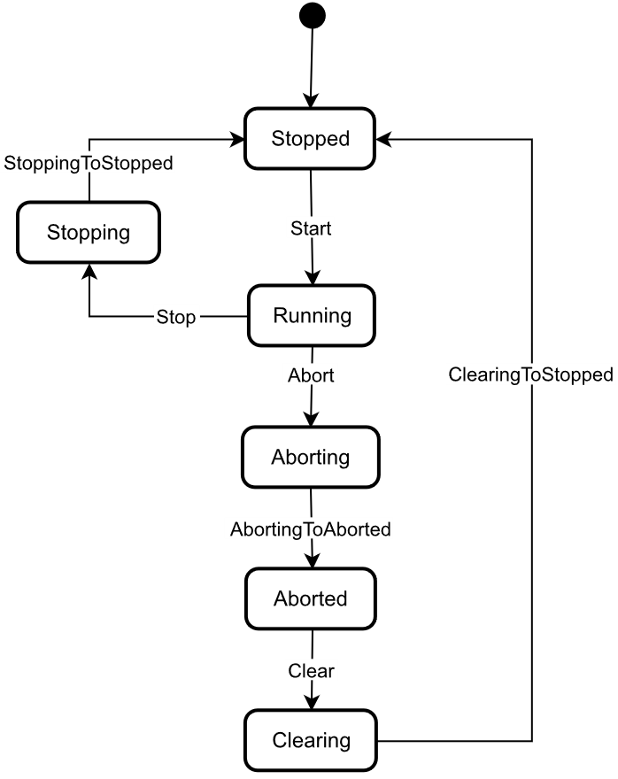
The FunctionalStateMachine is depicted in Figure 16.
| Attribute | Value | ||||
| BrowseName | FunctionalStateMachineType | ||||
| IsAbstract | True | ||||
| References | Node Class | BrowseName | DataType | TypeDefinition | Other |
|---|---|---|---|---|---|
| Subtype of the 0:FiniteStateMachineType defined in OPC 10000-5 | |||||
| 0:HasComponent | Variable | 0:AvailableTransitions | 0:NodeId[] | 0:BaseDataVariableType | M |
| 0:HasComponent | Variable | 0:AvailableStates | 0:NodeId[] | 0:BaseDataVariableType | M |
| 0:HasComponent | Method | Abort | O | ||
| 0:HasComponent | Object | Aborted | StateType | ||
| 0:HasComponent | Object | AbortedToClearing | TransitionType | ||
| 0:HasComponent | Object | Aborting | StateType | ||
| 0:HasComponent | Object | AbortingToAborted | TransitionType | ||
| 0:HasComponent | Method | Clear | O | ||
| 0:HasComponent | Object | Clearing | StateType | ||
| 0:HasComponent | Object | ClearingToStopped | TransitionType | ||
| 0:HasComponent | Object | Running | StateType | ||
| 0:HasComponent | Object | RunningStateMachine | RunningStateMachineType | O | |
| 0:HasComponent | Object | RunningToAborting | TransitionType | ||
| 0:HasComponent | Object | RunningToStopping | TransitionType | ||
| 0:HasComponent | Method | Stop | O | ||
| 0:HasComponent | Object | Stopped | InitialStateType | ||
| 0:HasComponent | Object | StoppedToRunning | TransitionType | ||
| 0:HasComponent | Object | Stopping | StateType | ||
| 0:HasComponent | Object | StoppingToStopped | TransitionType | ||
| 0:HasComponent | Variable | 0:CurrentState | 0:LocalizedText | FiniteStateVariableType | M |
| Conformance Units | |||||
|---|---|---|---|---|---|
| LADS FunctionalStateMachineType | |||||
The AvailableTransitions and AvailableStates Nodes are overwritten and made Mandatory in the FunctionalStateMachineType.
Abort is a Method to trigger a change of state to Aborting. This will affect all sub-states in a cleared state.
Aborted maintains unit/device status information relevant to the Abort condition. The unit/device can only exit the Aborted state after an explicit Clear command subsequent to manual intervention to correct and reset the detected unit/device faults.
Aborting represents a state that can be entered at any time in response to the Abort command or in the event of a unit/device fault. The aborting logic will bring the unit/device to a rapid safe stop. Operation of the emergency stop will cause the unit/device to be tripped by its safety system. It will also provide a signal to initiate the Aborting state.
Clear is a Method to trigger a change of state to Cleared.
Clearing is initiated by a state command to clear faults that may have occurred when Aborting that are present in the Aborted state.
Running is the state when the ActiveProgram, Function or FunctionalUnit is currently running/executing.
RunningStateMachine is a RunningStateMachineType that details the Running state.
Stop is a Method to trigger a change of state to Stopped. This will affect all sub-states in a Run state.
Stopped is the initial state for an ActiveProgram, FunctionalUnit or Function. It is an Idle state which means that the Function, FunctionalUnit or ActiveProgram is stopped and ready for activation. It can also be used to represent a non-running state, potentially caused by an error, where the Function, FunctionalUnit or ActiveProgram can invoke the Reset() Function before starting again.
Stopping indicates that the ActiveProgram, FunctionalUnit, or Function is in the process of stopping. This state usually occurs when the program execution is finished or stopped, either because it has ended or has been triggered by the Stop Method.
The Transitions of the FunctionalStateMachineType have additional References which are defined in Table 27. This StateMachine includes the transition from Unholding to Holding, Starting, Unsuspending, Suspended, and Suspending, all of which are extensions to the ISA-TR88.00.02-2015 specification.
| SourceBrowsePath | Reference Type | Is Forward | TargetBrowsePath |
| AbortedToClearing | 0:FromState | True | Aborted |
| 0:ToState | True | Clearing | |
| 0:HasCause | True | Clear | |
| 0:HasEffect | True | TransitionEventType | |
| AbortingToAborted | 0:FromState | True | Aborting |
| 0:ToState | True | Aborted | |
| 0:HasEffect | True | TransitionEventType | |
| ClearingToStopped | 0:FromState | True | Clearing |
| 0:ToState | True | Stopped | |
| 0:HasEffect | True | TransitionEventType | |
| RunningToAborting | 0:FromState | True | Running |
| 0:ToState | True | Aborting | |
| 0:HasCause | True | Abort | |
| 0:HasEffect | True | TransitionEventType | |
| RunningToStopping | 0:FromState | True | Running |
| 0:ToState | True | Stopping | |
| 0:HasCause | True | Stop | |
| 0:HasEffect | True | TransitionEventType | |
| StoppedToRunning | 0:FromState | True | Stopped |
| 0:ToState | True | Running | |
| 0:HasEffect | True | TransitionEventType | |
| StoppingToStopped | 0:FromState | True | Stopping |
| 0:ToState | True | Stopped | |
| 0:HasEffect | True | TransitionEventType | |
| Running | 0:HasSubStateMachine | True | RunningStateMachine |
The Component Variables of the FunctionalStateMachineType have additional Attributes, as defined in Table 28.
| BrowsePath | Value Attribute | ||
| 1 | ||
| 2 | ||
| 3 | ||
| 5 | ||
| 4 | ||
| 6 | ||
| 1 | ||
| 2 | ||
| 4 | ||
| 5 | ||
| 6 | ||
| 7 | ||
| 8 |
7.1.5.2 Abort
The Abort Method switches the state machine to the Aborting state. The current process will be aborted. The signature of this Method is specified below. Table 29 specifies its representation in the AddressSpace.
Signature
Abort ()| Attribute | Value | ||||
| BrowseName | Abort | ||||
| References | Node Class | BrowseName | DataType | TypeDefinition | ModellingRule |
|---|---|---|---|---|---|
7.1.5.3 Clear
The Clear Method allows an OPC UA Client to change the state of this state machine to the Cleared state. The signature of this Method is specified below. Table 30 specifies its representation in the AddressSpace.
Signature
Clear ()| Attribute | Value | ||||
| BrowseName | Clear | ||||
| References | Node Class | BrowseName | DataType | TypeDefinition | ModellingRule |
|---|---|---|---|---|---|
7.1.5.4 Stop
The Stop Method allows an OPC UA Client to change the state of this state machine to the Stopping state. The signature of this Method is specified below. Table 31 specifies the Arguments and AddressSpace representation.
Signature
Stop ()| Attribute | Value | ||||
| BrowseName | Stop | ||||
| References | Node Class | BrowseName | DataType | TypeDefinition | ModellingRule |
|---|---|---|---|---|---|
7.1.6 RunningStateMachineType ObjectType Definition
7.1.6.1 Overview
The RunningStateMachineType is a sub-state machine of the FunctionalStateMachine and includes detailed substates. It is formally defined in Table 32.
The Running StateMachine is depicted in Figure 17.
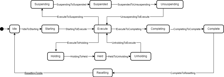
| Attribute | Value | ||||
| BrowseName | RunningStateMachineType | ||||
| IsAbstract | False | ||||
| References | Node Class | BrowseName | DataType | TypeDefinition | Other |
|---|---|---|---|---|---|
| Subtype of the FiniteStateMachineType defined in OPC 10000-5 | |||||
| 0:HasComponent | Object | Complete | StateType | ||
| 0:HasComponent | Object | CompleteToResetting | TransitionType | ||
| 0:HasComponent | Object | Completing | StateType | ||
| 0:HasComponent | Object | CompletingToComplete | TransitionType | ||
| 0:HasComponent | Object | Execute | StateType | ||
| 0:HasComponent | Object | ExecuteToCompleting | TransitionType | ||
| 0:HasComponent | Object | ExecuteToHolding | TransitionType | ||
| 0:HasComponent | Object | ExecuteToSuspending | TransitionType | ||
| 0:HasComponent | Object | Held | StateType | ||
| 0:HasComponent | Object | HeldToUnholding | TransitionType | ||
| 0:HasComponent | Method | Hold | O | ||
| 0:HasComponent | Object | Holding | StateType | ||
| 0:HasComponent | Object | HoldingToHeld | TransitionType | ||
| 0:HasComponent | Object | Idle | StateType | ||
| 0:HasComponent | Object | IdleToStarting | TransitionType | ||
| 0:HasComponent | Method | Reset | O | ||
| 0:HasComponent | Object | Resetting | StateType | ||
| 0:HasComponent | Object | ResettingToIdle | TransitionType | ||
| 0:HasComponent | Object | Starting | StateType | ||
| 0:HasComponent | Object | StartingToExecute | TransitionType | ||
| 0:HasComponent | Object | StartingToHolding | TransitionType | ||
| 0:HasComponent | Method | Suspend | O | ||
| 0:HasComponent | Object | Suspended | StateType | ||
| 0:HasComponent | Object | SuspendedToHolding | TransitionType | ||
| 0:HasComponent | Object | SuspendedToUnsuspending | TransitionType | ||
| 0:HasComponent | Object | Suspending | StateType | ||
| 0:HasComponent | Object | SuspendingToHolding | TransitionType | ||
| 0:HasComponent | Object | SuspendingToSuspended | TransitionType | ||
| 0:HasComponent | Method | ToComplete | O | ||
| 0:HasComponent | Method | Unhold | O | ||
| 0:HasComponent | Object | Unholding | StateType | ||
| 0:HasComponent | Object | UnholdingToExecute | TransitionType | ||
| 0:HasComponent | Object | UnholdingToHolding | TransitionType | ||
| 0:HasComponent | Method | Unsuspend | O | ||
| 0:HasComponent | Object | Unsuspending | StateType | ||
| 0:HasComponent | Object | UnsuspendingToExecute | TransitionType | ||
| 0:HasComponent | Object | UnsuspendingToHolding | TransitionType | ||
| Conformance Units | |||||
|---|---|---|---|---|---|
| LADS RunningStateMachineType | |||||
Complete: Complete indicates that the process associated with the active protocol has come to its defined end. The unit/device will wait in this state until a Reset command is issued (in which case it will transition to Resetting), or until the unit/device is Stopped or Aborted.
Completing: Once the process associated with the current mode has reached a defined threshold (e.g., the required number of samples for the current job have been analysed or the cultivation/fermentation process has reached is final stage in terms of cell count, product yield, cell viability, etc.), the unit/device transitions from Execute to Completing. All steps necessary to shut down the current process are carried out in this state. The unit/device then transitions automatically to the Complete state.
Execute: The unit/device is actively carrying out the behaviour or activity defined by the selected protocol and its associated processing mode. Examples of a unit/device in processing mode include when the unit/device is performing an analytical run, cultivation/fermentation in the case of a bioreactor, or another defined unit of operation provided by the instrument (e.g., separation in the case of a centrifuge).
Held: The unit/device is paused, waiting for internal process conditions to clear. In this state, the unit/device shall not continue processing, although it may dry cycle if required (e.g., maintaining process conditions critical for the preservation of the samples or culture). A transition to Unholding will occur once internal unit/device conditions have cleared, or if the Unhold command is initiated by an operator.
Holding: The unit/device will transition from Execute to Holding if conditions internal to the unit/device require a pause in processing. Examples of such conditions include low levels of materials required for processing (e.g., consumables, reagents, buffers, etc.) or other minor issues requiring operator service. After all steps required to hold the unit/device have been completed, the unit/device will transition automatically to the Held state.
Idle: The unit/device is in an error-free state, waiting to start. The unit/device transitions automatically to Idle after all steps necessary for Resetting have been completed. All conditions achieved during Resetting are maintained. A Start command will transition the unit/device from Idle to Starting.
Resetting: In response to a Reset command, the unit/device will transition to Resetting from either Stopped or Complete. In this state the unit/device attempts to clear any standing errors or stop causes. If successful, the unit/device transitions to Idle. No hazardous motion should occur while in this state.
Starting: The unit/device completes all steps necessary to begin execution of the active protocol. Typical steps during this state include but are not limited to inspecting system setup (checking sufficient supplies of resources and consumables), priming of fluids, homing of handling systems, or equilibration of process conditions. A Start command will cause the unit/device to transition from Idle to Starting. The unit/device will transition automatically from Starting to Execute once all required steps have been completed.
Suspended: The unit/device is paused, waiting for external process conditions to clear. In this state, the unit/device shall not continue processing, but may dry cycle if required (e.g., maintaining process conditions critical for the preservation of the samples or culture, including but not limited to temperature, oxygen or pH levels, etc.). Once external conditions have returned to normal, the unit/device will transition to Unsuspending, with or without operator intervention.
Suspending: The unit/device will transition from Execute to Suspending if conditions external to the unit/device require a pause in processing. Such conditions include faults to upstream or downstream equipment. The decision to Suspend may be made by a human operator supervising the process, an automated supervisory system monitoring the conditions of the overall process line/workflow, or by unit/device Sensors detecting downstream blockages or upstream scarcity of samples, etc. (In the former case, the unit/device is 'blocked"; in the latter case, the unit/device is "starved".) After all steps required to suspend the unit/device have been completed, the unit/device will automatically transition to the Suspended state.
Unholding: After all internal process conditions that caused the unit/device to hold have cleared, the unit/device completes all steps required to resume execution of the active protocol. Once all required actions to unhold the unit/device have been completed, the unit/device will transition automatically to the Execute state.
Unsuspending: After all external process conditions that caused the unit/device to suspend have cleared, the unit/device completes all steps required to resume execution of the active protocol.
The children of the RunningStateMachineType have additional References, which are defined in Table 33.
| SourceBrowsePath | Reference Type | Is Forward | TargetBrowsePath |
| IdleToStarting | 0:FromState | True | Idle |
| 0:ToState | True | Starting | |
| 0:HasEffect | True | TransitionEventType | |
| StartingToExecute | 0:FromState | True | Starting |
| 0:ToState | True | Execute | |
| 0:HasEffect | True | TransitionEventType | |
| ExecuteToCompleting | 0:FromState | True | Execute |
| 0:ToState | True | Completing | |
| 0:HasCause | True | ToComplete | |
| 0:HasEffect | True | TransitionEventType | |
| CompletingToComplete | 0:FromState | True | Completing |
| 0:ToState | True | Complete | |
| 0:HasEffect | True | TransitionEventType | |
| CompleteToResetting | 0:FromState | True | Complete |
| 0:ToState | True | Resetting | |
| 0:HasCause | True | Reset | |
| 0:HasEffect | True | TransitionEventType | |
| ResettingToIdle | 0:FromState | True | Resetting |
| 0:ToState | True | Idle | |
| 0:HasEffect | True | TransitionEventType | |
| ExecuteToSuspending | 0:FromState | True | Execute |
| 0:ToState | True | Suspending | |
| 0:HasCause | True | Suspend | |
| 0:HasEffect | True | TransitionEventType | |
| SuspendingToSuspended | 0:FromState | True | Suspending |
| 0:ToState | True | Suspended | |
| 0:HasEffect | True | TransitionEventType | |
| UnsuspendingToExecute | 0:FromState | True | Unsuspending |
| 0:ToState | True | Execute | |
| 0:HasEffect | True | TransitionEventType | |
| ExecuteToHolding | 0:FromState | True | Execute |
| 0:ToState | True | Holding | |
| 0:HasCause | True | Hold | |
| 0:HasEffect | True | TransitionEventType | |
| HoldingToHeld | 0:FromState | True | Holding |
| 0:ToState | True | Held | |
| 0:HasEffect | True | TransitionEventType | |
| HeldToUnholding | 0:FromState | True | Held |
| 0:ToState | True | Unholding | |
| 0:HasCause | True | Unhold | |
| 0:HasEffect | True | TransitionEventType | |
| UnholdingToExecute | 0:FromState | True | Unholding |
| 0:ToState | True | Execute | |
| 0:HasEffect | True | TransitionEventType |
| SourceBrowsePath | Reference Type | Is Forward | TargetBrowsePath |
| SuspendingToHolding | 0:FromState | True | Suspending |
| 0:ToState | True | Holding | |
| 0:HasCause | True | Hold | |
| 0:HasEffect | True | TransitionEventType | |
| StartingToHolding | 0:FromState | True | Starting |
| 0:ToState | True | Holding | |
| 0:HasCause | True | Hold | |
| 0:HasEffect | True | TransitionEventType | |
| SuspendedToHolding | 0:FromState | True | Suspended |
| 0:ToState | True | Holding | |
| 0:HasCause | True | Hold | |
| 0:HasEffect | True | TransitionEventType | |
| UnsuspendingToHolding | 0:FromState | True | Unsuspending |
| 0:ToState | True | Holding | |
| 0:HasCause | True | Hold | |
| 0:HasEffect | True | TransitionEventType | |
| UnholdingToHolding | 0:FromState | True | Unholding |
| 0:ToState | True | Holding | |
| 0:HasCause | True | Hold | |
| 0:HasEffect | True | TransitionEventType |
The Component Variables of the RunningStateMachineType have additional Attributes, as defined in Table 34.
| BrowsePath | Value Attribute | ||
| 1 | ||
| 2 | ||
| 3 | ||
| 4 | ||
| 5 | ||
| 6 | ||
| 7 | ||
| 8 | ||
| 9 | ||
| 10 | ||
| 11 | ||
| 12 | ||
| 1 | ||
| 2 | ||
| 5 | ||
| 6 | ||
| 7 | ||
| 8 | ||
| 9 | ||
| 10 | ||
| 11 | ||
| 12 |
| BrowsePath | Value Attribute | ||
| 13 | ||
| 14 | ||
| 15 | ||
| 16 | ||
| 17 | ||
| 18 | ||
| 19 |
7.1.6.2 Hold
The Hold Method allows an OPC UA Client to change the state of this state machine to Holding. The signature of this Method is specified below. Table 35 specifies its representation in the AddressSpace.
Signature
Hold ()| Attribute | Value | ||||
| BrowseName | Hold | ||||
| References | Node Class | BrowseName | DataType | TypeDefinition | ModellingRule |
|---|---|---|---|---|---|
7.1.6.3 Reset
The Reset Method allows an OPC UA Client to change the state of this state machine to Resetting. The signature of this Method is specified below. Table 36 specifies its representation in the AddressSpace.
Signature
Reset ()| Attribute | Value | ||||
| BrowseName | Reset | ||||
| References | Node Class | BrowseName | DataType | TypeDefinition | ModellingRule |
|---|---|---|---|---|---|
7.1.6.4 Suspend
The Suspend Method allows an OPC UA Client to change the state of this state machine to the Suspending state. The signature of this Method is specified below. Table 37 specifies its representation in the AddressSpace.
Signature
Suspend ()| Attribute | Value | ||||
| BrowseName | Suspend | ||||
| References | Node Class | BrowseName | DataType | TypeDefinition | ModellingRule |
|---|
7.1.6.5 ToComplete
The ToComplete Method allows an OPC UA Client to change the state of this state machine to Completed. The signature of this Method is specified below. Table 38 specifies its representation in the AddressSpace.
Signature
ToComplete ()| Attribute | Value | ||||
| BrowseName | ToComplete | ||||
| References | Node Class | BrowseName | DataType | TypeDefinition | ModellingRule |
|---|---|---|---|---|---|
7.1.6.6 Unhold
The Unhold Method allows an OPC UA Client to change the state of this state machine to Unholding. The signature of this Method is specified below. Table 39 specifies its representation in the AddressSpace.
Signature
Unhold ()| Attribute | Value | ||||
| BrowseName | Unhold | ||||
| References | Node Class | BrowseName | DataType | TypeDefinition | ModellingRule |
|---|---|---|---|---|---|
7.1.6.7 Unsuspend
The Unsuspend Method allows an OPC UA Client to change the state of this state machine to Unsuspending. The signature of this Method is specified below. Table 40 specifies its representation in the AddressSpace.
Signature
Unsuspend ()| Attribute | Value | ||||
| BrowseName | Unsuspend | ||||
| References | Node Class | BrowseName | DataType | TypeDefinition | ModellingRule |
|---|---|---|---|---|---|
7.1.7 FunctionalUnitStateMachineType Definition
7.1.7.1 Overview
The FunctionalUnitStateMachineType represents the state of a FunctionalUnit in a LADS Device. It uses the same StateTypes and TransitionTypes as its parent but specifies the additional Start Method to trigger state changes.
The FunctionalUnitStateMachineType is formally defined in Table 41.
| Attribute | Value | ||||
| BrowseName | FunctionalUnitStateMachineType | ||||
| IsAbstract | False | ||||
| References | Node Class | BrowseName | DataType | TypeDefinition | Other |
|---|---|---|---|---|---|
| Subtype of the FunctionalStateMachineType defined in 7.1.5 | |||||
| 0:HasComponent | Method | Start | O | ||
| 0:HasComponent | Method | StartProgram | O | ||
| Conformance Units | |||||
|---|---|---|---|---|---|
| LADS FunctionalUnitStateMachineType | |||||
Start is used to start a FunctionalUnit with properties.
StartProgram is used to start a FunctionalUnit with a Program Template.
7.1.7.2 Start
The Start Method is used when a Client application wants to initiate/execute an/the operation of a FunctionalUnit. The Properties Argument can be used to provide an optional list of property values when initiating the operation. The listed items represent key-value pairs that conform to the OPC UA KeyValuePair core datatype. The qualified name provided via the key field must match the BrowseName of a Property member in the FunctionalUnit's SupportedPropertySet.
The signature of this Method is specified below. Table 42 and Table 43 specify the Arguments and AddressSpace representation, respectively.
The Start Method should not be called by a Client with anonymous authentication.
Signature
	Start (
[in] KeyValuePair[] Properties)| Argument | Description |
| Properties | A set of Properties that parameterize the execution of the Functional Unit. |
| Attribute | Value | ||||
| BrowseName | Start | ||||
| References | Node Class | BrowseName | DataType | TypeDefinition | ModellingRule |
|---|---|---|---|---|---|
| 0:HasProperty | Variable | 0:InputArguments | Argument[1] | 0:PropertyType | M |
7.1.7.3 StartProgram
The StartProgram Method is used when a Client application wants to start running a program based on a ProgramTemplate of a FunctionalUnit. The Properties Argument can be used to provide an optional list of property values when initiating a program run. The listed items represent key-value pairs that conform to the OPC UA KeyValuePair core datatype. The qualified name provided via the key field must match the BrowseName of a Property member in the FunctionalUnit's SupportedPropertySet.
In contrast to the Start Method, additional fixed properties must also be set.
The signature of this Method is specified below. Table 44 and Table 45 specify the Arguments and AddressSpace representation, respectively.
The Start Method should not be called by a Client with anonymous authentication.
Signature
	StartProgram (
		[in]	0:String	ProgramTemplateId
		[in]	KeyValueType[]	Properties
		[in]	0:String	SupervisoryJobId
		[in]	0:String	SupervisoryTaskId
		[in]	SampleInfoType[]	Samples
[out] 0:String DeviceProgramRunId)| Argument | Description |
| ProgramTemplateId | The unique identifier of the program template used for the program-run. The template must be a member of the ProgramTemplateSet. |
| Properties | A Key/Value set for parameterization of the function. |
| SupervisoryJobId | The SupervisoryJobId assigned to this program. |
| SupervisoryTaskId | The Id of the SupervisoryTask. |
| Samples | An array of the SampleInfoType that describes the samples processed in this program-run. |
| DeviceProgramRunId | The Id of the created program run. |
| Attribute | Value | ||||
| BrowseName | StartProgram | ||||
| References | Node Class | BrowseName | DataType | TypeDefinition | ModellingRule |
|---|---|---|---|---|---|
| 0:HasProperty | Variable | 0:InputArguments | Argument[5] | 0:PropertyType | M |
| 0:HasProperty | Variable | 0:OutputArguments | Argument[1] | 0:PropertyType | M |
DeviceProgramRunId is the internal program identifier assigned by the Device to the program run to generate this result. It is used to identify a Result object and is returned to the Client when the StartProgram Method is called.
SupervisoryJobId is the identifier for the execution of a specific workflow, consisting of one or multiple tasks. It is provided as an Argument of the StartProgram() Method which initiates the program run.
SupervisoryTaskId is the unique identifier of the specific task in the supervisory system to which the result belongs. It is provided as an Argument of the StartProgram() Method which initiates the program run.
7.1.8 LADSComponentsType ObjectType Definition
The LADSComponentsType is used for organising LADSComponentsType objects in an unordered list structure. It is formally defined in Table 46.
| Attribute | Value | ||||
| BrowseName | LADSComponentsType | ||||
| IsAbstract | False | ||||
| References | Node Class | BrowseName | DataType | TypeDefinition | Other |
|---|---|---|---|---|---|
| Subtype of the MachineComponentsType defined in OPC 40001-1 | |||||
| 0:HasComponent | Object | <Component> | LADSComponentType | OP | |
| GeneratesEvent | ObjectType | GeneralModelChangeEventType | |||
| 0:HasProperty | Variable | NodeVersion | 0:String | 0:PropertyType | O |
| Conformance Units | |||||
|---|---|---|---|---|---|
| LADS LADSComponentsType | |||||
<Components> is a placeholder for the Components.
7.1.9 LADSOperationModeStateMachineType ObjectType Definition
The LADSOperationModeStateMachineType is a subtype of 4:MachineryOperationModeStateMachineType that adds optional Methods to the statemachine. It is formally defined in Table 46.
| Attribute | Value | ||||
| BrowseName | LADSOperationModeStateMachineType | ||||
| IsAbstract | False | ||||
| References | Node Class | BrowseName | DataType | TypeDefinition | Other |
|---|---|---|---|---|---|
| Subtype of the 4:MachineryOperationModeStateMachineType | |||||
| 0:HasComponent | Method | GotoMaintenance | O | ||
| 0:HasComponent | Method | GotoProcessing | O | ||
| 0:HasComponent | Method | GotoSetup | O | ||
| Conformance Units | |||||
|---|---|---|---|---|---|
| LADS LADSOperationModeStatemachineType | |||||
7.1.9.1 GotoMaintenance
The GotoMaintenance Method brings the LADSDevice in the Maintenance state.
The signature of this Method is specified below. Table 52 specifies its representation in the AddressSpace.
Signature
GotoMaintenance ()| Attribute | Value | ||||
| BrowseName | GotoMaintenance | ||||
| References | Node Class | BrowseName | DataType | TypeDefinition | ModellingRule |
|---|
7.1.9.2 GotoProcessing
The GotoMaintenance Method brings the LADSDevice in the Processing state.
The signature of this Method is specified below. Table 52 specifies its representation in the AddressSpace.
Signature
GotoProcessing ()| Attribute | Value | ||||
| BrowseName | GotoProcessing | ||||
| References | Node Class | BrowseName | DataType | TypeDefinition | ModellingRule |
|---|
7.1.9.3 GotoSetup
The GotoSetup Method brings the LADSDevice in the Setup state.
The signature of this Method is specified below. Table 52 specifies its representation in the AddressSpace.
Signature
GotoSetup ()| Attribute | Value | ||||
| BrowseName | GotoSetup | ||||
| References | Node Class | BrowseName | DataType | TypeDefinition | ModellingRule |
|---|
7.1.10 MaintenanceTaskType Definition
7.1.10.1 Overview
The MaintenanceTaskType shall be used to implement instances of maintenance tasks applicable at both the Device and Component levels. Maintenance tasks include activities such as periodic maintenance, cleaning, calibration, and validation.
Maintenance tasks for a Device shall be grouped under the Maintenance functional group present in the LADSDeviceType.
The MaintenanceTaskType is formally defined in Table 51.
| Attribute | Value | ||||
| BrowseName | MaintenanceTaskType | ||||
| IsAbstract | False | ||||
| References | Node Class | BrowseName | DataType | TypeDefinition | Other |
|---|---|---|---|---|---|
| Subtype of the MaintenanceRequiredAlarmType defined in OPC 10000-100 | |||||
| 0:HasProperty | Variable | LastExecutionDate | 0:UtcTime | 0:PropertyType | O |
| 0:HasProperty | Variable | LastOperatingCycles | 0:UInt32 | 0:PropertyType | O |
| 0:HasProperty | Variable | LastOperatingTime | 0:Duration | 0:PropertyType | O |
| 0:HasProperty | Variable | NextOperatingCycles | 0:UInt32 | 0:PropertyType | O |
| 0:HasProperty | Variable | NextOperatingTime | 0:Duration | 0:PropertyType | O |
| 0:HasProperty | Variable | RecurrencePeriod | 0:Duration | 0:PropertyType | O |
| 0:HasComponent | Method | ResetTask | O | ||
| 0:HasComponent | Method | StartTask | O | ||
| 0:HasComponent | Method | StopTask | O | ||
| 0:HasInterface | ObjectType | IMaintenanceEventType | Defined in OPC 10000-110 Section 12.2 | ||
| Applied from IMaintenanceEventType | |||||
| 0:HasProperty | Variable | 3:ConfigurationChanged | 0:Boolean | 0:PropertyType | O |
| 0:HasProperty | Variable | 3:EstimatedDowntime | 0:Duration | 0:PropertyType | O |
| 0:HasProperty | Variable | 3:MaintenanceMethod | 3:MaintenanceMethodEnum | 0:PropertyType | O |
| 0:HasComponent | Object | 3:MaintenanceState | 3:MaintenanceEventStateMachineType | M | |
| 0:HasProperty | Variable | 3:MaintenanceSupplier | 3:NameNodeIdDataType | 0:PropertyType | O |
| 0:HasProperty | Variable | 3:PartsOfAssetReplaced | 3:NameNodeIdDataType[] | 0:PropertyType | O |
| 0:HasProperty | Variable | 3:PartsOfAssetServiced | 3:NameNodeIdDataType[] | 0:PropertyType | O |
| 0:HasProperty | Variable | 3:PlannedDate | 0:UtcTime | 0:PropertyType | O |
| 0:HasProperty | Variable | 3:QualificationOfPersonnel | 3:NameNodeIdDataType | 0:PropertyType | O |
| Conformance Units | |||||
|---|---|---|---|---|---|
| LADS MaintenanceTaskType | |||||
LastExecutionDate is the date when the Task was last performed. Optional, as the Task may have never run before.
LastOperatingCycles is the number of cycles during the operating time (as defined in Section 9.3 of EN 13306-2017) recorded at the time of the last execution of the Task.
LastOperatingTime is the total amount of operating time (as defined in Section 9.3 of EN 13306-2017) in milliseconds (ms) by the Device at the time of the last execution of the Task.
NextOperatingCycles is the number of cycles during operating time (as defined in Section 9.3 of EN 13306-2017) to be completed before the next execution of the Task.
NextOperatingTime is the total amount of operating time (as defined in Section 9.3 of EN 13306-2017) in milliseconds (ms) by the Device before the next execution of the Task.
RecurrencePeriod is the period of repetition of the Task, specified in milliseconds. Optional, as not all Tasks have a recurrence period.
ResetTask Method resets the condition of the Task so that it is ready to be re-run.
Start Method starts the execution of the Task.
Stop Method stops the execution of the Task.
7.1.10.2 ResetTask
The ResetTask Method resets the execution of the Task so that it is ready to be re-run.
Optional, as instruments may not support resetting a maintenance task via a method call. The same effect can be achieved by means of a device-specific control.
Upon successful execution of the ResetTask Method, the MaintenanceState shall be changed to Planned and an accompanying event shall be raised. Also, the ActiveState and AckState properties are set to "False".
The signature of this Method is specified below. Table 52 specifies its representation in the AddressSpace.
Signature
ResetTask ()| Attribute | Value | ||||
| BrowseName | Reset | ||||
| References | Node Class | BrowseName | DataType | TypeDefinition | ModellingRule |
|---|
7.1.10.3 StartTask
The Start Method starts the execution of the Task.
Optional, as instruments may not support starting a maintenance task via a method call. The same effect can be achieved by means of a device-specific control.
Upon successful execution of the Start Method, the MaintenanceState shall be changed to Executing and an accompanying event shall be raised.
The signature of this Method is specified below. Table 53 specifies its representation in the AddressSpace.
Signature
StartTask ()| Attribute | Value | ||||
| BrowseName | StartTask | ||||
| References | Node Class | BrowseName | DataType | TypeDefinition | ModellingRule |
|---|
7.1.10.4 StopTask
The StopTask Method stops of the execution of the task.
Optional, as instruments may not support aborting the task via a method call. The same effect can be achieved by means of a device-specific control.
It includes 2 optional input parameters: MaintenanceTaskStopResult and Comment to document the outcome of the maintenance task.
Upon successful execution of the Stop Method, the MaintenanceState shall be changed to Finished and an accompanying event shall be raised. Also, the ActiveState and AckState properties are set to "False".
The signature of this Method is specified below. Table 54 and Table 55 specify the Arguments and AddressSpace representation, respectively.
Signature
	StopTask (
		[in]	MaintenanceTaskResultEnum	MaintenanceTaskStopResult,
[in] LocalizedText Comment)| Argument | Description |
| MaintenanceTaskStopResult | Give the reason why the task is stopped. |
| Comment | Add an additional comment to describe the call |
| Attribute | Value | ||||
| BrowseName | StopTask | ||||
| References | Node Class | BrowseName | DataType | TypeDefinition | ModellingRule |
|---|---|---|---|---|---|
| 0:HasProperty | Variable | 0:InputArguments | 0:Argument[] | 0:PropertyType | 0:Mandatory |
7.2 Program management
7.2.1 ProgramManagerType ObjectType Definition
7.2.1.1 Overview
The ProgramManagerType provides the FunctionalUnit's program manager. It is formally defined in Table 56.
| Attribute | Value | ||||
| BrowseName | ProgramManagerType | ||||
| IsAbstract | False | ||||
| References | Node Class | BrowseName | DataType | TypeDefinition | Other |
|---|---|---|---|---|---|
| Subtype of the TopologyElementType Type defined in OPC 10000-100 | |||||
| 0:HasComponent | Object | ActiveProgram | ActiveProgramType | M | |
| 0:HasComponent | Object | ProgramTemplateSet | ProgramTemplateSetType | M | |
| 0:HasComponent | Object | ResultSet | ResultSetType | M | |
| 0:HasComponent | Method | Download | O | ||
| 0:HasComponent | Method | Remove | O | ||
| 0:HasComponent | Method | Upload | O | ||
| Conformance Units | |||||
|---|---|---|---|---|---|
| LADS ProgramManagerType | |||||
ActiveProgram represents the ongoing operational state of a FunctionalUnit on a Device, providing user-friendly, sequential insight into the progress and context of the currently running program.
ProgramTemplateSet holds the template set associated with the ProgramManager.
ResultSet contains the results of program runs. It includes information about where and by whom the run was initiated, the template used along with any additional parameters, the samples included, contextual information to link the results with the associated samples, and where the results are provided.
7.2.1.2 Download
The Download Method is used to transfer a Program Template from the Server to the Client. The signature for this Method is specified below. Table 58 specifies its representation in the AddressSpace.
Signature
	Download (
		[in]	String	TemplateId
		[out]	KeyValueType[]	AdditionalParameters
		[out]	ByteString	Data
	)
| Argument | Description |
| TemplateId | Unique identifier of the template to be downloaded. |
| AdditionalParameters | Additional properties of the program template. |
| Data | Opaque program template data. |
| Attribute | Value | ||||
| BrowseName | Download | ||||
| References | Node Class | BrowseName | DataType | TypeDefinition | ModellingRule |
|---|---|---|---|---|---|
| HasProperty | Variable | 0:InputArguments | 0:Argument[] | 0:PropertyType | M |
| HasProperty | Variable | 0:OutputArguments | 0:Argument[] | 0:PropertyType | M |
7.2.1.3 Remove
The Remove Method deletes the Program Template from the Server. Table 60 specifies its representation in the AddressSpace.
Signature
	Remove (
		[in]	String	TemplateId
	)
| Argument | Description |
| TemplateId | Unique identifier of the template to be removed. |
| Attribute | Value | ||||
| BrowseName | Remove | ||||
| References | Node Class | BrowseName | DataType | TypeDefinition | ModellingRule |
|---|---|---|---|---|---|
| HasProperty | Variable | 0:InputArguments | 0:Argument[] | 0:PropertyType | M |
7.2.1.4 Upload
The Upload Method is used to transfer a Program Template from a Client to the Server. An instance of the ProgramTemplateType (see 7.2.5) needs to be created in the ProgramTemplateSet for each uploaded Program Template.
The properties of a Program Template and the information included are vendor specific. Considering the multiple different formats and ways of defining Program Templates in the laboratory and analytical domain, LADS handles the inner structure of the Program Template itself as a black box.
The properties of the instance of a ProgramTemplateType should be set via an Upload method call based on the Data and AdditionalParameter inputs.
Table 62 specifies its representation in the AddressSpace.
Signature
	Upload
	(
		[in]	KeyValueType[]	AdditionalParameters
		[in]	ByteString	Data
		[out]	String	TemplateId
	)
| Argument | Description |
| AdditionalParameters | Additional properties of the program template. |
| Data | Opaque program template data. |
| TemplateId | The unique identifier of the template which might be generated by the device/functional-unit itself or might be provided as element of the opaque input data.. |
| Attribute | Value | ||||
| BrowseName | Upload | ||||
| References | Node Class | BrowseName | DataType | TypeDefinition | ModellingRule |
|---|---|---|---|---|---|
| 0:HasProperty | Variable | 0:InputArguments | 0:Argument[] | 0:PropertyType | M |
| 0:HasProperty | Variable | 0:OutputArguments | 0:Argument[] | 0:PropertyType | M |
7.2.2 ResultType ObjectType Definition
The ResultType provides the results of a specific program run. It is formally defined in Table 63.
| Attribute | Value | ||||
| BrowseName | ResultType | ||||
| IsAbstract | False | ||||
| References | Node Class | BrowseName | DataType | TypeDefinition | Other |
|---|---|---|---|---|---|
| Subtype of 0:BaseObjectType defined in OPC 10000-5 | |||||
| 0:HasProperty | Variable | ApplicationUri | 0:String | 0:PropertyType | M |
| 0:HasProperty | Variable | Description | 0:LocalizedText | 0:PropertyType | M |
| 0:HasProperty | Variable | DeviceProgramRunId | 0:String | 0:PropertyType | O |
| 0:HasProperty | Variable | EstimatedRuntime | 0:Duration | 0:PropertyType | O |
| 0:HasComponent | Object | FileSet | ResultFileSetType | M | |
| 0:HasProperty | Variable | SupervisoryJobId | 0:String | 0:PropertyType | M |
| 0:HasComponent | Object | ProgramTemplate | ProgramTemplateType | M | |
| 0:HasProperty | Variable | Properties | KeyValueType[] | 0:PropertyType | M |
| 0:HasProperty | Variable | Samples | SampleInfoType[] | 0:PropertyType | M |
| 0:HasProperty | Variable | Started | 0:DateTime | 0:PropertyType | M |
| 0:HasProperty | Variable | Stopped | 0:DateTime | 0:PropertyType | M |
| 0:HasProperty | Variable | SupervisoryTaskId | 0:String | 0:PropertyType | M |
| 0:HasProperty | Variable | TotalPauseTime | 0:Duration | 0:PropertyType | O |
| 0:HasProperty | Variable | TotalRuntime | 0:Duration | 0:PropertyType | O |
| 0:HasProperty | Variable | User | 0:String | 0:PropertyType | M |
| 0:HasComponent | Object | VariableSet | VariableSetType | M | |
| 0:HasProperty | Variable | Samples | SampleInfoType[] | 0:PropertyType | M |
| Conformance Units | |||||
|---|---|---|---|---|---|
| LADS ResultType | |||||
ApplicationUri provides information about the remote client that initiated the program run generating the result. It must align with the ApplicationUri in the ApplicationDescription (refer to OPC 10000-4 section 7.1) of a Session (refer to OPC 10000-4 section 5.6.2). In instances where the program was initiated locally and cannot be attributed to an OPC UA Client, the ApplicationUri of the Server should be utilized.
User provides information about the remote client user that initiated the program run generating the result. User must be a human-readable value, based on the UserIdentityToken (refer to OPC 10000-4 section 7.36). In instances where the program was initiated locally and cannot be attributed to an OPC UA Client, the local user of the Server should be utilized.
Recommendations for creating the User parameter are as follows:
• AnonymousIdentityToken: This should not be utilized.
• UserNameIdentityToken: The UserName field should be utilized.
• X509IdentityToken: The Common Name of the certificate should be utilized.
• IssuedIdentityToken (JWT): The Name field of the access Token Claim should be utilized (refer to 10000-6 section 6.5.3.2).
Description is the human-readable description of the specific program run that created this result and the result itself.
DeviceProgramRunId is the internal program identifier assigned by the Device to the program run generating this result. It is used to identify a Result object and is returned to the Client when the StartProgram Method is called.
SupervisoryJobId is the identifier for the execution of a specific workflow consisting of one or multiple steps. It is provided as an Argument of the StartProgram() Method which initiates the program run.
SupervisoryTaskId is the unique identifier of the specific Task in the supervisory system to which the result belongs. It is provided as an Argument of the StartProgram() Method which initiates the program run.
ProgramTemplate is an immutable copy of the Program Template attributes with which the result was generated and is provided for documentation and traceability purposes. This copy will not change even if the original is changed.
Properties is a list of key-value pairs with KeyValueType which is provided when calling the StartProgram() Method. It can be utilized when performing the program run and is provided in the ResultType object for documentation and traceability purposes.
Samples is a list of sample-specific information with SampleInfoType which is provided when calling the StartProgram() Method. It can be utilized when performing the program run and is provided in the ResultType object for documentation and traceability purposes.
Started is the timestamp of when the program was started.
Stopped is the timestamp of when the program was stopped.
EstimatedRuntime is the time that was estimated for the program execution.
TotalRuntime is the total time of program execution, including paused states. The paused states are Held and Suspended.
TotalPauseTime is the time the program execution for the result was in a paused state. The paused states are Held and Suspended.
The EstimatedRuntime, TotalRuntime and TotalPauseTime information is retrieved from the last value of the ActiveProgram properties.
FileSet is a list of represented files of ResultFileType objects which were generated during the run. The format of the individual files is represented via an associated MIME type attribute.
VariableSet contains additional vendor-specific sample data that was created during a run. The value of the variables in the set or in a nested structure in the set are immutable. Thus, the value attribute is not allowed to change from the Client or Server side after the creation of a Node.
7.2.3 ResultFileType ObjectType Definition
The ResultFileType provides a description of a file that is part of a result of a program manager run. It is formally defined in Table 64.
| Attribute | Value | ||||
| BrowseName | ResultFileType | ||||
| IsAbstract | False | ||||
| References | Node Class | BrowseName | DataType | TypeDefinition | Other |
|---|---|---|---|---|---|
| Subtype of 0:BaseObjectType defined in OPC 10000-5 | |||||
| 0:HasComponent | Object | File | FileType | O | |
| 0:HasProperty | Variable | MimeType | 0:String | 0:PropertyType | M |
| 0:HasProperty | Variable | Name | 0:String | 0:PropertyType | M |
| 0:HasProperty | Variable | URL | 0:String | 0:PropertyType | O |
| Conformance Units | |||||
|---|---|---|---|---|---|
| LADS ResultFileType | |||||
File is the OPC UA Node of the file with the method for downloading the file.
MimeType is the MIME type of the file.
Name is the name that describes the file. The name may be different from the filename on the filesystem.
URL is a URL from which the file can be downloaded.
7.2.4 ActiveProgramType ObjectType Definition
The ActiveProgramType specifies the current state of operation of a FunctionalUnit. It provides context and information about the currently active program on the Device. This allows users to follow the progress of a program run in a standardized fashion by organising steps into a flat, linear sequence. It is formally defined in Table 65.
| Attribute | Value | ||||
| BrowseName | ActiveProgramType | ||||
| IsAbstract | False | ||||
| References | Node Class | BrowseName | DataType | TypeDefinition | Other |
|---|---|---|---|---|---|
| Subtype of 0:BaseObjectType defined in OPC 10000-5 | |||||
| 0:HasProperty | Variable | CurrentPauseTime | Duration | 0:PropertyType | O |
| 0:HasProperty | Variable | CurrentRuntime | Duration | 0:PropertyType | O |
| 0:HasProperty | Variable | CurrentStepName | LocalizedText | 0:PropertyType | O |
| 0:HasProperty | Variable | CurrentStepNumber | UInt32 | 0:PropertyType | O |
| 0:HasProperty | Variable | CurrentStepRuntime | Duration | 0:PropertyType | O |
| 0:HasProperty | Variable | EstimatedRuntime | Duration | 0:PropertyType | O |
| 0:HasProperty | Variable | EstimatedStepNumbers | UInt32 | 0:PropertyType | O |
| 0:HasProperty | Variable | EstimatedStepRuntime | Duration | 0:PropertyType | O |
| 0:HasProperty | Variable | DeviceProgramRunId | String | 0:PropertyType | O |
| 0:HasProperty | Variable | CurrentProgramTemplate | 3:NameNodeIdDataType | 0:PropertyType | O |
| Conformance Units | |||||
|---|---|---|---|---|---|
| LADS ActiveProgramType | |||||
The status of all properties must be communicated through various StatusCodes, depending on the situation:
• For a device that has not had a prior run and therefore cannot estimate the runtime, the StatusCode should be BadWaitingForInitialData. This indicates that the system is waiting for initial data to compute the estimated runtime.
• If the runtime cannot be estimated due to process-related reasons or incompatibility, the StatusCode should be BadNoData. This communicates that no data is available to estimate the runtime.
• If the runtime can be computed and the program is currently running or paused, the StatusCode should be Good. This indicates that the estimated runtime is available and the program is in progress.
• If the runtime can be computed after the program run but the value might not be the most current, the StatusCode should be UncertainLastUsableValue. This communicates that the last known value is being used for the estimated runtime, but it may not be the most up to date.
Additional StatusCodes are allowed depending on the specific situation (e.g., technical problems).
CurrentPauseTime is the current pause-time of the program run. The CurrentPauseTime is set to 0 at the start of the program and is counted upwards when the program run is in a paused state. The paused state is an aggregation of the Suspended and Held states.
CurrentRuntime is the current runtime of the program run. The CurrentRuntime is set to 0 at the start of the program and is counted upwards, as long as the program run is not in a paused state. The paused state is an aggregation of the Suspended and Held states.
CurrentStepName is the name of the current step.
CurrentStepNumber is the number/index of the current step (incremented whenever the next step is entered).
CurrentStepRuntime is the runtime of the current step. The CurrentStepRuntime is set to 0 at the start of the current step and is counted upwards, as long as the program run is not in paused state. The paused state is an aggregation of the Suspended and Held states.
EstimatedRuntime is the estimated runtime of the current program run.
EstimatedStepNumbers is the estimated total number of steps of the current program run.
EstimatedStepRuntime is the estimated runtime of the current program step.
CurrentProgramTemplate provides the template-id as well as the node-id of the currently executed program.
DeviceProgramRunId represents a device-specific unique internal identifier for this program run. Its value shall be identical to the return value of the last call to the FunctionalUnit's StartProgram() Method. It is used to identify the result object corresponding to this program run within the FunctionalUnit's result set.
7.2.5 ProgramTemplateType ObjectType Definition
The ProgramTemplateType provides a Program Template. It is formally defined in Table 66.
A Program Template is stored within the ProgramTemplateSet of a ProgramManager and can be selected to be executed as the ActiveProgram for the FunctionalUnit. Alternative common names for a Program Template are protocol, program, or recipe.
Clients (e.g., supervisory system clients, such as ELN or LIMS) can utilize the ProgramTemplateSet and Program Template objects to:
List all templates available on a FunctionalUnit,
Select a template for execution as the ActiveProgram.
The Download Method (see 7.2.1.2) and Upload Method (see 7.2.1.4) functions of the ProgramManagerType can be used to download and upload Program Templates.
Considering the multiple different formats and ways of defining Program Templates in the laboratory and analytical domain, LADS handles the Program Template itself as a black box.
The information contained is read-only and the properties are set based on information included in the Program Template itself. This is beyond the scope of the LADS specification. Thus, only generic information about the context and purpose of the Program Template is provided here.
| Attribute | Value | ||||
| BrowseName | ProgramTemplateType | ||||
| IsAbstract | False | ||||
| References | Node Class | BrowseName | DataType | TypeDefinition | Other |
|---|---|---|---|---|---|
| Subtype of the BaseObjectType defined in OPC 10000-5 | |||||
| 0:HasProperty | Variable | Author | String | 0:PropertyType | M |
| 0:HasProperty | Variable | Created | DateTime | 0:PropertyType | M |
| 0:HasProperty | Variable | Description | LocalizedText | 0:PropertyType | M |
| 0:HasProperty | Variable | Modified | DateTime | 0:PropertyType | M |
| 0:HasProperty | Variable | DeviceTemplateId | 0:String | 0:PropertyType | M |
| 0:HasProperty | Variable | SupervisoryTemplateId | 0:String | 0:PropertyType | O |
| 0:HasProperty | Variable | Version | 0:String | 0:PropertyType | M |
| Conformance Units | |||||
|---|---|---|---|---|---|
| LADS ProgramTemplateType | |||||
Author is the user who created the template.
Created is the time of the template's creation.
Description is a human-readable description of the template.
Modified is the time of last modification.
DeviceTemplateId is the program template's identifier unique within the scope of the device.
SupervisoryTemplateId is an optional enterprise-wide unique identifier for the template. This can be utilized to refer the template to supervisory systems.
Version is the version of the template (the format is at the user's discretion).
7.2.6 SupportedPropertyType Definition
The SupportedPropertyType provides argument names and links to variables within the information model, typically target values or parameters of Functions. This makes it possible to specify a list of KeyValueTypess as an input object. It is formally defined in Table 67.
The SupportedPropertyType is used in the SupportedPropertiesSet of the FunctionalUnit. The name of each Argument object is used as a key in the KeyValueType list input Argument of the Start()/StartFunctions() Method. Each Argument object should contain an Organizes Reference to the target variable to which it belongs. Thus, the metadata of the target variable can be introspected online. The name of the SupportedProperty object is typically an argument name for a variable in the Device.
| Attribute | Value | ||||
| BrowseName | SupportedPropertyType | ||||
| IsAbstract | False | ||||
| References | Node Class | BrowseName | DataType | TypeDefinition | Other |
|---|---|---|---|---|---|
| Subtype of the BaseObjectType defined in OPC 10000-5 | |||||
| Conformance Units | |||||
|---|---|---|---|---|---|
| LADS SupportedPropertyType | |||||
7.3 SetTypes
7.3.1 SetType ObjectType Definition
The SetType provides an unordered set of objects. It is formally defined in Table 68.
| Attribute | Value | ||||
| BrowseName | SetType | ||||
| IsAbstract | True | ||||
| References | Node Class | BrowseName | DataType | TypeDefinition | Other |
|---|---|---|---|---|---|
| Subtype of the FolderType defined in OPC 10000-5 | |||||
| 0:HasProperty | Variable | NodeVersion | 0:String | 0:PropertyType | O |
| 0:HasComponent | Object | <SetElement> | BaseObjectType | OP | |
| 0:GeneratesEvent | ObjectType | 0:GeneralModelChangeEventType | |||
| Conformance Units | |||||
|---|---|---|---|---|---|
| LADS SetType | |||||
NodeVersion and the GeneralModelChangeEventType are mechanisms to notify Clients that the content of the set has changed and shall be used as defined in OPC 10000-3.
SetElement is the element of the set. Subtypes of the SetType will override this Node.
7.3.2 SupportedPropertiesSetType ObjectType Definition
The SupportedPropertiesSetType provides a set of properties which are supported as members of a properties list Argument for Method calls, such as FunctionalUnit.StartFunctions() or ActiveProgram.Start(). It is formally defined in Table 69.
| Attribute | Value | ||||||
| BrowseName | SupportedPropertiesSetType | ||||||
| IsAbstract | False | ||||||
| References | Node Class | BrowseName | DataType | TypeDefinition | Other | ||
|---|---|---|---|---|---|---|---|
| Subtype of the SetType defined in 7.2.5 | |||||||
| 0:HasComponent | Object | <SetElement> | SupportedPropertyType | OP | |||
| Conformance Units | |||||||
|---|---|---|---|---|---|---|---|
| LADS SupportedPropertiesSetType | |||||||
SetElement is the element of the set and is overridden with SupportedPropertiesType.
7.3.3 ResultSetType ObjectType Definition
The ResultSetType is used for organising ResultType objects in an unordered list structure. It is formally defined in Table 70.
| Attribute | Value | |||||||||
| BrowseName | ResultSetType | |||||||||
| IsAbstract | False | |||||||||
| References | Node Class | BrowseName | DataType | TypeDefinition | Other | |||||
|---|---|---|---|---|---|---|---|---|---|---|
| Subtype of the SetType defined in 7.2.5 | ||||||||||
| 0:HasComponent | Object | <SetElement> | ResultType | OP | ||||||
| Conformance Units | ||||||||||
|---|---|---|---|---|---|---|---|---|---|---|
| LADS ResultSetType | ||||||||||
SetElement is the element of the set and is overridden with ResultSetType.
7.3.4 ResultFileSetType ObjectType Definition
The ResultFileSetType is used for organising ResultFileType objects in an unordered list structure. It is formally defined in Table 71.
| Attribute | Value | |||||||||
| BrowseName | ResultFileSetType | |||||||||
| IsAbstract | False | |||||||||
| References | Node Class | BrowseName | DataType | TypeDefinition | Other | |||||
|---|---|---|---|---|---|---|---|---|---|---|
| Subtype of the SetType defined in 7.2.5 | ||||||||||
| 0:HasComponent | Object | <SetElement> | ResultFileType | OP | ||||||
| Conformance Units | ||||||||||
|---|---|---|---|---|---|---|---|---|---|---|
| LADS ResultFileSetType | ||||||||||
SetElement is the element of the set and is overridden with ResultFileSetType.
7.3.5 FunctionalUnitSetType ObjectType Definition
The FunctionalUnitSetType provides a set of a FunctionalUnit. It is formally defined in Table 72.
| Attribute | Value | |||||||||
| BrowseName | FunctionalUnitSetType | |||||||||
| IsAbstract | False | |||||||||
| References | Node Class | BrowseName | DataType | TypeDefinition | Other | |||||
|---|---|---|---|---|---|---|---|---|---|---|
| Subtype of the SetType defined in 7.2.5 | ||||||||||
| 0:HasComponent | Object | <SetElement> | FunctionalUnitType | OP | ||||||
| Conformance Units | ||||||||||
|---|---|---|---|---|---|---|---|---|---|---|
| LADS FunctionalUnitSetType | ||||||||||
SetElement is the element of the set and is overridden with FunctionalUnitType.
7.3.6 FunctionSetType ObjectType Definition
The FunctionSetType is used for organising FunctionType objects in an unordered list structure. It is formally defined in Table 73.
| Attribute | Value | |||||||||
| BrowseName | FunctionSetType | |||||||||
| IsAbstract | False | |||||||||
| References | Node Class | BrowseName | DataType | TypeDefinition | Other | |||||
|---|---|---|---|---|---|---|---|---|---|---|
| Subtype of the SetType defined in 7.2.5 | ||||||||||
| 0:HasComponent | Object | <SetElement> | FunctionType | OP | ||||||
| Conformance Units | ||||||||||
|---|---|---|---|---|---|---|---|---|---|---|
| LADS FunctionSetType | ||||||||||
SetElement is the element of the set and is overridden with FunctionType.
7.3.7 ControllerParameterSetType ObjectType Definition
The ControllerParameterSetType is used for organising ControllerParameterType objects in an unordered list structure. It is formally defined in Table 74.
| Attribute | Value | |||||||||
| BrowseName | FunctionSetType | |||||||||
| IsAbstract | False | |||||||||
| References | Node Class | BrowseName | DataType | TypeDefinition | Other | |||||
|---|---|---|---|---|---|---|---|---|---|---|
| Subtype of the SetType defined in 7.2.5 | ||||||||||
| 0:HasComponent | Object | <SetElement> | FunctionType | OP | ||||||
| Conformance Units | ||||||||||
|---|---|---|---|---|---|---|---|---|---|---|
| LADS ControllerParameterSetType | ||||||||||
SetElement is the element of the set and is overridden with ControllerParameterSetType.
7.3.8 ProgramTemplateSetType ObjectType Definition
The ProgramTemplateSetType is used for organising ProgramTemplateType objects in an unordered list structure. It is formally defined in Table 75.
| Attribute | Value | |||||||||
| BrowseName | ProgramTemplateSetType | |||||||||
| IsAbstract | False | |||||||||
| References | Node Class | BrowseName | DataType | TypeDefinition | Other | |||||
|---|---|---|---|---|---|---|---|---|---|---|
| Subtype of the SetType defined in 7.2.5 | ||||||||||
| 0:HasComponent | Object | <SetElement> | ProgramTemplateType | OP | ||||||
| Conformance Units | ||||||||||
|---|---|---|---|---|---|---|---|---|---|---|
| LADS ProgramTemplateSetType | ||||||||||
SetElement is the element of the set and is overridden with ProgramTemplateType.
7.3.9 VariableSetType ObjectType Definition
The VariableSetType is used for storing additional sample data that was created during a run. It is formally defined in Table 76.
| Attribute | Value | ||||
| BrowseName | VariableSetType | ||||
| IsAbstract | False | ||||
| References | Node Class | BrowseName | DataType | TypeDefinition | Other |
|---|---|---|---|---|---|
| Subtype of the SetType defined in 7.2.5 | |||||
| 0:HasComponent | Variable | <VariableSetElement > | BaseDataType | BaseVariableType | OP |
| 0:HasComponent | Object | <SetElement> | BaseObjectType | OP | |
| Conformance Units | |||||
| LADS VariableSetType | |||||
VariableSetElement: Placeholder for vendor-specific properties.
SetElement: Placeholder for one or more objects that hold vendor-specific data that was created during a run. Objects follow these rules:
The type of each object shall be BaseObjectType. Each object may have arbitrary child nodes.
The structure and data contained in each object are vendor specific.
It is up to the vendor whether the list contains objects with the same kind of data or objects of different kinds of data.
The structure may be nested.
For objects and properties added to the VariableSet, vendors shall use only types from the OPC UA base specification, specifically:
Vendors shall use only the built-in data types defined in OPC UA Part 10000-6 (https://reference.opcfoundation.org/Core/Part6/v104/5.1.2)
Vendors shall use only simple variable types and simple object types (i.e., types that do not define child nodes beneath them).
Vendors should annotate each node with a reference to a dictionary entry.
Vendors should specify the structure in their documentation. See Annex D for a typical example.
7.3.10 MaintenanceSetType Definition
The MaintenanceSetType is a set containing all maintenance tasks for a Device or Component according to the recommendations in OPC UA 10000-110. It is formally defined in Table 77.
| Attribute | Value | ||||
| BrowseName | MaintenanceSetType | ||||
| IsAbstract | False | ||||
| References | Node Class | BrowseName | DataType | TypeDefinition | Other |
|---|---|---|---|---|---|
| Subtype of the SetType defined in OPC 10000-100 | |||||
| 0:HasComponent | Object | <SetElement> | MaintenanceTaskType | OP | |
| Conformance Units | |||||
|---|---|---|---|---|---|
| LADS MaintenanceSetType | |||||
SetElement is a placeholder for the maintenance tasks.
7.4 Functions
7.4.1 Overview
The following ObjectTypes are used to describe Functions of the LADS Device. LADS Device Functions can be divided into general functions, control functions (see 7.6) and Sensor functions (see 7.4.2).
The inheritance structure for all functions in this specification is shown in Figure 18.
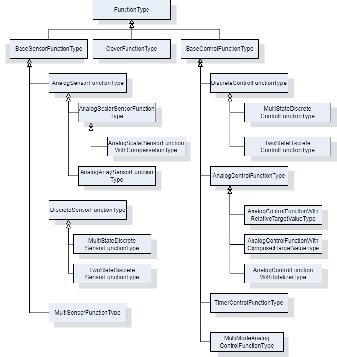
7.4.2 FunctionType ObjectType Definition
The FunctionType provides an abstract function type. It is formally defined in Table 78.
| Attribute | Value | ||||
| BrowseName | FunctionType | ||||
| IsAbstract | True | ||||
| References | Node Class | BrowseName | DataType | TypeDefinition | Other |
|---|---|---|---|---|---|
| Subtype of the TopologyElementType defined in OPC 10000-100 | |||||
| 0:HasComponent | Object | Configuration | 1:FunctionalGroupType | O | |
| 0:HasComponent | Object | FunctionSet | FunctionSetType | O | |
| 0:HasProperty | Variable | IsEnabled | Boolean | 0:PropertyType | M |
| Conformance Units | |||||
|---|---|---|---|---|---|
| LADS FunctionType | |||||
Configuration is used to organize parameters for configuration of the Function.
FunctionSet contains sub-functions of the Function.
IsEnabled indicates whether the Function can currently be executed on the Device. A Function may be disabled for several reasons including not licensed, missing hardware modules, or missing supplies.
7.5 Sensor Functions
7.5.1 BaseSensorFunctionType ObjectType Definition
The BaseSensorFunctionType is an abstract ObjectType used as a base for derivation of Sensor Functions. A Sensor Function is a Function that measures data. In LADS this is mainly data from the physical domain, but other domains are not excluded. In addition to the FunctionType, the Operational and Tuning FunctionalGroups were added for operational/tuneable Parameters and Methods. Furthermore, an AlarmMonitor of the Type ExclusiveLevelAlarm was added to observe unusual conditions in the measured data.
The ParameterSet was specialized to hold Parameters of the BaseSensorFunctionType.
The BaseSensorFunctionType is formally defined in Table 79.
| Attribute | Value | ||||
| BrowseName | BaseSensorFunctionType | ||||
| IsAbstract | True | ||||
| References | Node Class | BrowseName | DataType | TypeDefinition | Other |
|---|---|---|---|---|---|
| Subtype of the FunctionType defined in 7.4 | |||||
| Conformance Units | |||||
|---|---|---|---|---|---|
| LADS BaseSensorFunctionType | |||||
7.5.2 AnalogSensorFunctionType ObjectType Definition
The AnalogSensorFunctionType is an abstract subtype of the BaseSensorFunctionType which represents analogue measured values. The AnalogSensorFunctionType is formally defined in Table 80.
| Attribute | Value | ||||
| BrowseName | AnalogSensorFunctionType | ||||
| IsAbstract | True | ||||
| References | Node Class | BrowseName | DataType | TypeDefinition | Other |
|---|---|---|---|---|---|
| Subtype of the BaseSensorFunctionType defined in 7.5.1 | |||||
| 0:HasComponent | Object | AlarmMonitor | ExclusiveLevelAlarmType | O | |
| 0:HasComponent | Variable | RawValue | Double{Any} | AnalogUnitRangeType | M |
| 0:HasComponent | Variable | SensorValue | Double{Any} | AnalogUnitRangeType | M |
| 0:HasComponent | Object | Calibration | 1:FunctionalGroupType | O | |
| 0:HasComponent | Variable | CalibrationValues | Double[] | BaseDataVariableType | O |
| 0:HasProperty | Variable | Damping | Double | 0:PropertyType | O |
| 0:HasComponent | Object | Operational | 1:FunctionalGroupType | M | |
| 0:HasComponent | Object | Tuning | 1:FunctionalGroupType | O | |
| Conformance Units | |||||
|---|---|---|---|---|---|
| LADS AnalogSensorFunctionType | |||||
AlarmMonitor indicates whether the limit of an analogue Sensor is exceeded. See: 10000-9: Alarms & Conditions | ExclusiveLevelAlarmType.
RawValue is the raw value measured at the Sensor element, such as the Nernst voltage of a pH Sensor element.
SensorValue is the calibrated and optionally compensated/filtered process value.
Calibration is used to organize parameters for configuration of this Function.
CalibrationValues is an array of calibration values for converting the Sensor's raw value to the process value.
Damping is a low-pass filter parameter used for signal damping.
Operational is used to organize parameters for operation of this Function.
Tuning is used to organize parameters for operation of this Function.
7.5.3 AnalogArraySensorFunctionType ObjectType Definition
The AnalogArraySensorFunctionType is a concrete subtype of the AnalogSensorFunctionType which represents an array of analogue measured values. This is an extension point for all analogue measured values without built-in compensation on the Sensor. The AnalogArraySensorFunctionType is formally defined in Table 81.
| Attribute | Value | ||||
| BrowseName | AnalogArraySensorFunctionType | ||||
| IsAbstract | False | ||||
| References | Node Class | BrowseName | DataType | TypeDefinition | Other |
|---|---|---|---|---|---|
| Subtype of the AnalogSensorFunctionType defined in 7.5.2 | |||||
| 0:HasComponent | Variable | RawValue | Double{OneOrMoreDimensions} | AnalogUnitRangeType | M |
| 0:HasComponent | Variable | SensorValue | Double{OneOrMoreDimensions} | AnalogUnitRangeType | M |
| Conformance Units | |||||
|---|---|---|---|---|---|
| LADS AnalogArraySensorFunctionType | |||||
RawValue is the raw value measured at the Sensor element, such as the Nernst voltage of a pH Sensor element.
SensorValue is the calibrated and optionally compensated/filtered process value.
7.5.4 AnalogScalarSensorFunctionType ObjectType Definition
The AnalogScalarSensorFunctionType is a concrete subtype of the AnalogSensorFunctionType which represents an analogue measured value. This is an extension point for all analogue measured values without built-in compensation on the Sensor. The AnalogScalarSensorFunctionType is formally defined in Table 81.
| Attribute | Value | ||||
| BrowseName | AnalogScalarSensorFunctionType | ||||
| IsAbstract | False | ||||
| References | Node Class | BrowseName | DataType | TypeDefinition | Other |
|---|---|---|---|---|---|
| Subtype of the AnalogSensorFunctionType defined in 7.5.2 | |||||
| 0:HasComponent | Variable | RawValue | Double | AnalogUnitRangeType | M |
| 0:HasComponent | Variable | SensorValue | Double | AnalogUnitRangeType | M |
| Conformance Units | |||||
|---|---|---|---|---|---|
| LADS AnalogScalarSensorFunctionType | |||||
RawValue is the raw value measured at the Sensor element, such as the Nernst voltage of a pH Sensor element.
SensorValue is the calibrated and optionally compensated/filtered process value.
7.5.5 AnalogScalarSensorFunctionWithCompensationType ObjectType Definition
The AnalogScalarSensorFunctionWithCompensationType is a concrete subtype of the AnalogScalarSensorFunctionType which represents a measured value with compensation. This is an extension point for all analogue measured values with built-in compensation on the Sensor. The AnalogScalarSensorFunctionWithCompensationType is formally defined in Table 83.
| Attribute | Value | ||||
| BrowseName | AnalogScalarSensorFunctionWithCompensationType | ||||
| IsAbstract | False | ||||
| References | Node Class | BrowseName | DataType | TypeDefinition | Other |
|---|---|---|---|---|---|
| Subtype of the AnalogScalarSensorFunctionType defined in 7.5.4 | |||||
| 0:HasComponent | Variable | CompensationValue | Double | AnalogUnitRangeType | M |
| Conformance Units | |||||
|---|---|---|---|---|---|
| LADS AnalogScalarSensorFunctionWithCompensationType | |||||
CompensationValue is the compensation value used while calculating the process value, such as the temperature at the Sensor element for pH or DO Sensors.
7.5.6 DiscreteSensorFunctionType ObjectType Definition
The DiscreteSensorFunctionType is an abstract subtype of the base SensorFunctionType which represents a discrete measured value. It is formally defined in Table 84.
| Attribute | Value | ||||
| BrowseName | DiscreteSensorFunctionType | ||||
| IsAbstract | True | ||||
| References | Node Class | BrowseName | DataType | TypeDefinition | Other |
|---|---|---|---|---|---|
| Subtype of the BaseSensorFunctionType defined in 7.5.1 | |||||
| 0:HasComponent | Variable | SensorValue | BaseDataType | DiscreteItemType | M |
| 0:HasComponent | Object | Operational | 1:FunctionalGroupType | M | |
| Conformance Units | |||||
|---|---|---|---|---|---|
| LADS DiscreteSensorFunctionType | |||||
SensorValue is a discrete process value.
Operational is used to organize parameters for operation of this Function.
7.5.7 TwoStateDiscreteSensorFunctionType ObjectType Definition
The TwoStateDiscreteSensorFunctionType represents a Boolean value that is measured by a Sensor. It is formally defined in Table 85.
| Attribute | Value | ||||
| BrowseName | TwoStateDiscreteSensorFunctionType | ||||
| IsAbstract | False | ||||
| References | Node Class | BrowseName | DataType | TypeDefinition | Other |
|---|---|---|---|---|---|
| Subtype of the DiscreteSensorFunctionType defined in 7.5.1 | |||||
| 0:HasComponent | Variable | SensorValue | 0:Boolean | TwoStateDiscreteType | M |
| Conformance Units | |||||
|---|---|---|---|---|---|
| LADS TwoStateDiscreteSensorFunctionType | |||||
SensorValue a Boolean sensor value representing one of two discrete states.
7.5.8 MultiStateDiscreteSensorFunctionType ObjectType Definition
The MultiStateDiscreteSensorFunctionType represents a value that is measured by a Sensor and can only be set to a discrete set of values. It is formally defined in Table 86.
| Attribute | Value | ||||
| BrowseName | MultiStateDiscreteSensorFunctionType | ||||
| IsAbstract | False | ||||
| References | Node Class | BrowseName | DataType | TypeDefinition | Other |
|---|---|---|---|---|---|
| Subtype of the DiscreteSensorFunctionType defined in 7.5.1 | |||||
| 0:HasComponent | Variable | SensorValue | 0:UInt32 | MultiStateDiscreteType | M |
| Conformance Units | |||||
|---|---|---|---|---|---|
| LADS MultiStateDiscreteSensorFunctionType | |||||
SensorValue a UInt:32 sensore representing one out of multiple discrete states.
7.5.9 MultiSensorFunctionType ObjectType Definition
The MultiSensorFunctionType is a concrete subtype of the BaseSensorFunctionType which represents complex detectors with multiple sensors targeting a specific measurement task, e.g. diode array detector of a HPLC system.The specific sensor elements are represented by sensor-functions in the FunctionSet. The MultiSensorFunctionType is formally defined in Table 87.
| Attribute | Value | ||||
| BrowseName | MultiSensorFunctionType | ||||
| IsAbstract | False | ||||
| References | Node Class | BrowseName | DataType | TypeDefinition | Other |
|---|---|---|---|---|---|
| Subtype of the BaseSensorFunctionType defined in 7.5.1 | |||||
| 0:HasComponent | Object | FunctionSet | FunctionSetType | M | |
| Conformance Units | |||||
|---|---|---|---|---|---|
| LADS MultiSensorFunctionType | |||||
FunctionSet contains the sensor-functions of the different sensor elements.
7.6 Control Functions
7.6.1 BaseControlFunctionType ObjectType Definition
The BaseControlFunctionType provides an abstract superclass for all control functions. It is formally defined in Table 88.
| Attribute | Value | ||||
| BrowseName | BaseControlFunctionType | ||||
| IsAbstract | True | ||||
| References | Node Class | BrowseName | DataType | TypeDefinition | Other |
|---|---|---|---|---|---|
| Subtype of the FunctionType defined in7.4.2 | |||||
| 0:HasComponent | Object | AlarmMonitor | 0:ExclusiveDeviationAlarmType | O | |
| 0:HasComponent | Object | ControllerTuningParameter | ControllerTuningParameterType | O | |
| 0:HasComponent | Object | Operational | 1:FunctionalGroupType | M | |
| 0:HasComponent | Object | ControlFunctionState | ControlFunctionStateMachineType | M | |
| Conformance Units | |||||
|---|---|---|---|---|---|
| LADS BaseControlFunctionType | |||||
AlarmMonitor indicates whether the deviation from a set point exceeds the limit. See: 10000-9: Alarms & Conditions | ExclusiveDeviationAlarmType.
ControllerTuningParameter contains information on the Controller configuration. For example, the K factor of a PID control.
Operational is a FunctionalGroup that shall organize the CurrentState property of the ControlFunctionState StateMachine and all its remote invocable Methods. Furthermore, it shall organize at least the CurrentValue and TargetValue Properties found in the ParameterSet Object. Additional references to Properties or Methods within the scope of this Object are at the implementor's discretion (e.g., AlarmMonitor Properties).
ControlFunctionState is a state machine which represents the execution state and controls the execution of the Function.
7.6.2 ControlFunctionStateMachineType Definition
7.6.2.1 Overview
The ControlFunctionStateMachineType represents the state of a Function in a LADS Device. It uses the same StateTypes and TransitionTypes as its parent but specifies the additional Start Method to trigger state changes.
The ControlFunctionStateMachineType is formally defined in Table 89.
| Attribute | Value | ||||
| BrowseName | ControlFunctionStateMachineType | ||||
| IsAbstract | False | ||||
| References | Node Class | BrowseName | DataType | TypeDefinition | Other |
|---|---|---|---|---|---|
| Subtype of the FunctionalStateMachineType defined in 7.1.5 | |||||
| 0:HasComponent | Method | Start | O | ||
| 0:HasComponent | Method | StartWithTargetValue | O | ||
| Conformance Units | |||||
|---|---|---|---|---|---|
| LADS ControlFunctionStateMachineType | |||||
Start starts a Function on the LADS Device.
7.6.2.2 Start
The Start Method starts a Function on the LADS Device.
The signature of this Method is specified below. Table 90 specifies its representation in the AddressSpace.
Signature
Start()| Attribute | Value | ||||
| BrowseName | Start | ||||
| References | Node Class | BrowseName | DataType | TypeDefinition | ModellingRule |
|---|---|---|---|---|---|
7.6.2.3 StartWithTargetValue
The StartWithTargetValue Method starts a Function on the LADS Device with the target value as an argument.
Table 92 specify the Arguments and AddressSpace representation, respectively.
Signature
	StartWithTargetValue (
[in] Number TargetValue)| Argument | Description |
| TargetValue | (Optional) This value can be used to set the target value parallel with the start method. |
| Attribute | Value | ||||
| BrowseName | StartWithTargetValue | ||||
| References | Node Class | BrowseName | DataType | TypeDefinition | ModellingRule |
|---|---|---|---|---|---|
| 0:HasProperty | Variable | 0:InputArguments | 0:Argument[] | 0:PropertyType | M |
7.6.3 ControllerTuningParameterType Definition
The ControllerTuningParameterType is an abstract class. It is formally defined in Table 93. Subtypes of the ControllerTuningParameterType contain the parameters and information about a Controller (configuration).
| Attribute | Value | ||||
| BrowseName | ControllerTuningParameterType | ||||
| IsAbstract | False | ||||
| References | Node Class | BrowseName | DataType | TypeDefinition | Other |
|---|---|---|---|---|---|
| Subtype of the BaseObjectType defined in OPC 10000-5 | |||||
| Conformance Units | |||||
| LADS ControllerTuningParameterType | |||||
7.6.4 PidControllerParameterType Definition
The PidControllerParameterType contains the parameters of an PID controller. It is formally defined in Table 94.
| Attribute | Value | ||||
| BrowseName | PidControllerParameterType | ||||
| IsAbstract | False | ||||
| References | Node Class | BrowseName | DataType | TypeDefinition | Other |
|---|---|---|---|---|---|
| Subtype of the ControllerTuningParameterType defined in 7.6.2 | |||||
| HasComponent | Variable | CtrlP | Double | AnalogUnitRangeType | O |
| HasComponent | Variable | CtrlTd | Double | AnalogUnitRangeType | O |
| HasComponent | Variable | CtrlTi | Double | AnalogUnitRangeType | O |
| Conformance Units | |||||
|---|---|---|---|---|---|
| LADS PidControllerParameterType | |||||
CtrlP is the proportional controller parameter.
CtrlTd is the derivate controller parameter.
CtrlTi is the integrator controller parameter.
7.6.5 AnalogControlFunctionType ObjectType Definition
The AnalogControlFunctionType describes an analogue control function (using analogue values). In addition to the LADS BaseControlFunctionType, the ParameterSet has been made Mandatory. More specialized analogue control functions can be derived from this ObjectType. The AnalogControlFunctionType is formally defined in Table 95.
| Attribute | Value | ||||
| BrowseName | AnalogControlFunctionType | ||||
| IsAbstract | False | ||||
| References | Node Class | BrowseName | DataType | TypeDefinition | Other |
|---|---|---|---|---|---|
| Subtype of the BaseControlFunctionType defined in 7.6.1 | |||||
| 0:HasComponent | Variable | CurrentValue | 0:Double | AnalogUnitRangeType | M |
| 0:HasComponent | Variable | TargetValue | 0:Double | AnalogUnitRangeType | M |
| Conformance Units | |||||
|---|---|---|---|---|---|
| LADS AnalogControlFunctionType | |||||
CurrentValue is the current process value.
TargetValue is the targeted set-point value.
| BrowsePath | References | NodeClass | BrowseName | DataType | TypeDefinition | Others |
| ControlFunctionState | HasComponent | Method | StartWithTargetValue | O |
7.6.5.1 StartWithTargetValue
The StartWithTargetValue Method starts a Function on the LADS Device with the target value as an argument.
Table 92 specify the Arguments and AddressSpace representation, respectively.
Signature
	StartWithTargetValue (
[in] Double TargetValue)| Argument | Description |
| TargetValue | (Optional) This value can be used to set the target value parallel with the start method. |
| Attribute | Value | ||||
| BrowseName | StartWithTargetValue | ||||
| References | Node Class | BrowseName | DataType | TypeDefinition | ModellingRule |
|---|---|---|---|---|---|
| 0:HasProperty | Variable | 0:InputArguments | 0:Argument[] | 0:PropertyType | M |
7.6.6 AnalogControlFunctionWithComposedTargetValueType ObjectType Definition
The AnalogControlFunctionWithComposedTargetValueType describes an analogue control function (using analogue values), but the TargetValue is composed of several partial values.
An example of a composed target value used in mechanical stress analysers involves combining a static/constant base value with periodically changing values for defined amplitude, frequency, and waveform.
As the TargetValue is calculated from variables in the TargetValueSet, it should be read-only.
The AnalogControlFunctionWithComposedTargetValueType is formally defined in Table 99.
| Attribute | Value | ||||
| BrowseName | AnalogControlFunctionWithComposedTargetValueType | ||||
| IsAbstract | False | ||||
| References | Node Class | BrowseName | DataType | TypeDefinition | Other |
|---|---|---|---|---|---|
| Subtype of the AnalogControlFunctionType defined in 7.6.5 | |||||
| 0:HasComponent | Object | TargetValueSet | VariableSetType | M | |
| Conformance Units | |||||
|---|---|---|---|---|---|
| LADS AnalogControlFunctionWithComposedTargetValueType | |||||
TargetValueSet contains the partial values for the target value.
7.6.7 AnalogControlFunctionWithRelativeTargetValueType Definition
7.6.7.1 Overview
The AnalogControlFunctionWithRelativeTargetValueType supports applications where the target value is typically modified by relative increments or decrements.
Examples of its usage include position controllers where the actuator needs to modify its position relative to the last defined position by a specific amount, or dispenser controllers that are responsible for aspirating or dispensing a certain volume of fluid.
The optional DecreaseRate and IncreaseRate variables can be utilized to customize the dynamics of the resulting action based on application-specific requirements. These variables allow for adapting to factors such as viscosity when aspirating or dispensing fluids.
AnalogControlFunctionWithRelativeTargetValueType is formally defined in Table 100.
| Attribute | Value | ||||
| BrowseName | AnalogControlFunctionWithRelativeTargetValueType | ||||
| IsAbstract | False | ||||
| References | Node Class | BrowseName | DataType | TypeDefinition | Other |
|---|---|---|---|---|---|
| Subtype of the AnalogControlFunctionType defined in 7.6.5 | |||||
| 0:HasComponent | Variable | DecreaseRate | Double | AnalogUnitRangeType | O |
| 0:HasComponent | Method | ModifyTargetValueBy | O | ||
| 0:HasComponent | Variable | IncreaseRate | Double | AnalogUnitRangeType | O |
| Conformance Units | |||||
|---|---|---|---|---|---|
| LADS AnalogControlFunctionWithRelativeTargetValueType | |||||
7.6.7.2 ModifyTargetValueBy
The ModifyTargetValueBy Method is used to modify the current TargetValue by a relative amount. The resulting value shall be limited to the TargetValue's allowed range (EURange).
The direction of the action is application dependent and is controlled by the sign of the provided value. For instance, negative values may indicate moving left and positive values may indicate moving right, or positive values may be used for aspirating a defined volume while negative values may be used for dispensing a defined volume.
The signature of this Method is specified below. Table 101 and Table 102 specify the Arguments and AddressSpace representation, respectively.
Signature
	ModifyTargetValueBy (
		[in]	0:Double	Value
)| Argument | Description |
| Value | Relative value by which the target value will be changed. The resulting value will typically be limited to the target-value's allowed range. Provided values can be positive or negative. |
| Attribute | Value | ||||
| BrowseName | ModifyTargetValueBy | ||||
| References | Node Class | BrowseName | DataType | TypeDefinition | ModellingRule |
|---|---|---|---|---|---|
| 0:HasProperty | Variable | 0:InputArguments | 0:Argument[] | 0:PropertyType | 0:Mandatory |
7.6.8 AnalogControlFunctionWithTotalizerType ObjectType Definition
7.6.8.1 Overview
The AnalogControlFunctionWithTotalizerType describes an analogue control (using analogue values) function with totalizer.
Typical usage examples include but are not limited to fluid controllers where the quantity of fluid needs to be accurately measured and totalled for metering purposes.
AnalogControlFunctionWithTotalizerType is formally defined in Table 103.
| Attribute | Value | ||||
| BrowseName | AnalogControlFunctionWithTotalizerType | ||||
| IsAbstract | False | ||||
| References | Node Class | BrowseName | DataType | TypeDefinition | Other |
|---|---|---|---|---|---|
| Subtype of the AnalogControlFunctionType defined in 7.6.5 | |||||
| 0:HasComponent | Method | ResetTotalizer | O | ||
| 0:HasComponent | Variable | TotalizedValue | Double | AnalogUnitRangeType | M, RO |
| Conformance Units | |||||
|---|---|---|---|---|---|
| LADS AnalogControlFunctionWithTotalizerType | |||||
ResetTotalizer resets the totalizer to a specific value, or to zero if no input value is specified.
TotalizedValue is the totalized process value. It can be reset at any time using the ResetTotalizer() command.
7.6.8.2 ResetTotalizer
The ResetTotalizer Method resets the totalizer to a specific value, or to zero if no input value is specified. The signature of this Method is specified below. Table 104 and Table 105 specify the Arguments and AddressSpace representation, respectively.
Signature
	ResetTotalizer (
		[in] 	0:Double value
)| Argument | Description |
| Value | Relative value by which the target value will be changed. The resulting value will typically be limited to the target-value's allowed range. Provided values can be positive or negative. |
| Attribute | Value | ||||
| BrowseName | ResetTotalizer | ||||
| References | Node Class | BrowseName | DataType | TypeDefinition | ModellingRule |
|---|---|---|---|---|---|
| 0:HasProperty | Variable | 0:InputArguments | 0:Argument[] | 0:PropertyType | 0:Mandatory |
7.6.9 MultiModeAnalogControlFunctionType ObjectType Definition
The MultiModeAnalogControlFunctionType is used when a controller or actuator can be operated in different modes, depending on how the target value and current value are represented.
A common example in the laboratory and analytical domain is a peristaltic pump. In this case, the user can choose from various operation modes, such as relative pump speed (0 to 100%), absolute pump rotor speed in RPM, volumetric rate in mL/min (requiring pump calibration), or mass flow rate in g/min (requiring knowledge of the fluid density).
Another example in the laboratory and analytical domain is centrifuges. Operators can select between RPM or RCF (Rotational Centrifugal Force, defined as a multiple of G-force) modes. The RCF mode considers the radius of the centrifuge rotor when converting RCF to RPM.
When the centrifuge is operated in RCF mode, the RPM target value for the motor controller is calculated based on the RCF target value, while the reported RCF current value is calculated using the inverse function based on the measured rotation speed:
Centrifuge.RPM.TargetValue = f(Centrifuge.RCF.TargetValue, Radius)
Centrifuge.RCF.CurrentValue = f -1 (Centrifuge.RPM.CurrentValue, Radius)
As shown, a sequence of simple (typically bijective) mathematical equations can be used to convert between the target and current values of different modes. For example, linear functions are used in the pump example, while quadratic functions are used in the centrifuge example.
Essentially, the MultiModeAnalogControlFunctionType is modelled utilizing one common state machine with its methods to control the operation of the underlying resource (inherited from BaseControlFunctionType), a set of target/current value pairs, and a variable that allows the selection of the currently commanding mode.
The MultiModeAnalogControlFunctionType is formally defined in Table 95.
| Attribute | Value | ||||
| BrowseName | MultiModeAnalogControlFunctionType | ||||
| IsAbstract | False | ||||
| References | Node Class | BrowseName | DataType | TypeDefinition | Other |
|---|---|---|---|---|---|
| Subtype of the BaseControlFunctionType defined in 7.6.1 | |||||
| 0:HasComponent | Object | ControllerModeSet | ControllerParameterSetType | M | |
| 0:HasComponent | Variable | CurrentMode | 0:UInt32 | 0:MultiStateDiscreteType | M, RW |
| Conformance Units | |||||
|---|---|---|---|---|---|
| LADS MultiModeAnalogControlFunctionType | |||||
ControllerModeSet is the set of target/current value pairs.
CurrentMode defines the currently selected mode. Its EnumStrings array lists the different defined modes, which shall match the names of the corresponding elements in the ControllerModeSet.
7.6.10 ControllerParameterType ObjectType Definition
The ControllerParameterType represents a pair of target and current value variables for a specific mode of the MultiModeAnalogControlFunction (which typically have the same engineering unit).
| Attribute | Value | ||||
| BrowseName | ControllerParameterType | ||||
| IsAbstract | False | ||||
| References | Node Class | BrowseName | DataType | TypeDefinition | Other |
|---|---|---|---|---|---|
| Subtype of the BaseObjectType defined in OPC 10000-5 | |||||
| 0:HasComponent | Object | AlarmMonitor | 0:ExclusiveDeviationAlarmType | O | |
| 0:HasComponent | Variable | CurrentValue | 0:Double | 0:AnalogUnitRangeType | M, R |
| 0:HasComponent | Variable | TargetValue | 0:Double | 0:AnalogUnitRangeType | M, RW |
| Conformance Units | |||||
|---|---|---|---|---|---|
| LADS ControllerParameterType | |||||
AlarmMonitor indicates whether the deviation from a setpoint exceeds the limit. See: 10000-9: Alarms & Conditions | ExclusiveDeviationAlarmType.
CurrentValue is the current process value.
TargetValue is the targeted set-point value.
7.6.11 DiscreteControlFunctionType ObjectType Definition
The DiscreteControlFunctionType describes a discrete control function (using discrete values). More specialized discrete control functions can be derived from this ObjectType. The DiscreteControlFunctionType is formally defined in Table 108.
| Attribute | Value | ||||
| BrowseName | DiscreteControlFunctionType | ||||
| IsAbstract | True | ||||
| References | Node Class | BrowseName | DataType | TypeDefinition | Other |
|---|---|---|---|---|---|
| Subtype of the BaseControlFunctionType defined in 7.6.1 | |||||
| 0:HasComponent | Variable | CurrentValue | BaseDataType | DiscreteItemType | M |
| 0:HasComponent | Variable | TargetValue | BaseDataType | DiscreteItemType | M |
| Conformance Units | |||||
|---|---|---|---|---|---|
| LADS DiscreteControlFunctionType | |||||
CurrentValue is a current discrete process value.
TargetValue is the targeted set-point value.
7.6.12 MultiStateDiscreteControlFunctionType ObjectType Definition
The MultiStateDiscreteControlFunctionType describes a discrete control function (using more than two discrete values). It is formally defined in Table 109.
| Attribute | Value | ||||
| BrowseName | MultiStateDiscreteControlFunctionType | ||||
| IsAbstract | False | ||||
| References | Node Class | BrowseName | DataType | TypeDefinition | Other |
|---|---|---|---|---|---|
| Subtype of the DiscreteControlFunctionType defined in 7.6.1 | |||||
| 0:HasComponent | Variable | CurrentValue | UInt32 | MultiStateDiscreteType | M |
| 0:HasComponent | Variable | TargetValue | UInt32 | MultiStateDiscreteType | M |
| Conformance Units | |||||
|---|---|---|---|---|---|
| LADS MultiStateDiscreteControlFunctionType | |||||
| BrowsePath | References | NodeClass | BrowseName | DataType | TypeDefinition | Others |
| ControlFunctionState | HasComponent | Method | StartWithTargetValue | O |
7.6.12.1 StartWithTargetValue
The StartWithTargetValue Method starts a Function on the LADS Device with the target value as an argument.
Table 92 specify the Arguments and AddressSpace representation, respectively.
Signature
	StartWithTargetValue (
[in] UInt32 TargetValue)| Argument | Description |
| TargetValue | (Optional) This value can be used to set the target value parallel with the start method. |
| Attribute | Value | ||||
| BrowseName | StartWithTargetValue | ||||
| References | Node Class | BrowseName | DataType | TypeDefinition | ModellingRule |
|---|---|---|---|---|---|
| 0:HasProperty | Variable | 0:InputArguments | 0:Argument[] | 0:PropertyType | M |
7.6.13 TwoStateDiscreteControlFunctionType ObjectType Definition
The TwoStateDiscreteControlFunctionType describes a discrete control function with two possible values (e.g., on/off). It is formally defined in Table 113.
| Attribute | Value | ||||
| BrowseName | TwoStateDiscreteControlFunctionType | ||||
| IsAbstract | False | ||||
| References | Node Class | BrowseName | DataType | TypeDefinition | Other |
|---|---|---|---|---|---|
| Subtype of the DiscreteControlFunctionType defined in 7.6.7 | |||||
| 0:HasComponent | Variable | CurrentValue | Boolean | TwoStateDiscreteType | M |
| 0:HasComponent | Variable | TargetValue | Boolean | TwoStateDiscreteType | M |
| Conformance Units | |||||
|---|---|---|---|---|---|
| LADS TwoStateDiscreteControlFunctionType | |||||
| BrowsePath | References | NodeClass | BrowseName | DataType | TypeDefinition | Others |
| ControlFunctionState | HasComponent | Method | StartWithTargetValue | O |
7.6.13.1 StartWithTargetValue
The StartWithTargetValue Method starts a Function on the LADS Device with the target value as an argument.
Table 92 specify the Arguments and AddressSpace representation, respectively.
Signature
	StartWithTargetValue (
[in] Boolean TargetValue)| Argument | Description |
| TargetValue | (Optional) This value can be used to set the target value parallel with the start method. |
| Attribute | Value | ||||
| BrowseName | StartWithTargetValue | ||||
| References | Node Class | BrowseName | DataType | TypeDefinition | ModellingRule |
|---|---|---|---|---|---|
| 0:HasProperty | Variable | 0:InputArguments | 0:Argument[] | 0:PropertyType | M |
7.6.14 TimerControlFunctionType ObjectType Definition
The TimerControlFunctionType defines a simple "one shot" Timer which stops once it has elapsed. It follows the design of other LADS ControlFunctions, utilizing the same state machine and similar variable definitions. The TimerFunctionType is formally defined in Table 117.
Once started, the CurrentValue counts upwards from zero until it reaches the TargetValue.
The DifferenceValue is calculated by subtracting the CurrentValue from the TargetValue. Thus, it counts downwards from the TargetValue to zero.
As soon as the CurrentValue reaches the TargetValue, the CurrentState of the TimerFunction automatically transitions to Off. This is typically accompanied by some (internal) action/effect, such as stopping the execution of a Function or similar.
In the SuspendedState the CurrentValue holds its current value and does not count further until the state switches back to On, either due to a Client command or an internal state change.
| Attribute | Value | ||||
| BrowseName | TimerControlFunctionType | ||||
| IsAbstract | False | ||||
| References | Node Class | BrowseName | DataType | TypeDefinition | Other |
|---|---|---|---|---|---|
| Subtype of the BaseControlFunctionType defined in 7.6.1 | |||||
| 0:HasComponent | Variable | CurrentValue | Duration | AnalogUnitRangeType | O |
| 0:HasComponent | Variable | DifferenceValue | Duration | AnalogUnitRangeType | O |
| 0:HasComponent | Variable | TargetValue | Duration | AnalogUnitRangeType | O |
| Conformance Units | |||||
|---|---|---|---|---|---|
| LADS TimerControlFunctionType | |||||
CurrentValue is the elapsed time in milliseconds since the Timer was started.
DifferenceValue is the remaining time in milliseconds until the Timer will be stopped.
TargetValue is the target time in milliseconds.
7.7 Other Functions
7.7.1 CoverFunctionType ObjectType Definition
The CoverFunctionType is used to control the cover, door, or lid of a Laboratory Device. In addition to the FunctionType, the Operational FunctionalGroup was added for operational Parameters and Methods. Additionally, CoverStateMachine was added to monitor/control the state of a Device. The CoverFunctionType is formally defined in Table 118.
| Attribute | Value | ||||
| BrowseName | CoverFunctionType | ||||
| IsAbstract | False | ||||
| References | Node Class | BrowseName | DataType | TypeDefinition | Other |
|---|---|---|---|---|---|
| Subtype of the FunctionType defined in 7.4 | |||||
| 0:HasComponent | Object | Operational | 1:FunctionalGroupType | M | |
| 0:HasComponent | Object | CoverState | CoverStateMachineType | M | |
| Conformance Units | |||||
|---|---|---|---|---|---|
| LADS CoverFunctionType | |||||
CoverState is a state machine which controls the cover of a LADS Device. See CoverStateMachineType for details about the controlling state machine.
7.7.2 CoverStateMachineType ObjectType Definition
7.7.2.1 Overview
The CoverStateMachineType is used to control the lid, door, or cover of a LADS Device. One Device may have any arbitrary number of lids, doors, covers and their corresponding CoverFunction. It is formally defined in Table 119.
The CoverStateMachine is depicted in Figure 19.
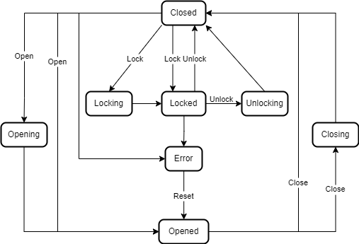
| Attribute | Value | ||||
| BrowseName | CoverStateMachineType | ||||
| IsAbstract | False | ||||
| References | Node Class | BrowseName | DataType | TypeDefinition | Other |
|---|---|---|---|---|---|
| Subtype of the FiniteStateMachineType defined in OPC 10000-5 | |||||
| 0:HasComponent | Method | Close | O | ||
| 0:HasComponent | Object | Closed | StateType | ||
| 0:HasComponent | Object | ClosedToError | TransitionType | ||
| 0:HasComponent | Object | ClosedToLocked | TransitionType | ||
| 0:HasComponent | Object | ClosedToLocking | TransitionType | ||
| 0:HasComponent | Object | ClosedToOpened | TransitionType | ||
| 0:HasComponent | Object | ClosedToOpening | TransitionType | ||
| 0:HasComponent | Object | Closing | StateType | ||
| 0:HasComponent | Object | ClosingToClosed | TransitionType | ||
| 0:HasComponent | Object | Error | StateType | ||
| 0:HasComponent | Object | ErrorToOpened | TransitionType | ||
| 0:HasComponent | Method | Lock | O | ||
| 0:HasComponent | Object | Locked | StateType | ||
| 0:HasComponent | Object | LockedToClosed | TransitionType | ||
| 0:HasComponent | Object | LockedToError | TransitionType | ||
| 0:HasComponent | Object | LockedToUnlocking | TransitionType | ||
| 0:HasComponent | Object | Locking | StateType | ||
| 0:HasComponent | Object | LockingToLocked | TransitionType | ||
| 0:HasComponent | Method | Open | O | ||
| 0:HasComponent | Object | Opened | StateType | ||
| 0:HasComponent | Object | OpenedToClosed | TransitionType | ||
| 0:HasComponent | Object | OpenedToClosing | TransitionType | ||
| 0:HasComponent | Object | Opening | StateType | ||
| 0:HasComponent | Object | OpeningToOpened | TransitionType | ||
| 0:HasComponent | Method | Reset | O | ||
| 0:HasComponent | Method | Unlock | O | ||
| 0:HasComponent | Object | Unlocking | StateType | ||
| 0:HasComponent | Object | UnlockingToClosed | TransitionType | ||
| Conformance Units | |||||
|---|---|---|---|---|---|
| LADS CoverStateMachineType | |||||
Close is a Optional Method that can be called in the Opened state to close the cover of the Device.
Closed is the state of the LADS Device cover when it is closed.
ClosedToError is triggered if the closed cover has a malfunction, such as on locking or opening.
ClosedToLocked is triggered if the closed cover is also locked. This can either be done manually on the Device or by calling the Lock Method remotely.
ClosedToLocking is triggered if the closed cover starts the process of closing. This can either be done manually on the Device or by calling the Lock Method remotely.
ClosedToOpened is triggered if the cover of the Device is opened. This can be done either manually or by calling the Open Method remotely.
ClosedToOpening is triggered in the process of opening the cover. This can be done either manually or by calling the Open Method remotely.
Closing is the transitive state of the LADS Device cover when it is in the process of closing.
ClosingToClosed is triggered if the cover has ended its process of closing and is finally closed.
Error is the state of the LADS Device cover when it is in an error state. For example, if the locking did not work properly or there is some kind of malfunction on locking/closing the Device cover.
ErrorToOpened is triggered if the cover recovers from an Error state. This can either be done manually or by calling the Reset Method.
Lock is a Optional Method that can be called from the Closed state to lock the cover of the Device.
Locked is the state of the LADS Device cover when it is closed and locked.
LockedToClosed is triggered if the locked cover is unlocked. This can either be done manually on the Device or by calling the Unlock Method remotely.
LockedToError is triggered if the locked cover has a malfunction, such as on unlocking.
LockedToUnlocking is triggered if the locked cover starts the process of unlocking. This can either be done manually on the Device or by calling the Unlock Method remotely.
Locking is the transitive state of the LADS Device cover when it is in the process of locking.
LockingToLocked is triggered if the cover has ended its locking process is finally locked.
Open is a Mandatory Method that can be called from the Closed state to open the cover of the Device.
Opened is the state of the LADS Device cover when it is opened.
OpenedToClosed is triggered if the cover of the Device is closed, either manually or by calling the Close Method remotely.
OpenedToClosing is triggered if the cover of the Device starts the process of closing, either manually or by calling the Close Method remotely.
Opening is the transitive state of the LADS Device cover when it is in the process of opening.
OpeningToOpened is triggered if the cover has ended its opening process is finally opened.
Unlock is a Optional Method that can be called from the Locked state to unlock the cover of the Device.
Unlocking is the transitive state of the LADS Device cover when it is in the process of unlocking.
UnlockingToClosed is triggered if the cover has ended its unlocking process is finally closed.
Reset is a Mandatory Method that can be called from the Error state to open the cover of the Device.
The children of the CoverStateMachineType have additional References, which are defined in Table 120.
| SourceBrowsePath | Reference Type | Is Forward | TargetBrowsePath |
| ClosedToError | 0:FromState | True | Closed |
| 0:ToState | True | Error | |
| 0:HasEffect | True | TransitionEventType | |
| ClosedToLocked | 0:FromState | True | Closed |
| 0:ToState | True | Locked | |
| 0:HasCause | True | Lock | |
| 0:HasEffect | True | TransitionEventType | |
| ClosedToLocking | 0:FromState | True | Closed |
| 0:ToState | True | Locking | |
| 0:HasCause | True | Lock | |
| ClosedToOpened | 0:FromState | True | Closed |
| 0:ToState | True | Opened | |
| 0:HasCause | True | Open | |
| 0:HasEffect | True | TransitionEventType | |
| ClosedToOpening | 0:FromState | True | Closed |
| 0:ToState | True | Opening | |
| 0:HasCause | True | Open | |
| ClosingToClosed | 0:FromState | True | Closing |
| 0:ToState | True | Closed | |
| ErrorToOpened | 0:FromState | True | Error |
| 0:ToState | True | Opened | |
| 0:HasCause | True | Reset | |
| 0:HasEffect | True | TransitionEventType | |
| LockedToClosed | 0:FromState | True | Locked |
| 0:ToState | True | Closed | |
| 0:HasCause | True | Unlock | |
| 0:HasEffect | True | TransitionEventType | |
| LockedToError | 0:FromState | True | Locked |
| 0:ToState | True | Error | |
| 0:HasEffect | True | TransitionEventType | |
| LockedToUnlocking | 0:FromState | True | Locked |
| 0:ToState | True | Unlocking | |
| 0:HasCause | True | Unlock | |
| LockingToLocked | 0:FromState | True | Locking |
| 0:ToState | True | Locked | |
| OpenedToClosed | 0:FromState | True | Opened |
| 0:ToState | True | Closed | |
| 0:HasCause | True | Close | |
| 0:HasEffect | True | TransitionEventType | |
| OpenedToClosing | 0:FromState | True | Opened |
| 0:ToState | True | Closing | |
| 0:HasCause | True | Close | |
| OpeningToOpened | 0:FromState | True | Opening |
| 0:ToState | True | Opened | |
| UnlockingToClosed | 0:FromState | True | Unlocking |
| 0:ToState | True | Closed |
The Component Variables of the CoverStateMachineType have additional Attributes, as defined in Table 121.
| BrowsePath | Value Attribute | ||
| 1 | ||
| 5 | ||
| 2 | ||
| 3 | ||
| 6 | ||
| 4 | ||
| 7 | ||
| 8 | ||
| 6 | ||
| 3 | ||
| 8 | ||
| 2 | ||
| 9 | ||
| 10 | ||
| 7 | ||
| 4 | ||
| 5 | ||
| 11 | ||
| 12 | ||
| 1 | ||
| 13 | ||
| 14 | ||
| 15 |
7.7.2.2 Close
The Close Method can be called in the Opened state to close the cover of the Device. The signature of this Method is specified below. Table 122 specifies its representation in the AddressSpace.
Signature
Close ()| Attribute | Value | ||||
| BrowseName | Close | ||||
| References | Node Class | BrowseName | DataType | TypeDefinition | ModellingRule |
|---|---|---|---|---|---|
7.7.2.3 Lock
The Lock Method can be called from the Closed state to lock the cover of the Device. The signature of this Method is specified below. Table 123 specifies its representation in the AddressSpace.
Signature
Lock ()| Attribute | Value | ||||
| BrowseName | Lock | ||||
| References | Node Class | BrowseName | DataType | TypeDefinition | ModellingRule |
|---|---|---|---|---|---|
7.7.2.4 Open
The Open Method can be called from the Closed state to open the cover of the Device. The signature of this Method is specified below. Table 124 specifies its representation in the AddressSpace.
Signature
Open ()| Attribute | Value | ||||
| BrowseName | Open | ||||
| References | Node Class | BrowseName | DataType | TypeDefinition | ModellingRule |
|---|
7.7.2.5 Reset
The Reset Method can be called from the Error state to open the cover of the Device. The signature of this Method is specified below. Table 125 specifies the Arguments and AddressSpace representation.
Signature
Reset ()| Attribute | Value | ||||
| BrowseName | Reset | ||||
| References | Node Class | BrowseName | DataType | TypeDefinition | ModellingRule |
|---|---|---|---|---|---|
7.7.2.6 Unlock
The Unlock Method can be called to unlock the cover. The signature of this Method is specified below. Table 126 specifies its representation in the AddressSpace.
Signature
Unlock ()| Attribute | Value | ||||
| BrowseName | Unlock | ||||
| References | Node Class | BrowseName | DataType | TypeDefinition | ModellingRule |
|---|
8 OPC UA DataTypes
8.1 KeyValueType
A key-value pair similar to 0:KeyValuePair which uses 0:String instead of 0:QualifiedName. The structure is defined in Table 127.
| Name | Type | Description | Allow Subtypes |
|---|---|---|---|
| KeyValueType | structure | Subtype of Structure defined in OPC 10000-3 | |
Key | 0:String | unique key to identify a value | |
Value | 0:String | the value associated with the key |
Its representation in the AddressSpace is defined in Table 128.
| Attribute | Value | |||||
| BrowseName | KeyValueType | |||||
| IsAbstract | False | |||||
| References | NodeClass | BrowseName | DataType | TypeDefinition | Other | |
|---|---|---|---|---|---|---|
| Subtype of the Structure defined in OPC 10000-3 | ||||||
| Conformance Units | ||||||
|---|---|---|---|---|---|---|
| LADS KeyValueType | ||||||
8.2 SampleInfoType
This DataType contains metadata for a sample, specifically data on the location of the sample in a container.
The structure is defined in Table 129.
| Name | Type | Description | Allow Subtypes |
|---|---|---|---|
| SampleInfoType | structure | Subtype of Structure defined in OPC 10000-3 | |
ContainerId | 0:String | Identifier of the container the sample is in. May be null. | |
SampleId | 0:String | Identifier of the sample | |
Position | 0:String | Vendor-specific description of the position of the sample in the container | |
CustomData | 0:String | Custom data field for vendor-specific data |
Its representation in the AddressSpace is defined in Table 130.
| Attribute | Value | |||||
| BrowseName | SampleInfoType | |||||
| IsAbstract | False | |||||
| References | NodeClass | BrowseName | DataType | TypeDefinition | Other | |
|---|---|---|---|---|---|---|
| Subtype of the Structure defined in OPC 10000-3 | ||||||
| Conformance Units | ||||||
|---|---|---|---|---|---|---|
| LADS SampleInfoType | ||||||
8.3 MaintenanceTaskResultEnum
This enumeration defines the different statuses a task can have as result. The enumeration is defined in Table 131.
| Name | Value | Description |
|---|---|---|
| Success | 0 | The maintenance task stopped successfully. |
| Failure | 1 | The maintenance task stopped with failure. |
| Undetermined | 2 | The status of the maintenance task upon stopping cannot be determined. |
Its representation in the AddressSpace is defined in Table 132.
| Attribute | Value | |||||
| BrowseName | MaintenanceTaskResultEnum | |||||
| IsAbstract | false | |||||
| References | NodeClass | BrowseName | DataType | TypeDefinition | Other | |
|---|---|---|---|---|---|---|
| Subtype of the Enumeration defined in OPC 10000-3 | ||||||
| 0:HasProperty | Variable | EnumValues | EnumValueType[] | 0:PropertyType | ||
| Conformance Units | ||||||
|---|---|---|---|---|---|---|
| LADS MaintenanceTaskResultEnum | ||||||
9 Profiles and Conformance Units
9.1 Conformance Units
Table 133 defines the corresponding ConformanceUnits for the OPC UA Information Model for LADS
| Category | Title | Description |
| Server | LADS ActiveProgramType | The server supports nodes that conform to (subtypes of) the ActiveProgramType. The ActiveProgramType node itself is available in the AddressSpace. Every instance of (subtypes of) the ActiveProgramType must include all mandatory components of the ActiveProgramType and may include the optional components. |
| Server | LADS AnalogArraySensorFunctionType | The server supports nodes that conform to (subtypes of) the AnalogArraySensorFunctionType. The AnalogArraySensorFunctionType node itself is available in the AddressSpace. Every instance of (subtypes of) the AnalogArraySensorFunctionType must include all mandatory components of the AnalogArraySensorFunctionType and may include the optional components. |
| Server | LADS AnalogControlFunctionType | The server supports nodes that conform to (subtypes of) the AnalogControlFunctionType. The AnalogControlFunctionType node itself is available in the AddressSpace. Every instance of (subtypes of) the AnalogControlFunctionType must include all mandatory components of the AnalogControlFunctionType and may include the optional components. |
| Server | LADS AnalogControlFunctionWithComposedTargetValueType | The server supports nodes that conform to (subtypes of) the AnalogControlFunctionWithComposedTargetValueType. The AnalogControlFunctionWithComposedTargetValueType node itself is available in the AddressSpace. Every instance of (subtypes of) the AnalogControlFunctionWithComposedTargetValueType must include all mandatory components of the AnalogControlFunctionWithComposedTargetValueType and may include the optional components. |
| Server | LADS AnalogControlFunctionWithRelativeTargetValueType | The server supports nodes that conform to (subtypes of) the AnalogControlFunctionWithRelativeTargetValueType. The AnalogControlFunctionWithRelativeTargetValueType node itself is available in the AddressSpace. Every instance of (subtypes of) the AnalogControlFunctionWithRelativeTargetValueType must include all mandatory components of the AnalogControlFunctionWithRelativeTargetValueType and may include the optional components. |
| Server | LADS AnalogControlFunctionWithTotalizerType | The server supports nodes that conform to (subtypes of) the AnalogControlFunctionWithTotalizerType. The AnalogControlFunctionWithTotalizerType node itself is available in the AddressSpace. Every instance of (subtypes of) the AnalogControlFunctionWithTotalizerType must include all mandatory components of the AnalogControlFunctionWithTotalizerType and may include the optional components. |
| Server | LADS AnalogSensorFunctionType | The server supports nodes that conform to (subtypes of) the AnalogSensorFunctionType. The AnalogSensorFunctionType node itself is available in the AddressSpace. Every instance of (subtypes of) the AnalogSensorFunctionType must include all mandatory components of the AnalogSensorFunctionType and may include the optional components. |
| Server | LADS AnalogScalarSensorFunctionType | The server supports nodes that conform to (subtypes of) the AnalogScalarSensorFunctionType. The AnalogScalarSensorFunctionType node itself is available in the AddressSpace. Every instance of (subtypes of) the AnalogScalarSensorFunctionType must include all mandatory components of the AnalogScalarSensorFunctionType and may include the optional components. |
| Server | LADS AnalogScalarSensorFunctionWithCompensationType | The server supports nodes that conform to (subtypes of) the AnalogScalarSensorFunctionWithCompensationType. The AnalogScalarSensorFunctionWithCompensationType node itself is available in the AddressSpace. Every instance of (subtypes of) the AnalogScalarSensorFunctionWithCompensationType must include all mandatory components of the AnalogScalarSensorFunctionWithCompensationType and may include the optional components. |
| Server | LADS BaseControlFunctionType | The server supports nodes that conform to (subtypes of) the BaseControlFunctionType. The BaseControlFunctionType node itself is available in the AddressSpace. Every instance of (subtypes of) the BaseControlFunctionType must include all mandatory components of the BaseControlFunctionType and may include the optional components. |
| Server | LADS BaseSensorFunctionType | The server supports nodes that conform to (subtypes of) the BaseSensorFunctionType. The BaseSensorFunctionType node itself is available in the AddressSpace. Every instance of (subtypes of) the BaseSensorFunctionType must include all mandatory components of the BaseSensorFunctionType and may include the optional components. |
| Server | LADS ControlFunctionStateMachineType | The server supports nodes that conform to (subtypes of) the ControlFunctionStateMachineType. The ControlFunctionStateMachineType node itself is available in the AddressSpace. Every instance of (subtypes of) the ControlFunctionStateMachineType must include all mandatory components of the ControlFunctionStateMachineType and may include the optional components. The ControlFunctionStateMachineType state machine is implemented correctly by the server. This means the succession of states adheres to the transitions defined in this specification and the 0:HasCause and 0:HasEffect references are implemented correctly. |
| Server | LADS ControlFunctionStateMachineType Start method | Supports the handling of the Start method of the ControlFunctionStateMachineType as described in this specification. |
| Server | LADS ControllerParameterSetType | The server supports nodes that conform to (subtypes of) the ControllerParameterSetType. The ControllerParameterSetType node itself is available in the AddressSpace. Every instance of (subtypes of) the ControllerParameterSetType must include all mandatory components of the ControllerParameterSetType and may include the optional components. |
| Server | LADS ControllerParameterType | The server supports nodes that conform to (subtypes of) the ControllerParameterType. The ControllerParameterType node itself is available in the AddressSpace. Every instance of (subtypes of) the ControllerParameterType must include all mandatory components of the ControllerParameterType and may include the optional components. |
| Server | LADS ControllerTuningParameterType | The server supports nodes that conform to (subtypes of) the ControllerTuningParameterType. The ControllerTuningParameterType node itself is available in the AddressSpace. Every instance of (subtypes of) the ControllerTuningParameterType must include all mandatory components of the ControllerTuningParameterType and may include the optional components. |
| Server | LADS CoverFunctionType | The server supports nodes that conform to (subtypes of) the CoverFunctionType. The CoverFunctionType node itself is available in the AddressSpace. Every instance of (subtypes of) the CoverFunctionType must include all mandatory components of the CoverFunctionType and may include the optional components. |
| Server | LADS CoverStateMachineType | The server supports nodes that conform to (subtypes of) the CoverStateMachineType. The CoverStateMachineType node itself is available in the AddressSpace. Every instance of (subtypes of) the CoverStateMachineType must include all mandatory components of the CoverStateMachineType and may include the optional components. The CoverStateMachineType state machine is implemented correctly by the server. This means the succession of states adheres to the transitions defined in this specification and the 0:HasCause and 0:HasEffect references are implemented correctly. |
| Server | LADS CoverStateMachineType Close method | Supports the handling of the Close method of the CoverStateMachineType as described in this specification. |
| Server | LADS CoverStateMachineType Lock method | Supports the handling of the Lock method of the CoverStateMachineType as described in this specification. |
| Server | LADS CoverStateMachineType Open method | Supports the handling of the Open method of the CoverStateMachineType as described in this specification. |
| Server | LADS CoverStateMachineType Reset method | Supports the handling of the Reset method of the CoverStateMachineType as described in this specification. |
| Server | LADS CoverStateMachineType Unlock method | Supports the handling of the Unlock method of the CoverStateMachineType as described in this specification. |
| Server | LADS DiscreteControlFunctionType | The server supports nodes that conform to (subtypes of) the DiscreteControlFunctionType. The DiscreteControlFunctionType node itself is available in the AddressSpace. Every instance of (subtypes of) the DiscreteControlFunctionType must include all mandatory components of the DiscreteControlFunctionType and may include the optional components. |
| Server | LADS DiscreteSensorFunctionType | The server supports nodes that conform to (subtypes of) the DiscreteSensorFunctionType. The DiscreteSensorFunctionType node itself is available in the AddressSpace. Every instance of (subtypes of) the DiscreteSensorFunctionType must include all mandatory components of the DiscreteSensorFunctionType and may include the optional components. |
| Server | LADS FunctionalStateMachineType | The server supports nodes that conform to (subtypes of) the FunctionalStateMachineType. The FunctionalStateMachineType node itself is available in the AddressSpace. Every instance of (subtypes of) the FunctionalStateMachineType must include all mandatory components of the FunctionalStateMachineType and may include the optional components. The FunctionalStateMachineType state machine is implemented correctly by the server. This means the succession of states adheres to the transitions defined in this specification and the hasCause and hasEffect references are implemented correctly. |
| Server | LADS FunctionalStateMachineType Abort method | Supports the handling of the Abort method of the FunctionalStateMachineType as described in this specification. |
| Server | LADS FunctionalStateMachineType Clear method | Supports the handling of the Clear method of the FunctionalStateMachineType as described in this specification. |
| Server | LADS FunctionalStateMachineType Stop method | Supports the handling of the Stop method of the FunctionalStateMachineType as described in this specification. |
| Server | LADS FunctionalUnitSetType | The server supports nodes that conform to (subtypes of) the FunctionalUnitSetType. The FunctionalUnitSetType node itself is available in the AddressSpace. Every instance of (subtypes of) the FunctionalUnitSetType must include all mandatory components of the FunctionalUnitSetType and may include the optional components. |
| Server | LADS FunctionalUnitStateMachineType | The server supports nodes that conform to (subtypes of) the FunctionalUnitStateMachineType. The FunctionalUnitStateMachineType node itself is available in the AddressSpace. Every instance of (subtypes of) the FunctionalUnitStateMachineType must include all mandatory components of the FunctionalUnitStateMachineType and may include the optional components. The FunctionalUnitStateMachineType state machine is implemented correctly by the server. This means the succession of states adheres to the transitions defined in this specification and the hasCause and hasEffect references are implemented correctly. |
| Server | LADS FunctionalUnitStateMachineType Start method | Supports the handling of the Start method of the FunctionalUnitStateMachineType as described in this specification. |
| Server | LADS FunctionalUnitStateMachineType StartProgram method | Supports the handling of the StartProgram method of the FunctionalUnitStateMachineType as described in this specification. |
| Server | LADS FunctionalUnitType | The server supports nodes that conform to (subtypes of) the FunctionalUnitType. The FunctionalUnitType node itself is available in the AddressSpace. Every instance of (subtypes of) the FunctionalUnitType must include all mandatory components of the FunctionalUnitType and may include the optional components. |
| Server | LADS FunctionSetType | The server supports nodes that conform to (subtypes of) the FunctionSetType. The FunctionSetType node itself is available in the AddressSpace. Every instance of (subtypes of) the FunctionSetType must include all mandatory components of the FunctionSetType and may include the optional components. |
| Server | LADS FunctionType | The server supports nodes that conform to (subtypes of) the FunctionType. The FunctionType node itself is available in the AddressSpace. Every instance of (subtypes of) the FunctionType must include all mandatory components of the FunctionType and may include the optional components. |
| Server | LADS KeyValueType | Exposes the KeyValueType and all its supertypes in the AddressSpace. |
| Server | LADS LADSComponentType | The server supports nodes that conform to (subtypes of) the LADSComponentType. The LADSComponentType node itself is available in the AddressSpace. Every instance of (subtypes of) the LADSComponentType must include all mandatory components of the LADSComponentType and may include the optional components. |
| Server | LADS LADSDeviceStateMachineType | The server supports nodes that conform to (subtypes of) the LADSDeviceStateMachineType. The LADSDeviceStateMachineType node itself is available in the AddressSpace. Every instance of (subtypes of) the LADSDeviceStateMachineType must include all mandatory components of the LADSDeviceStateMachineType and may include the optional components. |
| Server | LADS LADSDeviceStateMachineType GotoMaintenance method | Supports the handling of the GotoMaintenance method of the LADSDeviceStateMachineType as described in this specification. |
| Server | LADS LADSDeviceStateMachineType GotoOperating method | Supports the handling of the GotoOperating method of the LADSDeviceStateMachineType as described in this specification. |
| Server | LADS LADSDeviceStateMachineType GotoShutdown method | Supports the handling of the GotoShutdown method of the LADSDeviceStateMachineType as described in this specification. |
| Server | LADS LADSDeviceStateMachineType GotoSleep method | Supports the handling of the GotoSleep method of the LADSDeviceStateMachineType as described in this specification. |
| Server | LADS LADSDeviceType | The server supports nodes that conform to (subtypes of) the LADSDeviceType. The LADSDeviceType node itself is available in the AddressSpace. Every instance of (subtypes of) the LADSDeviceType must include all mandatory components of the LADSDeviceType and may include the optional components. |
| Server | LADS LADSMaintenanceSetType | The server supports nodes that conform to (subtypes of) the LADSMaintenanceSetType. The LADSMaintenanceSetType node itself is available in the AddressSpace. Every instance of (subtypes of) the LADSMaintenanceSetType must include all mandatory components of the LADSMaintenanceSetType and may include the optional components. |
| Server | LADS LADSOperationCountersType | The server supports nodes that conform to (subtypes of) the LADSOperationCountersType. The LADSOperationCountersType node itself is available in the AddressSpace. Every instance of (subtypes of) the LADSOperationCountersType must include all mandatory components of the LADSOperationCountersType and may include the optional components. |
| Server | LADS LADSOperationModeStateMachineType | The server supports nodes that conform to (subtypes of) the LADSOperationModeStateMachineType. The LADSOperationModeStateMachineType node itself is available in the AddressSpace. Every instance of (subtypes of) the LADSOperationModeStateMachineType must include all mandatory components of the LADSOperationModeStateMachineType and may include the optional components. |
| Server | LADS MaintenanceTaskResultEnum | Exposes the MaintenanceTaskResultEnum and all its supertypes in the AddressSpace. |
| Server | LADS MaintenanceTaskType | The MaintenanceType node is available in the AddressSpace. The server supports nodes that conform to (subtypes of) the MaintenanceType. The instance(s) of (subtypes of) the MaintenanceType is/are available in the AddressSpace. Events of (subtypes of) the MaintenanceType are generated by the server. |
| Server | LADS MaintenanceTaskType ResetTask method | Supports the handling of the ResetTask method of the MaintenanceTaskType as described in this specification. |
| Server | LADS MaintenanceTaskType Start method | Supports the handling of the Start method of the MaintenanceTaskType as described in this specification. |
| Server | LADS MaintenanceTaskType Stop method | Supports the handling of the Stop method of the MaintenanceTaskType as described in this specification. |
| Server | LADS MaintenanceType Historical Events | The EventNotifier of the instance of a LADSMaintenanceTaskSetType is set to HistoryRead and SubscribeToEvent and Events are stored on the server for HistoryRead. |
| Server | LADS MultiSensorFunctionType | The server supports nodes that conform to (subtypes of) the MultiSensorFunctionType. The MultiSensorFunctionType node itself is available in the AddressSpace. Every instance of (subtypes of) the MultiSensorFunctionType must include all mandatory components of the MultiSensorFunctionType and may include the optional components. |
| Server | LADS MultiModeAnalogControlFunctionType | The server supports nodes that conform to (subtypes of) the MultiModeAnalogControlFunctionType. The MultiModeAnalogControlFunctionType node itself is available in the AddressSpace. Every instance of (subtypes of) the MultiModeAnalogControlFunctionType must include all mandatory components of the MultiModeAnalogControlFunctionType and may include the optional components. |
| Server | LADS MultiStateDiscreteControlFunctionType | The server supports nodes that conform to (subtypes of) the MultiStateDiscreteControlFunctionType. The MultiStateDiscreteControlFunctionType node itself is available in the AddressSpace. Every instance of (subtypes of) the MultiStateDiscreteControlFunctionType must include all mandatory components of the MultiStateDiscreteControlFunctionType and may include the optional components. |
| Server | LADS MultiStateDiscreteSensorFunctionType | The server supports nodes that conform to (subtypes of) the MultiStateDiscreteSensorFunctionType. The MultiStateDiscreteSensorFunctionType node itself is available in the AddressSpace. Every instance of (subtypes of) the MultiStateDiscreteSensorFunctionType must include all mandatory components of the MultiStateDiscreteSensorFunctionType and may include the optional components. |
| Server | LADS PidControllerParameterType | The server supports nodes that conform to (subtypes of) the PidControllerParameterType. The PidControllerParameterType node itself is available in the AddressSpace. Every instance of (subtypes of) the PidControllerParameterType must include all mandatory components of the PidControllerParameterType and may include the optional components. |
| Server | LADS ProgramManagerType | The server supports nodes that conform to (subtypes of) the ProgramManagerType. The ProgramManagerType node itself is available in the AddressSpace. Every instance of (subtypes of) the ProgramManagerType must include all mandatory components of the ProgramManagerType and may include the optional components. |
| Server | LADS ProgramManagerType Download method | Supports the handling of the Download method of the ProgramManagerType as described in this specification. |
| Server | LADS ProgramManagerType Remove method | Supports the handling of the Remove method of the ProgramManagerType as described in this specification. |
| Server | LADS ProgramManagerType Upload method | Supports the handling of the Upload method of the ProgramManagerType as described in this specification. |
| Server | LADS ProgramTemplateSetType | The server supports nodes that conform to (subtypes of) the ProgramTemplateSetType. The ProgramTemplateSetType node itself is available in the AddressSpace. Every instance of (subtypes of) the ProgramTemplateSetType must include all mandatory components of the ProgramTemplateSetType and may include the optional components. |
| Server | LADS ProgramTemplateType | The server supports nodes that conform to (subtypes of) the ProgramTemplateType. The ProgramTemplateType node itself is available in the AddressSpace. Every instance of (subtypes of) the ProgramTemplateType must include all mandatory components of the ProgramTemplateType and may include the optional components. |
| Server | LADS RatebasedAccumulatingControlFunctionType | The server supports nodes that conform to (subtypes of) the RatebasedAccumulatingControlFunctionType. The RatebasedAccumulatingControlFunctionType node itself is available in the AddressSpace. Every instance of (subtypes of) the RatebasedAccumulatingControlFunctionType must include all mandatory components of the RatebasedAccumulatingControlFunctionType and may include the optional components. |
| Server | LADS ResultFileSetType | The server supports nodes that conform to (subtypes of) the ResultFileSetType. The ResultFileSetType node itself is available in the AddressSpace. Every instance of (subtypes of) the ResultFileSetType must include all mandatory components of the ResultFileSetType and may include the optional components. |
| Server | LADS ResultFileType | The server supports nodes that conform to (subtypes of) the ResultFileType. The ResultFileType node itself is available in the AddressSpace. Every instance of (subtypes of) the ResultFileType must include all mandatory components of the ResultFileType and may include the optional components. |
| Server | LADS ResultSetType | The server supports nodes that conform to (subtypes of) the ResultSetType. The ResultSetType node itself is available in the AddressSpace. Every instance of (subtypes of) the ResultSetType must include all mandatory components of the ResultSetType and may include the optional components. |
| Server | LADS ResultType | The server supports nodes that conform to (subtypes of) the ResultType. The ResultType node itself is available in the AddressSpace. Every instance of (subtypes of) the ResultType must include all mandatory components of the ResultType and may include the optional components. |
| Server | LADS RunningStateMachineType | The server supports nodes that conform to (subtypes of) the RunningStateMachineType. The RunningStateMachineType node itself is available in the AddressSpace. Every instance of (subtypes of) the RunningStateMachineType must include all mandatory components of the RunningStateMachineType and may include the optional components. |
| Server | LADS RunningStateMachineType Hold method | Supports the handling of the Hold method of the RunningStateMachineType as described in this specification. |
| Server | LADS RunningStateMachineType Reset method | Supports the handling of the Reset method of the RunningStateMachineType as described in this specification. |
| Server | LADS RunningStateMachineType Suspend method | Supports the handling of the Suspend method of the RunningStateMachineType as described in this specification. |
| Server | LADS RunningStateMachineType ToComplete method | Supports the handling of the ToComplete method of the RunningStateMachineType as described in this specification. |
| Server | LADS RunningStateMachineType Unhold method | Supports the handling of the Unhold method of the RunningStateMachineType as described in this specification. |
| Server | LADS RunningStateMachineType Unsuspend method | Supports the handling of the Unsuspend method of the RunningStateMachineType as described in this specification. |
| Server | LADS SampleInfoType | Exposes the SampleInfoType and all its supertypes in the AddressSpace. |
| Server | LADS SensorValueSetType | The server supports nodes that conform to (subtypes of) the SensorValueSetType. The SensorValueSetType node itself is available in the AddressSpace. Every instance of (subtypes of) the SensorValueSetType must include all mandatory components of the SensorValueSetType and may include the optional components. |
| Server | LADS SetType | The server supports nodes that conform to (subtypes of) the SetType. The SetType node itself is available in the AddressSpace. Every instance of (subtypes of) the SetType must include all mandatory components of the SetType and may include the optional components. |
| Server | LADS SupportedPropertiesSetType | The server supports nodes that conform to (subtypes of) the SupportedPropertiesSetType. The SupportedPropertiesSetType node itself is available in the AddressSpace. Every instance of (subtypes of) the SupportedPropertiesSetType must include all mandatory components of the SupportedPropertiesSetType and may include the optional components. |
| Server | LADS SupportedPropertyType | The server supports nodes that conform to (subtypes of) the SupportedPropertyType. The SupportedPropertyType node itself is available in the AddressSpace. Every instance of (subtypes of) the SupportedPropertyType must include all mandatory components of the SupportedPropertyType and may include the optional components. |
| Server | LADS TimerFunctionType | The server supports nodes that conform to (subtypes of) the TimerFunctionType. The TimerFunctionType node itself is available in the AddressSpace. Every instance of (subtypes of) the TimerFunctionType must include all mandatory components of the TimerFunctionType and may include the optional components. |
| Server | LADS TwoStateDiscreteControlFunctionType | The server supports nodes that conform to (subtypes of) the TwoStateDiscreteControlFunctionType. The TwoStateDiscreteControlFunctionType node itself is available in the AddressSpace. Every instance of (subtypes of) the TwoStateDiscreteControlFunctionType must include all mandatory components of the TwoStateDiscreteControlFunctionType and may include the optional components. |
| Server | LADS TwoStateDiscreteSensorFunctionType | The server supports nodes that conform to (subtypes of) the TwoStateDiscreteSensorFunctionType. The TwoStateDiscreteSensorFunctionType node itself is available in the AddressSpace. Every instance of (subtypes of) the TwoStateDiscreteSensorFunctionType must include all mandatory components of the TwoStateDiscreteSensorFunctionType and may include the optional components. |
| Server | LADS VariableSetType | The server supports nodes that conform to (subtypes of) the VariableSetType. The VariableSetType node itself is available in the AddressSpace. Every instance of (subtypes of) the VariableSetType must include all mandatory components of the VariableSetType and may include the optional components. |
9.2 Profiles
9.2.1 Overview
The structure of the Companion Specification Profile and its Facets is interdependent, as depicted in Figure 20. Implementations of the Companion Specification are required to fulfil the LADS BaseServer Server Profile. Additionally, up to three optional Facets - Maintenance, ProgramManager, and ExtendedFunctionalUnit (blue) - can be implemented.
The Maintenance Facet encompasses all necessary nodes for maintenance use cases. The ProgramManager Facet includes all nodes for read-only Program Management, which can be expanded with management methods in the ExtendedProgramManager.
The ExtendedFunctionalUnit Profile mandates the optional methods of the FunctionalUnit, enabling control of a functional unit and a program. This structure provides a comprehensive and flexible framework for implementing the LADS Companion Specification.
In addition, at least one Facet function (grey) needs to be implemented. For the CoverFunction and the ControllerFunction, there is a base Profile (read-only) and an extended Profile with method and write implementation.
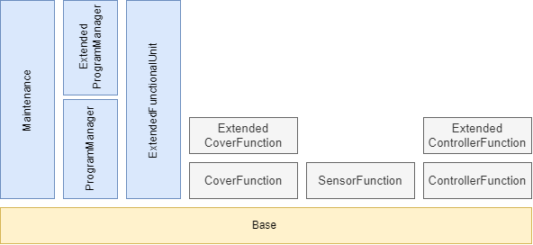
9.2.2 Profile list
Table 134 lists all Profiles defined in this document and defines their URIs.
| Profile | URI |
| LADS BaseServer Server Profile | http://opcfoundation.org/UA-Profile/LADS/Server/BaseServer |
| LADS Maintenance Server Facet | http://opcfoundation.org/UA-Profile/LADS/Server/Maintenance |
| LADS ProgramManager Server Facet | http://opcfoundation.org/UA-Profile/LADS/Server/ProgramManager |
| LADS ExtendedProgramManager | http://opcfoundation.org/UA-Profile/LADS/Server/ExtendedProgramManager |
| LADS ExtendedFunctionalUnit Server Facet | http://opcfoundation.org/UA-Profile/LADS/Server/ExtendedFunctionalUnit |
| LADS CoverFunction Server Facet | http://opcfoundation.org/UA-Profile/LADS/Server/CoverFunction |
| LADS SensorFunction Server Facet | http://opcfoundation.org/UA-Profile/LADS/Server/SensorFunction |
| LADS ControllerFunction Server Facet | http://opcfoundation.org/UA-Profile/LADS/Server/ControllerFunction |
| LADS ExtendedControllerFunction Server Facet | http://opcfoundation.org/UA-Profile/LADS/Server/ExtendedControllerFunction |
9.2.3 Server Facets
9.2.3.1 Overview
The following sections specify the Facets available for Servers that implement the LADS companion specification. Each section defines and describes a Facet or Profile.
9.2.3.2 LADS BaseServer Server Profile
Table 135 defines a Profile that describes a basic LADS OPC UA Server.
| Group | Conformance Unit/Profile Title | Mandatory/Optional |
| Profile | 0:Core 2022 Server Facet http://opcfoundation.org/UA-Profile/Server/Core2022Facet | |
| Profile | 0:Nano Embedded Device 2022 Server Profile http://opcfoundation.org/UA-Profile/Server/NanoEmbeddedDevice2022 | |
| Profile | 0:UA-TCP UA-SC UA Binary http://opcfoundation.org/UA-Profile/Transport/uatcp-uasc-uabinary | |
| Profile | 0:Data Access Server Facet http://opcfoundation.org/UA-Profile/Server/DataAccess | |
| Base Information | 0:Base Info Custom Type System | M |
| Base Information | 0:Base Info Engineering Units | M |
| Base Information | 0:Base Info Placeholder Modelling Rules | M |
| AMB | 3:AMB Configurable Asset Identification | M |
| AMB | 3:AMB Hierarchical Location Property | O |
| AMB | 3:AMB Operational Location Property | O |
| DI | 2:DI DeviceSet | M |
| DI | 2:DI DeviceType | M |
| DI | 2:DI DeviceHealth | O |
| DI | 2:DI Locking | O |
| Machinery | 4:Machinery Component Identification | O |
| Machinery | 4:Machinery Building Block Organization | O |
| Machinery | 4:Machinery MachineryItem State | O |
| Machinery | 4:Machinery Operation Mode | O |
| Machinery | 4:Machinery Operation Counter | O |
| Machinery | 4:Machinery Lifetime Counter | O |
| LADS | LADS ComponentSetType | M |
| LADS | LADS FunctionalStateMachineType | M |
| LADS | LADS FunctionalUnitSetType | M |
| LADS | LADS FunctionalUnitStateMachineType | M |
| LADS | LADS FunctionalUnitType | M |
| LADS | LADS FunctionSetType | M |
| LADS | LADS FunctionType | M |
| LADS | LADS LADSComponentType | M |
| LADS | LADS LADSDeviceStateMachineType | M |
| LADS | LADS LADSDeviceStateMachineType GotoMaintenance Method | O |
| LADS | LADS LADSDeviceStateMachineType GotoOperating Method | O |
| LADS | LADS LADSDeviceStateMachineType GotoShuttingDown method | O |
| LADS | LADS LADSDeviceStateMachineType GotoSleep Method | O |
| LADS | LADS LADSDeviceType | M |
| LADS | LADS LADSMaintenanceSetType | O |
| LADS | LADS LADSOperationCountersType | M |
| LADS | LADS RunningStateMachineType | M |
| LADS | LADS SensorValueSetType | M |
| LADS | LADS SetType | M |
| LADS | LADS SupportedPropertiesSetType | M |
| LADS | LADS SupportedPropertyType | M |
| LADS | LADS VariableSetType | M |
| LADS | LADS FunctionalStateMachineType | M |
| LADS | LADS FunctionalUnitSetType | M |
| LADS | LADS FunctionalUnitStateMachineType | M |
| LADS | LADS FunctionalUnitType | M |
| LADS | LADS FunctionSetType | M |
9.2.3.3 LADS Maintenance Server Facet
Table 136 defines a Profile that contains all necessary conformance units for maintenance tasks.
| Group | Conformance Unit/Profile Title | Mandatory/Optional |
| AMB | AMB Asset Health Status Base | M |
| AMB | AMB Asset Health Status Alarms | O |
| AMB | AMB Asset Health Tracking Overall Asset Status | O |
| AMB | AMB Asset Health Tracking Events | O |
| AMB | AMB Client Asset Health Status | O |
| LADS | LADS MaintenanceTaskType | M |
| LADS | LADS MaintenanceTaskType ResetTask Method | O |
| LADS | LADS MaintenanceTaskType Start Method | O |
9.2.3.4 LADS ProgramManager Server Facet
Table 137 defines a Profile that contains all necessary conformance units for program monitoring.
| Group | Conformance Unit/Profile Title | Mandatory/Optional |
| LADS | LADS ActiveProgramType | M |
| LADS | LADS ProgramManagerType | M |
| LADS | LADS ProgramTemplateSetType | M |
| LADS | LADS ProgramTemplateType | M |
| LADS | LADS ResultFileSetType | O |
| LADS | LADS ResultFileType | O |
| LADS | LADS ResultSetType | O |
| LADS | LADS ResultType | O |
9.2.3.5 LADS ExtendedProgramManager Server Facet
Table 138 defines a Profile that contains all necessary conformance units for complete program management, including up- and download of program templates.
| Group | Conformance Unit/Profile Title | Mandatory/Optional |
| LADS | LADS ProgramManager Server Facet | M |
| LADS | LADS ProgramManagerType Download method | M |
| LADS | LADS ProgramManagerType Remove method | M |
| LADS | LADS ProgramManagerType Upload method | M |
9.2.3.6 LADS ExtendedFunctionalUnit Server Facet
Table 139 defines a Profile that contains all conformance units which extend a Functional Unit with Methods.
| Group | Conformance Unit/Profile Title | Mandatory/Optional |
| LADS | LADS FunctionalStateMachineType Abort Method | M |
| LADS | LADS FunctionalStateMachineType Clear Method | M |
| LADS | LADS FunctionalStateMachineType Stop Method | M |
| LADS | LADS FunctionalUnitStateMachineType Start Method | M |
| LADS | LADS FunctionalUnitStateMachineType StartProgram Method | O |
| LADS | LADS RunningStateMachineType Hold Method | O |
| LADS | LADS RunningStateMachineType Reset Method | O |
| LADS | LADS RunningStateMachineType Suspend Method | O |
| LADS | LADS RunningStateMachineType ToComplete Method | O |
| LADS | LADS RunningStateMachineType Unhold Method | O |
| LADS | LADS RunningStateMachineType Unsuspend Method | O |
9.2.3.7 LADS CoverFunction Server Facet
Table 140 defines a Profile which contains all conformance units for implementing a cover function.
| Group | Conformance Unit/Profile Title | Mandatory/Optional |
| LADS | LADS CoverFunctionType | M |
| LADS | LADS CoverStateMachineType | M |
9.2.3.8 LADS ExtendedCoverFunction Server Facet
Table 141 defines a Profile which contains all conformance units for implementing a cover function and extending the CoverFunction with Methods.
| Group | Conformance Unit/Profile Title | Mandatory/Optional |
| LADS | LADS CoverFunction Server Facet | |
| LADS | LADS CoverStateMachineType Close Method | M |
| LADS | LADS CoverStateMachineType Lock Method | M |
| LADS | LADS CoverStateMachineType Open Method | M |
| LADS | LADS CoverStateMachineType Reset Method | O |
| LADS | LADS CoverStateMachineType Unlock Method | M |
| LADS | LADS CoverStateMachineType Close Method | M |
9.2.3.9 LADS SensorFunction Server Facet
Table 142 defines a Profile that a Server can provide if a Sensor is used in the model. At least one of the optional conformance units must also be implemented.
| Group | Conformance Unit/Profile Title | Mandatory/Optional |
| LADS | LADS AnalogArraySensorFunctionType | O |
| LADS | LADS AnalogSensorFunctionType | O |
| LADS | LADS AnalogScalarSensorFunctionType | O |
| LADS | LADS AnalogScalarSensorFunctionWithCompensationType | O |
| LADS | LADS BaseSensorFunctionType | M |
| LADS | LADS DiscreteSensorFunctionType | O |
| LADS | LADS MultiSensorFunctionType | O |
| LADS | LADS MultiStateDiscreteSensorFunctionType | O |
| LADS | LADS TwoStateDiscreteSensorFunctionType | O |
9.2.3.10 LADS ControllerFunction Server Facet
Table 143 defines a Profile that a Server can provide if a Controller system is used in the model. At least one of the optional conformance units must also be implemented.
| Group | Conformance Unit/Profile Title | Mandatory/Optional |
| LADS | LADS AnalogControlFunctionType | O |
| LADS | LADS AnalogControlFunctionWithComposedTargetValueType | O |
| LADS | LADS AnalogControlFunctionWithTotalizerType | O |
| LADS | LADS BaseControlFunctionType | M |
| LADS | LADS ControlFunctionStateMachineType | O |
| LADS | LADS ControllerParameterSetType | O |
| LADS | LADS ControllerParameterType | O |
| LADS | LADS ControllerTuningParameterType | M |
| LADS | LADS DiscreteControlFunctionType | O |
| LADS | LADS MultiModeAnalogControlFunctionType | O |
| LADS | LADS MultiStateDiscreteControlFunctionType | O |
| LADS | LADS PidControllerParameterType | O |
| LADS | LADS RatebasedAccumulatingControlFunctionType | O |
| LADS | LADS TimerFunctionType | O |
| LADS | LADS TwoStateDiscreteControlFunctionType | O |
9.2.3.11 LADS ExtendedControllerFunction Server Facet
Table 144 defines a Profile which extends the ControllerFunction Server Facet with method calls.
| Group | Conformance Unit/Profile Title | Mandatory/Optional |
| LADS | LADS ControllerFunction Server Facet | |
| LADS | LADS ControlFunctionStateMachineType Start Method | M |
| LADS | LADS RunningStateMachineType Hold Method | O |
| LADS | LADS RunningStateMachineType Reset Method | O |
| LADS | LADS RunningStateMachineType Suspend Method | O |
| LADS | LADS RunningStateMachineType ToComplete Method | O |
| LADS | LADS RunningStateMachineType Unhold Method | O |
| LADS | LADS RunningStateMachineType Unsuspend Method | O |
| LADS | LADS FunctionalStateMachineType Abort Method | M |
| LADS | LADS FunctionalStateMachineType Clear Method | M |
| LADS | LADS FunctionalStateMachineType Stop Method | M |
10 Namespaces
10.1 Namespace metadata
Table 145 defines the Namespace metadata for this document. The Object is used to provide version information for the Namespace and an indication of the static Nodes. Static Nodes are identical for all Attributes in all Servers, including the Value Attribute. See OPC 10000-5 for more details.
The information is provided as an Object of type NamespaceMetadataType. This Object is a Component of the Namespaces Object that is part of the Server Object. The NamespaceMetadataType ObjectType and its Properties are defined in OPC 10000-5.
The version information is also provided as part of the ModelTableEntry in the UANodeSet XML file. The UANodeSet XML schema is defined in OPC 10000-6.
| Attribute | Value | ||
| BrowseName | http://opcfoundation.org/UA/LADS/ | ||
| Property | DataType | Value | |
|---|---|---|---|
| NamespaceUri | String | http://opcfoundation.org/UA/LADS/ | |
| NamespaceVersion | String | 1.0.0 | |
| NamespacePublicationDate | DateTime | 2023-11-30 | |
| IsNamespaceSubset | Boolean | False | |
| StaticNodeIdTypes | IdType[] | 0 | |
| StaticNumericNodeIdRange | NumericRange[] | ||
| StaticStringNodeIdPattern | String | ||
Note: The IsNamespaceSubset Property is set to False, as the UANodeSet XML file contains the complete Namespace. Servers only exposing a subset of the Namespace should change this value to True.
10.2 Handling of OPC UA Namespaces
Namespaces are used by OPC UA to create unique identifiers across different naming authorities. The Attributes NodeId and BrowseName are identifiers. A Node in the UA AddressSpace is unambiguously identified using a NodeId. Unlike NodeIds, the BrowseName cannot be used to unambiguously identify a Node. Different Nodes may have the same BrowseName. They are used to build a browse path between two Nodes or to define a standard Property.
Servers may often choose to use the same Namespace for the NodeId and the BrowseName. However, if they want to provide a standard Property, its BrowseName shall have the Namespace of the standard's body even though the Namespace of the NodeId reflects something else, such as the EngineeringUnits Property. All NodeIds of Nodes not defined in this document shall not use the standard Namespaces.
Table 146 provides a list of Namespaces typically used in a LADS OPC UA Server.
| NamespaceURI | Description |
| http://opcfoundation.org/UA/ | Namespace for NodeIds and BrowseNames defined in the OPC UA specification. This Namespace shall have Namespace index 0. |
| Local Server URI | Namespace for Nodes defined in the local Server. This Namespace shall have Namespace index 1. |
| http://opcfoundation.org/UA/DI/ | Namespace for NodeIds and BrowseNames defined in OPC 10000-100. The Namespace index is Server specific. |
| http://opcfoundation.org/UA/Machinery/ | Namespace for NodeIds and BrowseNames defined in OPC UA for Machinery (OPC 40001-1). The Namespace index is Server specific. |
| http://opcfoundation.org/UA/AMB/ | Namespace for NodeIds and BrowseNames defined in Asset Management Base. The Namespace index is Server specific. |
| http://opcfoundation.org/UA/LADS/ | Namespace for NodeIds and BrowseNames defined in this document. The Namespace index is Server specific. |
| Vendor-specific types | A Server may provide vendor-specific types in a vendor-specific Namespace, such as types derived from ObjectTypes defined in this document. |
| Vendor-specific instances | A Server provides vendor-specific instances of the standard types or vendor-specific instances of vendor-specific types in a vendor-specific Namespace. It is recommended to separate vendor-specific types and vendor-specific instances into two or more Namespaces. |
Table 147 provides a list of Namespaces and their indices used for BrowseNames in this document.
The default Namespace of this document is not listed since all BrowseNames without prefix use this default Namespace.
| NamespaceURI | Namespace Index | Example |
| http://opcfoundation.org/UA/ | 0 | 0:EngineeringUnits |
| http://opcfoundation.org/UA/DI/ | 2 | 2:DeviceFeatures |
| http://opcfoundation.org/UA/AMB/ | 3 | 3:MaintenanceMethodEnum |
| http://opcfoundation.org/UA/Machinery/ | 4 | 4:Machines |
Annex A LADS Namespace and Mappings (Normative)
A.1 Namespace and supplementary files for LADS Information Model
The LADS Information Model is identified by the following URI:
http://opcfoundation.org/UA/LADS/
Documentation for the NamespaceUri can be found here.
The NodeSet associated with this version of specification can be found here:
https://reference.opcfoundation.org/nodesets/?u=http://opcfoundation.org/UA/LADS/&v=1.0.0&i=1
The NodeSet associated with the latest version of the specification can be found here:
https://reference.opcfoundation.org/nodesets/?u=http://opcfoundation.org/UA/LADS/&i=1
Supplementary files for the LADS Information Model can be found here:
https://reference.opcfoundation.org/nodesets/?u=http://opcfoundation.org/UA/LADS/&v=1.0.0&i=2
The files associated with the latest version of the specification can be found here:
https://reference.opcfoundation.org/nodesets/?u=http://opcfoundation.org/UA/LADS/&i=2
_____________
Annex B Recommendation for Mapping Between the Different State Machines (Informative)
B.1 Building the MachineryItemStateMachine
The MachineryItemStateMachine is constructed based on the state of the Device (as represented by the LADSDeviceStateMachineType), the states of the FunctionalUnits (as represented by the FunctionalUnitStateMachineType), and the DeviceHealth status.
Table 148 illustrates this mapping. The first column represents the state of the MachineryItemState, while the subsequent columns represent the states of the other state machines. Given that a device can have multiple functional units, their states are aggregated. The rules for this aggregation are also provided in the table.
This mapping ensures that the MachineryItemState accurately reflects the overall state of the device, considering the states of its individual components and their health status. It provides a comprehensive view of the device's operational status, which is crucial for effective device management and operation.
| MachineryItemState | LADSDeviceStateMachineType | FunctionalUnitStateMachineType | DeviceHealth |
| Executing | "Operate" | One or more in "Running" | Not in "FAILURE" |
| NotAvailable | "Sleep" OR "Shutdown" OR "Initialization" | StatusCode: Bad_StateNotActive | Not in "FAILURE" |
| NotExecuting | "Operate" | Not in "Running" | Not in "FAILURE" |
| OutOfService | StatusCode: Bad_StateNotActive | "Held" OR "Aborted" | "FAILURE" |
The aggregation rules for Held and Aborted are vendor specific.
B.2 Other Recommendations
The MachineryOperationMode operates independently of the MachineryItemStateMachine. This means that the operational mode of the device, as represented by MachineryOperationMode, does not directly influence and is not influenced by the state of the machinery item, as represented by MachineryItemStateMachine.
The StatusCode of the FunctionalUnitStateMachineType current state should be set to Bad_StateNotActive if the LADSDeviceStateMachineType is in the "Sleep" state. This ensures that the state of the functional unit accurately reflects the operational status of the overall device.
The DeviceHealth of the LADS Device should be determined by aggregating the DeviceHealth of its components. The specific rules for this aggregation are vendor specific and can vary based on the implementation. For instance, one possible rule could be that if one or more of the components have a state other than "NORMAL", the device is also considered to be in the corresponding state. This approach ensures that the overall health status of the device accurately reflects the health status of its individual components. However, it is important to note that this aggregation approach may have a potential drawback. It could indicate an error or issue with the device even if some components that are currently in a non-"NORMAL" state are not in use or needed.
Annex C Example for continuation info provided by StateVariableType and associated state machine interactions (Informative)
Future versions of OPC UA will include a concept that provides information about continuation options based on the current state of a state-machine. This appendix will in a future version use an example to illustrate the interaction between the information on continuation options and the associated state machine.
Annex D Examples of utilizing SampleInfoType (Informative)
D.1 Overview
When initiating the execution of a program on an instrument, it is common to supply a list of samples intended for processing during the run as part of the StartProgram() method's input arguments. Samples within this context are typically identified and tracked using their unique sample identifiers. These sample identifiers can take various application-specific or domain-specific formats, serving as representations of the materials (such as fluids, solids, cells, etc.) to be processed.
However, in most cases, the sample identifier itself cannot be directly associated with the sample, but rather it may be linked to a sample container. This container, whether it's a vial or a multi-well plate, encapsulates one or more samples and can be identified using human- and/or machine-readable codes like barcodes, QR codes, RFID, and similar technologies.
In real-world scenarios, there isn't always a straightforward one-to-one correspondence between a container's code and the sample identifier of the contained sample. Several variations exist, such as:
A single identifiable container containing multiple samples, including additional fluids like calibration standards or reagents. An example is a multi-well plate.
Certain processing steps within a workflow using a specialized instrument might require one sample to be divided among several containers due to volume constraints, with the possibility of pooling these samples back together at a later stage.
To address these diverse scenarios, the SampleInfoType offers multiple properties that can be better understood through illustrative examples provided in the subsequent sections.
D.2 Multi-well plate examples
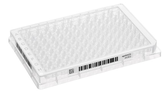
Figure 23 illustrates a commonly used 96-well format multi-well plate-utilized in numerous laboratory processes and instruments. Each plate, functioning as a sample container, possesses a distinct identifier, such as the barcode visible on its front surface. The wells within the plate, designated to accommodate the samples, are differentiated by their respective row and column positions. This grid-like arrangement is akin to the cells in a spreadsheet, albeit with a reversed schema where rows are denoted by letters and columns by numbers.
An example is provided below, presenting an instance of a Samples list that serves as an argument for the StartProgram() method. In this scenario, each well contains an individual sample, as detailed in the subsequent table:
| Array Index | ContainerId | SampleId | Position | CustomData |
| 0 | 1118642 | S0815001 | A1 | Sample |
| 1 | 1118642 | S0815002 | A2 | Sample |
| .. | .. | .. | .. | .. |
| 95 | 1118642 | S0815096 | H12 | Sample |
As all samples are housed within a single container, each element within the Samples list shares the identical container identifier. Nonetheless, individual samples are distinguishable through their unique sample identifiers, coupled with the respective well positions they occupy within the container. In this example the implementor decided to utilize the SampleInfoType structure's CustomData property to communicate the role of the fluid within each well from the application to the instrument. The specific usage of this attribute, however, extends beyond the scope of this LADS specification. Detailed specifications are likely to be outlined in a complementary specification utilizing LADS. Such specifications could potentially furnish more detailed information, possibly conveyed in formats like JSON.
The next example depicts a situation in which individual samples needed to be distributed across multiple wells to accommodate volume limitations. Additionally, calibration standards are introduced in this context.
| Array Index | ContainerId | SampleId | Position | CustomData |
| 0 | 1118642 | S081500A | A1 | Sample |
| 1 | 1118642 | S081500A | A2 | Sample |
| 2 | 1118642 | S081500B | A3 | Sample |
| 3 | 1118642 | S081500B | A4 | Sample |
| .. | .. | .. | .. | .. |
| 94 | 1118642 | Cal0 | H11 | Standard |
| 95 | 1118642 | Cal1 | H12 | Standard |
D.3 Conical tube example

Figure 23 illustrates a typical conical tube commonly employed for various purposes such as sample storage in freezers or during processes like centrifugation. These tubes are designed for singular sample use. A distinct container identifier can be assigned during manufacturing or applied later using a printed label provided by the user. In cases where a label is used, it might also directly display the sample identifier of the contents, although this isn't always guaranteed.
| Array Index | ContainerId | SampleId | Position | CustomData |
| 0 | eB0000031725 | S0815042 | 1 | Sample |
| 1 | eB0000031726 | S0815043 | 2 | Sample |
| .. | .. | .. | .. | .. |
| 31 | eB0000031856 | S0815073 | 32 | Sample |
The table shows an example of a Samples list as it might be used to initiate a separation run on a centrifuge. Each tube is accompanied by its unique container identifier and individual sample identifier. Given the vital role of balanced mass distribution in a centrifuge's rotor for optimal functioning, the orchestrating application (e.g., LIMS or ELN) for this process step recommends specific tube placement within the rotor. This recommendation is founded on the application's knowledge of the individual sample weights.
It's important to highlight that the precise meanings and formats of the Position and CustomData properties fall beyond the scope of the LADS Companion Specification. However, forthcoming companion specifications utilizing LADS might delve into these aspects in greater detail.
Annex E Example for representing the results of a program run in the VariableSet of the associated result object (Informative)
E.1 Overview
The example in this appendix illustrates how the result data of a program run can be represented within the VariableSet of the result object associated with it.
In the example, several samples are analysed in one run using an HPLC instrument. In this application it is useful to represent the raw data for each sample separately.
Please note that for other applications or use cases, other approaches to structuring may be conceivable and useful.
E.2 VariableSet example
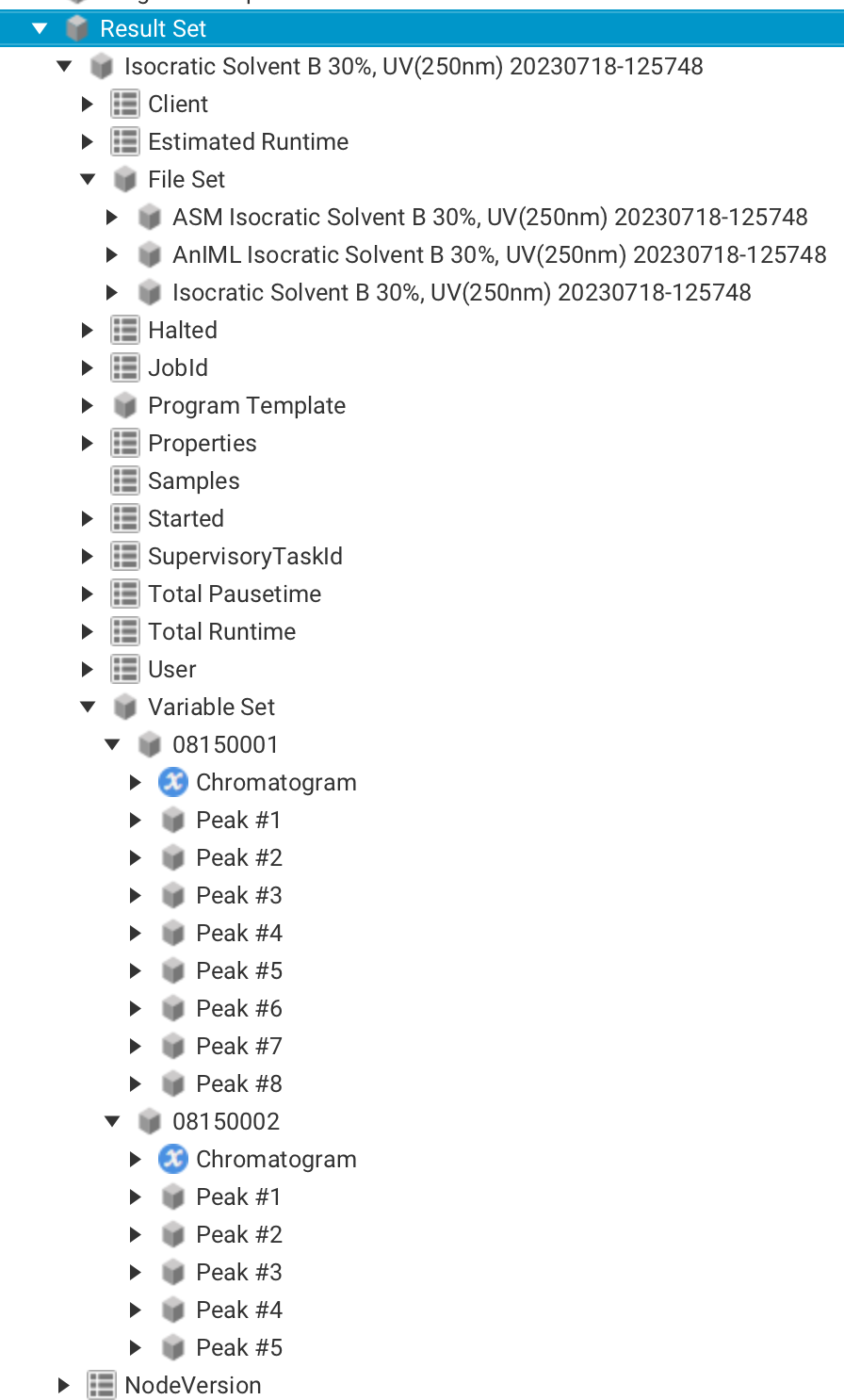
Figure 23 illustrates the structure of the result data generated from a program run called "Isocratic Solvent". The result data is organized in a structured manner, comprising different sections as follows:
Various pieces of important information are presented in the upper part of the picture, including the context data that was transferred at the beginning of the program run. Context data contains details about the execution environment, settings, and other relevant parameters. Additionally, the FileSet section is visible, which contains a collection of result files generated during the program run. Moreover, runtime parameters are displayed, including the start and stop times for the program.
The VariableSet is depicted in the lower part of the picture. In this example, the VariableSet is a structured container that organizes result data on a per-sample basis. During the program run, the individual sample names were passed as parameters using the variable named "Samples". This allows for clear identification and association of the results with each specific sample. For every sample, the result data is further broken down into two main components. Firstly, the raw data of the chromatogram is provided. The raw chromatogram data is stored using the standard OPC UA data type YArrayItemType (see Figure 24).
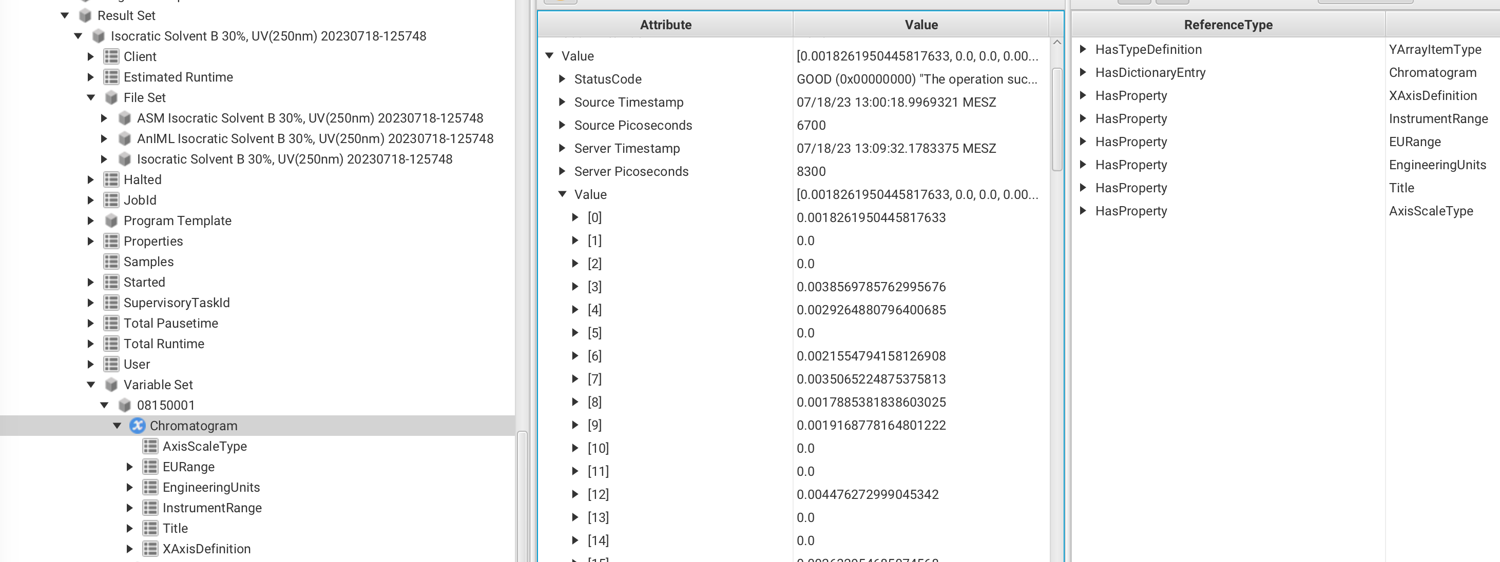
This data type serves several purposes, including facilitating the representation of the X-axis definition and data scaling. Additionally, it is worth noting that the Chromatogram variable includes a reference to a dictionary entry called "Chromatogram". This specific dictionary entry is linked to the machine-readable semantic definition of a Chromatogram in the Allotrope Ontology. The significance of this linkage lies in the fact that the data is labelled directly at its source, ensuring high-quality information for further machine-based reasoning.
In summary, this data type not only enables the representation of the Chromatagram's raw data but also optimizes data labelling and quality, thereby supporting more effective machine-based reasoning and analysis.
Secondly, the detected peaks for each sample are displayed in Figure 25.
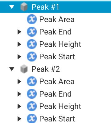
Various computed properties, such as area and height, are represented for each peak using OPC UA variables. Importantly, each of these variables can be linked to its respective semantic definition, provided it is available. This ensures that the properties associated with each peak are well-defined and can be easily understood and interpreted.
Agreement of Use
COPYRIGHT RESTRICTIONS
This document is provided "as is" by the OPC Foundation, SPECTARIS and the VDMA.
Right of use for this specification is restricted to this specification and does not grant rights of use for referred documents.
Right of use for this specification will be granted without cost.
This document may be distributed through computer systems, printed, or copied as long as the content remains unchanged and the document is not modified.
OPC Foundation, SPECTARIS and VDMA do not guarantee usability for any purpose and shall not be made liable for any case using the content of this document.
The user of the document agrees to indemnify OPC Foundation, SPECTARIS and VDMA and their officers, directors, and agents harmless from all demands, claims, actions, losses, damages (including damages from personal injuries), costs and expenses (including attorneys' fees) which are in any way related to activities associated with its use of content from this specification.
The document shall not be used in conjunction with company advertising and shall not be sold or licensed to any party.
The intellectual property and copyright are solely owned by the OPC Foundation, SPECTARIS and the VDMA.
PATENTS
The attention of adopters is directed to the possibility that compliance with or adoption of OPC, SPECTARIS or VDMA specifications may require use of an invention covered by patent rights. OPC Foundation, SPECTARIS or VDMA shall not be responsible for identifying patents for which a license may be required by any OPC, SPECTARIS or VDMA specification, or for conducting legal inquiries into the legal validity or scope of those patents that are brought to its attention. OPC, SPECTARIS or VDMA specifications are prospective and advisory only. Prospective users are responsible for protecting themselves against liability for infringement of patents.
WARRANTY AND LIABILITY DISCLAIMERS
WHILE THIS PUBLICATION IS BELIEVED TO BE ACCURATE, IT IS PROVIDED "AS IS" AND MAY CONTAIN ERRORS OR MISPRINTS. THE OPC FOUDATION, NOR SPECTARIS, NOR VDMA MAKES NO WARRANTY OF ANY KIND, EXPRESSED OR IMPLIED, WITH REGARD TO THIS PUBLICATION, INCLUDING BUT NOT LIMITED TO ANY WARRANTY OF TITLE OR OWNERSHIP, IMPLIED WARRANTY OF MERCHANTABILITY OR WARRANTY OF FITNESS FOR A PARTICULAR PURPOSE OR USE. IN NO EVENT SHALL THE OPC FOUNDATION NOR SPECTARIS, NOR VDMA BE LIABLE FOR ERRORS CONTAINED HEREIN OR FOR DIRECT, INDIRECT, INCIDENTAL, SPECIAL, CONSEQUENTIAL, RELIANCE OR COVER DAMAGES, INCLUDING LOSS OF PROFITS, REVENUE, DATA OR USE, INCURRED BY ANY USER OR ANY THIRD PARTY IN CONNECTION WITH THE FURNISHING, PERFORMANCE, OR USE OF THIS MATERIAL, EVEN IF ADVISED OF THE POSSIBILITY OF SUCH DAMAGES.
The entire risk as to the quality and performance of software developed using this specification is borne by you.
RESTRICTED RIGHTS LEGEND
This Specification is provided with Restricted Rights. Use, duplication, or disclosure by the U.S. government is subject to restrictions as set forth in (a) this Agreement pursuant to DFARs 227.7202-3(a); (b) subparagraph (c)(1)(i) of the Rights in Technical Data and Computer Software clause at DFARs 252.227-7013; or (c) the Commercial Computer Software Restricted Rights clause at FAR 52.227-19 subdivision (c)(1) and (2), as applicable. Contractor/manufacturer are the OPC Foundation, 16101 N. 82nd Street, Suite 3B, Scottsdale, AZ, 85260-1830
COMPLIANCE
The combination of SPECTARIS, VDMA and OPC Foundation shall at all times be the sole entities that may authorize developers, suppliers and sellers of hardware and software to use certification marks, trademarks or other special designations to indicate compliance with these materials as specified within this document. Products developed using this specification may claim compliance or conformance with this specification if and only if the software satisfactorily meets the certification requirements set by SPECTARIS or VDMA or the OPC Foundation. Products that do not meet these requirements may claim only that the product was based on this specification and must not claim compliance or conformance with this specification.
Trademarks
Most computer and software brand names have trademarks or registered trademarks. The individual trademarks have not been listed here.
GENERAL PROVISIONS
Should any provision of this Agreement be held to be void, invalid, unenforceable, or illegal by a court, the validity and enforceability of the other provisions shall not be affected thereby.
This Agreement shall be governed by and construed under the laws of the Federal Republic of Germany.
This Agreement embodies the entire understanding between the parties with respect to, and supersedes any prior understanding or agreement (oral or written) relating to, this specification.