
1 Scope
The scope of the OPC UA PROFINET Companion Specification is to define an OPC UA Information Model to represent the standardized object model (Object Dictionary) from PROFINET.
This OPC UA Information Model shall enable standard OPC UA Services to access the objects of PROFINET devices in a vendor independent way. The access can happen through an OPC UA Server directly integrated in the PROFINET device, or through an OPC UA Server aggregating Object Dictionaries of multiple PROFINET devices. This will allow the implementation of horizontal communication between PROFINET devices and OPC UA devices on the field level, as well the vertical communication initiated from devices in the process or enterprise level, e.g. for diagnostics, configuration, condition monitoring, visualization etc.
OPC Foundation
OPC UA is the interoperability standard for the secure and reliable exchange of data and information in the industrial automation space and in other industries. It is platform independent and ensures the seamless flow of information among devices from multiple vendors. The OPC Foundation is responsible for the development and maintenance of this standard.
OPC UA is a platform independent service-oriented architecture that integrates all the functionality of the individual OPC Classic specifications into one extensible framework. This multi-layered approach accomplishes the original design specification goals of:
Platform independence: from an embedded microcontroller to cloud-based infrastructure
Secure: encryption, authentication, authorization and auditing
Extensible: ability to add new features including transports without affecting existing applications
Comprehensive information modelling capabilities: for defining any model from simple to complex
PROFINET Standardization Group (PNO)
The PROFIBUS and PROFINET user organization (PNO: Profibus Nutzerorganisation e. V.) was founded in 1989 and is the largest automation community in the world and responsible for PROFIBUS and PROFINET, the two most important enabling technologies in automation today. The PNO is member of PROFIBUS and PROFINET International (PI).
The common interest of the PNO global network of vendors, developers, system integrators and end users covering all industries lies in promoting, supporting and using PROFINET. Regionally and globally about 1,400 member companies are working closely together to the best automation possible. No other fieldbus organization in the world has the same kind of global influence and reach.
2 Normative references
The following referenced documents are indispensable for the application of this specification. For dated references, only the edition cited applies. For undated references, the latest edition of the referenced document (including any amendments) applies.
[OPC 10000-1] OPC Unified Architecture - Part 1: Overview and Concepts - Version 1.04
[OPC 10000-2] OPC Unified Architecture - Part 2: Security Model - Version 1.04
[OPC 10000-3] OPC Unified Architecture - Part 3: Address Space Model - Version 1.04
[OPC 10000-4] OPC Unified Architecture - Part 4: Services - Version 1.04
[OPC 10000-5] OPC Unified Architecture - Part 5: Information Model - Version 1.04
[OPC 10000-6] OPC Unified Architecture - Part 6: Mappings - Version 1.04
[OPC 10000-7] OPC Unified Architecture - Part 7: Profiles - Version 1.04
[OPC 10000-9] OPC Unified Architecture - Part 9: Alarms and Conditions - Version 1.04
[OPC 10001-7] OPC Unified Architecture V1.04 - Amendment 7: Interfaces and AddIns
[OPC 10000-100] OPC Unified Architecture - Part 100: Devices - Version 1.02
[PN TAD] Topology and Asset Discovery - Guideline for PROFINET - Version 2.0 - Date: July 2017
[PN Service] IEC 61158-5-10, Industrial communication networks - Fieldbus specifications - Part 5-10: Application layer service definition - Type 10 elements
[PN Protocol] IEC 61158-6-10, Industrial communication networks - Fieldbus specifications - Part 6-10: Application layer protocol specification - Type 10 elements
[PN Diag] Guideline Diagnosis for PROFINET - Order No.: 7.142 - www.profibus.com
3 Terms, definitions and conventions
3.1 Overview
It is assumed that basic concepts of OPC UA information modelling and PROFINET are understood in this specification. This specification will use these concepts to describe the PROFINET OPC UA Information Model. For the purposes of this document, the terms and definitions given in [OPC 10000-1], [OPC 10000-3], [OPC 10000-4], [OPC 10000-5], [OPC 10000-7], [OPC 10000-100], as well as the following apply.
3.2 OPC UA for PROFINET terms
3.2.1 Asset
A piece of hardware and/or software which has a value for the user. In the scope of this document assets can discover properties like vendor, version or installation information by means of defined PROFINET services.
3.2.2 Startup Parameters
Device specific parameters which are set by the end user in the engineering system of the PLC. The parameter layout is described in the GSD file of the device. The configured values are transferred to the device during startup.
3.2.3 Tag-Function
The portion of the application specific device identification which defines the application specific function of an asset. The Tag Function is given during the planning phase of a plant e.g. by ECAD engineering tools. The specific usage of Tag-Function is defined by the OEM.
3.2.4 Tag-Location
The portion of the application specific device identification which defines the application specific location of an asset. Usually the TAG-Location is unique inside of a whole plant or OEM company. The Tag-Location is given during the planning phase of a plant e.g. by ECAD engineering tools. The specific usage of Tag-Location is defined by the OEM.
3.2.5 Edge Gateway
A physical device with one interface to the cell and an OPC UA interface to the factory.
3.3 Abbreviations and symbols
| AC | Alarm and Condition |
| AKZ/OKZ | Anlagenkennzeichen/Ortskennzeichen |
| AMx | Asset Management use case number x |
| AR | PROFINET Application Relationship |
| CR | PROFINET Communication Relationship |
| DA-AR | Device Access AR (Application Relationship) |
| DCS | Distributed Control Systems |
| DIAx | Diagnosis use case number x |
| EGW | Edge Gateway |
| ES | Engineering System of a PLC or IO controller |
| FB | Function Block |
| IOAR | Controller AR (Application Relationship) |
| IP | Internet Protocol |
| I&M | Identification and Maintenance |
| M | Mandatory (Implementation required) |
| NoS | Symbolic PROFINET DNS compatible station name of the IO device |
| O | Optional (Implementation optional) |
| PDev | Physical Device: Interface and Port Submodules |
| PLC | Programmable Logical Controller |
| PNO | Profibus Nutzerorganisation e.V.. |
3.4 Conventions used in this document
3.4.1 Conventions for Node descriptions
Node definitions are specified using tables (see Table 2).
Attributes are defined by providing the Attribute name and a value, or a description of the value.
References are defined by providing the ReferenceType name, the BrowseName of the TargetNode and its NodeClass.
If the TargetNode is a component of the Node being defined in the table, the Attributes of the composed Node are defined in the same row of the table.
The DataType is only specified for Variables; "[<number>]" indicates a single-dimensional array, for multi-dimensional arrays the expression is repeated for each dimension (e.g. [2][3] for a two-dimensional array). For all arrays the ArrayDimensions is set as identified by <number> values. If no <number> is set, the corresponding dimension is set to 0, indicating an unknown size. If no number is provided at all the ArrayDimensions can be omitted. If no brackets are provided, it identifies a scalar DataType and the ValueRank is set to the corresponding value (see [OPC 10000-5]. In addition, ArrayDimensions is set to null or is omitted. If it can be Any or ScalarOrOneDimension, the value is put into "{<value>}", so either "{Any}" or "{ScalarOrOneDimension}" and the ValueRank is set to the corresponding value (see [OPC 10000-3]) and the ArrayDimensions is set to null or is omitted. Examples are given in Table 1.
| Notation | DataType | ValueRank | ArrayDimensions | Description |
| Int32 | Int32 | -1 | omitted or null | A scalar Int32. |
| Int32[] | Int32 | 1 | omitted or {0} | Single-dimensional array of Int32 with an unknown size. |
| Int32[][] | Int32 | 2 | omitted or {0,0} | Two-dimensional array of Int32 with unknown sizes for both dimensions. |
| Int32[3][] | Int32 | 2 | {3,0} | Two-dimensional array of Int32 with a size of 3 for the first dimension and an unknown size for the second dimension. |
| Int32[5][3] | Int32 | 2 | {5,3} | Two-dimensional array of Int32 with a size of 5 for the first dimension and a size of 3 for the second dimension. |
| Int32{Any} | Int32 | -2 | omitted or null | An Int32 where it is unknown if it is scalar or array with any number of dimensions. |
| Int32{ScalarOrOneDimension} | Int32 | -3 | omitted or null | An Int32 where it is either a single-dimensional array or a scalar. |
The TypeDefinition is specified for Objects and Variables.
The TypeDefinition column specifies a symbolic name for a NodeId, i.e. the specified Node points with a HasTypeDefinition Reference to the corresponding Node.
The ModellingRule of the referenced component is provided by specifying the symbolic name of the rule in the ModellingRule column. In the AddressSpace, the Node shall use a HasModellingRule Reference to point to the corresponding ModellingRule Object.
If the NodeId of a DataType is provided, the symbolic name of the Node representing the DataType shall be used.
Nodes of all other NodeClasses cannot be defined in the same table; therefore only the used ReferenceType, their NodeClass and their BrowseName are specified. A reference to another part of this document points to their definition.
Table 2 illustrates the table. If no components are provided, the DataType, TypeDefinition and ModellingRule columns may be omitted and only a Comment column is introduced to point to the Node definition.
| Attribute | Value | ||||
| Attribute name | Attribute value. If it is an optional Attribute that is not set "--" will be used. | ||||
| References | NodeClass | BrowseName | DataType | TypeDefinition | ModellingRule |
|---|---|---|---|---|---|
| ReferenceType name | NodeClass of the TargetNode. | BrowseName of the target Node. If the Reference is to be instantiated by the server, then the value of the target Node's BrowseName is "--". | DataType of the referenced Node, only applicable for Variables. | TypeDefinition of the referenced Node, only applicable for Variables and Objects. | Referenced ModellingRule of the referenced Object. |
| NOTE Notes referencing footnotes of the table content. | |||||
Components of Nodes can be complex that is containing components by themselves. The TypeDefinition, NodeClass, DataType and ModellingRule can be derived from the type definitions, and the symbolic name can be created as defined in 3.4.3.1. Therefore, those containing components are not explicitly specified; they are implicitly specified by the type definitions.
3.4.2 NodeIds and BrowseNames
3.4.2.1 NodeIds
The NodeIds of all Nodes described in this standard are only symbolic names. Annex A defines the actual NodeIds.
The symbolic name of each Node defined in this specification is its BrowseName, or, when it is part of another Node, the BrowseName of the other Node, a ".", and the BrowseName of itself. In this case "part of" means that the whole has a HasProperty or HasComponent Reference to its part. Since all Nodes not being part of another Node have a unique name in this specification, the symbolic name is unique.
The namespace for all NodeIds defined in this specification is defined in Annex A. The NamespaceIndex for this namespace is Server-specific and depends on the position of the namespace URI in the server namespace table.
Note that this specification not only defines concrete Nodes, but also requires that some Nodes shall be generated, for example one for each Session running on the Server. The NodeIds of those Nodes are Server-specific, including the namespace. But the NamespaceIndex of those Nodes cannot be the NamespaceIndex used for the Nodes defined in this specification, because they are not defined by this specification but generated by the Server.
3.4.2.2 BrowseNames
The text part of the BrowseNames for all Nodes defined in this specification is specified in the tables defining the Nodes. The NamespaceIndex for all BrowseNames defined in this specification is defined in Annex A.
If the BrowseName is not defined by this specification, a namespace index prefix like '0:EngineeringUnits' or '2:DeviceRevision' is added to the BrowseName. This is typically necessary if a Property of another specification is overwritten or used in the OPC UA types defined in this specification. Table 110 provides a list of namespaces and their indexes as used in this specification.
3.4.3 Common Attributes
3.4.3.1 General
The Attributes of Nodes, their DataTypes and descriptions are defined in [OPC 10000-3]. Attributes not marked as optional are mandatory and shall be provided by a Server. The following tables define if the Attribute value is defined by this specification or if it is server specific.
For all Nodes specified in this specification, the Attributes named in Table 3 shall be set as specified in the table.
| Attribute | Value |
| DisplayName | The DisplayName is a LocalizedText. Each server shall provide the DisplayName identical to the BrowseName of the Node for the LocaleId "en". Whether the server provides translated names for other LocaleIds is server specific. |
| Description | Optionally a server-specific description is provided. |
| NodeClass | Shall reflect the NodeClass of the Node. |
| NodeId | The NodeId is described by BrowseNames as defined in 3.4.2.1. |
| WriteMask | Optionally the WriteMask Attribute can be provided. If the WriteMask Attribute is provided, it shall set all non-server-specific Attributes to not writable. For example, the Description Attribute may be set to writable since a Server may provide a server-specific description for the Node. The NodeId shall not be writable, because it is defined for each Node in this specification. |
| UserWriteMask | Optionally the UserWriteMask Attribute can be provided. The same rules as for the WriteMask Attribute apply. |
| RolePermissions | Optionally server-specific role permissions can be provided. |
| UserRolePermissions | Optionally the role permissions of the current Session can be provided. The value is server-specific and depends on the RolePermissions Attribute (if provided) and the current Session. |
| AccessRestrictions | Optionally server-specific access restrictions can be provided. |
3.4.3.2 Objects
For all Objects specified in this specification, the Attributes named in Table 4 shall be set as specified in the Table 4. The definitions for the Attributes can be found in [OPC 10000-5].
| Attribute | Value |
| EventNotifier | Whether the Node can be used to subscribe to Events or not is server specific. |
3.4.3.3 Variables
For all Variables specified in this specification, the Attributes named in Table 5 shall be set as specified in the table. The definitions for the Attributes can be found in [OPC 10000-5].
| Attribute | Value |
| MinimumSamplingInterval | Optionally, a server-specific minimum sampling interval is provided. |
| AccessLevel | The access level for Variables used for type definitions is server-specific, for all other Variables defined in this specification, the access level shall allow reading; other settings are server-specific. |
| UserAccessLevel | The value for the UserAccessLevel Attribute is server specific. It is assumed that all Variables can be accessed by at least one user. |
| Value | For Variables used as InstanceDeclarations, the value is server-specific; otherwise it shall represent the value described in the text. |
| ArrayDimensions | If the ValueRank does not identify an array of a specific dimension (i.e. ValueRank <= 0) the ArrayDimensions can either be set to null or the Attribute is missing. This behaviour is server specific. If the ValueRank specifies an array of a specific dimension (i.e. ValueRank > 0) then the ArrayDimensions Attribute shall be specified in the table defining the Variable. |
| Historizing | The value for the Historizing Attribute is server specific. |
| AccessLevelEx | If the AccessLevelEx Attribute is provided, it shall have the bits 8, 9, and 10 set to 0, meaning that read and write operations on an individual Variable are atomic, and arrays can be partly written. |
3.4.3.4 VariableTypes
For all VariableTypes specified in this specification, the Attributes named in Table 6 shall be set as specified in the table. The definitions for the Attributes can be found in [OPC 10000-5].
| Attributes | Value |
| Value | Optionally a server-specific default value can be provided. |
| ArrayDimensions | If the ValueRank does not identify an array of a specific dimension (i.e. ValueRank <= 0) the ArrayDimensions can either be set to null or the Attribute is missing. This behaviour is server specific. If the ValueRank specifies an array of a specific dimension (i.e. ValueRank > 0) then the ArrayDimensions Attribute shall be specified in the table defining the VariableType. |
3.4.3.5 Methods
For all Methods specified in this specification, the Attributes named in Table 7 shall be set as specified in the table. The definitions for the Attributes can be found in [OPC 10000-5].
| Attributes | Value |
| Executable | All Methods defined in this specification shall be executable (Executable Attribute set to "True"), unless it is defined differently in the Method definition. |
| UserExecutable | The value of the UserExecutable Attribute is server specific. It is assumed that all Methods can be executed by at least one user. |
4 General information to PROFINET and OPC UA
4.1 Introduction to PROFINET
4.1.1 What is PROFINET?
PROFINET is the communication standard for automation from PROFIBUS & PROFINET International (PI). Its modular range of functions makes PROFINET a flexible system for all applications and markets. PROFINET is the networking solution of production and process automation, from applications with functional safety requirements and the entire spectrum of drive technology to isochronous motion control applications. The use of application profiles allows optimal usage of PROFINET in all areas of automation engineering.
4.1.2 System Model of a PROFINET System
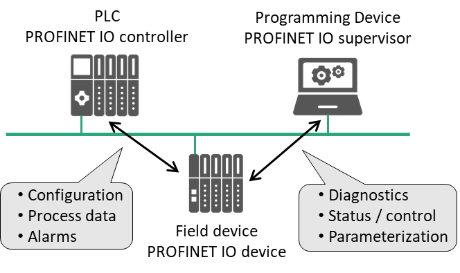
IO controller: This is typically the Programmable Logic Controller (PLC) in which the automation program runs. The IO controller provides output data to the configured IO devices in its role as provider and is the consumer of input data.
IO device: An IO device is a distributed IO field device connected to one or more IO controllers via PROFINET. The IO device is the provider of input data and the consumer of output data from the IO controller.
IO supervisor: This can be a programming device (PG), personal computer (PC) or human machine interface (HMI) device for commissioning or diagnostic purposes.
A system unit contains at least one IO controller and one or more IO devices. IO supervisors are usually integrated only temporarily for commissioning or troubleshooting purposes.
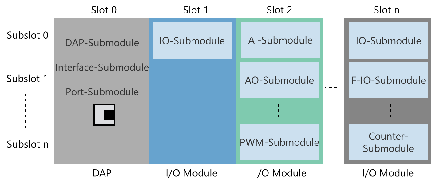
4.1.3 Device Model of an IO Device
In its logical structure, a PROFINET field device is always modular in design. Modularity in the logical sense, however, does not require actual modularity in the electrical and mechanical design sense. An IO device is usually comprised of a communication module with Ethernet interface and (physical or virtual) modules assigned to it. The assigned modules handle the actual process data traffic. The access point for communication (Ethernet interface with data processing) is called the DAP (Device Access Point). The following structures are standardized for an IO device:
The device model consists of slots, subslots, modules and submodules.
The slot designates the insertion slot of a module in an IO field device. A field device usually has two or more slots.
A module is comprised of one or more submodules or provides available subslots into which submodules can be inserted.
The modules themselves have no task other than to provide structuring. The actual inputs and outputs (channels) are implemented in its submodules. The granularity of the channels (bitwise, bytewise or wordwise division of IO data) is determined by the manufacturer. Acyclic services always address submodules. Therefore, a module always contains at least one submodule.
The data content of a submodule is always accompanied by status information. The index specifies the data within a submodule inserted into a slot/subslot which can be read or written acyclically using read/write services. For example, parameters can be written to a module, or manufacturer-specific module data can be read out based on an index. Specific indexes are defined in the standard here. Additional indexes can be freely defined by the manufacturer.
The submodule is the owner of the user data, diagnostics, channels, actual configuration, records and I&M data. Cyclic IO data of the submodule in the device is addressed by specifying the slot/subslot combination of the insertion slot. They can be freely defined by the manufacturer. For acyclic data communication via read/write services, an application can specify the data of the submodule to be addressed using slot, subslot and index (Figure 2).
4.1.4 Communication Relationships
To establish communication between the higher-level controller and an IO device, the communication paths must be established. These are set up by the IO controller during system startup based on the configuration data received from the engineering system. This specifies the data exchange explicitly.
All data exchange is embedded into an AR (Application Relationship) (Figure 3). Within the AR, CRs (Communication Relationships) specify the data explicitly. As a result, all data for device modelling, including the general communication parameters, are downloaded to the IO device. An IO device can have multiple ARs established from different IO controllers, for example, for shared devices.
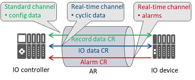
The communication channels for cyclic data exchange (IO data CR), acyclic data exchange (record data CR) and alarms (alarm CR) are set up simultaneously. Multiple IO controllers can be used in a PROFINET system (Figure 4). If these IO controllers can access the same data in the IO devices, this must be specified during parameter configuration (shared devices and shared inputs).
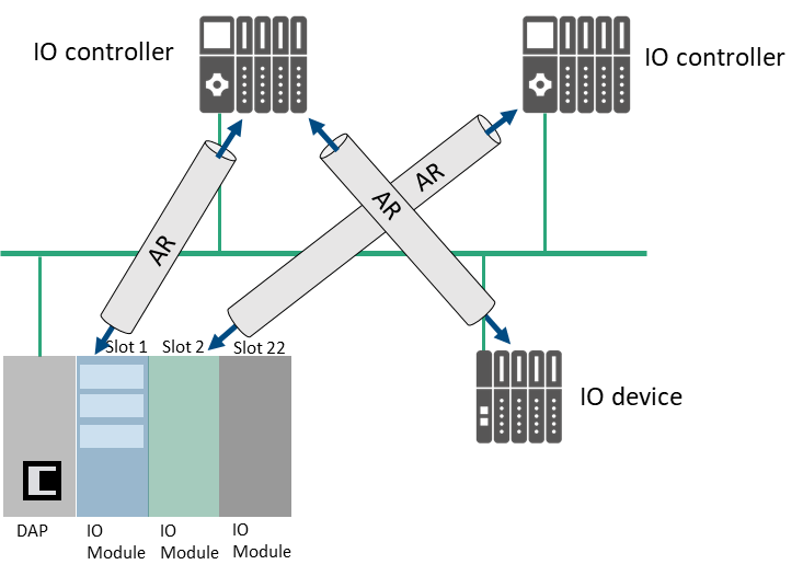
An IO controller can establish one AR each with multiple IO devices. Within an AR, several IO CRs on different APIs can be used for data exchange. This can be useful, for example, if more than one user profile (PROFIdrive, ENCODER etc.) is involved in communication and different submodules are required.
4.2 Introduction to OPC Unified Architecture
4.2.1 What is OPC UA?
OPC UA is an open and royalty free set of standards designed as a universal communication protocol. While there are numerous communication solutions available, OPC UA has key advantages:
A state of art security model (see [OPC 10000-2]).
A fault tolerant communication protocol.
An information modelling framework that allows application developers to represent their data in a way that makes sense to them.
OPC UA has a broad scope which delivers for economies of scale for application developers. This means that a larger number of high-quality applications at a reasonable cost are available. When combined with semantic models such as PROFINET, OPC UA makes it easier for end users to access data via generic commercial applications.
The OPC UA model is scalable from small devices to ERP systems. OPC UA Servers process information locally and then provide that data in a consistent format to any application requesting data - ERP, MES, PMS, Maintenance Systems, HMI, Smartphone or a standard Browser, for examples. For a more complete overview see [OPC 10000-1].
4.2.2 Basics of OPC UA
As an open standard, OPC UA is based on standard internet technologies, like TCP/IP, HTTP, Web Sockets.
As an extensible standard, OPC UA provides a set of Services (see [OPC 10000-4]) and a basic information model framework. This framework provides an easy manner for creating and exposing vendor defined information in a standard way. More importantly all OPC UA Clients are expected to be able to discover and use vendor-defined information. This means OPC UA users can benefit from the economies of scale that come with generic visualization and historian applications. This specification is an example of an OPC UA Information Model designed to meet the needs of developers and users.
OPC UA Clients can be any consumer of data from another device on the network to browser based thin clients and ERP systems. The full scope of OPC UA applications is shown in Figure 5.

OPC UA provides a robust and reliable communication infrastructure having mechanisms for handling lost messages, failover, heartbeat, etc. With its binary encoded data, it offers a high-performing data exchange solution. Security is built into OPC UA as security requirements become more and more important especially since environments are connected to the office network or the internet and attackers are starting to focus on automation systems.
4.2.3 Information modelling in OPC UA
4.2.3.1 Concepts
OPC UA provides a framework that can be used to represent complex information as Objects in an AddressSpace which can be accessed with standard services. These Objects consist of Nodes connected by References. Different classes of Nodes convey different semantics. For example, a Variable Node represents a value that can be read or written. The Variable Node has an associated DataType that can define the actual value, such as a string, float, structure etc. It can also describe the Variable value as a variant. A Method Node represents a function that can be called. Every Node has several Attributes including a unique identifier called a NodeId and a non-localized name called a BrowseName. An Object representing a 'Reservation' is shown in Figure 6.

Object and Variable Nodes represent instances and they always reference a TypeDefinition (ObjectType or VariableType) Node which describes their semantics and structure. Figure 7 illustrates the relationship between an instance and its TypeDefinition.
The type Nodes are templates that define all the children that can be present in an instance of the type. In the example in Figure 7 the PersonType ObjectType defines two children: First Name and Last Name. All instances of PersonType are expected to have the same children with the same BrowseNames. Within a type the BrowseNames uniquely identify the children. This means Client applications can be designed to search for children based on the BrowseNames from the type instead of NodeIds. This eliminates the need for manual reconfiguration of systems if a Client uses types that multiple Servers implement.
OPC UA also supports the concept of sub-typing. This allows a modeler to take an existing type and extend it. There are rules regarding sub-typing defined in [OPC 10000-3], but in general they allow the extension of a given type or the restriction of a DataType. For example, the modeler may decide that the existing ObjectType in some cases needs an additional Variable. The modeler can create a subtype of the ObjectType and add the Variable. A Client that is expecting the parent type can treat the new type as if it was of the parent type. Regarding DataTypes, subtypes can only restrict. If a Variable is defined to have a numeric value, a sub type could restrict it to a float.

References allow Nodes to be connected in ways that describe their relationships. All References have a ReferenceType that specifies the semantics of the relationship. References can be hierarchical or non-hierarchical. Hierarchical references are used to create the structure of Objects and Variables. Non-hierarchical references are used to create arbitrary associations. Applications can define their own ReferenceType by creating subtypes of an existing ReferenceType. Subtypes inherit the semantics of the parent but may add additional restrictions. Figure 8 depicts several References, connecting different Objects.

The figures above use a notation that was developed for the OPC UA specification. The notation is summarized in Figure 9. UML representations can also be used; however, the OPC UA notation is less ambiguous because there is a direct mapping from the elements in the figures to Nodes in the AddressSpace of an OPC UA Server.
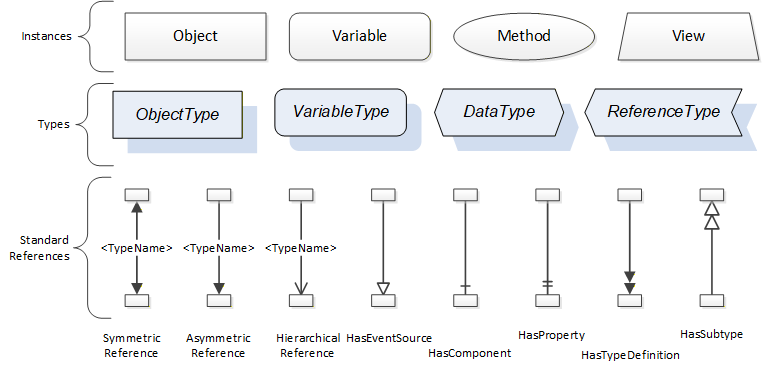
A complete description of the different types of Nodes and References can be found in [OPC 10000-3] and the base structure is described in [OPC 10000-5].
OPC UA specification defines a very wide range of functionality in its basic information model. It is not expected that all Clients or Servers support all functionality in the OPC UA specifications. OPC UA includes the concept of Profiles, which segment the functionality into testable certifiable units. This allows the definition of functional subsets (that are expected to be implemented) within a companion specification. The Profiles do not restrict functionality, but generate requirements for a minimum set of functionalities (see [OPC 10000-7])
4.2.3.2 Namespaces
OPC UA allows information from many different sources to be combined into a single coherent AddressSpace. Namespaces are used to make this possible by eliminating naming and id conflicts between information from different sources. Namespaces in OPC UA have a globally unique string called a NamespaceUri and a locally unique integer called a NamespaceIndex. The NamespaceIndex is only unique within the context of a Session between an OPC UA Client and an OPC UA Server. The Services defined for OPC UA use the NamespaceIndex to specify the Namespace for qualified values.
There are two types of values in OPC UA that are qualified with Namespaces: NodeIds and QualifiedNames. NodeIds are globally unique identifiers for Nodes. This means the same Node with the same NodeId can appear in many Servers. This, in turn, means Clients can have built in knowledge of some Nodes. OPC UA Information Models generally define globally unique NodeIds for the TypeDefinitions defined by the Information Model.
QualifiedNames are non-localized names qualified with a Namespace. They are used for the BrowseNames of Nodes and allow the same names to be used by different information models without conflict. TypeDefinitions are not allowed to have children with duplicate BrowseNames; however, instances do not have that restriction.
4.2.3.3 Companion Specifications
An OPC UA companion specification for an industry specific vertical market describes an Information Model by defining ObjectTypes, VariableTypes, DataTypes and ReferenceTypes that represent the concepts used in the vertical market, and potentially also well-defined Objects as entry points into the AddressSpace.
5 Use cases
5.1 Introduction
This chapter contains the basic use case specification for the PROFINET integration to OPC UA. Its purpose is to define the scope and the requirements for the companion standard.
5.2 Architecture
5.2.1 Overview
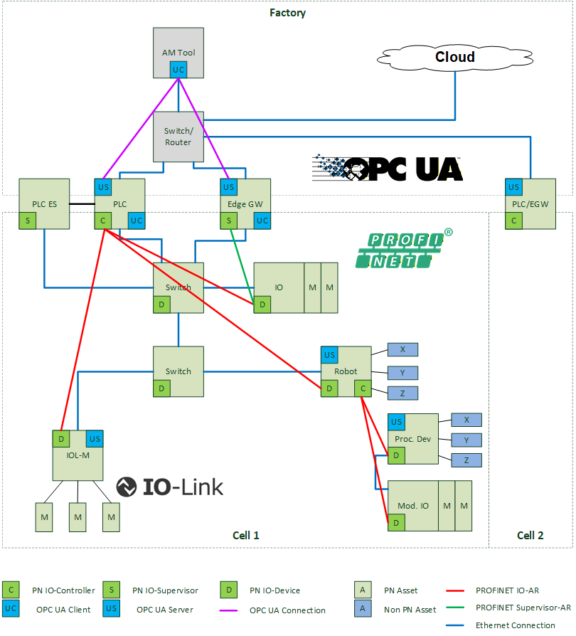
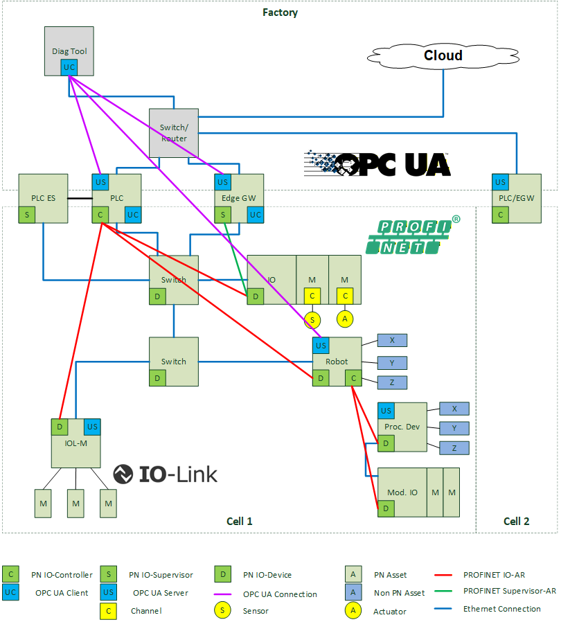
The following figure contains the basic architecture for the integration of PROFINET to OPC UA. It is used to define the scope of the use cases in this document.
5.2.2 Description
Aim of the current PROFINET OPC UA companion standard is the mapping of PROFINET concepts and functions to the corresponding concepts of OPC UA. For this mapping, an architecture of devices and instances helps to define the scope, responsibilities and borders.
The upper area of the architecture contains engineering tools or software which acts as OPC UA Client for the devices implementing the OPC UA Servers. It is important to understand, that these engineering tools can be specialized for a certain end customer use-case like asset management and diagnosis. A combination of responsibilities in one tool is possible as well. Moreover, this document does not suggest any implementation of these tools. They can be located as OPC UA Client FB in one PLC, as software parts of an ERP system, developed by an end customer or a vendor of the Edge gateways or PLCs. The requirements of the specialized engineering tools are described in the corresponding use case chapter. Scope of this document is the communication between those OPC UA Clients and OPC UA Servers implementing the defined PROFINET information model.
The interface between the OPC UA Clients and the PROFINET devices is built by components which are OPC UA Servers and implements the role of PROFINET IO controller, IO supervisor or IO device. Each of these components support the whole or parts of the standardized PROFINET OPC UA information model, depending on the information that is available:
PLC:
A PLC may map all configured and connected PROFINET devices to OPC UA. The OPC UA information model in PLCs is built based on the expected configuration downloaded from the PLC specific engineering system to the PLC. It is not necessary to have an online connection to the connected devices. In this case the relevant parts of the information model have an appropriate status variable. The standardized PROFINET specific OPC UA objects may be provided in addition to other OPC UA objects like e.g. PLCopen DA variables.
In cascaded Systems as shown above, every automation device with PROFINET IO controller functionality like e.g. robots is able to show the underlying devices as part of their specific information model in the same way as a PLC. An asset management or diagnosis tool may connect to all devices with IO controller functionality to have a complete view to all devices by the perspective of an IO controller.
If the underlying devices are not in the same IP network as the IO controller, OPC UA offers a way like aggregation or direct access through firewalls.
Edge gateway:
An Edge gateway may discover the connected PROFINET devices and their configuration and diagnosis with PROFINET services. It does not have information of devices configured in the PLC but not operational in the network. The standardized OPC UA PROFINET objects are provided in addition to other product specific OPC UA objects of the Edge gateway.
If the underlying devices are not in the same IP network as the Edge gateway, OPC UA offers a way like aggregation or direct access through firewalls.
IO device:
An IO device may discover the local PROFINET interface, their configuration and diagnosis, the local slot/subslot configuration, direct neighborhood and application relationships (ARs) to all IO controllers in shared device scenarios. It does not have information of other devices in the network. But in addition, an IO device may offer asset and diagnostics information via a local OPC UA Server which cannot be get by a PLC or Edge gateway. This is e.g. the case, if there is no PROFINET connection to an IO controller or the dynamics is higher than the scan cycle of an Edge gateway. A local representation of a PROFINET information model as part of an IO Device must be considered by the mapping of PROFINET to OPC UA.
In each of the above OPC UA Servers, the whole or parts of the standardized PROFINET OPC UA information model are contained. It is important that in all cases the same information is represented in a consistent manner.
5.2.3 Information from GSD files and engineering tools
A natural language identification of objects in the namespace of the OPC UA Server requires information from the GSDML files involved and/or given by the engineering system of a PLC like module and submodule names, vendor specific diagnosis text messages or user comments to a module or submodule.
The mapping of PROFINET to OPC UA considers those data in the information model independent of the way the OPC UA Server gets it.
5.3 Use Case description
5.3.1 General
Use cases in this document are described in tables to have a unified representation. These tables contain the following rows:
Goal:
The objective of the use case.
Implements:
Relation to the corresponding requirement.
Preconditions:
One or more conditions which must be met as a precondition for the use case.
OPC UA mapping:
This section describes the behavior of the use case by an OPC UA viewpoint.
5.3.2 Asset management
5.3.2.1 General
The following asset management use-cases focus mainly on running applications and plants. During the commissioning phase changes in the assets are normal. The asset management phase begins after the acceptance tests of the commissioning phase.
5.3.2.2 PROFINET basics
The following chapters give a brief introduction to relevant PROFINET objects and services, which are used in the scope of the OPC UA integration use cases. A detailed definition of these terms can be found in documents from Chapter 2 or several printed documents which are available at www.profinet.com. Nevertheless, the reader of this document should be able to understand the basic PROFINET concepts without knowledge of all the details.
It is important, that the support of some PROFINET information below is not mandatory. Therefore, an optimal usability and features coverage can be achieved with devices which implement a maximum of optional PROFINET features. The requirement of the PROFINET specification is denoted by the capital (PN-M) for mandatory or (PN-O) for optional.
5.3.2.2.1 General
The following information is general for all PROFINET devices.
Device Information (PN-M):
Information that is related to the device with the PROFINET connection to the network. Examples are VendorID, DeviceID, DCP type identification, DNS Name of Station and IP-Address.
Physical Topology (PN-M):
PROFINET can discover the physical topology of installed devices as all devices exchange neighborhood information with the LLDP protocol.
Real Configuration (PN-M):
The real configuration of a PROFINET device contains slots and subslots with modules and submodules plugged in the device independent from any controller connection. Each module/submodule is identified by a module/submodule identification number which must be unique in the scope of one DeviceID. One defined submodule is the representative of the device; one submodule is the representative of a module. Therefore, the submodule is the carrier of all information. Modules and submodules which are installed in the real configuration of the device can be discovered with a PROFINET service. These modules/submodules are the carrier of the asset information.
Expected Configuration (PN-M):
The expected PROFINET configuration is the result of the PROFINET engineering in the configuration tool of the PLC. It contains the devices, modules, submodules which are configured in the engineering system of the PLC, downloaded to the controller and transferred to the devices during startup.
The expected configuration can be read with a defined PROFINET service.
Module Diff Block (PN-M):
The difference between the expected configuration and the real configuration. The reference to the difference is the expected configuration. The module diff block can be read with a defined PROFINET service.
5.3.2.2.2 I&M
PROFINET defines Identification and Maintenance functions since PROFIBUS. As there is a long history, some restrictions in these data are possible. In general, I&M contain defined properties and values to identify the asset more precise as it is possible with IDs and without knowledge of the GSD file.
I&M0 - Electronic Faceplate (PN-M for device, PN-O for Modules):
Version Information of the submodule like serial number, HW-Version and FW-Version. I&M0 data are read-only.
I&M1 - function and location (PN-O):
A unique function and location of the device/submodule as visible strings. I&M1 data must be written by a PROFINET engineering tool or PLC before they can be used. The mapping to marking systems like IEC 81346 are in the responsibility of the user and not in scope of this document.
I&M2 - comment (PN-O):
A comment to the device as visible string. I&M2 data must be written by a PROFINET engineering tool or PLC before they can be used.
I&M3 - installation date (PN-O):
The installation date of the device. I&M3 data must be written by a PROFINET engineering tool or PLC before they can be used.
I&M4 - signature (PN-M and defined for Functional Safety):
If the submodule is configured by an external safety configuration tool, this tool can write a signature of the parameter set in I&M4 data of the submodule. With its signature it is possible to discover differences between a stored parameter set of the engineering tool and a parameter set in the field. I&M4 is only defined for safety devices.
I&M5 - additional information (PN-O)
Offers additional information about a communication module which is part on an IO device. If the device (e.g. a robot) is made by company A, and the communication module by company B, I&M0 contain information about the robot and company A, I&M5 contain information about the communication module and company B.
5.3.2.2.3 Asset management in PROFINET
In addition to the above I&M data which are only bound to the PROFINET address elements slot/subslot, additional end customer requirements for enhanced asset management capabilities are incorporated in the PROFINET specification. Definition of PROFINET asset management objects sometimes use data types already defined by I&M properties. In addition to them other asset management properties are available. Asset information can be bound to slots and subslots to extend information, which cannot be modelled with I&M properties. Moreover, the PROFINET specification defines a level-tree of assets which objects are independent from the slot/subslot addressing scheme.
The following picture shows a possible example of asset management usage in a modular IO device.
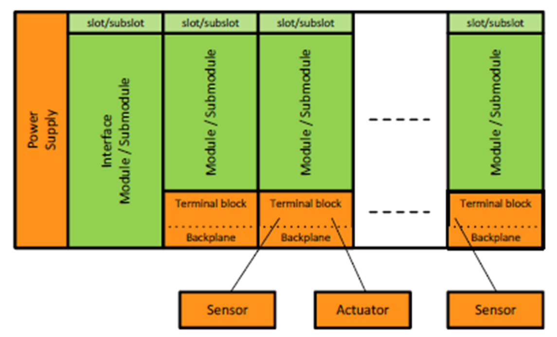
The green elements are the modules and submodules of the station carrying I&M information. Additional asset information like version info of the power supply, terminal blocks or connected sensors and actors can be described by means of asset management objects, which are not directly related to the slot/subslot model.
In addition to this example PROFINET AM can be used to manage all components with loadable software, which can be device or module firmware as well as application programs running on PLCs or robots.
The following asset management objects can be accessed via a defined acyclic read service.
AM_Info:
The scope of the asset information, which can be "full information", "firmware only" or "hardware only".
AM_Location:
The location of an asset within a device as 16 subsequent octets. The location can be either "slot/subslot" to extend I&M information or "level tree" to form hierarchical structures of assets.
IM_UniqueIdentifier:
A 128-bit globally unique identification of the asset created by the manufacturer e.g. by means of ISO/IEC 9834-8:2014.
IM_Annotation:
A manufacturer-specific identifier of the asset such as the asset's name as Unicode string8 with the length of 64 octets.
IM_OrderID:
The order ID of the asset as UnicodeString8 with the length of 64 octets.
AM_SoftwareRevision:
The edition of the software of the asset as UnicodeString8 with 64 octets.
IM_Software_Revision:
Software revision in a special I&M coding of VisibleString[9].
AM_HardwareRevision:
The edition of the hardware of the asset as UnicodeString8 with 64 octets.
IM_Hardware_Revision
The hardware revision in I&M coding.
IM_Serial_Number:
A unique production number of the asset set by the manufacturer as VisibleString16.
AM_DeviceIdentification:
The unique device identification in the address space of an organization like VendorID & DeviceID for PI. Or OUI for IO-Link.
AM_TypeIdentification:
Used to identify the family of the asset and assigned by the manufacturer like "IO controller", "IO device", "IO-Module". Standard and manufacturer specific values are defined in [3].
5.3.2.3 Architecture
The architecture from Chapter 5.2.1 can be specialized for the usage within asset management. An asset management tool as OPC UA Client is connected to an OPC UA Server located in a PLC, Edge gateway or IO device. The PLC acts as IO controller for the underlying PROFINET system. The Edge gateway is scanning the underlying assets by means of DCP and implicit Read Services.
5.3.2.4 End User Requirements
The following end customer requirements are relevant for asset management. A more detailed description of these use cases can be found in [PN TAD].
The requirements are written from the perspective of an asset management tool user.
| ID | Name | Details |
|---|---|---|
| AM1 | Unique Identification | The asset must have a unique Identification in the namespace of all installed assets independent whether the asset is installed in a cell or a machine. |
| AM2 | Hardware and Firmware version management | Hardware and Firmware versions of the installed equipment should be discovered or compared with possible white-lists or black-lists. |
| AM3 | Application version management | The application programs running on PLCs, robots or drives are also versioned and part of the asset management. Versioning for these applications shall be visible. This requirement can be solved in a comparable way then firmware version management. |
| AM4 | Asset changed | End users want to know, if an asset is changed. |
| AM5 | Asset installed | A new asset is installed in the cell or machine. |
| AM6 | Asset removed | A new asset is removed from the cell or machine. |
| AM7 | Asset localization changed | The physical location of an asset was changed. E.g. moved from one machine to another. |
| AM8 | Machine part discovery | Usually the assets installed in a machine are in the responsibility of the machine builder. If some of these assets are replaced by the operator of a machine, the asset discovery of integrated assets is required. |
| AM9 | PROFIsafe Device parameters changed | The OEM wants to know, if PROFIsafe Device parameters are changed by an external engineering tool in the device and/or in the engineering system of the IO controller for startup parameters. |
| AM10 | Asset location changed | The asset is moved to a different place in the asset hierarchy. |
| AM11 | I&M Write | The OEM wants to set writeable I&M1...3 parameters via OPC UA independent from the configuration in the engineering system of the IO controller. |
| AM12 | Network parameter check | The end user wants to know, if all installed PROFINET devices follow specific rules for their network parameters given by the OEM. Network parameters are: PROFINET Name of Station IP-Address Subnet mask Default gateway Allowed cycle times Allowed data hold times |
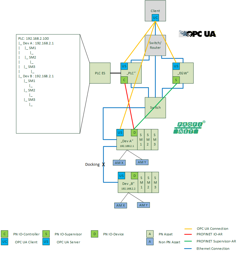
| AM13 | Docking Devices | PROFINET devices which are connected and disconnected to the network at runtime in normal operation. |
5.3.2.5 Asset discovery
The following use case describes the discovery of installed PROFINET assets.
| Goal | The end user wants to discover all installed assets within a cell. All available information shall be discovered. |
|---|---|
| Implements | AM1, AM8, AM12 |
| Preconditions | All PROFINET components are configured and connected to the network. Station Names and IP-Addresses of the devices can be set. The Tag-Function and Tag-Location in I&M1 and asset management data are available. The PLC/Edge Gateway is scanning the underlying network continuously with DCP-Identify and PROFINET read services to get all relevant asset information. For details see [1]. |
| OPC UA Mapping | AM tool connects the OPC UA Server in the EGW/PLC/Device. The OPC UA information model in the EGW is built based on the found devices, modules and submodules of the last scan cycle. The required I&M and Asset information are read with the corresponding PROFINET services in the context of an implicit or device access AR. The OPC UA information model in a PLC is built corresponding to the real configuration downloaded from the engineering system of the PLC. The required I&M and Asset information are read with the corresponding PROFINET services in the context of the already established IO-AR. The OPC UA information model in a device is build corresponding to the real configuration plugged by the local device application. The required I&M and Asset information are implemented according the local device application. |
| Remarks | When there is no station name, the MAC address shall be used as BrowseName. If those devices get a correct name, they are visible as a different entity under their station name as the OPC UA browse name shall be unique. |
5.3.2.6 Asset change detection
The following chapter describes criteria to detect changes in the assets. They may be useful to implement corresponding functionalities in the asset management tool.
5.3.2.6.1 Asset information changed
The user wants to be informed if assets in the plant or machine were changed. The following table describes criteria to detect changes.
Implements AM4.
| Changed asset | Criteria | PROFINET Service |
|---|---|---|
| Device | Software Version changed AKZ/OKZ changed | I&M0:SoftwareVersion I&M1: AKZ/OKZ |
| Module Submodule | Software Version changed AKZ/OKZ changed | I&M0:SoftwareVersion I&M1: AKZ/OKZ |
| Asset | Software Version changed AKZ/OKZ changed | Will be part of a next version of the companion specification |
5.3.2.6.2 Asset changed
The user wants to be informed if assets in the plant or machine were changed. The following table describes criteria to detect changes.
Implements AM4.
| Changed asset | Criteria | PROFINET Service |
|---|---|---|
| Device | Serial number changed | IM_SerialNumber of the DAP |
| Module Submodule | Serial number changed | IM_SerialNumber of the module/submodule |
| Asset | Serial number changed | IM_SerialNumber of the asset |
5.3.2.6.3 Asset installed
The user wants to be informed if assets in the plant or machine were added. The following table describes criteria to detect changes.
Implements AM5.
| Added asset | Criteria | PROFINET Service |
|---|---|---|
| Device | Device with unknown MAC address in the network | DCP-Identify-All |
| Module Submodule | Real configuration contains a new module/submodule | RecordRead RealIdentificationData for all API's |
| Asset | Asset list contains a new entry | RecordRead AM_Info |
5.3.2.6.4 Asset removed
The user wants to be informed if assets in the plant or machine were removed. The following table describes criteria to detect changes.
Implements AM6.
| Removed asset | Criteria | PROFINET Service |
|---|---|---|
| Device | Device list smaller than previous scan | DCP-Identify-All |
| Module Submodule | Real configuration contains less modules/submodules | RecordRead RealIdentificationData for all API's |
| Asset | Asset list contains less modules/submodules | RecordRead AM_Info |
5.3.2.6.5 Docking devices
Special cases in PROFINET are devices which are connected and disconnected to the network at runtime, like devices installed on a tool gripped by a robot. It is not guaranteed, that docking devices can be fully discovered by the scan cycle of Edge gateways. An IO controller may show information of docking devices in the local OPC UA Server.
5.3.2.6.6 Firmware or application program updated
One important use case of asset management is the detection of firmware updates in the plant or machine as well as a version change in a programmable application running on a PLC, robot or drive. The following table describes criteria to detect changes.
Implements AM2, AM3.
| Updated asset | Criteria | PROFINET Service |
|---|---|---|
| Device | IM_SoftwareRevision of the submodule representing the device has a changed value. | RecordRead I&M0FilterData RecordRead I&M0 |
| Module Submodule | IM_SoftwareRevision of module/submodule has a changed value. The modules/submodules with explicit I&M data can be found asking for I&M0FilterData. | RecordRead I&M0FilterData RecordRead I&M0 |
| Asset | IM_SoftwareRevision or AM_SoftwareRevision of asset has a changed value | RecordRead AM_Info |
5.3.2.6.7 PROFIsafe device parameters changed
Sometimes it is important to know, if a safety parameter of a device in the plant or machine, set by an engineering tool, was changed. The following table describes criteria to detect changes.
Implements AM9.
| Changed Parameter | Criteria | PROFINET Service |
|---|---|---|
| Device | IM_Signature of DAP has a changed value | RecordRead I&M4 |
| Module Submodule | IM_ Signature of module/submodule has a changed value | RecordRead I&M4 |
| Asset | Not available |
5.3.2.6.8 Asset Localization changed
As special case for asset management is a change of a device in the physical topology. This is sometimes the case while finding errors in the field by exchange of devices.
Implements AM10.
| Topology change | Criteria | PROFINET Service |
|---|---|---|
| Device moved | Changed neighborhood information of a device with a known MAC address and/or SerialNumber | DCP_Identifiy RecordRead PDRealData |
| Device added | Device with an unknown MAC address in physical topology | DCP_Identifiy RecordRead PDRealData |
| Device removed | New physical topology without a device which was there before | DCP_Identifiy RecordRead PDRealData |
5.3.3 PROFINET Diagnosis
5.3.3.1 General
PROFINET defines a comprehensive diagnostic model. The main focuses of this model are device diagnosis and network diagnosis. Diagnosis scenarios can appear during startup of a plant as well as during operation.
5.3.3.2 PROFINET Basics
Details of the PROFINET diagnosis concepts are contained in [PN Diag]. The main ideas are summarized in this chapter:
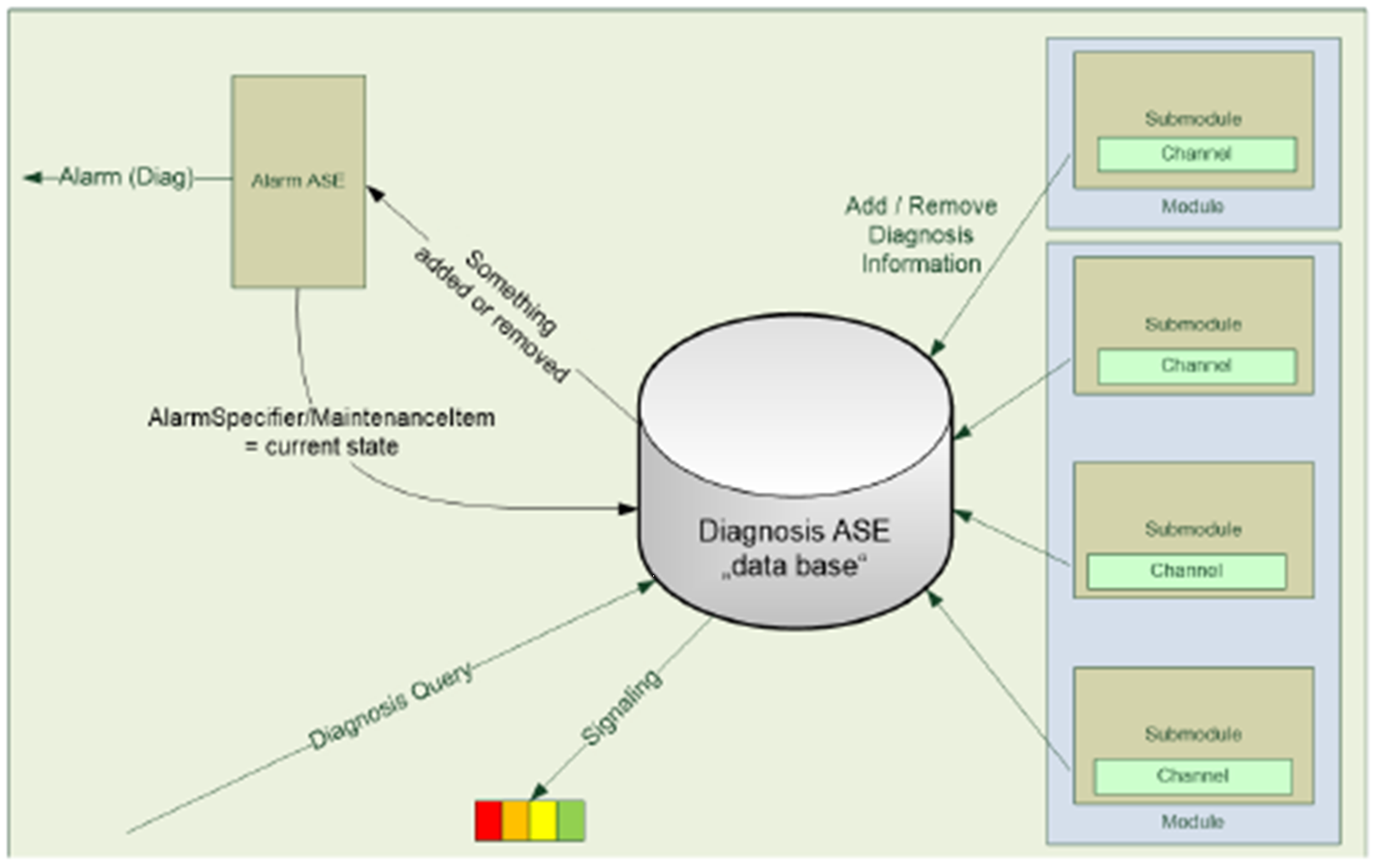
Each IO device maintains a global list of active diagnosis in a database called Diagnosis ASE.
All diagnosis entries are related to a channel of a submodule. The channel can represent a connected sensor or actor as well as the whole submodule. Submodule related diagnosis is marked with the channel number 0x8000.
If some relevant diagnosis or maintenance appears or disappears on a channel, an entry in the diagnosis ASE is added or removed. In this case, the IO controller is informed with diagnosis alarm to have event driven diagnosis information available in the PLC.
A supervisor like an Edge gateway or diagnosis tool can query the diagnosis ASE with a defined PROFINET record. If the ASE contains entries, the query is answered with a list of diagnosis entries. Otherwise the answer is empty to reduce the network load.
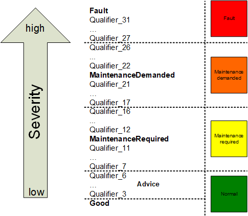
Each channel diagnosis entry contains a severity and a combination of error codes (see Figure 14). Some of these codes are system defined and can be decoded with the help of a general XML file available via PI. Vendor specific and profile specific error codes can be contained in the GSD file of the device.
5.3.3.3 Architecture
In the Diagnosis Use-Case a diagnosis tool is connected to a PLC, Edge gateway or the OPC UA Server of the device itself. The integrated OPC UA Server represents the subordinate PROFINET system or devices and their diagnosis state. There are differences in the available diagnosis information in IO controllers, Edge gateways or devices, which must be considered:
IO controller
An IO controller may form an OPC UA object model which is based on the expected configuration given by the engineering system. If there is no PROFINET connection (IOAR) between the controller and the device, the controller knows the reason (e.g. Device not found, duplicated names in the network, etc.). IO controllers are informed from the devices with a diagnosis alarm, if anything in the diagnosis ASE has been changed and may determine a time accurate diagnosis state.
Edge gateways:
An Edge gateway may show IO controllers and IO devices which can be discovered during the scanning process. An Edge gateway may determine the expected configuration of the devices with a normative record. The reason for an e.g. unreachable device can be different from an IO controller. Supervisors like Edge Gateways are not informed with an alarm if something in the diagnosis ASE of the devices has been changed. They can be as time accurate as the scanning time is configured.
Devices:
The IO device represents the diagnosis state of the included modules and submodules. In addition it knows if there is a running AR to the IO controller.
5.3.3.4 Use Cases
5.3.3.4.1 Discover differences between the expected configuration and the field
| Goal | The end user wants to know if there are any differences between the expected configuration given in the ES of an IO controller and installed devices in the field. |
|---|---|
| Preconditions | The expected PROFINET configuration is set up in the engineering system of the IO controller, downloaded and activated. The Tag-Function and Tag-Location of I&M1 is configured. |
| OPC UA Mapping | In a PLC the information model of the OPC UA Server is build according the expected configuration of the PLCs engineering system. Differences between real and expected configuration are marked at the corresponding submodule of the expected configuration. In an EGW the information model of the OPC UA Server is build according to the scanned devices. Differences to the expected configuration are shown based on module diff block information read from the device. In a device the information model of the OPC UA Server is build according the local configuration. Differences to the expected configuration are shown based on module diff block from the controller AR. PLC is named with its station name and IP-Address. Devices are named with their station name, IP-Address and I&M1 information. |
5.3.3.4.2 Discover reachable configuration
| Goal | The end user wants to know which devices and their configuration are installed in the field. |
|---|---|
| Preconditions | All connected PROFINET systems are configured and running. There can be multiple PLCs in the network visible by an EGW. An EGW or PLC may scan the underlying network continuously with DCP-Identify and PROFINET read services to get all relevant information. For details see [PN TAD]. |
| OPC UA Mapping | The information model of the OPC UA Server is build according the scanned devices and their real slot/subslot configuration. This Use-Case should not be implemented in a Device to avoid network load caused by Identify services. |
| Remarks | When there is no station name, the MAC address shall be used as BrowseName. If those devices get a correct name, they are visible as a different entity under their station name as the OPC UA browse name shall be unique. |
5.3.3.4.3 Connection Diagnosis
| Goal | The end user wants to know the state of the PROFINET connections related to the expected configuration of the IO controller |
|---|---|
| Preconditions | The expected PROFINET configuration is set up in the engineering system of the IO controller, downloaded and activated. Some ARs between the IO controller and IO devices are established, others cannot be established by e.g. following reasons: Device with configured NoS not found in the network Duplicate NoS detected Duplicate IP-Address detected AR deactivated in PLC application program |
| OPC UA Mapping | The connection state of the AR is signaled on the corresponding IO device in the address space of the OPC UA Server. The reason for error is part of the AR. |
5.3.3.4.4 Submodule state diagnosis
| Goal | The end user wants to know differences between the expected and real configuration related to modules/submodules, their identification as well as other reasons for connection problems. |
|---|---|
| Preconditions | The expected PROFINET slot/subslot configuration is set up in the engineering system of the IO controller, downloaded and activated. An EGW may continuously scan the ExpectedConfiguration and ModuleDiffBlock data records from the reachable devices. Some submodules in real configuration differ from the expected. Details see SubmoduleState. Examples: Wrong Submodule No Submodule Substitute Submodule Application Ready Pending Superordinated Locked Locked by IO controller Locked by IO supervisor |
| OPC UA Mapping | The difference related to the expected configuration is signaled on the corresponding module/submodule in the address space of the UA Server. The state is shown in a variable with corresponding values of SubmoduleState. |
5.3.3.4.5 Device diagnosis or maintenance update
| Goal | The end user wants to have information about device/module/submodule/channel related diagnosis or maintenance information. |
|---|---|
| Preconditions | All connected PROFINET systems are configured and running. Channel related diagnosis or maintenance (e.g. short circuit) appears on one channel of a real or PDev submodule. An entry in the diagnosis ASE of the IO device is made. The IO controller is informed with a corresponding diagnosis or maintenance alarm. The EGW may scan the underlying network continuously with DCP-Identify and PROFINET read services to the diagnosis ASE. Channel related diagnosis or maintenance (e.g. short circuit) disappears on one channel of a real or PDev submodule. |
| OPC UA Mapping | The diagnosis or maintenance is signaled on the corresponding module or submodule in the address space of the OPC UA Server with the following information: ChannelNumber (0x8000 is the whole submodule itself) Severity: fault, maintenance required, maintenance demanded mapped to OPC UA severity classes Error Text from GSDML in current language. Formatted information of ExtChannelAddValue based on GSDML. + Help Text from GSDML. |
5.3.3.4.6 Network diagnosis or maintenance
| Goal | The end user wants to have information about the "health" of the physical PROFINET network in the Diagnosis tool in a topological view. |
|---|---|
| Preconditions | All connected PROFINET systems are configured and running. PDev related diagnosis or maintenance appear on the network. An EGW or PLC may scan the underlying network continuously with DCP-Identify and PROFINET read services to get all relevant information. The PDev related diagnosis and properties are integrated in the OPC UA address space of the EGW or PLC according to Table 21. |
| OPC UA Mapping | A diagnosis tool uses the PDev related information from the OPC UA Server to display a topological view with corresponding details. It is not the responsibility of the OPC UA Server. |
| Remark | Display of physical Topology is possible for PROFINET-Devices and PROFINET-switches, but not possible for devices without topology information. |
5.3.4 Read/Write Record
5.3.4.1 General
This use case describes the reading and writing of PROFINET records via objects in the OPC UA Server. This use case is intentionally not provided in this companion specification because access to low level data records is a potential security problem and the access to additional application data via the OPC UA Server shall be done in a high-level object-oriented access.
6 PROFINET OPC UA Information Model
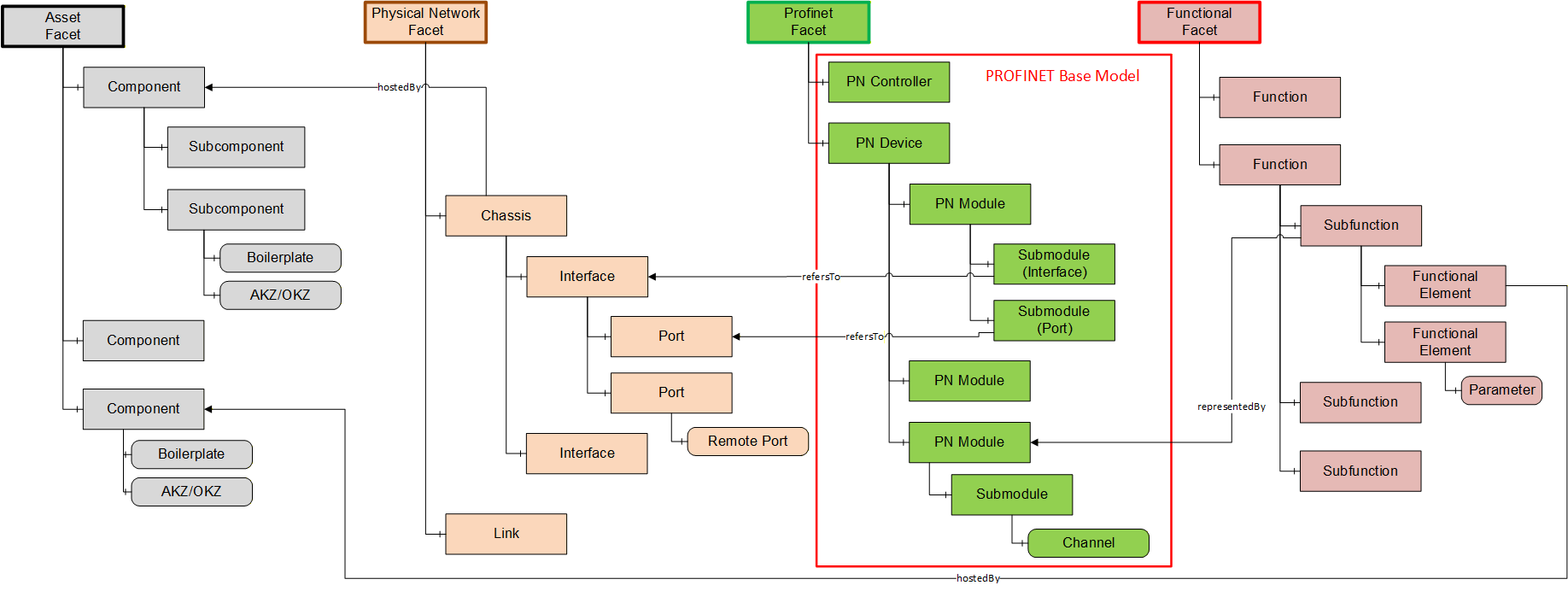
Today OPC UA information models focused on the functional aspects of a dedicated device and the management of parameters in a device parameter set, are typically based on the OPC UA for Devices (DI) base information model (defined in [OPC 10000-100], referenced as OPC UA DI also in this document). In contradiction to this the I4.0 system modelling, including multiple aggregated devices and controllers, requires the representation of several different aspects of the system and therefore will lead to more sophisticated modelling approaches. Such a system model approach using four different independent partial models called "Facets", linked together by typified references is shown in Figure 16. Here the Asset partial model contains an independent model related to orderable components (assets). The Physical Network partial model contains the independent model of the ethernet network structure. The PROFNET partial model contains all communication related aspects of the PN Controllers and Devices in the system. The Function partial model at least represents the application function aspect of the system. Objects out of the different partial models are connected to each other by typified references expressing semantic information about their relationship.
To be future proof and easily integrable to different base modelling approaches, this Companion Specification defines the PROFINET information model as an independent partial model using the OPC UA Interface and AddIn technology (See [OPC 10001-7]) . This gives the opportunity to connect the same unique PROFINET base information model to the OPC UA DI base model and to use the same PROFNET base model as partial model for the PROFINET communication aspect in the "Facet" modelling approach as shown in Figure 16.
The base information model in chapter 6.3 defines all common types of the PROFINET OPC UA information model.
The Annex B shows how to use the base information model together with OPC UA for Devices.
6.1 Conventions used in the mapping to PROFINET properties
| Method | Meaning |
| DCP | The mentioned values or properties are read with the DCP Identify service |
| GSDML | The mentioned values or properties are read from a GSD file |
| Read | The mentioned values or properties are read with a CLRPC or RSI read record service |
The mentioned values are obtained by the blocks (optionally also subblocks) and fields given in the description. The following syntax is used: "Block | field".
6.2 General conventions
All variables are read-only unless stated otherwise explicitly.
6.3 Base Information Model
6.3.1 OPC UA Object Types
The first 4 chapters of the base information model include the object types for the internal module/submodule structure of a PROFINET device and controller.
Figure 17 shows a simplified example for a module/submodule object structure. The container folders have been skipped in the figure.
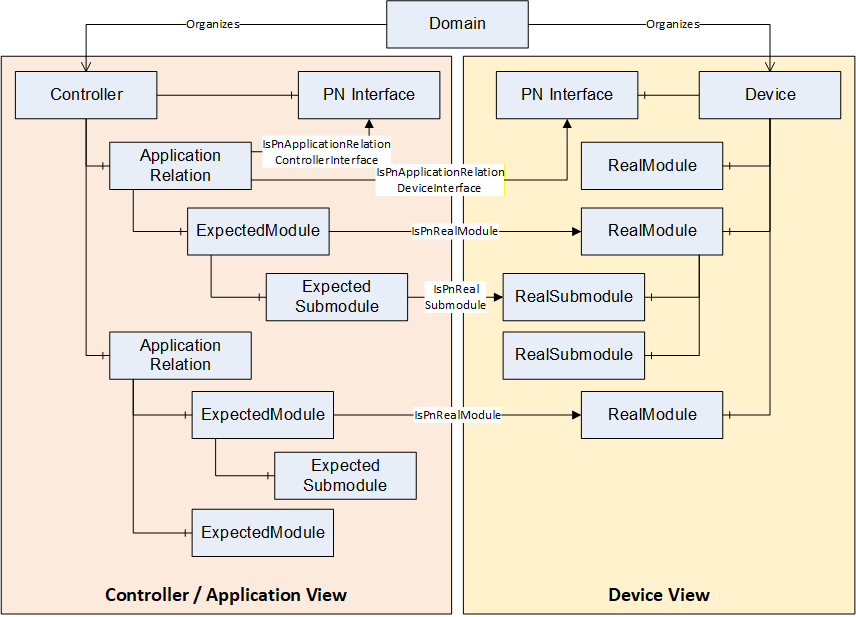
The Device View includes devices in the PROFINET network and their real existing modules and submodules.
The Controller / Application View includes the PROFINET connections (Application Relationships) and the expected modules and submodules which have been configured in the PROFINET controller.
Both views relate to each other by non-hierarchical references.
The chapter 6.3.1.7 includes the object types for the PROFINET network mapping.
The chapter 6.3.1.8 includes the 2 object types for the asset identification within a PROFINET device.
6.3.1.1 Object instances lifetime
All object instances of the base information model represent the online view on the PROFINET network.
All PROFINET objects modeled in this specification are only created in the address space when the OPC UA Server detects their PROFINET counterpart. The objects are removed from the address space when the OPC UA Server detects their absence in the PROFINET network or PROFINET device.
The chapter 6.10 of [PN TAD] describes the possible ways of implementing the PROFINET device discovery. The chapter 11.3 of [PN TAD] describes the detection of the real modules and real submodules of a device and how to get their identification and asset data.
All these ContainerType objects only exist if objects are available in the container.
6.3.1.2 Domain
6.3.1.2.1 IPnDomainType
| Attribute | Value | ||||
| BrowseName | IPnDomainType | ||||
| IsAbstract | True | ||||
| References | Node Class | BrowseName | DataType | TypeDefinition | Modelling Rule |
|---|---|---|---|---|---|
| Subtype of BaseInterfaceType defined in [OPC 10000-5]. | |||||
| HasComponent | Object | Nodes | PnEquipmentContainerType | Mandatory | |
The Nodes object of the Domain includes all device and controller nodes which belong to the PROFINET domain.
6.3.1.3 Node
6.3.1.3.1 IPnEquipmentType
| Attribute | Value | ||||
| BrowseName | IPnEquipmentType | ||||
| IsAbstract | True | ||||
| References | Node Class | BrowseName | DataType | TypeDefinition | Modelling Rule |
|---|---|---|---|---|---|
| Subtype of BaseInterfaceType defined in [OPC 10000-5]. | |||||
| HasComponent | Object | Interfaces | PnInterfaceContainerType | Mandatory | |
| HasComponent | Object | Modules | PnRealModuleContainerType | Optional | |
| HasComponent | Object | Assets | PnAssetContainerType | Optional | |
| HasComponent | Object | IM | PnIdentificationType | Optional | |
| HasProperty | Variable | Vendor | String | PropertyType | Optional |
| HasComponent | Variable | Diagnosis | PnDeviceDiagnosisDataType[] | BaseDataVariableType | Optional |
| HasComponent | Object | Alarms | FolderType | Optional | |
| HasComponent | Method | ShowLocation | ShowLocationMethod | Optional | |
| GeneratesEvent | ObjectType | PnDiagnosisAlarmType | |||
| GeneratesEvent | ObjectType | PnAssetChangedEventType | |||
If the IM component is provided, it must contain the data of the representative submodule for the device in accordance with the I&M0FilterDataDevice block (See [PN TAD] - Identification & Maintenance).
The Assets and IM objects are optional. If the interface is used with the OPC UA facet model, the asset data can be part of another facet (See chapter 6 "PROFINET OPC UA Information Model" and Figure 16 - "Facet" modelling approach for I4.0 System Modelling).
The <Assets> objects are only assets which are directly related to this device. Assets related to the modules or submodules are components of these objects.
The server may provide diagnosis data with the Diagnosis variable or by sending PnDiagnosisAlarmType events. The diagnosis data at the device object includes the diagnosis information of the whole device including the one of all real modules and real submodules. An OPC UA Server might provide instances of the PnDiagnosisAlarmType as objects under the Alarms object.
Mapping to PROFINET properties:
| BrowseName | Method | Source |
| Vendor | DCP | DeviceVendorBlockRes | DeviceVendorValue |
| Diagnosis | Read | DiagnosisData (0xF80C device specific) |
6.3.1.3.1.1 ShowLocation Method
This optional method shall trigger a perceivable signal which allows the identification of the physical device represented by the device object the method is invoked on. This is usually accomplished with a blinking LED.
The method has no parameters (no [in] and no [out] parameters) and no return value.
Signature
	ShowLocation (
		);
6.3.1.3.2 PnEquipmentContainerType
| Attribute | Value | ||||
| BrowseName | PnEquipmentContainerType | ||||
| IsAbstract | False | ||||
| References | Node Class | BrowseName | DataType | TypeDefinition | Modelling Rule |
|---|---|---|---|---|---|
| Subtype of BaseObjectType defined in [OPC 10000-5]. | |||||
| HasComponent | Object | <PnEquipments> | BaseObjectType | Optional Placeholder | |
The <PnEquipments> shall have the references and components defined in Table 26 and Table 27.
| Source Path | Reference Type | Is Forward | Target Path | ||||
| <PnEquipments> | 0:HasInterface | True |
|
| Source Path | References | NodeClass | BrowseName | DataType TypeDefinition | Others |
| Applied from IPnEquipmentType | |||||
| <PnEquipments> | 0:HasComponent | Object | Interfaces | PnInterfaceContainerType | M |
| <PnEquipments> | 0:HasComponent | Object | Modules | PnRealModuleContainerType | O |
| <PnEquipments> | 0:HasComponent | Object | Assets | PnAssetContainerType | O |
| <PnEquipments> | 0:HasComponent | Object | IM | PnIdentificationType | O |
| <PnEquipments> | 0:HasProperty | Variable | Vendor | String PropertyType | O |
| <PnEquipments> | 0:HasComponent | Variable | Diagnosis | PnDeviceDiagnosisDataType[] BaseDataVariableType | O |
| <PnEquipments> | 0:HasComponent | Object | Alarms | FolderType | O |
| <PnEquipments> | 0:HasComponent | Method | ShowLocation | ShowLocationMethod | O |
| <PnEquipments> | 0:GeneratesEvent | ObjectType | PnDiagnosisAlarmType | ||
| <PnEquipments> | 0:GeneratesEvent | ObjectType | PnAssetChangedEventType | ||
Mapping to PROFINET properties:
| BrowseName | Method | Source |
| <PnEquipments> | DCP | List of IdentifyResBlock |
6.3.1.3.3 IPnDeviceType
| Attribute | Value | ||||
| BrowseName | IPnDeviceType | ||||
| IsAbstract | True | ||||
| References | Node Class | BrowseName | DataType | TypeDefinition | Modelling Rule |
|---|---|---|---|---|---|
| Subtype of IPnEquipmentType | |||||
| HasProperty | Variable | GSDDescription | String | PropertyType | Optional |
| HasComponent | Variable | State | PnDeviceStateEnumeration | BaseDataVariableType | Optional |
The BrowseName of a device object instance shall be the content of the NameOfStation variable of the first interface sub module. If the NameOfStation variable is not set, the content of the MAC Address variable of the first interface sub module shall be used. The MAC address string should use the canonical format (separated with -, e.g. AC-FD-CE-EC-03-80).
If the GSDDescription property is provided, it must contain the InfoText with Device Id from the GSD (see mapping table below).
Mapping to PROFINET properties:
| BrowseName | Method | Source |
| GSDDescription | GSD | DeviceIdentity | InfoText with Device Id |
| State | Read | ARData | NumberOfARs | ARProperties Empty block if offline. Online if at least one ARProperties block with ARProperties.DeviceAccess != 1 can be found in the record data. |
6.3.1.3.4 IPnControllerType
| Attribute | Value | ||||
| BrowseName | IPnControllerType | ||||
| IsAbstract | True | ||||
| References | Node Class | BrowseName | DataType | TypeDefinition | Modelling Rule |
|---|---|---|---|---|---|
| Subtype of IPnEquipmentType | |||||
| HasComponent | Object | ARs | PnApplicationRelationContainerType | Optional | |
6.3.1.4 Application Relationship
6.3.1.4.1 PnApplicationRelationType
| Attribute | Value | ||||
| BrowseName | PnApplicationRelationType | ||||
| IsAbstract | False | ||||
| References | Node Class | BrowseName | DataType | TypeDefinition | Modelling Rule |
|---|---|---|---|---|---|
| Subtype of BaseObjectType defined in [OPC 10000-5]. | |||||
| HasComponent | Object | Modules | PnExpectedModuleContainerType | Optional | |
| HasComponent | Variable | State | PnARStateEnumeration | BaseDataVariableType | Mandatory |
| HasProperty | Variable | Id | Guid | PropertyType | Mandatory |
| HasProperty | Variable | Type | PnARTypeEnumeration | PropertyType | Mandatory |
| HasProperty | Variable | SendClockFactor | UInt16 | PropertyType | Optional |
| HasProperty | Variable | ReductionRatio | UInt16 | PropertyType | Optional |
| HasProperty | Variable | DataHoldFactor | UInt16 | PropertyType | Optional |
The BrowseName of an application relationship object instance shall be the Id in standard GUID string format.
The Modules container object is the root of the configuration hierarchy consisting of the expected modules of the application relationship and their expected submodules (See chapter 6.3 - Base Information Model and Figure 17 - Object Structure).
The State variable has always the value CONNECTED on devices since the object only exists if an AR is established.
An IsPnApplicationRelationControllerInterface reference points to the interface object of the controller used for the AR. If the AR relates to the device an IsPnApplicationRelationDeviceInterface reference points to the interface object of the device. See sections 6.3.2.11 and 6.3.2.12 also.
Mapping to PROFINET properties:
| BrowseName | Method | Source |
| Id | Read | ARData | ARUUID |
| Type | Read | ARData | ARType |
| SendClockFactor | Read | available also on Device/Gateway since PROFINET V2.4 via ARData | SendClockFactor or PDSyncData | SendClockFactor |
| ReductionRatio | Read | available also on Device/Gateway since PROFINET V2.4 via ARData | ReductionRatio |
| DataHoldFactor | Read | IOCRBlockReq | DataHoldFactor (not available on Device/Gateway) |
6.3.1.4.2 PnApplicationRelationContainerType
| Attribute | Value | ||||
| BrowseName | PnApplicationRelationContainerType | ||||
| IsAbstract | False | ||||
| References | Node Class | BrowseName | DataType | TypeDefinition | Modelling Rule |
|---|---|---|---|---|---|
| Subtype of BaseObjectType defined in [OPC 10000-5]. | |||||
| HasPnApplicationRelation | Object | <ARs> | PnApplicationRelationType | Optional Placeholder | |
Mapping to PROFINET properties:
| BrowseName | Method | Source |
| <ARs> | Read | ARData | NumberOfARs entries | ARUUID |
6.3.1.5 Module
6.3.1.5.1 IPnModuleType
| Attribute | Value | ||||
| BrowseName | IPnModuleType | ||||
| IsAbstract | True | ||||
| References | Node Class | BrowseName | DataType | TypeDefinition | Modelling Rule | |
|---|---|---|---|---|---|---|
| Subtype of BaseInterfaceType defined in [OPC 10000-5]. | ||||||
| HasProperty | Variable | Slot | UInt16 | PropertyType | Mandatory | |
| HasProperty | Variable | IdentNumber | UInt32 | PropertyType | Mandatory | |
| HasProperty | Variable | GSDName | String | PropertyType | Optional | |
| HasProperty | Variable | GSDDescription | String | PropertyType | Optional | |
The properties Slot and IdentNumber must contain the data as described in the mapping table provided for the subtypes IPnRealModuleType and IPnExpectedModuleType.
Mapping to PROFINET properties:
| BrowseName | Method | Source |
| GSDName | GSDML | ModuleList | ModuleItem | ModuleInfo | Name |
| GSDDescription | GSDML | ModuleList | ModuleItem | ModuleInfo | InfoText |
6.3.1.5.2 IPnRealModuleType
| Attribute | Value | ||||
| BrowseName | IPnRealModuleType | ||||
| IsAbstract | True | ||||
| References | Node Class | BrowseName | DataType | TypeDefinition | Modelling Rule | |
|---|---|---|---|---|---|---|
| Subtype of IPnModuleType | ||||||
| HasComponent | Object | Submodules | PnRealSubmoduleContainerType | Optional | ||
| HasComponent | Object | IM | PnIdentificationType | Optional | ||
| HasComponent | Variable | Diagnosis | PnDeviceDiagnosisDataType[] | BaseDataVariableType | Optional | |
| HasComponent | Object | Alarms | FolderType | Optional | ||
| GeneratesEvent | ObjectType | PnDiagnosisAlarmType | ||||
| GeneratesEvent | ObjectType | PnAssetChangedEventType | ||||
The BrowseName of a module object instance shall be the content of the Slot variable in decimal number string format.
If the IM component is provided, it must contain the data of the representative submodule for the module in accordance with the I&M0FilterDataModule block (See [PN TAD] - Identification & Maintenance).
The server may provide diagnosis data with the Diagnosis variable or by sending PnDiagnosisAlarmType events. The diagnosis data at the real module object includes the diagnosis information of the whole module including the one of the real submodules of the module. An OPC UA Server may provide instances of the PnDiagnosisAlarmType as objects under the Alarms object.
Mapping to PROFINET properties:
| BrowseName | Method | Source |
| Slot | Read | RealIdentificationData | SlotNumber |
| IdentNumber | Read | RealIdentificationData | IdentNumber |
| Diagnosis | Read | DiagnosisData (0xC00C slot specific) |
6.3.1.5.3 PnRealModuleContainerType
| Attribute | Value | ||||
| BrowseName | PnRealModuleContainerType | ||||
| IsAbstract | False | ||||
| References | Node Class | BrowseName | DataType | TypeDefinition | Modelling Rule |
|---|---|---|---|---|---|
| Subtype of BaseObjectType defined in [OPC 10000-5]. | |||||
| HasPnRealModule | Object | <Modules> | BaseObjectType | Optional Placeholder | |
The <Modules> shall have the references and components defined in Table 35 and Table 36.
| Source Path | Reference Type | Is Forward | Target Path | |||||
| <Modules> | 0:HasInterface | True |
|
| Source Path | References | NodeClass | BrowseName | DataType TypeDefinition | Others |
| Applied from IPnRealModuleType | |||||
| <Modules> | 0:HasProperty | Variable | Slot | UInt16 PropertyType | M |
| <Modules> | 0:HasProperty | Variable | IdentNumber | UInt32 PropertyType | M |
| <Modules> | 0:HasProperty | Variable | GSDName | String PropertyType | O |
| <Modules> | 0:HasProperty | Variable | GSDDescription | String PropertyType | O |
| <Modules> | 0:HasComponent | Object | Submodules | PnRealSubmoduleContainerType | O |
| <Modules> | 0:HasComponent | Object | IM | PnIdentificationType | O |
| <Modules> | 0:HasComponent | Variable | Diagnosis | PnDeviceDiagnosisDataType[] BaseDataVariableType | O |
| <Modules> | 0:HasComponent | Object | Alarms | FolderType | O |
| <Modules> | 0:GeneratesEvent | ObjectType | PnDiagnosisAlarmType | ||
| <Modules> | 0:GeneratesEvent | ObjectType | PnAssetChangedEventType | ||
Mapping to PROFINET properties:
| BrowseName | Method | Source |
| <Modules> | Read | RealIdentificationData | NumberOfSlots entries | SlotNumber |
6.3.1.5.4 IPnExpectedModuleType
| Attribute | Value | ||||
| BrowseName | IPnExpectedModuleType | ||||
| IsAbstract | True | ||||
| References | Node Class | BrowseName | DataType | TypeDefinition | Modelling Rule |
|---|---|---|---|---|---|
| Subtype of IPnModuleType | |||||
| HasComponent | Object | Submodules | PnExpectedSubmoduleContainerType | Optional | |
| HasComponent | Variable | State | PnModuleStateEnumeration | BaseDataVariableType | Mandatory |
The BrowseName of a module object instance shall be the content of the Slot variable in decimal number string format.
An IsPnRealModule reference points to the real module which is the real realization of the expected module. See section 6.3.2.9 also.
Mapping to PROFINET properties:
| BrowseName | Method | Source |
| Slot | Read | ExpectedIdentificationData | SlotNumber |
| IdentNumber | Read | ExpectedIdentificationData | IdentNumber |
| State | Read | ModuleDiffBlock | ModuleState |
6.3.1.5.5 PnExpectedModuleContainerType
| Attribute | Value | ||||
| BrowseName | PnExpectedModuleContainerType | ||||
| IsAbstract | False | ||||
| References | Node Class | BrowseName | DataType | TypeDefinition | Modelling Rule |
|---|---|---|---|---|---|
| Subtype of BaseObjectType defined in [OPC 10000-5]. | |||||
| HasPnExpectedModule | Object | <Modules> | BaseObjectType | Optional Placeholder | |
The <Modules> shall have the references and subcomponents defined in Table 39 and Table 40.
| Source Path | Reference Type | Is Forward | Target Path | |||||
| <Modules> | 0:HasInterface | True |
|
| Source Path | References | NodeClass | BrowseName | DataType TypeDefinition | Others |
| Applied from IPnExpectedModuleType | |||||
| <Modules> | 0:HasProperty | Variable | Slot | UInt16 PropertyType | M |
| <Modules> | 0:HasProperty | Variable | IdentNumber | UInt32 PropertyType | M |
| <Modules> | 0:HasProperty | Variable | GSDName | String PropertyType | O |
| <Modules> | 0:HasProperty | Variable | GSDDescription | String PropertyType | O |
| <Modules> | 0:HasComponent | Variable | State | PnModuleStateEnumeration BaseDataVariableType | M |
| <Modules> | 0:HasComponent | Object | Submodules | PnExpectedSubmoduleContainerType | O |
Mapping to PROFINET properties:
| BrowseName | Method | Source |
| <Modules> | Read | ExpectedIdentificationData | NumberOfSlots entries | SlotNumber |
6.3.1.6 Submodule
6.3.1.6.1 IPnSubmoduleType
| Attribute | Value | |||||
| BrowseName | IPnSubmoduleType | |||||
| IsAbstract | True | |||||
| References | Node Class | BrowseName | DataType | TypeDefinition | Modelling Rule |
|---|---|---|---|---|---|
| Subtype of BaseInterfaceType defined in [OPC 10000-5]. | |||||
| HasProperty | Variable | API | UInt32 | PropertyType | Mandatory |
| HasProperty | Variable | Subslot | UInt16 | PropertyType | Mandatory |
| HasProperty | Variable | IdentNumber | UInt32 | PropertyType | Mandatory |
| HasProperty | Variable | GSDName | String | PropertyType | Optional |
| HasProperty | Variable | GSDDescription | String | PropertyType | Optional |
The properties GSDName and GSDDescription must contain the data from the GSD, as described in the mapping table provided for the subtypes IPnRealSubmoduleType and IPnExpectedSubmoduleType.
6.3.1.6.2 IPnRealSubmoduleType
| Attribute | Value | |||||
| BrowseName | IPnRealSubmoduleType | |||||
| IsAbstract | True | |||||
| References | Node Class | BrowseName | DataType | TypeDefinition | Modelling Rule |
|---|---|---|---|---|---|
| Subtype of IPnSubmoduleType | |||||
| HasComponent | Object | IM | PnIdentificationType | Optional | |
| HasComponent | Variable | Diagnosis | PnDeviceDiagnosisDataType[] | BaseDataVariableType | Optional |
| HasComponent | Object | Alarms | FolderType | Optional | |
| GeneratesEvent | ObjectType | PnDiagnosisAlarmType | |||
| GeneratesEvent | ObjectType | PnAssetChangedEventType | |||
The BrowseName of a sub module object instance shall be the content of the Subslot variable in hexadecimal number string format (e.g. 0x8001).
If the IM component is provided, it must contain the data in accordance with the I&M0FilterDataSubmodule block (See [PN TAD] - Identification & Maintenance).
The server can provide diagnosis data with the Diagnosis variable or by sending PnDiagnosisAlarmType events. The diagnosis data at the real submodule object includes only the diagnosis information of the real submodule. An OPC UA Server might provide instances of the PnDiagnosisAlarmType as objects under the Alarms object.
An IsPnInterface reference exists if the submodule is an interface submodule. See section 6.3.2.13 also.
An IsPnPort reference exists if the submodule is a port submodule. It points to the PnPortType object. See section 6.3.2.14 also.
Mapping to PROFINET properties:
| BrowseName | Method | Source |
| API | Read | RealIdentificationData | API |
| SubSlot | Read | RealIdentificationData | SubslotNumber |
| IdentNumber | Read | RealIdentificationData | SubmoduleIdentNumber |
| GSDName | GSDML | SubmoduleList | SubmoduleItem | ModuleInfo | Name or SubmoduleList | VirtualSubmoduleItem | ModuleInfo | Name or SubmoduleList | PortSubmoduleItem | ModuleInfo | Name |
| GSDDescription | GSDML | SubmoduleList | SubmoduleItem | ModuleInfo | InfoText or SubmoduleList | VirtualSubmoduleItem | ModuleInfo | InfoText or SubmoduleList | PortSubmoduleItem | ModuleInfo | InfoText |
| Diagnosis | Read | DiagnosisData (0x800C subslot specific) |
6.3.1.6.3 PnRealSubmoduleContainerType
| Attribute | Value | ||||
| BrowseName | PnRealSubmoduleContainerType | ||||
| IsAbstract | False | ||||
| References | Node Class | BrowseName | DataType | TypeDefinition | Modelling Rule |
|---|---|---|---|---|---|
| Subtype of BaseObjectType defined in [OPC 10000-5]. | |||||
| HasPnRealSubmodule | Object | <Submodules> | BaseObjectType | Optional Placeholder | |
The <Submodules> shall have the references defined in Table 44 and Table 45.
| Source Path | Reference Type | Is Forward | Target Path | |||||
| <Submodules> | 0:HasInterface | True |
|
| Source Path | References | NodeClass | BrowseName | DataType TypeDefinition | Others |
| Applied from IPnRealSubmoduleType | |||||
| <Submodules> | 0:HasProperty | Variable | API | UInt32 PropertyType | M |
| <Submodules> | 0:HasProperty | Variable | Subslot | UInt16 PropertyType | M |
| <Submodules> | 0:HasProperty | Variable | IdentNumber | UInt32 PropertyType | M |
| <Submodules> | 0:HasProperty | Variable | GSDName | String PropertyType | O |
| <Submodules> | 0:HasProperty | Variable | GSDDescription | String PropertyType | O |
| <Submodules> | 0:HasComponent | Object | IM | PnIdentificationType | O |
| <Submodules> | 0:HasComponent | Variable | Diagnosis | PnDeviceDiagnosisDataType[] BaseDataVariableType | O |
| <Submodules> | 0:HasComponent | Object | Alarms | FolderType | O |
| <Submodules> | 0:GeneratesEvent | ObjectType | PnDiagnosisAlarmType | ||
| <Submodules> | 0:GeneratesEvent | ObjectType | PnAssetChangedEventType | ||
Mapping to PROFINET properties:
| BrowseName | Method | Source |
| <Submodules> | Read | RealIdentificationData | NumberOfSubslots entries | SubslotNumber |
6.3.1.6.4 IPnExpectedSubmoduleType
| Attribute | Value | ||||
| BrowseName | IPnExpectedSubmoduleType | ||||
| IsAbstract | True | ||||
| References | Node Class | BrowseName | DataType | TypeDefinition | Modelling Rule |
|---|---|---|---|---|---|
| Subtype of IPnSubmoduleType | |||||
| HasComponent | Object | State | PnSubmoduleStateType | Optional | |
An IsPnRealSubmodule reference points to the real submodule which is the real realization of the expected submodule. See section 6.3.2.10 also.
Mapping to PROFINET properties:
| BrowseName | Method | Source |
| API | Read | ExpectedIdentificationData | API |
| SubSlot | Read | ExpectedIdentificationData | SubslotNumber |
| IdentNumber | Read | ExpectedIdentificationData | SubmoduleIdentNumber |
| GSDName | GSDML | SubmoduleList | SubmoduleItem | ModuleInfo | Name or SubmoduleList | PortSubmoduleItem | ModuleInfo | Name |
| GSDDescription | GSDML | SubmoduleList | SubmoduleItem | ModuleInfo | InfoText or SubmoduleList | VirtualSubmoduleItem | ModuleInfo | InfoText or SubmoduleList | PortSubmoduleItem | ModuleInfo | InfoText |
| State | Read | ModuleDiffBlock | SubmoduleState |
6.3.1.6.5 PnExpectedSubmoduleContainerType
| Attribute | Value | ||||
| BrowseName | PnExpectedSubmoduleContainerType | ||||
| IsAbstract | False | ||||
| References | Node Class | BrowseName | DataType | TypeDefinition | Modelling Rule |
|---|---|---|---|---|---|
| Subtype of BaseObjectType defined in [OPC 10000-5]. | |||||
| HasPnExpectedSubmodule | Object | <Submodules> | BaseObjectType | Optional Placeholder | |
The <Submodules> shall have the references and subcomponents defined in Table 48 and Table 49.
| Source Path | Reference Type | Is Forward | Target Path | |||||
| <Submodules> | 0:HasInterface | True |
|
| Source Path | References | NodeClass | BrowseName | DataType TypeDefinition | Others |
| Applied from IPnExpectedSubmoduleType | |||||
| <Submodules> | 0:HasProperty | Variable | API | UInt32 PropertyType | M |
| <Submodules> | 0:HasProperty | Variable | Subslot | UInt16 PropertyType | M |
| <Submodules> | 0:HasProperty | Variable | IdentNumber | UInt32 PropertyType | M |
| <Submodules> | 0:HasProperty | Variable | GSDName | String PropertyType | O |
| <Submodules> | 0:HasProperty | Variable | GSDDescription | String PropertyType | O |
| <Submodules> | 0:HasComponent | Object | State | PnSubmoduleStateType | O |
Mapping to PROFINET properties:
| BrowseName | Method | Source |
| <Submodules> | Read | ExpectedIdentificationData | NumberOfSubslots entries | SubslotNumber |
6.3.1.6.6 PnSubmoduleStateType
| Attribute | Value | ||||
| BrowseName | PnSubmoduleStateType | ||||
| IsAbstract | False | ||||
| References | Node Class | BrowseName | DataType | TypeDefinition | Modelling Rule |
|---|---|---|---|---|---|
| Subtype of BaseObjectType defined in [OPC 10000-5]. | |||||
| HasComponent | Variable | AddInfo | PnSubmoduleAddInfoEnumeration | BaseDataVariableType | Optional |
| HasComponent | Variable | QualifiedInfo | Boolean | BaseDataVariableType | Optional |
| HasComponent | Variable | Maintenance Required | Boolean | BaseDataVariableType | Optional |
| HasComponent | Variable | Maintenance Demanded | Boolean | BaseDataVariableType | Optional |
| HasComponent | Variable | DiagInfo | Boolean | BaseDataVariableType | Optional |
| HasComponent | Variable | ARInfo | PnSubmoduleARInfoEnumeration | BaseDataVariableType | Optional |
| HasComponent | Variable | IdentInfo | PnSubmoduleIdentInfoEnumeration | BaseDataVariableType | Optional |
Mapping to PROFINET properties:
| BrowseName | Method | Source |
| AddInfo | Read | ModuleDiffBlock | SubmoduleState.AddInfo If entry not found, use: None |
| QualifiedInfo | Read | ModuleDiffBlock | SubmoduleState.Advice If entry not found, use: No Advice information available |
| MaintenanceRequired | Read | ModuleDiffBlock | SubmoduleState.MaintenanceRequired If entry not found, use: No MaintenanceRequired information available |
| MaintenanceDemanded | Read | ModuleDiffBlock | SubmoduleState.MaintenanceDemanded If entry not found, use: No MaintenanceDemanded information available |
| DiagInfo | Read | ModuleDiffBlock | SubmoduleState.Fault If entry not found, use: No Fault information available |
| ARInfo | Read | ModuleDiffBlock | SubmoduleState.ARInfo If entry not found, use: Own |
| IdentInfo | Read | ModuleDiffBlock | SubmoduleState.IdentInfo If entry not found, use: OK |
6.3.1.7 Network
This chapter includes all object types needed to represent the physical network topology of a PROFINET network.
Figure 18 shows an example which illustrates the relations between network objects of a single port PROFINET device and a 4 port Ethernet switch.
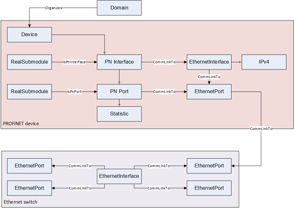
The Ethernet interface, ports and cables are represented by objects in the address space. This Ethernet objects relate to each other by CommLinkTo references. This enables the OPC UA Server to represent the physical network topology of the PROFINET network.
6.3.1.7.1 IPnInterfaceType
| Attribute | Value | ||||
| BrowseName | IPnInterfaceType | ||||
| IsAbstract | True | ||||
| References | Node Class | BrowseName | DataType | TypeDefinition | Modelling Rule |
|---|---|---|---|---|---|
| Subtype of BaseInterfaceType defined in [OPC 10000-5]. | |||||
| HasComponent | Object | Ports | PnPortContainerType | Mandatory | |
| HasProperty | Variable | NameOfStation | String | PropertyType | Mandatory |
| HasProperty | Variable | DeviceRole | PnDeviceRoleOptionSet | PropertyType | Mandatory |
| HasProperty | Variable | DeviceVendor | String | PropertyType | Optional |
| HasProperty | Variable | VendorId | UInt16 | PropertyType | Mandatory |
| HasProperty | Variable | DeviceId | UInt16 | PropertyType | Mandatory |
| HasProperty | Variable | DeviceInstance | UInt16 | PropertyType | Optional |
| HasProperty | Variable | OEMVendorId | UInt16 | PropertyType | Optional |
| HasProperty | Variable | OEMDeviceId | UInt16 | PropertyType | Optional |
| CommLinkTo | Object | EthernetInterface | EthernetInterfaceType | Optional | |
| HasComponent | Object | Statistic | PnPortStatisticType | Optional | |
| HasComponent | Method | SetNameOfStation | SetNameOfStationMethod | Optional | |
The BrowseName of an interface object instance shall be the PROFINET interface id with the range 1..16 in decimal number string format.
The NameOfStation variable may be set with the SetNameOfStation method. Nevertheless, the variable itself shall always be read-only.
The CommLinkTo reference points to an EthernetInterfaceType object instance. An object of the IPv4FeatureType must be implemented in this EthernetInterfaceType object instance.
Mapping to PROFINET properties:
| BrowseName | Method | Source |
| NameOfStation | DCP | DCP-Identify-ResPDU | NameOfStationValue |
| DeviceRole | DCP | DCP-Identify-ResPDU | DeviceRoleDetails |
| DeviceVendor | DCP | DCP-Identify-ResPDU | DeviceVendorValue |
| VendorId | DCP | DCP-Identify-ResPDU | DeviceIDBlockRes | DeviceIDValue |
| DeviceId | DCP | DCP-Identify-ResPDU | DeviceIDBlockRes | DeviceIDValue |
| DeviceInstance | DCP | DCP-Identify-ResPDU | DeviceInstanceValue |
| OEMVendorId | DCP | DCP-Identify-ResPDU | OEMDeviceIDBlockRes | DeviceIDValue |
| OEMDeviceId | DCP | DCP-Identify-ResPDU | OEMDeviceIDBlockRes | DeviceIDValue |
6.3.1.7.1.1 SetNameOfStation Method
This optional method writes the NameOfStation remanent to the PROFINET device and sets the NameOfStation variable accordingly.
Signature
	SetNameOfStation (
		[in]	String NameOfStation
		);
| Argument | Description |
| NameOfStation | String containing the new NameOfStation to be written remanent to the device. The maximum length shall be limited to 240 characters (See [PN Protocol] for details). |
Method Result Codes
| ResultCode | Description |
| Bad_InvalidArgument | The Server is not able to apply the name. The name may be too long or may contain invalid characters. |
| Bad_UnexpectedError | The Server is not able to apply the name because an unexpected error occurred. The device might be temporarily unavailable or unreachable due to network failure. |
6.3.1.7.2 PnInterfaceContainerType
| Attribute | Value | ||||
| BrowseName | PnInterfaceContainerType | ||||
| IsAbstract | False | ||||
| References | Node Class | BrowseName | DataType | TypeDefinition | Modelling Rule |
|---|---|---|---|---|---|
| Subtype of BaseObjectType defined in [OPC 10000-5]. | |||||
| HasPnInterface | Object | <Interfaces> | BaseObjectType | Optional Placeholder | |
The <Interfaces> shall have the references defined in Table 53 and Table 54.
| Source Path | Reference Type | Is Forward | Target Path | ||||
| <Interfaces> | 0:HasInterface | True |
|
| Source Path | References | NodeClass | BrowseName | DataType TypeDefinition | Others |
| Applied from IPnInterfaceType | |||||
| <Interfaces> | 0:HasComponent | Object | Ports | PnPortContainerType | M |
| <Interfaces> | 0:HasProperty | Variable | NameOfStation | String PropertyType | M |
| <Interfaces> | 0:HasProperty | Variable | DeviceRole | PnDeviceRoleOptionSet PropertyType | M |
| <Interfaces> | 0:HasProperty | Variable | DeviceVendor | String PropertyType | O |
| <Interfaces> | 0:HasProperty | Variable | VendorId | UInt16 PropertyType | M |
| <Interfaces> | 0:HasProperty | Variable | DeviceId | UInt16 PropertyType | M |
| <Interfaces> | 0:HasProperty | Variable | DeviceInstance | UInt16 PropertyType | O |
| <Interfaces> | 0:HasProperty | Variable | OEMVendorId | UInt16 PropertyType | O |
| <Interfaces> | 0:HasProperty | Variable | OEMDeviceId | UInt16 PropertyType | O |
| <Interfaces> | CommLinkTo | Object | EthernetInterface | EthernetInterfaceType | O |
| <Interfaces> | 0:HasComponent | Object | Statistic | PnPortStatisticType | O |
| <Interfaces> | 0:HasComponent | Method | SetNameOfStation | SetNameOfStationMethod | O |
6.3.1.7.3 PnPortType
The PnPortType Object Type includes the port specific data of a port submodule.
A PnRealSubmoduleType instance representing a port submodule has an IsPnPort reference to a PnPortType object instance.
| Attribute | Value | ||||
| BrowseName | PnPortType | ||||
| IsAbstract | False | ||||
| References | Node Class | BrowseName | DataType | TypeDefinition | Modelling Rule |
|---|---|---|---|---|---|
| Subtype of BaseObjectType defined in [OPC 10000-5]. | |||||
| HasComponent | Object | Statistic | PnPortStatisticType | Optional | |
| HasComponent | Variable | LinkState | PnLinkStateEnumeration | BaseDataVariableType | Optional |
| HasComponent | Variable | PortState | PnPortStateEnumeration | BaseDataVariableType | Optional |
| HasComponent | Variable | MAUType | UInt16 | BaseDataVariableType | Optional |
| HasComponent | Variable | CableDelay | UInt32 | BaseDataVariableType | Optional |
| HasComponent | Variable | PowerBudget | UInt32 | BaseDataVariableType | Optional |
| HasComponent | Variable | IsWireless | Boolean | BaseDataVariableType | Optional |
| CommLinkTo | Object | EthernetPort | EthernetPortType | Optional | |
| GeneratesEvent | ObjectType | PnTopologyChangedEventType | |||
Mapping to PROFINET properties:
| BrowseName | Method | Source |
| MAUType | Read | PDPortDataReal | MAUType |
| CableDelay | Read | PDPortDataReal | LineDelay |
| PowerBudget | Read | PDPortFODataReal | FiberOpticDiagnosisInfo | FiberOpticPowerBudgetReal |
| IsWireless | Read | PDPortDataReal | MediaType |
6.3.1.7.4 PnPortContainerType
| Attribute | Value | ||||
| BrowseName | PnPortContainerType | ||||
| IsAbstract | False | ||||
| References | Node Class | BrowseName | DataType | TypeDefinition | Modelling Rule |
|---|---|---|---|---|---|
| Subtype of BaseObjectType defined in [OPC 10000-5]. | |||||
| HasPnPort | Object | <Ports> | PnPortType | Optional Placeholder | |
6.3.1.7.5 PnPortStatisticType
| Attribute | Value | ||||
| BrowseName | PnPortStatisticType | ||||
| IsAbstract | False | ||||
| References | Node Class | BrowseName | DataType | TypeDefinition | Modelling Rule |
|---|---|---|---|---|---|
| Subtype of BaseObjectType defined in [OPC 10000-5]. | |||||
| HasComponent | Variable | InOctets | UInt32 | BaseDataVariableType | Optional |
| HasComponent | Variable | OutOctets | UInt32 | BaseDataVariableType | Optional |
| HasComponent | Variable | InDiscards | UInt32 | BaseDataVariableType | Optional |
| HasComponent | Variable | OutDiscards | UInt32 | BaseDataVariableType | Optional |
| HasComponent | Variable | InErrors | UInt32 | BaseDataVariableType | Optional |
| HasComponent | Variable | OutErrors | UInt32 | BaseDataVariableType | Optional |
The port statistic counters can be read from a PROFINET device with the Read PD Port Statistic PROFINET service.
6.3.1.7.6 NetworkComponentType
The NetworkComponentType is the abstract base ObjectType for different types of network components.
| Attribute | Value | ||||
| BrowseName | NetworkComponentType | ||||
| IsAbstract | True | ||||
| References | Node Class | BrowseName | DataType | TypeDefinition | Modelling Rule |
|---|---|---|---|---|---|
| Subtype of BaseObjectType defined in [OPC 10000-5]. | |||||
| HasComponent | Object | <FeatureName> | NetworkComponentFeatureType | OptionalPlaceholder | |
| HasComponent | Variable | Enabled | Boolean | BaseDataVariableType | Optional |
| CommLinkTo | Object | <ComponentName> | NetworkComponentType | OptionalPlaceholder | |
The Enabled variable indicates if the network component is activated (Enabled == True) or deactivated (Enabled == False).
6.3.1.7.7 EthernetInterfaceType
The EthernetInterfaceType is used to represent Ethernet network interfaces.
| Attribute | Value | ||||
| BrowseName | EthernetInterfaceType | ||||
| IsAbstract | False | ||||
| References | Node Class | BrowseName | DataType | TypeDefinition | Modelling Rule |
|---|---|---|---|---|---|
| Subtype of NetworkComponentType. | |||||
| HasComponent | Variable | MacAddress | Byte [6] | BaseDataVariableType | Mandatory |
| CommLinkTo | Object | <PortName> | EthernetPortType | MandatoryPlaceholder | |
The MacAddress Variable is read only and represents the unique Layer2 source MAC address of the related interface.
Mapping to PROFINET properties:
| BrowseName | Method | Source |
| MacAddress | DCP | DCP-Identify-ResPDU | MACAddressBlockRes | MACAddressValue |
6.3.1.7.8 EthernetPortType
The EthernetPortType is used to represent Ethernet ports.
| Attribute | Value | ||||
| BrowseName | EthernetPortType | ||||
| IsAbstract | False | ||||
| References | Node Class | BrowseName | DataType | TypeDefinition | Modelling Rule |
|---|---|---|---|---|---|
| Subtype of NetworkComponentType. | |||||
| HasComponent | Variable | PhysAddress | Byte [6] | BaseDataVariableType | Optional |
| CommLinkTo | Object | <EthernetPort> | EthernetPortType | Optional | |
The PhysAddress Variable is read only and contains a MAC address representing the Port.
6.3.1.7.9 NetworkComponentFeatureType
The NetworkComponentFeatureType is the abstract base ObjectType for different types of network components.
| Attribute | Value | ||||
| BrowseName | NetworkComponentFeatureType | ||||
| IsAbstract | True | ||||
| References | Node Class | BrowseName | DataType | TypeDefinition | Modelling Rule |
|---|---|---|---|---|---|
| Subtype of BaseObjectType defined in [OPC 10000-5]. | |||||
6.3.1.7.10 IPv4FeatureType
The IPv4FeatureType is used to represent IPv4 settings of a network interface.
| Attribute | Value | ||||
| BrowseName | IPv4FeatureType | ||||
| IsAbstract | False | ||||
| References | Node Class | BrowseName | DataType | TypeDefinition | Modelling Rule |
|---|---|---|---|---|---|
| Subtype of NetworkComponentFeatureType. | |||||
| HasComponent | Variable | IpAddress | Byte[4] | BaseDataVariableType | Mandatory |
| HasComponent | Variable | SubnetMask | Byte[4] | BaseDataVariableType | Mandatory |
| HasComponent | Variable | DefaultGateway | Byte[4] | BaseDataVariableType | Mandatory |
| HasComponent | Variable | DhcpEnabled | Boolean | BaseDataVariableType | Mandatory |
Mapping to PROFINET properties:
| BrowseName | Method | Source |
| IpAddress | DCP | DCP-Identify-ResPDU | IPParameterBlockRes | IPParameterValue | IPAddress |
| SubnetMask | DCP | DCP-Identify-ResPDU | IPParameterBlockRes | IPParameterValue | Subnetmask |
| DefaultGateway | DCP | DCP-Identify-ResPDU | IPParameterBlockRes | IPParameterValue | StandardGateway |
| DhcpEnabled | DCP | DCP-Identify-ResPDU | DHCPParameterBlockRes | DHCPParameter | DHCPParameterLength |
The IpAddress Variable describes the IPv4 address on the interface.
The SubnetMask Variable describes the IPv4 Subnet mask on the interface.
The DefaultGateway Variable describes the IPv4 address of the default gateway.
The DhcpEnabled Variable specifies whether the DHCPv4 Client functionality for this interface is enabled.
6.3.1.8 Identification
6.3.1.8.1 PnIdentificationType
| Attribute | Value | ||||
| BrowseName | PnIdentificationType | ||||
| IsAbstract | False | ||||
| References | Node Class | BrowseName | DataType | TypeDefinition | Modelling Rule |
|---|---|---|---|---|---|
| Subtype of BaseObjectType defined in [OPC 10000-5]. | |||||
| HasProperty | Variable | VendorId | UInt16 | PropertyType | Mandatory |
| HasProperty | Variable | OrderId | String | PropertyType | Mandatory |
| HasProperty | Variable | SerialNumber | String | PropertyType | Mandatory |
| HasProperty | Variable | SoftwareRevision | String | PropertyType | Mandatory |
| HasProperty | Variable | HardwareRevision | String | PropertyType | Mandatory |
| HasProperty | Variable | ProfileId | UInt32 | PropertyType | Mandatory |
| HasProperty | Variable | ProfileSpecificType | UInt16 | PropertyType | Mandatory |
| HasProperty | Variable | Version | String | PropertyType | Mandatory |
| HasProperty | Variable | RevisionCounter | UInt16 | PropertyType | Optional |
| HasProperty | Variable | IMSupported | UInt16 | PropertyType | Optional |
| HasProperty | Variable | TagFunction | String | PropertyType | Optional |
| HasProperty | Variable | TagLocation | String | PropertyType | Optional |
| HasProperty | Variable | Date | DateTime | PropertyType | Optional |
| HasProperty | Variable | Descriptor | String | PropertyType | Optional |
| HasProperty | Variable | Signature | ByteString | PropertyType | Optional |
| HasProperty | Variable | IM5 | PnIM5DataType[] | PropertyType | Optional |
| HasComponent | Method | SetTags | SetTagsMethod | Optional | |
| HasComponent | Method | SetDate | SetDateMethod | Optional | |
| HasComponent | Method | SetDescriptor | SetDescriptorMethod | Optional | |
Mapping to PROFINET properties:
| BrowseName | Method | Source |
| VendorId | Read | I&M0 | VendorID |
| OrderId | Read | I&M0 | OrderID |
| SerialNumber | Read | I&M0 | IM_Serial_Number |
| SoftwareRevision | Read | I&M0 | IM_Software_Revision |
| HardwareRevision | Read | I&M0 | IM_Hardware_Revision |
| ProfileId | Read | I&M0 | IM_Profile_ID |
| ProfileSpecificType | Read | I&M0 | IM_Profile_Specific_Type |
| Version | Read | I&M0 | IM_Version |
| RevisionCounter | Read | I&M0 | IM_Revision_Counter |
| IMSupported | Read | I&M0 | IM_Supported |
| TagFunction | Read | I&M1 | IM_Tag_Function |
| TagLocation | Read | I&M1 | IM_Tag_Location |
| Date | Read | I&M2 | IM_Date |
| Descriptor | Read | I&M3 | IM_Descriptor |
| Signature | Read | I&M4 | IM_Signature |
| IM5 | Read | I&M5 | I&M5Data, see chapter 6.3.3.1.2 for details Array size: I&M5 | NumberOfEntries |
6.3.1.8.1.1 SetTags Method
This optional method writes the I&M1 fields IM_TagFunction and IM_Tag_Location remanent to the PROFINET device and sets the TagFunction and TagLocation variables accordingly.
Signature
	SetTags (
		[in] IMTagSelectorEnumeration Tag_Selector,
		[in] String Tag_Function,
		[in] String Tag_Location
		);
| Argument | Description |
| Tag_Selector | If FUNCTION, Tag_Function shall be written, If LOCATION, Tag_Location shall be written, if BOTH both. |
| Tag_Function | String containing the new I&M1 | IM_Tag_Function to be written remanent to the device. |
| Tag_Location | String containing the new I&M1 | IM_Tag_Location to be written remanent to the device. |
Method Result Codes
| ResultCode | Description |
| Bad_InvalidArgument | The Server is not able to apply an argument. The argument may be too long or may contain invalid characters. |
| Bad_UnexpectedError | The Server is not able to apply the name because an unexpected error occurred. The device might be temporarily unavailable or unreachable due to network failure. |
6.3.1.8.1.2 SetDate Method
This optional method writes the I&M2 field IM_Date remanent to the PROFINET device and sets the Date variable accordingly.
Signature
	SetDate (
		[in] DateTime IM_Date
		);
| Argument | Description |
| IM_Date | New I&M2 | IM_Date to be written remanent to the device. |
Method Result Codes
| ResultCode | Description |
| Bad_InvalidArgument | The Server is not able to apply an argument. |
| Bad_UnexpectedError | The Server is not able to apply the name because an unexpected error occurred. The device might be temporarily unavailable or unreachable due to network failure. |
6.3.1.8.1.3 SetDescriptor Method
This optional method writes the I&M3 field IM_Descriptor remanent to the PROFINET device and sets the Descriptor variable accordingly.
Signature
	SetDescriptor (
		[in] String Descriptor
		);
| Argument | Description |
| Descriptor | New I&M3 | IM_Descriptor to be written remanent to the device. |
Method Result Codes
| ResultCode | Description |
| Bad_InvalidArgument | The Server is not able to apply an argument. The argument may be too long or may contain invalid characters. |
| Bad_UnexpectedError | The Server is not able to apply the name because an unexpected error occurred. The device might be temporarily unavailable or unreachable due to network failure. |
6.3.1.8.2 PnAssetType
| Attribute | Value | ||||
| BrowseName | PnAssetType | ||||
| IsAbstract | False | ||||
| References | Node Class | BrowseName | DataType | TypeDefinition | Modelling Rule |
|---|---|---|---|---|---|
| Subtype of BaseObjectType defined in [OPC 10000-5]. | |||||
| HasProperty | Variable | UniqueIdentifier | Guid | PropertyType | Mandatory |
| HasProperty | Variable | Location | String | PropertyType | Mandatory |
| HasProperty | Variable | Annotation | String | PropertyType | Mandatory |
| HasProperty | Variable | OrderId | String | PropertyType | Mandatory |
| HasProperty | Variable | SoftwareRevision | String | PropertyType | Optional |
| HasProperty | Variable | HardwareRevision | String | PropertyType | Optional |
| HasProperty | Variable | SerialNumber | String | PropertyType | Mandatory |
| HasProperty | Variable | TypeIdentification | UInt16 | PropertyType | Mandatory |
| HasProperty | Variable | Organization | UInt16 | PropertyType | Mandatory |
| HasProperty | Variable | VendorId | UInt16 | PropertyType | Mandatory |
| HasProperty | Variable | DeviceId | UInt16 | PropertyType | Mandatory |
| HasProperty | Variable | DeviceSubId | UInt16 | PropertyType | Mandatory |
| GeneratesEvent | ObjectType | PnAssetChangedEventType | |||
The BrowseName of an asset object instance shall be the content of the UniqueIdentifier variable in standard GUID string format.
Mapping to PROFINET properties:
| BrowseName | Method | Source |
| UniqueIdentifier | Read | AssetManagementData | IM_UniqueIdentifier |
| Location | Read | AssetManagementData | AM_Location |
| Annotation | Read | AssetManagementData | IM_Annotation |
| OrderId | Read | AssetManagementData | IM_OrderID |
| SoftwareRevision | Read | AssetManagementData | IM_Software_Revision or AM_SoftwareRevision |
| HardwareRevision | Read | AssetManagementData | IM_Hardware_Revision or AM_HardwareRevision |
| SerialNumber | Read | AssetManagementData | IM_Serial_Number |
| TypeIdentification | Read | AssetManagementData | AM_TypeIdentification |
| Organization | Read | AssetManagementData | AM_DeviceIdentification.Organization |
| VendorId | Read | AssetManagementData | AM_DeviceIdentification.VendorID |
| DeviceId | Read | AssetManagementData | AM_DeviceIdentification.DeviceID |
| DeviceSubId | Read | AssetManagementData | AM_DeviceIdentification.DeviceSubID |
If the AM_Location field is coded using the level tree format, each used level shall be encoded in the Location string with a '.' followed by the value of the level bits encoded as decimal number string. According to [PN TAD] - Figure 38, the HART sensor has the Location string ".0.4.1.1".
If the AM_Location field is coded using the slot- and subslotnumber format, the Location string shall be encoded as 'BeginSlotNumber/BeginSubslotNumber-EndSlotNumber/EndSubslotNumber'. BeginSlotNumber and EndSlotNumber shall be encoded as decimal number strings. BeginSubslotNumber and EndSubslotNumber shall be encoded as hexadecimal number strings (0x…) According to [PN TAD] - Figure 38, the IO-MC 1 asset has the Location string "2/0x1-4/0x1".
6.3.1.8.3 PnAssetContainerType
| Attribute | Value | ||||
| BrowseName | PnAssetContainerType | ||||
| IsAbstract | False | ||||
| References | Node Class | BrowseName | DataType | TypeDefinition | Modelling Rule |
| Subtype of BaseObjectType defined in [OPC 10000-5]. | |||||
| HasPnAsset | Object | <Assets> | PnAssetType | Optional Placeholder | |
6.3.2 OPC UA Reference Types
6.3.2.1 HasPnApplicationRelation
| Attribute | Value |
| BrowseName | HasPnApplicationRelation |
| InverseName | IsPnApplicationRelationOf |
| Symmetric | False |
| IsAbstract | False |
| Subtype of the HasComponent from [OPC 10000-5]. | |
The HasPnApplicationRelation reference is used to append nodes to the PnApplicationRelationContainerType node.
This reference should always be bidirectional.
The destination of the reference shall be an object of the ObjectType PnApplicationRelationType.
6.3.2.2 HasPnRealModule
| Attribute | Value |
| BrowseName | HasPnRealModule |
| InverseName | IsPnRealModuleOf |
| Symmetric | False |
| IsAbstract | False |
| Subtype of the HasComponent from [OPC 10000-5]. | |
The HasPnRealModule reference type is used to append nodes to the PnRealModuleContainerType node.
This reference should always be bidirectional.
The destination of the reference shall be an object implementing the IPnRealModuleType interface.
6.3.2.3 HasPnRealSubmodule
| Attribute | Value |
| BrowseName | HasPnRealSubmodule |
| InverseName | IsPnRealSubmoduleOf |
| Symmetric | False |
| IsAbstract | False |
| Subtype of the HasComponent from [OPC 10000-5]. | |
The HasPnRealSubmodule reference type is used to append nodes to the PnRealSubmoduleContainerType node.
This reference should always be bidirectional.
The destination of the reference shall be an object implementing the IPnRealSubmoduleType interface.
6.3.2.4 HasPnExpectedModule
| Attribute | Value |
| BrowseName | HasPnExpectedModule |
| InverseName | IsPnExpectedModuleOf |
| Symmetric | False |
| IsAbstract | False |
| Subtype of the HasComponent from [OPC 10000-5]. | |
The HasPnExpectedModule reference type is used to append nodes to the PnExpectedModuleContainerType node.
This reference should always be bidirectional.
The destination of the reference shall be an object implementing the IPnExpectedModuleType interface.
6.3.2.5 HasPnExpectedSubmodule
| Attribute | Value |
| BrowseName | HasPnExpectedSubmodule |
| InverseName | IsPnExpectedSubmoduleOf |
| Symmetric | False |
| IsAbstract | False |
| Subtype of the HasComponent from [OPC 10000-5]. | |
The HasPnExpectedSubmodule reference type is used to append nodes to the PnExpectedSubmoduleContainerType node.
This reference should always be bidirectional.
The destination of the reference shall be an object implementing the IPnExpectedSubmoduleType interface.
6.3.2.6 HasPnAsset
| Attribute | Value |
| BrowseName | HasPnAsset |
| InverseName | IsPnAssetOf |
| Symmetric | False |
| IsAbstract | False |
| Subtype of the HasComponent from [OPC 10000-5]. | |
The HasPnAsset reference type is used to append nodes to the PnAssetContainerType node.
This reference should always be bidirectional.
The destination of the reference shall be an object of the ObjectType PnAssetType.
6.3.2.7 HasPnInterface
| Attribute | Value |
| BrowseName | HasPnInterface |
| InverseName | IsPnInterfaceOf |
| Symmetric | False |
| IsAbstract | False |
| Subtype of the HasComponent from [OPC 10000-5]. | |
The HasPnInterface reference type is used to append nodes to the PnInterfaceContainerType node.
This reference should always be bidirectional.
The destination of the reference shall be an object implementing the IPnInterfaceType interface.
6.3.2.8 HasPnPort
| Attribute | Value |
| BrowseName | HasPnPort |
| InverseName | IsPnPortOf |
| Symmetric | False |
| IsAbstract | False |
| Subtype of the HasComponent from [OPC 10000-5]. | |
The HasPnPort reference type is used to append nodes to the PnPortContainerType node.
This reference should always be bidirectional.
The destination of the reference shall be an object of the ObjectType PnPortType.
6.3.2.9 IsPnRealModule
| Attribute | Value |
| BrowseName | IsPnRealModule |
| InverseName | IsPnExpectedModule |
| Symmetric | False |
| IsAbstract | False |
| Subtype of the NonHierarchicalReferences from [OPC 10000-5]. | |
The IsPnRealModule reference type is used to link ExpectedModule objects to their RealModule counterparts (See Figure 17 - Object Structure).
This reference should always be bidirectional.
The destination of the reference shall be an object implementing the IPnRealModuleType interface.
The source of the reference shall be an object implementing the IPnExpectedModuleType interface.
6.3.2.10 IsPnRealSubmodule
| Attribute | Value |
| BrowseName | IsPnRealSubmodule |
| InverseName | IsPnExpectedSubmodule |
| Symmetric | False |
| IsAbstract | False |
| Subtype of the NonHierarchicalReferences from [OPC 10000-5]. | |
The IsPnRealSubmodule reference type is used to link ExpectedSubmodule objects to their RealSubmodule counterparts (See Figure 17 - Object Structure).
This reference should always be bidirectional.
The destination of the reference shall be an object implementing the IPnRealSubmoduleType interface.
The source of the reference shall be an object implementing the IPnExpectedSubmoduleType interface.
6.3.2.11 IsPnApplicationRelationDeviceInterface
| Attribute | Value |
| BrowseName | IsPnApplicationRelationDeviceInterface |
| InverseName | UsedByPnApplicationRelation |
| Symmetric | False |
| IsAbstract | False |
| Subtype of the NonHierarchicalReferences from [OPC 10000-5]. | |
The IsPnApplicationRelationDeviceInterface is used to link PnApplicationRelationType objects to the PN Interface object of the Device object (objects implementing IDeviceType) the application relation connects to (See Figure 17 - Object Structure).
This reference should always be bidirectional.
The destination of the reference shall be an object implementing the IPnInterfaceType interface.
The source of the reference shall be an object of the ObjectType PnApplicationRelationType and shall not use the reference type more than once.
6.3.2.12 IsPnApplicationRelationControllerInterface
| Attribute | Value |
| BrowseName | IsPnApplicationRelationControllerInterface |
| InverseName | UsedByPnApplicationRelation |
| Symmetric | False |
| IsAbstract | False |
| Subtype of the NonHierarchicalReferences from [OPC 10000-5]. | |
The IsPnApplicationRelationControllerInterface is used to link PnApplicationRelationType objects to the PN Interface object of the controller object (objects implementing IControllerType) the application relation belongs to (See Figure 17 - Object Structure).
This reference should always be bidirectional.
The destination of the reference shall be an object implementing the IPnInterfaceType interface.
The source of the reference shall be an object of the ObjectType PnApplicationRelationType and shall not use the reference more than once.
6.3.2.13 IsPnInterface
| Attribute | Value |
| BrowseName | IsPnInterface |
| InverseName | RealizedByPnSubmodule |
| Symmetric | False |
| IsAbstract | False |
| Subtype of the NonHierarchicalReferences from [OPC 10000-5]. | |
The IsPnInterface reference type is used to link RealSubmodule objects to PN Interface objects (See Figure 18 - Network Topology).
This reference should always be bidirectional.
The destination of the reference shall be an object implementing the IPnInterfaceType interface.
The source of the reference shall be an object implementing the IPnRealSubmoduleType interface.
6.3.2.14 IsPnPort
| Attribute | Value |
| BrowseName | IsPnPort |
| InverseName | RealizedByPnSubmodule |
| Symmetric | False |
| IsAbstract | False |
| Subtype of the NonHierarchicalReferences from [OPC 10000-5]. | |
The IsPnPort reference type is used to link RealSubmodule objects to PN Port objects (Figure 18 - Network Topology).
This reference should always be bidirectional.
The destination of the reference shall be an object of the ObjectType PnPortType.
The source of the reference shall be an object implementing the IPnRealSubmoduleType interface.
6.3.2.15 CommLinkTo
| Attribute | Value |
| BrowseName | CommLinkTo |
| InverseName | CommLinkFrom |
| Symmetric | False |
| IsAbstract | False |
| Subtype of the Organizes from [OPC 10000-5]. | |
The CommLinkTo reference type is used between object instances representing network entities like Ethernet interfaces and Ethernet ports to describe their communication as well as their topology dependencies. (See Figure 18 - Network Topology).
This reference should always be bidirectional.
6.3.3 OPC UA Data Types
6.3.3.1 Structures
6.3.3.1.1 PnDeviceDiagnosisDataType
| Name | Type | Description |
| PnDeviceDiagnosisDataType | Structure | |
| API | UInt32 | |
| Slot | UInt16 | |
| Subslot | UInt16 | |
| ChannelNumber | UInt16 | |
| Type | PnChannelTypeEnumeration | |
| Accumulative | PnChannelAccumulativeEnumeration | |
| Maintenance | PnChannelMaintenanceEnumeration | |
| Specifier | PnChannelSpecifierEnumeration | |
| Direction | PnChannelDirectionEnumeration | |
| UserStructureIdentifier | UInt16 | |
| ChannelErrorType | UInt16 | |
| ExtChannelErrorType | UInt16 | |
| ExtChannelAddValue | UInt32 | |
| QualifiedChannelQualifier | UInt32 | |
| ManufacturerData | ByteString | Manufacturer specific diagnosis data |
| Message | LocalizedText | Diagnosis message read from the GSDML |
| HelpText | LocalizedText | Help text read from the GSDML |
If the field UserStructureIdentifier indicates manufacturer specific diagnosis information, the ByteString ManufacturerData contains the manufacturer specific diagnosis data.
The Message and the HelpText variables are retrieved from the GSDML file. If the Message includes a dynamic format string, this is replaced by the ExtChannelAddValue.
6.3.3.1.2 PnIM5DataType
| Name | Type | Description |
| PnIM5DataType | Structure | Contains the fields of the APDU element I&M5 | I&M5Data |
| Annotation | String | I&M5Data | IM_Annotation |
| OrderId | String | I&M5Data | IM_OrderID |
| VendorId | UInt16 | I&M5Data | VendorID |
| SerialNumber | String | I&M5Data | IM_Serial_Number |
| HardwareRevision | String | I&M5Data | IM_Hardware_Revision |
| SoftwareRevision | String | I&M5Data | IM_Software_Revision |
6.3.3.2 OptionSets
6.3.3.2.1 PnDeviceRoleOptionSet
| Value | Bit No. | Description |
| IO_DEVICE | 0 | The device contains an IO device interface. |
| IO_CONTROLLER | 1 | The device contains an IO controller interface. |
| IO_MULTIDEVICE | 2 | The device contains multiple IO device interfaces. |
| IO_SUPERVISOR | 3 | The device contains an IO supervisor interface. |
| IO_CIM | 4 | The device contains a CIM device interface. |
The PnDeviceRoleOptionSet representation in the AddressSpace is defined in Table 84.
| Attribute | Value | |||||
| BrowseName | PnDeviceRoleOptionSet | |||||
| IsAbstract | False | |||||
| References | NodeClass | BrowseName | DataType | TypeDefinition | Other | |
|---|---|---|---|---|---|---|
| Subtype of the OptionSet type defined in [OPC 10000-5] | ||||||
| 0:HasProperty | Variable | 0:OptionSetValues | 0:LocalizedText [] | 0:PropertyType | ||
See: [PN Protocol], Table - DeviceRoleDetails
6.3.3.3 Enumerations
6.3.3.3.1 PnDeviceStateEnumeration
| Name | Description |
| OFFLINE_0 | The device is not online, or no information is available. The device is offline if no ARs other than possible Device Access AR's exist. |
| OFFLINE_DOCKING_1 | The device is a docking device and currently not online. |
| ONLINE_2 | The device is online. This is the case if at least one AR other than possible Device Access AR's exists. |
| ONLINE_DOCKING_3 | The device is a docking device and currently online. |
6.3.3.3.2 PnARStateEnumeration
| Name | Description |
| CONNECTED_0 | The AR connection to the device is established |
| UNCONNECTED_1 | The AR connection to the device is not established |
| UNCONNECTED_ERR_DEVICE_NOT_FOUND_2 | The AR connection to the device is not established because the device is not available in the network |
| UNCONNECTED_ERR_DUPLICATE_IP_3 | The AR connection to the device is not established because the IP address of the device exists multiple times |
| UNCONNECTED_ERR_DUPLICATE_NOS_4 | The AR connection to the device is not established because the Name of Station of the device exists multiple times |
6.3.3.3.3 PnARTypeEnumeration
| Name | Description |
| IOCARSingle_0 | - |
| IOSAR_6 | The supervisor AR is a special form of the IOCARSingle allowing takeover of the ownership of a submodule |
| IOCARSingleUsingRT_CLASS_3_16 | This is a special form of the IOCARSingle indicating RT_CLASS_3 communication |
| IOCARSR_32 | The SR AR is a special form of the IOCARSingle indicating system redundancy or dynamic reconfiguration usage |
See: [PN Protocol], Table 508 - ARType
6.3.3.3.4 PnModuleStateEnumeration
| Name | Description |
| NO_MODULE_0 | For example module not plugged |
| WRONG_MODULE_1 | For example ModuleIdentNumber wrong |
| PROPER_MODULE_2 | Module is okay but at least one submodule is locked, wrong or missing |
| SUBSTITUTE_3 | Module is not the same as requested - but the IO device was able to adapt by its own knowledge |
| OK_4 | Default state |
See: [PN Protocol], Table 586 - ModuleState
6.3.3.3.5 PnSubmoduleAddInfoEnumeration
| Name | Description |
| NO_ADD_INFO_0 | - |
| TAKEOVER_NOT_ALLOWED_1 | This Submodule is not available for takeover by IOSAR. |
See: [PN Protocol], Table 587 - SubmoduleState.AddInfo
6.3.3.3.6 PnSubmoduleARInfoEnumeration
| Name | Description |
| OWN_0 | This AR is owner of the submodule |
| APPLICATION_READY_PENDING_128 | This AR is owner of the submodule but it is blocked. For example parameter checking pending |
| SUPERORDINATED_LOCKED_256 | This AR is not owner of the submodule. It is blocked by superordinated means |
| LOCKED_BY_IO_CONTROLLER_384 | This AR is not owner of the submodule. It is owned by another IOAR |
| LOCKED_BY_IO_SUPERVISOR_512 | This AR is not owner of the submodule. It is owned by another IOSAR |
See: [PN Protocol], Table 592 - SubmoduleState.ARInfo
6.3.3.3.7 PnSubmoduleIdentInfoEnumeration
| Name | Description |
| OK_0 | OK |
| SUBSTITUTE_2048 | Substitute (SU) |
| WRONG_4096 | Wrong (WR) |
| NO_SUBMODULE_6144 | NoSubmodule (NO) |
See: [PN Protocol], Table 593 - SubmoduleState.IdentInfo
6.3.3.3.8 PnChannelTypeEnumeration
| Name | Description |
| UNSPECIFIC_0 | Shall be used if the field ChannelNumber contains the value 0x8000 (submodule) Furthermore, it shall be used if none of the below defined types are appropriate. |
| 1BIT_1 | The data length of this channel is 1 Bit. |
| 2BIT_2 | The data length of this channel is 2 Bit. |
| 4BIT_3 | The data length of this channel is 4 Bit. |
| 8BIT_4 | The data length of this channel is 8 Bit. |
| 16BIT_5 | The data length of this channel is 16 Bit. |
| 32BIT_6 | The data length of this channel is 32 Bit. |
| 64BIT_7 | The data length of this channel is 64 Bit. |
See: [PN Protocol], Table 651 - ChannelProperties.Type
6.3.3.3.9 PnChannelAccumulativeEnumeration
| Name | Description |
| SINGLE_0 | Single channel Diagnosis only for the reported channel |
| ACCUMULATIVE_256 | Multiple channel Accumulative diagnosis from more than one channel |
See: [PN Protocol], Table 652 - ChannelProperties.Accumulative
6.3.3.3.10 PnChannelMaintenanceEnumeration
| Name | Description |
| FAULT_0 | Fault |
| MAINTENANCE_REQUIRED_512 | Maintenance required |
| MAINTENANCE_DEMANDED_1024 | Maintenance demanded |
| USE_QUALIFIED_CHANNEL_QUALIFIER_1536 | Use QualifiedChannelQualifier variable |
See: [PN Protocol], Table 653 - ChannelProperties.Maintenance
6.3.3.3.11 PnChannelSpecifierEnumeration
| Name | Description |
| ALL_DISAPPEARS_0 | The Diagnosis ASE contains no longer any entries (of any severity) for this channel |
| APPEARS_2048 | An event appears and/or exists further The Diagnosis ASE contains this and possible other entries for this channel. |
| DISAPPEARS_4096 | An event disappears and/or exists no longer The Diagnosis ASE contains no longer any entries of the same severity for this channel |
| DISAPPEARS_OTHER_REMAIN_6144 | An event disappears The Diagnosis ASE still contains other entries of the same severity for this channel |
See: [PN Protocol], Table 656 - ChannelProperties.Specifier
6.3.3.3.12 PnChannelDirectionEnumeration
| Name | Description |
| MANUFACTURER_SPECIFIC_0 | Manufacturer specific |
| INPUT_CHANNEL_8192 | Input |
| OUTPUT_CHANNEL_16384 | Output |
| BIDIRECTIONAL_CHANNEL_24576 | Input/Output |
See: [PN Protocol], Table 585 - ChannelProperties.Direction
6.3.3.3.13 PnAssetTypeEnumeration
| Name | Description |
| DEVICE_0 | Device |
| MODULE_1 | Real Module |
| SUBMODULE_2 | Real Submodule |
| ASSET_3 | Asset |
6.3.3.3.14 PnAssetChangeEnumeration
| Name | Description |
| INSERTED_0 | Asset has been added |
| REMOVED_1 | Asset has been removed |
| CHANGED_2 | Asset has been changed |
6.3.3.3.15 PnLinkStateEnumeration
| Name | Description |
| UP_1 | Ready to pass packets |
| DOWN_2 | No packets are passed |
| TESTING_3 | In some test mode |
| UNKNOWN_4 | Status cannot be determined |
| DORMANT_5 | In pending state waiting for some external event |
| NOT_PRESENT_6 | Port not present |
| LOWER_LAYER_DOWN_7 | Down due to lower layer |
6.3.3.3.16 PnPortStateEnumeration
| Name | Description |
| UNKNOWN_0 | Status cannot be determined |
| DISABLED_DISCARDING_1 | The port is administratively disabled and discarding frames |
| BLOCKING_2 | The port blocks incoming frames |
| LISTENING_3 | The port is listening to and sending BPDUs (Bridge Protocol Data Units). |
| LEARNING_4 | The port is listening for and processing BPDUs and starts learning MAC's |
| FORWARDING_5 | The port is processing BPDUs and forwarding frames |
| BROKEN_6 | The port blocks incoming frames since a configuration error is detected |
6.3.3.3.17 IMTagSelectorEnumeration
| Name | Description |
| FUNCTION_0 | The Tag_Function argument shall be written. |
| LOCATION_1 | The Tag_Location argument shall be written. |
| BOTH_2 | Both arguments, Tag_Function and Tag_Location, shall be written. |
6.3.4 OPC UA Event Types
6.3.4.1 PnDiagnosisAlarmType
This event type is used for PROFINET diagnosis events.
| Attribute | Value | ||||
| BrowseName | PnDiagnosisAlarmType | ||||
| IsAbstract | False | ||||
| References | Node Class | BrowseName | DataType | TypeDefinition | Modelling Rule |
|---|---|---|---|---|---|
| Subtype of AlarmConditionType defined in [OPC 10000-9]. | |||||
| HasProperty | Variable | API | UInt32 | PropertyType | Mandatory |
| HasProperty | Variable | Slot | UInt16 | PropertyType | Mandatory |
| HasProperty | Variable | Subslot | UInt16 | PropertyType | Mandatory |
| HasProperty | Variable | ChannelNumber | UInt16 | PropertyType | Mandatory |
| HasProperty | Variable | Type | PnChannelTypeEnumeration | PropertyType | Mandatory |
| HasProperty | Variable | Accumulative | PnChannelAccumulativeEnumeration | PropertyType | Mandatory |
| HasProperty | Variable | Maintenance | PnChannelMaintenanceEnumeration | PropertyType | Optional |
| HasProperty | Variable | Specifier | PnChannelSpecifierEnumeration | PropertyType | Mandatory |
| HasProperty | Variable | Direction | PnChannelDirectionEnumeration | PropertyType | Mandatory |
| HasProperty | Variable | UserStructureIdentifier | UInt16 | PropertyType | Mandatory |
| HasProperty | Variable | ChannelErrorType | UInt16 | PropertyType | Mandatory |
| HasProperty | Variable | ExtChannelErrorType | UInt16 | PropertyType | Optional |
| HasProperty | Variable | ExtChannelAddValue | UInt32 | PropertyType | Optional |
| HasProperty | Variable | QualifiedChannelQualifier | UInt32 | PropertyType | Optional |
| HasProperty | Variable | ManufacturerData | ByteString | PropertyType | Optional |
| HasProperty | Variable | HelpText | LocalizedText | PropertyType | Optional |
If the variable UserStructureIdentifier indicates manufacturer specific diagnosis information, the variable ManufacturerData contains the manufacturer specific diagnosis data.
The Message variable of the Event and the HelpText variable are retrieved from the GSDML file. If the message includes a dynamic format string, this is replaced by the ExtChannelAddValue.
For an active alarm the Severity variable of the Event must be dependent on the Maintenance and the QualifiedChannelQualifier variables.
The Severity is divided into the 4 categories shown in the following table:
| Category | Severity Range |
| Fault | 750 - 1000 |
| Maintenance demanded | 500 - 749 |
| Maintenance required | 250 - 499 |
| Advise | 2 - 249 |
If the Maintenance variable is provided, the following mapping is used for the Severity value:
| Maintenance | Severity |
| FAULT | 1000 |
| MAINTENANCE_DEMANDED | 612 |
| MAINTENANCE_REQUIRED | 362 |
If the QualifiedChannelQualifier is provided, the Severity value depends on the bit set in the UInt32 value of the QualifiedChannelQualifier. The bits 0 - 2 are not used.
The following mapping is used for the Severity value:
| Bit | Severity |
| 31 | 1000 |
| 30 | 937 |
| 29 | 875 |
| 28 | 812 |
| 27 | 750 |
| 26 | 725 |
| 25 | 700 |
| 24 | 675 |
| 23 | 650 |
| 22 | 625 |
| 21 | 600 |
| 20 | 575 |
| 19 | 550 |
| 18 | 525 |
| 17 | 500 |
| 16 | 475 |
| 15 | 450 |
| 14 | 425 |
| 13 | 400 |
| 12 | 375 |
| 11 | 350 |
| 10 | 325 |
| 9 | 300 |
| 8 | 275 |
| 7 | 250 |
| 6 | 200 |
| 5 | 150 |
| 4 | 100 |
| 3 | 50 |
6.3.4.2 PnAssetChangedEventType
This event is fired when a new asset (controller, device, real module, real submodule or asset) is detected, an asset was removed, or the data of an asset changed. The event is fired on the object with the change.
An asset change for a device, real module or real submodule means that its I&M data (PnIdentificationType) has changed. See section 5.3.2.6 "Asset change detection" for details.
| Attribute | Value | ||||
| BrowseName | PnAssetChangedEventType | ||||
| IsAbstract | False | ||||
| References | Node Class | BrowseName | DataType | TypeDefinition | Modelling Rule |
|---|---|---|---|---|---|
| Subtype of BaseEventType defined in [OPC 10000-5]. | |||||
| HasProperty | Variable | AssetType | PnAssetTypeEnumeration | PropertyType | Mandatory |
| HasProperty | Variable | AssetChange | PnAssetChangeEnumeration | PropertyType | Mandatory |
The SourceNode variable of the event includes the NodeId of the asset object.
The Severity variable shall be set according to the following table.
| Severity | Cause |
| 10 | Minor important asset detected |
| 20 | Normal important asset detected |
| 30 | Asset of vital importance detected |
| 110 | Minor important asset changed |
| 120 | Normal important asset changed |
| 130 | Asset of vital importance changed |
| 1100 | Minor important asset removed |
| 1200 | Normal important asset removed |
| 1300 | Asset of vital importance removed |
6.3.4.3 PnTopologyChangedEventType
This event is fired when the CommLinkTo reference between two EthernetPortType objects is created, removed or changed. The event is fired by the PnPortType object.
This means that the physical network topology has changed.
The Severity variable (inherited from BaseEventType) shall be set to 1.
| Attribute | Value | ||||
| BrowseName | PnTopologyChangedEventType | ||||
| IsAbstract | False | ||||
| References | Node Class | BrowseName | DataType | TypeDefinition | Modelling Rule |
|---|---|---|---|---|---|
| Subtype of BaseEventType defined in [OPC 10000-5]. | |||||
The SourceNode variable of the event includes the NodeId of the PnPortType object.
7 Profiles and Namespaces
7.1 Namespace Metadata
Table 105 defines the namespace metadata for this specification. The Objects are used to provide version information for the namespace and an indication about static Nodes. Static Nodes are identical for all Attributes in all Servers, including the Value Attribute. See [OPC 10000-5] for more details.
The information is provided as Object of type NamespaceMetadataType. This Object is a component of the Namespaces Object that is part of the Server Object. The NamespaceMetadataType ObjectType and its Properties are defined in [OPC 10000-5].
The version information is also provided as part of the ModelTableEntry in the UANodeSet XML file. The UANodeSet XML schema is defined in [OPC 10000-6].
| Attribute | Value | ||
| BrowseName | http://opcfoundation.org/UA/PROFINET/ | ||
| Property | DataType | Value | |
|---|---|---|---|
| NamespaceUri | String | http://opcfoundation.org/UA/PROFINET/ | |
| NamespaceVersion | String | 1.0.1 | |
| NamespacePublicationDate | DateTime | 2021-04-13 | |
| IsNamespaceSubset | Boolean | False | |
| StaticNodeIdTypes | IdType [] | 0 | |
| StaticNumericNodeIdRange | NumericRange [] | ||
| StaticStringNodeIdPattern | String | ||
7.2 Conformance Units and Profiles
This chapter defines the corresponding Profiles and Conformance Units for the OPC UA Information Model for PROFINET. Profiles are named groupings of Conformance Units. Facets are Profiles that will be combined with other Profiles to define the complete functionality of an OPC UA Server or Client.
7.3 Server Facets
The following tables specify the Facets available for Servers that implement the OPC UA for PROFINET Information Model companion specification.
Table 106 defines a facet for implementation of the OPC UA Server providing the information model in a PROFINET device.
| Conformance Unit | Description | Optional/ Mandatory |
| Device View from Device | Supports the objects and variables defined in the device view illustrated in chapter 6.3.1. The information model is created with the PROFINET device aspect of the data. | M |
| Controller View from Device | Supports the objects and variables defined in the controller / application view illustrated in chapter 6.3.1. The information model is created with the PROFINET device aspect of the data. | M |
| Profile | ||
|---|---|---|
| Nano Embedded Device Server Profile (defined in [OPC 10000-7]) | M | |
| ComplexType Server Facet (defined in [OPC 10000-7]) | M | |
Table 107 defines a facet for implementation of the OPC UA Server providing the information model in a PROFINET Controller.
| Conformance Unit | Description | Optional/ Mandatory |
| Device View from Controller | Supports the objects and variables defined in the device view illustrated in chapter 6.3.1. The information model is created with the PROFINET controller aspect of the data. | M |
| Controller View from Controller | Supports the objects and variables defined in the controller / application view illustrated in chapter 6.3.1. The information model is created with the PROFINET controller aspect of the data. | M |
| Network Topology from Controller | Supports the objects and variables defined in the chapter 6.3.1.7 for representing the physical network topology. The information model is created with the PROFINET controller aspect of the data. | O |
| Events | Supports the event notification of changes in the assets and the topology if topology objects are supported. | M |
| Conditions | Supports diagnosis conditions for the notification of new device diagnosis events. | O |
| Profile | ||
|---|---|---|
| Micro Embedded Device Server Profile (defined in [OPC 10000-7]) | M | |
| ComplexType Server Facet (defined in [OPC 10000-7]) | M | |
| A & C Base Condition Server Facet (defined in [OPC 10000-7]) | O | |
| Standard Event Subscription Server Facet (defined in [OPC 10000-7]) | M | |
Table 108 defines a facet for implementation of the OPC UA Server providing the information model in a PROFINET Gateway.
| Conformance Unit | Description | Optional/ Mandatory |
| Device View from Gateway | Supports the objects and variables defined in the device view illustrated in chapter 6.3.1. The information model is created with the PROFINET gateway aspect of the data. | M |
| Controller View from Gateway | Supports the objects and variables defined in the controller / application view illustrated in chapter 6.3.1. The information model is created with the PROFINET gateway aspect of the data. | M |
| Network Topology from Gateway | Supports the objects and variables defined in the chapter 6.3.1.7 for representing the physical network topology. The information model is created with the PROFINET gateway aspect of the data. | O |
| Events | Supports the event notification of changes in the assets and the topology if topology objects are supported.
| M |
| Conditions | Supports diagnosis conditions for the notification of new device diagnosis events. | O |
| Profile | ||
|---|---|---|
| Micro Embedded Device Server Profile (defined in [OPC 10000-7]) | M | |
| ComplexType Server Facet (defined in [OPC 10000-7]) | M | |
| A & C Base Condition Server Facet (defined in [OPC 10000-7]) | O | |
| Standard Event Subscription Server Facet (defined in [OPC 10000-7]) | M | |
7.4 Client Facets
This specification does not define any Client Facets.
7.5 Handling of OPC UA Namespaces
Namespaces are used by OPC UA to create unique identifiers across different naming authorities. The Attributes NodeId and BrowseName are identifiers. A Node in the UA AddressSpace is unambiguously identified using a NodeId. Unlike NodeIds, the BrowseName cannot be used to unambiguously identify a Node. Different Nodes may have the same BrowseName. They are used to build a browse path between two Nodes or to define a standard Property.
Servers may often choose to use the same namespace for the NodeId and the BrowseName. However, if they want to provide a standard Property, its BrowseName shall have the namespace of the standards body although the namespace of the NodeId reflects something else, for example the EngineeringUnits Property. All NodeIds of Nodes not defined in this specification shall not use the standard namespaces.
Table 109 provides a list of mandatory and optional namespaces used in a PROFINET OPC UA Server.
| NamespaceURI | Description | Use |
| http://opcfoundation.org/UA/ | Namespace for NodeIds and BrowseNames defined in the OPC UA specification. This namespace shall have namespace index 0. | Mandatory |
| Local Server URI | Namespace for nodes defined in the local server. This may include types and instances used in an PROFINET Device represented by the Server. This namespace shall have namespace index 1. | Mandatory |
| http://opcfoundation.org/UA/PROFINET/ | Namespace for NodeIds and BrowseNames of the base information model defined in this specification. The namespace index is Server specific. | Mandatory |
| Vendor specific types | A Server may provide vendor-specific types like types derived from ObjectTypes defined in this specification in a vendor-specific namespace. | Optional |
| Vendor specific instances | A Server provides vendor-specific instances of the standard types or vendor-specific instances of vendor-specific types in a vendor-specific namespace. It is recommended to separate vendor specific types and vendor specific instances into two or more namespaces. | Mandatory |
Table 110 - Namespaces used in this specification provides a list of namespaces and their index used for BrowseNames in this specification. The default namespace of this specification is not listed since all BrowseNames without prefix use this default namespace.
| NamespaceURI | Namespace Index | Example |
| http://opcfoundation.org/UA/ | 0 | 0:EngineeringUnits |
Annex A OPC UA for PROFINET Namespace and mappings (Normative)
A.1 Namespace and identifiers for OPC UA for PROFINET Information Model
This appendix defines the numeric identifiers for all the numeric NodeIds defined in this specification. The identifiers are specified in a CSV file with the following syntax:
<SymbolName>, <Identifier>, <NodeClass>Where the SymbolName is either the BrowseName of a Type Node or the BrowsePath for an Instance Node that appears in the specification and the Identifier is the numeric value for the NodeId.
The BrowsePath for an Instance Node is constructed by appending the BrowseName of the instance Node to the BrowseName for the containing instance or type. An underscore character is used to separate each BrowseName in the path.
The NamespaceUri for all NodeIds defined here is http://opcfoundation.org/UA/PROFINET/
The CSV released with this version of the specification can be found here:
http://www.opcfoundation.org/UA/schemas/PROFINET/1.0/Opc.Ua.Pn.NodeIds.csv
http://www.opcfoundation.org/UA/schemas/PROFINET/Opc.Ua.Pn.NodeIds.csv
A computer processible version of the complete Information Model defined in this specification is provided. It follows the XML Information Model schema syntax defined in [OPC 10000-6].
The Information Model Schema released with this version of the specification can be found here:
Base Information Model:
http://www.opcfoundation.org/UA/schemas/PROFINET/1.0/Opc.Ua.Pn.NodeSet2.xml
The CSV released with this version of the specification can be found here:
http://www.opcfoundation.org/UA/schemas/PROFINET/Opc.Ua.Pn.NodeSet2.xml
Profile URIs for OPC UA for PROFINET Information Model
The following table defines the Profile URIs for the OPC UA for PROFINET Information Model companion specification.
| Profile | Profile URI |
| PROFINET Device Server Facet | http://opcfoundation.org/UA/UA-Profile/External/PROFINET/DeviceServer |
| PROFINET Controller Server Facet | http://opcfoundation.org/UA/UA-Profile/External/PROFINET/ControllerServer |
| PROFINET Gateway Server Facet | http://opcfoundation.org/UA/UA-Profile/External/PROFINET/GatewayServer |
Annex B Usage with OPC UA for Devices (Informative)
This chapter shows an example of the extensions to the base model which are needed to use the base model together with OPC UA DI.
The following figure shows as an example how the objects are referred by the standard DI entry points "DeviceSet" and "NetworkSet".
B.1 OPC UA Object Types
To use the base information model together with OPC UA DI some object types are defined which implement the interfaces defined in the base information model.
The following figure illustrates the additional object types used to extend the base information model for the use with OPC UA DI.
B.1.1 PnDIDeviceType
| Attribute | Value | ||||
| BrowseName | PnDIDeviceType | ||||
| IsAbstract | False | ||||
| References | Node Class | BrowseName | DataType | TypeDefinition | Modelling Rule |
|---|---|---|---|---|---|
| Subtype of DeviceType defined in [OPC 10000-100]. | |||||
| HasInterface | ObjectType | IPnDeviceType | |||
| Applied from IPnDeviceType | |||||
| HasComponent | Object | Interfaces | PnInterfaceContainerType | Mandatory | |
| HasComponent | Object | Modules | PnRealModuleContainerType | Optional | |
| HasComponent | Object | Assets | PnAssetContainerType | Optional | |
| HasComponent | Object | IM | PnIdentificationType | Optional | |
| HasProperty | Variable | Vendor | String | PropertyType | Optional |
| HasComponent | Variable | Diagnosis | PnDeviceDiagnosis[] | BaseDataVariableType | Optional |
| HasComponent | Object | Alarms | FolderType | Optional | |
| HasComponent | Method | ShowLocation | ShowLocationMethod | Optional | |
| GeneratesEvent | ObjectType | PnDiagnosisAlarmType | |||
| GeneratesEvent | ObjectType | PnAssetChangedEventType | |||
| HasProperty | Variable | GSDDescription | String | PropertyType | Optional |
| HasComponent | Variable | State | PnDeviceStateEnumeration | BaseDataVariableType | Optional |
Although mandatory, some of the properties inherited from DeviceType may not be supported. In this case Vendors shall provide an empty string for properties with DataType String, an empty text field for properties with DataType LocalizedText and -1 for the RevisionCounter property (see [OPC 10000-100] - DeviceType also).
The following PROFINET properties are equal to their counterparts of PnIdentificationType an shall have the same content:
| BrowseName | Method | Source |
| SoftwareRevision | Read | I&M0 | IM_Software_Revision |
| HardwareRevision | Read | I&M0 | IM_Hardware_Revision |
| SerialNumber | Read | I&M0 | IM_Serial_Number |
| RevisionCounter | Read | I&M0 | IM_Revision_Counter |
B.1.2 PnDIControllerType
| Attribute | Value | ||||
| BrowseName | PnDIControllerType | ||||
| IsAbstract | False | ||||
| References | Node Class | BrowseName | DataType | TypeDefinition | Modelling Rule |
|---|---|---|---|---|---|
| Subtype of DeviceType defined in [OPC 10000-100]. | |||||
| HasInterface | ObjectType | IPnControllerType | |||
| Applied from IPnControllerType | |||||
| HasComponent | Object | Interfaces | PnInterfaceContainerType | Mandatory | |
| HasComponent | Object | Modules | PnRealModuleContainerType | Optional | |
| HasComponent | Object | Assets | PnAssetContainerType | Optional | |
| HasComponent | Object | IM | PnIdentificationType | Optional | |
| HasProperty | Variable | Vendor | String | PropertyType | Optional |
| HasComponent | Variable | Diagnosis | PnDeviceDiagnosis[] | BaseDataVariableType | Optional |
| HasComponent | Object | Alarms | FolderType | Optional | |
| HasComponent | Method | ShowLocation | ShowLocationMethod | Optional | |
| GeneratesEvent | ObjectType | PnDiagnosisAlarmType | |||
| GeneratesEvent | ObjectType | PnAssetChangedEventType | |||
| HasComponent | Object | ARs | PnApplicationRelationContainerType | Optional | |
B.1.3 PnDIRealModuleType
| Attribute | Value | ||||
| BrowseName | PnDIRealModuleType | ||||
| IsAbstract | False | ||||
| References | Node Class | BrowseName | DataType | TypeDefinition | Modelling Rule | |
|---|---|---|---|---|---|---|
| Subtype of ComponentType defined in [OPC 10000-100]. | ||||||
| HasInterface | ObjectType | IPnRealModuleType | ||||
| Applied from IPnRealModuleType | ||||||
| HasProperty | Variable | Slot | UInt16 | PropertyType | Mandatory | |
| HasProperty | Variable | IdentNumber | UInt32 | PropertyType | Mandatory | |
| HasProperty | Variable | GSDName | String | PropertyType | Optional | |
| HasProperty | Variable | GSDDescription | String | PropertyType | Optional | |
| HasComponent | Object | Submodules | PnRealSubmoduleContainerType | Optional | ||
| HasComponent | Object | IM | PnIdentificationType | Optional | ||
| HasComponent | Variable | Diagnosis | PnDeviceDiagnosis[] | BaseDataVariableType | Optional | |
| HasComponent | Object | Alarms | FolderType | Optional | ||
| GeneratesEvent | ObjectType | PnDiagnosisAlarmType | ||||
| GeneratesEvent | ObjectType | PnAssetChangedEventType | ||||
B.1.4 PnDIExpectedModuleType
| Attribute | Value | ||||
| BrowseName | PnDIExpectedModuleType | ||||
| IsAbstract | False | ||||
| References | Node Class | BrowseName | DataType | TypeDefinition | Modelling Rule | |
|---|---|---|---|---|---|---|
| Subtype of ComponentType defined in [OPC 10000-100]. | ||||||
| HasInterface | ObjectType | IPnExpectedModuleType | ||||
| Applied from IPnExpectedModuleType | ||||||
| HasProperty | Variable | Slot | UInt16 | PropertyType | Mandatory | |
| HasProperty | Variable | IdentNumber | UInt32 | PropertyType | Mandatory | |
| HasProperty | Variable | GSDName | String | PropertyType | Optional | |
| HasProperty | Variable | GSDDescription | String | PropertyType | Optional | |
| HasComponent | Object | Submodules | PnExpectedSubmoduleContainerType | Optional | ||
| HasComponent | Variable | State | PnModuleStateEnumeration | BaseDataVariableType | Mandatory | |
B.1.5 PnDIRealSubmoduleType
| Attribute | Value | ||||
| BrowseName | PnDIRealSubmoduleType | ||||
| IsAbstract | False | ||||
| References | Node Class | BrowseName | DataType | TypeDefinition | Modelling Rule | |
|---|---|---|---|---|---|---|
| Subtype of ComponentType defined in [OPC 10000-100]. | ||||||
| HasInterface | ObjectType | IPnRealSubmoduleType | ||||
| Applied from IPnRealSubmoduleType | ||||||
| HasProperty | Variable | API | UInt32 | PropertyType | Mandatory | |
| HasProperty | Variable | Subslot | UInt16 | PropertyType | Mandatory | |
| HasProperty | Variable | IdentNumber | UInt32 | PropertyType | Mandatory | |
| HasProperty | Variable | GSDName | String | PropertyType | Optional | |
| HasProperty | Variable | GSDDescription | String | PropertyType | Optional | |
| HasComponent | Object | IM | PnIdentificationType | Optional | ||
| HasComponent | Variable | Diagnosis | PnDeviceDiagnosis[] | BaseDataVariableType | Optional | |
| HasComponent | Object | Alarms | FolderType | Optional | ||
| GeneratesEvent | ObjectType | PnDiagnosisAlarmType | ||||
| GeneratesEvent | ObjectType | PnAssetChangedEventType | ||||
B.1.6 PnDIExpectedSubmoduleType
| Attribute | Value | ||||
| BrowseName | PnDIExpectedSubmoduleType | ||||
| IsAbstract | False | ||||
| References | Node Class | BrowseName | DataType | TypeDefinition | Modelling Rule | |
|---|---|---|---|---|---|---|
| Subtype of ComponentType defined in [OPC 10000-100]. | ||||||
| HasInterface | ObjectType | IPnExpectedSubmoduleType | ||||
| Applied from IPnExpectedSubmoduleType | ||||||
| HasProperty | Variable | API | UInt32 | PropertyType | Mandatory | |
| HasProperty | Variable | Subslot | UInt16 | PropertyType | Mandatory | |
| HasProperty | Variable | IdentNumber | UInt32 | PropertyType | Mandatory | |
| HasProperty | Variable | GSDName | String | PropertyType | Optional | |
| HasProperty | Variable | GSDDescription | String | PropertyType | Optional | |
| HasComponent | Object | State | PnSubmoduleStateType | Optional | ||
B.1.7 PnDIDomainType
| Attribute | Value | ||||
| BrowseName | PnDIDomainType | ||||
| IsAbstract | False | ||||
| References | Node Class | BrowseName | DataType | TypeDefinition | Modelling Rule |
|---|---|---|---|---|---|
| Subtype of NetworkType defined in [OPC 10000-100]. | |||||
| HasInterface | ObjectType | IPnDomainType | |||
| Applied from IPnDomainType | |||||
| HasComponent | Object | Nodes | PnEquipmentContainerType | Mandatory | |
The standard OPC UA DI object NetworkSet (defined in [OPC 10000-100]) has hierarchical references to all NetworkType (PnDIDomainType) object instances.
The Network Object (PnDIDomainType) has a ConnectsTo reference to the ConnectionPoint (PnDIInterfaceType).
B.1.8 PnDIInterfaceType
| Attribute | Value | ||||
| BrowseName | PnDIInterfaceType | ||||
| IsAbstract | False | ||||
| References | Node Class | BrowseName | DataType | TypeDefinition | Modelling Rule |
|---|---|---|---|---|---|
| Subtype of ConnectionPointType defined in [OPC 10000-100]. | |||||
| HasInterface | ObjectType | IPnInterfaceType | |||
| Applied from IPnInterfaceType | |||||
| HasComponent | Object | Ports | PnPortContainerType | Mandatory | |
| HasProperty | Variable | NameOfStation | String | PropertyType | Mandatory |
| HasProperty | Variable | DeviceRole | PnDeviceRoleOptionSet | PropertyType | Mandatory |
| HasProperty | Variable | DeviceVendor | String | PropertyType | Optional |
| HasProperty | Variable | VendorId | UInt16 | PropertyType | Mandatory |
| HasProperty | Variable | DeviceId | UInt16 | PropertyType | Mandatory |
| HasProperty | Variable | DeviceInstance | UInt16 | PropertyType | Optional |
| HasProperty | Variable | OEMVendorId | UInt16 | PropertyType | Optional |
| HasProperty | Variable | OEMDeviceId | UInt16 | PropertyType | Optional |
| CommLinkTo | Object | EthernetInterface | EthernetInterfaceType | Optional | |
| HasComponent | Object | Statistic | PnPortStatisticType | Optional | |
| HasComponent | Method | SetNameOfStation | SetNameOfStationMethod | Optional | |
The mandatory NetworkAddress FunctionalGroup of the ConnectionPointType has an Organizes reference to the EthernetInterface object representing the Ethernet address information of the interface.
B.1.9 PnDIPROFINETProtocolType
| Attribute | Value | ||||
| BrowseName | PnDIPROFINETProtocolType | ||||
| IsAbstract | False | ||||
| References | Node Class | BrowseName | DataType | TypeDefinition | Modelling Rule |
|---|---|---|---|---|---|
| Subtype of ProtocolType defined in [OPC 10000-100]. | |||||
Annex C AddIn Types (Informative)
This appendix defines AddIn types for convenience only which may be used by the system implementation. The AddIn types reference Interface types defined above.
C.1 PnDomainAddInType
| Attribute | Value | ||||
| BrowseName | PnDomainAddInType | ||||
| IsAbstract | False | ||||
| References | Node Class | BrowseName | DataType | TypeDefinition | Modelling Rule |
|---|---|---|---|---|---|
| Subtype of BaseObjectType defined in [OPC 10000-5]. | |||||
| HasInterface | ObjectType | IPnDomainType | |||
| Applied from IPnDomainType | |||||
| HasComponent | Object | Nodes | PnEquipmentContainerType | Mandatory | |
C.2 PnDeviceAddInType
| Attribute | Value | |||||||||
| BrowseName | PnDeviceAddInType | |||||||||
| IsAbstract | False | |||||||||
| References | Node Class | BrowseName | DataType | TypeDefinition | Modelling Rule | |||||
|---|---|---|---|---|---|---|---|---|---|---|
| Subtype of BaseObjectType defined in [OPC 10000-5]. | ||||||||||
| HasInterface | ObjectType | IPnDeviceType | ||||||||
| Applied from IPnDeviceType | ||||||||||
| HasComponent | Object | Interfaces | PnInterfaceContainerType | Mandatory | ||||||
| HasComponent | Object | Modules | PnRealModuleContainerType | Optional | ||||||
| HasComponent | Object | Assets | PnAssetContainerType | Optional | ||||||
| HasComponent | Object | IM | PnIdentificationType | Optional | ||||||
| HasProperty | Variable | Vendor | String | PropertyType | Optional | |||||
| HasComponent | Variable | Diagnosis | PnDeviceDiagnosis[] | BaseDataVariableType | Optional | |||||
| HasComponent | Object | Alarms | FolderType | Optional | ||||||
| HasComponent | Method | ShowLocation | ShowLocationMethod | Optional | ||||||
| GeneratesEvent | ObjectType | PnDiagnosisAlarmType | ||||||||
| GeneratesEvent | ObjectType | PnAssetChangedEventType | ||||||||
| HasProperty | Variable | GSDDescription | String | PropertyType | Optional | |||||
| HasComponent | Variable | State | PnDeviceStateEnumeration | BaseDataVariableType | Optional | |||||
C.3 PnControllerAddInType
| Attribute | Value | |||||||||
| BrowseName | PnControllerAddInType | |||||||||
| IsAbstract | False | |||||||||
| References | Node Class | BrowseName | DataType | TypeDefinition | Modelling Rule | |||||
|---|---|---|---|---|---|---|---|---|---|---|
| Subtype of BaseObjectType defined in [OPC 10000-5]. | ||||||||||
| HasInterface | ObjectType | IPnControllerType | ||||||||
| Applied from IPnControllerType | ||||||||||
| HasComponent | Object | Interfaces | PnInterfaceContainerType | Mandatory | ||||||
| HasComponent | Object | Modules | PnRealModuleContainerType | Optional | ||||||
| HasComponent | Object | Assets | PnAssetContainerType | Optional | ||||||
| HasComponent | Object | IM | PnIdentificationType | Optional | ||||||
| HasProperty | Variable | Vendor | String | PropertyType | Optional | |||||
| HasComponent | Variable | Diagnosis | PnDeviceDiagnosis[] | BaseDataVariableType | Optional | |||||
| HasComponent | Object | Alarms | FolderType | Optional | ||||||
| HasComponent | Method | ShowLocation | ShowLocationMethod | Optional | ||||||
| GeneratesEvent | ObjectType | PnDiagnosisAlarmType | ||||||||
| GeneratesEvent | ObjectType | PnAssetChangedEventType | ||||||||
| HasComponent | Object | ARs | PnApplicationRelationContainerType | Optional | ||||||
Agreement of Use
COPYRIGHT RESTRICTIONS
This document is provided "as is" by the OPC Foundation and the PROFIBUS Nutzerorganisation e.V..
Right of use for this specification is restricted to this specification and does not grant rights of use for referred documents.
Right of use for this specification will be granted without cost.
This document may be distributed through computer systems, printed or copied if the content remains unchanged and the document is not modified.
OPC Foundation and PROFIBUS Nutzerorganisation e.V. do not guarantee usability for any purpose and shall not be made liable for any case using the content of this document.
The user of the document agrees to indemnify OPC Foundation and PROFIBUS Nutzerorganisation e.V. and their officers, directors and agents harmless from all demands, claims, actions, losses, damages (including damages from personal injuries), costs and expenses (including attorneys' fees) which are in any way related to activities associated with its use of content from this specification.
The document shall not be used in conjunction with company advertising, shall not be sold or licensed to any party.
The intellectual property and copyright is solely owned by the OPC Foundation and the PROFIBUS Nutzerorganisation e.V..
PATENTS
The attention of adopters is directed to the possibility that compliance with or adoption of OPC or PROFIBUS Nutzerorganisation e.V. specifications may require use of an invention covered by patent rights. OPC Foundation or PROFIBUS Nutzerorganisation e.V. shall not be responsible for identifying patents for which a license may be required by any OPC or PROFIBUS Nutzerorganisation e.V. specification, or for conducting legal inquiries into the legal validity or scope of those patents that are brought to its attention. OPC or PROFIBUS Nutzerorganisation e.V. specifications are prospective and advisory only. Prospective users are responsible for protecting themselves against liability for infringement of patents.
WARRANTY AND LIABILITY DISCLAIMERS
WHILE THIS PUBLICATION IS BELIEVED TO BE ACCURATE, IT IS PROVIDED "AS IS" AND MAY CONTAIN ERRORS OR MISPRINTS. THE OPC FOUDATION NOR PROFIBUS Nutzerorganisation e.V. MAKES NO WARRANTY OF ANY KIND, EXPRESSED OR IMPLIED, WITH REGARD TO THIS PUBLICATION, INCLUDING BUT NOT LIMITED TO ANY WARRANTY OF TITLE OR OWNERSHIP, IMPLIED WARRANTY OF MERCHANTABILITY OR WARRANTY OF FITNESS FOR A PARTICULAR PURPOSE OR USE. IN NO EVENT SHALL THE OPC FOUNDATION NOR PROFIBUS Nutzerorganisation e.V. BE LIABLE FOR ERRORS CONTAINED HEREIN OR FOR DIRECT, INDIRECT, INCIDENTAL, SPECIAL, CONSEQUENTIAL, RELIANCE OR COVER DAMAGES, INCLUDING LOSS OF PROFITS, REVENUE, DATA OR USE, INCURRED BY ANY USER OR ANY THIRD PARTY IN CONNECTION WITH THE FURNISHING, PERFORMANCE, OR USE OF THIS MATERIAL, EVEN IF ADVISED OF THE POSSIBILITY OF SUCH DAMAGES.
The entire risk as to the quality and performance of software developed using this specification is borne by you.
RESTRICTED RIGHTS LEGEND
This Specification is provided with Restricted Rights. Use, duplication or disclosure by the U.S. government is subject to restrictions as set forth in (a) this Agreement pursuant to DFARs 227.7202-3(a); (b) subparagraph (c)(1)(i) of the Rights in Technical Data and Computer Software clause at DFARs 252.227-7013; or (c) the Commercial Computer Software Restricted Rights clause at FAR 52.227-19 subdivision (c)(1) and (2), as applicable. Contractor / manufacturer are the OPC Foundation, 16101 N. 82nd Street, Suite 3B, Scottsdale, AZ, 85260-1830
COMPLIANCE
The combination of PROFIBUS Nutzerorganisation e.V. and OPC Foundation shall at all times be the sole entities that may authorize developers, suppliers and sellers of hardware and software to use certification marks, trademarks or other special designations to indicate compliance with these materials as specified within this document. Products developed using this specification may claim compliance or conformance with this specification if and only if the software satisfactorily meets the certification requirements set by PROFIBUS Nutzerorganisation e.V. or the OPC Foundation. Products that do not meet these requirements may claim only that the product was based on this specification and must not claim compliance or conformance with this specification.
Trademarks
Most computer and software brand names have trademarks or registered trademarks. The individual trademarks have not been listed here.
GENERAL PROVISIONS
Should any provision of this Agreement be held to be void, invalid, unenforceable or illegal by a court, the validity and enforceability of the other provisions shall not be affected thereby.
This Agreement shall be governed by and construed under the laws of Germany.
This Agreement embodies the entire understanding between the parties with respect to, and supersedes any prior understanding or agreement (oral or written) relating to, this specification.
Revision 1.00.1 Highlights
The following table includes the issues resolved with this revision.
| Mantis ID | Summary | Resolution |
| 6696 | DataType "Date" is not part of Namespace 0, but used in PnIdentificationType and the SetDate Method | Data Type "Date" is replaced by "DateTime" at all occurrences. |