
Introduction
The OPC 40100-2 specifications contain OPC UA Companion Specifications of several industry sectors and are developed by members of VDMA and/or the OPC Foundation. OPC UA is a machine to machine communication technology to transmit characteristics of products (e.g. manufacturer name, device type or components) and process data (e.g. temperatures, pressures or feed rates). To enable vendor unspecific interoperability the description of product characteristics and process data must be standardized utilizing technical specifications, the OPC UA companion specifications.
Associations
VDMA Robotics + Automation
The VDMA represents around 3300 German and European companies in the mechanical engineering industry. The industry represents innovation, export orientation, medium-sized companies and employs around four million people in Europe, more than one million of them in Germany.
The Robotics + Automation Association as part of VDMA represents one of the most dynamic and fastest growing sectors of the machinery industry and consists of the three groups Robotics, Machine Vision, and Integrated Assembly Solutions. The German Robotics + Automation sector, which reached close to €15 billion in turnover in 2019, is a pacemaker for the digitalization of production. With future studies, trade fair policy and activities such as OPC UA the association is ready for the future.
OPC Foundation
OPC is the interoperability standard for the secure and reliable exchange of data and information in the industrial automation space and in other industries. It is platform independent and ensures the seamless flow of information among devices from multiple vendors. The OPC Foundation is responsible for the development and maintenance of this standard.
OPC UA is a platform independent service-oriented architecture that integrates all the functionality of the individual OPC Classic specifications into one extensible framework. This multi-layered approach accomplishes the original design specification goals of:
Platform independence: from an embedded microcontroller to cloud-based infrastructure
Security: encryption, authentication, authorization, and auditing
Extensibility: ability to add new features including transports without affecting existing applications
Comprehensive information modelling capabilities: for defining any model from simple to complex
1 Scope
This document specifies an OPC UA Information Model for the representation of a machine vision system.
OPC Machine Vision Part 1 concerned itself with the control & behavior of machine vision systems and their integration into production control and IT systems.
OPC Machine Vision Part 2 focuses on the management and monitoring of machine vision systems and their components for asset management systems, taking into account existing and emerging standards in these areas, like OPC for Devices and OPC for Machinery.
Part 2 thus aims at integrating machine vision systems into Industry 4.0 systems for monitoring the health of production equipment, predictive maintenance, data analytics, optimization of processes, resource efficiency, etc.
2 Normative references
The following documents are referred to in the text in such a way that some or all of their content constitutes requirements of this document. For dated references, only the edition cited applies. For undated references, the latest edition of the referenced document (including any amendments and errata) applies
There are no normative references in this document.
OPC 10000-1, OPC Unified Architecture - Part 1: Overview and Concepts
OPC 10000-1
OPC 10000-2, OPC Unified Architecture - Part 2: Security Model
OPC 10000-2
OPC 10000-3, OPC Unified Architecture - Part 3: Address Space Model
OPC 10000-3
OPC 10000-4, OPC Unified Architecture - Part 4: Services
OPC 10000-4
OPC 10000-5, OPC Unified Architecture - Part 5: Information Model
OPC 10000-5
OPC 10000-6, OPC Unified Architecture - Part 6: Mappings
OPC 10000-6
OPC 10000-7, OPC Unified Architecture - Part 7: Profiles
OPC 10000-7
OPC 10000-8, OPC Unified Architecture - Part 8: Data Access
OPC 10000-8
OPC 10000-100, OPC Unified Architecture - Part 100: Devices
OPC 10000-100
OPC 40001-1, OPC UA for Machinery - Part 1: Basic Building Blocks
http://www.opcfoundation.org/UA/Machinery/
OPC 40010-1, OPC UA for Robotics - Part 1: Vertical Integration
http://www.opcfoundation.org/UA/Robotics/
SEMI E10-0312: SEMI E10 Standard: Specification for Definition and Measurement of Equipment Reliability, Availability, and Maintainability (RAM) and Utilization).
3 Terms, definitions, and conventions
3.1 Overview
It is assumed that basic concepts of OPC UA information modelling are understood in this specification. This specification will use these concepts to describe the OPC UA for Machine Vision Information Model. For the purposes of this document, the terms and definitions given in OPC 10000-1, OPC 10000-3, OPC 10000-4, OPC 10000-5, OPC 10000-7, OPC 10000-100, OPC 40001-1 as well as the following apply.
3.2 OPC UA for Machine Vision Part 2 terms
| Term | Definition of Term |
| Computing Device | A device performing the actual processing of input and intermediate data and/or aggregation of prior results. |
| Light | Refers to visible light, infrared, ultraviolet, x-ray, radar, ultrasonic, virtual imaging, etc. it is used as a catch-all term for all current and future imaging techniques used to gather data in a machine vision context. |
| Display Unit | A device enabling the computing unit to show information to a human operator. |
| Physical Interface | An interface other than the named components (e.g., Fieldbus, Digital IO). |
| Image Sensor | A sensor that converts an optical signal into an electrical signal (VDI 2632). |
| Frame Grabber | A hardware component to connect an image source to a computer (VDI 2632). |
| Lens | An imaging optical system, usually implemented as a combination of several optical elements (lens elements, aperture, among others) in an enclosure (VDI 2632). The optics referred to in this specification is in line with the definition of light mentioned here. |
| Lens Controller | A device allowing to control specific parameters of the lens to adapt the image sensor to changing acquisition situations. |
| Optical Filter | A device used to limit/modify light before it reaches the image sensor or after it leaves the lamp. |
| Other Optical Equipment | Devices other than the named ones mentioned in this table, in the path of light between lamp and image sensor. |
| Object of Interest | The object being inspected in the scene sensed by the image sensor. The whole scene itself could also be the object of interest. |
| Way Encoder | A device providing distance or movement information of an object of interest. |
| Trigger Sensor | A device providing information on the presence of an object of interest to the image sensor. |
| Lamp | The source of light that is used by the image sensor to create an image of an object of interest. This definition is in line with the definition of light mentioned above. |
| Lighting Controller | A device allowing to control parameters of light created by a lamp. |
| Pattern Generator | A device allowing to create specific patterns (spatial distributions) of light. |
| Calibration Target | An object with well-known properties needed to calibrate aspects of the system |
| Acquisition Background | The scene around the object of interest as seen by the image sensor. |
| Surrounding Environment | Parameters of the environment around the vision system (brightness of ambient light, ambient temperature etc.). |
| Housing | A housing / casing / fencing around the vision system / image sensor |
| Motion Device | A motion device has as least one axis and is a multifunctional manipulator designed to move material, parts, tools, or specialized devices through variable programmed motions for the performance of a variety of tasks. Examples are an industrial robot, positioner, or mobile platform (OPC 40010-1). |
| Power Supply | A device supplying power to other components (electrical, hydraulic etc.) |
| Climate Controller | A device maintaining the climate of the vision system i.e., it might be used for cooling/heating other components or providing cooled/heated flow of media (air, water etc.), maintaining the humidity of the system etc. |
| License | A non-physical entity - which may have a physical anchor - controlling access to software functionality. |
| Software | A non-physical entity. A collection of instructions that are executed by a computing device. |
| Network Device | An infrastructure device providing data communication paths to interconnected devices (at the time of writing this specification, this definition encapsulates all types of communication). |
| Vision Item (or just Item) | An identifiable component or machine that is part of the machine vision system |
3.3 Abbreviated terms
| AMCM | Machine Vision - Asset Management and Condition Monitoring |
| MV | Machine Vision |
| RAID | Redundant Array of Independent Disks |
| RAM | Random Access Memory |
| OS | Operating System |
| CCU | Climate Control Unit |
| PLC | Programmable Logic Controller |
| VSA | Vision System Asset |
3.4 Conventions used in this document
3.4.1 Conventions for Node descriptions
3.4.1.1 Node definitions
Node definitions are specified using tables (see Table 2 ).
Attributes are defined by providing the Attribute name and a value, or a description of the value.
References are defined by providing the ReferenceType name, the BrowseName of the TargetNode and its NodeClass.
If the TargetNode is a component of the Node being defined in the table the Attributes of the composed Node are defined in the same row of the table.
The DataType is only specified for Variables; "[<number>]" indicates a single-dimensional array, for multi-dimensional arrays the expression is repeated for each dimension (e.g. [2][3] for a two-dimensional array). For all arrays the ArrayDimensions is set as identified by <number> values. If no <number> is set, the corresponding dimension is set to 0, indicating an unknown size. If no number is provided at all the ArrayDimensions can be omitted. If no brackets are provided, it identifies a scalar DataType and the ValueRank is set to the corresponding value (see OPC 10000-3). In addition, ArrayDimensions is set to null or is omitted. If it can be Any or ScalarOrOneDimension, the value is put into "{<value>}", so either "{Any}" or "{ScalarOrOneDimension}" and the ValueRank is set to the corresponding value (see OPC 10000-3) and the ArrayDimensions is set to null or is omitted. Examples are given in Table 1.
| Notation | DataType | ValueRank | ArrayDimensions | Description |
| 0:Int32 | 0:Int32 | -1 | omitted or null | A scalar Int32. |
| 0:Int32[] | 0:Int32 | 1 | omitted or {0} | Single-dimensional array of Int32 with an unknown size. |
| 0:Int32[][] | 0:Int32 | 2 | omitted or {0,0} | Two-dimensional array of Int32 with unknown sizes for both dimensions. |
| 0:Int32[3][] | 0:Int32 | 2 | {3,0} | Two-dimensional array of Int32 with a size of 3 for the first dimension and an unknown size for the second dimension. |
| 0:Int32[5][3] | 0:Int32 | 2 | {5,3} | Two-dimensional array of Int32 with a size of 5 for the first dimension and a size of 3 for the second dimension. |
| 0:Int32{Any} | 0:Int32 | -2 | omitted or null | An Int32 where it is unknown if it is scalar or array with any number of dimensions. |
| 0:Int32{ScalarOrOneDimension} | 0:Int32 | -3 | omitted or null | An Int32 where it is either a single-dimensional array or a scalar. |
The TypeDefinition is specified for Objects and Variables.
The TypeDefinition column specifies a symbolic name for a NodeId, i.e., the specified Node points to the corresponding Node, with a HasTypeDefinition Reference.
The ModellingRule of the referenced component is provided by specifying the symbolic name of the rule in the ModellingRule column. In the AddressSpace, the Node shall use a HasModellingRule Reference to point to the corresponding ModellingRule Object.
If the NodeId of a DataType is provided, the symbolic name of the Node representing the DataType shall be used.
Note that if a symbolic name of a different namespace is used, it is prefixed by the NamespaceIndex (see 3.4.2.2).
Nodes of all other NodeClasses cannot be defined in the same table; therefore, only the used ReferenceType, their NodeClass and their BrowseName are specified. A reference to another part of this document points to their definition.
Table 2 explains the content/structure of a Type definition table. If no components are provided, the DataType, TypeDefinition and ModellingRule columns may be omitted and only a Comment column is introduced to point to the Node definition.
| Attribute | Value | ||||
| Attribute name | Attribute value. If it is an optional Attribute that is not set "--" will be used. | ||||
| References | NodeClass | BrowseName | DataType | TypeDefinition | Other |
|---|---|---|---|---|---|
| ReferenceType name | NodeClass of the target Node. | BrowseName of the target Node. | DataType of the referenced Node, only applicable for Variables. | TypeDefinition of the referenced Node, only applicable for Variables and Objects. | Additional characteristics of the TargetNode such as the ModellingRule or AccessLevel. |
| NOTE Notes referencing footnotes of the table content. | |||||
Components of Nodes can be complex that is containing components by themselves. The TypeDefinition, NodeClass and DataType can be derived from the type definitions, and the symbolic name can be created as defined in 3.4.3.1. Therefore, those containing components are not explicitly specified; they are implicitly specified by the type definitions.
The Other column defines additional characteristics of the Node. Examples of characteristics that can appear in this column are show in Table 3.
| Name | Short Name | Description |
| 0:Mandatory | M | The Node has the Mandatory ModellingRule. |
| 0:Optional | O | The Node has the Optional ModellingRule. |
| 0:MandatoryPlaceholder | MP | The Node has the MandatoryPlaceholder ModellingRule. |
| 0:OptionalPlaceholder | OP | The Node has the OptionalPlaceholder ModellingRule. |
| ReadOnly | RO | The Node AccessLevel has the CurrentRead bit set but not the CurrentWrite bit. |
| ReadWrite | RW | The Node AccessLevel has the CurrentRead and CurrentWrite bits set. |
| WriteOnly | WO | The Node AccessLevel has the CurrentWrite bit set but not the CurrentRead bit. |
If multiple characteristics are defined, they are separated by commas. The name or the short name may be used.
3.4.1.2 Additional References
To provide information about additional References, the format as shown in Table 4 is used.
The components of the ObjectType have additional references which are defined in Table 4.
| SourceBrowsePath | Reference Type | Is Forward | TargetBrowsePath |
| SourceBrowsePath is always relative to the TypeDefinition. Multiple elements are defined as separate rows of a nested table. | ReferenceType name | True = forward Reference | TargetBrowsePath points to another Node, which can be a well-known instance or a TypeDefinition. You can use BrowsePaths here as well, which is either relative to the TypeDefinition or absolute. If absolute, the first entry needs to refer to a type or well-known instance, uniquely identified within a namespace by the BrowseName. |
References can be to any other Node.
3.4.1.3 Additional sub-components
To provide information about sub-components, the format as shown in Table 5 is used.
| BrowsePath | Reference | NodeClass | BrowseName | DataType | TypeDefinition | Others |
| BrowsePath is always relative to the TypeDefinition. Multiple elements are defined as separate rows of a nested table | NOTE Same as for Table 2 | |||||
3.4.1.4 Additional Attribute values
The type definition table provides columns to specify the values for required Node Attributes for InstanceDeclarations. To provide information about additional Attributes, the format as shown in Table 6 is used.
| BrowsePath | <Attribute name> Attribute |
| BrowsePath is always relative to the TypeDefinition. Multiple elements are defined as separate rows of a nested table | The values of attributes are converted to text by adapting the reversible JSON encoding rules defined in OPC 10000-6. If the JSON encoding of a value is a JSON string or a JSON number, then that value is entered in the value field. Double quotes are not included. If the DataType includes a NamespaceIndex (QualifiedNames, NodeIds or ExpandedNodeIds) then the notation used for BrowseNames is used. If the value is an Enumeration the name of the enumeration value is entered. If the value is a Structure then a sequence of name and value pairs is entered. Each pair is followed by a newline. The name is followed by a colon. The names are the names of the fields in the DataTypeDefinition. If the value is an array of non-structures then a sequence of values is entered where each value is followed by a newline. If the value is an array of Structures or a Structure with fields that are arrays or with nested Structures then the complete JSON array or JSON object is entered. Double quotes are not included. |
There can be multiple columns to define more than one Attribute.
3.4.2 NodeIds and BrowseNames
3.4.2.1 NodeIds
The NodeIds of all Nodes described in this standard are only symbolic names. Annex A defines the actual NodeIds.
The symbolic name of each Node defined in this document is its BrowseName, or, when it is part of another Node, the BrowseName of the other Node, a ".", and the BrowseName of itself. In this case "part of" means that the whole has a HasProperty or HasComponent Reference to its part. Since all Nodes not being part of another Node have a unique name in this document, the symbolic name is unique.
The NamespaceUri for all NodeIds defined in this document is defined in Annex A. The NamespaceIndex for this NamespaceUri is vendor-specific and depends on the position of the NamespaceUri in the server namespace table.
Note that this document not only defines concrete Nodes, but also requires that some Nodes shall be generated, for example one for each Session running on the Server. The NodeIds of those Nodes are Server-specific, including the namespace. But the NamespaceIndex of those Nodes cannot be the NamespaceIndex used for the Nodes defined in this document, because they are not defined by this document but generated by the Server.
3.4.2.2 BrowseNames
The text part of the BrowseNames for all Nodes defined in this document is specified in the tables defining the Nodes. The NamespaceUri for all BrowseNames defined in this document is defined in 14.2.
For InstanceDeclarations of NodeClass Object and Variable that are placeholders (OptionalPlaceholder and MandatoryPlaceholder ModellingRule), the BrowseName and the DisplayName are enclosed in angle brackets (<>) as recommended in OPC 10000-3. If the BrowseName is not defined by this document, a namespace index prefix is added to the BrowseName (e.g., prefix '0' leading to '0:EngineeringUnits' or prefix '2' leading to '2:DeviceRevision'). This is typically necessary if a Property of another specification is overwritten or used in the OPC UA types defined in this document. Table 81 provides a list of namespaces and their indexes as used in this document.
3.4.3 Common Attributes
3.4.3.1 General
The Attributes of Nodes, their DataTypes and descriptions are defined in OPC 10000-3. Attributes not marked as optional are mandatory and shall be provided by a Server. The following tables define if the Attribute value is defined by this specification or if it is server-specific.
For all Nodes specified in this specification, the Attributes named in Table 7 shall be set as specified in the table.
| Attribute | Value |
| DisplayName | The DisplayName is a LocalizedText. Each server shall provide the DisplayName identical to the BrowseName of the Node for the LocaleId "en". Whether the server provides translated names for other LocaleIds is server-specific. |
| Description | Optionally a server-specific description is provided. |
| NodeClass | Shall reflect the NodeClass of the Node. |
| NodeId | The NodeId is described by BrowseNames as defined in 3.4.2.1. |
| WriteMask | Optionally the WriteMask Attribute can be provided. If the WriteMask Attribute is provided, it shall set all non-server-specific Attributes to not writable. For example, the Description Attribute may be set to writable since a Server may provide a server-specific description for the Node. The NodeId shall not be writable, because it is defined for each Node in this specification. |
| UserWriteMask | Optionally the UserWriteMask Attribute can be provided. The same rules as for the WriteMask Attribute apply. |
| RolePermissions | Optionally server-specific role permissions can be provided. |
| UserRolePermissions | Optionally the role permissions of the current Session can be provided. The value is server-specifc and depend on the RolePermissions Attribute (if provided) and the current Session. |
| AccessRestrictions | Optionally server-specific access restrictions can be provided. |
3.4.3.2 Objects
For all Objects specified in this specification, the Attributes named in Table 8 shall be set as specified in the table. The definitions for the Attributes can be found in OPC 10000-3.
| Attribute | Value |
| EventNotifier | Whether the Node can be used to subscribe to Events or not is server-specific. |
3.4.3.3 Variables
For all Variables specified in this specification, the Attributes named in Table 9 shall be set as specified in the table. The definitions for the Attributes can be found in OPC 10000-3.
| Attribute | Value |
| MinimumSamplingInterval | Optionally, a server-specific minimum sampling interval is provided. |
| AccessLevel | The access level for Variables used for type definitions is server-specific, for all other Variables defined in this specification, the access level shall allow reading; other settings are server-specific. |
| UserAccessLevel | The value for the UserAccessLevel Attribute is server-specific. It is assumed that all Variables can be accessed by at least one user. |
| Value | For Variables used as InstanceDeclarations, the value is server-specific; otherwise it shall represent the value described in the text. |
| ArrayDimensions | If the ValueRank does not identify an array of a specific dimension (i.e. ValueRank <= 0) the ArrayDimensions can either be set to null or the Attribute is missing. This behaviour is server-specific. If the ValueRank specifies an array of a specific dimension (i.e. ValueRank > 0) then the ArrayDimensions Attribute shall be specified in the table defining the Variable. |
| Historizing | The value for the Historizing Attribute is server-specific. |
| AccessLevelEx | If the AccessLevelEx Attribute is provided, it shall have the bits 8, 9, and 10 set to 0, meaning that read and write operations on an individual Variable are atomic, and arrays can be partly written. |
3.4.3.4 VariableTypes
For all VariableTypes specified in this specification, the Attributes named in Table 10 shall be set as specified in the table. The definitions for the Attributes can be found in OPC 10000-3.
| Attributes | Value |
| Value | Optionally a server-specific default value can be provided. |
| ArrayDimensions | If the ValueRank does not identify an array of a specific dimension (i.e. ValueRank <= 0) the ArrayDimensions can either be set to null or the Attribute is missing. This behaviour is server-specific. If the ValueRank specifies an array of a specific dimension (i.e. ValueRank > 0) then the ArrayDimensions Attribute shall be specified in the table defining the VariableType. |
3.4.3.5 Methods
For all Methods specified in this specification, the Attributes named in Table 11 shall be set as specified in the table. The definitions for the Attributes can be found in OPC 10000-3.
| Attributes | Value |
| Executable | All Methods defined in this specification shall be executable (Executable Attribute set to "True"), unless it is defined differently in the Method definition. |
| UserExecutable | The value of the UserExecutable Attribute is server-specific. It is assumed that all Methods can be executed by at least one user. |
4 General information on Machine Vision and OPC UA
4.1 Introduction to Machine Vision Systems
A machine vision system is any computer system, smart camera, vision sensor or even any other component that has the capability to record and process digital images or video streams and extracts information from them. In an industrial production this usually refers to the factory floor or industrial market.
Digital images or video streams represent data in a general sense, comprising multiple spatial dimensions (e.g. 1D scanner lines, 2D camera images, 3D point clouds, image sequences, etc.) acquired with the help of any kind of light. The term "light" in this companion specification refers to visible light, infrared, ultraviolet, x-ray, radar, ultrasonic, virtual imaging, etc. it is used as a catch-all term for all current and future imaging techniques used to gather data in a machine vision context.
The output of a machine vision system can be raw or pre-processed images or any image-based measurements, inspection results, process control data, robot guidance data, etc., depending on the specific vision task.
Machine vision systems therefore cover a broad range of applications that can vary from small single task systems in an embedded board or smart camera, to a very complicated multi-computer, multi-camera setup that can be reconfigured to analyze different aspects of a product line.
Applications include identification (like data matrix code, bar code or character recognition), pose determination (e.g., for robot guidance), assembly checks, gauging up to very high accuracy, surface inspection, color identification, among others.
Therefore, a machine vision system is a collection of different components and other machines that work together to achieve a particular vision task.
Figure 49 shows an example of a machine vision system in the context of this companion specification composed of multiple hardware and software components.
These underlying components of the system and their relationships present themselves to the "outside world" in various ways, e.g., the PLC can use various interfaces like digital I/O, Fieldbus, or other vendor specific protocol definitions. The objects and relationships described in this specification may express these interfaces and offer a global view on the system.
This companion specification provides a way to model a machine vision system by using building blocks that express all the configurations that a component like a PLC can have. It envisions things not as rigid objects but as a collection of capabilities and aspects. A physical PLC will then not be model a single object but as a group of objects like a computing device + physical interfaces for its I/Os, serial and ethernet ports. This approach allows to be more granular and compact with the amount of information that can be expressed about a physical object. This abstraction may reflect the structure and relationships between all the components of the machine vision system or may present a view without too much detail.
4.2 Introduction to OPC Unified Architecture
4.2.1 What is OPC UA?
OPC UA is an open and royalty free set of standards designed as a universal communication protocol. While there are numerous communication solutions available, OPC UA has key advantages:
A state of art security model (see OPC 10000-2).
A fault tolerant communication protocol.
An information modelling framework that allows application developers to represent their data in a way that makes sense to them.
OPC UA has a broad scope which delivers for economies of scale for application developers. This means that a larger number of high-quality applications at a reasonable cost are available. When combined with semantic models such as OPC UA for Machine Vision, OPC UA makes it easier for end users to access data via generic commercial applications.
The OPC UA model is scalable from small devices to ERP systems. OPC UA Servers process information locally and then provides that data in a consistent format to any application requesting data - ERP, MES, PMS, Maintenance Systems, HMI, Smartphone, or a standard Browser, for examples. For a more complete overview see OPC 10000-1.
4.2.2 Basics of OPC UA
As an open standard, OPC UA is based on standard internet technologies, like TCP/IP, HTTP, Web Sockets.
As an extensible standard, OPC UA provides a set of Services (see OPC 10000-4) and a basic information model framework. This framework provides an easy manner for creating and exposing vendor defined information in a standard way. More importantly all OPC UA Clients are expected to be able to discover and use vendor-defined information. This means OPC UA users can benefit from the economies of scale that come with generic visualization and historian applications. This specification is an example of an OPC UA Information Model designed to meet the needs of developers and users.
OPC UA Clients can be any consumer of data from another device on the network to browser based thin clients and ERP systems. The full scope of OPC UA applications is shown in Figure 1.

OPC UA provides a robust and reliable communication infrastructure having mechanisms for handling lost messages, failover, heartbeat, etc. With its binary encoded data, it offers a high-performing data exchange solution. Security is built into OPC UA as security requirements become more and more important especially since environments are connected to the office network or the internet and attackers are starting to focus on automation systems.
4.2.3 Information modelling in OPC UA
4.2.3.1 Concepts
OPC UA provides a framework that can be used to represent complex information as Objects in an AddressSpace which can be accessed with standard services. These Objects consist of Nodes connected by References. Different classes of Nodes convey different semantics. For example, a Variable Node represents a value that can be read or written. The Variable Node has an associated DataType that can define the type of the actual value, such as a string, float, structure etc. It can also describe the Variable value as a variant. A Method Node represents a function that can be called. Every Node has several Attributes including a unique identifier called a NodeId and non-localized name called as BrowseName. An Object representing a 'Reservation' is shown in Figure 2.

Object and Variable Nodes represent instances, and they always reference a TypeDefinition (ObjectType or VariableType) Node which describes their semantics and structure. Figure 3 illustrates the relationship between an instance and its TypeDefinition.
The type Nodes are templates that define all the children that can be present in an instance of the type. In the example in Figure 3 the PersonType ObjectType defines two children: First Name and Last Name. All instances of PersonType are expected to have the same children with the same BrowseNames. Within a type the BrowseNames uniquely identify the children. This means Client applications can be designed to search for children based on the BrowseNames of the type instead of NodeIds. This eliminates the need for manual reconfiguration of systems if a Client uses types that multiple Servers implement.
OPC UA also supports the concept of sub-typing. This allows a modeller to take an existing type and extend it. There are rules regarding sub-typing defined in OPC 10000-3, but in general they allow the extension of a given type or the restriction of a DataType. For example, the modeller may decide that the existing ObjectType in some cases needs an additional Variable. The modeller can create a subtype of the ObjectType and add the Variable. A Client that is expecting the parent type can treat the new type as if it was of the parent type. Regarding DataTypes, subtypes can only restrict. If a Variable is defined to have a numeric value, a sub type could restrict it to a float.

References allow Nodes to be connected in ways that describe their relationships. All References have a ReferenceType that specifies the semantics of the relationship. References can be hierarchical or non-hierarchical. Hierarchical references are used to create the structure of Objects and Variables. Non-hierarchical are used to create arbitrary associations. Applications can define their own ReferenceType by creating subtypes of an existing ReferenceType. Subtypes inherit the semantics of the parent but may add additional restrictions. Figure 4 depicts several References, connecting different Objects.

The figures above use a notation that was developed for the OPC UA specification. The notation is summarized in Figure 5. UML representations can also be used; however, the OPC UA notation is less ambiguous because there is a direct mapping from the elements in the figures to Nodes in the AddressSpace of an OPC UA Server.

A complete description of the different types of Nodes and References can be found in OPC 10000-3 and the base structure is described in OPC 10000-5.
OPC UA specification defines a very wide range of functionality in its basic information model. It is not required that all Clients or Servers support all functionality in the OPC UA specifications. OPC UA includes the concept of Profiles, which segment the functionality into testable certifiable units. This allows the definition of functional subsets (that are expected to be implemented) within a companion specification. The Profiles do not restrict functionality, but generate requirements for a minimum set of functionalities (see OPC 10000-7)
4.2.3.2 Namespaces
OPC UA allows information from many different sources to be combined into a single coherent AddressSpace. Namespaces are used to make this possible by eliminating naming and id conflicts between information from different sources. Each namespace in OPC UA has a globally unique string called a NamespaceUri which identifies a naming authority and a locally unique integer called a NamespaceIndex, which is an index into the Server's table of NamespaceUris. The NamespaceIndex is unique only within the context of a Session between an OPC UA Client and an OPC UA Server- the NamespaceIndex can change between Sessions and still identify the same item even though the NamespaceUri's location in the table has changed. The Services defined for OPC UA use the NamespaceIndex to specify the Namespace for qualified values.
There are two types of structured values in OPC UA that are qualified with NamespaceIndexes: NodeIds and QualifiedNames. NodeIds are locally unique (and sometimes globally unique) identifiers for Nodes. The same globally unique NodeId can be used as the identifier in a node in many Servers - the node's instance data may vary but its semantic meaning is the same regardless of the Server it appears in. This means Clients can have built-in knowledge of what the data means in these Nodes. OPC UA Information Models generally define globally unique NodeIds for the TypeDefinitions defined by the Information Model.
QualifiedNames are non-localized names qualified with a Namespace. They are used for the BrowseNames of Nodes and allow the same names to be used by different information models without conflict. TypeDefinitions are not allowed to have children with duplicate BrowseNames; however, instances do not have that restriction.
4.2.3.3 Companion Specifications
An OPC UA companion specification for an industry specific vertical market describes an Information Model by defining ObjectTypes, VariableTypes, DataTypes and ReferenceTypes that represent the concepts used in the vertical market, and potentially also well-defined Objects as entry points into the AddressSpace.
5 Use cases
5.1 Overview
This section outlines the different use cases that this companion specification addresses.
5.2 Items and System Relationships
| ID | UC001 |
| Name | Items and System Relationships |
| Objective | As a support/commissioning engineer, I want to be able to easily see the relationships between the vision system and its items (i.e., hardware and software components of a machine) |
| Description | The vision system, and the items constituting it, need to specify relationships (IsConnectedTo, ControlledBy etc.) between them so additional information can be obtained. This allows the vision system to offer different views on its composition and the application. |
5.3 Inventory and replacements
| ID | UC002 |
| Name | Inventory and Replacements |
| Objective | As a support/commissioning engineer, I want to be able to get manufacture/build information about the complete vision system and its items (components and/or machines) and to be able to inventory and/or replace of those parts. |
| Description | The vision system and the items constituting it, need to provide a standardized set of information that can uniquely identify them such as serial number and manufacturer. Additional optional information such as software or hardware version, configuration code, model, construction date or other user-specific names or identification information can also be provided. This allows the user to manage the vision system in different application contexts (e.g., filtering, inventorying, finding replacements, etc.). |
5.4 Static maintenance information
| ID | UC003 |
| Name | Static Maintenance Information |
| Objective | As a service technician I want to get static information about items (components or machines) in a vision system to obtain spare parts or detect possible incompatibilities. |
| Description | A service technician comes onto the vision system (possibly physically or in any case with a network connection) and tries to get an overview of things relevant to them. This can take place on different levels. There should be a consistent interface to detect all the components and access their basic information. Then, after identifying the relevant components, additional, vendor-specific information and interfaces may be exposed. It may be a service technician from the main vision system vendor, it could also be from a component vendor. For example, if the vision system is using highly sophisticated third-party frame grabbers or cameras which need special maintenance from the original manufacturer. They log in to the system and want to find out what items there are based on some filter criteria, like manufacturer, item type, serial number, some date, firmware/driver version, etc. |
5.5 Dynamic Maintenance Information
| ID | UC004 |
| Name | Dynamic Maintenance Information |
| Objective | As a service technician/control engineer I want to get detailed information about various aspects of the operation of the items (components or machines) in the vision system and of the vision system as a whole, to devise optimization strategies and provide service. |
| Description | A service technician/controls engineer comes onto the vision system (possibly physically or in any case with a network connection) and tries to get specific information about an aspect of the vision system and its items. The exposed information can include aspects such as energy consumption, timing of various relevant operations, error conditions and calibration information and for some specific item types (e.g., Lenses, Lighting, etc.) additional information can be exposed. The service technician/control engineer can monitor the aforementioned information for a period of time to identify performance related characteristics, which can then be used to optimize the performance of the system or to identify anomalies and perform service and maintenance activities. |
5.6 Health Monitoring
| ID | UC005 |
| Name | Health Monitoring |
| Objective | As a maintenance/production engineer I want to get detailed information about the health of the vision system and its items (components or machines) to check the level of operability and estimate the probability of imminent degradation. |
| Description | A service technician/production engineer comes onto the vision system (possibly physically, in any case with a network connection) and tries to get specific information about a state of the vision system and its items. The vision system and its items expose information such as the temperature, the health state, alarms and/or estimates about the item's own state. |
5.7 Information recording
| ID | UC006 |
| Name | Information recording |
| Objective | As production engineer/ control engineer I want to monitor/retrieve information about the change of states and conditions in the vision system and its items (components and machines) over time. |
| Description | A production engineer/ control engineer comes onto the vision system ( usually via a network connection) and monitor/retrieve information about different aspects of the vision system and its items allowing to follow the evolution of the vision system over its lifetime in different contexts such as track statistics, processing times, health, recipe changes, software/firmware update, hardware replacements, etc. |
| Requirements | UC001, UC002, UC003, UC004, UC005 |
5.8 Service history record
| ID | UC007 |
| Name | Log of maintenance records |
| Objective | As a service technician I want to update the system with information about what I did because that is part of the system history. |
| Description | As a service technician comes onto the vision system (possibly in-person, with a network connection) and monitors/retrieves service/maintenance records about different aspects of the vision system and its items, thus allowing to get historical records of events that took place during the lifetime of the machine. |
6 OPC Machine Vision Part 2 Information Model overview
Part 1 of the OPC Machine Vision Companion Specification defines the VisionSystemType, an instance of which serves as the entry point to the functional view of a machine vision system. This specification introduces the VisionSystemAssetType, an instance of which shall provide an additional entry point into the inner structure of a machine vision system. The VisionSystemAssetType represents the composition of the machine vision system, i.e., it shows which components and other machines together build up the machine vision system. An instance of the VisionSystemType (defined in Part 1) and an instance of VisionSystemAssetType (defined in Part 2), representing the same machine vision system, shall have a RepresentsSameEntityAs reference (OPC 10000-23) connecting them (Figure 6).
The VisionSystemAssetType provides optional folders that can be instantiated individually to organize the different components and other machines that constitute the machine vision systems e.g., ComputingDevices, Lenses, DisplayUnits, etc., as can be seen from Figure 7. The complete set of defined possible common components can be found in section 8.1. With the exception of ImageHandlingAspects all the instances that are organized in the folders of the VisionSystemAssetType can be of any type but need to implement the interface IVisionInfoType (section 7.5) or one of its subtypes. The IVisionInfoType interface contains basic information about identification, maintenance, and health of the machine vision system, as well as all the items (machines or components) that form it.
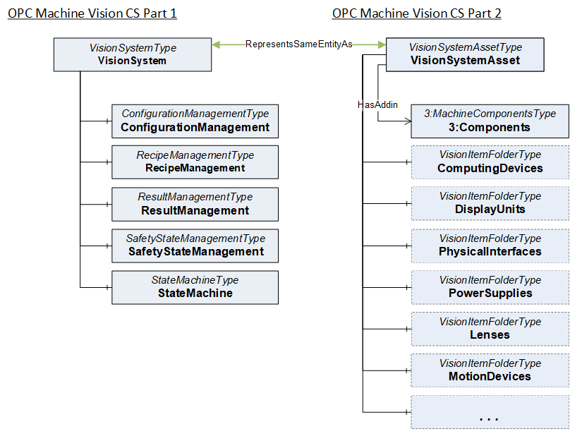
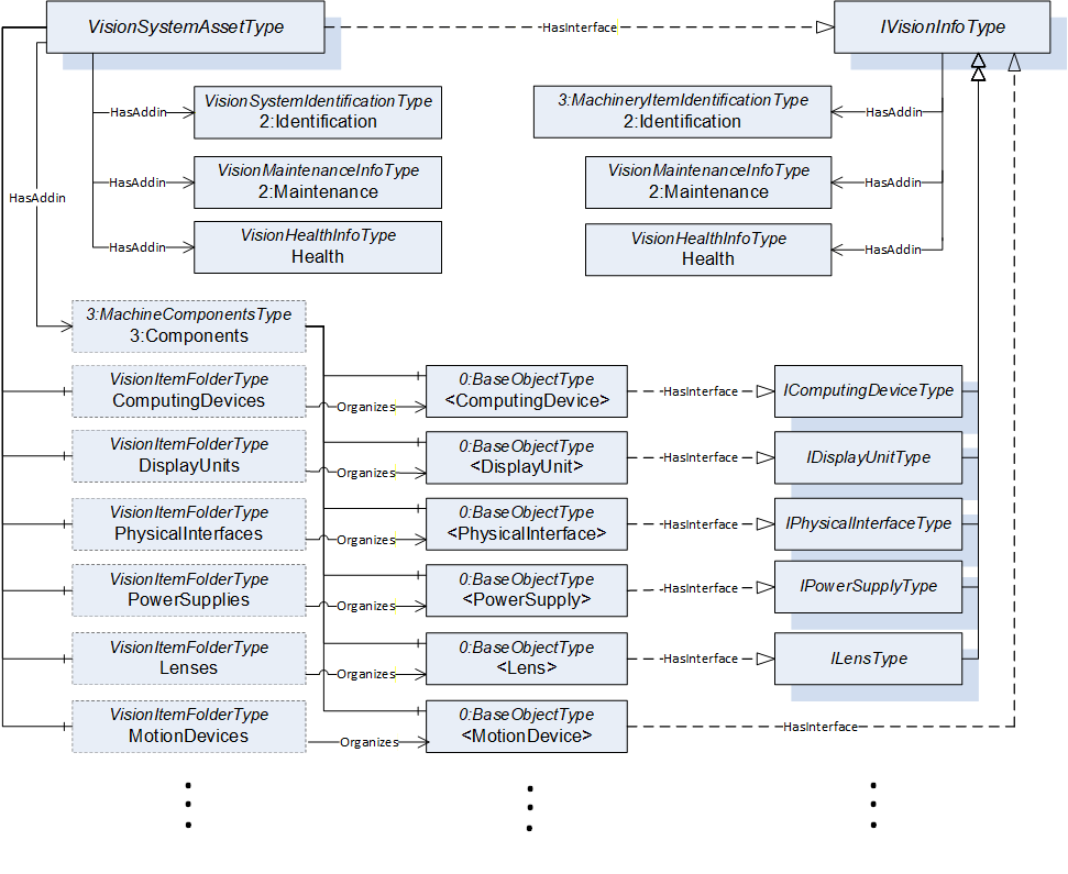
The idea behind this modelling approach is to enable the implementer to use instances of other ObjectTypes that are already defined in other companion specifications (future or current), when appropriate. The IVisionInfoType interface shall be implemented on the instances organized by the folders in VisionSystemAssetType unless a specific subtype of IVisionInfoType for that particular item type exists (e.g., IComputingDeviceType, IDisplayUnitType, etc.). The implementation of the IVisionInfoType or one of its subtypes can also be done on the ObjectType instead of the instance to be organized in that folder. This specification also defines several convenience ObjectTypes that are not mandatory, that can be directly instantiated, and implement the necessary interfaces for different items.
7 OPC Machine Vision Common Types
This section describes the InterfaceTypes and ObjectTypes containing the parameters that are common to all the items of the vision system as well as the vision system (as a whole). Any changes to the modelling rules of the existing parameters listed within these types or any addition of parameters can be done directly within the instances or by subtyping.
7.1 Vision Machine Identification
The VisionMachineIdentificationType contains the identification and nameplate information that can be used to identify an instance as a "Machine". This ObjectType is a subtype of the MachineIdentificationType defined in OPC 40001-1 Machinery Companion Specification. It is formally defined in Table 12. This ObjectType identifies the whole vision system and can be used for all components that are machines themselves.
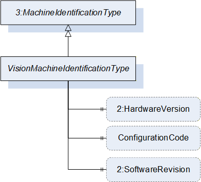
| Attribute | Value | ||||
| BrowseName | VisionMachineIdentificationType | ||||
| IsAbstract | False | ||||
| References | Node Class | BrowseName | DataType | TypeDefinition | Other |
|---|---|---|---|---|---|
| Subtype of the 3:MachineIdentificationType defined in OPC UA for Machinery, inheriting the InstanceDeclarations of that Node. | |||||
| 0:HasProperty | Variable | 2:HardwareRevision | 0:SemanticVersionString | 0:PropertyType | O |
| 0:HasProperty | Variable | ConfigurationCode | 0:String | 0:PropertyType | O |
| 0:HasProperty | Variable | 2:SoftwareRevision | 0:SemanticVersionString | 0:PropertyType | O |
The HardwareRevision property provides the revision level of the hardware of the machine vision system following the rules of Sematic Versioning 2.0.0
The ConfigurationCode property provides the specific information how the machine vision system has been configured for a specific use case or application.
The SoftwareRevision property provides the version or revision level of the software in the machine vision system following the rules of Semantic Versioning 2.0.0.
7.2 Vision Component Identification
The VisionComponentIdentificationType contains the identification and nameplate information that can be used to identify an instance as a "Component". This ObjectType is a subtype of MachineryComponentIdentificationType defined in OPC 40001-1 Machinery Companion Specification. It is formally defined in Table 13.
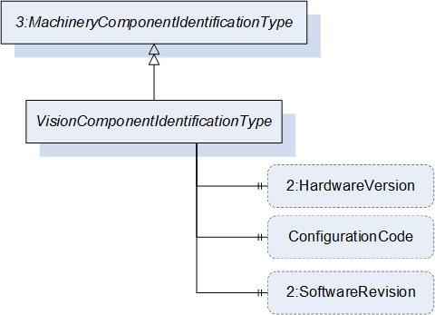
| Attribute | Value | ||||
| BrowseName | VisionComponentIdentificationType | ||||
| IsAbstract | False | ||||
| References | Node Class | BrowseName | DataType | TypeDefinition | Other |
|---|---|---|---|---|---|
| Subtype of the 3:MachineryComponentIdentificationType defined in OPC UA for Machinery, inheriting the InstanceDeclarations of that Node. | |||||
| 0:HasProperty | Variable | 2:HardwareRevision | 0:SemanticVersionString | 0:PropertyType | O |
| 0:HasProperty | Variable | ConfigurationCode | 0:String | 0:PropertyType | O |
| 0:HasProperty | Variable | 2:SoftwareRevision | 0:SemanticVersionString | 0:PropertyType | O |
The HardwareRevision property provides the revision level of the hardware of the component in the machine vision system following the rules of Sematic Versioning 2.0.0
The ConfigurationCode property provides the specific information how that component of the machine vision system has been configured for a specific use case or application.
The SoftwareRevision property provides the version or revision level of the software in the component of the machine vision system following the rules of Semantic Versioning 2.0.0.
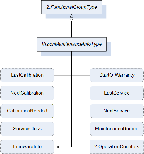
7.3 VisionMaintenanceInfoType ObjectType Definition
This subtype of FunctionalGroupType contains basic information needed to provide maintenance of an Item. It is formally defined in Table 14.
Note: In addition to the variables defined in this ObjectType it is possible to inform about maintenance related events of an Item using ConditionType's events. In those cases, it is strongly suggested the use of the information model describe on OPC 10000-110 Asset Management Basics. Each of those ConditionType's shall implement the IMaintenanceEventType and use a relevant category (e.g., CalibrationDueConditionClassType) when appropriate.
| Attribute | Value | ||||
| BrowseName | VisionMaintenanceInfoType | ||||
| IsAbstract | False | ||||
| References | Node Class | BrowseName | DataType | TypeDefinition | Other |
|---|---|---|---|---|---|
| Subtype of the 2:FunctionalGroupType defined in OPC 10000-100, i.e. inheriting the InstanceDeclarations of that Node | |||||
| 0:HasProperty | Variable | StartOfWarranty | 0:UtcTime | 0:PropertyType | O |
| 0:HasProperty | Variable | LastService | 0:UtcTime | 0:PropertyType | O |
| 0:HasProperty | Variable | NextService | 0:UtcTime | 0:PropertyType | O |
| 0:HasProperty | Variable | CalibrationNeeded | 0:Boolean | 0:PropertyType | O |
| 0:HasProperty | Variable | LastCalibration | 0:UtcTime | 0:PropertyType | O |
| 0:HasProperty | Variable | NextCalibration | 0:UtcTime | 0:PropertyType | O |
| 0:HasComponent | Variable | ServiceClass | 0:UInteger | 0:MultiStateDiscreteType | O |
| 0:HasProperty | Variable | MaintenanceRecord | 0:String | 0:PropertyType | O |
| 0:HasProperty | Variable | FirmwareInfo | 0:String | 0:PropertyType | O |
| 0:HasAddIn | Object | 2:OperationCounters | 3:MachineryOperationCounterType | O | |
The components of the VisionMaintenanceInfoType have additional subcomponents which are defined in Table 23.
| Source Path | Reference | NodeClass | BrowseName | DataType | TypeDefinition | Others | |
| 0:HasProperty | Variable | 2:PowerOnDuration | 0:Duration | 0:PropertyType | O | |
| 0:HasProperty | Variable | 2:OperationDuration | 0:Duration | 0:PropertyType | O | |
| 0:HasProperty | Variable | 2:OperationCycleCounter | 0:UInteger | 0:PropertyType | O |
The StartOfWarranty property denotes the beginning of the warranty period of the item.
The LastService property denotes the last moment in time when the most recent service was carried out on the item.
The NextService property denotes the planned moment in time when the next service is to be carried out on the item.
The CalibrationNeeded property is a flag that if True denotes that the item needs calibration.
The LastCalibration property denotes the time when the previous calibration was carried out on the item.
The NextCalibration property denotes the planned time when the next calibration is to be carried out on the item.
The ServiceClass property provides information that an item is classified as a wear and tear part, whether it is a line replaceable unit (LRU), shop replaceable unit (SRU), wear and tear part (WTP), infrastructural unit (ISU), infrastructural equipment (ISE), etc.
The 2:OperationCounters is recommended to be used as defined in OPC 40001-1.
Note: Servers can add additional entries into the EnumStrings array. The order of the value attributes corresponds with the numeric value that must be provided in the value of the variable.
| BrowsePath | Value Attributes | ||
| OTHER LRU - Line Replaceable Unit SRU - Shop Replaceable Unit WTP - Wear and Tear Part ISU - Infrastructural Unit ISE - Infrastructural Equipment |
The MaintenanceRecord property provides the most recent note that was recorded while performing maintenance. This property can be historized if a history of previous maintenance notes is to be made available. This property can also be used to provide a link to an external resource (e.g., a file or a webpage) where the user can get access to more information about the item related to maintenance.
Note: If the server implements maintenance events using OPC 10000-110 Asset Management Basics, a maintenance record can also be created by a client application monitoring the events triggered by Item.
The FirmwareInfo property denotes the information about the firmware of the Item.
7.4 VisionHealthInfoType ObjectType Definition
The VisionHealthInfoType provides the current general condition of the machine vision system or its item with respect to its/their functional fitness. It is formally defined in Table 17.
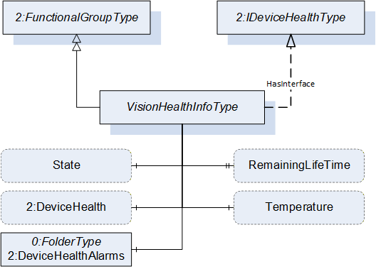
| Attribute | Value | |||||
| BrowseName | VisionHealthInfoType | |||||
| IsAbstract | False | |||||
| References | Node Class | BrowseName | DataType | TypeDefinition | Other | |
|---|---|---|---|---|---|---|
| Subtype of the 2:FunctionalGroupType defined in OPC 10000-100, i.e. inheriting the InstanceDeclarations of that Node | ||||||
| 0:HasComponent | Variable | RemainingLifeTime | 0:Number | 2:LifetimeVariableType | O | |
| 0:HasComponent | Variable | Temperature | 0:Double | 0:AnalogUnitType | O | |
| 0:HasComponent | Variable | State | SEMI_E10SystemStateDataType | SEMI_E10SystemStateType | O | |
| 0:HasInterface | ObjectType | 2:IDeviceHealthType | ||||
| Applied from 2:IDeviceHealthType | ||||||
| 0:HasComponent | Variable | 2:DeviceHealth | 2:DeviceHealthEnumeration | 0:BaseDataVariableType | O | |
| 0:HasComponent | Object | 2:DeviceHealthAlarms | 0:FolderType | O | ||
The RemainingLifeTime property denotes the remaining lifetime of the item. It serves as an indication to service personnel for maintenance activities.
The Temperature property denotes the temperature value (along with its unit) of the item.
The State property denotes the SEMI E10 State of the item (see Section 11.1).
The DeviceHealth variable indicates the status as defined by NAMUR Recommendation NE107. The DeviceHealthEnumeration DataType is formally defined in OPC 10000-100 Device Model.
The DeviceHealthAlarms folder shall organize the Alarms and Conditions related to the item if these Alarms and Conditions are instantiated in the address space.
7.5 IVisionInfoType InterfaceType definition
This InterfaceType defines the minimal basic information that each item (that can be either a component or a machine by itself) shall provide in a vision system. It is formally defined in Table 18.
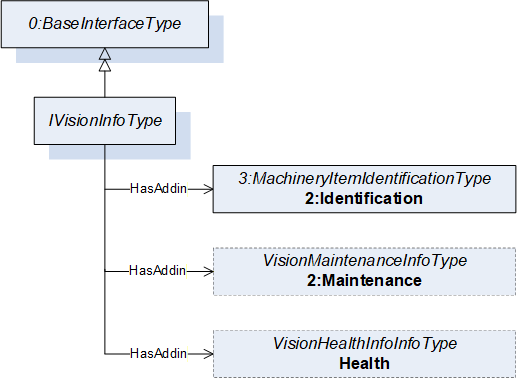
| Attribute | Value | ||||
| BrowseName | IVisionInfoType | ||||
| IsAbstract | True | ||||
| References | Node Class | BrowseName | DataType | TypeDefinition | Other |
|---|---|---|---|---|---|
| Subtype of the 0:BaseInterfaceType defined in OPC 10001-7, i.e. inheriting the InstanceDeclarations of that Node. | |||||
| 0:HasAddIn | Object | 2:Identification | 3:MachineryItemIdentificationType | M | |
| 0:HasAddIn | Object | 2:Maintenance | VisionMaintenanceInfoType | O | |
| 0:HasAddIn | Object | Health | VisionHealthInfoType | O | |
The 2:Identification object contains Properties of the item that will serve for identification like Manufacturer, SerialNumber, etc. This node shall be an instance of either the MachineIdentificationType or MachineryComponentIdentificationType or a subtype of either of these types. Depending on the type used, the item will be identified as a machine or a component. Implementers of this specification are free to provide subtypes of the base types defined in OPC 40001-1 Machinery Companion Specification or use the ones defined in Sections 7.1 and 7.2.
The 2:Maintenance object contains Properties which provide information needed for maintenance purposes e.g StartOfWarranty, MostRecentService etc., see Section 0 for further details.
The Health object contains Properties like Temperature, DeviceHealth and Notifications indicating the status of an item.
All the objects mentioned above (namely 2:Identification, 2:Maintenance and Health) are folders as they are instance declarations of types derived from the FolderType formally defined in in OPC 10000-5 Information Model
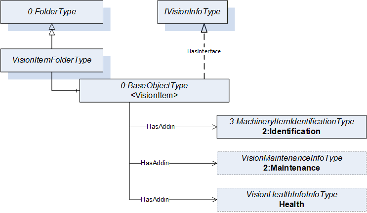
7.6 VisionItemFolderType ObjectType Definition
The VisionItemFolderType provides a way to organize items of the machine vision system into functional categories and is formally defined in Table 19. Each object instance within this folder shall implement the IVisionInfoType interface as defined in 7.5 or one of its subtypes.
| Attribute | Value | ||||
| BrowseName | VisionItemFolderType | ||||
| IsAbstract | False | ||||
| References | Node Class | BrowseName | DataType | TypeDefinition | Other |
|---|---|---|---|---|---|
| Subtype of the 0:FolderType defined in OPC 10000-5, i.e. inheriting the InstanceDeclarations of that Node. | |||||
| 0:Organizes | Object | <VisionItem> | 0:BaseObjectType | MP | |
The components of the VisionItemFolderType have additional subcomponents which are defined in Table 20.
| Source Path | Reference | NodeClass | BrowseName | DataType | TypeDefinition | Others |
| <VisionItem> | 0:HasInterface | ObjectType | IVisionInfoType | Defined in 8.1 | ||
| Applied from IVisionInfoType | ||||||
| <VisionItem> | 0:HasAddIn | Object | 2:Identification | 3:MachineryItemIdentificationType | M | |
| <VisionItem> | 0:HasAddIn | Object | 2:Maintenance | VisionMaintenanceInfoType | O | |
| <VisionItem> | 0:HasAddIn | Object | Health | VisionHealthInfoType | O | |
8 OPC Machine Vision System Asset
8.1 VisionSystemAssetType ObjectType Definition
The VisionSystemAssetType is an ObjectType that provides a representation of the machine vision system and organizes the items that constitute it into different folders depending on their function. This type is used to represent the entire machine vision system as an asset. It is formally defined in Table 21.
| Attribute | Value | ||||
| BrowseName | VisionSystemAssetType | ||||
| IsAbstract | False | ||||
| References | Node Class | BrowseName | DataType | TypeDefinition | Other |
|---|---|---|---|---|---|
| Subtype of the 0:BaseObjectType defined in OPC 10000-5, i.e. inheriting the InstanceDeclarations of that Node | |||||
| 0:HasAddIn | Object | 3:Components | 3:MachineComponentsType | O | |
| 0:HasComponent | Object | ComputingDevices | VisionItemFolderType | O | |
| 0:HasComponent | Object | DisplayUnits | VisionItemFolderType | O | |
| 0:HasComponent | Object | PhysicalInterfaces | VisionItemFolderType | O | |
| 0:HasComponent | Object | ImageSensors | VisionItemFolderType | O | |
| 0:HasComponent | Object | FrameGrabbers | VisionItemFolderType | O | |
| 0:HasComponent | Object | Lenses | VisionItemFolderType | O | |
| 0:HasComponent | Object | LensControllers | VisionItemFolderType | O | |
| 0:HasComponent | Object | OpticalFilters | VisionItemFolderType | O | |
| 0:HasComponent | Object | OtherOpticalEquipments | VisionItemFolderType | O | |
| 0:HasComponent | Object | WayEncoders | VisionItemFolderType | O | |
| 0:HasComponent | Object | TriggerSensors | VisionItemFolderType | O | |
| 0:HasComponent | Object | Lamps | VisionItemFolderType | O | |
| 0:HasComponent | Object | LightingControllers | VisionItemFolderType | O | |
| 0:HasComponent | Object | PatternGenerators | VisionItemFolderType | O | |
| 0:HasComponent | Object | CalibrationTargets | VisionItemFolderType | O | |
| 0:HasComponent | Object | AcquisitionBackgrounds | VisionItemFolderType | O | |
| 0:HasComponent | Object | SurroundingEnvironment | VisionItemFolderType | O | |
| 0:HasComponent | Object | Housings | VisionItemFolderType | O | |
| 0:HasComponent | Object | MotionDevices | VisionItemFolderType | O | |
| 0:HasComponent | Object | PowerSupplies | VisionItemFolderType | O | |
| 0:HasComponent | Object | ClimateControllers | VisionItemFolderType | O | |
| 0:HasComponent | Object | Licenses | VisionItemFolderType | O | |
| 0:HasComponent | Object | SoftwareComponents | VisionItemFolderType | O | |
| 0:HasComponent | Object | NetworkDevices | VisionItemFolderType | O | |
| 0:HasComponent | Object | Cables | VisionItemFolderType | O | |
| 0:HasComponent | Object | ImageHandlingAspects | 0:FolderType | O | |
| 0:HasInterface | ObjectType | IVisionInfoType | |||
| Applied from IVisionInfoType | |||||
| 0:HasAddIn | Object | 2:Identification | VisionMachineIdentificationType | M | |
| 0:HasAddIn | Object | 2:Maintenance | VisionMaintenanceInfoType | O | |
| 0:HasAddIn | Object | Health | VisionHealthInfoType | O | |
| Conformance Units | |||||
|---|---|---|---|---|---|
| VSA_BasicIdentification | |||||
| VSA_ExtendedIdentification | |||||
| VSA_MaintenanceInformation | |||||
| VSA_HealthInformation |
The Components object (with a standardized BrowseName as defined in the OPC UA for Machinery companion specification) provides a flat list of all the items of the machine vision system.
The ComputingDevices object organizes all instances representing computing devices within the Machine Vision system.
The DisplayUnits object organizes all instances representing display units within the Machine Vision system.
The PhysicalInterfaces object organizes all instances representing physical interfaces within the Machine Vision system.
The ImageSensors object organizes all instances representing image sensors within the Machine Vision system.
The FrameGrabbers object organizes all instances representing frame grabbers within the Machine Vision system.
The Lenses object organizes all instances representing lenses within the Machine Vision system.
The LensControllers object organizes all instances representing lens controllers within the Machine Vision system.
The OpticalFilters object organizes all instances representing optical filters within the Machine Vision system.
The OtherOpticalEquipment object organizes all instances representing other optical equipment within the Machine Vision system.
The WayEncoders object organizes all instances representing way encoders within the Machine Vision system.
The TriggerSensors object organizes all instances representing trigger sensors within the Machine Vision system.
The Lamps object organizes all instances representing lamps within the Machine Vision system.
The LightingControllers object organizes all instances representing lighting controllers within the Machine Vision system.
The PatternGenerators object organizes all instances representing pattern generators within the Machine Vision system.
The CalibrationTargets object organizes all instances representing calibration targets within the Machine Vision system. This document does not define a helper ObjectType for calibration targets. A standardized object type for calibration targets CalibrationTargetType has already been defined in Section 7.4.1 of OPC 10000-200 Industrial Automation.
The AcquisitionBackgrounds object organizes all instances representing acquisition backgrounds for the Machine Vision system.
The SurroundingEnvironment object organizes all instances representing surrounding environment properties of the Machine Vision system.
The Housings object organizes all instances representing housings within the Machine Vision system.
The MotionDevices object organizes all instances representing motion devices (e.g. a robot, a linear unit or a positioner) within the Machine Vision system. This document does not define a helper ObjectType for motion devices. A standardized object type for motion devices such as MotionDeviceType has already been defined in Section 7.2 of OPC 40010-1 - OPC UA for Robotics, Part 1: Vertical Integration. See OPC 40010-1 for more information.
The PowerSupplies object organizes all instances representing power supplies within the Machine Vision system.
The ClimateControllers object organizes all instances representing temperature l, humidity, or any other type of climate control device within the machine vision system.
The Licenses object organizes all instances representing licenses within the Machine Vision system.
The SoftwareComponents object organizes all instances representing software within the Machine Vision system. This document does not define a helper ObjectType for software. A standardized object type such as SoftwareType has already been defined in OPC 10000-100 Device Model.
The NetworkDevices object organizes all instances representing network devices within the Machine Vision system.
The Cables object organizes all instances representing cables within the Machine Vision system.
The ImageHandlingAspects object organizes all instances of object types that represent aspects of the image handling in an Item. See Sections 10.33, 10.34 and 10.35 for more information.
The components of the VisionSystemAssetType have additional subcomponents which are defined in Table 22.
| Source Path | Reference | NodeClass | BrowseName | DataType | TypeDefinition | Others |
| ComputingDevices | 0:Organizes | Object | <ComputingDevice> | 0:BaseObjectType | MP | |
| DisplayUnits | 0:Organizes | Object | <DisplayUnit> | 0:BaseObjectType | MP | |
| PhysicalInterfaces | 0:Organizes | Object | <PhysicalInterface> | 0:BaseObjectType | MP | |
| ImageSensors | 0:Organizes | Object | <ImageSensor> | 0:BaseObjectType | MP | |
| FrameGrabbers | 0:Organizes | Object | <FrameGrabber> | 0:BaseObjectType | MP | |
| Lenses | 0:Organizes | Object | <Lens> | 0:BaseObjectType | MP | |
| LensControllers | 0:Organizes | Object | <LensController> | 0:BaseObjectType | MP | |
| OpticalFilters | 0:Organizes | Object | <OpticalFilter> | 0:BaseObjectType | MP | |
| OtherOpticalEquipments | 0:Organizes | Object | <OtherOpticalEquipment> | 0:BaseObjectType | MP | |
| WayEncoders | 0:Organizes | Object | <WayEncoder> | 0:BaseObjectType | MP | |
| TriggerSensors | 0:Organizes | Object | <TriggerSensor> | 0:BaseObjectType | MP | |
| Lamps | 0:Organizes | Object | <Lamp> | 0:BaseObjectType | MP | |
| LightingControllers | 0:Organizes | Object | <LightingController> | 0:BaseObjectType | MP | |
| PatternGenerators | 0:Organizes | Object | <PatternGenerator> | 0:BaseObjectType | MP | |
| CalibrationTargets | 0:Organizes | Object | <CalibrationTarget> | 0:BaseObjectType | MP | |
| AcquisitionBackgrounds | 0:Organizes | Object | <AcquisitionBackground> | 0:BaseObjectType | MP | |
| SurroundingEnvironment | 0:Organizes | Object | <SurroundingEnvironment> | 0:BaseObjectType | MP | |
| Housings | 0:Organizes | Object | <Housing> | 0:BaseObjectType | MP | |
| MotionDevices | 0:Organizes | Object | <MotionDevice> | 0:BaseObjectType | MP | |
| PowerSupplies | 0:Organizes | Object | <PowerSupply> | 0:BaseObjectType | MP | |
| ClimateControllers | 0:Organizes | Object | <ClimateController> | 0:BaseObjectType | MP | |
| Licenses | 0:Organizes | Object | <License> | 0:BaseObjectType | MP | |
| SoftwareComponents | 0:Organizes | Object | <Software> | 0:BaseObjectType | MP | |
| NetworkDevices | 0:Organizes | Object | <NetworkDevice> | 0:BaseObjectType | MP | |
| Cables | 0:Organizes | Object | <Cable> | 0:BaseObjectType | MP | |
| ImageHandlingAspects | 0:Organizes | Object | <ImageHandlingAspect> | 0:BaseObjectType | MP |
The components of the VisionSystemAssetType have additional subcomponents which are defined in Table 23.
| Source Path | Reference | NodeClass | BrowseName | DataType | TypeDefinition | Others | ||
| 0:HasInterface | ObjectType | IComputingDeviceType | |||||
| 0:HasInterface | ObjectType | IDisplayUnitType | |||||
| 0:HasInterface | ObjectType | IPhysicalInterfaceType | |||||
| 0:HasInterface | ObjectType | ILensType | |||||
| 0:HasInterface | ObjectType | ILampType | |||||
| 0:HasInterface | ObjectType | ILightingControllerType | |||||
| 0:HasInterface | ObjectType | ILicenseType | |||||
| 0:HasInterface | ObjectType | ICableType |
All instances within the ComputingDevices folder shall implement the IComputingDeviceType interface (9.1).
All instances within the DisplayUnits folder shall implement the IDisplayUnitType interface (9.3).
All instances within the PhysicalInterfaces folder shall implement the IPhysicalInterfaceType interface 9.5).
All instances within the Lenses folder shall implement the ILensType interface (9.7).
All instances within the Lamps folder shall implement the ILampType interface (9.12).
All instances within the LightingControllers folder shall implement the ILightingControllerType interface (9.10).
All instances within the Licenses folder shall implement the ILicenseType interface (9.25).
All instances within the Cables folder shall implement the ICableType interface (9.28).
Note: In order to declare an arbitrary object (i.e., an instance of BaseObjectType or one of its subtypes) as a MachineryComponent which represents a particular component of the machine vision system, said instance shall be referenced by the instance of MachineryComponentsType with a HasComponent reference. It shall also be referenced from the folder representing a collection of the same type of components as it is representing e.g., a BaseObjectType instance (i.e., an instance of any arbitrary object type) representing a computing device, shall be referenced by the instance of MachineryComponentsType with a HasComponent reference, thereby representing a MachineryComponent. It shall also be referenced from the ComputingDevices folder, thereby representing a ComputingDevice.
9 OPC Machine Vision System Components
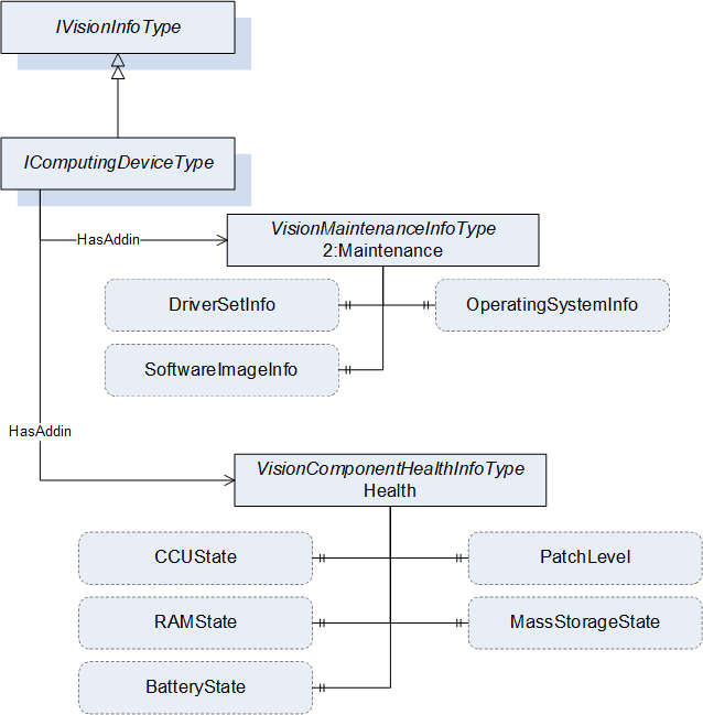
9.1 IComputingDeviceType InterfaceType Definition
The IComputingDeviceType provides the minimal set of information that a computing device object shall provide in a machine vision system. All objects that implement this interface shall be organized in the ComputingDevices folder of the VisionSystemAssetType. It is formally defined in Table 24.
| Attribute | Value | ||||
| BrowseName | IComputingDeviceType | ||||
| IsAbstract | True | ||||
| References | Node Class | BrowseName | DataType | TypeDefinition | Other |
|---|---|---|---|---|---|
| Subtype of the IVisionInfoType, inheriting the InstanceDeclarations of that Node. | |||||
The components of the IComputingDeviceType have additional subcomponents which are defined in Table 25.
| Source Path | Reference | NodeClass | BrowseName | DataType | TypeDefinition | Others |
| 2:Maintenance | 0:HasProperty | Variable | OperatingSystemInfo | 0:String | 0:PropertyType | O |
| 2:Maintenance | 0:HasProperty | Variable | DriverInfo | 0:String[] | 0:PropertyType | O |
| 2:Maintenance | 0:HasProperty | Variable | SoftwareImageInfo | 0:String | 0:PropertyType | O |
| Health | 0:HasProperty | Variable | PatchLevel | 0:String | 0:PropertyType | O |
| Health | 0:HasProperty | Variable | MassStorageState | 0:String | 0:PropertyType | O |
| Health | 0:HasProperty | Variable | RAMState | 0:String | 0:PropertyType | O |
| Health | 0:HasProperty | Variable | CCUState | 0:String | 0:PropertyType | O |
| Health | 0:HasProperty | Variable | BatteryState | 0:String | 0:PropertyType | O |
The OperatingSystemInfo property denotes information about low-level software that supports the basic functions of the computing device such as scheduling task and controlling peripherals.
The DriverInfo property denotes information about the set of drivers being used by the computing device
The SoftwareImageInfo property denotes information about the software image that is in use in the computing device.
The PatchLevel property denotes the patch level or patch set. When patches must be applied in order, it is usually an identifier of the most recent patch applied to the system.
The MassStorageState property denotes overall information about the condition of the mass storage e.g., specific drives or RAID arrays etc.
The RAMState property denotes overall information about the condition of the RAM (e.g., there are systems using ECC enabled RAM that can provide information about the health state of the RAM modules)
The CCUState property denotes a composite state providing overall information about the condition of the climate control units (CCU) e.g., fans, heatsinks, cooling pumps, heating etc.
The BatteryState property denotes overall information about the condition of the battery or batteries.
The MassStorageState, RAMState, CCUState and BatteryState have been left relatively open as they are intended to give the user a sense of the state of the computing device. This may be a percentage value or a textual description of the state.
9.2 VisionComputingDeviceType ObjectType Definition
The VisionComputingDeviceType provides a concrete ObjectType implementing the IComputingDeviceType interface that can be instantiated directly. This ObjectType is defined in this specification as a convenience to the implementer. The instances of this object type shall be organized in the ComputingDevices folder of the VisionSystemAssetType. It is formally defined in Table 26.
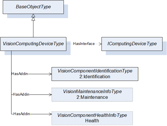
| Attribute | Value | ||||
| BrowseName | VisionComputingDeviceType | ||||
| IsAbstract | False | ||||
| References | Node Class | BrowseName | DataType | TypeDefinition | Other |
|---|---|---|---|---|---|
| Subtype of the 0:BaseObjectType defined in OPC 10000-5, i.e. inheriting the InstanceDeclarations of that Node | |||||
| 0:HasInterface | ObjectType | IComputingDeviceType | |||
| Applied from IComputingDeviceType | |||||
| 0:HasAddIn | Object | 2:Identification | VisionComponentIdentificationType | M | |
| 0:HasAddIn | Object | 2:Maintenance | VisionMaintenanceInfoType | O | |
| 0:HasAddIn | Object | Health | VisionHealthInfoType | O | |
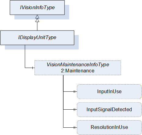
9.3 IDisplayUnitType ObjectType Definition
The IDisplayUnitType provides the minimal set of information that a display unit object shall provide in a vision system. All objects that implement this interface shall be organized in the DisplayUnits folder of the VisionSystemAssetType. It is formally defined in Table 27.
| Attribute | Value | ||||
| BrowseName | IDisplayUnitType | ||||
| IsAbstract | True | ||||
| References | Node Class | BrowseName | DataType | TypeDefinition | Other |
|---|---|---|---|---|---|
| Subtype of the IVisionInfoType, inheriting the InstanceDeclarations of that Node. | |||||
The components of the IDisplayUnitType have additional subcomponents which are defined in Table 28.
| Source Path | Reference | NodeClass | BrowseName | DataType | TypeDefinition | Others |
| 2:Maintenance | 0:HasProperty | Variable | InputInUse | 0:String | 0:PropertyType | O |
| 2:Maintenance | 0:HasProperty | Variable | InputSignalDetected | 0:Boolean | 0:PropertyType | O |
| 2:Maintenance | 0:HasProperty | Variable | ResolutionInUse | 0:String | 0:PropertyType | O |
The InputInUse property denotes the signal port for the display unit currently in use. This property could also be used from the vision system perspective to denote signal source for the display unit if multiple sources share the same display unit e.g., X1, X2 (as per the convention used in the DIN EN IEC 81346-2:2020-10 specification)
The InputSignalDetected property is a flag that denotes if a signal is being detected in the InputInUse.
The ResolutionInUse denotes the pixel resolution in use (e.g., 1920x1080).
9.4 VisionDisplayUnitType ObjectType Definition
The VisionDisplayUnitType provides a concrete ObjectType which can be instantiated directly implementing the IDisplayUnitType interface. The instances of this object type shall be organized in the DisplayUnits folder of the VisionSystemAssetType. It is formally defined in Table 29.
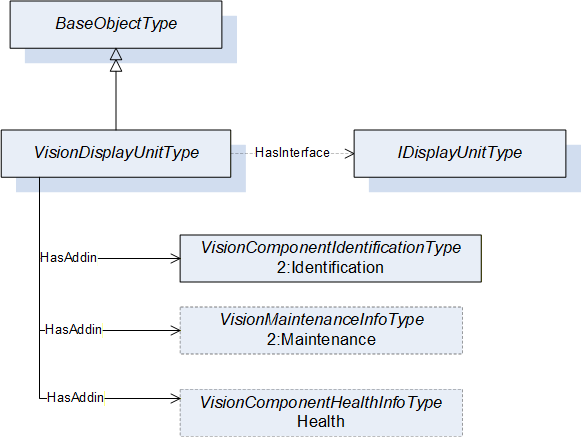
| Attribute | Value | ||||
| BrowseName | VisionDisplayUnitType | ||||
| IsAbstract | False | ||||
| References | Node Class | BrowseName | DataType | TypeDefinition | Other |
|---|---|---|---|---|---|
| Subtype of the 0:BaseObjectType defined in OPC 10000-5, i.e. inheriting the InstanceDeclarations of that Node | |||||
| 0:HasInterface | ObjectType | IDisplayUnitType | |||
| Applied from IDisplayUnitType | |||||
| 0:HasAddIn | Object | 2:Identification | VisionComponentIdentificationType | M | |
| 0:HasAddIn | Object | 2:Maintenance | VisionMaintenanceInfoType | O | |
| 0:HasAddIn | Object | Health | VisionHealthInfoType | O | |
9.5 IPhysicalInterfaceType ObjectType Definition
The IPhysicalInterfaceType provides the minimal set of information that a physical interface object shall provide in a vision system. All objects that implement this interface shall be organized in the PhysicalInterfaces folder of the VisionSystemAssetType. It is formally defined in Table 30.
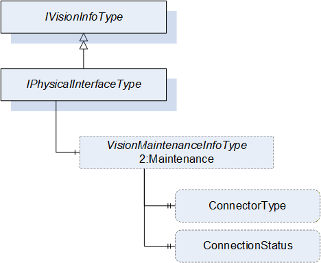
| Attribute | Value | ||||
| BrowseName | IPhysicalInterfaceType | ||||
| IsAbstract | True | ||||
| References | Node Class | BrowseName | DataType | TypeDefinition | Other |
|---|---|---|---|---|---|
| Subtype of the IVisionInfoType, inheriting the InstanceDeclarations of that Node. | |||||
The components of the IPhysicalInterfaceType have additional subcomponents which are defined in Table 31.
| Source Path | Reference | NodeClass | BrowseName | DataType | TypeDefinition | Others |
| 2:Maintenance | 0:HasProperty | Variable | ConnectorType | 0:String | 0:PropertyType | O |
| Health | 0:HasProperty | Variable | ConnectionStatus | 0:Boolean | 0:PropertyType | O |
The ConnectorType property denotes the type of connector for the physical interface (e.g., USB, Ethernet, etc.)
The ConnectionStatus property denotes if a signal is being received by the physical interface from the perspective of the machine vision system.
9.6 VisionPhysicalInterfaceType ObjectType Definition
The VisionPhysicalInterfaceType provides a concrete ObjectType which can be instantiated directly implementing the IPhysicalInterfaceType interface. The instances of this object type shall be organized in the PhysicalInterfaces folder of the VisionSystemAssetType. It is formally defined in Table 32.
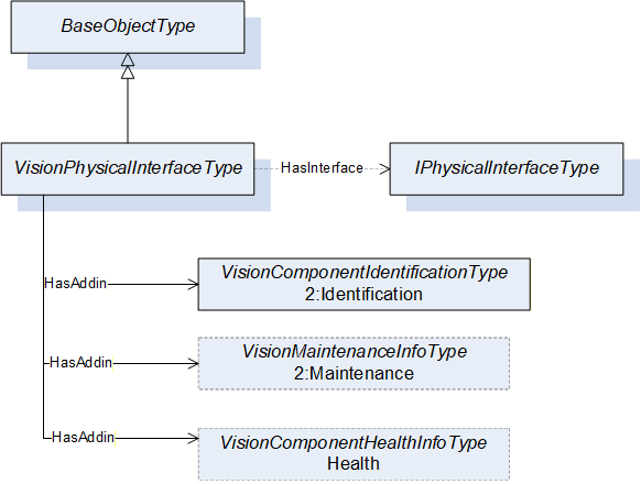
| Attribute | Value | ||||
| BrowseName | VisionPhysicalInterfaceType | ||||
| IsAbstract | False | ||||
| References | Node Class | BrowseName | DataType | TypeDefinition | Other |
|---|---|---|---|---|---|
| Subtype of the 0:BaseObjectType defined in OPC 10000-5, i.e. inheriting the InstanceDeclarations of that Node | |||||
| 0:HasInterface | ObjectType | IPhysicalInterfaceType | |||
| Applied from IPhysicalInterfaceType | |||||
| 0:HasAddIn | Object | 2:Identification | VisionComponentIdentificationType | M | |
| 0:HasAddIn | Object | 2:Maintenance | VisionMaintenanceInfoType | O | |
| 0:HasAddIn | Object | Health | VisionHealthInfoType | O | |
9.7 ILensType ObjectType Definition
This ILensType interface provides the minimal set of information that a lens object shall provide in a vision system. All objects that implement this interface shall be organized in the Lenses folder of the VisionSystemAssetType. It is formally defined in Table 33.

| Attribute | Value | ||||
| BrowseName | ILensType | ||||
| IsAbstract | True | ||||
| References | Node Class | BrowseName | DataType | TypeDefinition | Other |
|---|---|---|---|---|---|
| Subtype of the IVisionInfoType, inheriting the InstanceDeclarations of that Node. | |||||
The components of the ILensType have additional subcomponents which are defined in Table 34.
| Source Path | Reference | NodeClass | BrowseName | DataType | TypeDefinition | Others |
| 2:Maintenance | 0:HasComponent | Variable | MountType | 0:UInt32 | 0:MultiStateDiscreteType | O |
| 2:Maintenance | 0:HasProperty | Variable | LensType | 0:String | 0:PropertyType | O |
| 2:Maintenance | 0:HasProperty | Variable | FocalLength | 0:Double | 0:PropertyType | O |
| 2:Maintenance | 0:HasProperty | Variable | Aperture | 0:Double | 0:PropertyType | O |
| 2:Maintenance | 0:HasProperty | Variable | ModulationTransferFunction | 0:Byte | 0:PropertyType | O |
| 2:Maintenance | 0:HasProperty | Variable | Resolution | 0:Double | 0:PropertyType | O |
| 2:Maintenance | 0:HasProperty | Variable | BackFocalLength | 0:Double | 0:PropertyType | O |
| 2:Maintenance | 0:HasProperty | Variable | MinimumWorkingDistance | 0:Double | 0:PropertyType | O |
| 2:Maintenance | 0:HasProperty | Variable | Magnification | 0:Double | 0:PropertyType | O |
| 2:Maintenance | 0:HasProperty | Variable | WorkingDistance | 0:Double | 0:PropertyType | O |
| 2:Maintenance | 0:HasProperty | Variable | OpticalFormat | 0:String | 0:PropertyType | O |
The FocalLength property is the distance between the principal plane and the point where the light passing through the lens is focused and is given in millimeters.
The BackFocalLength property is the distance from the vertex of the last optical surface of the system to the rear focal point and is given in millimeters. This property should only exist when needed to provide additional system information such as to calculate the scheimpflug angle for tilted systems.
The Aperture property is the current aperture set on the lens. Examples are "1.4" and "2.0".
The Resolution property is the resolution that the lens is capable of (this is usually the catalog value). It is given in line pairs per millimeter (lp/mm) as the resolution would be determined with something like a 1951-USAF resolution target.
The MinimumWorkingDistance property is the minimum object distance where you can still get a sharp image and is given in meters.
The ModulationTransferFunction property is the ratio expressed as a percentage, between the actual contrast in the scene and the contrast transferred by the lens to the image at a given resolution.
The Magnification property is the relation between object size and image size. An example value of 1 will deliver a life-sized image. This property usually needs to be provided for Telecentric lenses only but might also be calculated for other lens types.
The WorkingDistance property is the current distance from the object to the lens and is given in meters.
The LensType property is the type of the Lens. Examples are "Macro", "Telecentric" and "Tilt-Shift".
The MountType component is an enumeration using MultiStateDiscreteType that defines the mount type of the Lens. In Table 35 standardized values for the EnumStrings are defined.
The OpticalFormat property denotes the maximum size of the sensor that the lens is suitable for (typically in inches).
| BrowsePath | Value Attributes | |||
| CUSTOM CS-MOUNT D-MOUNT A-MOUNT F-MOUNT T-MOUNT E-MOUNT EF-MOUNT V-MOUNT |
Note: Servers can add additional entries into the EnumStrings array. The order of the value attributes corresponds with the numeric value that must be provided in the value of the variable.
9.8 VisionLensType ObjectType Definition
The VisionLensType provides a concrete ObjectType which can be instantiated directly implementing the ILensType interface. The instances of this object type shall be organized in the Lenses folder of the VisionSystemAssetType. It is formally defined in Table 36.
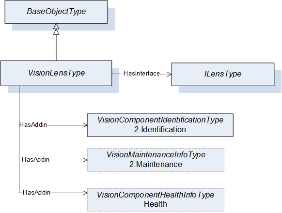
| Attribute | Value | ||||
| BrowseName | VisionLensType | ||||
| IsAbstract | False | ||||
| References | Node Class | BrowseName | DataType | TypeDefinition | Other |
|---|---|---|---|---|---|
| Subtype of the 0:BaseObjectType defined in OPC 10000-5, i.e. inheriting the InstanceDeclarations of that Node | |||||
| 0:HasInterface | ObjectType | ILensType | |||
| Applied from ILensType | |||||
| 0:HasAddIn | Object | 2:Identification | VisionComponentIdentificationType | M | |
| 0:HasAddIn | Object | 2:Maintenance | VisionMaintenanceInfoType | O | |
| 0:HasAddIn | Object | Health | VisionHealthInfoType | O | |
9.9 VisionLensControllerType ObjectType Definition
The VisionLensControllerType provides a concrete ObjectType which can be instantiated directly implementing the IVisionInfoType interface. The instances of this object type shall be organized in the LensControllers folder of the VisionSystemAssetType. It is formally defined in Table 37.
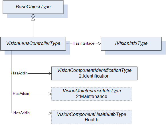
| Attribute | Value | ||||
| BrowseName | VisionLensControllerType | ||||
| IsAbstract | False | ||||
| References | Node Class | BrowseName | DataType | TypeDefinition | Other |
|---|---|---|---|---|---|
| Subtype of the 0:BaseObjectType defined in OPC 10000-5, i.e. inheriting the InstanceDeclarations of that Node | |||||
| 0:HasInterface | ObjectType | IVisionInfoType | |||
| Applied from IVisionInfoType | |||||
| 0:HasAddIn | Object | 2:Identification | VisionComponentIdentificationType | M | |
| 0:HasAddIn | Object | 2:Maintenance | VisionMaintenanceInfoType | O | |
| 0:HasAddIn | Object | Health | VisionHealthInfoType | O | |
9.10 ILightingControllerType ObjectType Definition
The ILightingControllerType interface provides the minimal set of information that a lighting controller object shall provide in a vision system. All objects that implement this interface shall be organized in the LightingControllers folder of the VisionSystemAssetType. It is formally defined in Table 38.
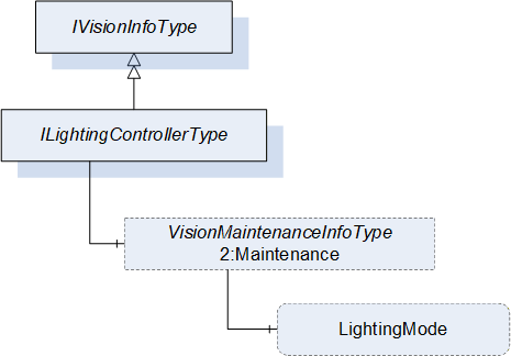
| Attribute | Value | ||||
| BrowseName | ILightingControllerType | ||||
| IsAbstract | True | ||||
| References | Node Class | BrowseName | DataType | TypeDefinition | Other |
|---|---|---|---|---|---|
| Subtype of the IVisionInfoType, inheriting the InstanceDeclarations of that Node. | |||||
The components of the ILightingController have additional subcomponents which are defined in Table 39.
| Source Path | Reference | NodeClass | BrowseName | DataType | TypeDefinition | Others |
| 2:Maintenance | 0:HasComponent | Variable | LightingMode | 0:UInt32 | 0:MultiStateDiscreteType | O |
The LigthingMode property denotes the current lighting mode of the lighting controller e.g. STROBE, CONTINUOUS, MODULATED, etc.
The component Variables of the ILightingControllerType have additional Attributes defined in Table 40.
| BrowsePath | Value Attribute | Description Attribute | |||
| STROBE CONTINUOUS MODULATED |
9.11 VisionLightingControllerType ObjectType Definition
The VisionLightingControllerType provides a concrete ObjectType which can be instantiated directly implementing the IVisionInfoType interface. The instances of this object type shall be organized in the LightingControllers folder of the VisionSystemAssetType. It is formally defined in Table 41.

| Attribute | Value | ||||
| BrowseName | VisionLightingControllerType | ||||
| IsAbstract | False | ||||
| References | Node Class | BrowseName | DataType | TypeDefinition | Other |
|---|---|---|---|---|---|
| Subtype of the 0:BaseObjectType defined in OPC 10000-5, i.e. inheriting the InstanceDeclarations of that Node | |||||
| 0:HasInterface | ObjectType | ILightingControllerType | |||
| Applied from ILightingControllerType | |||||
| 0:HasAddIn | Object | 2:Identification | VisionComponentIdentificationType | M | |
| 0:HasAddIn | Object | 2:Maintenance | VisionMaintenanceInfoType | O | |
| 0:HasAddIn | Object | Health | VisionHealthInfoType | O | |
9.12 ILampType ObjectType Definition
The ILampType interface provides the minimal set of information that a lamp object shall provide in a vision system. All objects that implement this interface shall be organized in the Lamps folder of the VisionSystemAssetType. It is formally defined in Table 42.
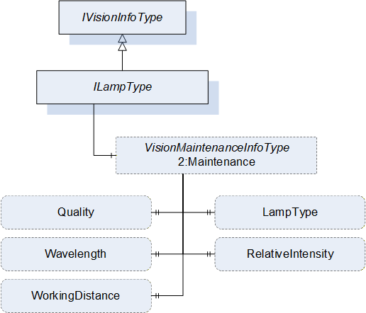
| Attribute | Value | ||||
| BrowseName | ILampType | ||||
| IsAbstract | True | ||||
| References | Node Class | BrowseName | DataType | TypeDefinition | Other |
|---|---|---|---|---|---|
| Subtype of the IVisionInfoType, inheriting the InstanceDeclarations of that Node. | |||||
The components of the ILampType have additional subcomponents which are defined in Table 43.
| Source Path | Reference | NodeClass | BrowseName | DataType | TypeDefinition | Others |
| 2:Maintenance | 0:HasProperty | Variable | LampType | 0:String | 0:PropertyType | O |
| 2:Maintenance | 0:HasProperty | Variable | Quality | 0:Byte | 0:PropertyType | O |
| 2:Maintenance | 0:HasProperty | Variable | Wavelength | 0:Double | 0:PropertyType | O |
| 2:Maintenance | 0:HasProperty | Variable | RelativeIntensity | 0:Byte | 0:PropertyType | O |
| 2:Maintenance | 0:HasProperty | Variable | WorkingDistance | 0:Double | 0:PropertyType | O |
The LampType property represents the type of the lamp e.g., FLUORESCENT, LED, LASER or XENON.
The Quality property is the percentage of the lamp quality and represents the light degradation because of multiple factors including the environment or age. A new lamp can have a quality of 100.
The Wavelength property is the wavelength of the light emitted by the lamp and is given in nanometers (nm).
The RelativeIntensity property is the amount of light emitted by the source as a percentage of the lamp total capability.
The WorkingDistance property is the current distance from the object to the lamp and is given in meters.
9.13 VisionLampType ObjectType Definition
The VisionLampType provides a concrete ObjectType which can be instantiated directly implementing the ILampType interface. The instances of this object type shall be organized in the Lamps folder of the VisionSystemAssetType. It is formally defined in Table 44.

| Attribute | Value | ||||
| BrowseName | VisionLampType | ||||
| IsAbstract | False | ||||
| References | Node Class | BrowseName | DataType | TypeDefinition | Other |
|---|---|---|---|---|---|
| Subtype of the 0:BaseObjectType defined in OPC 10000-5, i.e. inheriting the InstanceDeclarations of that Node | |||||
| 0:HasInterface | ObjectType | ILampType | |||
| Applied from ILampType | |||||
| 0:HasAddIn | Object | 2:Identification | VisionComponentIdentificationType | M | |
| 0:HasAddIn | Object | 2:Maintenance | VisionMaintenanceInfoType | O | |
| 0:HasAddIn | Object | Health | VisionHealthInfoType | O | |
9.14 VisionImageSensorType ObjectType Definition
The VisionImageSensorType provides a concrete ObjectType which can be instantiated directly implementing the IVisionInfoType interface. The instances of this object type shall be organized in the ImageSensors folder of the VisionSystemAssetType. It is formally defined in Table 45.

| Attribute | Value | |||||||||
| BrowseName | VisionImageSensorType | |||||||||
| IsAbstract | False | |||||||||
| References | Node Class | BrowseName | DataType | TypeDefinition | Other | |||||
|---|---|---|---|---|---|---|---|---|---|---|
| Subtype of the 0:BaseObjectType defined in OPC 10000-5, i.e. inheriting the InstanceDeclarations of that Node | ||||||||||
| 0:HasInterface | ObjectType | IVisionInfoType | ||||||||
| Applied from IVisionInfoType | ||||||||||
| 0:HasAddIn | Object | 2:Identification | VisionComponentIdentificationType | M | ||||||
| 0:HasAddIn | Object | 2:Maintenance | VisionMaintenanceInfoType | O | ||||||
| 0:HasAddIn | Object | Health | VisionHealthInfoType | O | ||||||
9.15 VisionFrameGrabberType ObjectType Definition
The VisionFrameGrabberType provides a concrete ObjectType which can be instantiated directly implementing the IVisionInfoType interface. The instances of this object type shall be organized in the FrameGrabbers folder of the VisionSystemAssetType. It is formally defined in Table 46.

| Attribute | Value | |||||||||
| BrowseName | VisionFrameGrabberType | |||||||||
| IsAbstract | False | |||||||||
| References | Node Class | BrowseName | DataType | TypeDefinition | Other | |||||
|---|---|---|---|---|---|---|---|---|---|---|
| Subtype of the 0:BaseObjectType defined in OPC 10000-5, i.e. inheriting the InstanceDeclarations of that Node | ||||||||||
| 0:HasInterface | ObjectType | IVisionInfoType | ||||||||
| Applied from IVisionInfoType | ||||||||||
| 0:HasAddIn | Object | 2:Identification | VisionComponentIdentificationType | M | ||||||
| 0:HasAddIn | Object | 2:Maintenance | VisionMaintenanceInfoType | O | ||||||
| 0:HasAddIn | Object | Health | VisionHealthInfoType | O | ||||||
9.16 VisionOpticalFilterType ObjectType Definition
The VisionOpticalFilterType provides a concrete ObjectType which can be instantiated directly implementing the IVisionInfoType interface. The instances of this object type shall be organized in the OpticalFilters folder of the VisionSystemAssetType. It is formally defined in Table 47.

| Attribute | Value | |||||||||
| BrowseName | VisionOpticalFilterType | |||||||||
| IsAbstract | False | |||||||||
| References | Node Class | BrowseName | DataType | TypeDefinition | Other | |||||
|---|---|---|---|---|---|---|---|---|---|---|
| Subtype of the 0:BaseObjectType defined in OPC 10000-5, i.e. inheriting the InstanceDeclarations of that Node | ||||||||||
| 0:HasInterface | ObjectType | IVisionInfoType | ||||||||
| Applied from IVisionInfoType | ||||||||||
| 0:HasAddIn | Object | 2:Identification | VisionComponentIdentificationType | M | ||||||
| 0:HasAddIn | Object | 2:Maintenance | VisionMaintenanceInfoType | O | ||||||
| 0:HasAddIn | Object | Health | VisionHealthInfoType | O | ||||||
9.17 VisionWayEncoderType ObjectType Definition
The VisionWayEncoderType provides a concrete ObjectType that which can be instantiated directly implementing the IVisionInfoType interface. The instances of this object type shall be organized in the WayEncoders folder of the VisionSystemAssetType. It is formally defined in Table 48.
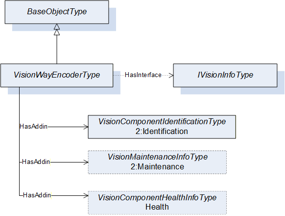
| Attribute | Value | |||||||||
| BrowseName | VisionWayEncoderType | |||||||||
| IsAbstract | False | |||||||||
| References | Node Class | BrowseName | DataType | TypeDefinition | Other | |||||
|---|---|---|---|---|---|---|---|---|---|---|
| Subtype of the 0:BaseObjectType defined in OPC 10000-5, i.e. inheriting the InstanceDeclarations of that Node | ||||||||||
| 0:HasInterface | ObjectType | IVisionInfoType | ||||||||
| Applied from IVisionInfoType | ||||||||||
| 0:HasAddIn | Object | 2:Identification | VisionComponentIdentificationType | M | ||||||
| 0:HasAddIn | Object | 2:Maintenance | VisionMaintenanceInfoType | O | ||||||
| 0:HasAddIn | Object | Health | VisionHealthInfoType | O | ||||||
9.18 VisionTriggerSensorType ObjectType Definition
The VisionTriggerSensorType provides a concrete ObjectType which can be instantiated directly implementing the IVisionInfoType interface. The instances of this object type shall be organized in the TriggerSensors folder of the VisionSystemAssetType. It is formally defined in Table 49.

| Attribute | Value | |||||||||
| BrowseName | VisionTriggerSensorType | |||||||||
| IsAbstract | False | |||||||||
| References | Node Class | BrowseName | DataType | TypeDefinition | Other | |||||
|---|---|---|---|---|---|---|---|---|---|---|
| Subtype of the 0:BaseObjectType defined in OPC 10000-5, i.e. inheriting the InstanceDeclarations of that Node | ||||||||||
| 0:HasInterface | ObjectType | IVisionInfoType | ||||||||
| Applied from IVisionInfoType | ||||||||||
| 0:HasAddIn | Object | 2:Identification | VisionComponentIdentificationType | M | ||||||
| 0:HasAddIn | Object | 2:Maintenance | VisionMaintenanceInfoType | O | ||||||
| 0:HasAddIn | Object | Health | VisionHealthInfoType | O | ||||||
9.19 VisionPatternGeneratorType ObjectType Definition
The VisionPatternGeneratorType provides a concrete ObjectType which can be instantiated directly implementing the IVisionInfoType interface. The instances of this object type shall be organized in the PatternGenerators folder of the VisionSystemAssetType. It is formally defined in Table 50.
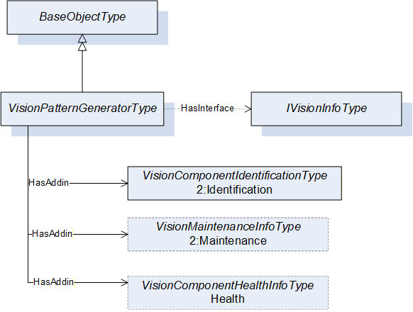
| Attribute | Value | |||||||||
| BrowseName | VisionPatternGeneratorType | |||||||||
| IsAbstract | False | |||||||||
| References | Node Class | BrowseName | DataType | TypeDefinition | Other | |||||
|---|---|---|---|---|---|---|---|---|---|---|
| Subtype of the 0:BaseObjectType defined in OPC 10000-5, i.e. inheriting the InstanceDeclarations of that Node | ||||||||||
| 0:HasInterface | ObjectType | IVisionInfoType | ||||||||
| Applied from IVisionInfoType | ||||||||||
| 0:HasAddIn | Object | 2:Identification | VisionComponentIdentificationType | M | ||||||
| 0:HasAddIn | Object | 2:Maintenance | VisionMaintenanceInfoType | O | ||||||
| 0:HasAddIn | Object | Health | VisionHealthInfoType | O | ||||||
9.20 VisionAcquisitionBackgroundType ObjectType Definition
The VisionAcquisitionBackgroundType provides a concrete ObjectType which can be instantiated directly implementing the IVisionInfoType interface. The instances of this object type shall be organized in the AcquisitionBackgrounds folder of the VisionSystemAssetType. It is formally defined in Table 51.

| Attribute | Value | |||||||||
| BrowseName | VisionAcquisitionBackgroundType | |||||||||
| IsAbstract | False | |||||||||
| References | Node Class | BrowseName | DataType | TypeDefinition | Other | |||||
|---|---|---|---|---|---|---|---|---|---|---|
| Subtype of the 0:BaseObjectType defined in OPC 10000-5, i.e. inheriting the InstanceDeclarations of that Node | ||||||||||
| 0:HasInterface | ObjectType | IVisionInfoType | ||||||||
| Applied from IVisionInfoType | ||||||||||
| 0:HasAddIn | Object | 2:Identification | VisionComponentIdentificationType | M | ||||||
| 0:HasAddIn | Object | 2:Maintenance | VisionMaintenanceInfoType | O | ||||||
| 0:HasAddIn | Object | Health | VisionHealthInfoType | O | ||||||
9.21 VisionSurroundingEnvironmentType ObjectType Definition
The VisionSurroundingEnviromentType provides a concrete ObjectType which can be instantiated directly implementing the IVisionInfoType interface. The instances of this object type shall be organized in the SurroundingEnviroment folder of the VisionSystemAssetType and contains information about the surrounding environment of the vision system. It is formally defined in Table 52.
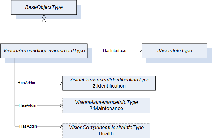
| Attribute | Value | |||||||||
| BrowseName | VisionSurroundingEnvironmentType | |||||||||
| IsAbstract | False | |||||||||
| References | Node Class | BrowseName | DataType | TypeDefinition | Other | |||||
|---|---|---|---|---|---|---|---|---|---|---|
| Subtype of the 0:BaseObjectType defined in OPC 10000-5, i.e. inheriting the InstanceDeclarations of that Node | ||||||||||
| 0:HasInterface | ObjectType | IVisionInfoType | ||||||||
| Applied from IVisionInfoType | ||||||||||
| 0:HasAddIn | Object | 2:Identification | VisionComponentIdentificationType | M | ||||||
| 0:HasAddIn | Object | 2:Maintenance | VisionMaintenanceInfoType | O | ||||||
| 0:HasAddIn | Object | Health | VisionHealthInfoType | O | ||||||
9.22 VisionHousingType ObjectType Definition
The VisionHousingType provides a concrete ObjectType which can be instantiated directly implementing the IVisionInfoType interface. The instances of this object type shall be organized in the Housings folder of the VisionSystemAssetType. It is formally defined in Table 53.

| Attribute | Value | |||||||||
| BrowseName | VisionHousingType | |||||||||
| IsAbstract | False | |||||||||
| References | Node Class | BrowseName | DataType | TypeDefinition | Other | |||||
|---|---|---|---|---|---|---|---|---|---|---|
| Subtype of the 0:BaseObjectType defined in OPC 10000-5, i.e. inheriting the InstanceDeclarations of that Node | ||||||||||
| 0:HasInterface | ObjectType | IVisionInfoType | ||||||||
| Applied from IVisionInfoType | ||||||||||
| 0:HasAddIn | Object | 2:Identification | VisionComponentIdentificationType | M | ||||||
| 0:HasAddIn | Object | 2:Maintenance | VisionMaintenanceInfoType | O | ||||||
| 0:HasAddIn | Object | Health | VisionHealthInfoType | O | ||||||
9.23 VisionPowerSupplyType ObjectType Definition
The VisionPowerSupplyType provides a concrete ObjectType which can be instantiated directly implementing the IVisionInfoType interface. The instances of this object type shall be organized in the PowerSupplies folder of the VisionSystemAssetType. It is formally defined in Table 54.

| Attribute | Value | |||||||||
| BrowseName | VisionPowerSupplyType | |||||||||
| IsAbstract | False | |||||||||
| References | Node Class | BrowseName | DataType | TypeDefinition | Other | |||||
|---|---|---|---|---|---|---|---|---|---|---|
| Subtype of the 0:BaseObjectType defined in OPC 10000-5, i.e. inheriting the InstanceDeclarations of that Node | ||||||||||
| 0:HasInterface | ObjectType | IVisionInfoType | ||||||||
| Applied from IVisionInfoType | ||||||||||
| 0:HasAddIn | Object | 2:Identification | VisionComponentIdentificationType | M | ||||||
| 0:HasAddIn | Object | 2:Maintenance | VisionMaintenanceInfoType | O | ||||||
| 0:HasAddIn | Object | Health | VisionHealthInfoType | O | ||||||
9.24 VisionClimateControllerType ObjectType Definition
The VisionClimateControllerType provides a concrete ObjectType which can be instantiated directly implementing the IVisionInfoType interface. instances of this object type shall be organized in the ClimateControllers folder of the VisionSystemAssetType. It is formally defined in Table 55.

| Attribute | Value | |||||||||
| BrowseName | VisionClimateControllerType | |||||||||
| IsAbstract | False | |||||||||
| References | Node Class | BrowseName | DataType | TypeDefinition | Other | |||||
|---|---|---|---|---|---|---|---|---|---|---|
| Subtype of the 0:BaseObjectType defined in OPC 10000-5, i.e. inheriting the InstanceDeclarations of that Node | ||||||||||
| 0:HasInterface | ObjectType | IVisionInfoType | ||||||||
| Applied from IVisionInfoType | ||||||||||
| 0:HasAddIn | Object | 2:Identification | VisionComponentIdentificationType | M | ||||||
| 0:HasAddIn | Object | 2:Maintenance | VisionMaintenanceInfoType | O | ||||||
| 0:HasAddIn | Object | Health | VisionHealthInfoType | O | ||||||
9.25 ILicenseType ObjectType Definition
The ILicenseType provides the minimal set of information that a license object shall provide in a vision system. All objects that implement this interface shall be organized in the Licenses folder of the VisionSystemAssetType. It is formally defined in Table 56.
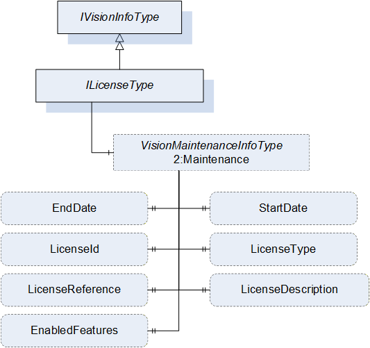
| Attribute | Value | ||||
| BrowseName | ILicenseType | ||||
| IsAbstract | True | ||||
| References | Node Class | BrowseName | DataType | TypeDefinition | Other |
|---|---|---|---|---|---|
| Subtype of the IVisionInfoType, inheriting the InstanceDeclaration of that Node | |||||
The components of the ILicenseType have additional subcomponents which are defined in Table 57.
| Source Path | Reference | NodeClass | BrowseName | DataType | TypeDefinition | Others |
| 2:Maintenance | 0:HasProperty | Variable | EndDate | 0:UtcTime | 0:PropertyType | O |
| 2:Maintenance | 0:HasProperty | Variable | StartDate | 0:UtcTime | 0:PropertyType | O |
| 2:Maintenance | 0:HasProperty | Variable | LicenseId | 0:String | 0:PropertyType | O |
| 2:Maintenance | 0:HasProperty | Variable | LicenseType | 0:String | 0:PropertyType | O |
| 2:Maintenance | 0:HasProperty | Variable | LicenseReference | 0:String | 0:PropertyType | M |
| 2:Maintenance | 0:HasProperty | Variable | LicenseDescription | 0:String | 0:PropertyType | O |
| 2:Maintenance | 0:HasProperty | Variable | EnabledFeatures | 0:String[] | 0:PropertyType | O |
The EndDate property is the end date of the license validity. If this property is set, the effects of not having a valid license are defined by the policy of the software or hardware provider.
The StartDate property is the start date of the license validity. If this property is set, the effects of not having a valid license are defined by the policy of the software or hardware provider.
The LicenseId property is the id that uniquely identifies the license for the software or hardware provider. It might be used for maintenance and/or support requests.
The LicenseType property is the type of license based on the policy of the software of hardware provider e.g., runtime, trial, developer, support.
The LicenseReference property is a reference to a file on the system, documentation, or webpage where more information about the license can be obtained.
The LicenseDescription property is a short description of the license.
The EnabledFeatures property is a list of the enabled features by the license.
9.26 VisionLicenseType ObjectType Definition
The VisionLicenseType provides a concrete ObjectType which can be instantiated directly implementing the ILicenseType interface. The instances of this object type shall be organized in the Licenses folder of the VisionSystemAssetType. It is formally defined in Table 58.
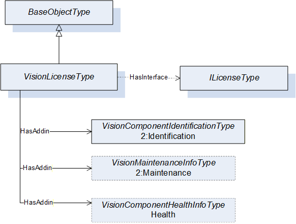
| Attribute | Value | |||||||||
| BrowseName | VisionLicenseType | |||||||||
| IsAbstract | False | |||||||||
| References | Node Class | BrowseName | DataType | TypeDefinition | Other | |||||
|---|---|---|---|---|---|---|---|---|---|---|
| Subtype of the 0:BaseObjectType defined in OPC 10000-5, i.e. inheriting the InstanceDeclarations of that Node | ||||||||||
| 0:HasInterface | ObjectType | ILicenseType | ||||||||
| Applied from IVisionInfoType | ||||||||||
| 0:HasAddIn | Object | 2:Identification | VisionComponentIdentificationType | M | ||||||
| 0:HasAddIn | Object | 2:Maintenance | VisionMaintenanceInfoType | O | ||||||
| 0:HasAddIn | Object | Health | VisionHealthInfoType | O | ||||||
9.27 VisionNetworkDeviceType ObjectType Definition
The VisionNetworkDeviceType provides a concrete ObjectType which can be instantiated directly implementing the IVisionInfoType interface.The instances of this object type shall be organized in the NetworkDevices folder of the VisionSystemAssetType. It is formally defined in Table 59.
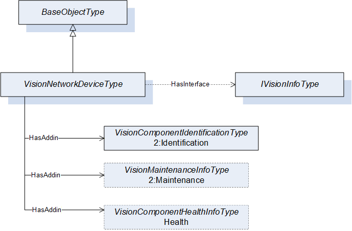
| Attribute | Value | |||||||||
| BrowseName | VisionNetworkDeviceType | |||||||||
| IsAbstract | False | |||||||||
| References | Node Class | BrowseName | DataType | TypeDefinition | Other | |||||
|---|---|---|---|---|---|---|---|---|---|---|
| Subtype of the 0:BaseObjectType defined in OPC 10000-5, i.e. inheriting the InstanceDeclarations of that Node | ||||||||||
| 0:HasInterface | ObjectType | IVisionInfoType | ||||||||
| Applied from IVisionType | ||||||||||
| 0:HasAddIn | Object | 2:Identification | VisionComponentIdentificationType | M | ||||||
| 0:HasAddIn | Object | 2:Maintenance | VisionMaintenanceInfoType | O | ||||||
| 0:HasAddIn | Object | Health | VisionHealthInfoType | O | ||||||
9.28 ICableType ObjectType Definition
The ICableType interface provides the minimal set of information that a cable object shall provide in a vision system. All objects that implement this interface shall be organized in the Cables folder of the VisionSystemAssetType. It is formally defined in in Table 60.
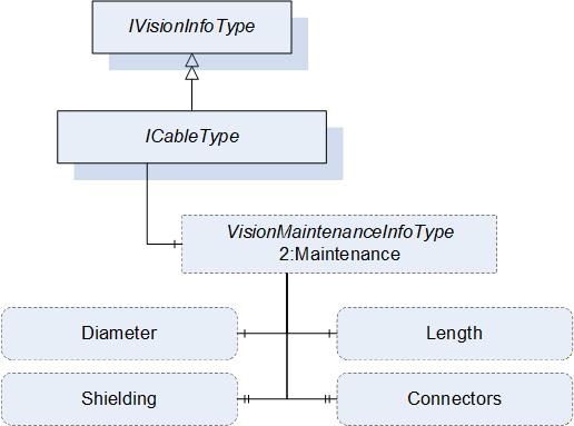
| Attribute | Value | ||||
| BrowseName | ICableType | ||||
| IsAbstract | True | ||||
| References | Node Class | BrowseName | DataType | TypeDefinition | Other |
|---|---|---|---|---|---|
| Subtype of the IVisionInfoType, inheriting the InstanceDeclarations of that Node. | |||||
The components of the ICableType have additional subcomponents which are defined in Table 61.
| Source Path | Reference | NodeClass | BrowseName | DataType | TypeDefinition | Others |
| 2:Maintenance | 0:HasComponent | Variable | Length | 0:Double | 0:AnalogUnitType | O |
| 2:Maintenance | 0:HasComponent | Variable | Diameter | 0:Double | 0:AnalogUnitType | O |
| 2:Maintenance | 0:HasProperty | Variable | Shielding | 0:String | 0:PropertyType | O |
| 2:Maintenance | 0:HasProperty | Variable | Connectors | 0:String[] | 0:PropertyType | O |
| BrowsePath | Value Attributes | |||
| m | |||
| mm |
The Length property denotes the length of the cable in meters.
The Diameter property denotes the outer diameter of the cable in millimeters
The Shielding property denotes the description of shielding on the cable.
The Connectors property denotes the connectors that the cable supports e.g. USB-A Female, Hirose 6-pin male.
9.29 VisionCableType ObjectType Definition
The VisionCableType provides a concrete ObjectType which can be instantiated directly implementing the ICableType interface. The instances of this object type shall be organized in the Cables folder of the VisionSystemAssetType. It is formally defined in Table 63.

| Attribute | Value | |||||||||
| BrowseName | VisionCableType | |||||||||
| IsAbstract | False | |||||||||
| References | Node Class | BrowseName | DataType | TypeDefinition | Other | |||||
|---|---|---|---|---|---|---|---|---|---|---|
| Subtype of the 0:BaseObjectType defined in OPC 10000-5, i.e. inheriting the InstanceDeclarations of that Node | ||||||||||
| 0:HasInterface | ObjectType | ICableType | ||||||||
| Applied from ICableType | ||||||||||
| 0:HasAddIn | Object | 2:Identification | VisionComponentIdentificationType | M | ||||||
| 0:HasAddIn | Object | 2:Maintenance | VisionMaintenanceInfoType | O | ||||||
| 0:HasAddIn | Object | Health | VisionHealthInfoType | O | ||||||
9.30 VisionOtherOpticalEquipmentType ObjectType Definition
The VisionOtherOpticalEquipmentType provides a concrete ObjectType which can be instantiated directly implementing the IVisionInfoType interface. instances of this object type shall be organized in the OtherOpticalEquipments folder of the VisionSystemAssetType. It is formally defined in Table 55.
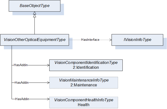
| Attribute | Value | |||||||||
| BrowseName | VisionOtherOpticalEquipmentType | |||||||||
| IsAbstract | False | |||||||||
| References | Node Class | BrowseName | DataType | TypeDefinition | Other | |||||
|---|---|---|---|---|---|---|---|---|---|---|
| Subtype of the 0:BaseObjectType defined in OPC 10000-5, i.e. inheriting the InstanceDeclarations of that Node | ||||||||||
| 0:HasInterface | ObjectType | IVisionInfoType | ||||||||
| Applied from IVisionInfoType | ||||||||||
| 0:HasAddIn | Object | 2:Identification | VisionComponentIdentificationType | M | ||||||
| 0:HasAddIn | Object | 2:Maintenance | VisionMaintenanceInfoType | O | ||||||
| 0:HasAddIn | Object | Health | VisionHealthInfoType | O | ||||||
9.31 VisionAspectImageReceiverType ObjectType Definition
The VisionAspectImageReceiverType provides a concrete ObjectType representing an aspect of an item. An image receiver is an aspect of an item that expresses the direction of the vision streaming data as a sink. An instance of VisionAspectImageReceiverType must be used in combination with the IsHostedBy reference to connect to other object instances (as shown in Annex B) e.g., Cable and a PhysicalInterface. It is formally defined in Table 65.
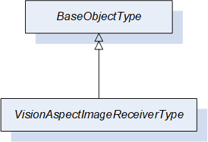
| Attribute | Value | ||||
| BrowseName | VisionAspectImageReceiverType | ||||
| IsAbstract | False | ||||
| References | Node Class | BrowseName | DataType | TypeDefinition | Other |
|---|---|---|---|---|---|
| Subtype of the 0:BaseObjectType defined in OPC 10000-5, i.e. inheriting the InstanceDeclarations of that Node | |||||
9.32 VisionAspectImageTransmitterType ObjectType Definition
The VisionAspectImageTransmitterType provides a concrete ObjectType representing an aspect of an item. An image transmitter is an aspect of an item that expresses the direction of the vision streaming data as source. An instance of VisionAspectImageTransmitterType must be used in combination with the IsHostedBy reference to connect to other object instances (as shown in Annex B) e.g., Cable and a PhysicalInterface. It is formally defined in Table 66.
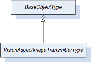
| Attribute | Value | ||||
| BrowseName | VisionAspectImageTransmitterType | ||||
| IsAbstract | False | ||||
| References | Node Class | BrowseName | DataType | TypeDefinition | Other |
|---|---|---|---|---|---|
| Subtype of the 0:BaseObjectType defined in OPC 10000-5, i.e. inheriting the InstanceDeclarations of that Node | |||||
9.33 VisionAspectImageTransceiverType ObjectType Definition
The VisionAspectImageTransceiverType provides a concrete ObjectType representing an aspect of an item. An image transceiver is an item aspect that expresses the direction of the vision streaming data as both source and sink. An instance of VisionAspectImageTransceiverType must be used in combination with the IsHostedBy reference to connect to other object instances (as shown in Annex B) e.g., Cable and a PhysicalInterface. It is formally defined in Table 67.
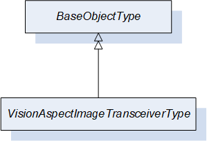
| Attribute | Value | ||||
| BrowseName | VisionAspectImageTransceiverType | ||||
| IsAbstract | False | ||||
| References | Node Class | BrowseName | DataType | TypeDefinition | Other |
|---|---|---|---|---|---|
| Subtype of the 0:BaseObjectType defined in OPC 10000-5, i.e. inheriting the InstanceDeclarations of that Node | |||||
10 OPC UA VariableTypes
10.1 SEMI_E10SystemStateType VariableType Definition
The SystemState is a subtype of BaseVariableType. It is used to denote a single level with one or multiple SEMI E10 states that might be active in an item. It is formally defined in Table 68.
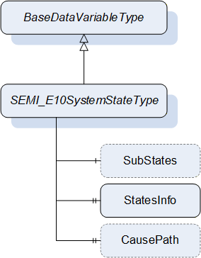
| Attribute | Value | ||||
| BrowseName | SEMI_E10SystemStateType | ||||
| IsAbstract | False | ||||
| ValueRank | -3 (-3 = ScalarOrOneDimension) | ||||
| DataType | SEMI_E10SystemStateDataType | ||||
| References | Node Class | BrowseName | DataType | TypeDefinition | Other |
|---|---|---|---|---|---|
| Subtype of the 0:BaseDataVariableType defined in OPC 10000-5, i.e. inheriting the InstanceDeclarations of that Node | |||||
| 0:HasComponent | Variable | SubStates | SEMI_E10SystemStateDataType{ ScalarOrOneDimension} | SEMI_E10SystemStateType | O |
| 0:HasProperty | Variable | StatesInfo | SEMI_E10SystemStateInfoDataType[] | 0:PropertyType | M |
| 0:HasProperty | Variable | CausePath | 0:String | 0:PropertyType | O |
The SubStates optional component is a recursive SEMI_E10SystemStateType to specify the next level of the sub states of the state store on the variable. It is possible to provide any number of levels to completely map all the SEMI E10 states of an item.
The StatesInfo is a mandatory property of all the states that can be assigned to the level of variable.
The CausePath optional property is a path information string based on the SEMI E10 scheme. Instantiated SEMI_E10SystemStateTypes using the SubStates component do not need to provide this property. If needed it should be instantiated only once at level one or zero of the system state.
More information about the usage of SEMI E10 in a vision system can be found in Section 11.6 of the OPC 40100-1 - UA Companion Specification Part 1 for Machine Vision.
| Id | Name | Parent state | Level | Description |
| 0 | TotalTime | 0 | 0 | The item total time of operation. |
| 1 | OperationsTime | 0 | 1 | The item is working. |
| 2 | NonscheduledTime | 0 | 1 | The item is not working because no production was scheduled. |
| 3 | Uptime | 1 | 2 | The item is in a condition to perform its intended function. |
| 4 | Downtime | 1 | 2 | The item is not in a condition to perform its intended function. |
| 5 | ManufacturingTime | 3 | 3 | The item is either working on a job or is idle and ready to accept a new job. |
| 6 | Engineering | 3 | 3 | The item is not working and not ready to accept a command because a user is currently working on the system |
| 7 | ScheduledDowntime | 4 | 3 | The item is not available for production and this was planned in advance. |
| 8 | UnscheduledDowntime | 4 | 3 | The item is not available for production due to failure and repair. |
| 9 | Production | 5 | 4 | The item is currently working on a job. |
| 10 | Standby | 5 | 4 | The item is ready to accept a command but is currently not executing a job. |
The different states defined in SEMI E10 can be organized in different levels depending on their position in the state hierarchy. The initial level (0) is always the TotalTime state that encapsulates the total time that the machine has been in existence, in the next level increasing the level of detail, the sub-states OperationsTime and NonscheduledTime are specified as the level 1 of the SEMI E10 states, from there OperationsTime specifies two sub-states Uptime and Downtime which become level 2 and so on. Each state has a relationship with its parent state that must be specified in the ParentStateId property of the SEMI_E10SystemStateInfoDataType with the exception of TotalTime which is the initial state and it shall refer itself as its parent state. When first instantiating a variable of the SEMI_E10SystemStateType, it shall be done starting with level 1 and then as many SEMI_E10SystemStateType variables can be instantiated as the required number of state levels, using the SubStates component. Each level must provide the corresponding information about the states on that level using the StatesInfo property. When a change of state happens on the Item it might be that a particular level must be deactivated. This is done by setting the BadStateNotActive status code on the value of the variable on the level that must be deactivated. For example, if the NonscheduledTime state becomes active all the additional sub-states below level 1 become deactivated.
Each Item (Machine or Component) can have their own individual SEMI E10 state variable. At the system level or if an Item is the master of other components the information of the SEMI E10 state of that object can take into account all the relevant information of the related Items. In addition, this companion specification defines the usage of parallel states with the usage of priority in each of the active SEMI E10 state. If parallel states are needed the value of the variable of the SEMI_E10SystemStateType will be an array and the priority value must be set in each of the elements of SEMI_E10SystemStateDataType.
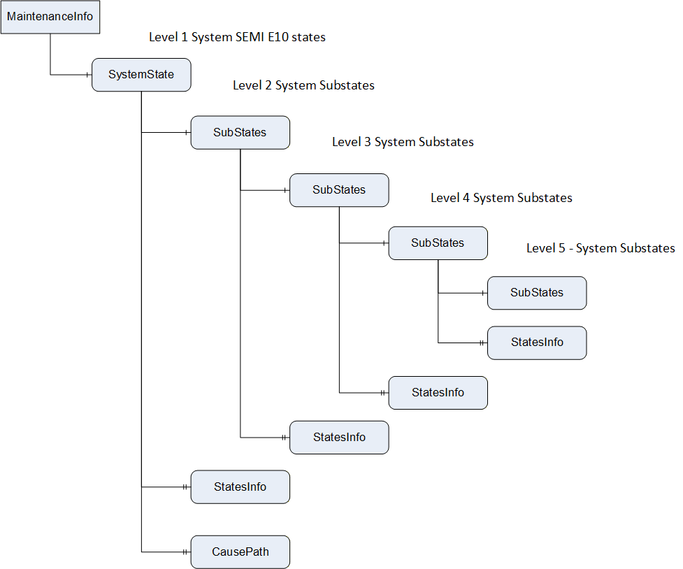
11 OPC UA DataTypes
11.1 SEMI_E10SystemStateDataType
This structure contains the id and state priority of a single SEMI E10 state. The structure is defined in Table 70.
| Name | Type | Description |
| SEMI_E10SystemStateDataType | structure | Subtype of Structure defined in OPC 10000-4 |
| Id | 0:UInt32 | System wide unique identifier for the SEMI E10 state |
| Priority | 0:UInt32 | The priority of the state in relation to other parallel states contained in the same variable. This priority can be used to create the most relevant cause path string using the SEMI E10 schema. |
11.2 SEMI_E10SystemStateInfoDataType
This structure contains the state information in order to allow the complete mapping of all the possible SEMI E10 states of the item. The structure is defined in Table 71.
| Name | Type | Description |
| SEMI_E10SystemStateInfoDataType | structure | Subtype of Structure defined in OPC 10000-4 |
| Id | 0:UInt32 | System wide unique identifier for the SEMI E10 state |
| Name | 0:LocalizedText | Human readable name of the state |
| ParentStateId | 0:UInt32 | The id of the parent state if applicable. The parent state is used to generate the complete tree of states base on the SEMI E10 schema. |
| Description | 0:LocalizedText | Optional short description of the meaning of the state |
12 OPC UA Reference Types
12.1 HasOpticalPathTo
The HasOpticalPathTo is a concrete ReferenceType and can be used directly. It is a subtype of NonHierarchicalReferences. This ReferenceType is asymmetric and allows looping (See Annex B.9).
The semantic of this ReferenceType is to link two components with an optical path in between them
The SourceNode of References of this type shall be an Object or ObjectType representing a component.
The TargetNode of this ReferenceType shall be an shall be an Object representing a component.
The HasOpticalPathTo is formally defined inTable 72.
| Attributes | Value | ||
| BrowseName | HasOpticalPathTo | ||
| InverseName | HasOpticalPathFrom | ||
| Symmetric | False | ||
| IsAbstract | False | ||
| References | NodeClass | BrowseName | Comment |
|---|---|---|---|
| Subtype of NonHierarchicalReferences | |||
12.2 TransmitsDataTo
The TransmitsDataTo is a concrete ReferenceType and can be used directly. It is a subtype of NonHierarchicalReferences. This ReferenceType is asymmetric and allows looping.
The semantic of this ReferenceType is to link two components where data is being transmitted from one component to the other.
The SourceNode of References of this type shall be an Object or ObjectType representing the data source.
The TargetNode of this ReferenceType shall be an shall be an Object representing the data sink.
The TransmitsDataTo is formally defined in Table 73.
| Attributes | Value | ||
| BrowseName | TransmitsDataTo | ||
| InverseName | ReceivesDataFrom | ||
| Symmetric | False | ||
| IsAbstract | False | ||
| References | NodeClass | BrowseName | Comment |
|---|---|---|---|
| Subtype of NonHierarchicalReferences | |||
13 Profiles and ConformanceUnits
13.1 Conformance Units
This chapter defines the corresponding Conformance Units for the OPC UA Information Model for Machine Vision Part 2.
| Category | Title | Description |
| Server | VSA Basic | The server provides the VisionSystemAssetType. The server also provides at least one instance of the VisionSystemAssetType with all its mandatory InstanceDeclarations. |
| Server | VSA Identification | The server provides the VisionMachineIdentificationType. The server also provides at least one instance of the VisionMachineIdentificationType with all its mandatory InstanceDeclarations, and may provide its optional InstanceDeclarations, with read access. An instance of VisionSystemAssetType shall reference an instance of VisionMachineIdentificationType with a HasAddIn Reference (or a subtype thereof). |
| Server | VSA Maintenance Information | The server provides the VisionMaintenanceInfoType. The server also provides at least one instance of the VisionMaintenanceInfoType, with all its mandatory InstanceDeclarations, and may provide its optional InstanceDeclarations, with read access. An instance of VisionSystemAssetType shall reference an instance of VisionMaintenanceInfoType with a HasAddIn Reference (or a subtype thereof). |
| Server | VSA Health Information | The server provides the VisionHealthInfoType. The server also provides at least one instance of the VisionHealthInfoType, with all its mandatory InstanceDeclarations, and may provide its optional InstanceDeclarations, with read access. An instance of VisionSystemAssetType shall reference an instance of VisionHealthInfoType with a HasAddIn Reference (or a subtype thereof). |
| Server | VSA Find ComputingDevices | The server provides at least one instance of VisionSystemAssetType and that instance shall contain exactly one ComputingDevices Object, connected to it with the HasComponent Reference. The ComputingDevices Object shall reference all objects representing computing devices under this object with an Organizes Reference. |
| Server | VSA ComputingDevice Identification | The server provides the VisionComponentIdentificationType. The server also provides at least one instance of VisionComponentIdentificationType with all its mandatory InstanceDeclarations, and may provide its optional InstanceDeclarations, with read access. An Object representing a computing device shall reference an instance of VisionComponentIdentificationType with a HasAddIn Reference (or a subtype thereof). |
| Server | VSA ComputingDevice Maintenance Information | The server provides the VisionMaintenanceInfoType. The server also provides at least one instance of VisionMaintenanceInfoType with all its mandatory InstanceDeclarations, and may provide its optional InstanceDeclarations, with read access. An Object representing a computing device shall reference an instance of VisionMaintenanceInfoType with a HasAddIn Reference (or a subtype thereof). |
| Server | VSA ComputingDevice Health Information | The server provides the VisionHealthInfoType. The server also provides at least one instance of VisionHealthInfoType with all its mandatory InstanceDeclarations, and may provide its optional InstanceDeclarations, with read access. An Object representing a computing device shall reference an instance of VisionHealthInfoType with a HasAddIn Reference (or a subtype thereof). |
| Server | VSA Find DisplayUnits | The server provides at least one instance of VisionSystemAssetType and that instance shall contain exactly one DisplayUnits Object, connected to it with the HasComponent Reference. The DisplayUnits Object shall reference all objects representing display units under this object with an Organizes Reference. |
| Server | VSA DisplayUnit Identification | The server provides the VisionComponentIdentificationType. The server also provides at least one instance of VisionComponentIdentificationType with all its mandatory InstanceDeclarations, and may provide its optional InstanceDeclarations, with read access. An Object representing a display unit shall reference an instance of VisionComponentIdentificationType with a HasAddIn Reference (or a subtype thereof). |
| Server | VSA DisplayUnit Maintenance Information | The server provides the VisionMaintenanceInfoType. The server also provides at least one instance of VisionMaintenanceInfoType with all its mandatory InstanceDeclarations, and may provide its optional InstanceDeclarations, with read access. An Object representing a display unit shall reference an instance of VisionMaintenanceInfoType with a HasAddIn Reference (or a subtype thereof). |
| Server | VSA DisplayUnit Health Information | The server provides the VisionHealthInfoType. The server also provides at least one instance of VisionHealthInfoType with all its mandatory InstanceDeclarations, and may provide its optional InstanceDeclarations, with read access. An Object representing a display unit shall reference an instance of VisionHealthInfoType with a HasAddIn Reference (or a subtype thereof). |
| Server | VSA Find PhysicalInterfaces | The server provides at least one instance of VisionSystemAssetType and that instance shall contain exactly one PhysicalInterfaces Object, connected to it with the HasComponent Reference. The PhysicalInterfaces Object shall reference all objects representing physical interfaces under this object with an Organizes Reference. |
| Server | VSA PhysicalInterface Identification | The server provides the VisionComponentIdentificationType. The server also provides at least one instance of VisionComponentIdentificationType with all its mandatory InstanceDeclarations, and may provide its optional InstanceDeclarations, with read access. An Object representing a physical interface shall reference an instance of VisionComponentIdentificationType with a HasAddIn Reference (or a subtype thereof). |
| Server | VSA PhysicalInterface Maintenance Information | The server provides the VisionMaintenanceInfoType. The server also provides at least one instance of VisionMaintenanceInfoType with all its mandatory InstanceDeclarations, and may provide its optional InstanceDeclarations, with read access. An Object representing a physical interface shall reference an instance of VisionMaintenanceInfoType with a HasAddIn Reference (or a subtype thereof). |
| Server | VSA PhysicalInterface Health Information | The server provides the VisionHealthInfoType. The server also provides at least one instance of VisionHealthInfoType with all its mandatory InstanceDeclarations, and may provide its optional InstanceDeclarations, with read access. An Object representing a physical interface shall reference an instance of VisionHealthInfoType with a HasAddIn Reference (or a subtype thereof). |
| Server | VSA Find ImageSensors | The server provides at least one instance of VisionSystemAssetType and that instance shall contain exactly one ImageSensors Object, connected to it with the HasComponent Reference. The ImageSensors Object shall reference all objects representing image sensors under this object with an Organizes Reference. |
| Server | VSA ImageSensor Identification | The server provides the VisionComponentIdentificationType. The server also provides at least one instance of VisionComponentIdentificationType with all its mandatory InstanceDeclarations, and may provide its optional InstanceDeclarations, with read access. An Object representing an image sensor shall reference an instance of VisionComponentIdentificationType with a HasAddIn Reference (or a subtype thereof). |
| Server | VSA ImageSensor Maintenance Information | The server provides the VisionMaintenanceInfoType. The server also provides at least one instance of VisionMaintenanceInfoType with all its mandatory InstanceDeclarations, and may provide its optional InstanceDeclarations, with read access. An Object representing a image sensor shall reference an instance of VisionMaintenanceInfoType with a HasAddIn Reference (or a subtype thereof). |
| Server | VSA ImageSensor Health Information | The server provides the VisionHealthInfoType. The server also provides at least one instance of VisionHealthInfoType with all its mandatory InstanceDeclarations, and may provide its optional InstanceDeclarations, with read access. An Object representing a image sensor shall reference an instance of VisionHealthInfoType with a HasAddIn Reference (or a subtype thereof). |
| Server | VSA Find FrameGrabbers | The server provides at least one instance of VisionSystemAssetType and that instance shall contain exactly one FrameGrabbers Object, connected to it with the HasComponent Reference. The FrameGrabbers Object shall reference all objects representing frame grabbers under this object with an Organizes Reference. |
| Server | VSA FrameGrabber Identification | The server provides the VisionComponentIdentificationType. The server also provides at least one instance of VisionComponentIdentificationType with all its mandatory InstanceDeclarations, and may provide its optional InstanceDeclarations, with read access. An Object representing a frame grabber shall reference an instance of VisionComponentIdentificationType with a HasAddIn Reference (or a subtype thereof). |
| Server | VSA FrameGrabber Maintenance Information | The server provides the VisionMaintenanceInfoType. The server also provides at least one instance of VisionMaintenanceInfoType with all its mandatory InstanceDeclarations, and may provide its optional InstanceDeclarations, with read access. An Object representing a frame grabber shall reference an instance of VisionMaintenanceInfoType with a HasAddIn Reference (or a subtype thereof). |
| Server | VSA FrameGrabber Health Information | The server provides the VisionHealthInfoType. The server also provides at least one instance of VisionHealthInfoType with all its mandatory InstanceDeclarations, and may provide its optional InstanceDeclarations, with read access. An Object representing a frame grabber shall reference an instance of VisionHealthInfoType with a HasAddIn Reference (or a subtype thereof). |
| Server | VSA Find Lenses | The server provides at least one instance of VisionSystemAssetType and that instance shall contain exactly one Lenses Object, connected to it with the HasComponent Reference. The Lenses Object shall reference all objects representing lenses under this object with an Organizes Reference. |
| Server | VSA Lens Identification | The server provides the VisionComponentIdentificationType. The server also provides at least one instance of VisionComponentIdentificationType with all its mandatory InstanceDeclarations, and may provide its optional InstanceDeclarations, with read access. An Object representing a lens shall reference an instance of VisionComponentIdentificationType with a HasAddIn Reference (or a subtype thereof). |
| Server | VSA Lens Maintenance Information | The server provides the VisionMaintenanceInfoType. The server also provides at least one instance of VisionMaintenanceInfoType with all its mandatory InstanceDeclarations, and may provide its optional InstanceDeclarations, with read access. An Object representing a lens shall reference an instance of VisionMaintenanceInfoType with a HasAddIn Reference (or a subtype thereof). |
| Server | VSA Lens Health Information | The server provides the VisionHealthInfoType. The server also provides at least one instance of VisionHealthInfoType with all its mandatory InstanceDeclarations, and may provide its optional InstanceDeclarations, with read access. An Object representing a lens shall reference an instance of VisionHealthInfoType with a HasAddIn Reference (or a subtype thereof). |
| Server | VSA Find LensControllers | The server provides at least one instance of VisionSystemAssetType and that instance shall contain exactly one LensControllers Object, connected to it with the HasComponent Reference. The LensControllers Object shall reference all objects representing lens controllers under this object with an Organizes Reference. |
| Server | VSA LensController Identification | The server provides the VisionComponentIdentificationType. The server also provides at least one instance of VisionComponentIdentificationType with all its mandatory InstanceDeclarations, and may provide its optional InstanceDeclarations, with read access. An Object representing a lens controller shall reference an instance of VisionComponentIdentificationType with a HasAddIn Reference (or a subtype thereof). |
| Server | VSA LensController Maintenance Information | The server provides the VisionMaintenanceInfoType. The server also provides at least one instance of VisionMaintenanceInfoType with all its mandatory InstanceDeclarations, and may provide its optional InstanceDeclarations, with read access. An Object representing a lens controller shall reference an instance of VisionMaintenanceInfoType with a HasAddIn Reference (or a subtype thereof). |
| Server | VSA LensController Health Information | The server provides the VisionHealthInfoType. The server also provides at least one instance of VisionHealthInfoType with all its mandatory InstanceDeclarations, and may provide its optional InstanceDeclarations, with read access. An Object representing a lens controller shall reference an instance of VisionHealthInfoType with a HasAddIn Reference (or a subtype thereof). |
| Server | VSA Find OpticalFilters | The server provides at least one instance of VisionSystemAssetType and that instance shall contain exactly one OpticalFilters Object, connected to it with the HasComponent Reference. The OpticalFilters Object shall reference all objects representing optical filters under this object with an Organizes Reference. |
| Server | VSA OpticalFilter Identification | The server provides the VisionComponentIdentificationType. The server also provides at least one instance of VisionComponentIdentificationType with all its mandatory InstanceDeclarations, and may provide its optional InstanceDeclarations, with read access. An Object representing a optical filter shall reference an instance of VisionComponentIdentificationType with a HasAddIn Reference (or a subtype thereof). |
| Server | VSA OpticalFilter Maintenance Information | The server provides the VisionMaintenanceInfoType. The server also provides at least one instance of VisionMaintenanceInfoType with all its mandatory InstanceDeclarations, and may provide its optional InstanceDeclarations, with read access. An Object representing a optical filter shall reference an instance of VisionMaintenanceInfoType with a HasAddIn Reference (or a subtype thereof). |
| Server | VSA OpticalFilter Health Information | The server provides the VisionHealthInfoType. The server also provides at least one instance of VisionHealthInfoType with all its mandatory InstanceDeclarations, and may provide its optional InstanceDeclarations, with read access. An Object representing a optical filter shall reference an instance of VisionHealthInfoType with a HasAddIn Reference (or a subtype thereof). |
| Server | VSA Find OtherOpticalEquipments | The server provides at least one instance of VisionSystemAssetType and that instance shall contain exactly one OtherOpticalEquipments Object, connected to it with the HasComponent Reference. The OtherOpticalEquipments Object shall reference all objects representing other optical equipments under this object with an Organizes Reference. |
| Server | VSA OtherOpticalEquipment Identification | The server provides the VisionComponentIdentificationType. The server also provides at least one instance of VisionComponentIdentificationType with all its mandatory InstanceDeclarations, and may provide its optional InstanceDeclarations, with read access. An Object representing a other optical equipment shall reference an instance of VisionComponentIdentificationType with a HasAddIn Reference (or a subtype thereof). |
| Server | VSA OtherOpticalEquipment Maintenance Information | The server provides the VisionMaintenanceInfoType. The server also provides at least one instance of VisionMaintenanceInfoType with all its mandatory InstanceDeclarations, and may provide its optional InstanceDeclarations, with read access. An Object representing a other optical equipment shall reference an instance of VisionMaintenanceInfoType with a HasAddIn Reference (or a subtype thereof). |
| Server | VSA OtherOpticalEquipment Health Information | The server provides the VisionHealthInfoType. The server also provides at least one instance of VisionHealthInfoType with all its mandatory InstanceDeclarations, and may provide its optional InstanceDeclarations, with read access. An Object representing a other optical equipment shall reference an instance of VisionHealthInfoType with a HasAddIn Reference (or a subtype thereof). |
| Server | VSA Find WayEncoders | The server provides at least one instance of VisionSystemAssetType and that instance shall contain exactly one WayEncoders Object, connected to it with the HasComponent Reference. The WayEncoders Object shall reference all objects representing way encoders under this object with an Organizes Reference. |
| Server | VSA WayEncoder Identification | The server provides the VisionComponentIdentificationType. The server also provides at least one instance of VisionComponentIdentificationType with all its mandatory InstanceDeclarations, and may provide its optional InstanceDeclarations, with read access. An Object representing a way encoder shall reference an instance of VisionComponentIdentificationType with a HasAddIn Reference (or a subtype thereof). |
| Server | VSA WayEncoder Maintenance Information | The server provides the VisionMaintenanceInfoType. The server also provides at least one instance of VisionMaintenanceInfoType with all its mandatory InstanceDeclarations, and may provide its optional InstanceDeclarations, with read access. An Object representing a way encoder shall reference an instance of VisionMaintenanceInfoType with a HasAddIn Reference (or a subtype thereof). |
| Server | VSA WayEncoder Health Information | The server provides the VisionHealthInfoType. The server also provides at least one instance of VisionHealthInfoType with all its mandatory InstanceDeclarations, and may provide its optional InstanceDeclarations, with read access. An Object representing a way encoder shall reference an instance of VisionHealthInfoType with a HasAddIn Reference (or a subtype thereof). |
| Server | VSA Find TriggerSensors | The server provides at least one instance of VisionSystemAssetType and that instance shall contain exactly one TriggerSensors Object, connected to it with the HasComponent Reference. The TriggerSensors Object shall reference all objects representing trigger sensors under this object with an Organizes Reference. |
| Server | VSA TriggerSensor Identification | The server provides the VisionComponentIdentificationType. The server also provides at least one instance of VisionComponentIdentificationType with all its mandatory InstanceDeclarations, and may provide its optional InstanceDeclarations, with read access. An Object representing a trigger sensor shall reference an instance of VisionComponentIdentificationType with a HasAddIn Reference (or a subtype thereof). |
| Server | VSA TriggerSensor Maintenance Information | The server provides the VisionMaintenanceInfoType. The server also provides at least one instance of VisionMaintenanceInfoType with all its mandatory InstanceDeclarations, and may provide its optional InstanceDeclarations, with read access. An Object representing a trigger sensor shall reference an instance of VisionMaintenanceInfoType with a HasAddIn Reference (or a subtype thereof). |
| Server | VSA TriggerSensor Health Information | The server provides the VisionHealthInfoType. The server also provides at least one instance of VisionHealthInfoType with all its mandatory InstanceDeclarations, and may provide its optional InstanceDeclarations, with read access. An Object representing a trigger sensor shall reference an instance of VisionHealthInfoType with a HasAddIn Reference (or a subtype thereof). |
| Server | VSA Find Lamps | The server provides at least one instance of VisionSystemAssetType and that instance shall contain exactly one Lamps Object, connected to it with the HasComponent Reference. The Lamps Object shall reference all objects representing lamps under this object with an Organizes Reference. |
| Server | VSA Lamp Identification | The server provides the VisionComponentIdentificationType. The server also provides at least one instance of VisionComponentIdentificationType with all its mandatory InstanceDeclarations, and may provide its optional InstanceDeclarations, with read access. An Object representing a lamp shall reference an instance of VisionComponentIdentificationType with a HasAddIn Reference (or a subtype thereof). |
| Server | VSA Lamp Maintenance Information | The server provides the VisionMaintenanceInfoType. The server also provides at least one instance of VisionMaintenanceInfoType with all its mandatory InstanceDeclarations, and may provide its optional InstanceDeclarations, with read access. An Object representing a lamp shall reference an instance of VisionMaintenanceInfoType with a HasAddIn Reference (or a subtype thereof). |
| Server | VSA Lamp Health Information | The server provides the VisionHealthInfoType. The server also provides at least one instance of VisionHealthInfoType with all its mandatory InstanceDeclarations, and may provide its optional InstanceDeclarations, with read access. An Object representing a lamp shall reference an instance of VisionHealthInfoType with a HasAddIn Reference (or a subtype thereof). |
| Server | VSA Find LightingControllers | The server provides at least one instance of VisionSystemAssetType and that instance shall contain exactly one LightingControllers Object, connected to it with the HasComponent Reference. The LightingControllers Object shall reference all objects representing lighting controllers under this object with an Organizes Reference. |
| Server | VSA LightingController Identification | The server provides the VisionComponentIdentificationType. The server also provides at least one instance of VisionComponentIdentificationType with all its mandatory InstanceDeclarations, and may provide its optional InstanceDeclarations, with read access. An Object representing a lighting controller shall reference an instance of VisionComponentIdentificationType with a HasAddIn Reference (or a subtype thereof). |
| Server | VSA LightingController Maintenance Information | The server provides the VisionMaintenanceInfoType. The server also provides at least one instance of VisionMaintenanceInfoType with all its mandatory InstanceDeclarations, and may provide its optional InstanceDeclarations, with read access. An Object representing a lighting controller shall reference an instance of VisionMaintenanceInfoType with a HasAddIn Reference (or a subtype thereof). |
| Server | VSA LightingController Health Information | The server provides the VisionHealthInfoType. The server also provides at least one instance of VisionHealthInfoType with all its mandatory InstanceDeclarations, and may provide its optional InstanceDeclarations, with read access. An Object representing a lighting controller shall reference an instance of VisionHealthInfoType with a HasAddIn Reference (or a subtype thereof). |
| Server | VSA Find PatternGenerators | The server provides at least one instance of VisionSystemAssetType and that instance shall contain exactly one PatternGenerators Object, connected to it with the HasComponent Reference. The PatternGenerators Object shall reference all objects representing pattern generators under this object with an Organizes Reference. |
| Server | VSA PatternGenerator Identification | The server provides the VisionComponentIdentificationType. The server also provides at least one instance of VisionComponentIdentificationType with all its mandatory InstanceDeclarations, and may provide its optional InstanceDeclarations, with read access. An Object representing a pattern generator shall reference an instance of VisionComponentIdentificationType with a HasAddIn Reference (or a subtype thereof). |
| Server | VSA PatternGenerator Maintenance Information | The server provides the VisionMaintenanceInfoType. The server also provides at least one instance of VisionMaintenanceInfoType with all its mandatory InstanceDeclarations, and may provide its optional InstanceDeclarations, with read access. An Object representing a pattern generator shall reference an instance of VisionMaintenanceInfoType with a HasAddIn Reference (or a subtype thereof). |
| Server | VSA PatternGenerator Health Information | The server provides the VisionHealthInfoType. The server also provides at least one instance of VisionHealthInfoType with all its mandatory InstanceDeclarations, and may provide its optional InstanceDeclarations, with read access. An Object representing a pattern generator shall reference an instance of VisionHealthInfoType with a HasAddIn Reference (or a subtype thereof). |
| Server | VSA Find CalibrationTargets | The server provides at least one instance of VisionSystemAssetType and that instance shall contain exactly one CalibrationTargets Object, connected to it with the HasComponent Reference. The CalibrationTargets Object shall reference all objects representing calibration targets under this object with an Organizes Reference. |
| Server | VSA CalibrationTarget Identification | The server provides the VisionComponentIdentificationType. The server also provides at least one instance of VisionComponentIdentificationType with all its mandatory InstanceDeclarations, and may provide its optional InstanceDeclarations, with read access. An Object representing a calibration target shall reference an instance of VisionComponentIdentificationType with a HasAddIn Reference (or a subtype thereof). |
| Server | VSA CalibrationTarget Maintenance Information | The server provides the VisionMaintenanceInfoType. The server also provides at least one instance of VisionMaintenanceInfoType with all its mandatory InstanceDeclarations, and may provide its optional InstanceDeclarations, with read access. An Object representing a calibration target shall reference an instance of VisionMaintenanceInfoType with a HasAddIn Reference (or a subtype thereof). |
| Server | VSA CalibrationTarget Health Information | The server provides the VisionHealthInfoType. The server also provides at least one instance of VisionHealthInfoType with all its mandatory InstanceDeclarations, and may provide its optional InstanceDeclarations, with read access. An Object representing a calibration target shall reference an instance of VisionHealthInfoType with a HasAddIn Reference (or a subtype thereof). |
| Server | VSA Find AcquisitionBackgrounds | The server provides at least one instance of VisionSystemAssetType and that instance shall contain exactly one AcquisitionBackgrounds Object, connected to it with the HasComponent Reference. The AcquisitionBackgrounds Object shall reference all objects representing acquisition backgrounds under this object with an Organizes Reference. |
| Server | VSA AcquisitionBackground Identification | The server provides the VisionComponentIdentificationType. The server also provides at least one instance of VisionComponentIdentificationType with all its mandatory InstanceDeclarations, and may provide its optional InstanceDeclarations, with read access. An Object representing an acquisition background shall reference an instance of VisionComponentIdentificationType with a HasAddIn Reference (or a subtype thereof). |
| Server | VSA AcquisitionBackground Maintenance Information | The server provides the VisionMaintenanceInfoType. The server also provides at least one instance of VisionMaintenanceInfoType with all its mandatory InstanceDeclarations, and may provide its optional InstanceDeclarations, with read access. An Object representing a acquisition background shall reference an instance of VisionMaintenanceInfoType with a HasAddIn Reference (or a subtype thereof). |
| Server | VSA AcquisitionBackground Health Information | The server provides the VisionHealthInfoType. The server also provides at least one instance of VisionHealthInfoType with all its mandatory InstanceDeclarations, and may provide its optional InstanceDeclarations, with read access. An Object representing a acquisition background shall reference an instance of VisionHealthInfoType with a HasAddIn Reference (or a subtype thereof). |
| Server | VSA Find SurroundingEnvironment | The server provides at least one instance of VisionSystemAssetType and that instance shall contain exactly one SurroundingEnvironment Object, connected to it with the HasComponent Reference. The SurroundingEnvironment Object shall reference all objects representing surrounding environment under this object with an Organizes Reference. |
| Server | VSA SurroundingEnvironment Identification | The server provides the VisionComponentIdentificationType. The server also provides at least one instance of VisionComponentIdentificationType with all its mandatory InstanceDeclarations, and may provide its optional InstanceDeclarations, with read access. An Object representing a surrounding environment shall reference an instance of VisionComponentIdentificationType with a HasAddIn Reference (or a subtype thereof). |
| Server | VSA SurroundingEnvironment Maintenance Information | The server provides the VisionMaintenanceInfoType. The server also provides at least one instance of VisionMaintenanceInfoType with all its mandatory InstanceDeclarations, and may provide its optional InstanceDeclarations, with read access. An Object representing a surrounding environment shall reference an instance of VisionMaintenanceInfoType with a HasAddIn Reference (or a subtype thereof). |
| Server | VSA SurroundingEnvironment Health Information | The server provides the VisionHealthInfoType. The server also provides at least one instance of VisionHealthInfoType with all its mandatory InstanceDeclarations, and may provide its optional InstanceDeclarations, with read access. An Object representing a surrounding environment shall reference an instance of VisionHealthInfoType with a HasAddIn Reference (or a subtype thereof). |
| Server | VSA Find Housings | The server provides at least one instance of VisionSystemAssetType and that instance shall contain exactly one Housings Object, connected to it with the HasComponent Reference. The Housings Object shall reference all objects representing housings under this object with an Organizes Reference. |
| Server | VSA Housing Identification | The server provides the VisionComponentIdentificationType. The server also provides at least one instance of VisionComponentIdentificationType with all its mandatory InstanceDeclarations, and may provide its optional InstanceDeclarations, with read access. An Object representing a housing shall reference an instance of VisionComponentIdentificationType with a HasAddIn Reference (or a subtype thereof). |
| Server | VSA Housing Maintenance Information | The server provides the VisionMaintenanceInfoType. The server also provides at least one instance of VisionMaintenanceInfoType with all its mandatory InstanceDeclarations, and may provide its optional InstanceDeclarations, with read access. An Object representing a housing shall reference an instance of VisionMaintenanceInfoType with a HasAddIn Reference (or a subtype thereof). |
| Server | VSA Housing Health Information | The server provides the VisionHealthInfoType. The server also provides at least one instance of VisionHealthInfoType with all its mandatory InstanceDeclarations, and may provide its optional InstanceDeclarations, with read access. An Object representing a housing shall reference an instance of VisionHealthInfoType with a HasAddIn Reference (or a subtype thereof). |
| Server | VSA Find MotionDevices | The server provides at least one instance of VisionSystemAssetType and that instance shall contain exactly one MotionDevices Object, connected to it with the HasComponent Reference. The MotionDevices Object shall reference all objects representing motion devices under this object with an Organizes Reference. |
| Server | VSA MotionDevice Identification | The server provides the VisionComponentIdentificationType. The server also provides at least one instance of VisionComponentIdentificationType with all its mandatory InstanceDeclarations, and may provide its optional InstanceDeclarations, with read access. An Object representing a motion device shall reference an instance of VisionComponentIdentificationType with a HasAddIn Reference (or a subtype thereof). |
| Server | VSA MotionDevice Maintenance Information | The server provides the VisionMaintenanceInfoType. The server also provides at least one instance of VisionMaintenanceInfoType with all its mandatory InstanceDeclarations, and may provide its optional InstanceDeclarations, with read access. An Object representing a motion device shall reference an instance of VisionMaintenanceInfoType with a HasAddIn Reference (or a subtype thereof). |
| Server | VSA MotionDevice Health Information | The server provides the VisionHealthInfoType. The server also provides at least one instance of VisionHealthInfoType with all its mandatory InstanceDeclarations, and may provide its optional InstanceDeclarations, with read access. An Object representing a motion device shall reference an instance of VisionHealthInfoType with a HasAddIn Reference (or a subtype thereof). |
| Server | VSA Find PowerSupplies | The server provides at least one instance of VisionSystemAssetType and that instance shall contain exactly one PowerSupplies Object, connected to it with the HasComponent Reference. The PowerSupplies Object shall reference all objects representing power supplies under this object with an Organizes Reference. |
| Server | VSA PowerSupply Identification | The server provides the VisionComponentIdentificationType. The server also provides at least one instance of VisionComponentIdentificationType with all its mandatory InstanceDeclarations, and may provide its optional InstanceDeclarations, with read access. An Object representing a power supply shall reference an instance of VisionComponentIdentificationType with a HasAddIn Reference (or a subtype thereof). |
| Server | VSA PowerSupply Maintenance Information | The server provides the VisionMaintenanceInfoType. The server also provides at least one instance of VisionMaintenanceInfoType with all its mandatory InstanceDeclarations, and may provide its optional InstanceDeclarations, with read access. An Object representing a power supply shall reference an instance of VisionMaintenanceInfoType with a HasAddIn Reference (or a subtype thereof). |
| Server | VSA PowerSupply Health Information | The server provides the VisionHealthInfoType. The server also provides at least one instance of VisionHealthInfoType with all its mandatory InstanceDeclarations, and may provide its optional InstanceDeclarations, with read access. An Object representing a power supply shall reference an instance of VisionHealthInfoType with a HasAddIn Reference (or a subtype thereof). |
| Server | VSA Find ClimateControllers | The server provides at least one instance of VisionSystemAssetType and that instance shall contain exactly one ClimateControllers Object, connected to it with the HasComponent Reference. The ClimateControllers Object shall reference all objects representing climate controllers under this object with an Organizes Reference. |
| Server | VSA ClimateController Identification | The server provides the VisionComponentIdentificationType. The server also provides at least one instance of VisionComponentIdentificationType with all its mandatory InstanceDeclarations, and may provide its optional InstanceDeclarations, with read access. An Object representing a termperature controller shall reference an instance of VisionComponentIdentificationType with a HasAddIn Reference (or a subtype thereof). |
| Server | VSA ClimateController Maintenance Information | The server provides the VisionMaintenanceInfoType. The server also provides at least one instance of VisionMaintenanceInfoType with all its mandatory InstanceDeclarations, and may provide its optional InstanceDeclarations, with read access. An Object representing a termperature controller shall reference an instance of VisionMaintenanceInfoType with a HasAddIn Reference (or a subtype thereof). |
| Server | VSA ClimateController Health Information | The server provides the VisionHealthInfoType. The server also provides at least one instance of VisionHealthInfoType with all its mandatory InstanceDeclarations, and may provide its optional InstanceDeclarations, with read access. An Object representing a termperature controller shall reference an instance of VisionHealthInfoType with a HasAddIn Reference (or a subtype thereof). |
| Server | VSA Find Licenses | The server provides at least one instance of VisionSystemAssetType and that instance shall contain exactly one Licenses Object, connected to it with the HasComponent Reference. The Licenses Object shall reference all objects representing licenses under this object with an Organizes Reference. |
| Server | VSA License Identification | The server provides the VisionComponentIdentificationType. The server also provides at least one instance of VisionComponentIdentificationType with all its mandatory InstanceDeclarations, and may provide its optional InstanceDeclarations, with read access. An Object representing a license shall reference an instance of VisionComponentIdentificationType with a HasAddIn Reference (or a subtype thereof). |
| Server | VSA License Maintenance Information | The server provides the VisionMaintenanceInfoType. The server also provides at least one instance of VisionMaintenanceInfoType with all its mandatory InstanceDeclarations, and may provide its optional InstanceDeclarations, with read access. An Object representing a license shall reference an instance of VisionMaintenanceInfoType with a HasAddIn Reference (or a subtype thereof). |
| Server | VSA License Health Information | The server provides the VisionHealthInfoType. The server also provides at least one instance of VisionHealthInfoType with all its mandatory InstanceDeclarations, and may provide its optional InstanceDeclarations, with read access. An Object representing a license shall reference an instance of VisionHealthInfoType with a HasAddIn Reference (or a subtype thereof). |
| Server | VSA Find SoftwareComponents | The server provides at least one instance of VisionSystemAssetType and that instance shall contain exactly one SoftwareComponents Object, connected to it with the HasComponent Reference. The SoftwareComponents Object shall reference all objects representing software components under this object with an Organizes Reference. |
| Server | VSA SoftwareComponents Identification | The server provides the VisionComponentIdentificationType. The server also provides at least one instance of VisionComponentIdentificationType with all its mandatory InstanceDeclarations, and may provide its optional InstanceDeclarations, with read access. An Object representing a software shall reference an instance of VisionComponentIdentificationType with a HasAddIn Reference (or a subtype thereof). |
| Server | VSA SoftwareComponents Maintenance Information | The server provides the VisionMaintenanceInfoType. The server also provides at least one instance of VisionMaintenanceInfoType with all its mandatory InstanceDeclarations, and may provide its optional InstanceDeclarations, with read access. An Object representing a software shall reference an instance of VisionMaintenanceInfoType with a HasAddIn Reference (or a subtype thereof). |
| Server | VSA SoftwareComponents Health Information | The server provides the VisionHealthInfoType. The server also provides at least one instance of VisionHealthInfoType with all its mandatory InstanceDeclarations, and may provide its optional InstanceDeclarations, with read access. An Object representing a software shall reference an instance of VisionHealthInfoType with a HasAddIn Reference (or a subtype thereof). |
| Server | VSA Find NetworkDevices | The server provides at least one instance of VisionSystemAssetType and that instance shall contain exactly one NetworkDevices Object, connected to it with the HasComponent Reference. The NetworkDevices Object shall reference all objects representing network devices under this object with an Organizes Reference. |
| Server | VSA NetworkDevice Identification | The server provides the VisionComponentIdentificationType. The server also provides at least one instance of VisionComponentIdentificationType with all its mandatory InstanceDeclarations, and may provide its optional InstanceDeclarations, with read access. An Object representing a network device shall reference an instance of VisionComponentIdentificationType with a HasAddIn Reference (or a subtype thereof). |
| Server | VSA NetworkDevice Maintenance Information | The server provides the VisionMaintenanceInfoType. The server also provides at least one instance of VisionMaintenanceInfoType with all its mandatory InstanceDeclarations, and may provide its optional InstanceDeclarations, with read access. An Object representing a network device shall reference an instance of VisionMaintenanceInfoType with a HasAddIn Reference (or a subtype thereof). |
| Server | VSA NetworkDevice Health Information | The server provides the VisionHealthInfoType. The server also provides at least one instance of VisionHealthInfoType with all its mandatory InstanceDeclarations, and may provide its optional InstanceDeclarations, with read access. An Object representing a network device shall reference an instance of VisionHealthInfoType with a HasAddIn Reference (or a subtype thereof). |
| Server | VSA Optical Paths | The server provides the HasOpticalPathTo ReferenceType. A reference of this ReferenceType shall be used to connect two components of the vision system that have an optical path between them. |
| Server | VSA Data Paths | The server provides the TransmitsDataTo ReferenceType. A reference of this ReferenceType shall be used to connect two components of the vision system where data is being transmitted from one component to the other. |
13.2 Profiles
13.2.1 Profile list
Table 75 lists all Profiles defined in this document and defines their URIs.
| Profile | URI |
| Vision Identification Server Facet | http://opcfoundation.org/UA-Profile/MachineVision/AMCM/Server/MVIdentification |
| Vision System Maintenance Info Server Facet | http://opcfoundation.org/UA-Profile/MachineVision/AMCM/Server/MVMaintenanceInfo |
| Vision System Health Info Server Facet | http://opcfoundation.org/UA-Profile/MachineVision/AMCM/Server/MVHealthInfo |
13.2.2 Server Facets
13.2.2.1 Overview
The following sections specify the Facets available for Servers that implement the OPC UA for Machine Vision Part 2 companion specification. Each section defines and describes a Facet or Profile.
13.2.2.2 Vision Identification Server Facet
Table 76 defines a Facet that provides the basic identification of the VisionSystemAsset and its items.
| Group | Conformance Unit / Profile Title | Mandatory / Optional |
| MV Asset Management | Basic Vision System Asset | M |
| MV Asset Management | VSA Identification | M |
| MV Asset Management | VSA Find ComputingDevices | O |
| MV Asset Management | VSA ComputingDevice Identification | O |
| MV Asset Management | VSA Find DisplayUnits | O |
| MV Asset Management | VSA DisplayUnit Identification | O |
| MV Asset Management | VSA Find PhysicalInterfaces | O |
| MV Asset Management | VSA PhysicalInterface Identification | O |
| MV Asset Management | VSA Find ImageSensors | O |
| MV Asset Management | VSA ImageSensor Identification | O |
| MV Asset Management | VSA Find FrameGrabbers | O |
| MV Asset Management | VSA FrameGrabber Identification | O |
| MV Asset Management | VSA Find Lenses | O |
| MV Asset Management | VSA Lens Identification | O |
| MV Asset Management | VSA Find LensControllers | O |
| MV Asset Management | VSA LensController Identification | O |
| MV Asset Management | VSA Find OpticalFilters | O |
| MV Asset Management | VSA OpticalFilter Identification | O |
| MV Asset Management | VSA Find OtherOpticalEquipments | O |
| MV Asset Management | VSA OtherOpticalEquipment Identification | O |
| MV Asset Management | VSA Find WayEncoders | O |
| MV Asset Management | VSA WayEncoder Identification | O |
| MV Asset Management | VSA Find TriggerSensors | O |
| MV Asset Management | VSA TriggerSensor Identification | O |
| MV Asset Management | VSA Find Lamps | O |
| MV Asset Management | VSA Lamp Identification | O |
| MV Asset Management | VSA Find LightingControllers | O |
| MV Asset Management | VSA LightingController Identification | O |
| MV Asset Management | VSA Find PatternGenerators | O |
| MV Asset Management | VSA PatternGenerator Identification | O |
| MV Asset Management | VSA Find CalibrationTargets | O |
| MV Asset Management | VSA CalibrationTarget Identification | O |
| MV Asset Management | VSA Find AcquisitionBackgrounds | O |
| MV Asset Management | VSA AcquisitionBackground Identification | O |
| MV Asset Management | VSA Find SurroundingEnvironment | O |
| MV Asset Management | VSA SurroundingEnvironment Identification | O |
| MV Asset Management | VSA Find Housings | O |
| MV Asset Management | VSA Housing Identification | O |
| MV Asset Management | VSA Find MotionDevices | O |
| MV Asset Management | VSA MotionDevice Identification | O |
| MV Asset Management | VSA Find PowerSupplies | O |
| MV Asset Management | VSA PowerSupply Identification | O |
| MV Asset Management | VSA Find ClimateControllers | O |
| MV Asset Management | VSA ClimateController Identification | O |
| MV Asset Management | VSA Find Licenses | O |
| MV Asset Management | VSA License Identification | O |
| MV Asset Management | VSA Find SoftwareComponents | O |
| MV Asset Management | VSA SoftwareComponents Identification | O |
| MV Asset Management | VSA Find NetworkDevices | O |
| MV Asset Management | VSA NetworkDevice Identification | O |
13.2.2.3 Vision System Maintenance Info Server Facet
Table 77 defines a Facet that provides the maintenance information of the VisionSystemAsset and its items.
| Group | Conformance Unit / Profile Title | Mandatory / Optional |
| MV Asset Management | Basic Vision System Asset | M |
| MV Asset Management | VSA Maintenance Information | M |
| MV Asset Management | VSA Find ComputingDevices | O |
| MV Asset Management | VSA ComputingDevice Maintenance Information | O |
| MV Asset Management | VSA Find DisplayUnits | O |
| MV Asset Management | VSA DisplayUnit Maintenance Information | O |
| MV Asset Management | VSA Find PhysicalInterfaces | O |
| MV Asset Management | VSA PhysicalInterface Maintenance Information | O |
| MV Asset Management | VSA Find ImageSensors | O |
| MV Asset Management | VSA ImageSensor Maintenance Information | O |
| MV Asset Management | VSA Find FrameGrabbers | O |
| MV Asset Management | VSA FrameGrabber Maintenance Information | O |
| MV Asset Management | VSA Find Lenses | O |
| MV Asset Management | VSA Lens Maintenance Information | O |
| MV Asset Management | VSA Find LensControllers | O |
| MV Asset Management | VSA LensController Maintenance Information | O |
| MV Asset Management | VSA Find OpticalFilters | O |
| MV Asset Management | VSA OpticalFilter Maintenance Information | O |
| MV Asset Management | VSA Find OtherOpticalEquipments | O |
| MV Asset Management | VSA OtherOpticalEquipment Maintenance Information | O |
| MV Asset Management | VSA Find WayEncoders | O |
| MV Asset Management | VSA WayEncoder Maintenance Information | O |
| MV Asset Management | VSA Find TriggerSensors | O |
| MV Asset Management | VSA TriggerSensor Maintenance Information | O |
| MV Asset Management | VSA Find Lamps | O |
| MV Asset Management | VSA Lamp Maintenance Information | O |
| MV Asset Management | VSA Find LightingControllers | O |
| MV Asset Management | VSA LightingController Maintenance Information | O |
| MV Asset Management | VSA Find PatternGenerators | O |
| MV Asset Management | VSA PatternGenerator Maintenance Information | O |
| MV Asset Management | VSA Find CalibrationTargets | O |
| MV Asset Management | VSA CalibrationTarget Maintenance Information | O |
| MV Asset Management | VSA Find AcquisitionBackgrounds | O |
| MV Asset Management | VSA AcquisitionBackground Maintenance Information | O |
| MV Asset Management | VSA Find SurroundingEnvironment | O |
| MV Asset Management | VSA SurroundingEnvironment Maintenance Information | O |
| MV Asset Management | VSA Find Housings | O |
| MV Asset Management | VSA Housing Maintenance Information | O |
| MV Asset Management | VSA Find MotionDevices | O |
| MV Asset Management | VSA MotionDevice Maintenance Information | O |
| MV Asset Management | VSA Find PowerSupplies | O |
| MV Asset Management | VSA PowerSupply Maintenance Information | O |
| MV Asset Management | VSA Find ClimateControllers | O |
| MV Asset Management | VSA ClimateController Maintenance Information | O |
| MV Asset Management | VSA Find Licenses | O |
| MV Asset Management | VSA License Maintenance Information | O |
| MV Asset Management | VSA Find SoftwareComponents | O |
| MV Asset Management | VSA SoftwareComponents Maintenance Information | O |
| MV Asset Management | VSA Find NetworkDevices | O |
| MV Asset Management | VSA NetworkDevice Maintenance Information | O |
13.2.2.4 Vision System Health Info Server Facet
Table 78 defines a Facet that provides the health information of the VisionSystemAsset and its items.
| Group | Conformance Unit / Profile Title | Mandatory / Optional |
| MV Asset Management | Basic Vision System Asset | M |
| MV Asset Management | VSA Health Information | M |
| MV Asset Management | VSA Find ComputingDevices | O |
| MV Asset Management | VSA ComputingDevice Health Information | O |
| MV Asset Management | VSA Find DisplayUnits | O |
| MV Asset Management | VSA DisplayUnit Health Information | O |
| MV Asset Management | VSA Find PhysicalInterfaces | O |
| MV Asset Management | VSA PhysicalInterface Health Information | O |
| MV Asset Management | VSA Find ImageSensors | O |
| MV Asset Management | VSA ImageSensor Health Information | O |
| MV Asset Management | VSA Find FrameGrabbers | O |
| MV Asset Management | VSA FrameGrabber Health Information | O |
| MV Asset Management | VSA Find Lenses | O |
| MV Asset Management | VSA Lens Health Information | O |
| MV Asset Management | VSA Find LensControllers | O |
| MV Asset Management | VSA LensController Health Information | O |
| MV Asset Management | VSA Find OpticalFilters | O |
| MV Asset Management | VSA OpticalFilter Health Information | O |
| MV Asset Management | VSA Find OtherOpticalEquipments | O |
| MV Asset Management | VSA OtherOpticalEquipment Health Information | O |
| MV Asset Management | VSA Find WayEncoders | O |
| MV Asset Management | VSA WayEncoder Health Information | O |
| MV Asset Management | VSA Find TriggerSensors | O |
| MV Asset Management | VSA TriggerSensor Health Information | O |
| MV Asset Management | VSA Find Lamps | O |
| MV Asset Management | VSA Lamp Health Information | O |
| MV Asset Management | VSA Find LightingControllers | O |
| MV Asset Management | VSA LightingController Health Information | O |
| MV Asset Management | VSA Find PatternGenerators | O |
| MV Asset Management | VSA PatternGenerator Health Information | O |
| MV Asset Management | VSA Find CalibrationTargets | O |
| MV Asset Management | VSA CalibrationTarget Health Information | O |
| MV Asset Management | VSA Find AcquisitionBackgrounds | O |
| MV Asset Management | VSA AcquisitionBackground Health Information | O |
| MV Asset Management | VSA Find SurroundingEnvironment | O |
| MV Asset Management | VSA SurroundingEnvironment Health Information | O |
| MV Asset Management | VSA Find Housings | O |
| MV Asset Management | VSA Housing Health Information | O |
| MV Asset Management | VSA Find MotionDevices | O |
| MV Asset Management | VSA MotionDevice Health Information | O |
| MV Asset Management | VSA Find PowerSupplies | O |
| MV Asset Management | VSA PowerSupply Health Information | O |
| MV Asset Management | VSA Find ClimateControllers | O |
| MV Asset Management | VSA ClimateController Health Information | O |
| MV Asset Management | VSA Find Licenses | O |
| MV Asset Management | VSA License Health Information | O |
| MV Asset Management | VSA Find SoftwareComponents | O |
| MV Asset Management | VSA SoftwareComponents Health Information | O |
| MV Asset Management | VSA Find NetworkDevices | O |
| MV Asset Management | VSA NetworkDevice Health Information | O |
14 Namespaces
14.1 Namespace Metadata
Table 79 defines the namespace metadata for this document. The Object is used to provide version information for the namespace and an indication about static Nodes. Static Nodes are identical for all Attributes in all Servers, including the Value Attribute. See OPC 10000-5 for more details.
The information is provided as Object of type NamespaceMetadataType. This Object is a component of the Namespaces Object that is part of the Server Object. The NamespaceMetadataType ObjectType and its Properties are defined in OPC 10000-5.
The version information is also provided as part of the ModelTableEntry in the UANodeSet XML file. The UANodeSet XML schema is defined in OPC 10000-6.
| Attribute | Value | ||
| BrowseName | http://opcfoundation.org/UA/MachineVision/AMCM/ | ||
| Property | DataType | Value | |
|---|---|---|---|
| NamespaceUri | String | http://opcfoundation.org/UA/MachineVision/AMCM/ | |
| NamespaceVersion | String | 1.00.0 | |
| NamespacePublicationDate | DateTime | 2024-05-17 | |
| IsNamespaceSubset | Boolean | False | |
| StaticNodeIdTypes | IdType [] | 0 | |
| StaticNumericNodeIdRange | NumericRange [] | ||
| StaticStringNodeIdPattern | String | ||
14.2 Handling of OPC UA Namespaces
Namespaces are used by OPC UA to create unique identifiers across different naming authorities. The Attributes NodeId and BrowseName are identifiers. A Node in the UA AddressSpace is unambiguously identified using a NodeId. Unlike NodeIds, the BrowseName cannot be used to unambiguously identify a Node. Different Nodes may have the same BrowseName. They are used to build a browse path between two Nodes or to define a standard Property.
Servers may often choose to use the same namespace for the NodeId and the BrowseName. However, if they want to provide a standard Property, its BrowseName shall have the namespace of the standards body although the namespace of the NodeId reflects something else, for example the EngineeringUnits Property. All NodeIds of Nodes not defined in this document shall not use the standard namespaces.
Table 80 provides a list of mandatory and optional namespaces used in an OPC Machine Vision Part 2 OPC UA Server.
| NamespaceURI | Description | Use |
| http://opcfoundation.org/UA/ | Namespace for NodeIds and BrowseNames defined in the OPC UA specification. This namespace shall have namespace index 0. | Mandatory |
| Local Server URI | Namespace for nodes defined in the local server. This may include types and instances used in a Machine Vision System represented by the Server. This namespace shall have namespace index 1. | Mandatory |
| http://opcfoundation.org/UA/DI/ | Namespace for NodeIds and BrowseNames defined in OPC 10000-100. The namespace index is Server specific. | Mandatory |
| http://opcfoundation.org/UA/Machinery/ | Namespace for NodeIds and BrowseNames defined in this document. The namespace index is Server specific. | Mandatory |
| http://opcfoundation.org/UA/MachineVision/AMCM/ | Namespace for NodeIds and BrowseNames defined in this document. The namespace index is Server specific. | Mandatory |
| Vendor specific types | A Server may provide vendor-specific types like types derived from ObjectTypes defined in this document in a vendor-specific namespace. | Optional |
| Vendor specific instances | A Server provides vendor-specific instances of the standard types or vendor-specific instances of vendor-specific types in a vendor-specific namespace. It is recommended to separate vendor specific types and vendor specific instances into two or more namespaces. | Mandatory |
Table 81 provides a list of namespaces and their indices used for BrowseNames in this document. The default namespace of this document is not listed since all BrowseNames without prefix use this default namespace.
| NamespaceURI | Namespace Index | Example |
| http://opcfoundation.org/UA/ | 0 | 0:EngineeringUnits |
| http://opcfoundation.org/UA/DI/ | 2 | 2:DeviceRevision |
| http://opcfoundation.org/UA/Machinery/ | 3 | 3:MachineIdentificationType |
15 Untitled
Annex A AMCM Namespace and mappings (Normative)
A.1 NodeSet and supplementary files for AMCM Information Model
The AMCM Information Model is identified by the following URI:
http://opcfoundation.org/UA/MachineVision/AMCM/
Documentation for the NamespaceUri can be found here.
The NodeSet associated with this version of specification can be found here:
The NodeSet associated with the latest version of the specification can be found here:
https://reference.opcfoundation.org/nodesets/?u=http://opcfoundation.org/UA/MachineVision/AMCM/&i=1
The supplementary files associated with this version of specification can be found here:
The supplementary files associated with the latest version of the specification can be found here:
https://reference.opcfoundation.org/nodesets/?u=http://opcfoundation.org/UA/MachineVision/AMCM/&i=2
___________
Annex B Example Scenario (Informative)
In the following chapter we want to give some examples on how to model a machine vision system using definitions from Part2.
As base for the examples, we use the vision system setup shown below.
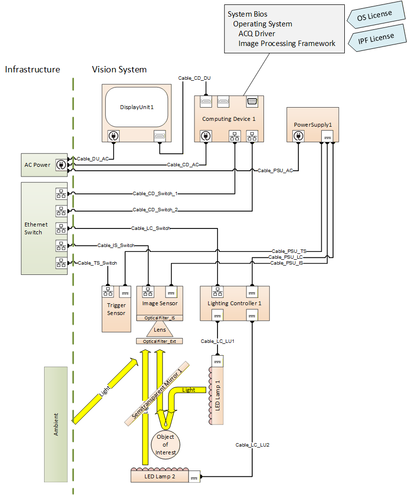
B.1 Mechanical Connections
Within a machine, its components are usually mounted / mechanically connected in some way. Part2 allows you to express the information, how and where things are mounted.
Let us model a simple example:
A camera is usually built out of a camera body (which we will represent by the image sensor as its most important functional part) and a lens that creates a projection on that sensor.
Using the object types given above, we would get an image sensor object and a lens object located in their specific folders.
As the lens is attached to the outside of the camera body, and in principle can be detached, we will use the HasAttachedComponent Reference to show this relationship between the two objects
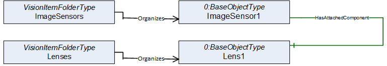
Browsing this model, we get the information that a lens called "Lens1" is attached to an image sensor called "ImageSensor1".
Now let us mount an optical filter onto the lens. This can be done using the same modeling approach.
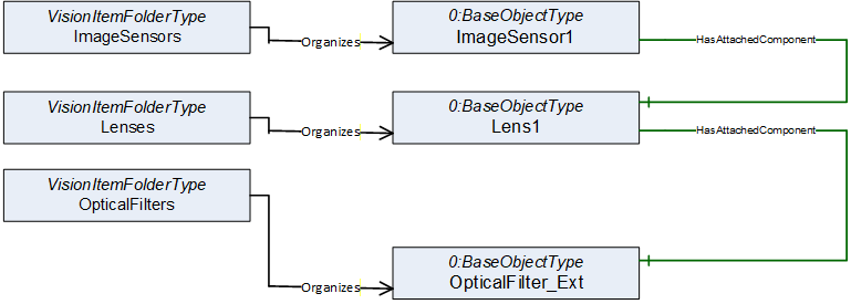
Let us assume the image sensor is equipped with an internal infrared filter in front of the actual sensor chip. As this filter is an integral part of the image sensor, there is no need to add it to the model at all, as the image sensor is already in the model.
But maybe we want to make sure that a service guy browsing this model during maintenance work is aware of the presence of that IR filter. Therefore, we can add it to the model, this time using the HasContianedComponent reference expressing that something is an integral, i.e., not easily removable, part of some other component.
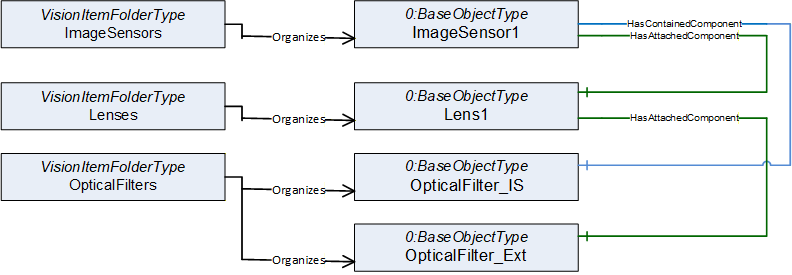
Maybe if someone later on will have to replace the lens it would be nice to know which mechanical interface (like C-Mount or F-Mount) is used in this assembly.
Part2 allows you to get into more detail by adding additional information layers to the model. To add information about the physical connection types supported by your components you may add objects naming each of this physical interfaces / connection points located at your item.
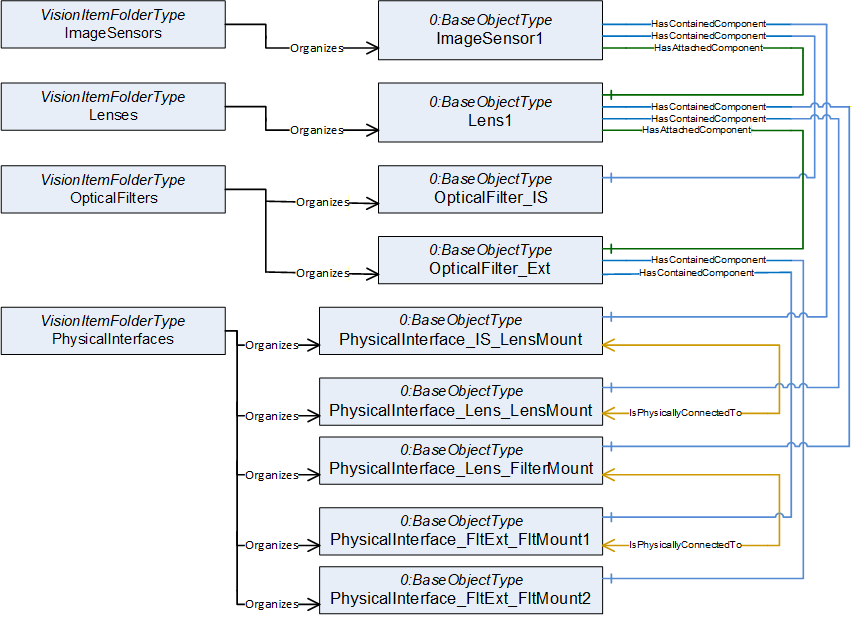
Browsing this model we get the information that there is a lens mount built into the Image sensor. The PhysicalInterface_IS_LensMount Object can hold all information you may need to specify what type of mount this is.
Further browsing shows that Lens1 has two physical connection ports. There is a lens mount on one end and a filter mount on the other.
We also see that the Filter has two filter mounts (on both sides) to be able to stack multiple filters if needed.
During engineering of the system, you may compare the image sensor1 lens mount to the lens1 lens mount to see if the components will fit together.
As this example shows an already mounted lens - as we can see by the HasAttachedComponent reference between image sensor and lens - we will find this information reflected also by the additional information layer of the physical ports. This time we find an IsPhysicallyConnectedTo reference between the two lens mount objects.
The nature of physical ports is that they may be connected or disconnected several times. Therefore, at this level we are only using the IsPhysicallyConnectedTo reference which expresses a somehow weak relation - it is currently physically connected, but this could change at any time. Despite of that, at the component level above you still have the much stronger HasAttachedComponent reference which tells you that this is a connection not intended to be broken during normal operation.
B.2 Service Class Tags
Part 2 offers an additional method of giving your service department information about what they should or should not try to disassemble on site during maintenance. It introduces the possibility to add a service class tag to the components, which gives information about what parts of the machine may be disassembled at the customer site and which components should only be removed as an assembly where you do not disassemble individual components.
So, let's say you know that the system will be working in a dusty environment, possibly with oil mist in the air. Therefore, it is probably not a good idea to remove the lens from the image sensor at the production site as there is a high risk to render the image sensor useless because oil is deposited on it.
The service class standard originating from aircraft maintenance, but now used in a wide field of applications, defines some standard labels like "line replaceable unit" - this component may be removed at the customer site - and "shop replaceable unit" - this component should not be removed at a customer site; only at your workshop you are supposed to dismantle this assembly.
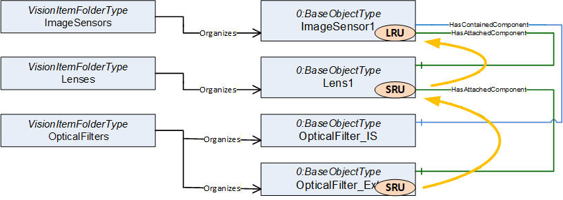
By tagging the components you can give your service guys some information how to handle a repair. If the filter mounted on the lens gets damaged, you can browse the following information from the model:
| the filter is tagged SRU - do not remove | |
| the filter is attached to the lens, the lens is tagged SRU - do not remove | |
| the lens is attached to the image sensor, that is tagged LRU - remove this assembly |
Therefore, the service technician should remove the sensor together with the lens and filter mounted to it and take it back to the repair shop to replace the damaged filter.
B.3 Modular Devices
Some devices / components itself are built in a modular way. For example, an IPC usually is shown as a unit within the system, but internally it uses standardized modules like a PCIe plug-in card or a 2,5" solid state drive. It may be worthwhile to be able to name these modules for maintenance purposes.
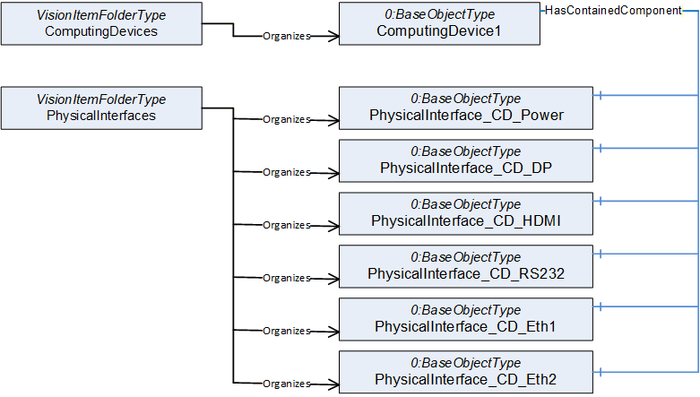
In the example above, we see an industrial computer together with its connectors that are named such that it is possible to show the connectivity within the MV system later on.
In this example, the IPC offers connectors for power supply, video output (Display Port and HDMI), a serial interface and two Ethernet Ports.
Most of these interfaces are built into the IPC (soldered to the mainboard). Therefore, we see HasContainedComponent references pointing from the ComputingDevice to the PhysicalInterface nodes which expresses a "this is an integral part of something" relation.
As in the Image sensor example above, it is up to you to decide what internal components are useful to be included in the model. If an internal component has meaningful maintenance information that may be monitored without the context of the device it belongs to, it may be worth it to add that component to the system model.
An example for that could be a hard disk or solid-state drive which usually provides health information (SMART / GPL) often including a prediction if this drive will fail in the near future.
You may incorporate this SMART data into the health information of the device containing the drive, but for a client it could be easier to have a standardized browse point (folder) where to find all SMART data from all drives no matter in which component they are located.
(Note: Part2 does not include a definition for mass storage devices as there are already standards for that)
Another example could be cooling fans. Instead of distributing their maintenance information over the components they are mounted to, it could make monitoring easier to have them all in one folder.
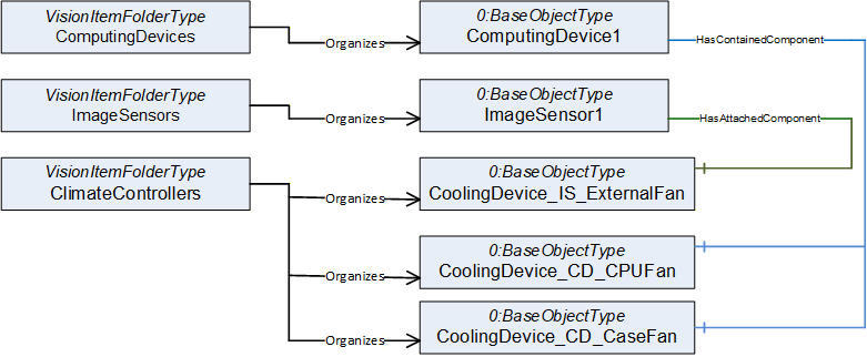
Again, choosing different reference types can be used to give more information on the service task that has to be expected if a part needs to be replaced.
In this example, the Image sensor has an externally attached fan which, by definition of that reference type, should not be hard to detach.
The IPC has a built in CPU fan, which by definition of that reference type Is not designed for easy replacement and it has a contained case fan which is in between those, maybe like a fan cassette of a rack device that may easily be replaced from the outside without the need to dismantle the IPC.
B.4 Software and Licenses
The OPC base specification offers several reference types to describe the relation between software and hardware components.
Below is an example of an IPC running some image processing software framework. To build the model, the first thing is to decide which software components should be named in the model. We here tried to include the things needed for an application that could be updated independently. Therefore, it makes sense to give some version information for those components to be able to keep track of their compatibility if they are updated during normal maintenance operations.
The Firmware / BIOS of the IPC is needed to run the computer, of course it must fit to the hardware of the IPC.
The operating system is usually provided as a software image (e.g., backup of the system drive). To be able to run on the IPC it often needs specific BIOS settings and functionality.
Usually, you need some driver software to adapt the OS to the hardware of the computer and its periphery
Installed to the OS you will have some application software packages, like the Image processing framework or some service tools. These programs may be started or stopped during normal operation
To legally use some of the software components like the OS or the Image processing software you usually need software licenses that may have a digital and/or physical representation (license dongle)
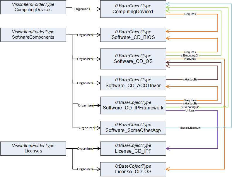
We now will have to add information about the relationships of the named components.
This can be difficult, as it is often hard to decide if a software is "running on" or "hosted by" something or if it "requires" or "utilizes" another component.
There is no right or wrong here, it mainly depends on what aspect you need to make visible to fulfill your monitoring and maintenance needs. And if you can't decide it is always possible to show multiple aspects by using different reference types in parallel.
The model does not necessarily have to be complete; it is often more helpful to limit it to the important information / relations.
To give you an impression, here are some thoughts why we did put the example together in this specific way:
If a BIOS update is to be done, we need to check compatibility. The BIOS has to fit to the hardware, but also its configuration has to fit to the OS image running on that machine. Therefore, we decided to show the aspect that the hardware as well as the OS has requirements on the BIOS distributed. The knowledge that a firmware runs on the hardware it is installed on is somehow trivial and therefore we decided to skip that relation.
If you want to keep track of different versions of the OS Images you did distribute to your system over time, there may be more than one OS Image entity present in the software folder. Therefore, we decided to use the "is executing on" reference to show that the OS image shown in the model is currently running on the IPC.
A driver package distributed often includes drivers for multiple versions of operating systems (e.g. Windows 10 and 11). Therefore, we did use an "IsHostedBy" to express that in this application the driver package runs on a specific OS Version.
The Image processing framework may be connected only loosely to the specific IPC and OS Image but instead run on "one available machine" (virtual environments, Docker etc.). Therefore, we used the "IsHostedBy" reference to connect it to the OS and the "IsExecutingOn" reference to show where it is currently executed. This may change during runtime if it becomes assigned to a different IPC.
The "OtherApp" is currently not executed, but if needed it could run on the IPC, which is indicated by the "IsExecutableOn" reference.
The OS may need a unique license key, which makes a one-to-one relation between the OS and the license. This is shown by the "Requires" reference. This OS needs this specific key.
The Image processing Framework may use some kind of "floating license" model. A license dongle allows to run up to a specific number of Image processing Frameworks in parallel no matter on which IPC they are executed. Therefore, we here used the "Utilizes" reference to express that, as long as it is executed, the framework uses up one of these floating licenses.
B.5 Shared Resources
The Utilizes reference is often used in conjunction with shared resources.
In the example below we have a power supply unit with a single power output.
Three devices are connected to that output and therefore share that resource.
This is modeled by Utilizes references.
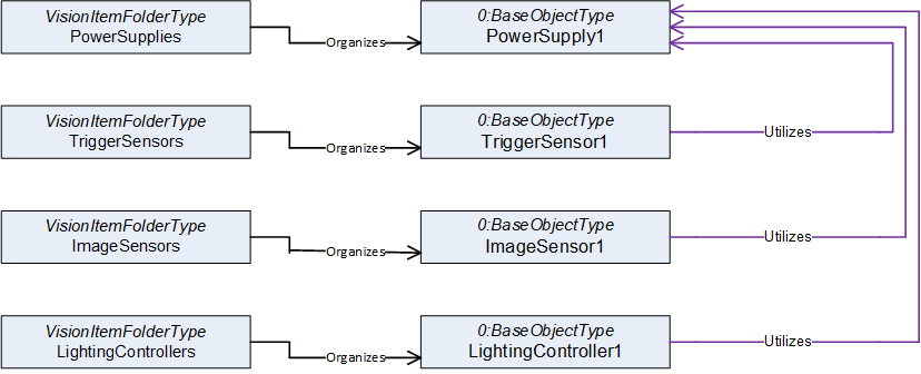
The references now can be used to aggregate information for resource planning.
If you have to select a replacement PSU during repair, you can follow the Utilizes references pointing to the power output in reverse to find the power needs of the three devices and aggregate them to get the requirements for the power supply.
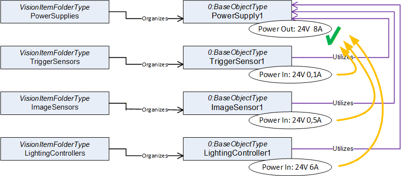
But not in all cases resources are directly used, there could be hidden indirect relations.
A lighting controller often controls an LED lamp by modulating the electrical current to the lamp.
Although there is no direct cable connection between lamp and PSU the lamp is indirectly supplied by the PSU. Normally the power need of the lamp therefore is incorporated into the power need of the lighting controller.
If it is instead needed to explicitly model the relation between lamp and PSU this can be done by adding an additional Utilizes reference (dotted line).
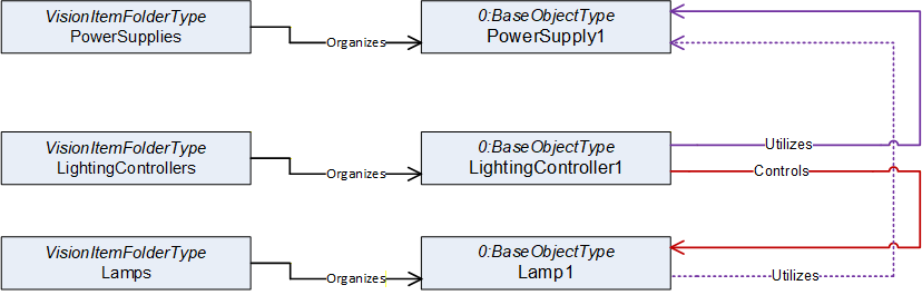
Please be aware that an OPC UA reference cannot have additional parameters. It is simply there or is not there. Therefore, by browsing the references a client cannot distinguish between a reference modeling a direct or indirect relationship (solid line vs. dotted line).
If this is needed a reference refinement must be used to further describe the nature of the dotted Utilizes reference.
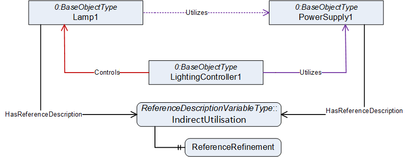
ReferenceDescription Value of IndirectUtilisation
| SourceNode: | Lamp1 |
| ReferenceType: | Utilizes |
| IsForward: | TRUE |
| TargetNode: | PowerSupply1 |
ReferenceRefinement of IndirectUtilisation
{
| ReferenceListEntry | |
| ReferenceType: Controls | |
| IsForward: FALSE | |
| TargetNode: LightingController1; |
| ReferenceListEntry | |
| ReferenceType: Utilizes | |
| IsForward: TRUE | |
| TargetNode: PowerSupply1; |
};
The refinement allows to give an ordered list of references (a path) that are simplified by the reference the refinement belongs to.
The dotted Utilizes reference is a simpler model of the real path that leads from the lamp to the power supply. In reality, Lamp1 receives its power from the lighting controller (which is expressed by the Controls reference from lighting controller to lamp) and the lighting controller gets its power from the power supply.
B.6 Cable Connections
Typically, in real world applications a connector of one device is not plugged directly into the connector of another device. You will find a piece of cable in between.
As cables are often a delicate part of a system and could be worn down if connected to a moving machine part, it can be helpful to get information what kind of cable is used and where it is connected directly from the system. Be aware that a cable can have more than two ends (Y-Cable, Bus Cable, Cable Tree).
Part2 allows you to include information in the model as needed, from basic items to in depth detail.
In the example above we saw a Controls reference between the lighting controller and Lamp1.
Now we will add a cable to the model that provides this control connection.
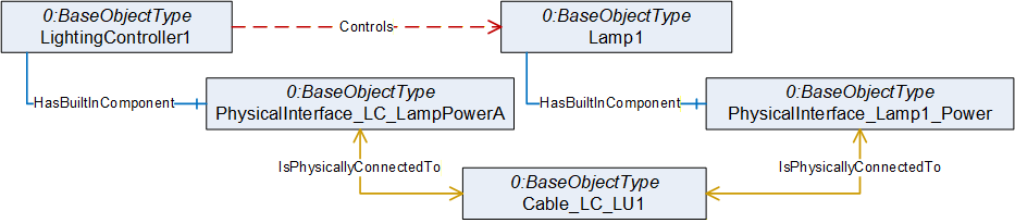
As in the last example we now have two paths from Controller to lamp that stand for the same relation. We again may use a reference refinement to give the information that the Controls reference is provided by that cable connection.
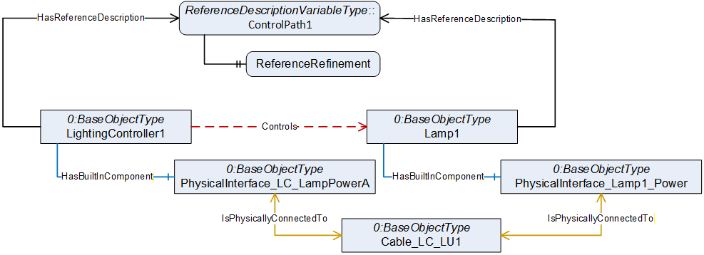
ReferenceDescription Value of ControlPath1
| SourceNode: | LightingController1 |
| ReferenceType: | Controls |
| IsForward: | TRUE |
| TargetNode: | Lamp1 |
ReferenceRefinement of ControlPath1
{
| ReferenceListEntry | |
| ReferenceType: HasContianedComponent | |
| IsForward: TRUE | |
| TargetNode: PhysicalInterface_ LC_LampPowerA |
| ReferenceListEntry | |
| ReferenceType: IsPhysicallyConnectedTo | |
| IsForward: TRUE | |
| TargetNode: Cable_LC_LU1; |
| ReferenceListEntry | |
| ReferenceType: IsPhysicallyConnectedTo | |
| IsForward: TRUE | |
| TargetNode: PhysicalInterface_Lamp1_Power; |
| ReferenceListEntry | |
| ReferenceType: HasContianedComponent | |
| IsForward: FALSE | |
| TargetNode: Lamp1; |
};
Such control flows often include multiple devices which are part of the communication. If the IPC sends a software trigger to the lighting controller via an Ethernet connection, the signal may have to pass an Ethernet switch. Modeling such details gives you the possibility to do sophisticated error analysis later.
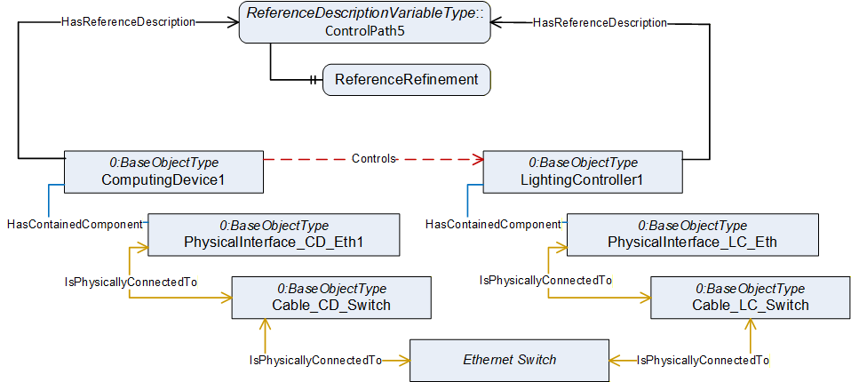
ReferenceDescription Value of ControlPath5
| SourceNode: | ComputingDevice1 |
| ReferenceType: | Controls |
| IsForward: | TRUE |
| TargetNode: | LightingController1 |
ReferenceRefinement of ControlPath5
{
| ReferenceListEntry | |
| ReferenceType: HasContianedComponent | |
| IsForward: TRUE | |
| TargetNode: PhysicalInterface_CD_Eth; | |
| ReferenceListEntry | |
| ReferenceType: IsPhysicallyConnectedTo | |
| IsForward: TRUE | |
| TargetNode: Cable_CD_Switch; | |
| ReferenceListEntry | |
| ReferenceType: IsPhysicallyConnectedTo | |
| IsForward: TRUE | |
| TargetNode: Ethernet Switch; | |
| ReferenceListEntry | |
| ReferenceType: IsPhysicallyConnectedTo | |
| IsForward: TRUE | |
| TargetNode: Cable_LC_Switch; | |
| ReferenceListEntry | |
| ReferenceType: IsPhysicallyConnectedTo | |
| IsForward: TRUE | |
| TargetNode: PhysicalInterface_LC_Eth; | |
| ReferenceListEntry | |
| ReferenceType: HasContianedComponent | |
| IsForward: FALSE | |
| TargetNode: LightingController1; |
};
If the IPC is currently unable to control the lighting controller, the reference refinement provides the information that a service technician not only will have to check the IPC and the controller, but that there are two cables and an Ethernet switch involved that could be causing the problem.
B.7 Detailed Cable models (Connectors and Pins)
Using the same modeling approach as described above you can easily add an additional information layer giving detailed information on the connectors and pinout of the cables in the system. If needed, you may even provide a full cabling plan for the whole system.
The models are simple but will become very large (you often hear people saying otherwise, but no, size and complexity are not the same thing).
Please keep in mind that such models are not intended to be made or read by human beings. A cabling plan will be an output of your engineering software and should be read by a service tool helping a service technician doing maintenance or error analysis.
The first thing to do is to add some connectors to the cable model.
Below is an example of a Y-cable with one connector on one end that is split to 2 connectors on the other end.
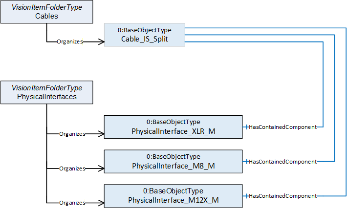
To show the pinout of the connectors we add the wires of the cable to the Cables folder and the pins of the connectors to the PhysicalInterfaces folder. We use the IsPhysicallyConnectedTo reference type to show how everything is wired.
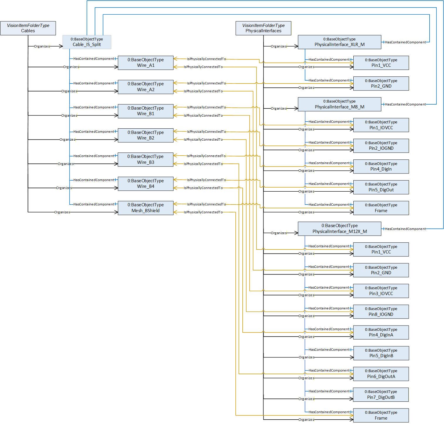
If the cable gets connected to a device, you may decide at which level of information depth you reflect this. The connector of the cable gets physically connected to the fitting connector of the device. You may also show that each pin gets connected which may make it easier to browse large cable trees later on.
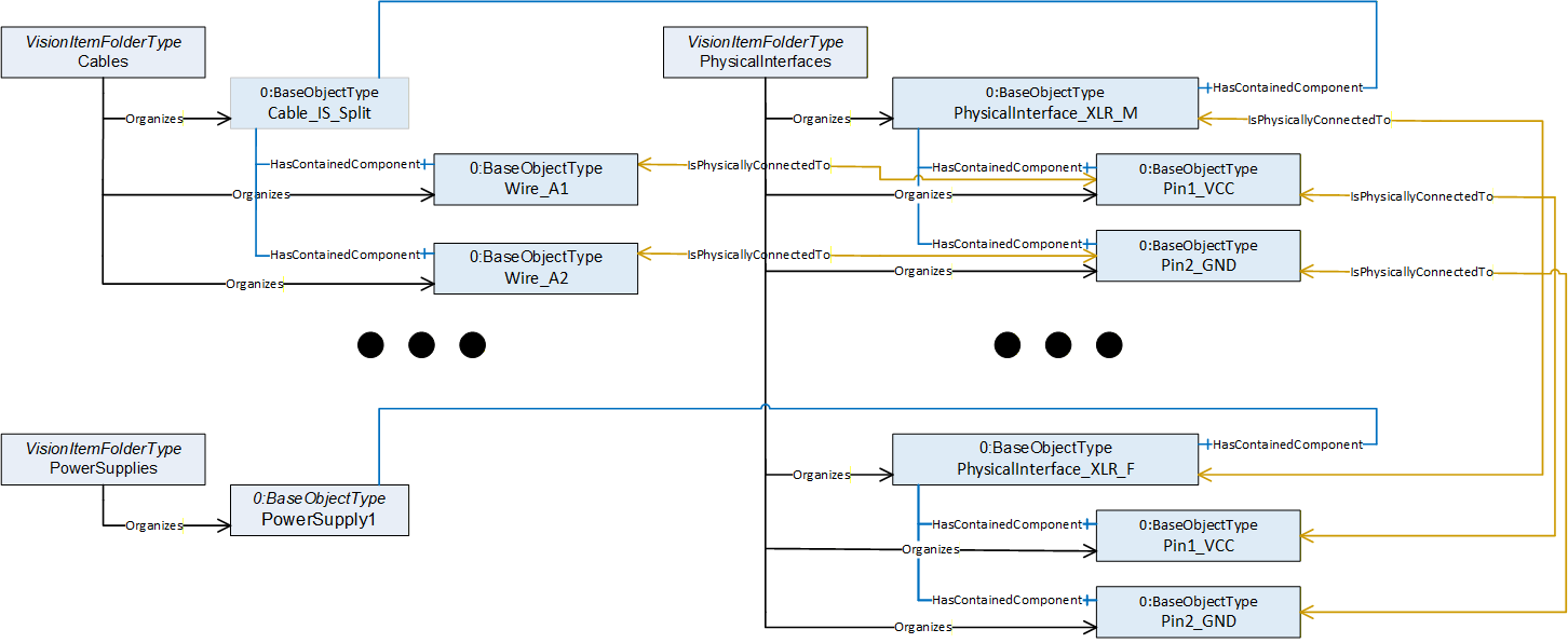
Note: In industrial applications it is common to use screw terminals instead of connectors to connect cables. But even in this case you often need to give detail information on how this end of the cable has to be manufactured. Do you simply have to strip the isolation, or do you need to put on a cable shoe and if yes what type and size of shoe is needed?
An "Open End" object (analog to a pin object) would be a good place to store such information.
B.8 Image Transceivers
In the good ol' days of image processing it was common practice to use specialized interface cards (framegrabbers) to connect an image sensor to a computing unit. But as the consumer grade interfaces included in nearly all computers kept evolving over time they today are often "good enough" and much cheaper than specialized hardware you have to add to the IPC.
So we now mostly use Ethernet or even USB ports to do image acquisition.
Whereas a frame grabber usually comes with detailed information on which image format and acquisition bandwidth it can handle, you rarely will find such information on a generic USB or Ethernet port. We could have added this kind of data elements to a machine vision specific definition of such ports to close that gap, but we did not find this very useful.
Such generic port types are widely used and there will be definitions how to describe them outside of the image processing world.
Instead, we decided to keep the information that is specific to image processing applications in a separate object that may be attached to a port using a reference.
Even in such a scenario you may want to have a frame grabber entity, even if this is now a software instead of a hardware component, whose hardware aspects are hosted by another physical interface.
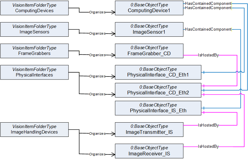
This approach has a big advantage. As consumer interfaces are usually very cheap, modern IPCs come with a lot of them. Often it does not really matter which Ethernet or which USB port the camera is connected to as they are technically identical. So you have some built in redundancy. If you decide to connect the image sensor to Ethernet Port1 instead of Port2, no objects in the model need to be changed. Simply the two "IsHostedBy" references need to be shifted to the other Ethernet port.
B.9 Optical Paths
As we saw above, our models show relations between devices / components. We may add further layers of information to give more details, e.g., to show that a control flow between devices is dependent on cables connecting them.
In a machine vision system, we do not only care about electrical signals being distributed.
We also care about the distribution of light to be able to answer questions like:
| Why do I get no image? | |
| Why is the image I get not as bright as expected? |
To be able to model optical relations we introduced an additional reference type called OpticalPath for that purpose.
Note: As our Industry is called machine vision, we use to speak of images coming from a sensor. This could be something like a photo, but often it is something different which would not be called an image in everyday circumstances.
In the same way we use the terms light and optics in a very general way. "Light" can be anything you use to get your "image", it could be Infrared light, could be X-ray or could even be a sound wave. Everything used to guide or manipulate your "source signal" we call "optical equipment" and the source of that signal we call "lamp".
We also introduced an SurroundingEnvironment Object. In real world applications you often struggle with the surrounding environment around your Vision System. Maybe you make use of ambient light to make your images or maybe scattered ambient light ruins your image processing if you can't isolate the system well enough.
In both cases, it is very often necessary to monitor "surrounding environment quality", meaning the influence the surroundings have on your application (e.g., brightness of ambient light, ambient temperature).
The surrounding environment object is the right place to store such information.
A similar object is the AcquisitionBackground. If for example you need to be able to correctly "see" the contour of an object of interest, you will have some requirements on what is behind that object. So often the background is monitored to warn about dirt and debris showing up before it influences the quality of your image processing. As the acquisition background is often a part of the system (e.g., a gray sheet of metal or a backlight) we distinguished it from the surrounding environment, that is what we find around the vision system.
But back to the optical path.
In the example vision system shown at the beginning of this chapter we can identify 3 main optical paths via which light can reach the image sensor.
Lamp1 in conjunction with a semitransparent mirror is used to illuminate the surface of our object of interest.
A backlight Lamp2 is used to be able to see the contour of the object. Some of that light is lost as it has to pass the mirror used for front face illumination
Stray light from the surrounding environment may disturb our image, as it is not completely blocked in that application
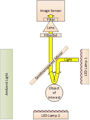
This gives us the following model
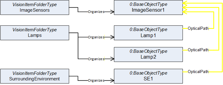
Using the same approach as we did with the cables we now can include all intermediate objects that are part of these paths of light. As shown above to express a "Path" we need to use reference refinements to give the single references an order to build a path.
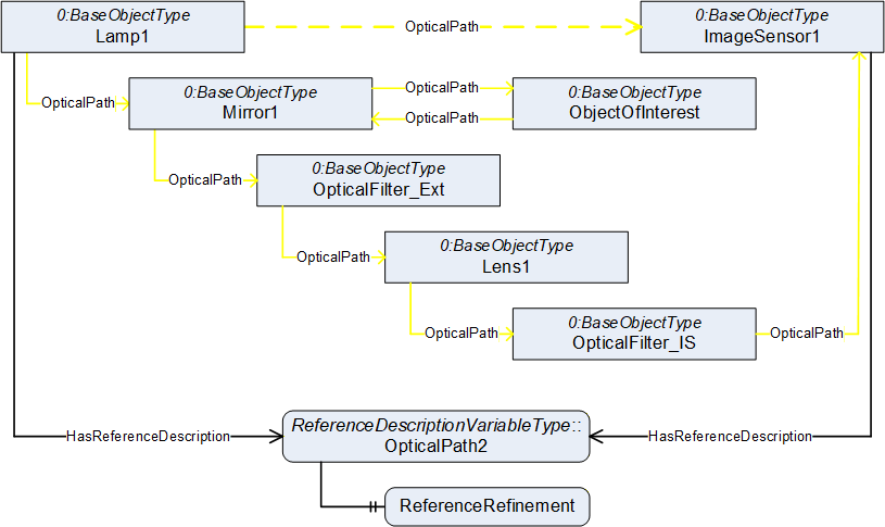
ReferenceDescription Value of OpticalPath1
| SourceNode: | Lamp1 |
| ReferenceType: | OpticalPath |
| IsForward: | TRUE |
| TargetNode: | ImageSensor1 |
ReferenceRefinement of OpticalPath3
{
| ReferenceListEntry | |
| ReferenceType: OpticalPath | |
| IsForward: TRUE | |
| TargetNode: Mirror1; | |
| ReferenceListEntry | |
| ReferenceType: OpticalPath | |
| IsForward: TRUE | |
| TargetNode: ObjectOfInterest; | |
| ReferenceListEntry | |
| ReferenceType: OpticalPath | |
| IsForward: TRUE | |
| TargetNode: Mirror1; | |
| ReferenceListEntry | |
| ReferenceType: OpticalPath | |
| IsForward: TRUE | |
| TargetNode: OpticalFilter_Ext; | |
| ReferenceListEntry | |
| ReferenceType: OpticalPath | |
| IsForward: TRUE | |
| TargetNode: Lens1; | |
| ReferenceListEntry | |
| ReferenceType: OpticalPath | |
| IsForward: TRUE | |
| TargetNode: OpticalFilter_IS; | |
| ReferenceListEntry | |
| ReferenceType: OpticalPath | |
| IsForward: TRUE | |
| TargetNode: ImageSensor1; |
};
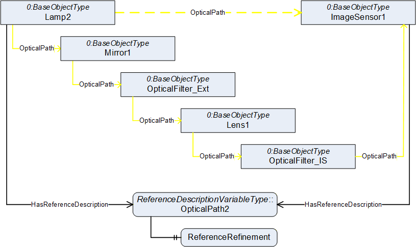
ReferenceDescription Value of OpticalPath2
| SourceNode: | Lamp2 |
| ReferenceType: | OpticalPath |
| IsForward: | TRUE |
| TargetNode: | ImageSensor1 |
ReferenceRefinement of OpticalPath2
{
| ReferenceListEntry | |
| ReferenceType: OpticalPath | |
| IsForward: TRUE | |
| TargetNode: Mirror1; | |
| ReferenceListEntry | |
| ReferenceType: OpticalPath | |
| IsForward: TRUE | |
| TargetNode: OpticalFilter_Ext; | |
| ReferenceListEntry | |
| ReferenceType: OpticalPath | |
| IsForward: TRUE | |
| TargetNode: Lens1; | |
| ReferenceListEntry | |
| ReferenceType: OpticalPath | |
| IsForward: TRUE | |
| TargetNode: OpticalFilter_IS; | |
| ReferenceListEntry | |
| ReferenceType: OpticalPath | |
| IsForward: TRUE | |
| TargetNode: ImageSensor1; |
};
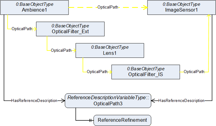
ReferenceDescription Value of OpticalPath3
| SourceNode: | Ambience1 |
| ReferenceType: | OpticalPath |
| IsForward: | TRUE |
| TargetNode: | ImageSensor1 |
ReferenceRefinement of OpticalPath3
{
| ReferenceListEntry | |
| ReferenceType: OpticalPath | |
| IsForward: TRUE | |
| TargetNode: OpticalFilter_Ext; | |
| ReferenceListEntry | |
| ReferenceType: OpticalPath | |
| IsForward: TRUE | |
| TargetNode: Lens1; | |
| ReferenceListEntry | |
| ReferenceType: OpticalPath | |
| IsForward: TRUE | |
| TargetNode: OpticalFilter_IS; | |
| ReferenceListEntry | |
| ReferenceType: OpticalPath | |
| IsForward: TRUE | |
| TargetNode: ImageSensor1; |
};
Browsing this model may aid you to answer the questions above. If you do not get the normal amount of brightness in the image you are taking from the front face of the object of interest, you may need to check if the mirror or the filter needs cleaning, as the light for that image must pass both.
B.10 Overview of the address space
Finally using the modelling tools introduced in this companion specification along with the usage of OPC UA References as explained in the previous sections, the figure on the next page shows the entire address space model of the example used throughout this Annex.
Agreement of Use
COPYRIGHT RESTRICTIONS
This document is provided "as is" by the OPC Foundation and VDMA.
Right of use for this specification is restricted to this specification and does not grant rights of use for referred documents.
Right of use for this specification will be granted without cost.
This document may be distributed through computer systems, printed or copied as long as the content remains unchanged and the document is not modified.
OPC Foundation and VDMA do not guarantee usability for any purpose and shall not be made liable for any case using the content of this document.
The user of the document agrees to indemnify OPC Foundation and VDMA and their officers, directors and agents harmless from all demands, claims, actions, losses, damages (including damages from personal injuries), costs and expenses (including attorneys' fees) which are in any way related to activities associated with its use of content from this specification.
The document shall not be used in conjunction with company advertising, shall not be sold or licensed to any party.
The intellectual property and copyright is solely owned by the OPC Foundation and VDMA.
PATENTS
The attention of adopters is directed to the possibility that compliance with or adoption of OPC or VDMA specifications may require use of an invention covered by patent rights. OPC Foundation or VDMA shall not be responsible for identifying patents for which a license may be required by any OPC or VDMA specification, or for conducting legal inquiries into the legal validity or scope of those patents that are brought to its attention. OPC or VDMA specifications are prospective and advisory only. Prospective users are responsible for protecting themselves against liability for infringement of patents.
WARRANTY AND LIABILITY DISCLAIMERS
WHILE THIS PUBLICATION IS BELIEVED TO BE ACCURATE, IT IS PROVIDED "AS IS" AND MAY CONTAIN ERRORS OR MISPRINTS. THE OPC FOUDATION NOR VDMA MAKES NO WARRANTY OF ANY KIND, EXPRESSED OR IMPLIED, WITH REGARD TO THIS PUBLICATION, INCLUDING BUT NOT LIMITED TO ANY WARRANTY OF TITLE OR OWNERSHIP, IMPLIED WARRANTY OF MERCHANTABILITY OR WARRANTY OF FITNESS FOR A PARTICULAR PURPOSE OR USE. IN NO EVENT SHALL THE OPC FOUNDATION NOR VDMA BE LIABLE FOR ERRORS CONTAINED HEREIN OR FOR DIRECT, INDIRECT, INCIDENTAL, SPECIAL, CONSEQUENTIAL, RELIANCE OR COVER DAMAGES, INCLUDING LOSS OF PROFITS, REVENUE, DATA OR USE, INCURRED BY ANY USER OR ANY THIRD PARTY IN CONNECTION WITH THE FURNISHING, PERFORMANCE, OR USE OF THIS MATERIAL, EVEN IF ADVISED OF THE POSSIBILITY OF SUCH DAMAGES.
The entire risk as to the quality and performance of software developed using this specification is borne by you.
RESTRICTED RIGHTS LEGEND
This Specification is provided with Restricted Rights. Use, duplication or disclosure by the U.S. government is subject to restrictions as set forth in (a) this Agreement pursuant to DFARs 227.7202-3(a); (b) subparagraph (c)(1)(i) of the Rights in Technical Data and Computer Software clause at DFARs 252.227-7013; or (c) the Commercial Computer Software Restricted Rights clause at FAR 52.227-19 subdivision (c)(1) and (2), as applicable. Contractor / manufacturer are the OPC Foundation, 16101 N. 82nd Street, Suite 3B, Scottsdale, AZ, 85260-1830
COMPLIANCE
The combination of VDMA and OPC Foundation shall at all times be the sole entities that may authorize developers, suppliers and sellers of hardware and software to use certification marks, trademarks or other special designations to indicate compliance with these materials as specified within this document. Products developed using this specification may claim compliance or conformance with this specification if and only if the software satisfactorily meets the certification requirements set by VDMA or the OPC Foundation. Products that do not meet these requirements may claim only that the product was based on this specification and must not claim compliance or conformance with this specification.
TRADEMARKS
Most computer and software brand names have trademarks or registered trademarks. The individual trademarks have not been listed here.
GENERAL PROVISIONS
Should any provision of this Agreement be held to be void, invalid, unenforceable or illegal by a court, the validity and enforceability of the other provisions shall not be affected thereby.
This Agreement shall be governed by and construed under the laws of Germany.
This Agreement embodies the entire understanding between the parties with respect to, and supersedes any prior understanding or agreement (oral or written) relating to, this specification.