
1 Scope
The OPC UA Compressed Air Systems (CAS) Companion Specification includes a description of a system and a basic description of its components regarding a Compressed Air System. Main scope of this specification is the communication between the Main Control System and the higher-level manufacturing system(s). More specific, it is the transport of condition data of a CAS vertically into higher level manufacturing systems (MES; etc.) for information and monitoring purposes and to set basic parameters regarding the target values of the respective CAS. The description of the CAS and its components is focused on selected use cases, e. g. device identification, configuration, maintenance management, energy management, and operation.
This Companion Specification is not intended to provide viable representations for components such as compressors or dryers outside the context of a compressed air system. It is not intended to use parts of this Companion Specification outside the context of a compressed air system. Particularly, it is not intended to use the components in the context of machine-to-machine communication.
Note: The focus lies on the system which the MCS represents. The MCS communicates with other machines outside of this system. It matches the demand of several users with the compressed air generation by controlling the components especially the compressors of that compressed air system. Therefore, this Companion Specification cannot be directly compared with a Companion Specification for direct machine to machine communication where the component is directly integrated in another machine or process like the Companion Specification for pumps, machine tools, etc.
2 Normative references
OPC 10000-1, OPC Unified Architecture - Part 1: Overview and Concepts
OPC 10000-1
OPC 10000-2, OPC Unified Architecture - Part 2: Security Model
OPC 10000-2
OPC 10000-3, OPC Unified Architecture - Part 3: Address Space Model
OPC 10000-3
OPC 10000-4, OPC Unified Architecture - Part 4: Services
OPC 10000-4
OPC 10000-5, OPC Unified Architecture - Part 5: Information Model
OPC 10000-5
OPC 10000-6, OPC Unified Architecture - Part 6: Mappings
OPC 10000-6
OPC 10000-7, OPC Unified Architecture - Part 7: Profiles
OPC 10000-7
OPC 10000-8, OPC Unified Architecture - Part 8: Data Access
OPC 10000-8
OPC 10000-9, OPC Unified Architecture - Part 9: Alarms and Conditions
OPC 10000-9
OPC 10000-100, OPC Unified Architecture - Part 100: Device Information Model
OPC 10000-100
OPC 10000-200, OPC Unified Architecture - Part 200: Industrial Automation
OPC 10000-200
OPC 40001-1, OPC UA for Machinery - Part 1: Basic Building Blocks
http://www.opcfoundation.org/UA/Machinery/
IEC 60050, International Electrotechnical Vocabulary
ISO 8573-1:2010-04, Compressed air - Part 1: Contaminants and purity classes
ISO 11011:2013, Compressed air - Energy efficiency - Assessment
ISO 50001, Energy management systems - Requirements with guidance for use
ISO 80000:2009, Quantities and units
NAMUR NE 107:2017-04-10, Self-monitoring and diagnosis of field devices
Details of the Asset Administration Shell - Part 1: The exchange of information between partners in the value chain of Industrie 4.0
3 Terms, definitions, and conventions
3.1 Overview
It is assumed that basic concepts of OPC UA information modelling, OPC Unified Architecture - Part 100, and OPC UA for Machinery - Part 1 are understood in this specification. This specification will use these concepts to describe the OPC UA for Compressed Air Systems Information Model. For the purposes of this document, the terms and definitions given in OPC 10000-1, OPC 10000-3, OPC 10000-4, OPC 10000-5, OPC 10000-7, OPC 10000-100, OPC 40001-1, as well as the following apply.
3.2 OPC UA for Compressed Air Systems terms
3.2.1 Airnet
Piping and all Components between at least two distinct points, the inputs and outputs of the Airnet, in a Compressed Air System.
Note 1 to entry: A Component can be connected to multiple Airnets.
Note 2 to entry: Airnets may touch or overlap each other.
Note 3 to entry: For examples on how Airnets can be used in the context of this specification see chapter 6.
3.2.2 CASPart
Identifiable and browsable element in a Compressed Air System.
Note 1 to entry: CASParts defined in this specification are: Airnet, all Components, Main Control System.
3.2.3 Component
CASPart that serves a particular purpose in compressed air generation, treatment, measurement, or storage.
Note 1 to entry: Components defined in this specification are: Charging System, Compressor, Condensate Drain, Condensate Separator, Converter, Cooling System, Dryer, Filter, Heat Recovery System, Receiver, Sensor.
Note 2 to entry: A Component may be connected to no, one, or more than one Airnet.
3.2.4 Compressed Air System
System that generates compressed air, consists of Components and at least one Airnet, and is commonly equipped with one Main Control System.
3.2.5 ComponentClass
Specific type of a Component and value of the ComponentClass Variable of an instance of the FunctionalGroup Design of a Component.
| EXAMPLE 1 | The compressor C1 is of the ComponentClass Axial turbo compressor. |
| EXAMPLE 2 | The filter F1 is of the ComponentClass Activated carbon filter. |
3.2.6 Customer Distribution Point
Connection point of a Compressed Air System to subsequent machines or systems.
Note 1 to entry: Usually the Customer Distribution Point is located at one of the outlets of an Airnet.
Note 2 to entry: The Customer Distribution Point provides Variables and/or Objects which describe the conditions of the compressed air.
3.2.7 DeviceClass
Specific class of a CASPart and value of the DeviceClass Property of an instance of the FunctionalGroup Identification of a CASPart.
Note 1 to entry: Available DeviceClasses for CASPart of this specification are listed in Table 9.
| EXAMPLE 1 | The compressor C1 is of the DeviceClass Compressor. |
| EXAMPLE 2 | The filter F1 is of the DeviceClass Filter. |
3.2.8 FunctionalGroup
Instance of the FunctionalGroupType or one of its subtypes.
Note 1 to entry: In this specification, FunctionalGroup usually refers to an instance of a Compressed Air System specific ObjectType like OperationalType, AnalysesType, or DesignType.
| EXAMPLE 1 | The compressor C1 has the FunctionalGroups Identification, Design, and Operational. |
3.2.9 GroupName
BrowseName of instances of the OptionalPlaceholder Object <ComponentsGroup> of instances of the ObjectType ComponentsGroupType.
Note 1 to entry: Available GroupNames for part groups of this specification are listed in Table 9.
| EXAMPLE 1 | The Object for organizing all compressors in this Compressed Air System uses the GroupName Compressors. |
| EXAMPLE 2 | The Object for organizing all Airnets in this Compressed Air System uses the GroupName Airnets. |
3.2.10 Integrated [Component]
A Component is Integrated if the Main Control System has control over the generation or treatment of compressed air.
Note 1 to entry: A compressor is Integrated if the Main Control System has control over the loaded state.
Note 2 to entry: The Main Control System can switch a Component between the two states Integrated and Isolated.
3.2.11 Isolated [Component]
A Component is Isolated if the Main Control System has no control over the generation or treatment of compressed air.
Note 1 to entry: A Component is Isolated if the Main Control System does not control the loaded state.
Note 2 to entry: The Main Control System can switch a Component between the two states Integrated and Isolated.
3.2.12 Main Control System
CASPart that controls all Components and Airnets simultaneously, represents the Compressed Air System, and serves for communication between the Components and higher-level systems.
3.2.13 Main Function [of a Component]
The actual main function of Components is not specified in this specification. The following examples of Main Functions do not imply the actual function of the referenced Component.
| EXAMPLE 1 | Charging system: to keep pressure upstream above a set minimum pressure or within a set pressure range |
| EXAMPLE 2 | Compressor: to deliver compressed air into the piping with an expected volume flow and at an expected pressure |
| EXAMPLE 3 | Condensate drain: to remove condensate from the compressed air piping or a condensate storage to outside the pressure system |
| EXAMPLE 4 | Condensate separator: to separate the hydrocarbon contents from the condensate to create a clean condensate that can easily be disposed of |
| EXAMPLE 5 | Converter: to eliminates hydrocarbons from the compressed air stream to create class 1 (and better) oil free air |
| EXAMPLE 6 | Cooling system: to reduce the compressed air temperature to a desired level |
| EXAMPLE 7 | Dryer: to remove moisture from compressed air and dry compressed air to a pressure dew point below the required value |
| EXAMPLE 8 | Filter: to remove particles and aerosols from the compressed air flow |
| EXAMPLE 9 | Heat recovery system: Main function: to heat up a material or substance flow by using the heat generated by the compressed air system |
| EXAMPLE 10 | Receiver: to store compressed air and provide a buffer |
| EXAMPLE 11 | Sensor: to measure specific parameters in the compressed air system and provide the data |
3.2.14 Quantity
A Variable representing physical measurements performed by a sensor, or calculations performed by a CASPart or the Main Control System to simulate a physical measurement.
Note 1 to entry: A physical quantity may be measured by an external sensor but is assigned to a specific CASPart.
Note 2 to entry: The measuring sensor may be integrated into the CASPart.
Note 3 to entry: A calculation performed on the Main Control System which is used by a Component shall be assigned to that Component.
| EXAMPLE 1 | A temperature Quantity is measured by an internal sensor of a compressor at its outlet. |
| EXAMPLE 2 | A pressure Quantity is measured by an external sensor at the inlet and outlet of a filter. |
| EXAMPLE 3 | The isentropic efficiency of a compressor is a Quantity which is calculated by the Main Control System but assigned to the compressor. |
3.2.15 Requirements [of an Airnet]
The actual requirements of an Airnet are not specified in this specification. The following examples of Requirements do not imply the actual requirements of an Airnet.
| EXAMPLE 1 | The Airnet pressure shall be within range. |
| EXAMPLE 2 | The dew point shall be within range. |
| EXAMPLE 3 | The volume flow rate shall be within range. |
3.2.16 Unavailable [Compressor]
A compressor is Unavailable if it cannot be Integrated and controlled by the Main Control System.
Note 1 to entry: The Main Control System cannot switch a compressor from Unavailable to any other state.
| EXAMPLE 1 | A compressor in an error state may be Unavailable. |
3.3 Abbreviated terms
| CAS | Compressed Air System |
| HOC | Heat of Compression Dryer |
| KPI | key performance indicator |
| MCS | Main Control System |
| VSD | Variable Speed Drive |
3.4 Conventions used in this document
3.4.1 Conventions for Node descriptions
Node definitions are specified using tables (see Table 2 ).
Attributes are defined by providing the Attribute name and a value, or a description of the value.
References are defined by providing the ReferenceType name, the BrowseName of the TargetNode and its NodeClass.
If the TargetNode is a component of the Node being defined in the table the Attributes of the composed Node are defined in the same row of the table.
The DataType is only specified for Variables; "[<number>]" indicates a single-dimensional array, for multi-dimensional arrays the expression is repeated for each dimension (e.g. [2][3] for a two-dimensional array). For all arrays the ArrayDimensions is set as identified by <number> values. If no <number> is set, the corresponding dimension is set to 0, indicating an unknown size. If no number is provided at all the ArrayDimensions can be omitted. If no brackets are provided, it identifies a scalar DataType and the ValueRank is set to the corresponding value (see OPC 10000-3). In addition, ArrayDimensions is set to null or is omitted. If it can be Any or ScalarOrOneDimension, the value is put into "{<value>}", so either "{Any}" or "{ScalarOrOneDimension}" and the ValueRank is set to the corresponding value (see OPC 10000-3) and the ArrayDimensions is set to null or is omitted. Examples are given in Table 1 .
| Notation | DataType | ValueRank | ArrayDimensions | Description |
| 0:Int32 | 0:Int32 | -1 | omitted or null | A scalar Int32. |
| 0:Int32[] | 0:Int32 | 1 | omitted or {0} | Single-dimensional array of Int32 with an unknown size. |
| 0:Int32[][] | 0:Int32 | 2 | omitted or {0,0} | Two-dimensional array of Int32 with unknown sizes for both dimensions. |
| 0:Int32[3][] | 0:Int32 | 2 | {3,0} | Two-dimensional array of Int32 with a size of 3 for the first dimension and an unknown size for the second dimension. |
| 0:Int32[5][3] | 0:Int32 | 2 | {5,3} | Two-dimensional array of Int32 with a size of 5 for the first dimension and a size of 3 for the second dimension. |
| 0:Int32{Any} | 0:Int32 | -2 | omitted or null | An Int32 where it is unknown if it is scalar or array with any number of dimensions. |
| 0:Int32{ScalarOrOneDimension} | 0:Int32 | -3 | omitted or null | An Int32 where it is either a single-dimensional array or a scalar. |
The TypeDefinition is specified for Objects and Variables.
The TypeDefinition column specifies a symbolic name for a NodeId, i.e. the specified Node points with a HasTypeDefinition Reference to the corresponding Node.
The ModellingRule of the referenced component is provided by specifying the symbolic name of the rule in the ModellingRule column. In the AddressSpace, the Node shall use a HasModellingRule Reference to point to the corresponding ModellingRule Object.
If the NodeId of a DataType is provided, the symbolic name of the Node representing the DataType shall be used.
Note that if a symbolic name of a different namespace is used, it is prefixed by the NamespaceIndex (see 3.4.2.2).
Nodes of all other NodeClasses cannot be defined in the same table; therefore only the used ReferenceType, their NodeClass and their BrowseName are specified. A reference to another part of this document points to their definition.
Table 2 illustrates the table. If no components are provided, the DataType, TypeDefinition and ModellingRule columns may be omitted and only a Comment column is introduced to point to the Node definition.
| Attribute | Value | ||||
| Attribute name | Attribute value. If it is an optional Attribute that is not set "--" will be used. | ||||
| References | NodeClass | BrowseName | DataType | TypeDefinition | Other |
| ReferenceType name | NodeClass of the TargetNode. | BrowseName of the target Node. If the Reference is to be instantiated by the server, then the value of the target Node's BrowseName is "--". | DataType of the referenced Node, only applicable for Variables. | TypeDefinition of the referenced Node, only applicable for Variables and Objects. | Additional characteristics of the TargetNode such as the ModellingRule or AccessLevel. |
| NOTE Notes referencing footnotes of the table content. | |||||
Components of Nodes can be complex that is containing components by themselves. The TypeDefinition, NodeClass and DataType can be derived from the type definitions, and the symbolic name can be created as defined in 3.4.3.1. Therefore, those containing components are not explicitly specified; they are implicitly specified by the type definitions.
The Other column defines additional characteristics of the Node. Examples of characteristics that can appear in this column are show in Table 3.
| Name | Short Name | Description |
| 0:Mandatory | M | The Node has the Mandatory ModellingRule. |
| 0:Optional | O | The Node has the Optional ModellingRule. |
| 0:MandatoryPlaceholder | MP | The Node has the MandatoryPlaceholder ModellingRule. |
| 0:OptionalPlaceholder | OP | The Node has the OptionalPlaceholder ModellingRule. |
| ReadOnly | RO | The Node AccessLevel has the CurrentRead bit set but not the CurrentWrite bit. |
| ReadWrite | RW | The Node AccessLevel has the CurrentRead and CurrentWrite bits set. |
| WriteOnly | WO | The Node AccessLevel has the CurrentWrite bit set but not the CurrentRead bit. |
If multiple characteristics are defined they are separated by commas. The name or the short name may be used.
3.4.2 NodeIds and BrowseNames
3.4.2.1 NodeIds
The NodeIds of all Nodes described in this standard are only symbolic names. Annex A defines the actual NodeIds.
The symbolic name of each Node defined in this document is its BrowseName, or, when it is part of another Node, the BrowseName of the other Node, a ".", and the BrowseName of itself. In this case "part of" means that the whole has a HasProperty or HasComponent Reference to its part. Since all Nodes not being part of another Node have a unique name in this document, the symbolic name is unique.
The NamespaceUri for all NodeIds defined in this document is defined in Annex A. The NamespaceIndex for this NamespaceUri is vendor-specific and depends on the position of the NamespaceUri in the server namespace table.
Note that this document not only defines concrete Nodes, but also requires that some Nodes shall be generated, for example one for each Session running on the Server. The NodeIds of those Nodes are Server-specific, including the namespace. But the NamespaceIndex of those Nodes cannot be the NamespaceIndex used for the Nodes defined in this document, because they are not defined by this document but generated by the Server.
3.4.2.2 BrowseNames
The text part of the BrowseNames for all Nodes defined in this document is specified in the tables defining the Nodes. The NamespaceUri for all BrowseNames defined in this document is defined in Annex A.
If the BrowseName is not defined by this document, a namespace index prefix like '0:EngineeringUnits' or '2:DeviceRevision' is added to the BrowseName. This is typically necessary if a Property of another specification is overwritten or used in the OPC UA types defined in this document. Table 184 provides a list of namespaces and their indexes as used in this document.
3.4.3 Common Attributes
3.4.3.1 General
The Attributes of Nodes, their DataTypes and descriptions are defined in OPC 10000-3. Attributes not marked as optional are mandatory and shall be provided by a Server. The following tables define if the Attribute value is defined by this specification or if it is server-specific.
For all Nodes specified in this specification, the Attributes named in Table 4 shall be set as specified in the table.
| Attribute | Value |
| DisplayName | The DisplayName is a LocalizedText. Each server shall provide the DisplayName identical to the BrowseName of the Node for the LocaleId "en". Whether the server provides translated names for other LocaleIds is server-specific. |
| Description | Optionally a server-specific description is provided. |
| NodeClass | Shall reflect the NodeClass of the Node. |
| NodeId | The NodeId is described by BrowseNames as defined in 3.4.2.1. |
| WriteMask | Optionally the WriteMask Attribute can be provided. If the WriteMask Attribute is provided, it shall set all non-server-specific Attributes to not writable. For example, the Description Attribute may be set to writable since a Server may provide a server-specific description for the Node. The NodeId shall not be writable, because it is defined for each Node in this specification. |
| UserWriteMask | Optionally the UserWriteMask Attribute can be provided. The same rules as for the WriteMask Attribute apply. |
| RolePermissions | Optionally server-specific role permissions can be provided. |
| UserRolePermissions | Optionally the role permissions of the current Session can be provided. The value is server-specific and depend on the RolePermissions Attribute (if provided) and the current Session. |
| AccessRestrictions | Optionally server-specific access restrictions can be provided. |
3.4.3.2 Objects
For all Objects specified in this specification, the Attributes named in Table 5 shall be set as specified in the table. The definitions for the Attributes can be found in OPC 10000-3.
| Attribute | Value |
| EventNotifier | Whether the Node can be used to subscribe to Events or not is server-specific. |
3.4.3.3 Variables
For all Variables specified in this specification, the Attributes named in Table 6 shall be set as specified in the table. The definitions for the Attributes can be found in OPC 10000-3.
| Attribute | Value |
| MinimumSamplingInterval | Optionally, a server-specific minimum sampling interval is provided. |
| AccessLevel | The access level for Variables used for type definitions is server-specific, for all other Variables defined in this specification, the access level shall allow reading; other settings are server-specific. |
| UserAccessLevel | The value for the UserAccessLevel Attribute is server-specific. It is assumed that all Variables can be accessed by at least one user. |
| Value | For Variables used as InstanceDeclarations, the value is server-specific; otherwise it shall represent the value described in the text. |
| ArrayDimensions | If the ValueRank does not identify an array of a specific dimension (i.e. ValueRank <= 0) the ArrayDimensions can either be set to null or the Attribute is missing. This behavior is server-specific. If the ValueRank specifies an array of a specific dimension (i.e. ValueRank > 0) then the ArrayDimensions Attribute shall be specified in the table defining the Variable. |
| Historizing | The value for the Historizing Attribute is server-specific. |
| AccessLevelEx | If the AccessLevelEx Attribute is provided, it shall have the bits 8, 9, and 10 set to 0, meaning that read and write operations on an individual Variable are atomic, and arrays can be partly written. |
3.4.3.4 VariableTypes
For all VariableTypes specified in this specification, the Attributes named in Table 7 shall be set as specified in the table. The definitions for the Attributes can be found in OPC 10000-3.
| Attributes | Value |
| Value | Optionally a server-specific default value can be provided. |
| ArrayDimensions | If the ValueRank does not identify an array of a specific dimension (i.e. ValueRank <= 0) the ArrayDimensions can either be set to null or the Attribute is missing. This behavior is server-specific. If the ValueRank specifies an array of a specific dimension (i.e. ValueRank > 0) then the ArrayDimensions Attribute shall be specified in the table defining the VariableType. |
3.4.3.5 Methods
For all Methods specified in this specification, the Attributes named in Table 8 shall be set as specified in the table. The definitions for the Attributes can be found in OPC 10000-3.
| Attributes | Value |
| Executable | All Methods defined in this specification shall be executable (Executable Attribute set to "True"), unless it is defined differently in the Method definition. |
| UserExecutable | The value of the UserExecutable Attribute is server-specific. It is assumed that all Methods can be executed by at least one user. |
4 General information to Compressed Air Systems and OPC UA
4.1 Introduction to Compressed Air Systems
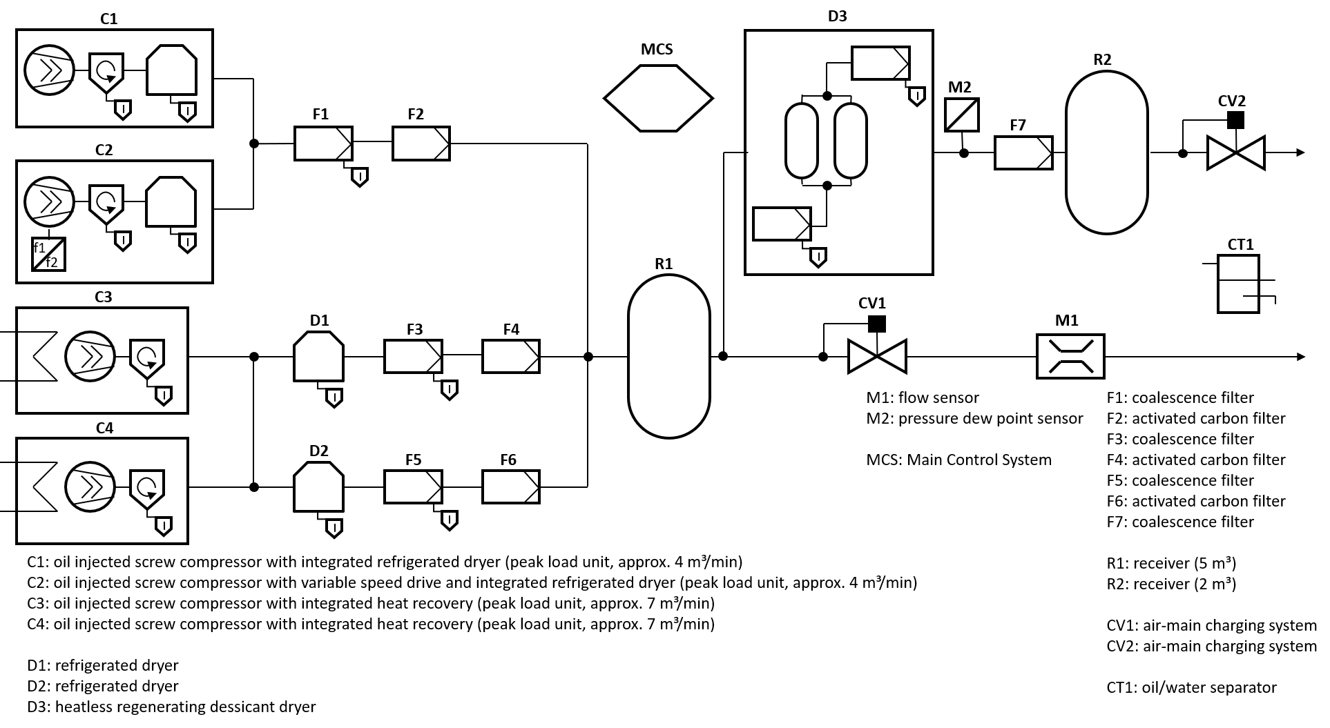
This document describes an information model, which aims to cover the whole Compressed Air System. A typical Compressed Air System consists of several devices, such as compressors, dryers, filters, air quality monitoring units etc., it is commonly also equipped with a Main Control System. The latter is used to control and/or monitor the connected devices and gather information from the same. This aggregated information is often provided to higher level systems through existing field bus technology (e.g. Profibus, Modbus, CAN Bus), with the drawback that the content and structure of the provided information is highly dependent on the manufacturer of the Main Control System. With this specification an integration in a Main Control System would be possible.
The variety of Compressed Air System is rather wide. It could be e.g. two compressors and a Main Control System and a basic compressed air treatment as a minimum configuration. More complex Compressed Air System have several compressors which must be controlled and several Airnets of different pressures with specific dryers, filters etc.
Therefore, this specification covers a very broad range of systems as well as of applications.
A typical more complex Compressed Air System is described in the following figure:
4.2 Introduction to OPC Unified Architecture
4.2.1 What is OPC UA?
OPC UA is an open and royalty free set of standards designed as a universal communication protocol. While there are numerous communication solutions available, OPC UA has key advantages:
A state of art security model (see OPC 10000-2).
A fault tolerant communication protocol.
An information modelling framework that allows application developers to represent their data in a way that makes sense to them.
OPC UA has a broad scope which delivers for economies of scale for application developers. This means that a larger number of high-quality applications at a reasonable cost are available. When combined with semantic models such as OPC UA for Compressed Air Systems, OPC UA makes it easier for end users to access data via generic commercial applications.
The OPC UA model is scalable from small devices to ERP systems. OPC UA Servers process information locally and then provide that data in a consistent format to any application requesting data - ERP, MES, PMS, Maintenance Systems, HMI, Smartphone or a standard Browser, for examples. For a more complete overview see OPC 10000-1.
4.2.2 Basics of OPC UA
As an open standard, OPC UA is based on standard internet technologies, like TCP/IP, HTTP, Web Sockets.
As an extensible standard, OPC UA provides a set of Services (see OPC 10000-4) and a basic information model framework. This framework provides an easy manner for creating and exposing vendor defined information in a standard way. More importantly all OPC UA Clients are expected to be able to discover and use vendor-defined information. This means OPC UA users can benefit from the economies of scale that come with generic visualization and historian applications. This specification is an example of an OPC UA Information Model designed to meet the needs of developers and users.
OPC UA Clients can be any consumer of data from another device on the network to browser based thin clients and ERP systems. The full scope of OPC UA applications is shown in Figure 2.

OPC UA provides a robust and reliable communication infrastructure having mechanisms for handling lost messages, failover, heartbeat, etc. With its binary encoded data, it offers a high-performing data exchange solution. Security is built into OPC UA as security requirements become more and more important especially since environments are connected to the office network or the internet and attackers are starting to focus on automation systems.
4.2.3 Information modelling in OPC UA
4.2.3.1 Concepts
OPC UA provides a framework that can be used to represent complex information as Objects in an AddressSpace which can be accessed with standard services. These Objects consist of Nodes connected by References. Different classes of Nodes convey different semantics. For example, a Variable Node represents a value that can be read or written. The Variable Node has an associated DataType that can define the actual value, such as a string, float, structure etc. It can also describe the Variable value as a variant. A Method Node represents a function that can be called. Every Node has a number of Attributes including a unique identifier called a NodeId and non-localized name called as BrowseName. An Object representing a 'Reservation' is shown in Figure 3.

Object and Variable Nodes represent instances and they always reference a TypeDefinition (ObjectType or VariableType) Node which describes their semantics and structure. illustrates the relationship between an instance and its TypeDefinition.
The type Nodes are templates that define all of the children that can be present in an instance of the type. In the example in Figure 4 the PersonType ObjectType defines two children: First Name and Last Name. All instances of PersonType are expected to have the same children with the same BrowseNames. Within a type the BrowseNames uniquely identify the children. This means Client applications can be designed to search for children based on the BrowseNames from the type instead of NodeIds. This eliminates the need for manual reconfiguration of systems if a Client uses types that multiple Servers implement.
OPC UA also supports the concept of sub-typing. This allows a modeler to take an existing type and extend it. There are rules regarding sub-typing defined in OPC 10000-3, but in general they allow the extension of a given type or the restriction of a DataType. For example, the modeler may decide that the existing ObjectType in some cases needs an additional Variable. The modeler can create a subtype of the ObjectType and add the Variable. A Client that is expecting the parent type can treat the new type as if it was of the parent type. Regarding DataTypes, subtypes can only restrict. If a Variable is defined to have a numeric value, a sub type could restrict it to a float.

References allow Nodes to be connected in ways that describe their relationships. All References have a ReferenceType that specifies the semantics of the relationship. References can be hierarchical or non-hierarchical. Hierarchical references are used to create the structure of Objects and Variables. Non-hierarchical are used to create arbitrary associations. Applications can define their own ReferenceType by creating subtypes of an existing ReferenceType. Subtypes inherit the semantics of the parent but may add additional restrictions. Figure 5 depicts several References, connecting different Objects.

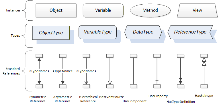
The figures above use a notation that was developed for the OPC UA specification. The notation is summarized in Figure 6 - The OPC UA Information Model Notation. UML representations can also be used; however, the OPC UA notation is less ambiguous because there is a direct mapping from the elements in the figures to Nodes in the AddressSpace of an OPC UA Server.
A complete description of the different types of Nodes and References can be found in OPC 10000-3 and the base structure is described in OPC 10000-5.
OPC UA specification defines a very wide range of functionality in its basic information model. It is not required that all Clients or Servers support all functionality in the OPC UA specifications. OPC UA includes the concept of Profiles, which segment the functionality into testable certifiable units. This allows the definition of functional subsets (that are expected to be implemented) within a companion specification. The Profiles do not restrict functionality, but generate requirements for a minimum set of functionality (see OPC 10000-7)
4.2.3.2 Namespaces
OPC UA allows information from many different sources to be combined into a single coherent AddressSpace. Namespaces are used to make this possible by eliminating naming and id conflicts between information from different sources. Each namespace in OPC UA has a globally unique string called a NamespaceUri which identifies a naming authority and a locally unique integer called a NamespaceIndex, which is an index into the Server's table of NamespaceUris. The NamespaceIndex is unique only within the context of a Session between an OPC UA Client and an OPC UA Server- the NamespaceIndex can change between Sessions and still identify the same item even though the NamespaceUri's location in the table has changed. The Services defined for OPC UA use the NamespaceIndex to specify the Namespace for qualified values.
There are two types of structured values in OPC UA that are qualified with NamespaceIndexes: NodeIds and QualifiedNames. NodeIds are locally unique (and sometimes globally unique) identifiers for Nodes. The same globally unique NodeId can be used as the identifier in a node in many Servers - the node's instance data may vary but its semantic meaning is the same regardless of the Server it appears in. This means Clients can have built-in knowledge of what the data means in these Nodes. OPC UA Information Models generally define globally unique NodeIds for the TypeDefinitions defined by the Information Model.
QualifiedNames are non-localized names qualified with a Namespace. They are used for the BrowseNames of Nodes and allow the same names to be used by different information models without conflict. TypeDefinitions are not allowed to have children with duplicate BrowseNames; however, instances do not have that restriction.
4.2.3.3 Companion Specifications
An OPC UA companion specification for an industry specific vertical market describes an Information Model by defining ObjectTypes, VariableTypes, DataTypes and ReferenceTypes that represent the concepts used in the vertical market, and potentially also well-defined Objects as entry points into the AddressSpace.
5 Use cases
Below is a list of possible use cases a Main Control System may implement fully or partly.
5.1 Device Identification
The use case Device Identification forms the basis for the operation of the Compressed Air System and the operators plant asset management, e.g. Documentation Management, Energy Management and Maintenance Management. For this purpose, the Main Control System shall provide properties for asset identification.
In addition to nameplate information of the CASParts of a Compressed Air System, the operator / integrator requires properties to describe its functional role and installation place.
An operator / integrator should be able to explore the topology of the Compressed Air System. All browsable Components shall be identifiable. This includes non-communicating Components (e.g. Airnet, receiver) as well as assets capable of communication (e.g. compressor).
5.2 Configuration
To improve commissioning respective recommissioning time, the operator / integrator requires support in configuration of the Compressed Air System. Configuration procedures due to replacement, upgrades, etc. should be supported by configuration templates and loading / storing of configuration settings.
5.3 Maintenance Management
For the integration of Compressed Air System Components in an operator's maintenance management application, the Main Control System should provide Compressed Air System specific maintenance properties.
To support asset monitoring, the Main Control System collects and analyzes operational and historical data (e.g. current values, deviations, performance, wear). Since plant operators require a generalized health status of plant assets, the Main Control System shall provide a generalized Compressed Air System health status, based on the NAMUR NE107 categories. Each Component should have a specific set of alarms and conditions assigned to it.
5.4 Energy Management
To integrate a Compressed Air System into the operator´s energy management, the Main Control System should provide energy-related information about the Compressed Air System and its installed CASParts, e.g. power consumption, flow, pressure, efficiency. The provided information is calculated or measured, representing current values, or aggregated in time (weekly, monthly etc.).
The operator should be able to trigger analyses of the Compressed Air Systems energy performance within the Main Control System.
5.5 Operation
An operator / integrator should be able to remotely activate / deactivate (via the Main Control System) the generation of compressed air. It should be possible to select from different operating modes for the Compressed Air System.
For the operators / integrators process monitoring, the Main Control System provides access to standardized state machine information, alarms, warnings, and events. The operator monitors the generation of compressed air by accessing operational data of the Compressed Air System via the Main Control System. The Main Control System shall provide actual values of e.g. pressure, flow, inlet / outlet temperature and power consumption. Actual values of other Compressed Air System CASParts (e.g. sensors) should also be offered. To analyze historical data of Compressed Air System operation within the Main Control System, an operator / integrator may browse archive data in the Main Control System.
6 OPC UA for Compressed Air Systems Information Model
This section introduces the "OPC UA Information Model for Compressed Air Systems - Main Control System".
6.1 Model Overview
Figure 7 shows all ObjectTypes which are defined by this companion specification.
6.1.1 Variables
In most cases Variables have the TypeDefinition DataItemType or one of its subtypes. The optional Property Definition can be added to a Variable that uses such a TypeDefinition. This allows manufacturers to store a specific definition for each Variable.
Variables that use the DataType Boolean are modeled with the TypeDefinition TwoStateDiscreteType. Such Variables have the TrueState and FalseState Properties, which provide human readable and mandatory True and False states in their Value Attribute.
6.1.2 FunctionalGroups
When applicable, the BrowseName of a FunctionalGroup was taken from the recommendation in OPC 10000-100.
A FunctionalGroup that would have no Variables, Objects, or Methods if instantiated shall not be instantiated.
6.2 Compressed air conditions for downstream machines or systems
Machines or systems downstream the Compressed Air System that use the compressed air require data on the condition of the compressed air. These conditions are provided at one or more Customer Distribution Points, depending on the concrete Compressed Air System setup. When modeling a Compressed Air System, the Customer Distribution Points shall be described as such. This can be done using external documentation, but it is recommended to use the Description Attribute of the Node that serves as the output of the Compressed Air System. Common examples of Customer Distribution Points are presented in chapter 6.3 Airnet Examples.
6.3 Airnet Examples
Figure 8 shows a simple model of an Airnet. The inlet of the Airnet is the sum of the inlets of compressors C1 and C2. The outlet of the Airnet is the Customer Distribution Point. All CASParts that are inside the red box are connected to the red Airnet and treated as such. The Main Control System is not a part of the Airnet.
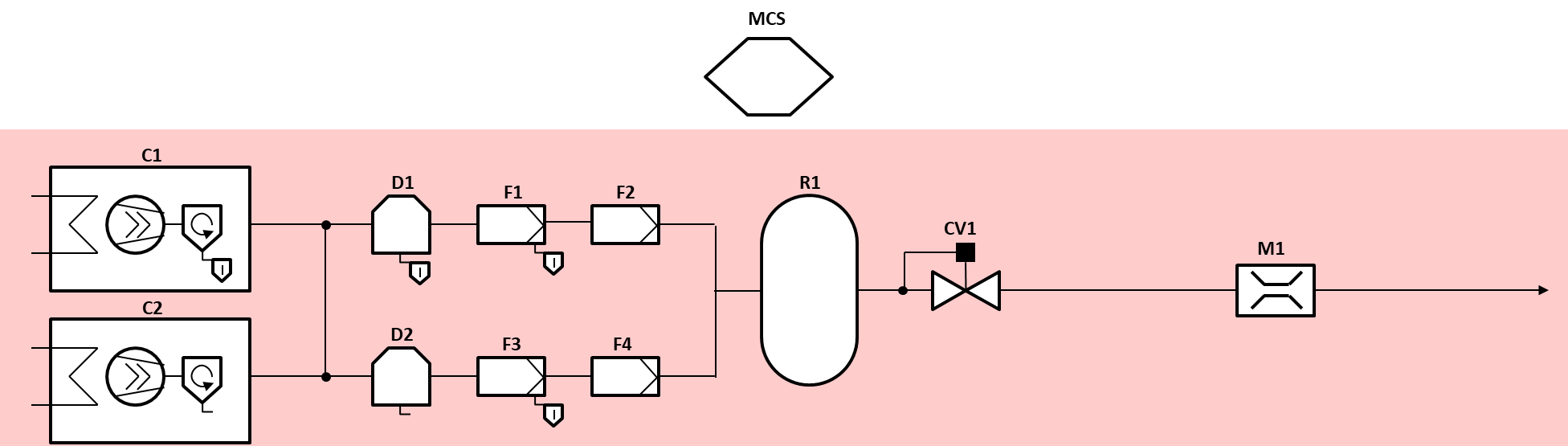
Figure 9 shows a Compressed Air System with two separate Airnets. The inlet of the red (upper) Airnet is the sum of the inlets of compressors C1 and C2. The outlet of the red Airnet is the upper Customer Distribution Point. All CASParts that are inside the red box are connected to the red Airnet and treated as such. The inlet of the blue (lower) Airnet is the sum of the inlets of compressors C3 and C4. The outlet of the blue Airnet is the lower Customer Distribution Point. All CASParts that are inside the blue box are connected to the blue Airnet and treated as such. The Main Control System is not a part of any Airnet.
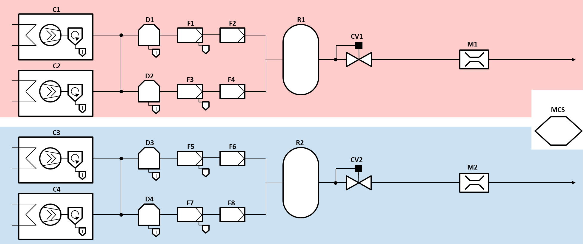
Figure 10 shows an arbitrary example on how two Airnets of the same Compressed Air System can be connected. The inlet of the red (bigger) Airnet is the sum of compressors C1, C2, C3, and C4. The two outlets of the red Airnet are the inlet of the dryer D3 and the lower Customer Distribution Point. All CASParts that are inside the red box are connected to the red Airnet and treated as such. The inlet of the blue (smaller) Airnet is the inlet of the dryer D3. The outlet of the blue Airnet is the upper Customer Distribution Point. All CASParts that are inside the blue box are connected to the blue Airnet and treated as such. The Main Control System is not a part of any Airnet.
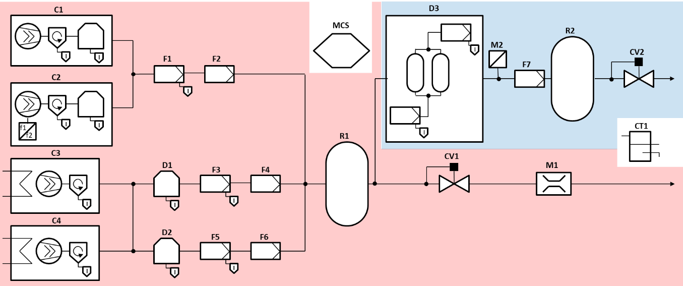
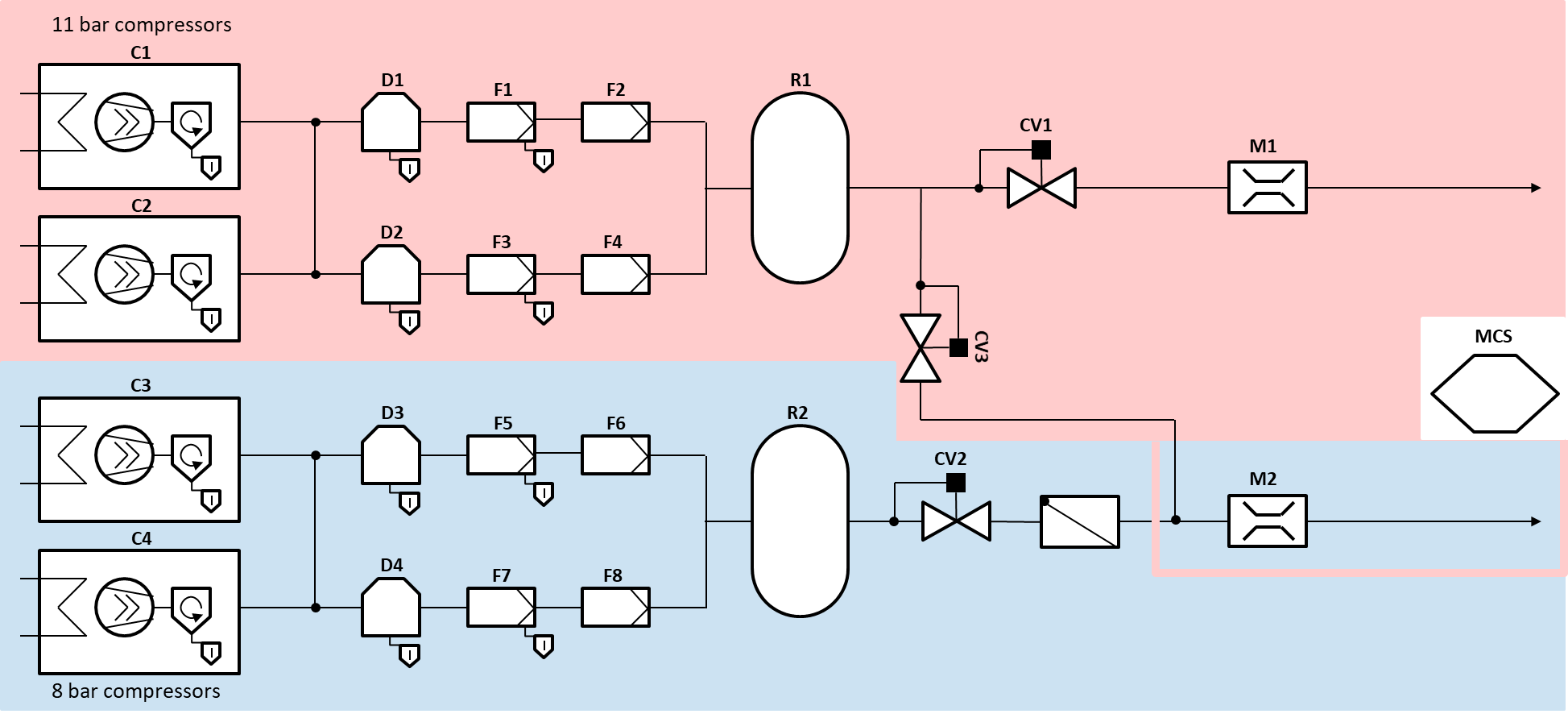
Figure 11 shows two overlapping Airnets of the same Compressed Air System. The inlet of the red (upper) Airnet is the sum of compressors C1 and C2. The two outlets of the red Airnet are the upper and the lower Customer Distribution Points. All CASParts that are inside the red box are connected to the red Airnet and treated as such. The inlet of the blue (lower) Airnet is the sum of compressors C3 and C4. The outlet of the blue Airnet is the lower Customer Distribution Point. All CASParts that are inside the blue box are connected to the blue Airnet and treated as such. The sensor M2 is connected to both Airnets. If Valve CV3 is open, the red Airnet is the active Airnet for M2. If Valve CV3 is closed, the blue Airnet is the active Airnet for M2. Valve CV3 is connected to the red Airnet and not to the blue Airnet, because its purpose is to divert the air from the Airnet with the higher pressure (red, 11 bar) to the lower distribution point and not from the Airnet with the lower pressure (blue, 8 bar) to the upper distribution point. The Main Control System is not a part of any Airnet.
6.4 Identification
The Compressed Air System and Airnets are identified by an Identification Object of the CASIdentificationType which uses the Interface ITagNameplateType and its Properties.
The Main Control System is identified by an Identification Object of the MachineryComponentIdentificationType.
Components are identified by an Identification Object of a subtype of the abstract MachineryItemIdentificationType defined by OPC UA for Machinery (OPC 40001-1). The MachineryItemIdentificationType and its subtypes provide the capabilities to globally uniquely identify the Component and have access to vendor defined information about the Component and manage user-specific information for the identification of the Component. When instantiating a Component, the Identification Object must use an appropriate subtype of the MachineryItemIdentificationType.
For all Components and the Main Control System the DeviceClass Property has its Value Attribute set to a mandatory specific value and its ModellingRule changed to mandatory.
Table 9 shows for each CASPart what value shall be set for different applications like the DeviceClass, BrowseName and GroupName.
| CASPart Name | DeviceClass | BrowseName | GroupName |
| Airnet | - | Airnet | Airnets |
| Charging System | Charging system | ChargingSystem | ChargingSystems |
| Compressor | Compressor | Compressor | Compressors |
| Condensate Drain | Condensate drain | CondensateDrain | CondensateDrains |
| Condensate Separator | Condensate separator | CondensateSeparator | CondensateSeparators |
| Converter | Converter | Converter | Converters |
| Cooling System | Cooling system | CoolingSystem | CoolingSystems |
| Dryer | Dryer | Dryer | Dryers |
| Filter | Filter | Filter | Filters |
| Heat Recovery System | Heat recovery system | HeatRecoverySystem | HeatRecoverySystems |
| Main Control System | MCS | MCS | - |
| Receiver | Receiver | Receiver | Receivers |
| Sensor | Sensor | Sensor | Sensors |
| Valve | Valve | Valve | Valves |
For Components that are not defined by this specification, the DeviceClass Property shall be mandatory as well. The value shall match the name of the new Component.
All properties of the MachineryItemIdentificationType and its subtypes shall be used as intended by the OPC UA for Machinery (OPC 40001-1) specification.
To comply with the Finding all Machines in a Server use case of the OPC UA for Machinery (OPC 40001-1) specification, all Components that are considered as machines by their manufacturer or the customer shall be added to the Machines Object defined in OPC 40001-1 and use the MachineIdentificationType as TypeDefinition for their Identification Object. The Compressed Air System, the Main Control System, and Airnets are not considered as machine in the sense of OPC 40001-1, whereas the following Components may be considered as machines in this context (this list is not exhaustive):
Compressors
Converters
Dryers
6.5 Extending FunctionalGroups
The manufacturer or system integrator of a Compressed Air System may wish to add Variables, Objects, or Methods which are not yet defined by this specification. In such a case the additional Variables, Objects, or Methods shall be added to an appropriate FunctionalGroup of the Component. It is important, that the Variables, Objects, or Methods which are added match the description of the FunctionalGroup they are added to. If there is no FunctionalGroup available the Variables, Objects, and Methods fit in, the manufacturer or system integrator shall create a new Object of the FunctionalGroupType.
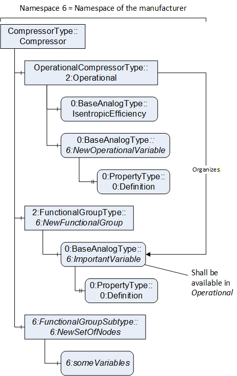
It is also possible to define a subtype of the FunctionalGroupType or one of its subtypes to define a new collection of Variables, Objects, or Methods. When subtyping, the manufacturer or system integrator should keep in mind, that all Variables, Objects, and Methods of the supertype are also available to the new subtype.
In general, no new Variables, Objects, or Methods shall be created that are already available in this specification. If the manufacturer or system integrator wants to add already existing Variables, Objects, or Methods to another FunctionalGroup, the Organizes ReferenceType shall be used.
When creating Variables which are representing Quantities, the BaseAnalogType or one of its subtypes shall be used as TypeDefinition. When creating Variable which are not representing Quantities, the DataItemType or one of its subtypes, other than the BaseAnalogType, shall be used as TypeDefinition. Either way, the Definition Property shall be instantiated to further clarify the intended purpose of the Variable.
Figure 12 illustrates some usage examples on how to extend FunctionalGroups of a compressor.
6.6 Alarms and Conditions
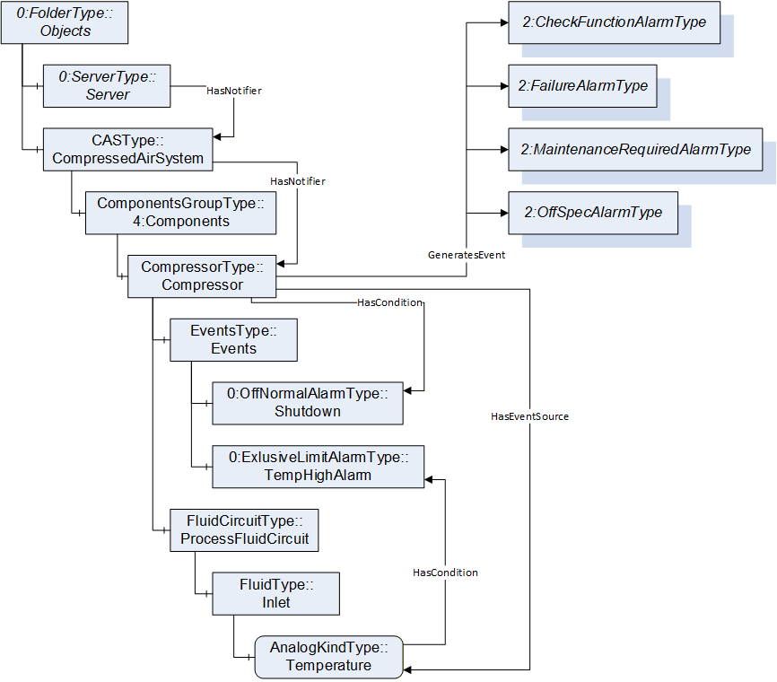
Most CASParts have an optional FunctionalGroup with the default BrowseName Events. This FunctionalGroup provides Objects for common alarms and conditions. In total four conditions are defined: EmergencyStop, Service, Shutdown, and Warning. An OptionalPlaceholder Object <Event> with the TypeDefinition ConditionType is defined. If a manufacturer or system integrator adds additional alarms or conditions to a CASPart, <Event> shall be used. When instantiating <Event>, a concrete subtypes of the abstract ConditionType has to be used as TypeDefinition. To comply with Annex B of OPC 10000-9 - Part 9: Alarms and Conditions, a CASPart must have a HasCondition reference for each instantiated condition using the condition instance as TargetNode and the CASPart as SourceNode.
A manufacturer or system integrator may add custom alarms and conditions targeting specific Variables or Objects of a CASPart. In that case, the Variable or Object is the SourceNode and the condition instance is the TargetNode. If such an alarm or condition is created, the CASPart shall have a HasEventSource reference with the CASPart as SourceNode and the Variable or Object as TargetNode.
| EXAMPLE | A high limit alarm is needed for the Temperature Quantity at the process fluid inlet of a dryer. The Object InletTemperatureHighLimitAlarm using the ExclusiveLimitAlarmType as TypeDefinition is created as child of the Events Object of the dryer instance. A HasCondition reference is created with the Temperature Quantity as SourceNode and the InletTemperatureHighLimitAlarm as TargetNode. The dryer receives a HasEventSource reference to the Temperature Quantity. |
To further comply with Annex B of OPC 10000-9, the Compressed Air System Object shall be the TargetNode of a HasNotifier reference, originating at the OPC UA Server Object. The Compressed Air System Object shall have a HasNotifier reference for each CASPart which instantiates alarms or conditions.
Every instantiated Component shall have at least one appropriate GeneratesEvent reference targeting the NAMUR NE 107 alarms defined in OPC 10000-100. These are CheckFunctionAlarmType, FailureAlarmType, MaintenanceRequiredAlarmType, and OffSpecAlarmType.
6.6.1 Severity
As defined by OPC 10000-5, all events shall have a severity assigned to them. This specification specifies specific severity ranges for some events. If no specific severity or severity range is provided for a defined event or condition, the manufacturer or integrator may choose from the default OPC UA range. The chosen severity when assigning it to a condition or event shall match the following categorization.
| Severity | Lower limit | Upper limit |
| HIGH | 801 | 1000 |
| MEDIUM HIGH | 601 | 800 |
| MEDIUM | 401 | 600 |
| MEDIUM LOW | 201 | 400 |
| LOW | 1 | 200 |
Figure 13 shows examples on how alarms and conditions shall be used in a Compressed Air System.
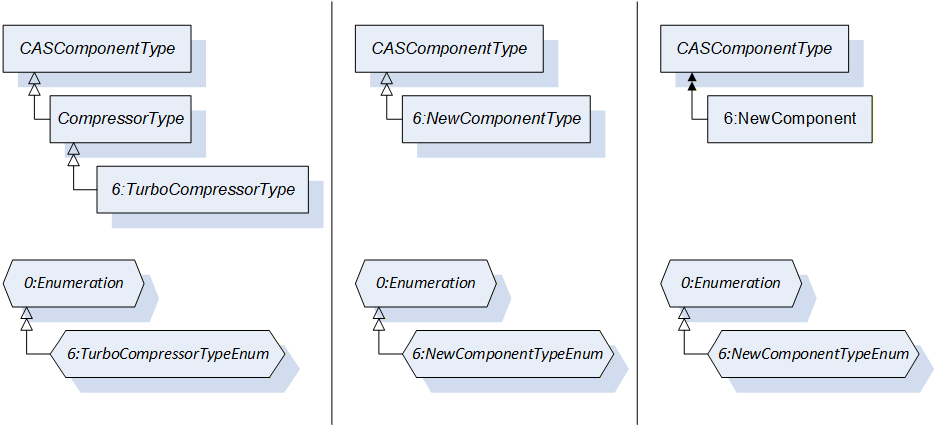
6.7 Adding new Components
All Component ObjectTypes in this specification (clauses 7.8 - 7.19) may be used for subtyping when defining more specific Components. If future companion specifications, a manufacturer, or system integrator wants to define a more specific ObjectType for one of the existing Components, the ObjectType of that Component shall be used as supertype.
If future companion specifications, a manufacturer, or system integrator wants to define a new Component which is not yet provided by this specification and which is no subtype of one of the existing Components, the CASComponentType shall be used as SourceNode for the new ObjectType.
If a manufacturer or system integrator wants to add a Component which is not yet defined by this specification and does not want to create a new ObjectType, the CASComponentType may be used as TypeDefinition for that Component. In such a case, the DataType of Design_ComponentClass must be changed to a concrete DataType.
Either way, in most cases a new Enumeration DataType is required to specify which ComponentClasses are possible for the new Component. The DataType shall be provided by the same party that introduces the new ObjectType.
Figure 14 shows all three approaches described above that a manufacturer or system integrator can take. The left panel shows the introduction of the new compressor type TurboCompressorType in a separate Namespace. The middle panel shows the introduction of a completely new Component type in a separate Namespace. The right panel shows the use of the CASComponentType as TypeDefinition for a new Component in a separate namespace. For each approach, the corresponding new enumeration is shown below.
6.8 Asset Administration Shell for Compressed Air Systems - Main Control System
This document was created in parallel with the asset administration shell for Compressed Air Systems - Main Control System.
The organization Plattform Industrie 4.0 published the specification Details of the Asset Administration Shell to define the concept and metamodel for asset administration shells. The specification describes every aspect of asset administration shells in detail.
Figure 15 shows an abstract example on the composition of an I4.0 component and the content of an asset administration shell.
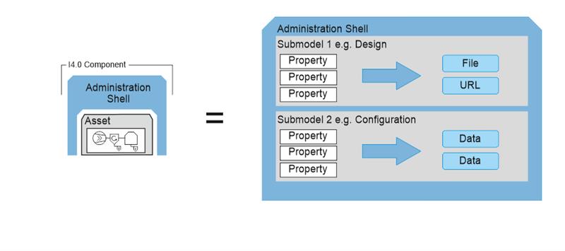
An asset administration shell is defined by the Plattform Industrie 4.0 organization as a "standardized digital representation of the asset, corner stone of the interoperability between the applications managing the manufacturing systems. It identifies the Administration Shell and the assets represented by it, holds digital models of various aspects (submodels) and describes technical functionality exposed by the Administration Shell or respective assets." [1]
The content of an asset administration shell consists of submodels and properties. "Each submodel refers to a well-defined domain or subject matter. Submodels can become standardized and thus become submodels templates." [1]
The content of this OPC UA Companion Specification is linked to the asset administration shell for Compressed Air Systems - Main Control Systems in a specific way. In general, submodels are modeled as subtypes of the FunctionalGroupType of OPC 10000-100.
7 OPC UA ObjectTypes
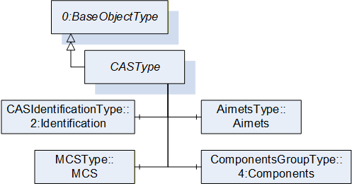
7.1 CASType ObjectType Definition
The CASType is the representation of a Compressed Air System and provides both Objects for Quantities and FunctionalGroups for its Airnets, Components, and the Main Control System. It is illustrated in Figure 16 and formally defined in Table 11.
| Attribute | Value | ||||
| BrowseName | CASType | ||||
| IsAbstract | False | ||||
| References | Node Class | BrowseName | DataType | TypeDefinition | Other |
|---|---|---|---|---|---|
| Subtype of the 0:BaseObjectType defined in OPC 10000-5. | |||||
| 0:HasComponent | Object | Airnets | AirnetsType | O | |
| 0:HasComponent | Object | 4:Components | ComponentsGroupType | O | |
| 0:HasComponent | Object | 2:Identification | CASIdentificationType | O | |
| 0:HasComponent | Object | MCS | MCSType | O | |
The CASType ObjectType is a concrete type and shall be used directly.
The optional Object Airnets organizes all available Airnets.
The optional Object Components organizes all installed Components by their ComponentClasses.
The optional FunctionalGroup Identification provides Properties to identify a Compressed Air System.
The optional Object MCS is the representation of the Main Control System.
The InstanceDeclarations of the CASType have additional Attributes defined in Table 12.
| Source Path | Description Attribute |
| Airnets | All airnets in a compressed air system as browsable objects. |
| 4:Components | All components in a compressed air system as browsable objects. |
| 2:Identification | Identification properties of the compressed air system. |
| MCS | Representation of the MCS in a compressed air system. |
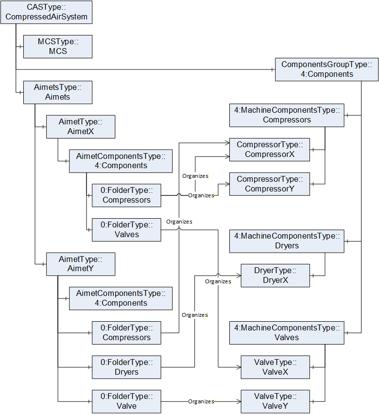
Figure 17 shows a usage example for the instantiation of an arbitrary Compressed Air System that has two Airnets, two compressors, one dryer, and two valves. The Airnets share CompressorX.
For each DeviceClass connected to the Compressed Air System, there is one ComponentGroup Object in the Components Object of the CompressedAirSystem Object. The instances of the compressors, valves, and the dryer are children of these Objects.
Both Airnets have a Components Object, just like the CompressedAirSystem Object. For each DeviceClass connected to an Airnet, there is one ComponentGroup Object in the Components Object of that Airnet. Connected Components are referenced by an Organizes reference.
7.2 AirnetsType ObjectType Definition
The AirnetsType enables the grouping of Airnets. It is formally defined in Table 13.
| Attribute | Value | ||||
| BrowseName | AirnetsType | ||||
| IsAbstract | False | ||||
| References | Node Class | BrowseName | DataType | TypeDefinition | Other |
|---|---|---|---|---|---|
| Subtype of the 4:MachineComponentsType defined in OPC 40001-1, i.e. inheriting the InstanceDeclarations of that Node. | |||||
| The following nodes override nodes added by the 4:MachineComponentsType | |||||
| 0:HasProperty | Variable | 0:DefaultInstanceBrowseName | 0:QualifiedName | 0:PropertyType | |
| 0:HasComponent | Object | 4:<Component> | AirnetType | OP | |
The InstanceDeclarations of the AirnetsType have additional Attributes defined in Table 14.
| Source Path | Value Attribute | Description Attribute |
| 0:DefaultInstanceBrowseName | "Airnets" | The default BrowseName for instances of the type. |
| 4:<Component> | Represents of an airnet. |
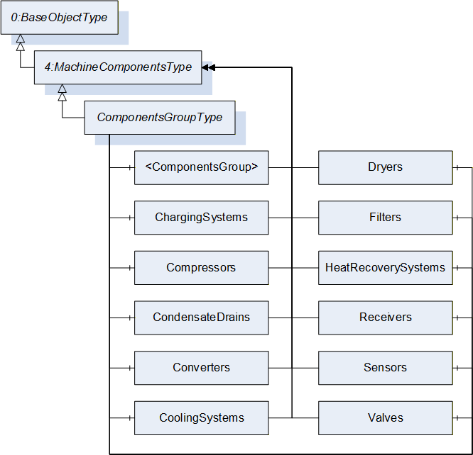
7.3 ComponentsGroupType ObjectType Definition
The ComponentsGroupType enables the grouping of Components and can be nested. It is illustrated in Figure 18 and formally defined in Table 15.
| Attribute | Value | ||||
| BrowseName | ComponentsGroupType | ||||
| IsAbstract | False | ||||
| References | Node Class | BrowseName | DataType | TypeDefinition | Other |
|---|---|---|---|---|---|
| Subtype of the 4:MachineComponentsType defined in OPC 40001-1, i.e. inheriting the InstanceDeclarations of that Node. | |||||
| 0:HasComponent | Object | <ComponentsGroup> | 4:MachineComponentsType | OP | |
| 0:HasComponent | Object | ChargingSystems | 4:MachineComponentsType | O | |
| 0:HasComponent | Object | Compressors | 4:MachineComponentsType | O | |
| 0:HasComponent | Object | CondensateDrains | 4:MachineComponentsType | O | |
| 0:HasComponent | Object | CondensateSeparators | 4:MachineComponentsType | O | |
| 0:HasComponent | Object | Converters | 4:MachineComponentsType | O | |
| 0:HasComponent | Object | CoolingSystems | 4:MachineComponentsType | O | |
| 0:HasComponent | Object | Dryers | 4:MachineComponentsType | O | |
| 0:HasComponent | Object | Filters | 4:MachineComponentsType | O | |
| 0:HasComponent | Object | HeatRecoverySystems | 4:MachineComponentsType | O | |
| 0:HasComponent | Object | Receivers | 4:MachineComponentsType | O | |
| 0:HasComponent | Object | Sensors | 4:MachineComponentsType | O | |
| 0:HasComponent | Object | Valves | 4:MachineComponentsType | O | |
The OptionalPlaceholder Object <ComponentsGroup> allows nesting this ObjectType to further categorize the referenced Components. It also allows adding concrete Component groups not defined by this specification.
The InstanceDeclarations of the ComponentsGroupType have additional Attributes defined in Table 16.
| SourcePath | Description Attribute |
| <ComponentsGroup> | All components of a specific type in a compressed air system as browsable objects. |
| ChargingSystems | Organizes all charging systems connected to the compressed air system. |
| Compressors | Organizes all compressors connected to the compressed air system. |
| CondensateDrains | Organizes all condensate drains connected to the compressed air system. |
| CondensateSeparators | Organizes all condensate separators connected to the compressed air system. |
| Converters | Organizes all converters connected to the compressed air system. |
| CoolingSystems | Organizes all cooling systems connected to the compressed air system. |
| Dryers | Organizes all dryers connected to the compressed air system. |
| Filters | Organizes all filters connected to the compressed air system. |
| HeatRecoverySystems | Organizes all heat recovery systems connected to the compressed air system. |
| Receivers | Organizes all receivers connected to the compressed air system. |
| Sensors | Organizes all sensors connected to the compressed air system. |
| Valves | Organizes all valves connected to the compressed air system. |
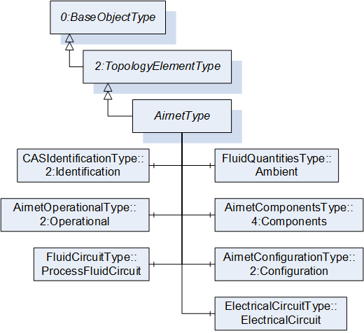
7.4 AirnetType ObjectType Definition
The AirnetType is the representation of an Airnet and provides both Objects for Quantities and FunctionalGroups. It is illustrated in Figure 19 and formally defined in Table 17.
| Attribute | Value | ||||
| BrowseName | AirnetType | ||||
| IsAbstract | False | ||||
| References | Node Class | BrowseName | DataType | TypeDefinition | Other |
|---|---|---|---|---|---|
| Subtype of the 2:TopologyElementType defined in OPC 10000-100, i.e. inheriting the InstanceDeclarations of that Node. | |||||
| 0:HasComponent | Object | Ambient | FluidQuantitiesType | O | |
| 0:HasComponent | Object | 4:Components | AirnetComponentsType | O | |
| 0:HasComponent | Object | 2:Configuration | AirnetConfigurationType | O | |
| 0:HasComponent | Object | ElectricalCircuit | ElectricalCircuitType | O | |
| 0:HasComponent | Object | 2:Operational | AirnetOperationalType | O | |
| 0:HasComponent | Object | ProcessFluidCircuit | FluidCircuitType | O | |
| The following nodes override nodes added by the 2:TopologyElementType | |||||
| 0:HasComponent | Object | 2:Identification | CASIdentificationType | M | |
The optional Object Ambient provides Quantities for the ambient air conditions at an Airnet. Of the optional Variables of the FluidQuantitiesType only AbsolutePressure, DewPoint, RelativeHumidity, and Temperature are available.
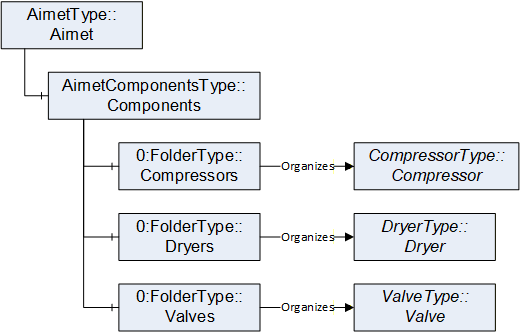
The optional Folder Components provides Folders for organizing Components connected to the Airnet. Usually, the Components are grouped by their DeviceClass and shall be referenced by using the Organizes ReferenceType. The concrete instance of a Component shall be instantiated in the Components Folder of the CASType instance.
Figure 20 shows an example on how to instantiate the FunctionalGroup Components for an Airnet in the AddressSpace of an OPC UA Server.
The optional FunctionalGroup Configuration provides Variables for configuring the behavior of an Airnet.
The optional Object ElectricalCircuit provides Quantities for the electrical ports of an Airnet.
The mandatory FunctionalGroup Identification provides Properties to identify an Airnet.
The optional FunctionalGroup Operational provides Variables for process data used during normal operation of an Airnet, such as measurements, efficiencies, and states.
The optional Object ProcessFluidCircuit provides static design information about the process fluid as well as Quantities for the process fluids inlets, outlets, and delta of an Airnet.
The InstanceDeclarations of the AirnetType have additional Attributes defined in Table 18.
| Source Path | Value Attribute | Description Attribute | ||
| Ambient | Measurements and calculations of ambient air at the topology element. | |||
| Measured or calculated actual absolute pressure of the environment in which the component, piping or system is working. | |||
| Measured or calculated actual dew point of the environment in which the component, piping or system is working. | |||
| Measured or calculated actual relative humidity of the environment in which the component, piping or system is working. | |||
| Measured or calculated actual temperature of the environment in which the component, piping or system is working. | |||
| 4:Components | Organizes components assigned to the airnet. | |||
| 2:Configuration | Configure the behavior of the topology element. | |||
| ElectricalCircuit | Measurements and calculations of the electrical ports and delta of the topology element. | |||
| 2:Identification | Identification properties of the topology element. | |||
| 2:Operational | Data for normal operation of the topology element. | |||
| ProcessFluidCircuit | Measurements and calculations of the process fluid ports and delta of the topology element. | |||
| Enumeration of possible process fluid types. |
7.5 AirnetComponentsType ObjectType Definition
The AirnetComponentsType enables the grouping of Airnets. It is formally defined in Table 19.
| Attribute | Value | ||||
| BrowseName | AirnetComponentsType | ||||
| IsAbstract | False | ||||
| References | Node Class | BrowseName | DataType | TypeDefinition | Other |
|---|---|---|---|---|---|
| Subtype of the 0:FolderType defined in OPC 10000-5. | |||||
| 0:HasComponent | Object | <ComponentsGroup> | 0:FolderType | OP | |
| 0:HasComponent | Object | ChargingSystems | 0:FolderType | O | |
| 0:HasComponent | Object | Compressors | 0:FolderType | O | |
| 0:HasComponent | Object | CondensateDrains | 0:FolderType | O | |
| 0:HasComponent | Object | CondensateSeparators | 0:FolderType | O | |
| 0:HasComponent | Object | Converters | 0:FolderType | O | |
| 0:HasComponent | Object | CoolingSystems | 0:FolderType | O | |
| 0:HasComponent | Object | Dryers | 0:FolderType | O | |
| 0:HasComponent | Object | Filters | 0:FolderType | O | |
| 0:HasComponent | Object | HeatRecoverySystems | 0:FolderType | O | |
| 0:HasComponent | Object | Receivers | 0:FolderType | O | |
| 0:HasComponent | Object | Sensors | 0:FolderType | O | |
| 0:HasComponent | Object | Valves | 0:FolderType | O | |
The OptionalPlaceholder Object <ComponentsGroup> allows adding concrete Component groups not defined by this specification.
The InstanceDeclarations of the AirnetComponentsType have additional Attributes defined in Table 20.
| Source Path | Description Attribute |
| <ComponentsGroup> | All components of a specific type connected to the airnet. |
| ChargingSystems | Organizes all charging systems connected to the airnet. |
| Compressors | Organizes all compressors connected to the airnet. |
| CondensateDrains | Organizes all condensate drains connected to the airnet. |
| CondensateSeparators | Organizes all condensate separators connected to the airnet. |
| Converters | Organizes all converters connected to the airnet. |
| CoolingSystems | Organizes all cooling systems connected to the airnet. |
| Dryers | Organizes all dryers connected to the airnet. |
| Filters | Organizes all filters connected to the airnet. |
| HeatRecoverySystems | Organizes all heat recovery systems connected to the airnet. |
| Receivers | Organizes all receivers connected to the airnet. |
| Sensors | Organizes all sensors connected to the airnet. |
| Valves | Organizes all valves connected to the airnet. |
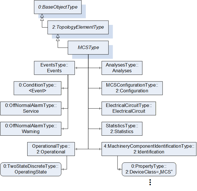
7.6 MCSType ObjectType Definition
The MCSType is the representation of a Main Control System and provides both Objects for Quantities and FunctionalGroups. It is illustrated in Figure 21 and formally defined in Table 21.
| Attribute | Value | ||||
| BrowseName | MCSType | ||||
| IsAbstract | False | ||||
| References | Node Class | BrowseName | DataType | TypeDefinition | Other |
|---|---|---|---|---|---|
| Subtype of the 2:TopologyElementType defined in OPC 10000-100, i.e. inheriting the InstanceDeclarations of that Node. | |||||
| 0:HasComponent | Object | Analyses | AnalysesType | O | |
| 0:HasComponent | Object | 2:Configuration | MCSConfigurationType | O | |
| 0:HasComponent | Object | ElectricalCircuit | ElectricalCircuitType | O | |
| 0:HasComponent | Object | Events | EventsType | O | |
| 0:HasComponent | Object | 2:Operational | OperationalType | O | |
| 0:HasComponent | Object | 2:Statistics | StatisticsType | O | |
| The following nodes override nodes added by the 2:TopologyElementType | |||||
| 0:HasComponent | Object | 2:Identification | 4:MachineryComponentIdentificationType | M | |
The optional FunctionalGroup Analyses provides Objects and Methods for analyses that can be invoked on the Main Control System.
The optional FunctionalGroup Configuration provides Objects and Methods for configuring the behavior of the Main Control System.
The optional Object ElectricalCircuit provides Quantities for the electrical input of the Main Control System.
The optional FunctionalGroup Events provides Objects for alarms and conditions of the Main Control System. Of the available optional Objects in the EventsType, only Service and Warning are instantiated.
The mandatory FunctionalGroup Identification provides Properties to identify the Main Control System. The optional Variable DeviceClass has its ModellingRule changed to mandatory and its Value Attribute set to a specific value.
The optional FunctionalGroup Operational provides Variables for process data used during normal operation of the Main Control System, such as measurements, efficiencies, and states.
The optional FunctionalGroup Statistics provides Variables for statistical applications of the Main Control System, such as counters.
The InstanceDeclarations of the MCSType have additional Attributes defined in Table 22.
| Source Path | Value Attribute | Description Attribute | ||
| Analyses | Invokable analyses for the topology element. | |||
| 2:Configuration | Configure the behavior of the topology element. | |||
| ElectricalCircuit | Measurements and calculations of the electrical ports and delta of the topology element. | |||
| Events | Alarms and conditions of the topology element. | |||
| 2:Identification | Identification properties of the topology element. | |||
| "MCS" | Domain or for what purpose this item is used. | ||
| 2:Operational | Data for normal operation of the topology element. | |||
| 2:Statistics | Data for statistics applications for the topology element. |
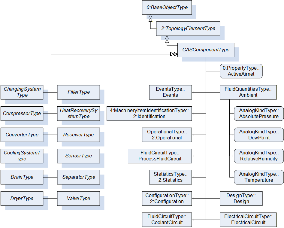
7.7 CASComponentType ObjectType Definition
The CASComponentType is the representation of a Component and provides both Objects for Quantities and FunctionalGroups. It is illustrated in Figure 22 and formally defined in Table 23.
| Attribute | Value | ||||
| BrowseName | CASComponentType | ||||
| IsAbstract | False | ||||
| References | Node Class | BrowseName | DataType | TypeDefinition | Other |
|---|---|---|---|---|---|
| Subtype of the 2:TopologyElementType defined in OPC 10000-100, i.e. inheriting the InstanceDeclarations of that Node. | |||||
| 0:HasSubtype | ObjectType | ChargingSystemType | Defined in 7.8 | ||
| 0:HasSubtype | ObjectType | CompressorType | Defined in 7.9 | ||
| 0:HasSubtype | ObjectType | ConverterType | Defined in 7.10 | ||
| 0:HasSubtype | ObjectType | CoolingSystemType | Defined in 7.11 | ||
| 0:HasSubtype | ObjectType | DrainType | Defined in 7.12 | ||
| 0:HasSubtype | ObjectType | DryerType | Defined in 7.13 | ||
| 0:HasSubtype | ObjectType | FilterType | Defined in 7.14 | ||
| 0:HasSubtype | ObjectType | HeatRecoverySystemType | Defined in 7.15 | ||
| 0:HasSubtype | ObjectType | ReceiverType | Defined in 7.16 | ||
| 0:HasSubtype | ObjectType | SensorType | Defined in 7.17 | ||
| 0:HasSubtype | ObjectType | SeparatorType | Defined in 7.18 | ||
| 0:HasSubtype | ObjectType | ValveType | Defined in 7.19 | ||
| 0:HasProperty | Variable | ActiveAirnet | 0:NodeId | 0:PropertyType | O, RW |
| 0:HasComponent | Object | Ambient | FluidQuantitiesType | O | |
| 0:HasComponent | Object | 2:Configuration | ConfigurationType | O | |
| 0:HasComponent | Object | CoolantCircuit | FluidCircuitType | O | |
| 0:HasComponent | Object | Design | DesignType | O | |
| 0:HasComponent | Object | ElectricalCircuit | ElectricalCircuitType | O | |
| 0:HasComponent | Object | Events | EventsType | O | |
| 0:HasComponent | Object | 2:Operational | OperationalType | O | |
| 0:HasComponent | Object | ProcessFluidCircuit | FluidCircuitType | O | |
| 0:HasComponent | Object | 2:Statistics | StatisticsType | O | |
| The following nodes override nodes added by the 2:TopologyElementType | |||||
| 0:HasComponent | Object | 2:Identification | 4:MachineryItemIdentificationType | M | |
The optional Property ActiveAirnet indicates which Airnet is currently using this Component. The Property shall only be instantiated if the Component is connected to more than one Airnet.
The optional Object Ambient provides Quantities for the ambient air conditions at a Component. Of the optional Variables of the FluidQuantitiesType only AbsolutePressure, DewPoint, RelativeHumidity, and Temperature are instantiated.
The optional FunctionalGroup Configuration provides a framework for properties aimed at configuring the behavior of a Component in a Compressed Air System.
The optional Object CoolantCircuit provides design information about the coolant used as well as measurements and calculations for the inlet, outlet, and delta of coolant conditions on a Component in a Compressed Air System.
The optional FunctionalGroup Design provides static design properties of a Component in a Compressed Air System and acts as a framework for design properties in general.
The optional Object ElectricalCircuit provides measurements and calculations for the electrical input, output, and delta of a Component in a Compressed Air System.
The optional FunctionalGroup Events provides instances of common conditions of a Component in a Compressed Air System. It also provides a framework for instantiating conditions in the AddressSpace. If the server is not capable of instantiating ConditionTypes, this group shall not be instantiated.
The mandatory FunctionalGroup Identification provides capabilities to identify a Component in a Compressed Air System.
The optional FunctionalGroup Operational provides properties for process data used during normal operation of a Component, such as measurements, efficiencies, and states.
The optional Object ProcessFluidCircuit provides design information about the process fluid processed as well as measurements and calculations for the inlet, outlet, and delta of process fluid conditions on a Component in a Compressed Air System.
The optional FunctionalGroup Statistics provides properties for statistics applications of a Component in a Compressed Air System, like counters.
The optional Property DeviceClass of the MachineryItemIdentificationType is overridden. The ModellingRule is changed to mandatory and the Value Attribute is set to a specific value for each DeviceClass. When a concrete subtype of the MachineryItemIdentificationType is selected for a subtype or an instance of the CASComponentType, the ModellingRule of the DeviceClass Property shall remain as mandatory.
When instantiating the CASComponentType or one of its subtypes, the instantiated Object shall have at least one appropriate GeneratesEvent reference targeting the subtypes of the DeviceHealthDiagnosticAlarmType.
The components of the CASComponentType have additional subcomponents defined in Table 24.
| Source Path | References | NodeClass | BrowseName | DataType | TypeDefinition | Other |
| The following nodes override nodes added by the 4:MachineryItemIdentificationType | ||||||
| 2:Identification | 0:HasProperty | Variable | 2:DeviceClass | 0:String | 0:PropertyType | M, RO |
| The following nodes override nodes added by the OperationalType | ||||||
| 2:Operational | 0:HasComponent | Variable | HealthState | HealthStateEnum | 0:DataItemType | O, RO |
| 2:Operational | 0:HasComponent | Variable | IntegratedState | IntegratedStateEnum | 0:DataItemType | O, RO |
| 2:Operational | 0:HasComponent | Variable | OperatingState | OperatingStateEnum | 0:DataItemType | O, RO |
The InstanceDeclarations of the CASComponentType have additional Attributes defined in Table 25.
| Source Path | Description Attribute | ||
| ActiveAirnet | Indicates which airnet is currently using this component. | ||
| Ambient | Measurements and calculations of ambient air at the topology element. | ||
| Measured or calculated actual absolute pressure of the environment in which the component, piping or system is working. | ||
| Measured or calculated actual dew point of the environment in which the component, piping or system is working. | ||
| Measured or calculated actual relative humidity of the environment in which the component, piping or system is working. | ||
| Measured or calculated actual temperature of the environment in which the component, piping or system is working. | ||
| 2:Configuration | Configure the behavior of the topology element. | ||
| CoolantCircuit | Measurements and calculations of the coolant ports and delta of the topology element. | ||
| Enumeration of possible coolant types. | ||
| Design | Static design properties of the topology element. | ||
| ElectricalCircuit | Measurements and calculations of the electrical ports and delta of the topology element. | ||
| Events | Alarms and conditions of the topology element. | ||
| 2:Identification | Identification properties of the topology element. | ||
| Domain or for what purpose this item is used. | ||
| 2:Operational | Data for normal operation of the topology element. | ||
| Actual health state of the component. | ||
| Actual integrated state of the component. | ||
| Actual operating state of the component. | ||
| ProcessFluidCircuit | Measurements and calculations of the process fluid ports and delta of the topology element. | ||
| Enumeration of possible process fluid types. | ||
| 2:Statistics | Data for statistics applications for the topology element. |
7.8 ChargingSystemType ObjectType Definition
The ChargingSystemType shall be used as TypeDefinition for concrete charging system Objects and shall be used as supertype for concrete charging system ObjectTypes. A charging system is a pressure maintenance system that maintains a minimum pressure in a Component. It is formally defined in Table 26.
| Attribute | Value | ||||
| BrowseName | ChargingSystemType | ||||
| IsAbstract | False | ||||
| References | Node Class | BrowseName | DataType | TypeDefinition | Other |
|---|---|---|---|---|---|
| Subtype of the CASComponentType defined in 7.7, i.e. inheriting the InstanceDeclarations of that Node. | |||||
When instantiating this ObjectType the Identification Object shall use one of the concrete subtypes of the MachineryItemIdentificationType, either MachineIdentificationType or MachineryComponentIdentificationType, depending on the concrete usage of this Component. The ModellingRule of the Property DeviceClass remains as mandatory and its Value Attribute shall match the value stated in Table 9.
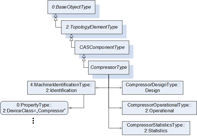
7.9 CompressorType ObjectType Definition
The CompressorType is the representation of a compressor and extends its supertype by specific Nodes. According to EN 1012-1/ISO/DIS 18623-1, a compressor compresses a gas or vapor media to a pressure higher than that at the inlet. It is illustrated in Figure 23 and formally defined in Table 27.
| Attribute | Value | ||||
| BrowseName | CompressorType | ||||
| IsAbstract | False | ||||
| References | Node Class | BrowseName | DataType | TypeDefinition | Other |
|---|---|---|---|---|---|
| Subtype of the CASComponentType defined in 7.7, i.e. inheriting the InstanceDeclarations of that Node. | |||||
| The following nodes override nodes added by the CASComponentType | |||||
| 0:HasComponent | Object | Design | CompressorDesignType | O | |
| 0:HasComponent | Object | 2:Identification | 4:MachineIdentificationType | M | |
| 0:HasComponent | Object | 2:Operational | CompressorOperationalType | O | |
| 0:HasComponent | Object | 2:Statistics | CompressorStatisticsType | O | |
The InstanceDeclarations of the CompressorType have additional Attributes defined in Table 28.
| Source Path | Value Attribute | Description Attribute | ||
| "Compressor" | Domain or for what purpose this item is used. |
7.10 ConverterType ObjectType Definition
The ConverterType is the representation of a converter and extends its supertype by specific Nodes. A converter eliminates hydrocarbons from a compressed air flow by catalytic reaction with oxygen into H2O and CO2. It is illustrated in Figure 24 and formally defined in Table 29.

| Attribute | Value | ||||
| BrowseName | ConverterType | ||||
| IsAbstract | False | ||||
| References | Node Class | BrowseName | DataType | TypeDefinition | Other |
|---|---|---|---|---|---|
| Subtype of the CASComponentType defined in 7.7, i.e. inheriting the InstanceDeclarations of that Node. | |||||
| The following nodes override nodes added by the CASComponentType | |||||
| 0:HasComponent | Object | Design | ConverterDesignType | O | |
| 0:HasComponent | Object | 2:Operational | ConverterOperationalType | O | |
When instantiating this ObjectType the Identification Object shall use one of the concrete subtypes of the MachineryItemIdentificationType, either MachineIdentificationType or MachineryComponentIdentificationType, depending on the concrete usage of this Component. The ModellingRule of the Property DeviceClass remains as mandatory and its Value Attribute shall match the value stated in Table 9.
7.11 CoolingSystemType ObjectType Definition
The CoolingSystemType shall be used as TypeDefinition for concrete cooling system Objects and shall be used as supertype for concrete cooling system ObjectTypes. A cooling system removes heat from a Component or the air flow in a Compressed Air System. It is formally defined in Table 30.
| Attribute | Value | ||||
| BrowseName | CoolingSystemType | ||||
| IsAbstract | False | ||||
| References | Node Class | BrowseName | DataType | TypeDefinition | Other |
|---|---|---|---|---|---|
| Subtype of the CASComponentType defined in 7.7, i.e. inheriting the InstanceDeclarations of that Node. | |||||
When instantiating this ObjectType the Identification Object shall use one of the concrete subtypes of the MachineryItemIdentificationType, either MachineIdentificationType or MachineryComponentIdentificationType, depending on the concrete usage of this Component. The ModellingRule of the Property DeviceClass remains as mandatory and its Value Attribute shall match the value stated in Table 9.
7.12 DrainType ObjectType Definition
The DrainType is the representation of a condensate drain and extends its supertype by specific Nodes. Derived from EN 1012-1/ISO/DIS 18623-1, a condensate drain minimizes the accumulation of stagnant liquid in a Compressed Air System. It is illustrated in Figure 25 and formally defined in Table 31.
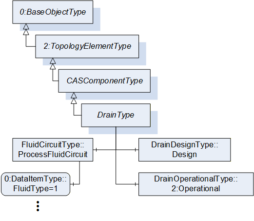
| Attribute | Value | ||||
| BrowseName | DrainType | ||||
| IsAbstract | False | ||||
| References | Node Class | BrowseName | DataType | TypeDefinition | Other |
|---|---|---|---|---|---|
| Subtype of the CASComponentType defined in 7.7, i.e. inheriting the InstanceDeclarations of that Node. | |||||
| The following nodes override nodes added by the CASComponentType | |||||
| 0:HasComponent | Object | Design | DrainDesignType | O | |
| 0:HasComponent | Object | 2:Operational | DrainOperationalType | O | |
| 0:HasComponent | Object | ProcessFluidCircuit | FluidCircuitType | O | |
When instantiating this ObjectType the Identification Object shall use one of the concrete subtypes of the MachineryItemIdentificationType, either MachineIdentificationType or MachineryComponentIdentificationType, depending on the concrete usage of this Component. The ModellingRule of the Property DeviceClass remains as mandatory and its Value Attribute shall match the value stated in Table 9.
The InstanceDeclarations of the DrainType have additional Attributes defined in Table 32.
| Source Path | Value Attribute | Description Attribute | ||
| 1 | Enumeration of possible process fluid types. |
7.13 DryerType ObjectType Definition
The DryerType is the representation of a dryer and extends its supertype by specific Nodes. According to ISO 5598, a dryer reduces the moisture vapor content of the compressed air. It is illustrated in Figure 26 and formally defined in Table 33.
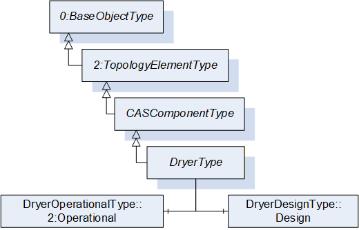
| Attribute | Value | ||||
| BrowseName | DryerType | ||||
| IsAbstract | False | ||||
| References | Node Class | BrowseName | DataType | TypeDefinition | Other |
|---|---|---|---|---|---|
| Subtype of the CASComponentType defined in 7.7, i.e. inheriting the InstanceDeclarations of that Node. | |||||
| The following nodes override nodes added by the CASComponentType | |||||
| 0:HasComponent | Object | Design | DryerDesignType | O | |
| 0:HasComponent | Object | 2:Operational | DryerOperationalType | O | |
When instantiating this ObjectType the Identification Object shall use one of the concrete subtypes of the MachineryItemIdentificationType, either MachineIdentificationType or MachineryComponentIdentificationType, depending on the concrete usage of this Component. The ModellingRule of the Property DeviceClass remains as mandatory and its Value Attribute shall match the value stated in Table 9.
7.14 FilterType ObjectType Definition
The FilterType is the representation of a filter and extends its supertype by specific Nodes. According to ISO 12500-1, a filter separates or removes contamination from a compressed air or gas stream. It is illustrated in Figure 27 and formally defined in Table 34.
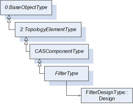
| Attribute | Value | ||||
| BrowseName | FilterType | ||||
| IsAbstract | False | ||||
| References | Node Class | BrowseName | DataType | TypeDefinition | Other |
|---|---|---|---|---|---|
| Subtype of the CASComponentType defined in 7.7, i.e. inheriting the InstanceDeclarations of that Node. | |||||
| The following nodes are override from CASComponentType | |||||
| 0:HasComponent | Object | Design | FilterDesignType | O | |
When instantiating this ObjectType the Identification Object shall use one of the concrete subtypes of the MachineryItemIdentificationType, either MachineIdentificationType or MachineryComponentIdentificationType, depending on the concrete usage of this Component. The ModellingRule of the Property DeviceClass remains as mandatory and its Value Attribute shall match the value stated in Table 9.
7.15 HeatRecoverySystemType ObjectType Definition
The HeatRecoverySystemType shall be used as TypeDefinition for concrete heat recovery system Objects and shall be used as supertype for concrete heat recovery system ObjectTypes. Derived from VDMA EcoLexicon, a heat recovery system removes heat from a compressor for further utilization, such as room heating. It is formally defined in Table 35.
| Attribute | Value | ||||
| BrowseName | HeatRecoverySystemType | ||||
| IsAbstract | False | ||||
| References | Node Class | BrowseName | DataType | TypeDefinition | Other |
|---|---|---|---|---|---|
| Subtype of the CASComponentType defined in 7.7, i.e. inheriting the InstanceDeclarations of that Node. | |||||
When instantiating this ObjectType the Identification Object shall use one of the concrete subtypes of the MachineryItemIdentificationType, either MachineIdentificationType or MachineryComponentIdentificationType, depending on the concrete usage of this Component. The ModellingRule of the Property DeviceClass remains as mandatory and its Value Attribute shall match the value stated in Table 9.
7.16 ReceiverType ObjectType Definition
The ReceiverType is the representation of a receiver and extends its supertype by specific Nodes. According to DIN EN 13445-1, a receiver is a pressure vessel with a housing and its direct attachments up to the coupling point connecting it to other equipment, designed and built to contain fluids under pressure. It is illustrated in Figure 28 and formally defined in Table 36.
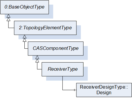
| Attribute | Value | ||||
| BrowseName | ReceiverType | ||||
| IsAbstract | False | ||||
| References | Node Class | BrowseName | DataType | TypeDefinition | Other |
|---|---|---|---|---|---|
| Subtype of the CASComponentType defined in 7.7, i.e. inheriting the InstanceDeclarations of that Node. | |||||
| The following nodes override nodes added by the CASComponentType | |||||
| 0:HasComponent | Object | Design | ReceiverDesignType | O | |
When instantiating this ObjectType the Identification Object shall use one of the concrete subtypes of the MachineryItemIdentificationType, either MachineIdentificationType or MachineryComponentIdentificationType, depending on the concrete usage of this Component. The ModellingRule of the Property DeviceClass remains as mandatory and its Value Attribute shall match the value stated in Table 9.
7.17 SensorType ObjectType Definition
The SensorType is the representation of a sensor and extends its supertype by specific Nodes. According to ISO 5598, a sensor is a device that detects a condition in a system or component and produces an output signal. It is illustrated in Figure 29 and formally defined in Table 37.
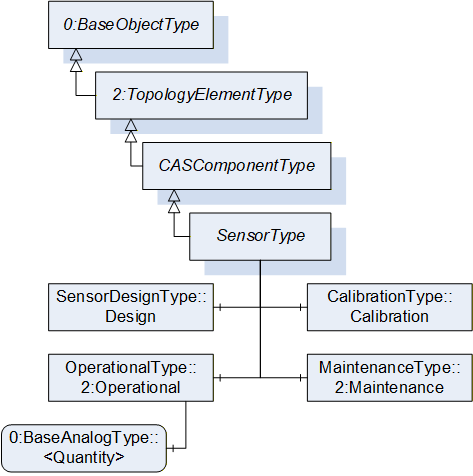
| Attribute | Value | ||||
| BrowseName | SensorType | ||||
| IsAbstract | False | ||||
| References | Node Class | BrowseName | DataType | TypeDefinition | Other |
|---|---|---|---|---|---|
| Subtype of the CASComponentType defined in 7.7, i.e. inheriting the InstanceDeclarations of that Node. | |||||
| 0:HasComponent | Object | Calibration | CalibrationType | O | |
| 0:HasComponent | Object | 2:Maintenance | MaintenanceType | O | |
| The following nodes override nodes added by the CASComponentType | |||||
| 0:HasComponent | Object | Design | SensorDesignType | O | |
| 0:HasComponent | Object | 2:Operational | OperationalType | O | |
The optional FunctionalGroup Calibration provides Variables useful for the documentation of the sensor calibration.
The optional FunctionalGroup Maintenance provides Variables useful for the documentation of the sensor maintenance.
The optional FunctionalGroup Operational is extended with an OptionalPlaceholder <Quantity> for the sensor Quantity. When instantiating a SensorType, the DataType of the <Quantity> instance must be changed to a concrete DataType. The TypeDefinition may be chosen from BaseAnalogType and its subtypes.
When instantiating this ObjectType the Identification Object shall use one of the concrete subtypes of the MachineryItemIdentificationType, either MachineIdentificationType or MachineryComponentIdentificationType, depending on the concrete usage of this Component. The ModellingRule of the Property DeviceClass remains as mandatory and its Value Attribute shall match the value stated in Table 9.
The components of the SensorType have additional subcomponents defined in Table 38.
| Source Path | References | NodeClass | BrowseName | DataType | TypeDefinition | Other |
| 2:Operational | 0:HasComponent | Variable | <Quantity> | 0:Number | 0:BaseAnalogType | OP, RO |
The InstanceDeclarations of the SensorType have additional Attributes defined in Table 39.
| Source Path | Value Attribute | Description Attribute | ||
| Calibration | Dates important for the calibration of a sensor. | |||
| 2:Maintenance | Servicing intervals for the sensor. | |||
| Measurement or calculation performed by a sensor. |
7.18 SeparatorType ObjectType Definition
The SeparatorType is the representation of a condensate separator and extends its supertype by specific Nodes. According to ISO 5598, a condensate separator retains contaminants by means other than a filter element, e.g. specific gravity, magnetism, chemical properties, density. It is illustrated in Figure 30 and formally defined in Table 40.
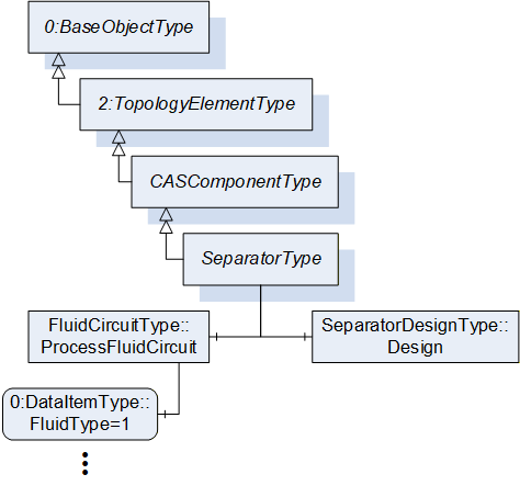
| Attribute | Value | ||||
| BrowseName | SeparatorType | ||||
| IsAbstract | False | ||||
| References | Node Class | BrowseName | DataType | TypeDefinition | Other |
|---|---|---|---|---|---|
| Subtype of the CASComponentType defined in 7.7, i.e. inheriting the InstanceDeclarations of that Node. | |||||
| The following nodes override nodes added by the CASComponentType | |||||
| 0:HasComponent | Object | Design | SeparatorDesignType | O | |
| 0:HasComponent | Object | ProcessFluidCircuit | FluidCircuitType | O | |
When instantiating this ObjectType the Identification Object shall use one of the concrete subtypes of the MachineryItemIdentificationType, either MachineIdentificationType or MachineryComponentIdentificationType, depending on the concrete usage of this Component. The ModellingRule of the Property DeviceClass remains as mandatory and its Value Attribute shall match the value stated in Table 9.
The InstanceDeclarations of the SeparatorType have additional Attributes defined in Table 41.
| Source Path | Value Attribute | Description Attribute | ||
| 1 | Enumeration of possible process fluid types. |
7.19 ValveType ObjectType Definition
The ValveType is the representation of a valve and extends its supertype by specific Nodes. Valves control the flow and passage of fluids through a piping network. It is illustrated in Figure 31 and formally defined in Table 42.
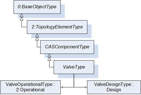
| Attribute | Value | ||||
| BrowseName | ValveType | ||||
| IsAbstract | False | ||||
| References | Node Class | BrowseName | DataType | TypeDefinition | Other |
|---|---|---|---|---|---|
| Subtype of the CASComponentType defined in 7.7, i.e. inheriting the InstanceDeclarations of that Node. | |||||
| The following nodes override nodes added by the CASComponentType | |||||
| 0:HasComponent | Object | Design | ValveDesignType | O | |
| 0:HasComponent | Object | 2:Operational | ValveOperationalType | O | |
When instantiating this ObjectType the Identification Object shall use one of the concrete subtypes of the MachineryItemIdentificationType, either MachineIdentificationType or MachineryComponentIdentificationType, depending on the concrete usage of this Component. The ModellingRule of the Property DeviceClass remains as mandatory and its Value Attribute shall match the value stated in Table 9.
7.20 ElectricalQuantitiesType ObjectType Definition
The ElectricalQuantitiesType provides Variables for Quantities of electrical properties and is formally defined in Table 43.
| Attribute | Value | ||||
| BrowseName | ElectricalQuantitiesType | ||||
| IsAbstract | False | ||||
| References | Node Class | BrowseName | DataType | TypeDefinition | Other |
|---|---|---|---|---|---|
| Subtype of the 0:BaseObjectType defined in OPC 10000-5. | |||||
| 0:HasInterface | ObjectType | 3:IStatisticsType | Defined in OPC 10000-200 | ||
| 0:HasComponent | Variable | ApparentPower | 0:Double | 0:BaseAnalogType | O, RO |
| 0:HasComponent | Variable | Current | 0:Double | 0:BaseAnalogType | O, RO |
| 0:HasComponent | Variable | Energy | 0:Double | 0:BaseAnalogType | O, RO |
| 0:HasComponent | Variable | Power | 0:Double | 0:BaseAnalogType | O, RO |
| 0:HasComponent | Variable | Voltage | 0:Double | 0:BaseAnalogType | O, RO |
| Applied from 3:IStatisticsType | |||||
| 0:HasComponent | Method | 3:ResetStatistics | See 3:IStatisticsType | O | |
| 0:HasProperty | Variable | 3:StartTime | 0:DateTime | 0:PropertyType | O, RO |
The Variable StartTime and the Method ResetStatistics are defined by the IStatisticsType and shall be used as defined by the Interface.
The InstanceDeclarations of the ElectricalQuantitiesType have additional Attributes defined in Table 44.
| Source Path | Value Attribute | Description Attribute |
| ApparentPower | Measured or calculated actual apparent power consumption including all auxiliary components (e.g. on a compressor including fans, controller, …). | |
| Current | Measured or calculated actual root mean square of the electric power consumption including all auxiliary components (e.g. on a compressor including fans, controller, …). | |
| Energy | Measured or calculated accumulated electrical energy consumed including all auxiliary components (e.g. on a compressor including fans, controller, …) since last reset. | |
| Power | Measured or calculated actual electric real power consumption including all auxiliary components (e.g. on a compressor including fans, controller, …). | |
| Voltage | Measured or calculated actual root mean square of the voltage applied including all auxiliary components (e.g. on a compressor including fans, controller, …). |
7.21 ElectricalCircuitType ObjectType Definition
The ElectricalCircuitType provides Objects that are used to group common Quantities of electrical properties and is formally defined in Table 51.
| Attribute | Value | ||||
| BrowseName | ElectricalCircuitType | ||||
| IsAbstract | False | ||||
| References | Node Class | BrowseName | DataType | TypeDefinition | Other |
|---|---|---|---|---|---|
| Subtype of the 0:BaseObjectType defined in OPC 10000-5. | |||||
| 0:HasComponent | Object | <Other> | ElectricalQuantitiesType | OP | |
| 0:HasComponent | Object | Delta | ElectricalQuantitiesType | O | |
| 0:HasComponent | Object | Input | ElectricalQuantitiesType | O | |
| 0:HasComponent | Object | Output | ElectricalQuantitiesType | O | |
The OptionalPlaceholder <Other> is used to add manufacturer or system specific groups to an electrical circuit.
The InstanceDeclarations of the ElectricalCircuitType have additional Attributes defined in Table 46.
| Source Path | Description Attribute |
| <Other> | Placeholder for manufacturer or system specific groups. |
| Delta | Measured or calculated deltas of electrical properties between inlet and outlet of the component. |
| Input | Measured or calculated electrical properties at the input of the component. |
| Output | Measured or calculated electrical properties at the output of the component. |
7.22 FluidQuantitiesType ObjectType Definition
The FluidQuantitiesType provides Variables and Objects for fluid Quantities and is formally defined in Table 47.
| Attribute | Value | ||||
| BrowseName | FluidQuantitiesType | ||||
| IsAbstract | False | ||||
| References | Node Class | BrowseName | DataType | TypeDefinition | Other |
|---|---|---|---|---|---|
| Subtype of the 0:BaseObjectType defined in OPC 10000-5. | |||||
| 0:HasInterface | ObjectType | 3:IStatisticsType | Defined in OPC 10000-200 | ||
| 0:HasComponent | Variable | <Quantity> | 0:Number | 0:BaseAnalogType | OP, RO |
| 0:HasComponent | Variable | AbsolutePressure | 0:Double | 0:BaseAnalogType | O, RO |
| 0:HasComponent | Variable | AccumulatedVolume | 0:Double | 0:BaseAnalogType | O, RO |
| 0:HasComponent | Variable | DewPoint | 0:Double | 0:BaseAnalogType | O, RO |
| 0:HasComponent | Variable | GaugePressure | 0:Double | 0:BaseAnalogType | O, RO |
| 0:HasComponent | Variable | MassFlowRate | 0:Double | 0:BaseAnalogType | O, RO |
| 0:HasComponent | Variable | OilConcentration | 0:Double | 0:BaseAnalogType | O, RO |
| 0:HasComponent | Object | ParticlesPerSizeRange | ParticleType | O | |
| 0:HasComponent | Variable | RelativeHumidity | 0:Double | 0:BaseAnalogType | O, RO |
| 0:HasComponent | Variable | Temperature | 0:Double | 0:BaseAnalogType | O, RO |
| 0:HasComponent | Variable | Volume | 0:Double | 0:BaseAnalogType | O, RO |
| 0:HasComponent | Variable | VolumeFlowRate | 0:Double | 0:BaseAnalogType | O, RO |
| Applied from 3:IStatisticsType | |||||
| 0:HasComponent | Method | 3:ResetStatistics | See 3:IStatisticsType | O | |
| 0:HasProperty | Variable | 3:StartTime | 0:DateTime | 0:PropertyType | O, RO |
The Variable StartTime and the Method ResetStatistics are defined by the IStatisticsType and shall be used as defined by the Interface.
The OptionalPlaceholder <Quantity> is used to add additional Quantities to this group. In this case the abstract DataType 0:Number must be changed to a non-abstract DataType. The TypeDefinition may be chosen from BaseAnalogType and its subtypes.
The InstanceDeclarations of the FluidQuantitiesType have additional Attributes defined in Table 48.
| Source Path | Value Attribute | Description Attribute |
| <Quantity> | Manufacturer or system specific measurements or calculations. | |
| AbsolutePressure | Measured or calculated actual absolute pressure of a fluid. | |
| AccumulatedVolume | Measured or calculated accumulated volume of a fluid since last reset. | |
| DewPoint | Measured or calculated actual dew point of a fluid. | |
| GaugePressure | Measured or calculated actual gauge pressure of a fluid. | |
| MassFlowRate | Measured or calculated actual mass flow rate of a fluid. | |
| OilConcentration | Measured or calculated actual oil concentration of a fluid. | |
| ParticlesPerSizeRange | Collection of particle counts for a fluid according to ISO 8573. | |
| RelativeHumidity | Measured or calculated actual relative humidity of a fluid. | |
| Temperature | Measured or calculated actual temperature of a fluid. | |
| Volume | Measured or calculated actual volume of a fluid. | |
| VolumeFlowRate | Measured or calculated actual volume flow rate of a fluid. |
7.23 ParticleType ObjectType Definition
The ParticleType provides Variables for particle counting in a fluid in three categories according to ISO 8573-1:2010-04 Compressed air - Part 1: Contaminants and purity classes. It is formally defined in Table 49.
| Attribute | Value | ||||
| BrowseName | ParticleType | ||||
| IsAbstract | False | ||||
| References | Node Class | BrowseName | DataType | TypeDefinition | Other |
|---|---|---|---|---|---|
| Subtype of the 0:BaseObjectType defined in OPC 10000-5. | |||||
| 0:HasComponent | Variable | Fine | 0:UInt64 | 0:BaseAnalogType | M, RO |
| 0:HasComponent | Variable | Large | 0:UInt64 | 0:BaseAnalogType | M, RO |
| 0:HasComponent | Variable | Medium | 0:UInt64 | 0:BaseAnalogType | M, RO |
The InstanceDeclarations of the ParticleType have additional Attributes defined in Table 50.
| Source Path | Value Attribute | Description Attribute |
| Fine | Particle count of sizes from 0.1 to 0.5 um. | |
| Large | Particle count of sizes from 1.0 to 5.0 um. | |
| Medium | Particle count of sizes from 0.5 to 1.0 um. |
7.24 FluidCircuitType ObjectType Definition
The FluidCircuitType provides Objects that are used to group fluid Quantities and is formally defined in Table 51.
| Attribute | Value | ||||
| BrowseName | FluidCircuitType | ||||
| IsAbstract | False | ||||
| References | Node Class | BrowseName | DataType | TypeDefinition | Other |
|---|---|---|---|---|---|
| Subtype of the 0:BaseObjectType defined in OPC 10000-5. | |||||
| 0:HasComponent | Object | <Other> | FluidQuantitiesType | OP | |
| 0:HasComponent | Object | Delta | FluidQuantitiesType | O | |
| 0:HasComponent | Variable | FluidType | FluidTypeEnum | 0:DataItemType | O, RO |
| 0:HasComponent | Object | Inlet | FluidQuantitiesType | O | |
| 0:HasComponent | Object | Outlet | FluidQuantitiesType | O | |
The OptionalPlaceholder Object <Other> is used to add manufacturer or system specific groups to a fluid circuit.
The InstanceDeclarations of the FluidCircuitType have additional Attributes defined in Table 52.
| Source Path | Description Attribute |
| <Other> | Placeholder for manufacturer or system specific groups. |
| Delta | Measured or calculated deltas of fluid properties between inlet and outlet of the component. |
| FluidType | Enumeration of possible fluid types. |
| Inlet | Measured or calculated fluid properties at the inlet of the component. |
| Outlet | Measured or calculated fluid properties at the outlet of the component. |
7.25 AnalysisType ObjectType Definition
The AnalysisType provides Objects and Methods that are used for invoking an analysis on the Main Control System and is formally defined in Table 53.
| Attribute | Value | ||||
| BrowseName | AnalysisType | ||||
| IsAbstract | False | ||||
| References | Node Class | BrowseName | DataType | TypeDefinition | Other |
|---|---|---|---|---|---|
| Subtype of the 0:BaseObjectType defined in OPC 10000-5. | |||||
| 0:HasComponent | Object | OutputFile | 0:FileType | O | |
| 0:HasComponent | Method | Trigger | See 7.25.1 | O | |
The optional Object OutputFile shall contain the result of an analysis if the Main Control System can provide a file in the AddressSpace of the OPC UA Server. If not, this Object must not be instantiated.
The results of an analysis may be submitted to the user via any communication technology. It is not necessary to provide the result in the OPC UA AddressSpace. However, it is recommended to do so if the Server is capable of such an operation. An analysis output file may be any kind of file. The manufacturer shall define the provided file type and any other necessary information.
The optional Method Trigger is used to invoke the generation of an analysis report on the Main Control System.
To define a parameterizable analysis, the manufacturer or integrator shall define a subtype of this AnalysisType. The Method Trigger shall be overridden, and the required parameters shall be added as InputArguments. The manufacturer or integrator may add Variables or Properties to the new subtype to represent the parameters.
The InstanceDeclarations of the AnalysisType have additional Attributes defined in Table 54.
| Source Path | Description Attribute |
| OutputFile | File containing the result of an analysis. |
| Trigger | Triggers the analysis on the MCS in a compressed air system. |
7.25.1 Trigger
The Method Trigger is used to trigger an analysis on the Main Control System. The signature of this Method is specified below. There are no InputArguments or OutputArguments defined. Its formal representation in the AddressSpace is defined in Table 55.
Signature
	Trigger (
);| Attribute | Value | ||||
| BrowseName | Trigger | ||||
| References | Node Class | BrowseName | DataType | TypeDefinition | ModellingRule |
|---|---|---|---|---|---|
7.26 AnalysesType ObjectType Definition
The AnalysesType provides Objects for invoking analyses performed by the Main Control System and is formally defined in Table 56. Such analyses may be performed on Compressed Air System or Airnet level.
| Attribute | Value | ||||
| BrowseName | AnalysesType | ||||
| IsAbstract | False | ||||
| References | Node Class | BrowseName | DataType | TypeDefinition | Other |
|---|---|---|---|---|---|
| Subtype of the 2:FunctionalGroupType defined in OPC 10000-100, i.e. inheriting the InstanceDeclarations of that Node. | |||||
| 0:HasComponent | Object | <Analysis> | AnalysisType | OP | |
| 0:HasComponent | Object | <PrefabAnalysis> | 0:FileType | OP | |
| 0:HasComponent | Object | EnergyReportISO50001 | AnalysisType | O | |
The OptionalPlaceholder Object <PrefabAnalyses> can be used to provide results of analyses performed by the manufacturer, automatically recurring analyses performed by the Main Control System, or other analyses that do not require a trigger and an output file.
The optional Object EnergyReportISO50001 can be used as a pre-parameterized analysis for generating an energy report according to ISO 50001. The parameterization for this analysis should be provided on the Main Control System.
The InstanceDeclarations of the AnalysesType have additional Attributes defined in Table 57.
| Source Path | Description Attribute |
| <Analysis> | Manufacturer or system specific analyses. |
| <PrefabAnalysis> | Prefabricated analysis provided by the MCS. |
| EnergyReportISO50001 | Energy report according to ISO 50001. |
7.27 CalibrationType ObjectType Definition
The CalibrationType provides Variables useful for the calibration of a sensor and is formally defined in Table 58.
| Attribute | Value | ||||
| BrowseName | CalibrationType | ||||
| IsAbstract | False | ||||
| References | Node Class | BrowseName | DataType | TypeDefinition | Other |
|---|---|---|---|---|---|
| Subtype of the 2:FunctionalGroupType defined in OPC 10000-100, i.e. inheriting the InstanceDeclarations of that Node | |||||
| 0:HasComponent | Variable | LastCalibrationDate | 0:DateTime | 0:DataItemType | M, RO |
| 0:HasComponent | Variable | NextCalibrationDate | 0:DateTime | 0:DataItemType | M, RO |
The InstanceDeclarations of the CalibrationType have additional Attributes defined in Table 59.
| Source Path | Description Attribute |
| LastCalibrationDate | Date when the sensor was last calibrated. |
| NextCalibrationDate | Date when the sensor is scheduled for the next calibration. |
7.28 CASIdentificationType ObjectType Definition
The CASIdentificationType provides Properties for basic identification purposes for Compressed Air Systems and Airnets. It is formally defined in Table 60.
| Attribute | Value | ||||
| BrowseName | CASIdentificationType | ||||
| IsAbstract | False | ||||
| References | Node Class | BrowseName | DataType | TypeDefinition | Other |
|---|---|---|---|---|---|
| Subtype of the 2:FunctionalGroupType defined in OPC 10000-100, i.e. inheriting the InstanceDeclarations of that Node | |||||
| 0:HasInterface | ObjectType | 2:ITagNameplateType | Defined in OPC 10000-100 | ||
| Applied from 2:ITagNameplateType | |||||
| 0:HasProperty | Variable | 2:AssetId | 0:String | 0:PropertyType | O, RW |
| 0:HasProperty | Variable | 2:ComponentName | 0:LocalizedText | 0:PropertyType | O, RW |
The Properties AssetId and ComponentName are defined by the ITagNameplateType and shall be used as defined by the Interface.
7.29 ConfigurationType ObjectType Definition
The ConfigurationType provides a framework for Nodes aimed at configuring the behavior of a CASPart. This specification defines configuration properties for Airnets and the Main Control System. There are no configuration properties defined for Components. It is formally defined in Table 61.
| Attribute | Value | ||||
| BrowseName | ConfigurationType | ||||
| IsAbstract | False | ||||
| References | Node Class | BrowseName | DataType | TypeDefinition | Other |
|---|---|---|---|---|---|
| Subtype of the 2:FunctionalGroupType defined in OPC 10000-100, i.e. inheriting the InstanceDeclarations of that Node. | |||||
| 0:HasSubtype | ObjectType | AirnetConfigurationType | Defined in 7.30 | ||
| 0:HasSubtype | ObjectType | MCSConfigurationType | Defined in 7.31 | ||
7.30 AirnetConfigurationType ObjectType Definition
The AirnetConfigurationType provides Variables for configuring the behavior of an Airnet and is formally defined in Table 62.
| Attribute | Value | ||||
| BrowseName | AirnetConfigurationType | ||||
| IsAbstract | False | ||||
| References | Node Class | BrowseName | DataType | TypeDefinition | Other |
|---|---|---|---|---|---|
| Subtype of the ConfigurationType defined in 7.28, i.e. inheriting the InstanceDeclarations of that Node. | |||||
| 0:HasComponent | Variable | OperatingModes | 0:UInt16 | 0:MultiStateDiscreteType | O, RW |
| 0:HasComponent | Variable | OperatingProfiles | 0:UInt16 | 0:MultiStateDiscreteType | M, RW |
The optional Variable OperatingModes provides manufacturer or system specific operating modes of an Airnet. When instantiating the AirnetConfigurationType, the manufacturer or system integrator shall add specific operating modes to the EnumStrings Property. However, Value 0 is already predefined as stopped operating mode. Examples for other operating modes are energy or maintenance optimized operating modes which are not specified by this specification.
The mandatory Variable OperatingProfiles provides manufacturer or system specific operating profiles of an Airnet. On the Main Control System, operating profiles are stored as sets of parameters for parameterizing the behavior of an Airnet. When instantiating the AirnetConfigurationType, the manufacturer or system integrator shall add specific operating profiles to the EnumStrings Property. An operating profile may change the OperatingMode Variable. An example for such profiles is the weekday profile, which change the operating mode and/or other parameters depending on the weekday.
The InstanceDeclarations of the AirnetConfigurationType have additional Attributes defined in Table 63.
| Source Path | Value Attribute | Description Attribute | ||
| OperatingModes | Configured operating mode for an airnet in a compressed air system. | |||
| stopped | Available operating modes for an airnet in a compressed air system. | ||
| OperatingProfiles | Configured operating profile for an airnet in a compressed air system. | |||
| Available operating profiles for an airnet in a compressed air system. |
7.31 MCSConfigurationType ObjectType Definition
The MCSConfigurationType provides Objects and Methods for configuring the behavior of the Compressed Air System and is formally defined in Table 64.
| Attribute | Value | ||||
| BrowseName | MCSConfigurationType | ||||
| IsAbstract | False | ||||
| References | Node Class | BrowseName | DataType | TypeDefinition | Other |
|---|---|---|---|---|---|
| Subtype of the ConfigurationType defined in 7.28, i.e. inheriting the InstanceDeclarations of that Node. | |||||
| 0:HasComponent | Object | CommunicationSettings | CommunicationSettingsType | O | |
| 0:HasComponent | Object | ConfigurationFile | 0:FileType | O | |
| 0:HasComponent | Method | LoadConfigurationFile | See 7.31.1 | O | |
| 0:HasComponent | Method | SaveConfigurationFile | See 7.31.2 | O | |
The optional Object CommunicationSettings is used to display the ethernet communication settings of the OPC UA connection point of the Main Control System.
The optional Object ConfigurationFile of the FileType shall be used to store the Main Control System configuration in the OPC UA AddressSpace. This configuration file may be uploaded to or downloaded from the Main Control System using the described Methods. It should be a persistent representation of the currently active configuration for the Compressed Air System.
The optional Method LoadConfigurationFile is the trigger for uploading the configuration stored in the ConfigurationFile Object to the Main Control System.
The optional Method SaveConfigurationFile is the trigger for downloading the current configuration from the Main Control System and store it in the ConfigurationFile Object.
The InstanceDeclarations of the MCSConfigurationType have additional Attributes defined in Table 65.
| Source Path | Description Attribute |
| CommunicationSettings | OPC UA communication settings of the MCS in a compressed air system. |
| ConfigurationFile | Configuration file for the MCS in a compressed air system. |
| LoadConfigurationFile | Loads the configuration stored in ConfigurationFile to the MCS. |
| SaveConfigurationFile | Saves the current configuration of the MCS to the stored ConfigurationFile. |
7.31.1 LoadConfigurationFile
The Method LoadConfigurationFile is used to load the configuration file stored in ConfigurationFile into the Main Control System. The signature of this Method is specified below. There are no InputArguments or OutputArguments defined. Its formal representation in the AddressSpace is defined in Table 66.
Signature
	LoadConfigurationFile (
);| Attribute | Value | ||||
| BrowseName | LoadConfigurationFile | ||||
| References | Node Class | BrowseName | DataType | TypeDefinition | ModellingRule |
|---|---|---|---|---|---|
7.31.2 SaveConfigurationFile
The Method SaveConfigurationFile is used to save the current configuration of the Main Control System to the file stored in ConfigurationFile. The signature of this Method is specified below. There are no InputArguments or OutputArguments defined. Its formal representation in the AddressSpace is defined in Table 67.
Signature
	SaveConfigurationFile (
);| Attribute | Value | ||||
| BrowseName | SaveConfigurationFile | ||||
| References | Node Class | BrowseName | DataType | TypeDefinition | ModellingRule |
|---|---|---|---|---|---|
7.32 CommunicationSettingsType ObjectType Definition
The CommunicationSettingsType provides Variables for the communication settings of the Main Control System and is formally defined in Table 68.
| Attribute | Value | ||||
| BrowseName | CommunicationSettingsType | ||||
| IsAbstract | False | ||||
| References | Node Class | BrowseName | DataType | TypeDefinition | Other |
|---|---|---|---|---|---|
| Subtype of the 0:BaseObjectType defined in OPC 10000-5. | |||||
| 0:HasProperty | Variable | DefaultGateway | 0:String | 0:PropertyType | O, RO |
| 0:HasComponent | Variable | Dhcp | 0:Boolean | 0:TwoStateDiscreteType | O, RO |
| 0:HasProperty | Variable | DnsServer | 0:String | 0:PropertyType | O, RO |
| 0:HasProperty | Variable | DomainName | 0:String | 0:PropertyType | O, RO |
| 0:HasProperty | Variable | Hostname | 0:String | 0:PropertyType | O, RO |
| 0:HasProperty | Variable | IpAddress | 0:String | 0:PropertyType | M, RO |
| 0:HasProperty | Variable | IpVersion | IpVersionEnum | 0:PropertyType | O, RO |
| 0:HasComponent | Variable | MacAddress | 0:String | 0:BaseDataVariableType | O, RO |
| 0:HasProperty | Variable | SubnetMask | 0:String | 0:PropertyType | O, RO |
The InstanceDeclarations of the CommunicationSettingsType have additional Attributes defined in Table 69.
| Source Path | Value Attribute | Description Attribute | ||
| DefaultGateway | IP Address of the default gateway used by the MCS. | |||
| Dhcp | States if DHCP is enabled or disabled on the MCS. | |||
| "DHCP disabled" | |||
| "DHCP enabled" | |||
| DnsServer | IP Address of the DNS server used by the MCS. | |||
| DomainName | Domain name the MCS is assigned to. | |||
| Hostname | Host name of the MCS. | |||
| IpAddress | IP address of the MCS. | |||
| IpVersion | Version of the internet protocol used for the MCS. | |||
| MacAddress | MAC address of the NIC of the MCS. | |||
| SubnetMask | Subnet mask of the MCS. |
7.33 DesignType ObjectType Definition
The DesignType provides a framework and Variables for static design information of Components and is formally defined in Table 70.
| Attribute | Value | ||||
| BrowseName | DesignType | ||||
| IsAbstract | False | ||||
| References | Node Class | BrowseName | DataType | TypeDefinition | Other |
|---|---|---|---|---|---|
| Subtype of the 2:FunctionalGroupType defined in OPC 10000-100, i.e. inheriting the InstanceDeclarations of that Node | |||||
| 0:HasSubtype | ObjectType | CompressorDesignType | Defined in 7.34 | ||
| 0:HasSubtype | ObjectType | ConverterDesignType | Defined in 7.35 | ||
| 0:HasSubtype | ObjectType | DrainDesignType | Defined in 7.36 | ||
| 0:HasSubtype | ObjectType | DryerDesignType | Defined in 7.37 | ||
| 0:HasSubtype | ObjectType | FilterDesignType | Defined in 7.38 | ||
| 0:HasSubtype | ObjectType | ReceiverDesignType | Defined in 7.39 | ||
| 0:HasSubtype | ObjectType | SensorDesignType | Defined in 7.40 | ||
| 0:HasSubtype | ObjectType | SeparatorDesignType | Defined in 7.41 | ||
| 0:HasSubtype | ObjectType | ValveDesignType | Defined in 7.42 | ||
| 0:HasComponent | Variable | ComponentClass | 0:Enumeration | 0:DataItemType | O, RO |
The InstanceDeclarations of the DesignType have additional Attributes defined in Table 71.
| Source Path | Description Attribute |
| ComponentClass | Enumeration of possible types of the component's device class. |
7.34 CompressorDesignType ObjectType Definition
The CompressorDesignType extends its supertype by compressor specific Variables and is formally defined in Table 72.
| Attribute | Value | ||||
| BrowseName | CompressorDesignType | ||||
| IsAbstract | False | ||||
| References | Node Class | BrowseName | DataType | TypeDefinition | Other |
|---|---|---|---|---|---|
| Subtype of the DesignType defined in 7.33, i.e. inheriting the InstanceDeclarations of that Node | |||||
| 0:HasComponent | Variable | DisplacementType | DisplacementTypeEnum | 0:DataItemType | O, RO |
| 0:HasComponent | Variable | LubricationType | LubricationTypeEnum | 0:DataItemType | O, RO |
| 0:HasComponent | Variable | NumberOfStages | 0:UInt16 | 0:DataItemType | O, RO |
| 0:HasComponent | Variable | VariableFlow | 0:Boolean | 0:TwoStateDiscreteType | O, RO |
| The following nodes override properties and components of the DesignType | |||||
| 0:HasComponent | Variable | ComponentClass | CompressorTypeEnum | 0:DataItemType | O, RO |
The InstanceDeclarations of the CompressorDesignType have additional Attributes defined in Table 73.
| Source Path | Value Attribute | Description Attribute | ||
| ComponentClass | Enumeration of possible compressor types. | |||
| DisplacementType | Enumeration of possible displacement types. | |||
| LubricationType | Enumeration of possible lubrication types for the compression process of a compressor. | |||
| NumberOfStages | Number of stages the compressor has available. | |||
| VariableFlow | Indicates if a compressor has a variable or fixed flow. | |||
| 'Fixed flow' means the product offers no control for changing the volume flow independent of pressure. | |||
| 'Variable flow' means the compressor package allows an intentional change in volume flow rate, most obviously by VSD but also by adjustable guide vanes in turbo compressors or by valve controls in piston compressors or other means. |
7.35 ConverterDesignType ObjectType Definition
The ConverterDesignType extends its supertype by converter specific Variables and is formally defined in Table 74.
| Attribute | Value | ||||
| BrowseName | ConverterDesignType | ||||
| IsAbstract | False | ||||
| References | Node Class | BrowseName | DataType | TypeDefinition | Other |
|---|---|---|---|---|---|
| Subtype of the DesignType defined in 7.33, i.e. inheriting the InstanceDeclarations of that Node | |||||
| The following nodes override properties and components of the DesignType | |||||
| 0:HasComponent | Variable | ComponentClass | ConverterTypeEnum | 0:DataItemType | O, RO |
The InstanceDeclarations of the ConverterDesignType have additional Attributes defined in Table 75.
| Source Path | Description Attribute |
| ComponentClass | Enumeration of possible converter types. |
7.36 DrainDesignType ObjectType Definition
The DrainDesignType extends its supertype by condensate drain specific Variables and is formally defined in Table 76.
| Attribute | Value | ||||
| BrowseName | DrainDesignType | ||||
| IsAbstract | False | ||||
| References | Node Class | BrowseName | DataType | TypeDefinition | Other |
|---|---|---|---|---|---|
| Subtype of the DesignType defined in 7.33, i.e. inheriting the InstanceDeclarations of that Node | |||||
| The following nodes override properties and components of the DesignType | |||||
| 0:HasComponent | Variable | ComponentClass | DrainTypeEnum | 0:DataItemType | O, RO |
The InstanceDeclarations of the DrainDesignType have additional Attributes defined in Table 77.
| Source Path | Description Attribute |
| ComponentClass | Enumeration of possible condensate drain types. |
7.37 DryerDesignType ObjectType Definition
The DryerDesignType extends its supertype by dryer specific Variables and is formally defined in Table 78.
| Attribute | Value | ||||
| BrowseName | DryerDesignType | ||||
| IsAbstract | False | ||||
| References | Node Class | BrowseName | DataType | TypeDefinition | Other |
|---|---|---|---|---|---|
| Subtype of the DesignType defined in 7.33, i.e. inheriting the InstanceDeclarations of that Node | |||||
| 0:HasComponent | Variable | LowestAmbientTemperature | 0:Double | 0:BaseAnalogType | O, RO |
| The following nodes override properties and components of the DesignType | |||||
| 0:HasComponent | Variable | ComponentClass | DryerTypeEnum | 0:DataItemType | O, RO |
The InstanceDeclarations of the DryerDesignType have additional Attributes defined in Table 79.
| Source Path | Description Attribute |
| ComponentClass | Enumeration of possible dryer types. |
| LowestAmbientTemperature | Lowest allowable ambient temperature for the dryer to work as intended. |
7.38 FilterDesignType ObjectType Definition
The FilterDesignType extends its supertype by filter specific Variables and is formally defined in Table 80.
| Attribute | Value | ||||
| BrowseName | FilterDesignType | ||||
| IsAbstract | False | ||||
| References | Node Class | BrowseName | DataType | TypeDefinition | Other |
|---|---|---|---|---|---|
| Subtype of the DesignType defined in 7.33, i.e. inheriting the InstanceDeclarations of that Node | |||||
| 0:HasComponent | Variable | FilterClass | FilterClassDataType | 0:DataItemType | O, RO |
| The following nodes override properties and components of the DesignType | |||||
| 0:HasComponent | Variable | ComponentClass | FilterTypeEnum | 0:DataItemType | O, RO |
The InstanceDeclarations of the FilterDesignType have additional Attributes defined in Table 81.
| Source Path | Description Attribute |
| ComponentClass | Enumeration of possible filter types. |
| FilterClass | Filter classes according to ISO 8573-1. |
7.39 ReceiverDesignType ObjectType Definition
The ReceiverDesignType extends its supertype by receiver specific Variables and is formally defined in Table 82.
| Attribute | Value | ||||
| BrowseName | ReceiverDesignType | ||||
| IsAbstract | False | ||||
| References | Node Class | BrowseName | DataType | TypeDefinition | Other |
|---|---|---|---|---|---|
| Subtype of the DesignType defined in 7.33, i.e. inheriting the InstanceDeclarations of that Node | |||||
| The following nodes override properties and components of the DesignType | |||||
| 0:HasComponent | Variable | ComponentClass | ReceiverTypeEnum | 0:DataItemType | O, RO |
| 0:HasComponent | Variable | Volume | 0:Double | 0:AnalogUnitType | O, RO |
The InstanceDeclarations of the ReceiverDesignType have additional Attributes defined in Table 83.
| Source Path | Description Attribute |
| ComponentClass | Enumeration of possible receiver types. |
| Volume | Total volume of the receiver. |
7.40 SensorDesignType ObjectType Definition
The SensorDesignType extends its supertype by sensor specific Variables and is formally defined in Table 84.
| Attribute | Value | ||||
| BrowseName | SensorDesignType | ||||
| IsAbstract | False | ||||
| References | Node Class | BrowseName | DataType | TypeDefinition | Other |
|---|---|---|---|---|---|
| Subtype of the DesignType defined in 7.33, i.e. inheriting the InstanceDeclarations of that Node | |||||
| 0:HasComponent | Variable | SensorTechnology | SensorTechnologyOptionSet | 0:DataItemType | O, RO |
| 0:HasComponent | Variable | SoftSensor | 0:Boolean | 0:TwoStateDiscreteType | O, RO |
| The following nodes override properties and components of the DesignType | |||||
| 0:HasComponent | Variable | ComponentClass | SensorTypeEnum | 0:DataItemType | O, RO |
The InstanceDeclarations of the SensorDesignType have additional Attributes defined in Table 85.
| Source Path | Value Attribute | Description Attribute | ||
| ComponentClass | Enumeration of possible sensor types. | |||
| SensorTechnology | Selection of sensor technologies this sensor uses. | |||
| SoftSensor | Indicates if the sensor is a software or hardware sensor. | |||
| "This sensor is a hardware sensor." | |||
| "This sensor is a software sensor." |
7.41 SeparatorDesignType ObjectType Definition
The SeparatorDesignType extends its supertype by condensate separator specific Variables and is formally defined in Table 86.
| Attribute | Value | ||||
| BrowseName | SeparatorDesignType | ||||
| IsAbstract | False | ||||
| References | Node Class | BrowseName | DataType | TypeDefinition | Other |
|---|---|---|---|---|---|
| Subtype of the DesignType defined in 7.33, i.e. inheriting the InstanceDeclarations of that Node | |||||
| The following nodes override properties and components of the DesignType | |||||
| 0:HasComponent | Variable | ComponentClass | SeparatorTypeEnum | 0:DataItemType | O, RO |
The InstanceDeclarations of the SeparatorDesignType have additional Attributes defined in Table 87.
| Source Path | Description Attribute |
| ComponentClass | Enumeration of possible condensate separator types. |
7.42 ValveDesignType ObjectType Definition
The ValveDesignType extends its supertype by valve specific Variables and is formally defined in Table 88.
| Attribute | Value | ||||
| BrowseName | ValveDesignType | ||||
| IsAbstract | False | ||||
| References | Node Class | BrowseName | DataType | TypeDefinition | Other |
|---|---|---|---|---|---|
| Subtype of the DesignType defined in 7.33, i.e. inheriting the InstanceDeclarations of that Node | |||||
| 0:HasComponent | Variable | NumberOfPorts | 0:UInt16 | 0:DataItemType | O, RO |
| The following nodes override properties and components of the DesignType | |||||
| 0:HasComponent | Variable | ComponentClass | ValveTypeEnum | 0:DataItemType | O, RO |
The InstanceDeclarations of the ValveDesignType have additional Attributes defined in Table 89.
| Source Path | Description Attribute |
| ComponentClass | Enumeration of possible valve types. |
| NumberOfPorts | Number of ports of a valve. |
7.43 EventsType ObjectType Definition
The EventsType provides Objects for conditions of Components and is formally defined in Table 90.
| Attribute | Value | ||||
| BrowseName | EventsType | ||||
| IsAbstract | False | ||||
| References | Node Class | BrowseName | DataType | TypeDefinition | Other |
|---|---|---|---|---|---|
| Subtype of the 2:FunctionalGroupType defined in OPC 10000-100, i.e. inheriting the InstanceDeclarations of that Node. | |||||
| 0:HasComponent | Object | <Event> | 0:ConditionType | OP | |
| 0:HasComponent | Object | EmergencyStop | 0:OffNormalAlarmType | O | |
| 0:HasComponent | Object | Service | 0:OffNormalAlarmType | O | |
| 0:HasComponent | Object | Shutdown | 0:OffNormalAlarmType | O | |
| 0:HasComponent | Object | Warning | 0:OffNormalAlarmType | O | |
The OptionalPlaceholder Object <Event> is used to add additional conditions to an instance of the EventsType. In this case a concrete subtype of the abstract ConditionType has to be used as TypeDefinition.
The InstanceDeclarations of the EventsType have additional Attributes defined in Table 91.
| Source Path | Description Attribute |
| <Event> | Manufacturer or system specific conditions. |
| EmergencyStop | Indicating an emergency stop of a component. |
| Service | Indicates that a component requires service. |
| Shutdown | Indicating a shutdown of a component. |
| Warning | Indicating a general warning of a component. |
When instantiating this EventsType, specific severities shall be assigned to each event or condition. The severity ranges as well as the states for each InstanceDeclaration of the EventsType are defined in Table 92.
| Source Path | Active | Inactive | Severity |
| <Event> | |||
| EmergencyStop | Emergency stop is pressed, or emergency stop alarm is active / has not been acknowledged. | Emergency stop is released, and emergency stop alarm is not active and has been acknowledged. | 1 - 1000 |
| Service | Machine requires service. | Machine does not require service. | 1 - 1000 |
| Shutdown | Machine is in shutdown, summary of all shutdown alarms. | No shutdown alarm is active, and all shutdown alarms have been acknowledged. | 801 - 1000 |
| Warning | Machine is in warning, summary of all warning alarms. | No warning is active, and all warnings have been acknowledged. | 1 - 800 |
7.44 MaintenanceType ObjectType Definition
The MaintenanceType provides Variables useful for sensor maintenance and is formally defined in Table 93.
| Attribute | Value | ||||
| BrowseName | MaintenanceType | ||||
| IsAbstract | False | ||||
| References | Node Class | BrowseName | DataType | TypeDefinition | Other |
|---|---|---|---|---|---|
| Subtype of the 2:FunctionalGroupType defined in OPC 10000-100, i.e. inheriting the InstanceDeclarations of that Node | |||||
| 0:HasComponent | Variable | RealTimeSinceLastService | 0:Double | 0:BaseAnalogType | M, RO |
| 0:HasComponent | Variable | RealTimeToNextService | 0:Double | 0:BaseAnalogType | M, RO |
The InstanceDeclarations of the MaintenanceType have additional Attributes defined in Table 94.
| Source Path | Value Attribute | Description Attribute |
| RealTimeSinceLastService | Real time passed since the sensor was last serviced. | |
| RealTimeToNextService | Real time left until the sensor is scheduled for the next servicing. |
7.45 OperationalType ObjectType Definition
The OperationalType provides Variables useful during normal operation, such as Quantities and states, and is formally defined in Table 95.
| Attribute | Value | ||||
| BrowseName | OperationalType | ||||
| IsAbstract | False | ||||
| References | Node Class | BrowseName | DataType | TypeDefinition | Other |
|---|---|---|---|---|---|
| Subtype of the 2:FunctionalGroupType defined in OPC 10000-100, i.e. inheriting the InstanceDeclarations of that Node. | |||||
| 0:HasSubtype | ObjectType | AirnetOperationalType | Defined in 7.46 | ||
| 0:HasSubtype | ObjectType | CompressorOperationalType | Defined in 7.47 | ||
| 0:HasSubtype | ObjectType | ConverterOperationalType | Defined in 7.48 | ||
| 0:HasSubtype | ObjectType | DrainOperationalType | Defined in 7.49 | ||
| 0:HasSubtype | ObjectType | DryerOperationalType | Defined in 7.50 | ||
| 0:HasSubtype | ObjectType | ValveOperationalType | Defined in 7.51 | ||
| 0:HasComponent | Variable | HealthState | 0:Enumeration | 0:DataItemType | O, RO |
| 0:HasComponent | Variable | IntegratedState | 0:Enumeration | 0:DataItemType | O, RO |
| 0:HasComponent | Variable | OnOff | 0:Boolean | 0:TwoStateDiscreteType | O, RO |
| 0:HasComponent | Variable | OperatingState | 0:Enumeration | 0:DataItemType | O, RO |
The optional Variable HealthState is used for Airnets and Components and describes whether the Main Function of a Component or the Requirements of an Airnet can be fulfilled. The states may be influenced by the events and condition instances in an Events FunctionalGroup. The concrete connection between an event or condition and the Variable HealthState is system and manufacturer specific and is not specified by this specification. Some subtypes of this OperationalType define more specific states and provide a more specific definition of this Variable.
The optional Variable IntegratedState is used for Airnets and Components and describes the degree of control over compressed air generation and/or treatment. Some subtypes of this OperationalType define more specific states and provide a more specific definition of this Variable.
The optional Variable OnOff describes whether a Component is switched on or switched off. Some subtypes of this OperationalType define more specific states and provide a more specific definition of this Variable.
The optional Variable OperatingState is used for Airnets and Components and describes whether the Main Function of a Component or the Requirements of an Airnet should be fulfilled. Some subtypes of this OperationalType define more specific states and provide a more specific definition of this Variable.
When instantiating this OperationalType, the abstract DataType 0:Enumeration for HealthState, IntegratedState, and OperatingState shall be changed to a CASPart specific concrete DataType or one of the general DataTypes HealthStateEnum, IntegratedStateEnum, OperatingStateEnum.
The InstanceDeclarations of the OperationalType have additional Attributes defined in Table 96.
| Source Path | Value Attribute | Description Attribute | ||
| HealthState | Actual health state of the part. | |||
| IntegratedState | Actual integrated state of the part. | |||
| OnOff | Actual OnOff state of the component. | |||
| "The component is switched off and not able to operate." | |||
| "The component is switched on and is in a specific operating state." | |||
| OperatingState | Actual operating state of the part. |
7.46 AirnetOperationalType ObjectType Definition
The AirnetOperationalType extends its supertype by Airnet specific Variables and is formally defined in Table 97.
| Attribute | Value | ||||
| BrowseName | AirnetOperationalType | ||||
| IsAbstract | False | ||||
| References | Node Class | BrowseName | DataType | TypeDefinition | Other |
|---|---|---|---|---|---|
| Subtype of the OperationalType defined in 7.45, i.e. inheriting the InstanceDeclarations of that Node. | |||||
| 0:HasComponent | Variable | AirDeliveryRate | 0:Double | 0:BaseAnalogType | O, RO |
| 0:HasComponent | Variable | CompressorsIntegrated | 0:UInt16 | 0:BaseAnalogType | O, RO |
| 0:HasComponent | Variable | CompressorsIsolated | 0:UInt16 | 0:BaseAnalogType | O, RO |
| 0:HasComponent | Variable | CompressorsNotAvailable | 0:UInt16 | 0:BaseAnalogType | O, RO |
| 0:HasComponent | Variable | ControlPressure | 0:Double | 0:BaseAnalogType | O, RO |
| 0:HasComponent | Variable | SpecificEnergy | 0:Double | 0:BaseAnalogType | O, RO |
| 0:HasComponent | Variable | SpecificEnergyCost | 0:Double | 0:BaseAnalogType | O, RO |
| 0:HasComponent | Variable | VolumeFlowRateAvailable | 0:Double | 0:BaseAnalogType | O, RO |
| 0:HasComponent | Variable | VolumeFlowRateUnavailable | 0:Double | 0:BaseAnalogType | O, RO |
| The following nodes override nodes added by the OperationalType | |||||
| 0:HasComponent | Variable | HealthState | AirnetHealthStateEnum | 0:DataItemType | O, RO |
| 0:HasComponent | Variable | IntegratedState | AirnetIntegratedStateEnum | 0:DataItemType | O, RO |
| 0:HasComponent | Variable | OperatingState | AirnetOperatingStateEnum | 0:DataItemType | O, RO |
Three KPIs were defined for an Airnet. Each of these KPIs is derived from ISO 11011 and is described below. The KPIs do not have to be calculated by the OPC UA Server but may be calculated by the Main Control System. The definition of the KPIs is intentionally flexible so that the KPIs can be adapted to the respective system. The integrator of a KPI shall provide a detailed description via the Definition Property. For the description it is important to define system boundaries and which Components of an Airnet are included in the calculation. The EngineeringUnits Property shall be used to specify the used quantities in calculating the KPI, e.g., "€/m³" as possible unit for SpecificEnergyCost.
In practice, the values of and calculations attached to the following KPIs are vendor and system specific and may not be used to compare systems from different manufacturers, or different systems from one manufacturer unless stated otherwise in the Definition Property.
The optional Variable AirDeliveryRate indicates how much compressed air is generated in a specified time frame. Usually, the AirDeliveryRate uses the denominator 1 hour. There can be multiple KPIs of this kind for different time frames, e.g., Volume per day (24 hours), week (7 days), year (52 weeks). The value is calculated according to the following formula:
The optional Variable SpecificEnergy indicates how much electrical energy is consumed in the generation of a specific volume of compressed air. Usually, the SpecificEnergy uses the denominator 1 m³ or 1 l. The value is calculated according to the following formula:
The optional Variable SpecificEnergyCost indicates what the generation of a specific volume of compressed air costs. Usually, the SpecificEnergyCost uses the denominator 1 m³ or 1 l. The value is calculated according to the following formula:
The optional Variable HealthState describes if the Requirements of an Airnet can be fulfilled.
The optional Variable IntegratedState describes the degree of control over the compressors for compressed air generation.
The optional Variable OperatingState describes if the Requirements of an Airnet should be fulfilled.
The Variable OnOff of the OperationalType should not be used for an instance of this AirnetOperationalType.
The InstanceDeclarations of the AirnetOperationalType have additional Attributes defined in Table 98.
| Source Path | Value Attribute | Description Attribute |
| AirDeliveryRate | Volume of generated compressed air per time frame. | |
| CompressorsIntegrated | Number of integrated compressors in the airnet. | |
| CompressorsIsolated | Number of isolated compressors in the airnet. | |
| CompressorsNotAvailable | Number of unavailable compressors in the airnet. | |
| ControlPressure | Current pressure in the airnet. | |
| HealthState | Actual health state of the airnet. | |
| IntegratedState | Actual integrated state of the airnet. | |
| OperatingState | Actual operating state of the airnet. | |
| SpecificEnergy | Electrical energy consumed in the generation of a volume of compressed air. | |
| SpecificEnergyCost | Costs for generating a volume of compressed air. | |
| VolumeFlowRateAvailable | Measured or calculated available volume flow rate of the process fluid in the airnet. | |
| VolumeFlowRateUnavailable | Calculated unavailable volume flow rate of the process fluid in the airnet. |
7.47 CompressorOperationalType ObjectType Definition
The CompressorOperationalType extends its supertype by compressor specific Variables and is formally defined in Table 99.
| Attribute | Value | ||||
| BrowseName | CompressorOperationalType | ||||
| IsAbstract | False | ||||
| References | Node Class | BrowseName | DataType | TypeDefinition | Other |
|---|---|---|---|---|---|
| Subtype of the OperationalType defined in 7.45, i.e. inheriting the InstanceDeclarations of that Node. | |||||
| 0:HasComponent | Variable | ActivePressureBand | 0:UInt16 | 0:DataItemType | O, RO |
| 0:HasComponent | Variable | FlowRateRatio | 0:Double | 0:BaseAnalogType | O, RO |
| 0:HasComponent | Variable | IsentropicEfficiency | 0:Double | 0:BaseAnalogType | O, RO |
| 0:HasComponent | Variable | SpecificEnergyRequirement | 0:Double | 0:BaseAnalogType | O, RO |
| The following nodes override nodes added by the OperationalType | |||||
| 0:HasComponent | Variable | OperatingState | CompressorOperatingStateEnum | 0:DataItemType | O, RO |
The following illustration of a state machine does not imply the actual function or state machine for a compressor. It serves as an example of how the actual state machines may function.
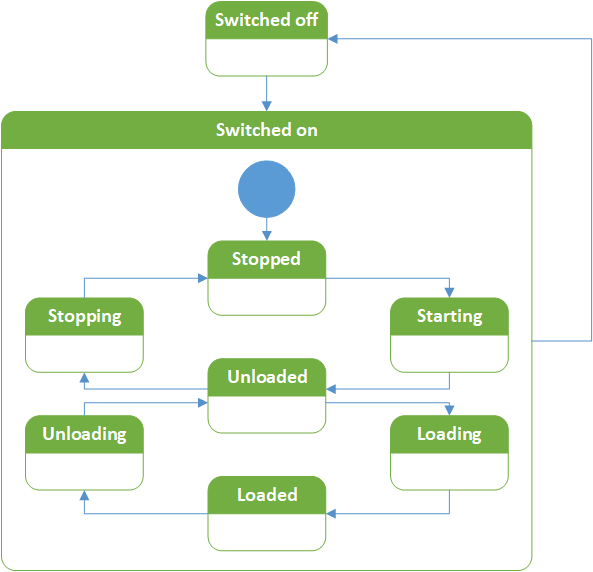
The InstanceDeclarations of the CompressorOperationalType have additional Attributes defined in Table 100.
| Source Path | Value Attribute | Description |
| ActivePressureBand | Indicates the actual active pressure band. | |
| FlowRateRatio | Calculated ratio of actual and maximum possible flow rate of a compressor. | |
| IsentropicEfficiency | Calculated isentropic efficiency. | |
| OperatingState | Actual operating state of the compressor. | |
| SpecificEnergyRequirement | Calculated shaft input energy per unit of compressor actual rate of flow. |
7.48 ConverterOperationalType ObjectType Definition
The ConverterOperationalType extends its supertype by converter specific Variables and is formally defined in Table 101.
| Attribute | Value | ||||
| BrowseName | ConverterOperationalType | ||||
| IsAbstract | False | ||||
| References | Node Class | BrowseName | DataType | TypeDefinition | Other |
|---|---|---|---|---|---|
| Subtype of the OperationalType defined in 7.45, i.e. inheriting the InstanceDeclarations of that Node. | |||||
| 0:HasComponent | Variable | CatalyticMaterialTemperature | 0:Double | 0:BaseAnalogType | O, RO |
The InstanceDeclarations of the ConverterOperationalType have additional Attributes defined in Table 102.
| Source Path | Value Attribute | Description Attribute |
| CatalyticMaterialTemperature | Measured actual temperature of the catalytic material inside a converter. |
7.49 DrainOperationalType ObjectType Definition
The DrainOperationalType provides extends its supertype by condensate drain specific Variables and is formally defined in Table 103.
| Attribute | Value | ||||
| BrowseName | DrainOperationalType | ||||
| IsAbstract | False | ||||
| References | Node Class | BrowseName | DataType | TypeDefinition | Other |
|---|---|---|---|---|---|
| Subtype of the OperationalType defined in 7.45, i.e. inheriting the InstanceDeclarations of that Node. | |||||
| 0:HasComponent | Method | DrainTest | See 7.49.1 | O | |
The InstanceDeclarations of the DrainOperationalType have additional Attributes defined in Table 104.
| Source Path | Description Attribute |
| DrainTest | Invoke a drain test on a condensate drain. |
7.49.1 DrainTest
The Method DrainTest is used to trigger a test of the condensate drain via the Main Control System. The signature of this Method is specified below. There are no InputArguments or OutputArguments defined. Its formal representation in the AddressSpace is defined in Table 105.
Signature
	DrainTest (
);| Attribute | Value | ||||
| BrowseName | DrainTest | ||||
| References | Node Class | BrowseName | DataType | TypeDefinition | ModellingRule |
|---|---|---|---|---|---|
7.50 DryerOperationalType ObjectType Definition
The DryerOperationalType extends its supertype by dryer specific Variables and is formally defined in Table 106.
| Attribute | Value | ||||
| BrowseName | DryerOperationalType | ||||
| IsAbstract | False | ||||
| References | Node Class | BrowseName | DataType | TypeDefinition | Other |
|---|---|---|---|---|---|
| Subtype of the OperationalType defined in 7.45, i.e. inheriting the InstanceDeclarations of that Node. | |||||
| 0:HasComponent | Variable | PressureDewPoint | 0:Double | 0:BaseAnalogType | O, RO |
| The following nodes override nodes added by the OperationalType | |||||
| 0:HasComponent | Variable | OnOff | 0:Boolean | 0:TwoStateDiscreteType | O, RO |
| 0:HasComponent | Variable | OperatingState | DryerOperatingStateEnum | 0:DataItemType | O, RO |
The following illustrations of a state machines do not imply the actual function or state machines for dryers. It serves as an example of how the actual state machines may function.
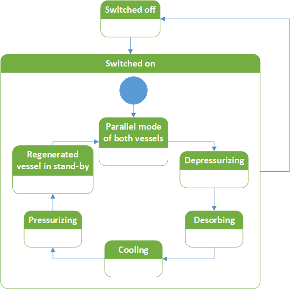
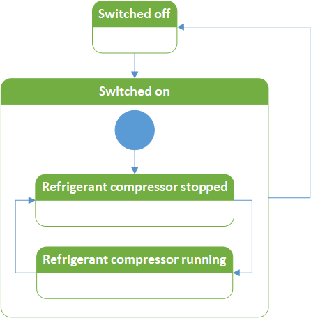
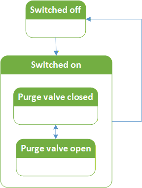
The InstanceDeclarations of the DryerOperationalType have additional Attributes defined in Table 107.
| Source Path | Value Attribute | Description Attribute | ||
| OnOff | Actual OnOff state of the dryer. For membrane dryers this describes the state of the controller. | |||
| "The dryer is switched off." | |||
| "The dryer is switched on." | |||
| OperatingState | Actual operating state of the dryer. | |||
| PressureDewPoint | Measured or calculated actual pressure dew point of the process fluid at a dryer. |
7.51 ValveOperationalType ObjectType Definition
The ValveOperationalType extends its supertype by valve specific Variables and is formally defined in Table 108.
| Attribute | Value | ||||
| BrowseName | ValveOperationalType | ||||
| IsAbstract | False | ||||
| References | Node Class | BrowseName | DataType | TypeDefinition | Other |
|---|---|---|---|---|---|
| Subtype of the OperationalType defined in 7.45, i.e. inheriting the InstanceDeclarations of that Node. | |||||
| 0:HasComponent | Variable | ContinuousPosition | 0:Double | 0:BaseAnalogType | O, RO |
| 0:HasComponent | Variable | PortUsed | 0:UInt16 | 0:DataItemType | O, RO |
Continuous valves shall use the Variable ContinuousPosition and define the EngineeringUnits Property.
Switching valves shall use the Variable PortUsed and define the EngineeringUnits Property as well as the Definition Property.
The InstanceDeclarations of the ValveOperationalType have additional Attributes defined in Table 109.
| Source Path | Value Attribute | Description Attribute |
| ContinuousPosition | Actual valve stroke. | |
| PortUsed | Actual port used. |
7.52 StatisticsType ObjectType Definition
The StatisticsType provides Variables for statistics applications, such as counters, and is formally defined in Table 110.
| Attribute | Value | ||||
| BrowseName | StatisticsType | ||||
| IsAbstract | False | ||||
| References | Node Class | BrowseName | DataType | TypeDefinition | Other |
|---|---|---|---|---|---|
| Subtype of the 2:FunctionalGroupType defined in OPC 10000-100, i.e. inheriting the InstanceDeclarations of that Node. | |||||
| 0:HasSubtype | ObjectType | CompressorStatisticsType | Defined in 7.53 | ||
| 0:HasInterface | ObjectType | 3:IAggregateStatisticsType | Defined in OPC 10000-200 | ||
| 0:HasComponent | Variable | RealTime | 0:Double | 0:BaseAnalogType | O, RO |
| 0:HasComponent | Variable | RealTimeToNextService | 0:Double | 0:BaseAnalogType | O, RO |
| 0:HasComponent | Variable | RunningTime | 0:Double | 0:BaseAnalogType | O, RO |
| 0:HasComponent | Variable | RunningTimeToNextService | 0:Double | 0:BaseAnalogType | O, RO |
| Applied from 3:IAggregateStatisticsType | |||||
| 0:HasProperty | Variable | 3:ResetCondition | 0:String | 0:PropertyType | O, RO |
| 0:HasComponent | Method | 3:ResetStatistics | See 3:IStatisticsType | O | |
| 0:HasProperty | Variable | 3:StartTime | 0:DateTime | 0:PropertyType | O, RO |
The Variables ResetCondition and StartTime, and the Method ResetStatistics are defined by the IAggregateStatisticsType and shall be used as defined by the Interface.
The InstanceDeclarations of the StatisticsType have additional Attributes defined in Table 111.
| Source Path | Value Attribute | Description Attribute |
| RealTime | Real time passed since last counter reset. | |
| RealTimeToNextService | Real time left until the real time of the next service level is exceeded. | |
| RunningTime | Time spent running since last counter reset. | |
| RunningTimeToNextService | Running time left until the running time of the next service level is exceeded. |
7.53 CompressorStatisticsType ObjectType Definition
The CompressorStatisticsType extends its supertype by compressor specific Variables and is formally defined in Table 112.
| Attribute | Value | ||||
| BrowseName | CompressorStatisticsType | ||||
| IsAbstract | False | ||||
| References | Node Class | BrowseName | DataType | TypeDefinition | Other |
|---|---|---|---|---|---|
| Subtype of the StatisticsType defined in 7.52, i.e. inheriting the InstanceDeclarations of that Node. | |||||
| 0:HasComponent | Variable | LoadedTime | 0:Double | 0:BaseAnalogType | O, RO |
| 0:HasComponent | Variable | UnloadedTime | 0:Double | 0:BaseAnalogType | O, RO |
The InstanceDeclarations of the CompressorStatisticsType have additional Attributes defined in Table 113.
| Source Path | Value Attribute | Description Attribute |
| LoadedTime | Time spent in loaded state since last counter reset. | |
| UnloadedTime | Time spent in unloaded state since last counter reset. |
8 OPC UA DataTypes
8.1 FilterClassDataType
This structure FilterClassDataType contains information about the used filter class according to ISO 8573-1 of a filter. The structure is defined in Table 114.
| Name | Type | Description |
| FilterClassDataType | structure | Filter class according to ISO 8573-1. |
A | FilterClassEnum | Class for particles |
B | FilterClassEnum | Class for water and humidity |
C | FilterClassEnum | Class for oil |
The FilterClassDataType representation in the AddressSpace is defined in Table 115.
| Attribute | Value | ||||
| BrowseName | FilterClassDataType | ||||
| IsAbstract | False | ||||
| References | NodeClass | BrowseName | DataType | TypeDefinition | Other |
|---|---|---|---|---|---|
| Subtype of 0:Structure defined in OPC 10000-5. | |||||
8.2 SensorTechnologyOptionSet
The SensorTechnologyOptionSet defines flags for the used sensor technologies for a sensor and is formally defined in Table 116.
| Value | Bit No. | Description |
| CapacitiveSensor | 0 | Capacitive sensor capabilities |
| ElectronTube | 1 | Electron tube capabilities |
| InductiveSensor | 2 | Inductive sensor capabilities |
| IonizationSensor | 3 | Ionization sensor capabilities |
| Magnetometer | 4 | Magnetometer capabilities |
| OpticalSensor | 5 | Optical sensor capabilities |
| PiezoelectricSensor | 6 | Piezoelectric sensor capabilities |
| ResistiveSensor | 7 | Resistive sensor capabilities |
| ResonantSensor | 8 | Resonant sensor capabilities |
| TemperatureSensor | 9 | Temperature sensor capabilities |
| ThermalSensor | 10 | Thermal sensor capabilities |
| UltrasoundSensor | 11 | Ultrasound sensor capabilities |
The SensorTechnologyOptionSet representation in the AddressSpace is defined in Table 117.
| Attribute | Value | |||||
| BrowseName | SensorTechnologyOptionSet | |||||
| IsAbstract | False | |||||
| References | Node Class | BrowseName | DataType | TypeDefinition | Other | |
|---|---|---|---|---|---|---|
| Subtype of OptionSet DataType defined in 5. | ||||||
| 0:HasProperty | Variable | OptionSetValues | 0:LocalizedText[] | 0:PropertyType | M, RO | |
8.3 CompressorTypeEnum
This enumeration CompressorTypeEnum contains predefined possible compressor types. The enumeration is defined in Table 118.
| Name | Value | Description |
| Other | 0 | Not specified in this enumeration |
| AxialTurboCompressor | 1 | Axial Turbo compressor |
| BellowsCompressor | 2 | Bellows compressor |
| DiaphragmCompressor | 3 | Diaphragm compressor |
| LiquidRingCompressor | 4 | Liquid ring compressor |
| PistonCompressor | 5 | Piston compressor |
| RadialTurboCompressor | 6 | Radial Turbo compressor |
| RootsCompressor | 7 | Roots compressor |
| ScrewCompressor | 8 | Screw compressor |
| ScrollCompressor | 9 | Scroll compressor |
| SideChannelCompressor | 10 | Side channel compressor |
| StraightLobeCompressor | 11 | Straight lobe compressor |
| VaneCompressor | 12 | Vane compressor |
The CompressorTypeEnum representation in the AddressSpace is defined in Table 119.
| Attribute | Value | ||||
| BrowseName | CompressorTypeEnum | ||||
| IsAbstract | False | ||||
| References | Node Class | BrowseName | DataType | TypeDefinition | Other |
|---|---|---|---|---|---|
| Subtype of the 0:Enumeration type defined in OPC 10000-5. | |||||
| 0:HasProperty | Variable | 0:EnumValues | 0:EnumValueType[] | 0:PropertyType | |
8.4 ConverterTypeEnum
This enumeration ConverterTypeEnum contains predefined possible converter types. The enumeration is defined in Table 120.
| Name | Value | Description |
| Other | 0 | Not specified in this enumeration |
| CatalyticHCConverter | 1 | Catalytic hydrocarbons converter |
The ConverterTypeEnum representation in the AddressSpace is defined in Table 121.
| Attribute | Value | ||||
| BrowseName | ConverterTypeEnum | ||||
| IsAbstract | False | ||||
| References | Node Class | BrowseName | DataType | TypeDefinition | Other |
|---|---|---|---|---|---|
| Subtype of the 0:Enumeration type defined in OPC 10000-5. | |||||
| 0:HasProperty | Variable | 0:EnumValues | 0:EnumValueType[] | 0:PropertyType | |
8.5 DisplacementTypeEnum
This enumeration DisplacementTypeEnum contains predefined possible displacement types for a compressor. The enumeration is defined in Table 122.
| Name | Value | Description |
| PositiveDisplacement | 0 | Positive displacement compressor |
| DynamicDisplacement | 1 | Dynamic displacement compressor |
The DisplacementTypeEnum representation in the AddressSpace is defined in Table 123.
| Attribute | Value | ||||
| BrowseName | DisplacementTypeEnum | ||||
| IsAbstract | False | ||||
| References | Node Class | BrowseName | DataType | TypeDefinition | Other |
|---|---|---|---|---|---|
| Subtype of the 0:Enumeration type defined in OPC 10000-5. | |||||
| 0:HasProperty | Variable | 0:EnumValues | 0:EnumValueType[] | 0:PropertyType | |
8.6 DrainTypeEnum
This enumeration DrainTypeEnum contains predefined possible condensate drain types. The enumeration is defined in Table 124.
| Name | Value | Description |
| Other | 0 | Not specified in this enumeration |
| CapacitiveDrain | 1 | Capacitive drain |
| LevelControlledDrain | 2 | Level controlled drain |
| TimedDrain | 3 | Timed drain |
The DrainTypeEnum representation in the AddressSpace is defined in Table 125.
| Attribute | Value | ||||
| BrowseName | DrainTypeEnum | ||||
| IsAbstract | False | ||||
| References | Node Class | BrowseName | DataType | TypeDefinition | Other |
|---|---|---|---|---|---|
| Subtype of the 0:Enumeration type defined in OPC 10000-5. | |||||
| 0:HasProperty | Variable | 0:EnumValues | 0:EnumValueType[] | 0:PropertyType | |
8.7 DryerTypeEnum
This enumeration DryerTypeEnum contains predefined possible dryer types. The enumeration is defined in Table 126.
| Name | Value | Description |
| Other | 0 | Not specified in this enumeration |
| AbsorptionDryer | 1 | Absorption dryer |
| AdsorptionDryer | 2 | Adsorption dryer |
| MembraneDryer | 3 | Membrane dryer |
| RefrigerationDryer | 4 | Refrigeration dryer |
The DryerTypeEnum representation in the AddressSpace is defined in Table 127.
| Attribute | Value | ||||
| BrowseName | DryerTypeEnum | ||||
| IsAbstract | False | ||||
| References | Node Class | BrowseName | DataType | TypeDefinition | Other |
|---|---|---|---|---|---|
| Subtype of the 0:Enumeration type defined in OPC 10000-5. | |||||
| 0:HasProperty | Variable | 0:EnumValues | 0:EnumValueType[] | 0:PropertyType | |
8.8 FilterClassEnum
This enumeration FilterClassEnum contains the possible filter classes according to ISO 8573-1 for the FilterClassDataType. The enumeration is defined in Table 128.
| Name | Value | Description |
| 0 | 0 | As specified by the equipment user or supplier and more stringent than class 1. |
| 1 | 1 | Particles: By Particle Size: 0.1 µm < d ≤ 0.5 µm: ≤ 20,000; 0.5 µ m< d ≤ 1.0 µm: ≤ 400; 1.0 µm < d ≤ 5.0 µm: ≤ 10; Water: Vapor Pressure Dewpoint: ≤ -70 °C, ≤ -94 °F; Oil: Liquid, Aerosol, & Vapor: ≤ 0.01 mg/m3; |
| 2 | 2 | Particles: By Particle Size: 0.1 µm < d ≤ 0.5 µm: ≤ 400,000; 0.5 µ m< d ≤ 1.0 µm: ≤ 6,000; 1.0 µm < d ≤ 5.0 µm: ≤ 100; Water: Vapor Pressure Dewpoint: ≤ -40 °C, ≤ -40 °F; Oil: Liquid, Aerosol, & Vapor: ≤ 0.1 mg/m3; |
| 3 | 3 | Particles: By Particle Size: 0.5 µ m< d ≤ 1.0 µm: ≤ 90,000; 1.0 µm < d ≤ 5.0 µm: ≤ 1,000; Water: Vapor Pressure Dewpoint: ≤ -20 °C, ≤ -4 °F; Oil: Liquid, Aerosol, & Vapor: ≤ 1 mg/m3; |
| 4 | 4 | Particles: By Particle Size: 1.0 µm < d ≤ 5.0 µm: ≤ 10,000; Water: Vapor Pressure Dewpoint: ≤ +3 °C, ≤ +37 °F; Oil: Liquid, Aerosol, & Vapor: ≤ 5 mg/m3; |
| 5 | 5 | Particles: By Particle Size: 1.0 µm < d ≤ 5.0 µm: ≤ 100,000; Water: Vapor Pressure Dewpoint: ≤ +7 °C, ≤ +45 °F; |
| 6 | 6 | Particles: By Mass: 0 - ≤ 5 mg/m3; Water: Vapor Pressure Dewpoint: ≤ +10 °C, ≤ +50 °F; |
| 7 | 7 | Particles: By Mass: 5 - ≤ 10 mg/m3; Water: Liquid: ≤ 0.5 g/m3; |
| 8 | 8 | Water: Liquid: ≤ 5 g/m3; |
| 9 | 9 | Water: Liquid: ≤ 10 g/m3; |
| X | 10 | Particles: By Mass: > 10 mg/m3; Water: Liquid: > 10 g/m3; Oil: Liquid, Aerosol, & Vapor: > 5 mg/m3; |
The FilterClassEnum representation in the AddressSpace is defined in Table 129.
| Attribute | Value | ||||
| BrowseName | FilterClassEnum | ||||
| IsAbstract | False | ||||
| References | Node Class | BrowseName | DataType | TypeDefinition | Other |
|---|---|---|---|---|---|
| Subtype of the 0:Enumeration type defined in OPC 10000-5. | |||||
| 0:HasProperty | Variable | 0:EnumValues | 0:EnumValueType[] | 0:PropertyType | |
8.9 FilterTypeEnum
This enumeration FilterTypeEnum contains predefined possible filter types. The enumeration is defined in Table 130.
| Name | Value | Description |
| Other | 0 | Not specified in this enumeration |
| ActivatedCarbonFilter | 1 | Activated carbon filter |
| AdsorptionFilter | 2 | Adsorption filter |
| CoalescingFilter | 3 | Coalescing filter |
| ParticulateFilter | 4 | Particulate filter |
| FabricFilter | 5 | Fabric filter |
| SterileFilter | 6 | Sterile filter |
The FilterTypeEnum representation in the AddressSpace is defined in Table 131.
| Attribute | Value | ||||
| BrowseName | FilterTypeEnum | ||||
| IsAbstract | False | ||||
| References | Node Class | BrowseName | DataType | TypeDefinition | Other |
|---|---|---|---|---|---|
| Subtype of the 0:Enumeration type defined in OPC 10000-5. | |||||
| 0:HasProperty | Variable | 0:EnumValues | 0:EnumValueType[] | 0:PropertyType | |
8.10 FluidTypeEnum
This enumeration FluidTypeEnum contains predefined possible process fluid types. The enumeration is defined in Table 132.
| Name | Value | Description |
| Air | 0 | Air used as fluid |
| Condensate | 1 | Condensate used as fluid |
| Oil | 2 | Oil used as fluid |
| Water | 3 | Water used as fluid |
The FluidTypeEnum representation in the AddressSpace is defined in Table 133.
| Attribute | Value | ||||
| BrowseName | FluidTypeEnum | ||||
| IsAbstract | False | ||||
| References | Node Class | BrowseName | DataType | TypeDefinition | Other |
|---|---|---|---|---|---|
| Subtype of the 0:Enumeration type defined in OPC 10000-5. | |||||
| 0:HasProperty | Variable | 0:EnumValues | 0:EnumValueType[] | 0:PropertyType | |
8.11 HealthStateEnum
This enumeration HealthStateEnum contains possible states for the Variable HealthState of the OperationalType. The enumeration is defined in Table 134.
| Name | Value | Description |
| OK | 0 | The main function can be fulfilled. |
| Warning | 1 | Check required, possibly there is a problem that leads to an Error. |
| Error | 2 | Immediate action needed to avoid Critical. |
| Critical | 3 | The main function cannot be fulfilled. |
Its representation in the AddressSpace is defined in Table 135.
| Attribute | Value | ||||
| BrowseName | HealthStateEnum | ||||
| IsAbstract | False | ||||
| References | Node Class | BrowseName | DataType | TypeDefinition | Other |
|---|---|---|---|---|---|
| Subtype of the Enumeration type defined in OPC 10000-5 | |||||
| 0:HasProperty | Variable | 0:EnumValues | 0:EnumValueType[] | 0:PropertyType | |
8.12 AirnetHealthStateEnum
This enumeration AirnetHealthStateEnum contains possible states for the Variable HealthState of the AirnetOperationalType. The enumeration is defined in Table 136.
| Name | Value | Description |
| OK | 0 | All requirements can be fulfilled. |
| Warning | 1 | Check required, possibly there is a problem that leads to an Error. |
| Error | 2 | Immediate action needed to avoid Critical. |
| Critical | 3 | At least one requirement cannot be fulfilled. |
Its representation in the AddressSpace is defined in Table 137.
| Attribute | Value | ||||
| BrowseName | AirnetHealthStateEnum | ||||
| IsAbstract | False | ||||
| References | Node Class | BrowseName | DataType | TypeDefinition | Other |
|---|---|---|---|---|---|
| Subtype of the Enumeration type defined in OPC 10000-5 | |||||
| 0:HasProperty | Variable | 0:EnumValues | 0:EnumValueType[] | 0:PropertyType | |
8.13 IntegratedStateEnum
This enumeration IntegratedStateEnum contains possible states for the Variable IntegratedState of the OperationalType. The enumeration is defined in Table 138.
| Name | Value | Description |
| FullyIntegrated | 0 | Compressed air generation or treatment is fully controlled by the MCS. |
| PartiallyIntegrated | 1 | Compressed air generation or treatment is partially controlled by the MCS. |
| FullyIsolated | 2 | Compressed air generation or treatment is not controlled by the MCS. |
Its representation in the AddressSpace is defined in Table 139.
| Attribute | Value | ||||
| BrowseName | IntegratedStateEnum | ||||
| IsAbstract | False | ||||
| References | Node Class | BrowseName | DataType | TypeDefinition | Other |
|---|---|---|---|---|---|
| Subtype of the Enumeration type defined in OPC 10000-5 | |||||
| 0:HasProperty | Variable | 0:EnumValues | 0:EnumValueType[] | 0:PropertyType | |
8.14 AirnetIntegratedStateEnum
This enumeration AirnetIntegratedStateEnum contains possible states for the Variable IntegratedState of the AirnetOperationalType. The enumeration is defined in Table 140.
| Name | Value | Description |
| FullyIntegrated | 0 | The MCS controls all compressors of this airnet. |
| PartiallyIntegrated | 1 | At least one compressor of this airnet is not controlled by the MCS. |
| FullyIsolated | 2 | The MCS does not control any compressor of this airnet. |
Its representation in the AddressSpace is defined in Table 141.
| Attribute | Value | ||||
| BrowseName | AirnetIntegratedStateEnum | ||||
| IsAbstract | False | ||||
| References | Node Class | BrowseName | DataType | TypeDefinition | Other |
|---|---|---|---|---|---|
| Subtype of the Enumeration type defined in OPC 10000-5 | |||||
| 0:HasProperty | Variable | 0:EnumValues | 0:EnumValueType[] | 0:PropertyType | |
8.15 IpVersionEnum
This enumeration IpVersionEnum contains possible internet protocol versions. The enumeration is defined in Table 142.
| Name | Value | Description |
| IPv4 | 0 | IP address is in IPv4 format |
| IPv6 | 1 | IP address is in IPv6 format |
Its representation in the AddressSpace is defined in Table 143.
| Attribute | Value | ||||
| BrowseName | IpVersionEnum | ||||
| IsAbstract | False | ||||
| References | Node Class | BrowseName | DataType | TypeDefinition | Other |
|---|---|---|---|---|---|
| Subtype of the Enumeration type defined in OPC 10000-5 | |||||
| 0:HasProperty | Variable | 0:EnumValues | 0:EnumValueType[] | 0:PropertyType | |
8.16 LubricationTypeEnum
This enumeration LubricationTypeEnum contains predefined possible lubrication types for the compression process of a compressor. The enumeration is defined in Table 144.
| Name | Value | Description |
| NoLubrication | 0 | No lubrication |
| OilLubricated | 1 | Oil lubricated |
| WaterLubricated | 2 | Water lubricated |
The LubricationTypeEnum representation in the AddressSpace is defined in Table 145.
| Attribute | Value | ||||
| BrowseName | LubricationTypeEnum | ||||
| IsAbstract | False | ||||
| References | Node Class | BrowseName | DataType | TypeDefinition | Other |
|---|---|---|---|---|---|
| Subtype of the 0:Enumeration type defined in OPC 10000-5. | |||||
| 0:HasProperty | Variable | 0:EnumValues | 0:EnumValueType[] | 0:PropertyType | |
8.17 OperatingStateEnum
This enumeration OperatingStateEnum contains possible states for the Variable OperatingState of the OperationalType. The enumeration is defined in Table 146.
| Name | Value | Description |
| Other | 0 | The component is in a state not specified by this enumeration. |
| Stopped | 1 | The main function shall not be fulfilled. |
| Starting | 2 | Transition phase to end in Operational state. |
| Stopping | 3 | Transition phase to end in Stopped state. |
| Operational | 4 | The main function should be fulfilled. |
The following illustration of a state machine does not imply the actual function or state machine in the Main Control System. It serves as an example of how the actual state machine may function.
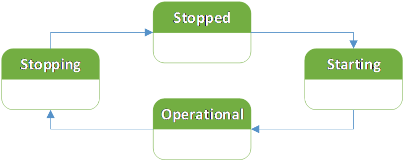
Its representation in the AddressSpace is defined in Table 147.
| Attribute | Value | ||||
| BrowseName | OperatingStateEnum | ||||
| IsAbstract | False | ||||
| References | Node Class | BrowseName | DataType | TypeDefinition | Other |
|---|---|---|---|---|---|
| Subtype of the Enumeration type defined in OPC 10000-5 | |||||
| 0:HasProperty | Variable | 0:EnumValues | 0:EnumValueType[] | 0:PropertyType | |
8.18 AirnetOperatingStateEnum
This enumeration AirnetOperatingStateEnum contains possible states for the Variable OperatingState of the AirnetOperationalType. The enumeration is defined in Table 148.
| Name | Value | Description |
| Other | 0 | The airnet is in a state not specified by this enumeration. |
| Stopped | 1 | The requirements shall not be fulfilled. |
| Starting | 2 | Transition phase to end in Operational state. |
| Stopping | 3 | Transition phase to end in Stopped state. |
| Operational | 4 | The requirements should be fulfilled. |
The following illustration of a state machine does not imply the actual function or state machine in the Main Control System. It serves as an example of how the actual state machine may function.
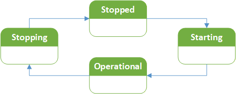
Its representation in the AddressSpace is defined in Table 149.
| Attribute | Value | ||||
| BrowseName | AirnetOperatingStateEnum | ||||
| IsAbstract | False | ||||
| References | Node Class | BrowseName | DataType | TypeDefinition | Other |
|---|---|---|---|---|---|
| Subtype of the Enumeration type defined in OPC 10000-5 | |||||
| 0:HasProperty | Variable | 0:EnumValues | 0:EnumValueType[] | 0:PropertyType | |
8.19 CompressorOperatingStateEnum
This enumeration CompressorOperatingStateEnum contains possible states for the Variable OperatingState of the CompressorOperationalType. The enumeration is defined in Table 150.
| Name | Value | Description |
| Other | 0 | The compressor is in a state not specified by this enumeration. |
| Stopped | 1 | The motor is not running. |
| Starting | 2 | Transition phase to end in Unloaded state. |
| Stopping | 3 | Transition phase to end in Stopped state. |
| Unloaded | 4 | The motor is running but the compressor does not deliver compressed air to the airnet. |
| Loading | 5 | Transition phase to end in Loaded state. |
| Unloading | 6 | Transition phase to end in Unloaded state. |
| Loaded | 7 | The compressor does deliver compressed air to the airnet. |
The following illustration of a state machine does not imply the actual function or state machine in the Main Control System. It serves as an example of how the actual state machine may function.
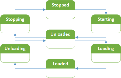
Its representation in the AddressSpace is defined in Table 151.
| Attribute | Value | ||||
| BrowseName | CompressorOperatingStateEnum | ||||
| IsAbstract | False | ||||
| References | Node Class | BrowseName | DataType | TypeDefinition | Other |
|---|---|---|---|---|---|
| Subtype of the Enumeration type defined in OPC 10000-5 | |||||
| 0:HasProperty | Variable | 0:EnumValues | 0:EnumValueType[] | 0:PropertyType | |
8.20 DryerOperatingStateEnum
This enumeration DryerOperatingStateEnum contains possible states for the Variable OperatingState of the DryerOperationalType. The enumeration is defined in Table 152.
| Name | Value | Description |
| Other | 0 | The dryer is in a state not specified by this enumeration. |
| Stopped | 1 | The dryer is stopped. This state is applicable to all adsorption dryers. |
| Running | 2 | The dryer is running. This state is applicable to all dryers. |
| RefrigerantCompressorStopped | 3 | The compressor of the refrigerant circuit is standing still, and the refrigerant dryer is operating using the stored cold. This state is applicable to refrigerant dryers. |
| RefrigerantCompressorRunning | 4 | The compressor of the refrigerant circuit is running and compressing refrigerant, creating cold. This state is applicable to refrigerant dryers. |
| PurgeValveClosed | 5 | Purge valve is closed, and no purge air is consumed, no purge of the humidity from membranes dryer. This state is applicable to membrane dryers. |
| PurgeValveOpen | 6 | Purge air can flow to purge the humidity out of the membrane dryer. This state is applicable to membrane dryers. |
| ParallelModeOfBothVessels | 7 | Both vessels of the adsorption dryer are used in parallel for adsorption. This state is applicable to all adsorption dryers. |
| Depressurizing | 8 | One vessel of the adsorption dryer is depressurized for regeneration. This state is applicable to heatless and heated adsorption dryers, not HOC. |
| Desorbing | 9 | One vessel of the adsorption dryer is in desorption phase, using purge or ambient air, heated or not heated. This state is applicable to all adsorption dryers. |
| Cooling | 10 | One vessel of the adsorption dryer is being cooled after being heated in the previous desorption phase. This state is applicable to heated adsorption dryers and HOC. |
| Pressurizing | 11 | The depressurized vessel is pressurized again. This state is applicable to heatless and heated adsorption dryers, not HOC. |
| RegeneratedVesselInStand-by | 12 | The regenerated vessel is in standby and ready for adsorption phase. This state is applicable to all adsorption dryers. |
The following illustrations of state machines do not imply the actual functions or state machines in the Main Control System. It serves as an example of how the actual state machines may function.
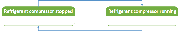

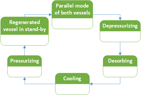
Its representation in the AddressSpace is defined in Table 153.
| Attribute | Value | ||||
| BrowseName | DryerOperatingStateEnum | ||||
| IsAbstract | False | ||||
| References | Node Class | BrowseName | DataType | TypeDefinition | Other |
|---|---|---|---|---|---|
| Subtype of the Enumeration type defined in OPC 10000-5 | |||||
| 0:HasProperty | Variable | 0:EnumValues | 0:EnumValueType[] | 0:PropertyType | |
8.21 ReceiverTypeEnum
This enumeration ReceiverTypeEnum contains predefined possible receiver types. The enumeration is defined in Table 154.
| Name | Value | Description |
| Other | 0 | Not specified in this enumeration |
| DryReceiver | 1 | Dry Receiver |
| WetReceiver | 2 | Wet Receiver |
The ReceiverTypeEnum representation in the AddressSpace is defined in Table 155.
| Attribute | Value | ||||
| BrowseName | ReceiverTypeEnum | ||||
| IsAbstract | False | ||||
| References | Node Class | BrowseName | DataType | TypeDefinition | Other |
|---|---|---|---|---|---|
| Subtype of the 0:Enumeration type defined in OPC 10000-5. | |||||
| 0:HasProperty | Variable | 0:EnumValues | 0:EnumValueType[] | 0:PropertyType | |
8.22 SensorTypeEnum
This enumeration SensorTypeEnum contains predefined possible sensor types. The enumeration is defined in Table 156.
| Name | Value | Description |
| Other | 0 | Not specified in this enumeration |
| Ammeter | 1 | Ammeter |
| DewPointSensor | 2 | Dew point sensor |
| FlowRateSensor | 3 | Flow rate sensor |
| FlowSpeedSensor | 4 | Flow speed sensor |
| HumiditySensor | 5 | Humidity sensor |
| OilConcentrationSensor | 6 | Oil concentration sensor |
| ParticleCounter | 7 | Particle counter |
| PressureSensor | 8 | Pressure sensor |
| TemperatureSensor | 9 | Temperature sensor |
| Voltmeter | 10 | Voltmeter |
| VolumeSensor | 11 | Volume sensor |
| Wattmeter | 12 | Wattmeter |
The SensorTypeEnum representation in the AddressSpace is defined in Table 157.
| Attribute | Value | ||||
| BrowseName | SensorTypeEnum | ||||
| IsAbstract | False | ||||
| References | Node Class | BrowseName | DataType | TypeDefinition | Other |
|---|---|---|---|---|---|
| Subtype of the 0:Enumeration type defined in OPC 10000-5. | |||||
| 0:HasProperty | Variable | 0:EnumValues | 0:EnumValueType[] | 0:PropertyType | |
8.23 SeparatorTypeEnum
This enumeration SeparatorTypeEnum contains predefined possible condensate separator types. The enumeration is defined in Table 158.
| Name | Value | Description |
| Other | 0 | Not specified in this enumeration |
| CentrifugalOilyWaterSeparator | 1 | Centrifugal oily water separator |
| EmulsionSplittingSeparator | 2 | Emulsion splitting separator |
| FlotationSeparator | 3 | Flotation separator |
| GravityPlateSeparator | 4 | Gravity plate separator |
| HydrocycloneOilyWaterSeparator | 5 | Hydrocyclone oily water separator |
The SeparatorTypeEnum representation in the AddressSpace is defined in Table 159.
| Attribute | Value | ||||
| BrowseName | SeparatorTypeEnum | ||||
| IsAbstract | False | ||||
| References | Node Class | BrowseName | DataType | TypeDefinition | Other |
|---|---|---|---|---|---|
| Subtype of the 0:Enumeration type defined in OPC 10000-5. | |||||
| 0:HasProperty | Variable | 0:EnumValues | 0:EnumValueType[] | 0:PropertyType | |
8.24 ValveTypeEnum
This enumeration ValveTypeEnum contains predefined possible valve types. The enumeration is defined in Table 160.
| Name | Value | Description |
| Other | 0 | Not specified in this enumeration |
| CheckValve | 1 | Check valve |
| ContinuousValve | 2 | Continuous valve |
| FlowControlValve | 3 | Flow control valve |
| PressureValve | 4 | Pressure valve |
| SwitchingValve | 5 | Switching valve |
The ValveTypeEnum representation in the AddressSpace is defined in Table 161.
| Attribute | Value | ||||
| BrowseName | ValveTypeEnum | ||||
| IsAbstract | False | ||||
| References | Node Class | BrowseName | DataType | TypeDefinition | Other |
|---|---|---|---|---|---|
| Subtype of the 0:Enumeration type defined in OPC 10000-5. | |||||
| 0:HasProperty | Variable | 0:EnumValues | 0:EnumValueType[] | 0:PropertyType | |
9 Profiles and ConformanceUnits
Profiles, Facets, and Conformance Units were designed for the MCS and its OPC UA Server, and do not apply to the whole CAS. If a Component does not provide the required information for a specific Conformance Unit or does not communicate with the MCS, and the information is not available by other means, the Conformance Unit cannot be fulfilled for this Component but is considered as fulfilled in general.
9.1 Conformance Units
This chapter defines the corresponding Conformance Units for the OPC UA for Compressed Air Systems Information Model.
| Category | Title | Description |
| Server | CAS Analyses - OutputFile | Results of analyses present in an instance of the AnalysesType can be provided in the AddressSpace via the Object OutputFile. |
| Server | CAS Analyses - Parameterizable | Instances of the MCSType or AirnetType have an instance of the AnalysesType and provide analyses that can be parameterized and called by the user to invoke an analysis on the MCS. |
| Server | CAS Analyses - Prefabricated | Instances of the MCSType or AirnetType have an instance of the AnalysesType and provide prefabricated analyses provided by the manufacturer or the MCS. |
| Server | CAS Analyses - Pre-parameterized | Instances of the MCSType or AirnetType have an instance of the AnalysesType and provide pre-parameterized analyses that can be called by the user to invoke an analysis on the MCS. |
| Server | CAS CASPart Identification | Instances of the AirnetType, MCSType, CASComponentType and its subtypes have the FunctionalGroup Identification. |
| Server | CAS CASType Identification | Instances of the CASType have the FunctionalGroup Identification. |
| Server | CAS CASType Mandatory Nodes | All nodes declared as mandatory in the CASType are available in the AddressSpace. |
| Server | CAS Configuration - Communication Settings | Instances of the MCSType have an instance of the CommunicationSettingsType. |
| Server | CAS Configuration - ComponentClass | Instances of the CASComponentType and its subtypes have an instance of the DesignType or one of its subtypes and use the ComponentClass Variable. |
| Server | CAS Configuration - Load | Instances of the MCSType have the ConfigurationFile and the LoadConfigurationFile method and the user can upload a configuration file to the AddressSpace and the MCS. |
| Server | CAS Configuration - Save | Instances of the MCSType have the ConfigurationFile and the SaveConfigurationFile method and the user can download a configuration file from the AddressSpace and the MCS. |
| Server | CAS Dynamic - Add/Remove | The Services AddNodes and DeleteNodes are integrated by the server. |
| Server | CAS Dynamic - Move | The Services AddReferences and DeleteReferences are integrated by the server. |
| Server | CAS Energy Management - Electrical Quantities | Instances of the CompressorType and its subtypes have the Variables Power and Energy. |
| Server | CAS Energy Management - Process Fluid Quantities | Instances of the CompressorType and its subtypes have an instance of the FluidCircuitType and the Variable VolumeFlowRate for its components' Object ProcessFluidCircuit. |
| Server | CAS Energy Management - Quantity Historization | Variables used for Energy Management have the Attribute Historizing set true and the AccessLevel includes HistoryRead. Depending on the supported Conformance Units, these Variables are Energy and Power, VolumeFlowRate, or RunningTime and LoadedTime. |
| Server | CAS Energy Management - Runtime Quantities | Instances of the CompressorType and its subtypes have the Variables RunningTime and LoadedTime. |
| Server | CAS Events | Instances of the CASComponentType and its subtypes have an instance of the EventsType. Predefined Events shall have a severity assigned as specified in 6.6.1. |
| Server | CAS Events - Historization | Events in the AddressSpace have the Attribute Historizing set true and the AccessLevel includes HistoryRead. |
| Server | CAS Historization | All Quantities as specified in this specification have the Attribute Historizing set true and the AccessLevel includes HistoryRead. |
| Server | CAS Maintenance - HealthState | Instances of the AirnetType and the CASComponentType and its subtypes have the Variable HealthState. |
| Server | CAS Maintenance - MCS to Server | If a condition is acknowledged or confirmed on the MCS user interface, the condition is also acknowledged or confirmed on the OPC UA Server. |
| Server | CAS Maintenance - Sensor | Instances of the SensorType have an instance of the CalibrationType and/or the MaintenanceType. |
| Server | CAS Maintenance - Server to MCS | If a condition is acknowledged or confirmed on the OPC UA Server, the condition is also acknowledged or confirmed on the MCS user interface. |
| Server | CAS Maintenance - Statistics | Instances of the CASComponentType and its subtypes have an instance of the StatisticsType or its subtypes and the Variables RunningTime and/or RealTime. |
| Server | CAS NE107 | Instances of the CASComponentType or one of its subtypes have at least one appropriate GeneratesEvent reference targeting the subtypes of the 2:DeviceHealthDiagnosticAlarmType. |
| Server | CAS Operation - CoolantCircuit | Instances of the CASComponentType and its subtypes have an instance of the FluidCircuitType as Object CoolantCircuit if the physical component uses a coolant. |
| Server | CAS Operation - ElectricalCircuit | Instances of the AirnetType and the CASComponentType and its subtypes have an instance of the ElectricalCircuitType if the physical component has electrical properties. |
| Server | CAS Operation - FluidType | Instances of the AirnetType and the CASComponentType and its subtypes have an instance of the FluidCircuitType and the Variable FluidType if the physical component handles a fluid. |
| Server | CAS Operation - IntegratedState | Instances of the CompressorType and its subtypes have the Variable IntegratedState. |
| Server | CAS Operation - OperatingState | Instances of the AirnetType and the CASComponentType and its subtypes have the Variable OperatingState. |
| Server | CAS Operation - ProcessFluidCircuit | Instances of the AirnetType and the CASComponentType and its subtypes have an instance of the FluidCircuitType as Object ProcessFluidCircuit if the physical component handles the process fluid. |
| Server | CAS Operation - Statistics | Instances of the CASComponentType and its subtypes have an instance of the StatisticsType. |
| Client | CAS Client Dynamic - Add/Remove | The Services AddNodes and DeleteNodes are available to the client. |
| Client | CAS Client Dynamic - Move | The Services AddReferences and DeleteReferences are integrated to the client. |
9.2 Facets and Profiles
9.2.1 Overview
Table 163 lists all Facets and Profiles defined in this document and defines their URIs.
9.2.2 Server
9.2.2.1 Overview
The following sections define the Facets and Profiles available for Servers that implement the OPC UA for Compressed Air Systems companion specification.
9.2.2.2 CAS Base Analyses Server Facet
This Facet defines the elements for a Main Control System that provides prefabricated or pre-parameterized analyses on Compressed Air System or Airnet level. Although both Conformance Units are listed as optional, at least one shall be implemented to comply with this Facet.
| Group | Conformance Unit / Profile Title | M / O |
| CAS | CAS Analyses - Prefabricated | O |
| CAS | CAS Analyses - Pre-parameterized | O |
9.2.2.3 CAS Advanced Analyses Server Facet
This Facet defines the elements for a Main Control System that provides parameterizable analyses on Compressed Air System or Airnet level and the possibility to store analysis reports in the AddressSpace.
| Group | Conformance Unit / Profile Title | M / O |
| CAS | CAS Analyses - Parameterizable | M |
| CAS | CAS Analyses - OutputFile | M |
9.2.2.4 CAS Base Configuration Server Facet
This Facet defines the elements for a Main Control System that provides its OPC UA communication settings and the component class for Components.
| Group | Conformance Unit / Profile Title | M / O |
| CAS | CAS Configuration - Communication Settings | M |
| CAS | CAS Configuration - ComponentClass | M |
9.2.2.5 CAS Advanced Configuration Server Facet
This Facet defines the elements for a Main Control System whose configuration can be stored as a file in the OPC UA AddressSpace.
| Group | Conformance Unit / Profile Title | M / O |
| CAS | CAS Configuration - Load | M |
| CAS | CAS Configuration - Save | M |
9.2.2.6 CAS Base Maintenance Management Server Facet
This Facet defines the elements for a Main Control System that provides a health state and statistics for CASParts.
| Group | Conformance Unit / Profile Title | M / O |
| CAS | CAS Maintenance - HealthState | M |
| CAS | CAS Maintenance - Statistics | M |
9.2.2.7 CAS Advanced Maintenance Management Server Facet
This Facet defines the elements for a Main Control System that provides events and conditions.
| Group | Conformance Unit / Profile Title | M / O |
| CAS | CAS Maintenance - MCS to Server | M |
| CAS | CAS Events | M |
9.2.2.8 CAS Energy Management Server Facet
This Facet defines the elements for a Main Control System that provides necessary Variables and their historization for energy management applications.
| Group | Conformance Unit / Profile Title | M / O |
| CAS | CAS Energy Management - Electrical Quantities | M |
| CAS | CAS Energy Management - Process Fluid Quantities | M |
| CAS | CAS Energy Management - Runtime Quantities | M |
| CAS | CAS Energy Management - Quantity Historization | M |
9.2.2.9 CAS Operation Server Facet
This Facet defines the elements for a Main Control System that provides necessary Variables for operational applications.
| Group | Conformance Unit / Profile Title | M / O |
| CAS | CAS Operation - IntegratedState | M |
| CAS | CAS Operation - OperatingState | M |
| CAS | CAS Operation - FluidType | M |
| CAS | CAS Operation - ProcessFluidCircuit | M |
| CAS | CAS Operation - ElectricalCircuit | M |
| CAS | CAS Operation - CoolantCircuit | M |
| CAS | CAS Operation - Statistics | M |
9.2.2.10 CAS Base Server Profile
This Profile defines the elements for a Main Control System that supports base functionality.
| Group | Conformance Unit / Profile Title | M / O |
| Profile | 0:Address Space Notifier Server Facet http://opcfoundation.org/UA-Profile/Server/AddressSpaceNotifier | M |
| Profile | 0:Embedded 2017 UA Server Profile | M |
| Profile | 0:Data Access Server Facet | M |
| Profile | 0:ComplexType 2017 Server Facet | M |
| Profile | 4:Machine Identification Writable Server Facet http://opcfoundation.org/UA-Profile/Machinery/Server/MachineIdentificationWritable | M |
| CAS | Base Analyses Server Facet | O |
| CAS | Base Configuration Server Facet http://opcfoundation.org/UA-Profile/CAS/Server/Configuration | M |
| CAS | Base Maintenance Management Server Facet http://opcfoundation.org/UA-Profile/CAS/Server/BaseMaintenance | M |
| CAS | Operation Server Facet http://opcfoundation.org/UA-Profile/CAS/Server/Operation | M |
| CAS | CASPart Identification | M |
| CAS | CASType Mandatory Nodes | M |
| CAS | CASType Identification | M |
| CAS | NE107 | M |
9.2.2.11 CAS Advanced Server Profile
This Profile defines the elements for a Main Control System that supports advanced functionality.
| Group | Conformance Unit / Profile Title | M / O |
| Profile | Base Server Profile | M |
| CAS | Advanced Configuration Server Facet http://opcfoundation.org/UA-Profile/CAS/Server/AdvancedConfiguration | M |
| CAS | Advanced Analyses Server Facet http://opcfoundation.org/UA-Profile/CAS/Server/AdvancedAnalyses | M |
9.2.2.12 CAS Maintenance Management Server Profile
This Profile defines the elements for a Main Control System that supports the maintenance management use case.
| Group | Conformance Unit / Profile Title | M / O |
| Profile | 0:A & C Address Space Instance Server Facet http://opcfoundation.org/UA-Profile/Server/ACAddressSpaceInstance | M |
| Profile | 0:A & C Exclusive Alarming Server Facet http://opcfoundation.org/UA-Profile/Server/ACExclusiveAlarming | M |
| Profile | 0:Aggregate Subscription Server Facet http://opcfoundation.org/UA-Profile/Server/AggregateSubscription | M |
| Profile | 3:IA Statistical Data Server Profile http://opcfoundation.org/UA-Profile/IA/Server/StatisticalData | M |
| Profile | Base Server Profile | M |
| CAS | Advanced Maintenance Management Server Facet http://opcfoundation.org/UA-Profile/CAS/Server/AdvancedMaintenance | M |
| CAS | Maintenance - Server to MCS | M |
| CAS | Maintenance - Sensor | O |
9.2.2.13 CAS Energy Management Server Profile
This Profile defines the elements for a Main Control System that supports the energy management use case.
| Group | Conformance Unit / Profile Title | M / O |
| Profile | Base Server Profile | M |
| CAS | Energy Management Server Facet | M |
9.2.2.14 CAS Dynamic Server Profile
This Profile defines the elements for a Main Control System that supports node manipulation during the runtime of the Server.
| Group | Conformance Unit / Profile Title | M / O |
| Profile | 0:Node Management Server Facet | M |
| Profile | Base Server Profile | M |
| CAS | Dynamic - Add/Remove | M |
| CAS | Dynamic - Move | M |
9.2.2.15 CAS Full Server Profile
This Profile defines the elements for a Main Control System which supports all ConformanceUnits.
| Group | Conformance Unit / Profile Title | M / O |
| Profile | Base Server Profile | M |
| CAS | Advanced Analyses Server Facet http://opcfoundation.org/UA-Profile/CAS/Server/AdvancedAnalyses | M |
| CAS | Advanced Configuration Server Facet http://opcfoundation.org/UA-Profile/CAS/Server/AdvancedConfiguration | M |
| CAS | Advanced Maintenance Management Server Facet http://opcfoundation.org/UA-Profile/CAS/Server/AdvancedMaintenance | M |
| CAS | Energy Management Server Facet | M |
| CAS | CAS Maintenance - Server to MCS | M |
| CAS | CAS Maintenance - Sensor | M |
| CAS | CAS Dynamic - Add/Remove | M |
| CAS | CAS Dynamic - Move | M |
9.2.3 Client
9.2.3.1 Overview
The following sections define the Facets and Profiles available for Clients that implement the OPC UA for Compressed Air Systems companion specification.
9.2.3.2 CAS Base Client Profile
This Profile defines the elements for a Client that can fully use a CAS Base Server Profile Server.
| Group | Conformance Unit / Profile Title | M / O |
| Profile | 0:Standard UA Client 2017 Profile http://opcfoundation.org/UA-Profile/Client/Standard2017 | M |
| Profile | 0:File Access Client Facet | M |
| Profile | 0:Attribute Read Client Facet http://opcfoundation.org/UA-Profile/Client/AttributeRead | M |
| Profile | 0:Attribute Write Client Facet http://opcfoundation.org/UA-Profile/Client/AttributeWrite | M |
| Profile | 0:DataAccess Client Facet | M |
| Profile | 0:Aggregate Subscriber Client Facet http://opcfoundation.org/UA-Profile/Client/AggregateSubscription | M |
9.2.3.3 CAS Advanced Client Profile
This Profile defines the elements for a Client that can fully use a CAS Advanced Server Profile, a CAS Maintenance Management Server Profile, and/or a CAS Energy Management Server Profile Server.
| Group | Conformance Unit / Profile Title | M / O |
| Profile | Base Client Profile | M |
| Profile | 0:A & C Address Space Instance Client Facet http://opcfoundation.org/UA-Profile/Client/ACAddressSpaceInstance | M |
| Profile | 0:A & C Exclusive Alarming Client Facet http://opcfoundation.org/UA-Profile/Client/ACExclusiveAlarming | M |
| Profile | 0:Historical Access Client Facet | M |
| Profile | 0:Historical Event Client Facet | M |
9.2.3.4 CAS Dynamic Client Profile
This Profile defines the elements for a Client that can fully use a CAS Dynamic Server Profile Server.
| Group | Conformance Unit / Profile Title | M / O |
| Profile | Base Client Profile | M |
| Profile | 0:Node Management Client Facet | M |
| CAS | CAS Client Dynamic - Add/Remove | M |
| CAS | CAS Client Dynamic - Move | M |
9.2.3.5 CAS Full Client Profile
This Profile defines the elements for a Client that can fully use every specified CAS Server.
| Group | Conformance Unit / Profile Title | M / O |
| Profile | Advanced Client Profile | M |
| Profile | Dynamic Client Profile | M |
10 Namespaces
10.1 Namespace Metadata
Table 182 defines the namespace metadata for this document. The Object is used to provide version information for the namespace and an indication about static Nodes. Static Nodes are identical for all Attributes in all Servers, including the Value Attribute. See OPC 10000-5 for more details.
The information is provided as Object of type NamespaceMetadataType. This Object is a component of the Namespaces Object that is part of the Server Object. The NamespaceMetadataType ObjectType and its Properties are defined in OPC 10000-5.
The version information is also provided as part of the ModelTableEntry in the UANodeSet XML file. The UANodeSet XML schema is defined in OPC 10000-6.
| Attribute | Value | ||
| BrowseName | http://opcfoundation.org/UA/CAS/ | ||
| Property | DataType | Value | |
|---|---|---|---|
| NamespaceUri | String | http://opcfoundation.org/UA/CAS/ | |
| NamespaceVersion | String | 1.00.1 | |
| NamespacePublicationDate | DateTime | 2021-07-13 | |
| IsNamespaceSubset | Boolean | False | |
| StaticNodeIdTypes | IdType [] | 0 | |
| StaticNumericNodeIdRange | NumericRange [] | ||
| StaticStringNodeIdPattern | String | ||
10.2 Handling of OPC UA Namespaces
Namespaces are used by OPC UA to create unique identifiers across different naming authorities. The Attributes NodeId and BrowseName are identifiers. A Node in the UA AddressSpace is unambiguously identified using a NodeId. Unlike NodeIds, the BrowseName cannot be used to unambiguously identify a Node. Different Nodes may have the same BrowseName. They are used to build a browse path between two Nodes or to define a standard Property.
Servers may often choose to use the same namespace for the NodeId and the BrowseName. However, if they want to provide a standard Property, its BrowseName shall have the namespace of the standards body although the namespace of the NodeId reflects something else, for example the EngineeringUnits Property. All NodeIds of Nodes not defined in this document shall not use the standard namespaces.
Table 183 provides a list of mandatory and optional namespaces used in an OPC UA for Compressed Air Systems OPC UA Server.
| NamespaceURI | Description | Use |
| http://opcfoundation.org/UA/ | Namespace for NodeIds and BrowseNames defined in the OPC UA specification. This namespace shall have namespace index 0. | Mandatory |
| Local Server URI | Namespace for nodes defined in the local server. This may include types and instances used in an AutoID Device represented by the Server. This namespace shall have namespace index 1. | Mandatory |
| http://opcfoundation.org/UA/DI/ | Namespace for NodeIds and BrowseNames defined in OPC 10000-100. The namespace index is Server specific. | Mandatory |
| http://opcfoundation.org/UA/IA/ | Namespace for NodeIds and BrowseNames defined in OPC 10000-200. The namespace index is Server specific. | Mandatory |
| http://opcfoundation.org/UA/Machinery/ | Namespace for NodeIds and BrowseNames defined in OPC 40001-1. The namespace index is Server specific. | Mandatory |
| http://opcfoundation.org/UA/CAS/ | Namespace for NodeIds and BrowseNames defined in this document. The namespace index is Server specific. | Mandatory |
| Vendor specific types | A Server may provide vendor-specific types like types derived from ObjectTypes defined in this document in a vendor-specific namespace. | Optional |
| Vendor specific instances | A Server provides vendor-specific instances of the standard types or vendor-specific instances of vendor-specific types in a vendor-specific namespace. It is recommended to separate vendor specific types and vendor specific instances into two or more namespaces. | Mandatory |
Table 184 provides a list of namespaces and their index used for BrowseNames in this document. The default namespace of this document is not listed since all BrowseNames without prefix use this default namespace.
| NamespaceURI | Namespace Index | Example |
| http://opcfoundation.org/UA/ | 0 | 0:EngineeringUnits |
| http://opcfoundation.org/UA/DI/ | 2 | 2:DeviceRevision |
| http://opcfoundation.org/UA/IA/ | 3 | 3:BasicStacklightType |
| http://opcfoundation.org/UA/Machinery/ | 4 | 4:YearOfConstruction |
Annex A OPC UA for Compressed Air Systems Namespace and mappings (Normative)
A.1 Namespace and identifiers for OPC UA for Compressed Air Systems Information Model
This appendix defines the numeric identifiers for all the numeric NodeIds defined in this specification. The identifiers are specified in a CSV file with the following syntax:
<SymbolName>, <Identifier>, <NodeClass>Where the SymbolName is either the BrowseName of a Type Node or the BrowsePath for an Instance Node that appears in the specification and the Identifier is the numeric value for the NodeId.
The BrowsePath for an Instance Node is constructed by appending the BrowseName of the instance Node to the BrowseName for the containing instance or type. An underscore character is used to separate each BrowseName in the path. Let's take for example, the CommunicationSettingsType ObjectType Node which has the Hostname Property. The Name for the Hostname InstanceDeclaration within the CommunicationSettingsType declaration is: CommunicationSettingsType_Hostname.
The NamespaceUri for all NodeIds defined here is http://opcfoundation.org/UA/CAS/
The CSV released with this version of the specification can be found here:
http://www.opcfoundation.org/UA/schemas/CAS/1.0/Opc.Ua.CAS.NodeIds.csv
NOTE The latest CSV that is compatible with this version of the specification can be found here:
http://www.opcfoundation.org/UA/schemas/CAS/Opc.Ua.CAS.NodeIds.csv
A computer processible version of the complete Information Model defined in this specification is also provided.
It follows the XML Information Model schema syntax defined in OPC 10000-6.
The Information Model Schema for this version of the document can be found here:
http://www.opcfoundation.org/UA/schemas/CAS/1.0/Opc.Ua.CAS.NodeSet2.xml
| NOTE | The latest Information Model schema that is compatible with this version of the specification can be found here: |
http://www.opcfoundation.org/UA/schemas/CAS/Opc.Ua.CAS.NodeSet2.xml
___________
Annex B Edge Cases for Component and Airnet Handling (Normative)
B.1 Adding or Removing a Component to/from a Compressed Air System
During the lifetime of a Compressed Air System, the manufacturer, integrator, or operator may wish to replace, add, or remove Components to or from the system. The OPC UA provided Services AddNodes and DeleteNodes can add or remove Nodes from the AddressSpace during runtime of the OPC UA Server and are described in OPC 10000-4. If the manufacturer of a Compressed Air System wants to enable an integrator or operator to add or remove Components while the OPC UA Server is running, at least those two Services shall be available to both the Server and the Client. To additionally support the edge case B.2, the whole NodeManagement Service Set, defined in OPC 10000-4 shall be supported by both the Client and Server.
If the used Server or Client does not support the Services AddNodes and RemoveNodes, the modelled Compressed Air System shall be changed while the OPC UA Server is not running. The OPC UA Server shall only boot up after the required mechanical work is done.
B.2 Adding or Removing a Component to/from an Airnet
During the life of a Compressed Air System the manufacturer, integrator, or operator may wish to add or remove Components to or from one of the Airnets. This also includes moving a Component permanently from one Airnet to another. The OPC UA provided Services AddReferences and DeleteReferences can add or remove References from Nodes in the AddressSpace during runtime of the OPC UA Server and are described in OPC 10000-4. If the manufacturer of a Compressed Air System wants to enable an integrator or operator to add or remove Components to or from one of the Airnets, or to move Components from one Airnet to another, while the OPC UA Server is running, at least those two Services shall be available to both the Server and the Client. To additionally support the edge case B.1, the whole NodeManagement Service Set, defined in OPC 10000-4 shall be supported by both the Client and Server.
If the used Server or Client does not support the Services AddReferences and DeleteReferences, the modelled Compressed Air System shall be changed while the OPC UA Server is not running. The OPC UA Server shall only boot up after the required mechanical work is done.
B.3 Temporarily Switch a Component from one Airnet to Another
Some Main Control Systems allow for Components to switch from one Airnet to another by operating a valve or a similar action. If the setup of a Compressed Air System allows for such a temporarily switch, the switchable Components shall have the ActiveAirnet Property and all possible Airnets shall have an Organizes Reference to these Components. If the operation of a valve or a similar action switches one of these Components from one Airnet to another, the ActiveAirnet Property changes its Value Attribute to indicate which Airnet is currently using the Component.
___________
Annex C Bibliography (Informative)
| [1] | Plattform Industrie 4.0, Details of the Asset Administration Shell, Berlin: Federal Ministry for Economic Affairs and Energy (BMWi), 2019. |
Agreement of Use
COPYRIGHT RESTRICTIONS
This document is provided "as is" by the OPC Foundation and VDMA.
Right of use for this specification is restricted to this specification and does not grant rights of use for referred documents.
Right of use for this specification will be granted without cost.
This document may be distributed through computer systems, printed or copied as long as the content remains unchanged and the document is not modified.
OPC Foundation and VDMA do not guarantee usability for any purpose and shall not be made liable for any case using the content of this document.
The user of the document agrees to indemnify OPC Foundation and VDMA and their officers, directors and agents harmless from all demands, claims, actions, losses, damages (including damages from personal injuries), costs and expenses (including attorneys' fees) which are in any way related to activities associated with its use of content from this specification.
The document shall not be used in conjunction with company advertising, shall not be sold or licensed to any party.
The intellectual property and copyright is solely owned by the OPC Foundation and VDMA.
PATENTS
The attention of adopters is directed to the possibility that compliance with or adoption of OPC or VDMA specifications may require use of an invention covered by patent rights. OPC Foundation or VDMA shall not be responsible for identifying patents for which a license may be required by any OPC or VDMA specification, or for conducting legal inquiries into the legal validity or scope of those patents that are brought to its attention. OPC or VDMA specifications are prospective and advisory only. Prospective users are responsible for protecting themselves against liability for infringement of patents.
WARRANTY AND LIABILITY DISCLAIMERS
WHILE THIS PUBLICATION IS BELIEVED TO BE ACCURATE, IT IS PROVIDED "AS IS" AND MAY CONTAIN ERRORS OR MISPRINTS. THE OPC FOUDATION NOR VDMA MAKES NO WARRANTY OF ANY KIND, EXPRESSED OR IMPLIED, WITH REGARD TO THIS PUBLICATION, INCLUDING BUT NOT LIMITED TO ANY WARRANTY OF TITLE OR OWNERSHIP, IMPLIED WARRANTY OF MERCHANTABILITY OR WARRANTY OF FITNESS FOR A PARTICULAR PURPOSE OR USE. IN NO EVENT SHALL THE OPC FOUNDATION NOR VDMA BE LIABLE FOR ERRORS CONTAINED HEREIN OR FOR DIRECT, INDIRECT, INCIDENTAL, SPECIAL, CONSEQUENTIAL, RELIANCE OR COVER DAMAGES, INCLUDING LOSS OF PROFITS, REVENUE, DATA OR USE, INCURRED BY ANY USER OR ANY THIRD PARTY IN CONNECTION WITH THE FURNISHING, PERFORMANCE, OR USE OF THIS MATERIAL, EVEN IF ADVISED OF THE POSSIBILITY OF SUCH DAMAGES.
The entire risk as to the quality and performance of software developed using this specification is borne by you.
RESTRICTED RIGHTS LEGEND
This Specification is provided with Restricted Rights. Use, duplication or disclosure by the U.S. government is subject to restrictions as set forth in (a) this Agreement pursuant to DFARs 227.7202-3(a); (b) subparagraph (c)(1)(i) of the Rights in Technical Data and Computer Software clause at DFARs 252.227-7013; or (c) the Commercial Computer Software Restricted Rights clause at FAR 52.227-19 subdivision (c)(1) and (2), as applicable. Contractor / manufacturer are the OPC Foundation, 16101 N. 82nd Street, Suite 3B, Scottsdale, AZ, 85260-1830
COMPLIANCE
The combination of VDMA and OPC Foundation shall at all times be the sole entities that may authorize developers, suppliers and sellers of hardware and software to use certification marks, trademarks or other special designations to indicate compliance with these materials as specified within this document. Products developed using this specification may claim compliance or conformance with this specification if and only if the software satisfactorily meets the certification requirements set by VDMA or the OPC Foundation. Products that do not meet these requirements may claim only that the product was based on this specification and must not claim compliance or conformance with this specification.
TRADEMARKS
Most computer and software brand names have trademarks or registered trademarks. The individual trademarks have not been listed here.
GENERAL PROVISIONS
Should any provision of this Agreement be held to be void, invalid, unenforceable or illegal by a court, the validity and enforceability of the other provisions shall not be affected thereby.
This Agreement shall be governed by and construed under the laws of Germany.
This Agreement embodies the entire understanding between the parties with respect to, and supersedes any prior understanding or agreement (oral or written) relating to, this specification.