
1 Scope
This specification was created by a joint working group of the OPC Foundation and the Ethernet POWERLINK Standardization Group (EPSG). It defines an OPC UA Information Model to represent the models from Ethernet POWERLINK.
OPC Foundation
The OPC Foundation defines standards for online data exchange between automation systems. They address access to current data (OPC DA), alarms and events (OPC A&E) and historical data (OPC HDA). Those standards are successfully applied in industrial automation.
The new OPC Unified Architecture (OPC UA) unifies the existing standards and brings them to state-of-the-art technology using service-oriented architecture (SOA). Platform-independent technology allows the deployment of OPC UA beyond current OPC applications only running on Windows-based PC systems. OPC UA can also run on embedded systems as well as Linux / UNIX based enterprise systems. The provided information can be generically modelled and therefore arbitrary information models can be provided using OPC UA.
Ethernet POWERLINK Standardization Group
The Ethernet POWERLINK Standardization Group (EPSG) was founded in 2003 as an independent association. Its goals are the standardisation, promotion and further development of POWERLINK technology, which was first presented to the public in 2001. POWERLINK is a patent-free, manufacturer-independent and completely software-based communication system for hard real-time that has been available as a free open source solution since 2008. The EPSG's POWERLINK office handles public relations, coordinates the implementation of shared projects and provides information for existing and prospective members.
The EPSG is working closely with the CiA (CAN in Automation) organisation to integrate CANopen with POWERLINK. CANopen is one of the most widely used application protocols today. Key benefits of this protocol include standardised device description files that make status information, parameter configurations, device characteristics and other relevant data available in transparent form on the network. A major decision made by the EPSG was to define the protocol's application layer as a carrier of all CANopen mechanisms. CiA, the international association of CAN users and manufacturers, was significantly involved in this development.
Ethernet POWERLINK uses the same concepts as CANopen for object dictionaries, device descriptions and communication mechanisms including process data objects (PDOs), service data objects (SDOs) and network management (NMT). As with CANopen, direct cross-traffic is also one of the essential features of POWERLINK. All CANopen applications and device profiles can be directly implemented in POWERLINK environments as well - the applications will not see a difference between the two protocols. For this reason, POWERLINK can also be referred to as "CANopen over Ethernet".
2 Reference documents
| EN 60325-4 | : Industrial communications subsystem based on ISO 11898 (CAN) for controller device interfaces (Part 4: CANopen) |
| EPSG DS 301 | V1.3.0 : Ethernet POWERLINK - Communication Profile Specification |
| EPSG DS 302-A | V1.1.0 : Ethernet POWERLINK - High Availability |
| EPSG DS 302-B | V1.1.0 : Ethernet POWERLINK - Multiple ASnd |
| EPSG DS 302-C | V1.1.0 : Ethernet POWERLINK - PollResponse Chaining |
| EPSG DS 302-D | V1.0.0 : Ethernet POWERLINK - Multiple PReq/PRes |
| EPSG DS 302-E | V1.1.0 : Ethernet POWERLINK - Dynamic Node Allocation |
| EPSG DS 302-F | V1.1.0 : Ethernet POWERLINK - Modular Device |
| EPSG DS 311 | V1.2.0 : Ethernet POWERLINK - XML Device Description |
| IEEE 802.3TM-2015 | : IEEE Standard for Ethernet |
| ISO 646-1973(E) | : International Organization for Standardization, 7-Bit Coded Character Set for Information Processing Exchange |
| OPC 10000-1, | OPC Unified Architecture - Part 1: Overview |
| OPC 10000-3, | OPC Unified Architecture - Part 3: Address Space Model |
| OPC 10000-4, | OPC Unified Architecture - Part 4: Services |
| OPC 10000-5, | OPC Unified Architecture - Part 5: Information Model |
| OPC 10000-6, | OPC Unified Architecture - Part 6: Mappings |
| OPC 10000-7, | OPC Unified Architecture - Part 7: Profiles |
| OPC 10000-100, | OPC Unified Architecture - Part 100: Devices |
3 Terms, definitions, and conventions
3.1 Use of terms
Defined terms of OPC UA specifications, types and their components defined in OPC UA specifications and in this specification are highlighted with italic in this document.
Certain Ethernet POWERLINK related terms and names are used together with POWERLINK, especially in cases where the terms might lead to naming conflicts with existing OPCUA terms. For instance the term Managing Node (a device role in POWERLINK) contains the word Node that has a different meaning in OPC UA.
Table 1 contains a list with the most prominent examples for common terms that have different meanings in OPC UA and POWERLINK.
| Term | OPC UA | POWERLINK |
| Node | OPC 10000-1: The fundamental component of an AddressSpace. | Commonly used for physical devices in a POWERLINK network. Terms: POWERLINK Device POWERLINK Controlled Node POWERLINK Managing Node |
| NodeId | OPC 10000-3: Nodes are unambiguously identified using a constructed identifier called the NodeId. | Each POWERLINK Device (MN, CN and Router) is addressed by an 8 bit POWERLINK Node ID on the POWERLINK layer. This ID has only local significance (i.e. it is unique within a POWERLINK segment) and addresses a physical device whereas the NodeId of OPC UA addresses elements of the internal object dictionary. |
| Object | OPC 10000-3: Objects and their components are represented in the AddressSpace as a set of Nodes described by Attributes and interconnected by References. | Data object: Element of the POWERLINK Object Dictionary Process data object: Object for isochronous data exchange between POWERLINK Devices. Service data object: Peer to peer communication with access to the POWERLINK Object Dictionary of a device. |
| Mapping | OPC 10000-6: Specifies how to implement an OPC UA feature with a specific technology. Note: For example, the OPC UA Binary Encoding is a Mapping that specifies how to serialise OPC UA data structures as sequences of bytes. | Selection of the POWERLINK Objects that are sent or received via PDOs. |
3.2 OPC UA for POWERLINK Information Model terms
For the purposes of this document, the terms and definitions given in the referenced OPC UA Specifications as well as the following apply.
3.2.1 Asynchronous POWERLINK Data
data in a POWERLINK network that is not time critical
3.2.2 Deterministic Communication
communication process with predictable timing behaviour (I.e. the time when a message reaches the recipient is predictable)
3.2.3 Isochronous POWERLINK Data
data in a POWERLINK network which is to be transmitted every cycle (or every nth cycle in case of multiplexed isochronous data)
3.2.4 Legacy Ethernet
ethernet as standardised in IEEE 802.3 (non-deterministic operation in non-time-critical environments)
3.2.5 NMT State
Network Management State of a POWERLINK Device
3.2.6 POWERLINK Controlled Node
POWERLINK Device without the ability to manage the SCNM mechanism
3.2.7 POWERLINK Device Profile
standardised or vendor specific definition of an object model
3.2.8 POWERLINK Managing Node
POWERLINK Device capable to manage the SCNM mechanism in a POWERLINK network
3.2.9 POWERLINK Device
device in a POWERLINK network
3.2.10 POWERLINK Object
data object, addressed by Index and Sub-Index
3.2.11 POWERLINK Object Dictionary
repository of all POWERLINK Objects accessible over POWERLINK communications
3.2.12 POWERLINK Record
record data type (as defined in the POWERLINK specification EPSG DS 301)
3.2.13 POWERLINK XML Device Description
XML file for the description of the objects in a POWERLINK Object Dictionary (also called XDD)
3.3 Abbreviations and symbols
| A&E | Alarms & Events |
| ANSI | American National Standards Institute |
| API | Application Program Interface |
| CN | POWERLINK Controlled Node |
| CSMA/CD | Carrier Sense Multiple Access/Collision Detection |
| DA | Data Access |
| EPSG | Ethernet POWERLINK Standardization Group |
| HDA | Historical Data Access |
| HMI | Human-Machine Interface |
| IEC | International Electrotechnical Commission |
| IM | OPC UA Information Model |
| IP | Internet Protocol - RFC 791 |
| ISO | International Organization for Standardization |
| LAN | Local Area Network |
| MES | Manufacturing Execution System |
| MN | POWERLINK Managing Node |
| NaN | "Not a Number", a unique binary pattern representing an invalid number |
| (ANSI/IEEE 754-1985) | |
| NAT | Network Address Translation - RFC 2663 |
| NMT | Network Management |
| OD | POWERLINK Object Dictionary |
| PDO | POWERLINK Process Data Object |
| RTE | Real Time Ethernet |
| SCADA | Supervisory Control And Data Acquisition |
| SCNM | Slot Communication Network Management |
| UA | Unified Architecture |
| UTC | Universal Time Coordinated |
| XDD | POWERLINK XML device description |
| XML | Extensible Markup Language |
3.4 Conventions used in this document
3.4.1 Conventions for Node descriptions
Node definitions are specified using tables (See Table 2)
| Attribute | Value | ||||
| Attribute name | Attribute value. If it is an optional Attribute that is not set "--" will be used. | ||||
| References | NodeClass | BrowseName | DataType | TypeDefinition | ModellingRule |
|---|---|---|---|---|---|
| ReferenceType name | NodeClass of the TargetNode. | BrowseName of the target Node. If the Reference is to be instantiated by the server, then the value of the target Node's BrowseName is "--". | Attributes of the referenced Node, only applicable for Variables and Objects. | Referenced ModellingRule of the referenced Object. | |
Notes - Notes referencing footnotes of the table content. | |||||
Attributes are defined by providing the Attribute name and a value, or a description of the value.
References are defined by providing the ReferenceType name, the BrowseName of the TargetNode and its NodeClass.
If the TargetNode is a component of the Node being defined in the table, the Attributes of the composed Node are defined in the same row of the table. That implies that the referenced Node has a HasModelParent Reference with the Node defined in the Table as TargetNode (see OPC 10000-3 for the definition of ModelParents).
The DataType is only specified for Variables; "[<number>]" indicates a single-dimensional array, for multi-dimensional arrays the expression is repeated for each dimension (e.g. [2][3] for a two-dimensional array). For all arrays the ArrayDimensions is set as identified by <number> values. If no <number> is set, the corresponding dimension is set to 0, indicating an unknown size. If no number is provided at all the ArrayDimensions can be omitted. If no brackets are provided, it identifies a scalar DataType and the ValueRank is set to the corresponding value (see OPC 10000-3). In addition, ArrayDimensions is set to null or is omitted. If it can be Any or ScalarOrOneDimension, the value is put into "{<value>}", so either "{Any}" or "{ScalarOrOneDimension}" and the ValueRank is set to the corresponding value (see OPC 10000-3) and the ArrayDimensions is set to null or is omitted. In Table 3 examples are given.
| Notation | DataType | ValueRank | ArrayDimensions | Description |
| Int32 | Int32 | -1 | omitted or NULL | A scalar Int32 |
| Int32[] | Int32 | 1 | omitted or {0} | Single-dimensional array of Int32 with an unknown size |
| Int32[][] | Int32 | 2 | omitted or {0,0} | Two-dimensional array of Int32 with unknown sizes for both dimensions |
| Int32[3][] | Int32 | 2 | {3,0} | Two-dimensional array of Int32 with a size of 3 for the first dimension and an unknown size for the second dimension |
| Int32[5][3] | Int32 | 2 | {5,3} | Two-dimensional array of Int32 with a size of 5 for the first dimension and a size of 3 for the second dimension |
| Int32{Any} | Int32 | -2 | omitted or NULL | An Int32 where it is unknown if it is scalar or array with any number of dimensions |
| Int32{ScalarOrOneDimension} | Int32 | -3 | omitted or NULL | An Int32 where it is either a single-dimensional array or a scalar |
The TypeDefinition is specified for Objects and Variables.
The TypeDefinition column specifies a NodeId of a TypeDefinitionNode, i.e. the specified Node points with a HasTypeDefinition Reference to the corresponding TypeDefinitionNode. The symbolic name of the NodeId is used in the table.
The ModellingRule of the referenced component is provided by specifying the symbolic name of the rule in the ModellingRule column. In the AddressSpace, the Node shall use a HasModellingRule Reference to point to the corresponding ModellingRule Object.
If the NodeId of a DataType is provided, the symbolic name of the Node representing the DataType shall be used.
Nodes of all other NodeClasses cannot be defined in the same table; therefore only the used ReferenceType, their NodeClass and their BrowseName are specified. A reference to another of this document points to their definition.
If no components are provided, the DataType, TypeDefinition and ModellingRule columns may be omitted and only a Comment column is introduced to point to the Node definition.
Components of Nodes can be complex, i.e. containing components by themselves. The TypeDefinition, NodeClass, DataType and ModellingRule can be derived from the type definitions, and the symbolic name can be created as defined in 3.4.2.1. Therefore those containing components are not explicitly specified; they are implicitly specified by the type definitions.
3.4.2 NodeIds and BrowseNames
3.4.2.1 NodeIds
The NodeIds of all Nodes described in this document are only symbolic names. Annex A defines the actual NodeIds.
The symbolic name of each Node defined in this document is its BrowseName, or, when it is part of another Node, the BrowseName of the other Node, a ".", and the BrowseName of itself. In this case "part of" means that the whole has a HasProperty or HasComponent Reference to its part. Since all Nodes not being part of another Node have a unique name in this document, the symbolic name is unique.
The namespace for this specification is defined in Annex A. The NamespaceIndex for all NodeIds defined in this specification is server specific and depends on the position of the namespace URI in the server namespace table.
Note: This specification does not only define concrete Nodes, but also requires that some Nodes have to be generated, for example one for each device type available in the frame application. The NodeIds of those Nodes are server-specific, including the Namespace. But the NamespaceIndex of those Nodes cannot be the NamespaceIndex used for the Nodes defined by this specification, because they are not defined by this specification but generated by the Server.
3.4.2.2 BrowseNames
The text part of the BrowseNames for all Nodes defined in this specification is specified in the tables defining the Nodes. The NamespaceIndex for all BrowseNames defined in this specification is server specific and depends on the position of the namespace URI defined in this specification in the server namespace table.
If the BrowseName is not defined by this specification, a NamespaceIndex prefix like '0:EngineeringUnits' is added to the BrowseName. This is typically necessary if a Property of another specification is overwritten or used in the OPC UA types defined in this specification. Table 56 provides a list of namespaces used in this specification.
3.4.3 Common Attributes
3.4.3.1 General
For all Nodes specified in this specification, the Attributes named in Table 4 shall be set as specified in the table.
| Attribute | Value |
| DisplayName | The DisplayName is a LocalizedText. Each server shall provide the DisplayName identical to the BrowseName of the Node for the LocaleId "en". Whether the server provides translated names for other LocaleIds is vendor specific. |
| Description | Optionally a vendor specific description is provided |
| NodeClass | Shall reflect the NodeClass of the Node |
| NodeId | The NodeId is described by BrowseNames as defined in 3.4.2.1 and defined in Annex A. |
| WriteMask | Optionally the WriteMask Attribute can be provided. If the WriteMask Attribute is provided, it shall set all Attributes to not writeable that are not said to be vendor-specific. For example, the Description Attribute may be set to writeable since a Server may provide a server-specific description for the Node. The NodeId shall not be writeable, because it is defined for each Node in this specification. |
| UserWriteMask | Optionally the UserWriteMask Attribute can be provided. The same rules as for the WriteMask Attribute apply. |
3.4.3.2 Objects
For all Objects specified in this specification, the Attributes named in Table 5 shall be set as specified in the table.
| Attribute | Value |
| EventNotifier | Whether the Node can be used to subscribe to Events or not is vendor specific |
3.4.3.3 Variables
For all Variables specified in this specification, the Attributes named in Table 6 shall be set as specified in the table.
| Attribute | Value |
| MinimumSamplingInterval | Optionally, a vendor-specific minimum sampling interval is provided |
| AccessLevel | The access level for Variables used for type definitions is vendor-specific, for all other Variables defined in this part, the access level shall allow a current read; other settings are vendor specific. |
| UserAccessLevel | The value for the UserAccessLevel Attribute is vendor-specific. It is assumed that all Variables can be accessed by at least one user. |
| Value | For Variables used as InstanceDeclarations, the value is vendor-specific; otherwise it shall represent the value described in the text. |
| ArrayDimensions | If the ValueRank does not identify an array of a specific dimension (i.e. ValueRank <= 0) the ArrayDimensions can either be set to null or the Attribute is missing. This behaviour is vendor-specific. If the ValueRank specifies an array of a specific dimension (i.e. ValueRank > 0) then the ArrayDimensions Attribute shall be specified in the table defining the Variable. |
3.4.3.4 VariableTypes
For all VariableTypes specified in this specification, the Attributes named in Table 7 shall be set as specified in the table.
| Attributes | Value |
| Value | Optionally a vendor-specific default value can be provided |
| ArrayDimensions | If the ValueRank does not identify an array of a specific dimension (i.e. ValueRank <= 0) the ArrayDimensions can either be set to null or the Attribute is missing. This behaviour is vendor-specific. If the ValueRank specifies an array of a specific dimension (i.e. ValueRank > 0) then the ArrayDimensions Attribute shall be specified in the table defining the VariableType. |
4 General information about Ethernet POWERLINK and OPC UA
4.1 Introduction to Ethernet POWERLINK
4.1.1 General
Ethernet POWERLINK is a communication profile for Real-Time Ethernet (RTE). It extends Ethernet according to the IEEE 802.3 standard with mechanisms to transfer data with predictable timing and precise synchronisation. The communication profile meets timing demands typical for high-performance automation and motion applications. It does not change basic principles of the Fast Ethernet Standard IEEE 802.3 but extends it towards RTE. Thus, it is possible to leverage and continue to use any standard Ethernet silicon, infrastructure component or test and measurement equipment like a network analyser.
POWERLINK provides mechanisms to achieve the following:
Transmit time-critical data in precise isochronous cycles. Data exchange is based on a publish/subscribe relationship. Isochronous data communication can be used for exchanging position data of motion applications of the automation industry.
Synchronise networked POWERLINK Devices with high accuracy.
Transmit less time-critical data asynchronously on request. Asynchronous POWERLINK Data communication can be used to transfer IP-based protocols like TCP or UDP and higher layer protocols such as HTTP, FTP, etc.
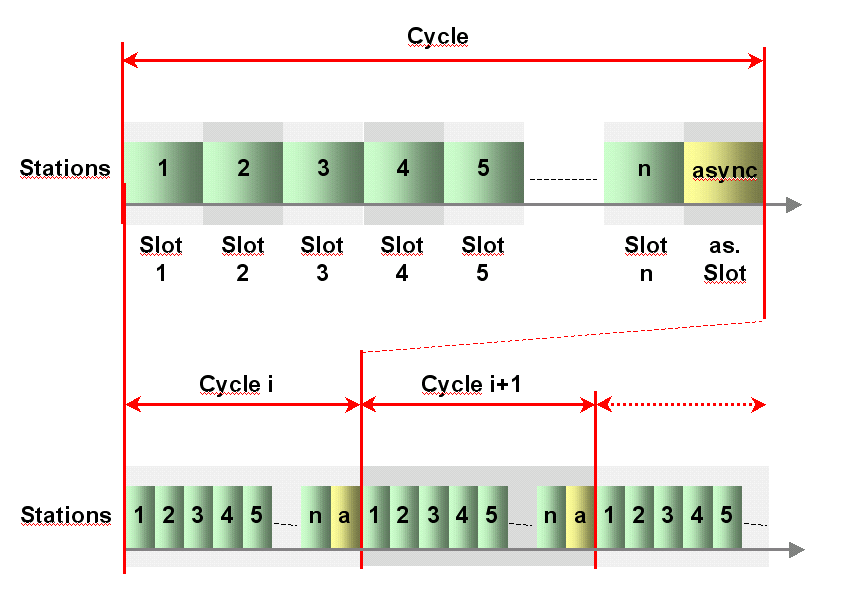
POWERLINK manages the network traffic in a way that there are dedicated time-slots for Isochronous and Asynchronous POWERLINK Data. It takes care that always only one networked device gains access to the network media. Thus, transmission of Isochronous POWERLINK Data and Asynchronous POWERLINK Data will never interfere and precise communication timing is guaranteed. The mechanism is called Slot Communication Network Management (SCNM). SCNM is managed by one particular networked device - the POWERLINK Managing Node (MN) - which includes the MN functionality. All other nodes are called POWERLINK Controlled Nodes (CN).
4.1.2 Key features
POWERLINK provides the following key features:
Ease-of-Use to be handled by typical automation engineers without in-depth Ethernet network knowledge.
Up to 240 networked real-time devices in one network segment
Deterministic communication guaranteed
Down to 100 μs cycle times
Ultra-low jitter (down to <1μs) for precise synchronisation of networked devices
Standard compliant
IEEE 802.3 Fast Ethernet
IP based protocols supported (TCP, UDP, etc.)
Integration with CANopen profiles EN 50325-4 for device interoperability
Implementation based on standard Ethernet chips - no special ASICs necessary
Direct peer-to-peer communication of all POWERLINK Devices (publish/subscribe)
Hot plugging
Seamless IT-integration - routing of IP protocols
POWERLINK supports Client/Server and Producer/Consumer communication relationships.
The POWERLINK communication profile is based on CANopen communication profiles DS301 and DS302. Based on these communication profiles, the multitude of CANopen device profiles can be used in a POWERLINK environment without changes.
A main focus of POWERLINK is ease of use. Ethernet technology can be quite complex and confusing for machine and plant manufacturers, which are not necessarily networking experts. The following features have thus been implemented:
Easy wiring, flexible topologies (line structures, tree structures or star structures). The network is adapting to the needs of the machine.
Utilisation of well-known industrial infrastructure components
Simple address assignment by switch is possible
Easy replacement of devices in case of failure
Straight-forward network diagnostics
Simple engineering separated from end user IT infrastructure
Easy integration of RTE network with IT infrastructure
4.1.3 POWERLINK device model
A POWERLINK Device is structured as follows (see Figure 2):
Communication - This function unit provides the communication objects and the appropriate functionality to transport data items via the underlying network structure.
POWERLINK Object Dictionary - The POWERLINK Object Dictionary is a collection of all the data items that have an influence on the behaviour of the application objects, the communication objects and the state machine used on this device.
Application - The application comprises the functionality of the device with respect to the interaction with the process environment.
Thus the POWERLINK Object Dictionary serves as an interface between the communication and the application. The complete description of a device's application with respect to the data items in the POWERLINK Object Dictionary is called the device profile.
4.1.4 POWERLINK Object Dictionary
The most important part of a POWERLINK profile is the POWERLINK Object Dictionary. The POWERLINK Object Dictionary is essentially a grouping of POWERLINK Objects accessible via the network in an ordered, pre-defined fashion. Each object within the dictionary is addressed using a 16-bit index.
The overall layout of the standard POWERLINK Object Dictionary is shown by Table 8. This layout closely conforms to other industrial serial bus system concepts.
The POWERLINK Object Dictionary may contain a maximum of 65536 entries which are addressed through a 16-bit index.
The Static Data Types at indices 0001h through 001Fh contain type definitions for standard data types like BOOLEAN, INTEGER, floating point, string, etc. These entries are included for reference only; they cannot be read or written.
| Index | Object |
| 0000h | not used |
| 0001h .. 001Fh | Static Data Types |
| 0020h .. 003Fh | Complex Data Types |
| 0040h .. 005Fh | Manufacturer Specific Complex Data Types |
| 0060h .. 007Fh | Device Profile Specific Static Data Types |
| 0080h .. 009Fh | Device Profile Specific Complex Data Types |
| 00A0h .. 03FFh | Reserved for further use |
| 0400h - 041Fh | POWERLINK Specific Static Data Types |
| 0420h - 04FFh | POWERLINK Specific Complex Data Types |
| 0500h .. 0FFFh | Reserved for further use |
| 1000h .. 1FFFh | Communication Profile Area |
| 2000h .. 5FFFh | Manufacturer Specific Profile Area |
| 6000h .. 9FFFh | Standardised Device Profile Area |
| A000h .. BFFFh | Standardised Interface Profile Area |
| C000h .. FFFFh | Reserved for further use |
Complex Data Types at indices 0020h through 003Fh are pre-defined structures that are composed of standard data types and are common to all devices.
Manufacturer Specific Complex Data Types at indices 0040h through 005Fh are structures composed of standard data types but are specific to a particular device.
Device Profiles may define additional data types specific to their device type. The static data types defined by the device profile are listed at indices 0060h - 007Fh, the complex data types at indices 0080h - 009Fh.
A device may optionally provide the structure of the supported complex data types (indices 0020h - 005Fh and 0080h - 009Fh) at read access to the corresponding index. Sub-Index 0 provides the number of entries at this index, and the following sub-indices contain the data type encoded as UNSIGNED16 according to 7.1 Primitive DataTypes.
POWERLINK Specific Static Data Types shall be described at indices 0400h - 041Fh. These entries are included for reference only; they cannot be read or written. POWERLINK Specific Complex Data Types shall be described at indices 0420h - 04FFh
The Communication Profile Area at indices 1000h through 1FFFh contains the communication specific parameters for the POWERLINK network. These entries are common to all devices and addressed by this companion specification.
4.1.5 Index and Sub-Index usage
A 16-bit index is used to address all entries within the POWERLINK Object Dictionary. In the case of a simple variable, the index references the value of this variable directly. In the case of records and arrays, however, the index addresses the whole data structure.
To allow individual elements of structures of data to be accessed via the network a Sub-Index is defined. For single POWERLINK Object Dictionary entries such as an UNSIGNED8, BOOLEAN, INTEGER32 etc. the value for the Sub-Index is always zero. For complex POWERLINK Object Dictionary entries such as arrays or records with multiple data fields the Sub-Index references fields within a data-structure pointed to by the main index. The fields accessed by the Sub-Index can be of differing data types.
4.2 Introduction to OPC Unified Architecture
4.2.1 General
The main use case for OPC standards is the online data exchange between devices and HMI or SCADA systems using Data Access functionality. In this use case the device data is provided by an OPC server and is consumed by an OPC client integrated into the HMI or SCADA system. OPC DA provides functionality to browse through a hierarchical namespaces containing data items and to read, write and to monitor these items for data changes. The classic OPC standards are based on Microsoft COM/DCOM technology for the communication between software components from different vendors. Therefore classic OPC server and clients are restricted to Windows PC based automation systems.
OPC UA incorporates all features of classic OPC standards like OPC DA, A&E and HDA but defines platform independent communication mechanisms and generic, extensible and object-oriented modelling capabilities for the information a system wants to expose.
The OPC UA network communication part defines different mechanisms optimised for different use cases. The first version of OPC UA is defining an optimised binary TCP protocol for high performance intranet communication as well as a mapping to accepted internet standards like Web Services. The abstract communication model does not depend on a specific protocol mapping and allows adding new protocols in the future. Features like security, access control and reliability are directly built into the transport mechanisms. Based on the platform independence of the protocols, OPC UA servers and clients can be directly integrated into devices and controllers.
The OPC UA Information Model provides a standard way for Servers to expose Objects to Clients. Objects in OPC UA terms are composed of other Objects, Variables and Methods. OPC UA also allows relationships to other Objects to be expressed.
The set of Objects and related information that an OPC UA Server makes available to Clients is referred to as its AddressSpace. The elements of the OPC UA Object Model are represented in the AddressSpace as a set of Nodes described by Attributes and interconnected by References. OPC UA defines eight classes of Nodes to represent AddressSpace components. The classes are Object, Variable, Method, ObjectType, DataType, ReferenceType and View. Each NodeClass has a defined set of Attributes.
This specification makes use of three essential OPC UA NodeClasses: Objects, Methods and Variables.
Objects are used to represent components of a system. An Object is associated to a corresponding ObjectType that provides definitions for that Object.
Methods are used to represent commands or services of a system.
Variables are used to represent values. Two categories of Variables are defined, Properties and DataVariables.
Properties are Server-defined characteristics of Objects, DataVariables and other Nodes. Properties are not allowed to have Properties defined for them. An example for Properties of Objects is the PowerlinkAttributes Property of the PowerlinkVariableType.
DataVariables represent the contents of an Object. DataVariables may have component DataVariables. This is typically used by Servers to expose individual elements of arrays and structures. This specification uses DataVariables to represent data like the CumulativeCount_U32 of a DLL_ErrorCntRec_Type Object.
4.2.2 Graphical notation
OPC UA defines a graphical notation for an OPC UA AddressSpace. It defines graphical symbols for all NodeClasses and how different types of References between Nodes can be visualised. Figure 3 shows the symbols for the six NodeClasses used in this specification. NodeClasses representing types always have a shadow.
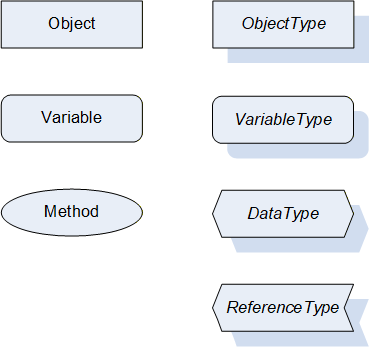
Figure 4 shows the symbols for the ReferenceTypes used in this specification. The Reference symbol is normally pointing from the source Node to the target Node. The only exception is the HasSubtype Reference. The most important References like HasComponent, HasProperty, HasTypeDefinition and HasSubtype have special symbols avoiding the name of the Reference. For other ReferenceTypes or derived ReferenceTypes the name of the ReferenceType is used together with the symbol.
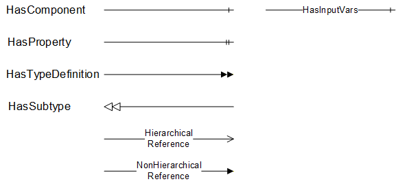
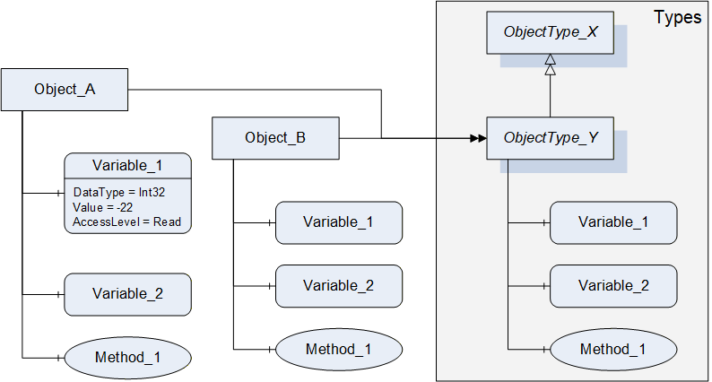
Figure 5 shows a typical example for the use of the graphical notation. Object_A and Object_B are instances of the ObjectType_Y indicated by the HasTypeDefinition References. The ObjectType_Y is derived from ObjectType_X indicated by the HasSubtype Reference. The Object_A has the components Variable_1, Variable_2 and Method_1.
To describe the components of an Object on the ObjectType the same NodeClasses and References are used on the Object and on the ObjectType like for ObjectType_Y in the example. The instance Nodes used to describe an ObjectType are instance declaration Nodes.
To provide more detailed information for a Node, a subset or all Attributes and their values can be added to a graphical symbol.
4.3 Use cases
4.3.1 Access to a POWERLINK Object Dictionary from an OPC UA Client
An OPC UA Client can use standard OPC UA Services to browse and access POWERLINK Objects defined in this document.
Possible use cases for this access are diagnostics, condition monitoring, configuration management, visualisation etc.
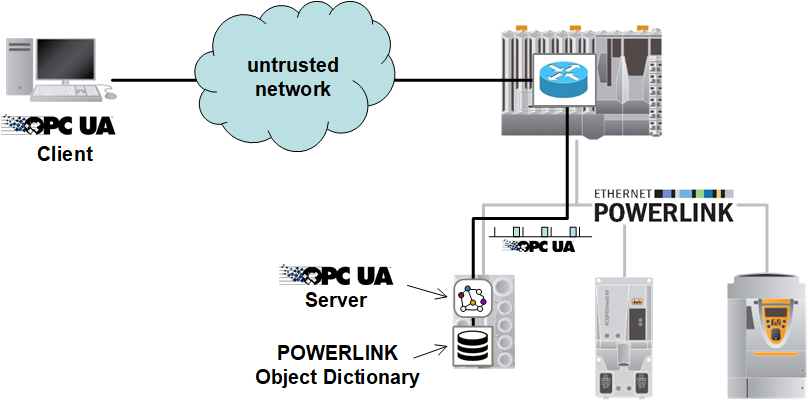
Figure 6 shows logical links between an OPC UA Client and a POWERLINK Object Dictionary.
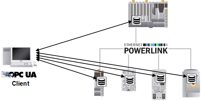
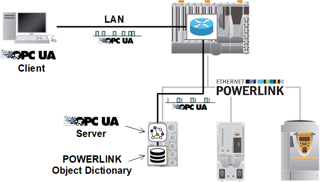
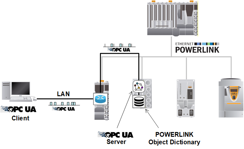
Since OPC UA Clients are typically operating in standard Ethernet networks using CSMA/CD and the POWERLINK network uses SCNM the physical connection will be established through standard TCP/IP routing mechanisms which may be implemented on the POWERLINK Managing Node (Figure 7) or on a POWERLINK Controlled Node (Figure 8).
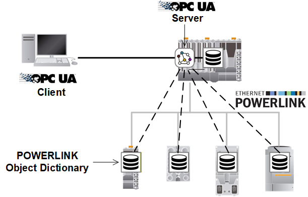
Another option to access POWERLINK Objects is an OPC UA Server that represents a group of POWERLINK Devices within one Information Model as shown in Figure 9.
4.3.2 Access to POWERLINK Objects through untrusted networks
The SDO protocol defined by POWERLINK is a Client/Server protocol to access POWERLINK Objects in a POWERLINK Object Dictionary, but this protocol does not support security.
The definition of SDO services over OPC UA allows secure SDO connections between POWERLINK Devices using the standard security mechanisms provided by OPC UA.
5 POWERLINK model overview
5.1 Overview
Figure 11 shows the general model and the central object types of this companion specification.
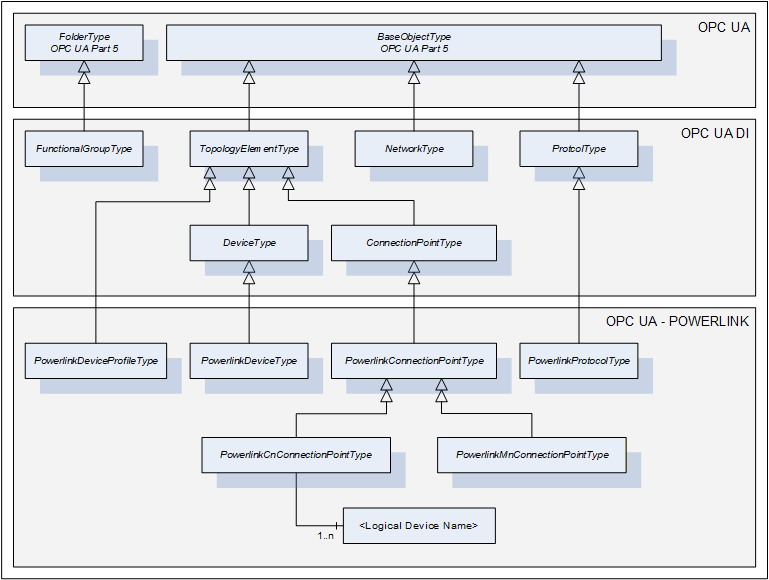
POWERLINK Objects are represented by OPC UA Variables as part of the PowerlinkConnectionPointType and its subtypes. A PowerlinkConnectionPointType contains common Variables while the subtypes contain only the Variables that are specific to the POWERLINK Controlled Node and the POWERLINK Managing Node.
Instances of subtypes of PowerlinkConnectionPointType are used to represent the POWERLINK Object Dictionary of a POWERLINK Device. The subtypes of ConnectionPointType are used to extend a Device (not limited to PowerlinkDeviceType) by one or more POWERLINK Object Dictionaries.
The PowerlinkDeviceType is used to represent a typical POWERLINK Device and defines a standardised way to generate the mandatory Properties for a DeviceType (like SerialNumber, RevisionCounter, etc.) from values of certain POWERLINK Objects. In case a Device implements more than one POWERLINK interface (by implementing multiple ConnectionPoints), the selection of the ConnectionPoint as source for the DeviceType Properties is implementation specific.
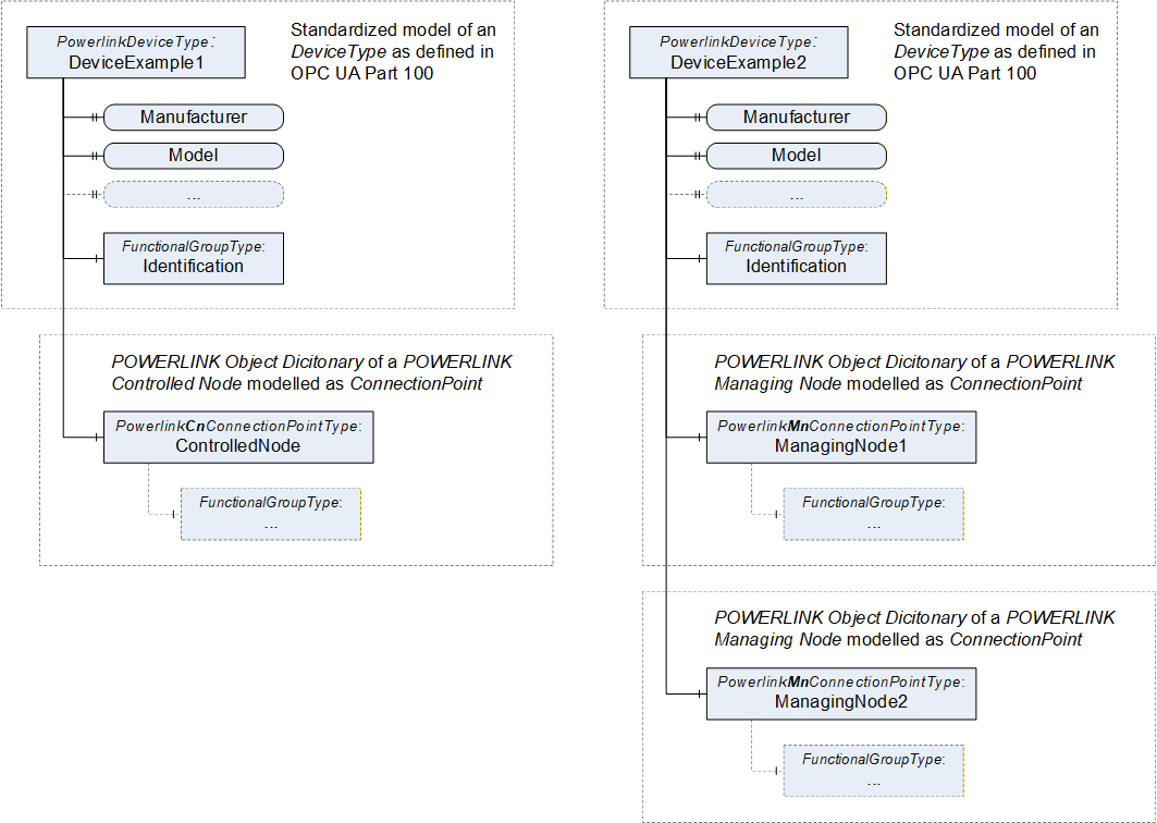
Figure 12 shows an example for a Device (DeviceExample1) that implements an instance of a POWERLINK Controlled Node and another Device (DeviceExample2) that implements two instances of a POWERLINK Managing Node.
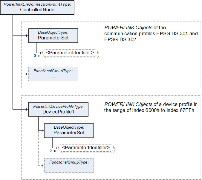
The focus of this document is the detailed specification of the POWERLINK Objects of the communication profile EPSG DS 301 and EPSG DS 302, but it also defines the modelling rules for the implementation of specific POWERLINK Device Profiles.
Figure 13 shows how to add device profile specific POWERLINK Objects to the existing definition for the communication profile. The modelling rules are defined in 5.2.
5.2 Modeling concepts
5.2.1 POWERLINK Objects and their attributes
One of the very significant differences between POWERLINK and OPC UA is that OPC UA provides metadata to each object directly through the Server, whereas POWERLINK can transport metadata only through XDD files or specification documents. Table 9 and Table 10 show examples for object definitions in the POWERLINK Communication Profile EPSG DS 301.
| Index | 1006h | Object Type | VAR |
| Name | NMT_CycleLen_U32 | ||
| Data Type | UNSIGNED32 | Category | M |
| Value Range | refer below | Access | rws, valid on reset |
| Default Range | - | PDO Mapping | No |
| Sub-Index | 09h | ||
| Name | Prescaler_U16 | ||
| Data Type | UNSIGNED16 | Category | MN: M, CN: O |
| Value Range | 0, 1-1000 | Access | rws, valid on reset |
| Default Range | 2 | PDO Mapping | No |
Figure 14 shows the same information in the XDD format defined in EPSG DS311.
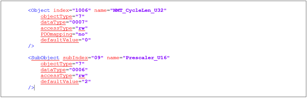
Table 11 lists the attributes that are specified for POWERLINK Objects, and how they are mapped to OPC UA mechanisms.
| POWERLINK Attribute | Description |
| Index | Index and Sub-Index are provided by the Information Model as Properties of the Objects as defined in 5.2.2, 5.2.3 and 5.2.4. |
| SubIndex | |
| Name | The name of the POWERLINK Object shall be used as the BrowseName and the DisplayName of the OPC UA Node |
| Object Type | The relevant object types of POWERLINK are VAR, ARRAY and RECORD. The VariableTypes PowerlinkArrayType, PowerlinkRecordType and PowerlinkVariableType are used to represent such objects from the POWERLINK Object Dictionary and extend the BaseDataVariableType by POWERLINK specific information about the object. POWERLINK Objects of the type ARRAY shall be modelled as PowerlinkArrayType (5.2.2) POWERLINK Objects of the type RECORD shall be modelled as PowerlinkRecordType (5.2.3) POWERLINK Objects of the type VAR shall be modelled as PowerlinkVariableType (5.2.4) |
| Data Type | The mapping of primitive datatypes is defined in Table 22. In certain cases the Information Model makes an exception and uses a Structure DataType to improve the usability. Examples for such exceptions: PowerlinkErrorEntryDataType (7.5.1), encoded as DOMAIN in POWERLINK PowerlinkPDOMappingEntryDataType (7.5.3), encoded as UINT64 in POWERLINK Also for usability reasons some variables are modelled as Enumeration. Examples for such cases: NMT_CurrNMTState_U8 (PowerlinkNMTStateEnumeratioin) NMT_ResetCmd_U8 (PowerlinkNMTResetCmdEnumeration) |
| Value Range | The Value Range of the POWERLINK Object can be provided by the optional Property Range of the PowerlinkVariableType (5.2.4). |
| Category | POWERLINK defines the 3 categories Mandatory (M), Optional (O) and Conditional (Cond). OPC UA defines the ModellingRules Mandatory and Optional. Since OPC UA does provide an ModellingRule which can be mapped to Conditional of POWERLINK, the mapping is the following: Category M becomes the ModellingRule Mandatory Category O becomes the ModellingRule Optional Category Cond becomes the ModellingRule Optional and requires a textual description at the objects definition about the condition that makes the object mandatory. |
| Access | Access and PDO Mapping are provided by the Property PowerlinkAttributes defined for the PowerlinkVariableType (5.2.4). |
| PDO Mapping | |
| Default Value | The default value of the object is provided by the optional Property DefaultValue of the PowerlinkVariableType (5.2.4). |
5.2.2 PowerlinkArrayType
The VariableType PowerlinkArrayType is formally defined in Table 12 and represents POWERLINK Objects of the type ARRAY as defined in 5.2.
| Attribute | Value | ||||||
| BrowseName | PowerlinkArrayType | ||||||
| IsAbstract | False | ||||||
| ValueRank | 1 (1 = OneDimension) | ||||||
| DataType | BaseDataType | ||||||
| References | NodeClass | BrowseName | DataType | TypeDefinition |
Modelling
Rule | Access Level | |
|---|---|---|---|---|---|---|---|
| Subtype of BaseDataVariableType defined in OPC 10000-5. | |||||||
| HasProperty | Variable | PowerlinkAttributes | PowerlinkAttributes | PropertyType | Mandatory | Read | |
| HasProperty | Variable | Index | UInt16 | PropertyType | Mandatory | Read | |
| HasProperty | Variable | NumberOfEntries | Byte | PropertyType | Mandatory | Read / Write | |
| HasProperty | Variable | Range | Range | PropertyType | Optional | Read | |
| HasProperty | Variable | DefaultValue | BaseDataType | PropertyType | Optional | Read | |
The Property PowerlinkAttributes provides the information of the XML-Attribute 'accessType' from the POWERLINK XML Device Description.
The Property Index provides the Index of the object in the POWERLINK Object Dictionary.
The Property NumberOfEntries provides the value of Sub-Index 0 of the POWERLINK Object. For most POWERLINK Objects this value is read-only. For a few, like ERR_History_ADOM or PDO_RxMappParam_XXh_AU64, this Property is also writable.
The optional Property Range provides the Value Range of the array elements.
The optional Property DefaultValue provides the default value of the array elements. The DataType of this Property shall be identical to the DataType of the DataVariable itself.
5.2.3 PowerlinkRecordType
The VariableType PowerlinkRecordType is formally defined in Table 13 and represents POWERLINK Objects of the type RECORD as defined in 5.2.
| Attribute | Value | ||||||
| BrowseName | PowerlinkRecordType | ||||||
| IsAbstract | True | ||||||
| ValueRank | -1 (-1 = Scalar) | ||||||
| DataType | Byte | ||||||
| Value | 0 | ||||||
| References | NodeClass | BrowseName | DataType | TypeDefinition |
Modelling
Rule | Access Level | |
|---|---|---|---|---|---|---|---|
| Subtype of BaseDataVariableType defined in OPC 10000-5. | |||||||
| HasProperty | Variable | Index | UInt16 | PropertyType | Mandatory | Read | |
| HasProperty | Variable | NumberOfEntries | Byte | PropertyType | Mandatory | Read | |
The Property Index provides the Index of the object in the POWERLINK Object Dictionary.
The Property NumberOfEntries provides the value of Sub-Index 0 of the POWERLINK Object.
5.2.4 PowerlinkVariableType
The VariableType PowerlinkVariableType if formally defined in Table 14 and represents POWERLINK Objects of the type VAR as defined in 5.2.
| Attribute | Value | ||||||
| BrowseName | PowerlinkVariableType | ||||||
| IsAbstract | False | ||||||
| ValueRank | -1 (-1 = Scalar) | ||||||
| DataType | BaseDataType | ||||||
| References | NodeClass | BrowseName | DataType | TypeDefinition |
Modelling
Rule | Access Level | |
|---|---|---|---|---|---|---|---|
| Subtype of BaseDataVariableType defined in OPC 10000-5. | |||||||
| HasProperty | Variable | PowerlinkAttributes | PowerlinkAttributes | PropertyType | Mandatory | Read | |
| HasProperty | Variable | Index | UInt16 | PropertyType | Mandatory | Read | |
| HasProperty | Variable | SubIndex | Byte | PropertyType | Mandatory | Read | |
| HasProperty | Variable | Range | Range | PropertyType | Optional | Read | |
| HasProperty | Variable | DefaultValue | BaseDataType | PropertyType | Optional | Read | |
The Property PowerlinkAttributes provides the information of the XML-Attribute 'accessType' from 'Object' and 'SubObject'-Elements in the POWERLINK XML Device Description. The DataType PowerlinkAttributes is formally defined in 7.3.1.
The Properties Index and SubIndex provide the address information of the object in the POWERLINK Object Dictionary.
The optional Property Range provides the Value Range of the POWERLINK Object.
The optional Property DefaultValue provides the default value of the POWERLINK Object. The DataType of this Property shall be identical to the DataType of the DataVariable itself.
Note 1 to entry:
The Properties Index and SubIndex serve two purposes. It is not only additional information for the Client, but it also allows a generic implementation to interpret an imported Information Model because it already provides the required addressing information.
6 OPC UA ObjectTypes for POWERLINK Communication Profile EPSG DS 301
6.1 PowerlinkDeviceType
6.1.1 General
This OPC UA ObjectType represents a Device with one or more POWERLINK interfaces.
Figure 15 shows an overview for the PowerlinkDeviceType with its Properties and related components. It is formally defined in Table 15.
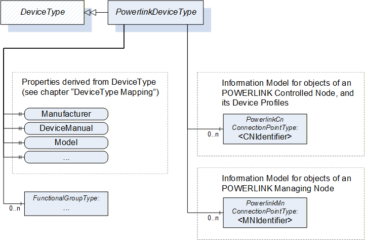
6.1.2 PowerlinkDeviceType Definition
The PowerlinkDeviceType is formally defined in Table 15.
| Attribute | Value | |||
| BrowseName | PowerlinkDeviceType | |||
| IsAbstract | False | |||
| NodeClass | BrowseName | DataType | TypeDefinition | Modelling Rule |
|---|---|---|---|---|
| Subtype of DeviceType defined in OPC 10000-100. | ||||
| Object | <CNIdentifier> | PowerlinkCnConnectionPointType | OptionalPlaceholder | |
| Object | <MNIdentifier> | PowerlinkMnConnectionPointType | OptionalPlaceholder | |
The PowerlinkDeviceType is an example for a DeviceType that only implements POWERLINK Managing Node (MN) and/or POWERLINK Controlled Node (CN) interfaces, for instance for the representation of POWERLINK Devices by a generic gateway. Usually a Device will only implement one of these choices, but it is also possible to implement multiple POWERLINK interfaces on one Device.
The usage of the PowerlinkCnConnectionPointType and the PowerlinkMnConnectionPointType is not limited to the PowerlinkDeviceType. These ConnectionPoint-Types can be used by any other subtype of DeviceType.
6.1.3 Placeholder CNIdentifier
The object CNIdentifier of the type PowerlinkCnConnectionPointType is a placeholder for the POWERLINK Object Dictionary of a POWERLINK Controlled Node. The PowerlinkCnConnectionPointType is defined in 6.3.
6.1.4 Placeholder MNIdentifier
The object MNIdentifier of the type PowerlinkMnConnectionPointType is a placeholder for the POWERLINK Object Dictionary of a POWERLINK Managing Node. The PowerlinkMnConnectionPointType is defined in 6.4.
6.1.5 Mapping for DeviceType (Types namespace)
The Type PowerlinkDeviceType is a subtype of DeviceType defined in OPC 10000-100, which mandates a list of Properties for the Device.
Table 16 defines the values for these Properties based on the POWERLINK Objects of the implemented POWERLINK interface. If a PowerlinkDeviceType implements more than one POWERLINK interface, the selection of the interface as source for these objects is device specific.
| DeviceType / OPC 10000-100 | POWERLINK | |
| BrowseName | DataType | Description |
| 1:SerialNumber | String | Value of the POWERLINK Object SerialNo_U32 (Index 1018h, Sub-Index 4), converted to a string as decimal number. If the optional POWERLINK Object is not provided by the device, SerialNumber shall be set to an empty string. |
| 1:RevisionCounter | Int32 | Always set to -1 |
| 1:Manufacturer | LocalizedText | This variable shall be set to the manufacturer name if known by the OPC UA server. If the server does not know the name the variable shall be set to the value of the POWERLINK Object VendorId_U32 (Index 1018h, Sub-Index 1), converted to a string as decimal number. |
| 1:Model | LocalizedText | Value of the POWERLINK Object NMT_ManufactDevName_VS (Index 1008h) If the optional POWERLINK Object is not provided by the device, Model shall be set to an empty text field. |
| 1:DeviceManual | String | Pathname in the file system or URL (Web Address) specifying the address of the user manual for the Device. |
| 1:DeviceRevision | String | Value of the POWERLINK Object RevisionNo_U32 (Index 1018h, Sub-Index 3), converted to a string with the format "major.minor", where "major" is the decimal number of the higher 16 bit and "minor" is the decimal number of the lower 16 bit (as defined in EPSG DS 301) Example: POWERLINK RevisionNo_U32 = 0x00020064 DeviceRevision = "2.100" If the optional POWERLINK Object t is not provided by the device, SoftwareRevision shall be set to an empty string. |
| 1:SoftwareRevision | String | Value of the POWERLINK Object NMT_ManufactSwVers_VS (Index 100Ah). If the optional POWERLINK Object is not provided by the device, SoftwareRevision shall be set to an empty string. |
| 1:HardwareRevision | String | Value of the POWERLINK Object NMT_ManufactHwVers_VS (Index 1009h) If the optional POWERLINK Object is not provided by the device, SoftwareRevision shall be set to an empty string. |
| 1:DeviceClass | String | Value of the POWERLINK Object NMT_DeviceType_U32 (Index 1000h), converted to a string as decimal number. |
6.2 PowerlinkConnectionPointType
6.2.1 General
The PowerlinkConnectionPointType is an abstract Object Type that defines the POWERLINK Objects, which are common for both POWERLINK Managing Node and POWERLINK Controlled Node.
Figure 16 shows a part of the PowerlinkConnectionPointType. The Object ParameterSet contains the POWERLINK Objects, modelled as defined in 5.2. In addition to these Variables, this specification defines a list of Methods (components of the Object MethodSet).
As defined by the concepts of OPC 10000-100 the Parameters (Variables) of the ParameterSet and Methods of the MethodSet are organised in FunctionalGroups where they are referenced by Organize-References. This concept allows splitting the Parameters into different categories, and at the same time, all Parameters are accessible under ParameterSet.
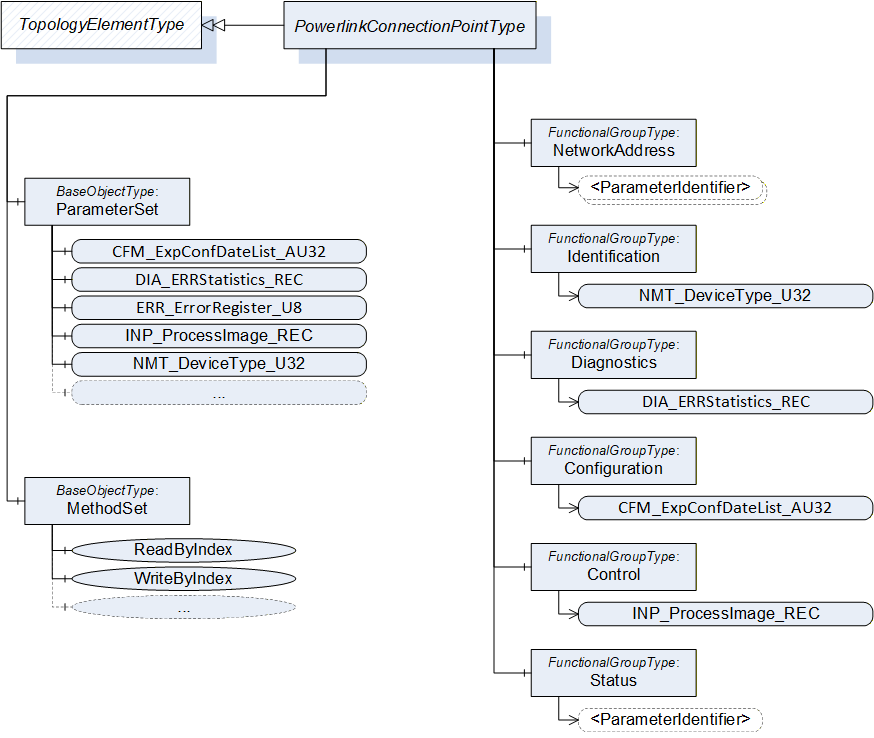
6.2.2 PowerlinkConnectionPointType Definition
The PowerlinkConnectionPointType is formally defined in Table 17.
| Attribute | Value | |||||||
| BrowseName | PowerlinkConnectionPointType | |||||||
| IsAbstract | True | |||||||
| NodeClass | BrowseName | DataType | TypeDefinition | Modelling Rule | Powerlink Attributes | |||
|---|---|---|---|---|---|---|---|---|
Subtype of ConnectionPointType defined in OPC 10000-100. HasSubtype PowerlinkCnConnectionPointType defined in 6.3 HasSubtype PowerlinkMnConnectionPointType defined in 6.4 | ||||||||
| FunctionalGroup NetworkAddress | ||||||||
|---|---|---|---|---|---|---|---|---|
| Variable | NMT_EPLNodeID_REC | - | NMT_EPLNodeID_Type | Mandatory | - | |||
| Variable | NWL_IpAddrTable_0h_REC | - | NWL_IpAddrTable_Type | Optional | - | |||
| Functional Group Identification | ||||||||
|---|---|---|---|---|---|---|---|---|
| Variable | NMT_ChildIdentList_AU16 | UInt16 [ ] | PowerlinkArrayType | Optional | R | |||
| Variable | NMT_DeviceType_U32 | UInt32 | PowerlinkVariableType | Mandatory | CONST | |||
| Variable | NMT_EPLVersion_U8 | Byte | PowerlinkVariableType | Mandatory | CONST | |||
| Variable | NMT_FeatureFlags_U32 | UInt32 | PowerlinkVariableType | Mandatory | CONST | |||
| Variable | NMT_HostName_VSTR | String | PowerlinkVariableType | Optional | RW,S | |||
| Variable | NMT_IdentityObject_REC | - | IDENTITY_Type | Mandatory | - | |||
| Variable | NMT_ManufactDevName_VS | String | PowerlinkVariableType | Optional | CONST | |||
| Variable | NMT_ManufactHwVers_VS | String | PowerlinkVariableType | Optional | CONST | |||
| Variable | NMT_ManufactSwVers_VS | String | PowerlinkVariableType | Optional | CONST | |||
| Functional Group Diagnostics | ||||||||
|---|---|---|---|---|---|---|---|---|
| Variable | DIA_ERRStatistics_REC | - | DIA_ERRStatistics_Type | Optional | - | |||
| Variable | DIA_NMTTelegrCount_REC | - | DIA_NMTTelegrCount_Type | Optional | - | |||
| Variable | ERR_ErrorRegister_U8 | ErrorRegisterBits | PowerlinkVariableType | Mandatory | R | |||
| Variable | ERR_History_ADOM | PowerlinkErrorEntryDataType [ ] | PowerlinkArrayType | Optional | R | |||
| Variable | PDO_ErrMapVers_OSTR | ByteString | PowerlinkVariableType | Optional | RW | |||
| Variable | PDO_ErrShort_RX_OSTR | ByteString | PowerlinkVariableType | Optional | RW | |||
| Functional Group Configuration | ||||||||
|---|---|---|---|---|---|---|---|---|
| Variable | NMT_ConsumerHeartbeatTime_AU32 | UInt32 [ ] | PowerlinkArrayType | Optional | RW,S | |||
| Variable | NMT_CycleLen_U32 | UInt32 | PowerlinkVariableType | Mandatory | RW,S,VR | |||
| Variable | NMT_CycleTiming_REC | - | NMT_CycleTiming_Type | Mandatory | - | |||
| Variable | NMT_IsochrSlotAssign_AU8 | Byte [ ] | PowerlinkArrayType | Optional | RW,S,VR | |||
| Variable | NMT_MultiplCycleAssign_AU8 | Byte [ ] | PowerlinkArrayType | Optional | RW,S,VR | |||
| Variable | NMT_NodeAssignment_AU32 | UInt32 [ ] | PowerlinkArrayType | Optional | RW,S | |||
| Variable | NMT_PResPayloadLimitList_AU16 | UInt16 [ ] | PowerlinkArrayType | Optional | RW,S,VR | |||
| Variable | NMT_RestoreDefParam_REC | - | NMT_ParameterStorage_Type | Optional | - | |||
| Variable | NMT_StoreParam_REC | |||||||
| Variable | PDL_MnExpAppSwDateList_AU32 | UInt32 [ ] | PowerlinkArrayType | Optional | RW,S | |||
| Variable | PDL_MnExpAppSwTimeList_AU32 | UInt32 [ ] | PowerlinkArrayType | Optional | RW,S | |||
| Variable | PDO_RxCommParam_00h_REC | - | PDO_CommParamRecord_Type | Optional | - | |||
| Variable | PDO_RxCommParam_01h_REC | |||||||
| Variable | PDO_RxCommParam_02h_REC | |||||||
| Variable | PDO_RxCommParam_03h_REC | |||||||
| Variable | PDO_RxMappParam_00h_AU64 | PowerlinkPDOMappingEntryDataType [ ] | PowerlinkArrayType | Optional | RW,S | |||
| Variable | PDO_RxMappParam_01h_AU64 | |||||||
| Variable | PDO_RxMappParam_02h_AU64 | |||||||
| Variable | PDO_RxMappParam_03h_AU64 | |||||||
| Variable | PDO_TxCommParam_00h_REC | - | PDO_CommParamRecord_Type | Optional | - | |||
| Variable | PDO_TxMappParam_00h_AU64 | PowerlinkPDOMappingEntryDataType [ ] | PowerlinkArrayType | Optional | RW,S | |||
| Variable | SDO_CmdLayerTimeout_U32 | UInt32 | PowerlinkVariableType | Optional | RW,S,VR | |||
| Variable | SDO_SequLayerNoAck_U32 | UInt32 | PowerlinkVariableType | Optional | RW,S,VR | |||
| Variable | SDO_SequLayerTimeout_U32 | UInt32 | PowerlinkVariableType | Mandatory | RW,S,VR | |||
| Functional Group Status | ||||||||
|---|---|---|---|---|---|---|---|---|
| Variable | NMT_CurrNMTState_U8 | PowerlinkNMTStateEnumeration | PowerlinkVariableType | Mandatory | R | |||
| Variable | NMT_InterfaceGroup_0h_REC | - | NMT_InterfaceGroup_Type | Mandatory | - | |||
| Variable | NMT_RelativeLatencyDiff_AU32 | UInt32 [ ] | PowerlinkArrayType | Optional | R | |||
| Functional Group Control | ||||||||
|---|---|---|---|---|---|---|---|---|
| Variable | INP_ProcessImage_REC | - | INP_ProcessImage_Type | Optional | - | |||
| Variable | NMT_ResetCmd_U8 | PowerlinkNMTResetCmdEnumeration | PowerlinkVariableType | Mandatory | RW | |||
| FunctionalGroup SdoServices | ||||||||
|---|---|---|---|---|---|---|---|---|
| Method | ReadByIndex | Defined in 6.2.3 Method ReadByIndex | Mandatory | |||||
| Method | WriteByIndex | Defined in 6.2.4 Method WriteByIndex | Mandatory | |||||
6.2.3 Method ReadByIndex
The Method ReadByIndex reads the value of a POWERLINK Object addressed by Index and Sub-Index.
Signature
	ReadByIndex (
		[in]	UInt16		Index
		[in]	Byte			SubIndex
		[out]	BaseDataType	Data
		[out]	UInt32		PowerlinkAbortCode
		);
| Argument | Description |
| Index | Index of the POWERLINK Object in the POWERLINK Object Dictionary |
| SubIndex | Sub-Index of the POWERLINK Object in the POWERLINK Object Dictionary |
| Data | Value of the POWERLINK Object |
| PowerlinkAbortCode | SDO Abort Code as defined in EPSG DS 301 Some of the SDO Abort Codes defined in POWERLINK are mapped to an OPC UA ResultCode, see table for 'Method Result Codes' |
Method Result Codes
| ResultCode | SDO Abort Code | Description |
| Good | 0 | The read access was successful |
| Bad_ResourceInvalid | - | The POWERLINK Device is not available, the output argument PowerlinkAbortCode will be set to 0x0504 0000 (timeout) |
| Bad_NotFound | 0x0602 0000 | Object does not exist in the POWERLINK Object Dictionary |
| 0x0609 0011 | Sub-Index does not exist | |
| Bad_Timeout | 0x0504 0000 | The operation timed out / SDO protocol timed out |
| Bad_NotReadable | 0x0601 0001 | Attempt to read a write-only POWERLINK Object |
| Bad_CommunicationError | All other SDO Abort Codes |
6.2.4 Method WriteByIndex
The Method WriteByIndex can be used to access the POWERLINK Object Dictionary by Index and Sub-Index to write values of POWERLINK Objects.
Signature
	WriteByIndex (
		[in]	UInt16		Index
		[in]	Byte			SubIndex
		[in]	BaseDataType	Data
		[out]	UInt32		PowerlinkAbortCode
		);
| Argument | Description |
| Index | Index of the POWERLINK Object in the POWERLINK Object Dictionary |
| SubIndex | Sub-Index of the POWERLINK Object in the POWERLINK Object Dictionary |
| Data | Data to be written to the POWERLINK Object |
| PowerlinkAbortCode | SDO Abort Code as defined in EPSG DS 301 Some of the SDO Abort Codes defined in POWERLINK are mapped to an OPC UA ResultCode, see table for 'Method Result Codes' |
Method Result Codes
| ResultCode | SDO Abort Code | Description |
| Good | 0 | The write access was successful |
| Bad_ResourceInvalid | - | The POWERLINK Device is not available, the output argument PowerlinkAbortCode will be set to 0x0504 0000 (timeout) |
| Bad_NotFound | 0x0602 0000 | Object does not exist in the POWERLINK Object Dictionary |
| 0x0609 0011 | Sub-Index does not exist | |
| Bad_Timeout | 0x0504 0000 | The operation timed out / SDO protocol timed out |
| Bad_NotSupported | 0x0601 0000 | Unsupported access to an POWERLINK Object |
| Bad_NotWritable | 0x0601 0002 | Attempt to write a read-only POWERLINK Object |
| Bad_OutOfRange | 0x0609 0030 | Value range of parameter exceeded |
| 0x0609 0031 | Value of parameter written too high | |
| 0x0609 0032 | Value of parameter written too low | |
| Bad_TypeMismatch | 0x0607 0010 | length of service parameter does not match |
| 0x0607 0012 | length of service parameter too high | |
| 0x0607 0013 | length of service parameter too low | |
| Bad_CommunicationError | All other SDO Abort Codes |
6.3 PowerlinkCnConnectionPointType
6.3.1 General
The PowerlinkCnConnectionPointType is a subtype of PowerlinkConnectionPointType and adds the POWERLINK Objects that are specific to the POWERLINK Controlled Node. It also provides the possibility to implement POWERLINK Device Profiles and customer specific POWERLINK Objects by adding components of the Type PowerlinkDeviceProfileType.
6.3.2 PowerlinkCnConnectionPointType Definition
The PowerlinkCnConnectionPointType is formally defined in Table 18.
| Attribute | Value | ||||
| BrowseName | PowerlinkCnConnectionPointType | ||||
| IsAbstract | False | ||||
| NodeClass | BrowseName | DataType | TypeDefinition | Modelling Rule | Powerlink Attributes |
|---|---|---|---|---|---|
| Subtype of PowerlinkConnectionPointType defined in 6.2.2. | |||||
| Object | <DeviceProfileIdentifier> | - | PowerlinkDeviceProfileType | OptionalPlaceholder | |
| FunctionalGroup Diagnostics | |||||
|---|---|---|---|---|---|
| Variable | DLL_CNCollision_REC | - | DLL_ErrorCntRec_Type | Optional | - |
| Variable | DLL_CNCRCError_REC | - | DLL_ErrorCntRec_Type | Mandatory | - |
| Variable | DLL_CNLossOfLinkCum_U32 | UInt32 | PowerlinkVariableType | Optional | RW |
| Variable | DLL_CNLossOfSocTolerance_U32 | UInt32 | PowerlinkVariableType | Mandatory | RW,S |
| Variable | DLL_CNLossPReq_REC | - | DLL_ErrorCntRec_Type | Optional | - |
| Variable | DLL_CNLossSoA_REC | - | DLL_ErrorCntRec_Type | Optional | - |
| Variable | DLL_CNLossSoC_REC | - | DLL_ErrorCntRec_Type | Mandatory | - |
| Variable | DLL_CNSoCJitter_REC | - | DLL_ErrorCntRec_Type | Optional | - |
| FunctionalGroup Configuration | |||||
|---|---|---|---|---|---|
| Variable | DLL_CNSoCJitterRange_U32 | UInt32 | PowerlinkVariableType | Optional | RW |
| Variable | NMT_CNBasicEthernetTimeout_U32 | UInt32 | PowerlinkVariableType | Mandatory | RW,S,VR |
6.3.3 Placeholder DeviceProfileIdentifier
The object DeviceProfileIdentifier of the type PowerlinkDeviceProfileType is a placeholder for the device- or vendor-specific part of the POWERLINK Object Dictionary.
The PowerlinkDeviceProfileType is formally defined in Table 19.
| Attribute | Value | ||||||
| BrowseName | PowerlinkDeviceProfileType | ||||||
| IsAbstract | False | ||||||
| References | NodeClass | BrowseName | DataType | TypeDefinition |
Modelling
Rule |
Access
Level | |
|---|---|---|---|---|---|---|---|
| Subtype of TopologyElementType defined in OPC 10000-100 | |||||||
| HasProperty | Variable | IndexRangeStart | UInt16 | PropertyType | Mandatory | Read | |
| HasProperty | Variable | IndexRangeSize | UInt16 | PropertyType | Mandatory | Read | |
The Properties IndexRangeStart and IndexRangeSize indicate the range of POWERLINK Objects represented by the instance. The POWERLINK Objects shall be components of the Object ParameterSet, which is defined in the TopologyElementType by OPC 10000-100.
Table 20 shows the ranges that are available for objects defined by POWERLINK Device Profiles and manufacturer specific POWERLINK Objects.
| Index Range | Description |
| 2000h - 5FFFh | Manufacturer Specific Profile Area |
| 6000h - 67FFh | Standardised Device Profile Area, device 0 |
| 6800h - 6FFFh | Standardised Device Profile Area, device 1 |
| 7000h - 77FFh | Standardised Device Profile Area, device 2 |
| 7800h - 7FFFh | Standardised Device Profile Area, device 3 |
| 8000h - 87FFh | Standardised Device Profile Area, device 4 |
| 8800h - 8FFFh | Standardised Device Profile Area, device 5 |
| 9000h - 97FFh | Standardised Device Profile Area, device 6 |
| 9800h - 9FFFh | Standardised Device Profile Area, device 7 |
6.4 PowerlinkMnConnectionPointType
6.4.1 General
The PowerlinkMnConnectionPointType is a subtype of PowerlinkConnectionPointType and adds the POWERLINK Objects that are specific to the POWERLINK Managing Node.
6.4.2 PowerlinkMnConnectionPointType Definition
The PowerlinkMnConnectionPointType is formally defined in Table 21.
| Attribute | Value | |||||||
| BrowseName | PowerlinkMnConnectionPointType | |||||||
| IsAbstract | False | |||||||
| NodeClass | BrowseName | DataType | TypeDefinition | Modelling Rule | Powerlink Attributes | |||
|---|---|---|---|---|---|---|---|---|
| Subtype of PowerlinkConnectionPointType defined in 6.2.2. | ||||||||
| FunctionalGroup Diagnostics | ||||||||
|---|---|---|---|---|---|---|---|---|
| Variable | DLL_MNCNLatePResCumCnt_AU32 | UInt32 [ ] | PowerlinkArrayType | Optional | RW | |||
| Variable | DLL_MNCNLatePResThrCnt_AU32 | UInt32 [ ] | PowerlinkArrayType | Optional | R | |||
| Variable | DLL_MNCNLatePResThreshold_AU32 | UInt32 [ ] | PowerlinkArrayType | Optional | RW,S | |||
| Variable | DLL_MNCNLossPResCumCnt_AU32 | UInt32 [ ] | PowerlinkArrayType | Optional | RW | |||
| Variable | DLL_MNCNLossPResThrCnt_AU32 | UInt32 [ ] | PowerlinkArrayType | Mandatory | R | |||
| Variable | DLL_MNCNLossPResThreshold_AU32 | UInt32 [ ] | PowerlinkArrayType | Mandatory | RW,S | |||
| Variable | DLL_MNCollision_REC | - | DLL_ErrorCntRec_Type | Optional | - | |||
| Variable | DLL_MNCRCError_REC | - | DLL_ErrorCntRec_Type | Mandatory | - | |||
| Variable | DLL_MNCycTimeExceed_REC | - | DLL_ErrorCntRec_Type | Optional | - | |||
| Variable | DLL_MNLossOfLinkCum_U32 | UInt32 [ ] | PowerlinkVariableType | Optional | RW | |||
| Variable | DLL_MNLossStatusResCumCnt_AU32 | UInt32 [ ] | PowerlinkArrayType | Optional | RW | |||
| Variable | DLL_MNLossStatusResThrCnt_AU32 | UInt32 [ ] | PowerlinkArrayType | Mandatory | R | |||
| Variable | DLL_MNLossStatusResThreshold_AU32 | UInt32 [ ] | PowerlinkArrayType | Mandatory | RW,S | |||
| Variable | NMT_MNNodeCurrState_AU8 | PowerlinkNMTStateEnumeration [ ] | PowerlinkArrayType | Mandatory | R | |||
| Variable | NMT_MNNodeExpState_AU8 | PowerlinkNMTStateEnumeration [ ] | PowerlinkArrayType | Optional | R | |||
| Variable | NMT_RequestCmd_REC | - | NMT_RequestCmd_Type | Mandatory | - | |||
| FunctionalGroup Configuration | ||||||||
|---|---|---|---|---|---|---|---|---|
| Variable | CFM_ExpConfDateList_AU32 | UInt32 [ ] | PowerlinkArrayType | Optional | RW,S | |||
| Variable | CFM_ExpConfIdList_AU32 | UInt32 [ ] | PowerlinkArrayType | Optional | RW,S | |||
| Variable | CFM_ExpConfTimeList_AU32 | UInt32 [ ] | PowerlinkArrayType | Optional | RW,S | |||
| Variable | DLL_MNCycleSuspendNumber_U32 | UInt32 | PowerlinkVariableType | Mandatory | RW | |||
| Variable | NMT_BootTime_REC | - | NMT_BootTime_Type | Mandatory | - | |||
| Variable | NMT_MNCNPResTimeout_AU32 | UInt32 [ ] | PowerlinkArrayType | Mandatory | RW,S,VR | |||
| Variable | NMT_MNCycleTiming_REC | - | NMT_MNCycleTiming_Type | Mandatory | - | |||
| Variable | NMT_MNDeviceTypeIdList_AU32 | UInt32 [ ] | PowerlinkArrayType | Mandatory | RW,S,VR | |||
| Variable | NMT_MNPReqPayloadLimitList_AU16 | UInt16 [ ] | PowerlinkArrayType | Mandatory | RW,S,VR | |||
| Variable | NMT_MNProductCodeList_AU32 | UInt32 [ ] | PowerlinkArrayType | Optional | RW,S,VR | |||
| Variable | NMT_MNRevisionNoList_AU32 | UInt32 [ ] | PowerlinkArrayType | Optional | RW,S,VR | |||
| Variable | NMT_MNSerialNoList_AU32 | UInt32 [ ] | PowerlinkArrayType | Optional | RW,S,VR | |||
| Variable | NMT_MNVendorIdList_AU32 | UInt32 [ ] | PowerlinkArrayType | Optional | RW,S,VR | |||
| Variable | NMT_StartUp_U32 | UInt32 | PowerlinkVariableType | Mandatory | RW,S,VR | |||
| Variable | PDO_TxCommParam_01h_REC | - | PDO_CommParamRecord_Type | Optional | - | |||
| Variable | PDO_TxCommParam_02h_REC | |||||||
| Variable | PDO_TxCommParam_03h_REC | |||||||
| Variable | PDO_TxMappParam_01h_AU64 | PowerlinkPDOMappingEntryDataType [ ] | PowerlinkArrayType | Optional | RW,S | |||
| Variable | PDO_TxMappParam_02h_AU64 | |||||||
| Variable | PDO_TxMappParam_03h_AU64 | |||||||
7 Mapping of DataTypes
7.1 Primitive DataTypes
Table 22 shows the mapping between basic data types of both standards.
POWERLINK Basic Data Types | OPC UA DataTypes | Description |
| BOOLEAN | Boolean | 1 Bit |
| INTEGER8 | SByte | Signed integer, 8 Bit |
| INTEGER16 | Int16 | Signed integer, 16 Bit |
| INTEGER32 | Int32 | Signed integer, 32 Bit |
| INTEGER64 | Int64 | Signed integer, 64 Bit |
| UNSIGNED8 | Byte | Unsigned integer, 8 Bit |
| UNSIGNED16 | UInt16 | Unsigned integer, 16 Bit |
| UNSIGNED32 | UInt32 | Unsigned integer, 32 Bit |
| UNSIGNED64 | UInt64 | Unsigned integer, 64 Bit |
| REAL32 | Float | Float, 32 Bit |
| REAL64 | Double | Float, 64 Bit |
| DOMAIN | ByteString | ByteString with variable size |
| IP_ADDRESS | PowerlinkIpAddressDataType | IPV4 Address |
| OCTET_STRING | ByteString | ByteString with variable size |
| VISIBLE_STRING | String | Variable number bytes interpreted as ISO 646-1973(E) 7-bit coded characters |
7.2 Enumeration DataTypes
7.2.1 PowerlinkNMTStateEnumeration
This DataType is an enumeration that represents the NMT State. Its values are defined in Table 23. States with the prefix "NMT_XS" represent a state that is existing for the POWERLINK Controlled Node as well as for the POWERLINK Managing Node. For instance, the states NMT_MS_OPERATIONAL and NMT_CS_OPERATIONAL are both represented by the enumeration value NMT_XS_OPERATIONAL_253.
| Value | Description |
| NMT_GS_OFF_0 | |
| NMT_GS_INITIALISING_25 | first state after power-on of the POWERLINK Device |
| NMT_GS_RESET_APPLICATION_41 | set manufacturer-specific and standardised device profile area to their power-on values |
| NMT_GS_RESET_COMMUNICATION_57 | set communication profile area (except ERR_History_ADOM) to their power-on values |
| NMT_GS_RESET_CONFIGURATION_121 | generate the active device configuration |
| NMT_XS_NOT_ACTIVE_28 | a non-permanent state which allows a starting device to recognise the current network state |
| NMT_XS_PRE_OPERATIONAL_1_29 | the POWERLINK network operates in reduced cycle |
| NMT_XS_PRE_OPERATIONAL_2_93 | the POWERLINK network operates in isochronous operation, but the device is still in a configuration state |
| NMT_XS_READY_TO_OPERATE_109 | the device configuration is completed and the device is ready to switch over to NMT_XS_OPERATIONAL |
| NMT_XS_OPERATIONAL_253 | normal operating state of a POWERLINK Device |
| NMT_CS_STOPPED_77 | the device is largely passive, NMT_CS_STOPPED shall be used for controlled shutdown of a selected CN while the system is still running |
| NMT_XS_BASIC_ETHERNET_30 | Legacy Ethernet communication according to IEEE 802.3, no POWERLINK specific network traffic control |
Its representation in the AddressSpace is defined in Table 24.
| Attributes | Value |
| BrowseName | PowerlinkNMTStateEnumeration |
| Subtype of Enumeration defined in OPC 10000-5. | |
7.2.2 PowerlinkNMTResetCmdEnumeration
This DataType is an Enumeration that represents the NMT reset commands for POWERLINK. Its values are defined in Table 23.
| Value | Description |
| NMTResetNode_40 | start application initialisation |
| NMTResetCommunication_41 | start communication initialisation |
| NMTResetConfiguration_42 | activate device configuration |
| NMTSwReset_43 | start basic node initialisation |
| NMTInvalidService_255 | readback value for the POWERLINK Object NMT_ResetCmd_U8 |
Its representation in the AddressSpace is defined in Table 24.
| Attributes | Value |
| BrowseName | PowerlinkNMTResetCmdEnumeration |
| Subtype of Enumeration defined in OPC 10000-5. | |
7.3 OptionSet DataTypes
7.3.1 PowerlinkAttributes
This DataType is an OptionSet that represents the POWERLINK entry attributes. It is a subtype of OptionSet. Its values are defined in Table 27 and the DataType is used for the Property PowerlinkAttributes in the VariableTypes PowerlinkArrayType (5.2.2) and PowerlinkVariableType (5.2.4).
| Value | Bit | Abbreviation | Description |
| Const | 0 | CONST | Read access only, the value is not changing |
| Read | 1 | R | Read access |
| Write | 2 | W | Write access |
| Input | 3 | I | Represents process input data, object can be used in PDO mapping |
| Output | 4 | O | Represents process output data, object can be used in PDO mapping |
| Store | 5 | S | Can be stored to non-volatile memory |
| ValidOnReset | 6 | VR | Only valid after reset |
| DefaultMapping | 7 | DEF | Variable is included in default mapping |
| RPDO | 8 | RPDO | Variable may be mapped into receive PDO |
| TPDO | 9 | TPDO | Variable may be mapped into transmit PDO |
The expressions in the column 'Abbreviation' are used in the OPC UA object definitions.
The Field CurrentRead of the Variables Attribute AccessLevel shall be contain the same value as the Field Read in the Variables Attribute PowerlinkAttributes.
The Field CurrentWrite of the Variables Attribute AccessLevel shall be contain the same value as the Field Write in the Variables Attribute PowerlinkAttributes.
| Attributes | Value |
| BrowseName | PowerlinkAttributes |
| Subtype of OptionSet defined in OPC 10000-3. | |
7.3.2 ErrorRegisterBits
This DataType is an OptionSet that represents the values of the Variable ERR_ErrorRegister_U8. It is a subtype of Byte. Its values are defined in Table 29.
| Value | Bit | Description |
| Generic_error | 0 | This bit shall be set if any error is present. Additionally to this bit, the following bits may be used to signal more detailed error information. |
| Current | 1 | |
| Voltage | 2 | |
| Temperature | 3 | |
| Communication_error | 4 | |
| Device_profile_specific | 5 | |
| Reserved | 6 | always 0 |
| Manufacturer_specific | 7 |
| Attributes | Value |
| BrowseName | ErrorRegisterBits |
| Subtype of OptionSet defined in OPC 10000-3. | |
7.4 VariableTypes
7.4.1 DIA_ERRStatistics_Type Definition
Table 31 formally defines the VariableType to represent the POWERLINK Record DIA_ERRStatistics_TYPE.
| Attribute | Value | |||||
| BrowseName | DIA_ERRStatistics_Type | |||||
| IsAbstract | False | |||||
| References | NodeClass | BrowseName |
Data
Type |
Type
Definition |
Modelling
Rule | Powerlink Attributes |
|---|---|---|---|---|---|---|
| Subtype of PowerlinkRecordType defined in 5.2.3. | ||||||
| HasComponent | Variable | HistoryEntryWrite_U32 | UInt32 | PowerlinkVariableType | Optional | R |
| HasComponent | Variable | EmergencyQueueWrite_U32 | ||||
| HasComponent | Variable | EmergencyQueueOverflow_U32 | ||||
| HasComponent | Variable | StatusEntryChanged_U32 | ||||
| HasComponent | Variable | StaticErrorBitFieldChanged_U32 | ||||
| HasComponent | Variable | ExceptionResetEdgePos_U32 | ||||
| HasComponent | Variable | ExceptionNewEdge_U32 | ||||
7.4.2 DIA_NMTTelegrCount_Type Definition
Table 32 formally defines the VariableType to represent the POWERLINK Record DIA_NMTTelegrCount_TYPE.
| Attribute | Value | |||||
| BrowseName | DIA_NMTTelegrCount_Type | |||||
| IsAbstract | False | |||||
| References | NodeClass | BrowseName |
Data
Type |
Type
Definition |
Modelling
Rule | Powerlink Attributes |
|---|---|---|---|---|---|---|
| Subtype of PowerlinkRecordType defined in 5.2.3. | ||||||
| HasComponent | Variable | IsochrCyc_U32 | UInt32 | PowerlinkVariableType | Optional | R |
| HasComponent | Variable | IsochrRx_U32 | ||||
| HasComponent | Variable | IsochrTx_U32 | ||||
| HasComponent | Variable | AsyncRx_U32 | ||||
| HasComponent | Variable | AsyncTx_U32 | ||||
| HasComponent | Variable | SdoRx_U32 | ||||
| HasComponent | Variable | SdoTx_U32 | ||||
| HasComponent | Variable | Status_U32 | ||||
7.4.3 DLL_ErrorCntRec_Type Definition
Table 33 formally defines the VariableType to represent the POWERLINK Record DLL_ErrorCntRec_TYPE.
| Attribute | Value | |||||
| BrowseName | DLL_ErrorCntRec_Type | |||||
| IsAbstract | False | |||||
| References | NodeClass | BrowseName |
Data
Type |
Type
Definition |
Modelling
Rule | Powerlink Attributes |
|---|---|---|---|---|---|---|
| Subtype of PowerlinkRecordType defined in 5.2.3. | ||||||
| HasComponent | Variable | CumulativeCnt_U32 | UInt32 | PowerlinkVariableType | Mandatory | RW |
| HasComponent | Variable | Threshold_U32 | UInt32 | Mandatory | RW,S,VR | |
| HasComponent | Variable | ThresholdCnt_U32 | UInt32 | Mandatory | R | |
7.4.4 IDENTITY_Type Definition
Table 34 formally defines the VariableType to represent the POWERLINK Record IDENTITY.
| Attribute | Value | |||||
| BrowseName | IDENTITY_Type | |||||
| IsAbstract | False | |||||
| References | NodeClass | BrowseName |
Data
Type |
Type
Definition |
Modelling
Rule | Powerlink Attributes |
|---|---|---|---|---|---|---|
| Subtype of PowerlinkRecordType defined in 5.2.3. | ||||||
| HasComponent | Variable | VendorId_U32 | UInt32 | PowerlinkVariableType | Mandatory | CONST |
| HasComponent | Variable | ProductCode_U32 | UInt32 | Optional | CONST | |
| HasComponent | Variable | RevisionNo_U32 | UInt32 | Optional | CONST | |
| HasComponent | Variable | SerialNo_U32 | UInt32 | Optional | CONST | |
7.4.5 INP_ProcessImage_Type Definition
Table 35 formally defines the VariableType to represent the POWERLINK Record INP_ProcessImage_TYPE.
| Attribute | Value | |||||
| BrowseName | INP_ProcessImage_Type | |||||
| IsAbstract | False | |||||
| References | NodeClass | BrowseName |
Data
Type |
Type
Definition |
Modelling
Rule | Powerlink Attributes |
|---|---|---|---|---|---|---|
| Subtype of PowerlinkRecordType defined in 5.2.3. | ||||||
| HasComponent | Variable | SelectedRange_U32 | UInt32 | PowerlinkVariableType | Mandatory | RW |
| HasComponent | Variable | ProcessImageDomain_DOM | ByteString | Mandatory | RW | |
7.4.6 NMT_BootTime_Type Definition
Table 36 formally defines the VariableType to represent the POWERLINK Record NMT_BootTime_TYPE.
| Attribute | Value | |||||
| BrowseName | NMT_BootTime_Type | |||||
| IsAbstract | False | |||||
| References | NodeClass | BrowseName |
Data
Type |
Type
Definition |
Modelling
Rule | Powerlink Attributes |
|---|---|---|---|---|---|---|
| Subtype of PowerlinkRecordType defined in 5.2.3. | ||||||
| HasComponent | Variable | MNWaitNotAct_U32 | UInt32 | PowerlinkVariableType | Mandatory | RW,S,VR |
| HasComponent | Variable | MNTimeoutPreOp1_U32 | UInt32 | Mandatory | RW,S,VR | |
| HasComponent | Variable | MNWaitPreOp1_U32 | UInt32 | Optional | RW,S,VR | |
| HasComponent | Variable | MNTimeoutPreOp2_U32 | UInt32 | Mandatory | RW,S,VR | |
| HasComponent | Variable | MNTimeoutReadyToOp_U32 | UInt32 | Mandatory | RW,S,VR | |
| HasComponent | Variable | MNIdentificationTimeout_U32 | UInt32 | Optional | RW,S,VR | |
| HasComponent | Variable | MNSoftwareTimeout_U32 | UInt32 | Optional | RW,S,VR | |
| HasComponent | Variable | MNConfigurationTimeout_U32 | UInt32 | Optional | RW,S,VR | |
| HasComponent | Variable | MNStartCNTimeout_U32 | UInt32 | Optional | RW,S,VR | |
| HasComponent | Variable | MNSwitchOverPriority_U32 | UInt32 | Optional | RW,VR | |
| HasComponent | Variable | MNSwitchOverDelay_U32 | UInt32 | Optional | RW,VR | |
| HasComponent | Variable | MNSwitchOverCycleDivider_U32 | UInt32 | Optional | RW,VR | |
7.4.7 NMT_CycleTiming_Type Definition
Table 37 formally defines the VariableType to represent the POWERLINK Record NMT_CycleTiming_TYPE.
| Attribute | Value | |||||
| BrowseName | NMT_CycleTiming_Type | |||||
| IsAbstract | False | |||||
| References | NodeClass | BrowseName |
Data
Type |
Type
Definition |
Modelling
Rule | Powerlink Attributes |
|---|---|---|---|---|---|---|
| Subtype of PowerlinkRecordType defined in 5.2.3. | ||||||
| HasComponent | Variable | IsochrTxMaxPayload_U16 | UInt16 | PowerlinkVariableType | Mandatory | CONST |
| HasComponent | Variable | IsochrRxMaxPayload_U16 | UInt16 | Mandatory | CONST | |
| HasComponent | Variable | PResMaxLatency_U32 | UInt32 | Optional | CONST | |
| HasComponent | Variable | PReqActPayloadLimit_U16 | UInt16 | Optional | RW,S,VR | |
| HasComponent | Variable | PResActPayloadLimit_U16 | UInt16 | Optional | RW,S,VR | |
| HasComponent | Variable | ASndMaxLatency_U32 | UInt32 | Optional | CONST | |
| HasComponent | Variable | MultiplCycleCnt_U8 | Byte | Mandatory | RW,S,VR | |
| HasComponent | Variable | AsyncMTU_U16 | UInt16 | Mandatory | RW,S,VR | |
| HasComponent | Variable | Prescaler_U16 | UInt16 | Optional | RW,S,VR | |
| HasComponent | Variable | PResMode_U8 | Byte | Optional | R | |
| HasComponent | Variable | PResTimeFirst_U32 | UInt32 | Optional | R | |
| HasComponent | Variable | PResTimeSecond_U32 | UInt32 | Optional | R | |
| HasComponent | Variable | SyncMNDelayFirst_U32 | UInt32 | Optional | R | |
| HasComponent | Variable | SyncMNDelaySecond_U32 | UInt32 | Optional | R | |
| HasComponent | Variable | LeaseTime_U32 | UInt32 | Optional | R | |
7.4.8 NMT_EPLNodeID_Type Definition
Table 38 formally defines the VariableType to represent the POWERLINK Record NMT_EPLNodeID_TYPE.
| Attribute | Value | |||||
| BrowseName | NMT_EPLNodeID_Type | |||||
| IsAbstract | False | |||||
| References | NodeClass | BrowseName |
Data
Type |
Type
Definition |
Modelling
Rule | Powerlink Attributes |
|---|---|---|---|---|---|---|
| Subtype of PowerlinkRecordType defined in 5.2.3. | ||||||
| HasComponent | Variable | NodeID_U8 | Byte | PowerlinkVariableType | Mandatory | R |
| HasComponent | Variable | NodeIDByHW_BOOL | Boolean | Mandatory | R | |
| HasComponent | Variable | SWNodeID_U8 | Byte | Optional | RW,S,VR | |
7.4.9 NMT_InterfaceGroup_Type Definition
Table 39 formally defines the VariableType to represent the POWERLINK Record NMT_InterfaceGroup_Xh_TYPE.
| Attribute | Value | |||||
| BrowseName | NMT_InterfaceGroup_Type | |||||
| IsAbstract | False | |||||
| References | NodeClass | BrowseName |
Data
Type |
Type
Definition |
Modelling
Rule | Powerlink Attributes |
|---|---|---|---|---|---|---|
| Subtype of PowerlinkRecordType defined in 5.2.3. | ||||||
| HasComponent | Variable | InterfaceIndex_U16 | UInt16 | PowerlinkVariableType | Mandatory | R |
| HasComponent | Variable | InterfaceDescription_VSTR | String | Mandatory | CONST | |
| HasComponent | Variable | InterfaceType_U8 | Byte | Mandatory | CONST | |
| HasComponent | Variable | InterfaceMtu_U16 | UInt16 | Mandatory | CONST | |
| HasComponent | Variable | InterfacePhysAddress_OSTR | ByteString | Mandatory | CONST | |
| HasComponent | Variable | InterfaceName_VSTR | String | Mandatory | R | |
| HasComponent | Variable | InterfaceOperStatus_U8 | Byte | Mandatory | R | |
| HasComponent | Variable | InterfaceAdminState_U8 | Byte | Mandatory | RW,S | |
| HasComponent | Variable | Valid_BOOL | Boolean | Mandatory | RW,S | |
| HasComponent | Variable | PortEnableMask_U64 | UInt64 | Optional | R | |
7.4.10 NMT_MNCycleTiming_Type Definition
Table 40 formally defines the VariableType to represent the POWERLINK Record NMT_MNCycleTiming_TYPE.
| Attribute | Value | |||||
| BrowseName | NMT_MNCycleTiming_Type | |||||
| IsAbstract | False | |||||
| References | NodeClass | BrowseName |
Data
Type |
Type
Definition |
Modelling
Rule | Powerlink Attributes |
|---|---|---|---|---|---|---|
| Subtype of PowerlinkRecordType defined in 5.2.3. | ||||||
| HasComponent | Variable | WaitSoCPReq_U32 | UInt32 | PowerlinkVariableType | Mandatory | RW,S,VR |
| HasComponent | Variable | AsyncSlotTimeout_U32 | UInt32 | Optional | RW,S,VR | |
| HasComponent | Variable | ASndMaxNumber | Byte | Optional | RW,S,VR | |
| HasComponent | Variable | MinRedCycleTime_U32 | UInt32 | Optional | RW,S,VR | |
7.4.11 NMT_ParameterStorage_Type Definition
Table 41 formally defines the VariableType to represent the POWERLINK Record NMT_ParameterStorage_TYPE.
| Attribute | Value | |||||
| BrowseName | NMT_ParameterStorage_Type | |||||
| IsAbstract | False | |||||
| References | NodeClass | BrowseName |
Data
Type |
Type
Definition |
Modelling
Rule | Powerlink Attributes |
|---|---|---|---|---|---|---|
| Subtype of PowerlinkRecordType defined in 5.2.3. | ||||||
| HasComponent | Variable | AllParam_U32 | UInt32 | PowerlinkVariableType | Mandatory | RW |
| HasComponent | Variable | CommunicationParam_U32 | UInt32 | Optional | RW | |
| HasComponent | Variable | ApplicationParam_U32 | UInt32 | Optional | RW | |
| HasComponent | Variable | ManufacturerParam_XXh_U32 | UInt32 | Optional Placeholder | RW | |
7.4.12 NMT_RequestCmd_Type Definition
Table 42 formally defines the VariableType to represent the POWERLINK Record NMT_RequestCmd_TYPE.
| Attribute | Value | |||||
| BrowseName | NMT_RequestCmd_Type | |||||
| IsAbstract | False | |||||
| References | NodeClass | BrowseName | DataType |
Type
Definition |
Modelling
Rule | Powerlink Attributes |
|---|---|---|---|---|---|---|
| Subtype of PowerlinkRecordType defined in 5.2.3. | ||||||
| HasComponent | Variable | Release_BOOL | Boolean | PowerlinkVariableType | Mandatory | RW |
| HasComponent | Variable | CmdID_U8 | Byte | Mandatory | RW | |
| HasComponent | Variable | CmdTarget_U8 | Byte | Mandatory | RW | |
| HasComponent | Variable | CmdData_DOM | ByteString | Optional | RW | |
7.4.13 NWL_IpAddrTable_Type Definition
Table 43 formally defines the VariableType to represent the POWERLINK Record NWL_IpAddrTable_TYPE.
| Attribute | Value | |||||
| BrowseName | NWL_IpAddrTable_Type | |||||
| IsAbstract | False | |||||
| References | NodeClass | BrowseName | DataType |
Type
Definition |
Modelling
Rule | Powerlink Attributes |
|---|---|---|---|---|---|---|
| Subtype of PowerlinkRecordType defined in 5.2.3. | ||||||
| HasComponent | Variable | IfIndex_U16 | UInt16 | PowerlinkVariableType | Mandatory | R |
| HasComponent | Variable | Addr_IPAD | PowerlinkIpAddressDatatType | Mandatory | RW,S | |
| HasComponent | Variable | NetMask_IPAD | PowerlinkIpAddressDatatType | Mandatory | RW,S | |
| HasComponent | Variable | ReasmMaxSize_U16 | UInt16 | Mandatory | R | |
| HasComponent | Variable | DefaultGateway_IPAD | PowerlinkIpAddressDatatType | Mandatory | RW,S | |
7.4.14 PDO_CommParamRecord_Type Definition
Table 44 formally defines the VariableType to represent the POWERLINK Record PDO_CommParamRecord_TYPE.
| Attribute | Value | |||||
| BrowseName | PDO_CommParamRecord_Type | |||||
| IsAbstract | False | |||||
| References | NodeClass | BrowseName | DataType |
Type
Definition |
Modelling
Rule | Powerlink Attributes |
|---|---|---|---|---|---|---|
| Subtype of PowerlinkRecordType defined in 5.2.3. | ||||||
| HasComponent | Variable | NodeID_U8 | Byte | PowerlinkVariableType | Mandatory | RW,S |
| HasComponent | Variable | MappingVersion_U8 | Byte | Mandatory | RW,S | |
7.5 Structure DataTypes
7.5.1 PowerlinkErrorEntryDataType
Table 45 formally defines the Structure DataType PowerlinkErrorEntryDataType to represent the entries of the POWERLINK Object ERR_History_ADOM.
| Name | Type | Description |
| PowerlinkErrorEntryDataType | Structure | |
entryType | UInt16 | Entry type as defined in the Powerlink specification EPSG DS 301 |
errorCode | UInt16 | Error code as defined in the Powerlink specification EPSG DS 301 |
timeStamp | UInt64 | SoC Nettime from the cycle when the error/event was detected |
additionalInformation | UInt64 | This field contains device profile or vendor specific additional error information |
7.5.2 PowerlinkIpAddressDataType
Table 46 formally defines the Structure DataType PowerlinkIpAddressDataType to represent POWERLINK Objects of the POWERLINK data type IP_ADDRESS.
| Name | Type | Description |
| PowerlinkIpAddressDataType | Structure | |
b1 | Byte | 1st byte of the IP-Address, e.g. 192 for the Address 192.168.100.1 |
b2 | Byte | 2nd byte of the IP-Address, e.g. 168 for the Address 192.168.100.1 |
b3 | Byte | 3rd byte of the IP-Address, e.g. 100 for the Address 192.168.100.1 |
b4 | Byte | 4th byte of the IP-Address, e.g. 1 for the Address 192.168.100.1 |
7.5.3 PowerlinkPDOMappingEntryDataType
Table 47 formally defines the Structure DataType PowerlinkPDOMappingEntryDataType to represent the entries of POWERLINK Objects like PDO_RxCommParam_00h_REC.
| Name | Type | Description |
| PowerlinkPDOMappingEntryDataType | Structure | |
length | UInt16 | Index of the object to be mapped |
offset | UInt16 | Sub-Index of the object to be mapped |
reserved | Byte | for alignment purpose |
subIndex | Byte | Offset related to start of PDO payload (Bit count) |
index | UInt16 | Length of the mapped object (Bit count) |
8 Direct addressing of the POWERLINK Object Dictionary
8.1 General
The definition of the objects in the previous paragraphs enables the generic access to POWERLINK Objects from the POWERLINK Communication Profiles EPSG DS 301 and EPSG DS 302. Without an extension of the Information Model the access to vendor- or profile-specific POWERLINK Objects would be only possible through the SDO Services defined in 6.2.A client would not be able to create MonitoredItems and Subscriptions to vendor-specific objects since they would not have an individual NodeId.
One way to generate individual NodeIds is to convert the vendor specific device description from POWERLINK into an OPC UA Information Model and to deploy the models of all involved POWERLINK Devices to the OPC UA Server. This might be feasible for Servers that run on the POWERLINK Device itself and represent only their own device.
This paragraph defines another, more generic way to provide individual NodeIds for random objects in a POWERLINK Object Dictionary.
For this generic access the Namespace 'http://opcfoundation.org/UA/POWERLINK/UA/DirectAccess/' is used.
8.2 OPAQUE NodeIds
8.2.1 General
When using NodeIds of the type OPAQUE_3 the NodeId contains information about address and DataType in binary form. Compared to String-NodeIds this format is smaller and generates less overhead when registering Nodes for Subscriptions.
8.2.2 NodeIds for single instances
To access POWERLINK Objects on a Server, which represents only one POWERLINK Object Dictionary the size of the NodeId is 4 byte and the format is defined in shown in Table 48.
| Byte | Description |
| 0 | LSB of the objects POWERLINK Index |
| 1 | HSB of the objects POWERLINK Index |
| 2 | POWERLINK Sub-Index |
| 3 | DataTypeId |
Byte 0, 1 and 2 are the values of the POWERLINK addressing scheme Index / Sub-Index. If the POWERLINK Object requested by Index/Sub-Index is not existing the server shall signal this case with the StatusCode Bad_NodeIdUnknown.
With byte 3 the client specifies the expected DataType of the response data by using the built-in types defined in OPC 10000-6. Allowed values are 1 to 12, as well as 15. If byte 3 is set to 12 or 15 (String or ByteString) the server shall respond with the same length like the POWERLINK Object. Otherwise, if the bit-length of the referenced POWERLINK Object is different to the bit-length of the requested DataType, the Server shall signal this case with the StatusCode Bad_NodeIdInvalid.
8.2.3 NodeIds for multiple instances
To access POWERLINK Objects on a Server, which represents more than one POWERLINK Object Dictionary the size of the NodeId is 6 byte and the format is defined in Table 49.
| Byte | Description |
| 0 | LSB of the objects POWERLINK Index |
| 1 | HSB of the objects POWERLINK Index |
| 2 | POWERLINK Sub-Index |
| 3 | DataTypeId |
| 4 | POWERLINK DeviceAddress |
| 5 | POWERLINK Network |
Byte 0 to 3 have the same function like in Table 48.
Byte 4 defines the Address of the device in the POWERLINK network.
Byte 5 defines the interface/network number where this device is expected. The assignment of a number to a physical interface is application specific.
8.3 String NodeIds
When using NodeIds of type STRING_1 the NodeId contains information about address and DataType as string value. Compared to opaque NodeIds this format is easier for manual entry by the user.
The NodeId has the following form:
[[<Network>.]<DeviceAddress>.]<Index>.<Sub-Index>:<Datatype>
Network:
This parameter identifies the network and starts with "NW" followed by the decimal number of the selected network, e.g. "NW1" for the first POWERLINK network which is represented by this Server. If the parameter is omitted the selection of a network is server specific.
DeviceAddress:
This parameter identifies the POWERLINK Device within a network. It shall either be "MN" for the POWERLINK Managed Node or "CN" followed by the device address, e.g. "CN2".
Both parameters (Network and Device) are not relevant for Servers that only implement one single POWERLINK Object Dictionary and therefore they may be omitted.
Index:
Index of the POWERLINK Object, e.g. "0x1001" for the object ERR_ErrorRegister_U8. The value shall be given as decimal string, or as hexadecimal string preceding the characters "0x".
Sub-Index:
Sub-Index of the POWERLINK Object, e.g. "17" for accessing Sub-Index 17. The value shall be given as decimal string, or as hexadecimal string preceding the characters "0x".
If the POWERLINK Object requested by Index/Sub-Index is not existing the server shall signal this case with the StatusCode Bad_NodeIdUnknown.
Datatype:
Requested DataType of the response data for read access or MonitoredItems. Allowed values are the names of the built-in types 1 to 12, and 15. E.g. if Datatype is "UInt64" the Server shall respond with an unsigned 64 bit integer. Capitalisation of this parameter shall be irrelevant, so "uint64" and "UInt64" shall give the same result. If Datatype is set to "String" or "ByteString" the server shall respond with the same length like the POWERLINK Object. Otherwise, if the bit-length of the referenced POWERLINK Object is different to the bit-length of the requested DataType, the Server shall signal this case with the StatusCode Bad_NodeIdInvalid.
Examples for String NodeIds:
"0x1001.0:byte" : Object ERR_ErrorRegister_U8
"NW2.CN104.24640.0:UInt16" : Object 0x6040, SubIndex 0, 16 Bit unsigned
"CN1.0x1018.1:UInt32" : VendorId_U32 in Object NMT_IdentityObject_REC
9 Profiles and namespaces
9.1 Namespace metadata
Table 50 defines the namespace metadata for this specification. The Object is used to provide version information for the namespace and an indication about static Nodes. Static Nodes are identical for all Attributes in all Servers, including the Value Attribute. See OPC 10000-5 for more details.
The information is provided as Object of type NamespaceMetadataType. This Object is a component of the Namespaces Object that is part of the Server Object. The NamespaceMetadataType ObjectType and its Properties are defined in OPC 10000-5.
The version information is also provided as part of the ModelTableEntry in the UANodeSet XML file. The UANodeSet XML schema is defined in OPC 10000-6.
| Attribute | Value | |||
| BrowseName | http://opcfoundation.org/UA/POWERLINK/ | |||
| References | BrowseName | DataType | Value | |
|---|---|---|---|---|
| HasProperty | NamespaceUri | String | http://opcfoundation.org/UA/POWERLINK/ | |
| HasProperty | NamespaceVersion | String | 1.0.0 | |
| HasProperty | NamespacePublicationDate | DateTime | 2017-10-10 , 13:00 | |
| HasProperty | IsNamespaceSubset | Boolean | False | |
| HasProperty | StaticNodeIdTypes | IdType[] | {Numeric} | |
| HasProperty | StaticNumericNodeIdRange | NumericRange[] | Null | |
| HasProperty | StaticStringNodeIdPattern | String | Null | |
9.2 OPC UA Conformance Units and Profiles
This chapter defines the corresponding profiles and conformance units for the OPC UA Information Model for POWERLINK Profiles are named groupings of conformance units. Facets are profiles that will be combined with other Profiles to define the complete functionality of an OPC UA Server or Client. The following tables specify the facets available for Servers that implement the POWERLINK Information Model companion standard, and for Clients that are communicating with such Servers.
Table 51 defines a server facet for direct access to the POWERLINK Objects through a structured NodeId that may be generated by user entry or by tools.
| Conformance Unit | Description | Optional/ Mandatory |
| POWERLINK BinaryAddress | Supports generic access to POWERLINK Objects using opaque NodeIds | M |
| POWERLINK StringAddress | Supports generic access to POWERLINK Objects using string NodeIds | M |
| Profiles | ||
|---|---|---|
| Core Server Facet | M | |
| Embedded DataChange Subscription Server Facet | O | |
Table 52 defines a client facet for direct access to the POWERLINK Objects through a structured NodeId that may be generated by user entry or by tools.
| Conformance Unit | Description | Optional/ Mandatory |
| POWERLINK DirectAccessClient | Use services like Attribute Read or Attribute Write to access POWERLINK Objects through constant NodeIds | M |
| Profiles | ||
|---|---|---|
| Core Client Facet | M | |
| Attribute Read Client Facet | M | |
| Attribute Write Client Facet | O | |
| DataChange Subscriber Client Facet | O | |
Table 53 defines a server facet for access to POWERLINK Objects of the communication profiles EPSG DS 301 and EPSG DS302 through the OPC UA Information Model.
| Conformance Unit | Description | Optional/ Mandatory |
| POWERLINK CommunicationProfileServer | Supports the Information Model for the communication profile EPSG DS 301 and EPSG DS 302 | M |
| Profiles | ||
|---|---|---|
| ComplexType Server Facet | M | |
| Method Server Facet | M | |
| BaseDevice_Server_Facet (defined in OPC 10000-100) | M | |
| DeviceIdentification_Server_Facet (defined in OPC 10000-100) | M | |
| DeviceCommunication_Server_Facet (defined in OPC 10000-100) | M | |
Table 54 defines a client facet for access to POWERLINK Objects of the communication profiles EPSG DS 301 and EPSG DS302 through the OPC UA Information Model.
| Conformance Unit | Description | Optional/ Mandatory |
| POWERLINK CommunicationProfileClient | Use OPC UA services like the View Service Set and the Attribute Service Set to browse and access POWERLINK Objects available in the OPC UA Information Model. | M |
| Profiles | ||
|---|---|---|
| Core Client Facet | M | |
| Method Client Facet | M | |
| ComplexType Server Facet | M | |
| BaseDevice_Client_Facet (defined in OPC 10000-100) | M | |
| DeviceIdentification_Client_Facet (defined in OPC 10000-100) | M | |
| DeviceCommunication_Client_Facet (defined in OPC 10000-100) | M | |
9.3 Handling of OPC UA namespaces
Namespaces are used by OPC UA to create unique identifiers across different naming authorities. The Attributes NodeId and BrowseName are identifiers. A node in the UA Address Space is unambiguously identified using a NodeId. Unlike NodeIds, the BrowseName cannot be used to unambiguously identify a node. Different nodes may have the same BrowseName. They are used to build a browse path between two nodes or to define a standard Property.
Servers may often choose to use the same namespace for the NodeId and the BrowseName. However, if they want to provide a standard Property, its BrowseName shall have the namespace of the standards body although the namespace of the NodeId reflects something else, for example the EngineeringUnits property. All NodeIds of nodes not defined in this specification shall not use the standard namespaces.
Table 55 provides a list of mandatory and optional namespaces used in a POWERLINK OPC UA Server.
| Namespace | Description | Use |
| http://opcfoundation.org/UA/ | Namespace for NodeIds and BrowseNames defined in the OPC UA specification. This namespace shall have namespace index 0. | Mandatory |
| Local Server URI | Namespace for nodes defined in the local server. This may include types and instances used in a device represented by the server. This namespace shall have namespace index 1 in the server. | Mandatory |
| http://opcfoundation.org/UA/DI/ | Namespace for NodeIds and BrowseNames defined in OPC 10000-100. The namespace index is server specific. | Mandatory |
| http://opcfoundation.org/UA/POWERLINK/ | Namespace for NodeIds and BrowseNames defined in this specification. The namespace index is server specific. | Mandatory |
| http://opcfoundation.org/UA/POWERLINK/DirectAccess/ | Namespace for NodeId scheme defined in paragraph 8. The namespace index is server specific. | Optional |
| Vendor specific types and instances | A server may provide vendor specific types like types derived from PowerlinkDeviceType or PowerlinkCnConnectionPointType, or vendor specific instances of devices in a vendor specific namespace. | Optional |
Table 56 provides a list of namespaces and their index used for BrowseNames in this specification. The default namespace of this specification is not listed since all BrowseNames without prefix use this default namespace.
| Namespace | Namespace Index | Example |
| http://opcfoundation.org/UA/ | 0 | 0:EngineeringUnits |
| http://opcfoundation.org/UA/DI/ | 1 | 1:SerialNumber |
Annex A (normative): POWERLINK namespace and mappings
A.1 Namespace and identifiers for POWERLINK Information Model
This appendix defines the numeric identifiers for all of the numeric NodeIds defined in this standard. The identifiers are specified in a CSV file with the following syntax:
<SymbolName>, <Identifier>, <NodeClass>Where the SymbolName is either the BrowseName of a Type Node or the BrowsePath for an Instance Node that appears in the specification and the Identifier is the numeric value for the NodeId.
The BrowsePath for an Instance Node is constructed by appending the BrowseName of the instance Node to the BrowseName for the containing instance or type. An underscore character is used to separate each BrowseName in the path. Let's take for example, the DIA_ERRStatistics_Type ObjectType Node which has the HistoryEntryWrite_U32 Variable. The Name for the HistoryEntryWrite_U32 InstanceDeclaration within the DIA_ERRStatistics_Type declaration is DIA_ERRStatistics_Type_HistoryEntryWrite_U32.
The NamespaceUri for all NodeIds defined here is http://opcfoundation.org/UA/POWERLINK/
The CSV released with this version of the standard can be found here:
http://www.opcfoundation.org/UA/schemas/POWERLINK/1.0/Opc.Ua.POWERLINK.NodeIds.csv
http://www.opcfoundation.org/UA/schemas/POWERLINK/Opc.Ua.POWERLINK.NodeIds.csv
A computer processible version of the complete Information Model defined in this standard is also provided. It follows the XML Information Model schema syntax defined in OPC 10000-6.
The Information Model Schema released with this version of the standard can be found here:
http://www.opcfoundation.org/UA/schemas/POWERLINK/1.0/Opc.Ua.POWERLINK.NodeSet2.xml
http://www.opcfoundation.org/UA/schemas/POWERLINK/Opc.Ua.POWERLINK.NodeSet2.xml
A.2 Profile URIs for POWERLINK Information Model
Table 57 defines the Profile URIs for the POWERLINK Information Model companion standard.
| Profile | Profile URI |
| POWERLINK Direct Access Server Facet | http://opcfoundation.org/UA-Profile/External/POWERLINK/DirectAccessServer |
| POWERLINK Direct Access Client Facet | http://opcfoundation.org/UA-Profile/External/POWERLINK/DirectAccessClient |
| POWERLINK Communication Profile Server Facet | http://opcfoundation.org/UA-Profile/External/POWERLINK/CommunicationProfileServer |
| POWERLINK Communication Profile Client Facet | http://opcfoundation.org/UA-Profile/External/POWERLINK/CommunicationProfileClient |
Annex B : POWERLINK Object Dictionary
B.1 References POWERLINK Objects to OPC UA Objects
Table 58 shows the references where the POWERLINK Objects of the communication profile EPSG DS 301 can be found in this OPCUA POWERLINK Companion Specification.
| Index | Scope | Name | Store | Category | Reference to OPC UA Model |
| 1000h | CN + MN | NMT_DeviceType_U32 | - | M | defined in 6.2 |
| 1001h | ERR_ErrorRegister_U8 | - | M | ||
| 1003h | ERR_History_ADOM | - | O | ||
| 1006h | NMT_CycleLen_U32 | x | M | ||
| 1008h | NMT_ManufactDevName_VS | - | O | ||
| 1009h | NMT_ManufactHwVers_VS | - | O | ||
| 100Ah | NMT_ManufactSwVers_VS | - | O | ||
| 1010h | NMT_StoreParam_REC | - | O | ||
| 1011h | NMT_RestoreDefParam_REC | - | O | ||
| 1016h | NMT_ConsumerHeartbeatTime_AU32 | 1-254 | O | ||
| 1018h | NMT_IdentityObject_REC | - | M | ||
| 1020h | CFM_VerifyConfiguration_REC | 1-3 | M | Annex B.2 Objects not defined in OPC UA Information Model | |
| 1021h | CFM_StoreDevDescrFile_DOM | x | O | ||
| 1022h | CFM_StoreDevDescrFormat_U16 | x | Cond | ||
| 1027h | NMT_ChildIdentList_AU16 (used by EPSG DS302-F) | Cond | defined in 6.2 | ||
| 1030h | NMT_InterfaceGroup_0h_REC | 8-9 | M | ||
| 1031h .. 1039h | NMT_InterfaceGroup_Xh_REC | 8-9 | O | Annex B.2 Objects not defined in OPC UA Information Model | |
| 1050h | NMT_RelativeLatencyDiff_AU32 (used by EPSG DS302-C) | Cond | defined in 6.2 | ||
| 1101h | DIA_NMTTelegrCount_REC | - | O | ||
| 1102h | DIA_ERRStatistics_REC | - | O | ||
| 1200h .. 127Fh | SDO_ServerContainerParam_XXh_REC | 1-4 | O | Annex B.2 Objects not defined in OPC UA Information Model | |
| 1280h .. 12FFh | SDO_ClientContainerParam_XXh_REC | 1-4 | O | ||
| 1300h | SDO_SequLayerTimeout_U32 | x | M | defined in 6.2 | |
| 1301h | SDO_CmdLayerTimeout_U32 | x | O | ||
| 1302h | SDO_SequLayerNoAck_U32 | x | O | ||
| 1400h | PDO_RxCommParam_00h_REC | 1-2 | Cond | ||
| 1401h | PDO_RxCommParam_01h_REC | 1-2 | Cond | ||
| 1402h | PDO_RxCommParam_02h_REC | 1-2 | Cond | ||
| 1403h | PDO_RxCommParam_03h_REC | 1-2 | Cond | ||
| 1404h .. 14FFh | PDO_RxCommParam_XXh_REC | 1-2 | Cond | Annex B.2 Objects not defined in OPC UA Information Model | |
| 1600h | PDO_RxMappParam_00h_AU64 | 0-254 | Cond | defined in 6.2 | |
| 1601h | PDO_RxMappParam_01h_AU64 | 0-254 | Cond | ||
| 1602h | PDO_RxMappParam_02h_AU64 | 0-254 | Cond | ||
| 1603h | PDO_RxMappParam_03h_AU64 | 0-254 | Cond | ||
| 1604h .. 16FFh | PDO_RxMappParam_04h_AU64 | 0-254 | Cond | Annex B.2 Objects not defined in OPC UA Information Model | |
| 1800h | PDO_TxCommParam_00h_REC | 1-2 | Cond | defined in 6.2 | |
| 1801h | MN | PDO_TxCommParam_01h_REC | 1-2 | Cond | defined in 6.4 |
| 1802h | PDO_TxCommParam_02h_REC | 1-2 | Cond | ||
| 1803h | PDO_TxCommParam_03h_REC | 1-2 | Cond | ||
| 1804h .. 18FFh | PDO_TxCommParam_XXh_REC | 1-2 | Cond | Annex B.2 Objects not defined in OPC UA Information Model | |
| 1A00h | MN + CN | PDO_TxMappParam_00h_AU64 | 0-254 | Cond | defined in 6.2 |
| 1A01h | MN | PDO_TxMappParam_01h_AU64 | 0-254 | Cond | defined in 6.4 |
| 1A02h | PDO_TxMappParam_02h_AU64 | 0-254 | Cond | ||
| 1A03h | PDO_TxMappParam_03h_AU64 | 0-254 | Cond | ||
| 1A04h .. 1AFFh | PDO_TxMappParam_XXh_AU64 | 0-254 | Cond | Annex B.2 Objects not defined in OPC UA Information Model | |
| 1B00h .. 1BFFh | MN + CN | RT1_AclFwdTable_XXh_REC | 1-9 | Cond | |
| 1C00h | MN | DLL_MNCRCError_REC | 3 | M | defined in 6.4 |
| 1C01h | DLL_MNCollision_REC | 3 | O | ||
| 1C02h | DLL_MNCycTimeExceed_REC | 3 | O | ||
| 1C03h | DLL_MNLossOfLinkCum_U32 | - | Cond | ||
| 1C04h | DLL_MNCNLatePResCumCnt_AU32 | - | Cond | ||
| 1C05h | DLL_MNCNLatePResThrCnt_AU32 | - | Cond | ||
| 1C06h | DLL_MNCNLatePResThreshold_AU32 | 1-254 | Cond | ||
| 1C07h | DLL_MNCNLossPResCumCnt_AU32 | - | O | ||
| 1C08h | DLL_MNCNLossPResThrCnt_AU32 | - | M | ||
| 1C09h | DLL_MNCNLossPResThreshold_AU32 | 1-254 | M | ||
| 1C0Ah | CN | DLL_CNCollision_REC | 3 | O | defined in 6.3 |
| 1C0Bh | DLL_CNLossSoC_REC | 3 | M | ||
| 1C0Ch | DLL_CNLossSoA_REC | 3 | Cond | ||
| 1C0Dh | DLL_CNLossPReq_REC | 3 | Cond | ||
| 1C0Eh | DLL_CNSoCJitter_REC | 3 | Cond | ||
| 1C0Fh | DLL_CNCRCError_REC | 3 | M | ||
| 1C10h | DLL_CNLossOfLinkCum_U32 | - | Cond | ||
| 1C12h | MN | DLL_MNCycleSuspendNumber_U32 | x | M | defined in 6.4 |
| 1C13h | CN | DLL_CNSoCJitterRange_U32 | x | Cond | defined in 6.3 |
| 1C14h | DLL_CNLossOfSocTolerance_U32 | x | M | ||
| 1C15h | MN | DLL_MNLossStatusResCumCnt_AU32 | - | O | defined in 6.4 |
| 1C16h | DLL_MNLossStatusResThrCnt_AU32 | - | M | ||
| 1C17h | DLL_MNLossStatusResThreshold_AU32 | 1-254 | M | ||
| 1C40h | DLL_MNRingRedundancy_REC (used by EPSG DS302-A) | Cond | Annex B.2 Objects not defined in OPC UA Information Model | ||
| 1C80h | MN + CN | PDO_ErrMapVers_OSTR | - | O | defined in 6.2 |
| 1C81h | PDO_ErrShort_RX_OSTR | - | O | ||
| 1D00h .. 1DFFh | RT1_NatTable_XXh_REC | 1-4 | Cond | Annex B.2 Objects not defined in OPC UA Information Model | |
| 1E40h | NWL_IpAddrTable_0h_REC | (2,3,) 5 | Cond | defined in 6.2 | |
1E41h 1E49h | NWL_IpAddrTable_Xh_REC | (2,3,) 5 | O | Annex B.2 Objects not defined in OPC UA Information Model | |
| 1E4Ah | NWL_IpGroup_REC | (1,) 2 | Cond | ||
| 1E80h | RT1_EplRouter_REC | 1,2 | Cond | ||
| 1E81h | RT1_SecurityGroup_REC | 1-3 | Cond | ||
| 1E90h .. 1ECFh | RT1_IpRoutingTable_XXh_REC | 1-4, 6,7 | Cond | ||
| 1ED0h .. 1EDFh | RT1_AclInTable_Xh_REC | 1-9 | Cond | ||
| 1EE0h .. 1EEFh | RT1_AclOutTable_Xh_REC | 1-9 | Cond | ||
| 1F20h | MN | CFM_StoreDcfList_ADOM | 1-254 | Cond | |
| 1F21h | CFM_DcfStorageFormatList_AU8 | 1-254 | O | ||
| 1F22h | CFM_ConciseDcfList_ADOM | 1-254 | O | ||
| 1F23h | CFM_StoreDevDescrFileList_ADOM | 1-254 | Cond | ||
| 1F24h | CFM_DevDescrFileFormatList_AU8 | 1-254 | O | ||
| 1F25h | CFM_ConfCNRequest_AU32 | - | O | ||
| 1F26h | CFM_ExpConfDateList_AU32 | 1-254 | O | defined in 6.4 | |
| 1F27h | CFM_ExpConfTimeList_AU32 | 1-254 | O | ||
| 1F28h | CFM_ExpConfIdList_AU32 | 1-254 | O | ||
| 1F50h | CN + MN | PDL_DownloadProgData_ADOM | - | O | Annex B.2 Objects not defined in OPC UA Information Model |
| 1F51h | PDL_ProgCtrl_AU8 | - | Cond | ||
| 1F52h | PDL_LocVerApplSw_REC | - | Cond | ||
| 1F53h | PDL_MnExpAppSwDateList_AU32 | 0-254 | Cond | defined in 6.2 | |
| 1F54h | PDL_MnExpAppSwTimeList_AU32 | 0-254 | Cond | defined in 6.2 | |
| 1055h | PDL_DownloadChildProgList_AU16 (used by EPSG DS302-F) | Cond | Annex B.2 Objects not defined in OPC UA Information Model | ||
| 1F70h | INP_ProcessImage_REC | - | O | defined in 6.2 | |
| 1F80h | MN | NMT_StartUp_U32 | x | M | defined in 6.4 |
| 1F81h | CN + MN | NMT_NodeAssignment_AU32 | x | O | defined in 6.2 |
| 1F82h | NMT_FeatureFlags_U32 | - | M | ||
| 1F83h | NMT_EPLVersion_U8 | - | M | ||
| 1F84h | MN | NMT_MNDeviceTypeIdList_AU32 | 0-254 | M | defined in 6.4 |
| 1F85h | NMT_MNVendorIdList_AU32 | 0-254 | O | ||
| 1F86h | NMT_MNProductCodeList_AU32 | 0-254 | O | ||
| 1F87h | NMT_MNRevisionNoList_AU32 | 0-254 | O | ||
| 1F88h | NMT_MNSerialNoList_AU32 | 0-254 | O | ||
| 1F89h | NMT_BootTime_REC | 1-9 | M | ||
| 1F8Ah | NMT_MNCycleTiming_REC | 1,2,4 | M | ||
| 1F8Bh | NMT_MNPReqPayloadLimitList_AU16 | 0-254 | M | ||
| 1F8Ch | CN + MN | NMT_CurrNMTState_U8 | - | M | defined in 6.2 |
| 1F8Dh | NMT_PResPayloadLimitList_AU16 | 0-254 | O | ||
| 1F8Eh | MN | NMT_MNNodeCurrState_AU8 | - | M | defined in 6.4 |
| 1F8Fh | NMT_MNNodeExpState_AU8 | - | O | ||
| 1F92h | NMT_MNCNPResTimeout_AU32 | 0-254 | M | ||
| 1F93h | CN + MN | NMT_EPLNodeID_REC | 3 | M | defined in 6.2 |
| 1F94h | NMT_PdoNodeAssign_AU8 (used by EPSG DS302-D) | Cond | Annex B.2 Objects not defined in OPC UA Information Model | ||
| 1F98h | NMT_CycleTiming_REC | 4,5, 7-9 | M | defined in 6.2 | |
| 1F99h | CN | NMT_CNBasicEthernetTimeout_U32 | x | M | defined in 6.3 |
| 1F9Ah | CN + MN | NMT_HostName_VSTR | x | Cond | defined in 6.2 |
| 1F9Bh | NMT_MultiplCycleAssign_AU8 | 0-254 | Cond | ||
| 1F9Ch | NMT_IsochrSlotAssign_AU8 | 0-254 | O | ||
| 1F9Eh | NMT_ResetCmd_U8 | - | M | ||
| 1F9Fh | MN | NMT_RequestCmd_REC | - | M | |
| 1FA0h | CN + MN | NMT_PredecessorNodeNumberList_AU32 (used by EPSG DS302-E) | Cond | Annex B.2 Objects not defined in OPC UA Information Model | |
| 1FA1h | NMT_PredecessorHubPortList_AU32 (used by EPSG DS302-E) | Cond |
B.2 Objects not defined in OPC UA Information Model
Some of the objects in the POWERLINK Object Dictionary are not defined in the OPC UA Information Model of the current version of this document. However most of this objects can be accessed by the SDO Services (like ReadByIndex or WriteByIndex) provided by the PowerlinkConnectionPointType defined in 6.2.
The current specification does not allow access to DOMAIN objects that are so large that standard stack implementations cannot handle it in one single service.
Examples:
| - | 1F50h / PDL_DownloadProgData_ADOM (Firmware download) |
| - | 1F22h / CFM_ConciseDcfList_ADOM |
The access to these objects will be defined in future versions of this specification. The definition should be done in alignment with future developments in the DI Working Group (OPC 10000-100).
Agreement of Use
COPYRIGHT RESTRICTIONS
This document is provided "as is" by the OPC Foundation and the Ethernet POWERLINK Standardization Group (EPSG).
Right of use for this specification is restricted to this specification and does not grant rights of use for referred documents.
Right of use for this specification will be granted without cost.
This document may be distributed through computer systems, printed or copied as long as the content remains unchanged and the document is not modified.
OPC Foundation and EPSG do not guarantee usability for any purpose and shall not be made liable for any case using the content of this document.
The user of the document agrees to indemnify OPC Foundation and EPSG and their officers, directors and agents harmless from all demands, claims, actions, losses, damages (including damages from personal injuries), costs and expenses (including attorneys' fees) which are in any way related to activities associated with its use of content from this specification.
The document shall not be used in conjunction with company advertising, shall not be sold or licensed to any party.
The intellectual property and copyright is solely owned by the OPC Foundation and the EPSG.
PATENTS
The attention of adopters is directed to the possibility that compliance with or adoption of OPC or EPSG specifications may require use of an invention covered by patent rights. OPC Foundation or EPSG shall not be responsible for identifying patents for which a license may be required by any OPC or EPSG specification, or for conducting legal inquiries into the legal validity or scope of those patents that are brought to its attention. OPC or EPSG specifications are prospective and advisory only. Prospective users are responsible for protecting themselves against liability for infringement of patents.
WARRANTY AND LIABILITY DISCLAIMERS
WHILE THIS PUBLICATION IS BELIEVED TO BE ACCURATE, IT IS PROVIDED "AS IS" AND MAY CONTAIN ERRORS OR MISPRINTS. THE OPC FOUDATION NOR EPSG MAKES NO WARRANTY OF ANY KIND, EXPRESSED OR IMPLIED, WITH REGARD TO THIS PUBLICATION, INCLUDING BUT NOT LIMITED TO ANY WARRANTY OF TITLE OR OWNERSHIP, IMPLIED WARRANTY OF MERCHANTABILITY OR WARRANTY OF FITNESS FOR A PARTICULAR PURPOSE OR USE. IN NO EVENT SHALL THE OPC FOUNDATION NOR EPSG BE LIABLE FOR ERRORS CONTAINED HEREIN OR FOR DIRECT, INDIRECT, INCIDENTAL, SPECIAL, CONSEQUENTIAL, RELIANCE OR COVER DAMAGES, INCLUDING LOSS OF PROFITS, REVENUE, DATA OR USE, INCURRED BY ANY USER OR ANY THIRD PARTY IN CONNECTION WITH THE FURNISHING, PERFORMANCE, OR USE OF THIS MATERIAL, EVEN IF ADVISED OF THE POSSIBILITY OF SUCH DAMAGES.
The entire risk as to the quality and performance of software developed using this specification is borne by you.
RESTRICTED RIGHTS LEGEND
This Specification is provided with Restricted Rights. Use, duplication or disclosure by the U.S. government is subject to restrictions as set forth in (a) this Agreement pursuant to DFARs 227.7202-3(a); (b) subparagraph (c)(1)(i) of the Rights in Technical Data and Computer Software clause at DFARs 252.227-7013; or (c) the Commercial Computer Software Restricted Rights clause at FAR 52.227-19 subdivision (c)(1) and (2), as applicable. Contractor / manufacturer are the OPC Foundation, 16101 N. 82nd Street, Suite 3B, Scottsdale, AZ, 85260-1830
COMPLIANCE
The combination of EPSG and OPC Foundation shall at all times be the sole entities that may authorise developers, suppliers and sellers of hardware and software to use certification marks, trademarks or other special designations to indicate compliance with these materials as specified within this document. Products developed using this specification may claim compliance or conformance with this specification if and only if the software satisfactorily meets the certification requirements set by EPSG or the OPC Foundation. Products that do not meet these requirements may claim only that the product was based on this specification and must not claim compliance or conformance with this specification.
Trademarks
Most computer and software brand names have trademarks or registered trademarks. The individual trademarks have not been listed here.
GENERAL PROVISIONS
Should any provision of this Agreement be held to be void, invalid, unenforceable or illegal by a court, the validity and enforceability of the other provisions shall not be affected thereby.
This Agreement shall be governed by and construed under the laws of Germany.
This Agreement embodies the entire understanding between the parties with respect to, and supersedes any prior understanding or agreement (oral or written) relating to, this specification.