
Introduction
The following table includes new features and the Mantis issues resolved with this revision.
| Mantis ID | Summary | Resolution |
| 6117 | Issue in Opc.Ua.FDT.NodeSet2.xml | Fixed datatype for DeviceHealth in Opc.Ua.FDT.NodeSet.xml file. |
| Applied new template for companion specs | o Introduction shortened o "System Architecture", description of "locking" shortened | |
| Changes related to update of OPC UA for Devices | Reference to OPC UA for Devices 1.0 changed to OPC UA for Devices 1.01 New figure FdtDeviceType overview Overwrite for IDeviceHealthType and ISupportInfoType defined, and changed the description for document support | |
Support for additional information on process data added (according to FDT2.1) | o New FdtIoSignalInfoType o New IECDatatype o New SignalType enumeration o New ProcessDataset o New DataTypeMapping o Added support for array DataTypes | |
| Mapping for StaticFunction added | o additional description in 12.2.6.1 | |
| Changed mapping for protocol support files (according to changed definition in FDT2.1) | o changed description in 12.2.8.2 | |
| Correction of datatype specification | Changed FdtDeviceClassification from ObjectType to DataType Changed DataRefType from VariableType to DataType Changed SemanticInfoType from VariableType to DataType |
1 Scope
This document OPC 30090 was created by a joint working group of the OPC Foundation and the FDT Group. It defines an OPC UA Information Model to represent the FDT architectural models. The OPC UA Information Model for FDT represents device information which is provided based on FDT/DTMs.
OPC Foundation
OPC is the interoperability standard for the secure and reliable exchange of data and information in the industrial automation space and in other industries. It is platform independent and ensures the seamless flow of information among devices from multiple vendors. The OPC Foundation is responsible for the development and maintenance of this standard.
OPC UA is a platform independent service-oriented architecture that integrates all the functionality of the individual OPC Classic specifications into one extensible framework. This multi-layered approach accomplishes the original design specification goals of:
Platform independence: from an embedded microcontroller to cloud-based infrastructure
Secure: encryption, authentication, authorization and auditing
Extensible: ability to add new features including transports without affecting existing applications
Comprehensive information modelling capabilities: for defining any model from simple to complex
FDT Group
The FDT Group's mission is to promote, enhance and support the usage of FDT Technology in Factory Automation, Process Automation and Hybrid Applications, to preserve end users' and automation manufacturers' investments by providing state-of-the-art technology that is fully backward compatible, to ensure stability, interoperability and compatibility of FDT based products by ensuring that they are rigorously tested and certified and to continuously maintain the FDT standard consistent with leading-edge technology.
FDT standardizes the communication and configuration interface between all field devices and host systems. FDT provides a common environment for accessing the devices' most sophisticated features. Any device can be configured, operated, and maintained through the standardized user interface - regardless of supplier, type or communication protocol.
2 Normative references
The following referenced documents are indispensable for the application of this document. For dated references, only the edition cited applies. For undated references, the latest edition of the referenced document (including any amendments and errata) applies.
FDT®2.0 Technical Specification, Version 1.01.01,
https://www.fdtgroup.org/resources/?category=fdt-2-1-specifications OPC 10000-1
FDT®3.0 Technical Specification, Version 1.00.00,
https://www.fdtgroup.org/resources/?category=fdt-3-0-specifications
OPC 10000-1, OPC Unified Architecture - Part 1: Overview and Concepts
OPC 10000-1
OPC 10000-3, OPC Unified Architecture - Part 3: Address Space Model
OPC 10000-3
OPC 10000-4, OPC Unified Architecture - Part 4: Services
OPC 10000-4
OPC 10000-5, OPC Unified Architecture - Part 5: Information Model
OPC 10000-5
OPC 10000-6, OPC Unified Architecture - Part 6: Mappings
OPC 10000-6
OPC 10000-7, OPC Unified Architecture - Part 7: Profiles
OPC 10000-7
OPC 10000-100, OPC Unified Architecture - Part 100: Devices
OPC 10000-100
3 Terms, abbreviated terms and conventions
3.1 Overview
It is assumed that basic concepts of OPC UA information modelling and FDT specification are understood in this document. This document will use these concepts to describe the OPC UA for Field Device Tool (FDT) Information Model. For the purposes of this document, the terms and definitions given in OPC 10000-1, OPC 10000-3, OPC 10000-4, OPC 10000-5, OPC 10000-7, OPC 10000-100, FDT Specification as well as the following apply.
Note that OPC UA terms and terms defined in this document are italicized in the document.
3.2 Abbreviated terms
| DTM | Device Type Manager |
| FDT | Field Device Technology |
| XML | Extensible Markup Language |
3.3 Conventions used in this document
3.3.1 Document conventions
Throughout this document certain document conventions are used.
Italics are used to denote a defined term or definition that appears in the "Terms and definition" clause in this document or in one of the referenced OPC UA documents.
Italics are also used to denote the name of a service input or output parameter or the name of a structure or element of a structure that are usually defined in tables.
3.3.2 Conventions for FDT methods
FDT defines synchronous methods and asynchronous methods. Asynchronous methods are implemented with a set of methods. For example an asynchronous method <MethodName> is implemented with Begin<MethodName>(), Cancel<MethodName>(), and End<MethodName>().
In this document asynchronous methods are indicated by '<>' in front of the name (e.g. <>MethodName).
3.3.3 Conventions for Node descriptions
3.3.3.1 Node definitions
Node definitions are specified using tables (see Table 2).
Attributes are defined by providing the Attribute name and a value, or a description of the value.
References are defined by providing the ReferenceType name, the BrowseName of the TargetNode and its NodeClass.
If the TargetNode is a component of the Node being defined in the table the Attributes of the composed Node are defined in the same row of the table.
The DataType is only specified for Variables; "[<number>]" indicates a single-dimensional array, for multi-dimensional arrays the expression is repeated for each dimension (e.g. [2][3] for a two-dimensional array). For all arrays the ArrayDimensions is set as identified by <number> values. If no <number> is set, the corresponding dimension is set to 0, indicating an unknown size. If no number is provided at all the ArrayDimensions can be omitted. If no brackets are provided, it identifies a scalar DataType and the ValueRank is set to the corresponding value (see OPC 10000-3). In addition, ArrayDimensions is set to null or is omitted. If it can be Any or ScalarOrOneDimension, the value is put into "{<value>}", so either "{Any}" or "{ScalarOrOneDimension}" and the ValueRank is set to the corresponding value (see OPC 10000-3) and the ArrayDimensions is set to null or is omitted. Examples are given in Table 1.
| Notation | DataType | ValueRank | ArrayDimensions | Description |
| 0:Int32 | 0:Int32 | -1 | omitted or null | A scalar Int32. |
| 0:Int32[] | 0:Int32 | 1 | omitted or {0} | Single-dimensional array of Int32 with an unknown size. |
| 0:Int32[][] | 0:Int32 | 2 | omitted or {0,0} | Two-dimensional array of Int32 with unknown sizes for both dimensions. |
| 0:Int32[3][] | 0:Int32 | 2 | {3,0} | Two-dimensional array of Int32 with a size of 3 for the first dimension and an unknown size for the second dimension. |
| 0:Int32[5][3] | 0:Int32 | 2 | {5,3} | Two-dimensional array of Int32 with a size of 5 for the first dimension and a size of 3 for the second dimension. |
| 0:Int32{Any} | 0:Int32 | -2 | omitted or null | An Int32 where it is unknown if it is scalar or array with any number of dimensions. |
| 0:Int32{ScalarOrOneDimension} | 0:Int32 | -3 | omitted or null | An Int32 where it is either a single-dimensional array or a scalar. |
The TypeDefinition is specified for Objects and Variables.
The TypeDefinition column specifies a symbolic name for a NodeId, i.e. the specified Node points with a HasTypeDefinition Reference to the corresponding Node.
The ModellingRule of the referenced component is provided by specifying the symbolic name of the rule in the ModellingRule column. In the AddressSpace, the Node shall use a HasModellingRule Reference to point to the corresponding ModellingRule Object.
If the NodeId of a DataType is provided, the symbolic name of the Node representing the DataType shall be used.
Note that if a symbolic name of a different namespace is used, it is prefixed by the NamespaceIndex (see 3.3.4.2).
Nodes of all other NodeClasses cannot be defined in the same table; therefore, only the used ReferenceType, their NodeClass and their BrowseName are specified. A reference to another part of this document points to their definition.
Table 2 illustrates the table. If no components are provided, the DataType, TypeDefinition and Other columns may be omitted and only a Comment column is introduced to point to the Node definition.
| Attribute | Value | ||||
| Attribute name | Attribute value. If it is an optional Attribute that is not set "--" is used. | ||||
| References | NodeClass | BrowseName | DataType | TypeDefinition | Other |
|---|---|---|---|---|---|
| ReferenceType name | NodeClass of the target Node. | BrowseName of the target Node. | DataType of the referenced Node, only applicable for Variables. | TypeDefinition of the referenced Node, only applicable for Variables and Objects. | Additional characteristics of the TargetNode such as the ModellingRule or AccessLevel. |
| NOTE Notes referencing footnotes of the table content. | |||||
Components of Nodes can be complex that is containing components by themselves. The TypeDefinition, NodeClass and DataType can be derived from the type definitions, and the symbolic name can be created as defined in 3.3.5.1. Therefore, those containing components are not explicitly specified; they are implicitly specified by the type definitions.
The Other column defines additional characteristics of the Node. Examples of characteristics that can appear in this column are show in Table 3.
| Name | Short Name | Description |
| 0:Mandatory | M | The Node has the Mandatory ModellingRule. |
| 0:Optional | O | The Node has the Optional ModellingRule. |
| 0:MandatoryPlaceholder | MP | The Node has the MandatoryPlaceholder ModellingRule. |
| 0:OptionalPlaceholder | OP | The Node has the OptionalPlaceholder ModellingRule. |
| ReadOnly | RO | The Node AccessLevel has the CurrentRead bit set but not the CurrentWrite bit. |
| ReadWrite | RW | The Node AccessLevel has the CurrentRead and CurrentWrite bits set. |
| WriteOnly | WO | The Node AccessLevel has the CurrentWrite bit set but not the CurrentRead bit. |
If multiple characteristics are defined they are separated by commas. The name or the short name may be used.
3.3.3.2 Additional References
To provide information about additional References, the format as shown in Table 4 is used.
| SourceBrowsePath | Reference Type | Is Forward | TargetBrowsePath |
| SourceBrowsePath is always relative to the TypeDefinition. Multiple elements are defined as separate rows of a nested table. | ReferenceType name | True = forward Reference. | TargetBrowsePath points to another Node, which can be a well-known instance or a TypeDefinition. You can use BrowsePaths here as well, which is either relative to the TypeDefinition or absolute. If absolute, the first entry needs to refer to a type or well-known instance, uniquely identified within a namespace by the BrowseName. |
References can be to any other Node.
3.3.3.3 Additional sub-components
To provide information about sub-components, the format as shown in Table 5 is used.
| BrowsePath | References | NodeClass | BrowseName | DataType | TypeDefinition | Others |
| BrowsePath is always relative to the TypeDefinition. Multiple elements are defined as separate rows of a nested table | NOTE Same as for Table 2 | |||||
3.3.3.4 Additional Attribute values
The type definition table provides columns to specify the values for required Node Attributes for InstanceDeclarations. To provide information about additional Attributes, the format as shown in Table 6 is used.
| BrowsePath | <Attribute name> Attribute |
| BrowsePath is always relative to the TypeDefinition. Multiple elements are defined as separate rows of a nested table | The values of attributes are converted to text by adapting the reversible JSON encoding rules defined in OPC 10000-6. If the JSON encoding of a value is a JSON string or a JSON number then that value is entered in the value field. Double quotes are not included. If the DataType includes a NamespaceIndex (QualifiedNames, NodeIds or ExpandedNodeIds) then the notation used for BrowseNames is used. If the value is an Enumeration the name of the enumeration value is entered. If the value is a Structure then a sequence of name and value pairs is entered. Each pair is followed by a newline. The name is followed by a colon. The names are the names of the fields in the DataTypeDefinition. If the value is an array of non-structures then a sequence of values is entered where each value is followed by a newline. If the value is an array of Structures or a Structure with fields that are arrays or with nested Structures then the complete JSON array or JSON object is entered. Double quotes are not included. |
There can be multiple columns to define more than one Attribute.
3.3.4 NodeIds and BrowseNames
3.3.4.1 NodeIds
The NodeIds of all Nodes described in this standard are only symbolic names. Annex A defines the actual NodeIds.
The symbolic name of each Node defined in this document is its BrowseName, or, when it is part of another Node, the BrowseName of the other Node, a ".", and the BrowseName of itself. In this case "part of" means that the whole has a HasProperty or HasComponent Reference to its part. Since all Nodes not being part of another Node have a unique name in this document, the symbolic name is unique.
The NamespaceUri for all NodeIds defined in this document is defined in Annex A. The NamespaceIndex for this NamespaceUri is vendor-specific and depends on the position of the NamespaceUri in the server namespace table.
Note that this document not only defines concrete Nodes, but also requires that some Nodes shall be generated, for example one for each Session running on the Server. The NodeIds of those Nodes are Server-specific, including the namespace. But the NamespaceIndex of those Nodes cannot be the NamespaceIndex used for the Nodes defined in this document, because they are not defined by this document but generated by the Server.
3.3.4.2 BrowseNames
The text part of the BrowseNames for all Nodes defined in this document is specified in the tables defining the Nodes. The NamespaceUri for all BrowseNames defined in this document is defined in 14.2.
For InstanceDeclarations of NodeClass Object and Variable that are placeholders (OptionalPlaceholder and MandatoryPlaceholder ModellingRule), the BrowseName and the DisplayName are enclosed in angle brackets (<>) as recommended in OPC 10000-3.If the BrowseName is not defined by this document, a namespace index prefix is added to the BrowseName (e.g., prefix '0' leading to '0:EngineeringUnits' or prefix '2' leading to '2:DeviceRevision'). This is typically necessary if a Property of another specification is overwritten or used in the OPC UA types defined in this document. Table 82 provides a list of namespaces and their indexes as used in this document.
3.3.5 Common Attributes
3.3.5.1 General
The Attributes of Nodes, their DataTypes and descriptions are defined in OPC 10000-3. Attributes not marked as optional are mandatory and shall be provided by a Server. The following tables define if the Attribute value is defined by this document or if it is server-specific.
For all Nodes specified in this document, the Attributes named in Table 7 shall be set as specified in the table.
| Attribute | Value |
| DisplayName | The DisplayName is a LocalizedText. Each Server shall provide the DisplayName identical to the BrowseName of the Node for the LocaleId "en". Whether the server provides translated names for other LocaleIds are server-specific. |
| Description | Optionally a server-specific description is provided. |
| NodeClass | Shall reflect the NodeClass of the Node. |
| NodeId | The NodeId is described by BrowseNames as defined in 3.3.4.1. |
| WriteMask | Optionally the WriteMask Attribute can be provided. If the WriteMask Attribute is provided, it shall set all non-server-specific Attributes to not writable. For example, the Description Attribute may be set to writable since a Server may provide a server-specific description for the Node. The NodeId shall not be writable, because it is defined for each Node in this document. |
| UserWriteMask | Optionally the UserWriteMask Attribute can be provided. The same rules as for the WriteMask Attribute apply. |
| RolePermissions | Optionally server-specific role permissions can be provided. |
| UserRolePermissions | Optionally the role permissions of the current Session can be provided. The value is server-specific and depends on the RolePermissions Attribute (if provided) and the current Session. |
| AccessRestrictions | Optionally server-specific access restrictions can be provided. |
3.3.5.2 Objects
For all Objects specified in this document, the Attributes named in Table 8 shall be set as specified in the Table 8. The definitions for the Attributes can be found in OPC 10000-3.
| Attribute | Value |
| EventNotifier | Whether the Node can be used to subscribe to Events or not is server-specific. |
3.3.5.3 Variables
For all Variables specified in this document, the Attributes named in Table 9 shall be set as specified in the table. The definitions for the Attributes can be found in OPC 10000-3.
| Attribute | Value |
| MinimumSamplingInterval | Optionally, a server-specific minimum sampling interval is provided. |
| AccessLevel | The access level for Variables used for type definitions is server-specific, for all other Variables defined in this document, the access level shall allow reading; other settings are server-specific. |
| UserAccessLevel | The value for the UserAccessLevel Attribute is server-specific. It is assumed that all Variables can be accessed by at least one user. |
| Value | For Variables used as InstanceDeclarations, the value is server-specific; otherwise it shall represent the value described in the text. |
| ArrayDimensions | If the ValueRank does not identify an array of a specific dimension (i.e. ValueRank <= 0) the ArrayDimensions can either be set to null or the Attribute is missing. This behaviour is server-specific. If the ValueRank specifies an array of a specific dimension (i.e. ValueRank > 0) then the ArrayDimensions Attribute shall be specified in the table defining the Variable. |
| Historizing | The value for the Historizing Attribute is server-specific. |
| AccessLevelEx | If the AccessLevelEx Attribute is provided, it shall have the bits 8, 9, and 10 set to 0, meaning that read and write operations on an individual Variable are atomic, and arrays can be partly written. |
3.3.5.4 VariableTypes
For all VariableTypes specified in this document, the Attributes named in Table 10 shall be set as specified in the table. The definitions for the Attributes can be found in OPC 10000-3.
| Attributes | Value |
| Value | Optionally a server-specific default value can be provided. |
| ArrayDimensions | If the ValueRank does not identify an array of a specific dimension (i.e. ValueRank <= 0) the ArrayDimensions can either be set to null or the Attribute is missing. This behaviour is server-specific. If the ValueRank specifies an array of a specific dimension (i.e. ValueRank > 0) then the ArrayDimensions Attribute shall be specified in the table defining the VariableType. |
3.3.5.5 Methods
For all Methods specified in this document, the Attributes named in Table 11 shall be set as specified in the table. The definitions for the Attributes can be found in OPC 10000-3.
| Attributes | Value |
| Executable | All Methods defined in this document shall be executable (Executable Attribute set to "True"), unless it is defined differently in the Method definition. |
| UserExecutable | The value of the UserExecutable Attribute is server-specific. It is assumed that all Methods can be executed by at least one user. |
4 General information to FDT and OPC UA
4.1 Introduction to FDT
FDT is a technology supporting the data exchange between field devices and automation systems. The technology is based on an interface specification standardized as IEC 62453. The specification defines two main concepts: Device Type Manager (DTM) and Frame Application. A DTM is a software component specific to a field device type. A Frame Application is a software environment (part of the automation system) for integration of DTMs. Within a Frame Application every DTM provides data and services specific to the respective field device. Since the technology is based on a standardized set of interfaces, every DTM may be integrated in every Frame Application. Based on FDT it is possible to integrate communication devices, communication infrastructure devices (e.g. gateways) and field devices, depending on their communication protocols. Support for different communication protocols is provided by means of supplemental communication protocol specifications (e.g. for PROFINET, PROFIBUS, Ethernet IP, TCP, HART and FF) or by means of manufacturer-specific protocol integration.
4.2 Introduction to OPC Unified Architecture
4.2.1 What is OPC UA?
OPC UA is an open and royalty free set of standards designed as a universal communication protocol. While there are numerous communication solutions available, OPC UA has key advantages:
A state of art security model (see OPC 10000-2).
A fault tolerant communication protocol.
An information modelling framework that allows application developers to represent their data in a way that makes sense to them.
OPC UA has a broad scope which delivers for economies of scale for application developers. This means that a larger number of high-quality applications at a reasonable cost are available. When combined with semantic models such as FDT, OPC UA makes it easier for end users to access data via generic commercial applications.
The OPC UA model is scalable from small devices to ERP systems. OPC UA Servers process information locally and then provide that data in a consistent format to any application requesting data - ERP, MES, PMS, Maintenance Systems, HMI, Smartphone or a standard Browser, for examples. For a more complete overview see OPC 10000-1.
4.2.2 Basics of OPC UA
As an open standard, OPC UA is based on standard internet technologies, like TCP/IP, HTTP, Web Sockets.
As an extensible standard, OPC UA provides a set of Services (see OPC 10000-4) and a basic information model framework. This framework provides an easy manner for creating and exposing vendor defined information in a standard way. More importantly all OPC UA Clients are expected to be able to discover and use vendor-defined information. This means OPC UA users can benefit from the economies of scale that come with generic visualization and historian applications. This specification is an example of an OPC UA Information Model designed to meet the needs of developers and users.
OPC UA Clients can be any consumer of data from another device on the network to browser based thin clients and ERP systems. The full scope of OPC UA applications is shown in Figure 1.

OPC UA provides a robust and reliable communication infrastructure having mechanisms for handling lost messages, failover, heartbeat, etc. With its binary encoded data, it offers a high-performing data exchange solution. Security is built into OPC UA as security requirements become more and more important especially since environments are connected to the office network or the internet and attackers are starting to focus on automation systems.
4.2.3 Information modelling in OPC UA
4.2.3.1 Concepts
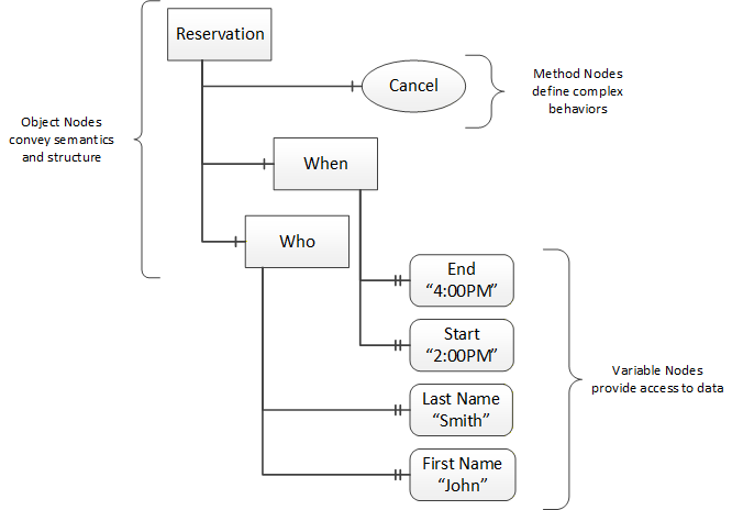
OPC UA provides a framework that can be used to represent complex information as Objects in an AddressSpace which can be accessed with standard services. These Objects consist of Nodes connected by References. Different classes of Nodes convey different semantics. For example, a Variable Node represents a value that can be read or written. The Variable Node has an associated DataType that can define the actual value, such as a string, float, structure etc. It can also describe the Variable value as a variant. A Method Node represents a function that can be called. Every Node has a number of Attributes including a unique identifier called a NodeId and non-localized name called a BrowseName. An Object representing a 'Reservation' is shown in Figure 2.
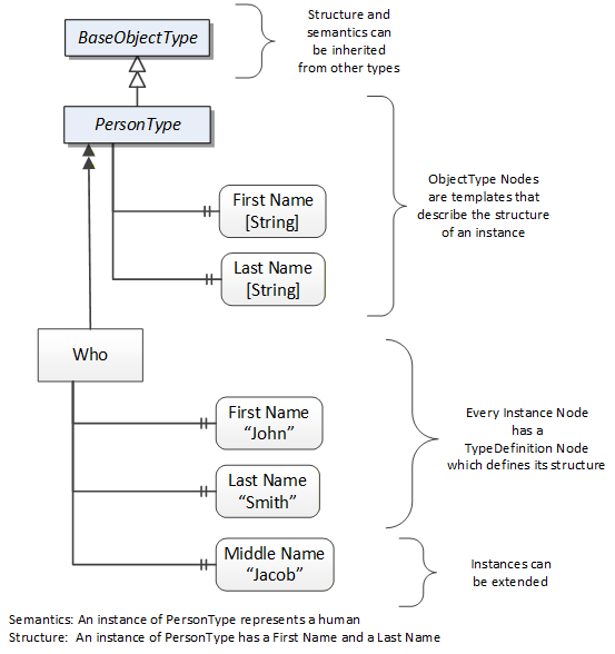
Object and Variable Nodes represent instances and they always reference a TypeDefinition (ObjectType or VariableType) Node which describes their semantics and structure. Figure 3 illustrates the relationship between an instance and its TypeDefinition.
The type Nodes are templates that define all of the children that can be present in an instance of the type. In the example in Figure 3 the PersonType ObjectType defines two children: First Name and Last Name. All instances of PersonType are expected to have the same children with the same BrowseNames. Within a type the BrowseNames uniquely identify the children. This means Client applications can be designed to search for children based on the BrowseNames from the type instead of NodeIds. This eliminates the need for manual reconfiguration of systems if a Client uses types that multiple Servers implement.
OPC UA also supports the concept of sub-typing. This allows a modeller to take an existing type and extend it. There are rules regarding sub-typing defined in OPC 10000-3, but in general they allow the extension of a given type or the restriction of a DataType. For example, the modeller may decide that the existing ObjectType in some cases needs an additional Variable. The modeller can create a subtype of the ObjectType and add the Variable. A Client that is expecting the parent type can treat the new type as if it was of the parent type. Regarding DataTypes, subtypes can only restrict. If a Variable is defined to have a numeric value, a sub type could restrict it to a float.
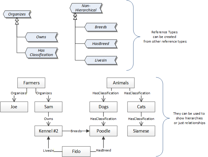
References allow Nodes to be connected in ways that describe their relationships. All References have a ReferenceType that specifies the semantics of the relationship. References can be hierarchical or non-hierarchical. Hierarchical references are used to create the structure of Objects and Variables. Non-hierarchical are used to create arbitrary associations. Applications can define their own ReferenceType by creating subtypes of an existing ReferenceType. Subtypes inherit the semantics of the parent but may add additional restrictions. Figure 4 depicts several References, connecting different Objects.
The figures above use a notation that was developed for the OPC UA specification. The notation is summarized in Figure 5. UML representations can also be used; however, the OPC UA notation is less ambiguous because there is a direct mapping from the elements in the figures to Nodes in the AddressSpace of an OPC UA Server.

A complete description of the different types of Nodes and References can be found in OPC 10000-3 and the base structure is described in OPC 10000-5.
OPC UA specification defines a very wide range of functionality in its basic information model. It is not required that all Clients or Servers support all functionality in the OPC UA specifications. OPC UA includes the concept of Profiles, which segment the functionality into testable certifiable units. This allows the definition of functional subsets (that are expected to be implemented) within a companion specification. The Profiles do not restrict functionality, but generate requirements for a minimum set of functionality (see OPC 10000-7).
4.2.3.2 Namespaces
OPC UA allows information from many different sources to be combined into a single coherent AddressSpace. Namespaces are used to make this possible by eliminating naming and id conflicts between information from different sources. Each namespace in OPC UA has a globally unique string called a NamespaceUri which identifies a naming authority and a locally unique integer called a NamespaceIndex, which is an index into the Server's table of NamespaceUris. The NamespaceIndex is unique only within the context of a Session between an OPC UA Client and an OPC UA Server- the NamespaceIndex can change between Sessions and still identify the same item even though the NamespaceUri's location in the table has changed. The Services defined for OPC UA use the NamespaceIndex to specify the Namespace for qualified values.
There are two types of structured values in OPC UA that are qualified with NamespaceIndexes: NodeIds and QualifiedNames. NodeIds are locally unique (and sometimes globally unique) identifiers for Nodes. The same globally unique NodeId can be used as the identifier in a node in many Servers - the node's instance data may vary but its semantic meaning is the same regardless of the Server it appears in. This means Clients can have built-in knowledge of of what the data means in these Nodes. OPC UA Information Models generally define globally unique NodeIds for the TypeDefinitions defined by the Information Model.
QualifiedNames are non-localized names qualified with a Namespace. They are used for the BrowseNames of Nodes and allow the same names to be used by different information models without conflict. TypeDefinitions are not allowed to have children with duplicate BrowseNames; however, instances do not have that restriction.
4.2.3.3 Companion Specifications
An OPC UA companion specification for an industry specific vertical market describes an Information Model by defining ObjectTypes, VariableTypes, DataTypes and ReferenceTypes that represent the concepts used in the vertical market, and potentially also well-defined Objects as entry points into the AddressSpace.
5 Use cases
This information model supports following use cases:
List topology
Identify device
Get list of available device parameters
Browse device parameters
Get attributes of a device parameter
Get Device Status
Get Device Diagnostics
Read parameters
Read offline data
Read online data
Write device parameters
Audit trail
A detailed description of these use cases is provided in Annex B.
6 FDT Information Model overview
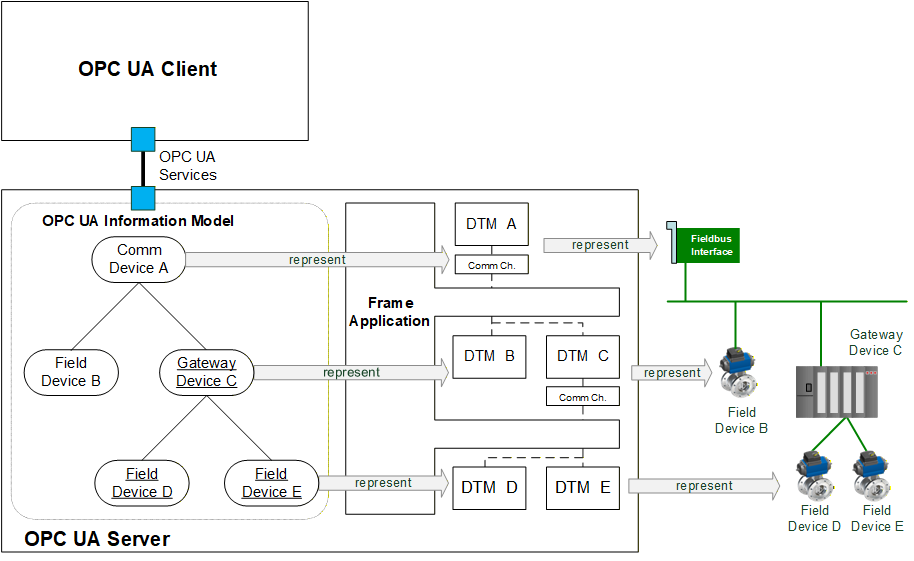
The system architecture as shown in Figure 6 has already been defined in FDT2 specification.
The OPC UA server is a Frame Application. The Frame Application is interacting with the DTMs in order to manage the device-specific information and in order to interact with the devices. Frame Applications may support different use cases, for example: vendor-specific service, process control or asset management. Frame Applications may start and terminate the DTMs on demand (e.g. only if a value is read from the respective device).
The OPC UA server is equipped with an OPC UA server interface. In the information model of the OPC UA server the application-specific project information may be represented (depending on the Frame Application) and device-specific information shall be represented. The OPC UA client may browse the information model and may use the services of the OPC UA interface to access the represented information. If device-specific information is accessed, the information is retrieved from the DTMs.
In a multi-client scenario the Frame Application is responsible for managing the access to the DTMs. The approach for managing the access from multiple clients is to use the "multi user access" as specified in FDT2 specification.
Since the contents of the FDT project and the management of multi-client access is specific to the Frame Application, this document focuses on the mapping of the information from the DTM to the 'Device model' of OPC UA for Devices. One possible approach for presentation of the project information would be the 'Device Integration Host Model' according to OPC UA for Devices.
7 FDT specific OPC UA ObjectTypes
7.1 General
The OPC UA information model for FDT is based on OPC UA for Devices. This document defines a mapping for device-related information, services and data types.
Services which are defined in OPC UA for Devices, but for which no mapping is defined here (e.g. Locking service), have to be implemented by the OPC UA Server according to the specification in OPC UA for Devices.
7.2 FdtDeviceType
This OPC UA ObjectType is the base for a device type derived from an FDT device type definition. Any manufacturer-specific device type is derived from FdtDeviceType.
Figure 7 shows an overview for the FdtDeviceType with its Properties and related ObjectTypes. It is formally defined in Table 12.
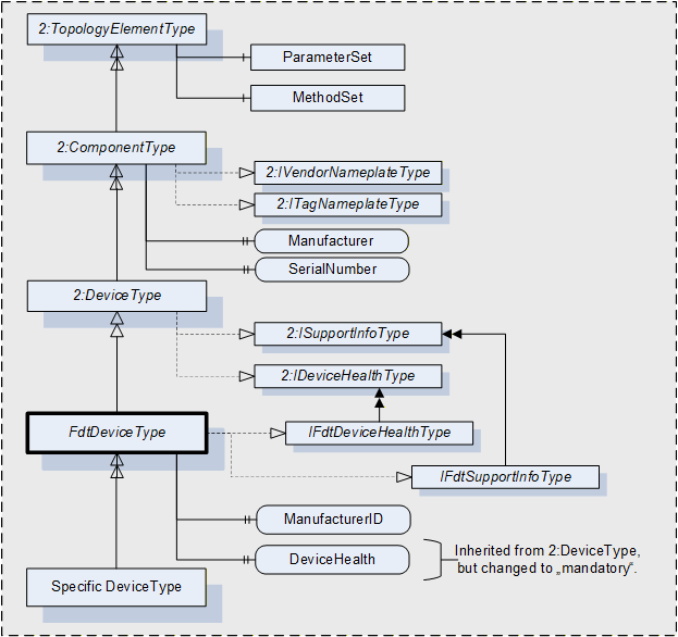
The FdtDeviceType is formally defined in Table 12.
| Attribute | Value | ||||
| BrowseName | FdtDeviceType | ||||
| IsAbstract | True | ||||
| References | Node Class | BrowseName | DataType | TypeDefinition | Other |
|---|---|---|---|---|---|
| Subtype of 2:DeviceType defined in OPC UA for Devices | |||||
| HasInterface | ObjectType | IFdtDeviceHealthType | Defined in 7.4 | ||
| HasInterface | ObjectType | IFdtSupportInfoType | Defined in 7.5 | ||
| 0:HasProperty | Variable | ManufacturerId | 0:String | 0:PropertyType | O |
| 0:HasProperty | Variable | DeviceTypeId | 0:String | 0:PropertyType | O |
| 0:HasProperty | Variable | DeviceTag | 0:String | 0:PropertyType | M |
| Applied from 2:IFdtDeviceHealthType | |||||
| 0:HasComponent | Variable | 2:DeviceHealth | 2:DeviceHealthEnumeration | 0:BaseDataVariableType | M, RO |
The FdtDeviceType is an abstract type and cannot be used directly.
The definition for DeviceHealth overrides the definition of OPC UA for Devices and makes this member mandatory for FdtDeviceType.
The mapping of FDT information to FdtDeviceType is defined in 12.2.1.
7.3 FdtFunctionalGroupType
FdtFunctionalGroupType is used for representing functional grouping of methods and parameters. It is formally defined in Table 13.
| Attribute | Value | ||||
| BrowseName | FdtFunctionalGroupType | ||||
| IsAbstract | False | ||||
| References | Node Class | BrowseName | DataType | TypeDefinition | Other |
|---|---|---|---|---|---|
| Subtype of 2:FunctionalGroupType defined in OPC UA for Devices 5.4 | |||||
| 0:HasProperty | Variable | ApplicationId | ApplicationIdEnumeration | 0:PropertyType | O |
| 0:HasProperty | Variable | SemanticInfo | SemanticInfoType | 0:PropertyType | O |
The FdtFunctionalGroupType is a concrete type and can be used directly.
7.4 IFdtDeviceHealthType Interface
IFdtDeviceHealthType defines additional requirements for the IDeviceHealthType interface, which is formally defined in Table 14.
| Attribute | Value | ||||
| BrowseName | IFdtDeviceHealthType | ||||
| IsAbstract | True | ||||
| References | Node Class | BrowseName | DataType | TypeDefinition | Other |
|---|---|---|---|---|---|
| Subtype of the 2:IDeviceHealthType interface defined in OPC UA for Devices 5.5.4. | |||||
| 0:HasComponent | Variable | 2:DeviceHealth | 2:DeviceHealthEnumeration | 0:BaseDataVariableType | M |
The definition for DeviceHealth overrides the definition of OPC UA for Devices and makes the DeviceHealth member mandatory for IFdtDeviceHealthType.
7.5 IFdtSupportInfoType Interface
7.5.1 Overview
The IFdtSupportInfoType defines additional requirements for the ISupportInfoType interface, which is formally defined in Table 15.
| Attribute | Value | ||||
| BrowseName | IFdtSupportInfoType | ||||
| IsAbstract | True | ||||
| References | Node Class | BrowseName | DataType | TypeDefinition | Other |
|---|---|---|---|---|---|
| Subtype of the 2:ISupportInfoType interface defined in OPC UA for Devices 5.5.5. | |||||
The components of the IFdtSupportInfoType have additional references as defined in Table 16.
| Source Path | References | Node Class | BrowseName | Data Type | TypeDefintion | Others |
| 2:Documentation | HasComponent | Object | <FdtDocumentIdentifier> | FdtDocumentType | MP | |
| 2:ProtocolSupport | HasComponent | Object | <FdtProtocolSupportIdentifier> | FdtDocumentType | MP |
Documents provided for a device are exposed as Objects organized in the Documentation folder. In most cases they will represent a product manual, which can exist as a set of individual documents. The BrowseName of each Object in the Documentation Folder will consist of the document label that can be used to identify the document.
Protocol support files (e.g. GSD files, EDS files) provided for a device are exposed as Objects organised in the ProtocolSupport folder.
7.6 Document types
7.6.1 FdtDocumentType
This abstract type describes the information associated with a document provided by a DTM. The FdtDocumentType is formally described in Table 17.
| Attribute | Value | ||||
| BrowseName | FdtDocumentType | ||||
| IsAbstract | True | ||||
| References | Node Class | BrowseName | DataType | TypeDefinition | Other |
|---|---|---|---|---|---|
| Subtype of 0:BaseObjectType | |||||
| 0:HasProperty | Variable | Classification | DocumentClassification | 0:PropertyType | M |
| 0:HasProperty | Variable | Help | 0:String | 0:PropertyType | O |
| 0:HasProperty | Variable | Language | 0:String | 0:PropertyType | O |
| 0:HasProperty | Variable | MediaType | 0:String | 0:PropertyType | M |
| 0:HasProperty | Variable | SemanticInfo | SemanticInfoType | 0:PropertyType | O |
The FdtDocumentType is an abstract type and cannot be used directly.
The MIME type of document is identified by the MediaType property of each Variable.
7.6.2 FdtDocumentFile
This is a type for representing documents, which are provided as files. It is formally defined in Table 18.
| Attribute | Value | ||||
| BrowseName | FdtDocumentFile | ||||
| IsAbstract | False | ||||
| References | Node Class | BrowseName | DataType | TypeDefinition | Other |
|---|---|---|---|---|---|
| Subtype of FdtDocumentType | |||||
| 0:HasComponent | Object | File | 0:FileType | M | |
The FdtDocumentFile is a concrete type and can be used directly.
The document may be retrieved from the server by using the methods related to the object of type FileType.
7.6.3 FdtDocumentUrl
This is a type for representing documents, which are provided as URL. It is formally defined in Table 19.
| Attribute | Value | ||||
| BrowseName | FdtDocumentUrl | ||||
| IsAbstract | False | ||||
| References | Node Class | BrowseName | DataType | TypeDefinition | Other |
|---|---|---|---|---|---|
| Subtype of FdtDocumentType | |||||
| 0:HasProperty | Variable | URL | 0:String | 0:PropertyType | M |
The FdtDocumentUrl is a concrete type and can be used directly.
The actual document may be retrieved by the Client from the URL.
7.7 FdtProtocolType
This type is used to specify which protocols an FdtDeviceType requires or supports.
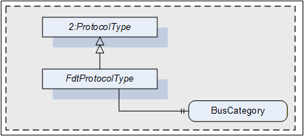
The FdtProtocolType is formally defined in Table 20.
| Attribute | Value | ||||
| BrowseName | FdtProtocolType | ||||
| IsAbstract | True | ||||
| References | Node Class | BrowseName | DataType | TypeDefinition | Other |
|---|---|---|---|---|---|
| Subtype of 2:ProtocolType defined in OPC UA for Devices 6.1 | |||||
| 0:HasProperty | Variable | BusCategory | 0:String | 0:PropertyType | M |
The FdtProtocolType is an abstract type and cannot be used directly.
The property BusCategory shall be used by any instance of FdtProtocolType or its subtypes.
7.8 FdtTransferServiceType
This type is used to specify support for transfer services.
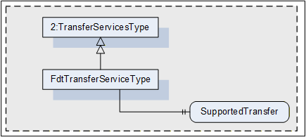
The FdtTransferServiceType is formally defined in Table 21.
| Attribute | Value | ||||
| BrowseName | FdtTransferServiceType | ||||
| IsAbstract | False | ||||
| References | Node Class | BrowseName | DataType | TypeDefinition | Other |
|---|---|---|---|---|---|
| Subtype of 2:TransferServicesType | |||||
| 0:HasProperty | Variable | SupportedTransfer | SupportedTransfer | 0:PropertyType | M |
The FdtTransferServiceType is a concrete type and can be used directly.
The property SupportedTransfer (defined in 10.4.11) is used to indicate the services supported for the respective device.
7.9 FdtIoSignalInfoType
This type is used to provide information about the IO signals available at the device.
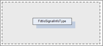
The FdtIoSignalInfoType is formally defined in Table 22.
| Attribute | Value | ||||
| BrowseName | FdtIoSignalInfoType | ||||
| IsAbstract | False | ||||
| References | Node Class | BrowseName | DataType | TypeDefinition | Other |
|---|---|---|---|---|---|
| Subtype of BaseObjectType | |||||
| 0:HasProperty | Variable | Description | 0:String | 0:PropertyType | O |
| 0:HasProperty | Variable | FrameApplicationTag | 0:String | 0:PropertyType | M |
| 0:HasProperty | Variable | IECDatatype | IECDatatype | 0:PropertyType | M |
| 0:HasProperty | Variable | IsLocked | 0:Boolean | 0:PropertyType | M |
| 0:HasProperty | Variable | IsSafety | 0:Boolean | 0:PropertyType | M |
| 0:HasProperty | Variable | RoutedIoSignalId | 0:String | 0:PropertyType | O |
| 0:HasProperty | Variable | SemanticInfo | SemanticInfoType | 0: PropertyType | O |
| 0:HasProperty | Variable | SignalType | SignalTypeEnumeration | 0:PropertyType | M |
| 0:HasProperty | Variable | HasAlarmInfo | DataRefType | 0:PropertyType | O |
| 0:HasProperty | Variable | HasDeviceData | DataRefType | 0:PropertyType | O |
| 0:HasProperty | Variable | HasRange | DataRefType | 0:PropertyType | O |
| 0:HasProperty | Variable | HasSubstituteValue | DataRefType | 0:PropertyType | O |
| 0:HasProperty | Variable | HasUnit | DataRefType | 0:PropertyType | O |
The FdtIoSignalInfoType is a concrete type and can be used directly.
8 OPC UA EventTypes
8.1 Overview
In order to support audit trail, new audit trail event types are defined (see Figure 11).
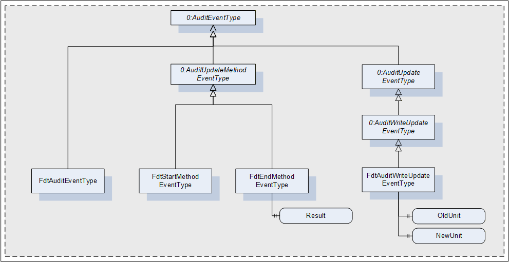
8.2 FdtAuditEventType
The FdtAuditEventType is an event type for general events (e.g. for device status update). It is formally defined in Table 23.
| Attribute | Value | |||||
| BrowseName | FdtAuditEventType | |||||
| IsAbstract | False | |||||
| References | NodeClass | BrowseName | DataType | TypeDefinition | Other | |
|---|---|---|---|---|---|---|
| Subtype of the 0:AuditEventType defined in OPC UA 10000-3 Address Space Model 9.5, which means it inherits the InstanceDeclarations of that Node. | ||||||
8.3 FdtStartMethodEventType
The FdtStartMethodEventType is an event type for indication of start of execution of a command function. It is formally defined in Table 24.
| Attribute | Value | |||||
| BrowseName | FdtStartMethodEventType | |||||
| IsAbstract | False | |||||
| References | NodeClass | BrowseName | DataType | TypeDefinition | Other | |
|---|---|---|---|---|---|---|
| Subtype of the 0:AuditUpdateMethodEventType defined in 8.2, which means it inherits the InstanceDeclarations of that Node. | ||||||
8.4 FdtEndMethodEventType
The FdtEndMethodEventType is an event type for indication of end of execution of a command function. It is formally defined in Table 25.
| Attribute | Value | |||||
| BrowseName | FdtEndMethodEventType | |||||
| IsAbstract | False | |||||
| References | NodeClass | BrowseName | DataType | TypeDefinition | Other | |
|---|---|---|---|---|---|---|
| Subtype of the 0:AuditUpdateMethodEventType defined in 8.2, which means it inherits the InstanceDeclarations of that Node. | ||||||
| 0:HasProperty | Variable | Result | FunctionExecutionResultState | 0:PropertyType | M | |
The property Result is used to indicate the result of the function execution.
8.5 FdtAuditWriteUpdateEventType
The FdtAuditWriteUpdateEventType is used to indicate the change of a parameter value. It is formally defined in Table 26.
| Attribute | Value | ||||||
| BrowseName | FdtAuditWriteUpdateEventType | ||||||
| IsAbstract | False | ||||||
| References | NodeClass | BrowseName | DataType | TypeDefinition | Other | ||
|---|---|---|---|---|---|---|---|
| Subtype of the 0:AuditWriteUpdateEventType defined in OPC UA 10000-3 Address Space Model 9.27, which means it inherits the InstanceDeclarations of that Node. | |||||||
| 0:HasProperty | Variable | OldUnit | 0:String | 0:PropertyType | O | ||
| 0:HasProperty | Variable | NewUnit | 0:String | 0:PropertyType | O | ||
The property OldUnit may be used to indicate the unit of the old value. The property NewUnit may be used to indicate the unit of the new value. If the source node of the event has an engineering unit, it is mandatory to provide these properties.
9 OPC UA VariableTypes
9.1 FdtParameter
A specific type FdtParameter is defined, which is an extension of DataItemType (see Table 27).
| Attribute | Value | |||||
| BrowseName | FdtParameter | |||||
| IsAbstract | False | |||||
| ValueRank | -2 (-2 = Any) | |||||
| DataType | 0:BaseDataType | |||||
| References | NodeClass | BrowseName | DataType | TypeDefinition | Other | |
|---|---|---|---|---|---|---|
| Subtype of DataItemType/ HasTypeDefinition FdtParameter | ||||||
| 0:HasProperty | Variable | DisplayFormat | 0:String | 0:PropertyType | O | |
| 0:HasProperty | Variable | AlarmType | AlarmType | 0:PropertyType | O | |
| 0:HasProperty | Variable | RangeType | RangeType | 0:PropertyType | O | |
| 0:HasProperty | Variable | SubstitutionType | SubstitutionType | 0:PropertyType | O | |
| 0:HasProperty | Variable | ApplicationId | ApplicationIdEnumeration | 0:PropertyType | O | |
| 0:HasProperty | Variable | 0:EURange | 0:Range | 0:PropertyType | O | |
| 0:HasProperty | Variable | 0:EngineeringUnits | 0:EUInformation | 0:PropertyType | O | |
| 0:HasProperty | Variable | 0:EnumStrings | 0:LocalizedText[] | 0:PropertyType | O | |
| 0:HasProperty | Variable | SemanticInfo | SemanticInfoType | 0:PropertyType | O | |
| 0:HasProperty | Variable | DataRef | DataRefType | 0:PropertyType | O | |
| 0:HasProperty | Variable | AlarmDataRef | DataRefType | 0:PropertyType | O | |
| 0:HasProperty | Variable | RangeDataRef | DataRefType | 0:PropertyType | O | |
| 0:HasProperty | Variable | SubstituteDataRef | DataRefType | 0:PropertyType | O | |
| NonHierarchicalReferences | ||||||
| HasIOSignalRef | ObjectType | FdtIoSignalInfoType | ||||
The FdtParameter is a concrete type and can be used directly.
DisplayFormat is a format string for numerical data, compliant to .NET string format definitions.
If the DataType of the FdtParameter is an Enumeration DataType, then EnumStrings are used according to OPC 10000-3.
EURange and EngineeringUnits are used as defined in OPC 10000-8 for the AnalogueItem variable type.
SemanticInfo provides additional semantic information for the parameter (e.g., a reference to a definition in a device profile).
If the FdtParameter represents a structured data information, then ApplicationId may be used to categorize the use case for the data structure.
The DataRefType properties are used to reference related FdtParameters:
DataRef, provides references to other data. Information about the type of reference is provided by the SemanticInfo of the DataRefType.
AlarmDataRef, provides references to alarm information,
RangeDataRef, provides references to range information, and
SubstituteDataRef, provides references to substitute value settings.
If the FdtParameter represents alarm information, then AlarmType categorizes the available alarm type.
If the FdtParameter represents range information, then RangeType distinguishes whether the data represents an upper range or a lower range.
If the FdtParameter represents substitute information, then SubstitutionType specifies which value shall be used when a substitute value is needed.
The HasIOSignalRef reference, provides a reference to the description of an IO signal that corresponds to the FdtParameter.
10 OPC UA DataTypes
10.1 DataRefType
The DataRefType provides a reference to a data item. It is formally defined in Table 28.
| Name | Type | Description |
|---|---|---|
| DataRefType | structure | Reference to a data item. |
| DataId | 0:String | Id of the referenced data item. |
| SemanticInfo | SemanticInfoType | Meaning of the data item in the current context. |
The representation of DataRefType in the AddressSpace is defined in Table 29.
| Attribute | Value | |||||
| BrowseName | DataRefType | |||||
| IsAbstract | False | |||||
| References | NodeClass | BrowseName | DataType | TypeDefinition | Other | |
|---|---|---|---|---|---|---|
| Subtype of the 0:Structure defined in OPC 10000-3. | ||||||
10.2 FdtDeviceClassificationType
The FdtDeviceClassificationType is used to classify devices. It is formally defined in Table 30.
| Name | Type | Description |
|---|---|---|
| FdtDeviceClassificationType | structure | Classification of a device according to IEC 62390 Annex G. |
ClassificationDomain | ClassificationDomainId | Device classification domain groups. |
DeviceClassification | ClassificationId | Unique identifiers according to device primary function. |
The representation of FdtDeviceClassificationType in the AddressSpace is defined in Table 31.
| Attribute | Value | |||||
| BrowseName | FdtDeviceClassificationType | |||||
| IsAbstract | False | |||||
| References | NodeClass | BrowseName | DataType | TypeDefinition | Other | |
|---|---|---|---|---|---|---|
| Subtype of the 0:Structure defined in OPC 10000-3. | ||||||
10.3 SemanticInfoType
This type describes semantic information associated with data provided by a DTM. The SemanticInfoType is formally defined in Table 32.
| Name | Type | Description |
|---|---|---|
| SemanticInfoType | structure | Semantic information associated with data provided by a DTM. |
ApplicationDomain | 0:String | Application domain. |
SemanticId | 0:String | Semantic identifiers in domain. |
The representation of SemanticInfoType in the AddressSpace is defined in Table 33.
| Attribute | Value | |||||
| BrowseName | SemanticInfoType | |||||
| IsAbstract | False | |||||
| References | NodeClass | BrowseName | DataType | TypeDefinition | Other | |
|---|---|---|---|---|---|---|
| Subtype of the 0:Structure defined in OPC 10000-3. | ||||||
10.4 Enumeration datatypes
10.4.1 AlarmType
AlarmType is an enumeration that defines the available alarm types. The values shall be mapped as defined in Table 34.
| Name | Value | Description |
|---|---|---|
| HighHighAlarm | 0 | Alarm if a process value exceeds 'highhigh' limit. |
| HighAlarm | 1 | Alarm if a process value exceeds 'high' limit. |
| LowLowAlarm | 2 | Alarm if a process value falls below 'lowlow' limit. |
| LowAlarm | 3 | Alarm if a process value falls below 'low' limit. |
Its representation in the AddressSpace is defined in Table 35.
| Attribute | Value | |||||
| BrowseName | AlarmType | |||||
| IsAbstract | False | |||||
| References | NodeClass | BrowseName | DataType | TypeDefinition | Other | |
|---|---|---|---|---|---|---|
| Subtype of the Enumeration type defined in OPC 10000-5 | ||||||
| 0:HasProperty | Variable | 0:EnumValues | 0: EnumValueType[] | 0:PropertyType | ||
10.4.2 ApplicationIdEnumeration
The ApplicationIdEnumeration is an enumeration that defines the use of the FunctionalGroup. Its values are defined in Table 36.
| Name | Value | Description |
|---|---|---|
| AdjustSetValue | 0 | Functional group is used to adjust the set value. |
| AssetManagement | 1 | Functional group is used for asset management. |
| AuditTrail | 2 | Functional group is used for audit trail. |
| Configuration | 3 | Functional group is used for configuration. |
| Diagnosis | 4 | Functional group is used for diagnosis. |
| Force | 5 | Functional group is used for forcing values. |
| Observe | 6 | Functional group is used for observation of the device. |
| OfflineCompare | 7 | Functional group is used for comparison of offline data from different devices. |
| OfflineParameterize | 8 | Functional group is used for offline parameterization. |
| OnlineCompare | 9 | Functional group is used for comparison of the device dataset and the instance dataset. |
| OnlineParameterize | 10 | Functional group is used for online parameterization. |
| Identify | 11 | Functional group is used for identification. |
| Calibration | 12 | Functional group is used for calibration. |
| MainOperation | 13 | Functional group is the aggregation of all functional groups. |
| NetworkManagement | 14 | Functional group is used for network management. |
Its representation in the AddressSpace is defined in Table 37.
| Attribute | Value | |||||
| BrowseName | ApplicationIdEnumeration | |||||
| IsAbstract | False | |||||
| References | NodeClass | BrowseName | DataType | TypeDefinition | Other | |
|---|---|---|---|---|---|---|
| Subtype of the Enumeration type defined in OPC 10000-5 | ||||||
| 0:HasProperty | Variable | 0:EnumValues | 0:EnumValueType[] | 0:PropertyType | ||
10.4.3 ClassificationDomainId
ClassificationDomainId is an enumeration that defines the available domains for device classifications. Its values are defined in Table 38.
| Name | Value | Description |
|---|---|---|
| PowerDistribution | 0 | Classification domain is PowerDistribution. |
| MotionControl | 1 | Classification domain is MotionControl. |
| Measurement | 2 | Classification domain is Measurement. |
| OperatorInterface | 3 | Classification is OperatorInterface. |
| ModulesAndControllers | 4 | Classification domain is ModulesAndControllers. |
| Communication | 5 | Classification domain is Communication. |
Its representation in the AddressSpace is defined in Table 39.
| Attribute | Value | |||||
| BrowseName | ClassificationDomainId | |||||
| IsAbstract | False | |||||
| References | NodeClass | BrowseName | DataType | TypeDefinition | Other | |
|---|---|---|---|---|---|---|
| Subtype of the Enumeration type defined in OPC 10000-5 | ||||||
| 0:HasProperty | Variable | 0:EnumValues | 0:EnumValueType[] | 0:PropertyType | ||
10.4.4 ClassificationId
ClassificationId is an enumeration that defines the available classifications for devices. Its values are defined in Table 40.
| Name | Value | Description | |
|---|---|---|---|
| Flow | 0 | Classification is Flow. | |
| Level | 1 | Classification is Level. | |
| Pressure | 2 | Classification is Pressure. | |
| Temperature | 3 | Classification is Temperature. | |
| Valve | 4 | Classification is Valve. | |
| Positioner | 5 | Classification is Positioner. | |
| Actuator | 6 | Classification is Actuator. | |
| Nc_rc | 7 | Classification is Numeric Control / Robotic Control. | |
| Encoder | 8 | Classification is Encoder. | |
| SpeedDrive | 9 | Classification is SpeedDrive. | |
| Hmi | 10 | Classification is Hmi. | |
| AnalogInput | 11 | Classification is AnalogInput. | |
| AnalogOutput | 12 | Classification is AnalogOutput. | |
| DigitalInput | 13 | Classification is DigitalInput. | |
| DigitalOutput | 14 | Classification is DigitalOutput. | |
| ElectrochemicalAnalyser | 15 | Classification is ElectrochemicalAnalyser. | |
| DtmSpecific | 16 | Classification is DtmSpecific. | |
| Universal | 17 | Classification is Universal. | |
| Analyser | 18 | Classification is Analyser. | |
| RemoteIO | 19 | Classification is RemoteIO. | |
| AnalogCombinedIO | 20 | Classification is AnalogCombinedIO. | |
| DigitalCombinedIO | 21 | Classification is DigitalCombinedIO. | |
| Recorder | 22 | Classification is Recorder. | |
| Controller | 23 | Classification is Controller. | |
| Angle | 24 | Classification is Angle. | |
| LimitSwitch | 25 | Classification is LimitSwitch. | |
| Converter | 26 | Classification is Converter. | |
| Motor | 27 | Classification is Motor. | |
| Switchboard | 28 | Classification is Switchboard. | |
| CircuitBreaker | 29 | Classification is CircuitBreaker. | |
| PowerMonitoring | 30 | Classification is PowerMonitoring. | |
| DistributionPanel | 31 | Classification is DistributionPanel. | |
| Contactor | 32 | Classification is Contactor. | |
| ProtectionStarter | 33 | Classification is ProtectionStarter. | |
| SoftStarter | 34 | Classification is SoftStarter. | |
| Drive | 35 | Classification is Drive. | |
| AxisControl | 36 | Classification is AxisControl. | |
| MotorControlCenter | 37 | Classification is MotorControlCenter. | |
| ControlValve | 38 | Classification is ControlValve. | |
| Electrical | 39 | Classification is Electrical. | |
| Density | 40 | Classification is Density. | |
| Quality | 41 | Classification is Quality. | |
| SpeedOrRotaryFrequency | 42 | Classification is SpeedOrRotaryFrequency. | |
| Radiation | 43 | Classification is Radiation. | |
| WeightMass | 44 | Classification is WeightMass. | |
| DistanceOrPositionPresence | 45 | Classification is DistanceOrPositionPresence. | |
| PushButton | 46 | Classification is PushButton. | |
| Joystick | 47 | Classification is Joystick. | |
| Keypad | 48 | Classification is Keypad. | |
| PilotLight | 49 | Classification is PilotLight. | |
| StackLight | 50 | Classification is StackLight. | |
| Display | 51 | Classification is Display | |
| CombinedButtonsAndLights | 52 | Classification is CombinedButtonsAndLights. | |
| OperatorStation | 53 | Classification is OperatorStation. | |
| GeneralInput | 54 | Classification is GeneralInput. | |
| GeneralOutput | 55 | Classification is GeneralOutput. | |
| CombinedInputOutput | 56 | Classification is CombinedInputOutput. | |
| Relay | 57 | Classification is Relay. | |
| Timer | 58 | Classification is Timer. | |
| Scanner | 59 | Classification is Scanner. | |
| ProgrammableController | 60 | Classification is ProgrammableController. | |
| CommunicationAdapter | 61 | Classification is CommunicationAdapter. | |
| Gateway | 62 | Classification is Gateway. | |
Its representation in the AddressSpace is defined in Table 41.
| Attribute | Value | |||||
| BrowseName | ClassificationId | |||||
| IsAbstract | False | |||||
| References | NodeClass | BrowseName | DataType | TypeDefinition | Other | |
|---|---|---|---|---|---|---|
| Subtype of the Enumeration type defined in OPC 10000-5 | ||||||
| 0:HasProperty | Variable | 0:EnumValues | 0:EnumValueType[] | 0:PropertyType | ||
10.4.5 DocumentClassification
DocumentClassification is an enumeration that defines the available classes of documents. Its values are defined in Table 42.
| Name | Value | Description |
|---|---|---|
| Help | 0 | Document contains help information. |
| TechnicalDocumentation | 1 | Document contains technical information. |
| OrderingInformation | 2 | Document contains order information. |
| Miscellaneous | 3 | Document contains general information. |
| TenderSpecification | 4 | Document contains tender specification. |
Its representation in the AddressSpace is defined in Table 43.
| Attribute | Value | |||||
| BrowseName | DocumentClassification | |||||
| IsAbstract | False | |||||
| References | NodeClass | BrowseName | DataType | TypeDefinition | Other | |
|---|---|---|---|---|---|---|
| Subtype of the Enumeration type defined in OPC 10000-5 | ||||||
| 0:HasProperty | Variable | 0:EnumValues | 0:EnumValueType[] | 0:PropertyType | ||
10.4.6 FunctionExecutionResultState
FunctionExecutionResultState is an enumeration that defines the type of result states for execution of a function provided for a device. Its values are defined in Table 44.
| Name | Value | Description |
|---|---|---|
| Cancel | 0 | The function was canceled. |
| Success | 1 | The function finished execution successfully. |
| Fail | 2 | The function execution failed. |
Its representation in the AddressSpace is defined in Table 45.
| Attribute | Value | |||||
| BrowseName | FunctionExecutionResultState | |||||
| IsAbstract | False | |||||
| References | NodeClass | BrowseName | DataType | TypeDefinition | Other | |
|---|---|---|---|---|---|---|
| Subtype of the Enumeration type defined in OPC 10000-5 | ||||||
| 0:HasProperty | Variable | 0:EnumValues | 0:EnumValueType[] | 0:PropertyType | ||
10.4.7 IECDatatype
IECDatatype is an enumeration that defines the IEC type of an IOSignal. Its values are defined in Table 46.
| Name | Value | Description |
|---|---|---|
| BOOL | 0 | 1 bit |
| SINT | 1 | Signed short integer (1byte) |
| INT | 2 | Signed integer (2 byte) |
| DINT | 3 | Signed double integer (4 byte) |
| LINT | 4 | Signed long integer (8 byte) |
| USINT | 5 | Unsigned short integer (1 byte) |
| UINT | 6 | Unsigned integer (2 byte) |
| UDINT | 7 | Unsigned double integer (4 byte) |
| ULINT | 8 | Unsigned long integer (8 byte) |
| REAL | 9 | Floating point (4 byte) |
| LREAL | 10 | Long floating point (8 byte) |
| TIME | 11 | Time |
| DATE | 12 | Calendar date |
| TimeOfDay | 13 | Clock time |
| DateAndTime | 14 | Date and time |
| STRING | 15 | Variable-length single-byte character string |
| BYTE | 16 | 8 bit |
| WORD | 17 | 16 bit |
| DWORD | 18 | 32 bit |
| LWORD | 19 | 64 bit |
| WSTRING | 20 | Variable-length double-byte character string |
Its representation in the AddressSpace is defined in Table 47.
| Attribute | Value | |||||
| BrowseName | IECDatatype | |||||
| IsAbstract | False | |||||
| References | NodeClass | BrowseName | DataType | TypeDefinition | Other | |
|---|---|---|---|---|---|---|
| Subtype of the Enumeration type defined in OPC 10000-5 | ||||||
| 0:HasProperty | Variable | 0:EnumValues | 0:EnumValueType[] | 0:PropertyType | ||
10.4.8 RangeType
RangeType is an enumeration that defines the available types of range limits. Its values are defined in Table 48.
| Name | Value | Description |
|---|---|---|
| LowerRange | 0 | Device data represents a lower range. |
| UpperRange | 1 | Device data represents an upper range. |
Its representation in the AddressSpace is defined in Table 49.
| Attribute | Value | |||||
| BrowseName | RangeType | |||||
| IsAbstract | False | |||||
| References | NodeClass | BrowseName | DataType | TypeDefinition | Other | |
|---|---|---|---|---|---|---|
| Subtype of the Enumeration type defined in OPC 10000-5 | ||||||
| 0:HasProperty | Variable | 0:EnumValues | 0:EnumValueType[] | 0:PropertyType | ||
10.4.9 SignalTypeEnumeration
SignalTypeEnumeration is an enumeration that defines the type of an IO signal. Its values are defined in Table 50.
| Name | Value | Description |
|---|---|---|
| Input | 0 | Input signal |
| Output | 1 | Output signal |
Its representation in the AddressSpace is defined in Table 51.
| Attribute | Value | |||||
| BrowseName | SignalTypeEnumeration | |||||
| IsAbstract | False | |||||
| References | NodeClass | BrowseName | DataType | TypeDefinition | Other | |
|---|---|---|---|---|---|---|
| Subtype of the Enumeration type defined in OPC 10000-5 | ||||||
| 0:HasProperty | Variable | 0:EnumValues | 0:EnumValueType[] | 0:PropertyType | ||
10.4.10 SubstitutionType
SubstitutionType is an enumeration that defines the type of substitution data. Its values are defined in Table 52.
| Name | Value | Description |
|---|---|---|
| LastValue | 0 | The last known value shall be used. |
| LastValidValue | 1 | The last valid value shall be used. |
| UpperRange | 2 | The upper range shall be used. |
| LowerRange | 3 | The lower range shall be used. |
Its representation in the AddressSpace is defined in Table 53.
| Attribute | Value | |||||
| BrowseName | SubstitutionType | |||||
| IsAbstract | False | |||||
| References | NodeClass | BrowseName | DataType | TypeDefinition | Other | |
|---|---|---|---|---|---|---|
| Subtype of the Enumeration type defined in OPC 10000-5 | ||||||
| 0:HasProperty | Variable | 0:EnumValues | 0:EnumValueType[] | 0:PropertyType | ||
10.4.11 SupportedTransfer
SupportedTransfer is an enumeration that defines the types of transfers provided for a device. Its values are defined in Table 54.
| Name | Value | Description |
|---|---|---|
| None | 0 | The DTM does not support upload / download at all. |
| OnlyDownload | 1 | The DTM supports only writing data to the device. Reading data to the device is not supported. |
| OnlyUpload | 2 | The DTM supports only reading data from the device. Writing data to the device is not supported. |
| BothUploadAndDownload | 3 | The DTM supports both reading values from the device and writing values to the device. |
Its representation in the AddressSpace is defined in Table 55.
| Attribute | Value | |||||
| BrowseName | SupportedTransfer | |||||
| IsAbstract | False | |||||
| References | NodeClass | BrowseName | DataType | TypeDefinition | Other | |
|---|---|---|---|---|---|---|
| Subtype of the Enumeration type defined in OPC 10000-5 | ||||||
| 0:HasProperty | Variable | 0:EnumValues | 0:EnumValueType[] | 0:PropertyType | ||
11 OPC UA ReferenceTypes
11.1 HasIOSignalRef
The HasIOSignalRef ReferenceType is a concrete ReferenceType that can be used directly. It is a subtype of the NonHierarchicalReferences ReferenceType.
The TargetNode of a Reference of the HasIOSignalRef ReferenceType is providing the IO signal description for the SourceNode.
The SourceNode of References of this type shall be an FdtParameter.
The TargetNode of this ReferenceType shall be an FdtIoSignalInfoType.
The HasIOSignalRef is formally defined in Table 56.
| Attributes | Value | ||
| BrowseName | HasIOSignalRef | ||
| InverseName | IsParameterOfIOSignal | ||
| Symmetric | False | ||
| IsAbstract | False | ||
| References | NodeClass | BrowseName | Comment |
|---|---|---|---|
| Subtype NonHierarchicalReferences defined in OPC UA 10000-5. | |||
12 Mapping of DataTypes
12.1 Primitive data types
12.1.1 DeviceHealthEnumeration
The datatype DeviceHealthEnumeration defined by OPC UA for Devices shall be mapped to the FDT2 datatype DeviceStatus. The values shall be mapped as defined in Table 57.
| OPC UA for Devices DeviceHealthEnumeration Value | FDT2 DeviceStatus.StatusFlag Value |
| NORMAL_0 | Ok |
| FAILURE_1 | Invalid |
| CHECK_FUNCTION_2 | FunctionCheck |
| OFF_SPEC_3 | OutOfSpecification |
| MAINTENANCE_REQUIRED_4 | MaintenanceRequired |
12.2 Mapping to OPC DI Types
12.2.1 Device Type
12.2.1.1 General
OPC UA for Devices and FDT use different approaches in regard to representation of device type specific data. Some of the data defined in OPC UA for representation of the device type is available only in instance-specific data of the DTMs (see Figure 12).
The data from FDT may be mapped either to Attributes (table header "Attribute") or to properties and other child Nodes (table header "BrowseName") of the corresponding OPC UA Node.
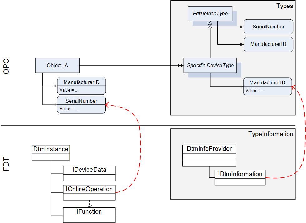
For this reason the device type specific data of OPC is mapped to data on several interfaces of the DTM (see Table 58).
12.2.1.2 Mapping for DeviceType ("Types" standard Object)
All device types provided by DTMs in IDtmInformation shall be represented as subtypes of FdtDeviceType in the "Types" standard Object (see Table 58).
| OPC | FDT | |||
|---|---|---|---|---|
| Attribute | Interface | Method | Data member | Description |
| BrowseName | IDtmInformation | <>GetSupportedTypes | DeviceTypeInfo.Name | |
| DisplayName | IDtmInformation | <>GetSupportedTypes | DeviceTypeInfo.Name | |
| BrowseName | Interface | Method | Data member | Description |
| 2:SerialNumber | Mapping for online device only, see Table 61 | |||
| 2:RevisionCounter | Not supported. Value is always set to -1 | |||
| 2:Manufacturer | IDtmInformation | <>GetSupportedTypes | DeviceTypeInfo.ProductManufacturerName | |
| ManufacturerId | IDtmInformation | GetDeviceIdentInfo | DeviceIdentInfo.ManufacturerId | |
| 2:Model | IDtmInformation | <>GetSupportedTypes | DeviceTypeInfo.ProductName | |
| 2:DeviceManual | All documents will be provided in folder Documentation | |||
| 2:DeviceRevision | IDtmInformation | <>GetSupportedTypes | DeviceTypeInfo.ProductRevision | |
| 2:SoftwareRevision | IDtmInformation | GetDeviceIdentInfo | DeviceIdentInfo.SoftwareRevision | |
| 2:HardwareRevision | IDtmInformation | GetDeviceIdentInfo | DeviceIdentInfo.HardwareRevision | |
| 2:DeviceClass(O) | IDtmInformation | <>GetSupportedTypes | DeviceTypeInfo.DeviceClassifications[0].DomainId + ":" + DeviceTypeInfo.DeviceClassifications[0].Id | The value is a concatenation of the enumeration member names for DomainId and Id. |
| DeviceTypeId | IDtmInformation | <>GetSupportedTypes | DeviceTypeInfo.Id | |
| 2:ManufacturerUri(O) | Not supported. | |||
| 2:ProductCode(O) | Not supported. | |||
| 2:ProductInstanceUri(O) | Not supported. | |||
| <CP_Identifier>(O) | IDtmInformation | <>GetSupportedTypes | TypeInfo.BusCategories[].Category¬Type == required <Identifier> = TypeInfo.BusCategories[].Protocol¬Name | HasComponent-reference of type RequiredProtocol. |
IDtmInformation IChannels | <>GetSupportedTypes IChannels.CommunicationChannels | TypeInfo.BusCategories[].Category¬Type == supported <Identifier> = CommunicationChannelItem.Id | HasComponent-reference of type SupportedProtocol. If one Channel requires multiple protocols, multiple connection points are provided, an additional number is concatenated to the channel id. | |
| 0:Icon | IDtmInformation | GetFdtIcon() | Icon | see explanation below the table |
| Applied from IFdtDeviceHealthType | ||||
| 2:DeviceHealth | Mapping for online device only, see Table 61 | |||
| 2:DeviceHealthAlarms(O) | - | - | - | No mapping defined. |
| OPC | FDT | |||
| BrowseName | Interface | Method | Data member | Description |
| Applied from IFdtSupportInfoType | ||||
| 2:DeviceTypeImage(O) | This folder will contain items as defined in 12.2.8.1. | |||
| 2:Documentation (O) | IDtmInformation | <>GetSupportedTypes | DeviceTypeInfo.Documents | This folder will contain items that represent the shown FDT data member as defined in 7.3 |
| 2:ProtocolSupport (O) | INetworkData | GetNetworkDataInfo | NetworkData. DeviceInformationDocuments | This folder will be provided as defined in 12.2.8.2. |
| 2:ImageSet(O) | Not supported. | |||
A DTM can provide several icons (list of icons). The rule for selection of the icon and extraction of an image (a specific resolution) from the icon is frame application specific. The selection of the image format in general is implementation specific, all types are allowed that are defined in OPC UA 10000-3.
12.2.1.3 Mapping for Offline Device ("Objects" standard Object)
The information for a device (instance) is based on the information provided by a DTM (instance). The mapping for the device node is defined in Table 59.
| OPC | FDT | |||
|---|---|---|---|---|
| Attribute | Interface | Method | Data member | Description |
| TypeReference | - | - | - | NodeId of the DeviceType |
| BrowseName | IDtm | DtmSystemGuiLabel | ||
| DisplayName | IDtm | DtmSystemGuiLabel | ||
The device parameters provide offline identification information based on DTM type information intended for identification. This data may provide values or regular expressions to define ranges of supported values.
In the call to IDtmInformation.GetDeviceIdentInfo() a protocol must be specified. The first entry from the list of INetworkData.ActiveProtocols shall be used.
GetDeviceIdentInfo() may return a list of DeviceIdentInfo where the first entry is used for the parameters as defined below. Exposing the remaining list entries is implementation specific.
| OPC | FDT | |||
|---|---|---|---|---|
| BrowseName | Interface | Method | Data member | Description |
| ManufacturerId | IDtmInformation | GetDeviceIdentInfo() | DeviceIdentInfo[0].GetManufacturerId() | |
| DeviceTypeId | IDtmInformation | GetDeviceIdentInfo() | DeviceIdentInfo[0]. GetDeviceTypeId() | |
| 2:NetworkAddress | INetworkData | GetAddressInfo() | AddressInfo.DeviceAddresses[].Address | string array containing all addresses provided |
| DeviceTag | -/- | -/- | (default value) | |
| 2:Serial Number | -/- | -/- | (default value) | |
| 2:SoftwareRevision | IDtmInformation | GetDeviceIdentInfo() | DeviceIdentInfo[0].GetSoftwareRevision() | |
| 2:HardwareRevision | IDtmInformation | GetDeviceIdentInfo() | DeviceIdentInfo[0].GetHardwareRevision() | |
| Contents of FunctionalGroup "Identification" (see 12.2.5.) | ||||
| ProtocolId | IDtmInformation | GetDeviceIdentInfo() | DeviceIdentInfo[0].GetProtocolId() | |
| ProtocolSpecificIdentification | IDtmInformation | GetDeviceIdentInfo() | DeviceIdentInfo[0]. GetProtocolSpecificProperties() | |
| DeviceSpecific-Identification | IDtmInformation | GetDeviceIdentInfo() | DeviceIdentInfo[0].DeviceSpecificProperties | |
12.2.1.4 Mapping for Online Device ("Objects" standard Object online reference)
Device parameters provide identification information based on data read online from the device. This data may be different from the data provided in the DeviceType.
| OPC | FDT | |||
|---|---|---|---|---|
| BrowseName | Interface | Method | Data member | Description |
| ManufacturerId | IHardwareInformation | <>HardwareScan() | DeviceScanInfo.GetManufacturerId() | |
| DeviceTypeId | IHardwareInformation | <>HardwareScan() | DeviceScanInfo.GetDeviceTypeId() | |
| 2:NetworkAddress | IHardwareInformation | <>HardwareScan() | DeviceScanInfo.GetAddress() | |
| DeviceTag | IHardwareInformation | <>HardwareScan() | DeviceScanInfo.GetTag() | |
| 2:DeviceHealth | IOnlineOperation | <>ReadDevice-Status() | DeviceStatus.StatusFlag | For mapping of the enumeration values see 12.1.1. |
| 2:Serial Number | IHardwareInformation | <>HardwareScan() | DeviceScanInfo.SerialNumber() | |
| 2:SoftwareRevision | IHardwareInformation | <>HardwareScan() | DeviceScanInfo.GetSoftwareRevision() | |
| 2:HardwareRevision | IHardwareInformation | <>HardwareScan() | DeviceScanInfo.GetHardwareRevision() | |
| Contents of FunctionalGroup "Identification" (see 12.2.5.) | ||||
| ProtocolId | IHardwareInformation | <>HardwareScan() | DeviceScanInfo.GetProtocolId() | |
| ProtocolSpecificIdentification | IHardwareInformation | <>HardwareScan() | DeviceScanInfo.GetProtocolSpecificProperties() | |
| DeviceSpecific-Identification | IHardwareInformation | <>HardwareScan() | DeviceScanInfo.DeviceSpecificProperties | |
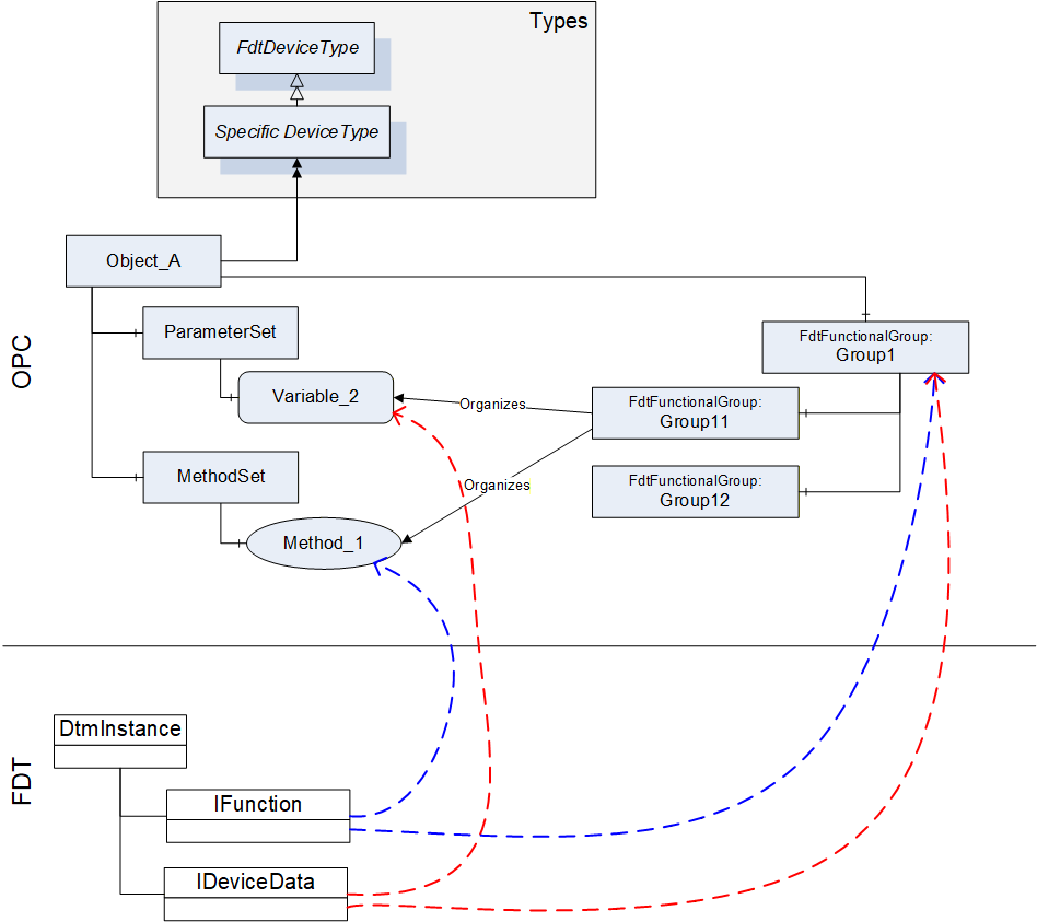
12.2.2 TopologyElementType
The information provided by a DTM with IFunction.FunctionInfo and IData.DataInfo is mapped into the MethodSet and to the ParameterSet. For both types of information (Commands and Parameters) also references in FunctionalGroup nodes are created, so that an OPC Client may represent a joint user interface (see Figure 13).
The BrowseName and DisplayName of the FunctionalGroup-Nodes are based on the grouping in IFunction.FunctionInfo (FunctionGroup) and IData.DataInfo (DataGroup).
Information about IO signals are provided in a folder ProcessDataSet, which contains FdtIoSignalInfoType nodes. FdtIoSignalInfoType nodes are referenced by the corresponding FdtParameter nodes.
| OPC | FDT | |||
|---|---|---|---|---|
| BrowseName | Interface | Method | Data member | Description |
| ParameterSet | IInstanceData / IDeviceData | <>GetDataInfo | DataInfo.DeviceDataItems | DeviceDataItems is a hierarchical list of data items that represent different types of data items. In the ParameterSet only AccessibleData and StructDataGroup shall be represented (see 12.2.7). The flat list of parameters is constructed from the hierarchical list where duplicates must be removed. |
| MethodSet | IFunction | FunctionInfo | FunctionInfo.FunctionItems | FunctionItems provides a hierarchical list of functions that are supported by the DTM. Only functions without user interface (CommandFunction) shall be represented in the MethodSet (see 12.2.6). |
| ProcessDataSet | IProcessData | <>GetProcessData | ProcessDataInfo.ProcessDataItems | ProcessDataItems provides a list of process data supported by the device. The FdtSignalInfo objects are referenced by the respective parameter objects (in the online device). |
| <GroupIdentifier> | IInstanceData / IDeviceData | <>GetDataInfo | DataInfo.DeviceDataItems | The hierarchical list provided through DeviceDataItems is mapped to a tree of FunctionalGroups. The strings used for the placeholder <GroupIdentifier> are defined by the names of the DataGroups. |
| Identification | The contents of the FunctionalGroup is defined in 12.2.5. | |||
| Lock | (defined in UA Devices) | |||
12.2.3 FunctionalGroupType
The FunctionalGroupType is used to organize Parameters and Methods (which are defined in ParameterSet and MethodSet) in a user-friendly way (see Table 63). FunctionalGroups may be organized hierarchically by organizing FunctionalGroups as child nodes of FunctionalGroups.
| OPC | FDT | |||
|---|---|---|---|---|
| Attribute | Interface | Method | Data member | Description |
| <GroupIdentifier> | IInstanceData / IDeviceData | <>GetDataInfo | DataInfo.DeviceDataItems == DataGroup DataGroup.Name | Only DataInfo.DeviceDataItems shall be mapped, that are of type DataGroup. The Name member of the DataGroup shall be used as <GroupIdentifier>. |
| DisplayName | IInstanceData / IDeviceData | <>GetDataInfo | DataGroup.Label | |
| Description | IInstanceData / IDeviceData | <>GetDataInfo | DataGroup.Descriptor | |
| BrowseName | Interface | Method | Data member | Description |
| <ParameterIdentifier> | IInstanceData / IDeviceData | <>GetDataInfo | DataInfo.DeviceDataItems == Data Data.Name | Only DataInfo.DeviceDataItems shall be mapped, that are of type Data. The Name member of the Data shall be used as <ParameterIdentifier>. |
| <MethodIdentifier> | (no mapping defined) | |||
| UIElement | (no mapping defined) | |||
12.2.4 Identification FunctionalGroup
The Identification FunctionalGroup organizes references to parameters, which may be used to identify the device and its device type. The list of parameters that shall be provided in the Identification FunctionalGroup is defined in Table 64.
| References | BrowseName | Modelling Rule |
|---|---|---|
| Organizes | ManufacturerId | O |
| Organizes | DeviceTypeId | O |
| Organizes | 2:NetworkAddress | O |
| Organizes | DeviceTag | M |
| Organizes | 2:Serial Number | M |
| Organizes | 2:SoftwareRevision | M |
| Organizes | 2:HardwareRevision | M |
| Organizes | 2:ProtocolId | OP |
| HasComponent | ProtocolSpecific¬Identification | O |
| HasComponent | DeviceSpecific¬Identification | O |
The values of the referenced Variables may vary for online and offline device. See section 12.2.1 for the mapping of these Variables.
Protocol specific properties shall be organised in a FunctionalGroup called "ProtocolSpecificIdentification" contained in the Identification FunctionalGroup.
Device specific properties shall be organised in a FunctionalGroup called "DeviceSpecificIdentification" contained in the Identification FunctionalGroup.
12.2.5 Device Data and Device Methods
While device data and methods related to the device are defined in separate areas of the OPC UA Information model (i.e. ParameterSet and MethodSet), they are organized by functional groups into a concise representation, which may be structured to present different aspects of the device. A DTM provides different interfaces (e.g. IDeviceData and IFunction), where data and methods are presented independently, while each interface may provide an own structure.
In the mapping from DTM interfaces to OPC UA information model, the representation hierarchies of IData interfaces and IFunction interface are combined into FunctionalGroups to provide a concise representation of the device data and methods within one hierarchy.
This means, that the data of the IData interfaces are mapped to the ParameterSet node in the OPC UA Information model and the command functions from IFunction interface are mapped to the MethodSet of the device. The hierarchical structures in the IData and IFunction interfaces are mapped to the hierarchical structure provided by the FdtFunctionalGroup elements, which organize the representation of data and methods (see Figure 14).
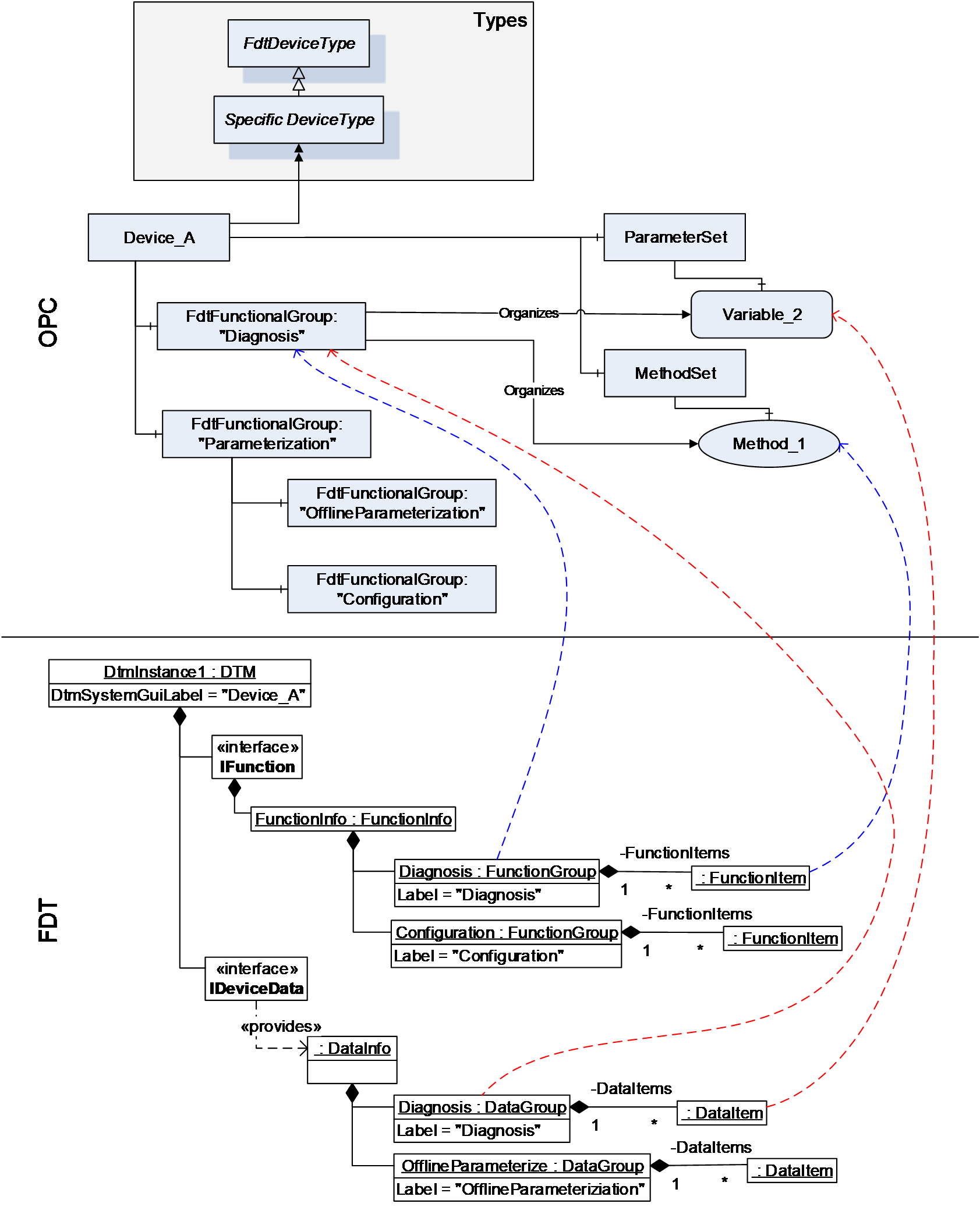
12.2.6 Methods
12.2.6.1 General
A DTM instance can offer command functions. These functions do not have a user interface, they can have arguments and optional default values.
Each command function shall be mapped to a method in the MethodSet of the device instance (see Figure 15). The arguments are mapped to the InputArguments and OutputArguments for the methods. Optional arguments shall be included.
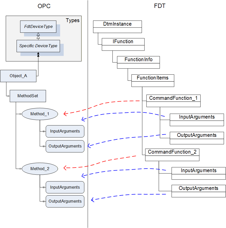
| OPC | FDT | |||
|---|---|---|---|---|
| Attribute | Interface | Method | Data member | Description |
| BrowseName | IFunctions | FunctionInfo | FunctionItem.Label | |
| DisplayName | IFunctions | FunctionInfo | FunctionItem.Label | |
| Description | IFunctions | FunctionInfo | FunctionItem.Descriptor | |
The DTMInfoBuilder can offer information about static functions that are independent of a DTM instance. Such FDT Static Functions may be mapped to methods on the device type created for the DTM. The execution of the method on a device object will need to be mapped to the execution of a static function with a StaticFunctionProvider. The Frame/Server will need to hold the reference to the provider internally and use it for execution of the method (see Figure 16).
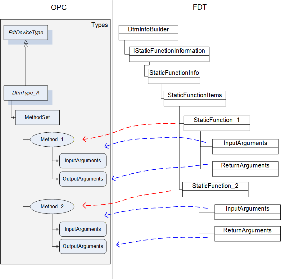
| OPC | FDT | |||
|---|---|---|---|---|
| Attribute | Interface | Method | Data member | Description |
| BrowseName | IStaticFunctionInformation | GetStaticFunctions | StaticFunctionDescription.Label | |
| DisplayName | IStaticFunctionInformation | GetStaticFunctions | StaticFunctionDescription.Label | |
| Description | IStaticFunctionInformation | GetStaticFunctions | StaticFunctionDescription.Descriptor | |
12.2.6.2 TransferServices
For a DTM instance it is mandatory to provide the interface IOnlineOperation if the device provides online data. This interface is mapped to an object of type FdtTransferServiceType (see 7.8). Since the DTM interface is not mandatory for all devices, the availability of the TransferServices depends on the availability of the DTM interface. The member SupportedTransfer indicates, which TransferServices are supported for the device.
| OPC | FDT | |||
|---|---|---|---|---|
| BrowseName | Interface | Method | Data member | Description |
| 2:TransferToDevice | IOnlineOperation | BeginWriteDataToDevice / EndWriteDataToDevice | - | |
| 2:TransferFromDevice | IOnlineOperation | BeginReadDataFromDevice / EndReadDataFromDevice | - | |
| 2:FetchTransferResultData | IOnlineOperation | - | - | Retrieves the result / status from the executed methods. |
| SupportedTransfer | IOnlineOperation | - | SupportedTransfer | |
The TransferServices Type object (with browse name "Transfer") is provided as child node of an offline device node (not for an online device node).
For the method FetchTransferResultData the server is allowed to limit the TransferResultData in regard to the list of transferred parameters (parameterDefs) to zero data. The results of the transfer will be represented in the parameter values of the device node.
12.2.7 Variable
12.2.7.1 General
The parameter set of a device (offline and online) is described by means of the DataInfo data type (available with the <GetDataInfo> method from IInstanceData (offline) and IDeviceData (online)).
DataInfo provides a description of the available data without the values. The actual values are accessible with <Read> and <Write> methods from IInstanceData (offline) and IDeviceData (online).
DataInfo provides a list of data items (member DeviceDataItems), which may represent a range of types. Some of these data items are mapped to DataVariables (see Table 68).
| OPC | FDT |
|---|---|
| DataVariable (according OPC UA 10000-3) | Data |
| UnitData | |
| RangeData | |
| AlarmData | |
| SubstituteData | |
| StructDataGroup | |
FunctionalGroup (according OPC UA 10000-100) | DataGroup |
| Block object (according OPC UA 10000-100) | ModuleDataGroup |
12.2.7.2 FdtParameter
12.2.7.2.1 General
Table 69 shows the mapping for the FdtParameter.
| OPC | FDT | |||
|---|---|---|---|---|
| Attribute | Interface | Method | Data member | Description |
| NodeClass | Fixed value: Variable | |||
| BrowseName | IData | <GetDataInfo> | Name | |
| DisplayName | IData | <GetDataInfo> | Label | |
| Description | IData | <GetDataInfo> | Descriptor | |
| WriteMask | Generated by Frame | |||
| UserWriteMask | IData | <GetDataInfo> | IsChangeEnabled | Generated by Frame |
| Value | IData | <Read> / <Write> | ||
| DataType | IData | <GetDataInfo> | DataTypeInfo | |
| ValueRank | IData | <GetDataInfo> | DataTypeInfo | Indicates whether the datatype is an array. |
| ArrayDimensions | IData | <GetDataInfo> | DataTypeInfo | If the datatype is an array, then provide dimensions. |
| AccessLevel | IData | <GetDataInfo> | IsReadable, IsWritable | Generated by Frame |
| UserAccessLevel | IData | <GetDataInfo> | IsReadable, IsWritable | Generated by Frame |
| MinimumSamplingInterval | Defined by Frame. | |||
| Historizing | Defined by Frame. | |||
| BrowseName | ||||
| 2:EURange | IData | <GetDataInfo> | RangeDataRefs | |
| 2:EngineeringUnits | IData | <GetDataInfo> | UnitDataRef | |
| 0:HasComponent | May be used for structured datatypes (StructDataGroup) | |||
| 2:HasDefinition | Defined by Frame. | |||
| 2:ValuePrecision | Defined by Frame. | |||
| DisplayFormat | IData | <GetDataInfo> | DisplayFormat | |
| AlarmType | IData | <GetDataInfo> | AlarmType | |
| RangeType | IData | <GetDataInfo> | RangeType | |
| SubstitutionType | IData | <GetDataInfo> | SubstitutionType | |
| ApplicationId | IData | <GetDataInfo> | ApplicationId | |
| SemanticInfo | IData | <GetDataInfo> | SemanticInfos | |
| DataRef | IData | <GetDataInfo> | DataRefs | |
| IOSignalRef | IData | <GetDataInfo> | IOSignalRef | |
| AlarmDataRef | IData | <GetDataInfo> | AlarmDataRefs | |
| SubstituteDataRef | IData | <GetDataInfo> | SubstituteDataRef | |
12.2.7.2.2 Datatype mapping
The datatype mapping for parameter data is described in Table 70.
| OPC | FDT | |
|---|---|---|
| Data type | Data type | Description |
| Float | Float | |
| Double | Double | |
| Byte | Byte | |
| Int32 | Int | |
| Int64 | Long | |
| UInt32 | UInt | |
| UInt64 | ULong | |
| DateTime | DateTime | |
| DateTime | Date | Date is represented as date at 0:00 a clock. |
| Duration | Time | Time is expressed as duration since midnight. |
| Duration | TimeSpan | Duration is expressed in milliseconds, TimeSpan is expressed in terms of days, hours, minutes. For the conversion of large TimeSpan a loss of precision may occur. |
| String | String | |
| Array of Byte | BinaryByteArray | |
| Array of Bit | BinaryBitArray | |
| Enumeration | Enumerator | |
| Boolean | Boolean | |
| SByte | SByte | |
In OPC UA array datatypes are represented by a combination of the properties datatype, value-rank and array-dimensions (see OPC OPC UA 10000-5, section 5.6.2).
In FDT array datatypes are represented with a dedicated ArrayDatatypeInfo datatype. This datatype has a member ArrayDatatypeInfo.ArrayDimensions, which specifies the length of each dimension of the array.
The mapping for array data types is defined as follows.
OPC datatype value is mapped according to Table 70.
OPC value rank is:
-1 for a simple datatype, or
Number of fields in FDT ArrayDatatypeInfo.ArrayDimensions (always > 0)
OPC array-dimensions property is:
NULL for a simple datatype, or
has the same value as ArrayDatatypeInfo.ArrayDimensions.
value of 0 means that the array has a variable length,
values > 0 indicate a defined length.
12.2.8 Device Support Information
12.2.8.1 Device Type Image
All Bitmaps provided by a DTM shall be represented in the DeviceTypeImage folder according OPC UA 10000-100 (see Table 58). An image shall be represented by an FdtParameter with DataType set to one of the defined image data types. The actual image is provided by the value attribute as ByteString.
The mapping for a device type image is defined in Table 71.
| OPC | FDT | |||
|---|---|---|---|---|
| BrowseName | Interface | Method | Data member | Description |
| SemanticInfo | IDtmInformation | <>GetSupportedTypes | TypeInfo.Bitmaps.SemanticInfo | |
| Bitmap | IDtmInformation | GetBitmap() | Bitmap | |
Selection of the image format according to FDT2 is specific for a Frame Application. All image types are allowed that are defined in OPC UA 10000-3.
12.2.8.2 Protocol Support Files
Protocol support files provided for a device are exposed as Variables organised in the ProtocolSupport folder. They may represent various types of information as defined by a protocol. Examples are a GSD or a CFF file. The ProtocolSupport folder is formally defined in OPC UA for Devices 5.7.3.. The mapping is protocol independent. All the documents listed in NetworkData.DeviceInformationDocuments are mapped. The value of the <PlaceHolder> is defined by the label of the respective document (Document.Label).
| OPC | FDT | |||
|---|---|---|---|---|
| BrowseName | Interface | Method | Data member | Description |
| <PlaceHolder> | INetworkData | GetNetworkDataInfo | NetworkData. DeviceInformationDocuments | This applies to all protocols. The optional data member provides protocol support files for all protocols. |
The label of the DeviceInformationDocument shall be used as BrowseName for the OPC Node.
12.2.9 FdtIoSignalInfoType
All IOSignalInfo provided by the DTM in the IProcessData interface are mapped to respective FdtIoSignalInfo objects.
| OPC | FDT | |||
|---|---|---|---|---|
| Attribute | Interface | Method | Data member | Description |
| BrowseName | IProcessData | <>GetProcessData() | IOSignalInfo.Name | |
| DisplayName | IProcessData | <>GetProcessData() | IOSignalInfo.Label | |
| Description | IProcessData | <>GetProcessData() | IOSignalInfo.Descriptor | |
| BrowseName | ||||
| FrameApplicationTag | IProcessData | <>GetProcessData() | IOSignalInfo.FrameApplicationTag | |
| IECDatatype | IProcessData | <>GetProcessData() | IOSignalInfo.IECDatatype | |
| IsLocked | IProcessData | <>GetProcessData() | IOSignalInfo.IsLocked | |
| IsSafety | IProcessData | <>GetProcessData() | IOSignalInfo.IsSafety | |
| RoutedIoSignalId | IProcessData | <>GetProcessData() | IOSignalInfo.RoutedIoSignalId | |
| SemanticInfo | IProcessData | <>GetProcessData() | IOSignalInfo.SemanticInfo | |
| SignalType | IProcessData | <>GetProcessData() | IOSignalInfo.SignalType | |
| HasAlarmInfo | IProcessData | <>GetProcessData() | IOSignalInfo.AlarmInfoRef | |
| HasDeviceData | IProcessData | <>GetProcessData() | IOSignalInfo.DeviceDataRef | |
| HasRange | IProcessData | <>GetProcessData() | IOSignalInfo.RangeInfoRef | |
| HasSubstituteValue | IProcessData | <>GetProcessData() | IOSignalInfo.SubstituteValueRef | |
| HasUnit | IProcessData | <>GetProcessData() | IOSignalInfo.UnitInfoRef | |
12.2.10 FdtProtocolType
The FdtProtocolType and its sub-types are used to specify a communication protocol that is supported by a Device or Network. The BrowseName of each instance of a ProtocolType shall define the Communication Profile (see OPC UA for Devices 6.3).
OPC UA for FDT uses a sub-type FdtProtocolType (see 7.7) for mapping the needed information.
| OPC | FDT | |||
|---|---|---|---|---|
| Attribute | Interface | Method | Data member | Description |
| BrowseName | IDtmInformation | <>GetSupported-Types | DeviceTypeInfo.BusCategories[].protocolName | |
| DisplayName | IDtmInformation | <>GetSupported-Types | DeviceTypeInfo.BusCategories[].protocolName | |
| BrowseName | ||||
| BusCategory | IDtmInformation | <>GetSupported-Types | DeviceTypeInfo.BusCategories[].protocolId | The protocolId is formatted as string with upper case letters. |
13 Profiles and Conformance Units
13.1 Conformance Units
Table 75 defines the corresponding ConformanceUnits for the OPC UA Information Model for FDT.
| Category | Title | Description |
|---|---|---|
| Server | ||
| Server | FDT DeviceType | Support of objects of specific types derived from FdtDeviceType. |
| Server | FDT FunctionalGroup Type | Support of the FdtFunctionalGroupType. |
| Server | FDT DeviceHealth interface | Support of the IFdtDeviceHealth interface as defined in this document. |
| Server | FDT SupportInfo interface | Support of the IFdtSupportInfo interface as defined in this document. |
| Server | FDT DocumentTypes | Support of the FdtDocumentType and derived types. |
| Server | FDT ProtocolType | Support of the FdtProtocolType. |
| Server | FDT TransferServiceType | Support of the FdtTransferServiceType |
| Server | FDT IOSignalInfo | Support of the FdtIoSignalInfoType. |
| Server | FDT Parameter | Support of the FdtParameter variable type. |
| Client | ||
| Client | FDT Client DeviceType | Consumes objects of specific types derived from FdtDeviceType. |
| Client | FDT Client FunctionalGroup Type | Consumes objects of the FdtFunctionalGroupType. |
| Client | FDT Client DeviceHealth interface | Uses the IFdtDeviceHealth interface as defined in this document. |
| Client | FDT Client SupportInfo interface | Uses the IFdtSupportInfo interface as defined in this document. |
| Client | FDT Client DocumentTypes | Consumes objects of the FdtDocumentType and derived types. |
| Client | FDT Client ProtocolType | Consumes objects of the FdtProtocolType. |
| Client | FDT Client TransferServiceType | Consumes objects of the FdtTransferServiceType |
| Client | FDT Client IOSignalInfo | Consumes objects of the FdtIoSignalInfoType. |
| Client | FDT Client Parameter | Consumes objects of the FdtParameter variable type. |
13.2 Profiles
13.2.1 Profile list
Table 76 lists all Profiles defined in this document and defines their URIs.
| Profile | URI |
| FDT Base Server Profile | http://opcfoundation.org/UA-Profile/FDT/Server/Base |
| FDT General Server Facet | http://opcfoundation.org/UA-Profile/FDT/Server/General |
| FDT General Client Facet | http://opcfoundation.org/UA-Profile/FDT/Server/Client |
13.2.2 Server Facets
13.2.2.1 Overview
The following sections specify the Facets available for Servers that implement the FDT companion specification. Each section defines and describes a Facet or Profile.
13.2.2.2 FDT Base Server Profile
Table 77 defines a Profile that describes the basic requirements for an OPC UA server supporting the FDT information model.
| Group | Conformance Unit / Profile Title | Mandatory / Optional |
| Profile | 0:Embedded 2017 UA Server Profile http://opcfoundation.org/UA-Profile/Server/EmbeddedUA2017 | M |
| Profile | 0:Data Access Server Facet http://opcfoundation.org/UA-Profile/Server/DataAccess | M |
| Profile | 2:BaseDevice_Server_Facet | M |
| Profile | 2:DeviceIdentification_Server_Facet | M |
| Profile | 2:DeviceCommunication_Server_Facet | O |
| Profile | 2:DeviceIntegrationHost_Server_Facet | O |
| Profile | FDT General Server Facet | M |
| Subscription Services | 0:Subscription Durable | M |
13.2.2.3 FDT General Server Facet
Table 78 defines a Facet that describes the general requirements for a server.
| Group | Conformance Unit / Profile Title | Mandatory / Optional |
| FDT | FDT DeviceType | M |
| FDT | FDT DeviceHealth interface | M |
| FDT | FDT ProtocolType | M |
| FDT | FDT Parameter | M |
| FDT | FDT FunctionalGroup Type | O |
| FDT | FDT SupportInfo interface | O |
| FDT | FDT DocumentTypes | O |
| FDT | FDT TransferServiceType | O |
| FDT | FDT IOSignalInfo | O |
13.2.3 Client Facets
13.2.3.1 Overview
The following tables specify the Facets available for Clients that implement the FDT companion specification.
13.2.3.2 FDT General Client Facet
Table 79 defines a Facet that describes the base characteristics for all OPC UA Clients that make use of this companion specification. Additional Profiles will define support for various information models that are part of this document.
| Group | Conformance Unit / Profile Title | Mandatory / Optional |
| Profile | 0:AddressSpace Lookup Client Facet http://opcfoundation.org/UA-Profile/Client/AddressSpaceLookup | O |
| Profile | 0:DataAccess Client Facet http://opcfoundation.org/UA-Profile/Client/DataAccess | M |
| Profile | 0:DataChange Subscriber Client Facet http://opcfoundation.org/UA-Profile/Client/DataChangeSubscriber | O |
| Session Services | 0:Session Client Detect Shutdown | M |
| FDT | FDT Client DeviceType | M |
| FDT | FDT Client Parameter | M |
| FDT | FDT Client FunctionalGroup Type | O |
| FDT | FDT Client IFdtDeviceHealth interface | O |
| FDT | FDT Client IFdtSupportInfo interface | O |
| FDT | FDT Client DocumentTypes | O |
| FDT | FDT Client ProtocolType | O |
| FDT | FDT Client TransferServiceType | O |
| FDT | FDT Client IOSignalInfo | O |
14 Namespaces
14.1 Namespace Metadata
Table 80 defines the namespace metadata for this document. The Object is used to provide version information for the namespace and an indication about static Nodes. Static Nodes are identical for all Attributes in all Servers, including the Value Attribute. See OPC 10000-5 for more details.
The information is provided as Object of type NamespaceMetadataType. This Object is a component of the Namespaces Object that is part of the Server Object. The NamespaceMetadataType ObjectType and its Properties are defined in OPC 10000-5.
The version information is also provided as part of the ModelTableEntry in the UANodeSet XML file. The UANodeSet XML schema is defined in OPC 10000-6.
| Attribute | Value | ||
| BrowseName | http://opcfoundation.org/UA/FDT/ | ||
| Property | DataType | Value | |
|---|---|---|---|
| 0:NamespaceUri | 0:String | http://opcfoundation.org/UA/FDT/ | |
| 0:NamespaceVersion | 0:String | 1.01.00 | |
| 0:NamespacePublicationDate | 0:DateTime | 2021-08-06 | |
| 0:IsNamespaceSubset | 0:Boolean | False | |
| 0:StaticNodeIdTypes | 0:IdType [] | 0 | |
| 0:StaticNumericNodeIdRange | 0:NumericRange [] | ||
| 0:StaticStringNodeIdPattern | 0:String | ||
14.2 Handling of OPC UA Namespaces
Namespaces are used by OPC UA to create unique identifiers across different naming authorities. The Attributes NodeId and BrowseName are identifiers. A Node in the UA AddressSpace is unambiguously identified using a NodeId. Unlike NodeIds, the BrowseName cannot be used to unambiguously identify a Node. Different Nodes may have the same BrowseName. They are used to build a browse path between two Nodes or to define a standard Property.
Servers may often choose to use the same namespace for the NodeId and the BrowseName. However, if they want to provide a standard Property, its BrowseName shall have the namespace of the standards body although the namespace of the NodeId reflects something else, for example the EngineeringUnits Property. All NodeIds of Nodes not defined in this document shall not use the standard namespaces.
Table 81 provides a list of mandatory and optional namespaces used in an FDT OPC UA Server.
| NamespaceURI | Description | Use |
| http://opcfoundation.org/UA/ | Namespace for NodeIds and BrowseNames defined in the OPC UA specification. This namespace shall have namespace index 0. | Mandatory |
| Local Server URI | Namespace for nodes defined in the local server. This namespace shall have namespace index 1. | Mandatory |
| http://opcfoundation.org/UA/DI/ | Namespace for NodeIds and BrowseNames defined in OPC 10000-100. The namespace index is Server specific. | Mandatory |
| http://opcfoundation.org/UA/FDT/1.01/ | Namespace for NodeIds and BrowseNames defined in this document. The namespace index is Server specific. | Mandatory |
| Vendor specific types | A Server may provide vendor-specific types like types derived from ObjectTypes defined in this document in a vendor-specific namespace. | Optional |
| Vendor specific instances | A Server provides vendor-specific instances of the standard types or vendor-specific instances of vendor-specific types in a vendor-specific namespace. It is recommended to separate vendor specific types and vendor specific instances into two or more namespaces. | Mandatory |
Table 82 provides a list of namespaces and their indices used for BrowseNames in this document. The default namespace of this document is not listed since all BrowseNames without prefix use this default namespace.
| NamespaceURI | Namespace Index | Example |
| http://opcfoundation.org/UA/ | 0 | 0:EngineeringUnits |
| http://opcfoundation.org/UA/DI/ | 2 | 2:DeviceRevision |
Annex A FDT Namespace and mappings (Normative)
A.1 Namespace and identifiers for FDT Information Model
This appendix defines the numeric identifiers for all of the numeric NodeIds defined in this document. The identifiers are specified in a CSV file with the following syntax:
<SymbolName>, <Identifier>, <NodeClass>Where the SymbolName is either the BrowseName of a Type Node or the BrowsePath for an Instance Node that appears in the specification and the Identifier is the numeric value for the NodeId.
The BrowsePath for an Instance Node is constructed by appending the BrowseName of the instance Node to the BrowseName for the containing instance or type. An underscore character is used to separate each BrowseName in the path. Let's take for example, the FdtParameter ObjectType Node which has the DisplayFormat Property. The SymbolName for the DisplayFormat InstanceDeclaration within the FdtParameter declaration is: FdtParameter_DisplayFormat.
The NamespaceUri for all NodeIds defined here is http://opcfoundation.org/UA/FDT/1.01/
The CSV released with this version of the specification can be found here:
http:/opcfoundation.org/UA/schemas/FDT/1.01/Opc.Ua.FDT.NodeSet.csv
https://opcfoundation.org/UA/schemas/FDT/Opc.Ua.FDT.NodeSet.csv
A computer processible version of the complete Information Model defined in this document is also provided. It follows the XML Information Model schema syntax defined in OPC 10000-6.
The Information Model Schema for this version of the document (including any revisions, amendments or errata) can be found here:
http://www.opcfoundation.org/UA/schemas/FDT/1.01/Opc.Ua.FDT.NodeSet.xml
http://www.opcfoundation.org/UA/schemas/FDT/Opc.Ua.FDT.NodeSet.xml
Annex B Use cases (Informative)
B.1 General
The following use cases describe how base features are supported by the FDT OPC UA system architecture.
B.2 Use case: List topology
| Use Case | List Topology | |
|---|---|---|
| Description | The OPC UA client shows the topology in a hierarchical tree to the user. The tree is provided by an OPC UA server for FDT OPC Information Model. If the OPC UA server supports a network topology, it is provided according to the 'Device Integration Host Model' defined in OPC UA DI. | |
| Stakeholder | ||
| Preconditions | Topology is available in OPC UA Server | |
| Post conditions | User can see the topology in a hierarchy | |
| Actors | Engineer, Expert, Observer | |
| Trigger | Whenever a user needs a list of devices for further access | |
| Frequency | ||
| Description | ||
| Step | Action | |
| 1 | User triggers connect from OPC Client to OPC Server | |
| 2 | User starts browsing from node 2:DeviceTopology | |
| 3 | OPC Client displays the topology to the user | |
| Exceptions | ||
| Requirements | User has access permissions to the server | |
| Notes | Network/communication topology Physical topology | |
| Open Issues | ||
B.3 Use case: Identify device
| Use Case | Identify Device | |
|---|---|---|
| Description | A user gets information about a physical device selected in a topology. The OPC UA client provides this information to the user by reading identification information provided according to the FDT OPC UA information model. | |
| Preconditions | Topology and device node is available in OPC UA Server | |
| Post conditions | ||
| Actors | Engineer, Expert, Observer, Plant Asset Manager | |
| Trigger | Whenever a user needs information about a device | |
| Frequency | ||
| Description | ||
| Step | Action | |
| 1 | User browses namespace to a node representing a device | |
| 2 | User starts reading identification information of the device | |
| 3 | OPC Server obtains information about the device from associated DTM | |
| 4 | OPC Client displays the identification values to the user | |
| Exceptions | ||
| Requirements | User has access permissions to the server | |
| Notes | ||
| Open Issues | ||
B.4 Get list of available device parameters
B.4.1 Use case: Browse device parameters
| Use Case | Browse device parameters. | |
|---|---|---|
| Description | OPC Client has the UI windows for displaying the device details information. If the device has the blocks, the UI window displays block names which the device has. If a device has blocks, the UI window displays parameter names which are included in blocks. If a device does not have a block, the UI window displays parameter names which the device has. | |
| Stakeholder | Mass Configuration | |
| Preconditions | Use Case B.2 (List Topology) | |
| Post conditions | On the OPC client, user can see the parameter names which the device or the block has. | |
| Actors | Engineer, Expert, Observer, Plant Asset Manager | |
| Trigger | Whenever a user needs a list of parameters for further access. | |
| Frequency | ||
| Description | ||
| Step | Action | |
| 1 | On OPC Client, user opens a UI window of a device which is selected on the topology which is listed by the Use Case B.2. | |
| 2 | User browses a name list on the selected device in the OPC Client. | |
| 3 | OPC Server retrieves a name list of the selected device. | |
| 4 | OPC Client displays a name list to user. If selected device has blocks (if the device is FF-H1 or PROFIBUS PA), OPC Client displays the block name list. | |
| 5 | User selects an item in the name list, and user browses the selected item (block name list or parameter list). | |
| 6 | If the object type of selected item is "Block", OPC Server retrieves available parameters of the selected block. | |
| Extension | ||
| Step | Branching Action | |
| 4 | OPC Server gets the attributes (Label Name / Help Description) of the selected item in the list and displays in the OPC Client. | |
| Variations | ||
| Step | Branching Action | |
| 4 | If selected device has no blocks (if the device is HART), OPC Client displays the parameter name list. | |
| 6 | If the object type of selected item is "Parameter", OPC Server retrieves available attributes of the selected parameter. For the enumeration case, an OPC Client displays the corresponding label with the value. | |
| Exceptions | Step 2, The device is not ready to communicate. | |
| Step 3, The DTM which is browsed does not provide a block list (if the device is FF-H1) or a parameter list. | ||
| Step 6, If the object type of selected item is "Parameter Element", OPC Server does not return a list. OPC Client displays a message informing user that there are no available items. | ||
| Requirements | User has access permissions to the server | |
| Notes | [Hierarchy of items] [Up to the parameter] FF-H1 / PROFIBUS PA : {Device} --- {Block} --- {Parameter} HART : {Device} --- {Parameter} [Up to the element] FF-H1 : {Device} --- {Block} --- {Parameter} --- {Element(*)} (*) Element = the member variable of the structure [Up to the enumeration] FF-H1 / PROFIBUS PA : {Device} --- {Block} --- {Parameter} --- {Enumeration} FF-H1 : {Device} --- {Block} --- {Parameter} --- {Element} --- {Enumeration} HART : {Device} --- {Parameter} --- {Enumeration} | |
| Open Issues | ||
B.4.2 Use case: Get attributes of a device parameter
| Use Case | Get attributes of a device parameter | |
|---|---|---|
| Description | OPC Client has the UI windows for displaying the device details information. The UI window displays parameter names, its' engineering units and values (if the parameter is readable). When OPC Client displays the value of a parameter, the value is displayed according to the "display format", which is described in the DD. If the OPC Client also has the parameter-write-function and if the parameter is writable, an UI-element for writing the value to a parameter is displayed. | |
| Stakeholder | Mass Configuration | |
| Preconditions | Topology and device node are available in OPC UA Server Device is connected to the OPC UA Server. OPC Client gets the parameter list of a device from OPC Server. To display the parameter name and its value, OPC Client tries to get the detail information of each parameter. | |
| Post conditions | On the OPC client, user can see the parameter names, and can see the detail information for each parameter. Detail Information of parameter: the data type, the label name, the minimum value, the maximum value, the engineering units, writable, readable, the enumeration list, the display format, the edit format. | |
| Actors | Engineer, Expert, Observer, Plant Asset Manager | |
| Trigger | Whenever a user needs the attributes of parameters for further access. | |
| Frequency | ||
| Description | ||
| Step | Action | |
| 1 | OPC Client requests to get the attributes of a parameter of a device to OPC Server. | |
| 2 | OPC Server gets the attributes of the parameter which is specified by OPC Client from the device DTM. | |
| 3 | OPC Client displays the parameter name to use the label name, and the engineering units. | |
| Exceptions | Step 1, The specified parameter does not exist in the device. | |
| Requirements | ||
| Notes | To use the attributes of a device parameter which is gotten by this use case, OPC Client can work as follows. [For read parameter] OPC Client can recognize a parameter is readable or not, and then OPC Client gets the value of the parameter via OPC Server from the device. OPC Client displays the corresponding label with the value if the data type of a parameter is the enumeration, otherwise (if the data type is not the enumeration) OPC Client displays the value according to the "display format". [For write parameter] OPC Client can recognize a parameter is writable or not, and then OPC Client can check the entered value whether the data type, and the minimum value and the maximum value of the entered value are correct or not when user tries to write a value to a parameter. | |
| Open Issues | ||
B.5 Use case: Get Device Status
| Use Case | Get Device Status | |
|---|---|---|
| Description | DTM can provide the NE107 status as the device status by the next procedure. Reading the data from the device parameters which express the device status or the results of the diagnosis of the device. Calculating the bits and mapping to the NE107 status definition. | |
| Stakeholder | Mass Configuration | |
| Preconditions | Client connected to OPC Server. | |
| Post conditions | OPC Client can display NE107 status as the device status. | |
| Actors | Engineer, Expert, Observer, Plant Asset Manager | |
| Trigger | Whenever a user needs the device status information of the device. | |
| Frequency | ||
| Description | ||
| Step | Action | |
| 2 | User triggers to retrieve device status of a device in OPC Client. | |
| 3 | OPC Client requests to get the diagnosis parameter/s of a device to OPC Server. | |
| 4 | OPC Server retrieves the device status from the DTM | |
| 5 | DTM reads the value of the diagnosis parameter/s of a device and calculates the status | |
| 8 | OPC Client displays the NE107 status of the device. | |
| Exceptions | Step 4, No diagnosis parameter/s are defined, if the DTM does not support to retrieve the diagnosis parameter/s. | |
| Requirements | ||
| Notes | ||
| Open Issues | ||
B.6 Use case: Get Device Diagnostics
| Use Case | Get Device Diagnostic Information | |
|---|---|---|
| Description | A software or user requests diagnostic information (context specific diagnostic information) from a physical device. The OPC UA client collects this information by reading device diagnostic information provided according to the OPC UA DI information model. | |
| Stakeholder | ||
| Used by | ||
| Preconditions | Device node is available in OPC UA Server Device is connected to the OPC UA Server (means online or only somehow accessible?) Use case B.2 (List Topology) | |
| Post conditions | Maintenance or asset manager can derive actions | |
| Actors | Engineer, Expert, Observer, Maintenance Manager, Asset Manager, Operator | |
| Trigger | Status of device is not Good. This information is provided by: Use case B5 or by alarms | |
| Frequency | ||
| Description | ||
| Step | Action | |
| 1 | OPC Client User opens UI of the device | |
| 2 | User requests diagnostic data of the device | |
| 3 | OPC client requests diagnostic data of the device from the OPC server | |
| 4 | OPC server gets diagnostic data from the DTM | |
| 5 | OPC server sends the diagnostic data to the client, displaying the data on the UI | |
| Exceptions | ||
| Requirements | ||
| Notes | According to FDT2.0 the expectation is, that the DTM provides the parameters for device specific diagnostic within one group of parameters. | |
| Open Issues | ||
B.7 Read parameters
B.7.1 Use case: Read offline data
| Use Case | Read offline parameters | |
|---|---|---|
| Description | A software or user requests device parameter (the last set values) from a DTM. The OPC UA client collects this information by reading device parameter from the offline set provided according to the FDT OPC UA information model. | |
| Stakeholder | ||
| Preconditions | Device node is available in OPC UA Server and the Client already knows the ParameterIds of the Parameters to read (may have been retrieved according to use case B4.2). | |
| Post conditions | Client knows the current value of device parameters | |
| Actors | Engineer, Expert, Observer, Operator | |
| Trigger | Whenever the data is needed | |
| Frequency | ||
| Description | ||
| Step | Action | |
| Preparation | The OPC Client selects the respective device node and the parameter set of the device. | |
| 1 | OPC Client executes Read-Service (one or multiple times) with the list of identifiers for the respective device parameters (list of ParameterIds) and the list of AttributeIds for Value and (at least once) for DateType. | |
| 2 | OPC Server retrieves the requested attributes (e.g. value) of the parameter which are specified in the Read-Request from the DTM (instance data set) and returns them to the client. | |
| 5 | OPC Client displays the parameter value (or uses it otherwise). | |
| Exceptions | Step 1, The specified parameter does not exist in the device. | |
| Requirements | ||
| Notes | ||
| Open Issues | ||
B.7.2 Use case: Read online data
| Use Case | Read online parameters | |
|---|---|---|
| Description | A software or user requests device parameter (the current values in the device) from a DTM. The OPC UA client collects this information by reading device parameter from the online set provided according to the FDT OPC UA information model. | |
| Stakeholder | ||
| Preconditions | Device node is available in OPC UA Server and the Client already knows the ParameterIds of the Parameters to read (may have been retrieved according to use case B4.2). | |
| Post conditions | Client knows the current value of device parameters | |
| Actors | Engineer, Expert, Observer, Operator | |
| Trigger | Whenever the data is needed | |
| Frequency | ||
| Description | ||
| Step | Action | |
| Preparation | The OPC Client selects the respective offline device node | |
| 1 | OPC Client selects the online device and the parameter set of the online device. | |
| 2 | OPC Client executes Read-Service (one or multiple times) with the list of identifiers for the respective device parameters (list of ParameterIds) and the list of AttributeIds for Value and (at least once) for DateType. | |
| 3 | OPC Server requests the requested attributes (e.g. value) of the parameter which are specified in the Read-Request from the DTM (instance data set). | |
| 4 | The DTM retrieves the current values from the device and returns them to the server. | |
| 5 | OPC Server returns the requested information to the client. | |
| 6 | OPC Client displays the parameter value (or uses it otherwise). | |
| Exceptions | Step 1, The specified parameter does not exist in the device. | |
| Requirements | ||
| Notes | ||
| Open Issues | ||
B.8 Use case: Write device parameters
| Use Case | Writing Online Device Parameter | |
|---|---|---|
| Description | The OPC client allows configuring or updating parameter values on the device. Writing is executed from an OPC client to an OPC server providing the FDT OPC UA information model. | |
| Stakeholder | ||
| Preconditions | Use Case B1 (List Topology) | |
| Post conditions | OPC client can retrieve the updated device parameter values | |
| Actors | Field Engineer, Device Expert, Maintenance Engineer | |
| Trigger | Device Commissioning, Device Calibration, Device Configuration | |
| Frequency | ||
| Description | ||
| Step | Action | |
| 2 | User starts browse from Device Topology | |
| 3 | OPC Client displays the topology to the user | |
| 4 | User browse the parameters on the selected device | |
| 5 | OPC Client displays available parameters on the device | |
| 6 | User selects the device parameter that the value needs to be updated or changed | |
| 7 | User changes the value of the selected device parameter based on its type | |
| 8 | User commits the changes | |
| 9 | OPC server puts the lock on the device | |
| 10 | OPC server validates the specified parameter value | |
| 11 | OPC server writes the updated value to the device | |
| 12 | OPC server removes the lock on the device | |
| 13 | OPC client displays the new value of the selected device parameter | |
| Exceptions | Step 7, Value does not match the data type of the device parameter. | |
| Step 8, Device is in locked state. | ||
| Step 10, Value exceeds the minimum and maximum limit specification of the device parameter. | ||
| Requirements | User has access permissions to the server | |
| Notes | ||
| Open Issues | ||
B.9 Use case: Audit trail
| Use Case | Audit Trail | |
|---|---|---|
| Description | A central Audit Trail system logs audit events from FDT based tools. All auditable actions in the FDT tool produce OPC UA Audit Events and the central Audit Trail system subscribes for OPC UA Audit Events from the tool. | |
| Used by | ||
| Preconditions | Audit Events are supported by the OPC UA Server | |
| Post conditions | Configuration changes are logged in the central Audit Trail. | |
| Actors | Administrator for central Audit Trail system, Engineer, Expert | |
| Trigger | Whenever device configuration actions must be logged in an audit trail | |
| Frequency | ||
| Description | ||
| Step | Action | |
| 1 | Define configuration changes that create an audit event in the OPC UA Server and FDT Frame | |
| 2 | Activate Audit Events in the OPC UA Server | |
| 3 | Configure central Audit Trail system to subscribe for audit events from the FDT OPC UA Server | |
| 4 | Log configuration changes in the central Audit Trail system | |
| 5 | View Audit Trail through a tool that comes with the central Audit Trail system | |
| Exceptions | ||
| Requirements | ||
| Notes | ||
| Open Issues | ||
_____________
Agreement of Use
COPYRIGHT RESTRICTIONS
This document is provided "as is" by the OPC Foundation and the FDT Group.
Right of use for this specification is restricted to this specification and does not grant rights of use for referred documents.
Right of use for this specification will be granted without cost.
This document may be distributed through computer systems, printed or copied as long as the content remains unchanged and the document is not modified.
OPC Foundation and FDT Group do not guarantee usability for any purpose and shall not be made liable for any case using the content of this document.
The user of the document agrees to indemnify OPC Foundation and FDT Group and their officers, directors and agents harmless from all demands, claims, actions, losses, damages (including damages from personal injuries), costs and expenses (including attorneys' fees) which are in any way related to activities associated with its use of content from this specification.
The document shall not be used in conjunction with company advertising, shall not be sold or licensed to any party.
The intellectual property and copyright is solely owned by the OPC Foundation and FDT Group.
Copyright © 2021, OPC Foundation, Inc. and FDT Group.
PATENTS
The attention of adopters is directed to the possibility that compliance with or adoption of OPC or FDT Group specifications may require use of an invention covered by patent rights. OPC Foundation or FDT Group shall not be responsible for identifying patents for which a license may be required by any OPC or FDT Group specification, or for conducting legal inquiries into the legal validity or scope of those patents that are brought to its attention. OPC or FDT Group specifications are prospective and advisory only. Prospective users are responsible for protecting themselves against liability for infringement of patents.
WARRANTY AND LIABILITY DISCLAIMERS
WHILE THIS PUBLICATION IS BELIEVED TO BE ACCURATE, IT IS PROVIDED "AS IS" AND MAY CONTAIN ERRORS OR MISPRINTS. THE OPC FOUDATION NOR FDT GROUP MAKES NO WARRANTY OF ANY KIND, EXPRESSED OR IMPLIED, WITH REGARD TO THIS PUBLICATION, INCLUDING BUT NOT LIMITED TO ANY WARRANTY OF TITLE OR OWNERSHIP, IMPLIED WARRANTY OF MERCHANTABILITY OR WARRANTY OF FITNESS FOR A PARTICULAR PURPOSE OR USE. IN NO EVENT SHALL THE OPC FOUNDATION NOR FDT GROUP BE LIABLE FOR ERRORS CONTAINED HEREIN OR FOR DIRECT, INDIRECT, INCIDENTAL, SPECIAL, CONSEQUENTIAL, RELIANCE OR COVER DAMAGES, INCLUDING LOSS OF PROFITS, REVENUE, DATA OR USE, INCURRED BY ANY USER OR ANY THIRD PARTY IN CONNECTION WITH THE FURNISHING, PERFORMANCE, OR USE OF THIS MATERIAL, EVEN IF ADVISED OF THE POSSIBILITY OF SUCH DAMAGES.
The entire risk as to the quality and performance of software developed using this specification is borne by you.
RESTRICTED RIGHTS LEGEND
This Specification is provided with Restricted Rights. Use, duplication or disclosure by the U.S. government is subject to restrictions as set forth in (a) this Agreement pursuant to DFARs 227.7202-3(a); (b) subparagraph (c)(1)(i) of the Rights in Technical Data and Computer Software clause at DFARs 252.227-7013; or (c) the Commercial Computer Software Restricted Rights clause at FAR 52.227-19 subdivision (c)(1) and (2), as applicable. Contractor / manufacturer are the OPC Foundation, 16101 N. 82nd Street, Suite 3B, Scottsdale, AZ, 85260-1830
COMPLIANCE
The combination of FDT Group and OPC Foundation shall at all times be the sole entities that may authorize developers, suppliers and sellers of hardware and software to use certification marks, trademarks or other special designations to indicate compliance with these materials as specified within this document. Products developed using this specification may claim compliance or conformance with this specification if and only if the software satisfactorily meets the certification requirements set by FDT Group or the OPC Foundation. Products that do not meet these requirements may claim only that the product was based on this specification and must not claim compliance or conformance with this specification.
Trademarks
Most computer and software brand names have trademarks or registered trademarks. The individual trademarks have not been listed here.
GENERAL PROVISIONS
Should any provision of this Agreement be held to be void, invalid, unenforceable or illegal by a court, the validity and enforceability of the other provisions shall not be affected thereby.
This Agreement shall be governed by and construed under the laws of Germany.
This Agreement embodies the entire understanding between the parties with respect to, and supersedes any prior understanding or agreement (oral or written) relating to, this specification.