
12 Mapping of DataTypes
12.1 Primitive data types
12.1.1 DeviceHealthEnumeration
The datatype DeviceHealthEnumeration defined by OPC UA for Devices shall be mapped to the FDT2 datatype DeviceStatus. The values shall be mapped as defined in Table 57.
| OPC UA for Devices DeviceHealthEnumeration Value | FDT2 DeviceStatus.StatusFlag Value |
| NORMAL_0 | Ok |
| FAILURE_1 | Invalid |
| CHECK_FUNCTION_2 | FunctionCheck |
| OFF_SPEC_3 | OutOfSpecification |
| MAINTENANCE_REQUIRED_4 | MaintenanceRequired |
12.2 Mapping to OPC DI Types
12.2.1 Device Type
12.2.1.1 General
OPC UA for Devices and FDT use different approaches in regard to representation of device type specific data. Some of the data defined in OPC UA for representation of the device type is available only in instance-specific data of the DTMs (see Figure 12).
The data from FDT may be mapped either to Attributes (table header "Attribute") or to properties and other child Nodes (table header "BrowseName") of the corresponding OPC UA Node.
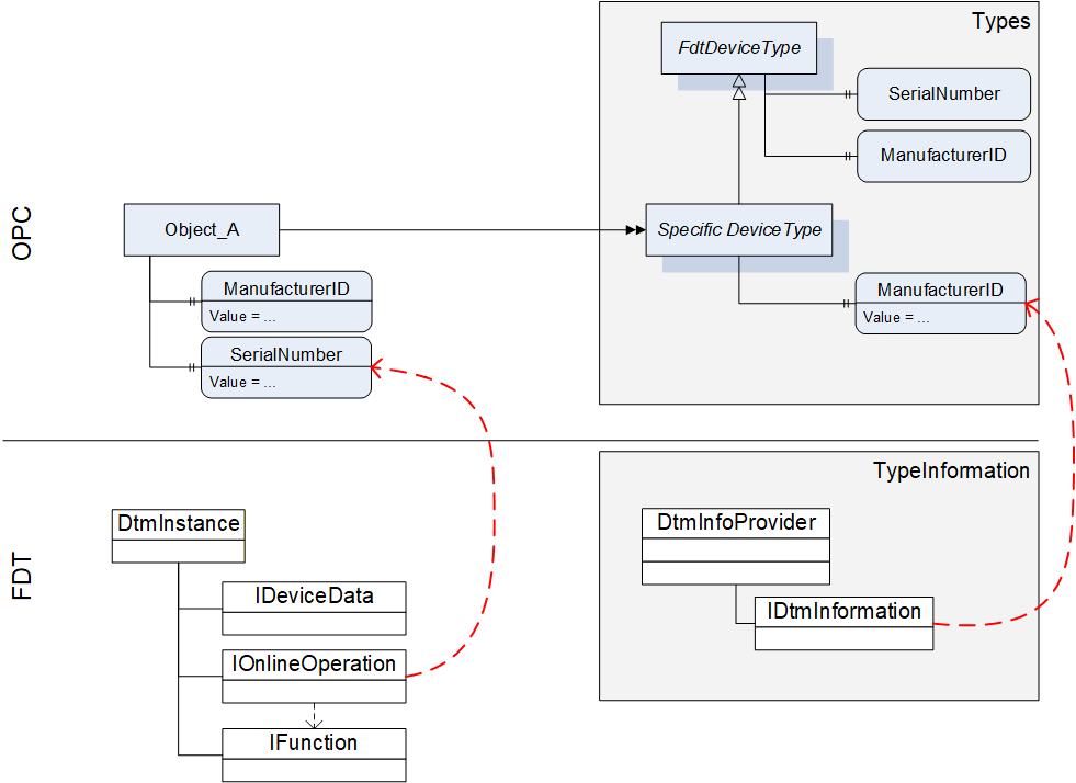
For this reason the device type specific data of OPC is mapped to data on several interfaces of the DTM (see Table 58).
12.2.1.2 Mapping for DeviceType ("Types" standard Object)
All device types provided by DTMs in IDtmInformation shall be represented as subtypes of FdtDeviceType in the "Types" standard Object (see Table 58).
| OPC | FDT | |||
|---|---|---|---|---|
| Attribute | Interface | Method | Data member | Description |
| BrowseName | IDtmInformation | <>GetSupportedTypes | DeviceTypeInfo.Name | |
| DisplayName | IDtmInformation | <>GetSupportedTypes | DeviceTypeInfo.Name | |
| BrowseName | Interface | Method | Data member | Description |
| 2:SerialNumber | Mapping for online device only, see Table 61 | |||
| 2:RevisionCounter | Not supported. Value is always set to -1 | |||
| 2:Manufacturer | IDtmInformation | <>GetSupportedTypes | DeviceTypeInfo.ProductManufacturerName | |
| ManufacturerId | IDtmInformation | GetDeviceIdentInfo | DeviceIdentInfo.ManufacturerId | |
| 2:Model | IDtmInformation | <>GetSupportedTypes | DeviceTypeInfo.ProductName | |
| 2:DeviceManual | All documents will be provided in folder Documentation | |||
| 2:DeviceRevision | IDtmInformation | <>GetSupportedTypes | DeviceTypeInfo.ProductRevision | |
| 2:SoftwareRevision | IDtmInformation | GetDeviceIdentInfo | DeviceIdentInfo.SoftwareRevision | |
| 2:HardwareRevision | IDtmInformation | GetDeviceIdentInfo | DeviceIdentInfo.HardwareRevision | |
| 2:DeviceClass(O) | IDtmInformation | <>GetSupportedTypes | DeviceTypeInfo.DeviceClassifications[0].DomainId + ":" + DeviceTypeInfo.DeviceClassifications[0].Id | The value is a concatenation of the enumeration member names for DomainId and Id. |
| DeviceTypeId | IDtmInformation | <>GetSupportedTypes | DeviceTypeInfo.Id | |
| 2:ManufacturerUri(O) | Not supported. | |||
| 2:ProductCode(O) | Not supported. | |||
| 2:ProductInstanceUri(O) | Not supported. | |||
| <CP_Identifier>(O) | IDtmInformation | <>GetSupportedTypes | TypeInfo.BusCategories[].Category¬Type == required <Identifier> = TypeInfo.BusCategories[].Protocol¬Name | HasComponent-reference of type RequiredProtocol. |
IDtmInformation IChannels | <>GetSupportedTypes IChannels.CommunicationChannels | TypeInfo.BusCategories[].Category¬Type == supported <Identifier> = CommunicationChannelItem.Id | HasComponent-reference of type SupportedProtocol. If one Channel requires multiple protocols, multiple connection points are provided, an additional number is concatenated to the channel id. | |
| 0:Icon | IDtmInformation | GetFdtIcon() | Icon | see explanation below the table |
| Applied from IFdtDeviceHealthType | ||||
| 2:DeviceHealth | Mapping for online device only, see Table 61 | |||
| 2:DeviceHealthAlarms(O) | - | - | - | No mapping defined. |
| OPC | FDT | |||
| BrowseName | Interface | Method | Data member | Description |
| Applied from IFdtSupportInfoType | ||||
| 2:DeviceTypeImage(O) | This folder will contain items as defined in 12.2.8.1. | |||
| 2:Documentation (O) | IDtmInformation | <>GetSupportedTypes | DeviceTypeInfo.Documents | This folder will contain items that represent the shown FDT data member as defined in 7.3 |
| 2:ProtocolSupport (O) | INetworkData | GetNetworkDataInfo | NetworkData. DeviceInformationDocuments | This folder will be provided as defined in 12.2.8.2. |
| 2:ImageSet(O) | Not supported. | |||
A DTM can provide several icons (list of icons). The rule for selection of the icon and extraction of an image (a specific resolution) from the icon is frame application specific. The selection of the image format in general is implementation specific, all types are allowed that are defined in OPC UA 10000-3.
12.2.1.3 Mapping for Offline Device ("Objects" standard Object)
The information for a device (instance) is based on the information provided by a DTM (instance). The mapping for the device node is defined in Table 59.
| OPC | FDT | |||
|---|---|---|---|---|
| Attribute | Interface | Method | Data member | Description |
| TypeReference | - | - | - | NodeId of the DeviceType |
| BrowseName | IDtm | DtmSystemGuiLabel | ||
| DisplayName | IDtm | DtmSystemGuiLabel | ||
The device parameters provide offline identification information based on DTM type information intended for identification. This data may provide values or regular expressions to define ranges of supported values.
In the call to IDtmInformation.GetDeviceIdentInfo() a protocol must be specified. The first entry from the list of INetworkData.ActiveProtocols shall be used.
GetDeviceIdentInfo() may return a list of DeviceIdentInfo where the first entry is used for the parameters as defined below. Exposing the remaining list entries is implementation specific.
| OPC | FDT | |||
|---|---|---|---|---|
| BrowseName | Interface | Method | Data member | Description |
| ManufacturerId | IDtmInformation | GetDeviceIdentInfo() | DeviceIdentInfo[0].GetManufacturerId() | |
| DeviceTypeId | IDtmInformation | GetDeviceIdentInfo() | DeviceIdentInfo[0]. GetDeviceTypeId() | |
| 2:NetworkAddress | INetworkData | GetAddressInfo() | AddressInfo.DeviceAddresses[].Address | string array containing all addresses provided |
| DeviceTag | -/- | -/- | (default value) | |
| 2:Serial Number | -/- | -/- | (default value) | |
| 2:SoftwareRevision | IDtmInformation | GetDeviceIdentInfo() | DeviceIdentInfo[0].GetSoftwareRevision() | |
| 2:HardwareRevision | IDtmInformation | GetDeviceIdentInfo() | DeviceIdentInfo[0].GetHardwareRevision() | |
| Contents of FunctionalGroup "Identification" (see 12.2.5.) | ||||
| ProtocolId | IDtmInformation | GetDeviceIdentInfo() | DeviceIdentInfo[0].GetProtocolId() | |
| ProtocolSpecificIdentification | IDtmInformation | GetDeviceIdentInfo() | DeviceIdentInfo[0]. GetProtocolSpecificProperties() | |
| DeviceSpecific-Identification | IDtmInformation | GetDeviceIdentInfo() | DeviceIdentInfo[0].DeviceSpecificProperties | |
12.2.1.4 Mapping for Online Device ("Objects" standard Object online reference)
Device parameters provide identification information based on data read online from the device. This data may be different from the data provided in the DeviceType.
| OPC | FDT | |||
|---|---|---|---|---|
| BrowseName | Interface | Method | Data member | Description |
| ManufacturerId | IHardwareInformation | <>HardwareScan() | DeviceScanInfo.GetManufacturerId() | |
| DeviceTypeId | IHardwareInformation | <>HardwareScan() | DeviceScanInfo.GetDeviceTypeId() | |
| 2:NetworkAddress | IHardwareInformation | <>HardwareScan() | DeviceScanInfo.GetAddress() | |
| DeviceTag | IHardwareInformation | <>HardwareScan() | DeviceScanInfo.GetTag() | |
| 2:DeviceHealth | IOnlineOperation | <>ReadDevice-Status() | DeviceStatus.StatusFlag | For mapping of the enumeration values see 12.1.1. |
| 2:Serial Number | IHardwareInformation | <>HardwareScan() | DeviceScanInfo.SerialNumber() | |
| 2:SoftwareRevision | IHardwareInformation | <>HardwareScan() | DeviceScanInfo.GetSoftwareRevision() | |
| 2:HardwareRevision | IHardwareInformation | <>HardwareScan() | DeviceScanInfo.GetHardwareRevision() | |
| Contents of FunctionalGroup "Identification" (see 12.2.5.) | ||||
| ProtocolId | IHardwareInformation | <>HardwareScan() | DeviceScanInfo.GetProtocolId() | |
| ProtocolSpecificIdentification | IHardwareInformation | <>HardwareScan() | DeviceScanInfo.GetProtocolSpecificProperties() | |
| DeviceSpecific-Identification | IHardwareInformation | <>HardwareScan() | DeviceScanInfo.DeviceSpecificProperties | |
12.2.2 TopologyElementType
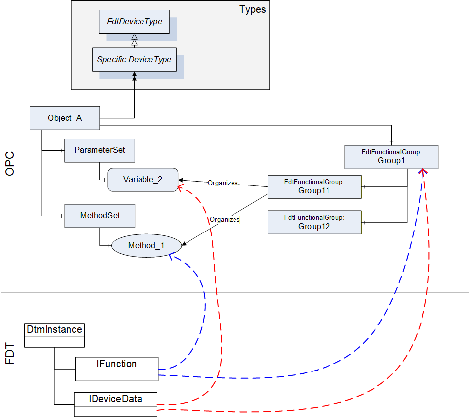
The information provided by a DTM with IFunction.FunctionInfo and IData.DataInfo is mapped into the MethodSet and to the ParameterSet. For both types of information (Commands and Parameters) also references in FunctionalGroup nodes are created, so that an OPC Client may represent a joint user interface (see Figure 13).
The BrowseName and DisplayName of the FunctionalGroup-Nodes are based on the grouping in IFunction.FunctionInfo (FunctionGroup) and IData.DataInfo (DataGroup).
Information about IO signals are provided in a folder ProcessDataSet, which contains FdtIoSignalInfoType nodes. FdtIoSignalInfoType nodes are referenced by the corresponding FdtParameter nodes.
| OPC | FDT | |||
|---|---|---|---|---|
| BrowseName | Interface | Method | Data member | Description |
| ParameterSet | IInstanceData / IDeviceData | <>GetDataInfo | DataInfo.DeviceDataItems | DeviceDataItems is a hierarchical list of data items that represent different types of data items. In the ParameterSet only AccessibleData and StructDataGroup shall be represented (see 12.2.7). The flat list of parameters is constructed from the hierarchical list where duplicates must be removed. |
| MethodSet | IFunction | FunctionInfo | FunctionInfo.FunctionItems | FunctionItems provides a hierarchical list of functions that are supported by the DTM. Only functions without user interface (CommandFunction) shall be represented in the MethodSet (see 12.2.6). |
| ProcessDataSet | IProcessData | <>GetProcessData | ProcessDataInfo.ProcessDataItems | ProcessDataItems provides a list of process data supported by the device. The FdtSignalInfo objects are referenced by the respective parameter objects (in the online device). |
| <GroupIdentifier> | IInstanceData / IDeviceData | <>GetDataInfo | DataInfo.DeviceDataItems | The hierarchical list provided through DeviceDataItems is mapped to a tree of FunctionalGroups. The strings used for the placeholder <GroupIdentifier> are defined by the names of the DataGroups. |
| Identification | The contents of the FunctionalGroup is defined in 12.2.5. | |||
| Lock | (defined in UA Devices) | |||
12.2.3 FunctionalGroupType
The FunctionalGroupType is used to organize Parameters and Methods (which are defined in ParameterSet and MethodSet) in a user-friendly way (see Table 63). FunctionalGroups may be organized hierarchically by organizing FunctionalGroups as child nodes of FunctionalGroups.
| OPC | FDT | |||
|---|---|---|---|---|
| Attribute | Interface | Method | Data member | Description |
| <GroupIdentifier> | IInstanceData / IDeviceData | <>GetDataInfo | DataInfo.DeviceDataItems == DataGroup DataGroup.Name | Only DataInfo.DeviceDataItems shall be mapped, that are of type DataGroup. The Name member of the DataGroup shall be used as <GroupIdentifier>. |
| DisplayName | IInstanceData / IDeviceData | <>GetDataInfo | DataGroup.Label | |
| Description | IInstanceData / IDeviceData | <>GetDataInfo | DataGroup.Descriptor | |
| BrowseName | Interface | Method | Data member | Description |
| <ParameterIdentifier> | IInstanceData / IDeviceData | <>GetDataInfo | DataInfo.DeviceDataItems == Data Data.Name | Only DataInfo.DeviceDataItems shall be mapped, that are of type Data. The Name member of the Data shall be used as <ParameterIdentifier>. |
| <MethodIdentifier> | (no mapping defined) | |||
| UIElement | (no mapping defined) | |||
12.2.4 Identification FunctionalGroup
The Identification FunctionalGroup organizes references to parameters, which may be used to identify the device and its device type. The list of parameters that shall be provided in the Identification FunctionalGroup is defined in Table 64.
| References | BrowseName | Modelling Rule |
|---|---|---|
| Organizes | ManufacturerId | O |
| Organizes | DeviceTypeId | O |
| Organizes | 2:NetworkAddress | O |
| Organizes | DeviceTag | M |
| Organizes | 2:Serial Number | M |
| Organizes | 2:SoftwareRevision | M |
| Organizes | 2:HardwareRevision | M |
| Organizes | 2:ProtocolId | OP |
| HasComponent | ProtocolSpecific¬Identification | O |
| HasComponent | DeviceSpecific¬Identification | O |
The values of the referenced Variables may vary for online and offline device. See section 12.2.1 for the mapping of these Variables.
Protocol specific properties shall be organised in a FunctionalGroup called "ProtocolSpecificIdentification" contained in the Identification FunctionalGroup.
Device specific properties shall be organised in a FunctionalGroup called "DeviceSpecificIdentification" contained in the Identification FunctionalGroup.
12.2.5 Device Data and Device Methods
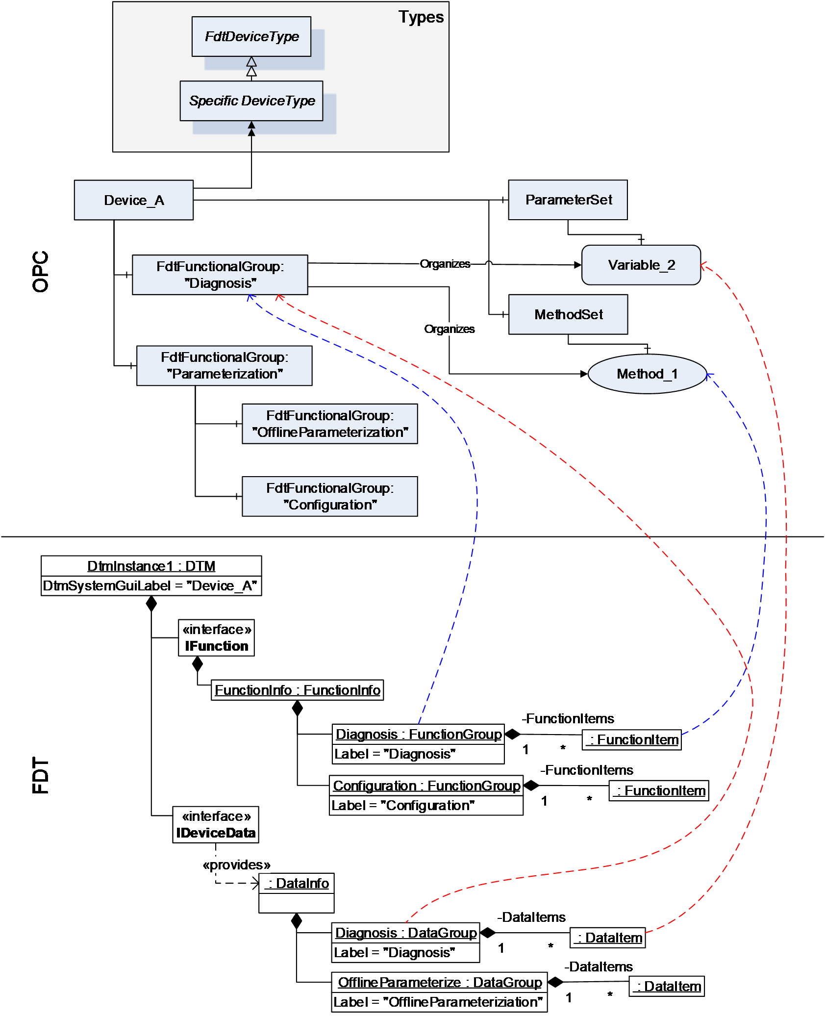
While device data and methods related to the device are defined in separate areas of the OPC UA Information model (i.e. ParameterSet and MethodSet), they are organized by functional groups into a concise representation, which may be structured to present different aspects of the device. A DTM provides different interfaces (e.g. IDeviceData and IFunction), where data and methods are presented independently, while each interface may provide an own structure.
In the mapping from DTM interfaces to OPC UA information model, the representation hierarchies of IData interfaces and IFunction interface are combined into FunctionalGroups to provide a concise representation of the device data and methods within one hierarchy.
This means, that the data of the IData interfaces are mapped to the ParameterSet node in the OPC UA Information model and the command functions from IFunction interface are mapped to the MethodSet of the device. The hierarchical structures in the IData and IFunction interfaces are mapped to the hierarchical structure provided by the FdtFunctionalGroup elements, which organize the representation of data and methods (see Figure 14).
12.2.6 Methods
12.2.6.1 General
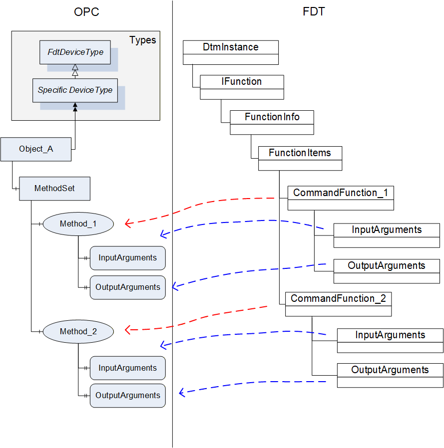
A DTM instance can offer command functions. These functions do not have a user interface, they can have arguments and optional default values.
Each command function shall be mapped to a method in the MethodSet of the device instance (see Figure 15). The arguments are mapped to the InputArguments and OutputArguments for the methods. Optional arguments shall be included.
| OPC | FDT | |||
|---|---|---|---|---|
| Attribute | Interface | Method | Data member | Description |
| BrowseName | IFunctions | FunctionInfo | FunctionItem.Label | |
| DisplayName | IFunctions | FunctionInfo | FunctionItem.Label | |
| Description | IFunctions | FunctionInfo | FunctionItem.Descriptor | |
The DTMInfoBuilder can offer information about static functions that are independent of a DTM instance. Such FDT Static Functions may be mapped to methods on the device type created for the DTM. The execution of the method on a device object will need to be mapped to the execution of a static function with a StaticFunctionProvider. The Frame/Server will need to hold the reference to the provider internally and use it for execution of the method (see Figure 16).
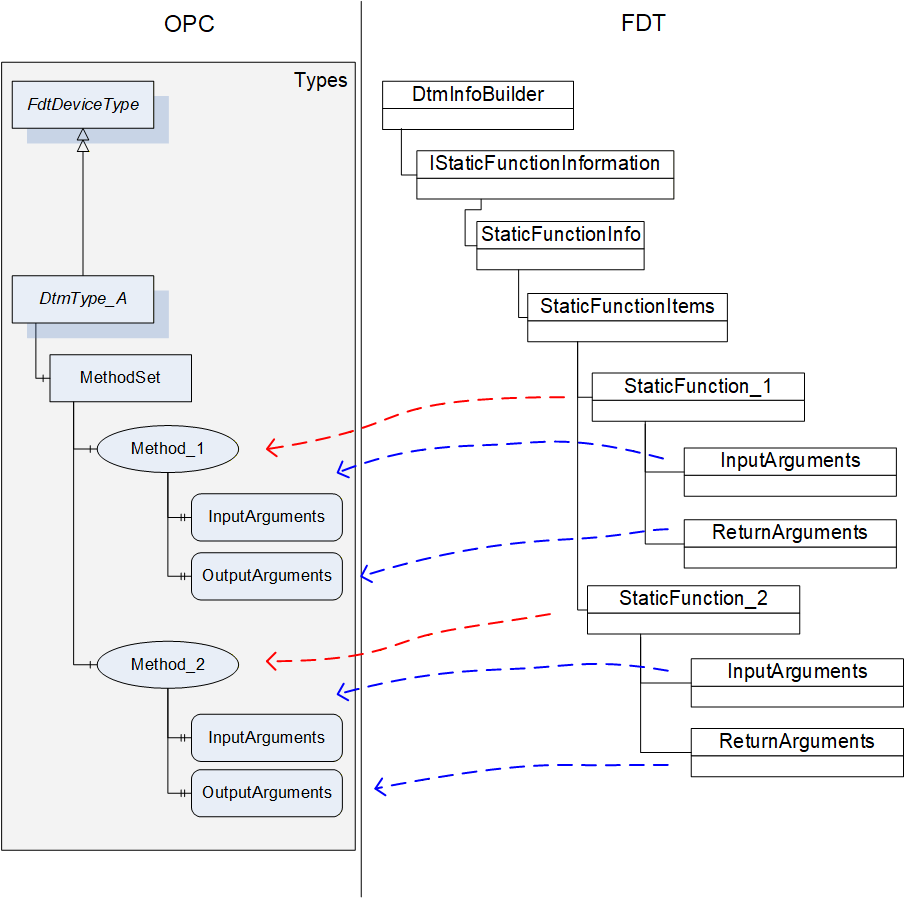
| OPC | FDT | |||
|---|---|---|---|---|
| Attribute | Interface | Method | Data member | Description |
| BrowseName | IStaticFunctionInformation | GetStaticFunctions | StaticFunctionDescription.Label | |
| DisplayName | IStaticFunctionInformation | GetStaticFunctions | StaticFunctionDescription.Label | |
| Description | IStaticFunctionInformation | GetStaticFunctions | StaticFunctionDescription.Descriptor | |
12.2.6.2 TransferServices
For a DTM instance it is mandatory to provide the interface IOnlineOperation if the device provides online data. This interface is mapped to an object of type FdtTransferServiceType (see 7.8). Since the DTM interface is not mandatory for all devices, the availability of the TransferServices depends on the availability of the DTM interface. The member SupportedTransfer indicates, which TransferServices are supported for the device.
| OPC | FDT | |||
|---|---|---|---|---|
| BrowseName | Interface | Method | Data member | Description |
| 2:TransferToDevice | IOnlineOperation | BeginWriteDataToDevice / EndWriteDataToDevice | - | |
| 2:TransferFromDevice | IOnlineOperation | BeginReadDataFromDevice / EndReadDataFromDevice | - | |
| 2:FetchTransferResultData | IOnlineOperation | - | - | Retrieves the result / status from the executed methods. |
| SupportedTransfer | IOnlineOperation | - | SupportedTransfer | |
The TransferServices Type object (with browse name "Transfer") is provided as child node of an offline device node (not for an online device node).
For the method FetchTransferResultData the server is allowed to limit the TransferResultData in regard to the list of transferred parameters (parameterDefs) to zero data. The results of the transfer will be represented in the parameter values of the device node.
12.2.7 Variable
12.2.7.1 General
The parameter set of a device (offline and online) is described by means of the DataInfo data type (available with the <GetDataInfo> method from IInstanceData (offline) and IDeviceData (online)).
DataInfo provides a description of the available data without the values. The actual values are accessible with <Read> and <Write> methods from IInstanceData (offline) and IDeviceData (online).
DataInfo provides a list of data items (member DeviceDataItems), which may represent a range of types. Some of these data items are mapped to DataVariables (see Table 68).
| OPC | FDT |
|---|---|
| DataVariable (according OPC UA 10000-3) | Data |
| UnitData | |
| RangeData | |
| AlarmData | |
| SubstituteData | |
| StructDataGroup | |
FunctionalGroup (according OPC UA 10000-100) | DataGroup |
| Block object (according OPC UA 10000-100) | ModuleDataGroup |
12.2.7.2 FdtParameter
12.2.7.2.1 General
Table 69 shows the mapping for the FdtParameter.
| OPC | FDT | |||
|---|---|---|---|---|
| Attribute | Interface | Method | Data member | Description |
| NodeClass | Fixed value: Variable | |||
| BrowseName | IData | <GetDataInfo> | Name | |
| DisplayName | IData | <GetDataInfo> | Label | |
| Description | IData | <GetDataInfo> | Descriptor | |
| WriteMask | Generated by Frame | |||
| UserWriteMask | IData | <GetDataInfo> | IsChangeEnabled | Generated by Frame |
| Value | IData | <Read> / <Write> | ||
| DataType | IData | <GetDataInfo> | DataTypeInfo | |
| ValueRank | IData | <GetDataInfo> | DataTypeInfo | Indicates whether the datatype is an array. |
| ArrayDimensions | IData | <GetDataInfo> | DataTypeInfo | If the datatype is an array, then provide dimensions. |
| AccessLevel | IData | <GetDataInfo> | IsReadable, IsWritable | Generated by Frame |
| UserAccessLevel | IData | <GetDataInfo> | IsReadable, IsWritable | Generated by Frame |
| MinimumSamplingInterval | Defined by Frame. | |||
| Historizing | Defined by Frame. | |||
| BrowseName | ||||
| 2:EURange | IData | <GetDataInfo> | RangeDataRefs | |
| 2:EngineeringUnits | IData | <GetDataInfo> | UnitDataRef | |
| 0:HasComponent | May be used for structured datatypes (StructDataGroup) | |||
| 2:HasDefinition | Defined by Frame. | |||
| 2:ValuePrecision | Defined by Frame. | |||
| DisplayFormat | IData | <GetDataInfo> | DisplayFormat | |
| AlarmType | IData | <GetDataInfo> | AlarmType | |
| RangeType | IData | <GetDataInfo> | RangeType | |
| SubstitutionType | IData | <GetDataInfo> | SubstitutionType | |
| ApplicationId | IData | <GetDataInfo> | ApplicationId | |
| SemanticInfo | IData | <GetDataInfo> | SemanticInfos | |
| DataRef | IData | <GetDataInfo> | DataRefs | |
| IOSignalRef | IData | <GetDataInfo> | IOSignalRef | |
| AlarmDataRef | IData | <GetDataInfo> | AlarmDataRefs | |
| SubstituteDataRef | IData | <GetDataInfo> | SubstituteDataRef | |
12.2.7.2.2 Datatype mapping
The datatype mapping for parameter data is described in Table 70.
| OPC | FDT | |
|---|---|---|
| Data type | Data type | Description |
| Float | Float | |
| Double | Double | |
| Byte | Byte | |
| Int32 | Int | |
| Int64 | Long | |
| UInt32 | UInt | |
| UInt64 | ULong | |
| DateTime | DateTime | |
| DateTime | Date | Date is represented as date at 0:00 a clock. |
| Duration | Time | Time is expressed as duration since midnight. |
| Duration | TimeSpan | Duration is expressed in milliseconds, TimeSpan is expressed in terms of days, hours, minutes. For the conversion of large TimeSpan a loss of precision may occur. |
| String | String | |
| Array of Byte | BinaryByteArray | |
| Array of Bit | BinaryBitArray | |
| Enumeration | Enumerator | |
| Boolean | Boolean | |
| SByte | SByte | |
In OPC UA array datatypes are represented by a combination of the properties datatype, value-rank and array-dimensions (see OPC OPC UA 10000-5, section 5.6.2).
In FDT array datatypes are represented with a dedicated ArrayDatatypeInfo datatype. This datatype has a member ArrayDatatypeInfo.ArrayDimensions, which specifies the length of each dimension of the array.
The mapping for array data types is defined as follows.
OPC datatype value is mapped according to Table 70.
OPC value rank is:
-1 for a simple datatype, or
Number of fields in FDT ArrayDatatypeInfo.ArrayDimensions (always > 0)
OPC array-dimensions property is:
NULL for a simple datatype, or
has the same value as ArrayDatatypeInfo.ArrayDimensions.
value of 0 means that the array has a variable length,
values > 0 indicate a defined length.
12.2.8 Device Support Information
12.2.8.1 Device Type Image
All Bitmaps provided by a DTM shall be represented in the DeviceTypeImage folder according OPC UA 10000-100 (see Table 58). An image shall be represented by an FdtParameter with DataType set to one of the defined image data types. The actual image is provided by the value attribute as ByteString.
The mapping for a device type image is defined in Table 71.
| OPC | FDT | |||
|---|---|---|---|---|
| BrowseName | Interface | Method | Data member | Description |
| SemanticInfo | IDtmInformation | <>GetSupportedTypes | TypeInfo.Bitmaps.SemanticInfo | |
| Bitmap | IDtmInformation | GetBitmap() | Bitmap | |
Selection of the image format according to FDT2 is specific for a Frame Application. All image types are allowed that are defined in OPC UA 10000-3.
12.2.8.2 Protocol Support Files
Protocol support files provided for a device are exposed as Variables organised in the ProtocolSupport folder. They may represent various types of information as defined by a protocol. Examples are a GSD or a CFF file. The ProtocolSupport folder is formally defined in OPC UA for Devices 5.7.3.. The mapping is protocol independent. All the documents listed in NetworkData.DeviceInformationDocuments are mapped. The value of the <PlaceHolder> is defined by the label of the respective document (Document.Label).
| OPC | FDT | |||
|---|---|---|---|---|
| BrowseName | Interface | Method | Data member | Description |
| <PlaceHolder> | INetworkData | GetNetworkDataInfo | NetworkData. DeviceInformationDocuments | This applies to all protocols. The optional data member provides protocol support files for all protocols. |
The label of the DeviceInformationDocument shall be used as BrowseName for the OPC Node.
12.2.9 FdtIoSignalInfoType
All IOSignalInfo provided by the DTM in the IProcessData interface are mapped to respective FdtIoSignalInfo objects.
| OPC | FDT | |||
|---|---|---|---|---|
| Attribute | Interface | Method | Data member | Description |
| BrowseName | IProcessData | <>GetProcessData() | IOSignalInfo.Name | |
| DisplayName | IProcessData | <>GetProcessData() | IOSignalInfo.Label | |
| Description | IProcessData | <>GetProcessData() | IOSignalInfo.Descriptor | |
| BrowseName | ||||
| FrameApplicationTag | IProcessData | <>GetProcessData() | IOSignalInfo.FrameApplicationTag | |
| IECDatatype | IProcessData | <>GetProcessData() | IOSignalInfo.IECDatatype | |
| IsLocked | IProcessData | <>GetProcessData() | IOSignalInfo.IsLocked | |
| IsSafety | IProcessData | <>GetProcessData() | IOSignalInfo.IsSafety | |
| RoutedIoSignalId | IProcessData | <>GetProcessData() | IOSignalInfo.RoutedIoSignalId | |
| SemanticInfo | IProcessData | <>GetProcessData() | IOSignalInfo.SemanticInfo | |
| SignalType | IProcessData | <>GetProcessData() | IOSignalInfo.SignalType | |
| HasAlarmInfo | IProcessData | <>GetProcessData() | IOSignalInfo.AlarmInfoRef | |
| HasDeviceData | IProcessData | <>GetProcessData() | IOSignalInfo.DeviceDataRef | |
| HasRange | IProcessData | <>GetProcessData() | IOSignalInfo.RangeInfoRef | |
| HasSubstituteValue | IProcessData | <>GetProcessData() | IOSignalInfo.SubstituteValueRef | |
| HasUnit | IProcessData | <>GetProcessData() | IOSignalInfo.UnitInfoRef | |
12.2.10 FdtProtocolType
The FdtProtocolType and its sub-types are used to specify a communication protocol that is supported by a Device or Network. The BrowseName of each instance of a ProtocolType shall define the Communication Profile (see OPC UA for Devices 6.3).
OPC UA for FDT uses a sub-type FdtProtocolType (see 7.7) for mapping the needed information.
| OPC | FDT | |||
|---|---|---|---|---|
| Attribute | Interface | Method | Data member | Description |
| BrowseName | IDtmInformation | <>GetSupported-Types | DeviceTypeInfo.BusCategories[].protocolName | |
| DisplayName | IDtmInformation | <>GetSupported-Types | DeviceTypeInfo.BusCategories[].protocolName | |
| BrowseName | ||||
| BusCategory | IDtmInformation | <>GetSupported-Types | DeviceTypeInfo.BusCategories[].protocolId | The protocolId is formatted as string with upper case letters. |