
Introduction
| Revision | Description |
| 1.01 | - Added a number of new components to existing ObjectTypes - Improved descriptions. |
1 Scope
This specification was created by a joint working group of the OPC Foundation and AIM. It defines an OPC UA Information Model to represent and access AutoID Devices.
OPC Foundation
OPC is the interoperability standard for the secure and reliable exchange of data and information in the industrial automation space and in other industries. It is platform independent and ensures the seamless flow of information among devices from multiple vendors. The OPC Foundation is responsible for the development and maintenance of this standard.
Initially, the OPC standard was restricted to the Windows operating system. As such, the acronym OPC was borne from OLE (object linking and embedding) for Process Control. These specifications, which are now known as OPC Classic, have enjoyed widespread adoption across multiple industries, including manufacturing, building automation, oil and gas, renewable energy and utilities, among others.
With the introduction of service-oriented architectures in manufacturing systems came new challenges in security and data modelling. The OPC Foundation developed the OPC UA specifications to address these needs and at the same time provided a feature-rich technology open-platform architecture that was future-proof, scalable and extensible.
AIM
AIM (including AIM Global) is the leading industry association and worldwide authority on automatic identification & data capture technologies (AIDC/AutoID), which comprise barcode, OCR, 2D code, RFID, NFC, RTLS, sensors and mobile computing. It is serving members around the globe as a trusted resource for more than 40 years. AIM actively supports the development of standards through its own Technical Symbology Committee (TSC), Global Standards Advisory Groups, the US and European RFID Experts Groups (REG / EREG) and the IoT Experts Group. Furthermore, AIM experts take a leading role at working groups at standardisation organisations like ISO, ANSI, CEN, CENELEC, ETSI and DIN. AIM Germany (AIM-D e.V., Lampertheim, Germany: www.AIM-D.de) is the regional chapter for central Europe (Germany, Austria, Switzerland). AIM members include technology providers, systems integrators, consulting firms, research institutes and other associations. AIM's general goal is to facilitate the market dissemination of AIDC technologies on a reliable basis for the benefit of solution providers and users.
2 Normative References
OPC UA for AutoID Information Model specification references
OPC 10000-1, OPC Unified Architecture - Part 1: Overview and Concepts
OPC 10000-3, OPC Unified Architecture - Part 3: Address Space Model
OPC 10000-4, OPC Unified Architecture - Part 4: Services
OPC 10000-5, OPC Unified Architecture - Part 5: Information Model
OPC 10000-6, OPC Unified Architecture - Part 6: Mappings
OPC 10000-7, OPC Unified Architecture - Part 7: Profiles
OPC 10000-100, OPC Unified Architecture - Part 100: Devices
ISO/IEC 14443 (all parts) Identification cards -- Contactless integrated circuit cards -- Proximity cards
| ISO/IEC 15415: 2011 | Information technology - Automatic identification and data capture techniques - Bar code symbol print quality test specification - Two-dimensional symbols |
| ISO/IEC 15416: 2000 | Information technology - Automatic identification and data capture techniques - Bar code print quality test specification - Linear symbols |
ISO/IEC 15418: 2009 Information technology -- Automatic identification and data capture techniques -- GS1 Application Identifiers and ASC MH10 Data Identifiers and maintenance
ISO/IEC 15434: 2006 Information technology -- Automatic identification and data capture techniques -- Syntax for high-capacity ADC media
ISO/IEC 15693 (all parts) Identification cards -- Contactless integrated circuit cards -- Vicinity cards
ISO 17363: 2013 Supply chain applications of RFID -- Freight containers
ISO 17364: 2013 Supply chain applications of RFID -- Returnable transport items (RTIs) and returnable packaging items (RPIs)
ISO 17365: 2013 Supply chain applications of RFID - Transport units
ISO 17366: 2013 Supply chain applications of RFID - Product packaging
ISO 17367: 2013 Supply chain applications of RFID - Product tagging ISO/IEC 18000-1: 2008 Information technology - Radio frequency identification for item management - Part 1: Reference architecture and definition of parameters to be standardized
ISO/IEC 18000-1: 2008 Information technology - Radio frequency identification for item management - Part 1: Reference architecture and definition of parameters to be standardized
ISO/IEC 18000-2: 2009 Information technology - Radio frequency identification for item management - Part 2: Parameters for air interface communications below 135 kHz
ISO/IEC 18000-3: 2010 Information technology - Radio frequency identification for item management - Part 3: Parameters for air interface communications at 13,56 MHz
ISO/IEC 18000-63: 2013 Information technology - Radio frequency identification for item management - Part 63: Parameters for air interface communications at 860 MHz to 960 MHz Type C
ISO/IEC 19762, Information technology - Automatic identification and data capture (AIDC) techniques - Harmonized vocabulary
GS1 EPCglobal™: GS1 EPC™ Tag Data Standard [EPCTDS]
GS1 EPCglobal™: EPC™ Radio-Frequency Identity Protocols Class-1 Generation-2 UHF RFID Protocol for Communications at 860 MHz - 960 MHz Version 1.2.0 [EPCGen2]
NMEA 0183 v. 4.10: Data transmission protocol and time and specific sentence formats
3 Terms, abbreviations and conventions
3.1 Use of terms
Defined terms of OPC UA specifications, types and their components defined in OPC UA specifications and in this specification are highlighted with italic in this specification.
3.2 OPC UA for AutoID Information Model terms
3.2.1 AutoID Device
Identification device executing a scan, read or write process
3.2.1.1 Untitled
3.2.2 AutoID Identifier
Transponder, tag or code identifying an object
3.3 Abbreviations
| A&E | Alarms & Events |
| AFI | Application Family Identifier |
| AIDC | Automatic Identification and Data Capture |
| ANSI | American National Standards Institute |
| AutoID | Automatic Identification |
| DA | Data Access |
| DSFID | Data Storage Format Identifier |
| EAN | European Article Number |
| EPC | Electronic Product Code |
| GNSS | Global Navigation Satelite System |
| GPS | Global Positioning System |
| HDA | Historical Data Access |
| HF | High Frequency |
| HMI | Human-Machine Interface |
| IEC | International Electrotechnical Commission |
| IoT | Internet of Things |
| ISO | International Organization for Standardization |
| MB | Memory Bank |
| MIME | Multipurpose Internet Mail Extensions |
| NFC | Near Field Communication |
| OCR | Optical Character Recognition |
| RFID | Radio Frequency Identification |
| RTLS | Real Time Locating System |
| SCADA | Supervisory Control And Data Acquisition |
| TID | Tag IDentifier |
| UA | Unified Architecture |
| UHF | Ultra High Frequency |
| UID | Unique Identifier |
| UII | Unique Item Identifier |
| UTM | Universal Transverse Mercator |
| WLAN | Wireless Local Network |
| XML | Extensible Markup Language |
3.4 Conventions used in this specification
3.4.1 Conventions for Node descriptions
Node definitions are specified using tables (See Table 1)
| Attribute | Value | ||||
| Attribute name | Attribute value. If it is an optional attribute that is not set "--" will be used. | ||||
| References | NodeClass | BrowseName | DataType | TypeDefinition | ModellingRule |
|---|---|---|---|---|---|
| ReferenceType name | NodeClass of the TargetNode. | BrowseName of the target Node. If the Reference is to be instantiated by the server, then the value of the target Node's BrowseName is "--". | Attribute of the referenced Node, only applicable for Variables. | TypeDefinition Node of the referenced Node, only applicable for Variables and Objects. | Referenced ModellingRule of the referenced Object. |
Notes - Notes referencing footnotes of the table content. | |||||
Attributes are defined by providing the Attribute name and a value, or a description of the value.
References are defined by providing the ReferenceType name, the BrowseName of the TargetNode and its NodeClass.
If the TargetNode is a component of the Node being defined in the table the Attributes of the composed Node are defined in the same row of the table.
The DataType is only specified for Variables; "[<number>]" indicates a single-dimensional array, for multi-dimensional arrays the expression is repeated for each dimension (e.g. [2][3] for a two-dimensional array). For all arrays the ArrayDimensions is set as identified by <number> values. If no <number> is set, the corresponding dimension is set to 0, indicating a dynamic size. If no number is provided at all the value is scalar and the ArrayDimensions is omitted. If no brackets are provided, it identifies a scalar DataType and the ValueRank is set to the corresponding value (see OPC 10000-3). In addition, ArrayDimensions is set to null or is omitted. If it can be Any or ScalarOrOneDimension, the value is put into "{<value>}", so either "{Any}" or "{ScalarOrOneDimension}" and the ValueRank is set to the corresponding value (see OPC 10000-3) and the ArrayDimensions is set to null or is omitted. In Table 2 examples are given.
| Notation | DataType | ValueRank | ArrayDimensions | Description |
| Int32 | Int32 | -1 | omitted or NULL | A scalar Int32 |
| Int32[] | Int32 | 1 | omitted or {0} | Single-dimensional array of Int32 with an unknown size |
| Int32[][] | Int32 | 2 | omitted or {0,0} | Two-dimensional array of Int32 with unknown sizes for both dimensions |
| Int32[3][] | Int32 | 2 | {3,0} | Two-dimensional array of Int32 with a size of 3 for the first dimension and an unknown size for the second dimension |
| Int32[5][3] | Int32 | 2 | {5,3} | Two-dimensional array of Int32 with a size of 5 for the first dimension and a size of 3 for the second dimension |
| Int32{Any} | Int32 | -2 | omitted or NULL | An Int32 where it is unknown if it is scalar or array with any number of dimensions |
| Int32{ScalarOrOneDimension} | Int32 | -3 | omitted or NULL | An Int32 where it is either a single-dimensional array or a scalar |
The TypeDefinition is specified for Objects and Variables.
The TypeDefinition column specifies a NodeId of a TypeDefinitionNode, i.e. the specified Node points with a HasTypeDefinition Reference to the corresponding TypeDefinitionNode. The symbolic name of the NodeId is used in the table.
The ModellingRule of the referenced component is provided by specifying the symbolic name of the rule in the ModellingRule column. In the AddressSpace, the Node shall use a HasModellingRule Reference to point to the corresponding ModellingRule Object.
If the NodeId of a DataType is provided, the symbolic name of the Node representing the DataType shall be used.
Nodes of all other NodeClasses cannot be defined in the same table; therefore only the used ReferenceType, their NodeClass and their BrowseName are specified. A reference to another section of this specificationpoints to their definition.
If no components are provided, the DataType, TypeDefinition and ModellingRule columns may be omitted and only a Comment column is introduced to point to the Node definition.
Components of Nodes can be complex, i.e. containing components by themselves. The TypeDefinition, NodeClass, DataType and ModellingRule can be derived from the type definitions, and the symbolic name can be created as defined in 3.4.2.1. Therefore those containing components are not explicitly specified; they are implicitly specified by the type definitions.
3.4.2 NodeIds and BrowseNames
3.4.2.1 NodeIds
The NodeIds of all Nodes described in this specification are only symbolic names. Annex A defines the actual NodeIds.
The symbolic name of each Node defined in this specificationis its BrowseName, or, when it is part of another Node, the BrowseName of the other Node, a ".", and the BrowseName of itself. In this case "part of" means that the whole has a HasProperty or HasComponent Reference to its part. Since all Nodes not being part of another Node have a unique name in this specification, the symbolic name is unique.
The NamespaceUri for all NodeIds defined in this document is defined in Annex A. The NamespaceIndex for this NamespaceUri is vendor-specific and depends on the position of the NamespaceUri in the server namespace table.
Note: This specification does not only define concrete Nodes, but also requires that some Nodes have to be generated, for example one for each AutoID Device represented by the Server. The NodeIds of those Nodes are server-specific, including the Namespace. But the NamespaceIndex of those Nodes cannot be the NamespaceIndex used for the Nodes defined by this specification, because they are not defined by this specification but generated by the Server.
3.4.2.2 BrowseNames
The text part of the BrowseNames for all Nodes defined in this specification is specified in the tables defining the Nodes. The NamespaceIndex for all BrowseNames defined in this specification is server specific and depends on the position of the namespace URI defined in this specification in the server namespace table.
If the BrowseName is not defined by this specification, a namespace index prefix like '0:EngineeringUnits' is added to the BrowseName. This is typically necessary if a Property of another specification is overwritten or used in the OPC UA types defined in this specification. Table 87 provides a list of namespaces used in this specification.
3.4.3 Common Attributes
3.4.3.1 General
The Attributes of Nodes, their DataTypes and descriptions are defined in OPC 10000-3. Attributes not marked as optional are mandatory and shall be provided by a Server. The following tables define if the Attribute value is defined by this specification or if they vendor specific.
For all Nodes specified in this specification, the Attributes named in Table 3 shall be set as specified in the table.
| Attribute | Value |
| DisplayName | The DisplayName is a LocalizedText. Each server shall provide the DisplayName identical to the BrowseName of the Node for the LocaleId "en". Whether the server provides translated names for other LocaleIds is vendor specific. |
| Description | Optionally a vendor specific description is provided |
| NodeClass | Shall reflect the NodeClass of the Node |
| NodeId | The NodeId is described by BrowseNames as defined in 3.4.2.1 and defined in Annex A. |
| WriteMask | Optionally the WriteMask Attribute can be provided. If the WriteMask Attribute is provided, it shall set all Attributes to not writeable that are not said to be vendor-specific like Description, EventNotifier or DisplayName with a LocaleId other than 'en'. For example, the Description Attribute may be set to writeable since a Server may provide a server-specific description for the Node. The Attributes NodeId, BrowseName and NodeClass and DataType shall not be writeable, because they are defined for each Node in this specification. The WriteMask Attribute does not take any user access rights into account, that is, although an Attribute is writeable this may be restricted to a certain user / user group. |
| UserWriteMask | Optionally the UserWriteMask Attribute can be provided. It takes the user access rights for the Session user into account. The same rules as for the WriteMask Attribute apply. |
3.4.3.2 Objects
For all Objects specified in this specification, the Attributes named in Table 4 shall be set as specified in the table. The definitions for the Attributes can be found in OPC 10000-3.
| Attribute | Value |
| EventNotifier | Indicates whether the Node can be used to subscribe to Events or not. The value of the Attribute is vendor specific. |
3.4.3.3 Variables
For all Variables specified in this specification, the Attributes named in Table 5 shall be set as specified in the table. The definitions for the Attributes can be found in OPC 10000-3.
| Attribute | Value |
| MinimumSamplingInterval | Optionally, a vendor-specific minimum sampling interval is provided |
| AccessLevel | The access level for Variables used for type definitions is vendor-specific, for all other Variables defined in this specification, the access level shall allow a current read; other settings are vendor specific. |
| UserAccessLevel | The value for the UserAccessLevel Attribute is vendor-specific. It is assumed that all Variables can be accessed by at least one user. |
| Value | For Variables used as InstanceDeclarations, the value is vendor-specific; otherwise it shall represent the value described in the text. |
| ArrayDimensions | If the ValueRank does not identify an array of a specific dimension (i.e. ValueRank <= 0) the ArrayDimensions can either be set to null or the Attribute is missing. This behaviour is vendor-specific. If the ValueRank specifies an array of a specific dimension (i.e. ValueRank > 0) then the ArrayDimensions Attribute shall be specified in the table defining the Variable. The concrete array length is contained in the delivered Value. Therefore this information is only relevant for write access to the Variable Value if the array has a fixed length. |
3.4.3.4 VariableTypes
For all VariableTypes specified in this specification, the Attributes named in Table 6 shall be set as specified in the table. The definitions for the Attributes can be found in OPC 10000-3.
| Attributes | Value |
| Value | Optionally a vendor-specific default value can be provided |
| ArrayDimensions | If the ValueRank does not identify an array of a specific dimension (i.e. ValueRank <= 0) the ArrayDimensions can either be set to null or the Attribute is missing. This behaviour is vendor-specific. If the ValueRank specifies an array of a specific dimension (i.e. ValueRank > 0) then the ArrayDimensions Attribute shall be specified in the table defining the VariableType. The concrete array length is contained in the delivered Value. Therefore this information is only relevant for write access to the VariableType Value if the array has a fixed length. |
4 General information to AutoID and OPC UA
4.1 Introduction to AutoID
AutoID (Automatic Identification) technologies use mainly barcodes, OCR, 2D codes, RFID and NFC in order to identify all sorts of objects in all industry sectors and in logistics: articles in the super market, parts and modules in the production line, (returnable) transport items (RTI), vehicles and so forth. The main benefits of AutoID solutions are the acceleration of business processes and the improvement of data quality compared to manual procedures. AutoID systems rely on numbers, which identify the marked objects ("article number"). If it is required to distinguish similar objects uniquely from each other the article numbers must be extended by serial numbers.
While the automation of enterprise processes is rapidly growing the AutoID technologies achieve a crucial meaning. Concepts like the Internet of Things (IoT) or "Industrie 4.0" can only be put into practice successfully, if AutoID systems provide reliable data about all kinds of moving objects in the diversity of business processes, production lines and logistics chains. This data must be transferred securely to the IT systems in the background which control the processes, take actions if discrepancies are detected and post alerts to managers if human actions are required.
Talking about AutoID today means not to stay with the mere automatic identification of objects. It is also important to collect information about further parameters of moved or stationary goods. Therefore, critical goods are not only equipped with RFID tags, but also with sensors which record parameters like temperature, humidity, acceleration (to detect shocks), etc. Such functionality helps to make sure, that goods do not only reach their goal, but also keep appropriate properties so that they can be sold in the super market or mounted at the production line.
After identification and sensing there is a third vital requirement in modern logistics and production environments: real-time locating systems (RTLS). Primarily, people think of GPS systems to provide real-time locating. But GPS has its limits. For instance a truck approaching a distribution centre cannot make sure to hit the right hub when just using GPS. For the last meters towards the hub this truck would need complementary components based on e. g. active RFID or RTLS.
The collaboration of AIM Germany and OPC Foundation aims at the easy systems integration of all these AutoID components and at an easy way to improve and substitute systems according to new requirements and market developments.
4.2 Introduction to OPC Unified Architecture
4.2.1 General
The main use case for OPC classic specifications is the online data exchange between devices and HMI or SCADA systems using Data Access functionality. In this use case the device data is provided by an OPC server and is consumed by an OPC client integrated into the HMI or SCADA system. OPC DA provides functionality to browse through a hierarchical namespaces containing data items and to read, write and to monitor these items for data changes. The OPC classic specifications are based on Microsoft COM/DCOM technology for the communication between software components from different vendors. Therefore OPC classic server and clients are restricted to Windows PC based automation systems.
OPC UA incorporates all features of OPC classic specifications like OPC DA, A&E and HDA but defines platform independent and secure communication mechanisms and generic, extensible and object-oriented modelling capabilities for the information a system wants to expose. OPC UA is directly integrated into devices and is used for configuration, diagnostic and maintenance use cases in addition to online data exchange. OPC UA is an integrated communication interface used from sensor level devices up to enterprise applications.
The OPC 10000-6 defines different transport mechanisms optimized for different use cases. The first version of OPC UA is defining an optimized binary TCP protocol for high performance intranet communication as well as a mapping to accepted internet standards like Web Services. The abstract communication model does not depend on a specific protocol mapping and allows adding new protocols in the future. Features like security and reliability are directly built into the transport mechanisms. Based on the platform independence of the protocols, OPC UA servers and clients can be directly integrated into devices and controllers.
The OPC UA Information Model provides a standard way for Servers to expose Objects to Clients. Objects in OPC UA terms are composed of other Objects, Variables and Methods. OPC UA also allows relationships to other Objects to be expressed.
The set of Objects and related information that an OPC UA Server makes available to Clients is referred to as its AddressSpace. The elements of the OPC UA Object Model are represented in the AddressSpace as a set of Nodes described by Attributes and interconnected by References. OPC UA defines eight classes of Nodes to represent AddressSpace components. The classes are Object, Variable, Method, ObjectType, DataType, ReferenceType and View. Each NodeClass has a defined set of Attributes.
This specification defines Nodes of the OPC UA NodeClasses Object, Method, Variable, ObjectType and DataType.
Objects are used to represent components of a system. An Object is associated to a corresponding ObjectType that provides definitions for that Object.
Methods are used to represent commands or services of a system.
Variables are used to represent values. Two categories of Variables are defined, Properties and DataVariables.
Properties are Server-defined characteristics of Objects, DataVariables and other Nodes. Properties are not allowed to have Properties defined for them. An example for Properties of Objects is the DeviceLocation Property of an AutoIdDeviceType ObjectType.
DataVariables represent the data contents of an Object.
4.2.2 Graphical Notation
OPC UA defines a graphical notation for an OPC UA AddressSpace. It defines graphical symbols for all NodeClasses and how different types of References between Nodes can be visualized. Figure 1 shows the symbols for the six NodeClasses used in this specification. NodeClasses representing types always have a shadow.
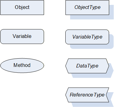
Figure 2 shows the symbols for the ReferenceTypes used in this specification. The Reference symbol is normally pointing from the source Node to the target Node. The only exception is the HasSubtype Reference. The most important References like HasComponent, HasProperty, HasTypeDefinition and HasSubtype have special symbols avoiding the name of the Reference. For other ReferenceTypes or derived ReferenceTypes the name of the ReferenceType is used together with the symbol.
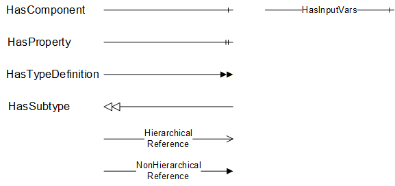
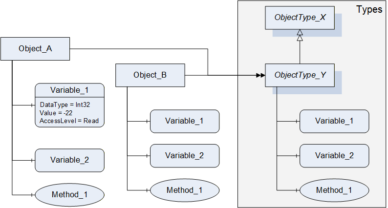
Figure 3 shows a typical example for the use of the graphical notation. Object_A and Object_B are instances of the ObjectType_Y indicated by the HasTypeDefinition References. The ObjectType_Y is derived from ObjectType_X indicated by the HasSubtype Reference. The Object_A has the components Variable_1, Variable_2 and Method_1.
To describe the components of an Object on the ObjectType the same NodeClasses and References are used on the Object and on the ObjectType like for ObjectType_Y in the example. The instance Nodes used to describe an ObjectType are instance declaration Nodes.
To provide more detailed information for a Node, a subset or all Attributes and their values can be added to a graphical symbol.
4.3 Use Cases
AutoID Devices like RFID or optical readers and RTLS are used in several applications, from production control to material flow, logistics, asset management, and more. In all of these applications, the AutoID Devices have to scan the environment and read / decode the given object ids.
In addition, the object ids can be altered in case of RFID and RTLS systems.
If a RFID transponder provides additional memory, these data areas might be read and written.
In case of RTLS, the host system may ask the RTLS for the current position of a given object transponder.
The information delivered by AutoID systems can be used by host systems as PC applications, mobile applications, IT systems, programmable logic controllers (PLC), and more.
5 AutoID Information Model Overview
5.1 Modelling concepts
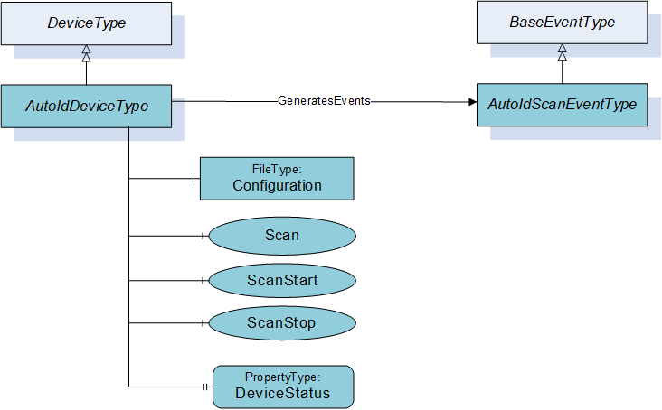
The base interface concept of the AutoID information model shown in Figure 4 supports two different communication procedures. One procedure is to trigger the scan from an OPC UA client and the other procedure is that the AutoID Device sends a scan event whenever the AutoID Device detected a tag or code.
The AutoIdDeviceType provides the method Scan to trigger a scan and to return the scan result with the Method response. In addition the ScanStart provides a way to start the scan but to receive the scan result through an AutoIdScanEventType.
The AutoIdScanEventType defines the information provided with a scan event and it is either triggered through a ScanStart Method call or through the AutoID Device itself.
5.2 Model Overview
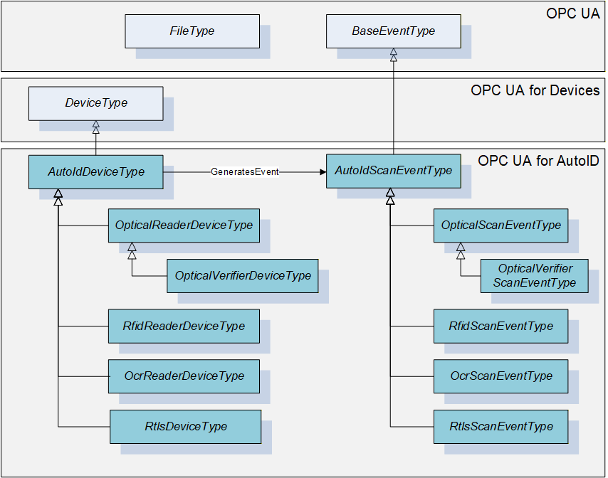
The following Figure 5 provides an overview of the concrete types for the different AutoID reader device types and the corresponding scan event types. They define the AutoID Device type specific semantic of the method parameters and event fields. The AutoID Device types are derived from the DeviceType defined in OPC 10000-100.
6 OPC UA ObjectTypes
6.1 AutoIdDeviceType
6.1.1 General
This OPC UA ObjectType represents an AutoID Device. It defines all methods and properties required for any kind of AutoID Device in general, e.g. methods for controlling the scan operation or the mechanism to load a configuration file to the reader. However, the object is an abstract definition in terms of the actual AutoID technology, i.e. there are no properties or methods which rely on specific features or technologies.
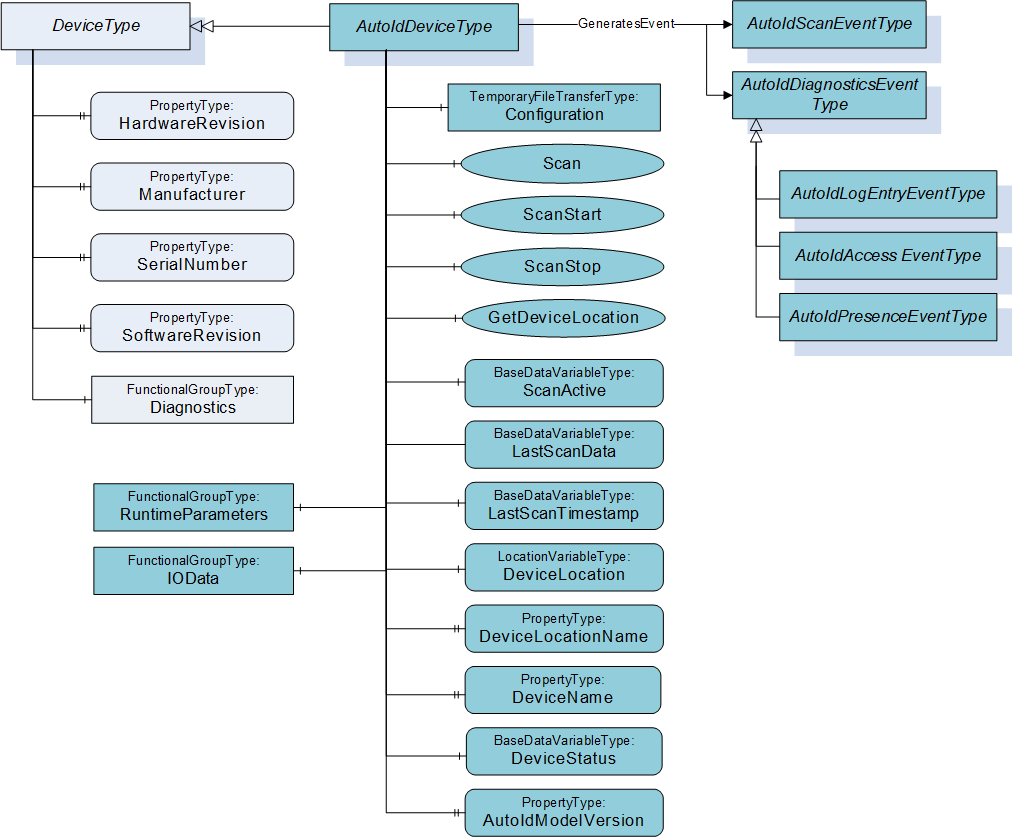
Figure 6 shows an overview for the AutoIdDeviceType with its Properties and the base type DeviceType. It is formally defined in Table 7.
There are several options to start the scanning of AutoID Identifiers like transponders or codes. The access to the different options requires that the OPC UA Client and the user are authorized to access the requested information.
Option 1: The reader starts the scanning when the Client calls the Scan Method. The operation stops according to the termination conditions specified in the Settings parameter of the Method. The scanned data will be the result of the method call. The Settings parameter has the DataType ScanSettings. The DataType is defined in 9.3.7. Only the OPC UA Client calling the Method receives the scanned data.
Option 2: The reader will throw Events at each time a transponder or code has been detected. The scan operation starts when the client calls the ScanStart Method. The operation stops according to the termination conditions specified in the Settings parameter of the Method, or if the client calls the ScanStop Method. The scanned data is delivered through the Events. Every OPC UA Client subscribed for Events will receive the scanned data.
Option 3: The reader will throw Events at each time a transponder or code has been detected. The scan operation is controlled by the reader itself, e.g. by a trigger button. In this case, none of the scan Methods has to be called. The scanned data is delivered through the Events. Every OPC UA Client subscribed for Events will receive the scanned data.
Option 4: The reader starts the scanning when the Client writes True to the Variable ScanActive. The scan result is provided through the Variable LastScanData. The configuration is provided through the parameters in the FunctionalGroup ScanSettings. The simple option has several limitations and is only used with OPC Clients limited to Data Access functionality. Additional Scan result information can be provided via Variables like LastScanTimestamp, LastScanAntenna and LastScanRSSI, where the last two Variables are only offered by the RfidReaderDeviceType. OPC UA does not ensure a consistent delivery of a list of Variable Values. An OPC UA Server shall set all Variable SourceTimestamps and the value of the LastScanTimestamp Variable with a consistent value if the Variables Values are updated. An OPC UA Client must ensure that it has a constent set of Values. The Client can use the DataChangeFilter STATUS_VALUE_TIMESTAMP_2 to receive updates for all Variables to verify if all necessary information is available or a Client can subscribe only for one Variable like LastScanData and then read the related Variables including a verification of the SourceTimestamp.
Depending on the AutoID Device capabilities, the Scan, ScanStart and ScanStop Methods are optional. If none of these methods are implemented, option 3 or 4 has to be supported. See also 10.1 for the definition of the different AutoID Device Profiles.
6.1.2 ObjectType definition
The AutoIdDeviceType is formally defined in Table 7.
| Attribute | Value | ||||
| BrowseName | AutoIdDeviceType | ||||
| IsAbstract | True | ||||
| References | Node Class | BrowseName | DataType | TypeDefinition | Modelling Rule |
|---|---|---|---|---|---|
| Subtype of DeviceType defined in OPC 10000-100. | |||||
| HasComponent | Object | RuntimeParameters | FunctionalGroupType | Optional | |
| HasComponent | Object | IOData | FunctionalGroupType | Optional | |
| HasComponent | Object | Diagnostics | FunctionalGroupType | Optional | |
| HasComponent | Method | Scan | Optional | ||
| HasComponent | Method | ScanStart | Optional | ||
| HasComponent | Method | ScanStop | Optional | ||
| HasComponent | Method | GetDeviceLocation | Optional | ||
| HasComponent | Variable | ScanActive | Boolean | BaseDataVariableType | Optional |
| HasComponent | Variable | LastScanData | BaseDataType | BaseDataVariableType | Optional |
| HasComponent | Variable | LastScanTimestamp | UtcTime | BaseDataVariableType | Optional |
| HasProperty | Variable | DeviceInfo | String | PropertyType | Optional |
| HasComponent | Variable | DeviceLocation | Location | LocationVariableType | Optional |
| HasProperty | Variable | DeviceLocationName | String | PropertyType | Optional |
| HasProperty | Variable | DeviceName | String | PropertyType | Mandatory |
| HasComponent | Variable | DeviceStatus | DeviceStatusEnumeration | BaseDataVariableType | Mandatory |
| HasProperty | Variable | AutoIdModelVersion | String | PropertyType | Mandatory |
| GeneratesEvent | ObjectType | AutoIdScanEventType | Defined in 7.2. | ||
| GeneratesEvent | ObjectType | AutoIdLogEntryEventType | Defined in 7.9. | ||
| GeneratesEvent | ObjectType | AutoIdAccessEventType | Defined in 7.10. | ||
| GeneratesEvent | ObjectType | AutoIdPresenceEventType | Defined in 7.12. | ||
The AutoIdDeviceType ObjectType is an abstract type and cannot be used directly.
| Source Path | References | NodeClass | BrowseName | DataType TypeDefinition | Others | ||
| RuntimeParameters | HasComponent | Variable | CodeTypes | UInt32[] MultiStateDiscreteType | O | ||
| RuntimeParameters | HasComponent | Object | ScanSettings | FunctionalGroupType | O | ||
| HasComponent | Variable | Duration | Duration BaseDataVariableType | O | ||
| HasComponent | Variable | Cycles | Int32 BaseDataVariableType | O | ||
| HasComponent | Variable | DataAvailable | Boolean BaseDataVariableType | O | ||
| HasComponent | Variable | CodeType | CodeTypeDataType BaseDataVariableType | O | ||
| Diagnostics | HasComponent | Object | Logbook | FunctionalGroupType | O | ||
| Diagnostics | HasComponent | Object | LastAccess | FunctionalGroupType | O | ||
| Diagnostics | HasComponent | Variable | Presence | UInt16 BaseDataVariableType | O | ||
| HasComponent | Variable | LogColumns | String BaseDataVariableType | O | ||
| HasComponent | Variable | LastLogEntry | String BaseDataVariableType | O | ||
| HasComponent | Variable | Client | String BaseDataVariableType | O | ||
| HasComponent | Variable | Command | String BaseDataVariableType | O | ||
| HasComponent | Variable | Identifier | BaseDataType BaseDataVariableType | O | ||
| HasComponent | Variable | Timestamp | UtcTime BaseDataVariableType | O | ||
6.1.3 ObjectType Description
6.1.3.1 Object RuntimeParameters
This FunctionalGroup is used to organize runtime configuration parameters and Methods. All standard or vendor specific runtime parameters of AutoID Devices shall be exposed below this FunctionalGroup. FunctionalGroups can be nested. The runtime parameters may be also exposed in other parts of the AutoID Device OPC UA Server Address Space.
The FunctionalGroupType is defined in OPC 10000-100.
Predefined parameters for this FunctionalGroup are defined in Table 8 and described below.
The parameter CodeTypes allows the user to determine the supported and to select the configured code types. It is used to expose the list of supported code types.
The Value of the Variable contains the currently selected types as a number. The assigned code type Strings are defined in 9.1.3.
CodeTypes can contain the predefined values or vendor specific values.
The ScanSettings FunctionalGroup shall be provided if the ScanActive Variable is supported for the control of the scan behaviour. It contains the following parameters (defined in Table 8):
Parameter Duration specifies the duration of the scan operation in milliseconds. The value 0 is infinite. It is one of the termination conditions for the scan operation. The termination conditions are related to each other. If one of the conditions is fulfilled, the scan operation is stopped.
Parameter Cycles specifies the duration of the scan operation in 'number of scan cycles'. The value 0 is infinite. It is one of the termination conditions for the scan operation. The termination conditions are related to each other. If one of the conditions is fulfilled, the scan operation is stopped.
If parameter DataAvailable is True, the scan operation is completed as soon as scan data is available. If DataAvailable is False, only the other termination conditions are used.
Parameter CodeType specifies the format of the LastScanData Variable Value as string. The CodeTypeDataType and the predefined format strings are defined in 9.1.3.
6.1.3.2 Object IOData
This FunctionalGroup is used to organize IO data from sensors and actuators connected to the AutoID Device. All vendor or configuration specific IO data of AutoID Devices shall be exposed below this FunctionalGroup. FunctionalGroups can be nested. The IO data may also be exposed in other parts of the AutoID Device OPC UA Server Address Space.
An IO data point is represented by an OPC UA Variable Value. OPC UA Clients can read and write Variable Values depending on the AccessLevel of the Variable. Values can also be monitored for changes.
The FunctionalGroupType is defined in OPC 10000-100.
6.1.3.3 Object Diagnostics
This FunctionalGroup is used to organize diagnostic data from the AutoID Device. All diagnostics data of AutoID Devices shall be exposed below this FunctionalGroup. FunctionalGroups can be nested. The diagnostics data may also be exposed in other parts of the AutoID Device OPC UA Server Address Space.
A diagnostics point is represented by an OPC UA Variable Value. OPC UA Clients can read the Variable Values. Values can also be monitored for changes.
The FunctionalGroupType is defined in OPC 10000-100.
Predefined parameters for this FunctionalGroup are defined in Table 8 and described below.
Presence identifies if there currently is seen an AutoID Identifier (e.g. a code or a transponder) by the device. If supported by a device, it may show the concrete number of AutoID Identifiers.
The Logbook FunctionalGroup shall be provided if Logging values are supported for diagnostic purposes. Its predefined parameters are defined in Table 8 and described in the following list:
Parameter LogColumns specifies the column headings of the Logbook.
Parameter LastLogEntry specifies the last entry of the Logbook.
The LastAccess FunctionalGroup shall be provided if values for the last AutoID Identifier access are supported for diagnostic purposes. Its predefined parameters are described in the following list:
Parameter Client specifies the client application (interface) which was the originator of the AutoID Identifier access.
Parameter Command specifies executed command, including the Scan command. Dependend on the kind of the client application, the names of the commands may vary. When the client application is an OPC UA Client, the names shall correspond to the command names used within this specification, e.g. "ReadTag" for the execution of the ReadTag command.
Parameter Identifier specifies the AutoID Identifier which was accessed by the command. The DataType can be one of the DataTypes defined in the ScanData Union defined in 9.4.2. Due to the use case for limited OPC UA Clients, the DataType is normally String or ByteString.
Parameter Timestamp specifies the point of time the AutoID identifier (e.g. a transponder) was accessed by the command.
The Last Access Variable Values belong together logically. OPC UA does not ensure a consistent delivery of a list of Variable Values. Thus, there are several limitations and the Last Access Variables should only used with OPC Clients limited to Data Access functionality. It is recommended that complex applications use the AutoIdAccessEvents or RfidAccessEvents.
An OPC UA Server shall set all Variable SourceTimestamps with a consistent value if the Variables Values are updated. An OPC UA Client must ensure that it has a constent set of Values. The Client can use the DataChangeFilter STATUS_VALUE_TIMESTAMP_2 to receive updates for all Variables to verify if all necessary information is available or a Client can subscribe only for one Variable like Timestamp and then read the related Variables including a verification of the SourceTimestamp.
6.1.3.4 Method Scan
This method starts the scan process of the AutoID Device synchronous and returns the scan results.
The duration of the scan process is defined by the termination conditions in the Settings parameter. A Client shall not set all parameters to infinite for the Scan Method. The values for infinite are defined in the ScanSettings DataType definition in 9.3.7. An additional setting to consider is the TimeoutHint used for the Call Service.
Signature
	Scan (
		[in]	ScanSettings				Settings
		[out]	ScanResult []				Results
		[out]	AutoIdOperationStatusEnumeration	Status
		);
| Argument | Description |
| Settings | Configuration settings for the scan execution. The ScanSettings DataType is defined in 9.3.7. |
| Results | Results of the scan execution. The ScanResult DataType is defined in 9.3.8. |
| Status | Returns the status of the scan operation. The AutoIdOperationStatusEnumeration DataType is defined in 9.2.1. |
Method Result Codes
| ResultCode | Description |
| Bad_InvalidState | There is already a scan active |
| Bad_InvalidArgument | The scan setting contained an invalid value like infinite duration. |
| Other OPC UA status codes defined for the Call Service in OPC 10000-4. |
6.1.3.5 Method ScanStart
This method starts the scan process of the AutoID Device asynchronous. The scan results are delivered through Events where the EventType is a subtype of the AutoIdScanEventType defined in 7.2. There is a subtype defined for each concrete AutoID Device types.
The scan process is stopped through the Method ScanStop or if one of the termination conditions in the Settings parameter is fulfilled.
In addition, the scanning stops if the Client closes the Session, or if a new configuration file is stored within the AutoID Device. There might be other conditions depending on technology or device manufacturer.
Signature
	ScanStart (
		[in]	ScanSettings				Settings
		[out]	AutoIdOperationStatusEnumeration	Status
		);
| Argument | Description |
| Settings | Configuration settings for the scan execution. The ScanSettings DataType is defined in 9.3.7. |
| Status | Returns the status of the scan start operation. The AutoIdOperationStatusEnumeration DataType is defined in 9.2.1. |
Method Result Codes
| ResultCode | Description |
| Bad_InvalidState | There is already a scan active |
| Other OPC UA status codes defined for the Call Service in OPC 10000-4. |
6.1.3.6 Method ScanStop
This method stops an active scan process of the AutoID Device.
Signature
ScanStop ( );Method Result Codes
| ResultCode | Description |
| Bad_InvalidState | There is no scan active. |
6.1.3.7 Method GetDeviceLocation
This method returns the location of the AutoID Device.
Signature
	GetDeviceLocation (
		[in]	LocationTypeEnumeration	LocationType
		[out]	Location				Location
		);
| Argument | Description |
| LocationType | The type of location information to return. The LocationTypeEnumeration DataType is defined in 9.2.3. |
| Location | The location of the AutoID Device. The Location DataType is defined in 9.4.1. |
Method Result Codes
| ResultCode | Description |
| Standard OPC UA status codes defined for the Call Service in OPC 10000-4. |
6.1.3.8 Variable ScanActive
This OPC UA Variable allows simple applications to trigger the scan process. Simple appications involve OPC UA Clients that are limited to Data Access functionality.
The scan is triggered by writing True to the Variable Value. The behaviour of the scan is defined by the parameters in the ScanSettings FunctionalGroup defined in 9.3.7. The Value of the Variable is changed back to False by the Server if the scan is stopped according to the ScanSettings. The Client can stop the scan by writing False to the Variable Value.
The write permission can be limited to one Client. OPC 10000-3 and OPC 10000-5 define capabilities to enforce this limit with Roles and RolePermissions. Roles can be limited to a single OPC UA Application.
The scan result is provided through the Variable LastScanData. Further restrictions for this simple mechanism are described for the Variable LastScanData.
6.1.3.9 Variable LastScanData
This OPC UA Variable represents the last scanned AutoID Identifier. The DataType can be one of the DataTypes defined in the ScanData Union defined in 9.4.2. Due to the use case for limited OPC UA Clients, the DataType is normally String or ByteString.
The Variable can be provided for simple applications where OPC UA Clients are limited to Data Access functionality. Such OPC UA Clients are typically limited to built-in DataTypes like String or ByteString too. The use of this Variable implies the following restrictions.
Only one AutoID Identifier can be delivered for a scan.
The frequency of scans is limited to the sampling interval set by the OPC UA Client.
The delivery of scan results depends on the MonitoredItem settings or Read behaviour of the OPC UA Client.
It is recommended that complex applications use scan Methods and Events.
6.1.3.10 Variable LastScanTimestamp
This OPC UA Variable of DataType UtcTime belongs to the Variable LastScanData and represents the point of time the last AutoID Identifier was scanned. The value of this Variable shall be equal to the SourceTimestamp of the Variable LastScanData.
The Variable can be provided for simple applications where OPC UA Clients are limited to Data Access functionality. Such OPC UA Clients are typically limited to built-in DataTypes like UtcTime. The use of this Variable implies the following restrictions.
Only one AutoID Identifier can be delivered for a scan.
The frequency of scans is limited to the sampling interval set by the OPC UA Client.
The delivery of scan results depends on the MonitoredItem settings or Read behaviour of the OPC UA Client.
It is recommended that complex applications use scan Methods and Events.
6.1.3.11 Variable DeviceInfo
This OPC UA Property of DataType String represents an AutoID Device additional information, which can be used freely for device management purposes.
6.1.3.12 Variable DeviceLocation
This OPC UA Variable of DataType Location represents the AutoID Device location as Union of different coordinate systems and the related units. The DataType Location is defined in 9.4.1. The VariableType LocationVariableType is defined in 8.1.
The variable can be set during commissioning for fixed-mounted readers or can be updated automatically for mobile readers. The aim is to give the actual position where a specific scan event has been created.
6.1.3.13 Variable DeviceLocationName
This OPC UA Property of DataType String represents a user defined name of the AutoID Device location.
This variable can be used to assign a real name to the AutoID Device, e.g. "Gate 21". It allows a device-independent event description in higher IT levels.
6.1.3.14 Variable DeviceName
This OPC UA Property of DataType String represents the AutoID Device name, which can be used freely for device management purposes.
6.1.3.15 Variable DeviceStatus
This OPC UA Property of DataType DeviceStatusEnumeration represents the AutoID Device status. The DeviceStatusEnumeration is defined in 9.2.2.
6.1.3.16 Variable AutoIdModelVersion
This OPC UA Property of DataType String represents the AutoID Information Model version. The version string for this specification version is "1.00".
6.2 OcrReaderDeviceType
6.2.1 General
This OPC UA ObjectType represents an OCR reader device. It defines additional methods and properties required for managing OCR readers or to get additional information on the OCR scan events.
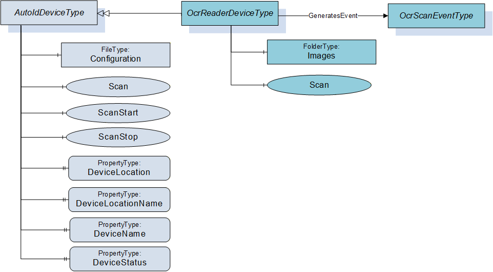
Figure 7 shows an overview for the OcrReaderDeviceType with its Object, Methods, Properties and related ObjectType. It is formally defined in Table 9.
6.2.2 ObjectType definition
The OcrReaderDeviceType is formally defined in Table 9.
| Attribute | Value | ||||
| BrowseName | OcrReaderDeviceType | ||||
| IsAbstract | False | ||||
| References | Node Class | BrowseName | DataType | TypeDefinition | Modelling Rule |
|---|---|---|---|---|---|
| Subtype of AutoIdDeviceType defined in 6.1. | |||||
| HasComponent | Object | Images | FolderType | Optional | |
| HasComponent | Method | Scan | Optional | ||
| GeneratesEvent | ObjectType | OcrScanEventType | Defined in 7.3. | ||
The OcrReaderDeviceType ObjectType is a concrete type and can be used directly.
| Source Path | References | NodeClass | BrowseName | DataType TypeDefinition | Others |
| RuntimeParameters | HasComponent | Variable | TemplateName | String BaseDataVariableType | O |
| RuntimeParameters | HasComponent | Variable | MatchCode | String BaseDataVariableType | O |
| Images | Organizes | Object | <ImageName> | 0:FileType | OP |
6.2.3 ObjectType Description
6.2.3.1 Object RuntimeParameters
This FunctionalGroup is inherited from the AutoIdDeviceType and described in 6.1. Predefined runtime parameters for for this FunctionalGroup are defined in Table 10 and described below.
Parameter TemplateName is the activate template which defines a specific identification task. The templates have to be defined during configuration.
Parameter MatchCode defines the target value for 2D and OCR decoding.
6.2.3.2 Object Images
For quality and testing purposes, the actual image taken by the OCR reader can be accessed with this object. E.g. the picture might be checked by engineers if the OCR decoding does not deliver the expected results.
The Images Object when available shall contain the list of FileType Objects (see Table 10) with the images taken by the OCR reader.
The MIME type of an image is provided through the MimeType Property of the FileType.
6.2.3.3 Method Scan
This method starts the scan process of the OCR reader device syncronous and returns the scan results. It overwrites the Scan method of the AutoIdDeviceType defined in 6.1.3.4.
Signature
	Scan (
		[in]	ScanSettings				Settings
		[out]	OcrScanResult []				Results
		[out]	AutoIdOperationStatusEnumeration	Status
		);
| Argument | Description |
| Settings | Configuration settings for the scan execution. The ScanSettings DataType is defined in 9.3.7. |
| Results | Results of the scan execution. The OcrScanResult DataType is defined in 9.3.9. |
| Status | Returns the status of the scan operation. The AutoIdOperationStatusEnumeration DataType is defined in 9.2.1. |
Method Result Codes
| ResultCode | Description |
| Bad_InvalidState | There is already a scan active |
| Bad_InvalidArgument | The scan setting contained an invalid value like infinite duration. |
| Other OPC UA status codes defined for the Call Service in OPC 10000-4. |
6.3 OpticalReaderDeviceType
6.3.1 General
This OPC UA ObjectType represents an optical reader device (1D or 2D codes). It defines additional methods and properties required for managing optical code readers or to get additional information on their scan events.
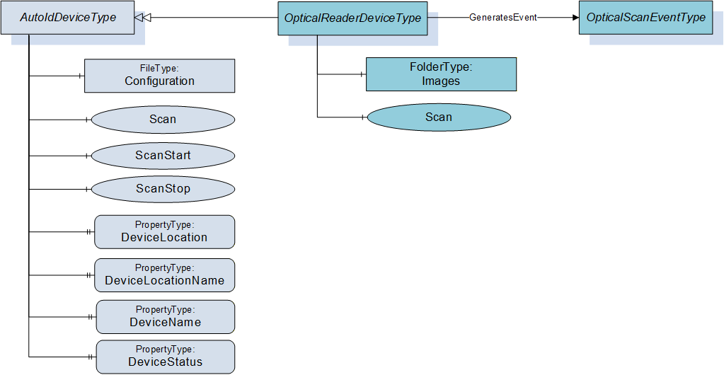
Figure 8 shows an overview for the OpticalReaderDeviceType with its Methods and related ObjectType. It is formally defined in Table 11.
6.3.2 ObjectType definition
The OpticalReaderDeviceType is formally defined in Table 11.
| Attribute | Value | ||||
| BrowseName | OpticalReaderDeviceType | ||||
| IsAbstract | False | ||||
| References | Node Class | BrowseName | DataType | TypeDefinition | Modelling Rule |
|---|---|---|---|---|---|
| Subtype of AutoIdDeviceType defined in 6.1. | |||||
| HasComponent | Object | Images | FolderType | Optional | |
| HasComponent | Method | Scan | Optional | ||
| GeneratesEvent | ObjectType | OpticalScanEventType | Defined in 7.4. | ||
The OpticalReaderDeviceType ObjectType is a concrete type and can be used directly.
| Source Path | References | NodeClass | BrowseName | DataType TypeDefinition | Others |
| RuntimeParameters | HasComponent | Variable | TemplateName | String BaseDataVariableType | O |
| RuntimeParameters | HasComponent | Variable | MatchCode | String BaseDataVariableType | O |
| Images | Organizes | Object | <ImageName> | 0:FileType | OP |
6.3.3 ObjectType Description
6.3.3.1 Object RuntimeParameters
This FunctionalGroup is inherited from the AutoIdDeviceType and described in 6.1. Predefined runtime parameters for the OpticalReaderDeviceType are defined in Table 12.
The parameters TemplateName and MatchCode are described in 6.2.3.1.
6.3.3.2 Object Images
For quality and testing purposes, the actual image taken by the optical reader can be accessed with this object. E.g. the picture might be checked by engineers if the optical decoding does not deliver the expected results.
The Images Object when available shall contain the list of FileType Objects (see Table 12) with the images taken by the optical reader.
The MIME type of an image is provided through the MimeType Property of the FileType.
6.3.3.3 Method Scan
This method starts the scan process of the optical reader device synchronous and returns the scan results. It overwrites the Scan method of the AutoIdDeviceType defined in 6.1.3.4.
Signature
	Scan (
		[in]	ScanSettings				Settings
		[out]	OpticalScanResult []			Results
		[out]	AutoIdOperationStatusEnumeration	Status
		);
| Argument | Description |
| Settings | Configuration settings for the scan execution. The ScanSettings DataType is defined in 9.3.7. |
| Results | Results of the scan execution. The OpticalScanResult DataType is defined in 9.3.10. |
| Status | Returns the status of the scan operation. The AutoIdOperationStatusEnumeration DataType is defined in 9.2.1. |
Method Result Codes
| ResultCode | Description |
| Bad_InvalidState | There is already a scan active |
| Bad_InvalidArgument | The scan setting contained an invalid value like infinite duration. |
| Other OPC UA status codes defined for the Call Service in OPC 10000-4. |
6.4 OpticalVerifierDevice
6.4.1 General
This OPC UA ObjectType represents an optical verifier device (1D or 2D codes). It defines additional methods and properties required for managing optical code verifiers or to get additional information on their scan events.
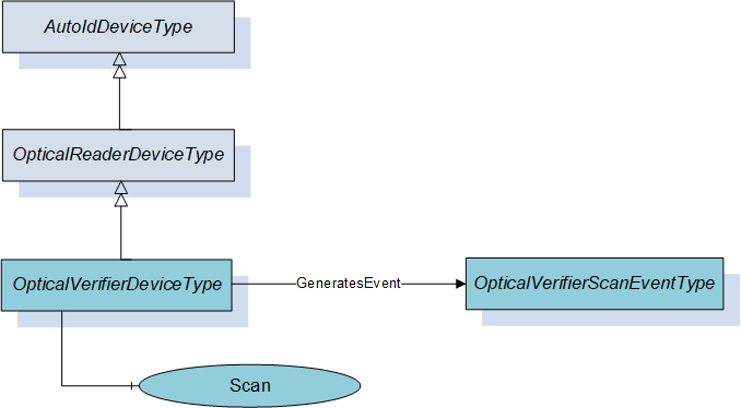
Figure 9 shows an overview for the OpticalVerifierDeviceType with its Methods and related ObjectType. It is formally defined in Table 13.
6.4.2 ObjectType definition
The OpticalVerifierDeviceType is formally defined in Table 13.
| Attribute | Value | ||||
| BrowseName | OpticalVerifierDeviceType | ||||
| IsAbstract | False | ||||
| References | Node Class | BrowseName | DataType | TypeDefinition | Modelling Rule |
|---|---|---|---|---|---|
| Subtype of OpticalReaderDeviceType defined in 6.3. | |||||
| HasComponent | Method | Scan | Optional | ||
| GeneratesEvent | ObjectType | OpticalVerifierScanEventType | Defined in 7.5. | ||
The OpticalVerifierDeviceType ObjectType is a concrete type and can be used directly.
6.4.3 ObjectType Description
6.4.3.1 Method Scan
This method starts the scan process of the optical verifier device synchronous and returns the scan results. It overwrites the Scan method of the OpticalReaderDeviceType defined in 0.
Signature
	Scan (
		[in]	ScanSettings				Settings
		[out]	OpticalVerifierScanResult []		Results
		[out]	AutoIdOperationStatusEnumeration	Status
		);
| Argument | Description |
| Settings | Configuration settings for the scan execution. The ScanSettings DataType is defined in 9.3.7. |
| Results | Results of the scan execution. The OpticalVerifierScanResult DataType is defined in 9.3.11. |
| Status | Returns the status of the scan operation. The AutoIdOperationStatusEnumeration DataType is defined in 9.2.1. |
Method Result Codes
| ResultCode | Description |
| Bad_InvalidState | There is already a scan active |
| Bad_InvalidArgument | The scan setting contained an invalid value like infinite duration. |
| Other OPC UA status codes defined for the Call Service in OPC 10000-4. |
6.5 RfidReaderDeviceType
6.5.1 General
This OPC UA ObjectType represents an RFID reader device including NFC reader devices. It defines additional methods and properties required for managing RFID readers or to get additional information on their scan events. The object provides also functions for accessing the user memory, writing to a tag, and more. There is no dependency to the actual RFID technology (e.g. HF, UHF).
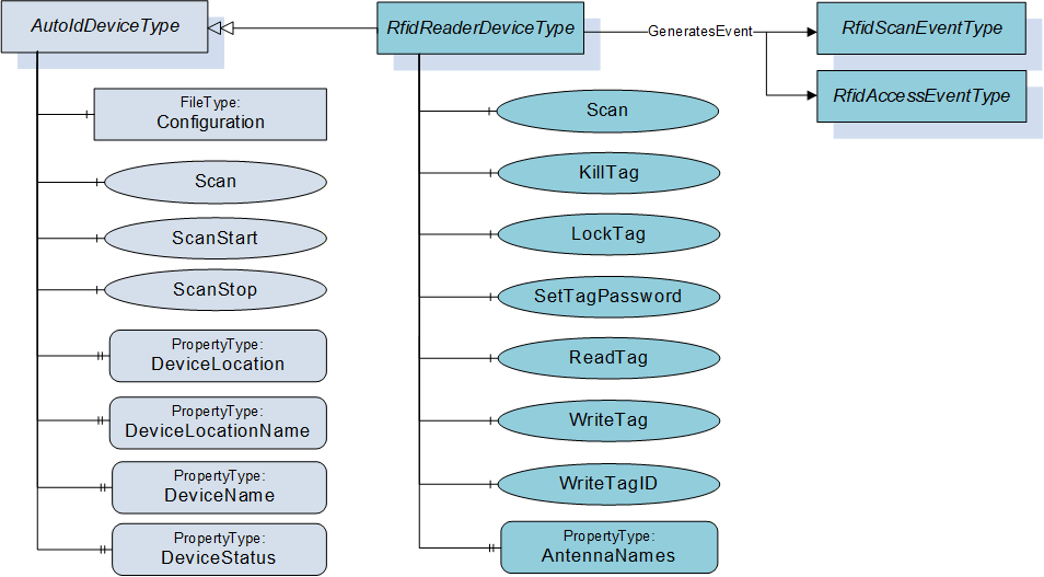
Figure 10 shows an overview for the RfidReaderDeviceType with its Methods, Property and related ObjectType. It is formally defined in Table 14.
6.5.2 ObjectType definition
The RfidReaderDeviceType is formally defined in Table 14.
| Attribute | Value | ||||
| BrowseName | RfidReaderDeviceType | ||||
| IsAbstract | False | ||||
| References | Node Class | BrowseName | DataType | TypeDefinition | Modelling Rule |
|---|---|---|---|---|---|
| Subtype of AutoIdDeviceType defined in 6.1. | |||||
| HasComponent | Method | Scan | Optional | ||
| HasComponent | Method | KillTag | Optional | ||
| HasComponent | Method | LockTag | Optional | ||
| HasComponent | Method | SetTagPassword | Optional | ||
| HasComponent | Method | ReadTag | Optional | ||
| HasComponent | Method | WriteTag | Optional | ||
| HasComponent | Method | WriteTagID | Optional | ||
| HasComponent | Variable | LastScanAntenna | Int32 | BaseDataVariableType | Optional |
| HasComponent | Variable | LastScanRSSI | Int32 | BaseDataVariableType | Optional |
| HasProperty | Variable | AntennaNames | AntennaNameIdPair [ ] | PropertyType | Optional |
| GeneratesEvent | ObjectType | RfidScanEventType | Defined in 7.6. | ||
| GeneratesEvent | ObjectType | RfidAccessEventType | Defined in 7.11. | Optional | |
The RfidReaderDeviceType ObjectType is a concrete type and can be used directly.
| Source Path | References | NodeClass | BrowseName | DataType TypeDefinition | Others | ||
| RuntimeParameters | HasComponent | Variable | CodeTypesRWData | UInt32[] MultiStateDiscreteType | O | ||
| RuntimeParameters | HasComponent | Variable | TagTypes | UInt32[] MultiStateDiscreteType | O | ||
| RuntimeParameters | HasComponent | Variable | RfPower | SByte BaseDataVariableType | O | ||
| RuntimeParameters | HasComponent | Variable | MinRssi | Int32 BaseDataVariableType | O | ||
| RuntimeParameters | HasComponent | Variable | EnableAntennas | UInt32 BaseDataVariableType | O | ||
| HasComponent | Variable | RWData | BaseDataType BaseDataVariableType | O | ||
| HasComponent | Variable | Antenna | Int32 BaseDataVariableType | O | ||
| HasComponent | Variable | CurrentPowerLevel | Int32 BaseDataVariableType | O | ||
| HasComponent | Variable | PC | UInt16 BaseDataVariableType | O | ||
| HasComponent | Variable | Polarization | String BaseDataVariableType | O | ||
| HasComponent | Variable | Strength | Int32 BaseDataVariableType | O | ||
6.5.3 ObjectType Description
6.5.3.1 Object RuntimeParameters
This FunctionalGroup is inherited from the AutoIdDeviceType and described in 6.1. Predefined runtime parameters for for this FunctionalGroup are defined in Table 15 and described below.
Parameter CodeTypesRWData allows the user to determine the supported code types and to select the configured CodeTypes for the diagnostics value RWData (defined in ). This parameter is used to expose the list of supported CodeTypes. This list can contain the predefined values or vendor specific values. The Value of the Variable contains the currently selected types. The code type Strings are defined in 9.1.3.
Parameter TagTypes allows the user to determine the expected tags in a multi-type environment (e.g. ISO 14443 or ISO 15693). This parameter is used to expose the list of supported tag types. This list can contain the predefined values or vendor specific values. The Value of the Variable contains the currently selected types. The following Strings are defined by this specification.
ISO 14443
ISO 15693
ISO 18000-2
ISO 18000-3 Mode1
ISO 18000-3 Mode2
ISO 18000-3 Mode3
ISO 18000-4
ISO 18000-61
ISO 18000-62
ISO 18000-63
ISO 18000-64
EPC Class1 Gen2 V1
EPC Class1 Gen2 V2
Parameter RfPower is used to adjust radio transmission power, per antenna.
Parameter MinRssi is the lowest acceptable RSSI value (see also Strength field in RFIDSighting).
Parameter EnableAntennas determines the antennas that shall be used by the RfidDevice for its operation. The value is a binary selection of the antennas. Each bit represents one antenna, max. 32 antennas can be addressed.
Bit0 corresponds to antenna number 1, Bit1 corresponds to antenna number 2, …
A Bit value of 1 means an activated antenna, a Bit value of 0 a deactivated antenna. E.g.: The value BIN 1101 = DEC 13 enables the antennas 1+3+4
A total value of 0 of EnableAntennas does not have any effect. The general device configuration can just be limited, not extended by EnableAntennas. E.g. if a four-port reader has three antennas activated according to the general configuration, it is not possible to activate the antenna four via EnableAntennas.
6.5.3.2 Object Diagnostics
The Diagnostics FunctionalGroup and its component, the LastAccess FunctionalGroup, are described in clause 6.1.3.3.
Predefined parameters that are specific for the LastAccess FunctionalGroup in the RfidReaderDeviceType are defined in Table 15 and described in the following list:
Parameter RWData specifies the user data which was written to / was read from the Rfid Transponder by the command. The DataType can be one of the DataTypes defined in the ScanData Union defined in 9.4.2. Due to the use case for limited OPC UA Clients, the DataType is normally String or ByteString.
Parameter Antenna specifies the antenna with which the transponder was accessed by the command.
Parameter CurrentPowerLevel specifies the power level with which the transponder was accessed by the command.
Parameter PC specifies the Protocol Control Word of the transponder accessed by the command.
Parameter Polarization specifies the Polarization with which the transponder was accessed by the command.
Parameter Strength specifies the Rssi value with which the transponder was accessed by the command.
6.5.3.3 Method Scan
This method starts the scan process of the RFID reader device synchronous and returns the scan results. It overwrites the Scan method of the AutoIdDeviceType defined in 6.1.3.4.
Signature
	Scan (
		[in]	ScanSettings				Settings
		[out]	RfidScanResult []			Results
		[out]	AutoIdOperationStatusEnumeration	Status
		);
| Argument | Description |
| Settings | Configuration settings for the scan execution. The ScanSettings DataType is defined in 9.3.7. |
| Result | Results of the scan execution. The RfidScanResult DataType is defined in 9.3.12. |
| Status | Returns the status of the scan operation. The AutoIdOperationStatusEnumeration DataType is defined in 9.2.1. |
Method Result Codes
| ResultCode | Description |
| Bad_MethodInvalid | The device does not support this function |
| Bad_InvalidState | There is already a scan active or this command is not available or not allowed e.g. due to special configuration |
| Bad_InvalidArgument | The scan setting contained an invalid value like infinite duration. |
| Other OPC UA status codes defined for the Call Service in OPC 10000-4. | |
6.5.3.4 Method KillTag
This method will process a kill command e.g. like specified in GS1 EPCglobal™, ISO/IEC 18000-63 and ISO/IEC 18000-3. The related standard depends on the RFID technology which is in use. The kill command allows an interrogator to permanently disable a transponder.
See Annex B for technology specific mappings.
Signature
	KillTag (
		[in]	ScanData					Identifier
		[in]	CodeTypeDataType				CodeType
		[in]	ByteString					KillPassword
		[out]	AutoIdOperationStatusEnumeration	Status
		);
| Argument | Description |
| Identifier | AutoID Identifier according to the device configuration as returned as part of a ScanResult in a scan event or scan method. The ScanData DataType is defined in 9.4.2. If the ScanData is used as returned in the ScanResult, the structure may contain information that must be ignored by the AutoID Device. An example is the ScanDataEpc where only the parameter UId is relevant for this Method. If the Identifier is provided from a different source than the ScanResult, a ScanData with a ByteString can be used to pass a UId where the CodeType is set to 'UId'. |
| CodeType | Defines the format of the ScanData in the Identifier as string. The String DataType CodeTypeDataType and the predefined format strings are defined in 9.1.3. |
| KillPassword | Transponder password to get access to the kill operation of this transponder |
| Status | Returns the result of the kill operation. The AutoIdOperationStatusEnumeration DataType is defined in 9.2.1. |
Method Result Codes
| ResultCode | Description |
| Bad_MethodInvalid | The device does not support this function |
| Bad_InvalidState | This command is not available or not allowed e.g. due to special configuration |
6.5.3.5 Method LockTag
This method is used to protect specific areas of the transponder memory against read and/or write access. If a user wants to access such an area, an access password is required.
See Annex B for technology specific mappings.
Signature
	LockTag (
		[in]	ScanData					Identifier
		[in]	CodeTypeDataType				CodeType
		[in]	ByteString					Password
		[in]	RfidLockRegionEnumeration		Region
		[in]	RfidLockOperationEnumeration		Lock
		[in]	UInt32					Offset
		[in]	UInt32					Length
		[out]	AutoIdOperationStatusEnumeration	Status
		);
| Argument | Description |
| Identifier | AutoID Identifier according to the device configuration as returned as part of a ScanResult in a scan event or scan method. The ScanData DataType is defined in 9.4.2. If the ScanData is used as returned in the ScanResult, the structure may contain information that must be ignored by the AutoID Device. An example is the ScanDataEpc where only the parameter UId is relevant for this Method. If the Identifier is provided from a different source than the ScanResult, a ScanData with a ByteString can be used to pass a UId where the CodeType is set to 'UId'. |
| CodeType | Defines the format of the ScanData in the Identifier as string. The String DataType CodeTypeDataType and the predefined format strings are defined in 9.1.3. |
| Password | Transponder (access) password |
| Region | Bank of the memory area to be accessed The RfidLockRegionEnumeration DataType is defined in 9.2.5. |
| Lock | Specifies the lock action like write/read protection, permanently. The RfidLockOperationEnumeration DataType is defined in 9.2.4. |
| Offset | Start address of the memory area [byte counting] |
| Length | Length of the memory area [byte counting] |
| Status | Returns the result of the LOCK operation. The AutoIdOperationStatusEnumeration DataType is defined in 9.2.1. |
Method Result Codes
| ResultCode | Description |
| Bad_MethodInvalid | The device does not support this function |
| Bad_InvalidState | This command is not available or not allowed e.g. due to special configuration |
6.5.3.6 Method SetTagPassword
This method changes the password for a specific transponder.
The Method should only be called via a SecureChannel with encryption enabled.
See Annex B for technology specific mappings.
Signature
	SetTagPassword (
		[in]	ScanData					Identifier
		[in]	CodeTypeDataType				CodeType
		[in]	RfidPasswordTypeEnumeration		PasswordType
		[in]	ByteString					AccessPassword
		[in]	ByteString					NewPassword
		[out]	AutoIdOperationStatusEnumeration	Status
		);
| Argument | Description |
| Identifier | AutoID Identifier according to the device configuration as returned as part of a ScanResult in a scan event or scan method. The ScanData DataType is defined in 9.4.2. If the ScanData is used as returned in the ScanResult, the structure may contain information that must be ignored by the AutoID Device. An example is the ScanDataEpc where only the parameter UId is relevant for this Method. If the Identifier is provided from a different source than the ScanResult, a ScanData with a ByteString can be used to pass a UId where the CodeType is set to 'UId'. |
| CodeType | Defines the format of the ScanData in the Identifier as string. The String DataType CodeTypeDataType and the predefined format strings are defined in 9.1.3. |
| PasswordType | Defines the operations for which the password is valid The RfidPasswordTypeEnumeration DataType is defined in 9.2.6. |
| AccessPassword | The old password |
| NewPassword | Gives the new password to the transponder |
| Status | Returns the result of the TagPassword method. The AutoIdOperationStatusEnumeration DataType is defined in 9.2.1. |
Method Result Codes
| ResultCode | Description |
| Bad_MethodInvalid | The device does not support this function |
| Bad_InvalidState | This command is not available or not allowed e.g. due to special configuration |
6.5.3.7 Method ReadTag
This method reads a specified area from a tag memory.
One Method invocation reads one AutoID Identifier. The Call Service used to invoke the Method can take a list of Methods. Therefore a list of AutoID Identifiers can be read by passing in a list of Methods to the Call Service.
See Annex B for technology specific mappings.
Signature
	ReadTag (
		[in]	ScanData					Identifier
		[in]	CodeTypeDataType				CodeType
		[in]	UInt16					Region
		[in]	UInt32					Offset
		[in]	UInt32					Length
		[in]	ByteString					Password
		[out]	ByteString					ResultData
		[out]	AutoIdOperationStatusEnumeration	Status
		);
| Argument | Description |
| Identifier | AutoID Identifier according to the device configuration as returned as part of a ScanResult in a scan event or scan method. The ScanData DataType is defined in 9.4.2. If the ScanData is used as returned in the ScanResult, the structure may contain information that must be ignored by the AutoID Device. An example is the ScanDataEpc where only the parameter UId is relevant for this Method. If the Identifier is provided from a different source than the ScanResult, a ScanData with a ByteString can be used to pass a UId where the CodeType is set to 'UId'. |
| CodeType | Defines the format of the ScanData in the Identifier as string. The String DataType CodeTypeDataType and the predefined format strings are defined in 9.1.3. |
| Region | Region of the memory area to be accessed. If there is no bank available this value is set to 0. This is the bank for UHF (ISO/IEC 18000-63) or the bank (ISO/IEC 18000-3 Mode 3) or data bank (ISO/IEC 18000-3 Mode 1) for HF or memory area (ISO/IEC 18000-2) for LF. See Annex B for technology specific mappings. |
| Offset | Start address of the memory area [byte counting] |
| Length | Length of the memory area [byte counting] |
| Password | Password for read operation (if required) |
| ResultData | Returns the requested tag data |
| Status | Returns the status of the read operation. The AutoIdOperationStatusEnumeration DataType is defined in 9.2.1. |
Method Result Codes
| ResultCode | Description |
| Bad_MethodInvalid | The device does not support this function |
| Bad_InvalidState | This command is not available or not allowed e.g. due to special configuration |
6.5.3.8 Method WriteTag
This method writes data to a RFID tag.
See Annex B for technology specific mappings.
Signature
	WriteTag (
		[in]	ScanData					Identifier
		[in]	CodeTypeDataType				CodeType
		[in]	UInt16					Region
		[in]	UInt32					Offset
		[in]	ByteString					Data
		[in]	ByteString					Password
		[out]	AutoIdOperationStatusEnumeration	Status
		);
| Argument | Description |
| Identifier | AutoID Identifier according to the device configuration as returned as part of a ScanResult in a scan event or scan method. The ScanData DataType is defined in 9.4.2. If the ScanData is used as returned in the ScanResult, the structure may contain information that must be ignored by the AutoID Device. An example is the ScanDataEpc where only the parameter UId is relevant for this Method. If the Identifier is provided from a different source than the ScanResult, a ScanData with a ByteString can be used to pass a UId where the CodeType is set to 'UId'. |
| CodeType | Defines the format of the ScanData in the Identifier as string. The String DataType CodeTypeDataType and the predefined format strings are defined in 9.1.3. |
| Region | Region of the memory area to be accessed. If there is no bank available this value is set to 0. This is the bank for UHF (ISO/IEC 18000-63) or the bank (ISO/IEC 18000-3 Mode 3) or data bank (ISO/IEC 18000-3 Mode 1) for HF. |
| Offset | Start address of the memory area [byte counting] |
| Data | Data to be written |
| Password | Password for write operation (if required) |
| Status | Returns the status of the write operation. The AutoIdOperationStatusEnumeration DataType is defined in 9.2.1. |
Method Result Codes
| ResultCode | Description |
| Bad_MethodInvalid | The device does not support this function |
| Bad_InvalidState | This command is not available or not allowed e.g. due to special configuration |
6.5.3.9 Method WriteTagID
This method initializes an EPC-ID inclusive the PC of an ISO 18000-63 tag.
See Annex B for technology specific mappings.
Signature
	WriteTagID (
		[in]	ScanData					Identifier
		[in]	CodeTypeDataType				CodeType
		[in]	ByteString					NewUId
		[in]	Byte						AFI
		[in]	Boolean					Toggle
		[in]	ByteString					Password
		[out]	AutoIdOperationStatusEnumeration	Status
		);
| Argument | Description |
| Identifier | AutoID Identifier according to the device configuration as returned as part of a ScanResult in a scan event or scan method. The ScanData DataType is defined in 9.4.2. If the ScanData is used as returned in the ScanResult, the structure may contain information that must be ignored by the AutoID Device. An example is the ScanDataEpc where only the parameter UId is relevant for this Method. If the Identifier is provided from a different source than the ScanResult, a ScanData with a ByteString can be used to pass a UId where the CodeType is set to 'UId'. |
| CodeType | Defines the format of the ScanData in the Identifier as string. The String DataType CodeTypeDataType and the predefined format strings are defined in 9.1.3. |
| NewUId | AutoID Identifier according to ISO/IEC 18000-3 Mode 3, ISO/IEC 18000-63 and GS1 EPCglobal™. Depending on the length of this field, the UID length of the transponder will be adjusted. The byte length shall be an even number otherwise a Status OP_NOT_POSSIBLE_ERROR_6 shall be returned. |
| AFI | Application Family Identifier. According to ISO/IEC 18000-3 Mode 3, ISO/IEC 18000-63 and GS1 EPCglobal™. The default value is 0. |
| Toggle | Numbering system identifier toggle. According to ISO/IEC 18000-3 Mode 3, ISO/IEC 18000-63 and GS1 EPCglobal™. The default value is false. |
| Password | Password for write operation (if required) |
| Status | Returns the status of the write operation. The AutoIdOperationStatusEnumeration DataType is defined in 9.2.1. |
Method Result Codes
| ResultCode | Description |
| Bad_MethodInvalid | The device does not support this function |
| Bad_InvalidState | This command is not available or not allowed e.g. due to special configuration |
6.5.3.10 Variable AntennaNames
This OPC UA Property of DataType AntennaNameIdPair array represents the list of ID and name pairs for the antennas of the RFID reader device. The DataType AntennaNameIdPair is defined in 9.3.3. The Property can be set during commissioning.
6.5.3.11 Variable LastScanAntenna
This OPC UA Variable of DataType Int32 belongs to the Variable LastScanData and represents the ID of the antenna with which the last AutoID Identifier was scanned.
The Variable can be provided for simple applications where OPC UA Clients are limited to Data Access functionality. Such OPC UA Clients are typically limited to built-in DataTypes like UtcTime. The use of this Variable implies the following restrictions.
Only one AutoID Identifier can be delivered for a scan.
The frequency of scans is limited to the sampling interval set by the OPC UA Client.
The delivery of scan results depends on the MonitoredItem settings or Read behaviour of the OPC UA Client.
It is recommended that complex applications use scan Methods and Events.
6.5.3.12 Variable LastScanRSSI
This OPC UA Variable of DataType Int32 belongs to the Variable LastScanData and represents the RSSI Value with which the last AutoID Identifier was scanned.
The Variable can be provided for simple applications where OPC UA Clients are limited to Data Access functionality. Such OPC UA Clients are typically limited to built-in DataTypes like UtcTime. The use of this Variable implies the following restrictions.
Only one AutoID Identifier can be delivered for a scan.
The frequency of scans is limited to the sampling interval set by the OPC UA Client.
The delivery of scan results depends on the MonitoredItem settings or Read behaviour of the OPC UA Client.
It is recommended that complex applications use scan Methods and Events.
6.6 RtlsDeviceType
6.6.1 General
This OPC UA ObjectType represents an RTLS device. It defines additional methods and properties required for managing RTLS sensors or systems, and to retrieve information on located objects, either via a direct method call or returned by location events.
Figure 11 shows an overview for the RtlsDeviceType with its Methods, Property and related ObjectType. It is formally defined in Table 16.
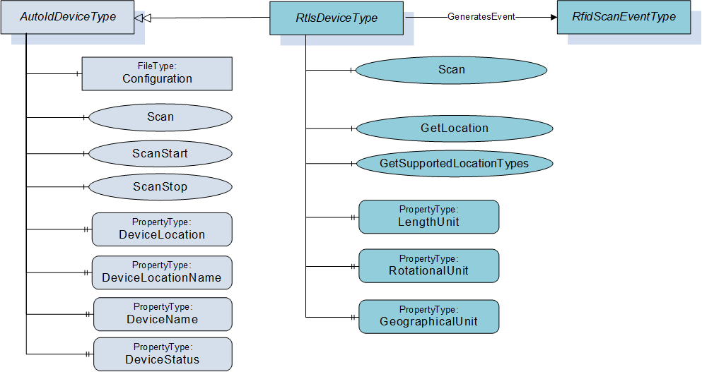
6.6.2 ObjectType definition
The RtlsDeviceType is formally defined in Table 16.
| Attribute | Value | ||||
| BrowseName | RtlsDeviceType | ||||
| IsAbstract | False | ||||
| References | Node Class | BrowseName | DataType | TypeDefinition | Modelling Rule |
|---|---|---|---|---|---|
| Subtype of AutoIdDeviceType defined in 6.1. | |||||
| HasComponent | Method | Scan | Optional | ||
| HasComponent | Method | GetLocation | Optional | ||
| HasComponent | Method | GetUnits | Optional | ||
| HasComponent | Method | GetSupportedLocationTypes | Optional | ||
| HasProperty | Variable | LengthUnit | EUInformation | PropertyType | Mandatory |
| HasProperty | Variable | RotationalUnit | EUInformation | PropertyType | Mandatory |
| HasProperty | Variable | GeographicalUnit | EUInformation | PropertyType | Mandatory |
| HasProperty | Variable | SpeedUnit | EUInformation | PropertyType | Mandatory |
| GeneratesEvent | ObjectType | RtlsLocationEventType | Defined in 7.7. | ||
The RtlsDeviceType ObjectType is a concrete type and can be used directly.
6.6.3 ObjectType Description
6.6.3.1 Method Scan
This method executes the location acquisition process of the RTLS device or system. It overwrites the Scan method of the AutoIdDeviceType defined in 6.1.3.4.
Signature
	Scan (
		[in]	ScanSettings				Settings
		[out]	RtlsLocationResult []			Results
		[out]	AutoIdOperationStatusEnumeration	Status
		);
| Argument | Description |
| Settings | Configuration settings for the scan execution. The ScanSettings DataType is defined in 9.3.7. |
| Result | Results of the scan execution. The RtlsLocationResult DataType is defined in 9.3.15. |
| Status | Returns the status of the scan operation. The AutoIdOperationStatusEnumeration DataType is defined in 9.2.1. |
Method Result Codes
| ResultCode | Description |
| Bad_MethodInvalid | The device does not support this function |
| Bad_InvalidState | This command is not available or not allowed e.g. due to special configuration |
| Other OPC UA status codes defined for the Call Service in OPC 10000-4. |
6.6.3.2 Method GetLocation
This method queries the RTLS device or system synchronous and returns the location of an object. Depending on vendor-specific implementation, it may initiate a location or range acquisition and synchronously return a result, or the RTLS device may return the last known location of the object (the age of the last location acquisition will be apparent from the timestamp returned in the result).
Signature
	GetLocation (
		[in]	ScanData			Identifier
		[in]	CodeTypeDataType		CodeType
		[in]	LocationTypeEnum		LocationType
		[out]	RtlsLocationResult	Result
		);
| Argument | Description |
| Identifier | AutoID Identifier according to the device configuration as returned as part of a ScanResult in a scan event or scan method. The ScanData DataType is defined in 9.4.2. If the ScanData is used as returned in the ScanResult, the structure may contain information that must be ignored by the AutoID Device. An example is the ScanDataEpc where only the parameter UId is relevant for this Method. If the Identifier is provided from a different source than the ScanResult, a ScanData with a ByteString can be used to pass a UId where the CodeType is set to 'UId'. |
| CodeType | Defines the format of the ScanData in the Identifier as string. The String DataType CodeTypeDataType and the predefined format strings are defined in 9.1.3. |
| LocationType | The requestsd type of the location information returned in the scan results. The LocationTypeEnumeration DataType is defined in 9.2.3. |
| Result | Results of the method execution. The RtlsLocationResult DataType is defined in 9.3.15. |
Method Result Codes
| ResultCode | Description |
| Bad_MethodInvalid | The device does not support this function |
| Bad_InvalidState | This command is not available or not allowed e.g. due to special configuration |
6.6.3.3 Method GetSupportedLocationTypes
This method returns the RTLSLocationTypes (as defined in RTLSLocationTypeEnum and in section 8.3) the RTLS device or system supports. At least one Type must be returned. The first type that is returned (first position in the resulting array) is the default type that the RTLS device or system will use.
Signature
	GetSupportedLocationTypes (
		[out]	LocationTypeEnumeration[]	SupportedLocationTypes
		);
| Argument | Description |
| SupportedLocationTypes[] | Array of supported LocationTypeEnumeration values as defined in 9.2.3. At least one Type shall be returned. |
Method Result Codes
| ResultCode | Description |
| Bad_MethodInvalid | The device does not support this function |
| Bad_InvalidState | This command is not available or not allowed e.g. due to special configuration |
7 OPC UA EventTypes
7.1 General
The following Figure 12 provides an overview of the different AutoID reader Scan Event types.
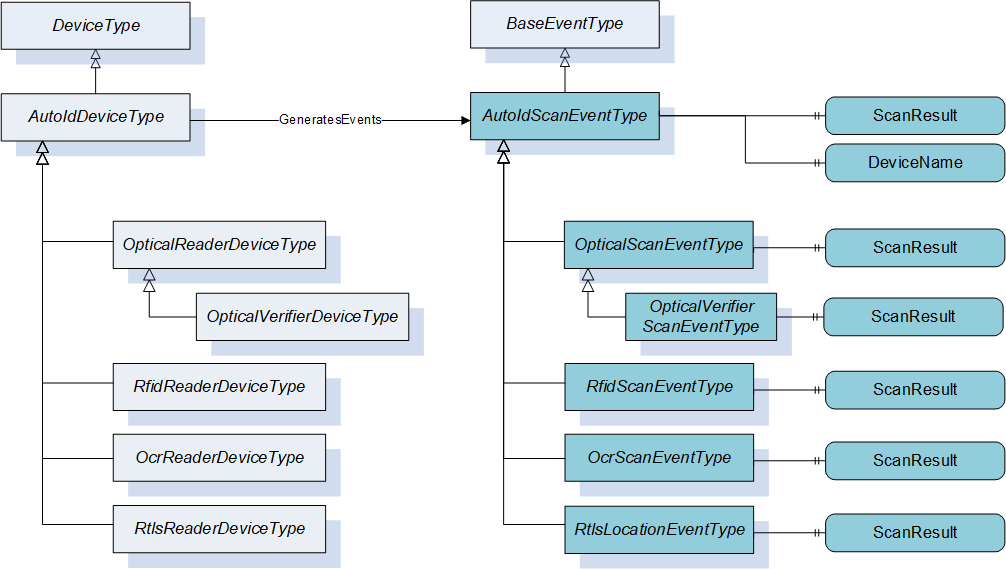
The following Figure 13 provides an overview of the different AutoID reader Diagnostic Event types.
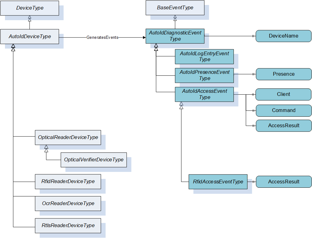
The Events created by AutoID devices can be received by all OPC UA clients that subscribe for the Events from a device.
7.2 AutoIdScanEventType
The AutoIdScanEventType is formally defined in Table 17.
| Attribute | Value | ||||
| BrowseName | AutoIdScanEventType | ||||
| IsAbstract | True | ||||
| References | Node Class | BrowseName | DataType | TypeDefinition | Modelling Rule |
|---|---|---|---|---|---|
| Subtype of BaseEventType defined in OPC 10000-5. | |||||
| HasProperty | Variable | ScanResult | ScanResult [] | PropertyType | Mandatory |
| HasProperty | Variable | DeviceName | String | PropertyType | Mandatory |
This event is the abstract definition of an AutoID scan event. It will be fired by the AutoID Device after execution of the ScanStart Method or after a scan triggered by the reader device.
The ScanResult contains the results of the scan execution. The ScanResult DataType is defined in 9.3.8.
The DeviceName contains the name of the AutoID Device that executed the scan.
7.3 OcrScanEventType
The OcrScanEventType is formally defined in Table 18.
| Attribute | Value | ||||
| BrowseName | OcrScanEventType | ||||
| IsAbstract | True | ||||
| References | Node Class | BrowseName | DataType | TypeDefinition | Modelling Rule |
|---|---|---|---|---|---|
| Subtype of AutoIdScanEventType defined in 7.2. | |||||
| HasProperty | Variable | ScanResult | OcrScanResult [] | PropertyType | Mandatory |
This event is the definition of a scan event for OCR reader devices. It will be fired by the AutoID Device after execution of the ScanStart Method or after a scan triggered by the reader device.
The ScanResult contains the results of the scan execution. The OcrScanResult DataType is defined in 9.3.9.7.4 OpticalScanEventType
The OpticalScanEventType is formally defined in Table 19.
| Attribute | Value | |||||
| BrowseName | OpticalScanEventType | |||||
| IsAbstract | True | |||||
| References | Node Class | BrowseName | DataType | TypeDefinition | Modelling Rule | |
|---|---|---|---|---|---|---|
| Subtype of AutoIdScanEventType defined in 7.2. | ||||||
| HasProperty | Variable | ScanResult | OpticalScanResult [] | PropertyType | Mandatory | |
This event is the definition of a scan event for optical code readers. It will be fired by the AutoID Device after execution of the ScanStart Method or after a scan triggered by the reader device.
The ScanResult contains the results of the scan execution. The OpticalScanResult DataType is defined in 9.3.10.7.5 OpticalVerifierScanEventType
The OpticalVerifierScanEventType is formally defined in Table 20.
| Attribute | Value | ||||
| BrowseName | OpticalVerifierScanEventType | ||||
| IsAbstract | True | ||||
| References | Node Class | BrowseName | DataType | TypeDefinition | Modelling Rule |
|---|---|---|---|---|---|
| Subtype of OpticalScanEventType defined in 7.4. | |||||
| HasProperty | Variable | ScanResult | OpticalVerifierScanResult [] | PropertyType | Mandatory |
This event is the definition of a scan event for optical code verifiers. It will be fired by the AutoID Device after execution of the ScanStart Method or after a scan triggered by the verifier device.
The ScanResult contains the results of the scan execution. The OpticalVerifierScanResult DataType is defined in 9.3.11.7.6 RfidScanEventType
The RfidScanEventType is formally defined in Table 21.
| Attribute | Value | ||||
| BrowseName | RfidScanEventType | ||||
| IsAbstract | True | ||||
| References | Node Class | BrowseName | DataType | TypeDefinition | Modelling Rule |
|---|---|---|---|---|---|
| Subtype of AutoIdScanEventType defined in 7.2. | |||||
| HasProperty | Variable | ScanResult | RfidScanResult [] | PropertyType | Mandatory |
This event is the definition of a scan event for RFID readers. It will be fired by the AutoID Device after execution of the ScanStart Method or after a scan triggered by the reader device.
The ScanResult contains the results of the scan execution. The RfidScanResult DataType is defined in 9.3.12.
7.7 RtlsLocationEventType
The RtlsLocationEventType is formally defined in Table 22.
| Attribute | Value | ||||
| BrowseName | RtlsLocationEventType | ||||
| IsAbstract | True | ||||
| References | Node Class | BrowseName | DataType | TypeDefinition | Modelling Rule |
|---|---|---|---|---|---|
| Subtype of AutoIdScanEventType defined in 7.2. | |||||
| HasProperty | Variable | ScanResult | RtlsLocationResult [] | PropertyType | Mandatory |
This event is the definition of a location event for RTLS devices or systems. It will be fired by the AutoID Device or system after execution of the ScanStart Method or after a scan triggered by the RTLS device or system.
The ScanResult contains the results of the scan execution. The RtlsLocationResult DataType is defined in 9.3.15.
7.8 AutoIdDiagnosticsEventType
The AutoIdDiagnosticsEventType is formally defined in Table 23.
| Attribute | Value | ||||
| BrowseName | AutoIdDiagnosticsEventType | ||||
| IsAbstract | True | ||||
| References | Node Class | BrowseName | DataType | TypeDefinition | Modelling Rule |
|---|---|---|---|---|---|
| Subtype of BaseEventType defined in OPC 10000-5. | |||||
| HasProperty | Variable | DeviceName | String | PropertyType | Mandatory |
This event is the abstract definition of an AutoID diagnostics event. It will be fired by the AutoID Device after the occurrence of specific diagnostics data.
The DeviceName contains the name of the AutoID Device that performed the diagnostic action.
7.9 AutoIdLogEntryEventType
The AutoIdLogEntryEventType is formally defined in Table 24.
| Attribute | Value | ||||
| BrowseName | AutoIdLogEntryEventType | ||||
| IsAbstract | True | ||||
| References | Node Class | BrowseName | DataType | TypeDefinition | Modelling Rule |
|---|---|---|---|---|---|
| Subtype of AutoIdDiagnosticsEventType defined in 7.8. | |||||
This event is the definition of a Log Entry diagnostics event for AutoID devices. It will be fired by the AutoID Device after a new entry to the Logbook was written.
The new entry to the Logbook will be provided in the Event field Message defined by the BaseEventType.
7.10 AutoIdAccessEventType
The AutoIdAccessEventType is formally defined in Table 25.
| Attribute | Value | ||||
| BrowseName | AutoIdAccessEventType | ||||
| IsAbstract | True | ||||
| References | Node Class | BrowseName | DataType | TypeDefinition | Modelling Rule |
|---|---|---|---|---|---|
| Subtype of AutoIdDiagnosticsEventType defined in 7.8. | |||||
| HasProperty | Variable | Client | String | PropertyType | Optional |
| HasProperty | Variable | Command | String | PropertyType | Optional |
| HasProperty | Variable | AccessResult | AccessResult [] | PropertyType | Mandatory |
This event is the definition of an Access diagnostics event for AutoID devices. It will be fired by the AutoID Device after at least one AutoID Identifier was accessed by a command, including the Scan command.
Client contains the name of the client application which was the originator of the command.
Command contains the executed command. Dependend on the kind of the client application, the names of the commands may vary. When the client application is an OPC UA Client, the names shall correspond to the command names used within this specification, e.g. "ReadTag" for the execution of the ReadTag command.
The AccessResult contains additional values of the AutoID Identifier access. The AccessResult DataType is defined in 9.3.17.
7.11 RfidAccessEventType
The RfidAccessEventType is formally defined in Table 26.
| Attribute | Value | ||||
| BrowseName | RfidAccessEventType | ||||
| IsAbstract | True | ||||
| References | Node Class | BrowseName | DataType | TypeDefinition | Modelling Rule |
|---|---|---|---|---|---|
| Subtype of AutoIdAccessEventType defined in 7.8. | |||||
| HasProperty | Variable | AccessResult | RfidAccessResult [] | PropertyType | Mandatory |
This event is the definition of a Rfid Access diagnostics event for Rfid devices. It will be fired by the Rfid Device after at least one Rfid Transponder was accessed by a command, including the Scan command.
The AccessResult contains additional values of the transponder access. The RfidAccessResult DataType is defined in 9.3.18.
7.12 AutoIdPresenceEventType
The AutoIdPresenceEventType is formally defined in Table 27.
| Attribute | Value | ||||
| BrowseName | AutoIdPresenceEventType | ||||
| IsAbstract | True | ||||
| References | Node Class | BrowseName | DataType | TypeDefinition | Modelling Rule |
|---|---|---|---|---|---|
| Subtype of AutoIdDiagnosticsEventType defined in 7.8. | |||||
| HasProperty | Variable | Presence | UInt16 | PropertyType | Mandatory |
This event is the definition of a Presence diagnostics event for AutoID devices. It will be fired by the AutoID Device if the number of AutoID Identifiers (e.g. Codes or transponder), seen by the device, changes.
Presence identifies if there currently is seen an AutoID Identifier by the device. If supported by a device, it may show the concrete number of AutoID Identifiers.
8 OPC UA Variable Types
8.1 LocationVariableType
This VariableType is used for location information. The Properties defined by this type provide the units used for the different information contained in the location information. The LocationVariableType is formally defined in Table 28.
| Attribute | Value | ||||
| BrowseName | LocationVariableType | ||||
| IsAbstract | False | ||||
| ValueRank | -1 (-1 = Scalar) | ||||
| DataType | Location | ||||
| References | Node Class | BrowseName | DataType | TypeDefinition | Modelling Rule |
|---|---|---|---|---|---|
| Subtype of the BaseDataVariableType defined in OPC 10000-5. | |||||
| HasProperty | Variable | LengthUnit | EUInformation | PropertyType | Optional |
| HasProperty | Variable | RotationalUnit | EUInformation | PropertyType | Optional |
| HasProperty | Variable | GeographicalUnit | EUInformation | PropertyType | Optional |
| HasProperty | Variable | SpeedUnit | EUInformation | PropertyType | Optional |
The LengthUnit Property of DataType EUInformation represents the unit with which the AutoID Device returns length measurements, e.g. for coordinates. Examples are meters, millimetres, inches, miles, etc.
The RotationalUnit Property of DataType EUInformation represents the unit with which the AutoID Device returns rotational measurements, e.g. to express the orientation of an object. Examples are degrees, radians, gon, etc.
The GeographicalUnit Property of DataType EUInformation represents the unit with which the AutoID Device returns geographical coordinates. Examples are deg[°] min['] sec["]; deg[°] min.decimal_fraction_min['] or deg.decimal_fraction_deg[°].
The SpeedUnit Property of DataType EUInformation represents the unit with which the AutoID Device returns the current speed of a located object. Examples are m/s, km/h or mph.
9 Mapping of DataTypes
9.1 Primitive data types
9.1.1 LocationName
This DataType is a String that represents an arbitrary name given to a location. It can be used to return location denominations in a simple way, independent of complex coordinate structures.
Its representation in the AddressSpace is defined in Table 29.
| Attributes | Value |
| BrowseName | LocationName |
| Subtype of String defined in OPC 10000-5. | |
9.1.2 NmeaCoordinateString
This DataType is a String that represents a GPS coordinate as defined by NMEA 0183 v. 4.10.
Its representation in the AddressSpace is defined in Table 30.
| Attributes | Value |
| BrowseName | NmeaCoordinateString |
| Subtype of String defined in OPC 10000-5. | |
9.1.3 CodeTypeDataType
This DataType is a String that represents a code type used for an AutoID Identifier.
Its representation in the AddressSpace is defined in Table 31.
| Attributes | Value |
| BrowseName | CodeTypeDataType |
| Subtype of String defined in OPC 10000-5. | |
The values in the CodeTypeDataType are extensible by individual manufacturers, starting with "CUSTOM:". Predefined values are defined in Table 32
| Code Type Value | ScanData Value field in union defined in 9.4.2 | Data Type | Description |
| "RAW:BYTES" | ByteString | ByteString | AutoID Device specific raw data |
| "RAW:STRING" | String | String | AutoID Device specific raw data to be interpreted as string |
| "EPC" | Epc | ScanDataEpc | EPC binary structure as defined in 9.3.6 |
| "UID" | ByteString | ByteString | AutoID Identifier according to ISO/IEC 18000-3 Mode 3, ISO/IEC 18000-63 and GS1 EPCglobal™. |
| "GS1" | ByteString | ByteString | Raw data containing application identifiers (AI) and data according to ISO/IEC 15418. In case of RFID bit 0x17 of PC is not set. PC contains no AFI. In case of barcode data start with macro 05 according ISO/IEC 15434. |
| "ASC" | ByteString | ByteString | Raw data containing data identifiers (DI) and data according to ISO/IEC 15418. In case of RFID bit 0x17 is set. PC contains AFI. In case of barcode data start with macro 06 according ISO/IEC 15434. |
| "URI" | String | String | URI, e.g. EPC string value according to "GS1 EPC Tag Data Standard 1.6" Example ScanData String value: "urn:epc:id:sgtin:0614141.112345.400" Also usable for other URIs |
| "CUSTOM:xxx" | ByteString String Custom | ByteString String BaseDataType | Any custom defined value ("xxx" is a AutoID Device specific substring of arbitrary length). |
Transponder as well as optical 2D-Codes are data carrier for information usually displayed in bits and bytes. But the contained information could be organized in a certain structure. How to do this in a norm conforming way is described in the standard ISO/IEC 15434 "Syntax for high capacity ADC Media" (ADC stands for Automatic Data Capture).
The two most prominent data structures in use are following the rules of GS1 and the ASC MH1. They are described in the standard ISO/IEC 15418 (Data Identifier and Application Identifier).
It is the purpose of these international standards to define the syntax for high capacity ADC media (such as transponder or 2D-Codes), in order to enable ADC users to utilize a single mapping utility, regardless of which high capacity ADC media is employed.
The interoperability of different data structures is achieved by the definition of a Message Header and a Format Header. While the Message Header defines the start and the end of the data contained, the Format Header indicates which data format is used.
Below two examples are shown for a GS1 and an ASC data format.
Example GS1
<Macro05>01312345123457GS1012345GS17101231
Interpretation by the Reader
]d1[)>RS05GS0134012345123457GS1012345GS17101231RSEOT
Example ASC MH 10
<Macro06>25PLEABCBQ3DGS1T234567GS14D101231
Interpretation by the Reader
]d1[)>RS06GS 25PLEABCBQ3DGS1T234567GS14D20101231RSEOT
For RFID the data structures are controlled by AFIs (lower 8 bits of PC) when ISO format is used according ISO/IEC 15961-2 and -3. Depending on the AFI different data compression methods may be used. Details are described for example in ISO 17363, 17364, 17365, 17366 and 17367.
9.2 Enumeration DataTypes
9.2.1 AutoIdOperationStatusEnumeration
This DataType is an enumeration that specifies the status for the AutoID operations like scan, read, write, lock or kill. Its values are defined in Table 33.
Not all status values are usable for all AutoID reader types. The table contains flags to indicate the expected status values for the different reader types.
| Name | Description | OCR | Opt. | RFID | RTLS |
| SUCCESS_0 | Successful operation | X | X | X | X |
| MISC_ERROR_TOTAL_1 | The operation has not been executed in total | X | |||
| MISC_ERROR_PARTIAL_2 | The operation has been executed only partial | X | |||
| PERMISSON_ERROR_3 | Password required | X | |||
| PASSWORD_ERROR_4 | Password is wrong | X | |||
| REGION_NOT_FOUND_ERROR_5 | Memory region not available for the actual tag | X | |||
| OP_NOT_POSSIBLE_ERROR_6 | Operation not supported by the actual tag | X | |||
| OUT_OF_RANGE_ERROR_7 | Addressed memory not available for the actual tag | X | |||
| NO_IDENTIFIER_8 | The operation cannot be executed because no tag or code was inside the range of the AutoID Device or the tag or code has been moved out of the range during execution | X | X | X | X |
| MULTIPLE_IDENTIFIERS_9 | Multiple tags or codes have been selected, but the command can only be used with a single tag or code | X | X | X | |
| READ_ERROR_10 | The tag or code exists and has a valid format, but there was a problem reading the data (e.g. still CRC error after maximum number of retries) | X | X | ||
| DECODING_ERROR_11 | The (optical) code or plain text has too many failures and cannot be detected | X | X | ||
| MATCH_ERROR_12 | The code doesn't match the given target value | X | X | ||
| CODE_NOT_SUPPORTED_13 | The code format is not supported by the AutoID Device | X | |||
| WRITE_ERROR_14 | The tag exists, but there was a problem writing the data | X | |||
| NOT_SUPPORTED_BY_DEVICE_15 | The command or a parameter combination is not supported by the AutoID Device | X | X | X | X |
| NOT_SUPPORTED_BY_TAG_16 | The command or a parameter combination is not supported by the tag | X | |||
| DEVICE_NOT_READY_17 | The AutoID Device is in a state not ready to execute the command | X | X | X | X |
| INVALID_CONFIGURATION_18 | The AutoID Device configuration is not valid | X | X | X | |
| RF_COMMUNICATION_ERROR_19 | This error indicates that there is a general error in the communication between the transponder and the reader | X | X | ||
| DEVICE_FAULT_20 | The AutoID Device has a hardware fault | X | X | X | X |
| TAG_HAS_LOW_BATTERY_21 | The battery of the (active) tag is low | X | X |
Its representation in the AddressSpace is defined in Table 34.
| Attribute | Value | |||||
| BrowseName | AutoIdOperationStatusEnumeration | |||||
| IsAbstract | False | |||||
| References | NodeClass | BrowseName | DataType | TypeDefinition | Other | |
|---|---|---|---|---|---|---|
| Subtype of Enumeration defined in OPC 10000-5. | ||||||
| 0:HasProperty | Variable | 0:EnumValues | 0:EnumValueType [] | 0:PropertyType | ||
9.2.2 DeviceStatusEnumeration
This DataType is an enumeration that defines operational states of an AutoID Device. Its values are defined in Table 35.
| Name | Description |
| Idle_0 | The AutoID Device is operating normally and ready to accept commands like Scan or ScanStart method calls (whichever are supported). |
| Error_1 | The AutoID Device is not operating normally. An error condition has to be fixed before normal operation is possible. |
| Scanning_2 | The AutoID Device is operating normally and asynchronous scanning (via ScanStart or automatically) is active. It is AutoID Device dependent which method calls other than ScanStop will be accepted in this state. |
| Busy_3 | The AutoID Device is operating normally, but currently busy (e.g. by synchronous calls of other clients) and not able to accept commands like Scan or ScanStart method calls. This state normally is a temporary one. |
Its representation in the AddressSpace is defined in Table 36.
| Attribute | Value | |||||
| BrowseName | DeviceStatusEnumeration | |||||
| IsAbstract | False | |||||
| References | NodeClass | BrowseName | DataType | TypeDefinition | Other | |
|---|---|---|---|---|---|---|
| Subtype of Enumeration defined in OPC 10000-5. | ||||||
| 0:HasProperty | Variable | 0:EnumStrings | 0:LocalizedText [] | 0:PropertyType | ||
9.2.3 LocationTypeEnumeration
This DataType is an enumeration that defines the format of the location of an object returned by an RTLS device or system. Its values are defined in Table 37.
| Name | Description |
| NMEA_0 | An NMEA string representing a coordinate as defined in 9.1.2. |
| LOCAL_1 | A local coordinate as defined in 9.3.4 |
| WGS84_2 | A lat/lon/alt coordinate as defined in 9.3.16 |
| NAME_3 | A name for a location as defined in 9.1.1 |
Its representation in the AddressSpace is defined in Table 38.
| Attribute | Value | |||||
| BrowseName | LocationTypeEnumeration | |||||
| IsAbstract | False | |||||
| References | NodeClass | BrowseName | DataType | TypeDefinition | Other | |
|---|---|---|---|---|---|---|
| Subtype of Enumeration defined in OPC 10000-5. | ||||||
| 0:HasProperty | Variable | 0:EnumStrings | 0:LocalizedText [] | 0:PropertyType | ||
9.2.4 RfidLockOperationEnumeration
This DataType is an enumeration that defines the operational mode of the LockTag Method Its values are defined in Table 39.
| Name | Description |
| Lock_0 | Locks the memory area |
| Unlock_1 | Unlocks the memory area |
| PermanentLock_2 | Locks the memory area irreversible |
| PermanentUnlock_3 | Unlocks the memory area irreversible |
Its representation in the AddressSpace is defined in Table 40.
| Attribute | Value | |||||
| BrowseName | RfidLockOperationEnumeration | |||||
| IsAbstract | False | |||||
| References | NodeClass | BrowseName | DataType | TypeDefinition | Other | |
|---|---|---|---|---|---|---|
| Subtype of Enumeration defined in OPC 10000-5. | ||||||
| 0:HasProperty | Variable | 0:EnumStrings | 0:LocalizedText [] | 0:PropertyType | ||
9.2.5 RfidLockRegionEnumeration
This DataType is an enumeration that defines the memory region that a lock operation affects. Its values are defined in Table 41.
| Name | Description |
| Kill_0 | The kill password |
| Access_1 | The access password |
| EPC_2 | The UII/EPC bank (bank 01) |
| TID_3 | The TID bank (bank 10) |
| User_4 | The user memory bank (bank 11) |
Its representation in the AddressSpace is defined in Table 42.
| Attribute | Value | |||||
| BrowseName | RfidLockRegionEnumeration | |||||
| IsAbstract | False | |||||
| References | NodeClass | BrowseName | DataType | TypeDefinition | Other | |
|---|---|---|---|---|---|---|
| Subtype of Enumeration defined in OPC 10000-5. | ||||||
| 0:HasProperty | Variable | 0:EnumStrings | 0:LocalizedText [] | 0:PropertyType | ||
9.2.6 RfidPasswordTypeEnumeration
This DataType is an enumeration that defines the type of a password. Its values are defined in Table 43.
| Name | Description |
| Access_0 | Access password |
| Kill_1 | Kill password |
| Read_2 | Read password |
| Write_3 | Write password |
Its representation in the AddressSpace is defined in Table 44.
| Attribute | Value | |||||
| BrowseName | RfidPasswordTypeEnumeration | |||||
| IsAbstract | False | |||||
| References | NodeClass | BrowseName | DataType | TypeDefinition | Other | |
|---|---|---|---|---|---|---|
| Subtype of Enumeration defined in OPC 10000-5. | ||||||
| 0:HasProperty | Variable | 0:EnumStrings | 0:LocalizedText [] | 0:PropertyType | ||
9.3 OPC UA Structure DataTypes
9.3.1 General
The Stuctured DataTypes in this chapter are formally defined in two different table formats.
One table format has the columns Name, Type and Description for the definition of standard OPC UA structures where all structure elements are mandatory and must be transported between OPC UA Client and Server.
The second table format has the columns Name, Type, Optional and Description for the definition of OPC UA structures with optional structure elements.
9.3.2 Structure DataType Overview
The following Figure 14 provides an overview of the Structure DataTypes defined for the AutoID Device access.
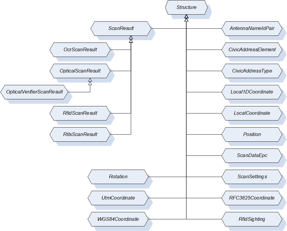
9.3.3 AntennaNameIdPair
This DataType is a structure that defines a pair of RFID antenna ID and antenna name. Its composition is formally defined in Table 45.
| Name | Type | Description |
| AntennaNameIdPair | Structure | Subtype of Structure defined in OPC 10000-5. |
AntennaId | Int32 | ID of the antenna returned in the RfidSighting contained in the RfidScanResult. The RfidSighting is defined in 9.3.13. The RfidScanResult is defined in 9.3.12. |
AntennaName | String | Name of the antenna with the AntennaId. |
Its representation in the AddressSpace is defined in Table 46.
| Attribute | Value | |||||
| BrowseName | AntennaNameIdPair | |||||
| IsAbstract | False | |||||
| References | NodeClass | BrowseName | DataType | TypeDefinition | Other | |
|---|---|---|---|---|---|---|
| Subtype of Structure defined in OPC 10000-5. | ||||||
9.3.4 LocalCoordinate
This DataType is a structure that defines the location of an object in a Cartesian local coordinate system arbitrarily chosen during configuration of an RTLS system. Its composition is formally defined in Table 47.
| Name | Type | Description |
| LocalCoordinate | Structure | Subtype of Structure defined in OPC 10000-5. |
| X | Double | The X - coordinate of the object's position in the unit defined by the LengthUnit property of the AutoID Device. |
| Y | Double | The Y - coordinate of the object's position in the unit defined by the LengthUnit property of the AutoID Device. |
| Z | Double | The Z - coordinate of the object's position in the unit defined by the LengthUnit property of the AutoID Device. |
| Timestamp | UtcTime | Timestamp in UtcTime |
| DilutionOfPrecision | Double | DOP is a value for the variance of the measurements delivered by the location system. The calculation of the value depends on the underlying system and is vendor specific. Values should be in accordance with the implementations like in GNSS systems. |
| UsefulPrecision | Int32 | Values for Easting, Northing, and Altitude should be rounded by the clien tapplication to the n-th position after the decimal point. It specifies the number of useful digits after the decimal place. |
Its representation in the AddressSpace is defined in Table 48.
| Attribute | Value | |||||
| BrowseName | LocalCoordinate | |||||
| IsAbstract | False | |||||
| References | NodeClass | BrowseName | DataType | TypeDefinition | Other | |
|---|---|---|---|---|---|---|
| Subtype of Structure defined in OPC 10000-5. | ||||||
9.3.5 Position
This DataType is a structure that defines the position and the size of a code or a plain text within an image (so-called code area, used by OCR and optical code readers). Its composition is formally defined in Table 49.
| Name | Type | Description |
| Position | Structure | Subtype of Structure defined in OPC 10000-5. |
| PositionX | Int32 | X coordinate of the top-left edge of the code area (counting starts on the left side of the image) |
| PositionY | Int32 | Y coordinate of the top-left edge of the code area (counting starts on the top side of the image) |
| SizeX | Int32 | Horizontal size of the code area in pixel |
| SizeY | Int32 | Vertical size of the code area in pixel |
| Rotation | Int32 | The rotation of the code area |
Its representation in the AddressSpace is defined in Table 50.
| Attribute | Value | |||||
| BrowseName | Position | |||||
| IsAbstract | False | |||||
| References | NodeClass | BrowseName | DataType | TypeDefinition | Other | |
|---|---|---|---|---|---|---|
| Subtype of Structure defined in OPC 10000-5. | ||||||
9.3.6 ScanDataEpc
This DataType is a structure that defines the structure of the scanned data in Epc_1 format. Its composition is formally defined in Table 51.
| Name | Type | Description | Optional |
| ScanDataEpc | Structure | Subtype of Structure defined in OPC 10000-5. | |
PC | UInt16 | Protocol control information according to ISO/IEC 18000-3 Mode 3, ISO/IEC 18000-63 and GS1 EPCglobal™. | False |
UId | ByteString | AutoID Identifier according to ISO/IEC 18000-3 Mode 3, ISO/IEC 18000-63 and GS1 EPCglobal™. | False |
XPC_W1 | UInt16 | Extended protocol control word 1 according to ISO/IEC 18000-3 Mode 3, ISO/IEC 18000-63 and GS1 EPCglobal™. | True |
XPC_W2 | UInt16 | Extended protocol control word 2 according to ISO/IEC 18000-3 Mode 3, ISO/IEC 18000-63 and GS1 EPCglobal™. | True |
Its representation in the AddressSpace is defined in Table 52.
| Attribute | Value | |||||
| BrowseName | ScanDataEpc | |||||
| IsAbstract | False | |||||
| References | NodeClass | BrowseName | DataType | TypeDefinition | Other | |
|---|---|---|---|---|---|---|
| Subtype of Structure defined in OPC 10000-5. | ||||||
9.3.7 ScanSettings
This DataType is a structure that defines the settings for a scan execution. Its composition is formally defined in Table 53.
| Name | Type | Description | Optional |
| ScanSettings | Structure | Subtype of Structure defined in OPC 10000-5. | |
Duration | Duration | Duration of the scan operation in milliseconds. Duration is one of the termination conditions for the scan operation. The value 0 is infinite. The termination conditions are related to each other. If one of the conditions is fulfilled, the scan operation is stopped. | False |
Cycles | Int32 | Duration of the scan operation in 'number of scan cycles'. The parameter Cycles is one of the termination conditions for the scan operation. The value 0 is infinite. The termination conditions are related to each other. If one of the conditions is fulfilled, the scan operation is stopped. | False |
DataAvailable | Boolean | If this value is set to True, the scan operation is completed as soon as scan data is available. If this value is set to False, only the other termination conditions are used. | False |
LocationType | LocationType Enumeration | The requestsd type of the location information returned in the scan results. The LocationTypeEnumeration DataType is defined in 9.2.3. | True |
Its representation in the AddressSpace is defined in Table 54.
| Attribute | Value | |||||
| BrowseName | ScanSettings | |||||
| IsAbstract | False | |||||
| References | NodeClass | BrowseName | DataType | TypeDefinition | Other | |
|---|---|---|---|---|---|---|
| Subtype of Structure defined in OPC 10000-5. | ||||||
9.3.8 ScanResult
This DataType is a structure that defines the results of a scan. Its composition is formally defined in Table 55.
| Name | Type | Description | Optional |
| ScanResult | Structure | Subtype of Structure defined in OPC 10000-5. | |
CodeType | CodeTypeDataType | Defines the format of the ScanData as string. The String DataType CodeTypeDataType and the predefined format strings are defined in 9.1.3. | False |
ScanData | ScanData | Holds the information about the detected objects e.g. the detected transponders. The ScanData DataType is defined in 9.4.2. | False |
Timestamp | UtcTime | Timestamp of the ScanResult creation. | False |
Location | Location | Returns the location of the object detection. The Location DataType is defined in 9.4.1. | True |
The ScanResult Structure representation in the AddressSpace is defined in Table 56.
| Attribute | Value | |||||
| BrowseName | ScanResult | |||||
| IsAbstract | True | |||||
| References | NodeClass | BrowseName | DataType | TypeDefinition | IsAbstract | |
|---|---|---|---|---|---|---|
| Subtype of Structure defined in OPC 10000-5. | ||||||
| Has Subtype | DataType | OcrScanResult | False | |||
| Has Subtype | DataType | OpticalScanResult | False | |||
| Has Subtype | DataType | RfidScanResult | False | |||
| Has Subtype | DataType | RtlsLocationResult | False | |||
9.3.9 OcrScanResult
This DataType is a structure that defines the results of an OCR reader device scan. Its composition is formally defined in Table 57.
| Name | Type | Description | Optional |
| OcrScanResult | Structure | Subtype of ScanResult defined in 9.3.8. | |
ImageId | NodeId | NodeId of the original scan image file object used for this scan result. This image file is also available through the Images folder defined in 6.2.3.2. | False |
Quality | Byte | Returns the probability of correct decoding. | False |
Position | Position | Returns the position of the text within the image The Position DataType is defined in 9.3.5. | False |
Font | String | Returns the font name used for decoding | True |
DecodingTime | UtcTime | Returns the required decoding time | True |
Its representation in the AddressSpace is defined in Table 58.
| Attribute | Value | |||||
| BrowseName | OcrScanResult | |||||
| IsAbstract | False | |||||
| References | NodeClass | BrowseName | DataType | TypeDefinition | Other | |
|---|---|---|---|---|---|---|
| Subtype of ScanResult defined in 9.3.8. | ||||||
9.3.10 OpticalScanResult
This DataType is a structure that defines the results of a scan. Its composition is formally defined in Table 59.
| Name | Type | Description | Optional |
| OpticalScanResult | Structure | Subtype of ScanResult defined in 9.3.8. | |
Grade | Float | Returns the Grade of the 1D/2D code according to IEC 15415 (2D) and IEC 15416 (1D). The Grade is a value between 0 and 4 where 0 is the worst quality and 4 is the best quality. | True |
Position | Position | Returns the position of the text within the image The Position DataType is defined in 9.3.5. | True |
Symbology | String | Type of barcode per ISO/IEC 15424. Example: "]I1". | True |
ImageId | NodeId | NodeId of the original scan image file object used for this scan result. | True |
Its representation in the AddressSpace is defined in Table 60.
| Attribute | Value | |||||
| BrowseName | OpticalScanResult | |||||
| IsAbstract | False | |||||
| References | NodeClass | BrowseName | DataType | TypeDefinition | IsAbstract | |
|---|---|---|---|---|---|---|
| Subtype of ScanResult defined in 9.3.8. | ||||||
| Has Subtype | DataType | OpticalVerifierScanResult | False | |||
9.3.11 OpticalVerifierScanResult
This DataType is a structure that defines the results of a scan. Its composition is formally defined in Table 61.
| Name | Type | Description | Optional |
| OpticalVerifierScanResult | Structure | Subtype of OpticalScanResult defined in 9.3.10. | |
IsoGrade | String | This value contains the ISO grade, the aperture and the wavelength used. Example content: "2.7/10/660" With the '2.7' being the grade, the '10' being the measuring aperture that was used for the analysis and the '660' is the wavelength of light used to illuminate the code. If the grade is reported without aperture and wavelength, then it really is quite meaningless (a code measured with an '06' aperture can give a totally different result that one measured with a '20' aperture for instance). | False |
RMin | Int16 | The minimum reflection value in percent (from a dark bar). Example: 6 | False |
SymbolContrast | Int16 | The Symbol Contrast value (Rmax - Rmin) in percent. Example: 41 | False |
ECMin | Int16 | The minimum Edge Contrast value in percent. Example: 31 | False |
Modulation | Int16 | The modulation (ECmin / SC) value in percent. Example: 76 | False |
Defects | Int16 | The defects value in percent. Example: 14 | False |
Decodability | Int16 | The decodability value in percent. Example: 87 | False |
Decode | Int16 | The decode content value in percent. Example: 100 | False |
PrintGain | Int16 | The print gain value in percent (-4%). Example: -4 | False |
Its representation in the AddressSpace is defined in Table 62.
| Attribute | Value | |||||
| BrowseName | OpticalVerifierScanResult | |||||
| IsAbstract | False | |||||
| References | NodeClass | BrowseName | DataType | TypeDefinition | Other | |
|---|---|---|---|---|---|---|
| Subtype of OpticalScanResult defined in 9.3.10. | ||||||
9.3.12 RfidScanResult
This DataType is a structure that defines the results of a RFID reader device scan. Its composition is formally defined in Table 63.
| Name | Type | Description |
| RfidScanResult | Structure | Subtype of ScanResult defined in 9.3.8. |
Sighting | RfidSighting [ ] | Returns additional information on the RFID-related properties of the scan event as array of RfidSightings. Each AutoID Identifier can be detected several times during a scan cycle. Each detection of the AutoID Identifier causes an entry into the Sightings array. The RfidSighting DataType is defined in 9.3.13. |
Its representation in the AddressSpace is defined in Table 64.
| Attribute | Value | |||||
| BrowseName | RfidScanResult | |||||
| IsAbstract | False | |||||
| References | NodeClass | BrowseName | DataType | TypeDefinition | Other | |
|---|---|---|---|---|---|---|
| Subtype of ScanResult defined in 9.3.8. | ||||||
9.3.13 RfidSighting
This DataType is a structure that defines additional RFID-related information of an AutoID Identifier detection during a scan cycle. Its composition is formally defined in Table 65.
| Name | Type | Description |
| RfidSighting | Structure | Subtype of Structure defined in OPC 10000-5. |
Antenna | Int32 | Returns the number of the antenna which detects the RFID tag first. |
Strength | Int32 | Returns the signal strength (RSSI) of the transponder. Higher values indicate a better strength. |
Timestamp | UtcTime | Timestamp in UtcTime. |
CurrentPowerLevel | Int32 | Returns the current power level (unit according to parameter settings) |
Its representation in the AddressSpace is defined in Table 66.
| Attribute | Value | |||||
| BrowseName | RfidSighting | |||||
| IsAbstract | False | |||||
| References | NodeClass | BrowseName | DataType | TypeDefinition | Other | |
|---|---|---|---|---|---|---|
| Subtype of Structure defined in OPC 10000-5. | ||||||
9.3.14 Rotation
This DataType is a structure that defines the rotation (or heading) of an object relative to the base coordinate system. The format is 'yaw, pitch, roll' as defined for aircraft principal axes. Its composition is formally defined in Table 67.
| Name | Type | Description |
| Rotation | Structure | Subtype of Structure defined in OPC 10000-5. |
Yaw | Double | The yaw of the object, in the unit defined for rotational measurements, e. g. in radians between PI and -PI (or in deg between +180° and -180°). Rotation measured around a vertical axis. Reference (yaw = 0) is the X-axis of the coordinate system |
Pitch | Double | The pitch of the object, in the unit defined for rotational measurements, e. g. in radians between PI and -PI (or in deg between +180° and -180°). Rotation measured around a horizontal axis. Reference (pitch = 0) is the direction of the yaw on the horizontal plane of the coordinate system |
Roll | Double | The roll of the object, in the unit defined for rotational measurements, e. g. in radians between PI and -PI (or in deg between +180° and -180°). Rotation measured around a horizontal axis pointing in the direction defined by yaw, pitch |
Its representation in the AddressSpace is defined in Table 68.
| Attribute | Value | |||||
| BrowseName | Rotation | |||||
| IsAbstract | False | |||||
| References | NodeClass | BrowseName | DataType | TypeDefinition | Other | |
|---|---|---|---|---|---|---|
| Subtype of Structure defined in OPC 10000-5. | ||||||
9.3.15 RtlsLocationResult
This DataType is a structure that defines the results that an RTLS device or system returns. It extends the ScanResult structure. Its composition is formally defined in Table 69.
The optional Location field defined in the ScanResult structure shall be included in RtlsLocationResults.
| Name | Type | Description | Optional |
| RtlsLocationResult | Structure | Subtype of ScanResult defined in 9.3.8. | |
Speed | Double | The current speed above ground of the located object. The unit is defined by the SpeedUnit variable. | True |
Heading | Double | The (geographical) direction the located object is moving in on a plane. The unit is defined by the RotationUnit variable, but note that the heading can be different from the rotation of the object. | True |
Rotation | Rotation | The rotation of the object identified by the UId as defined in 9.3.14. | True |
ReceiveTime | UtcTime | ReceiveTime provides the time the RTLS received the location information from the underlying device. | True |
Its representation in the AddressSpace is defined in Table 70.
| Attribute | Value | |||||
| BrowseName | RtlsLocationResult | |||||
| IsAbstract | False | |||||
| References | NodeClass | BrowseName | DataType | TypeDefinition | Other | |
|---|---|---|---|---|---|---|
| Subtype of ScanResult defined in 9.3.8. | ||||||
9.3.16 WGS84Coordinate
This DataType is a structure that defines the georeferenced location of an object on the earth's surface in latitude, longitude and altitude using the World Geodetic System's (WGS84) reference frame. Its composition is formally defined in Table 71.
| Name | Type | Description |
| WGS84Coordinate | Structure | Subtype of Structure defined in OPC 10000-5. |
N/S Hemisphere | String | 'N' or 'S' for northern or southern hemisphere |
Latitude | Double | Latitude in the unit defined by the GeographicalUnit property of the DeviceLocation Variable of the AutoID Device defined in 6.1.3.12. |
E/W Hemisphere | String | 'E' or 'W' for eastern or western hemisphere |
Longitude | Double | Longitude in the unit by the GeographicalUnit property of the DeviceLocation Variable of the AutoID Device defined in 6.1.3.12. |
Altitude | Double | Altitude in the unit by the GeographicalUnit property of the DeviceLocation Variable of the AutoID Device defined in 6.1.3.12. |
Timestamp | UtcTime | Timestamp in UtcTime |
DilutionOfPrecision | Double | DOP is a value for the variance of the measurements delivered by the location system. The calculation of the value depends on the underlying system and is vendor specific. Values should be in accordance with the implementations like in GNSS systems. |
UsefulPrecisionLatLon | Int32 | Values for Latitude and Longitude should be rounded by the client application to the n-th position after the decimal point. It specifies the number of useful digits after the decimal place. |
UsefulPrecisionAlt | Int32 | Values for Altitude should be rounded by the client application to the n-th position after the decimal point. It specifies the number of useful digits after the decimal place. |
Its representation in the AddressSpace is defined in Table 72.
| Attribute | Value | |||||
| BrowseName | WGS84Coordinate | |||||
| IsAbstract | False | |||||
| References | NodeClass | BrowseName | DataType | TypeDefinition | Other | |
|---|---|---|---|---|---|---|
| Subtype of Structure defined in OPC 10000-5. | ||||||
9.3.17 AccessResult
This DataType is a structure that defines the result values of an AutoID Identifier access of an AutoID device. Its composition is formally defined in Table 73.
| Name | Type | Description | Optional |
| AccessResult | Structure | Subtype of Structure defined in OPC 10000-5. | |
CodeType | CodeTypeDataType | Defines the format of Identifier as string. The String DataType CodeTypeDataType and the predefined format strings are defined in 9.1.3. | true |
Identifier | ScanData | The AutoID identifier (e.g. a code or a transponder) which was accessed by the command. The ScanData DataType is defined in 9.4.2. When this value exists, the value CodeType must be available too. | true |
Timestamp | UtcTime | The point of time the AutoID Identifier was accessed by the command. | true |
The AccessResult Structure representation in the AddressSpace is defined in Table 74.
| Attribute | Value | |||||
| BrowseName | AccessResult | |||||
| IsAbstract | False | |||||
| References | NodeClass | BrowseName | DataType | TypeDefinition | IsAbstract | |
|---|---|---|---|---|---|---|
| Subtype of Structure defined in OPC 10000-5. | ||||||
| Has Subtype | DataType | RfidAccessResult | False | |||
9.3.18 RfidAccessResult
This DataType is a structure that defines the additional result values of a Rfid Transponder access of a Rfid reader device. Its composition is formally defined in Table 75.
| Name | Type | Description | Optional |
| RfidAccessResult | Structure | Subtype of AccessResult defined in 9.3.17. | |
CodeTypeRWData | CodeTypeDataType | Defines the format of RWData as string. The String DataType CodeTypeDataType and the predefined format strings are defined in 9.1.3. | true |
RWData | ScanData | The user data which was written to / was read from the Rfid Transponder by the command. The ScanData DataType is defined in 9.4.2. When this value exists, the value CodeType must be available too. | true |
Antenna | Int32 | The antenna by which the transponder was accessed by the command. | true |
CurrentPowerLevel | Int32 | The power level with which the transponder was accessed by the command. | true |
PC | UInt16 | The Protocol Control Word of the transponder accessed by the command. | true |
Polarization | String | The Polarization with which the transponder was accessed by the command. | true |
Strength | Int32 | The Rssi value with which the transponder was accessed by the command. | true |
Its representation in the AddressSpace is defined in Table 76.
| Attribute | Value | |||||
| BrowseName | RfidAccessResult | |||||
| IsAbstract | False | |||||
| References | NodeClass | BrowseName | DataType | TypeDefinition | Other | |
|---|---|---|---|---|---|---|
| Subtype of AccessResult defined in 9.3.17. | ||||||
9.4 OPC UA Union DataTypes
9.4.1 Location
This DataType is a union that defines different types of location values. Its composition is formally defined in Table 77.
| Name | Type | Description |
| Location | Union | |
NMEA | NmeaCoordinateString | The DataType NmeaCoordinateString is defined in 9.1.2. |
Local | LocalCoordinate | The DataType LocalCoordinate is defined in 9.3.4. |
WGS84 | WGS84Coordinate | The DataType WGS84Coordinate is defined in 9.3.16. |
Name | LocationName | The DataType LocationName is defined in 9.1.1 |
Its representation in the AddressSpace is defined in Table 78.
| Attribute | Value | |||||
| BrowseName | Location | |||||
| IsAbstract | False | |||||
| References | NodeClass | BrowseName | DataType | TypeDefinition | Other | |
|---|---|---|---|---|---|---|
| Subtype of Union defined in OPC 10000-5. | ||||||
9.4.2 ScanData
This DataType is a union that defines the format of the data scanned by the AutoID Device. Its composition is formally defined in Table 79.
| Name | Type | Description |
| ScanData | Union | |
ByteString | ByteString | Scanned data in RAW format. |
String | String | Scanned data as String. |
Epc | ScanDataEpc | Scanned data as ScanDataEpc structure. |
Custom | BaseDataType | Vendor specific data structure. |
Its representation in the AddressSpace is defined in Table 80.
| Attribute | Value | |||||
| BrowseName | ScanData | |||||
| IsAbstract | False | |||||
| References | NodeClass | BrowseName | DataType | TypeDefinition | Other | |
|---|---|---|---|---|---|---|
| Subtype of Union defined in OPC 10000-5. | ||||||
10 Profiles and Namespaces
10.1 Namespace Metadata
Table 81 defines the namespace metadata for this specification. The Object is used to provide version information for the namespace and an indication about static Nodes. Static Nodes are identical for all Attributes in all Servers, including the Value Attribute. See OPC 10000-5 for more details.
The information is provided as Object of type NamespaceMetadataType. This Object is a component of the Namespaces Object that is part of the Server Object. The NamespaceMetadataType ObjectType and its Properties are defined in OPC 10000-5.
The version information is also provided as part of the ModelTableEntry in the UANodeSet XML file. The UANodeSet XML schema is defined in OPC 10000-6.
| Attribute | Value | |||
| BrowseName | http://opcfoundation.org/UA/AutoID/ | |||
| References | BrowseName | DataType | Value | |
|---|---|---|---|---|
| HasProperty | NamespaceUri | String | http://opcfoundation.org/UA/AutoID/ | |
| HasProperty | NamespaceVersion | String | 1.01 | |
| HasProperty | NamespacePublicationDate | DateTime | 2020-06-18 | |
| HasProperty | IsNamespaceSubset | Boolean | False | |
| HasProperty | StaticNodeIdTypes | IdType[] | {Numeric} | |
| HasProperty | StaticNumericNodeIdRange | NumericRange[] | Null | |
| HasProperty | StaticStringNodeIdPattern | String | Null | |
10.2 OPC UA Conformance Units and Profiles
This chapter defines the corresponding profiles and conformance units for the OPC UA Information Model for AutoID. Profiles are named groupings of conformance units. Facets are profiles that will be combined with other Profiles to define the complete functionality of an OPC UA Server or Client. The following tables specify the facets available for Servers that implement the AutoID Information Model companion specification.
Table 82 defines a facet for the base functionality necessary for a synchronous scan operation with AutoID Devices by pure Data Access functionality, where the OPC UA Client optional can trigger the scan operation.
| Conformance Unit | Description | Optional/ Mandatory |
| AutoID DeviceType | Supports the base AutoID device type, the device specific type and the mandatory components of the types. | M |
| AutoID Simple Sync Access | Supports the LastScanData Variable for synchronous access to the scan data. | M |
| AutoID Simple Sync Access Control | Supports the ScanActive Variable for starting/stopping the scan. | O |
| AutoID Device Parameters | Supports the optional components for the AutoID device type like device location or the configuration parameters. | O |
| Profile | ||
|---|---|---|
| ComplexType Server Facet (defined in OPC 10000-7) | M | |
| BaseDevice_Server_Facet (defined in OPC 10000-100) | M | |
Table 83 defines a facet for the base functionality necessary for a synchronous scan operation with AutoID Devices where the OPC UA Client triggers the scan operation.
| Conformance Unit | Description | Optional/ Mandatory |
| AutoID DeviceType | Supports the base AutoID device type, the device specific type and the mandatory components of the types. | M |
| AutoID Sync Access | Supports the LastScanData Variable and the Scan Method for synchronous access to the scan data. | M |
| AutoID Device Parameters | Supports the optional components for the AutoID device type like device location or the configuration parameters. | O |
| Profile | ||
|---|---|---|
| ComplexType Server Facet (defined in OPC 10000-7) | M | |
| BaseDevice_Server_Facet (defined in OPC 10000-100) | M | |
Table 84 defines a facet for the base functionality necessary for an asynchronous scan operation with AutoID Devices where the device triggers the scan operation.
| Conformance Unit | Description | Optional/ Mandatory |
| AutoID DeviceType | Supports the base AutoID device type, the device specific type and the mandatory components of the types. | M |
| AutoID Async Access | Supports the AutoIdScanEventType to inform clients about new scan result. | M |
| AutoID Async Access Control | Supports the ScanStart and ScanStop Method for asynchronous access to the scan data. | O |
| AutoID Device Parameters | Supports the optional components for the AutoID device type like device location or the configuration parameters. | O |
| Profile | ||
|---|---|---|
| ComplexType Server Facet (defined in OPC 10000-7) | M | |
| Standard Event Subscription Server Facet (defined in OPC 10000-7) | M | |
| BaseDevice_Server_Facet (defined in OPC 10000-100) | M | |
Table 85 defines a facet that indicates full support for the different scan operation modes defined by this specification.
| Conformance Unit | Description | Optional/ Mandatory |
| AutoID Device Parameters | Supports the optional components for the AutoID device type like device location or the configuration parameters. | M |
| AutoID Async Access Control | Supports the ScanStart and ScanStop Method for asynchronous access to the scan data. | M |
| Profile | ||
|---|---|---|
| ComplexType Server Facet (defined in OPC 10000-7) | M | |
| Standard Event Subscription Server Facet (defined in OPC 10000-7) | M | |
| BaseDevice_Server_Facet (defined in OPC 10000-100) | M | |
| Simple Sync AutoID Server Facet defined in Table 82. | M | |
| Base Sync AutoID Server Facet defined in Table 83. | M | |
| Base Async AutoID Server Facet defined in Table 84. | M | |
10.3 Handling of OPC UA namespaces
Namespaces are used by OPC UA to create unique identifiers across different naming authorities. The Attributes NodeId and BrowseName are identifiers. A node in the UA Address Space is unambiguously identified using a NodeId. Unlike NodeIds, the BrowseName cannot be used to unambiguously identify a node. Different nodes may have the same BrowseName. They are used to build a browse path between two nodes or to define a standard Property.
Servers may often choose to use the same namespace for the NodeId and the BrowseName. However, if they want to provide a standard Property, its BrowseName shall have the namespace of the standards body although the namespace of the NodeId reflects something else, for example the EngineeringUnits property. All NodeIds of nodes not defined in this specification shall not use the standard namespaces.
Table 86 provides a list of mandatory and optional namespaces used in an AutoID OPC UA Server.
| NamespaceURI | Description | Use |
| http://opcfoundation.org/UA/ | Namespace for NodeIds and BrowseNames defined in the OPC UA specification. This namespace shall have namespace index 0. | Mandatory |
| Local Server URI | Namespace for nodes defined in the local server. This may include types and instances used in an AutoID Device represented by the server. This namespace shall have namespace index 1. | Mandatory |
| http://opcfoundation.org/UA/DI/ | Namespace for NodeIds and BrowseNames defined in OPC 10000-100. The namespace index is server specific. | Mandatory |
| http://opcfoundation.org/UA/AutoID/ | Namespace for NodeIds and BrowseNames defined in this specification. The namespace index is server specific. | Mandatory |
| Vendor specific types and instances | A server may provide vendor specific types like types derived from RfidReaderDeviceType or OpticalReaderDeviceType or vendor specific instances of devices in a vendor specific namespace. | Optional |
Table 87 provides a list of namespaces and their index used for BrowseNames in this specification. The default namespace of this specification is not listed since all BrowseNames without prefix use this default namespace.
| NamespaceURI | Namespace Index | Example |
| http://opcfoundation.org/UA/ | 0 | 0:EngineeringUnits |
| http://opcfoundation.org/UA/DI/ | 1 | 1:DeviceRevision |
Annex A (normative): AutoID Namespace and Mappings
A.1 Namespace and identifiers for AutoID Information Model
This appendix defines the numeric identifiers for all of the numeric NodeIds defined in this specification. The identifiers are specified in a CSV file with the following syntax:
<SymbolName>, <Identifier>, <NodeClass>Where the SymbolName is either the BrowseName of a Type Node or the BrowsePath for an Instance Node that appears in the specification and the Identifier is the numeric value for the NodeId.
The BrowsePath for an Instance Node is constructed by appending the BrowseName of the instance Node to the BrowseName for the containing instance or type. An underscore character is used to separate each BrowseName in the path. Let's take for example, the AutoIdDeviceType ObjectType Node which has the DeviceLocation Property. The Name for the DeviceLocation InstanceDeclaration within the AutoIdDeviceType declaration is: AutoIdDeviceType_DeviceLocation.
The NamespaceUri for all NodeIds defined here is http://opcfoundation.org/UA/AutoID/
The CSV released with this version of the specification can be found here:
http://www.opcfoundation.org/UA/AutoID/1.0/Opc.Ua.AutoID.NodeIds.csv
http://www.opcfoundation.org/UA/AutoID/Opc.Ua.AutoID.NodeIds.csv
A computer processable version of the complete Information Model defined in this specification is also provided. It follows the XML Information Model schema syntax defined in OPC 10000-6.
The Information Model Schema released with this version of the specification can be found here:
http://www.opcfoundation.org/UA/AutoID/1.0/Opc.Ua.AutoID.NodeSet2.xml
http://www.opcfoundation.org/UA/AutoID/Opc.Ua.AutoID.NodeSet2.xml
A.2 Profile URIs for AutoID Information Model
Table A.1 defines the Profile URIs for the AutoID Information Model companion specification.
| Profile | Profile URI |
| Simple Sync AutoID Server Facet | http://opcfoundation.org/UA-Profile/External/AutoID/SimpleAutoIdSyncServer |
| Base Sync AutoID Server Facet | http://opcfoundation.org/UA-Profile/External/AutoID/BaseAutoIdSyncServer |
| Base Async AutoID Server Facet | http://opcfoundation.org/UA-Profile/External/AutoID/BaseAutoIdAsyncServer |
| Full AutoID Server Facet | http://opcfoundation.org/UA-Profile/External/AutoID/FullAutoIdServer |
Annex B (informative): Mapping to RFID technologies
B.1 LF
There are several proprietary LF tags on the market. For these tags the ReadTag and WriteTag commands can be used. Here we describe the operation of standardized tags according ISO/IEC 18000-2. In addition, we describe simple tags with fixed codes or data that can be read only.
LF tags according ISO/IEC 18000-2 have no memory banks. The memory is organized block wise. A block is 32 bits. There may be up to 256 blocks. Maximum memory size is 1024 Bytes This is page 0. But additional memory may be added as pages 1…255.
Tag contain a system memory area with system information consisting of an optional Application Family Identifier (AFI, 1 byte), an optional Data storage format identifier (DSFID, 1 byte).
KillTag
There is no Kill command for LF tags.
LockTag
According ISO/IEC 18000-2 memory blocks can be locked, i.e. write operations to locked blocks are prohibited. Therefore, the State PermanentLock_2 is the only acceptable state. The mapping of the lock type is defined in Table B.1.
| State | Meaning |
| Lock_0 | not allowed |
| Unlock_1 | not allowed |
| PermanentLock_2 | Read operations to the memory area are allowed without limitation. Write operations to the memory area are not allowed under any circumstances. It is not possible to unlock the memory area again. |
| PermanentUnlock_3 | not allowed |
The mapping of the LockTag parameters is defined in Table B.2.
| Command Argument | Description |
| Identifier | AutoID Identifier according to the device configuration as returned as part of a ScanResult in a scan event or scan method. AFI and mask as part of the UII (0…48 bits) or no value, if no identifier is available. |
| CodeType | raw data |
| Password | no password defined |
| Region | to be set to 0 for memory, to be set to AFI for AFI, to be set to DSFID for DSFID |
| Lock | PermanentLock_2 |
| Offset | Start address of the memory area [byte counting]. It is up to the user to enter values as multiples of 4 or any other block length. To be set to 0 for AFI or DSFID. |
| Length | Length of the memory area [byte counting]. It is up to the user to enter values as multiples of 4 or any other block length. To be set to 1 for AFI or DSFID. |
| Status | Returns the result of the LOCK operation. The AutoIdOperationStatusEnumeration DataType is defined in 9.2.1. |
SetTagPassword
Commands for Change Password and Lock Password are listed in ISO/IEC 18000-2 but are not defined and reserved for future use.
As proprietary LF tags may use password commands this command should be defined here (for example transponder chip EM 4550). For EM 4550 the password is 4 bytes. Further parameters are Protection Word (4 bytes) and Control Word (4 bytes). Password mode must be set in order to read or write Protection Word or Control Word. Password is not used for other read or write operations.
The mapping of the SetTagPassword parameters is defined in Table B.3.
| Command Argument | Description |
| Identifier | AutoID Identifier according to the device configuration as returned as part of a ScanResult in a scan event or scan method. AFI and mask as part of the UII or no value, if no identifier is available. |
| CodeType | raw data |
| PasswordType | |
| AccessPassword | not applicable |
| NewPassword | The new password of the tag, if unequal from zero (4 bytes, MSB first). |
| Status | Returns the result of the SetTagPassword method. |
ReadTag
Read and write operations according ISO/IEC 18000-2 are defined for blocks only. It is up to the user to use the correct values for Offset and Length. They must be multiples of 4.
There is a further read command "Get system information". It reads the system memory block data, i.e. 104 bits = 13 bytes, including UII, AFI and DSFID (see ISO/IEC 18000-2 Table 25).
Region should be set to 0 for data. For UII/TID region should be set to 2. The region mapping is defined in Table B.4.
| Region | Meaning |
| 0 | Read data area of the Tag |
| 1 | not allowed |
| 2 | TID bank, bank size is tag dependant |
| 3 | not allowed |
| 4 | Read AFI |
| 5 | Read DSFID |
An access password is not defined for LF tags.
The mapping of the ReadTag parameters is defined in Table B.17.
| Command Argument | Description |
| Identifier | AutoID Identifier according to the device configuration as returned as part of a ScanResult in a scan event or scan method. AFI and mask as part of the UII or no value, if no identifier is available. |
| CodeType | raw data |
| Region | To be set to 0 for memory, to be set to 2 for UII, to be set to 4 for AFI or to be set to 5 for DSFID |
| Offset | Start address of the memory area [byte counting]. It is up to the user to enter values as multiples of 4 or any other block length. To be set to 0 for AFI or DSFID. |
| Length | Length of the memory area [byte counting]. It is up to the user to enter values as multiples of 4 or any other block length. To be set to 1 for AFI or DSFID. |
| Password | no password |
| ResultData | Returns the requested tag data |
| Status | Returns the status of the read operation. |
ISO/IEC 18000-2 describes a system with read/write tags. In addition, there are many RFID systems on the market with read only transponders (ROM). Tags store only a fixed code that is factory programmed, or the user programs it himself (WORM). Such tags will be red with a read command. Region will be set to 0. Length will be set to 0 as well as the length of data cannot be changed.
WriteTag
Read and write operations according ISO/IEC 18000-2 are defined for blocks only. It is up to the user to use the correct values for Offset and Length. They must be multiples of 4.
There is a further write command "Write system data". It writes the AFI (1 byte) or the DSFID (1 byte).
Region should be set to 0 for data. For UII/TID region should be set to 2. The region mapping is defined in Table B.6.
| Region | Meaning |
| 0 | Write data area of the Tag |
| 1 | not allowed |
| 2 | TID bank, bank size is tag dependant |
| 3 | not allowed |
| 4 | Write AFI |
| 5 | Write DSFID |
The length of the data is defined by the data itself.
The mapping of the WriteTag parameters is defined in Table B.7.
| Command Argument | Description |
| Identifier | AutoID Identifier according to the device configuration as returned as part of a ScanResult in a scan event or scan method. AFI and mask as part of the UII or no value, if no identifier available |
| CodeType | raw data |
| Region | to be set to 0 for memory, to be set to 4 for AFI, to be set to 5 for DSFID |
| Offset | Start address of the memory area [byte counting]. It is up to the user to enter values as multiples of 4 or any other block length. To be set to 0 for AFI or DSFID. |
| Data | Data to be written |
| Password | no password |
| Status | Returns the status of the read operation. |
B.2 HF
B.2.1 General
For HF few standards have to be considered. ISO/IEC 18000-3 defines three HF RFID systems as Modes 1, 2 and 3. Mode 1 is based on ISO/IEC 15693 and common in use. Mode 2 is far less important and rarely used. Mode 3 is based on the memory and command structures of ISO/IEC 18000-63. Further, the standard ISO/IEC 14443 is prevalently in use for identification cards. NFC transponders are transponders using the ISO/IEC 14443 (type 1, 2 and 4 tags) standard or the ISO/IEC 15693 standard (type 5 tags). NFC tags can be accessed with the same commands as ISO/IEC 14443 tags.
B.2.2 ISO/IEC 18000-3 Mode 1, ISO/IEC 15693
Commands and memory structures follow the above described standards ISO/IEC 18000-2 for LF tags.
B.2.3 ISO/IEC 18000-3 Mode 3
This standard copies the commands and memory structure of the UHF standards ISO/IEC 18000-63. The HF standard is less complex as the UHF standards. For example, ISO/IEC 18000-3 Mode 3 defines only a subset of 5 error codes compared to 14 error codes defined in ISO/IEC 18000-63.
All definitions from B.3 apply.
Memory structure may be reduced compared to ISO/IEC 18000-63. Reserved memory (MB 00) may be absent, when no passwords are needed. UII memory (MB 01) may be as small as 32 bits. Maximum size is 464 bits. TID memory (MB 10) has at least an 8-bit ISO/IEC 15963 allocation class identifier and further identifying information for unique identification. User memory (MB 11) is optional. For the operation of the tag it is the same memory structure as ISO/IEC 18000-63.
B.2.4 ISO/IEC 14443
This standard defines an UID of 4, 7 or 10 bytes (ISO/IEC 14443-3). Further memory structures are not defined in parts 1 to 4. UID shall be accessed as Region 2.
Again, this standard is similar to the LF standard above and the same commands shall be used.
B.3 UHF
KillTag
For RFID Readers working on ISO/IEC 18000-63 UHF transponders, KillTag invokes a Kill procedure to the specified transponder according to [EPCGen2] to permanently disable the tag.
The transponder (tag) can only be disabled, if the kill password stored in bits 00h .. 1Fh in bank 00 of the tag's memory is different from zero AND the KillPassword parameter given matches the tag's stored value.
For Version 1.x of the EPC Global standard, both passwords (Kill and Access) are 32-bit values, represented as 4 bytes in a Byte String parameter (MSB first).
The mapping of the KillTag parameters is defined in Table B.8.
| Command Argument | Description |
| Identifier | The Identifier (i.e. the EPC code) of the tag to be disabled in a data type the RFID reader understands. Usually the reader will accept at least the same type that the reader provides in his own ScanResult and the UID as a Byte String, but may also accept other data types. If a ScanDataEPC structure according to 9.3.6 is used, only the UId field needs to contain valid data. |
| CodeType | A string defining the type of Identifier used in "Identifier" argument, see 9.1.3, for example "EPC" or "UID" |
| KillPassword | The kill password of the tag (4 bytes) |
| Status | Return value indicating the success of the kill procedure. |
LockTag
For RFID Readers working on ISO/IEC 18000-63 UHF transponders, LockTag can set the lock status of a memory region.
Lockable memory regions are:
- the kill password
- the access password
- the (complete) EPC memory bank
- the (complete) TID memory bank
- the (complete) User memory bank
The kill and the access password can be set to one of the states defined in Table B.9 (see 9.2.4).
| State | Meaning |
| Lock_0 | Read and write operations to the password area are only possible with the correct access password of the tag. |
| Unlock_1 | Read and write operations to the password area are allowed without knowing the access password of the tag. |
| PermanentLock_2 | Read and write operations to the password area are not allowed under any circumstances. It is not possible to unlock the password area again (except by re-commissioning the tag). |
| PermanentUnlock_3 | Read and write operations to the password area are allowed without knowing the access password of the tag. It is not possible to lock the password area again (except by re-commissioning the tag). |
The EPC, TID and User memory banks can be set to one of these states defined in Table B.10 (see 9.2.4).
| State | Meaning |
| Lock_0 | Read operations to the memory bank are allowed without knowing the access password of the tag. Write operations to the memory bank area are only possible with the correct access password of the tag. |
| Unlock_1 | Read and write operations to the memory bank are allowed without knowing the access password of the tag. |
| PermanentLock_2 | Read operations to the memory bank are allowed without knowing the access password of the tag. Write operations to the memory bank are not allowed under any circumstances. It is not possible to unlock the memory bank again (except by re-commissioning the tag). |
| PermanentUnlock_3 | Read and write operations to the memory bank are allowed without knowing the access password of the tag. It is not possible to lock the memory bank again (except by re-commissioning the tag). |
Since it is not possible to lock or unlock specific memory addresses, Offset and Length parameters shall be set to zero for UHF devices.
The mapping of the LockTag parameters is defined in Table B.11.
| Command Argument | Description |
| Identifier | The Identifier (i.e. the EPC code) of the tag to be locked or unlocked in a data type the RFID reader understands. Usually the reader will accept at least the same type that the reader provides in his own ScanResult and the UID as a Byte String but may also accept other data types. If a ScanDataEPC structure according to 9.3.6 is used, only the UId field needs to contain valid data. |
| CodeType | A string defining the type of Identifier used in "Identifier" argument, see 9.1.3, for example "EPC" or "UID" |
| Password | (optional) The access password of the tag, if unequal from zero (4 bytes, MSB first). |
| Region | Bank of the memory area to be accessed The RfidLockRegionEnumeration DataType is defined in 9.2.5. |
| Lock | Specifies the lock action like write/read protection, permanently. The RfidLockOperationEnumeration DataType is defined in 9.2.4. |
| Offset | 0 for UHF tags |
| Length | 0 for UHF tags |
| Status | Returns the result of the LOCK operation |
SetTagPassword
For RFID Readers working on ISO/IEC 18000-63 UHF transponders, the SetTagPassword method can set either the access password or the kill password of a UHF transponder.
Only the values defined in Table B.12 are allowed from the RfidPasswordTypeEnumeration DataType as defined in 9.2.6.
| Allowed Value | Description |
| Access_0 | Access password |
| Kill_1 | Kill password |
Other values are currently not defined for UHF readers.
For Version 1.x of the EPC Global standard, both passwords (Kill and Access) are 32-bit values, represented as 4 bytes in a Byte String parameter (MSB first).
Passwords can only be altered when they are not locked (see LockTag command).
The mapping of the SetPassword parameters is defined in Table B.13.
| Command Argument | Description |
| Identifier | The Identifier (i.e. the EPC code) of the tag whose password is to be set in a data type the RFID reader understands. Usually the reader will accept at least the same type that the reader provides in his own ScanResult and the UID as a Byte String, but may also accept other data types. If a ScanDataEPC structure according to 9.3.6 is used, only the UId field needs to contain valid data. |
| CodeType | A string defining the type of Identifier used in "Identifier" argument, see 9.1.3, for example "EPC" or "UID" |
| PasswordType | Either Access_0 or Kill_1, the type of password to be changed |
| AccessPassword | (optional) The current access password of the tag, if unequal from zero (4 bytes, MSB first). |
| NewPassword | The new access or kill password of the tag, if unequal from zero (4 bytes, MSB first). |
| Status | Returns the result of the SetTagPassword method. |
ReadTag
For RFID Readers working on ISO/IEC 18000-63 UHF transponders, the ReadTag method can read the raw data of any memory bank of a single UHF transponder.
The address range to be read can be the complete bank or a continuous part of the bank. All addresses from Offset to Offset+Length-1 must be inside the bank's memory area.
The Region parameter denominates the bank from which data is to be read. The values are defined in Table B.14.
| Region | Meaning |
| 0 | Reserved bank (Kill and Access passwords), usually 8 byte size |
| 1 | EPC bank, bank size is tag dependant |
| 2 | TID bank, bank size is tag dependant |
| 3 | USER data bank, bank size is tag dependant |
Other values are currently not defined for UHF readers.
An access password may be required to read from bank 0. See description of LockTag method.
The mapping of the ReadTag parameters is defined in Table B.15.
| Command Argument | Description |
| Identifier | The Identifier (i.e. the EPC code) of the tag whose password is to be set in a data type the RFID reader understands. Usually the reader will accept at least the same type that the reader provides in his own ScanResult and the UID as a Byte String, but may also accept other data types. If a ScanDataEPC structure according to 9.3.6 is used, only the UId field needs to contain valid data. |
| CodeType | A string defining the type of Identifier used in "Identifier" argument, see 9.1.3, for example "EPC" or "UID" |
| Region | The memory bank to be read 0, 1, 2 or 3. |
| Offset | Start address inside the memory bank [0-based byte counting] |
| Length | Number of bytes to be read. |
| Password | (optional) The current access password of the tag, if unequal from zero (4 bytes, MSB first). |
| ResultData | Returns the requested tag data |
| Status | Returns the status of the read operation. |
WriteTag
For RFID Readers working on ISO/IEC 18000-63 UHF transponders, the WriteTag method can alter the raw data of any memory bank of a single UHF transponder.
The Region parameter denominates the bank to which data is to be written. The values are defined in Table B.16.
| Region | Meaning |
| 0 | Reserved bank (Kill and Access passwords), usually 8 byte size |
| 1 | EPC bank, bank size is tag dependant |
| 2 | TID bank, bank size is tag dependant |
| 3 | USER data bank, bank size is tag dependant |
Other values are currently not defined for UHF readers.
Memory banks may be write protected completely or an access password may be required to write, see LockTag method for details.
The length of the data is defined by the data itself.
The address range to be written can be the complete bank or a continuous part of the bank. All addresses from Offset to Offset+(length of data)-1 must be inside the bank's memory area.
The mapping of the WriteTag parameters is defined in Table B.17.
| Command Argument | Description |
| Identifier | The Identifier (i.e. the EPC code) of the tag whose password is to be set in a data type the RFID reader understands. Usually the reader will accept at least the same type that the reader provides in his own ScanResult and the UID as a Byte String, but may also accept other data types. If a ScanDataEPC structure according to 9.3.6 is used, only the UId field needs to contain valid data. |
| CodeType | A string defining the type of Identifier used in "Identifier" argument, see 9.1.3, for example "EPC" or "UID" |
| Region | The memory bank to be written 0, 1, 2 or 3. |
| Offset | Start address inside the memory bank [0-based byte counting] |
| Data | Data to be written |
| Password | (optional) The current access password of the tag, if unequal from zero (4 bytes, MSB first). |
| Status | Returns the status of the read operation. |
Agreement of Use
COPYRIGHT RESTRICTIONS
This document is provided "as is" by the OPC Foundation and the industry association AIM Germany (hereinafter referred to as "AIM"). AIM Germany covers also Austria and Switzerland.
Right of use for the Mapping Document is restricted to the Mapping Document.
Right of use for the Mapping Document will be granted without cost exclusively to any OPC Foundation or AIM Germany member.
The Mapping Document may be distributed through computer systems, printed or copied as long as the content remains unchanged and the document is not modified.
OPC Foundation and AIM do not guarantee usability for any purpose and shall not be made liable for any case using the content of this document.
The user of the document agrees to indemnify OPC Foundation and AIM and their officers, directors and agents harmless from all demands, claims, actions, losses, damages (including damages from personal injuries), costs and expenses (including attorneys' fees) which are in any way related to activities associated with its use of content from the Mapping Document.
The document shall not be used in conjunction with company advertising, shall not be sold or licensed to any party.
The intellectual property and copyright is solely owned by the OPC Foundation and AIM.
PATENTS
The attention of adopters is directed to the possibility that compliance with or adoption of OPC or AIM specifications may require use of an invention covered by patent rights. OPC Foundation or AIM shall not be responsible for identifying patents for which a license may be required by any OPC or AIM specification, or for conducting legal inquiries into the legal validity or scope of those patents that are brought to its attention. OPC or AIM specifications are prospective and advisory only. Prospective users are responsible for protecting themselves against liability for infringement of patents.
WARRANTY AND LIABILITY DISCLAIMERS
WHILE THIS PUBLICATION IS BELIEVED TO BE ACCURATE, IT IS PROVIDED "AS IS" AND MAY CONTAIN ERRORS OR MISPRINTS. THE OPC FOUDATION NOR AIM MAKES NO WARRANTY OF ANY KIND, EXPRESSED OR IMPLIED, WITH REGARD TO THIS PUBLICATION, INCLUDING BUT NOT LIMITED TO ANY WARRANTY OF TITLE OR OWNERSHIP, IMPLIED WARRANTY OF MERCHANTABILITY OR WARRANTY OF FITNESS FOR A PARTICULAR PURPOSE OR USE. IN NO EVENT SHALL THE OPC FOUNDATION NOR AIM BE LIABLE FOR ERRORS CONTAINED HEREIN OR FOR DIRECT, INDIRECT, INCIDENTAL, SPECIAL, CONSEQUENTIAL, RELIANCE OR COVER DAMAGES, INCLUDING LOSS OF PROFITS, REVENUE, DATA OR USE, INCURRED BY ANY USER OR ANY THIRD PARTY IN CONNECTION WITH THE FURNISHING, PERFORMANCE, OR USE OF THIS MATERIAL, EVEN IF ADVISED OF THE POSSIBILITY OF SUCH DAMAGES.
The entire risk as to the quality and performance of software developed using this specification is borne by you.
RESTRICTED RIGHTS LEGEND
This Specification is provided with Restricted Rights. Use, duplication or disclosure by the U.S. government is subject to restrictions as set forth in (a) this Agreement pursuant to DFARs 227.7202-3(a); (b) subparagraph (c)(1)(i) of the Rights in Technical Data and Computer Software clause at DFARs 252.227-7013; or (c) the Commercial Computer Software Restricted Rights clause at FAR 52.227-19 subdivision (c)(1) and (2), as applicable. Contractor / manufacturer are the OPC Foundation, 16101 N. 82nd Street, Suite 3B, Scottsdale, AZ, 85260-1830
COMPLIANCE
The combination of AIM and OPC Foundation shall at all times be the sole entities that may authorize developers, suppliers and sellers of hardware and software to use certification marks, trademarks or other special designations to indicate compliance with these materials as specified within this document. Products developed using this specification may claim compliance or conformance with this specification if and only if the software satisfactorily meets the certification requirements set by AIM or the OPC Foundation. Products that do not meet these requirements may claim only that the product was based on this specification and must not claim compliance or conformance with this specification.
Trademarks
Most computer and software brand names have trademarks or registered trademarks. The individual trademarks have not been listed here.
GENERAL PROVISIONS
Should any provision of this Agreement be held to be void, invalid, unenforceable or illegal by a court, the validity and enforceability of the other provisions shall not be affected thereby.
This Agreement shall be governed by and construed under the laws of Germany.
This Agreement embodies the entire understanding between the parties with respect to, and supersedes any prior understanding or agreement (oral or written) relating to, this specification.