
7.2.2.4 SafetyProvider state diagram
[RQ7.13] Figure 17 shows a simplified representation of the state diagram of the SafetyProvider. The exact behaviour is described in Table 30, Table 31, and Table 32. The SafetyProvider shall implement that behaviour. It is not required to literally follow the entries given in the tables, if the externally observable behaviour does not change.
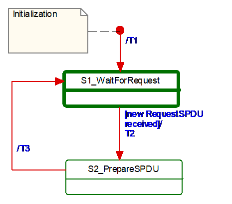
Table 29 shows the symbols used for state machines.
| Graphical representation | Type | Description |
|---|---|---|

| Activity state | Within these interruptible activity states the SafetyProvider waits for new input. |

| Action state | Within these non-interruptible action states events like new requests are deferred until the next activity state is reached, see [1]. |
The transitions are fired in case of an event. “Event” in this context means either a Method call in the case of Client/Server communication or the detection of a changed RequestSPDU by the OPC UA Mapper in the case of PubSub communication.
In case of several possible transitions, so-called guard conditions (refer to […] in UML diagrams) define which transition to fire.
The diagram consists of activity and action states. Activity states are surrounded by bold lines, action states are surrounded by thin lines. While activity states can be interruptible by new events, action states are not. External events occurring while the state machine is in an action state, are deferred until the next activity state is reached.
If input is available, it starts executing action states until its time-slice is up or until the next activity state is reached.
Table 30 shows the internal items of a SafetyProvider instance.
| Internal items | Type | Definition |
|---|---|---|
| RequestSPDU_i | Variable | Local memory for RequestSPDU (required to react on changes). |
| SPDU_ID_1_i | UInt32 | Local variable to store SPDU_ID_1. |
| SPDU_ID_2_i | UInt32 | Local variable to store SPDU_ID_2. |
| SPDU_ID_3_i | UInt32 | Local variable to store SPDU_ID_3. |
| BaseID_i | Guid | Local variable containing the BaseID (taken either from the SPI or SAPI). |
| ProviderID_i | UInt32 | Local variable containing the ProviderID (taken either from the SPI or SAPI). |
| <Get RequestSPDU> | Macro | Instruction to take the whole RequestSPDU from the OPC UA Mapper. |
| <Set ResponseSPDU> | Macro | Instruction to transfer the whole ResponseSPDU to the OPC UA Mapper. |
| <Calc SPDU_ID_i> | Macro | const uint32 SafetyProviderLevel_ID:= … // see 7.2.3.4 If(SAPI.SafetyBaseID == 0) then Endif Endif SPDU_ID_1_i:= BaseID_i (octets 0…3) SPDU_ID_2_i:= BaseID_i (octets 4…7) SPDU_ID_3_i:= BaseID_i (octets 8…11) // see 7.2.3.2 for clarification |
| <build ResponseSPDU> | Macro | Take the MNR and the SafetyConsumerID of the received RequestSPDU. Add the SPDU_ID_1_i, SPDU_ID_2_i, SPDU_ID_3_i, Flags, the SafetyData and the NonSafetyData, as well as the calculated CRC. See 7.2.3.1 |
Table 31 shows the states of a SafetyProvider instance. The SafetyProvider does not check for correct configuration. It will reply to requests even if it is incorrectly configured (e.g. its SafetyProviderID is zero). However, SafetyConsumers will never try to communicate with SafetyProviders having incorrect parameters, see Transitions T13 and T27 in Table 35 and the macro <ParametersOK?> in Table 33.
| State name | State description |
|---|---|
| Initialization | // Initial state SAPI.SafetyData:= 0 SAPI.NonSafetyData:= 0 SAPI.OperatorAckRequested:= 0 RequestSPDU_i:= 0 |
| S1_WaitForRequest | // waiting on next RequestSPDU from SafetyConsumer <Get RequestSPDU> |
| S2_PrepareSPDU | ResponseSPDU.Flags.ActivateFSV:= SAPI.ActivateFSV <Calc SPDU_ID_i> <build ResponseSPDU> // see 7.2.3.1 |
Table 32 shows the transitions of the SafetyProvider.
| Transition | Source state | Target state | Guard condition | Activity |
|---|---|---|---|---|
| T1 | Init | S1 | ||
| T2 | S1 | S2 | // RequestSPDU received1 - | // Process request RequestSPDU_i:= RequestSPDU SAPI.MonitoringNumber:= RequestSPDU.MonitoringNumber SAPI.SafetyConsumerID:= RequestSPDU.SafetyConsumerID SAPI.OperatorAckRequested:= RequestSPDU.Flags.OperatorAckRequested |
| T3 | S2 | S1 | // SPDU is prepared - | <Set ResponseSPDU> |
| 1 See the preceding explanation in 7.2.2.4 of what constitutes events which trigger this transition. | ||||