
6.3 Service interfaces
6.3.1 Overview
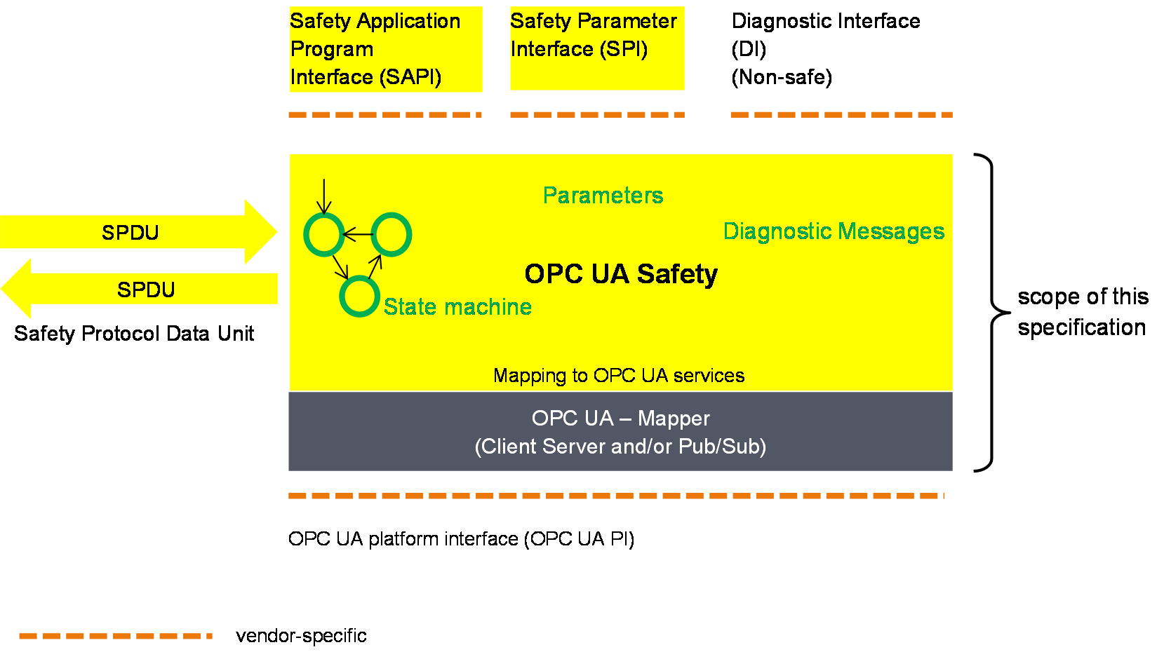
Figure 7 gives an overview of the safety communication layer and its interfaces. It thereby also shows the scope of this document. The main function of the layer services is the state machine which handles the protocol. The state machines interact with the following interfaces:
The Safety Application Program Interface (SAPI) is accessed by the safety application for exchanging SafetyData during runtime.
The Safety Parameter Interface (SPI) is accessed during commissioning for setting safety parameters such as IDs or the timeout value in the SafetyConsumer.
The non-safety related Diagnostic Interface (DI) can be accessed at runtime for troubleshooting the safety communication.
The OPC UA Platform Interface (OPC UA PI) connects the SCL to the non-safe OPC UA stack and is used during runtime.
The interfaces (SAPI, SPI, DI and OPC UA PI) described in 6.3 are abstract and informative. They represent logical data inputs and outputs to this layer that are necessary for the proper operation of the state machine. No normative, concrete mappings are specified. The concrete implementations are vendor-specific and do no necessarily exactly match the abstract interfaces described in this document.
6.3.2 OPC UA Platform interface (OPC UA PI)
The state machines of this document are independent from the actual OPC UA services used for data transmission. This is accomplished by introducing a so-called OPC UA Mapper, serving as an interface between the safety communication layer and the OPC UA stack.
The mapper can either make use of OPC UA Client/Server and remote Method invocation or the publishing of and subscribing to remote Variables as defined in OPC 10000-14. The requirements on the implementation of the mapper are implicitly given in 6.2.
6.3.3 SafetyProvider interfaces
6.3.3.1 General
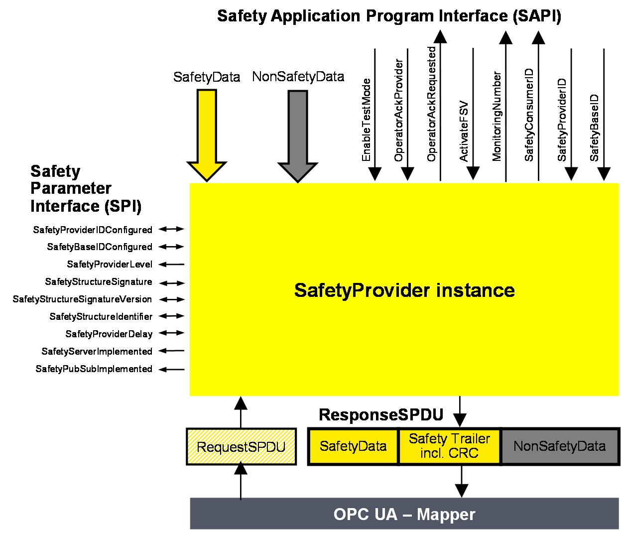
Figure 8 shows an overview of the SafetyProvider interfaces. The SAPI is specified in 6.3.3.2, the SPI is specified in 6.3.3.3.
6.3.3.2 SAPI of SafetyProvider
[RQ6.12] The SAPI of the SafetyProvider represents the safety communication layer services of the SafetyProvider. Table 23 lists all inputs and outputs of the SAPI of the SafetyProvider. Each SafetyProvider shall implement the SAPI as shown in Table 23, however, the details are vendor-specific.
| SAPI Term | Type | I/O | Definition |
|---|---|---|---|
| SafetyData | Structure | I | This input is used to accept the user data which is then transmitted as SafetyData in the SPDU. NOTE Whenever a new MNR is received from a SafetyConsumer, the state machine of the SafetyProvider will read a new value of the SafetyData from its corresponding Safety Application and use it until the next MNR is received. If no valid user data is available at the Safety Application, ActivateFSV can be set to “1” by the Safety Application. |
| NonSafetyData | Structure | I | Used to consistently transmit NonSafetyData values (e.g. diagnostic information) together with safe data, see 7.2.1.11 |
| EnableTestMode | Boolean | I | By setting this input to “1” the remote SafetyConsumer is informed (by Bit 2 in ResponseSPDU.Flags, see 6.2.3.2) that the SafetyData are test data, and are not to be used for safety-related decisions. NOTE This document is intended for implementation in safety devices exclusively, see requirement RQ4.1. |
| OperatorAckProvider | Boolean | I | This input is used to implement an operator acknowledgment on the SafetyProvider side. The value will be forwarded to the SafetyConsumer, where it can be used to trigger a return from fail-safe substitute values (FSV) to actual process values (PV), see B.3.4. |
| OperatorAckRequested | Boolean | O | Indicates that an operator acknowledge is requested by the SafetyConsumer. This flag is received within the RequestSPDU. |
| ActivateFSV (Fail-safe substitute values) | Boolean | I | By setting this input to “1” the SafetyConsumer is instructed (via Bit 1 in ResponseSPDU.Flags, see 6.2.3.2) to deliver FSV instead of PV to the safety application program. NOTE If the replacement of process values by FSV is to be controllable in a more fine-grained way, this can be realized by using qualifiers within the SafetyData, see 6.3.6. |
| SafetyConsumerID | UInt32 | O | This output yields the ConsumerID used in the last access to this SafetyProvider by a SafetyConsumer (see 6.2.2.3). Since all safety-related checks are executed by an implementation of this document, the safety application is not required to check this SafetyConsumerID. |
| MonitoringNumber | UInt32 | O | This output yields the MonitoringNumber (MNR). It is updated whenever a new request comes in from the SafetyConsumer. Since all safety-related checks are executed by an implementation of this document, the safety application is not required to check this MonitoringNumber. |
| SafetyProviderID | UInt32 | I | For dynamic systems, this input can be set to a non-zero value. In this case, the SafetyProvider uses this value instead of the value from the SPI parameter SafetyProviderIDConfigured. If the value is changed to “0”, the value of parameter SafetyProviderIDConfigured from the SPI will be used (again). See Figure 8, 3.1.2.15, and 9.1.1. For static systems, this input is usually always kept at value “0”. |
| SafetyBaseID | Guid | I | For dynamic systems, this input can be set to a non-zero value. In this case, the SafetyProvider uses this value instead of the value of the SPI parameter SafetyBaseIDConfigured. If the value is changed to “0”, the value of parameter SafetyBaseIDConfigured from the SPI will be used (again). See Figure 8, 3.1.2.14, and 9.1.1. For static systems, this input is usually always kept at value “0”. |
6.3.3.3 SPI of SafetyProvider
[RQ6.13a] Each SafetyProvider shall implement the parameters and constants [RQ6.13b] as shown in Table 24. The parameters (R/W in column “Access”) can be set via the SPI, whereas the constants (R in column “Access”) are read-only. The mechanisms for setting the parameters are vendor-specific. The attempt of setting a parameter to a value outside its range, or of the setting of a read-only parameter, shall not become effective, and a diagnostic message should be shown when appropriate. The values of the constants depend on the way the SafetyProvider is implemented. They never change and are therefore not writable via any of the interfaces.
| Identifier | Type | Range | Initial value (before configuration) | Access | Note |
|---|---|---|---|---|---|
| SafetyProviderIDConfigured | UInt32 | 0x0 to 0xFFFFFFFF | 0x0 | R/W | SafetyProviderID of the SafetyProvider that is normally used, see 3.1.2.15 and 9.1.1. For dynamic systems, the safety application program can overwrite this ID by providing a non-zero value at the input SafetyProviderID of the SafetyProvider’s SAPI. This runtime value can be queried using the SafetyProviderIDActive parameter. See 6.2.2.6 for details on configured and active values. NOTE If both the values provided at the SPI and the SAPI are 0x0, this means that the SafetyProvider is not properly configured. SafetyConsumers will never try to communicate with SafetyProviders having a SafetyProviderID of 0x0, see Transitions T13/T27 in Table 35 and the macro <ParametersOK?> in Table 33. |
| SafetyBaseIDConfigured | Guid | Any value which can be represented with sixteen octets | All sixteenoctets are 0x00 | R/W | SafetyBaseID of the SafetyProvider that is normally used, see 3.1.2.14 and 9.1.1. For dynamic systems, the safety application program can overwrite this ID by providing a non-zero value at the input SafetyBaseID of the SafetyProvider’s SAPI. This runtime value can be queried using the SafetyBaseIDActive parameter. See 6.2.2.6 for details on configured and active values. NOTE If both the values provided at the SPI and the SAPI are 0x0, this means that the SafetyProvider is not properly configured. SafetyConsumers will never try to communicate with SafetyProviders having a SafetyBaseID of 0x0, see Transitions T13/T27 in Table 35 and the macro <ParametersOK?> in Table 33. See 9.1.1 for more information on GUID. |
| SafetyProviderLevel | Byte | 0x01 to 0x04 | n.a. | R | The SIL the SafetyProvider implementation (hardware and software) is capable of, see Figure 9. NOTE 1 It is independent from the generation of the SafetyData at SAPI. NOTE 2 The SafetyProviderLevel is used to distinguish devices of a different SIL. As a result, SPDUs coming from a device with a low SIL will never be accepted when a SafetyConsumer is parameterized to implement a safety function with a high SIL. |
| SafetyStructureSignature | UInt32 | 0x0 to 0xFFFFFFFF | 0x0 | R/W | Signature of the SafetyData structure, for calculation see 7.2.3.5. NOTE “0” would not be a valid signature and thus indicates a SafetyProvider which is not properly configured. SafetyConsumers will never try to communicate with SafetyProviders having a SafetyStructureSignature of 0x0, see Transitions T13/T27 in Table 35 and the macro <ParametersOK?> in Table 33. |
| SafetyStructureSignatureVersion | UInt16 | 0x1 | 0x1 | R/W | Version used to calculate SafetyStructureSignature, see 7.2.3.5 |
| SafetyStructureIdentifier | String | all strings | “” (the empty string) | R/W | Identifier describing the DataType of the SafetyData, see 7.2.3.5. |
| SafetyProviderDelay | UInt32 | 0x0 to 0xFFFFFFFF | 0x0 | R/W | In microseconds (µs). It can be set during the engineering phase of the SafetyProvider or set during online configuration as well. SafetyProviderDelay is the maximum time at the SafetyProvider from receiving the RequestSPDU to start the transmission of ResponseSPDU, see 8.1. The parameter SafetyProviderDelay has no influence on the functional behaviour of the SafetyProvider. Therefore, it is not necessary for this value to be generated in a safety-related way. However, it will be provided in the OPC UA Information Model of a SafetyProvider to inform about its worst-case delay time. The value can be used during commissioning to check whether the timing behaviour of the SafetyProvider is suitable to fulfill the watchdog delay of the corresponding SafetyConsumer. |
| SafetyServerImplemented | Boolean | 0x0 or 0x1 | n.a. | R | This read-only parameter indicates whether the SafetyProvider has implemented the Server part of OPC UA Client/Server communication (see 5.4): 1: Server for OPC UA Client/Server communication is implemented. 0: Server for OPC UA Client/Server communication is not implemented. The corresponding Facets are SafetyProviderServer and SafetyProviderServerMapper. |
| SafetyPubSubImplemented | Boolean | 0x0 or 0x1 | n.a. | R | This read-only parameter indicates whether the SafetyProvider has implemented the necessary publishers and subscribers for OPC UA PubSub communication (see 5.4): 1: OPC UA PubSub communication is implemented. 0: OPC UA PubSub communication is not implemented. The corresponding Facets are SafetyProviderPubSub and SafetyProviderPubSubMapper. |
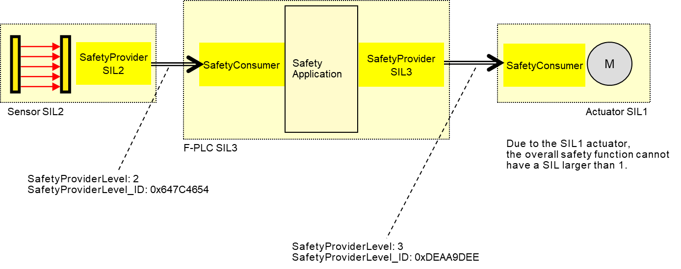
The constant SafetyProviderLevel determines the value that is used for SafetyProviderLevel_ID when calculating the SPDU_ID, see 7.2.3.4.
It is necessary for the respective SafetyConsumers (on the PLC and the actuator) to know the SafetyProviderLevel of their SafetyProviders in order to check the SPDU_ID (see 7.2.3.2).
6.3.4 SafetyConsumer interfaces
6.3.4.1 General
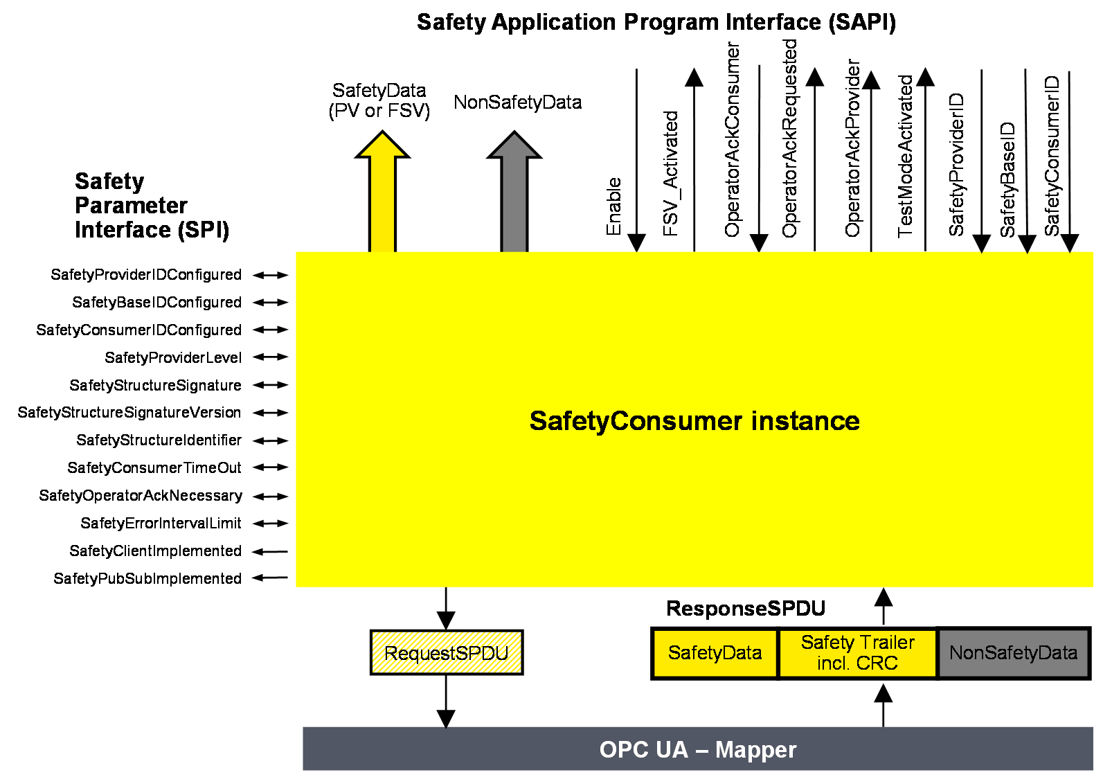
Figure 10 shows an overview of the SafetyConsumer interfaces. The Safety Application Program Interface (SAPI) is specified in 6.3.4.2, the Safety Parameter Interface (SPI) is specified in 6.3.4.4.
6.3.4.2 SAPI of SafetyConsumer
The SAPI of the SafetyConsumer represents the safety communication layer services of the SafetyConsumer. Table 25 lists all inputs and outputs of the SAPI of the SafetyConsumer.
[RQ6.14] Each SafetyConsumer shall implement the SAPI as shown in Table 25, however, the details are vendor-specific.
| SAPI Term | Type | I/O | Definition |
|---|---|---|---|
| SafetyData | Structure | O | This output either delivers the process values received from the SafetyProvider in the SPDU field SafetyData, or FSV. |
| NonSafetyData | Structure | O | This output delivers the non-safety process values (e.g. diagnostic information) which were sent together with safe data, see 7.2.1.11 |
| Enable | Boolean | I | By changing this input to “0” the SafetyConsumer will change each and every Variable of the SafetyData to “0”1 and stop sending requests to the SafetyProvider. When changing Enable to “1” the SafetyConsumer will restart safe communication. The variable can be used to delay the start of the safety communication according to this document, after power on until “OPC UA connection ready” is set.The delay time is not monitored while enable is set to “0”. |
| FSV_Activated | Boolean | O | This output indicates via “1” that on the output SafetyData FSV (all binary “0”) are provided1. NOTE A ResponseSPDU which is checked with an error results in FSV_Activated being set to “1”, see T24 in Table 35. There could be other reasons. |
| OperatorAckConsumer | Boolean | I | For motivation, see 6.3.4.3. After an indication of OperatorAckRequested this input can be used to signal an operator acknowledgment. By changing this input from “0” to “1” (rising edge) the SafetyConsumer is instructed to switch SafetyData from FSV to PV. OperatorAckConsumer is processed only if this rising edge arrives after OperatorAckRequested was set to “1”, see Figure 19. If a rising edge of OperatorAckConsumer arrives before OperatorAckRequested becomes 1, this rising edge is ignored. |
| OperatorAckRequested | Boolean | O | This output indicates the request for operator acknowledgment. The bit is set to “1” by the SafetyConsumer, when three conditions are met: 1) Too many communication errors were detected in the past, so the SafetyConsumer decided to switch to fail-safe substitute values. 2) Currently, no communication errors occur, and hence operator acknowledgment is possible. 3) Operator acknowledgment (rising edge at input OperatorAckConsumer) has not yet occurred. The bit is reset to “0” when a rising edge at OperatorAckConsumer is detected. |
| OperatorAckProvider | Boolean | O | This output indicates that an operator acknowledgment has taken place on the SafetyProvider. If operator acknowledgment at the SafetyProvider should be allowed, this output is connected to OperatorAckConsumer, see B.3.4 and B.3.5. NOTE If the ResponseSPDU is checked with error, this output remains at its last value, see T24 in Table 35. |
| TestModeActivated | Boolean | O | The safety application program is expected to evaluate this output for determining whether the communication partner is in test mode or not. A value of “1” indicates that the communication partner (source of data) is in test mode, e.g. during commissioning. Data coming from a device in test mode may be used for testing but is not intended to be used to control safety-critical processes. A value of “0” represents the “normal” safety-related mode. The test mode enables the programmer and commissioner to validate the safety application using test data. NOTE If the ResponseSPDU check results in an error and the ErrorIntervalTimer (see 6.3.4.4) is also not expired, TestModeActivated is reset, see state S17_Error in Table 34. |
| SafetyProviderID | UInt32 | I | For dynamic systems, this input can be set to a non-zero value. In this case, the SafetyConsumer uses this variable instead of the SPI parameter SafetyProviderIDConfigured. This input is only read in the first cycle, or when a rising edge occurs at the input Enable. See also Table 26. If it is changed to “0”, the value of SPI parameter SafetyProviderIDConfigured will be used (again). For static systems, this input is usually always kept at value “0”. |
| SafetyBaseID | Guid | I | For dynamic systems, this input can be set to a non-zero value. In this case, the SafetyConsumer uses this variable instead of the SPI parameter SafetyBaseIDConfigured. This input is only read in the first cycle, or when a rising edge occurs at the input Enable. See also Table 26. If it is changed to “0”, the SPI parameter SafetyBaseIDConfigured will become activated. For static systems, this input is usually always kept at value “0”. |
| SafetyConsumerID | UInt32 | I | For dynamic systems, this input can be set to a non-zero value. In this case, the SafetyConsumer uses this variable instead of the SPI parameter SafetyConsumerID. This input is only read in the first cycle, or when a rising edge occurs at the input Enable. See also Table 26. If it is changed to “0”, the SPI parameter SafetyConsumerID will become activated. For static systems, this input is usually always kept at value “0”. |
| 1 If an application requires different FSV than “all binary 0”, it is expected to use appropriate constants and ignore the output of SafetyData whenever FSV_Activated is set. | |||
6.3.4.3 Motivation for SAPI Operator Acknowledge (OperatorAckConsumer)
The safety argumentation assumes that random errors in the underlying OPC UA stack including its communication links are not too frequent, i.e. that its failure rate is lower than a given threshold, depending on the desired SIL (see 9.3.1).
Whenever the SafetyConsumer detects a faulty message, it checks whether the assumption is still valid, and switches to fail-safe substitute values otherwise. Returning to process values then requires an operator acknowledgment.
Operator Acknowledge is expected to be initiated by a human operator who is responsible to check the installation, see Table 40, row “Operator Acknowledge”. For this reason, the parameter OperatorAckRequested is delivered by the SafetyConsumer to the safety application. See Clause B.2 for details on operator acknowledgment scenarios.
Timeout errors do only require an operator acknowledgment if operator acknowledgment is required by the safety function itself. In this case, SafetyOperatorAckNecessary is set to indicate that operator acknowledgments are required. See 6.3.4.5 for details.
6.3.4.4 SPI of the SafetyConsumer
[RQ6.15a] Each SafetyConsumer shall implement the parameters and constants [RQ6.15b] as shown in Table 26. The parameters (R/W in column “Access”) can be set via the SPI, whereas the constants (R in column “Access”) are read-only. The mechanisms for setting these parameters are vendor-specific. The attempt of setting a parameter to a value outside its range, or of the setting of a read-only parameter, shall not become effective, and a diagnostic message should be shown when appropriate. The SPI of the SafetyConsumer represents the parameters of the safety communication layer management of the SafetyConsumer. The values of the constants depend on the way the SafetyConsumer is implemented. They never change and are therefore not writable via any of the interfaces.
| Identifier | Type | Valid range | Initial value (before configuration) | Access | Note |
|---|---|---|---|---|---|
| SafetyProviderIDConfigured | UInt32 | 0x0 to 0xFFFFFFFF | 0x0 | R/W | The default SafetyProviderID of the SafetyProvider this SafetyConsumer uses to make a connection, see Figure 8 and 3.1.2.15. For dynamic systems, the safety application program can overwrite this ID by providing a non-zero value at the input SafetyProviderID of the SafetyConsumer’s SAPI. This runtime value can be queried using the SafetyProviderIDActive parameter. See 6.2.2.6 for details on configured and active values. |
| SafetyBaseIDConfigured | Guid | Any value which can be represented with sixteen octets. | All sixteen octets are 0x0 | R/W | The default SafetyBaseID of the SafetyProvider this SafetyConsumer uses to make a connection, see 3.1.2.14. For dynamic systems, the safety application program can overwrite this ID by providing a non-zero value at the input SafetyBaseID of the SafetyConsumer’s SAPI. This runtime value can be queried using the SafetyBaseIDActive parameter. See 6.2.2.6 for details on configured and active values. See 9.1.1 for more information on GUID. |
| SafetyConsumerIDConfigured | UInt32 | 0x0 to 0xFFFFFFFF | 0x0 | R/W | SafetyConsumerID of the SafetyConsumer, see 9.1.2. For dynamic systems, the safety application program can overwrite this ID by providing a non-zero value at the input SafetyConsumerID of the SafetyConsumer’s SAPI. This runtime value can be queried using the SafetyConsumerIDActive parameter. See 6.2.2.6 for details on configured and active values. |
| SafetyProviderLevel | Byte | 0x01 to 0x04 | 0x04 | R/W | SafetyConsumer’s expectation on the SIL the SafetyProvider implementation (hardware and software) is capable of. See 3.1, 7.2.3.4, and Figure 9. |
| SafetyStructureSignature | UInt32 | 0x0 to 0xFFFFFFFF | 0x0 | R/W | Signature over the SafetyData structure, see 7.2.3.5. |
| SafetyStructureSignatureVersion | UInt16 | 0x1 | 0x1 | R/W | Version used to calculate SafetyStructureSignature, see 7.2.3.5. For the SafetyConsumer, this parameter is optional. |
| SafetyStructureIdentifier | String | “” | R/W | Identifier describing the DataType of the SafetyData, see 7.2.3.5. For the SafetyConsumer, this parameter is optional. | |
| SafetyConsumerTimeout | UInt32 | 0x0 to 0xFFFFFFFF | 0x0 | R/W | Watchdog-time in microseconds (µs). Whenever the SafetyConsumer sends a request to a SafetyProvider, its watchdog timer is set to this value. The expiration of this timer prior to receiving an error-free reply by the SafetyProvider indicates an unacceptable delay. See 8.1 |
| SafetyOperatorAckNecessary | Boolean | 0x0 or 0x1 | 0x1 | R/W | This parameter controls whether an operator acknowledgment (OA) is necessary in case of errors of type “unacceptable delay” or “loss”, or when the SafetyProvider has activated FSV (ActivateFSV). NOTE This parameter does not have an influence on the behaviour of the SafetyConsumer following the detection of other types of communication errors, such as data corruption or an error detected by the SPDU_ID. For these types of errors, OA is mandatory, see 6.3.4.3. |
| SafetyErrorIntervalLimit | UInt16 | 6, 60, 600 | 600 | R/W | Value in minutes. The parameter SafetyErrorIntervalLimit determines the minimal time interval between two consecutive communication errors so that they do not trigger a switch to FSV in the SafetyConsumer, see 6.3.4.3. It affects the availability and either the PFH or PFDavg, or both, of the safety communication link according to this document, see 9.4. |
| SafetyClientImplemented | Boolean | 0x0 or 0x1 | n.a. | R | This read-only parameter indicates whether the SafetyConsumer has implemented the client part of OPC UA Client/Server communication (see 5.4): 1: Client for OPC UA Client/Server communication is implemented. 0: Client for OPC UA Client/Server communication is not implemented. The corresponding Facet is SafetyConsumerClient. |
| SafetyPubSubImplemented | Boolean | 0x0 or 0x1 | n.a. | R | This read-only parameter indicates whether the SafetyConsumer has implemented the necessary publishers and subscribers for OPC UA PubSub communication (see 5.4): 1: OPC UA PubSub communication is implemented. 0: OPC UA PubSub communication is not implemented. The corresponding Facets are SafetyConsumerPubSub and SafetyConsumerPubSubMapper. |
6.3.4.5 Motivation for SPI SafetyOperatorAckNecessary
This parameter determines whether automatic restart (i.e. automatically switching back from fail-safe values to process values) is possible for the safety function or not. It is expected to be set to 1 for safety functions where automatic restart is not allowed and restart always requires human interaction.
If automatic restart of the safety function is safe, the parameter can be set to 0.
6.3.5 Cyclic and acyclic safety communication
This document supports cyclic and acyclic safety communication.
For most safety functions it is necessary to react in a timely manner to external events, such as an emergency stop button being pressed or a light curtain being interrupted. In these applications, cyclic safety communication is established. That means the SafetyConsumer is executed cyclically, and the time between two consecutive executions is safely bounded. The maximum time between two executions of the SafetyConsumer will contribute to the safety function response time (SFRT).
Some safety functions, such as the transfer of safe configuration data at startup, do not have to react on external events. In this case, it is not required to execute the SafetyConsumer cyclically.
6.3.6 Principle for “application variables with qualifier”
Qualifiers allow the SafetyProvider to indicate the correctness of values on a fine-grained level. It is good practice to attach qualifiers to each individual value sent within an SPDU. The qualifiers are part of the SafetyData and hence not within the scope of this document.
[RQ6.16] However, whenever qualifiers are used, the values shown in Table 27 shall be used, i.e. 0x1 for a valid value (“good”), and 0x0 for an invalid value (“bad”).
| Value | Qualifier |
|---|---|
| valid | 0x1 (= good) |
| invalid | 0x0 (= bad) |
Checking of the qualifiers is done in the safety application.