
7.2.2 Behaviour
7.2.2.1 General
The two SCL services SafetyProvider and SafetyConsumer are specified using state diagrams.
7.2.2.2 SafetyProvider and SafetyConsumer Sequence diagram
Figure 13 and Figure 14 show sequences of requests and responses with SafetyData for this document using OPC UA Client/Server and PubSub communication mechanisms, respectively. The figures show selected scenarios only and are therefore informative.
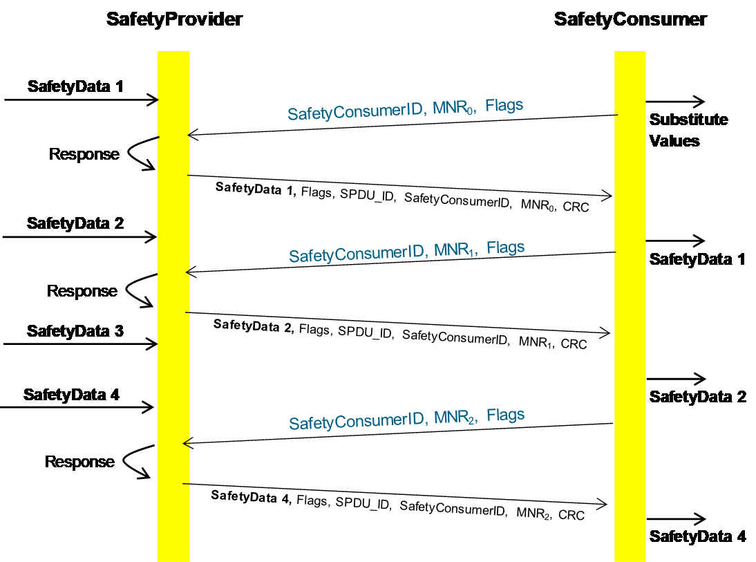
[RQ7.10] In the case of Client/Server communication, a SafetyConsumer’s OPC UA Mapper may call a SafetyProvider (either the state machine implementation itself or the SafetyProvider’s OPC UA Mapper) with an identical RequestSPDU multiple times in a row. In that case, the SafetyProvider (state machine or OPC UA Mapper) shall answer all requests. The returned ResponseSPDUs may contain different values (e.g. currently available process values) or contain the initially returned values.
[RQ7.11] For each SafetyProvider, the implemented choice of behaviour according to RQ7.10 (i.e. whether currently available process values or initially returned values will be used) shall be documented in the corresponding safety manual.

The SafetyConsumerTimeout is the watchdog time checked in the SafetyConsumer. The watchdog is restarted immediately before a new RequestSPDU is generated (transitions T14 and T28 of the SafetyConsumer in Table 35). If an appropriate ResponseSPDU is received in time, and the checks for data integrity, authenticity, and timeliness are all valid, the timer will not expire before it is restarted.
Otherwise, the watchdog timer expires, and the SafetyConsumer triggers a safe reaction. To duly check its timer, the SafetyConsumer is executed cyclically, with period ConsumerCycleTime. ConsumerCycleTime is expected to be smaller than SafetyConsumerTimeout.
The ConsumerCycleTime is the maximum time for the cyclic update of the SafetyConsumer. It is the timeframe from one execution of the SafetyConsumer to the next execution of the SafetyConsumer. The implementation of the monitoring of the ConsumerCycleTime and the reaction in case of exceeding the ConsumerCycleTime are not part of this document; these are vendor-specific.
[RQ7.12] The ConsumerCycleTime shall be monitored in a safety-related way.
[RQ7.26] A change of the SafetyConsumerTimeout parameter value shall take immediate effect on the ConsumerTimer.
7.2.2.3 Duration of demand
In case it is necessary to ensure that a given SafetyData (e.g. a safety demand or a command value) that originates in the SafetyProvider’s safety application is being received by a SafetyConsumer and forwarded to the SafetyConsumer’s safety application, i.e. if no SafetyData in a series of SafetyData is to be missed, the following two cases shall be considered.
In case A, repeated identical RequestSPDUs are being answered by the SafetyProvider with ResponseSPDUs which contain the initially returned value. This is the case for PubSub communication and is a choice for Client/Server communication, see RQ7.11. In this case, the SafetyProvider’s safety application shall provide the respective SafetyData at the SafetyProvider’s SAPI until at least one change of the MNR is detected.
In case B, repeated identical RequestSPDUs are being answered by the SafetyProvider with the currently available SafetyData. This is a choice for Client/Server communication, see RQ7.11. In this case, the SafetyProvider’s safety application shall provide the respective SafetyData at the SafetyProvider’s SAPI until at least two changes of the MNR have been detected.
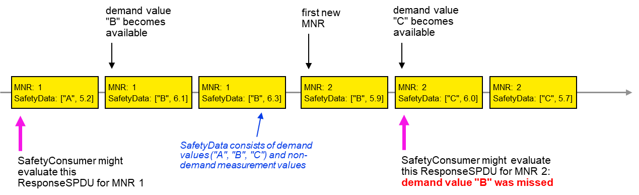
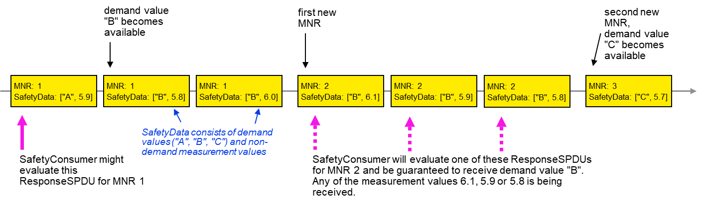
Figure 15 and Figure 16 show examples justifying case B by depicting two sequences of ResponseSPDUs as sent by a SafetyProvider. Due to the cycles of SafetyProvider and SafetyConsumer not being synchronized, a SafetyConsumer can evaluate any one of a given number of ResponseSPDUs for a given RequestSPDU.
In the examples, the SafetyData is made up of two components: the “respective safety data”, i.e. a safety demand that is not to be missed (one of the values “A”, “B” or “C”) and non-demand numerical measurement values for which it does not matter whether some are not received by the SafetyConsumer.
The worst-case time to make sure that the respective safety data from the SafetyProvider is made available to the SafetyConsumer is two times the SafetyConsumerTimeout. This worst-case time occurs when the two transmissions of a RequestSPDU and its corresponding ResponseSPDU, which are necessary according to the descriptions above, each take a time of just slightly under one SafetyConsumerTimeout.
If the SafetyConsumer’s SafetyConsumerTimeout is known at the SafetyProvider, the SafetyProvider may alternatively provide the respective safety data for at least two times the SafetyConsumerTimeout to ensure that the respective safety data reaches the SafetyConsumer.
Since NonSafetyData is consistently transmitted with SafetyData, the same considerations apply for NonSafetyData.
7.2.2.4 SafetyProvider state diagram
[RQ7.13] Figure 17 shows a simplified representation of the state diagram of the SafetyProvider. The exact behaviour is described in Table 30, Table 31, and Table 32. The SafetyProvider shall implement that behaviour. It is not required to literally follow the entries given in the tables, if the externally observable behaviour does not change.
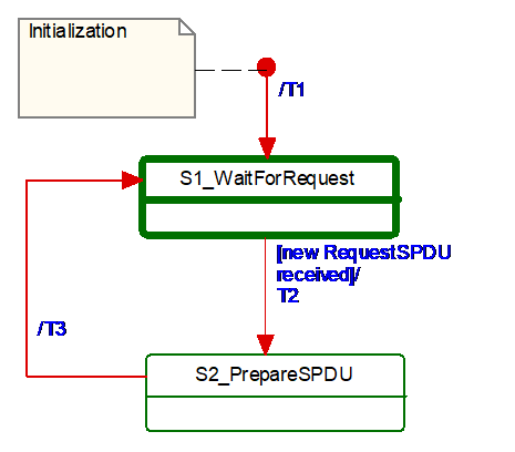
Table 29 shows the symbols used for state machines.
| Graphical representation | Type | Description |
|---|---|---|

| Activity state | Within these interruptible activity states the SafetyProvider waits for new input. |

| Action state | Within these non-interruptible action states events like new requests are deferred until the next activity state is reached, see [1]. |
The transitions are fired in case of an event. “Event” in this context means either a Method call in the case of Client/Server communication or the detection of a changed RequestSPDU by the OPC UA Mapper in the case of PubSub communication.
In case of several possible transitions, so-called guard conditions (refer to […] in UML diagrams) define which transition to fire.
The diagram consists of activity and action states. Activity states are surrounded by bold lines, action states are surrounded by thin lines. While activity states can be interruptible by new events, action states are not. External events occurring while the state machine is in an action state, are deferred until the next activity state is reached.
If input is available, it starts executing action states until its time-slice is up or until the next activity state is reached.
Table 30 shows the internal items of a SafetyProvider instance.
| Internal items | Type | Definition |
|---|---|---|
| RequestSPDU_i | Variable | Local memory for RequestSPDU (required to react on changes). |
| SPDU_ID_1_i | UInt32 | Local variable to store SPDU_ID_1. |
| SPDU_ID_2_i | UInt32 | Local variable to store SPDU_ID_2. |
| SPDU_ID_3_i | UInt32 | Local variable to store SPDU_ID_3. |
| BaseID_i | Guid | Local variable containing the BaseID (taken either from the SPI or SAPI). |
| ProviderID_i | UInt32 | Local variable containing the ProviderID (taken either from the SPI or SAPI). |
| <Get RequestSPDU> | Macro | Instruction to take the whole RequestSPDU from the OPC UA Mapper. |
| <Set ResponseSPDU> | Macro | Instruction to transfer the whole ResponseSPDU to the OPC UA Mapper. |
| <Calc SPDU_ID_i> | Macro | const uint32 SafetyProviderLevel_ID:= … // see 7.2.3.4 If(SAPI.SafetyBaseID == 0) then Endif Endif SPDU_ID_1_i:= BaseID_i (octets 0…3) SPDU_ID_2_i:= BaseID_i (octets 4…7) SPDU_ID_3_i:= BaseID_i (octets 8…11) // see 7.2.3.2 for clarification |
| <build ResponseSPDU> | Macro | Take the MNR and the SafetyConsumerID of the received RequestSPDU. Add the SPDU_ID_1_i, SPDU_ID_2_i, SPDU_ID_3_i, Flags, the SafetyData and the NonSafetyData, as well as the calculated CRC. See 7.2.3.1 |
Table 31 shows the states of a SafetyProvider instance. The SafetyProvider does not check for correct configuration. It will reply to requests even if it is incorrectly configured (e.g. its SafetyProviderID is zero). However, SafetyConsumers will never try to communicate with SafetyProviders having incorrect parameters, see Transitions T13 and T27 in Table 35 and the macro <ParametersOK?> in Table 33.
| State name | State description |
|---|---|
| Initialization | // Initial state SAPI.SafetyData:= 0 SAPI.NonSafetyData:= 0 SAPI.OperatorAckRequested:= 0 RequestSPDU_i:= 0 |
| S1_WaitForRequest | // waiting on next RequestSPDU from SafetyConsumer <Get RequestSPDU> |
| S2_PrepareSPDU | ResponseSPDU.Flags.ActivateFSV:= SAPI.ActivateFSV <Calc SPDU_ID_i> <build ResponseSPDU> // see 7.2.3.1 |
Table 32 shows the transitions of the SafetyProvider.
| Transition | Source state | Target state | Guard condition | Activity |
|---|---|---|---|---|
| T1 | Init | S1 | ||
| T2 | S1 | S2 | // RequestSPDU received1 - | // Process request RequestSPDU_i:= RequestSPDU SAPI.MonitoringNumber:= RequestSPDU.MonitoringNumber SAPI.SafetyConsumerID:= RequestSPDU.SafetyConsumerID SAPI.OperatorAckRequested:= RequestSPDU.Flags.OperatorAckRequested |
| T3 | S2 | S1 | // SPDU is prepared - | <Set ResponseSPDU> |
| 1 See the preceding explanation in 7.2.2.4 of what constitutes events which trigger this transition. | ||||
7.2.2.5 SafetyConsumer state diagram
[RQ7.14] Figure 18 shows a simplified representation of the state diagram of the SafetyConsumer. The exact behaviour is described in Table 33, Table 34, and Table 35. The SafetyConsumer shall implement this behaviour. It is not required to literally follow the entries given in the tables, if the externally observable behaviour does not change.
To avoid unnecessary spurious trips requiring operator acknowledgment, it is recommended that a SafetyConsumer is started after an OPC UA connection to a running SafetyProvider has been established, or that the setting of input SAPI.Enable to “1” is delayed until the SafetyProvider is running.
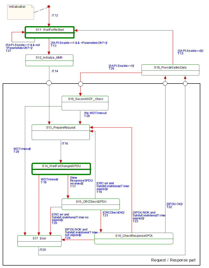
Table 33 shows the internal items of a SafetyConsumer. A macro is a shorthand representation for operations described in the according definition.
| Internal items | Type | Definition | |
|---|---|---|---|
| Constants | |||
| MNR_min:= 0x100 | UInt32 | // 0x100 is the start value for MNR, also used after wrap-around // The values 0…0xFF are reserved for future use | |
| Variables | |||
| FaultReqOA_i | Boolean | Local memory for errors which request operator acknowledgment | |
| OperatorAckConsumerAllowed_i | Boolean | Auxiliary flag indicating that operator acknowledgment is allowed. It is true if the input SAPI.OperatorAckConsumer has been ‘false’ since FaultReqOA_i was set | |
| MNR_i | UInt32 | Local MonitoringNumber (MNR) | |
| prevMNR_i | UInt32 | Local memory for previous MNR | |
| ConsumerID_i | UInt32 | Local memory for SafetyConsumerID in use | |
| CRCCheck_i | Boolean | Local variable used to store the result of the CRC check | |
| SPDUCheck_i | Boolean | Local variable used to store the result of the additional SPDU checks | |
| SPDU_ID_1_i | UInt32 | Local variable to store the expected SPDU_ID_1 | |
| SPDU_ID_2_i | UInt32 | Local variable to store the expected SPDU_ID_2 | |
| SPDU_ID_3_i | UInt32 | Local variable to store the expected SPDU_ID_3 | |
| SPI_SafetyConsumerID_i | UInt32 | Local variable to store the parameter SafetyConsumerID | |
| SPI_SafetyProviderID_i | UInt32 | Local variable to store the parameter SafetyProviderID | |
| SPI_SafetyBaseID_i | UInt128 | Local variable to store the parameter SafetyBaseID | |
| SPI_SafetyStructureSignature_i | UInt32 | Local variable to store the parameter SafetyStructureSignature | |
| SPI_SafetyOperatorAckNecessary_i | Boolean | Local variable to store the parameter SafetyOperatorAckNecessary | |
| SPI_SafetyErrorIntervalLimit_i | UInt16 | Local variable to store the parameter SafetyErrorIntervalLimit | |
| MNR_re_sync_i | Boolean | Local variable used to support re-synchronization of MNR after detected error | |
| Timers | |||
| ConsumerTimer | Timer | This timer is used to check whether the next valid ResponseSPDU has arrived on time. It is initialized using the parameter SPI.SafetyConsumerTimeout. NOTE As opposed to other parameters, a modification of the parameter value SafetyConsumerTimeout takes effect immediately, i.e. not only when state S11 is visited, see RQ7.26. | |
| ErrorIntervalTimer | Timer | This timer is used to check the elapsed time between errors. If the elapsed time between two consecutive errors is smaller than the value SafetyErrorIntervalLimit, FSV will be activated. Otherwise, the ResponseSPDU is discarded and the SafetyConsumer waits for the next ResponseSPDU. This timer is initialized using the local variable SPI_SafetyErrorIntervalLimit_i. See Table 26, 6.3.4.3, and 9.4 for more information. NOTE The local variable SPI_SafetyErrorIntervalLimit_i is not to be confused with the parameter SPI.SafetyErrorIntervalLimit. The local variable is copied from the parameter in state S11 (restart). Hence, if the parameter value changes during runtime, the new value will only be used after the connection has been restarted. | |
| Macros <...><...> | |||
| <risingEdge x> | Macro | // detection of a rising edge: If x==true && tmp==false tmp:= x | |
| <Get ResponseSPDU> | Macro | Instruction to take the whole ResponseSPDU from the OPC UA Mapper. | |
| <Use FSV> | Macro | SAPI.SafetyData is set to binary 0 If [<ConsumerTimer expired || SAPI.Enable==0 ?>] Else Endif SAPI.FSV_Activated:= 1 RequestSPDU.Flags.FSV_Activated:= 1 NOTE 1 If a safety application prefers fail-safe values other than binary 0, this can be implemented in the safety application by querying SAPI.FSV_Activated. NOTE 2 The NonSafetyData is always updated if data is available. In case of a timeout, no data is available, which is indicated using binary zero. If it is necessary for an application to distinguish between “no data available” and “binary zero received”, it can add a Boolean variable to the NonSafetyData. This value is set to ”1” during normal operation, and to ”0” for indicating that no data is available. | |
| <Use PV> | Macro | SAPI.SafetyData is set to ResponseSPDU.SafetyData SAPI.NonSafetyData is set to ResponseSPDU.NonSafetyData SAPI.FSV_Activated:= 0 RequestSPDU.Flags.FSV_Activated:= 0 RequestSPDU.Flags.CommunicationError:= 0 | |
| <Set RequestSPDU> | Macro | Instruction to transfer the whole RequestSPDU to the OPC UA Mapper. | |
| <(Re)Start ConsumerTimer> | Macro | Restarts the ConsumerTimer. | |
| <(Re)Start ErrorIntervalTimer> | Macro | Restarts the ErrorIntervalTimer. | |
| <ConsumerTimer expired?> | Macro | Yields “true” if the timer is running longer than SPI.SafetyConsumerTimeout since last restart, “false” otherwise. | |
| <ErrorIntervalTimer expired?> | Macro | Yields “true” if the timer is running longer than SPI.SafetyErrorIntervalLimit since last restart, “false” otherwise. | |
| <Assign ConsumerID> | Macro | If SAPI.SafetyConsumerID != 0 Then ConsumerID_i:= SAPI.SafetyConsumerID Else ConsumerID_i:= SPI_SafetyConsumerID_i Endif | |
| <Calc SPDU_ID_i> | Macro | uint128 BaseID uint32 ProviderID const uint32 SafetyProviderLevel_ID:= … // see 7.2.3.4 If(SAPI.SafetyBaseID == 0) Then Endif Then Endif SPDU_ID_1_i:= BaseID (octets 0…3) SPDU_ID_2_i:= BaseID (octets 4…7) SPDU_ID_3_i:= BaseID (octets 8…11) // see 7.2.3.2 for clarification | |
| <ParametersOK?> | Macro | Boolean result:= true If(SAPI.SafetyProviderID == 0 && SPI_SafetyProviderID_i==0) If(SAPI.SafetyConsumerID == 0 && SPI_SafetyConsumerID_i==0) If(SPI_SafetyStructureSignature_i==0) yield result | |
<Set Diag(ID, Boolean isPermanent)> | Macro | // ID is the identifier for the type of diagnostic output, see Table 28. If(RequestSPDU.Flags.CommunicationError == 0) RequestSPDU.Flags.CommunicationError:= isPermanent | |
| <ResponseSPDU ready for checks> | Macro | Boolean result:= false If MNR_re_sync_i == false Then Then result:= true Else Else If ResponseSPDU.MNR == MNR_i Then result:= true Else Endif yield result | |
| <Handle WDTimeout> | Macro | <Set Diag(CommErrTO,isPermanent:=true)> If SPI_SafetyOperatorAckNecessary_i == 1 | |
| External event | |||
| Restart cycle | Event | The external call of SafetyConsumer can be interpreted as event “restart cycle” | |
Table 34 shows the states of the SafetyConsumer. The SafetyConsumer parameters are accessed only in state S11. In this state, a copy is made, and in all other states and transitions the copied values are used. This ensures that a change of one of these parameters takes effect only when a new safety connection is established. The only exception from this rule is the parameter SafetyConsumerTimeout. A change of this parameter becomes effective immediately (see RQ7.26). If this is not the desired behaviour, i.e. if parameters should be changeable during runtime, this can be accomplished by establishing a second safety connection according to this document with the new parameters, and then switching between these two safety connections at runtime.
| State name | State description |
|---|---|
| Initialization | // Initial state of the SafetyConsumer instance. <Use FSV> MNR_re_sync_i:= false |
| S11_Wait for (Re)Start | // Safety layer is waiting for (Re)Start // Changes to these parameters are only considered in this state // Exception: a change of SafetyConsumerTimeout is possible during operation // Read parameters from the SPI and store them in local variables: SPI_SafetyConsumerID_i:= SPI.SafetyConsumerID SPI_SafetyProviderID_i:= SPI.SafetyProviderIDConfigured SPI_SafetyBaseID_i:= SPI.SafetyBaseIDConfigured SPI_SafetyStructureSignature_i:= SPI.SafetyStructureSignature SPI_SafetyOperatorAckNecessary_i:= SPI.SafetyOperatorAckNecessary SPI_SafetyErrorIntervalLimit_i:= SPI_SafetyErrorIntervalLimit |
| S12_initialize MNR | // Use previous MNR if known MNR_i:= (previous MNR_i if known) or (random MNR) MNR_i:= max(MNR_i, MNR_min)1 |
| S13_PrepareRequest | // Build RequestSPDU and send (done in T16) |
| S14_WaitForChangedSPDU | // Safety Layer is waiting for next ResponseSPDU from SafetyProvider. // A new ResponseSPDU is characterized by a change in the MNR. |
| S15_CRCCheckSPDU | // Check CRC uint32 CRC_calc // see 7.2.3.6 on how to calculate CRC_calc |
| S16_CheckResponseSPDU | // Check SafetyConsumerID and SPDU_ID and MNR (see T22, T23, T24) SPDUCheck_i:= |
| S17_Error | SAPI.TestModeActivated:= 0 |
| S18_ProvideSafetyData | // Provide SafetyData to the application program |
| S19_SecondWDT_Check | // Second check of WDTimeout // Prevents restarting of ConsumerTimer if it expired since initial check |
| 1 This ensures that the MNR is greater or equal to MNR_min, in cases the random number generator yielded a smaller value. | |
Table 35 shows the transitions of the SafetyConsumer.
| Tran sition | Source state | Target state | Guard condition | Activity |
|---|---|---|---|---|
| T12 | Init | S11 | - | |
| T13 | S11 | S12 | //Start [SAPI.Enable==1 && <ParametersOK?>] | <(Re)Start ErrorIntervalTimer> <calc SPDU_ID_i> // see 7.2.3.2 for clarification |
| T14 | S12 | S13 | // MNR initialized | <(Re)Start ConsumerTimer> <Assign ConsumerID> |
| T15 | S18 | S11 | // Termination [SAPI.Enable==0] | <Use FSV> RequestSPDU.Flags.CommunicationError:= 0 // necessary to make sure that no diagnostic // message is lost, see macro <Set Diag ...> // NOTE Depending on its implementation, it could // be necessary to stop the ConsumerTimer here. |
| T16 | S13 | S14 | // Build RequestSPDU // and send it | prevMNR_i:= MNR_i If MNR_i == 0xFFFFFFFFF MNR_i:= MNR_i + 1 RequestSPDU.MonitoringNumber:= MNR_i <Set RequestSPDU> |
| T17 | S14 | S15 | // Changed ResponseSPDU <Get ResponseSPDU>2 <ResponseSPDU ready for checks> | // A changed ResponseSPDU is characterized by a change in the MNR. |
| T18 | S14 | S17 | // WDTimeout [<ConsumerTimer expired?>] | <Handle WDTimeout> |
| T19 | S15 | S13 | // When CRC err and ErrorIntervalTimer expired [(crcCheck_i == 0) && <ErrorIntervalTimer expired?>] | MNR_re_sync_i:= true <(Re)Start ErrorIntervalTimer> |
| T20 | S15 | S17 | // When CRC err and ErrorIntervalTimer not expired [(crcCheck_i == 0) && not <ErrorIntervalTimer expired?>] | <(Re)Start ErrorIntervalTimer> FaultReqOA_i:= 1 |
| T21 | S15 | S16 | // When CRCCheckOK [crcCheck_i == 1] | - |
| T22 | S16 | S18 | // SPDU OK [SPDUCheck_i==true] | // For clarification, refer to Figure 19; MNR_re_sync_i:= false // indicate OA from provider SAPI.OperatorAckProvider:= ResponseSPDU.Flags.OperatorAckProvider // OA requested due to rising edge at ActivateFSV? If (<risingEdge ResponseSPDU.Flags.ActivateFSV>&& SPI_SafetyOperatorAckNecessary_i == true) Endif // Set Flags if OA requested: If FaultReqOA_i==1 // Wait until OperatorAckConsumer is not active If SAPI.OperatorAckConsumer==0 Then OperatorAckConsumerAllowed_i:= 1 Else //do nothing Endif // Reset Flags after OA: If SAPI.OperatorAckConsumer ==1 && OperatorAckConsumerAllowed_i == 1 Then SAPI.OperatorAckRequested:= 0, RequestSPDU.Flags.OperatorAckRequested:= 0 // do nothing Endif If SAPI.OperatorAckRequested==1 || ResponseSPDU.Flags.ActivateFSV==1 // Notify safety application that SafetyProvider is in test mode: SAPI.TestModeActivated:= ResponseSPDU.Flags.TestModeActivated |
| T23 | S16 | S13 | // SPDU NOK and ErrorIntervalTimer expired [SPDUCheck_i == false && <ErrorIntervalTimer expired?>] | <(Re)Start ErrorIntervalTimer>, MNR_re_sync_i:= true // Send diagnostic message according to the If ResponseSPDU.SafetyConsumerID <> ConsumerID_i isPermanent:=false)>3 |
| T24 | S16 | S17 | // SPDU NOK and ErrorIntervalTimer not expired
| <(Re)Start ErrorIntervalTimer> If ResponseSPDU.SafetyConsumerID<> ConsumerID_i FaultReqOA_i:= 1 SAPI.OperatorAckRequested:= 0 |
| T25 | S17 | S18 | // SPDU NOK - | MNR_re_sync_i:= true |
| T26 | S18 | S19 | // Restart Cycle [SAPI.Enable==1] | - |
| T27 | S11 | S11 | // Invalid parameters [SAPI.Enable==1 && not <ParametersOK?>] | <Set Diag(ParametersInvalid, isPermanent:=true)> |
| T28 | S19 | S13 | // No WDTimeout | <(Re)Start ConsumerTimer> |
| T29 | S19 | S17 | // WDTimeout [<ConsumerTimer expired?>] | <Handle WDTimeout> |
1 Another event like “Method completion successful” can be used as guard condition of “Changed ResponseSPDU received” as well. 2 SPDUs with all values (incl. CRC signature) being zero shall be ignored, see requirement RQ5.6. 3 See Table 28. | ||||
7.2.2.6 SafetyConsumer sequence diagram for operator acknowledgment (informative)
Figure 19 shows the sequence after the detection of an error requiring operator acknowledge until communication returns to delivering process values again.
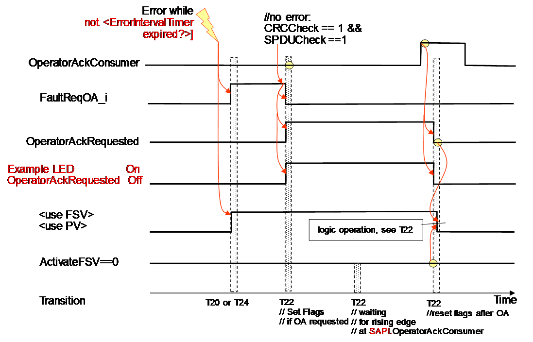
After the error is gone the sequence follows the logic of T22 in Table 35.