
1 Scope
This OPC UA Companion Specification shall define the required data structures, parameters, methods, state machines etc. for the communication among process air extraction and filtration systems (PAEFS), between process air extraction and filtration systems and preceding machinery, between process air extraction and filtration systems and supporting systems (e.g. technical ventilation, conveying systems) and from process air extraction and filtration systems into higher level manufacturing systems (e.g. Manufacturing Execution System, MES), for information and diagnostic purposes and to set parameters regarding the extraction and filtration system process.
Note: Compressed air is not considered in this Companion Specification.
2 Normative references
The following referenced documents are indispensable for the application of this document. For dated references, only the edition cited applies. For undated references, the latest edition of the referenced document (including any amendments and errata) applies.
OPC 10000-1, OPC Unified Architecture - Part 1: Overview and Concepts
OPC 10000-1
OPC 10000-2, OPC Unified Architecture - Part 2: Security Model
OPC 10000-2
OPC 10000-3, OPC Unified Architecture - Part 3: Address Space Model
OPC 10000-3
OPC 10000-4, OPC Unified Architecture - Part 4: Services
OPC 10000-4
OPC 10000-5, OPC Unified Architecture - Part 5: Information Model
OPC 10000-5
OPC 10000-6, OPC Unified Architecture - Part 6: Mappings
OPC 10000-6
OPC 10000-7, OPC Unified Architecture - Part 7: Profiles
OPC 10000-7
OPC 10000-8, OPC Unified Architecture - Part 8: Data Access
OPC 10000-8
OPC 10000-9, OPC Unified Architecture - Part 9: Alarms and Conditions
OPC 10000-9
OPC 10000-16, OPC Unified Architecture - Part 16: State Machines
OPC 10000-16
OPC 10000-100, OPC Unified Architecture - Part 100: Devices
OPC 10000-100
OPC 30081, OPC UA for Process Automation Devices - PA-DIMTM
http://www.opcfoundation.org/UA/PADIM/
OPC 40001-1, OPC UA for Machinery - Part 1: Basic Building Blocks
http://www.opcfoundation.org/UA/Machinery/
OPC 40001-2, OPC UA for Machinery - Part 2: Process Values
http://www.opcfoundation.org/UA/Machinery/ProcessValues/
3 Terms, definitions and conventions
3.1 Overview
It is assumed that basic concepts of OPC UA information modelling are understood in this specification. This specification will use these concepts to describe the Process Air Extraction and Filtration Systems Information Model. For the purposes of this document, the terms and definitions given in OPC 10000-1, OPC 10000-3, OPC 10000-4, OPC 10000-5, OPC 10000-7, OPC 10000-100, OPC 40001-1, OPC 40001-2.
3.2 OPC UA for Process Air Extraction and Filtration Systems terms
3.2.1 Filter system
3.2.1.1 Untitled
System which serves the purpose of extracting and filtering process gas; e.g., air. It consists of several filter units and other devices and components.
3.2.2 Filter unit
Subcomponent of a filter system, consisting of other devices and components.
3.2.3 Separator
Part of the filter unit that filters solid, liquid or gaseous components from the process gas.
Examples are:
Wet separator
Cartridge filter
Automatic roll band filter
Electrostatic precipitator
3.2.4 Process air
Atmospheric air that comes into contact with a manufacturing process and must be present in a defined degree of purity for the manufacturing process to function or is contaminated with released substances (e.g. solid, liquid or gaseous components) or energy loads as a result of the manufacturing process
3.2.5 Air connection
Air interface that connects the filter system and the filter units to the process air duct system. Parts of this interface can be, for example, gate valves or check valves.
3.2.6 Discharge system
Device used to remove collected filter material from the filter unit. Examples are: rotary valves or discharge gate valves.
3.2.7 Cleaning unit
Device for the reduction of filtered materials in separators. The cleaning can be achieved e.g. by vibration, reversed airflow or compressed-air blast (EN 12779:2015).
3.2.8 Device for filter aid
Device for the application of a filter aid. Examples of filter aids are: finely divided, porous solid material, material for neutralization of gases or liquids.
3.2.9 Fan
Component within the filter system which produces the volume flow rate necessary for extracting process gas. Examples are: ventilators, blowers
3.2.10 Temperature regulator
Component in the filter system for heating or cooling the process gas.
3.2.11 Safety system
Component that represents a protective device. Examples are: extinguishing systems, smoke detectors, spark detectors.
3.3 Abbreviated terms
PAEFS Process Air Extraction and Filtration Systems
ESP Electrostatic precipitator
3.4 Conventions used in this document
3.4.1 Conventions for Node descriptions
3.4.1.1 Node definitions
Node definitions are specified using tables (see Table 2).
Attributes are defined by providing the Attribute name and a value, or a description of the value.
References are defined by providing the ReferenceType name, the BrowseName of the TargetNode and its NodeClass.
If the TargetNode is a component of the Node being defined in the table the Attributes of the composed Node are defined in the same row of the table.
The DataType is only specified for Variables; "[<number>]" indicates a single-dimensional array, for multi-dimensional arrays the expression is repeated for each dimension (e.g. [2][3] for a two-dimensional array). For all arrays the ArrayDimensions is set as identified by <number> values. If no <number> is set, the corresponding dimension is set to 0, indicating an unknown size. If no number is provided at all the ArrayDimensions can be omitted. If no brackets are provided, it identifies a scalar DataType and the ValueRank is set to the corresponding value (see OPC 10000-3). In addition, ArrayDimensions is set to null or is omitted. If it can be Any or ScalarOrOneDimension, the value is put into "{<value>}", so either "{Any}" or "{ScalarOrOneDimension}" and the ValueRank is set to the corresponding value (see OPC 10000-3) and the ArrayDimensions is set to null or is omitted. Examples are given in Table 1.
| Notation | DataType | ValueRank | ArrayDimensions | Description |
| 0:Int32 | 0:Int32 | -1 | omitted or null | A scalar Int32. |
| 0:Int32[] | 0:Int32 | 1 | omitted or {0} | Single-dimensional array of Int32 with an unknown size. |
| 0:Int32[][] | 0:Int32 | 2 | omitted or {0,0} | Two-dimensional array of Int32 with unknown sizes for both dimensions. |
| 0:Int32[3][] | 0:Int32 | 2 | {3,0} | Two-dimensional array of Int32 with a size of 3 for the first dimension and an unknown size for the second dimension. |
| 0:Int32[5][3] | 0:Int32 | 2 | {5,3} | Two-dimensional array of Int32 with a size of 5 for the first dimension and a size of 3 for the second dimension. |
| 0:Int32{Any} | 0:Int32 | -2 | omitted or null | An Int32 where it is unknown if it is scalar or array with any number of dimensions. |
| 0:Int32{ScalarOrOneDimension} | 0:Int32 | -3 | omitted or null | An Int32 where it is either a single-dimensional array or a scalar. |
The TypeDefinition is specified for Objects and Variables.
The TypeDefinition column specifies a symbolic name for a NodeId, i.e. the specified Node points with a HasTypeDefinition Reference to the corresponding Node.
The ModellingRule of the referenced component is provided by specifying the symbolic name of the rule in the ModellingRule column. In the AddressSpace, the Node shall use a HasModellingRule Reference to point to the corresponding ModellingRule Object.
If the NodeId of a DataType is provided, the symbolic name of the Node representing the DataType shall be used.
Note that if a symbolic name of a different namespace is used, it is prefixed by the NamespaceIndex (see 3.4.2.2).
Nodes of all other NodeClasses cannot be defined in the same table; therefore only the used ReferenceType, their NodeClass and their BrowseName are specified. A reference to another part of this document points to their definition. Table 2 illustrates the table. If no components are provided, the DataType, TypeDefinition and ModellingRule columns may be omitted and only a Comment column is introduced to point to the Node definition.
Each Type Node or well-known Instance Node defined shall have one or more ConformanceUnits defined in 11.1 that require the Node to be in the AddressSpace.
The relations between Nodes and ConformanceUnits are defined at the end of the tables defining Nodes, one row per ConformanceUnit. The ConformanceUnits are reflected in the Category element for the Node definition in the UANodeSet (see OPC 10000-6).
The list of ConformanceUnits in the UANodeSet allows Servers to optimize resource consumption by using a list of supported ConformanceUnits to select a subset of the Nodes in an Information Model.
When a Node is selected in this way, all dependencies implied by the References are also selected.
Dependencies exist if the Node is the source of HasTypeDefinition, HasInterface, HasAddIn or any HierarchicalReference. Dependencies also exist if the Node is the target of a HasSubtype Reference. For Variables and VariableTypes, the value of the DataType Attribute is a dependency. For DataType Nodes, any DataTypes referenced in the DataTypeDefinition Attribute are also dependencies.
For additional details see OPC 10000-5.
| Attribute | Value | ||||
| Attribute name | Attribute value. If it is an optional Attribute that is not set "--" will be used. | ||||
| References | NodeClass | BrowseName | DataType | TypeDefinition | Other |
|---|---|---|---|---|---|
| ReferenceType name | NodeClass of the target Node. | BrowseName of the target Node. | DataType of the referenced Node, only applicable for Variables. | TypeDefinition of the referenced Node, only applicable for Variables and Objects. | Additional characteristics of the TargetNode such as the ModellingRule or AccessLevel. |
| NOTE Notes referencing footnotes of the table content. | |||||
| Conformance Units | |||||
|---|---|---|---|---|---|
| Name of ConformanceUnit, one row per ConformanceUnit |
Components of Nodes can be complex that is containing components by themselves. The TypeDefinition, NodeClass and DataType can be derived from the type definitions, and the symbolic name can be created as defined in 3.4.3.1. Therefore, those containing components are not explicitly specified; they are implicitly specified by the type definitions.
The Other column defines additional characteristics of the Node. Examples of characteristics that can appear in this column are show in Table 3.
| Name | Short Name | Description |
| 0:Mandatory | M | The Node has the Mandatory ModellingRule. |
| 0:Optional | O | The Node has the Optional ModellingRule. |
| 0:MandatoryPlaceholder | MP | The Node has the MandatoryPlaceholder ModellingRule. |
| 0:OptionalPlaceholder | OP | The Node has the OptionalPlaceholder ModellingRule. |
| ReadOnly | RO | The Node AccessLevel has the CurrentRead bit set but not the CurrentWrite bit. |
| ReadWrite | RW | The Node AccessLevel has the CurrentRead and CurrentWrite bits set. |
| WriteOnly | WO | The Node AccessLevel has the CurrentWrite bit set but not the CurrentRead bit. |
If multiple characteristics are defined they are separated by commas. The name or the short name may be used.
3.4.1.2 Additional References
To provide information about additional References, the format as shown in Table 4 is used.
The components of the ObjectType have additional references which are defined in Table 4.
| SourceBrowsePath | Reference Type | Is Forward | TargetBrowsePath |
| SourceBrowsePath is always relative to the TypeDefinition. Multiple elements are defined as separate rows of a nested table. | ReferenceType name | True = forward Reference | TargetBrowsePath points to another Node, which can be a well-known instance or a TypeDefinition. You can use BrowsePaths here as well, which is either relative to the TypeDefinition or absolute. If absolute, the first entry needs to refer to a type or well-known instance, uniquely identified within a namespace by the BrowseName. |
References can be to any other Node.
3.4.1.3 Additional sub-components
To provide information about sub-components, the format as shown in Table 5 is used.
| BrowsePath | Reference | NodeClass | BrowseName | DataType | TypeDefinition | Others |
| BrowsePath is always relative to the TypeDefinition. Multiple elements are defined as separate rows of a nested table | NOTE Same as for Table 2 | |||||
3.4.1.4 Additional Attribute values
The type definition table provides columns to specify the values for required Node Attributes for InstanceDeclarations. To provide information about additional Attributes, the format as shown in Table 6 is used.
| BrowsePath | <Attribute name> Attribute |
| BrowsePath is always relative to the TypeDefinition. Multiple elements are defined as separate rows of a nested table | The values of attributes are converted to text by adapting the reversible JSON encoding rules defined in OPC 10000-6. If the JSON encoding of a value is a JSON string or a JSON number then that value is entered in the value field. Double quotes are not included. If the DataType includes a NamespaceIndex (QualifiedNames, NodeIds or ExpandedNodeIds) then the notation used for BrowseNames is used. If the value is an Enumeration the name of the enumeration value is entered. If the value is a Structure then a sequence of name and value pairs is entered. Each pair is followed by a newline. The name is followed by a colon. The names are the names of the fields in the DataTypeDefinition. If the value is an array of non-structures then a sequence of values is entered where each value is followed by a newline. If the value is an array of Structures or a Structure with fields that are arrays or with nested Structures then the complete JSON array or JSON object is entered. Double quotes are not included. |
There can be multiple columns to define more than one Attribute.
3.4.2 NodeIds and BrowseNames
3.4.2.1 NodeIds
The NodeIds of all Nodes described in this standard are only symbolic names. Annex A defines the actual NodeIds.
The symbolic name of each Node defined in this document is its BrowseName, or, when it is part of another Node, the BrowseName of the other Node, a ".", and the BrowseName of itself. In this case "part of" means that the whole has a HasProperty or HasComponent Reference to its part. Since all Nodes not being part of another Node have a unique name in this document, the symbolic name is unique.
The NamespaceUri for all NodeIds defined in this document is defined in Annex A. The NamespaceIndex for this NamespaceUri is vendor-specific and depends on the position of the NamespaceUri in the server namespace table.
Note that this document not only defines concrete Nodes, but also requires that some Nodes shall be generated, for example one for each Session running on the Server. The NodeIds of those Nodes are Server-specific, including the namespace. But the NamespaceIndex of those Nodes cannot be the NamespaceIndex used for the Nodes defined in this document, because they are not defined by this document but generated by the Server.
3.4.2.2 BrowseNames
The text part of the BrowseNames for all Nodes defined in this document is specified in the tables defining the Nodes. The NamespaceUri for all BrowseNames defined in this document is defined in 12.2.
For InstanceDeclarations of NodeClass Object and Variable that are placeholders (OptionalPlaceholder and MandatoryPlaceholder ModellingRule), the BrowseName and the DisplayName are enclosed in angle brackets (<>) as recommended in OPC 10000-3. If the BrowseName is not defined by this document, a namespace index prefix is added to the BrowseName (e.g., prefix '0' leading to '0:EngineeringUnits' or prefix '2' leading to '2:DeviceRevision'). This is typically necessary if a Property of another specification is overwritten or used in the OPC UA types defined in this document. Table 121 provides a list of namespaces and their indexes as used in this document.
3.4.3 Common Attributes
3.4.3.1 General
The Attributes of Nodes, their DataTypes and descriptions are defined in OPC 10000-3. Attributes not marked as optional are mandatory and shall be provided by a Server. The following tables define if the Attribute value is defined by this specification or if it is server-specific.
For all Nodes specified in this specification, the Attributes named in Table 7 shall be set as specified in the table.
| Attribute | Value |
| DisplayName | The DisplayName is a LocalizedText. Each server shall provide the DisplayName identical to the BrowseName of the Node for the LocaleId "en". Whether the server provides translated names for other LocaleIds is server-specific. |
| Description | Optionally a server-specific description is provided. |
| NodeClass | Shall reflect the NodeClass of the Node. |
| NodeId | The NodeId is described by BrowseNames as defined in 3.4.2.1. |
| WriteMask | Optionally the WriteMask Attribute can be provided. If the WriteMask Attribute is provided, it shall set all non-server-specific Attributes to not writable. For example, the Description Attribute may be set to writable since a Server may provide a server-specific description for the Node. The NodeId shall not be writable, because it is defined for each Node in this specification. |
| UserWriteMask | Optionally the UserWriteMask Attribute can be provided. The same rules as for the WriteMask Attribute apply. |
| RolePermissions | Optionally server-specific role permissions can be provided. |
| UserRolePermissions | Optionally the role permissions of the current Session can be provided. The value is server-specifc and depend on the RolePermissions Attribute (if provided) and the current Session. |
| AccessRestrictions | Optionally server-specific access restrictions can be provided. |
3.4.3.2 Objects
For all Objects specified in this specification, the Attributes named in Table 8 shall be set as specified in the table. The definitions for the Attributes can be found in OPC 10000-3.
| Attribute | Value |
| EventNotifier | Whether the Node can be used to subscribe to Events or not is server-specific. |
3.4.3.3 Variables
For all Variables specified in this specification, the Attributes named in Table 9 shall be set as specified in the table. The definitions for the Attributes can be found in OPC 10000-3.
| Attribute | Value |
| MinimumSamplingInterval | Optionally, a server-specific minimum sampling interval is provided. |
| AccessLevel | The access level for Variables used for type definitions is server-specific, for all other Variables defined in this specification, the access level shall allow reading; other settings are server-specific. |
| UserAccessLevel | The value for the UserAccessLevel Attribute is server-specific. It is assumed that all Variables can be accessed by at least one user. |
| Value | For Variables used as InstanceDeclarations, the value is server-specific; otherwise it shall represent the value described in the text. |
| ArrayDimensions | If the ValueRank does not identify an array of a specific dimension (i.e. ValueRank <= 0) the ArrayDimensions can either be set to null or the Attribute is missing. This behaviour is server-specific. If the ValueRank specifies an array of a specific dimension (i.e. ValueRank > 0) then the ArrayDimensions Attribute shall be specified in the table defining the Variable. |
| Historizing | The value for the Historizing Attribute is server-specific. |
| AccessLevelEx | If the AccessLevelEx Attribute is provided, it shall have the bits 8, 9, and 10 set to 0, meaning that read and write operations on an individual Variable are atomic, and arrays can be partly written. |
3.4.3.4 VariableTypes
For all VariableTypes specified in this specification, the Attributes named in Table 10 shall be set as specified in the table. The definitions for the Attributes can be found in OPC 10000-3.
| Attributes | Value |
| Value | Optionally a server-specific default value can be provided. |
| ArrayDimensions | If the ValueRank does not identify an array of a specific dimension (i.e. ValueRank <= 0) the ArrayDimensions can either be set to null or the Attribute is missing. This behaviour is server-specific. If the ValueRank specifies an array of a specific dimension (i.e. ValueRank > 0) then the ArrayDimensions Attribute shall be specified in the table defining the VariableType. |
3.4.3.5 Methods
For all Methods specified in this specification, the Attributes named in Table 11 shall be set as specified in the table. The definitions for the Attributes can be found in OPC 10000-3.
| Attributes | Value |
| Executable | All Methods defined in this specification shall be executable (Executable Attribute set to "True"), unless it is defined differently in the Method definition. |
| UserExecutable | The value of the UserExecutable Attribute is server-specific. It is assumed that all Methods can be executed by at least one user. |
4 General information to Process Air Extraction and Filtration Systems and OPC UA
4.1 Introduction to Process Air Extraction and Filtration Systems
The joint VDMA and OPC Foundation "Process Air Extraction and Filtration Systems" OPC UA Working Group has developed an OPC UA Information Model for Process Air Extraction and Filtration Systems. Universal manufacturer-independent interfaces based on OPC UA have been created.
PAEFS are important systems which are used in the process industry and manufacturing industry or others. An elementary task of PAEFS in operational process air technology is to fulfill their basic function of supplying a process with the required air and/or establishing the air condition necessary for the operation of a process and/or eliminating substances released by the process (e.g. extraction systems for hazardous substances).
Extraction and filtration systems include inertial force extraction and filtration systems, electrostatic extraction and filtration systems, wet separators and automatic roll filters. These extraction and filtration systems may be cleanable or non-cleanable as well as regenerative or non-regenerative.
Apart from the basic function, additional functionalities, such as:
self-monitoring
generation of condition information
diagnostic purposes to set parameters regarding the extraction and filtration system process
identification of PAEFS for device management
energy consumption for energy management applications
remote device control
are essential for data generation, for the optimization of performance, (foresighted) maintenance and operational process control.
4.2 Introduction to OPC Unified Architecture
4.2.1 What is OPC UA?
OPC UA is an open and royalty free set of standards designed as a universal communication protocol. While there are numerous communication solutions available, OPC UA has key advantages:
A state of art security model (see OPC 10000-2).
A fault tolerant communication protocol.
An information modelling framework that allows application developers to represent their data in a way that makes sense to them.
OPC UA has a broad scope which delivers for economies of scale for application developers. This means that a larger number of high-quality applications at a reasonable cost are available. When combined with semantic models such as Process Air Extraction and Filtration Systems, OPC UA makes it easier for end users to access data via generic commercial applications.
The OPC UA model is scalable from small devices to ERP systems. OPC UA Servers process information locally and then provide that data in a consistent format to any application requesting data - ERP, MES, PMS, Maintenance Systems, HMI, Smartphone or a standard Browser, for examples. For a more complete overview see OPC 10000-1.
4.2.2 Basics of OPC UA
As an open standard, OPC UA is based on standard internet technologies, like TCP/IP, HTTP, Web Sockets.
As an extensible standard, OPC UA provides a set of Services (see OPC 10000-4) and a basic information model framework. This framework provides an easy manner for creating and exposing vendor defined information in a standard way. More importantly all OPC UA Clients are expected to be able to discover and use vendor-defined information. This means OPC UA users can benefit from the economies of scale that come with generic visualization and historian applications. This specification is an example of an OPC UA Information Model designed to meet the needs of developers and users.
OPC UA Clients can be any consumer of data from another device on the network to browser based thin clients and ERP systems. The full scope of OPC UA applications is shown in Figure 1.

OPC UA provides a robust and reliable communication infrastructure having mechanisms for handling lost messages, failover, heartbeat, etc. With its binary encoded data, it offers a high-performing data exchange solution. Security is built into OPC UA as security requirements become more and more important especially since environments are connected to the office network or the internet and attackers are starting to focus on automation systems.
4.2.3 Information modelling in OPC UA
4.2.3.1 Concepts
OPC UA provides a framework that can be used to represent complex information as Objects in an AddressSpace which can be accessed with standard services. These Objects consist of Nodes connected by References. Different classes of Nodes convey different semantics. For example, a Variable Node represents a value that can be read or written. The Variable Node has an associated DataType that can define the actual value, such as a string, float, structure etc. It can also describe the Variable value as a variant. A Method Node represents a function that can be called. Every Node has a number of Attributes including a unique identifier called a NodeId and non-localized name called as BrowseName. An Object representing a 'Reservation' is shown in Figure 2.

Object and Variable Nodes represent instances and they always reference a TypeDefinition (ObjectType or VariableType) Node which describes their semantics and structure. Figure 3 illustrates the relationship between an instance and its TypeDefinition.
The type Nodes are templates that define all of the children that can be present in an instance of the type. In the example in Figure 3 the PersonType ObjectType defines two children: First Name and Last Name. All instances of PersonType are expected to have the same children with the same BrowseNames. Within a type the BrowseNames uniquely identify the children. This means Client applications can be designed to search for children based on the BrowseNames from the type instead of NodeIds. This eliminates the need for manual reconfiguration of systems if a Client uses types that multiple Servers implement.
OPC UA also supports the concept of sub-typing. This allows a modeller to take an existing type and extend it. There are rules regarding sub-typing defined in OPC 10000-3, but in general they allow the extension of a given type or the restriction of a DataType. For example, the modeller may decide that the existing ObjectType in some cases needs an additional Variable. The modeller can create a subtype of the ObjectType and add the Variable. A Client that is expecting the parent type can treat the new type as if it was of the parent type. Regarding DataTypes, subtypes can only restrict. If a Variable is defined to have a numeric value, a sub type could restrict it to a float.

References allow Nodes to be connected in ways that describe their relationships. All References have a ReferenceType that specifies the semantics of the relationship. References can be hierarchical or non-hierarchical. Hierarchical references are used to create the structure of Objects and Variables. Non-hierarchical are used to create arbitrary associations. Applications can define their own ReferenceType by creating subtypes of an existing ReferenceType. Subtypes inherit the semantics of the parent but may add additional restrictions. Figure 4 depicts several References, connecting different Objects.

The figures above use a notation that was developed for the OPC UA specification. The notation is summarized in Figure 5. UML representations can also be used; however, the OPC UA notation is less ambiguous because there is a direct mapping from the elements in the figures to Nodes in the AddressSpace of an OPC UA Server.

A complete description of the different types of Nodes and References can be found in OPC 10000-3 and the base structure is described in OPC 10000-5.
OPC UA specification defines a very wide range of functionality in its basic information model. It is not required that all Clients or Servers support all functionality in the OPC UA specifications. OPC UA includes the concept of Profiles, which segment the functionality into testable certifiable units. This allows the definition of functional subsets (that are expected to be implemented) within a companion specification. The Profiles do not restrict functionality, but generate requirements for a minimum set of functionality (see OPC 10000-7)
4.2.3.2 Namespaces
OPC UA allows information from many different sources to be combined into a single coherent AddressSpace. Namespaces are used to make this possible by eliminating naming and id conflicts between information from different sources. Each namespace in OPC UA has a globally unique string called a NamespaceUri which identifies a naming authority and a locally unique integer called a NamespaceIndex, which is an index into the Server's table of NamespaceUris. The NamespaceIndex is unique only within the context of a Session between an OPC UA Client and an OPC UA Server- the NamespaceIndex can change between Sessions and still identify the same item even though the NamespaceUri's location in the table has changed. The Services defined for OPC UA use the NamespaceIndex to specify the Namespace for qualified values.
There are two types of structured values in OPC UA that are qualified with NamespaceIndexes: NodeIds and QualifiedNames. NodeIds are locally unique (and sometimes globally unique) identifiers for Nodes. The same globally unique NodeId can be used as the identifier in a node in many Servers - the node's instance data may vary but its semantic meaning is the same regardless of the Server it appears in. This means Clients can have built-in knowledge of of what the data means in these Nodes. OPC UA Information Models generally define globally unique NodeIds for the TypeDefinitions defined by the Information Model.
QualifiedNames are non-localized names qualified with a Namespace. They are used for the BrowseNames of Nodes and allow the same names to be used by different information models without conflict. TypeDefinitions are not allowed to have children with duplicate BrowseNames; however, instances do not have that restriction.
4.2.3.3 Companion Specifications
An OPC UA companion specification for an industry specific vertical market describes an Information Model by defining ObjectTypes, VariableTypes, DataTypes and ReferenceTypes that represent the concepts used in the vertical market, and potentially also well-defined Objects as entry points into the AddressSpace.
5 Use cases
Below is a list of possible use cases a PAEFS may implement fully or partly.
5.1 Device Identification
Device Identification forms the basis for the operation of a Process Air Extraction and Filtration System and the operator's plant asset management. For this purpose, the PAEFS shall provide properties for asset identification. An operator/integrator should be able to explore the topology of the PAEFS. All browsable components shall be identifiable.
5.2 Device Monitoring
A PAEFS can be monitored by reading and collecting sensor and operational data. This data collection forms the basis for process planning and job management.
The data may include e.g., operating hours, material supply and energy consumption.
5.3 Device Maintenance
Maintenance management is designed to give the plant operator access to PAEFS-specific maintenance information. A plant operator can actively check the health status of the plant or be notified about problems and errors. This allows the operator to react to impending failures or to proactively plan maintenance.
5.4 Device Operation
Device Operation includes turning on and off the PAEFS or one of its components and choosing from different operating modes. Furthermore, setpoints can be configured and methods for controlling the PAEFS can be called.
5.5 Untitled
6 PAEFS Information Model overview
6.1 Model Overview
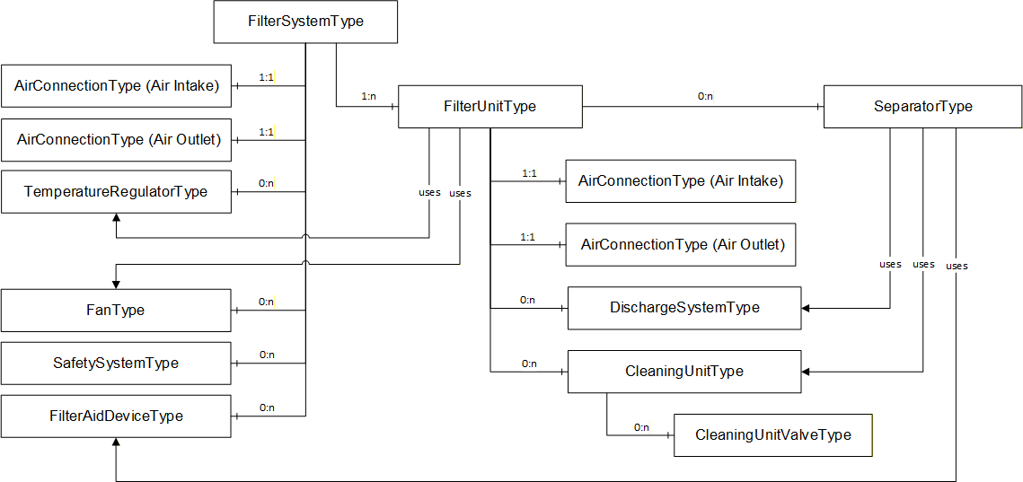
Figure 6 shows a schematic overview of all parts a PAEFS consists of and how they relate to each other. The representation uses a mixture of a type and instance representation for ease of understanding. Auxiliary objects that represent data structures are not displayed.
| Figure 6 notes | |
| 0:n | Indicates that the component can have several instances of this type. There can also be no instances of this type. |
| 1:1 | Indicates that the component must have exactly one instance of this type. |
| 1:n | Indicates that the component can have several instances of this type. There must be at least one instance of this type. |
The filter system serves as a root node to which several filter units are attached. A filter unit consists of subcomponents, some of which are optional.
Some components can be shared between filter units and some components are exclusively used by one filter unit. A component which can be used by exactly one filter unit is represented as a child node of the filter unit. A component which is shared by multiple filter units is represented as a child node of the filter system and referenced by its filter units via the Uses reference defined in 10.1.
The shared component temperature regulator is intended to be referenced by one or more filter units. The same applies to the fan component. The discharge system, the cleaning unit and the device for filter aid may be shared by multiple separators. These components should be referenced from the separator by the Uses ReferenceType. Every component may have a safety system that is responsible for monitoring the component. The safety system is referenced by the component via a Uses reference.
Example: Two filter units share a fan. The fan can be used either by one filter unit or by the other filter unit. Both fans are referenced by a Uses reference from the filter unit.
The Uses reference is a many-to-many relation between components which are functionally connected. It serves primarily navigational and organizational purposes.
The filter system and the filter unit must each have exactly two instances of the air connection. Any other component can be instantiated any number of times. The safety system can be used by any main component via the Uses reference. Main components are defined in 10.1.
For the benefit of clarity, the dashed arrows between the safety system and other components in Figure 6 are not drawn.
Depending on the design of the plant, either the filter system or the individual filter units can be regarded as a machine. The following cases are possible:
The filter system is a machine and the filter units are its components.
The filter system is not a machine and each filter unit is a machine.
Each machine has methods to turn it on and off. Each machine is listed in the machines folder provided by OPC 40001-1.
The air connection component is an abstract component. It represents a link between two air-carrying systems. It is not a physical component. There are always two air connections, one for the air intake and one for the air outlet. The two air connections are available both on the filter system (total air inflow/outflow) and on the individual filter units (total air distribution).
6.2 PAEFS modelling examples
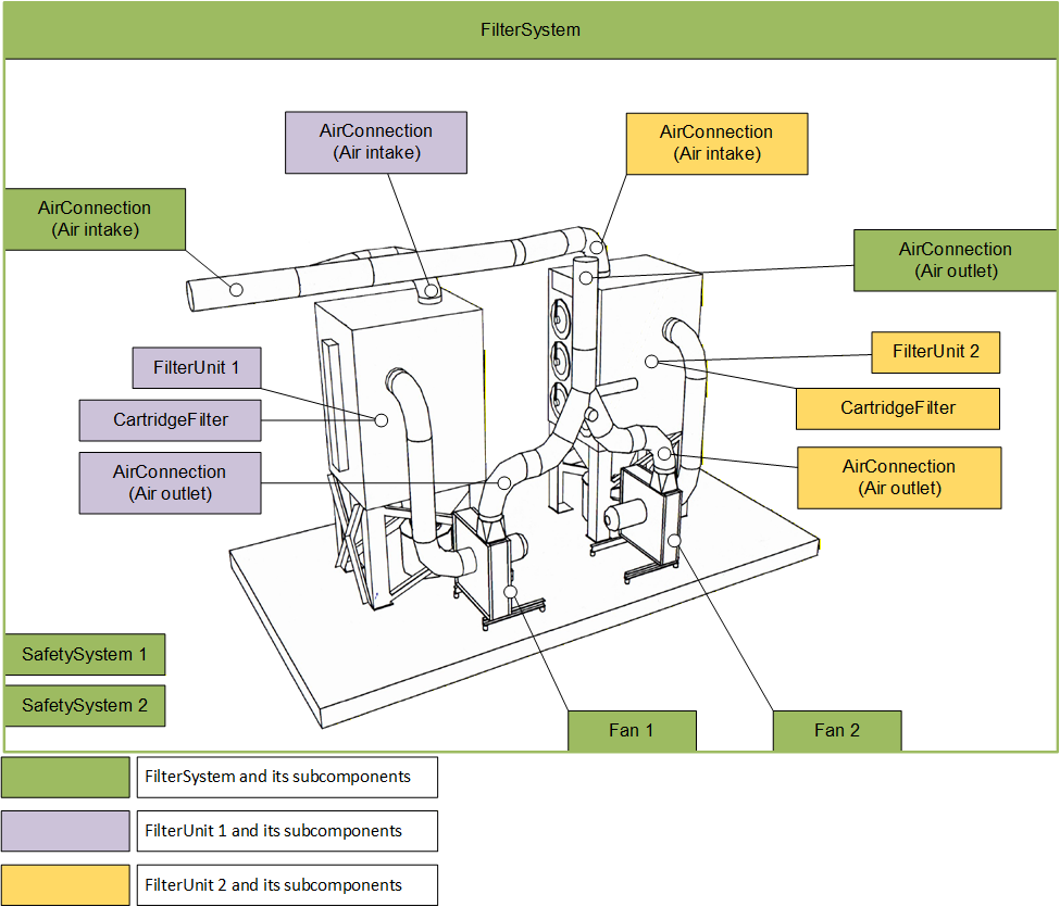
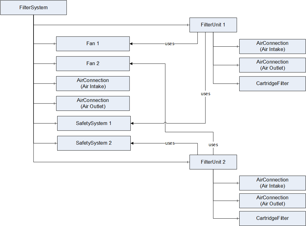
6.2.1 Example 1: Air filtration system with redundant cartridge filter
This filter system has two identical filter units and two fans. Only one filter unit is in operation at a time. Both units have a common air inflow and outflow. The air flow can be routed through either of the filter units via switch-over flaps.
In this example, the ducting of the common air intake and outlet of the filter units is represented by the two air connections on the filter system. The total airflow is distributed to the two filter units via the switch flaps. The split airflow is represented by the two air connections on the filter units.
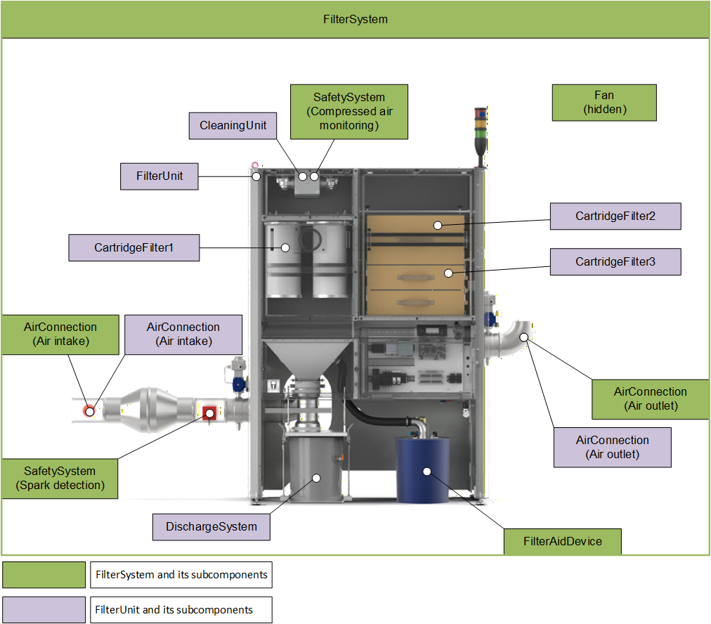
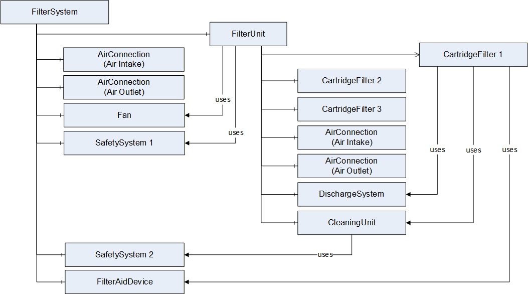
6.2.2 Example 2: Air filtration system with multiple separators
This filter system is used for the filtration of laser dust. It is modelled as a filter system with one filter unit. Physically, three different filter types are installed: a cartridge filter (CartridgeFilter1), a HEPA storage filter (CartridgeFilter2), and a sorption filter (CartridgeFilter3). In the PAEFS data model, all three filters are represented by the cartridge filter type. Assigned to CartridgeFilter1 are a device for adding filter aids to bind sticky and very fine laser smoke, and a cleaning unit for removing dust from the cartridge filter.
The assignment in the PAEFS data model is done via the Uses reference. The system also has several safety systems that are connected to the component to be monitored via a Uses reference.
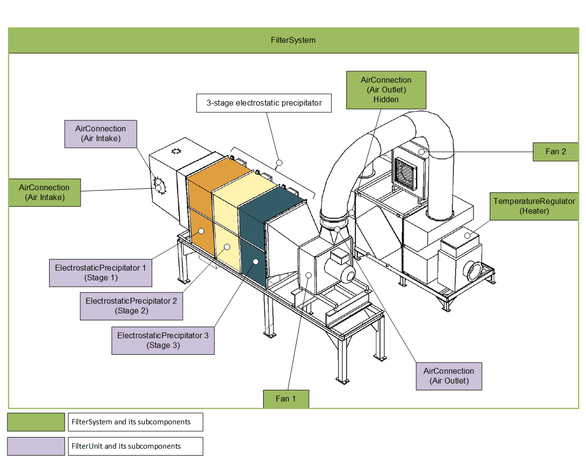
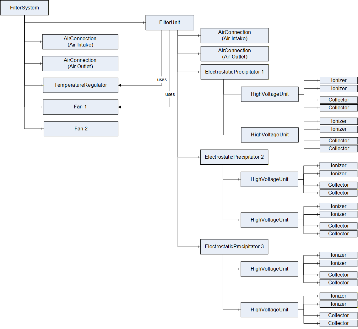
6.2.3 Example 3: Electrostatic precipitator with three filter stages
This filter system is used for the filtration of plasticizers using electrostatic precipitators. The polluted intake air is drawn in by a fan (Fan 1). The polluted air is mixed with fresh air before it is directed to the precipitator. The fresh air is preheated by a heat exchanger and a heater (temperature regulator). A second fan (Fan 2) is used for this purpose. The actual separation is performed by three electrostatic precipitators, each with two high-voltage units. Each high-voltage unit has two collectors and two ionizers. Each electrostatic precipitator is considered as one stage of the filter unit.
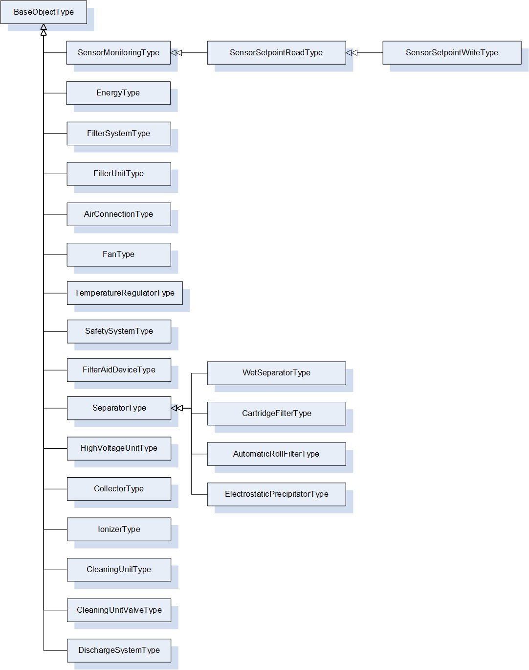
7 OPC UA ObjectTypes
Figure 13 shows all ObjectTypes which are defined by this companion specification.
7.1 SensorMonitoringType ObjectType Definition
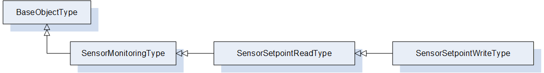
The SensorMonitoringType represents a process value whose value is determined by a measuring device. It is formally defined in Table 12. The measuring device can be identified via the MachineryComponentIdentificationType from OPC 40001-1.
The process value and all associated metadata such as unit and value ranges are inherited from the ProcessValueType. The optional setpoint of the ProcessValueType must not be used in instances of this type. If a setpoint is needed, the subtypes SensorSetpointReadType and SensorSetpointWrite should be used.
Optionally it can be specified whether the measuring signal is provided in analog or digital form.
| Attribute | Value | ||||
| BrowseName | SensorMonitoringType | ||||
| IsAbstract | False | ||||
| References | Node Class | BrowseName | DataType | TypeDefinition | Other |
|---|---|---|---|---|---|
| Subtype of the BaseObjectType defined in OPC 10000-5 | |||||
| 0:HasComponent | Object | Signal | 5:ProcessValueType | M | |
| 0:HasAddIn | Object | 2:Identification | 4:MachineryComponentIdentificationType | O | |
| 0:HasComponent | Object | 4:MachineryBuildingBlocks | 0:FolderType | O | |
| 0:HasProperty | Variable | SignalForm | AnalogDigitalEnum | 0:PropertyType | O,R |
| Conformance Units | |||||
|---|---|---|---|---|---|
| PAEFS SensorMonitoringType Basic | |||||
| PAEFS SensorMonitoringType Advanced |
| BrowsePath | Attribute Description |
| Signal | Value of the signal. This includes min/max ranges, unit and other meta information. The optional setpoint should be implemented only for SensorSetpointReadType and SensorSetpointWriteType types. |
| 2:Identification | Data to identify the sensor (OPC 40001-1). |
| SignalForm | Specifies whether the sensor is an analog or a digital sensor. |
The components of the SensorMonitoringType have additional references which are defined in Table 14.
| SourceBrowsePath | Reference Type | Is Forward | TargetBrowsePath |
| 4:MachineryBuildingBlocks | 0:HasAddIn | True | 2:Identification |
7.2 SensorSetpointReadType ObjectType Definition
The SensorSetpointReadType represents a process value and provides a setpoint for this value. It is formally defined in Table 15. A device is not required to provide a setpoint.
This type provides only read-access to the setpoint. Write-access is provided by SensorSetpointWriteType.
| Attribute | Value | ||||
| BrowseName | SensorSetpointReadType | ||||
| IsAbstract | False | ||||
| References | Node Class | BrowseName | DataType | TypeDefinition | Other |
|---|---|---|---|---|---|
| Subtype of the SensorMonitoringType | |||||
| 0:HasProperty | Variable | IsActiveSetpoint | 0:Boolean | 0:PropertyType | O,R |
| Conformance Units | |||||
|---|---|---|---|---|---|
| PAEFS SensorSetpointReadType Basic | |||||
| PAEFS SensorSetpointReadType Advanced |
The component Variables of the SensorSetpointReadType have additional Attributes defined in Table 16.
| BrowsePath | Description Attribute |
| IsActiveSetpoint | Indicates that the setpoint is currently active. |
The components of the SensorSetpointReadType have additional subcomponents which are defined in Table 17.
| Source Path | Reference | NodeClass | BrowseName | DataType | TypeDefinition | Others |
| Signal | 0:HasComponent | Variable | 5:ProcessValueSetpoint | 0:Number{Any} | 5:ProcessValueSetpointVariableType | O,R |
Some devices may control a process value via alternative, mutually exclusive setpoint (e.g. a target value for either pressure or airflow may be specified). The IsActiveSetpoint variable indicates whether the setpoint of an instance of this type is the currently active setpoint.
7.3 SensorSetpointWriteType ObjectType Definition
The SensorSetpointWriteType represents a process value and provides a readable and writable setpoint for this value. It is formally defined in Table 18.
| Attribute | Value | ||||
| BrowseName | SensorSetpointWriteType | ||||
| IsAbstract | False | ||||
| References | Node Class | BrowseName | DataType | TypeDefinition | Other |
|---|---|---|---|---|---|
| Subtype of the SensorSetpointReadType | |||||
| Conformance Units | |||||
|---|---|---|---|---|---|
| PAEFS SensorSetpointWriteType Basic | |||||
| PAEFS SensorSetpointWriteType Advanced |
The components of the SensorSetpointWriteType have additional subcomponents which are defined in Table 19.
| Source Path | Reference | NodeClass | BrowseName | DataType | TypeDefinition | Others |
| Signal | 0:HasComponent | Variable | 5:ProcessValueSetpoint | 0:Number{Any} | 5:ProcessValueSetpointVariableType | M,RW |
7.4 ConsumptionType ObjectType Definition
The ConsumptionType contains information related to the consumption of a device and is formally defined in Table 20. Consumption can refer, for example, to electricity or compressed air consumption.
| Attribute | Value | ||||
| BrowseName | ConsumptionType | ||||
| IsAbstract | False | ||||
| References | Node Class | BrowseName | DataType | TypeDefinition | Other |
|---|---|---|---|---|---|
| Subtype of the BaseObjectType defined in OPC 10000-5 | |||||
| 0:HasComponent | Object | CurrentConsumption | SensorMonitoringType | O | |
| 0:HasComponent | Variable | LifetimeConsumption | 0:Double | 0:AnalogUnitType | O,R |
| Conformance Units | |||||
|---|---|---|---|---|---|
| PAEFS ConsumptionType Basic | |||||
| PAEFS ConsumptionType Advanced |
| BrowsePath | Attribute Description |
| CurrentConsumption | The current consumption of the device. |
| LifetimeConsumption | Consumption over total machine lifetime. The AnalogUnitType variables InstrumentRange and EURange must not be used. |
7.5 FilterSystemType ObjectType Definition
7.5.1 Overview
The FilterSystemType serves the purpose of extracting and filtering process gas, e.g., air. It consists of several filter units and other devices and components. It is formally defined in Table 22.
| Attribute | Value | ||||
| BrowseName | FilterSystemType | ||||
| IsAbstract | False | ||||
| References | Node Class | BrowseName | DataType | TypeDefinition | Other |
|---|---|---|---|---|---|
| Subtype of the BaseObjectType defined in OPC 10000-5 | |||||
| 0:HasAddIn | Object | 2:Identification | 4:MachineIdentificationType | O | |
| 0:HasComponent | Object | 4:MachineryBuildingBlocks | 0:FolderType | O | |
| 0:HasComponent | Object | <FilterUnit> | FilterUnitType | MP | |
| 0:HasComponent | Object | AirIntakeConnection | AirConnectionType | M | |
| 0:HasComponent | Object | AirOutletConnection | AirConnectionType | M | |
| 0:HasComponent | Object | <FilterAidDevice> | FilterAidDeviceType | OP | |
| 0:HasComponent | Object | <Fan> | FanType | OP | |
| 0:HasComponent | Object | <SafetySystem> | SafetySystemType | OP | |
| 0:HasComponent | Object | <TemperatureRegulator> | TemperatureRegulatorType | OP | |
| 0:HasComponent | Object | PowerConsumption | ConsumptionType | O | |
| 0:HasComponent | Object | AirConsumption | ConsumptionType | O | |
| 0:HasProperty | Variable | MaintenanceRequested | 0:Boolean | 0:PropertyType | O,R |
| 0:HasAddIn | Object | 4:MachineryItemState | 4:MachineryItemState_StateMachineType | M | |
| 0:HasProperty | Variable | ControlMode | ControlModeEnum | 0:PropertyType | O,R |
| 0:HasComponent | Method | OperationOn | O | ||
| 0:HasComponent | Method | OperationOff | O | ||
| 0:HasProperty | Variable | Malfunction | 0:Boolean | 0:PropertyType | M,R |
| 0:HasComponent | Object | PressureLoss | SensorMonitoringType | O | |
| 0:GeneratesEvent | ObjectType | MaintenanceRequestedConditionType | |||
| 0:GeneratesEvent | ObjectType | MalfunctionAlarmType | |||
| 0:HasInterface | ObjectType | 2:IOperationCounterType | |||
| Applied from IOperationCounterType | |||||
| 0:HasProperty | Variable | PowerOnDuration | 0:Duration | 0:PropertyType | O |
| 0:HasProperty | Variable | OperationDuration | 0:Duration | 0:PropertyType | O |
| 0:HasProperty | Variable | OperationCycleCounter | 0:UInteger | 0:PropertyType | O |
| Conformance Units | |||||
|---|---|---|---|---|---|
| PAEFS FilterSystemType Basic | |||||
| PAEFS FilterSystemType Advanced | |||||
| PAEFS FilterSystem Machine Identification | |||||
| PAEFS FilterSystem Statemachine | |||||
| PAEFS Operation FilterSystemType | |||||
| PAEFS FilterSystemType Events |
| BrowsePath | Attribute Description | ||
| 2:Identification | Data for identification (OPC 40001-1): The FilterSystem should only have an Identification folder if the system as a whole is considered a machine. If the individual filter units are considered machines, the FilterSystem should not have an Identification folder. | ||
| The nominal airflow of the filter system is the value specified by the manufacturer which defines the nominal extraction capacity of a unit under operating conditions. | ||
| The marking on the type plate of the filter system regarding explosion protection. | ||
| The rated power of the filter system is the nominal electrical power of the unit under operating conditions specified by the manufacturer. | ||
| <FilterUnit> | All filter units of the system. | ||
| AirIntakeConnection | The connection to the ducting system from which the process gas enters the filter system. | ||
| AirOutletConnection | The connection to the ducting system to which the cleaned process gas leaves the filter system. | ||
| <FilterAidDevice> | All filter aid devices that are used on the server. | ||
| <Fan> | All fans used on the server. | ||
| <SafetySystem> | All safety systems used on the server. | ||
| <TemperatureRegulator> | All temperature regulators used on the server. | ||
| PowerConsumption | Contains information regarding the energy consumption of the filter system. | ||
| AirConsumption | Contains information regarding the consumption of compressed air of the filter system. | ||
| MaintenanceRequested | The maintenance request allows the manufacturer to inform the operator that the system requires maintenance. True = maintenance requested by system. False = no maintenance requested. | ||
| 4:MachineryItemState | StateMachine representing the operating state of the filter system (OPC 40001-1). | ||
| ControlMode | Operating mode that describes whether the system can be controlled externally. Possible values are manual, auto and other. | ||
| Malfunction | Malfunction describes that the filter system has a collective fault message. True in case of error. | ||
| PressureLoss | Specification of the current total pressure loss of the filter system between the device intake connection on the raw gas side and the device outlet on the clean gas side. |
The server sends a MalfunctionAlarmType event when the Malfunction property changes.
The MaintenanceRequestedConditionType is triggered when the MaintenanceRequested property changes.
The components of the FilterSystemType have additional subcomponents which are defined in Table 24.
| Source Path | Reference | NodeClass | BrowseName | DataType | TypeDefinition | Others |
| 2:Identification | 0:HasComponent | Variable | NominalAirflow | 0:Double | 0:AnalogUnitRangeType | M,R |
| 2:Identification | 0:HasProperty | Variable | ExIdentification | 0:String | 0:PropertyType | O,R |
| 2:Identification | 0:HasComponent | Variable | RatedPower | 0:Double | 0:AnalogUnitRangeType | O,R |
The components of the FilterSystemType have additional references which are defined in Table 25.
| SourceBrowsePath | Reference Type | Is Forward | TargetBrowsePath |
| 4:MachineryBuildingBlocks | 0:HasAddIn | True | 2:Identification |
| 4:MachineryBuildingBlocks | 0:HasAddIn | True | 4:MachineryItemState |
7.5.2 OperationOn Method
The Method OperationOn turns the filter system machine on. It should only be available on the filter system if the filter units are considered components of the filter system and do not have their own OperationOn and OperationOff methods. The method changes the state of MachineryItemState. The signature of this Method is specified below. Table 26 specifies the AddressSpace representation.
Signature
OperationOn ()| Attribute | Value | ||||
| BrowseName | OperationOn | ||||
| References | Node Class | BrowseName | DataType | TypeDefinition | ModellingRule |
|---|---|---|---|---|---|
| Conformance Units | |||||
| PAEFS Operation FilterSystemType | |||||
7.5.3 OperationOff Method
The Method OperationOff turns the filter system machine off. As with the OperationOn method, this method should be present under the FilterSystemType if and only if the filter units are considered components of the system rather than individual machines. The method changes the state of MachineryItemState. The signature of this Method is specified below. Table 27 specifies the AddressSpace representation.
Signature
OperationOff ()| Attribute | Value | ||||
| BrowseName | OperationOff | ||||
| References | Node Class | BrowseName | DataType | TypeDefinition | ModellingRule | |
|---|---|---|---|---|---|---|
| Conformance Units | ||||||
| PAEFS Operation FilterSystemType | ||||||
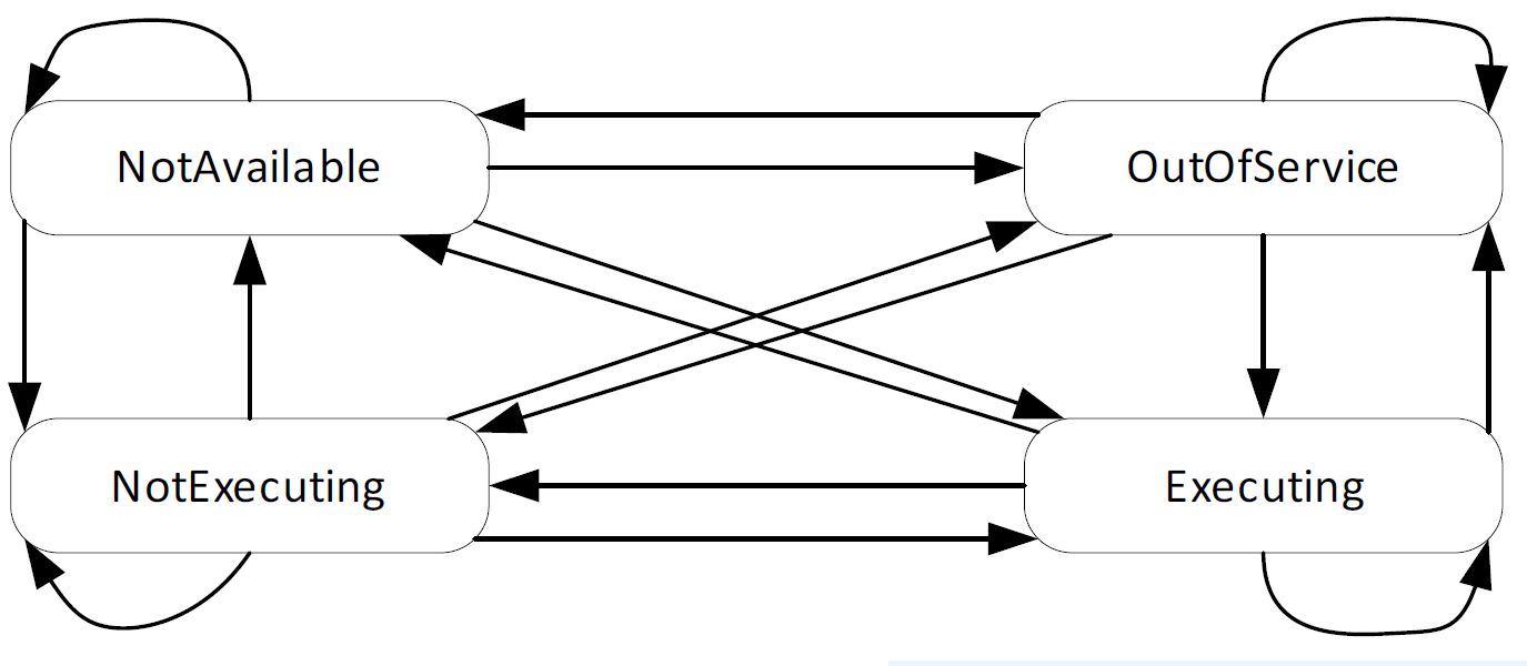
7.5.4 MachineryItemState StateMachine
This building block provides information about the state of a MachineryItem. It defines the states NotAvailable, OutOfService, NotExecuting and Executing. The exact semantics of the states are defined in OPC 40001-1. The StateMachine defines Transitions between all States. Instances might restrict the usage of the defined States and Transitions. An overview of the StateMachine is provided in Figure 15.
7.6 FilterUnitType ObjectType Definition
7.6.1 Overview
The FilterUnitType is a subcomponent of a filter system consisting of other devices and components.
It is formally defined in Table 28.
| Attribute | Value | ||||
| BrowseName | FilterUnitType | ||||
| IsAbstract | False | ||||
| References | Node Class | BrowseName | DataType | TypeDefinition | Other |
|---|---|---|---|---|---|
| Subtype of the BaseObjectType defined in OPC 10000-5 | |||||
| 0:HasComponent | Object | <CleaningUnit> | CleaningUnitType | OP | |
| 0:HasComponent | Object | <Separator> | SeparatorType | OP | |
| 0:HasComponent | Object | <DischargeSystem> | DischargeSystemType | OP | |
| 0:HasComponent | Object | AirIntakeConnection | AirConnectionType | M | |
| 0:HasComponent | Object | AirOutletConnection | AirConnectionType | M | |
| 0:HasAddIn | Object | 2:Identification | 4:MachineryItemIdentificationType | O | |
| 0:HasComponent | Object | 4:MachineryBuildingBlocks | 0:FolderType | O | |
| 0:HasAddIn | Object | 4:MachineryItemState | 4:MachineryItemState_StateMachineType | M | |
| 0:HasComponent | Object | Airflow | SensorSetpointReadType | O | |
| 0:HasComponent | Object | Pressure | SensorSetpointReadType | O | |
| 0:HasComponent | Object | RotationalSpeed | SensorSetpointReadType | O | |
| 0:HasProperty | Variable | MaintenanceRequested | 0:Boolean | 0:PropertyType | O,R |
| 0:HasComponent | Object | PowerConsumption | ConsumptionType | O | |
| 0:HasComponent | Object | AirConsumption | ConsumptionType | O | |
| 0:HasProperty | Variable | Malfunction | 0:Boolean | 0:PropertyType | M,R |
| 0:HasComponent | Object | PressureLoss | SensorMonitoringType | O | |
| 0:HasComponent | Method | OperationOn | O | ||
| 0:HasComponent | Method | OperationOff | O | ||
| 0:HasComponent | Method | SetAndActivateAirflowSetpoint | O | ||
| 0:HasComponent | Method | SetAndActivatePressureSetpoint | O | ||
| 0:HasComponent | Method | SetAndActivateRotationalSpeedSetpoint | O | ||
| 0:GeneratesEvent | ObjectType | MaintenanceRequestedConditionType | |||
| 0:GeneratesEvent | ObjectType | MalfunctionAlarmType | |||
| 0:HasInterface | ObjectType | 2:IOperationCounterType | |||
| Applied from IOperationCounterType | |||||
| 0:HasProperty | Variable | PowerOnDuration | 0:Duration | 0:PropertyType | O |
| 0:HasProperty | Variable | OperationDuration | 0:Duration | 0:PropertyType | O |
| 0:HasProperty | Variable | OperationCycleCounter | 0:UInteger | 0:PropertyType | O |
| Conformance Units | |||||
|---|---|---|---|---|---|
| PAEFS FilterUnitType Basic | |||||
| PAEFS FilterUnitType Advanced | |||||
| PAEFS FilterUnit Component Identification | |||||
| PAEFS FilterUnit Machine Identification | |||||
| PAEFS FilterUnit Statemachine | |||||
| PAEFS Operation FilterUnitType | |||||
| PAEFS FilterUnit Airflow Setpoint | |||||
| PAEFS FilterUnit Pressure Setpoint | |||||
| PAEFS FilterUnit Rotational Speed Setpoint | |||||
| PAEFS FilterUnitType Events |
| BrowsePath | Attribute Description | ||
| <CleaningUnit> | The cleaning units that are part of the filter unit. | ||
| <Separator> | The separators that are part of the filter unit. | ||
| <DischargeSystem> | The discharge systems that are part of the filter unit. | ||
| AirIntakeConnection | The connection to the ducting system from which the polluted process gas enters the filter unit. | ||
| AirOutletConnection | The connection to the ducting system through which the cleaned process gas leaves the filter unit. | ||
| 2:Identification | Data for machine identification (OPC 40001-1): The Identification folder can have either the concrete type MachineIdentificationType or MachineryComponentType. If the filter unit is considered a component of a larger filter machine, MachineryComponentType is used. If the filter unit is considered a machine by itself, MachineIdentificationType is used. | ||
| The nominal airflow of the filter unit is the value specified by the manufacturer which defines the nominal extraction capacity of a filter unit under operating conditions. | ||
| The marking on the type plate of the filter unit regarding explosion protection. | ||
| The rated power of the filter unit is the nominal electrical power of the filter unit under operating conditions specified by the manufacturer. | ||
| 4:MachineryItemState | StateMachine representing the operating state of the filter unit (OPC 40001-1). | ||
| Airflow | Setpoint for the airflow that flows through the filter unit. | ||
| Pressure | Setpoint for the negative pressure at the filter unit. Describes the setpoint value for the pressure difference of the raw gas side compared to the environment. | ||
| RotationalSpeed | Setpoint for the rotational speed of a "virtual" fan. This value is a setpoint. In reality, the filter system can have several fans. | ||
| MaintenanceRequested | The maintenance request allows the manufacturer to inform the operator that the system requires maintenance. True = maintenance requested by system. False = no maintenance requested. | ||
| PowerConsumption | Contains information regarding the energy consumption of the filter unit. | ||
| AirConsumption | Contains information regarding the consumption of compressed air of the filter unit. | ||
| Malfunction | One or more subsystems of the filter unit have a malfunction. True in case of error. | ||
| PressureLoss | The specification of the total pressure loss of the filter unit between the device intake connection on the raw gas side and the device outlet on the clean gas side. |
The server sends a MalfunctionAlarmType event when the Malfunction property changes.
The MaintenanceRequestedConditionType is triggered when the MaintenanceRequested property changes.
The amount of gas that is processed by the filter unit can be governed either by airflow, pressure, or rotational fan speed. Only one of these three quantities can be specified as the setpoint at a time.
The methods SetAndActivateAirflowSetpoint, SetAndActivatePressureSetpoint, and SetAndActivateRotationalSpeedSetpoint set the value of the setpoint and set this setpoint as the active setpoint.
Each of the objects Airflow, Pressure, and RotationalSpeed of type SensorType contains a read-only boolean variable IsActiveSetpoint. The boolean IsActiveSetpoint indicates which of the three setpoints is currently active. IsActiveSetpoint must be true for exactly one quantity at any given time.
| Source Path | Reference | NodeClass | BrowseName | DataType | TypeDefinition | Others |
| 2:Identification | 0:HasComponent | Variable | NominalAirflow | 0:Double | 0:AnalogUnitRangeType | M,R |
| 2:Identification | 0:HasProperty | Variable | ExIdentification | 0:String | 0:PropertyType | O,R |
| 2:Identification | 0:HasComponent | Variable | RatedPower | 0:Double | 0:AnalogUnitRangeType | O,R |
The components of the FilterUnitType have additional references which are defined in Table 31.
| SourceBrowsePath | Reference Type | Is Forward | TargetBrowsePath |
| 4:MachineryBuildingBlocks | 0:HasAddIn | True | 2:Identification |
| 4:MachineryBuildingBlocks | 0:HasAddIn | True | 4:MachineryItemState |
7.6.2 SetAndActivateAirflowSetpointMethod
The Method SetAndActivateAirflowSetpoint sets a setpoint for the airflow. The value's unit is the same as the one specified in object Airflow. Since setpoints are mutually exclusive, the method also sets the boolean IsActiveSetpoint of the setpoints for pressure and rotational speed to false.
The signature of this Method is specified below. Table 32 and Table 33 specify the Arguments and AddressSpace representation, respectively.
Signature
	SetAndActivateAirflowSetpoint(
[in] 0:Double Value)| Argument | Description |
| Value | New setpoint value |
| Attribute | Value | ||||
| BrowseName | SetAndActivateAirflowSetpoint | ||||
| References | Node Class | BrowseName | DataType | TypeDefinition | ModellingRule |
|---|---|---|---|---|---|
| 0:HasProperty | Variable | 0:InputArguments | 0:Argument[] | 0:PropertyType | 0:Mandatory |
| Conformance Units | |||||
|---|---|---|---|---|---|
| PAEFS FilterUnit Airflow Setpoint |
7.6.3 SetAndActivatePressureSetpoint Method
The Method SetAndActivatePressureSetpoint sets a setpoint for the pressure. The value's unit is the same as the one specified in object Pressure. Since setpoints are mutually exclusive, the method also sets the boolean IsActiveSetpoint of the setpoints for airflow and rotational speed to false. The signature of this Method is specified below.
Table 34 and Table 35 specify the Arguments and AddressSpace representation, respectively.
Signature
	SetAndActivatePressureSetpoint (
[in] 0:Double Value)| Argument | Description |
| Value | New setpoint value |
| Attribute | Value | ||||
| BrowseName | SetAndActivatePressureSetpoint | ||||
| References | Node Class | BrowseName | DataType | TypeDefinition | ModellingRule |
|---|---|---|---|---|---|
| 0:HasProperty | Variable | 0:InputArguments | 0:Argument[] | 0:PropertyType | 0:Mandatory |
| Conformance Units | |||||
|---|---|---|---|---|---|
| PAEFS FilterUnit Pressure Setpoint |
7.6.4 SetAndActivateRotationalSpeedSetpoint Method
The Method SetAndActivateRotationalSpeedSetpoint sets a setpoint for the rotational speed. The value's unit is the same as the one specified in object RotationalSpeed. Since setpoints are mutually exclusive, the method also sets the boolean IsActiveSetpoint of the setpoints for airflow and pressure to false.
The signature of this Method is specified below. Table 36 and Table 37 specify the Arguments and AddressSpace representation, respectively.
Signature
	SetAndActivateRotationalSpeedSetpoint (
[in] 0:Double Value)| Argument | Description |
| Value | New setpoint value |
| Attribute | Value | ||||
| BrowseName | SetAndActivateRotationalSpeedSetpoint | ||||
| References | Node Class | BrowseName | DataType | TypeDefinition | ModellingRule |
|---|---|---|---|---|---|
| 0:HasProperty | Variable | 0:InputArguments | 0:Argument[] | 0:PropertyType | 0:Mandatory |
| Conformance Units | |||||
|---|---|---|---|---|---|
| PAEFS FilterUnit Rotational Speed Setpoint |
7.6.5 OperationOn Method
The Method OperationOn turns the machine on. It should only be available on the filter unit if the filter unit is considered a machine, rather than a component of a larger machine. If the filter unit is only a component of a larger machine, the OperationOn Method should be present on the filter system. The method changes the state of MachineryItemState.
Table 38 specifies the AddressSpace representation.
Signature
OperationOn ()| Attribute | Value | ||||
| BrowseName | OperationOn | ||||
| References | Node Class | BrowseName | DataType | TypeDefinition | ModellingRule |
|---|---|---|---|---|---|
| Conformance Units | |||||
| PAEFS Operation FilterUnitType | |||||
7.6.6 OperationOff Method
The Method OperationOff turns the machine off. As with the OperationOn Method, this method should be present under the filter unit if and only if the filter unit is considered a machine. The signature of this Method is specified below. Table 39 specifies the AddressSpace representation. The method changes the state of MachineryItemState.
Signature
OperationOff ()| Attribute | Value | ||||
| BrowseName | OperationOff | ||||
| References | Node Class | BrowseName | DataType | TypeDefinition | ModellingRule |
|---|---|---|---|---|---|
| Conformance Units | |||||
| PAEFS Operation FilterUnitType | |||||
7.7 AirConnectionType ObjectType Definition
7.7.1 Overview
The AirConnectionType is a non-tangible component representing the state of a connection from the ducting system to a filter unit. The connection can be open or closed. The open state represents a state of the ducting system where air can pass through to the filter unit.
It is formally defined in Table 40.
| Attribute | Value | ||||
| BrowseName | AirConnectionType | ||||
| IsAbstract | False | ||||
| References | Node Class | BrowseName | DataType | TypeDefinition | Other |
|---|---|---|---|---|---|
| Subtype of the BaseObjectType defined in OPC 10000-5 | |||||
| 0:HasComponent | Object | Humidity | SensorMonitoringType | O | |
| 0:HasComponent | Object | Temperature | SensorMonitoringType | O | |
| 0:HasComponent | Object | Airflow | SensorMonitoringType | O | |
| 0:HasComponent | Object | GasQuality | SensorMonitoringType | O | |
| 0:HasComponent | Object | Pressure | SensorMonitoringType | O | |
| 0:HasProperty | Variable | ConnectionOpen | AirConnectionOpenEnum | 0:PropertyType | O,R |
| 0:HasProperty | Variable | Malfunction | 0:Boolean | 0:PropertyType | O,R |
| 0:HasComponent | Method | Open | O | ||
| 0:HasComponent | Method | Close | O | ||
| 0:GeneratesEvent | ObjectType | MalfunctionAlarmType | |||
| 0:GeneratesEvent | ObjectType | AirConnectionStatusChangedConditionType | |||
| Conformance Units | |||||
|---|---|---|---|---|---|
| PAEFS AirConnectionType Basic | |||||
| PAEFS AirConnectionType Advanced | |||||
| PAEFS AirConnectionType Events | |||||
| PAEFS AirConnectionType Methods |
| BrowsePath | Attribute Description |
| Humidity | Value of the humidity sensor |
| Temperature | Value of the temperature sensor |
| Airflow | Value of the air flow sensor |
| GasQuality | Value of the gas quality sensor |
| Pressure | Value of the pressure sensor |
| ConnectionOpen | Indicates the connections status (open, closed, or a state in between) |
| Malfunction | Indicates that the AirConnection is malfunctioning, i.e., an error occurs in a component that provides functionality for this abstract component; e.g., an error in the ducting system or a valve. True in case of error. |
The Open and Close Methods can be called to open or close the connection. In a complex ducting system that consists of a network of joints and junctions, opening or closing the connection may involve switching multiple valves.
The control logic for switching the state of the ducting system is determined by the server implementation.
The air connection may contain optional sensors for humidity, temperature, air flow, gas quality, and air pressure.
The server sends a MalfunctionAlarmType event when the Malfunction property changes.
The AirConnectionStatusChangedConditionType event is triggered when the ConnectionOpen property changes.
7.7.2 Open Method
The Method Open opens or switches all valves of the ducting system so that the air can pass through to the filter device. The signature of this Method is specified below. Table 42 specifies the AddressSpace representation.
Signature
Open ()| Attribute | Value | ||||
| BrowseName | Open | ||||
| References | Node Class | BrowseName | DataType | TypeDefinition | ModellingRule | |
|---|---|---|---|---|---|---|
| Conformance Units | ||||||
| PAEFS AirConnectionType Methods | ||||||
7.7.3 Close Method
The Method Close closes or switches some of the valves in the ducting system so that no air may pass through the ducting system to the device. The signature of this Method is specified below. Table 43 specifies the AddressSpace representation.
Signature
Close ()| Attribute | Value | ||||
| BrowseName | Close | ||||
| References | Node Class | BrowseName | DataType | TypeDefinition | ModellingRule | |
|---|---|---|---|---|---|---|
| Conformance Units | ||||||
| PAEFS AirConnectionType Methods | ||||||
7.8 FanType ObjectType Definition
The FanType represents a device for generating negative air pressure and is formally defined in Table 44.
| Attribute | Value | ||||
| BrowseName | FanType | ||||
| IsAbstract | False | ||||
| References | Node Class | BrowseName | DataType | TypeDefinition | Other |
|---|---|---|---|---|---|
| Subtype of the BaseObjectType defined in OPC 10000-5 | |||||
| 0:HasAddIn | Object | 2:Identification | 4:MachineryComponentIdentificationType | O | |
| 0:HasComponent | Object | 4:MachineryBuildingBlocks | 0:FolderType | O | |
| 0:HasProperty | Variable | MaintenanceSwitchOn | 0:Boolean | 0:PropertyType | O,R |
| 0:HasProperty | Variable | Malfunction | 0:Boolean | 0:PropertyType | O,R |
| 0:HasAddIn | Object | 4:MachineryItemState | 4:MachineryItemState_StateMachineType | O | |
| 0:HasComponent | Object | RotationalSpeed | SensorSetpointWriteType | O | |
| 0:HasComponent | Object | PowerConsumption | ConsumptionType | O | |
| 0:GeneratesEvent | ObjectType | MalfunctionAlarmType | |||
| 0:GeneratesEvent | ObjectType | MaintenanceSwitchConditionType | |||
| Conformance Units | |||||
|---|---|---|---|---|---|
| PAEFS FanType Basic | |||||
| PAEFS FanType Advanced | |||||
| PAEFS Additional Statemachines | |||||
| PAEFS FanType Events |
| BrowsePath | Attribute Description |
| 2:Identification | Data for component identification (OPC 40001-1). |
| MaintenanceSwitchOn | Status of a physical maintenance switch on the fan. True when the switch is on. |
| Malfunction | Indicates whether there is an error with the fan. True in case of error. |
| 4:MachineryItemState | StateMachine representing the operating state of the fan (OPC 40001-1). |
| RotationalSpeed | Measured rotational speed of the fan. |
| PowerConsumption | Contains information regarding the energy consumption of the fan. |
The components of the FanType have additional references which are defined in Table 46.
| SourceBrowsePath | Reference Type | Is Forward | TargetBrowsePath |
| 4:MachineryBuildingBlocks | 0:HasAddIn | True | 2:Identification |
| 4:MachineryBuildingBlocks | 0:HasAddIn | True | 4:MachineryItemState |
The server sends a MalfunctionAlarmType event when the Malfunction property changes.
The server sends a MaintenanceSwitchOnConditionType event when the physical maintenance switch is turned on.
7.9 TemperatureRegulatorType ObjectType Definition
The TemperatureRegulatorType represents a device for regulating the temperature of the process gas and is formally defined in Table 47.
| Attribute | Value | ||||
| BrowseName | TemperatureRegulatorType | ||||
| IsAbstract | False | ||||
| References | Node Class | BrowseName | DataType | TypeDefinition | Other |
|---|---|---|---|---|---|
| Subtype of the BaseObjectType defined in OPC 10000-5 | |||||
| 0:HasAddIn | Object | 2:Identification | 4:MachineryComponentIdentificationType | O | |
| 0:HasComponent | Object | 4:MachineryBuildingBlocks | 0:FolderType | O | |
| 0:HasProperty | Variable | Malfunction | 0:Boolean | 0:PropertyType | O,R |
| 0:HasAddIn | Object | 4:MachineryItemState | 4:MachineryItemState_StateMachineType | O | |
| 0:HasComponent | Object | Temperature | SensorSetpointWriteType | O | |
| 0:HasComponent | Object | PowerConsumption | ConsumptionType | O | |
| GeneratesEvent | ObjectType | MalfunctionAlarmType | |||
| Conformance Units | |||||
|---|---|---|---|---|---|
| PAEFS TemperatureRegulatorType Basic | |||||
| PAEFS TemperatureRegulatorType Advanced | |||||
| PAEFS TemperatureRegulatorType Events | |||||
| PAEFS Additional Statemachines |
| BrowsePath | Description Attribute |
| 2:Identification | Data for component identification (OPC 40001-1). |
| Malfunction | Indicates whether there is an error with the temperature regulator. True in case of error. |
| 4:MachineryItemState | StateMachine representing the operating state of the temperature regulator (OPC 40001-1). |
| Temperature | Temperature of the process gas. |
| PowerConsumption | Contains information regarding the energy consumption of the temperature regulator. |
The components of the TemperatureRegulatorType have additional references which are defined in Table 49.
| SourceBrowsePath | Reference Type | Is Forward | TargetBrowsePath |
| 4:MachineryBuildingBlocks | 0:HasAddIn | True | 2:Identification |
| 4:MachineryBuildingBlocks | 0:HasAddIn | True | 4:MachineryItemState |
The server sends a MalfunctionAlarmType event when the Malfunction property changes.
7.10 SafetySystemType ObjectType Definition
The SafetySystemType is a generic component that represents a protective device. Each component in the PAEFS can reference an instance of the safety system via a Uses reference.
It is formally defined in Table 50.
| Attribute | Value | ||||
| BrowseName | SafetySystemType | ||||
| IsAbstract | False | ||||
| References | Node Class | BrowseName | DataType | TypeDefinition | Other |
|---|---|---|---|---|---|
| Subtype of the BaseObjectType defined in OPC 10000-5 | |||||
| 0:HasAddIn | Object | 2:Identification | 4:MachineryComponentIdentificationType | O | |
| 0:HasComponent | Object | 4:MachineryBuildingBlocks | 0:FolderType | O | |
| 0:HasProperty | Variable | Triggered | 0:Boolean | 0:PropertyType | O,R |
| 0:HasAddIn | Object | 4:MachineryItemState | 4:MachineryItemState_StateMachineType | O | |
| 0:HasProperty | Variable | Malfunction | 0:Boolean | 0:PropertyType | O,R |
| 0:GeneratesEvent | ObjectType | MalfunctionAlarmType | |||
| 0:GeneratesEvent | ObjectType | SafetySystemTriggeredAlarmType | |||
| Conformance Units | |||||
|---|---|---|---|---|---|
| PAEFS SafetySystemType Basic | |||||
| PAEFS SafetySystemType Advanced | |||||
| PAEFS SafetySystemType Events | |||||
| PAEFS Additional Statemachines |
The component Variables of the SafetySystemType have additional Attributes defined in Table 51.
| BrowsePath | Description Attribute |
| 2:Identification | Data for component identification (OPC 40001-1). |
| Triggered | Indicates that the safety system has been triggered. If true the safety system has been triggered. |
| 4:MachineryItemState | StateMachine representing the operating state of the unit (OPC 40001-1). |
| Malfunction | Indicates that the safety system is malfunctioning. True in case of error. |
The components of the SafetySystemType have additional references which are defined in Table 52.
| SourceBrowsePath | Reference Type | Is Forward | TargetBrowsePath |
| 4:MachineryBuildingBlocks | 0:HasAddIn | True | 2:Identification |
| 4:MachineryBuildingBlocks | 0:HasAddIn | True | 4:MachineryItemState |
The server sends a SafetySystemTriggeredAlarmType event when the safety system is triggered.
The server sends a MalfunctionAlarmType event when the Malfunction property changes.
7.11 FilterAidDeviceType ObjectType Definition
7.11.1 Overview
The FilterAidDeviceType is a device for the application of a filter aid. It is formally defined in Table 53.
| Attribute | Value | ||||
| BrowseName | FilterAidDeviceType | ||||
| IsAbstract | False | ||||
| References | Node Class | BrowseName | DataType | TypeDefinition | Other |
|---|---|---|---|---|---|
| Subtype of the BaseObjectType defined in OPC 10000-5 | |||||
| 0:HasAddIn | Object | 2:Identification | 4:MachineryComponentIdentificationType | O | |
| 0:HasComponent | Object | 4:MachineryBuildingBlocks | 0:FolderType | O | |
| 0:HasProperty | Variable | ContainerOpen | 0:Boolean | 0:PropertyType | O,R |
| 0:HasComponent | Object | DosageAmount | SensorSetpointWriteType | O | |
| 0:HasProperty | Variable | FilterAidDeviceStatus | FilterAidDeviceStatusEnum | 0:PropertyType | O,R |
| 0:HasComponent | Object | FillingLevel | SensorMonitoringType | O | |
| 0:HasProperty | Variable | Malfunction | 0:Boolean | 0:PropertyType | M,R |
| 0:HasAddIn | Object | 4:MachineryItemState | 4:MachineryItemState_StateMachineType | O | |
| 0:HasProperty | Variable | CompressedAirSupplyInterrupted | 0:Boolean | 0:PropertyType | O,R |
| 0:HasComponent | Object | PowerConsumption | ConsumptionType | O | |
| 0:HasComponent | Object | AirConsumption | ConsumptionType | O | |
| 0:HasProperty | Variable | DosingRequested | 0:Boolean | 0:PropertyType | O,R |
| 0:HasProperty | Variable | AutomaticDosingEnabled | 0:Boolean | 0:PropertyType | O,RW |
| 0:HasComponent | Method | ResetFillingLevel | O | ||
| 0:HasComponent | Method | TriggerDosing | O | ||
| 0:GeneratesEvent | ObjectType | ContainerOpenConditionType | |||
| 0:GeneratesEvent | ObjectType | CompressedAirSupplyInterruptedAlarmType | |||
| 0:GeneratesEvent | ObjectType | MalfunctionAlarmType | |||
| 0:GeneratesEvent | ObjectType | FilterAidDeviceStatusChangedConditionType | |||
| Conformance Units | |||||
|---|---|---|---|---|---|
| PAEFS FilterAidDeviceType Basic | |||||
| PAEFS FilterAidDeviceType Advanced | |||||
| PAEFS FilterAidDeviceType Events | |||||
| PAEFS FilterAidDeviceType Methods | |||||
| PAEFS Additional Statemachines |
| BrowsePath | Description Attribute |
| 2:Identification | Data for machine identification (OPC 40001-1). |
| ContainerOpen | Indicates that the filter aid reservoir is not closed. |
| DosageAmount | The amount of filter aid that is added per cycle. |
| FilterAidDeviceStatus | Describes the action performed by the dosage unit (see FilterAidDeviceStatusEnum). |
| FillingLevel | The filling level describes the amount of filter aid in the pre-storage reservoir. |
| Malfunction | Indicates that the filter aid device is malfunctioning. True in case of error. Malfunctions can be, for example, that there is no more filter aid or that there is a malfunction in the subsystems of the filter aid device. |
| 4:MachineryItemState | StateMachine representing the operating state of the device (OPC 40001-1). |
| CompressedAirSupplyInterrupted | Indicates that the air supply is interrupted. |
| PowerConsumption | Describes the current power consumption of the filter aid device. |
| AirConsumption | Describes the compressed air consumption. |
| DosingRequested | Indicates that the filter system requests dosing. |
| AutomaticDosingEnabled | If enabled, the filter aid device is allowed to perform dosing automatically. |
The components of the FilterAidDeviceType have additional references which are defined in Table 55.
| SourceBrowsePath | Reference Type | Is Forward | TargetBrowsePath |
| 4:MachineryBuildingBlocks | 0:HasAddIn | True | 2:Identification |
| 4:MachineryBuildingBlocks | 0:HasAddIn | True | 4:MachineryItemState |
If the filter aid reservoir is opened or closed, the event ContainerOpenConditionType will be triggered.
The event CompressedAirSupplyInterruptedAlarmType is triggered when the compressed air supply is interrupted.
When the value FilterAidDeviceStatus changes, the event FilterAidDeviceStatusChangedConditionType is triggered. The event contains a copy of the status value.
The server sends a MalfunctionAlarmType event when the Malfunction property changes.
7.11.2 TriggerDosing Method
The Method TriggerDosing triggers a single additional dosage. The signature of this Method is specified below. Table 56 specifies the AddressSpace representation.
Signature
TriggerDosing ()| Attribute | Value | ||||
| BrowseName | TriggerDosing | ||||
| References | Node Class | BrowseName | DataType | TypeDefinition | ModellingRule |
|---|---|---|---|---|---|
| Conformance Units | |||||
| PAEFS FilterAidDeviceType Methods | |||||
7.11.3 ResetFillingLevel Method
The Method ResetFillingLevel resets the filling level of the filter aid reservoir. The signature of this Method is specified below. Table 57 specifies the AddressSpace representation.
Signature
ResetFillingLevel ()| Attribute | Value | ||||
| BrowseName | ResetFillingLevel | ||||
| References | Node Class | BrowseName | DataType | TypeDefinition | ModellingRule |
|---|---|---|---|---|---|
| Conformance Units | |||||
| PAEFS FilterAidDeviceType Methods | |||||
7.12 SeparatorType ObjectType Definition
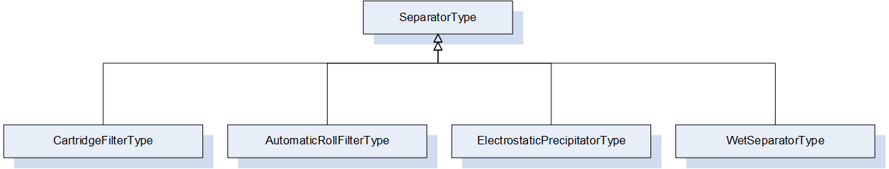
The SeparatorType is the abstract base type for separators. It contains optional sensor values that are common to all separators. Users may use one of the subtypes provided within this specification or create their own type. It is formally defined in Table 58.
| Attribute | Value | ||||
| BrowseName | SeparatorType | ||||
| IsAbstract | True | ||||
| References | Node Class | BrowseName | DataType | TypeDefinition | Other |
|---|---|---|---|---|---|
| Subtype of the BaseObjectType defined in OPC 10000-5 | |||||
| 0:HasAddIn | Object | 2:Identification | 4:MachineryComponentIdentificationType | O | |
| 0:HasComponent | Object | 4:MachineryBuildingBlocks | 0:FolderType | O | |
| 0:HasAddIn | Object | 4:MachineryItemState | 4:MachineryItemState_StateMachineType | O | |
| 0:HasComponent | Object | FilterMediumState | SensorMonitoringType | O | |
| 0:HasComponent | Object | Humidity | SensorMonitoringType | O | |
| 0:HasComponent | Object | Temperature | SensorMonitoringType | O | |
| 0:HasProperty | Variable | FilterMediumOperatingHours | 0:UInt32 | 0:PropertyType | O,R |
| Conformance Units | |||||
|---|---|---|---|---|---|
| PAEFS SeparatorType Basic | |||||
| PAEFS SeparatorType Advanced |
The component Variables of the SeparatorType have additional Attributes defined in Table 59.
| BrowsePath | Description Attribute |
| 2:Identification | Data for machine identification (OPC 40001-1). |
| 4:MachineryItemState | StateMachine representing the operating state of the separator (OPC 40001-1). |
| FilterMediumState | The state of the filter medium; e.g., pressure difference or gas loading. |
| Humidity | The current humidity in the separator. |
| Temperature | The current temperature in the separator. |
| FilterMediumOperatingHours | The number of hours that the unit has been in operation since the last filter change. |
The components of the SeparatorType have additional references which are defined in Table 60.
| SourceBrowsePath | Reference Type | Is Forward | TargetBrowsePath |
| 4:MachineryBuildingBlocks | 0:HasAddIn | True | 2:Identification |
| 4:MachineryBuildingBlocks | 0:HasAddIn | True | 4:MachineryItemState |
7.13 CartridgeFilterType ObjectType Definition
The CartridgeFilterType is a basic mechanical separator and is formally defined in Table 61.
| Attribute | Value | ||||
| BrowseName | CartridgeFilterType | ||||
| IsAbstract | False | ||||
| References | Node Class | BrowseName | DataType | TypeDefinition | Other |
|---|---|---|---|---|---|
| Subtype of the SeparatorType | |||||
| Conformance Units | |||||
|---|---|---|---|---|---|
| PAEFS CartridgeFilterType Basic |
7.14 AutomaticRollFilterType ObjectType Definition
The AutomaticRollFilterType is a separator that is regenerated by rolling up the filter medium. It is formally defined in Table 62.
| Attribute | Value | ||||
| BrowseName | AutomaticRollFilterType | ||||
| IsAbstract | False | ||||
| References | Node Class | BrowseName | DataType | TypeDefinition | Other |
|---|---|---|---|---|---|
| Subtype of the SeparatorType | |||||
| 0:HasProperty | Variable | EndOfFilterRoll | 0:Boolean | 0:PropertyType | O,R |
| 0:GeneratesEvent | ObjectType | EndOfFilterRollAlarmType | |||
| Conformance Units | |||||
|---|---|---|---|---|---|
| PAEFS AutomaticRollFilterType Basic | |||||
| PAEFS AutomaticRollFilterType Advanced | |||||
| PAEFS AutomaticRollFilterType Events |
The component Variables of the AutomaticRollFilterType have additional Attributes defined in Table 63.
| BrowsePath | Description Attribute |
| EndOfFilterRoll | EndOfFilterRoll is true if the end of the filter roll is reached. |
The EndOfFilterRollAlarmType event is sent when the end of the filter roll is reached.
7.15 WetSeparatorType ObjectType Definition
The WetSeparatorType represents a separator that filters solid, liquid, or gaseous components using a liquid medium and is formally defined in Table 64.
| Attribute | Value | ||||
| BrowseName | WetSeparatorType | ||||
| IsAbstract | False | ||||
| References | Node Class | BrowseName | DataType | TypeDefinition | Other |
|---|---|---|---|---|---|
| Subtype of the SeparatorType | |||||
| 0:HasProperty | Variable | WashingAgentDrainOpen | 0:Boolean | 0:PropertyType | O,R |
| 0:HasProperty | Variable | WashingAgentDrainMalfunction | 0:Boolean | 0:PropertyType | O,R |
| 0:HasProperty | Variable | WashingAgentInflowOpen | 0:Boolean | 0:PropertyType | O,R |
| 0:HasProperty | Variable | WashingAgentInflowMalfunction | 0:Boolean | 0:PropertyType | O,R |
| 0:GeneratesEvent | ObjectType | WashingAgentInflowOpenConditionType | |||
| 0:GeneratesEvent | ObjectType | WashingAgentInflowMalfunctionAlarmType | |||
| 0:GeneratesEvent | ObjectType | WashingAgentDrainOpenConditionType | |||
| 0:GeneratesEvent | ObjectType | WashingAgentDrainMalfunctionAlarmType | |||
| Conformance Units | |||||
|---|---|---|---|---|---|
| PAEFS WetSeparatorType Basic | |||||
| PAEFS WetSeparatorType Advanced | |||||
| PAEFS WetSeparatorType Events |
The component Variables of the WetSeparatorType have additional Attributes defined in Table 65.
| BrowsePath | Description Attribute |
| WashingAgentDrainOpen | Indicates that the washing agent drain valve is open. |
| WashingAgentDrainMalfunction | Indicates whether there is an error with the washing agent drain. True in case of error. Examples: clogging, burst pipe, defective valve. |
| WashingAgentInflowOpen | Indicates that the washing agent inflow valve is open. |
| WashingAgentInflowMalfunction | Indicates whether there is an error with the washing agent inflow. True in case of error. Examples: clogging, burst pipe, defective valve. |
The WashingAgentDrainOpenConditionType event is triggered when the value of the property WashingAgentDrainOpen changes.
The WashingAgentInflowOpenConditionType event is triggered when the value of the property WashingAgentInflowOpen changes.
The server sends a WashingAgentDrainMalfunctionAlarmType event when the WashingAgentDrainMalfunction property changes.
The server sends a WashingAgentInflowMalfunctionAlarmType event when the WashingAgentInflowMalfunction property changes.
7.16 ElectrostaticPrecipitatorType ObjectType Definition
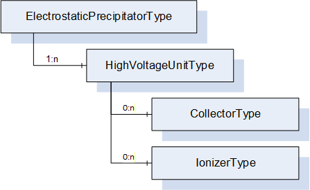
The ElectrostaticPrecipitatorType represents a separator that uses electrostatics to filter solid or liquid components from the process air and is formally defined in Table 66.
| Attribute | Value | ||||
| BrowseName | ElectrostaticPrecipitatorType | ||||
| IsAbstract | False | ||||
| References | Node Class | BrowseName | DataType | TypeDefinition | Other |
|---|---|---|---|---|---|
| Subtype of the SeparatorType | |||||
| 0:HasComponent | Object | <HighVoltageUnit> | HighVoltageUnitType | MP | |
| Conformance Units | |||||
|---|---|---|---|---|---|
| PAEFS ElectrostaticPrecipitatorType Basic | |||||
| PAEFS ElectrostaticPrecipitatorType Advanced | |||||
| PAEFS ElectrostaticPrecipitatorType Events |
The component Variables of the ElectrostaticPrecipitatorType have additional Attributes defined in Table 67.
| BrowsePath | Description Attribute |
| <HighVoltageUnit> | The precipitator's high voltage units. |
The electrostatic precipitator is composed of multiple high voltage units. Each high voltage unit may have multiple ionizers and collectors.
7.17 HighVoltageUnitType ObjectType Definition
The HighVoltageUnitType is a unit to produce high voltage to supply to ionizers and collectors. It is formally defined in Table 68.
| Attribute | Value | ||||
| BrowseName | HighVoltageUnitType | ||||
| IsAbstract | False | ||||
| References | Node Class | BrowseName | DataType | TypeDefinition | Other |
|---|---|---|---|---|---|
| Subtype of the BaseObjectType defined in OPC 10000-5 | |||||
| 0:HasProperty | Variable | SupplyActive | 0:Boolean | 0:PropertyType | O,R |
| 0:HasComponent | Variable | CurrentOutput | 0:Double | 0:AnalogUnitRangeType | O,R |
| 0:HasProperty | Variable | Malfunction | 0:Boolean | 0:PropertyType | O,R |
| 0:HasProperty | Variable | MaintenanceRequested | 0:Boolean | 0:PropertyType | O,R |
| 0:HasComponent | Object | <Ionizer> | IonizerType | OP | |
| 0:HasComponent | Object | <Collector> | CollectorType | OP | |
| 0:GeneratesEvent | ObjectType | MalfunctionAlarmType | |||
| 0:GeneratesEvent | ObjectType | MaintenanceRequestedConditionType | |||
| 0:GeneratesEvent | ObjectType | HighVoltageUnitSupplyActiveEventType | |||
| 0:HasInterface | ObjectType | 2:IOperationCounterType | |||
| Applied from IOperationCounterType | |||||
| 0:HasProperty | Variable | PowerOnDuration | 0:Duration | 0:PropertyType | O |
| 0:HasProperty | Variable | OperationDuration | 0:Duration | 0:PropertyType | O |
| 0:HasProperty | Variable | OperationCycleCounter | 0:UInteger | 0:PropertyType | O |
| Conformance Units | |||||
|---|---|---|---|---|---|
| PAEFS HighVoltageUnitType Basic | |||||
| PAEFS HighVoltageUnitType Advanced | |||||
| PAEFS HighVoltageUnitType Events |
The component Variables of the HighVoltageUnitType have additional Attributes defined in Table 69.
| BrowsePath | Description Attribute |
| SupplyActive | Indicates that the high-voltage generator is emitting high voltage. |
| CurrentOutput | Current output of the high voltage unit. |
| Malfunction | Indicates that the high voltage generator is malfunctioning (e.g., excess/insufficient voltage, overheating, etc). True in case of error. |
| MaintenanceRequested | Indicates that maintenance is requested for the high voltage generator. |
| <Ionizer> | The ionizers of the high voltage unit. |
| <Collector> | The collectors of the high voltage unit. |
The Ionizer and Collector placeholders contain a list of ionizers and collectors, each of which provides an output value.
The HighVoltageUnitSupplyActiveEventType is triggered when the SupplyActive property changes.
The server sends a MalfunctionAlarmType event when the Malfunction property changes.
The MaintenanceRequestedConditionType is sent when the MaintenanceRequested property changes.
7.18 IonizerType ObjectType Definition
The IonizerType represents a unit for ionizing particles in a process air stream and is formally defined in Table 70.
| Attribute | Value | ||||
| BrowseName | IonizerType | ||||
| IsAbstract | False | ||||
| References | Node Class | BrowseName | DataType | TypeDefinition | Other |
|---|---|---|---|---|---|
| Subtype of the BaseObjectType defined in OPC 10000-5 | |||||
| 0:HasComponent | Object | IonizerOutput | SensorMonitoringType | M | |
| Conformance Units | |||||
|---|---|---|---|---|---|
| PAEFS IonizerType Basic |
The component Variables of the IonizerType have additional Attributes defined in Table 71.
| BrowsePath | Description Attribute |
| IonizerOutput | Describes the current flow or the voltage to the ionizer. |
7.19 CollectorType ObjectType Definition
The CollectorType represents a unit for separating particles from a process air stream and is formally defined in Table 72.
| Attribute | Value | ||||
| BrowseName | CollectorType | ||||
| IsAbstract | False | ||||
| References | Node Class | BrowseName | DataType | TypeDefinition | Other |
|---|---|---|---|---|---|
| Subtype of the BaseObjectType defined in OPC 10000-5 | |||||
| 0:HasComponent | Object | CollectorOutput | SensorMonitoringType | M | |
| Conformance Units | |||||
|---|---|---|---|---|---|
| PAEFS CollectorType Basic |
The component Variables of the CollectorType have additional Attributes defined in Table 73.
| BrowsePath | Description Attribute |
| CollectorOutput | Describes the current flow or the voltage to the collector. |
7.20 CleaningUnitType ObjectType Definition
7.20.1 Overview
The CleaningUnitType represents a device for the reduction of filtered materials in separators and is formally defined in Table 74.
| Attribute | Value | ||||
| BrowseName | CleaningUnitType | ||||
| IsAbstract | False | ||||
| References | Node Class | BrowseName | DataType | TypeDefinition | Other |
|---|---|---|---|---|---|
| Subtype of the BaseObjectType defined in OPC 10000-5 | |||||
| 0:HasComponent | Object | <Valve> | CleaningUnitValveType | OP | |
| 0:HasAddIn | Object | 2:Identification | 4:MachineryComponentIdentificationType | O | |
| 0:HasComponent | Object | 4:MachineryBuildingBlocks | 0:FolderType | O | |
| 0:HasProperty | Variable | CleaningActive | 0:Boolean | 0:PropertyType | M,R |
| 0:HasComponent | Object | ReservoirPressure | SensorSetpointWriteType | O | |
| 0:HasProperty | Variable | TotalCleaningCycles | 0:UInt32 | 0:PropertyType | O,R |
| 0:HasComponent | Object | FilterCleaningEffect | SensorSetpointWriteType | O | |
| 0:HasProperty | Variable | CleaningRecommended | 0:Boolean | 0:PropertyType | O,R |
| 0:HasAddIn | Object | 4:MachineryItemState | 4:MachineryItemState_StateMachineType | O | |
| 0:HasProperty | Variable | Malfunction | 0:Boolean | 0:PropertyType | O,R |
| 0:HasComponent | Method | RequestCleaning | O | ||
| 0:HasProperty | Variable | AutomaticCleaningEnabled | 0:Boolean | 0:PropertyType | O,RW |
| 0:HasComponent | Object | CleaningInterval | SensorSetpointWriteType | O | |
| 0:HasComponent | Object | AirConsumption | ConsumptionType | O | |
| 0:GeneratesEvent | ObjectType | MalfunctionAlarmType | |||
| 0:GeneratesEvent | ObjectType | CleaningUnitActiveConditionType | |||
| 0:GeneratesEvent | ObjectType | CleaningRecommendedConditionType | |||
| Conformance Units | |||||
|---|---|---|---|---|---|
| PAEFS CleaningUnitType Basic | |||||
| PAEFS CleaningUnitType Advanced | |||||
| PAEFS CleaningUnitType Events | |||||
| PAEFS CleaningUnitType Methods | |||||
| PAEFS Additional Statemachines |
The component Variables of the CleaningUnitType have additional Attributes defined in Table 75.
| BrowsePath | Description Attribute |
| <Valve> | The valves that are part of the cleaning unit. |
| 2:Identification | Data for machine identification (OPC 40001-1). |
| CleaningActive | Describes that the unit is currently in a cleaning cycle. |
| ReservoirPressure | Describes the pressure of the compressed gas reservoir of the system. |
| TotalCleaningCycles | Count of the number of cleaning cycles carried out by the cleaning system. |
| FilterCleaningEffect | The filter cleaning effect describes the change in state of the separator after the last cleaning cycle has been run through. This can be, for example, a change in the pressure difference before and after the cleaning cycle. |
| CleaningRecommended | Indicates that cleaning of the separator is recommended. |
| 4:MachineryItemState | StateMachine representing the operating state of the unit (OPC 40001-1). |
| Malfunction | Indicates that the cleaning unit is malfunctioning. True in case of error. Malfunctions can be, for example, that the filter cleaning effect is not sufficient. |
| AutomaticCleaningEnabled | If enabled, the cleaning unit may automatically perform the cleaning according to predefined rules when cleaning is necessary. Otherwise, automatic cleaning is blocked. |
| CleaningInterval | Time between cleaning cycles. |
| AirConsumption | Describes the current consumption of compressed air. |
The components of the CleaningUnitType have additional references which are defined in Table 76.
| SourceBrowsePath | Reference Type | Is Forward | TargetBrowsePath |
| 4:MachineryBuildingBlocks | 0:HasAddIn | True | 2:Identification |
| 4:MachineryBuildingBlocks | 0:HasAddIn | True | 4:MachineryItemState |
The condition CleaningUnitActiveConditionType is triggered when the value of property CleaningActive changes.
The CleaningRecommendedConditionType event is triggered by the cleaning unit when the value of property CleaningRecommended changes.
7.20.2 RequestCleaning Method
The Method RequestCleaning requests cleaning of the unit. The cleaning unit will perform the cleaning as soon as possible. The signature of this Method is specified below. Table 77 specifies the AddressSpace representation.
Signature
RequestCleaning ()| Attribute | Value | ||||
| BrowseName | RequestCleaning | ||||
| References | Node Class | BrowseName | DataType | TypeDefinition | ModellingRule |
|---|---|---|---|---|---|
| Conformance Units | |||||
| PAEFS CleaningUnitType Methods | |||||
7.21 CleaningUnitValveType ObjectType Definition
The CleaningUnitValveType represents a part of the pressure tank of the cleaning unit for triggering a pressure surge into the separator. It is formally defined in Table 78.
| Attribute | Value | ||||
| BrowseName | CleaningUnitValveType | ||||
| IsAbstract | False | ||||
| References | Node Class | BrowseName | DataType | TypeDefinition | Other |
|---|---|---|---|---|---|
| Subtype of the BaseObjectType defined in OPC 10000-5 | |||||
| 0:HasProperty | Variable | Malfunction | 0:Boolean | 0:PropertyType | O,R |
| 0:HasProperty | Variable | Open | 0:Boolean | 0:PropertyType | O,R |
| 0:GeneratesEvent | ObjectType | MalfunctionAlarmType | |||
| Conformance Units | |||||
|---|---|---|---|---|---|
| PAEFS CleaningUnitValveType Basic | |||||
| PAEFS CleaningUnitValveType Advanced | |||||
| PAEFS CleaningUnitValveType Events |
The component Variables of the CleaningUnitValveType have additional Attributes defined in Table 79.
| BrowsePath | Description Attribute |
| Open | Indicates that the valve is open. |
| Malfunction | Indicates that the cleaning unit valve is malfunctioning. True in case of error. Malfunctions can be, for example, that the valve does not open or close. |
The server sends a MalfunctionAlarmType event when the malfunction property changes.
7.22 DischargeSystemType ObjectType Definition
The DischargeSystemType is a device used to remove collected filter material from the filter unit. The container can be discharged when a certain filling level is reached. It is formally defined in Table 80.
| Attribute | Value | ||||
| BrowseName | DischargeSystemType | ||||
| IsAbstract | False | ||||
| References | Node Class | BrowseName | DataType | TypeDefinition | Other |
|---|---|---|---|---|---|
| Subtype of the BaseObjectType defined in OPC 10000-5 | |||||
| 0:HasAddIn | Object | 2:Identification | 4:MachineryComponentIdentificationType | O | |
| 0:HasComponent | Object | 4:MachineryBuildingBlocks | 0:FolderType | O | |
| 0:HasProperty | Variable | MaintenanceSwitchOn | 0:Boolean | 0:PropertyType | M,R |
| 0:HasAddIn | Object | 4:MachineryItemState | 4:MachineryItemState_StateMachineType | M | |
| 0:HasProperty | Variable | Malfunction | 0:Boolean | 0:PropertyType | O,R |
| 0:HasProperty | Variable | DischargeContainerInstalled | 0:Boolean | 0:PropertyType | O,R |
| 0:HasComponent | Object | FillingLevel | SensorMonitoringType | O | |
| 0:HasComponent | Object | AirConsumption | ConsumptionType | O | |
| 0:HasProperty | Variable | DischargeSystemEnabled | 0:Boolean | 0:PropertyType | O,RW |
| 0:GeneratesEvent | ObjectType | MalfunctionAlarmType | |||
| 0:GeneratesEvent | ObjectType | MaintenanceSwitchConditionType | |||
| 0:GeneratesEvent | ObjectType | DischargeContainerInstalledConditionType | |||
| Conformance Units | |||||
|---|---|---|---|---|---|
| PAEFS DischargeSystemType Basic | |||||
| PAEFS DischargeSystemType Advanced | |||||
| PAEFS DischargeSystemType Events |
The component Variables of the DischargeSystemType have additional Attributes defined in Table 81.
| BrowsePath | Description Attribute |
| 2:Identification | Data for component identification (OPC 40001-1). |
| MaintenanceSwitchOn | Status of a physical maintenance switch on the discharge system. True when the switch is on. |
| Malfunction | Indicates whether there is an error with the discharge system. True in case of error. Examples: discharge motor defective, discharge container full, discharge system blocked. |
| 4:MachineryItemState | StateMachine representing the operating state of the discharge system (OPC 40001-1). |
| DischargeContainerInstalled | Indicates that the discharge container is in place. |
| FillingLevel | Filling level of the device. |
| AirConsumption | Contains information regarding the consumption of compressed air. |
| DischargeSystemEnabled | If enabled, discharge can be performed. If disabled, discharge cannot take place; for example, because a rotary valve is stopped or a discharge flap is closed. |
The components of the DischargeSystemType have additional references which are defined in Table 82.
| SourceBrowsePath | Reference Type | Is Forward | TargetBrowsePath |
| 4:MachineryBuildingBlocks | 0:HasAddIn | True | 2:Identification |
| 4:MachineryBuildingBlocks | 0:HasAddIn | True | 4:MachineryItemState |
The server sends a MalfunctionAlarmType event when the Malfunction property changes.
The server sends a MaintenanceSwitchConditionType event when the physical maintenance switch is turned on or off.
The server sends a DischargeContainerInstalledConditionType event when the container is installed or removed.
8 OPC UA EventTypes
8.1 MaintenanceRequestedConditionType ObjectType Definition
The MaintenanceRequestedConditionType is sent when the manufacturer wants to inform the operator that the system requires maintenance. The condition is also sent when the maintenance is no longer required. It is formally defined in Table 83.
| Attribute | Value | ||||
| BrowseName | MaintenanceRequestedConditionType | ||||
| IsAbstract | False | ||||
| References | Node Class | BrowseName | DataType | TypeDefinition | Other |
|---|---|---|---|---|---|
| Subtype of the AcknowledgeableConditionType defined in OPC 10000-9 | |||||
| 0:HasProperty | Variable | Requested | 0:Boolean | 0:PropertyType | M,R |
| Conformance Units | |||||
|---|---|---|---|---|---|
The property Requested reflects the value of the MaintenanceRequested property of the object from which the event originates at the time the event was sent.
8.2 MaintenanceSwitchConditionType ObjectType Definition
The MaintenanceSwitchConditionType is sent when the physical maintenance switch is toggled. It is formally defined in Table 84.
| Attribute | Value | ||||
| BrowseName | MaintenanceSwitchConditionType | ||||
| IsAbstract | False | ||||
| References | Node Class | BrowseName | DataType | TypeDefinition | Other |
|---|---|---|---|---|---|
| Subtype of the ConditionType defined in OPC 10000-9 | |||||
| 0:HasProperty | Variable | SwitchOn | 0:Boolean | 0:PropertyType | M,R |
| Conformance Units | |||||
|---|---|---|---|---|---|
The property SwitchOn reflects the value of the MaintenanceSwitchOn property of the object from which the event originates at the time the event was sent.
8.3 MalfunctionAlarmType ObjectType Definition
The MalfunctionAlarmType is sent when the component has an error that may prevent it from operating. The type of the error depends on the specific component that emits the alarm. This specification does not specify the details of the error in a standardized way. It is formally defined in Table 85.
| Attribute | Value | ||||
| BrowseName | MalfunctionAlarmType | ||||
| IsAbstract | False | ||||
| References | Node Class | BrowseName | DataType | TypeDefinition | Other |
|---|---|---|---|---|---|
| Subtype of the OffNormalAlarmType defined in OPC 10000-9 | |||||
| Conformance Units | |||||
|---|---|---|---|---|---|
8.4 DischargeContainerInstalledConditionType ObjectType Definition
The DischargeSystemType sends an event of type DischargeContainerInstalledConditionType when the container is installed or removed. It is formally defined in Table 86.
| Attribute | Value | ||||
| BrowseName | DischargeContainerInstalledConditionType | ||||
| IsAbstract | False | ||||
| References | Node Class | BrowseName | DataType | TypeDefinition | Other |
|---|---|---|---|---|---|
| Subtype of the ConditionType defined in OPC 10000-9 | |||||
| 0:HasProperty | Variable | Installed | 0:Boolean | 0:PropertyType | M,R |
| Conformance Units | |||||
|---|---|---|---|---|---|
The property Installed reflects the value of the DischargeContainerInstalled property of the DischargeSystemType at the time the event was sent.
8.5 WashingAgentInflowOpenConditionType ObjectType Definition
The WashingAgentInflowOpenConditionType is triggered when the washing agent inflow valve is opened or closed. It is formally defined in Table 87.
| Attribute | Value | ||||
| BrowseName | WashingAgentInflowOpenConditionType | ||||
| IsAbstract | False | ||||
| References | Node Class | BrowseName | DataType | TypeDefinition | Other |
|---|---|---|---|---|---|
| Subtype of the ConditionType defined in OPC 10000-9 | |||||
| 0:HasProperty | Variable | Open | 0:Boolean | 0:PropertyType | M,R |
| Conformance Units | |||||
|---|---|---|---|---|---|
The property Open reflects the value of the WashingAgentInflowOpen property of the WetSeparatorType at the time the event was sent.
8.6 WashingAgentInflowMalfunctionAlarmType ObjectType Definition
The WashingAgentInflowMalfunctionAlarmType event is triggered when an error occurs on the washing agent inflow. It is formally defined in Table 88.
| Attribute | Value | ||||
| BrowseName | WashingAgentInflowMalfunctionAlarmType | ||||
| IsAbstract | False | ||||
| References | Node Class | BrowseName | DataType | TypeDefinition | Other |
|---|---|---|---|---|---|
| Subtype of the OffNormalAlarmType defined in OPC 10000-9 | |||||
| Conformance Units | |||||
|---|---|---|---|---|---|
8.7 WashingAgentDrainOpenConditionType ObjectType Definition
The WashingAgentDrainOpenConditionType is triggered when the washing agent drain valve is opened or closed. It is formally defined in Table 89.
| Attribute | Value | ||||
| BrowseName | WashingAgentDrainOpenConditionType | ||||
| IsAbstract | False | ||||
| References | Node Class | BrowseName | DataType | TypeDefinition | Other |
|---|---|---|---|---|---|
| Subtype of the ConditionType defined in OPC 10000-9 | |||||
| 0:HasProperty | Variable | Open | 0:Boolean | 0:PropertyType | M,R |
| Conformance Units | |||||
|---|---|---|---|---|---|
The property Open reflects the value of the WashingAgentDrainOpen property of the WetSeparatorType at the time the event was sent.
8.8 WashingAgentDrainMalfunctionAlarmType ObjectType Definition
The WashingAgentDrainMalfunctionAlarmType is triggered when an error occurs on the washing agent drain. It is formally defined in Table 90.
| Attribute | Value | ||||
| BrowseName | WashingAgentDrainMalfunctionAlarmType | ||||
| IsAbstract | False | ||||
| References | Node Class | BrowseName | DataType | TypeDefinition | Other |
|---|---|---|---|---|---|
| Subtype of the OffNormalAlarmType defined in OPC 10000-9 | |||||
| Conformance Units | |||||
|---|---|---|---|---|---|
8.9 EndOfFilterRollAlarmType ObjectType Definition
The EndOfFilterRollAlarmType is triggered when the automatic roll filter reaches the end of the filter roll. It is formally defined in Table 91.
| Attribute | Value | ||||
| BrowseName | EndOfFilterRollAlarmType | ||||
| IsAbstract | False | ||||
| References | Node Class | BrowseName | DataType | TypeDefinition | Other |
|---|---|---|---|---|---|
| Subtype of the OffNormalAlarmType defined in OPC 10000-9 | |||||
| Conformance Units | |||||
|---|---|---|---|---|---|
8.10 HighVoltageUnitSupplyActiveEventType ObjectType Definition
The HighVoltageUnitSupplyActiveEventType is triggered when the high voltage unit supply is activated or deactivated. it is formally defined in Table 92.
| Attribute | Value | ||||
| BrowseName | HighVoltageUnitSupplyActiveEventType | ||||
| IsAbstract | True | ||||
| References | Node Class | BrowseName | DataType | TypeDefinition | Other |
|---|---|---|---|---|---|
| Subtype of the BaseEventType defined in OPC 10000-9 | |||||
| 0:HasProperty | Variable | Active | 0:Boolean | 0:PropertyType | M,R |
| Conformance Units | |||||
|---|---|---|---|---|---|
The property Active reflects the value of the SupplyActive property of the HighVoltageUnitType at the time the event was triggered.
8.11 ContainerOpenConditionType ObjectType Definition
The ContainerNotClosedConditionType is triggered when the filter aid reservoir is opened or closed. It is formally defined in Table 93.
| Attribute | Value | ||||
| BrowseName | ContainerOpenConditionType | ||||
| IsAbstract | False | ||||
| References | Node Class | BrowseName | DataType | TypeDefinition | Other |
|---|---|---|---|---|---|
| Subtype of the ConditionType defined in OPC 10000-9 | |||||
| 0:HasProperty | Variable | Open | 0:Boolean | 0:PropertyType | M,R |
| Conformance Units | |||||
|---|---|---|---|---|---|
The property Open reflects the value of the ContainerOpen property of the FilterAidDeviceType at the time the condition was triggered.
8.12 CompressedAirSupplyInterruptedAlarmType ObjectType Definition
The CompressedAirSupplyInterruptedAlarmType is triggered when the compressed air supply is interrupted. It is formally defined in Table 94.
| Attribute | Value | ||||
| BrowseName | CompressedAirSupplyInterruptedAlarmType | ||||
| IsAbstract | False | ||||
| References | Node Class | BrowseName | DataType | TypeDefinition | Other |
|---|---|---|---|---|---|
| Subtype of the OffNormalAlarmType defined in OPC 10000-9 | |||||
| Conformance Units | |||||
|---|---|---|---|---|---|
8.13 FilterAidDeviceStatusChangedConditionType ObjectType Definition
The FilterAidDeviceStatusChangedConditionType is triggered when the FilterAidDeviceStatus of the FilterAidDeviceType changes. It is formally defined in Table 95.
| Attribute | Value | ||||
| BrowseName | FilterAidDeviceStatusChangedConditionType | ||||
| IsAbstract | False | ||||
| References | Node Class | BrowseName | DataType | TypeDefinition | Other |
|---|---|---|---|---|---|
| Subtype of the ConditionType defined in OPC 10000-9 | |||||
| 0:HasProperty | Variable | Status | FilterAidDeviceStatusEnum | 0:PropertyType | M,R |
| Conformance Units | |||||
|---|---|---|---|---|---|
The property Status reflects the value of the FilterAidDeviceStatus property at the time the condition was triggered.
8.14 CleaningUnitActiveConditionType ObjectType Definition
The CleaningUnitActiveConditionType is triggered when a cleaning cycle is started or stopped. It is formally defined in Table 96.
| Attribute | Value | ||||
| BrowseName | CleaningUnitActiveConditionType | ||||
| IsAbstract | False | ||||
| References | Node Class | BrowseName | DataType | TypeDefinition | Other |
|---|---|---|---|---|---|
| Subtype of the ConditionType defined in OPC 10000-9 | |||||
| 0:HasProperty | Variable | Active | 0:Boolean | 0:PropertyType | M,R |
| Conformance Units | |||||
|---|---|---|---|---|---|
The property Active reflects the value of the CleaningActive property of the CleaningUnitType at the time the condition was triggered.
8.15 CleaningRecommendedConditionType ObjectType Definition
The CleaningRecommendedConditionType is triggered by the cleaning unit when cleaning of the separator is recommended. It is formally defined in Table 97.
| Attribute | Value | ||||
| BrowseName | CleaningRecommendedConditionType | ||||
| IsAbstract | False | ||||
| References | Node Class | BrowseName | DataType | TypeDefinition | Other |
|---|---|---|---|---|---|
| Subtype of the AcknowledgeableConditionType defined in OPC 10000-9 | |||||
| 0:HasProperty | Variable | Recommended | 0:Boolean | 0:PropertyType | M,R |
| Conformance Units | |||||
|---|---|---|---|---|---|
The Recommended property reflects the value of the property CleaningRecommended of the CleaningUnitType.
8.16 AirConnectionStatusChangedConditionType ObjectType Definition
The AirConnectionStatusChangedConditionType is triggered when the ConnectionOpen variable of the AirConnectionType changes. It is formally defined in Table 98.
| Attribute | Value | ||||
| BrowseName | AirConnectionStatusChangedConditionType | ||||
| IsAbstract | False | ||||
| References | Node Class | BrowseName | DataType | TypeDefinition | Other |
|---|---|---|---|---|---|
| Subtype of the ConditionType defined in OPC 10000-9 | |||||
| 0:HasProperty | Variable | Status | AirConnectionOpenEnum | 0:PropertyType | M,R |
| Conformance Units | |||||
|---|---|---|---|---|---|
The Status property reflects the value of the ConnectionOpen property at the time the event is triggered.
8.17 SafetySystemTriggeredAlarmType ObjectType Definition
The SafetySystemTriggeredAlarmType is sent when the safety system is triggered. It is formally defined in Table 99.
| Attribute | Value | ||||
| BrowseName | SafetySystemTriggeredAlarmType | ||||
| IsAbstract | False | ||||
| References | Node Class | BrowseName | DataType | TypeDefinition | Other |
|---|---|---|---|---|---|
| Subtype of the OffNormalAlarmType defined in OPC 10000-9 | |||||
| Conformance Units | |||||
|---|---|---|---|---|---|
9 OPC UA DataTypes
9.1 AnalogDigitalEnum
This enumeration AnalogDigitalEnum specifies the type of a sensor. The type can be analog or digital. The enumeration is defined in Table 100.
| Name | Value | Description |
| Analog | 0 | Analog sensor type |
| Digital | 1 | Digital sensor type |
Its representation in the AddressSpace is defined in Table 101.
| Attribute | Value | ||||
| BrowseName | AnalogDigitalEnum | ||||
| IsAbstract | False | ||||
| References | Node Class | BrowseName | DataType | TypeDefinition | Other |
|---|---|---|---|---|---|
| Subtype of the Enumeration type defined in OPC 10000-5 | |||||
| 0:HasProperty | Variable | 0:EnumStrings | 0:LocalizedText[] | 0:PropertyType | |
9.2 ControlModeEnum
This enumeration ControlModeEnum describes the possibility of controlling the system externally. The enumeration is defined in Table 102.
| Name | Value | Description |
| Automatic | 0 | The system can be controlled externally |
| Manual | 1 | The system is in manual mode and cannot be controlled externally |
| Other | 2 | Other operating states |
Its representation in the AddressSpace is defined in Table 103.
| Attribute | Value | ||||
| BrowseName | ControlModeEnum | ||||
| IsAbstract | False | ||||
| References | Node Class | BrowseName | DataType | TypeDefinition | Other |
|---|---|---|---|---|---|
| Subtype of the Enumeration type defined in OPC 10000-5 | |||||
| 0:HasProperty | Variable | 0:EnumStrings | 0:LocalizedText[] | 0:PropertyType | |
9.3 AirConnectionOpenEnum
This enumeration AirConnectionOpenEnum describes whether the air connection is open, i.e., it is in a state in which air can be passed through. This may be physically determined by the states of the valves of a ducting system. As a system may need time to alter the state of its valves, the enumeration can also represent intermediary states where the connection is neither open nor closed.
The enumeration is defined in Table 104.
| Name | Value | Description |
| Open | 0 | The air connection is open |
| Closed | 1 | The air connection is closed |
| Opening | 2 | The air connection is in transition from closed to open |
| Closing | 3 | The air connection is in transition from open to closed |
Its representation in the AddressSpace is defined in Table 105.
| Attribute | Value | ||||
| BrowseName | AirConnectionOpenEnum | ||||
| IsAbstract | False | ||||
| References | Node Class | BrowseName | DataType | TypeDefinition | Other |
|---|---|---|---|---|---|
| Subtype of the Enumeration type defined in OPC 10000-5 | |||||
| 0:HasProperty | Variable | 0:EnumStrings | 0:LocalizedText[] | 0:PropertyType | |
9.4 FilterAidDeviceStatusEnum
This enumeration FilterAidDeviceStatusEnum describes the action performed by the device for filter aid. The enumeration is defined in Table 106.
| Name | Value | Description |
| DeviceActive | 0 | The device is currently working |
| DeviceInactive | 1 | The device is currently not active |
| FillingActive | 2 | The filter aid is currently being refilled |
| DischargeActive | 3 | The filter aid is currently being discharged |
Its representation in the AddressSpace is defined in Table 107.
| Attribute | Value | ||||
| BrowseName | FilterAidDeviceStatusEnum | ||||
| IsAbstract | False | ||||
| References | Node Class | BrowseName | DataType | TypeDefinition | Other |
|---|---|---|---|---|---|
| Subtype of the Enumeration type defined in OPC 10000-5 | |||||
| 0:HasProperty | Variable | 0:EnumStrings | 0:LocalizedText[] | 0:PropertyType | |
10 OPC UA Reference Types
10.1 Uses ReferenceType
The Uses ReferenceType is a concrete ReferenceType and can be used directly. It is a subtype of the HasChild ReferenceType.
The Uses reference indicates that a component is used by another component. The reference represents a logical relation. The components do not need to be physically attached to each other. The reference is only used to assign components to each other that otherwise have no relationship. This facilitates navigation in the PAEFS model.
Example: In a filter system with multiple fans and filter units, one filter unit may use more than one fan. One fan may be used by more than one filter unit. For example, a client application can easily query the rotational speeds of fans that are assigned to a specific filter unit.
The SourceNode and TargetNode of this type shall be either both an Object. If the TargetNode is a SafetySystemType, the SourceNode must be a main component.
Main components are: filter unit, fan, device for filter aid, temperature regulator, cleaning system, air connection.
Within a PAEFS model, the Uses reference should only connect the components outlined in Figure 6.
The Uses ReferenceType is formally defined in Table 108.
| Attributes | Value | ||
| BrowseName | Uses | ||
| InverseName | UsedBy | ||
| Symmetric | False | ||
| IsAbstract | False | ||
| References | NodeClass | BrowseName | Comment |
|---|---|---|---|
| Subtype of HasChild defined in OPC 10000-5 | |||
11 Profiles and ConformanceUnits
11.1 Conformance Units
This chapter defines the corresponding Conformance Units for the OPC UA Information Model for Process Air Extraction and Filtration Systems.
| Category | Title | Description |
| Server | PAEFS FilterSystemType Basic | Type definition of FilterSystemType is available on the server. There is at least one instance of FilterSystemType. The instance has all mandatory nodes. |
| Server | PAEFS FilterSystem Machine Identification | The FilterSystemType instance has an Identification folder of type MachineIdentificationType and is listed in the Machines folder. |
| Server | PAEFS FilterUnit Component Identification | Each instance of FilterUnitType has an Identification folder of type MachineryComponentIdentificationType. |
| Server | PAEFS FilterSystem Statemachine | The MachineryItemState_StateMachineType is implemented for the instance of FilterSystemType. |
| Server | PAEFS FilterUnit Machine Identification | Each FilterUnitType instance has an Identification folder of type MachineIdentificationType and is listed in the Machines folder. |
| Server | PAEFS FilterUnit Statemachine | The MachineryItemState_StateMachineType is implemented for instances of the FilterUnitType. |
| Server | PAEFS AirConnectionType Basic | Type definition of AirConnectionType is available on the server. Each instance has all mandatory nodes. |
| Server | PAEFS CleaningUnitType Basic | Type definition of CleaningUnitType is available on the server. Each instance has all mandatory nodes. |
| Server | PAEFS CleaningUnitValveType Basic | Type definition of CleaningUnitValveType is available on the server. Each instance has all mandatory nodes. |
| Server | PAEFS DischargeSystemType Basic | Type definition of DischargeSystemType is available on the server. Each instance has all mandatory nodes. |
| Server | PAEFS ConsumptionType Basic | Type definition of ConsumptionType is available on the server. Each instance has all mandatory nodes. |
| Server | PAEFS FanType Basic | Type definition of FanType is available on the server. Each instance has all mandatory nodes. |
| Server | PAEFS FilterAidDeviceType Basic | Type definition of FilterAidDeviceType is available on the server. Each instance has all mandatory nodes. |
| Server | PAEFS FilterUnitType Basic | Type definition of FilterUnitType is available on the server. Each instance has all mandatory nodes. |
| Server | PAEFS TemperatureRegulatorType Basic | Type definition of TemperatureRegulatorType is available on the server. Each instance has all mandatory nodes. |
| Server | PAEFS SafetySystemType Basic | Type definition of SafetySystemType is available on the server. Each instance has all mandatory nodes. |
| Server | PAEFS SeparatorType Basic | Type definition of SeparatorType is available on the server. Each instance has all mandatory nodes. |
| Server | PAEFS SensorMonitoringType Basic | Type definition of SensorMonitoringType is available on the server. Each instance has all mandatory nodes. |
| Server | PAEFS SensorSetpointReadType Basic | Type definition of SensorSetpointReadType is available on the server. Each instance has all mandatory nodes. |
| Server | PAEFS SensorSetpointWriteType Basic | Type definition of SensorSetpointWriteType is available on the server. Each instance has all mandatory nodes. |
| Server | PAEFS Operation FilterSystemType | The FilterSystemType instance provides the methods OperationOn and OperationOff and the methods provide meaningful return values. |
| Server | PAEFS Operation FilterUnitType | An instance of FilterUnitType supports the methods OperationOn and OperationOff and the methods provide meaningful return values. |
| Server | PAEFS FilterUnit Airflow Setpoint | The FilterUnit has the Airflow node and implements the SetAndActivateAirflowSetpointMethod. |
| Server | PAEFS FilterUnit Pressure Setpoint | The FilterUnit has the Pressure node and implements the SetAndActivatePressureSetpoint Method. |
| Server | PAEFS FilterUnit Rotational Speed Setpoint | The FilterUnit has the RotationalSpeed node and implements the SetAndActivateRotationalSpeedSetpoint Method. |
| Server | PAEFS Additional Statemachines | The MachineryItemState_StateMachineType is implemented for instances of FanType, FilterAidDeviceType, CleaningUnitType, DischargeSystemType and SafetySystemType, TemperatureRegulatorType. |
| Server | PAEFS AutomaticRollFilterType Basic | Type definition of AutomaticRollFilterType is available on the server. Each instance has all mandatory nodes. |
| Server | PAEFS CartridgeFilterType Basic | Type definition of CartridgeFilterType is available on the server. Each instance has all mandatory nodes. |
| Server | PAEFS WetSeparatorType Basic | Type definition of WetSeparatorType is available on the server. Each instance has all mandatory nodes. |
| Server | PAEFS ElectrostaticPrecipitatorType Basic | Type definition of ElectrostaticPrecipitatorType is available on the server. Each instance has all mandatory nodes. |
| Server | PAEFS HighVoltageUnitType Basic | Type definition of HighVoltageUnitType is available on the server. Each instance has all mandatory nodes. |
| Server | PAEFS IonizerType Basic | Type definition of IonizerType is available on the server. Each instance has all mandatory nodes. |
| Server | PAEFS CollectorType Basic | Type definition of CollectorType is available on the server. Each instance has all mandatory nodes. |
| Server | PAEFS AirConnectionType Advanced | An instance of AirConnectionType has at least one of each optional node. |
| Server | PAEFS CleaningUnitType Advanced | An instance of CleaningUnitType has at least one of each optional node. |
| Server | PAEFS CleaningUnitValveType Advanced | An instance of CleaningUnitValveType has at least one of each optional node. |
| Server | PAEFS DischargeSystemType Advanced | An instance of DischargeSystemType has at least one of each optional node. |
| Server | PAEFS ConsumptionType Advanced | An instance of ConsumptionType has at least one of each optional node. |
| Server | PAEFS FanType Advanced | An instance of FanType has at least one of each optional node. |
| Server | PAEFS FilterAidDeviceType Advanced | An instance of FilterAidDeviceType has at least one of each optional node. |
| Server | PAEFS FilterSystemType Advanced | An instance of FilterSystemType has at least one of each optional node. |
| Server | PAEFS FilterUnitType Advanced | An instance of FilterUnitType has at least one of each optional node. |
| Server | PAEFS TemperatureRegulatorType Advanced | An instance of TemperatureRegulatorType has at least one of each optional node. |
| Server | PAEFS SafetySystemType Advanced | An instance of SafetySystemType has at least one of each optional node. |
| Server | PAEFS SeparatorType Advanced | An instance of SeparatorType has at least one of each optional node. |
| Server | PAEFS SensorMonitoringType Advanced | An instance of SensorMonitoringType has at least one of each optional node. |
| Server | PAEFS SensorSetpointReadType Advanced | An instance of SensorSetpointReadType has at least one of each optional node. |
| Server | PAEFS SensorSetpointWriteType Advanced | An instance of SensorSetpointWriteType has at least one of each optional node. |
| Server | PAEFS AutomaticRollFilterType Advanced | An instance of AutomaticRollFilterType has at least one of each optional node. |
| Server | PAEFS ElectrostaticPrecipitatorType Advanced | An instance of ElectrostaticPrecipitatorType has at least one of each optional node. |
| Server | PAEFS HighVoltageUnitType Advanced | An instance of HighVoltageUnitType has at least one of each optional node. |
| Server | PAEFS WetSeparatorType Advanced | An instance of WetSeparatorType has at least one of each optional node. |
| Server | PAEFS AirConnectionType Events | An instance of AirConnectionType generates an event when the property associated with the event changes. |
| Server | PAEFS CleaningUnitType Events | An instance of CleaningUnitType generates an event when the property associated with the event changes. |
| Server | PAEFS CleaningUnitValveType Events | An instance of CleaningUnitValveType generates an event when the property associated with the event changes. |
| Server | PAEFS DischargeSystemType Events | An instance of DischargeSystemType generates an event when the property associated with the event changes. |
| Server | PAEFS FanType Events | An instance of FanType generates an event when the property associated with the event changes. |
| Server | PAEFS FilterAidDeviceType Events | An instance of FilterAidDeviceType generates an event when the property associated with the event changes. |
| Server | PAEFS FilterSystemType Events | An instance of FilterSystemType generates an event when the property associated with the event changes. |
| Server | PAEFS FilterUnitType Events | An instance of FilterUnitType generates an event when the property associated with the event changes. |
| Server | PAEFS HighVoltageUnitType Events | An instance of HighVoltageUnitType generates an event when the property associated with the event changes. |
| Server | PAEFS SafetySystemType Events | An instance of SafetySystemType generates an event when the property associated with the event changes. |
| Server | PAEFS TemperatureRegulatorType Events | An instance of TemperatureRegulatorType generates an event when the property associated with the event changes. |
| Server | PAEFS AutomaticRollFilterType Events | An instance of AutomaticRollFilterType generates an event when the property associated with the event changes. |
| Server | PAEFS WetSeparatorType Events | An instance of WetSeparatorType generates an event when the property associated with the event changes. |
| Server | PAEFS ElectrostaticPrecipitatorType Events | An instance of ElectrostaticPrecipitatorType generates an event when the property associated with the event changes. |
| Server | PAEFS FilterAidDeviceType Methods | All defined methods are instantiable and provide meaningful return values. |
| Server | PAEFS CleaningUnitType Methods | All defined methods are instantiable and provide meaningful return values. |
| Server | PAEFS AirConnectionType Methods | All defined methods are instantiable and provide meaningful return values. |
| Server | PAEFS FilterSystem is Machine | The Server supports the PAEFS FilterSystem is Machine Server Facet |
| Server | PAEFS FilterUnit is Machine | The Server supports the PAEFS FilterUnit is Machine Server Facet |
| Server | PAEFS Event Server | The Server supports the PAEFS Event Server is Machine Server Facet |
11.2 Profiles
11.2.1 Profile list
Table 110 lists all Profiles defined in this document and defines their URIs.
| Profile | URI |
| PAEFS Basic Server Profile | http://opcfoundation.org/UA-Profile/PAEFS/Server/Base |
| PAEFS Advanced Server Facet | http://opcfoundation.org/UA-Profile/PAEFS/Server/Advanced |
| PAEFS AutomaticRollFilter Server Facet | http://opcfoundation.org/UA-Profile/PAEFS/Server/Separator/AutomaticRollFilter |
| PAEFS CartridgeFilter Server Facet | http://opcfoundation.org/UA-Profile/PAEFS/Server/Separator/CartridgeFilter |
| PAEFS ElectrostaticPrecipitator Server Facet | http://opcfoundation.org/UA-Profile/PAEFS/Server/Separator/ElectrostaticPrecipitator |
| PAEFS WetSeparator Server Facet | http://opcfoundation.org/UA-Profile/PAEFS/Server/Separator/WetSeparator |
| PAEFS Event Server Facet | http://opcfoundation.org/UA-Profile/PAEFS/Server/Events |
| PAEFS FilterSystem is Machine Server Facet | http://opcfoundation.org/UA-Profile/PAEFS/Server/FilterSystemIsMachine |
| PAEFS FilterUnit is Machine Server Facet | http://opcfoundation.org/UA-Profile/PAEFS/Server/FilterUnitIsMachine |
11.2.2 Server Facets
11.2.2.1 Overview
The following sections specify the Facets available for Servers that implement the Process Air Extraction and Filtration Systems companion specification. Each section defines and describes a Facet or Profile.
11.2.2.2 PAEFS Basic Server Profile
Table 111 defines a Profile that describes the filter system and its basic components.
| Group | Conformance Unit / Profile Title | Mandatory / Optional |
| Profile | 0:Embedded 2017 UA Server Profile | |
| PAEFS | PAEFS FilterSystem is Machine | O |
| PAEFS | PAEFS FilterUnit is Machine | O |
| PAEFS | PAEFS Event Server | O |
| PAEFS | PAEFS Operation FilterSystemType | O |
| PAEFS | PAEFS Operation FilterUnitType | O |
| PAEFS | PAEFS FilterUnit Airflow Setpoint | O |
| PAEFS | PAEFS FilterUnit Pressure Setpoint | O |
| PAEFS | PAEFS FilterUnit Rotational Speed Setpoint | O |
| PAEFS | PAEFS Operation FilterSystemType | O |
| PAEFS | PAEFS Operation FilterUnitType | O |
| PAEFS | PAEFS FilterUnit Airflow Setpoint | O |
| PAEFS | PAEFS FilterUnit Pressure Setpoint | O |
| PAEFS | PAEFS FilterUnit Rotational Speed Setpoint | O |
| PAEFS | PAEFS Additional Statemachines | O |
| PAEFS | PAEFS AirConnectionType Basic | M |
| PAEFS | PAEFS AirConnectionType Advanced | O |
| PAEFS | PAEFS AirConnectionType Methods | O |
| PAEFS | PAEFS CleaningUnitType Basic | M |
| PAEFS | PAEFS CleaningUnitType Advanced | O |
| PAEFS | PAEFS CleaningUnitType Methods | O |
| PAEFS | PAEFS CleaningUnitValveType Basic | M |
| PAEFS | PAEFS CleaningUnitValveType Advanced | O |
| PAEFS | PAEFS DischargeSystemType Basic | M |
| PAEFS | PAEFS DischargeSystemType Advanced | O |
| PAEFS | PAEFS ConsumptionType Basic | M |
| PAEFS | PAEFS ConsumptionType Advanced | O |
| PAEFS | PAEFS FanType Basic | M |
| PAEFS | PAEFS FanType Advanced | O |
| PAEFS | PAEFS FilterAidDeviceType Basic | M |
| PAEFS | PAEFS FilterAidDeviceType Advanced | O |
| PAEFS | PAEFS FilterAidDeviceType Methods | O |
| PAEFS | PAEFS FilterSystemType Basic | M |
| PAEFS | PAEFS FilterSystemType Advanced | O |
| PAEFS | PAEFS FilterUnitType Basic | M |
| PAEFS | PAEFS FilterUnitType Advanced | O |
| PAEFS | PAEFS TemperatureRegulatorType Basic | M |
| PAEFS | PAEFS TemperatureRegulatorType Advanced | O |
| PAEFS | PAEFS SafetySystemType Basic | M |
| PAEFS | PAEFS SafetySystemType Advanced | O |
| PAEFS | PAEFS SeparatorType Basic | M |
| PAEFS | PAEFS SensorMonitoringType Basic | M |
| PAEFS | PAEFS SensorMonitoringType Advanced | O |
| PAEFS | PAEFS SensorSetpointReadType Basic | M |
| PAEFS | PAEFS SensorSetpointReadType Advanced | O |
| PAEFS | PAEFS SensorSetpointWriteType Basic | M |
| PAEFS | PAEFS SensorSetpointWriteType Advanced | O |
11.2.2.3 PAEFS FilterSystem is Machine Server Facet
Table 112 defines a Facet that describes a filter system that, as a whole, is considered a machine. The filter units are considered subcomponents of that machine.
| Group | Conformance Unit / Profile Title | Mandatory / Optional |
| PAEFS | PAEFS FilterSystem Machine Identification | M |
| PAEFS | PAEFS FilterUnit Component Identification | M |
| PAEFS | PAEFS FilterSystem Statemachine | M |
| PAEFS | PAEFS FilterUnit Statemachine | O |
11.2.2.4 PAEFS FilterUnit is Machine Server Facet
Table 112 defines a Facet that describes a filter system that consists of filter units, each of which is considered a machine by itself.
| Group | Conformance Unit / Profile Title | Mandatory / Optional |
| PAEFS | PAEFS FilterUnit Machine Identification | M |
| PAEFS | PAEFS FilterUnit Statemachine | M |
11.2.2.5 PAEFS Event Server Facet
Table 112 defines a Facet that describes the events that can be used to monitor state changes of the PAEFS.
| Group | Conformance Unit / Profile Title | Mandatory / Optional |
| PAEFS | PAEFS AirConnectionType Events | M |
| PAEFS | PAEFS CleaningUnitType Events | M |
| PAEFS | PAEFS CleaningUnitValveType Events | M |
| PAEFS | PAEFS DischargeSystemType Events | M |
| PAEFS | PAEFS FanType Events | M |
| PAEFS | PAEFS FilterAidDeviceType Events | M |
| PAEFS | PAEFS FilterSystemType Events | M |
| PAEFS | PAEFS FilterUnitType Events | M |
| PAEFS | PAEFS SafetySystemType Events | M |
| PAEFS | PAEFS TemperatureRegulatorType Events | M |
| PAEFS | PAEFS AutomaticRollFilterType Events | O |
| PAEFS | PAEFS WetSeparatorType Events | O |
| PAEFS | PAEFS HighVoltageUnitType Events | O |
| PAEFS | PAEFS ElectrostaticPrecipitatorType Events | O |
11.2.2.6 PAEFS ElectrostaticPrecipitator Server Facet
Table 112 defines a Facet that describes the requirements to support the electrostatic precipitator.
| Group | Conformance Unit / Profile Title | Mandatory / Optional |
| PAEFS | PAEFS ElectrostaticPrecipitatorType Basic | M |
| PAEFS | PAEFS HighVoltageUnitType Basic | M |
| PAEFS | PAEFS IonizerType Basic | M |
| PAEFS | PAEFS CollectorType Basic | M |
| PAEFS | PAEFS ElectrostaticPrecipitatorType Advanced | O |
| PAEFS | PAEFS HighVoltageUnitType Advanced | O |
| PAEFS | PAEFS ElectrostaticPrecipitatorType Events | O |
| PAEFS | PAEFS HighVoltageUnitType Events | O |
11.2.2.7 PAEFS WetSeparator Server Facet
Table 112 defines a Facet that describes the requirements to support the wet separator.
| Group | Conformance Unit / Profile Title | Mandatory / Optional |
| PAEFS | PAEFS WetSeparatorType Basic | M |
| PAEFS | PAEFS WetSeparatorType Advanced | O |
| PAEFS | PAEFS WetSeparatorType Events | O |
11.2.2.8 PAEFS AutomaticRollFilter Server Facet
Table 112 defines a Facet that describes the requirements to support an automatic roll filter.
| Group | Conformance Unit / Profile Title | Mandatory / Optional |
| PAEFS | PAEFS AutomaticRollFilter Basic | M |
| PAEFS | PAEFS AutomaticRollFilter Advanced | O |
| PAEFS | PAEFS AutomaticRollFilterType Events | O |
11.2.2.9 PAEFS CartridgeFilter Server Facet
Table 112 defines a Facet that describes the requirements to support a cartridge filter.
| Group | Conformance Unit / Profile Title | Mandatory / Optional |
| PAEFS | PAEFS CartridgeFilterType Basic | M |
12 Namespaces
12.1 Namespace Metadata
Table 119 defines the namespace metadata for this document. The Object is used to provide version information for the namespace and an indication about static Nodes. Static Nodes are identical for all Attributes in all Servers, including the Value Attribute. See OPC 10000-5 for more details.
The information is provided as Object of type NamespaceMetadataType. This Object is a component of the Namespaces Object that is part of the Server Object. The NamespaceMetadataType ObjectType and its Properties are defined in OPC 10000-5.
The version information is also provided as part of the ModelTableEntry in the UANodeSet XML file. The UANodeSet XML schema is defined in OPC 10000-6.
| Attribute | Value | ||
| BrowseName | http://opcfoundation.org/UA/PAEFS/ | ||
| Property | DataType | Value | |
|---|---|---|---|
| NamespaceUri | String | http://opcfoundation.org/UA/PAEFS/ | |
| NamespaceVersion | String | 1.0.1 | |
| NamespacePublicationDate | DateTime | 2025-03-01 | |
| IsNamespaceSubset | Boolean | False | |
| StaticNodeIdTypes | IdType [] | 0 | |
| StaticNumericNodeIdRange | NumericRange [] | ||
| StaticStringNodeIdPattern | String | ||
12.2 Handling of OPC UA Namespaces
Namespaces are used by OPC UA to create unique identifiers across different naming authorities. The Attributes NodeId and BrowseName are identifiers. A Node in the UA AddressSpace is unambiguously identified using a NodeId. Unlike NodeIds, the BrowseName cannot be used to unambiguously identify a Node. Different Nodes may have the same BrowseName. They are used to build a browse path between two Nodes or to define a standard Property.
Servers may often choose to use the same namespace for the NodeId and the BrowseName. However, if they want to provide a standard Property, its BrowseName shall have the namespace of the standards body although the namespace of the NodeId reflects something else, for example the EngineeringUnits Property. All NodeIds of Nodes not defined in this document shall not use the standard namespaces.
Table 120 provides a list of mandatory and optional namespaces used in a Process Air Extraction and Filtration Systems OPC UA Server.
| NamespaceURI | Description | Use |
| http://opcfoundation.org/UA/ | Namespace for NodeIds and BrowseNames defined in the OPC UA specification. This namespace shall have namespace index 0. | Mandatory |
| Local Server URI | Namespace for nodes defined in the local server. This namespace shall have namespace index 1. | Mandatory |
| http://opcfoundation.org/UA/DI/ | Namespace for NodeIds and BrowseNames defined in OPC 10000-100. The namespace index is Server specific. | Mandatory |
| http://opcfoundation.org/UA/PADIM/ | Namespace for NodeIds and BrowseNames defined in OPC 30081. The namespace index is Server specific. | |
| http://opcfoundation.org/UA/Machinery/ | Namespace for NodeIds and BrowseNames defined in OPC UA for Machinery (OPC 40001-1). The namespace index is Server specific. | Mandatory |
| http://opcfoundation.org/UA/Machinery/ProcessValues/ | Namespace for NodeIds and BrowseNames defined in OPC 40001-. The namespace index is Server specific. | Mandatory |
| http://opcfoundation.org/UA/PAEFS/ | Namespace for NodeIds and BrowseNames defined in this document. The namespace index is Server specific. | Mandatory |
| Vendor specific types | A Server may provide vendor-specific types like types derived from ObjectTypes defined in this document in a vendor-specific namespace. | Optional |
| Vendor specific instances | A Server provides vendor-specific instances of the standard types or vendor-specific instances of vendor-specific types in a vendor-specific namespace. It is recommended to separate vendor specific types and vendor specific instances into two or more namespaces. | Mandatory |
Table 121 provides a list of namespaces and their indices used for BrowseNames in this document. The default namespace of this document is not listed since all BrowseNames without prefix use this default namespace.
| NamespaceURI | Namespace Index | Example |
| http://opcfoundation.org/UA/ | 0 | 0:EngineeringUnits |
| http://opcfoundation.org/UA/DI/ | 2 | 2:IDeviceHealthType |
| http://opcfoundation.org/UA/PADIM/ | 3 | 3:AnalogSignalType |
| http://opcfoundation.org/UA/Machinery/ | 4 | 4:MachineryComponentIdentificationType |
| http://opcfoundation.org/UA/Machinery/ProcessValues/ | 5 | 5:ProcessValueType |
Annex A Process Air Extraction and Filtration Systems Namespace and mappings (Normative)
A.1 NodeSet and Supplementary Files for PAEFS Information Model
The PAEFS Information Model is identified by the following URI:
http://opcfoundation.org/UA/PAEFS/
Documentation for the NamespaceUri can be found here.
The NodeSet associated with this version of specification can be found here:
https://reference.opcfoundation.org/nodesets/?u=http://opcfoundation.org/UA/PAEFS/&v=1.0.1&i=1
The NodeSet associated with the latest version of the specification can be found here:
https://reference.opcfoundation.org/nodesets/?u=http://opcfoundation.org/UA/PAEFS/&i=1
The supplementary files associated with this version of specification can be found here:
https://reference.opcfoundation.org/nodesets/?u=http://opcfoundation.org/UA/PAEFS/&v=1.0.1&i=2
The supplementary files associated with the latest version of the specification can be found here:
https://reference.opcfoundation.org/nodesets/?u=http://opcfoundation.org/UA/PAEFS/&i=2
___________
Agreement of Use
COPYRIGHT RESTRICTIONS
This document is provided "as is" by the OPC Foundation and VDMA.
Right of use for this specification is restricted to this specification and does not grant rights of use for referred documents.
Right of use for this specification will be granted without cost.
This document may be distributed through computer systems, printed or copied as long as the content remains unchanged and the document is not modified.
OPC Foundation and VDMA do not guarantee usability for any purpose and shall not be made liable for any case using the content of this document.
The user of the document agrees to indemnify OPC Foundation and VDMA and their officers, directors and agents harmless from all demands, claims, actions, losses, damages (including damages from personal injuries), costs and expenses (including attorneys' fees) which are in any way related to activities associated with its use of content from this specification.
The document shall not be used in conjunction with company advertising, shall not be sold or licensed to any party.
The intellectual property and copyright is solely owned by the OPC Foundation and VDMA.
PATENTS
The attention of adopters is directed to the possibility that compliance with or adoption of OPC or VDMA specifications may require use of an invention covered by patent rights. OPC Foundation or VDMA shall not be responsible for identifying patents for which a license may be required by any OPC or VDMA specification, or for conducting legal inquiries into the legal validity or scope of those patents that are brought to its attention. OPC or VDMA specifications are prospective and advisory only. Prospective users are responsible for protecting themselves against liability for infringement of patents.
WARRANTY AND LIABILITY DISCLAIMERS
WHILE THIS PUBLICATION IS BELIEVED TO BE ACCURATE, IT IS PROVIDED "AS IS" AND MAY CONTAIN ERRORS OR MISPRINTS. THE OPC FOUDATION NOR VDMA MAKES NO WARRANTY OF ANY KIND, EXPRESSED OR IMPLIED, WITH REGARD TO THIS PUBLICATION, INCLUDING BUT NOT LIMITED TO ANY WARRANTY OF TITLE OR OWNERSHIP, IMPLIED WARRANTY OF MERCHANTABILITY OR WARRANTY OF FITNESS FOR A PARTICULAR PURPOSE OR USE. IN NO EVENT SHALL THE OPC FOUNDATION NOR VDMA BE LIABLE FOR ERRORS CONTAINED HEREIN OR FOR DIRECT, INDIRECT, INCIDENTAL, SPECIAL, CONSEQUENTIAL, RELIANCE OR COVER DAMAGES, INCLUDING LOSS OF PROFITS, REVENUE, DATA OR USE, INCURRED BY ANY USER OR ANY THIRD PARTY IN CONNECTION WITH THE FURNISHING, PERFORMANCE, OR USE OF THIS MATERIAL, EVEN IF ADVISED OF THE POSSIBILITY OF SUCH DAMAGES.
The entire risk as to the quality and performance of software developed using this specification is borne by you.
RESTRICTED RIGHTS LEGEND
This Specification is provided with Restricted Rights. Use, duplication or disclosure by the U.S. government is subject to restrictions as set forth in (a) this Agreement pursuant to DFARs 227.7202-3(a); (b) subparagraph (c)(1)(i) of the Rights in Technical Data and Computer Software clause at DFARs 252.227-7013; or (c) the Commercial Computer Software Restricted Rights clause at FAR 52.227-19 subdivision (c)(1) and (2), as applicable. Contractor / manufacturer are the OPC Foundation, 16101 N. 82nd Street, Suite 3B, Scottsdale, AZ, 85260-1830
COMPLIANCE
The combination of VDMA and OPC Foundation shall at all times be the sole entities that may authorize developers, suppliers and sellers of hardware and software to use certification marks, trademarks or other special designations to indicate compliance with these materials as specified within this document. Products developed using this specification may claim compliance or conformance with this specification if and only if the software satisfactorily meets the certification requirements set by VDMA or the OPC Foundation. Products that do not meet these requirements may claim only that the product was based on this specification and must not claim compliance or conformance with this specification.
TRADEMARKS
Most computer and software brand names have trademarks or registered trademarks. The individual trademarks have not been listed here.
GENERAL PROVISIONS
Should any provision of this Agreement be held to be void, invalid, unenforceable or illegal by a court, the validity and enforceability of the other provisions shall not be affected thereby.
This Agreement shall be governed by and construed under the laws of Germany.
This Agreement embodies the entire understanding between the parties with respect to, and supersedes any prior understanding or agreement (oral or written) relating to, this specification.