OPC UA for Process Air Extraction and Filtration Systems (PAEFS)
7 OPC UA ObjectTypes
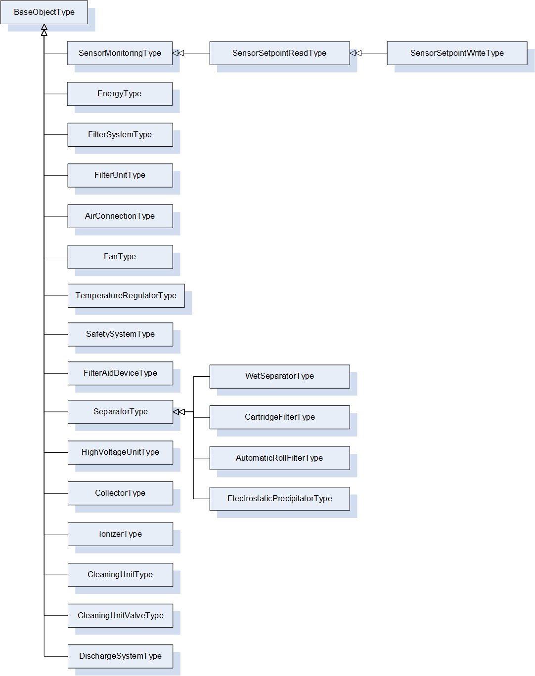
Figure 13 shows all ObjectTypes which are defined by this companion specification.
Figure 13 - All PAEFS ObjectTypes
7.1 SensorMonitoringType ObjectType Definition
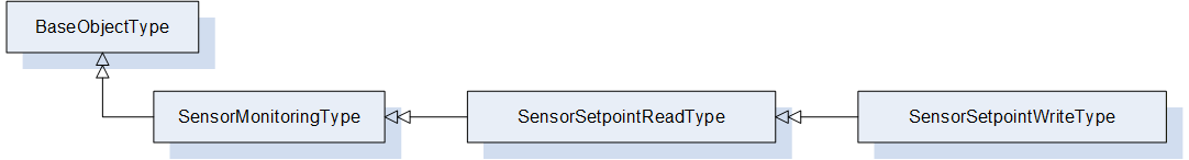
Figure 14 - SensorMonitoringType Inheritance
The SensorMonitoringType represents a process value whose value is determined by a measuring device. It is formally defined in Table 12. The measuring device can be identified via the MachineryComponentIdentificationType from OPC 40001-1.
The process value and all associated metadata such as unit and value ranges are inherited from the ProcessValueType. The optional setpoint of the ProcessValueType must not be used in instances of this type. If a setpoint is needed, the subtypes SensorSetpointReadType and SensorSetpointWrite should be used.
Optionally it can be specified whether the measuring signal is provided in analog or digital form.
Table 12 - SensorMonitoringType Definition
Attribute
Value
BrowseName
SensorMonitoringType
IsAbstract
False
References
Node Class
BrowseName
DataType
TypeDefinition
Other
Subtype of the BaseObjectType defined in OPC 10000-5
0:HasComponent
Object
Signal
5:ProcessValueType
M
0:HasAddIn
Object
2:Identification
4:MachineryComponentIdentificationType
O
0:HasComponent
Object
4:MachineryBuildingBlocks
0:FolderType
O
0:HasProperty
Variable
SignalForm
AnalogDigitalEnum
0:PropertyType
O,R
Conformance Units
PAEFS SensorMonitoringType Basic
PAEFS SensorMonitoringType Advanced
Table 13 - SensorMonitoringType Attribute values for child Nodes
BrowsePath
Attribute Description
Signal
Value of the signal. This includes min/max ranges, unit and other meta information. The optional setpoint should be implemented only for SensorSetpointReadType and SensorSetpointWriteType types.
The SensorSetpointReadType represents a process value and provides a setpoint for this value. It is formally defined in Table 15. A device is not required to provide a setpoint.
This type provides only read-access to the setpoint. Write-access is provided by SensorSetpointWriteType.
Table 15 - SensorSetpointReadType Definition
Attribute
Value
BrowseName
SensorSetpointReadType
IsAbstract
False
References
Node Class
BrowseName
DataType
TypeDefinition
Other
Subtype of the SensorMonitoringType
0:HasProperty
Variable
IsActiveSetpoint
0:Boolean
0:PropertyType
O,R
Conformance Units
PAEFS SensorSetpointReadType Basic
PAEFS SensorSetpointReadType Advanced
The component Variables of the SensorSetpointReadType have additional Attributes defined in Table 16.
Table 16 - SensorSetpointReadType Attribute values for child nodes
BrowsePath
Description Attribute
IsActiveSetpoint
Indicates that the setpoint is currently active.
The components of the SensorSetpointReadType have additional subcomponents which are defined in Table 17.
Some devices may control a process value via alternative, mutually exclusive setpoint (e.g. a target value for either pressure or airflow may be specified). The IsActiveSetpoint variable indicates whether the setpoint of an instance of this type is the currently active setpoint.
7.3 SensorSetpointWriteType ObjectType Definition
The SensorSetpointWriteType represents a process value and provides a readable and writable setpoint for this value. It is formally defined in Table 18.
Table 18 - SensorSetpointWriteType Definition
Attribute
Value
BrowseName
SensorSetpointWriteType
IsAbstract
False
References
Node Class
BrowseName
DataType
TypeDefinition
Other
Subtype of the SensorSetpointReadType
Conformance Units
PAEFS SensorSetpointWriteType Basic
PAEFS SensorSetpointWriteType Advanced
The components of the SensorSetpointWriteType have additional subcomponents which are defined in Table 19.
The ConsumptionType contains information related to the consumption of a device and is formally defined in Table 20. Consumption can refer, for example, to electricity or compressed air consumption.
Table 20 - ConsumptionType Definition
Attribute
Value
BrowseName
ConsumptionType
IsAbstract
False
References
Node Class
BrowseName
DataType
TypeDefinition
Other
Subtype of the BaseObjectType defined in OPC 10000-5
0:HasComponent
Object
CurrentConsumption
SensorMonitoringType
O
0:HasComponent
Variable
LifetimeConsumption
0:Double
0:AnalogUnitType
O,R
Conformance Units
PAEFS ConsumptionType Basic
PAEFS ConsumptionType Advanced
Table 21 - ConsumptionType Attribute values for child nodes
BrowsePath
Attribute Description
CurrentConsumption
The current consumption of the device.
LifetimeConsumption
Consumption over total machine lifetime. The AnalogUnitType variables InstrumentRange and EURange must not be used.
7.5 FilterSystemType ObjectType Definition
7.5.1 Overview
The FilterSystemType serves the purpose of extracting and filtering process gas, e.g., air. It consists of several filter units and other devices and components. It is formally defined in Table 22.
Table 22 - FilterSystemType Definition
Attribute
Value
BrowseName
FilterSystemType
IsAbstract
False
References
Node Class
BrowseName
DataType
TypeDefinition
Other
Subtype of the BaseObjectType defined in OPC 10000-5
0:HasAddIn
Object
2:Identification
4:MachineIdentificationType
O
0:HasComponent
Object
4:MachineryBuildingBlocks
0:FolderType
O
0:HasComponent
Object
<FilterUnit>
FilterUnitType
MP
0:HasComponent
Object
AirIntakeConnection
AirConnectionType
M
0:HasComponent
Object
AirOutletConnection
AirConnectionType
M
0:HasComponent
Object
<FilterAidDevice>
FilterAidDeviceType
OP
0:HasComponent
Object
<Fan>
FanType
OP
0:HasComponent
Object
<SafetySystem>
SafetySystemType
OP
0:HasComponent
Object
<TemperatureRegulator>
TemperatureRegulatorType
OP
0:HasComponent
Object
PowerConsumption
ConsumptionType
O
0:HasComponent
Object
AirConsumption
ConsumptionType
O
0:HasProperty
Variable
MaintenanceRequested
0:Boolean
0:PropertyType
O,R
0:HasAddIn
Object
4:MachineryItemState
4:MachineryItemState_StateMachineType
M
0:HasProperty
Variable
ControlMode
ControlModeEnum
0:PropertyType
O,R
0:HasComponent
Method
OperationOn
O
0:HasComponent
Method
OperationOff
O
0:HasProperty
Variable
Malfunction
0:Boolean
0:PropertyType
M,R
0:HasComponent
Object
PressureLoss
SensorMonitoringType
O
0:GeneratesEvent
ObjectType
MaintenanceRequestedConditionType
0:GeneratesEvent
ObjectType
MalfunctionAlarmType
0:HasInterface
ObjectType
2:IOperationCounterType
Applied from IOperationCounterType
0:HasProperty
Variable
PowerOnDuration
0:Duration
0:PropertyType
O
0:HasProperty
Variable
OperationDuration
0:Duration
0:PropertyType
O
0:HasProperty
Variable
OperationCycleCounter
0:UInteger
0:PropertyType
O
Conformance Units
PAEFS FilterSystemType Basic
PAEFS FilterSystemType Advanced
PAEFS FilterSystem Machine Identification
PAEFS FilterSystem Statemachine
PAEFS Operation FilterSystemType
PAEFS FilterSystemType Events
Table 23 - FilterSystemType Attribute values for child nodes
BrowsePath
Attribute Description
2:Identification
Data for identification (OPC 40001-1): The FilterSystem should only have an Identification folder if the system as a whole is considered a machine. If the individual filter units are considered machines, the FilterSystem should not have an Identification folder.
2:Identification
NominalAirflow
The nominal airflow of the filter system is the value specified by the manufacturer which defines the nominal extraction capacity of a unit under operating conditions.
2:Identification
ExIdentification
The marking on the type plate of the filter system regarding explosion protection.
2:Identification
RatedPower
The rated power of the filter system is the nominal electrical power of the unit under operating conditions specified by the manufacturer.
<FilterUnit>
All filter units of the system.
AirIntakeConnection
The connection to the ducting system from which the process gas enters the filter system.
AirOutletConnection
The connection to the ducting system to which the cleaned process gas leaves the filter system.
<FilterAidDevice>
All filter aid devices that are used on the server.
<Fan>
All fans used on the server.
<SafetySystem>
All safety systems used on the server.
<TemperatureRegulator>
All temperature regulators used on the server.
PowerConsumption
Contains information regarding the energy consumption of the filter system.
AirConsumption
Contains information regarding the consumption of compressed air of the filter system.
MaintenanceRequested
The maintenance request allows the manufacturer to inform the operator that the system requires maintenance. True = maintenance requested by system. False = no maintenance requested.
4:MachineryItemState
StateMachine representing the operating state of the filter system (OPC 40001-1).
ControlMode
Operating mode that describes whether the system can be controlled externally. Possible values are manual, auto and other.
Malfunction
Malfunction describes that the filter system has a collective fault message. True in case of error.
PressureLoss
Specification of the current total pressure loss of the filter system between the device intake connection on the raw gas side and the device outlet on the clean gas side.
The server sends a MalfunctionAlarmType event when the Malfunction property changes.
The MaintenanceRequestedConditionType is triggered when the MaintenanceRequested property changes.
The components of the FilterSystemType have additional subcomponents which are defined in Table 24.
The components of the FilterSystemType have additional references which are defined in Table 25.
Table 25 - FilterSystemType Additional References
SourceBrowsePath
Reference Type
Is Forward
TargetBrowsePath
4:MachineryBuildingBlocks
0:HasAddIn
True
2:Identification
4:MachineryBuildingBlocks
0:HasAddIn
True
4:MachineryItemState
7.5.2 OperationOn Method
The Method OperationOn turns the filter system machine on. It should only be available on the filter system if the filter units are considered components of the filter system and do not have their own OperationOn and OperationOff methods. The method changes the state of MachineryItemState. The signature of this Method is specified below. Table 26 specifies the AddressSpace representation.
The Method OperationOff turns the filter system machine off. As with the OperationOn method, this method should be present under the FilterSystemType if and only if the filter units are considered components of the system rather than individual machines. The method changes the state of MachineryItemState. The signature of this Method is specified below. Table 27 specifies the AddressSpace representation.
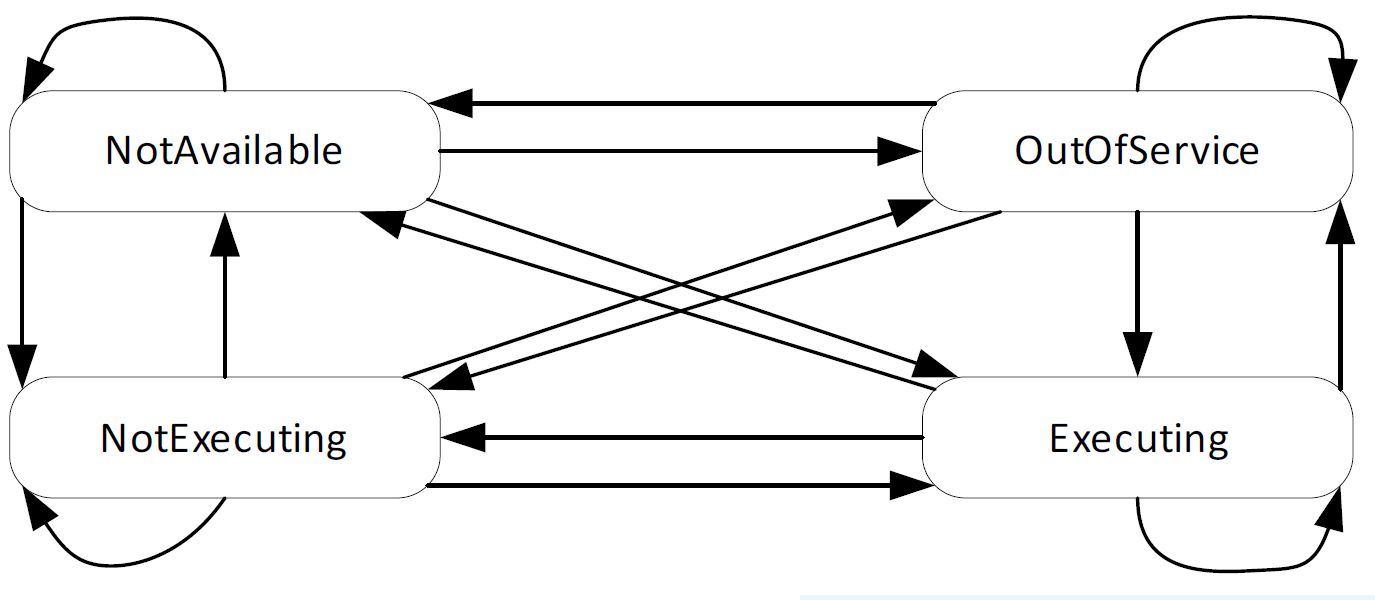
This building block provides information about the state of a MachineryItem. It defines the states NotAvailable, OutOfService, NotExecuting and Executing. The exact semantics of the states are defined in OPC 40001-1. The StateMachine defines Transitions between all States. Instances might restrict the usage of the defined States and Transitions. An overview of the StateMachine is provided in Figure 15.
Figure 15 - MachineryItemState StateMachine
7.6 FilterUnitType ObjectType Definition
7.6.1 Overview
The FilterUnitType is a subcomponent of a filter system consisting of other devices and components.
Subtype of the BaseObjectType defined in OPC 10000-5
0:HasComponent
Object
<CleaningUnit>
CleaningUnitType
OP
0:HasComponent
Object
<Separator>
SeparatorType
OP
0:HasComponent
Object
<DischargeSystem>
DischargeSystemType
OP
0:HasComponent
Object
AirIntakeConnection
AirConnectionType
M
0:HasComponent
Object
AirOutletConnection
AirConnectionType
M
0:HasAddIn
Object
2:Identification
4:MachineryItemIdentificationType
O
0:HasComponent
Object
4:MachineryBuildingBlocks
0:FolderType
O
0:HasAddIn
Object
4:MachineryItemState
4:MachineryItemState_StateMachineType
M
0:HasComponent
Object
Airflow
SensorSetpointReadType
O
0:HasComponent
Object
Pressure
SensorSetpointReadType
O
0:HasComponent
Object
RotationalSpeed
SensorSetpointReadType
O
0:HasProperty
Variable
MaintenanceRequested
0:Boolean
0:PropertyType
O,R
0:HasComponent
Object
PowerConsumption
ConsumptionType
O
0:HasComponent
Object
AirConsumption
ConsumptionType
O
0:HasProperty
Variable
Malfunction
0:Boolean
0:PropertyType
M,R
0:HasComponent
Object
PressureLoss
SensorMonitoringType
O
0:HasComponent
Method
OperationOn
O
0:HasComponent
Method
OperationOff
O
0:HasComponent
Method
SetAndActivateAirflowSetpoint
O
0:HasComponent
Method
SetAndActivatePressureSetpoint
O
0:HasComponent
Method
SetAndActivateRotationalSpeedSetpoint
O
0:GeneratesEvent
ObjectType
MaintenanceRequestedConditionType
0:GeneratesEvent
ObjectType
MalfunctionAlarmType
0:HasInterface
ObjectType
2:IOperationCounterType
Applied from IOperationCounterType
0:HasProperty
Variable
PowerOnDuration
0:Duration
0:PropertyType
O
0:HasProperty
Variable
OperationDuration
0:Duration
0:PropertyType
O
0:HasProperty
Variable
OperationCycleCounter
0:UInteger
0:PropertyType
O
Conformance Units
PAEFS FilterUnitType Basic
PAEFS FilterUnitType Advanced
PAEFS FilterUnit Component Identification
PAEFS FilterUnit Machine Identification
PAEFS FilterUnit Statemachine
PAEFS Operation FilterUnitType
PAEFS FilterUnit Airflow Setpoint
PAEFS FilterUnit Pressure Setpoint
PAEFS FilterUnit Rotational Speed Setpoint
PAEFS FilterUnitType Events
Table 29 - FilterUnitType Attribute values for child nodes
BrowsePath
Attribute Description
<CleaningUnit>
The cleaning units that are part of the filter unit.
<Separator>
The separators that are part of the filter unit.
<DischargeSystem>
The discharge systems that are part of the filter unit.
AirIntakeConnection
The connection to the ducting system from which the polluted process gas enters the filter unit.
AirOutletConnection
The connection to the ducting system through which the cleaned process gas leaves the filter unit.
2:Identification
Data for machine identification (OPC 40001-1): The Identification folder can have either the concrete type MachineIdentificationType or MachineryComponentType. If the filter unit is considered a component of a larger filter machine, MachineryComponentType is used. If the filter unit is considered a machine by itself, MachineIdentificationType is used.
2:Identification
NominalAirflow
The nominal airflow of the filter unit is the value specified by the manufacturer which defines the nominal extraction capacity of a filter unit under operating conditions.
2:Identification
ExIdentification
The marking on the type plate of the filter unit regarding explosion protection.
2:Identification
RatedPower
The rated power of the filter unit is the nominal electrical power of the filter unit under operating conditions specified by the manufacturer.
4:MachineryItemState
StateMachine representing the operating state of the filter unit (OPC 40001-1).
Airflow
Setpoint for the airflow that flows through the filter unit.
Pressure
Setpoint for the negative pressure at the filter unit. Describes the setpoint value for the pressure difference of the raw gas side compared to the environment.
RotationalSpeed
Setpoint for the rotational speed of a "virtual" fan. This value is a setpoint. In reality, the filter system can have several fans.
MaintenanceRequested
The maintenance request allows the manufacturer to inform the operator that the system requires maintenance. True = maintenance requested by system. False = no maintenance requested.
PowerConsumption
Contains information regarding the energy consumption of the filter unit.
AirConsumption
Contains information regarding the consumption of compressed air of the filter unit.
Malfunction
One or more subsystems of the filter unit have a malfunction. True in case of error.
PressureLoss
The specification of the total pressure loss of the filter unit between the device intake connection on the raw gas side and the device outlet on the clean gas side.
The server sends a MalfunctionAlarmType event when the Malfunction property changes.
The MaintenanceRequestedConditionType is triggered when the MaintenanceRequested property changes.
The amount of gas that is processed by the filter unit can be governed either by airflow, pressure, or rotational fan speed. Only one of these three quantities can be specified as the setpoint at a time.
The methods SetAndActivateAirflowSetpoint, SetAndActivatePressureSetpoint, and SetAndActivateRotationalSpeedSetpoint set the value of the setpoint and set this setpoint as the active setpoint.
Each of the objects Airflow, Pressure, and RotationalSpeed of type SensorType contains a read-only boolean variable IsActiveSetpoint. The boolean IsActiveSetpoint indicates which of the three setpoints is currently active. IsActiveSetpoint must be true for exactly one quantity at any given time.
The components of the FilterUnitType have additional references which are defined in Table 31.
Table 31 - FilterUnitType Additional References
SourceBrowsePath
Reference Type
Is Forward
TargetBrowsePath
4:MachineryBuildingBlocks
0:HasAddIn
True
2:Identification
4:MachineryBuildingBlocks
0:HasAddIn
True
4:MachineryItemState
7.6.2 SetAndActivateAirflowSetpointMethod
The Method SetAndActivateAirflowSetpoint sets a setpoint for the airflow. The value's unit is the same as the one specified in object Airflow. Since setpoints are mutually exclusive, the method also sets the boolean IsActiveSetpoint of the setpoints for pressure and rotational speed to false.
The signature of this Method is specified below. Table 32 and Table 33 specify the Arguments and AddressSpace representation, respectively.
The Method SetAndActivatePressureSetpoint sets a setpoint for the pressure. The value's unit is the same as the one specified in object Pressure. Since setpoints are mutually exclusive, the method also sets the boolean IsActiveSetpoint of the setpoints for airflow and rotational speed to false. The signature of this Method is specified below.
Table 34 and Table 35 specify the Arguments and AddressSpace representation, respectively.
The Method SetAndActivateRotationalSpeedSetpoint sets a setpoint for the rotational speed. The value's unit is the same as the one specified in object RotationalSpeed. Since setpoints are mutually exclusive, the method also sets the boolean IsActiveSetpoint of the setpoints for airflow and pressure to false.
The signature of this Method is specified below. Table 36 and Table 37 specify the Arguments and AddressSpace representation, respectively.
The Method OperationOn turns the machine on. It should only be available on the filter unit if the filter unit is considered a machine, rather than a component of a larger machine. If the filter unit is only a component of a larger machine, the OperationOnMethod should be present on the filter system. The method changes the state of MachineryItemState.
Table 38 specifies the AddressSpace representation.
The Method OperationOff turns the machine off. As with the OperationOnMethod, this method should be present under the filter unit if and only if the filter unit is considered a machine. The signature of this Method is specified below. Table 39 specifies the AddressSpace representation. The method changes the state of MachineryItemState.
The AirConnectionType is a non-tangible component representing the state of a connection from the ducting system to a filter unit. The connection can be open or closed. The open state represents a state of the ducting system where air can pass through to the filter unit.
Subtype of the BaseObjectType defined in OPC 10000-5
0:HasComponent
Object
Humidity
SensorMonitoringType
O
0:HasComponent
Object
Temperature
SensorMonitoringType
O
0:HasComponent
Object
Airflow
SensorMonitoringType
O
0:HasComponent
Object
GasQuality
SensorMonitoringType
O
0:HasComponent
Object
Pressure
SensorMonitoringType
O
0:HasProperty
Variable
ConnectionOpen
AirConnectionOpenEnum
0:PropertyType
O,R
0:HasProperty
Variable
Malfunction
0:Boolean
0:PropertyType
O,R
0:HasComponent
Method
Open
O
0:HasComponent
Method
Close
O
0:GeneratesEvent
ObjectType
MalfunctionAlarmType
0:GeneratesEvent
ObjectType
AirConnectionStatusChangedConditionType
Conformance Units
PAEFS AirConnectionType Basic
PAEFS AirConnectionType Advanced
PAEFS AirConnectionType Events
PAEFS AirConnectionType Methods
Table 41 - AirConnectionType Attribute values for child nodes
BrowsePath
Attribute Description
Humidity
Value of the humidity sensor
Temperature
Value of the temperature sensor
Airflow
Value of the air flow sensor
GasQuality
Value of the gas quality sensor
Pressure
Value of the pressure sensor
ConnectionOpen
Indicates the connections status (open, closed, or a state in between)
Malfunction
Indicates that the AirConnection is malfunctioning, i.e., an error occurs in a component that provides functionality for this abstract component; e.g., an error in the ducting system or a valve. True in case of error.
The Open and Close Methods can be called to open or close the connection. In a complex ducting system that consists of a network of joints and junctions, opening or closing the connection may involve switching multiple valves.
The control logic for switching the state of the ducting system is determined by the server implementation.
The air connection may contain optional sensors for humidity, temperature, air flow, gas quality, and air pressure.
The server sends a MalfunctionAlarmType event when the Malfunction property changes.
The AirConnectionStatusChangedConditionType event is triggered when the ConnectionOpen property changes.
7.7.2 Open Method
The Method Open opens or switches all valves of the ducting system so that the air can pass through to the filter device. The signature of this Method is specified below. Table 42 specifies the AddressSpace representation.
Signature
Open ()
Table 42 - Open Method AddressSpace Definition
Attribute
Value
BrowseName
Open
References
Node Class
BrowseName
DataType
TypeDefinition
ModellingRule
Conformance Units
PAEFS AirConnectionType Methods
7.7.3 Close Method
The Method Close closes or switches some of the valves in the ducting system so that no air may pass through the ducting system to the device. The signature of this Method is specified below. Table 43 specifies the AddressSpace representation.
Signature
Close ()
Table 43 - Close Method AddressSpace Definition
Attribute
Value
BrowseName
Close
References
Node Class
BrowseName
DataType
TypeDefinition
ModellingRule
Conformance Units
PAEFS AirConnectionType Methods
7.8 FanType ObjectType Definition
The FanType represents a device for generating negative air pressure and is formally defined in Table 44.
Table 44 - FanType Definition
Attribute
Value
BrowseName
FanType
IsAbstract
False
References
Node Class
BrowseName
DataType
TypeDefinition
Other
Subtype of the BaseObjectType defined in OPC 10000-5
0:HasAddIn
Object
2:Identification
4:MachineryComponentIdentificationType
O
0:HasComponent
Object
4:MachineryBuildingBlocks
0:FolderType
O
0:HasProperty
Variable
MaintenanceSwitchOn
0:Boolean
0:PropertyType
O,R
0:HasProperty
Variable
Malfunction
0:Boolean
0:PropertyType
O,R
0:HasAddIn
Object
4:MachineryItemState
4:MachineryItemState_StateMachineType
O
0:HasComponent
Object
RotationalSpeed
SensorSetpointWriteType
O
0:HasComponent
Object
PowerConsumption
ConsumptionType
O
0:GeneratesEvent
ObjectType
MalfunctionAlarmType
0:GeneratesEvent
ObjectType
MaintenanceSwitchConditionType
Conformance Units
PAEFS FanType Basic
PAEFS FanType Advanced
PAEFS Additional Statemachines
PAEFS FanType Events
Table 45 - FanType Attribute values for child nodes
The server sends a MalfunctionAlarmType event when the Malfunction property changes.
7.10 SafetySystemType ObjectType Definition
The SafetySystemType is a generic component that represents a protective device. Each component in the PAEFS can reference an instance of the safety system via a Uses reference.
The filling level describes the amount of filter aid in the pre-storage reservoir.
Malfunction
Indicates that the filter aid device is malfunctioning. True in case of error. Malfunctions can be, for example, that there is no more filter aid or that there is a malfunction in the subsystems of the filter aid device.
4:MachineryItemState
StateMachine representing the operating state of the device (OPC 40001-1).
CompressedAirSupplyInterrupted
Indicates that the air supply is interrupted.
PowerConsumption
Describes the current power consumption of the filter aid device.
AirConsumption
Describes the compressed air consumption.
DosingRequested
Indicates that the filter system requests dosing.
AutomaticDosingEnabled
If enabled, the filter aid device is allowed to perform dosing automatically.
The components of the FilterAidDeviceType have additional references which are defined in Table 55.
If the filter aid reservoir is opened or closed, the event ContainerOpenConditionType will be triggered.
The event CompressedAirSupplyInterruptedAlarmType is triggered when the compressed air supply is interrupted.
When the value FilterAidDeviceStatus changes, the event FilterAidDeviceStatusChangedConditionType is triggered. The event contains a copy of the status value.
The server sends a MalfunctionAlarmType event when the Malfunction property changes.
7.11.2 TriggerDosing Method
The Method TriggerDosing triggers a single additional dosage. The signature of this Method is specified below. Table 56 specifies the AddressSpace representation.
The Method ResetFillingLevel resets the filling level of the filter aid reservoir. The signature of this Method is specified below. Table 57 specifies the AddressSpace representation.
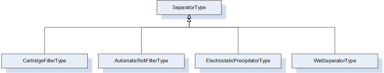
Figure 16 - Illustration of SeparatorType and its subtypes
The SeparatorType is the abstract base type for separators. It contains optional sensor values that are common to all separators. Users may use one of the subtypes provided within this specification or create their own type. It is formally defined in Table 58.
Table 58 - SeparatorType Definition
Attribute
Value
BrowseName
SeparatorType
IsAbstract
True
References
Node Class
BrowseName
DataType
TypeDefinition
Other
Subtype of the BaseObjectType defined in OPC 10000-5
0:HasAddIn
Object
2:Identification
4:MachineryComponentIdentificationType
O
0:HasComponent
Object
4:MachineryBuildingBlocks
0:FolderType
O
0:HasAddIn
Object
4:MachineryItemState
4:MachineryItemState_StateMachineType
O
0:HasComponent
Object
FilterMediumState
SensorMonitoringType
O
0:HasComponent
Object
Humidity
SensorMonitoringType
O
0:HasComponent
Object
Temperature
SensorMonitoringType
O
0:HasProperty
Variable
FilterMediumOperatingHours
0:UInt32
0:PropertyType
O,R
Conformance Units
PAEFS SeparatorType Basic
PAEFS SeparatorType Advanced
The component Variables of the SeparatorType have additional Attributes defined in Table 59.
Table 59 - SeparatorType Attribute values for child nodes
The AutomaticRollFilterType is a separator that is regenerated by rolling up the filter medium. It is formally defined in Table 62.
Table 62 - AutomaticRollFilterType Definition
Attribute
Value
BrowseName
AutomaticRollFilterType
IsAbstract
False
References
Node Class
BrowseName
DataType
TypeDefinition
Other
Subtype of the SeparatorType
0:HasProperty
Variable
EndOfFilterRoll
0:Boolean
0:PropertyType
O,R
0:GeneratesEvent
ObjectType
EndOfFilterRollAlarmType
Conformance Units
PAEFS AutomaticRollFilterType Basic
PAEFS AutomaticRollFilterType Advanced
PAEFS AutomaticRollFilterType Events
The component Variables of the AutomaticRollFilterType have additional Attributes defined in Table 63.
Table 63 - AutomaticRollFilterType Attribute values for child nodes
BrowsePath
Description Attribute
EndOfFilterRoll
EndOfFilterRoll is true if the end of the filter roll is reached.
The EndOfFilterRollAlarmType event is sent when the end of the filter roll is reached.
7.15 WetSeparatorType ObjectType Definition
The WetSeparatorType represents a separator that filters solid, liquid, or gaseous components using a liquid medium and is formally defined in Table 64.
Table 64 - WetSeparatorType Definition
Attribute
Value
BrowseName
WetSeparatorType
IsAbstract
False
References
Node Class
BrowseName
DataType
TypeDefinition
Other
Subtype of the SeparatorType
0:HasProperty
Variable
WashingAgentDrainOpen
0:Boolean
0:PropertyType
O,R
0:HasProperty
Variable
WashingAgentDrainMalfunction
0:Boolean
0:PropertyType
O,R
0:HasProperty
Variable
WashingAgentInflowOpen
0:Boolean
0:PropertyType
O,R
0:HasProperty
Variable
WashingAgentInflowMalfunction
0:Boolean
0:PropertyType
O,R
0:GeneratesEvent
ObjectType
WashingAgentInflowOpenConditionType
0:GeneratesEvent
ObjectType
WashingAgentInflowMalfunctionAlarmType
0:GeneratesEvent
ObjectType
WashingAgentDrainOpenConditionType
0:GeneratesEvent
ObjectType
WashingAgentDrainMalfunctionAlarmType
Conformance Units
PAEFS WetSeparatorType Basic
PAEFS WetSeparatorType Advanced
PAEFS WetSeparatorType Events
The component Variables of the WetSeparatorType have additional Attributes defined in Table 65.
Table 65 - WetSeparatorType Attribute values for child nodes
BrowsePath
Description Attribute
WashingAgentDrainOpen
Indicates that the washing agent drain valve is open.
WashingAgentDrainMalfunction
Indicates whether there is an error with the washing agent drain. True in case of error. Examples: clogging, burst pipe, defective valve.
WashingAgentInflowOpen
Indicates that the washing agent inflow valve is open.
WashingAgentInflowMalfunction
Indicates whether there is an error with the washing agent inflow. True in case of error. Examples: clogging, burst pipe, defective valve.
The WashingAgentDrainOpenConditionType event is triggered when the value of the property WashingAgentDrainOpen changes.
The WashingAgentInflowOpenConditionType event is triggered when the value of the property WashingAgentInflowOpen changes.
The server sends a WashingAgentDrainMalfunctionAlarmType event when the WashingAgentDrainMalfunction property changes.
The server sends a WashingAgentInflowMalfunctionAlarmType event when the WashingAgentInflowMalfunction property changes.
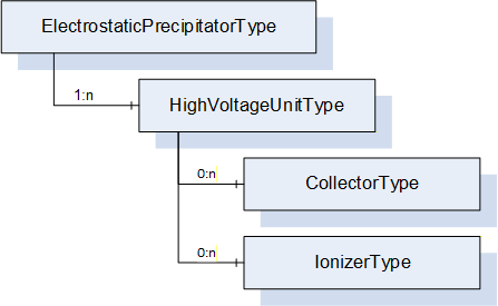
Figure 17 - The electrostatic precipitator and its subcomponents
The ElectrostaticPrecipitatorType represents a separator that uses electrostatics to filter solid or liquid components from the process air and is formally defined in Table 66.
Describes that the unit is currently in a cleaning cycle.
ReservoirPressure
Describes the pressure of the compressed gas reservoir of the system.
TotalCleaningCycles
Count of the number of cleaning cycles carried out by the cleaning system.
FilterCleaningEffect
The filter cleaning effect describes the change in state of the separator after the last cleaning cycle has been run through. This can be, for example, a change in the pressure difference before and after the cleaning cycle.
CleaningRecommended
Indicates that cleaning of the separator is recommended.
4:MachineryItemState
StateMachine representing the operating state of the unit (OPC 40001-1).
Malfunction
Indicates that the cleaning unit is malfunctioning. True in case of error. Malfunctions can be, for example, that the filter cleaning effect is not sufficient.
AutomaticCleaningEnabled
If enabled, the cleaning unit may automatically perform the cleaning according to predefined rules when cleaning is necessary. Otherwise, automatic cleaning is blocked.
CleaningInterval
Time between cleaning cycles.
AirConsumption
Describes the current consumption of compressed air.
The components of the CleaningUnitType have additional references which are defined in Table 76.
Table 76 - CleaningUnitType Additional References
SourceBrowsePath
Reference Type
Is Forward
TargetBrowsePath
4:MachineryBuildingBlocks
0:HasAddIn
True
2:Identification
4:MachineryBuildingBlocks
0:HasAddIn
True
4:MachineryItemState
The condition CleaningUnitActiveConditionType is triggered when the value of property CleaningActive changes.
The CleaningRecommendedConditionType event is triggered by the cleaning unit when the value of property CleaningRecommended changes.
7.20.2 RequestCleaning Method
The Method RequestCleaning requests cleaning of the unit. The cleaning unit will perform the cleaning as soon as possible. The signature of this Method is specified below. Table 77 specifies the AddressSpace representation.
The CleaningUnitValveType represents a part of the pressure tank of the cleaning unit for triggering a pressure surge into the separator. It is formally defined in Table 78.
Table 78 - CleaningUnitValveType Definition
Attribute
Value
BrowseName
CleaningUnitValveType
IsAbstract
False
References
Node Class
BrowseName
DataType
TypeDefinition
Other
Subtype of the BaseObjectType defined in OPC 10000-5
0:HasProperty
Variable
Malfunction
0:Boolean
0:PropertyType
O,R
0:HasProperty
Variable
Open
0:Boolean
0:PropertyType
O,R
0:GeneratesEvent
ObjectType
MalfunctionAlarmType
Conformance Units
PAEFS CleaningUnitValveType Basic
PAEFS CleaningUnitValveType Advanced
PAEFS CleaningUnitValveType Events
The component Variables of the CleaningUnitValveType have additional Attributes defined in Table 79.
Table 79 - CleaningUnitValveType Attribute values for child nodes
BrowsePath
Description Attribute
Open
Indicates that the valve is open.
Malfunction
Indicates that the cleaning unit valve is malfunctioning. True in case of error. Malfunctions can be, for example, that the valve does not open or close.
The server sends a MalfunctionAlarmType event when the malfunction property changes.
7.22 DischargeSystemType ObjectType Definition
The DischargeSystemType is a device used to remove collected filter material from the filter unit. The container can be discharged when a certain filling level is reached. It is formally defined in Table 80.
Table 80 - DischargeSystemType Definition
Attribute
Value
BrowseName
DischargeSystemType
IsAbstract
False
References
Node Class
BrowseName
DataType
TypeDefinition
Other
Subtype of the BaseObjectType defined in OPC 10000-5
0:HasAddIn
Object
2:Identification
4:MachineryComponentIdentificationType
O
0:HasComponent
Object
4:MachineryBuildingBlocks
0:FolderType
O
0:HasProperty
Variable
MaintenanceSwitchOn
0:Boolean
0:PropertyType
M,R
0:HasAddIn
Object
4:MachineryItemState
4:MachineryItemState_StateMachineType
M
0:HasProperty
Variable
Malfunction
0:Boolean
0:PropertyType
O,R
0:HasProperty
Variable
DischargeContainerInstalled
0:Boolean
0:PropertyType
O,R
0:HasComponent
Object
FillingLevel
SensorMonitoringType
O
0:HasComponent
Object
AirConsumption
ConsumptionType
O
0:HasProperty
Variable
DischargeSystemEnabled
0:Boolean
0:PropertyType
O,RW
0:GeneratesEvent
ObjectType
MalfunctionAlarmType
0:GeneratesEvent
ObjectType
MaintenanceSwitchConditionType
0:GeneratesEvent
ObjectType
DischargeContainerInstalledConditionType
Conformance Units
PAEFS DischargeSystemType Basic
PAEFS DischargeSystemType Advanced
PAEFS DischargeSystemType Events
The component Variables of the DischargeSystemType have additional Attributes defined in Table 81.
Table 81 - DischargeSystemType Attribute values for child nodes
Status of a physical maintenance switch on the discharge system. True when the switch is on.
Malfunction
Indicates whether there is an error with the discharge system. True in case of error. Examples: discharge motor defective, discharge container full, discharge system blocked.
4:MachineryItemState
StateMachine representing the operating state of the discharge system (OPC 40001-1).
DischargeContainerInstalled
Indicates that the discharge container is in place.
FillingLevel
Filling level of the device.
AirConsumption
Contains information regarding the consumption of compressed air.
DischargeSystemEnabled
If enabled, discharge can be performed. If disabled, discharge cannot take place; for example, because a rotary valve is stopped or a discharge flap is closed.
The components of the DischargeSystemType have additional references which are defined in Table 82.