7.5 FilterSystemType ObjectType Definition
7.5.1 Overview
The FilterSystemType serves the purpose of extracting and filtering process gas, e.g., air. It consists of several filter units and other devices and components. It is formally defined in Table 22.
| Attribute | Value | ||||
| BrowseName | FilterSystemType | ||||
| IsAbstract | False | ||||
| References | Node Class | BrowseName | DataType | TypeDefinition | Other |
|---|---|---|---|---|---|
| Subtype of the BaseObjectType defined in OPC 10000-5 | |||||
| 0:HasAddIn | Object | 2:Identification | 4:MachineIdentificationType | O | |
| 0:HasComponent | Object | 4:MachineryBuildingBlocks | 0:FolderType | O | |
| 0:HasComponent | Object | <FilterUnit> | FilterUnitType | MP | |
| 0:HasComponent | Object | AirIntakeConnection | AirConnectionType | M | |
| 0:HasComponent | Object | AirOutletConnection | AirConnectionType | M | |
| 0:HasComponent | Object | <FilterAidDevice> | FilterAidDeviceType | OP | |
| 0:HasComponent | Object | <Fan> | FanType | OP | |
| 0:HasComponent | Object | <SafetySystem> | SafetySystemType | OP | |
| 0:HasComponent | Object | <TemperatureRegulator> | TemperatureRegulatorType | OP | |
| 0:HasComponent | Object | PowerConsumption | ConsumptionType | O | |
| 0:HasComponent | Object | AirConsumption | ConsumptionType | O | |
| 0:HasProperty | Variable | MaintenanceRequested | 0:Boolean | 0:PropertyType | O,R |
| 0:HasAddIn | Object | 4:MachineryItemState | 4:MachineryItemState_StateMachineType | M | |
| 0:HasProperty | Variable | ControlMode | ControlModeEnum | 0:PropertyType | O,R |
| 0:HasComponent | Method | OperationOn | O | ||
| 0:HasComponent | Method | OperationOff | O | ||
| 0:HasProperty | Variable | Malfunction | 0:Boolean | 0:PropertyType | M,R |
| 0:HasComponent | Object | PressureLoss | SensorMonitoringType | O | |
| 0:GeneratesEvent | ObjectType | MaintenanceRequestedConditionType | |||
| 0:GeneratesEvent | ObjectType | MalfunctionAlarmType | |||
| 0:HasInterface | ObjectType | 2:IOperationCounterType | |||
| Applied from IOperationCounterType | |||||
| 0:HasProperty | Variable | PowerOnDuration | 0:Duration | 0:PropertyType | O |
| 0:HasProperty | Variable | OperationDuration | 0:Duration | 0:PropertyType | O |
| 0:HasProperty | Variable | OperationCycleCounter | 0:UInteger | 0:PropertyType | O |
| Conformance Units | |||||
|---|---|---|---|---|---|
| PAEFS FilterSystemType Basic | |||||
| PAEFS FilterSystemType Advanced | |||||
| PAEFS FilterSystem Machine Identification | |||||
| PAEFS FilterSystem Statemachine | |||||
| PAEFS Operation FilterSystemType | |||||
| PAEFS FilterSystemType Events |
| BrowsePath | Attribute Description |
| 2:Identification | Data for identification (OPC 40001-1): The FilterSystem should only have an Identification folder if the system as a whole is considered a machine. If the individual filter units are considered machines, the FilterSystem should not have an Identification folder. |
| The nominal airflow of the filter system is the value specified by the manufacturer which defines the nominal extraction capacity of a unit under operating conditions. | |
| The marking on the type plate of the filter system regarding explosion protection. | |
| The rated power of the filter system is the nominal electrical power of the unit under operating conditions specified by the manufacturer. | |
| <FilterUnit> | All filter units of the system. |
| AirIntakeConnection | The connection to the ducting system from which the process gas enters the filter system. |
| AirOutletConnection | The connection to the ducting system to which the cleaned process gas leaves the filter system. |
| <FilterAidDevice> | All filter aid devices that are used on the server. |
| <Fan> | All fans used on the server. |
| <SafetySystem> | All safety systems used on the server. |
| <TemperatureRegulator> | All temperature regulators used on the server. |
| PowerConsumption | Contains information regarding the energy consumption of the filter system. |
| AirConsumption | Contains information regarding the consumption of compressed air of the filter system. |
| MaintenanceRequested | The maintenance request allows the manufacturer to inform the operator that the system requires maintenance. True = maintenance requested by system. False = no maintenance requested. |
| 4:MachineryItemState | StateMachine representing the operating state of the filter system (OPC 40001-1). |
| ControlMode | Operating mode that describes whether the system can be controlled externally. Possible values are manual, auto and other. |
| Malfunction | Malfunction describes that the filter system has a collective fault message. True in case of error. |
| PressureLoss | Specification of the current total pressure loss of the filter system between the device intake connection on the raw gas side and the device outlet on the clean gas side. |
The server sends a MalfunctionAlarmType event when the Malfunction property changes.
The MaintenanceRequestedConditionType is triggered when the MaintenanceRequested property changes.
The components of the FilterSystemType have additional subcomponents which are defined in Table 24.
| Source Path | Reference | NodeClass | BrowseName | DataType | TypeDefinition | Others |
| 2:Identification | 0:HasComponent | Variable | NominalAirflow | 0:Double | 0:AnalogUnitRangeType | M,R |
| 2:Identification | 0:HasProperty | Variable | ExIdentification | 0:String | 0:PropertyType | O,R |
| 2:Identification | 0:HasComponent | Variable | RatedPower | 0:Double | 0:AnalogUnitRangeType | O,R |
The components of the FilterSystemType have additional references which are defined in Table 25.
| SourceBrowsePath | Reference Type | Is Forward | TargetBrowsePath |
| 4:MachineryBuildingBlocks | 0:HasAddIn | True | 2:Identification |
| 4:MachineryBuildingBlocks | 0:HasAddIn | True | 4:MachineryItemState |
7.5.2 OperationOn Method
The Method OperationOn turns the filter system machine on. It should only be available on the filter system if the filter units are considered components of the filter system and do not have their own OperationOn and OperationOff methods. The method changes the state of MachineryItemState. The signature of this Method is specified below. Table 26 specifies the AddressSpace representation.
Signature
OperationOn ()| Attribute | Value | ||||
| BrowseName | OperationOn | ||||
| References | Node Class | BrowseName | DataType | TypeDefinition | ModellingRule |
|---|---|---|---|---|---|
| Conformance Units | |||||
| PAEFS Operation FilterSystemType | |||||
7.5.3 OperationOff Method
The Method OperationOff turns the filter system machine off. As with the OperationOn method, this method should be present under the FilterSystemType if and only if the filter units are considered components of the system rather than individual machines. The method changes the state of MachineryItemState. The signature of this Method is specified below. Table 27 specifies the AddressSpace representation.
Signature
OperationOff ()| Attribute | Value | ||||
| BrowseName | OperationOff | ||||
| References | Node Class | BrowseName | DataType | TypeDefinition | ModellingRule | |
|---|---|---|---|---|---|---|
| Conformance Units | ||||||
| PAEFS Operation FilterSystemType | ||||||
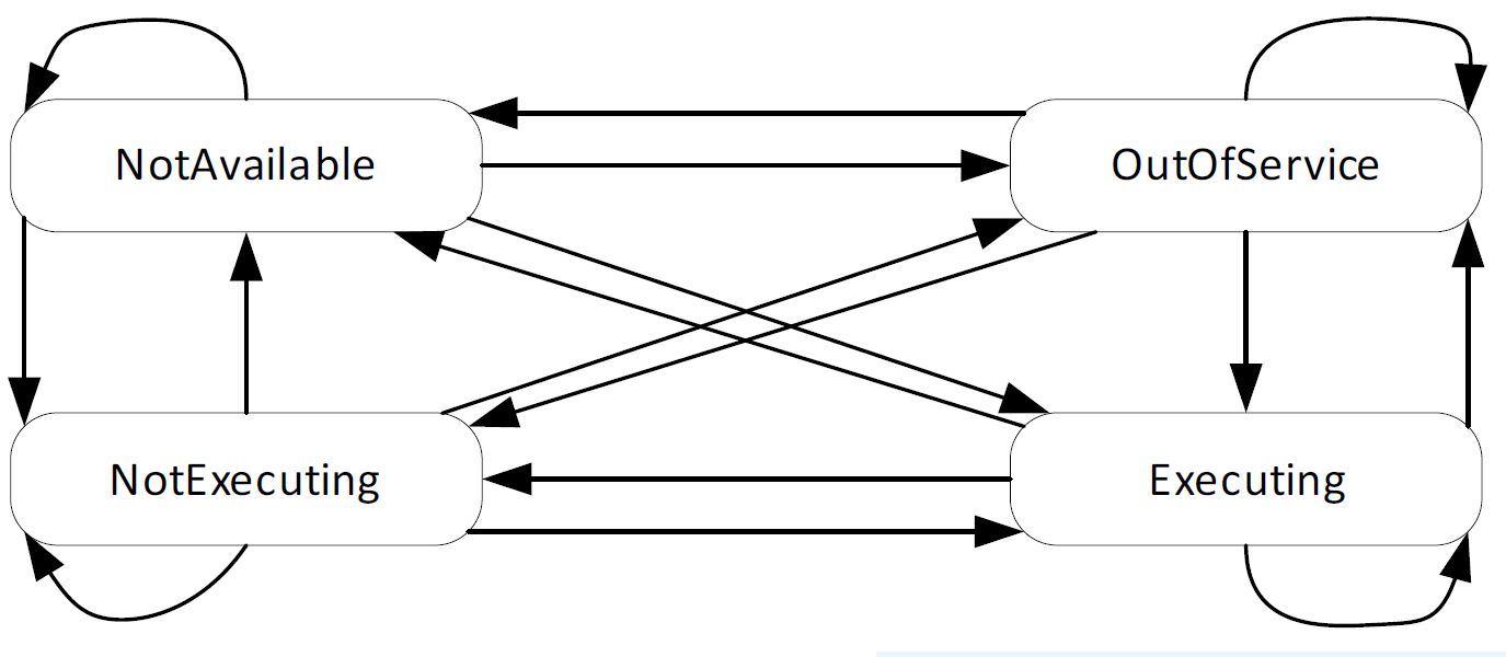
7.5.4 MachineryItemState StateMachine
This building block provides information about the state of a MachineryItem. It defines the states NotAvailable, OutOfService, NotExecuting and Executing. The exact semantics of the states are defined in OPC 40001-1. The StateMachine defines Transitions between all States. Instances might restrict the usage of the defined States and Transitions. An overview of the StateMachine is provided in Figure 15.