
1 Scope
This document specifies an OPC UA Information Model for the representation of an additive manufacturing machine ("AM machine"), as defined by ISO/ASTM 52900:2021 (3.1.4). It supports but is not limited to all industrial AM process categories listed by ISO/ASTM 52900:2021: Binder Jetting, Directed Energy Deposition, Material Extrusion, Material Jetting, Powder Bed Fusion, Sheet Lamination, Vat Photopolymerization. OPC UA for Additive Manufacturing aims at straightforward integration of an AM machine into higher level IT systems. The scope is to create a common interface that enables identification, monitoring and controlling* AM machines of different technologies, manufacturers and model series (*covered in later versions). Peripheral systems of the AM process chain (e.g. post processings) are not considered in this first version of the specification. This OPC UA for Additive Manufacturing interface allows an exchange of information between an AM machine and software systems like MES, ERP, SCADA or data analytics systems.
2 Normative references
The following referenced documents are indispensable for the application of this document. For dated references, only the edition cited applies. For undated references, the latest edition of the referenced document (including any amendments and errata) applies.
OPC 10000-1, OPC Unified Architecture - Part 1: Overview and Concepts
http://www.opcfoundation.org/documents/10000-1/
OPC 10000-2, OPC Unified Architecture - Part 2: Security Model
http://www.opcfoundation.org/documents/10000-2/
OPC 10000-3, OPC Unified Architecture - Part 3: Address Space Model
http://www.opcfoundation.org/documents/10000-3/
OPC 10000-4, OPC Unified Architecture - Part 4: Services
http://www.opcfoundation.org/documents/10000-4/
OPC 10000-5, OPC Unified Architecture - Part 5: Information Model
http://www.opcfoundation.org/documents/10000-5/
OPC 10000-6, OPC Unified Architecture - Part 6: Mappings
http://www.opcfoundation.org/documents/10000-6/
OPC 10000-7, OPC Unified Architecture - Part 7: Profiles
http://www.opcfoundation.org/documents/10000-7/
OPC 10000-100, OPC Unified Architecture - Part 100: Devices
http://www.opcfoundation.org/documents/10000-100/
OPC 10000-200, OPC Unified Architecture - Part 200: Industrial Automation
http://www.opcfoundation.org/documents/10000-200/
OPC 40001-1, OPC UA for Machinery - Part 1: Basic Building Blocks
http://www.opcfoundation.org/documents/40001-1/
OPC 40001-2, OPC UA for Machinery - Part 2: Process Values
http://www.opcfoundation.org/documents/40001-2/
OPC 40001-3, OPC UA for Machinery - Part 3: Job Management
http://www.opcfoundation.org/documents/40001-3/
OPC 40501-1, OPC UA for Machine Tools - Part 1: Monitoring and Job (min. v1.02)
http://www.opcfoundation.org/documents/40501-1/
3 Terms, definitions and conventions
3.1 Overview
It is assumed that basic concepts of OPC UA information modelling are understood in this document. This document will use these concepts to describe the Additive Manufacturing Information Model. For the purposes of this document, the terms and definitions given in OPC 10000-1, OPC 10000-2, OPC 10000-3, OPC 10000-4, OPC 10000-5, OPC 10000-6, OPC 10000-7, OPC 10000-100, OPC 10000-200, OPC 40001-1, OPC 40001-2, OPC 40001-3, OPC 40501-1, as well as the following apply.
3.2 OPC UA for Additive Manufacturing terms
3.2.1 Additive Manufacturing
process of joining materials to make parts from 3D model data, usually layer upon layer, as opposed to subtractive manufacturing and formative manufacturing methodologies
[SOURCE: ISO/ASTM 52900:2021, 3.1.2]
3.2.2 Additive Manufacturing System
machine and auxiliary equipment used for additive manufacturing
[SOURCE: ISO/ASTM 52900:2021, 3.1.3]
3.2.3 Additive Manufacturing Machine ("AM machine")
section of the additive manufacturing system including hardware, machine control software, required set-up software and peripheral accessories necessary to complete a build cycle for producing parts
[SOURCE: ISO/ASTM 52900:2021, 3.1.4]
3.2.4 Part
joined material forming a functional element that can constitute all or a section of an intended product
[SOURCE: ISO/ASTM 52900:2021, 3.9.1]
3.2.5 Build Cycle
single process cycle in which one or more components are built by successive joining of material within the build space of the additive manufacturing system
[SOURCE: ISO/ASTM 52900:2021, 3.3.8]
3.2.6 Feedstock
bulk raw material supplied to the additive manufacturing building process
[SOURCE: ISO/ASTM 52900:2021, 3.6.5]
3.2.7 Batch
<of feedstock> defined quantity of feedstock with uniform properties and composition
[SOURCE: ISO/ASTM 52900:2021, 3.6.1]
3.2.8 Lot
<of feedstock> quantity of feedstock produced under traceable controlled conditions from a single manufacturing process cycle
[SOURCE: ISO/ASTM 52900:2021, 3.6.2]
3.2.9 Layer
<matter> material laid out, or spread, to create a surface
[SOURCE: ISO/ASTM 52900:2021, 3.3.7]
3.3 Abbreviated terms
| AM | Additive Manufacturing |
| ERP | Enterprise Resource Planning |
| MES | Manufacturing Execution System |
| PMS | Production Management System |
| SCADA | Supervisory Control and Data Acquisition |
3.4 Conventions used in this document
3.4.1 Conventions for Node descriptions
3.4.1.1 Node definitions
Node definitions are specified using tables (see Table 2).
Attributes are defined by providing the Attribute name and a value, or a description of the value.
References are defined by providing the ReferenceType name, the BrowseName of the TargetNode and its NodeClass.
If the TargetNode is a component of the Node being defined in the table the Attributes of the composed Node are defined in the same row of the table.
The DataType is only specified for Variables; "[<number>]" indicates a single-dimensional array, for multi-dimensional arrays the expression is repeated for each dimension (e.g. [2][3] for a two-dimensional array). For all arrays the ArrayDimensions is set as identified by <number> values. If no <number> is set, the corresponding dimension is set to 0, indicating an unknown size. If no number is provided at all the ArrayDimensions can be omitted. If no brackets are provided, it identifies a scalar DataType and the ValueRank is set to the corresponding value (see OPC 10000-3). In addition, ArrayDimensions is set to null or is omitted. If it can be Any or ScalarOrOneDimension, the value is put into "{<value>}", so either "{Any}" or "{ScalarOrOneDimension}" and the ValueRank is set to the corresponding value (see OPC 10000-3) and the ArrayDimensions is set to null or is omitted. Examples are given in Table 1.
| Notation | DataType | ValueRank | ArrayDimensions | Description |
| 0:Int32 | 0:Int32 | -1 | omitted or null | A scalar Int32. |
| 0:Int32[] | 0:Int32 | 1 | omitted or {0} | Single-dimensional array of Int32 with an unknown size. |
| 0:Int32[][] | 0:Int32 | 2 | omitted or {0,0} | Two-dimensional array of Int32 with unknown sizes for both dimensions. |
| 0:Int32[3][] | 0:Int32 | 2 | {3,0} | Two-dimensional array of Int32 with a size of 3 for the first dimension and an unknown size for the second dimension. |
| 0:Int32[5][3] | 0:Int32 | 2 | {5,3} | Two-dimensional array of Int32 with a size of 5 for the first dimension and a size of 3 for the second dimension. |
| 0:Int32{Any} | 0:Int32 | -2 | omitted or null | An Int32 where it is unknown if it is scalar or array with any number of dimensions. |
| 0:Int32{ScalarOrOneDimension} | 0:Int32 | -3 | omitted or null | An Int32 where it is either a single-dimensional array or a scalar. |
The TypeDefinition is specified for Objects and Variables.
The TypeDefinition column specifies a symbolic name for a NodeId, i.e. the specified Node points with a HasTypeDefinition Reference to the corresponding Node.
The ModellingRule of the referenced component is provided by specifying the symbolic name of the rule in the ModellingRule column. In the AddressSpace, the Node shall use a HasModellingRule Reference to point to the corresponding ModellingRule Object.
If the NodeId of a DataType is provided, the symbolic name of the Node representing the DataType shall be used.
Note that if a symbolic name of a different namespace is used, it is prefixed by the NamespaceIndex (see 3.4.2.2).
Nodes of all other NodeClasses cannot be defined in the same table; therefore only the used ReferenceType, their NodeClass and their BrowseName are specified. A reference to another part of this document points to their definition.
Table 2 illustrates the table. If no components are provided, the DataType, TypeDefinition and ModellingRule columns may be omitted and only a Comment column is introduced to point to the Node definition.
| Attribute | Value | ||||
| Attribute name | Attribute value. If it is an optional Attribute that is not set "--" will be used. | ||||
| References | NodeClass | BrowseName | DataType | TypeDefinition | Other |
|---|---|---|---|---|---|
| ReferenceType name | NodeClass of the target Node. | BrowseName of the target Node. | DataType of the referenced Node, only applicable for Variables. | TypeDefinition of the referenced Node, only applicable for Variables and Objects. | Additional characteristics of the TargetNode such as the ModellingRule or AccessLevel. |
| NOTE Notes referencing footnotes of the table content. | |||||
Components of Nodes can be complex that is containing components by themselves. The TypeDefinition, NodeClass and DataType can be derived from the type definitions, and the symbolic name can be created as defined in 3.4.3.1. Therefore, those containing components are not explicitly specified; they are implicitly specified by the type definitions.
The Other column defines additional characteristics of the Node. Examples of characteristics that can appear in this column are show in Table 3.
| Name | Short Name | Description |
| 0:Mandatory | M | The Node has the Mandatory ModellingRule. |
| 0:Optional | O | The Node has the Optional ModellingRule. |
| 0:MandatoryPlaceholder | MP | The Node has the MandatoryPlaceholder ModellingRule. |
| 0:OptionalPlaceholder | OP | The Node has the OptionalPlaceholder ModellingRule. |
| ReadOnly | RO | The Node AccessLevel has the CurrentRead bit set but not the CurrentWrite bit. |
| ReadWrite | RW | The Node AccessLevel has the CurrentRead and CurrentWrite bits set. |
| WriteOnly | WO | The Node AccessLevel has the CurrentWrite bit set but not the CurrentRead bit. |
If multiple characteristics are defined they are separated by commas. The name or the short name may be used.
3.4.1.2 Additional References
To provide information about additional References, the format as shown in Table 4 is used.
The components of the ObjectType have additional references which are defined in Table 4.
| SourceBrowsePath | Reference Type | Is Forward | TargetBrowsePath |
| SourceBrowsePath is always relative to the TypeDefinition. Multiple elements are defined as separate rows of a nested table. | ReferenceType name | True = forward Reference | TargetBrowsePath points to another Node, which can be a well-known instance or a TypeDefinition. You can use BrowsePaths here as well, which is either relative to the TypeDefinition or absolute. If absolute, the first entry needs to refer to a type or well-known instance, uniquely identified within a namespace by the BrowseName. |
References can be to any other Node.
3.4.1.3 Additional sub-components
To provide information about sub-components, the format as shown in Table 5 is used.
| BrowsePath | Reference | NodeClass | BrowseName | DataType | TypeDefinition | Others |
| BrowsePath is always relative to the TypeDefinition. Multiple elements are defined as separate rows of a nested table | NOTE Same as for Table 2 | |||||
3.4.1.4 Additional Attribute values
The type definition table provides columns to specify the values for required Node Attributes for InstanceDeclarations. To provide information about additional Attributes, the format as shown in Table 6 is used.
| BrowsePath | <Attribute name> Attribute |
| BrowsePath is always relative to the TypeDefinition. Multiple elements are defined as separate rows of a nested table | The values of attributes are converted to text by adapting the reversible JSON encoding rules defined in OPC 10000-6. If the JSON encoding of a value is a JSON string or a JSON number then that value is entered in the value field. Double quotes are not included. If the DataType includes a NamespaceIndex (QualifiedNames, NodeIds or ExpandedNodeIds) then the notation used for BrowseNames is used. If the value is an Enumeration the name of the enumeration value is entered. If the value is a Structure then a sequence of name and value pairs is entered. Each pair is followed by a newline. The name is followed by a colon. The names are the names of the fields in the DataTypeDefinition. If the value is an array of non-structures then a sequence of values is entered where each value is followed by a newline. If the value is an array of Structures or a Structure with fields that are arrays or with nested Structures then the complete JSON array or JSON object is entered. Double quotes are not included. |
There can be multiple columns to define more than one Attribute.
3.4.2 NodeIds and BrowseNames
3.4.2.1 NodeIds
The NodeIds of all Nodes described in this standard are only symbolic names. Annex A defines the actual NodeIds.
The symbolic name of each Node defined in this document is its BrowseName, or, when it is part of another Node, the BrowseName of the other Node, a ".", and the BrowseName of itself. In this case "part of" means that the whole has a HasProperty or HasComponent Reference to its part. Since all Nodes not being part of another Node have a unique name in this document, the symbolic name is unique.
The NamespaceUri for all NodeIds defined in this document is defined in Annex A. The NamespaceIndex for this NamespaceUri is vendor-specific and depends on the position of the NamespaceUri in the server namespace table.
Note that this document not only defines concrete Nodes, but also requires that some Nodes shall be generated, for example one for each Session running on the Server. The NodeIds of those Nodes are Server-specific, including the namespace. But the NamespaceIndex of those Nodes cannot be the NamespaceIndex used for the Nodes defined in this document, because they are not defined by this document but generated by the Server.
3.4.2.2 BrowseNames
The text part of the BrowseNames for all Nodes defined in this document is specified in the tables defining the Nodes. The NamespaceUri for all BrowseNames defined in this document is defined in 13.2.
For InstanceDeclarations of NodeClass Object and Variable that are placeholders (OptionalPlaceholder and MandatoryPlaceholder ModellingRule), the BrowseName and the DisplayName are enclosed in angle brackets (<>) as recommended in OPC 10000-3. If the BrowseName is not defined by this document, a namespace index prefix is added to the BrowseName (e.g., prefix '0' leading to '0:EngineeringUnits' or prefix '2' leading to '2:DeviceRevision'). This is typically necessary if a Property of another specification is overwritten or used in the OPC UA types defined in this document. Table provides a list of namespaces and their indexes as used in this document.
3.4.3 Common Attributes
3.4.3.1 General
The Attributes of Nodes, their DataTypes and descriptions are defined in OPC 10000-3. Attributes not marked as optional are mandatory and shall be provided by a Server. The following tables define if the Attribute value is defined by this specification or if it is server-specific.
For all Nodes specified in this specification, the Attributes named in Table 7 shall be set as specified in the table.
| Attribute | Value |
| DisplayName | The DisplayName is a LocalizedText. Each server shall provide the DisplayName identical to the BrowseName of the Node for the LocaleId "en". Whether the server provides translated names for other LocaleIds is server-specific. |
| Description | Optionally a server-specific description is provided. |
| NodeClass | Shall reflect the NodeClass of the Node. |
| NodeId | The NodeId is described by BrowseNames as defined in 3.4.2.1. |
| WriteMask | Optionally the WriteMask Attribute can be provided. If the WriteMask Attribute is provided, it shall set all non-server-specific Attributes to not writable. For example, the Description Attribute may be set to writable since a Server may provide a server-specific description for the Node. The NodeId shall not be writable, because it is defined for each Node in this specification. |
| UserWriteMask | Optionally the UserWriteMask Attribute can be provided. The same rules as for the WriteMask Attribute apply. |
| RolePermissions | Optionally server-specific role permissions can be provided. |
| UserRolePermissions | Optionally the role permissions of the current Session can be provided. The value is server-specifc and depend on the RolePermissions Attribute (if provided) and the current Session. |
| AccessRestrictions | Optionally server-specific access restrictions can be provided. |
3.4.3.2 Objects
For all Objects specified in this specification, the Attributes named in Table 8 shall be set as specified in the table. The definitions for the Attributes can be found in OPC 10000-3.
| Attribute | Value |
| EventNotifier | Whether the Node can be used to subscribe to Events or not is server-specific. |
3.4.3.3 Variables
For all Variables specified in this specification, the Attributes named in Table 9 shall be set as specified in the table. The definitions for the Attributes can be found in OPC 10000-3.
| Attribute | Value |
| MinimumSamplingInterval | Optionally, a server-specific minimum sampling interval is provided. |
| AccessLevel | The access level for Variables used for type definitions is server-specific, for all other Variables defined in this specification, the access level shall allow reading; other settings are server-specific. |
| UserAccessLevel | The value for the UserAccessLevel Attribute is server-specific. It is assumed that all Variables can be accessed by at least one user. |
| Value | For Variables used as InstanceDeclarations, the value is server-specific; otherwise it shall represent the value described in the text. |
| ArrayDimensions | If the ValueRank does not identify an array of a specific dimension (i.e. ValueRank <= 0) the ArrayDimensions can either be set to null or the Attribute is missing. This behaviour is server-specific. If the ValueRank specifies an array of a specific dimension (i.e. ValueRank > 0) then the ArrayDimensions Attribute shall be specified in the table defining the Variable. |
| Historizing | The value for the Historizing Attribute is server-specific. |
| AccessLevelEx | If the AccessLevelEx Attribute is provided, it shall have the bits 8, 9, and 10 set to 0, meaning that read and write operations on an individual Variable are atomic, and arrays can be partly written. |
3.4.3.4 VariableTypes
For all VariableTypes specified in this specification, the Attributes named in Table 10 shall be set as specified in the table. The definitions for the Attributes can be found in OPC 10000-3.
| Attributes | Value |
| Value | Optionally a server-specific default value can be provided. |
| ArrayDimensions | If the ValueRank does not identify an array of a specific dimension (i.e. ValueRank <= 0) the ArrayDimensions can either be set to null or the Attribute is missing. This behaviour is server-specific. If the ValueRank specifies an array of a specific dimension (i.e. ValueRank > 0) then the ArrayDimensions Attribute shall be specified in the table defining the VariableType. |
3.4.3.5 Methods
For all Methods specified in this specification, the Attributes named in Table 11 shall be set as specified in the table. The definitions for the Attributes can be found in OPC 10000-3.
| Attributes | Value |
| Executable | All Methods defined in this specification shall be executable (Executable Attribute set to "True"), unless it is defined differently in the Method definition. |
| UserExecutable | The value of the UserExecutable Attribute is server-specific. It is assumed that all Methods can be executed by at least one user. |
4 General information to Additive Manufacturing and OPC UA
4.1 Introduction to Additive Manufacturing
The joint VDMA and OPC Foundation "Additive Manufacturing" OPC UA Working Group will develop an OPC UA Information Model for the industrial process chain of additive manufacturing ("AM").
AM-Technology is an innovative production method, which allows to build parts with a "layer-by-layer" material adding process. A large variety of different materials are assembled into components using this method. A special feature is the great freedom of design. In the industrial production process, data from the design can be converted into complete layer data according to the desired geometries in the production process. The multitude of individual layers then results in the component geometry.
The method makes use of very different processes such as electron beam melting, arc welding, laser sintering, build-up welding, inkjet application, UV curing and many more.
AM systems and other systems directly involved in the additive manufacturing process can be easily connected, configured and integrated into industrial manufacturing processes with this standard. Uniform interfaces are available for networking and logging the machines and systems involved as an open standard.
The end-user-oriented specifications in the information model support production planning (overview of current and planned jobs), process data acquisition and (in future versions) process control over the entire process chain by reading data from or sending data to the machine. The analysis of the recorded production data can be used to increase productivity, create an energy and resource balance, and optimize maintenance cycles.
The material cycle is supported in the area of supply (powders, granulates, resins...), processing and handling of components and production residues. Sustainable production operation in networked production is promoted through optimized material use and recycling.
The OPC UA for Machine Tools interface enables the exchange of information between the machines involved and software systems such as MES, SCADA, ERP or data analysis systems.
4.2 Introduction to OPC Unified Architecture
4.2.1 What is OPC UA?
OPC UA is an open and royalty free set of standards designed as a universal communication protocol. While there are numerous communication solutions available, OPC UA has key advantages:
A state of art security model (see OPC 10000-2 ).
A fault tolerant communication protocol.
An information modelling framework that allows application developers to represent their data in a way that makes sense to them.
OPC UA has a broad scope which delivers for economies of scale for application developers. This means that a larger number of high-quality applications at a reasonable cost are available. When combined with semantic models such as Additive Manufacturing, OPC UA makes it easier for end users to access data via generic commercial applications.
The OPC UA model is scalable from small devices to ERP systems. OPC UA Servers process information locally and then provide that data in a consistent format to any application requesting data - ERP, MES, PMS, Maintenance Systems, HMI, Smartphone or a standard Browser, for examples. For a more complete overview see OPC 10000-1.
4.2.2 Basics of OPC UA
As an open standard, OPC UA is based on standard internet technologies, like TCP/IP, HTTP, Web Sockets.
As an extensible standard, OPC UA provides a set of Services (see OPC 10000-4) and a basic information model framework. This framework provides an easy manner for creating and exposing vendor defined information in a standard way. More importantly all OPC UA Clients are expected to be able to discover and use vendor-defined information. This means OPC UA users can benefit from the economies of scale that come with generic visualization and historian applications. This specification is an example of an OPC UA Information Model designed to meet the needs of developers and users.
OPC UA Clients can be any consumer of data from another device on the network to browser based thin clients and ERP systems. The full scope of OPC UA applications is shown in Figure 1.

OPC UA provides a robust and reliable communication infrastructure having mechanisms for handling lost messages, failover, heartbeat, etc. With its binary encoded data, it offers a high-performing data exchange solution. Security is built into OPC UA as security requirements become more and more important especially since environments are connected to the office network or the internet and attackers are starting to focus on automation systems.
4.2.3 Information modelling in OPC UA
4.2.3.1 Concepts
OPC UA provides a framework that can be used to represent complex information as Objects in an AddressSpace which can be accessed with standard services. These Objects consist of Nodes connected by References. Different classes of Nodes convey different semantics. For example, a Variable Node represents a value that can be read or written. The Variable Node has an associated DataType that can define the actual value, such as a string, float, structure etc. It can also describe the Variable value as a variant. A Method Node represents a function that can be called. Every Node has a number of Attributes including a unique identifier called a NodeId and non-localized name called as BrowseName. An Object representing a 'Reservation' is shown in Figure 2.

Object and Variable Nodes represent instances and they always reference a TypeDefinition (ObjectType or VariableType) Node which describes their semantics and structure. Figure 3 illustrates the relationship between an instance and its TypeDefinition.
The type Nodes are templates that define all of the children that can be present in an instance of the type. In the example in Figure 3 the PersonType ObjectType defines two children: First Name and Last Name. All instances of PersonType are expected to have the same children with the same BrowseNames. Within a type the BrowseNames uniquely identify the children. This means Client applications can be designed to search for children based on the BrowseNames from the type instead of NodeIds. This eliminates the need for manual reconfiguration of systems if a Client uses types that multiple Servers implement.
OPC UA also supports the concept of sub-typing. This allows a modeller to take an existing type and extend it. There are rules regarding sub-typing defined in OPC 10000-3, but in general they allow the extension of a given type or the restriction of a DataType. For example, the modeller may decide that the existing ObjectType in some cases needs an additional Variable. The modeller can create a subtype of the ObjectType and add the Variable. A Client that is expecting the parent type can treat the new type as if it was of the parent type. Regarding DataTypes, subtypes can only restrict. If a Variable is defined to have a numeric value, a sub type could restrict it to a float.

References allow Nodes to be connected in ways that describe their relationships. All References have a ReferenceType that specifies the semantics of the relationship. References can be hierarchical or non-hierarchical. Hierarchical references are used to create the structure of Objects and Variables. Non-hierarchical are used to create arbitrary associations. Applications can define their own ReferenceType by creating subtypes of an existing ReferenceType. Subtypes inherit the semantics of the parent but may add additional restrictions. Figure 4 depicts several References, connecting different Objects.

The figures above use a notation that was developed for the OPC UA specification. The notation is summarized in Figure 5. UML representations can also be used; however, the OPC UA notation is less ambiguous because there is a direct mapping from the elements in the figures to Nodes in the AddressSpace of an OPC UA Server.

A complete description of the different types of Nodes and References can be found in OPC 10000-3 and the base structure is described in OPC 10000-5.
OPC UA specification defines a very wide range of functionality in its basic information model. It is not required that all Clients or Servers support all functionality in the OPC UA specifications. OPC UA includes the concept of Profiles, which segment the functionality into testable certifiable units. This allows the definition of functional subsets (that are expected to be implemented) within a companion specification. The Profiles do not restrict functionality but generate requirements for a minimum set of functionality (see OPC 10000-7).
4.2.3.2 Namespaces
OPC UA allows information from many different sources to be combined into a single coherent AddressSpace. Namespaces are used to make this possible by eliminating naming and id conflicts between information from different sources. Each namespace in OPC UA has a globally unique string called a NamespaceUri which identifies a naming authority and a locally unique integer called a NamespaceIndex, which is an index into the Server's table of NamespaceUris. The NamespaceIndex is unique only within the context of a Session between an OPC UA Client and an OPC UA Server- the NamespaceIndex can change between Sessions and still identify the same item even though the NamespaceUri's location in the table has changed. The Services defined for OPC UA use the NamespaceIndex to specify the Namespace for qualified values.
There are two types of structured values in OPC UA that are qualified with NamespaceIndexes: NodeIds and QualifiedNames. NodeIds are locally unique (and sometimes globally unique) identifiers for Nodes. The same globally unique NodeId can be used as the identifier in a node in many Servers - the node's instance data may vary but its semantic meaning is the same regardless of the Server it appears in. This means Clients can have built-in knowledge of what the data means in these Nodes. OPC UA Information Models generally define globally unique NodeIds for the TypeDefinitions defined by the Information Model.
QualifiedNames are non-localized names qualified with a Namespace. They are used for the BrowseNames of Nodes and allow the same names to be used by different information models without conflict. TypeDefinitions are not allowed to have children with duplicate BrowseNames; however, instances do not have that restriction.
4.2.3.3 Companion Specifications
An OPC UA companion specification for an industry specific vertical market describes an Information Model by defining ObjectTypes, VariableTypes, DataTypes and ReferenceTypes that represent the concepts used in the vertical market, and potentially also well-defined Objects as entry points into the AddressSpace.
5 Use cases
This section introduces the use cases for the OPC UA Additive Manufacturing specification. For the use cases described in sections 5.1 to 5.6, a maximum sampling rate of 1 Hz is considered to be sufficient.
5.1 Identify an AM machine
Identify an AM machine and its additive manufacturing production techniques. Each varies due to materials, layering, and machine technology used.
5.2 Monitor machine condition, maintenance indicators and production operability
Monitor available sensor data indicating the current machine's health, serviceable components and production operability in order to generate quality reports and alert the machine operator to potential errors.
5.3 Identify and track usage of production feedstock
Identify feedstock and track their consumption during production on an AM machine for cost analysis and inventory management.
5.4 Monitor availability of production feedstock
Monitor the availability and left-over quantities of feedstock for production to enable foresighted production and maintenance planning.
5.5 Provide and extend OPC UA for Machinery Use Cases for AM
The Additive Manufacturing interface makes use of OPC 40001-1. As such, it is providing the use cases "Machine Identification and Nameplate", "Finding all Machines in a Server", "Finding all Components of a Machine" and "Machine Monitoring". It also provides the MachineryBuildingBlocks folder, directly referencing all Machinery Building blocks used by the Machine Tools interface instance.
5.6 Provide and extend OPC UA for Machine Tools Use Cases
The Additive Manufacturing interface makes use of OPC 40501-1. As such, it is providing the use cases "Identify Machines of Different Manufacturers", "Overview if Production is Running", "Overview of Parts in a Job", "Overview of Runtimes for a Job", "Overview of Upcoming Manual Activities", "Overview of Errors and Warnings" and "Providing Data for KPI Calculations".
6 General Recommendations for Implementation
6.1 Localization
If the text part of a value of DataType is language neutral, i.e. it is the same in all languages, the locale of the 0:LocalizedText should be null or an empty string.
For all 0:LocalizedText that have a language, at least an English version should be provided.
6.2 Extending the Specification
If a type definition in this specification lacks information for a specific scenario, it is possible to extend the type. This is done in a separate vendor specific namespace to indicate that it is outside the scope of this specification. To extend a type, a subtype containing the additional information is created. Instances of this subtype can be used interchangeably with instances of its supertype in the overall Additive Manufacturing node structure of this specification. As the subtyped object needs to contain all information the supertype requires, all clients using this specification can handle the information of the supertype in the subtype. Clients that don't know the subtype might not use its additional information though.
6.3 GeneralModelChangeEvent and NodeVersion
This specification provides the possibility to indicate changes in the AddressSpace to a client. Most often this concept is used in list representations, to add or delete Nodes from the list. OPC 10000-3 defines the property 0:NodeVersion and the 0:GeneralModelChangeEventType to indicate such changes. Whenever the address space in this specification is changing, the 0:NodeVersion and the 0:GeneralModelChangeEvent shall be used in the way defined in OPC 10000-3.
As content for the 0:NodeVersion property, a timestamp of the moment the node structure was changed converted to a string with the format yyyy-MM-ddTHH:mm:ss.sZ (using UTC time for display) shall be used.
6.4 Engineering Units Recommendations
This specification makes use of 0:EngineeringUnits and 0:EUInformation for describing the units of measurement. For this 0:EUInformation applies the UN/CEFACT "Codes for Units of Measurement" and maps the codes to OPC UA: http://www.opcfoundation.org/UA/EngineeringUnits/UNECE/UNECE_to_OPCUA.csv. In the context of this specification only engineering units according to Table 12 should be used.
| UnitId | DisplayName | Description | UNECE Code |
| 5066068 | mm | Millimetre | MMT |
| 5067858 | m | Metre | MTR |
| 4804168 | in | Inch | INH |
| 4607828 | ft | Foot | FOT |
| 4933453 | kg | Kilogram | KGM |
| 4674125 | g | Gram | GRM |
| 4997714 | lb | Pound | LBR |
| 5197402 | oz | Ounze | ONZ |
| 5002322 | l | Litre | LTR |
| 5065812 | ml | Millilitre | MLT |
| 5067857 | m³ | Cubic metre | MTQ |
| 4410705 | cm³ | Cubic centimetre | CMQ |
| 4408652 | °C | Degree Celsius | CEL |
| 4604232 | °F | Degree Fahrenheit | FAH |
| 4342098 | bar | Bar (pressure unit) | BAR |
7 Additive Manufacturing Information Model overview
This section introduces the "OPC UA Information Model for Additive Manufacturing".
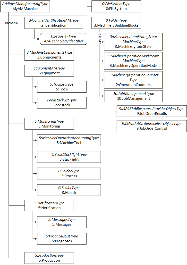
This Information Model provides the necessary ObjectTypes to model an additive manufacturing machine interface in a structure as illustrated in Figures 6. There are ObjectTypes that are used to identify the additive manufacturing machine (MachineIdentificationAMType), to identify and monitor production feedstock (FeedstockListType) and to manage the production (10:JobManagementType).
8 OPC UA ObjectTypes
8.1 AdditiveManufacturingType Definition
The AdditiveManufacturingType represents the entire additive manufacturing interface of this information model. It is the entry point to the OPC UA interface of an AM machine and provides a basic structure. An instance of this type aggregates all information related to one AM machine.
All instances of the AdditiveManufacturingType have to be referenced from the 3:Machines node defined in OPC 40001-1. At least one AdditiveManufacturingType instance shall be present to qualify for any profile of OPC UA for Additive Manufacturing.
The AdditiveManufacturingType is a subtype of the 5:MachineToolType as defined by OPC 40501-1. It contains the MachineIdentificationAMType, a subtype of 5:MachineToolIdentificationType, for further identification of the AM machine but inherits all other type definitions.
The AdditiveManufacturingType is formally defined in Table 13.
| Attribute | Value | ||||
| BrowseName | AdditiveManufacturingType | ||||
| IsAbstract | False | ||||
| References | Node Class | BrowseName | DataType | TypeDefinition | Other |
|---|---|---|---|---|---|
| Subtype of the 5:MachineToolType defined in OPC 40501-1 i.e. inheriting the InstanceDeclarations of that Node. | |||||
| 0:HasComponent | Object | 5:Equipment | EquipmentAMType | M | |
| 0:HasAddIn | Object | 2:Identification | MachineIdentificationAMType | M | |
| Conformance Units | |||||
|---|---|---|---|---|---|
| AdditiveManufacturing AdditiveManufacturingType Mandatory Nodes | |||||
| AdditiveManufacturing Monitoring - Process | |||||
| AdditiveManufacturing Monitoring - Health |
The components of the AdditiveManufacturingType have additional subcomponents which are defined in Table 14.
| Source Path | Reference | NodeClass | BrowseName | DataType | TypeDefinition | Others |
| 5:Monitoring | 0:HasComponent | Object | 3:Process | 0:FolderType | O | |
| 5:Monitoring | 0:HasComponent | Object | 3:Health | 0:FolderType | O | |
| 3:MachineryBuildingBlocks | 0:HasAddIn | Object | 10:JobManagement | 10:JobManagementType | O |
2:Identification is an instance of the MachineIdentificationAMType (see 8.2). Together with the other inherited instance declarations it is used to structure the information in the AdditiveManufacturingType topically.
5:Equipment is an instance of the EquipmentAMType (see 8.3). Together with the other inherited instance declarations it is used to structure the information in the AdditiveManufacturingType topically.
The 3:MachineryBuildingBlocks and 10:JobManagement shall be used as defined by OPC 40001-1 and OPC 40001-3.
5:Monitoring is an instance of the 5:MonitoringType and adds a 3:Process folder as an entry point to process information and 3:Health as and entry point for machine health information of the AM machine using the ProcessValueAMType.
8.2 MachineIdentificationAMType Definition
The MachineIdentificationAMType of the Additive Manufacturing information model holds static data which shall uniquely identify an AM machine among a pool of the AM machine operating entity. It is a subtype of the 5:MachineToolIdentificationType defined in OPC 40501-1, thus inheriting all InstanceDeclarations specified and is formally defined in Table 15.
| Attribute | Value | ||||
| BrowseName | MachineIdentificationAMType | ||||
| IsAbstract | False | ||||
| References | Node Class | BrowseName | DataType | TypeDefinition | Other |
|---|---|---|---|---|---|
| Subtype of the 5:MachineToolIdentificationType defined in OPC 40501-1 i.e. inheriting the InstanceDeclarations of that Node. | |||||
| 0:HasProperty | Variable | AMTechnologyIdentifier | 0:String | 0:PropertyType | M |
| Conformance Units | |||||
|---|---|---|---|---|---|
| AdditiveManufacturing Technology Identification |
For the 1:DeviceClass inherited from the 5:MachineToolIdentificationType, the values "Additive Manufacturing machine" or "Additive Manufacturing hybrid machine" shall be used as applicable.
For the AMTechnologyIdentifier the values in Table 16 should be used but might be extended by specifications using OPC 40540. The most appropriate value to identify the machine's main additive manufacturing technology category according to ISO/ASTM 52900 shall be used.
| Name | Value | Description |
| Binder Jetting | BJT | Liquid binding agent is selectively deposited onto powdered material |
| Directed Energy Deposition | DED | Focused thermal energy is used to melt and fuse the material during deposition |
| Material Extrusion | MEX | Material is selectively applied through a nozzle |
| Material Jetting | MJT | Molten material droplets are selectively jetted onto a build platform |
| Powder Bed Fusion | PBF | Focused thermal energy is used to melt and fuse parts of a powder bed |
| Sheet Lamination | SHL | Sheets of material are bonded together layer-by-layer to form a single piece |
| Vat Photopolymerization | VPP | Liquid photopolymer resin, cured by UV-light polymerization |
8.3 EquipmentAMType Definition
The EquipmentAMType is a subtype of the 5:EquipmentType as defined by OPC 40501-1. It provides lists for installed feedstock on the AM machine but inherits all other type definitions and is formally described in Table 15.
| Attribute | Value | ||||
| BrowseName | EquipmentAMType | ||||
| IsAbstract | False | ||||
| References | Node Class | BrowseName | DataType | TypeDefinition | Other |
|---|---|---|---|---|---|
| Subtype of the 5:EquipmentType defined in OPC 40501-1 i.e. inheriting the InstanceDeclarations of that Node. | |||||
| 0:HasComponent | Object | Feedstock | FeedstockListType | O | |
| Conformance Units | |||||
|---|---|---|---|---|---|
| AdditiveManufacturing Identify & Monitor Feedstock | |||||
Feedstock contains a list of raw materials currently installed on the AM machine.
8.4 ProcessValueAMType Definition
The ProcessValueAMType of the Additive Manufacturing information model provides sensor monitoring information of an AM machine that are a direct and active part of the machining process. It is a subtype of the 8:ProcessValueType defined in OPC 40001-2, thus inheriting all InstanceDeclarations specified and is formally defined in Table 18.
| Attribute | Value | ||||
| BrowseName | ProcessValueAMType | ||||
| IsAbstract | False | ||||
| References | Node Class | BrowseName | DataType | TypeDefinition | Other |
|---|---|---|---|---|---|
| Subtype of the 8:ProcessValueType defined in OPC 40001-2 i.e. inheriting the InstanceDeclarations of that Node. | |||||
| 0:HasProperty | Variable | Severity | SensorSeverity | 0:PropertyType | O |
| 0:HasProperty | Variable | Category | SensorCategory | 0:PropertyType | M |
| Conformance Units | |||||
|---|---|---|---|---|---|
| AdditiveManufacturing Monitoring - Process | |||||
| AdditiveManufacturing Monitoring - Health |
Severity indicates the criticality of the respective sensor data.
Category indicates the area of application of the respective sensor.
| Warnings and errors created by these process values shall be indicated by 0:Events sent via the 5:Notification node of the AdditiveManufacturingType. |
The 0:EngineeringUnits of the 0:AnalogSignal inherited from 8:ProcessValueType uses the 0:EUInformation to indicate the engineering unit of the process value represented. For the 0:EngineeringUnits only the recommendations according to 6.4 should be used.
8.5 FeedstockListType Definition
The FeedstockListType represents a list of feedstocks available on the AM machine.
The FeedstockListType is formally defined in Table 20.
| Attribute | Value | ||||
| BrowseName | FeedstockListType | ||||
| IsAbstract | False | ||||
| References | Node Class | BrowseName | DataType | TypeDefinition | Other |
|---|---|---|---|---|---|
| Subtype of the 0:BaseObjectType defined in OPC 10000-5 i.e. inheriting the InstanceDeclarations of that Node | |||||
| 0:HasComponent | Object | <Feedstock> | FeedstockType | MP | |
| 0:HasProperty | Variable | 0:NodeVersion | 0:String | 0:PropertyType | O |
| Conformance Units | |||||
|---|---|---|---|---|---|
| AdditiveManufacturing Identify & Monitor Feedstock |
<Feedstock> is an 0:MandatoryPlaceholder for nodes of FeedstockType. The feedstock list can thus contain any number of feedstock equal or greater than one. For the DisplayName of the <Feedstock>, it is recommended to use the value of the Name property of the respective FeedstockType instance.
The contents of the FeedstockListType instance can change during the server runtime (e.g., if feedstock is installed on the machine or removed from it). A change in the list can be indicated using the 0:GeneralModelChangeEventType and change of the 0:NodeVersion. The 0:GeneralModelChangeEventType is intended to be used in the way defined in OPC 10000-3.
8.6 FeedstockType Definition
The FeedstockType represents a feedstock installed on the AM Machine. A feedstock is used to produce an AM part. It may or may not be part of the finished part.
The FeedstockType is formally defined in Table 20.
| Attribute | Value | ||||
| BrowseName | FeedstockType | ||||
| IsAbstract | False | ||||
| References | Node Class | BrowseName | DataType | TypeDefinition | Other |
|---|---|---|---|---|---|
| Subtype of the 0:BaseObjectType defined in OPC 10000-5 i.e. inheriting the InstanceDeclarations of that Node | |||||
| 0:HasProperty | Variable | Identifier | 0:String | 0:PropertyType | M |
| 0:HasProperty | Variable | ExternalIdentifier | 0:String | 0:PropertyType | O |
| 0:HasProperty | Variable | Name | 0:String | 0:PropertyType | O |
| 0:HasComponent | Variable | Function | FeedstockFunction | 0:BaseDataVariableType | O |
| 0:HasProperty | Variable | 2:Manufacturer | 0:String | 0:PropertyType | O |
| 0:HasComponent | Variable | RemainingQuantity | 0:Number | 0:AnalogUnitType | O |
| 0:HasComponent | Variable | ReadyForProduction | 0:Boolean | 0:BaseDataVariableType | O |
| 0:HasComponent | Variable | Cycle | 0:UInt32 | 0:BaseDataVariableType | O |
| Conformance Units | |||||
|---|---|---|---|---|---|
| AdditiveManufacturing Identify & Monitor Feedstock |
The Identifier is the Identifier of the feedstock. This Identifier is used to determine the type of feedstock. For this reason, the Identifier shall be unique.
The Name is used as a human readable name of the feedstock used (e.g., "PLA_Black").
The ExternalIdentifier shall be used to identify the feedstock instance used (e.g., lot ID/batch ID). For this reason, the ExternalIdentifier shall be unique per feedstock identifier.
The Function indicates the usage purpose of a feedstock using the FeedstockFunction defined in 10.1.
The 2:Manufacturer is the original manufacturer of the feedstock.
The RemainingQuantity indicates the remaining amount of this feedstock instance installed on the AM machine. For the 0:EngineeringUnits only the recommendations according to 6.4 should be used.
ReadyForProduction indicates if the feedstock meets all AM machine specific preconditions to be used in a job (e.g. temperature).
The Cycle count may be used for technologies where the remaining feedstock is recycled in the following job. After a feedstock change, the Cycle count shall start at 0.
9 Predefined Job-Order-Input and Job-Order-Response Information
OPC 40001-3 and OPC 40501-1 define Job-Order-Input and Job-Order-Response information for the use case of 10:JobManagement on a machine.
This specification adds some standardized parameters, which are application-specific from the view of OPC 40540.
9.1 Predefined JobOrderParameters and JobResponseData
| ID | DataType of Value | Description | EngineeringUnits | Subparameters | In | Out |
| LayersPlanned | 0:UInt32 | Indicates how many layers are needed in order to successfully finish the job | - | - | x | - |
| Runs | RunInfoDataType[] | Array of job runs, which contain unique run identifiers and current layer counts. | - | - | - | x |
9.2 Material
| ID | DataType of Value | Description | EngineeringUnits | Subparameters | In | Out |
| Feedstock | 0:NodeId | Used to reference the feedstocks managed by the EquipmentAMType that are used to produce this part. | - | - | x | x |
10 OPC UA DataTypes
10.1 RunInfoDataType
This structure contains the information related to a job run. The structure is defined in Table 23.
| Name | Type | Description | Optional |
| RunInfoDataType | structure | Subtype of 0:Structure defined in OPC 10000-5 | |
CurrentLayer | 0:UInt32 | Counter that increases after each completed layer of the job run. This counter does not give any indication about the part quality. | True |
Identifier | 0:String | Identifier of the job run. This identifier is used to ensure an assignment of parts and job run(s). For this reason, the identifier shall be unique. | False |
State | 9:ISA95StateDataType | State information on job run level. This state works additionally to the overall job status. | False |
RemainingTime | 0:Duration | Describes the remaining process time in seconds. | True |
Its representation in the AddressSpace is defined in Table 24.
| Attribute | Value | ||||
| BrowseName | RunInfoDataType | ||||
| IsAbstract | False | ||||
| References | Node Class | BrowseName | DataType | TypeDefinition | Other |
|---|---|---|---|---|---|
| Subtype of the 0:Structure defined in OPC 10000-5 | |||||
| Conformance Units | |||||
|---|---|---|---|---|---|
| AdditiveManufacturing Job Management - Run Information |
10.2 FeedstockFunction Enumeration
This enumeration indicates the function of a specific feedstock.
The FeedstockFunction enumeration is defined in Table 26.
| Name | Value | Description |
| Undefined | 0 | The function of the feedstock is unknown. |
| Main | 1 | The feedstock is used for production and is part of the finished part. |
| Ancillary | 2 | The feedstock is used for production but removed before the part is finished. |
| Consumable | 3 | The feedstock is consumed during the production e.g., process gas. |
Its representation in the AddressSpace is defined in Table 27.
| Attribute | Value | ||||
| BrowseName | FeedstockFunction | ||||
| IsAbstract | False | ||||
| References | Node Class | BrowseName | DataType | TypeDefinition | Other |
|---|---|---|---|---|---|
| Subtype of the 0:Enumeration type defined in OPC 10000-3 | |||||
| 0:HasProperty | Variable | 0:EnumValues | 0:EnumValueType [] | 0:PropertyType | |
| Conformance Units | |||||
|---|---|---|---|---|---|
| AdditiveManufacturing Identify & Monitor Feedstock |
10.3 SensorSeverity Enumeration
This enumeration indicates the severity of the value of a specific sensor.
The SensorSeverity enumeration is defined in Table 28.
| Name | Value | Description |
| Info | 0 | This sensor's current value is not critical for the overall production |
| Critical | 1 | This sensor's current value is critical for the overall production |
Its representation in the AddressSpace is defined in Table 29.
| Attribute | Value | ||||
| BrowseName | SensorSeverity | ||||
| IsAbstract | False | ||||
| References | Node Class | BrowseName | DataType | TypeDefinition | Other |
|---|---|---|---|---|---|
| Subtype of the 0:Enumeration type defined in OPC 10000-3 | |||||
| 0:HasProperty | Variable | 0:EnumValues | 0:EnumValueType [] | 0:PropertyType | |
| Conformance Units | |||||
|---|---|---|---|---|---|
| AdditiveManufacturing Monitoring - Process | |||||
| AdditiveManufacturing Monitoring - Health |
10.4 SensorCategory Enumeration
This enumeration indicates the category of a specific sensor which further defines its area of application.
The SensorCategory enumeration is defined in Table 30.
| Name | Value | Description |
| MachineHealth | 0 | The sensor is mainly relevant to indicate the current AM machine's health. |
| MaintenanceTracking | 1 | The sensor is mainly relevant to track serviceable components |
| ProcessMonitoring | 2 | The sensor is mainly relevant to monitor the production operability. |
Its representation in the AddressSpace is defined in Table 31.
| Attribute | Value | ||||
| BrowseName | SensorSeverity | ||||
| IsAbstract | False | ||||
| References | Node Class | BrowseName | DataType | TypeDefinition | Other |
|---|---|---|---|---|---|
| Subtype of the 0:Enumeration type defined in OPC 10000-3 | |||||
| 0:HasProperty | Variable | 0:EnumValues | 0:EnumValueType [] | 0:PropertyType | |
| Conformance Units | |||||
|---|---|---|---|---|---|
| AdditiveManufacturing Monitoring - Process | |||||
| AdditiveManufacturing Monitoring - Health |
11 Finding AM Machine in a Server
All instances of AdditiveManufacturingType in a 0:Server shall be referenced from the 3:Machines Object as defined in OPC 40001-1. This provides the capability to easily find all AM machines managed in a 0:Server.
The 3:Machines Object may contain other nodes than instances of AdditiveManufacturingType.
12 Profiles and ConformanceUnits
12.1 ConformanceUnits
This section defines the corresponding 0:ConformanceUnits for the OPC UA Information Model for Additive Manufacturing.
| Category | Title | Description |
| Server | AdditiveManufacturing AdditiveManufacturingType Mandatory Nodes | All nodes declared as mandatory in the AdditiveManufacturingType are available in the AddressSpace. The nodes declared as optional may be included in the AddressSpace. At least one machine instance using the AdditiveManufacturingType is available in the 3:Machines folder. |
| Server | AdditiveManufacturing Technology Identification | The property AMTechnologyIdentifier is available in the AddressSpace and used in at least on instance of the AdditiveManufacturingType. |
| Server | AdditiveManufacturing Monitoring - Process | Supports the 5:MonitoringType with process information using the 3:Process folder and at least on instance of the ProcessValueAMType for a process related measurement. |
| Server | AdditiveManufacturing Monitoring - Health | Supports the 5:MonitoringType with process information using the 3:Health folder and at least on instance of the ProcessValueAMType for a process related measurement. |
| Server | AdditiveManufacturing Identify & Monitor Feedstock | All available feedstock on the AM machine is instantiated below Feedstock using the FeedstockType and its mandatory subcomponents. They are referenced with its 0:NodeId in a job with with ID Feedstock according to 9.2. |
| Server | AdditiveManufacturing Job Management - Run Information | Supports the 10:JobManagement and uses the RunInfoDataType to provide job run information of the jobs on the AM machine. |
| Server | AdditiveManufacturing Base256Sha256 | Support the SecurityPolicy http://opcfoundation.org/UA/SecurityPolicy#Basic256Sha256 |
| Server | AdditiveManufacturing Operation Counter | Supports the Machinery Operation Counter Facet http://opcfoundation.org/UA-Profile/Machinery/Server/OperationCounter |
12.2 Profiles
12.2.1 Profile List
Table 31 lists all Profiles defined in this document and defines their URIs.
| Profile | URI |
| AdditiveManufacturing Basic Server Profile | http://opcfoundation.org/UA-Profile/AdditiveManufacturing/Server/Basic |
| AdditiveManufacturing Basic Server ClientAuth Profile | http://opcfoundation.org/UA-Profile/AdditiveManufacturing/Server/BasicClientAuth |
12.2.2 Server Facets and Profiles
12.2.2.1 Overview
The following sections specify the Facets and Profiles available for Servers that implement the Additive Manufacturing companion specification. Each section defines and describes a Facet or Profile.
12.2.2.2 AdditiveManufacturing Basic Server Profile
Table 32 defines a Profile that describes the minimum required content and address space functionality any AM machine server shall at least provide. Concerning 5:Stacklight, it is expected that a server instantiates these elements if they are available on the AM machine.
| Group | ConformanceUnit/Profile Title | M/O |
| Profile | 0:Micro Embedded Device 2022 Server Profile | M |
| Base Information | 0:Base Info Custom Type System | M |
| Base Information | 0:Base Info Engineering Units | M |
| Base Information | 0:Base Info Placeholder Modelling Rules | M |
| Profile | 0:SecurityPolicy [A] - Aes128-Sha256-RsaOaep | M |
| AdditiveManufacturing | AdditiveManufacturing Base256Sha256 | O |
| Profile | 3:Machinery Machine Identification Server Facet | M |
| Machinery | 3:Machinery Building Block Organization | M |
| Profile | 4:IA Stacklight Server Profile | M |
| MachineTool | 5:MachineTool Monitor Items Min | M |
| MachineTool | 5:MachineTool Monitor Items | O |
| MachineTool | 5:MachineTool Monitoring Basic - Stacklight | M |
| AdditiveManufacturing | AdditiveManufacturing AdditiveManufacturingType Mandatory Nodes | M |
| AdditiveManufacturing | AdditiveManufacturing Technology Identification | M |
| AdditiveManufacturing | AdditiveManufacturing Operation Counter | O |
12.2.2.3 AdditiveManufacturing Basic Server ClientAuth Profile
Table 33 defines a Profile that adds security features for client authentication to the Additive Manufacturing Basic Server Profile.
| Group | ConformanceUnit/Profile Title | M/O |
| Profile | AdditiveManufacturing Basic Server Profile | M |
| Profile | 0:User Token - X509 Certificate Server Facet | M |
13 Namespaces
13.1 Namespace Metadata
Table 35 defines the namespace metadata for this document. The Object is used to provide version information for the namespace and an indication about static Nodes. Static Nodes are identical for all Attributes in all Servers, including the Value Attribute. See OPC 10000-5 for more details.
The information is provided as Object of type NamespaceMetadataType. This Object is a component of the Namespaces Object that is part of the Server Object. The NamespaceMetadataType ObjectType and its Properties are defined in OPC 10000-5.
The version information is also provided as part of the ModelTableEntry in the UANodeSet XML file. The UANodeSet XML schema is defined in OPC 10000-6.
| Attribute | Value | ||
| BrowseName | http://opcfoundation.org/UA/AdditiveManufacturing/ | ||
| Property | DataType | Value | |
|---|---|---|---|
| NamespaceUri | String | http://opcfoundation.org/UA/AdditiveManufacturing/ | |
| NamespaceVersion | String | 1.0.0 | |
| NamespacePublicationDate | DateTime | 2025-02-01 | |
| IsNamespaceSubset | Boolean | False | |
| StaticNodeIdTypes | IdType [] | 0 | |
| StaticNumericNodeIdRange | NumericRange [] | - | |
| StaticStringNodeIdPattern | String | - | |
13.2 Handling of OPC UA Namespaces
Namespaces are used by OPC UA to create unique identifiers across different naming authorities. The Attributes NodeId and BrowseName are identifiers. A Node in the UA AddressSpace is unambiguously identified using a NodeId. Unlike NodeIds, the BrowseName cannot be used to unambiguously identify a Node. Different Nodes may have the same BrowseName. They are used to build a browse path between two Nodes or to define a standard Property.
Servers may often choose to use the same namespace for the NodeId and the BrowseName. However, if they want to provide a standard Property, its BrowseName shall have the namespace of the standards body although the namespace of the NodeId reflects something else, for example the 0:EngineeringUnits Property. All NodeIds of Nodes not defined in this document shall not use the standard namespaces.
Table provides a list of mandatory and optional namespaces used in an Additive Manufacturing OPC UA Server.
| NamespaceURI | Description |
| http://opcfoundation.org/UA/ | Namespace for NodeIds and BrowseNames defined in the OPC UA specification. This namespace shall have namespace index 0. |
| Local Server URI | Namespace for nodes defined in the local server. This namespace shall have namespace index 1. |
| http://opcfoundation.org/UA/DI/ | Namespace for NodeIds and BrowseNames defined in OPC 10000-100. The namespace index is Server specific. |
| http://opcfoundation.org/UA/Machinery/ | Namespace for NodeIds and BrowseNames defined in OPC 40001-1. The namespace index is Server specific. |
| http://opcfoundation.org/UA/IA/ | Namespace for NodeIds and BrowseNames defined in OPC 10000-200. The namespace index is Server specific. |
| http://opcfoundation.org/UA/MachineTool/ | Namespace for NodeIds and BrowseNames defined in OPC 40501-1. The namespace index is Server specific. |
| http://opcfoundation.org/UA/Dictionary/IRDI | Namespace for NodeIds for IRDIs using HasDictionaryEntry (defined for example by OPC 30081). The namespace index is server specific. |
| http://opcfoundation.org/UA/PADIM/ | Namespace for NodeIds and BrowseNames defined in OPC 30081. The namespace index is Server specific. |
| http://opcfoundation.org/UA/Machinery/ProcessValues/ | Namespace for NodeIds and BrowseNames defined in OPC 40001-2. The namespace index is Server specific. |
| http://opcfoundation.org/UA/ISA95-JOBCONTROL_V2/ | Namespace for NodeIds and BrowseNames defined in OPC 10031-4. The namespace index is Server specific. |
| http://opcfoundation.org/UA/Machinery/Jobs/ | Namespace for NodeIds and BrowseNames defined in OPC 40001-3. The namespace index is Server specific. |
| http://opcfoundation.org/UA/AdditiveManufacturing/ | Namespace for NodeIds and BrowseNames defined in this document. The namespace index is Server specific. |
| Vendor specific types | A Server may provide vendor-specific types like types derived from ObjectTypes defined in this document in a vendor-specific namespace. |
| Vendor specific instances | A Server provides vendor-specific instances of the standard types or vendor-specific instances of vendor-specific types in a vendor-specific namespace. It is recommended to separate vendor specific types and vendor specific instances into two or more namespaces. |
Table 37 provides a list of namespaces and their indices used for BrowseNames in this document. The default namespace of this document is not listed since all BrowseNames without prefix use this default namespace.
| NamespaceURI | Namespace Index | Example |
| http://opcfoundation.org/UA/ | 0 | 0:EngineeringUnits |
| http://opcfoundation.org/UA/DI/ | 2 | 2:Identification |
| http://opcfoundation.org/UA/Machinery/ | 3 | 3:Machines |
| http://opcfoundation.org/UA/IA/ | 4 | 4:BasicStacklightType |
| http://opcfoundation.org/UA/MachineTool/ | 5 | 5:MachineToolType |
| http://opcfoundation.org/UA/Machinery/ProcessValues/ | 8 | 8:ProcessValueType |
| http://opcfoundation.org/UA/ISA95-JOBCONTROL_V2/ | 9 | 9:ISA95JobOrderReceiverObjectType |
| http://opcfoundation.org/UA/Machinery/Jobs/ | 10 | 10:JobManagement |
Annex A Additive Manufacturing Namespace and mappings (Normative)
A.1 NodeSet and Supplementary Files for AdditiveManufacturing Information Model
The AdditiveManufacturing Information Model is identified by the following URI:
http://opcfoundation.org/UA/AdditiveManufacturing/
Documentation for the NamespaceUri can be found here.
The NodeSet associated with this version of specification can be found here:
The NodeSet associated with the latest version of the specification can be found here:
The supplementary files associated with this version of specification can be found here:
The supplementary files associated with the latest version of the specification can be found here:
https://reference.opcfoundation.org/nodesets/?u=http://opcfoundation.org/UA/AdditiveManufacturing/
___________
Agreement of Use
COPYRIGHT RESTRICTIONS
This document is provided "as is" by the OPC Foundation and VDMA.
Right of use for this specification is restricted to this specification and does not grant rights of use for referred documents.
Right of use for this specification will be granted without cost.
This document may be distributed through computer systems, printed or copied as long as the content remains unchanged and the document is not modified.
OPC Foundation and VDMA do not guarantee usability for any purpose and shall not be made liable for any case using the content of this document.
The user of the document agrees to indemnify OPC Foundation and VDMA and their officers, directors and agents harmless from all demands, claims, actions, losses, damages (including damages from personal injuries), costs and expenses (including attorneys' fees) which are in any way related to activities associated with its use of content from this specification.
The document shall not be used in conjunction with company advertising, shall not be sold or licensed to any party.
The intellectual property and copyright is solely owned by the OPC Foundation and VDMA.
PATENTS
The attention of adopters is directed to the possibility that compliance with or adoption of OPC or VDMA specifications may require use of an invention covered by patent rights. OPC Foundation or VDMA shall not be responsible for identifying patents for which a license may be required by any OPC or VDMA specification, or for conducting legal inquiries into the legal validity or scope of those patents that are brought to its attention. OPC or VDMA specifications are prospective and advisory only. Prospective users are responsible for protecting themselves against liability for infringement of patents.
WARRANTY AND LIABILITY DISCLAIMERS
WHILE THIS PUBLICATION IS BELIEVED TO BE ACCURATE, IT IS PROVIDED "AS IS" AND MAY CONTAIN ERRORS OR MISPRINTS. THE OPC FOUDATION NOR VDMA MAKES NO WARRANTY OF ANY KIND, EXPRESSED OR IMPLIED, WITH REGARD TO THIS PUBLICATION, INCLUDING BUT NOT LIMITED TO ANY WARRANTY OF TITLE OR OWNERSHIP, IMPLIED WARRANTY OF MERCHANTABILITY OR WARRANTY OF FITNESS FOR A PARTICULAR PURPOSE OR USE. IN NO EVENT SHALL THE OPC FOUNDATION NOR VDMA BE LIABLE FOR ERRORS CONTAINED HEREIN OR FOR DIRECT, INDIRECT, INCIDENTAL, SPECIAL, CONSEQUENTIAL, RELIANCE OR COVER DAMAGES, INCLUDING LOSS OF PROFITS, REVENUE, DATA OR USE, INCURRED BY ANY USER OR ANY THIRD PARTY IN CONNECTION WITH THE FURNISHING, PERFORMANCE, OR USE OF THIS MATERIAL, EVEN IF ADVISED OF THE POSSIBILITY OF SUCH DAMAGES.
The entire risk as to the quality and performance of software developed using this specification is borne by you.
RESTRICTED RIGHTS LEGEND
This Specification is provided with Restricted Rights. Use, duplication or disclosure by the U.S. government is subject to restrictions as set forth in (a) this Agreement pursuant to DFARs 227.7202-3(a); (b) subparagraph (c)(1)(i) of the Rights in Technical Data and Computer Software clause at DFARs 252.227-7013; or (c) the Commercial Computer Software Restricted Rights clause at FAR 52.227-19 subdivision (c)(1) and (2), as applicable. Contractor / manufacturer are the OPC Foundation, 16101 N. 82nd Street, Suite 3B, Scottsdale, AZ, 85260-1830
COMPLIANCE
The combination of VDMA and OPC Foundation shall at all times be the sole entities that may authorize developers, suppliers and sellers of hardware and software to use certification marks, trademarks or other special designations to indicate compliance with these materials as specified within this document. Products developed using this specification may claim compliance or conformance with this specification if and only if the software satisfactorily meets the certification requirements set by VDMA or the OPC Foundation. Products that do not meet these requirements may claim only that the product was based on this specification and must not claim compliance or conformance with this specification.
TRADEMARKS
Most computer and software brand names have trademarks or registered trademarks. The individual trademarks have not been listed here.
GENERAL PROVISIONS
Should any provision of this Agreement be held to be void, invalid, unenforceable or illegal by a court, the validity and enforceability of the other provisions shall not be affected thereby.
This Agreement shall be governed by and construed under the laws of Germany.
This Agreement embodies the entire understanding between the parties with respect to, and supersedes any prior understanding or agreement (oral or written) relating to, this specification.