
1 Scope
OPC 40082-1 describes the interface for temperature control devices (TCD) for data exchange via OPC UA. The target of OPC 40082-1 is to provide a standardized interface for TCD from different manufacturers to ensure compatibility.
The following functionalities are covered:
General information about the temperature control device
Status information
Process data
Safety related signals like emergency stop are not included.
2 Normative references
The following documents are referred to in the text in such a way that some or all of their content constitutes requirements of this document. For dated references, only the edition cited applies. For undated references, the latest edition of the referenced document (including any amendments) applies
OPC 10000-1, OPC Unified Architecture - Part 1: Overview and Concepts
OPC 10000-1
OPC 10000-2, OPC Unified Architecture - Part 2: Security Model
OPC 10000-2
OPC 10000-3, OPC Unified Architecture - Part 3: Address Space Model
OPC 10000-3
OPC 10000-4, OPC Unified Architecture - Part 4: Services
OPC 10000-4
OPC 10000-5, OPC Unified Architecture - Part 5: Information Model
OPC 10000-5
OPC 10000-6, OPC Unified Architecture - Part 6: Mappings
OPC 10000-6
OPC 10000-7, OPC Unified Architecture - Part 7: Profiles
OPC 10000-7
OPC 10000-8, OPC Unified Architecture - Part 8: Data Access
OPC 10000-8
OPC 10000-9, OPC Unified Architecture - Part 9: Alarms and Conditions
OPC 10000-9
OPC 10000-11, OPC Unified Architecture - Part 11: Historical Access
OPC 10000-11
OPC 10001-1, OPC Unified Architecture V1.04 - Amendment 1: AnalogItem Types
http://www.opcfoundation.org/UA/Amendment1/
OPC 10001-3, OPC Unified Architecture V1.04 - Amendment 3: Method Metadata
http://www.opcfoundation.org/UA/Amendment3/
OPC 10000-100, OPC Unified Architecture - Part 100: Devices
OPC 10000-100
OPC 40083: OPC UA interfaces for plastics and rubber machinery - General Type definitions (version 1.02)
http://www.opcfoundation.org/UA/PlasticsRubber/GeneralTypes
3 Terms, definitions and conventions
3.1 Overview
It is assumed that basic concepts of OPC UA information modelling are understood in this specification. This specification will use these concepts to describe the OPC 40082-1 Information Model. For the purposes of this document, the terms and definitions given in the documents referenced in Clause 2 apply.
3.2 Conventions used in this document
The conventions described in OPC 40083 apply.
3.3 Abbreviations
| TCD | temperature control device |
4 General information to OPC UA interfaces for plastics and rubber machinery and OPC UA
For general information on OPC UA interfaces for plastics and rubber machinery and OPC UA see OPC 40083.
5 Use cases
OPC 40082-1 covers the following functionalities:
General information about the temperature control device
Status information
Process data
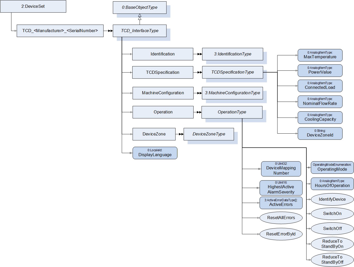
6 TCD_InterfaceType
6.1 TCD_InterfaceType Definition
This OPC UA ObjectType is used for the root Object representing a TCD with its subcomponents. It is formally defined in Table 1.
| Attribute | Value | ||||
| BrowseName | TCD_InterfaceType | ||||
| IsAbstract | False | ||||
| References | Node Class | BrowseName | DataType | TypeDefinition | Other |
|---|---|---|---|---|---|
| Subtype of 0:BaseObjectType defined in OPC UA Part 5 | |||||
| 0:HasComponent | Object | Identification | 3:IdentificationType | M | |
| 0:HasComponent | Object | TCDSpecification | TCDSpecificationType | M | |
| 0:HasComponent | Object | MachineConfiguration | 3:MachineConfigurationType | M | |
| 0:HasComponent | Object | Operation | OperationType | M | |
| 0:HasComponent | Object | DeviceZone | DeviceZoneType | M | |
| 0:HasProperty | Variable | DisplayLanguage | 0:LocaleId | 0:PropertyType | O, RW |
| 0:GeneratesEvent | ObjectType | TCDHelpOffNormalAlarmType | |||
The BrowseName of the object instance shall be "TCD_<Manufacturer>_<SerialNumber>"
Example: "TCD_HB-Therm_0123456".
Some TCD have several device zones (see 0). For these, the OPC UA server needs to create several instances of the TCD_InterfaceType. As the TCD has only one serial number, the BrowseNames of the objects shall include an extension e.g. "TCD_Wittmann_634_a" and "TCD_Wittmann_634_b".
Examples:
| BrowseName | Namespace | Namespace index | Remarks |
| TCD_HB-Therm_0123456 | Local Server URI or vendor specific namespace | 1 or server specific | OPC 40082-1 only defines the TCD_InterfaceType. The instance is generated in the local server |
| Identification | http://opcfoundation.org/UA/ PlasticsRubber/TCD/ | server specific | The object Identification is a child of TCD_InterfaceType which is defined in OPC 40082-1 |
| Manufacturer | http://opcfoundation.org/UA/ PlasticsRubber/GenrealTypes/ | server specific | The variable Manufacturer is a child of IdentificationType which is defined in OPC 40083. |
| BrowseName | Namespace | Namespace index | Remarks |
| TCD_HB-Therm_0123456 | Local Server URI or vendor specific namespace | 1 or server specific | OPC 40082-1 only defines the TCD_InterfaceType. The instance is generated in the local server |
| DeviceZone | http://opcfoundation.org/UA/ PlasticsRubber/TCD/ | server specific | The object DeviceZone is a child of TCD_InterfaceType which is defined in OPC 40082-1 |
| ExternalChannels | http://opcfoundation.org/UA/ PlasticsRubber/TCD/ | server specific | The object ExternalChannels is a child DeviceZoneType which is defined in OPC 40082-1 |
| ExternalChannel_1 | Local Server URI or vendor specific namespace | 1 or server specific | The objects for the extern channels are modelled as OptionalPlaceholder. The instances are server specific |
| PressureDifference | http://opcfoundation.org/UA/ PlasticsRubber/TCD/ | server specific | The object PressureDifference is a child ExternalChannelType which is defined in OPC 40082-1 |
| ActualValue | http://opcfoundation.org/UA/ PlasticsRubber/GenrealTypes/ | server specific | The variable ActualValue is a child of PressureDifference which has the MontoredItemType as type definition which is defined in OPC 40083 |
| BrowseName | Namespace | Namespace index | Remarks |
| TCD_HB-Therm_0123456 | Local Server URI or vendor specific namespace | 1 or server specific | OPC 40082-1 only defines the TCD_InterfaceType. The instance is generated in the local server |
| DeviceZone | http://opcfoundation.org/UA/ PlasticsRubber/TCD/ | server specific | The object DeviceZone is a child of TCD_InterfaceType which is defined in OPC 40082-1 |
| ExternalChannels | http://opcfoundation.org/UA/ PlasticsRubber/TCD/ | server specific | The object ExternalChannels is a child DeviceZoneType which is defined in OPC 40082-1 |
| NodeVersion | http://opcfoundation.org/UA/ | 0 | The Property NodeVersion is defined in OPC UA |
6.2 DisplayLanguage
With the DisplayLanguage Property the client can set the desired language on the user interface at the TCD. If the peripheral device does not support the configured language, it can keep the previous setting or use English as the default.
7 Identification
The IdentificationType for the identification of the device is defined in OPC 40083. All mandatory nodes shall be filled with valid values from the server.
The DeviceClass Property in the Identification Object shall have the value "Temperature Control Device".
8 TCDSpecificationType
This OPC UA ObjectType is used representing the basic specification of a TCD temperature control device with its subcomponents. It is formally defined in Table 2.
| Attribute | Value | ||||
| BrowseName | TCDSpecificationType | ||||
| IsAbstract | False | ||||
| References | Node Class | BrowseName | DataType | TypeDefinition | Other |
|---|---|---|---|---|---|
| Subtype of 0:BaseObjectType defined in OPC UA Part 5 | |||||
| 0:HasComponent | Variable | MaxTemperature | 0:Int32 | 0:AnalogItemType | M, RO |
| 0:HasComponent | Variable | PowerValue | 0:Double | 0:AnalogItemType | M, RO |
| 0:HasComponent | Variable | ConnectedLoad | 0:Double | 0:AnalogItemType | M, RO |
| 0:HasComponent | Variable | NominalFlowRate | 0:Double | 0:AnalogItemType | M, RO |
| 0:HasComponent | Variable | CoolingCapacity | 0:UInt32 | 0:AnalogItemType | O, RO |
| 0:HasProperty | Variable | DeviceZoneId | 0:String | 0:PropertyType | O, RO |
8.1 MaxTemperature
| Description: | Defines the maximum working temperature of the TCD |
| Unit: | °C or °F |
| Example: | 160 |
8.2 PowerValue
| Description: | Power value, defines the heating capacity of the TCD with the rated voltage |
| Unit: | kW |
| Example: | 8 |
8.3 ConnectedLoad
| Description: | Connected load, defines the connections of the TCD (pump performance, heating capacity and performance of the remaining components) |
| Unit: | kW |
| Example: | 10.2 |
8.4 NominalFlowRate
| Description: | Nominal flow rate, defines the maximum achievable flow rate of the TCD |
| Unit: | l/min, gal/min or ft³/min |
| Example: | 45 |
8.5 CoolingCapacity
| Description: | Power value for cooling, defines the power value for cooling at temperature difference 60 K between cooling water and heat transfer medium |
| Unit: | kW |
| Example: | 30 |
8.6 DeviceZoneId
| Description: | As written in 4.1, for a TCD with several device zones, there shall be several instances of TCD_InterfaceType with one object DeviceZone each. In this case, the DeviceZoneId shall be used to identify the different device zones. |
| Example: | "A" |
9 OperationType
This ObjectType contains components which are necessary to operate the TCD. It is formally defined in Table 3.
| Attribute | Value | ||||
| BrowseName | OperationType | ||||
| IsAbstract | False | ||||
| References | Node Class | BrowseName | DataType | TypeDefinition | Other |
|---|---|---|---|---|---|
| Subtype of 0:BaseObjectType defined in OPC UA Part 5 | |||||
| 0:HasProperty | Variable | DeviceMappingNumber | 0:UInt32 | 0:PropertyType | M, RW |
| 0:HasProperty | Variable | HighestActiveAlarmSeverity | 0:UInt16 | 0:PropertyType | M, R |
| 0:HasComponent | Variable | ActiveErrors | 3:ActiveErrorDataType[] | 0:BaseDataVariableType | M, R |
| 0:HasComponent | Method | ResetAllErrors | O | ||
| 0:HasComponent | Method | ResetErrorById | O | ||
| 0:HasProperty | Variable | OperatingMode | OperatingMode Enumeration | 0:PropertyType | M, RO |
| 0:HasComponent | Variable | HoursOfOperation | 0:Double | 0:AnalogItemType | O, RO |
| 0:HasComponent | Method | IdentifyDevice | O | ||
| 0:HasComponent | Method | SwitchOn | M | ||
| 0:HasComponent | Method | SwitchOff | M | ||
| 0:HasComponent | Method | ReduceToStandByOn | O | ||
| 0:HasComponent | Method | ReduceToStandByOff | O | ||
9.1 DeviceMappingNumber
| Description: | Unique identifier/address/number for devices of the same DeviceType within a local network. Several peripheral devices of the same DeviceType can be connected to a machine. In most applications, the machine must map the connected peripheral devices to internal logical devices and zones in a fixed configuration (e.g. hot runner systems according to the wiring or temperature control devices according to the tubing). The mapping shall be stable after reconnecting the devices and is therefore not possible via IP addresses, which can be assigned dynamically via DHCP. DeviceMappingNumber sets the mapping order of peripheral devices of the same type on the local network and is therefore of type UInt32. |
| Example: | 1 |
9.2 HighestActiveAlarmSeverity
| Description: | Indication of the severity of the highest active alarm (0 = no active alarm - 1000 = possible error). Together with ActiveErrors, it provides a minimal error handling for devices without alarm support. However, the variable shall be filled even if alarms are supported. |
| Example: | 400 |
9.3 ActiveErrors
| Description: | List of the active errors of the device. It provides a minimal error handling for devices without alarm support. However, the variable shall be filled even if alarms are supported. The ActiveErrorDataType is defined in OPC 40083. If there is no active error, the array is empty. |
9.4 ResetAllErrors
| Description: | Method to reset all errors of the device. |
Signature
ResetAllErrors();9.5 ResetErrorById
| Description: | Method to reset one error of the device. |
Signature
	ResetErrorById(
[in] String Id);| Argument | Description |
| Id | Id of the error, listed in ActiveErrors, that shall be reset. |
| Attribute | Value | ||||
| BrowseName | ResetErrorById | ||||
| References | Node Class | BrowseName | DataType | TypeDefinition | Modelling Rule |
|---|---|---|---|---|---|
| HasProperty | Variable | InputArguments | Argument[] | PropertyType | Mandatory |
9.6 OperatingMode
| Description: | Actual operating mode of the TCD. |
| Name | Value | Description |
| OTHER | 0 | Operating mode of the TCD is unknown |
| READY_TO_OPERATE | 1 | TCD is ready to operate (heating, pump and cooling are switched off) |
| NORMAL_OPERATION | 2 | TCD is running in normal operating mode |
| LEAK_STOPPER | 3 | TCD is running in leak stopper operating mode |
| MOULD_EVACUATION | 4 | TCD is carrying out a mould evacuation process |
| PRESSURE_RELIEF | 5 | TCD is carrying out a pressure relief process |
| COOLING | 6 | TCD is cooling down to StandbyTemperature and switch off |
| SAFETY_COOLING | 7 | TCD is cooling down to SwitchingOffTemperature and switch off |
| ECO | 8 | TCD is running in Eco operating mode (energy is saved via the reduced pump speed) |
| BOOST | 9 | TCD is running in Boost operating mode (pump runs at maximum possible speed) |
9.7 HoursOfOperation
| Description: | Actual hours of operation |
| Unit: | h |
| Example: | 4586 |
9.8 IdentifyDevice
| Description: | The TCD on which this method is called shows itself by e.g. activation of a LED. |
Signature
IdentifyDevice ();9.9 SwitchOn
| Description: | Main switch method of the TCD for switching on. OperatingMode shows the actual state of the device. |
Signature
SwitchOn ();9.10 SwitchOff
| Description: | Main switch method of the TCD for switching off. OperatingMode shows the actual state of the device. |
Signature
SwitchOff ();9.11 ReduceToStandByOn
| Description: | Activate the cooling down function on the TCD followed by switching off. OperatingMode shows the actual state of the device during the cooling down process. |
Signature
ReduceToStandByOn ();9.12 ReduceToStandByOff
| Description: | Deactivate the cooling down function on the TCD. If it is already in progress, it will be interrupted and the device changes back to the last selected operating mode. |
Signature
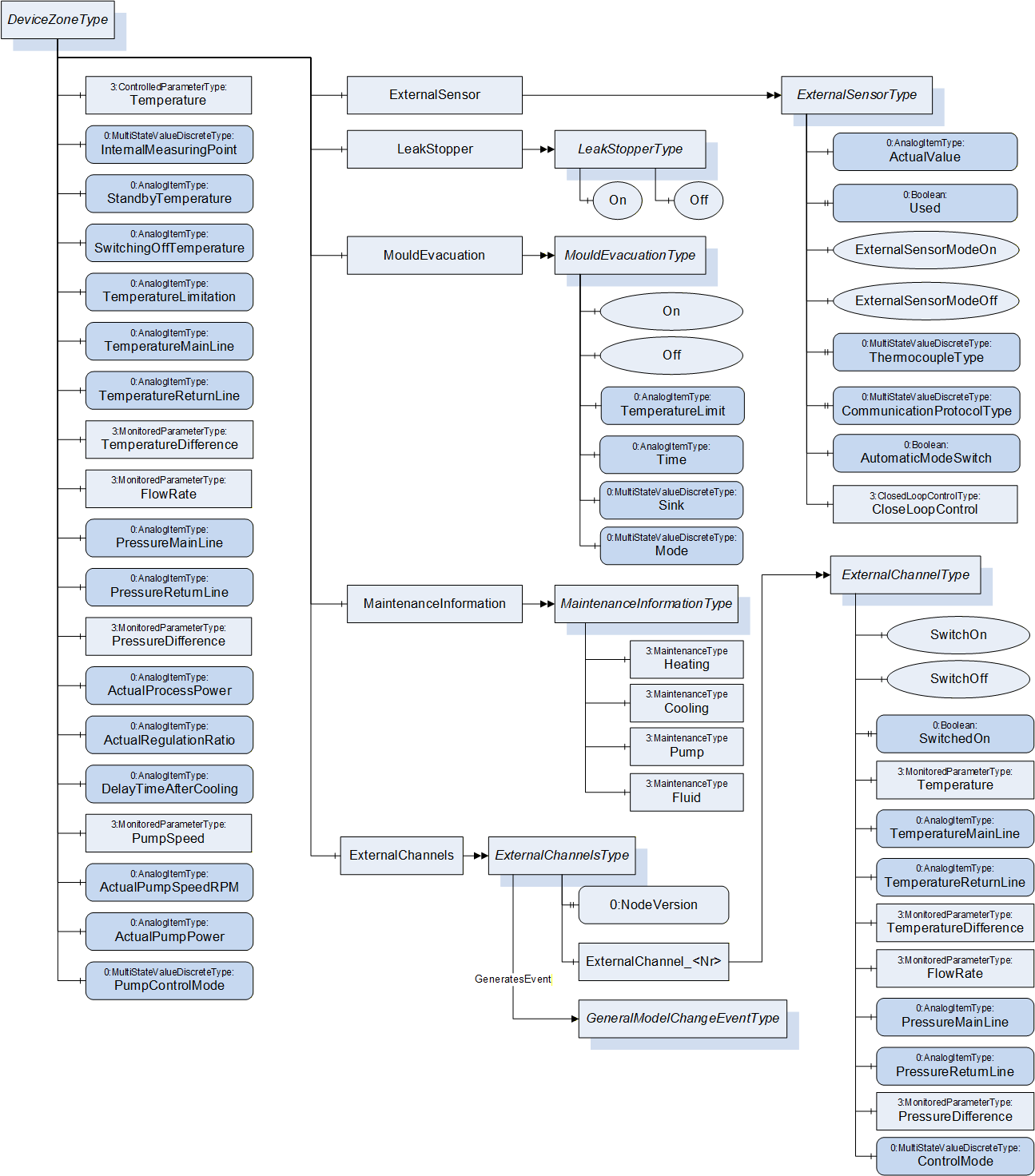
ReduceToStandByOff ();10 DeviceZoneType
The DeviceZoneType represents the functional main component of a TCD and is therefore mandatory.
| Attribute | Value | ||||
| BrowseName | DeviceZoneType | ||||
| IsAbstract | False | ||||
| References | Node Class | BrowseName | DataType | TypeDefinition | Other |
|---|---|---|---|---|---|
| Subtype of 0:BaseObjectType defined in OPC UA Part 5 | |||||
| 0:HasComponent | Object | Temperature | ControlledParameterType | M | |
| 0:HasComponent | Variable | InternalMeasuringPoint | 0:UInt16 | 0:MultiStateValueDiscreteType | O, RW |
| 0:HasComponent | Variable | StandbyTemperature | 0:Double | 0:AnalogItemType | O, RW |
| 0:HasComponent | Variable | SwitchingOffTemperature | 0:Double | 0:AnalogItemType | O, RW |
| 0:HasComponent | Variable | TemperatureLimitation | 0:Double | 0:AnalogItemType | O, RW |
| 0:HasComponent | Variable | TemperatureMainLine | 0:Double | 0:AnalogItemType | O, RO |
| 0:HasComponent | Variable | TemperatureReturnLine | 0:Double | 0:AnalogItemType | O, RO |
| 0:HasComponent | Object | TemperatureDifference | 3:MonitoredParameterType | O | |
| 0:HasComponent | Object | FlowRate | 3:MonitoredParameterType | O | |
| 0:HasComponent | Variable | PressureMainLine | 0:Double | 0:AnalogItemType | O, RO |
| 0:HasComponent | Variable | PressureReturnLine | 0:Double | 0:AnalogItemType | O, RO |
| 0:HasComponent | Object | PressureDifference | 3:MonitoredParameterType | O | |
| 0:HasComponent | Variable | ActualProcessPower | 0:Double | 0:AnalogItemType | O, RO |
| 0:HasComponent | Variable | ActualRegulationRatio | 0:Double | 0:AnalogItemType | O, RO |
| 0:HasComponent | Variable | DelayTimeAfterCooling | 0:Double | 0:AnalogItemType | O, RW |
| 0:HasComponent | Object | PumpSpeed | 3:MonitoredParameterType | O | |
| 0:HasComponent | Variable | ActualPumpSpeedRPM | 0:Double | 0:AnalogItemType | O, RO |
| 0:HasComponent | Variable | ActualPumpPower | 0:Double | 0:AnalogItemType | O, RO |
| 0:HasComponent | Variable | PumpControlMode | 0:UInt16 | 0:MultiStateValueDiscreteType | O, RW |
| 0:HasComponent | Object | ExternalSensor | ExternalSensorType | O | |
| 0:HasComponent | Object | LeakStopper | LeakStopperType | O | |
| 0:HasComponent | Object | MouldEvacuation | MouldEvacuationType | O | |
| 0:HasComponent | Object | MaintenanceInformation | MaintenanceInformationType | O | |
| 0:HasComponent | Object | ExternalChannels | ExternalChannelsType | O | |
10.1 Temperature
| Description: | Setting and/or monitoring of the temperature in the main or return line (see InternalMeasuringPoint) or active external Sensor (ExternalSensorModeOn) |
| Unit: | °C or °F |
| Example (for ActualValue): | 120 |
10.2 InternalMeasuringPoint
| Description: | This determines whether the temperature of the main or the return is to be controlled. |
The TypeDefinition is MultiStateValueDiscreteType, so the Properties EnumValues and ValueAsText must be filled with the supported values out of Table 8.
| EnumValue | ValueAsText | Description |
| 0 | MAIN_LINE | Control of the forward flow temperature |
| 1 | RETURN_LINE | Control of the return flow temperature |
10.3 StandbyTemperature
| Description: | The standby value temperature is approached with the Method ReduceToStandByOn. The TCD switches off. |
| Unit: | °C or °F |
| Example: | 35.0 |
10.4 SwitchingOffTemperature
| Description: | Defines the temperature to which the TCD must be cooled down before it switches off. |
| Unit: | °C or °F |
| Example: | 70.0 |
10.5 TemperatureLimitation
| Description: | This setpoint is for temperature limitation of the mould circuit e.g. to protect the connected tubes or the downstream water distribution system. |
| Unit: | °C or °F |
| Example: | 120 |
10.6 TemperatureMainLine
| Description: | Actual temperature in the main line. |
| Unit: | °C or °F |
| Example: | 100 |
10.7 TemperatureReturnLine
| Description: | Actual temperature in the return line. |
| Unit: | °C or °F |
| Example: | 105 |
10.8 TemperatureDifference
| Description: | Setting and/or monitoring of the temperature difference between return and main line. Positive if temperature in return line is higher than in main line. |
| Unit: | °C or °F |
| Example (for ActualValue): | 5 |
10.9 FlowRate
| Description: | Setting and/or monitoring of the flow rate. |
| Unit: | l/min, gal/min or ft³/min |
| Example (for ActualValue): | 10.0 |
10.10 PressureMainLine
| Description: | Actual pressure in the main line (Pressure return line + pump pressure). |
| Unit: | bar or lbf/in² (=psi) |
| Example: | 6.5 |
10.11 PressureReturnLine
| Description: | Actual pressure in the return line. |
| Unit: | bar or lbf/in² (=psi) |
| Example: | 6 |
10.12 PressureDifference
| Description: | Setting and/or monitoring of the pressure difference between main and return line |
| Unit: | bar or lbf/in² (=psi) |
| Example: | 2.8 |
10.13 ActualProcessPower
| Description: | Actual calculated process performance (from the view of the TCD: heating = positive value, cooling = negative value) |
| Unit: | kW |
| Example: | - 2.3 |
10.14 ActualRegulationRatio
| Description: | Actual Regulation Ratio (heating = positive value, cooling = negative value) |
| Unit: | % |
| Example: | -0.15 |
10.15 DelayTimeAfterCooling
| Description: | Delay Time after cooling before switching off the TCD |
| Unit: | min |
| Example: | 2 |
10.16 PumpSpeed
| Description: | Setting and/or monitoring the speed of the pump in percent of maximum speed |
| Unit: | % |
Example (for ActualValue): 100
10.17 ActualPumpSpeedRPM
| Description: | Actual speed of the pump in revolutions per minute |
| Unit: | min-1 |
| Example: | 3000 |
10.18 ActualPumpPower
| Description: | Actual power of the pump in kW |
| Unit: | kW |
| Example: | 1.5 |
10.19 PumpControlMode
| Description: | Defines to which setpoint or function the pump is controlled. The TypeDefinition is MultiStateValueDiscreteType, so the Properties EnumValues and ValueAsText must be filled with the supported values out of Table 9. |
| EnumValue | ValueAsText | Description |
| 0 | NORMAL | Normal Operation: fixed pump rotational speed |
| 1 | AUTO | Automatic adjustment of the pump rotational speed |
| 2 | SPEED | Speed controlled: the pump is controlled according to the specified nominal value PumpSpeed |
| 3 | FLOW | Flow rate controlled: the pump is controlled according to the specified nominal value FlowRate |
| 4 | TEMP_DIFF | Temperature difference controlled: the pump is controlled according to the specified nominal value TemperatureDifference |
| 5 | PRESS_DIFF | Pressure difference controlled: the pump is controlled according to the specified nominal value PressureDifference |
| 6 | BOOST | Boost mode: the pump is operated at the maximum possible rotational pump speed |
10.20 ExternalSensorType
ExternalSensor is an optional component from DeviceZoneType and includes variables for the operation with an external temperature sensor. The temperature sensor is connected at the TCD directly or the value can come from the connected machine.
| Attribute | Value | ||||
| BrowseName | ExternalSensorType | ||||
| IsAbstract | False | ||||
| References | Node Class | BrowseName | DataType | TypeDefinition | Other |
|---|---|---|---|---|---|
| Subtype of 0:aseObjectType defined in OPC UA Part 5 | |||||
| 0:HasComponent | Variable | ActualValue | 0:Double | 0:AnalogItemType | M, RW |
| 0:HasProperty | Variable | Used | 0:Boolean | 0:PropertyType | M, RO |
| 0:HasComponent | Method | ExternalSensorModeOn | M | ||
| 0:HasComponent | Method | ExternalSensorModeOff | M | ||
| 0:HasComponent | Variable | ThermocoupleType | 0:UInt16 | 0:MultiStateValueDiscreteType | M, RW |
| 0:HasComponent | Variable | CommunicationProtocolType | 0:UInt16 | 0:MultiStateValueDiscreteType | M, RW |
| 0: HasProperty | Variable | AutomaticModeSwitch | 0:Boolean | 0:PropertyType | O, RW |
| 0:HasComponent | Object | ClosedLoopControl | 3:ClosedLoopControlType | O | |
10.20.1 ActualValue
| Description: | Actual value of external temperature sensor |
| Unit: | °C or °F |
| Example: | 41.0 |
The value is only writeable if the CommunicationProtocolType is OPC_UA (value 3).
10.20.2 Used
| Description: | Return whether an external temperature sensor is used for control |
| Example: | true |
10.20.3 ExternalSensorModeOn
| Description: | Activate the mode where the external temperature sensor is used for temperature control |
Signature
ExternalSensorModeOn ();10.20.4 ExternalSensorModeOff
| Description: | Deactivate the mode where the external temperature sensor is used for temperature control |
Signature
ExternalSensorModeOff ();10.20.5 ThermocoupleType and CommunicationProtocolType
This two Variables are used to specify the type of connected external temperature sensor and the used communication protocol between the sensor and the control system of the TCD.
The TypeDefinition for both Variables is MultiStateValueDiscreteType, so the Properties EnumValues and ValueAsText must be filled with the supported values out of Table 11 and Table 12.
| EnumValue | ValueAsText | Description |
| 0 | OTHER | Other sensor type |
| 1 | E | Type E sensor: NiCr-CuNi |
| 2 | J | Type J, L sensor: Fe-CuNi |
| 3 | K | Type K sensor: NiCr-Ni |
| 4 | N | Type N sensor: NiCrSi-NiSi |
| 5 | T | Type T sensor: Cu-CuNi |
| 6 | PT100 | Pt 100-Sensor |
| EnumValue | ValueAsText | Description |
| 0 | OTHER | Other connection type |
| 1 | LOCAL | Communication integrated in the local control system (local input) |
| 2 | PROFIBUS | Values via Profibus |
| 3 | OPC_UA | Values via OPC UA |
| 4 | I2C | Values via I2C |
| 5 | CAN | Values via CAN |
Which sensor types and protocols and combinations are supported is device dependent. Especially when the CommunicationProtocolType has the value 1 (LOCAL), the ThermocoupleType could be set to a fixed value by the TCD.
10.20.6 AutomaticModeSwitch
Setting whether switching to external sensor is performed automatically (TRUE) or manually (FALSE). If TRUE, temperature control is regulated to the external sensor when the external sensor is plugged, and again switched automatically to the internal measurement site when the external sensor is unplugged.
10.20.7 ClosedLoopControl
With this Object of ClosedLoopControlType (defined in OPC 40083) the client can do settings for the closed loop control for the sensor.
10.21 LeakStopperType
LeakStopperType is an optional component of DeviceZoneType and is used for switching the leak stopper mode.
| Attribute | Value | ||||
| BrowseName | LeakStopperType | ||||
| IsAbstract | False | ||||
| References | Node Class | BrowseName | DataType | TypeDefinition | Other |
|---|---|---|---|---|---|
| Subtype of 0:BaseObjectType defined in OPC UA Part 5 | |||||
| 0:HasComponent | Method | On | M | ||
| 0:HasComponent | Method | Off | M | ||
10.21.1 On
| Description: | Activate the leak stopper mode (emergency operation in case of leaks in the system) |
Signature
On ();10.21.2 Off
| Description: | Deactivate the leak stopper mode |
Signature
Off ();10.22 MouldEvacuationType
MouldEvacuationType is an optional component of DeviceZoneType and includes parameters and nodes for mould evacuation.
| Attribute | Value | ||||
| BrowseName | MouldEvacuationType | ||||
| IsAbstract | False | ||||
| References | Node Class | BrowseName | DataType | TypeDefinition | Other |
|---|---|---|---|---|---|
| Subtype of 0:BaseObjectType defined in OPC UA Part 5 | |||||
| 0:HasComponent | Method | On | M | ||
| 0:HasComponent | Method | Off | M | ||
| 0:HasComponent | Variable | TemperatureLimit | 0:Double | 0:AnalogItemType | O, RW |
| 0:HasComponent | Variable | Time | 0:Double | 0:AnalogItemType | O, RW |
| 0:HasComponent | Variable | Sink | 0:UInt16 | 0:MultiStateValueDiscreteType | O, RW |
| 0:HasComponent | Variable | Mode | 0:UInt16 | 0:MultiStateValueDiscreteType | O, RW |
10.22.1 On
| Description: | Activate evacuation mode |
Signature
On ();10.22.2 Off
| Description: | Deactivate evacuation mode |
Signature
Off ();10.22.3 TemperatureLimit
| Description: | Temperature Limitation of the mould evacuation. TCD is cooled to this temperature first if necessary. |
| Unit: | °C or °F |
| Example: | 70 |
10.22.4 Time
| Description: | Duration of the mould evacuation. |
| Unit: | s |
| Example: | 45 |
10.22.5 Sink
| Description: | Defines where the medium is to be emptied |
The TypeDefinition is MultiStateValueDiscreteType, so the Properties EnumValues and ValueAsText must be filled with the supported values out of Table 15.
| EnumValue | ValueAsText | Description |
| 0 | DRAIN | medium is passed into the cooling or system water outlet |
| 1 | TANK | medium is conducted in a separate outlet |
10.22.6 Mode
| Description: | Defines how the medium is to be emptied. |
The TypeDefinition is MultiStateValueDiscreteType, so the Properties EnumValues and ValueAsText must be filled with the supported values out of Table 16.
| EnumValue | ValueAsText | Description |
| 0 | PUMP | Evacuation by the pump |
| 1 | COMPRESSED_AIR | Evacuation with compressed air |
10.23 MaintenanceInformationType
Information on the maintenance status of heating, cooling, pump and fluid.
| Attribute | Value | ||||
| BrowseName | MaintenanceInformationType | ||||
| IsAbstract | False | ||||
| References | Node Class | BrowseName | DataType | TypeDefinition | Other |
|---|---|---|---|---|---|
| Subtype of 0:BaseObjectType defined in OPC UA Part 5 | |||||
| 0:HasComponent | Object | Heating | 3:MaintenanceType | O | |
| 0:HasComponent | Object | Cooling | 3:MaintenanceType | O | |
| 0:HasComponent | Object | Pump | 3:MaintenanceType | O | |
| 0:HasComponent | Object | Fluid | 3:MaintenanceType | O | |
The MaintenanceType is defined in OPC 40083.
10.24 ExternalChannelsType
This ObjectType is a container for the external channel(s). It is formally defined in Table 18.
| Attribute | Value | ||||
| BrowseName | ExternalChannelsType | ||||
| IsAbstract | False | ||||
| References | Node Class | BrowseName | DataType | TypeDefinition | Other |
|---|---|---|---|---|---|
| Subtype of 0:BaseObjectType defined in OPC UA Part 5 | |||||
| 0:HasProperty | Variable | 0:NodeVersion | String | 0:PropertyType | M, RO |
| 0:HasComponent | Object | ExternalChannel_<Nr> | ExternalChannelType | OP | |
| 0:GeneratesEvent | ObjectType | 0:GeneralModelChangeEventType | |||
When instances for device zones are created, the BrowseNames shall be "ExternalChannel_<Nr>" (starting with 1).
10.25 ExternalChannelType
ExternalChannelType includes information for monitoring or controlling of external temperature, flow rate or pressure channels. (One zone of the TCD is split into several external channels).
| Attribute | Value | ||||
| BrowseName | ExternalChannelType | ||||
| IsAbstract | False | ||||
| References | Node Class | BrowseName | DataType | TypeDefinition | Other |
|---|---|---|---|---|---|
| Subtype of 0:BaseObjectType defined in OPC UA Part 5 | |||||
| 0:HasComponent | Method | SwitchOn | O | ||
| 0:HasComponent | Method | SwitchOff | O | ||
| 0:HasProperty | Variable | SwitchedOn | 0:Boolean | 0:PropertyType | O, RO |
| 0:HasComponent | Object | Temperature | 3:MonitoredParameterType | O | |
| 0:HasComponent | Variable | TemperatureMainLine | 0:Double | 0:AnalogItemType | O, RO |
| 0:HasComponent | Variable | TemperatureReturnLine | 0:Double | 0:AnalogItemType | O, RO |
| 0:HasComponent | Object | TemperatureDifference | 3:MonitoredParameterType | O | |
| 0:HasComponent | Object | FlowRate | 3:MonitoredParameterType | O | |
| 0:HasComponent | Variable | PressureMainLine | 0:Double | 0:AnalogItemType | O, RO |
| 0:HasComponent | Variable | PressureReturnLine | 0:Double | 0:AnalogItemType | O, RO |
| 0:HasComponent | Object | PressureDifference | 3:MonitoredParameterType | O | |
| 0:HasComponent | Variable | ControlMode | 0:UInt16 | 0:MultiStateValueDiscreteType | O, RW |
10.25.1 SwitchOn
| Description: | Switch method of the external channel for switching on. SwitchedOn shows the actual state of the channel. |
Signature
SwitchOn ();10.25.2 SwitchOff
| Description: | Switch method of the external channel for switching off. SwitchedOn shows the actual state of the channel. |
Signature
SwitchOff ();10.25.3 SwitchedOn
| Description: | Information if the external channel is switched on. If the methods SwitchOn and SwitchOff are provided, also this Property shall be available. |
| Example: | TRUE |
10.25.4 Temperature
| Description: | Setting and/or monitoring of the temperature |
| Unit: | °C or °F |
| Example (for ActualValue): | 120 |
10.25.5 TemperatureMainLine
| Description: | Actual temperature in the main line |
| Unit: | °C or °F |
| Example: | 120 |
10.25.6 TemperatureReturnLine
| Description: | Actual temperature in the return line |
| Unit: | °C or °F |
| Example: | 115 |
10.25.7 TemperatureDifference
| Description: | Setting and/or monitoring of the temperature difference between return and main line. Positive if temperature in return line is higher than in main line. |
| Unit: | °C, K or °F |
| Example (for ActualValue): | 5 |
10.25.8 FlowRate
| Description: | Setting and/or monitoring of the flow rate. |
| Unit: | l/min, gal/min or ft³/min |
| Example (for ActualValue): | 10,0 |
10.25.9 PressureMainLine
| Description: | Actual value of the pressure in the main line. |
| Unit: | bar or lbf/in² (=psi) |
| Example: | 6 |
10.25.10 PressureReturnLine
| Description: | Actual value of the pressure in the return line. |
| Unit: | bar or lbf/in² (=psi) |
| Example: | 5 |
10.25.11 PressureDifference
| Description: | Setting and/or monitoring of the pressure difference between main and return line |
| Unit: | bar or lbf/in² (=psi) |
| Example (for ActualValue): | 2.5 |
10.25.12 ControlMode
| Description: | Defines to which setpoint the external channel is controlled |
The TypeDefinition is MultiStateValueDiscreteType, so the Properties EnumValues and ValueAsText must be filled with the supported values out of Table 20.
| EnumValue | ValueAsText | Description |
| 0 | NONE | No control, only monitoring |
| 1 | TEMPERATURE | Temperature controlled |
| 2 | FLOW | Flow rate controlled |
| 3 | TEMP_DIFF | Temperature difference controlled |
| 4 | PRESS_DIFF | Pressure difference controlled |
11 Alarms
For alarms (alarms, warnings, information) of the TCD the TCDHelpOffNormalAlarmType as defined in Table 21 shall be used, if the alarm facet is supported. A machine which connects to a TCD via OPC 40082-1 shall subscribe this event.
| Attribute | Value | ||||
| BrowseName | TCDHelpOffNormalAlarmType | ||||
| IsAbstract | False | ||||
| References | Node Class | BrowseName | DataType | TypeDefinition | Other |
|---|---|---|---|---|---|
| Subtype of 3:HelpOffNormalAlarmType (defined in OPC 40083) | |||||
| 0:HasProperty | Variable | DeviceMappingNumber | 0:UInt32 | 0:PropertyType | M, RO |
The value of DeviceMappingNumber corresponds to the value given in the instance of the OperationType (see 9.1) for assigning the alarm to a device.
For unique identification of the alarm event, the SourceNode (included in BaseEventType) of the device needs to be sent for every alarm message. The SourceNode includes the namespace number and the Identifier from the object instance of TCD_InterfaceType (for general events) or the NodeId of a child element (e.g. a variable of MonitoredParameterType if this is out of tolerance).
For the Severity Property (included in BaseEventType) the following classes shall be used:
| Range of Severity | Description |
| 667-1000 | Messages of high urgency (error, system alarm): Acknowledgement: compulsory |
| 334-666 | Messages of medium urgency (warning, process alarm): Limit values have been exceeded. The transgression has no influence on the operational safety of the unit. Acknowledgement: not compulsory |
| 1-333 | Messages of low urgency (Information) |
12 Profiles and Conformance Units
This chapter defines the corresponding profiles and conformance units for the OPC UA Information Model for OPC 40082-1. Profiles are named groupings of conformance units. Facets are profiles that will be combined with other Profiles to define the complete functionality of an OPC UA Server or Client. The following tables specify the facets available for Servers that implement the OPC 40082-1 Information Model companion specification.
Table 23 lists all Profiles defined in this document and defines their URIs.
| Profile | URI |
| OPC 40082-1 Basic Server Profile | http://opcfoundation.org/UA-Profile/PlasticsRubber/TCD/Server/Basic |
| OPC 40082-1 Alarms Server Facet | http://opcfoundation.org/UA-Profile/PlasticsRubber/TCD/Server/Alarms |
| OPC 40082-1 Maintenance Server Facet | http://opcfoundation.org/UA-Profile/PlasticsRubber/TCD/Server/Maintenance |
| Conformance Unit | Description | Optional/ Mandatory |
| OPC 40082-1 Basic | Support of TCD_lnterfaceType and all mandatory child elements giving information on the temperature control device itself, the current configuration and status. | M |
| Profile | ||
| ComplexType Server Facet (defined in OPC UA Part 7) | M | |
| Method Server Facet (defined in OPC UA Part 7) | M | |
| BaseDevice_Server_Facet (defined in OPC UA Part 100) | M | |
| Conformance Unit | Description | Optional/ Mandatory |
| OPC 40082-1 Alarms | Support of HelpOffNormalAlarmType providing error information. If this facet is supported and a client subscribes to the events, the server shall provide all errors via alarms in addition to the error variables included in the OperationType | M |
| A & C Alarm Server Facet (defined in OPC UA Part 7) | M | |
| Conformance Unit | Description | Optional/ Mandatory |
| OPC 40082-1 Maintenance | Support of MaintenanceType for device zones | M |
13 Namespaces
13.1 Namespace Metadata
Table 27 defines the namespace metadata for this specification. The Object is used to provide version information for the namespace and an indication about static Nodes. Static Nodes are identical for all Attributes in all Servers, including the Value Attribute. See Part5 for more details.
The information is provided as Object of type NamespaceMetadataType. This Object is a component of the Namespaces Object that is part of the Server Object. The NamespaceMetadataType ObjectType and its Properties are defined in Part5.
The version information is also provided as part of the ModelTableEntry in the UANodeSet XML file. The UANodeSet XML schema is defined in Part 6.
| Attribute | Value | |||
| BrowseName | http://opcfoundation.org/UA/PlasticsRubber/TCD/ | |||
| References | BrowseName | DataType | Value | |
|---|---|---|---|---|
| HasProperty | NamespaceUri | String | http://opcfoundation.org/UA/PlasticsRubber/TCD/ | |
| HasProperty | NamespaceVersion | String | 1.01 | |
| HasProperty | NamespacePublicationDate | DateTime | 2020-06-01 00:00:00 | |
| HasProperty | IsNamespaceSubset | Boolean | False | |
| HasProperty | StaticNodeIdTypes | IdType[] | {Numeric} | |
| HasProperty | StaticNumericNodeIdRange | NumericRange[] | Null | |
| HasProperty | StaticStringNodeIdPattern | String | Null | |
13.2 Handling of OPC UA Namespaces
Namespaces are used by OPC UA to create unique identifiers across different naming authorities. The Attributes NodeId and BrowseName are identifiers. A Node in the UA AddressSpace is unambiguously identified using a NodeId. Unlike NodeIds, the BrowseName cannot be used to unambiguously identify a Node. Different Nodes may have the same BrowseName. They are used to build a browse path between two Nodes or to define a standard Property.
Servers may often choose to use the same namespace for the NodeId and the BrowseName. However, if they want to provide a standard Property, its BrowseName shall have the namespace of the standards body although the namespace of the NodeId reflects something else, for example the EngineeringUnits Property. All NodeIds of Nodes not defined in this document shall not use the standard namespaces.
Table 28 provides a list of mandatory and optional namespaces used in an OPC 40082-1 OPC UA Server.
| NamespaceURI | Description | Use |
| http://opcfoundation.org/UA/ | Namespace for NodeIds and BrowseNames defined in the OPC UA specification. This namespace shall have namespace index 0. | Mandatory |
| Local Server URI | Namespace for nodes defined in the local server. This may include types and instances used in a device represented by the server. This namespace shall have namespace index 1. | Mandatory |
| http://opcfoundation.org/UA/DI/ | Namespace for NodeIds and BrowseNames defined in OPC UA Part 100. The namespace index is server specific. | Mandatory |
http://opcfoundation.org/UA/PlasticsRubber/ GeneralTypes/ | Namespace for NodeIds and BrowseNames defined in OPC 40083. The namespace index is server specific. | Mandatory |
http://opcfoundation.org/UA/PlasticsRubber/ TCD/ | Namespace for NodeIds and BrowseNames defined in this specification. The namespace index is server specific. | Mandatory |
| Vendor specific types and instances | A server may provide vendor specific types like types derived from MachineType or MachineStatusType or vendor specific instances of devices in a vendor specific namespace. | Optional |
Table 29 provides a list of namespaces and their index used for BrowseNames in this specification. The default namespace of this specification is not listed since all BrowseNames without prefix use this default namespace.
| NamespaceURI | Namespace Index | Example |
| http://opcfoundation.org/UA/ | 0 | 0:NodeVersion |
| http://opcfoundation.org/UA/DI/ | 2 | 2:DeviceClass |
| http://opcfoundation.org/UA/PlasticsRubber/GeneralTypes/ | 3 | 3:MachineInformationType |
Annex A OPC 40082-1 Namespace and mappings (Normative)
A.1 Namespace and identifiers for OPC 40082-1 Information Model
This appendix defines the numeric identifiers for all of the numeric NodeIds defined in this specification. The identifiers are specified in a CSV file with the following syntax:
<SymbolName>, <Identifier>, <NodeClass>Where the SymbolName is either the BrowseName of a Type Node or the BrowsePath for an Instance Node that appears in the specification and the Identifier is the numeric value for the NodeId.
The BrowsePath for an Instance Node is constructed by appending the BrowseName of the instance Node to the BrowseName for the containing instance or type. An underscore character is used to separate each BrowseName in the path. Let's take for example, the MachineInformationType ObjectType Node which has the ControllerName Property. The Name for the ControllerName InstanceDeclaration within the MachineInformationType declaration is: MachineInformationType_ControllerName.
The NamespaceUri for all NodeIds defined here is http://opcfoundation.org/UA/PlasticsRubber/TCD/
The CSV released with this version of the specification can be found here:
http://www.opcfoundation.org/UA/schemas/PlasticsRubber/TCD/1.01/NodeIds.csv
http://www.opcfoundation.org/UA/schemas/PlasticsRubber/TCD/NodeIds.csv
A computer processible version of the complete Information Model defined in this specification is also provided. It follows the XML Information Model schema syntax defined in Part 6.
The Information Model Schema released with this version of the specification can be found here:
http://www.opcfoundation.org/UA/schemas/PlasticsRubber/TCD/Opc.Ua.PlasticsRubber.TCD.NodeSet2.xml
___________
Agreement of Use
COPYRIGHT RESTRICTIONS
This document is provided "as is" by the OPC Foundation and EUROMAP.
Right of use for this specification is restricted to this specification and does not grant rights of use for referred documents.
Right of use for this specification will be granted without cost.
This document may be distributed through computer systems, printed or copied as long as the content remains unchanged and the document is not modified.
OPC Foundation and EUROMAP do not guarantee usability for any purpose and shall not be made liable for any case using the content of this document.
The user of the document agrees to indemnify OPC Foundation and EUROMAP and their officers, directors and agents harmless from all demands, claims, actions, losses, damages (including damages from personal injuries), costs and expenses (including attorneys' fees) which are in any way related to activities associated with its use of content from this specification.
The document shall not be used in conjunction with company advertising, shall not be sold or licensed to any party.
The intellectual property and copyright is solely owned by the OPC Foundation and EUROMAP.
PATENTS
The attention of adopters is directed to the possibility that compliance with or adoption of OPC or EUROMAP specifications may require use of an invention covered by patent rights. OPC Foundation or EUROMAP shall not be responsible for identifying patents for which a license may be required by any OPC or EUROMAP specification, or for conducting legal inquiries into the legal validity or scope of those patents that are brought to its attention. OPC or EUROMAP specifications are prospective and advisory only. Prospective users are responsible for protecting themselves against liability for infringement of patents.
WARRANTY AND LIABILITY DISCLAIMERS
WHILE THIS PUBLICATION IS BELIEVED TO BE ACCURATE, IT IS PROVIDED "AS IS" AND MAY CONTAIN ERRORS OR MISPRINTS. THE OPC FOUDATION NOR EUROMAP MAKES NO WARRANTY OF ANY KIND, EXPRESSED OR IMPLIED, WITH REGARD TO THIS PUBLICATION, INCLUDING BUT NOT LIMITED TO ANY WARRANTY OF TITLE OR OWNERSHIP, IMPLIED WARRANTY OF MERCHANTABILITY OR WARRANTY OF FITNESS FOR A PARTICULAR PURPOSE OR USE. IN NO EVENT SHALL THE OPC FOUNDATION NOR EUROMAP BE LIABLE FOR ERRORS CONTAINED HEREIN OR FOR DIRECT, INDIRECT, INCIDENTAL, SPECIAL, CONSEQUENTIAL, RELIANCE OR COVER DAMAGES, INCLUDING LOSS OF PROFITS, REVENUE, DATA OR USE, INCURRED BY ANY USER OR ANY THIRD PARTY IN CONNECTION WITH THE FURNISHING, PERFORMANCE, OR USE OF THIS MATERIAL, EVEN IF ADVISED OF THE POSSIBILITY OF SUCH DAMAGES.
The entire risk as to the quality and performance of software developed using this specification is borne by you.
RESTRICTED RIGHTS LEGEND
This Specification is provided with Restricted Rights. Use, duplication or disclosure by the U.S. government is subject to restrictions as set forth in (a) this Agreement pursuant to DFARs 227.7202-3(a); (b) subparagraph (c)(1)(i) of the Rights in Technical Data and Computer Software clause at DFARs 252.227-7013; or (c) the Commercial Computer Software Restricted Rights clause at FAR 52.227-19 subdivision (c)(1) and (2), as applicable. Contractor / manufacturer are the OPC Foundation, 16101 N. 82nd Street, Suite 3B, Scottsdale, AZ, 85260-1830
COMPLIANCE
The combination of EUROMAP and OPC Foundation shall at all times be the sole entities that may authorize developers, suppliers and sellers of hardware and software to use certification marks, trademarks or other special designations to indicate compliance with these materials as specified within this document. Products developed using this specification may claim compliance or conformance with this specification if and only if the software satisfactorily meets the certification requirements set by EUROMAP or the OPC Foundation. Products that do not meet these requirements may claim only that the product was based on this specification and must not claim compliance or conformance with this specification.
TRADEMARKS
Most computer and software brand names have trademarks or registered trademarks. The individual trademarks have not been listed here.
GENERAL PROVISIONS
Should any provision of this Agreement be held to be void, invalid, unenforceable or illegal by a court, the validity and enforceability of the other provisions shall not be affected thereby.
This Agreement shall be governed by and construed under the laws of Germany.
This Agreement embodies the entire understanding between the parties with respect to, and supersedes any prior understanding or agreement (oral or written) relating to, this specification.