
1 Scope
This document 40719 specifies a Companion Specification for plasma surface treatment machinery.
Plasma surface treatment machinery in this context can be any existing or future plasma surface treatment machinery. The implicit and explicit information model specified by the plasma surface treatment machinery Companion Specification will be defined as a UA companion specification using OPC UA constructs for the purpose of exchanging plasma surface treatment machinery information with OPC UA applications. It shall define the required data structures, parameters, methods, state machines etc. for the communication among plasma surface treatment machinery, between plasma surface treatment machinery and supporting systems (e.g. shot blasting machinery, drying systems, conveying systems) and from plasma surface treatment machinery into higher level manufacturing systems (e.g. Manufacturing Execution System, MES), for information and diagnostic purposes and to set parameters regarding the plasma surface treatment process.
2 Normative references
The following documents are referred to in the text in such a way that some or all of their content constitutes requirements of this document. For dated references, only the edition cited applies. For undated references, the latest edition of the referenced document (including any amendments and errata) applies.
OPC 10000-1, OPC Unified Architecture - Part 1: Overview and Concepts
http://www.opcfoundation.org/documents/10000-1/
OPC 10000-2, OPC Unified Architecture - Part 2: Security Model
http://www.opcfoundation.org/documents/10000-2/
OPC 10000-3, OPC Unified Architecture - Part 3: Address Space Model
http://www.opcfoundation.org/documents/10000-3/
OPC 10000-4, OPC Unified Architecture - Part 4: Services
http://www.opcfoundation.org/documents/10000-4/
OPC 10000-5, OPC Unified Architecture - Part 5: Information Model
http://www.opcfoundation.org/documents/10000-5/
OPC 10000-6, OPC Unified Architecture - Part 6: Mappings
http://www.opcfoundation.org/documents/10000-6/
OPC 10000-7, OPC Unified Architecture - Part 7: Profiles
http://www.opcfoundation.org/documents/10000-7/
OPC 10000-8, OPC Unified Architecture - Part 8: Data Access
http://www.opcfoundation.org/documents/10000-8/
OPC 10000-100, OPC Unified Architecture - Part 100: Devices
http://www.opcfoundation.org/documents/10000-100/
OPC 10000-200, OPC Unified Architecture - Part 200: Industrial Automation
http://www.opcfoundation.org/documents/10000-200/
OPC 40001-1, OPC UA for Machinery - Part 1: Basic Building Blocks
http://www.opcfoundation.org/documents/40001-1/
OPC 10031-4, OPC UA for ISA-95 - Part 4: Job Control
http://www.opcfoundation.org/documents/10031-4/
OPC 40001-3, OPC UA for Machinery - Part 3: Job Management
http://www.opcfoundation.org/documents/40001-3/
3 Terms, definitions and conventions
3.1 Overview
It is assumed that basic concepts of OPC UA information modelling are understood in this specification. This specification will use these concepts to describe the Plasma Surface Technology Information Model. For the purposes of this document, the terms and definitions given in OPC 10000-1 - 200, OPC 40001-1 , OPC 40001-3, OPC 10031-4 as well as the following apply.
3.2 OPC UA for Plasma Surface Technology terms
3.2.1 Plasma Generator
System for electrical excitation of the plasma.
3.2.2 Precursor System
System providing the initial substance for the chemical plasma reaction.
3.2.3 Gas System
System providing required gases to the process.
3.2.4 Plant Cooling System
System for cooling the plasma treatment machine.
3.2.5 Low Pressure Plasma Machine
Plasma machine for plasma surface treatment in the pressure range of a few Pascal.
3.2.6 Processing Chamber
Process vessel of a low pressure plasma machine.
3.2.7 Plasma Jet
Jet of process gas excited to plasma under atmospheric pressure.
3.3 Abbreviated terms
| AC | Alarm and Condition |
| DCS | Distributed Control Systems |
| ERP | Enterprise Resource Planning |
| HMI | Human Machine Interface |
| HTTP | Hypertext Transfer Protocol |
| IP | Internet Protocol |
| MES | Manufacturing Execution System |
| PLC | Programmable Logical Controller |
| PMS | Production Management System |
| TCP | Transmission Control Protocol |
| UML | Unified Modelling Language |
| URI | Uniform Resource Identifier |
| XML | Extensible Markup Language |
3.4 Conventions used in this document
3.4.1 Conventions for Node descriptions
3.4.1.1 Node definitions
Node definitions are specified using tables (see Table 2).
Attributes are defined by providing the Attribute name and a value, or a description of the value.
References are defined by providing the ReferenceType name, the BrowseName of the TargetNode and its NodeClass.
If the TargetNode is a component of the Node being defined in the table the Attributes of the composed Node are defined in the same row of the table.
The DataType is only specified for Variables; "[<number>]" indicates a single-dimensional array, for multi-dimensional arrays the expression is repeated for each dimension (e.g. [2][3] for a two-dimensional array). For all arrays the ArrayDimensions is set as identified by <number> values. If no <number> is set, the corresponding dimension is set to 0, indicating an unknown size. If no number is provided at all the ArrayDimensions can be omitted. If no brackets are provided, it identifies a scalar DataType and the ValueRank is set to the corresponding value (see OPC 10000-3). In addition, ArrayDimensions is set to null or is omitted. If it can be Any or ScalarOrOneDimension, the value is put into "{<value>}", so either "{Any}" or "{ScalarOrOneDimension}" and the ValueRank is set to the corresponding value (see OPC 10000-3) and the ArrayDimensions is set to null or is omitted. Examples are given in Table 1.
| Notation | DataType | ValueRank | ArrayDimensions | Description |
| 0:Int32 | 0:Int32 | -1 | omitted or null | A scalar Int32. |
| 0:Int32[] | 0:Int32 | 1 | omitted or {0} | Single-dimensional array of Int32 with an unknown size. |
| 0:Int32[][] | 0:Int32 | 2 | omitted or {0,0} | Two-dimensional array of Int32 with unknown sizes for both dimensions. |
| 0:Int32[3][] | 0:Int32 | 2 | {3,0} | Two-dimensional array of Int32 with a size of 3 for the first dimension and an unknown size for the second dimension. |
| 0:Int32[5][3] | 0:Int32 | 2 | {5,3} | Two-dimensional array of Int32 with a size of 5 for the first dimension and a size of 3 for the second dimension. |
| 0:Int32{Any} | 0:Int32 | -2 | omitted or null | An Int32 where it is unknown if it is scalar or array with any number of dimensions. |
| 0:Int32{ScalarOrOneDimension} | 0:Int32 | -3 | omitted or null | An Int32 where it is either a single-dimensional array or a scalar. |
The TypeDefinition is specified for Objects and Variables.
The TypeDefinition column specifies a symbolic name for a NodeId, i.e. the specified Node points with a HasTypeDefinition Reference to the corresponding Node.
The ModellingRule of the referenced component is provided by specifying the symbolic name of the rule in the ModellingRule column. In the AddressSpace, the Node shall use a HasModellingRule Reference to point to the corresponding ModellingRule Object.
If the NodeId of a DataType is provided, the symbolic name of the Node representing the DataType shall be used.
Note that if a symbolic name of a different namespace is used, it is prefixed by the NamespaceIndex (see 3.4.2.2).
Nodes of all other NodeClasses cannot be defined in the same table; therefore only the used ReferenceType, their NodeClass and their BrowseName are specified. A reference to another part of this document points to their definition. Table 2 illustrates the table. If no components are provided, the DataType, TypeDefinition and ModellingRule columns may be omitted and only a Comment column is introduced to point to the Node definition.
Each Type Node or well-known Instance Node defined shall have one or more ConformanceUnits defined in 8.1 that require the Node to be in the AddressSpace.
The relations between Nodes and ConformanceUnits are defined at the end of the tables defining Nodes, one row per ConformanceUnit. The ConformanceUnits are reflected in the Category element for the Node definition in the UANodeSet (see OPC 10000-6).
The list of ConformanceUnits in the UANodeSet allows Servers to optimize resource consumption by using a list of supported ConformanceUnits to select a subset of the Nodes in an Information Model.
When a Node is selected in this way, all dependencies implied by the References are also selected.
Dependencies exist if the Node is the source of HasTypeDefinition, HasInterface, HasAddIn or any HierarchicalReference. Dependencies also exist if the Node is the target of a HasSubtype Reference. For Variables and VariableTypes, the value of the DataType Attribute is a dependency. For DataType Nodes, any DataTypes referenced in the DataTypeDefinition Attribute are also dependencies.
For additional details see OPC 10000-5.
| Attribute | Value | ||||
| Attribute name | Attribute value. If it is an optional Attribute that is not set "-" will be used. | ||||
| References | NodeClass | BrowseName | DataType | TypeDefinition | Other |
|---|---|---|---|---|---|
| ReferenceType name | NodeClass of the target Node. | BrowseName of the target Node. | DataType of the referenced Node, only applicable for Variables. | TypeDefinition of the referenced Node, only applicable for Variables and Objects. | Additional characteristics of the TargetNode such as the ModellingRule or AccessLevel. |
| NOTE Notes referencing footnotes of the table content. | |||||
| Conformance Units | |||||
|---|---|---|---|---|---|
| Name of ConformanceUnit, one row per ConformanceUnit |
Components of Nodes can be complex that is containing components by themselves. The TypeDefinition, NodeClass and DataType can be derived from the type definitions, and the symbolic name can be created as defined in 3.4.3.1. Therefore, those containing components are not explicitly specified; they are implicitly specified by the type definitions.
The Other column defines additional characteristics of the Node. Examples of characteristics that can appear in this column are show in Table 3.
| Name | Short Name | Description |
| 0:Mandatory | M | The Node has the Mandatory ModellingRule. |
| 0:Optional | O | The Node has the Optional ModellingRule. |
| 0:MandatoryPlaceholder | MP | The Node has the MandatoryPlaceholder ModellingRule. |
| 0:OptionalPlaceholder | OP | The Node has the OptionalPlaceholder ModellingRule. |
| ReadOnly | RO | The Node AccessLevel has the CurrentRead bit set but not the CurrentWrite bit. |
| ReadWrite | RW | The Node AccessLevel has the CurrentRead and CurrentWrite bits set. |
| WriteOnly | WO | The Node AccessLevel has the CurrentWrite bit set but not the CurrentRead bit. |
If multiple characteristics are defined they are separated by commas. The name or the short name may be used.
3.4.1.2 Additional References
To provide information about additional References, the format as shown in Table 4 is used.
| SourceBrowsePath | Reference Type | Is Forward | TargetBrowsePath |
| SourceBrowsePath is always relative to the TypeDefinition. Multiple elements are defined as separate rows of a nested table. | ReferenceType name | True = forward Reference | TargetBrowsePath points to another Node, which can be a well-known instance or a TypeDefinition. You can use BrowsePaths here as well, which is either relative to the TypeDefinition or absolute. If absolute, the first entry needs to refer to a type or well-known instance, uniquely identified within a namespace by the BrowseName. |
References can be to any other Node.
3.4.1.3 Additional sub-components
To provide information about sub-components, the format as shown in Table 5 is used.
| BrowsePath | Reference | NodeClass | BrowseName | DataType | TypeDefinition | Others |
| BrowsePath is always relative to the TypeDefinition. Multiple elements are defined as separate rows of a nested table | NOTE Same as for Table 2 | |||||
3.4.1.4 Additional Attribute values
The type definition table provides columns to specify the values for required Node Attributes for InstanceDeclarations. To provide information about additional Attributes, the format as shown in Table 6 is used.
| BrowsePath | <Attribute name> Attribute |
| BrowsePath is always relative to the TypeDefinition. Multiple elements are defined as separate rows of a nested table | The values of attributes are converted to text by adapting the reversible JSON encoding rules defined in OPC 10000-6. If the JSON encoding of a value is a JSON string or a JSON number then that value is entered in the value field. Double quotes are not included. If the DataType includes a NamespaceIndex (QualifiedNames, NodeIds or ExpandedNodeIds) then the notation used for BrowseNames is used. If the value is an Enumeration the name of the enumeration value is entered. If the value is a Structure then a sequence of name and value pairs is entered. Each pair is followed by a newline. The name is followed by a colon. The names are the names of the fields in the DataTypeDefinition. If the value is an array of non-structures then a sequence of values is entered where each value is followed by a newline. If the value is an array of Structures or a Structure with fields that are arrays or with nested Structures then the complete JSON array or JSON object is entered. |
There can be multiple columns to define more than one Attribute.
3.4.2 NodeIds and BrowseNames
3.4.2.1 NodeIds
The NodeIds of all Nodes described in this standard are only symbolic names. Annex A defines the actual NodeIds.
The symbolic name of each Node defined in this document is its BrowseName, or, when it is part of another Node, the BrowseName of the other Node, a ".", and the BrowseName of itself. In this case "part of" means that the whole has a HasProperty or HasComponent Reference to its part. Since all Nodes not being part of another Node have a unique name in this document, the symbolic name is unique.
The NamespaceUri for all NodeIds defined in this document is defined in Annex A. The NamespaceIndex for this NamespaceUri is vendor-specific and depends on the position of the NamespaceUri in the server namespace table.
Note that this document not only defines concrete Nodes, but also requires that some Nodes shall be generated, for example one for each Session running on the Server. The NodeIds of those Nodes are Server-specific, including the namespace. But the NamespaceIndex of those Nodes cannot be the NamespaceIndex used for the Nodes defined in this document, because they are not defined by this document but generated by the Server.
3.4.2.2 BrowseNames
The text part of the BrowseNames for all Nodes defined in this document is specified in the tables defining the Nodes. The NamespaceUri for all BrowseNames defined in this document is defined in 9.2.
For InstanceDeclarations of NodeClass Object and Variable that are placeholders (OptionalPlaceholder and MandatoryPlaceholder ModellingRule), the BrowseName and the DisplayName are enclosed in angle brackets (<>) as recommended in OPC 10000-3.
If the BrowseName is not defined by this document, a namespace index prefix is added to the BrowseName (e.g., prefix '0' leading to '0:EngineeringUnits' or prefix '2' leading to '2:DeviceRevision'). This is typically necessary if a Property of another specification is overwritten or used in the OPC UA types defined in this document. Table 67 provides a list of namespaces and their indexes as used in this document.
3.4.3 Common Attributes
3.4.3.1 General
The Attributes of Nodes, their DataTypes and descriptions are defined in OPC 10000-3. Attributes not marked as optional are mandatory and shall be provided by a Server. The following tables define if the Attribute value is defined by this specification or if it is server-specific.
For all Nodes specified in this specification, the Attributes named in Table 7 shall be set as specified in the table.
| Attribute | Value |
| DisplayName | The DisplayName is a LocalizedText. Each server shall provide the DisplayName identical to the BrowseName of the Node for the LocaleId "en". Whether the server provides translated names for other LocaleIds is server-specific. |
| Description | Optionally a server-specific description is provided. |
| NodeClass | Shall reflect the NodeClass of the Node. |
| NodeId | The NodeId is described by BrowseNames as defined in 3.4.2.1. |
| WriteMask | Optionally the WriteMask Attribute can be provided. If the WriteMask Attribute is provided, it shall set all non-server-specific Attributes to not writable. For example, the Description Attribute may be set to writable since a Server may provide a server-specific description for the Node. The NodeId shall not be writable, because it is defined for each Node in this specification. |
| UserWriteMask | Optionally the UserWriteMask Attribute can be provided. The same rules as for the WriteMask Attribute apply. |
| RolePermissions | Optionally server-specific role permissions can be provided. |
| UserRolePermissions | Optionally the role permissions of the current Session can be provided. The value is server-specifc and depend on the RolePermissions Attribute (if provided) and the current Session. |
| AccessRestrictions | Optionally server-specific access restrictions can be provided. |
3.4.3.2 Objects
For all Objects specified in this specification, the Attributes named in Table 8 shall be set as specified in the table. The definitions for the Attributes can be found in OPC 10000-3.
| Attribute | Value |
| EventNotifier | Whether the Node can be used to subscribe to Events or not is server-specific. |
3.4.3.3 Variables
For all Variables specified in this specification, the Attributes named in Table 9 shall be set as specified in the table. The definitions for the Attributes can be found in OPC 10000-3.
| Attribute | Value |
| MinimumSamplingInterval | Optionally, a server-specific minimum sampling interval is provided. |
| AccessLevel | The access level for Variables used for type definitions is server-specific, for all other Variables defined in this specification, the access level shall allow reading; other settings are server-specific. |
| UserAccessLevel | The value for the UserAccessLevel Attribute is server-specific. It is assumed that all Variables can be accessed by at least one user. |
| Value | For Variables used as InstanceDeclarations, the value is server-specific; otherwise it shall represent the value described in the text. |
| ArrayDimensions | If the ValueRank does not identify an array of a specific dimension (i.e. ValueRank <= 0) the ArrayDimensions can either be set to null or the Attribute is missing. This behaviour is server-specific. If the ValueRank specifies an array of a specific dimension (i.e. ValueRank > 0) then the ArrayDimensions Attribute shall be specified in the table defining the Variable. |
| Historizing | The value for the Historizing Attribute is server-specific. |
| AccessLevelEx | If the AccessLevelEx Attribute is provided, it shall have the bits 8, 9, and 10 set to 0, meaning that read and write operations on an individual Variable are atomic, and arrays can be partly written. |
3.4.3.4 VariableTypes
For all VariableTypes specified in this specification, the Attributes named in Table 10 shall be set as specified in the table. The definitions for the Attributes can be found in OPC 10000-3.
| Attributes | Value |
| Value | Optionally a server-specific default value can be provided. |
| ArrayDimensions | If the ValueRank does not identify an array of a specific dimension (i.e. ValueRank <= 0) the ArrayDimensions can either be set to null or the Attribute is missing. This behaviour is server-specific. If the ValueRank specifies an array of a specific dimension (i.e. ValueRank > 0) then the ArrayDimensions Attribute shall be specified in the table defining the VariableType. |
3.4.3.5 Methods
For all Methods specified in this specification, the Attributes named in Table 11 shall be set as specified in the table. The definitions for the Attributes can be found in OPC 10000-3.
| Attributes | Value |
| Executable | All Methods defined in this specification shall be executable (Executable Attribute set to "True"), unless it is defined differently in the Method definition. |
| UserExecutable | The value of the UserExecutable Attribute is server-specific. It is assumed that all Methods can be executed by at least one user. |
3.4.4 Structures
OPC 10000-3 differentiates between different kinds of Structures. The following conventions explain, how these Structures shall be defined.
The first kind are Structures without optional fields where none of the fields allows subtype (except fields with abstract DataTypes). Its definition is in Table 12.
| Name | Type | Description |
| <someStructure> | structure | Subtype of <someParentStructure> defined in … |
SP1 | 0:Byte[] | Setpoint 1 |
SP2 | 0:Byte[] | Setpoint 2 |
The second kind are Structures with optional fields where none of the fields allows subtypes (except fields with abstract DataTypes). Its definition is in Table 13.
Structures with fields that are optional have an "Optional" column. Fields that are optional have True set, otherwise False.
| Name | Type | Description | Optional |
| <someStructure> | structure | Subtype of <someParentStructure> defined in … | |
SP1 | 0:Byte[] | Setpoint 1 | False |
SP2 | 0:Byte[] | Setpoint 2 | True |
The third kind are Structures without optional fields where one or more of the fields allow subtypes. Its definition is in Table 14.
Structures with fields that allow subtypes have an "Allow Subtypes" column. Fields that allow subtypes have True set, otherwise False. Fields with abstract DataTypes can always be subtyped.
| Name | Type | Description | Allow SubTypes |
| <someStructure> | structure | Subtype of <someParentStructure> defined in … | |
SP1 | 0:Byte[] | Setpoint 1 | False |
Allow Subtypes | 0:ByteString | Some Bytestring | True |
4 General information to Plasma Surface Technology and OPC UA
4.1 Introduction to Plasma Surface Technology
Plasma Surface Technology is used to coat, modify, clean or activate material surfaces. Plasma Surface Treatment is widely used in the producing industries. Plasma surface treatment machinery can be divided into machine types for plasma processes at atmospheric pressure and at low pressure. The information model covers both plasma surface technologies and their specific machine components. By means of sensors, process data like power consumption, gas consumption, temperature, pressure etc. can be recorded and used for process monitoring.
4.2 Introduction to OPC Unified Architecture
4.2.1 What is OPC UA?
OPC UA is an open and royalty free set of standards designed as a universal communication protocol. While there are numerous communication solutions available, OPC UA has key advantages:
A state of art security model (see OPC 10000-2).
A fault tolerant communication protocol.
An information modelling framework that allows application developers to represent their data in a way that makes sense to them.
OPC UA has a broad scope which delivers for economies of scale for application developers. This means that a larger number of high-quality applications at a reasonable cost are available. When combined with semantic models such as Plasma Surface Technology, OPC UA makes it easier for end users to access data via generic commercial applications.
The OPC UA model is scalable from small devices to ERP systems. OPC UA Servers process information locally and then provide that data in a consistent format to any application requesting data - ERP, MES, PMS, Maintenance Systems, HMI, Smartphone or a standard Browser, for examples. For a more complete overview see OPC 10000-1.
4.2.2 Basics of OPC UA
As an open standard, OPC UA is based on standard internet technologies, like TCP/IP, HTTP, Web Sockets.
As an extensible standard, OPC UA provides a set of Services (see OPC 10000-4) and a basic information model framework. This framework provides an easy manner for creating and exposing vendor defined information in a standard way. More importantly all OPC UA Clients are expected to be able to discover and use vendor-defined information. This means OPC UA users can benefit from the economies of scale that come with generic visualization and historian applications. This specification is an example of an OPC UA Information Model designed to meet the needs of developers and users.
OPC UA Clients can be any consumer of data from another device on the network to browser based thin clients and ERP systems. The full scope of OPC UA applications is shown in Figure 1.

OPC UA provides a robust and reliable communication infrastructure having mechanisms for handling lost messages, failover, heartbeat, etc. With its binary encoded data, it offers a high-performing data exchange solution. Security is built into OPC UA as security requirements become more and more important especially since environments are connected to the office network or the internet and attackers are starting to focus on automation systems.
4.2.3 Information modelling in OPC UA
4.2.3.1 Concepts
OPC UA provides a framework that can be used to represent complex information as Objects in an AddressSpace which can be accessed with standard services. These Objects consist of Nodes connected by References. Different classes of Nodes convey different semantics. For example, a Variable Node represents a value that can be read or written. The Variable Node has an associated DataType that can define the actual value, such as a string, float, structure etc. It can also describe the Variable value as a variant. A Method Node represents a function that can be called. Every Node has a number of Attributes including a unique identifier called a NodeId and non-localized name called as BrowseName. An Object representing a 'Reservation' is shown in Figure 2.

Object and Variable Nodes represent instances and they always reference a TypeDefinition (ObjectType or VariableType) Node which describes their semantics and structure. Figure 3 illustrates the relationship between an instance and its TypeDefinition.
The type Nodes are templates that define all of the children that can be present in an instance of the type. In the example in Figure 3 the PersonType ObjectType defines two children: First Name and Last Name. All instances of PersonType are expected to have the same children with the same BrowseNames. Within a type the BrowseNames uniquely identify the children. This means Client applications can be designed to search for children based on the BrowseNames from the type instead of NodeIds. This eliminates the need for manual reconfiguration of systems if a Client uses types that multiple Servers implement.
OPC UA also supports the concept of sub-typing. This allows a modeller to take an existing type and extend it. There are rules regarding sub-typing defined in OPC 10000-3, but in general they allow the extension of a given type or the restriction of a DataType. For example, the modeller may decide that the existing ObjectType in some cases needs an additional Variable. The modeller can create a subtype of the ObjectType and add the Variable. A Client that is expecting the parent type can treat the new type as if it was of the parent type. Regarding DataTypes, subtypes can only restrict. If a Variable is defined to have a numeric value, a sub type could restrict it to a float.

References allow Nodes to be connected in ways that describe their relationships. All References have a ReferenceType that specifies the semantics of the relationship. References can be hierarchical or non-hierarchical. Hierarchical references are used to create the structure of Objects and Variables. Non-hierarchical are used to create arbitrary associations. Applications can define their own ReferenceType by creating subtypes of an existing ReferenceType. Subtypes inherit the semantics of the parent but may add additional restrictions. Figure 4 depicts several References, connecting different Objects.

The figures above use a notation that was developed for the OPC UA specification. The notation is summarized in Figure 5. UML representations can also be used; however, the OPC UA notation is less ambiguous because there is a direct mapping from the elements in the figures to Nodes in the AddressSpace of an OPC UA Server.

A complete description of the different types of Nodes and References can be found in OPC 10000-3 and the base structure is described in OPC 10000-5.
OPC UA specification defines a very wide range of functionality in its basic information model. It is not required that all Clients or Servers support all functionality in the OPC UA specifications. OPC UA includes the concept of Profiles, which segment the functionality into testable certifiable units. This allows the definition of functional subsets (that are expected to be implemented) within a companion specification. The Profiles do not restrict functionality, but generate requirements for a minimum set of functionality (see OPC 10000-7)
4.2.3.2 Namespaces
OPC UA allows information from many different sources to be combined into a single coherent AddressSpace. Namespaces are used to make this possible by eliminating naming and id conflicts between information from different sources. Each namespace in OPC UA has a globally unique string called a NamespaceUri which identifies a naming authority and a locally unique integer called a NamespaceIndex, which is an index into the Server's table of NamespaceUris. The NamespaceIndex is unique only within the context of a Session between an OPC UA Client and an OPC UA Server- the NamespaceIndex can change between Sessions and still identify the same item even though the NamespaceUri's location in the table has changed. The Services defined for OPC UA use the NamespaceIndex to specify the Namespace for qualified values.
There are two types of structured values in OPC UA that are qualified with NamespaceIndexes: NodeIds and QualifiedNames. NodeIds are locally unique (and sometimes globally unique) identifiers for Nodes. The same globally unique NodeId can be used as the identifier in a node in many Servers - the node's instance data may vary but its semantic meaning is the same regardless of the Server it appears in. This means Clients can have built-in knowledge of of what the data means in these Nodes. OPC UA Information Models generally define globally unique NodeIds for the TypeDefinitions defined by the Information Model.
QualifiedNames are non-localized names qualified with a Namespace. They are used for the BrowseNames of Nodes and allow the same names to be used by different information models without conflict. TypeDefinitions are not allowed to have children with duplicate BrowseNames; however, instances do not have that restriction.
4.2.3.3 Companion Specifications
An OPC UA companion specification for an industry specific vertical market describes an Information Model by defining ObjectTypes, VariableTypes, DataTypes and ReferenceTypes that represent the concepts used in the vertical market, and potentially also well-defined Objects as entry points into the AddressSpace.
5 Use cases
5.1 Identify machines in a standardized way
The plasma surface treatment machines of different manufacturers shall be identifiable in a standardized manner. To realize this, a number of basic and static information like manufacturer name and serial number are offered on the information model.
5.2 Monitoring of the plasma surface treatment machine
The user wants an overview of the production and machine status. The information model is therefore intended to provide information about current process values. In addition, the current status of the machine and which activity is being carried out should also be made available. This data should also be sufficient for calculating KPI key values of the production process.
Different counters, such as operating hours counters, should also be available.
5.3 Monitoring of jobs
The user would like to be able to send production orders to the machine with all the data required to execute the order. It should also be possible to monitor the individual jobs.
5.4 Physical representation of the machine and its components
The machine should not be seen as a single assembly, but as a component representation. It should be possible to assign individual parameters to the respective system components. The information model should follow the physical structure of the machine.
5.5 Harmonizing with existing standards
If available, the customer wants to be able to fall back on cross-industry preparatory work and comply with existing standards. The OPC UA for Machinery standard should be mentioned here in particular. If possible and sensible, different building blocks from OPC UA for Machinery should be implemented in the information model of the blasting systems.
6 Plasma Surface Technology Information Model overview
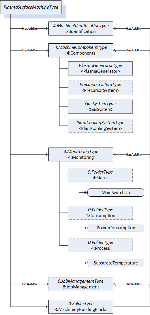
This section provides an overview of the OPC UA information model for plasma surface treatment machines. The information model is structured in such a way that it represents the physical machine and its system components. The instantiation of the PlasmaSurfaceMachineType represents the entry point into the information model of each plasma surface treatment machine. An overview can be seen in Figure 6.
There are two folders on the first level which help to structure the information model. These are the Components folder, in which the physical objects and system components of a plasma surface treatment machine to be mapped are referenced, and the Monitoring folder, which contains all other variables relating to the overall machine.
Furthermore, several building blocks of the OPC UA for Machinery specification are used in this Companion Specification. This is the Building Block Identification, which maps all available characteristics of the system. The MachineryOperationCounter and the MachineryLifetimeCounter are used to map any counting series. The MachineryOperationMode represents a StateMachines provided by the OPC UA for Machinery. The MonitoringType contains all measured values. And the Building Block JobManagement can be used to map complex jobs on the machine. All Machinery Building Blocks are also referenced as an Addin in the MachineryBuildingBlocks folder.
Annex B contains two implementation examples of the described OPC UA Companion Specification for Plasma Surface Technology. In each case, a machine for the atmospheric pressure range B.2 and a system for the low pressure range B.1 were instantiated.
7 OPC UA ObjectTypes
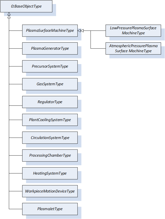
Figure 7 shows all ObjectTypes which are defined by this companion specification.
The parent ObjectType of a general machine for surface treatment using plasma is the PlasmaSurfaceMachineType ObjectType. This ObjectType is divided into the SubTypes LowPressurePlasmaSurfaceMachineType and AtmosphericPressurePlasmaSurfaceMachineType.
This Companion Specification has also defined a separate ObjectType for each system component. These are the ObjectTypes PlasmaGeneratorType, PrecursorSystemType, GasSystemType, PlantCoolingSystemType, ProcessingChamberType, HeatingSystemType, WorkpieceMotionDeviceType and PlasmaJetType.
7.1 PlasmaSurfaceMachineType ObjectType Definition
The PlasmaSurfaceMachineType ObjectType defines the representation of a plasma surface treatment machine. The PlasmaSurfaceMachineType represents the SuperType of the LowPressurePlasmaSurfaceMachineType and the AtmosphericPressurePlasmaSurfaceMachineType, as shown in Figure 8.
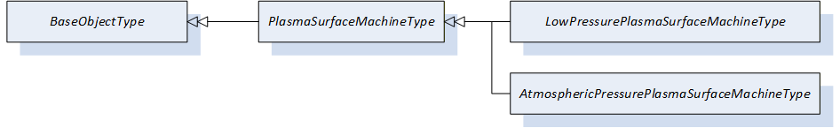
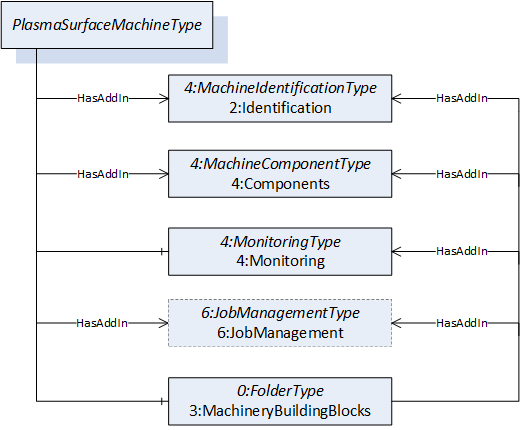
Figure 9 shows the hierarchical structure with some details of this ObjectType. The PlasmaSurfaceMachineType is formally defined in Table 15.
| Attribute | Value | ||||
| BrowseName | PlasmaSurfaceMachineType | ||||
| IsAbstract | False | ||||
| References | Node Class | BrowseName | DataType | TypeDefinition | Other |
|---|---|---|---|---|---|
| Subtype of the BaseObjectType defined in OPC 10000-5 | |||||
| 0:HasAddIn | Object | 2:Identification | 4:MachineIdentificationType | M | |
| 0:HasAddIn | Object | 4:Components | 4:MachineComponentsType | M | |
| 0:HasComponent | Object | 4:Monitoring | 4:MonitoringType | M | |
| 0:HasAddIn | Object | 6:JobManagement | 6:JobManagementType | O | |
| 0:HasComponent | Object | 4:MachineryBuildingBlocks | 0:FolderType | M | |
| Conformance Units | |||||
|---|---|---|---|---|---|
| PST PlasmaSurfaceMachineType Basic | |||||
| PST PlasmaSurfaceMachineType JobManagement | |||||
| PST PlasmaSurfaceMachineType OperationMode | |||||
| PST PlasmaSurfaceMachineType Advanced |
Identification is used as defined in OPC 40001-1 and shall also be referenced as AddIn in the
MachineryBuildingBlocks Folder.
Components is representing a collection of all physical components of the plasma surface treatment machine.
Monitoring is representing a collection of the variables that are not assigned to a component but to the overall plasma surface treatment machine.
MachineryOperationCounter is used as defined in OPC 40001-1. In the information model for plasma surface machines, all counters that are implemented according to the MachineryOperationCounterType of the OPC 40001-1 shall be integrated with the HasComponent reference under this Object. This Object shall also be referenced as AddIn in the MachineryBuildingBlocks Folder.
MachineryLifetimeCounter is used as defined in OPC 40001-1. In the information model for plasma surface machines, all counters that are implemented according to the MachineryLifetimeCounterType of the OPC 40001-1 shall be integrated with the HasComponent reference under this Object. This Object shall also be referenced as AddIn in the MachineryBuildingBlocks Folder.
JobManagement is used as defined in OPC 40001-3 and shall also be referenced as AddIn in the MachineryBuildingBlocks Folder.
MachineryBuildingBlocks is representing a folder that directly references all those building blocks of the OPC UA for Machinery (OPC 40001-1, OPC 40001-3) which are implemented as an add-in in the PlasmaSurfaceMachineType or it's subtypes.
The components of the PlasmaSurfaceMachineType have additional references which are defined in Table 16.
| SourceBrowsePath | Reference Type | Is Forward | TargetBrowsePath |
| 4:MachineryBuildingBlocks | 0:HasAddIn | True | 2:Identification |
| 4:MachineryBuildingBlocks | 0:HasAddIn | True | 4:Components |
| 4:MachineryBuildingBlocks | 0:HasAddIn | True | 6:JobManagement |
| 4:MachineryBuildingBlocks | 0:HasAddIn | True | 4:Monitoring |
The components of the PlasmaSurfaceMachineType have additional subcomponents which are defined in Table 17.
| Source Path | Reference | NodeClass | BrowseName | DataType | TypeDefinition | Others | ||
| 4:Components | 0:HasComponent | Object | <PlasmaGenerator> | PlasmaGeneratorType | MP | |||
| 4:Components | 0:HasComponent | Object | <PrecursorSystem> | PrecursorSystemType | OP | |||
| 4:Components | 0:HasComponent | Object | <GasSystem> | GasSystemType | MP | |||
| 4:Components | 0:HasComponent | Object | <PlantCoolingSystem> | PlantCoolingSystemType | OP | |||
| 0:HasProperty | Variable | MainSwitchOn | 0:Boolean | 0:PropertyType | M, RO | ||
| 0:HasComponent | Variable | PowerConsumption | 0:Double | 0:AnalogUnitType | O, RO | ||
| 0:HasComponent | Variable | SubstrateTemperature | 0:Double | 0:AnalogUnitType | O, RO |
PlasmaGenerator is representing the plasma power supply of the plasma surface treatment machine.
PrecursorSystem is representing the precursor system of the plasma surface treatment machine.
GasSystem is representing the gas supply system of the plasma surface treatment machine.
PlantCoolingSystem is representing the cooling system of the plasma surface treatment machine.
MainSwitchOn is representing the power on status of the plasma surface treatment machine. True means the machine is powered.
PowerConsumption is representing the total power consumption of the plasma surface treatment machine including all its components.
SubstrateTemperature is representing the current temperature of the substrate. The substrate is the workpiece to be plasma treated.
NOTE regarding MachineryOperationMode: The working group for plasma surface treatment machines has agreed that a state transition between the "Maintenance" and "Processing" states does not exist for the plasma surface treatment machines. It is therefore not permitted to execute the TransisionType FromMaintenanceToProcessing and FromProcessingToMaintenance of OPC 40001-1.
7.2 LowPressurePlasmaSurfaceMachineType ObjectType Definition
7.2.1 Overview
The LowPressurePlasmaSurfaceMachineType ObjectType is the representation of a plasma surface treatment machine that performs surface treatment at low pressure. The LowPressurePlasmaSurfaceMachineType is a SubType of the PlasmaSurfaceMachineType. This implies that all nodes of the PlasmaSurfaceMachineType are inherited by the LowPressurePlasmaSurfaceMachineType. The LowPressurePlasmaSurfaceMachineType is formally defined in Table 18.
| Attribute | Value | ||||
| BrowseName | LowPressurePlasmaSurfaceMachineType | ||||
| IsAbstract | False | ||||
| References | Node Class | BrowseName | DataType | TypeDefinition | Other |
|---|---|---|---|---|---|
| Subtype of the PlasmaSurfaceMachineType | |||||
| 0:HasAddIn | Object | 4:Components | 4:MachineComponentsType | M | |
| 0:HasComponent | Object | 4:Monitoring | 4:MonitoringType | M | |
| Conformance Units | |||||
|---|---|---|---|---|---|
| PST LowPressurePlasmaSurfaceMachineType Basic | |||||
| PST LowPressurePlasmaSurfaceMachineType StateMachine | |||||
| PST LowPressurePlasmaSurfaceMachineType HeatingSystem | |||||
| PST LowPressurePlasmaSurfaceMachineType WorkpieceMotionDevice | |||||
| PST LowPressurePlasmaSurfaceMachineType Advanced |
The components of the LowPressurePlasmaSurfaceMachineType have additional subcomponents which are defined in Table 19.
| Source Path | Reference | NodeClass | BrowseName | DataType | TypeDefinition | Others | ||
| 4:Components | 0:HasComponent | Object | <ProcessingChamber> | ProcessingChamberType | MP | |||
| 4:Components | 0:HasComponent | Object | <HeatingSystem> | HeatingSystemType | OP | |||
| 4:Components | 0:HasComponent | Object | <WorkpieceMotionDevice> | WorkpieceMotionDeviceType | OP | |||
| 0:HasAddIn | Object | 4:MachineryItemState | LowPressurePlasmaMachineryItemState_StateMachineType | O |
ProcessingChamber is representing the processing chamber of the plasma surface treatment machine.
HeatingSystem is representing the heating system of the plasma surface treatment machine.
WorkpieceMotionDevice is representing the device that is moving the workpiece inside of the processing chamber.
NOTE: The LowPressurePlasmaSurfaceMachineType is a subtype of the PlasmaSurfacemachineType. The additional subcomponents mentioned above are referring to the mandatory Components of the PlasmaSurfacemachineType which is inherited to the LowPressurePlasmaSurfacemachineType.
7.2.2 Extension of MachineryItemState for low pressure plasma surface treatment machines
For this specification the MachineryItemState defined in OPC UA for Machinery is extended by a SubStateMachine for the State NotExecuting. An exemplary illustration can be found in Figure 10.
For this, the LowPressurePlasmaMachineryItemState_StateMachineType is defined in Table 20.
| Attribute | Value | ||||
| BrowseName | LowPressurePlasmaMachineryItemState_StateMachineType | ||||
| IsAbstract | False | ||||
| References | Node Class | BrowseName | DataType | TypeDefinition | Other |
|---|---|---|---|---|---|
| Subtype of 4:MachineryItemState_StateMachineType defined in OPC UA for Machinery (OPC 40001-1) | |||||
| 0:HasComponent | Object | LowPressurePlasmaNotExecutingSubState | LowPressurePlasmaNotExecutingSubState_StateMachineType | M | |
The State NotExecuting is overriden in the LowPressurePlasmaMachineryItemState_StateMachineType to get the additional reference defined in Table 21.
| SourceBrowsePath | Reference Type | Is Forward | TargetBrowsePath |
| LowPressurePlasmaNotExecutingSubState | 0:HasSubStateMachine | False | 4:NotExecuting |
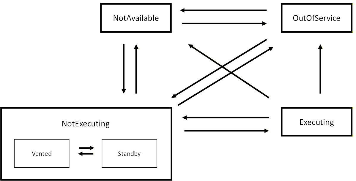
7.2.3 LowPressurePlasmaNotExecutingSubState_StateMachineType ObjectType Definition
The LowPressurePlasmaNotExecutingSubState_StateMachineType is used for a SubStateMachine which divides the NotExecuting State into Vented and Standby. This SubStateMachine is not active if the parent State Executing is not active. In this case the CurrentState and LastTransition Variables of the LowPressurePlasmaNotExecutingSubState state machine shall have a status equal to Bad_StateNotActive.
The LowPressurePlasmaNotExecutingSubState_StateMachineType is formally defined in Table 22.
| Attribute | Value | ||||
| BrowseName | LowPressurePlasmaNotExecutingSubState_StateMachineType | ||||
| IsAbstract | False | ||||
| References | Node Class | BrowseName | DataType | TypeDefinition | Other |
|---|---|---|---|---|---|
| Subtype of the 0:FiniteStateMachineType defined in OPC 10000-16, i.e. inheriting the InstanceDeclarations of that Node. | |||||
| 0:HasProperty | Variable | 0:DefaultInstanceBrowseName | 0:QualifiedName | 0:PropertyType | |
| 0:HasComponent | Object | Vented | 0:StateType | ||
| 0:HasComponent | Object | Standby | 0:StateType | ||
| 0:HasComponent | Object | FromStandbyToVented | 0:TransitionType | ||
| 0:HasComponent | Object | FromVentedToStandby | 0:TransitionType | ||
The InstanceDeclaration of the LowPressurePlasmaNotExecutingSubState_StateMachineType has additional Attributes defined in Table 23.
| BrowsePath | Value Attribute | Description Attribute | ||
| 0:DefaultInstanceBrowseName | LowPressurePlasmaNotExecutingSubState | The default BrowseName for instances of the type | ||
| Vented | The machine is being prepared for the next run | |||
| Standby | The vacuum chamber is evacuated and the system is ready to start | |||
| FromStandbyToVented | Transition from state Standby to state Vented | |||
| FromVentedToStandby | Transition from state Vented to state Standby | |||
| 0 | |||
| 1 | |||
| 0 | |||
| 1 |
The components of the LowPressurePlasmaNotExecutingSubState_StateMachineType have additional references which are defined in Table 24.
| SourceBrowsePath | Reference Type | Is Forward | TargetBrowsePath |
| FromStandbyToVented | 0:FromState | True | Standby |
| 0:ToState | True | Vented | |
| FromVentedToStandby | 0:FromState | True | Vented |
| 0:ToState | True | Standby |
7.3 AtmosphericPressurePlasmaSurfaceMachineType ObjectType Definition
7.3.1 Overview
The AtmosphericPressurePlasmaSurfaceMachineType ObjectType is the representation of a plasma surface treatment machine that performs surface treatment at atmospheric pressure. The AtmosphericPressurePlasmaSurfaceMachineType is a SubType of the PlasmaSurfaceMachineType. This implies that all nodes of the PlasmaSurfaceMachineType are inherited by the AtmosphericPressurePlasmaSurfaceMachineType. The AtmosphericPressurePlasmaSurfaceMachineType is formally defined in Table 25.
| Attribute | Value | ||||
| BrowseName | AtmosphericPressurePlasmaSurfaceMachineType | ||||
| IsAbstract | False | ||||
| References | Node Class | BrowseName | DataType | TypeDefinition | Other |
|---|---|---|---|---|---|
| Subtype of the PlasmaSurfaceMachineType | |||||
| 0:HasAddIn | Object | 4:Components | 4:MachineComponentsType | M | |
| 0:HasComponent | Object | 4:Monitoring | 4:MonitoringType | M | |
| Conformance Units | |||||
|---|---|---|---|---|---|
| PST AtmosphericPressurePlasmaSurfaceMachineType Basic | |||||
| PST AtmosphericPressurePlasmaSurfaceMachineType StateMachine | |||||
| PST AtmosphericPressurePlasmaSurfaceMachineType Advanced |
The components of the AtmosphericPressurePlasmaSurfaceMachineType have additional subcomponents which are defined in Table 26.
| Source Path | Reference | NodeClass | BrowseName | DataType | TypeDefinition | Others | ||
| 4:Components | 0:HasComponent | Object | <PlasmaJet> | PlasmaJetType | MP | |||
| 0:HasAddIn | Object | 4:MachineryItemState | AtmosphericPressurePlasmaMachineryItemState_StateMachineType | O |
PlasmaJet is representing the unit that generates the plasma required for the process.
NOTE: The LowPressurePlasmaSurfaceMachineType is a subtype of the PlasmaSurfacemachineType. The additional subcomponents mentioned above are refering to the mandatory Components of the PlasmaSurfacemachineType which is inherited to the LowPressurePlasmaSurfacemachineType.
7.3.2 Extension of MachineryItemState for atmospheric pressure plasma surface treatment machines
For this specification the MachineryItemState defined in OPC UA for Machinery is extended by a SubStateMachine for the State NotExecuting. An exemplary illustration can be found in Figure 11.
For this, the AtmosphericPressurePlasmaMachineryItemState_StateMachineType is defined Table 27.
| Attribute | Value | ||||
| BrowseName | AtmosphericPressurePlasmaMachineryItemState_StateMachineType | ||||
| IsAbstract | False | ||||
| References | Node Class | BrowseName | DataType | TypeDefinition | Other |
|---|---|---|---|---|---|
| Subtype of 4:MachineryItemState_StateMachineType defined in OPC UA for Machinery (OPC 40001-1) | |||||
| 0:HasComponent | Object | AtmosphericPressurePlasmaNotExecutingSubState | AtmosphericPressurePlasmaNotExecutingSubState_StateMachineType | M | |
The State NotExecuting is overriden in the AtmosphericPressurePlasmaMachineryItemState_StateMachineType to get the additional reference defined in Table 28.
| SourceBrowsePath | Reference Type | Is Forward | TargetBrowsePath |
| AtmosphericPressurePlasmaNotExecutingSubState | 0:HasSubStateMachine | False | 4:NotExecuting |
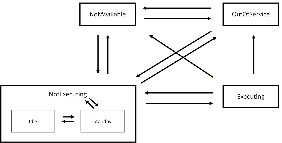
7.3.3 AtmosphericPressurePlasmaNotExecutingSubState_StateMachineType ObjectType Definition
The AtmosphericPressurePlasmaNotExecutingSubState_StateMachineType is used for a SubStateMachine which divides the NotExecuting State into Idle and Standby. This SubStateMachine is not active if the parent State Executing is not active. In this case the CurrentState and LastTransition Variables of the AtmosphericPressurePlasmaNotExecutingSubState state machine shall have a status equal to Bad_StateNotActive.
The AtmosphericPressurePlasmaNotExecutingSubState_StateMachineType is formally defined in Table 29.
| Attribute | Value | ||||
| BrowseName | AtmosphericPressurePlasmaNotExecutingSubState_StateMachineType | ||||
| IsAbstract | False | ||||
| References | Node Class | BrowseName | DataType | TypeDefinition | Other |
|---|---|---|---|---|---|
| Subtype of the 0:FiniteStateMachineType defined in OPC 10000-16, i.e. inheriting the InstanceDeclarations of that Node. | |||||
| 0:HasProperty | Variable | 0:DefaultInstanceBrowseName | QualifiedName | 0:PropertyType | |
| 0:HasComponent | Object | Idle | 0:StateType | ||
| 0:HasComponent | Object | Standby | 0:StateType | ||
| 0:HasComponent | Object | FromStandbyToIdle | 0:TransitionType | ||
| 0:HasComponent | Object | FromIdleToStandby | 0:TransitionType | ||
The InstanceDeclaration of the AtmosphericPressurePlasmaNotExecutingSubState_StateMachineType has additional Attributes defined in Table 30.
| BrowsePath | Value Attribute | Description Attribute | ||
| 0:DefaultInstanceBrowseName | AtmosphericPressurePlasmaNotExecutingSubState | The default BrowseName for instances of the type | ||
| Idle | The machine is being prepared for the next run | |||
| Standby | The system is ready to start | |||
| FromStandbyToIdle | Transition from state Standby to state Idle | |||
| FromIdleToStandby | Transition from state Idle to state Standby | |||
| 0 | |||
| 1 | |||
| 0 | |||
| 1 |
The components of the AtmosphericPressurePlasmaNotExecutingSubState_StateMachineType have additional references which are defined in Table 31.
| SourceBrowsePath | Reference Type | Is Forward | TargetBrowsePath |
| FromStandbyToIdle | 0:FromState | True | Standby |
| 0:ToState | True | Idle | |
| FromIdleToStandby | 0:FromState | True | Idle |
| 0:ToState | True | Standby |
7.4 PlasmaGeneratorType ObjectType Definition
The PlasmaGeneratorType provides all relevant Variables and parameters for monitoring a plasma generator of a plasma surface treatment machine. An overview of the information model is shown in Figure 12.
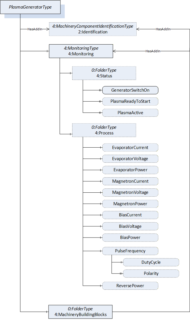
The PlasmaGeneratorType is formally defined in Table 32.
| Attribute | Value | ||||
| BrowseName | PlasmaGeneratorType | ||||
| IsAbstract | False | ||||
| References | Node Class | BrowseName | DataType | TypeDefinition | Other |
|---|---|---|---|---|---|
| Subtype of the BaseObjectType defined in OPC 10000-5 | |||||
| 0:HasAddIn | Object | 2:Identification | 4:MachineryComponentIdentificationType | O | |
| 0:HasComponent | Object | 4:Monitoring | 4:MonitoringType | M | |
| 0:HasComponent | Object | 4:MachineryBuildingBlocks | 0:FolderType | M | |
| Conformance Units | |||||
|---|---|---|---|---|---|
| PST PlasmaGeneratorType Basic | |||||
| PST PlasmaGeneratorType Advanced |
Identification is used as defined in OPC 40001-1 and shall also be referenced as AddIn in the MachineryBuildingBlocks Folder.
Monitoring is representing a collection of the variables that are assigned to this specific component.
MachineryBuildingBlocks is representing a folder that directly references all those building blocks of the OPC UA for Machinery (OPC 40001-1, OPC 40001-3) which are implemented as an add-in in this specific component.
The components of the PlasmaGeneratorType have additional references which are defined in Table 33.
| SourceBrowsePath | Reference Type | Is Forward | TargetBrowsePath |
| 4:MachineryBuildingBlocks | 0:HasAddIn | True | 2:Identification |
| 4:MachineryBuildingBlocks | 0:HasAddIn | True | 4:Monitoring |
The components of the PlasmaGeneratorType have additional subcomponents which are defined in Table 34.
| Source Path | Reference | NodeClass | BrowseName | DataType | TypeDefinition | Others | |||
| 0:HasComponent | Variable | EvaporatorCurrent | 0:Double | 0:AnalogUnitType | O, RO | |||
| 0:HasComponent | Variable | EvaporatorVoltage | 0:Double | 0:AnalogUnitType | O, RO | |||
| 0:HasComponent | Variable | EvaporatorPower | 0:Double | 0:AnalogUnitType | O, RO | |||
| 0:HasComponent | Variable | BiasCurrent | 0:Double | 0:AnalogUnitType | O, RO | |||
| 0:HasComponent | Variable | BiasVoltage | 0:Double | 0:AnalogUnitType | O, RO | |||
| 0:HasComponent | Variable | BiasPower | 0:Double | 0:AnalogUnitType | O, RO | |||
| 0:HasProperty | Variable | BiasGeneratorSwitchOn | 0:Boolean | 0:PropertyType | O, RO | |||
| 0:HasComponent | Variable | BiasArcCounter | UInt32 | 0:AnalogUnitType | O, RO | |||
| 0:HasProperty | Variable | EvaporatorGeneratorSwitchOn | 0:Boolean | 0:PropertyType | O, RO | |||
| 0:HasProperty | Variable | PlasmaReadyToStart | 0:Boolean | 0:PropertyType | O, RO | |||
| 0:HasProperty | Variable | PlasmaActive | 0:Boolean | 0:PropertyType | O, RO | |||
| 0:HasComponent | Variable | BiasPulseFrequency | 0:Double | 0:AnalogUnitType | O, RO | |||
| 0:HasComponent | Variable | BiasDutyCycle | UInt16 | 0:AnalogUnitType | O, RO | |||
| 0:HasProperty | Variable | BiasPolarity | 0:String | 0:PropertyType | O, RO | |||
| 0:HasComponent | Variable | EvaporatorPulseFrequency | 0:Double | 0:AnalogUnitType | O, RO | |||
| 0:HasComponent | Variable | EvaporatorDutyCycle | UInt16 | 0:AnalogUnitType | O, RO | |||
| 0:HasProperty | Variable | EvaporatorPolarity | 0:String | 0:PropertyType | O, RO | |||
| 0:HasComponent | Variable | BiasReversePower | 0:Double | 0:AnalogUnitType | O, RO | |||
| 0:HasComponent | Variable | EvaporatorReversePower | 0:Double | 0:AnalogUnitType | O, RO |
EvaporatorCurrent is representing the present current of the evaporator.
EvaporatorVoltage is representing the present voltage of the evaporator.
EvaporatorPower is representing the present power of the evaporator.
BiasCurrent is representing the present current of the bias.
BiasVoltage is representing the present voltage of the bias.
BiasPower is representing the present power of the bias.
BiasGeneratorSwitchOn is indicating the power on status of the bias generator. True means the generator is switched on.
BiasArcCounter is counting the amount of arc events during the process.
EvaporatorGeneratorSwitchOn is indicating the power on status of the evaporator generator. True means the generator is switched on.
PlasmaReadyToStart is indicating if the plasma can be switched on. True means the plasma can be switched on.
PlasmaActive is indicating if the plasma is working.
BiasPulseFrequency is representing the output frequency of the bias generator.
BiasDutyCycle is a descriptive property of BiasPulseFrequency. It is representing the pulse ontime in percent.
BiasPolarity is a descriptive property of BiasPulseFrequency. It is indicating what polarity the BiasPulseFrequence has.
EvaporatorPulseFrequency is representing the output frequency of the evaporator generator.
EvaporatorDutyCycle is a descriptive property of EvaporatorPulseFrequency. It is representing the pulse ontime in percent.
EvaporatorPolarity is a descriptive property of EvaporatorPulseFrequency. It is indicating what polarity the EvaporatorPulseFrequencehas.
BiasReversePower is representing the power which flows back into the generator. It is also known by the name "reflected power".
EvaporatorReversePower is representing the power which flows back into the generator. It is also known by the name "reflected power".
7.5 PrecursorSystemType ObjectType Definition
The PrecursorSystemType provides all relevant Variables and parameters for monitoring a precursor system of a plasma surface treatment machine. An overview of the information model is shown in Figure 13.
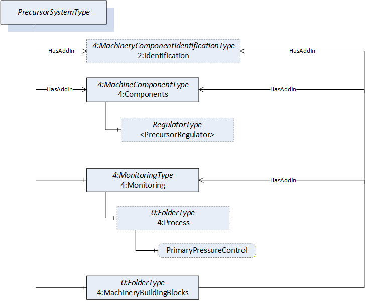
The PrecursorSystemType is formally defined in Table 35.
| Attribute | Value | ||||
| BrowseName | PrecursorSystemType | ||||
| IsAbstract | False | ||||
| References | Node Class | BrowseName | DataType | TypeDefinition | Other |
|---|---|---|---|---|---|
| Subtype of the BaseObjectType defined in OPC 10000-5 | |||||
| 0:HasAddIn | Object | 2:Identification | 4:MachineryComponentIdentificationType | O | |
| 0:HasAddIn | Object | 4:Components | 4:MachineComponentsType | M | |
| 0:HasComponent | Object | 4:Monitoring | 4:MonitoringType | M | |
| 0:HasComponent | Object | 4:MachineryBuildingBlocks | 0:FolderType | M | |
| Conformance Units | |||||
|---|---|---|---|---|---|
| PST PrecursorSystemType Basic | |||||
| PST PrecursorSystemType Advanced |
Identification is used as defined in OPC 40001-1 and shall also be referenced as AddIn in the MachineryBuildingBlocks Folder.
Components is representing a collection of all physical components of the precursor system of a plasma surface treatment machine.
Monitoring is representing a collection of the variables that are assigned to this specific component.
MachineryBuildingBlocks is representing a folder that directly references all those building blocks of the OPC UA for Machinery (OPC 40001-1, OPC 40001-3) which are implemented as an add-in in this specific component.
The components of the PrecursorSystemType have additional references which are defined in Table 36.
| SourceBrowsePath | Reference Type | Is Forward | TargetBrowsePath |
| 4:MachineryBuildingBlocks | 0:HasAddIn | True | 2:Identification |
| 4:MachineryBuildingBlocks | 0:HasAddIn | True | 4:Components |
| 4:MachineryBuildingBlocks | 0:HasAddIn | True | 4:Monitoring |
The components of the PrecursorSystemType have additional subcomponents which are defined in Table 37.
| Source Path | Reference | NodeClass | BrowseName | DataType | TypeDefinition | Others | ||
| 0:HasComponent | Variable | PrimaryPressureControl | 0:Double | 0:AnalogUnitType | O, RO | ||
| 4:Components | 0:HasComponent | Object | <PrecursorRegulator> | RegulatorType | OP |
PrimaryPressureControl is representing the prepressure of the precursor system.
PrecursorRegulator is representing an instance of a single precursor regulator of the gas system.
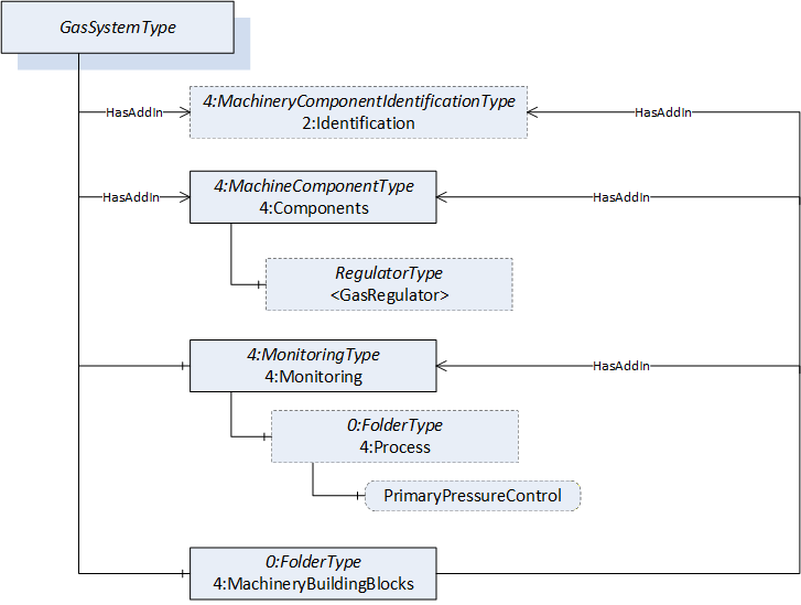
7.6 GasSystemType ObjectType Definition
The GasSystemType provides all relevant Variables and parameters for monitoring a gas supply system of a plasma surface treatment machine. An overview of the information model is shown in Figure 14.
The GasSystemType is formally defined in Table 38.
| Attribute | Value | ||||
| BrowseName | GasSystemType | ||||
| IsAbstract | False | ||||
| References | Node Class | BrowseName | DataType | TypeDefinition | Other |
|---|---|---|---|---|---|
| Subtype of the BaseObjectType defined in OPC 10000-5 | |||||
| 0:HasAddIn | Object | 2:Identification | 4:MachineryComponentIdentificationType | O | |
| 0:HasAddIn | Object | 4:Components | 4:MachineComponentsType | M | |
| 0:HasComponent | Object | 4:Monitoring | 4:MonitoringType | M | |
| 0:HasComponent | Object | 4:MachineryBuildingBlocks | 0:FolderType | M | |
| Conformance Units | |||||
|---|---|---|---|---|---|
| PST GasSystemType Basic | |||||
| PST GasSystemType Advanced |
Identification is used as defined in OPC 40001-1. Shall also be referenced as AddIn in the MachineryBuildingBlocks Folder.
Components is representing a collection of all physical components of the gas system of a plasma surface treatment machine.
Monitoring is representing a collection of the variables that are assigned to this specific component.
MachineryBuildingBlocks is representing a folder that directly references all those building blocks of the OPC UA for Machinery (OPC 40001-1, OPC 40001-3) which are implemented as an add-in in this specific component.
The components of the GasSystemType have additional references which are defined in Table 39.
| SourceBrowsePath | Reference Type | Is Forward | TargetBrowsePath |
| 4:MachineryBuildingBlocks | 0:HasAddIn | True | 2:Identification |
| 4:MachineryBuildingBlocks | 0:HasAddIn | True | 4:Components |
| 4:MachineryBuildingBlocks | 0:HasAddIn | True | 4:Monitoring |
The components of the GasSystemType have additional subcomponents which are defined in Table 40.
| Source Path | Reference | NodeClass | BrowseName | DataType | TypeDefinition | Others | ||
| 0:HasComponent | Variable | PrimaryPressureControl | 0:Double | 0:AnalogUnitType | O, RO | ||
| 4:Components | 0:HasComponent | Object | <GasRegulator> | RegulatorType | OP |
PrimaryPressureControl is representing the prepressure of the gas system.
GasRegulator is representing an instance of a single gas regulator of the gas system.
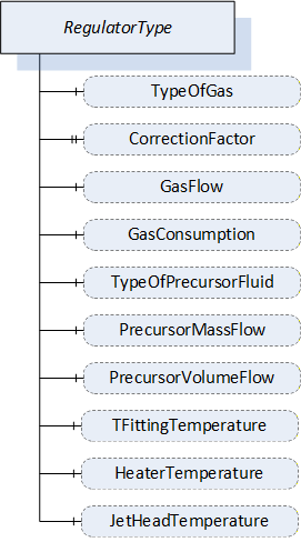
7.7 RegulatorType ObjectType Definition
The RegulatorType provides a representation of a single gas or precursor regulator that is controlling the gas or precursor flow. An overview of the information model is shown in Figure 15.
The RegulatorType is formally defined in Table 41.
| Attribute | Value | ||||
| BrowseName | RegulatorType | ||||
| IsAbstract | False | ||||
| References | Node Class | BrowseName | DataType | TypeDefinition | Other |
|---|---|---|---|---|---|
| Subtype of the BaseObjectType defined in OPC 10000-5 | |||||
| 0:HasComponent | Variable | TypeOfGas | 0:UInt16 | 0:MultiStateValueDiscreteType | O, RW |
| 0:HasProperty | Variable | CorrectionFactor | 0:Double | 0:PropertyType | O, RW |
| 0:HasComponent | Variable | GasFlow | 0:Double | 0:AnalogUnitType | O, RO |
| 0:HasComponent | Variable | GasConsumption | 0:Double | 0:AnalogUnitType | O, RO |
| 0:HasComponent | Variable | TypeOfPrecursorFluid | 0:UInt16 | 0:MultiStateValueDiscreteType | O, RW |
| 0:HasComponent | Variable | PrecursorMassFlow | 0:Double | 0:AnalogUnitType | O, RO |
| 0:HasComponent | Variable | PrecursorVolumeFlow | 0:Double | 0:AnalogUnitType | O, RO |
| 0:HasComponent | Variable | TFittingTemperature | 0:Double | 0:AnalogUnitType | O, RO |
| 0:HasComponent | Variable | HeaterTemperature | 0:Double | 0:AnalogUnitType | O, RO |
| 0:HasComponent | Variable | JetHeadTemperature | 0:Double | 0:AnalogUnitType | O, RO |
GasType is representing the type of gas used.
CorrectionFactor is representing the correction factor of the used gas. As the gas regulator is calibrated to a specific gas, correction factors are required when using other gases. The CorrectionFactor is representing this factor for the gas used.
GasFlow is representing the flow of the gas through the gas system.
GasConsumption is representing the total gas consumption of the gas regulator.
TypeOfPrecursorFluid is indicating which type of precursor gas is used in the precursor system.
PrecursorMassFlow is representing the mass flow of the precursant gas through the precursor system.
PrecursorVolumeFlow is representing the volume flow of the precursant gas through the precursor system.
TFittingTemperature is representing the current temperature at the T-Fitting of the precursor system.
HeaterTemperature is representing the current temperature of the heater of the precursor system.
JetHeadTemperature is representing the current temperature of the jet head of the precursor system.
The component Variables of the RegulatorType have additional Attributes defined in Table 42.
| BrowsePath | Value Attribute | Description Attribute | ||
| [ {"Value": 0, "DisplayName": "Ar", "Description": ""}, {"Value": 1, "DisplayName": "N2", "Description": ""}, {"Value": 2, "DisplayName": "CH4", "Description": ""}, {"Value": 3, "DisplayName": "C2H2", "Description": ""}, {"Value": 4, "DisplayName": "O2", "Description": ""}, {"Value": 5, "DisplayName": "H2", "Description": ""}, ] | |||
| [ {"Value": 0, "DisplayName": "Ar", "Description": ""}, {"Value": 1, "DisplayName": "N2", "Description": ""}, {"Value": 2, "DisplayName": "CH4", "Description": ""}, {"Value": 3, "DisplayName": "C2H2", "Description": ""}, {"Value": 4, "DisplayName": "O2", "Description": ""}, {"Value": 5, "DisplayName": "H2", "Description": ""}, ] |
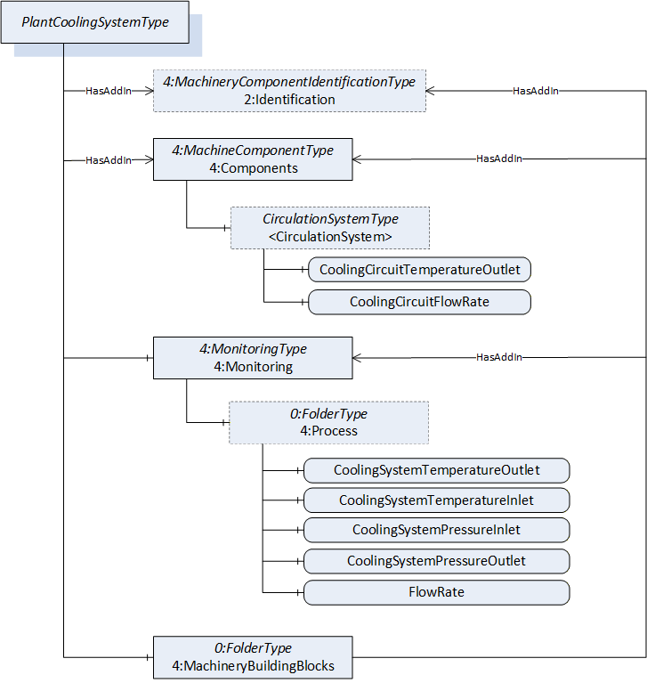
7.8 PlantCoolingSystemType ObjectType Definition
7.8.1 Overview
The PlantCoolingSystemType provides all relevant Variables and parameters for monitoring a cooling system of a plasma surface treatment machine. An overview of the information model is shown in Figure 16.
The PlantCoolingSystemType is formally defined in Table 43.
| Attribute | Value | ||||
| BrowseName | PlantCoolingSystemType | ||||
| IsAbstract | False | ||||
| References | Node Class | BrowseName | DataType | TypeDefinition | Other |
|---|---|---|---|---|---|
| Subtype of the BaseObjectType defined in OPC 10000-5 | |||||
| 0:HasAddIn | Object | 2:Identification | 4:MachineryComponentIdentificationType | O | |
| 0:HasAddIn | Object | 4:Components | 4:MachineComponentsType | M | |
| 0:HasComponent | Object | 4:Monitoring | 4:MonitoringType | M | |
| 0:HasComponent | Object | 4:MachineryBuildingBlocks | 0:FolderType | M | |
| Conformance Units | |||||
|---|---|---|---|---|---|
| PST PlantCoolingSystemType Basic | |||||
| PST PlantCoolingSystemType Advanced |
Identification is used as defined in OPC 40001-1. Shall also be referenced as AddIn in the MachineryBuildingBlocks Folder.
Components is representing a collection of all physical components of the plasma surface treatment machine.
Monitoring is representing a collection of the variables that are assigned to this specific component.
MachineryBuildingBlocks is representing a folder that directly references all those building blocks of the OPC UA for Machinery (OPC 40001-1, OPC 40001-3) which are implemented as an add-in in this specific component.
The components of the PlantCoolingSystemType have additional references which are defined in Table 44.
| SourceBrowsePath | Reference Type | Is Forward | TargetBrowsePath |
| 4:MachineryBuildingBlocks | 0:HasAddIn | True | 2:Identification |
| 4:MachineryBuildingBlocks | 0:HasAddIn | True | 4:Components |
| 4:MachineryBuildingBlocks | 0:HasAddIn | True | 4:Monitoring |
The components of the PlantCoolingSystemType have additional subcomponents which are defined in Table 45.
| Source Path | Reference | NodeClass | BrowseName | DataType | TypeDefinition | Others | ||
| 4:Components | 0:HasComponent | Object | <CirculationSystem> | CirculationSystemType | OP | |||
| 0:HasComponent | Variable | FlowRate | 0:Double | 0:AnalogUnitType | O, RO | ||
| 0:HasComponent | Variable | CoolingSystemTemperatureOutlet | 0:Double | 0:AnalogUnitType | O, RO | ||
| 0:HasComponent | Variable | CoolingSystemTemperatureInlet | 0:Double | 0:AnalogUnitType | O, RO | ||
| 0:HasComponent | Variable | CoolingSystemPressureInlet | 0:Double | 0:AnalogUnitType | O, RO | ||
| 0:HasComponent | Variable | CoolingSystemPressureOutlet | 0:Double | 0:AnalogUnitType | O, RO |
CirculationSystem is representing a single cooling circuit of the whole cooling system.
FlowRate is representing the volume flow of coolant through the whole plant cooling system.
CoolingSystemTemperatureOutlet is representing the temperature of the coolant at the outlet of the main coolant storage.
CoolingSystemTemperatureInlet is representing the temperature of the coolant at the inlet of the main coolant storage.
CoolingSystemPressureInlet is representing the pressure of the inlet of the main coolant storage.
CoolingSystemPressureOutlet is representing the pressure of the outlet of the main coolant storage.
7.8.2 CirculationSystemType ObjectType Definition
The CirculationSystemType provides a representation of a single circuit of the cooling system of a plasma surface treatment machine. An Instance of the PlantCoolingSystemType can have several Instances of the CirculationSystemsType as components. The CirculationSystemType is formally defined in Table 46.
| Attribute | Value | ||||
| BrowseName | CirculationSystemType | ||||
| IsAbstract | False | ||||
| References | Node Class | BrowseName | DataType | TypeDefinition | Other |
|---|---|---|---|---|---|
| Subtype of the BaseObjectType defined in OPC 10000-5 | |||||
| 0:HasComponent | Variable | CoolingCircuitTemperatureOutlet | 0:Double | 0:AnalogUnitType | O, RO |
| 0:HasComponent | Variable | CoolingCircuitFlowRate | 0:Double | 0:AnalogUnitType | O, RO |
CoolingCircuitTemperatureOutlet is representing the temperature of the coolant at the outlet of the specific cooling circuit.
CoolingCircuitFlowRate is representing the volume flow of coolant through the specific cooling circuit.
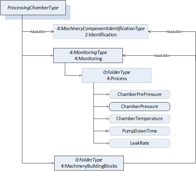
7.9 ProcessingChamberType ObjectType Definition
The ProcessingChamberType provides all relevant Variables and parameters for monitoring a processing chamber of a low pressure plasma surface treatment machine. An overview of the information model is shown in Figure 17.
The ProcessingChamberType is formally defined in Table 47.
| Attribute | Value | ||||
| BrowseName | ProcessingChamberType | ||||
| IsAbstract | False | ||||
| References | Node Class | BrowseName | DataType | TypeDefinition | Other |
|---|---|---|---|---|---|
| Subtype of the BaseObjectType defined in OPC 10000-5 | |||||
| 0:HasAddIn | Object | 2:Identification | 4:MachineryComponentIdentificationType | O | |
| 0:HasComponent | Object | 4:Monitoring | 4:MonitoringType | M | |
| 0:HasComponent | Object | 4:MachineryBuildingBlocks | 0:FolderType | M | |
| Conformance Units | |||||
|---|---|---|---|---|---|
| PST ProcessingChamberType Basic | |||||
| PST ProcessingChamberType Advanced |
Identification is used as defined in OPC 40001-1. Shall also be referenced as AddIn in the MachineryBuildingBlocks Folder.
Monitoring is representing a collection of the variables that are assigned to this specific component.
MachineryOperationCounter is used as defined in OPC 40001-1. In the component ProcessingChamberType all counters that are implemented according to the MachineryOperationCounterType of the OPC 40001-1 shall be integrated with the HasComponent reference under this Object. This Object shall also be referenced as AddIn in the MachineryBuildingBlocks Folder.
MachineryBuildingBlocks is representing a folder that directly references all those building blocks of the OPC UA for Machinery (OPC 40001-1, OPC 40001-3) which are implemented as an add-in in this specific component.
The components of the ProcessingChamberType have additional references which are defined in Table 48.
| SourceBrowsePath | Reference Type | Is Forward | TargetBrowsePath |
| 4:MachineryBuildingBlocks | 0:HasAddIn | True | 2:Identification |
| 4:MachineryBuildingBlocks | 0:HasAddIn | True | 4:Monitoring |
The components of the ProcessingChamberType have additional subcomponents which are defined in Table 49.
| Source Path | Reference | NodeClass | BrowseName | DataType | TypeDefinition | Others | ||
| 0:HasComponent | Variable | ChamberPrePressure | 0:Double | 0:AnalogUnitType | O, RO | ||
| 0:HasComponent | Variable | ChamberPressure | 0:Double | 0:AnalogUnitType | M, RO | ||
| 0:HasComponent | Variable | ChamberTemperature | 0:Double | 0:AnalogUnitType | O, RO | ||
| 0:HasProperty | Variable | PumpDownTime | 0:DurationString | 0:PropertyType | O, RO | ||
| 0:HasComponent | Variable | LeakRate | 0:Double | 0:AnalogUnitType | O, RO |
ChamberPrePressure is representing the current pre-pressure of the processing chamber.
ChamberPressure is representing the current pressure inside the processing chamber.
ChamberTemperature is representing the current temperature inside the processing chamber.
PumpDownTime is representing the time needed for evacuating the processing chamber. When the evacuation of the processing chamber has not yet been completed, the PumpDownTime is the time required so far. When the target pressure of the processing chamber has been reached, the PumpDownTime represents the total duration of the evacuation.
LeakRate is representing in what period of time the processing chamber loses what pressure.
7.10 HeatingSystemType ObjectType Definition
The HeatingSystemType provides all relevant Variables and parameters for monitoring a heating system of a plasma surface treatment machine. An overview of the information model is shown in Figure 18.
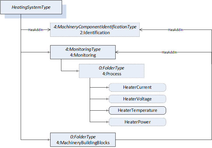
The HeatingSystemType is formally defined in Table 50.
| Attribute | Value | ||||
| BrowseName | HeatingSystemType | ||||
| IsAbstract | False | ||||
| References | Node Class | BrowseName | DataType | TypeDefinition | Other |
|---|---|---|---|---|---|
| Subtype of the BaseObjectType defined in OPC 10000-5 | |||||
| 0:HasAddIn | Object | 2:Identification | 4:MachineryComponentIdentificationType | O | |
| 0:HasComponent | Object | 4:Monitoring | 4:MonitoringType | M | |
| 0:HasComponent | Object | 4:MachineryBuildingBlocks | 0:FolderType | M | |
| Conformance Units | |||||
|---|---|---|---|---|---|
| PST HeatingSystemType Basic | |||||
| PST HeatingSystemType Advanced |
Identification is used as defined in OPC 40001-1. Shall also be referenced as AddIn in the MachineryBuildingBlocks Folder.
Monitoring is representing a collection of the variables that are assigned to this specific component.
MachineryBuildingBlocks is representing a folder that directly references all those building blocks of the OPC UA for Machinery (OPC 40001-1, OPC 40001-3) which are implemented as an add-in in this specific component.
The components of the HeatingSystemType have additional references which are defined in Table 51.
| SourceBrowsePath | Reference Type | Is Forward | TargetBrowsePath |
| 4:MachineryBuildingBlocks | 0:HasAddIn | True | 2:Identification |
| 4:MachineryBuildingBlocks | 0:HasAddIn | True | 4:Monitoring |
The components of the HeatingSystemType have additional subcomponents which are defined in Table 52.
| Source Path | Reference | NodeClass | BrowseName | DataType | TypeDefinition | Others | ||
| 0:HasComponent | Variable | HeaterCurrent | 0:Double | 0:AnalogUnitType | O, RO | ||
| 0:HasComponent | Variable | HeaterVoltage | 0:Double | 0:AnalogUnitType | O, RO | ||
| 0:HasComponent | Variable | HeaterTemperature | 0:Double | 0:AnalogUnitType | M, RO | ||
| 0:HasComponent | Variable | HeaterPower | 0:Double | 0:AnalogUnitType | O, RO |
HeaterCurrent is representing the present current of the heater.
HeaterVoltage is representing the present voltage of the heater.
HeaterTemperature is representing the present temperature of the heater.
HeaterPower is representing the present power of the heater.
7.11 WorkpieceMotionDeviceType ObjectType Definition
The WorkpieceMotionDeviceType provides all relevant Variables and parameters for monitoring a device that moves the treated workpiece of a plasma surface treatment machine. An overview of the information model is shown in Figure 19.
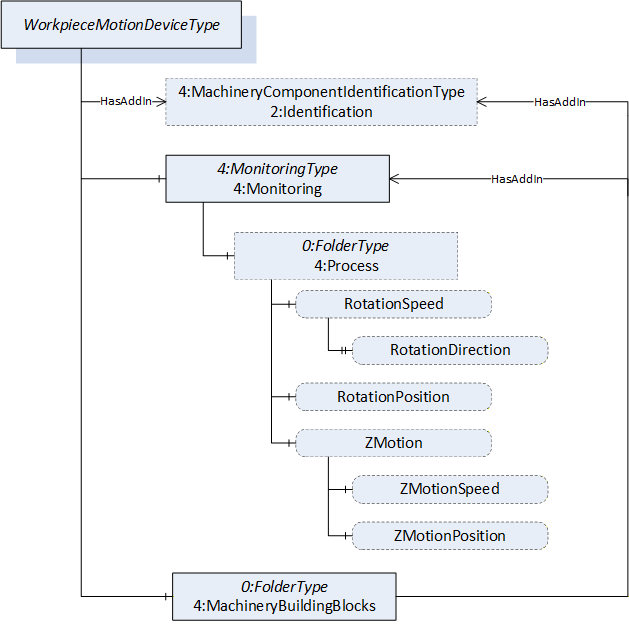
The WorkpieceMotionDevice is formally defined in Table 53.
| Attribute | Value | ||||
| BrowseName | WorkpieceMotionDeviceType | ||||
| IsAbstract | False | ||||
| References | Node Class | BrowseName | DataType | TypeDefinition | Other |
|---|---|---|---|---|---|
| Subtype of the BaseObjectType defined in OPC 10000-5 | |||||
| 0:HasAddIn | Object | 2:Identification | 4:MachineryComponentIdentificationType | O | |
| 0:HasComponent | Object | 4:Monitoring | 4:MonitoringType | M | |
| 0:HasComponent | Object | 4:MachineryBuildingBlocks | 0:FolderType | M | |
| Conformance Units | |||||
|---|---|---|---|---|---|
| PST WorkpieceMotionDeviceType Basic | |||||
| PST WorkpieceMotionDeviceType Advanced |
Identification is used as defined in OPC 40001-1. Shall also be referenced as AddIn in the MachineryBuildingBlocks Folder.
Monitoring is representing a collection of the variables that are assigned to this specific component.
MachineryBuildingBlocks is representing a folder that directly references all those building blocks of the OPC UA for Machinery (OPC 40001-1, OPC 40001-3) which are implemented as an add-in in this specific component.
The components of the WorkpieceMotionDevice have additional references which are defined in Table 54.
| SourceBrowsePath | Reference Type | Is Forward | TargetBrowsePath |
| 4:MachineryBuildingBlocks | 0:HasAddIn | True | 2:Identification |
| 4:MachineryBuildingBlocks | 0:HasAddIn | True | 4:Monitoring |
The components of the WorkpieceMotionDeviceType have additional subcomponents which are defined in Table 55.
| Source Path | Reference | NodeClass | BrowseName | DataType | TypeDefinition | Others | |||
| 0:HasComponent | Variable | RotationSpeed | 0:Double | 0:AnalogUnitType | O, RO | |||
| 0:HasProperty | Variable | RotationDirection | 0:Boolean | 0:PropertyType | O, RO | |||
| 0:HasComponent | Variable | RotationPosition | 0:Int16 | 0:AnalogUnitType | O, RO | |||
| 0:HasComponent | Variable | ZMotion | 0:Boolean | 0:BaseDataVariableType | O, RO | |||
| 0:HasComponent | Variable | ZMotionSpeed | 0:Double | 0:AnalogUnitType | O, RO | |||
| 0:HasComponent | Variable | ZMotionPosition | 0:Int16 | 0:AnalogUnitType | O, RO |
RotationSpeed is representing the current rotational speed of the workpiece motion device.
RotationDirection is a descriptive property of RotationSpeed that is representing the current direction of the rotation of the workpiece motion device. True value corresponds to clockwise rotation.
RotationPosition is representing the current rotational position of the workpiece motion device.
ZMotion is representing the information if the motion device is active in the vertical direction. The value true means the motion device is active in the vertical direction.
ZMotionSpeed is a descriptive property of ZMotion that is representing the current speed of the motion perpendicular to rotation plane of the workpiece motion device.
ZMotionPosition is a descriptive property of ZMotion that is representing the current position perpendicular to rotation plane of the workpiece motion device.
7.12 PlasmaJetType ObjectType Definition
The PlasmaJetType provides all relevant Variables and parameters for monitoring a plasma jet of a plasma surface treatment machine. An overview of the information model is shown in Figure 20.
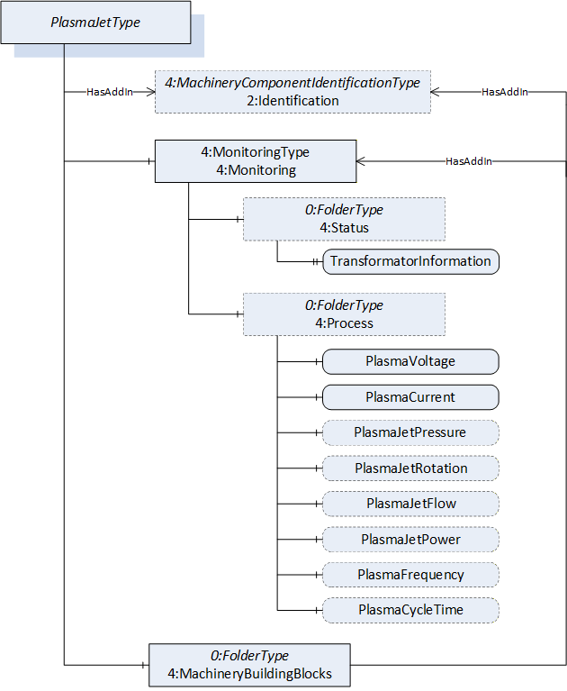
The PlasmaJetType is formally defined in Table 56.
| Attribute | Value | ||||
| BrowseName | PlasmaJetType | ||||
| IsAbstract | False | ||||
| References | Node Class | BrowseName | DataType | TypeDefinition | Other |
|---|---|---|---|---|---|
| Subtype of the BaseObjectType defined in OPC 10000-5 | |||||
| 0:HasAddIn | Object | 2:Identification | 4:MachineryComponentIdentificationType | O | |
| 0:HasComponent | Object | 4:Monitoring | 4:MonitoringType | M | |
| 0:HasComponent | Object | 4:MachineryBuildingBlocks | 0:FolderType | M | |
| Conformance Units | |||||
|---|---|---|---|---|---|
| PST PlasmaJetType Basic | |||||
| PST PlasmaJetType Identification | |||||
| PST PlasmaJetType Advanced |
Identification is used as defined in OPC 40001-1. Shall also be referenced as AddIn in the MachineryBuildingBlocks Folder.
Monitoring is representing a collection of the variables that are assigned to this specific component.
MachineryOperationCounter is used as defined in OPC 40001-1. In the component PlasmaJetType all counters that are implemented according to the MachineryOperationCounterType of the OPC 40001-1 shall be integrated with the HasComponent reference under this Object. This Object shall also be referenced as AddIn in the MachineryBuildingBlocks Folder.
MachineryLifetimeCounter is used as defined in OPC 40001-1. In the component PlasmaJetType all counters that are implemented according to the MachineryLifetimeCounterType of the OPC 40001-1 shall be integrated with the HasComponent reference under this Object. This Object shall also be referenced as AddIn in the MachineryBuildingBlocks Folder.
MachineryBuildingBlocks is representing a folder that directly references all those building blocks of the OPC UA for Machinery (OPC 40001-1, OPC 40001-3) which are implemented as an add-in in this specific component.
The components of the PlasmaJetType have additional references which are defined in Table 57.
| SourceBrowsePath | Reference Type | Is Forward | TargetBrowsePath |
| 4:MachineryBuildingBlocks | 0:HasAddIn | True | 2:Identification |
| 4:MachineryBuildingBlocks | 0:HasAddIn | True | 4:Monitoring |
The components of the PlasmaJetType have additional subcomponents which are defined in Table 58.
| Source Path | Reference | NodeClass | BrowseName | DataType | TypeDefinition | Others | ||
| 0:HasComponent | Variable | PlasmaVoltage | 0:Double | 0:AnalogUnitType | M, RO | ||
| 0:HasComponent | Variable | PlasmaCurrent | 0:Double | 0:AnalogUnitType | M, RO | ||
| 0:HasComponent | Variable | PlasmaJetPressure | 0:Double | 0:AnalogUnitType | O, RO | ||
| 0:HasComponent | Variable | PlasmaJetRotation | 0:Int32 | 0:AnalogUnitType | O, RO | ||
| 0:HasComponent | Variable | PlasmaJetFlow | 0:Double | 0:AnalogUnitType | O, RO | ||
| 0:HasComponent | Variable | PlasmaJetPower | 0:Double | 0:AnalogUnitType | O, RO | ||
| 0:HasComponent | Variable | PlasmaFrequency | 0:Double | 0:AnalogUnitType | O, RO | ||
| 0:HasComponent | Variable | PlasmaCycleTime | 0:UInt16 | 0:AnalogUnitType | O, RO | ||
| 0:HasProperty | Variable | TransformatorInformation | 0:String | 0:PropertyType | M, RO |
PlasmaVoltage is representing the present voltage of the plasma generator.
PlasmaCurrent is representing the present current of the plasma generator.
PlasmaJetPressure is representing the present jet pressure of the plasma jet.
PlasmaJetRotation is representing the present rotational speed of the plasma jet.
PlasmaJetFlow is representing the present ionization gas flow of the plasma jet.
PlasmaJetPower is representing the present power of the plasma jet.
PlasmaFrequency is representing the present plasma frequency of the plasma generator.
PlasmaCycleTime is representing the present plasma cycle time of the plasma generator.
TransformatorInformation is representing important information of the transformer of the plasma jet. This Variable should carry all information necessary to replace the transformer.
8 Profiles and ConformanceUnits
8.1 Conformance Units
This chapter defines the corresponding Conformance Units for the OPC UA Information Model for Plasma Surface Technology.
| Category | Title | Description |
| Server | PST PlasmaSurfaceMachineType Basic | Type definition of PlasmaSurfaceMachineType is available on the server. There is at least one instance of PlasmaSurfaceMachineType. The instance has all mandatory nodes. |
| Server | PST PlasmaSurfaceMachineType JobManagement | The PlasmaSurfaceMachineType instance has the optional node of JobManagement. |
| Server | PST PlasmaSurfaceMachineType OperationMode | The PlasmaSurfaceMachineType instance has the optional node for OperationMode. |
| Server | PST LowPressurePlasmaSurfaceMachineType Basic | Type definition of LowPressurePlasmaSurfaceMachineType is available on the server. There is at least one instance of LowPressurePlasmaSurfaceMachineType. The instance has all mandatory nodes. |
| Server | PST LowPressurePlasmaSurfaceMachineType StateMachine | The LowPressurePlasmaSurfaceMachineType instance has the optional node of LowPressurePlasmaMachineryItemState_StateMachineType. |
| Server | PST LowPressurePlasmaSurfaceMachineType HeatingSystem | The LowPressurePlasmaSurfaceMachineType instance has at least one instance of the optional component from the HeatingSystemType. |
| Server | PST LowPressurePlasmaSurfaceMachineType WorkpieceMotionDevice | The LowPressurePlasmaSurfaceMachineType instance has at least one instance of the optional component from the WorkpieceMotionDeviceType. |
| Server | PST LowPressurePlasmaSurfaceMachineType Advanced | There is at least one instance of LowPressurePlasmaSurfaceMachineType. The instance has all mandatory and optional nodes. |
| Server | PST AtmosphericPressurePlasmaSurfaceMachineType Basic | Type definition of AtmosphericPressurePlasmaSurfaceMachineType is available on the server. There is at least one instance of AtmosphericPressurePlasmaSurfaceMachineType. The instance has all mandatory nodes. |
| Server | PST AtmosphericPressurePlasmaSurfaceMachineType StateMachine | The AtmosphericPressurePlasmaSurfaceMachineType instance has the optional node of AtmosphericPressurePlasmaMachineryItemState_StateMachineType. |
| Server | PST AtmosphericPressurePlasmaSurfaceMachineType Advanced | There is at least one instance of AtmosphericPressurePlasmaSurfaceMachineType. The instance has all mandatory and optional nodes. |
| Server | PST PlasmaGeneratorType Basic | Type definition of PlasmaGeneratorType is available on the server. There is at least one instance of PlasmaGeneratorType. The instance has all mandatory nodes. |
| Server | PST PlasmaGeneratorType Advanced | There is at least one instance of PlasmaGeneratorType. The instance has all mandatory and optional nodes. |
| Server | PST PrecursorSystemType Basic | Type definition of PrecursorSystemType is available on the server. There is at least one instance of PrecursorSystemType. The instance has all mandatory nodes. |
| Server | PST PrecursorSystemType Advanced | There is at least one instance of PrecursorSystemType. The instance has all mandatory and optional nodes. |
| Server | PST GasSystemType Basic | Type definition of GasSystemType is available on the server. There is at least one instance of GasSystemType. The instance has all mandatory nodes. |
| Server | PST GasSystemType Advanced | There is at least one instance of GasSystemType. The instance has all mandatory and optional nodes. |
| Server | PST PlantCoolingSystemType Basic | Type definition of PlantCoolingSystemType is available on the server. There is at least one instance of PlantCoolingSystemType. The instance has all mandatory nodes. |
| Server | PST PlantCoolingSystemType Advanced | There is at least one instance of PlantCoolingSystemType. The instance has all mandatory and optional nodes. |
| Server | PST ProcessingChamberType Basic | Type definition of ProcessingChamberType is available on the server. There is at least one instance of ProcessingChamberType. The instance has all mandatory nodes. |
| Server | PST ProcessingChamberType Advanced | There is at least one instance of ProcessingChamberType. The instance has all mandatory and optional nodes. |
| Server | PST HeatingSystemType Basic | Type definition of HeatingSystemType is available on the server. There is at least one instance of HeatingSystemType. The instance has all mandatory nodes. |
| Server | PST HeatingSystemType Advanced | There is at least one instance of HeatingSystemType. The instance has all mandatory and optional nodes. |
| Server | PST WorkpieceMotionDeviceType Basic | Type definition of WorkpieceMotionDeviceType is available on the server. There is at least one instance of WorkpieceMotionDeviceType. The instance has all mandatory nodes. |
| Server | PST WorkpieceMotionDeviceType Advanced | There is at least one instance of WorkpieceMotionDeviceType. The instance has all mandatory and optional nodes. |
| Server | PST PlasmaJetType Basic | Type definition of PlasmaJetType is available on the server. There is at least one instance of PlasmaJetType. The instance has all mandatory nodes. |
| Server | PST PlasmaJetType Advanced | There is at least one instance of PlasmaJetType. The instance has all mandatory and optional nodes. |
8.2 Profiles
8.2.1 Profile list
Table 60 lists all Profiles defined in this document and defines their URIs.
| Profile | URI |
| PST Basic Server Facet | http://opcfoundation.org/UA-Facet/PlasmaSurfaceTechnology/Server/PSTBasicServer |
| PST Advanced Server Facet | http://opcfoundation.org/UA-Facet/PlasmaSurfaceTechnology/Server/PSTAdvancedServer |
| PST Low Pressure Facet | http://opcfoundation.org/UA-Facet/PlasmaSurfaceTechnology/Server/PSTLowPressure |
| PST Atmospheric Pressure Facet | http://opcfoundation.org/UA-Facet/PlasmaSurfaceTechnology/Server/PSTAtmosphericPressure |
8.2.2 Server Facets
8.2.2.1 Overview
The following sections specify the Facets available for Servers that implement the Plasma Surface Technology companion specification. Each section defines and describes a Facet or Profile.
8.2.2.2 PST Basic Server Facet
This Facet defines support for base Plasma Surface Technology functionality. At least five of the optional Conformance Units must be implemented.
| Group | Conformance Unit/ Profile Title | M / O |
| PlasmaSurfaceTechnology | PST PlasmaSurfaceMachineType Basic | M |
| PlasmaSurfaceTechnology | PST PlasmaGeneratorType Basic | O |
| PlasmaSurfaceTechnology | PST PrecursorSystemType Basic | O |
| PlasmaSurfaceTechnology | PST GasSystemType Basic | O |
| PlasmaSurfaceTechnology | PST PlantCoolingSystemType Basic | O |
| PlasmaSurfaceTechnology | PST ProcessingChamberType Basic | O |
| PlasmaSurfaceTechnology | PST HeatingSystemType Basic | O |
| PlasmaSurfaceTechnology | PST WorkpieceMotionDeviceType Basic | O |
| PlasmaSurfaceTechnology | PST PlasmaJetType Basic | O |
8.2.2.3 PST Advanced Server Facet
This Facet defines support for advanced Plasma Surface Technology functionality. At least five of the optional Conformance Units must be implemented.
| Group | Conformance Unit/ Profile Title | M / O |
| PlasmaSurfaceTechnology | PST PlasmaSurfaceMachineType Basic | M |
| PlasmaSurfaceTechnology | PST PlasmaGeneratorType Advanced | O |
| PlasmaSurfaceTechnology | PST PrecursorSystemType Advanced | O |
| PlasmaSurfaceTechnology | PST GasSystemType Advanced | O |
| PlasmaSurfaceTechnology | PST PlantCoolingSystemType Advanced | O |
| PlasmaSurfaceTechnology | PST ProcessingChamberType Advanced | O |
| PlasmaSurfaceTechnology | PST HeatingSystemType Advanced | O |
| PlasmaSurfaceTechnology | PST WorkpieceMotionDeviceType Advanced | O |
| PlasmaSurfaceTechnology | PST PlasmaJetType Advanced | O |
| PlasmaSurfaceTechnology | PST PlasmaSurfaceMachineType OperationMode | O |
| PlasmaSurfaceTechnology | PST PlasmaSurfaceMachineType JobManagement | O |
8.2.2.4 PST Low Pressure Facet
This Facet defines support of Low Pressure Plasma Surface Technology functionality. At least one of the optional Conformance Units has to be implemented.
| Group | Conformance Unit/ Profile Title | M / O |
| PlasmaSurfaceTechnology | PST LowPressurePlasmaSurfaceMachineType Basic | M |
| PlasmaSurfaceTechnology | PST LowPressurePlasmaSurfaceMachineType StateMachine | O |
| PlasmaSurfaceTechnology | PST LowPressurePlasmaSurfaceMachineType HeatingSystem | O |
| PlasmaSurfaceTechnology | PST LowPressurePlasmaSurfaceMachineType WorkpieceMotionDevice | O |
| PlasmaSurfaceTechnology | PST LowPressurePlasmaSurfaceMachineType Advanced | O |
8.2.2.5 PST Atmospheric Pressure Facet
This Facet defines support of Atmospheric Pressure Plasma Surface Technology functionality. At least one of the optional Conformance Units must be implemented.
| Group | Conformance Unit/ Profile Title | M / O |
| PlasmaSurfaceTechnology | PST AtmosphericPressurePlasmaSurfaceMachineType Basic | M |
| PlasmaSurfaceTechnology | PST AtmosphericPressurePlasmaSurfaceMachineType StateMachine | O |
| PlasmaSurfaceTechnology | PST AtmosphericPressurePlasmaSurfaceMachineType Advanced | O |
8.2.3 Client Facets
This specification does not define any Client Facets.
9 Namespaces
9.1 Namespace Metadata
Table 65 defines the namespace metadata for this document. The Object is used to provide version information for the namespace and an indication about static Nodes. Static Nodes are identical for all Attributes in all Servers, including the Value Attribute. See OPC 10000-5 for more details.
The information is provided as Object of type NamespaceMetadataType. This Object is a component of the Namespaces Object that is part of the Server Object. The NamespaceMetadataType ObjectType and its Properties are defined in OPC 10000-5.
The version information is also provided as part of the ModelTableEntry in the UANodeSet XML file. The UANodeSet XML schema is defined in OPC 10000-6.
| Attribute | Value | ||
| BrowseName | http://opcfoundation.org/UA/SurfaceTechnology/Plasma/ | ||
| Property | DataType | Value | |
|---|---|---|---|
| NamespaceUri | String | http://opcfoundation.org/UA/SurfaceTechnology/Plasma/ | |
| NamespaceVersion | String | 1.0.0 | |
| NamespacePublicationDate | DateTime | 2026-01-01 | |
| IsNamespaceSubset | Boolean | False | |
| StaticNodeIdTypes | IdType [] | 0 | |
| StaticNumericNodeIdRange | NumericRange [] | ||
| StaticStringNodeIdPattern | String | ||
9.2 Handling of OPC UA Namespaces
Namespaces are used by OPC UA to create unique identifiers across different naming authorities. The Attributes NodeId and BrowseName are identifiers. A Node in the UA AddressSpace is unambiguously identified using a NodeId. Unlike NodeIds, the BrowseName cannot be used to unambiguously identify a Node. Different Nodes may have the same BrowseName. They are used to build a browse path between two Nodes or to define a standard Property.
Servers may often choose to use the same namespace for the NodeId and the BrowseName. However, if they want to provide a standard Property, its BrowseName shall have the namespace of the standards body although the namespace of the NodeId reflects something else, for example the EngineeringUnits Property. All NodeIds of Nodes not defined in this document shall not use the standard namespaces.
Table 66 provides a list of mandatory and optional namespaces used in a Plasma Surface Technology OPC UA Server.
| NamespaceURI | Description | Use |
| http://opcfoundation.org/UA/ | Namespace for NodeIds and BrowseNames defined in the OPC UA specification. This namespace shall have namespace index 0. | Mandatory |
| Local Server URI | Namespace for nodes defined in the local server. This namespace shall have namespace index 1. | Mandatory |
| http://opcfoundation.org/UA/DI/ | Namespace for NodeIds and BrowseNames defined in OPC 10000-100. The namespace index is Server specific. | Mandatory |
| http://opcfoundation.org/UA/IA/ | Namespace for NodeIds and BrowseNames defined in OPC 10000-200. The namespace index is Server specific. | Mandatory |
| http://opcfoundation.org/UA/Machinery/ | Namespace for NodeIds and BrowseNames defined in OPC 40001-1. The namespace index is Server specific. | Mandatory |
| http://opcfoundation.org/UA/ISA95-JOBCONTROL_V2/ | Namespace for NodeIds and BrowseNames defined in OPC 10031-4. The namespace index is Server specific. | Mandatory |
| Namespace for NodeIds and BrowseNames defined in OPC 40001-3. The namespace index is Server specific. | Mandatory | |
| Vendor specific types | A Server may provide vendor-specific types like types derived from ObjectTypes defined in this document in a vendor-specific namespace. | Optional |
| Vendor specific instances | A Server provides vendor-specific instances of the standard types or vendor-specific instances of vendor-specific types in a vendor-specific namespace. It is recommended to separate vendor specific types and vendor specific instances into two or more namespaces. | Mandatory |
Table 67 provides a list of namespaces and their indices used for BrowseNames in this document. The default namespace of this document is not listed since all BrowseNames without prefix use this default namespace.
| NamespaceURI | Namespace Index | Example |
| http://opcfoundation.org/UA/ | 0 | 0:EngineeringUnits |
| http://opcfoundation.org/UA/DI/ | 2 | 2:DeviceRevision |
| http://opcfoundation.org/UA/IA/ | 3 | 3:BasicStacklightType |
| http://opcfoundation.org/UA/Machinery/ | 4 | 4:MachineIdentificationType |
| http://opcfoundation.org/UA/ISA95-JOBCONTROL_V2/ | 5 | 5:ISA95MaterialDataType |
| http://opcfoundation.org/UA/Machinery/Jobs/ | 6 | 6:JobManagementType |
Annex A OPC UA for Plasma Surface Technology Namespace and mappings (Normative)
A.1 NodeSet and supplementary files for Plasma Surface Technology Information Model
The Plasma Surface Technology Information Model is identified by the following URI:
http://opcfoundation.org/UA/SurfaceTechnology/Plasma/
Documentation for the NamespaceUri can be found here.
The NodeSet associated with this version of specification can be found here:
The NodeSet associated with the latest version of the specification can be found here:
Supplementary files for the Plasma Surface Technology Information Model can be found here:
The files associated with the latest version of the specification can be found here:
A.2 Capability Identifier
The capability identifier for this document shall be:
STPlasma___________
Annex B OPC UA for Plasma Surface Technology modelling examples (Normative)
This section uses two suggestions to show how an exemplary machine could be implemented using this OPC UA Companion Specification. One example is used for low pressure plasma surface treatment machines and one for atmospheric pressure plasma surface treatment machines.
B.1 Instantiation of an exemplary low pressure plasma surface treatment machine
Figure 21 shows an exemplary low pressure plasma surface treatment machine
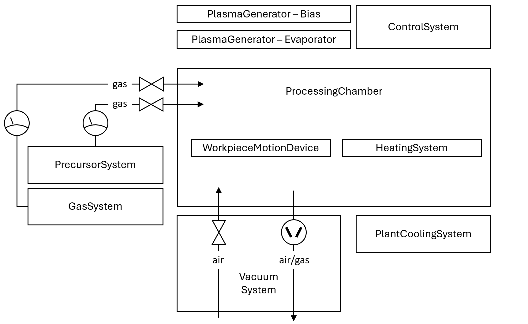
A low pressure plasma surface treatment machine comprises several essential components to enable the diverse plasma surface treatments.
The processing chamber is the central component where the plasma treatment process takes place. It is a vacuum vessel. As the name of the machine type suggests, the plasma treatment process is carried out at low pressures, meaning below atmospheric pressure, typically in the range of a few hundred millibars to 10-4 mbar.
The major components within the processing chamber are the workpiece motion device and the heating system. Depending on the diverse treatment methods, various evaporation sources may also be present.
The workpiece motion device securely fixes the work pieces to be treated and rotates or moves them inside the processing chamber when it is needed to ensure even treatment. The heating system is designed both to heat the work pieces to a target temperature prior to the actual plasma treatment and to maintain the to be treated parts at a specific temperature level during plasma treatment.
The task of the vacuum system is to evacuate the processing chamber to a certain residual gas pressure, to maintain a predetermined pressure during the plasma treatment process and to ventilate the processing chamber back to atmospheric pressure.
Depending on the application in industrial plasma surface technology, corresponding systems require diverse pumps as part of the vacuum system that can evacuate the vacuum chamber from atmospheric pressure into the rough vacuum range of 300-1mbar up to the high vacuum range of 10-3-10-7mbar.
The gas system comprises the precisely regulated addition of pure or premixed process gases, reactive gases and cooling gases, usually via separate lines and gas flow controllers into the processing chamber. Often various different gases are needed to promote specific effects and reactions during the plasma treatment.
The precursor system is basically the same as the gas system. The main difference is the use of precursor feedstock, which is usually liquid. The precursor fluid must first be converted into a gaseous state via an evaporator system before the vapour / gas is injected into the supply line and fed into the processing chamber via gas flow controller.
The creation of layers in the plasma process occurs either the chemical rout meaning purely from the gas phase or through the physical rout by the evaporation of solids or powders or by combining these or different methods for coating synthesis. Plasma generators of various power levels, modes and frequencies are required to synthesize and grow both layers and crystals from the gas phase or to convert solid or powder source material into the vapour phase using various evaporator systems.
Basically and generally speaking, the plasma generator - bias is necessary for the surface activation of the workpieces. It generates the needed plasma. Devices of various power levels, modes and frequencies are used. The plasma generator - bias is usually connected directly with the workpiece motion device. In simple words, a quasi-neutral plasma is a combination of charged, excited, and neutral species. The bias is used to attract charged and exited gas and/or vapor species to the workpiece surfaces. Depending on the polarization the bias is used for various purposes such as electron heating, ion etching, ion incorporation, coating densification etc. during different process steps. Sometimes the plasma generator - bias is not directly attached to the workpiece motion device, but for instance to a so call plasma screen for indirect activation of the workpiece surface.
The control system is mainly a PLC / computer-based system that monitors and controls all process parameters. It is the brain of each low pressure plasma surface treatment machine. It provides monitoring of all critical parameters, relevant status information, recipe management and data logging features, etc.
For heat dissipation and to prevent overheating most of the components that are not air-cooled need water cooling. The plant cooling system ensures that all components are sufficiently cooled during the process, in general during entire use. This may be necessary for safety reasons (keyword: hot surfaces / contact protection) or to protect the individual components by keeping them within the permissible operating temperature limits. Cooling of air-cooled components as well as electronics can be supported by temperature controlled fan cooling / air conditioning (air/air, air/water heat exchanger).
shows how the example machine described can be implemented in an information model using OPC UA for PlasmaSurfaceTechnology.
The following page shows how the example machine described can be implemented in an information model using OPC UA for PlasmaSurfaceTechnology.
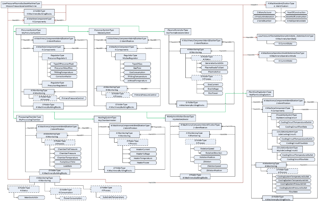
B.2 Instantiation of an exemplary atmospheric pressure plasma surface treatment machine
shows an exemplary atmospheric pressure plasma surface treatment machine.
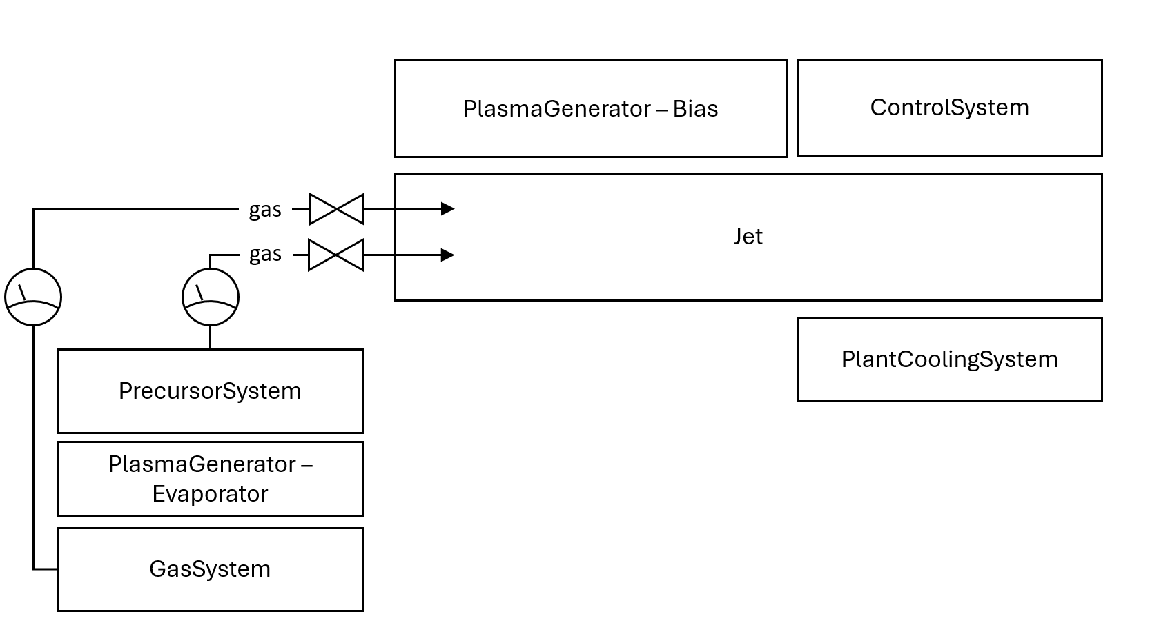
An atmospheric pressure plasma surface treatment machine comprises several essential components to enable the diverse plasma surface treatments.
The plasma jet is the central component where the plasma treatment process takes place. As the name of the machine type suggests, the plasma treatment process is carried out at atmospheric pressures, instead of below low pressure.
The plasma is generated inside the jet by a high voltage between a stator and a rotor and is blown out through the jet head using working gas that is provided by the gas system.
The atmospheric pressure plasma surface machine directed at the material serve to generate and spread the plasma. Plasma surface treatment is a versatile technique that can be used to improve the performance of materials in a range of applications.
The gas system comprises the precisely regulated addition of pure or premixed process gases, reactive gases, usually via separate lines and gas flow controllers into the processing jet. Often various different gases are needed to promote specific effects and reactions during the plasma treatment.
The precursor system is basically the same as the gas system. The main difference is the use of precursor feedstock, which is usually liquid. The precursor fluid must first be converted into a gaseous state via an evaporator system before the vapour / gas is injected into the supply line and fed into the jet via gas flow controller.
The creation of layers in the plasma process occurs either the chemical rout meaning purely from the gas phase or through the physical rout by the evaporation of solids or powders or by combining these or different methods for coating synthesis. In order to transfer solid or powder source material into the vapour phase plasma generators of various power levels, modes and frequencies are used for the wide range of different evaporator systems.
Basically and generally speaking, the plasma generator - bias is necessary for the surface activation of the workpieces. It generates the needed plasma. Devices of various power levels, modes and frequencies are used. The plasma generator - bias is usually connected directly with the workpiece motion device. In simple words, a quasi-neutral plasma is a combination of charged, excited, and neutral species. The bias is used to attract charged and exited gas and/or vapor species to the workpiece surfaces. Depending on the polarization the bias is used for various purposes such as electron heating, ion etching, ion incorporation, coating densification etc. during different process steps. Sometimes the plasma generator - bias is not directly attached to the workpiece motion device, but for instance to a so call plasma screen for indirect activation of the workpiece surface.
The control system is mainly a PLC / computer-based system that monitors and controls all process parameters. It is the brain of each atmospheric pressure plasma surface treatment machine. It provides monitoring of all critical parameters, relevant status information, recipe management and data logging features, etc.
An additionally plant cooling system cools a special jet to a constant temperature if needed.
The following page shows how the example machine described can be implemented in an information model using OPC UA for PlasmaSurfaceTechnology.
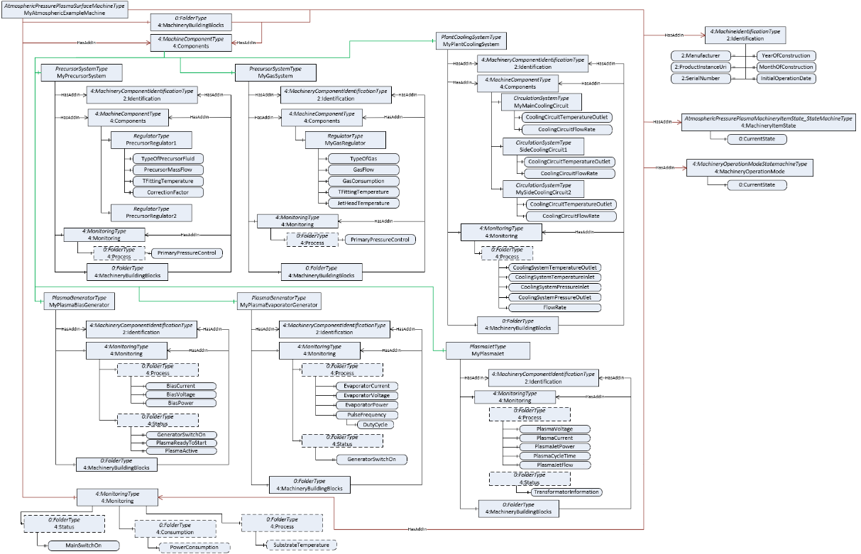
Agreement of Use
COPYRIGHT RESTRICTIONS
This document is provided "as is" by the OPC Foundation and VDMA.
Right of use for this specification is restricted to this specification and does not grant rights of use for referred documents.
Right of use for this specification will be granted without cost.
This document may be distributed through computer systems, printed or copied as long as the content remains unchanged and the document is not modified.
OPC Foundation and VDMA do not guarantee usability for any purpose and shall not be made liable for any case using the content of this document.
The user of the document agrees to indemnify OPC Foundation and VDMA and their officers, directors and agents harmless from all demands, claims, actions, losses, damages (including damages from personal injuries), costs and expenses (including attorneys' fees) which are in any way related to activities associated with its use of content from this specification.
The document shall not be used in conjunction with company advertising, shall not be sold or licensed to any party.
The intellectual property and copyright is solely owned by the OPC Foundation and VDMA.
PATENTS
The attention of adopters is directed to the possibility that compliance with or adoption of OPC or VDMA specifications may require use of an invention covered by patent rights. OPC Foundation or VDMA shall not be responsible for identifying patents for which a license may be required by any OPC or VDMA specification, or for conducting legal inquiries into the legal validity or scope of those patents that are brought to its attention. OPC or VDMA specifications are prospective and advisory only. Prospective users are responsible for protecting themselves against liability for infringement of patents.
WARRANTY AND LIABILITY DISCLAIMERS
WHILE THIS PUBLICATION IS BELIEVED TO BE ACCURATE, IT IS PROVIDED "AS IS" AND MAY CONTAIN ERRORS OR MISPRINTS. THE OPC FOUDATION NOR VDMA MAKES NO WARRANTY OF ANY KIND, EXPRESSED OR IMPLIED, WITH REGARD TO THIS PUBLICATION, INCLUDING BUT NOT LIMITED TO ANY WARRANTY OF TITLE OR OWNERSHIP, IMPLIED WARRANTY OF MERCHANTABILITY OR WARRANTY OF FITNESS FOR A PARTICULAR PURPOSE OR USE. IN NO EVENT SHALL THE OPC FOUNDATION NOR VDMA BE LIABLE FOR ERRORS CONTAINED HEREIN OR FOR DIRECT, INDIRECT, INCIDENTAL, SPECIAL, CONSEQUENTIAL, RELIANCE OR COVER DAMAGES, INCLUDING LOSS OF PROFITS, REVENUE, DATA OR USE, INCURRED BY ANY USER OR ANY THIRD PARTY IN CONNECTION WITH THE FURNISHING, PERFORMANCE, OR USE OF THIS MATERIAL, EVEN IF ADVISED OF THE POSSIBILITY OF SUCH DAMAGES.
The entire risk as to the quality and performance of software developed using this specification is borne by you.
RESTRICTED RIGHTS LEGEND
This Specification is provided with Restricted Rights. Use, duplication or disclosure by the U.S. government is subject to restrictions as set forth in (a) this Agreement pursuant to DFARs 227.7202-3(a); (b) subparagraph (c)(1)(i) of the Rights in Technical Data and Computer Software clause at DFARs 252.227-7013; or (c) the Commercial Computer Software Restricted Rights clause at FAR 52.227-19 subdivision (c)(1) and (2), as applicable. Contractor / manufacturer are the OPC Foundation, 16101 N. 82nd Street, Suite 3B, Scottsdale, AZ, 85260-1830.
COMPLIANCE
The combination of VDMA and OPC Foundation shall at all times be the sole entities that may authorize developers, suppliers and sellers of hardware and software to use certification marks, trademarks or other special designations to indicate compliance with these materials as specified within this document. Products developed using this specification may claim compliance or conformance with this specification if and only if the software satisfactorily meets the certification requirements set by VDMA or the OPC Foundation. Products that do not meet these requirements may claim only that the product was based on this specification and must not claim compliance or conformance with this specification.
TRADEMARKS
Most computer and software brand names have trademarks or registered trademarks. The individual trademarks have not been listed here.
GENERAL PROVISIONS
Should any provision of this Agreement be held to be void, invalid, unenforceable or illegal by a court, the validity and enforceability of the other provisions shall not be affected thereby.
This Agreement shall be governed by and construed under the laws of Germany.
This Agreement embodies the entire understanding between the parties with respect to, and supersedes any prior understanding or agreement (oral or written) relating to, this specification.