
1 Scope
This document defines the UA companion specification using OPC UA constructs to provide information for data transfer from and to Geometric Measurement Systems (e.g., Manual and Automatic Gauging Systems for Dimensional Tasks, Coordinate Measuring Systems, Form Measuring Systems, Surface Texture Measuring Systems) in various industries. The OPC UA Companion Specification for Geometric Measurement Systems (GMS) aims to provide a unique interface for communication partners from different manufacturers to allow for interoperability.
Among others, the following functionalities are covered:
Identification of machines, machine data and status
Managing part data (in version 1 only monitoring)
Accessing data of measuring results.
Job management (in version 1 only monitoring)
OPC Foundation
OPC is the interoperability standard for the secure and reliable exchange of data and information in the industrial automation space and in other industries. It is platform-independent and ensures the seamless flow of information among devices from multiple vendors. The OPC Foundation is responsible for the development and maintenance of this standard.
OPC UA is a platform-independent service-oriented architecture that integrates all the functionality of the individual OPC Classic specifications into one extensible framework. This multi-layered approach accomplishes the original design specification goals of:
Platform independence: from an embedded microcontroller to cloud-based infrastructure
Secure: encryption, authentication, authorization and auditing
Extensible: ability to add new features, including transports, without affecting existing applications
Comprehensive information modelling capabilities: for defining any model from simple to complex
VDMA Measuring and Testing Technology
The VDMA represents over 3.300 mainly small and medium-size member companies in the engineering industry, making it one of the largest and most important industrial associations in Europe. The VDMA Measuring and testing technology represent more than 200 manufacturers of length measurement technology, testing technology and weighing technology. The objective of this industry-driven platform is to support this sector through a wide spectrum of activities and services such as standardization, statistics, marketing, public relations, trade fair policy, networking events and representation of interests.
2 Normative references
The following referenced documents are indispensable for the application of this document. For dated references, only the edition cited applies. For undated references, the latest edition of the referenced document (including any amendments and errata) applies.
OPC 10000-1, OPC Unified Architecture - Part 1: Overview and Concepts
OPC 10000-1
OPC 10000-2, OPC Unified Architecture - Part 2: Security Model
OPC 10000-2
OPC 10000-3, OPC Unified Architecture - Part 3: Address Space Model
OPC 10000-3
OPC 10000-4, OPC Unified Architecture - Part 4: Services
OPC 10000-4
OPC 10000-5, OPC Unified Architecture - Part 5: Information Model
OPC 10000-5
OPC 10000-6, OPC Unified Architecture - Part 6: Mappings
OPC 10000-6
OPC 10000-7, OPC Unified Architecture - Part 7: Profiles
OPC 10000-7
OPC 10000-8, OPC Unified Architecture - Part 8: Data Access
OPC 10000-8
OPC 10000-9, OPC Unified Architecture - Part 9: Alarms and Conditions
OPC 10000-9
OPC 10000-100, OPC Unified Architecture - Part 100: Devices
OPC 10000-100
OPC 10000-200, OPC Unified Architecture - Part 200: Industrial Automation
OPC 10000-200
OPC 40001-1 OPC Unified Architecture - Part 1: Building Blocks for Machinery
http://www.opcfoundation.org/UA/Machinery/Part1/
OPC 40001-101 OPC Unified Architecture - Part 101: Machinery Result Transfer
http://www.opcfoundation.org/UA/Machinery/Part101/
OPC 40501-1 OPC Unified Architecture - Part 1: Machine Tools - Monitoring and Job
http://www.opcfoundation.org/UA/MachineTools/Part1/
| [JCGM 200] | JCGM 200:2012 (VIM, 3rd edition, JCGM 200:2008 with minor corrections) International Vocabulary of Metrology - Basic and General Concepts and Associated Terms, JCGM (Joint Committee for Guides in Metrology) 2012 (Internet 05.03.2021: https://www.bipm.org/en/publications/guides), identical to: ISO/IEC Guide 99:2007-12 |
| [IEC 62264-1] | Enterprise-control system integration - Part 1: Models and terminology, 2013 |
| [ISO 10360] | Geometrical Product Specifications (GPS) - Acceptance and reverification tests for coordinate measuring systems (CMS), part 1 -13, 2000-2021. |
| [ISO 14638] | Geometrical product specifications (GPS) - Matrix model, 2015. |
| [ISO 14978] | Geometrical product specifications (GPS) - General concepts and requirements for GPS measuring equipment, 2018. |
| [ISO 1938] | Geometrical product specifications (GPS) - Dimensional measuring equipment - Part 1: Plain limit gauges of linear size, 2015, Part 2: Reference disk gauges, 2017. |
| [ISO 22093] | Industrial automation systems and integration - Physical device control - Dimensional Measuring Interface Standard (DMIS) 2011. |
| [ISO 22400] | Automation systems and integration - Key performance indicators (KPIs) for manufacturing operations management, part 1 - 2, 2014. |
| [ISO 25178] | Geometrical product specifications (GPS) - Surface texture: Areal, several parts 2010-2021. |
| [VDI 2627] | VDI/VDE-Standard 2627, Measuring rooms, several parts 2005 - 2015 |
| [AQDEF 5] | Advanced Quality Data Exchange Format (AQDEF), Version 5.01, Deutsch, Englisch, Q-DAS GmbH & Co. KG, Weinheim, Germany Mai 2017. (Internet, 26.08.2021: https://www.q-das.com/en/service/datenformat-aqdef) |
3 References
| [Pfeifer 2006] | Pfeifer, T., Imkamp, D., Schmitt, R.: Coordinate Metrology and CAx Applications in Industrial Production, Carl Hanser Verlag, München 2006. |
4 Terms, abbreviated terms and conventions
4.1 Overview
This document assumes that basic concepts of OPC UA information modelling and OPC 40501-1 are understood. This document will use these concepts to describe the OPC UA for GMS Information Model. For the purposes of this document, the terms and definitions are given in OPC 10000-1, OPC 10000-3, OPC 10000-4, OPC 10000-5, OPC 10000-7, OPC 10000-100, as well as the following apply.
The terminology used in this specification considers the definitions according to The International Vocabulary of Metrology (VIM) [JCGM 200].
Note that OPC UA terms and terms defined in this document are italicized in the document.
4.2 OPC UA for GMS terms
4.2.1 Geometric Measurement System (GMS)
4.2.1.1 Untitled
[SOURCE: JCGM 200]
4.2.2 Measurement Reason (MeasReason)
4.2.2.1 Untitled
indication why a measurement is carried out
4.2.3 Measurement Routine (MeasurementRoutine)
4.2.3.1 Untitled
sequence of steps to perform a measurement on a GMS. In most cases, this routine is done automatically or semi-automatically. It is also called a measurement plan or sequence.
4.2.4 Measuring System
4.2.4.1 Untitled
[SOURCE: JCGM 200]
4.2.5 Master
4.2.5.1 Untitled
[SOURCE: JCGM 200]
4.2.6 Part
4.2.6.1 Untitled
[SOURCE: OPC 40501-1]
4.2.7 Sensor (Primary)
4.2.7.1 Untitled
[SOURCE: JCGM 200]
4.2.8 Additional Sensor
4.2.8.1 Untitled
every further sensor except the primary sensor that carries out the geometric measurement
4.2.9 Calibration
4.2.9.1 Untitled
[SOURCE: JCGM 200]
4.2.10 Qualification
4.2.10.1 Untitled
[SOURCE: ISO 10360 Part 1]
4.3 Abbreviated terms
| AQDEF® | Advanced Quality Data Exchange Format |
| ASCII | American Standard Code for Information Interchange |
| CS | Companion Specification (referring to OPC UA) |
| CSV | Comma separated values (ASCII text file format) |
| DMIS | Dimensional Measuring Interface Standard |
| ERP | Enterprise Resource Planning |
| GMS | Geometric Measurement System |
| HMI | Human-machine interface |
| HTTP | Hypertext Transfer Protocol |
| I++ DMS | Inspection PlusPlus Data Management Services |
| IEC | International Electrotechnical Commission |
| ISO | International Organization for Standardization |
| ISO GPS | ISO Geometrical Product Specification |
| JSON | JavaScript Object Notation |
| MES | Manufacturing Execution System |
| OEE | Overall equipment effectiveness from ISO 22400 |
| OPC UA | Open Platform Communications Unified Automation |
| PMS | Production management system |
| Q-DAS | Qualitative Data Analysis Software |
| QIF | Quicken Interchange Format |
| TCP/IP | Internet protocol suite (Transmission Control Protocol / Internet Protocol) |
| URI | Uniform Resource Identifier |
| VDI | Association of German Engineers |
| VDMA | The Mechanical Engineering Industry Association of Germany |
| VIM | The International Vocabulary of Metrology |
| XML | Extensible Markup Language |
4.4 Conventions used in this document
4.4.1 Conventions for Node descriptions
4.4.1.1 Node definitions
Node definitions are specified using tables (see Table 2).
Attributes are defined by providing the Attribute name and a value, or a description of the value.
References are defined by providing the ReferenceType name, the BrowseName of the TargetNode and its NodeClass.
If the TargetNode is a component of the Node being defined in the table the Attributes of the composed Node are defined in the same row of the table.
The DataType is only specified for Variables; "[<number>]" indicates a single-dimensional array, for multi-dimensional arrays the expression is repeated for each dimension (e.g. [2][3] for a two-dimensional array). For all arrays the ArrayDimensions is set as identified by <number> values. If no <number> is set, the corresponding dimension is set to 0, indicating an unknown size. If no number is provided at all the ArrayDimensions can be omitted. If no brackets are provided, it identifies a scalar DataType and the ValueRank is set to the corresponding value (see OPC 10000-3). In addition, ArrayDimensions is set to null or is omitted. If it can be Any or ScalarOrOneDimension, the value is put into "undefined", so either "undefined" or "undefined" and the ValueRank is set to the corresponding value (see OPC 10000-3) and the ArrayDimensions is set to null or is omitted. Examples are given in Table 1.
| Notation | DataType | ValueRank | ArrayDimensions | Description |
| 0:Int32 | 0:Int32 | -1 | omitted or null | A scalar Int32. |
| 0:Int32[] | 0:Int32 | 1 | omitted or undefined | Single-dimensional array of Int32 with an unknown size. |
| 0:Int32[][] | 0:Int32 | 2 | omitted or undefined | Two-dimensional array of Int32 with unknown sizes for both dimensions. |
| 0:Int32[3][] | 0:Int32 | 2 | undefined | Two-dimensional array of Int32 with a size of 3 for the first dimension and an unknown size for the second dimension. |
| 0:Int32[5][3] | 0:Int32 | 2 | undefined | Two-dimensional array of Int32 with a size of 5 for the first dimension and a size of 3 for the second dimension. |
| 0:Int32undefined | 0:Int32 | -2 | omitted or null | An Int32 where it is unknown if it is scalar or array with any number of dimensions. |
| 0:Int32undefined | 0:Int32 | -3 | omitted or null | An Int32 where it is either a single-dimensional array or a scalar. |
The TypeDefinition is specified for Objects and Variables.
The TypeDefinition column specifies a symbolic name for a NodeId, i.e. the specified Node points with a HasTypeDefinition Reference to the corresponding Node.
The ModellingRule of the referenced component is provided by specifying the symbolic name of the rule in the ModellingRule column. In the AddressSpace, the Node shall use a HasModellingRule Reference to point to the corresponding ModellingRule Object.
If the NodeId of a DataType is provided, the symbolic name of the Node representing the DataType shall be used.
Note that if a symbolic name of a different namespace is used, it is prefixed by the NamespaceIndex (see 4.4.2.2).
Nodes of all other NodeClasses cannot be defined in the same table; therefore, only the used ReferenceType, their NodeClass and their BrowseName are specified. A reference to another part of this document points to their definition.
Table 2 illustrates the table. If no components are provided, the DataType, TypeDefinition and Other columns may be omitted and only a Comment column is introduced to point to the Node definition.
| Attribute | Value | ||||
| Attribute name | Attribute value. If it is an optional Attribute that is not set "--" is used. | ||||
| References | NodeClass | BrowseName | DataType | TypeDefinition | Other |
|---|---|---|---|---|---|
| ReferenceType name | NodeClass of the target Node. | BrowseName of the target Node. | DataType of the referenced Node, only applicable for Variables. | TypeDefinition of the referenced Node, only applicable for Variables and Objects. | Additional characteristics of the TargetNode such as the ModellingRule or AccessLevel. |
| NOTE Notes referencing footnotes of the table content. | |||||
Components of Nodes can be complex that is containing components by themselves. The TypeDefinition, NodeClass and DataType can be derived from the type definitions, and the symbolic name can be created as defined in 4.4.3.1. Therefore, those containing components are not explicitly specified; they are implicitly specified by the type definitions.
The Other column defines additional characteristics of the Node. Examples of characteristics that can appear in this column are show in Table 3.
| Name | Short Name | Description |
| 0:Mandatory | M | The Node has the Mandatory ModellingRule. |
| 0:Optional | O | The Node has the Optional ModellingRule. |
| 0:MandatoryPlaceholder | MP | The Node has the MandatoryPlaceholder ModellingRule. |
| 0:OptionalPlaceholder | OP | The Node has the OptionalPlaceholder ModellingRule. |
| ReadOnly | RO | The Node AccessLevel has the CurrentRead bit set but not the CurrentWrite bit. |
| ReadWrite | RW | The Node AccessLevel has the CurrentRead and CurrentWrite bits set. |
| WriteOnly | WO | The Node AccessLevel has the CurrentWrite bit set but not the CurrentRead bit. |
If multiple characteristics are defined, they are separated by commas. The name or the short name may be used.
4.4.1.2 Additional References
To provide information about additional References, the format as shown in Table 4 is used.
| SourceBrowsePath | Reference Type | Is Forward | TargetBrowsePath |
| SourceBrowsePath is always relative to the TypeDefinition. Multiple elements are defined as separate rows of a nested table. | ReferenceType name | True = forward Reference. | TargetBrowsePath points to another Node, which can be a well-known instance or a TypeDefinition. You can use BrowsePaths here as well, which is either relative to the TypeDefinition or absolute. If absolute, the first entry needs to refer to a type or well-known instance, uniquely identified within a namespace by the BrowseName. |
References can be to any other Node.
4.4.1.3 Additional sub-components
To provide information about sub-components, the format as shown in Table 5 is used.
| BrowsePath | References | NodeClass | BrowseName | DataType | TypeDefinition | Others |
| BrowsePath is always relative to the TypeDefinition. Multiple elements are defined as separate rows of a nested table | NOTE Same as for Table 2 | |||||
4.4.1.4 Additional Attribute values
The type definition table provides columns to specify the values for required Node Attributes for InstanceDeclarations. To provide information about additional Attributes, the format as shown in Table 6 is used.
| BrowsePath | <Attribute name> Attribute |
| BrowsePath is always relative to the TypeDefinition. Multiple elements are defined as separate rows of a nested table | The values of attributes are converted to text by adapting the reversible JSON encoding rules defined in OPC 10000-6. If the JSON encoding of a value is a JSON string or a JSON number then that value is entered in the value field. Double quotes are not included. If the DataType includes a NamespaceIndex (QualifiedNames, NodeIds or ExpandedNodeIds) then the notation used for BrowseNames is used. If the value is an Enumeration the name of the enumeration value is entered. If the value is a Structure then a sequence of name and value pairs is entered. Each pair is followed by a newline. The name is followed by a colon. The names are the names of the fields in the DataTypeDefinition. If the value is an array of non-structures then a sequence of values is entered where each value is followed by a newline. If the value is an array of Structures or a Structure with fields that are arrays or with nested Structures then the complete JSON array or JSON object is entered. Double quotes are not included. |
There can be multiple columns to define more than one Attribute.
4.4.2 NodeIds and BrowseNames
4.4.2.1 NodeIds
The NodeIds of all Nodes described in this standard are only symbolic names. Annex A defines the actual NodeIds.
The symbolic name of each Node defined in this document is its BrowseName, or, when it is part of another Node, the BrowseName of the other Node, a ".", and the BrowseName of itself. In this case "part of" means that the whole has a 0:HasProperty or 0:HasComponent Reference to its part. Since all Nodes not being part of another Node have a unique name in this document, the symbolic name is unique.
The NamespaceUri for all NodeIds defined in this document is defined in Annex A. The NamespaceIndex for this NamespaceUri is vendor-specific and depends on the position of the NamespaceUri in the server namespace table.
Note that this document not only defines concrete Nodes, but also requires that some Nodes shall be generated, for example one for each Session running on the Server. The NodeIds of those Nodes are Server-specific, including the namespace. But the NamespaceIndex of those Nodes cannot be the NamespaceIndex used for the Nodes defined in this document, because they are not defined by this document but generated by the Server.
4.4.2.2 BrowseNames
The text part of the BrowseNames for all Nodes defined in this document is specified in the tables defining the Nodes. The NamespaceUri for all BrowseNames defined in this document is defined in 13.2.
For InstanceDeclarations of NodeClass Object and Variable that are placeholders (OptionalPlaceholder and MandatoryPlaceholder ModellingRule), the BrowseName and the DisplayName are enclosed in angle brackets (<>) as recommended in OPC 10000-3.If the BrowseName is not defined by this document, a namespace index prefix is added to the BrowseName (e.g., prefix '0' leading to '0:EngineeringUnits' or prefix '2' leading to '2:DeviceRevision'). This is typically necessary if a Property of another specification is overwritten or used in the OPC UA types defined in this document. Table 69 provides a list of namespaces and their indexes as used in this document.
4.4.3 Common Attributes
4.4.3.1 General
The Attributes of Nodes, their DataTypes and descriptions are defined in OPC 10000-3. Attributes not marked as optional are mandatory and shall be provided by a Server. The following tables define if the Attribute value is defined by this document or if it is server-specific.
For all Nodes specified in this document, the Attributes named in Table 7 shall be set as specified in the table.
| Attribute | Value |
| DisplayName | The DisplayName is a LocalizedText. Each Server shall provide the DisplayName identical to the BrowseName of the Node for the LocaleId "en". Whether the server provides translated names for other LocaleIds are server-specific. |
| Description | Optionally a server-specific description is provided. |
| NodeClass | Shall reflect the NodeClass of the Node. |
| NodeId | The NodeId is described by BrowseNames as defined in 4.4.2.1. |
| WriteMask | Optionally the WriteMask Attribute can be provided. If the WriteMask Attribute is provided, it shall set all non-server-specific Attributes to not writable. For example, the Description Attribute may be set to writable since a Server may provide a server-specific description for the Node. The NodeId shall not be writable, because it is defined for each Node in this document. |
| UserWriteMask | Optionally the UserWriteMask Attribute can be provided. The same rules as for the WriteMask Attribute apply. |
| RolePermissions | Optionally server-specific role permissions can be provided. |
| UserRolePermissions | Optionally the role permissions of the current Session can be provided. The value is server-specific and depends on the RolePermissions Attribute (if provided) and the current Session. |
| AccessRestrictions | Optionally server-specific access restrictions can be provided. |
4.4.3.2 Objects
For all Objects specified in this document, the Attributes named in Table 8 shall be set as specified in the Table 8. The definitions for the Attributes can be found in OPC 10000-3.
| Attribute | Value |
| EventNotifier | Whether the Node can be used to subscribe to Events or not is server-specific. |
4.4.3.3 Variables
For all Variables specified in this document, the Attributes named in Table 9 shall be set as specified in the table. The definitions for the Attributes can be found in OPC 10000-3.
| Attribute | Value |
| MinimumSamplingInterval | Optionally, a server-specific minimum sampling interval is provided. |
| AccessLevel | The access level for Variables used for type definitions is server-specific, for all other Variables defined in this document, the access level shall allow reading; other settings are server-specific. |
| UserAccessLevel | The value for the UserAccessLevel Attribute is server-specific. It is assumed that all Variables can be accessed by at least one user. |
| Value | For Variables used as InstanceDeclarations, the value is server-specific; otherwise it shall represent the value described in the text. |
| ArrayDimensions | If the ValueRank does not identify an array of a specific dimension (i.e. ValueRank <= 0) the ArrayDimensions can either be set to null or the Attribute is missing. This behaviour is server-specific. If the ValueRank specifies an array of a specific dimension (i.e. ValueRank > 0) then the ArrayDimensions Attribute shall be specified in the table defining the Variable. |
| Historizing | The value for the Historizing Attribute is server-specific. |
| AccessLevelEx | If the AccessLevelEx Attribute is provided, it shall have the bits 8, 9, and 10 set to 0, meaning that read and write operations on an individual Variable are atomic, and arrays can be partly written. |
4.4.3.4 VariableTypes
For all VariableTypes specified in this document, the Attributes named in Table 10 shall be set as specified in the table. The definitions for the Attributes can be found in OPC 10000-3.
| Attributes | Value |
| Value | Optionally a server-specific default value can be provided. |
| ArrayDimensions | If the ValueRank does not identify an array of a specific dimension (i.e. ValueRank <= 0) the ArrayDimensions can either be set to null or the Attribute is missing. This behaviour is server-specific. If the ValueRank specifies an array of a specific dimension (i.e. ValueRank > 0) then the ArrayDimensions Attribute shall be specified in the table defining the VariableType. |
4.4.3.5 Methods
For all Methods specified in this document, the Attributes named in Table 11 shall be set as specified in the table. The definitions for the Attributes can be found in OPC 10000-3.
| Attributes | Value |
| Executable | All Methods defined in this document shall be executable (Executable Attribute set to "True"), unless it is defined differently in the Method definition. |
| UserExecutable | The value of the UserExecutable Attribute is server-specific. It is assumed that all Methods can be executed by at least one user. |
5 General information about Geometric Measurement Systems (GMS) and OPC UA
5.1 Introduction to Geometric Measurement Systems in Industrial Production
Metrology is an important provider of information in industrial production. Therefore, its integration into the digital data flow of information in production is obvious. The most common application of metrology is its use for quality inspection.
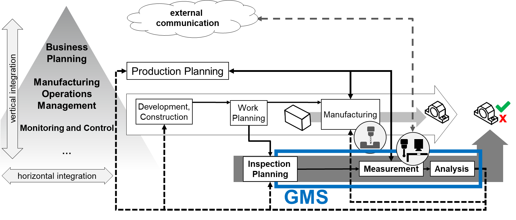
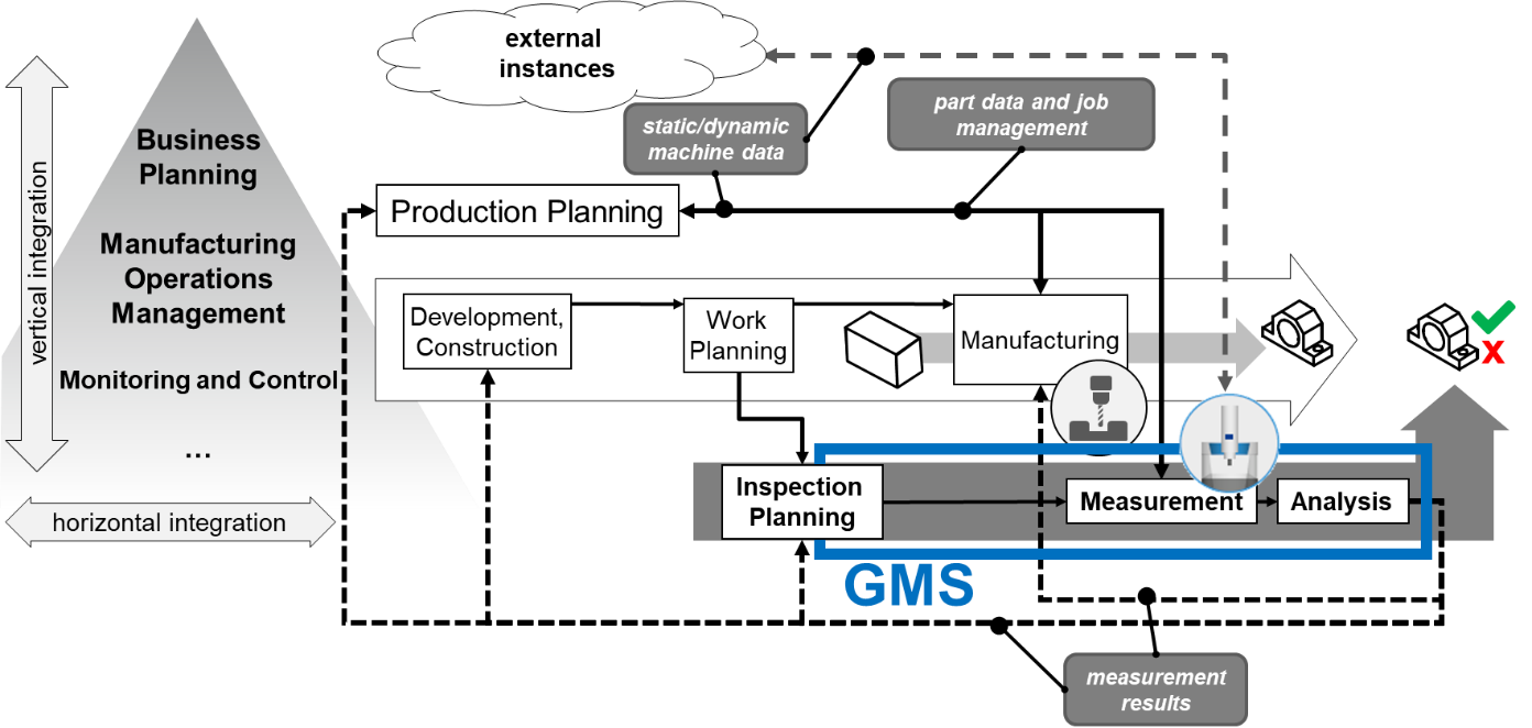
Figure 1 shows a simplified representation of the process chain for order processing in production from development and construction to work planning (routing) and to manufacturing. This process is connected to the process of quality inspection based on measurements from inspection, (test) planning to measurement and to analysis. All process steps are managed by production planning. The feedback of data from the analysis into upstream processes are marked with dashed lines [Pfeifer 2006]. An additional line represents the connection between the measurement system and external instances.
Besides the horizontal integration along the process chain of production, a vertical integration into upper management exists. This integration can be described by the levels of automation pyramid according to [IEC 62264-1].
The scope of the Geometric Measurement System companion specification is marked with "GMS".
A large proportion of the measurements in production are measurements on the part geometry.
5.1.1 Definition of a Geometric Measurement System
The International Vocabulary for Metrology (VIM) [JCGM 200] defines the general concepts and the associated terms for metrology. Chapter 3 of VIM describes devices for measurement. A measuring instrument is thus a device used for making measurements, alone or with one or more supplementary devices. A measuring system consists of a set of one or more measuring instruments and often other devices, including any reagent and supply, assembled and adapted to give information used to generate measured quantity values within specified intervals for quantities of specified kinds. A measuring system may even consist of one single measuring instrument only.
The standards of Geometrical Product Specification (ISO GPS) are used to define the geometric requirements for workpieces in technical specifications and the requirements for their verification [ISO 14638]. The verification is mainly done by measurements. General concepts and requirements for the used measuring equipment define ISO 14978. The described measuring equipment is also called a measuring system. This leads to the term Geometric Measurement System (GMS). A GMS is a measuring system according to [JCGM 200] performing geometrical measuring tasks. The measurement in production is often automated.
OPC UA offers the opportunity to integrate GMS into production according to the described path in Figure 1.
5.1.2 Classification and Structure of Geometric Measurement Systems
The field of Geometric Measurement Systems is very broad. In this section, the components of a GMS, as well as a classification for possible implementations, will be shown. The structures described here are exemplary. There may be further or future classifications for which this Companion Specification can still be used, and a GMS may contain further components or subsystems. Figure 2 contains an overview of the common components. It does not claim to be complete.
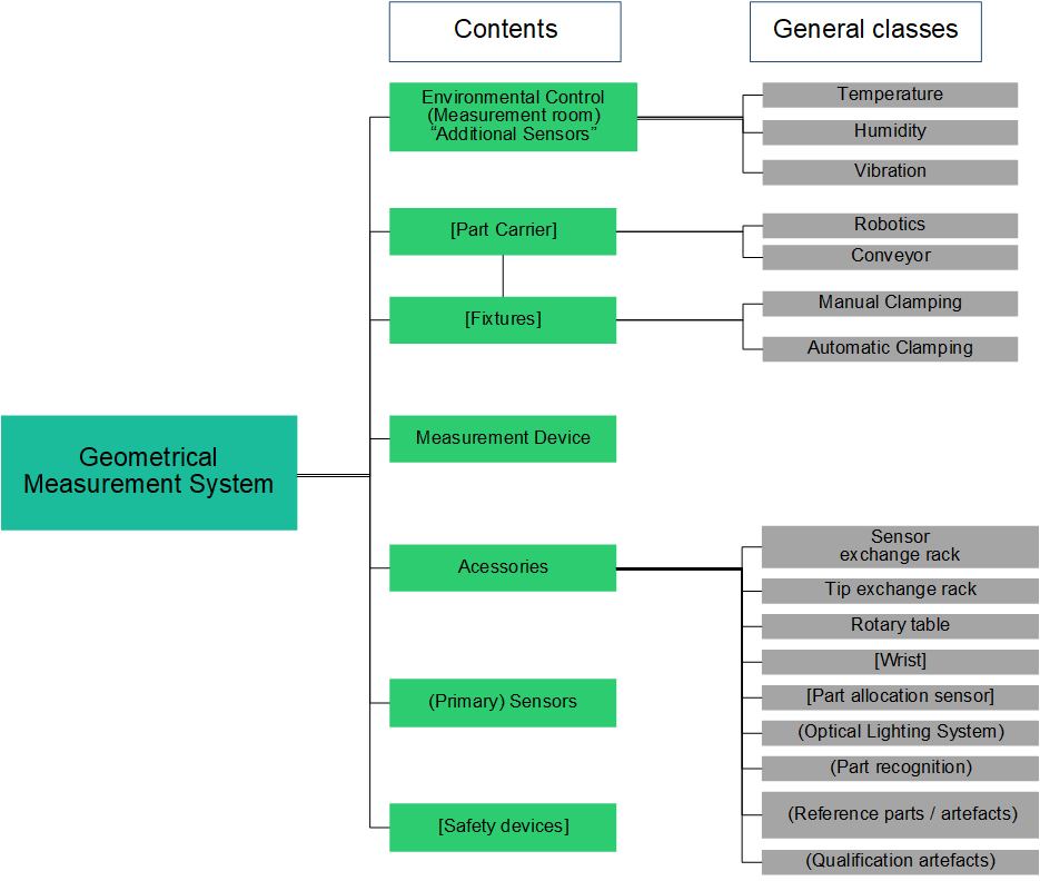
According to Figure 2, there are seven different main types of common components of a GMS (green). They may also be split into different subtypes (grey). The main types are defined as:
The GMS consists of an instrument that comprises one or more sensors (4.2.7).
Environmental control [VDI 2627] requires additional sensors (4.2.8)).
Part carrier & fixtures: enable a strict control and fixed reference in space and time - the coordinate systems - between measured component and measurement system.
Accessories enable the GMS to function according to the production plan.
Safety devices enable the GMS to observe its environment and prevent it from harming the operator or the measured part.
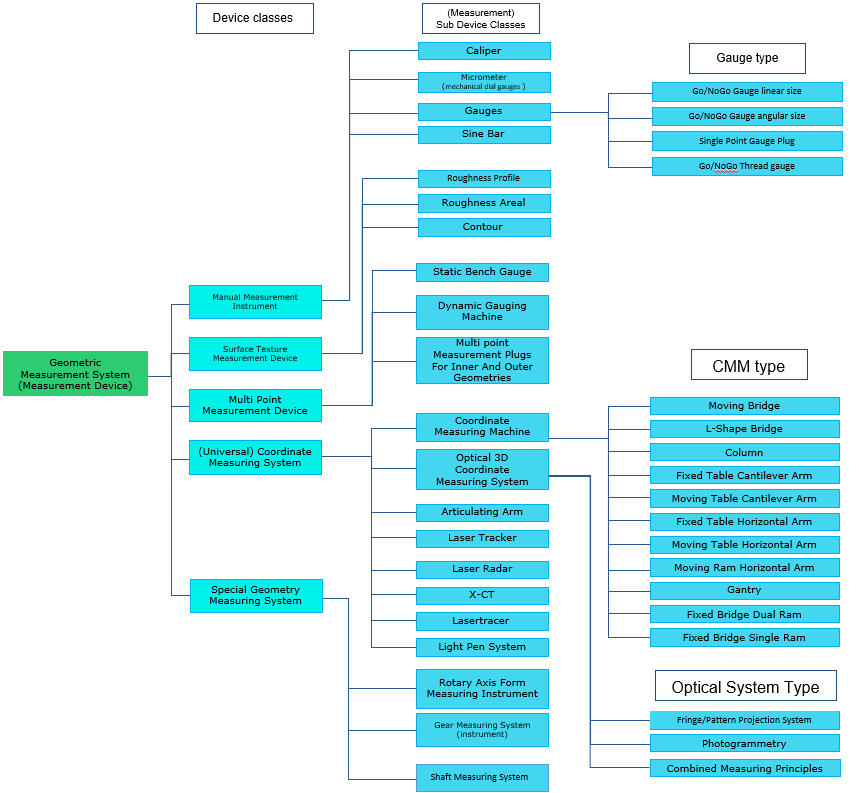
Figure 3 contains the classification of a GMS and divide the GMS into manual measurement instruments [ISO 14978], surface texture measuring instruments [ISO 25178], multi point measuring instruments, coordinate measuring systems [ISO 10360] and special systems. The gauges [ISO 1938] are treated as manual instruments. The list of applicable GMS does not claim to be complete.
5.1.3 Result Management in Geometric Measurement Systems
The output of all measurement systems are measurement results. For geometric measurement results, many file formats and structures (e.g., AQDEF® [AQDEF 5], DMIS [ISO 22093], QIF, I++ DMS, ...) and other generic formats (CSV, raw text, JSON, XML …) are used. All these formats have their specific use cases, domains, and benefits [Pfeifer 2006]. Therefore, this Companion Specification defines only the transport and the management of the result. The concepts of the result management are based on the Result Management of the OPC 40001-101.
5.2 Introduction to OPC Unified Architecture
5.2.1 What is OPC UA?
OPC UA is an open and royalty free set of standards designed as a universal communication protocol. While there are numerous communication solutions available, OPC UA has key advantages:
A state of art security model (see OPC 10000-2).
A fault tolerant communication protocol.
An information modelling framework that allows application developers to represent their data in a way that makes sense to them.
OPC UA has a broad scope which delivers for economies of scale for application developers. This means that a larger number of high-quality applications at a reasonable cost are available. When combined with semantic models such as OPC UA for Geometric Measurement Systems, OPC UA makes it easier for end users to access data via generic commercial applications.
The OPC UA model is scalable from small devices to ERP systems. OPC UA Servers process information locally and then provide that data in a consistent format to any application requesting data - ERP, MES, PMS, Maintenance Systems, HMI, Smartphone or a standard Browser, for examples. For a more complete overview see OPC 10000-1.
5.2.2 Basics of OPC UA
As an open standard, OPC UA is based on standard internet technologies, like TCP/IP, HTTP, Web Sockets.
As an extensible standard, OPC UA provides a set of Services (see OPC 10000-4) and a basic information model framework. This framework provides an easy manner for creating and exposing vendor defined information in a standard way. More importantly all OPC UA Clients are expected to be able to discover and use vendor-defined information. This means OPC UA users can benefit from the economies of scale that come with generic visualization and historian applications. This specification is an example of an OPC UA Information Model designed to meet the needs of developers and users.
OPC UA Clients can be any consumer of data from another device on the network to browser based thin clients and ERP systems. The full scope of OPC UA applications is shown in Figure 4.

OPC UA provides a robust and reliable communication infrastructure having mechanisms for handling lost messages, failover, heartbeat, etc. With its binary encoded data, it offers a high-performing data exchange solution. Security is built into OPC UA as security requirements become more and more important especially since environments are connected to the office network or the internet and attackers are starting to focus on automation systems.
5.2.3 Information modelling in OPC UA
5.2.3.1 Concepts
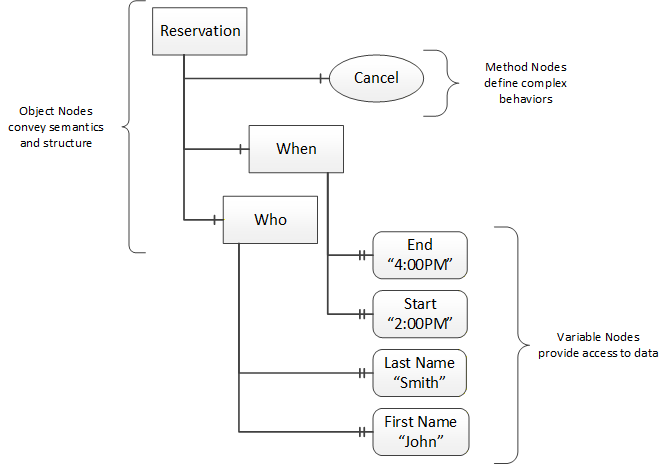
OPC UA provides a framework that can be used to represent complex information as Objects in an AddressSpace which can be accessed with standard services. These Objects consist of Nodes connected by References. Different classes of Nodes convey different semantics. For example, a Variable Node represents a value that can be read or written. The Variable Node has an associated DataType that can define the actual value, such as a string, float, structure etc. It can also describe the Variable value as a variant. A Method Node represents a function that can be called. Every Node has a number of Attributes including a unique identifier called a NodeId and non-localized name called as BrowseName. An Object representing a 'Reservation' is shown in Figure 5.
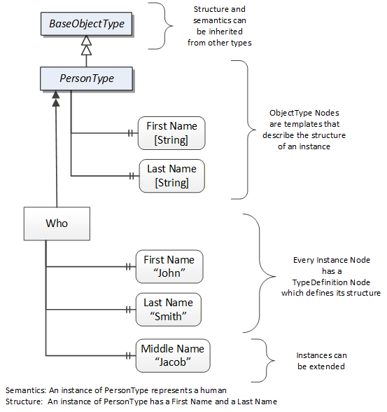
Object and Variable Nodes represent instances and they always reference a TypeDefinition (ObjectType or VariableType) Node which describes their semantics and structure. Figure 6 illustrates the relationship between an instance and its TypeDefinition.
The type Nodes are templates that define all of the children that can be present in an instance of the type. In the example in Figure 6 the PersonType ObjectType defines two children: First Name and Last Name. All instances of PersonType are expected to have the same children with the same BrowseNames. Within a type the BrowseNames uniquely identify the children. This means Client applications can be designed to search for children based on the BrowseNames from the type instead of NodeIds. This eliminates the need for manual reconfiguration of systems if a Client uses types that multiple Servers implement.
OPC UA also supports the concept of sub-typing. This allows a modeller to take an existing type and extend it. There are rules regarding sub-typing defined in OPC 10000-3, but in general they allow the extension of a given type or the restriction of a DataType. For example, the modeller may decide that the existing ObjectType in some cases needs an additional Variable. The modeller can create a subtype of the ObjectType and add the Variable. A Client that is expecting the parent type can treat the new type as if it was of the parent type. Regarding DataTypes, subtypes can only restrict. If a Variable is defined to have a numeric value, a sub type could restrict it to a float.
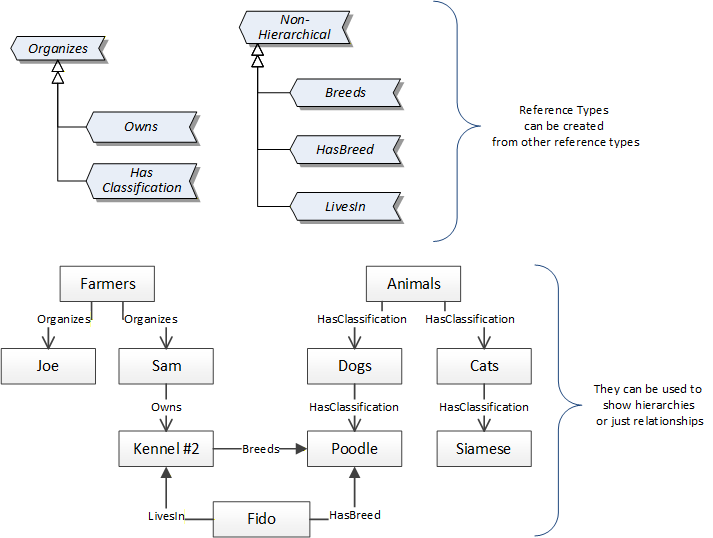
References allow Nodes to be connected in ways that describe their relationships. All References have a ReferenceType that specifies the semantics of the relationship. References can be hierarchical or non-hierarchical. Hierarchical references are used to create the structure of Objects and Variables. Non-hierarchical are used to create arbitrary associations. Applications can define their own ReferenceType by creating subtypes of an existing ReferenceType. Subtypes inherit the semantics of the parent but may add additional restrictions. Figure 7 depicts several References, connecting different Objects.
The Figures above use a notation that was developed for the OPC UA specification. The notation is summarized in Figure 8. UML representations can also be used; however, the OPC UA notation is less ambiguous because there is a direct mapping from the elements in the Figures to Nodes in the AddressSpace of an OPC UA Server.

A complete description of the different types of Nodes and References can be found in OPC 10000-3 and the base structure is described in OPC 10000-5.
OPC UA specification defines a very wide range of functionality in its basic information model. It is not required that all Clients or Servers support all functionality in the OPC UA specifications. OPC UA includes the concept of Profiles, which segment the functionality into testable certifiable units. This allows the definition of functional subsets (that are expected to be implemented) within a companion specification. The Profiles do not restrict functionality, but generate requirements for a minimum set of functionalities (see OPC 10000-7).
5.2.3.2 Namespaces
OPC UA allows information from many different sources to be combined into a single coherent AddressSpace. Namespaces are used to make this possible by eliminating naming and id conflicts between information from different sources. Each namespace in OPC UA has a globally unique string called a NamespaceUri which identifies a naming authority and a locally unique integer called a NamespaceIndex, which is an index into the Server's table of NamespaceUris. The NamespaceIndex is unique only within the context of a Session between an OPC UA Client and an OPC UA Server- the NamespaceIndex can change between Sessions and still identify the same item even though the NamespaceUri's location in the table has changed. The Services defined for OPC UA use the NamespaceIndex to specify the Namespace for qualified values.
There are two types of structured values in OPC UA that are qualified with NamespaceIndexes: NodeIds and QualifiedNames. NodeIds are locally unique (and sometimes globally unique) identifiers for Nodes. The same globally unique NodeId can be used as the identifier in a node in many Servers - the node's instance data may vary but its semantic meaning is the same regardless of the Server it appears in. This means Clients can have built-in knowledge of what the data means in these Nodes. OPC UA Information Models generally define globally unique NodeIds for the TypeDefinitions defined by the Information Model.
QualifiedNames are non-localized names qualified with a Namespace. They are used for the BrowseNames of Nodes and allow the same names to be used by different information models without conflict. TypeDefinitions are not allowed to have children with duplicate BrowseNames; however, instances do not have that restriction.
5.2.3.3 Companion Specifications
An OPC UA companion specification for an industry specific vertical market describes an Information Model by defining ObjectTypes, VariableTypes, DataTypes and ReferenceTypes that represent the concepts used in the vertical market, and potentially also well-defined Objects as entry points into the AddressSpace.
6 Use cases
This companion specification describes how a GMS is addressed via OPC UA. For this purpose, the following primary use cases for the communication with a GMS are considered in sections 6.1 to 6.56.5. These use cases are located in the overview figure of a Geometric Measurement System (GMS) in Figure 9.
Further use cases can also be covered or specified in other standards (vendor or Companion Specification).
In each chapter for the use cases, a simple sequence diagram demonstrates a typical communication example between GMS and other instances like operator, high-level system in the automation pyramid, data bases or other systems.
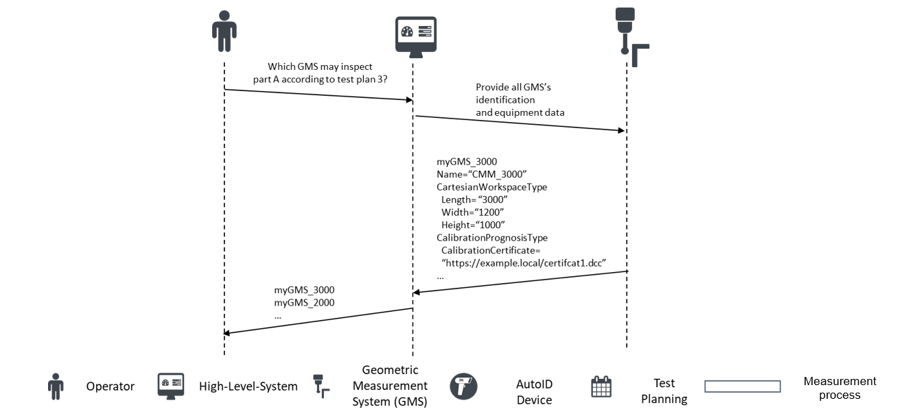
6.1 Retrieve static machine data
A higher-level system requests from a GMS which (measurement) functions/parameters (measuring space) are available, how the machine is identified if the measuring system is calibrated, retrieves additional information from machine components and, to receive an overview of the sensor system, respectively in order to
provide an overview of GMS's capabilities
validate measurement jobs addressed to a certain GMS
plan measuring tasks for GMSs
be able to locate all GMSs
assign the appropriate GMS to the part to be measured, if several different GMSs are available
Figure 10 shows a typical communication between GMS, operator and high-level system to retrieve static machine data as a sequence diagram.
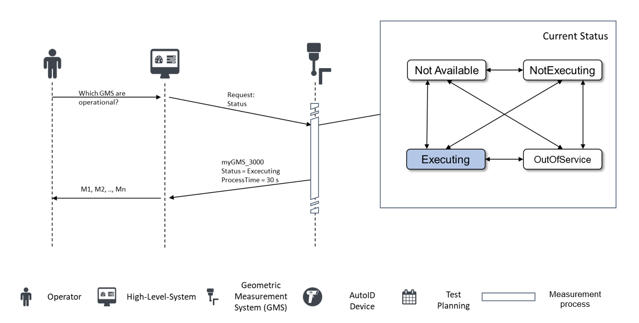
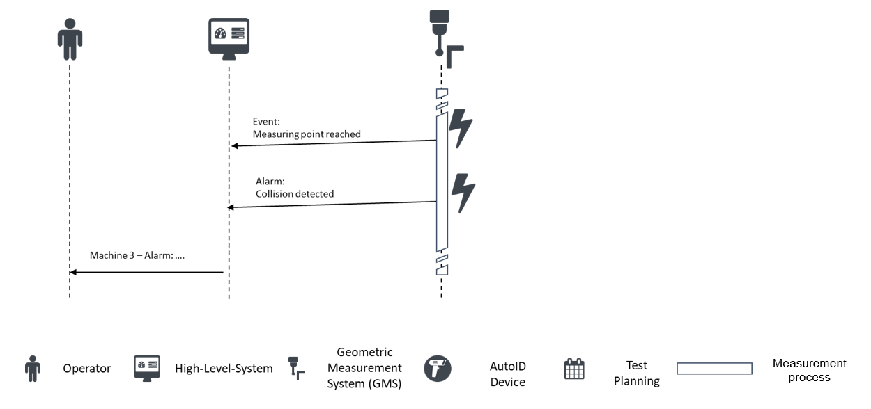
6.2 Retrieve dynamic machine status
A higher-level system would like to know the status/state/condition (e.g., collision) of the GMS, when manual intervention is required, the current error message, what measures have to be taken in case of intervention to
plan the next jobs
keep usage statistics
plan maintenance
assign service
calculate key performance indicators (e.g., OEE [ISO 22400-2])
archive data
verify the reliability of the measurements
send warnings, if necessary.
Figure 11 and Figure 12 show a typical communication between GMS, operator, and high-level system to retrieve dynamic machine data as a sequence diagram.
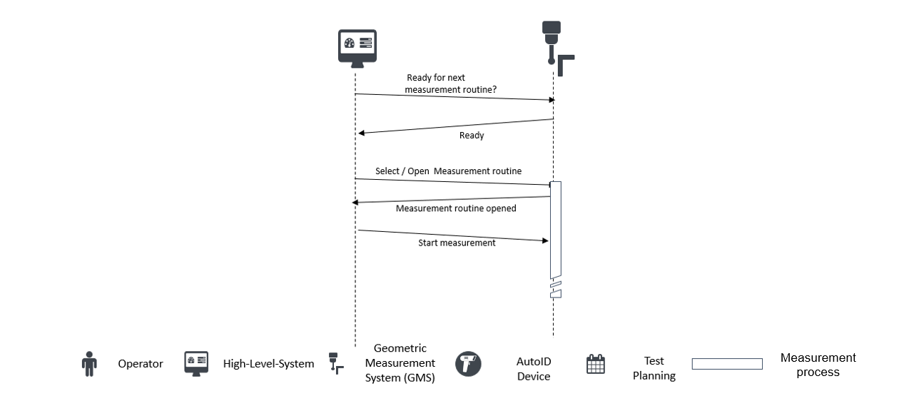
6.3 Job management
A higher-level system may manage/schedule/start/stop measurement routines, be able to assign part to a job/measurement routine/batch, want to know the remaining time till the job is finished, know what the current status of the job is and include dynamic part data in the measurement result (e.g., material no., part no., comments, operator) in order to
be able to distribute the execution processes automatically
(automatically) start/enable the measurement routine
create an overview of the current job status
ensure traceability
Figure 13 shows a typical communication between GMS, operator and high-level system to manage jobs as a sequence diagram.
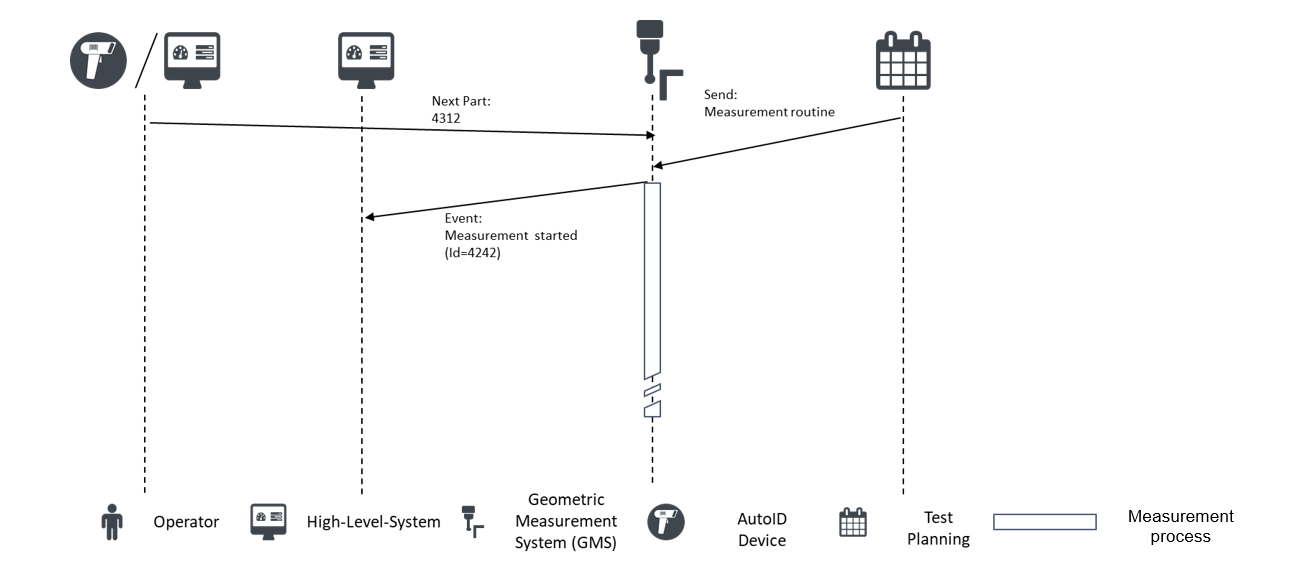
6.4 Managing part data
A higher-level system/handling system would like to identify a part on the GMS, know whether the measuring procedure was error-free, know when a measurement is finished as well as read and write meta-data (e.g., batch, temperature) in order to
decide whether the part requires further processing, has to be sorted out, or the measurement has to be repeated
annotate measured values with the meta-data and save them
transmit these to the next production process
request the GMS to load proper data to measure (e.g., measurement routine) a part
Figure 14 shows a typical communication between GMS, operator, and high-level system to manage part data as a sequence diagram.
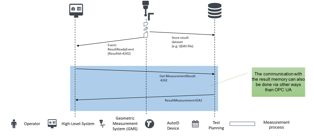
6.5 Retrieve measurement results
A higher-level system would like to receive the measurement results (incl. meta-data) for a part in order to
correct/adjust the program in the machine tool
be able to guarantee complete traceability of the workpiece
reject or rework the workpiece, if necessary
release the products
optimize the product
interpret the product (e.g., statistical analyses)
check the product quality
Figure 15 shows a typical communication between GMS, operator, and high-level system to retrieve measurement results as a sequence diagram.
7 Geometric Measurement System Information Model overview
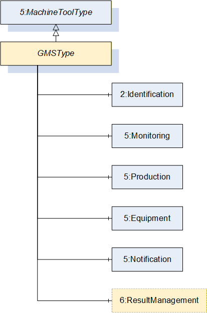
This section introduces the "OPC UA Information Model for Geometric Measurement Systems". This Information Model provides the necessary ObjectTypes to model the interface of a Geometric Measurement System with the hierarchy as illustrated in Figure 16 (nodes of GMS marked in yellow, whereas nodes of the OPC UA Information model of machine tools are marked in blue/grey). The model is based on the OPC UA model of machine tools, so the most important types are (subtype of) types of the machine tool model.
There are ObjectTypes that are used to identify the GMS (GMSIdentificationType), to monitor the GMS (GMSMonitoringType), to manage the production (ProductionType) of the GMS, to handle the Equipment of the GMS (GMSEquipmentType) and to give notification on the status of the GMS (NotificationType).
Additional to the types adopted from the machine tool information model, there are types for the Result Management (GMSResultManagementType) which is based on the result transfer model of OPC UA for Machinery.
The ObjectType hierarchy and the important children of an ObjectType of this Companion Specification are shown in Figure 17 - Figure 22. Objects from external specifications are positioned within greyish-blue boxes.
8 OPC UA ObjectTypes
8.1 GMSType
The GMSType provides information about the Geometric Measurement System itself. It is the entry point to the OPC UA interface of a Geometric Measurement System. There is a basic structure to the interface. An instance of this type aggregates all information related to one system.
All instances of GMSType have to be referenced from the 3:Machines node defined in OPC 40001-1. At least one instance of GMSType shall be present to qualify for any profile of OPC UA for GMS.
The GMSType is formally defined in Table 12.
| Attribute | Value | ||||
| BrowseName | GMSType | ||||
| IsAbstract | False | ||||
| References | Node Class | BrowseName | DataType | TypeDefinition | Other |
|---|---|---|---|---|---|
| Subtype of the MachineToolType defined in OPC UA for Machine Tools i.e. inheriting the InstanceDeclarations of that Node. | |||||
| 0:HasComponent | Object | 5:Equipment | GMSEquipmentType | 0:Mandatory | |
| 0:HasAddIn | Object | 2:Identification | GMSIdentificationType | 0:Mandatory | |
| 0:HasComponent | Object | 5:Notification | 5:NotificationType | 0:Mandatory | |
| 0:HasComponent | Object | 5:Production | 5:ProductionType | 0:Mandatory | |
| 0:HasComponent | Object | ResultManagement | GMSResultManagementType | 0:Mandatory | |
| 0:HasComponent | Object | 5:Monitoring | GMSMonitoringType | 0:Mandatory | |
| Conformance Units | |||||
|---|---|---|---|---|---|
| GMS GMSType |
Equipment (see 8.6), Identification (see 8.7), Monitoring (see 8.8), Notification (see OPC UA 40501-1) and Production (see 8.9) are instances of the respective types. They are used to thematically assign the structure of the information in the MachineToolType and the GMSType, respectively. ResultManagement is the entry point for the result management.
The components of the GMSType have additional subcomponents that are defined in Table 13.
| BrowsePath | References | NodeClass | BrowseName | DataType | TypeDefinition | Others | ||
| 0:HasComponent | Object | Calibration | CalibrationPrognosisType | 0:Optional |
8.2 MultiSensorType
The MultiSensorType provides information about the type of measuring probe.
The MultiSensorType is formally defined in Table 14.
| Attribute | Value | ||||
| BrowseName | MultiSensorType | ||||
| IsAbstract | False | ||||
| References | Node Class | BrowseName | DataType | TypeDefinition | Other |
|---|---|---|---|---|---|
| Subtype of the MultiToolType defined in OPC UA for Machine Tools i.e. inheriting the InstanceDeclarations of that Node. | |||||
| 0:HasProperty | Variable | Alignment | ToolAlignmentState | 0:PropertyType | 0:Optional |
| 0:HasProperty | Variable | Axes | 0:String[] | 0:PropertyType | 0:Optional |
| 0:HasComponent | Object | 5:<Tool> | SensorType | 0:OptionalPlaceholder | |
| Conformance Units | |||||
|---|---|---|---|---|---|
| MultiSensorType |
Axes describes the number and name (e.g., X,Y,Z) of available axes. The names of the axes should be described according to ISO 841 / ISO 10791.
Alignment describes if a tool is fixed or flexible.
8.3 SensorType
The SensorType provides information about the properties of the sensor.
The SensorType is formally defined in Table 15.
| Attribute | Value | ||||
| BrowseName | SensorType | ||||
| IsAbstract | False | ||||
| References | Node Class | BrowseName | DataType | TypeDefinition | Other |
|---|---|---|---|---|---|
| Subtype of the ToolType defined in OPC UA for Machine Tools inheriting the InstanceDeclarations of that Node. | |||||
| 0:HasProperty | Variable | AbsoluteProbe | 0:Boolean | 0:PropertyType | 0:Optional |
| 0:HasProperty | Variable | Alignment | ToolAlignmentState | 0:PropertyType | 0:Optional |
| 0:HasProperty | Variable | Axes | 0:String[] | 0:PropertyType | 0:Optional |
| 0:HasComponent | Variable | Capabilities | 0:UInteger[] | 0:MultiStateDiscreteType | 0:Optional |
| 0:HasComponent | Variable | Class | 0:UInteger | 0:MultiStateDiscreteType | 0:Mandatory |
| 0:HasProperty | Variable | EngineeringUnit | 0:EUInformation | 0:Optional | |
| 0:HasProperty | Variable | IsQualifiedStatus | ToolIsQualifiedStatus | 0:PropertyType | 0:Optional |
| 0:HasProperty | Variable | MeasuringRange | 0:Double | 0:PropertyType | 0:Optional |
| 0:HasProperty | Variable | Resolution | 0:Double | 0:PropertyType | 0:Optional |
| 0:HasProperty | Variable | WorkingRange | 0:Double | 0:PropertyType | 0:Optional |
| The following nodes are overwritten from ToolType and the Modelling Rule changed to Mandatory | |||||
| 0:HasComponent | Object | 5:ToolLife | 0:BaseObjectType | 0:Mandatory | |
| Conformance Units | |||||
|---|---|---|---|---|---|
| SensorType |
AbsoluteProbe indicates if the sensor provides an absolute position directly after switching on. The sensor does not need a referencing or zeroing after the start up.
Axes describes the number of available axes. The names of the axes should be descripted according to ISO 841 / ISO 10791.
Alignment describes if a sensor is fixed or flexible.
Capabilities is defined as an array of tool capabilities (e.g., single point measurement, scanning measurement, contact measurement). This value must not be changed.
The Class indicates in which mode a sensor is operated. This value must not be changed (see Table 17)
For each quantity, an EngineeringUnit is defined as reference value. A measured value is a multiple of this unit.
IsQualifiedStatus is defined as the status of the tool qualification.
The MeasuringRange defines the part of the working range for which the errors do not exceed the specified error limits. This is also called as "used range".
The Resolution indicates the smallest perceptible difference.
WorkingRange is the maximum range in which a probe can deliver values. It is normally larger than measuring range.
The components of the SensorType have additional subcomponents which are defined in Table 16.
| BrowsePath | References | NodeClass | BrowseName | DataType | TypeDefinition | Others | |
| 0:HasComponent | Variable | Qualified | 0:Double | 5:ToolLifeType | 0:Optional |
The 0:EngineeringUnits of Qualified must be a time unit (e.g., hour, days) and the StartValue is the timestamp (Unix timestamp) of the last qualification.
LimitValue is the chosen value at which the tool is no longer qualified.
WarningValue is the chosen value at which a warning is sent, that the sensor must be requalified.
The component Variables of the SensorType have specific Attribute values defined in Table 17. The Attribute values for Capabilities/0:EnumStrings and Class/0:EnumStrings given here shall be used by instances must not be changed.
| BrowsePath | Value Attribute | Description Attribute | |||
| Other PtMeas PtMeasSelfCenter FeatureExtract ProfileScan ArealScan | ||||
| Other NoTool UnDefTool TactileTouchTrigger TactileMeasuring Optical-1D Optical-2D Optical-3D Roughness Eddy Current Sensor TemperatureProbing PtMeas | ||||
| 0 | ||||
| True |
The element entries to the value attribute of Capabilities/0:EnumStrings have the following meaning:
Other: None of the entries defined applies.
PtMeas: Sensor capable to do single point measurement.
PtMeasSelfCenter: Sensor capable to do single point self-centering measurement.
FeatureExtract: Sensor capable to extract parameters of feature from recorded points.
ProfileScan: Sensor capable to record continuously points along a spatial path.
ArealScan: Sensor capable to record continuously lines with points along a spatial path.
The element entries to the value attribute of Class/0:EnumStrings have the following meaning:
Other: None of the entries defined applies.
NoTool: No sensor for the GMS is currently available.
UnDefTool: The properties of the current sensor are not defined.
TactileTouchTrigger: The current sensor is a tactile sensor with touch trigger contact detection.
TactileMeasuring: The current sensor is a tactile sensor with measuring contact detection.
Optical-1D: The current sensor is an optical sensor for 1 dimension (e.g., point distance sensor).
Optical-2D: The current sensor is an optical sensor for 2 dimensions (e.g., camera).
Optical-3D: The current sensor is an optical sensor for 3 dimensions (e.g., fringe projection sensor).
Roughness: The current sensor measures surface texture.
Eddy Current Sensor: The current sensor measures eddy current.
TemperatureProbing: The current sensor measures temperature.
SensorType and MultiSensorType define a two-level structure to inform about the abilities of the available sensors on a GMS. The MultiSensorType offers the possibility of combining technically connected sensors (e.g. different sensors on a flexible carrier like an articulating carrier [ISO 10360-1]). It is not intended to provide complete information about the technical structure of all sensor components (e.g. information about each stylus of a tactile probe [ISO 10360-1]). Nevertheless it is possible to do so by defining each stylus as a sensor.
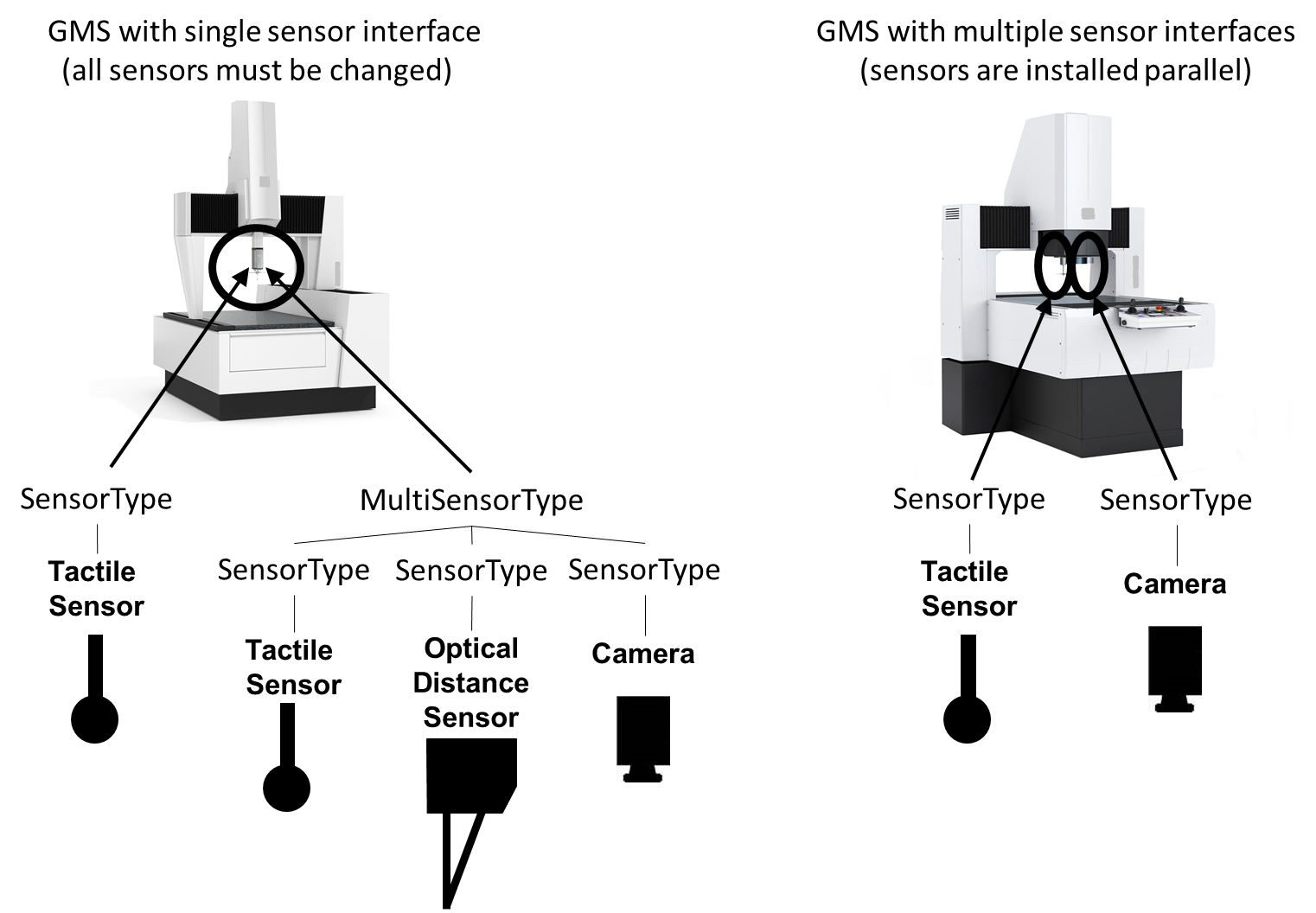
Figure 23 shows two examples for GMSs with typical sensor equipment. The GMS on the left has a tactile sensor (e.g. fixed scanning sensor) and an articulating carrier described by the MultiSensorType with three further sensors, that are changeably connected to the same mount. The tactile sensor is modelled as SensorType; the MultiSensorType describing the articulating carrier combines three instances of SensorType. The GMS on the right has two sensors mounted in parallel, both are modelled as SensorTypes.
8.4 LoadingMonitoringType
The LoadingMonitoringType provides information about the availability of the machine for loading a component for testing.
The LoadingMonitoringType is formally defined in Table 18.
| Attribute | Value | ||||
| BrowseName | LoadingMonitoringType | ||||
| IsAbstract | False | ||||
| References | Node Class | BrowseName | DataType | TypeDefinition | Other |
|---|---|---|---|---|---|
| Subtype of the ElementMonitoringType defined in OPC UA for Machine Tools i.e. inheriting the InstanceDeclarations of that Node. | |||||
| 0:HasComponent | Variable | IsInLoadingPosition | 0:Boolean | 0: TwoStateDiscreteType | 0:Optional |
| 0:HasComponent | Variable | LoadStatus | 0:UInteger | 0: MultiStateDiscreteType | 0:Mandatory |
| Conformance Units | |||||
|---|---|---|---|---|---|
| GMS LoadingMonitoringType |
IsInLoadingPosition informs if the machine is in a safe position for loading.
LoadStatus contains information whether a part is loaded or not.
The component Variables of the SensorType have Attribute values defined in Table 19. The Attribute values given here shall be used by instances must not be changed.
| BrowsePath | Value Attribute | Description Attribute | ||
| Unknown Empty Filled InProgress |
The element entries to the Attribute values of LoadStatus/0:EnumStrings have the following meaning:
Unknown: The load status is not known by the GMS.
Empty: There is no part in the GMS.
Filled: There is one or more parts in the GMS.
InProgess: The load status is changing.
8.5 ToolMonitoringType
The ToolMonitoringType provides the monitoring information about the active tool.
The ToolMonitoringType is formally defined in Table 20.
| Attribute | Value | ||||
| BrowseName | ToolMonitoringType | ||||
| IsAbstract | False | ||||
| References | Node Class | BrowseName | DataType | TypeDefinition | Other |
|---|---|---|---|---|---|
| Subtype of the WorkingUnitMonitoringType defined in OPC UA for Machine Tools i.e. inheriting the InstanceDeclarations of that Node. | |||||
| 0:HasProperty | Variable | ActiveTool | 0:NodeId[] | 0:PropertyType | 0:Optional |
| Conformance Units | |||||
|---|---|---|---|---|---|
| GMS ToolMonitoringType |
ActiveTool comprises all NodeIds of the tools which are currently used in the process.
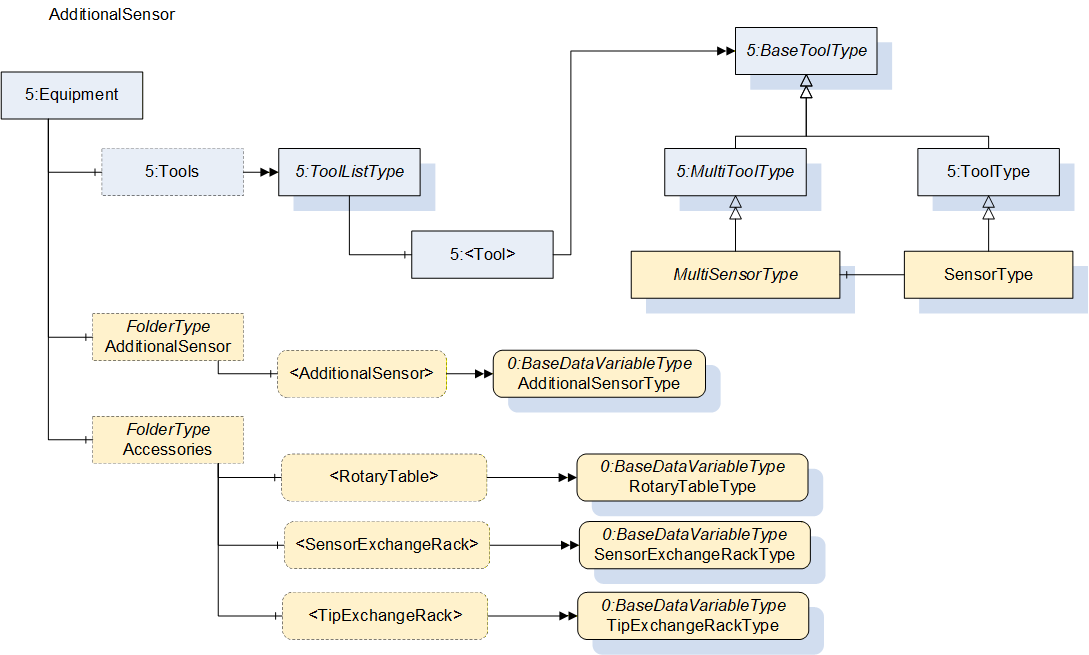
8.6 GMSEquipmentType
The GMSEquipmentType provides information about the sensor or measuring probe.
The GMSEquipmentType is formally defined in Table 21.
| Attribute | Value | ||||
| BrowseName | GMSEquipmentType | ||||
| IsAbstract | False | ||||
| References | Node Class | BrowseName | DataType | TypeDefinition | Other |
|---|---|---|---|---|---|
| Subtype of the EquipmentType defined in OPC UA for Machine Tools i.e. inheriting the InstanceDeclarations of that Node. | |||||
| 0:HasComponent | Object | AdditionalSensor | 0:FolderType | 0:Optional | |
| 0:HasComponent | Object | Accessories | 0:FolderType | 0:Optional | |
| Conformance Units | |||||
|---|---|---|---|---|---|
| GMS GMSEquipmentType |
AdditionalSensor is a folder that contains all available additional sensors.
Accessories is a folder that contains all available accessories.
| BrowsePath | References | NodeClass | BrowseName | DataType | TypeDefinition | Others |
| AdditionalSensor | 0:HasComponent | Variable | <AdditionalSensor> | 0:Number | AdditionalSensorType | 0:OptionalPlaceholder |
| Accessories | 0:HasComponent | Object | <RotaryTable> | RotaryTableType | 0:OptionalPlaceholder | |
| Accessories | 0:HasComponent | Object | <SensorExchangeRack> | SensorExchangeRackType | 0:OptionalPlaceholder | |
| Accessories | 0:HasComponent | Object | <TipExchangeRack> | TipExchangeRackType | 0:OptionalPlaceholder |
<AdditionalSensor> represents individual additional sensors.
<RotaryTable> represents individual rotary tables.
<SensorExchangeRack> represents individual sensor exchange racks.
<TipExchangeRack> represents individual tip exchange racks.
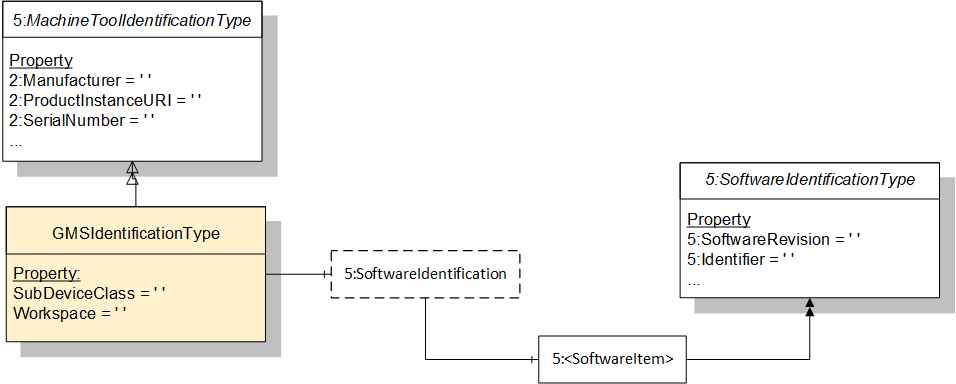
8.7 GMSIdentificationType
The GMSIdentificationType provides information about the current machine.
The GMSIdentificationType is formally defined in Table 23.
| Attribute | Value | ||||
| BrowseName | GMSIdentificationType | ||||
| IsAbstract | False | ||||
| References | Node Class | BrowseName | DataType | TypeDefinition | Other |
|---|---|---|---|---|---|
| Subtype of the MachineToolIdentificationType defined in OPC UA for Machine Tools i.e. inheriting the InstanceDeclarations of that Node. | |||||
| 0:HasProperty | Variable | SubDeviceClass | 0:String | 0:PropertyType | 0:Optional |
| 0:HasProperty | Variable | Workspace | WorkspaceType | 0:PropertyType | 0:Optional |
| Conformance Units | |||||
|---|---|---|---|---|---|
| GMS GMSIdentificationType |
SubDeviceClass is defined in a more special way than the generic DeviceClass. The classification is made based on the description in section 5.1.2. The corresponding possible values (for the SubDeviceClass) may be taken from Table 24.
| DeviceClass | SubDeviceClass |
| ManualMeasurementDevice | Caliper |
| Micrometer | |
| Gauges | |
| SineBar | |
| Other | |
| SurfaceTextureMeasurementDevice | RoughnessProfile |
| RoughnessAreal | |
| Contour | |
| Other | |
| MultiPointMeasurementDevice | StaticBenchGauge |
| DynamicGaugingMachine | |
| MultiPointMeasurementPlugsForInnerAndOuterGeometries | |
| Other | |
| CoordinateMeasuringSystem | CoordinateMeasuringMachine |
| Optical3DCoordinateMeasuringSystem | |
| ArticulatingArm | |
| LaserTracker | |
| LaserRadar | |
| X-CT | |
| LaserTracer | |
| LightPenSystem | |
| Other | |
| SpecialGeometryMeasuringSystem | RotaryAxisFormMeasuringInstrument |
| GearMeasuringSystem | |
| ShaftMeasuringSystem | |
| Other | |
| Other | Other |
Workspace is defined as the workspace of the axes, which is the same as the Measuring Range in most situations.
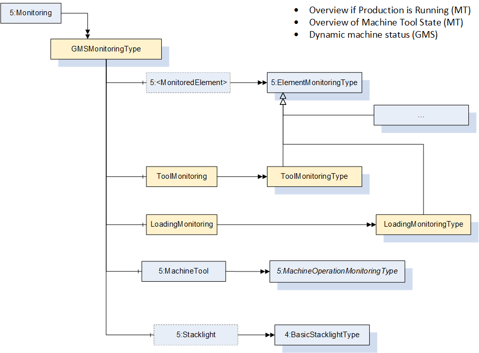
8.8 GMSMonitoringType
The GMSMonitoringType provides information about monitoring the status of the GMS.
The GMSMonitoringType is formally defined in Table 25.
| Attribute | Value | ||||
| BrowseName | GMSMonitoringType | ||||
| IsAbstract | False | ||||
| References | Node Class | BrowseName | DataType | TypeDefinition | Other |
|---|---|---|---|---|---|
| Subtype of the MonitoringType defined in OPC UA for Machine Tools i.e. inheriting the InstanceDeclarations of that Node. | |||||
| 0:HasComponent | Object | LoadingMonitoring | LoadingMonitoringType | 0:Optional | |
| 0:HasComponent | Object | ToolMonitoring | ToolMonitoringType | 0:Optional | |
| Conformance Units | |||||
|---|---|---|---|---|---|
| GMS GMSMonitoringType |
LoadingMonitoring informs if the machine is in a safe position for loading.
ToolMonitoring provides monitoring information about the tool (e.g., the currently used tool).
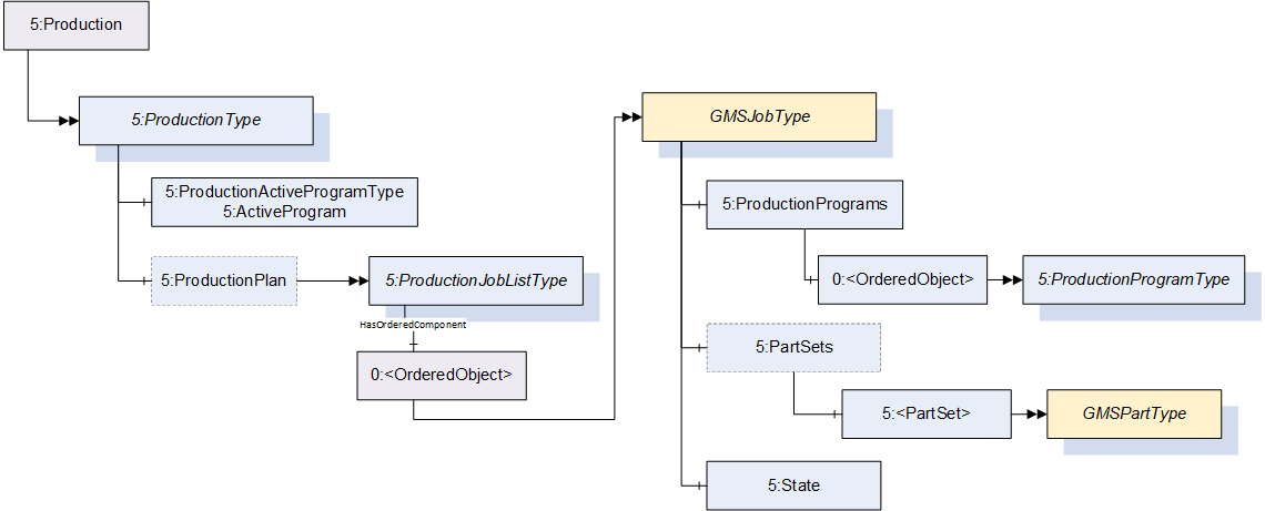
8.9 GMSJobType
The GMSJobType provides aggregated production data to run a sequence of measurements of several parts after one preparatory mounting.
The GMSJobType is formally defined in Table 26.
| Attribute | Value | ||||
| BrowseName | GMSJobType | ||||
| IsAbstract | False | ||||
| References | Node Class | BrowseName | DataType | TypeDefinition | Other |
|---|---|---|---|---|---|
| Subtype of the ProductionJobType defined in OPC UA for Machine Tools i.e. inheriting the InstanceDeclarations of that Node. | |||||
| 0:HasProperty | Variable | BatchIdentifier | 0:String | 0:PropertyType | 0:Optional |
| 0:HasProperty | Variable | Duration | 0:Duration | 0:PropertyType | 0:Optional |
| 0:HasProperty | Variable | RemainingTime | 0:Duration | 0:PropertyType | 0:Optional |
| 0:HasProperty | Variable | MeasurementReason | MeasurementReasonEnum | 0:PropertyType | 0:Optional |
| Conformance Units | |||||
|---|---|---|---|---|---|
| GMS GMSJobType |
BatchIdentifier is defined as the unique batch identifier of the job for future reference.
Duration is defined as approximate time in milliseconds this job will take. This value can be estimated by the machine based on the last measurement runs or on the measuring equipment capability test.
RemainingTime is defined as the time in milliseconds remaining for the MeasuringRoutine and the part. It represents an approximated value that can't always be determined precisely.
MeasurementReason indicates why this job is carried out.
8.10 GMSPartType
The GMSPartType provides information about the component to be measured by the GMS.
The GMSPartType is formally defined in Table 27.
| Attribute | Value | ||||
| BrowseName | GMSPartType | ||||
| IsAbstract | False | ||||
| References | Node Class | BrowseName | DataType | TypeDefinition | Other |
|---|---|---|---|---|---|
| Subtype of the ProductionPartType defined in OPC UA for Machine Tools i.e. inheriting the InstanceDeclarations of that Node. | |||||
| 0:HasComponent | Variable | NestIdentifier | Number | CatalogType | 0:Optional |
| 0:HasComponent | Variable | Operator | Number | CatalogType | 0:Optional |
| 0:HasProperty | Variable | PartAmendmentStatus | 0:String | 0:PropertyType | 0:Optional |
| 0:HasComponent | Variable | PartCarrierIdentifier | Number | CatalogType | 0:Optional |
| 0:HasProperty | Variable | PartDescription | 0:String | 0:PropertyType | 0:Optional |
| 0:HasComponent | Variable | ProcessParameter | Number[] | CatalogType | 0:Optional |
| 0:HasComponent | Variable | ProcessingMachineIdentifier | Number | CatalogType | 0:Optional |
| 0:HasProperty | Variable | ProductionNumber | 0:String | 0:PropertyType | 0:Optional |
| Conformance Units | |||||
|---|---|---|---|---|---|
| GMS GMSPartType |
NestIdentifier indicates the nesting or spindle used to create or process the current part.
The operator specifies the worker who performs the measurement. The field contains an Identifier of the worker.
PartAmendmentStatus is used to distinguish and identify a version of the part type currently measured via a GMS.
PartCarrierIdentifier defines the unique identifier for the part carrier.
PartDescription is defined as a free text field that can be used for a customer part description.
ProcessParameter is defined as an additional parameter that describes the process.
ProcessingMachineIdentifier is a unique identifier of the machine that has processed the part.
ProductionNumber is a freely selectable identifier that identifies a subset of a production batch.
8.11 CalibrationPrognosisType
The CalibrationPrognosisType provides information about the GMS status regarding its performance. During the calibration the GMS's errors are determined. The GMS performance is verified if the error is not greater than the specification. The information about the error is not used for correction. The GMS is not considered as a calibration target according to OPC 10000-200. Therefore a separate specification is defined here. The CalibrationPrognosisType is formally defined in Table 28.
| Attribute | Value | ||||
| BrowseName | CalibrationPrognosisType | ||||
| IsAbstract | False | ||||
| References | Node Class | BrowseName | DataType | TypeDefinition | Other |
|---|---|---|---|---|---|
| Subtype of the PrognosisType defined in OPC UA for Machine Tools i.e. inheriting the InstanceDeclarations of that Node. | |||||
| 0:HasProperty | Variable | Calibrated | 0:Boolean | 0:PropertyType | 0:Mandatory |
| 0:HasProperty | Variable | CalibrationInterval | 0:Duration | 0:PropertyType | 0:Optional |
| 0:HasProperty | Variable | CalibrationPreptime | 0:Duration | 0:PropertyType | 0:Optional |
| 0:HasProperty | Variable | DateOfCalibration | 0:UtcTime | 0:PropertyType | 0:Mandatory |
| 0:HasProperty | Variable | CalibrationCertificate | 0:String[] | 0:PropertyType | 0:Optional |
| Conformance Units | |||||
|---|---|---|---|---|---|
| GMS CalibrationPrognosisType |
Calibrated indicates whether the machine is calibrated or not.
CalibrationInterval is defined as the interval of time in which the machine needs a new calibration. The exact interval depends on the measuring principle and the machine utilization and is provided by the customer.
CalibrationPreptime is defined as the additional time needed to prepare a calibration considering the calibration interval to assure that the calibration expired (see Figure 24 for reference).

DateOfCalibration is defined as the date and time when the last calibration was carried out.
CalibrationCertificate contains a reference to all available calibration certificates.
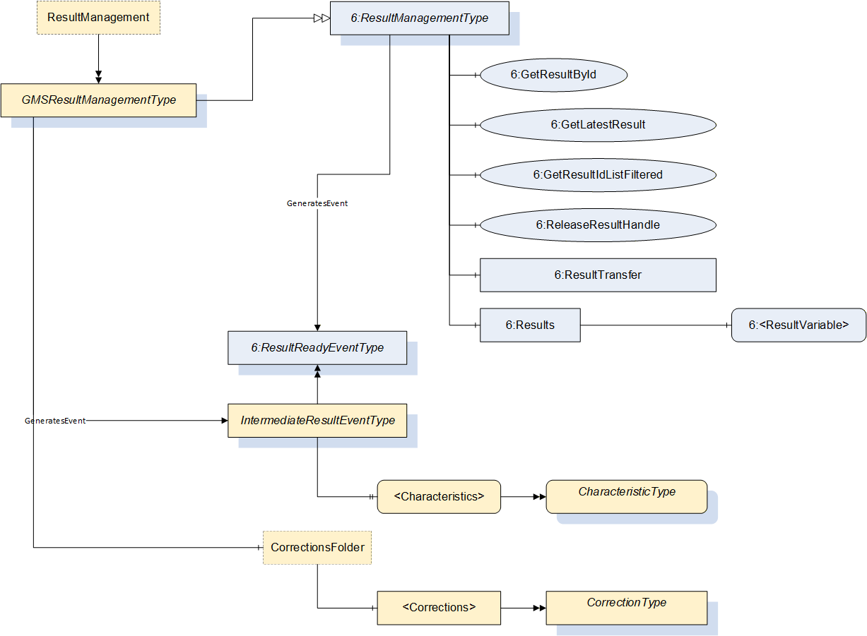
8.12 GMSResultManagementType
The GMSResultManagementType provides mechanisms to access results generated by the underlying GMS. Results can be managed in a local result store of the Server. Methods and Objects with Variables as well as Events and external file stores can be used to provide the results for the Client.
Figure 22 shows the hierarchical structure and details of the composition. It is formally defined in Table 29.
This ObjectType extends the ResultManagementType of the Machinery. As part of this extension, deviation values can be provided via OPC UA.
| Attribute | Value | ||||
| BrowseName | GMSResultManagementType | ||||
| IsAbstract | False | ||||
| References | Node Class | BrowseName | DataType | TypeDefinition | Other |
|---|---|---|---|---|---|
| Subtype of the ResultManagementType defined in OPC UA 10000-3 i.e. inheriting the InstanceDeclarations of that Node. | |||||
| 0:HasComponent | Object | CorrectionsFolder | 0:FolderType | 0:Optional | |
| 0:GeneratesEvent | ObjectType | IntermediateResultEventType | |||
| Conformance Units | |||||
|---|---|---|---|---|---|
| GMS ResultManagementType |
CorrectionsFolder is a folder that contains several corrections. The count and the corrections itself are application-specific.
The components of the GMSResultManagementType have additional subcomponents which are defined in Table 30.
| BrowsePath | References | NodeClass | BrowseName | DataType | TypeDefinition | Others |
| CorrectionsFolder | 0:HasComponent | Object | <Corrections> | CorrectionType | 0:OptionalPlaceholder | |
| CorrectionsFolder | 0:HasComponent | Variable | CorrectionCount | Integer | BaseDataVariableType | 0:Optional |
<Corrections> represents individual corrections.
CorrectionCount indicates the total number of corrections.
8.13 CorrectionType
The CorrectionType provides information about a correction value the GMS has calculated. It is formally defined in Table 31. The value is the deviation of a characteristic value from a target value. The target value is a value the manufacturing should achieve. The correction can be used by a (tool) machine to adjust the production process. This can be, for example, the correction of a tool. Either the correction value relative or the correction value absolute must be implemented.
| Attribute | Value | ||||
| BrowseName | CorrectionType | ||||
| IsAbstract | False | ||||
| References | NodeClass | BrowseName | DataType | TypeDefinition | Other |
| Subtype of the BaseObjectType defined in OPC 10000-3 | |||||
| 0:HasProperty | Variable | Identifier | 0:String | 0:PropertyType | 0:Mandatory |
| 0:HasProperty | Variable | CharacteristicIdentifier | 0:String | 0:PropertyType | 0:Mandatory |
| 0:HasComponent | Variable | CorrectionValueRelative | 0:Double | 0:AnalogUnitType | 0:Optional |
| 0:HasComponent | Variable | CorrectionValueAbsolute | 0:Double | 0:AnalogUnitType | 0:Optional |
| 0:HasComponent | Variable | UpperControlLimit | 0:Double | 0:AnalogUnitType | 0:Optional |
| 0:HasComponent | Variable | LowerControlLimit | 0:Double | 0:AnalogUnitType | 0:Optional |
| 0:HasProperty | Variable | Description | 0:LocalizedText | 0:PropertyType | 0:Optional |
| 0:HasProperty | Variable | ProgramName | 0:String | 0:PropertyType | 0:Optional |
| Conformance Units | |||||
|---|---|---|---|---|---|
| GMS CorrectionType |
Identifier is a unique ID to identify this correction value.
CharacteristicIdentifier is a reference to the characteristic.
CorrectionValueRelative indicates how much the characteristic deviates and gives an indication to the upstream system how much the processing needs to be adjusted. The value is relative to the target value.
CorrectionValueAbsolute indicates how much the characteristic deviates and gives an indication to the upstream system how much the processing needs to be adjusted. The value is absolute to the target value.
The UpperControlLimit is the upper limit from which on a correction should be applied.
The LowerControlLimit is the lower limit from which on a correction should be applied.
| Description | is a human-readable description of the correction of the correction value. |
ProgramName contains the name of the program.
8.14 RotaryTableType
The RotaryTableType provides information about a rotary table used as an additional degree of freedom in some GMS.
The RotaryTableType is formally defined in Table 32.
| Attribute | Value | ||||
| BrowseName | RotaryTableType | ||||
| IsAbstract | False | ||||
| References | Node Class | BrowseName | DataType | TypeDefinition | Other |
|---|---|---|---|---|---|
| Subtype of the 0:BaseObjectType defined in OPC 10000-5 i.e. inheriting the InstanceDeclarations of that Node. | |||||
| 0:HasAddIn | Object | 2:Identification | 3:MachineryItemIdentificationType | 0:Mandatory | |
| 0:HasProperty | Variable | IsIntegrated | 0:Boolean | 0:PropertyType | 0:Mandatory |
| 0:HasProperty | Variable | NumberOfAxes | 0:Byte | 0:PropertyType | 0:Mandatory |
| Conformance Units | |||||
|---|---|---|---|---|---|
| GMS RotaryTableType |
Identification is performed according to MachineryIdentificationType.
IsIntegrated is defined as True if the RotaryTable is integrated into the GMS and cannot be removed.
NumberOfAxes defines the number of axes (DegreesOfFreedom) the RotaryTable can be configured for.
8.15 SensorExchangeRackType
The SensorExchangeRackType provides information about a sensor exchange rack used as an additional rack for sensors in some GMS.
The SensorExchangeRackType is formally defined in Table 33.
| Attribute | Value | ||||
| BrowseName | SensorExchangeRackType | ||||
| IsAbstract | False | ||||
| References | Node Class | BrowseName | DataType | TypeDefinition | Other |
|---|---|---|---|---|---|
| Subtype of the 0:BaseObjectType defined in OPC 10000-5 i.e. inheriting the InstanceDeclarations of that Node. | |||||
| 0:HasAddIn | Object | 2:Identification | 3:MachineryItemIdentificationType | 0:Mandatory | |
| 0:HasProperty | Variable | IsAvailable | 0:Boolean | 0:PropertyType | 0:Mandatory |
| Conformance Units | |||||
|---|---|---|---|---|---|
| GMS SensorExchangeRackType |
Identification is performed according to MachineryIdentificationType.
IsAvailable is defined as True if the SensorExchangeRack is available into the GMS.
8.16 TipExchangeRackType
The TipExchangeRackType provides information about a tip exchange rack used as an additional rack for tips in some GMS.
The TipExchangeRackType is formally defined in Table 34.
| Attribute | Value | ||||
| BrowseName | TipExchangeRackType | ||||
| IsAbstract | False | ||||
| References | Node Class | BrowseName | DataType | TypeDefinition | Other |
|---|---|---|---|---|---|
| Subtype of the 0:BaseObjectType defined in OPC 10000-5 i.e. inheriting the InstanceDeclarations of that Node. | |||||
| 0:HasAddIn | Object | 2:Identification | 3:MachineryItemIdentificationType | 0:Mandatory | |
| 0:HasProperty | Variable | IsAvailable | 0:Boolean | 0:PropertyType | 0:Mandatory |
| Conformance Units | |||||
|---|---|---|---|---|---|
| GMS SensorExchangeRackType |
Identification is performed according to MachineryIdentificationType.
IsAvailable is defined as True if the TipExchangeRack is available into the GMS.
8.17 CharacteristicType
The CharacteristicType contains the Metainformation about a characteristic of the part. Its representation in the AddressSpace is formally defined in Table 35.
| Attribute | Value | |||||
| BrowseName | CharacteristicType | |||||
| IsAbstract | False | |||||
| References | NodeClass | BrowseName | DataType | TypeDefinition | Other | |
|---|---|---|---|---|---|---|
| Subtype of the 0:BaseObjectType defined in OPC 10000-3, which means it inherits the InstanceDeclarations of that Node. | ||||||
| 0:HasProperty | Variable | CharacteristicIdentifier | 0:String | 0:PropertyType | 0:Optional | |
| 0:HasComponent | Variable | ResultValue | 0:Double | 0:AnalogUnitType | 0:Optional | |
| 0:HasComponent | Variable | UpperToleranceLimit | 0:Double | 0:AnalogUnitType | 0:Optional | |
| 0:HasComponent | Variable | LowerToleranceLimit | 0:Double | 0:AnalogUnitType | 0:Optional | |
| 0:HasComponent | Variable | Nominal | 0:Double | 0:AnalogUnitType | 0:Optional | |
| 0:HasProperty | Variable | CharacteristicsClass | 0:Byte | 0:PropertyType | 0:Optional | |
| 0:HasProperty | Variable | ResultEvaluation | 6:ResultEvaluationEnum | 0:PropertyType | 0:Optional | |
| 0:HasProperty | Variable | IsValid | 0:Boolean | 0:PropertyType | 0:Optional | |
| 0:HasProperty | Variable | Formula | 0:String | 0:PropertyType | 0:Optional | |
| Conformance Units | ||||||
|---|---|---|---|---|---|---|
| GMS CharacteristicType |
CharacteristicIdentifier is a unique identifier of the measured characteristic.
ResultValue is the actual measurement result value.
ResultEvaluation indicates whether the result was in tolerance.
UpperToleranceLimit is the absolute upper limit where the part is still in its specification.
LowerToleranceLimit is the absolute lower limit where the part is still in its specification.
Nominal is the value given in the Geometrical Product Specification. This value indicates which theoretical value the component or the distance between two construction reference points must have (e.g., how large the bore hole must be).
CharacteristicsClass is a hint of the importance of the characteristic. The least important class is 0. Higher classes are more important. An example based on Q-DAS for the value description is given here [AQDEF 5]:
0 unimportant
1 little important
2 important
3 significant
4 critical
IsValid is used to mark the measured value as valid or invalid. A measurement run can be invalid within the scope of the current measurement for some reason (e.g., a hole missing in the current part). The result file could contain more information.
The Formula describes how the measurement is performed (e.g., T1-((T20-21)*0.41 + (T22-T23)*0.7))
CharacteristicType components have additional subcomponents which are defined inTable 36.
| BrowsePath | References | NodeClass | BrowseName | DataType | TypeDefinition | Others |
| UpperToleranceLimit | 0:HasProperty | Variable | ToleranceForm | ToleranceLimitEnum | 0:PropertyType | 0:Mandatory |
| LowerToleranceLimit | 0:HasProperty | Variable | ToleranceForm | ToleranceLimitEnum | 0:PropertyType | 0:Mandatory |
9 OPC UA EventTypes
9.1 SensorWarningAlarmType
This SensorWarningAlarmType is used if an additional sensor (e.g., a temperature sensor) measures a value that is out of the allowed range. This alarm is only used for sensors that are not involved in the geometrical measurement directly (e.g., a probe). Its representation in the AddressSpace is formally defined in Table 37.
| Attribute | Value | |||||
| BrowseName | SensorWarningAlarmType | |||||
| IsAbstract | False | |||||
| References | NodeClass | BrowseName | DataType | TypeDefinition | Other | |
|---|---|---|---|---|---|---|
| Subtype of the LimitAlarmType defined in OPC 10000-9, which means it inherits the InstanceDeclarations of that Node. | ||||||
| 0:HasProperty | Variable | ErrorCode | 0:String | 0:PropertyType | 0:Mandatory | |
| Conformance Units | ||||||
|---|---|---|---|---|---|---|
| GMS SensorWarningEventType |
The ErrorCode is used as the manufacturer defined error code. Often this is a numeric code whose meaning can be found in the manufacturer's documentation for the Geometric Measurement System.
It is supposed that any error message shown to users of the system is transmitted with the SensorWarningAlarmType in the Message Property inherited from the BaseEventType.
9.2 IntermediateResultEventType
This IntermediateResultEventType is a subtype of the ResultReadyEventType. Instead of a ResultReadyEvent this event should be used for an intermediate result which contains information about one or more characteristics. Its representation in the AddressSpace is formally defined in Table 38.
| Attribute | Value | |||||
| BrowseName | IntermediateResultEventType | |||||
| IsAbstract | True | |||||
| References | NodeClass | BrowseName | DataType | TypeDefinition | Other | |
|---|---|---|---|---|---|---|
| Subtype of the ResultReadyEventType defined in OPC 40100-1, which means it inherits the InstanceDeclarations of that Node. | ||||||
| 0:HasComponent | Object | <Characteristics> | CharacteristicType | 0:MandatoryPlaceholder | ||
| 0:HasProperty | Variable | ProgramName | String | PropertyType | 0:Optional | |
| Conformance Units | ||||||
|---|---|---|---|---|---|---|
| GMS IntermediateResultEventType |
Characteristics contains the information about the characteristics that are measured in this step.
ProgramName contains the name of the program.
10 OPC UA VariableTypes
10.1 GMSResultType
The GMSResultType contains information about the measurement result. It extends the generic ResultType of OPC UA for Machinery.
The GMSResultType is formally defined in Table 39.
| Attribute | Value | ||||
| BrowseName | GMSResultType | ||||
| IsAbstract | False | ||||
| ValueRank | -1 (-1 = Scalar) | ||||
| DataType | ResultDataType | ||||
| References | Node Class | BrowseName | DataType | TypeDefinition | Other |
| Subtype of the ResultType defined in OPC UA 40000-101 i.e. inheriting the InstanceDeclarations of that Node. | |||||
| 0:HasProperty | Variable | UsedTools | 0:String[] | 0:PropertyType | 0:Optional |
| Conformance Units | |||||
|---|---|---|---|---|---|
| GMS ResultType |
UsedTools is defined as an array of all tools used to create this result
10.2 CatalogType
The CatalogType is a subtype of the MultiStateValueDiscreteType. It is used to represent a value that is defined by a customer catalogue (e.g., company catalog). An example of a catalog can be found at https://www.q-das.com/en/service/data-format-aqdef.
It is formally defined in Table 40.
| Attribute | Value | |||||
| BrowseName | CatalogType | |||||
| IsAbstract | False | |||||
| ValueRank | -2 (-2 = Any) | |||||
| DataType | Number | |||||
| References | NodeClass | BrowseName | DataType | TypeDefinition | Other | |
|---|---|---|---|---|---|---|
| Subtype of the 0:MultiStateValueDiscreteType defined in OPC 10000-3 | ||||||
| 0:HasProperty | Variable | CatalogEntry | 0:String | 0:PropertyType | 0:Mandatory | |
| 0:HasProperty | Variable | CatalogName | 0:String | 0:PropertyType | 0:Mandatory | |
| Conformance Units | ||||||
|---|---|---|---|---|---|---|
| GMS GMSType |
The CatalogEntry is the key that points to the value.
The CatalogName is the name of the catalog or a subcatalog used in the machine environment.
10.3 AdditionalSensorType
The AdditionalSensorType is a subtype of the 0:AnalogUnitType. It is used to represent additional sensor e.g., temperature sensors.
It is formally defined in Table 41.
| Attribute | Value | |||||
| BrowseName | AdditionalSensorType | |||||
| IsAbstract | False | |||||
| ValueRank | -1 (-1 = Scalar) | |||||
| DataType | Number | |||||
| References | NodeClass | BrowseName | DataType | TypeDefinition | Other | |
|---|---|---|---|---|---|---|
| Subtype of the 0:AnalogUnitType defined in OPC 10000-3 | ||||||
| 0:HasProperty | Variable | Identifier | 0:String | 0:PropertyType | 0:Mandatory | |
| 0:HasComponent | Variable | Class | 0:UInteger | 0:MultiStateDiscreteType | 0:Optional | |
| 0:HasProperty | Variable | Name | 0:String | 0:PropertyType | 0:Optional | |
| Conformance Units | ||||||
|---|---|---|---|---|---|---|
| GMS GMSEquipmentType |
Identifier is the identifier of the sensor. The Identifier shall be unique within the AddressSpace.
Class indicates what type of sensor the current one is (e.g., temperature, vibration, humidity, others).
Name is used to distinguish and identify sensors on a GMS (e.g., temp_sensor_ext_1). Hence, the Name should be unique within the GMSType it belongs to.
The component Variables of the SensorType have additional Attributes defined in Table 42.
| BrowsePath | Value Attribute | Description Attribute | ||
| Other Temperature Vibration Humidity |
11 OPC UA DataTypes
11.1 WorkspaceType
This structure contains all information about a Workspace. This Structure is an abstract DataType and further divides into the subtypes of Cartesian and Cylindrical workspaces.
Its representation in the AddressSpace is defined in Table 43.
| Attribute | Value | |||||
| BrowseName | WorkspaceType | |||||
| IsAbstract | True | |||||
| References | NodeClass | BrowseName | DataType | TypeDefinition | Other | |
|---|---|---|---|---|---|---|
| Subtype of the Structure defined in OPC 10000-3 | ||||||
| Conformance Units | ||||||
| GMS GMSIdentificationType | ||||||
11.2 CartesianWorkspaceType
This structure contains the information of a Cartesian Workspace. The structure is defined in Table 44.
| Name | Type | Description |
|---|---|---|
| CartesianWorkspaceType | structure | Subtype of WorkspaceType defined in this Companion Specification |
| Length | 0:Double | in direction of global gravity |
| Width | 0:Double | An orthogonal direction to height and length |
| Height | 0:Double | An orthogonal direction to width and length |
Its representation in the AddressSpace is defined in Table 45.
| Attribute | Value | |||||
| BrowseName | CartesianWorkspaceType | |||||
| IsAbstract | False | |||||
| References | NodeClass | BrowseName | DataType | TypeDefinition | Other | |
|---|---|---|---|---|---|---|
| Subtype of the WorkspaceType defined in this Companion Specification | ||||||
| Conformance Units | ||||||
| GMS GMSIdentificationType | ||||||
11.3 CylindricalWorkspaceType
This structure contains the information of a Cylindrical Workspace. The structure is defined in Table 46
| Name | Type | Description |
|---|---|---|
| CylindricalWorkspaceType | structure | Subtype of WorkspaceType defined in this Companion Specification |
| Length | 0:Double | in direction of global gravity |
| Radius | 0:Double | An orthogonal direction to height and length |
Its representation in the AddressSpace is defined in Table 47
| Attribute | Value | |||||
| BrowseName | CylindricalWorkspaceType | |||||
| IsAbstract | False | |||||
| References | NodeClass | BrowseName | DataType | TypeDefinition | Other | |
|---|---|---|---|---|---|---|
| Subtype of the WorkspaceType defined in this Companion Specification | ||||||
| Conformance Units | ||||||
| GMS GMSIdentificationType | ||||||
11.4 MeasurementReasonEnum
This enumeration MeasurementReasonEnum indicates the reason of a measurement. The enumeration is defined in Table 48.
| Name | Value | Description |
| ContinuousMeasurements | 0 | Series measurement. Default inspection |
| SpecialMeasurement | 1 | Other kind of measurements apart from series production |
| AuditMeasurement | 2 | capability and audit inspections |
| MinMastering | 3 | Zeroing / sensitivity check with Min Master |
| MedMastering | 4 | Zeroing / calibration |
| MaxMastering | 5 | Zeroing / sensitivity check with Max Master |
The MeasurementReasonEnum representation in the AddressSpace is defined in Table 49.
| Attribute | Value | |||||
| BrowseName | MeasurementReasonEnum | |||||
| IsAbstract | False | |||||
| References | NodeClass | BrowseName | DataType | TypeDefinition | Other | |
| Subtype of the Enumeration type defined in OPC 10000-5 | ||||||
| 0:HasProperty | Variable | 0:EnumStrings | 0:LocalizedText [] | 0:PropertyType | ||
| Conformance Units | ||||||
|---|---|---|---|---|---|---|
| GMS GMSJobType |
11.5 ToleranceLimitEnum
This enumeration defines the kind of a tolerance limit. The enumeration is defined in Table 50.
| Name | Value | Description |
|---|---|---|
| NoLimit | 0 | There is no tolerance limit. |
| LimitValue | 1 | The limit is a predefined limit. |
| NaturalLimit | 2 | The limit is defined for technological or physical reasons. |
Its representation in the AddressSpace is defined in Table 51.
| Attribute | Value | |||||
| BrowseName | ToleranceLimitEnum | |||||
| IsAbstract | False | |||||
| References | NodeClass | BrowseName | DataType | TypeDefinition | Other | |
|---|---|---|---|---|---|---|
| Subtype of the Enumeration type defined in OPC 10000-5 | ||||||
| 0:HasProperty | Variable | 0:EnumStrings | 0:LocalizedText [] | 0:PropertyType | ||
| Conformance Units | ||||||
|---|---|---|---|---|---|---|
| GMS CharacteristicType |
11.6 ToolAlignmentState
This enumeration defines the alignment of a tool. The enumeration is defined in Table 52.
| Name | Value | Description |
|---|---|---|
| Fixed | 0 | Means the tool is fixed. |
| Indexed | 1 | Means the tool can be moved in steps. |
| Continuous | 2 | Means the tool can be moved Continuous. |
Its representation in the AddressSpace is defined in Table 53.
| Attribute | Value | |||||
| BrowseName | ToolAlignmentState | |||||
| IsAbstract | False | |||||
| References | NodeClass | BrowseName | DataType | TypeDefinition | Other | |
|---|---|---|---|---|---|---|
| Subtype of the Enumeration type defined in OPC 10000-5 | ||||||
| 0:HasProperty | Variable | 0:EnumStrings | 0:LocalizedText [] | 0:PropertyType | ||
| Conformance Units | ||||||
|---|---|---|---|---|---|---|
| GMS SensorType |
11.7 ToolIsQualifiedStatus
This enumeration defines qualified status of a tool. The enumeration is defined in Table 54.
| Name | Value | Description |
|---|---|---|
| Qualified | 0 | The tool is qualified. |
| Imprecise | 1 | Means the tool can be moved in steps. |
| NotQualified | 2 | The tool is not qualified. |
Its representation in the AddressSpace is defined in Table 55.
| Attribute | Value | |||||
| BrowseName | ToolIsQualifiedStatus | |||||
| IsAbstract | False | |||||
| References | NodeClass | BrowseName | DataType | TypeDefinition | Other | |
|---|---|---|---|---|---|---|
| Subtype of the Enumeration type defined in OPC 10000-5 | ||||||
| 0:HasProperty | Variable | 0:EnumStrings | 0:LocalizedText [] | 0:PropertyType | ||
| Conformance Units | ||||||
|---|---|---|---|---|---|---|
| GMS SensorType |
12 Profiles and Conformance Units
12.1 Overview
The structure of the Profiles and Conformance Units is based on the Profiles of the machine tools and is shown in Figure 25. All servers need to implement the basic profile which can be extended with additional facets.
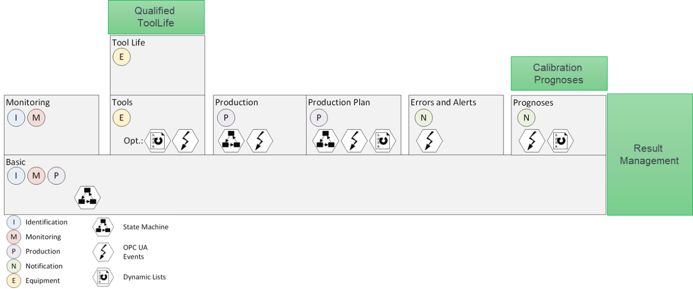
12.2 Conformance Units
Table 56 defines the corresponding ConformanceUnits for the OPC UA Information for GMS.
| Category | Title | Description |
|---|---|---|
| Server | GMS QualifiedToolLife | Within ToolLife of every instance of a SensorType, at least one ToolLifeEntry has to be provided. The value has the BrowseName "Qualified" and indicates the remaining time (Indication=Time) the tool is qualified. The value of the Property IsCountingUp is "False". |
| Server | GMS GMSType | The Server supports nodes that conform to the (subtypes of) GMSType. The GMSType node itself is available in the AddressSpace. Every instance of the (subtypes of) GMSType has to include all mandatory components of the GMSType and may include the optional components. |
| Server | GMS MultiSensorType | The Server supports nodes that conform to the (subtypes of) MultiSensorType. The MultiSensorType node itself is available in the AddressSpace. Every instance of the (subtypes of) MultiSensorType has to include all mandatory components of the MultiSensorType and may include the optional components. |
| Server | GMS SensorType | The Server supports nodes that conform to the (subtypes of) SensorType. The SensorType node itself is available in the AddressSpace. Every instance of the (subtypes of) SensorType has to include all mandatory components of the SensorType and may include the optional components. |
| Server | GMS LoadingMonitoringType | The Server supports nodes that conform to the (subtypes of) LoadingMonitoringType. The LoadingMonitoringType node itself is available in the AddressSpace. Every instance of the (subtypes of) LoadingMonitoringType has to include all mandatory components of the LoadingMonitoringType and may include the optional components. |
| Server | GMS ToolMonitoringType | The Server supports nodes that conform to the (subtypes of) ToolMonitoringType. The ToolMonitoringType node itself is available in the AddressSpace. Every instance of the (subtypes of) ToolMonitoringType has to include all mandatory components of the ToolMonitoringType and may include the optional components. |
| Server | GMS GMSEquipmentType | The Server supports nodes that conform to the (subtypes of) GMSEquipmentType. The GMSEquipmentType node itself is available in the AddressSpace. Every instance of the (subtypes of) GMSEquipmentType has to include all mandatory components of the GMSEquipmentType and may include the optional components. |
| Server | GMS GMSIdentificationType | The Server supports nodes that conform to the (subtypes of) GMSIdentificationType. The GMSIdentificationType node itself is available in the AddressSpace. Every instance of the (subtypes of) GMSIdentificationType has to include all mandatory components of the GMSIdentificationType and may include the optional components. |
| Server | GMS GMSMonitoringType | The Server supports nodes that conform to the (subtypes of) GMSMonitoringType. The GMSMonitoringType node itself is available in the AddressSpace. Every instance of the (subtypes of) GMSMonitoringType has to include all mandatory components of the GMSMonitoringType and may include the optional components. |
| Server | GMS GMSJobType | The Server supports nodes that conform to the (subtypes of) GMSJobType. The GMSJobType node itself is available in the AddressSpace. Every instance of the (subtypes of) GMSJobType has to include all mandatory components of the GMSJobType and may include the optional components. |
| Server | GMS GMSPartType | The Server supports nodes that conform to the (subtypes of) GMSPartType. The GMSPartType node itself is available in the AddressSpace. Every instance of the (subtypes of) GMSPartType has to include all mandatory components of the GMSPartType and may include the optional components. |
| Server | GMS CalibrationPrognosisType | The Server supports nodes that conform to the (subtypes of) CalibrationPrognosisType. The CalibrationPrognosisType node itself is available in the AddressSpace. Every instance of the (subtypes of) CalibrationPrognosisType has to include all mandatory components of the CalibrationPrognosisType and may include the optional components. |
| Server | GMS ResultManagementType | The Server supports nodes that conform to the (subtypes of) ResultManagementType. The ResultManagementType node itself is available in the AddressSpace. Every instance of the (subtypes of) ResultManagementType has to include all mandatory components of the ResultManagementType and may include the optional components. |
| Server | GMS CorrectionType | The Server supports nodes that conform to the (subtypes of) CorrectionType. The CorrectionType node itself is available in the AddressSpace. Every instance of the (subtypes of) CorrectionType has to include all mandatory components of the CorrectionType and may include the optional components. |
| Server | GMS ResultType | The Server supports nodes that conform to the (subtypes of) ResultType. The ResultType node itself is available in the AddressSpace. Every instance of the (subtypes of) ResultType has to include all mandatory components of the ResultType and may include the optional components. |
| Server | GMS RotaryTableType | The Server supports nodes that conform to the (subtypes of) RotaryTableType. The RotaryTableType node itself is available in the AddressSpace. Every instance of the (subtypes of) RotaryTableType has to include all mandatory components of the RotaryTableType and may include the optional components. |
| Server | GMS SensorExchangeRackType | The Server supports nodes that conform to the (subtypes of) SensorExchangeRackType. The SensorExchangeRackType node itself is available in the AddressSpace. Every instance of the (subtypes of) SensorExchangeRackType has to include all mandatory components of the SensorExchangeRackType may include the optional components. |
| Server | GMS TipExchangeRackType | The Server supports nodes that conform to the (subtypes of) TipExchangeRackType. The TipExchangeRackType node itself is available in the AddressSpace. Every instance of the (subtypes of) TipExchangeRackType has to include all mandatory components of the TipExchangeRackType and may include the optional components. |
| Server | GMS CharacteristicType | The Server supports nodes that conform to the (subtypes of) CharacteristicType. The CharacteristicType node itself is available in the AddressSpace. Every instance of the (subtypes of) CharacteristicType has to include all mandatory components of the CharacteristicType and may include the optional components.
|
| Server | GMS SensorWarningEventType | The Server supports nodes that conform to the (subtypes of) SensorWarningEventType. The SensorWarningEventType node itself is available in the AddressSpace. Every instance of the (subtypes of) SensorWarningEventType has to include all mandatory components of the SensorWarningEventType and may include the optional components. Events of the (subtypesof) SensorWarningEventType are generated by the server. |
| Server | GMS IntermediateResultEventType | The Server supports nodes that conform to the (subtypes of) IntermediateResultEventType. The IntermediateResultEventType node itself is available in the AddressSpace. Every instance of the (subtypes of) IntermediateResultEventType has to include all mandatory components of the IntermediateResultEventType and may include the optional components. Events of the (subtypesof) IntermediateResultEventType are generated by the server. |
12.3 Profiles
12.3.1 Profile list
Table 57 lists all Profiles defined in this document and defines their URIs.
| Profile | URI |
|---|---|
| GMS Basic Server Profile | http://opcfoundation.org/UA-Profile/GMS/Server/Basic |
| GMS Basic Secure Server Profile | http://opcfoundation.org/UA-Profile/GMS/Server/BasicSecure |
| GMS Monitoring Server Facet | http://opcfoundation.org/UA-Profile/GMS/Server/Monitoring |
| GMS Tools Server Facet | http://opcfoundation.org/UA-Profile/GMS/Server/Tools |
| GMS Tool Life Server Facet | http://opcfoundation.org/UA-Profile/GMS/Server/ToolLife |
| GMS Production Server Facet | http://opcfoundation.org/UA-Profile/GMS/Server/Production |
| GMS Errors and Alerts Server Facet | http://opcfoundation.org/UA-Profile/GMS/Server/ErrorsAndAlerts |
| GMS Prognoses Server Facet | http://opcfoundation.org/UA-Profile/GMS/Server/Prognoses |
| GMS Result Server Facet | http://opcfoundation.org/UA-Profile/GMS/Server/Result |
12.3.2 Server Facets
12.3.2.1 Overview
The following sections specify the Facets available for Servers that implement the OPC UA for Geometric Measurement Systems. Each section defines and describes a Facet or Profile.
12.3.2.2 GMS Basic Server Profile
Table 58 defines a Profile that describes the minimum required content and address space functionality any GMS server shall at least provide.
| Group | Conformance Unit / Profile Title | (M)andatory / (O)ptional |
|---|---|---|
| Profile | 0:Micro Embedded Device 2017 Server Profile | M |
| Base Information | 0:Base Info Custom Type System | M |
| Base Information | 0:Base Info Engineering Units | M |
| Base Information | 0:Base Info Placeholder Modelling Rules | M |
| Profile | 0:SecurityPolicy [B] - Basic256Sha256 | M |
| MachineTool | 5:MachineTool Monitor Items Min | M |
| MachineTool | 5:MachineTool Monitor Items | O |
| Profile | 3:Machinery Machine Identification Server Facet | M |
| MachineTool | 5:MachineTool MachineToolType Mandatory Nodes | M |
| Profile | 4:IA Stacklight Server Profile | O |
| MachineTool | 5:MachineTool Monitoring Basic - Stacklight | O |
| MachineTool | 5:MachineTool Monitoring Basic - PowerOnDuration | O |
| MachineTool | 5:MachineTool Production Basic | M |
| GMS | GMS GMSType | M |
| Machinery_Result | 6:Simple Result Transfer | M |
| Machinery_Result | 6:Result Transfer | O |
| Machinery_Result | 6:Result Transfer Variables | M |
12.3.2.3 GMS Basic Secure Server Profile
Table 58 defines a Profile that adds security features for client authentication to the GMS Basic Server Profile.
| Group | Conformance Unit / Profile Title | (M)andatory / (O)ptional |
| Profile | GMS Basic Server Profile | M |
| Profile | 0:SecurityPolicy [A] - Aes128-Sha256-RsaOaep | M |
| Profile | 0:User Token - X509 Certificate Server Facet | M |
12.3.2.4 GMS Monitoring Server Profile
Table 60 defines a Facet that describes the additional monitoring information.
| Group | Conformance Unit / Profile Title | (M)andatory / (O)ptional |
| Profile | 5:MachineTool Monitoring Server Facet | M |
| GMS | GMS ToolMonitoringType | O |
| GMS | GMS LoadingMonitoringType | O |
12.3.2.5 GMS Tools Server Facet
Table 61 defines a Facet, that contains the information about tools (sensors) in the GMS. If the list of tools is used dynamically, the ConformanceUnits MachineTool Event Propagation and MachineTool Event Tools shall be provided.
| Group | Conformance Unit / Profile Title | (M)andatory / (O)ptional |
| Profile | 5:MachineTool Tools Server Facet | M |
| GMS | GMS MultiSensorType | M |
| GMS | GMS SensorType | M |
| MachineTool | MachineTool Event Tools | O |
| MachineTool | MachineTool Event Propagation | O |
12.3.2.6 GMS Tool Life Server Facet
Table 62 defines a Facet, that provides the tool life data for tools in the GMS.
| Group | Conformance Unit / Profile Title | (M)andatory / (O)ptional |
| Profile | 5:MachineTool Tool Life Server Facet | M |
| GMS | GMS QualifiedToolLife | M |
12.3.2.7 GMS Production Server Facet
Table 63 defines a Facet, that contains enhanced information about the process on the GMS compared to the MachineTool Basic Server Profile.
| Group | Conformance Unit / Profile Title | (M)andatory / (O)ptional |
| Profile | 5:MachineTool Production Server Facet | M |
| GMS | GMS GMSPartType | M |
| GMS | GMS GMSJobType | M |
| GMS | GMS GMS_ProductionStatisticsType | M |
12.3.2.8 GMS Errors and Alerts Server Facet
Table 64 defines a Facet, that contains the ConformanceUnits concerning errors and alerts sent by the GMS.
| Group | Conformance Unit / Profile Title | (M)andatory / (O)ptional |
| Profile | 5:MachineTool Errors and Alerts Server Facet | M |
| GMS | GMS SensorWariningEventType | M |
12.3.2.9 GMS Prognoses Server Facet
Table 65 defines a Facet, that contains the ConformanceUnits related to the Prognoses Server sent by the GMS
| Group | Conformance Unit / Profile Title | (M)andatory / (O)ptional |
| Profile | 5:MachineTool Prognoses Server Facet | M |
| GMS | GMS CalibrationPrognosisType | M |
12.3.2.10 GMS Result Server Facet
Table 66 defines a Facet, that contains enhanced information about the result and result management on the GMS.
| Group | Conformance Unit / Profile Title | (M)andatory / (O)ptional |
| GMS | GMS ResultManagementType | M |
| GMS | GMS ResultType | M |
| GMS | GMS CharacteristicType | O |
| GMS | GMS IntermediateResultEventType | O |
13 Namespaces
13.1 Namespace Metadata
Table 67 defines the namespace metadata for this document. The object is used to provide version information for the namespace and an indication about static Nodes. Static Nodes are identical for all Attributes in all Servers, including the Value Attribute. See OPC 10000-5 for more details.
The information is provided as Object of type NamespaceMetadataType. This object is a component of the Namespaces Object that is part of the Server Object. The NamespaceMetadataType ObjectType and its Properties are defined in OPC 10000-5.
The version information is also provided as part of the ModelTableEntry in the UANodeSet XML file. The UANodeSet XML schema is defined in OPC 10000-6.
| Attribute | Value | ||
| BrowseName | http://opcfoundation.org/UA/GMS/ | ||
| Property | DataType | Value | |
|---|---|---|---|
| NamespaceUri | String | http://opcfoundation.org/UA/GMS/ | |
| NamespaceVersion | String | 1.0.0 | |
| NamespacePublicationDate | DateTime | 2023-07-01 | |
| IsNamespaceSubset | Boolean | False | |
| StaticNodeIdTypes | IdType [] | ||
| StaticNumericNodeIdRange | NumericRange [] | ||
| StaticStringNodeIdPattern | String | ||
Note: The IsNamespaceSubset Property is set to False as the UANodeSet XML file contains the complete Namespace. Servers only exposing a subset of the Namespace need to change the value to True.
13.2 Handling of OPC UA Namespaces
Namespaces are used by OPC UA to create unique identifiers across different naming authorities. The Attributes NodeId and BrowseName are identifiers. A Node in the UA AddressSpace is unambiguously identified using a NodeId. Unlike NodeIds, the BrowseName cannot be used to unambiguously identify a Node. Different Nodes may have the same BrowseName. They are used to build a browse path between two Nodes or to define a standard Property.
Servers may often choose to use the same namespace for the NodeId and the BrowseName. However, if they want to provide a standard Property, its BrowseName shall have the namespace of the standards body although the namespace of the NodeId reflects something else, for example the EngineeringUnits Property. All NodeIds of Nodes not defined in this document shall not use the standard namespaces.
Table 68 provides a list of mandatory and optional namespaces used in an GMS OPC UA Server.
| NamespaceURI | Description | Use |
| http://opcfoundation.org/UA/ | Namespace for NodeIds and BrowseNames defined in the OPC UA specification. This namespace shall have namespace index 0. | Mandatory |
| Local Server URI | Namespace for nodes defined in the local server. This namespace shall have namespace index 1. | Mandatory |
| http://opcfoundation.org/UA/DI/ | Namespace for NodeIds and BrowseNames defined in OPC 10000-100. The namespace index is Server specific. | Mandatory |
| http://opcfoundation.org/UA/Machinery/ | Namespace for NodeIds and BrowseNames defined in OPC 40001-1. The namespace index is Server specific. | |
| http://opcfoundation.org/UA/Machinery/Results | Namespace for NodeIds and BrowseNames defined in OPC 40001-101. The namespace index is Server specific. | |
| http://opcfoundation.org/UA/IA/ | Namespace for NodeIds and BrowseNames defined in OPC 10000-200. The namespace index is Server specific. | |
| http://opcfoundation.org/UA/MachineTool/ | Namespace for NodeIds and BrowseNames defined in OPC 40501-1. The namespace index is Server specific. | |
| http://opcfoundation.org/UA/GMS/ | Namespace for NodeIds and BrowseNames defined in this document. The namespace index is Server specific. | Mandatory |
| Vendor specific types | A Server may provide vendor-specific types like types derived from ObjectTypes defined in this document in a vendor-specific namespace. | Optional |
| Vendor specific instances | A Server provides vendor-specific instances of the standard types or vendor-specific instances of vendor-specific types in a vendor-specific namespace. It is recommended to separate vendor specific types and vendor specific instances into two or more namespaces. | Mandatory |
Table 69 provides a list of namespaces and their indices used for BrowseNames in this document. The default namespace of this document is not listed since all BrowseNames without prefix use this default namespace.
| NamespaceURI | Namespace Index | Example |
| http://opcfoundation.org/UA/ | 0 | 0:EngineeringUnits |
| http://opcfoundation.org/UA/DI/ | 2 | 2:DeviceRevision |
| http://opcfoundation.org/UA/Machinery/ | 3 | 3:YearOfConstruction |
| http://opcfoundation.org/UA/IA/ | 4 | 4:BasicStacklightType |
| http://opcfoundation.org/UA/MachineTool/ | 5 | 5:MachineToolType |
| http://opcfoundation.org/UA/Machinery/Result/ | 6 | 6:ResultType |
Annex A GMS Namespace and mappings (Normative)
A.1 NodeSet and Supplementary Files for GMS Information Model
The GMS Information Model is identified by the following URI:
http://opcfoundation.org/UA/GMS/
Documentation for the NamespaceUri can be found here.
The NodeSet associated with this version of specification can be found here:
https://reference.opcfoundation.org/nodesets/?u=http://opcfoundation.org/UA/GMS/&v=1.0.0&i=1
The NodeSet associated with the latest version of the specification can be found here:
https://reference.opcfoundation.org/nodesets/?u=http://opcfoundation.org/UA/GMS/&i=1
The supplementary files associated with this version of specification can be found here:
https://reference.opcfoundation.org/nodesets/?u=http://opcfoundation.org/UA/GMS/&v=1.0.0&i=2
The supplementary files associated with the latest version of the specification can be found here:
https://reference.opcfoundation.org/nodesets/?u=http://opcfoundation.org/UA/GMS/&i=2
_____________
Annex B Example of a minimal Geometric Measurement System (Informative)
B.1 Example 1 - Minimal GMS
Figure B.26 shows the address space of an OPC UA Server of a simple scale. The Object SimpleGMS represents the scale. The Object has the ObjectType GMSType and all mandatory nodes. Figure B.27 shows the same nodeset in Graphical Notation.
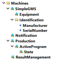
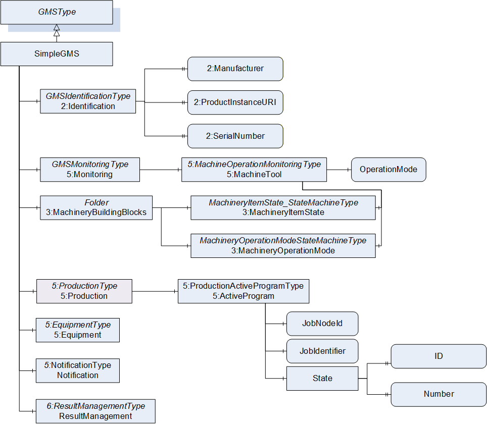
Agreement of Use
COPYRIGHT RESTRICTIONS
This document is provided "as is" by the OPC Foundation and VDMA.
Right of use for this specification is restricted to this specification and does not grant rights of use for referred documents.
Right of use for this specification will be granted without cost.
This document may be distributed through computer systems, printed or copied as long as the content remains unchanged and the document is not modified.
OPC Foundation and VDMA do not guarantee usability for any purpose and shall not be made liable for any case using the content of this document.
The user of the document agrees to indemnify OPC Foundation and VDMA and their officers, directors and agents harmless from all demands, claims, actions, losses, damages (including damages from personal injuries), costs and expenses (including attorneys' fees) which are in any way related to activities associated with its use of content from this specification.
The document shall not be used in conjunction with company advertising, shall not be sold or licensed to any party.
The intellectual property and copyright is solely owned by the OPC Foundation and VDMA.
PATENTS
The attention of adopters is directed to the possibility that compliance with or adoption of OPC or VDMA specifications may require use of an invention covered by patent rights. OPC Foundation or VDMA shall not be responsible for identifying patents for which a license may be required by any OPC or VDMA specification, or for conducting legal inquiries into the legal validity or scope of those patents that are brought to its attention. OPC or VDMA specifications are prospective and advisory only. Prospective users are responsible for protecting themselves against liability for infringement of patents.
WARRANTY AND LIABILITY DISCLAIMERS
WHILE THIS PUBLICATION IS BELIEVED TO BE ACCURATE, IT IS PROVIDED "AS IS" AND MAY CONTAIN ERRORS OR MISPRINTS. THE OPC FOUDATION NOR VDMA MAKES NO WARRANTY OF ANY KIND, EXPRESSED OR IMPLIED, WITH REGARD TO THIS PUBLICATION, INCLUDING BUT NOT LIMITED TO ANY WARRANTY OF TITLE OR OWNERSHIP, IMPLIED WARRANTY OF MERCHANTABILITY OR WARRANTY OF FITNESS FOR A PARTICULAR PURPOSE OR USE. IN NO EVENT SHALL THE OPC FOUNDATION NOR VDMA BE LIABLE FOR ERRORS CONTAINED HEREIN OR FOR DIRECT, INDIRECT, INCIDENTAL, SPECIAL, CONSEQUENTIAL, RELIANCE OR COVER DAMAGES, INCLUDING LOSS OF PROFITS, REVENUE, DATA OR USE, INCURRED BY ANY USER OR ANY THIRD PARTY IN CONNECTION WITH THE FURNISHING, PERFORMANCE, OR USE OF THIS MATERIAL, EVEN IF ADVISED OF THE POSSIBILITY OF SUCH DAMAGES.
The entire risk as to the quality and performance of software developed using this specification is borne by you.
RESTRICTED RIGHTS LEGEND
This Specification is provided with Restricted Rights. Use, duplication or disclosure by the U.S. government is subject to restrictions as set forth in (a) this Agreement pursuant to DFARs 227.7202-3(a); (b) subparagraph (c)(1)(i) of the Rights in Technical Data and Computer Software clause at DFARs 252.227-7013; or (c) the Commercial Computer Software Restricted Rights clause at FAR 52.227-19 subdivision (c)(1) and (2), as applicable. Contractor / manufacturer are the OPC Foundation, 16101 N. 82nd Street, Suite 3B, Scottsdale, AZ, 85260-1830
COMPLIANCE
The combination of VDMA and OPC Foundation shall at all times be the sole entities that may authorize developers, suppliers and sellers of hardware and software to use certification marks, trademarks or other special designations to indicate compliance with these materials as specified within this document. Products developed using this specification may claim compliance or conformance with this specification if and only if the software satisfactorily meets the certification requirements set by VDMA or the OPC Foundation. Products that do not meet these requirements may claim only that the product was based on this specification and must not claim compliance or conformance with this specification.
TRADEMARKS
Most computer and software brand names have trademarks or registered trademarks. The individual trademarks have not been listed here.
GENERAL PROVISIONS
Should any provision of this Agreement be held to be void, invalid, unenforceable or illegal by a court, the validity and enforceability of the other provisions shall not be affected thereby.
This Agreement shall be governed by and construed under the laws of Germany.
This Agreement embodies the entire understanding between the parties with respect to, and supersedes any prior understanding or agreement (oral or written) relating to, this specification.