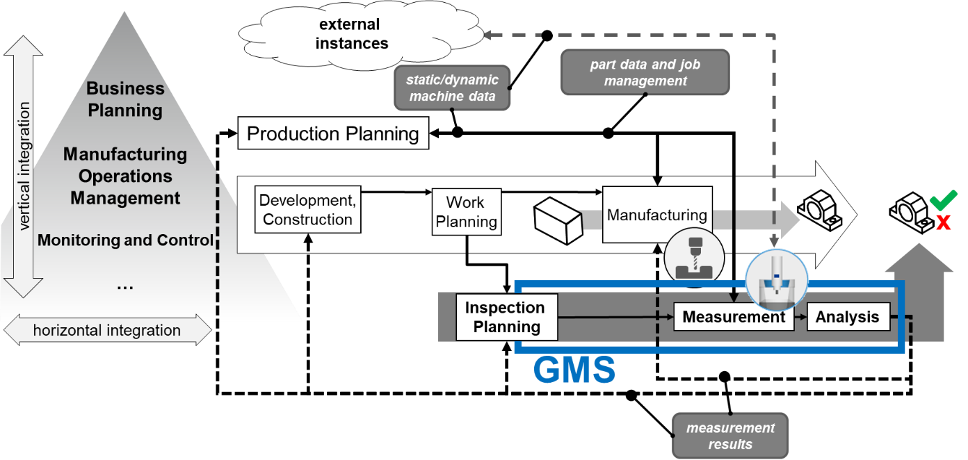
6 Use cases
This companion specification describes how a GMS is addressed via OPC UA. For this purpose, the following primary use cases for the communication with a GMS are considered in sections 6.1 to 6.56.5. These use cases are located in the overview figure of a Geometric Measurement System (GMS) in Figure 9.
Further use cases can also be covered or specified in other standards (vendor or Companion Specification).
In each chapter for the use cases, a simple sequence diagram demonstrates a typical communication example between GMS and other instances like operator, high-level system in the automation pyramid, data bases or other systems.
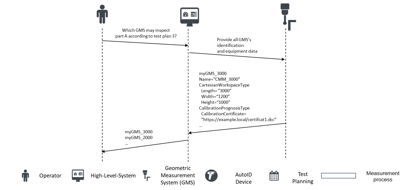
6.1 Retrieve static machine data
A higher-level system requests from a GMS which (measurement) functions/parameters (measuring space) are available, how the machine is identified if the measuring system is calibrated, retrieves additional information from machine components and, to receive an overview of the sensor system, respectively in order to
provide an overview of GMS's capabilities
validate measurement jobs addressed to a certain GMS
plan measuring tasks for GMSs
be able to locate all GMSs
assign the appropriate GMS to the part to be measured, if several different GMSs are available
Figure 10 shows a typical communication between GMS, operator and high-level system to retrieve static machine data as a sequence diagram.
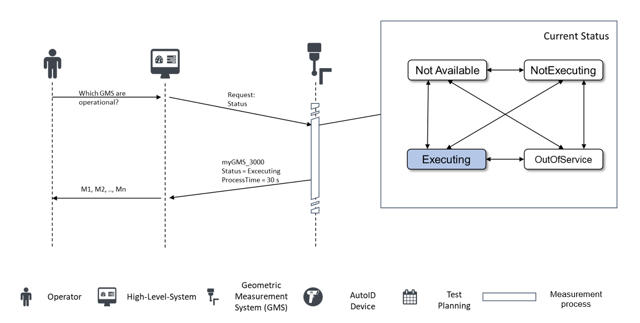
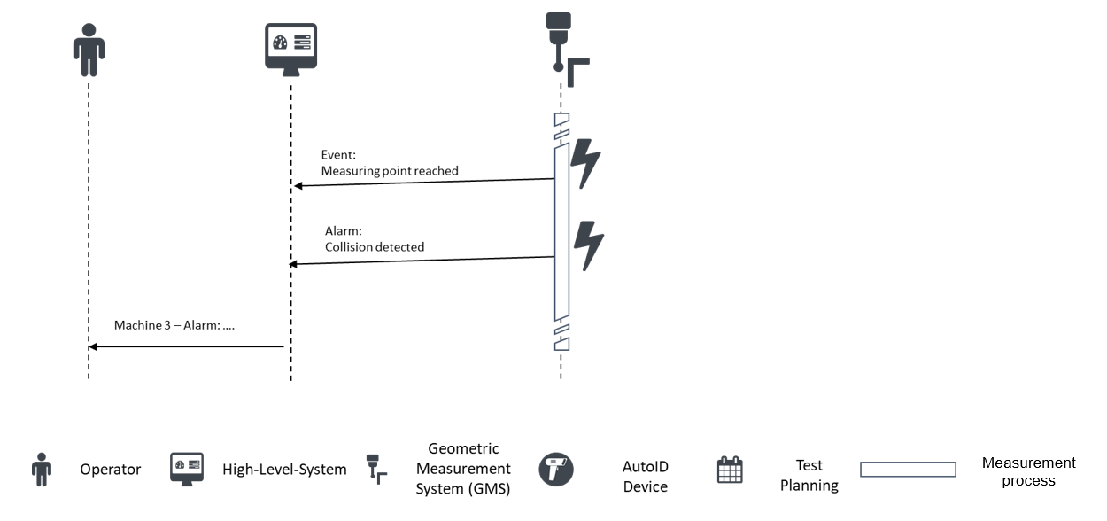
6.2 Retrieve dynamic machine status
A higher-level system would like to know the status/state/condition (e.g., collision) of the GMS, when manual intervention is required, the current error message, what measures have to be taken in case of intervention to
plan the next jobs
keep usage statistics
plan maintenance
assign service
calculate key performance indicators (e.g., OEE [ISO 22400-2])
archive data
verify the reliability of the measurements
send warnings, if necessary.
Figure 11 and Figure 12 show a typical communication between GMS, operator, and high-level system to retrieve dynamic machine data as a sequence diagram.
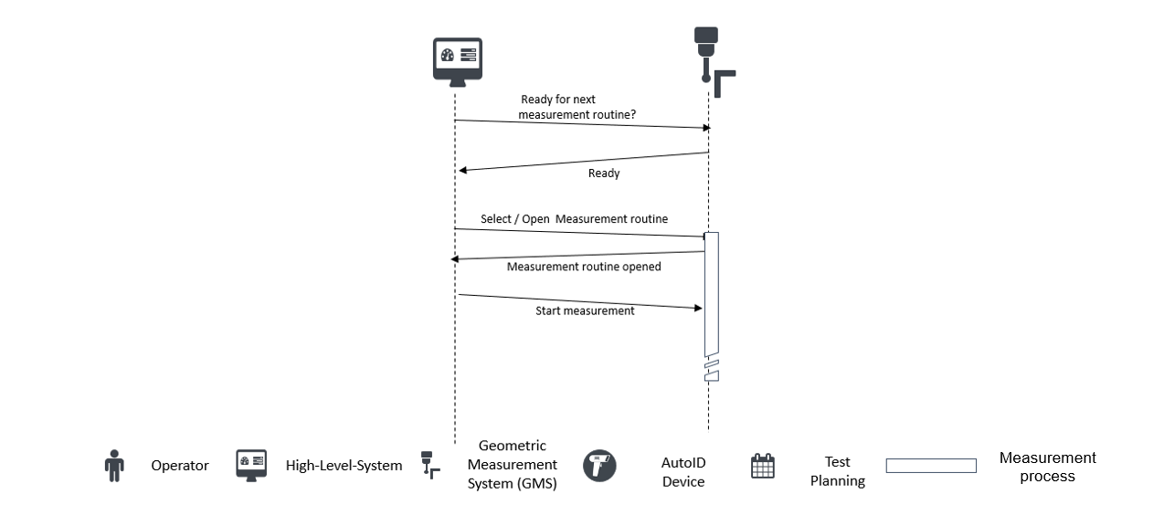
6.3 Job management
A higher-level system may manage/schedule/start/stop measurement routines, be able to assign part to a job/measurement routine/batch, want to know the remaining time till the job is finished, know what the current status of the job is and include dynamic part data in the measurement result (e.g., material no., part no., comments, operator) in order to
be able to distribute the execution processes automatically
(automatically) start/enable the measurement routine
create an overview of the current job status
ensure traceability
Figure 13 shows a typical communication between GMS, operator and high-level system to manage jobs as a sequence diagram.
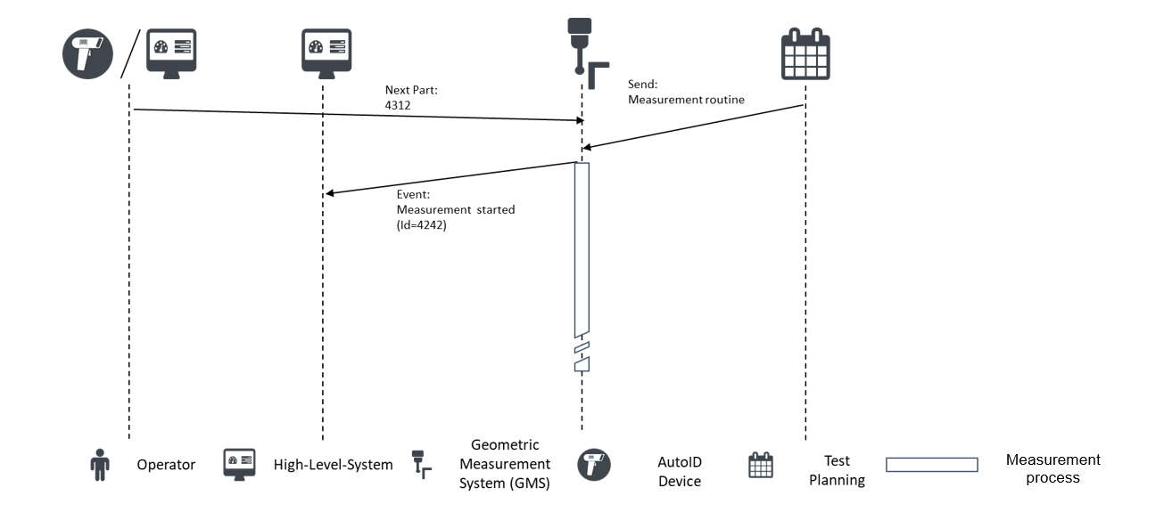
6.4 Managing part data
A higher-level system/handling system would like to identify a part on the GMS, know whether the measuring procedure was error-free, know when a measurement is finished as well as read and write meta-data (e.g., batch, temperature) in order to
decide whether the part requires further processing, has to be sorted out, or the measurement has to be repeated
annotate measured values with the meta-data and save them
transmit these to the next production process
request the GMS to load proper data to measure (e.g., measurement routine) a part
Figure 14 shows a typical communication between GMS, operator, and high-level system to manage part data as a sequence diagram.
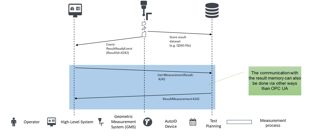
6.5 Retrieve measurement results
A higher-level system would like to receive the measurement results (incl. meta-data) for a part in order to
correct/adjust the program in the machine tool
be able to guarantee complete traceability of the workpiece
reject or rework the workpiece, if necessary
release the products
optimize the product
interpret the product (e.g., statistical analyses)
check the product quality
Figure 15 shows a typical communication between GMS, operator, and high-level system to retrieve measurement results as a sequence diagram.