
1 Scope
OPC 40082-3 describes the interface between injection moulding machines (IMM) and liquid silicone rubber (LSR) dosing systems for data exchange via OPC UA. The target of OPC 40082-3 is to provide a standardised interface for IMM and LSR dosing system from different manufacturers to ensure compatibility.
The following functionalities are covered:
General information about the LSR dosing systems
Status information
Process data
Synchronisation of dosing between IMM and LSR dosing systems is not part of OPC 40082-3 and must be done by additional interfaces e.g. via hardwired signals.
Safety related signals like emergency stop are not included.
2 Normative references
The following documents are referred to in the text in such a way that some or all of their content constitutes requirements of this document. For dated references, only the edition cited applies. For undated references, the latest edition of the referenced document (including any amendments) applies
OPC 10000-3, OPC Unified Architecture - Part 3: Address Space Model
OPC 10000-3
OPC 10000-5, OPC Unified Architecture - Part 5: Information Model
OPC 10000-5
OPC 10000-6, OPC Unified Architecture - Part 6: Mappings
OPC 10000-6
OPC 10000-7, OPC Unified Architecture - Part 7: Profiles
OPC 10000-7
OPC 10000-8, OPC Unified Architecture - Part 8: Data Access
OPC 10000-8
OPC 10000-9, OPC Unified Architecture - Part 9: Alarms and Conditions
OPC 10000-9
OPC 10000-100, OPC Unified Architecture - Part 100: Devices
OPC 10000-100
OPC 40083: OPC UA interfaces for plastics and rubber machinery - General Type definitions
http://www.opcfoundation.org/UA/PlasticsRubber/GeneralTypes
3 Terms, definitions and conventions
3.1 Overview
It is assumed that basic concepts of OPC UA information modelling are understood in this specification. This specification will use these concepts to describe the OPC 40082-3 Information Model. For the purposes of this document, the terms and definitions given in the documents referenced in Clause 2 apply.
3.2 Conventions used in this document
The conventions described in OPC 40083 apply.
3.3 Abbreviations
| IMM | injection moulding machine |
| LSR | liquid silicone rubber |
| LDS | LSR dosing system |
4 General information to OPC UA interfaces for plastics and rubber machinery and OPC UA
For general information on OPC UA interfaces for plastics and rubber machinery and OPC UA see OPC 40083.
5 Use cases
OPC 40082-3 covers the following functionalities:
General information about the LSR dosing system
Status information
Process data
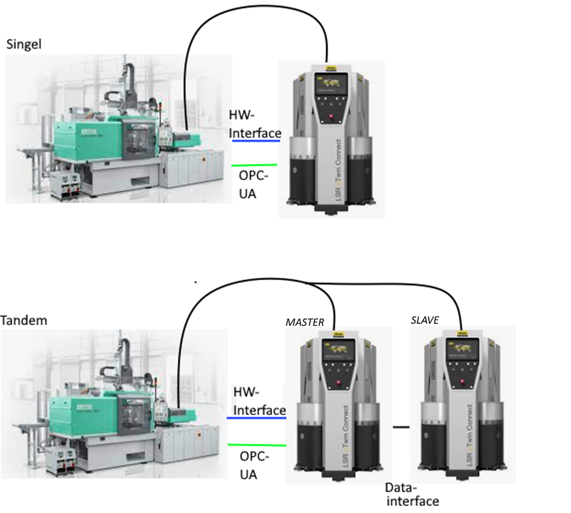
If multiple LDS are operated alternately on one machine for the same injection unit (see Figure 1), one system must act as the Master. This Master provides the regular OPC UA server. The Master server always provides the data of the active system in the network. The direct operation of several LDS servers between machines and LDS is not scope of this specification.
More information is listed in Table 1.
| OPC UA Server (Master) | Data Master | Data Slave |
| DisplayLanguage | Basically Master | |
| Identification | Basically Master | |
| MachineConfiguration | Basically Master | |
| Operation | Always the data from the active system/last active system | |
| Events | Always the events from the active system/last active system | |
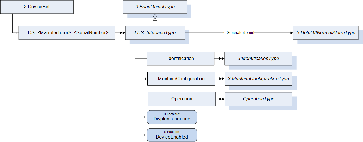
6 LDS_InterfaceType
6.1 LDS_InterfaceType Definition
This OPC UA ObjectType is used for the root Object representing an LSR dosing system with its subcomponents. It is formally defined in Table 2.
| Attribute | Value | |||||
| BrowseName | LDS_InterfaceType | |||||
| IsAbstract | False | |||||
| References | Node Class | BrowseName | DataType | TypeDefinition | Other | |
|---|---|---|---|---|---|---|
| Subtype of 0:BaseObjectType defined in OPC UA Part 5 | ||||||
| 0:HasComponent | Object | Identification | 3:IdentificationType | M | ||
| 0:HasComponent | Object | MachineConfiguration | 3:MachineConfigurationType | M | ||
| 0:HasComponent | Object | Operation | OperationType | M | ||
| 0:HasProperty | Variable | DisplayLanguage | 0:LocaleId | 0:PropertyType | O, RW | |
| 0:HasProperty | Variable | DeviceEnabled | 0:Boolean | 0:PropertyType | O, RW | |
| 0:GeneratesEvent | ObjectType | 0:HelpOffNormalAlarmType | Defined in OPC 40083 | |||
| Conformance Units | ||||||
|---|---|---|---|---|---|---|
| OPC 40082-3 Basic |
The BrowseName of the object instance shall be "LDS_<Manufacturer>_<SerialNumber>"
Example: "LDS_Reinhardt_0123456".
Example:
| BrowseName | Namespace | Namespace index | Remarks |
| LDS_Reinhardt_0123456 | Local Server URI or vendor specific namespace | 1 or server specific | OPC 40082-3 only defines the LDS_InterfaceType. The instance is generated in the local server |
| Identification |
http://opcfoundation.org/UA/
PlasticsRubber/LDS/ | server specific | The object Identification is a child of LDS_InterfaceType which is defined in OPC 40082-3 |
| Manufacturer | http://opcfoundation.org/UA/DI/ | server specific | The variable Manufacturer is a child of IdentificationType which is defined in OPC 40083. However, it derives from the ComponentType defined in OPC 10000-100. The Variable Manufacturer is defined there. |
6.2 DisplayLanguage
With the DisplayLanguage Property the client can set the desired language on the user interface at the LDS. If the peripheral device does not support the configured language, it can keep the previous setting or use English as the default.
6.3 DeviceEnabled
The variable DeviceEnabled is used to release the drives of the dosing system. If the value is FALSE, the LDS shall not be able to start its drives.
7 Identification
The IdentificationType for the identification of the device is defined in OPC 40083. All mandatory nodes shall be filled with valid values from the server.
The DeviceClass Property in the Identification Object shall have the value "LSR Dosing System"
8 MachineConfiguration
| The MachineConfiguration Object represents the current configuration of the LDS. |
The MachineConfigurationType is defined in OPC 40083. |
9 OperationType
This ObjectType contains components which are necessary to operate the LDS. It is formally defined in Table 3.
| Attribute | Value | ||||
| BrowseName | OperationType | ||||
| IsAbstract | False | ||||
| References | Node Class | BrowseName | DataType | TypeDefinition | Other |
|---|---|---|---|---|---|
| Subtype of 0:BaseObjectType defined in OPC UA Part 5 | |||||
| 0:HasProperty | Variable | DeviceMappingNumber | 0:UInt32 | 0:PropertyType | M, RW |
| 0:HasComponent | Method | IdentifyDevice | O | ||
| 0:HasProperty | Variable | HighestActiveAlarmSeverity | 0:UInt16 | 0:PropertyType | M, RO |
| 0:HasComponent | Variable | ActiveErrors | 3:Classified ActiveError DataType[] | 0:BaseDataVariableType | M, RO |
| 0:HasComponent | Method | ResetAllErrors | O | ||
| 0:HasComponent | Method | ResetErrorById | O | ||
| 0:HasComponent | Method | SetCycleNumber | O | ||
| 0:HasProperty | Variable | MaterialBalanceSystemType | MaterialBalance SystemType Enumeration | 0:PropertyType | M, RO |
| 0:HasProperty | Variable | ActivateMaterialBalance System | 0:Boolean | 0:PropertyType | O, RW |
| 0:HasComponent | Variable | DeliveryType | 0:UInt16 | 0:MultiStateValue DiscreteType | M, RW |
| 0:HasComponent | Object | DeliveryPressure | 3:ControlledParameterType | O | |
| 0:HasComponent | Variable | DeliveryPressure MeasuringPoint | 0:UInt16 | 0:MultiStateValueDiscreteType | O, RW |
| 0:HasComponent | Object | DeliveryFlowrate | 3:ControlledParameterType | O | |
| 0:HasComponent | Variable | ActualShotWeight | 0:Double | 0:AnalogItemType | O, RO |
| 0:HasComponent | Variable | SetShotWeight | 0:Double | 0:AnalogItemType | O, RW |
| 0:HasComponent | Variable | SetValueCompositeDensity | 0:Double | 0:AnalogItemType | O, RW |
| 0:HasComponent | Variable | MixingRatioTarget | 0:Double | 0:AnalogItemType | O, RW |
| 0:HasComponent | Variable | MaxDeviationMixingRatio | 0:Double | 0:AnalogItemType | O, RW |
| 0:HasComponent | Variable | TargetDeviationMixingRatio | 0:Double | 0:AnalogItemType | O, RO |
| 0:HasComponent | Variable | ActualDeviationMixingRatio | 0:Double | 0:AnalogItemType | O, RO |
| 0:HasComponent | Variable | RemainingMaterialTime | 0:Duration | 0:BaseDataVariableType | O, RO |
| 0:HasComponent | Variable | PurgeMode | 0:UInt16 | 0:MultiStateValue DiscreteType | O, RW |
| 0:HasProperty | Variable | PurgeStatus | PurgeStatus Enumeration | 0:PropertyType | O, RO |
| 0:HasComponent | Variable | PurgeQuantity | 0:Double | 0:AnalogItemType | O, RW |
| 0:HasComponent | Variable | PurgeTimeout | 0:Duration | 0:BaseDataVariableType | O, RW |
| 0:HasComponent | Variable | PurgeCyclicQuantity | 0:Double | 0:AnalogItemType | O, RW |
| 0:HasComponent | Variable | PurgeCyclicIdleTime | 0:Duration | 0:BaseDataVariableType | O, RW |
| 0:HasComponent | Variable | PurgeCyclicActive | 0:Boolean | 0:BaseDataVariableType | O, RO |
| 0:HasComponent | Variable | ActivateRemoteControl | 0:UInt16 | 0:MultiStateValueDiscreteType | M, RW |
| 0:HasComponent | Variable | RemoteControlActivated | 0:UInt16 | 0:MultiStateValueDiscreteType | M, RO |
| 0:HasComponent | Method | StartDosing | O | ||
| 0:HasComponent | Method | StopDosing | O | ||
| 0:HasComponent | Variable | DosingActive | 0:Boolean | 0:BaseDataVariableType | O, RO |
| 0:HasComponent | Object | Component_A | ComponentType | M | |
| 0:HasComponent | Object | Component_B | ComponentType | M | |
| 0:HasComponent | Object | Additive_<Y> | AdditiveType | OP | |
| 0:GeneratesEvent | Object Type | LDSCycleParameters EventType | Defined in 9.29 | ||
| Conformance Units | |||||
|---|---|---|---|---|---|
| OPC 40082-3 Basic | |||||
| OPC 40082-3 DosingFunction | |||||
| OPC 40082-3 Purge | |||||
| OPC 40082-3 PurgeCyclic | |||||
| OPC 40082-3 SelectableMaterialBalanceSystem | |||||
| OPC 40082-3 DeliveryPressure | |||||
| OPC 40082-3 DeliveryFlowrate | |||||
| OPC 40082-3 MixingRatioTarget | |||||
| OPC 40082-3 BalanceSystem | |||||
| OPC 40082-3 Identify Device | |||||
| OPC 40082-3 ResetAllErrors | |||||
| OPC 40082-3 ResetErrorById | |||||
| OPC 40082-3 SetCycleNumber | |||||
| OPC 40082-3 ActualShotWeight | |||||
| OPC 40082-3 SetShotWeight | |||||
| OPC 40082-3 SetValueCompositeDensity | |||||
| OPC 40082-3 RemainingMaterialTime | |||||
| OPC 40082-3 Additive |
The BrowseName of ComponentType shall be built of "Component_" and a character 'A', 'B' , … (e.g. Component_A, Component_B).
The BrowseName of AdditiveType shall be built of "Additive_" and a number from 1 to n (e.g. Additive_1).
9.1 DeviceMappingNumber
| Description: | Unique identifier/address/number for devices of the same DeviceType within a local network. Several peripheral devices of the same DeviceType can be connected to an IMM. In most applications, the IMM must map the connected peripheral devices to internal logical devices and zones in a fixed configuration (e.g. hot runner systems according to the wiring or temperature control devices according to the tubing). |
The mapping shall be stable after reconnecting the devices and is therefore not possible via IP addresses, which can be assigned dynamically via DHCP. DeviceMappingNumber sets the mapping order of peripheral devices of the same type on the local network and is therefore of type UInt32.
| Example: | 1 |
9.2 IdentifyDevice
| Description: | The peripheral device on which this method is called shows itself by e.g. activation of a LED. |
Signature:
IdentifyDevice ();The method has no Input- or OutputArguments.
| Attribute | Value | ||||
| BrowseName | IdentifyDevice | ||||
| References | Node Class | BrowseName | DataType | TypeDefinition | Modelling Rule |
|---|
9.3 HighestActiveAlarmSeverity
| Description: | Indication of the severity of the highest active alarm (0 = no active alarm - 1000 = possible error). It provides a minimal error handling for devices without alarm support. However, the variable shall be filled even if alarms are supported. |
| Example: | 400 |
9.4 ActiveErrors
| Description: | List of the active errors of the device. It provides a minimal error handling for devices without alarm support. However, the variable shall be filled even if alarms are supported. The ClassifiedActiveErrorDataType is defined in OPC 40083. If there is no active error, the array is empty. |
9.5 ResetAllErrors
| Description: | Method to reset all errors on the device. |
Signature:
ResetAllErrors();The method has no Input- or OutputArguments.
| Attribute | Value | ||||
| BrowseName | ResetAllErrors | ||||
| References | Node Class | BrowseName | DataType | TypeDefinition | Modelling Rule |
|---|
9.6 ResetErrorById
| Description: | Method to reset one error of the device. |
Signature:
	ResetErrorById(
[in] 0:String Id);| Argument | Description |
| Id | Id of the error, listed in ActiveErrors, that shall be reset. |
| Attribute | Value | ||||
| BrowseName | ResetErrorById | ||||
| References | Node Class | BrowseName | DataType | TypeDefinition | Modelling Rule |
|---|---|---|---|---|---|
| HasProperty | Variable | InputArguments | Argument[] | PropertyType | Mandatory |
9.7 SetCycleNumber
| Description: | Method to set the cycle number of the LDS to synchronize it with the cycle number of the injection moulding machine. |
Signature:
	SetCycleNumber(
[in] 0:UInt64 CycleNumber);| Argument | Description |
| CycleNumber | Number, to which the cycle counter of the LDS shall be set. The next LDSCycleParametersEvent will use this value. |
| Attribute | Value | ||||
| BrowseName | SetCycleNumber | ||||
| References | Node Class | BrowseName | DataType | TypeDefinition | Modelling Rule |
|---|---|---|---|---|---|
| HasProperty | Variable | InputArguments | Argument[] | PropertyType | Mandatory |
9.8 MaterialBalanceSystemType
Type of the material balance system.
| Name | Value | Description |
| NOT_AVAILABLE | 0 | No material balance system available on the LDS. ActivateMaterialBalanceSystem is not present, because it is not possible to switch a material balance system on |
| ALWAYS_ACTIVE | 1 | Material balance system is available on the LDS and is always active. ActivateMaterialBalanceSystem is not present, because it is not possible to switch a material balance system off |
| SELECTABLE | 2 | Material balance system is available on the LDS and it can be switched on and off via the interface via the variable ActivateMaterialBalanceSystem. |
9.9 ActivateMaterialBalanceSystem
If the value is true, the material balance system is activated.
9.10 DeliveryType
The dosing system works with delivery pressure or volumetric flow. As some LSR dosing systems support the selection of the DeliveryType, the Property can be writeable. Therefore, the TypeDefinition is MultiStateValueDiscreteType, so the Properties EnumValues and ValueAsText must be filled with the supported values out of Table 11.
| EnumValue | ValueAsText | Description |
| 0 | PRESSURE | Dosing system with delivery pressure |
| 1 | VOLUMETRIC_FLOWRATE | Dosing system with volumetric flow |
A server can provide manufacturer specific values with EnumValues ≥ 100.
9.11 DeliveryPressure, DeliveryPressureMeasuringPoint
With the objects DeliveryPressure and DeliveryPressureMeasuringPoint the client can set (and monitor) the delivery pressure of the LDS. Both are optional, but the two elements shall always be used together.
For systems with DeliveryPressure the components ActualValue, SetValue, UpperTolerance and LowerTolerance defined in the ControlledParameterType are mandatory. If the upper or lower tolerance band is passed it is documented in the ErrorStatus.
Unit: bar or psi (=lbf/in²)
The variable DeliveryPressureMeasuringPoint represents the position of the pressure sensor used for the DeliveryPressure. As some LSR dosing systems support the selection of the position, the Property can be writeable. Therefore, the TypeDefinition is MultiStateValueDiscreteType, so the Properties EnumValues and ValueAsText must be filled with the supported values out of Table 12.
| EnumValue | ValueAsText | Description |
| 0 | PUMP_A | Pressure sensor position pump A |
| 1 | PUMP_B | Pressure sensor position pump B |
| 2 | BLENDER | Pressure sensor position blender |
| 3 | MANUAL | Pressure is manually adjusted |
A server can provide manufacturer specific values with EnumValues ≥ 100.
9.12 DeliveryFlowrate
For system with delivery volumetric flow rate the components ActualValue, SetValue, UpperTolerance and LowerTolerance are mandatory. If the upper or lower tolerance band is passed it is documented in the ErrorStatus.
Unit: l/h or gal/h
9.13 ActualShotWeight
Specifies the value determined by the feeder as the shot weight.
Unit: g or lb
9.14 SetShotWeight
Reference value determined by the IMM or defined by the user on the IMM side.
Unit: g or lb
9.15 SetValueCompositeDensity
The composite set point of density.
Unit: g/cm³ or lb/in³
9.16 MixingRatioTarget
Target of the mixing ratio (includes ratio change when MaterialBalanceSystem is active). The share of component A (in percent) defines the value:
| Examples: | 50 (A 50 : 50 B) without MaterialBalanceSystem |
| 51,25 | (A 51,25 : 48,75 B) active MaterialBalanceSystem |
9.17 MaxDeviationMixingRatio, TargetDeviationMixingRatio, ActualDeviationMixingRatio
If a material balance system is used these variables are used to set and monitor the deviation from the set mixing ratio of component A and B.
MaxDeviationMixingRatio is writeable by the client and used to limit the maximum deviation in percent.
TargetDeviationMixingRatio: This deviation (in percent) is set/used by the material balance system
ActualDeviationMixingRatio: Actual deviation (in percent)
The values are given related to the mixing ratio of component A. If the maximum allowed mixing ratio is 51% component A and 49% component B MaxDeviationMixingRatio is 1%.
9.18 RemainingMaterialTime
Remaining time until first material is empty.
9.19 PurgeMode
Purge functions can be activated directly when the PurgeMode is selected on the LDS. Each device is allowed to set the PurgeMode. When in remote control and purging by the IMM is activated with a hard wired dosing signal, PurgeTimeout and PurgeQuantity has no effect.
When in remote control and purging by the IMM is activated with the StartDosing Method, either PurgeTimeout/PurgeCyclicIdleTime or PurgeQuantity/PurgeCyclicQuantity must be set.
After the dosing signal is deactivated again, the PurgeMode will be reset to OFF by the LDS.
| EnumValue | ValueAsText | Description |
| 0 | OFF | No purge function. Normal dosing via dosing signal. |
| 1 | WITH_COMPONENT_A | Purge A |
| 2 | WITH_COMPONENT_B | Purge B |
| 3 | WITH_COMPONENT_A_B | Venting |
| 4 | WITH_COMPONENT_A_OR_B | System chooses the component which is used for purging (usually the component with the larger remaining quantity) |
| 5 | CYCLIC_COMPONENT_A_B | Purge A and B cyclic |
Figure 3 shows the interactions between ActivateRemoteControl, RemoteControlActivated, PurgeMode, PurgeStatus and the dosing signal.
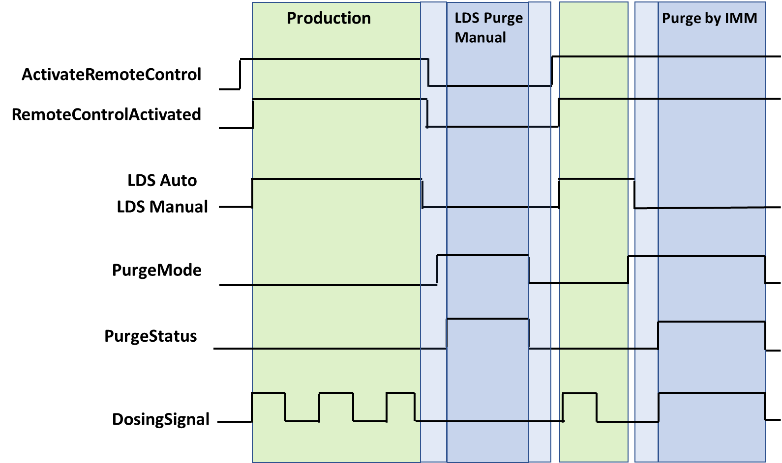
Note: "LDS Auto" and "LDS Manual" are LDS internal parameters which are not covered by this specification.
9.20 PurgeStatus
Actual status of the purge function. PurgeStatus must show OFF if no purge function is active. The PurgeStatus is also shown in Figure 3.
| Name | Value | Description |
| OFF | 0 | No purge function is active. |
| COMPONENT_A | 1 | Purge component A is active. |
| COMPONENT_B | 2 | Purge component B is active. |
| COMPONENT_A_AND_B | 3 | Venting |
| COMPONENT_A_AND_B_CYCLIC | 4 | Cyclic purge component A and B is active. |
9.21 PurgeQuantity
The PurgeQuantity is only used in relation with PurgeMode EnumValue 1-4 and describes the amount of material during the active purge mode.
Unit: cm³ or in³
9.22 PurgeTimeout
PurgeTimeout describes the maximum time of the active PurgeMode (1-5). For PurgeMode EnumValue 1-4, the PurgeMode is set to 0 after the PurgeTimeout has expired. For PurgeMode EnumValue 5, the PurgeCyclicActive is set to false, PurgeMode is unaffected.
9.23 PurgeCyclicQuantity
The PurgeCyclicQuantity is only used in relation with PurgeMode EnumValue 5 and describes the amount of material during a purge cycle as the sum of both components. After the volume is reached, the variable PurgeCyclicActive will become false and PurgeCyclicIdleTime starts.
Unit: cm³ or in³
9.24 PurgeCyclicIdleTime
The PurgeCyclicIdleTime is only used in relation with PurgeMode EnumValue 5 and describes the time until the next purge cycle starts.
9.25 PurgeCyclicActive
PurgeCyclicActive is only used in relation with PurgeMode EnumValue 5 and indicates the difference between purging (true) and waiting (false)
9.26 ActivateRemoteControl
It is necessary to synchronize the dosing between IMM and LSR dosing systems. This can be done via a separate interface e.g. via hardwired signals or also via OPC UA (if the process is robust against small time delays that can be caused by the client/server-connection). Signal 0 can be set by IMM or LDS, signals > 0 only by IMM.
With ActivateRemoteControl the client selects the method of remote control. If the server provides only one method for remote control, the other one is not listed in the possible values of the MultiStateValueDiscreteType.
| EnumValue | ValueAsText | Description |
| 0 | OFF | Remote control / automatic mode switched off. |
| 1 | SEPARATE_INTERFACE | Activating automatic mode on LDS and using a separate interface from the injection moulding machine for remote control |
| 2 | OPC_UA | Activating automatic mode on LDS and using this OPC UA connection with the methods StartDosing/StopDosing for remote control |
A server can provide manufacturer specific values with EnumValues ≥ 100.
Figure 3 shows the interaction between ActivateRemoteControl and RemoteControlActivated.
9.27 RemoteControlActivated
With this signal, the LDS signals, if it is ready to be controlled via this or a separate interface. See Table 15 for possible values.
Figure 3 shows the interaction between ActivateRemoteControl and RemoteControlActivated.
9.28 StartDosing, StopDosing, DosingActive
| Description: | If RemoteControlActivated = 2, the two Methods (without arguments) are used to start and stop the dosing. With the Variable DosingActive the LDS can inform the IMM, if dosing is really active. |
Signatures:
	StartDosing();
	StopDosing();
The methods have no Input- or OutputArguments.
| Attribute | Value | ||||
| BrowseName | StartDosing | ||||
| References | Node Class | BrowseName | DataType | TypeDefinition | Modelling Rule |
|---|
| Attribute | Value | ||||
| BrowseName | StopDosing | ||||
| References | Node Class | BrowseName | DataType | TypeDefinition | Modelling Rule |
|---|
9.29 LDSCycleParametersEventType
The LDSCycleParametersEventType represents information on a dosing cycle. A complete dosing is defined from the beginning of the dosing signal to the next one, i.e. the event for cycle n is fired, when the dosing signal for cycle n+1 starts. After the last cycle the event must be raised after a timeout which corresponds to the cycle time.
Note: The event data refer to the current injected material and not to the current dosing process (1 cycle offset).
The LDSCycleParametersEventType is formally defined in Table 18.
| Attribute | Value | ||||
| BrowseName | LDSCycleParametersEventType | ||||
| IsAbstract | True | ||||
| References | Node Class | BrowseName | DataType | TypeDefinition | Other |
|---|---|---|---|---|---|
| Subtype of 0:BaseEventType defined in OPC UA Part 5 | |||||
| 0:HasProperty | Variable | CycleNumber | 0:UInt64 | 0:PropertyType | M |
| 0:HasProperty | Variable | DosingTime | 0:Duration | 0:PropertyType | O |
| 0:HasComponent | Variable | MixingRatioTarget | 0:Double | 0:AnalogItemType | O |
| 0:HasComponent | Variable | MixingRatioActual | 0:Double | 0:AnalogItemType | O |
| 0:HasComponent | Variable | AdditivesRatioTarget | 0:Double[] | 0:AnalogItemType | O |
| 0:HasComponent | Variable | AdditivesRatioActual | 0:Double[] | 0:AnalogItemType | O |
| 0:HasComponent | Variable | VolumeA | 0:Double | 0:AnalogItemType | O |
| 0:HasComponent | Variable | VolumeB | 0:Double | 0:AnalogItemType | O |
| 0:HasComponent | Variable | VolumeAB | 0:Double | 0:AnalogItemType | O |
| 0:HasComponent | Variable | VolumeAdditives | 0:Double[] | 0:AnalogItemType | O |
| 0:HasComponent | Variable | VolumeTotal | 0:Double | 0:AnalogItemType | O |
| 0:HasComponent | Variable | ResidualAmountA | 0:Double | 0:AnalogItemType | O |
| 0:HasComponent | Variable | ResidualAmountB | 0:Double | 0:AnalogItemType | O |
| 0:HasComponent | Variable | MixingPointPressureA | 0:Double | 0:AnalogItemType | O |
| 0:HasComponent | Variable | MixingPointPressureB | 0:Double | 0:AnalogItemType | O |
| 0:HasComponent | Variable | MixingPointPressureBlender | 0:Double | 0:AnalogItemType | O |
| 0:HasComponent | Variable | AdditivesPressure | 0:Double[] | 0:AnalogItemType | O |
| 0:HasComponent | Variable | FilterPressurePrimary | 0:Double | 0:AnalogItemType | O |
| 0:HasComponent | Variable | FilterPressureSecondary | 0:Double | 0:AnalogItemType | O |
9.29.1 CycleNumber
Number of the dosing cycle. Gets counted up after each dosing cycle. The value can be set by calling the method "SetCycleNumber". It is recommended to synchronize CycleNumber after a reconnection by calling this method.
Example: 900
9.29.2 DosingTime
Duration of the dosing cycle.
9.29.3 MixingRatioTarget
Target mixing ratio of the last cycle (includes ratio change when MaterialBalanceSystem is active). The share of component A (in percent) defines the value:
| Examples: | 50 (A 50 : 50 B) without MaterialBalanceSystem |
| 51,25 | (A 51,25 : 48,75 B) active MaterialBalanceSystem |
9.29.4 MixingRatioActual
Actual mixing ratio of the components. The share of component A defines the value:
| Example: 50,9 | (A 50,9 : 49,1 B) |
9.29.5 AdditivesRatioTarget
Target ratios of additives in percentage which are set in AdditiveFraction of AdditiveType.
9.29.6 AdditivesRatioActual
Actual ratios of additives in percentage.
Example: [ 2,1 % ; 1,2 % ]
9.29.7 VolumeA
Volume of component A that was added to the process in the last cycle.
Unit: cm³ or in³
9.29.8 VolumeB
Volume of component B that was added to the process in the last cycle.
Unit: cm³ or in³
9.29.9 VolumeAB
Volume of components A + B that was added to the process in the last cycle.
Unit: cm³ or in³
9.29.10 VolumeAdditives
Volumes of the additives that were added to the process in the last cycle.
Unit: cm³ or in³
9.29.11 VolumeTotal
Volume of all components (A + B + all additives).
Unit: cm³ or in³
9.29.12 ResidualAmountA
Residual weight amount of component A at the end of the dosing cycle.
Unit: kg or lb
9.29.13 ResidualAmountB
Residual weight amount of component B at the end of the dosing cycle.
Unit: kg or lb
9.29.14 MixingPointPressureA
Average pressure of component A during the last cycle at the blender.
Unit: bar or psi
9.29.15 MixingPointPressureB
Average pressure of component B during the last cycle at the blender.
Unit: bar or psi
9.29.16 MixingPointPressureBlender
Average pressure of components A and B during the last cycle at the blender.
Unit: bar or psi
9.29.17 AdditivesPressure
Average pressure of the additive during the last cycle at the measuring point.
Unit: bar or psi
9.29.18 FilterPressurePrimary, FilterPressureSecondary
Average material pressure during the last cycle before and after the filter. The Pressure difference between FilterPressurePrimary & FilterPressureSecondary can be used to check if the filter is blocked/ will be blocked soon/ has to be maintained. Unit: bar or psi
10 ComponentType
This ObjectType contains information about the mixing components A and B. It is formally defined in Table 19.
| Attribute | Value | |||||
| BrowseName | ComponentType | |||||
| IsAbstract | False | |||||
| References | Node Class | BrowseName | DataType | TypeDefinition | Other | |
|---|---|---|---|---|---|---|
| Subtype of 0:BaseObjectType defined in OPC UA Part 5 | ||||||
| 0:HasComponent | Variable | SetValueDensity | 0:Double | 0:AnalogItemType | O, RO | |
| 0:HasComponent | Method | SetSetValueDensity | O | |||
| 0:HasComponent | Variable | ActualPressure | 0:Double | 0:AnalogItemType | O, RO | |
| 0:HasComponent | Variable | ActualFollowerPlatePressure | 0:Double | 0:AnalogItemType | O, RO | |
| 0:HasComponent | Variable | SetFollowerPlatePressure | 0:Double | 0:AnalogItemType | O, RW | |
| 0:HasComponent | Variable | DrumCapacity | 0:Double | 0:AnalogItemType | O, RO | |
| 0:HasComponent | Variable | ResidualAmount | 0:Double | 0:AnalogItemType | O, RO | |
| 0:HasComponent | Variable | RemainingMaterialTime | 0:Duration | 0:BaseDataVariableType | O, RO | |
| 0:HasProperty | Variable | AllowsCycles | 0:Double | 0:PropertyType | O, RO | |
| 0:HasProperty | Variable | Status | ComponentStatus Enumeration | 0:PropertyType | M, RO | |
| Conformance Units | |||||
|---|---|---|---|---|---|
| OPC 40082-3 Basic | |||||
| OPC 40082-3 SetValueDensity | |||||
| OPC 40082-3 SetSetValueDensity | |||||
| OPC 40082-3 ActualPressure | |||||
| OPC 40082-3 ActualFollowerPlatePressure | |||||
| OPC 40082-3 SetFollowerPlatePressure | |||||
| OPC 40082-3 DrumCapacity | |||||
| OPC 40082-3 ResidualAmount | |||||
| OPC 40082-3 RemainingMaterialTime | |||||
| OPC 40082-3 AllowsCycles |
10.1 SetValueDensity
Set point material density.
Unit: g/cm³ or lb/in³
10.2 SetSetValueDensity
This optional method is used to modify SetValueDensity if allowed by the device.
Signature:
		SetSetValueDensity(
[in] 0:Double Density);| Argument | Description |
| Density | New set point of the material density. Note: The DataType is Double. The unit is specified in the Variable SetValueDensity. |
| Attribute | Value | ||||
| BrowseName | SetSetValueDensity | ||||
| References | Node Class | BrowseName | DataType | TypeDefinition | Modelling Rule |
|---|---|---|---|---|---|
| HasProperty | Variable | InputArguments | Argument[] | PropertyType | Mandatory |
10.3 ActualPressure
Actual pressure of the component (between drum and blender measured after the pump).
Unit: bar or psi
10.4 ActualFollowerPlatePressure
Actual material pressure under the follower plate (e.g. calculated by the pressure transmission ratio of pneumatics cylinder to follower plate).
Unit: bar or psi
10.5 SetFollowerPlatePressure
Set value for material pressure under the follower plate (e.g. calculated by the pressure transmission ratio of pneumatics cylinder to follower plate).
Unit: bar or psi
10.6 DrumCapacity
Maximum capacity of the drum (typically 20 or 200 l).
Unit: l or gal
10.7 ResidualAmount
Residual amount of the material.
Unit: kg or lb
10.8 RemainingMaterialTime
Time until the material of the component is empty.
10.9 AllowsCycles
Expected number of remaining cycles with the current drum.
10.10 Status
Actual status of the component provides a minimal error handling for devices without event support.
Detailed information may be published via ComponentAlarmType.
| Name | Value | Description |
| GOOD | 0 | Component has no error or warning. |
| WARNING | 1 | The component has an undefined warning, but no need to stop the production. Detailed information may be published via an alarm (HelpOffNormalAlarmType). |
| WARNING_PRESSURE_TOO_HIGH | 2 | Pressure is too high. No need to stop the process but influence to the part quality. |
| WARNING_PRESSURE_TOO_LOW | 3 | Pressure is too low. No need to stop the process but influence to the part quality. |
| ADVANCE_WARNING_DRUM_CHANGE | 4 | Warning, barrel change is imminent. No need to stop the process. |
| ERROR_DRUM_EMPTY | 5 | Drum of the component is empty. Production needs to be stopped. |
| ERROR | 6 | The component has an error and process needs to be stopped. Detailed information may be published via an alarm (HelpOffNormalAlarmType). |
11 AdditiveType
This ObjectType contains information about used additives. It is formally defined in Table 23.
| Attribute | Value | ||||
| BrowseName | AdditiveType | ||||
| IsAbstract | False | ||||
| References | Node Class | BrowseName | DataType | TypeDefinition | Other |
|---|---|---|---|---|---|
| Subtype of 0:BaseObjectType defined in OPC UA Part 5 | |||||
| 0:HasProperty | Variable | IsPresent | 0:Boolean | 0:PropertyType | M, RO |
| 0:HasProperty | Variable | ActivateAdditive | 0:Boolean | 0:PropertyType | M, RW |
| 0:HasProperty | Variable | AdditiveActivated | 0:Boolean | 0:PropertyType | M, RO |
| 0:HasProperty | Variable | Status | AdditiveStatusEnumeration | 0:PropertyType | M, RO |
| 0:HasComponent | Object | AdditiveFraction | 3:ControlledParameterType | O | |
| 0:HasComponent | Object | AdditiveStrokeVolume | 3:ControlledParameterType | O | |
| 0:HasProperty | Variable | ActivateClosedLoopControl | 0:Boolean | 0:PropertyType | O, RW |
| 0:HasProperty | Variable | ClosedLoopControlActivated | 0:Boolean | 0:PropertyType | O, RO |
| ConformanceUnits | |||||
| OPC 40082-3 AdditiveClosedLoopControl | |||||
| OPC 40082-3 AdditiveFraction | |||||
| OPC 40082-3 AdditiveStrokeVolume | |||||
11.1 IsPresent
This Property informs the client if the additive is physically present. May be FALSE e.g. if the server does not create dynamically instances and has a fixed number of instances for the additives out of which some are currently not used.
11.2 ActivateAdditive
Set value to activate the additive.
11.3 AdditiveActivated
Is true if the additive is activated.
11.4 Status
Actual status of the additive provides a minimal error handling for devices without event support.
Detailed information may be published via AdditiveAlarmType.
| Name | Value | Description |
| GOOD | 0 | Additive has no error or warning |
| WARNING | 1 | The additive has an undefined warning, but no need to stop the production. Detailed information may be published via an alarm (HelpOffNormalAlarmType). |
| ADVANCE_WARNING_ADDITIVE_CHANGE | 2 | Warning, additive change is imminent. No need to stop the process. |
| ERROR_EMPTY | 3 | Error, the additive is empty. Production needs to be stopped. |
| ERROR | 4 | The additive has an error and process needs to be stopped. Detailed information may be published via an alarm (HelpOffNormalAlarmType). |
11.5 AdditiveFraction
Contains the SetValue, ActualValue, LowerTolerance and UpperTolerance of the additive fraction in percent.
11.6 AdditiveStrokeVolume
Defines the value of additive per shot/stroke. Total amount stays the same (defined by AdditiveFraction). Used to distribute the total amount to several strokes.
Unit: mm³ or in³
11.7 ActivateClosedLoopControl
Activate the closed loop control of the additive.
11.8 ClosedLoopControlActivated
Is false if the closed loop control of the additive is not activated. In this case the ActualValues of AdditiveFraction and AdditiveVolume are equal to the SetValues.
Is true if the closed loop control of the additive is activated. In this case, the ActualValues of AdditiveFraction and AdditiveVolume are the measured values.
12 Alarmmanagement
As defined in OPC 40083, the root node of the specific interface, e.g. an instance of LDS_InterfaceType, sets the SubscribeToEvents flag in the EventNotifier attribute.
The client subscribes to events at this root node and receives the events already defined in this specification, such as temperature limit alarms or diagnostic events.
An LDS may optionally generate additional manufacturer-specific alarms, warnings or information displayed on the user interface of the device and can publish these events via two special AlarmTypes.
Component-related messages should be represented by instances of ComponentAlarmType, additive-related messages should be represented by instances of AdditiveAlarmType, other device information is of type HelpOffNormalAlarmType.
All are subtypes of OffNormalAlarmType, can be synchronized via ConditionRefresh and contain a Severity for error handling according to OPC 40083.
12.1 ComponentAlarmType
The ComponentAlarmType represent component-related text messages (alarms, error messages, warnings, information) of the peripheral device and is a subtype of HelpOffNormalAlarmType as defined in OPC 40083.
| Attribute | Value | ||||
| BrowseName | ComponentAlarmType | ||||
| IsAbstract | False | ||||
| References | Node Class | BrowseName | DataType | TypeDefinition | Modelling Rule |
|---|---|---|---|---|---|
| Subtype of 3:HelpOffNormalAlarmType defined in OPC 40083 | |||||
| Conformance Units | |||||
|---|---|---|---|---|---|
| OPC 40082-3 Alarms |
The SourceNode (included in BaseEventType) shall contain the NodeId of the related component. In case of medium or high severity, the IMM can sort out bad parts or stop production.
12.2 AdditiveAlarmType
The AdditiveAlarmType represents additive-related text messages (alarms, error messages, warnings, information) of the peripheral device and is a subtype of HelpOffNormalAlarmType.
| Attribute | Value | ||||
| BrowseName | AdditiveAlarmType | ||||
| IsAbstract | False | ||||
| References | Node Class | BrowseName | DataType | TypeDefinition | Other |
|---|---|---|---|---|---|
| Subtype of 3:HelpOffNormalAlarmType defined in OPC 40083 | |||||
| Conformance Units | |||||
|---|---|---|---|---|---|
| OPC 40082-3 Alarms |
The SourceNode (included in BaseEventType) shall contain the NodeId of the related additive. In case of medium or high severity, the IMM can sort out bad parts or stop production.
13 Profiles and Conformance Units
This chapter defines the corresponding profiles and conformance units for the OPC UA Information Model for OPC 40082-3. Profiles are named groupings of conformance units. Facets are profiles that will be combined with other Profiles to define the complete functionality of an OPC UA Server or Client.
13.1 Conformance Units
This chapter defines the corresponding Conformance Unit for OPC 40082-3.
| Category | Title | Description |
| Server | OPC 40082-3 Basic | Support of LDS_InterfaceType and all mandatory child elements giving information on the LDS and its status. There is at least one instance of the LDS_InterfaceType in the Machines Object. |
| Server | OPC 40082-3 Alarms | Support of HelpOffNormalAlarmType, ComponentAlarmType and AdditiveAlarmType providing error information. If this facet is supported and a client subscribes to the events, the server shall provide all errors via alarms in addition to the error variables included in the OperationType |
| Server | OPC 40083 Tolerances | Support of Status, UpperTolerance and LowerTolerance in the MonitoredParameterType and ControlledParameterType and the according alarms. |
| Server | OPC 40082-3 DosingFunction | Support of StartDosing, StopDosing and DosingActive in the OperationType |
| Server | OPC 40082-3 Purge | Support of PurgeMode, PurgeStatus, PurgeQuantitiy and PurgeTimeout in the OperationType |
| Server | OPC 40082-3 PurgeCyclic | Support of OPC 40082-3 Purge, the PurgeMode CYCLIC_COMPONENT_A_B and PurgeCyclicQuanitity, PurgeCyclicIdleTime, PurgeCyclicActive in the OperationType |
| Server | OPC 40082-3 SelectableMaterialBalanceSystem | If SELECTABLE is supported in the MaterialBalanceSystemTypeEnumeration, the variable AcivateMaterialBalanceSystem has to be supported. |
| Server | OPC 40082-3 DeliveryPressure | If DeliveryType PRESSURE is supported, DeliveryPressure and DeliveryPressureMeasuringPoint have to be supported |
| Server | OPC 40082-3 Flowrate | If DeliveryType VOLUMETRIC_FLOWRATE is supported, DeliveryFlowRate has to be supported |
| Server | OPC 40082-3 MixingRatioTarget | If a Material balance system is used, MixingRatioTarget has to be supported |
| Server | OPC 40082-3 BalanceSystem | If a Material balance system is used, MaxDeviationMixingRatio, TargetDeviationMixingRatio, ActualDeviationMixingRatio have to be supported. |
| Server | OPC 40082-3 Identify Device | Support of the IdentifyDevice Method in the OperationType |
| Server | OPC 40082-3 ResetAllErrors | Support of the ResetAllErrors Method in the OperationType |
| Server | OPC 40082-3 ResetErrorById | Support of the ResetErrorById Method in the OperationType |
| Server | OPC 40082-3 SetCycleNumber | Support of the SetCycleNumber Method in the OperationType |
| Server | OPC 40082-3 ActualShotWeight | Support of the ActualShotWeight Variable in the OperationType |
| Server | OPC 40082-3 SetShotWeight | Support of the SetShotWeight Variable in the OperationType |
| Server | OPC 40082-3 SetValueCompositeDensity | Support of the SetValueCompositeDensity Variable in the OperationType |
| Server | OPC 40082-3 RemainingMaterialTime | Support of the RemainingMaterialTime Variable in the OperationType |
| Server | OPC 40082-3 Additive | Support of the AdditiveType with all its mandatory child elements |
| Server | OPC 40082-3 SetValueDensity | Support of the SetValueDensity Variable in the ComponentType |
| Server | OPC 40082-3 SetSetValueDensity | Support of the SetSetValueDensity Method and the SetValueDensity Variable in the ComponentType |
| Server | OPC 40082-3 ActualPressure | Support of the ActualPressure Variable in the ComponentType |
| Server | OPC 40082-3 ActualFollowerPlatePressure | Support of the ActualFollowerPlatePressure Variable in the ComponentType |
| Server | OPC 40082-3 SetFollowerPlatePressure | Support of the SetFollowerPlatePressure Variable in the ComponentType |
| Server | OPC 40082-3 DrumCapacity | Support of the DrumCapacity Variable in the ComponentType |
| Server | OPC 40082-3 ResidualAmount | Support of the ResidualAmount Variable in the ComponentType |
| Server | OPC 40082-3 RemainingMaterialTime | Support of the RemainingMaterialTime Variable in the ComponentType |
| Server | OPC 40082-3 AllowsCycles | Support of the AllowsCycle Variable in the ComponentType |
| Server | OPC 40082-3 AdditiveFraction | Support of AdditiveFraction in the AdditiveType |
| Server | OPC 40082-3 AdditiveStrokeVolume | Support of AdditiveStrokeVolume in the AdditiveType |
| Server | OPC 40082-3 AdditiveClosedLoopControl | Support of ActivateClosedLoopControl and ClosedLoopControlActivated in the AdditiveType |
13.2 Profiles
13.2.1 Profile list
The following tables specify the facets available for Servers that implement the OPC 40082-3 Information Model companion specification.
Table 28 lists all Profiles defined in this document and defines their URIs.
| Profile | URI |
| OPC 40082-3 Basic Server Profile | http://opcfoundation.org/UA-Profile/PlasticsRubber/LDS/Server/Basic |
| OPC 40082-3 Alarms Server Facet | http://opcfoundation.org/UA-Profile/PlasticsRubber/LDS/Server/Alarms |
13.2.2 Server Facets
13.2.2.1 Overview
The following sections specify the Facets available for Servers that implement the OPC 40082-3 companion specification. Each section defines and describes a Facet or Profile.
13.2.2.2 OPC 40082-3 Basic Server Profile
| Group | Conformance Unit / Profile Title | Mandatory / Optional |
| OPC 40082-3 | OPC 40082-3 Basic | M |
| Profile | 0:ComplexType Server Facet | M |
| Profile | 0:Method Server Facet | M |
| Profile | 2:BaseDevice Server Facet | M |
| OPC 40082-3 | OPC 40083 Tolerances | O |
| OPC 40082-3 | OPC 40082-3 DosingFunction | O |
| OPC 40082-3 | OPC 40082-3 Purge | O |
| OPC 40082-3 | OPC 40082-3 PurgeCyclic | O |
| OPC 40082-3 | OPC 40082-3 SelectableMaterialBalanceSystem | O |
| OPC 40082-3 | OPC 40082-3 DeliveryPressure | O |
| OPC 40082-3 | OPC 40082-3 Flowrate | O |
| OPC 40082-3 | OPC 40082-3 MixingRatioTarget | O |
| OPC 40082-3 | OPC 40082-3 BalanceSystem | O |
| OPC 40082-3 | OPC 40082-3 Identify Device | O |
| OPC 40082-3 | OPC 40082-3 ResetAllErrors | O |
| OPC 40082-3 | OPC 40082-3 ResetErrorById | O |
| OPC 40082-3 | OPC 40082-3 SetCycleNumber | O |
| OPC 40082-3 | OPC 40082-3 ActualShotWeight | O |
| OPC 40082-3 | OPC 40082-3 SetShotWeight | O |
| OPC 40082-3 | OPC 40082-3 SetValueCompositeDensity | O |
| OPC 40082-3 | OPC 40082-3 RemainingMaterialTime | O |
| OPC 40082-3 | OPC 40082-3 Additive | O |
| OPC 40082-3 | OPC 40082-3 SetValueDensity | O |
| OPC 40082-3 | OPC 40082-3 SetSetValueDensity | O |
| OPC 40082-3 | OPC 40082-3 ActualPressure | O |
| OPC 40082-3 | OPC 40082-3 ActualFollowerPlatePressure | O |
| OPC 40082-3 | OPC 40082-3 SetFollowerPlatePressure | O |
| OPC 40082-3 | OPC 40082-3 DrumCapacity | O |
| OPC 40082-3 | OPC 40082-3 ResidualAmount | O |
| OPC 40082-3 | OPC 40082-3 RemainingMaterialTime | O |
| OPC 40082-3 | OPC 40082-3 AllowsCycles | O |
| OPC 40082-3 | OPC 40082-3 AdditiveFraction | O |
| OPC 40082-3 | OPC 40082-3 AdditiveStrokeVolume | O |
| OPC 40082-3 | OPC 40082-3 AdditiveClosedLoopControl | O |
13.2.2.3 OPC 40082-3 Alarms Server Facet
| Group | Conformance Unit / Profile Title | Mandatory / Optional |
| OPC 40082-3 | OPC 40082-3 Alarms | M |
| Profile | 0:A & C Alarm Server Facet | M |
14 Namespaces
14.1 Namespace Metadata
Table 31 defines the namespace metadata for this specification. The Object is used to provide version information for the namespace and an indication about static Nodes. Static Nodes are identical for all Attributes in all Servers, including the Value Attribute. See Part 5 for more details.
The information is provided as Object of type NamespaceMetadataType. This Object is a component of the Namespaces Object that is part of the Server Object. The NamespaceMetadataType ObjectType and its Properties are defined in Part 5.
The version information is also provided as part of the ModelTableEntry in the UANodeSet XML file. The UANodeSet XML schema is defined in Part 6.
| Attribute | Value | |||
| BrowseName | http://opcfoundation.org/UA/PlasticsRubber/LDS/ | |||
| Property | DataType | Value | ||
| NamespaceUri | String | http://opcfoundation.org/UA/PlasticsRubber/LDS/ | ||
| NamespaceVersion | String | 1.02.0 | ||
| NamespacePublicationDate | DateTime | 2025-04-01 | ||
| IsNamespaceSubset | Boolean | False | ||
| StaticNodeIdTypes | IdType [] | 0 | ||
| StaticNumericNodeIdRange | NumericRange [] | |||
| StaticStringNodeIdPattern | String | |||
14.2 Handling of OPC UA Namespaces
Namespaces are used by OPC UA to create unique identifiers across different naming authorities. The Attributes NodeId and BrowseName are identifiers. A Node in the UA AddressSpace is unambiguously identified using a NodeId. Unlike NodeIds, the BrowseName cannot be used to unambiguously identify a Node. Different Nodes may have the same BrowseName. They are used to build a browse path between two Nodes or to define a standard Property.
Servers may often choose to use the same namespace for the NodeId and the BrowseName. However, if they want to provide a standard Property, its BrowseName shall have the namespace of the standards body although the namespace of the NodeId reflects something else, for example the EngineeringUnits Property. All NodeIds of Nodes not defined in this document shall not use the standard namespaces.
Table 32 provides a list of mandatory and optional namespaces used in an OPC 40082-3 OPC UA Server.
| NamespaceURI | Description | Use |
| http://opcfoundation.org/UA/ | Namespace for NodeIds and BrowseNames defined in the OPC UA specification. This namespace shall have namespace index 0. | Mandatory |
| Local Server URI | Namespace for nodes defined in the local server. This may include types and instances used in a device represented by the server. This namespace shall have namespace index 1. | Mandatory |
| http://opcfoundation.org/UA/DI/ | Namespace for NodeIds and BrowseNames defined in OPC UA Part 100. The namespace index is server specific. | Mandatory |
http://opcfoundation.org/UA/PlasticsRubber/ GeneralTypes/ | Namespace for NodeIds and BrowseNames defined in OPC 40083. The namespace index is server specific. | Mandatory |
http://opcfoundation.org/UA/PlasticsRubber/ LDS/ | Namespace for NodeIds and BrowseNames defined in this specification. The namespace index is server specific. | Mandatory |
| Vendor specific types and instances | A server may provide vendor specific types like types derived from MachineType or MachineStatusType or vendor specific instances of devices in a vendor specific namespace. | Optional |
Table 33 provides a list of namespaces and their index used for BrowseNames in this specification. The default namespace of this specification is not listed since all BrowseNames without prefix use this default namespace.
| NamespaceURI | Namespace Index | Example |
| http://opcfoundation.org/UA/ | 0 | 0:NodeVersion |
| http://opcfoundation.org/UA/DI/ | 2 | 2:DeviceClass |
| http://opcfoundation.org/UA/PlasticsRubber/GeneralTypes/ | 3 | 3:MachineInformationType |
Annex A OPC 40082-3 Namespace and mappings (Normative)
A.1 NodeSet and supplementary files for OPC 40082-3 Information Model
The OPC 40082-3 Information Model is identified by the following URI:
http://opcfoundation.org/UA/PlasticsRubber/LDS/
Documentation for the NamespaceUri can be found here.
The NodeSet associated with this version of specification can be found here:
The NodeSet associated with the latest version of the specification can be found here:
https://reference.opcfoundation.org/nodesets/?u=http://opcfoundation.org/UA/PlasticsRubber/LDS/&i=1
Supplementary files for the OPC 40082-3 Information Model can be found here:
The files associated with the latest version of the specification can be found here:
https://reference.opcfoundation.org/nodesets/?u=http://opcfoundation.org/UA/PlasticsRubber/LDS/&i=2
___________
Agreement of Use
COPYRIGHT RESTRICTIONS
This document is provided "as is" by the OPC Foundation and EUROMAP.
Right of use for this specification is restricted to this specification and does not grant rights of use for referred documents.
Right of use for this specification will be granted without cost.
This document may be distributed through computer systems, printed or copied as long as the content remains unchanged and the document is not modified.
OPC Foundation and EUROMAP do not guarantee usability for any purpose and shall not be made liable for any case using the content of this document.
The user of the document agrees to indemnify OPC Foundation and EUROMAP and their officers, directors and agents harmless from all demands, claims, actions, losses, damages (including damages from personal injuries), costs and expenses (including attorneys' fees) which are in any way related to activities associated with its use of content from this specification.
The document shall not be used in conjunction with company advertising, shall not be sold or licensed to any party.
The intellectual property and copyright is solely owned by the OPC Foundation and EUROMAP.
PATENTS
The attention of adopters is directed to the possibility that compliance with or adoption of OPC or EUROMAP specifications may require use of an invention covered by patent rights. OPC Foundation or EUROMAP shall not be responsible for identifying patents for which a license may be required by any OPC or EUROMAP specification, or for conducting legal inquiries into the legal validity or scope of those patents that are brought to its attention. OPC or EUROMAP specifications are prospective and advisory only. Prospective users are responsible for protecting themselves against liability for infringement of patents.
WARRANTY AND LIABILITY DISCLAIMERS
WHILE THIS PUBLICATION IS BELIEVED TO BE ACCURATE, IT IS PROVIDED "AS IS" AND MAY CONTAIN ERRORS OR MISPRINTS. THE OPC FOUDATION NOR EUROMAP MAKES NO WARRANTY OF ANY KIND, EXPRESSED OR IMPLIED, WITH REGARD TO THIS PUBLICATION, INCLUDING BUT NOT LIMITED TO ANY WARRANTY OF TITLE OR OWNERSHIP, IMPLIED WARRANTY OF MERCHANTABILITY OR WARRANTY OF FITNESS FOR A PARTICULAR PURPOSE OR USE. IN NO EVENT SHALL THE OPC FOUNDATION NOR EUROMAP BE LIABLE FOR ERRORS CONTAINED HEREIN OR FOR DIRECT, INDIRECT, INCIDENTAL, SPECIAL, CONSEQUENTIAL, RELIANCE OR COVER DAMAGES, INCLUDING LOSS OF PROFITS, REVENUE, DATA OR USE, INCURRED BY ANY USER OR ANY THIRD PARTY IN CONNECTION WITH THE FURNISHING, PERFORMANCE, OR USE OF THIS MATERIAL, EVEN IF ADVISED OF THE POSSIBILITY OF SUCH DAMAGES.
The entire risk as to the quality and performance of software developed using this specification is borne by you.
RESTRICTED RIGHTS LEGEND
This Specification is provided with Restricted Rights. Use, duplication or disclosure by the U.S. government is subject to restrictions as set forth in (a) this Agreement pursuant to DFARs 227.7202-3(a); (b) subparagraph (c)(1)(i) of the Rights in Technical Data and Computer Software clause at DFARs 252.227-7013; or (c) the Commercial Computer Software Restricted Rights clause at FAR 52.227-19 subdivision (c)(1) and (2), as applicable. Contractor / manufacturer are the OPC Foundation, 16101 N. 82nd Street, Suite 3B, Scottsdale, AZ, 85260-1830
COMPLIANCE
The combination of EUROMAP and OPC Foundation shall at all times be the sole entities that may authorize developers, suppliers and sellers of hardware and software to use certification marks, trademarks or other special designations to indicate compliance with these materials as specified within this document. Products developed using this specification may claim compliance or conformance with this specification if and only if the software satisfactorily meets the certification requirements set by EUROMAP or the OPC Foundation. Products that do not meet these requirements may claim only that the product was based on this specification and must not claim compliance or conformance with this specification.
TRADEMARKS
Most computer and software brand names have trademarks or registered trademarks. The individual trademarks have not been listed here.
GENERAL PROVISIONS
Should any provision of this Agreement be held to be void, invalid, unenforceable or illegal by a court, the validity and enforceability of the other provisions shall not be affected thereby.
This Agreement shall be governed by and construed under the laws of Germany.
This Agreement embodies the entire understanding between the parties with respect to, and supersedes any prior understanding or agreement (oral or written) relating to, this specification.