
9 OperationType
This ObjectType contains components which are necessary to operate the LDS. It is formally defined in Table 3.
| Attribute | Value | ||||
| BrowseName | OperationType | ||||
| IsAbstract | False | ||||
| References | Node Class | BrowseName | DataType | TypeDefinition | Other |
|---|---|---|---|---|---|
| Subtype of 0:BaseObjectType defined in OPC UA Part 5 | |||||
| 0:HasProperty | Variable | DeviceMappingNumber | 0:UInt32 | 0:PropertyType | M, RW |
| 0:HasComponent | Method | IdentifyDevice | O | ||
| 0:HasProperty | Variable | HighestActiveAlarmSeverity | 0:UInt16 | 0:PropertyType | M, RO |
| 0:HasComponent | Variable | ActiveErrors | 3:Classified ActiveError DataType[] | 0:BaseDataVariableType | M, RO |
| 0:HasComponent | Method | ResetAllErrors | O | ||
| 0:HasComponent | Method | ResetErrorById | O | ||
| 0:HasComponent | Method | SetCycleNumber | O | ||
| 0:HasProperty | Variable | MaterialBalanceSystemType | MaterialBalance SystemType Enumeration | 0:PropertyType | M, RO |
| 0:HasProperty | Variable | ActivateMaterialBalance System | 0:Boolean | 0:PropertyType | O, RW |
| 0:HasComponent | Variable | DeliveryType | 0:UInt16 | 0:MultiStateValue DiscreteType | M, RW |
| 0:HasComponent | Object | DeliveryPressure | 3:ControlledParameterType | O | |
| 0:HasComponent | Variable | DeliveryPressure MeasuringPoint | 0:UInt16 | 0:MultiStateValueDiscreteType | O, RW |
| 0:HasComponent | Object | DeliveryFlowrate | 3:ControlledParameterType | O | |
| 0:HasComponent | Variable | ActualShotWeight | 0:Double | 0:AnalogItemType | O, RO |
| 0:HasComponent | Variable | SetShotWeight | 0:Double | 0:AnalogItemType | O, RW |
| 0:HasComponent | Variable | SetValueCompositeDensity | 0:Double | 0:AnalogItemType | O, RW |
| 0:HasComponent | Variable | MixingRatioTarget | 0:Double | 0:AnalogItemType | O, RW |
| 0:HasComponent | Variable | MaxDeviationMixingRatio | 0:Double | 0:AnalogItemType | O, RW |
| 0:HasComponent | Variable | TargetDeviationMixingRatio | 0:Double | 0:AnalogItemType | O, RO |
| 0:HasComponent | Variable | ActualDeviationMixingRatio | 0:Double | 0:AnalogItemType | O, RO |
| 0:HasComponent | Variable | RemainingMaterialTime | 0:Duration | 0:BaseDataVariableType | O, RO |
| 0:HasComponent | Variable | PurgeMode | 0:UInt16 | 0:MultiStateValue DiscreteType | O, RW |
| 0:HasProperty | Variable | PurgeStatus | PurgeStatus Enumeration | 0:PropertyType | O, RO |
| 0:HasComponent | Variable | PurgeQuantity | 0:Double | 0:AnalogItemType | O, RW |
| 0:HasComponent | Variable | PurgeTimeout | 0:Duration | 0:BaseDataVariableType | O, RW |
| 0:HasComponent | Variable | PurgeCyclicQuantity | 0:Double | 0:AnalogItemType | O, RW |
| 0:HasComponent | Variable | PurgeCyclicIdleTime | 0:Duration | 0:BaseDataVariableType | O, RW |
| 0:HasComponent | Variable | PurgeCyclicActive | 0:Boolean | 0:BaseDataVariableType | O, RO |
| 0:HasComponent | Variable | ActivateRemoteControl | 0:UInt16 | 0:MultiStateValueDiscreteType | M, RW |
| 0:HasComponent | Variable | RemoteControlActivated | 0:UInt16 | 0:MultiStateValueDiscreteType | M, RO |
| 0:HasComponent | Method | StartDosing | O | ||
| 0:HasComponent | Method | StopDosing | O | ||
| 0:HasComponent | Variable | DosingActive | 0:Boolean | 0:BaseDataVariableType | O, RO |
| 0:HasComponent | Object | Component_A | ComponentType | M | |
| 0:HasComponent | Object | Component_B | ComponentType | M | |
| 0:HasComponent | Object | Additive_<Y> | AdditiveType | OP | |
| 0:GeneratesEvent | Object Type | LDSCycleParameters EventType | Defined in 9.29 | ||
| Conformance Units | |||||
|---|---|---|---|---|---|
| OPC 40082-3 Basic | |||||
| OPC 40082-3 DosingFunction | |||||
| OPC 40082-3 Purge | |||||
| OPC 40082-3 PurgeCyclic | |||||
| OPC 40082-3 SelectableMaterialBalanceSystem | |||||
| OPC 40082-3 DeliveryPressure | |||||
| OPC 40082-3 DeliveryFlowrate | |||||
| OPC 40082-3 MixingRatioTarget | |||||
| OPC 40082-3 BalanceSystem | |||||
| OPC 40082-3 Identify Device | |||||
| OPC 40082-3 ResetAllErrors | |||||
| OPC 40082-3 ResetErrorById | |||||
| OPC 40082-3 SetCycleNumber | |||||
| OPC 40082-3 ActualShotWeight | |||||
| OPC 40082-3 SetShotWeight | |||||
| OPC 40082-3 SetValueCompositeDensity | |||||
| OPC 40082-3 RemainingMaterialTime | |||||
| OPC 40082-3 Additive |
The BrowseName of ComponentType shall be built of "Component_" and a character 'A', 'B' , … (e.g. Component_A, Component_B).
The BrowseName of AdditiveType shall be built of "Additive_" and a number from 1 to n (e.g. Additive_1).
9.1 DeviceMappingNumber
| Description: | Unique identifier/address/number for devices of the same DeviceType within a local network. Several peripheral devices of the same DeviceType can be connected to an IMM. In most applications, the IMM must map the connected peripheral devices to internal logical devices and zones in a fixed configuration (e.g. hot runner systems according to the wiring or temperature control devices according to the tubing). |
The mapping shall be stable after reconnecting the devices and is therefore not possible via IP addresses, which can be assigned dynamically via DHCP. DeviceMappingNumber sets the mapping order of peripheral devices of the same type on the local network and is therefore of type UInt32.
| Example: | 1 |
9.2 IdentifyDevice
| Description: | The peripheral device on which this method is called shows itself by e.g. activation of a LED. |
Signature:
IdentifyDevice ();The method has no Input- or OutputArguments.
| Attribute | Value | ||||
| BrowseName | IdentifyDevice | ||||
| References | Node Class | BrowseName | DataType | TypeDefinition | Modelling Rule |
|---|
9.3 HighestActiveAlarmSeverity
| Description: | Indication of the severity of the highest active alarm (0 = no active alarm - 1000 = possible error). It provides a minimal error handling for devices without alarm support. However, the variable shall be filled even if alarms are supported. |
| Example: | 400 |
9.4 ActiveErrors
| Description: | List of the active errors of the device. It provides a minimal error handling for devices without alarm support. However, the variable shall be filled even if alarms are supported. The ClassifiedActiveErrorDataType is defined in OPC 40083. If there is no active error, the array is empty. |
9.5 ResetAllErrors
| Description: | Method to reset all errors on the device. |
Signature:
ResetAllErrors();The method has no Input- or OutputArguments.
| Attribute | Value | ||||
| BrowseName | ResetAllErrors | ||||
| References | Node Class | BrowseName | DataType | TypeDefinition | Modelling Rule |
|---|
9.6 ResetErrorById
| Description: | Method to reset one error of the device. |
Signature:
	ResetErrorById(
[in] 0:String Id);| Argument | Description |
| Id | Id of the error, listed in ActiveErrors, that shall be reset. |
| Attribute | Value | ||||
| BrowseName | ResetErrorById | ||||
| References | Node Class | BrowseName | DataType | TypeDefinition | Modelling Rule |
|---|---|---|---|---|---|
| HasProperty | Variable | InputArguments | Argument[] | PropertyType | Mandatory |
9.7 SetCycleNumber
| Description: | Method to set the cycle number of the LDS to synchronize it with the cycle number of the injection moulding machine. |
Signature:
	SetCycleNumber(
[in] 0:UInt64 CycleNumber);| Argument | Description |
| CycleNumber | Number, to which the cycle counter of the LDS shall be set. The next LDSCycleParametersEvent will use this value. |
| Attribute | Value | ||||
| BrowseName | SetCycleNumber | ||||
| References | Node Class | BrowseName | DataType | TypeDefinition | Modelling Rule |
|---|---|---|---|---|---|
| HasProperty | Variable | InputArguments | Argument[] | PropertyType | Mandatory |
9.8 MaterialBalanceSystemType
Type of the material balance system.
| Name | Value | Description |
| NOT_AVAILABLE | 0 | No material balance system available on the LDS. ActivateMaterialBalanceSystem is not present, because it is not possible to switch a material balance system on |
| ALWAYS_ACTIVE | 1 | Material balance system is available on the LDS and is always active. ActivateMaterialBalanceSystem is not present, because it is not possible to switch a material balance system off |
| SELECTABLE | 2 | Material balance system is available on the LDS and it can be switched on and off via the interface via the variable ActivateMaterialBalanceSystem. |
9.9 ActivateMaterialBalanceSystem
If the value is true, the material balance system is activated.
9.10 DeliveryType
The dosing system works with delivery pressure or volumetric flow. As some LSR dosing systems support the selection of the DeliveryType, the Property can be writeable. Therefore, the TypeDefinition is MultiStateValueDiscreteType, so the Properties EnumValues and ValueAsText must be filled with the supported values out of Table 11.
| EnumValue | ValueAsText | Description |
| 0 | PRESSURE | Dosing system with delivery pressure |
| 1 | VOLUMETRIC_FLOWRATE | Dosing system with volumetric flow |
A server can provide manufacturer specific values with EnumValues ≥ 100.
9.11 DeliveryPressure, DeliveryPressureMeasuringPoint
With the objects DeliveryPressure and DeliveryPressureMeasuringPoint the client can set (and monitor) the delivery pressure of the LDS. Both are optional, but the two elements shall always be used together.
For systems with DeliveryPressure the components ActualValue, SetValue, UpperTolerance and LowerTolerance defined in the ControlledParameterType are mandatory. If the upper or lower tolerance band is passed it is documented in the ErrorStatus.
Unit: bar or psi (=lbf/in²)
The variable DeliveryPressureMeasuringPoint represents the position of the pressure sensor used for the DeliveryPressure. As some LSR dosing systems support the selection of the position, the Property can be writeable. Therefore, the TypeDefinition is MultiStateValueDiscreteType, so the Properties EnumValues and ValueAsText must be filled with the supported values out of Table 12.
| EnumValue | ValueAsText | Description |
| 0 | PUMP_A | Pressure sensor position pump A |
| 1 | PUMP_B | Pressure sensor position pump B |
| 2 | BLENDER | Pressure sensor position blender |
| 3 | MANUAL | Pressure is manually adjusted |
A server can provide manufacturer specific values with EnumValues ≥ 100.
9.12 DeliveryFlowrate
For system with delivery volumetric flow rate the components ActualValue, SetValue, UpperTolerance and LowerTolerance are mandatory. If the upper or lower tolerance band is passed it is documented in the ErrorStatus.
Unit: l/h or gal/h
9.13 ActualShotWeight
Specifies the value determined by the feeder as the shot weight.
Unit: g or lb
9.14 SetShotWeight
Reference value determined by the IMM or defined by the user on the IMM side.
Unit: g or lb
9.15 SetValueCompositeDensity
The composite set point of density.
Unit: g/cm³ or lb/in³
9.16 MixingRatioTarget
Target of the mixing ratio (includes ratio change when MaterialBalanceSystem is active). The share of component A (in percent) defines the value:
| Examples: | 50 (A 50 : 50 B) without MaterialBalanceSystem |
| 51,25 | (A 51,25 : 48,75 B) active MaterialBalanceSystem |
9.17 MaxDeviationMixingRatio, TargetDeviationMixingRatio, ActualDeviationMixingRatio
If a material balance system is used these variables are used to set and monitor the deviation from the set mixing ratio of component A and B.
MaxDeviationMixingRatio is writeable by the client and used to limit the maximum deviation in percent.
TargetDeviationMixingRatio: This deviation (in percent) is set/used by the material balance system
ActualDeviationMixingRatio: Actual deviation (in percent)
The values are given related to the mixing ratio of component A. If the maximum allowed mixing ratio is 51% component A and 49% component B MaxDeviationMixingRatio is 1%.
9.18 RemainingMaterialTime
Remaining time until first material is empty.
9.19 PurgeMode
Purge functions can be activated directly when the PurgeMode is selected on the LDS. Each device is allowed to set the PurgeMode. When in remote control and purging by the IMM is activated with a hard wired dosing signal, PurgeTimeout and PurgeQuantity has no effect.
When in remote control and purging by the IMM is activated with the StartDosing Method, either PurgeTimeout/PurgeCyclicIdleTime or PurgeQuantity/PurgeCyclicQuantity must be set.
After the dosing signal is deactivated again, the PurgeMode will be reset to OFF by the LDS.
| EnumValue | ValueAsText | Description |
| 0 | OFF | No purge function. Normal dosing via dosing signal. |
| 1 | WITH_COMPONENT_A | Purge A |
| 2 | WITH_COMPONENT_B | Purge B |
| 3 | WITH_COMPONENT_A_B | Venting |
| 4 | WITH_COMPONENT_A_OR_B | System chooses the component which is used for purging (usually the component with the larger remaining quantity) |
| 5 | CYCLIC_COMPONENT_A_B | Purge A and B cyclic |
Figure 3 shows the interactions between ActivateRemoteControl, RemoteControlActivated, PurgeMode, PurgeStatus and the dosing signal.
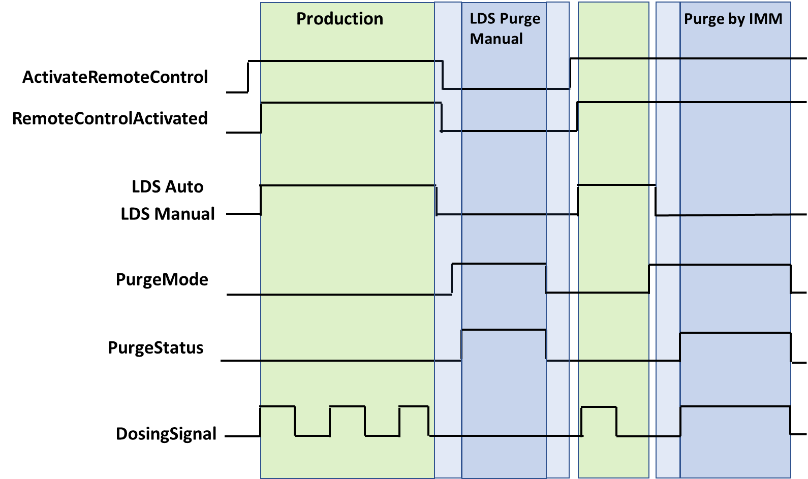
Note: "LDS Auto" and "LDS Manual" are LDS internal parameters which are not covered by this specification.
9.20 PurgeStatus
Actual status of the purge function. PurgeStatus must show OFF if no purge function is active. The PurgeStatus is also shown in Figure 3.
| Name | Value | Description |
| OFF | 0 | No purge function is active. |
| COMPONENT_A | 1 | Purge component A is active. |
| COMPONENT_B | 2 | Purge component B is active. |
| COMPONENT_A_AND_B | 3 | Venting |
| COMPONENT_A_AND_B_CYCLIC | 4 | Cyclic purge component A and B is active. |
9.21 PurgeQuantity
The PurgeQuantity is only used in relation with PurgeMode EnumValue 1-4 and describes the amount of material during the active purge mode.
Unit: cm³ or in³
9.22 PurgeTimeout
PurgeTimeout describes the maximum time of the active PurgeMode (1-5). For PurgeMode EnumValue 1-4, the PurgeMode is set to 0 after the PurgeTimeout has expired. For PurgeMode EnumValue 5, the PurgeCyclicActive is set to false, PurgeMode is unaffected.
9.23 PurgeCyclicQuantity
The PurgeCyclicQuantity is only used in relation with PurgeMode EnumValue 5 and describes the amount of material during a purge cycle as the sum of both components. After the volume is reached, the variable PurgeCyclicActive will become false and PurgeCyclicIdleTime starts.
Unit: cm³ or in³
9.24 PurgeCyclicIdleTime
The PurgeCyclicIdleTime is only used in relation with PurgeMode EnumValue 5 and describes the time until the next purge cycle starts.
9.25 PurgeCyclicActive
PurgeCyclicActive is only used in relation with PurgeMode EnumValue 5 and indicates the difference between purging (true) and waiting (false)
9.26 ActivateRemoteControl
It is necessary to synchronize the dosing between IMM and LSR dosing systems. This can be done via a separate interface e.g. via hardwired signals or also via OPC UA (if the process is robust against small time delays that can be caused by the client/server-connection). Signal 0 can be set by IMM or LDS, signals > 0 only by IMM.
With ActivateRemoteControl the client selects the method of remote control. If the server provides only one method for remote control, the other one is not listed in the possible values of the MultiStateValueDiscreteType.
| EnumValue | ValueAsText | Description |
| 0 | OFF | Remote control / automatic mode switched off. |
| 1 | SEPARATE_INTERFACE | Activating automatic mode on LDS and using a separate interface from the injection moulding machine for remote control |
| 2 | OPC_UA | Activating automatic mode on LDS and using this OPC UA connection with the methods StartDosing/StopDosing for remote control |
A server can provide manufacturer specific values with EnumValues ≥ 100.
Figure 3 shows the interaction between ActivateRemoteControl and RemoteControlActivated.
9.27 RemoteControlActivated
With this signal, the LDS signals, if it is ready to be controlled via this or a separate interface. See Table 15 for possible values.
Figure 3 shows the interaction between ActivateRemoteControl and RemoteControlActivated.
9.28 StartDosing, StopDosing, DosingActive
| Description: | If RemoteControlActivated = 2, the two Methods (without arguments) are used to start and stop the dosing. With the Variable DosingActive the LDS can inform the IMM, if dosing is really active. |
Signatures:
	StartDosing();
	StopDosing();
The methods have no Input- or OutputArguments.
| Attribute | Value | ||||
| BrowseName | StartDosing | ||||
| References | Node Class | BrowseName | DataType | TypeDefinition | Modelling Rule |
|---|
| Attribute | Value | ||||
| BrowseName | StopDosing | ||||
| References | Node Class | BrowseName | DataType | TypeDefinition | Modelling Rule |
|---|
9.29 LDSCycleParametersEventType
The LDSCycleParametersEventType represents information on a dosing cycle. A complete dosing is defined from the beginning of the dosing signal to the next one, i.e. the event for cycle n is fired, when the dosing signal for cycle n+1 starts. After the last cycle the event must be raised after a timeout which corresponds to the cycle time.
Note: The event data refer to the current injected material and not to the current dosing process (1 cycle offset).
The LDSCycleParametersEventType is formally defined in Table 18.
| Attribute | Value | ||||
| BrowseName | LDSCycleParametersEventType | ||||
| IsAbstract | True | ||||
| References | Node Class | BrowseName | DataType | TypeDefinition | Other |
|---|---|---|---|---|---|
| Subtype of 0:BaseEventType defined in OPC UA Part 5 | |||||
| 0:HasProperty | Variable | CycleNumber | 0:UInt64 | 0:PropertyType | M |
| 0:HasProperty | Variable | DosingTime | 0:Duration | 0:PropertyType | O |
| 0:HasComponent | Variable | MixingRatioTarget | 0:Double | 0:AnalogItemType | O |
| 0:HasComponent | Variable | MixingRatioActual | 0:Double | 0:AnalogItemType | O |
| 0:HasComponent | Variable | AdditivesRatioTarget | 0:Double[] | 0:AnalogItemType | O |
| 0:HasComponent | Variable | AdditivesRatioActual | 0:Double[] | 0:AnalogItemType | O |
| 0:HasComponent | Variable | VolumeA | 0:Double | 0:AnalogItemType | O |
| 0:HasComponent | Variable | VolumeB | 0:Double | 0:AnalogItemType | O |
| 0:HasComponent | Variable | VolumeAB | 0:Double | 0:AnalogItemType | O |
| 0:HasComponent | Variable | VolumeAdditives | 0:Double[] | 0:AnalogItemType | O |
| 0:HasComponent | Variable | VolumeTotal | 0:Double | 0:AnalogItemType | O |
| 0:HasComponent | Variable | ResidualAmountA | 0:Double | 0:AnalogItemType | O |
| 0:HasComponent | Variable | ResidualAmountB | 0:Double | 0:AnalogItemType | O |
| 0:HasComponent | Variable | MixingPointPressureA | 0:Double | 0:AnalogItemType | O |
| 0:HasComponent | Variable | MixingPointPressureB | 0:Double | 0:AnalogItemType | O |
| 0:HasComponent | Variable | MixingPointPressureBlender | 0:Double | 0:AnalogItemType | O |
| 0:HasComponent | Variable | AdditivesPressure | 0:Double[] | 0:AnalogItemType | O |
| 0:HasComponent | Variable | FilterPressurePrimary | 0:Double | 0:AnalogItemType | O |
| 0:HasComponent | Variable | FilterPressureSecondary | 0:Double | 0:AnalogItemType | O |
9.29.1 CycleNumber
Number of the dosing cycle. Gets counted up after each dosing cycle. The value can be set by calling the method "SetCycleNumber". It is recommended to synchronize CycleNumber after a reconnection by calling this method.
Example: 900
9.29.2 DosingTime
Duration of the dosing cycle.
9.29.3 MixingRatioTarget
Target mixing ratio of the last cycle (includes ratio change when MaterialBalanceSystem is active). The share of component A (in percent) defines the value:
| Examples: | 50 (A 50 : 50 B) without MaterialBalanceSystem |
| 51,25 | (A 51,25 : 48,75 B) active MaterialBalanceSystem |
9.29.4 MixingRatioActual
Actual mixing ratio of the components. The share of component A defines the value:
| Example: 50,9 | (A 50,9 : 49,1 B) |
9.29.5 AdditivesRatioTarget
Target ratios of additives in percentage which are set in AdditiveFraction of AdditiveType.
9.29.6 AdditivesRatioActual
Actual ratios of additives in percentage.
Example: [ 2,1 % ; 1,2 % ]
9.29.7 VolumeA
Volume of component A that was added to the process in the last cycle.
Unit: cm³ or in³
9.29.8 VolumeB
Volume of component B that was added to the process in the last cycle.
Unit: cm³ or in³
9.29.9 VolumeAB
Volume of components A + B that was added to the process in the last cycle.
Unit: cm³ or in³
9.29.10 VolumeAdditives
Volumes of the additives that were added to the process in the last cycle.
Unit: cm³ or in³
9.29.11 VolumeTotal
Volume of all components (A + B + all additives).
Unit: cm³ or in³
9.29.12 ResidualAmountA
Residual weight amount of component A at the end of the dosing cycle.
Unit: kg or lb
9.29.13 ResidualAmountB
Residual weight amount of component B at the end of the dosing cycle.
Unit: kg or lb
9.29.14 MixingPointPressureA
Average pressure of component A during the last cycle at the blender.
Unit: bar or psi
9.29.15 MixingPointPressureB
Average pressure of component B during the last cycle at the blender.
Unit: bar or psi
9.29.16 MixingPointPressureBlender
Average pressure of components A and B during the last cycle at the blender.
Unit: bar or psi
9.29.17 AdditivesPressure
Average pressure of the additive during the last cycle at the measuring point.
Unit: bar or psi
9.29.18 FilterPressurePrimary, FilterPressureSecondary
Average material pressure during the last cycle before and after the filter. The Pressure difference between FilterPressurePrimary & FilterPressureSecondary can be used to check if the filter is blocked/ will be blocked soon/ has to be maintained. Unit: bar or psi