
1 Scope
This document specifies the OPC UA Information Model to represent the Objects and services that comprise PROFIenergy (PE) Energy Management as defined in chapter 4.1. The PE Energy Management Information Model is based on PROFIenergy [PE CAP].
OPC Foundation
OPC is the interoperability standard for the secure and reliable exchange of data and information in the industrial automation space and in other industries. It is platform independent and ensures the seamless flow of information among devices from multiple vendors. The OPC Foundation is responsible for the development and maintenance of this standard.
OPC UA is a platform independent service-oriented architecture that integrates all the functionality of the individual OPC Classic specifications into one extensible framework. This multi-layered approach accomplishes the original design specification goals such as:
Platform independence: from an embedded microcontroller to cloud-based infrastructure
Secure: encryption, authentication, authorization and auditing
Extensible: ability to add new features including transports without affecting existing applications
Comprehensive Information Modelling capabilities: for defining any model from simple to complex
PROFINET Standardization Group (PNO)
The PROFIBUS and PROFINET user organization (PNO: Profibus Nutzerorganisation e. V.) was founded in 1989 and is the largest automation community in the world and responsible for PROFIBUS and PROFINET, the two most important enabling technologies in automation today. The PNO is member of PROFIBUS and PROFINET International (PI).
The common interest of the PNO global network of vendors, developers, system integrators and end users covering all industries lies in promoting, supporting and using PROFINET. Regionally and globally about 1,400 member companies are working closely together to the best automation possible. No other fieldbus organization in the world has the same kind of global influence and reach.
2 Normative references
The following referenced documents are indispensable for the application of this document. For dated references, only the edition cited applies. For undated references, the latest edition of the referenced document (including any amendments and errata) applies.
[OPC 10000-1], OPC Unified Architecture - Part 1: Overview and Concepts
OPC 10000-1
[OPC 10000-2], OPC Unified Architecture - Part 2: Security Model
OPC 10000-2
[OPC 10000-3], OPC Unified Architecture - Part 3: Address Space Model
OPC 10000-3
[OPC 10000-4], OPC Unified Architecture - Part 4: Services
OPC 10000-4
[OPC 10000-5], OPC Unified Architecture - Part 5: Information Model
OPC 10000-5
[OPC 10000-6], OPC Unified Architecture - Part 6: Mappings
OPC 10000-6
[OPC 10000-7], OPC Unified Architecture - Part 7: Profiles
OPC 10000-7
[OPC 10000-8], OPC Unified Architecture - Part 8: Data Access
OPC 10000-8
[OPC 10001-7], OPC Unified Architecture V1.04 - Amendment 7: Interfaces ad AddIns
http://www.opcfoundation.org/UA/Amendment7/
[OPC 10001-11], OPC Unified Architecture V1.04 - Amendment 11: Spatial Types
http://www.opcfoundation.org/UA/Amendment11/
[OPC 10000-100], OPC Unified Architecture - Part 100: Devices
OPC 10000-100
[PE CAP] Common Application Profile PROFIenergy - Version V1.3 - Date: September 2019 -
Order No.: 3.802
[OPC PN] OPC UA for PROFINET - Release V1.0 - Date: January 2020 -
Order No.: 30140
3 Terms, abbreviated terms and conventions
3.1 Overview
It is assumed that basic concepts of OPC UA information modelling and PROFIenergy [PE CAP] are known to understand this document. This document will use these concepts to describe the PE Energy Management Information Model. For the purposes of this document, the terms and definitions given in [OPC 10000-1], [OPC 10000-3], [OPC 10000-4], [OPC 10000-5], [OPC 10000-7], and [OPC 10000-100] as well as the following apply.
Note that OPC UA terms and terms defined in this document are italicized.
3.2 OPC UA for PROFIenergy terms
3.2.1 PE Energy Management
3.2.1.1 Untitled
PE Energy Management comprises all services allowing to retrieve Energy Measurement data and all services allowing to change the operational state with respect to its energy consumption: Standby Management and Sleep Mode WOL. PE Energy Management services are offered by devices implementing the PROFIenergy Common Application Profile (See [PE CAP]).
3.2.2 Standby Management
3.2.2.1 Untitled
Standby Management comprises the services allowing the switchover of a Standby Management Entity into an Energy Saving Mode, the change from one Energy Saving Mode into another and the transition back to normal operational state. The switchover of a Standby Management Entity into an Energy Saving Mode is only possible if the Standby Management Entity is not in operation.
3.2.3 Standby Management Entity
3.2.3.1 Untitled
A Standby Management Entity consists of specific components or functionality of the device or server which are addressed by the Standby Management services. One device or server can have more than one Standby Management Entity.
3.2.4 Energy Saving Mode
3.2.4.1 Untitled
An Energy Saving Mode is a mode of operation in which energy consumption of a Standby Management Entity is lower than in normal operational state.
3.2.5 Energy Measurement
3.2.5.1 Untitled
Energy Measurement comprises the services to retrieve energy related data from a Metering Point.
3.2.6 Metering Point
3.2.6.1 Untitled
A Metering Point defines a specific location or function block to which a set of Energy Measurement values belongs.
3.2.7 Sleep Mode WOL
3.2.7.1 Untitled
Sleep Mode WOL is a functionality affecting the whole device. It allows to switch off a device entirely and to switch on again by sending a special WOL network packet.
3.3 Abbreviated terms
| AC | Alarm and Conditions |
| HW | Hardware |
| PE | PROFIenergy |
| PE Entity | PROFIenergy Entity |
| PESAP | PROFIenergy Service Access Point |
| PROFIBUS | Process Field Bus |
| PROFINET | Process Field Bus |
| SW | Software |
| WOL | Wake-on-LAN |
3.4 Conventions used in this document
3.4.1 Conventions for Node descriptions
3.4.1.1 Node definitions
Node definitions are specified using tables (see Table 2).
Attributes are defined by providing the Attribute name and a value, or a description of the value.
References are defined by providing the ReferenceType name, the BrowseName of the TargetNode and its NodeClass.
If the TargetNode is a component of the Node being defined in the table the Attributes of the composed Node are defined in the same row of the table.
The DataType is only specified for Variables; "[<number>]" indicates a single-dimensional array, for multi-dimensional arrays the expression is repeated for each dimension (e.g. [2][3] for a two-dimensional array). For all arrays the ArrayDimensions is set as identified by <number> values. If no <number> is set, the corresponding dimension is set to 0, indicating an unknown size. If no number is provided at all the ArrayDimensions can be omitted. If no brackets are provided, it identifies a scalar DataType and the ValueRank is set to the corresponding value (see [OPC 10000-3]). In addition, ArrayDimensions is set to null or is omitted. If it can be Any or ScalarOrOneDimension, the value is put into "{<value>}", so either "{Any}" or "{ScalarOrOneDimension}" and the ValueRank is set to the corresponding value (see [OPC 10000-3]) and the ArrayDimensions is set to null or is omitted. Examples are given in Table 1.
| Notation | DataType | ValueRank | ArrayDimensions | Description |
| 0:Int32 | 0:Int32 | -1 | omitted or null | A scalar Int32. |
| 0:Int32[] | 0:Int32 | 1 | omitted or {0} | Single-dimensional array of Int32 with an unknown size. |
| 0:Int32[][] | 0:Int32 | 2 | omitted or {0,0} | Two-dimensional array of Int32 with unknown sizes for both dimensions. |
| 0:Int32[3][] | 0:Int32 | 2 | {3,0} | Two-dimensional array of Int32 with a size of 3 for the first dimension and an unknown size for the second dimension. |
| 0:Int32[5][3] | 0:Int32 | 2 | {5,3} | Two-dimensional array of Int32 with a size of 5 for the first dimension and a size of 3 for the second dimension. |
| 0:Int32{Any} | 0:Int32 | -2 | omitted or null | An Int32 where it is unknown if it is scalar or array with any number of dimensions. |
| 0:Int32{ScalarOrOneDimension} | 0:Int32 | -3 | omitted or null | An Int32 where it is either a single-dimensional array or a scalar. |
The TypeDefinition is specified for Objects and Variables.
The TypeDefinition column specifies a symbolic name for a NodeId, i.e. the specified Node points with a HasTypeDefinition Reference to the corresponding Node.
The ModellingRule of the referenced component is provided by specifying the symbolic name of the rule in the ModellingRule column. In the AddressSpace, the Node shall use a HasModellingRule Reference to point to the corresponding ModellingRule Object.
If the NodeId of a DataType is provided, the symbolic name of the Node representing the DataType shall be used.
Note that if a symbolic name of a different namespace is used, it is prefixed by the NamespaceIndex (see [OPC 10000-3]).
Nodes of all other NodeClasses cannot be defined in the same table; therefore, only the used ReferenceType, their NodeClass and their BrowseName are specified. A reference to another part of this document points to their definition.
Table 2 illustrates the table. If no components are provided, the DataType, TypeDefinition and Other columns may be omitted and only a Comment column is introduced to point to the Node definition.
| Attribute | Value | ||||
| Attribute name | Attribute value. If it is an optional Attribute that is not set "--" is used. | ||||
| References | NodeClass | BrowseName | DataType | TypeDefinition | Other |
|---|---|---|---|---|---|
| ReferenceType name | NodeClass of the TargetNode. | BrowseName of the target Node. | DataType of the referenced Node, only applicable for Variables. | TypeDefinition of the referenced Node, only applicable for Variables and Objects. | Additional characteristics of the TargetNode such as the ModellingRule or AccessLevel. |
| NOTE Notes referencing footnotes of the table content. | |||||
Components of Nodes can be complex that is containing components by themselves. The TypeDefinition, NodeClass and DataType can be derived from the type definitions, and the symbolic name can be created as defined in [OPC 10000-6]. Therefore, those containing components are not explicitly specified; they are implicitly specified by the type definitions.
The Other column defines additional characteristics of the Node. Examples of characteristics that can appear in this column are show in Table 3.
| Name | Short Name | Description |
| 0:Mandatory | M | The Node has the Mandatory ModellingRule. |
| 0:Optional | O | The Node has the Optional ModellingRule. |
| 0:MandatoryPlaceholder | MP | The Node has the MandatoryPlaceholder ModellingRule. |
| 0:OptionalPlaceholder | OP | The Node has the OptionalPlaceholder ModellingRule. |
| ReadOnly | RO | The Node AccessLevel has the CurrentRead bit set but not the CurrentWrite bit. |
| ReadWrite | RW | The Node AccessLevel has the CurrentRead and CurrentWrite bits set. |
| WriteOnly | WO | The Node AccessLevel has the CurrentWrite bit set but not the CurrentRead bit. |
If multiple characteristics are defined, they are separated by commas. The name or the short name may be used.
3.4.1.2 Additional References
To provide information about additional References, the format as shown in Table 4 is used.
| SourceBrowsePath | Reference Type | Is Forward | TargetBrowsePath |
| SourceBrowsePath is always relative to the TypeDefinition. Multiple elements are defined as separate rows of a nested table. | ReferenceType name | True = forward Reference. | TargetBrowsePath points to another Node, which can be a well-known instance or a TypeDefinition. You can use BrowsePaths here as well, which is either relative to the TypeDefinition or absolute. If absolute, the first entry needs to refer to a type or well-known instance, uniquely identified within a namespace by the BrowseName. |
References can be to any other Node.
3.4.1.3 Additional sub-components
To provide information about sub-components, the format as shown in Table 5 is used.
| BrowsePath | References | NodeClass | BrowseName | DataType | TypeDefinition | Others |
| BrowsePath is always relative to the TypeDefinition. Multiple elements are defined as separate rows of a nested table | NOTE Same as for Table 2 | |||||
3.4.2 NodeIds and BrowseNames
3.4.2.1 NodeIds
The NodeIds of all Nodes described in this standard are only symbolic names. [OPC 10000-6] defines the actual NodeIds.
The symbolic name of each Node defined in this document is its BrowseName, or, when it is part of another Node, the BrowseName of the other Node, a ".", and the BrowseName of itself. In this case "part of" means that the whole has a HasProperty or HasComponent Reference to its part. Since all Nodes not being part of another Node have a unique name in this document, the symbolic name is unique.
The NamespaceUri for all NodeIds defined in this document is defined in Annex A. The NamespaceIndex for this NamespaceUri is vendor-specific and depends on the position of the NamespaceUri in the server namespace table.
Note that this document not only defines concrete Nodes, but also requires that some Nodes shall be generated, for example one for each Session running on the Server. The NodeIds of those Nodes are Server-specific, including the namespace. But the NamespaceIndex of those Nodes cannot be the NamespaceIndex used for the Nodes defined in this document, because they are not defined by this document but generated by the Server.
3.4.2.2 BrowseNames
The text part of the BrowseNames for all Nodes defined in this document is specified in the tables defining the Nodes. The NamespaceUri for all BrowseNames defined in this document is defined in Annex A.
For InstanceDeclarations of NodeClass Object and Variable that are placeholders (OptionalPlaceholder and MandatoryPlaceholder ModellingRule), the BrowseName and the DisplayName are enclosed in angle brackets (<>) as recommended in [OPC 10000-3].
If the BrowseName is not defined by this document, a namespace index prefix like '0:EngineeringUnits' or '2:DeviceRevision' is added to the BrowseName. This is typically necessary if a Property of another specification is overwritten or used in the OPC UA types defined in this document. Table 70 provides a list of namespaces and their indexes as used in this document.
3.4.3 Common Attributes
3.4.3.1 General
The Attributes of Nodes, their DataTypes and descriptions are defined in [OPC 10000-3]. Attributes not marked as optional are mandatory and shall be provided by the Server. The following tables define if the Attribute value is defined by this document or if it is server-specific.
For all Nodes specified in this document, the Attributes named in Table 6 shall be set as specified in the table.
| Attribute | Value |
| DisplayName | The DisplayName is a LocalizedText. Each server shall provide the DisplayName identical to the BrowseName of the Node for the LocaleId "en". Whether the server provides translated names for other LocaleIds are server-specific. |
| Description | Optionally a server-specific description is provided. |
| NodeClass | Shall reflect the NodeClass of the Node. |
| NodeId | The NodeId is described by BrowseNames as defined in 3.4.2.1. |
| WriteMask | Optionally the WriteMask Attribute can be provided. If the WriteMask Attribute is provided, it shall set all non-server-specific Attributes to not writable. For example, the Description Attribute may be set to writable since a Server may provide a server-specific description for the Node. The NodeId shall not be writable, because it is defined for each Node in this document. |
| UserWriteMask | Optionally the UserWriteMask Attribute can be provided. The same rules as for the WriteMask Attribute apply. |
| RolePermissions | Optionally server-specific role permissions can be provided. |
| UserRolePermissions | Optionally the role permissions of the current Session can be provided. The value is server-specific and depends on the RolePermissions Attribute (if provided) and the current Session. |
| AccessRestrictions | Optionally server-specific access restrictions can be provided. |
3.4.3.2 Objects
For all Objects specified in this document, the Attributes named in Table 7 shall be set as specified in the table. The definitions for the Attributes can be found in [OPC 10000-3].
| Attribute | Value |
| EventNotifier | Whether the Node can be used to subscribe to Events or not is server-specific. |
3.4.3.3 Variables
For all Variables specified in this document, the Attributes named in Table 8 shall be set as specified in the table. The definitions for the Attributes can be found in [OPC 10000-3].
| Attribute | Value |
| MinimumSamplingInterval | Optionally, a server-specific minimum sampling interval is provided. |
| AccessLevel | The access level for Variables used for type definitions is server-specific, for all other Variables defined in this document, the access level shall allow reading; other settings are server-specific. |
| UserAccessLevel | The value for the UserAccessLevel Attribute is server-specific. It is assumed that all Variables can be accessed by at least one user. |
| Value | For Variables used as InstanceDeclarations, the value is server-specific; otherwise it shall represent the value described in the text. |
| ArrayDimensions | If the ValueRank does not identify an array of a specific dimension (i.e. ValueRank <= 0) the ArrayDimensions can either be set to null or the Attribute is missing. This behaviour is server-specific. If the ValueRank specifies an array of a specific dimension (i.e. ValueRank > 0) then the ArrayDimensions Attribute shall be specified in the table defining the Variable. |
| Historizing | The value for the Historizing Attribute is server-specific. |
| AccessLevelEx | If the AccessLevelEx Attribute is provided, it shall have the bits 8, 9, and 10 set to 0, meaning that read and write operations on an individual Variable are atomic, and arrays can be partly written. |
3.4.3.4 VariableTypes
For all VariableTypes specified in this document, the Attributes named in Table 9 shall be set as specified in the table. The definitions for the Attributes can be found in [OPC 10000-3].
| Attributes | Value |
| Value | Optionally a server-specific default value can be provided. |
| ArrayDimensions | If the ValueRank does not identify an array of a specific dimension (i.e. ValueRank <= 0) the ArrayDimensions can either be set to null or the Attribute is missing. This behaviour is server-specific. If the ValueRank specifies an array of a specific dimension (i.e. ValueRank > 0) then the ArrayDimensions Attribute shall be specified in the table defining the VariableType. |
3.4.3.5 Methods
For all Methods specified in this document, the Attributes named in Table 10 shall be set as specified in the table. The definitions for the Attributes can be found in [OPC 10000-3].
| Attributes | Value |
| Executable | All Methods defined in this document shall be executable (Executable Attribute set to "True"), unless it is defined differently in the Method definition. |
| UserExecutable | The value of the UserExecutable Attribute is server-specific. It is assumed that all Methods can be executed by at least one user. |
4 General information to PE Energy Management and OPC UA
4.1 Introduction to PE Energy Management
4.1.1 General
PE Energy Management comprises all services allowing to obtain energy related information and to control the state of all energy manageable entities contained in the PE Energy Information Model. The PE Energy Information Model is based on the PROFIenergy profile [PE CAP]. The PE Energy Management functions defined in this specification are separated into three main categories: Standby Management, Energy Measurement, and Sleep Mode WOL.
4.1.2 Standby Management
Standby Management allows a device or parts of a device to switch into an Energy Saving Mode if not in operation or engaged. If a Standby Management Entity supports more than one Energy Saving Mode (with different levels of energy consumption), transitions from one Energy Saving Mode into another might be possible. For the smooth integration of devices with Standby Management functionality into a production process, Standby Management offers commands to issue the transition into an Energy Saving Mode and the termination of an Energy Saving Mode with switchback to normal operation.
Devices might also support Sleep Mode WOL functionality allowing to completely switch off a device. If this Sleep Mode WOL functionality is active, the device in Sleep Mode WOL is not reachable for network communication and can only be 'awakened' by receiving a 'WOL magic packet'.
Standby Management defines a state model determining the possible state transitions. Figure 1 shows the state model.
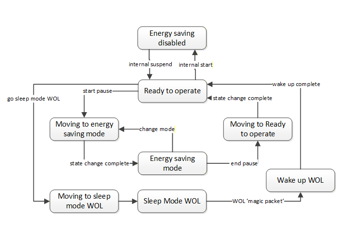
When in 'Energy saving disabled' state, the device is in normal operation and does not accept standby commands. In the 'Ready to operate' state the device accepts standby commands. When in transition to or from an Energy Saving Mode, the device has a 'Moving to …' transition state. Thus the state model reflects the physical properties of a real-world device: Changes in energy consumption imply changes of some physical processes which will always be time consuming.
Standby Management is made available for OPC UA Clients with the ObjectTypes defined in chapter 8.1 "Standby Management".
Status information functionality of Standby Management provides information about the current state of a Standby Management Entity, the current energy consumption, the available Energy Saving Modes and their detailed characteristics.
The current state information of a Standby Management Entity is made available for OPC UA Clients with the EnergySavingModeStatusType (chapter 8.1.3) referenced by the EnergyStandbyManagementType.
Detailed information about a specific Energy Saving Mode is provided by the EnergySavingModeType defined in chapter 8.1.4.
4.1.3 Energy Measurement
Energy Measurement functionality allows the retrieval of energy related measurement values. Possible Energy Measurement values offered are energy counters, current power consumption, active and reactive power, frequency, voltage, current, information about maximum and minimum values of the former, and more. Furthermore, the Energy Measurement is not limited to electrical energy. In addition, different Metering Points of a device can be distinguished.
In general, the number and type of Energy Measurement values provided are vendor specific. For simplification and standardization, specific EnergyProfile types are defined which comprise a predefined set of measurement values together with a guaranteed measurement accuracy. However, when proxying the PROFIenergy Profile, additional measurement values are already defined (See [PE CAP] for details).
Energy Measurement is made available for OPC UA Clients with the ObjectTypes defined in chapter 8.2 "Energy Measurement".
4.1.4 Sleep Mode WOL
The Sleep Mode WOL functionality allows to entirely switch off the device, including the network interface, and to switch on again by using the standard WOL (Wake-on-LAN) mechanism. The transition to the Sleep Mode WOL state is initiated by invoking the SwitchOffWOL Method of the EnergyDevicePowerOffType.
If the switched off device contains the OPC UA server, the connection of the OPC client to the server disconnects. The server will be reachable again after a wake up of the device by Wake-on-LAN (sending the WOL magic wake-up packet).
4.2 Introduction to OPC Unified Architecture
4.2.1 What is OPC UA?
OPC UA is an open and royalty free set of standards designed as a universal communication protocol. While there are numerous communication solutions available, OPC UA has key advantages:
A state of art security model (see [OPC 10000-2]).
A fault tolerant communication protocol.
An information modelling framework that allows application developers to represent their data in a way that makes sense to them.
OPC UA has a broad scope which delivers for economies of scale for application developers. This means that a larger number of high-quality applications at a reasonable cost are available. When combined with semantic models such as PROFIenergy, OPC UA makes it easier for end users to access data via generic commercial applications.
The OPC UA model is scalable from small devices to ERP systems. OPC UA Servers process information locally and then provide that data in a consistent format to any application requesting data - ERP, MES, PMS, Maintenance Systems, HMI, Smartphone or a standard Browser, for examples. For a more complete overview see [OPC 10000-1].
4.2.2 Basics of OPC UA
OPC UA is an open standard based on internet technologies like TCP/IP, HTTP, Web Sockets.
As an extensible standard, OPC UA provides a set of Services (see [OPC 10000-4]) and a basic Information Model framework. This framework provides an easy manner for creating and exposing vendor defined information in a standard way. More importantly all OPC UA Clients are expected to be able to discover and use vendor-defined information. This means OPC UA users can benefit from the economies of scale that come with generic visualization and historian applications. This specification is an OPC UA Information Model designed to meet the needs of developers and users.
OPC UA Clients can be any consumer of data from another device on the network to browser based thin Clients and ERP systems. The full scope of OPC UA applications is shown in Figure 2.

OPC UA provides a robust and reliable communication infrastructure having mechanisms for handling lost messages, failover, heartbeat, etc. With its binary encoded data, it offers a high-performing data exchange solution. Security is built into OPC UA as security requirements become more and more important especially since environments are connected to the office network or the internet and attackers are starting to focus on automation systems.
4.2.3 Information modelling in OPC UA
4.2.3.1 Concepts
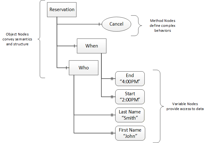
OPC UA provides a framework that can be used to represent complex information as Objects in an AddressSpace which can be accessed with standard services. These Objects consist of Nodes connected by References. Different classes of Nodes convey different semantics. For example, a Variable Node represents a value that can be read or written. The Variable Node has an associated DataType that can define the actual value, such as a string, float, structure etc. It can also describe the Variable value as a variant. A Method Node represents a function that can be called. Every Node has a number of Attributes including a unique identifier called a NodeId and non-localized name called as BrowseName. An Object representing a 'Reservation' is shown in Figure 3.
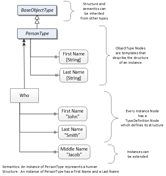
Object and Variable Nodes represent instances and they always reference a TypeDefinition (ObjectType or VariableType) Node which describes their semantics and structure. Figure 4 illustrates the relationship between an instance and its TypeDefinition.
The type Nodes are templates that define all of the children that can be present in an instance of the type. In the example in Figure 4 the PersonType ObjectType defines two children: First Name and Last Name. All instances of PersonType are expected to have the same children with the same BrowseNames. Within a type the BrowseNames uniquely identify the children. This means Client applications can be designed to search for children based on the BrowseNames from the type instead of NodeIds. This eliminates the need for manual reconfiguration of systems if a Client uses types that multiple Servers implement.
OPC UA also supports the concept of sub-typing. This allows a modeller to take an existing type and extend it. There are rules regarding sub-typing defined in [OPC 10000-3], but in general they allow the extension of a given type or the restriction of a DataType. For example, the modeller may decide that the existing ObjectType in some cases needs an additional Variable. The modeller can create a subtype of the ObjectType and add the Variable. A Client that is expecting the parent type can treat the new type as if it was of the parent type. Regarding DataTypes, subtypes can only restrict. If a Variable is defined to have a numeric value, a sub type could restrict it to a float.
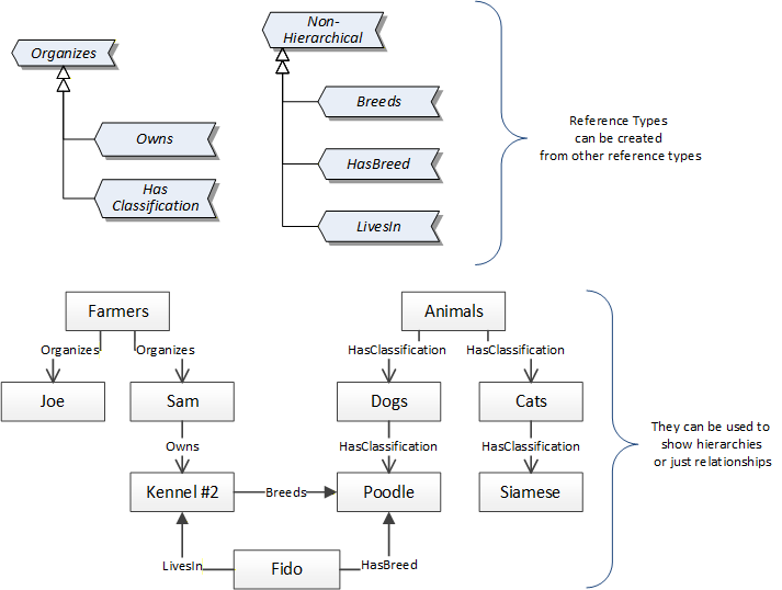
References allow Nodes to be connected in ways that describe their relationships. All References have a ReferenceType that specifies the semantics of the relationship. References can be hierarchical or non-hierarchical. Hierarchical References are used to create the structure of Objects and Variables. Non-hierarchical are used to create arbitrary associations. Applications can define their own ReferenceType by creating subtypes of an existing ReferenceType. Subtypes inherit the semantics of the parent but may add additional restrictions. Figure 5 depicts several References, connecting different Objects.
The figures above use a notation that was developed for the OPC UA specification. The notation is summarized in Figure 6. UML representations can also be used; however, the OPC UA notation is less ambiguous because there is a direct mapping from the elements in the figures to Nodes in the AddressSpace of an OPC UA Server.
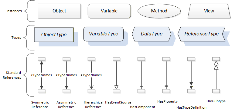
A complete description of the different types of Nodes and References can be found in [OPC 10000-3] and the base structure is described in [OPC 10000-5].
OPC UA specification defines a very wide range of functionality in its basic Information Model. It is not required that all Clients or Servers support all functionality in the OPC UA specifications. OPC UA includes the concept of Profiles, which segment the functionality into testable certifiable units. This allows the definition of functional subsets (that are expected to be implemented) within a companion specification. The Profiles do not restrict functionality, but generate requirements for a minimum set of functionality (see [OPC 10000-7])
4.2.3.2 Namespaces
OPC UA allows information from many different sources to be combined into a single coherent AddressSpace. Namespaces are used to make this possible by eliminating naming and id conflicts between information from different sources. Each namespace in OPC UA has a globally unique string called a NamespaceUri which identifies a naming authority and a locally unique integer called a NamespaceIndex, which is an index into the Server's table of NamespaceUris. The NamespaceIndex is unique only within the context of a Session between an OPC UA Client and an OPC UA Server- the NamespaceIndex can change between Sessions and still identify the same item even though the NamespaceUri's location in the table has changed. The Services defined for OPC UA use the NamespaceIndex to specify the Namespace for qualified values.
There are two types of structured values in OPC UA that are qualified with NamespaceIndexes: NodeIds and QualifiedNames. NodeIds are locally unique (and sometimes globally unique) identifiers for Nodes. The same globally unique NodeId can be used as the identifier in a Node in many Servers - the Node's instance data may vary but its semantic meaning is the same regardless of the Server it appears in. This means Clients can have built-in knowledge of what the data means in these Nodes. OPC UA Information Models generally define globally unique NodeIds for the TypeDefinitions defined by the Information Model.
QualifiedNames are non-localized names qualified with a Namespace. They are used for the BrowseNames of Nodes and allow the same names to be used by different Information Models without conflict. TypeDefinitions are not allowed to have children with duplicate BrowseNames; however, instances do not have that restriction.
4.2.3.3 Companion Specifications
An OPC UA companion specification for an industry specific vertical market describes an Information Model by defining ObjectTypes, VariableTypes, DataTypes and ReferenceTypes that represent the concepts used in the vertical market, and potentially also well-defined Objects as entry points into the AddressSpace.
5 Use cases
Table 11 lists possible use cases of interest for OPC UA Clients. Typically, the use case implementation consists of data retrieval with OPC UA, utilisation of OPC UA standard mechanisms like subscriptions and downstream data processing on the client site.
The use cases are supported by OPC UA Servers running directly on the device or by proxy Servers offering OPC UA access for devices discovered with PROFINET services (according to the Edge gateway use case in [OPC PN], chapter 5.2.2).
6 PE Energy Management Information Model
The PE Energy Management functionality and the Energy Measurement data are accessible for Clients directly when browsing the components of the "EnergyManagement" folder. Figure 7 shows an overview of the structural organization of the energy related functionality.
Devices offering Energy Measurement functionality provide EnergyMeasurementType Objects. Each EnergyMeasurementType Object contains the measurement values belonging to a specific Metering Point. A device can support an arbitrary number of Metering Points.
Devices offering Standby Management provide EnergyStandbyManagementType Objects. Each EnergyStandbyManagementType Object contains an EnergySavingModes container Object referencing EnergySavingModeType Objects that represent all available Energy Saving Modes (the EnergySavingModeType Objects are not visible in the Figure 7).
A device might support multiple EnergyStandbyManagementType Objects. Each EnergyStandbyManagementType Object represents one Standby Management Entity.
By invoking the StartPause Method of the EnergyStandbyManagementType Object, Clients can initiate the transition into an Energy Saving Mode.
The EnergyDevicePowerOffType Object provides access to the devices' Sleep Mode WOL if supported. Clients can initiate the transition into the Sleep Mode WOL by invoking the SwitchOffWOL Method.
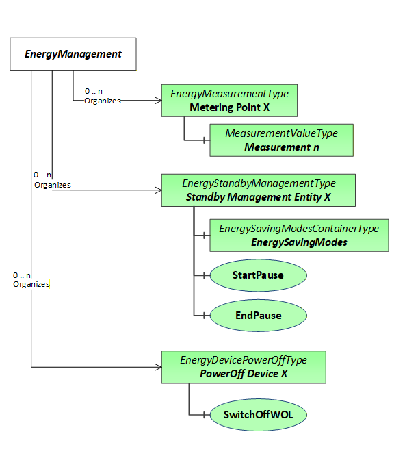
Figure 8 shows the relationship between the PE Energy Management model and the other functional parts of the application model. HasEnergyMeasurement References connect the functional parts of the model with related EnergyMeasurementType Objects providing Energy Measurement values. HasEnergyStandbyManagement References connect the functional parts of the model offering Standby Management functions with related EnergyStandbyManagementType Objects. The EnergyDevicePowerOffType Object has no Reference to a functional part since the entire device is affected by power off.
Figure 8 shows a device with two main functional parts: The DriveConveyor Object is a functional part supporting Energy Measurement only. The Heating Object is a functional part supporting Energy Measurement and Standby Management.
For EnergyDevicePowerOffType Objects no association with a functional part is appropriate.
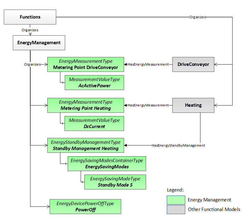
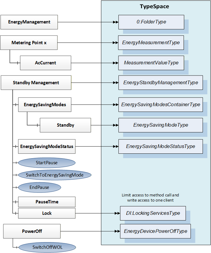
Figure 9 shows the detailed PE Energy Management's Information Model with the whole Object structure and the related type definitions. The figure contains the three basic independent root Objects for energy Standby Management, Energy Measurement and Sleep Mode WOL.
A LockingServicesType Object (defined in OPC 10000-100) is part of the EnergyStandbyManagementType Object to ensure that only one Client can control the Standby Management related functions.
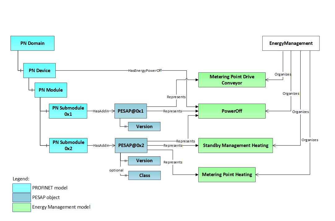
7 PROFIenergy Service Access Point Information Model
A connection of the PE Energy Management Information Model with the PROFINET model using PESAP Objects as shown in Figure 10 may be provided. The PESAP@PN Object represents the PROFIenergy Entity (PE Entity). A PE Entity comprises all PE Energy Management services accessible through one service access point (SAP). For a PROFINET device, a dedicated submodule is the service access point for the PROFIenergy functionality of one PE Entity. The connection with the PROFINET submodule is provided with a HasAddin Reference.
One device can have more than one service access points thus containing more than one PE Entity.
The 'Represents' References pointing to the Standby Management Object, the Energy Measurement Objects and the PowerOff Object allow to browse the PN Submodule representing the PROFIenergy service access point (PESAP) from the PE Energy Management Information Model.
The properties attributed to a specific PE Entity in the PROFIenergy Object model like PROFIenergy version and PROFIenergy class are available through a PESAP Object.
Figure 10 shows that all PE Energy Management Object instances (EnergyStandbyManagementType Object, EnergyMeasurementType Objects and EnergyDevicePowerOffType Object) are connected to a related PESAP Object using Represents References.
8 OPC UA ObjectTypes
8.1 Standby Management
8.1.1 EnergyStandbyManagementType
The EnergyStandbyManagementType ObjectTypes provide access to the Standby Management functionality of one Standby Management Entity. Parallel access of Clients to the read only data shall be possible but write operations and Method invocation can be limited to one Client at a time with the Lock Object.
| Attribute | Value | ||||
| BrowseName | EnergyStandbyManagementType | ||||
| IsAbstract | False | ||||
| References | Node Class | BrowseName | DataType | TypeDefinition | Other |
|---|---|---|---|---|---|
| Subtype of the BaseObjectType defined in [OPC 10000-5]. | |||||
| 0:HasComponent | Variable | StandbyManagementStatus | Byte | 0:MultiStateDiscreteType | M, RO |
| 0:HasComponent | Object | EnergySavingModeStatus | EnergySavingModeStatusType | M | |
| 0:HasComponent | Object | EnergySavingModes | EnergySavingModesContainerType | O | |
| 0:HasComponent | Variable | PauseTime | 0:Duration | 0:BaseDataVariableType | M, RW |
| 0:HasComponent | Object | 2:Lock | 2:LockingServicesType | O | |
| 0:HasComponent | Method | StartPause | O | ||
| 0:HasComponent | Method | EndPause | O | ||
| 0:HasComponent | Method | SwitchToEnergySavingMode | O | ||
The StandbyManagementStatus Variable shall contain the current state of the Standby Management. The value of this Variable shall be consistent with the content of the EnergySavingModeStatus Object.
The values of the 0:EnumStrings of the StandbyManagementStatus shall follow the definition of Table 13. Each instance shall have the values 0 to 8. Element numbers 9-15 are reserved for future use. If vendors add specific elements, the range 9-15 shall be filled with 'null'-strings.
| Element number (starting with 0) | Message (for locale "en") |
| 0 | Energy saving disabled |
| 1 | Power Off |
| 2 | Ready to operate |
| 3 | Moving to Energy Saving Mode |
| 4 | Energy saving mode |
| 5 | Moving to ready to operate |
| 6 | Moving to Sleep mode WOL |
| 7 | Sleep mode WOL |
| 8 | Wake up WOL |
| 9-15 | 'null'-String |
| 16 - 255 | Vendor specific |
The Variables of the EnergyStandbyManagementType have additional Attributes defined in Table 14
| Source Path | Value Attribute | ||
| Energy saving disabled Power Off Ready to operate Moving to Energy Saving Mode Energy saving mode Moving to ready to operate Moving to Sleep mode WOL Sleep mode WOL Wake up WOL |
The EnergySavingModes container Object contains References to EnergySavingModeType Objects representing the supported Energy Saving Modes.
Writing the PauseTime Variable can be used to update the pause time alternatively to the StartPause Method. Setting the PauseTime Variable with a value not equal to 0 shall have the same effect as invoking the StartPause Method passing the PauseTime value. Setting the PauseTime Variable with a value equal to 0 shall have the same effect as invoking the EndPause Method. An additional benefit is that the Variable PauseTime can be used in a PubSub communication scenario where the PauseTime is distributed by a central time management client using a broadcast telegram to which every Standby Management Entity subscribes.
The Lock Object ensures exclusive write access and Method call for one client. Write access and Method calls from Clients shall be blocked unless the client has locked the Object by invoking the InitLock Method of the Lock Object.
The StartPause Method starts the transition to an Energy Saving Mode. The SwitchToEnergySavingMode allows the transition into a specific Energy Saving Mode. The EndPause Method ends the Energy Saving Mode.
A RepresentedBy Reference may connect the Object to the representing PROFIenergy service access point Object (see PeServiceAccessPointType). The BrowseName of the Reference shall be "PESAP".
8.1.1.1 StartPause Method
This Method starts the transition into an Energy Saving Mode.
Signature
	StartPause (
		[in]  0:Duration	PauseTime
		[out] 0:Byte		ModeID
		[out] 0:Duration	CurrentTimeToDestination
		[out] 0:Duration	RegularTimeToOperate
		[out] 0:Duration	TimeMinLengthOfStay
		[out] 0:Byte		ReturnCode
		);
| Argument | Description |
| PauseTime | Requested pause time. |
| ModeID | ID of the destination Energy Saving Mode if successful, otherwise 0. |
| CurrentTimeToDestination | Time needed to reach the Energy Saving Mode if successful, otherwise 0. |
| RegularTimeToOperate | Time needed to reach "Ready to operate" again if the destination Energy Saving Mode will be regularly terminated if successful, otherwise 0. |
| TimeMinLengthOfStay | Time of minimum stay in the destination Energy Saving Mode if successful, otherwise 0. |
| ReturnCode | Return code. See Table 16. |
The Method Result Codes (defined in Call Service) are defined in Table 15.
8.1.1.2 SwitchToEnergySavingMode Method
This Method initiates a switch to a certain Energy Saving Mode.
Signature
	SwitchToEnergySavingMode (
		[in]  0:Byte		ModeID
	[out] 0:Byte		EffectiveModeID
	[out] 0:Duration	CurrentTimeToDestination
		[out] 0:Duration	RegularTimeToOperate
		[out] 0:Duration	TimeMinLengthOfStay
		[out] 0:Byte		ReturnCode
		);
| Argument | Description |
| ModeID | ID of the requested Energy Saving Mode. |
| EffectiveModeID | ID of the effectively chosen Energy Saving Mode if successful, otherwise ID of current mode. |
| CurrentTimeToDestination | Time needed to reach the destination Energy Saving Mode if successful, otherwise 0. |
| RegularTimeToOperate | Time needed to reach "Ready to operate" again if the destination Energy Saving Mode will be regularly terminated if successful, otherwise 0. |
| TimeMinLengthOfStay | Time of minimum stay in the destination Energy Saving Mode if successful, otherwise 0. |
| ReturnCode | Return code. See table Table 16. |
The Method Result Codes (defined in Call Service) are defined in Table 15.
8.1.1.3 EndPause Method
This Method ends the current Energy Saving Mode.
Signature
	EndPause (
		[out] 0:Duration	CurrentTimeToOperate
		[out] 0:Byte		ReturnCode
		);
| Argument | Description |
| CurrentTimeToOperate | Time needed to reach "Ready to operate" if successful, 0. |
| ReturnCode | Return code. See table Table 16. |
The Method Result Codes (defined in Call Service) are defined in Table 15.
Table 15 shows the possible values for the Method call result codes.
| Result Code | Description |
| Good | The Method execution was successful and the ReturnCode parameter has the value 0x00 ("Success") |
| Uncertain | The Method execution was successful, but the ReturnCode parameter indicates an error. |
| Bad_UserAccessDenied | The user has not the right to execute the Method. The client shall not evaluate the ReturnCode parameter. |
| Bad_UnexpectedError | The server is not able to execute the function because an unexpected error occurred. The device might be temporarily unavailable or unreachable due to network failure. The client shall not evaluate the ReturnCode parameter. |
Table 16 shows the possible values for the out parameter ReturnCode.
| ReturnCode | Description |
| 0x00 | Success. |
| 0x50 | No suitable energy-saving mode available. |
| 0x52 | No switch to requested energy-saving mode because of invalid mode ID. |
| 0x53 | No switch to Energy Saving Mode because of state operate. |
| 0x54 | Service or function not available due to internal device status. |
8.1.2 EnergySavingModesContainerType
| Attribute | Value | ||||
| BrowseName | EnergySavingModesContainerType | ||||
| IsAbstract | False | ||||
| References | Node Class | BrowseName | DataType | TypeDefinition | Other |
|---|---|---|---|---|---|
| Subtype of the BaseObjectType defined in [OPC 10000-5]. | |||||
| 0:HasComponent | Object | <EnergySavingModes> | EnergySavingModeType | MP | |
8.1.3 EnergySavingModeStatusType
| Attribute | Value | ||||
| BrowseName | EnergySavingModeStatusType | ||||
| IsAbstract | False | ||||
| References | Node Class | BrowseName | DataType | TypeDefinition | Other |
|---|---|---|---|---|---|
| Subtype of the BaseObjectType defined in [OPC 10000-5]. | |||||
| 0:HasComponent | Variable | CurrentTransitionData | StandbyModeTransitionDataType | 0:BaseDataVariableType | O, RO |
| 0:HasComponent | Variable | StateInformation | EnergyStateInformationDataType | 0:BaseDataVariableType | M, RO |
The CurrentTransitionData Variable contains details for the state transition indicated by the StateInformation Variable.
The StateInformation Variable contains details for the actual Energy Saving Mode state.
8.1.4 EnergySavingModeType
The EnergySavingModeType provides detailed information for a specific Energy Saving Mode.
| Attribute | Value | ||||
| BrowseName | EnergySavingModeType | ||||
| IsAbstract | False | ||||
| References | Node Class | BrowseName | DataType | TypeDefinition | Other |
|---|---|---|---|---|---|
| Subtype of the BaseObjectType defined in [OPC 10000-5]. | |||||
| 0:HasProperty | Variable | ID | 0:Byte | 0:PropertyType | M, RO |
| 0:HasProperty | Variable | DynamicData | 0:Boolean | 0:PropertyType | M, RO |
| 0:HasComponent | Variable | TimeMinPause | 0:Duration | 0:BaseDataVariableType | M, RO |
| 0:HasComponent | Variable | TimeToPause | 0:Duration | 0:BaseDataVariableType | M, RO |
| 0:HasComponent | Variable | TimeMinLengthOfStay | 0:Duration | 0:BaseDataVariableType | M, RO |
| 0:HasComponent | Variable | TimeMaxLengthOfStay | 0:Duration | 0:BaseDataVariableType | M, RO |
| 0:HasComponent | Variable | RegularTimeToOperate | 0:Duration | 0:BaseDataVariableType | M, RO |
| 0:HasComponent | Variable | ModePowerConsumption | 0:Float | 0:AnalogUnitType | M, RO |
| 0:HasComponent | Variable | EnergyConsumptionToPause | 0:Float | 0:AnalogUnitType | M, RO |
| 0:HasComponent | Variable | EnergyConsumptionToOperate | 0:Float | 0:AnalogUnitType | M, RO |
The BrowseName shall contain a unique name for the Energy Saving Mode.
The ID Variable shall contain a unique mode ID for the Energy Saving Mode. The mode ID's 0x00, 0xF0, 0xFE and 0xFF are reserved for predefined states.
DynamicData shall indicate whether the time, energy consumption and power values can vary (slightly) during runtime.
The TimeMinPause Variable shall contain the minimum pause time for this Energy Saving Mode.
The TimeToPause Variable shall contain the expected time to switch to this Energy Saving Mode.
The TimeMinLengthOfStay Variable shall contain the time of minimum stay in this Energy Saving Mode.
The TimeMaxLengthOfStay Variable shall contain the time of maximum stay in this Energy Saving Mode.
The RegularTimeToOperate Variable shall contain the time value to reach "Ready to operate" (see Figure 1) if this Energy Saving Mode will be regularly terminated.
The ModePowerConsumption Variable shall contain the power consumption in this Energy Saving Mode. Unit: [kW].
The EnergyConsumptionToPause Variable shall contain the energy consumption from "Ready to operate" to this Energy Saving Mode. Unit: [kWh].
The EnergyConsumptionToOperate Variable shall contain the energy consumption from this Energy Saving Mode to "Ready to operate". Unit: [kWh].
Mapping to PROFIenergy properties:
| BrowseName | PE Service | PE Service Data Response Field |
| ID | List_Energy_Saving_Modes | PE_Mode_ID |
| TimeMinPause | Get_Mode | Time_min_Pause |
| TimeToPause | Get_Mode | Time_to_Pause |
| TimeMinLengthOfStay | Get_Mode | Time_min_length_of_stay |
| TimeMaxLengthOfStay | Get_Mode | Time_max_length_of_stay |
| RegularTimeToOperate | Get_Mode | Regular_time_to_operate |
| ModePowerConsumption | Get_Mode | Mode_Power_Consumption |
| EnergyConsumptionToPause | Get_Mode | Energy_Consumption_to_pause |
| EnergyConsumptionToOperate | Get_Mode | Energy_Consumption_to_operate |
8.2 Energy Measurement
8.2.1 Overview
The Energy Measurement Objects provide access to the Energy Measurement values. For each Metering Point one EnergyMeasurementType Object shall exist.
8.2.2 EnergyMeasurementType
The EnergyMeasurementType contains References to MeasurementValueType Objects.
| Attribute | Value | ||||
| BrowseName | EnergyMeasurementType | ||||
| IsAbstract | False | ||||
| References | Node Class | BrowseName | DataType | TypeDefinition | Other |
|---|---|---|---|---|---|
| Subtype of the BaseObjectType | |||||
| 0:HasProperty | Variable | PeObjectNumber | 0:UInt16 | 0:PropertyType | M, RO |
| 0:HasComponent | Variable | <MeasurementValue> | 0:Number | MeasurementValueType | MP, RO |
| 0:HasComponent | Method | ResetEnergyCounter | O | ||
The PeObjectNumber Variable shall contain the Object number of the related PROFIenergy measurement Object.
The MeasurementValue Variable contains one actual measurement value. For each measurement value of a Metering Point one MeasurementValueType Variable shall exist.
If one of the MeasurementValueType Variables is used as energy counter, the ResetEnergyCounter Method can be used to set the value of this Variable to 0. See section 9.1, "MeasurementValueType" for further details.
A RepresentedBy Reference may connect the Object to the representing PROFIenergy service access point Object (see PeServiceAccessPointType). The BrowseName of the Reference shall be "PESAP". If the PESAP is not part of the Information Model, the RepresentedBy Reference in the EnergyMeasurementType Object is omitted.
Mapping to PROFIenergy properties:
| BrowseName | PE Service | PE Service Data Response Field |
| PeObjectNumber | Get_Measurement_List_with_Object_Number | Object_Number |
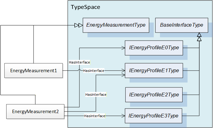
8.2.3 Interfaces for EnergyProfiles
EnergyMeasurementType Objects should support Interfaces for standardized energy data profiles, so called EnergyProfiles. The supported measurement values demanded by an energy data profile are specified by Interfaces applied to instances of the EnergyMeasurementType.
Table 21 shows the definitions of the Interfaces for the standardized energy data profiles. The EnergyProfiles represent standard Energy Measurement use cases and are therefore the preferred way to represent Energy Measurement data. It is recommended to support at least one of the EnergyProfiles.
| EnergyProfile | MeasurementValue | DataType | Accuracy | |||
| InterfaceType | BrowseName | Symbol | Engineering Unit | |||
| IEnergyProfileE0Type | E0 | AcCurrent | IL1 IL2 IL3 | A | AcPeData Type | ≤10% |
| IEnergyProfileE1Type | E1 | AcActivePowerTotal | ∑P | W | Float | ≤5% |
| IEnergyProfileE2Type | E2 | AcActivePowerTotal | ∑P | W | Float | ≤5% |
| AcActiveEnergyTotalImportLp | ∑↓E | W·h | Float | |||
| AcActiveEnergyTotalExportLp | ∑↑E | W·h | Float | |||
| IEnergyProfileE3Type | E3 | AcActivePower | PL1 PL2 PL3 | W | AcPeData Type | ≤2% |
| AcReactivePower | QtotL1 QtotL2 QtotL3 | var | AcPeData Type | |||
| AcActiveEnergyTotalImportHp | ∑↓E | W·h | Double | |||
| AcActiveEnergyTotalExportHp | ∑↑E | W·h | Double | |||
| AcReactiveEnergyTotalImportHp | ∑↓EQ | Varh | Double | |||
| AcReactiveEnergyTotalExportHp | ∑↑EQ | Varh | Double | |||
| AcVoltagePe | UL1N UL2N UL3N | V | AcPeData Type | |||
| AcVoltagePp | UL1L2 UL2L3 UL3L1 | V | AcPpData Type | |||
| AcCurrent | IL1 IL2 IL3 | A | Float | |||
| AcPowerFactor | λL1 λL2 λL3 | Float | ||||
| IEnergyProfileD0Type | D0 | DcCurrent | I | A | Float | ≤10% |
Figure 11 shows an example how different EnergyProfiles can be supported by EnergyMeasurementType Object instances.
8.2.3.1 IEnergyProfileE0Type
The IEnergyProfileE0Type contains the References to MeasurementValueType Variables needed for EnergyProfile E0.
| Attribute | Value | ||||
| BrowseName | IEnergyProfileE0Type | ||||
| IsAbstract | True | ||||
| References | Node Class | BrowseName | DataType | TypeDefinition | Other |
|---|---|---|---|---|---|
| Subtype of the BaseInterfaceType defined in [OPC 10001-7] | |||||
| 0:HasComponent | Variable | AcCurrent | AcPeDataType | MeasurementValueType | M |
| Source Path | Value Attribute | ||
| NamespaceUri: http://www.opcfoundation.org/UA/units/un/cefact UnitId: 4279632 DisplayName: A Description: ampere |
8.2.3.2 IEnergyProfileE1Type
The IEnergyProfileE1Type contains the References to MeasurementValueType Variables needed for EnergyProfile E1.
| Attribute | Value | ||||
| BrowseName | IEnergyProfileE1Type | ||||
| IsAbstract | True | ||||
| References | Node Class | BrowseName | DataType | TypeDefinition | Other |
|---|---|---|---|---|---|
| Subtype of the BaseInterfaceType defined in [OPC 10001-7] | |||||
| 0:HasComponent | Variable | AcActivePowerTotal | 0:Float | MeasurementValueType | M |
| Source Path | Value Attribute | ||
| NamespaceUri: http://www.opcfoundation.org/UA/units/un/cefact UnitId: 5723220 DisplayName: W Description: watt |
8.2.3.3 IEnergyProfileE2Type
The IEnergyProfileE2Type contains the References to MeasurementValueType Variables needed for EnergyProfile E2.
| Attribute | Value | ||||
| BrowseName | IEnergyProfileE2Type | ||||
| IsAbstract | True | ||||
| References | Node Class | BrowseName | DataType | TypeDefinition | Other |
|---|---|---|---|---|---|
| Subtype of the BaseInterfaceType defined in [OPC 10001-7] | |||||
| 0:HasComponent | Variable | AcActivePowerTotal | 0:Float | MeasurementValueType | M |
| 0:HasComponent | Variable | AcActiveEnergyTotalImportLp | 0:Float | MeasurementValueType | M |
| 0:HasComponent | Variable | AcActiveEnergyTotalExportLp | 0:Float | MeasurementValueType | M |
| Source Path | Value Attribute | ||
| NamespaceUri: http://www.opcfoundation.org/UA/units/un/cefact UnitId: 5723220 DisplayName: W Description: watt | ||
| NamespaceUri: http://www.opcfoundation.org/UA/units/un/cefact UnitId: 5720146 DisplayName: W·h Description: watt hour | ||
| NamespaceUri: http://www.opcfoundation.org/UA/units/un/cefact UnitId: 5720146 DisplayName: W·h Description: watt hour |
8.2.3.4 IEnergyProfileE3Type
The IEnergyProfileE3Type contains the References to MeasurementValueType Variables needed for EnergyProfile E3.
| Attribute | Value | ||||
| BrowseName | IEnergyProfileE3Type | ||||
| IsAbstract | True | ||||
| References | Node Class | BrowseName | DataType | TypeDefinition | Other |
|---|---|---|---|---|---|
| Subtype of the BaseInterfaceType defined in [OPC 10001-7] | |||||
| 0:HasComponent | Variable | AcActivePower | AcPeDataType | MeasurementValueType | M |
| 0:HasComponent | Variable | AcReactivePower | AcPeDataType | MeasurementValueType | M |
| 0:HasComponent | Variable | AcActiveEnergyTotalImportHp | 0:Double | MeasurementValueType | M |
| 0:HasComponent | Variable | AcActiveEnergyTotalExportHp | 0:Double | MeasurementValueType | M |
| 0:HasComponent | Variable | AcReactiveEnergyTotalImportHp | 0:Double | MeasurementValueType | M |
| 0:HasComponent | Variable | AcReactiveEnergyTotalExportHp | 0:Double | MeasurementValueType | M |
| 0:HasComponent | Variable | AcVoltagePe | AcPeDataType | MeasurementValueType | M |
| 0:HasComponent | Variable | AcVoltagePp | AcPpDataType | MeasurementValueType | M |
| 0:HasComponent | Variable | AcCurrent | AcPeDataType | MeasurementValueType | M |
| 0:HasComponent | Variable | AcPowerFactor | AcPeDataType | MeasurementValueType | M |
| Source Path | Value Attribute | ||
| NamespaceUri: http://www.opcfoundation.org/UA/units/un/cefact UnitId: 5723220 DisplayName: W Description: watt | ||
| NamespaceUri: http://www.opcfoundation.org/UA/units/un/cefact UnitId: 4469812 DisplayName: var Description: var | ||
| NamespaceUri: http://www.opcfoundation.org/UA/units/un/cefact UnitId: 5720146 DisplayName: W·h Description: watt hour | ||
| NamespaceUri: http://www.opcfoundation.org/UA/units/un/cefact UnitId: 5720146 DisplayName: W·h Description: watt hour | ||
| NamespaceUri: http://www.opcfoundation.org/UA/units/un/cefact UnitId: 5655636 DisplayName: V Description: volt | ||
| NamespaceUri: http://www.opcfoundation.org/UA/units/un/cefact UnitId: 5655636 DisplayName: V Description: volt | ||
| NamespaceUri: http://www.opcfoundation.org/UA/units/un/cefact UnitId: 4279632 DisplayName: A Description: ampere |
8.2.3.5 IEnergyProfileD0Type
The IEnergyProfileD0Type Interface contains a Reference to a MeasurementValueType Variable representing direct current (EnergyProfile D0).
| Attribute | Value | ||||
| BrowseName | IEnergyProfileD0Type | ||||
| IsAbstract | True | ||||
| References | Node Class | BrowseName | DataType | TypeDefinition | Other |
|---|---|---|---|---|---|
| Subtype of the BaseInterfaceType defined in [OPC 10001-7] | |||||
| 0:HasComponent | Variable | DcCurrent | 0:Float | MeasurementValueType | M |
| Source Path | Value Attribute | ||
| NamespaceUri: http://www.opcfoundation.org/UA/units/un/cefact UnitId: 4279632 DisplayName: A Description: ampere |
8.3 Sleep Mode WOL Functionality
8.3.1 EnergyDevicePowerOffType
The EnergyDevicePowerOffType type provides access to the Sleep Mode WOL functionality of the device if supported.
| Attribute | Value | ||||
| BrowseName | EnergyDevicePowerOffType | ||||
| IsAbstract | False | ||||
| References | Node Class | BrowseName | DataType | TypeDefinition | Other |
|---|---|---|---|---|---|
| Subtype of the BaseObjectType defined in [OPC 10000-5]. | |||||
| 0:HasComponent | Variable | RegularTimeToOperate | 0:Duration | 0:BaseDataVariableType | M, RO |
| 0:HasComponent | Variable | TimeMinPause | 0:Duration | 0:BaseDataVariableType | M, RO |
| 0:HasComponent | Variable | ModePowerConsumption | 0:UInt32 | 0:BaseDataVariableType | M, RO |
| 0:HasProperty | Variable | WOLMagicPacket | 0:ByteString | 0:PropertyType | M, RO |
| 0:HasComponent | Method | SwitchOffWOL | M | ||
A RepresentedBy Reference may connect the Object to the representing PROFIenergy service access point Object (see PeServiceAccessPointType). The BrowseName of the Reference shall be "PESAP". If the PESAP is not part of the Information Model, the RepresentedBy Reference in the EnergyDevicePowerOffType Object is omitted.
The RegularTimeToOperate Variable shall contain the time value to reach the state "Ready to operate" if the Wake-on-LAN sleep mode is terminated by a wake-up (see below).
The ModePowerConsumption Variable shall contain the power consumption in the
Wake-on-LAN sleep mode. Unit: [kW].
The WOLMagicPacket Variable shall contain the 6 bytes MAC address to be used with the magic packet sent for wake-up (see [PE CAP], chapter 7.3.4.9).
The SwitchOffWOL Method initiates the transition into the Wake-on-LAN sleep mode. In this mode the device is effectively switched off and unavailable for network communication. The device can be awakened using the magic packet (see [PE CAP], chapter 7.3.4.9).
8.3.1.1 SwitchOffWOL Method
This Method starts the transition into the special Wake-on-LAN mode.
Signature
	SwitchOffWOL (
		[out] 0:Byte			ModeID
		[out] 0:Duration		CurrentTimeToDestination
		[out] 0:Duration		RegularTimeToOperate
		[out] 0:Duration		TimeMinLengthOfStay
		[out] 0:Byte			ReturnCode
		);
| Argument | Description |
| ModeID | ID of the "Sleep Mode WOL" (0xFE) if successful, otherwise 0. |
| CurrentTimeToDestination | Time needed to reach the Energy Saving Mode if successful, otherwise 0. |
| RegularTimeToOperate | Time needed to reach "Ready to operate" again if the Wake-on-LAN sleep mode will be regularly terminated if successful, otherwise 0. |
| TimeMinLengthOfStay | Time of minimum stay in the Wake-on-LAN sleep mode if successful, otherwise 0. |
| ReturnCode | Return code. See Table 16. |
The Method Result Codes (defined in Call Service) are defined in Table 15.
8.4 PeServiceAccessPointType
The PeServiceAccessPointType connects the PE Energy Management Objects belonging to one PE Entity. The PeServiceAccessPointType Object could be included in the PE Energy Management model to model the PROFIenergy Service Access Point within PROFINET devices. Independent from the PeServiceAccessPointType Object, the PE Energy Management functionality can be directly managed by OPC UA access.
| Attribute | Value | ||||
| BrowseName | PeServiceAccessPointType | ||||
| IsAbstract | False | ||||
| References | Node Class | BrowseName | DataType | TypeDefinition | Other |
|---|---|---|---|---|---|
| Subtype of the BaseObjectType defined in [OPC 10000-5]. | |||||
| 0:HasProperty | Variable | PeClass | PeClassEnumeration | 0:PropertyType | O, RO |
| 0:HasProperty | Variable | PeSubclass | PeSubclassEnumeration | 0:PropertyType | O, RO |
| 0:HasProperty | Variable | PeVersion | PeVersionDataType | 0:PropertyType | M, RO |
The BrowseName of a PeServiceAccessPointType instance should be "PESAP@<Subslot>, where <Subslot> shall be the content of the subslot Variable of the Object which is the source of the 0:HasAddin Reference pointing to the service access point Object in hexadecimal number string format.
The PeSubclass Property shall be provided in conjunction with the Class Property: If the Class Property has the value PE_CLASS1 or the value PE_CLASS3, this Property is mandatory.
The PeVersion Property shall contain the implemented PROFIenergy version number.
A Represents Reference with the BrowseName "Standby" is mandatory for PROFIenergy class 1 and class 3 and shall point to the EnergyStandbyManagementType Object representing the Standby Management functionality.
A Represents Reference with the BrowseName "Measurement" is mandatory for PROFIenergy class 2 and class 3 and shall point to the EnergyMeasurementType Object representing the Energy Measurement functionality.
One optional Represents Reference with the BrowseName "EnergyPowerOff" points to an EnergyDevicePowerOffType Object if "Sleep Mode WOL" is supported.
9 OPC UA VariableTypes
9.1 MeasurementValueType
The MeasurementValueType is a subtype of BaseDataVariableType. Variables of this type are used to hold one measurement value.
| Attribute | Value | ||||
| BrowseName | MeasurementValueType | ||||
| IsAbstract | False | ||||
| ValueRank | -2 (-2 = Any) | ||||
| DataType | BaseDataType | ||||
| References | NodeClass | BrowseName | DataType | TypeDefinition | Other |
|---|---|---|---|---|---|
| Subtype of the BaseDataVariableType defined in [OPC 10000-5] | |||||
| 0:HasProperty | Variable | PeMeasurementID | 0:UInt16 | 0:PropertyType | M, RO |
| 0:HasProperty | Variable | AccuracyDomain | AccuracyDomainEnumeration | 0:PropertyType | M, RO |
| 0:HasProperty | Variable | AccuracyClass | AccuracyClassEnumeration | 0:PropertyType | M, RO |
| 0:HasProperty | Variable | EngineeringUnits | 0:EUInformation | 0:PropertyType | O, RO |
| 0:HasProperty | Variable | ValueBeforeReset | 0:BaseDataType | 0:PropertyType | O, RO |
The BrowseName should be the name of the measurement as defined in Table 21 like "DcCurrent" or "AcReactivePower".
The PeMeasurementID Variable shall contain the PE measurement ID of this measurement value.
The AccuracyDomain Variable shall contain the PE accuracy domain of this measurement value encoded as AccuracyDomainEnumeration (See Table 53). Table 35 lists the meaning of the possible PE accuracy domain values (see [PE CAP], Table 8).
| AccuracyDomain | Meaning |
| ACCURACY_DOMAIN_PERCENT_FULL_SCALE | The accuracy is given as percent of the full-scale reading. The percentage is coded according to Table 36 and is stored in AccuracyClass. |
| ACCURACY_DOMAIN_PERCENT_ACTUAL_READING | The accuracy is given as percent of the actual reading. The percentage is coded according to Table 36 and is stored in AccuracyClass. |
| ACCURACY_DOMAIN_IEC | The accuracy is given according to IEC 61557-12. The function performance classes for performance measurement and monitoring devices (PMD) without external sensors and system performance classes for PMD with external sensors are coded according to Table 37 and stored in AccuracyClass. |
| ACCURACY_DOMAIN_EN | The accuracy is given as specified in the EN 50470-3, Chapter 8 , encoded according to Table 38 and stored in AccuracyClass. |
It is recommended to deliver the measurement values according to accuracy domain ACCURACY_DOMAIN_PERCENT_FULL_SCALE and -_ACTUAL_READING.
The AccuracyClass Variable shall contain the PE accuracy class of this measurement value encoded as AccuracyClassEnumeration (See Table 55). Table 36, Table 37 andTable 38 shows the possible AccuracyClass values if the AccuracyDomain value is ACCURACY_DOMAIN_EN (see Table 35).
Table 38 list the possible PE accuracy class values (see [PE CAP], tables 9, 10 and 11).
Table 36 shows the possible AccuracyClass values if the AccuracyDomain value is ACCURACY_DOMAIN_PERCENT_FULL_SCALE or -_ACTUAL_READING (see Table 35).
| AccuracyClass | Percent Value |
| ACCURACY_CLASS_0 | reserved |
| ACCURACY_CLASS_1 | 0,01% |
| ACCURACY_CLASS_2 | 0,02% |
| ACCURACY_CLASS_3 | 0,05% |
| ACCURACY_CLASS_4 | 0,1% |
| ACCURACY_CLASS_5 | 0,2% |
| ACCURACY_CLASS_6 | 0,5% |
| ACCURACY_CLASS_7 | 1% |
| ACCURACY_CLASS_8 | 1,5% |
| ACCURACY_CLASS_9 | 2% |
| ACCURACY_CLASS_10 | 2,5% |
| ACCURACY_CLASS_11 | 3% |
| ACCURACY_CLASS_12 | 5% |
| ACCURACY_CLASS_13 | 10% |
| ACCURACY_CLASS_14 | 20% |
| ACCURACY_CLASS_15 | >20% |
Table 37 shows the possible AccuracyClass values if the AccuracyDomain value is ACCURACY_DOMAIN_IEC (see Table 35).
| AccuracyClass | Function- and System Performance Class |
| ACCURACY_CLASS_0 | reserved |
| ACCURACY_CLASS_1 | 0,02 |
| ACCURACY_CLASS_2 | 0,05 |
| ACCURACY_CLASS_3 | 0,1 |
| ACCURACY_CLASS_4 | 0,2 |
| ACCURACY_CLASS_5 | 0,5 |
| ACCURACY_CLASS_6 | 1 |
| ACCURACY_CLASS_7 | 1,5 |
| ACCURACY_CLASS_8 | 2 |
| ACCURACY_CLASS_9 | 2,5 |
| ACCURACY_CLASS_10 | 3 |
| ACCURACY_CLASS_11 | 5 |
| ACCURACY_CLASS_12 | 10 |
| ACCURACY_CLASS_13 | 20 |
| > ACCURACY_CLASS_13 | undefined |
Table 38 shows the possible AccuracyClass values if the AccuracyDomain value is ACCURACY_DOMAIN_EN (see Table 35).
| AccuracyClass | Function- and System Performance Class |
| ACCURACY_CLASS_0 | reserved |
| ACCURACY_CLASS_1 | 0,5 |
| ACCURACY_CLASS_2 | 1,0 |
| ACCURACY_CLASS_3 | 1,5 |
| ACCURACY_CLASS_4 | 2,0 |
| ACCURACY_CLASS_5 | 2,5 |
| ACCURACY_CLASS_6 | 3,0 |
| >ACCURACY_CLASS_6 | undefined |
The EngineeringUnits Variable shall contain the mapped UNECE code of the OPC UA EUInformation data type (see [OPC 10000-8], section 5.6.3) for the engineering unit of this measurement value. If the value contains the power factor, no EngineeringUnits Property shall be provided.
If the MeasurementValueType Variable is used as energy counter, the ValueBeforeReset Variable shall be set to the value of the Variable when the energy counter is reset. A reset can be performed using the ResetEnergyCounter Method of the EnergyMeasurementType Object which contains the MeasurementValueType Variable.
After the start of the device the ValueBeforeReset Variable and the value of the MeasurementValueType Variable shall be equal and have the value 0. Further on, the value of the ValueBeforeReset Variable shall not change unless a reset is performed.
The DataType of a MeasurementValueType value shall be one of the following: 0:Int32, 0:Float, 0:Double, AcPeDataType or AcPpDataType.
Instances of MeasurementValueType shall use the same EngineeringUnits as defined in the Interface implemented by the containing EnergyMeasurementType Object.
When reading the value of the MeasurementValueType Variable the status code shall be set to "UncertainSensorValueNotAccurate" if the accuracy of the value cannot be guaranteed for some reason, e.g. the calibration interval is overdue.
Mapping to PROFIenergy properties:
| BrowseName | PE Service | PE Service Data Response Field |
| PeMeasurementID | Get_Measurement_Values_with_Object_Number | Measurement_ID |
| AccuracyDomain | Get_Measurement_List_with_Object_Number | Accuracy_Domain |
| AccuracyClass | Get_Measurement_List_with_Object_Number | Accuracy_Class |
10 OPC UA DataTypes
10.1 Structures
10.1.1 StandbyModeTransitionDataType
The StandbyModeTransitionDataType holds information which might change when the device is in a transition state to an Energy Saving Mode.
| Name | Type | Description |
|---|---|---|
| StandbyModeTransitionDataType | Structure | |
| IDDestination | 0:Byte | Mode ID of destination Energy Saving Mode. |
| CurrentTimeToDestination | 0:Duration | Time needed to reach the mode IDDestination. Shall be a "Worst case" value if ongoing (dynamic) time value is not supported. Shall be 0 if destination Energy Saving Mode is reached. |
| CurrentTimeToOperate | 0:Duration | Time needed to reach "Ready to operate" if the Energy Saving Mode is not regularly terminated. The server might update the value after reaching the destination state as long as the TimeMinLengthOfStay of the destination state is not reached. |
| EnergyConsumptionToDestination | 0:Float | Energy consumption for actual transition. Shall be 0 if not in a transition state. |
Its representation in the AddressSpace is defined in Table 40.
| Attribute | Value | |||||
| BrowseName | StandbyModeTransitionDataType | |||||
| IsAbstract | False | |||||
| References | NodeClass | BrowseName | DataType | TypeDefinition | Other | |
|---|---|---|---|---|---|---|
| Subtype of the Structure type defined in [OPC 10000-3] | ||||||
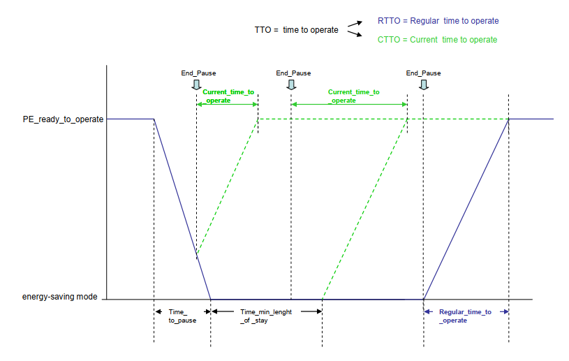
Figure 12 shows how CurrentTimeToOperate varies in dependence of TimeToPause and TimeMinLengthOfStay of the destination Energy Saving Mode during and immediately after the transition.
The relationship of RegularTimeToOperate and CurrentTimeToOperate during a mode transition shall follow the specification defined by PROFIenergy (See [PE CAP], figure 14).
xxxx
10.1.2 EnergyStateInformationDataType
The EnergyStateInformationDataType holds information specific to a certain state which also does not change if the device is in transition state. The members shall have the values characterizing the current state and shall be changed only in case of a transition to a different state.
| Name | Type | Description |
|---|---|---|
| EnergyStateInformationDataType | Structure | |
IDSource | 0:Byte | Mode ID of current Energy Saving Mode. |
IDDestination | 0:Byte | Mode ID of destination Energy Saving Mode. |
RegularTimeToOperate | 0:Duration | Time needed to reach "Ready to operate" if the Energy Saving Mode is regularly terminated. Shall be 0 if IDSource is equal to 0xFF (The StandbyManagementStatus Variable has the value "Ready to operate"). |
ModePowerConsumption | 0:Float | Power consumption in actual state. |
Its representation in the AddressSpace is defined in Table 42
| Attribute | Value | |||||
| BrowseName | EnergyStateInformationDataType | |||||
| IsAbstract | False | |||||
| References | NodeClass | BrowseName | DataType | TypeDefinition | Other | |
|---|---|---|---|---|---|---|
| Subtype of the Structure type defined in [OPC 10000-3] | ||||||
If the StandbyManagementStatus Variable of the EnergyStandbyManagementType Object has the value 2 ("Ready to operate"), IDSource and IDDestination shall be equal and have the value 0xFF.
If this StandbyManagementStatus Variable has the value 0 ("Energy saving disabled"), IDSource and IDDestination shall be equal and have the value 0xF0.
If this StandbyManagementStatus Variable has the value 4 ("Energy saving mode"), IDSource and IDDestination shall be equal and have the value of the ID Property of the EnergySavingModeType Object representing the current Energy Saving Mode.
If this StandbyManagementStatus Variable has the value 3 ("Moving to energy saving mode") and if the previous value was 2 ("Ready to operate"), IDSource shall have the value 0xFF and IDDestination shall have the value of the ID Property of the EnergySavingModeType Object representing the destination Energy Saving Mode.
If this StandbyManagementStatus Variable has the value 3 ("Moving to energy saving mode") and if the previous value was 4 ("Energy saving mode", the state transition takes place between two Energy Saving Modes), IDSource shall be the value of the ID Property of the EnergySavingModeType Object representing the source Energy Saving Mode. IDDestination shall have the value of the ID Property of the EnergySavingModeType Object representing the destination Energy Saving Mode.
If this StandbyManagementStatus Variable has the value 5 ("Moving to ready to operate"), IDDestination shall have the value 0xFF. IDSource shall have the value of the ID Property of the EnergySavingModeType Object representing the source Energy Saving Mode.
10.1.3 PeVersionDataType
This structure contains the PROFIenergy version implemented by the device.
| Name | Type | Description |
|---|---|---|
| PeVersionDataType | Structure | |
MajorVersion | 0:Byte | |
MinorVersion | 0:Byte | |
Revision | 0:Byte |
| Attribute | Value | |||||
| BrowseName | PeVersionDataType | |||||
| IsAbstract | False | |||||
| References | NodeClass | BrowseName | DataType | TypeDefinition | Other | |
|---|---|---|---|---|---|---|
| Subtype of the Structure type defined in [OPC 10000-3] | ||||||
10.1.4 AcPeDataType
This structure can also be seen as L1, L2, L3.
| Name | Type | Description |
|---|---|---|
| AcPeDataType | Structure | |
A | 0:Float | Phase a-n |
B | 0:Float | Phase b-n |
C | 0:Float | Phase c-n |
| Attribute | Value | |||||
| BrowseName | PeVersionDataType | |||||
| IsAbstract | False | |||||
| References | NodeClass | BrowseName | DataType | TypeDefinition | Other | |
|---|---|---|---|---|---|---|
| Subtype of the Structure type defined in [OPC 10000-3] | ||||||
10.1.5 AcPpDataType
This structure can also be seen as L1L2, L2L3, L3L1.
| Name | Type | Description |
|---|---|---|
| AcPpDataType | Structure | |
A_b | 0:Float | Phase a-b |
B_c | 0:Float | Phase b-c |
C_a | 0:Float | Phase c-a |
| Attribute | Value | |||||
| BrowseName | AcPpDataType | |||||
| IsAbstract | False | |||||
| References | NodeClass | BrowseName | DataType | TypeDefinition | Other | |
|---|---|---|---|---|---|---|
| Subtype of the Structure type defined in [OPC 10000-3] | ||||||
10.2 Enumerations
10.2.1 PeClassEnumeration
This enumeration defines the possible values for the PeClass Property of the PeServiceAccessPointType. The enumeration is defined in Table 49.
| Name | Value | Description |
|---|---|---|
| PE_CLASS1 | 0 | The PE Entity supports Standby Management functionality. |
| PE_CLASS2 | 1 | The PE Entity supports Energy Measurement functionality. |
| PE_CLASS3 | 2 | The PE Entity supports both Standby Management and Energy Measurement functionality. |
Its representation in the AddressSpace is defined in Table 50.
| Attribute | Value | |||||
| BrowseName | PeClassEnumeration | |||||
| IsAbstract | False | |||||
| References | NodeClass | BrowseName | DataType | TypeDefinition | Other | |
|---|---|---|---|---|---|---|
| Subtype of the Enumeration type defined in [OPC 10000-5] | ||||||
| 0:HasProperty | Variable | 0:EnumValues | 0:EnumValueType [] | 0:PropertyType | ||
10.2.2 PeSubclassEnumeration
This enumeration defines the possible values for the PeSubclass Property of the PeServiceAccessPointType. The enumeration is defined in Table 51.
| Name | Value | Description |
|---|---|---|
| PE_SUBCLASS1 | 0 | The PE Entity does not support a Standby Management disabled state. |
| PE_SUBCLASS2 | 1 | The PE Entity supports a Standby Management disabled state. |
Its representation in the AddressSpace is defined in Table 52.
| Attribute | Value | |||||
| BrowseName | PeSubclassEnumeration | |||||
| IsAbstract | False | |||||
| References | NodeClass | BrowseName | DataType | TypeDefinition | Other | |
|---|---|---|---|---|---|---|
| Subtype of the Enumeration type defined in [OPC 10000-5] | ||||||
| 0:HasProperty | Variable | 0:EnumValues | 0:EnumValueType [] | 0:PropertyType | ||
10.2.3 AccuracyDomainEnumeration
This enumeration defines the possible values for the AccuracyDomain Property of the MeasurementValueType. The enumeration is defined in Table 53.
| Name | Value | Description |
|---|---|---|
| ACCURACY_DOMAIN_RESERVED | 0 | Reserved. |
| ACCURACY_DOMAIN_PERCENT_FULL_SCALE | 1 | The accuracy is given as percent of the full-scale reading. |
| ACCURACY_DOMAIN_PERCENT_ACTUAL_READING | 2 | The accuracy is given as percent of the actual reading. |
| ACCURACY_DOMAIN_IEC | 3 | The accuracy is given according to IEC 61557-12. |
| ACCURACY_DOMAIN_EN | 4 | The accuracy is given as specified in the EN 50470-3, Chapter 8. |
Its representation in the AddressSpace is defined in Table 54.
| Attribute | Value | |||||
| BrowseName | AccuracyDomainEnumeration | |||||
| IsAbstract | False | |||||
| References | NodeClass | BrowseName | DataType | TypeDefinition | Other | |
|---|---|---|---|---|---|---|
| Subtype of the Enumeration type defined in [OPC 10000-5] | ||||||
| 0:HasProperty | Variable | 0:EnumValues | 0:EnumValueType [] | 0:PropertyType | ||
10.2.4 AccuracyClassEnumeration
This enumeration defines the possible values for the AccuracyClass Property of the MeasurementValueType. The enumeration is defined in Table 55.
| Name | Value | Description |
|---|---|---|
| ACCURACY_CLASS_0 | 0 | Reserved. |
| ACCURACY_CLASS_1 | 1 | . |
| ACCURACY_CLASS_2 | 2 | |
| ACCURACY_CLASS_3 | 3 | |
| ACCURACY_CLASS_4 | 4 | |
| ACCURACY_CLASS_5 | 5 | |
| ACCURACY_CLASS_6 | 6 | Meaning of value depends on AccuracyDomain variable value. |
| ACCURACY_CLASS_7 | 7 | See Table 36, Table 37 and Table 38. |
| ACCURACY_CLASS_8 | 8 | |
| ACCURACY_CLASS_9 | 9 | |
| ACCURACY_CLASS_10 | 10 | |
| ACCURACY_CLASS_11 | 11 | |
| ACCURACY_CLASS_12 | 12 | |
| ACCURACY_CLASS_13 | 13 | |
| ACCURACY_CLASS_14 | 14 | |
| ACCURACY_CLASS_15 | 15 |
Its representation in the AddressSpace is defined in Table 56.
| Attribute | Value | |||||
| BrowseName | AccuracyClassEnumeration | |||||
| IsAbstract | False | |||||
| References | NodeClass | BrowseName | DataType | TypeDefinition | Other | |
|---|---|---|---|---|---|---|
| Subtype of the Enumeration type defined in [OPC 10000-5] | ||||||
| 0:HasProperty | Variable | 0:EnumValues | 0:EnumValueType [] | 0:PropertyType | ||
11 OPC UA ReferenceTypes
11.1 Represents Reference Type
The Represents is a concrete ReferenceType and can be used directly. It is a subtype of NonHierarchicalReferences defined in [OPC 10000-5].
The semantic of this ReferenceType is to connect the EnergyMeasurementType, EnergyStandbyManagementType and EnergyDevicePowerOffType Objects of a PE Entity with the PeServiceAccessPointType Object.
The SourceNode of References of this type shall be a PeServiceAccessPointType Object. The TargetNode shall be either EnergyMeasurementType Object, an EnergyStandbyManagementType Object or an EnergyDevicePowerOffType Object.
The Represents Reference type is formally defined in Table 57.
| Attributes | Value | ||
| BrowseName | Represents | ||
| InverseName | RepresentedBy | ||
| Symmetric | False | ||
| IsAbstract | False | ||
| References | NodeClass | BrowseName | Comment |
|---|---|---|---|
| Subtype of NonHierarchicalReferences from [[OPC 10000-5]]. | |||
11.2 HasEnergyStandbyManagement Reference Type
The HasEnergyStandbyManagement is a concrete ReferenceType and can be used directly. It is a subtype of NonHierarchicalReferences from [OPC 10000-5].
The SourceNode shall be an Object offering Standby Management functionality. The TargetNode shall be an Object of the EnergyStandbyManagementType.
The semantic of this ReferenceType is to connect the EnergyStandbyManagementType Objects representing Standby Management Entities with the functional part of the application model (See Figure 8).
The HasEnergyStandbyManagement Reference type is formally defined in Table 58.
| Attributes | Value | ||
| BrowseName | HasEnergyStandbyManagement | ||
| InverseName | IsEnergyStandbyManagementOf | ||
| Symmetric | False | ||
| IsAbstract | False | ||
| References | NodeClass | BrowseName | Comment |
|---|---|---|---|
| Subtype of NonHierarchicalReferences from [OPC 10000-5]. | |||
11.3 HasEnergyMeasurement Reference Type
The HasEnergyMeasurement is a concrete ReferenceType and can be used directly. It is a subtype of NonHierarchicalReferences from [OPC 10000-5].
The SourceNode shall be an Object offering Energy Measurement functionality. The TargetNode shall be an Object of the EnergyMeasurementType.
The semantic of this ReferenceType is to connect the EnergyMeasurementType Objects with the functional part of the application model (See Figure 8).
The HasEnergyMeasurement Reference type is formally defined in Table 59.
| Attributes | Value | ||
| BrowseName | HasEnergyMeasurement | ||
| InverseName | IsEnergyMeasurementOf | ||
| Symmetric | False | ||
| IsAbstract | False | ||
| References | NodeClass | BrowseName | Comment |
|---|---|---|---|
| Subtype of NonHierarchicalReferences from [OPC 10000-5]. | |||
11.4 HasEnergyPowerOff Reference Type
The HasEnergyPowerOff is a concrete ReferenceType and can be used directly. It is a subtype of NonHierarchicalReferences from [OPC 10000-5].
Source shall be a device Object of the PROFINET model offering Sleep Mode WOL functionality. Target shall be an Object of the EnergyDevicePowerOffType.
The semantic of this ReferenceType is to connect the EnergyDevicePowerOffType Objects with the PROFINET part of the application model (See Figure 8).
The HasEnergyPowerOff Reference type is formally defined in Table 60.
| Attributes | Value | ||
| BrowseName | HasEnergyPowerOff | ||
| InverseName | IsEnergyPowerOffFor | ||
| Symmetric | False | ||
| IsAbstract | False | ||
| References | NodeClass | BrowseName | Comment |
|---|---|---|---|
| Subtype of NonHierarchicalReferences from [OPC 10000-5]. | |||
12 Profiles and Conformance Units
12.1 Conformance Units
This chapter defines the corresponding Conformance Units for the OPC UA Information Model for PE Energy Management.
| Category | Title | Description |
| Server | PNEM Standby Management | Supports the Standby Management functionality defined in Standby Management Information Model. |
| Server | PNEM Standby Management Control | Supports the Standby Management functionality defined in Standby Management Information Model. The Methods StartPause, EndPause, PauseTime are supported. |
| Server | PNEM Energy Measurement | Supports the Energy Measurement functionality defined in Energy Measurement Information Model. |
| Server | PNEM Sleep Mode WOL | Supports the Sleep Mode WOL functionality defined in Sleep Mode WOL Functionality Information Model. |
| Server | PNEM Energy Management Support | Supports at least one of the Conformance Units: PNEM Standby Management, PNEM Energy Measurement or PNEM Power Off. |
| Server | PNEM PROFIenergy | Supports the PeServiceAccessPointType ObjectType defined in PE Energy Management Information Model (The device implements the PROFIenergy Common Application Profile). |
| Server | PNEM EnergyProfile E0 | IEnergyProfileE0 Interface is supported by EnergyMeasurementType Object instances. |
| Server | PNEM EnergyProfile E1 | IEnergyProfileE1 Interface is supported by EnergyMeasurementType Object instances. |
| Server | PNEM EnergyProfile E2 | IEnergyProfileE2 Interface is supported by EnergyMeasurementType Object instances. |
| Server | PNEM EnergyProfile E3 | IEnergyProfileE3 Interface is supported by EnergyMeasurementType Object instances. |
| Server | PNEM EnergyProfile D0 | IEnergyProfileD0 Interface is supported by EnergyMeasurementType Object instances. |
12.2 Profiles
12.2.1 Profile list
Table 62 lists all Profiles defined in this document and defines their URIs.
| Profile | URI |
| PNEM Energy Management Server Profile | http://opcfoundation.org/UA-Profile/PNEM/Server/EnergyManagement |
| PNEM PROFINET Energy Management Server Profile | http://opcfoundation.org/UA-Profile/PNEM/Server/PROFINETEnergyManagement |
| PNEM Energy Management Control Server Profile | http://opcfoundation.org/UA-Profile/PNEM/Server/EnergyManagementControl |
| PNEM PROFINET Energy Management Control Server Profile | http://opcfoundation.org/UA-Profile/PNEM/Server/PROFINETEnergyManagementControl |
| PNEM Energy Controller Server Facet | http://opcfoundation.org/UA-Profile/PNEM/Server/EnergyController |
12.2.2 Server Facets
12.2.2.1 Overview
The following sections specify the Facets available for Servers that implement the PE Energy Management companion specification. Each section defines and describes a Facet or Profile.
12.2.2.2 PNEM Energy Management Server Profile
| Group | Conformance Unit / Profile Title | M / O |
| PNEM | PNEM Standby Management | O |
| PNEM | PNEM Energy Measurement | O |
| PNEM | PNEM Sleep Mode WOL | O |
| PNEM | PNEM EnergyProfile E0 | O |
| PNEM | PNEM EnergyProfile E1 | O |
| PNEM | PNEM EnergyProfile E2 | O |
| PNEM | PNEM EnergyProfile E3 | O |
| PNEM | PNEM EnergyProfile D0 | O |
| PNEM | PNEM Energy Management Support | M |
| Profile | 0:Nano Embedded Device 2017 Server Profile http://opcfoundation.org/UA-Profile/Server/NanoEmbeddedDevice2017 | M |
| Profile | 0:Data Access Server Facet http://opcfoundation.org/UA-Profile/Server/DataAccess | M |
| Profile | 0:ComplexType 2017 Server Facet http://opcfoundation.org/UA-Profile/Server/ComplexTypes2017 | M |
| Subscription Services | 0:SubscriptionDurable http://opcfoundation.org/UA-Profile/Server/DurableSubscription | M |
12.2.2.3 PNEM Energy Management Control Server Profile
| Group | Conformance Unit / Profile Title | M / O |
| Profile | PNEM Energy Controller Server Facet | M |
| Profile | PNEM Energy Management Server Profile | M |
| Profile | 0:Embedded Device 2017 Server Profile http://opcfoundation.org/UA-Profile/Server/EmbeddedUA2017 | M |
12.2.2.4 PNEM PROFINET Energy Management Server Profile
| Group | Conformance Unit / Profile Title | M / O |
| PNEM | PNEM PROFIenergy | M |
| Profile | PNEM Energy Management Server Profile | M |
12.2.2.5 PNEM PROFINET Energy Management Control Server Profile
| Group | Conformance Unit / Profile Title | M / O |
| Profile | PNEM PROFIenergy | M |
| Profile | PNEM Energy Management Control Server Profile | M |
12.2.2.6 PNEM Energy Controller Server Facet
| Group | Conformance Unit / Profile Title | M / O |
| PNEM | PNEM Standby Management Control | M |
| Profile | 2:Locking_Server_Facet | M |
12.2.3 Client Facets
This specification does not define any Client Facets.
13 Namespaces
13.1 Namespace Metadata
Table 68 defines the namespace metadata for this document. The Object is used to provide version information for the namespace and an indication about static Nodes. Static Nodes are identical for all Attributes in all Servers, including the Value Attribute. See [OPC 10000-5] for more details.
The information is provided as Object of type NamespaceMetadataType. This Object is a component of the Namespaces Object that is part of the Server Object. The NamespaceMetadataType ObjectType and its Properties are defined in [OPC 10000-5].
The version information is also provided as part of the ModelTableEntry in the UANodeSet XML file. The UANodeSet XML schema is defined in [OPC 10000-6].
| Attribute | Value | |||
| BrowseName | http://opcfoundation.org/UA/PNEM/ | |||
| References | NodeClass | BrowseName | DataType | Value |
|---|---|---|---|---|
| HasProperty | Variable | NamespaceUri | String | http://opcfoundation.org/UA/PNEM |
| HasProperty | Variable | NamespaceVersion | String | 1.00 |
| HasProperty | Variable | NamespacePublicationDate | DateTime | 2020-03-11 |
| HasProperty | Variable | IsNamespaceSubset | Boolean | Vendor-specific |
| HasProperty | Variable | StaticNodeIdTypes | IdType [] | {Numeric} |
| HasProperty | Variable | StaticNumericNodeIdRange | NumericRange [] | |
| HasProperty | Variable | StaticStringNodeIdPattern | String |
13.2 Handling of OPC UA Namespaces
Namespaces are used by OPC UA to create unique identifiers across different naming authorities. The Attributes NodeId and BrowseName are identifiers. A Node in the UA AddressSpace is unambiguously identified using a NodeId. Unlike NodeIds, the BrowseName cannot be used to unambiguously identify a Node. Different Nodes may have the same BrowseName. They are used to build a browse path between two Nodes or to define a standard Property.
Servers may often choose to use the same namespace for the NodeId and the BrowseName. However, if they want to provide a standard Property, its BrowseName shall have the namespace of the standards body although the namespace of the NodeId reflects something else, for example the EngineeringUnits Property. All NodeIds of Nodes not defined in this document shall not use the standard namespaces.
Table 69 provides a list of mandatory and optional namespaces used in an OPC UA for PROFIenergy Server.
| NamespaceURI | Description | Use |
| http://opcfoundation.org/UA/ | Namespace for NodeIds and BrowseNames defined in the OPC UA specification. This namespace shall have namespace index 0. | Mandatory |
| Local Server URI | Namespace for Nodes defined in the local server. This may include types and instances used in an AutoID Device represented by the Server. This namespace shall have namespace index 1. | Mandatory |
| http://opcfoundation.org/UA/DI/ | Namespace for NodeIds and BrowseNames defined in [OPC 10000-100]. The namespace index is Server specific. | Optional |
| http://opcfoundation.org/UA/PNEM/ | Namespace for NodeIds and BrowseNames defined in this document. The namespace index is Server specific. | Mandatory |
| Vendor specific types | A Server may provide vendor-specific types like types derived from ObjectTypes defined in this document in a vendor-specific namespace. | Optional |
| Vendor specific instances | A Server provides vendor-specific instances of the standard types or vendor-specific instances of vendor-specific types in a vendor-specific namespace. It is recommended to separate vendor specific types and vendor specific instances into two or more namespaces. | Mandatory |
Table 70 provides a list of namespaces and their index used for BrowseNames in this document. The default namespace of this document is not listed since all BrowseNames without prefix use this default namespace.
| NamespaceURI | Namespace Index | Example |
| http://opcfoundation.org/UA/ | 0 | 0:EngineeringUnits |
| http://opcfoundation.org/UA/DI/ | 2 | 2:DeviceRevision |
Annex A OPC UA for PROFIenergy Namespace and mappings (Normative)
A.1 Namespace and identifiers for OPC UA for PROFIenergy Information Model
This appendix defines the numeric identifiers for all of the numeric NodeIds defined in this document. The identifiers are specified in a CSV file with the following syntax:
<SymbolName>, <Identifier>, <NodeClass>Where the SymbolName is either the BrowseName of a Type Node or the BrowsePath for an Instance Node that appears in the specification and the Identifier is the numeric value for the NodeId.
The BrowsePath for an Instance Node is constructed by appending the BrowseName of the instance Node to the BrowseName for the containing instance or type. An underscore character is used to separate each BrowseName in the path.
The NamespaceUri for all NodeIds defined here is http://opcfoundation.org/UA/PNEM/
The CSV released with this version of the specification can be found here:
http://www.opcfoundation.org/UA/schemas/PNEM/1.0/NodeIds.csv
NOTE The latest CSV that is compatible with this version of the specification can be found here:
http://www.opcfoundation.org/UA/schemas/PNEM/NodeIds.csv
A computer processible version of the complete Information Model defined in this document is also provided. It follows the XML Information Model schema syntax defined in [OPC 10000-6].
The Information Model Schema for this version of the document (including any revisions, amendments or errata) can be found here:
http://www.opcfoundation.org/UA/schemas/PNEM/1.0/Opc.Ua.PnEm.NodeSet2.xml
NOTE The latest Information Model schema that is compatible with this version of the document can be found here:
http://www.opcfoundation.org/UA/schemas/PNEM/Opc.Ua.PnEm.NodeSet2.xml
_____________
Annex B Relationship to PROFIenergy Concepts (Informative)
B.1 PE Entity
A PE Entity comprises all PROFIenergy services and properties that are accessible with the same PROFIenergy service access point (PESAP). According to the Object model defined in [PE CAP], one device may have more than one PE Entity; see Figure 13 also.
However, the preferred Energy Management Object model follows the approach of independent partial models ("facets") chosen in [OPC PN]. The reason for this is that the PESAP is not needed when accessing the energy functions of a device using OPC UA. The OPC UA Client can find out the offered Energy Management functionality by browsing the Information Model (See Figure 8 and Figure 10).
Since the PROFIenergy properties PE class and PE version are unique for each PE Entity, a PeServiceAccessPointType Object provides this information.
A remote proxy server can provide OPC UA access to the device. In order to do so, the proxy must know the PROFIenergy service access point to gain access to the PROFINET device, to find out the PROFIenergy capabilities of the device and to create the Information Model for the device. Further on, OPC UA Client accesses to PROFIenergy services are routed to the device through the service access point.
Annex C PROFIenergy Common Application Profile (Informative)
C.1 What is PROFIenergy?
PROFIenergy is a Common Application Profile of the Industrial Ethernet protocol PROFINET. It enables the deployment of Energy Management strategies over PROFINET architectures. The PROFINET address schema is used for the PROFIenergy service access point (PESAP) only. Although the PROFIenergy services are defined based on PROFINET mechanisms (e.g. record read/write), a PROFINET independent implementation accessible through a different PESAP is possible. OPC UA provides a service access point independent of PROFINET.
C.2 Services of PROFIenergy
PROFIenergy defines a state model characterizing the state of a device with respect to energy consumption. The services defined by PROFIenergy are grouped into three main classes:
PROFIenergy Standby Management allows switching on Energy Saving Modes for unused energy consuming entities during breaks in a standard way. It also allows transitions between individual Energy Saving Modes.
PROFIenergy measurement functionality allows the retrieval of Energy Measurement data from a device. PROFIenergy also defines a set of possible measurement values identified by measurement ID's.
The status and administration commands of PROFIenergy allow determining the supported services, retrieval of the PROFIenergy version, querying the properties of the device with respect to energy functions, listing the supported Energy Saving Modes, obtaining the properties of a specific Energy Saving Mode and retrieving detailed status information.
C.3 PE Object Model
PROFIenergy defines a basic object model. The object model consists of PE objects and defines how the objects shall be aggregated. Figure 13 shows the basic PE object model and how the PE functionality accompanies the 'standard' device functionality.
A PE Entity is a unit of offered PE services and properties. A PROFIenergy device may offer more than on PE Entity.
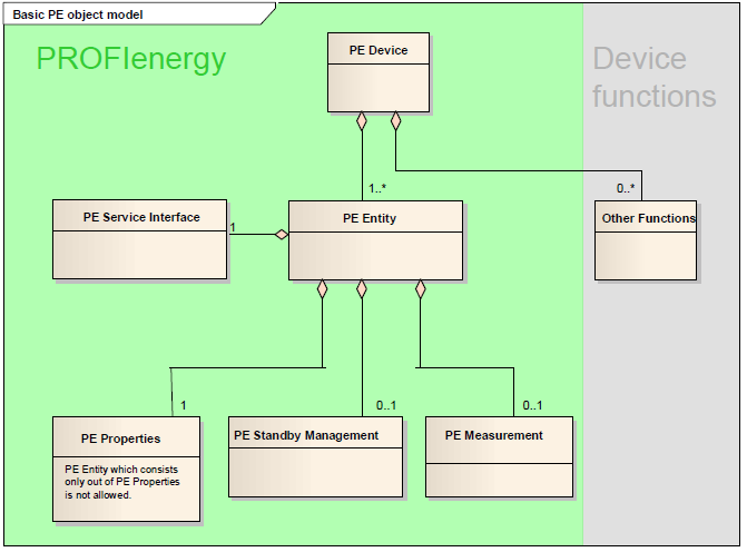
C.4 PE State Model
PROFIenergy defines a basic state model. The state model determines the possible modes of a device regarding energy consumption. The state model also determines the possible changes in energy consumption as state transitions. Figure 14 shows the PROFIenergy state model.
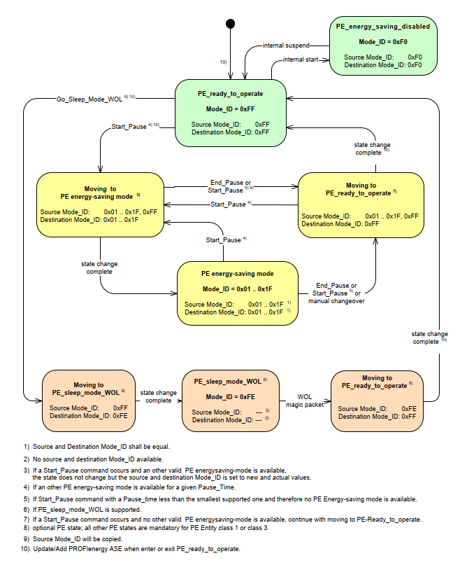
Each PE mode is identified by the PE Mode_ID. Table 71 gives a brief description of the modes defined by the basic state model and their PE Mode_ID. Note the mode PE_power_off is not part of the basic state model. For an in-depth description of the state model, especially the constraints and possible state transitions, refer to [PE CAP].
The state transition modes do not have a distinctive PE Mode_ID, but are identified by differing source Mode_ID and the destination Mode_ID. When in a non-transition state, the source Mode_ID and the destination Mode_ID are identical.
| PE Mode | Source PE Mode_ID | Destination PE Mode_ID | Description |
| PE_power_off | 0x00 | The device is free from voltage and cannot communicate. When in a different mode, the mode properties can be queried. | |
| PE_energy_saving_disabled | 0xF0 | The device is in productive operation and Standby Management is disabled. The device will not execute commands requesting the transition into an energy-saving mode. | |
| PE_ready_to_operate | 0xFF | Standby Management is enabled and the device is able for a transition into an Energy Saving Mode. | |
| Moving to PE energy-saving-mode | 0x1-0x1F, 0xFF | 0x01-0x1F | The device is in transition to one of the supported energy-saving modes. |
| Moving to PE_ready_to_operate | 0x01-0x1F, 0xFF, 0xFE | 0xFF | The device is in transition from an energy-saving mode to PE_ready_to_operate. |
| PE energy-saving-mode | 0x01 - 0x1F | The device is in some standby operation mode saving energy. The supported modes are determined by the manufacturer. | |
| Moving to PE_sleep_mode_WOL | 0xFF | 0xFE | The device is in transition to the PE_sleep_mode_WOL. |
| PE_sleep_mode_WOL | 0xFE | The device is in Wake-on-LAN sleep mode and cannot communicate. | |
C.5 Mapping of Measurement values
The following table is based on Table 24 Instantaneous measurements in the PROFIenergy specification.
|
PE Measurement
ID | Measurements | Unit |
Data
Type | Phase |
PNEM
Mapping |
| 1 | Voltage | V | Float32 | a-n | AcVoltagePe (Structure) |
| 2 | Voltage | V | Float32 | b-n | |
| 3 | Voltage | V | Float32 | c-n | |
| 4 | Voltage | V | Float32 | a-b | AcVoltagePp (Structure) |
| 5 | Voltage | V | Float32 | b-c | |
| 6 | Voltage | V | Float32 | c-a | |
| 7 | Current | A | Float32 | a | AcCurrent (Structure) |
| 8 | Current | A | Float32 | b | |
| 9 | Current | A | Float32 | c | |
| 10 | Apparent Power | VA | Float32 | a | |
| 11 | Apparent Power | VA | Float32 | b | |
| 12 | Apparent Power | VA | Float32 | c | |
| 13 | Active Power | W | Float32 | a | AcActivePower (Structure) |
| 14 | Active Power | W | Float32 | b | |
| 15 | Active Power | W | Float32 | c | |
| 16 | Reactive Power Qn | var | Float32 | a | |
| 17 | Reactive Power Qn | var | Float32 | b | |
| 18 | Reactive Power Qn | var | Float32 | c | |
| 19 | Power factor | non | Float32 | a | AcPowerFactor (Structure) |
| 20 | Power factor | non | Float32 | b | |
| 21 | Power factor | non | Float32 | c | |
| 22 | Reactive Power Qtot | var | Float32 | a | AcReactivePower (Structure) |
| 23 | Reactive Power Qtot | var | Float32 | b | |
| 24 | Reactive Power Qtot | var | Float32 | c | |
| … | |||||
| 30 | Frequency | Hz | Float32 | total | |
| 31 | Voltage | V | Float32 | average-ph-n | |
| 32 | Voltage | V | Float32 | average-ph-ph | |
| 33 | Current | A | Float32 | average-abc | |
| 34 | Active Power | W | Float32 | total | AcActivePowerTotal |
| 35 | Reactive Power Qn | Var | Float32 | total | |
| 36 | Apparent Power | VA | Float32 | total | |
| 37 | Power factor | non | Float32 | total | |
| 38 | Reactive Power Qtot | var | Float32 | total |
C.5.1 Energy Measurements
The following table is based on Table 26 Energy measurements in the PROFIenergy specification.
|
PE Measurement
ID | Measurements | Unit |
Data
Type | Phase |
PNEM
Mapping |
| 200 | Active Energy Import | Wh | Float32 | total | AcActiveEnergyTotalImportLp |
| 201 | Active Energy Export | Wh | Float32 | total | AcActiveEnergyTotalExportLp |
| 202 | Reactive Energy Import | varh | Float32 | total | AcReactiveEnergyTotalImporttLp |
| 203 | Reactive Energy Export | varh | Float32 | total | AcReactiveEnergyTotalExportLp |
| 204 | Apparent Energy | VAh | Float32 | total | |
| 205 | Active Energy Sum | Wh | Float32 | total | |
| 206 | Reactive Energy Sum | Wh | Float32 | total | |
| … | |||||
| 210 | Active Energy Import | Wh | Float64 | total | AcActiveEnergyTotalImportHp |
| 211 | Active Energy Export | Wh | Float64 | total | AcActiveEnergyTotalExportHp |
| 212 | Reactive Energy Import | varh | Float64 | total | AcReactiveEnergyTotalImporttHp |
| 213 | Reactive Energy Export | varh | Float64 | total | AcReactiveEnergyTotalExportHp |
| 214 | Apparent Energy | VAh | Float64 | total | |
| 215 | Active Energy Sum | Wh | Float64 | total | |
| 216 | Reactive Energy Sum | Wh | Float64 | total |
Agreement of Use
COPYRIGHT RESTRICTIONS
This document is provided "as is" by the OPC Foundation and the PROFIBUS Nutzerorganisation e.V..
Right of use for this specification is restricted to this specification and does not grant rights of use for referred documents.
Right of use for this specification will be granted without cost.
This document may be distributed through computer systems, printed or copied as long as the content remains unchanged and the document is not modified.
OPC Foundation and the PROFIBUS Nutzerorganisation e.V. do not guarantee usability for any purpose and shall not be made liable for any case using the content of this document.
The user of the document agrees to indemnify OPC Foundation and the PROFIBUS Nutzerorganisation e.V. and their officers, directors and agents harmless from all demands, claims, actions, losses, damages (including damages from personal injuries), costs and expenses (including attorneys' fees) which are in any way related to activities associated with its use of content from this specification.
The document shall not be used in conjunction with company advertising, shall not be sold or licensed to any party.
The intellectual property and copyright is solely owned by the OPC Foundation and the PROFIBUS Nutzerorganisation e.V..
PATENTS
The attention of adopters is directed to the possibility that compliance with or adoption of OPC or PROFIBUS Nutzerorganisation e.V. specifications may require use of an invention covered by patent rights. OPC Foundation or PROFIBUS Nutzerorganisation e.V. shall not be responsible for identifying patents for which a license may be required by any OPC or PROFIBUS Nutzerorganisation e.V. specification, or for conducting legal inquiries into the legal validity or scope of those patents that are brought to its attention. OPC or PROFIBUS Nutzerorganisation e.V. specifications are prospective and advisory only. Prospective users are responsible for protecting themselves against liability for infringement of patents.
WARRANTY AND LIABILITY DISCLAIMERS
WHILE THIS PUBLICATION IS BELIEVED TO BE ACCURATE, IT IS PROVIDED "AS IS" AND MAY CONTAIN ERRORS OR MISPRINTS. THE OPC FOUDATION NOR PROFIBUS Nutzerorganisation e.V. MAKES NO WARRANTY OF ANY KIND, EXPRESSED OR IMPLIED, WITH REGARD TO THIS PUBLICATION, INCLUDING BUT NOT LIMITED TO ANY WARRANTY OF TITLE OR OWNERSHIP, IMPLIED WARRANTY OF MERCHANTABILITY OR WARRANTY OF FITNESS FOR A PARTICULAR PURPOSE OR USE. IN NO EVENT SHALL THE OPC FOUNDATION NOR PROFIBUS Nutzerorganisation e.V. BE LIABLE FOR ERRORS CONTAINED HEREIN OR FOR DIRECT, INDIRECT, INCIDENTAL, SPECIAL, CONSEQUENTIAL, RELIANCE OR COVER DAMAGES, INCLUDING LOSS OF PROFITS, REVENUE, DATA OR USE, INCURRED BY ANY USER OR ANY THIRD PARTY IN CONNECTION WITH THE FURNISHING, PERFORMANCE, OR USE OF THIS MATERIAL, EVEN IF ADVISED OF THE POSSIBILITY OF SUCH DAMAGES.
The entire risk as to the quality and performance of software developed using this specification is borne by you.
RESTRICTED RIGHTS LEGEND
This Specification is provided with Restricted Rights. Use, duplication or disclosure by the U.S. government is subject to restrictions as set forth in (a) this Agreement pursuant to DFARs 227.7202-3(a); (b) subparagraph (c)(1)(i) of the Rights in Technical Data and Computer Software clause at DFARs 252.227-7013; or (c) the Commercial Computer Software Restricted Rights clause at FAR 52.227-19 subdivision (c)(1) and (2), as applicable. Contractor / manufacturer are the OPC Foundation, 16101 N. 82nd Street, Suite 3B, Scottsdale, AZ, 85260-1830
COMPLIANCE
The combination of PROFIBUS Nutzerorganisation e.V. and OPC Foundation shall at all times be the sole entities that may authorize developers, suppliers and sellers of hardware and software to use certification marks, trademarks or other special designations to indicate compliance with these materials as specified within this document. Products developed using this specification may claim compliance or conformance with this specification if and only if the software satisfactorily meets the certification requirements set by PROFIBUS Nutzerorganisation e.V. or the OPC Foundation. Products that do not meet these requirements may claim only that the product was based on this specification and must not claim compliance or conformance with this specification.
Trademarks
Most computer and software brand names have trademarks or registered trademarks. The individual trademarks have not been listed here.
GENERAL PROVISIONS
Should any provision of this Agreement be held to be void, invalid, unenforceable or illegal by a court, the validity and enforceability of the other provisions shall not be affected thereby.
This Agreement shall be governed by and construed under the laws of Germany.
This Agreement embodies the entire understanding between the parties with respect to, and supersedes any prior understanding or agreement (oral or written) relating to, this specification.