
1 Scope
This document 40400-2 specifies an Information Model for the powertrain functional model.
OPC Foundation
OPC is the interoperability standard for the secure and reliable exchange of data and information in the industrial automation space and in other industries. It is platform independent and ensures the seamless flow of information among devices from multiple vendors. The OPC Foundation is responsible for the development and maintenance of this standard.
OPC UA is a platform independent service-oriented architecture that integrates all the functionality of the individual OPC Classic specifications into one extensible framework. This multi-layered approach accomplishes the original design specification goals of:
Platform independence: from an embedded microcontroller to cloud-based infrastructure
Secure: encryption, authentication, authorisation, and auditing
Extensible: ability to add new features including transports without affecting existing applications
Comprehensive information modelling capabilities: for defining any model from simple to complex
VDMA
With 3,500 members, the VDMA is the largest network organization and an important voice for the machinery and equipment manufacturing industry in Europe and Germany. The association represents the common economic, technical and scientific interests of this unique and diverse industry.
2 Normative references
The following referenced documents are indispensable for the application of this document. For dated references, only the edition cited applies. For undated references, the latest edition of the referenced document (including any amendments and errata) applies.
OPC 10000-1, OPC Unified Architecture - Part 1: Overview and Concepts
http://www.opcfoundation.org/documents/10000-1/
OPC 10000-2, OPC Unified Architecture - Part 2: Security Model
http://www.opcfoundation.org/documents/10000-2/
OPC 10000-3, OPC Unified Architecture - Part 3: Address Space Model
http://www.opcfoundation.org/documents/10000-3/
OPC 10000-4, OPC Unified Architecture - Part 4: Services
http://www.opcfoundation.org/documents/10000-4/
OPC 10000-5, OPC Unified Architecture - Part 5: Information Model
http://www.opcfoundation.org/documents/10000-5/
OPC 10000-6, OPC Unified Architecture - Part 6: Mappings
http://www.opcfoundation.org/documents/10000-6/
OPC 10000-7, OPC Unified Architecture - Part 7: Profiles
http://www.opcfoundation.org/documents/10000-7/
OPC 10000-8, OPC Unified Architecture - Part 8: Data Access
http://www.opcfoundation.org/documents/10000-8/
OPC 10000-9, OPC Unified Architecture - Part 9: Alarms and Conditions
http://www.opcfoundation.org/documents/10000-9/
OPC 10000-10, OPC Unified Architecture - Part 10: Programs
http://www.opcfoundation.org/documents/10000-10/
OPC 10000-11, OPC Unified Architecture - Part 11: Historical Access
http://www.opcfoundation.org/documents/10000-11/
OPC 10000-12, OPC Unified Architecture - Part 12: Discovery and Global Services
http://www.opcfoundation.org/documents/10000-12/
OPC 10000-13, OPC Unified Architecture - Part 13: Aggregates
http://www.opcfoundation.org/documents/10000-13/
OPC 10000-14, OPC Unified Architecture - Part 14: PubSub
http://www.opcfoundation.org/documents/10000-14/
OPC 10000-15, OPC Unified Architecture - Part 15: Safety
http://www.opcfoundation.org/documents/10000-15/
OPC 10000-16, OPC Unified Architecture - Part 16: State Machines
http://www.opcfoundation.org/documents/10000-16/
OPC 10000-17, OPC Unified Architecture - Part 17: Alias Names
http://www.opcfoundation.org/documents/10000-17/
OPC 10000-18, OPC Unified Architecture - Part 18: Role-Based Security
http://www.opcfoundation.org/documents/10000-18/
OPC 10000-19, OPC Unified Architecture - Part 19: Dictionary References
http://www.opcfoundation.org/documents/10000-19/
OPC 10000-20, OPC Unified Architecture - Part 20: File Transfer
http://www.opcfoundation.org/documents/10000-20/
OPC 10000-22, OPC Unified Architecture - Part 22: Base Network Model
http://www.opcfoundation.org/documents/10000-22/
OPC 10000-23, OPC Unified Architecture - Part 23: Common Reference Types
http://www.opcfoundation.org/documents/10000-23/
OPC 10000-26 OPC Unified Architecture - Part 26: LogObject Model
http://www.opcfoundation.org/documents/10000-26/
OPC 10000-100, OPC Unified Architecture - Part 100: Devices
http://www.opcfoundation.org/documents/10000-100/
OPC 10000-110, OPC Unified Architecture - Part 110: Asset Management Basics
http://www.opcfoundation.org/documents/10000-110/
OPC 10000-200, OPC Unified Architecture - Part 200: Industrial Automation
http://www.opcfoundation.org/documents/10000-200/
OPC 40001-1, OPC UA for Machinery - Part 1: Basic Building Blocks
http://www.opcfoundation.org/documents/40001-1/
OPC 40400-1, OPC UA for Powertrain - Asset Management - RC 1.0 - Date: Juni 2023
http://www.opcfoundation.org/documents/40400-1/
OPC 10031-4, OPC UA for ISA-95 - Part 4: Job Control
http://www.opcfoundation.org/documents/10031-4/
OPC 30140 PN, OPC UA for PROFINET - Release V1.00.1 - Date: March 2021 -
Order No.: 30140
OPC 10000-81, OPC UA Field eXchange - Connecting Devices and Information Model -
Date: January 2023
http://www.opcfoundation.org/UA/FX/
ENCP, Profile Drive Technology - Encoder Profile - Version 4.2 - Date: March 2017 -
PNO, Order No.: 3.162
PDP, Profile Drive Technology - PROFIdrive Profile - Version 4.2 - Date: October 2015 -
PNO, Order Nr: 3.172
3 Terms, abbreviated terms and conventions
3.1 Overview
It is assumed that basic concepts of OPC UA information modelling and <other specifications> are understood in this document. This document will use these concepts to describe the OPC UA for Powertrain - Functional Model Information Model. For the purposes of this document, the terms and definitions given in OPC 10000-1, OPC 10000-3, OPC 10000-4, OPC 10000-5, OPC 10000-7, OPC 10000-100, … as well as the following apply.
Note that OPC UA terms and terms defined in this document are italicized in the document.
3.1.1 OPC UA for Powertrain - Functional Model terms
3.1.2 Axis
a logical element inside an automation system (e.g., a motion control system) that represents some form of movement.
3.1.3 CommandValue
a numeric control value generated by the Controller in the context of a superordinated automation task.
3.1.4 Controller
a host running a program which writes CommandValues to a Device.
3.1.5 Device
a material element or assembly of such elements intended to perform a required function
3.1.6 Drive
a Device equipped with one or more motors (or Axis) controlled by the application which has control priority.
3.2 Abbreviated terms
| AC | Alarm and Condition |
| CCW | counterclockwise |
| CPU | Central Processing Unit |
| CW | clockwise |
| DC | Direct Current |
| DCS | Distributed Control Systems |
| ERP | Enterprise Resource Planning |
| HMI | Human Machine Interface |
| HTTP | Hypertext Transfer Protocol |
| IP | Internet Protocol |
| KPI | Key Performance Indicator |
| MES | Manufacturing Execution System |
| PLC | Programable Logical Controller |
| PMS | Production Management System |
| RAM | Random Access Memory |
| RFG | Ramp Function Generator |
| SDI | Safe Direction |
| SLA | Safely Limited Acceleration |
| SLP | Safely Limited Position |
| SLS | Safely Limited Speed |
| SOS | Safe Operating Stop |
| STO | Safe Torque Off |
| TCP | Transmission Control Protocol |
| UML | Unified Modelling Language |
| URI | Uniform Resource Identifier |
| VSD | Variable Speed Drive |
| XML | Extensible Markup Language |
3.3 Naming conventions
Figure 1 shows the overall schema of the naming convention used for the characteristic Variables describing key control values.
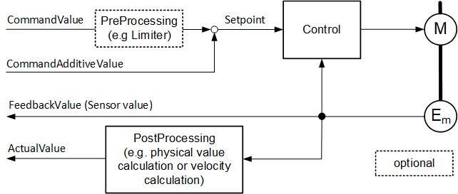
Variables representing values coming in over the field bus from the Controller have BrowseNames according to the template string "<controllable variable name>CommandValue" (e.g. FrequencyCommandValue, PositionCommandValue, etc).
Setpoint values can be a combination of CommandValues and additive "CommandAdditiveValues" and represent the direct setpoint to the control algorithm. The BrowseNames of Variables representing additive values follow the naming convention <controllable variable name>CommandAdditiveValue, e.g. VelocityCommandAdditiveValue. Setpoint values have the naming convention <controllable variable name>Setpoint, e.g. VelocitySetpoint.
Variables representing an axis internal measured or calculated actual value have the naming convention <name of value>ActualValue, e.g. VelocityActualValue.
Variables representing a directly measured actual value provided by a sensor have the naming convention <name of value>FeedbackValue, e.g. PositionSensorFeedbackValue.
3.4 Conventions used in this document
3.4.1 Conventions for Node descriptions
3.4.1.1 Node definitions
Node definitions are specified using tables (see Table 2).
Attributes are defined by providing the Attribute name and a value, or a description of the value.
References are defined by providing the ReferenceType name, the BrowseName of the TargetNode and its NodeClass.
If the TargetNode is a component of the Node being defined in the table the Attributes of the composed Node are defined in the same row of the table.
The DataType is only specified for Variables; "[<number>]" indicates a single-dimensional array, for multi-dimensional arrays the expression is repeated for each dimension (e.g. [2][3] for a two-dimensional array). For all arrays the ArrayDimensions is set as identified by <number> values. If no <number> is set, the corresponding dimension is set to 0, indicating an unknown size. If no number is provided at all the ArrayDimensions can be omitted. If no brackets are provided, it identifies a scalar DataType and the ValueRank is set to the corresponding value (see OPC 10000-3). In addition, ArrayDimensions is set to null or is omitted. If it can be Any or ScalarOrOneDimension, the value is put into "{<value>}", so either "{Any}" or "{ScalarOrOneDimension}" and the ValueRank is set to the corresponding value (see OPC 10000-3) and the ArrayDimensions is set to null or is omitted. Examples are given in Table 1.
| Notation | DataType | ValueRank | ArrayDimensions | Description |
| 0:Int32 | 0:Int32 | -1 | omitted or null | A scalar Int32. |
| 0:Int32{OneOrMoreDimensions} | 0:Int32 | 0 | omitted or null | The Int32 value is an array with one or more dimensions. |
| 0:Int32[] | 0:Int32 | 1 | omitted or {0} | Single-dimensional array of Int32 with an unknown size. |
| 0:Int32[][] | 0:Int32 | 2 | omitted or {0,0} | Two-dimensional array of Int32 with unknown sizes for both dimensions. |
| 0:Int32[3][] | 0:Int32 | 2 | {3,0} | Two-dimensional array of Int32 with a size of 3 for the first dimension and an unknown size for the second dimension. |
| 0:Int32[5][3] | 0:Int32 | 2 | {5,3} | Two-dimensional array of Int32 with a size of 5 for the first dimension and a size of 3 for the second dimension. |
| 0:Int32{Any} | 0:Int32 | -2 | omitted or null | An Int32 where it is unknown if it is scalar or array with any number of dimensions. |
| 0:Int32{ScalarOrOneDimension} | 0:Int32 | -3 | omitted or null | An Int32 where it is either a single-dimensional array or a scalar. |
The TypeDefinition is specified for Objects and Variables.
The TypeDefinition column specifies a symbolic name for a NodeId, i.e., the specified Node points with a HasTypeDefinition Reference to the corresponding Node.
The ModellingRule of the referenced component is provided by specifying the symbolic name of the rule in the ModellingRule column. In the AddressSpace, the Node shall use a HasModellingRule Reference to point to the corresponding ModellingRule Object.
If the NodeId of a DataType is provided, the symbolic name of the Node representing the DataType shall be used.
Note that if a symbolic name of a different namespace is used, it is prefixed by the NamespaceIndex (see 3.4.2.2).
Nodes of all other NodeClasses cannot be defined in the same table; therefore, only the used ReferenceType, their NodeClass and their BrowseName are specified. A reference to another part of this document points to their definition. Table 2 illustrates the table. If no components are provided, the DataType, TypeDefinition and Other columns can be omitted and only a Comment column is introduced to point to the Node definition.
Each Type Node or well-known Instance Node defined shall have one or more ConformanceUnits defined in 0 that require the Node to be in the AddressSpace.
The relations between Nodes and ConformanceUnits are defined at the end of the tables defining Nodes, one row per ConformanceUnit. The ConformanceUnits are reflected in the Category element for the Node definition in the UANodeSet (see OPC 10000-6).
The list of ConformanceUnits in the UANodeSet allows Servers to optimize resource consumption by using a list of supported ConformanceUnits to select a subset of the Nodes in an Information Model.
When a Node is selected in this way, all dependencies implied by the References are also selected.
Dependencies exist if the Node is the source of HasTypeDefinition, HasInterface, HasAddIn or any HierarchicalReference. Dependencies also exist if the Node is the target of a HasSubtype Reference. For Variables and VariableTypes, the value of the DataType Attribute is a dependency. For DataType Nodes, any DataTypes referenced in the DataTypeDefinition Attribute are also dependencies.
For additional details see OPC 10000-5.
| Attribute | Value | ||||
| Attribute name | Attribute value. If it is an optional Attribute that is not set "--" is used. | ||||
| References | NodeClass | BrowseName | DataType | TypeDefinition | Other |
|---|---|---|---|---|---|
| ReferenceType name | NodeClass of the target Node. | BrowseName of the target Node. | DataType of the referenced Node, only applicable for Variables. | TypeDefinition of the referenced Node, only applicable for Variables and Objects. | Additional characteristics of the TargetNode such as the ModellingRule or AccessLevel. |
| NOTE Notes referencing footnotes of the table content. | |||||
| Conformance Units | |||||
|---|---|---|---|---|---|
| Name of ConformanceUnit, one row per ConformanceUnit |
Components of Nodes can be complex that is containing components by themselves. The TypeDefinition, NodeClass and DataType can be derived from the type definitions, and the symbolic name can be created as defined in 3.4.3.1. Therefore, those containing components are not explicitly specified; they are implicitly specified by the type definitions.
The Other column defines additional characteristics of the Node. Examples of characteristics that can appear in this column are show in Table 3.
| Name | Short Name | Description |
| 0:Mandatory | M | The Node has the Mandatory ModellingRule. |
| 0:Optional | O | The Node has the Optional ModellingRule. |
| 0:MandatoryPlaceholder | MP | The Node has the MandatoryPlaceholder ModellingRule. |
| 0:OptionalPlaceholder | OP | The Node has the OptionalPlaceholder ModellingRule. |
| ReadOnly | RO | The Node AccessLevel has the CurrentRead bit set but not the CurrentWrite bit. |
| ReadWrite | RW | The Node AccessLevel has the CurrentRead and CurrentWrite bits set. |
| WriteOnly | WO | The Node AccessLevel has the CurrentWrite bit set but not the CurrentRead bit. |
If multiple characteristics are defined, they are separated by commas. The name or the short name can be used.
3.4.1.2 Additional References
To provide information about additional References, the format as shown in Table 4 is used.
| SourceBrowsePath | Reference Type | Is Forward | TargetBrowsePath |
| SourceBrowsePath is always relative to the TypeDefinition. Multiple elements are defined as separate rows of a nested table. | ReferenceType name | True = forward Reference. | TargetBrowsePath points to another Node, which can be a well-known instance or a TypeDefinition. You can use BrowsePaths here as well, which is either relative to the TypeDefinition or absolute. If absolute, the first entry needs to refer to a type or well-known instance, uniquely identified within a namespace by the BrowseName. |
References can be to any other Node.
3.4.1.3 Additional sub-components
To provide information about sub-components, the format as shown in Table 5 is used.
| BrowsePath | References | NodeClass | BrowseName | DataType | TypeDefinition | Others |
| BrowsePath is always relative to the TypeDefinition. Multiple elements are defined as separate rows of a nested table | NOTE Same as for Table 2 | |||||
3.4.1.4 Additional Attribute values
The type definition table provides columns to specify the values for required Node Attributes for InstanceDeclarations. To provide information about additional Attributes, the format as shown in Table 6 is used.
| BrowsePath | <Attribute name> Attribute |
| BrowsePath is always relative to the TypeDefinition. Multiple elements are defined as separate rows of a nested table | The values of attributes are converted to text by adapting the reversible JSON encoding rules defined in OPC 10000-6. If the JSON encoding of a value is a JSON string or a JSON number then that value is entered in the value field. Double quotes are not included. If the DataType includes a NamespaceIndex (QualifiedNames, NodeIds or ExpandedNodeIds) then the notation used for BrowseNames is used. If the value is an Enumeration the name of the enumeration value is entered. If the value is a Structure then a sequence of name and value pairs is entered. Each pair is followed by a newline. The name is followed by a colon. The names are the names of the fields in the DataTypeDefinition. If the value is an array of non-structures then a sequence of values is entered where each value is followed by a newline. If the value is an array of Structures or a Structure with fields that are arrays or with nested Structures then the complete JSON array or JSON object is entered. |
There can be multiple columns to define more than one Attribute.
3.4.2 NodeIds and BrowseNames
3.4.2.1 NodeIds
The NodeIds of all Nodes described in this standard are only symbolic names. Annex A defines the actual NodeIds.
The symbolic name of each Node defined in this document is its BrowseName, or, when it is part of another Node, the BrowseName of the other Node, a ".", and the BrowseName of itself. In this case "part of" means that the whole has a HasProperty or HasComponent Reference to its part. Since all Nodes not being part of another Node have a unique name in this document, the symbolic name is unique.
The NamespaceUri for all NodeIds defined in this document is defined in Annex A. The NamespaceIndex for this NamespaceUri is vendor-specific and depends on the position of the NamespaceUri in the server namespace table.
Note that this document not only defines concrete Nodes, but also requires that some Nodes shall be generated, for example one for each Session running on the Server. The NodeIds of those Nodes are Server-specific, including the namespace. But the NamespaceIndex of those Nodes cannot be the NamespaceIndex used for the Nodes defined in this document, because they are not defined by this document but generated by the Server.
3.4.2.2 BrowseNames
The text part of the BrowseNames for all Nodes defined in this document is specified in the tables defining the Nodes. The NamespaceUri for all BrowseNames defined in this document is defined in 13.2.
For InstanceDeclarations of NodeClass Object and Variable that are placeholders (OptionalPlaceholder and MandatoryPlaceholder ModellingRule), the BrowseName and the DisplayName are enclosed in angle brackets (<>) as recommended in OPC 10000-3.
If a BrowseName is not defined by this document, a namespace index prefix is added to the BrowseName (e.g., prefix '0' leading to '0:EngineeringUnits' or prefix '2' leading to '2:DeviceRevision'). This is typically necessary if a Property of another specification is overwritten or used in the OPC UA types defined in this document. Table 109 provides a list of namespaces and their indexes as used in this document.
3.4.3 Common Attributes
3.4.3.1 General
The Attributes of Nodes, their DataTypes and descriptions are defined in OPC 10000-3. Attributes not marked as optional are mandatory and shall be provided by a Server. The following tables define if the Attribute value is defined by this document or if it is server-specific.
For all Nodes specified in this document, the Attributes named in Table 7 shall be set as specified in the table.
| Attribute | Value |
| DisplayName | The DisplayName is a LocalizedText. Each Server shall provide the DisplayName identical to the BrowseName of the Node for the LocaleId "en" unless specified differently in the specification. Whether the Server provides translated names for other LocaleIds is server-specific. |
| Description | Optionally a server-specific description is provided. |
| NodeClass | Shall reflect the NodeClass of the Node. |
| NodeId | The NodeId is described by BrowseNames as defined in 3.4.2.1. |
| WriteMask | Optionally the WriteMask Attribute can be provided. If the WriteMask Attribute is provided, it shall set all non-server-specific Attributes to not writable. For example, the Description Attribute can be set to writable since a Server can provide a server-specific description for the Node. The NodeId shall not be writable, because it is defined for each Node in this document. |
| UserWriteMask | Optionally the UserWriteMask Attribute can be provided. The same rules as for the WriteMask Attribute apply. |
| RolePermissions | Optionally server-specific role permissions can be provided. |
| UserRolePermissions | Optionally the role permissions of the current Session can be provided. The value is server-specific and depends on the RolePermissions Attribute (if provided) and the current Session. |
| AccessRestrictions | Optionally server-specific access restrictions can be provided. |
3.4.3.2 Objects
For all Objects specified in this document, the Attributes named in Table 8 shall be set as specified in the Table 8. The definitions for the Attributes can be found in OPC 10000-3.
| Attribute | Value |
| EventNotifier | Whether the Node can be used to subscribe to Events or not is server-specific. |
3.4.3.3 Variables
For all Variables specified in this document, the Attributes named in Table 9 shall be set as specified in the table. The definitions for the Attributes can be found in OPC 10000-3.
| Attribute | Value |
| MinimumSamplingInterval | Optionally, a server-specific minimum sampling interval is provided. |
| AccessLevel | The access level for Variables used for type definitions is server-specific, for all other Variables defined in this document, the access level shall allow reading; other settings are server-specific. |
| UserAccessLevel | The value for the UserAccessLevel Attribute is server-specific. It is assumed that all Variables can be accessed by at least one user. |
| Value | For Variables used as InstanceDeclarations, the value is server-specific; otherwise, it shall represent the value described in the text. |
| ArrayDimensions | If the ValueRank does not identify an array of a specific dimension (i.e., ValueRank <= 0) the ArrayDimensions can either be set to null or the Attribute is missing. This behaviour is server-specific. If the ValueRank specifies an array of a specific dimension (i.e., ValueRank > 0) then the ArrayDimensions Attribute shall be specified in the table defining the Variable. |
| Historizing | The value for the Historizing Attribute is server-specific. |
| AccessLevelEx | If the AccessLevelEx Attribute is provided, it shall have the bits 8, 9, and 10 set to 0, meaning that read and write operations on an individual Variable are atomic, and arrays can be partly written. |
3.4.3.4 VariableTypes
For all VariableTypes specified in this document, the Attributes named in Table 10 shall be set as specified in the table. The definitions for the Attributes can be found in OPC 10000-3.
| Attributes | Value |
| Value | Optionally a server-specific default value can be provided. |
| ArrayDimensions | If the ValueRank does not identify an array of a specific dimension (i.e., ValueRank <= 0) the ArrayDimensions can either be set to null or the Attribute is missing. This behaviour is server-specific. If the ValueRank specifies an array of a specific dimension (i.e., ValueRank > 0) then the ArrayDimensions Attribute shall be specified in the table defining the VariableType. |
3.4.3.5 Methods
For all Methods specified in this document, the Attributes named in Table 11 shall be set as specified in the table. The definitions for the Attributes can be found in OPC 10000-3.
| Attributes | Value |
| Executable | All Methods defined in this document shall be executable (Executable Attribute set to "True"), unless it is defined differently in the Method definition. |
| UserExecutable | The value of the UserExecutable Attribute is server-specific. It is assumed that all Methods can be executed by at least one user. |
3.4.4 Structures
OPC 10000-3 differentiates between different kinds of Structures. The following conventions explain, how these Structures shall be defined.
The first kind are Structures without optional fields where none of the fields allows subtype (except fields with abstract DataTypes). Its definition is in Table 12.
| Name | Type | Description |
|---|---|---|
| <someStructure> | structure | Subtype of <someParentStructure> defined in … |
SP1 | 0:Byte[] | Setpoint 1 |
SP2 | 0:Byte[] | Setpoint 2 |
The second kind are Structures with optional fields where none of the fields allows subtypes (except fields with abstract DataTypes). Its definition is in Table 13.
Structures with fields that are optional have an "Optional" column. Fields that are optional have True set, otherwise False.
| Name | Type | Description | Optional |
|---|---|---|---|
| <someStructure> | structure | Subtype of <someParentStructure> defined in … | |
SP1 | 0:Byte[] | Setpoint 1 | False |
Optional Field_1 | 0:String | Some Text | True |
The third kind are Structures without optional fields where one or more of the fields allow subtypes. Its definition is in Table 14.
Structures with fields that allow subtypes have an "Allow Subtypes" column. Fields that allow subtypes have True set, otherwise False. Fields with abstract DataTypes can always be subtyped.
| Name | Type | Description | Allow Subtypes |
|---|---|---|---|
| <someStructure> | structure | Subtype of <someParentStructure> defined in … | |
SP1 | 0:Byte[] | Setpoint 1 | False |
Allow Subtypes | 0:ByteString | Some Bytestring | True |
Fields with abstract DataTypes shall have True in the "Allow Subtypes" column.
It is not allowed to add both columns to combine optional fields and fields that allow subtypes in one structure.
4 General information to OPC UA for Powertrain - Functional Model and OPC UA
4.1 Introduction to Powertrain
Powertrain stands for a system that includes electromechanical components e.g. one or more motor starter(s), complete drive module(s) (CDM), electric motor(s) as well as transmission elements (see [OPC 40400-1]).
4.2 Introduction to OPC Unified Architecture
An OPC UA introduction for companion specifications is found in OPC 20018.
5 Use cases
| Use Case | Description | Companion Specification Contribution |
| Data acquisition for "Data Mining" | Client applications gather the measurement data available for storage in an IT-based database ("Data Lake") without predetermined purpose. Analysts further on use the data extensively with continuously refined methods and algorithms to identify the potential for economic improvements. | Providing position, velocity, and acceleration measurement value Variables as components of the PtDriveAxisType Object. |
| Contribute data for Industrial Internet of Things | Client applications present Axis Objects, their properties, and their "live" data in an Industrial Internet of Things ecosystem. | Providing position, velocity, and acceleration measurement value Variables as components of the PtDriveAxisType Object. |
| Support standardized information model and data for digital twin | Companies offering automation solutions in special domains want to offer their own digital twin products to their customers. | Providing position, velocity, and acceleration measurement value Variables as components of the PtDriveAxisType Object. |
| Support predictive maintenance | Gather sensor data accompanying the normal operation enabling analysis algorithms to detect data change patterns indicating coming failures before the failure occurs. | Providing position, velocity, and acceleration measurement value Variables as components of the PtDriveAxisType Object. |
| Enhance Axis Objects with semantic information | Plant operators store semantic information providing meaningful additional data for their domain for each Axis Object. | Providing the SetApplicationTag Method as component of the PtDriveAxisType Object. |
| Obtain and use metadata for measurement values | Measurement metadata like engineering units allow Clients substantially improved understanding and ease of use for the data obtained. | Providing engineering unit and range information by providing 0:AnalogUnitType Variables for position, velocity, and acceleration as components of the PtDriveAxisType Object. |
| Support logbook functions for diagnosis | Lightweight recording of history of diagnosis relevant events without usage of OPC UA historical data access. | Providing the PtLogbookType Object allowing access to the Axis Object's diagnosis system. |
6 OPC UA for Powertrain - Functional Model Information Model overview
6.1 Introduction to OPC UA for Powertrain - Functional Model Information Model
To be able to model all aspects of a Powertrain and to offer high flexibility for combining with other models, the Powertrain model is using the partial modelling approach and not OPC DI.
The comprehensive Information Model describes all aspects of a Powertrain system, containing the asset partial model related to orderable components and the functional partial model related to the application function part of the system (for basic concept see OPC 10000-81). The asset types to be used for the asset partial model are specified in OPC 40400-1 (OPC UA for Powertrain, Part1: Asset Management). This specification document (OPC 40400-2) defines the functional model of the Powertrain. The possible connections (relations) enabling the navigation between related Powertrain Objects representing the same entity in different partial models are modelled by using ReferenceTypes defined in OPC 10000-23 (e.g. 0:IsHostedBy or 0:RepresentsSameEntityAs ReferenceTypes).
Figure 2 shows a simple example of a one axis drive Powertrain composed out of an induction motor and a frequency converter. Here the "0:IsHostedBy" cross-aspect reference is shown for connecting the Powertrain Functional Object with the Powertrain:PtAssetType Object. This ObjectType implements the Machinery:IMachineryItemVendorNameplateType Interface and provides Properties for basic asset information. This 0:IsHostedBy Reference constitutes the relationship between the Asset Model defined in OPC 40400-1 and the Functional Model specified in this document.
The Powertrain:PtAssetMotor Object relates to an additional part of the Asset Model using the UAFX:ConnectedTo (see [OPC 10000-81]) ReferenceType.
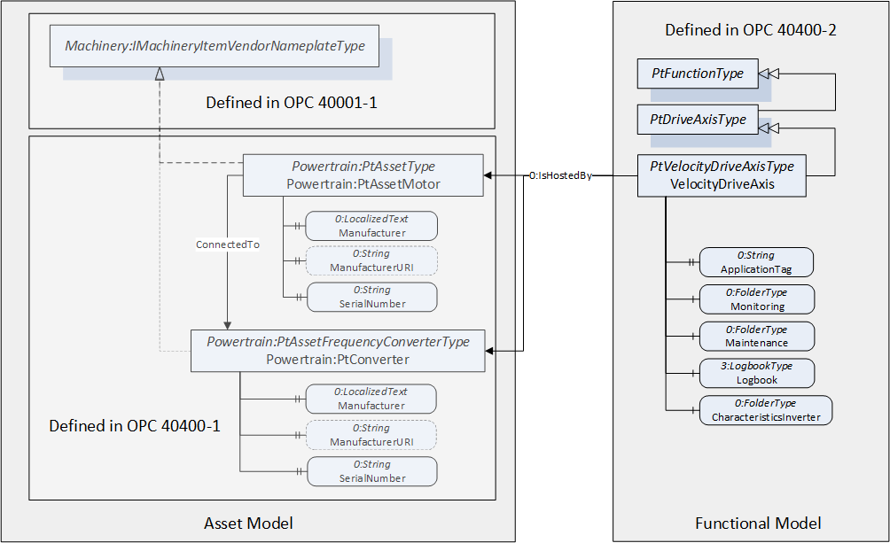
The OPC UA for Powertrain - Functional Model defines all Objects and types provided by an OPC UA Server allowing OPC UA Clients to access online data and services of the Powertrain Functional Objects by providing Powertrain DriveAxis Objects, Powertrain EncoderAxis Objects and Powertrain GearAxis Objects.
The PtFunctionType ObjectType serves as the abstract base for all Powertrain functional ObjectTypes. The components of the PtFunctionType ObjectType belong the sub-aspects of "Fieldbus", "Actual and Command Values", "Diagnosis", "Maintenance" and "Semantic". These sub-aspects combine folder Objects containing Variables matching the designation of this sub-aspect, as shown in Figure 3. Typically, these sub-aspects are dedicated to specific use cases for vertical communication in automation systems.
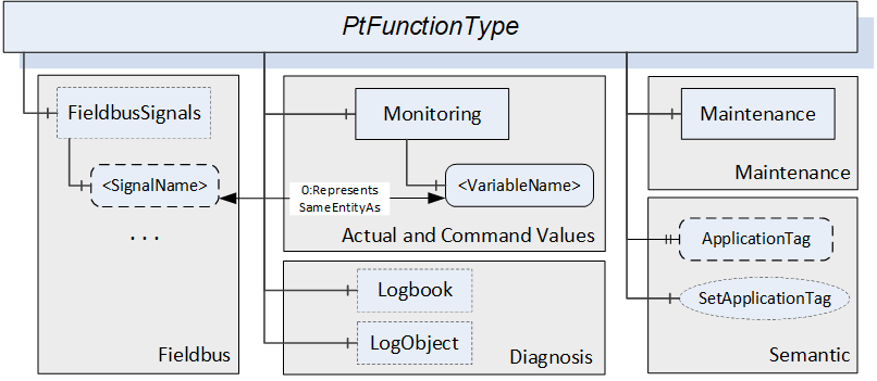
In the optional "Fieldbus" sub-aspect, the "FieldbusSignals" folder Object contains Variables representing signals transmitted over the fieldbus interface. These "Signals" can be used for supervision or debugging of the original values transmitted between the Controller and the Powertrain Object.
The Variable representing a fieldbus signal can relate to a Variable in the "Monitoring" folder using the 0:RepresentsSameEntityAs ReferenceType if the Variables contain the same information. Note, that these two Variables might be encoded in two different ways, e.g. if there is a signal representing the actual velocity the representing Variable may be connected to the VelocityActualValue Variable with the DataType float and an associated unit (via 0:AnalogUnitType) directly usable by Clients. The signal variable might encode the actual velocity as Int32 using a different unit not directly usable by Clients (shift factors, etc.).
Common for all Powertrain Objects, the mandatory "Actual and Command Values" sub-aspect is mainly consisting of Variables which contain the setpoint and measurement values like velocity and acceleration represented as physical values in floating point data types. These Variables are used to address the use case for monitoring on a control panel and the use case for data mining.
The Logbook Object provides access to the Powertrain diagnosis system logbook. Via the Logbook Object access to the current fault situation (faults, warnings, maintenance) and to historical fault situations and diagnosis history is possible.
The "Maintenance" sub-aspect contains Variables yielding maintenance related information, such as operation duration.
The "Semantic" sub-aspect contains information about the overall application context which can be set by an operator.
The Powertrain Axis Objects serve as the root containers for modelling of Devices equipped with one or more motors (also referred to as CDM or Drive). The functional aspect of a Drive contains as many Powertrain Axis Objects as needed. Figure 4 shows the organization of Powertrain Axis Objects. The components of a PtDriveAxisType Object representing a Powertrain Axis Object are part of the sub-aspects "Functional Safety", "Process Supervision" and "Axis Properties".
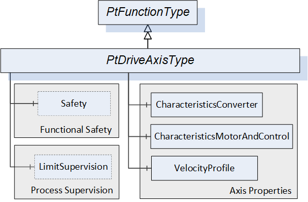
The abstract PtDriveAxisType is derived from the PtFunctionType abstract base ObjectType common to all Powertrain Objects. The concrete ObjectTypes representing Powertrain Axis Objects like PtVelocityDriveAxisType (see section 7.1.1.2) and PtFrequencyDriveAxisType (see section 7.1.1.1) are derived from the abstract PtDriveAxisType base ObjectType (see section 7.1.1).
The "Axis Properties" sub-aspect contains a collection of values which are of special interest for the functional identification and behaviour (configuration) of a Powertrain Axis Object. These values are organized into several containers further structuring the sub-aspects.
The "Safety" sub-aspect contains Objects informing about the status of implemented safety functions.
The "Process Supervision" sub-aspect hosts the optional "LimitSupervision" folder containing Variables with information about limiting values of the PtDriveAxisType Object. Derived ObjectTypes may render the LimitSupervision folder mandatory.
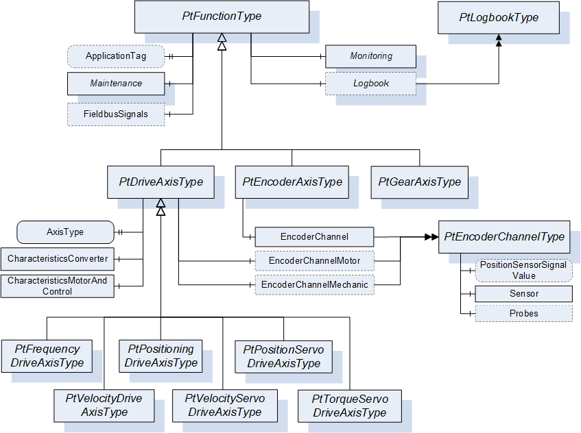
As shown in Figure 5, the PtEncoderAxisType and PtGearAxisType concrete ObjectTypes are derived directly from the abstract PtFunctionType thus not containing a controllable motor or actuator.
6.2 Powertrain Functional Model Security
Servers shall allow Method invocation only for Sessions using user accounts with the right to invoke Methods. There shall exist user accounts with restricted rights (that is, no Method invocation unless explicitly allowed for all users for a specific Method) for Clients performing data acquisition or diagnosis also.
If well-known Roles are supported by the Server, role-based security (see [OPC 10000-18] shall be applied. Method invocation shall only be possible if the well-known "Operator" Role is granted to the Client's Session. This applies to all Methods except for those where the restriction is lifted explicitly.
All Variables are read-only. Modifying the content of Variables shall only be possible by invoking a "Set-" Method.
7 OPC UA ObjectTypes
Figure 5 shows the organization of the OPC UA for Powertrain - Functional Model ObjectTypes used to model Powertrain Objects. All Axis ObjectTypes are derived from the abstract PtDriveAxisType providing the functions common to all Axis ObjectTypes.
The PtDriveAxisType ObjectType is derived from the PtFunctionType ObjectType defining common properties shared by all Powertrain Objects.
7.1 PtFunctionType definition
The PtFunctionType specifies the properties which are common for all OPC UA for Powertrain - Functional Model ObjectTypes.
| Attribute | Value | ||||
| BrowseName | PtFunctionType | ||||
| IsAbstract | True | ||||
| References | Node Class | BrowseName | DataType | TypeDefinition | Other |
|---|---|---|---|---|---|
| Subtype of the 0:BaseObjectType defined in OPC 10000-5. | |||||
| 0:HasProperty | Variable | ApplicationTag | 0:String | 0:PropertyType | O, RO |
| 0:HasComponent | Method | SetApplicationTag | O | ||
| 0:HasComponent | Object | Lock | 2:LockingServicesType | O | |
| 0:HasComponent | Object | FieldbusSignals | 0:FolderType | O | |
| 0:HasComponent | Object | Monitoring | 0:FolderType | M | |
| 0:HasComponent | Object | Maintenance | 0:FolderType | M | |
| 0:HasComponent | Object | Logbook | PtLogbookType | O | |
| 0:GeneratesEvent | ObjectType | PtLogbookEventType | |||
| 0:HasComponent | Object | LogObject | 0:LogObjectType | O | |
| 0:GeneratesEvent | ObjectType | PtLogObjectEventType | |||
| Conformance Units | |||||
|---|---|---|---|---|---|
| Powertrain Actual and Command Values | |||||
| Powertrain Logbook Readable | |||||
| Powertrain Logbook Events | |||||
| Powertrain Fieldbus | |||||
| Powertrain Encoder Channel | |||||
| Powertrain LogObject | |||||
| Powertrain LogObject Events |
General Properties in Semantic sub-aspect
The ApplicationTag Variable contains information given by the overall application. The purpose is to provide additional semantic information about the represented Powertrain Objects role or labelling in the context of the specific overall application context (machine, site or plant). Therefore, plant operators and/or application engineers are responsible to set the content of the ApplicationTag with information used for site management, asset management or other administrative purposes, e.g. "Production Line <m>/Machine <n>/x-Axis".
Furthermore, information out of identification objects offered by field bus protocols may be used as content of the ApplicationTag Variable (e.g. in case of PROFINET, the I&M-1 record "tag-function" or the I&M-3 "descriptor" could be used). However, as a default, vendors could also generate the ApplicationTag string out of the device or field bus configuration data as initial content of the Variable (e.g. in case of PROFINET, the NameOfStation and Module/Axis number could be used).
The Client can change the Value of this Variable by invoking the SetApplicationTag Method.
Before invoking a Method of the PtFunctionType Object, Clients must gain exclusive write access ("lock" the PtFunctionType Object) using the Lock Object.
The Lock Object ensures exclusive Method call for one Client. The Client locks the PtFunctionType Object by invoking the InitLock Method of the Lock Object. The Client invokes ExitLock to release the lock.
Some components of the PtFunctionType have additional subcomponents which are defined in Table 16.
| BrowsePath | References | NodeClass | BrowseName | DataType | TypeDefinition | Others | ||
| FieldbusSignals | 0:HasComponent | Variable | <SignalName> | 0:Number | 0:BaseDataVariableType | OP, RO | ||
| Monitoring | 0:HasComponent | Variable | ControlPriority | 0:UInt16 | PtControlPriorityVariableType | O, RO | ||
| Monitoring | 0:HasComponent | Variable | ShaftTurningDirection | 0:UInt16 | PtShaftTurningDirectionVariableType | O, RO | ||
| Monitoring | 0:HasComponent | Variable | DeviceTemperature | 0:Float | PtTemperatureVariableType | O, RO | ||
| Monitoring | 0:HasComponent | Object | <VibrationSensor_x> | PtVibrationSensorType | OP | |||
| Applied from 2:IOperationCounterType Interface: | ||||||||
| Maintenance | 0:HasProperty | Variable | 2:PowerOnDuration | 0:Duration | 0:PropertyType | O, RO | ||
| Maintenance | 0:HasProperty | Variable | 2:OperationDuration | 0:Duration | 0:PropertyType | O, RO | ||
| Maintenance | 0:HasProperty | Variable | 2:OperationCycleCounter | 0:UInteger | 0:PropertyType | O, RO | ||
| Maintenance | 0:HasComponent | Object | <Motor_x> | 0:BaseObjectType | OP | |||
| Maintenance | 0:HasComponent | Object | <Converter> | 0:BaseObjectType | OP | |||
| Maintenance | 0:HasComponent | Object | <Gear_x> | 0:BaseObjectType | OP | |||
| Maintenance | 0:HasComponent | Object | <Encoder_x> | 0:BaseObjectType | OP | |||
| Maintenance | 0:HasComponent | Object | <Brake_x> | 0:BaseObjectType | OP | |||
| Applied from 2:IOperationCounterType Interface: | ||||||||
| 0:HasProperty | Variable | 2:PowerOnDuration | 0:Duration | 0:PropertyType | O, RO | ||
| 0:HasProperty | Variable | 2:OperationDuration | 0:Duration | 0:PropertyType | O, RO | ||
| 0:HasProperty | Variable | 2:OperationCycleCounter | 0:UInteger | 0:PropertyType | O, RO | ||
| 0:HasProperty | Variable | 2:PowerOnDuration | 0:Duration | 0:PropertyType | O, RO | ||
| 0:HasProperty | Variable | 2:OperationDuration | 0:Duration | 0:PropertyType | O, RO | ||
| 0:HasProperty | Variable | 2:OperationCycleCounter | 0:UInteger | 0:PropertyType | O, RO | ||
| 0:HasProperty | Variable | 2:PowerOnDuration | 0:Duration | 0:PropertyType | O, RO | ||
| 0:HasProperty | Variable | 2:OperationDuration | 0:Duration | 0:PropertyType | O, RO | ||
| 0:HasProperty | Variable | 2:OperationCycleCounter | 0:UInteger | 0:PropertyType | O, RO | ||
| 0:HasProperty | Variable | 2:PowerOnDuration | 0:Duration | 0:PropertyType | O, RO | ||
| 0:HasProperty | Variable | 2:OperationDuration | 0:Duration | 0:PropertyType | O, RO | ||
| 0:HasProperty | Variable | 2:OperationCycleCounter | 0:UInteger | 0:PropertyType | O, RO | ||
| 0:HasProperty | Variable | 2:PowerOnDuration | 0:Duration | 0:PropertyType | O, RO | ||
| 0:HasProperty | Variable | 2:OperationDuration | 0:Duration | 0:PropertyType | O, RO | ||
| 0:HasProperty | Variable | 2:OperationCycleCounter | 0:UInteger | 0:PropertyType | O, RO | ||
| 0:HasComponent | Variable | ThermalCapacityUtilization | 0:UInteger | 0:BaseDataVariableType | O, RO | ||
| 0:HasComponent | Variable | PeakUtilization | 0:UInteger | 0:BaseDataVariableType | O, RO | ||
| 0:HasComponent | Variable | RemainingUsefulLifetime | 0:Integer | 0:BaseDataVariableType | O, RO | ||
| 0:HasProperty | Variable | OilRemainingUsefulLifetime | 0:Duration | 0:PropertyType | O, RO | ||
| 0:HasComponent | Variable | MaintenanceStatus | 0:UInt16 | PtMaintenanceStatusVariableType | O, RO | ||
| Maintenance | 0:HasComponent | Variable | ThermalCapacityUtilization | 0:UInteger | 0:BaseDataVariableType | O, RO | ||
| Maintenance | 0:HasComponent | Variable | PeakUtilization | 0:UInteger | 0:BaseDataVariableType | O, RO | ||
| Maintenance | 0:HasComponent | Variable | RemainingUsefulLifetime | 0:Integer | 0:BaseAnalogType | O, RO | ||
| Maintenance | 0:HasComponent | Variable | GearOilRemainingUsefulLifetime | 0:Integer | 0:BaseAnalogType | O, RO | ||
| Maintenance | 0:HasComponent | Variable | GearMaintenanceStatus | 0:UInt16 | PtMaintenanceStatusVariableType | O, RO | ||
SetApplicationTag Method
This Method sets the Value of the ApplicationTag Variable. The security constraints defined in chapter 0 apply.
Signature
	SetApplicationTag (
		[in] 0:String	 ApplicationTag
		);
| Argument | Description |
| ApplicationTag | String containing the desired content of the ApplicationTag Variable. |
The Method Result Codes (defined in Call Service) are defined in Table 17.
| Result Code | Description |
| Good | The Method execution was successful. |
| Bad_UserAccessDenied | The user has not the authorization to execute the Method. |
| Bad_InvalidArgument | The Server is not able to apply the name. The ApplicationTag string may be too long or may contain invalid characters. The Server may also reject duplicates. |
| Bad_Locked | The PtFunctionType Object is locked by a different Client's Session. |
| Bad_RequiresLock | The PtFunctionType Object is not locked. Clients must lock the PtFunctionType Object before invoking a Method. |
| Bad_UnexpectedError | The Server is not able to execute the function because an unexpected error occurred. The Device might be temporarily unavailable or unreachable due to network failure. |
Monitoring folder in Actual and Command Values sub-aspect
The Monitoring folder contains Variables common to all derived ObjectTypes. Derived ObjectTypes add additional type specific components to the Monitoring folder.
The specification of the Monitoring folder at the abstract root of the type hierarchy renders this folder mandatory for all derived ObjectTypes. The Variables specified by PtFunctionType are defined in Table 16 and are common for all derived ObjectTypes.
Maintenance folder in Maintenance sub-aspect
The Maintenance folder contains optional properties defined by the 2:IOperationCounterType Interface specified in [OPC 10000-100]. Figure 6 shows the motor related components of the Maintenance folder if the Drive has one motor. The PowerOnDuration, OperationDuration and OperationCycleCounter Properties are specified by the applied 2:IOperationCounterType Interface.
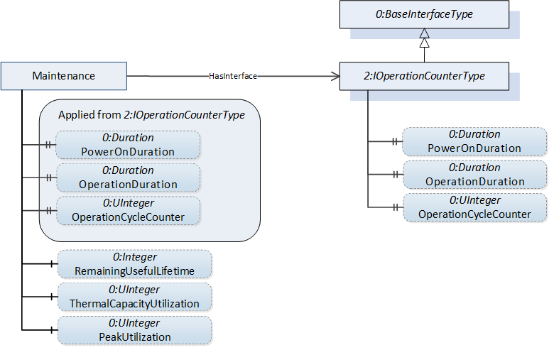
For a description of all Variables and Properties in the "Maintenance" folder see Table 54. The specification of the Maintenance folder at the abstract root of the type hierarchy renders this folder mandatory for all derived ObjectTypes. Derived ObjectTypes may add additional Variables to this folder.
If the Drive has more than one motor, and there are separate maintenance related variables for motors and converter, the 2:IOperationCounterType Interface shall be applied to the <Motor_x> or <Converter> placeholder Objects. The RemainingUsefulLifetime, ThermalCapacityUtilization and PeakUtilization Variables shall also be provided as components of the separate Objects representing the motors or converter in this case, as shown in Figure 7 for a dual motor scenario.
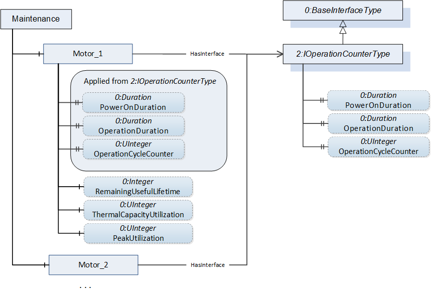
The same principle applies for the <Gear_x> placeholder objects. If the Drive has one gear, the gear-related Variables GearMaintenanceStatus and GearOilRemainingUsefulLifetime shall be provided as components of the Maintenance folder. If the Drive has more than one gear, the <Gear_x> placeholder Objects shall provide the MaintenanceStatus and OilRemainingUsefulLifetime Variables and the GearMaintenanceStatus and GearOilRemainingUsefulLifetime Variables shall be omitted.
If the Drive is equipped with more than one brake, the 2:IOperationCounterType Interface shall be applied to the individual <Brake_x> placeholder Objects. If the Drive is equipped with more than one encoder, this Interface shall be applied to the individual <Encoder_x> Objects.
Diagnosis sub-aspect
The Logbook Object provides access to the PtDriveAxisType Object's diagnosis system.
The Server might provide the Client with information about new incidents by sending PtLogbookEventType Events.
The 0:LogObject Object (defined in OPC 10000-26) can be provided to make the content of the diagnosis system represented by the Logbook Object available for all Clients which prefer to utilize the LogObject. The mapping from the LogEntryDataType structures provided by the Logbook Object to the LogObject's 0:LogRecord structures is specified in Table 94.
The Server might provide the Client with information about new entries in the LogObject by sending PtLogObjectType Events.
The Logbook Object essentially provides the Client with the means to obtain information about the diagnosis state of a PtFunctionType Object. The Logbook also makes the history of diagnosis relevant events available for Clients by recording timestamps for the event when the event first appears, when it is acknowledged and when it disappears. Since the capacity of the diagnosis buffer the Logbook represents is limited, acknowledged events may be deleted by the Server.
The 0:LogObject provides a standard way to collect diagnostic information and to make it available for Clients. This allows a standard Client unaware of the Logbook Object defined in this specification to access the diagnosis information of a Powertrain Object. It also offers more flexibility regarding the required local memory, since the 0:LogObject may send the diagnosis records to a remote Server allowing the local 0:LogObject to have only a small buffer of records. The 0:LogObject also allows the collection of diagnosis information in a system using OpenTelemetry (see OPC 10000-26 Annex C).
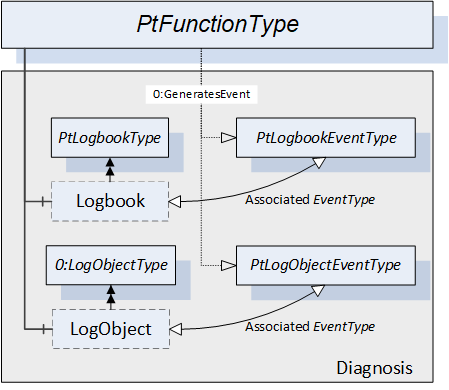
Figure 8 shows the structure of the "Diagnosis" sub-aspect in conjunction with the associated EventTypes. The PtLogbookEventType Events related to entries into the Logbook are generated by the parent PtFunctionType Object. The insertion of 0:LogRecords by the LogObject causes PtLogObjectEventType Events to be generated by the parent PtFunctionType Object as well. The parent PtFunctionType Object is the SourceNode of the Events.
7.1.1 PtDriveAxisType definition
The PtDriveAxisType ObjectType specifies the properties which are common for OPC UA for Powertrain - Functional Model Axis Type Drive Object ObjectTypes. The general characteristic for the PtDriveAxisType is that it contains an actuator.
The PtDriveAxisType is an abstract ObjectType representing Powertrain Drive Axis Objects.
| Attribute | Value | ||||
| BrowseName | PtDriveAxisType | ||||
| IsAbstract | True | ||||
| References | Node Class | BrowseName | DataType | TypeDefinition | Other |
|---|---|---|---|---|---|
| Subtype of the PtFunctionType. | |||||
| 0:HasComponent | Variable | AxisType | 0:UInt16 | 0:MultiStateValueDiscreteType | M, RO |
| 0:HasComponent | Object | LimitSupervision | 0:FolderType | O | |
| 0:HasComponent | Object | CharacteristicsConverter | PtCharacteristicsConverterType | O | |
| 0:HasComponent | Object | CharacteristicsMotorAndControl | 0:FolderType | M | |
| 0:HasComponent | Object | Logbook | PtLogbookType | M | |
| 0:HasComponent | Object | Safety | PtSafetyType | O | |
| 0:HasComponent | Object | VelocityProfile | 0:FolderType | O | |
| 0:HasComponent | Object | Monitoring | 0:FolderType | M | |
| 0:HasComponent | Object | Maintenance | 0:FolderType | M | |
| Conformance Units | |||||
|---|---|---|---|---|---|
| Powertrain Actual and Command Values | |||||
| Powertrain Axis Properties | |||||
| Powertrain Logbook Readable | |||||
| Powertrain Safety |
Some components of the PtDriveAxisType have additional subcomponents which are defined in Table 19. For detailed descriptions of these Variables see Table 54.
| BrowsePath | References | NodeClass | BrowseName | DataType | TypeDefinition | Others |
| Monitoring | 0:HasComponent | Variable | AxisState | 0:UInt16 | 0:MultiStateValueDiscreteType | M, RO |
| Monitoring | 0:HasComponent | Variable | ControlPriority | 0:UInt16 | PtControlPriorityVariableType | M, RO |
| Monitoring | 0:HasComponent | Variable | ControlMode | 0:UInt16 | 0:MultiStateValueDiscreteType | O, RO |
| Monitoring | 0:HasComponent | Variable | FrequencySetpoint | 0:Float | 0:AnalogUnitType | O, RO |
| Applied from IMonitoringElectric Interface (for electric drives only): | ||||||
| Monitoring | 0:HasComponent | Variable | BleederTemperature | 0:Float | PtTemperatureVariableType | O, RO |
| Monitoring | 0:HasComponent | Variable | ConverterOutputFrequency | 0:Float | 0:AnalogUnitType | O, RO |
| Monitoring | 0:HasComponent | Variable | ConverterOutputVoltage | 0:Float | 0:AnalogUnitType | O, RO |
| Monitoring | 0:HasComponent | Variable | ConverterOutputVoltageMagnetization | 0:Float | 0:AnalogUnitType | O, RO |
| Monitoring | 0:HasComponent | Variable | ConverterOutputVoltageTorque | 0:Float | 0:AnalogUnitType | O, RO |
| Monitoring | 0:HasComponent | Variable | ConverterOutputCosPhi | 0:Float | 0:AnalogUnitType | O, RO |
| Monitoring | 0:HasComponent | Variable | ConverterOutputCurrent | 0:Float | 0:AnalogUnitType | O, RO |
| Monitoring | 0:HasComponent | Variable | ConverterOutputCurrentMagnetization | 0:Float | 0:AnalogUnitType | O, RO |
| Monitoring | 0:HasComponent | Variable | ConverterOutputCurrentTorque | 0:Float | 0:AnalogUnitType | O, RO |
| Monitoring | 0:HasComponent | Variable | ConverterOutputPower | 0:Float | 0:AnalogUnitType | O, RO |
| Monitoring | 0:HasComponent | Variable | ConverterTemperature | 0:Float | PtTemperatureVariableType | O, RO |
| Monitoring | 0:HasComponent | Variable | DcBusVoltage | 0:Float | 0:AnalogUnitType | O, RO |
| Monitoring | 0:HasComponent | Variable | LineInputPower | 0:Float | 0:AnalogUnitType | O, RO |
| Monitoring | 0:HasComponent | Variable | TorqueForceActualValue | 0:Float | 0:AnalogUnitType | O, RO |
| Monitoring | 0:HasComponent | Variable | MotorTemperature | 0:Float | PtTemperatureVariableType | O, RO |
| Monitoring | 0:HasComponent | Variable | BrakeState | 0:UInt16 | PtBrakeStateVariableType | O, RO |
| Monitoring | 0:HasComponent | Variable | AxisTorqueForce | 0:Float | 0:AnalogUnitType | O, RO |
| Monitoring | 0:HasComponent | Variable | AxisOutputVelocity | 0:Float | 0:AnalogUnitType | O, RO |
| Monitoring | 0:HasComponent | Variable | GearInputVelocity | 0:Float | 0:AnalogUnitType | O, RO |
| Monitoring | 0:HasComponent | Variable | GearInputTorque | 0:Float | 0:AnalogUnitType | O, RO |
| Monitoring | 0:HasComponent | Variable | GearOutputVelocity | 0:Float | 0:AnalogUnitType | O, RO |
| Monitoring | 0:HasComponent | Variable | GearOutputTorque | 0:Float | 0:AnalogUnitType | O, RO |
| Monitoring | 0:HasComponent | Variable | GearRatio | 0:Float | 0:BaseDataVariableType | O, RO |
| Monitoring | 0:HasComponent | Variable | GearTemperature | 0:Float | PtTemperatureVariableType | O, RO |
| Monitoring | 0:HasComponent | Variable | GearState | 0:UInt16 | PtGearStateVariableType | O, RO |
| Monitoring | 0:HasComponent | Variable | GearOutputShaftTurningDirection | 0:UInt16 | PtShaftTurningDirectionVariableType | O, RO |
| Monitoring | 0:HasComponent | Variable | GearInputShaftTurningDirection | 0:UInt16 | PtShaftTurningDirectionVariableType | O, RO |
| Maintenance | 0:HasComponent | Variable | GearBacklash | 0:Float | 0:AnalogUnitType | O, RO |
| CharacteristicsMotorAndControl | 0:HasComponent | Variable | MotorPowerRated | 0:Float | 0:AnalogUnitType | M, RO |
| CharacteristicsMotorAndControl | 0:HasComponent | Variable | MotorSpeedRated | 0:Float | 0:AnalogUnitType | O, RO |
| CharacteristicsMotorAndControl | 0:HasComponent | Variable | MotorTorqueRated | 0:Float | 0:AnalogUnitType | O, RO |
| CharacteristicsMotorAndControl | 0:HasComponent | Variable | MotorForceRated | 0:Float | 0:AnalogUnitType | O, RO |
| Applied from ICharacteristicsMotorAndControlElectric Interface (for electric drives only): | ||||||
| CharacteristicsMotorAndControl | 0:HasComponent | Variable | MotorMaxCurrent | 0:Float | 0:AnalogUnitType | O, RO |
| CharacteristicsMotorAndControl | 0:HasProperty | Variable | MotorUfRatio | 0:Float | 0:PropertyType | O, RO |
| CharacteristicsMotorAndControl | 0:HasComponent | Variable | MotorRunUpVoltage | 0:Float | 0:AnalogUnitType | O, RO |
| CharacteristicsMotorAndControl | 0:HasComponent | Variable | MotorDcBrakingCurrent | 0:Float | 0:AnalogUnitType | O, RO |
| CharacteristicsMotorAndControl | 0:HasComponent | Variable | DcBrakingTime | 0:Float | 0:AnalogUnitType | O, RO |
| CharacteristicsMotorAndControl | 0:HasComponent | Variable | MotorThermalLoadLimitConfigured | 0:Float | 0:AnalogUnitType | O, RO |
| CharacteristicsMotorAndControl | 0:HasComponent | Variable | MotorPeakCurrentConfigured | 0:Float | 0:AnalogUnitType | O, RO |
| CharacteristicsMotorAndControl | 0:HasComponent | Variable | TimePeriodCurrentControl | 0:Float | 0:AnalogUnitType | O, RO |
| CharacteristicsMotorAndControl | 0:HasComponent | Variable | FeedbackMode | 0:UInt16 | 0:MultiStateValueDiscreteType | O, RO |
| CharacteristicsMotorAndControl | 0:HasComponent | Variable | SpeedMaxConfigured | 0:Float | 0:AnalogUnitType | O, RO |
| CharacteristicsMotorAndControl | 0:HasComponent | Variable | TorqueMaxConfigured | 0:Float | 0:AnalogUnitType | O, RO |
| CharacteristicsMotorAndControl | 0:HasComponent | Variable | MotorType | 0:UInt16 | 0:MultiStateValueDiscreteType | M, RO |
| CharacteristicsMotorAndControl | 0:HasComponent | Variable | PositionFollowingErrorLimit | 0:Float | 0:AnalogUnitType | O, RO |
| CharacteristicsMotorAndControl | 0:HasComponent | Variable | VelocityFollowingErrorLimit | 0:Float | 0:AnalogUnitType | O, RO |
| Applied from ILimitSupervisionElectric Interface (for electric drives only): | ||||||
| LimitSupervision | 0:HasComponent | Variable | MotorCurrentLimitLow | 0:Float | 0:AnalogUnitType | O, RO |
| LimitSupervision | 0:HasComponent | Variable | MotorCurrentLimitHigh | 0:Float | 0:AnalogUnitType | O, RO |
| VelocityProfile | 0:HasComponent | Variable | JogSpeed1 | 0:Float | 0:AnalogUnitType | O, RO |
| VelocityProfile | 0:HasComponent | Variable | JogSpeed2 | 0:Float | 0:AnalogUnitType | O, RO |
| VelocityProfile | 0:HasComponent | Variable | NominalSpeed | 0:Float | 0:AnalogUnitType | O, RO |
| VelocityProfile | 0:HasComponent | Variable | VelocityRampDownTime | 0:Float | 0:AnalogUnitType | O, RO |
| VelocityProfile | 0:HasComponent | Variable | QuickStopVelocityRampDownTime | 0:Float | 0:AnalogUnitType | O, RO |
| VelocityProfile | 0:HasComponent | Variable | VelocityRampDeceleration | 0:Float | 0:AnalogUnitType | O, RO |
| VelocityProfile | 0:HasComponent | Variable | QuickStopVelocityRampDeceleration | 0:Float | 0:AnalogUnitType | O, RO |
| VelocityProfile | 0:HasComponent | Variable | MinimumVelocity | 0:Float | 0:AnalogUnitType | O, RO |
| VelocityProfile | 0:HasComponent | Variable | MaximumVelocity | 0:Float | 0:AnalogUnitType | O, RO |
The child Nodes of the PtDriveAxisType have additional Attribute values defined in Table 20.
| BrowsePath | Value Attribute | |||
| [ { "Value":0, "DisplayName": "LINEAR", "Description": "Axis with linear movement" }, { "Value":1, "DisplayName": "ROTATORY", "Description": "Axis with rotatory movement" }, { "Value":2, "DisplayName": "ROTATORY_MODULO", "Description": "Single turn rotatory axis with modulo correction" }, { "Value":3, "DisplayName": "SPINDLE", "Description": "Axis with spindle properties" }, { "Value":4, "DisplayName": "VIRTUAL_AXIS_LINEAR", "Description": "Virtual axis with linear movement" }, { "Value":5, "DisplayName": "VIRTUAL_AXIS_ROTARY", "Description": "Virtual axis with rotatory movement" } ] | |||
| [ { "Value":0, "DisplayName": "SWITCHING_ON_INHIBITED", "Description": "Switching on inhibited" }, { "Value":1, "DisplayName": "READY_FOR_SWITCHING_ON", "Description": "Ready for switching on" }, { "Value":2, "DisplayName": "SWITCHED_ON", "Description": "Switched on" }, { "Value":3, "DisplayName": "OPERATION", "Description": "In operation" }, { "Value":4, "DisplayName": "RAMP_STOP", "Description": "Controlled stop by ramp function" }, { "Value":5, "DisplayName": "QUICK_STOP", "Description": "Controlled stop with maximum deceleration" }, { "Value":6, "DisplayName": "POS_BASIC_STATE", "Description": "Positioning mode basic state" }, { "Value":7, "DisplayName": "POS_JOGGING", "Description": "Positioning mode jogging" }, { "Value":8, "DisplayName": "POS_BRAKING_WITH_RAMP", "Description": "Positioning mode braking with ramp function" }, { "Value":9, "DisplayName": "POS_HOMING_PROCEDURE", "Description": "Positioning mode homing" }, { "Value":10, "DisplayName": "POS_TRAVERSING_TASK_ACTIVE", "Description": "Positioning mode traversing task active" }, { "Value":11, "DisplayName": "POS_INTERMEDIATE_STOP_STOPPED", "Description": "Positioning mode stopped in intermediate stop" }, { "Value":12, "DisplayName": "POS_INTERMEDIATE_STOP_BRAKING", "Description": "Positioning mode breaking in intermediate stop" }, { "Value":13, "DisplayName": "PARKED", "Description": "Parked" }, { "Value":14, "DisplayName": "SPINDLE_STOPPED", "Description": "Spindle stopped" }, { "Value":15, "DisplayName": "SPINDLE_ACCELERATING", "Description": "Spindle is accelerating" }, { "Value":16, "DisplayName": "SPINDLE_DECELERATING", "Description": "Spindle is decelerating" }, { "Value":17, "DisplayName": "SPINDLE_IN_TARGET_AREA", "Description": "Spindle is in target area" } ] | |||
| [ { "Value":0, "DisplayName": "TORQUE_CONTROL", "Description": "Torque control" }, { "Value":1, "DisplayName": "TORQUE_CONTROL_SENSORLESS", "Description": "Torque control sensorless" }, { "Value":2, "DisplayName": "FORCE_CONTROL", "Description": "Force control" }, { "Value":3, "DisplayName": "FORCE_CONTROL_SENSORLESS", "Description": "Force control sensorless" }, { "Value":4, "DisplayName": "SPEED_CONTROL", "Description": "Speed control" }, { "Value":5, "DisplayName": "SPEED_CONTROL_SENSORLESS", "Description": "Speed control sensorless" }, { "Value":6, "DisplayName": "SPEED_CONTROL_DSC", "Description": "Speed control with dynamic stiffness control" }, { "Value":7, "DisplayName": "POSITION_CONTROL", "Description": "Position control" }, { "Value":8, "DisplayName": "POSITION_CONTROL_SENSORLESS", "Description": "Position control sensorless" }, { "Value":9, "DisplayName": "POSITIONING_CONTROL", "Description": "Positioning control" }, { "Value":10, "DisplayName": "UF_CONTROL", "Description": "U/F control" }, { "Value":11, "DisplayName": "VECTOR_CONTROL", "Description": "Vector control" }, { "Value":12, "DisplayName": "VECTOR_CONTROL_SENSORLESS", "Description": "Vector control sensorless" } ] | |||
| [ { "Value":0, "DisplayName": "FEEDBACK_MOTOR", "Description": "Feedback with motor encoder" }, { "Value":1, "DisplayName": "FEEDBACK_DIRECT", "Description": "Feedback with direct encoder" }, { "Value":2, "DisplayName": "FEEDBACK_MOTOR_AND_DIRECT", "Description": "Feedback with motor and direct encoder" }, { "Value":3, "DisplayName": "FEEDBACK_SENSOR_1", "Description": "Feedback with sensor 1" }, { "Value":4, "DisplayName": "FEEDBACK_SENSOR_2", "Description": "Feedback with sensor 2" }, { "Value":5, "DisplayName": "FEEDBACK_SENSOR_3", "Description": "Feedback with sensor 3" }, { "Value":6, "DisplayName": "SENSORLESS", "Description": "Feedback without sensor" } ] | |||
| [ { "Value":0, "DisplayName": "ASYNCHRONOUS", "Description": "Induction motor" }, { "Value":1, "DisplayName": "PM_AC_SYNCHRONOUS", "Description": "Synchronous motor" }, { "Value":2, "DisplayName": "PM_AC_SYNCHRONOUS_IRONLESS", "Description": "Synchronous ironless motor" }, { "Value":3, "DisplayName": "DC_BRUSHLESS", "Description": "Brushless DC motor" }, { "Value":4, "DisplayName": "DC_BRUSHED", "Description": "DC motor" }, { "Value":5, "DisplayName": "PM_STEPPER", "Description": "Stepper motor" }, { "Value":6, "DisplayName": "HYBRID_STEPPER", "Description": "Hybrid stepper motor" }, { "Value":7, "DisplayName": "SYNC_RELUCTANCE", "Description": "Synchronous reluctance motor" } ] |
Some values represented as enumerations in the Monitoring and CharacteristicsMotorAndControl folders are modelled as 0:MultiStateValueDiscreteType Variables. The content of the EnumValues lookup table Property is defined in Table 20 for all these 0:MultiStateValueDiscreteType Variables. The "Locale" field of the 0:LocalizedText structures is Server specific.
The AxisType Variable contains the mechanical drive type of the represented Powertrain Axis Object modelled as 0:MultiStateValueDiscreteType.
Monitoring folder in Actual and Command Values sub-aspect
The Monitoring folder inherited from PtFunctionType contains Monitoring Variables describing measurements of the Powertrain Axis Objects which are of interest for monitoring encoded as numeric data type. The PtDriveAxisType ObjectType adds Variables and Properties common for all the derived concrete ObjectTypes. Each derived ObjectType may add the Variables and Properties specific for the respective ObjectType.
Instances of the Monitoring folder shall reference the IMonitoringElectric Interface using the HasInterface ReferenceType.
For a description of all Variables and Properties in the "Monitoring" folder see Table 54.
LimitSupervision folder in Process Supervision sub-aspect
The LimitSupervision folder contains Variables with Values describing limit values for motor current, torque, and the like. These limit Variables differ between concrete derived Axis ObjectTypes and are specified separately for each derived Axis ObjectType.
Instances of the LimitSupervision folder shall reference the ILimitSupervisionElectric Interface using the HasInterface ReferenceType.
For a description of the Variables in the "LimitSupervision" folder see Table 54.
Axis Properties sub-aspect
The CharacteristicsConverter Object contains Variables with Values describing key data of the CDM's converter. This ObjectType represents the electric converter properties of electric drives and shall be always provided for electric drives. However, future versions of this specification might support additional drive types such as hydraulic or pneumatic drives. For these drive types dedicated Objects might be specified and referenced with additional optional HasComponent References.
The CharacteristicsMotorAndControl folder contains Variables with Values describing key data of the CDM's motor and its key control features.
Instances of the CharacteristicsMotorAndControl folder shall reference the ICharacteristicsMotorAndControlElectric Interface using the HasInterface ReferenceType.
The VelocityProfile folder contains Variables describing key properties of brake ramps. In addition, this folder also contains Variables describing the properties of a ramp function generator often available with VSD drives. The folder contains the properties mandatory for each derived Powertrain Axis Object type.
The Variables VelocityRampUpTime and VelocityRampDownTime are always related to the Value of the NominalSpeed Variable. The Variable VelocityRampDeceleration describes the same ramp function as VelocityRampDownTime and shall therefore always be provided together with this Variable. The same is true for the Variables VelocityRampUpTime and VelocityRampAcceleration provided by derived axis types.
For a description of the Variables in the CharacteristicsMotorAndControl folder and the VelocityProfile folder see Table 54.
7.1.1.1 PtFrequencyDriveAxisType
A PtFrequencyDriveAxisType is a PtDriveAxisType representing the functionality of a VSD with a frequency command interface. Figure 9 shows a block diagram demonstrating the basic organization and control flow for this axis type.
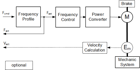
The formal definition of the PtFrequencyDriveAxisType ObjectType can be found in Table 21.
| Attribute | Value | ||||
| BrowseName | PtFrequencyDriveAxisType | ||||
| IsAbstract | False | ||||
| References | Node Class | BrowseName | DataType | TypeDefinition | Other |
|---|---|---|---|---|---|
| Subtype of the PtDriveAxisType. | |||||
| 0:GeneratesEvent | ObjectType | PtMotorCurrentLimitEventType | |||
| 0:HasComponent | Object | CharacteristicsMechanics | 0:FolderType | O | |
| 0:HasComponent | Object | VelocityProfile | 0:FolderType | M | |
| 0:HasComponent | Object | Monitoring | 0:FolderType | M | |
| 0:HasComponent | Object | CharacteristicsMotorAndControl | 0:FolderType | M | |
| 0:HasComponent | Object | LimitSupervision | 0:FolderType | O | |
| Conformance Units | |||||
|---|---|---|---|---|---|
| Powertrain Actual and Command Values | |||||
| Powertrain Axis Properties |
The components of the PtFrequencyDriveAxisType have additional subcomponents which are defined in Table 22.
| BrowsePath | References | NodeClass | BrowseName | DataType | TypeDefinition | Others |
| Monitoring | 0:HasComponent | Variable | FrequencyCommandValue | 0:Float | 0:AnalogUnitType | M, RO |
| Monitoring | 0:HasComponent | Variable | VelocityActualValue | 0:Float | 0:AnalogUnitType | O, RO |
| Monitoring | 0:HasComponent | Variable | FrequencySetpoint | 0:Float | 0:AnalogUnitType | M, RO |
| Monitoring | 0:HasComponent | Variable | ConverterOutputFrequency | 0:Float | 0:AnalogUnitType | M, RO |
| CharacteristicsMotorAndControl | 0:HasComponent | Variable | TimePeriodVelocityControl | 0:Float | 0:AnalogUnitType | O, RO |
| CharacteristicsMechanics | 0:HasComponent | Variable | GearFactorPrecise | PtGearFactorDataType | 0:BaseDataVariableType | O, RO |
| CharacteristicsMechanics | 0:HasComponent | Variable | GearRatio | 0:Float | 0:BaseDataVariableType | O, RO |
| LimitSupervision | 0:HasComponent | Variable | MotorCurrentLimitHigh | 0:Float | 0:AnalogUnitType | M, RO |
| LimitSupervision | 0:HasComponent | Variable | TorqueLimit | 0:Float | 0:AnalogUnitType | O, RO |
| LimitSupervision | 0:HasComponent | Variable | TorqueLimitLow | 0:Float | 0:AnalogUnitType | O, RO |
| LimitSupervision | 0:HasComponent | Variable | TorqueLimitHigh | 0:Float | 0:AnalogUnitType | O, RO |
| VelocityProfile | 0:HasComponent | Variable | VelocityRampUpTime | 0:Float | 0:AnalogUnitType | O, RO |
| VelocityProfile | 0:HasComponent | Variable | VelocityRampAcceleration | 0:Float | 0:AnalogUnitType | O, RO |
For a description of the Variables see Table 54.
7.1.1.2 PtVelocityDriveAxisType
The PtVelocityDriveAxisType is an PtDriveAxisType representing the functionality of a VSD with a speed command interface. Figure 10 shows a block diagram demonstrating the basic organization and control flow for this axis type.
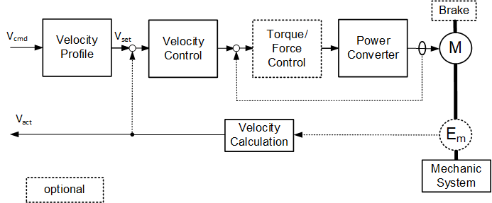
The formal definition of the PtVelocityDriveAxisType ObjectType can be found in Table 23.
| Attribute | Value | ||||
| BrowseName | PtVelocityDriveAxisType | ||||
| IsAbstract | False | ||||
| References | Node Class | BrowseName | DataType | TypeDefinition | Other |
|---|---|---|---|---|---|
| Subtype of the PtDriveAxisType. | |||||
| 0:HasComponent | Object | VelocityProfile | 0:FolderType | M | |
| 0:HasComponent | Object | CharacteristicsMechanics | 0:FolderType | O | |
| 0:GeneratesEvent | ObjectType | PtTorqueForceLimitEventType | |||
| 0:GeneratesEvent | ObjectType | PtMotorCurrentLimitEventType | |||
| 0:HasComponent | Object | Monitoring | 0:FolderType | M | |
| 0:HasComponent | Object | CharacteristicsMotorAndControl | 0:FolderType | M | |
| 0:HasComponent | Object | LimitSupervision | 0:FolderType | O | |
| Conformance Units | |||||
|---|---|---|---|---|---|
| Powertrain Actual and Command Values | |||||
| Powertrain Axis Properties | |||||
| Powertrain Limit Events |
The components of the PtVelocityDriveAxisType have additional subcomponents which are defined in Table 24.
| BrowsePath | References | NodeClass | BrowseName | DataType | TypeDefinition | Others |
| Monitoring | 0:HasComponent | Variable | VelocitySetpoint | 0:Float | 0:AnalogUnitType | M, RO |
| Monitoring | 0:HasComponent | Variable | VelocityCommandValue | 0:Float | 0:AnalogUnitType | M, RO |
| Monitoring | 0:HasComponent | Variable | VelocityCommandAdditiveValue | 0:Float | 0:AnalogUnitType | O, RO |
| Monitoring | 0:HasComponent | Variable | VelocityActualValue | 0:Float | 0:AnalogUnitType | M, RO |
| Monitoring | 0:HasComponent | Variable | AccelerationSetpoint | 0:Float | 0:AnalogUnitType | O, RO |
| Monitoring | 0:HasComponent | Variable | AccelerationCommandAdditiveValue | 0:Float | 0:AnalogUnitType | O, RO |
| Monitoring | 0:HasComponent | Variable | AccelerationActualValue | 0:Float | 0:AnalogUnitType | O, RO |
| Monitoring | 0:HasComponent | Variable | PositionActualValue | 0:Double | 0:AnalogUnitType | O, RO |
| Monitoring | 0:HasComponent | Variable | TorqueForceSetpoint | 0:Float | 0:AnalogUnitType | O, RO |
| Monitoring | 0:HasComponent | Variable | TorqueForceCommandAdditiveValue | 0:Float | 0:AnalogUnitType | O, RO |
| Monitoring | 0:HasComponent | Variable | <EncoderxTemperature> | 0:Float | PtTemperatureVariableType | OP, RO |
| Monitoring | 0:HasComponent | Variable | VelocityFollowingError | 0:Float | 0:AnalogUnitType | O, RO |
| CharacteristicsMotorAndControl | 0:HasComponent | Variable | TimePeriodVelocityControl | 0:Float | 0:AnalogUnitType | O, RO |
| CharacteristicsMotorAndControl | 0:HasComponent | Variable | TimePeriodTorqueControl | 0:Float | 0:AnalogUnitType | O, RO |
| CharacteristicsMechanics | 0:HasComponent | Variable | GearFactorPrecise | PtGearFactorDataType | 0:BaseDataVariableType | O, RO |
| CharacteristicsMechanics | 0:HasComponent | Variable | GearRatio | 0:Float | 0:BaseDataVariableType | O, RO |
| LimitSupervision | 0:HasComponent | Variable | TorqueLimit | 0:Float | 0:AnalogUnitType | O, RO |
| LimitSupervision | 0:HasComponent | Variable | TorqueLimitLow | 0:Float | 0:AnalogUnitType | O, RO |
| LimitSupervision | 0:HasComponent | Variable | TorqueLimitHigh | 0:Float | 0:AnalogUnitType | O, RO |
| VelocityProfile | 0:HasComponent | Variable | VelocityRampUpTime | 0:Float | 0:AnalogUnitType | O, RO |
| VelocityProfile | 0:HasComponent | Variable | VelocityRampAcceleration | 0:Float | 0:AnalogUnitType | O, RO |
For a description of the Variables see Table 54.
7.1.1.3 PtPositioningDriveAxisType
A PtPositioningDriveAxisType is an PtDriveAxisType representing the functionality of a servo drive or stepper drive with a motion trajectory command interface. Figure 11 shows a block diagram demonstrating the basic organization and control flow for this axis type.
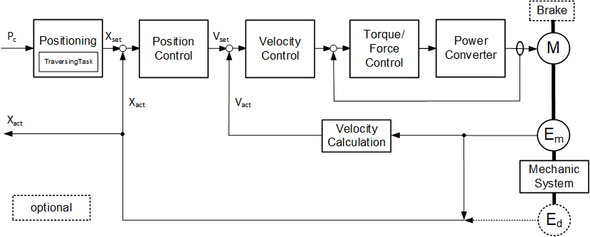
The formal definition of the PtPositioningDriveAxisType ObjectType can be found in Table 25.
| Attribute | Value | ||||
| BrowseName | PtPositioningDriveAxisType | ||||
| IsAbstract | False | ||||
| References | Node Class | BrowseName | DataType | TypeDefinition | Other |
|---|---|---|---|---|---|
| Subtype of the PtDriveAxisType. | |||||
| 0:HasComponent | Object | Homing | 0:FolderType | M | |
| 0:HasComponent | Object | CharacteristicsMechanics | 0:FolderType | O | |
| 0:HasComponent | Object | VelocityProfile | 0:FolderType | M | |
| 0:HasComponent | Object | LimitSupervision | 0:FolderType | M | |
| 0:HasComponent | Object | Monitoring | 0:FolderType | M | |
| 0:HasComponent | Object | CharacteristicsMotorAndControl | 0:FolderType | M | |
| 0:HasComponent | Object | MotionProgram | 0:FileType | O | |
| 0:GeneratesEvent | ObjectType | PtTorqueForceLimitEventType | |||
| 0:GeneratesEvent | ObjectType | PtMotorCurrentLimitEventType | |||
| Conformance Units | |||||
|---|---|---|---|---|---|
| Powertrain Actual and Command Values | |||||
| Powertrain Axis Properties | |||||
| Powertrain Limit Events |
Some components of the PtPositioningDriveAxisType have additional subcomponents which are defined in Table 26.
| BrowsePath | References | NodeClass | BrowseName | DataType | TypeDefinition | Others |
| Monitoring | 0:HasComponent | Variable | PositionActualValue | 0:Double | 0:AnalogUnitType | M, RO |
| Monitoring | 0:HasComponent | Variable | PositionCommandValue | 0:Float | 0:AnalogUnitType | O, RO |
| Monitoring | 0:HasComponent | Variable | PositionSetpoint | 0:Float | 0:AnalogUnitType | O, RO |
| Monitoring | 0:HasComponent | Variable | VelocityActualValue | 0:Float | 0:AnalogUnitType | M, RO |
| Monitoring | 0:HasComponent | Variable | VelocitySetpoint | 0:Float | 0:AnalogUnitType | O, RO |
| Monitoring | 0:HasComponent | Variable | AccelerationActualValue | 0:Float | 0:AnalogUnitType | O, RO |
| Monitoring | 0:HasComponent | Variable | AccelerationSetpoint | 0:Float | 0:AnalogUnitType | O, RO |
| Monitoring | 0:HasComponent | Variable | TorqueForceSetpoint | 0:Float | 0:AnalogUnitType | O, RO |
| Monitoring | 0:HasComponent | Variable | TorqueForceCommandAdditiveValue | 0:Float | 0:AnalogUnitType | O, RO |
| Monitoring | 0:HasComponent | Variable | <EncoderxTemperature> | 0:Float | PtTemperatureVariableType | OP, RO |
| Monitoring | 0:HasComponent | Variable | PositionFollowingError | 0:Float | 0:AnalogUnitType | O, RO |
| Monitoring | 0:HasComponent | Variable | VelocityFollowingError | 0:Float | 0:AnalogUnitType | O, RO |
| Monitoring | 0:HasComponent | Object | TraversingTask | PtTraversingTaskType | M | |
| Monitoring | 0:HasComponent | Variable | Override | 0:Float | 0:BaseDataVariableType | O, RO |
| Monitoring | 0:HasComponent | Variable | HomingState | 0:UInt16 | PtHomingStateVariableType | M, RO |
| LimitSupervision | 0:HasComponent | Variable | MotorCurrentLimitHigh | 0:Float | 0:AnalogUnitType | M, RO |
| LimitSupervision | 0:HasComponent | Variable | TorqueLimit | 0:Float | 0:AnalogUnitType | O, RO |
| LimitSupervision | 0:HasComponent | Variable | TorqueLimitLow | 0:Float | 0:AnalogUnitType | O, RO |
| LimitSupervision | 0:HasComponent | Variable | TorqueLimitHigh | 0:Float | 0:AnalogUnitType | O, RO |
| LimitSupervision | 0:HasComponent | Variable | SoftwarePosLimitLow | 0:Float | 0:AnalogUnitType | M, RO |
| LimitSupervision | 0:HasComponent | Variable | SoftwarePosLimitHigh | 0:Float | 0:AnalogUnitType | M, RO |
| LimitSupervision | 0:HasComponent | Variable | TorqueLimiting | 0:Boolean | 0:BaseDataVariableType | O, RO |
| CharacteristicsMotorAndControl | 0:HasComponent | Variable | TimePeriodVelocityControl | 0:Float | 0:AnalogUnitType | O, RO |
| CharacteristicsMotorAndControl | 0:HasComponent | Variable | TimePeriodTrajectoryInterpolation | 0:Float | 0:AnalogUnitType | O, RO |
| CharacteristicsMotorAndControl | 0:HasComponent | Variable | TimePeriodPositionControl | 0:Float | 0:AnalogUnitType | O, RO |
| CharacteristicsMotorAndControl | 0:HasComponent | Variable | TimePeriodTorqueControl | 0:Float | 0:AnalogUnitType | O, RO |
| CharacteristicsMotorAndControl | 0:HasComponent | Variable | TrajectoryInterpolationMode | 0:Byte | 0:MultiStateValueDiscreteType | O, RO |
| Homing | 0:HasComponent | Variable | HomingDirection | 0:UInt16 | PtHomingDirectionVariableType | O, RO |
| Homing | 0:HasComponent | Variable | HomingSpeedToCam | 0:Float | 0:AnalogUnitType | O, RO |
| Homing | 0:HasComponent | Variable | HomingSpeedToMark | 0:Float | 0:AnalogUnitType | O, RO |
| Homing | 0:HasComponent | Variable | HomingPointOffset | 0:Float | 0:AnalogUnitType | O, RO |
| Homing | 0:HasComponent | Variable | HomingMode | 0:UInt16 | PtHomingModeVariableType | M, RO |
| CharacteristicsMechanics | 0:HasComponent | Variable | GearFactorPrecise | PtGearFactorDataType | 0:BaseDataVariableType | O, RO |
| CharacteristicsMechanics | 0:HasComponent | Variable | GearRatio | 0:Float | 0:BaseDataVariableType | O, RO |
| CharacteristicsMechanics | 0:HasComponent | Variable | SpindlePitch | 0:Float | 0:BaseDataVariableType | O, RO |
| VelocityProfile | 0:HasComponent | Variable | JogPosInc1 | 0:Float | 0:AnalogUnitType | O, RO |
| VelocityProfile | 0:HasComponent | Variable | JogPosInc2 | 0:Float | 0:AnalogUnitType | O, RO |
The SpindlePitch Variable shall be provided if a spindle is present in the Powertrain Axis Object.
The child Nodes of the PtPositioningDriveAxisType have additional Attribute values defined in Table 27.
| BrowsePath | Value Attribute | |||
| [ { "Value":0, "DisplayName": "LINEAR", "Description": "Linear trajectory interpolation" }, { "Value":1, "DisplayName": "VENDOR_SPECIFIC", "Description": "Vendor specific trajectory interpolation" } ]
|
For a description of the Variables see Table 54.
7.1.1.4 PtVelocityServoDriveAxisType
A PtVelocityServoDriveAxisType is an PtDriveAxisType representing the functionality of a servo drive with a velocity command interface. Figure 12 shows a block diagram demonstrating the basic organization and control flow for this axis type.
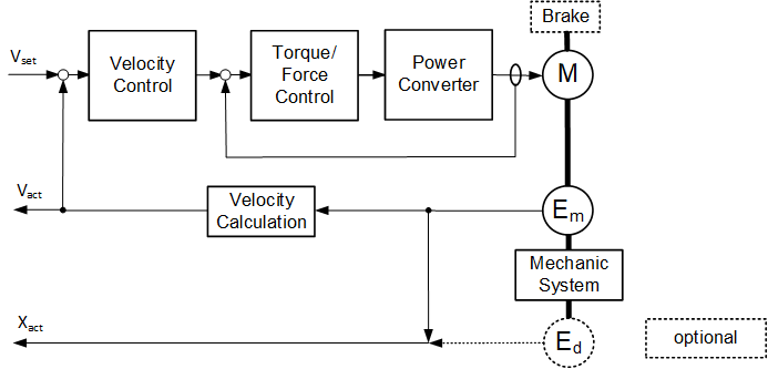
The formal definition of the PtVelocityServoDriveAxisType ObjectType can be found in Table 28.
| Attribute | Value | ||||
| BrowseName | PtVelocityServoDriveAxisType | ||||
| IsAbstract | False | ||||
| References | Node Class | BrowseName | DataType | TypeDefinition | Other |
|---|---|---|---|---|---|
| Subtype of the PtDriveAxisType. | |||||
| 0:HasComponent | Object | EncoderChannelMotor | PtEncoderChannelType | M | |
| 0:HasComponent | Object | EncoderChannelMechanic | PtEncoderChannelType | O | |
| 0:HasComponent | Object | <EncoderChannelAuxiliary> | PtEncoderChannelType | OP | |
| 0:HasComponent | Object | CharacteristicsMechanics | 0:FolderType | O | |
| 0:HasComponent | Object | Homing | 0:FolderType | O | |
| 0:HasComponent | Object | VelocityProfile | 0:FolderType | M | |
| 0:HasComponent | Object | Monitoring | 0:FolderType | M | |
| 0:HasComponent | Object | CharacteristicsMotorAndControl | 0:FolderType | M | |
| 0:HasComponent | Object | LimitSupervision | 0:FolderType | O | |
| 0:GeneratesEvent | ObjectType | PtAxisSwOvertravelEventType | |||
| 0:GeneratesEvent | ObjectType | PtAxisHwOvertravelEventType | |||
| 0:GeneratesEvent | ObjectType | PtTorqueForceLimitEventType | |||
| Conformance Units | |||||
|---|---|---|---|---|---|
| Powertrain Actual and Command Values | |||||
| Powertrain Axis Properties | |||||
| Powertrain Limit Events | |||||
| Powertrain Encoder Channel |
Some components of the PtVelocityServoDriveAxisType have additional subcomponents which are defined in Table 29.
| BrowsePath | References | NodeClass | BrowseName | DataType | TypeDefinition | Others |
| Monitoring | 0:HasComponent | Variable | VelocitySetpoint | 0:Float | 0:AnalogUnitType | O, RO |
| Monitoring | 0:HasComponent | Variable | VelocityCommandValue | 0:Float | 0:AnalogUnitType | M, RO |
| Monitoring | 0:HasComponent | Variable | VelocityCommandAdditiveValue | 0:Float | 0:AnalogUnitType | O, RO |
| Monitoring | 0:HasComponent | Variable | VelocityActualValue | 0:Float | 0:AnalogUnitType | M, RO |
| Monitoring | 0:HasComponent | Variable | PositionActualValue | 0:Double | 0:AnalogUnitType | O, RO |
| Monitoring | 0:HasComponent | Variable | AccelerationActualValue | 0:Float | 0:AnalogUnitType | O, RO |
| Monitoring | 0:HasComponent | Variable | AccelerationSetpoint | 0:Float | 0:AnalogUnitType | O, RO |
| Monitoring | 0:HasComponent | Variable | AccelerationCommandAdditiveValue | 0:Float | 0:AnalogUnitType | O, RO |
| Monitoring | 0:HasComponent | Variable | TorqueForceSetpoint | 0:Float | 0:AnalogUnitType | O, RO |
| Monitoring | 0:HasComponent | Variable | TorqueForceCommandValue | 0:Float | 0:AnalogUnitType | O, RO |
| Monitoring | 0:HasComponent | Variable | CurrentTorqueCommandValue | 0:Float | 0:AnalogUnitType | O, RO |
| Monitoring | 0:HasComponent | Variable | TorqueForceCommandAdditiveValue | 0:Float | 0:AnalogUnitType | O, RO |
| Monitoring | 0:HasComponent | Variable | <EncoderxTemperature> | 0:Float | PtTemperatureVariableType | OP, RO |
| Monitoring | 0:HasComponent | Variable | VelocityFollowingError | 0:Float | 0:AnalogUnitType | O, RO |
| Monitoring | 0:HasComponent | Variable | HomingState | 0:UInt16 | PtHomingStateVariableType | O, RO |
| CharacteristicsMotorAndControl | 0:HasComponent | Variable | TimePeriodVelocityControl | 0:Float | 0:AnalogUnitType | O, RO |
| CharacteristicsMotorAndControl | 0:HasComponent | Variable | TimePeriodTorqueControl | 0:Float | 0:AnalogUnitType | O, RO |
| Homing | 0:HasComponent | Variable | HomingMode | 0:UInt16 | PtHomingModeVariableType | O, RO |
| CharacteristicsMechanics | 0:HasComponent | Variable | GearFactorPrecise | PtGearFactorDataType | 0:BaseDataVariableType | O, RO |
| CharacteristicsMechanics | 0:HasComponent | Variable | GearRatio | 0:Float | 0:BaseDataVariableType | O, RO |
| CharacteristicsMechanics | 0:HasComponent | Variable | SpindlePitch | 0:Float | 0:BaseDataVariableType | O, RO |
| LimitSupervision | 0:HasComponent | Variable | TorqueLimit | 0:Float | 0:AnalogUnitType | O, RO |
| LimitSupervision | 0:HasComponent | Variable | TorqueLimitLow | 0:Float | 0:AnalogUnitType | M, RO |
| LimitSupervision | 0:HasComponent | Variable | TorqueLimitHigh | 0:Float | 0:AnalogUnitType | M, RO |
| LimitSupervision | 0:HasComponent | Variable | SoftwarePosLimitHigh | 0:Float | 0:AnalogUnitType | O, RO |
| LimitSupervision | 0:HasComponent | Variable | SoftwarePosLimitLow | 0:Float | 0:AnalogUnitType | O, RO |
| LimitSupervision | 0:HasComponent | Variable | TorqueLimiting | 0:Boolean | 0:BaseDataVariableType | O, RO |
The SpindlePitch Variable shall be provided if a spindle is present in the Powertrain Axis Object.
For a description of the Variables see Table 54.
7.1.1.5 PtPositionServoDriveAxisType
A PtPositionServoDriveAxisType is an PtDriveAxisType representing the functionality of a servo drive with a position command interface. Figure 13 shows a block diagram demonstrating the basic organization and control flow for this axis type.
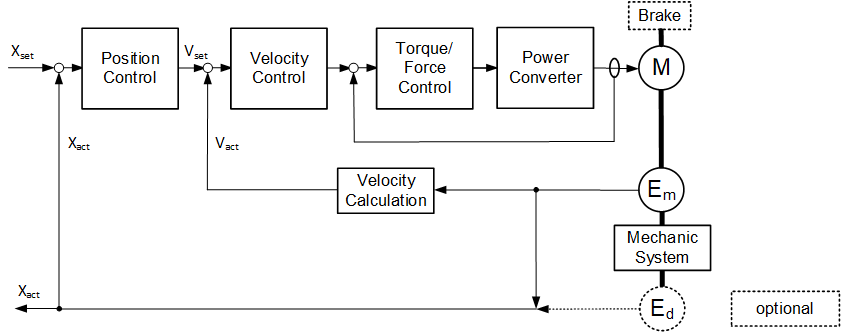
The formal definition of the PtPositionServoDriveAxisType ObjectType can be found in Table 30.
| Attribute | Value | ||||
| BrowseName | PtPositionServoDriveAxisType | ||||
| IsAbstract | False | ||||
| References | Node Class | BrowseName | DataType | TypeDefinition | Other |
|---|---|---|---|---|---|
| Subtype of the PtDriveAxisType. | |||||
| 0:HasComponent | Object | CharacteristicsMechanics | 0:FolderType | O | |
| 0:HasComponent | Object | EncoderChannelMotor | PtEncoderChannelType | M | |
| 0:HasComponent | Object | EncoderChannelMechanic | PtEncoderChannelType | O | |
| 0:HasComponent | Object | <EncoderChannelAuxiliary> | PtEncoderChannelType | OP | |
| 0:HasComponent | Object | Homing | 0:FolderType | M | |
| 0:HasComponent | Object | VelocityProfile | 0:FolderType | M | |
| 0:HasComponent | Object | Monitoring | 0:FolderType | M | |
| 0:HasComponent | Object | CharacteristicsMotorAndControl | 0:FolderType | M | |
| 0:HasComponent | Object | LimitSupervision | 0:FolderType | O | |
| 0:GeneratesEvent | ObjectType | PtAxisSwOvertravelEventType | |||
| 0:GeneratesEvent | ObjectType | PtAxisHwOvertravelEventType | |||
| 0:GeneratesEvent | ObjectType | PtTorqueForceLimitEventType | |||
| Conformance Units | |||||
|---|---|---|---|---|---|
| Powertrain Actual and Command Values | |||||
| Powertrain Axis Properties | |||||
| Powertrain Limit Events | |||||
| Powertrain Encoder Channel |
Some components of the PtPositionServoDriveAxisType have additional subcomponents which are defined in Table 31.
| BrowsePath | References | NodeClass | BrowseName | DataType | TypeDefinition | Others |
| Monitoring | 0:HasComponent | Variable | PositionCommandValue | 0:Float | 0:AnalogUnitType | M, RO |
| Monitoring | 0:HasComponent | Variable | VelocityCommandAdditiveValue | 0:Float | 0:AnalogUnitType | O, RO |
| Monitoring | 0:HasComponent | Variable | VelocitySetpoint | 0:Float | 0:AnalogUnitType | O, RO |
| Monitoring | 0:HasComponent | Variable | PositionActualValue | 0:Double | 0:AnalogUnitType | M, RO |
| Monitoring | 0:HasComponent | Variable | VelocityActualValue | 0:Float | 0:AnalogUnitType | M, RO |
| Monitoring | 0:HasComponent | Variable | VelocityCommandValue | 0:Float | 0:AnalogUnitType | O, RO |
| Monitoring | 0:HasComponent | Variable | TorqueForceCommandValue | 0:Float | 0:AnalogUnitType | O, RO |
| Monitoring | 0:HasComponent | Variable | CurrentTorqueCommandValue | 0:Float | 0:AnalogUnitType | O, RO |
| Monitoring | 0:HasComponent | Variable | PositionSetpoint | 0:Float | 0:AnalogUnitType | O, RO |
| Monitoring | 0:HasComponent | Variable | AccelerationActualValue | 0:Float | 0:AnalogUnitType | O, RO |
| Monitoring | 0:HasComponent | Variable | AccelerationSetpoint | 0:Float | 0:AnalogUnitType | O, RO |
| Monitoring | 0:HasComponent | Variable | AccelerationCommandAdditiveValue | 0:Float | 0:AnalogUnitType | O, RO |
| Monitoring | 0:HasComponent | Variable | TorqueForceSetpoint | 0:Float | 0:AnalogUnitType | O, RO |
| Monitoring | 0:HasComponent | Variable | TorqueForceCommandAdditiveValue | 0:Float | 0:AnalogUnitType | O, RO |
| Monitoring | 0:HasComponent | Variable | <EncoderxTemperature> | 0:Float | PtTemperatureVariableType | OP, RO |
| Monitoring | 0:HasComponent | Variable | PositionFollowingError | 0:Float | 0:AnalogUnitType | O, RO |
| Monitoring | 0:HasComponent | Variable | VelocityFollowingError | 0:Float | 0:AnalogUnitType | O, RO |
| Monitoring | 0:HasComponent | Variable | HomingState | 0:UInt16 | PtHomingStateVariableType | O, RO |
| LimitSupervision | 0:HasComponent | Variable | TorqueLimit | 0:Float | 0:AnalogUnitType | M, RO |
| LimitSupervision | 0:HasComponent | Variable | TorqueLimitLow | 0:Float | 0:AnalogUnitType | O, RO |
| LimitSupervision | 0:HasComponent | Variable | TorqueLimitHigh | 0:Float | 0:AnalogUnitType | O, RO |
| LimitSupervision | 0:HasComponent | Variable | SoftwarePosLimitLow | 0:Float | 0:AnalogUnitType | M, RO |
| LimitSupervision | 0:HasComponent | Variable | SoftwarePosLimitHigh | 0:Float | 0:AnalogUnitType | M, RO |
| LimitSupervision | 0:HasComponent | Variable | TorqueLimiting | 0:Boolean | 0:BaseDataVariableType | O, RO |
| CharacteristicsMotorAndControl | 0:HasComponent | Variable | TimePeriodVelocityControl | 0:Float | 0:AnalogUnitType | O, RO |
| CharacteristicsMotorAndControl | 0:HasComponent | Variable | TimePeriodPositionControl | 0:Float | 0:AnalogUnitType | O, RO |
| CharacteristicsMotorAndControl | 0:HasComponent | Variable | TimePeriodTorqueControl | 0:Float | 0:AnalogUnitType | O, RO |
| Homing | 0:HasComponent | Variable | HomingDirection | 0:UInt16 | PtHomingDirectionVariableType | O, RO |
| Homing | 0:HasComponent | Variable | HomingSpeedToCam | 0:Float | 0:AnalogUnitType | O, RO |
| Homing | 0:HasComponent | Variable | HomingSpeedToMark | 0:Float | 0:AnalogUnitType | O, RO |
| Homing | 0:HasComponent | Variable | HomingPointOffset | 0:Float | 0:AnalogUnitType | O, RO |
| Homing | 0:HasComponent | Variable | HomingMode | 0:UInt16 | PtHomingModeVariableType | M, RO |
| CharacteristicsMechanics | 0:HasComponent | Variable | GearFactorPrecise | PtGearFactorDataType | 0:BaseDataVariableType | O, RO |
| CharacteristicsMechanics | 0:HasComponent | Variable | GearRatio | 0:Float | 0:BaseDataVariableType | O, RO |
| CharacteristicsMechanics | 0:HasComponent | Variable | SpindlePitch | 0:Float | 0:BaseDataVariableType | O, RO |
| VelocityProfile | 0:HasComponent | Variable | JogPosInc1 | 0:Float | 0:AnalogUnitType | O, RO |
| VelocityProfile | 0:HasComponent | Variable | JogPosInc2 | 0:Float | 0:AnalogUnitType | O, RO |
The SpindlePitch Variable shall be provided if a spindle is present in the Powertrain Axis Object.
For a description of the Variables see Table 54.
7.1.1.6 PtTorqueServoDriveAxisType
A PtTorqueServoDriveAxisType is an PtDriveAxisType representing the functionality of a servo drive with a torque command interface. Figure 14 shows a block diagram demonstrating the basic organization and control flow for this axis type.
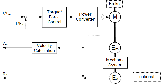
The formal definition of the PtTorqueServoDriveAxisType ObjectType can be found in Table 32.
| Attribute | Value | ||||
| BrowseName | PtTorqueServoDriveAxisType | ||||
| IsAbstract | False | ||||
| References | Node Class | BrowseName | DataType | TypeDefinition | Other |
|---|---|---|---|---|---|
| Subtype of the PtDriveAxisType. | |||||
| 0:HasComponent | Object | EncoderChannelMotor | PtEncoderChannelType | M | |
| 0:HasComponent | Object | EncoderChannelMechanic | PtEncoderChannelType | O | |
| 0:HasComponent | Object | <EncoderChannelAuxiliary> | PtEncoderChannelType | OP | |
| 0:HasComponent | Object | CharacteristicsMechanics | 0:FolderType | O | |
| 0:HasComponent | Object | Homing | 0:FolderType | O | |
| 0:HasComponent | Object | Monitoring | 0:FolderType | M | |
| 0:HasComponent | Object | CharacteristicsMotorAndControl | 0:FolderType | M | |
| 0:HasComponent | Object | LimitSupervision | 0:FolderType | O | |
| 0:GeneratesEvent | ObjectType | PtTorqueForceLimitEventType | |||
| Conformance Units | |||||
|---|---|---|---|---|---|
| Powertrain Actual and Command Values | |||||
| Powertrain Axis Properties | |||||
| Powertrain Limit Events | |||||
| Powertrain Encoder Channel |
Some components of the PtTorqueServoDriveAxisType have additional subcomponents which are defined in Table 33.
| BrowsePath | References | NodeClass | BrowseName | DataType | TypeDefinition | Others |
| Monitoring | 0:HasComponent | Variable | VelocityActualValue | 0:Float | 0:AnalogUnitType | O, RO |
| Monitoring | 0:HasComponent | Variable | PositionActualValue | 0:Double | 0:AnalogUnitType | M, RO |
| Monitoring | 0:HasComponent | Variable | AccelerationSetpoint | 0:Float | 0:AnalogUnitType | O, RO |
| Monitoring | 0:HasComponent | Variable | AccelerationCommandAdditiveValue | 0:Float | 0:AnalogUnitType | O, RO |
| Monitoring | 0:HasComponent | Variable | AccelerationActualValue | 0:Float | 0:AnalogUnitType | O, RO |
| Monitoring | 0:HasComponent | Variable | TorqueForceSetpoint | 0:Float | 0:AnalogUnitType | O, RO |
| Monitoring | 0:HasComponent | Variable | TorqueForceCommandValue | 0:Float | 0:AnalogUnitType | O, RO |
| Monitoring | 0:HasComponent | Variable | CurrentTorqueCommandValue | 0:Float | 0:AnalogUnitType | O, RO |
| Monitoring | 0:HasComponent | Variable | TorqueForceCommandAdditiveValue | 0:Float | 0:AnalogUnitType | O, RO |
| Monitoring | 0:HasComponent | Variable | <EncoderxTemperature> | 0:Float | PtTemperatureVariableType | OP, RO |
| Monitoring | 0:HasComponent | Variable | HomingState | 0:UInt16 | PtHomingStateVariableType | O, RO |
| CharacteristicsMotorAndControl | 0:HasComponent | Variable | TimePeriodTorqueControl | 0:Float | 0:AnalogUnitType | O, RO |
| Homing | 0:HasComponent | Variable | HomingMode | 0:UInt16 | PtHomingModeVariableType | O, RO |
| CharacteristicsMechanics | 0:HasComponent | Variable | GearFactorPrecise | PtGearFactorDataType | 0:BaseDataVariableType | O, RO |
| CharacteristicsMechanics | 0:HasComponent | Variable | GearRatio | 0:Float | 0:BaseDataVariableType | O, RO |
| CharacteristicsMechanics | 0:HasComponent | Variable | SpindlePitch | 0:Float | 0:BaseDataVariableType | O, RO |
| LimitSupervision | 0:HasComponent | Variable | TorqueLimit | 0:Float | 0:AnalogUnitType | O, RO |
| LimitSupervision | 0:HasComponent | Variable | TorqueLimitLow | 0:Float | 0:AnalogUnitType | O, RO |
| LimitSupervision | 0:HasComponent | Variable | TorqueLimitHigh | 0:Float | 0:AnalogUnitType | O, RO |
| LimitSupervision | 0:HasComponent | Variable | SoftwarePosLimitLow | 0:Float | 0:AnalogUnitType | O, RO |
| LimitSupervision | 0:HasComponent | Variable | SoftwarePosLimitHigh | 0:Float | 0:AnalogUnitType | O, RO |
| LimitSupervision | 0:HasComponent | Variable | TorqueLimiting | 0:Boolean | 0:BaseDataVariableType | O, RO |
The SpindlePitch Variable shall be provided if a spindle is present in the Powertrain Axis Object.
One of the TorqueForceCommandValue and CurrentTorqueCommandValue Variables shall be provided.
For a description of the Variables see Table 54.
7.1.2 PtEncoderAxisType definition
The PtEncoderAxisType ObjectType specifies the properties of encoder Objects.
| Attribute | Value | ||||
| BrowseName | PtEncoderAxisType | ||||
| IsAbstract | False | ||||
| References | Node Class | BrowseName | DataType | TypeDefinition | Other |
|---|---|---|---|---|---|
| Subtype of the PtFunctionType. | |||||
| 0:HasComponent | Object | EncoderChannel | PtEncoderChannelType | M | |
| 0:HasComponent | Object | Monitoring | 0:FolderType | M | |
| Conformance Units | |||||
|---|---|---|---|---|---|
| Powertrain Actual and Command Values | |||||
| Powertrain Encoder Channel |
Some components of the PtEncoderAxisType have additional subcomponents which are defined in Table 35.
| BrowsePath | References | NodeClass | BrowseName | DataType | TypeDefinition | Others |
| Monitoring | 0:HasComponent | Variable | ControlPriority | 0:UInt16 | PtControlPriorityVariableType | M, RO |
| Monitoring | 0:HasComponent | Variable | VelocityActualValue | 0:Float | 0:AnalogUnitType | O, RO |
| Monitoring | 0:HasComponent | Variable | PositionActualValue | 0:Double | 0:AnalogUnitType | M, RO |
| Monitoring | 0:HasComponent | Variable | AccelerationActualValue | 0:Float | 0:AnalogUnitType | O, RO |
| Monitoring | 0:HasComponent | Variable | EncoderTemperature | 0:Float | PtTemperatureVariableType | O, RO |
7.1.3 PtGearAxisType definition
The PtGearAxisType ObjectType specifies the properties of Objects representing gears.
| Attribute | Value | ||||
| BrowseName | PtGearAxisType | ||||
| IsAbstract | False | ||||
| References | Node Class | BrowseName | DataType | TypeDefinition | Other |
|---|---|---|---|---|---|
| 0:HasComponent | Object | CharacteristicsMechanics | 0:FolderType | O | |
| 0:HasComponent | Object | Monitoring | 0:FolderType | M | |
| 0:HasComponent | Object | Maintenance | 0:FolderType | M | |
| Subtype of the PtFunctionType. | |||||
| Conformance Units | |||||
|---|---|---|---|---|---|
| Powertrain Actual and Command Values |
Some components of the PtGearAxisType have additional subcomponents which are defined in Table 37.
| BrowsePath | References | NodeClass | BrowseName | DataType | TypeDefinition | Others |
| Monitoring | 0:HasComponent | Variable | BrakeState | 0:UInt16 | PtBrakeStateVariableType | O, RO |
| Monitoring | 0:HasComponent | Variable | AxisTorqueForce | 0:Float | 0:AnalogUnitType | O, RO |
| Monitoring | 0:HasComponent | Variable | AxisOutputVelocity | 0:Float | 0:AnalogUnitType | O, RO |
| Monitoring | 0:HasComponent | Variable | GearInputVelocity | 0:Float | 0:AnalogUnitType | O, RO |
| Monitoring | 0:HasComponent | Variable | GearInputTorque | 0:Float | 0:AnalogUnitType | O, RO |
| Monitoring | 0:HasComponent | Variable | GearOutputVelocity | 0:Float | 0:AnalogUnitType | O, RO |
| Monitoring | 0:HasComponent | Variable | GearOutputTorque | 0:Float | 0:AnalogUnitType | O, RO |
| Monitoring | 0:HasComponent | Variable | GearTemperature | 0:Float | PtTemperatureVariableType | O, RO |
| Monitoring | 0:HasComponent | Variable | GearRatio | 0:Float | 0:AnalogUnitType | M, RO |
| Monitoring | 0:HasComponent | Variable | GearState | 0:UInt16 | PtGearStateVariableType | O, RO |
| Monitoring | 0:HasComponent | Variable | GearOutputShaftTurningDirection | 0:UInt16 | PtShaftTurningDirectionVariableType | O, RO |
| Monitoring | 0:HasComponent | Variable | GearInputShaftTurningDirection | 0:UInt16 | PtShaftTurningDirectionVariableType | O, RO |
| Maintenance | 0:HasComponent | Variable | GearBacklash | 0:Float | 0:AnalogUnitType | O, RO |
| CharacteristicsMechanics | 0:HasComponent | Variable | GearFactorPrecise | PtGearFactorDataType | 0:BaseDataVariableType | O, RO |
| CharacteristicsMechanics | 0:HasComponent | Variable | GearRatio | 0:Float | 0:BaseDataVariableType | O, RO |
7.2 PtLogbookType definition
The PtLogbookType provides access to diagnosis information provided by ObjectTypes derived from the PtFunctionType.
| Attribute | Value | ||||
| BrowseName | PtLogbookType | ||||
| IsAbstract | False | ||||
| References | Node Class | BrowseName | DataType | TypeDefinition | Other |
|---|---|---|---|---|---|
| Subtype of the 0:BaseObjectType defined in OPC 10000-5. | |||||
| 0:HasComponent | Variable | LogEntries | PtLogEntryDataType[] | 0:BaseDataVariableType | M, RO |
| 0:HasProperty | Variable | LogbookSize | 0:UInt16 | 0:PropertyType | M, RO |
| 0:HasComponent | Method | ClearLogbookEntries | O | ||
| 0:HasComponent | Method | GetFilteredLogbookEntries | O | ||
| 0:HasComponent | Method | GetCurrentDiagnosis | O | ||
| 0:HasComponent | Method | GetActiveDiagnosis | O | ||
| 0:HasComponent | Method | GetHistoricDiagnosis | O | ||
| Conformance Units | |||||
|---|---|---|---|---|---|
| Powertrain Logbook Readable | |||||
| Powertrain Logbook Events |
The LogEntries array Variable consists of PtLogEntryDataType structure elements. The array is limited to the maximum size specified by the LogbookSize Property. The array contains PtLogEntryDataType elements for events and starts with the most recent event (the element with the most recent EventComing timestamp). If the Server maintains different fault situations in its diagnosis system, faults (events) which are still present after an acknowledge generate a new entry in the actual fault situation causing more than one entry with the same EventNumber for one event.
The LogbookSize Property contains the maximum length of the LogEntries array. The actual length of the array may be smaller.
Clients must lock the parent PtFunctionType Object before invoking a Method of the PtLogbookType Object.
7.2.1 ClearLogbookEntries Method
The ClearLogbookEntries Method clears the LogEntries array and resets the diagnosis system of the functional Object. The security constraints defined in chapter 6.2 apply.
Signature
	ClearLogbookEntries (
	);
The Method Result Codes (defined in Call Service) are defined in Table 39.
| Result Code | Description |
| Good | The Method execution was successful. |
| Bad_UserAccessDenied | The user has not the right to execute the Method. |
| Bad_UnexpectedError | The Server is not able to execute the function because an unexpected error occurred. The Device might be temporarily unavailable or unreachable due to network failure. |
7.2.2 GetFilteredLogbookEntries Method
The GetFilteredLogbookEntries Method returns a LogEntries array matching the filter criteria. Method invocation shall be possible for all users (read-only).
Signature
	GetFilteredLogbookEntries (
		[in] 0:Byte				LogbookFilterOptions,
		[in] 0:Byte				FaultSituationNumber
		[in] PtEventTypeEnumeration 	EventType,
		[in] PtEventClassEnumeration	EventClass,
	[in] 0:Int32			VendorEventCode
		[in] 0:Duration			EventAppearanceInterval,
	[out] PtLogEntryDataType[] 	FilteredLogEntries
	);
| Argument | Description |
| LogbookFilterOptions | Parameter restricting the returned logbook entries to those having valid EventGoing and/or EventAcknowledged timestamps. If set to 1 ("GOING" filter), only logbook entries with valid EventGoing timestamp are returned. If set to 2 ("ACKNOWLEDGED" filter), only entries with valid EventAcknowledged timestamp are returned. If set to 3, the logic applied is "AND": only logbook entries meeting both filter criteria are returned. Set to 0 if no filtering shall be applied. If a value greater than 3 is passed, the Method Result Code shall be set to Bad_InvalidArgument. |
| FaultSituationNumber | Restricts the returned logbook entries to those with the FaultSituationNumber field equal to this parameter. Passing 255 means "don't care". |
| EventType | Restricts the returned logbook entries to those with the EventType field equal to this parameter. It is encoded as PtEventTypeEnumeration. Passing "UNSPECIFIED" means "don't care". |
| EventClass | Restricts the returned logbook entries to those with the EventClass field equal to this parameter. It is encoded as PtEventClassEnumeration. Passing "UNSPECIFIED" means "don't care". |
| VendorEventCode | Restricts the returned logbook entries to those with the VendorEventCode field equal to this parameter. Passing -1 means "don't care" and does not restrict to entries with the VendorEventCode field set to -1. |
| EventAppearanceInterval | Time interval encoded as 0:Duration defined in [OPC 10000-3]. Restricts the returned logbook entries to those appearing within a timespan from the past up to now. The EventComing field of the logbook entries is used for checking this filter. Passing 0 means "don't care". |
| FilteredLogEntries | Array containing the logbook entries matching all filter criteria passed with the first 5 parameters. An empty array is returned if no logbook entry matches the filter criteria. |
The Method Result Codes (defined in Call Service) are defined in Table 40.
| Result Code | Description |
| Good | The Method execution was successful. |
| Bad_InvalidArgument | The Server is unable to execute the Method due to invalid arguments. For instance, the EventClass passed may be unknown. |
| Bad_UnexpectedError | The Server cannot execute the function because an unexpected error occurred. The Device might be temporarily unavailable or unreachable due to network failure. |
7.2.3 GetCurrentDiagnosis Method
The GetCurrentDiagnosis Method returns all log entries which occurred since the last acknowledge as LogEntries array. Starting with the most recent one, all log entries without valid EventAcknowledged timestamp are returned. Method invocation shall be possible for all users (read-only).
Signature
	GetCurrentDiagnosis (
		[out] PtLogEntryDataType[] 	CurrentLogEntries
	);
| Argument | Description |
| CurrentLogEntries | Array containing the log entries occurred since the last acknowledge. An empty array is returned if no logbook entry matches the filter criteria. |
The Method Result Codes (defined in Call Service) are defined in Table 41.
| Result Code | Description |
| Good | The Method execution was successful. |
| Bad_UnexpectedError | The Server is not able to execute the function because an unexpected error occurred. The Device might be temporarily unavailable or unreachable due to network failure. |
7.2.4 GetHistoricDiagnosis Method
The GetHistoricDiagnosis Method returns a LogEntries array with valid EventGoing field. Method invocation shall be possible for all users (read-only).
Signature
	GetHistoricDiagnosis (
		[in]  0:Byte					FaultSituationNumber,
		[out] PtLogEntryDataType[]		HistoricLogEntries
	);
| Argument | Description |
| FaultSituationNumber | Fault situation number the faults belong to. 0 identifies the current situation, 1 the historic situation preceding the current situation, and so on (see explanation below). |
| HistoricLogEntries | Array containing the log entries with valid EventGoing field entry. An empty array is returned if no logbook entry matches the filter criteria. |
The Method Result Codes (defined in Call Service) are defined in Table 42.
| Result Code | Description |
| Good | The Method execution was successful. |
| Bad_InvalidArgument | The fault situation specified by FaultSituationNumber does not exist. |
| Bad_UnexpectedError | The Server cannot execute the function because an unexpected error occurred. The Device might be temporarily unavailable or unreachable due to network failure. |
7.2.5 GetActiveDiagnosis Method
The GetActiveDiagnosis Method returns a LogEntries array containing log entries belonging to the current fault situation (log entries with FaultSituationNumber equal to 0) with valid EventComing timestamp, but with missing EventGoing timestamp. The method returns a subset of the entries returned by the GetCurrentDiagnosis Method. Method invocation shall be possible for all users (read-only).
Signature
	GetActiveDiagnosis (
		[out] PtLogEntryDataType[] 	ActiveDiagnosis
	);
| Argument | Description |
| ActiveDiagnosis | Array containing the log entries with missing EventGoing field entry. An empty array is returned if no logbook entry matches the filter criteria. |
The Method Result Codes (defined in Call Service) are defined in Table 43.
| Result Code | Description |
| Good | The Method execution was successful. |
| Bad_UnexpectedError | The Server is not able to execute the function because an unexpected error occurred. The Device might be temporarily unavailable or unreachable due to network failure. |
7.3 PtEncoderChannelType
The PtEncoderChannelType is the representation of the Encoder sensor and sensor related auxiliary functionality. Clients gain access to the Encoder Object's data, properties, error log and configuration settings using an PtEncoderChannelType Object.
| Attribute | Value | ||||
| BrowseName | PtEncoderChannelType | ||||
| IsAbstract | False | ||||
| References | Node Class | BrowseName | DataType | TypeDefinition | Other |
|---|---|---|---|---|---|
| Subtype of the 0:BaseObjectType defined in OPC 10000-5. | |||||
| 0:HasComponent | Variable | EncoderChannelState | 0:UInt16 | PtEncoderChannelStateVariableType | O, RO |
| 0:HasComponent | Object | Sensor | PtEncoderSensorType | M | |
| 0:HasComponent | Object | <Probe_x> | PtEncoderProbeType | OP | |
| 0:HasComponent | Variable | PositionSensorFeedbackValue | 0:Number | 0:BaseDataVariableType | O, RO |
| 0:HasComponent | Variable | Resolution | 0:Double | 0:BaseAnalogType | O, RO |
| 0:HasProperty | Variable | AbsolutePositionRange | 0:Range | 0:PropertyType | O, RO |
| 0:HasComponent | Variable | SignalType | 0:UInt16 | PtEncoderChannelSignalTypeVariableType | O, RO |
| Conformance Units | |||||
|---|---|---|---|---|---|
| Powertrain Encoder Channel |
The EncoderChannelState Variable contains the state of the encoder channel encoded as PtEncoderChannelStateVariableType.
The Sensor PtEncoderSensorType Object offers sensor related data. See section 7.3.1 for details.
The <Probe_x> PtEncoderProbeType Objects represent the probes provided by the Encoder. There shall be as many PtEncoderProbeType Objects as are needed to represent all probes provided. The BrowseNames shall be provided as defined by the template string <Probe_x>, where x is the probe number.
The PositionSensorSignalValue Variable contains the Encoder's position Signal encoded as numeric data type. Dependent on Encoder resolution, the data type may be 0:UInt32 or 0:UInt64. This is the raw signal value delivered by the encoder sensor.
The Resolution Variable contains the resolution of the Encoder's Position Variable Value.
The AbsolutePositionRange Variable contains the possible range of absolute position values represented as 0:Range Value.
The SignalType Variable contains the type of the position sensor's signal value encoded as PtEncoderChannelSignalTypeVariableType.
7.3.1 PtEncoderSensorType
| Attribute | Value | ||||
| BrowseName | PtEncoderSensorType | ||||
| IsAbstract | False | ||||
| References | Node Class | BrowseName | DataType | TypeDefinition | Other |
|---|---|---|---|---|---|
| Subtype of the 0:BaseObjectType defined in OPC 10000-5. | |||||
| 0:HasComponent | Variable | PositionOffset | 0:Number | 0:BaseDataVariableType | O, RO |
| 0:HasComponent | Variable | LatchStatus | 0:UInt16 | PtLatchStatusVariableType | O, RO |
| 0:HasComponent | Variable | LatchValue | 0:Number | 0:BaseDataVariableType | O, RO |
| Conformance Units | |||||
|---|---|---|---|---|---|
| Powertrain Encoder Channel |
The PositionOffset Variable contains the calculated offset belonging to the current preset value of the Encoder.
The LatchStatus Variable contains the current state of the reference pulse latch encoded as PtLatchStatusVariableType.
The LatchValue Variable contains the last latched value of the reference pulse latch.
7.3.2 PtEncoderProbeType
The PtEncoderProbeType represents the Encoder's probe functionality.
| Attribute | Value | ||||
| BrowseName | PtEncoderProbeType | ||||
| IsAbstract | False | ||||
| References | Node Class | BrowseName | DataType | TypeDefinition | Other |
|---|---|---|---|---|---|
| Subtype of the 0:BaseObjectType defined in OPC 10000-5. | |||||
| 0:HasComponent | Variable | LatchStatus | 0:UInt16 | PtLatchStatusVariableType | O, RO |
| 0:HasComponent | Variable | LastLatchedPos | 0:Number | 0:BaseDataVariableType | M, RO |
| 0:HasComponent | Variable | ProbeInputSignal | 0:Boolean | 0:BaseDataVariableType | O |
| Conformance Units | |||||
|---|---|---|---|---|---|
| Powertrain Encoder Channel |
The LatchStatus Variable contains the current state of the probe latch encoded as PtLatchStatusVariableType.
The LastLatchedPos Variable contains the last latched position of the probe.
The ProbeInputSignal Variable contains the status of the probe sensor at the clamp.
7.4 PtVibrationSensorType
The PtVibrationSensorType represents a vibration sensor and provides measurement values for velocity, vibration displacement and acceleration. The -X, -Y and -Z suffixes identify values provided individually for the x-, y- and z-direction.
| Attribute | Value | ||||
| BrowseName | PtVibrationSensorType | ||||
| IsAbstract | False | ||||
| References | Node Class | BrowseName | DataType | TypeDefinition | Other |
|---|---|---|---|---|---|
| Subtype of the 0:BaseObjectType defined in OPC 10000-5. | |||||
| 0:HasComponent | Variable | RMSAcceleration | 0:Float | PtVibrationMeasurementVariableType | O, RO |
| 0:HasComponent | Variable | RMSAccelerationX | 0:Float | PtVibrationMeasurementVariableType | O, RO |
| 0:HasComponent | Variable | RMSAccelerationY | 0:Float | PtVibrationMeasurementVariableType | O, RO |
| 0:HasComponent | Variable | RMSAccelerationZ | 0:Float | PtVibrationMeasurementVariableType | O, RO |
| 0:HasComponent | Variable | RMSVelocity | 0:Float | PtVibrationMeasurementVariableType | O, RO |
| 0:HasComponent | Variable | RMSVelocityX | 0:Float | PtVibrationMeasurementVariableType | O, RO |
| 0:HasComponent | Variable | RMSVelocityY | 0:Float | PtVibrationMeasurementVariableType | O, RO |
| 0:HasComponent | Variable | RMSVelocityZ | 0:Float | PtVibrationMeasurementVariableType | O, RO |
| 0:HasComponent | Variable | RMSDisplacement | 0:Float | PtVibrationMeasurementVariableType | O, RO |
| 0:HasComponent | Variable | RMSDisplacementX | 0:Float | PtVibrationMeasurementVariableType | O, RO |
| 0:HasComponent | Variable | RMSDisplacementY | 0:Float | PtVibrationMeasurementVariableType | O, RO |
| 0:HasComponent | Variable | RMSDisplacementZ | 0:Float | PtVibrationMeasurementVariableType | O, RO |
| 0:HasComponent | Variable | PeakToPeakAcceleration | 0:Float | PtVibrationMeasurementVariableType | O, RO |
| 0:HasComponent | Variable | PeakToPeakAccelerationX | 0:Float | PtVibrationMeasurementVariableType | O, RO |
| 0:HasComponent | Variable | PeakToPeakAccelerationY | 0:Float | PtVibrationMeasurementVariableType | O, RO |
| 0:HasComponent | Variable | PeakToPeakAccelerationZ | 0:Float | PtVibrationMeasurementVariableType | O, RO |
| 0:HasComponent | Variable | PeakToPeakVelocity | 0:Float | PtVibrationMeasurementVariableType | O, RO |
| 0:HasComponent | Variable | PeakToPeakVelocityX | 0:Float | PtVibrationMeasurementVariableType | O, RO |
| 0:HasComponent | Variable | PeakToPeakVelocityY | 0:Float | PtVibrationMeasurementVariableType | O, RO |
| 0:HasComponent | Variable | PeakToPeakVelocityZ | 0:Float | PtVibrationMeasurementVariableType | O, RO |
| 0:HasComponent | Variable | PeakToPeakDisplacement | 0:Float | PtVibrationMeasurementVariableType | O, RO |
| 0:HasComponent | Variable | PeakToPeakDisplacementX | 0:Float | PtVibrationMeasurementVariableType | O, RO |
| 0:HasComponent | Variable | PeakToPeakDisplacementY | 0:Float | PtVibrationMeasurementVariableType | O, RO |
| 0:HasComponent | Variable | PeakToPeakDisplacementZ | 0:Float | PtVibrationMeasurementVariableType | O, RO |
| 0:HasComponent | Variable | ZeroToPeakAcceleration | 0:Float | PtVibrationMeasurementVariableType | O, RO |
| 0:HasComponent | Variable | ZeroToPeakAccelerationX | 0:Float | PtVibrationMeasurementVariableType | O, RO |
| 0:HasComponent | Variable | ZeroToPeakAccelerationY | 0:Float | PtVibrationMeasurementVariableType | O, RO |
| 0:HasComponent | Variable | ZeroToPeakAccelerationZ | 0:Float | PtVibrationMeasurementVariableType | O, RO |
| 0:HasComponent | Variable | ZeroToPeakVelocity | 0:Float | PtVibrationMeasurementVariableType | O, RO |
| 0:HasComponent | Variable | ZeroToPeakVelocityX | 0:Float | PtVibrationMeasurementVariableType | O, RO |
| 0:HasComponent | Variable | ZeroToPeakVelocityY | 0:Float | PtVibrationMeasurementVariableType | O, RO |
| 0:HasComponent | Variable | ZeroToPeakVelocityZ | 0:Float | PtVibrationMeasurementVariableType | O, RO |
| 0:HasComponent | Variable | ZeroToPeakDisplacement | 0:Float | PtVibrationMeasurementVariableType | O, RO |
| 0:HasComponent | Variable | ZeroToPeakDisplacementX | 0:Float | PtVibrationMeasurementVariableType | O, RO |
| 0:HasComponent | Variable | ZeroToPeakDisplacementY | 0:Float | PtVibrationMeasurementVariableType | O, RO |
| 0:HasComponent | Variable | ZeroToPeakDisplacementZ | 0:Float | PtVibrationMeasurementVariableType | O, RO |
| Conformance Units | |||||
|---|---|---|---|---|---|
| Powertrain Actual and Command Values |
The RMSAcceleration, RMSAccelerationX, RMSAccelerationY and RMSAccelerationZ Variables contain the vibration acceleration KPI calculated via Root-Mean-Square based on DIN ISO 20816 series of standards.
The RMSVelocity, RMSVelocityX, RMSVelocityY and RMSVelocityZ Variables contain the standard vibration velocity KPI as defined in DIN ISO 20816-1, …-3 (Annex A) and …-9.
The RMSDisplacement, RMSDisplacementX, RMSDisplacementY and RMSDisplacementZ Variables contain the vibration displacement KPI calculated via Root-Mean-Square.
The PeakToPeakAcceleration, PeakToPeakAccelerationX, PeakToPeakAccelerationY and PeakToPeakAccelerationZ Variables contain the difference between maximum and minimum acceleration in the last interval based on DIN ISO 20816 series of standards.
The PeakToPeakVelocity, PeakToPeakVelocityX, PeakToPeakVelocityY and PeakToPeakVelocityZ Variables contain the difference between maximum and minimum velocity in the last interval.
The PeakToPeakDisplacement, PeakToPeakDisplacementX, PeakToPeakDisplacementY, PeakToPeakDisplacementZ Variables contain the standard vibration displacement KPI as defined in DIN ISO 20816-1, …-3 (Annex A) and …-9.
The ZeroToPeakAcceleration, ZeroToPeakAccelerationX, ZeroToPeakAccelerationY, ZeroToPeakAccelerationZ Variables contain the standard acceleration KPI as defined in DIN ISO 20816-1, …-3 (Annex A) and …-9.
The ZeroToPeakVelocity, ZeroToPeakVelocityX, ZeroToPeakVelocityY and ZeroToPeakVelocityZ Variables contain the difference between maximum and minimum velocity in the last interval.
The ZeroToPeakDisplacement, ZeroToPeakDisplacementX, ZeroToPeakDisplacementY and ZeroToPeakDisplacementZ Variables contain the difference between maximum and minimum displacement in the last interval.
7.5 PtCharacteristicsConverterType
The PtCharacteristicsConverterType represents the properties of the electric converter unit belonging to an electric drive.
| Attribute | Value | ||||
| BrowseName | PtCharacteristicsConverterType | ||||
| IsAbstract | False | ||||
| References | Node Class | BrowseName | DataType | TypeDefinition | Other |
|---|---|---|---|---|---|
| Subtype of the 0:BaseObjectType defined in OPC 10000-5. | |||||
| 0:HasComponent | Variable | BleederExcessCurrentLimit | 0:Float | 0:AnalogUnitType | O, RO |
| 0:HasComponent | Variable | ConverterExcessCurrentConfigured | 0:Float | 0:AnalogUnitType | O, RO |
| 0:HasComponent | Variable | ConverterThermalLoadLimitConfigured | 0:Float | 0:AnalogUnitType | O, RO |
| 0:HasComponent | Variable | DcBusVoltageConfigured | 0:UInt16 | 0:AnalogUnitType | O, RO |
| 0:HasComponent | Variable | InputConverterAcInputVoltage | 0:UInt16 | 0:AnalogUnitType | O, RO |
| 0:HasComponent | Variable | OutputConverterPulseFrequency | 0:Float | 0:AnalogUnitType | M, RO |
The BleederExcessCurrentLimit Variable contains the excess current limit of the brake resistor in ampere.
The ConverterExcessCurrentConfigured Variable contains the excess current of the converter determined by configuration data.
The ConverterThermalLoadLimitConfigured Variable contains the thermal load limit of the converter determined by configuration data.
The DcBusVoltageConfigured Variable contains the voltage of the intermediate circuit determined by configuration data.
The InputConverterAcInputVoltage Variable contains the input alternating voltage.
The OutputConverterPulseFrequency Variable contains the pulse frequency of the converter.
7.6 PtTraversingTaskType
The PtTraversingTaskType represents a traversing task.
| Attribute | Value | ||||
| BrowseName | PtTraversingTaskType | ||||
| IsAbstract | False | ||||
| References | Node Class | BrowseName | DataType | TypeDefinition | Other |
|---|---|---|---|---|---|
| Subtype of the 0:BaseObjectType defined in OPC 10000-5. | |||||
| 0:HasComponent | Variable | TraversingTaskNumber | 0:Int32 | 0:BaseDataVariableType | M, RO |
| 0:HasComponent | Variable | TargetPosition | 0:Float | 0:AnalogUnitType | O, RO |
| 0:HasComponent | Variable | Velocity | 0:Float | 0:AnalogUnitType | O, RO |
| 0:HasComponent | Variable | Acceleration | 0:Float | 0:AnalogUnitType | O, RO |
| 0:HasComponent | Variable | Deceleration | 0:Float | 0:AnalogUnitType | O, RO |
| 0:HasComponent | Variable | PositioningModuloMode | 0:UInt16 | 0:MultiStateValueDiscreteType | M, RO |
| 0:HasComponent | Variable | PositioningTaskChangeMode | 0:UInt16 | 0:MultiStateValueDiscreteType | O, RO |
| Conformance Units | |||||
|---|---|---|---|---|---|
| Powertrain Actual and Command Values |
The TraversingTaskNumber Variable contains the number of the traversing task currently executed. Interpretation of TraversingTaskNumber:
| TraversingTaskNumber Value | Traversing task executed |
| -5 | Jogging positive (S42) |
| -4 | Jogging negative (S42) |
| -3 | Homing procedure (S44) |
| -2 | MDI sub-mode active |
| -1 | No traversing task is executed: stand still (S41) |
| >=0 | Number of traversing task (0 - 1023) |
If no traversing task is executed (TraversingTaskNumber == -1), the Value of all other Variables shall be 0. If a traversing task is executed (TraversingTaskNumber >=0), the AxisState Variable contains one of the values belonging to the S45 sub state machine (see [PDP], Figure 35 also).
The TargetPosition Variable contains the target position for the traversing task generator.
The Velocity Variable contains the desired speed for the traversing task generator.
The Acceleration Variable contains the desired acceleration for the traversing task generator.
The PositioningModuloMode Variable contains the information if the TargetPosition Variable must be interpreted as absolute or relative position encoded as 0:MultiStateValueDiscreteType defined in [OPC 10000-8]. The PositioningTaskChangeMode Variable corresponds to Bit 5 in DS402 control word " also encoded as 0:MultiStateValueDiscreteType. The content of their EnumStrings lookup table Properties is defined in Table 50.
| BrowsePath | Value Attribute | ||
| [ { "Value":0, "DisplayName": "NO_MODULO_FUNCTION", "Description": "No traversing task is active" }, { "Value":1, "DisplayName": "RELATIVE_POSITIONING", "Description": "Relative Positioning" }, { "Value":2, "DisplayName": "ABSOLUTE_SHORTEST_PATH_MODULO_DIRECTION _POSITIONING", "Description": "The absolute position shall be reached by the shortest path" }, { "Value":3, "DisplayName": "ABSOLUTE_POSITIVE_MODULO_DIRECTION _POSITIONING", "Description": "The absolute position shall be reached by a motion in positive direction" }, { "Value":4, "DisplayName": "ABSOLUTE_NEGATIVE_ MODULO_DIRECTION _POSITIONING", "Description": "The absolute position shall be reached by a motion in negative direction" } ] | ||
| [ { "Value":0, "DisplayName": "CHANGE_TARGET_REACHED", "Description": "Change traversing task after target position reached" }, { "Value":1, "DisplayName": "CHANGE_IMMEDIATE", "Description": "Change traversing task immediate" } ] |
The following table contains descriptions of the semantic for all possible Values of the PositioningModuloMode Variable.
7.7 PtSafetyType
The PtSafetyType contains PtSafetyFunctionType Variables describing basic settings for safety functions.
| Attribute | Value | ||||
| BrowseName | PtSafetyType | ||||
| IsAbstract | False | ||||
| References | Node Class | BrowseName | DataType | TypeDefinition | Other |
|---|---|---|---|---|---|
| Subtype of the 0:BaseObjectType defined in OPC 10000-5. | |||||
| 0:HasComponent | Object | STO | PtSafetyFunctionType | M | |
| 0:HasComponent | Object | SS1 | PtSafetyFunctionType | O | |
| 0:HasComponent | Object | SS2 | PtSafetyFunctionType | O | |
| 0:HasComponent | Object | SOS | PtSafetyFunctionType | O | |
| 0:HasComponent | Object | SLS | PtSafetyFunctionType | O | |
| 0:HasComponent | Object | SDI | PtSafetyFunctionType | O | |
| 0:HasComponent | Object | SLA | PtSafetyFunctionType | O | |
| 0:HasComponent | Object | SLP | PtSafetyFunctionType | O | |
| Conformance Units | |||||
|---|---|---|---|---|---|
| Powertrain Safety |
The STO Object represents the status of the "Safe torque off" safety function.
The SS1 Object represents the status of the "Safe stop 1" safety function.
The SS2 Object represents the status of the "Safe stop 2" safety function.
The SOS Object represents the status of the "Safe operating stop" safety function.
The SLS Object represents the status of the "Safely limited speed" safety function.
The SDI Object represents the status of the "Safe direction" safety function.
The SLA Object represents the status of the "Safely limited acceleration" safety function.
The SLP Object represents the status of the "Safely limited position" safety function.
If a specific safety function is supported by the Axis/DO, the representing PtSafetyFunctionType Object shall be provided.
7.8 PtSafetyFunctionType
The PtSafetyFunctionType represents the status of one safety function.
| Attribute | Value | ||||
| BrowseName | PtSafetyFunctionType | ||||
| IsAbstract | False | ||||
| References | Node Class | BrowseName | DataType | TypeDefinition | Other |
|---|---|---|---|---|---|
| Subtype of the 0:BaseObjectType defined in OPC 10000-5. | |||||
| 0:HasComponent | Variable | SelectionState | 0:UInt16 | 0:MultiStateValueDiscreteType | M, RO |
| 0:HasComponent | Variable | ActivationState | 0:UInt16 | 0:MultiStateValueDiscreteType | M, RO |
| 0:HasProperty | Variable | Limit | 0:Float | 0:PropertyType | O, RO |
| Conformance Units | |||||
|---|---|---|---|---|---|
| Powertrain Safety |
The SelectionState Variable represents the selection status of the represented safety function.
The ActivationState Variable represents the activation status of the represented safety function.
The Limit Variable represents the speed limit if representing the SLS safety function or the acceleration limit if representing the SLA safety function. Shall only be provided for these two safety functions.
| BrowsePath | Value Attribute | ||
| [ { "Value":0, "DisplayName": "NONE", "Description": "No safety function is selected" }, { "Value":1, "DisplayName": "SELECTED", "Description": "Safety function is selected" }, { "Value":2, "DisplayName": "SELECTED_INTERN", "Description": "Safety function is selected by internal client" }, { "Value":3, "DisplayName": "SELECTED_EXTERN", "Description": "Safety function is selected by external client" }, { "Value":4, "DisplayName": "SELECTED_LIMIT_1", "Description": "Safety function is selected with limit 1" }, { "Value":5, "DisplayName": "SELECTED_LIMIT_2", "Description": "Safety function is selected with limit 2" }, { "Value":6, "DisplayName": "SELECTED_LIMIT_3", "Description": "Safety function is selected with limit 3" }, { "Value":7, "DisplayName": "SELECTED_LIMIT_4", "Description": "Safety function is selected with limit 4" }, { "Value":8, "DisplayName": "SELECTED_POS", "Description": "Safety function positive direction selected" }, { "Value":9, "DisplayName": "SELECTED_NEG", "Description": "Safety function negative direction selected" } ] | ||
| [ { "Value":0, "DisplayName": "NONE", "Description": "No safety function is active" }, { "Value":1, "DisplayName": "POWER_REMOVED", "Description": "STO safety function is active" }, { "Value":2, "DisplayName": "SS1_ACTIVE", "Description": "SS1 safety function is active" }, { "Value":3, "DisplayName": "SS1_ACTIVE_FAULTED", "Description": "SS1 safety function is faulted" }, { "Value":4, "DisplayName": "SS2_ACTIVE", "Description": "SS2 safety function is active" }, { "Value":5, "DisplayName": "SS2_ACTIVE_FAULTED", "Description": "SS2 safety function is faulted" }, { "Value":6, "DisplayName": "SOS_ACTIVE", "Description": "SOS safety function is active" }, { "Value":7, "DisplayName": "SOS_ACTIVE_FAULTED", "Description": "SOS safety function is faulted" }, { "Value":8, "DisplayName": "SLS_ACTIVE", "Description": "SLS safety function is active" }, { "Value":9, "DisplayName": "SLS_ACTIVE_FAULTED", "Description": "SLS safety function is faulted" }, { "Value":10, "DisplayName": "SDI_POS_ACTIVE", "Description": "SDI positive safety function is active" }, { "Value":11, "DisplayName": "SDI_NEG_ACTIVE", "Description": "SDI negative safety function is active" }, { "Value":12, "DisplayName": "SLA_ACTIVE", "Description": "SLA safety function is active" }, { "Value":13, "DisplayName": "SLA_ACTIVE_FAULTED", "Description": "SLA safety function is faulted" }, { "Value":14, "DisplayName": "SLP_ACTIVE", "Description": "SLP safety function is active" }, { "Value":15, "DisplayName": "SLP_ACTIVE_FAULTED", "Description": "SLP safety function is faulted" }, { "Value":16, "DisplayName": "SLP_INOPERABLE", "Description": "SLP safety function is inoperable" } ] |
7.9 OPC UA Variable Mapping to PtFunctionType Properties
Table 54 lists the OPC UA Variables and the drive properties represented by Variables which are components of ObjectTypes specified above.
The Variables listed are components of a parent folder which belongs to the Object. The parent folder is specified in the row preceding the rows specifying the Variables which belong to this very folder.
The "Modelling Rule" columns have an entry for each ObjectType supporting the Variable listed in the respective row. If an ObjectType does not support the Variable, the respective column is empty. The modelling rules "optional" and "optional placeholder" are not distinguished.
| PtFrequencyDriveAxisType | PtVelocityDriveAxisType | PtPositioningDriveAxisType | PtVelocityServoDriveAxisType | PtPositionServoDriveAxisType | PtTorqueServoDriveAxisType | PtEncoderAxisType | PtGearAxisType | |||
| BrowseName | Modelling Rule | Description | ||||||||
|---|---|---|---|---|---|---|---|---|---|---|
| Monitoring | ||||||||||
| AccelerationActualValue | O | O | O | O | O | O | Current acceleration of motor or axis. | |||
| AccelerationCommandAdditiveValue | O | O | O | O | Additional additive value for AccelerationSetpoint (e.g. precontrol value from motion controller). | |||||
| AccelerationSetpoint | O | O | O | O | O | Acceleration setpoint as input for motor/axis control algorithm. | ||||
| AxisTorqueForce | O | O | O | O | O | O | O | Actual force or torque that is provided at the end of the full drive train. Differentiation via unit e.g. Nm or N. Shall be provided only if it differs from TorqueForceActualValue (e.g. a gear following the motor and the drive control command value refers to the motor and not to the powertrain output). | ||
| AxisOutputVelocity | O | O | O | O | O | O | O | Actual velocity that is provided at the end of the full drive train. Can be interpreted as rotational velocity or linear velocity. Differentiation via unit e.g. rpm or m/s. Shall be provided only if it differs from VelocityActualValue (e.g. a gear following the motor and the velocity or drive control command value refers to the motor and not to the powertrain output). | ||
| AxisState | M | M | M | M | M | M | Actual state of the Powertrain Axis Object' internal state machine, e.g. S2, encoded as 0:MultiStateValueDiscreteType. The content of the EnumStrings lookup table Property is defined in Table 20. | |||
| BrakeState | O | O | O | O | O | O | O | Actual brake status encoded as PtBrakeStateVariableType. The Variable shall not be provided if the Drive Axis has no brake. | ||
| ControlMode | O | O | O | O | O | O | Active control function in the overall control cascade, e.g. SPEED_CONTROL_MODE, encoded as 0:MultiStateValueDiscreteType. The content of the EnumStrings lookup table Property is defined in Table 20. | |||
| ControlPriority | M | M | M | M | M | M | M | O | Leading control context, e.g. Fieldbus or Local, of the Powertrain Axis Object encoded as PtControlPriorityVariableType. | |
| DeviceTemperature | O | O | O | O | O | O | O | O | Actual device temperature. May be used if no separate motor and converter temperature is available. | |
| <EncoderxTemperature> | O | O | O | O | O | O | Actual temperature of encoder feedback sensor. | |||
| FrequencyCommandValue | M | Commanded frequency value, transmitted from the controller to the drive by Fieldbus communication or analogue input clamp. | ||||||||
| FrequencySetpoint | M | O | O | O | O | O | Frequency setpoint as input for motor/axis control algorithm. | |||
| GearInputShaftTurningDirection | O | O | O | O | O | O | O | Turning direction of gear input shaft, encoded as PtShaftTurningDirectionVariableType. | ||
| GearInputTorque | O | O | O | O | O | O | O | Actual torque that is provided/measured to/at the gearbox input shaft. | ||
| GearInputVelocity | O | O | O | O | O | O | O | Actual velocity that is provided/measured to/at the gearbox. Most commonly a rotational velocity. | ||
| GearOutputShaftTurningDirection | O | O | O | O | O | O | O | Turning direction of gear output shaft, encoded as PtShaftTurningDirectionVariableType. | ||
| GearOutputTorque | O | O | O | O | O | O | O | Actual torque that is provided/measured at the end of the gearbox (classical rotational output) | ||
| GearOutputVelocity | O | O | O | O | O | O | O | Actual rotational velocity that is provided/measured at the output shaft of the gearbox. | ||
| GearRatio | O | O | O | O | O | O | M | If gear ratio is adjustable, active ratio should be shown here. Gear factor represented as ratio of input turns / output turns. | ||
| GearState | O | O | O | O | O | O | O | If there are multiple gear stages that can be switched the current "state" should be presented here. It is encoded as PtGearStateVariableType. | ||
| GearTemperature | O | O | O | O | O | O | O | Actual temperature for monitoring the gearbox. E.g. oil sump. | ||
| HomingState | M | O | O | O | Homing state (NOT_REFERENCED, REFERENCED). | |||||
| MotorTemperature | O | O | O | O | O | O | Actual motor temperature. | |||
| Override | O | Active override factor on programmed velocity in percent (100% == programmed velocity). | ||||||||
| PositionActualValue | O | M | O | M | M | M | Current position of motor or axis. | |||
| PositionCommandValue | O | M | Commanded position of the controller. | |||||||
| PositionFollowingError | O | O | Actual difference between PositionSetpoint and PositionActualValue. | |||||||
| PositionSetpoint | O | O | Setpoint as input for motor/axis control algorithm. | |||||||
| ShaftTurningDirection | O | O | O | O | O | O | O | O | Turning direction of the shaft, encoded as PtShaftTurningDirectionVariableType. | |
| TorqueForceActualValue | O | O | O | O | O | O | Actual axis torque. Means torque for a rotatory axis and force for a linear axis. | |||
| TorqueForceCommandAdditiveValue | O | O | O | O | O | Additional value for commanded torque/force of the controller, transmitted by associated signal, or fixed offset value e.g. for compensation of weight or constant process forces. | ||||
| TorqueForceCommandValue | O | O | O | Commanded torque/force value, transmitted from the controller to the drive by Fieldbus communication or analogue input clamp. | ||||||
| CurrentTorqueCommandValue | O | O | O | Commanded torque related current of the controller, transmitted by the associated Telegram Signal. | ||||||
| TorqueForceSetpoint | O | O | O | O | O | Torque/Force setpoint as input for motor/axis control unit. | ||||
| TraversingTask | M | Current active/executed traversing task. May be commanded via fieldbus by PLC or is commanded by drive internal program execution. Details are visible at referenced PtTraversingTaskType Object. | ||||||||
| VelocityActualValue | O | M | M | M | M | O | O | Current velocity of axis. Corresponds to VelocityCommandValue. | ||
| VelocityCommandAdditiveValue | O | O | O | Additional additive value for Velocity Setpoint (e.g. precontrol value from motion controller). | ||||||
| VelocityCommandValue | M | M | O | Commanded velocity value, transmitted from the controller to the drive by Fieldbus communication or analogue input clamp. | ||||||
| VelocityFollowingError | O | O | O | O | Actual difference between VelocitySetpoint and VelocityActualValue. | |||||
| VelocitySetpoint | M | O | O | M | Velocity setpoint as input for motor/axis control algorithm. | |||||
| <VibrationSensor_x> | O | O | O | O | O | O | O | O | PtVibrationSensorType Object representing an attached vibration sensor. | |
| Maintenance | ||||||||||
|---|---|---|---|---|---|---|---|---|---|---|
| GearBacklash | O | O | O | O | O | O | O | Measured value of wear. | ||
| GearMaintenanceStatus | O | O | O | O | O | O | O | O | Status indicator with the values "Green", "Yellow", "Red", encoded as PtMaintenanceStatusVariableType. Provided if no Gear x Object present. | |
| GearOilRemainingUsefulLifetime | O | O | O | O | O | O | O | O | Remaining hours until scheduled maintenance, in hours or percentage. Provided if no Gear x Object present. | |
| <Gear_x> MaintenanceStatus | O | O | O | O | O | O | O | O | Status indicator with the values "Green", "Yellow", "Red", encoded as PtMaintenanceStatusVariableType. | |
| <Gear_x> OilRemainingUsefulLifetime | O | O | O | O | O | O | O | O | Remaining hours until scheduled maintenance, in hours or percentage. | |
| <Motor_x>, <Converter>, <Encoder_x> ,<Brake_x>, <Gear_x> PowerOnDuration | O | O | O | O | O | O | O | O | Actual duration of the power-on-state of motor x in milliseconds. | |
| <Motor_x> , <Converter>, <Encoder_x> ,<Brake_x>, <Gear_x> OperationDuration | O | O | O | O | O | O | O | O | Actual duration of performing effective operation of motor x in milliseconds. | |
| <Motor_x> , <Converter>, <Encoder_x> ,<Brake_x>, <Gear_x> OperationCycleCounter | O | O | O | O | O | O | O | O | Number of switches of motor x between power-on and operation. | |
| <Motor_x>PeakUtilization | O | O | O | O | O | O | O | O | Utilization of motor (converter) capacity, in % of converter load limit (0% - 100%), applies for motor x. Provide if global PeakUtilization Variable is not provided or not adequate. | |
| <Motor_x> RemainingUsefulLifetime | O | O | O | O | O | O | O | O | Remaining hours until scheduled maintenance, in hours or percentage, applies for motor x. Provide if global RemainingUsefulLifetime Variable is not provided or not adequate. | |
| <Motor_x> ThermalCapacityUtilization | O | O | O | O | O | O | O | O | Utilization of motor thermal capacity, in % of motor load limit (0% - 100%), applies for motor x. Provide if global ThermalCapacityUtilization Variable is not provided or not adequate. | |
| OperationCycleCounter | O | O | O | O | O | O | O | O | Number of switches between power-on and operation. | |
| OperationDuration | O | O | O | O | O | O | O | O | Actual duration of performing effective operation of the Powertrain Axis Object (e.g. the Drive's motor "works") in milliseconds. | |
| PeakUtilization | O | O | O | O | O | O | O | O | Utilization of motor (converter) capacity, in % of converter load limit (0% - 100%). | |
| PowerOnDuration | O | O | O | O | O | O | O | O | Actual duration of the power-on-state in milliseconds of the Powertrain Axis Object. | |
| RemainingUsefulLifetime | O | O | O | O | O | O | O | O | Remaining hours until scheduled maintenance, in hours or percentage. | |
| ThermalCapacityUtilization | O | O | O | O | O | O | O | O | Utilization of motor (converter) thermal capacity, in % of converter load limit (0% - 100%). | |
| CharacteristicsMotorAndControl | ||||||||||
|---|---|---|---|---|---|---|---|---|---|---|
| FeedbackMode | O | O | O | O | O | O | Sensing device used by closed loop control of the Powertrain Axis Object, e.g. FEEDBACK_SENSOR_1, encoded as 0:MultiStateValueDiscreteType. The content of the EnumStrings lookup table Property is defined in Table 20. | |||
| MotorForceRated | O | O | O | O | O | O | Rated force of a linear moving axis. | |||
| MotorPowerRated | M | M | M | M | M | M | Rated power of the motor. | |||
| MotorSpeedRated | O | O | O | O | O | O | Rated speed of rotatory motor. If the motor of the axis does not work rotatory, the Variable shall not be provided. | |||
| MotorTorqueRated | O | O | O | O | O | O | Rated torque of the motor. | |||
| MotorType | M | M | M | M | M | M | Kind of motor, e.g. STEPPER, INDUCTION_ROTATORY, etc. encoded as 0:MultiStateValueDiscreteType. The content of the EnumStrings lookup table Property is defined in Table 20. | |||
| PositionFollowingErrorLimit | O | O | O | O | O | O | Maximum allowed position deviation in the position closed loop control. Exceeding this limit causes position following error. | |||
| SpeedMaxConfigured | O | O | O | O | O | O | Maximum speed determined by configuration data. | |||
| TimePeriodPositionControl | O | O | Time period for calculation of position control. | |||||||
| TimePeriodTorqueControl | O | O | O | O | O | Time period for calculation of torque control. | ||||
| TimePeriodTrajectoryInterpolation | O | Time period for delivering of new trajectory setpoint. | ||||||||
| TimePeriodVelocityControl | O | O | O | O | O | Time period for calculation of velocity control | ||||
| TorqueMaxConfigured | O | O | O | O | O | O | Maximum torque determined by configuration data. | |||
| TrajectoryInterpolationMode | O | Interpolation mode of trajectory interpolator | ||||||||
| VelocityFollowingErrorLimit | O | O | O | O | O | O | Maximum allowed velocity deviation in the velocity closed loop control. Exceeding this limit causes velocity following error. | |||
| LimitSupervision | O | O | M | O | O | O | ||||
| SoftwarePosLimitHigh | M | O | M | O | Software upper position limit. | |||||
| SoftwarePosLimitLow | M | O | M | O | Software lower position limit. | |||||
| TorqueLimit | O | O | O | O | M | O | Torque limit of the motor. | |||
| TorqueLimitHigh | O | O | O | M | O | O | Upper torque limit of the motor. | |||
| TorqueLimiting | O | O | O | O | Indicates if torque limiting is active. | |||||
| TorqueLimitLow | O | O | O | M | O | O | Lower torque limit of the motor. | |||
| VelocityProfile | M | M | M | M | M | |||||
| JogPosInc1 | O | O | Jogging position increment 1. | |||||||
| JogPosInc2 | O | O | Jogging position increment 2. | |||||||
| JogSpeed1 | O | O | O | O | O | O | Jogging setpoint 1 value (see [PDP], chapter 6.3.3.3.4). | |||
| JogSpeed2 | O | O | O | O | O | O | Jogging setpoint 2 value (see [PDP], chapter 6.3.3.3.4). | |||
| MaximumVelocity | O | O | O | O | O | O | Highest speed of the ramp-function. | |||
| MinimumVelocity | O | O | O | O | O | O | Lowest speed of the ramp-function. | |||
| NominalSpeed | M | M | M | M | M | O | Reference value for ramp up (down) used to calculate ramp acceleration (deceleration) | |||
| QuickStopVelocityRampDeceleration | M | M | M | M | M | O | Quick stop ramp deceleration. | |||
| QuickStopVelocityRampDownTime | M | M | M | M | M | O | Quick stop ramp down time, in seconds. | |||
| VelocityRampAcceleration | M | M | Actual ramp acceleration. | |||||||
| VelocityRampDeceleration | M | M | M | M | M | O | Actual ramp deceleration. | |||
| VelocityRampDownTime | M | M | M | M | M | O | Actual ramp down time of the RFG (see RfgRampUpTime above), in seconds | |||
| VelocityRampUpTime | M | M | Actual ramp up time of the Ramp Function Generator (RFG), see [PDP], chapter 6.3.3, in seconds | |||||||
| CharacteristicsMechanics | O | O | O | O | ||||||
| GearFactorPrecise | O | O | O | O | O | O | O | May be used if GearRatio is not precise enough. Structure representing the Gear factor as ratio of input turns / output turns. Mechanical movement at the input to mechanical movement at the output (transmission factor). | ||
| GearRatio | O | O | O | O | O | O | O | Rotation to rotation transmission factor. Mechanical movement at the input to mechanical movement at the output (transmission factor). Shall be provided if a gear is present in the Powertrain Axis Object. | ||
| SpindlePitch | O | O | O | O | Rotation to linear transmission factor. Mechanical movement at the input to mechanical movement at the output (transmission factor). | |||||
| Homing | M | M | M | M | ||||||
| HomingDirection | O | O | Homing direction (POSITIVE or NEGATIVE) | |||||||
| HomingMode | M | O | M | O | Active homing mode (ABSOLUTE, REF_MARK, DIST_CODE, FLY). | |||||
| HomingPointOffset | O | O | Home position shift for adjustment of axis mechanical zero. | |||||||
| HomingSpeedToCam | O | O | Speed when moving to cam. | |||||||
| HomingSpeedToMark | O | O | Speed when moving to mark. | |||||||
| Diagnosis | ||||||||||
|---|---|---|---|---|---|---|---|---|---|---|
| Logbook | M | M | M | M | M | M | O | O | PtLogbookType mapping the content of the Powertrain Axis Object diagnosis system. | |
| LogObject | O | O | O | O | O | O | O | O | 0:LogObjectType (specified in OPC 10000-26) mapping the content of the Powertrain Axis Object diagnosis system. | |
8 OPC UA Interface Types
8.1 Electric Properties Interface Types
The InterfaceTypes specified in this section cover electric properties specific for electric Drives. These InterfaceTypes are referenced using the 0:HasInterface ReferenceType by the folder Object instances containing the Variables the Interfaces specify.
Future versions of this specification might specify additional InterfaceTypes for different Drive types, such as pneumatic Drives or hydraulic Drives. However, instances shall always only reference the one Interface which is specific for the represented Drive type.
8.1.1 IMonitoringElectric Interface
The IMonitoringElectric Interface specifies the Variables representing electric properties which are components of the Monitoring Folder. Instances of the Monitoring folder shall reference this InterfaceType if the containing Powertrain Axis Object represents an electric Drive.
| Attribute | Value | ||||
| BrowseName | IMonitoringElectric | ||||
| IsAbstract | True | ||||
| References | Node Class | BrowseName | DataType | TypeDefinition | Other |
|---|---|---|---|---|---|
| Subtype of the 0:BaseInterfaceType defined in OPC 10000-5. | |||||
| 0:HasComponent | Variable | BleederTemperature | 0:Float | PtTemperatureVariableType | O, RO |
| 0:HasComponent | Variable | ConverterOutputCosPhi | 0:Float | 0:AnalogUnitType | O, RO |
| 0:HasComponent | Variable | ConverterOutputCurrent | 0:Float | 0:AnalogUnitType | O, RO |
| 0:HasComponent | Variable | ConverterOutputCurrentTorque | 0:Float | 0:AnalogUnitType | O, RO |
| 0:HasComponent | Variable | ConverterOutputCurrentMagnetization | 0:Float | 0:AnalogUnitType | O, RO |
| 0:HasComponent | Variable | ConverterOutputFrequency | 0:Float | 0:AnalogUnitType | O, RO |
| 0:HasComponent | Variable | ConverterOutputPower | 0:Float | 0:AnalogUnitType | O, RO |
| 0:HasComponent | Variable | ConverterOutputVoltage | 0:Float | 0:AnalogUnitType | O, RO |
| 0:HasComponent | Variable | ConverterOutputVoltageMagnetization | 0:Float | 0:AnalogUnitType | O, RO |
| 0:HasComponent | Variable | ConverterOutputVoltageTorque | 0:Float | 0:AnalogUnitType | O, RO |
| 0:HasComponent | Variable | ConverterTemperature | 0:Float | PtTemperatureVariableType | O, RO |
| 0:HasComponent | Variable | DcBusVoltage | 0:Float | 0:AnalogUnitType | O, RO |
| 0:HasComponent | Variable | LineInputPower | 0:Float | 0:AnalogUnitType | O, RO |
| Conformance Units | |||||
|---|---|---|---|---|---|
| Powertrain Actual and Command Values |
The BleederTemperature Variable contains the actual temperature of the brake resistor.
The ConverterOutputCosPhi Variable contains the actual motor power factor.
The ConverterOutputCurrent Variable contains the actual current measured at the output converter clamp as rms value.
The ConverterOutputCurrentMagnetization Variable contains the motor magnetization related output current of the output converter as rms value.
The ConverterOutputCurrentTorque Variable contains the motor torque related output current of the output converter as rms value.
The ConverterOutputFrequency Variable contains the output frequency of the output converter.
The ConverterOutputPower Variable contains the actual power delivered to the motor.
The ConverterOutputVoltage Variable contains the output voltage RMS of the output converter as rms value.
The ConverterOutputVoltageMagnetization Variable contains the motor magnetization related output voltage of the output converter as rms value.
The ConverterOutputVoltageTorque Variable contains the motor torque related output voltage of the output converter as rms value.
The ConverterTemperature Variable contains the actual converter temperature.
The DcBusVoltage Variable contains the actual DC bus voltage value.
The LineInputPower Variable contains the actual input power consumption of the converter.
8.1.2 ICharacteristicsMotorAndControlElectric Interface
The ICharacteristicsMotorAndControlElectric Interface specifies the Variables representing electric properties which are components of the CharacteristicsMotorAndControl Folder. Instances of the CharacteristicsMotorAndControl folder shall reference this InterfaceType if the containing Powertrain Axis Object represents an electric Drive.
| Attribute | Value | ||||
| BrowseName | ICharacteristicsMotorAndControlElectric | ||||
| IsAbstract | True | ||||
| References | Node Class | BrowseName | DataType | TypeDefinition | Other |
|---|---|---|---|---|---|
| Subtype of the 0:BaseInterfaceType defined in OPC 10000-5. | |||||
| 0:HasComponent | Variable | MotorDcBrakingCurrent | 0:Float | 0:AnalogUnitType | O, RO |
| 0:HasComponent | Variable | DcBrakingTime | 0:Float | 0:AnalogUnitType | O, RO |
| 0:HasComponent | Variable | MotorMaxCurrent | 0:Float | 0:AnalogUnitType | O, RO |
| 0:HasComponent | Variable | MotorPeakCurrentConfigured | 0:Float | 0:AnalogUnitType | O, RO |
| 0:HasComponent | Variable | MotorRunUpVoltage | 0:Float | 0:AnalogUnitType | O, RO |
| 0:HasComponent | Variable | MotorThermalLoadLimitConfigured | 0:Float | 0:AnalogUnitType | O, RO |
| 0:HasProperty | Variable | MotorUfRatio | 0:Float | 0:PropertyType | O, RO |
| 0:HasComponent | Variable | TimePeriodCurrentControl | 0:Float | 0:AnalogUnitType | O, RO |
| Conformance Units | |||||
|---|---|---|---|---|---|
| Powertrain Actual and Command Values |
The MotorDcBrakingCurrent Variable contains the DC-current applied to the motor during braking.
The DcBrakingTime Variable contains the time needed in DC-braking mode until stand still if the braking current given by the MotorDcBrakingCurrent Variable is applied.
The MotorMaxCurrent Variable contains the maximum current the motor draws from the power supply.
The MotorPeakCurrentConfigured Variable contains the peak current of motor determined by configuration data.
The MotorRunUpVoltage Variable contains the voltage the motor creates at the feeder clamp during start-up.
The MotorThermalLoadLimitConfigured Variable contains the thermal load limit of motor determined by configuration data.
The MotorUfRatio Property contains the constant ratio of voltage and frequency.
The TimePeriodCurrentControl Variable contains the time period for calculation of current control.
8.1.3 ILimitSupervisionElectric
The ILimitSupervisionElectric Interface specifies the Variables representing electric properties which are components of the LimitSupervision Folder. Instances of the LimitSupervision folder shall reference this InterfaceType if the containing Powertrain Axis Object represents an electric Drive.
| Attribute | Value | ||||
| BrowseName | ILimitSupervisionElectric | ||||
| IsAbstract | True | ||||
| References | Node Class | BrowseName | DataType | TypeDefinition | Other |
|---|---|---|---|---|---|
| Subtype of the 0:BaseInterfaceType defined in OPC 10000-5. | |||||
| 0:HasComponent | Variable | MotorCurrentLimitLow | 0:Float | 0:AnalogUnitType | O, RO |
| 0:HasComponent | Variable | MotorCurrentLimitHigh | 0:Float | 0:AnalogUnitType | O, RO |
| Conformance Units | |||||
|---|---|---|---|---|---|
| Powertrain Actual and Command Values |
The MotorCurrentLimitHigh Variable contains the currently active upper motor current limit of the Powertrain Axis Object.
The MotorCurrentLimitLow Variable contains the currently active lower motor current limit of the Powertrain Axis Object.
8.2 InterfaceTypes for Export and use within other OPC UA models
This section specifies InterfaceTypes which are intended to be used by other companion specifications or for vendor specific models. These "Export"- Interfaces are the same then defined in the OPC UA for Machinery part 40001-5 IMachineryDriveAxisType and IMachineryServoDriveAxisType definitions and contain an extract of variables to be used as an easy PTS or drives model showing the basic states and information about a drive or servo drive axis. All variables in these interfaces are taken out of the complete PTS model specified in this companion specification.
8.2.1 IDriveAxis Interface
The IDriveAxis InterfaceType contains the basis states and information for a PTS variable speed or variable frequency drive axis type.
| Attribute | Value | ||||
| BrowseName | IDriveAxis | ||||
| IsAbstract | True | ||||
| References | Node Class | BrowseName | DataType | TypeDefinition | Other |
|---|---|---|---|---|---|
| Subtype of the 0:BaseInterfaceType defined in OPC 10000-5. | |||||
| 0:HasComponent | Variable | AxisType | 0:UInt16 | 0:MultiStateValueDiscreteType | O, RO |
| 0:HasComponent | Variable | ControlMode | 0:UInt16 | 0:MultiStateValueDiscreteType | O, RO |
| 0:HasComponent | Variable | AxisState | 0:UInt16 | 0:MultiStateValueDiscreteType | O, RO |
| 0:HasComponent | Variable | BrakeState | 0:UInt16 | 0:MultiStateValueDiscreteType | O, RO |
| 0:HasComponent | Variable | VelocityActualValue | 0:Float | 0:BaseAnalogType | O, RO |
| 0:HasComponent | Variable | VelocityFollowingError | 0:Float | 0:BaseAnalogType | O, RO |
| 0:HasComponent | Variable | TorqueForceActualValue | 0:Float | 0:BaseAnalogType | O, RO |
| 0:HasComponent | Variable | ShaftTurningDirection | 0:UInt16 | 0:MultiStateValueDiscreteType | O, RO |
| 0:HasComponent | Variable | AccelerationActualValue | 0:Float | 0:BaseAnalogType | O, RO |
| 0:HasComponent | Variable | MotorTemperature | 0:Float | 0:BaseAnalogType | O, RO |
| 0:HasComponent | Variable | ConverterTemperature | 0:Float | 0:BaseAnalogType | O, RO |
| Conformance Units | |||||
|---|---|---|---|---|---|
The AxisType Variable contains the mechanical drive type of the represented Powertrain Axis Object modelled as 0:MultiStateValueDiscreteType (Corresponds to the AxisType Variable of the PtDriveAxisType) . The content of the EnumValues lookup table Property is defined in Table 20.
For a description of the other Variables see Table 54.
8.2.2 IServoDriveAxis Interface
The IServoDriveAxis InterfaceType contains the basis states and information for a PTS positioning or servo drive axis type. This InterfaceType shall not be used if the axis is only operating as a spindle or variable speed drive without any positioning functionality. In case of a spindle with positioning functionality, which is currently operating in variable speed mode, the access to Variables of the interface related to the positioning mode, shall return the BAD StatusCode in this case.
| Attribute | Value | ||||
| BrowseName | IServoDriveAxis | ||||
| IsAbstract | True | ||||
| References | Node Class | BrowseName | DataType | TypeDefinition | Other |
|---|---|---|---|---|---|
| Subtype of the IDriveAxis InterfaceType. | |||||
| 0:HasComponent | Variable | HomingState | 0:UInt16 | 0:MultiStateValueDiscreteType | O, RO |
| 0:HasComponent | Variable | PositionActualValue | 0:Double | 0:BaseAnalogType | O, RO |
| 0:HasComponent | Variable | PositionFollowingError | 0:Float | 0:BaseAnalogType | O, RO |
| 0:HasComponent | Variable | PositionOffset | 0:Float | 0:BaseAnalogType | O, RO |
| Conformance Units | |||||
|---|---|---|---|---|---|
The PositionOffset Variable contains the home position shift for adjustment of axis mechanical zero (see HomingPointOffset Variable in the Homing Folder also).
For a description of the other Variables see Table 54.
9 OPC UA EventTypes
9.1 PtDriveAxisEventType
The PtDriveAxisEventType is the abstract base for the EventTypes provided by the different subtypes of the PtDriveAxisType. Derived EventTypes render certain components mandatory, dependent on the nature of the event reported.
| Attribute | Value | ||||
| BrowseName | PtDriveAxisEventType | ||||
| IsAbstract | True | ||||
| References | Node Class | BrowseName | DataType | TypeDefinition | Other |
|---|---|---|---|---|---|
| Subtype of 0:BaseEventType defined in OPC 10000-5. | |||||
| 0:HasProperty | Variable | AxisState | 0:UInt16 | 0:PropertyType | M, RO |
| 0:HasProperty | Variable | ControlPriority | 0:UInt16 | 0:PropertyType | M, RO |
| 0:HasProperty | Variable | ConverterOutputCurrent | 0:Float | 0:PropertyType | O, RO |
| 0:HasProperty | Variable | ConverterOutputPower | 0:Float | 0:PropertyType | O, RO |
| 0:HasProperty | Variable | TorqueForceActualValue | 0:Float | 0:PropertyType | O, RO |
| 0:HasProperty | Variable | MotorTemperature | 0:Float | 0:PropertyType | O, RO |
| 0:HasProperty | Variable | ConverterTemperature | 0:Float | 0:PropertyType | O, RO |
| 0:HasProperty | Variable | DeviceTemperature | 0:Float | 0:PropertyType | O, RO |
| 0:HasProperty | Variable | DcBusVoltage | 0:Float | 0:PropertyType | O, RO |
| 0:HasProperty | Variable | PositionFollowingError | 0:Float | 0:PropertyType | O, RO |
| 0:HasProperty | Variable | VelocityFollowingError | 0:Float | 0:PropertyType | O, RO |
| 0:HasProperty | Variable | ControlMode | 0:UInt16 | 0:PropertyType | O, RO |
| 0:HasProperty | Variable | <EncoderxTemperature> | 0:Float | 0:PropertyType | OP, RO |
| 0:HasProperty | Variable | BleederTemperature | 0:Float | 0:PropertyType | O, RO |
| Conformance Units | |||||
|---|---|---|---|---|---|
| Powertrain Limit Events |
The Properties provided are the components of the "Monitoring" folder (for a description see Table 54 section for Monitoring folder). The Values of these properties shall constitute a snapshot of the Axis/DO state when the Event is fired.
9.2 PtAxisSwOvertravelEventType
The PtAxisSwOvertravelEventType Event is fired if a motion range software limit of the axis is exceeded.
| Attribute | Value | ||||
| BrowseName | PtAxisSwOvertravelEventType | ||||
| IsAbstract | False | ||||
| References | Node Class | BrowseName | DataType | TypeDefinition | Other |
|---|---|---|---|---|---|
| Subtype of PtDriveAxisEventType. | |||||
| HasProperty | Variable | IsUpperSwLimit | 0:Boolean | 0:PropertyType | M, RO |
| Conformance Units | |||||
|---|---|---|---|---|---|
| Powertrain Limit Events |
The IsUpperSwLimit Property indicates whether the upper software limit is exceeded (True) or the lower software limit is exceeded (False).
9.3 PtAxisHwOvertravelEventType
The PtAxisHwOvertravelEventType is fired if a motion range hardware limit of the axis is exceeded.
| Attribute | Value | ||||
| BrowseName | PtAxisHwOvertravelEventType | ||||
| IsAbstract | False | ||||
| References | Node Class | BrowseName | DataType | TypeDefinition | Other |
|---|---|---|---|---|---|
| Subtype of PtDriveAxisEventType. | |||||
| HasProperty | Variable | IsUpperHwLimit | 0:Boolean | 0:PropertyType | M,RO |
| Conformance Units | |||||
|---|---|---|---|---|---|
| Powertrain Limit Events |
The IsUpperHwLimit Property indicates whether the upper hardware limit is exceeded (True) or the lower hardware limit is exceeded (False).
9.4 PtTorqueForceLimitEventType
The PtTorqueForceLimitEventType Event is fired if a torque/force range limit of the axis is exceeded.
| Attribute | Value | ||||
| BrowseName | PtTorqueForceLimitEventType | ||||
| IsAbstract | False | ||||
| References | Node Class | BrowseName | DataType | TypeDefinition | Other |
|---|---|---|---|---|---|
| Subtype of PtDriveAxisEventType. | |||||
| HasProperty | Variable | TorqueForceActualValue | 0:Float | 0:PropertyType | M, RO |
| HasProperty | Variable | TorqueForceLimit | 0:Float | 0:PropertyType | M, RO |
| Conformance Units | |||||
|---|---|---|---|---|---|
| Powertrain Limit Events |
The TorqueForceActualValue Property contains the actual torque/force value.
The TorqueForceLimit Property contains the torque/force limit which was exceeded causing the Event to be fired.
9.5 PtMotorCurrentLimitEventType
The PtMotorCurrentLimitEventType Event is fired if a motor current limit of the axis's motor is exceeded.
| Attribute | Value | ||||
| BrowseName | PtMotorCurrentLimitEventType | ||||
| IsAbstract | False | ||||
| References | Node Class | BrowseName | DataType | TypeDefinition | Other |
|---|---|---|---|---|---|
| Subtype of PtDriveAxisEventType. | |||||
| 0:HasProperty | Variable | ConverterOutputCurrent | 0:Float | 0:PropertyType | M, RO |
| 0:HasProperty | Variable | MotorCurrentLimitHigh | 0:Float | 0:PropertyType | M, RO |
| Conformance Units | |||||
|---|---|---|---|---|---|
| Powertrain Limit Events |
The ConverterOutputCurrent Property contains the actual motor current.
The MotorCurrentLimitHigh Property contains the upper motor current limit exceeded causing the Event to be fired.
9.6 PtLogbookEventType
| Attribute | Value | ||||
| BrowseName | PtLogbookEventType | ||||
| IsAbstract | False | ||||
| References | Node Class | BrowseName | DataType | TypeDefinition | Other |
|---|---|---|---|---|---|
| Subtype of 0:BaseEventType defined in OPC 10000-5. | |||||
| 0:HasProperty | Variable | LogEntry | PtLogEntryDataType | 0:PropertyType | M, RO |
| Conformance Units | |||||
|---|---|---|---|---|---|
| Powertrain Logbook Events |
The LogEntry Variable contains a new or a modified log entry. A modification of a log entry usually means that the EventGoing or the EventAcknowledged or both fields of the PtLogEntryDataType structure are set with a valid time.
9.7 PtLogObjectEventType
| Attribute | Value | ||||
| BrowseName | PtLogObjectEventType | ||||
| IsAbstract | False | ||||
| References | Node Class | BrowseName | DataType | TypeDefinition | Other |
|---|---|---|---|---|---|
| Subtype of 0:BaseLogEventType defined in OPC 10000-26. | |||||
| 0:HasProperty | Variable | LogEntry | PtLogEntryDataType | 0:PropertyType | M, RO |
| Conformance Units | |||||
|---|---|---|---|---|---|
| Powertrain LogObject Events |
The LogEntry Variable corresponds to the LogEntry Property of the PtLogbookEventType.
9.8 PtLogbookAlarmType
The PtLogbookAlarmType provides the same information as the PtLogbookEventType but uses OPC UA Alarms & Conditions defined in OPC 10000-9.
| Attribute | Value | ||||
| BrowseName | PtLogbookAlarmType | ||||
| IsAbstract | False | ||||
| References | Node Class | BrowseName | DataType | TypeDefinition | Other |
|---|---|---|---|---|---|
| Subtype of 0:AlarmConditionType defined in [OPC 10000-9]. | |||||
| 0:HasProperty | Variable | LogEntry | PtLogEntryDataType | 0:PropertyType | M, RO |
| Conformance Units | |||||
|---|---|---|---|---|---|
| Powertrain Diagnosis Alarms |
10 OPC UA VariableTypes
10.1 PtTemperatureVariableType
The PtTemperatureVariableType contains a temperature value. It is formally defined in Table 68.
| Attribute | Value | ||||
| BrowseName | PtTemperatureVariableType | ||||
| IsAbstract | False | ||||
| ValueRank | -1 (-1 = Scalar) | ||||
| DataType | 0:Float | ||||
| References | NodeClass | BrowseName | DataType | TypeDefinition | Other |
|---|---|---|---|---|---|
| Subtype of the 0:AnalogUnitType defined in OPC 10000-8. | |||||
| HasProperty | Variable | WarningThreshold | 0:Float | 0:PropertyType | O,RO |
| HasProperty | Variable | FaultThreshold | 0:Float | 0:PropertyType | O,RO |
| Conformance Units | |||||
|---|---|---|---|---|---|
| Powertrain Actual and Command Values |
The Value of the Variable contains a temperature value provided by the Server. The Server might provide the optional InstrumentRange and EURange Properties of the 0:AnalogUnitType the PtTemperatureVariableType is derived from.
The WarningThreshold Property contains a temperature threshold causing a diagnosis system warning entry if the temperature value exceeds this threshold.
The FaultThreshold Property contains a temperature threshold causing a diagnosis system error entry if the temperature value exceeds this threshold.
The engineering unit used for the Value of these two Properties shall be equal to the engineering unit used for the Value of the PtTemperatureVariableType Variable and indicated by the EngineeringUnits Property.
10.2 PtVibrationMeasurementVariableType
The PtVibrationMeasurementVariableType contains a standard vibration measurement value.
| Attribute | Value | |||||
| BrowseName | PtVibrationMeasurementVariableType | |||||
| IsAbstract | False | |||||
| ValueRank | -1 (-1 = Scalar) | |||||
| DataType | 0:Float | |||||
| References | NodeClass | BrowseName | DataType | TypeDefinition | Other | |
|---|---|---|---|---|---|---|
| Subtype of the 0:AnalogUnitType defined in OPC 10000-8. | ||||||
| HasProperty | Variable | TimeConstant | Float | 0:PropertyType | O, RO | |
| Conformance Units | ||||||
|---|---|---|---|---|---|---|
| Powertrain Actual and Command Values |
The TimeConstant Property contains the time constant required and shall be provided if needed for comparability of calculated time series. The engineering unit used shall be seconds. It is assumed that the Variable Value is calculated out of the measurement values sampled in the time interval specified by the TimeConstant Property. For details of calculations refer to DIN ISO 20816.
10.3 PtMaintenanceStatusVariableType
The PtMaintenanceStatusVariableType is a subtype of the 0:MultiStateValueDiscreteType. It is used to encode the maintenance status of Powertrain Objects and their components. It is formally defined in Table 70.
| Attribute | Value | ||||||
| BrowseName | PtMaintenanceStatusVariableType | ||||||
| IsAbstract | False | ||||||
| ValueRank | -1 (-1 = Scalar) | ||||||
| DataType | 0:UInt16 | ||||||
| References | NodeClass | BrowseName | DataType | TypeDefinition | Other | ||
|---|---|---|---|---|---|---|---|
| Subtype of the 0:MultiStateValueDiscreteType defined in OPC 10000-8. | |||||||
| HasProperty | Variable | EnumValues | EnumValueType[] | PropertyType | M | ||
| Conformance Units | |||||||
|---|---|---|---|---|---|---|---|
| Powertrain Actual and Command Values |
| BrowsePath | Value Attribute |
| 0:EnumValues | [ { "Value":0, "DisplayName": "GREEN", "Description": "No Maintenance required" }, { "Value":1, "DisplayName": "YELLOW", "Description": "Maintenance demanded" }, { "Value":2, "DisplayName": "RED", "Description": "Maintenance required" } ] |
The predefined attribute values must be supported by the Server for each instance. Future versions of this specification might extend the value range.
10.4 PtControlPriorityVariableType
The PtControlPriorityVariableType is a subtype of the 0:MultiStateValueDiscreteType. It is used to encode the entity controlling the Powertrain Object. It is formally defined in Table 72.
| Attribute | Value | |||||
| BrowseName | PtControlPriorityVariableType | |||||
| IsAbstract | False | |||||
| ValueRank | -1 (-1 = Scalar) | |||||
| DataType | 0:UInt16 | |||||
| References | NodeClass | BrowseName | DataType | TypeDefinition | Other | |
|---|---|---|---|---|---|---|
| Subtype of the 0:MultiStateValueDiscreteType defined in OPC 10000-8. | ||||||
| HasProperty | Variable | EnumValues | EnumValueType[] | PropertyType | M | |
| Conformance Units | ||||||
|---|---|---|---|---|---|---|
| Powertrain Actual and Command Values |
| BrowsePath | Value Attribute |
| 0:EnumValues | [ { "Value":0, "DisplayName": "NONE", "Description": "No control priority" }, { "Value":1, "DisplayName": "REMOTE_CONTROL", "Description": "Control is remote" }, { "Value":2, "DisplayName": "REMOTE_PRIORITY", "Description": "Priority is remote" }, { "Value":3, "DisplayName": "LOCAL_CONTROL", "Description": "Control is local" }, { "Value":4, "DisplayName": "LOCAL_OPERATOR", "Description": "Local operator has control" }, { "Value":5, "DisplayName": "SETUP_TOOL_CONTROL", "Description": "Setup tool has control" } ] |
The predefined attribute values must be supported by the Server for each instance. Future versions of this specification might extend the value range.
10.5 PtShaftTurningDirectionVariableType
The PtShaftTurningDirectionVariableType is a subtype of the 0:MultiStateValueDiscreteType. It is used to encode the turning direction of shafts. It is formally defined in Table 73.
| Attribute | Value | ||||||
| BrowseName | PtShaftTurningDirectionVariableType | ||||||
| IsAbstract | False | ||||||
| ValueRank | -1 (-1 = Scalar) | ||||||
| DataType | 0:UInt16 | ||||||
| References | NodeClass | BrowseName | DataType | TypeDefinition | Other | ||
|---|---|---|---|---|---|---|---|
| Subtype of the 0:MultiStateValueDiscreteType defined in OPC 10000-8. | |||||||
| HasProperty | Variable | EnumValues | EnumValueType[] | PropertyType | M | ||
| Conformance Units | |||||||
|---|---|---|---|---|---|---|---|
| Powertrain Actual and Command Values |
| BrowsePath | Value Attribute |
| 0:EnumValues | [ { "Value":0, "DisplayName": "CLOCKWISE", "Description": "Gear shaft is turning clockwise (CW)" }, { "Value":1, "DisplayName": "COUNTERCLOCKWISE", "Description": "Gear shaft is turning counterclockwise (CCW)" }, { "Value":2, "DisplayName": "STOPPED", "Description": "Gear shaft is stopped" } ] |
The predefined attribute values must be supported by the Server for each instance. Future versions of this specification might extend the value range.
10.6 PtBrakeStateVariableType
The PtBrakeStateVariableType is a subtype of the 0:MultiStateValueDiscreteType. It is used to encode the state of brakes. It is formally defined in Table 76.
| Attribute | Value | ||||||
| BrowseName | PtBrakeStateVariableType | ||||||
| IsAbstract | False | ||||||
| ValueRank | -1 (-1 = Scalar) | ||||||
| DataType | 0:UInt16 | ||||||
| References | NodeClass | BrowseName | DataType | TypeDefinition | Other | ||
|---|---|---|---|---|---|---|---|
| Subtype of the 0:MultiStateValueDiscreteType defined in OPC 10000-8. | |||||||
| HasProperty | Variable | EnumValues | EnumValueType[] | PropertyType | M | ||
| Conformance Units | |||||||
|---|---|---|---|---|---|---|---|
| Powertrain Actual and Command Values |
| BrowsePath | Value Attribute |
| 0:EnumValues | [ { "Value":0, "DisplayName": "NO_BRAKE", "Description": "No brake" }, { "Value":1, "DisplayName": "OPEN_BRAKE", "Description": "Brake is open and has no effect" }, { "Value":2, "DisplayName": "MECHANIC_BRAKE_APPLIED", "Description": "The mechanic brake is active" }, { "Value":3, "DisplayName": "DC_BRAKE_APPLIED", "Description": "The DC brake is active" }, { "Value":4, "DisplayName": "ROTOR_SHORT_APPLIED", "Description": "Rotor short circuit is active" } ] |
The predefined attribute values must be supported by the Server for each instance. Future versions of this specification might extend the value range.
10.7 PtGearStateVariableType
The PtGearStateVariableType is a subtype of the 0:MultiStateValueDiscreteType. It is used to encode the state of gears. It is formally defined in Table 78.
| Attribute | Value | ||||||
| BrowseName | PtGearStateVariableType | ||||||
| IsAbstract | False | ||||||
| ValueRank | -1 (-1 = Scalar) | ||||||
| DataType | 0:UInt16 | ||||||
| References | NodeClass | BrowseName | DataType | TypeDefinition | Other | ||
|---|---|---|---|---|---|---|---|
| Subtype of the 0:MultiStateValueDiscreteType defined in OPC 10000-8. | |||||||
| HasProperty | Variable | EnumValues | EnumValueType[] | PropertyType | M | ||
| Conformance Units | |||||||
|---|---|---|---|---|---|---|---|
| Powertrain Actual and Command Values |
| BrowsePath | Value Attribute |
| 0:EnumValues | [ { "Value":0, "DisplayName": "IDLE", "Description": "No gear" }, { "Value":1, "DisplayName": "HIGH_GEAR", "Description": "High gear" }, { "Value":2, "DisplayName": "LOW_GEAR", "Description": "Low gear" }, { "Value":3, "DisplayName": "FIRST_GEAR", "Description": "First gear" }, { "Value":4, "DisplayName": "SECOND_GEAR", "Description": "Second gear" } ] |
The predefined attribute values must be supported by the Server for each instance. Future versions of this specification might extend the value range. Vendors might extend the value range by appending "THIRD_GEAR", "FOURTH_GEAR" to the EnumValues array.
10.8 PtHomingDirectionVariableType
The PtHomingDirectionVariableType is a subtype of the 0:MultiStateValueDiscreteType. It is used to encode the direction of the homing function. It is formally defined in Table 80.
| Attribute | Value | ||||||
| BrowseName | PtHomingDirectionVariableType | ||||||
| IsAbstract | False | ||||||
| ValueRank | -1 (-1 = Scalar) | ||||||
| DataType | 0:UInt16 | ||||||
| References | NodeClass | BrowseName | DataType | TypeDefinition | Other | ||
|---|---|---|---|---|---|---|---|
| Subtype of the 0:MultiStateValueDiscreteType defined in OPC 10000-8. | |||||||
| HasProperty | Variable | EnumValues | EnumValueType[] | PropertyType | M | ||
| Conformance Units | |||||||
|---|---|---|---|---|---|---|---|
| Powertrain Axis Properties |
| BrowsePath | Value Attribute |
| 0:EnumValues | [ { "Value":0, "DisplayName": "POSITIVE", "Description": "Positive homing direction" }, { "Value":1, "DisplayName": "NEGATIVE", "Description": "Negative homing direction" } ] |
The predefined attribute values must be supported by the Server for each instance. Future versions of this specification might extend the value range.
10.9 PtHomingModeVariableType
The PtHomingModeVariableType is a subtype of the 0:MultiStateValueDiscreteType. It is used to encode the mode of the homing function. It is formally defined in Table 82.
| Attribute | Value | ||||||
| BrowseName | PtHomingModeVariableType | ||||||
| IsAbstract | False | ||||||
| ValueRank | -1 (-1 = Scalar) | ||||||
| DataType | 0:UInt16 | ||||||
| References | NodeClass | BrowseName | DataType | TypeDefinition | Other | ||
|---|---|---|---|---|---|---|---|
| Subtype of the 0:MultiStateValueDiscreteType defined in OPC 10000-8. | |||||||
| HasProperty | Variable | EnumValues | EnumValueType[] | PropertyType | M | ||
| Conformance Units | |||||||
|---|---|---|---|---|---|---|---|
| Powertrain Axis Properties |
| BrowsePath | Value Attribute |
| 0:EnumValues | [ { "Value":0, "DisplayName": "ABSOLUTE", "Description": "" }, { "Value":1, "DisplayName": "REF_MARK", "Description": "" }, { "Value":2, "DisplayName": "DIST_CODE", "Description": "" }, { "Value":3, "DisplayName": "FLY", "Description": "" } ] |
The predefined attribute values must be supported by the Server for each instance. Future versions of this specification might extend the value range.
10.10 PtHomingStateVariableType
The PtHomingStateVariableType is a subtype of the 0:MultiStateValueDiscreteType. It is used to encode the mode of the homing function. It is formally defined in Table 84.
| Attribute | Value | ||||||
| BrowseName | PtHomingStateVariableType | ||||||
| IsAbstract | False | ||||||
| ValueRank | -1 (-1 = Scalar) | ||||||
| DataType | 0:UInt16 | ||||||
| References | NodeClass | BrowseName | DataType | TypeDefinition | Other | ||
|---|---|---|---|---|---|---|---|
| Subtype of the 0:MultiStateValueDiscreteType defined in OPC 10000-8. | |||||||
| HasProperty | Variable | EnumValues | EnumValueType[] | PropertyType | M | ||
| Conformance Units | |||||||
|---|---|---|---|---|---|---|---|
| Powertrain Actual and Command Values |
| BrowsePath | Value Attribute |
| 0:EnumValues | [ { "Value":0, "DisplayName": "NOT_REFERENCED", "Description": "" }, { "Value":1, "DisplayName": "REFERENCED", "Description": "" } ] |
The predefined attribute values must be supported by the Server for each instance. Future versions of this specification might extend the value range.
10.11 PtEncoderChannelSignalTypeVariableType
The PtEncoderChannelSignalTypeVariableType is a subtype of the 0:MultiStateValueDiscreteType. It is used to encode the signal type of the encoder channel. It is formally defined in Table 86.
| Attribute | Value | ||||||
| BrowseName | PtEncoderChannelSignalTypeVariableType | ||||||
| IsAbstract | False | ||||||
| ValueRank | -1 (-1 = Scalar) | ||||||
| DataType | 0:UInt16 | ||||||
| References | NodeClass | BrowseName | DataType | TypeDefinition | Other | ||
|---|---|---|---|---|---|---|---|
| Subtype of the 0:MultiStateValueDiscreteType defined in OPC 10000-8. | |||||||
| HasProperty | Variable | EnumValues | EnumValueType[] | PropertyType | M | ||
| Conformance Units | |||||||
|---|---|---|---|---|---|---|---|
| Powertrain Encoder Channel |
| BrowsePath | Value Attribute |
| 0:EnumValues | [ { "Value":0, "DisplayName": "OTHER", "Description": "Other encoder protocol" }, { "Value":1, "DisplayName": "BISS_C", "Description": "BiSS interface continuous mode" }, { "Value":2, "DisplayName": "ENDAT2.1", "Description": "EnDat (Encoder Data), operating mode 2.1" }, { "Value":3, "DisplayName": "ENDAT2.2", "Description": "EnDat (Encoder Data), operating mode 2.2" }, { "Value":4, "DisplayName": "HIPERFACE", "Description": "Hiperface" }, { "Value":5, "DisplayName": "HIPERFACE_DSL", "Description": "Hiperface DSL (Digital Servo Link)" }, { "Value":6, "DisplayName": "SSI_BINARY", "Description": "Binary synchronous serial output (SSI)" }, { "Value":7, "DisplayName": "SSI_GRAY_CODE", "Description": "Gray code synchronous serial output (SSI)" }, { "Value":8, "DisplayName": "SINCOS_1VSS", "Description": "SinCos, 1 Vss output level" }, { "Value":9, "DisplayName": "SCS_OPEN_LINK", "Description": "Single cable solution (SCS open link)" }, { "Value":10, "DisplayName": "DRIVECLIQ", "Description": "DRIVE-CLiQ" }, { "Value":11, "DisplayName": "BISS_LINE", "Description": "BiSS Line" }, { "Value":12, "DisplayName": "FANUC_37BIT_SERIAL_COMM", "Description": "Fanuc 37-bit serial interface" }, { "Value":13, "DisplayName": "MITSUBISHI_40BIT_SERIAL_COMM", "Description": "Mitsubishi 40-bit serial interface" }, { "Value":14, "DisplayName": "OMRON/PANASONIC_48BIT_SERIAL_COMM", "Description": "OMRON/Panasonic 48-bit serial interface" }, { "Value":15, "DisplayName": "YASKAWA_36BIT_SERIAL_COMM", "Description": "Yaskawa 36-bit serial interface" }, { "Value":16, "DisplayName": "RS422_5V_TTL", "Description": "RS422 (TTL - Transistor Transistor Logic), 5 V signal level" }, { "Value":17, "DisplayName": "RS422_5..30V", "Description": "RS422 signal level depend on entry level 5 V to 30 V" }, { "Value":18, "DisplayName": "SINCOS_1VPP", "Description": "SinCos, 1 Vss output level" }, { "Value":19, "DisplayName": "RESOLVER", "Description": "Resolver signal" }, { "Value":20, "DisplayName": "HTL_PUSH-PULL", "Description": "High Threshold Logic (HTL), typically voltage ranges from 5 to 30 VDC" }, { "Value":21, "DisplayName": "RS485", "Description": "RS-485, signal is transmitted over a Sig+ line and a Sig- line" }, { "Value":22, "DisplayName": "RS485_SINCOS", "Description": "RS-485, Sin-/Cos-Signal" }, { "Value":23, "DisplayName": "RS485_HTL", "Description": "RS-485, High Threshold Logic (HTL) signal" }, { "Value":24, "DisplayName": "RS485_TTL", "Description": "RS-485, Transistor Transistor Logic (TTL) signal" } ] |
The predefined attribute values must be supported by the Server for each instance. Future versions of this specification might extend the value range.
10.12 PtEncoderChannelStateVariableType
The PtEncoderChannelStateVariableType is a subtype of the 0:MultiStateValueDiscreteType. It is used to encode the state of the encoder channel. It is formally defined in Table 88.
| Attribute | Value | ||||||
| BrowseName | PtEncoderChannelStateVariableType | ||||||
| IsAbstract | False | ||||||
| ValueRank | -1 (-1 = Scalar) | ||||||
| DataType | 0:UInt16 | ||||||
| References | NodeClass | BrowseName | DataType | TypeDefinition | Other | ||
|---|---|---|---|---|---|---|---|
| Subtype of the 0:MultiStateValueDiscreteType defined in OPC 10000-8. | |||||||
| HasProperty | Variable | EnumValues | EnumValueType[] | PropertyType | M | ||
| Conformance Units | |||||||
|---|---|---|---|---|---|---|---|
| Powertrain Encoder Channel |
| BrowsePath | Value Attribute |
| 0:EnumValues | [ { "Value":0, "DisplayName": "NORMAL_OPERATION", "Description": "The position feedback interface operates normally" }, { "Value":1, "DisplayName": "ERROR_ACKNOWLEDGEMENT", "Description": "Error acknowledgement is being processed" }, { "Value":2, "DisplayName": "ERROR", "Description": "There is an error present" }, { "Value":3, "DisplayName": "REFERENCE_VALUE_TRANSMISSION", "Description": "The reference value is transmitted to the controller" }, { "Value":4, "DisplayName": "WAIT_FOR_REFERENCE_VALUE", "Description": "The reference mark pulse is expected" }, { "Value":5, "DisplayName": "SET_SHIFT_HOME_POSITION", "Description": "Position actual value is set or shifted" }, { "Value":6, "DisplayName": "WAIT_FOR_MEASURED_VALUE", "Description": "Measurement task active, waiting for measurement values" }, { "Value":7, "DisplayName": "MEASURED_VALUE_TRANSMISSION", "Description": "The requested measured value is transmitted to the controller" }, { "Value":8, "DisplayName": "PARKING", "Description": "The position feedback interface is inactive and does not deliver a valid position value" }, { "Value":9, "DisplayName": "ERROR_INVALID_ACTUAL_VALUE", "Description": "There is an error present and position value is signalled invalid" }, { "Value":10, "DisplayName": "ERROR_ACKNOWLEDGEMENT_INVALID_ACTUAL_VALUE", "Description": "Error acknowledgement is being processed and position is signalled invalid" }, { "Value":11, "DisplayName": "REFERENCE_VALUE_AVAILABLE", "Description": "Reference latch was triggered and latched reference value is available" }, { "Value":12, "DisplayName": "MEASURED_VALUE_AVAILABLE", "Description": "Measurement latch was triggered and latched measurement value is available" } ] |
The predefined attribute values must be supported by the Server for each instance. Future versions of this specification might extend the value range.
10.13 PtLatchStatusVariableType
The PtLatchStatusVariableType is a subtype of the 0:MultiStateValueDiscreteType. It is used to encode the mode of the homing function. It is formally defined in Table 90.
| Attribute | Value | ||||||
| BrowseName | PtLatchStatusVariableType | ||||||
| IsAbstract | False | ||||||
| ValueRank | -1 (-1 = Scalar) | ||||||
| DataType | 0:UInt16 | ||||||
| References | NodeClass | BrowseName | DataType | TypeDefinition | Other | ||
|---|---|---|---|---|---|---|---|
| Subtype of the 0:MultiStateValueDiscreteType defined in OPC 10000-8. | |||||||
| HasProperty | Variable | EnumValues | EnumValueType[] | PropertyType | M | ||
| Conformance Units | |||||||
|---|---|---|---|---|---|---|---|
| Powertrain Actual and Command Values |
| BrowsePath | Value Attribute |
| 0:EnumValues | [ { "Value":0, "DisplayName": "INACTIVE", "Description": "Latch function is deactivated" }, { "Value":1, "DisplayName": "ACTIVE_WAITING", "Description": "Latch function is active and latch is armed. Latch is waiting for trigger" }, { "Value":2, "DisplayName": "ACTIVE_LATCHED", "Description": "Latch function is active and latch has been triggered. Latched value is available in LatchValue Variable" }, { "Value":3, "DisplayName": "CONTINOUS_MEASUREMENT", "Description": "Latch function is active. Latch is armed automatically for continuous measurement process. Last latched value is always available in LatchValue Variable" } ] |
The predefined attribute values must be supported by the Server for each instance. Future versions of this specification might extend the value range.
11 OPC UA DataTypes
11.1 PtLogEntryDataType
| Name | Type | Description | Optional |
|---|---|---|---|
| PtLogEntryDataType | structure | ||
| FaultSituationNumber | 0:Byte | Identification of fault situation. 0 means current fault situation. Usually, an operator acknowledge generates a new fault situation if the server maintains different fault situations or snapshots in the diagnosis system. | False |
| EventNumber | 0:UInt32 | Unique number of event. LogEntries with the same EventNumber belong to different fault situations. | False |
| EventType | PtEventTypeEnumeration | Characterization of the event (fault, warning, etc.), encoded as PtEventTypeEnumeration Must never have the value "UNSPECIFIED". | False |
| EventClass | PtEventClassEnumeration | Fault-code identifying a fault or warning, encoded as PtEventClassEnumeration. Must never have the value "UNSPECIFIED". | False |
| VendorEventCode | 0:Int32 | Optional field containing the vendor specific fault code. Set to -1 if not used. -1 is reserved and may not be used as error code. In case of an existing definition of -1 as error code, it must be mapped to a different value. Clients should not expect this field to be present (backward compatibility). | False |
| VendorEventSubcode | 0:UInt32 | Additional information specifying more detailed information for the VendorEventCode. | True |
| EventText | 0:LocalizedText | Brief description of the fault or warning. | False |
| EventComing | 0:DateTime | Time when the event appears. | False |
| EventGoing | 0:DateTime | Time when the event disappears. May not be set when the log entry is created. The field shall be set to "1900-01-01T00:00:00Z" to indicate an "empty" value in this case. Must be set when the event disappears. | False |
| EventAcknowledged | 0:DateTime | Time when the event is acknowledged. May not be set when the log entry is created. The field shall be set to "1900-01-01T00:00:00Z" to indicate an "empty" value in this case. Must be set when the event is acknowledged. | False |
Its representation in the AddressSpace is defined in Table 93
| Attribute | Value | |||||
| BrowseName | PtLogEntryDataType | |||||
| IsAbstract | False | |||||
| References | NodeClass | BrowseName | DataType | TypeDefinition | Other | |
|---|---|---|---|---|---|---|
| Subtype of the 0:Structure type defined in OPC 10000-3. | ||||||
| Conformance Units | ||||||
|---|---|---|---|---|---|---|
| Powertrain Logbook Readable |
Note: EventType refers to the diagnosis of Axis function. In addition to this, asset component related health status is available in the asset model (see [OPC 40400-1]).
If the Server provides the LogObject, the LogRecords provided by this 0:LogObjectType Object shall make the same information as the PtLogEntryDataType elements of the Logbook Object's LogEntries array available for the Client. The necessary mapping of PtLogEntryDataType fields to 0:LogRecord fields is specified in Table 94.
| LogRecord field | PtLogEntryDataType field mapped | Used Value |
|---|---|---|
| Time | EventComing, EventGoing, EventAcknowledged | Time when the event appears, disappears or is acknowledged. Each of these generates a new event. |
| Severity | EventType | Severity mapped according to Table 95. |
| EventType | - | PtLogObjectEventType if a corresponding PtLogObjectEventType Event is generated, otherwise Null NodeId. |
| SourceNode | - | NodeId of the PtFunctionType Object representing the axis/drive affected. |
| SourceName | - | BrowseName of the SourceNode. |
| Message | EventText | |
| TraceContext | - | |
| AdditionalData[] {"LogEntry", Value} | Value = PtLogbookEventType.LogEntry | Use LogEntry Property of corresponding PtLogObjectEventType. If Events are not supported, use corresponding element of the PtLogbook LogEntries component. |
Table 95 maps the EventType fields' enumeration values of the PtLogEntryDataType to severity ranges specified in OPC 10000-26, "Table 9 - LogRecord Severity Mapping".
| EventType Field Value | Mapped Severity ranges | Syslog Names |
|---|---|---|
| FAULT | 301 - 1000 | Alert, Emergency |
| WARNING | 251 - 299 | Critical |
| MAINTENANCE | 230 - 250 | Error |
| MAINTENANCE_REQUIRED | 201 - 229 | Error |
| MAINTENANCE_DEMANDED | 151 - 200 | Warning |
| MAINTENANCE_CALIBRATION | 101 - 150 | Notice |
11.2 PtGearFactorDataType
| Name | Type | Description | Optional |
|---|---|---|---|
| PtGearFactorDataType | structure | ||
| InputTurns | 0:Int32 | Number of turns at the gear input. | False |
| OutputTurns | 0:Int32 | Number of turns at the gear output. | False |
Its representation in the AddressSpace is defined in Table 97.
| Attribute | Value | |||||
| BrowseName | PtGearFactorDataType | |||||
| IsAbstract | False | |||||
| References | NodeClass | BrowseName | DataType | TypeDefinition | Other | |
|---|---|---|---|---|---|---|
| Subtype of the 0:Structure type defined in OPC 10000-3. | ||||||
| Conformance Units | ||||||
|---|---|---|---|---|---|---|
| Powertrain Axis Properties |
11.3 PtEventTypeEnumeration
This enumeration is used for the characterization of an event. The values specified for future use may not be used by Servers.
| Name | Value | Description |
|---|---|---|
| UNSPECIFIED | 0 | Unspecified. May be used for the EventType parameter of the PtLogbookType GetFilteredLogbookEntries Method only. |
| FAULT | 1 | Severe exception. Axis or function not working as commanded. |
| WARNING | 2 | Exception. Critical limit reached. Axis or function still working as commanded. |
| MAINTENANCE | 3 | Limit for maintenance reached. Axis or function still working as commanded. |
| MAINTENANCE_REQUIRED | 4 | Maintenance is required. |
| MAINTENANCE_DEMANDED | 5 | Maintenance is demanded. |
| MAINTENANCE_CALIBRATION | 6 | Calibration is due. |
Its representation in the AddressSpace is defined in Table 99.
| Attribute | Value | |||||
| BrowseName | PtEventTypeEnumeration | |||||
| IsAbstract | False | |||||
| References | NodeClass | BrowseName | DataType | TypeDefinition | Other | |
|---|---|---|---|---|---|---|
| Subtype of the 0:Enumeration type defined in OPC 10000-5. | ||||||
| 0:HasProperty | Variable | 0:EnumValues | 0:EnumValueType [] | 0:PropertyType | ||
| Conformance Units | ||||||
|---|---|---|---|---|---|---|
| Powertrain Actual and Command Values |
11.4 PtEventClassEnumeration
This enumeration contains detailed information for a fault or warning. The values specified for future use may not be used by Servers.
| Name | Value | Description |
|---|---|---|
| UNSPECIFIED | 0 | Unspecified. May be used for the EventClass parameter of the PtLogbookType GetFilteredLogbookEntries Method only. |
| MICROCONTROLLER_HARDWARE_OR_SOFTWARE | 1 | Comprises exceptions in the main CPU of the drive, memory/checksum errors, over-/underrun in control processes, controller self test failed, etc. |
| MAINS_SUPPLY | 2 | Comprises exceptions out of the mains supply like phase error, mains over- /undervoltage, etc. |
| LOW_VOLTAGE_SUPPLY | 3 | Comprises exceptions out of the low voltage supply supplied to the drive system (e.g. external 24 V supply). |
| DC_LINK_OVERVOLTAGE | 4 | Exception because of overvoltage of the DC link, which typically is a result of excessive energy feedback from the motor/process or a faulty dummy load. |
| POWER_ELECTRONICS | 5 | Comprises exceptions in the inverter stage of the drive: phase current measurement errors, overcurrent supervision error. |
| OVERTEMPERATURE_ELECTRONIC_DEVICE | 6 | Overtemperature because of overload or faulty cooling system. |
| ISOLATION_FAULT | 7 | Exception because of over-current resulting from shortage between phase and phase or phase and ground. |
| MOTOR_OVERLOAD | 8 | Exception because of over-temperature of the motor. This may be a result from motor overload or a faulty cooling system. |
| FIELDBUS_SYSTEM | 9 | Exception from the Communication System between the drive (DU) and the controller. For example, this may be temporary communication frame errors or exceptions in the isochronous operation. |
| SAFETY_CHANNEL | 10 | Exception because of a fault in the drive safety function (e.g. results from the redundant safety paths don't match). |
| FEEDBACK | 11 | Exception because of an exception in the feedback interface or the feedback sensor (e.g. encoder, position or velocity measurement system). |
| INTERNAL_COMMUNICATION | 12 | Exception from the drive internal Communication System if there is a separate physical entity related to the internal Communication System (e.g. communication backplane, bus cable, etc.). |
| INFEED | 13 | Comprises exceptions out of the infeed unit of the drive: for example missing DC link voltage, etc. |
| BRAKE_RESISTOR | 14 | Exception from the dummy load circuit of the drive: Over-temperature brake resistor, brake resistor no current, etc. |
| LINE_FILTER | 15 | Exception from the main line filter in front of the infeed unit if the filter is a separate physical entity (e.g. over-temperature, etc.). |
| EXTERNAL | 16 | Exception posted by additional input channels to the drive. For example, a separate custom specific temperature sensor connected to the drive system by an digital input. |
| TECHNOLOGY | 17 | Exception from a drive internal process supervision task/system. For example, supervision of a torque limit. |
| ENGINEERING | 18 | Exception from differences between real and expected configuration information. |
| OTHER | 19 | Necessary because every entry in the actual fault situation of the diagnosis system and the warning mechanism shall result in an exception in one of the PROFIdrive fault classes because of consistency. Therefore, if a drive exception does not match with one of the defined fault classes it shall be mapped with the fault class (Other). |
| AUXILIARY_DEVICE | 20 | Exception because of a fault in an auxiliary device of the drive which cannot be mapped to another fault class (e.g. special cooling devices often used for large drives). |
Its representation in the AddressSpace is defined in Table 101.
| Attribute | Value | |||||
| BrowseName | PtEventClassEnumeration | |||||
| IsAbstract | False | |||||
| References | NodeClass | BrowseName | DataType | TypeDefinition | Other | |
|---|---|---|---|---|---|---|
| Subtype of the 0:Enumeration type defined in OPC 10000-5. | ||||||
| 0:HasProperty | Variable | 0:EnumValues | 0:EnumValueType [] | 0:PropertyType | ||
| Conformance Units | ||||||
|---|---|---|---|---|---|---|
| Powertrain Actual and Command Values |
12 Profiles and Conformance Units
Meaning and significance of Profiles and ConformanceUnits are described in OPC 10000-7.
The Profiles and ConformanceUnits for this specification are maintained in an online database and accessible via https://profiles.opcfoundation.org/pg=Powertrain Functional Model.
12.1 Conformance Units
Table 102 defines the corresponding ConformanceUnits for Powertrain Functional Model.
Profiles and ConformanceUnits are configured in the Profile Database.
See OPC 20023 for guidelines to do this. The following table is for review purposes only.
| Category | Title | Description |
|---|---|---|
| Server | Powertrain Actual and Command Values | Supports Variables in the "Actual and Command Values" sub-aspect. |
| Server | Powertrain Axis Properties | Supports Variables in the "Axis Properties" sub-aspect. |
| Server | Powertrain Limit Events | Supports limit Events such as PtAxisSwOvertravelEventType, PtAxisHwOvertravelEventType, PtTorqueForceLimitEventType and PtMotorCurrentLimitEventType according to the axis type. This includes support of the OPC UA "Standard Event Subscription Server Facet". |
| Server | Powertrain Logbook Readable | Supports the Logbook Object in the "Diagnosis" sub-aspect. |
| Server | Powertrain Logbook Events | Supports PtLogbookEventType Notifications. This includes support of the OPC UA "Standard Event Subscription Server Facet". |
| Server | Powertrain Fieldbus | Supports Signal Variables in the "Fieldbus" sub-aspect. |
| Server | Powertrain Encoder Channel | Supports the PtEncoderChannelType ObjectType. |
| Server | Powertrain Safety | Safety folder is provided. |
| Server | Powertrain Security Roles | Server supports role-based security and restricts Method invocation to Sessions with granted "Operator" role. This includes support of the OPC UA "Security User Access Control Base Facet". |
| Server | Powertrain Diagnosis Alarms | Supports PtLogbookAlarmType Notifications. This includes support of the OPC UA "A & C Alarm Server Facet". |
| Server | Powertrain LogObject | Supports the 0:LogObjectType. |
| Server | Powertrain LogObject Events | Supports PtLogObjectEventType Notifications. This includes support of the OPC UA "Standard Event Subscription Server Facet". |
12.2 Profiles
12.2.1 Profile list
Profiles and ConformanceUnits are configured in the Profile Database.
See OPC 20023 for guidelines to do this. The following table is for review purposes only.
| Profile | URI |
|---|---|
| Powertrain Functional Model Small Server Facet | http://opcfoundation.org/UA-Profile/Powertrain/FunctionalModel/Server/Small |
| Powertrain Functional Model Standard Server Facet | http://opcfoundation.org/UA-Profile/Powertrain/FunctionalModel/Server/Standard |
| Powertrain Functional Model Full Server Facet | http://opcfoundation.org/UA-Profile/Powertrain/FunctionalModel/Server/Full |
12.2.2 Server Facets
12.2.2.1 Overview
The following sections specify the Facets available for Servers that implement the OPC UA Companion Specification for Powertrain. Each section defines and describes a Facet or Profile.
12.2.2.2 Powertrain Functional Model Small Server Facet
Table 104 defines a Facet containing the minimum OPC UA functionality and Conformance Units any Powertrain Functional Model Server at least shall provide. Intended to be implemented by Servers on simple Devices.
| Group | Conformance Unit / Profile Title | Mandatory / Optional |
|---|---|---|
| Powertrain | Powertrain Actual and Command Values | M |
| Powertrain | Powertrain Axis Properties | O |
| Powertrain | Powertrain Logbook Readable | M |
| Powertrain | Powertrain Logbook Events | O |
| Powertrain | Powertrain LogObject | O |
| Powertrain | Powertrain LogObject Events | O |
| Powertrain | Powertrain Limit Events | O |
| Powertrain | Powertrain Safety | O |
| Powertrain | Powertrain Encoder Channel | O |
| Powertrain | Powertrain Security Roles | O |
12.2.2.3 Powertrain Functional Model Standard Server Facet
Table 105 defines a Facet that extends the Small Server Facet by adding Event generation. Intended to be implemented by Servers on complex Devices like Drives or robots, but also on small Devices, Edge Devices and PLCs.
| Group | Conformance Unit / Profile Title | Mandatory / Optional |
|---|---|---|
| Profile | Powertrain Functional Model Small Server Facet | M |
| Powertrain | Powertrain Logbook Events | M |
| Powertrain | Powertrain Limit Events | M |
| Powertrain | Powertrain Fieldbus | O |
12.2.2.4 Powertrain Functional Model Full Server Facet
Table 106 defines a Facet that extends the Standard Server Facet by adding security roles support, encoder channel support and optional Alarm generation. Intended to be implemented by Servers on Complex Devices, Edge Devices and PLCs.
| Group | Conformance Unit / Profile Title | Mandatory / Optional |
|---|---|---|
| Profile | Powertrain Functional Model Standard Server Facet | M |
| Powertrain | Powertrain Diagnosis Alarms | O |
| Powertrain | Powertrain Security Roles | M |
| Powertrain | Powertrain Encoder Channel | M |
13 Namespaces
13.1 Namespace Metadata
Table 107 defines the namespace metadata for this document. The Object is used to provide version information for the namespace and an indication about static Nodes. Static Nodes are identical for all Attributes in all Servers, including the Value Attribute. See OPC 10000-5 for more details.
The information is provided as Object of type NamespaceMetadataType. This Object is a component of the Namespaces Object that is part of the Server Object. The NamespaceMetadataType ObjectType and its Properties are defined in OPC 10000-5.
The version information is also provided as part of the ModelTableEntry in the UANodeSet XML file. The UANodeSet XML schema is defined in OPC 10000-6.
| Attribute | Value | ||
| BrowseName | http://opcfoundation.org/UA/Powertrain/FunctionalModel/ | ||
| Property | DataType | Value | |
|---|---|---|---|
| NamespaceUri | String | http://opcfoundation.org/UA/Powertrain/FunctionalModel/ | |
| NamespaceVersion | String | 1.0.0 | |
| NamespacePublicationDate | DateTime | 2026-10-19 | |
| IsNamespaceSubset | Boolean | True | |
| StaticNodeIdTypes | IdType[] | 0 | |
| StaticNumericNodeIdRange | NumericRange [] | ||
| StaticStringNodeIdPattern | String | ||
Note: The IsNamespaceSubset Property is set to False as the UANodeSet XML file contains the complete Namespace. Servers only exposing a subset of the Namespace need to change the value to True.
13.2 Handling of OPC UA Namespaces
Namespaces are used by OPC UA to create unique identifiers across different naming authorities. The Attributes NodeId and BrowseName are identifiers. A Node in the UA AddressSpace is unambiguously identified using a NodeId. Unlike NodeIds, the BrowseName cannot be used to unambiguously identify a Node. Different Nodes can have the same BrowseName. They are used to build a browse path between two Nodes or to define a standard Property.
Servers can often choose to use the same namespace for the NodeId and the BrowseName. However, if they want to provide a standard Property, its BrowseName shall have the namespace of the standards body although the namespace of the NodeId reflects something else, for example the EngineeringUnits Property. All NodeIds of Nodes not defined in this document shall not use the standard namespaces.
Table 108 provides a list of namespaces typically used in a OPC UA for Powertrain - Functional Model OPC UA Server.
| NamespaceURI | Description |
| http://opcfoundation.org/UA/ | Namespace for NodeIds and BrowseNames defined in the OPC UA specification. This namespace shall have namespace index 0. |
| Local Server URI | Namespace for nodes defined in the local server. This namespace shall have namespace index 1. |
| http://opcfoundation.org/UA/DI/ | Namespace for NodeIds and BrowseNames defined in OPC 10000-100. The namespace index is Server specific. |
| http://opcfoundation.org/UA/Powertrain/FunctionalModel/ | Namespace for NodeIds and BrowseNames defined in this document. The namespace index is Server specific. |
| Vendor specific types | A Server can provide vendor-specific types like types derived from ObjectTypes defined in this document in a vendor-specific namespace. |
| Vendor specific instances | A Server provides vendor-specific instances of the standard types or vendor-specific instances of vendor-specific types in a vendor-specific namespace. It is recommended to separate vendor specific types and vendor specific instances into two or more namespaces. |
Table 109 provides a list of namespaces and their indices used for BrowseNames in this document. The default namespace of this document is not listed since all BrowseNames without prefix use this default namespace.
| NamespaceURI | Namespace Index | Example |
| http://opcfoundation.org/UA/ | 0 | 0:EngineeringUnits |
| http://opcfoundation.org/UA/DI/ | 2 | 2:DeviceRevision |
Annex A Powertrain Functional Model Namespace and mappings (Normative)
A.1 NodeSet and supplementary files for Powertrain Functional Model Information Model
The Powertrain Functional Model Information Model is identified by the following URI:
http://opcfoundation.org/UA/Powertrain/FunctionalModel/
Documentation for the NamespaceUri can be found here.
The NodeSet associated with this version of specification can be found here:
The NodeSet associated with the latest version of the specification can be found here:
Supplementary files for the Powertrain Functional Model Information Model can be found here:
The files associated with the latest version of the specification can be found here:
Annex B (normative)
B.1 Recommendation for unique EventCodes for Encoder devices
Table 110 contains unique EventCode definitions for encoders (taken out of ENCP table 54). These unique EventCodes may be used for the VendorEventCode in the log entry instead of a proprietary vendor specific event code definition.
| EventCode | Event name | Description |
| 100 | Position error (hardware and signal quality) | Fault: Error and malfunction of the encoder position measurement system or the measured value processing unit. |
| 101 | Position error (frequency/speed exceeded) | Fault: A temporary failure in the evaluation of the measurement system due to excessive speed was detected. |
| 102 | Position inconsistent (for incremental encoders only) | Fault: A failure in the counting of increments of the measurement system was detected. |
| 103 | Safety exception | Fault: An exception (internal event) in the encoder safety process was detected. |
| 104 | Safety parameterisation | Fault: An exception because of wrong iParameter in the encoder safety process was detected. |
| 105 | Commissioning diagnostics | Fault: The encoder application process is not operative/working because of a commissioning error (invalid encoder parameter set). |
| 106 | Commissioning invalid scaling | Fault: The encoder application process is not operative/working because of a commissioning error (invalid encoder parameter set related to the scaling parameters). |
| 107 | Invalid parameter setup in RAM | Warning: The writing of encoder configuration parameters via the BMP parameter access mechanism has caused an invalid parameter set. |
| 108 | Communication | Fault: A fault in the communication with the controller (Application Relationship) was detected (IOAR not working any more or cancelled). Warning: The quality of the cyclic communication service (e.g. because of excessive number of package drops) is fallen below a dedicated (vendor specific) limit. |
| 109 | Safety Communication | Fault: A fault in the PROFIsafe communication with the safety controller (PROFIsafe driver level) was detected (PROFIsafe communication is not working any more or cancelled). |
| 110 | Synchronisation fault (isochronous operation only) | Fault: A synchronisation fault in the Isochronous Mode ASE was detected (PLL window error occurred). If a telegram with life sign monitoring is used the additional fault "Masters sign of life fault" is also expected. Warning: The quality of the synchronisation (e.g. PLL-deviation) is fallen below a dedicated (vendor specific) limit. |
| 111 | Master's sign of life fault | Fault: A master sign of life evaluation error was detected. Warning: The master sign of life failure counter exceeded a dedicated (vendor specific) warning level. |
| 112 | Overspeed | Warning: A critical speed limit for the encoder was exceeded. Operation of the encoder beyond this speed limit may cause position and speed acquisition errors or may damage the encoder mechanical system. |
| 113 | Preset failed (speed to high) | Warning: While requesting the preset set or shift to home position functionality (all classes) the speed was to high to execute the preset functionality. Therefore the encoder didn't executed the preset functionality but generated this fault message. |
| 114 | Preset failed (preset value out of range) | Warning: While requesting the preset set or shift to home position functionality (all classes) the chosen preset or shift value was out of valid value range. Therefore the encoder didn't execute the preset or shift functionality but generated this fault message. |
| 115 | Command not supported | Warning: The activation of a not supported function/command was detected (encoder state machine). |
| 116 | Undervoltage | Fault: Fault because of an undervoltage situation at the supply line (typically 24V supply) which caused the breakdown of the internal power supply of the encoder. Warning: An undervoltage limit at the supply line (typically 24V supply) was exceeded but the internal power supply of the encoder is still working. |
| 117 | Overvoltage | Fault: Fault because of an overvoltage situation at the supply line (typically 24V supply) which caused the breakdown of the internal power supply of the encoder. Warning: An overvoltage limit at the supply line (typically 24V supply) was exceeded but the internal power supply of the encoder is still working. |
| 118 | Short circuit | Fault: A short circuit situation was detected with components which are attached to the Encoder device (e.g. external measurement device, digital IOs, probe devices, external switches, …) and this situation causes the malfunction of an active encoder functionality. Warning: A short circuit situation was detected with components which are attached to the Encoder device (e.g. external measurement device, digital IOs, probe devices, external switches, …) and this situation currently has no influence on the active encoder functionality. |
| 119 | Overtemperature | Fault: A critical temperature level for the encoder was exceeded. Proper operation of the encoder under this temperature condition can't be guarantied because of malfunction of the position and speed acquisition mechanism. Warning: A critical temperature level for the encoder was exceeded. Operation of the encoder beyond this temperature limit may cause position and speed acquisition errors or may damage the encoder permanently. |
| 120 | Excessive Vibration | Fault: A critical level of vibration for the encoder was exceeded. Proper operation of the encoder under this vibration condition can't be guarantied because of malfunction of the position and speed acquisition mechanism. Warning: A critical level for vibration for the encoder was exceeded. Operation of the encoder beyond this vibration limit may cause position and speed acquisition errors or may damage the encoder permanently. |
| 121 | CPU Watchdog triggered | Warning: Because of an abnormal condition a reboot of the CPU and runtime system of the encoder was detected. |
| 122 | Memory error | Fault: During the startup of the device or during operation of the device internal memory, a memory fault was detected and the encoder application process was stopped or not started (actual values are invalid). |
| 123 | Operating time limit | Fault: A critical limit for the encoder life time due to degradation of critical components of the encoder system was exceeded. The encoder is no longer operational and has to be replaced now. Warning: A critical limit for the encoder life time due to degradation of critical components of the encoder system was exceeded. The remaining life time for the encoder is at its minimum and the encoder device should be replaced now. |
| 124 | Battery voltage | Fault: A critical limit for the battery power level due to life time degradation of the battery system was exceeded. Some functions of the encoder are not available any more (absolute position). The battery of the encoder has to be replaced now. Warning: A critical limit for the battery power level due to life time degradation of the battery system was exceeded. The remaining life time for the battery is at its minimum and the battery of the encoder should be replaced now. |
| 199 | Currently | |
| … | Not | |
| 999P | Assigned, reserved for future Encoder EventCodes | |
_____________
Bibliography
Agreement of Use
COPYRIGHT RESTRICTIONS
This document is provided "as is" by the OPC Foundation and VDMA.
Right of use for this specification is restricted to this specification and does not grant rights of use for referred documents.
Right of use for this specification will be granted without cost.
This document may be distributed through computer systems, printed or copied as long as the content remains unchanged and the document is not modified.
OPC Foundation and VDMA do not guarantee usability for any purpose and shall not be made liable for any case using the content of this document.
The user of the document agrees to indemnify OPC Foundation and VDMA and their officers, directors and agents harmless from all demands, claims, actions, losses, damages (including damages from personal injuries), costs and expenses (including attorneys' fees) which are in any way related to activities associated with its use of content from this specification.
The document shall not be used in conjunction with company advertising, shall not be sold or licensed to any party.
The intellectual property and copyright is solely owned by the OPC Foundation and VDMA.
PATENTS
The attention of adopters is directed to the possibility that compliance with or adoption of OPC or VDMA specifications may require use of an invention covered by patent rights. OPC Foundation or VDMA shall not be responsible for identifying patents for which a license may be required by any OPC or VDMA specification, or for conducting legal inquiries into the legal validity or scope of those patents that are brought to its attention. OPC or VDMA specifications are prospective and advisory only. Prospective users are responsible for protecting themselves against liability for infringement of patents.
WARRANTY AND LIABILITY DISCLAIMERS
WHILE THIS PUBLICATION IS BELIEVED TO BE ACCURATE, IT IS PROVIDED "AS IS" AND MAY CONTAIN ERRORS OR MISPRINTS. THE OPC FOUDATION NOR VDMA MAKES NO WARRANTY OF ANY KIND, EXPRESSED OR IMPLIED, WITH REGARD TO THIS PUBLICATION, INCLUDING BUT NOT LIMITED TO ANY WARRANTY OF TITLE OR OWNERSHIP, IMPLIED WARRANTY OF MERCHANTABILITY OR WARRANTY OF FITNESS FOR A PARTICULAR PURPOSE OR USE. IN NO EVENT SHALL THE OPC FOUNDATION NOR VDMA BE LIABLE FOR ERRORS CONTAINED HEREIN OR FOR DIRECT, INDIRECT, INCIDENTAL, SPECIAL, CONSEQUENTIAL, RELIANCE OR COVER DAMAGES, INCLUDING LOSS OF PROFITS, REVENUE, DATA OR USE, INCURRED BY ANY USER OR ANY THIRD PARTY IN CONNECTION WITH THE FURNISHING, PERFORMANCE, OR USE OF THIS MATERIAL, EVEN IF ADVISED OF THE POSSIBILITY OF SUCH DAMAGES.
The entire risk as to the quality and performance of software developed using this specification is borne by you.
RESTRICTED RIGHTS LEGEND
This Specification is provided with Restricted Rights. Use, duplication or disclosure by the U.S. government is subject to restrictions as set forth in (a) this Agreement pursuant to DFARs 227.7202-3(a); (b) subparagraph (c)(1)(i) of the Rights in Technical Data and Computer Software clause at DFARs 252.227-7013; or (c) the Commercial Computer Software Restricted Rights clause at FAR 52.227-19 subdivision (c)(1) and (2), as applicable. Contractor / manufacturer are the OPC Foundation, 16101 N. 82nd Street, Suite 3B, Scottsdale, AZ, 85260-1830.
COMPLIANCE
The combination of VDMA and OPC Foundation shall at all times be the sole entities that may authorize developers, suppliers and sellers of hardware and software to use certification marks, trademarks or other special designations to indicate compliance with these materials as specified within this document. Products developed using this specification may claim compliance or conformance with this specification if and only if the software satisfactorily meets the certification requirements set by VDMA or the OPC Foundation. Products that do not meet these requirements may claim only that the product was based on this specification and must not claim compliance or conformance with this specification.
TRADEMARKS
Most computer and software brand names have trademarks or registered trademarks. The individual trademarks have not been listed here.
GENERAL PROVISIONS
Should any provision of this Agreement be held to be void, invalid, unenforceable or illegal by a court, the validity and enforceability of the other provisions shall not be affected thereby.
This Agreement shall be governed by and construed under the laws of Germany.
This Agreement embodies the entire understanding between the parties with respect to, and supersedes any prior understanding or agreement (oral or written) relating to, this specification.
ISSUE REPORTING
If an error or problem is found in this specification, the UaNodeSet, or any associated supplementary files, it should be reported as an issue.
The reporting process can be found here: https://opcfoundation.org/resources/issue-tracking/
The Link to the issue tracking project for this document is here:
https://mantis.opcfoundation.org/set_project.php?project_id=246&make_default=no