
7 OPC UA ObjectTypes
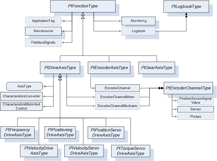
Figure 5 shows the organization of the OPC UA for Powertrain - Functional Model ObjectTypes used to model Powertrain Objects. All Axis ObjectTypes are derived from the abstract PtDriveAxisType providing the functions common to all Axis ObjectTypes.
The PtDriveAxisType ObjectType is derived from the PtFunctionType ObjectType defining common properties shared by all Powertrain Objects.
7.1 PtFunctionType definition
The PtFunctionType specifies the properties which are common for all OPC UA for Powertrain - Functional Model ObjectTypes.
| Attribute | Value | ||||
| BrowseName | PtFunctionType | ||||
| IsAbstract | True | ||||
| References | Node Class | BrowseName | DataType | TypeDefinition | Other |
|---|---|---|---|---|---|
| Subtype of the 0:BaseObjectType defined in OPC 10000-5. | |||||
| 0:HasProperty | Variable | ApplicationTag | 0:String | 0:PropertyType | O, RO |
| 0:HasComponent | Method | SetApplicationTag | O | ||
| 0:HasComponent | Object | Lock | 2:LockingServicesType | O | |
| 0:HasComponent | Object | FieldbusSignals | 0:FolderType | O | |
| 0:HasComponent | Object | Monitoring | 0:FolderType | M | |
| 0:HasComponent | Object | Maintenance | 0:FolderType | M | |
| 0:HasComponent | Object | Logbook | PtLogbookType | O | |
| 0:GeneratesEvent | ObjectType | PtLogbookEventType | |||
| 0:HasComponent | Object | LogObject | 0:LogObjectType | O | |
| 0:GeneratesEvent | ObjectType | PtLogObjectEventType | |||
| Conformance Units | |||||
|---|---|---|---|---|---|
| Powertrain Actual and Command Values | |||||
| Powertrain Logbook Readable | |||||
| Powertrain Logbook Events | |||||
| Powertrain Fieldbus | |||||
| Powertrain Encoder Channel | |||||
| Powertrain LogObject | |||||
| Powertrain LogObject Events |
General Properties in Semantic sub-aspect
The ApplicationTag Variable contains information given by the overall application. The purpose is to provide additional semantic information about the represented Powertrain Objects role or labelling in the context of the specific overall application context (machine, site or plant). Therefore, plant operators and/or application engineers are responsible to set the content of the ApplicationTag with information used for site management, asset management or other administrative purposes, e.g. "Production Line <m>/Machine <n>/x-Axis".
Furthermore, information out of identification objects offered by field bus protocols may be used as content of the ApplicationTag Variable (e.g. in case of PROFINET, the I&M-1 record "tag-function" or the I&M-3 "descriptor" could be used). However, as a default, vendors could also generate the ApplicationTag string out of the device or field bus configuration data as initial content of the Variable (e.g. in case of PROFINET, the NameOfStation and Module/Axis number could be used).
The Client can change the Value of this Variable by invoking the SetApplicationTag Method.
Before invoking a Method of the PtFunctionType Object, Clients must gain exclusive write access ("lock" the PtFunctionType Object) using the Lock Object.
The Lock Object ensures exclusive Method call for one Client. The Client locks the PtFunctionType Object by invoking the InitLock Method of the Lock Object. The Client invokes ExitLock to release the lock.
Some components of the PtFunctionType have additional subcomponents which are defined in Table 16.
| BrowsePath | References | NodeClass | BrowseName | DataType | TypeDefinition | Others | ||
| FieldbusSignals | 0:HasComponent | Variable | <SignalName> | 0:Number | 0:BaseDataVariableType | OP, RO | ||
| Monitoring | 0:HasComponent | Variable | ControlPriority | 0:UInt16 | PtControlPriorityVariableType | O, RO | ||
| Monitoring | 0:HasComponent | Variable | ShaftTurningDirection | 0:UInt16 | PtShaftTurningDirectionVariableType | O, RO | ||
| Monitoring | 0:HasComponent | Variable | DeviceTemperature | 0:Float | PtTemperatureVariableType | O, RO | ||
| Monitoring | 0:HasComponent | Object | <VibrationSensor_x> | PtVibrationSensorType | OP | |||
| Applied from 2:IOperationCounterType Interface: | ||||||||
| Maintenance | 0:HasProperty | Variable | 2:PowerOnDuration | 0:Duration | 0:PropertyType | O, RO | ||
| Maintenance | 0:HasProperty | Variable | 2:OperationDuration | 0:Duration | 0:PropertyType | O, RO | ||
| Maintenance | 0:HasProperty | Variable | 2:OperationCycleCounter | 0:UInteger | 0:PropertyType | O, RO | ||
| Maintenance | 0:HasComponent | Object | <Motor_x> | 0:BaseObjectType | OP | |||
| Maintenance | 0:HasComponent | Object | <Converter> | 0:BaseObjectType | OP | |||
| Maintenance | 0:HasComponent | Object | <Gear_x> | 0:BaseObjectType | OP | |||
| Maintenance | 0:HasComponent | Object | <Encoder_x> | 0:BaseObjectType | OP | |||
| Maintenance | 0:HasComponent | Object | <Brake_x> | 0:BaseObjectType | OP | |||
| Applied from 2:IOperationCounterType Interface: | ||||||||
| 0:HasProperty | Variable | 2:PowerOnDuration | 0:Duration | 0:PropertyType | O, RO | ||
| 0:HasProperty | Variable | 2:OperationDuration | 0:Duration | 0:PropertyType | O, RO | ||
| 0:HasProperty | Variable | 2:OperationCycleCounter | 0:UInteger | 0:PropertyType | O, RO | ||
| 0:HasProperty | Variable | 2:PowerOnDuration | 0:Duration | 0:PropertyType | O, RO | ||
| 0:HasProperty | Variable | 2:OperationDuration | 0:Duration | 0:PropertyType | O, RO | ||
| 0:HasProperty | Variable | 2:OperationCycleCounter | 0:UInteger | 0:PropertyType | O, RO | ||
| 0:HasProperty | Variable | 2:PowerOnDuration | 0:Duration | 0:PropertyType | O, RO | ||
| 0:HasProperty | Variable | 2:OperationDuration | 0:Duration | 0:PropertyType | O, RO | ||
| 0:HasProperty | Variable | 2:OperationCycleCounter | 0:UInteger | 0:PropertyType | O, RO | ||
| 0:HasProperty | Variable | 2:PowerOnDuration | 0:Duration | 0:PropertyType | O, RO | ||
| 0:HasProperty | Variable | 2:OperationDuration | 0:Duration | 0:PropertyType | O, RO | ||
| 0:HasProperty | Variable | 2:OperationCycleCounter | 0:UInteger | 0:PropertyType | O, RO | ||
| 0:HasProperty | Variable | 2:PowerOnDuration | 0:Duration | 0:PropertyType | O, RO | ||
| 0:HasProperty | Variable | 2:OperationDuration | 0:Duration | 0:PropertyType | O, RO | ||
| 0:HasProperty | Variable | 2:OperationCycleCounter | 0:UInteger | 0:PropertyType | O, RO | ||
| 0:HasComponent | Variable | ThermalCapacityUtilization | 0:UInteger | 0:BaseDataVariableType | O, RO | ||
| 0:HasComponent | Variable | PeakUtilization | 0:UInteger | 0:BaseDataVariableType | O, RO | ||
| 0:HasComponent | Variable | RemainingUsefulLifetime | 0:Integer | 0:BaseDataVariableType | O, RO | ||
| 0:HasProperty | Variable | OilRemainingUsefulLifetime | 0:Duration | 0:PropertyType | O, RO | ||
| 0:HasComponent | Variable | MaintenanceStatus | 0:UInt16 | PtMaintenanceStatusVariableType | O, RO | ||
| Maintenance | 0:HasComponent | Variable | ThermalCapacityUtilization | 0:UInteger | 0:BaseDataVariableType | O, RO | ||
| Maintenance | 0:HasComponent | Variable | PeakUtilization | 0:UInteger | 0:BaseDataVariableType | O, RO | ||
| Maintenance | 0:HasComponent | Variable | RemainingUsefulLifetime | 0:Integer | 0:BaseAnalogType | O, RO | ||
| Maintenance | 0:HasComponent | Variable | GearOilRemainingUsefulLifetime | 0:Integer | 0:BaseAnalogType | O, RO | ||
| Maintenance | 0:HasComponent | Variable | GearMaintenanceStatus | 0:UInt16 | PtMaintenanceStatusVariableType | O, RO | ||
SetApplicationTag Method
This Method sets the Value of the ApplicationTag Variable. The security constraints defined in chapter 0 apply.
Signature
	SetApplicationTag (
		[in] 0:String	 ApplicationTag
		);
| Argument | Description |
| ApplicationTag | String containing the desired content of the ApplicationTag Variable. |
The Method Result Codes (defined in Call Service) are defined in Table 17.
| Result Code | Description |
| Good | The Method execution was successful. |
| Bad_UserAccessDenied | The user has not the authorization to execute the Method. |
| Bad_InvalidArgument | The Server is not able to apply the name. The ApplicationTag string may be too long or may contain invalid characters. The Server may also reject duplicates. |
| Bad_Locked | The PtFunctionType Object is locked by a different Client's Session. |
| Bad_RequiresLock | The PtFunctionType Object is not locked. Clients must lock the PtFunctionType Object before invoking a Method. |
| Bad_UnexpectedError | The Server is not able to execute the function because an unexpected error occurred. The Device might be temporarily unavailable or unreachable due to network failure. |
Monitoring folder in Actual and Command Values sub-aspect
The Monitoring folder contains Variables common to all derived ObjectTypes. Derived ObjectTypes add additional type specific components to the Monitoring folder.
The specification of the Monitoring folder at the abstract root of the type hierarchy renders this folder mandatory for all derived ObjectTypes. The Variables specified by PtFunctionType are defined in Table 16 and are common for all derived ObjectTypes.
Maintenance folder in Maintenance sub-aspect
The Maintenance folder contains optional properties defined by the 2:IOperationCounterType Interface specified in [OPC 10000-100]. Figure 6 shows the motor related components of the Maintenance folder if the Drive has one motor. The PowerOnDuration, OperationDuration and OperationCycleCounter Properties are specified by the applied 2:IOperationCounterType Interface.
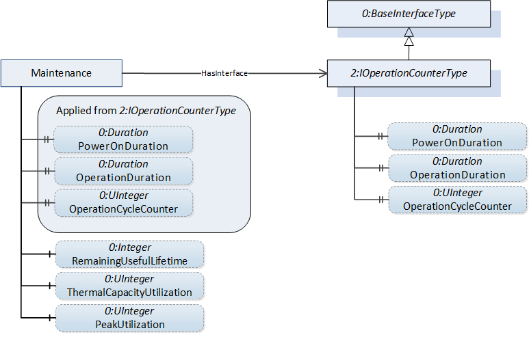
For a description of all Variables and Properties in the "Maintenance" folder see Table 54. The specification of the Maintenance folder at the abstract root of the type hierarchy renders this folder mandatory for all derived ObjectTypes. Derived ObjectTypes may add additional Variables to this folder.
If the Drive has more than one motor, and there are separate maintenance related variables for motors and converter, the 2:IOperationCounterType Interface shall be applied to the <Motor_x> or <Converter> placeholder Objects. The RemainingUsefulLifetime, ThermalCapacityUtilization and PeakUtilization Variables shall also be provided as components of the separate Objects representing the motors or converter in this case, as shown in Figure 7 for a dual motor scenario.
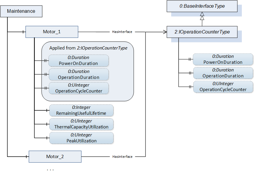
The same principle applies for the <Gear_x> placeholder objects. If the Drive has one gear, the gear-related Variables GearMaintenanceStatus and GearOilRemainingUsefulLifetime shall be provided as components of the Maintenance folder. If the Drive has more than one gear, the <Gear_x> placeholder Objects shall provide the MaintenanceStatus and OilRemainingUsefulLifetime Variables and the GearMaintenanceStatus and GearOilRemainingUsefulLifetime Variables shall be omitted.
If the Drive is equipped with more than one brake, the 2:IOperationCounterType Interface shall be applied to the individual <Brake_x> placeholder Objects. If the Drive is equipped with more than one encoder, this Interface shall be applied to the individual <Encoder_x> Objects.
Diagnosis sub-aspect
The Logbook Object provides access to the PtDriveAxisType Object's diagnosis system.
The Server might provide the Client with information about new incidents by sending PtLogbookEventType Events.
The 0:LogObject Object (defined in OPC 10000-26) can be provided to make the content of the diagnosis system represented by the Logbook Object available for all Clients which prefer to utilize the LogObject. The mapping from the LogEntryDataType structures provided by the Logbook Object to the LogObject's 0:LogRecord structures is specified in Table 94.
The Server might provide the Client with information about new entries in the LogObject by sending PtLogObjectType Events.
The Logbook Object essentially provides the Client with the means to obtain information about the diagnosis state of a PtFunctionType Object. The Logbook also makes the history of diagnosis relevant events available for Clients by recording timestamps for the event when the event first appears, when it is acknowledged and when it disappears. Since the capacity of the diagnosis buffer the Logbook represents is limited, acknowledged events may be deleted by the Server.
The 0:LogObject provides a standard way to collect diagnostic information and to make it available for Clients. This allows a standard Client unaware of the Logbook Object defined in this specification to access the diagnosis information of a Powertrain Object. It also offers more flexibility regarding the required local memory, since the 0:LogObject may send the diagnosis records to a remote Server allowing the local 0:LogObject to have only a small buffer of records. The 0:LogObject also allows the collection of diagnosis information in a system using OpenTelemetry (see OPC 10000-26 Annex C).
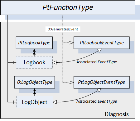
Figure 8 shows the structure of the "Diagnosis" sub-aspect in conjunction with the associated EventTypes. The PtLogbookEventType Events related to entries into the Logbook are generated by the parent PtFunctionType Object. The insertion of 0:LogRecords by the LogObject causes PtLogObjectEventType Events to be generated by the parent PtFunctionType Object as well. The parent PtFunctionType Object is the SourceNode of the Events.
7.1.1 PtDriveAxisType definition
The PtDriveAxisType ObjectType specifies the properties which are common for OPC UA for Powertrain - Functional Model Axis Type Drive Object ObjectTypes. The general characteristic for the PtDriveAxisType is that it contains an actuator.
The PtDriveAxisType is an abstract ObjectType representing Powertrain Drive Axis Objects.
| Attribute | Value | ||||
| BrowseName | PtDriveAxisType | ||||
| IsAbstract | True | ||||
| References | Node Class | BrowseName | DataType | TypeDefinition | Other |
|---|---|---|---|---|---|
| Subtype of the PtFunctionType. | |||||
| 0:HasComponent | Variable | AxisType | 0:UInt16 | 0:MultiStateValueDiscreteType | M, RO |
| 0:HasComponent | Object | LimitSupervision | 0:FolderType | O | |
| 0:HasComponent | Object | CharacteristicsConverter | PtCharacteristicsConverterType | O | |
| 0:HasComponent | Object | CharacteristicsMotorAndControl | 0:FolderType | M | |
| 0:HasComponent | Object | Logbook | PtLogbookType | M | |
| 0:HasComponent | Object | Safety | PtSafetyType | O | |
| 0:HasComponent | Object | VelocityProfile | 0:FolderType | O | |
| 0:HasComponent | Object | Monitoring | 0:FolderType | M | |
| 0:HasComponent | Object | Maintenance | 0:FolderType | M | |
| Conformance Units | |||||
|---|---|---|---|---|---|
| Powertrain Actual and Command Values | |||||
| Powertrain Axis Properties | |||||
| Powertrain Logbook Readable | |||||
| Powertrain Safety |
Some components of the PtDriveAxisType have additional subcomponents which are defined in Table 19. For detailed descriptions of these Variables see Table 54.
| BrowsePath | References | NodeClass | BrowseName | DataType | TypeDefinition | Others |
| Monitoring | 0:HasComponent | Variable | AxisState | 0:UInt16 | 0:MultiStateValueDiscreteType | M, RO |
| Monitoring | 0:HasComponent | Variable | ControlPriority | 0:UInt16 | PtControlPriorityVariableType | M, RO |
| Monitoring | 0:HasComponent | Variable | ControlMode | 0:UInt16 | 0:MultiStateValueDiscreteType | O, RO |
| Monitoring | 0:HasComponent | Variable | FrequencySetpoint | 0:Float | 0:AnalogUnitType | O, RO |
| Applied from IMonitoringElectric Interface (for electric drives only): | ||||||
| Monitoring | 0:HasComponent | Variable | BleederTemperature | 0:Float | PtTemperatureVariableType | O, RO |
| Monitoring | 0:HasComponent | Variable | ConverterOutputFrequency | 0:Float | 0:AnalogUnitType | O, RO |
| Monitoring | 0:HasComponent | Variable | ConverterOutputVoltage | 0:Float | 0:AnalogUnitType | O, RO |
| Monitoring | 0:HasComponent | Variable | ConverterOutputVoltageMagnetization | 0:Float | 0:AnalogUnitType | O, RO |
| Monitoring | 0:HasComponent | Variable | ConverterOutputVoltageTorque | 0:Float | 0:AnalogUnitType | O, RO |
| Monitoring | 0:HasComponent | Variable | ConverterOutputCosPhi | 0:Float | 0:AnalogUnitType | O, RO |
| Monitoring | 0:HasComponent | Variable | ConverterOutputCurrent | 0:Float | 0:AnalogUnitType | O, RO |
| Monitoring | 0:HasComponent | Variable | ConverterOutputCurrentMagnetization | 0:Float | 0:AnalogUnitType | O, RO |
| Monitoring | 0:HasComponent | Variable | ConverterOutputCurrentTorque | 0:Float | 0:AnalogUnitType | O, RO |
| Monitoring | 0:HasComponent | Variable | ConverterOutputPower | 0:Float | 0:AnalogUnitType | O, RO |
| Monitoring | 0:HasComponent | Variable | ConverterTemperature | 0:Float | PtTemperatureVariableType | O, RO |
| Monitoring | 0:HasComponent | Variable | DcBusVoltage | 0:Float | 0:AnalogUnitType | O, RO |
| Monitoring | 0:HasComponent | Variable | LineInputPower | 0:Float | 0:AnalogUnitType | O, RO |
| Monitoring | 0:HasComponent | Variable | TorqueForceActualValue | 0:Float | 0:AnalogUnitType | O, RO |
| Monitoring | 0:HasComponent | Variable | MotorTemperature | 0:Float | PtTemperatureVariableType | O, RO |
| Monitoring | 0:HasComponent | Variable | BrakeState | 0:UInt16 | PtBrakeStateVariableType | O, RO |
| Monitoring | 0:HasComponent | Variable | AxisTorqueForce | 0:Float | 0:AnalogUnitType | O, RO |
| Monitoring | 0:HasComponent | Variable | AxisOutputVelocity | 0:Float | 0:AnalogUnitType | O, RO |
| Monitoring | 0:HasComponent | Variable | GearInputVelocity | 0:Float | 0:AnalogUnitType | O, RO |
| Monitoring | 0:HasComponent | Variable | GearInputTorque | 0:Float | 0:AnalogUnitType | O, RO |
| Monitoring | 0:HasComponent | Variable | GearOutputVelocity | 0:Float | 0:AnalogUnitType | O, RO |
| Monitoring | 0:HasComponent | Variable | GearOutputTorque | 0:Float | 0:AnalogUnitType | O, RO |
| Monitoring | 0:HasComponent | Variable | GearRatio | 0:Float | 0:BaseDataVariableType | O, RO |
| Monitoring | 0:HasComponent | Variable | GearTemperature | 0:Float | PtTemperatureVariableType | O, RO |
| Monitoring | 0:HasComponent | Variable | GearState | 0:UInt16 | PtGearStateVariableType | O, RO |
| Monitoring | 0:HasComponent | Variable | GearOutputShaftTurningDirection | 0:UInt16 | PtShaftTurningDirectionVariableType | O, RO |
| Monitoring | 0:HasComponent | Variable | GearInputShaftTurningDirection | 0:UInt16 | PtShaftTurningDirectionVariableType | O, RO |
| Maintenance | 0:HasComponent | Variable | GearBacklash | 0:Float | 0:AnalogUnitType | O, RO |
| CharacteristicsMotorAndControl | 0:HasComponent | Variable | MotorPowerRated | 0:Float | 0:AnalogUnitType | M, RO |
| CharacteristicsMotorAndControl | 0:HasComponent | Variable | MotorSpeedRated | 0:Float | 0:AnalogUnitType | O, RO |
| CharacteristicsMotorAndControl | 0:HasComponent | Variable | MotorTorqueRated | 0:Float | 0:AnalogUnitType | O, RO |
| CharacteristicsMotorAndControl | 0:HasComponent | Variable | MotorForceRated | 0:Float | 0:AnalogUnitType | O, RO |
| Applied from ICharacteristicsMotorAndControlElectric Interface (for electric drives only): | ||||||
| CharacteristicsMotorAndControl | 0:HasComponent | Variable | MotorMaxCurrent | 0:Float | 0:AnalogUnitType | O, RO |
| CharacteristicsMotorAndControl | 0:HasProperty | Variable | MotorUfRatio | 0:Float | 0:PropertyType | O, RO |
| CharacteristicsMotorAndControl | 0:HasComponent | Variable | MotorRunUpVoltage | 0:Float | 0:AnalogUnitType | O, RO |
| CharacteristicsMotorAndControl | 0:HasComponent | Variable | MotorDcBrakingCurrent | 0:Float | 0:AnalogUnitType | O, RO |
| CharacteristicsMotorAndControl | 0:HasComponent | Variable | DcBrakingTime | 0:Float | 0:AnalogUnitType | O, RO |
| CharacteristicsMotorAndControl | 0:HasComponent | Variable | MotorThermalLoadLimitConfigured | 0:Float | 0:AnalogUnitType | O, RO |
| CharacteristicsMotorAndControl | 0:HasComponent | Variable | MotorPeakCurrentConfigured | 0:Float | 0:AnalogUnitType | O, RO |
| CharacteristicsMotorAndControl | 0:HasComponent | Variable | TimePeriodCurrentControl | 0:Float | 0:AnalogUnitType | O, RO |
| CharacteristicsMotorAndControl | 0:HasComponent | Variable | FeedbackMode | 0:UInt16 | 0:MultiStateValueDiscreteType | O, RO |
| CharacteristicsMotorAndControl | 0:HasComponent | Variable | SpeedMaxConfigured | 0:Float | 0:AnalogUnitType | O, RO |
| CharacteristicsMotorAndControl | 0:HasComponent | Variable | TorqueMaxConfigured | 0:Float | 0:AnalogUnitType | O, RO |
| CharacteristicsMotorAndControl | 0:HasComponent | Variable | MotorType | 0:UInt16 | 0:MultiStateValueDiscreteType | M, RO |
| CharacteristicsMotorAndControl | 0:HasComponent | Variable | PositionFollowingErrorLimit | 0:Float | 0:AnalogUnitType | O, RO |
| CharacteristicsMotorAndControl | 0:HasComponent | Variable | VelocityFollowingErrorLimit | 0:Float | 0:AnalogUnitType | O, RO |
| Applied from ILimitSupervisionElectric Interface (for electric drives only): | ||||||
| LimitSupervision | 0:HasComponent | Variable | MotorCurrentLimitLow | 0:Float | 0:AnalogUnitType | O, RO |
| LimitSupervision | 0:HasComponent | Variable | MotorCurrentLimitHigh | 0:Float | 0:AnalogUnitType | O, RO |
| VelocityProfile | 0:HasComponent | Variable | JogSpeed1 | 0:Float | 0:AnalogUnitType | O, RO |
| VelocityProfile | 0:HasComponent | Variable | JogSpeed2 | 0:Float | 0:AnalogUnitType | O, RO |
| VelocityProfile | 0:HasComponent | Variable | NominalSpeed | 0:Float | 0:AnalogUnitType | O, RO |
| VelocityProfile | 0:HasComponent | Variable | VelocityRampDownTime | 0:Float | 0:AnalogUnitType | O, RO |
| VelocityProfile | 0:HasComponent | Variable | QuickStopVelocityRampDownTime | 0:Float | 0:AnalogUnitType | O, RO |
| VelocityProfile | 0:HasComponent | Variable | VelocityRampDeceleration | 0:Float | 0:AnalogUnitType | O, RO |
| VelocityProfile | 0:HasComponent | Variable | QuickStopVelocityRampDeceleration | 0:Float | 0:AnalogUnitType | O, RO |
| VelocityProfile | 0:HasComponent | Variable | MinimumVelocity | 0:Float | 0:AnalogUnitType | O, RO |
| VelocityProfile | 0:HasComponent | Variable | MaximumVelocity | 0:Float | 0:AnalogUnitType | O, RO |
The child Nodes of the PtDriveAxisType have additional Attribute values defined in Table 20.
| BrowsePath | Value Attribute | |||
| [ { "Value":0, "DisplayName": "LINEAR", "Description": "Axis with linear movement" }, { "Value":1, "DisplayName": "ROTATORY", "Description": "Axis with rotatory movement" }, { "Value":2, "DisplayName": "ROTATORY_MODULO", "Description": "Single turn rotatory axis with modulo correction" }, { "Value":3, "DisplayName": "SPINDLE", "Description": "Axis with spindle properties" }, { "Value":4, "DisplayName": "VIRTUAL_AXIS_LINEAR", "Description": "Virtual axis with linear movement" }, { "Value":5, "DisplayName": "VIRTUAL_AXIS_ROTARY", "Description": "Virtual axis with rotatory movement" } ] | |||
| [ { "Value":0, "DisplayName": "SWITCHING_ON_INHIBITED", "Description": "Switching on inhibited" }, { "Value":1, "DisplayName": "READY_FOR_SWITCHING_ON", "Description": "Ready for switching on" }, { "Value":2, "DisplayName": "SWITCHED_ON", "Description": "Switched on" }, { "Value":3, "DisplayName": "OPERATION", "Description": "In operation" }, { "Value":4, "DisplayName": "RAMP_STOP", "Description": "Controlled stop by ramp function" }, { "Value":5, "DisplayName": "QUICK_STOP", "Description": "Controlled stop with maximum deceleration" }, { "Value":6, "DisplayName": "POS_BASIC_STATE", "Description": "Positioning mode basic state" }, { "Value":7, "DisplayName": "POS_JOGGING", "Description": "Positioning mode jogging" }, { "Value":8, "DisplayName": "POS_BRAKING_WITH_RAMP", "Description": "Positioning mode braking with ramp function" }, { "Value":9, "DisplayName": "POS_HOMING_PROCEDURE", "Description": "Positioning mode homing" }, { "Value":10, "DisplayName": "POS_TRAVERSING_TASK_ACTIVE", "Description": "Positioning mode traversing task active" }, { "Value":11, "DisplayName": "POS_INTERMEDIATE_STOP_STOPPED", "Description": "Positioning mode stopped in intermediate stop" }, { "Value":12, "DisplayName": "POS_INTERMEDIATE_STOP_BRAKING", "Description": "Positioning mode breaking in intermediate stop" }, { "Value":13, "DisplayName": "PARKED", "Description": "Parked" }, { "Value":14, "DisplayName": "SPINDLE_STOPPED", "Description": "Spindle stopped" }, { "Value":15, "DisplayName": "SPINDLE_ACCELERATING", "Description": "Spindle is accelerating" }, { "Value":16, "DisplayName": "SPINDLE_DECELERATING", "Description": "Spindle is decelerating" }, { "Value":17, "DisplayName": "SPINDLE_IN_TARGET_AREA", "Description": "Spindle is in target area" } ] | |||
| [ { "Value":0, "DisplayName": "TORQUE_CONTROL", "Description": "Torque control" }, { "Value":1, "DisplayName": "TORQUE_CONTROL_SENSORLESS", "Description": "Torque control sensorless" }, { "Value":2, "DisplayName": "FORCE_CONTROL", "Description": "Force control" }, { "Value":3, "DisplayName": "FORCE_CONTROL_SENSORLESS", "Description": "Force control sensorless" }, { "Value":4, "DisplayName": "SPEED_CONTROL", "Description": "Speed control" }, { "Value":5, "DisplayName": "SPEED_CONTROL_SENSORLESS", "Description": "Speed control sensorless" }, { "Value":6, "DisplayName": "SPEED_CONTROL_DSC", "Description": "Speed control with dynamic stiffness control" }, { "Value":7, "DisplayName": "POSITION_CONTROL", "Description": "Position control" }, { "Value":8, "DisplayName": "POSITION_CONTROL_SENSORLESS", "Description": "Position control sensorless" }, { "Value":9, "DisplayName": "POSITIONING_CONTROL", "Description": "Positioning control" }, { "Value":10, "DisplayName": "UF_CONTROL", "Description": "U/F control" }, { "Value":11, "DisplayName": "VECTOR_CONTROL", "Description": "Vector control" }, { "Value":12, "DisplayName": "VECTOR_CONTROL_SENSORLESS", "Description": "Vector control sensorless" } ] | |||
| [ { "Value":0, "DisplayName": "FEEDBACK_MOTOR", "Description": "Feedback with motor encoder" }, { "Value":1, "DisplayName": "FEEDBACK_DIRECT", "Description": "Feedback with direct encoder" }, { "Value":2, "DisplayName": "FEEDBACK_MOTOR_AND_DIRECT", "Description": "Feedback with motor and direct encoder" }, { "Value":3, "DisplayName": "FEEDBACK_SENSOR_1", "Description": "Feedback with sensor 1" }, { "Value":4, "DisplayName": "FEEDBACK_SENSOR_2", "Description": "Feedback with sensor 2" }, { "Value":5, "DisplayName": "FEEDBACK_SENSOR_3", "Description": "Feedback with sensor 3" }, { "Value":6, "DisplayName": "SENSORLESS", "Description": "Feedback without sensor" } ] | |||
| [ { "Value":0, "DisplayName": "ASYNCHRONOUS", "Description": "Induction motor" }, { "Value":1, "DisplayName": "PM_AC_SYNCHRONOUS", "Description": "Synchronous motor" }, { "Value":2, "DisplayName": "PM_AC_SYNCHRONOUS_IRONLESS", "Description": "Synchronous ironless motor" }, { "Value":3, "DisplayName": "DC_BRUSHLESS", "Description": "Brushless DC motor" }, { "Value":4, "DisplayName": "DC_BRUSHED", "Description": "DC motor" }, { "Value":5, "DisplayName": "PM_STEPPER", "Description": "Stepper motor" }, { "Value":6, "DisplayName": "HYBRID_STEPPER", "Description": "Hybrid stepper motor" }, { "Value":7, "DisplayName": "SYNC_RELUCTANCE", "Description": "Synchronous reluctance motor" } ] |
Some values represented as enumerations in the Monitoring and CharacteristicsMotorAndControl folders are modelled as 0:MultiStateValueDiscreteType Variables. The content of the EnumValues lookup table Property is defined in Table 20 for all these 0:MultiStateValueDiscreteType Variables. The "Locale" field of the 0:LocalizedText structures is Server specific.
The AxisType Variable contains the mechanical drive type of the represented Powertrain Axis Object modelled as 0:MultiStateValueDiscreteType.
Monitoring folder in Actual and Command Values sub-aspect
The Monitoring folder inherited from PtFunctionType contains Monitoring Variables describing measurements of the Powertrain Axis Objects which are of interest for monitoring encoded as numeric data type. The PtDriveAxisType ObjectType adds Variables and Properties common for all the derived concrete ObjectTypes. Each derived ObjectType may add the Variables and Properties specific for the respective ObjectType.
Instances of the Monitoring folder shall reference the IMonitoringElectric Interface using the HasInterface ReferenceType.
For a description of all Variables and Properties in the "Monitoring" folder see Table 54.
LimitSupervision folder in Process Supervision sub-aspect
The LimitSupervision folder contains Variables with Values describing limit values for motor current, torque, and the like. These limit Variables differ between concrete derived Axis ObjectTypes and are specified separately for each derived Axis ObjectType.
Instances of the LimitSupervision folder shall reference the ILimitSupervisionElectric Interface using the HasInterface ReferenceType.
For a description of the Variables in the "LimitSupervision" folder see Table 54.
Axis Properties sub-aspect
The CharacteristicsConverter Object contains Variables with Values describing key data of the CDM's converter. This ObjectType represents the electric converter properties of electric drives and shall be always provided for electric drives. However, future versions of this specification might support additional drive types such as hydraulic or pneumatic drives. For these drive types dedicated Objects might be specified and referenced with additional optional HasComponent References.
The CharacteristicsMotorAndControl folder contains Variables with Values describing key data of the CDM's motor and its key control features.
Instances of the CharacteristicsMotorAndControl folder shall reference the ICharacteristicsMotorAndControlElectric Interface using the HasInterface ReferenceType.
The VelocityProfile folder contains Variables describing key properties of brake ramps. In addition, this folder also contains Variables describing the properties of a ramp function generator often available with VSD drives. The folder contains the properties mandatory for each derived Powertrain Axis Object type.
The Variables VelocityRampUpTime and VelocityRampDownTime are always related to the Value of the NominalSpeed Variable. The Variable VelocityRampDeceleration describes the same ramp function as VelocityRampDownTime and shall therefore always be provided together with this Variable. The same is true for the Variables VelocityRampUpTime and VelocityRampAcceleration provided by derived axis types.
For a description of the Variables in the CharacteristicsMotorAndControl folder and the VelocityProfile folder see Table 54.
7.1.1.1 PtFrequencyDriveAxisType
A PtFrequencyDriveAxisType is a PtDriveAxisType representing the functionality of a VSD with a frequency command interface. Figure 9 shows a block diagram demonstrating the basic organization and control flow for this axis type.
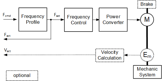
The formal definition of the PtFrequencyDriveAxisType ObjectType can be found in Table 21.
| Attribute | Value | ||||
| BrowseName | PtFrequencyDriveAxisType | ||||
| IsAbstract | False | ||||
| References | Node Class | BrowseName | DataType | TypeDefinition | Other |
|---|---|---|---|---|---|
| Subtype of the PtDriveAxisType. | |||||
| 0:GeneratesEvent | ObjectType | PtMotorCurrentLimitEventType | |||
| 0:HasComponent | Object | CharacteristicsMechanics | 0:FolderType | O | |
| 0:HasComponent | Object | VelocityProfile | 0:FolderType | M | |
| 0:HasComponent | Object | Monitoring | 0:FolderType | M | |
| 0:HasComponent | Object | CharacteristicsMotorAndControl | 0:FolderType | M | |
| 0:HasComponent | Object | LimitSupervision | 0:FolderType | O | |
| Conformance Units | |||||
|---|---|---|---|---|---|
| Powertrain Actual and Command Values | |||||
| Powertrain Axis Properties |
The components of the PtFrequencyDriveAxisType have additional subcomponents which are defined in Table 22.
| BrowsePath | References | NodeClass | BrowseName | DataType | TypeDefinition | Others |
| Monitoring | 0:HasComponent | Variable | FrequencyCommandValue | 0:Float | 0:AnalogUnitType | M, RO |
| Monitoring | 0:HasComponent | Variable | VelocityActualValue | 0:Float | 0:AnalogUnitType | O, RO |
| Monitoring | 0:HasComponent | Variable | FrequencySetpoint | 0:Float | 0:AnalogUnitType | M, RO |
| Monitoring | 0:HasComponent | Variable | ConverterOutputFrequency | 0:Float | 0:AnalogUnitType | M, RO |
| CharacteristicsMotorAndControl | 0:HasComponent | Variable | TimePeriodVelocityControl | 0:Float | 0:AnalogUnitType | O, RO |
| CharacteristicsMechanics | 0:HasComponent | Variable | GearFactorPrecise | PtGearFactorDataType | 0:BaseDataVariableType | O, RO |
| CharacteristicsMechanics | 0:HasComponent | Variable | GearRatio | 0:Float | 0:BaseDataVariableType | O, RO |
| LimitSupervision | 0:HasComponent | Variable | MotorCurrentLimitHigh | 0:Float | 0:AnalogUnitType | M, RO |
| LimitSupervision | 0:HasComponent | Variable | TorqueLimit | 0:Float | 0:AnalogUnitType | O, RO |
| LimitSupervision | 0:HasComponent | Variable | TorqueLimitLow | 0:Float | 0:AnalogUnitType | O, RO |
| LimitSupervision | 0:HasComponent | Variable | TorqueLimitHigh | 0:Float | 0:AnalogUnitType | O, RO |
| VelocityProfile | 0:HasComponent | Variable | VelocityRampUpTime | 0:Float | 0:AnalogUnitType | O, RO |
| VelocityProfile | 0:HasComponent | Variable | VelocityRampAcceleration | 0:Float | 0:AnalogUnitType | O, RO |
For a description of the Variables see Table 54.
7.1.1.2 PtVelocityDriveAxisType
The PtVelocityDriveAxisType is an PtDriveAxisType representing the functionality of a VSD with a speed command interface. Figure 10 shows a block diagram demonstrating the basic organization and control flow for this axis type.
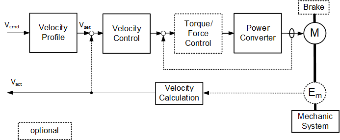
The formal definition of the PtVelocityDriveAxisType ObjectType can be found in Table 23.
| Attribute | Value | ||||
| BrowseName | PtVelocityDriveAxisType | ||||
| IsAbstract | False | ||||
| References | Node Class | BrowseName | DataType | TypeDefinition | Other |
|---|---|---|---|---|---|
| Subtype of the PtDriveAxisType. | |||||
| 0:HasComponent | Object | VelocityProfile | 0:FolderType | M | |
| 0:HasComponent | Object | CharacteristicsMechanics | 0:FolderType | O | |
| 0:GeneratesEvent | ObjectType | PtTorqueForceLimitEventType | |||
| 0:GeneratesEvent | ObjectType | PtMotorCurrentLimitEventType | |||
| 0:HasComponent | Object | Monitoring | 0:FolderType | M | |
| 0:HasComponent | Object | CharacteristicsMotorAndControl | 0:FolderType | M | |
| 0:HasComponent | Object | LimitSupervision | 0:FolderType | O | |
| Conformance Units | |||||
|---|---|---|---|---|---|
| Powertrain Actual and Command Values | |||||
| Powertrain Axis Properties | |||||
| Powertrain Limit Events |
The components of the PtVelocityDriveAxisType have additional subcomponents which are defined in Table 24.
| BrowsePath | References | NodeClass | BrowseName | DataType | TypeDefinition | Others |
| Monitoring | 0:HasComponent | Variable | VelocitySetpoint | 0:Float | 0:AnalogUnitType | M, RO |
| Monitoring | 0:HasComponent | Variable | VelocityCommandValue | 0:Float | 0:AnalogUnitType | M, RO |
| Monitoring | 0:HasComponent | Variable | VelocityCommandAdditiveValue | 0:Float | 0:AnalogUnitType | O, RO |
| Monitoring | 0:HasComponent | Variable | VelocityActualValue | 0:Float | 0:AnalogUnitType | M, RO |
| Monitoring | 0:HasComponent | Variable | AccelerationSetpoint | 0:Float | 0:AnalogUnitType | O, RO |
| Monitoring | 0:HasComponent | Variable | AccelerationCommandAdditiveValue | 0:Float | 0:AnalogUnitType | O, RO |
| Monitoring | 0:HasComponent | Variable | AccelerationActualValue | 0:Float | 0:AnalogUnitType | O, RO |
| Monitoring | 0:HasComponent | Variable | PositionActualValue | 0:Double | 0:AnalogUnitType | O, RO |
| Monitoring | 0:HasComponent | Variable | TorqueForceSetpoint | 0:Float | 0:AnalogUnitType | O, RO |
| Monitoring | 0:HasComponent | Variable | TorqueForceCommandAdditiveValue | 0:Float | 0:AnalogUnitType | O, RO |
| Monitoring | 0:HasComponent | Variable | <EncoderxTemperature> | 0:Float | PtTemperatureVariableType | OP, RO |
| Monitoring | 0:HasComponent | Variable | VelocityFollowingError | 0:Float | 0:AnalogUnitType | O, RO |
| CharacteristicsMotorAndControl | 0:HasComponent | Variable | TimePeriodVelocityControl | 0:Float | 0:AnalogUnitType | O, RO |
| CharacteristicsMotorAndControl | 0:HasComponent | Variable | TimePeriodTorqueControl | 0:Float | 0:AnalogUnitType | O, RO |
| CharacteristicsMechanics | 0:HasComponent | Variable | GearFactorPrecise | PtGearFactorDataType | 0:BaseDataVariableType | O, RO |
| CharacteristicsMechanics | 0:HasComponent | Variable | GearRatio | 0:Float | 0:BaseDataVariableType | O, RO |
| LimitSupervision | 0:HasComponent | Variable | TorqueLimit | 0:Float | 0:AnalogUnitType | O, RO |
| LimitSupervision | 0:HasComponent | Variable | TorqueLimitLow | 0:Float | 0:AnalogUnitType | O, RO |
| LimitSupervision | 0:HasComponent | Variable | TorqueLimitHigh | 0:Float | 0:AnalogUnitType | O, RO |
| VelocityProfile | 0:HasComponent | Variable | VelocityRampUpTime | 0:Float | 0:AnalogUnitType | O, RO |
| VelocityProfile | 0:HasComponent | Variable | VelocityRampAcceleration | 0:Float | 0:AnalogUnitType | O, RO |
For a description of the Variables see Table 54.
7.1.1.3 PtPositioningDriveAxisType
A PtPositioningDriveAxisType is an PtDriveAxisType representing the functionality of a servo drive or stepper drive with a motion trajectory command interface. Figure 11 shows a block diagram demonstrating the basic organization and control flow for this axis type.
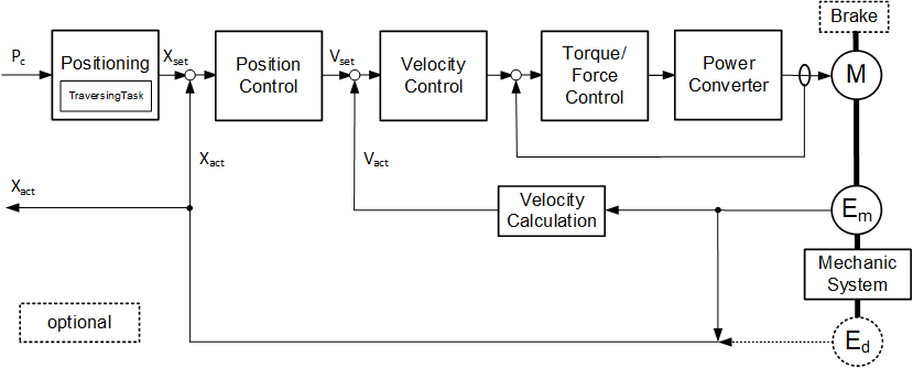
The formal definition of the PtPositioningDriveAxisType ObjectType can be found in Table 25.
| Attribute | Value | ||||
| BrowseName | PtPositioningDriveAxisType | ||||
| IsAbstract | False | ||||
| References | Node Class | BrowseName | DataType | TypeDefinition | Other |
|---|---|---|---|---|---|
| Subtype of the PtDriveAxisType. | |||||
| 0:HasComponent | Object | Homing | 0:FolderType | M | |
| 0:HasComponent | Object | CharacteristicsMechanics | 0:FolderType | O | |
| 0:HasComponent | Object | VelocityProfile | 0:FolderType | M | |
| 0:HasComponent | Object | LimitSupervision | 0:FolderType | M | |
| 0:HasComponent | Object | Monitoring | 0:FolderType | M | |
| 0:HasComponent | Object | CharacteristicsMotorAndControl | 0:FolderType | M | |
| 0:HasComponent | Object | MotionProgram | 0:FileType | O | |
| 0:GeneratesEvent | ObjectType | PtTorqueForceLimitEventType | |||
| 0:GeneratesEvent | ObjectType | PtMotorCurrentLimitEventType | |||
| Conformance Units | |||||
|---|---|---|---|---|---|
| Powertrain Actual and Command Values | |||||
| Powertrain Axis Properties | |||||
| Powertrain Limit Events |
Some components of the PtPositioningDriveAxisType have additional subcomponents which are defined in Table 26.
| BrowsePath | References | NodeClass | BrowseName | DataType | TypeDefinition | Others |
| Monitoring | 0:HasComponent | Variable | PositionActualValue | 0:Double | 0:AnalogUnitType | M, RO |
| Monitoring | 0:HasComponent | Variable | PositionCommandValue | 0:Float | 0:AnalogUnitType | O, RO |
| Monitoring | 0:HasComponent | Variable | PositionSetpoint | 0:Float | 0:AnalogUnitType | O, RO |
| Monitoring | 0:HasComponent | Variable | VelocityActualValue | 0:Float | 0:AnalogUnitType | M, RO |
| Monitoring | 0:HasComponent | Variable | VelocitySetpoint | 0:Float | 0:AnalogUnitType | O, RO |
| Monitoring | 0:HasComponent | Variable | AccelerationActualValue | 0:Float | 0:AnalogUnitType | O, RO |
| Monitoring | 0:HasComponent | Variable | AccelerationSetpoint | 0:Float | 0:AnalogUnitType | O, RO |
| Monitoring | 0:HasComponent | Variable | TorqueForceSetpoint | 0:Float | 0:AnalogUnitType | O, RO |
| Monitoring | 0:HasComponent | Variable | TorqueForceCommandAdditiveValue | 0:Float | 0:AnalogUnitType | O, RO |
| Monitoring | 0:HasComponent | Variable | <EncoderxTemperature> | 0:Float | PtTemperatureVariableType | OP, RO |
| Monitoring | 0:HasComponent | Variable | PositionFollowingError | 0:Float | 0:AnalogUnitType | O, RO |
| Monitoring | 0:HasComponent | Variable | VelocityFollowingError | 0:Float | 0:AnalogUnitType | O, RO |
| Monitoring | 0:HasComponent | Object | TraversingTask | PtTraversingTaskType | M | |
| Monitoring | 0:HasComponent | Variable | Override | 0:Float | 0:BaseDataVariableType | O, RO |
| Monitoring | 0:HasComponent | Variable | HomingState | 0:UInt16 | PtHomingStateVariableType | M, RO |
| LimitSupervision | 0:HasComponent | Variable | MotorCurrentLimitHigh | 0:Float | 0:AnalogUnitType | M, RO |
| LimitSupervision | 0:HasComponent | Variable | TorqueLimit | 0:Float | 0:AnalogUnitType | O, RO |
| LimitSupervision | 0:HasComponent | Variable | TorqueLimitLow | 0:Float | 0:AnalogUnitType | O, RO |
| LimitSupervision | 0:HasComponent | Variable | TorqueLimitHigh | 0:Float | 0:AnalogUnitType | O, RO |
| LimitSupervision | 0:HasComponent | Variable | SoftwarePosLimitLow | 0:Float | 0:AnalogUnitType | M, RO |
| LimitSupervision | 0:HasComponent | Variable | SoftwarePosLimitHigh | 0:Float | 0:AnalogUnitType | M, RO |
| LimitSupervision | 0:HasComponent | Variable | TorqueLimiting | 0:Boolean | 0:BaseDataVariableType | O, RO |
| CharacteristicsMotorAndControl | 0:HasComponent | Variable | TimePeriodVelocityControl | 0:Float | 0:AnalogUnitType | O, RO |
| CharacteristicsMotorAndControl | 0:HasComponent | Variable | TimePeriodTrajectoryInterpolation | 0:Float | 0:AnalogUnitType | O, RO |
| CharacteristicsMotorAndControl | 0:HasComponent | Variable | TimePeriodPositionControl | 0:Float | 0:AnalogUnitType | O, RO |
| CharacteristicsMotorAndControl | 0:HasComponent | Variable | TimePeriodTorqueControl | 0:Float | 0:AnalogUnitType | O, RO |
| CharacteristicsMotorAndControl | 0:HasComponent | Variable | TrajectoryInterpolationMode | 0:Byte | 0:MultiStateValueDiscreteType | O, RO |
| Homing | 0:HasComponent | Variable | HomingDirection | 0:UInt16 | PtHomingDirectionVariableType | O, RO |
| Homing | 0:HasComponent | Variable | HomingSpeedToCam | 0:Float | 0:AnalogUnitType | O, RO |
| Homing | 0:HasComponent | Variable | HomingSpeedToMark | 0:Float | 0:AnalogUnitType | O, RO |
| Homing | 0:HasComponent | Variable | HomingPointOffset | 0:Float | 0:AnalogUnitType | O, RO |
| Homing | 0:HasComponent | Variable | HomingMode | 0:UInt16 | PtHomingModeVariableType | M, RO |
| CharacteristicsMechanics | 0:HasComponent | Variable | GearFactorPrecise | PtGearFactorDataType | 0:BaseDataVariableType | O, RO |
| CharacteristicsMechanics | 0:HasComponent | Variable | GearRatio | 0:Float | 0:BaseDataVariableType | O, RO |
| CharacteristicsMechanics | 0:HasComponent | Variable | SpindlePitch | 0:Float | 0:BaseDataVariableType | O, RO |
| VelocityProfile | 0:HasComponent | Variable | JogPosInc1 | 0:Float | 0:AnalogUnitType | O, RO |
| VelocityProfile | 0:HasComponent | Variable | JogPosInc2 | 0:Float | 0:AnalogUnitType | O, RO |
The SpindlePitch Variable shall be provided if a spindle is present in the Powertrain Axis Object.
The child Nodes of the PtPositioningDriveAxisType have additional Attribute values defined in Table 27.
| BrowsePath | Value Attribute | |||
| [ { "Value":0, "DisplayName": "LINEAR", "Description": "Linear trajectory interpolation" }, { "Value":1, "DisplayName": "VENDOR_SPECIFIC", "Description": "Vendor specific trajectory interpolation" } ]
|
For a description of the Variables see Table 54.
7.1.1.4 PtVelocityServoDriveAxisType
A PtVelocityServoDriveAxisType is an PtDriveAxisType representing the functionality of a servo drive with a velocity command interface. Figure 12 shows a block diagram demonstrating the basic organization and control flow for this axis type.
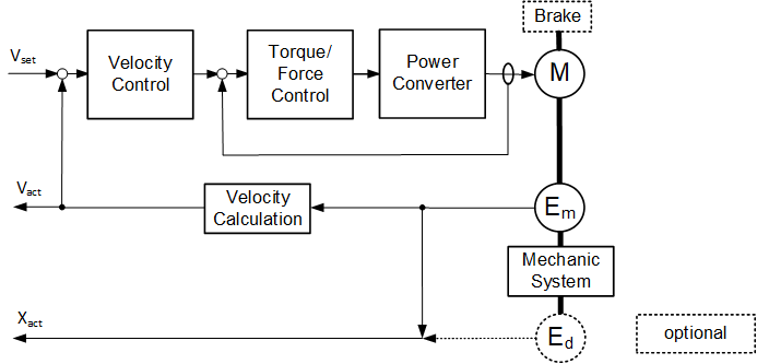
The formal definition of the PtVelocityServoDriveAxisType ObjectType can be found in Table 28.
| Attribute | Value | ||||
| BrowseName | PtVelocityServoDriveAxisType | ||||
| IsAbstract | False | ||||
| References | Node Class | BrowseName | DataType | TypeDefinition | Other |
|---|---|---|---|---|---|
| Subtype of the PtDriveAxisType. | |||||
| 0:HasComponent | Object | EncoderChannelMotor | PtEncoderChannelType | M | |
| 0:HasComponent | Object | EncoderChannelMechanic | PtEncoderChannelType | O | |
| 0:HasComponent | Object | <EncoderChannelAuxiliary> | PtEncoderChannelType | OP | |
| 0:HasComponent | Object | CharacteristicsMechanics | 0:FolderType | O | |
| 0:HasComponent | Object | Homing | 0:FolderType | O | |
| 0:HasComponent | Object | VelocityProfile | 0:FolderType | M | |
| 0:HasComponent | Object | Monitoring | 0:FolderType | M | |
| 0:HasComponent | Object | CharacteristicsMotorAndControl | 0:FolderType | M | |
| 0:HasComponent | Object | LimitSupervision | 0:FolderType | O | |
| 0:GeneratesEvent | ObjectType | PtAxisSwOvertravelEventType | |||
| 0:GeneratesEvent | ObjectType | PtAxisHwOvertravelEventType | |||
| 0:GeneratesEvent | ObjectType | PtTorqueForceLimitEventType | |||
| Conformance Units | |||||
|---|---|---|---|---|---|
| Powertrain Actual and Command Values | |||||
| Powertrain Axis Properties | |||||
| Powertrain Limit Events | |||||
| Powertrain Encoder Channel |
Some components of the PtVelocityServoDriveAxisType have additional subcomponents which are defined in Table 29.
| BrowsePath | References | NodeClass | BrowseName | DataType | TypeDefinition | Others |
| Monitoring | 0:HasComponent | Variable | VelocitySetpoint | 0:Float | 0:AnalogUnitType | O, RO |
| Monitoring | 0:HasComponent | Variable | VelocityCommandValue | 0:Float | 0:AnalogUnitType | M, RO |
| Monitoring | 0:HasComponent | Variable | VelocityCommandAdditiveValue | 0:Float | 0:AnalogUnitType | O, RO |
| Monitoring | 0:HasComponent | Variable | VelocityActualValue | 0:Float | 0:AnalogUnitType | M, RO |
| Monitoring | 0:HasComponent | Variable | PositionActualValue | 0:Double | 0:AnalogUnitType | O, RO |
| Monitoring | 0:HasComponent | Variable | AccelerationActualValue | 0:Float | 0:AnalogUnitType | O, RO |
| Monitoring | 0:HasComponent | Variable | AccelerationSetpoint | 0:Float | 0:AnalogUnitType | O, RO |
| Monitoring | 0:HasComponent | Variable | AccelerationCommandAdditiveValue | 0:Float | 0:AnalogUnitType | O, RO |
| Monitoring | 0:HasComponent | Variable | TorqueForceSetpoint | 0:Float | 0:AnalogUnitType | O, RO |
| Monitoring | 0:HasComponent | Variable | TorqueForceCommandValue | 0:Float | 0:AnalogUnitType | O, RO |
| Monitoring | 0:HasComponent | Variable | CurrentTorqueCommandValue | 0:Float | 0:AnalogUnitType | O, RO |
| Monitoring | 0:HasComponent | Variable | TorqueForceCommandAdditiveValue | 0:Float | 0:AnalogUnitType | O, RO |
| Monitoring | 0:HasComponent | Variable | <EncoderxTemperature> | 0:Float | PtTemperatureVariableType | OP, RO |
| Monitoring | 0:HasComponent | Variable | VelocityFollowingError | 0:Float | 0:AnalogUnitType | O, RO |
| Monitoring | 0:HasComponent | Variable | HomingState | 0:UInt16 | PtHomingStateVariableType | O, RO |
| CharacteristicsMotorAndControl | 0:HasComponent | Variable | TimePeriodVelocityControl | 0:Float | 0:AnalogUnitType | O, RO |
| CharacteristicsMotorAndControl | 0:HasComponent | Variable | TimePeriodTorqueControl | 0:Float | 0:AnalogUnitType | O, RO |
| Homing | 0:HasComponent | Variable | HomingMode | 0:UInt16 | PtHomingModeVariableType | O, RO |
| CharacteristicsMechanics | 0:HasComponent | Variable | GearFactorPrecise | PtGearFactorDataType | 0:BaseDataVariableType | O, RO |
| CharacteristicsMechanics | 0:HasComponent | Variable | GearRatio | 0:Float | 0:BaseDataVariableType | O, RO |
| CharacteristicsMechanics | 0:HasComponent | Variable | SpindlePitch | 0:Float | 0:BaseDataVariableType | O, RO |
| LimitSupervision | 0:HasComponent | Variable | TorqueLimit | 0:Float | 0:AnalogUnitType | O, RO |
| LimitSupervision | 0:HasComponent | Variable | TorqueLimitLow | 0:Float | 0:AnalogUnitType | M, RO |
| LimitSupervision | 0:HasComponent | Variable | TorqueLimitHigh | 0:Float | 0:AnalogUnitType | M, RO |
| LimitSupervision | 0:HasComponent | Variable | SoftwarePosLimitHigh | 0:Float | 0:AnalogUnitType | O, RO |
| LimitSupervision | 0:HasComponent | Variable | SoftwarePosLimitLow | 0:Float | 0:AnalogUnitType | O, RO |
| LimitSupervision | 0:HasComponent | Variable | TorqueLimiting | 0:Boolean | 0:BaseDataVariableType | O, RO |
The SpindlePitch Variable shall be provided if a spindle is present in the Powertrain Axis Object.
For a description of the Variables see Table 54.
7.1.1.5 PtPositionServoDriveAxisType
A PtPositionServoDriveAxisType is an PtDriveAxisType representing the functionality of a servo drive with a position command interface. Figure 13 shows a block diagram demonstrating the basic organization and control flow for this axis type.
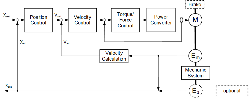
The formal definition of the PtPositionServoDriveAxisType ObjectType can be found in Table 30.
| Attribute | Value | ||||
| BrowseName | PtPositionServoDriveAxisType | ||||
| IsAbstract | False | ||||
| References | Node Class | BrowseName | DataType | TypeDefinition | Other |
|---|---|---|---|---|---|
| Subtype of the PtDriveAxisType. | |||||
| 0:HasComponent | Object | CharacteristicsMechanics | 0:FolderType | O | |
| 0:HasComponent | Object | EncoderChannelMotor | PtEncoderChannelType | M | |
| 0:HasComponent | Object | EncoderChannelMechanic | PtEncoderChannelType | O | |
| 0:HasComponent | Object | <EncoderChannelAuxiliary> | PtEncoderChannelType | OP | |
| 0:HasComponent | Object | Homing | 0:FolderType | M | |
| 0:HasComponent | Object | VelocityProfile | 0:FolderType | M | |
| 0:HasComponent | Object | Monitoring | 0:FolderType | M | |
| 0:HasComponent | Object | CharacteristicsMotorAndControl | 0:FolderType | M | |
| 0:HasComponent | Object | LimitSupervision | 0:FolderType | O | |
| 0:GeneratesEvent | ObjectType | PtAxisSwOvertravelEventType | |||
| 0:GeneratesEvent | ObjectType | PtAxisHwOvertravelEventType | |||
| 0:GeneratesEvent | ObjectType | PtTorqueForceLimitEventType | |||
| Conformance Units | |||||
|---|---|---|---|---|---|
| Powertrain Actual and Command Values | |||||
| Powertrain Axis Properties | |||||
| Powertrain Limit Events | |||||
| Powertrain Encoder Channel |
Some components of the PtPositionServoDriveAxisType have additional subcomponents which are defined in Table 31.
| BrowsePath | References | NodeClass | BrowseName | DataType | TypeDefinition | Others |
| Monitoring | 0:HasComponent | Variable | PositionCommandValue | 0:Float | 0:AnalogUnitType | M, RO |
| Monitoring | 0:HasComponent | Variable | VelocityCommandAdditiveValue | 0:Float | 0:AnalogUnitType | O, RO |
| Monitoring | 0:HasComponent | Variable | VelocitySetpoint | 0:Float | 0:AnalogUnitType | O, RO |
| Monitoring | 0:HasComponent | Variable | PositionActualValue | 0:Double | 0:AnalogUnitType | M, RO |
| Monitoring | 0:HasComponent | Variable | VelocityActualValue | 0:Float | 0:AnalogUnitType | M, RO |
| Monitoring | 0:HasComponent | Variable | VelocityCommandValue | 0:Float | 0:AnalogUnitType | O, RO |
| Monitoring | 0:HasComponent | Variable | TorqueForceCommandValue | 0:Float | 0:AnalogUnitType | O, RO |
| Monitoring | 0:HasComponent | Variable | CurrentTorqueCommandValue | 0:Float | 0:AnalogUnitType | O, RO |
| Monitoring | 0:HasComponent | Variable | PositionSetpoint | 0:Float | 0:AnalogUnitType | O, RO |
| Monitoring | 0:HasComponent | Variable | AccelerationActualValue | 0:Float | 0:AnalogUnitType | O, RO |
| Monitoring | 0:HasComponent | Variable | AccelerationSetpoint | 0:Float | 0:AnalogUnitType | O, RO |
| Monitoring | 0:HasComponent | Variable | AccelerationCommandAdditiveValue | 0:Float | 0:AnalogUnitType | O, RO |
| Monitoring | 0:HasComponent | Variable | TorqueForceSetpoint | 0:Float | 0:AnalogUnitType | O, RO |
| Monitoring | 0:HasComponent | Variable | TorqueForceCommandAdditiveValue | 0:Float | 0:AnalogUnitType | O, RO |
| Monitoring | 0:HasComponent | Variable | <EncoderxTemperature> | 0:Float | PtTemperatureVariableType | OP, RO |
| Monitoring | 0:HasComponent | Variable | PositionFollowingError | 0:Float | 0:AnalogUnitType | O, RO |
| Monitoring | 0:HasComponent | Variable | VelocityFollowingError | 0:Float | 0:AnalogUnitType | O, RO |
| Monitoring | 0:HasComponent | Variable | HomingState | 0:UInt16 | PtHomingStateVariableType | O, RO |
| LimitSupervision | 0:HasComponent | Variable | TorqueLimit | 0:Float | 0:AnalogUnitType | M, RO |
| LimitSupervision | 0:HasComponent | Variable | TorqueLimitLow | 0:Float | 0:AnalogUnitType | O, RO |
| LimitSupervision | 0:HasComponent | Variable | TorqueLimitHigh | 0:Float | 0:AnalogUnitType | O, RO |
| LimitSupervision | 0:HasComponent | Variable | SoftwarePosLimitLow | 0:Float | 0:AnalogUnitType | M, RO |
| LimitSupervision | 0:HasComponent | Variable | SoftwarePosLimitHigh | 0:Float | 0:AnalogUnitType | M, RO |
| LimitSupervision | 0:HasComponent | Variable | TorqueLimiting | 0:Boolean | 0:BaseDataVariableType | O, RO |
| CharacteristicsMotorAndControl | 0:HasComponent | Variable | TimePeriodVelocityControl | 0:Float | 0:AnalogUnitType | O, RO |
| CharacteristicsMotorAndControl | 0:HasComponent | Variable | TimePeriodPositionControl | 0:Float | 0:AnalogUnitType | O, RO |
| CharacteristicsMotorAndControl | 0:HasComponent | Variable | TimePeriodTorqueControl | 0:Float | 0:AnalogUnitType | O, RO |
| Homing | 0:HasComponent | Variable | HomingDirection | 0:UInt16 | PtHomingDirectionVariableType | O, RO |
| Homing | 0:HasComponent | Variable | HomingSpeedToCam | 0:Float | 0:AnalogUnitType | O, RO |
| Homing | 0:HasComponent | Variable | HomingSpeedToMark | 0:Float | 0:AnalogUnitType | O, RO |
| Homing | 0:HasComponent | Variable | HomingPointOffset | 0:Float | 0:AnalogUnitType | O, RO |
| Homing | 0:HasComponent | Variable | HomingMode | 0:UInt16 | PtHomingModeVariableType | M, RO |
| CharacteristicsMechanics | 0:HasComponent | Variable | GearFactorPrecise | PtGearFactorDataType | 0:BaseDataVariableType | O, RO |
| CharacteristicsMechanics | 0:HasComponent | Variable | GearRatio | 0:Float | 0:BaseDataVariableType | O, RO |
| CharacteristicsMechanics | 0:HasComponent | Variable | SpindlePitch | 0:Float | 0:BaseDataVariableType | O, RO |
| VelocityProfile | 0:HasComponent | Variable | JogPosInc1 | 0:Float | 0:AnalogUnitType | O, RO |
| VelocityProfile | 0:HasComponent | Variable | JogPosInc2 | 0:Float | 0:AnalogUnitType | O, RO |
The SpindlePitch Variable shall be provided if a spindle is present in the Powertrain Axis Object.
For a description of the Variables see Table 54.
7.1.1.6 PtTorqueServoDriveAxisType
A PtTorqueServoDriveAxisType is an PtDriveAxisType representing the functionality of a servo drive with a torque command interface. Figure 14 shows a block diagram demonstrating the basic organization and control flow for this axis type.
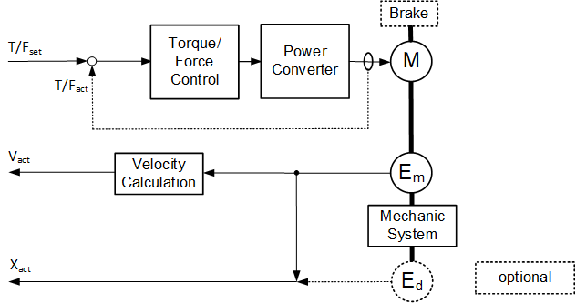
The formal definition of the PtTorqueServoDriveAxisType ObjectType can be found in Table 32.
| Attribute | Value | ||||
| BrowseName | PtTorqueServoDriveAxisType | ||||
| IsAbstract | False | ||||
| References | Node Class | BrowseName | DataType | TypeDefinition | Other |
|---|---|---|---|---|---|
| Subtype of the PtDriveAxisType. | |||||
| 0:HasComponent | Object | EncoderChannelMotor | PtEncoderChannelType | M | |
| 0:HasComponent | Object | EncoderChannelMechanic | PtEncoderChannelType | O | |
| 0:HasComponent | Object | <EncoderChannelAuxiliary> | PtEncoderChannelType | OP | |
| 0:HasComponent | Object | CharacteristicsMechanics | 0:FolderType | O | |
| 0:HasComponent | Object | Homing | 0:FolderType | O | |
| 0:HasComponent | Object | Monitoring | 0:FolderType | M | |
| 0:HasComponent | Object | CharacteristicsMotorAndControl | 0:FolderType | M | |
| 0:HasComponent | Object | LimitSupervision | 0:FolderType | O | |
| 0:GeneratesEvent | ObjectType | PtTorqueForceLimitEventType | |||
| Conformance Units | |||||
|---|---|---|---|---|---|
| Powertrain Actual and Command Values | |||||
| Powertrain Axis Properties | |||||
| Powertrain Limit Events | |||||
| Powertrain Encoder Channel |
Some components of the PtTorqueServoDriveAxisType have additional subcomponents which are defined in Table 33.
| BrowsePath | References | NodeClass | BrowseName | DataType | TypeDefinition | Others |
| Monitoring | 0:HasComponent | Variable | VelocityActualValue | 0:Float | 0:AnalogUnitType | O, RO |
| Monitoring | 0:HasComponent | Variable | PositionActualValue | 0:Double | 0:AnalogUnitType | M, RO |
| Monitoring | 0:HasComponent | Variable | AccelerationSetpoint | 0:Float | 0:AnalogUnitType | O, RO |
| Monitoring | 0:HasComponent | Variable | AccelerationCommandAdditiveValue | 0:Float | 0:AnalogUnitType | O, RO |
| Monitoring | 0:HasComponent | Variable | AccelerationActualValue | 0:Float | 0:AnalogUnitType | O, RO |
| Monitoring | 0:HasComponent | Variable | TorqueForceSetpoint | 0:Float | 0:AnalogUnitType | O, RO |
| Monitoring | 0:HasComponent | Variable | TorqueForceCommandValue | 0:Float | 0:AnalogUnitType | O, RO |
| Monitoring | 0:HasComponent | Variable | CurrentTorqueCommandValue | 0:Float | 0:AnalogUnitType | O, RO |
| Monitoring | 0:HasComponent | Variable | TorqueForceCommandAdditiveValue | 0:Float | 0:AnalogUnitType | O, RO |
| Monitoring | 0:HasComponent | Variable | <EncoderxTemperature> | 0:Float | PtTemperatureVariableType | OP, RO |
| Monitoring | 0:HasComponent | Variable | HomingState | 0:UInt16 | PtHomingStateVariableType | O, RO |
| CharacteristicsMotorAndControl | 0:HasComponent | Variable | TimePeriodTorqueControl | 0:Float | 0:AnalogUnitType | O, RO |
| Homing | 0:HasComponent | Variable | HomingMode | 0:UInt16 | PtHomingModeVariableType | O, RO |
| CharacteristicsMechanics | 0:HasComponent | Variable | GearFactorPrecise | PtGearFactorDataType | 0:BaseDataVariableType | O, RO |
| CharacteristicsMechanics | 0:HasComponent | Variable | GearRatio | 0:Float | 0:BaseDataVariableType | O, RO |
| CharacteristicsMechanics | 0:HasComponent | Variable | SpindlePitch | 0:Float | 0:BaseDataVariableType | O, RO |
| LimitSupervision | 0:HasComponent | Variable | TorqueLimit | 0:Float | 0:AnalogUnitType | O, RO |
| LimitSupervision | 0:HasComponent | Variable | TorqueLimitLow | 0:Float | 0:AnalogUnitType | O, RO |
| LimitSupervision | 0:HasComponent | Variable | TorqueLimitHigh | 0:Float | 0:AnalogUnitType | O, RO |
| LimitSupervision | 0:HasComponent | Variable | SoftwarePosLimitLow | 0:Float | 0:AnalogUnitType | O, RO |
| LimitSupervision | 0:HasComponent | Variable | SoftwarePosLimitHigh | 0:Float | 0:AnalogUnitType | O, RO |
| LimitSupervision | 0:HasComponent | Variable | TorqueLimiting | 0:Boolean | 0:BaseDataVariableType | O, RO |
The SpindlePitch Variable shall be provided if a spindle is present in the Powertrain Axis Object.
One of the TorqueForceCommandValue and CurrentTorqueCommandValue Variables shall be provided.
For a description of the Variables see Table 54.
7.1.2 PtEncoderAxisType definition
The PtEncoderAxisType ObjectType specifies the properties of encoder Objects.
| Attribute | Value | ||||
| BrowseName | PtEncoderAxisType | ||||
| IsAbstract | False | ||||
| References | Node Class | BrowseName | DataType | TypeDefinition | Other |
|---|---|---|---|---|---|
| Subtype of the PtFunctionType. | |||||
| 0:HasComponent | Object | EncoderChannel | PtEncoderChannelType | M | |
| 0:HasComponent | Object | Monitoring | 0:FolderType | M | |
| Conformance Units | |||||
|---|---|---|---|---|---|
| Powertrain Actual and Command Values | |||||
| Powertrain Encoder Channel |
Some components of the PtEncoderAxisType have additional subcomponents which are defined in Table 35.
| BrowsePath | References | NodeClass | BrowseName | DataType | TypeDefinition | Others |
| Monitoring | 0:HasComponent | Variable | ControlPriority | 0:UInt16 | PtControlPriorityVariableType | M, RO |
| Monitoring | 0:HasComponent | Variable | VelocityActualValue | 0:Float | 0:AnalogUnitType | O, RO |
| Monitoring | 0:HasComponent | Variable | PositionActualValue | 0:Double | 0:AnalogUnitType | M, RO |
| Monitoring | 0:HasComponent | Variable | AccelerationActualValue | 0:Float | 0:AnalogUnitType | O, RO |
| Monitoring | 0:HasComponent | Variable | EncoderTemperature | 0:Float | PtTemperatureVariableType | O, RO |
7.1.3 PtGearAxisType definition
The PtGearAxisType ObjectType specifies the properties of Objects representing gears.
| Attribute | Value | ||||
| BrowseName | PtGearAxisType | ||||
| IsAbstract | False | ||||
| References | Node Class | BrowseName | DataType | TypeDefinition | Other |
|---|---|---|---|---|---|
| 0:HasComponent | Object | CharacteristicsMechanics | 0:FolderType | O | |
| 0:HasComponent | Object | Monitoring | 0:FolderType | M | |
| 0:HasComponent | Object | Maintenance | 0:FolderType | M | |
| Subtype of the PtFunctionType. | |||||
| Conformance Units | |||||
|---|---|---|---|---|---|
| Powertrain Actual and Command Values |
Some components of the PtGearAxisType have additional subcomponents which are defined in Table 37.
| BrowsePath | References | NodeClass | BrowseName | DataType | TypeDefinition | Others |
| Monitoring | 0:HasComponent | Variable | BrakeState | 0:UInt16 | PtBrakeStateVariableType | O, RO |
| Monitoring | 0:HasComponent | Variable | AxisTorqueForce | 0:Float | 0:AnalogUnitType | O, RO |
| Monitoring | 0:HasComponent | Variable | AxisOutputVelocity | 0:Float | 0:AnalogUnitType | O, RO |
| Monitoring | 0:HasComponent | Variable | GearInputVelocity | 0:Float | 0:AnalogUnitType | O, RO |
| Monitoring | 0:HasComponent | Variable | GearInputTorque | 0:Float | 0:AnalogUnitType | O, RO |
| Monitoring | 0:HasComponent | Variable | GearOutputVelocity | 0:Float | 0:AnalogUnitType | O, RO |
| Monitoring | 0:HasComponent | Variable | GearOutputTorque | 0:Float | 0:AnalogUnitType | O, RO |
| Monitoring | 0:HasComponent | Variable | GearTemperature | 0:Float | PtTemperatureVariableType | O, RO |
| Monitoring | 0:HasComponent | Variable | GearRatio | 0:Float | 0:AnalogUnitType | M, RO |
| Monitoring | 0:HasComponent | Variable | GearState | 0:UInt16 | PtGearStateVariableType | O, RO |
| Monitoring | 0:HasComponent | Variable | GearOutputShaftTurningDirection | 0:UInt16 | PtShaftTurningDirectionVariableType | O, RO |
| Monitoring | 0:HasComponent | Variable | GearInputShaftTurningDirection | 0:UInt16 | PtShaftTurningDirectionVariableType | O, RO |
| Maintenance | 0:HasComponent | Variable | GearBacklash | 0:Float | 0:AnalogUnitType | O, RO |
| CharacteristicsMechanics | 0:HasComponent | Variable | GearFactorPrecise | PtGearFactorDataType | 0:BaseDataVariableType | O, RO |
| CharacteristicsMechanics | 0:HasComponent | Variable | GearRatio | 0:Float | 0:BaseDataVariableType | O, RO |
7.2 PtLogbookType definition
The PtLogbookType provides access to diagnosis information provided by ObjectTypes derived from the PtFunctionType.
| Attribute | Value | ||||
| BrowseName | PtLogbookType | ||||
| IsAbstract | False | ||||
| References | Node Class | BrowseName | DataType | TypeDefinition | Other |
|---|---|---|---|---|---|
| Subtype of the 0:BaseObjectType defined in OPC 10000-5. | |||||
| 0:HasComponent | Variable | LogEntries | PtLogEntryDataType[] | 0:BaseDataVariableType | M, RO |
| 0:HasProperty | Variable | LogbookSize | 0:UInt16 | 0:PropertyType | M, RO |
| 0:HasComponent | Method | ClearLogbookEntries | O | ||
| 0:HasComponent | Method | GetFilteredLogbookEntries | O | ||
| 0:HasComponent | Method | GetCurrentDiagnosis | O | ||
| 0:HasComponent | Method | GetActiveDiagnosis | O | ||
| 0:HasComponent | Method | GetHistoricDiagnosis | O | ||
| Conformance Units | |||||
|---|---|---|---|---|---|
| Powertrain Logbook Readable | |||||
| Powertrain Logbook Events |
The LogEntries array Variable consists of PtLogEntryDataType structure elements. The array is limited to the maximum size specified by the LogbookSize Property. The array contains PtLogEntryDataType elements for events and starts with the most recent event (the element with the most recent EventComing timestamp). If the Server maintains different fault situations in its diagnosis system, faults (events) which are still present after an acknowledge generate a new entry in the actual fault situation causing more than one entry with the same EventNumber for one event.
The LogbookSize Property contains the maximum length of the LogEntries array. The actual length of the array may be smaller.
Clients must lock the parent PtFunctionType Object before invoking a Method of the PtLogbookType Object.
7.2.1 ClearLogbookEntries Method
The ClearLogbookEntries Method clears the LogEntries array and resets the diagnosis system of the functional Object. The security constraints defined in chapter 6.2 apply.
Signature
	ClearLogbookEntries (
	);
The Method Result Codes (defined in Call Service) are defined in Table 39.
| Result Code | Description |
| Good | The Method execution was successful. |
| Bad_UserAccessDenied | The user has not the right to execute the Method. |
| Bad_UnexpectedError | The Server is not able to execute the function because an unexpected error occurred. The Device might be temporarily unavailable or unreachable due to network failure. |
7.2.2 GetFilteredLogbookEntries Method
The GetFilteredLogbookEntries Method returns a LogEntries array matching the filter criteria. Method invocation shall be possible for all users (read-only).
Signature
	GetFilteredLogbookEntries (
		[in] 0:Byte				LogbookFilterOptions,
		[in] 0:Byte				FaultSituationNumber
		[in] PtEventTypeEnumeration 	EventType,
		[in] PtEventClassEnumeration	EventClass,
	[in] 0:Int32			VendorEventCode
		[in] 0:Duration			EventAppearanceInterval,
	[out] PtLogEntryDataType[] 	FilteredLogEntries
	);
| Argument | Description |
| LogbookFilterOptions | Parameter restricting the returned logbook entries to those having valid EventGoing and/or EventAcknowledged timestamps. If set to 1 ("GOING" filter), only logbook entries with valid EventGoing timestamp are returned. If set to 2 ("ACKNOWLEDGED" filter), only entries with valid EventAcknowledged timestamp are returned. If set to 3, the logic applied is "AND": only logbook entries meeting both filter criteria are returned. Set to 0 if no filtering shall be applied. If a value greater than 3 is passed, the Method Result Code shall be set to Bad_InvalidArgument. |
| FaultSituationNumber | Restricts the returned logbook entries to those with the FaultSituationNumber field equal to this parameter. Passing 255 means "don't care". |
| EventType | Restricts the returned logbook entries to those with the EventType field equal to this parameter. It is encoded as PtEventTypeEnumeration. Passing "UNSPECIFIED" means "don't care". |
| EventClass | Restricts the returned logbook entries to those with the EventClass field equal to this parameter. It is encoded as PtEventClassEnumeration. Passing "UNSPECIFIED" means "don't care". |
| VendorEventCode | Restricts the returned logbook entries to those with the VendorEventCode field equal to this parameter. Passing -1 means "don't care" and does not restrict to entries with the VendorEventCode field set to -1. |
| EventAppearanceInterval | Time interval encoded as 0:Duration defined in [OPC 10000-3]. Restricts the returned logbook entries to those appearing within a timespan from the past up to now. The EventComing field of the logbook entries is used for checking this filter. Passing 0 means "don't care". |
| FilteredLogEntries | Array containing the logbook entries matching all filter criteria passed with the first 5 parameters. An empty array is returned if no logbook entry matches the filter criteria. |
The Method Result Codes (defined in Call Service) are defined in Table 40.
| Result Code | Description |
| Good | The Method execution was successful. |
| Bad_InvalidArgument | The Server is unable to execute the Method due to invalid arguments. For instance, the EventClass passed may be unknown. |
| Bad_UnexpectedError | The Server cannot execute the function because an unexpected error occurred. The Device might be temporarily unavailable or unreachable due to network failure. |
7.2.3 GetCurrentDiagnosis Method
The GetCurrentDiagnosis Method returns all log entries which occurred since the last acknowledge as LogEntries array. Starting with the most recent one, all log entries without valid EventAcknowledged timestamp are returned. Method invocation shall be possible for all users (read-only).
Signature
	GetCurrentDiagnosis (
		[out] PtLogEntryDataType[] 	CurrentLogEntries
	);
| Argument | Description |
| CurrentLogEntries | Array containing the log entries occurred since the last acknowledge. An empty array is returned if no logbook entry matches the filter criteria. |
The Method Result Codes (defined in Call Service) are defined in Table 41.
| Result Code | Description |
| Good | The Method execution was successful. |
| Bad_UnexpectedError | The Server is not able to execute the function because an unexpected error occurred. The Device might be temporarily unavailable or unreachable due to network failure. |
7.2.4 GetHistoricDiagnosis Method
The GetHistoricDiagnosis Method returns a LogEntries array with valid EventGoing field. Method invocation shall be possible for all users (read-only).
Signature
	GetHistoricDiagnosis (
		[in]  0:Byte					FaultSituationNumber,
		[out] PtLogEntryDataType[]		HistoricLogEntries
	);
| Argument | Description |
| FaultSituationNumber | Fault situation number the faults belong to. 0 identifies the current situation, 1 the historic situation preceding the current situation, and so on (see explanation below). |
| HistoricLogEntries | Array containing the log entries with valid EventGoing field entry. An empty array is returned if no logbook entry matches the filter criteria. |
The Method Result Codes (defined in Call Service) are defined in Table 42.
| Result Code | Description |
| Good | The Method execution was successful. |
| Bad_InvalidArgument | The fault situation specified by FaultSituationNumber does not exist. |
| Bad_UnexpectedError | The Server cannot execute the function because an unexpected error occurred. The Device might be temporarily unavailable or unreachable due to network failure. |
7.2.5 GetActiveDiagnosis Method
The GetActiveDiagnosis Method returns a LogEntries array containing log entries belonging to the current fault situation (log entries with FaultSituationNumber equal to 0) with valid EventComing timestamp, but with missing EventGoing timestamp. The method returns a subset of the entries returned by the GetCurrentDiagnosis Method. Method invocation shall be possible for all users (read-only).
Signature
	GetActiveDiagnosis (
		[out] PtLogEntryDataType[] 	ActiveDiagnosis
	);
| Argument | Description |
| ActiveDiagnosis | Array containing the log entries with missing EventGoing field entry. An empty array is returned if no logbook entry matches the filter criteria. |
The Method Result Codes (defined in Call Service) are defined in Table 43.
| Result Code | Description |
| Good | The Method execution was successful. |
| Bad_UnexpectedError | The Server is not able to execute the function because an unexpected error occurred. The Device might be temporarily unavailable or unreachable due to network failure. |
7.3 PtEncoderChannelType
The PtEncoderChannelType is the representation of the Encoder sensor and sensor related auxiliary functionality. Clients gain access to the Encoder Object's data, properties, error log and configuration settings using an PtEncoderChannelType Object.
| Attribute | Value | ||||
| BrowseName | PtEncoderChannelType | ||||
| IsAbstract | False | ||||
| References | Node Class | BrowseName | DataType | TypeDefinition | Other |
|---|---|---|---|---|---|
| Subtype of the 0:BaseObjectType defined in OPC 10000-5. | |||||
| 0:HasComponent | Variable | EncoderChannelState | 0:UInt16 | PtEncoderChannelStateVariableType | O, RO |
| 0:HasComponent | Object | Sensor | PtEncoderSensorType | M | |
| 0:HasComponent | Object | <Probe_x> | PtEncoderProbeType | OP | |
| 0:HasComponent | Variable | PositionSensorFeedbackValue | 0:Number | 0:BaseDataVariableType | O, RO |
| 0:HasComponent | Variable | Resolution | 0:Double | 0:BaseAnalogType | O, RO |
| 0:HasProperty | Variable | AbsolutePositionRange | 0:Range | 0:PropertyType | O, RO |
| 0:HasComponent | Variable | SignalType | 0:UInt16 | PtEncoderChannelSignalTypeVariableType | O, RO |
| Conformance Units | |||||
|---|---|---|---|---|---|
| Powertrain Encoder Channel |
The EncoderChannelState Variable contains the state of the encoder channel encoded as PtEncoderChannelStateVariableType.
The Sensor PtEncoderSensorType Object offers sensor related data. See section 7.3.1 for details.
The <Probe_x> PtEncoderProbeType Objects represent the probes provided by the Encoder. There shall be as many PtEncoderProbeType Objects as are needed to represent all probes provided. The BrowseNames shall be provided as defined by the template string <Probe_x>, where x is the probe number.
The PositionSensorSignalValue Variable contains the Encoder's position Signal encoded as numeric data type. Dependent on Encoder resolution, the data type may be 0:UInt32 or 0:UInt64. This is the raw signal value delivered by the encoder sensor.
The Resolution Variable contains the resolution of the Encoder's Position Variable Value.
The AbsolutePositionRange Variable contains the possible range of absolute position values represented as 0:Range Value.
The SignalType Variable contains the type of the position sensor's signal value encoded as PtEncoderChannelSignalTypeVariableType.
7.3.1 PtEncoderSensorType
| Attribute | Value | ||||
| BrowseName | PtEncoderSensorType | ||||
| IsAbstract | False | ||||
| References | Node Class | BrowseName | DataType | TypeDefinition | Other |
|---|---|---|---|---|---|
| Subtype of the 0:BaseObjectType defined in OPC 10000-5. | |||||
| 0:HasComponent | Variable | PositionOffset | 0:Number | 0:BaseDataVariableType | O, RO |
| 0:HasComponent | Variable | LatchStatus | 0:UInt16 | PtLatchStatusVariableType | O, RO |
| 0:HasComponent | Variable | LatchValue | 0:Number | 0:BaseDataVariableType | O, RO |
| Conformance Units | |||||
|---|---|---|---|---|---|
| Powertrain Encoder Channel |
The PositionOffset Variable contains the calculated offset belonging to the current preset value of the Encoder.
The LatchStatus Variable contains the current state of the reference pulse latch encoded as PtLatchStatusVariableType.
The LatchValue Variable contains the last latched value of the reference pulse latch.
7.3.2 PtEncoderProbeType
The PtEncoderProbeType represents the Encoder's probe functionality.
| Attribute | Value | ||||
| BrowseName | PtEncoderProbeType | ||||
| IsAbstract | False | ||||
| References | Node Class | BrowseName | DataType | TypeDefinition | Other |
|---|---|---|---|---|---|
| Subtype of the 0:BaseObjectType defined in OPC 10000-5. | |||||
| 0:HasComponent | Variable | LatchStatus | 0:UInt16 | PtLatchStatusVariableType | O, RO |
| 0:HasComponent | Variable | LastLatchedPos | 0:Number | 0:BaseDataVariableType | M, RO |
| 0:HasComponent | Variable | ProbeInputSignal | 0:Boolean | 0:BaseDataVariableType | O |
| Conformance Units | |||||
|---|---|---|---|---|---|
| Powertrain Encoder Channel |
The LatchStatus Variable contains the current state of the probe latch encoded as PtLatchStatusVariableType.
The LastLatchedPos Variable contains the last latched position of the probe.
The ProbeInputSignal Variable contains the status of the probe sensor at the clamp.
7.4 PtVibrationSensorType
The PtVibrationSensorType represents a vibration sensor and provides measurement values for velocity, vibration displacement and acceleration. The -X, -Y and -Z suffixes identify values provided individually for the x-, y- and z-direction.
| Attribute | Value | ||||
| BrowseName | PtVibrationSensorType | ||||
| IsAbstract | False | ||||
| References | Node Class | BrowseName | DataType | TypeDefinition | Other |
|---|---|---|---|---|---|
| Subtype of the 0:BaseObjectType defined in OPC 10000-5. | |||||
| 0:HasComponent | Variable | RMSAcceleration | 0:Float | PtVibrationMeasurementVariableType | O, RO |
| 0:HasComponent | Variable | RMSAccelerationX | 0:Float | PtVibrationMeasurementVariableType | O, RO |
| 0:HasComponent | Variable | RMSAccelerationY | 0:Float | PtVibrationMeasurementVariableType | O, RO |
| 0:HasComponent | Variable | RMSAccelerationZ | 0:Float | PtVibrationMeasurementVariableType | O, RO |
| 0:HasComponent | Variable | RMSVelocity | 0:Float | PtVibrationMeasurementVariableType | O, RO |
| 0:HasComponent | Variable | RMSVelocityX | 0:Float | PtVibrationMeasurementVariableType | O, RO |
| 0:HasComponent | Variable | RMSVelocityY | 0:Float | PtVibrationMeasurementVariableType | O, RO |
| 0:HasComponent | Variable | RMSVelocityZ | 0:Float | PtVibrationMeasurementVariableType | O, RO |
| 0:HasComponent | Variable | RMSDisplacement | 0:Float | PtVibrationMeasurementVariableType | O, RO |
| 0:HasComponent | Variable | RMSDisplacementX | 0:Float | PtVibrationMeasurementVariableType | O, RO |
| 0:HasComponent | Variable | RMSDisplacementY | 0:Float | PtVibrationMeasurementVariableType | O, RO |
| 0:HasComponent | Variable | RMSDisplacementZ | 0:Float | PtVibrationMeasurementVariableType | O, RO |
| 0:HasComponent | Variable | PeakToPeakAcceleration | 0:Float | PtVibrationMeasurementVariableType | O, RO |
| 0:HasComponent | Variable | PeakToPeakAccelerationX | 0:Float | PtVibrationMeasurementVariableType | O, RO |
| 0:HasComponent | Variable | PeakToPeakAccelerationY | 0:Float | PtVibrationMeasurementVariableType | O, RO |
| 0:HasComponent | Variable | PeakToPeakAccelerationZ | 0:Float | PtVibrationMeasurementVariableType | O, RO |
| 0:HasComponent | Variable | PeakToPeakVelocity | 0:Float | PtVibrationMeasurementVariableType | O, RO |
| 0:HasComponent | Variable | PeakToPeakVelocityX | 0:Float | PtVibrationMeasurementVariableType | O, RO |
| 0:HasComponent | Variable | PeakToPeakVelocityY | 0:Float | PtVibrationMeasurementVariableType | O, RO |
| 0:HasComponent | Variable | PeakToPeakVelocityZ | 0:Float | PtVibrationMeasurementVariableType | O, RO |
| 0:HasComponent | Variable | PeakToPeakDisplacement | 0:Float | PtVibrationMeasurementVariableType | O, RO |
| 0:HasComponent | Variable | PeakToPeakDisplacementX | 0:Float | PtVibrationMeasurementVariableType | O, RO |
| 0:HasComponent | Variable | PeakToPeakDisplacementY | 0:Float | PtVibrationMeasurementVariableType | O, RO |
| 0:HasComponent | Variable | PeakToPeakDisplacementZ | 0:Float | PtVibrationMeasurementVariableType | O, RO |
| 0:HasComponent | Variable | ZeroToPeakAcceleration | 0:Float | PtVibrationMeasurementVariableType | O, RO |
| 0:HasComponent | Variable | ZeroToPeakAccelerationX | 0:Float | PtVibrationMeasurementVariableType | O, RO |
| 0:HasComponent | Variable | ZeroToPeakAccelerationY | 0:Float | PtVibrationMeasurementVariableType | O, RO |
| 0:HasComponent | Variable | ZeroToPeakAccelerationZ | 0:Float | PtVibrationMeasurementVariableType | O, RO |
| 0:HasComponent | Variable | ZeroToPeakVelocity | 0:Float | PtVibrationMeasurementVariableType | O, RO |
| 0:HasComponent | Variable | ZeroToPeakVelocityX | 0:Float | PtVibrationMeasurementVariableType | O, RO |
| 0:HasComponent | Variable | ZeroToPeakVelocityY | 0:Float | PtVibrationMeasurementVariableType | O, RO |
| 0:HasComponent | Variable | ZeroToPeakVelocityZ | 0:Float | PtVibrationMeasurementVariableType | O, RO |
| 0:HasComponent | Variable | ZeroToPeakDisplacement | 0:Float | PtVibrationMeasurementVariableType | O, RO |
| 0:HasComponent | Variable | ZeroToPeakDisplacementX | 0:Float | PtVibrationMeasurementVariableType | O, RO |
| 0:HasComponent | Variable | ZeroToPeakDisplacementY | 0:Float | PtVibrationMeasurementVariableType | O, RO |
| 0:HasComponent | Variable | ZeroToPeakDisplacementZ | 0:Float | PtVibrationMeasurementVariableType | O, RO |
| Conformance Units | |||||
|---|---|---|---|---|---|
| Powertrain Actual and Command Values |
The RMSAcceleration, RMSAccelerationX, RMSAccelerationY and RMSAccelerationZ Variables contain the vibration acceleration KPI calculated via Root-Mean-Square based on DIN ISO 20816 series of standards.
The RMSVelocity, RMSVelocityX, RMSVelocityY and RMSVelocityZ Variables contain the standard vibration velocity KPI as defined in DIN ISO 20816-1, …-3 (Annex A) and …-9.
The RMSDisplacement, RMSDisplacementX, RMSDisplacementY and RMSDisplacementZ Variables contain the vibration displacement KPI calculated via Root-Mean-Square.
The PeakToPeakAcceleration, PeakToPeakAccelerationX, PeakToPeakAccelerationY and PeakToPeakAccelerationZ Variables contain the difference between maximum and minimum acceleration in the last interval based on DIN ISO 20816 series of standards.
The PeakToPeakVelocity, PeakToPeakVelocityX, PeakToPeakVelocityY and PeakToPeakVelocityZ Variables contain the difference between maximum and minimum velocity in the last interval.
The PeakToPeakDisplacement, PeakToPeakDisplacementX, PeakToPeakDisplacementY, PeakToPeakDisplacementZ Variables contain the standard vibration displacement KPI as defined in DIN ISO 20816-1, …-3 (Annex A) and …-9.
The ZeroToPeakAcceleration, ZeroToPeakAccelerationX, ZeroToPeakAccelerationY, ZeroToPeakAccelerationZ Variables contain the standard acceleration KPI as defined in DIN ISO 20816-1, …-3 (Annex A) and …-9.
The ZeroToPeakVelocity, ZeroToPeakVelocityX, ZeroToPeakVelocityY and ZeroToPeakVelocityZ Variables contain the difference between maximum and minimum velocity in the last interval.
The ZeroToPeakDisplacement, ZeroToPeakDisplacementX, ZeroToPeakDisplacementY and ZeroToPeakDisplacementZ Variables contain the difference between maximum and minimum displacement in the last interval.
7.5 PtCharacteristicsConverterType
The PtCharacteristicsConverterType represents the properties of the electric converter unit belonging to an electric drive.
| Attribute | Value | ||||
| BrowseName | PtCharacteristicsConverterType | ||||
| IsAbstract | False | ||||
| References | Node Class | BrowseName | DataType | TypeDefinition | Other |
|---|---|---|---|---|---|
| Subtype of the 0:BaseObjectType defined in OPC 10000-5. | |||||
| 0:HasComponent | Variable | BleederExcessCurrentLimit | 0:Float | 0:AnalogUnitType | O, RO |
| 0:HasComponent | Variable | ConverterExcessCurrentConfigured | 0:Float | 0:AnalogUnitType | O, RO |
| 0:HasComponent | Variable | ConverterThermalLoadLimitConfigured | 0:Float | 0:AnalogUnitType | O, RO |
| 0:HasComponent | Variable | DcBusVoltageConfigured | 0:UInt16 | 0:AnalogUnitType | O, RO |
| 0:HasComponent | Variable | InputConverterAcInputVoltage | 0:UInt16 | 0:AnalogUnitType | O, RO |
| 0:HasComponent | Variable | OutputConverterPulseFrequency | 0:Float | 0:AnalogUnitType | M, RO |
The BleederExcessCurrentLimit Variable contains the excess current limit of the brake resistor in ampere.
The ConverterExcessCurrentConfigured Variable contains the excess current of the converter determined by configuration data.
The ConverterThermalLoadLimitConfigured Variable contains the thermal load limit of the converter determined by configuration data.
The DcBusVoltageConfigured Variable contains the voltage of the intermediate circuit determined by configuration data.
The InputConverterAcInputVoltage Variable contains the input alternating voltage.
The OutputConverterPulseFrequency Variable contains the pulse frequency of the converter.
7.6 PtTraversingTaskType
The PtTraversingTaskType represents a traversing task.
| Attribute | Value | ||||
| BrowseName | PtTraversingTaskType | ||||
| IsAbstract | False | ||||
| References | Node Class | BrowseName | DataType | TypeDefinition | Other |
|---|---|---|---|---|---|
| Subtype of the 0:BaseObjectType defined in OPC 10000-5. | |||||
| 0:HasComponent | Variable | TraversingTaskNumber | 0:Int32 | 0:BaseDataVariableType | M, RO |
| 0:HasComponent | Variable | TargetPosition | 0:Float | 0:AnalogUnitType | O, RO |
| 0:HasComponent | Variable | Velocity | 0:Float | 0:AnalogUnitType | O, RO |
| 0:HasComponent | Variable | Acceleration | 0:Float | 0:AnalogUnitType | O, RO |
| 0:HasComponent | Variable | Deceleration | 0:Float | 0:AnalogUnitType | O, RO |
| 0:HasComponent | Variable | PositioningModuloMode | 0:UInt16 | 0:MultiStateValueDiscreteType | M, RO |
| 0:HasComponent | Variable | PositioningTaskChangeMode | 0:UInt16 | 0:MultiStateValueDiscreteType | O, RO |
| Conformance Units | |||||
|---|---|---|---|---|---|
| Powertrain Actual and Command Values |
The TraversingTaskNumber Variable contains the number of the traversing task currently executed. Interpretation of TraversingTaskNumber:
| TraversingTaskNumber Value | Traversing task executed |
| -5 | Jogging positive (S42) |
| -4 | Jogging negative (S42) |
| -3 | Homing procedure (S44) |
| -2 | MDI sub-mode active |
| -1 | No traversing task is executed: stand still (S41) |
| >=0 | Number of traversing task (0 - 1023) |
If no traversing task is executed (TraversingTaskNumber == -1), the Value of all other Variables shall be 0. If a traversing task is executed (TraversingTaskNumber >=0), the AxisState Variable contains one of the values belonging to the S45 sub state machine (see [PDP], Figure 35 also).
The TargetPosition Variable contains the target position for the traversing task generator.
The Velocity Variable contains the desired speed for the traversing task generator.
The Acceleration Variable contains the desired acceleration for the traversing task generator.
The PositioningModuloMode Variable contains the information if the TargetPosition Variable must be interpreted as absolute or relative position encoded as 0:MultiStateValueDiscreteType defined in [OPC 10000-8]. The PositioningTaskChangeMode Variable corresponds to Bit 5 in DS402 control word " also encoded as 0:MultiStateValueDiscreteType. The content of their EnumStrings lookup table Properties is defined in Table 50.
| BrowsePath | Value Attribute | ||
| [ { "Value":0, "DisplayName": "NO_MODULO_FUNCTION", "Description": "No traversing task is active" }, { "Value":1, "DisplayName": "RELATIVE_POSITIONING", "Description": "Relative Positioning" }, { "Value":2, "DisplayName": "ABSOLUTE_SHORTEST_PATH_MODULO_DIRECTION _POSITIONING", "Description": "The absolute position shall be reached by the shortest path" }, { "Value":3, "DisplayName": "ABSOLUTE_POSITIVE_MODULO_DIRECTION _POSITIONING", "Description": "The absolute position shall be reached by a motion in positive direction" }, { "Value":4, "DisplayName": "ABSOLUTE_NEGATIVE_ MODULO_DIRECTION _POSITIONING", "Description": "The absolute position shall be reached by a motion in negative direction" } ] | ||
| [ { "Value":0, "DisplayName": "CHANGE_TARGET_REACHED", "Description": "Change traversing task after target position reached" }, { "Value":1, "DisplayName": "CHANGE_IMMEDIATE", "Description": "Change traversing task immediate" } ] |
The following table contains descriptions of the semantic for all possible Values of the PositioningModuloMode Variable.
7.7 PtSafetyType
The PtSafetyType contains PtSafetyFunctionType Variables describing basic settings for safety functions.
| Attribute | Value | ||||
| BrowseName | PtSafetyType | ||||
| IsAbstract | False | ||||
| References | Node Class | BrowseName | DataType | TypeDefinition | Other |
|---|---|---|---|---|---|
| Subtype of the 0:BaseObjectType defined in OPC 10000-5. | |||||
| 0:HasComponent | Object | STO | PtSafetyFunctionType | M | |
| 0:HasComponent | Object | SS1 | PtSafetyFunctionType | O | |
| 0:HasComponent | Object | SS2 | PtSafetyFunctionType | O | |
| 0:HasComponent | Object | SOS | PtSafetyFunctionType | O | |
| 0:HasComponent | Object | SLS | PtSafetyFunctionType | O | |
| 0:HasComponent | Object | SDI | PtSafetyFunctionType | O | |
| 0:HasComponent | Object | SLA | PtSafetyFunctionType | O | |
| 0:HasComponent | Object | SLP | PtSafetyFunctionType | O | |
| Conformance Units | |||||
|---|---|---|---|---|---|
| Powertrain Safety |
The STO Object represents the status of the "Safe torque off" safety function.
The SS1 Object represents the status of the "Safe stop 1" safety function.
The SS2 Object represents the status of the "Safe stop 2" safety function.
The SOS Object represents the status of the "Safe operating stop" safety function.
The SLS Object represents the status of the "Safely limited speed" safety function.
The SDI Object represents the status of the "Safe direction" safety function.
The SLA Object represents the status of the "Safely limited acceleration" safety function.
The SLP Object represents the status of the "Safely limited position" safety function.
If a specific safety function is supported by the Axis/DO, the representing PtSafetyFunctionType Object shall be provided.
7.8 PtSafetyFunctionType
The PtSafetyFunctionType represents the status of one safety function.
| Attribute | Value | ||||
| BrowseName | PtSafetyFunctionType | ||||
| IsAbstract | False | ||||
| References | Node Class | BrowseName | DataType | TypeDefinition | Other |
|---|---|---|---|---|---|
| Subtype of the 0:BaseObjectType defined in OPC 10000-5. | |||||
| 0:HasComponent | Variable | SelectionState | 0:UInt16 | 0:MultiStateValueDiscreteType | M, RO |
| 0:HasComponent | Variable | ActivationState | 0:UInt16 | 0:MultiStateValueDiscreteType | M, RO |
| 0:HasProperty | Variable | Limit | 0:Float | 0:PropertyType | O, RO |
| Conformance Units | |||||
|---|---|---|---|---|---|
| Powertrain Safety |
The SelectionState Variable represents the selection status of the represented safety function.
The ActivationState Variable represents the activation status of the represented safety function.
The Limit Variable represents the speed limit if representing the SLS safety function or the acceleration limit if representing the SLA safety function. Shall only be provided for these two safety functions.
| BrowsePath | Value Attribute | ||
| [ { "Value":0, "DisplayName": "NONE", "Description": "No safety function is selected" }, { "Value":1, "DisplayName": "SELECTED", "Description": "Safety function is selected" }, { "Value":2, "DisplayName": "SELECTED_INTERN", "Description": "Safety function is selected by internal client" }, { "Value":3, "DisplayName": "SELECTED_EXTERN", "Description": "Safety function is selected by external client" }, { "Value":4, "DisplayName": "SELECTED_LIMIT_1", "Description": "Safety function is selected with limit 1" }, { "Value":5, "DisplayName": "SELECTED_LIMIT_2", "Description": "Safety function is selected with limit 2" }, { "Value":6, "DisplayName": "SELECTED_LIMIT_3", "Description": "Safety function is selected with limit 3" }, { "Value":7, "DisplayName": "SELECTED_LIMIT_4", "Description": "Safety function is selected with limit 4" }, { "Value":8, "DisplayName": "SELECTED_POS", "Description": "Safety function positive direction selected" }, { "Value":9, "DisplayName": "SELECTED_NEG", "Description": "Safety function negative direction selected" } ] | ||
| [ { "Value":0, "DisplayName": "NONE", "Description": "No safety function is active" }, { "Value":1, "DisplayName": "POWER_REMOVED", "Description": "STO safety function is active" }, { "Value":2, "DisplayName": "SS1_ACTIVE", "Description": "SS1 safety function is active" }, { "Value":3, "DisplayName": "SS1_ACTIVE_FAULTED", "Description": "SS1 safety function is faulted" }, { "Value":4, "DisplayName": "SS2_ACTIVE", "Description": "SS2 safety function is active" }, { "Value":5, "DisplayName": "SS2_ACTIVE_FAULTED", "Description": "SS2 safety function is faulted" }, { "Value":6, "DisplayName": "SOS_ACTIVE", "Description": "SOS safety function is active" }, { "Value":7, "DisplayName": "SOS_ACTIVE_FAULTED", "Description": "SOS safety function is faulted" }, { "Value":8, "DisplayName": "SLS_ACTIVE", "Description": "SLS safety function is active" }, { "Value":9, "DisplayName": "SLS_ACTIVE_FAULTED", "Description": "SLS safety function is faulted" }, { "Value":10, "DisplayName": "SDI_POS_ACTIVE", "Description": "SDI positive safety function is active" }, { "Value":11, "DisplayName": "SDI_NEG_ACTIVE", "Description": "SDI negative safety function is active" }, { "Value":12, "DisplayName": "SLA_ACTIVE", "Description": "SLA safety function is active" }, { "Value":13, "DisplayName": "SLA_ACTIVE_FAULTED", "Description": "SLA safety function is faulted" }, { "Value":14, "DisplayName": "SLP_ACTIVE", "Description": "SLP safety function is active" }, { "Value":15, "DisplayName": "SLP_ACTIVE_FAULTED", "Description": "SLP safety function is faulted" }, { "Value":16, "DisplayName": "SLP_INOPERABLE", "Description": "SLP safety function is inoperable" } ] |
7.9 OPC UA Variable Mapping to PtFunctionType Properties
Table 54 lists the OPC UA Variables and the drive properties represented by Variables which are components of ObjectTypes specified above.
The Variables listed are components of a parent folder which belongs to the Object. The parent folder is specified in the row preceding the rows specifying the Variables which belong to this very folder.
The "Modelling Rule" columns have an entry for each ObjectType supporting the Variable listed in the respective row. If an ObjectType does not support the Variable, the respective column is empty. The modelling rules "optional" and "optional placeholder" are not distinguished.
| PtFrequencyDriveAxisType | PtVelocityDriveAxisType | PtPositioningDriveAxisType | PtVelocityServoDriveAxisType | PtPositionServoDriveAxisType | PtTorqueServoDriveAxisType | PtEncoderAxisType | PtGearAxisType | |||
| BrowseName | Modelling Rule | Description | ||||||||
|---|---|---|---|---|---|---|---|---|---|---|
| Monitoring | ||||||||||
| AccelerationActualValue | O | O | O | O | O | O | Current acceleration of motor or axis. | |||
| AccelerationCommandAdditiveValue | O | O | O | O | Additional additive value for AccelerationSetpoint (e.g. precontrol value from motion controller). | |||||
| AccelerationSetpoint | O | O | O | O | O | Acceleration setpoint as input for motor/axis control algorithm. | ||||
| AxisTorqueForce | O | O | O | O | O | O | O | Actual force or torque that is provided at the end of the full drive train. Differentiation via unit e.g. Nm or N. Shall be provided only if it differs from TorqueForceActualValue (e.g. a gear following the motor and the drive control command value refers to the motor and not to the powertrain output). | ||
| AxisOutputVelocity | O | O | O | O | O | O | O | Actual velocity that is provided at the end of the full drive train. Can be interpreted as rotational velocity or linear velocity. Differentiation via unit e.g. rpm or m/s. Shall be provided only if it differs from VelocityActualValue (e.g. a gear following the motor and the velocity or drive control command value refers to the motor and not to the powertrain output). | ||
| AxisState | M | M | M | M | M | M | Actual state of the Powertrain Axis Object' internal state machine, e.g. S2, encoded as 0:MultiStateValueDiscreteType. The content of the EnumStrings lookup table Property is defined in Table 20. | |||
| BrakeState | O | O | O | O | O | O | O | Actual brake status encoded as PtBrakeStateVariableType. The Variable shall not be provided if the Drive Axis has no brake. | ||
| ControlMode | O | O | O | O | O | O | Active control function in the overall control cascade, e.g. SPEED_CONTROL_MODE, encoded as 0:MultiStateValueDiscreteType. The content of the EnumStrings lookup table Property is defined in Table 20. | |||
| ControlPriority | M | M | M | M | M | M | M | O | Leading control context, e.g. Fieldbus or Local, of the Powertrain Axis Object encoded as PtControlPriorityVariableType. | |
| DeviceTemperature | O | O | O | O | O | O | O | O | Actual device temperature. May be used if no separate motor and converter temperature is available. | |
| <EncoderxTemperature> | O | O | O | O | O | O | Actual temperature of encoder feedback sensor. | |||
| FrequencyCommandValue | M | Commanded frequency value, transmitted from the controller to the drive by Fieldbus communication or analogue input clamp. | ||||||||
| FrequencySetpoint | M | O | O | O | O | O | Frequency setpoint as input for motor/axis control algorithm. | |||
| GearInputShaftTurningDirection | O | O | O | O | O | O | O | Turning direction of gear input shaft, encoded as PtShaftTurningDirectionVariableType. | ||
| GearInputTorque | O | O | O | O | O | O | O | Actual torque that is provided/measured to/at the gearbox input shaft. | ||
| GearInputVelocity | O | O | O | O | O | O | O | Actual velocity that is provided/measured to/at the gearbox. Most commonly a rotational velocity. | ||
| GearOutputShaftTurningDirection | O | O | O | O | O | O | O | Turning direction of gear output shaft, encoded as PtShaftTurningDirectionVariableType. | ||
| GearOutputTorque | O | O | O | O | O | O | O | Actual torque that is provided/measured at the end of the gearbox (classical rotational output) | ||
| GearOutputVelocity | O | O | O | O | O | O | O | Actual rotational velocity that is provided/measured at the output shaft of the gearbox. | ||
| GearRatio | O | O | O | O | O | O | M | If gear ratio is adjustable, active ratio should be shown here. Gear factor represented as ratio of input turns / output turns. | ||
| GearState | O | O | O | O | O | O | O | If there are multiple gear stages that can be switched the current "state" should be presented here. It is encoded as PtGearStateVariableType. | ||
| GearTemperature | O | O | O | O | O | O | O | Actual temperature for monitoring the gearbox. E.g. oil sump. | ||
| HomingState | M | O | O | O | Homing state (NOT_REFERENCED, REFERENCED). | |||||
| MotorTemperature | O | O | O | O | O | O | Actual motor temperature. | |||
| Override | O | Active override factor on programmed velocity in percent (100% == programmed velocity). | ||||||||
| PositionActualValue | O | M | O | M | M | M | Current position of motor or axis. | |||
| PositionCommandValue | O | M | Commanded position of the controller. | |||||||
| PositionFollowingError | O | O | Actual difference between PositionSetpoint and PositionActualValue. | |||||||
| PositionSetpoint | O | O | Setpoint as input for motor/axis control algorithm. | |||||||
| ShaftTurningDirection | O | O | O | O | O | O | O | O | Turning direction of the shaft, encoded as PtShaftTurningDirectionVariableType. | |
| TorqueForceActualValue | O | O | O | O | O | O | Actual axis torque. Means torque for a rotatory axis and force for a linear axis. | |||
| TorqueForceCommandAdditiveValue | O | O | O | O | O | Additional value for commanded torque/force of the controller, transmitted by associated signal, or fixed offset value e.g. for compensation of weight or constant process forces. | ||||
| TorqueForceCommandValue | O | O | O | Commanded torque/force value, transmitted from the controller to the drive by Fieldbus communication or analogue input clamp. | ||||||
| CurrentTorqueCommandValue | O | O | O | Commanded torque related current of the controller, transmitted by the associated Telegram Signal. | ||||||
| TorqueForceSetpoint | O | O | O | O | O | Torque/Force setpoint as input for motor/axis control unit. | ||||
| TraversingTask | M | Current active/executed traversing task. May be commanded via fieldbus by PLC or is commanded by drive internal program execution. Details are visible at referenced PtTraversingTaskType Object. | ||||||||
| VelocityActualValue | O | M | M | M | M | O | O | Current velocity of axis. Corresponds to VelocityCommandValue. | ||
| VelocityCommandAdditiveValue | O | O | O | Additional additive value for Velocity Setpoint (e.g. precontrol value from motion controller). | ||||||
| VelocityCommandValue | M | M | O | Commanded velocity value, transmitted from the controller to the drive by Fieldbus communication or analogue input clamp. | ||||||
| VelocityFollowingError | O | O | O | O | Actual difference between VelocitySetpoint and VelocityActualValue. | |||||
| VelocitySetpoint | M | O | O | M | Velocity setpoint as input for motor/axis control algorithm. | |||||
| <VibrationSensor_x> | O | O | O | O | O | O | O | O | PtVibrationSensorType Object representing an attached vibration sensor. | |
| Maintenance | ||||||||||
|---|---|---|---|---|---|---|---|---|---|---|
| GearBacklash | O | O | O | O | O | O | O | Measured value of wear. | ||
| GearMaintenanceStatus | O | O | O | O | O | O | O | O | Status indicator with the values "Green", "Yellow", "Red", encoded as PtMaintenanceStatusVariableType. Provided if no Gear x Object present. | |
| GearOilRemainingUsefulLifetime | O | O | O | O | O | O | O | O | Remaining hours until scheduled maintenance, in hours or percentage. Provided if no Gear x Object present. | |
| <Gear_x> MaintenanceStatus | O | O | O | O | O | O | O | O | Status indicator with the values "Green", "Yellow", "Red", encoded as PtMaintenanceStatusVariableType. | |
| <Gear_x> OilRemainingUsefulLifetime | O | O | O | O | O | O | O | O | Remaining hours until scheduled maintenance, in hours or percentage. | |
| <Motor_x>, <Converter>, <Encoder_x> ,<Brake_x>, <Gear_x> PowerOnDuration | O | O | O | O | O | O | O | O | Actual duration of the power-on-state of motor x in milliseconds. | |
| <Motor_x> , <Converter>, <Encoder_x> ,<Brake_x>, <Gear_x> OperationDuration | O | O | O | O | O | O | O | O | Actual duration of performing effective operation of motor x in milliseconds. | |
| <Motor_x> , <Converter>, <Encoder_x> ,<Brake_x>, <Gear_x> OperationCycleCounter | O | O | O | O | O | O | O | O | Number of switches of motor x between power-on and operation. | |
| <Motor_x>PeakUtilization | O | O | O | O | O | O | O | O | Utilization of motor (converter) capacity, in % of converter load limit (0% - 100%), applies for motor x. Provide if global PeakUtilization Variable is not provided or not adequate. | |
| <Motor_x> RemainingUsefulLifetime | O | O | O | O | O | O | O | O | Remaining hours until scheduled maintenance, in hours or percentage, applies for motor x. Provide if global RemainingUsefulLifetime Variable is not provided or not adequate. | |
| <Motor_x> ThermalCapacityUtilization | O | O | O | O | O | O | O | O | Utilization of motor thermal capacity, in % of motor load limit (0% - 100%), applies for motor x. Provide if global ThermalCapacityUtilization Variable is not provided or not adequate. | |
| OperationCycleCounter | O | O | O | O | O | O | O | O | Number of switches between power-on and operation. | |
| OperationDuration | O | O | O | O | O | O | O | O | Actual duration of performing effective operation of the Powertrain Axis Object (e.g. the Drive's motor "works") in milliseconds. | |
| PeakUtilization | O | O | O | O | O | O | O | O | Utilization of motor (converter) capacity, in % of converter load limit (0% - 100%). | |
| PowerOnDuration | O | O | O | O | O | O | O | O | Actual duration of the power-on-state in milliseconds of the Powertrain Axis Object. | |
| RemainingUsefulLifetime | O | O | O | O | O | O | O | O | Remaining hours until scheduled maintenance, in hours or percentage. | |
| ThermalCapacityUtilization | O | O | O | O | O | O | O | O | Utilization of motor (converter) thermal capacity, in % of converter load limit (0% - 100%). | |
| CharacteristicsMotorAndControl | ||||||||||
|---|---|---|---|---|---|---|---|---|---|---|
| FeedbackMode | O | O | O | O | O | O | Sensing device used by closed loop control of the Powertrain Axis Object, e.g. FEEDBACK_SENSOR_1, encoded as 0:MultiStateValueDiscreteType. The content of the EnumStrings lookup table Property is defined in Table 20. | |||
| MotorForceRated | O | O | O | O | O | O | Rated force of a linear moving axis. | |||
| MotorPowerRated | M | M | M | M | M | M | Rated power of the motor. | |||
| MotorSpeedRated | O | O | O | O | O | O | Rated speed of rotatory motor. If the motor of the axis does not work rotatory, the Variable shall not be provided. | |||
| MotorTorqueRated | O | O | O | O | O | O | Rated torque of the motor. | |||
| MotorType | M | M | M | M | M | M | Kind of motor, e.g. STEPPER, INDUCTION_ROTATORY, etc. encoded as 0:MultiStateValueDiscreteType. The content of the EnumStrings lookup table Property is defined in Table 20. | |||
| PositionFollowingErrorLimit | O | O | O | O | O | O | Maximum allowed position deviation in the position closed loop control. Exceeding this limit causes position following error. | |||
| SpeedMaxConfigured | O | O | O | O | O | O | Maximum speed determined by configuration data. | |||
| TimePeriodPositionControl | O | O | Time period for calculation of position control. | |||||||
| TimePeriodTorqueControl | O | O | O | O | O | Time period for calculation of torque control. | ||||
| TimePeriodTrajectoryInterpolation | O | Time period for delivering of new trajectory setpoint. | ||||||||
| TimePeriodVelocityControl | O | O | O | O | O | Time period for calculation of velocity control | ||||
| TorqueMaxConfigured | O | O | O | O | O | O | Maximum torque determined by configuration data. | |||
| TrajectoryInterpolationMode | O | Interpolation mode of trajectory interpolator | ||||||||
| VelocityFollowingErrorLimit | O | O | O | O | O | O | Maximum allowed velocity deviation in the velocity closed loop control. Exceeding this limit causes velocity following error. | |||
| LimitSupervision | O | O | M | O | O | O | ||||
| SoftwarePosLimitHigh | M | O | M | O | Software upper position limit. | |||||
| SoftwarePosLimitLow | M | O | M | O | Software lower position limit. | |||||
| TorqueLimit | O | O | O | O | M | O | Torque limit of the motor. | |||
| TorqueLimitHigh | O | O | O | M | O | O | Upper torque limit of the motor. | |||
| TorqueLimiting | O | O | O | O | Indicates if torque limiting is active. | |||||
| TorqueLimitLow | O | O | O | M | O | O | Lower torque limit of the motor. | |||
| VelocityProfile | M | M | M | M | M | |||||
| JogPosInc1 | O | O | Jogging position increment 1. | |||||||
| JogPosInc2 | O | O | Jogging position increment 2. | |||||||
| JogSpeed1 | O | O | O | O | O | O | Jogging setpoint 1 value (see [PDP], chapter 6.3.3.3.4). | |||
| JogSpeed2 | O | O | O | O | O | O | Jogging setpoint 2 value (see [PDP], chapter 6.3.3.3.4). | |||
| MaximumVelocity | O | O | O | O | O | O | Highest speed of the ramp-function. | |||
| MinimumVelocity | O | O | O | O | O | O | Lowest speed of the ramp-function. | |||
| NominalSpeed | M | M | M | M | M | O | Reference value for ramp up (down) used to calculate ramp acceleration (deceleration) | |||
| QuickStopVelocityRampDeceleration | M | M | M | M | M | O | Quick stop ramp deceleration. | |||
| QuickStopVelocityRampDownTime | M | M | M | M | M | O | Quick stop ramp down time, in seconds. | |||
| VelocityRampAcceleration | M | M | Actual ramp acceleration. | |||||||
| VelocityRampDeceleration | M | M | M | M | M | O | Actual ramp deceleration. | |||
| VelocityRampDownTime | M | M | M | M | M | O | Actual ramp down time of the RFG (see RfgRampUpTime above), in seconds | |||
| VelocityRampUpTime | M | M | Actual ramp up time of the Ramp Function Generator (RFG), see [PDP], chapter 6.3.3, in seconds | |||||||
| CharacteristicsMechanics | O | O | O | O | ||||||
| GearFactorPrecise | O | O | O | O | O | O | O | May be used if GearRatio is not precise enough. Structure representing the Gear factor as ratio of input turns / output turns. Mechanical movement at the input to mechanical movement at the output (transmission factor). | ||
| GearRatio | O | O | O | O | O | O | O | Rotation to rotation transmission factor. Mechanical movement at the input to mechanical movement at the output (transmission factor). Shall be provided if a gear is present in the Powertrain Axis Object. | ||
| SpindlePitch | O | O | O | O | Rotation to linear transmission factor. Mechanical movement at the input to mechanical movement at the output (transmission factor). | |||||
| Homing | M | M | M | M | ||||||
| HomingDirection | O | O | Homing direction (POSITIVE or NEGATIVE) | |||||||
| HomingMode | M | O | M | O | Active homing mode (ABSOLUTE, REF_MARK, DIST_CODE, FLY). | |||||
| HomingPointOffset | O | O | Home position shift for adjustment of axis mechanical zero. | |||||||
| HomingSpeedToCam | O | O | Speed when moving to cam. | |||||||
| HomingSpeedToMark | O | O | Speed when moving to mark. | |||||||
| Diagnosis | ||||||||||
|---|---|---|---|---|---|---|---|---|---|---|
| Logbook | M | M | M | M | M | M | O | O | PtLogbookType mapping the content of the Powertrain Axis Object diagnosis system. | |
| LogObject | O | O | O | O | O | O | O | O | 0:LogObjectType (specified in OPC 10000-26) mapping the content of the Powertrain Axis Object diagnosis system. | |