
1 Scope
The specification "Energy Consumption Management" defines a standardized information model on OPC UA for the purpose of defining interoperable interfaces and a standardized semantic for energy management systems in industrial automation and process automation industries. The purpose of an energy management system is to save overall energy consumption and energy costs, as well as the fulfilment of regulatory standards like ISO 50001 [1] and the protection of the climate.
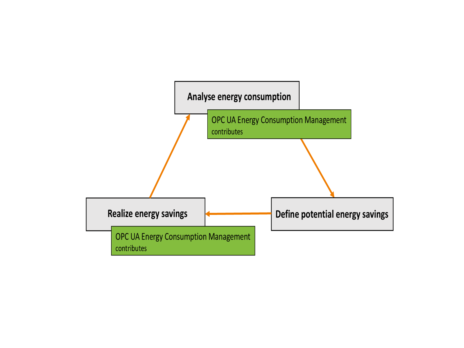
As Figure 1 shows, the general approach to cut down overall energy consumption and energy costs is a step-by-step circular approach. Starting point is the analysis of today's energy consumption. With awareness about energy consumption of sections, machines and devices in the production plant, in a next step potential energy savings are identified. After the definition of potential energy savings, the next step is the realization of the identified savings.
The specification Energy Consumption Management is focused on the communication of energy related measurement data, which is to be used in the task of "analyse energy consumption" and in the advertisement and control of energy savings in the task of "realize energy savings". Existing OPC UA models for Energy Management (OPC 30141) together with other fieldbus energy profiles serve as the basis for this companion specification. Also, the universal energy information model out of the project results of the IGF research project 21329 N "Development of energy management interfaces for IoT technologies (IoT_EnRG) " [3] was used here.
It will allow management of energy consumption by automated equipment in manufacturing and processing applications for discrete and continuous productions. The model is intended to be scalable from small stand-alone devices to complete machines to production cells or entire factories and plants.
2 Normative references
The following referenced documents are indispensable for the application of this document. For dated references, only the edition cited applies. For undated references, the latest edition of the referenced document (including any amendments and errata) applies.
OPC 10000-1, OPC Unified Architecture - Part 1: Overview and Concepts
http://www.opcfoundation.org/documents/10000-1/
OPC 10000-2, OPC Unified Architecture - Part 2: Security Model
http://www.opcfoundation.org/documents/10000-2/
OPC 10000-3, OPC Unified Architecture - Part 3: Address Space Model
http://www.opcfoundation.org/documents/10000-3/
OPC 10000-4, OPC Unified Architecture - Part 4: Services
http://www.opcfoundation.org/documents/10000-4/
OPC 10000-5, OPC Unified Architecture - Part 5: Information Model
http://www.opcfoundation.org/documents/10000-5/
OPC 10000-6, OPC Unified Architecture - Part 6: Mappings
http://www.opcfoundation.org/documents/10000-6/
OPC 10000-7, OPC Unified Architecture - Part 7: Profiles
http://www.opcfoundation.org/documents/10000-7/
OPC 10000-100, OPC Unified Architecture - Part 100: Devices
http://www.opcfoundation.org/documents/10000-100/
OPC 10000-200, OPC Unified Architecture - Part 200: Industrial Automation
http://www.opcfoundation.org/documents/10000-200/
PE 3802 Common Application Profile PROFIenergy - Version 1.3MU1 - Date: October 2021 Order No.: 3.802
3 Terms, definitions and conventions
3.1 Overview
It is assumed that basic concepts of OPC UA information modelling are understood in this specification. This specification will use these concepts to describe the Energy Consumption Management Information Model. For the purposes of this document, the terms and definitions given in OPC 10000-1, OPC 10000-3, OPC 10000-4, OPC 10000-5, OPC 10000-6, OPC 10000-7, OPC 10000-100, and OPC 10000-200 as well as the following apply.
3.2 OPC UA for Energy Consumption Management terms
3.2.1 EnergyProfile
standardized aggregation of energy variables with standardized semantic and predefined accuracy classes reflecting typical use cases and devices
3.3 Abbreviated terms
| ECM | Energy Consumption Management |
| ERP | Enterprise Resource Planning |
| HMI | Human Machine Interface |
| HTTP | Hypertext Transfer Protocol |
| IP | Internet Protocol |
| JSON | JavaScript Object Notation |
| LAN | Local Area Network |
| MAC | Media Access Control |
| MES | Manufacturing Execution System |
| PMS | Production Management System |
| RMS | Root Mean Square |
| TCP | Transmission Control Protocol |
| UML | Unified Modelling Language |
| URI | Uniform Resource Identifier |
| WOL | Wake-on-LAN |
| XML | Extensible Markup Language |
3.4 Conventions used in this document
3.4.1 Conventions for Node descriptions
3.4.1.1 Node definitions
Node definitions are specified using tables (see Table 2).
Attributes are defined by providing the Attribute name and a value, or a description of the value.
References are defined by providing the ReferenceType name, the BrowseName of the TargetNode and its NodeClass.
If the TargetNode is a component of the Node being defined in the table the Attributes of the composed Node are defined in the same row of the table.
The DataType is only specified for Variables; "[<number>]" indicates a single-dimensional array, for multi-dimensional arrays the expression is repeated for each dimension (e.g. [2][3] for a two-dimensional array). For all arrays the ArrayDimensions is set as identified by <number> values. If no <number> is set, the corresponding dimension is set to 0, indicating an unknown size. If no number is provided at all the ArrayDimensions can be omitted. If no brackets are provided, it identifies a scalar DataType and the ValueRank is set to the corresponding value (see OPC 10000-3). In addition, ArrayDimensions is set to null or is omitted. If it can be Any or ScalarOrOneDimension, the value is put into "{<value>}", so either "{Any}" or "{ScalarOrOneDimension}" and the ValueRank is set to the corresponding value (see OPC 10000-3) and the ArrayDimensions is set to null or is omitted. Examples are given in Table 1.
| Notation | DataType | ValueRank | ArrayDimensions | Description |
| 0:Int32 | 0:Int32 | -1 | omitted or null | A scalar Int32. |
| 0:Int32[] | 0:Int32 | 1 | omitted or {0} | Single-dimensional array of Int32 with an unknown size. |
| 0:Int32[][] | 0:Int32 | 2 | omitted or {0,0} | Two-dimensional array of Int32 with unknown sizes for both dimensions. |
| 0:Int32[3][] | 0:Int32 | 2 | {3,0} | Two-dimensional array of Int32 with a size of 3 for the first dimension and an unknown size for the second dimension. |
| 0:Int32[5][3] | 0:Int32 | 2 | {5,3} | Two-dimensional array of Int32 with a size of 5 for the first dimension and a size of 3 for the second dimension. |
| 0:Int32{Any} | 0:Int32 | -2 | omitted or null | An Int32 where it is unknown if it is scalar or array with any number of dimensions. |
| 0:Int32{ScalarOrOneDimension} | 0:Int32 | -3 | omitted or null | An Int32 where it is either a single-dimensional array or a scalar. |
The TypeDefinition is specified for Objects and Variables.
The TypeDefinition column specifies a symbolic name for a NodeId, i.e. the specified Node points with a HasTypeDefinition Reference to the corresponding Node.
The ModellingRule of the referenced component is provided by specifying the symbolic name of the rule in the ModellingRule column. In the AddressSpace, the Node shall use a HasModellingRule Reference to point to the corresponding ModellingRule Object.
If the NodeId of a DataType is provided, the symbolic name of the Node representing the DataType shall be used.
Note that if a symbolic name of a different namespace is used, it is prefixed by the NamespaceIndex (see 3.4.2.2).
Nodes of all other NodeClasses cannot be defined in the same table; therefore only the used ReferenceType, their NodeClass and their BrowseName are specified. A reference to another part of this document points to their definition. Table 2 illustrates the table. If no components are provided, the DataType, TypeDefinition and ModellingRule columns may be omitted and only a Comment column is introduced to point to the Node definition.
Each Type Node or well-known Instance Node defined shall have one or more ConformanceUnits defined in 11.1 that require the Node to be in the AddressSpace.
The relations between Nodes and ConformanceUnits are defined at the end of the tables defining Nodes, one row per ConformanceUnit. The ConformanceUnits are reflected in the Category element for the Node definition in the UANodeSet (see OPC 10000-6).
The list of ConformanceUnits in the UANodeSet allows Servers to optimize resource consumption by using a list of supported ConformanceUnits to select a subset of the Nodes in an Information Model.
When a Node is selected in this way, all dependencies implied by the References are also selected.
Dependencies exist if the Node is the source of HasTypeDefinition, HasInterface, HasAddIn or any HierarchicalReference. Dependencies also exist if the Node is the target of a HasSubtype Reference. For Variables and VariableTypes, the value of the DataType Attribute is a dependency. For DataType Nodes, any DataTypes referenced in the DataTypeDefinition Attribute are also dependencies.
For additional details see OPC 10000-5.
| Attribute | Value | ||||
| Attribute name | Attribute value. If it is an optional Attribute that is not set "--" will be used. | ||||
| References | NodeClass | BrowseName | DataType | TypeDefinition | Other |
|---|---|---|---|---|---|
| ReferenceType name | NodeClass of the target Node. | BrowseName of the target Node. | DataType of the referenced Node, only applicable for Variables. | TypeDefinition of the referenced Node, only applicable for Variables and Objects. | Additional characteristics of the TargetNode such as the ModellingRule or AccessLevel. |
| NOTE Notes referencing footnotes of the table content. | |||||
| Conformance Units | |||||
|---|---|---|---|---|---|
| Name of ConformanceUnit, one row per ConformanceUnit |
Components of Nodes can be complex that is containing components by themselves. The TypeDefinition, NodeClass and DataType can be derived from the type definitions, and the symbolic name can be created as defined in 3.4.3.1. Therefore, those containing components are not explicitly specified; they are implicitly specified by the type definitions.
The Other column defines additional characteristics of the Node. Examples of characteristics that can appear in this column are show in Table 3.
| Name | Short Name | Description |
| 0:Mandatory | M | The Node has the Mandatory ModellingRule. |
| 0:Optional | O | The Node has the Optional ModellingRule. |
| 0:MandatoryPlaceholder | MP | The Node has the MandatoryPlaceholder ModellingRule. |
| 0:OptionalPlaceholder | OP | The Node has the OptionalPlaceholder ModellingRule. |
| ReadOnly | RO | The Node AccessLevel has the CurrentRead bit set but not the CurrentWrite bit. |
| ReadWrite | RW | The Node AccessLevel has the CurrentRead and CurrentWrite bits set. |
| WriteOnly | WO | The Node AccessLevel has the CurrentWrite bit set but not the CurrentRead bit. |
If multiple characteristics are defined they are separated by commas. The name or the short name may be used.
3.4.1.2 Additional References
To provide information about additional References, the format as shown in Table 4 is used.
| SourceBrowsePath | Reference Type | Is Forward | TargetBrowsePath |
| SourceBrowsePath is always relative to the TypeDefinition. Multiple elements are defined as separate rows of a nested table. | ReferenceType name | True = forward Reference | TargetBrowsePath points to another Node, which can be a well-known instance or a TypeDefinition. You can use BrowsePaths here as well, which is either relative to the TypeDefinition or absolute. If absolute, the first entry needs to refer to a type or well-known instance, uniquely identified within a namespace by the BrowseName. |
References can be to any other Node.
3.4.1.3 Additional sub-components
To provide information about sub-components, the format as shown in Table 5 is used.
| BrowsePath | Reference | NodeClass | BrowseName | DataType | TypeDefinition | Others |
| BrowsePath is always relative to the TypeDefinition. Multiple elements are defined as separate rows of a nested table | NOTE Same as for Table 2 | |||||
3.4.1.4 Additional Attribute values
The type definition table provides columns to specify the values for required Node Attributes for InstanceDeclarations. To provide information about additional Attributes, the format as shown in Table 6 is used.
| BrowsePath | <Attribute name> Attribute |
| BrowsePath is always relative to the TypeDefinition. Multiple elements are defined as separate rows of a nested table | The values of attributes are converted to text by adapting the reversible JSON encoding rules defined in OPC 10000-6. If the JSON encoding of a value is a JSON string or a JSON number then that value is entered in the value field. Double quotes are not included. If the DataType includes a NamespaceIndex (QualifiedNames, NodeIds or ExpandedNodeIds) then the notation used for BrowseNames is used. If the value is an Enumeration the name of the enumeration value is entered. If the value is a Structure then a sequence of name and value pairs is entered. Each pair is followed by a newline. The name is followed by a colon. The names are the names of the fields in the DataTypeDefinition. If the value is an array of non-structures then a sequence of values is entered where each value is followed by a newline. If the value is an array of Structures or a Structure with fields that are arrays or with nested Structures then the complete JSON array or JSON object is entered. |
There can be multiple columns to define more than one Attribute.
3.4.2 NodeIds and BrowseNames
3.4.2.1 NodeIds
The NodeIds of all Nodes described in this standard are only symbolic names. Annex A defines the actual NodeIds.
The symbolic name of each Node defined in this document is its BrowseName, or, when it is part of another Node, the BrowseName of the other Node, a ".", and the BrowseName of itself. In this case "part of" means that the whole has a HasProperty or HasComponent Reference to its part. Since all Nodes not being part of another Node have a unique name in this document, the symbolic name is unique.
The NamespaceUri for all NodeIds defined in this document is defined in Annex A. The NamespaceIndex for this NamespaceUri is vendor-specific and depends on the position of the NamespaceUri in the server namespace table.
Note that this document not only defines concrete Nodes, but also requires that some Nodes shall be generated, for example one for each Session running on the Server. The NodeIds of those Nodes are Server-specific, including the namespace. But the NamespaceIndex of those Nodes cannot be the NamespaceIndex used for the Nodes defined in this document, because they are not defined by this document but generated by the Server.
3.4.2.2 BrowseNames
The text part of the BrowseNames for all Nodes defined in this document is specified in the tables defining the Nodes. The NamespaceUri for all BrowseNames defined in this document is defined in 12.2.
For InstanceDeclarations of NodeClass Object and Variable that are placeholders (OptionalPlaceholder and MandatoryPlaceholder ModellingRule), the BrowseName and the DisplayName are enclosed in angle brackets (<>) as recommended in OPC 10000-3.
If the BrowseName is not defined by this document, a namespace index prefix is added to the BrowseName (e.g., prefix '0' leading to '0:EngineeringUnits' or prefix '2' leading to '2:DeviceRevision'). This is typically necessary if a Property of another specification is overwritten or used in the OPC UA types defined in this document. Table 69 provides a list of namespaces and their indexes as used in this document.
3.4.3 Common Attributes
3.4.3.1 General
The Attributes of Nodes, their DataTypes and descriptions are defined in OPC 10000-3. Attributes not marked as optional are mandatory and shall be provided by a Server. The following tables define if the Attribute value is defined by this specification or if it is server-specific.
For all Nodes specified in this specification, the Attributes named in Table 7 shall be set as specified in the table.
| Attribute | Value |
| DisplayName | The DisplayName is a LocalizedText. Each server shall provide the DisplayName identical to the BrowseName of the Node for the LocaleId "en". Whether the server provides translated names for other LocaleIds is server-specific. |
| Description | Optionally a server-specific description is provided. |
| NodeClass | Shall reflect the NodeClass of the Node. |
| NodeId | The NodeId is described by BrowseNames as defined in 3.4.2.1. |
| WriteMask | Optionally the WriteMask Attribute can be provided. If the WriteMask Attribute is provided, it shall set all non-server-specific Attributes to not writable. For example, the Description Attribute may be set to writable since a Server may provide a server-specific description for the Node. The NodeId shall not be writable, because it is defined for each Node in this specification. |
| UserWriteMask | Optionally the UserWriteMask Attribute can be provided. The same rules as for the WriteMask Attribute apply. |
| RolePermissions | Optionally server-specific role permissions can be provided. |
| UserRolePermissions | Optionally the role permissions of the current Session can be provided. The value is server-specific and depends on the RolePermissions Attribute (if provided) and the current Session. |
| AccessRestrictions | Optionally server-specific access restrictions can be provided. |
3.4.3.2 Objects
For all Objects specified in this specification, the Attributes named in Table 8 shall be set as specified in the table. The definitions for the Attributes can be found in OPC 10000-3.
| Attribute | Value |
| EventNotifier | Whether the Node can be used to subscribe to Events or not is server-specific. |
3.4.3.3 Variables
For all Variables specified in this specification, the Attributes named in Table 9 shall be set as specified in the table. The definitions for the Attributes can be found in OPC 10000-3.
| Attribute | Value |
| MinimumSamplingInterval | Optionally, a server-specific minimum sampling interval is provided. |
| AccessLevel | The access level for Variables used for type definitions is server-specific, for all other Variables defined in this specification, the access level shall allow reading; other settings are server-specific. |
| UserAccessLevel | The value for the UserAccessLevel Attribute is server-specific. It is assumed that all Variables can be accessed by at least one user. |
| Value | For Variables used as InstanceDeclarations, the value is server-specific; otherwise it shall represent the value described in the text. |
| ArrayDimensions | If the ValueRank does not identify an array of a specific dimension (i.e. ValueRank <= 0) the ArrayDimensions can either be set to null or the Attribute is missing. This behaviour is server-specific. If the ValueRank specifies an array of a specific dimension (i.e. ValueRank > 0) then the ArrayDimensions Attribute shall be specified in the table defining the Variable. |
| Historizing | The value for the Historizing Attribute is server-specific. |
| AccessLevelEx | If the AccessLevelEx Attribute is provided, it shall have the bits 8, 9, and 10 set to 0, meaning that read and write operations on an individual Variable are atomic, and arrays can be partly written. |
3.4.3.4 VariableTypes
For all VariableTypes specified in this specification, the Attributes named in Table 10 shall be set as specified in the table. The definitions for the Attributes can be found in OPC 10000-3.
| Attributes | Value |
| Value | Optionally a server-specific default value can be provided. |
| ArrayDimensions | If the ValueRank does not identify an array of a specific dimension (i.e. ValueRank <= 0) the ArrayDimensions can either be set to null or the Attribute is missing. This behaviour is server-specific. If the ValueRank specifies an array of a specific dimension (i.e. ValueRank > 0) then the ArrayDimensions Attribute shall be specified in the table defining the VariableType. |
3.4.3.5 Methods
For all Methods specified in this specification, the Attributes named in Table 11 shall be set as specified in the table. The definitions for the Attributes can be found in OPC 10000-3.
| Attributes | Value |
| Executable | All Methods defined in this specification shall be executable (Executable Attribute set to "True"), unless it is defined differently in the Method definition. |
| UserExecutable | The value of the UserExecutable Attribute is server-specific. It is assumed that all Methods can be executed by at least one user. |
3.4.4 Structures
OPC 10000-3 differentiates between different kinds of Structures. The following conventions explain, how these Structures shall be defined.
The first kind are Structures without optional fields where none of the fields allows subtype (except fields with abstract DataTypes). Its definition is in Table 12.
| Name | Type | Description |
| <someStructure> | structure | Subtype of <someParentStructure> defined in … |
SP1 | 0:Byte[] | Setpoint 1 |
SP2 | 0:Byte[] | Setpoint 2 |
The second kind are Structures with optional fields where none of the fields allows subtypes (except fields with abstract DataTypes). Its definition is in Table 13.
Structures with fields that are optional have an "Optional" column. Fields that are optional have True set, otherwise False.
| Name | Type | Description | Optional |
| <someStructure> | structure | Subtype of <someParentStructure> defined in … | |
SP1 | 0:Byte[] | Setpoint 1 | False |
SP2 | 0:Byte[] | Setpoint 2 | True |
The third kind are Structures without optional fields where one or more of the fields allow subtypes. Its definition is in Table 14.
Structures with fields that allow subtypes have an "Allow Subtypes" column. Fields that allow subtypes have True set, otherwise False. Fields with abstract DataTypes can always be subtyped.
| Name | Type | Description | Allow SubTypes |
| <someStructure> | structure | Subtype of <someParentStructure> defined in … | |
SP1 | 0:Byte[] | Setpoint 1 | False |
Allow Subtypes | 0:ByteString | Some Bytestring | True |
4 General information to Energy Consumption Management and OPC UA
4.1 Introduction to Energy Consumption Management
Due to the climate and energy crisis, industrial companies are faced with the challenge of taking appropriate steps to efficiently manage their own energy requirements. The introduction of an energy management system according to the ISO 50001 standard [1] has proven to be a promising approach in the past. The introduction of such an energy management system provides the organizational framework for deriving energy efficiency actions based on recorded energy data, implementing them, and monitoring their effects. In this context, the procedure is continuously monitored and optimized through the application of a so-called Plan-Do-Check-Act cycle, so that energy inputs are constantly made more energy-efficient. In addition to the organizational part, an energy management system also needs a technical part that can be used to measure, provide, store, display and evaluate energy data. Furthermore, energy demands can be directly influenced by a load management system. With standby management functions, devices or entire plant sections can be ramped down to an energy-saving mode during production pauses, e.g. when cleaning of the production plant is required. The components of the required technical part can be termed as technical energy management system [2].
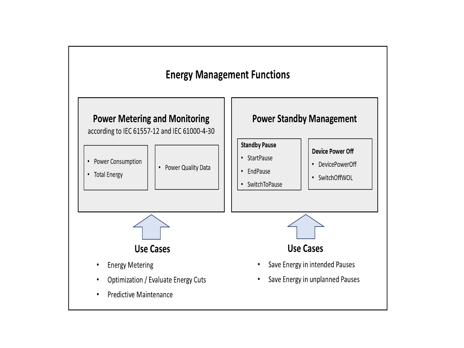
The functions of such a technical energy management system are clustered according to Figure 2 and show the basic functional submodels scoped by this specification. The cluster "Power Metering and Monitoring" functions provides energy related measurement values to cover the use case for energy consumption monitoring and metering and energy related measurement values to cover the use case power quality monitoring. The electrical measurement values in this cluster are based on the standards IEC 61557-12 [4] and IEC 61000-4-30 [6].
The cluster "Power Standby Management" addresses the switch down of components and devices to a power standby or power off mode in cases the component or device is temporarily not needed in the production process. This can be the case for planned pauses like lunchtime or maintenance or because of unplanned pauses caused by defects in the production line and temporary interruptions in the supply chain. The power standby management cluster contains basically two different modes for standby. The standby pause management assumes that the ethernet or fieldbus interface at the device is still operative and the device is able to receive commands for management of the standby pause states of the device. The device power off management causes a complete power down of the device, leaving only the ethernet MAC functionality operative in order to be able to receive an ethernet WOL magic package to conduct the standard ethernet wake on LAN functionality.
4.2 Introduction to OPC Unified Architecture
4.2.1 What is OPC UA?
OPC UA is an open and royalty free set of standards designed as a universal communication protocol. While there are numerous communication solutions available, OPC UA has key advantages:
A state of art security model (see OPC 10000-2).
A fault tolerant communication protocol.
An information modelling framework that allows application developers to represent their data in a way that makes sense to them.
OPC UA has a broad scope which delivers for economies of scale for application developers. This means that a larger number of high-quality applications at a reasonable cost are available. When combined with semantic models such as energy consumption management, OPC UA makes it easier for end users to access data via generic commercial applications.
The OPC UA model is scalable from small devices to ERP systems. OPC UA Servers process information locally and then provide that data in a consistent format to any application requesting data - ERP, MES, PMS, Maintenance Systems, HMI, Smartphone or a standard Browser, for examples. For a more complete overview see OPC 10000-1.
4.2.2 Basics of OPC UA
As an open standard, OPC UA is based on standard internet technologies, like TCP/IP, HTTP, Web Sockets.
As an extensible standard, OPC UA provides a set of Services (see OPC 10000-4) and a basic information model framework. This framework provides an easy manner for creating and exposing vendor defined information in a standard way. More importantly all OPC UA Clients are expected to be able to discover and use vendor-defined information. This means OPC UA users can benefit from the economies of scale that come with generic visualization and historian applications. This specification is an example of an OPC UA Information Model designed to meet the needs of developers and users.
OPC UA Clients can be any consumer of data from another device on the network to browser based thin clients and ERP systems. The full scope of OPC UA applications is shown in Figure 3.

OPC UA provides a robust and reliable communication infrastructure having mechanisms for handling lost messages, failover, heartbeat, etc. With its binary encoded data, it offers a high-performing data exchange solution. Security is built into OPC UA as security requirements become more and more important especially since environments are connected to the office network or the internet and attackers are starting to focus on automation systems.
4.2.3 Information modelling in OPC UA
4.2.3.1 Concepts
OPC UA provides a framework that can be used to represent complex information as Objects in an AddressSpace which can be accessed with standard services. These Objects consist of Nodes connected by References. Different classes of Nodes convey different semantics. For example, a Variable Node represents a value that can be read or written. The Variable Node has an associated DataType that can define the actual value, such as a string, float, structure etc. It can also describe the Variable value as a variant. A Method Node represents a function that can be called. Every Node has a number of Attributes including a unique identifier called a NodeId and non-localized name called as BrowseName. An Object representing a 'Reservation' is shown in Figure 4.

Object and Variable Nodes represent instances and they always reference a TypeDefinition (ObjectType or VariableType) Node which describes their semantics and structure. Figure 5 illustrates the relationship between an instance and its TypeDefinition.
The type Nodes are templates that define all of the children that can be present in an instance of the type. In the example in Figure 5 the PersonType ObjectType defines two children: First Name and Last Name. All instances of PersonType are expected to have the same children with the same BrowseNames. Within a type the BrowseNames uniquely identify the children. This means Client applications can be designed to search for children based on the BrowseNames from the type instead of NodeIds. This eliminates the need for manual reconfiguration of systems if a Client uses types that multiple Servers implement.
OPC UA also supports the concept of sub-typing. This allows a modeller to take an existing type and extend it. There are rules regarding sub-typing defined in OPC 10000-3, but in general they allow the extension of a given type or the restriction of a DataType. For example, the modeller may decide that the existing ObjectType in some cases needs an additional Variable. The modeller can create a subtype of the ObjectType and add the Variable. A Client that is expecting the parent type can treat the new type as if it was of the parent type. Regarding DataTypes, subtypes can only restrict. If a Variable is defined to have a numeric value, a sub type could restrict it to a float.

References allow Nodes to be connected in ways that describe their relationships. All References have a ReferenceType that specifies the semantics of the relationship. References can be hierarchical or non-hierarchical. Hierarchical references are used to create the structure of Objects and Variables. Non-hierarchical are used to create arbitrary associations. Applications can define their own ReferenceType by creating subtypes of an existing ReferenceType. Subtypes inherit the semantics of the parent but may add additional restrictions. Figure 6 depicts several References, connecting different Objects.

The figures above use a notation that was developed for the OPC UA specification. The notation is summarized in Figure 7. UML representations can also be used; however, the OPC UA notation is less ambiguous because there is a direct mapping from the elements in the figures to Nodes in the AddressSpace of an OPC UA Server.

A complete description of the different types of Nodes and References can be found in OPC 10000-3 and the base structure is described in OPC 10000-5.
OPC UA specification defines a very wide range of functionality in its basic information model. It is not required that all Clients or Servers support all functionality in the OPC UA specifications. OPC UA includes the concept of Profiles, which segment the functionality into testable certifiable units. This allows the definition of functional subsets (that are expected to be implemented) within a companion specification. The Profiles do not restrict functionality, but generate requirements for a minimum set of functionalities (see OPC 10000-7).
4.2.3.2 Namespaces
OPC UA allows information from many different sources to be combined into a single coherent AddressSpace. Namespaces are used to make this possible by eliminating naming and id conflicts between information from different sources. Each namespace in OPC UA has a globally unique string called a NamespaceUri which identifies a naming authority and a locally unique integer called a NamespaceIndex, which is an index into the Server's table of NamespaceUris. The NamespaceIndex is unique only within the context of a Session between an OPC UA Client and an OPC UA Server- the NamespaceIndex can change between Sessions and still identify the same item even though the NamespaceUri's location in the table has changed. The Services defined for OPC UA use the NamespaceIndex to specify the Namespace for qualified values.
There are two types of structured values in OPC UA that are qualified with NamespaceIndexes: NodeIds and QualifiedNames. NodeIds are locally unique (and sometimes globally unique) identifiers for Nodes. The same globally unique NodeId can be used as the identifier in a node in many Servers - the node's instance data may vary but its semantic meaning is the same regardless of the Server it appears in. This means Clients can have built-in knowledge of what the data means in these Nodes. OPC UA Information Models generally define globally unique NodeIds for the TypeDefinitions defined by the Information Model.
QualifiedNames are non-localized names qualified with a Namespace. They are used for the BrowseNames of Nodes and allow the same names to be used by different information models without conflict. TypeDefinitions are not allowed to have children with duplicate BrowseNames; however, instances do not have that restriction.
4.2.3.3 Companion Specifications
An OPC UA companion specification for an industry specific vertical market describes an Information Model by defining ObjectTypes, VariableTypes, DataTypes and ReferenceTypes that represent the concepts used in the vertical market, and potentially also well-defined Objects as entry points into the AddressSpace.
5 Use cases
5.1 Use cases for Energy Consumption Measurement
The following uses cases are addressed in this specification.
As a user, I want to know the electricity and piped resources consumption (per part or per output produced) to be able to determine key figures.
As a user, I want to know the electricity and piped resources consumption (per operating condition) to be able to determine key figures.
As a user, I want to measure the energy consumption over an external coordinated time period.
As a user, I want to see the change in energy consumption to assess the condition of the consumer. With regard to condition monitoring, the consumer may be a machine, component, system or process.
As a user, I want to see the energy consumption so I can relate it to a production phase.
As a user, I would like to know the energy consumption in the individual operating modes in order to be able to compare machines and minimize standby consumption, among other things.
As a user, I want to know the largest consumers in the facility in order to identify optimization potential.
As an energy manager, I want to know the energy consumption of individual functions so that I can compare machines and minimize standby consumption, among other things.
As a user, I want to know the energy consumption in order to optimize the production parameters.
As a user, I would like to determine the potential energy savings between existing and new equipment in order to apply for government funding and/or to reduce energy costs.
As a user, I would like to know the energy consumption of the individual machine components in order to be able to compare machine components, among other things, and to minimize the consumption of the components in the respective operating state.
As a user, I want to know the electrical load behaviour of my equipment in order to avoid expensive load peaks or overload shutdowns.
As a user, I want to know the load behaviour of all forms of energy in my equipment in order to avoid peak loads, for example, I would like to know the pneumatic load behaviour of my operating equipment, for example, in order to avoid inadmissible lowering of the pressure.
As a user, I want to know the energy consumption/load profile of the production (per component/per operating condition) in order to be able to cover the energy requirements of the machine with the production plan.
As a user, I would like to determine the CO2 emissions per unit produced/per operating condition in order to calculate component-specific carbon footprint (or product-specific carbon footprint).
As a user, I would like to determine the CO2 emissions per year in order to draw up the balance sheet for the machine.
As a user, I would like to receive information about the connected load of the machines and components in the facility in order to carry out energy network planning and, if necessary, increase production capacities.
As a user, I would like to record and compensate for the reactive power of the machine up to the total production in order to save costs and reduce internal losses.
As a user, I want to ensure voltage/network quality to avoid power and production outages.
As a user, I want to ensure voltage quality to avoid machine failure.
Note that not all use cases are directly addressed by the information model defined in this specification, but provide the base information so that clients can implement the use case.
5.2 Use cases for Standby Management and Sleep Mode
The following uses cases are addressed in this specification to support all scenarios of energy saving for planned or unplanned pauses:
As a user I want to request switching in energy saving modes by only requesting the pause period and the entity should go to a fitting energy saving mode. The entity shall select the best fitting energy saving mode from the perspective of energy savings and startup time.
As a user I want to interrupt an active energy saving mode.
As a user I want to change the duration of an active energy saving mode or switch to another energy saving mode.
6 Energy Consumption Management Information Model overview
6.1 Overview
The information model is separated into a part considering energy consumption measurements, one for standby management and one for sleep mode WOL functionality.
6.2 Energy Consumption Measurement
6.2.1 Base Concepts
In order to provide measured energy consumption, either current values or aggregated values (counters), the information model enables to create Objects of ObjectType EnergyMeasurementType with potentially several measurements measured at the same point in a system represented by Variables of VariableType EnergyMeasurementValueType. Those Objects may have a Method to reset the aggregated values. How those Objects are connected to other parts of an information model (e.g., for a device or a machine) is not addressed by this specification. The EnergyMeasurementValueType provides additional meta data of the measurement like the engineering unit.
In Figure 8, an overview of the EnergyMeasurementType and the EnergyMeasurementValueType is given. They are formally defined in 7.1.1 and 8.1.

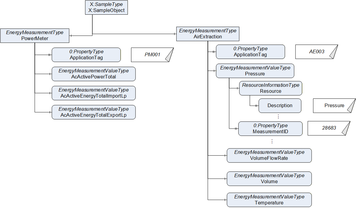
In Figure 9, an example of the usage of those TypeDefinitions is given. The "X:SampleObject" contains two instances of EnergyMeasurementType, one measuring the electrical power and one the air extraction. Both contain different measurement values, like pressure, volume, and temperature.
6.2.2 Standardized Measurement Identifiers
6.2.2.1 Overview
Instead of defining the different types of measurements in a large variety of TypeDefinitions or InstanceDeclarations, this specification defines a container for measurement identifiers (MeasurementID) and a list of those standardized identifiers. In Table 15, the format of the table containing the standardized IDs is given. The file, as comma separated value file is published in addition to this document (see Annex A).
| MeasurementID | BrowseName | Description | EngineeringUnits | MeasurementPeriod | DataType | HasStatisticComponent |
The MeasurementID is a unique numeric identification. The BrowseName (leaving out the NamespaceIndex, which is always the one of this specification (see Annex A)), is a unique identification that is used as BrowseName for instances of the EnergyMeasurementType. Those BrowseNames are also used for the interfaces (see 6.2.3). The Description (in English) may be used as the Description Attribute for those Nodes.
For all instances of EnergyMeasurementType using the BrowseName as defined in the table, the EngineeringUnits shall be used for the 0:EngineeringUnits Property, the DataType shall be used as DataType (Attributes DataType and ValueRank), and the MeasurementPeriod shall be used for the MeasurementPeriod. If no EngineeringUnits is provided in the table, the 0:EngineeringUnits Property shall not be provided as well. If no MeasurementPeriod is provided in the table, the MeasurementPeriod Property shall not be provided as well. The MeasurementPeriod is the interval of time over which the data is collected and at the end of the period being reported. If the MeasurementPeriod is defined as "user-defined", the MeasurementPeriod Property shall be provided, but the value is not pre-defined. If it is defined to start in the full hour (see Description), a multiple of the value shall fit into one hour.
The HasStatisticComponent defines, if the 2:HasStatisticComponent ReferenceType shall be used to reference the Variable of EnergyMeasurementType (YES), or the 0:HasComponent ReferenceType shall be used (NO). Using 2:HasStatisticComponent indicates, that the Variable is aggregating values over time and may be reset, potentially using the 2:ResetStatistics Method (see 7.1.1).
Note that the referenced file is part of the specification, and changes in the file are considered as changes in the specification, requiring the normal update process.
6.2.2.2 Explanations to the defined measurements
In general, measurements of voltage and current are RMS values calculated over 3 seconds or 10 minutes as described in IEC 61000-4-30. Note: 3 s corresponds to 150 cycles on a 50 Hz system or 180 cycles on a 60 Hz system.
Energy values are calculated over a period of time, typically 15 minutes, as described in IEC 61577-12.
Values described as minimum or maximum values are calculated over the period since the last reset.
For measurements defined in this companion standard that do not have a specific measurement period, the system integrator or manufacturer may use any period that is appropriate or available.
The BrowseNames of the standardized measurement identifiers follow the following naming conventions:
AcPe: Phase to Neutral
AcPp: Phase to phase
Lp: Low Precision (Float DataType)
Hp: High Precision (Double DataType)
Total: concerns all phases
Sum: concerns the sum of all measured import and export parts (sum = import - export)
Some explanations to the Description text in the table:
Qtot is according to IEC 61557-12 [4] the reactive power calculated by the triangle formula, also known as Fryze's definition (harmonics are specified vendor specific)
Qn is according to IEC 61557-12 [4] the reactive power calculated according to the Budeanu's harmonic definition (harmonics are specified vendor specific)
Measurements defined to have the DataType Int16[5] represent values as defined in [8].
6.2.3 Standardized Interfaces for combinations of Measurements
Some combinations of measurement values are reasonably provided together. This specification standardizes some of those combinations by defining interfaces containing all those combinations. Applications may implement those interfaces and thereby provide the combinations of measurement values.
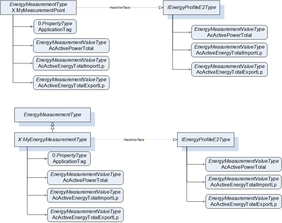
Standardized interfaces are defined in 7.1.3 An example, how standardized interfaces are used is shown in Figure 10. The interface can either be used directly on an instance, like on MyMeasurementPoint, or on a ObjectType like on MyEnergyMeasurementType.
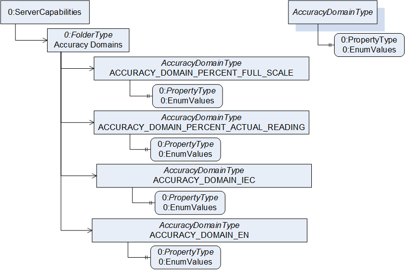
6.2.4 Accuracy Domains and Classes
Individual measurements (Variables of EnergyMeasurementValueType) have a specific accuracy class defined by a specific accuracy domain. This specification defines accuracy domains in a way, that it is possible to add additional accuracy domains. Each accuracy domain is represented by an Object of AccuracyDomainType (see 7.1.2). The Objects can be browsed from the standardized AccuracyDomains Object (see 10.1), allowing a Client to receive all accuracy domains used by the Server (see Figure 11). This specification defines standardized accuracy domains in 10.
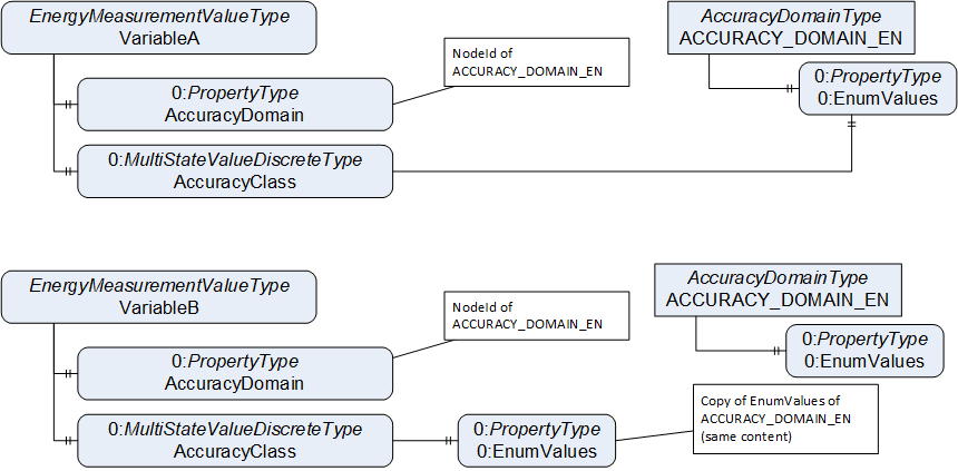
The Object representing an accuracy domain contains the EnumValues Property containing the different accuracy classes defined by the accuracy domain. Each measurement of EnergyMeasurementValueType references its accuracy domain by the Property AccuracyDomain of DataType NodeId. The accuracy class is provided in the AccuracyClass Variable. This Variable of MultiStateValueDiscreteType shall either reference the EnumValues Property of the referenced accuracy domain Object (see VariableA in Figure 12 as example) or it shall contain a copy of that Property containing the same values (see VariableB in Figure 12 as example).
6.3 Standby Management
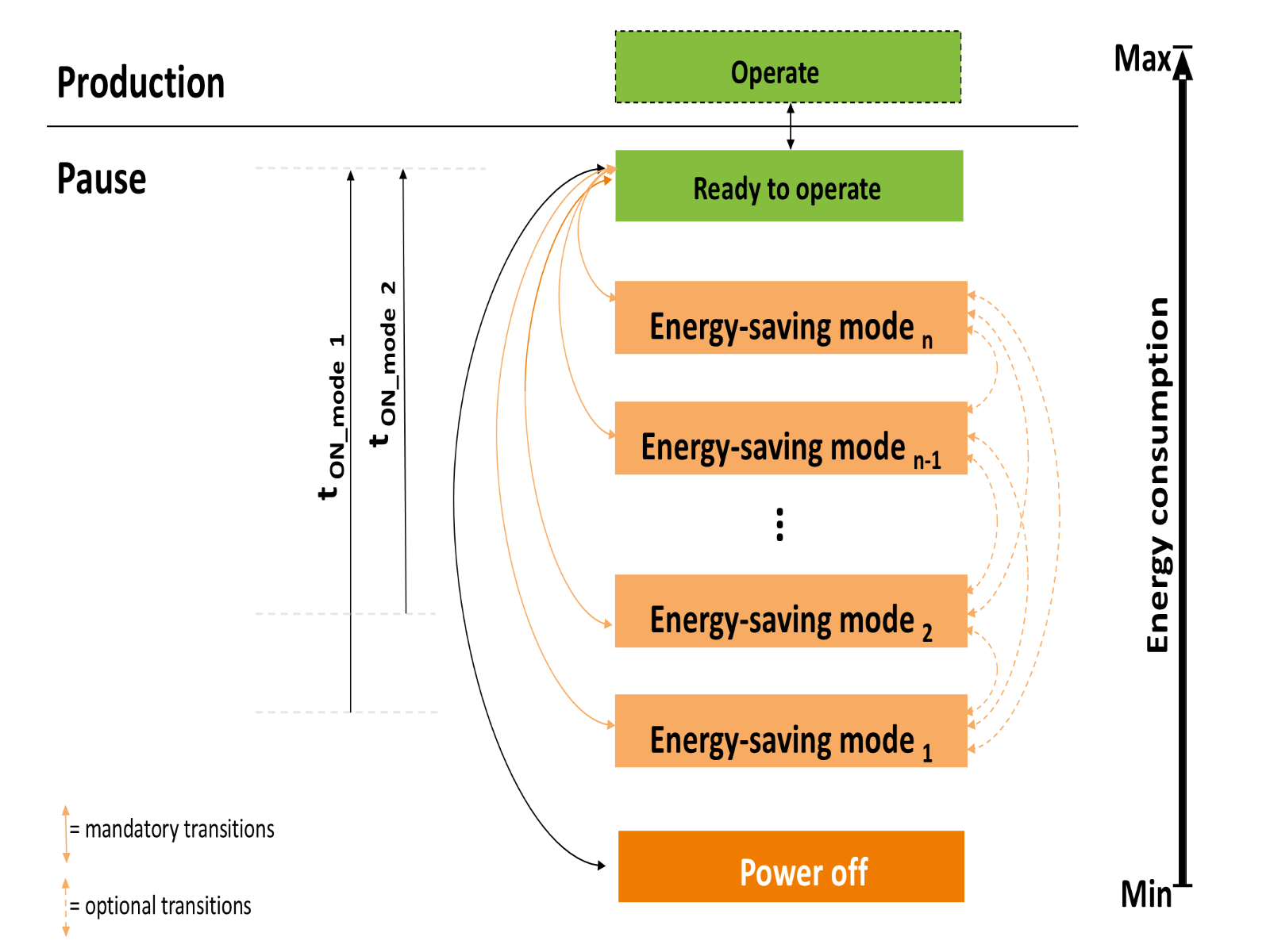
Standby Management allows a device or parts of a device to switch into an Energy Saving Mode if not in operation or engaged. If a Standby Management Entity supports more than one Energy Saving Mode (with different levels of energy consumption), transitions from one Energy Saving Mode into another might be possible (see Figure 13). For the smooth integration of devices with Standby Management functionality into a production process, Standby Management offers commands to issue the transition into an Energy Saving Mode and the termination of an Energy Saving Mode with switchback to normal operation.
For further cutdown in energy consumption the functionality of Sleep Mode WOL, defined in 6.4, could be used.
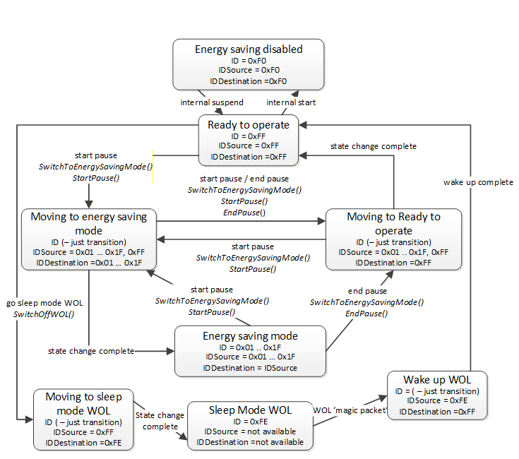
Standby Management defines a state model determining the possible state transitions. Figure 14 shows the state model.
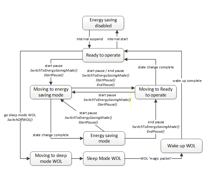
When in 'Energy saving disabled' state, the device is in normal operation and does not accept standby commands. In the 'Ready to operate' state the device accepts standby commands. When in transition to or from an Energy Saving Mode, the device has a 'Moving to …' transition state. Thus, the state model reflects the physical properties of a real-world device: Changes in energy consumption imply changes of some physical processes which will always be time consuming.
Standby Management is made available for OPC UA Clients with the ObjectTypes defined in 7.2.
Status information functionality of Standby Management provides information about the current state of a Standby Management Entity, the current energy consumption, the available Energy Saving Modes and their detailed characteristics.
The current state information of a Standby Management Entity is made available for OPC UA Clients with the EnergySavingModeStatusType (defined in 7.2.3) referenced by the EnergyStandbyManagementType.
Detailed information about a specific Energy Saving Mode is provided by the EnergySavingModeType defined in chapter 7.2.4.
6.4 Sleep Mode WOL
Devices might support Sleep Mode WOL functionality allowing to switch off a device almost completely. If this Sleep Mode WOL functionality is active, the device in Sleep Mode WOL is not reachable for network communication and can only be 'awakened' by receiving a 'WOL magic packet'. The energy consumption of a device in Sleep Mode WOL is caused by the power to keep the network MAC controller alive while Standby Management demands an application on the device to monitor and control the Standby Management states. Therefore, Sleep Mode WOL typically consumes less power than Standby Management.
The transition to the Sleep Mode WOL state is initiated by invoking the SwitchOffWOL Method of the EnergyDevicePowerOffType defined in 7.3.1.
If the switched off device contains the OPC UA server, the connection of the OPC client to the server disconnects. The server will be reachable again after a wake up of the device by WOL (sending the WOL magic wake-up packet).
7 OPC UA ObjectTypes
7.1 ObjectTypes for Energy Consumption Measurement
7.1.1 EnergyMeasurementType ObjectType Definition
The EnergyMeasurementType provides various energy measurement values measured at the same point in a system and is formally defined in Table 16.
| Attribute | Value | ||||
| BrowseName | EnergyMeasurementType | ||||
| IsAbstract | False | ||||
| References | Node Class | BrowseName | DataType | TypeDefinition | Other |
|---|---|---|---|---|---|
| Subtype of the 0:BaseObjectType | |||||
| 0:HasProperty | Variable | ApplicationTag | 0:String | 0:PropertyType | M, RW |
| 0:HasComponent | Variable | <MeasurementValue> | 0:BaseDataType{Any} | EnergyMeasurementValueType | MP |
| 0:HasComponent | Method | 2:ResetStatistics | O | ||
| 0:HasProperty | Variable | 2:StartTime | 0:DateTime | 0:PropertyType | O |
| 0:HasInterface | ObjectType | 2:IStatisticsType | |||
| Conformance Units | |||||
|---|---|---|---|---|---|
| ECM Energy Measurement | |||||
The ApplicationTag provides a string that is supposed to uniquely identify the functionality of the energy measurement. It is to be set by an end user or system integrator. Server-provider would typically initially set it to an empty string. It is marked as writable. However, applications may also provide other mechanisms than the OPC UA interface to set the value, e.g. by some proprietary engineering environments.
The <MeasurementValue> Variable is a placeholder for all measurement values provided by the instance of the EnergyMeasurementType. At least one measurement value shall be provided. There are standardized measurement values defined (see 6.2.2).
The ObjectType implements the 2:IStatisticsType Interface as defined in OPC 10000-200 providing the optional 2:ResetStatistics and 2:StartTime.
The optional 2:ResetStatistics Method can be used to reset measurement values used as energy counter, i.e. aggregating the energy consumption over time. Details of its usage are defined in OPC 10000-200. Measurement values that can be reset are identified by being referenced using the 2:HasStatisticComponent (a subtype of 0:HasComponent).
The optional 2:StartTime indicates when the collection of aggregated data has started or was reset. Details of its usage are defined in OPC 10000-200.
7.1.2 AccuracyDomainType
The AccuracyDomainType is used to represent accuracy domains and contains the accuracy classes of the accuracy domain (see 6.2.4). It is formally defined in Table 17.
| Attribute | Value | ||||
| BrowseName | AccuracyDomainType | ||||
| IsAbstract | False | ||||
| References | Node Class | BrowseName | DataType | TypeDefinition | Other |
|---|---|---|---|---|---|
| Subtype of the 0:BaseObjectType | |||||
| 0:HasProperty | Variable | 0:EnumValues | 0:EnumValueType[] | 0:PropertyType | M |
| Conformance Units | |||||
|---|---|---|---|---|---|
| ECM Energy Measurement | |||||
The EnumValues provides the accuracy classes of the accuracy domain.
7.1.3 Interfaces for Energy Consumption Measurement
7.1.3.1 IEnergyProfileE0Type
The IEnergyProfileE0Type contains the References to EnergyMeasurementValueType Variables needed for EnergyProfile E0.
| Attribute | Value | ||||
| BrowseName | IEnergyProfileE0Type | ||||
| IsAbstract | True | ||||
| References | Node Class | BrowseName | DataType | TypeDefinition | Other |
|---|---|---|---|---|---|
| Subtype of the 0:BaseInterfaceType | |||||
| 0:HasComponent | Variable | AcCurrentPe | AcPeDataType | EnergyMeasurementValueType | M |
| Conformance Units | |||||
|---|---|---|---|---|---|
| ECM EnergyProfile E0 | |||||
| Source Path | Value Attribute | ||
| NamespaceUri: http://www.opcfoundation.org/UA/units/un/cefact UnitId: 4279632 DisplayName: A Description: ampere | ||
| 1218 | ||
| 1 |
7.1.3.2 IEnergyProfileE1Type
The IEnergyProfileE1Type contains the References to EnergyMeasurementValueType Variables needed for EnergyProfile E1.
| Attribute | Value | ||||
| BrowseName | IEnergyProfileE1Type | ||||
| IsAbstract | True | ||||
| References | Node Class | BrowseName | DataType | TypeDefinition | Other |
|---|---|---|---|---|---|
| Subtype of the 0:BaseInterfaceType | |||||
| 0:HasComponent | Variable | AcActivePowerTotal | 0:Float | EnergyMeasurementValueType | M |
| Conformance Units | |||||
|---|---|---|---|---|---|
| ECM EnergyProfile E1 | |||||
| Source Path | Value Attribute | ||
| NamespaceUri: http://www.opcfoundation.org/UA/units/un/cefact UnitId: 5723220 DisplayName: W Description: watt | ||
| 1412 | ||
| 1 |
7.1.3.3 IEnergyProfileE2Type
The IEnergyProfileE2Type contains the References to EnergyMeasurementValueType Variables needed for EnergyProfile E2.
| Attribute | Value | ||||
| BrowseName | IEnergyProfileE2Type | ||||
| IsAbstract | True | ||||
| References | Node Class | BrowseName | DataType | TypeDefinition | Other |
|---|---|---|---|---|---|
| Subtype of the 0:BaseInterfaceType | |||||
| 0:HasComponent | Variable | AcActivePowerTotal | 0:Float | EnergyMeasurementValueType | M |
| 2:HasStatisticComponent | Variable | AcActiveEnergyTotalImportLp | 0:Float | EnergyMeasurementValueType | M |
| 2:HasStatisticComponent | Variable | AcActiveEnergyTotalExportLp | 0:Float | EnergyMeasurementValueType | M |
| Conformance Units | |||||
|---|---|---|---|---|---|
| ECM EnergyProfile E2 | |||||
| Source Path | Value Attribute | ||
| NamespaceUri: http://www.opcfoundation.org/UA/units/un/cefact UnitId: 5723220 DisplayName: W Description: watt | ||
| 1412 | ||
| 1 | ||
| NamespaceUri: http://www.opcfoundation.org/UA/units/un/cefact UnitId: 5720146 DisplayName: W·h Description: watt hour | ||
| 1001 | ||
| 1 | ||
| NamespaceUri: http://www.opcfoundation.org/UA/units/un/cefact UnitId: 5720146 DisplayName: W·h Description: watt hour | ||
| 1004 | ||
| 1 |
7.1.3.4 IEnergyProfileE3Type
The IEnergyProfileE3Type contains the References to EnergyMeasurementValueType Variables needed for EnergyProfile E3.
| Attribute | Value | ||||
| BrowseName | IEnergyProfileE3Type | ||||
| IsAbstract | True | ||||
| References | Node Class | BrowseName | DataType | TypeDefinition | |
|---|---|---|---|---|---|
| Subtype of the 0:BaseInterfaceType | |||||
| 0:HasComponent | Variable | AcActivePowerPe | AcPeDataType | EnergyMeasurementValueType | M |
| 0:HasComponent | Variable | AcReactivePowerPe | AcPeDataType | EnergyMeasurementValueType | M |
| 2:HasStatisticComponent | Variable | AcActiveEnergyTotalImportHp | 0:Double | EnergyMeasurementValueType | M |
| 2:HasStatisticComponent | Variable | AcActiveEnergyTotalExportHp | 0:Double | EnergyMeasurementValueType | M |
| 2:HasStatisticComponent | Variable | AcReactiveEnergyTotalImportHp | 0:Double | EnergyMeasurementValueType | M |
| 2:HasStatisticComponent | Variable | AcReactiveEnergyTotalExportHp | 0:Double | EnergyMeasurementValueType | M |
| 0:HasComponent | Variable | AcVoltagePe | AcPeDataType | EnergyMeasurementValueType | M |
| 0:HasComponent | Variable | AcVoltagePp | AcPpDataType | EnergyMeasurementValueType | M |
| 0:HasComponent | Variable | AcCurrentPe | AcPeDataType | EnergyMeasurementValueType | M |
| 0:HasComponent | Variable | AcPowerFactorPe | AcPeDataType | EnergyMeasurementValueType | M |
| Conformance Units | |||||
|---|---|---|---|---|---|
| ECM EnergyProfile E3 | |||||
| Source Path | Value Attribute | ||
| NamespaceUri: http://www.opcfoundation.org/UA/units/un/cefact UnitId: 5723220 DisplayName: W Description: watt | ||
| 1409 | ||
| 1 | ||
| NamespaceUri: http://www.opcfoundation.org/UA/units/un/cefact UnitId: 4469812 DisplayName: var Description: var | ||
| 1618 | ||
| 1 | ||
| NamespaceUri: http://www.opcfoundation.org/UA/units/un/cefact UnitId: 5720146 DisplayName: W·h Description: watt hour | ||
| 1002 | ||
| 1 | ||
| NamespaceUri: http://www.opcfoundation.org/UA/units/un/cefact UnitId: 5720146 DisplayName: W·h Description: watt hour | ||
| 1005 | ||
| 1 | ||
| NamespaceUri: http://opcfoundation.org/UA/ECM/ UnitId: 1 DisplayName: var·h Description: volt ampere reactive hour | ||
| 1011 | ||
| 1 | ||
| NamespaceUri: http://opcfoundation.org/UA/ECM/ UnitId: 1 DisplayName: var·h Description: volt ampere reactive hour | ||
| 1014 | ||
| 1 | ||
| NamespaceUri: http://www.opcfoundation.org/UA/units/un/cefact UnitId: 5655636 DisplayName: V Description: volt | ||
| 1118 | ||
| 1 | ||
| NamespaceUri: http://www.opcfoundation.org/UA/units/un/cefact UnitId: 5655636 DisplayName: V Description: volt | ||
| 1145 | ||
| 1 | ||
| NamespaceUri: http://www.opcfoundation.org/UA/units/un/cefact UnitId: 4279632 DisplayName: A Description: ampere | ||
| 1218 | ||
| 1 | ||
| 1709 | ||
| 1 |
7.1.3.5 IEnergyProfileD0Type
The IEnergyProfileD0Type Interface contains a Reference to a EnergyMeasurementValueType Variable representing direct current (EnergyProfile D0).
| Attribute | Value | ||||
| BrowseName | IEnergyProfileD0Type | ||||
| IsAbstract | True | ||||
| References | Node Class | BrowseName | DataType | TypeDefinition | Other |
|---|---|---|---|---|---|
| Subtype of the 0:BaseInterfaceType | |||||
| 0:HasComponent | Variable | DcCurrent | 0:Float | EnergyMeasurementValueType | M |
| Conformance Units | |||||
|---|---|---|---|---|---|
| ECM EnergyProfile D0 | |||||
| Source Path | Value Attribute | ||
| NamespaceUri: http://www.opcfoundation.org/UA/units/un/cefact UnitId: 4279632 DisplayName: A Description: ampere | ||
| 1033 | ||
| 1 |
7.1.3.6 IEnergyProfileD1Type
The IEnergyProfileD1Type Interface contains the References to EnergyMeasurementValueType Variables representing measurements for equipment that produces or consumes direct current.
| Attribute | Value | ||||
| BrowseName | IEnergyProfileD1Type | ||||
| IsAbstract | True | ||||
| References | Node Class | BrowseName | DataType | TypeDefinition | Other |
|---|---|---|---|---|---|
| Subtype of the 0:BaseInterfaceType | |||||
| 0:HasComponent | Variable | DcCurrent | 0:Float | EnergyMeasurementValueType | M |
| 0:HasComponent | Variable | DcVoltage | 0:Float | EnergyMeasurementValueType | M |
| 0:HasComponent | Variable | DcActivePower | 0:Float | EnergyMeasurementValueType | M |
| 2:HasStatisticComponent | Variable | DcEnergyTotalImportLp | 0:Float | EnergyMeasurementValueType | M |
| 2:HasStatisticComponent | Variable | DcEnergyTotalExportLp | 0:Float | EnergyMeasurementValueType | M |
| 2:HasStatisticComponent | Variable | DcElectricalCharge | 0:Float | EnergyMeasurementValueType | M |
| 2:HasStatisticComponent | Variable | DcRelativeCharge | 0:Float | EnergyMeasurementValueType | M |
| Conformance Units | |||||
|---|---|---|---|---|---|
| ECM EnergyProfile D1 | |||||
| Source Path | Value Attribute | ||
| NamespaceUri: http://www.opcfoundation.org/UA/units/un/cefact UnitId: 4279632 DisplayName: A Description: ampere | ||
| 1033 | ||
| 1 | ||
| NamespaceUri: http://www.opcfoundation.org/UA/units/un/cefact UnitId: 5655636 DisplayName: V Description: volt | ||
| 1034 | ||
| 1 | ||
| NamespaceUri: http://www.opcfoundation.org/UA/units/un/cefact UnitId: 5723220 DisplayName: W Description: watt | ||
| 1032 | ||
| 1 | ||
| NamespaceUri: http://www.opcfoundation.org/UA/units/un/cefact UnitId: 5720146 DisplayName: W·h Description: watt hour | ||
| 1022 | ||
| 1 | ||
| NamespaceUri: http://www.opcfoundation.org/UA/units/un/cefact UnitId: 5720146 DisplayName: W·h Description: watt hour | ||
| 1025 | ||
| 1 | ||
| NamespaceUri: http://www.opcfoundation.org/UA/units/un/cefact UnitId: 4279624 DisplayName: A·h Description: ampere hour | ||
| 1030 | ||
| 1 | ||
| NamespaceUri: http://www.opcfoundation.org/UA/units/un/cefact UnitId: 20529 DisplayName: % Description: percent | ||
| 1031 | ||
| 1 |
7.2 ObjectTypes for Standby Management
7.2.1 EnergyStandbyManagementType
7.2.1.1 Overview
The EnergyStandbyManagementType ObjectType provides access to the Standby Management functionality of one Standby Management Entity. Parallel access of Clients to the read only data shall be possible but write operations and Method invocation can be limited to one Client at a time with the Lock Object.
| Attribute | Value | ||||
| BrowseName | EnergyStandbyManagementType | ||||
| IsAbstract | False | ||||
| References | Node Class | BrowseName | DataType | TypeDefinition | Other |
|---|---|---|---|---|---|
| Subtype of the 0:BaseObjectType | |||||
| 0:HasComponent | Variable | StandbyManagementStatus | 0:Byte | 0:MultiStateDiscreteType | M, RO |
| 0:HasComponent | Object | EnergySavingModeStatus | EnergySavingModeStatusType | M | |
| 0:HasComponent | Object | EnergySavingModes | EnergySavingModesContainerType | O | |
| 0:HasComponent | Variable | PauseTime | 0:Duration | 0:BaseDataVariableType | M, RW |
| 0:HasComponent | Object | 3:Lock | 3:LockingServicesType | O | |
| 0:HasComponent | Method | StartPause | O | ||
| 0:HasComponent | Method | EndPause | O | ||
| 0:HasComponent | Method | SwitchToEnergySavingMode | O | ||
| Conformance Units | |||||
|---|---|---|---|---|---|
| ECM Standby Management | |||||
The StandbyManagementStatus Variable shall contain the current state of the Standby Management. The value of this Variable shall be consistent with the content of the EnergySavingModeStatus Object.
The mode IDs used in the EnergySavingModeStatus and the EnergySavingModes (IDSource and IDDestination) in correlation to the StandbyManagementStatus are described in Figure 15.
The values of the 0:EnumStrings of the StandbyManagementStatus shall follow the definition of Table 31. Each instance shall have the values 0 to 8. Element numbers 9-15 are reserved for future use. If vendors add specific elements, the range 9-15 shall be filled with 'null'-strings.
| Element number (starting with 0) | Message (for locale "en") |
| 0 | Energy saving disabled |
| 1 | Power Off |
| 2 | Ready to operate |
| 3 | Moving to Energy Saving Mode |
| 4 | Energy saving mode |
| 5 | Moving to ready to operate |
| 6 | Moving to Sleep mode WOL |
| 7 | Sleep mode WOL |
| 8 | Wake up WOL |
| 9-15 | 'null'-String |
| 16-255 | Vendor specific |
The Variables of the EnergyStandbyManagementType have additional Attributes defined in Table 32.
| Source Path | Value Attribute | ||
| Energy saving disabled Power Off Ready to operate Moving to Energy Saving Mode Energy saving mode Moving to ready to operate Moving to Sleep mode WOL Sleep mode WOL Wake up WOL |
The EnergySavingModes container Object contains References to EnergySavingModeType Objects representing the supported Energy Saving Modes.
Writing the PauseTime Variable can be used to update the pause time alternatively to the StartPause Method. Setting the PauseTime Variable with a value not equal to 0 shall have the same effect as invoking the StartPause Method passing the PauseTime value. Setting the PauseTime Variable with a value equal to 0 shall have the same effect as invoking the EndPause Method. An additional benefit is that the Variable PauseTime can be used in a PubSub communication scenario where the PauseTime is distributed by a central time management client using a broadcast telegram to which every Standby Management Entity subscribes.
The Lock Object ensures exclusive write access and Method call for one Client. Write access and Method calls from Clients shall be blocked unless the client has locked the Object by invoking the InitLock Method of the Lock Object. The LockingServicesType is defined in OPC 10000-100.
The StartPause Method starts the transition to an Energy Saving Mode. The SwitchToEnergySavingMode allows the transition into a specific Energy Saving Mode. The EndPause Method ends the Energy Saving Mode.
7.2.1.2 StartPause Method
This Method starts the transition into an Energy Saving Mode.
Signature
	StartPause (
		[in]  0:Duration		PauseTime
		[out] 0:Byte		ModeID
		[out] 0:Duration		CurrentTimeToDestination
		[out] 0:Duration		RegularTimeToOperate
		[out] 0:Duration		TimeMinLengthOfStay
		[out] 0:Byte		ReturnCode
		);
| Argument | Description |
| PauseTime | Requested pause time. |
| ModeID | ID of the destination Energy Saving Mode if successful, otherwise 0. |
| CurrentTimeToDestination | Time needed to reach the Energy Saving Mode if successful, otherwise 0. |
| RegularTimeToOperate | Time needed to reach "Ready to operate" again if the destination Energy Saving Mode will be regularly terminated if successful, otherwise 0. |
| TimeMinLengthOfStay | Time of minimum stay in the destination Energy Saving Mode if successful, otherwise 0. |
| ReturnCode | Return code. |
The Method Result Codes (defined in Call Service) are defined in Table 33.
ReturnCodes are defined in Table 34.
7.2.1.3 SwitchToEnergySavingMode Method
This Method initiates a switch to a certain Energy Saving Mode.
Signature
	SwitchToEnergySavingMode (
	[in]  0:Byte		ModeID
	[out] 0:Byte		EffectiveModeID
	[out] 0:Duration	CurrentTimeToDestination
	[out] 0:Duration	RegularTimeToOperate
	[out] 0:Duration	TimeMinLengthOfStay
	[out] 0:Byte	ReturnCode
		);
| Argument | Description |
| ModeID | ID of the requested Energy Saving Mode. |
| EffectiveModeID | ID of the effectively chosen Energy Saving Mode if successful, otherwise ID of current mode. |
| CurrentTimeToDestination | Time needed to reach the destination Energy Saving Mode if successful, otherwise 0. |
| RegularTimeToOperate | Time needed to reach "Ready to operate" again if the destination Energy Saving Mode will be regularly terminated if successful, otherwise 0. |
| TimeMinLengthOfStay | Time of minimum stay in the destination Energy Saving Mode if successful, otherwise 0. |
| ReturnCode | Return code. |
The Method Result Codes (defined in Call Service) are defined in Table 33.
ReturnCodes are defined in Table 34.
7.2.1.4 EndPause Method
This Method ends the current Energy Saving Mode.
Signature
	EndPause (
		[out] 0:Duration	CurrentTimeToOperate
		[out] 0:Byte	ReturnCode
		);
| Argument | Description |
| CurrentTimeToOperate | Time needed to reach "Ready to operate" if successful, 0. |
| ReturnCode | Return code. |
The Method Result Codes (defined in Call Service) are defined in Table 33.
ReturnCodes are defined in Table 34.
Table 33 shows the possible values for the Method call result codes.
| Result Code | Description |
| Good | The Method execution was successful and the ReturnCode parameter has the value 0x00 ("Success"). |
| Uncertain | The Method execution was successful, but the ReturnCode parameter indicates an error. |
| Bad_UserAccessDenied | The user has not the right to execute the Method. The client shall not evaluate the ReturnCode parameter. |
| Bad_UnexpectedError | The server is not able to execute the function because an unexpected error occurred. The device might be temporarily unavailable or unreachable due to network failure. The client shall not evaluate the ReturnCode parameter. |
Table 34 shows the possible values for the out parameter ReturnCode.
| ReturnCode | Description |
| 0x00 | Success. |
| 0x50 | No suitable energy-saving mode available. |
| 0x52 | No switch to requested energy-saving mode because of invalid mode ID. |
| 0x53 | No switch to Energy Saving Mode because of state operate. |
| 0x54 | Service or function not available due to internal device status. |
7.2.2 EnergySavingModesContainerType
The EnergySavingModesContainerType provides a grouping of different Energy Saving Modes.
| Attribute | Value | ||||
| BrowseName | EnergySavingModesContainerType | ||||
| IsAbstract | False | ||||
| References | Node Class | BrowseName | DataType | TypeDefinition | Other |
|---|---|---|---|---|---|
| Subtype of the 0:BaseObjectType | |||||
| 0:HasComponent | Object | <EnergySavingModes> | EnergySavingModeType | MP | |
| Conformance Units | |||||
|---|---|---|---|---|---|
| ECM Standby Management | |||||
7.2.3 EnergySavingModeStatusType
The EnergySavingModeStatusType provides information about the current status of the Energy Saving Mode.
| Attribute | Value | ||||
| BrowseName | EnergySavingModeStatusType | ||||
| IsAbstract | False | ||||
| References | Node Class | BrowseName | DataType | TypeDefinition | Other |
|---|---|---|---|---|---|
| Subtype of the 0:BaseObjectType | |||||
| 0:HasComponent | Variable | CurrentTransitionData | StandbyModeTransitionDataType | 0:BaseDataVariableType | O, RO |
| 0:HasComponent | Variable | StateInformation | EnergyStateInformationDataType | 0:BaseDataVariableType | M, RO |
| Conformance Units | |||||
|---|---|---|---|---|---|
| ECM Standby Management | |||||
The CurrentTransitionData Variable contains details for the state transition indicated by the StateInformation Variable.
The StateInformation Variable contains details for the actual Energy Saving Mode state.
7.2.4 EnergySavingModeType
The EnergySavingModeType provides detailed information for a specific Energy Saving Mode.
| Attribute | Value | ||||
| BrowseName | EnergySavingModeType | ||||
| IsAbstract | False | ||||
| References | Node Class | BrowseName | DataType | TypeDefinition | Other |
|---|---|---|---|---|---|
| Subtype of the 0:BaseObjectType | |||||
| 0:HasProperty | Variable | ID | 0:Byte | 0:PropertyType | M, RO |
| 0:HasProperty | Variable | DynamicData | 0:Boolean | 0:PropertyType | M, RO |
| 0:HasComponent | Variable | TimeMinPause | 0:Duration | 0:BaseDataVariableType | M, RO |
| 0:HasComponent | Variable | TimeToPause | 0:Duration | 0:BaseDataVariableType | M, RO |
| 0:HasComponent | Variable | TimeMinLengthOfStay | 0:Duration | 0:BaseDataVariableType | M, RO |
| 0:HasComponent | Variable | TimeMaxLengthOfStay | 0:Duration | 0:BaseDataVariableType | M, RO |
| 0:HasComponent | Variable | RegularTimeToOperate | 0:Duration | 0:BaseDataVariableType | M, RO |
| 0:HasComponent | Variable | ModePowerConsumption | 0:Float | 0:AnalogUnitType | M, RO |
| 0:HasComponent | Variable | EnergyConsumptionToPause | 0:Float | 0:AnalogUnitType | M, RO |
| 0:HasComponent | Variable | EnergyConsumptionToOperate | 0:Float | 0:AnalogUnitType | M, RO |
| Conformance Units | |||||
|---|---|---|---|---|---|
| ECM Standby Management | |||||
The BrowseName shall contain a unique name for the Energy Saving Mode.
The ID Variable shall contain a unique mode ID for the Energy Saving Mode. The mode ID's 0x00, 0xF0, 0xFE and 0xFF are reserved for predefined states.
DynamicData shall indicate whether the time, energy consumption and power values can vary (slightly) during runtime.
The TimeMinPause Variable shall contain the minimum pause time for this Energy Saving Mode.
The TimeToPause Variable shall contain the expected time to switch to this Energy Saving Mode.
The TimeMinLengthOfStay Variable shall contain the time of minimum stay in this Energy Saving Mode.
The TimeMaxLengthOfStay Variable shall contain the time of maximum stay in this Energy Saving Mode.
The RegularTimeToOperate Variable shall contain the time value to reach "Ready to operate" (see Figure 14) if this Energy Saving Mode will be regularly terminated.
The ModePowerConsumption Variable shall contain the energy consumption in this Energy Saving Mode. Unit: [kW].
The EnergyConsumptionToPause Variable shall contain the energy consumption from "Ready to operate" to this Energy Saving Mode. Unit: [kWh].
The EnergyConsumptionToOperate Variable shall contain the energy consumption from this Energy Saving Mode to "Ready to operate". Unit: [kWh].
7.3 ObjectTypes for Sleep Mode WOL Functionality
7.3.1 EnergyDevicePowerOffType
7.3.1.1 Overview
The EnergyDevicePowerOffType type provides access to the Sleep Mode WOL functionality of the device if supported.
| Attribute | Value | ||||
| BrowseName | EnergyDevicePowerOffType | ||||
| IsAbstract | False | ||||
| References | Node Class | BrowseName | DataType | TypeDefinition | Other |
|---|---|---|---|---|---|
| Subtype of the 0:BaseObjectType | |||||
| 0:HasComponent | Variable | RegularTimeToOperate | 0:Duration | 0:BaseDataVariableType | M, RO |
| 0:HasComponent | Variable | TimeMinPause | 0:Duration | 0:BaseDataVariableType | M, RO |
| 0:HasComponent | Variable | ModePowerConsumption | 0:UInt32 | 0:BaseDataVariableType | M, RO |
| 0:HasProperty | Variable | WOLMagicPacket | 0:ByteString | 0:PropertyType | M, RO |
| 0:HasComponent | Method | SwitchOffWOL | M | ||
| Conformance Units | |||||
|---|---|---|---|---|---|
| ECM Sleep Mode WOL | |||||
The RegularTimeToOperate Variable shall contain the time value to reach the state "Ready to operate" if the WOL sleep mode is terminated by a wake-up (see below).
The ModePowerConsumption Variable shall contain the energy consumption in the
WOL sleep mode. Unit: [kW].
The WOLMagicPacket Variable shall contain the 6 bytes MAC address to be used with the magic packet sent for wake-up (see PE 3802, chapter 7.3.4.9).
The SwitchOffWOL Method initiates the transition into the WOL sleep mode. In this mode the device is effectively switched off and unavailable for network communication. The device can be awakened using the magic packet (see PE 3802, chapter 7.3.4.9).
7.3.1.2 SwitchOffWOL Method
This Method starts the transition into the special WOL mode.
Signature
	SwitchOffWOL (
		[out] 0:Byte		ModeID
		[out] 0:Duration		CurrentTimeToDestination
		[out] 0:Duration		RegularTimeToOperate
		[out] 0:Duration		TimeMinLengthOfStay
		[out] 0:Byte		ReturnCode
		);
| Argument | Description |
| ModeID | ID of the "Sleep Mode WOL" (0xFE) if successful, otherwise 0. |
| CurrentTimeToDestination | Time needed to reach the Energy Saving Mode if successful, otherwise 0. |
| RegularTimeToOperate | Time needed to reach "Ready to operate" again if the Wake-on-LAN sleep mode will be regularly terminated if successful, otherwise 0. |
| TimeMinLengthOfStay | Time of minimum stay in the Wake-on-LAN sleep mode if successful, otherwise 0. |
| ReturnCode | Return code. |
The Method Result Codes (defined in Call Service) are defined in Table 33.
ReturnCodes are defined in Table 34.
8 OPC UA VariableTypes
8.1 EnergyMeasurementValueType VariableType Definition
The EnergyMeasurementValueType is a subtype of BaseDataVariableType. It is used to provide an individual energy measurement value. It is formally defined in Table 39.
| Attribute | Value | ||||
| BrowseName | EnergyMeasurementValueType | ||||
| IsAbstract | False | ||||
| ValueRank | -2 (-2 = Any) | ||||
| DataType | BaseDataType | ||||
| References | Node Class | BrowseName | DataType | TypeDefinition | Other |
|---|---|---|---|---|---|
| Subtype of the 0:BaseDataVariableType | |||||
| 0:HasProperty | Variable | AccuracyDomain | 0:NodeId | 0:PropertyType | M |
| 0:HasComponent | Variable | AccuracyClass | 0:UInt32 | 0:MultiStateValueDiscreteType | M |
| 0:HasProperty | Variable | AccuracyRange | 0:Float | 0:PropertyType | O |
| 0:HasProperty | Variable | MeasurementID | 0:UInt16 | 0:PropertyType | O |
| 0:HasComponent | Variable | Resource | 0:UInt32 | 0:MultiStateValueDiscreteType | M |
| 0:HasProperty | Variable | ValueBeforeReset | 0:BaseDataType{Any} | 0:PropertyType | O |
| 0:HasProperty | Variable | 0:EngineeringUnits | 0:EUInformation | 0:PropertyType | O |
| 0:HasProperty | Variable | MeasurementPeriod | MeasurementPeriodDataType | 0:PropertyType | O |
| Conformance Units | |||||
|---|---|---|---|---|---|
| ECM Energy Measurement | |||||
The AccuracyDomain defines the semantic how to interpret the AccuracyClass (see 6.2.4).
The AccuracyClass defines the accuracy, in which the energy measurement value is provided. Its interpretation depends on the AccuracyDomain (see 6.2.4).
The AccuracyRange describes the maximum measurement value of the used measuring device. It shall be provided for the AccuracyDomain ACCURACY_DOMAIN_PERCENT_FULL_SCALE. It is used to interpret the percentage values provided by the AccuracyDomain.
The MeasurementID provides a standardized identification of the energy measurement value (see 6.2.2). When provided, the BrowseName, DataType (including ValueRank), 0:EngineeringUnits Property, and MeasurementPeriod Property shall be set as defined by the MeasurementID. The MeasurementID shall be provided, if the measurement is defined by a standardized identification.
The Resource defines the measured resource. This specification defines standardized values for resources (see Table 40). The numbers 0 to 128 are reserved for this specification. Vendors may use values larger 128 for their own defined resources.
The ValueBeforeReset shall only be provided, if the value of the measurement represents an aggregation that can be reset with the 2:ResetStatistics Method (see 8.1). When provided, it shall contain the last value before the reset took place. The ValueBeforeReset may be used by Clients to store aggregated values without a reset.
The 0:EngineeringUnits provides the engineering units of the energy measurement value. The Property is defined in OPC 10000-3.
The MeasurementPeriod provides information about the measurement period of the value (see 9.6).
The child Nodes of the EnergyMeasurementValueType have additional Attribute values defined in Table 40.
| BrowsePath | Value Attribute | Description Attribute | ||
| [ {"Value": 0, "DisplayName": "Not specified", "Description": ""}, {"Value": 1, "DisplayName": "Electricity", "Description": ""}, {"Value": 2, "DisplayName": "Natural Gas", "Description": ""}, {"Value": 3, "DisplayName": "Compressed Air", "Description": ""}, {"Value": 4, "DisplayName": "Steam, Saturated", "Description": ""}, {"Value": 5, "DisplayName": "Steam, Superheated", "Description": ""}, {"Value": 6, "DisplayName": "Chilled Water", "Description": ""}, {"Value": 7, "DisplayName": "Hot Water", "Description": ""}, {"Value": 8, "DisplayName": "Hot Hot Water", "Description": ""}, {"Value": 9, "DisplayName": "Crude Oil", "Description": ""}, {"Value": 10, "DisplayName": "Fuel Oil #2", "Description": ""}, {"Value": 11, "DisplayName": "Fuel Oil #5", "Description": ""}, {"Value": 12, "DisplayName": "Fuel Oil #6", "Description": ""}, {"Value": 13, "DisplayName": "Diesel Oil", "Description": ""}, {"Value": 14, "DisplayName": "Gasoline", "Description": ""}, {"Value": 15, "DisplayName": "Propane", "Description": ""}, {"Value": 16, "DisplayName": "Biogas", "Description": ""}, {"Value": 17, "DisplayName": "Coal, Anthracite", "Description": ""}, {"Value": 18, "DisplayName": "Coal, Bituminous", "Description": ""}, {"Value": 19, "DisplayName": "Coal, Sub-bituminous", "Description": ""}, {"Value": 20, "DisplayName": "Coal, Lignite", "Description": ""}, {"Value": 21, "DisplayName": "Tallow", "Description": ""}, {"Value": 22, "DisplayName": "Cooling Lubricant", "Description": ""}, {"Value": 23, "DisplayName": "Hydraulic Oil", "Description": ""} ] |
9 OPC UA DataTypes
9.1 StandbyModeTransitionDataType
The StandbyModeTransitionDataType holds information which might change when the device is in a transition state to an Energy Saving Mode.
| Name | Type | Description |
|---|---|---|
| StandbyModeTransitionDataType | Structure | |
| IDDestination | 0:Byte | Mode ID of destination Energy Saving Mode. |
| CurrentTimeToDestination | 0:Duration | Time needed to reach the mode IDDestination. Shall be a "Worst case" value if ongoing (dynamic) time value is not supported. Shall be 0 if destination Energy Saving Mode is reached. |
| CurrentTimeToOperate | 0:Duration | Time needed to reach "Ready to operate" if the Energy Saving Mode is not regularly terminated. The server might update the value after reaching the destination state as long as the TimeMinLengthOfStay of the destination state is not reached. |
| EnergyConsumptionToDestination | 0:Float | Energy consumption for actual transition. Shall be 0 if not in a transition state. |
Its representation in the AddressSpace is defined in Table 42.
| Attribute | Value | |||||
| BrowseName | StandbyModeTransitionDataType | |||||
| IsAbstract | False | |||||
| References | NodeClass | BrowseName | DataType | TypeDefinition | Other | |
|---|---|---|---|---|---|---|
| Subtype of the 0:Structure | ||||||
| Conformance Units | ||||||
|---|---|---|---|---|---|---|
| ECM Standby Management | ||||||
Figure 16 shows how CurrentTimeToOperate varies in dependence of TimeToPause and TimeMinLengthOfStay of the destination Energy Saving Mode during and immediately after the transition.
The relationship of RegularTimeToOperate and CurrentTimeToOperate during a mode transition shall follow Figure 16. A more comprehensive explanation may be found in PE 3802.
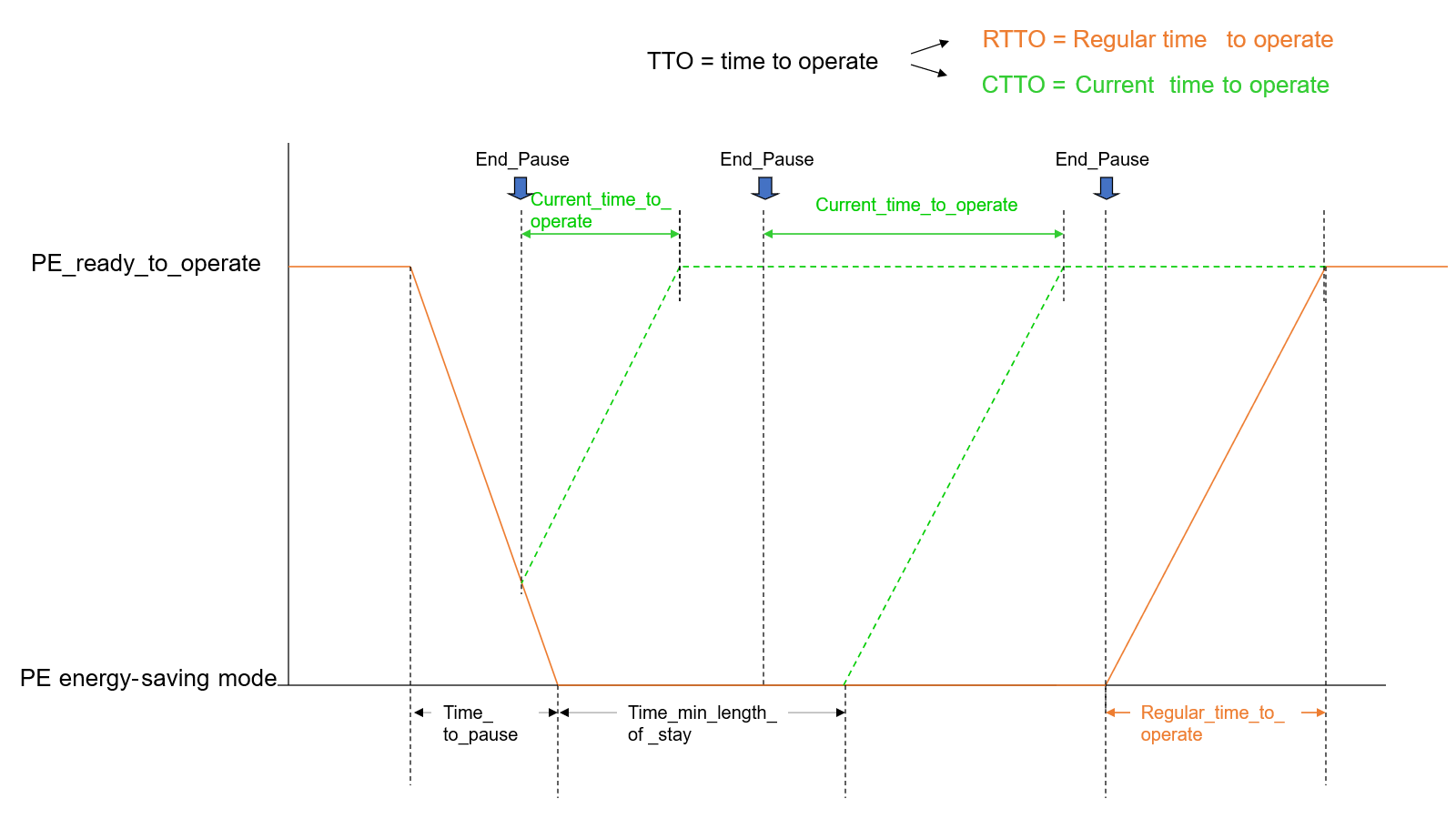
9.2 EnergyStateInformationDataType
The EnergyStateInformationDataType holds information specific to a certain state which also does not change if the device is in transition state. The members shall have the values characterizing the current state and shall be changed only in case of a transition to a different state.
| Name | Type | Description |
|---|---|---|
| EnergyStateInformationDataType | Structure | |
IDSource | 0:Byte | Mode ID of current Energy Saving Mode. |
IDDestination | 0:Byte | Mode ID of destination Energy Saving Mode. |
RegularTimeToOperate | 0:Duration | Time needed to reach "Ready to operate" if the Energy Saving Mode is regularly terminated. Shall be 0 if IDSource is equal to 0xFF (the StandbyManagementStatus Variable has the value "Ready to operate"). |
ModePowerConsumption | 0:Float | Power consumption in actual state. |
| Attribute | Value | |||||
| BrowseName | EnergyStateInformationDataType | |||||
| IsAbstract | False | |||||
| References | NodeClass | BrowseName | DataType | TypeDefinition | Other | |
|---|---|---|---|---|---|---|
| Subtype of the 0:Structure | ||||||
| Conformance Units | ||||||
|---|---|---|---|---|---|---|
| ECM Standby Management | ||||||
If the StandbyManagementStatus Variable of the EnergyStandbyManagementType Object has the value 2 ("Ready to operate"), IDSource and IDDestination shall be equal and have the value 0xFF.
If this StandbyManagementStatus Variable has the value 0 ("Energy saving disabled"), IDSource and IDDestination shall be equal and have the value 0xF0.
If this StandbyManagementStatus Variable has the value 4 ("Energy saving mode"), IDSource and IDDestination shall be equal and have the value of the ID Property of the EnergySavingModeType Object representing the current Energy Saving Mode.
If this StandbyManagementStatus Variable has the value 3 ("Moving to energy saving mode") and if the previous value was 2 ("Ready to operate"), IDSource shall have the value 0xFF and IDDestination shall have the value of the ID Property of the EnergySavingModeType Object representing the destination Energy Saving Mode.
If this StandbyManagementStatus Variable has the value 3 ("Moving to energy saving mode") and if the previous value was 4 ("Energy saving mode", the state transition takes place between two Energy Saving Modes), IDSource shall be the value of the ID Property of the EnergySavingModeType Object representing the source Energy Saving Mode. IDDestination shall have the value of the ID Property of the EnergySavingModeType Object representing the destination Energy Saving Mode.
If this StandbyManagementStatus Variable has the value 5 ("Moving to ready to operate"), IDDestination shall have the value 0xFF. IDSource shall have the value of the ID Property of the EnergySavingModeType Object representing the source Energy Saving Mode.
9.3 AcPeDataType
This structure represents the measurement values of phases relative to neutral, for example for current or voltage.
Phase names L1, L2, L3 can also be seen as A, B, C according to IEC 61557-12 [4].
AcPeDataType corresponds to the magnitude values for phsA, phsB, phsC data objects within a WYE Common Data Class as defined by IEC 61850-7-3 [7].
| Name | Type | Description |
|---|---|---|
| AcPeDataType | Structure | |
L1 | 0:Float | Phase L1-N (or phase a-n) |
L2 | 0:Float | Phase L2-N (or phase b-n) |
L3 | 0:Float | Phase L3-N (or phase c-n) |
| Attribute | Value | |||||
| BrowseName | AcPeDataType | |||||
| IsAbstract | False | |||||
| References | NodeClass | BrowseName | DataType | TypeDefinition | Other | |
|---|---|---|---|---|---|---|
| Subtype of the 0:Structure | ||||||
| Conformance Units | ||||||
|---|---|---|---|---|---|---|
| ECM EnergyProfile E0 | ||||||
| ECM EnergyProfile E3 | ||||||
| ECM Energy Measurement Common DataTypes |
9.4 AcPpDataType
This structure represents the measurement values of phases relative to each other, for example for current or voltage.
Phase names L1L2, L2L3, L3L1 can also be seen as A_b, B_c, C_a according to IEC 61557-12 [4].
AcPpDataType corresponds to the magnitude values for phsAB, phsBC, phsCA data objects within a DEL Common Data Class as defined by IEC 61850-7-3 [7].
| Name | Type | Description |
|---|---|---|
| AcPpDataType | Structure | |
L1L2 | 0:Float | Phase L1-L2 (or phase a-b) |
L2L3 | 0:Float | Phase L2-L3 (or phase b-c) |
L3L1 | 0:Float | Phase L3-L1 (or phase c-a) |
| Attribute | Value | |||||
| BrowseName | AcPpDataType | |||||
| IsAbstract | False | |||||
| References | NodeClass | BrowseName | DataType | TypeDefinition | Other | |
|---|---|---|---|---|---|---|
| Subtype of the 0:Structure | ||||||
| Conformance Units | ||||||
|---|---|---|---|---|---|---|
| ECM EnergyProfile E3 | ||||||
| ECM Energy Measurement Common DataTypes |
9.5 MeasurementPeriodEnum
This enumeration MeasurementPeriodEnum defines how a measurement period is to be interpreted. The enumeration is defined in Table 49.
| Name | Value | Description |
| SlidingDemand | 0 | The measurement period is interpreted to consider the last measurement period. |
| FixedBlockCompleted | 1 | The measurement period is interpreted to take the last completed measurement period aligned to the full hour. |
| FixedBlockInstantaneous | 2 | The measurement period is interpreted to take the current measurement period aligned to the full hour. That means, if for example only have of the measurement period has passed, only that half is considered. |
| FixedBlockPredicted | 3 | The measurement period is interpreted to take the current measurement period aligned to the full hour and predicts the duration that has not been passed. That means, if for example only have of the measurement period has passed, the first half of the considered values is based on real measurements while the second half takes predicted values. |
Its representation in the AddressSpace is defined in Table 50.
| Attribute | Value | ||||
| BrowseName | MeasurementPeriodEnum | ||||
| IsAbstract | False | ||||
| References | Node Class | BrowseName | DataType | TypeDefinition | Other |
|---|---|---|---|---|---|
| Subtype of the Enumeration type defined in OPC 10000-5 | |||||
| 0:HasProperty | Variable | 0:EnumValues | 0:EnumValueType[] | 0:PropertyType | |
| Conformance Units | |||||
|---|---|---|---|---|---|
| ECM Energy Measurement |
9.6 MeasurementPeriodDataType
This structure contains information about the measurement period. The structure is defined in Table 51.
| Name | Type | Description |
| MeasurementPeriodDataType | structure | |
Duration | 0:Duration | The duration of the measurement period in ms. |
Definition | MeasurementPeriodEnum | Defines how to interpret the duration of the measurement period. |
Its representation in the AddressSpace is defined in Table 52.
| Attribute | Value | ||||
| BrowseName | MeasurementPeriodDataType | ||||
| IsAbstract | False | ||||
| References | Node Class | BrowseName | DataType | TypeDefinition | Other |
|---|---|---|---|---|---|
| Subtype of 0:Structure | |||||
| Conformance Units | |||||
|---|---|---|---|---|---|
| ECM Energy Measurement |
10 Instances
10.1 AccuracyDomains
The AccuracyDomains Object is the entry point to Objects representing accuracy domains (see 6.2.4) and is formally defined in Table 53.
| Attribute | Value | |||
| BrowseName | AccuracyDomains | |||
| References | NodeClass | BrowseName | DataType | TypeDefinition |
|---|---|---|---|---|
| OrganizedBy by the 0:ServerCapabilities Object defined in OPC 10000-5 | ||||
| 0:HasTypeDefinition | ObjectType | 0:FolderType | Defined in OPC 10000-5 | |
| Conformance Units | ||||
|---|---|---|---|---|
| ECM Energy Measurement | ||||
10.2 ACCURACY_DOMAIN_PERCENT_FULL_SCALE
The ACCURACY_DOMAIN_PERCENT_FULL_SCALE Object represents a specific accuracy domain (see 6.2.4) and is formally defined in Table 54.
| Attribute | Value | |||
| BrowseName | ACCURACY_DOMAIN_PERCENT_FULL_SCALE | |||
| Description | The accuracy is given as percent of the full-scale reading. | |||
| References | NodeClass | BrowseName | DataType | TypeDefinition |
|---|---|---|---|---|
| OrganizedBy by the AccuracyDomains Object defined in 10.1 | ||||
| 0:HasTypeDefinition | ObjectType | 0:AccuracyDomainType | Defined in 7.1.2 | |
| 0:HasProperty | Variable | 0:EnumValues | 0:EnumValueType[] | 0:PropertyType |
| Conformance Units | ||||
|---|---|---|---|---|
| ECM Accuracy Domain Percent full scale | ||||
The child Nodes of the ACCURACY_DOMAIN_PERCENT_FULL_SCALE have additional Attribute values defined in Table 55.
| BrowsePath | Value Attribute | Description Attribute |
| 0:EnumValues | [ {"Value": 0, "DisplayName": "ACCURACY_CLASS_0", "Description": "reserved"}, {"Value": 1, "DisplayName": "ACCURACY_CLASS_1", "Description": "0,01%"}, {"Value": 2, "DisplayName": "ACCURACY_CLASS_2", "Description": "0,02%"}, {"Value": 3, "DisplayName": "ACCURACY_CLASS_3", "Description": "0,05%"}, {"Value": 4, "DisplayName": "ACCURACY_CLASS_4", "Description": "0,1%"}, {"Value": 5, "DisplayName": "ACCURACY_CLASS_5", "Description": "0,2%"}, {"Value": 6, "DisplayName": "ACCURACY_CLASS_6", "Description": "0,5%"}, {"Value": 7, "DisplayName": "ACCURACY_CLASS_7", "Description": "1%"}, {"Value": 8, "DisplayName": "ACCURACY_CLASS_8", "Description": "1,5%"}, {"Value": 9, "DisplayName": "ACCURACY_CLASS_9", "Description": "2%"}, {"Value": 10, "DisplayName": "ACCURACY_CLASS_10", "Description": "2,5%"}, {"Value": 11, "DisplayName": "ACCURACY_CLASS_11", "Description": "3%"}, {"Value": 12, "DisplayName": "ACCURACY_CLASS_12", "Description": "5%"}, {"Value": 13, "DisplayName": "ACCURACY_CLASS_13", "Description": "10%"}, {"Value": 14, "DisplayName": "ACCURACY_CLASS_14", "Description": "20%"}, {"Value": 15, "DisplayName": "ACCURACY_CLASS_15", "Description": ">20%"} ] |
10.3 ACCURACY_DOMAIN_PERCENT_ACTUAL_READING
The ACCURACY_DOMAIN_PERCENT_ACTUAL_READING Object represents a specific accuracy domain (see 6.2.4) and is formally defined in Table 56.
| Attribute | Value | |||
| BrowseName | ACCURACY_DOMAIN_PERCENT_ACTUAL_READING | |||
| Description | The accuracy is given as percent of the actual reading. | |||
| References | NodeClass | BrowseName | DataType | TypeDefinition |
|---|---|---|---|---|
| OrganizedBy by the AccuracyDomains Object defined in 10.1 | ||||
| 0:HasTypeDefinition | ObjectType | 0:AccuracyDomainType | Defined in 7.1.2 | |
| 0:HasProperty | Variable | 0:EnumValues | 0:EnumValueType[] | 0:PropertyType |
| Conformance Units | ||||
|---|---|---|---|---|
| ECM Accuracy Domain Percent actual reading | ||||
The child Nodes of the ACCURACY_DOMAIN_PERCENT_ACTUAL_READING have additional Attribute values defined in Table 57.
| BrowsePath | Value Attribute | Description Attribute |
| 0:EnumValues | [ {"Value": 0, "DisplayName": "ACCURACY_CLASS_0", "Description": "reserved"}, {"Value": 1, "DisplayName": "ACCURACY_CLASS_1", "Description": "0,01%"}, {"Value": 2, "DisplayName": "ACCURACY_CLASS_2", "Description": "0,02%"}, {"Value": 3, "DisplayName": "ACCURACY_CLASS_3", "Description": "0,05%"}, {"Value": 4, "DisplayName": "ACCURACY_CLASS_4", "Description": "0,1%"}, {"Value": 5, "DisplayName": "ACCURACY_CLASS_5", "Description": "0,2%"}, {"Value": 6, "DisplayName": "ACCURACY_CLASS_6", "Description": "0,5%"}, {"Value": 7, "DisplayName": "ACCURACY_CLASS_7", "Description": "1%"}, {"Value": 8, "DisplayName": "ACCURACY_CLASS_8", "Description": "1,5%"}, {"Value": 9, "DisplayName": "ACCURACY_CLASS_9", "Description": "2%"}, {"Value": 10, "DisplayName": "ACCURACY_CLASS_10", "Description": "2,5%"}, {"Value": 11, "DisplayName": "ACCURACY_CLASS_11", "Description": "3%"}, {"Value": 12, "DisplayName": "ACCURACY_CLASS_12", "Description": "5%"}, {"Value": 13, "DisplayName": "ACCURACY_CLASS_13", "Description": "10%"}, {"Value": 14, "DisplayName": "ACCURACY_CLASS_14", "Description": "20%"}, {"Value": 15, "DisplayName": "ACCURACY_CLASS_15", "Description": ">20%"} ] |
10.4 ACCURACY_DOMAIN_IEC
The ACCURACY_DOMAIN_IEC Object represents a specific accuracy domain (see 6.2.4) and is formally defined in Table 58.
| Attribute | Value | |||
| BrowseName | ACCURACY_DOMAIN_IEC | |||
| Description | The accuracy is given according to IEC 61557-12. | |||
| References | NodeClass | BrowseName | DataType | TypeDefinition |
|---|---|---|---|---|
| OrganizedBy by the AccuracyDomains Object defined in 10.1 | ||||
| 0:HasTypeDefinition | ObjectType | 0:AccuracyDomainType | Defined in 7.1.2 | |
| 0:HasProperty | Variable | 0:EnumValues | 0:EnumValueType[] | 0:PropertyType |
| Conformance Units | ||||
|---|---|---|---|---|
| ECM Accuracy Domain IEC | ||||
The child Nodes of the ACCURACY_DOMAIN_IEC have additional Attribute values defined in Table 59.
| BrowsePath | Value Attribute | Description Attribute |
| 0:EnumValues | [ {"Value": 0, "DisplayName": "ACCURACY_CLASS_0", "Description": "reserved"}, {"Value": 1, "DisplayName": "ACCURACY_CLASS_1", "Description": "0,02"}, {"Value": 2, "DisplayName": "ACCURACY_CLASS_2", "Description": "0,05"}, {"Value": 3, "DisplayName": "ACCURACY_CLASS_3", "Description": "0,1"}, {"Value": 4, "DisplayName": "ACCURACY_CLASS_4", "Description": "0,2"}, {"Value": 5, "DisplayName": "ACCURACY_CLASS_5", "Description": "0,5"}, {"Value": 6, "DisplayName": "ACCURACY_CLASS_6", "Description": "1"}, {"Value": 7, "DisplayName": "ACCURACY_CLASS_7", "Description": "1,5"}, {"Value": 8, "DisplayName": "ACCURACY_CLASS_8", "Description": "2"}, {"Value": 9, "DisplayName": "ACCURACY_CLASS_9", "Description": "2,5"}, {"Value": 10, "DisplayName": "ACCURACY_CLASS_10", "Description": "3"}, {"Value": 11, "DisplayName": "ACCURACY_CLASS_11", "Description": "5"}, {"Value": 12, "DisplayName": "ACCURACY_CLASS_12", "Description": "10"}, {"Value": 13, "DisplayName": "ACCURACY_CLASS_13", "Description": "20"} ] |
10.5 ACCURACY_DOMAIN_EN
The ACCURACY_DOMAIN_EN Object represents a specific accuracy domain as specified in EN 50470-3 [5] (see 6.2.4) and is formally defined in Table 60.
| Attribute | Value | |||
| BrowseName | ACCURACY_DOMAIN_EN | |||
| Description | The accuracy is given as specified in the EN 50470-3. | |||
| References | NodeClass | BrowseName | DataType | TypeDefinition |
|---|---|---|---|---|
| OrganizedBy by the AccuracyDomains Object defined in 10.1 | ||||
| 0:HasTypeDefinition | ObjectType | 0:AccuracyDomainType | Defined in 7.1.2 | |
| 0:HasProperty | Variable | 0:EnumValues | 0:EnumValueType[] | 0:PropertyType |
| Conformance Units | ||||
|---|---|---|---|---|
| ECM Accuracy Domain EN | ||||
The child Nodes of the ACCURACY_DOMAIN_EN have additional Attribute values defined in Table 61.
| BrowsePath | Value Attribute | Description Attribute |
| 0:EnumValues | [ {"Value": 0, "DisplayName": "ACCURACY_CLASS_0", "Description": "reserved"}, {"Value": 1, "DisplayName": "ACCURACY_CLASS_1", "Description": "0,5"}, {"Value": 2, "DisplayName": "ACCURACY_CLASS_2", "Description": "1,0"}, {"Value": 3, "DisplayName": "ACCURACY_CLASS_3", "Description": "1,5"}, {"Value": 4, "DisplayName": "ACCURACY_CLASS_4", "Description": "2,0"}, {"Value": 5, "DisplayName": "ACCURACY_CLASS_5", "Description": "2,5"}, {"Value": 6, "DisplayName": "ACCURACY_CLASS_6", "Description": "3,0"} ] |
11 Profiles and ConformanceUnits
11.1 Conformance Units
This chapter defines the corresponding Conformance Units for the OPC UA Information Model for Energy Consumption Management.
| Category | Title | Description |
| Server | ECM Standby Management | Supports the Standby Management functionality defined by EnergyStandbyManagementType. The Server is configurable to support at least one instance of EnergyStandbyManagementType. The ObjectTypes EnergyStandbyManagementType, EnergySavingModesContainerType, EnergySavingModeStatusType, and EnergySavingModeType are supported. The DataTypes StandbyModeTransitionDataType and EnergyStateInformationDataType are supported. |
| Server | ECM Standby Management Control | Supports the Standby Management functionality defined by EnergyStandbyManagementType. The Methods StartPause, EndPause, PauseTime are supported in at least one instance of EnergyStandbyManagementType. |
| Server | ECM Energy Measurement | Supports the Energy Measurement functionality defined by EnergyMeasurementType. The Server is configurable to support at least one instance of EnergyMeasurementType. The ObjectTypes EnergyMeasurementType and AccuracyDomainType are supported. The VariableType EnergyMeasurementValueType is supported. The DataTypes MeasurementPeriodEnum and MeasurementPeriodDataType are supported. |
| Server | ECM Accuracy Domain Percent full scale | The instance ACCURACY_DOMAIN_PERCENT_FULL_SCALE is supported. |
| Server | ECM Accuracy Domain Percent actual reading | The instance ACCURACY_DOMAIN_PERCENT_ACTUAL_READING is supported. |
| Server | ECM Accuracy Domain IEC | The instance ACCURACY_DOMAIN_IEC is supported. |
| Server | ECM Accuracy Domain EN | The instance ACCURACY_DOMAIN_EN is supported. |
| Server | ECM Sleep Mode WOL | Supports the Sleep Mode WOL functionality defined by EnergyDevicePowerOffType. The Server is configurable to support at least one instance of EnergyDevicePowerOffType. The ObjectType EnergyDevicePowerOffType is supported. |
| Server | ECM Energy Management Support | Supports at least one of the Conformance Units: ECM Standby Management, ECM Energy Measurement or ECM Sleep Mode WOL. |
| Server | ECM Energy Measurement Common DataTypes | Supports the DataTypes AcPeDataType and AcPpDataType. |
| Server | ECM EnergyProfile E0 | IEnergyProfileE0 Interface is supported by at least one EnergyMeasurementType Object instance. |
| Server | ECM EnergyProfile E1 | IEnergyProfileE1 Interface is supported by at least one EnergyMeasurementType Object instance. |
| Server | ECM EnergyProfile E2 | IEnergyProfileE2 Interface is supported by at least one EnergyMeasurementType Object instance. |
| Server | ECM EnergyProfile E3 | IEnergyProfileE3 Interface is supported by at least one EnergyMeasurementType Object instance. |
| Server | ECM EnergyProfile D0 | IEnergyProfileD0 Interface is supported by at least one EnergyMeasurementType Object instance. |
| Server | ECM EnergyProfile D1 | IEnergyProfileD1 Interface is supported by at least one EnergyMeasurementType Object instance. |
11.2 Profiles
11.2.1 Profile list
Table 63 lists all Profiles defined in this document and defines their URIs.
| Profile | URI |
| ECM Energy Management Server Profile | http://opcfoundation.org/UA-Profile/ECM/Server/EnergyManagement |
| ECM Energy Management Control Server Profile | http://opcfoundation.org/UA-Profile/ECM/Server/EnergyManagementControl |
| ECM Energy Controller Server Facet | http://opcfoundation.org/UA-Profile/ECM/Server/EnergyController |
11.2.2 Server Facets
11.2.2.1 Overview
The following sections specify the Facets available for Servers that implement the Energy Consumption Management companion specification. Each section defines and describes a Facet or Profile.
11.2.2.2 ECM Energy Management Server Profile
This profile defines support for base energy management functionality.
| Group | Conformance Unit / Profile Title | M / O |
| ECM | ECM Standby Management | O |
| ECM | ECM Energy Measurement | O |
| ECM | ECM Sleep Mode WOL | O |
| ECM | ECM EnergyProfile E0 | O |
| ECM | ECM EnergyProfile E1 | O |
| ECM | ECM EnergyProfile E2 | O |
| ECM | ECM EnergyProfile E3 | O |
| ECM | ECM EnergyProfile D0 | O |
| ECM | ECM EnergyProfile D1 | O |
| ECM | ECM Energy Measurement Common DataTypes | O |
| ECM | ECM Energy Management Support | M |
| ECM | ECM Accuracy Domain Percent full scale | O |
| ECM | ECM Accuracy Domain Percent actual reading | O |
| ECM | ECM Accuracy Domain IEC | O |
| ECM | ECM Accuracy Domain EN | O |
| Profile | 0:Nano Embedded Device 2017 Server Profile http://opcfoundation.org/UA-Profile/Server/NanoEmbeddedDevice2017 | |
| Profile | 0:Data Access Server Facet http://opcfoundation.org/UA-Profile/Server/DataAccess | |
| Profile | 0:ComplexType 2017 Server Facet http://opcfoundation.org/UA-Profile/Server/ComplexTypes2017 |
11.2.2.3 ECM Energy Management Control Server Profile
This profile defines support for base for control of standby functionality.
| Group | Conformance Unit / Profile Title | M / O |
| Profile | ECM Energy Controller Server Facet | |
| Profile | ECM Energy Management Server Profile | |
| Profile | 0:Embedded 2017 Server Profile http://opcfoundation.org/UA-Profile/Server/EmbeddedUA2017 | M |
11.2.2.4 ECM Energy Controller Server Facet
This facet defines support for base functionality for control of standby functionality.
| Group | Conformance Unit / Profile Title | M / O |
| ECM | ECM Standby Management Control | M |
| Profile | 3:DI Locking Server Facet |
11.2.3 Client Facets
This specification does not define any Client Facets.
12 Namespaces
12.1 Namespace Metadata
Table 67 defines the namespace metadata for this document. The Object is used to provide version information for the namespace and an indication about static Nodes. Static Nodes are identical for all Attributes in all Servers, including the Value Attribute. See OPC 10000-5 for more details.
The information is provided as Object of type NamespaceMetadataType. This Object is a component of the Namespaces Object that is part of the Server Object. The NamespaceMetadataType ObjectType and its Properties are defined in OPC 10000-5.
The version information is also provided as part of the ModelTableEntry in the UANodeSet XML file. The UANodeSet XML schema is defined in OPC 10000-6.
| Attribute | Value | ||
| BrowseName | http://opcfoundation.org/UA/ECM/ | ||
| Property | DataType | Value | |
|---|---|---|---|
| NamespaceUri | String | http://opcfoundation.org/UA/ECM/ | |
| NamespaceVersion | String | 1.0.1 | |
| NamespacePublicationDate | DateTime | 2026-09-01 | |
| IsNamespaceSubset | Boolean | False | |
| StaticNodeIdTypes | IdType [] | 0 | |
| StaticNumericNodeIdRange | NumericRange [] | ||
| StaticStringNodeIdPattern | String | ||
12.2 Handling of OPC UA Namespaces
Namespaces are used by OPC UA to create unique identifiers across different naming authorities. The Attributes NodeId and BrowseName are identifiers. A Node in the UA AddressSpace is unambiguously identified using a NodeId. Unlike NodeIds, the BrowseName cannot be used to unambiguously identify a Node. Different Nodes may have the same BrowseName. They are used to build a browse path between two Nodes or to define a standard Property.
Servers may often choose to use the same namespace for the NodeId and the BrowseName. However, if they want to provide a standard Property, its BrowseName shall have the namespace of the standards body although the namespace of the NodeId reflects something else, for example the EngineeringUnits Property. All NodeIds of Nodes not defined in this document shall not use the standard namespaces.
Table 68 provides a list of mandatory and optional namespaces used in an Energy Consumption Management OPC UA Server.
| NamespaceURI | Description |
| http://opcfoundation.org/UA/ | Namespace for NodeIds and BrowseNames defined in the OPC UA specification. This namespace shall have namespace index 0. |
| Local Server URI | Namespace for nodes defined in the local server. This namespace shall have namespace index 1. |
| http://opcfoundation.org/UA/DI/ | Namespace for NodeIds and BrowseNames defined in OPC 10000-100. The namespace index is Server specific. |
| http://opcfoundation.org/UA/IA/ | Namespace for NodeIds and BrowseNames defined in OPC UA for Industrial Automation (OPC 10000-200). The namespace index is Server specific. |
| http://opcfoundation.org/UA/ECM/ | Namespace for NodeIds and BrowseNames defined in this document. The namespace index is Server specific. |
| Vendor specific types | A Server may provide vendor-specific types like types derived from ObjectTypes defined in this document in a vendor-specific namespace. |
| Vendor specific instances | A Server provides vendor-specific instances of the standard types or vendor-specific instances of vendor-specific types in a vendor-specific namespace. It is recommended to separate vendor specific types and vendor specific instances into two or more namespaces. |
Table 69 provides a list of namespaces and their indices used for BrowseNames in this document. The default namespace of this document is not listed since all BrowseNames without prefix use this default namespace.
| NamespaceURI | Namespace Index | Example |
| http://opcfoundation.org/UA/ | 0 | 0:EngineeringUnits |
| http://opcfoundation.org/UA/IA/ | 2 | 2:ResetStatistics |
| http://opcfoundation.org/UA/DI/ | 3 | 3:Lock |
Annex A Energy Consumption Management Namespace and mappings (Normative)
A.1 NodeSet and supplementary files for Energy Consumption Management Information Model
The Energy Consumption Management Information Model is identified by the following URI:
http://opcfoundation.org/UA/ECM/
Documentation for the NamespaceUri can be found here.
The NodeSet associated with this version of specification can be found here:
https://reference.opcfoundation.org/nodesets/?u=http://opcfoundation.org/UA/ECM/&v=1.0.1&i=1
The NodeSet associated with the latest version of the specification can be found here:
https://reference.opcfoundation.org/nodesets/?u=http://opcfoundation.org/UA/ECM/&i=1
Supplementary files for the Energy Consumption Management Information Model can be found here:
https://reference.opcfoundation.org/nodesets/?u=http://opcfoundation.org/UA/ECM/&v=1.0.1&i=2
The files associated with the latest version of the specification can be found here:
https://reference.opcfoundation.org/nodesets/?u=http://opcfoundation.org/UA/ECM/&i=2
_____________
Annex B EngineeringUnits (Normative)
B.1 Overview
OPC UA defines a predefined namespace for EngineeringUnits:
http://www.opcfoundation.org/UA/units/un/cefact
This specification uses EngineeringUnits defined by that namespace in the base OPC UA specification.
In Table 70, EngineeringUnits are defined in the namespace of this specification for EngineeringUnits used by this specification but not defined in the above-mentioned namespace.
| NamespaceUri | UnitId | DisplayName | Description |
|---|---|---|---|
| http://opcfoundation.org/UA/ECM/ | 1 | var·h | volt ampere reactive hour |
_____________
Bibliography
Agreement of Use
COPYRIGHT RESTRICTIONS
This document is provided "as is" by the ECM owners.
Right of use for this specification is restricted to this specification and does not grant rights of use for referred documents.
Right of use for this specification will be granted without cost.
This document may be distributed through computer systems, printed or copied as long as the content remains unchanged and the document is not modified.
ECM owners do not guarantee usability for any purpose and shall not be made liable for any case using the content of this document.
The user of the document agrees to indemnify ECM owners and their officers, directors and agents harmless from all demands, claims, actions, losses, damages (including damages from personal injuries), costs and expenses (including attorneys' fees) which are in any way related to activities associated with its use of content from this specification.
The document shall not be used in conjunction with company advertising, shall not be sold or licensed to any party.
The intellectual property and copyright is solely owned by the ECM owners;.
PATENTS
The attention of adopters is directed to the possibility that compliance with or adoption of OPC or VDMA specifications may require use of an invention covered by patent rights. ECM owners shall not be responsible for identifying patents for which a license may be required by any OPC or VDMA specification, or for conducting legal inquiries into the legal validity or scope of those patents that are brought to its attention. OPC or VDMA specifications are prospective and advisory only. Prospective users are responsible for protecting themselves against liability for infringement of patents.
WARRANTY AND LIABILITY DISCLAIMERS
WHILE THIS PUBLICATION IS BELIEVED TO BE ACCURATE, IT IS PROVIDED "AS IS" AND MAY CONTAIN ERRORS OR MISPRINTS. THE OPC FOUDATION NOR VDMA MAKES NO WARRANTY OF ANY KIND, EXPRESSED OR IMPLIED, WITH REGARD TO THIS PUBLICATION, INCLUDING BUT NOT LIMITED TO ANY WARRANTY OF TITLE OR OWNERSHIP, IMPLIED WARRANTY OF MERCHANTABILITY OR WARRANTY OF FITNESS FOR A PARTICULAR PURPOSE OR USE. IN NO EVENT SHALL THE ECM OWNERS BE LIABLE FOR ERRORS CONTAINED HEREIN OR FOR DIRECT, INDIRECT, INCIDENTAL, SPECIAL, CONSEQUENTIAL, RELIANCE OR COVER DAMAGES, INCLUDING LOSS OF PROFITS, REVENUE, DATA OR USE, INCURRED BY ANY USER OR ANY THIRD PARTY IN CONNECTION WITH THE FURNISHING, PERFORMANCE, OR USE OF THIS MATERIAL, EVEN IF ADVISED OF THE POSSIBILITY OF SUCH DAMAGES.
The entire risk as to the quality and performance of software developed using this specification is borne by you.
RESTRICTED RIGHTS LEGEND
This Specification is provided with Restricted Rights. Use, duplication or disclosure by the U.S. government is subject to restrictions as set forth in (a) this Agreement pursuant to DFARs 227.7202-3(a); (b) subparagraph (c)(1)(i) of the Rights in Technical Data and Computer Software clause at DFARs 252.227-7013; or (c) the Commercial Computer Software Restricted Rights clause at FAR 52.227-19 subdivision (c)(1) and (2), as applicable. Contractor / manufacturer are the OPC Foundation, 16101 N. 82nd Street, Suite 3B, Scottsdale, AZ, 85260-1830.
COMPLIANCE
The combination of ECM owners shall at all times be the sole entities that may authorize developers, suppliers and sellers of hardware and software to use certification marks, trademarks or other special designations to indicate compliance with these materials as specified within this document. Products developed using this specification may claim compliance or conformance with this specification if and only if the software satisfactorily meets the certification requirements set by ECM owners. Products that do not meet these requirements may claim only that the product was based on this specification and must not claim compliance or conformance with this specification.
TRADEMARKS
Most computer and software brand names have trademarks or registered trademarks. The individual trademarks have not been listed here.
GENERAL PROVISIONS
Should any provision of this Agreement be held to be void, invalid, unenforceable or illegal by a court, the validity and enforceability of the other provisions shall not be affected thereby.
This Agreement shall be governed by and construed under the laws of Germany.
This Agreement embodies the entire understanding between the parties with respect to, and supersedes any prior understanding or agreement (oral or written) relating to, this specification.
ISSUE REPORTING
If an error or problem is found in this specification, the UaNodeSet, or any associated supplementary files, it should be reported as a mantis issue.
The process can be found here: https://opcfoundation.org/resources/issue-tracking/
The Link to the Mantis project for this specification is here:
https://apps.opcfoundation.org/mantis/set_project.php?project_id=183&make_default=no